A Dutch merchant vessel of 1664. The Keel, part 5/15.
7
The Keel The stopwaters. “De Keernagels, sijn ronde Gaten, die men ten getaale van 2 of 3, tusschen de Vergaring deser Lasschen in boord, om daar door, voor altijd, het Water te beletten, dat het door dese Lasschen, in het Schip dringe. Den Bouwmeester mag door een of twee voorzigtige Mannen, deselve met Mosch tot in haar binnenste, laten aanvullen, en, ter weder Einden, met houte Nagels doen sluiten”. (p. 54 l. 25) (The stopwaters are round holes of which 2 or 3 are drilled at the exact joint surfaces to prevent, forever, water coming into the ship through these joints. The master shipwright may choose one or two cautious men who fill these holes with moss and seal both ends with pegs.) A ‘Vergaring’ is the place where joint surfaces from different pieces of construction timber meet, in this case six surfaces from two keel parts forming one joint. Exact at the point where the two oblique surfaces meet, holes are drilled. The direction of these holes is right-angled to the longitudinal direction of the joints surface, they are subsequently filled with moss and sealed with a peg. This hole filled with moss is called a ‘keernagel’ or ‘scheinagel’, in English a stopwater. I could not find sources that indicate this procedure is practiced (in the 17 th century) by for instance the French or the English. Cornelis mentions specifically that cautious men should apply the moss in this hole. I can imagine you indicate the men should be cautious drilling holes at the exact assembly of the two joint surfaces because this is no simple task. The drill has a tendency to seek its way in the wrong direction, i.e. where there is mass rather than just follow the exact surface of the joint. But maybe the ‘avegaar’ (auger) or ‘lepelboor’ (literally: ‘spoon drill’), the type of manual force drill they used in these days, had less tendency to deviate from its desired direction compared to the machines we use today. Cornelis mentions this type of drill: “Alderley groote, en kleine Bout-avegaars”. (p. 29, l. 9) (Several big and small bolt-augers), drills used to drill holes for the bolts like we saw applied at the keel joints and he supplies a picture: Auger. Cornelis van Yk, between page 58 and 59. © Jaap Luiting 2015
-
Upload
independent -
Category
Documents
-
view
1 -
download
0
Transcript of A Dutch merchant vessel of 1664. The Keel, part 5/15.

The Keel
The stopwaters.
“De Keernagels, sijn ronde Gaten, die men ten getaale van 2 of 3, tusschen de Vergaring deser Lasschen in boord, om daar door, voor altijd, het Water te beletten, dat het door dese Lasschen, in het Schip dringe. Den Bouwmeester mag door een of twee voorzigtige Mannen, deselve met Mosch tot in haar binnenste, laten aanvullen, en, ter weder Einden, met houte Nagels doen sluiten”. (p. 54 l. 25) (The stopwaters are round holes of which 2 or 3 are drilled at the exact joint surfaces to prevent, forever, water coming into the ship through these joints. The master shipwright may choose one or two cautious men who fill these holes with moss and seal both ends with pegs.)
A ‘Vergaring’ is the place where joint surfaces from different pieces of construction timber meet, in this case six surfaces from two keel parts forming one joint. Exact at the point where the two oblique surfaces meet, holes are drilled. The direction of these holes is right-angled to the longitudinal direction of the joints surface, they are subsequently filled with moss and sealed with a peg. This hole filled with moss is called a ‘keernagel’ or ‘scheinagel’, in English a stopwater. I could not find sources that indicate this procedure is practiced (in the 17th century) by for instance the French or the English.Cornelis mentions specifically that cautious men should apply the moss in this hole. I can imagine you indicate the men should be cautious drilling holes at the exact assembly of the two joint surfaces because this is no simple task. The drill has a tendency to seek its way in the wrong direction, i.e. where there is mass rather than just follow the exact surface of the joint. But maybe the ‘avegaar’ (auger) or ‘lepelboor’ (literally: ‘spoon drill’), the type of manual force drill they used in these days, had less tendency to deviate from its desired direction compared to the machines we use today.Cornelis mentions this type of drill: “Alderley groote, en kleine Bout-avegaars”. (p. 29, l. 9) (Several big and small bolt-augers), drills used to drill holes for the bolts like we saw applied at the keel joints and he supplies a picture:
Auger.Cornelis van Yk, between page 58 and 59.
© Jaap Luiting 2015

The Keel
Nicolaes mentions these stopwaters also at different places in his book. The descriptions concerning this subject are almost the same in both editions.
“Door ’t lasch van de kiel, voor- en achter-steven, zyn schei-nagels geboort”. (p. 99, c. 2, l. 40, 1690)(Stopwaters are drilled through the joint of the keel and the joints with stem and stern)
“De scheiding van de kiel en achter-steven is met schei-nagels geboort”. (p. 112, c. 1, l. 33, 1690)(At the separation between keel and stern stopwaters are drilled)
“Boort de Schey-nagels in de Stevens, en in de Kiel” (p. 164, c. 1, l. 47, 1690)(Drill stopwaters in stem, stern and keel)
Stern at the keel.Nicolaes Witsen, plate 48, between page 146 and 147, 1671.
© Jaap Luiting 2015

The Keel
“Aen de figuur A ziet de gedaente van een Achter-steven, staende op de Kiel” (p. 146, c. 2, l. 17, 1671)(Figure A shows the profile of a stern standing on the keel)
Ab Het Vallen van de Steven. (The rake of the stern)Ac De hoogte van de steven. (The height of the stern)be Onder de breete van de Steeven. (The width of the stern under)cf Boven-stevens breete. (The width of the stern atop)gb De lengte van d’Achter-scheg. (The length of the skeg aft)h De Sponning. (The rabbet)bd De hieling van de Kiel, en dickte. (Depth and ‘hieling’ of the keel)e Het knie op de kiel aen de Steven. (The knee on the keel attached to the stern)y De Schey-nagels. (The stopwaters)
The ‘y’ in the picture looks like:
o De Teyckening daer de Schey-nagel ingeslagen werdt. (The mark where the stopwater is applied)k De pen van de Steven die in de kiel komt te staen”. (The pin of the stern who is applied in the keel)
“en als men de lasschen vast gemaakt heeft, zoo boort men van onderen in de sponning een schei-nagel, op dat het water daar niet door speele”. (p. 168, c. 1, l. 33, 1690) (when one has assembled the joints, one drills from below in the rabbet a stopwater to prevent the water coming through.)
All quoted descriptions can be found in both editions except for this last one who can only be found in the 1690 edition. Nicolaes also mentions the stopwaters to be drilled holes.With these descriptions Nicolaes provides more information then Cornelis does. The most interesting thing is that Nicolaes mentions a specific place for one of these stopwaters; not only between the surfaces of the joint but at the same time in the rabbet.We may assume these moss-filled holes actually created a barrier for incoming water moving upward due to the water pressure under the keel although I found no indications this practice was continued or even mentioned in the 18th century. This practice has survived the 18th century though because in the 19th century it is mentioned by J. C. Pilaar and G. P. J. Mossel in their book ‘Handleiding tot de kennis van het schip’, 1859)On the pages 100 and 149 of this book a description is given together with two illustrations.
Keeljoint.J. C. Pilaar and G. P. J. Mossel. 1859.
“Door mossponningen verstaat men gleuven, welke in de beide vlakken van eene lasch gehakt worden, en daarna met mos worden opgevuld. Zij worden gewoonlijk bij de kiel- en stevenlasschen aangewend; zij vormen gemeenlijk eene rechthoekige figuur, en dienen om daar binnen de bouten te slaan, en alzoo het water, dat hierdoor zoude kunnen heendringen, den toegang tot het schip te beletten. Dergelijke sponningen maakt men ook dwars in eenen naad, die gedeeltelijk binnen en buiten het schip uitkomt,
© Jaap Luiting 2015

The Keel
zoo als bij h h fig. 50 is voorgesteld. Hiermede bedoelt men, om het water, dat bijvoorbeeld ergens bij g binnen de lasch zou kunnen komen, het verder binnendringen te beletten. De beide uiteinden van deze sponningen worden met zoogenoemde keernagels gesloten; dit zijn korte houten pennen of nagels, die juist in de sponning passen, en daarin geslagen wordende, het mos vaster aandrijven en tegen uitvallen behoeden. Bij de kiellasschen worden deze keernagels in de kielsponning geplaatst”. (Edition 1859, p.100) (‘Moss-grooves’ are grooves cut in both surfaces of a joint and subsequently filled with moss. They are usually applied at the joints of keel, stem and stern and form a rectangular shape and function as a barrier for water eventually penetrating through the holes drilled for the bolts who are applied within this rectangular shape. Grooves like this are also applied transverse, ending partly inside and outside the ship as shown by h h, fig 50. This is intended to prevent water coming in the joint at g, to penetrate further into joint and ship. Both ends of the grooves are sealed with a so called ‘keernagel’ a short wooden peg or nail who fit right into the groove and while hammered into the groove compress the moss and prevent it from falling out. At the keeljoints these ‘keernagels’ are placed in the rabbet.)
The grooves where the moss is applied are cut in transverse and longitudinal direction before the joint is closed and mounted. The transverse grooves are, just like Nicolaas mentions, placed in the rabbet of the keel. Instead of defining the hole with moss as a ‘keernagel’, here only the wooden seals at the end of the grooves are called ‘keernagels’.The grooves form a rectangular barrier preventing water pressing through the drilled holes for the bolts from diffusing further into the ship. Also visible is a hoop near the lower butt joint, a comparable situation to the keeljoint of the Delft.
Another description is given on page 149:
Top view of a keeljoint with moss grooves.J. C. Pilaar and G. P. J. Mossel. 1859.
“Om het indringen van het water te beletten, wordt de lasch van binnen met mospapier aangelegd, en voorzien van mossponningen n n, fig. 175, alwaar de lasch van binnen te zien, alsmede van twee keernagels h h in de kielsponning. De bevestiging van de lasch geschiedt door koperen bouten p p, welke binnen de mossponningen in verband geslagen worden, zoodat geen water daardoor naar binnen kan dringen. Dit zijn kopbouten, die aan het vooreinde geklonken worden, en aan weerszijde komt een koperen plaatje dat gelijk met het hout inzinkt. Verder komen er eenige spijkers q q op de einden van de lasch, welke zoodanig geslagen worden, dat het dunste deel aan het dikste wordt vastgespijkerd. Sommige bouwmeesters zijn van oordeel, dat de mossponningen het indringen van water door de kiel eerder bevorderen, en gebruiken dus alleen keernagels”. (Edition 1859, page 149) (To prevent the penetration of water the joint is provided on the inside with moss-paper and moss-grooves n n figure 175 showing the inside of a joint and two moss grooves h h in the rabbet. The mounting of the joint is
© Jaap Luiting 2015

The Keel
done by copper bolts applied in a regular pattern within the rectangle of the moss-dowels so no water can penetrate. These are head bolts which are riveted at the top end with a copper plate at both ends which is recessed equal to the wood surface. Furthermore a number of nails q q at the ends of the joint are nailed in such a way that the thinnest part is nailed to the thickest part. Some master shipwrights believe the moss-grooves rather promote the penetration of water and thus use only “keernagels” (wooden dowels). (r shows the notch for the hoop, visible in fig. 50)
The use of these grooves filled with moss is apparently not undisputed and some master shipwrights only use the wooden “keernagel”.
Again the practice surfaces in the manuscript ‘Handboek voor the houtscheepmaker’ written by Cornelis Brinkman and Jan Lienos. This manuscript is part of the collection of the National Maritime Museum in Amsterdam, has been edited by J. P. Puype and still issued under that title. It is one of the very few books about the actual practice of building large wooden vessels I've ever faced written in the Dutch language. The authors know from experience what they're talking about which is quite significant as we saw in the introduction of this analysis. The manuscript was presumed written after World War II and never published probably because the construction of large wooden ships at the Navy Yard in Den Helder (in the north of Holland) gradually ended and the need for a textbook on the subject no longer made sense. It is interesting to read what they have to say about the structure of a keel joint in general and about the ‘keernagels’.
On page 21 one reads:
“Later plaatst men in de bovenkant van de las, in de diepte der sponning voor de zandstrook, een scheinagel. Dit is een magere grenehouten pen, welke door de breedte van de las heengaat en daardoor een beletsel vormt voor het water, dat eventueel door de las in het schip zou kunnen komen. Ook wordt hiervoor wel een mosnagel gebruikt. Deze ontstaat door in het geboorde gat losse mos vast in te slaan door middel van een harde houten of ijzeren pen, zodat dit een vaste massa wordt en daardoor een zeer goede afsluiting vormt. Veelal worden in lange lassen één of enige pennen van ± 2½ cm¹ dik ingeslagen om het verschuiven in lengterichting tegen te gaan. Men noemt deze treknagels.” (Cornelis Brinkman, Jan Lienos, edition 1980, manuscript around 1960, page 21) (Later one places in the upper side of the joint, in the depth of the rabbet for the garboard strakes, a stopwater. This is a dowel made of pine going through the width of the joint forming a barrier for water coming in through the joint. One also applies a moss stopwater to this use. This originates by filling the drilled hole with moss and compress this with a wooden or iron bar as to form a solid mass forming a very good seal. Long joints usually receive one or two dowels of ± 2,5 cm¹ (diameter) to prevent displacement in the longitudinal direction. These are called ‘treknagels’) The following pictures are given, figure 5 and figure 5a:
© Jaap Luiting 2015
The Keel
Keeljoint.
C. Brinkman, J. Lienos, page 20, 1980.
‘Kiel las’: Keel joint.‘Trek nagels’: Dowels applied to prevent sliding off of the two surfaces of the joint.‘Huid sponning’: Rabbet for the garboard strakes.‘Neuten of douwels': Wooden (lignum vitae) dowels.‘Boutgaten’: Drilled holes for the bolts.The length of the joint is 5 to 6 times the height of the keel, the butt joint is 1/6 the height of the keel.
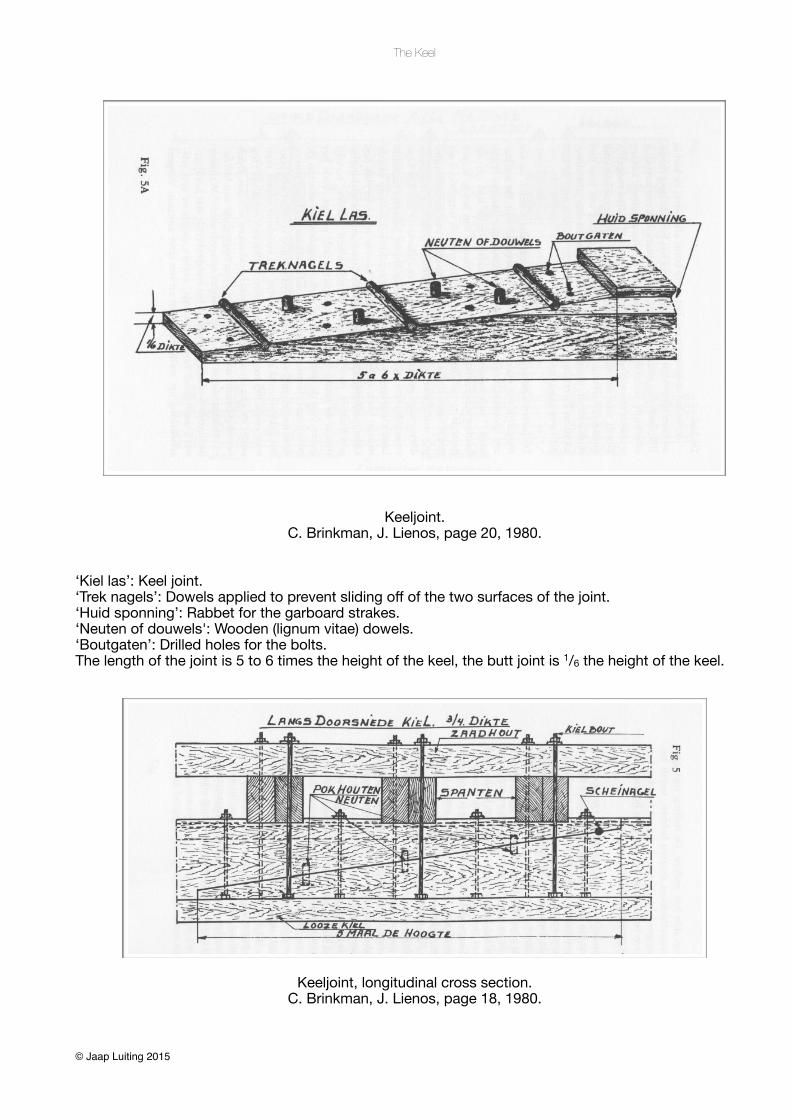
Keeljoint, longitudinal cross section.C. Brinkman, J. Lienos, page 18, 1980.
© Jaap Luiting 2015

The Keel
‘Zaadhout’: Kelson.‘Kielbout’: Bolt.‘Pokhouten neuten’: Lignum Vitae dowels.‘Spanten’: Frames.‘Scheinagel’: Stopwater.‘Looze kiel’: Shoe.
The emphasis is on the relation between the stopwater and the rabbet while the stopwater is applied in “de diepte” (the depth) by which is meant the place where the ‘inner rabbet’ and the ‘outer rabbet’ meet: the heart of the rabbet. More about this in the section about the rabbet. Picture 5a reveals the appliance of three (instead of the mentioned one or two) transverse nails made out of pine who are named ‘treknagels’ to prevent a transition in longitudinal direction, something, as we saw earlier with the joints of the Delft, the vertical bolts could not prevent properly. The “neuten” or “douwels” are wooden dowels applied to prevent twisting of the joint along the longitudinal axis. In this case the dowel in the rabbet is to be considered as a stopwater, the function of the other two is primarily to prevent the two joint surfaces sliding off each other. Remarkable is the number of bolts used to close the joint: 8 just like Nicolaes mentions. Another thing which is clearly visible are bolts mounted all the way through keel, futtock and kelson.
Returning to the 17th century: one can determine the use of moss filled holes occurred in the 17th century only athwart. They are drilled at the assembly of the joints surfaces and, concerning the keel joints, one in the heart of the rabbet. Because this procedure was continued into the 20th century one can assume these barriers made a fairly adequate defence against incoming water though the understanding wasn’t without disagreement.For our 155 feet ship we will use three stopwaters in one joint, drilled holes one inch in diameter, evenly distributed, filled with moss, sealed with wooden pegs and one of them in the heart of the rabbet. The stopwater in the rabbet is placed as high up as possible.One possible implementation of a joint of a 155 feet ship in this stage is the following picture.
Keeljoint with stopwaters.
© Jaap Luiting 2015