A disposable and multifunctional capsule for easy operation of microfluidic elastomer systems
15
http://uu.diva-portal.org This is an author-produced version of a paper published in Journal of Micromechanics and Microengineering. This paper has been peer- reviewed but does not include the final publisher proof-corrections or journal pagination. Citation for the published paper: Thorslund S., Nguyen H., Läräng T., Barkefors I., Kreuger J. "A disposable and multifunctional capsule for easy operation of microfluidic elastomer systems" Journal of Micromechanics and Microengineering, 2011, 21(12), 127001 URL: http://dx.doi.org/10.1088/0960-1317/21/12/127001 Access to the published version may require subscription.
-
Upload
independent -
Category
Documents
-
view
4 -
download
0
Transcript of A disposable and multifunctional capsule for easy operation of microfluidic elastomer systems

http://uu.diva-portal.org
This is an author-produced version of a paper published in Journal of Micromechanics and Microengineering. This paper has been peer-reviewed but does not include the final publisher proof-corrections or journal pagination.
Citation for the published paper:Thorslund S., Nguyen H., Läräng T., Barkefors I., Kreuger J. "A disposable and multifunctional capsule for easy operation of microfluidic elastomer systems"Journal of Micromechanics and Microengineering, 2011, 21(12), 127001URL: http://dx.doi.org/10.1088/0960-1317/21/12/127001
Access to the published version may require subscription.

1
A disposable and multifunctional capsule for easy operation of microfluidic elastomer systems Sara Thorslund1, 2, Hugo Nguyen3, Thomas Läräng1, 2, Irmeli Barkefors2 and Johan Kreuger 1, 2, 4
1Gradientech AB, Uppsala Science Park, SE-751 83 Uppsala, Sweden 2Dept. of Medical Biochemistry and Microbiology, Uppsala University, Husargatan 3, P.O. Box 582, SE-751 23, Uppsala, Sweden 3Dept. of Engineering Sciences, Division of Microsystems Technology, Uppsala University, P.O. Box 534, SE-751 21, Uppsala, Sweden E-mail: [email protected] Abstract The global lab-on-chip and microfluidics markets for cell-based assays have been predicted to grow considerably, as novel microfluidic systems enable cell biologists to perform in vitro experiments at an unprecedented level of experimental control. Nevertheless, microfluidic assays must in order to compete with conventional assays be made available at easily affordable costs, and in addition be made simple to operate for users having no previous experience with microfluidics. We have to this end developed a multifunctional microfluidic capsule that can be mass-produced at low costs in thermoplastic material. The capsule enables straightforward operation of elastomer inserts of optional design, here exemplified with insert designs for molecular gradient formation in microfluidic cell culture systems. The integrated macro-micro interface of the capsule ensures reliable connection of the elastomer fluidic structures to an external perfusion system. A separate compartment in the capsule filled with superabsorbent material is used for internal waste absorption. The capsule assembly process is made easy by integrated snap-fits, and samples within the closed capsule can be analyzed using both inverted and upright microscopes. Taken together, the capsule concept presented here could help accelerate the use of microfluidic-based biological assays in the life science sector. 1. Introduction Microfluidic technology has the potential to revolutionize experimentation with living cells in vitro [1]. Numerous studies providing proof-of-principle for novel high-quality cell assays based on microfluidics have been published over the past decade [2]. A set of examples of what microfluidics has to offer modern biology are the increasing number of assays designed to allow formation of predictable concentration gradients in different cell culture setups [3, 4]. Concentration gradients of signaling molecules are central to cell-cell communication in all multicellular organisms. In many of the microfluidic cell culture systems, the fluidic channels and the cavities for cell culture are created in polydimethylsiloxane (PDMS) sealed by bonding to a glass surface. These assays enable real-time studies of cell migration, proliferation and differentiation in response to concentration gradients of soluble signaling molecules (often proteins), in both two- and three-dimensional settings [5-11]. Conceivably, some of these methods based on microfluidic technology could become new global standards, and thereby in part replace techniques such as for example the Boyden chamber assay for the study of chemotaxis.
The market for microfluidic cell assays and applications has considerable growth potential. This is in part propelled by the need for new in vitro systems in academic research to better replicate biological processes, but also because of an increasing demand from regulatory authorities for improved cell-based screening of chemical compounds in the process of drug development. However, in spite of the great promise of microfluidics to both improve and accelerate biological research, the commercial impact on the

2
field of cell biology still remains relatively small. A reason for the modest use of microfluidics in various cell culture applications is likely that there is a “communication gap” between engineers and life science researchers; the awareness of what microfluidics has to offer life science could still be increased. Also, many microfluidic assays of today are fairly difficult to set up and operate for non-expert users. There are however a growing body of simplistic and commercially available systems, and several companies such as BellBrook Labs (WI, USA), Xona Microfluidics LLC (CA, USA) and Ibidi GmbH (Germany) have fluidic devices for cell studies on sale.
The present study describes the design of a versatile and disposable microfluidic capsule that enables easy assembly and operation of microfluidic elastomer systems. The capsule assembly process is simplified by the use of snap-fits. Further, the capsule is designed to be compatible with live imaging experiments using both inverted and upright microscopes, and features an integrated macro-micro interface together with a separate compartment for waste assimilation. Taken together, the capsule concept presented here represents a new strategy to enable easy operation of several microfluidics-based cell assays.
2. Design and fabrication of the microfluidic capsule 2.1 General requirements When designing the microfluidic capsule, the following criteria were set to be fulfilled: The capsule should 1) be compatible with diverse types of microfluidic elastomer inserts; 2) be easy to operate; 3) consist of a minimum of pieces; 4) have minimal fluidic dead volumes; 5) have the capacity to directly absorb waste fluid; 6) be compatible with serial production in a thermoplastic material such as polystyrene; and finally 7) allow for high-resolution live imaging of biological samples in both inverted and upright microscope setups. 2.2 Initial prototype fabrication and stress modeling The capsule design work started with the consideration of two separate parts, denoted the upper and bottom pieces, as shown in supplementary figure 1(a). The two pieces were designed to be placed on the opposite sides of a PDMS microfluidic system insert, to provide interfaces required for the fluidic functions. Prototypes were produced in DurusWhite (Objet Geometries Ltd, Rehovot, Israel) using PolyJet 3D printing (printing performed by Digital Mechanics Sweden AB, Västerås, Sweden), and used for assembly tests according to the setup in supplementary figure 1(a). DurusWhite is a polypropylene-like material that is cured by irradiation with UV-light. The large elongation factor (44%) of DurusWhite makes it a suitable material for fabrication of structures that require some flexibility, such as snap-fits. The DurusWhite material was printed in consecutive 16 µm thick layers until the final device shape was achieved. Out from initial tests, it was obvious that bending of the upper piece upon assembly by snap clamping of the PDMS insert caused leakage from the fluidic channels. A structural finite element modeling (FEM) (material data for polystyrene: elasticity module = 3 GPa, Poisson’s ratio = 0.4, ProMechanica software) was conducted, and revealed that the upper piece acted as a membrane that did not resist the high pressure exerted from the clamped PDMS insert. The PDMS insert could in this context be considered as a massive piece of an incompressible elastic material that provides even hydrostatic pressure upon clamping. A modest pressure of 10 kPa on the surface of the upper piece (with a thickness of 1.5 mm) was shown to induce bending of around 100 µm at the centre (supplementary figure 1(b)). The 10 kPa pressure was taken from an iterative modeling and corresponded to a nominal 200 µm excess of the PDMS insert thickness (total thickness of 2.7 mm). An effective stress of 7.8 MPa was seen to be concentrated around the light window, whereas a stress around 2 MPa was detected in the solid part of the upper piece for this pressure load. Similarly, significant bending (more than 300 µm) of the bottom piece was also shown to occur as a result of assembly (supplementary figure 1(c)). The mapped bending and

3
stress concentrations in both pieces were taken into account in the iterative amendments that eventually led to the final capsule design. 2.3 Final design of the capsule The design of an object to be produced in a thermoplastic material by injection molding, to allow for mass-production, warrants some special considerations. For example, it is important to adjust the draft angles for vertical surfaces that retract sequentially in the mold after the polymerization step, and it is also important to adjust the thicknesses of the different parts of a given piece to minimize structural distortions due to cooling shrinkage. The final capsule was hence designed considering (a) the results from the initial prototype modeling, (b) the requirements for production of tools for injection molding, together with (c) the initially listed general requirements. The consideration of all these aspects led to a final capsule design composed of three plastic pieces, denoted top lid, middle piece and bottom piece. 2.3.1 Functionalities of the upper unit A schematic view of the final capsule design is shown in figure 1. The upper unit is defined as the combined elastomer insert, middle piece, waste absorber, and top lid. A commercial product based on the present design reaching end users would consist of an assembled upper unit, together with a bottom piece and a circular glass cover slip. The user would then load a biological sample of interest into the cell culture chamber of the insert [10], before assembling the capsule by snapping the bottom piece to the upper unit, thereby pressing the cover slip against the elastomer insert to seal the fluidic channels (figure 2).
To counteract bending of the middle piece upon assembly, sideboards were added around the light window and the vacuum connectors, as well as around the outer perimeter. The added sideboards, when bonded to the top lid, made the upper unit mechanically robust and considerably enhanced the stiffness of the middle piece bottom surface; now a maximum bending of 3 µm occurred (figure 3(a)). Permanent bonding was achieved by gluing the top lid to the middle piece via all surfaces highlighted in figure 3(b). This not only resulted in enhanced mechanical stability, but also created an enclosed compartment for fluid waste collection (see below).
The middle piece of the capsule integrates the fluidic macro-to-micro connections. Figure 1 shows tubing connectors attached to the two integrated calycinal inlet nipples of the middle piece. Smaller nipple structures at the bottom side of the middle piece (not shown) enable alignment of the PDMS insert during bonding to the middle piece, and serve to guide fluids directly into the fluidic channels of the insert. Producing the capsule in polystyrene or cyclo-olefin polymer (COP) makes it possible to efficiently bond the underside of the middle piece to a PDMS insert by plasma activation.
The vacuum connectors, which are the vertical open structures going through the upper unit, enable the user to connect tubing from an external vacuum source to vacuum channels present in the insert (figure 1). This allows for reversible bonding of the elastomer insert to any surface of choice, if the users wish not to use the here described bottom piece together with the glass cover slip for closure of the system [10, 12]. The central part of the capsule below the light window is open throughout the upper unit, importantly enabling conventional light microscopy of samples, as well as gas flux to centrally positioned microfluidic channels and cell culture compartments of the elastomer insert. 2.3.2 Functionalities of the bottom piece The bottom piece consists of a base structure wherein a circular borosilicate cover slip is deposited to serve as the actual bottom substrate for alignment to the elastomer insert. Measures were taken based on the FEM analysis to stabilize the bottom piece; the double sideboard was made lower but thicker as

4
compared to the sideboard of the middle piece (figure 1). The bottom piece also has integrated snap-fits for closing the system after sample loading. 3. Experimental 3.1 Functionality tests Capsule prototypes of the final and improved design were produced by 3D printing in DurusWhite. Proof-of-concept tests were initially performed using the previously published PDMS insert for concentration gradient formation in 3-dimensional cell culture models (see figure 6(a)). Circular cover slips in borosilicate glass (0.3 mm thick; Thermo Fisher Scientific) were used as bottom substrates within the capsule. Testing showed that the present capsule tolerated PDMS inserts with a thickness in the range of 2.70-2.95 mm for maintained functionality. Under these conditions, there was no detectable leakage in any part of the capsule at fluid flow rates of up to 10 µl min-1. Gradients were readily formed in the cell culture chamber of the closed capsule system connected to a syringe pump (Harvard Apparatus) run at 0.5 µl min-
1. The cell culture chamber, flanked by a source and a sink channel was filled with a collagen I matrix that was allowed to polymerize before closing the capsule, as previously described [10]. Figure 4 shows how an approximately linear gradient (0-2 µg ml-1) of FITC-dextran (MW=20 kDa; Sigma Aldrich) was formed within 14 hours.
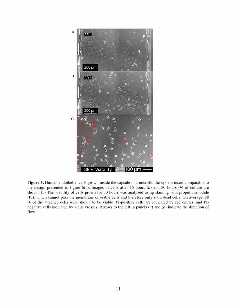
To further validate the functionality of the system, primary human microvascular endothelial cells (PromoCell) were grown in the capsule in an insert designed for 2-dimensional cell culture (see figure 6(c)) using standard endothelial cell culture media and a flow rate of 1 µl min-1. After 30 hours of culture in the closed capsule, 88 % of the attached cells were shown to be viable (figure 5). Finally, the capsule was shown to work equally well in both upright and inverted microscopes with no difference in functionality. The capsule is thus compatible with imaging using virtually all types of microscope setups. 3.2 Collection of waste fluid It is advantageous to have integrated waste collection in the capsule, as this will reduce the risk of fluid spill that might damage expensive microscope equipment. The waste from the outlet nipple in the top unit (hidden behind the light window sideboard in figure 1) thus enters into a piece of superabsorbent material capable of assimilating up to 5 ml of fluid. Notably, the absorbent material is not in direct contact with the tip of the outlet nipple, instead it is cut so that it will surround the nipple to avoid drawing liquid from the nipple after that the pump has been stopped (see supplementary figure 2). Total input flows of 1 µl min-1 allow the system to be run for almost 3.5 days without exceeding the waste fluid assimilation capacity. As an alternative to internal waste collection, tubing can be connected to the outlet nipple to export fluid waste to an external vessel, or if applicable to an on-line detector for analysis of waste fluid components. Notably, the top lid has two small waste observation windows that allow the user to directly observe the expansion and saturation of the waste absorber. The open waste observation windows also prevent pressure from building up in the waste collection compartment as it becomes filled with liquid. 3.3 Examples of elastomer inserts compatible with the capsule
Elastomer inserts to be used in the capsule can be of different design, as long as they match the positions of the two inlets and the outlet of the capsule middle piece. Figure 6 shows examples of fluidic designs that fit into the capsule. The insert design in figure 6(a) allows formation of a concentration gradient within a centrally positioned cell culture chamber, as shown here (figure 4) and previously described [10]. In figure 6(b-d) cells may be cultured directly on the glass cover slip before capsule closure, or alternatively infused into the closed capsule and allowed to adhere for 1-2 hours prior to start of the

5
experiment. The imaged designs can be used for leukocyte rolling studies (figure 6(b)) [13], gradient formation in 2-dimensional cell culture systems (figure 6(c)), or formation of gradients in multiple parallel microgrooves, as previously described (figure 6(d)) [7]. Among different possible applications, the study of cancer cell migration in response to chemotactic gradients in a 3-dimensional matrix during hypoxic conditions is likely to be of great interest to tumor biologists. Notably, as the elastomer insert is gas permeable and in contact with the surrounding atmosphere via the open light window, cell behavior in response to gradients under hypoxic conditions can be performed by placing the capsule in an incubator where the oxygen levels can be controlled. Such experiments will be important to better understand how cancer cells in hypoxic tumors respond to chemotactic stimuli. 4. Conclusions The number of commercially available microfluidic assays for in vitro testing of cell behavior will surely increase over the next years. Assays that become widely used will likely share some features, such as application handiness and versatility. In this context, the present study describes a disposable microfluidic capsule that enables straightforward operation of a variety of microfluidic elastomer systems. Notably, the capsule is fully compatible with mass-production in a thermoplastic material such as polystyrene. PDMS inserts of optional design can be fitted into the capsule, as long as the positions of the insert flow channel inlets and outlet are placed in positions that match the inlet and outlet nipples of the capsule middle piece. It is important to remember that cells grown inside microfluidic systems may exhibit altered behavior as compared to cells grown in more conventional macroscale cell culture setups, as recently discussed by Paguirigan and Beebe [14]. This notion highlights the need to validate different microfluidic cell-based assays that could be run by using the capsule strategy presented here.
Any final commercial product reaching end users based on the present capsule design would consist only of three separate pieces: an upper unit with a bonded PDMS insert, a glass cover slip and a bottom piece. The capsule is closed in a simple one-step procedure, and depending on application (i.e. insert design) the user may load the biological sample before or after capsule closure. Finally, the capsule is connected to a syringe pump to start the experiment. Important characteristics of the capsule described here is that it is compatible with both inverted as well as upright microscopes, and that it features an integrated macro-micro interface together with a separate compartment for waste absorption. In summary, the new capsule concept presented here represents a possible way forward to increase the accessibility of microfluidic-based biological assays to researchers in the life science sector. Acknowledgements This work was supported by grants to JK from the Swedish Research Council, the Swedish Cancer Society, the Swedish Childhood Cancer Foundation, the Swedish Foundation for Strategic Research and Uppsala University. Gradientech AB was financially supported by the Swedish Governmental Agency for Innovation Systems. HN and IB declare no competing financial interests. JK and ST own shares in the company Gradientech AB, commercializing microfluidic systems for biological and medical studies. This does not alter the authors' adherence to the Journal of Micromechanics and Microengineering policies, as detailed in the guide for authors. Footnote 4Author to whom any correspondence should be addressed.

6
References [1] Whitesides G M 2006 The origins and the future of microfluidics Nature 442 368-73 [2] Paguirigan A L and Beebe D J 2008 Microfluidics meet cell biology: bridging the gap by
validation and application of microscale techniques for cell biological assays Bioessays 30 811-21
[3] Jeon N L, Baskaran H, Dertinger S K W, Whitesides G M, Van de Water L and Toner M 2002 Neutrophil chemotaxis in linear and complex gradients of interleukin-8 formed in a microfabricated device Nature Biotechnology 20 826-30
[4] Kim S, Kim H J and Jeon N L 2010 Biological applications of microfluidic gradient devices Integr Biol (Camb) 2 584-603
[5] Toh Y C, Lim T C, Tai D, Xiao G F, van Noort D and Yu H R 2009 A microfluidic 3D hepatocyte chip for drug toxicity testing Lab on a Chip 9 2026-35
[6] Taylor A M, Blurton-Jones M, Rhee S W, Cribbs D H, Cotman C W and Jeon N L 2005 A microfluidic culture platform for CNS axonal injury, regeneration and transport Nature Methods 2 599-605
[7] Saadi W, Rhee S W, Lin F, Vahidi B, Chung B G and Jeon N L 2007 Generation of stable concentration gradients in 2D and 3D environments using a microfluidic ladder chamber Biomedical Microdevices 9 627-35
[8] Abhyankar V V, Toepke M W, Cortesio C L, Lokuta M A, Huttenlocher A and Beebe D J 2008 A platform for assessing chemotactic migration within a spatiotemporally defined 3D microenvironment Lab on a Chip 8 1507-15
[9] Barkefors I, Le Jan S, Jakobsson L, Hejll E, Carlson G, Johansson H, Jarvius J, Park J W, Li Jeon N and Kreuger J 2008 Endothelial cell migration in stable gradients of vascular endothelial growth factor A and fibroblast growth factor 2: effects on chemotaxis and chemokinesis Journal of Biological Chemistry 283 13905-12
[10] Barkefors I, Thorslund S, Nikolajeff F and Kreuger J 2009 A fluidic device to study directional angiogenesis in complex tissue and organ culture models Lab on a Chip 9 529-35
[11] Kim M S, Kim T, Kong S Y, Kwon S, Bae C Y, Choi J, Kim C H, Lee E S and Park J K 2010 Breast Cancer Diagnosis Using a Microfluidic Multiplexed Immunohistochemistry Platform Plos One 5 e10441
[12] Chung B G, Park J W, Hu J S, Huang C, Monuki E S and Jeon N L 2007 A hybrid microfluidic-vacuum device for direct interfacing with conventional cell culture methods Bmc Biotechnology 7 60
[13] Schaff U Y, Xing M M Q, Lin K K, Pan N, Jeon N L and Simon S I 2007 Vascular mimetics based on microfluidics for imaging the leukocyte-endothelial inflammatory response Lab on a Chip 7 448-56
[14] Paguirigan A L and Beebe D J 2009 From the cellular perspective: exploring differences in the cellular baseline in macroscale and microfluidic cultures Integr Biol (Camb) 1 182-95

7
Figures and figure captions
Figure 1. Illustration showing an exploded view of the final capsule design. The assembled capsule measures 42 mm in diameter and 14 mm in height.

8
Figure 2. (a) A photograph of the upper unit of the capsule with the attached PDMS insert. The biological sample (matrix together with cells) is loaded into the central cell culture chamber before snapping the cover glass and bottom piece to the upper unit to close the system. A closed system with tubing connected to a syringe pump is shown in (b).

9
Figure 3. (a) FEM analysis of the middle piece of the final design corresponding to a situation when the capsule is assembled. Measures were taken to counteract mechanical stress created by capsule assembly. The scale bar shows the deformation in mm along the z-axis. (b) Surfaces indicated in yellow were used for bonding of the middle piece to the top lid.

10
Figure 4. Diagram showing the formation of an approximately linear FITC-dextran (MW=20 kDa) concentration gradient in the capsule, inside the 4 mm wide central chamber for 3-dimensional cell culture of the PDMS insert shown in Figure 6 (a), filled with a polymerized collagen I gel. The FITC-dextran tested has a diffusion coefficient similar to many growth factors regulating cell proliferation and migration, such as fibroblast growth factor 2.
11
Figure 5. Human endothelial cells grown inside the capsule in a microfluidic system insert comparable to the design presented in figure 6(c). Images of cells after 15 hours (a) and 30 hours (b) of culture are shown. (c) The viability of cells grown for 30 hours was analyzed using staining with propidium iodide (PI), which cannot pass the membrane of viable cells and therefore only stain dead cells. On average, 88 % of the attached cells were shown to be viable. PI-positive cells are indicated by red circles, and PI-negative cells indicated by white crosses. Arrows to the left in panels (a) and (b) indicate the direction of flow.

12
Figure 6. Examples of PDMS inserts with fluidic designs having two inlets (top) and a single outlet (bottom), compatible with the generic capsule design presented here. The different designs allow for (a) formation of gradients in complex 3-dimensional cell culture setups, (b) leukocyte rolling experiments, (c) gradient formation in 2-dimensional cell culture setups, and (d) formation of concentration gradients in parallel microgrooves. Note that in all examples a network of vacuum channels surrounds the centrally positioned fluidic channels. In panel (a) the sample is loaded into the centrally positioned rectangular cell culture compartment, flanked by two flow channels with a common outlet. See the text for references.

13
Supplementary data
Supplementary figure 1. (a) Exploded view of the first simplistic capsule design for structural tests. (b, c) Structural FEM analysis of an assembled capsule was carried out in order to identify areas with large deformations in the upper and bottom pieces respectively. Scale bars show the deformation in mm along the z-axis.

14
Supplementary figure 2. Fluorescent beads (diameter=10 µm) were pumped into the capsule at a flow velocity of 10 µl min-1. Images were captured at 1 s intervals from channels in the microfluidic system insert. (a) Movement of a bead in the channel when the pump is on. (b) Movement of a bead when the pump has been turned off. In this experiment, the absorbent material in the waste compartment had absorbed a total of 400 µl fluid prior to stopping the pump. The bead stopped moving around 15 s after stopping the pump, indicating that fluid is not significantly pulled nor pushed back in the channel. (c) Fluorescent beads pumped into the capsule at a flow velocity of 10 µl min-1, when the absorbent material in the waste compartment had absorbed a total of 3 ml fluid prior to stopping the pump. (d) Images captured 10 s, 20 s and 30 s after that the external pump was stopped, show that there is no significant fluid flow 20 s after stopping the pump.