A Decision Support System for Design of Transmission ...
11
A Decision Support System for Design of Transmission System of Low Power Tractors NARENDRA SINGH CHANDEL, 1 VIRENDRA KUMAR TEWARI, 2 CHAMPAT RAJ MEHTA, 3 MANOHAR BHAGAVAN PATIL 4 1 Agricultural Mechanization Division, Central Institute of Agricultural Engineering, Bhopal, Madhya Pradesh, India 2 Agricultural and Food Engineering Department, Indian Institute of Technology, Kharagpur, West Bengal, India 3 All India Coordinated Research Project on Farm Implements and Machinery, Central Institute of Agricultural Engineering, Bhopal, Madhya Pradesh, India 4 Mahindra and Mahindra Limited, Maharashtra, India Received 30 September 2014; accepted 1 March 2015 ABSTRACT: A decision support system (DSS) was developed in Visual Basic 6.0 programming language to design transmission system of low horsepower agricultural tractors, which involved the design of clutch and gearbox. The DSS provided graphical user interface by linking databases to support decision on design of transmission system for low horsepower tractors on the basis of modified ASABE draft model. The developed program for design of tractor transmission system calculated clutch size, gear ratios, number of teeth on each gear, and various gear design parameters. Related deviation was computed for design of transmission system of tractors based on measured and predicted values (simulated). The related deviation was less than 7% for design of clutch plate outer diameter and less than 3% for inner diameter. There was less than 1% variation between the predicted results by the developed DSS and those obtained from actual measurement for design of gear ratio. The DSS program was user friendly and efficient for predicting the design of transmission system for different tractor models to meet requirements of research institutions and industry. ß 2015 Wiley Periodicals, Inc. Comput Appl Eng Educ 9999:1–11, 2015; View this article online at wileyonlinelibrary.com/journal/cae; DOI 10.1002/cae.21648 Keywords: decision support system; tractor transmission system; low power tractors; simulation; ASABE equation INTRODUCTION Computer models and simulation programs for design of tractor transmission system helped researchers and students to determine various parameters related to tractor transmission without going through the complex and iterative design procedure. It also helped researchers and manufacturers to improve design of tractor transmission system by comparing and analyzing various parameters that influenced tractor transmission system design. The rapid progress in developing new software and trend in enhancing the existing application software and programming languages facilitated the interaction between users and com- puters [1]. A lot of research was conducted in developing computer-based models and simulation programs to meet educational and research needs in the farm machinery branch of agricultural engineering [2]. Design of a gear involved analysis and treatment of geometric factors to optimize the parameters like surface compressive stress, tooth stress, tooth bending stress, etc. Radzevich [3] gave a detailed procedure for designing the spur gear. Buckingham and Bucking- ham [4] gave information in tabular form for calculating gear ratios that permitted the use of a simple and direct method in finding a suitable set of different gears for a wide variety of requirements and applications. Mitra and Prasad [5] gave a detailed procedure for designing the spur gear along with the standard table for backlash Correspondence to N. S. Chandel ([email protected]) © 2015 Wiley Periodicals, Inc. 1
-
Upload
khangminh22 -
Category
Documents
-
view
2 -
download
0
Transcript of A Decision Support System for Design of Transmission ...
A Decision Support System forDesign of Transmission Systemof Low Power TractorsNARENDRA SINGH CHANDEL,1 VIRENDRA KUMAR TEWARI,2 CHAMPAT RAJ MEHTA,3
MANOHAR BHAGAVAN PATIL4
1Agricultural Mechanization Division, Central Institute of Agricultural Engineering, Bhopal, Madhya Pradesh, India
2Agricultural and Food Engineering Department, Indian Institute of Technology, Kharagpur, West Bengal, India
3All India Coordinated Research Project on Farm Implements and Machinery, Central Institute of Agricultural
Engineering, Bhopal, Madhya Pradesh, India
4Mahindra and Mahindra Limited, Maharashtra, India
Received 30 September 2014; accepted 1 March 2015
ABSTRACT: A decision support system (DSS) was developed in Visual Basic 6.0 programming language to
design transmission system of low horsepower agricultural tractors, which involved the design of clutch and
gearbox. The DSS provided graphical user interface by linking databases to support decision on design of
transmission system for low horsepower tractors on the basis of modified ASABE draft model. The developed
program for design of tractor transmission system calculated clutch size, gear ratios, number of teeth on each gear,
and various gear design parameters. Related deviation was computed for design of transmission system of tractors
based on measured and predicted values (simulated). The related deviation was less than 7% for design of clutch
plate outer diameter and less than 3% for inner diameter. There was less than 1% variation between the predicted
results by the developed DSS and those obtained from actual measurement for design of gear ratio. The DSS
programwas user friendly and efficient for predicting the design of transmission system for different tractormodels
to meet requirements of research institutions and industry. � 2015 Wiley Periodicals, Inc. Comput Appl Eng Educ9999:1–11, 2015; View this article online at wileyonlinelibrary.com/journal/cae; DOI 10.1002/cae.21648
Keywords: decision support system; tractor transmission system; low power tractors; simulation; ASABE
equation
INTRODUCTION
Computer models and simulation programs for design of tractortransmission system helped researchers and students to determinevarious parameters related to tractor transmission without goingthrough the complex and iterative design procedure. It also helpedresearchers and manufacturers to improve design of tractortransmission system by comparing and analyzing variousparameters that influenced tractor transmission system design.The rapid progress in developing new software and trend in
enhancing the existing application software and programminglanguages facilitated the interaction between users and com-puters [1]. A lot of research was conducted in developingcomputer-based models and simulation programs to meeteducational and research needs in the farm machinery branch ofagricultural engineering [2].
Design of a gear involved analysis and treatment of geometricfactors to optimize the parameters like surface compressive stress,tooth stress, tooth bending stress, etc. Radzevich [3] gave a detailedprocedure for designing the spur gear. Buckingham and Bucking-ham [4] gave information in tabular form for calculating gear ratiosthat permitted the use of a simple and direct method in finding asuitable set of different gears for a wide variety of requirements andapplications. Mitra and Prasad [5] gave a detailed procedure fordesigning the spur gear along with the standard table for backlash
Correspondence to N. S. Chandel ([email protected])
© 2015 Wiley Periodicals, Inc.
1

values and simple process for calculation of contact ratio.Ramamurti et al. [6] described a design methodology for designof two-speed gearbox based on input power, input speed, and netreductions in gearbox. The user was given the choice of selection ofmaterials for shaft and gear. The methodology specified the shaftdimensions, gear specifications, bearing selection, overall spaceoccupied, and the self weight of the gearbox. Chong et al. [7]described a new generalized four steps methodology to designmulti-stage gear drives by integrating the dimensional and theconfiguration design process in a formalized algorithm. In the firststep, the user provisionally set the number of reduction stages. In thesecond step, gear ratios of every stage were chosen by using therandomsearchmethod (within the specified ratio change), and in thenext step the ratioswere used as the basic inputs for the dimensionaldesign of gears. In the third step, the values of the basic designparameters of a gearwere chosen. In the final step, the configurationdesign was carried out by using the simulated annealing algorithmto calculate design parameters, such as pitch parameters and outerdiameters. The positions of the gears and shafts were determined tominimize the geometrical volume of a gearbox while satisfyingspatial constraints. These steps were carried out iteratively until adesirable solution was acquired. Argyris et al. [8] developed a toothcontact analysis program for design of worm gear system. Theprogram was written in Visual Basic (VB) language and enabled tocombine numerical computation and graphical illustration. Thomp-son et al. [9] describe the detailed procedure of spurgear designwitha goal to reduce the total volume and weight. They developed aprogram in MATLAB
1
software with optimization toolbox tooptimize the gear design. They concluded that the three-stagedesignwas clearly superior and offered a potential weight reductionof as much as 20% over the two-stage design at the higher ratio.
Simulation software to predict tractor performances wasdeveloped from different programming tools [10]. Presently, VBand Visual Cþþ languages, MATLAB’s SIMULINK and PG-Simwere used to develop such programs [2,11,12]. The availability ofvisual language, e.g., VB was easy to users. Mondal et at. [13]developed a program in VB 6.0 to design 16þ 4 speeds gearboxfor TAFE tractor.
ASABE models [14] were not suitable for predicting thedrawbar power of tractors in Indian soil conditions. ModifiedASABE models were accurate in predicting the draft of tractorimplement system when used under Indian cohesive/frictionalsoils [15,16]. The calculation of clutch size, gear ratio, and numberof teeth on each gear was not included in these models. It washighlighted the need to conduct research in developing computer-based models and simulation programs to improve the design oftractor transmission system by analyzing the relative importance ofvarious parameters. Keeping in view of limitations of the availablesoftwares, a decision support system (DSS) inVBwas developed todesign transmission system for low power two wheel drive (2WD)tractors.The developed programalso provided a newcomputationaltool which allowed the students to familiarize with fundamentalconcepts and introduction to gear trains, gear terminology,transmission ratios along steps in transmission system design.
THEORETICAL CONSIDERATIONS
The tractor drive train included power transmission elementsbetween the engine and drive wheels along with PTO drive. Itconsisted of the clutch, gearbox, differential, final drives, and PTO.The gear design parameters, gear kinetics, geometry, and synthesisdefined by the Radzevich [3] were used in the development ofprogram. Additionally, a compatible clutch design would alsoenhance the efficiency of the system. The modified ASABE modelfor prediction of draft and power requirements was used in thedeveloped software for more accurate design of tractor gearbox.The sub-systems of the DSS included design of clutch and gearboxalong with modified ASABE model for draft prediction.
Design of a Clutch
Low horsepower Indian tractors were fitted with manuallyoperated clutch. They had good torque exertion capability andfacilitated shifting of gears as a result of relatively low inertia. Drysingle-disk friction clutch was often used in drive trains which
Table 1 Different Gear Parameters Used in the Developed Software
Parameter Driving gear Driven gear
Pitch circle diameter d1 ¼ z1m d2 ¼ z2mBase circle diameter db1 ¼ d1cosa db2 ¼ d2cosaTip circle diameter dt1 ¼ d1 þ 2mþ 2x1mþ 2ym dt2 ¼ d2 þ 2mþ 2x2mþ 2ymRoot circle diameter dr1 ¼ d1 � 2 1:25� x1ð Þm dr2 ¼ d2 � 2 1:25� x2ð ÞmWorking pitch circle diameter dw1 ¼ d1 cosa
cosawdw2 ¼ d2 cosa
cosaw
Tooth thickness on pitch circle s1 ¼ p2 þ 2x1mtana s2 ¼ p
2 þ 2x2mtanaAddendum D1 ¼ dw1 � dr1 a2 ¼ dt2 � dw2Dedendum D1 ¼ dw1 � dr1 D2 ¼ dw2 � dr2Total depth Dt1 ¼ a1 þ D1 Dt2 ¼ a2 þ D2
Circular pitch p ¼ pmActual center distance a0 ¼ m z1þz2
2
Working pressure angle aw ¼ cos�1 a0a cosa
� �
Total profile correction factor x1 þ x2 ¼ z1 þ z2ð Þ invw�inva2tana
� �
Topping ym ¼ a0 þ x1 þ x2ð Þm½ � � aContact ratio
CR ¼ffiffiffiffiffir2a1
p�r2b1þ
ffiffiffiffir2a2
p� a0sinað Þ
pmcosa
Top clearance c ¼ a� dt1þdr22 þ ym � 2:25m
� �
Diametral pitch p ¼ 1m
Face width Bf ¼ FtKv0:44�put�0:525
2 CHANDEL ET AL.
provided higher capacity and durability at low cost. Duringrunning condition, the pressure distribution was adjusted in such amanner that the product pressure was constant. There was uniformpressure distribution over the entire new contact friction surfaces.In the design of clutches, it is assumed that maximum time thefriction lining operated in uniform wear condition.
Design of Gearbox
The design of a tractor transmission system required determinationgear ratios in different gears, number of teeth on each gear, center tocenter distance between gears, and various design parameters foreach gear. It was assumed that dynamic loading in the toothwas dueto profile errors, circular pitch error, and deflection of teeth underload. Load applied on the tooth was not uniformly distributedbecause of the deformation of tooth due to torque, deflection ofshaft, location of bearing, and misalignment. Load concentrationfactor (K) of 1.1, shock factor (K0) of 1.1, and dynamic load factor(Kd) of 1.1 were taken for calculating the number of teeth on eachgear during programming. Different gear parameters and formulasused for developing the program are given in Table 1.
Modified ASABE Model for Draft Prediction
The American Society of Agricultural and Biological Engi-neers [14] defined equation (1) for estimation of draft requirementof various agricultural implements and machine for a variety of soil
conditions. The equation (1) was modified for predicting the draftunder field condition using the data collected for various fieldoperations inmedium textured soil at Indian Institute of Technology(IIT), Kharagpur in India. Additional correction coefficientsK1 andK2 were introduced to account for variations in draft whencalculated by using modified ASABE draft model for mediumtextured soils (2) formold board plough, cultivator, and disc harrow.
Di ¼ FjðAþ BVaþ CVa2ÞWcH ð1ÞDim ¼ K1ðF2ðAþ BVaþ CVa2ÞWcHÞ þ K2 ð2Þ
The values of correction coefficients K1 were 1.735, 0.809, and0.73 and K2 were 1,618, 4,048, and 1,406 for mold board plough,cultivator, and disc harrow, respectively [16]. The values ofK1 andK2 were determined by finding the best fit equations for observedand predicted (by ASABE model) values of draft for the same setof machine, soil, and operating parameters. The coefficient ofdetermination for three operations (ploughing, harrowing, andtilling) ranged from 0.90 to 0.93 [16]. The cutting width (Wc) ofmajor tillage implements viz., mold board plough, cultivator, anddisc harrow were calculated by equations Wc¼ nw, Wc¼ n andWc¼ 0.95NdSd� 0.6Dd, respectively.
DSS Design Process
Development of DSS for tractor transmission system of low powertractors includes three internal stages i.e., analysis, algorithmdesign, and coding stage [17].
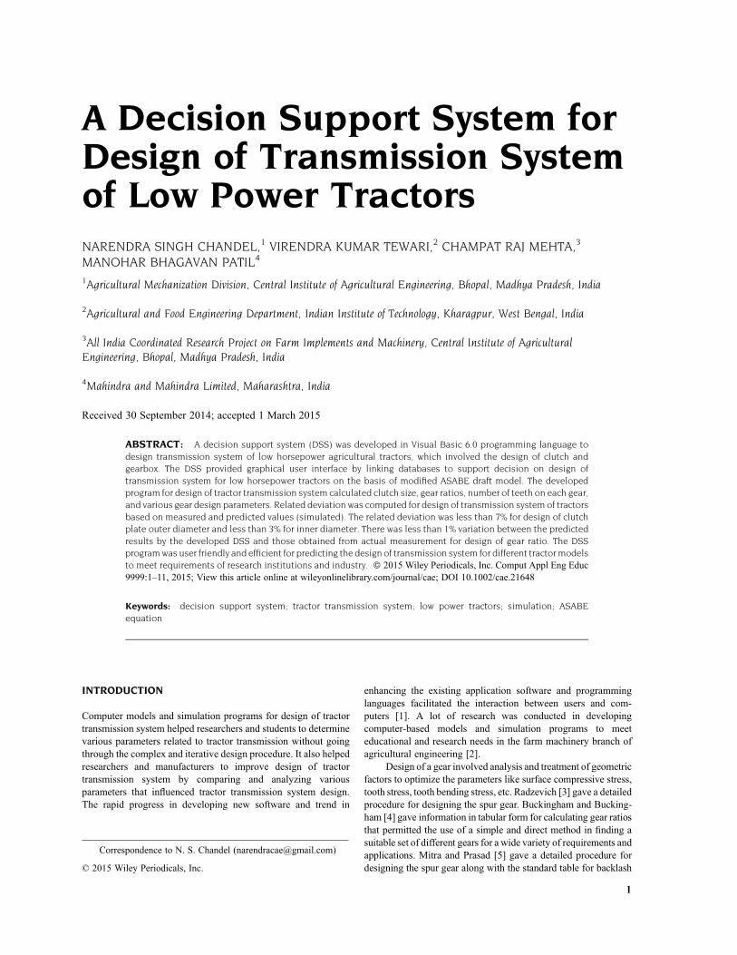
Input Pt, Nr, Vmax, Ntm, Tm, rr, W, n, w, H, Va, ηt, Cr, Dr and y
Take Crr = 0.2
Calculate Rr, Rg, Dm, Rt
Calculate n1, z, Take x = 2
Calculate nx
Output the different calculated gear ratios
STOP
Calculate Fr
Is x < y+1 x = x+1
START
YES
NO
Figure 1 Flowchart for calculation of different gear ratios.
TRACTOR TRANSMISSION SYSTEM DESIGN 3
Analysis. It needed to produce and display the design parametersfor transmission system in user friendly and easily accessibleapproach. The DSS developed based on the input of certainparameters. The DSS accurately calculates the output parametersthrough the written codes (design equations) to determine variousresults.
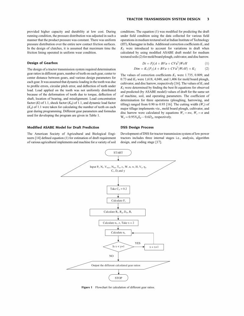
Algorithm Design. It involved development of instructions in alogical manner so that execution of the instruction resulted in thesolution of the problem. The use of flowchart made it simpler at theprogramming stage to avoid algorithmic ambiguity. The variousinput parameters and equations used for calculation of designparameters were included in the module shown in the flowcharts(Figs. 1 and 2). Figure 1 shows the flowchart for calculation ofdifferent gear ratios and Figure 2 shows for gear parameters.
Coding. An accurate and efficient coding were the major andimportant aspects of DSS for proper working of application. VBprogram with dedicated coding was developed for design oftransmission system of agricultural tractor.ModifiedASABE draftmodel (Eq. 2) for medium textured soils of India with machine andsoil specific parameters was used in coding. Different clutch and
gear design formulas were also coded to develop programmodules(Table 1). Integrated development environment (IDE) was used tocompile the program. It was checked for errors by debugging eachstage of the code. Debugging helped to avoid too manyuntraceable errors of transmission system design program.
MATERIALS AND METHODS
A DSS in visual basic (VB) was developed for design of tractortransmission system on the basis of modified ASABE model (Eq.2) for Indian soils and operating conditions. The developedprogram was flexible, object oriented, and user friendly and wasdeveloped using VB 6.0 as front end. The program was developedin two sub-systems i.e., clutch design and gearbox design. Severalsequential GUI screens were developed to complete the processand get the desired output. The developed screens were veryintuitive and easy to select the values and enter the required designparameters wherever required. The developed software wasvalidated for design of tractor transmission system using the actualmeasured readings obtained for three low power agriculturaltractors at Indian Institute of Technology, Kharagpur in India. The
START
Enter theoretical pressure angle, gear, type and properties of the gear material
Is z1>z2 x1 = (x1+x2)×( z1/ z2)/(1+ z1/ z2)YES
Calculate a0, αw, x1+x2, p, P
Calculate ym
x1 = 0.5×(1- z1 / z2 )+(x1+x2)×( z1 / z2)/(1+ z1 / z2)
NO
x2 = (x1+x2) – x1
x1 = x1- 0.001
Calculate d1, d2, db1, db2, dt1, dt2, dw1, dw2, dr1, dr2, Ft, v, Kv
Is CR>1.0
Calculate s1, s2, Bf, c, CR
Calculate a1, a2, D1, D2, Dt1, Dt2
Output various gear parameters
NO
YES
STOP
Figure 2 Flowchart for calculation of different gear parameters.
4 CHANDEL ET AL.
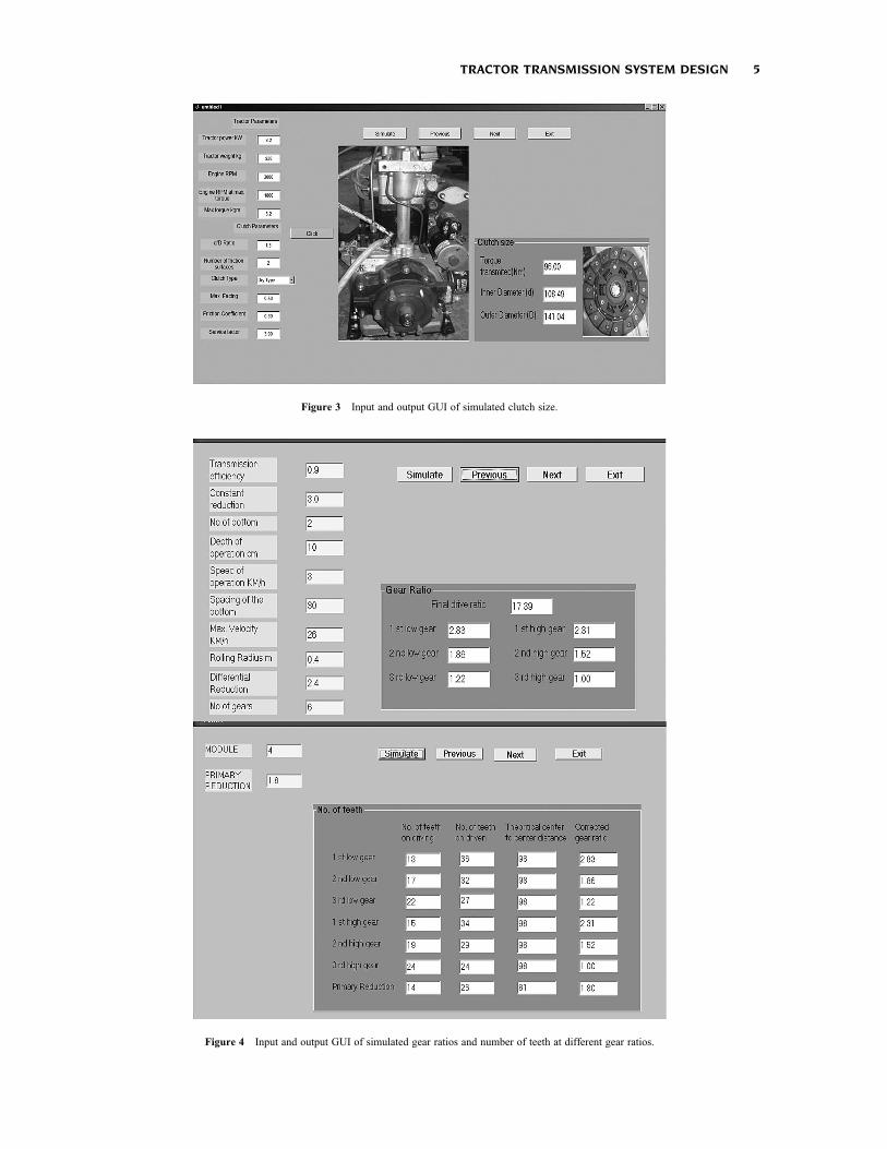
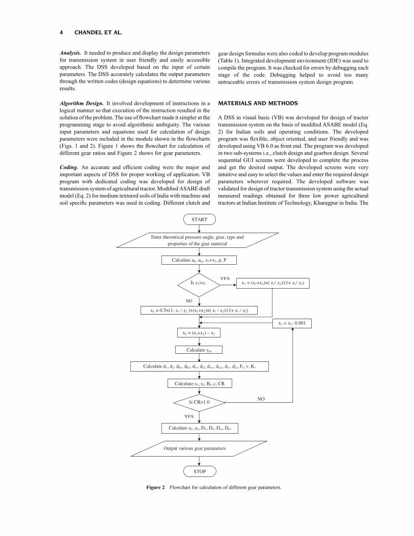
Figure 3 Input and output GUI of simulated clutch size.
Figure 4 Input and output GUI of simulated gear ratios and number of teeth at different gear ratios.
TRACTOR TRANSMISSION SYSTEM DESIGN 5
developed software was also evaluated by 27 undergraduatestudents using a questionnaire.
Clutch Design
The design of a clutch was done according to conditions that metthe requirement of low horse power tractor clutch. The design ofclutch required tractor engine specification (tractor power, tractorweight, engine RPM, maximum torque), clutch parameters (d/Dratio, number of friction surfaces) and clutch type and splinefriction factor (sf). Simulation of different inputs was done beforedeciding desired design parameters. The GUI for clutch designwas shown in Figure 3 and included the basic databases for thesimulation to predict parameters for clutch design. The user couldedit, remove, or add specific parameters and simulate for betterresults. This GUI also provided an option to select the clutch typefrom pop-up menu and to simulate to predict design parametersand performance. The output results of design of clutch size were
shown in Figure 3 and ended with the final result required by theuser. The developed program determined the torque transmitted(Nm) and inner and outer diameters (mm) of clutch.
Gearbox Design
Flowchart for calculation of the different gear ratio’s module isshown in Figure 2. The GUI for design of gear consisted of fourbuttons, i.e., Simulate, Previous, Next, and Exit. The input andoutput (after simulation) windows of GUI for gear ratios andnumber of teeth were shown in Figure 4. On choosing next button,GUI was opened which consisted of an option to enter the inputparameters needed to find out the different gear ratios. Theseparameters were transmission efficiency (ht), constant reduction(Cr), number of bottom (n), depth of operation (H), speed ofoperation (Va), bottom spacing (w), maximum velocity (Vmax),rolling radius (rr), differential reduction (Dr), and number of gears(y). Finally, the output screen of simulated gear ratios indicated
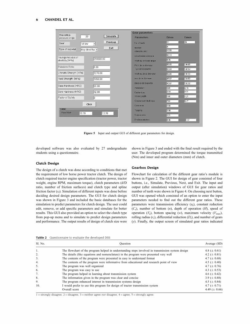
Figure 5 Input and output GUI of different gear parameters for design.
Table 2 Questionnaire to evaluate the developed DSS
Sl. No. Question Average (SD)
1. The flowchart of the program helped in understanding steps involved in transmission system design 4.8 (� 0.61)2. The details (like equations and nomenclature) in the program were presented very well 4.2 (� 0.81)3. The contents of the program were presented in easy to understand format 4.7 (� 0.68)4. The contents of the program were informative from educational and research point of view 4.5 (� 0.40)5. The program was well organized 4.7 (� 0.76)6. The program was easy to use 4.3 (� 0.53)7. The program helped in learning about transmission system 4.6 (� 0.42)8. The information given in the program was clear and concise 3.9 (� 0.88)9. The program enhanced interest in transmission systems design 4.5 (� 0.84)10. I would prefer to use this program for design of tractor transmission system 4.7 (� 0.71)
Overall score 4.49 (� 0.66)
1¼ strongly disagree, 2¼ disagree, 3¼ neither agree nor disagree, 4¼ agree, 5¼ strongly agree.
6 CHANDEL ET AL.
the gear ratio in each gear and total final drive reduction ratio (Fr).This screen provided a simulate button to predict its performance.The output screen for number of teeth calculation was shown inFigure 4 and it indicated the number of teeth on pinion (z1) and gear(z2).
Calculation of Different Gear Parameters. The GUI as shownin Figure 5 allowed the user to enter the theoretical pressure angle(a). The screen also provided pop-up menu option to select the pairof gears for which the parameters were determined and mostimportantly the type of material which was used for gearproduction. After selecting the type of material, choose “Click”button provided on the screen so that the screen showed the variousmaterial properties for the selected material. On choosing“Simulate” button provided on GUI screen, the output screen ofgear parameters was opened as shown in Figure 5. Tangential force(Ft), peripheral velocity (v) and velocity factor (Kv) were used todesign the driver and driven gears along with face width (Bf).
Validation of the Developed DSS
Three tractors of 10.03, 18.64, and 26.09 kW PTO power wereselected to test the developed DSS. The developed program wasvalidated for design of tractor transmission system by measuringthe actual readings obtained for the tractors and comparing withthe predicted values using the developed program. The tractorswere dismantled to measure the clutch and gear parameters. Thegear ratios for different gears were calculated from the measuredreadings of number of teeth on each gear. The various gearparameters for a particular gear were also calculated. The relateddeviation (RD) was computed based on measured and predictedvalues (simulated) for design of transmission system of tractors.The RD was defined as follows:
RD ¼ 1
N
XN
i¼1
jPi � OijPi
� 100 ð3Þ
Where, Pi was the predicted value from the program, Oi was theobserved value from the measurement of actual gear, and N wasthe number of observations.
Questionnaire to Evaluate Developed DSS
A questionnaire given in Table 2 was developed to evaluatethe DSS by 27 undergraduate students. The questionnairehad questions about the developed DSS for design of transmissionsystem of low power tractors. There were no right or wronganswers to the questions. The students were asked to rate theDSS on scale of 1 to 5 with “1¼ strongly disagree, 2¼ disagree,3¼ neither agree nor disagree, 4¼ agree, 5¼ strongly agree,”respectively. The results of the survey are reported in Table 2.
RESULTS AND DISCUSSION
The DSS program was written in VB programming language witha new method of predicting tractor performance using modifiedASABE draft model. The program provided an intuitive userinterface by linking databases such as tractor specifications,implements data, tyre size, and modified ASABE model of draftequation to predict the transmission design for a selected powerrange of tractors. The developed VB based program providedflexibility to either select or edit input parameters to design thetractor transmission to match the tractor implement combinationbased on soil conditions. The modified ASABE models predictedthe draft of implements for design of transmission system. Theoutput results of the program could be exported in spreadsheetformat for further analysis.
Clutch Parameters
The output screen for design of clutch size indicated the clutchdesign parameters such as torque transmitted (T), outer diameter(D), and inner diameter (d). The calculated RD values for clutchdesign data set were given in Table 3. Clutch plate innerdiameter data set indicated that maximum and minimum RD was
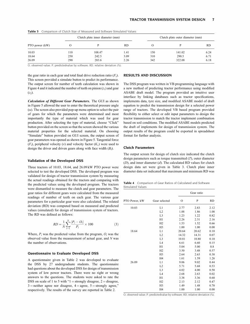
Table 3 Comparison of Clutch Size of Measured and Software Simulated Values
Clutch plate inner diameter (mm) Clutch plate outer diameter (mm)
PTO power (kW) O P RD O P RD
10.03 110 108.47 1.41 150 141.02 6.2418.64 250 242.5 3.09 310 290.5 6.7126.09 290 283.6 2.26 342 322.08 6.18
O, observed value; P, predictedvalue by software; RD, relative deviation (%).
Table 4 Comparison of Gear Ratios of Calculated and Software
Simulated Values
Gear ratio
PTO Power, kW Gear selected O P RD
10.03 L1 2.77 2.83 2.12L2 1.88 1.86 1.08L3 1.23 1.22 0.82H1 2.26 2.31 2.16H2 1.53 1.52 0.66H3 1.00 1.00 0.00
18.64 L1 20.64 20.62 0.10L2 14.32 14.31 0.07L3 10.81 10.80 0.10L4 6.61 6.60 0.15H1 5.04 5.00 0.8H2 3.50 3.48 0.57H3 2.64 2.63 0.38H4 1.61 1.59 1.26
26.09 L1 9.06 9.02 0.44L2 5.71 5.68 0.53L3 4.02 4.00 0.50L4 2.68 2.63 0.02H1 3.38 3.36 0.60H2 2.13 2.12 0.47H3 1.49 1.48 0.70H4 1.00 1.00 0.00
O, observed value; P, predictedvalue by software; RD, relative deviation (%).
TRACTOR TRANSMISSION SYSTEM DESIGN 7
found for 18.64 and 10.03 kW tractors but for the outer diameterit was maximum for 18.64 kW PTO power tractor. The RDvalues also indicated that the variation of the predicted resultsfrom those found in the actual design was less than 7% in clutchplate outer diameter and less than 3% in inner diameter. Thisdifference may be due to general calculation (Table 1) andaccuracy level of the various prediction models used indeveloping the DSS.
Gear Ratios
One tractor of 10.03 kW PTO power was tested in six forwardgears and two tractors of 18.64 and 26.09 kW PTO power weretested in eight forward low and high gears (L1, L2, L3, L4, H1, H2,H3, and H4). Data set of testing of gear ratio indicated (Table 4),
variation of less than 1% in most of the cases for predicted resultsby the developed program and from those found in the actualmeasurement. The maximum RD was 2.16% in H1 gear and zeroin H3 gear for 10.03 kW PTO power tractor. The minimum RDwas 0.02% (L4) and 0.07% (L2) for 18.64 and 26.09 kW PTOpower tractors, respectively. The variation in RD may be due tosome instrumental error in measuring the tractor transmission dataor using various prediction models and formulas used indeveloping the program.
Gear Parameters
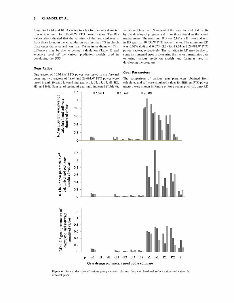
The comparison of various gear parameters obtained fromcalculated and software simulated values for different PTO powertractors were shown in Figure 6. For circular pitch (p), zero RD
Figure 6 Related deviation of various gear parameters obtained from calculated and software simulated values fordifferent gears.
8 CHANDEL ET AL.
was observed in calculated and software predicated values in allgears of gearbox of three different low power tractors. MaximumRD was observed in addendum (a2) of driven gear for 10.03 and18.64 kW PTO tractors but not in case of 26.09 kW PTO tractor ofL3 gear. Maximum RDwas in a2 in three tested gears (L1, L2, andL3) of 10.03 kW PTO tractor. In case of 18.64 kW PTO tractor,maximum RD was found in a1 in L1 and L2 gears. In 26.09 kWPTO tractor, maximum RD was in dedendum of a driver gear (D1)in L3 gear.
The related deviation in predicted results from the developedDSS was less than 7% as compared to the measured values fordesign of transmission system of low power tractors. Therefore,the developed DSS predicted results with reasonable accuracy.Therefore, it may be concluded that the DSS was flexible andeffective for design of transmission system of low horse powertractor. This will ultimately help researcher and educationalprofessionals in selection of the right size of transmission systembased on tractor-implement system, soils, and operatingparameters.
Survey Results and Feedback on developed DSS
Table 2 shows the findings of the survey to evaluate the developedDSS. The comments of the students about the program weremainly positive. The majority of the students were highly satisfiedin terms of ease of use and simplicity of the instructions in theprogram. The overall score for 10 questions in the questionnairewas 4.49 out of 5.0. This indicated that students agreed that DSSbased design of tractor transmission system was helpful,informative, fast, and easy to use. The students strongly feltthat the flow chart of the program helped in understanding stepsinvolved in tractor transmission systems design. The question“information given in the program was clear and concise” got thelowest score of 3.9. The following advantages and disadvantagesof the developed DSS were observed based on feedback of 27undergraduate students for design of transmission system of lowpower tractor.
Advantages
� The program did not require users to have in-depthknowledge about introduction to gear trains and gearterminology for design of tractor transmission system.
� It created more interest among users for design of tractortransmission system due to availability of pop-up and drop-down menu facility in the DSS.
� The program was easy to use at most of the places due toavailability of Microsoft Operating System.
Limitations
� Software incompatibility issues with other operatingsystem.
� Loss of sense of theoretical andmathematical understandingbehind the designing.
CONCLUSIONS
A simulation based user-friendly DSS was developed in a VBprogramming environment for design of transmission system oflow power agricultural tractors. The program used the modifiedASABE model for predicting the draft and tractive performances
of the tractor. The program could be used to simulate the variousdesign aspects of a gearbox and clutch design through GUI. Themodel was verified with real and measured data obtained from lowpower tractor tests. The program was found to have very closeprediction for design of tractor transmission system. Therefore, itmay be concluded that the developed program was effective andsupported in design of transmission system of lower horse powertractors.
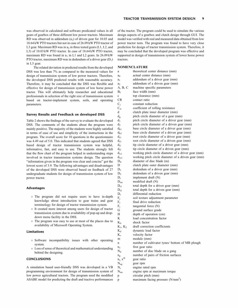
NOMENCLATUREa theoretical center distance (mm)a0 actual center distance (mm)a1 addendum of a driver gear (mm)a2 addendum of a driven gear (mm)A, B, C machine specific parametersBf face width (mm)c top clearance (mm)CR contact ratioCr constant reductionCrr coefficient of rolling resistanced clutch plate inner diameter (mm)dg pitch circle diameter of a gear (mm)d1 pitch circle diameter of a driver gear (mm)d2 pitch circle diameter of a driven gear (mm)db1 base circle diameter of a driver gear (mm)db2 base circle diameter of a driven gear (mm)dr1 root circle diameter of a driver gear (mm)dr2 root circle diameter of a driven gear (mm)dt1 tip circle diameter of a driver gear (mm)dt2 tip circle diameter of a driven gear (mm)dw1 working pitch circle diameter of a driver gear (mm)dw2 working pitch circle diameter of a driven gear (mm)Dd diameter of disc blade (m)D clutch plate outer diameter (mm)D1 dedendum of a driver gear (mm)D2 dedendum of a driven gear (mm)Di implement draft (N)Dim modified draft (N)Dt1 total depth for a driver gear (mm)Dt2 total depth for a driven gear (mm)Dr differential reductionFj soil texture adjustment parameterFr final drive reductionFt tangential force (N)G ground surface gradeH depth of operation (cm)K load concentration factorK0 shock factorK1, K2 draft correction coefficientsKd dynamic load factorKv velocity factorm module (mm)n number of cultivator tynes/ bottom of MB ploughn1 first gear ratioNd number of disc blade on a gangnp number of pairs of friction surfacesnx x
th gear ratioNeg gear rpmNr engine rated rpmNtm engine rpm at maximum torquep circular pitch (mm)p maximum facing pressure (N/mm2)
TRACTOR TRANSMISSION SYSTEM DESIGN 9
P diametral pitch (mm)Pr primary gear ratioPt tractor engine power (kW)rr rolling radius (m)Rg grade resistance (N)Rr rolling resistance (N)Rt total resistance (N)s service factors1 tooth thickness on pitch circle for a driver gear (mm)s2 tooth thickness on pitch circle for a driven gear (mm)Sf spline friction factorSd disc spacing (m)T torque transmitted by the clutch (Nm)Td design torque (Nm)Tm maximum engine torque (Nm)Tmg maximum torque at a gear (Nm)ut ultimate strength (N/mm2)v peripheral velocity (m/s)Vmax maximum tractor travel velocity on road (km/h)Va speed of operation (km/h)w cutting width of each bottom of MB plough (m)W tractor weight (N)Wc cutting width of tillage implement (m)y number of gearsym topping (mm)x gear numberx1 profile correction factor of a driver gearx2 profile correction factor of a driven gearz gear reduction ratioz1 number of teeth on pinionz2 number of teeth on geara theoretical pressure angle (0)aw working pressure angle (0)m coefficient of frictionht transmission efficiency (decimal)
REFERENCES
[1] J. A. Calvo, M. J. Boada, V. D�ıaz, and E. Olmeda, SIMPERF:SIMULINK-based educational software for vehicle’s performanceestimation, Comput Appl Eng Educ 17 (2009), 139–147.
[2] S. A. Al-Hamed, and A. A. Al-Janobi, A program for predictingtractor performance in Visual Cþþ, Comput Electron Agric 31(2001), 137–149.
[3] S. P. Radzevich, Dudley’s Handbook of Practical Gear Design andManufacture. Second ed., CRC Press, Boca Raton, FL, 2012.
[4] E. Buckingham, and E. K. Buckingham, Manual of gear design:spur and internal gears Volume II Buckingham Associates Inc1999.
[5] G. M. Mitra, and L. V. Prasad, Handbook of mechanical design.Second Edition, Tata McGraw-Hill, New Delhi, 1995.
[6] V. Ramamurti, P. Gautam, and A. Kothari, Computer-aided design ofa two-stage gearbox, Adv Eng Softw 28 (1997), 73–82.
[7] T. H. Chong, I. Bae, and G. J. Park, A new and generalizedmethodology to design multi stage gear drives by integrating thedimensional and the configuration design process, Mech MachTheory 37 (2002), 295–310.
[8] J. Argyris, M. De. Donno, and F. Litvin, Computer program in visualbasic language for simulation of meshing and contact of gear drivesand its application for design of worm gear drive, Comput MethodAppl M 189 (2000), 595–612.
[9] D. F. Thompson, S. Gupta, and A. Shukla, Trade off analysis inminimum volume design of multi- stage spur gear reduction units,Mech Mach Theory 35 (2000), 609–627.
[10] H. Catalan, P. Linaresb, and V. Mendez, A traction prediction softwarefor agricultural tractors, Comput Electron Agr 60 (2008), 289–295.
[11] S. T. Dennis, and D. D. Jensen, Planetary gear set and automatictransmission simulation for machine design courses, Comput ApplEng Educ 11 (2003), 144–155.
[12] E. S. S. Aziz, Y. Chang, S. K. Esche, and C. Chassapis, A multi-uservirtual laboratory environment for gear train design, Comput ApplEng Educ 22 (2014), 788–802.
[13] P.Mondal,U.D.Bhangale,D.Tyagi, andV.K.Tewari,Development ofcomputer software for design of 16þ4 speed gearbox for tractor andpractical validation, Br J Math Comp Scie 1 (2011), 1–15.
[14] ASAE Standards. Agricultural machinery management data. ASAED497.5 FEB2006. ASAE, St. Joseph, MI, 2006.
[15] R. K. Sahu, and H. Raheman, Draught prediction of agriculturalimplements using reference tillage tools in sandy clay loam soil,Biosyst Eng 94 (2006), 275–284.
[16] R. Kumar, and K. P. Pandey, A program in visual basic for predictinghaulage and field performance of 2WD tractors, Comput ElectronAgric 67 (2009), 18–26.
[17] S. B. Adejuyigbe, CAD/CAM for Manufacturing. An EngineeringTextbook for University and Polytechnics. Topfun Publications,Akure, Nigeria, 2002.
10 CHANDEL ET AL.
BIOGRAPHIES
Er. Narendra Singh Chandel is workingas Scientist in the Agricultural MechanizationDivision at Central Institute of AgriculturalEngineering, Bhopal in India. He did hisM. Tech(Agricultural Engineering) with specializationof Farm Power and Machinery from JNKVV,Jabalpur in 2007. He is having 6 years ofexperience in research, extension andfarm machinery production at IIT, Kharagpur,Directorate of Agricultural Engineering, Bhopal
(Government of Madhya Pradesh) and ICAR. He has published 8research articles, 2 book chapters, 5 technical bulletins and 22 populararticles.
Prof. Virendra Kumar Tewari is Professorobtained his B.Tech. (Hons.) degree inAgricultural Engineering in 1979 from IndianInstitute of Technology, Kharagpur, followed byM.Tech. (Farm Machinery & Power), and Ph.D(Engg.) from the same institute in 1981 and 1985respectively. His field of specialization includes,Machinery Systems Design, Industrial Ergo-nomics and Safety, and Electronics Applicationin Farm Machinery Design. Professor Tewari
has published more than 100 research papers in National and Internationalpeer reviewed journals in the field of Tractor & Farm Machinery Design,Industrial Ergonomics & Safety and Precision Agriculture. He is the authorand co-author of several books and more then 30 years of teaching andresearch experiences. Professor Tewari is a Fellow of the Indian Society ofAgricultural Engineers and Institution of Engineers (India).
Dr. Champat Raj Mehta obtained PhDdegree from Indian Institute of Technology,Kharagpur in 2000. He has been workingas Project Coordinator, AICRP on Farm Imple-ments and Machinery at Central Institute ofAgricultural Engineering (CIAE), Bhopal. He ishaving 24 years of vast experience in FarmMachinery and Power, Ergonomics, Conserva-tion Agriculture, and Instrumentation. He re-ceived Distinguished Service Certificate (2002-
03), Commendation Medal (2005-06), Team Award (2006-07) and ISAEFellow (2012-13) from Indian Society of Agricultural Engineers (ISAE)for research and development in the field of Farm Machinery and Power.He is Cooperating Editor of AgriculturalMechanization in Asia, Africa andLatin America (AMA) and reviewer of number of International journals.He has published over 150 papers including 25 in referred Internationaljournals, 31 books/book chapters, 22 technical bulletins and presented 80papers in conferences/workshops.
Er. Manohar Bhagavan Patil is workingas Deputy Manager at Mahindra & Mahindralimited He did his M. Tech (AgriculturalEngineering) with specialization of Farm Powerand Machinery from, IIT Kharagpur in 2011.He is having 4 years of experience in researchand development of tractor hydraulic brake andtransmission system in Mahindra and Mahindralimited.
TRACTOR TRANSMISSION SYSTEM DESIGN 11