A Constrained Optimization Approach For CMG Robust Flex Filter Design
9
1 A CONSTRAINED OPTIMIZATION APPROACH FOR CMG ROBUST FLEX FILTER DESIGN Jiann-Woei Jang 1 , Nazareth Bedrossian 2 , Andy Lee 3 The Charles Stark Draper Laboratory, Inc. 2200 Space Park Dr, Suite 210, Houston, TX 77058 Pol Spanos 4 Department of Mechanical Engineering & Material Science Rice University, Houston, TX 77005 ABSTRACT In this paper, a simple and innovative robust flex filter design procedure is proposed. The proposed method converts the design task to a constrained optimization problem. The robust flex filter generated by this constrained optimization approach meets both flex input- output stability and robust margin requirements. Even though the proposed approach is demonstrated for the CMG robust flex filter design, it can be used for any other robust filter design with minor modifications. INTRODUCTION Digital filter designs have been intensively investigated in the literature. Applications of filter design have been found in control and dynamics engineering [1]-[5]. Traditional digital filter designs have been performed in continuous-time domain and then converted to the discrete-time domain [1][3]. The most popular analog filter design approaches include Butterworth, Chebyshev and elliptic filter. Direct digital filter design methodologies are also available in the literature [2]. These methodologies have been used for open-loop system designs by shaping filters to meet the open-loop performance specifications in the 1 Senior Member Technical Staff, The Charles Stark Draper Laboratory, [email protected] , Senior Member AIAA. 2 Project Manager, The Charles Stark Draper Laboratory, Inc.; [email protected] 3 Draper Fellow, The Charles Stark Draper Laboratory, Inc.; [email protected] 4 L. B. Ryon Professor of Mechanical and Civil Engineering, Rice University; [email protected] frequency domain. Unfortunately, most of the closed- loop system stability/performance requirements cannot be directly mapped into the open-loop system specifications. Thus, even if the filter satisfies the open-loop system specification, it will not meet the closed-loop system requirements most of the time. To the end, engineers still have to tweak the filter designs until all the closed-loop system specifications, such as stability, performance, and robustness, are met. It is conceivable that there exists more than one open-loop filter design which will satisfy all the closed- loop requirements. Then, the question is raised: which filter design is the best one? In the past three decades, engineers and mathematicians have devoted their efforts to answer this question by developing modern control theory. In general, modern control design methodologies utilize optimization processes to determine the filter/controller designs that provide the best closed-loop performance according to different system metrics. The H 2 control method minimizes the 2-norm of the closed-loop system, which does not guarantee closed-loop stability margins. The H ∞ control method generates the optimal filter based on the minimum of the maximum of the closed-loop singular value. However, it may still not meet the closed-loop stability margin requirements. The constrained H 2 optimization method [4][5] expands the design space by including the closed-loop stability margin requirements. In order to preserve the convexity of the problem, the infinite-dimensional Youla parameterization is approximated by a finite number of orthogonal basis functions. Typical orthogonal basis functions include the FIR, Laguerre, and GOBF [6]. The orthogonality of these basis functions may limit its application space. First, all the orthonormal basis functions either have no zeros or pole dependent zeros in their filter architecture. Second, the numerator order is always less than the denominator order for both the Laguerre and GOBF basis function.
Transcript of A Constrained Optimization Approach For CMG Robust Flex Filter Design

1
A CONSTRAINED OPTIMIZATION APPROACHFOR CMG ROBUST FLEX FILTER DESIGN
Jiann-Woei Jang1, Nazareth Bedrossian2, Andy Lee3
The Charles Stark Draper Laboratory, Inc.2200 Space Park Dr, Suite 210,
Houston, TX 77058
Pol Spanos4
Department of Mechanical Engineering & Material ScienceRice University,
Houston, TX 77005
ABSTRACT
In this paper, a simple and innovativerobust flex filter design procedure is proposed.The proposed method converts the design taskto a constrained optimization problem. Therobust flex filter generated by this constrainedoptimization approach meets both flex input-output stability and robust marginrequirements. Even though the proposedapproach is demonstrated for the CMG robustflex filter design, it can be used for any otherrobust filter design with minor modifications.
INTRODUCTION
Digital filter designs have been intensivelyinvestigated in the literature. Applications of filterdesign have been found in control and dynamicsengineering [1]-[5]. Traditional digital filter designshave been performed in continuous-time domain andthen converted to the discrete-time domain [1][3]. Themost popular analog filter design approaches includeButterworth, Chebyshev and elliptic filter. Directdigital filter design methodologies are also available inthe literature [2]. These methodologies have been usedfor open-loop system designs by shaping filters to meetthe open-loop performance specifications in the
1 Senior Member Technical Staff, The Charles StarkDraper Laboratory, [email protected], Senior MemberAIAA.2 Project Manager, The Charles Stark DraperLaboratory, Inc.; [email protected] Draper Fellow, The Charles Stark Draper Laboratory,Inc.; [email protected] L. B. Ryon Professor of Mechanical and CivilEngineering, Rice University; [email protected]
frequency domain. Unfortunately, most of the closed-loop system stability/performance requirements cannotbe directly mapped into the open-loop systemspecifications. Thus, even if the filter satisfies theopen-loop system specification, it will not meet theclosed-loop system requirements most of the time. Tothe end, engineers still have to tweak the filter designsuntil all the closed-loop system specifications, such asstability, performance, and robustness, are met.
It is conceivable that there exists more than oneopen-loop filter design which will satisfy all the closed-loop requirements. Then, the question is raised: whichfilter design is the best one? In the past three decades,engineers and mathematicians have devoted theirefforts to answer this question by developing moderncontrol theory. In general, modern control designmethodologies utilize optimization processes todetermine the filter/controller designs that provide thebest closed-loop performance according to differentsystem metrics. The H2 control method minimizes the2-norm of the closed-loop system, which does notguarantee closed-loop stability margins. The H∞control method generates the optimal filter based on theminimum of the maximum of the closed-loop singularvalue. However, it may still not meet the closed-loopstability margin requirements.
The constrained H2 optimization method [4][5]expands the design space by including the closed-loopstability margin requirements. In order to preserve theconvexity of the problem, the infinite-dimensionalYoula parameterization is approximated by a finitenumber of orthogonal basis functions. Typicalorthogonal basis functions include the FIR, Laguerre,and GOBF [6]. The orthogonality of these basisfunctions may limit its application space. First, all theorthonormal basis functions either have no zeros or poledependent zeros in their filter architecture. Second, thenumerator order is always less than the denominatororder for both the Laguerre and GOBF basis function.
2
Thus, those basis functions cannot be directly used todesign an arbitrary filter, such as the InternationalSpace Station (ISS) Control Moment Gyros (CMG) flexfilters, which require the numerator order being equal tothe denominator order. In this paper, an alternativedesign approach is proposed to design robust filter withprescribed architecture.
The ISS program requires 6dB/30degreegain/phase margins for the CMG control system. Theserequirements must be met through out all the assemblystages. On top of this program requirement, the filterdesign must also meet flex input-output stability.Instead of designing filters for each ISS assembly stage,an innovative concept is proposed to design a singleCMG robust flex filter to meet both margin andstability requirements for multiple ISS assembly stages.To accomplish these goals, the robust flex filter designproblem is converted into a constrained optimizationproblem, which maximizes the stability margins of theISS CMG control system subject to both robustgain/phase margin and flex input-output stabilityconstraints.
The paper is organized as follows. First, a briefintroduction to the ISS CMG control system isprovided. Next, the upper for multiple flex models areestimated. Both flex input-output stability and robustgain/phase margin requirements are converted to simpleinequality constraints. The robust flex filter design taskis then posed as a constrained optimization problem.Finally, the optimal robust flex filter is presented, andmargin verification via time domain simulation isgiven.
ISS CMG ATTIDUDE CONTROL SYSTEMMODEL
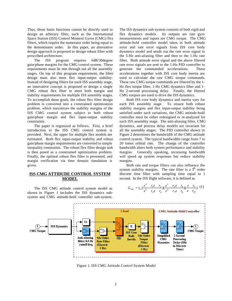
The ISS CMG attitude control system model asshown in Figure 1 includes the ISS dynamics sub-system and CMG attitude-hold controller sub-system.
The ISS dynamics sub-system consists of both rigid andflex dynamics models. Its outputs are rate gyromeasurements and inputs are CMG torque. The CMGattitude-hold controller model takes in both attitudeerror and rate error signals from ISS core bodydynamics model and sends out the rate error signal tothe 5-Hz anti-aliasing filter and then to the 1-Hz ratefilter. Both attitude error signal and the above filteredrate error signals are sent to the 1-Hz PID controller togenerate the commanded accelerations. Theseaccelerations together with ISS core body inertia areused to calculate the raw CMG torque commands.These raw CMG torque commands are filtered by the 1-Hz flex torque filter, 1-Hz CMG dynamics filter and 1-Hz 2-second processing delay. Finally, the filteredCMG torques are used to drive the ISS dynamics.
Both ISS core body dynamics and inertia vary foreach ISS assembly stage. To ensure both robuststability margins and flex input-output stability beingsatisfied under such variations, the CMG attitude-holdcontroller must be either redesigned or re-analyzed foreach ISS assembly stage. The anti-aliasing filter, CMGdynamics, and process delay models are invariant forall the assembly stages. The PID controller shown inFigure 2 determines the bandwidth of the CMG attitudecontrol system. The typical bandwidths range from 7 to20 times orbital rate. The change of the controllerbandwidth alters both system performance and stabilitymargins. Generally speaking, increasing bandwidthwill speed up system responses but reduce stabilitymargins.
Both rate and torque filters can also influence thesystem stability margins. The rate filter is a 5th orderdiscrete time filter with sampling time equal to 1second. In the ISS flight software, it is defined as
))()((10
9
872
652
432
212
11 rzrz
rzrzrzrz
rzrzrzrz
rGrate ++
++++
++++
= (1)
Figure 1. ISS CMG Attitude Control System Model
CMG Attitude-Hold Controller

3
Figure 2. PID Controller
The uniqueness of the rate filter architecture limits itsdesign space, since the numerator and the denominatormust have the same orders. The torque filter, which hasthe same filter architecture, is defined as
))()((10
9
872
652
432
212
11 tztz
tztztztz
tztztztz
tGtorque ++
++++
++++
= (2)
Although the PID controller and flex filtersinfluence the CMG stability margin, there is not muchdesign room for tweaking PID controller parameters.The PID controller parameters are mainly functions ofnumbers of orbital rate. Thus, the CMG controllerdesign task can be reduced to determining the robustflex filter parameters in Eqs. (1) and (2) to meetstability margins as well as flex input-output stability.The robust flex filter design procedures are detailed inthe next sections.
UPPER BOUNDS FOR ISS PLANTFLEXIBILITY
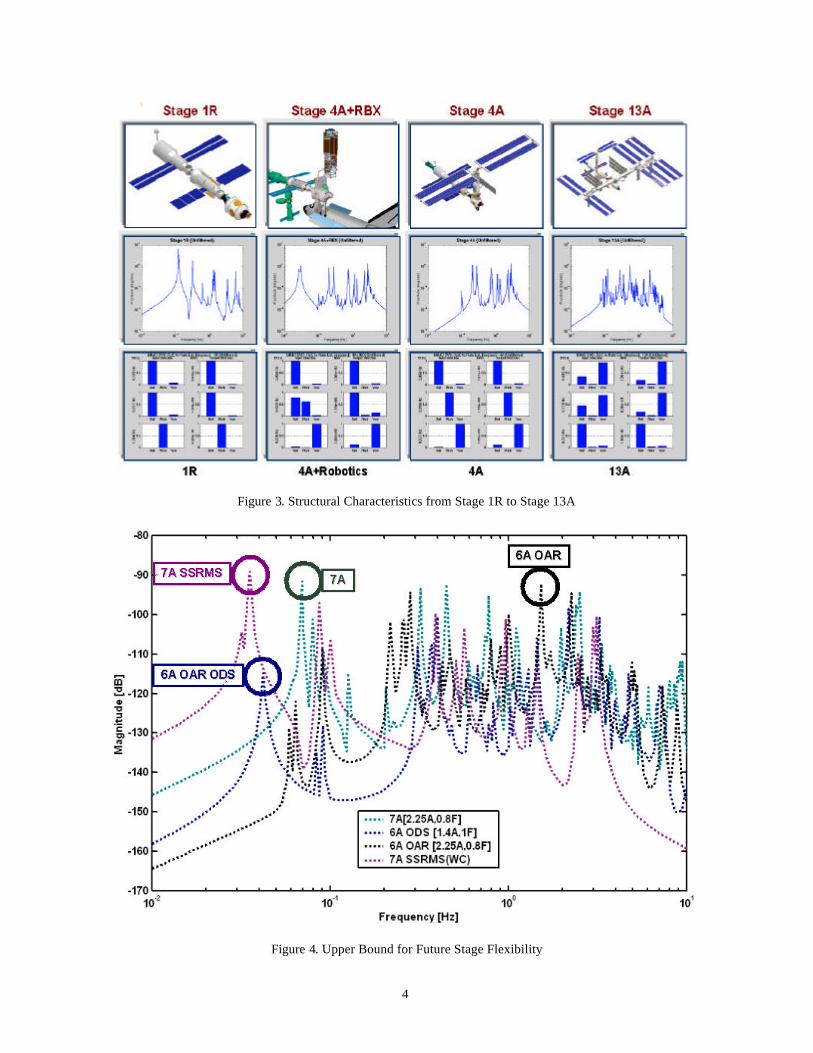
Based on the flex models analyzed so far (i.e., ISSstage 1R to 8A), the trends in flexibility were used toestimate the robust upper bound future assembly stageflex models. As ISS assembly progresses, flexamplitudes tend to decrease while frequencyspectrums/densities increase. As shown in Figure 3,early stages have fewer modes, higher amplitudes, andnarrower frequency spreads with lowest mode usuallybeing higher than 0.1Hz. Later stages have moremodes, lower relative low frequency amplitudes, andwider frequency spreads with lowest modes usuallylower than 0.1Hz.
Flex plant frequency characteristics can be groupedas follows: (1) Unmated configurations, (2) Matedconfigurations, (3) Mated Orbiter Docking System(ODS) configurations, (4) Robotics configurations. Forunmated configurations, dominant flex modes appear atlow frequency and usually have larger amplitudes thanmated ones. On the other hand, dominant flex modesfor mated configurations are at higher frequencies and
usually show larger amplitudes than unmated stages.Mated ODS configurations have nonlinear pitchfrequency responses between 0.06Hz and 0.12Hz withworst case edge at 0.06Hz and 50% total amplitudeuncertainty. For robotics configurations, the worst casefrequencies are dependent on arm configurations andare expected to have the contribution at the lowestfrequency modes around 0.03Hz. The robust upperbounds for structural flexibility is estimated by takingthe maximum of the worst case flex responses from theabove four configurations. The worst case flexresponses for the early assembly stages are shown inFigure 4. The upper envelop in Figure 4 will be used asthe upper bounds for the future stage flexibility.
CONSTRAINED OPTIMIZATIONPROBLEM
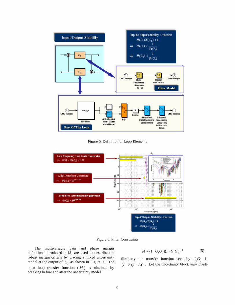
In this section, the robust filter design task will beconverted into a constraint optimization problem.Before the constrained optimization problem is posed,several simplifications are made. First, assume the ratefilter is also applied to the attitude loop. Second, all thenonlinear elements in the CMG attitude control system,such as torque saturation, are not included in the design.These simplifications allow us to break the ISS attitudecontrol system into two linear elements: (1) filtermodels ( 1G ) and (2) rest of the loop ( 2G ) as shown inFigure 5. With this simplified system, both flex input-output constraints and robust stability requirements canbe mathematically modeled as inequality constraints.
Based on input-output stability [7] or small gaintheory, the closed loop is bounded if the open loop gainis less than one. This implies 1)()( 21 <GG σσ , or
)(
1 )(
21 G
Gσ
σ <(3)
To guarantee flex input-output stability, filter gain hasto be less than the gain of the rest of the loop. In theprevious section, the upper bounds for future stageflexibility have been estimated from early stageflexibility. Thus, )(/1 2Gσ can be approximated bymultiplying the inverse of the upper bounds for plantflexibility and the inverse of the frequency response ofthe CMG controller without the filter part. To get rid ofthe frequency dependency, Eq. (3) can be furthersimplified as
)(
1min )(
21 G
Gσ
σω
< (4)
The flex input-stability criterion based on Eq. (4) isshown on Figure 6. It will be used as an inequalityconstraint for the proposed optimization problem.
4
Figure 3. Structural Characteristics from Stage 1R to Stage 13A
Figure 4. Upper Bound for Future Stage Flexibility
5
Figure 5. Definition of Loop Elements
Figure 6. Filter Constraints
The multivariable gain and phase margindefinitions introduced in [8] are used to describe therobust margin criteria by placing a mixed uncertaintymodel at the output of 1G as shown in Figure 7. The
open loop transfer function ( M ) is obtained bybreaking before and after the uncertainty model
12121 ))(( −−+= GGIGGIM (5)
Similarly the transfer function seen by 21GG is1))(( −∆−∆+ II . Let the uncertainty block vary inside
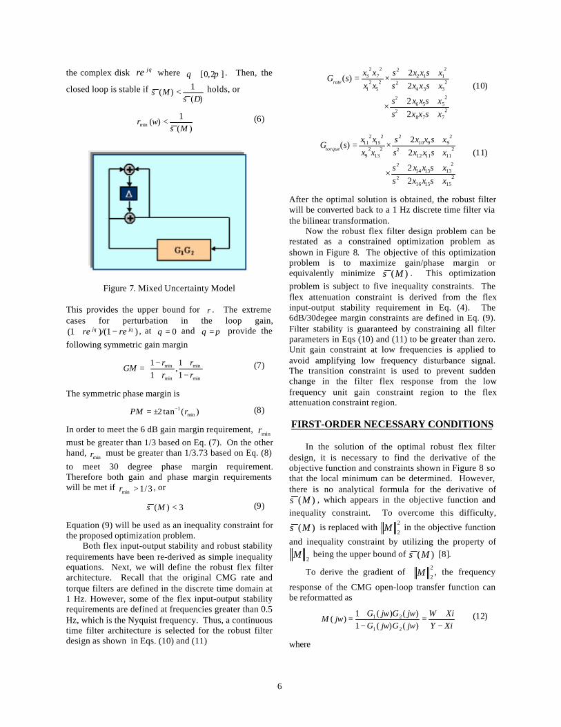
6
the complex disk θjre where ]2,0[ πθ ∈ . Then, the
closed loop is stable if )(
1)(
∆σσ <M holds, or
)(1
)(min Mwr
σ< (6)
Figure 7. Mixed Uncertainty Model
This provides the upper bound for r . The extremecases for perturbation in the loop gain,
))/(1(1 θθ jj rere −+ , at 0=θ and πθ = provide the
following symmetric gain margin
−+
+−
=min
min
min
min
11
,11
rr
rr
GM (7)
The symmetric phase margin is
)(tan2 min1 rPM −±= (8)
In order to meet the 6 dB gain margin requirement, minrmust be greater than 1/3 based on Eq. (7). On the otherhand,
minr must be greater than 1/3.73 based on Eq. (8)
to meet 30 degree phase margin requirement.Therefore both gain and phase margin requirementswill be met if 3/1min >r , or
3)( <Mσ (9)
Equation (9) will be used as an inequality constraint forthe proposed optimization problem.
Both flex input-output stability and robust stabilityrequirements have been re-derived as simple inequalityequations. Next, we will define the robust flex filterarchitecture. Recall that the original CMG rate andtorque filters are defined in the discrete time domain at1 Hz. However, some of the flex input-output stabilityrequirements are defined at frequencies greater than 0.5Hz, which is the Nyquist frequency. Thus, a continuoustime filter architecture is selected for the robust filterdesign as shown in Eqs. (10) and (11)
2778
2
2556
2
2334
2
2112
2
25
21
27
23
22
22
)(
xsxxsxsxxs
xsxxsxsxxs
xxxx
sGrate
++++
×
++++
×=(10)
2151516
2
2131314
2
2111112
2
29910
2
213
29
215
211
22
22
)(
xsxxsxsxxs
xsxxsxsxxs
xxxx
sGtorque
++++
×
++++
×=(11)
After the optimal solution is obtained, the robust filterwill be converted back to a 1 Hz discrete time filter viathe bilinear transformation.
Now the robust flex filter design problem can berestated as a constrained optimization problem asshown in Figure 8. The objective of this optimizationproblem is to maximize gain/phase margin orequivalently minimize )(Mσ . This optimizationproblem is subject to five inequality constraints. Theflex attenuation constraint is derived from the flexinput-output stability requirement in Eq. (4). The6dB/30degee margin constraints are defined in Eq. (9).Filter stability is guaranteed by constraining all filterparameters in Eqs (10) and (11) to be greater than zero.Unit gain constraint at low frequencies is applied toavoid amplifying low frequency disturbance signal.The transition constraint is used to prevent suddenchange in the filter flex response from the lowfrequency unit gain constraint region to the flexattenuation constraint region.
FIRST-ORDER NECESSARY CONDITIONS
In the solution of the optimal robust flex filterdesign, it is necessary to find the derivative of theobjective function and constraints shown in Figure 8 sothat the local minimum can be determined. However,there is no analytical formula for the derivative of
)(Mσ , which appears in the objective function andinequality constraint. To overcome this difficulty,
)(Mσ is replaced with 2
2M in the objective function
and inequality constraint by utilizing the property of
2M being the upper bound of )(Mσ [8].
To derive the gradient of 2
2M , the frequency
response of the CMG open-loop transfer function canbe reformatted as
XiYXiW
jwGjwGjwGjwG
jwM−+
=−+
=)()(1)()(1
)(21
21 (12)
where

7
Figure 8. Optimization Problem Statements
))()(Re(1
))()(Im())()(Re(1
21
21
21
jwGjwGY
jwGjwGXjwGjwGW
−=
=+=
The 2-norm of M is defined as
222
2 IR MMM += (13)
where
22
2
XYXWY
M R +−
= , 22 XY
XYWXM I +
+=
The derivative of 2
2M follows
′+′=′ IIRR MMMMM 22)(2
2(14)
where
2222
22
)(22
)(
2
XYXXYY
XWY
XYXXWYYW
M R
+
′+′−−
+
′−′+′=′
222
22
)(22
)(
XYXXYY
XYWX
XYXYYXWXXW
M I
+
′+′+−
+
′+′+′+′=′
Similarly, due to lack of analytical formulas for thederivative of an absolute function, all four magnitudeconstraints on 1G shown in Figure 8 are also re-
imposed as 2-norm constraints on 1G .
OPTIMAL ROBUST FLEX FILTER DESIGN
The optimization is solved by the Sequential QuadraticProgramming (SQR) method [9]. The upper bound forstation flexibility was estimated via the upper envelopeof the following flex responses:
[1]. ISS 7A unmated configuration with 100%amplitude and -30% frequency perturbation,
[2]. ISS 6A mated configuration with 125%amplitude and –20% frequency uncertainties,
[3]. ISS 6A ODS configuration, and
8
[4]. ISS 7A robotic worst case configuration.
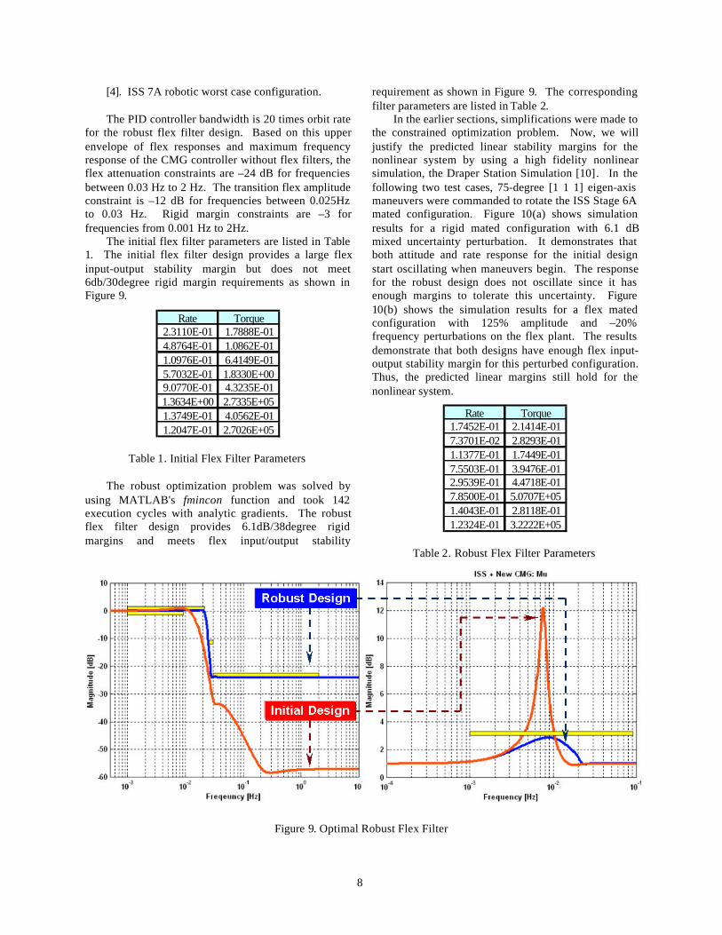
The PID controller bandwidth is 20 times orbit ratefor the robust flex filter design. Based on this upperenvelope of flex responses and maximum frequencyresponse of the CMG controller without flex filters, theflex attenuation constraints are –24 dB for frequenciesbetween 0.03 Hz to 2 Hz. The transition flex amplitudeconstraint is –12 dB for frequencies between 0.025Hzto 0.03 Hz. Rigid margin constraints are –3 forfrequencies from 0.001 Hz to 2Hz.
The initial flex filter parameters are listed in Table1. The initial flex filter design provides a large flexinput-output stability margin but does not meet6db/30degree rigid margin requirements as shown inFigure 9.
Rate Torque2.3110E-01 1.7888E-014.8764E-01 1.0862E-011.0976E-01 6.4149E-015.7032E-01 1.8330E+009.0770E-01 4.3235E-011.3634E+00 2.7335E+051.3749E-01 4.0562E-011.2047E-01 2.7026E+05
Table 1. Initial Flex Filter Parameters
The robust optimization problem was solved byusing MATLAB's fmincon function and took 142execution cycles with analytic gradients. The robustflex filter design provides 6.1dB/38degree rigidmargins and meets flex input/output stability
requirement as shown in Figure 9. The correspondingfilter parameters are listed in Table 2.
In the earlier sections, simplifications were made tothe constrained optimization problem. Now, we willjustify the predicted linear stability margins for thenonlinear system by using a high fidelity nonlinearsimulation, the Draper Station Simulation [10]. In thefollowing two test cases, 75-degree [1 1 1] eigen-axismaneuvers were commanded to rotate the ISS Stage 6Amated configuration. Figure 10(a) shows simulationresults for a rigid mated configuration with 6.1 dBmixed uncertainty perturbation. It demonstrates thatboth attitude and rate response for the initial designstart oscillating when maneuvers begin. The responsefor the robust design does not oscillate since it hasenough margins to tolerate this uncertainty. Figure10(b) shows the simulation results for a flex matedconfiguration with 125% amplitude and –20%frequency perturbations on the flex plant. The resultsdemonstrate that both designs have enough flex input-output stability margin for this perturbed configuration.Thus, the predicted linear margins still hold for thenonlinear system.
Rate Torque1.7452E-01 2.1414E-017.3701E-02 2.8293E-011.1377E-01 1.7449E-017.5503E-01 3.9476E-012.9539E-01 4.4718E-017.8500E-01 5.0707E+051.4043E-01 2.8118E-011.2324E-01 3.2222E+05
Table 2. Robust Flex Filter Parameters
Figure 9. Optimal Robust Flex Filter

9
(a) (b)
Figure 10. ISS 6A Mated Configuration: Nonlinear Simulation
CONCLUSIONS
In this paper, a simple and innovative CMG robustflex filter design procedure was proposed. First, theupper bounds of future stage flexibility were estimated.Next, both flex input-output stability and robustgain/phase margin requirements were converted tosimple inequality constraints. The robust flex filterdesign task was then posed as a constrainedoptimization problem. The linear margins predicted viathe robust flex filter design were verified via anonlinear simulation. Although the proposed designapproach is only demonstrated for the CMG flex filterdesign, it can still be used to design any other robustfilter with minor modifications.
REFERENCES
[1]. Oppenheim, A. V, and Schafer, R. W., DigitalSignal Processing, Prentice-Hall Company, Inc.,Englewood Cliffs, New Jersey, 1975.
[2]. Friedlander, B., and Porat, B, “The ModifiedYule-Walker Method of ARMA SpectralEstimation,” IEEE Transactions on AerospaceElectronic Systems, AES-20, No. 2, March 1984,pp. 158-173.
[3]. Strum, R. D. and Kirk, D. E., First Principles ofDiscrete Systems and Digital Signal Processing,Addison-Wesley Publishing Company, Inc., NewYork, April 1989.
[4]. McGovern, L. K., A Constrained OptimizationApproach to Control with Application to FlexibleStructures, Massachusetts Institute of Technology,Massachusetts, June 1996.
[5]. Lintereur, B. V., Constrained H2 Design ViaConvex Optimization with Applications, MasterThesis , Massachusetts Institute of Technology,Massachusetts, June 1998.
[6]. Ninness, B. and Gustafsson, F., “A UnifyingConstruction of Orthonormal Bases for SystemIdentification,” IEEE Transactions on AutomaticControl, vol. 42, no. 4, pp. 515-521, April 1997.
[7]. Zames, G., “On the Input-Output Stability ofTime-Varying Nonlinear Feedback Systems,”Parts I and II, IEEE Trans. On Automatic Control,AC-11, 2 3, pp. 228-238 465-476, 1966.
[8]. Daily, R. L., “Lecture Notes for the Workshop onH∞ and µ Methods for Robust Control,” presentedat the IEEE Conference on Decision and Control,December 1991.
[9]. Optimization Toolbox for the Use withMATLAB, Version 2, The Mathworks Inc.,Natick, Massachusetts, January 1999
[10]. Jang, J.-W., Bedrossian, N., Zoss, J, Templeton,J., McCants, E. “D Station Simulation - a StandardArchitecture for Space Vehicle Simulation,” PaperAIAA 2000-4084, AIAA Modeling andSimulation Technologies Conference, Denver,CO, Aug. 14-17, 2000.