A Computational Efficient Algorithm for the Design of a Line Start Synchronous Motor with...
6
1 Abstract—Line start permanent magnet synchronous motors present many advantages therefore are considered as an attractive choice for being induction motors alternatives. In this context, this paper presents an analytical though simple algorithmic approach for determining the geometrical characteristics of a multi-segment magnet rotor as a replacement of an already designed and optimized induction motor counterpart. Three different rotor geometries and eight magnet alloys are examined through simulations to validate the proposed algorithm's efficiency. Moreover the manufacturing cost is calculated while the target is to minimize the magnet weight. The relevant results showed that the proposed algorithm performs satisfactorily as an aid design tool. The feasibility of the replacement of the induction motor's rotor with a multi-segment magnet synchronous motor rotor was also confirmed in terms of economic and operational viability. Index Terms—Line start permanent magnet synchronous motor, multi-segment magnet rotor, electrical machines design. I. INTRODUCTION ERMANENT magnet synchronous motors (PMSM) with buried magnets have been considered in a wide range of either fixed or variable speed drives. Also, a buried magnet design has many advantages compared to designs with surface mounted and inset magnets. With a buried magnet design, flux concentration can be achieved, which induces higher air gap flux density. That, in turn, gives a possibility to increase the torque of the machine. The buried magnet construction also gives a possibility to create a non- uniform air gap resulting smoother torque and more sinusoidal currents [1], [2]. Arranging the permanent magnets (PM) in a V-magnet shape is a good solution for this kind of applications as it produces a high reluctance torque next to the PM torque. This leads to an advantage in efficiency as the field weakening current needed above rated speed is also torque-producing. Additionally, it Y. L. Karnavas is with the Department of Electrical and Computer Engineering, Democritus University of Thrace, Xanthi, Hellas (GR), (e- mail: [email protected]). I. D. Chasiotis is with the Department of Electrical and Computer Engineering, Democritus University of Thrace, Xanthi, Hellas (GR), (e- mail: [email protected]). decreases the dependency of the design on temperature variations according to the temperature dependency of the PM flux. Of course, since the used rare-earth magnets have a great effect on the machine costs it is advantageous to reduce the needed magnet volume per torque. This is a motivation to produce a high share of torque through the reluctance effect [3], [4]. The use of multi-layer magnets has also been proposed as it gives saliency to the machine thus increasing the reluctance torque even more. This effect, results to higher output torque in a wider speed range, comparing to the single-layer topology. However, the increase in the magnets number is accompanying by a larger cost, while the mechanical strength and durability are reduced as the number of layers are getting larger [5]. On the other hand, high efficiency induction motors (IM) obtain higher efficiency than standard IMs but with a lower power factor at the same time. Moreover, they are quite material-consuming. The simplest way to increase an IM's efficiency, its power factor, its simplicity, its mechanical robustness and its inherent self-starting property, is the replacement of the standard squirrel-cage rotor with a squirrel-cage permanent magnet rotor and, consequently, change the IM into a line start permanent magnet synchronous motor (LS-PMSM) [6]-[8]. This can be fulfilled by the proper selection of a) the rotor's inner (shaft) and outer diameter, and b) the widths and displacements of the magnet segments. Although finite element analysis (FEA) is an accurate method for this purpose, it is very time consuming in finding optimal configuration due to the exponentially large number of simulations needed. Thus, an algorithmic based design optimization may be very useful and eases the design process [9]. In this paper, a simple algorithm for the calculation of the rotor topology characteristics in candidate LS-PMSMs is proposed. Based on an already designed IM stator, a multi-variable determination framework is developed. It was found that the algorithm needs a small number of iterations until convergence to an optimal machine design solution. Three rotor types were examined, each one by eight commercially available magnet types. Materials consumptions were also taken into account, while the desired motor torque, power factor and efficiency achieved. A Computational Efficient Algorithm for the Design of a Line Start Synchronous Motor with Multi-Segment Magnet Rotor Yannis L. Karnavas, Member, IEEE, and Ioannis D. Chasiotis, S. Member, IEEE P IEEE Workshop on Electrical Machines Design, Control and Diagnosis (WEMDCD), 26-27 Mar. 2015, Torino, Italy.
Transcript of A Computational Efficient Algorithm for the Design of a Line Start Synchronous Motor with...
1
Abstract—Line start permanent magnet synchronous
motors present many advantages therefore are considered as
an attractive choice for being induction motors alternatives. In
this context, this paper presents an analytical though simple
algorithmic approach for determining the geometrical
characteristics of a multi-segment magnet rotor as a
replacement of an already designed and optimized induction
motor counterpart. Three different rotor geometries and eight
magnet alloys are examined through simulations to validate the
proposed algorithm's efficiency. Moreover the manufacturing
cost is calculated while the target is to minimize the magnet
weight. The relevant results showed that the proposed
algorithm performs satisfactorily as an aid design tool. The
feasibility of the replacement of the induction motor's rotor
with a multi-segment magnet synchronous motor rotor was
also confirmed in terms of economic and operational viability.
Index Terms—Line start permanent magnet synchronous
motor, multi-segment magnet rotor, electrical machines design.
I. INTRODUCTION
ERMANENT magnet synchronous motors (PMSM)
with buried magnets have been considered in a wide
range of either fixed or variable speed drives. Also, a buried
magnet design has many advantages compared to designs
with surface mounted and inset magnets. With a buried
magnet design, flux concentration can be achieved, which
induces higher air gap flux density. That, in turn, gives a
possibility to increase the torque of the machine. The buried
magnet construction also gives a possibility to create a non-
uniform air gap resulting smoother torque and more
sinusoidal currents [1], [2]. Arranging the permanent
magnets (PM) in a V-magnet shape is a good solution for
this kind of applications as it produces a high reluctance
torque next to the PM torque. This leads to an advantage in
efficiency as the field weakening current needed above
rated speed is also torque-producing. Additionally, it
Y. L. Karnavas is with the Department of Electrical and Computer
Engineering, Democritus University of Thrace, Xanthi, Hellas (GR), (e-mail: [email protected]).
I. D. Chasiotis is with the Department of Electrical and Computer Engineering, Democritus University of Thrace, Xanthi, Hellas (GR), (e-mail: [email protected]).
decreases the dependency of the design on temperature
variations according to the temperature dependency of the
PM flux. Of course, since the used rare-earth magnets have
a great effect on the machine costs it is advantageous to
reduce the needed magnet volume per torque. This is a
motivation to produce a high share of torque through the
reluctance effect [3], [4]. The use of multi-layer magnets
has also been proposed as it gives saliency to the machine
thus increasing the reluctance torque even more. This effect,
results to higher output torque in a wider speed range,
comparing to the single-layer topology. However, the
increase in the magnets number is accompanying by a larger
cost, while the mechanical strength and durability are
reduced as the number of layers are getting larger [5].
On the other hand, high efficiency induction motors (IM)
obtain higher efficiency than standard IMs but with a lower
power factor at the same time. Moreover, they are quite
material-consuming. The simplest way to increase an IM's
efficiency, its power factor, its simplicity, its mechanical
robustness and its inherent self-starting property, is the
replacement of the standard squirrel-cage rotor with a
squirrel-cage permanent magnet rotor and, consequently,
change the IM into a line start permanent magnet
synchronous motor (LS-PMSM) [6]-[8]. This can be
fulfilled by the proper selection of a) the rotor's inner (shaft)
and outer diameter, and b) the widths and displacements of
the magnet segments. Although finite element analysis
(FEA) is an accurate method for this purpose, it is very time
consuming in finding optimal configuration due to the
exponentially large number of simulations needed. Thus, an
algorithmic based design optimization may be very useful
and eases the design process [9].
In this paper, a simple algorithm for the calculation of
the rotor topology characteristics in candidate LS-PMSMs
is proposed. Based on an already designed IM stator, a
multi-variable determination framework is developed. It
was found that the algorithm needs a small number of
iterations until convergence to an optimal machine design
solution. Three rotor types were examined, each one by
eight commercially available magnet types. Materials
consumptions were also taken into account, while the
desired motor torque, power factor and efficiency achieved.
A Computational Efficient Algorithm for the Design of a Line Start Synchronous Motor with
Multi-Segment Magnet Rotor Yannis L. Karnavas, Member, IEEE, and Ioannis D. Chasiotis, S. Member, IEEE
P
IEEE Workshop on Electrical Machines Design, Control and Diagnosis (WEMDCD), 26-27 Mar. 2015, Torino, Italy.
2
II. INDUCTION MOTOR MODEL UNDER CONSIDERATION
A three-phase squirrel-cage induction motor (SCIM) is
considered here with nominal values and specification data
as per the Appendix (Table XI). Since the emphasis here is
on the LS-PMSM rotor design, the SCIM's design is just
presented here (also in the Appendix, Table XII), so the
reader can verify and check the validity of our further
results obtained. It should be stated though, that these data
refer to an actual commercial motor and derived through
FEA calculations based on its name plate’s data only. With
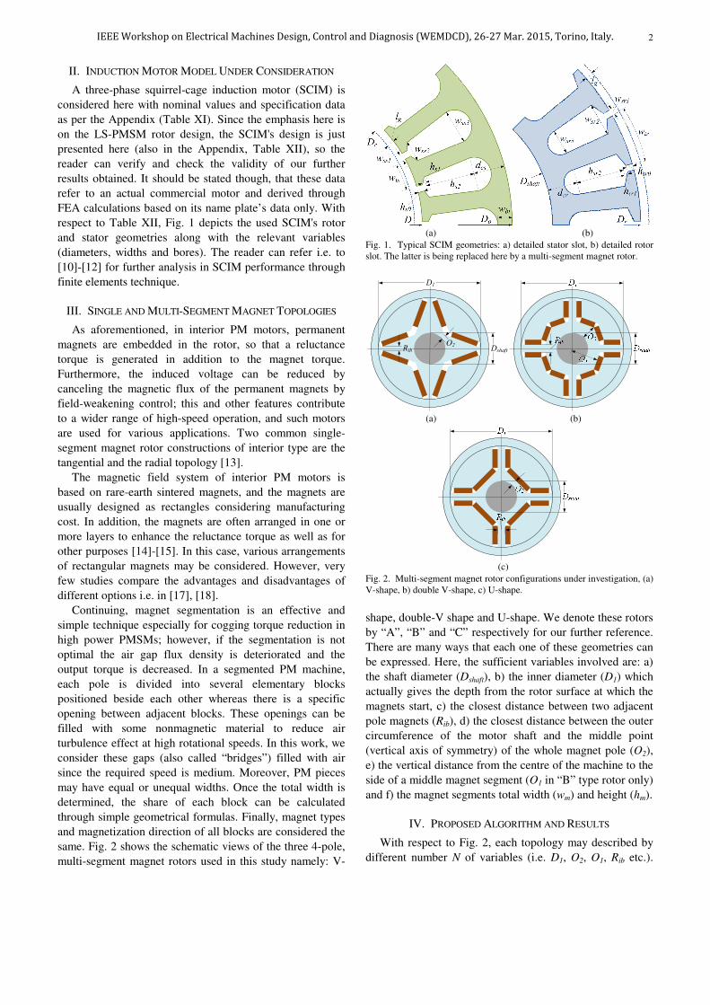
respect to Table XII, Fig. 1 depicts the used SCIM's rotor
and stator geometries along with the relevant variables
(diameters, widths and bores). The reader can refer i.e. to
[10]-[12] for further analysis in SCIM performance through
finite elements technique.
III. SINGLE AND MULTI-SEGMENT MAGNET TOPOLOGIES
As aforementioned, in interior PM motors, permanent
magnets are embedded in the rotor, so that a reluctance
torque is generated in addition to the magnet torque.
Furthermore, the induced voltage can be reduced by
canceling the magnetic flux of the permanent magnets by
field-weakening control; this and other features contribute
to a wider range of high-speed operation, and such motors
are used for various applications. Two common single-
segment magnet rotor constructions of interior type are the
tangential and the radial topology [13].
The magnetic field system of interior PM motors is
based on rare-earth sintered magnets, and the magnets are
usually designed as rectangles considering manufacturing
cost. In addition, the magnets are often arranged in one or
more layers to enhance the reluctance torque as well as for
other purposes [14]-[15]. In this case, various arrangements
of rectangular magnets may be considered. However, very
few studies compare the advantages and disadvantages of
different options i.e. in [17], [18].
Continuing, magnet segmentation is an effective and
simple technique especially for cogging torque reduction in
high power PMSMs; however, if the segmentation is not
optimal the air gap flux density is deteriorated and the
output torque is decreased. In a segmented PM machine,
each pole is divided into several elementary blocks
positioned beside each other whereas there is a specific
opening between adjacent blocks. These openings can be
filled with some nonmagnetic material to reduce air
turbulence effect at high rotational speeds. In this work, we
consider these gaps (also called “bridges”) filled with air
since the required speed is medium. Moreover, PM pieces
may have equal or unequal widths. Once the total width is
determined, the share of each block can be calculated
through simple geometrical formulas. Finally, magnet types
and magnetization direction of all blocks are considered the
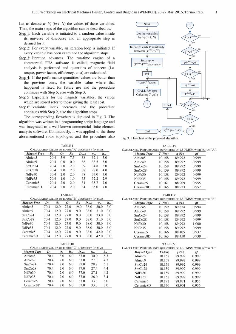
same. Fig. 2 shows the schematic views of the three 4-pole,
multi-segment magnet rotors used in this study namely: V-
(a) (b)
Fig. 1. Typical SCIM geometries: a) detailed stator slot, b) detailed rotor slot. The latter is being replaced here by a multi-segment magnet rotor.
Ο2Rib Dshaft
D1
40
(a) (b)
40
(c)
Fig. 2. Multi-segment magnet rotor configurations under investigation, (a) V-shape, b) double V-shape, c) U-shape.
shape, double-V shape and U-shape. We denote these rotors
by “A”, “B” and “C” respectively for our further reference.
There are many ways that each one of these geometries can
be expressed. Here, the sufficient variables involved are: a)
the shaft diameter (Dshaft), b) the inner diameter (D1) which
actually gives the depth from the rotor surface at which the
magnets start, c) the closest distance between two adjacent
pole magnets (Rib), d) the closest distance between the outer
circumference of the motor shaft and the middle point
(vertical axis of symmetry) of the whole magnet pole (O2),
e) the vertical distance from the centre of the machine to the
side of a middle magnet segment (O1 in “B” type rotor only)
and f) the magnet segments total width (wm) and height (hm).
IV. PROPOSED ALGORITHM AND RESULTS
With respect to Fig. 2, each topology may described by
different number N of variables (i.e. D1, O2, O1, Rib etc.).
IEEE Workshop on Electrical Machines Design, Control and Diagnosis (WEMDCD), 26-27 Mar. 2015, Torino, Italy.
3
Let us denote as Vi (i=1..N) the values of these variables.
Then, the main steps of the algorithm can be described as:
Step 1: Each variable is initiated to a random value inside
its universe of discourse and an appropriate step is
defined for it.
Step 2: For every variable, an iteration loop is initiated. If
every variable has been examined the algorithm stops.
Step 3: Iteration advances. The run-time engine of a
commercial FEA software is called, magnetic field
analysis is performed and quantities of concern (i.e.
torque, power factor, efficiency, cost) are calculated.
Step 4: If the performance quantities' values are better than
the previous ones, the variable value where that
happened is fixed for future use and the procedure
continues with Step 5, else with Step 3.
Step 5 Especially for the magnets' variables, the values
which are stored refer to those giving the least cost.
Step 6: Variable index increases and the procedure
continues with Step 2, else the algorithm stops.
The corresponding flowchart is depicted in Fig. 3. The
algorithm was written in a programming script language and
was integrated to a well known commercial finite element
analysis software. Continuously, it was applied to the three
aforementioned rotor topologies and the procedure also
TABLE I
CALCULATED VALUES OF ROTOR "A" GEOMETRY (IN MM).
Magnet Type D1 O2 Rib Dshaft wm hm
Alnico5 70.4 5.9 7.5 38 32.1 5.0 Alnico9 70.4 0.0 0.0 38 33.5 3.0 SmCo24 70.4 2.0 2.0 39 34.8 3.0 SmCo28 70.4 2.0 2.0 38 28.0 4.0 NdFe30 70.4 2.0 2.0 38 33.0 3.0 NdFe35 70.4 1.0 1.0 33 32.2 2.9 Ceramic5 70.4 2.0 2.0 34 35.7 7.0 Ceramic8D 70.4 2.0 2.0 34 35.0 7.0
TABLE II
CALCULATED VALUES OF ROTOR "B" GEOMETRY (IN MM).
Magnet Type D1 O2 O1 Rib Dshaft wm hm
Alnico5 70.4 12.0 27.0 19.0 38.0 30.0 3.0 Alnico9 70.4 12.0 27.0 9.0 38.0 31.0 3.0 SmCo24 70.4 12.0 27.0 9.0 38.0 33.0 3.0 SmCo28 70.4 12.0 27.0 9.0 38.0 31.0 3.0 NdFe30 70.4 12.0 27.0 9.0 38.0 30.0 3.0 NdFe35 70.4 12.0 27.0 9.0 38.0 30.0 3.0 Ceramic5 70.4 12.0 27.0 9.0 38.0 42.0 3.0 Ceramic8D 70.4 12.0 27.0 9.0 38.0 42.0 3.0
TABLE III
CALCULATED VALUES OF ROTOR "C" GEOMETRY (IN MM).
Magnet Type D1 O2 Rib Dshaft wm hm
Alnico5 70.4 3.0 6.0 37.0 30.0 5.3 Alnico9 70.4 2.0 6.0 37.0 27.3 4.7 SmCo24 70.4 2.0 6.0 37.0 28.2 5.1 SmCo28 70.4 2.0 6.0 37.0 27.4 4.4 NdFe30 70.4 2.0 6.0 37.0 27.1 4.2 NdFe35 70.4 2.0 6.0 37.0 26.0 3.4 Ceramic5 70.4 2.0 6.0 37.0 33.3 8.0 Ceramic8D 70.4 2.0 6.0 37.0 33.3 8.0
Let the variables
be Vi (i=1..N)
Initialize each Vi randomly
between [Vimin
,Vimax
]
Set stepi =
(Vimax
-Vimin
)/accuracy
Start
i=1
Vi=Vimin
+stepi
CALL RMxprt
Calculate T, pf, η
1
T ≥ T nom
pf > pf prev
pf prev
=pf
η > η prev
η prev=η
Vibest
=Vi
Vi > Vi max
1
i = N
i=i+1
no
no
no
yes
yes
yes
yes
yes
no
no1
End Vibest
(i=1..N)
Fig. 3. Flowchart of the proposed algorithm.
TABLE IV CALCULATED PERFORMANCE QUANTITIES OF LS-PMSM WITH ROTOR "A".
Magnet Type T (Nm) η (%) pf
Alnico5 10.158 89.992 0.999 Alnico9 10.158 89.992 0.999 SmCo24 10.158 89.992 0.999 SmCo28 10.159 89.992 0.999 NdFe30 10.158 89.992 0.999 NdFe35 10.158 89.992 0.999 Ceramic5 10.161 88.909 0.955 Ceramic8D 10.165 88.933 0.957
TABLE V
CALCULATED PERFORMANCE QUANTITIES OF LS-PMSM WITH ROTOR "B".
Magnet Type T (Nm) η (%) pf
Alnico5 10.159 89.854 0.994 Alnico9 10.158 89.992 0.999 SmCo24 10.158 89.992 0.999 SmCo28 10.158 89.992 0.999 NdFe30 10.158 89.992 1.000 NdFe35 10.158 89.992 0.999 Ceramic5 10.166 88.405 0.937 Ceramic8D 10.163 88.450 0.939
TABLE VI
CALCULATED PERFORMANCE QUANTITIES OF LS-PMSM WITH ROTOR "C".
Magnet Type T (Nm) η (%) pf
Alnico5 10.158 89.992 0.999 Alnico9 10.159 89.992 0.999 SmCo24 10.159 89.992 0.999 SmCo28 10.159 89.992 0.999 NdFe30 10.159 89.992 0.999 NdFe35 10.158 89.992 0.999 Ceramic5 10.172 88.871 0.955 Ceramic8D 10.170 88.901 0.956
IEEE Workshop on Electrical Machines Design, Control and Diagnosis (WEMDCD), 26-27 Mar. 2015, Torino, Italy.
4
TABLE VII CALCULATED ROTOR MATERIAL CONSUMPTIONS AND COST OF ROTOR "A"
FOR DIFFERENT MAGNET TYPES.
Magnet
type
Rotor Cage
material
consumption
(gr)
Magnetic
material
consumption
(gr)
Rotor Core
material
consumption
(kgr)
Overall
Rotor
Cost
(USD)
Alnico5 96.0 492.093 6.377 27.77 Alnico9 96.0 308.333 6.377 19.66 SmCo24 96.0 363.938 6.377 62.24 SmCo28 96.0 390.932 6.377 66.40 NdFe30 96.0 313.929 6.377 36.65 NdFe35 96.0 290.225 6.377 30.29 Ceramic5 96.0 514.294 6.377 8.33 Ceramic8D 96.0 504.210 6.377 8.29
TABLE VIII
CALCULATED ROTOR MATERIAL CONSUMPTIONS AND COST OF ROTOR "B"
FOR DIFFERENT MAGNET TYPES.
Magnet
type
Rotor Cage
material
consumption
(gr)
Magnetic
material
consumption
(gr)
Rotor Core
material
consumption
(kgr)
Overall
Rotor
Cost
(USD)
Alnico5 96.0 279.720 6.377 18.40 Alnico9 96.0 285.138 6.377 18.64 SmCo24 96.0 345.114 6.377 59.33 SmCo28 96.0 313.740 6.377 54.49 NdFe30 96.0 266.364 6.377 26.62 NdFe35 96.0 233.100 6.377 24.05 Ceramic5 96.0 259.308 6.377 7.21 Ceramic8D 96.0 253.134 6.377 7.18
TABLE IX
CALCULATED ROTOR MATERIAL CONSUMPTIONS AND COST OF ROTOR "C"
FOR DIFFERENT MAGNET TYPES.
Magnet
type
Rotor Cage
material
consumption
(gr)
Magnetic
material
consumption
(gr)
Rotor Core
material
consumption
(kgr)
Overall
Rotor
Cost
(USD)
Alnico5 96.0 496.692 6.377 27.90 Alnico9 96.0 393.398 6.377 23.41 SmCo24 96.0 501.357 6.377 83.45 SmCo28 96.0 420.272 6.377 70.93 NdFe30 96.0 360.923 6.377 33.92 NdFe35 96.0 274.747 6.377 27.27 Ceramic5 96.0 548.251 6.377 8.48 Ceramic8D 96.0 548.251 6.377 8.48
repeated for 8 different magnet materials (4 types by 2
grades), thus a total of 24 result sets obtained. Tables I-III
show the corresponding geometrical (core and magnet) final
values for each magnet type. It is reminded that, specifically
for the magnet width wm the calculated value refer to the
total width of all the segments involved per pole. The
software then "splits" this width by applying simple
geometrical formulas regarding each segment. For example,
in U-shape magnet, if l1 is the length of the middle segment,
l2 is the length of the side segments (l1+2l2 = wm), and bw the
total bridge width, then l2 (with Rib=0) can be expressed as:
( ) ( )
( )/
m w shaft m mD h b D O h w
l− − − + + +
=−
1 2
2
2 2 2 2
2 2 1
(1)
(a)
(b)
(c)
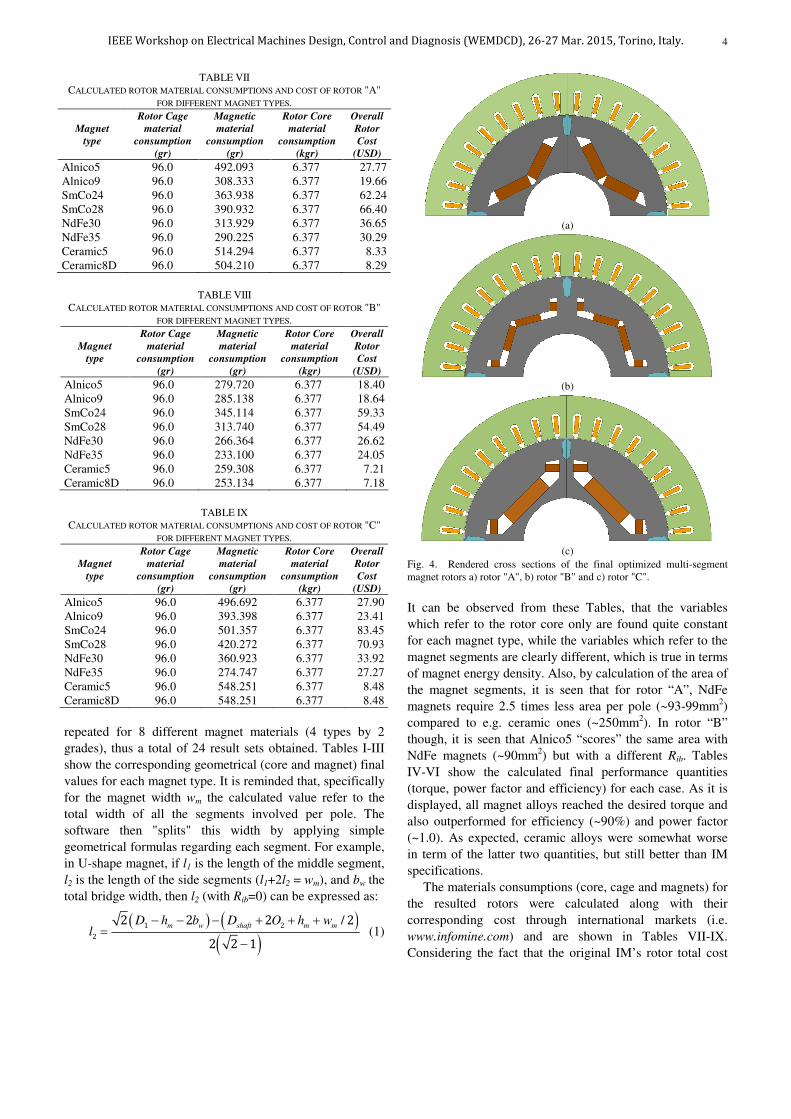
Fig. 4. Rendered cross sections of the final optimized multi-segment magnet rotors a) rotor "A", b) rotor "B" and c) rotor "C".
It can be observed from these Tables, that the variables
which refer to the rotor core only are found quite constant
for each magnet type, while the variables which refer to the
magnet segments are clearly different, which is true in terms
of magnet energy density. Also, by calculation of the area of
the magnet segments, it is seen that for rotor “A”, NdFe
magnets require 2.5 times less area per pole (~93-99mm2)
compared to e.g. ceramic ones (~250mm2). In rotor “B”
though, it is seen that Alnico5 “scores” the same area with
NdFe magnets (~90mm2) but with a different Rib. Tables
IV-VI show the calculated final performance quantities
(torque, power factor and efficiency) for each case. As it is
displayed, all magnet alloys reached the desired torque and
also outperformed for efficiency (~90%) and power factor
(~1.0). As expected, ceramic alloys were somewhat worse
in term of the latter two quantities, but still better than IM
specifications.
The materials consumptions (core, cage and magnets) for
the resulted rotors were calculated along with their
corresponding cost through international markets (i.e.
www.infomine.com) and are shown in Tables VII-IX.
Considering the fact that the original IM’s rotor total cost
IEEE Workshop on Electrical Machines Design, Control and Diagnosis (WEMDCD), 26-27 Mar. 2015, Torino, Italy.
5
(a)
(b)
(c)
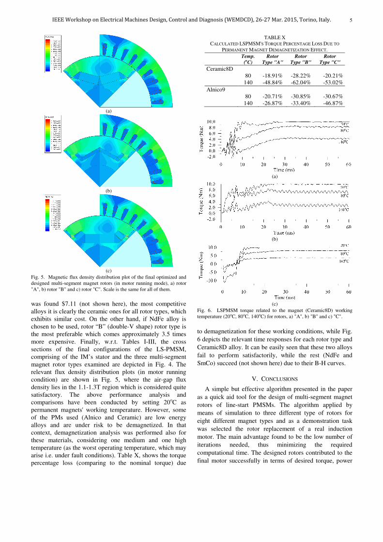
Fig. 5. Magnetic flux density distribution plot of the final optimized and designed multi-segment magnet rotors (in motor running mode), a) rotor "A", b) rotor "B" and c) rotor "C". Scale is the same for all of them.
was found $7.11 (not shown here), the most competitive alloys it is clearly the ceramic ones for all rotor types, which exhibits similar cost. On the other hand, if NdFe alloy is chosen to be used, rotor “B” (double-V shape) rotor type is the most preferable which comes approximately 3.5 times more expensive. Finally, w.r.t. Tables I-III, the cross sections of the final configurations of the LS-PMSM, comprising of the IM’s stator and the three multi-segment magnet rotor types examined are depicted in Fig. 4. The relevant flux density distribution plots (in motor running condition) are shown in Fig. 5, where the air-gap flux density lies in the 1.1-1.3T region which is considered quite satisfactory. The above performance analysis and comparisons have been conducted by setting 20oC as permanent magnets' working temperature. However, some of the PMs used (Alnico and Ceramic) are low energy alloys and are under risk to be demagnetized. In that context, demagnetization analysis was performed also for these materials, considering one medium and one high temperature (as the worst operating temperature, which may arise i.e. under fault conditions). Table X, shows the torque percentage loss (comparing to the nominal torque) due
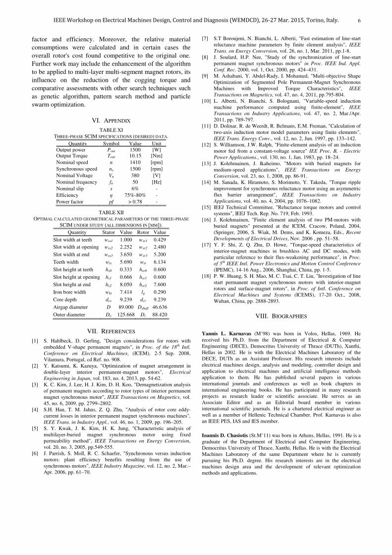
TABLE X CALCULATED LSPMSM'S TORQUE PERCENTAGE LOSS DUE TO
PERMANENT MAGNET DEMAGNETIZATION EFFECT.
Temp.
(oC)
Rotor
Type "A"
Rotor
Type "B"
Rotor
Type "C"
Ceramic8D 80 -18.91% -28.22% -20.21% 140 -48.84% -62.04% -53.02%
Alnico9 80 -20.71% -30.85% -30.67% 140 -26.87% -33.40% -46.87%
(a)
(b)
(c)
Fig. 6. LSPMSM torque related to the magnet (Ceramic8D) working temperature (20oC, 80oC, 140oC) for rotors, a) "A", b) "B" and c) "C".
to demagnetization for these working conditions, while Fig.
6 depicts the relevant time responses for each rotor type and
Ceramic8D alloy. It can be easily seen that these two alloys
fail to perform satisfactorily, while the rest (NdFe and
SmCo) succeed (not shown here) due to their B-H curves.
V. CONCLUSIONS
A simple but effective algorithm presented in the paper
as a quick aid tool for the design of multi-segment magnet
rotors of line-start PMSMs. The algorithm applied by
means of simulation to three different type of rotors for
eight different magnet types and as a demonstration task
was selected the rotor replacement of a real induction
motor. The main advantage found to be the low number of
iterations needed, thus minimizing the required
computational time. The designed rotors contributed to the
final motor successfully in terms of desired torque, power
IEEE Workshop on Electrical Machines Design, Control and Diagnosis (WEMDCD), 26-27 Mar. 2015, Torino, Italy.
6
factor and efficiency. Moreover, the relative material
consumptions were calculated and in certain cases the
overall rotor's cost found competitive to the original one.
Further work may include the enhancement of the algorithm
to be applied to multi-layer multi-segment magnet rotors, its
influence on the reduction of the cogging torque and
comparative assessments with other search techniques such
as genetic algorithm, pattern search method and particle
swarm optimization.
VI. APPENDIX
TABLE XI THREE-PHASE SCIM SPECIFICATIONS (DESIRED) DATA.
Quantity Symbol Value Unit Output power Pout 1500 [W] Output Torque Tout 10.15 [Nm]
Nominal speed n 1410 [rpm]
Synchronous speed ns 1500 [rpm]
Nominal Voltage Vn 380 [V]
Nominal frequency fn 50 [Hz]
Nominal slip s 6% -
Efficiency η 75%-80% -
Power factor pf > 0.78 -
TABLE XII OPTIMAL CALCULATED GEOMETRICAL PARAMETERS OF THE THREE-PHASE
SCIM UNDER STUDY (ALL DIMENSIONS IN [MM]).
Quantity Stator Value Rotor Value
Slot width at teeth wss1 1.000 wsr1 0.429
Slot width at opening wss2 2.252 wsr2 2.480
Slot width at end wss3 3.650 wsr3 5.200
Teeth width wts 5.690 wtr 6.134
Slot height at teeth hs0 0.333 hsr0 0.600
Slot height at opening hs1 0.666 hsr1 0.600
Slot height at end hs2 8.050 hsr2 7.600
Iron bore width wbi 7.414 lg 0.290
Core depth dcs 9.239 dcr 9.239
Airgap diameter D 89.000 Dshaft 46.636
Outer diameter Do 125.668 Dr 88.420
VII. REFERENCES
[1] S. Hahlbeck, D. Gerling, "Design considerations for rotors with embedded V-shape permanent magnets", in Proc. of the 18th Intl.
Conference on Electrical Machines, (ICEM), 2-5 Sep. 2008, Vilamura, Portugal, cd Ref. no. 908.
[2] Y. Katsumi, K. Kazuya, "Optimization of magnet arrangement in double-layer interior permanent-magnet motors", Electrical
Engineering in Japan, vol. 183, no. 4, 2013, pp. 54-62. [3] K. C. Kim, J. Lee, H. J. Kim, D. H. Koo, "Demagnetization analysis
of permanent magnets according to rotor types of interior permanent magnet synchronous motor", IEEE Transactions on Magnetics, vol. 45, no. 6, 2009, pp. 2799–2802.
[4] S.H. Han, T. M. Jahns, Z. Q. Zhu, "Analysis of rotor core eddy-current losses in interior permanent magnet synchronous machines", IEEE Trans. in Industry Appl., vol. 46, no. 1, 2009, pp. 196–205.
[5] S. Y. Kwak, J. K. Kim, H. K. Jung, "Characteristic analysis of multilayer-buried magnet synchronous motor using fixed permeability method", IEEE Transactions on Energy Conversion, vol. 20, no. 3, 2005, pp.549-555.
[6] J. Parrish, S. Moll, R. C. Schaefer, "Synchronous versus induction motors: plant efficiency benefits resulting from the use of synchronous motors", IEEE Industry Magazine, vol. 12, no. 2, Mar.–Apr. 2006, pp. 61–70.
[7] S.T Boroujeni, N. Bianchi, L. Alberti, "Fast estimation of line-start reluctance machine parameters by finite element analysis", IEEE
Trans. on Energy Conversion, vol. 26, no. 1, Mar. 2011, pp.1-8. [8] J. Soulard, H.P. Nee, "Study of the synchronization of line-start
permanent magnet synchronous motors" in Proc. IEEE Ind. Appl.
Conf. Rec. 2000, vol. 1, Oct. 2000, pp. 424–431. [9] M. Ashabani, Y. Abdel-Rady, I. Mohamed, "Multi-objective Shape
Optimization of Segmented Pole Permanent-Magnet Synchronous Machines with Improved Torque Characteristics", IEEE
Transactions on Magnetics, vol. 47, no. 4, 2011, pp.795-804. [10] L. Alberti, N. Bianchi, S. Bolognani, "Variable-speed induction
machine performance computed using finite-element", IEEE
Transactions on Industry Applications, vol. 47, no. 2, Mar./Apr. 2011, pp. 789-797.
[11] D. Dolinar, R. de Weerdt, R. Belmans, E.M. Freman, "Calculation of two-axis induction motor model parameters using finite elements", IEEE Trans. Energy Conv., vol. 12, no. 2, Jun. 1997, pp. 133–142.
[12] S. Williamson, J.W. Ralph, "Finite-element analysis of an induction motor fed from a constant-voltage source" IEE Proc. B, - Electric
Power Applications., vol. 130, no. 1, Jan. 1983, pp. 18–24. [13] J. Kolehmainen, J. Ikaheimo, "Motors with buried magnets for
medium-speed applications", IEEE Transactions on Energy
Conversion, vol. 23, no. 1, 2008, pp. 86-91. [14] M. Sanada, K. Hiramoto, S. Morimoto, Y. Takeda, "Torque ripple
improvement for synchronous reluctance motor using an asymmetric flux barrier arrangement", IEEE Transactions on Industry
Applications, vol. 40, no. 4, 2004, pp. 1076–1082. [15] IEEJ Technical Committee, "Reluctance torque motors and control
systems", IEEJ Tech. Rep. No. 719, Feb. 1993. [16] J. Kolehmainen, "Finite element analysis of two PM-motors with
buried magnets" presented at the ICEM, Cracow, Poland, 2004, (Springer, 2006, S. Wiak, M. Dems, and K. Komeza, Eds., Recent
Developments of Electrical Drives, Nov. 2006 , pp. 51–58. [17] Y. F. Shi, Z. Q. Zhu, D. Howe, "Torque-speed characteristics of
interior-magnet machines in brushless AC and DC modes, with particular reference to their flux-weakening performance", in Proc.
of 5th IEEE Intl. Power Electronics and Motion Control Conference (IPEMC), 14-16 Aug., 2006, Shanghai, China, pp. 1-5.
[18] P. W. Huang, S. H. Mao, M. C. Tsai, C. T. Liu, "Investigation of line start permanent magnet synchronous motors with interior-magnet rotors and surface-magnet rotors", in Proc. of Intl. Conference on
Electrical Machines and Systems (ICEMS), 17-20 Oct., 2008, Wuhan, China, pp. 2888-2893.
VIII. BIOGRAPHIES
Yannis L. Karnavas (M’98) was born in Volos, Hellas, 1969. He received his Ph.D. from the Department of Electrical & Computer Engineering (DECE), Democritus University of Thrace (DUTh), Xanthi, Hellas in 2002. He is with the Electrical Machines Laboratory of the DECE, DUTh as an Assistant Professor. His research interests include electrical machines design, analysis and modeling, controller design and application to electrical machines and artificial intelligence methods application to them. He has published several papers in various international journals and conferences as well as book chapters in international engineering books. He has participated in many research projects as research leader or scientific associate. He serves as an Associate Editor and as an Editorial board member in various international scientific journals. He is a chartered electrical engineer as well as a member of Hellenic Technical Chamber. Prof. Karnavas is also an IEEE PES, IAS and IES member.
Ioannis D. Chasiotis (St.M’11) was born in Athens, Hellas, 1991. He is a graduate of the Department of Electrical and Computer Engineering, Democritus University of Thrace, Xanthi, Hellas. He is with the Electrical Machines Laboratory of the same Department where he is currently pursuing his Ph.D. degree. His research interests are in the electrical machines design area and the development of relevant optimization methods and applications.
IEEE Workshop on Electrical Machines Design, Control and Diagnosis (WEMDCD), 26-27 Mar. 2015, Torino, Italy.