A comprehensive view on performance, emission, and combustion characteristics of biodiesel-diesel...
11
A comprehensive view on performance, emission, and combustion characteristics of biodiesel-diesel blends at advanced injection timings A. Murugesan, D. Subramaniam, A. Avinash, and N. Nedunchezhian Citation: J. Renewable Sustainable Energy 5, 033103 (2013); doi: 10.1063/1.4803745 View online: http://dx.doi.org/10.1063/1.4803745 View Table of Contents: http://jrse.aip.org/resource/1/JRSEBH/v5/i3 Published by the American Institute of Physics. Additional information on J. Renewable Sustainable Energy Journal Homepage: http://jrse.aip.org/ Journal Information: http://jrse.aip.org/about/about_the_journal Top downloads: http://jrse.aip.org/features/most_downloaded Information for Authors: http://jrse.aip.org/authors
Transcript of A comprehensive view on performance, emission, and combustion characteristics of biodiesel-diesel...
A comprehensive view on performance, emission, and combustioncharacteristics of biodiesel-diesel blends at advanced injection timingsA. Murugesan, D. Subramaniam, A. Avinash, and N. Nedunchezhian Citation: J. Renewable Sustainable Energy 5, 033103 (2013); doi: 10.1063/1.4803745 View online: http://dx.doi.org/10.1063/1.4803745 View Table of Contents: http://jrse.aip.org/resource/1/JRSEBH/v5/i3 Published by the American Institute of Physics. Additional information on J. Renewable Sustainable EnergyJournal Homepage: http://jrse.aip.org/ Journal Information: http://jrse.aip.org/about/about_the_journal Top downloads: http://jrse.aip.org/features/most_downloaded Information for Authors: http://jrse.aip.org/authors
A comprehensive view on performance, emission,and combustion characteristics of biodiesel-dieselblends at advanced injection timings
A. Murugesan,1,a) D. Subramaniam,2 A. Avinash,2 and N. Nedunchezhian3
1Department of Mechatronics Engineering, K.S. Rangasamy College of Technology,Tiruchengode 637215, Tamil Nadu, India2Department of Mechanical Engineering, K.S. Rangasamy College of Technology,Tiruchengode 637215, Tamil Nadu, India3Department of Automobile Engineering, IRTT, Erode 637215, Tamil Nadu, India
(Received 7 December 2012; accepted 19 April 2013; published online 3 May 2013)
In this article, an endeavor has been made to assess the operating characteristics of
a diesel engine fuelled with methyl esters of pungamia, ethyl esters of pungamia,
and ethyl esters of neem, added to diesel by percentage volume ranging from B20
to B80. The test runs on diesel fuel in the first phase of work were carried out under
standard injection timing of 23� before top dead center (BTDC), so as to establish
baseline for other parameters. The similar test procedures were repeated with an
advanced injection timings of 26� BTDC and 28� BTDC fuelled with diesel and
biodiesel–diesel blends varying from B20 to B100. Experimental results proved
that the 3� advancement of injection timing from the standard injection timing
proved promising outcomes for biodiesel operated engine, whereas 5� BTDC crank
angle degree produced a higher exhaust gas temperature and higher levels of NOx
formation. VC 2013 AIP Publishing LLC. [http://dx.doi.org/10.1063/1.4803745]
I. INTRODUCTION
The world is presently confronted with the twin crisis of fossil fuel depletion and ecologi-
cal degradation. In contrast, indiscriminate extraction and copious consumption of fossil fuels
have led to reduction in underground-based carbon resources. Recent days, considerable atten-
tion has been focused on the development of alternate fuels.1–8 Researchers like Murugesan
et al.9 reported that the oil extracted from Jatropha curcus, pungamia, and neem could serve as
a potential alternative fuel for Compression ignition (C.I.) engine. They prepared various pro-
portions of biodiesel-diesel blends to run the diesel engine in order to examine the performance,
emission, and combustion characteristics at standard injection timings. The phenomenon of
combustion in engine will have an adverse effect on both the performance and emission param-
eters. Most of the research studies had been carried out with a standard injection timing of 23�
before top dead center (BTDC) to investigate the engine operating characteristics. Nevertheless,
to the author’s knowledge only few research works had been carried out with advanced injec-
tion timings. Narayana Reddy and Ramesh10 conducted experiments on single cylinder, air-
cooled high speed diesel engine by using jatropha oil and diesel as fuel for standard injection
timing of 30.5� BTDC, and advanced the injection timing to 32� BTDC, 33.5� BTDC, and
34.5� BTDC, respectively. The experimental results showed improvements in the brake thermal
efficiency, and reduction in HC and smoke emissions, as well as improved heat release rate at
advanced injection timings. Thus, by advancing the injection timing from the standard value,
there is more time available for mixture formation and this could effectively lead to better com-
bustion and improved engine performance. The engine has the standard injection timing of 23�
BTDC as recommended by manufacturer, which is also determined in the usual way by
1941-7012/2013/5(3)/033103/10/$30.00 VC 2013 AIP Publishing LLC5, 033103-1
JOURNAL OF RENEWABLE AND SUSTAINABLE ENERGY 5, 033103 (2013)
observing the spill cut-off of the injection pump. In the present work, the injection time was
advanced by changing the position of the fuel injection pump with respect to the fuel injection
cam. Experiments were carried out by advancing 3� and 5� from the standard injection timing
of 23� BTDC, which in turn gives the injection timing of 26� BTDC and 28� BTDC.
II. TRANSESTERIFICATION UNIT
The vegetable oil usually contains free fatty acids, phospholipids, sterols, water, odorants,
and other impurities. Because of their presence, the oil cannot be directly used as fuel. To over-
come these problems, the oil requires chemical modifications like transesterification, pyrolysis,
and emulsification. Among these, the transesterification is an imperative process to produce
clean and environment friendly fuel from vegetable oil, and also it appears to be more suitable
because the by-product (glycerol) has got commercial value.9 A small batch type unit was
designed and fabricated keeping in mind the objective of the present work for producing biodie-
sel from all types of non-edible oils. It is very compact and can produce 5 l biodiesel from non-
edible oils within a period of 11/2 h. The production of bio diesel is approximately 70 to 80 l
per day. The container and blades were made up of stainless steel. It is possible to produce bio
diesel of about 80% to 96% based on the nature of oils and reactants.
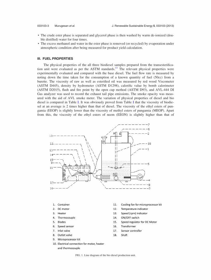
The transesterification unit used for biodiesel production was designed and fabricated in
the laboratory. It consists of stainless steel container with a capacity of 6 l and a variable speed
D.C. motor, which was fixed on the top of the container. The D.C. motor was attached with
mechanical stirrer. The operating speed of mechanical stirrer is about 200 rpm to 900 rpm. The
speed of the stirrer can be easily varied with the help of an electronic speed regulator, and the
speed of the stirrer was monitored using digital speed sensor along with digital speed indicator.
The stirrer consists of eight stainless steel blades at an angle of 45� and oriented at 45� to the
base. A heater having a capacity of 1.5 kW was fixed at the bottom of the container for heating
the oil. A temperature control unit was used to vary the temperature of oil from 30 �C to
250 �C. The temperature of the oil was measured using Chromel-Alumel (k-type) thermocouple
along with digital temperature indicator. An electronic microprocessor was used to control the
motor speed and temperature. The cooling fan was provided inside the electronic kit to absorb
the heat from the transformer and integrated circuits. The top of the container has one inlet
valve and the bottom of the container has one drain valve. The line diagram of the biodiesel
production unit is shown in Figure 1. The biodiesel from pungamia and neem oil was produced
with the aid of the transesterification unit by adding optimum amount of alcohol and catalyst.
The step-by-step procedure of transesterification process is explained as follows:
• 2400 ml of raw oil is filtered using cloth to remove the impurities and poured into biodiesel pro-
duction unit. 400 ml of methanol/ethanol is used as a solvent for 2400 ml of raw oil.• Under agitation, the raw oil is heated up to 65 �C (boiling point of methanol) for production of
methyl ester and 75 �C (boiling point of ethanol) for ethyl ester by using heating coil. At room
temperature, the conversion efficiency is noted to be very low (about 10% only) even after 2 h
of stirring.• The required amount of catalyst pellets (NaOH/KOH) is quickly weighed, protecting it as much
as possible from atmospheric moisture and carbon dioxide.• The pellets are quickly transferred to the dry mixture grinder to convert into powder form.• The powdered form of catalyst and solvent (methanol/ethanol) solution is then vigorously
shaken in a conical flask for homogeneous mixing. At this point, dissolved catalyst (NaOH/
KOH) is presumed to have been converted into ethoxide/methoxide.• A fixed amount of solvent and catalyst solution is poured into oil to mark the beginning of
reaction.• Once the reaction period is over, the product is allowed to settle overnight. Two distinct liquid
phases are identified. Crude esters phase at the top and glycerol phase at bottom. That is transes-
terification process turns the oil into esters, separating out the glycerol. The glycerol sinks at the
bottom and the biodiesel floats on top, which can be removed off.
033103-2 Murugesan et al. J. Renewable Sustainable Energy 5, 033103 (2013)
• The crude ester phase is separated and glycerol phase is then washed by warm de-ionized (dou-
ble distilled) water for four times.• The excess methanol and water in the ester phase is removed (or recycled) by evaporation under
atmospheric condition after being measured for product yield calculation.
III. FUEL PROPERTIES
The physical properties of the all three biodiesel samples prepared from the transesterifica-
tion unit were evaluated as per the ASTM standards.11 The relevant physical properties were
experimentally evaluated and compared with the base diesel. The fuel flow rate is measured by
noting down the time taken for the consumption of a known quantity of fuel (50cc) from a
burette. The viscosity of raw as well as esterified oil was measured by red wood Viscometer
(ASTM D445), density by hydrometer (ASTM D1298), calorific value by bomb calorimeter
(ASTM D2015), flash and fire point by the open cup method (ASTM D93), and AVL-444 DI
Gas analyzer was used to record the exhaust tail pipe emissions. The smoke opacity was meas-
ured with the aid of AVL smoke meter. The variation of physical properties of diesel and bio
diesel is compared in Table I. It was obviously proved from Table I that the viscosity of biodie-
sel at an average is 2 times higher than that of diesel. The viscosity of the ethyl esters of pun-
gamia (EEOP) is slightly lower than the viscosity of methyl esters of pungamia (MEOP). Apart
from this, the viscosity of the ethyl esters of neem (EEON) is slightly higher than that of
FIG. 1. Line diagram of the bio diesel production unit.
033103-3 Murugesan et al. J. Renewable Sustainable Energy 5, 033103 (2013)
MEOP and EEOP. Also, the values of specific gravity and flash point increased for B100
blends, and the calorific value decreased for B100 blends when compared to base diesel. The
primary reason for this variation in properties is the change in molecular structure of biodiesel
and diesel.
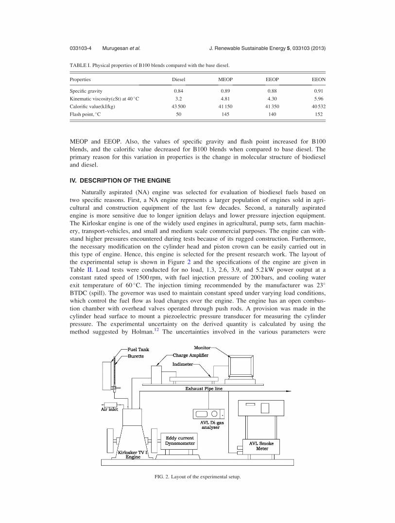
IV. DESCRIPTION OF THE ENGINE
Naturally aspirated (NA) engine was selected for evaluation of biodiesel fuels based on
two specific reasons. First, a NA engine represents a larger population of engines sold in agri-
cultural and construction equipment of the last few decades. Second, a naturally aspirated
engine is more sensitive due to longer ignition delays and lower pressure injection equipment.
The Kirloskar engine is one of the widely used engines in agricultural, pump sets, farm machin-
ery, transport-vehicles, and small and medium scale commercial purposes. The engine can with-
stand higher pressures encountered during tests because of its rugged construction. Furthermore,
the necessary modification on the cylinder head and piston crown can be easily carried out in
this type of engine. Hence, this engine is selected for the present research work. The layout of
the experimental setup is shown in Figure 2 and the specifications of the engine are given in
Table II. Load tests were conducted for no load, 1.3, 2.6, 3.9, and 5.2 kW power output at a
constant rated speed of 1500 rpm, with fuel injection pressure of 200 bars, and cooling water
exit temperature of 60 �C. The injection timing recommended by the manufacturer was 23�
BTDC (spill). The governor was used to maintain constant speed under varying load conditions,
which control the fuel flow as load changes over the engine. The engine has an open combus-
tion chamber with overhead valves operated through push rods. A provision was made in the
cylinder head surface to mount a piezoelectric pressure transducer for measuring the cylinder
pressure. The experimental uncertainty on the derived quantity is calculated by using the
method suggested by Holman.12 The uncertainties involved in the various parameters were
TABLE I. Physical properties of B100 blends compared with the base diesel.
Properties Diesel MEOP EEOP EEON
Specific gravity 0.84 0.89 0.88 0.91
Kinematic viscosity(cSt) at 40 �C 3.2 4.81 4.30 5.96
Calorific value(kJ/kg) 43 500 41 150 41 350 40 532
Flash point, �C 50 145 140 152
FIG. 2. Layout of the experimental setup.
033103-4 Murugesan et al. J. Renewable Sustainable Energy 5, 033103 (2013)
calculated to be less than 1%, except for that of the emission measurement (1.5%). The calcula-
tion of emissions involves many parameters such as exhaust mass flow, temperature, power,
and the emission level. Hence, the uncertainty increases in specific emission values, the uncer-
tainty of 1.5% is still a small value and may not affect the accuracy of results as reported by
Nedunchezhian.13 In this work, the engine characteristics were evaluated under both standard as
well as advanced injection timings. Since biodiesel-diesel blends up to B40 seldom affected the
engine characteristics to a greater extent, the test engine performance, emission, and combustion
characteristics were evaluated for B40 biodiesel operation. Furthermore, diesel engine produces
lesser amount of CO and HC emissions than spark ignition engine. From the above fact, emis-
sion from advanced injection timing of 26� BTDC and 28� BTDC was focused on NOx and
smoke.
V. RESULT AND DISCUSSION
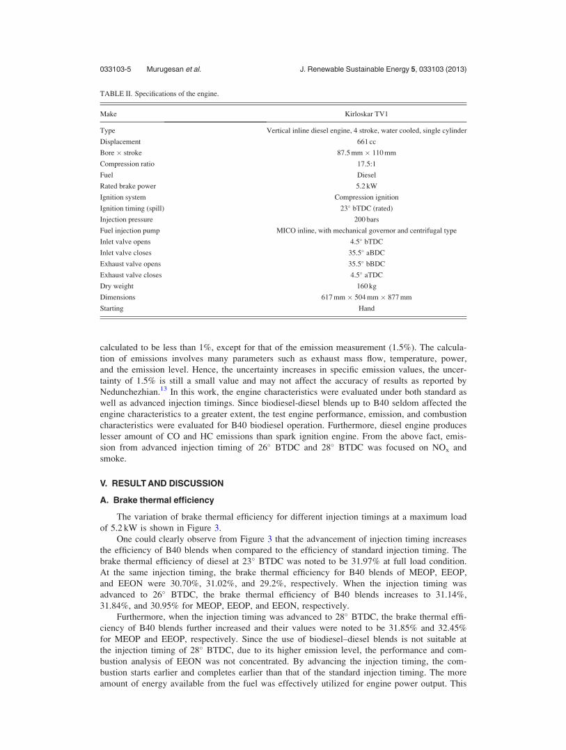
A. Brake thermal efficiency
The variation of brake thermal efficiency for different injection timings at a maximum load
of 5.2 kW is shown in Figure 3.
One could clearly observe from Figure 3 that the advancement of injection timing increases
the efficiency of B40 blends when compared to the efficiency of standard injection timing. The
brake thermal efficiency of diesel at 23� BTDC was noted to be 31.97% at full load condition.
At the same injection timing, the brake thermal efficiency for B40 blends of MEOP, EEOP,
and EEON were 30.70%, 31.02%, and 29.2%, respectively. When the injection timing was
advanced to 26� BTDC, the brake thermal efficiency of B40 blends increases to 31.14%,
31.84%, and 30.95% for MEOP, EEOP, and EEON, respectively.
Furthermore, when the injection timing was advanced to 28� BTDC, the brake thermal effi-
ciency of B40 blends further increased and their values were noted to be 31.85% and 32.45%
for MEOP and EEOP, respectively. Since the use of biodiesel–diesel blends is not suitable at
the injection timing of 28� BTDC, due to its higher emission level, the performance and com-
bustion analysis of EEON was not concentrated. By advancing the injection timing, the com-
bustion starts earlier and completes earlier than that of the standard injection timing. The more
amount of energy available from the fuel was effectively utilized for engine power output. This
TABLE II. Specifications of the engine.
Make Kirloskar TV1
Type Vertical inline diesel engine, 4 stroke, water cooled, single cylinder
Displacement 661 cc
Bore � stroke 87.5 mm � 110 mm
Compression ratio 17.5:1
Fuel Diesel
Rated brake power 5.2 kW
Ignition system Compression ignition
Ignition timing (spill) 23� bTDC (rated)
Injection pressure 200 bars
Fuel injection pump MICO inline, with mechanical governor and centrifugal type
Inlet valve opens 4.5� bTDC
Inlet valve closes 35.5� aBDC
Exhaust valve opens 35.5� bBDC
Exhaust valve closes 4.5� aTDC
Dry weight 160 kg
Dimensions 617 mm � 504 mm � 877 mm
Starting Hand
033103-5 Murugesan et al. J. Renewable Sustainable Energy 5, 033103 (2013)
is the reason for the improved thermal efficiency of the engine. This result agreed with the ear-
lier studies reported by Narayana Reddy and Ramesh.10
The experimental results clearly proved that the brake thermal efficiency increases when
injection timing is advanced. This is due to earlier start of the combustion, which compensates
the effect of slow burning. The combustion of B40 blends was slow because of its higher vis-
cosity compared to diesel, which lead to poor spray characteristics and mixture formation with
air. This snag was compensated by advancing the injection time to get better efficiency. The
similar results were observed by Nwafor et al.14
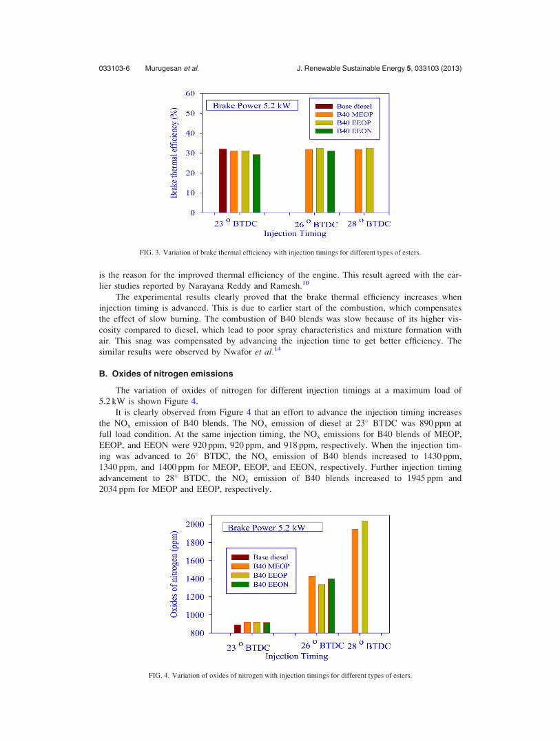
B. Oxides of nitrogen emissions
The variation of oxides of nitrogen for different injection timings at a maximum load of
5.2 kW is shown Figure 4.
It is clearly observed from Figure 4 that an effort to advance the injection timing increases
the NOx emission of B40 blends. The NOx emission of diesel at 23� BTDC was 890 ppm at
full load condition. At the same injection timing, the NOx emissions for B40 blends of MEOP,
EEOP, and EEON were 920 ppm, 920 ppm, and 918 ppm, respectively. When the injection tim-
ing was advanced to 26� BTDC, the NOx emission of B40 blends increased to 1430 ppm,
1340 ppm, and 1400 ppm for MEOP, EEOP, and EEON, respectively. Further injection timing
advancement to 28� BTDC, the NOx emission of B40 blends increased to 1945 ppm and
2034 ppm for MEOP and EEOP, respectively.
FIG. 3. Variation of brake thermal efficiency with injection timings for different types of esters.
FIG. 4. Variation of oxides of nitrogen with injection timings for different types of esters.
033103-6 Murugesan et al. J. Renewable Sustainable Energy 5, 033103 (2013)
The experimental results clearly proved that when the injection timing was advanced, an
increase in the NOx emissions for all the fuel mixture was observed. This is due to earlier start
of combustion, so the residual time of the burning mixture in the cylinder and combustion tem-
perature is increased. This allows the NOx formation reaction to proceed. This reason was
agreed with the previous researchers like Pradeep and Sharma15 and Sayin et al.16
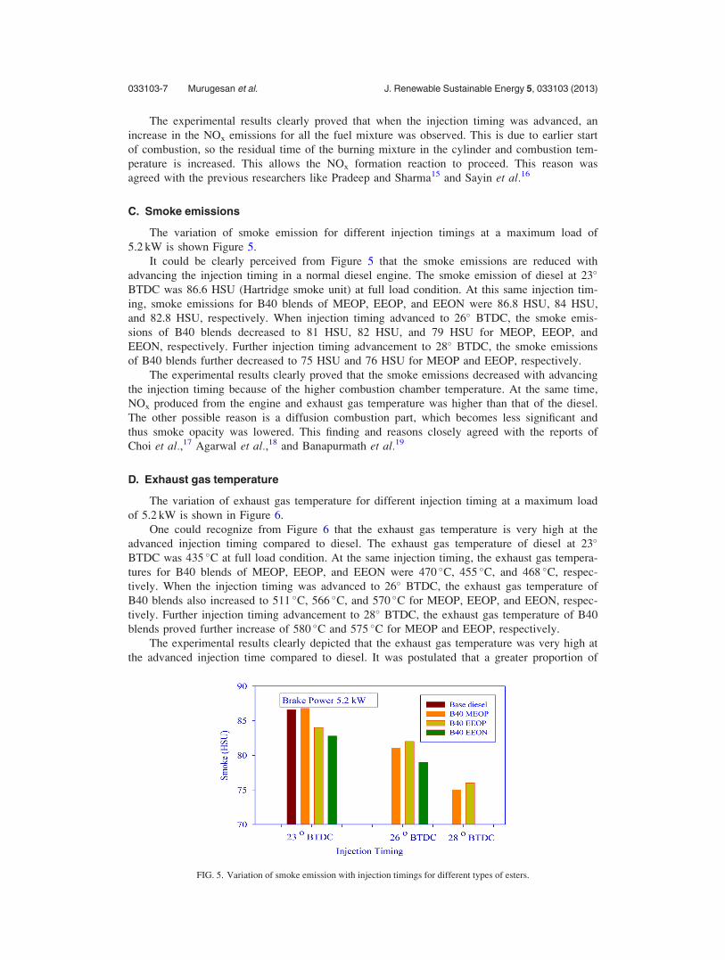
C. Smoke emissions
The variation of smoke emission for different injection timings at a maximum load of
5.2 kW is shown Figure 5.
It could be clearly perceived from Figure 5 that the smoke emissions are reduced with
advancing the injection timing in a normal diesel engine. The smoke emission of diesel at 23�
BTDC was 86.6 HSU (Hartridge smoke unit) at full load condition. At this same injection tim-
ing, smoke emissions for B40 blends of MEOP, EEOP, and EEON were 86.8 HSU, 84 HSU,
and 82.8 HSU, respectively. When injection timing advanced to 26� BTDC, the smoke emis-
sions of B40 blends decreased to 81 HSU, 82 HSU, and 79 HSU for MEOP, EEOP, and
EEON, respectively. Further injection timing advancement to 28� BTDC, the smoke emissions
of B40 blends further decreased to 75 HSU and 76 HSU for MEOP and EEOP, respectively.
The experimental results clearly proved that the smoke emissions decreased with advancing
the injection timing because of the higher combustion chamber temperature. At the same time,
NOx produced from the engine and exhaust gas temperature was higher than that of the diesel.
The other possible reason is a diffusion combustion part, which becomes less significant and
thus smoke opacity was lowered. This finding and reasons closely agreed with the reports of
Choi et al.,17 Agarwal et al.,18 and Banapurmath et al.19
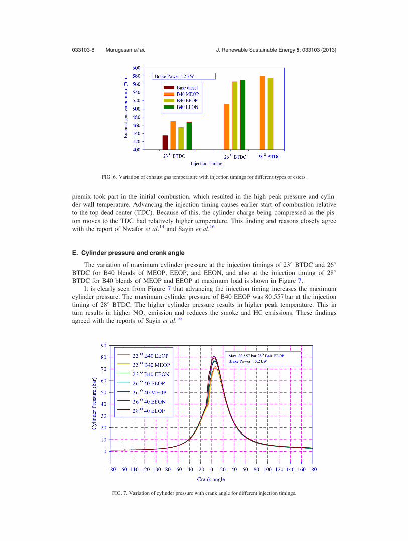
D. Exhaust gas temperature
The variation of exhaust gas temperature for different injection timing at a maximum load
of 5.2 kW is shown in Figure 6.
One could recognize from Figure 6 that the exhaust gas temperature is very high at the
advanced injection timing compared to diesel. The exhaust gas temperature of diesel at 23�
BTDC was 435 �C at full load condition. At the same injection timing, the exhaust gas tempera-
tures for B40 blends of MEOP, EEOP, and EEON were 470 �C, 455 �C, and 468 �C, respec-
tively. When the injection timing was advanced to 26� BTDC, the exhaust gas temperature of
B40 blends also increased to 511 �C, 566 �C, and 570 �C for MEOP, EEOP, and EEON, respec-
tively. Further injection timing advancement to 28� BTDC, the exhaust gas temperature of B40
blends proved further increase of 580 �C and 575 �C for MEOP and EEOP, respectively.
The experimental results clearly depicted that the exhaust gas temperature was very high at
the advanced injection time compared to diesel. It was postulated that a greater proportion of
FIG. 5. Variation of smoke emission with injection timings for different types of esters.
033103-7 Murugesan et al. J. Renewable Sustainable Energy 5, 033103 (2013)
premix took part in the initial combustion, which resulted in the high peak pressure and cylin-
der wall temperature. Advancing the injection timing causes earlier start of combustion relative
to the top dead center (TDC). Because of this, the cylinder charge being compressed as the pis-
ton moves to the TDC had relatively higher temperature. This finding and reasons closely agree
with the report of Nwafor et al.14 and Sayin et al.16
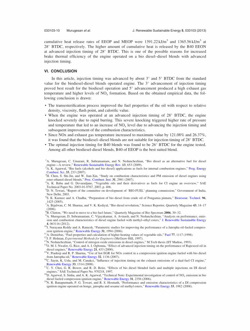
E. Cylinder pressure and crank angle
The variation of maximum cylinder pressure at the injection timings of 23� BTDC and 26�
BTDC for B40 blends of MEOP, EEOP, and EEON, and also at the injection timing of 28�
BTDC for B40 blends of MEOP and EEOP at maximum load is shown in Figure 7.
It is clearly seen from Figure 7 that advancing the injection timing increases the maximum
cylinder pressure. The maximum cylinder pressure of B40 EEOP was 80.557 bar at the injection
timing of 28� BTDC. The higher cylinder pressure results in higher peak temperature. This in
turn results in higher NOx emission and reduces the smoke and HC emissions. These findings
agreed with the reports of Sayin et al.16
FIG. 6. Variation of exhaust gas temperature with injection timings for different types of esters.
FIG. 7. Variation of cylinder pressure with crank angle for different injection timings.
033103-8 Murugesan et al. J. Renewable Sustainable Energy 5, 033103 (2013)

F. Heat release analysis
The variation of heat release rate with crank angle at the injection timings of 23� BTDC
and 26� BTDC for B40 blends of MEOP, EEOP, and EEON and at the injection timing of 28�
BTDC for B40 blends of MEOP and EEOP at maximum load is shown in Figure 8.
It is clearly seen from Figure 8 that when advancing the injection timing, the heat release
rate increases. The maximum heat release for B40 EEOP is 92.84 kJ/m3 degree at the injection
timing of 28� BTDC.
G. Cumulative heat release rate
Figure 9 shows the variation of the cumulative heat release rate with crank angle at the
injection timings of 23� BTDC and 26� BTDC for B40 blends of MEOP, EEOP, and EEON
and also at the injection timing of 28� BTDC for B40 blends of MEOP and EEOP at maximum
load. It is clearly seen from Figure 9 that the maximum cumulative heat release in premixed
combustion of B40 EEON is 1400.04 kJ/m3 at an injection timing of 26� BTDC. The
FIG. 8. Variation of heat release rate with crank angle for different injection timings.
FIG. 9. Variation of cumulative heat release rate with crank angle for different injection timings.
033103-9 Murugesan et al. J. Renewable Sustainable Energy 5, 033103 (2013)
cumulative heat release rates of EEOP and MEOP were 1391.22 kJ/m3 and 1365.56 kJ/m3 at
28� BTDC, respectively. The higher amount of cumulative heat is released by the B40 EEON
at advanced injection timing of 28� BTDC. This is one of the possible reasons for increased
brake thermal efficiency of the engine operated on a bio diesel–diesel blends with advanced
injection timing.
VI. CONCLUSION
In this article, injection timing was advanced by about 3� and 5� BTDC from the standard
value for the biodiesel-diesel blends operated engine. The 3� advancement of injection timing
proved best result for the biodiesel operation and 5� advancement produced a high exhaust gas
temperature and higher levels of NOx formation. Based on the obtained empirical data, the fol-
lowing conclusion is drawn:
• The transesterification process improved the fuel properties of the oil with respect to relative
density, viscosity, flash point, and calorific value.• When the engine was operated at an advanced injection timing of 28� BTDC, the engine
knocked severely due to rapid burring. This severe knocking triggered higher rate of pressure
and temperature that led to an increase of NOx level due to advancing the injection timing and
subsequent improvement of the combustion characteristics.• Since NOx and exhaust gas temperature increased to maximum value by 121.08% and 26.37%,
it was found that the biodiesel–diesel blends are not suitable for injection timing of 28� BTDC.• The optimal injection timing for B40 blends was found to be 26� BTDC for the engine tested.
Among all other biodiesel-diesel blends, B40 of EEOP is the best suited blend.
1A. Murugesan, C. Umarani, R. Subramaniam, and N. Nedunchezhian, “Bio diesel as an alternative fuel for dieselengine—A review,” Renewable Sustainable Energy Rev. 13, 653 (2009).
2A. K. Agarwal, “Bio fuels (alcohols and bio diesel) applications as fuels for internal combustion engines,” Prog. EnergyCombust. Sci. 33, 233 (2007).
3H. Chen, S. Shi-Jin, and W. Jian-Xin, “Study on combustion characteristics and PM emission of diesel engines usingester-ethanol-diesel blends,” Proc. Combust. Inst. 31, 2981 (2007).
4A. K. Babu and G. Devaradjane, “Vegetable oils and their derivatives as fuels for CI engine an overview,” SAETechnical Paper No. 2003-01-0767, 2003, p. 406.
5D. N. Tewari, “Report of the committee on development of ‘BIO-FUEL’ planning commission,” Government of India,New Delhi, 2003.
6S. K. Karmee and A. Chadha, “Preparation of bio diesel from crude oil of Pongamia pinnata,” Bioresour. Technol. 96,1425 (2005).
7A. Bijalwan, C. M. Sharma, and V. K. Kediyal, “Bio diesel revolution,” Science Reporter, Quarterly Magazine 43, 14–17(2006).
8B. Clinton, “We need to move to a bio fuel future,” Quarterly Magazine of Bio Spectrum 2006, 30–32.9A. Murugesan, D. Subramaniam, C. Vijayakumar, A. Avinash, and N. Nedunchezhian, “Analysis on performance, emis-sion and combustion characteristics of diesel engine fueled with methyl–ethyl esters,” J. Renewable Sustainable Energy4, 063116 (2012).
10J. Narayana Reddy and A. Ramesh, “Parametric studies for improving the performance of a Jatropha oil-fueled compres-sion ignition engine,” Renewable Energy 31, 1994 (2006).
11A. Demirbas, “Fuel properties and calculation of higher heating values of vegetable oils,” Fuel 77, 1117 (1998).12J. P. Holman, Experimental Methods for Engineers (McGraw-Hill, 1997).13N. Nedunchezhian, “Control of nitrogen oxide emissions in diesel engines,” M.Tech thesis (IIT Madras, 1993).14O. M. I. Nwafor, G. Rice, and A. I. Ogbonna, “Effect of advanced injection timing on the performance of Rapeseed oil in
diesel engines,” Renewable Energy 21, 433 (2000).15V. Pradeep and R. P. Sharma, “Use of hot EGR for NOx control in a compression ignition engine fueled with bio diesel
from Jatropha oil,” Renewable Energy 32, 1136 (2007).16C. Sayin, K. Uslu, and M. Canakci, “Influence of injection timing on the exhaust emissions of a dual-fuel CI engine,”
Renewable Energy 33, 1314 (2008).17C. Y. Choi, G. R. Bower, and R. D. Reitz, “Effects of bio diesel blended fuels and multiple injections on DI diesel
engines,” SAE Technical Paper No. 970218, 1997.18D. Agarwal, S. Sinha, and A. K. Agarwal, “Technical Note: Experimental investigation of control of NOx emission in bio
diesel fueled compression ignition engine,” Renewable Energy 31, 2356 (2006).19N. R. Banapurmath, P. G. Tewari, and R. S. Hosmath, “Performance and emission characteristics of a DI compression
ignition engine operated on honge, jatropha and sesame oil methyl esters,” Renewable Energy 33, 1982 (2008).
033103-10 Murugesan et al. J. Renewable Sustainable Energy 5, 033103 (2013)