
A Comparative Evaluation of Industrial Design Models Produced Using Rapid Prototyping and...
11
Rapid Prototyping Journal 2003 A Comparative Evaluation of Industrial Design Models Produced Using Rapid Prototyping and Workshop-Based Fabrication Techniques Dr Mark A Evans* and Dr R Ian Campbell Department of Design and Technology, Loughborough University, UK *International Scholar, Department of Mechanical Engineering, Massachusetts Institute of Technology, USA ABSTRACT As a profession with a distinct remit to define the exterior form of manufactured products, industrial designers make extensive us of physical models. Whilst the use of rapid prototyping during new product development is now well documented, no direct comparison between the use of conventional fabrication techniques and rapid prototyping for the production of appearance models has been published. This paper discusses a research programme in which the 3D computer aided industrial design (CAID) geometry for a consumer product was translated into appearance models using the contrasting techniques of workshop-based fabrication techniques and rapid prototyping using stereolithography. The research also examined the capacity to extend the use of the rapid prototype components for the production of a fully working prototype. The ability to combine an appearance model and a working prototype into a single "appearance prototype" was a significant advance in the application of RP within industrial design. Introduction Despite the advent of virtual systems such as rendered animation and stereoscopic viewing for the visualisation and evaluation of product design proposals, the use of physical appearance models remains an essential part of industrial design practice. Its significance is noted by Powell who states “it is through the model, of course, that an idea reaches three dimensions for the first time, and both designer and client can truly assess the design. A rendering can never be a substitute for a model and it is a fool who goes straight into tooling without investing in a model (many have done it and learnt the hard way!)” (Powell, 1990). In addition to the acknowledged need to produce physical representations of a design proposal, manufacturers face increasing pressure to reduce time to market. In support of this business objective, the use of rapid prototyping during new product development has reached record levels, including instances of use for the production of appearance models that define product form only (Rapid News, 1999; C3, 1999; C3, 2000). To identify the contribution of rapid prototyping in the production of appearance models, this research project was undertaken to provide evidence of its merits and shortcomings through comparative evaluation. This was achieved through the production of two identical appearance models: one using workshop-based fabrication techniques, the other using stereolithography. On completion of the two appearance models, the potential for rapid prototyping to contribute to the production of a fully functional appearance prototype became apparent, and further research was undertaken to evaluate this capability. Research Methodology Case studies have been described as an approach to research as opposed to a research method (Moore, 1983), with a capability, “to describe and understand the phenomenon ‘in depth’ and ‘in the round’ (completeness). In this role, case studies serve a useful purpose, since many important issues can be overlooked in a more superficial survey.” (Birley, 1998) In addition, the way in which data are collected and analysed “implies the collection of unstructured data, and qualitative analysis of those data.” (Gomm, 2000) The principle of an in
Transcript of A Comparative Evaluation of Industrial Design Models Produced Using Rapid Prototyping and...
Rapid Prototyping Journal 2003
A Comparative Evaluation of Industrial Design Models Produced Using Rapid Prototyping and Workshop-Based Fabrication Techniques Dr Mark A Evans* and Dr R Ian Campbell Department of Design and Technology, Loughborough University, UK *International Scholar, Department of Mechanical Engineering, Massachusetts Institute of Technology, USA ABSTRACT As a profession with a distinct remit to define the exterior form of manufactured products, industrial designers make extensive us of physical models. Whilst the use of rapid prototyping during new product development is now well documented, no direct comparison between the use of conventional fabrication techniques and rapid prototyping for the production of appearance models has been published. This paper discusses a research programme in which the 3D computer aided industrial design (CAID) geometry for a consumer product was translated into appearance models using the contrasting techniques of workshop-based fabrication techniques and rapid prototyping using stereolithography. The research also examined the capacity to extend the use of the rapid prototype components for the production of a fully working prototype. The ability to combine an appearance model and a working prototype into a single "appearance prototype" was a significant advance in the application of RP within industrial design. Introduction Despite the advent of virtual systems such as rendered animation and stereoscopic viewing for the visualisation and evaluation of product design proposals, the use of physical appearance models remains an essential part of industrial design practice. Its significance is noted by Powell who states “it is through the model, of course, that an idea reaches three dimensions for the first time, and both designer and client can truly assess the design. A rendering can never be a substitute for a model and it is a fool who goes straight into tooling without investing in a model (many have done it and learnt the hard way!)” (Powell, 1990). In addition to the acknowledged need to produce physical representations of a design proposal, manufacturers face increasing pressure to reduce time to market. In support of this business objective, the use of rapid prototyping during new product development has reached record levels, including instances of use for the production of appearance models that define product form only (Rapid News, 1999; C3, 1999; C3, 2000). To identify the contribution of rapid prototyping in the production of appearance models, this research project was undertaken to provide evidence of its merits and shortcomings through comparative evaluation. This was achieved through the production of two identical appearance models: one using workshop-based fabrication techniques, the other using stereolithography. On completion of the two appearance models, the potential for rapid prototyping to contribute to the production of a fully functional appearance prototype became apparent, and further research was undertaken to evaluate this capability. Research Methodology Case studies have been described as an approach to research as opposed to a research method (Moore, 1983), with a capability, “to describe and understand the phenomenon ‘in depth’ and ‘in the round’ (completeness). In this role, case studies serve a useful purpose, since many important issues can be overlooked in a more superficial survey.” (Birley, 1998) In addition, the way in which data are collected and analysed “implies the collection of unstructured data, and qualitative analysis of those data.” (Gomm, 2000) The principle of an in
depth investigation into the integration of rapid prototyping within industrial design practice through the use of case study methods forms the core of this study. In focusing on specific methods applied as part of case study research, Moore (op cit), Gomm (op cit) and Cohen and Manion (1980) identify action research as a valid approach. Action research has been defined as:
"an on-the-spot procedure designed to deal with a concrete problem located in an immediate situation. This means that the step-by-step process is constantly monitored (ideally, that is) over varying periods of time and by a variety of mechanisms (questionnaires, diaries, interviews and case studies, for example) so that the ensuing feedback may be translated into modifications, adjustments, directional changes, redefinitions, as necessary, so as to bring about lasting benefit to the ongoing process itself" (Cohen and Manion, 1980).
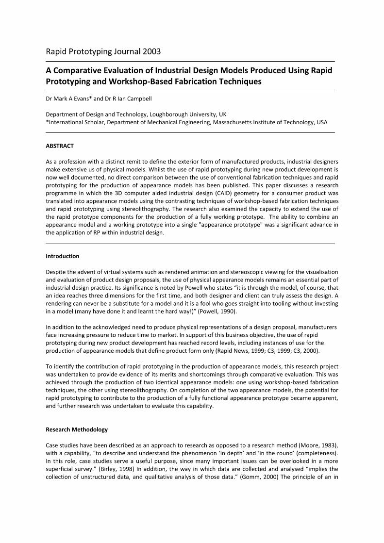
The cyclical nature of action research has been identified by Birley, who sees it as being conducted by a professional within their own activity, the aim of which is to bring about an improvement in practice. (Birley, 1998) Action research was therefore considered particularly appropriate in meeting the objectives of this project, as it represented a recognised method for the facilitation of improvements in the execution and understanding of industrial design practice. Product Design and CAD Modelling Most current designs of hand-held garden trimmers make use of a rotating nylon wire driven by an electric motor in the head of the tool. However, positioning of the motor in the head produces an unbalanced product that is tiring to hold for long periods. Following a period of concept generation and design development using sketching and simple mock-ups, a design proposal for an innovative garden trimmer was modelled using the DeskArtes CAID system. The new design comprised a motor near the handle of the trimmer connected to the rotating nylon wire in the head of the tool by a flexible coupling. It was envisaged that this configuration would created a much more balanced product. The generation of this 3D geometry then enabled the production of the two forms of output required for the construction of the workshop-based and stereolithography appearance models i.e. a printed general arrangement drawing for use in the workshop and an STL file for rapid prototyping. A rendered view of the geometry from which these were produced can be seen in Figure 1.
Figure 1: Rendered view of CAD geometry
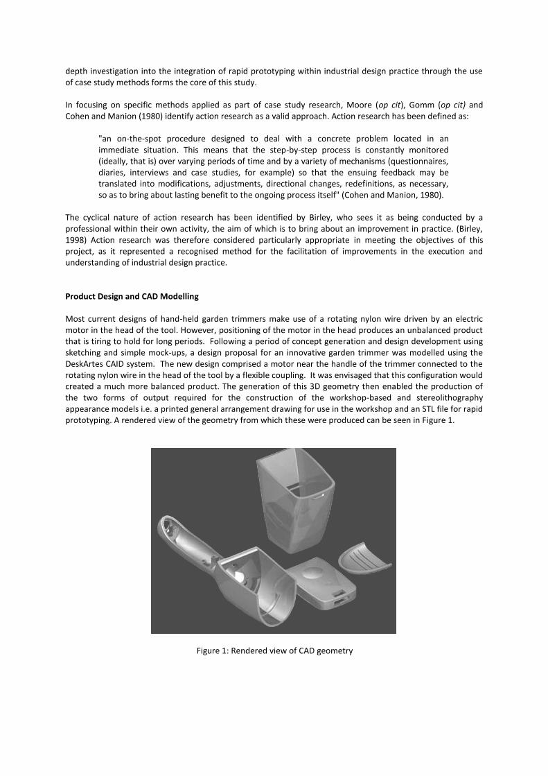
Production of Workshop-Based Appearance Model Production of components The majority of the components were made by shaping medium density fibreboard (MDF) blocks and urethane modelling material by hand using standard workshop equipment such as band saws, sanding discs, and various hand-tools. Other techniques included milling, turning, and vacuum forming. An example of how the fabricated elements came together to produce a single component can be seen in the photograph of the unpainted cutter guard assembly in Figure 2.
Figure 2: Unpainted cutter guard assembly for the fabricated appearance model The cutter guard for the conventional appearance model was vacuum formed from sheet material. This resulted in negligible deformation of the concave underside and therefore minimal preparation prior to painting. This was in sharp contrast to the extensive effort that was later required to restore the shape of the same component produced using SLA. In addition, the concave dimples on the cutter guard release were produced by milling a urethane modelling material, which left a smooth surface finish. Finishing All MDF components were sealed with a cellulose shellac to prevent distortion due to the absorbtion of moisture and provide a sealed surface for the application of paint. These were then primed with an aerosol-based filler primer. The surface finish on plastic components was smooth enough to use a less viscous grey primer. After lightly rubbing-down surfaces with fine wet and dry paper, any blemishes were filled with cellulose knifing putty. Once dry, this was sanded down and the component sprayed with a coat of grey primer. Blemishes still present were removed by repeating this process. When all surfaces were paint primed to a satisfactory level, a colour coat was applied. Once dry, this was rubbed down with fine wet and dry paper. A second coat was applied to complete the painting of the components. The finishing of all components to a high level of surface definition took six hours. Assembly The techniques employed in the production of components for the conventional appearance model included features to assist in the construction of the model. This meant that following paint finishing the assembly of
the model was relatively straightforward, involving the bonding of components with either epoxy or cyanoacrylate adhesives. Component assembly took four hours. Time-scales The time-scales required for the production of the conventional appearance model were as follows:
Manual component build by - 37 hours
Painting- 6 hours
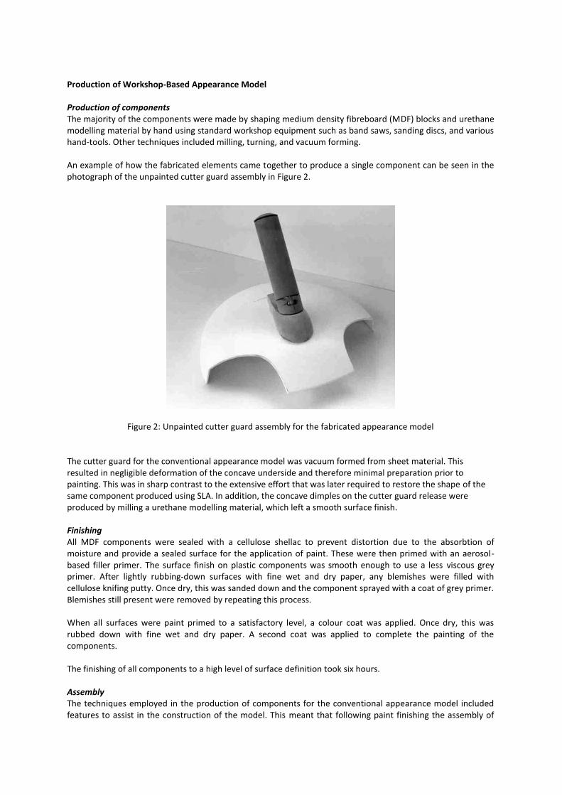
Assembly – 4 hours The total production time for the manual appearance model was forty seven hours. Production of Stereolithography Appearance Model SLA component build SLA components were produced in accuDur100 using a 3D systems SLA 5000 machine. The components took 10 hours to produce at a build thickness of 0.1mm. The commercial cost for the components was £1500. On completion of the build, support structures and excess resin were removed and components cured for one hour. After delivery it was necessary to remove stepping on exterior (visual) surfaces as this would not be present on production components. A smooth finish was achieved using wet and dry paper, taking care not to distort the surfaces as specified in the CAID geometry. This operation required an additional two and a half hours of workshop time. Finishing As with an appearance model produced using workshop-based fabrication techniques, the SLA appearance model was required to have a quality of surface finish that matched that of a production item. Not surprisingly, it required considerably more time to achieve a smooth surface on the concave surfaces of the SLA components than on those that were convex. In fact, the large concave surface of the cutter guard proved particularly difficult to finish to a satisfactory level, requiring the application of a spray-based filler primer followed by light sanding. The complete removal of the stepping required this operation to be repeated five times (see Figure 3).
Figure 3: Application of filler primer to remove stepping
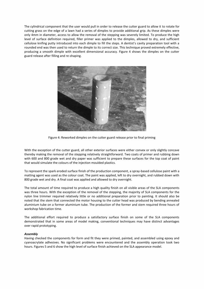
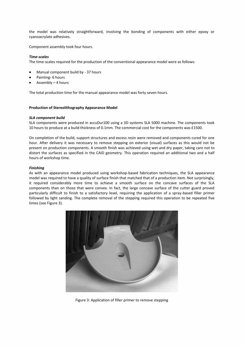
The cylindrical component that the user would pull in order to release the cutter guard to allow it to rotate for cutting grass on the edge of a lawn had a series of dimples to provide additional grip. As these dimples were only 4mm in diameter, access to allow the removal of the stepping was severely limited. To produce the high level of surface definition required, filler primer was applied to the dimples, allowed to dry, and sufficient cellulose knifing putty introduced into each dimple to fill the steps. A dentist’s cavity preparation tool with a rounded end was then used to return the dimple to its correct size. This technique proved extremely effective, producing a smooth dimple with excellent dimensional accuracy. Figure 4 shows the dimples on the cutter guard release after filling and re-shaping.
Figure 4: Reworked dimples on the cutter guard release prior to final priming With the exception of the cutter guard, all other exterior surfaces were either convex or only slightly concave thereby making the removal of the stepping relatively straightforward. Two coats of primer and rubbing down with 600 and 800 grade wet and dry paper was sufficient to prepare these surfaces for the top coat of paint that would simulate the colours of the injection moulded plastics. To represent the spark eroded surface finish of the production component, a spray-based cellulose paint with a matting agent was used as the colour coat. The paint was applied, left to dry overnight, and rubbed down with 800 grade wet and dry. A final coat was applied and allowed to dry overnight. The total amount of time required to produce a high quality finish on all visible areas of the SLA components was three hours. With the exception of the removal of the stepping, the majority of SLA components for the nylon line trimmer required relatively little or no additional preparation prior to painting. It should also be noted that the stem that connected the motor housing to the cutter head was produced by bending annealed aluminium tube on a former aluminium tube. The production of the former and stem required three hours of workshop fabrication time. The additional effort required to produce a satisfactory surface finish on some of the SLA components demonstrated that in some areas of model making, conventional techniques may have distinct advantages over rapid prototyping. Assembly Having checked the components for form and fit they were primed, painted, and assembled using epoxy and cyanoacrylate adhesives. No significant problems were encountered and the assembly operation took two hours. Figures 5 and 6 show the high level of surface finish achieved on the SLA appearance model.
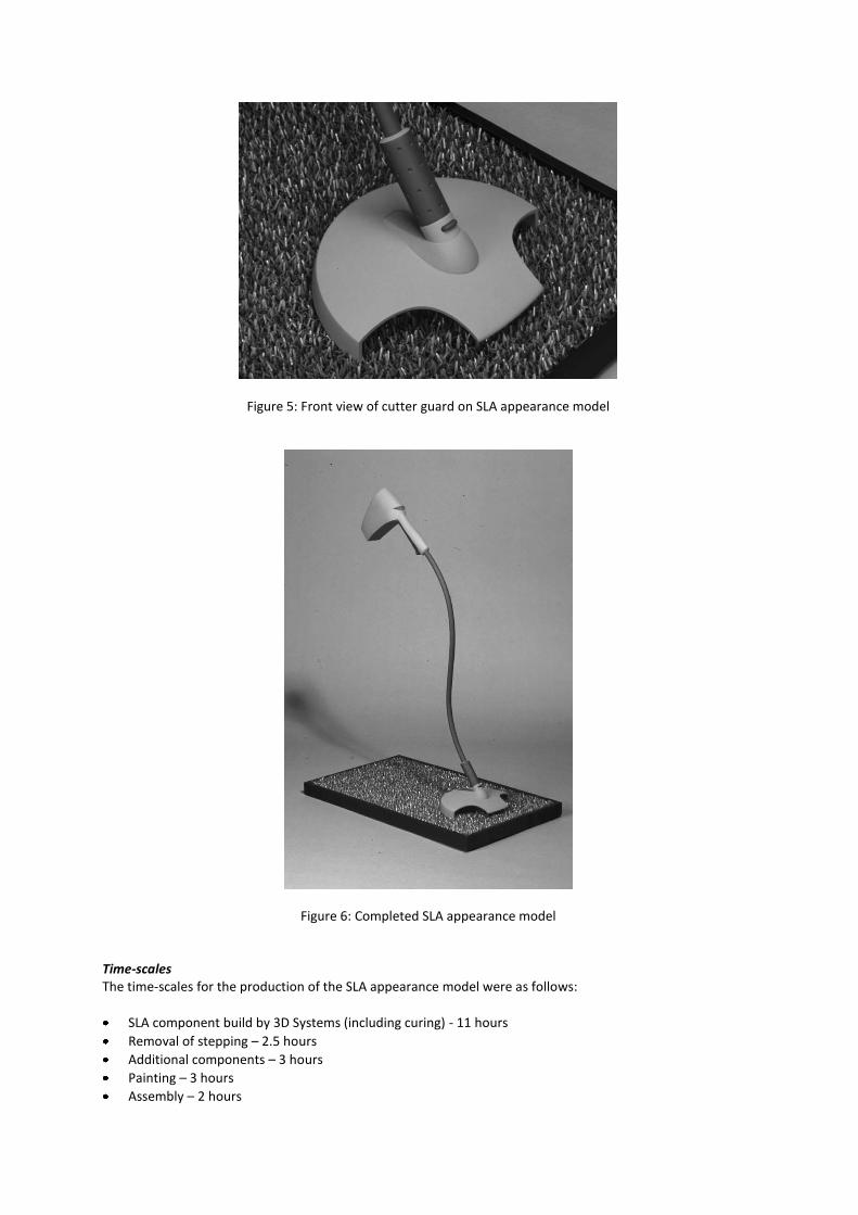
Figure 5: Front view of cutter guard on SLA appearance model
Figure 6: Completed SLA appearance model
Time-scales The time-scales for the production of the SLA appearance model were as follows:
SLA component build by 3D Systems (including curing) - 11 hours
Removal of stepping – 2.5 hours
Additional components – 3 hours
Painting – 3 hours
Assembly – 2 hours
The total production time for the SLA appearance model was twenty-one hours and thirty minutes. Decision to Produce SLA Appearance Prototype The distinction between appearance models and appearance prototypes is that the latter integrate both form and functionality. As such, appearance prototypes are significantly more complicated, requiring the inclusion of internal cavities and components. Kochan notes that appearance prototypes constructed using conventional workshop techniques can take considerable time and effort to produce due to the complexity of fabricating high definition exterior surfaces with internal cavities. (Kochan, 1993) The cost and time involved in the production of appearance prototypes generally excludes their use to the latter phases of new product development. Indeed it is only then that the design has evolved to a sufficient level of detail to make the production of appearance prototypes possible. When using fabrication techniques, the requirement to make the appearance prototype an exact visual representation of the production item can cause problems, as bonded material rarely has the strength of production processes such as injection moulding. It can therefore be necessary to supplement adhesives with mechanical joining that must be disguised by techniques such as countersinking and then filling. A significant feature of rapid prototyping is that an increase in component complexity does not attract a corresponding increase in production cost, making it viable to produce components with a wall thickness and other features similar to production components. This is in contrast with workshop-based fabrication techniques that typically involve the time consuming operations of vacuum forming and fabrication to produce components with internal cavities. It is also possible to employ vacuum casting to provide additional strength. Rapid prototyping has the capacity to reduce both the costs and time scales involved in the production of components with internal cavities. Extending the functionality of an appearance model to that of an appearance prototype requires the inclusion of production parts such as motors, batteries and circuit boards. As a relatively complicated electro-mechanical product, the nylon line trimmer represented a significant challenge for the production of appearance prototype when compared to an appearance model. SLA Component production A second set of nylon line trimmer components were produced using stereoliothography. These were similar to those used for the appearance model, except that they had to accommodate electro-mechanical components. They required ten hours of build time plus an additional hour to cure. Two and a half hours were required for the removal of the stepping. Pre-assembly of electro-mechanical components Prior to paint finishing, the motor and drive system were positioned within the rapid prototype components and tested. As the electro-mechanical components (motor, battery, flexible drive and bearings) had been modelled on the CAID system and used as templates for the 3D computer modelling, no problems of fit were encountered. The only problem that arose from the pre-assembly was that the rear of the motor housing had distorted due to the unsupported wall being exposed to excessive heat whilst stored in an office. This was easily corrected by using a hairdryer to re-heat the affected area and applying slight pressure to correct the distortion. To ensure that the original shape was achieved, the air intake that attaches to this area was used as a template. Paint finishing of the SLA components for the appearance prototype was identical to that of the appearance model (three hours), although an additional hour was required to fill and paint two countersunk holes used to attach the drive mechanism onto the cutter guard. Assembly The electro-mechanical components were either bonded (using epoxy adhesive) or mechanically attached to the SLA components. The only problem encountered was due to an excessive build-up of paint around the hole
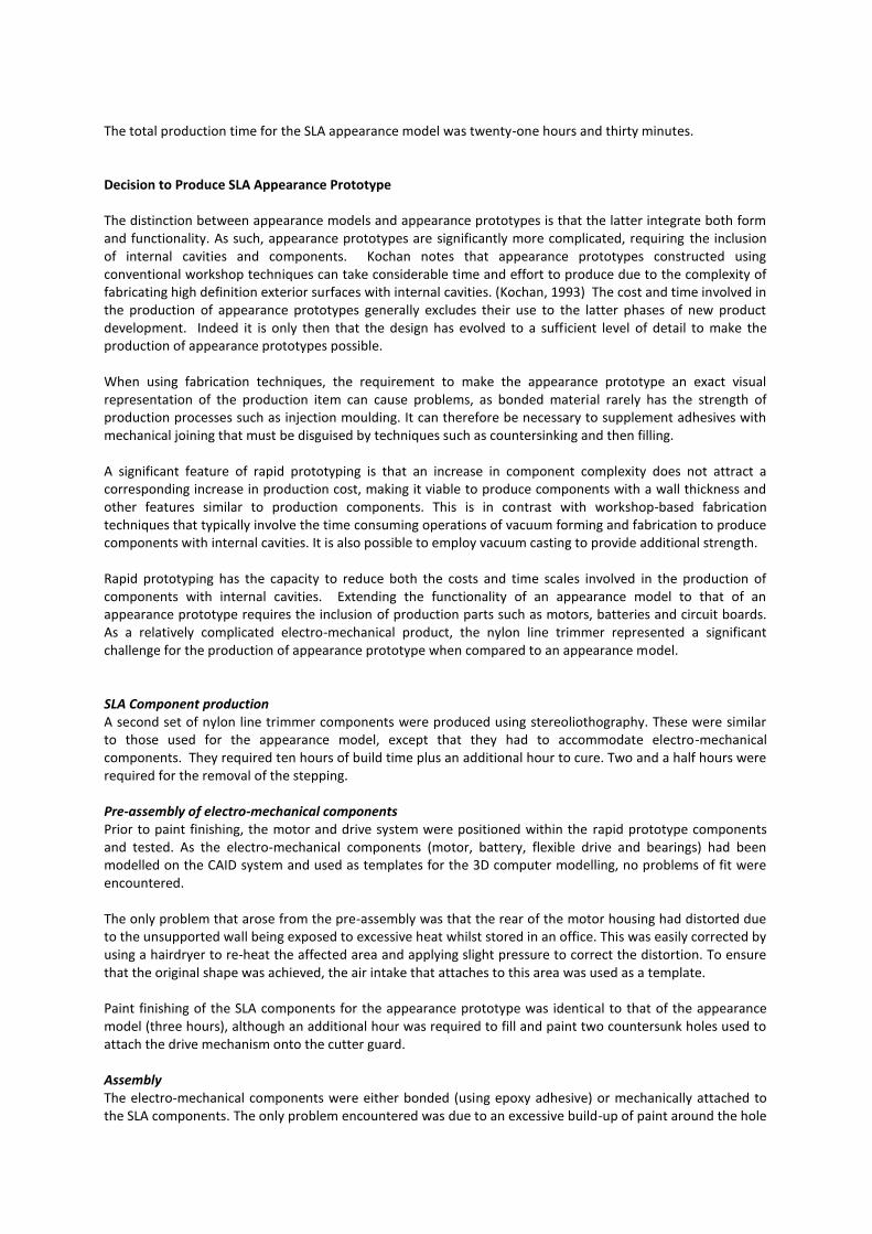
through which the aluminium stem was attached to the motor housing. This was corrected by lightly sanding with wet and dry paper. The angle at which the flexible drive entered the cutter guard was too severe to allow the cable to be bent and directly inserted into the spool housing. To allow such a dramatic change in the orientation of the drive system, a universal coupling was mounted on the spool housing. This universal coupling was retained by a Delrin bearing surface bolted onto a mounting plate (see Figure 7)
Figure 7: Universal coupling retained by mounting plate and Delrin bearing surface
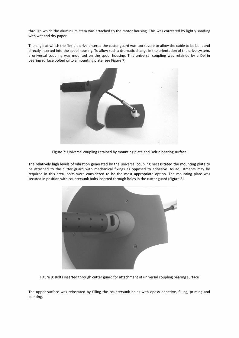
The relatively high levels of vibration generated by the universal coupling necessitated the mounting plate to be attached to the cutter guard with mechanical fixings as opposed to adhesive. As adjustments may be required in this area, bolts were considered to be the most appropriate option. The mounting plate was secured in position with countersunk bolts inserted through holes in the cutter guard (Figure 8).
Figure 8: Bolts inserted through cutter guard for attachment of universal coupling bearing surface The upper surface was reinstated by filling the countersunk holes with epoxy adhesive, filling, priming and painting.
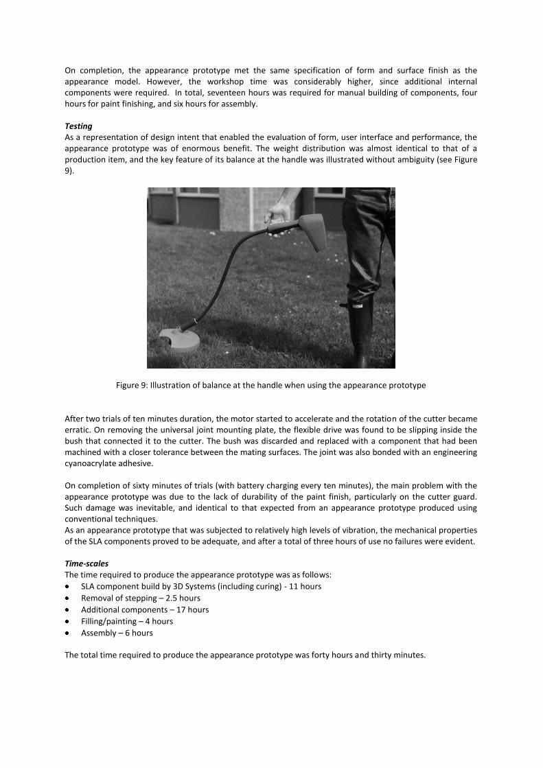
On completion, the appearance prototype met the same specification of form and surface finish as the appearance model. However, the workshop time was considerably higher, since additional internal components were required. In total, seventeen hours was required for manual building of components, four hours for paint finishing, and six hours for assembly. Testing As a representation of design intent that enabled the evaluation of form, user interface and performance, the appearance prototype was of enormous benefit. The weight distribution was almost identical to that of a production item, and the key feature of its balance at the handle was illustrated without ambiguity (see Figure 9).
Figure 9: Illustration of balance at the handle when using the appearance prototype
After two trials of ten minutes duration, the motor started to accelerate and the rotation of the cutter became erratic. On removing the universal joint mounting plate, the flexible drive was found to be slipping inside the bush that connected it to the cutter. The bush was discarded and replaced with a component that had been machined with a closer tolerance between the mating surfaces. The joint was also bonded with an engineering cyanoacrylate adhesive. On completion of sixty minutes of trials (with battery charging every ten minutes), the main problem with the appearance prototype was due to the lack of durability of the paint finish, particularly on the cutter guard. Such damage was inevitable, and identical to that expected from an appearance prototype produced using conventional techniques. As an appearance prototype that was subjected to relatively high levels of vibration, the mechanical properties of the SLA components proved to be adequate, and after a total of three hours of use no failures were evident. Time-scales The time required to produce the appearance prototype was as follows:
SLA component build by 3D Systems (including curing) - 11 hours
Removal of stepping – 2.5 hours
Additional components – 17 hours
Filling/painting – 4 hours
Assembly – 6 hours
The total time required to produce the appearance prototype was forty hours and thirty minutes.
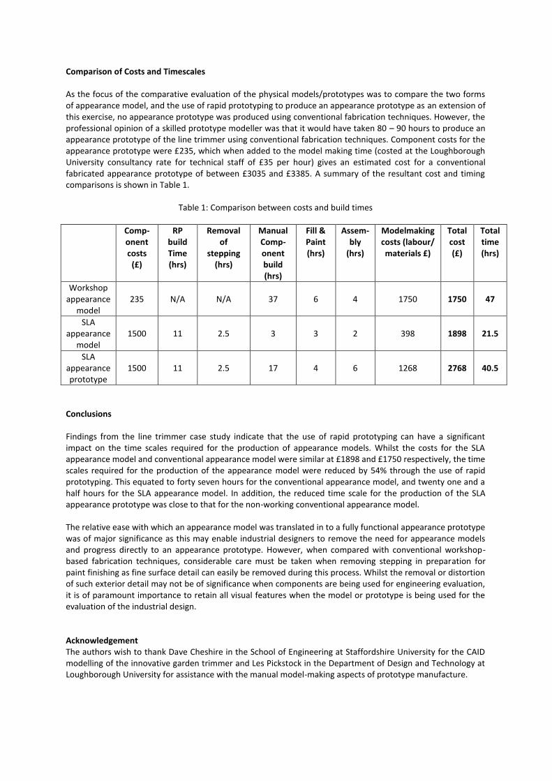
Comparison of Costs and Timescales As the focus of the comparative evaluation of the physical models/prototypes was to compare the two forms of appearance model, and the use of rapid prototyping to produce an appearance prototype as an extension of this exercise, no appearance prototype was produced using conventional fabrication techniques. However, the professional opinion of a skilled prototype modeller was that it would have taken 80 – 90 hours to produce an appearance prototype of the line trimmer using conventional fabrication techniques. Component costs for the appearance prototype were £235, which when added to the model making time (costed at the Loughborough University consultancy rate for technical staff of £35 per hour) gives an estimated cost for a conventional fabricated appearance prototype of between £3035 and £3385. A summary of the resultant cost and timing comparisons is shown in Table 1.
Table 1: Comparison between costs and build times
Comp- onent costs
(£)
RP build Time (hrs)
Removal of
stepping (hrs)
Manual Comp-onent build (hrs)
Fill & Paint (hrs)
Assem-bly
(hrs)
Modelmaking costs (labour/ materials £)
Total cost (£)
Total time (hrs)
Workshop appearance
model
235
N/A
N/A
37
6
4
1750
1750
47
SLA appearance
model
1500
11
2.5
3
3
2
398
1898
21.5
SLA appearance prototype
1500
11
2.5
17
4
6
1268
2768
40.5
Conclusions Findings from the line trimmer case study indicate that the use of rapid prototyping can have a significant impact on the time scales required for the production of appearance models. Whilst the costs for the SLA appearance model and conventional appearance model were similar at £1898 and £1750 respectively, the time scales required for the production of the appearance model were reduced by 54% through the use of rapid prototyping. This equated to forty seven hours for the conventional appearance model, and twenty one and a half hours for the SLA appearance model. In addition, the reduced time scale for the production of the SLA appearance prototype was close to that for the non-working conventional appearance model. The relative ease with which an appearance model was translated in to a fully functional appearance prototype was of major significance as this may enable industrial designers to remove the need for appearance models and progress directly to an appearance prototype. However, when compared with conventional workshop-based fabrication techniques, considerable care must be taken when removing stepping in preparation for paint finishing as fine surface detail can easily be removed during this process. Whilst the removal or distortion of such exterior detail may not be of significance when components are being used for engineering evaluation, it is of paramount importance to retain all visual features when the model or prototype is being used for the evaluation of the industrial design. Acknowledgement The authors wish to thank Dave Cheshire in the School of Engineering at Staffordshire University for the CAID modelling of the innovative garden trimmer and Les Pickstock in the Department of Design and Technology at Loughborough University for assistance with the manual model-making aspects of prototype manufacture.

References Birley, G. and Moreland, N. (1998) A Practical Guide to Academic Research, London: Kogan Page, p36. C3 (1999) June, London: Media Directories International, pp20-21. C3 (2000) January, London: Media Directories International, p17. Cohen, L. and Manion, L. (1980) Research Methods in Education, London: Croom Helm, p178. D Powell, Presentation Techniques, London: Macdonald 1990 Rapid News (1999) Volume 4, Number 3, pp30-35. Gomm, R., Hammersley, M. and Foster, P. (eds), (2000) Case Study Method, London: Sage Publications, p3. Kochan, (1993) Solid freeform Manufacturing, Amsterdam: Elsevier, p22. Moore, N. (1983) How to Do Research, London: Library Association Publishing, p84.