A combined series-parallel active filter system implementation using generalized non-active power...
7
A Combined Series-Parallel Active Filter System Implementation Using Generalized Non-Active Power Theory Mehmet Ucar, Sule Ozdemir and Engin Ozdemir Kocaeli University, Faculty of Technology, 41380, Umuttepe, Kocaeli, Turkey e-mails: {mucar, sozaslan, eozdemir}@kocaeli.edu.tr Abstract—In this paper, a generalized non-active power theory based control strategy is implemented in a 3-phase 4-wire combined series-parallel active filter (CSPAF) system for periodic and non-periodic waveforms compensation. The CSPAF system consists of a series active filter (SAF) and a parallel active filter (PAF) combination connected a common dc- link. The generalized non-active power theory is valid for single- phase and multi-phase systems, as well as periodic and non- periodic waveforms. The theory was applied in previous studies for current control in the PAF. In this study the theory is used for current and voltage control in the CSPAF system. The CSPAF system is simulated in Matlab/Simulink and an experimental setup is also built, so that different cases can be studied in simulations or experiments. The simulation and experimental results verify that the generalized non-active power theory is suitable for periodic and non-periodic current and voltage waveforms compensation in the CSPAF system. I. INTRODUCTION The widespread use of non-linear loads and power electronic converters has increased the generation of non- sinusoidal and non-periodic currents and voltages in electric power systems. Generally, power electronic converters generate harmonic components which frequencies that are integer multiplies of the line frequency. However, in some cases, such as controlled 3-phase rectifiers, arc furnaces and welding machines are typical loads, the line currents may contain both frequency lower than the line frequency and frequency higher than the line frequency but not the integer multiple of line frequency [1]-[4]. These currents interact with the impedance of the power distribution system and disturb voltage waveforms at point of common coupling (PCC) that can affect other loads. These waveforms are considered as non-periodic for the period of the currents is not equal to the period of the line voltage [1], [2]. The effects of non-periodic components of voltages and currents are similar to that caused by harmonics. They may contribute power loss, disturbances, measurement errors and control malfunctions, thus degradation of the supply quality in distribution systems [2]. Additionally, voltage sags are one of most important power quality problems in the distribution system and usually caused by fault conditions or by the starting of large electric motors [5]. Various non-active power theories in the time domain have been discussed [6]. The generalized non-active power theory was applied compensation of the non-sinusoidal and non-periodic load current for parallel active filter (PAF) [7], [8] and static synchronous compensator (STATCOM) [9]. This paper presents the application of the generalized non- active power theory for the compensation of periodic (but non-sinusoidal) and non-periodic currents and voltages with the combined series-parallel active filter (CSPAF) system. The simulation and experimental results showed that the theory proposed in this paper is applicable to the non-active power compensation of periodic load currents and source voltages with harmonics and non-periodic load currents and source voltages in 3-phase 4-wire systems. The CSPAF system consists of back-to-back connection of the series active filter (SAF) and the PAF with a common dc- link. The CSPAF system function is to compensate for all current related problems such as reactive power compensation, power factor improvement, current harmonic compensation, and load unbalance compensation. It regulates the dc-link voltage using the PAF. Besides, it can compensate all voltage related problems, such as voltage harmonics, voltage sag, flicker and regulate the load voltage using the SAF [10], [11]. Fig. 1 shows the general power circuit configuration of the CSPAF system. 3∼ Source Sensitive loads i L i S i PF + v S v SF v L – SAF PAF CSPAF system CDC L S L SF L PF L L L L Non-linear loads VDC C SF R SF C PF R PF N 1 /N 2 PCC Fig. 1. General power circuit configuration of the CSPAF system. This work is supported by TUBITAK Research Fund., (No. 108E083) 978-1-4244-4783-1/10/$25.00 ©2010 IEEE 367
-
Upload
independent -
Category
Documents
-
view
0 -
download
0
Transcript of A combined series-parallel active filter system implementation using generalized non-active power...
A Combined Series-Parallel Active Filter System Implementation Using Generalized
Non-Active Power Theory
Mehmet Ucar, Sule Ozdemir and Engin Ozdemir Kocaeli University, Faculty of Technology, 41380, Umuttepe, Kocaeli, Turkey
e-mails: mucar, sozaslan, [email protected]
Abstract—In this paper, a generalized non-active power theory based control strategy is implemented in a 3-phase 4-wire combined series-parallel active filter (CSPAF) system for periodic and non-periodic waveforms compensation. The CSPAF system consists of a series active filter (SAF) and a parallel active filter (PAF) combination connected a common dc-link. The generalized non-active power theory is valid for single-phase and multi-phase systems, as well as periodic and non-periodic waveforms. The theory was applied in previous studies for current control in the PAF. In this study the theory is used for current and voltage control in the CSPAF system. The CSPAF system is simulated in Matlab/Simulink and an experimental setup is also built, so that different cases can be studied in simulations or experiments. The simulation and experimental results verify that the generalized non-active power theory is suitable for periodic and non-periodic current and voltage waveforms compensation in the CSPAF system.
I. INTRODUCTION The widespread use of non-linear loads and power
electronic converters has increased the generation of non-sinusoidal and non-periodic currents and voltages in electric power systems. Generally, power electronic converters generate harmonic components which frequencies that are integer multiplies of the line frequency. However, in some cases, such as controlled 3-phase rectifiers, arc furnaces and welding machines are typical loads, the line currents may contain both frequency lower than the line frequency and frequency higher than the line frequency but not the integer multiple of line frequency [1]-[4]. These currents interact with the impedance of the power distribution system and disturb voltage waveforms at point of common coupling (PCC) that can affect other loads. These waveforms are considered as non-periodic for the period of the currents is not equal to the period of the line voltage [1], [2].
The effects of non-periodic components of voltages and currents are similar to that caused by harmonics. They may contribute power loss, disturbances, measurement errors and control malfunctions, thus degradation of the supply quality in distribution systems [2]. Additionally, voltage sags are one of most important power quality problems in the distribution
system and usually caused by fault conditions or by the starting of large electric motors [5].
Various non-active power theories in the time domain have been discussed [6]. The generalized non-active power theory was applied compensation of the non-sinusoidal and non-periodic load current for parallel active filter (PAF) [7], [8] and static synchronous compensator (STATCOM) [9]. This paper presents the application of the generalized non-active power theory for the compensation of periodic (but non-sinusoidal) and non-periodic currents and voltages with the combined series-parallel active filter (CSPAF) system. The simulation and experimental results showed that the theory proposed in this paper is applicable to the non-active power compensation of periodic load currents and source voltages with harmonics and non-periodic load currents and source voltages in 3-phase 4-wire systems.
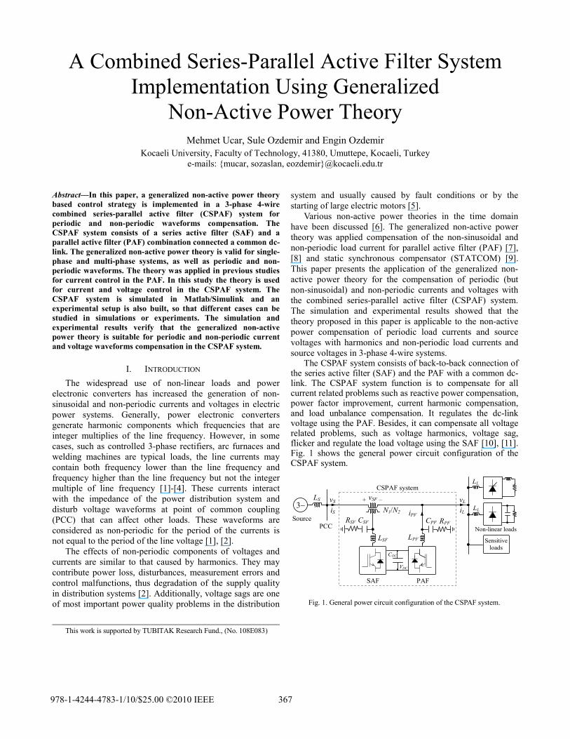
The CSPAF system consists of back-to-back connection of the series active filter (SAF) and the PAF with a common dc-link. The CSPAF system function is to compensate for all current related problems such as reactive power compensation, power factor improvement, current harmonic compensation, and load unbalance compensation. It regulates the dc-link voltage using the PAF. Besides, it can compensate all voltage related problems, such as voltage harmonics, voltage sag, flicker and regulate the load voltage using the SAF [10], [11]. Fig. 1 shows the general power circuit configuration of the CSPAF system.
3∼Source
Sensitive loads
iLiS iPF
+vS vSF vL–
SAF PAF
CSPAF system
CDC
LS
LSF LPF
LL
LL
Non-linear loads
VDC
CSF RSF CPF RPF
N1/N2
PCC
Fig. 1. General power circuit configuration of the CSPAF system.
This work is supported by TUBITAK Research Fund., (No. 108E083)
978-1-4244-4783-1/10/$25.00 ©2010 IEEE 367
II. GENERALIZED NON-ACTIVE POWER THEORY The generalized non-active power theory [7] is based on
Fryze’s definition of non-active power [12] and is an extension of the theory proposed in [13]. Voltage vector v(t) and current vector i(t) in a 3-phase system,
,)](),(),([)( 321Ttvtvtvtv = (1)
.)](),(),([)( 321Ttitititi = (2)
The instantaneous power p(t) and the average power P(t) is defined as the average value of the instantaneous power p(t) over the averaging interval [t-Tc, t], that is
,)()()()()(3
1∑
=
==p
ppT titvtitvtp (3)
.)(1)( ∫−
=t
Ttcc
dpT
tP ττ (4)
The instantaneous active current ia(t) and instantaneous non-active current in(t) are given in (5) and (6).
)()(
)()( 2 tvtV
tPti pp
a = (5)
)()()( tititi an −= (6)
In (5), voltage vp(t) is the reference voltage, which is chosen on the basis of the characteristics of the system and the desired compensation results. Vp(t) is the corresponding rms value of the reference voltage vp(t), that is
.)()(1)( ∫−
=t
Ttp
Tp
cp
c
dvvT
tV τττ (7)
The instantaneous non-active power pn(t) and average non-active power Pn(t) are defined by averaging the instantaneous powers over time interval [t-Tc, t],
,)()()()()(1∑
=
==m
pnppn
Tn titvtitvtp (8)
.)(1)( ∫−
=t
Ttn
cn
c
dpT
tP ττ (9)
In the generalized non-active power theory, the standard definitions for an ideal 3-phase, sinusoidal power system use the fundamental period T to define the rms values and average active power and non-active power. If there are only harmonics in the load current, Tc does not change the compensation results as long as it is an integral multiple of T/2, where T is the fundamental period of the system.
However, in other cases, such as a 3-phase load with sub-harmonics, or a non-periodic load, Tc has significant influence on the compensation results, and the power and energy storage rating of the compensator’s components [7].
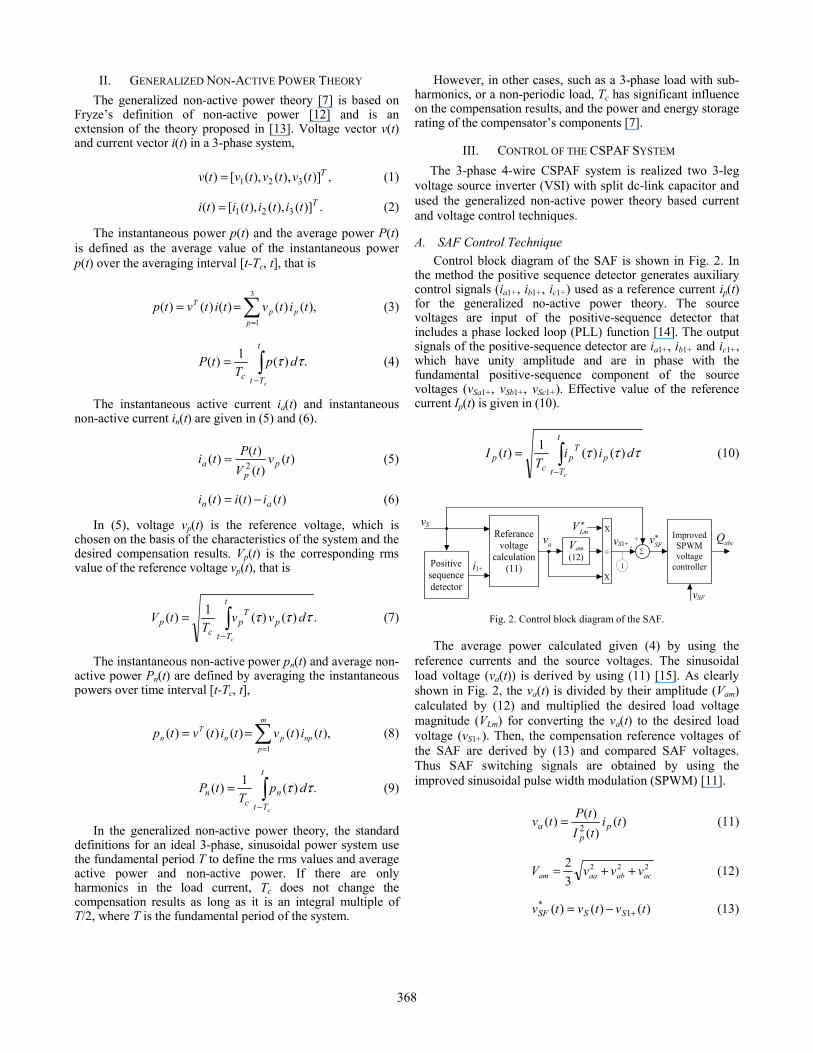
III. CONTROL OF THE CSPAF SYSTEM The 3-phase 4-wire CSPAF system is realized two 3-leg
voltage source inverter (VSI) with split dc-link capacitor and used the generalized non-active power theory based current and voltage control techniques.
A. SAF Control Technique Control block diagram of the SAF is shown in Fig. 2. In
the method the positive sequence detector generates auxiliary control signals (ia1+, ib1+, ic1+) used as a reference current ip(t) for the generalized no-active power theory. The source voltages are input of the positive-sequence detector that includes a phase locked loop (PLL) function [14]. The output signals of the positive-sequence detector are ia1+, ib1+ and ic1+, which have unity amplitude and are in phase with the fundamental positive-sequence component of the source voltages (vSa1+, vSb1+, vSc1+). Effective value of the reference current Ip(t) is given in (10).
∫−
=t
Ttp
Tp
cp
c
diiT
tI τττ )()(1)( (10)
vS
Positive sequence detector
Referance
voltage calculation
(11)
-
i1+
av
Improved SPWM voltage
controller
1
Vam (12)
X
X
÷
vSF
*SFv
*LmV
abcQ∑
+ vS1+
Fig. 2. Control block diagram of the SAF.
The average power calculated given (4) by using the reference currents and the source voltages. The sinusoidal load voltage (va(t)) is derived by using (11) [15]. As clearly shown in Fig. 2, the va(t) is divided by their amplitude (Vam) calculated by (12) and multiplied the desired load voltage magnitude (VLm) for converting the va(t) to the desired load voltage (vS1+). Then, the compensation reference voltages of the SAF are derived by (13) and compared SAF voltages. Thus SAF switching signals are obtained by using the improved sinusoidal pulse width modulation (SPWM) [11].
)()()()( 2 titItPtv p
pa = (11)
222
32
acabaaam vvvV ++= (12)
)()()( 1* tvtvtv SSSF +−= (13)
368
B. PAF Control Technique The average power calculated given (4) by using load
currents and fundamental positive sequence source voltages (vSa1+, vSb1+, vSc1+) over the averaging interval [t-Tc, t]. Desired sinusoidal load currents (iLa1+, iLb1+, iLc1+) is derived by using (5) and instantaneous non-active current in(t) is calculated as in (6). Also, the additional active current ica(t) required to meet the losses in (14) is drawn from the source by regulating the dc-link voltage vDC to the reference VDC. A PI controller is used to regulate the dc-link voltage vDC. The error between the actual dc voltage and its reference value is treated in the PI controller and the output is multiplied by a sinusoidal fundamental template of unity amplitude for each phase of the three phases. In addition, as shown in Fig. 3, the difference between Vdc1 and Vdc2 is applied to the PI controller. Thus, equal voltage sharing between the capacitors is accomplished. The compensation reference currents of the PAF are obtained by (15). The reference currents are compared the PAF currents and applied to hysteresis current controller. Thus, the PAF switching signals are obtained. Control block diagram of the PAF is shown in Fig. 3.
( ) ( )
( ) ( ) )(
])[()(
0212212
0111
dtvvKvvK
dtvVKvVKvti
t
DCDCIDCDCP
t
DCDCIDCDCPSca
∫
∫
−+−+
−+−= +
(14)
)()()(* tititi canPF −= (15)
vS1+
Referance
current calculation
(5)-(6)
Hysteresis current
controller
iL
iPF
ni *PFi
−
X vDC1
+
PI2
vDC2
PI1
1
∑ ∑
∑
+
+
+ −
∑
∑ + −
+ +
mV1/
DCV
cai
abcQ
dc voltage control
dc voltage unbalance control Fig. 3. Control block diagram of the PAF.
IV. SIMULATION AND EXPERIMENTAL RESULTS The CSPAF system prototype is designed and developed
in laboratory to validate the generalized non-active power theory proposed in the paper. The power circuit and control block diagram of the CSPAF system implementation is given in Fig. 4. The non-linear load-1 (which contains a 3-phase half controlled thyristor rectifier with firing angle 30˚ and a single-phase diode rectifier are used as nonlinear loads) is the load that requires ideal source voltages. The non-linear load-2 (which contains a 3-phase diode rectifier) is connected to the PCC to create source voltage distortion and imitates the effect of other loads on a radial network. The 3-phase source voltages with distortion are synthesized by increasing system impedance from 59 µH to 2.2 mH and connecting the non-linear load-2 to PCC as shown in Fig. 4.
vSabc
3-phase Source
CSF
RSF LSF RPF
CPF
Series AF Parallel AF
i PFa
i PFb
i PFc
i PFn
iSa
iSb
iSc
iSn
Reset
vSb vSa vSc
vSFb vSFa
vSFc
CS: Hall-Effect Current-Sensor VS: Hall-Effect Voltage Sensor IA: Isolation Amplifier
CS
CS
VS
VS
Pre-charge Resistors
Single-Phase Transformers
LPF QAL
QAH QBH
QBL QCL
QCH
iLn
iLa
iLb
iLc
Voltage Measurement Board
Voltage Measurement Board
Current Measurement Board
DC Voltage Measurement Board
VDC1
VDC2
IA
Reset
QAL QAH QBH QCHQBL QCL
IGBT Driver Board (gate driver-isolation-short
circuit-high current protection)
vSFbc
iPFabc
vDC2
QBH QAL QAH QCHQBL QCL
IGBT Driver Board (gate driver-isolation-short
circuit-high current protection)
High Current-Voltage Protection Board
vDC1
Non-linear Load-2
(Three-Phase Diode Rectifier)
iLa iLciLb R
LL
LL
iPFb iPFa
iPFc
QAL
QAH QBH
QBL QCL
QCH
Non-linear Load-1 (Three-Phase
Thyristor Rectifier and
Single-Phase Diode Rectifier)
Current Measurement Board
PC dSPACE DS1103 PPC Controller Board
Fiber-Optic Connection Voltage-Current
Signal Conditioning Interface Boards
iPFabc vSFabc vSabc
iLabc
vDC2 vDC1
Δ-Y Step-down
Transformer and
Single-Phase Sag Generator
Fig. 4. Power circuit and control block diagram of the CSPAF system implementation.
369

Additionally, the voltage-sag generator was employed to simulate the single-phase source voltage sag for phase-a in the laboratory. The 3-phase step-down transformer is used for supply voltage to the CSPAF system and testing the experimental voltage sag problem. The power circuit configuration of the CSPAF system combines 3-phase 4-wire SAF and PAF. Two voltage source 3-leg IGBT converters sharing a common dc-link are used. The dc-link includes two capacitor with the midpoint connected to the neutral wire of the supply system. The dc-link voltage is adjusted at 400 V. The ac side of the SAF is connected through single-phase injection transformers in series with the input supply lines. The PAF is connected in parallel with the output of the system through an inductor. The CSPAF system parameters are given in Table I.
Both AF are digitally controlled using a dSPACE DS1103 controller board, includes a real-time processor and the necessary I/O interfaces that allow carry-out the control operation. Owing to the switching of the parallel and the series VSI’s, the compensating currents and voltages have unwanted high-order harmonics that can be removed by small high-pass passive filters represented by RPF, CPF and RSF, CSF.
The generalized non-active power theory based compensation system is simulated and an experimental setup is also built, so that different cases can be studied in simulations or experiments. The first three cases for periodic current and voltage compensation (subsections A–C) are tested in the experimental setup and the last two cases for (subsections D and E) are simulated in Matlab/Simulink software since they are difficult to be carried out in an experimental setup. The compensation of periodic currents and voltages with fundamental period T, using a compensation period Tc that is a multiple of T/2 is enough for complete compensation [7].
Tektronix DPO3054 oscilloscope
Fluke 434 Power quality
analyser
dSPACE DS1103 controller board
SAF injection transformers
Non-linear loads
PAF and SAF Power stages
Control boards
PAF and SAF passive filters
Split dc-link capacitors
IGBT driver board
CLP1103 connector led panel
Fig. 5. The experimental test setup photograph.
TABLE I THE CSPAF SYSTEM PARAMETERS
Components Symbol Parameters Power source
Voltage, frequency VSabc, fs, 110V, 50Hz, Impedance Ls 59µH
DC-link Capacitors C1, C2 4700µF, 4700µF Reference voltage VDC 400V
PAF Filter LPF, RPF, CPF 3mH, 5Ω, 30µF Swithching frequency fSWp 8kHz
SAF Filter LSF, RSF, CSF 2.5mH, 2Ω, 150µF Swithching frequency fSWs 10kHz Injection transformer N1/N2, S 2, 5.4kVA
Non-linear loads
(rectifiers)
3-phase thyristor LL, LDC, RDC 3mH, 5.7mH, 12Ω 1-phase diode LL2, CDC, RDC 2mH, 330µF, 45Ω 3-phase diode CDC, RDC 8800µF, 15Ω
A. Unbalanced Non-linear Load Current Compensation
The experimental results of unbalanced non-linear load current compensation under ideal source voltages are shown in Fig. 6.
35A
/div
35
A/d
iv
35A
/div
20
A/d
iv
iSa
iSb
iSc
iSn
10ms/div (a) Source currents before compensation.
35A
/div
35
A/d
iv
35A
/div
20
A/d
iv
iSa
iSb
iSc
iSn
10ms/div (b) Source currents after compensation.
10ms/div
40A
/div
10
0V/d
iv
40A
/div
10
0V/d
iv
iLb vSb
iSb vSb
(c) Reactive power compensation.
Fig. 6. Experimental results: Unbalanced non-linear load current compensation under ideal source voltages.
370
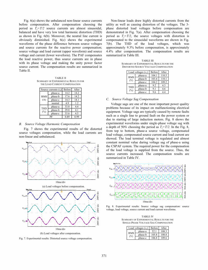
Fig. 6(a) shows the unbalanced non-linear source currents before compensation. After compensation choosing the period as Tc=T/2 source currents are almost sinusoidal, balanced and have very low total harmonic distortion (THD) as shown in Fig. 6(b). Moreover, the neutral line current is obviously diminished. Fig. 6(c) shows the experimental waveforms of the phase difference between source voltages and source currents for the reactive power compensation; source voltage and load current (upper waveform) and source voltage and current (lower waveform). The PAF compensates the load reactive power, thus source currents are in phase with its phase voltage and making the unity power factor source current. The compensation results are summarized in Table II.
TABLE II SUMMARY OF EXPERIMENTAL RESULTS FOR
THE LOAD CURRENT COMPENSATION
Source currents (iS) Before After
RMS (A)
phase-a 14.2 14.2 phase-b 17.6 14.2 phase-c 14.3 14.1 neutral 4.9 1.2
THD (%)
phase-a 33.8 4.4 phase-b 29.8 4.1 phase-c 33.6 4.5
PF 0.89 0.99
B. Source Voltage Harmonic Compensation Fig. 7 shows the experimental results of the distorted
source voltages compensation, while the load currents are non-linear and unbalanced.
vLa
vLb
vLc
10ms/div
200V
/div
20
0V/d
iv
200V
/div
(a) Load voltages before compensation.
200V
/div
20
0V/d
iv
200V
/div
vLa
vLb
vLc
10ms/div (b) Load voltages after compensation.
Fig. 7. Experimental results: Distorted source voltage compensation.
Non-linear loads draw highly distorted currents from the utility as well as causing distortion of the voltages. The 3-phase distorted load voltages before compensation are demonstrated in Fig. 7(a). After compensation choosing the period as Tc=T/2, the source voltages with distortion is compensated to the sinusoidal waveforms are shown in Fig. 7(b). The THD of the load voltages, which was approximately 9.3% before compensation, is approximately 4.4% after compensation. The compensation results are summarized in Table III.
TABLE III SUMMARY OF EXPERIMENTAL RESULTS FOR THE DISTORTED SOURCE VOLTAGE COMPENSATION
Load voltages (vL) Before After
RMS (V)
phase-a 104.1 110.5 phase-b 103.4 110.1 phase-c 104.2 109.2
THD (%)
phase-a 9.2 4.3 phase-b 9.1 4.6 phase-c 9.6 4.4
C. Source Voltage Sag Compensation Voltage sags are one of the most important power quality
problems because of its impact on malfunctioning electrical equipment. Voltage sags are typically caused by remote faults such as a single line to ground fault on the power system or due to starting of large induction motors. Fig. 8 shows the experimental waveforms under single-phase voltage sag with a depth of 50% choosing the period as Tc=T/2. In the Fig. 8, from top to bottom, phase-a source voltage, compensated load voltage, compensated source current and load current are showed. The load terminal voltage is regulated and almost constant nominal value during voltage sag of phase-a using the CSPAF system. The required power for the compensation of the load voltage is supplied from the source. Thus, the source currents increased. The compensation results are summarized in Table IV.
200V
/div
20
0V/d
iv
30A
/div
30
A/d
iv
vSa
vLa
iSa
iLa
10ms/div Fig. 8. Experimental results: Source voltage sag compensation: source voltage, load voltage, source current and load current waveforms.
TABLE IV SUMMARY OF EXPERIMENTAL RESULTS FOR THE SINGLE-PHASE VOLTAGE SAG COMPENSATION
Load voltages (vL) Before After
RMS (V)
phase-a 52.1 108.3 phase-b 105.8 108.8 phase-c 106.8 109.6
371

D. Sub-Harmonic Current and Voltage Compensation The sub-harmonic currents (frequency lower than
fundamental frequency) are typically generated by power electronic converters [7]. The main feature of these non-periodic currents is that the currents may have a repetitive period. When the fundamental frequency of the source voltage is an odd multiple of the sub-harmonic frequency, the minimum Tc for complete compensation is 1/2 of the common period of both fs and fsub. When fs are an even multiple of fsub, the minimum Tc for complete compensation is the common period of both fs and fsub [8]. In this study, source voltage and load current contains sub-harmonics of 10 Hz frequency and 20% amplitude are given in Table V. The sub-harmonic current and voltage compensation simulation results are shown in Fig. 9 and Fig. 10, respectively.
TABLE V THREE-PHASE SOURCE VOLTAGE AND
LOAD CURRENT VALUES
Parameters Fundamental Sub-harmonic Freq. (Hz) 50 10 Currents 15 A % 20 Voltages 110 V % 20
0.15 0.2 0.25 0.3 0.35 0.4 0.45 0.5-200
-100
0
100
200
t (s)
v Sab
c(V)
(a) 3-phase sub-harmonic source voltage waveforms.
0.15 0.2 0.25 0.3 0.35 0.4 0.45 0.5-200
-100
0
100
200
t (s)
v Lab
c(V)
(b) 3-phase load voltages after compensation.
Fig. 9. Simulation results: Sub-harmonic voltage compensation.
0.15 0.2 0.25 0.3 0.35 0.4 0.45 0.5-25
0
25
t (s)
i Labc
(A)
(a) 3-phase sub-harmonic load current waveforms.
0.15 0.2 0.25 0.3 0.35 0.4 0.45 0.5-25
0
25
t (s)
i Sabc
(A)
(b) 3-phase source currents after compensation.
Fig. 10. Simulation results: Sub-harmonic current compensation.
The sub-harmonic component can be completely compensated by choosing Tc=2.5T, and the source currents
and load voltages are balanced and sinusoidal. The CSPAF system is able to suppress all the sub-harmonic component of the load current and the voltage at the load terminals is constant amplitude after compensation.
E. Stochastic Non-Periodic Current and Voltage Compensation The arc furnace load currents may contain stochastic non-
periodic currents (frequency higher than fundamental frequency but not an integer multiple of it). Theoretically, the period T of a non-periodic load is infinite [7]. In a non-periodic system, the instantaneous current varies with different averaging interval Tc, which is different from the periodic cases. The source current could be a pure sine wave if Tc goes to infinity. However, this is not practical in a power system, and Tc is chosen to have a finite value. The non-active components in these loads cannot be completely compensated by choosing Tc as T/2 or T, or even several multiples of T. Choosing that period as may result in an acceptable both source current and load voltage which are quite close to a sine wave. If Tc is large enough, increasing Tc further will not typically improve the compensation results significantly [8].
In this work, 3-phase source voltage and load current components are given in Table VI [16]. Fig. 11 and Fig. 12 shows simulation results of the stochastic non-periodic voltage and current compensation choosing the period as Tc=5T. After compensation, load voltages and source currents are balanced and almost sinusoidal with low THD as shown in Fig 11(b) and Fig 12(b). In addition, source neutral current have been reduced considerably.
TABLE VI THREE-PHASE SOURCE VOLTAGE AND
LOAD CURRENT COMPONENTS
Parameters Fund. Components (%) Freq. (Hz) 50 104 117 134 147 250 Currents 15 A 30 40 20 20 50 Voltages 110 V 7.5 10 5 5 12.5
0.1 0.12 0.14 0.16 0.18 0.2 0.22 0.24 0.26 0.28 0.3-200
0
200
0.1 0.12 0.14 0.16 0.18 0.2 0.22 0.24 0.26 0.28 0.3-200
0
200
0.1 0.12 0.14 0.16 0.18 0.2 0.22 0.24 0.26 0.28 0.3-200
0
200
v Sa(
V)
v Sb(
V)
v Sc(V
)
t (s) (a) 3-phase stochastic non-periodic source voltage waveforms.
0.1 0.12 0.14 0.16 0.18 0.2 0.22 0.24 0.26 0.28 0.3-200
0
200
v Lab
c(V)
t (s) (b) 3-phase load voltages after compensation.
Fig. 11. Simulation results: Stochastic non-periodic voltage compensation.
372

0.1 0.12 0.14 0.16 0.18 0.2 0.22 0.24 0.26 0.28 0.3-25
0
25
0.1 0.12 0.14 0.16 0.18 0.2 0.22 0.24 0.26 0.28 0.3-25
0
25
0.1 0.12 0.14 0.16 0.18 0.2 0.22 0.24 0.26 0.28 0.3-25
0
25
i La(A
) I L
b(A
) i Lc
(A)
t (s) (a) 3-phase stochastic non-periodic load current waveforms.
0.1 0.12 0.14 0.16 0.18 0.2 0.22 0.24 0.26 0.28 0.3-25
0
25
i Sabc
(A)
t (s) (b) 3-phase source currents after compensation.
0.1 0.12 0.14 0.16 0.18 0.2 0.22 0.24 0.26 0.28 0.3-12
0
12
i Lnab
c(A)
t (s) (c) Load neutral current waveforms.
0.1 0.12 0.14 0.16 0.18 0.2 0.22 0.24 0.26 0.28 0.3-12
0
12
i Snab
c(A)
t (s) (d) Source neutral current after compensation.
Fig. 12. Simulation results: Stochastic non-periodic current compensation.
V. CONCLUSION The presence of non-linear, time-variant, disturbing loads
connected to the electric power system is responsible for the presence of periodic and non-periodic disturbances on the line currents and voltages. In this paper, the generalized non-active power theory, which is applicable to sinusoidal or non-sinusoidal, periodic or non-periodic, balanced or unbalanced electrical systems, is presented. It has been applied to the 3-phase 4-wire CSPAF system. This theory is adapted to different compensation objectives by changing the averaging interval Tc. The CSPAF experimental setup system was built and tested in the laboratory. Three cases, unbalanced nonlinear load currents, distorted source voltages and source voltage sag with unbalanced non-linear load currents compensation are tested in the experiments. The sub-harmonic and the stochastic non-periodic current and voltage
compensation are simulated in Matlab/Simulink. The simulation and experimental results showed that the theory proposed in the CSPAF system was applicable to non-active power compensation of periodic and non-periodic waveforms in 3-phase 4-wire systems.
VI. REFERENCES [1] E. H. Watanabe and M. Aredes, “Compensation of nonperiodic currents
using the instantaneous power theory,” IEEE Power Engineering Soc. Summer Meeting, pp. 994–999, 2000.
[2] L. S. Czarnecki, “Non-periodic currents: their properties, identification and compensation fundamentals,” IEEE Power Engineering Soc. Summer Meeting, pp. 971-976, 2000.
[3] H. Akagi, “Active filters and energy storage systems operated under nonperiodic conditions,” IEEE Power Engineering Soc. Summer Meeting, Seattle, pp. 965-970, 2000.
[4] S. A. Farghal, M. S. Kandil and Elmitwally, “Evaluation of a shunt active power conditioner with a modified control scheme under nonperiodic conditions,” IEE Proc. Generation, Transmission and Distribution, vol. 149, no. 6, pp. 726-732, Nov. 2002.
[5] M. F. McGranaghan, D. R. Mueller and M. J. Samotyj, “Voltage sags in industrial systems,” IEEE Trans. Ind. Appl., vol. 29, no. 2, pp. 397-403, 1993.
[6] L. M. Tolbert and T. G. Habetler, “Comparison of time-based non-active power definitions for active filtering,” IEEE Int. Power Electron. Congress, pp. 73–79, Oct. 15-19, 2000.
[7] Y. Xu, L. M. Tolbert, F. Z. Peng, J. N. Chiasson and J. Chen, “Compensation-based non-active power definition,” IEEE Power Electr. Letter, vol. 1, no. 2, pp. 45-50, 2003.
[8] Y. Xu, L. M. Tolbert, J. N. Chiasson, J. B. Campbell and F. Z. Peng, “Active filter implementation using a generalized nonactive power theory”, IEEE Industry Applications Conference, pp. 153-160, 2006.
[9] Y. Xu, L. M. Tolbert, J. N. Chiasson, J. B. Campbell and F. Z. Peng, “A generalised instantaneous non-active power theory for STATCOM,” IET Electric Power Applications, pp. 853-861, 2007.
[10] H. Fujita and H. Akagi, “The unified power quality conditioner: the integration of series and shunt active filters,” IEEE Trans. on Power Electr., vol. 13, no. 2, 1998.
[11] M. Aredes, K. Heumann, and E. H. Walandble, “An universal active power line conditioner,” IEEE Trans. Power Del., vol. 13, no. 2, pp. 545-551, Apr. 1998.
[12] S. Fryze, “Active, reactive, and apparent power in non-sinusoidal systems,” Przeglad Elektrot., vol. 7, pp. 193-203 (in Polish), 1931.
[13] F. Z. Peng and L. M. Tolbert, “Compensation of non-active current in power systems-definitions from compensation standpoint,” IEEE Power Eng. Soc. Summer Meeting, pp. 983-987, 2000.
[14] G. W. Chang and W. C. Chen “A new reference compensation voltage strategy for series active power filter control,” IEEE Trans. on Power Delivery, vol. 21, no. 3, pp. 1754-1756, July 2006.
[15] M. Ucar, S. Ozdemir and E. Ozdemir, “A control strategy for combined series-parallel active filter system under non-periodic conditions,” International Conference on Renewable Energies and Power Quality, ICREPQ’09, Valencia (Spain), 15-17 Apr. 2009.
[16] IEEE Interharmonic Task Force, “Interharmonic in power systems,” Cigre 36.05/CIRED 2 CC02, Voltage Quality Working Group, 1997.
373


![Active low pass filter design[1]](https://static.fdokumen.com/doc/165x107/631aaeddd43f4e1763048eee/active-low-pass-filter-design1.jpg)