A Case Study of on Board Diagnostic (OBD II) - IJERT
15
Specifications and Analysis of Digitized Diagnostics of Automobiles: A Case Study of on Board Diagnostic (OBD II) Medashe Michael Oluwaseyi *, Abolarin Matthew Sunday Mechanical Engineering Department Federal University of Technology, Minna, Nigeria Abstract— On-board diagnostics, (OBD) is an automotive term that refers to a vehicle’s self-diagnostic and reporting ability. OBD systems enable owner of vehicles or automobile repair technician to gain access to the condition of the various vehicle sub-systems. Modern motor vehicles are highly sophisticated machines that incorporate development in electrical, electronics and mechanical engineering. The traditional “trial-and-error” mode of diagnosis could no longer be efficient to meet up with the need for maintenance and repairs on such vehicles. Therefore, this probes a challenge to meet up with the technological trend, and hence it becomes imperative to adopt new mode of diagnosis with high efficiency on the new generation motor vehicles. To facilitate and enhance the early detection of faults and malfunctions related to emissions control components, different diagnostic tools like Launch X-431 and Autel Maxidiag (Elite Series) were used and from the research carried out and the various results obtained from the various diagnostics of some selected automobiles from German Make, American Make, and Japanese Make vehicles, the diagnostics results provided an appreciated feedback through the triggering of Malfunction Indicator Light (MIL) and thereby with the use of diagnostic scan tools, the failures and faults within the engine compartment were detected. It was evident that On Board Diagnostic has the capacity to facilitate and enhance the early detection of vehicle malfunction and faults related to emissions control components and as a result reducing high emissions caused by emission related malfunctions. Keywords— Diagnostic Trouble Code; Malfunction Indicator Light; On-board Diagnostics I. INTRODUCTION Every automobile is equipped with an electrical instrumentation panel that is used as a driver information centre, formerly known as a dashboard. It contains various gauges and indicators that provide valuable information to the driver [1]. Gauges provide scaled indication of the system condition such as distance, engine speed, vehicle speed, and fuel level. Whereas, the indicator lights supply information of something is being turned on or warn the driver about system malfunctioning problems. However, this instrumentation panel has limitation in providing more information on specific areas such as malfunctioning problems, trip information, scheduled maintenance reminder and data logging system. The information displayed on the dash board is retrieved from the electronic control unit (ECU) of the vehicle. The ECU that can provide this information normally has on-board diagnostic (OBD) software (known as a diagnostic management system). This management system performs diagnostic testing, record the result of the tests, and request the test fail actions [2]. On-board diagnostics, (OBD) is an automotive term that refers to a vehicle’s self-diagnostic and reporting ability. OBD systems enable owner of vehicles or automobile repair technician to gain access to the condition of the various vehicle sub-systems. The available diagnostic information through OBD has considerably been improved, as its introduction dates back to the early 1980s. The early versions of OBD simply illuminates a malfunction indicator light if there was any prevailing fault detected, but has no capability of further providing any information about the nature of the fault. The modern OBD systems have become more sophisticated and now adopt a standardized digital communications port to provide real time data in addition to a standardized series of diagnostic trouble codes, (DTCs), which allow one to quickly identify and repair malfunctions within the vehicle, as it provides almost complete control and also monitors parts of chassis, body and accessory devices as well as the diagnostic control network of the vehicle. All vehicles (light and medium duty) built since January 1, 1996, in the United States, or in Asia and Europe designed to U.S specifications has On Board Diagnostics Version II (OBD II) specification, although some early OBD 2 vehicles were not 100% compliant. The OBD-II standard specifies the type of diagnostic connector and its pinout, the electrical signaling protocols available, and the messaging format. It also provides a candidate list of vehicle parameters to monitor along with how to encode the data for each. OBD-II provides access to numerous data from the engine control unit (ECU) and offers a valuable source of information when troubleshooting problems inside a vehicle. OBD II was developed by the State of California Air Resources Board (CARB) and the United States Environmental Protection Agency (EPA) and is standardized in the US by the Society for Automotive Engineers (SAE) and worldwide (as E- OBD) by the International Organization for Standardization (ISO). The SAE (J1979) standard defines a method for requesting various diagnostic data and a list of standard parameters that might be available from the ECU. The various parameters that are available are addressed by “parameter identification numbers” or PIDs which are defined in (J1979). OBD-II PIDs are codes used to request data from a vehicle, used as a diagnostic tool. All cars sold in the United States are required to use the ISO 15765-4 signaling a variant of the Controller Area Network (CAN) bus. OBD-II data can be International Journal of Engineering Research & Technology (IJERT) ISSN: 2278-0181 http://www.ijert.org IJERTV9IS010045 (This work is licensed under a Creative Commons Attribution 4.0 International License.) Published by : www.ijert.org Vol. 9 Issue 01, January-2020 91
-
Upload
khangminh22 -
Category
Documents
-
view
2 -
download
0
Transcript of A Case Study of on Board Diagnostic (OBD II) - IJERT

Specifications and Analysis of Digitized
Diagnostics of Automobiles: A Case Study of on
Board Diagnostic (OBD II)
Medashe Michael Oluwaseyi *, Abolarin Matthew Sunday Mechanical Engineering Department
Federal University of Technology,
Minna, Nigeria
Abstract— On-board diagnostics, (OBD) is an automotive
term that refers to a vehicle’s self-diagnostic and reporting
ability. OBD systems enable owner of vehicles or automobile
repair technician to gain access to the condition of the various
vehicle sub-systems. Modern motor vehicles are highly
sophisticated machines that incorporate development in
electrical, electronics and mechanical engineering. The
traditional “trial-and-error” mode of diagnosis could no longer
be efficient to meet up with the need for maintenance and repairs
on such vehicles. Therefore, this probes a challenge to meet up
with the technological trend, and hence it becomes imperative to
adopt new mode of diagnosis with high efficiency on the new
generation motor vehicles. To facilitate and enhance the early
detection of faults and malfunctions related to emissions control
components, different diagnostic tools like Launch X-431 and
Autel Maxidiag (Elite Series) were used and from the research
carried out and the various results obtained from the various
diagnostics of some selected automobiles from German Make,
American Make, and Japanese Make vehicles, the diagnostics
results provided an appreciated feedback through the triggering
of Malfunction Indicator Light (MIL) and thereby with the use of
diagnostic scan tools, the failures and faults within the engine
compartment were detected. It was evident that On Board
Diagnostic has the capacity to facilitate and enhance the early
detection of vehicle malfunction and faults related to emissions
control components and as a result reducing high emissions
caused by emission related malfunctions.
Keywords— Diagnostic Trouble Code; Malfunction Indicator
Light; On-board Diagnostics
I. INTRODUCTION
Every automobile is equipped with an electrical instrumentation panel that is used as a driver information centre, formerly known as a dashboard. It contains various gauges and indicators that provide valuable information to the driver [1]. Gauges provide scaled indication of the system condition such as distance, engine speed, vehicle speed, and fuel level. Whereas, the indicator lights supply information of something is being turned on or warn the driver about system malfunctioning problems. However, this instrumentation panel has limitation in providing more information on specific areas such as malfunctioning problems, trip information, scheduled maintenance reminder and data logging system. The information displayed on the dash board is retrieved from the electronic control unit (ECU) of the vehicle. The ECU that can provide this information normally has on-board diagnostic (OBD) software (known as a diagnostic management system).
This management system performs diagnostic testing, record the result of the tests, and request the test fail actions [2].
On-board diagnostics, (OBD) is an automotive term that refers to a vehicle’s self-diagnostic and reporting ability. OBD systems enable owner of vehicles or automobile repair technician to gain access to the condition of the various vehicle sub-systems. The available diagnostic information through OBD has considerably been improved, as its introduction dates back to the early 1980s. The early versions of OBD simply illuminates a malfunction indicator light if there was any prevailing fault detected, but has no capability of further providing any information about the nature of the fault. The modern OBD systems have become more sophisticated and now adopt a standardized digital communications port to provide real time data in addition to a standardized series of diagnostic trouble codes, (DTCs), which allow one to quickly identify and repair malfunctions within the vehicle, as it provides almost complete control and also monitors parts of chassis, body and accessory devices as well as the diagnostic control network of the vehicle.
All vehicles (light and medium duty) built since January 1, 1996, in the United States, or in Asia and Europe designed to U.S specifications has On Board Diagnostics Version II (OBD II) specification, although some early OBD 2 vehicles were not 100% compliant. The OBD-II standard specifies the type of diagnostic connector and its pinout, the electrical signaling protocols available, and the messaging format. It also provides a candidate list of vehicle parameters to monitor along with how to encode the data for each. OBD-II provides access to numerous data from the engine control unit (ECU) and offers a valuable source of information when troubleshooting problems inside a vehicle.
OBD II was developed by the State of California Air Resources Board (CARB) and the United States Environmental Protection Agency (EPA) and is standardized in the US by the Society for Automotive Engineers (SAE) and worldwide (as E-OBD) by the International Organization for Standardization (ISO). The SAE (J1979) standard defines a method for requesting various diagnostic data and a list of standard parameters that might be available from the ECU. The various parameters that are available are addressed by “parameter identification numbers” or PIDs which are defined in (J1979). OBD-II PIDs are codes used to request data from a vehicle, used as a diagnostic tool. All cars sold in the United States are required to use the ISO 15765-4 signaling a variant of the Controller Area Network (CAN) bus. OBD-II data can be
International Journal of Engineering Research & Technology (IJERT)
ISSN: 2278-0181http://www.ijert.org
IJERTV9IS010045(This work is licensed under a Creative Commons Attribution 4.0 International License.)
Published by :
www.ijert.org
Vol. 9 Issue 01, January-2020
91

collected through one of five communication protocols that are listed thus; SAE J1850 (PWM), SAE J1850 (VPW), ISO 9141-2, ISO 14230-4 (KWP 2000), ISO 15765-4 (CAN). The format of the request command has to follow the SAE J1979 standard (common diagnostic test mode). The OBD-II standards were primarily developed to regulate vehicles emission level standards. Many supporting systems were developed to improve the quality and performance of the instrumentation panel available in a car [3]. OBD is not a new field of study, but poor documentation, complicated interface requirements and an industry stranglehold has prevented major advancesalthough the various table text styles are provided. The formatter will need to create these components, incorporating the applicable criteria that follow.
II. MATERIALS AND METHODS
The materials that were used in the course of carrying out this
research were the different diagnostic tools that were
employed in carrying out diagnosis of fault on automobile at
Sarki Pawa Automobile Workshop, along Kpakungu –
Gidankwano Expressway, Albishirin, Minna Niger state,
Nigeria. The different diagnostic tools were Launch
X431(Normal) and Autel MaxiDiag (Elite Series).
The Launch X431 auto scan tool is a new generation of
product developed by Launch Tech. Available X431 products
developed by Launch Tech. among others are Launch X431
(Normal), Launch X431 (Infinite) and Launch X431 (Super
scanner). It is a perfect union between automotive electronic
technology and information networking. X431 adopts open
diagnostic technology, which is the most advanced in the
world as well as the future of automotive diagnosis. It carries
Personal Digital Assistant (PDA) functions apart from reading
trouble code, data stream and actuation test, sensor waveform
and digital code control. Important characteristics of Launch
X431 include the following among others; to interface with
computer with X431-PCLINK so as to store test data in
vehicle service record; To simulate and test sensors with the
help of sensor box; To test the parameters of the battery and
conduct analysis on battery conditions through battery box;
To print out test data any time with built-in printer; Easy
operation through input on large touch sensitive screen; As
generic diagnostic equipment, it can interface with diagnostic
adaptors of all vehicles models in the world; Strong test
capacity to cover all electronic systems; Unique reading of
data stream to ensure fast data updating; Strong waveform
display to monitor any change in the data stream; Embedded
operation system and open-platform diagnosis to make
effective diagnosis possible; Integrated adaptors featuring
compact design and reliability; Multi-language choices and
easy update through the Internet.
Figure 1: Complete package of a Launch X431 (Normal) with adapters for
connectors of several vehicle manufacturers.
Autel scan tools are powerful and professional auto tools for
diagnosis. Autel Scan tools have many different series
including maxidiag, maxidas, autolink and more. Autel new
MaxiDiag Elite Series, is the most advanced and
multifunctional scan tools powered by its exclusive
technology and designed for technicians to troubleshoot either
the basic four systems or all the systems for most of the major
vehicles on the road today.
Method/Procedure in Carrying out Diagnosis
The data processed in this report were all gather at Sarki Pawa
Automobile Workshop along Kpakungu- Gidankwano
expressway Minna, Niger state, Nigeria during the period of
this research for different make and model of automobiles.
The information obtained includes the following; model year
(MY), make, model, Engine Number, and the Diagnostic
Trouble Codes (DTC) for all the automobiles covered in this
report.
Although there are generalised procedures of carrying out
diagnostics, but individual diagnostic tool has their specific
procedures of carrying out their diagnostics.
Figure 2a: Autel Scan Tool (MaxiDiag Elite Series)
Figure 2b: Complete package of Autel Scan Tool (MaxiDiag Elite Series) –
Scan tool, DLC, DVD, Carry Case, USB Cable, and user manual.
.
Diagnostic with Launch X-431
To carry out diagnostic with X-431, the following are the step
by step procedure to be undertaken;
There are a few things to keep in mind when using the X-431.
i. Always use the OEM connector that comes with the
X-431, even if the vehicle has an OBDII socket.
ii. If the unit is cold, the monitor may not function
properly. Allow it to warm up before using.
iii. The X-431 is powered by the vehicle’s battery. If the
battery voltage is less than 10, the unit will
notify you by beeping.
International Journal of Engineering Research & Technology (IJERT)
ISSN: 2278-0181http://www.ijert.org
IJERTV9IS010045(This work is licensed under a Creative Commons Attribution 4.0 International License.)
Published by :
www.ijert.org
Vol. 9 Issue 01, January-2020
92

By now the Scan tool is ready to be connected to the car. The
following are the steps to be followed;
1. Take the appropriate connector and attach it to the free end
of the main cable. Then take that end and attach it to the car.
2. Press the On/Off button to turn the X-431 on.
3. Allow it to run until you see “LAUNCH” displayed across
the screen.
Then press the Hot Key (button above the power key). The
following screen will appear:
Figure 3: Startup screen of X-431
4. Touch START. A screen resembling the following will be
displayed for the vehicle make to be selected.
Figure 4: Selecting the Vehicle make
5. Select the car line to which you are connected (Volkswagen
was selected). From this point on, the X-431 mirrors the OEM
factory tool.
Figure 5: OEM factory tool
6. Choose the software version that you would like to use to
scan the vehicle.
Figure 6: Selecting the software version
The latest version will be listed on top. Select it and then press
OK.
7. The Smart box will now be initialized (that is, the software
stored on the
CF Card will be uploaded to the Smart box), as shown below.
Figure 7: Initialization of the smart box
When initialization is finished, press OK.
8. Launch X-431 is now ready for diagnosis. A screen similar
to the following is displayed. (It is worthy to note, for some
vehicles lines, you may be required to select the vehicle model
on which you are working before this screen is displayed.)
Figure 8: Selecting Menu
At this point, the X-431 scan tool will become highly intuitive
and is really very user friendly. Then from the systems
displayed, it can be chosen to find out which systems have
codes.
Diagnostics with Autel (MaxiDiag Elite Series) Location of the Data Link Connector (DLC)
The DLC (Data Link Connector or Diagnostic Link
Connector) is the standardized 16-cavity connector where
diagnostic scan tools interface with the vehicle’s on-board
PCM. The DLC is usually located from the center of the
instrument panel (dashboard), under or around the driver’s
side for most vehicles. If Data Link Connector is not located
International Journal of Engineering Research & Technology (IJERT)
ISSN: 2278-0181http://www.ijert.org
IJERTV9IS010045(This work is licensed under a Creative Commons Attribution 4.0 International License.)
Published by :
www.ijert.org
Vol. 9 Issue 01, January-2020
93

under dashboard, a label will be there telling the location. If
the DLC cannot be found, refer to the vehicle’s service manual
for the location.
Figure 9: Location of Data Link Connector
Cable connection to vehicle
During vehicle testing, power for the scan tool is usually
provided through the vehicle cable connection. When the scan
tool is not connected to a vehicle, the scan tool can be
powered with an AC/DC external power adapter.
While the scan tool is powered via the vehicle Data Link
Connector (DLC), the following steps can be followed to turn
on the scan tool:
1. Connect the Cable to scan tool.
2. Find DLC on vehicle.
Note: For some vehicles, it may be required to remove a
plastic DLC cover before plugging the OBD2 cable.
Figure 10: Connection of scan tool to the vehicle
3. Plug the cable to the vehicle’s DLC.
4. Power up the scan tool, and wait for the Main Screen to
appear. (Figure 3.19)
Figure 11: Main Screen of Autel Scan when power up
Entering vehicle information
Before using the scan tool to diagnose, it is required to input
the vehicle information. There are generally three ways to
input the vehicle information.
i. Vehicle information manual acquisition.
ii. VIN code automatic acquisition.
iii. VIN code manual acquisition.
The way to enter diagnostic procedure depends on vehicle
being tested.
Vehicle information manual acquisition
Figure 12: Different Vehicle Make
Figure 13: Selecting the vehicle
The following steps are to be followed to enter the vehicle
information and begin diagnostics. (Taking Ford as an
example)
1. Turn on the scan tool and wait for the Main Screen to
appear.
2. Select Scan icon in the Main Screen (Figure 3.20) and wait
for the vehicle manufacturer screen. Choose the correct
vehicle make.
3. Step by step, select the right options for your vehicle
according to each screen that appears.
4. Do this until the complete vehicle information is entered.
Then the scan tool will ask your confirmation.
VIN code automatic acquisition
Some vehicles could identify the VIN code intelligently,
saving the technician time to input complex information.
(Taking Renault as an example)
Figure 14: VIN code automatic acquisitions
In this mode, the scan tool will communicate with the vehicle
and read off the VIN code automatically, and then it will ask
for your confirmation if the VIN code is correct. If the VIN
code is incorrect, it will turn to manual mode to input VIN
code.
VIN code manual acquisition
For some vehicles, both selecting the options manually and
acquiring the VIN are available for you to enter the vehicle
information. (Taking Benz as an example)
International Journal of Engineering Research & Technology (IJERT)
ISSN: 2278-0181http://www.ijert.org
IJERTV9IS010045(This work is licensed under a Creative Commons Attribution 4.0 International License.)
Published by :
www.ijert.org
Vol. 9 Issue 01, January-2020
94

Figure 15: VIN Manual code acquisitions
In the Benz Cars menu, choose the item “2”. Select by
entering VIN” and you can enter the VIN code directly.
Figure 16: Entering VIN
When you choose to enter VIN directly, a pop-up soft
keyboard is used to input VIN code. (Figure 3.24)
To pop up the keyboard, press the Function button
corresponding to Show. Use UP/DOWN scroll button and
LEFT/RIGHT scroll button to select digit and character, and
then press OK button to confirm. Use Backspace button to
delete the previous digit or character. When finished, press the
Function button corresponding to Finish to proceed. The scan
tool will identify the VIN code and turn to diagnostic
procedure.
Diagnostic Test
After the correct vehicle information has been entered, the
diagnostic testing selection will display:
Auto Scan
Depending on the scan tool model, Auto Scan function will
carry out an overall scan to check the status of all systems or
four systems (engine, transmission, airbag and ABS) on the
vehicle being tested. Selecting Auto Scan will lead to retrieve
the trouble codes in each system of the vehicle one by one. It
will take a few minutes to display.
Use the UP/DOWN scroll button to select Auto Scan from
Select an Option menu, and press the OK button.
The User is allowed to check the details of each system,
quickly erase DTC, save the data, and display DTC from the
Auto Scan menu screen. To select the options on the bottom,
simply press the corresponding function button.
Save: - You can save the Auto Scan information as
“Vehicle Record” so that you will not need to follow the
vehicle selection process again on the same vehicle in later
tests.
Quick Erase: - By selecting this option, the scan tool will
erase all displaying DTCs and once again read the data and
check the latest status of the system. If the system did not
repair, the trouble codes will keep on displaying.
Display DTC: - This option allows you to read DTC
definitions in the highlighted system. If more than one fault is
detected in a system, the scan tool will display an option list to
view different kind of DTCs or freeze frames.
In Auto Scan screen, pressing OK button will turn to
diagnostic operation.
Diagnostic Operation
This function allows you to read and clear diagnostic trouble
codes (DTCs) from a vehicle.
Read Codes
The Read Codes procedure varies for each vehicle being
tested. This section includes the following Read Codes
procedures.
In the Function Menu screen, select Read Codes. This will
display the Read Codes menu screen.
In the Read Codes menu, select one of the options to proceed.
Select one of the DTC options to view detailed diagnostic
trouble code information.
You can save the code results for later review by selecting
Save option on the bottom. When you finished viewing the
DTCs, press the ESC button to return to previous screen.
Erase Codes
After reading and / or reviewing the diagnostic trouble codes,
use the following steps to erase the codes from the vehicle. If
Erase Codes is not an available menu option, consult the
manufacturer’s service manual for the correct “clear code”
method. This Erase Codes function clears the DTCs from the
selected ECU or provides instructions for how to manually
clear the codes from the ECU. Before performing this
procedure, it is important to ensure the vehicle’s ignition key
is in the On (Run) position with the engine off. (KOEO)
To Erase DTCs, the following steps are undertaken:
1. With the Function Menu screen displayed, click on Erase
Codes. The scan tool displays an instruction message.
2. Follow the instructions on each screen that appears until the
procedure is complete.
3. When finished, press any key to exit.
4. Use Read Codes function to check the codes again to see if
DTCs have been erased successfully. If any codes remain,
repeat the Erase Codes steps.
III. RESULTS & DISCUSSION
The vehicle information (Make, Model Year, and Engine) and
Diagnostics Trouble Codes (DTCs) used for the analysis
carried out in this report were as collected from actual
diagnosis of Customer’s Vehicles at Sarki Pawa Automobile
Workshop. The data collected covers some selected Japanese,
German and American vehicles from 2001 Model Year to
2011 Model Year.
International Journal of Engineering Research & Technology (IJERT)
ISSN: 2278-0181http://www.ijert.org
IJERTV9IS010045(This work is licensed under a Creative Commons Attribution 4.0 International License.)
Published by :
www.ijert.org
Vol. 9 Issue 01, January-2020
95

Table 1: Vehicle Make, Model Year, Engine and DTCs for some selected German Vehicles
Table 2: Vehicle Make, Model Year, Engine and DTCs for some selected American Vehicles
Table 3: Vehicle Make, Model Year, Engine and DTCs for some selected Japanese Vehicles
Discussion of Results
The experimental results (DTCs) obtained from the various
diagnostic carried out on some selected vehicle Make, MY are
thus, analyzed as follows;
Analysis of DTCs from Selected German Vehicles
P1171: Long Term Fuel Trim
The control module receives information from the heated
oxygen sensor (H S) about the fuel-air mixture during the
idle cycle at both the lower and upper part-load range. When
the short-term fuel trim makes an adjustment, the integrator
median must be adjusted by the long-term trim. Diagnostic
trouble code (DTC) ECM-261A will be stored when the long-
term trim must be adjusted to almost maximum in the lower
part load area.
Possible Cause
Upper limit:
➢ Leakage of intake air
➢ leakage of exhaust system air
➢ low fuel pressure
➢ heated oxygen sensor (H S) is defective
Lower limit:
➢ leakage of intake air
➢ high fuel pressure
➢ leakages of injectors
➢ defective mass air flow (MAF) sensor
➢ contaminated engine oil
➢ oil level too high
➢ defective heated oxygen sensor (H S)
Vehicle Make Model Model Year Engine DTCs
Volvo S60 T5 2001 L5-2.3L Turbo VIN53B5234T3 P1171
Mercedez Benz E320 Sedan (210.065) 2002 V6-3.2L (112.941) P0011
Volvo S80 T6 Executive 2003 L6-2.9L Turbo VIN91B6294T P0300
Mercedez Benz E320 4MATIC Wagon (211.282) 2003 V6-3.2L (112.954) P0156
Mercedez Benz E320 Sedan (211.065) 2003 V6-3.2L (112.949) P0171
BMW 325i Sedan (E46) 2005 L6-2.5L (M56) P1182
Volkswagen Passat Sedan 2008 L4-2.0L Turbo P0056
Mercedez Benz Truck GL450 (164.871) 2008 V8-4.6L(273.923) P0306
Mercedez Benz C300 4MATIC (204.081) 2008 V6-3.0L (272.948) P0154
Volkswagen Passat Sedan 2010 L4-2.0L Turbo (CCTA) P0410
Volkswagen Passat Sedan 2011 L4-2.0L Turbo P0431
Vehicle Make Model Model Year Engine DTCs
Jeep Truck Cherokee 4WD LHD 2001 L6-4.0L VIN S P0075
Ford Truck Ranger 2WD 2001 V6-4.0L VIN E P0102
Ford Truck Explorer 4WD 2002 V6-4.0L VIN E P0118
Ford Truck Explorer 4WD 2003 V8-4.6L VIN W P1651
Ford Truck Explorer 4WD 2004 V8-4.6L SOHC VIN W P0080
Ford Five Hundred AWD 2006 V6-3.0LVIN 1 P1451
Ford Fusion 2006 V6-3.0L VIN 1 P1650
Jeep Truck Liberty 4WD 2008 V6-3.7L P0506
GMC Truck Envoy 4WD 2009 L6-4.2L P0171
Chevrolet Corvette 2010 V8-7.0L P1860
Ford Truck F 250 2WD Super Duty 2011 V10-6.8L P0102
Vehicle Make Model Model Year Engine DTCs
Toyota Truck Highlander4WD 2002 V6-3.0L (1MZ-FE) P0500
Toyota Camry LE Sedan 2002 L4-2.4L (2AZ-FE) P1135
Nissan Datsun Sentra XE 2002 L4-1.8L (QG18DE) P0011
Honda Civic LX Sedan 2002 L4-1668cc1.7L SOHC MFI P0420
Mazda Truck MPV 2003 V6-3.0L DOHC P0421
Toyota Corolla CE Sedan 2003 L4-1.8L (1ZZ-FE) P0304
Toyota Truck Highlander 4WD 2004 V6-3.3L (3MZ-FE) P0306
Honda Civic 2007 L4-1.8L P0420
Honda Civic Si 2007 L4-2.0L P0135
Toyota Truck Highlander4WD 2008 V6-3.5L (2GR-FE) P0500
Honda Civic 2009 L4-1.3L Hybrid P0420
International Journal of Engineering Research & Technology (IJERT)
ISSN: 2278-0181http://www.ijert.org
IJERTV9IS010045(This work is licensed under a Creative Commons Attribution 4.0 International License.)
Published by :
www.ijert.org
Vol. 9 Issue 01, January-2020
96

P0011: "A" Camshaft Position - Timing Over-Advanced or
System Performance (Bank 1)
A code P0011 refers to the VVT (variable valve timing) or
VCT (variable camshaft timing) components and the car's
PCM (powertrain control module, also called an ECM). That
consists of a few different components but the P0011 DTC
specifically refers to the camshaft (cam) timing. In this case, if
the cam timing is above a set limit (over-advanced), the Check
Engine Light will be illuminated and the code will be set. The
"A" camshaft is either the intake, left, or front camshaft.
Potential Symptoms
Most likely a P0011 DTC will result in one of the following:
hard starting, poor idle, and/or stalling. There are potentially
other symptoms as well. Of course, when trouble codes are
set, the MIL (malfunction indicator lamp, a.k.a. the check
engine light) illuminates.
Causes
A P0011 DTC trouble code may be caused by one or more of
the following:
➢ Incorrect camshaft timing
➢ Wiring problems (harness/wiring) in intake timing
control valve control solenoid system
➢ Continuous oil flow to VCT piston chamber
➢ Failed timing valve control solenoid (stuck open)
Possible Solutions
This DTC code is a result of a mechanical fault of the VCT
unit or related components, so there is no need for electrical
diagnosis.
P0300 – Random/Multiple Cylinder Misfire Detected
Basically this means that the car's computer has detected that
not all of the engine's cylinders are firing properly. A P0300
diagnostic code indicates a random or multiple misfire. If the
last digit is a number other than zero, it corresponds to the
cylinder number that is misfiring. A P0301 code, for example,
would tell you cylinder number one is misfiring.
Unfortunately, the limitation of a P0300 is that it does not tell
one specifically which cylinder(s) is/are misfiring, nor why.
Symptoms
Symptoms may include:
➢ the engine may be harder to start
➢ the engine may stumble, and/or hesitate
➢ other symptoms may also be present like illumination
of MIL
Possible Causes
A P0300 code may mean that one or more of the following has
happened:
➢ Faulty spark plugs or wires
➢ Faulty coil (pack)
➢ Faulty oxygen sensor(s)
➢ Faulty fuel injector(s)
➢ Burned exhaust valve
➢ Faulty catalytic converter(s)
➢ Stuck/blocked/leaking EGR valve or passages
➢ Faulty camshaft position sensor
Possible Solution
If there are no symptoms, the simplest thing to do is to reset or
erase the code and see if it comes back.
If there are symptoms such as the engine is stumbling or
hesitating, check all wiring and connectors that lead to the
cylinders (i.e. spark plugs). Depending on how long the
ignition components have been in the car, it may be a good
idea to replace them as part of regular maintenance schedule. I
would suggest spark plugs, spark plug wires, distributor cap,
and rotor (if applicable). Otherwise, check the coils (a.k.a. coil
packs). In some cases, the catalytic converter has gone bad. If
there is smell of rotten eggs in the exhaust, the cat converter
needs to be replaced.
P0156: Oxygen ( ) Sensor Circuit Malfunction (Bank 2
Sensor 2)
The (oxygen) sensors measure the amount of oxygen
content in the exhaust. The PCM (powertrain control module)
then uses this information to regulate fuel injector pulse. The
sensors are very important for the proper operation of the
engine. Inaccurate or faulty sensors can cause the PCM to
add or take away fuel based on the faulty sensor voltage
which can cause a host of problems. Also for the sensor
heater element there is a battery voltage supply wire and
another ground circuit for that. The sensor heater allows
the sensor to warm up faster, thus achieving closed loop in
less time than it would normally take for the exhaust to warm
the sensor up to operating temperature. The sensor varies
the supplied reference voltage based on oxygen content in the
exhaust.
Symptoms
Although do not directly control fuel, often times
sensor problems present few symptoms since they are inputs
to the PCM to monitor catalytic converter quality. Sometimes
no symptoms are noticeable. However the following may be
possible on some vehicles:
➢ MIL (Malfunction Indicator Lamp) illumination
➢ Increase in tailpipe emissions
Causes
Potential causes of a P0156 code include the following:
➢ Bad sensor Signal shorted to voltage
➢ Wiring problems due to contact with exhaust
components
➢ Holes in exhaust near sensor
Possible Solutions
A scan tool can be used to check the signal voltage for the
Bank 2, 2 oxygen sensor with the engine at normal operating
temperature. Is it stuck low currently? If so, increase RPM for
a few seconds and see if it affects the reading. If it begins
working with increased RPM, check for holes in the exhaust
near the sensor that may cause a false lean. If the exhaust
pipe is intact, this then imply that sensor is sluggish and hence
should be replaceed. If the Bank 2, 2 sensor voltage
reading remains low with increased RPM, unplug it and then
observe the reading. If it did, check for water intrusion or
International Journal of Engineering Research & Technology (IJERT)
ISSN: 2278-0181http://www.ijert.org
IJERTV9IS010045(This work is licensed under a Creative Commons Attribution 4.0 International License.)
Published by :
www.ijert.org
Vol. 9 Issue 01, January-2020
97

other connector problems. If none is found, replace the shorted
sensor. checks out, suspect the PCM.
P0171- Fuel Trim System Too Lean
The adaptive fuel strategy in the vehicle’s computer constantly
monitors the fuel delivery system to make sure the engine is
running at an optimum air to fuel ratio, which is 14.7:1 (15:1
approximately). The computer adjusts the injector pulse width
to regulate amount of fuel going into the engine. The oxygen
sensors relay information to the powertrain Control Module,
informing it of the content in the exhaust. This information is
translated by the computer, and used to determine whether
more or less fuel is needed. The computer will then adjust
fuel flow, to keep the correct air fuel mixture. The loop
continues as long as the engine is running. A P0171 trouble
code tells you the fuel mixture is running lean (not enough
fuel and/or too much air). This code triggered the Check
Engine Light when the computer has reached a rich calibration
and cannot add enough fuel to maintain the correct mixture.
Possible Causes and Remedy
A lean fuel condition can be caused by:
➢ Low fuel pressure due to a weak pump or leaky fuel
pressure regulator. A fuel pressure gauge can be used
to check fuel pressure at idle cycle. If fuel pressure is
less than specifications, your fuel filter may be
plugged, your fuel pump may be failing or have a bad
wiring connection, or the fuel pressure regulator may
be leaking.
➢ Dirty fuel injectors. Cleaning the injectors with a fuel
system additive, or having the injectors
professionally cleaned may solve the problem.
➢ Vacuum leaks at the intake manifold, vacuum hose
connections or throttle body.
➢ Leaky EGR valve. Check the operation of EGR valve
and system, and for a buildup of carbon under the
valve.
➢ Leaky PCV Valve or hose. (Check valve and hose
connections)
➢ Dirty or defective Mass Airflow Sensor (MAF). Try
cleaning the MAF sensor wires or filament with
aerosol electronics cleaner. Do NOT use anything
else to clean the sensor, and do not touch the sensor
wires.
P1182: Sensor (Bank 1 Sensor 2) Open Circuit during
Coast down Fuel Cut-off
P0056: H S Heated Oxygen Sensor Control Circuit (Bank
2 Sensor 2)
Fuel injected vehicles use heated oxygen sensors in the
exhaust system before and after the catalytic converters to
determine oxygen content. This feedback is used to adjust the
fuel system accordingly to maintain a proper air-fuel ratio of
14.7:1 (approximately 15:1). The oxygen sensors used a
heated circuit to warm up the sensor for faster feedback
operation. The oxygen sensor may use three or four wires
depending on the vehicle, two are usually used for the sensor
feedback to the Powertrain Control Module (PCM) or Engine
Control Module (ECM) and the other wires are for the heater
to power the heated circuit. Three wire sensors are usually
grounded through the exhaust system, and four wire sensors
have a separate ground wire. The P0056 code refers to the
sensor after the catalytic converter on Bank 2, which is on the
side of the engine that does NOT contain the number 1
cylinder. The heater circuit may be supplied power or ground
by the PCM/ECM or another source that can be controlled by
the PCM/ECM. It is important to note that this code is similar
to P0030 and basically identical to P0036.
Symptoms
Symptoms of a P0056 DTC includes; MIL (Malfunction
Indicator Light) illumination. You will probably not notice
any other symptoms associated with the failure of the heated
circuit since it only runs momentarily when the vehicle is first
started. This sensor is also after the catalytic converter, so it
will not affect the air-fuel ratio input to the PCM/ECM; it is
primarily used to verify the catalytic converters efficiency.
Causes
Potential causes of a P0056 trouble code may include: Open
circuit inside oxygen sensor or open power or ground wires to
oxygen sensor Exhaust system ground strap may have become
corroded or broken PCM/ECM or oxygen sensor heater circuit
wiring has failed
Possible Solutions
Visually inspect the oxygen sensor wiring for damaged or
loose wiring to the sensor. Unplug the oxygen sensor and
using a digital volt ohm meter (DVOM) set to the ohms scale,
test the resistance of the heater circuit using a wiring diagram
for reference. The heater circuit inside the sensor should have
some resistance present, excessive resistance or an over limit
reading would indicate an open in the heated portion of the
circuit and the oxygen sensor will need to be replaced. Back-
probe the ground wire at the connector and check for
resistance between a good known ground and the connector to
the oxygen sensor. Back-probe the power supply wire at the
connector with the DVOM set to DC volts with the positive
lead on the power supply wire and the negative lead at a good
known ground to check for power to supply at the oxygen
sensor. If no power is present at the connector during initial
car startup (cold start), there may be a problem with the power
supply circuit to the oxygen sensor or the PCM itself.
P0306: Cylinder Number 6 Misfire Detected
A P0306 code means that the car's computer has detected that
one of the engine's cylinders is not firing properly. In this case
it's cylinder Number 6.
Symptoms
Symptoms may include:
➢ the engine may be harder to start
➢ the engine may stumble, and/or hesitate
➢ other symptoms may also be present
Causes
A code P0306 may mean that one or more of the following has
happened:
➢ Faulty spark plug or wire
➢ Faulty coil (pack)
➢ Faulty oxygen sensor(s)
➢ Faulty fuel injector
International Journal of Engineering Research & Technology (IJERT)
ISSN: 2278-0181http://www.ijert.org
IJERTV9IS010045(This work is licensed under a Creative Commons Attribution 4.0 International License.)
Published by :
www.ijert.org
Vol. 9 Issue 01, January-2020
98

➢ Burned exhaust valve
➢ Faulty catalytic converter(s)
➢ Running out of fuel
➢ Poor compression
➢ Defective computer
Possible Solutions
If there are no symptoms, the simplest thing to do is to reset or
erase the code and see if it comes back. If there are symptoms
such as the engine is stumbling or hesitating, check all wiring
and connectors that lead to the cylinders (i.e. spark plugs).
Depending on how long the ignition components have been in
the car, it may be a good idea to replace them as part of your
regular maintenance schedule. I would suggest spark plugs,
spark plug wires, distributor cap, and rotor (if applicable).
Otherwise, check the coils (coil packs). In some cases, the
catalytic converter has gone bad. If there is a smell of rotten
eggs in the exhaust, it imply the cat converter needs to be
replaced. This could in some cases be problems of faulty fuel
injectors.
P0154: Oxygen ( ) Sensor No Activity Detected (Bank 2,
Sensor 1)
The oxygen sensors are critical to the engine running properly.
It basically informs the PCM (Powertrain Control Module) of
oxygen content of the exhaust. The PCM then uses this
information to regulate fuel into the engine and maintain
proper air: fuel ratio. It is a four wire sensor, with the PCM
providing a reference/signal voltage of about half a volt (0.5v)
to the sensor. The other two wires are dedicated to the oxygen
sensor heater element. This heater allows the sensor to warm
up faster, which allows the engine to enter closed loop faster,
reducing startup emissions. The heater element is supplied a
12v feed from the power distribution center (usually) and a
ground. The oxygen content of the exhaust affects the
sensor resistance. This resistance produces a counter voltage
on the reference/signal wire that the PCM will use to analyze
oxygen in the exhaust. Lean exhaust produces low voltage,
while rich exhaust produces high voltage. If for some reason
the sensor doesn't switch properly or "sticks", P0154 may
set. This code indicates the sensor is not operating.
Symptoms
Symptoms of a P0154 code may include:
➢ MIL (Malfunction Indicator Lamp) illumination
➢ Other codes indicating rich or lean condition may be
present
➢ Poor idle, won't idle
➢ Misfire at idle or at highway speed
➢ Engine may blow black smoke at tailpipe
➢ Fuel economy may decrease
➢ May start and stall
Causes
Potential causes of a P0154 code include:
➢ Faulty bank 2,1 Oxygen sensor
➢ Holes in exhaust near oxygen sensor
➢ Short to voltage or ground on signal circuit
➢ Open or high resistance in signal circuit
➢ Wiring harness chafing/rubbing on exhaust
components
➢ Water/oil intrusion at sensor connector
➢ Broken lock or loose terminals on sensor
connector
➢ Oil/coolant fouled oxygen sensor
Possible Solutions
First start the engine and bring it up to operating temperature
and ensure the engine reaches closed loop. Then, using the
live data function on a scan tool, observe the Bank 2, 1 oxygen
sensor voltage reading. Is it switching properly? If so, the
problem may be an intermittently bad sensor or more likely a
wiring problem. Visually check the sensor wiring and
repair as needed. Does the voltage for the Bank 2, 1 oxygen
sensor appear to be "stuck" and not moving? If so, increase
idle speed for 30 seconds or so. If the sensor begins switching
after a period of elevated idle, visually check the exhaust for
holes or rust near the sensor that could be affecting the
voltage reading if the exhaust checks out, suspect the sensor to
be sluggish and replace it. If the Bank 2, 1 oxygen sensor
appears to be not switching, turn the engine off, and unplug
the Bank 2, 1 oxygen sensor. With KOEO (Key on engine off)
jumper the sensor signal wire to the ground wire. Now the
voltage reading should be low (about 0.1v). If it is, then check
for a bad connection at the sensor connector. Repair as
necessary. If no bad connection is found, replace the
sensor and re-check. If when you jumper the signal wire to the
ground wire the voltage reading isn't low (about 0.1v), remove
the jumper wire. Now check for voltage at the sensor
signal wire. It should have, with KOEO and sensor
unplugged, roughly 0.5 volts. If it does, check also for a good
ground to the sensor as well. Repair as necessary Check for
loose connections, water intrusion at PCM connector, etc. If
you have no 0.5 volt reference voltage, unplug the PCM
connector and ohm the signal circuit and ground circuits.
There should be no resistance or any voltage. Repair excessive
resistance. If you still have no 0.5 volt reference voltage,
recheck at the PCM connector. It may be necessary to clip the
signal wire to eliminate the possibility of a short or open
somewhere. If you now have reference voltage present coming
out of the PCM, fix open/short in signal circuit. If you have no
reference voltage coming out of the PCM, the PCM will have
to be diagnosed for a fault. It may be the problem.
P0410: Secondary Air Injection (AIR) Malfunction
The most common trouble codes or P Codes associated with
broken or cracked vacuum hoses are: P0410 Secondary air
injection (AIR) system malfunction, P0411 Secondary air
injection (AIR) system incorrect flow detected or P1423
Secondary air injection (AIR) system throughput too small.
This straightforward fix will require VW P/N: 1JM 133 001
vacuum hose. Vacuum hose material changed with
introduction of engine codes AVH and AZG. The engine
number code letters and serial number can be found on the
front of the engine near the engine / transmission joint. The
engine/serial number may also be located on a label on the
cylinder head cover and vehicle data plate.
International Journal of Engineering Research & Technology (IJERT)
ISSN: 2278-0181http://www.ijert.org
IJERTV9IS010045(This work is licensed under a Creative Commons Attribution 4.0 International License.)
Published by :
www.ijert.org
Vol. 9 Issue 01, January-2020
99

P0431: "Warm up catalyst efficiency below threshold (bank
2)"
Basically this means that the oxygen sensor downstream of the
catalytic converter on bank 2 is detecting that the converter is
not working as efficiently as it should be (according to
specifications). It is part of the vehicle emissions system.
Symptoms
You will likely not notice any drivability problems, although
there may be symptoms such as a rough/hard idle when cold.
Causes
A code P0431 may mean that one or more of the following has
happened:
➢ The catalytic converter is no longer functioning
properly
➢ An oxygen sensor is not reading (functioning)
properly
➢ There is an exhaust leak
Possible Solutions
Inspect for exhaust leaks. Next step is to measure the voltage
at the oxygen sensor on Bank 2. In fact, it would be a good
idea to test each oxygen sensor while you're at it.
Analysis of DTCs from Selected American Vehicles
P0075: Intake Valve Control Solenoid Circuit Bank 1
Intake Valve Control Solenoid Circuit Bank 1 is the generic
definition for the P0075; however different vehicle's
manufacturer may have a different definition and information
for the P0075 code.
Possible symptoms
- Engine Light ON (or Service Engine Soon Warning Light)
Possible Causes
➢ Faulty Intake Valve Control Solenoid Bank 1
➢ Intake Valve Control Solenoid Circuit Bank 1
harness is open or shorted
➢ Intake Valve Control Solenoid Circuit Bank 1 circuit
poor electrical connection
P0102: Mass Air Flow (MAF) Circuit Low Input
Basically this means that there is a problem with the Mass Air
Flow (MAF) sensor or circuit. A more technical description
would be that the MAF circuit had lower than expected
voltage (air flow). Other MAF sensor circuit DTC trouble
codes are P0100, P0101, P0103, and P0104.
Symptoms
You will likely not notice any serious drivability problems,
although there may be symptoms such as a general decrease in
power or sluggishness.
Causes
A code P0102 may mean that one or more of the following has
happened:
➢ The MAF may be disconnected, or a wiring
connection may be bad
➢ The MAF may be dirty or otherwise contaminated
(Note: if you use a reusable oiled air filter, be careful
not to apply too much oil or that can contaminate the
MAF).
➢ The MAF sensor may be faulty
Possible Solutions
The simplest thing to do is to reset or erase the code and see if
it comes back. Then start with the cheapest, easiest repair
procedures: Verify that the Mass Air Flow Sensor wiring is
connected properly and that there are no broken / frayed wires.
Inspect for any air leaks near the MAF sensor. Take the MAF
out and clean it using a spray cleaner such as brake cleaner or
electrical contact cleaner. Be gentle with the sensor. Replace
the MAF sensor.
P0118 - Engine Coolant Temperature Circuit High Input
The engine coolant temperature (ECT) sensor is a thermostat
screwed into a coolant passage in the cylinder head. Sensor
resistance is high when coolant temperature is low and
resistance drops when coolant temperature increases. The
powertrain control module (PCM) provides a 5 volt reference
and a ground to the sensor. The PCM monitors voltage drop to
determine coolant temperature. If the ECT reads less than
freezing temperature, when engine has been running for more
than a few minutes, the PCM determines a circuit fault and
sets this code. Or if the PCM determines the sensor resistance
is out of specifications, this code is set.
Potential Symptoms
Symptoms of a P0118 could include:
➢ Very poor fuel economy
➢ A no start condition
➢ Vehicle may start, but run very poorly, blowing black
smoke, running very rough and misfiring
➢ Illumination of MIL
Causes
A code P0118 may mean that one or more of the following has
happened:
➢ A bad connection at the sensor
➢ An open in the ground circuit between the ECT
sensor and the PCM
➢ A short in the voltage feed between the sensor and
the PCM
➢ A bad PCM (less likely)
➢ A bad temperature sensor (shorted internally)
Possible Solutions
First, with the help of a scan tool, check the reading of the
coolant sensor. Does it read a logical number? If so, the
problem is likely intermittent. Perform a "wiggle" test by
wiggling the connector and harness to the sensor while
watching the reading on the scan tool. Watch for any drop-
outs. Drop-outs would indicate a bad connection. If the scan
tool reads an illogical temperature, check the resistance of the
temperature sensor. If it is out of specifications, replace it. If it
is in specifications, unplug the sensor and, using a fused
jumper wire, jumper the two terminals of the connector
together. The temperature reading should now be maxed out to
above 250 degrees F ( C). If not, there is likely a problem
with the ground circuit or voltage supply. Check for 5 volts
reference voltage at the connector. Also check for ground
presence at the connector. If you do not have 5V reference
and/or ground continuity, check for these back at the PCM
connector. If you have these at the PCM connector, then repair
open or short between the PCM and the sensor. If you do not,
International Journal of Engineering Research & Technology (IJERT)
ISSN: 2278-0181http://www.ijert.org
IJERTV9IS010045(This work is licensed under a Creative Commons Attribution 4.0 International License.)
Published by :
www.ijert.org
Vol. 9 Issue 01, January-2020
100

remove the offending wire from the PCM and then check for
proper voltage at the PCM pin. If it's present now, repair short
on the circuit. If it is not present after removing the wire and
checking the pin, replace PCM.
P1651: Ford - Power Steering Pressure Switch Input
Malfunction
Possible causes
➢ Vehicle towed with engine running
➢ Faulty Power Steering Pressure (PSP)
➢ Power Steering Pressure (PSP) harness is open or
shorted
➢ Power Steering Pressure (PSP) circuit poor electrical
connection
➢ PCM damaged
Possible symptoms
- Engine Light ON (or Service Engine Soon Warning Light)
P0080: Exhaust Valve Control Solenoid Circuit High B1
This code is a generic OBD-II powertrain code, which means
it applies to all makes and models of vehicles (1996 MY-till
date), although specific repair steps may vary depending on
the model. On vehicles equipped with variable valve timing
(VVT), the Engine Control Module/Powertrain Control
Module (ECM/PCM) controls the camshaft position by
regulating the engine oil through the control solenoid to
change the position of the camshaft. The control solenoid is
commanded using a Pulse Width Modulated signal (PWM)
from the ECM/PCM. The ECM/PCM monitors this signal and
if the voltage is above specification, it will set this trouble
code and illuminate the Malfunction Indicator Lamp (MIL).
Bank 1 refers to the side of the engine with cylinder number 1.
The exhaust valve control solenoid is usually located on the
Exhaust manifold side of the cylinder head. This code is
similar to codes P0078 and P0079. This code may also be
accompanied by P0027.
Symptoms
Symptoms of a P0080 may include: Check engine light
illuminated (Malfunction indicator lamp) Vehicle may suffer
from poor acceleration and decreased fuel economy.
Potential Causes
Potential causes may include:
➢ Wire harness poor connections or disconnected
➢ Control solenoid open circuit Short to power Faulty
ECM
Possible Solutions
Wire harness - Check for unplugged harness connections, look
for corrosion or loose wires to connectors. Unplug harness
connectors from Solenoid and PCM, using a wiring diagram
locate the + and - wires to the solenoid. The solenoid can be
ground side or power side controlled, depending on the
application. Check with factory wiring diagrams to determine
the power flow in the circuit. Using a digital volt ohm meter
(DVOM) set to the ohms setting, check for resistance between
each end of the wire. An over limit reading on the DVOM
may be an open in the wiring, loose connection or terminal.
Control solenoid - With the electrical harness to the solenoid
unplugged, using the DVOM set to ohms, check for resistance
between each of the electrical terminals on the control
solenoid itself. Use the factory specifications or a known good
control solenoid if available to determine if there is resistance
in the solenoid. If there is an over limit or very low resistance
reading on the DVOM, the solenoid is likely faulty. Short to
power - Unplug the harness to the PCM/ECM and locate the
wires to the control solenoid. With the DVOM set to the volts
scale, connect the negative lead to ground and the positive
lead to the wire(s) to the control solenoid. Check for voltage,
if there voltage present there may be a short to power in the
wiring harness. Locate the short to power by unplugging
harness connectors and testing the wiring back to the solenoid.
PCM / ECM - If all wiring and the control solenoid checks out
okay, it will be necessary to monitor the solenoid during
engine operation by back probing the wires at the PCM/ECM.
Using an advanced scan tool that will read the engine
functions, monitor the duty cycle commanded to the control
solenoid. It will be necessary to monitor the solenoid during
engine operation under various engine RPM's and load. If the
signal detected from the PCM is constantly on, there may be a
fault with the PCM itself.
P1451: Ford EVAP Control System Canister Vent Solenoid
Circuit Malfunction
This particular DTC article refers to a P1451 trouble code on
Ford vehicles. This does not apply to other makes of vehicles.
The EVAP system monitors the canister vent (CV) solenoid
circuit for an electrical failure. The test fails when the signal
moves outside the minimum or maximum allowable calibrated
parameters for a specified canister vent duty cycle by PCM
command.
Symptoms
You will likely not notice any drivability problems.
Causes
A code P1451 may mean that one or more of the following has
happened:
➢ VPWR circuit open
➢ Damaged canister vent solenoid
➢ Canister vent solenoid circuit open or shorted to
ground, power, etc.
➢ Damaged Powertrain Control Module (PCM)
Possible Solutions
➢ Verify canister vent solenoid - To verify normal
functioning, monitor the EVAP canister vent solenoid
signal PID EVAPCV and the signal voltage (PCM
control side). With the valve open, EVAPCV
indicates 0% duty cycle and a voltage approximately
equal to battery voltage. When the valve is
commanded fully closed, EVAPCV indicates 100%
duty cycle, and a minimum voltage drop of 4 volts is
normal. Output test mode may be used to switch
output on/off to verify function.
➢ Replace canister vent solenoid
P1650 Ford - Power Steering Pressure Switch Out of Self-
Test Range
In the key on engine off (KOEO) self-test, this DTC indicates
the PSP input to the powertrain control module (PCM) is high.
International Journal of Engineering Research & Technology (IJERT)
ISSN: 2278-0181http://www.ijert.org
IJERTV9IS010045(This work is licensed under a Creative Commons Attribution 4.0 International License.)
Published by :
www.ijert.org
Vol. 9 Issue 01, January-2020
101

In the key on engine running (KOER) self-test, this DTC
indicates the PSP input did not change state.
Possible causes
➢ The steering wheel must be turned during key on
engine off self-test
➢ PSP switch/shorting bar damaged
➢ PSP circuit open or shorted
P0506 - Idle Air Control (IAC) System RPM Lower Than
Expected
This P0506 code is one that's sometimes triggered on vehicles
that have electronic throttle control. That is, they don't have a
regular throttle cable from the accelerator pedal to the engine.
They rely on sensors and electronics to control the throttle. In
this case, the P0506 DTC (diagnostic trouble code) is
triggered when the PCM (powertrain control module) detects
an engine idle speed that is lower than the desired (pre-
programmed) RPM.
Potential Symptoms
Most likely the only thing that will be noticed is, the idle
speed is lower than normal so it will likely be rougher. There
are potentially other symptoms as well. Of course, when
trouble codes are set, the MIL (malfunction indicator lamp, or
the check engine light) will illuminates.
Causes
A P0506 DTC trouble code may be caused by one or more of
the following:
➢ A vacuum leak
➢ An air restriction in the intake air path or exhaust
➢ A faulty positive crankcase ventilation (PCV) valve
➢ Damaged/failed/dirty throttle body
➢ Internal engine problem
➢ Failed PCM
Possible Solutions
This DTC is more of an informational code, so if there are any
other codes set, they should diagnosed first. If there are no
other codes, inspect for vacuum leaks, restrictions and
damage. If there are no symptoms other than the DTC itself,
just erase the code and see whether it returns.
P0171: Lean Code for Cylinder Bank 1
A General Motors/Ford P0171 is a LEAN code for cylinder
bank 1, and P0174 is a LEAN code for cylinder bank 2. These
codes commonly occur on many GM/Ford vehicles, and are
set when the powertrain control module (PCM) sees the air-
fuel mixture is running too lean (too much air, not enough
fuel). When the Check Engine Light comes on, either one of
these codes, or both, may be found when a code reader or scan
tool is plugged into the vehicle diagnostic connector. A lean
fuel condition may exist if the engine is sucking in too much
air and/or the fuel system is not delivering enough fuel. If bad
enough, a lean fuel condition may cause lean misfire, a rough
idle, hesitation or stumble when accelerating, and/or poor
engine performance. Unmetered air can enter the engine
through a vacuum leak, a dirty airflow sensor that is not
reading airflow accurately, an EGR valve is not closing and is
leaking exhaust into the intake manifold, an EGR valve that is
allowing too much flow (because the EGR differential
pressure sensor that monitors EGR flow is faulty and is under-
reporting EGR flow).
Possible Causes
If the problem is not enough fuel, the underlying cause may
be;
➢ a weak fuel pump,
➢ restricted fuel filter,
➢ leaky fuel pressure regulator or
➢ dirty fuel injectors.
➢ dirty MAF sensor
➢ vacuum leaks
➢ low fuel volume delivery
P1860: Chevrolet - TCC PWM Solenoid Circuit Electrical
The Torque Converter Clutch Pulse Width Modulation (TCC
PWM) solenoid valve controls the fluid acting on the
converter clutch valve. The converter clutch valve controls the
TCC application and release. The solenoid attaches to the
control valve body within the transmission. The solenoid
receives ignition voltage through circuit 239. The Powertrain
Control Module (PCM) controls the solenoid by providing a
ground path on circuit 418. Current flows through the solenoid
coil according to the duty cycle (percentage of ON and OFF
time). The TCC PWM solenoid valve provides a smooth
engagement of the torque converter clutch by operating during
a duty cycle percent of ON time.
Possible causes
➢ Faulty Torque Converter Clutch Pulse Width
Modulation (TCC PWM) Solenoid
➢ Torque Converter Clutch Pulse Width Modulation
(TCC PWM) Solenoid harness is open or shorted
➢ Torque Converter Clutch Pulse Width Modulation
(TCC PWM) Solenoid circuit poor electrical
connection.
When the PCM detects a continuous open, short to ground or
short to power in the TCC PWM solenoid valve circuit, then
DTC P1860 sets. DTC P1860 is a type B DTC.
Possible symptoms
Engine Light ON (or Service Engine Soon Warning Light)
Analysis of DTCs from Selected Japanese Vehicles
P0500: Vehicle Speed Sensor Malfunction
Basically this means that the vehicle's speed as read by the
Vehicle Speed Sensor (VSS) is not working properly.
Symptoms
Symptoms of a P0500 DTC may include:
➢ loss of anti-lock brakes
➢ the "anti-lock" or "brake" warning lamps on the dash
may be lit
➢ the speedometer or odometer may not work properly
(or at all)
➢ the vehicle's RPM limiter may be decreased the
shifting of an automatic transmission may become
erratic other symptoms may also be present
International Journal of Engineering Research & Technology (IJERT)
ISSN: 2278-0181http://www.ijert.org
IJERTV9IS010045(This work is licensed under a Creative Commons Attribution 4.0 International License.)
Published by :
www.ijert.org
Vol. 9 Issue 01, January-2020
102

Causes
A code P0500 may mean that one or more of the following has
happened:
➢ The Vehicle Speed Sensor (VSS) is not reading
(functioning) properly
➢ There is a broken/frayed wire leading to the vehicle
speed sensor
➢ The vehicle's PCM is not correctly configured for the
actual tire size on the vehicle
Possible Solutions
The simplest thing to do is to reset the code and see if it comes
back. Next, check all wiring and connectors that lead to the
speed sensor. The location of the sensor depends on your
vehicle. The sensor could be on the rear axle, transmission, or
perhaps the wheel hub (brake) assembly. If the wiring and
connectors are OK, then check the voltage at the speed sensor.
Again, the exact procedure will depend on your make and
model of vehicle. If everything looks OK, the sensor should be
replaced.
P1135: Heated Oxygen Sensor Heater Circuit Malfunction
The P1135 is set when the Engine Control Module (ECM)
detects a heated oxygen sensor heater circuit malfunction. Air-
Fuel Ratio (A/F) sensor need to reach a minimum operating
temperature of F ( C) to produce an accurate
voltage signal. The faster the air-fuel ratio sensor reaches that
temperature the faster the sensor will start sending an accurate
signal to the Engine Control Module (ECM). In order to
achieve the require temperature, a heater element is included
inside the air-fuel ratio sensor. The ECM controls the air-fuel
ratio sensor heater element based on signals from the engine
coolant temperature and engine load. The ECM controls the
heater element circuit by allowing current flow to ground. The
ECM monitors the voltage signal received through the heater
element circuit and determines the state of the circuit by
comparing the voltage detected with the factory specifications.
Possible causes
➢ Faulty Air-Fuel Ratio (A/F) Sensor Bank 1 Sensor 1
➢ Air-Fuel Ratio (A/F) Sensor Bank 1 Sensor 1 harness
is open or shorted
➢ Air-Fuel Ratio (A/F) Sensor Bank 1 Sensor 1 circuit
poor electrical connection
➢ Faulty Engine Control Module (ECM)
P0011 Nissan - Intake Valve Timing Control Performance
Bank 1
This mechanism hydraulically controls cam phases
continuously with the fixed operating angle of the intake
valve. The ECM receives signals such as crankshaft position,
camshaft position, engine speed, and engine coolant
temperature. Then, the ECM sends ON/OFF pulse duty signals
to the intake valve timing control solenoid valve depending on
driving status. This makes it possible to control the shut/open
timing of the intake valve to increase engine torque in low/mid
speed range and output in high-speed range. The intake valve
timing control solenoid valve changes the oil amount and
direction of flow through intake valve timing control unit or
stops oil flow. The longer pulse width advances valve angle.
The shorter pulse width retards valve angle. When ON and
OFF pulse widths become equal, the solenoid valve stops oil
pressure flow to fix the intake valve angle at the control
position. When there is a gap between angle of target and
phase-control angle degree, the valve will stop working and
the ECM will trigger the P0011 code.
Possible symptoms
➢ Engine Light ON (or Service Engine Soon Warning
Light)
➢ Possible engine lack/loss of power
➢ Possible engine rough idle
Possible causes
➢ Faulty Intake Valve Timing Control Solenoid Valve
➢ Intake Valve Timing Control Solenoid Valve harness
is open or shorted
➢ Intake Valve Timing Control Solenoid Valve circuit
poor electrical connection
➢ Faulty Camshaft Position Sensor
➢ Camshaft Position Sensor harness is open or shorted
➢ Camshaft Position Sensor circuit poor electrical
connection
➢ Faulty Crankshaft Position Sensor (POS)
Possible Solutions
This DTC code is a result of a mechanical fault of the VCT
(variable camshaft timing) unit or related components, so there
is no need for electrical diagnosis.
P0420: Catalyst System Efficiency below Threshold (Bank 1)
This diagnostic trouble code (DTC) is a generic powertrain
code. It is considered generic because it applies to all makes
and models of vehicles (from 1996 MY-Till date), although
specific repair steps may be slightly different depending on the
model. So this engine code article applies to Nissan, Toyota,
Ford, GM, etc. The catalytic converter is a part of the exhaust
system that looks kind of like a muffler, although its job is
very different from that of a muffler. A catalytic converter's
job is to reduce emissions from the exhaust. The catalytic
converter has an oxygen sensor in front and behind it. When
the vehicle is warm and running in closed loop mode, the
upstream oxygen sensor waveform reading should fluctuate.
The downstream sensor reading should be fairly steady.
Typically the P0420 code triggers the Check Engine Light if
the readings of the two sensors are similar. This is indicative
of (among other things) a converter that is not working as
efficiently as it should be (according to specifications).
Catalytic converters are not normally a "wear" type item. That
is they are not designed to wear out and need replacement. If
they have failed, it is likely due to something else that caused
it to fail.
Symptoms
The main symptom to the driver is the illumination of the
MIL (malfunction indicator lamp). You will likely not notice
any drivability problems, although there may be symptoms.
For example, if the substance inside the catalytic converter is
broken or failed, it may be restricting the exhaust which will
result in a feeling of reduced power output from the vehicle.
International Journal of Engineering Research & Technology (IJERT)
ISSN: 2278-0181http://www.ijert.org
IJERTV9IS010045(This work is licensed under a Creative Commons Attribution 4.0 International License.)
Published by :
www.ijert.org
Vol. 9 Issue 01, January-2020
103

Causes
A code P0420 may mean that one or more of the following
has happened:
➢ Leaded fuel was used where unleaded was called for
➢ A damaged or failed oxygen sensor (H S)
➢ Downstream oxygen sensor (H S) wiring damaged
or connected improperly.
➢ The engine coolant temperature sensor is not working
properly
➢ Damaged or leaking exhaust manifold / catalytic
converter / muffler / exhaust pipe
➢ Retarded spark timing
➢ The oxygen sensors in front and behind the converter
are reporting too similar of readings
➢ Leaking fuel injector or high fuel pressure
➢ Cylinder misfire
➢ Oil contamination
Possible Solutions
Some suggested steps for troubleshooting a P0420 error code
include:
➢ Check for exhaust leaks at the manifold, pipes,
catalytic converter. Repair as required.
➢ Inspect the downstream heated oxygen sensor
(H S), replace if necessary
➢ Replace the catalytic converter
The overall and probably the biggest mistake vehicles owners
make when they have a P0420 code is to simply replace an
oxygen sensor (H S). It is important to do proper diagnosis
so you are not wasting money replacing parts unnecessarily.
P0421: Warm Up Catalyst Efficiency below Threshold (Bank
1)
Basically this means that the oxygen sensor downstream of the
catalytic converter on bank 1 is detecting that the converter is
not working as efficiently as it should be (according to
specifications). It is part of the vehicle emissions system.
Symptoms
You will likely not notice any drivability problems, although
there may be symptoms. The code may be more likely to
occur after the engine has had numerous cold starts in the past
1-2 days.
Causes
A code P0421 may mean that one or more of the following has
happened:
➢ The catalytic converter is no longer functioning
properly
➢ An oxygen sensor is not reading (functioning)
properly
➢ A spark plug is fouled up
Possible Solutions
Measure the voltage at the oxygen sensor on Bank 1 (the rear
sensor, or the sensor after the converter). In fact, it would be a
good idea to test each oxygen sensor while you're at it.
P0304 Code - Cylinder Number 4 Misfire Detected
A P0304 code means that the vehicle's computer has detected
that one of the engine's cylinders is not firing properly. In this
case it is cylinder Number 4.
Symptoms
Symptoms may include:
➢ the engine may be harder to start
➢ the engine may stumble, and/or hesitate
➢ other symptoms may also be present like
illumination of the MIL
Causes
A code P0304 may mean that one or more of the following has
happened:
➢ Faulty spark plug or wire
➢ Faulty coil (pack)
➢ Faulty oxygen sensor(s)
➢ Faulty fuel injector Burned exhaust valve
➢ Faulty catalytic converter(s)
➢ Running out of fuel Poor compression
Possible Solutions
If there are no symptoms, the simplest thing to do is to reset
the code and see if it comes back. If there are symptoms such
as the engine is stumbling or hesitating, check all wiring and
connectors that lead to the cylinders (i.e. spark plugs).
Depending on how long the ignition components have been in
the car, it may be a good idea to replace them as part of the
regular maintenance schedule. It is also suggested that spark
plugs, spark plug wires, distributor cap, and rotor (if
applicable) be replaced. Otherwise, check the coils (coil
packs). In some cases, the catalytic converter has gone bad. If
there is smell of rotten eggs in the exhaust, then the cat
converter needs to be replaced. In other cases the problems
may also be faulty fuel injectors.
P0135: Oxygen Sensor Heater Circuit Malfunction
(Bank 1, Sensor 1)
This code refers to the front oxygen sensor on Bank 1. The
heated circuit in the oxygen sensor decreases time needed to
enter closed loop. As the heater reaches operating
temperature, the oxygen sensor responds by switching
according to oxygen content of the exhaust surrounding it. The
ECM tracks how long it takes for the oxygen sensor to begin
switching. If the ECM determines (based on coolant temp)
that too much time elapsed before the oxygen sensor began
operating properly, it will set P0135.
Symptoms
It will likely be noticed that poor fuel economy prompt the
illumination of the MIL.
Causes
A code P0135 may mean that one or more of the following has
happened:
➢ Heater element resistance is high
➢ Internal short or open in the heater element
➢ heater circuit wiring high resistance
➢ open or short to ground in the wiring harness
International Journal of Engineering Research & Technology (IJERT)
ISSN: 2278-0181http://www.ijert.org
IJERTV9IS010045(This work is licensed under a Creative Commons Attribution 4.0 International License.)
Published by :
www.ijert.org
Vol. 9 Issue 01, January-2020
104
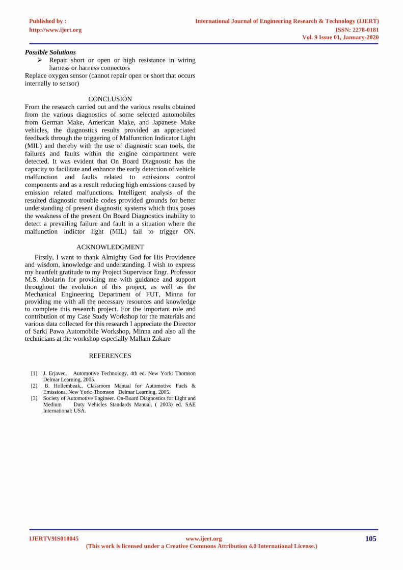
Possible Solutions
➢ Repair short or open or high resistance in wiring
harness or harness connectors
Replace oxygen sensor (cannot repair open or short that occurs
internally to sensor)
CONCLUSION
From the research carried out and the various results obtained
from the various diagnostics of some selected automobiles
from German Make, American Make, and Japanese Make
vehicles, the diagnostics results provided an appreciated
feedback through the triggering of Malfunction Indicator Light
(MIL) and thereby with the use of diagnostic scan tools, the
failures and faults within the engine compartment were
detected. It was evident that On Board Diagnostic has the
capacity to facilitate and enhance the early detection of vehicle
malfunction and faults related to emissions control
components and as a result reducing high emissions caused by
emission related malfunctions. Intelligent analysis of the
resulted diagnostic trouble codes provided grounds for better
understanding of present diagnostic systems which thus poses
the weakness of the present On Board Diagnostics inability to
detect a prevailing failure and fault in a situation where the
malfunction indictor light (MIL) fail to trigger ON.
ACKNOWLEDGMENT
Firstly, I want to thank Almighty God for His Providence and wisdom, knowledge and understanding. I wish to express my heartfelt gratitude to my Project Supervisor Engr. Professor M.S. Abolarin for providing me with guidance and support throughout the evolution of this project, as well as the Mechanical Engineering Department of FUT, Minna for providing me with all the necessary resources and knowledge to complete this research project. For the important role and contribution of my Case Study Workshop for the materials and various data collected for this research I appreciate the Director of Sarki Pawa Automobile Workshop, Minna and also all the technicians at the workshop especially Mallam Zakare
REFERENCES
[1] J. Erjavec, Automotive Technology, 4th ed. New York: Thomson
Delmar Learning, 2005.
[2] B. Hollembeak,. Classroom Manual for Automotive Fuels & Emissions. New York: Thomson Delmar Learning, 2005.
[3] Society of Automotive Engineer. On-Board Diagnostics for Light and
Medium Duty Vehicles Standards Manual, ( 2003) ed. SAE International: USA.
International Journal of Engineering Research & Technology (IJERT)
ISSN: 2278-0181http://www.ijert.org
IJERTV9IS010045(This work is licensed under a Creative Commons Attribution 4.0 International License.)
Published by :
www.ijert.org
Vol. 9 Issue 01, January-2020
105