A C-arm fluoroscopy-guided progressive cut refinement strategy using a surgical robot
18
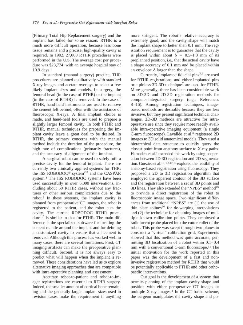
Biomedical Paper A C-Arm Fluoroscopy-Guided Progressive Cut Refinement Strategy Using a Surgical Robot Jianhua Yao, M.S., Russell H. Taylor, Ph.D., Randal P. Goldberg, M.S., Rajesh Kumar, M.S., Andrew Bzostek, M.S., Robert Van Vorhis, Ph.D., Peter Kazanzides, Ph.D., and Andre Gueziec, Ph.D. Departments of Computer Science (J.Y., R.H.T., R.K., A.B.) and Mechanical Engineering (R.P.G.), The Johns Hopkins University, Baltimore, Maryland; Integrated Surgical Systems, Davis, California (R.V.V., P.K.), and IBM T.J. Watson Research Center, Yorktown Heights, New York (A.G.) ABSTRACT We describe a new method to cut a precise, high-quality femoral cavity in Revision Total Hip Replacement surgery (RTHR) using a surgical robot and an intra-operative C-arm fluoroscope. With respect to previous approaches, our method contains several new features. (1) We describe a novel checkerboard plate designed to correct the geometric distortion within fluoroscopic images. Unlike previous distortion correction devices, the plate does not completely obscure any part of the image, and the distortion correction algorithm works well even when there are some overlaid objects in the field of view. (2) Also included are a novel corkscrew fiducial object designed to be integrated with the robot end-effector, and a 6D pose estimation algorithm based on the two- dimensional (2D) projection of the corkscrew, used in robot-imager registration and imager co- registration. (3) In addition, we develop a cavity location algorithm, which utilizes image subtraction and 2D anatomy contour registration techniques. (4) Finally, we propose a progressive cut refine- ment strategy, which progressively improves the robot registration during the procedure. We have conducted several experiments, in both simulated and in vitro environments. The results indicate that our strategy is a promising method for precise orthopedic procedures like total hip replacement. Comp Aid Surg 5:373–390 (2000). ©2001 Wiley-Liss, Inc. Key words: C-arm fluoroscopy guidance, cut refinement, image registration, surgical robot INTRODUCTION This paper describes novel techniques permitting the use of portable fluoroscopic C-arms for intra- operative localization and guidance in robotically assisted orthopaedic surgery. Specifically, our goal is to direct the robot to cut a precisely defined shape in a bone that has been located in C-arm images without requiring additional navigation equipment such as an optical tracking system. Instead, we emphasize the use of feedback from the images themselves to provide robust registration and adap- tation to residual calibration errors. Our research is part of a joint project with Integrated Surgical Systems (ISS) to develop a computer-integrated system to assist surgeons in Revision Total Hip Replacement surgery (RTHR). RTHR is performed after a patient has had PTHR Received November 1, 1999; accepted November 15, 2000. Address correspondence/reprint requests to: Jianhua Yao, NEB 224, Department of Computer Science, The Johns Hopkins University, Baltimore, MD 21218, USA; Telephone: (410) 516-4057; E-mail: [email protected]. Computer Aided Surgery 5:373–390 (2000) ©2001 Wiley-Liss, Inc.
-
Upload
independent -
Category
Documents
-
view
2 -
download
0
Transcript of A C-arm fluoroscopy-guided progressive cut refinement strategy using a surgical robot
Biomedical Paper
A C-Arm Fluoroscopy-Guided Progressive CutRefinement Strategy Using a Surgical Robot
Jianhua Yao, M.S., Russell H. Taylor, Ph.D., Randal P. Goldberg, M.S., Rajesh Kumar, M.S.,Andrew Bzostek, M.S., Robert Van Vorhis, Ph.D., Peter Kazanzides, Ph.D.,
and Andre Gueziec, Ph.D.
Departments of Computer Science (J.Y., R.H.T., R.K., A.B.) and Mechanical Engineering (R.P.G.),The Johns Hopkins University, Baltimore, Maryland; Integrated Surgical Systems, Davis, California
(R.V.V., P.K.), and IBM T.J. Watson Research Center, Yorktown Heights, New York (A.G.)
ABSTRACT We describe a new method to cut a precise, high-quality femoral cavity in RevisionTotal Hip Replacement surgery (RTHR) using a surgical robot and an intra-operative C-armfluoroscope. With respect to previous approaches, our method contains several new features. (1) Wedescribe a novel checkerboard plate designed to correct the geometric distortion within fluoroscopicimages. Unlike previous distortion correction devices, the plate does not completely obscure any partof the image, and the distortion correction algorithm works well even when there are some overlaidobjects in the field of view. (2) Also included are a novel corkscrew fiducial object designed to beintegrated with the robot end-effector, and a 6D pose estimation algorithm based on the two-dimensional (2D) projection of the corkscrew, used in robot-imager registration and imager co-registration. (3) In addition, we develop a cavity location algorithm, which utilizes image subtractionand 2D anatomy contour registration techniques. (4) Finally, we propose a progressive cut refine-ment strategy, which progressively improves the robot registration during the procedure. We haveconducted several experiments, in both simulated and in vitro environments. The results indicatethat our strategy is a promising method for precise orthopedic procedures like total hip replacement.Comp Aid Surg 5:373–390 (2000). ©2001 Wiley-Liss, Inc.
Key words: C-arm fluoroscopy guidance, cut refinement, image registration, surgical robot
INTRODUCTIONThis paper describes novel techniques permittingthe use of portable fluoroscopic C-arms for intra-operative localization and guidance in roboticallyassisted orthopaedic surgery. Specifically, our goalis to direct the robot to cut a precisely defined shapein a bone that has been located in C-arm imageswithout requiring additional navigation equipmentsuch as an optical tracking system. Instead, we
emphasize the use of feedback from the imagesthemselves to provide robust registration and adap-tation to residual calibration errors.
Our research is part of a joint project withIntegrated Surgical Systems (ISS) to develop acomputer-integrated system to assist surgeons inRevision Total Hip Replacement surgery (RTHR).RTHR is performed after a patient has had PTHR
Received November 1, 1999; accepted November 15, 2000.
Address correspondence/reprint requests to: Jianhua Yao, NEB 224, Department of Computer Science, The Johns HopkinsUniversity, Baltimore, MD 21218, USA; Telephone: (410) 516-4057; E-mail: [email protected].
Computer Aided Surgery 5:373–390 (2000)
©2001 Wiley-Liss, Inc.
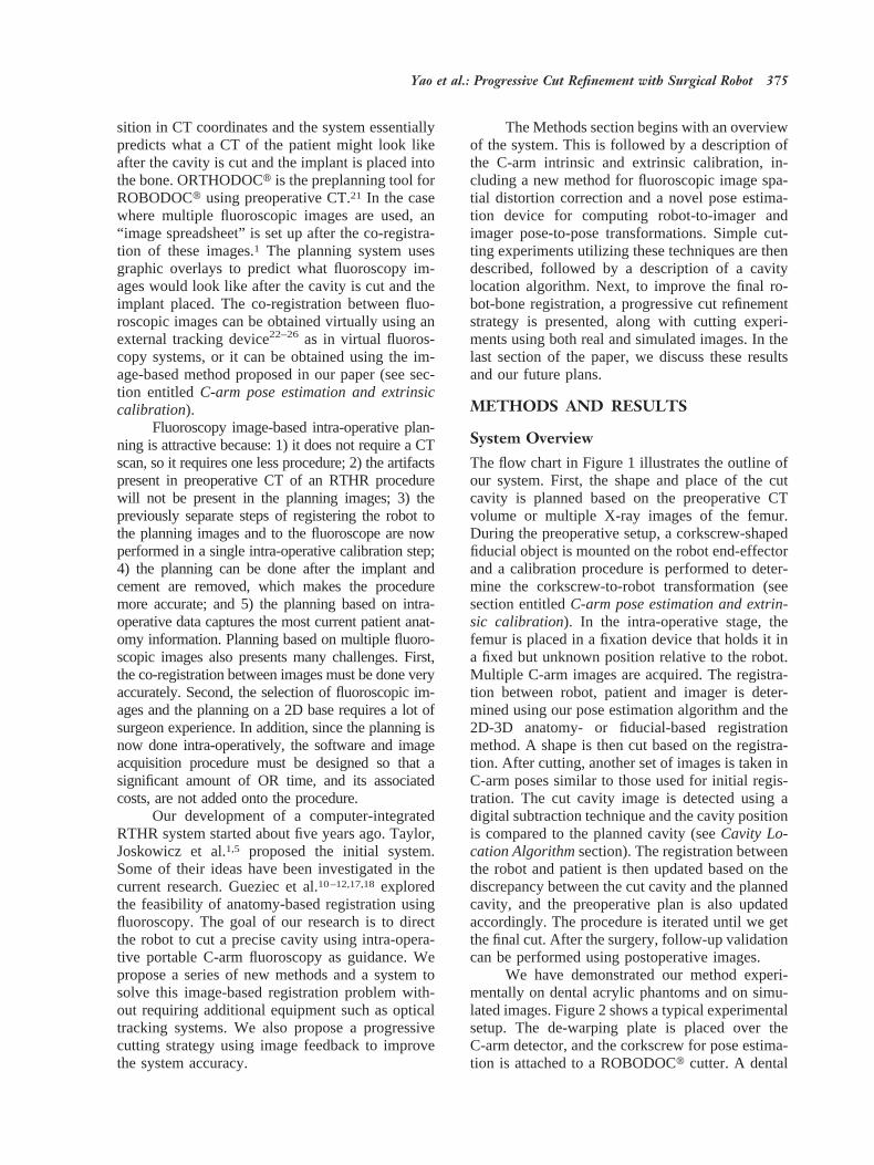
(Primary Total Hip Replacement surgery) and theimplant has failed for some reason. RTHR is amuch more difficult operation, because less bonetissue remains and a precise, high-quality cavity isrequired. In 1992, 27,000 RTHR procedures wereperformed in the U.S. The average cost per proce-dure was $23,774, with an average hospital stay of10.9 days.1
In standard (manual surgery) practice, THRprocedures are planned qualitatively with standardX-ray images and acetate overlays to select a fewlikely implant sizes and models. In surgery, thefemoral head (in the case of PTHR) or the implant(in the case of RTHR) is removed. In the case ofRTHR, hand-held instruments are used to removethe cement left behind, often with the assistance offluoroscopic X-rays. A final implant choice ismade, and hand-held tools are used to prepare aslightly larger femoral cavity. In both PTHR andRTHR, manual techniques for preparing the im-plant cavity leave a great deal to be desired. InRTHR, the primary concerns with the manualmethod include the duration of the procedure, thehigh rate of complications (primarily fractures),and the accuracy of alignment of the implant.
A surgical robot can be used to safely mill aprecise cavity for the femoral implant. There arecurrently two clinically applied systems for THR:the ISS ROBODOCt system2,3 and the CASPARsystem.4 The ISS ROBODOC systems have beenused successfully in over 6,000 interventions, in-cluding about 50 RTHR cases, without any frac-tures or other serious complications due to therobot.2 In these systems, the implant cavity isplanned from preoperative CT images, the robot isregistered to the patient, and the robot cuts thecavity. The current ROBODOC RTHR proce-dure1,5 is similar to that for PTHR. The main dif-ference is the specialized software for locating thecement mantle around the implant and for defininga customized cavity to ensure that all cement isremoved. Although this process has worked well inmany cases, there are several limitations. First, CTimaging artifacts can make the preoperative plan-ning difficult. Second, it is not always easy topredict what will happen when the implant is re-moved. These considerations have led us to explorealternative imaging approaches that are compatiblewith intra-operative planning and assessment.
Accurate robot-to-patient and robot-to-im-ager registrations are essential to RTHR surgery.Indeed, the smaller amount of cortical bone remain-ing and the generally larger implant sizes used inrevision cases make the requirement if anything
more stringent. The robot’s relative accuracy isextremely good, and the cavity shape will matchthe implant shape to better than 0.1 mm. The reg-istration requirement is to guarantee that the cavityis placed within aboutd 5 0.5–1.0 mm of itspreplanned position, i.e., that the actual cavity havea shape accuracy of 0.1 mm and be placed withinan enveloped larger than the shape.
Currently, implanted fiducial pins2,6 are usedfor RTHR registrations, and either implanted pinsor a pinless 3D-3D technique7 are used for PTHR.More generally, there has been considerable workon 3D-3D and 2D-3D registration methods forcomputer-integrated surgery (e.g., References8–16). Among registration techniques, image-based methods are desirable because they are lessinvasive, but they present significant technical chal-lenges. 2D-3D methods are attractive for intra-operative use since they require more readily avail-able intra-operative imaging equipment (a singleC-arm fluoroscope). Lavalle´e et al.8 registered 2Dimages to 3D solid anatomical models. They used ahierarchical data structure to quickly query theclosest point from anatomy surface to X-ray paths.Hamadeh et al.9 extended this work by using cooper-ation between 2D-3D registration and 2D segmenta-tion. Gueziec et al.10–12,17,18explored the feasibility ofanatomy-based registration using fluoroscopy.Theyproposed a 2D to 3D registration algorithm thatemployed the apparent contour of the 3D surfaceand the registration between a set of 3D points and3D lines. They also extended the “NPBS” method19
to provide a direct registration of the robot tofluoroscopic image space. Two significant differ-ences from traditional “NPBS” are (1) the use ofthin plate splines20 for de-warping interpolationsand (2) the technique for obtaining images of mul-tiple known calibration points. They employed aradiolucent probe placed into the cutter collet of therobot. This probe was swept through two planes toconstruct a “virtual” calibration grid. Experimentsshowed that this method was quite accurate, per-mitting 3D localization of a robot within 0.1–0.4mm with a conventional C-arm fluoroscope.11 Theinitial motivation for the work reported in thispaper was the development of a fast and non-invasive registration method for RTHR that wouldbe potentially applicable to PTHR and other ortho-paedic interventions.
Our goal is the development of a system thatpermits planning of the implant cavity shape andposition with either preoperative CT images ormultiple X-ray images.1 In the CT-based scheme,the surgeon manipulates the cavity shape and po-
374 Yao et al.: Progressive Cut Refinement with Surgical Robot
sition in CT coordinates and the system essentiallypredicts what a CT of the patient might look likeafter the cavity is cut and the implant is placed intothe bone. ORTHODOCt is the preplanning tool forROBODOCt using preoperative CT.21 In the casewhere multiple fluoroscopic images are used, an“image spreadsheet” is set up after the co-registra-tion of these images.1 The planning system usesgraphic overlays to predict what fluoroscopy im-ages would look like after the cavity is cut and theimplant placed. The co-registration between fluo-roscopic images can be obtained virtually using anexternal tracking device22–26 as in virtual fluoros-copy systems, or it can be obtained using the im-age-based method proposed in our paper (see sec-tion entitledC-arm pose estimation and extrinsiccalibration).
Fluoroscopy image-based intra-operative plan-ning is attractive because: 1) it does not require a CTscan, so it requires one less procedure; 2) the artifactspresent in preoperative CT of an RTHR procedurewill not be present in the planning images; 3) thepreviously separate steps of registering the robot tothe planning images and to the fluoroscope are nowperformed in a single intra-operative calibration step;4) the planning can be done after the implant andcement are removed, which makes the proceduremore accurate; and 5) the planning based on intra-operative data captures the most current patient anat-omy information. Planning based on multiple fluoro-scopic images also presents many challenges. First,the co-registration between images must be done veryaccurately. Second, the selection of fluoroscopic im-ages and the planning on a 2D base requires a lot ofsurgeon experience. In addition, since the planning isnow done intra-operatively, the software and imageacquisition procedure must be designed so that asignificant amount of OR time, and its associatedcosts, are not added onto the procedure.
Our development of a computer-integratedRTHR system started about five years ago. Taylor,Joskowicz et al.1,5 proposed the initial system.Some of their ideas have been investigated in thecurrent research. Gueziec et al.10–12,17,18exploredthe feasibility of anatomy-based registration usingfluoroscopy. The goal of our research is to directthe robot to cut a precise cavity using intra-opera-tive portable C-arm fluoroscopy as guidance. Wepropose a series of new methods and a system tosolve this image-based registration problem with-out requiring additional equipment such as opticaltracking systems. We also propose a progressivecutting strategy using image feedback to improvethe system accuracy.
The Methods section begins with an overviewof the system. This is followed by a description ofthe C-arm intrinsic and extrinsic calibration, in-cluding a new method for fluoroscopic image spa-tial distortion correction and a novel pose estima-tion device for computing robot-to-imager andimager pose-to-pose transformations. Simple cut-ting experiments utilizing these techniques are thendescribed, followed by a description of a cavitylocation algorithm. Next, to improve the final ro-bot-bone registration, a progressive cut refinementstrategy is presented, along with cutting experi-ments using both real and simulated images. In thelast section of the paper, we discuss these resultsand our future plans.
METHODS AND RESULTS
System OverviewThe flow chart in Figure 1 illustrates the outline ofour system. First, the shape and place of the cutcavity is planned based on the preoperative CTvolume or multiple X-ray images of the femur.During the preoperative setup, a corkscrew-shapedfiducial object is mounted on the robot end-effectorand a calibration procedure is performed to deter-mine the corkscrew-to-robot transformation (seesection entitledC-arm pose estimation and extrin-sic calibration). In the intra-operative stage, thefemur is placed in a fixation device that holds it ina fixed but unknown position relative to the robot.Multiple C-arm images are acquired. The registra-tion between robot, patient and imager is deter-mined using our pose estimation algorithm and the2D-3D anatomy- or fiducial-based registrationmethod. A shape is then cut based on the registra-tion. After cutting, another set of images is taken inC-arm poses similar to those used for initial regis-tration. The cut cavity image is detected using adigital subtraction technique and the cavity positionis compared to the planned cavity (seeCavity Lo-cation Algorithmsection). The registration betweenthe robot and patient is then updated based on thediscrepancy between the cut cavity and the plannedcavity, and the preoperative plan is also updatedaccordingly. The procedure is iterated until we getthe final cut. After the surgery, follow-up validationcan be performed using postoperative images.
We have demonstrated our method experi-mentally on dental acrylic phantoms and on simu-lated images. Figure 2 shows a typical experimentalsetup. The de-warping plate is placed over theC-arm detector, and the corkscrew for pose estima-tion is attached to a ROBODOCt cutter. A dental
Yao et al.: Progressive Cut Refinement with Surgical Robot 375
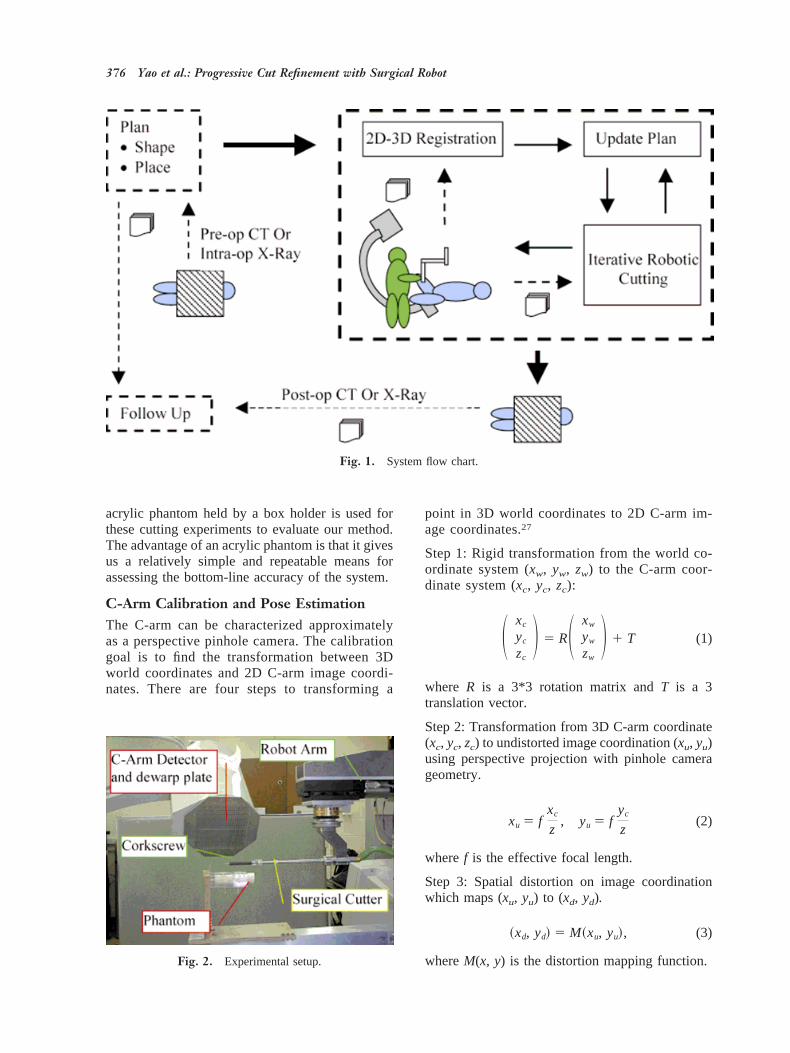
acrylic phantom held by a box holder is used forthese cutting experiments to evaluate our method.The advantage of an acrylic phantom is that it givesus a relatively simple and repeatable means forassessing the bottom-line accuracy of the system.
C-Arm Calibration and Pose EstimationThe C-arm can be characterized approximatelyas a perspective pinhole camera. The calibrationgoal is to find the transformation between 3Dworld coordinates and 2D C-arm image coordi-nates. There are four steps to transforming a
point in 3D world coordinates to 2D C-arm im-age coordinates.27
Step 1: Rigid transformation from the world co-ordinate system (xw, yw, zw) to the C-arm coor-dinate system (xc, yc, zc):
S xc
yc
zc
D 5 RS xw
yw
zw
D 1 T (1)
where R is a 3*3 rotation matrix andT is a 3translation vector.
Step 2: Transformation from 3D C-arm coordinate(xc, yc, zc) to undistorted image coordination (xu, yu)using perspective projection with pinhole camerageometry.
xu 5 fxc
z, yu 5 f
yc
z(2)
wheref is the effective focal length.
Step 3: Spatial distortion on image coordinationwhich maps (xu, yu) to (xd, yd).
~xd, yd! 5 M~xu, yu!, (3)
whereM(x, y) is the distortion mapping function.
Fig. 1. System flow chart.
Fig. 2. Experimental setup.
376 Yao et al.: Progressive Cut Refinement with Surgical Robot
Step 4: Physical image coordinate (xd, yd) to com-puter image coordinate (xf, yf) transformation.
xf 5xd
px1 cx, yf 5
yd
py1 cy (4)
where (px, py) is the pixel scaling on the image baseand (cx, cy) is the image center.
The parameters used in these four steps canbe categorized into two classes:
1. Intrinsic Parameters. The effective focallength, or image plane to projective center dis-tance,f; the image center, (cx, cy); the pixelscaling, (px, py); and the distortion map,M(x, y).
2. Extrinsic Parameters. There are six extrinsicparameters: the Euler angles yawa, pitch b,and tilt g for RotationR, and the three com-ponents (Tx, Ty, Tz) for the translation vectorT. The process of computing the extrinsicparameter is also called pose estimation.
The calibration method in our system will bedescribed in the next two sections below.
Intrinsic Image CalibrationIntrinsic imaging parameters correspond to imagewarping, focal length, pixel scaling, and imagecenter, and can be computed by analyzing an imageof a calibration object of known geometry. Thecalibration method of Schreiner et al.28 was used tocompute the C-arm focal length, the pixel scaling,and the image center. It has been reported in theliterature that the focal length may change up toseveral millimeters at different C-arm poses.29 Cur-rently, this change in focal length results in achange of pixel size, which is captured by thede-warping algorithm. This allows the change infocal length to be accounted for.
In general, the curved geometry of the X-raydetector causes a circular symmetric distortion, andthe interaction of the electrons in the intensifiertube with the Earth’s magnetic field causes anasymmetric distortion. Thus, the C-arm exhibitsdiffering but repeatable distortions at differentposes. Using fluoroscopic X-ray imaging for quan-titative measurement requires precise calibration ofthe imager to eliminate these spatial distortions.Some researchers conducted extensive investiga-tions on this topic. Boone et al.30 provided thetheory and analysis of the nature of the distortionand proposed some software techniques to correctit. Schreiner et al.28 implemented Boone’s methodby placing a grid of radiopaque spheres over the
C-arm detector. Fahrig et al.29 also used a grid ofsmall steel beads to correct the distortion and fit afifth-order polynomial of distortions based on thepose of the C-arm. Yaniv et al.31 also reported theirfluoroscopic image de-warping technique for a com-puter-integrated bone fracture reduction system. Theyused a grid of beads to generate a de-warping map ofthe pixels at the bead location and used bilinear in-terpolation to obtain the map for the rest of the pixels.Gueziec et al.12 extended the “NPBS” method toprovide a method that combined the fluoroscopic im-age de-warping and calibration.
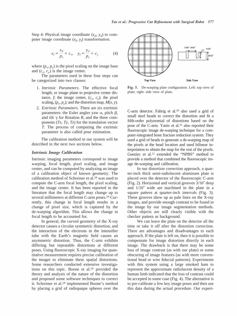
In our distortion correction approach, a quar-ter-inch thick semi-radiolucent aluminum plate isplaced over the detector of the fluoroscopic C-arm(Fig. 2). Horizontal and vertical grooves 3/160 deepand 1/160 wide are machined in the plate in asquare pattern at quarter-inch intervals (Fig. 3).These grooves show up as pale lines on the X-rayimages, and provide enough contrast to be found inthe image by our image segmentation methods.Other objects are still clearly visible with thechecker pattern as background.
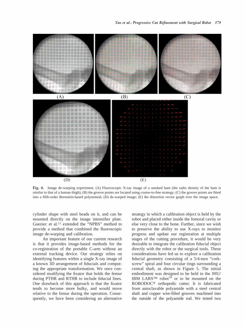
We can leave the plate on the detector all thetime or take it off after the distortion correction.There are advantages and disadvantages to eachapproach. If the plate is left on, then it is possible tocompensate for image distortion directly in eachimage. The drawback is that there may be someloss of image contrast (as with our plate) or someobscuring of image features (as with more conven-tional bead or wire fiducial patterns). Experimentswith this system using a large smoked ham torepresent the approximate radiolucent density of ahuman limb indicated that the loss of contrast couldbe accepted in some case (Fig. 4). The alternative isto pre-calibrate a few key image poses and then usethis data during the actual procedure. Our experi-
Fig. 3. De-warping plate configuration. Left: top view ofplate; right: side view of plate.
Yao et al.: Progressive Cut Refinement with Surgical Robot 377
ments were done with a 1970s-era C-arm (GEPolarix 2). We chose the latter approach during thecutting experiments described below, since it sim-plified image processing and reduced artifacts withour very old C-arm.
We have investigated various algorithms to usewith this checkerboard plate to compensate for fluo-roscopic image distortion. Methods examined includePiecewise Polynomial Mapping Algorithms, ThinPlate Spline Morphometric Algorithms,20 and a Two-Pass Scanline Algorithm.32 Our current preferredchoice outlined below is based on a variant of aTwo-Pass Scanline Algorithm.
1. Image points (ui, vi) corresponding to thecenterline of each vertical and horizontal grooveare found. First, the profiles of the image densityalong the horizontal and vertical directions are ob-tained by summing up all pixel values on the hor-izontal and vertical scan line. Then the image spaceis subdivided into small square regions at the peaksof the profiles. Hence, each small square regioncontains only one square. In each region, thegroove points are first roughly located at the peakpoint of image intensity between two squares, thenthey are refined by the constraints between groovepoints in neighborhood regions (smoothness, con-tinuity, and gradient).
2. A fifth-order Bernstein polynomial is fitted toeach vertical or horizontal groove using the entire setof candidate groove points found in that groove. TheBernstein polynomial is defined by Equation (5):
u 5 B~a0, . . . , a5; n! 5 Ok50
5
akS 5k D ~1 2 n!52knk
(5)
The fitting operation is to find theak to minimizethe least square metric
S@ui 2 B~a0, k, a5; ni!#2
Bernstein polynomial curves have several advan-tages compared to regular power basis polynomialcurves. They are more robust, less sensitive tonoise, and have the ability to smoothly interpolatethe missing part of the curve.
3. A Two-Pass Scanline Algorithm is em-ployed to correct the image distortion.32 The firstpass is responsible for re-sampling each row inde-pendently. It maps all (u, v) to their (x, v) coordi-nates in an intermediate imageI . The second pass
then re-samples each column inI , mapping every(x, v) to its final (x, y) position.
In the first pass, for each horizontal scan line inthe image, the intersections between the scan line andthe vertical Bernstein-based curves found in the abovesteps are computed. Thus, the scan line is divided intosmall intervals and the intersection points are used tofit a piece-wise cubic spline using the displacementsfrom their ideal locations. By interpolating all thepixels on the scan line using the cubic spline line, theimage can be re-sampled in the horizontal direction.This process is repeated to correct the distortion of thegrid in the vertical direction.
Our experience so far with this method is thatit is fast and robust. Sample experimental imageson smoked ham can be found in Figure 4. Thefigure shows the intermediate steps and result of thede-warping algorithm, and a distortion vector graphover the image space.
The accuracy of the distortion correction pro-cess was verified by following experiment. First,one image with the checkerboard plate was taken,the spatial distortion of the image was corrected,and the lookup table was saved. Next, a set of beadsspaced 20 mm apart was attached over the plate,and another image was taken. The image of thebeads was then de-warped using the saved lookuptable. The beads were detected in the image and thedistances between pairs of beads computed. Com-parison of the computed distance and the knownactual distance between beads gives an assessmentof the accuracy of the de-warping algorithm. Themean error was 0.12 mm on the central area (ap-proximately 1203 120 mm) and 0.25 mm on themarginal area. Pixel size is approximately 0.32mm. This shows that our distortion correctionmethod provides reasonably accurate results.
C-Arm Pose Estimation and ExtrinsicCalibrationFor extrinsic calibration, the task is to compute thetransformation between the C-arm coordinate sys-tem and other intra-operative coordinate systemssuch as the patient’s anatomy, the robot, and thesurgical tool. There are a number of papers thatdescribe 2D-3D registration of C-arm images topreoperative CT.8–10,33There are also several sys-tems that combine intra-operative C-arm imageswith intra-operative navigation systems to assist insurgical task execution.22–26Typically, those meth-ods rely on external tracking devices such as theOptotrakt to determine relative changes in C-armposes. Yaniv et al.31 designed a calibration objectto perform C-arm calibration. The object has a
378 Yao et al.: Progressive Cut Refinement with Surgical Robot
cylinder shape with steel beads on it, and can bemounted directly on the image intensifier plate.Gueziec et al.12 extended the “NPBS” method toprovide a method that combined the fluoroscopicimage de-warping and calibration.
An important feature of our current researchis that it provides image-based methods for theco-registration of the portable C-arm without anexternal tracking device. Our strategy relies onidentifying features within a single X-ray image ofa known 3D arrangement of fiducials and comput-ing the appropriate transformation. We once con-sidered modifying the fixator that holds the femurduring PTHR and RTHR to include fiducial lines.One drawback of this approach is that the fixatortends to become more bulky, and would moverelative to the femur during the operation. Conse-quently, we have been considering an alternative
strategy in which a calibration object is held by therobot and placed either inside the femoral cavity orelse very close to the bone. Further, since we wishto preserve the ability to use X-rays to monitorprogress and update our registration at multiplestages of the cutting procedure, it would be verydesirable to integrate the calibration fiducial objectdirectly with the robot or the surgical tools. Theseconsiderations have led us to explore a calibrationfiducial geometry consisting of a 5/4-turn “cork-screw” spiral and four circular rings surrounding acentral shaft, as shown in Figure 5. The initialembodiment was designed to be held in the JHU/IBM LARS™ robot34 or to be mounted on theROBODOCt orthopedic cutter. It is fabricatedfrom autoclavable polyamide with a steel centralshaft and copper wire-filled grooves machined intothe outside of the polyamide rod. We tested two
Fig. 4. Image de-warping experiment. (A) Fluoroscopic X-ray image of a smoked ham (the radio density of the ham issimilar to that of a human thigh); (B) the groove points are located using coarse-to-fine strategy; (C) the groove points are fittedinto a fifth-order Bernstein-based polynomial; (D) de-warped image; (E) the distortion vector graph over the image space.
Yao et al.: Progressive Cut Refinement with Surgical Robot 379
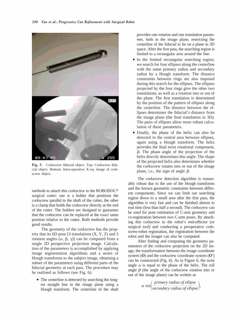
methods to attach this corkscrew to the ROBODOCtsurgical cutter: one is a holder that positions thecorkscrew parallel to the shaft of the cutter, the otheris a clamp that holds the corkscrew directly at the endof the cutter. The holders are designed to guaranteethat the corkscrew can be replaced at the exact sameposition relative to the cutter. Both methods providegood results.
The geometry of the corkscrew has the prop-erty that its 6D pose [3 translations (X, Y, Z) and 3rotation angles (a, b, g)] can be computed from asingle 2D perspective projection image. Calcula-tion of the parameters is accomplished by applyingimage segmentation algorithms and a series ofHough transforms to the subject image, obtaining asubset of the parameters using different parts of thefiducial geometry at each pass. The procedure maybe outlined as follows (see Fig. 6):
● The centerline is detected by searching the long-est straight line in the image plane using aHough transform. The centerline of the shaft
provides one rotation and one translation param-eter, both in the image plane, restricting thecenterline of the fiducial to lie on a plane in 3Dspace. After the first pass, the searching region islimited to a rectangular area around the line.
● In the limited rectangular searching region,we search for four ellipses along the centerlinewith the same primary radius and secondaryradius by a Hough transform. The distanceconstraints between rings are also imposedduring this search for the ellipses. The ellipsesprojected by the four rings give the other twotranslations, as well as a rotation into or out ofthe plane. The first translation is determinedby the position of the pattern of ellipses alongthe centerline. The distance between the el-lipses determines the fiducial’s distance fromthe image plane (the final translation in 3D).The pairs of ellipses allow more robust calcu-lation of these parameters.
● Finally, the phase of the helix can also bedetected in the central area between ellipses,again using a Hough transform. The helixprovides the final twist rotational component,b. The phase angle of the projection of thehelix directly determines this angle. The shapeof the projected helix also determines whetherthe corkscrew rotates into or out of the imageplane, i.e., the sign of angleb.
The corkscrew detection algorithm is reason-ably robust due to the use of the Hough transformsand the known geometric constraints between differ-ent components. Since we can limit our searchingregion down to a small area after the first pass, thealgorithm is very fast and can be finished almost inreal time (less than half a second). The corkscrew canbe used for pose estimation of C-arm geometry andco-registration between two C-arm poses. By attach-ing this corkscrew to the robot’s end-effector (orsurgical tool) and conducting a preoperative cork-screw-robot registration, the registration between therobot and the imager can also be computed.
After finding and computing the geometry pa-rameters of the corkscrew projection on the 2D im-age, the transformation between the image coordinatesystem (O) and the corkscrew coordinate system (O*)can be constructed (Fig. 6). As in Figure 6, the twistanglea is equal to the phase of the helix. The rollangleb (the angle of the corkscrew rotation into orout of the image plane) can be written as
a sinS primary radius of ellipse
secondary radius of ellipseD,
Fig. 5. Corkscrew fiducial object. Top: Corkscrew fidu-cial object. Bottom: Intra-operative X-ray image of cork-screw object.
380 Yao et al.: Progressive Cut Refinement with Surgical Robot
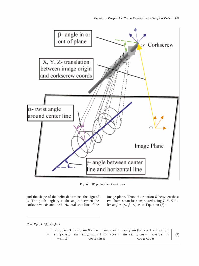
and the shape of the helix determines the sign ofb. The pitch angleg is the angle between thecorkscrew axis and the horizontal scan line of the
image plane. Thus, the rotationR between thesetwo frames can be constructed using Z-Y-X Eu-ler angles (g, b, a) as in Equation (6):
R 5 RZ~g! RY~b! RX~a!
5 F cosg cosb cosg sin b sin a 2 sin g cosasin g cosb sin g sin b sin a 1 cosg cosa
2sin b cosb sin a
cosg sin b cosa 1 sin g sin asin g sin b cosa 2 cosg sin a
cosb cosaG (6)
Fig. 6. 2D projection of corkscrew.
Yao et al.: Progressive Cut Refinement with Surgical Robot 381
The translationT (Tx, Ty, Tz) between two framescan be computed using Equation (7),
Tx
Tx95
l cosb
l9,
Ty
Ty95
l cosb
l9,
f 2 Tz
f5
l cosb
l9(7)
wheref is the focal length,l is the physical lengthof the corkscrew,l9 is the projected length of thecorkscrew computed from the image, and (Tx9, Ty9)is the 2D translation of the corkscrew in the imageplane.
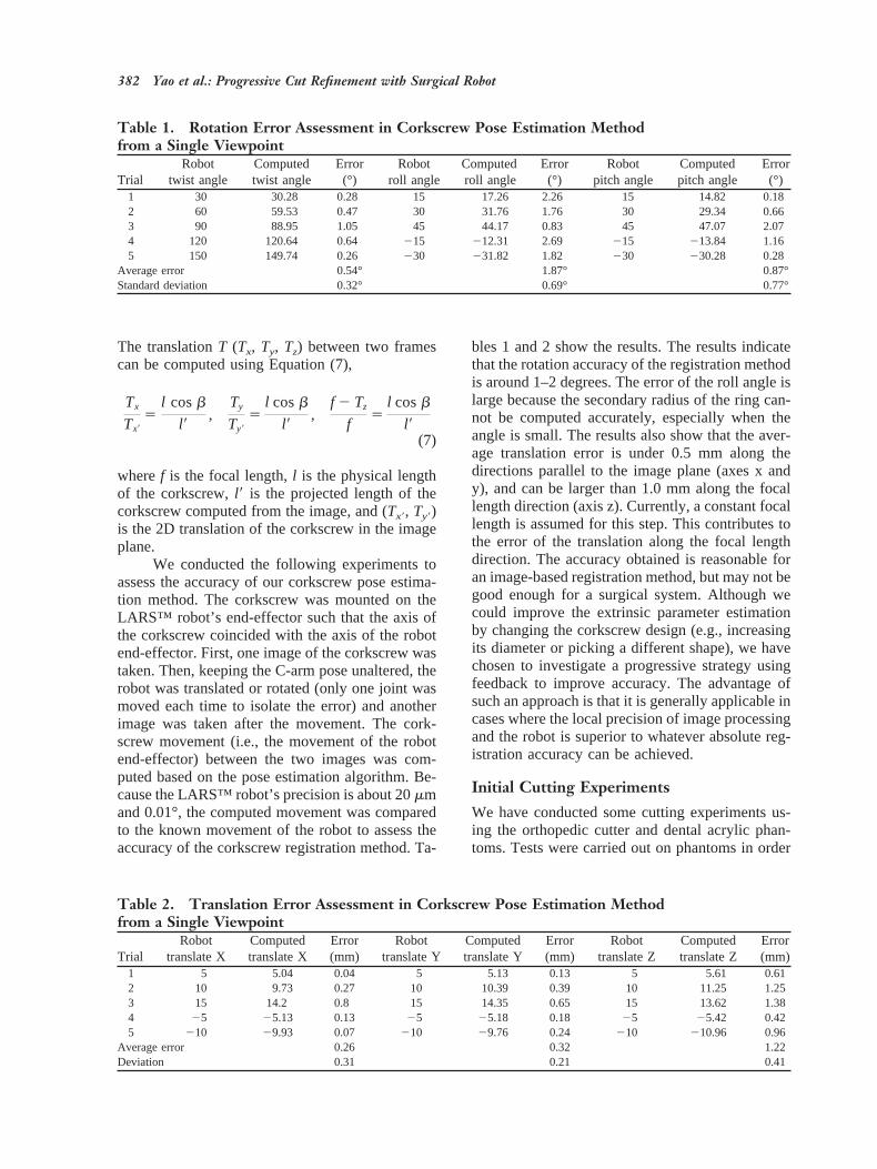
We conducted the following experiments toassess the accuracy of our corkscrew pose estima-tion method. The corkscrew was mounted on theLARS™ robot’s end-effector such that the axis ofthe corkscrew coincided with the axis of the robotend-effector. First, one image of the corkscrew wastaken. Then, keeping the C-arm pose unaltered, therobot was translated or rotated (only one joint wasmoved each time to isolate the error) and anotherimage was taken after the movement. The cork-screw movement (i.e., the movement of the robotend-effector) between the two images was com-puted based on the pose estimation algorithm. Be-cause the LARS™ robot’s precision is about 20mmand 0.01°, the computed movement was comparedto the known movement of the robot to assess theaccuracy of the corkscrew registration method. Ta-
bles 1 and 2 show the results. The results indicatethat the rotation accuracy of the registration methodis around 1–2 degrees. The error of the roll angle islarge because the secondary radius of the ring can-not be computed accurately, especially when theangle is small. The results also show that the aver-age translation error is under 0.5 mm along thedirections parallel to the image plane (axes x andy), and can be larger than 1.0 mm along the focallength direction (axis z). Currently, a constant focallength is assumed for this step. This contributes tothe error of the translation along the focal lengthdirection. The accuracy obtained is reasonable foran image-based registration method, but may not begood enough for a surgical system. Although wecould improve the extrinsic parameter estimationby changing the corkscrew design (e.g., increasingits diameter or picking a different shape), we havechosen to investigate a progressive strategy usingfeedback to improve accuracy. The advantage ofsuch an approach is that it is generally applicable incases where the local precision of image processingand the robot is superior to whatever absolute reg-istration accuracy can be achieved.
Initial Cutting Experiments
We have conducted some cutting experiments us-ing the orthopedic cutter and dental acrylic phan-toms. Tests were carried out on phantoms in order
Table 1. Rotation Error Assessment in Corkscrew Pose Estimation Methodfrom a Single Viewpoint
TrialRobot
twist angleComputedtwist angle
Error(°)
Robotroll angle
Computedroll angle
Error(°)
Robotpitch angle
Computedpitch angle
Error(°)
1 30 30.28 0.28 15 17.26 2.26 15 14.82 0.182 60 59.53 0.47 30 31.76 1.76 30 29.34 0.663 90 88.95 1.05 45 44.17 0.83 45 47.07 2.074 120 120.64 0.64 215 212.31 2.69 215 213.84 1.165 150 149.74 0.26 230 231.82 1.82 230 230.28 0.28
Average error 0.54° 1.87° 0.87°Standard deviation 0.32° 0.69° 0.77°
Table 2. Translation Error Assessment in Corkscrew Pose Estimation Methodfrom a Single Viewpoint
TrialRobot
translate XComputedtranslate X
Error(mm)
Robottranslate Y
Computedtranslate Y
Error(mm)
Robottranslate Z
Computedtranslate Z
Error(mm)
1 5 5.04 0.04 5 5.13 0.13 5 5.61 0.612 10 9.73 0.27 10 10.39 0.39 10 11.25 1.253 15 14.2 0.8 15 14.35 0.65 15 13.62 1.384 25 25.13 0.13 25 25.18 0.18 25 25.42 0.425 210 29.93 0.07 210 29.76 0.24 210 210.96 0.96
Average error 0.26 0.32 1.22Deviation 0.31 0.21 0.41
382 Yao et al.: Progressive Cut Refinement with Surgical Robot
to verify basic system accuracy and to gain confi-dence in overall system behavior. The following isa general procedure for a cutting experiment.
Step 1: The corkscrew is attached to the cuttermounted on the robot end-effector. A separate pro-cedure is performed to calibrate the robot and thecorkscrew, i.e., to computeFrobot-corkscrew.
Step 2: Several images (typically two images) ofthe corkscrew and the femur (phantom) are taken.Then the registration,Fcorkscrew-imager, between thecorkscrew and the imager is computed using thecorkscrew pose estimation algorithm described inthe section entitledC-arm pose estimation and ex-trinsic calibration. The registrationFfemur-imagerbetween the femur and the imager isobtained using the femur anatomy or fiducial beads(at present fiducial beads are used). Finally theregistration between femur and robot is written as
Frobot-femur5 Frobot-corkscrewz Fcorkscrew-imager z Fimager-femur
Step 3: The cutter is moved to the starting position,and a predefined shape is cut. At present, a con-stant-orientation cutting strategy is employed and acubic staircase pocket is machined at the center ofthe phantom along the long axis of the phantom.
The cavity position error was determined bymeasuring wall thickness using calipers. With anangular separation of about 50 degrees betweentwo C-arm views, we observed a cavity placementerror of around 0.5 mm to 1.5 mm. A number offactors may account for the errors in this initialregistration. To begin with, the elderly Polarix 2fluoroscope being used in these experiments pro-vides relatively poor resolution, resulting in smallerrors in location of the fiducial patterns (bothcorkscrew and beads). In addition, the robot con-figuration being used for these experiments pro-vides only translational degrees of freedom. There-fore, the assumption is made that the axis of thecutter, the x-axis of the robot, the central axis of thecoil, and the axis of the phantom are all exactlycollinear. Since no control is available to correct formisalignments between these axes, small devia-tions from this assumption can result in significantpositioning error. In any case, these results led us toexplore a progressive cutting strategy described inthe next two sections.
Cavity Location AlgorithmWe are investigating a progressive cut refinementstrategy to improve the cavity placement accuracy.
First a small cavity is cut, then a cavity locationalgorithm is applied to compute the discrepancybetween the real cut pocket and the cut model, andthe registration between the robot and femur anat-omy is adjusted accordingly. During the next cut, alarger pocket is milled and the process is repeateduntil the final desired shape has been cut. Theprogressive cut refinement strategy is practical, be-cause in present ROBODOCt PTHR surgery, thecavity is already milled in similar stages.
The idea of progressive cutting is straightfor-ward. The problem is how to measure the errorafter each cut using the fluoroscopic C-arm. Wedeveloped the following cavity location algorithmto solve this problem. The 3D surface model of thecut cavity (a list of triangular facets) and its trans-formation relative to the femur is planned in thepreoperative stage. After one progressive cut, sev-eral images of the cut cavity and corkscrew aretaken from different view angles. The C-arm ge-ometry of each image is constructed using the cork-screw pose estimation algorithm. At each pose, animage subtraction technique is employed to gener-ate the 2D contour of the cut cavity, denoted asCc.The projective apparent contourCm of the surfacemodel of the cut cavity is then built. A 2D contourregistration algorithm is applied to get the 2D trans-formation betweenCc and Cm, then the transforma-tion between the real cut cavity and the cut modelis updated according to the 2D transformation ob-tained. The above procedure is iterated at eachC-arm pose to compute the estimated transforma-tion between the real cut cavity and the cut model.Finally, this transformation is used to update theregistration between the robot and the femur.
Projective Apparent Contour of 3D SurfaceModelAn algorithm for generating the 2D projective ap-parent contour of a 3D surface model under knownview geometry was developed. The 3D surfacemodel is a list of 3D triangular facets. Given theview geometry (center of perspective and viewingdirection), each facet on the surface is evaluated. Ifits normal makes an obtuse angle with the viewingdirection, then the facet is said to be visible; oth-erwise, it is invisible. The projective apparent con-tour is then the projection of the set of edges on thesurface, such that the facet on one side of the edgeis visible while the facet on the other side of theedge is invisible. To efficiently compute the pro-jective apparent contour, the 3D surface model isstored in a winged edge data structure.
Figure 7 shows some results of our algorithm.
Yao et al.: Progressive Cut Refinement with Surgical Robot 383
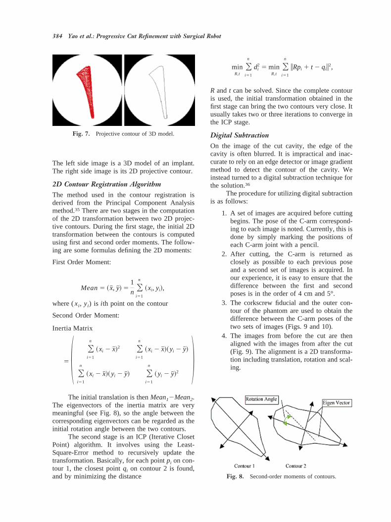
The left side image is a 3D model of an implant.The right side image is its 2D projective contour.
2D Contour Registration AlgorithmThe method used in the contour registration isderived from the Principal Component Analysismethod.35 There are two stages in the computationof the 2D transformation between two 2D projec-tive contours. During the first stage, the initial 2Dtransformation between the contours is computedusing first and second order moments. The follow-ing are some formulas defining the 2D moments:
First Order Moment:
Mean5 ~x#, y#! 51
nOi51
n
~xi, yi!,
where (xi, yi) is i th point on the contour
Second Order Moment:
Inertia Matrix
5 1 Oi51
n
~xi 2 x#!2 Oi51
n
~xi 2 x#!~yi 2 y#!
Oi51
n
~xi 2 x#!~yi 2 y#! Oi51
n
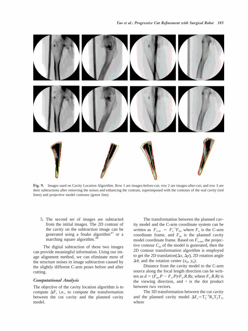
~yi 2 y#!2 2The initial translation is thenMean12Mean2.
The eigenvectors of the inertia matrix are verymeaningful (see Fig. 8), so the angle between thecorresponding eigenvectors can be regarded as theinitial rotation angle between the two contours.
The second stage is an ICP (Iterative ClosetPoint) algorithm. It involves using the Least-Square-Error method to recursively update thetransformation. Basically, for each pointpi on con-tour 1, the closest pointqi on contour 2 is found,and by minimizing the distance
minR,t
Oi51
n
di2 5 min
R,tOi51
n
iRpi 1 t 2 qii2,
R and t can be solved. Since the complete contouris used, the initial transformation obtained in thefirst stage can bring the two contours very close. Itusually takes two or three iterations to converge inthe ICP stage.
Digital SubtractionOn the image of the cut cavity, the edge of thecavity is often blurred. It is impractical and inac-curate to rely on an edge detector or image gradientmethod to detect the contour of the cavity. Weinstead turned to a digital subtraction technique forthe solution.36
The procedure for utilizing digital subtractionis as follows:
1. A set of images are acquired before cuttingbegins. The pose of the C-arm correspond-ing to each image is noted. Currently, this isdone by simply marking the positions ofeach C-arm joint with a pencil.
2. After cutting, the C-arm is returned asclosely as possible to each previous poseand a second set of images is acquired. Inour experience, it is easy to ensure that thedifference between the first and secondposes is in the order of 4 cm and 5°.
3. The corkscrew fiducial and the outer con-tour of the phantom are used to obtain thedifference between the C-arm poses of thetwo sets of images (Figs. 9 and 10).
4. The images from before the cut are thenaligned with the images from after the cut(Fig. 9). The alignment is a 2D transforma-tion including translation, rotation and scal-ing.
Fig. 8. Second-order moments of contours.
Fig. 7. Projective contour of 3D model.
384 Yao et al.: Progressive Cut Refinement with Surgical Robot
5. The second set of images are subtractedfrom the initial images. The 2D contour ofthe cavity on the subtraction image can begenerated using a Snake algorithm37 or amarching square algorithm.38
The digital subtraction of these two imagescan provide meaningful information. Using our im-age alignment method, we can eliminate most ofthe structure noises in image subtraction caused bythe slightly different C-arm poses before and aftercutting.
Computational AnalysisThe objective of the cavity location algorithm is tocomputeDF, i.e., to compute the transformationbetween the cut cavity and the planned cavitymodel.
The transformation between the planned cav-ity model and the C-arm coordinate system can bewritten as Fn-m 5 Fn
21Fm, whereFv is the C-armcoordinate frame, andFm is the planned cavitymodel coordinate frame. Based onFv-m, the projec-tive contourCm of the model is generated, then the2D contour transformation algorithm is employedto get the 2D translation(Dx, Dy), 2D rotation angleDu, and the rotation center (x0, y0).
Distance from the cavity model to the C-armsource along the focal length direction can be writ-ten asd 5 (Fm.P 2 Fv.P)+Fv.R.Rz, whereFv.R.Rzisthe viewing direction, and+ is the dot productbetween two vectors.
The 3D transformation between the cut cavityand the planned cavity modelDFc5T2
21R1T2T1,where
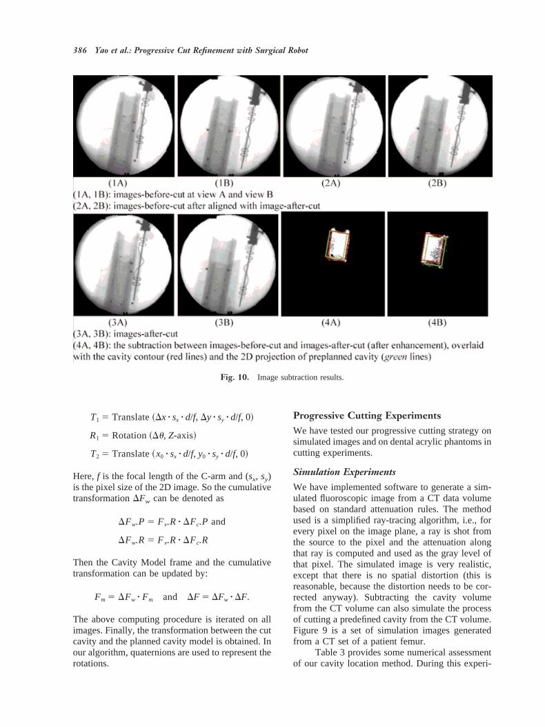
Fig. 9. Images used on Cavity Location Algorithm. Row 1 are images-before-cut; row 2 are images-after-cut; and row 3 aretheir subtractions after removing the noises and enhancing the contrast, superimposed with the contours of the real cavity (redlines) and projective model contours (green line).
Yao et al.: Progressive Cut Refinement with Surgical Robot 385
T1 5 Translate~Dx z sx z d/f, Dy z sy z d/f, 0!
R1 5 Rotation~Du, Z-axis!
T2 5 Translate~x0 z sx z d/f, y0 z sy z d/f, 0!
Here,f is the focal length of the C-arm and (sx, sy)is the pixel size of the 2D image. So the cumulativetransformationDFw can be denoted as
DFw.P 5 Fn.R z DFc.P and
DFw.R 5 Fn.R z DFc.R
Then the Cavity Model frame and the cumulativetransformation can be updated by:
Fm 5 DFw z Fm and DF 5 DFw z DF.
The above computing procedure is iterated on allimages. Finally, the transformation between the cutcavity and the planned cavity model is obtained. Inour algorithm, quaternions are used to represent therotations.
Progressive Cutting ExperimentsWe have tested our progressive cutting strategy onsimulated images and on dental acrylic phantoms incutting experiments.
Simulation ExperimentsWe have implemented software to generate a sim-ulated fluoroscopic image from a CT data volumebased on standard attenuation rules. The methodused is a simplified ray-tracing algorithm, i.e., forevery pixel on the image plane, a ray is shot fromthe source to the pixel and the attenuation alongthat ray is computed and used as the gray level ofthat pixel. The simulated image is very realistic,except that there is no spatial distortion (this isreasonable, because the distortion needs to be cor-rected anyway). Subtracting the cavity volumefrom the CT volume can also simulate the processof cutting a predefined cavity from the CT volume.Figure 9 is a set of simulation images generatedfrom a CT set of a patient femur.
Table 3 provides some numerical assessmentof our cavity location method. During this experi-
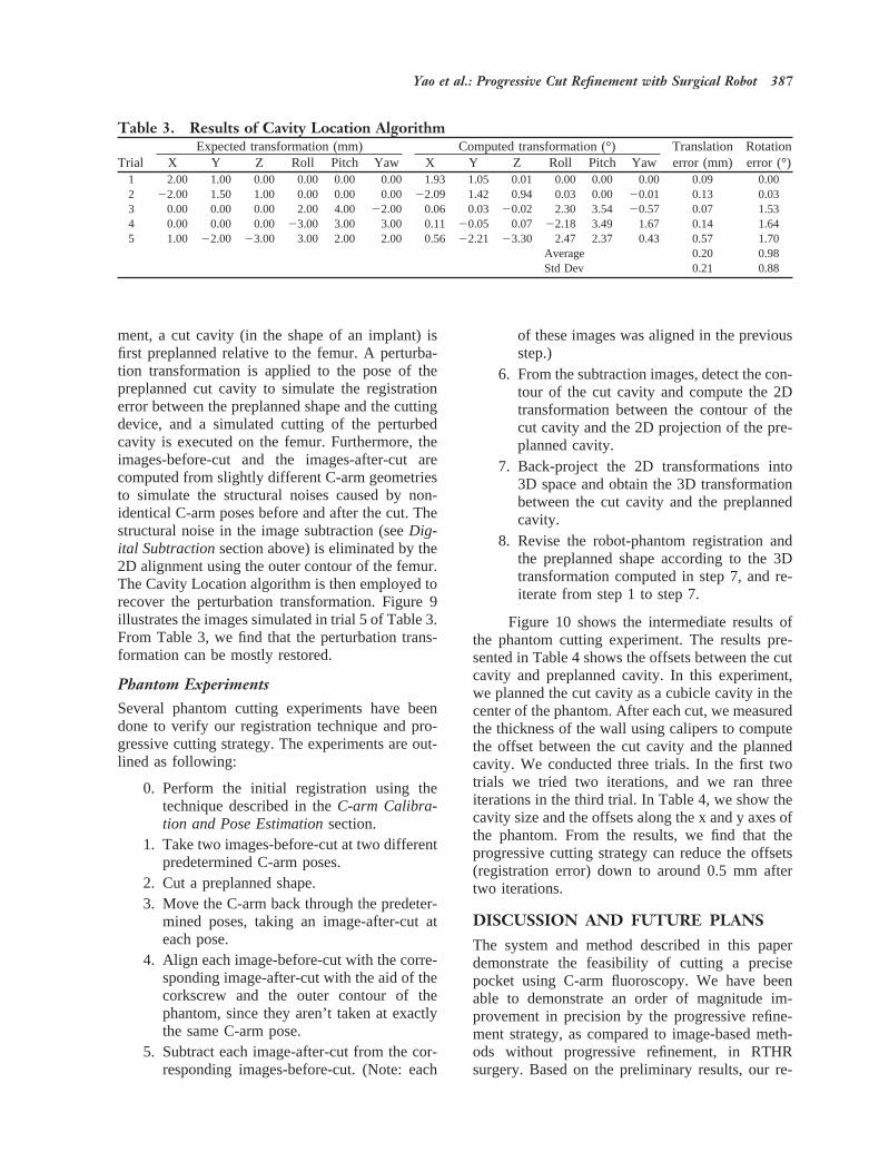
Fig. 10. Image subtraction results.
386 Yao et al.: Progressive Cut Refinement with Surgical Robot
ment, a cut cavity (in the shape of an implant) isfirst preplanned relative to the femur. A perturba-tion transformation is applied to the pose of thepreplanned cut cavity to simulate the registrationerror between the preplanned shape and the cuttingdevice, and a simulated cutting of the perturbedcavity is executed on the femur. Furthermore, theimages-before-cut and the images-after-cut arecomputed from slightly different C-arm geometriesto simulate the structural noises caused by non-identical C-arm poses before and after the cut. Thestructural noise in the image subtraction (seeDig-ital Subtractionsection above) is eliminated by the2D alignment using the outer contour of the femur.The Cavity Location algorithm is then employed torecover the perturbation transformation. Figure 9illustrates the images simulated in trial 5 of Table 3.From Table 3, we find that the perturbation trans-formation can be mostly restored.
Phantom ExperimentsSeveral phantom cutting experiments have beendone to verify our registration technique and pro-gressive cutting strategy. The experiments are out-lined as following:
0. Perform the initial registration using thetechnique described in theC-arm Calibra-tion and Pose Estimationsection.
1. Take two images-before-cut at two differentpredetermined C-arm poses.
2. Cut a preplanned shape.3. Move the C-arm back through the predeter-
mined poses, taking an image-after-cut ateach pose.
4. Align each image-before-cut with the corre-sponding image-after-cut with the aid of thecorkscrew and the outer contour of thephantom, since they aren’t taken at exactlythe same C-arm pose.
5. Subtract each image-after-cut from the cor-responding images-before-cut. (Note: each
of these images was aligned in the previousstep.)
6. From the subtraction images, detect the con-tour of the cut cavity and compute the 2Dtransformation between the contour of thecut cavity and the 2D projection of the pre-planned cavity.
7. Back-project the 2D transformations into3D space and obtain the 3D transformationbetween the cut cavity and the preplannedcavity.
8. Revise the robot-phantom registration andthe preplanned shape according to the 3Dtransformation computed in step 7, and re-iterate from step 1 to step 7.
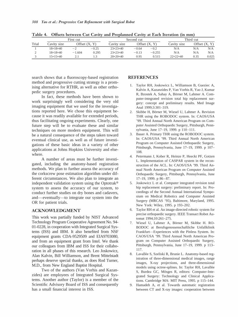
Figure 10 shows the intermediate results ofthe phantom cutting experiment. The results pre-sented in Table 4 shows the offsets between the cutcavity and preplanned cavity. In this experiment,we planned the cut cavity as a cubicle cavity in thecenter of the phantom. After each cut, we measuredthe thickness of the wall using calipers to computethe offset between the cut cavity and the plannedcavity. We conducted three trials. In the first twotrials we tried two iterations, and we ran threeiterations in the third trial. In Table 4, we show thecavity size and the offsets along the x and y axes ofthe phantom. From the results, we find that theprogressive cutting strategy can reduce the offsets(registration error) down to around 0.5 mm aftertwo iterations.
DISCUSSION AND FUTURE PLANSThe system and method described in this paperdemonstrate the feasibility of cutting a precisepocket using C-arm fluoroscopy. We have beenable to demonstrate an order of magnitude im-provement in precision by the progressive refine-ment strategy, as compared to image-based meth-ods without progressive refinement, in RTHRsurgery. Based on the preliminary results, our re-
Table 3. Results of Cavity Location Algorithm
TrialExpected transformation (mm) Computed transformation (°) Translation
error (mm)Rotationerror (°)X Y Z Roll Pitch Yaw X Y Z Roll Pitch Yaw
1 2.00 1.00 0.00 0.00 0.00 0.00 1.93 1.05 0.01 0.00 0.00 0.00 0.09 0.002 22.00 1.50 1.00 0.00 0.00 0.0022.09 1.42 0.94 0.03 0.00 20.01 0.13 0.033 0.00 0.00 0.00 2.00 4.00 22.00 0.06 0.03 20.02 2.30 3.54 20.57 0.07 1.534 0.00 0.00 0.00 23.00 3.00 3.00 0.11 20.05 0.07 22.18 3.49 1.67 0.14 1.645 1.00 22.00 23.00 3.00 2.00 2.00 0.5622.21 23.30 2.47 2.37 0.43 0.57 1.70
Average 0.20 0.98Std Dev 0.21 0.88
Yao et al.: Progressive Cut Refinement with Surgical Robot 387
search shows that a fluoroscopy-based registrationmethod and progressive cutting strategy is a prom-ising alternative for RTHR, as well as other ortho-pedic surgery procedures.
In fact, these methods have been shown towork surprisingly well considering the very oldimaging equipment that we used for the investiga-tions reported here. We chose this equipment be-cause it was readily available for extended periods,thus facilitating ongoing experiments. Clearly, onefuture step will be to evaluate these and similartechniques on more modern equipment. This willbe a natural consequence of the steps taken towardeventual clinical use, as well as of future investi-gations of these basic ideas in a variety of otherapplications at Johns Hopkins University and else-where.
A number of areas must be further investi-gated, including the anatomy-based registrationmethods. We plan to further assess the accuracy ofthe corkscrew pose estimation algorithm under dif-ferent circumstances. We also plan to integrate anindependent validation system using the Optotraktsystem to assess the accuracy of our system, toconduct further studies on dry bones and cadavers,and—eventually—to integrate our system into theOR for patient trials.
ACKNOWLEDGMENTThis work was partially funded by NIST AdvancedTechnology Program Cooperative Agreement No. 94-01-0228, in cooperation with Integrated Surgical Sys-tems (ISS) and IBM. It also benefited from NSFequipment grants CDA-9529509 and EIA9703080,and from an equipment grant from Intel. We thankour colleagues from IBM and ISS for their collabo-ration in all phases of this research. Leo Joskowicz,Alan Kalvin, Bill Williamson, and Brent Mittelstadtperhaps deserve special thanks, as does Rod Turner,M.D., from New England Baptist Hospital.
Two of the authors (Van Vorhis and Kazan-zides) are employees of Integrated Surgical Sys-tems. Another author (Taylor) is a member of theScientific Advisory Board of ISS and consequentlyhas a small financial interest in ISS.
REFERENCES
1. Taylor RH, Joskowicz L, Williamson B, Gueziec A,Kalvin A, Kazanzides P, Van Vorhis R, Yao J, KumarR, Bzostek A, Sahay A, Bo¨rner M, Lahmer A. Com-puter-integrated revision total hip replacement sur-gery: concept and preliminary results. Med ImageAnal 1999;3:301–319.
2. Skibbe H, Bo¨rner M, Wiesel U, Lahmer A. RevisionTHR using the ROBODOC system. In: CAOS/USA’99. Third Annual North American Program on Com-puter Assisted Orthopaedic Surgery, Pittsburgh, Penn-sylvania, June 17–19, 1999. p 110–111.
3. Bauer A. Primary THR using the ROBODOC system.In: CAOS/USA ’99. Third Annual North AmericanProgram on Computer Assisted Orthopaedic Surgery,Pittsburgh, Pennsylvania, June 17–19, 1999. p 107–108.
4. Petermann J, Kober R, Heinze P, Heeckt PF, GotzenL. Implementation of CASPAR system in the recon-struction of the ACL. In: CAOS/USA ’99. Third An-nual North American Program on Computer AssistedOrthopaedic Surgery, Pittsburgh, Pennsylvania, June17–19, 1999. p 86–87.
5. Joskowicz L et al. Computer integrated revision totalhip replacement surgery: preliminary report. In: Pro-ceedings of the Second Annual International Sympo-sium on Medical Robotics and Computer AssistedSurgery (MRCAS ’95), Baltimore, Maryland, 1995.New York: Wiley, 1995. p 193–202.
6. Taylor RH et al. An image-directed robotic system forprecise orthopaedic surgery. IEEE Transact Robot Au-tomat 1994;10:261–275.
7. Wiesel U, Lahmer A, Bo¨rner M, Skibbe H. RO-BODOC at Berufsgenossenschaftliche UnfallklinikFrankfurt—Experiences with the Pinless System. In:CAOS/USA ’99. Third Annual North American Pro-gram on Computer Assisted Orthopaedic Surgery,Pittsburgh, Pennsylvania, June 17–19, 1999. p 113–117.
8. Lavallee S, Szeliski R, Brunie L. Anatomy-based reg-istration of three-dimensional medical images, rangeimages, X-ray projections, and three-dimensionalmodels using octree-splines. In: Taylor RH, Lavalle´eS, Burdea GC, Mo¨sges R, editors: Computer-Inte-grated Surgery: Technology and Clinical Applica-tions. Cambridge MA: MIT Press, 1995. p 115–144.
9. Hamadeh A, et al. Towards automatic registrationbetween CT and X-ray images: cooperation between
Table 4. Offsets between Cut Cavity and Preplanned Cavity at Each Iteration (in mm)
TrialFirst cut Second cut Third cut
Cavity size Offset (X, Y) Cavity size Offset (X, Y) Cavity size Offset (X, Y)1 18p18p40 22 20.25 23p23p40 20.64 20.2 N/A N/A N/A2 18p18p40 21.604 0.295 23p23p40 20.13 20.255 N/A N/A N/A3 15p15p40 2.1 1.3 20p20p40 0.95 0.515 22p22p40 0.35 0.025
388 Yao et al.: Progressive Cut Refinement with Surgical Robot
3D/2D registration and 2D edge detection. In: Pro-ceedings of the Second Annual International Sympo-sium on Medical Robotics and Computer AssistedSurgery (MRCAS ’95), Baltimore, Maryland, 1995.New York: Wiley, 1995. p 39–46.
10. Gueziec A, Kazanzides P, Williamson B, Taylor RH.Anatomy based registration of CT-scan and intra-operative X-ray images for guiding a surgical robot.IEEE Transact Med Imaging 1998;17:715–728.
11. Gueziec A, Kazanzides P, Williamson B, Taylor RH,Lord D. Anatomy based registration of CT-scan andX-ray fluoroscopy data for intra-operative guidance ofa surgical robot. In: Hanson KM, editor: MedicalImaging 1998: Image Processing. SPIE ProceedingsVol. 3338, 1998. p 81–94.
12. Gueziec AP, et al. Registration of computed tomog-raphy data to a surgical robot using fluoroscopy: afeasibility study. 1996.
13. Hamadeh A, Lavalle´e S, Szeliski R, Cinquin P, PeriaO. Anatomy-based registration for computer-inte-grated surgery. In: Ayache N, editor: Computer Vi-sion, Virtual Reality, and Robotics in Medicine. Lec-ture Notes in Computer Science Vol. 905. Berlin:Springer, 1995. p 212–218.
14. Liu A, Bullitt E, Pizer SM. 3D/2D registration viaskeletal near projective invariance in tubular objects.In: Wells WM, Colchester A, Delp S, editors: Pro-ceedings of First International Conference on MedicalImage Computing and Computer-Assisted Interven-tion (MICCAI ’98), Cambridge, MA, October 1998.Berlin: Springer, 1998. p 952–963.
15. Weese J, Buzug TM, Lorenz C, Fassnacht C. Anapproach to 2D/3D registration of a vertebra in 2DX-ray fluoroscopies with 3D CT images. In: Troccaz J,Grimson E, Mosges R, editors: Proceedings of FirstJoint Conference on Computer Vision, Virtual Realityand Robotics in Medicine and Medical Robotics andComputer Assisted Surgery (CVRMed-MRCAS ’97),Grenoble, France, March 1997. Berlin: Springer,1997. p 119–128.
16. Wells WM, Viola P, Kikinis R. Multi-model volumeregistration by maximization of mutual information.In: Second Annual International Symposium on MedicalRobotics and Computer Assisted Surgery (MRCAS ’95),Baltimore, Maryland, 1995. New York: Wiley; 1995. p39–46.
17. Gueziec AP, Funda J. Evaluating the registration of3D points to 3D lines with application to the poseestimation in a projective image. 1996.
18. Gueziec A. Assessing the registration of CT-scan datato intra-operative X-rays by fusing X-rays and preop-erative information. Proc SPIE Med Imaging 1999. p3661–3688.
19. Champleboux G et al. Accurate calibration of camerasand range imaging sensors, the NPBS method. Pro-ceedings of the IEEE International Conference onRobotics and Automation, 1992. p 1552–1557.
20. Bookstein FL. Morphometric Tools for Landmark
Data, Geometry and Biology. Cambridge UniversityPress, 1991.
21. IS Systems. ORTHODOC User Guide. 1997.22. Nolte LP et al. Use of C-arm for surgical navigation in
the spine. In: CAOS/USA ’98. Second Annual NorthAmerican Program on Computer Assisted Orthopae-dic Surgery, Pittsburgh, Pennsylvania, 1998.
23. Phillips R et al. Image guided orthopaedic surgery—design and analysis. IEEE Transact Robot Control,March 1996.
24. Hofstetter R, Slomczykowski M, Sati M, Nolte L-P.Principles of precise fluoroscopy based surgical nav-igation (abstract). In: 4th International Symposium onComputer Assisted Orthopaedic Surgery, Davos,Switzerland, March 1999. p 28.
25. Hofstetter R, Slomczykowski M, Bourquin I, Nolte L-P.Fluoroscopy based surgical navigation—concept andclinical applications. In: Lemke HU, Vannier MW, In-amura K, editors: Computer Assisted Radiology andSurgery. Proceedings of the 11th International Sympo-sium and Exhibition (CAR ’97), Berlin, Germany, June1997. Amsterdam: Elsevier, 1997. p 956–960.
26. Brack C, Burgkart R, Czopf A, Go¨tte H, Roth M,Radig B, Schweikard A. Accurate X-ray-based navi-gation in computer-assisted orthopedic surgery. In:Lemke HU, Vannier MW, Inamura K, Farman AG,editors: Computer Assisted Radiology and Surgery.Proceedings of the 12th International Symposium andExhibition (CAR ’98), Tokyo, Japan, June 1998. Am-sterdam: Elsevier, 1998. p 716–722.
27. Tsai RY. A versatile camera calibration technique forhigh-accuracy 3D machine vision metrology usingoff-the-shelf TV cameras and lenses. IEEE J RobotAutomat 1987;RA-3(4):323-358.
28. Schreiner S, Anderson JH, Taylor RH, Funda J, Bzos-tek A, Barnes AC. A system for percutaneous deliveryof treatment with a fluoroscopically-guided robot. In:Troccaz J, Grimson E, Mo¨sges R, editors: Proceedingsof First Joint Conference on Computer Vision, VirtualReality and Robotics in Medicine and Medical Robot-ics and Computer Assisted Surgery (CVRMed-MRCAS ’97), Grenoble, France, March 1997. Berlin:Springer, 1997. p 747–756.
29. Fahrig R, Moreau M, Holdsworth D. Three-dimen-sional computed tomographic reconstruction using aC-arm mounted XRII: correction of image intensifierdistortion. Med Phys 1997;24:1097–1106.
30. Boone JM, Seibert JA, Barrett WA, Blood EA. Anal-ysis and correction of imperfections in the imageintensifier-TV-digitizer imaging chain. Med Phys1991;18:236–242.
31. Yaniv Z, Joskowicz L, Simkin A, Garza-Jinich M,Milgrom C. Fluoroscopic image processing for com-puter-aided orthopaedic surgery. In: Wells WM,Colchester A, Delp S, editors: Proceedings of FirstInternational Conference on Medical Image Comput-ing and Computer-Assisted Intervention (MICCAI
Yao et al.: Progressive Cut Refinement with Surgical Robot 389

’98), Cambridge, MA, October 1998. Berlin: Springer,1998. p 325–334.
32. Wolberg G. Digital Image Warping. IEEE ComputSoc Press Monogr, 1990.
33. Joskowicz L, Milgrom C, Simkin A, Tockus L, YanivZ. FRACAS: A system for computer-aided image-guided long bone fracture surgery. Comp Aid Surg1998;3:271-288.
34. Taylor RH, Funda J, Eldridge B, Larose D, Gomory S,Gruben K, Talamini M, Kavoussi L, Anderson J. Atelerobotic assistant for laparoscopic surgery. In: Tay-lor RH, Lavallee S, Burdea GC, Mo¨sges R, editors:Computer-Integrated Surgery: Technology and Clini-
cal Applications. Cambridge MA: MIT Press, 1995. p581–592.
35. Jolliffe IT. Principal Component Analysis. Berlin:Springer Verlag, 1986.
36. Levy G. Robotic control for digital subtraction radi-ography. In: Electrical Engineering. New Brunswick,NJ: Rutgers, the State University of New York, 1994.p 145.
37. Kass M, Witkin A, Terzopoulos D. Snakes: Activecontour models. Int J Comput Vision 1987;1:321–331.
38. Schroeder W, Martin K, Lorensen B. The Visualiza-tion Toolkit. Englewood Cliffs, NJ: Prentice Hall,1998.
390 Yao et al.: Progressive Cut Refinement with Surgical Robot