A benzene interference single-electron transistor
17
arXiv:0810.2461v2 [cond-mat.str-el] 30 Mar 2009 A benzene interference single-electron transistor D. Darau, G. Begemann, A. Donarini, and M. Grifoni Institut f¨ ur Theoretische Physik, Universit¨at Regensburg, 93035 Regensburg, Germany (Dated: May 13, 2013) Interference effects strongly affect the transport characteristics of a benzene single-electron tran- sistor (SET) and for this reason we call it interference SET (I-SET). We focus on the effects of degeneracies between many-body states of the isolated benzene. We show that the particular cur- rent blocking and selective conductance suppression occurring in the benzene I-SET are due to interference effects between the orbitally degenerate states. Further we study the impact of re- duced symmetry due to anchor groups or potential drop over the molecule. We identify in the quasi-degeneracy of the involved molecular states the necessary condition for the robustness of the results. PACS numbers: 85.65.+h, 85.85.+j, 73.63.b I. INTRODUCTION Molecular electronics, due to perfect reproducibility and versatile chemical tailoring of its basic components, represents one of the most promising answers to the in- creasing miniaturization demand of information technol- ogy. A crucial issue in molecular electronics is thus the understanding of the conduction characteristics through single molecules 1 . Single-molecule-transport measurements rely on the fabrication of a nanogap between source and drain elec- trodes and the formation of a stable molecule-electrode contact. Nanogaps are nowadays routinely obtained us- ing different techniques including electromigration 2–10 , mechanical break-junction 11–14 and scanning tunnelling microscopy 15–17 . Also the challenging goal of effectively gating a nanometer sized molecule in presence of macro- scopic metallic leads has been achieved 6,14,18 . A stable contact between molecule and leads is com- monly realized with the mediation of anchor groups at- tached to the molecule during its chemical synthesis. Also direct coupling of the molecule to the electric leads, though, has been very recently reported 13 . One of the advantages of the first connecting method is some con- trol over the contact configuration of the molecule 19 and the possibility to design the strength of the tunnelling coupling by choosing specific anchor groups 6,17,20,21 . All previous achievements combined with experience accu- mulated with semiconducting and carbon-based single electron transistors (SET) allowed in recent years to mea- sure stability diagrams of single molecule transistor de- vices thus realizing molecular spectroscopy via transport experiments 2–10 . Single molecule transistors display transport proper- ties which are very different from those of conventional single electron transistors. In fact, vibrational or tor- sional modes 7,10 and intrinsic symmetries of the molecule can hinder or favor transport through the molecular SET, visible e.g. in the absence or presence of specific excita- tion lines in the stability diagram, or in negative differen- tial conductance features. Many-body phenomena as e.g. the Kondo effect, have been observed as well 2,3,5,10,22 . FIG. 1: (color online) Schematic representation of the two different setups for the benzene I-SET considered in this pa- per. The molecule, lying on a dielectric substrate, is weakly contacted to source and drain leads as well as capacitively gated. Despite the experimental progress, the theoretical un- derstanding of the properties of single organic molecules coupled to electrodes is far from being satisfactory. On the one hand, numerical approaches to transport based on the combination of Green’s function meth- ods with tight binding model or density functional the- ory have become standard in the study of transport at the nanoscale 1 . These methods are appropriate to in- vestigate quantum transport through molecular bridges strongly coupled to leads. In this regime various groups have recently discussed the possibility to observe interfer- ence effects 23–26 , e.g. in conjugated monocyclic molecules as benzene or annulene 23,25 . However, for the description of transport through a molecule weakly coupled to leads, other methods are required. In the Coulomb Blockade regime, for example, due to the crucial role played by the Coulomb interaction in these systems it is common to resort to a Pauli rate equation 27 or to a generalized master equation for the reduced density matrix (RDM). For example, in Hettler et al. 28 , an electronic structure calculation was performed in order to construct an effec- tive interacting Hamiltonian for the π orbitals of benzene, and the I-V characteristics of the corresponding molec-
-
Upload
independent -
Category
Documents
-
view
1 -
download
0
Transcript of A benzene interference single-electron transistor

arX
iv:0
810.
2461
v2 [
cond
-mat
.str
-el]
30
Mar
200
9
A benzene interference single-electron transistor
D. Darau, G. Begemann, A. Donarini, and M. GrifoniInstitut fur Theoretische Physik, Universitat Regensburg, 93035 Regensburg, Germany
(Dated: May 13, 2013)
Interference effects strongly affect the transport characteristics of a benzene single-electron tran-sistor (SET) and for this reason we call it interference SET (I-SET). We focus on the effects ofdegeneracies between many-body states of the isolated benzene. We show that the particular cur-rent blocking and selective conductance suppression occurring in the benzene I-SET are due tointerference effects between the orbitally degenerate states. Further we study the impact of re-duced symmetry due to anchor groups or potential drop over the molecule. We identify in thequasi-degeneracy of the involved molecular states the necessary condition for the robustness of theresults.
PACS numbers: 85.65.+h, 85.85.+j, 73.63.b
I. INTRODUCTION
Molecular electronics, due to perfect reproducibilityand versatile chemical tailoring of its basic components,represents one of the most promising answers to the in-creasing miniaturization demand of information technol-ogy. A crucial issue in molecular electronics is thus theunderstanding of the conduction characteristics throughsingle molecules1.
Single-molecule-transport measurements rely on thefabrication of a nanogap between source and drain elec-trodes and the formation of a stable molecule-electrodecontact. Nanogaps are nowadays routinely obtained us-ing different techniques including electromigration2–10,mechanical break-junction11–14 and scanning tunnellingmicroscopy15–17. Also the challenging goal of effectivelygating a nanometer sized molecule in presence of macro-scopic metallic leads has been achieved6,14,18.
A stable contact between molecule and leads is com-monly realized with the mediation of anchor groups at-tached to the molecule during its chemical synthesis.Also direct coupling of the molecule to the electric leads,though, has been very recently reported13. One of theadvantages of the first connecting method is some con-trol over the contact configuration of the molecule19 andthe possibility to design the strength of the tunnellingcoupling by choosing specific anchor groups6,17,20,21. Allprevious achievements combined with experience accu-mulated with semiconducting and carbon-based singleelectron transistors (SET) allowed in recent years to mea-sure stability diagrams of single molecule transistor de-vices thus realizing molecular spectroscopy via transportexperiments2–10.
Single molecule transistors display transport proper-ties which are very different from those of conventionalsingle electron transistors. In fact, vibrational or tor-sional modes7,10 and intrinsic symmetries of the moleculecan hinder or favor transport through the molecular SET,visible e.g. in the absence or presence of specific excita-tion lines in the stability diagram, or in negative differen-tial conductance features. Many-body phenomena as e.g.
the Kondo effect, have been observed as well2,3,5,10,22.
FIG. 1: (color online) Schematic representation of the twodifferent setups for the benzene I-SET considered in this pa-per. The molecule, lying on a dielectric substrate, is weaklycontacted to source and drain leads as well as capacitivelygated.
Despite the experimental progress, the theoretical un-derstanding of the properties of single organic moleculescoupled to electrodes is far from being satisfactory.On the one hand, numerical approaches to transportbased on the combination of Green’s function meth-ods with tight binding model or density functional the-ory have become standard in the study of transport atthe nanoscale1. These methods are appropriate to in-vestigate quantum transport through molecular bridgesstrongly coupled to leads. In this regime various groupshave recently discussed the possibility to observe interfer-ence effects23–26, e.g. in conjugated monocyclic moleculesas benzene or annulene23,25. However, for the descriptionof transport through a molecule weakly coupled to leads,other methods are required. In the Coulomb Blockaderegime, for example, due to the crucial role played bythe Coulomb interaction in these systems it is commonto resort to a Pauli rate equation27 or to a generalizedmaster equation for the reduced density matrix (RDM).For example, in Hettler et al.28, an electronic structurecalculation was performed in order to construct an effec-tive interacting Hamiltonian for the π orbitals of benzene,and the I-V characteristics of the corresponding molec-

2
ular junction were calculated within the rate equationapproach.In the presence of degenerate states, however, coher-ences of the density matrix influence the dynamics anda master equation approach is appropriate29–36. Suchcoherences can give rise to precession effects in spintransport30,34 or cause interference in a molecular singleelectron transistor32,34,35. In the present work we wishto generalize the discussion on interference phenomena ina benzene interference-SET presented in35 to the case inwhich the perfect degeneracy is broken due e.g. to con-tact effects or to the applied external bias. To this ex-tent the master equation used in35 will be generalized totreat the case of quasi-degenerate states. Conditions forthe persistence of interference phenomena are identified.We observe that the effects of quasi-degenerate states ontransport have been very recently addressed also in36.We treat the transport through the benzene I-SET intwo different setups, the para and the meta configura-tion, depending on the position of the leads with respectto the benzene molecule (see Fig. 1). Similar to28, westart from an interacting Hamiltonian of isolated benzenewhere only the localized pz orbitals are considered andthe ions are assumed to have the same spatial symmetryas the relevant electrons. We calculate the 46 = 4096 en-ergy eigenstates of the benzene Hamiltonian numerically.
Subsequently, with the help of group theory, we classifythe eigenstates according to their different symmetriesand thus give a group-theoretical explanation to the largedegeneracies occurring between the electronic states. Forexample, while the six-particles ground state (A1g sym-metry) is non-degenerate, there exist four seven-particleground states due to spin and orbital (E2u symmetry)degeneracy. Fingerprints of these orbital symmetries areclearly visible in the strong differences in the stability di-agrams obtained by coupling the benzene I-SET to theleads in the meta and para configurations. Striking arethe selective reduction of conductance and the appear-ance of regions of interference driven current blockingwith associated negative differential conductance (NDC)when changing from the para to the meta configuration.
NDC and current blocking for benzene junctions havebeen predicted also in28, but in the para configurationand in presence of an external electromagnetic field. Inour work NDC occurs despite the absence of an externalfield in the unperturbed setup and with no asymmetryin the tunnelling rates. In fact, NDC and current block-ing triggered by interference take place any time a SETpresents an N -particle non-degenerate state and two de-generate N+1-particle states such that the ratio betweenthe transition amplitudes γiα (i = 1, 2, α = L,R) be-tween those N - and N + 1-particle states is different fortunneling at the left (L) and at the right (R) lead:
γ1L
γ2L6=γ1R
γ2R. (1)
Notice that no asymmetry in the tunnelling rates, whichare proportional to |γiα|
2, is implied by (1). This fact
excludes the interpretation of the physics of the interfer-ence SET in terms of standard NDC with asymmetriccouplings. Due to condition (1) there exist linear com-binations of the degenerate N + 1-particle states whichare coupled to one of the leads but not to the other. Thestate which is decoupled from the right lead represents ablocking state for the current flowing L → R since elec-trons can populate this state by tunnelling from the leftlead but cannot tunnel out towards the right lead. Vicev-ersa the state decoupled from the left lead is a blockingstate for the currentR → L. Typically these two blockingstates are not orthogonal and thus cannot form togethera valid basis set. The basis set that diagonalizes the sta-tionary density matrix (what we call in the manuscriptthe ”physical basis”) contains at large positive biases theL → R blocking state and is thus different from thephysical basis at large negative biases which necessar-ily contains the R → L blocking state. More generallythe ”physical basis” depends continuously on the bias.Thus only a treatment that includes coherences in thedensity matrix can capture the full picture at all biases.By neglecting for simplicity the spin degree of freedom,the 7-particle ground state of benzene is two times de-generate while the 6-particle one is non-degenerate. Ifwe choose for the 7-particle states the eigenstates of thez-projection of the angular momentum we obtain the re-lation:
γ1L
γ2L=γ1R
γ2Re4iφ, (2)
where φ is the angle between the left and the right lead.Thus in the meta configuration (φ = 2π/3) the condi-tion (1) is fullfilled while in the para (φ = π) the am-plitude ratios are equal. This condition implies that, inthe para configuration one of the 7-particle states is de-coupled from both leads at the same time and can thus(in first approximation) be excluded from the dynam-ics. In contrast, in the meta configuration, the linearcombination of uniformly distributed eigenstates of theangular momentum creates states with a peculiar inter-ference pattern. The position of their nodes allows tocharacterize them as different blocking states.
This paper is outlined as follows: in Section II we intro-duce the model Hamiltonian of the system and present adensity matrix approach setting up a generalized masterequation describing the electron dynamics. We give theexpression for the current in the fully symmetric setup(the generalized master equation and current formula forthe setup under perturbation are given in Appendix A).Further we provide a detailed analysis of the symmetrycharacteristics of the molecular eigenstates.In Section III we present numerical and analytical resultsof transport calculations for the unperturbed setup. Westudy the occurring interference effects and provide anexplanation of the phenomena based on symmetry con-siderations.In Section IV we present the results for the perturbedsetup including a detailed discussion of the transport in

3
this case. We identify in the quasi-degeneracy of the con-tributing molecular states the necessary condition for therobustness of the interference effects.Conclusions and remarks are presented in section V.
II. MODEL HAMILTONIAN AND THEDENSITY MATRIX APPROACH
A. Model Hamiltonian
For the description of the benzene molecule weaklycoupled to source and drain leads, we adopt the totalHamiltonian H = H0
ben + Hleads + HT + H ′ben. The
first term is the interacting Hamiltonian for isolatedbenzene37–39
H0ben = ξ0
∑
iσ
d†iσdiσ + b∑
iσ
(
d†iσdi+1σ + d†i+1σdiσ
)
+U∑
i
(
ni↑ −12
) (
ni↓ −12
)
+V∑
i
(ni↑ + ni↓ − 1) (ni+1↑ + ni+1↓ − 1) ,
(3)
where d†iσ creates an electron of spin σ in the pz orbitalof carbon i, i = 1, . . . , 6 runs over the six carbon atoms
of benzene and niσ = d†iσdiσ.Only the pz orbitals (one per carbon atom) are explic-itly taken into account, while the core electrons and thenuclei are combined into frozen ions, with the same spa-tial symmetry as the relevant electrons. They contributeonly to the constant terms of the Hamiltonian and en-force particle-hole symmetry. Mechanical oscillations areneglected and all atoms are considered at their equilib-rium position.This Hamiltonian for isolated benzene is respecting theD6h symmetry of the molecule. Since for every site thereare 4 different possible configurations (|0〉, |↑〉, |↓〉, |↑↓〉),the Fock space has the dimension 46 = 4096, which re-quires a numerical treatment. Though the diagonaliza-tion of the Hamiltonian is not a numerical challenge, itturns out to be of benefit for the physical understand-ing of the transport processes to divide Hben into blocks,according to the number N of pz electrons (from 0 to12), the z projection Sz of the total spin and the orbitalsymmetries of benzene (see Table I).The parameters b, U , and V for isolated benzene aregiven in the literature40 and are chosen to fit optical ex-citation spectra. The presence, in the molecular I-SET,of metallic electrodes and the dielectric is expected tocause a substantial renormalization of U and V 4,41. Nev-ertheless, we do not expect the main results of this workto be affected by this change. We consider the benzenemolecule weakly coupled to the leads. Thus, to first ap-proximation, we assume the symmetry of the isolatedmolecule not to be changed by the screening. Perturba-tions due to the lead-molecule contacts reduce the sym-metry in the molecular junction. They are included in
H ′ben (see Eq. (25) and (26)) and will be treated in Sec-
tion IV.The effect of the gate is included as a renormalization ofthe on-site energy ξ = ξ0 − eVg (Vg is the gate voltage)and we conventionally set Vg = 0 at the charge neutralitypoint. Source and drain leads are two reservoirs of non-
interacting electrons: Hleads =∑
α k σ(ǫk − µα)c†αkσcαkσ,where α = L,R stands for the left or right lead and thechemical potentials µα of the leads depend on the ap-plied bias voltage µL,R = µ0 ± Vb
2 . In the following wewill measure the energy starting from the equilibriumchemical potential µ0 = 0. The coupling to source anddrain leads is described by the tunnelling Hamiltonian
HT = t∑
αkσ
(
d†ασcαkσ + c†αkσdασ
)
, (4)
where we define d†ασ as the creator of an electron in thebenzene carbon atom which is closest to the lead α. Inparticular d†Rσ := d†4σ, d
†5σ respectively in the para and
meta configuration, while d†Lσ := d†1σ in both setups.
B. Dynamics of the reduced density matrix
Given the high degeneracy of the spectrum, themethod of choice to treat the dynamics in the weak cou-pling is the Liouville equation method already used e.g.
in32,33. In this section we shortly outline how to derivethe equation of motion for the reduced density matrix(RDM) to lowest non-vanishing order in the tunnellingHamiltonian. For more details we refer to33,34.Starting point is the Liouville equation for the total den-sity operator of molecule and leads ρ in the interac-
tion picture, treating HT as a perturbation: i~dρI(t)dt =
[
HIT, ρ
I(t)]
. This equation integrated over time and iter-ated to the second order reads
ρI(t) = −i
~[HI
T(t), ρI(t0)] (5)
−1
~2
∫ t
t0
dt′[HIT(t), [HI
T(t′), ρI(t′)]].
Since we are only interested in the transport through themolecule, we treat from now on the time evolution ofthe reduced density matrix (RDM) σ = Trleads{ρ
I(t)}42,which is formally obtained from Eq. (5) by tracing outthe leads degrees of freedom: σ = Trleads{ρ
I}.In order to proceed, we make the following standard ap-proximations:i) The leads are considered as reservoirs of non-interacting electrons in thermal equilibrium. Hence wecan factorize the density matrix as ρI(t) = σ(t)ρsρd =σ(t)ρleads.ii) Since the moecule is weakly coupled to the leads wetreat the effects of HT to the lowest non-vanishing order.iii) Due to the continuous interaction of the system withthe leads and at high enough temperature, it is legiti-mate to apply the Markov approximation and obtain an

4
equation for σ which is local in time (σ(t) instead of σ(t′)inside the integral). In particular the Markov approxima-tion becomes exact in the stationary limit (t → ∞) wewill focus on. Since we are interested in the long termbehavior of the system, we set t0 → −∞ in Eq. (5) andfinally obtain the generalized master equation (GME)
σ(t) =−1
~2
∫ ∞
0
dt′′Trleads
{
[HIT(t), [HI
T(t− t′′), σ(t)ρleads]]}
.
(6)
The reduced density operator σ is defined on the Fockspace of benzene, yet we can neglect coherences betweenstates with different particle number since decoupledfrom the dynamics of the populations. For simplicity,we continue here the derivation of the GME only forthe symmetric case with exact orbital degeneracy, i.e.,neglecting H ′
ben (the perturbed case is presented in Ap-pendix A).iv) Further we also neglect coherences between stateswith different energy (secular approximation). They areirrelevant due to their fast fluctuation compared to thedynamics of the system triggered by the tunnelling cou-
pling.
Under these considerations, it is convenient to ex-press the GME in terms of the reduced density operatorσNE = PNE σ PNE, where PNE :=
∑
ℓτ |N E ℓ τ〉〈N E ℓ τ |is the projection operator on the subspace of N parti-cles and energy E. The sum runs over the orbital andspin quantum numbers ℓ and τ , respectively. The orbitalquantum number ℓ distinguishes between orbitally degen-erate states. The exact meaning of ℓ will be illustrated inthe next section. In Appendix A we derive a GME thatretains coherences also between quasi-degenerate states.That approach treats with special care the small asym-metries introduced in the molecule by the coupling tothe leads. In fact it interpolates between the degeneratecase treated here and the fully non-degenerate case inwhich the GME reduces to a master equation for pop-ulations only. Equation (6) can be further manipulatedby projection into the subspace of N -particle and energyE. Since we assume the density matrix to be factorizedand the leads to be in thermal equilibrium, also the tracesover the leads degree of freedom can be easily performed.Eventually, the GME for the degenerate case reads
σNE = −∑
ατ
Γα
2
{
PNEdατ
[
f+α (H0
ben − E) −i
πpα(H0
ben − E)
]
d†ατ σNE+
+ PNEd†ατ
[
f−α (E −H0
ben) −i
πpα(E −H0
ben)
]
dατ σNE +H.c.
}
+
+∑
ατE′
ΓαPNE
{
d†ατf+α (E − E′)σN−1E′
dατ + dατf−α (E′ − E)σN+1E′
d†ατ
}
PNE,
(7)
where ΓL,R = 2π~|tL,R|
2DL,R are the bare transfer rateswith the constant densities of states of the leads DL,R.Terms describing sequential tunnelling from and to thelead α are proportional to the Fermi functions f+
α (x) :=f(x − µα) and f−
α (x) := 1 − f+α (x), respectively. Still
in the sequential tunnelling limit, but only in the equa-tions for the coherences, one finds also the energy non-conserving terms, proportional to the function pα(x) =
−Reψ[
12 + iβ
2π (x− µα)]
, where ψ is the digamma func-
tion. Both the Fermi functions and the digamma func-tion result from the trace over the leads degrees offreedom30,33,42.A closer analysis of the master equation allows also to for-mulate an expression for the current operator. We startfrom the definition of the time derivative of the chargeon benzene:
d
dt〈Q〉 = Tr
{
N σ}
= 〈 IL + IR 〉 (8)
where Q =∑
iτ (d†iτdiτ − 6) is the operator of the charge
on benzene, N is the particle number operator and IL,R
are the current operators at the left(right) contact. Con-ventionally, in the definition of IL,R we assume the cur-rent to be positive when it is increasing the charge on themolecule. Thus, in the stationary limit, 〈 IL+IR 〉 is zero.We write this expression in the basis of the subspaces ofN particles and energy E:
〈 IL + IR 〉 =∑
NE
Tr{
NPNEσPNE
}
=∑
NE
Tr{
NσNE}
.
(9)Further we insert (7) in (9) and take advantage of thecyclic properties of the trace to find :

5
〈 IL + IR 〉 =∑
NE
∑
ατ
NΓαTr
{
−[
f+α (H0
ben − E)d†ατσNEdατ + f−
α (E −H0ben)dατσ
NEd†ατ
]
+
+∑
E′
PNE
[
f+α (E − E′)d†ατσ
N−1E′
dατ + f−α (E′ − E)dατσ
N+1E′
d†ατ
]
}
.
(10)
Notice that the energy non-conserving contributions dropfrom the expression of the current. Still they contributeto the average current via the density matrix. Since Eand E′ are dummy variables, we can switch them in thesummands containing E′. Applying the relation:
∑
NE′
Tr {PNE′ g(E′)} = Tr{
g(H0ben)
}
,
where g(E′) is a generic function, we substitute E′ withH0
ben in Eq. (10). Further we can conveniently rearrangethe sum over N , arriving at the expression for the cur-rent:
〈 IL + IR 〉 =∑
NE
∑
ατ
ΓαTr
{
d†ατσNEdατ
[
−Nf+α (H0
ben−E)+(N+1)f+α (H0
ben−E)]
+dατσNEd†ατ
[
−Nf−α (E−H0
ben)+(N−1)f−α (E−H0
ben)]
}
.
(11)
This relation can be further simplified in order to iden-tify the current operators. The one corresponding to theleft contact is e.g.
IL = ΓL
∑
NEτ
PNE
[
dLτf+L (H0
ben − E)d†Lτ+
− d†Lτf−L (E −H0
ben)dLτ
]
PNE.
(12)
With this relation we can calculate the stationary currentas the average 〈IL〉 = Tr{σstatIL} = −〈IR〉, with σstat
as the stationary density operator. The expression ofthe current operator for the perturbed system is given inAppendix A.
C. Symmetry of the benzene eigenstates
In this section, we will review the symmetry charac-teristics of the eigenstates of the interacting Hamiltonianof benzene, focusing on the symmetry operations σv andCn which have a major impact on the electronic trans-port through the molecular I-SET. Benzene belongs tothe D6h point group. Depending on their behavior un-der symmetry operations, one can classify the molecular
orbitals by their belonging to a certain irreducible repre-sentation of the point group.
N # ↑ # ↓ # states # states with acertain symmetry
6 6 0 1 1 B1u
4 A1g
2 A2g
5 1 36 2×6 E2g
4 B1u
2 B2u
2×6 E1u
16 A1g
20 A2g
4 2 225 2×36 E2g
22 B1u
17 B2u
2×39 E1u
38 A1g
30 A2g
3 3 400 2×66 E2g
38 B1u
30 B2u
2×66 E1u
2 4 225
1 5 36...
0 6 1
TABLE I: Overview of the 6 particle states of benzene, sortedby Sz and symmetry. Orbitals with A- and B-type of sym-metry show no degeneracy, while E-type orbitals are doublydegenerate.
Table I shows an overview of the states of the neutralmolecule (the 6 particle states) sorted by Sz and symme-tries. The eigenstates of the interacting benzene moleculehave either A-, B- or E-type symmetries. While orbitalshaving A or B symmetries can only be spin degenerate,states with an E symmetry show an additional twofoldorbital degeneracy, essential for the explanation of thetransport features occurring in the meta configuration.
Transport at low bias is described in terms of transi-tions between ground states with diferent particle num-ber. Table II shows the symmetries of the ground states(and of some first excited states) of interacting ben-zene for all possible particle numbers. Ground state

6
transitions occur both between orbitally non-degeneratestates (with A and B symmetry), as well as between or-bitally degenerate and non-degenerate states (E- to A-type states).
The interacting benzene Hamiltonian commutes withall the symmetry operations of the D6h point group, thusit has a set of common eigenvectors with each operation.The element of D6h of special interest for the para config-uration is σv, i.e., the reflection about the plane throughthe contact atoms and perpendicular to the molecularplane. The molecular orbitals with A and B symmetryare eigenstates of σv with eigenvalue ±1, i.e., they areeither symmetric or antisymmetric with respect to theσv operation. The behavior of the E−type orbitals un-der σv is basis dependent, yet one can always choose abasis in which one orbital is symmetric and the other oneantisymmetric.
Let us now consider the generic transition amplitude〈N |dατ |N + 1〉, where dατ destroys an electron of spin τon the contact atom closest to the α lead. It is useful torewrite this amplitude in the form
〈N |dατ |N + 1〉 = 〈N |σ†vσvdατσ
†vσv|N + 1〉, (13)
where we have used the property σ†vσv = 1. Since in the
para configuration both contact atoms lie in the mirrorplane σv, it follows σvdασ
†v = dα. If the participating
states are both symmetric under σv, Eq. (13) becomes
〈N, sym|σ†vdατσv|N + 1, sym〉 =
= 〈N, sym|dατ |N + 1, sym〉. (14)
and analogously in the case that both states are antisym-metric. For states with different symmetry it is
〈N, sym|dατ |N + 1, antisym〉 =
= −〈N, sym|dατ |N + 1, antisym〉 = 0. (15)
In other terms, there is a selection rule that forbidstransitions between symmetric and antisymmetric states.Further, since the ground state of the neutral molecule issymmetric, for the transport calculations in the para con-figuration we select the effective Hilbert space containingonly states symmetric with respect to σv. Correspond-ingly, when referring to the N particle ground state wemean the energetically lowest symmetric state. For ex-ample in the case of 4 and 8 particle states it is the firstexcited state to be the effective ground state. In the paraconfiguration also the orbital degeneracy of the E−typestates is effectively cancelled due to the selection of thesymmetric orbital (see Table II).
Small violations of this selection rule, due e.g. tomolecular vibrations or coupling to an electromag-netic bath, result in the weak connection of differentmetastable electronic subspaces. We suggest this mech-anism as a possible explanation for the switching andhysteretic behaviour reported in various molecular junc-tions. This effect is not addressed in this work.
For a simpler analysis of the different transport char-acteristics it is useful to introduce a unified geometrical
description of the two configurations. In both cases, onelead is rotated by an angle φ with respect to the posi-tion of the other lead. Hence we can write the creatorof an electron in the right contact atom d†Rτ in terms ofthe creation operator of the left contact atom and therotation operator:
d†Rτ = R†φd
†LτRφ, (16)
where Rφ is the rotation operator for the anticlockwiserotation of an angle φ around the axis perpendicular tothe molecular plane and piercing the center of the ben-zene ring; φ = π for the para and φ = (2π/3) for themeta configuration.
N Degeneracy Energy[eV] Symmetry Symmetry behavior
(at ξ = 0) under σv
0 1 0 A1g sym
1 2 -22 A2u sym
2 1 -42.25 A1g sym
3 4 -57.42 E1g 2 sym, [2 antisym]
4 [3] [-68.87] [A2g ] [antisym]
2 -68.37 E2g 1 sym, [1 antisym]
5 4 -76.675 E1g 2 sym, [2 antisym]
6 1 -81.725 A1g sym
7 4 -76.675 E2u 2 sym, [2 antisym]
8 [3] [-68.87] [A2g ] [antisym]
2 -68.37 E2g 1 sym, [1 antisym]
9 4 -57.42 E2u 2 sym, [2 antisym]
10 1 -42.25 A1g sym
11 2 -22 B2g sym
12 1 0 A1g sym
TABLE II: Degeneracy, energy and symmetry of the groundstates of the isolated benzene molecule for different particlenumbers. We choose the on-site and inter-site Coulomb in-teractions to be U = 10 eV, V = 6 eV, and the hopping tobe b = −2.5 eV. Notice, however, that screening effects fromthe leads and the dielectric are expected to renormalize theenergy of the benzene many-body states.
The energy eigenstates of the interacting Hamiltonianof benzene can be classified also in terms their quasi-angular momentum. In particular, the eigenstates of thez-projection of the quasi angular momentum are the onesthat diagonalize all operators Rφ the with angles multi-ples of π/3. The corresponding eigenvalues are phase fac-tors e−iℓφ where ~ℓ, the quasi-angular momentum of thestate, is an integer multiple of ~. The discrete rotationoperator of an angle φ = π (C2 symmetry operation), isthe one relevant for the para configuration. All orbitalsare eigenstates of the C2 rotation with the eigenvalue ±1.
The relevant rotation operator for the meta configu-ration correspond to an angle φ = 2π/3 (C3 symmetryoperation). Orbitals with an A or B symmetry are eigen-states of this operator with the eigenvalue +1 (angularmomentum ℓ = 0 or ℓ = 3). Hence we can already pre-dict that there will be no difference based on rotational

7
symmetry between the para and the meta configurationfor transitions between states involving A- and B-typesymmetries. Orbitals with E symmetry however behavequite differently under the C3 operation. They are thepairs of states of angular momenta ℓ = ±1 or ℓ = ±2.The diagonal form of the rotation operator on the two-fold degenerate subspace of E-symmetry reads:
C3 =
(
e−|ℓ|·2π
3i 0
0 e|ℓ|·2π
3i
)
(17)
For the two-fold orbitally degenerate 7-particle groundstates |ℓ| = 2. This analysis in terms of the quasi-angularmomentum makes easier the calculation of the fundamen-tal interference condition (2) given in the introduction.In fact the following relation holds between the transitionamplitudes of the 6 and 7 particle ground states:
γℓR ≡ 〈7gℓτ |d†Rτ |6g〉
= 〈7gℓτ |R†φd
†LτRφ, |6g〉 = e−iℓφγℓL
(18)
and (2) follows directly.
III. TRANSPORT CALCULATIONS: FULLYSYMMETRIC SETUP
With the knowledge of the eigenstates and eigenvaluesof the Hamiltonian for the isolated molecule, we imple-ment Eq. (7) and look for a stationary solution. Thesymmetries of the eigenstates are reflected in the transi-tion amplitudes contained in the GME. We find numeri-cally its stationary solution and calculate the current andthe differential conductance of the device. In Fig. 2 wepresent the stability diagram for the benzene I-SET con-tacted in the para (upper panel) and meta position (lowerpanel). Bright ground state transition lines delimit di-amonds of zero differential conductance typical for theCoulomb blockade regime, while a rich pattern of satellitelines represents the transitions between excited states.Though several differences can be noticed, most strikingare the suppression of the linear conductance, the appear-ance of negative differential conductance (NDC) and thestrong suppression of the current at the right(left) borderof the 7 (5) particle diamond when passing from the parato the meta configuration. All these features are differ-ent manifestations of the interference between orbitallydegenerate states and ultimately reveal the specific sym-metry of benzene.
A. Linear conductance
We study the linear transport regime both numericallyand analytically. For the analytical calculation of theconductance we consider the low temperature limit where
FIG. 2: (color online) Stability diagram for the benzene I-SET contacted in the para (above) and meta (below) con-figuration. Dot-dashed lines highlight the conductance cutspresented in Fig. 3, the dashed lines the regions correspondingto the current traces presented in Fig. 4 and Fig. 6, the dottedline the region corresponding to the current trace presented inFig. 5. The parameters used are U = 4|b|, V = 2.4|b|, kBT =0.04|b|, ~ΓL = ~ΓR = 10−3|b|.
only ground states with N and N +1 particles have con-siderable occupation probabilities, with N fixed by thegate voltage. Therefore only transitions between thesestates are relevant and we can treat just the terms of (7)with N and N + 1 particles and the ground state ener-gies Eg,N and Eg,N+1, respectively. A closer look to (7)reveals that the spin coherences are decoupled from theother elements of the density matrix. Thus we can setthem to zero, and write (7) in a block diagonal form inthe basis of the ground states of N and N+1 particles.Additionally, since the total Hamiltonian H is symmet-ric in spin, the blocks of the GME with the same particlebut different spin quantum number τ must be identical.Finally, since around the resonance the only populatedstates are the N and N + 1 particle states, the conserva-tion of probability implies that:
1 =∑
n
σNnn +
∑
m
σN+1mm , (19)
where σNnn is the population of the N-particle ground
state and n contains the orbital and spin quantum num-bers. With all these observations we can reduce (7) to amuch smaller set of coupled differential equations, thatcan be treated analytically. The stationary solution ofthis set of equations can be derived more easily by ne-glecting the energy non-conserving terms in (7). Theseare contained in the elements of the GME describing thedynamics of the coherences between orbitally degeneratestates. With this simplification we derive an analyti-cal formula for the conductance close to the resonancebetween N and N + 1 particle states as the first order
8
coefficient of the Taylor series of the current in the bias:
GN,N+1(∆E) =2e2ΓLΓR
ΓL + ΓRΛN,N+1×
×
[
−SNSN+1f
′(∆E)
(SN+1 − SN)f(∆E) + SN
] (20)
where ∆E = Eg,N−Eg,N+1 +eVg is the energy differencebetween the benzene ground states with N and N + 1electrons diminished by a term linear in the gate voltage.Interference effects are contained in the overlap factorΛN,N+1:
ΛN,N+1 =
∣
∣
∣
∑
nmτ〈N,n|dLτ |N+1,m〉〈N+1,m|d†Rτ |N,n〉
∣
∣
∣
2
SNSN+1
∑
nmατ
∣
∣
∣〈N,n|dατ |N+1,m〉
∣
∣
∣
2 ,
where n and m label the SN-fold and SN+1-fold degen-erate ground states with N and N + 1 particles, respec-tively. In order to make the interference effects more
visible we remind that d†Rτ = R†φd
†LτRφ, with φ = π for
the para while φ = 2π/3 for the meta configuration. Dueto the behaviour of all eigenstates of H0
ben under discreterotation operators with angles multiples of π/3, we canrewrite the overlap factor:
ΛN,N+1 =
∣
∣
∣
∑
nmτ|〈N,n|dLτ |N+1,m〉|2eiφnm
∣
∣
∣
2
SNSN+12∑
nmτ
∣
∣
∣〈N,n|dLτ |N+1,m〉
∣
∣
∣
2 , (21)
where φnm encloses the phase factors coming from therotation of the states |N,n〉 and |N + 1,m〉.
The energy non-conserving terms neglected in (20) in-fluence only the dynamics of the coherences between or-bitally degenerate states. Thus, Eq. (20) provides anexact description of transport for the para configuration,where orbital degeneracy is cancelled. Even if Eq. (20)captures the essential mechanism responsible for the con-ductance suppression, we have derived an exact ana-lytical formula also for the meta configuration and wepresent it in Appendix B.
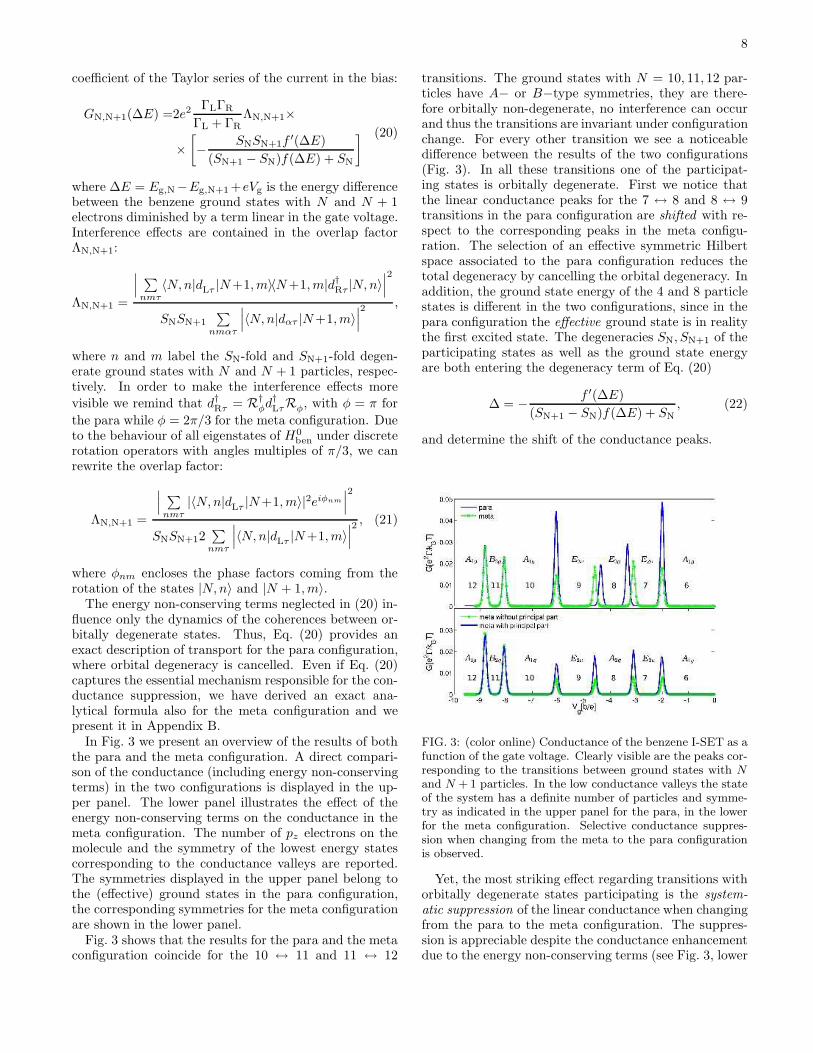
In Fig. 3 we present an overview of the results of boththe para and the meta configuration. A direct compari-son of the conductance (including energy non-conservingterms) in the two configurations is displayed in the up-per panel. The lower panel illustrates the effect of theenergy non-conserving terms on the conductance in themeta configuration. The number of pz electrons on themolecule and the symmetry of the lowest energy statescorresponding to the conductance valleys are reported.The symmetries displayed in the upper panel belong tothe (effective) ground states in the para configuration,the corresponding symmetries for the meta configurationare shown in the lower panel.
Fig. 3 shows that the results for the para and the metaconfiguration coincide for the 10 ↔ 11 and 11 ↔ 12
transitions. The ground states with N = 10, 11, 12 par-ticles have A− or B−type symmetries, they are there-fore orbitally non-degenerate, no interference can occurand thus the transitions are invariant under configurationchange. For every other transition we see a noticeabledifference between the results of the two configurations(Fig. 3). In all these transitions one of the participat-ing states is orbitally degenerate. First we notice thatthe linear conductance peaks for the 7 ↔ 8 and 8 ↔ 9transitions in the para configuration are shifted with re-spect to the corresponding peaks in the meta configu-ration. The selection of an effective symmetric Hilbertspace associated to the para configuration reduces thetotal degeneracy by cancelling the orbital degeneracy. Inaddition, the ground state energy of the 4 and 8 particlestates is different in the two configurations, since in thepara configuration the effective ground state is in realitythe first excited state. The degeneracies SN, SN+1 of theparticipating states as well as the ground state energyare both entering the degeneracy term of Eq. (20)
∆ = −f ′(∆E)
(SN+1 − SN)f(∆E) + SN, (22)
and determine the shift of the conductance peaks.
FIG. 3: (color online) Conductance of the benzene I-SET as afunction of the gate voltage. Clearly visible are the peaks cor-responding to the transitions between ground states with N
and N + 1 particles. In the low conductance valleys the stateof the system has a definite number of particles and symme-try as indicated in the upper panel for the para, in the lowerfor the meta configuration. Selective conductance suppres-sion when changing from the meta to the para configurationis observed.
Yet, the most striking effect regarding transitions withorbitally degenerate states participating is the system-
atic suppression of the linear conductance when changingfrom the para to the meta configuration. The suppres-sion is appreciable despite the conductance enhancementdue to the energy non-conserving terms (see Fig. 3, lower
9
panel). Thus, we will for simplicity discard them in thefollowing discussion.
The conductance suppression is determined by thecombination of two effects: the reduction to the symmet-ric Hilbert space in the para configuration and the inter-ference effects between degenerate orbitals in the metaconfiguration. The reduction to the symmetric Hilbertspace implies also a lower number of conducting chan-nels (see Table III). One would expect a suppression oftransport in the para configuration. As we can see fromTable III on the example of the 6 ↔ 7 transition peak,∆max is higher in the para configuration but not enoughto fully explain the difference between the two configu-rations.
# Channels Overlap factor Degeneracy term
SNSN+1 Λ ∆max [1/kBT ]
PARA 2 C 0,17
META 4 1
8C 0,11
TABLE III: Number of channels participating to transport,overlap factor and resonance value of the degeneracy term inthe para and the meta configuration for the 6 ↔ 7 transitionpeak. It is C = |〈6g|dLτ |7gℓτ 〉|
2, where τ and ℓ are the spinand the quasi angular momentum quantum numbers, respec-tively. The values of ∆max are given for kBT = 0.04|b|
. .
The second effect determining transport is the interfer-ence between the E-type states, which is accounted forin the overlap factor Λ. The overlap factor is basis in-dependent, thus we can write the transition probabilities
for the 6 ↔ 7 transition as |〈6g|dLτ |7g ℓ τ〉|2 = C, where
τ and ℓ are the spin and the quasi-angular momentumquantum number, respectively. The transition probabil-ities have the same value, since all four 7 particle statesare in this basis equivalent (see Appendix C). Under theC2 rotation the symmetric 7 particle ground state doesnot acquire any phase factor. Under the C3 rotation how-ever, the two orbitally degenerate states acquire differentphase factors, namely e
4π
3i and e−
4π
3i, respectively. Thus
the overlap factors Λ for the 6 ↔ 7 transition are:
Λpara =1
2 · 8C· |4C|
2= C,
Λmeta =1
4 · 8C·∣
∣
∣2Ce+
4π
3i + 2Ce−
4π
3i∣
∣
∣
2
=1
8C.
The linear conductance is determined by the product be-tween the number of conducting channels, the overlapfactor and the degeneracy term. Yet, it is the destruc-
tive interference between degenerate E-type orbitals, ac-counted for in the overlap factor Λ, that gives the majorcontribution to the strong suppression of the conductancein the meta configuration.
B. Negative differential conductance (NDC) andcurrent blocking
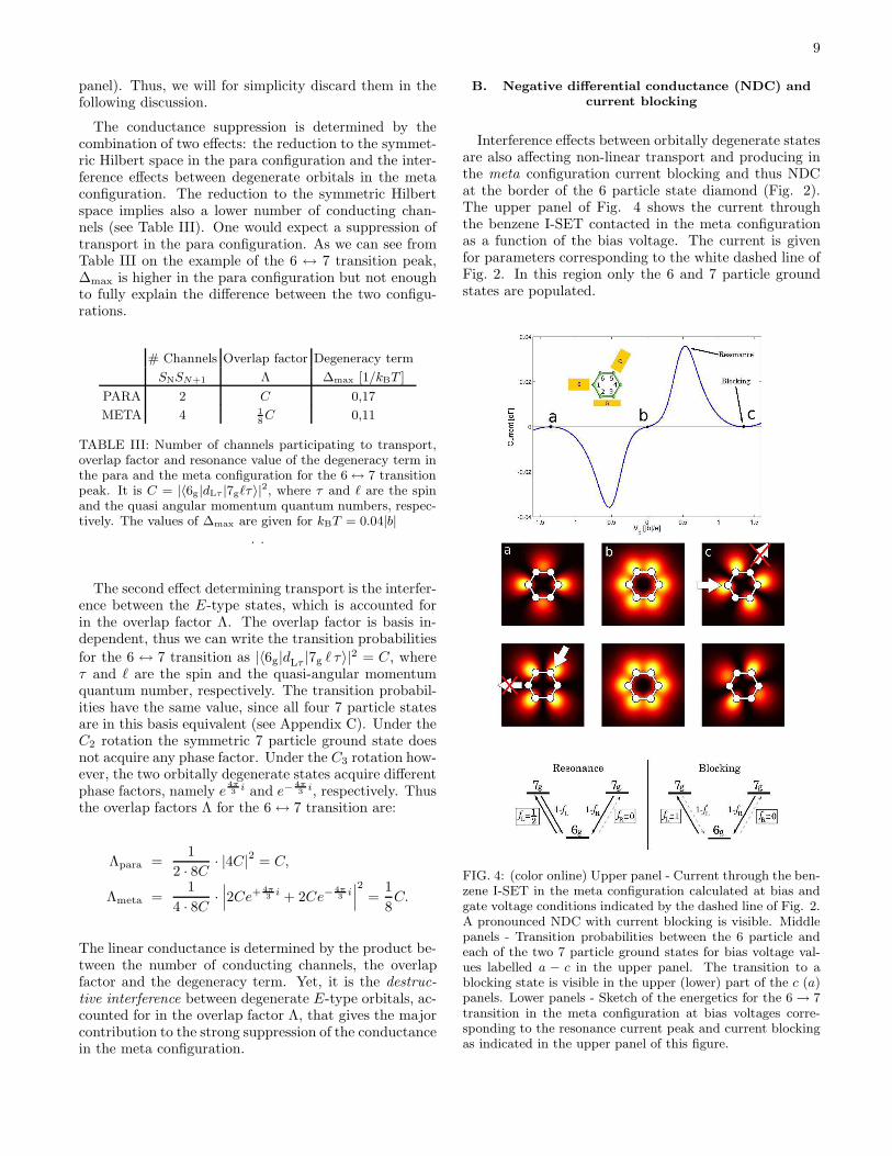
Interference effects between orbitally degenerate statesare also affecting non-linear transport and producing inthe meta configuration current blocking and thus NDCat the border of the 6 particle state diamond (Fig. 2).The upper panel of Fig. 4 shows the current throughthe benzene I-SET contacted in the meta configurationas a function of the bias voltage. The current is givenfor parameters corresponding to the white dashed line ofFig. 2. In this region only the 6 and 7 particle groundstates are populated.
FIG. 4: (color online) Upper panel - Current through the ben-zene I-SET in the meta configuration calculated at bias andgate voltage conditions indicated by the dashed line of Fig. 2.A pronounced NDC with current blocking is visible. Middlepanels - Transition probabilities between the 6 particle andeach of the two 7 particle ground states for bias voltage val-ues labelled a − c in the upper panel. The transition to ablocking state is visible in the upper (lower) part of the c (a)panels. Lower panels - Sketch of the energetics for the 6 → 7transition in the meta configuration at bias voltages corre-sponding to the resonance current peak and current blockingas indicated in the upper panel of this figure.

10
At low bias the 6 particle state is mainly occupied. Asthe bias is raised, transitions 6 ↔ 7 occur and currentflows. Above a certain bias threshold a blocking state ispopulated and the current drops. For the understand-ing of this non-linear current characteristics, we have totake into account energy conservation, the Pauli exclu-sion principle and the interference between participatingstates. For the visualization of the interference effects, weintroduce the transition probability (averaged over the zcoordinate and the spin σ):
P (x, y;n, τ) = limL→∞
∑
σ
1
2L
∫ L/2
−L/2
dz|〈7g n τ |ψ†σ(r)|6g〉|
2
(23)for the physical 7 particle basis, i.e., the 7 particle ba-sis that diagonalizes the stationary density matrix at afixed bias. Here τ is the spin quantum number, n = 1, 2labels the two states of the physical basis which are lin-ear combinations of the orbitally degenerate states |7gℓτ〉and can be interpreted as conduction channels. Each ofthe central panels of Fig. 4 are surface plots of (23) atthe different bias voltages a-c. The 7 particle groundstates can interfere and thus generate nodes in the tran-sition probability at the contact atom close to one or theother lead, but, in the meta configuration, never at bothcontact atoms at the same time.
Energetic considerations are illustrated in the lowerpanels of Fig. 4 for two key points of the current curveat positive biases. The left panel corresponds to the res-onance peak of the current. Due to energy conservation,electrons can enter the molecule only from the left lead.On the contrary the exit is allowed at both leads. Thecurrent is suppressed when transitions occur to a statewhich cannot be depopulated (a blocking state). Since,energetically, transmissions to the 6 particle state are al-lowed at both leads, each 7 particle state can always bedepopulated and no blocking occurs.
The current blocking scenario is depicted in the lowerright panel of Fig. 4. For large positive bias the transitionfrom a 7 particle ground state to the 6 particle groundstate is energetically forbidden at the left lead. Thus,for example, the c panel in Fig. 4 visualizes the currentblocking situation yielding NDC: while for both channelsthere is a non-vanishing transition probability from thesource lead to the molecule, for the upper channel a nodeprevents an electron from exiting to the drain lead. Inthe long time limit the blocking state gets fully populatedwhile the non-blocking state is empty. At large negativebias the blocking scenario is depicted in the panel a thatshows the left-right symmetry obtained by a reflectionthrough a plane perpendicular to the molecule and pass-ing through the carbon atoms atoms 6 and 3.We remark that only a description that retains coher-ences between the degenerate 7 particle ground statescorrectly captures NDC at both positive and negativebias.
In contrast to the 6 → 7 transition, one does not ob-serve NDC at the border of the 7 particle Coulomb di-
amond, but rather a strong suppression of the current.The upper panel of Fig. 5 shows the current through thebenzene I-SET contacted in the meta configuration as afunction of the bias voltage corresponding to the whitedotted line of Fig. 2. The middle panels show the transi-tion probabilities between each of the 7 particle and the6 particle ground state.
FIG. 5: (color online) Upper panel - Current through thebenzene I-SET in the meta configuration calculated at biasand gate voltage conditions indicated by the dotted line of Fig.2. No NDC is visible. Middle panels - Transition probabilitiesbetween each of the 7 particle and the 6 particle ground statefor bias voltage values labelled a−c in the upper panel. Lowerpanel - Sketch of the energetics for the 7 → 6 transition inthe meta configuration at bias voltage corresponding to theexpected resonance peak. (compare to Fig. 4).
The lower panel of Fig. 5 shows a sketch of the ener-getics at positive bias corresponding to the “expected”resonance peak. Here electrons can enter the moleculardot at both leads, while the exit is energetically forbiddenat the left lead. Thus, if the system is in the 7 particlestate which is blocking the right lead, this state cannotbe depopulated, becoming the blocking state.

11
On the other hand, transitions from the 6 particle groundstate to both 7 particle ground states are equally proba-ble. Thus the blocking state will surely be populated atsome time. The upper plot of the b panel in Fig. 5 showsthe transition probability to the blocking state that ac-cepts electrons from the source lead but cannot releaseelectrons to the drain.As just proved, in this case the current blocking situa-tion occurs already at the resonance bias voltage. For ahigher positive bias, the transition probability from theblocking state at the drain lead increases and current canflow. This effect, though, can be captured only by takinginto account also the energy non-conserving terms in (7).
In the para configuration, the current as a function ofthe bias voltage is shown in Fig. 6. The current is givenfor parameters corresponding to the white dashed line ofFig. 2. In this case, no interference effects are visible. Wesee instead the typical step-like behavior of the currentin the Coulomb blockade regime.The panels on the right are the surface plots of
P (x, y; τ) = limL→∞
∑
σ
1
2L
∫ L/2
−L/2
dz|〈7g τ ; (a)sym|ψ†σ(r)|6g〉|
2.
(24)The upper plot shows the transition probability to thesymmetric 7 particle state, the lower to the antisym-metric. Remember that in the para configuration onlythe symmetric states contribute to transport. Evidentlythe symmetric state is in the para configuration non-blocking. Additionally, since the coherences between or-bitally degenerate states and therefore the energy non-conserving terms do not play any role in the transport,the physical basis states are not bias dependent. Thusin the para configuration there are always non-blockingstates populated and no NDC can occur.
FIG. 6: (color online) Left panel - Current through the ben-zene I-SET in the para configuration calculated at bias andgate voltage conditions indicated by the dashed line of Fig. 2.No interference effects are visible. Right panels - Transitionprobabilities between the 6 particle and the symmetric andantisymmetric 7 particle ground states.
IV. REDUCED SYMMETRY
In this section we study the effect of reduced symme-try on the results presented previously. We generalizethe model Hamiltonian by taking into account the per-turbations on the molecule due to the contacts and thebias voltage. The contact between molecule and leads isprovided by different anchor groups. These linkers arecoupled to the contact carbon atoms over a σ bond thusreplacing the corresponding benzene hydrogen atoms.Due to the orthogonality of π and σ orbitals, the anchorgroups affect in first approximation only the σ orbitalsof benzene. In particular the different electron affinity ofthe atoms in the linkers imply a redistribution of the den-sity of σ electrons. Assuming that transport is carried byπ electrons only, we model the effect of this redistribu-tion as a change in the on-site energy for the pz orbitalsof the contact carbon atoms:
H ′ben := Hcontact = ξc
∑
ασ
d†ασdασ, α = L,R (25)
where R = 4, 5, respectively, in the para and meta con-figuration, L = 1 in both setups.
We also study the effect of an external bias on the ben-zene I-SET. In particular we release the strict conditionof potential drop all concentrated at the lead-moleculeinterface. Nevertheless, due to the weak coupling ofthe molecule to the leads, we assume that only a frac-tion of the bias potential drops across the molecule. Forthis residual potential we take the linear approximationVb(r) = −Vb
a (r · rsd/a0), where we choose the center ofthe molecule as the origin and rsd is the unity vector di-rected along the source to drain direction. a0 = 1.43 Ais the bond length between two carbon atoms in ben-zene, a is the coefficient determining the intensity of thepotential drop over the molecule. Since the pz orbitalsare strongly localized, we can assume that this potentialwill not affect the inter-site hopping, but only the on-siteterm of the Hamiltonian:
H ′ben := Hbias = e
∑
iσ
ξbid†iσdiσ (26)
with ξbi=∫
dr pz(r − Ri)Vb(r)pz(r − Ri).
Under the influence of the contacts or the bias poten-tial, the symmetry of the molecule changes. Table IVshows the point groups to which the molecule belongs inthe perturbed setup. This point groups have only A- andB-type reducible representations. Thus the correspond-ing molecular orbitals do not exhibit orbital degeneracy.
No interference effects influence the transport in thepara configuration. Thus we do not expect its transportcharacteristics to be qualitatively modified by the newset up with the corresponding loss of degeneracies.
In the meta configuration on the other hand, interfer-ences between orbitally degenerate states play a crucial

12
role in the explanation of the occurring transport fea-tures. Naıvely one would therefore expect that neitherconductance suppression nor NDC and current blockingoccur in a benzene I-SET with reduced symmetry. Yet we
PARA META
Contact perturb. D2h C2v
Bias perturb. C2v C2v
TABLE IV: Point groups to which the molecule belongs underthe influence of the contacts and the external bias potential.
find that, under certain conditions, the mentioned trans-port features are robust under the lowered symmetry.
The perturbations due to the contacts and the biaslead to an expected level splitting of the former orbitallydegenerate states. Very different current-voltage charac-teristics are obtained depending of the relation betweenthe energy splitting δE and other two important energyscales of the system: the tunnelling rate Γ and the tem-perature T . In particular, when δE ≪ Γ ≪ T , interfer-ence phenomena persist. In contrast when Γ < δE ≪ Tinterference phenomena disappear, despite the fact that,due to temperature broadening, the two states still cannot be resolved. In this regime, due to the asymmetryin the tunnelling rates introduced by the perturbation,standard NDC phenomena, see Fig. 8, occur.
In the absence of perfect degeneracy, we abandonthe strict secular approximation scheme that would dis-card the coherences in the density matrix between stateswith different energies. We adopt instead a softer ap-proximation by retaining also coherences between quasi-degenerate states. Since they have Bohr frequencies com-parable to the tunnelling rate, they influence the sta-tionary density matrix. Formulas for the GME and thecurrent taking into account these coherence terms arepresented in Appendix A.
Fig. 7 shows from left to right closeup views of thestability diagram for the setup under the influence ofincreasing contact perturbation around the 6 ↔ 7 res-onance. The orbital degeneracy of the 7 particle statesis lifted and the transport behavior for the 6 ↔ 7 tran-sition depends on the energy difference between the for-merly degenerate 7 particle ground states. In panel a theenergy difference is so small that the states are quasi-degenerate: δE ≪ ~Γ ≪ kBT . As expected, we recoverNDC at the border of the 6 particle diamond and currentsuppression at the border of the 7 particle diamond, likein the unperturbed setup.Higher on-site energy-shifts correspond to a larger levelspacing. Panel b displays the situation in which the latteris of the order of the level broadening, but still smallerthan the thermal energy (δE ≃ ~Γ ≪ kBT ): no interfer-ence causing NDC and current blocking can occur. Yet,due to thermal broadening, we cannot resolve the two 7particle states.Eventually, panel c presents the stability diagram for thecase δE > kBT > ~Γ: the level spacing between the 7
FIG. 7: (color online) Closeup views of the stability diagramaround the 6 ↔ 7 resonance for the system under contactperturbation. The perturbation strength grows from left toright The parameter that describes the contact effect assumesthe values ξc = 0.15Γ, 2Γ, 15T from left to right respectivelyand T = 10Γ .
particle ground and first excited state is now bigger thanthe thermal energy, thus the two transition lines corre-sponding to these states are clearly visible at the borderof the 6 particle stability diamond.
FIG. 8: (color online) Closeup views of the stability diagramaround the 6 ↔ 7 resonance for the system under the effectof the bias potential, displayed for different strengths of theelectrostatic potential drop over the molecule. The parameterthat describe the strength of the electrostatic drop overthemolecule assumes the values a = 25, 12, 0.6 from left to rightrespectively.
Fig. 8 shows closeup views of the stability diagram forthe setup under the influence of the bias perturbation atthe border of the 6 and 7 particle diamonds. The sameregion is plotted for different strengths of the externalpotential over the molecule. In contrast to the contactperturbation, the amount of level splitting of the formerdegenerate states is here bias dependent. This fact im-poses a bias window of interference visibility. The bias

13
must be small enough, for the 7 particle states to bequasi-degenerate and at the same time bigger than thethermal energy, so that the occurring NDC is not ob-scured by the thermally broadened conductance peak. Astrong electrostatic potential perturbation closes the biaswindow and no interference effect can be detected.Panel a of Fig. 8 represents the weak perturbation regimewith no qualitative differences with the unperturbed case.The typical fingerprints of interference (NDC at the bor-der of the 6 particle diamond and current blocking forthe 7 → 6 transition) are still visible for intermediateperturbation strength (panel b) but this time only in alimited bias window. Due to the perturbation strength,at some point in the bias, the level splitting is so big thatthe quasi-degeneracy is lifted and the interference effectsdestroyed. In panel c the quasi-degeneracy is lifted inthe entire bias range. There is NDC at the border of the6 particle diamond, but is not accompanied by currentblocking as proved by the excitation line at the border ofthe 7 particle diamond (see arrow): no interference oc-curs. The NDC is here associated to the sudden openingof a slow current channel, the one involving the 6 particleground state and the 7 particle (non-degenerate) excitedstate (standard NDC).
FIG. 9: (color online) Combination of the bias and contactperturbations. Left panel - Energy levels of the 7 particleground and first excited state as functions of the bias voltage.Right panel - Stability diagram around the 6 ↔ 7 resonance.The perturbation parameters are in this case ξc = 2Γ anda = 12.
Fig. 9 refers to the setup under both the bias and con-
tact perturbations. The left panel shows the energy of thelowest 7 particle states as a function of the bias. In theright panel we present the stability diagram around the6 ↔ 7 resonance. NDC and current blocking are clearlyvisible only in the bias region where, due to the combina-tion of bias and contact perturbation, the two seven par-ticle states return quasi-degenerate. Also the fine struc-ture in the NDC region is understandable in terms of in-terference if in the condition of quasi-degeneracy we takeinto account the renormalization of the level splitting due
to the energy non-conserving terms.
Interference effects predicted for the unperturbed ben-zene I-SET are robust against various sources of sym-metry breaking. Quasi-degeneracy, δE ≪ ~Γ ≪ kBT ,is the necessary condition required for the detection ofthe interference in the stability diagram of the benzeneI-SET.
V. CONCLUSIONS
In this paper we analyze the transport characteristicsof a benzene I-SET. Two different setups are considered,the para and the meta configuration, depending on theposition of the leads with respect to the molecule.
Within an effective pz orbital model, we diagonalize ex-actly the Hamiltonian for the molecule. We further applya group theoretical method to classify the many-bodymolecular eigenstates according to their symmetry andquasi-angular momentum. With the help of this knowl-edge we detect the orbital degeneracy and, in the paraconfiguration, we select the states relevant for transport.
We introduce a generic interference condition (1) forI-SETs in terms of the tunnelling transitions amplitudes
of degenerate states with respect to the source and drainlead. By applying it to the benzene I-SET we predict theexistence of interference effects in the meta configuration
In order to study the dynamics of the molecular I-SET, we use a density matrix approach which starts fromthe Liouville equation for the total density operator andwhich enables the treatment of quasi-degenerate states.
The stability diagrams for the two configurations showstriking differences. In the linear regime a selective con-ductance suppression is visible when changing from thepara to the meta configuration. Only transitions betweenground states with well defined particle number are af-fected by the change in the lead configuration. With thehelp of the group theoretical classification of the stateswe recognize in this effect a fingerprint of the destructive
interference between orbitally degenerate states. We de-rive an analytical formula for the conductance that re-produces exactly the numerical result and supports theirinterpretation in terms of interference. Other interfer-ence effects are also visible in the non-linear regime wherethey give rise to NDC and current blocking at the borderof the 6 particle Coulomb diamond as well as to cur-rent suppression for transitions between 7 and 6 particlestates.
We provide a detailed discussion of the impact of thereduced symmetry due to linking groups between themolecule and the leads or to an electrostatic potentialdrop over the molecule. We classify different transportregimes and set up the limits within which the discussedtransport features are robust against perturbations. Weidentify in the quasi-degeneracy of the molecular statesthe necessary condition for interference effects.

14
Acknowledgments
We acknowledge financial support by the DFG withinthe research programs SPP 1243 and SFB 689.
APPENDIX A: GME AND CURRENT IN THENON-SECULAR APPROXIMATION
The bias and the contact perturbations in our modelfor a benzene I-SET lower the symmetry of the activepart of the junction and consequently lift the degeneracythat appeared so crucial for the interference effects. The
robustness of the latter relies on the fact that the nec-essary condition is rather quasi-degeneracy, expressed bythe relation δE ≪ ~Γ.
Nevertheless, if the perfect degeneracy is violated, thesecular approximation applied to obtain Eq. (7) does notcapture this softer condition. We report here the generalexpression for the generalized master equation and theassociated current operator in the Born-Markov approxi-mation and under the only further condition (exact in ab-sence of superconductors) that coherences between stateswith different particle number are decoupled from thepopulations and vanish exactly in the stationary limit:
σNEE′ = −
i
~(E − E′)σN
EE′+
−∑
ατF
Γα
2PNE
{
d†ατ
[
−i
πpα(F −H0
ben) + f−α (F −H0
ben)
]
dατ+
dατ
[
−i
πpα(H0
ben − F ) + f+α (H0
ben − F )
]
d†ατ
}
σNFE′
−∑
ατF
Γα
2σN
EF
{
d†ατ
[
+i
πpα(F −H0
ben) + f−α (F −H0
ben)
]
dατ+
dατ
[
+i
πpα(H0
ben − F ) + f+α (H0
ben − F )
]
d†ατ
}
PNE′
+∑
ατFF′
Γα
2PNE
{
d†ατσN−1FF′ dατ
[
+i
πpα(E′ − F ′) + f+
α (E′ − F ′) −i
πpα(E − F ) + f+
α (E − F )
]
+
dατσN+1FF′ d
†ατ
[
+i
πpα(F ′ − E′) + f−
α (F ′ − E′) −i
πpα(F − E) + f−
α (F − E)
]}
PNE′
(A1)
where σNEE′ is, differently to Eq. (7), in the Schrodinger
picture. Eq. (7) represents a special case of Eq. (A1) inwhich all energy spacings between states with the sameparticle number are either zero or much larger than thelevel broadening ~Γ. The problem of a master equationin presence of quasi-degenerate states in order to studytransport through molecules has been recently addressedin the work of Schultz et al.36. The authors claim intheir work that the singular coupling limit should be usedin order to derive an equation for the density matrix inpresence of quasi-degenerate states. Equation (A1) isderived in the weak coupling limit and bridges all theregimes as illustrated by Fig. 7-9.
The current operators associated to the master equa-tion just presented read:
Iα =Γα
2
∑
NEFτ
PNE
{
d†ατ
[
+i
πpα(E −H0
ben) + f−α (E −H0
ben)
]
dατ
+ d†ατ
[
−i
πpα(F −H0
ben) + f−α (F −H0
ben)
]
dατ
− dατ
[
+i
πpα(H0
ben − E) + f+α (H0
ben − E)
]
d†ατ
− dατ
[
−i
πpα(H0
ben − F ) + f+α (H0
ben − F )
]
d†ατ
}
PNF
(A2)
where α = L,R indicates the left or right contact.Nevertheless, within the limits of derivation of the mas-ter equation, this formula can be simplified. Actually, ifE − F ≤ ~Γ, then F can be safely substituted with Ein the argument of the principal values and of the Fermi

15
functions, with an error of order E−FkBT < ~Γ
kBT which is
negligible (the generalized master equation that we areconsidering is valid for ~Γ ≪ kBT ). The approximationE ∼ F breaks down only if E−F ∼ kBT , but this impliesE−F ≫ ~Γ which is the regime of validity of the secularapproximation. Consequently, in this regime, terms withE 6= F do not contribute to the average current becausethey vanish in the stationary density matrix. Ultimatelywe can thus reduce the current operators to the simplerform:
Iα = Γα
∑
NEτ
PNE
{
+ d†ατ
[
f−α (E −H0
ben)]
dατ
− dατ
[
f+α (H0
ben − E)]
d†ατ
}
,
(A3)
which is almost equal to the current operator correspond-ing to the secular approximation. The only difference ishere the absence of the second projector operator that al-lows contributions to the current coming from coherences
between different energy eigenstates.
APPENDIX B: ANALYTICAL FORMULA FORTHE LINEAR CONDUCTANCE INCLUDINGTHE ENERGY NON-CONSERVING TERMS
In the derivation of the conductance formula (20) weneglected the energy non-conserving terms in the Eq. (7).Since in the GME they appear only in the dynamics of thecoherences between orbitally degenerate states, Eq. (20)is exact for the para configuration, where the orbital de-generacy is cancelled. This is not the case in the metaconfiguration where the orbital (quasi-)degeneracy is es-sential for the description of interference. Thus we de-rived a generic analytical formula for the conductance,taking into account the energy non-conserving terms. Itreads
GN,N+1(∆E) = e2ΓΛN,N+1
[
−SNSN+1f
′(∆E)
(SN+1 − SN)f(∆E) + SN
]
[
1 +aux(SN, SN+1)3P
2
16Λ2N,N+1(SNSN+1)2 (f±(∆E))
2+ P2
]
. (B1)
Here, it is Γ = ΓL = ΓR. ΛN,N+1 is the overlap fac-tor introduced in Section III A, Eq. (21). The auxiliaryfunction aux(SN, SN+1) in the correction term is zero ifthere are no orbitally degenerate ground states involvedin the transition. If one of the participating states is or-bitally degenerate it is aux(SN, SN+1) = 1. The signin f±(∆E) is defined as follows: f+(∆E) has to beused if the N particle ground state is orbitally degen-
erate. If instead the N + 1 particle ground state exhibitsorbital degeneracy, f−(∆E) has to be inserted. Theenergy non-conserving terms are included in the factorP = PL|Vbias=0 = PR|Vbias=0. It is defined only if a de-generate state is participating transport. In case thate.g. the N particle ground state is orbitally degenerate,Pα with α = L,R reads
Pα =∑
E′,l
∑
nm
[
i
πpα(Eg,N − E′)
]
〈N − 1, E′ l|dατ |Ng, n〉〈Ng,m|d†ατ |N − 1, E′ l〉
−∑
E′,l
∑
nm
[
i
πpα(E′ − Eg,N)
]
〈N + 1, E′ l|d†ατ |Ng, n〉〈Ng,m|dατ |N + 1, E′ l〉,
where pα(x) = −Reψ[
12 + iβ
2π (x− µα)]
and ψ is the
digamma function, as defined in Section II B.
APPENDIX C: TRANSITION PROBABILITIESFOR THE 6 ↔ 7 TRANSITION
In the calculation of the overlap factor Λ in Sec-tion III A we used the relation
|〈6g|dL|7g, ℓ = 2〉|2 = |〈6g|dL|7g, ℓ = −2〉|2. (C1)
for the transition probabilities between the 6 particleground state and the 7 particle ground states |7g, ℓ〉,

16
where ℓ is the eigenvalue of the quasi-angular momen-tum. This relation is now to be proved.Again, we take advantage of the symmetry properties ofthe molecular states with respect to the σv operation andto the rotation operator Rφ for rotations about a discreteangle φ = nπ
3 , as introduced in Section II C. The startingpoint is the generic relation between these two operators:
Rφσv = σvR−φ. (C2)
We can now apply both sides of this relation to the 7particle ground states |7g, ℓ = ±2〉:
Rφσv|7g, ℓ = ±2〉 = σvR−φ|7g, ℓ = ±2〉. (C3)
The 7 particle ground states |7g, ℓ = ±2〉 are eigenstatesof each Rφ, and the corresponding eigenvalues are phasefactors:
Rφ|7g, ℓ = ±2〉 = e∓2·iφ|7g, ℓ = ±2〉. (C4)
Thus, Eq. (C3) becomes
Rφ
(
σv|7g, ℓ = ±2〉)
= e±2·iφ(
σv|7g, ℓ = ±2〉)
. (C5)
Yet, according to Eq. (C4), this equation can only bevalid if
σv|7g, ℓ = ±2〉 = λ|7g, ℓ = ∓2〉. (C6)
and, since σ2v = 1, λ can only be a phase factor. For the
calculation of the transition probabilities we use furtherthe property σ†
vσv = 1. Since the left contact atom (atom1) lays in the reflection plane σv, it is: σvdLσ
†v = dL.
Also, since the symmetry of the 6 particle ground stateis A1g, it is: σv|6g〉 = |6g〉. Under these considerations,we can write for the transition probability to the state|7g, ℓ = 2〉:
|〈6g|dL|7g, ℓ = 2〉|2 = |〈6g|σ†vσvdLσ
†vσv|7g, ℓ = 2〉|2 =
= |〈6g|dLσv|7g, ℓ = 2〉|2 =
= |〈6g|dL|7g, ℓ = −2〉|2.
(C7)
1 G. Cuniberti, G. Fagas, and K. Richter (eds.), Introducing
Molecular Electronics, (Springer, Berlin, 2005).2 J. Park, A. N. Pasupathy, J. I. Goldsmith, C. Chang,
Yu. Yaish, J. R. Petta, M. Rinkoski, J. P. Sethna,H. D. Abruna, P. L. McEuen, and D. C. Ralph, Nature417, 722 (2002).
3 W. Liang, M. P. Shores, M. Bockrath, J. R. Long, H. Park,Nature 417, 725 (2002).
4 S. Kubatkin, A. Danilov, M. Hjort, J. Cornil, J.-L. Bredas,N. Stuhr-Hansen, P. Hedegard and T. Bjørnholm, Nature425, 698 (2003).
5 L. H. Yu, Z. K. Keane, J. W. Ciszek, L. Cheng, J. M. Tour,T. Baruah, M. R. Pederson, and D. Natelson, Phys. Rev.Lett. 95, 256803 (2005).
6 A. V. Danilov, S. Kubatkin, S. Kafanov, P. Hedegard,N. Stuhr-Hansen, K. Moth-Poulsen, and T. Bjørnholm,Nano Lett. 8, 1 (2008).
7 D.-H. Chae, J. F. Berry, S. Jung, F. A. Cotton,C. A. Murillo, and Z. Yao, Nano Lett. 6, 165 (2006).
8 M. Poot, E. Osorio, K. O’Neill, J. M. Thijssen, D. Van-maekelbergh, C. A. van Walree, L. W. Jenneskens, andH. S. J. van der Zant, Nano Lett. 6, 1031 (2006).
9 H. B. Heersche, Z. de Groot, J. A. Folk, H. S. J. van derZant, C. Romeike, M. R. Wegewijs, L. Zobbi, D. Barreca,E. Tondello, and A. Cornia, Phys. Rev. Lett. 96, 206801(2006).
10 E. A. Osorio, K. O’Neill, N. Stuhr-Hansen, O. F. Nielsen,T. Bjørnholm, H. S. J. van der Zant, Adv. Mater. 19, 281(2007).
11 E. Loertscher, H. Weber and H. Riel, Phys. Rev. Lett. 98,176807 (2007).
12 R. H. M. Smit, Y. Noat, C. Untiedt, N. D. Lang, M. C. vanHemert and J. M. van Ruitenbeek, Nature 419, 906 (2002).
13 M. Kiguchi, O. Tal, S. Wohlthat, F. Pauly, M. Krieger,
D. Djukic, J. C. Cuevas and J. M. van Ruitenbeek, Phys.Rev. Lett. 101, 046801 (2008).
14 A. R. Champagne, A. N. Pasupathy and D. C. Ralph, NanoLett. 5, 305 (2005).
15 L. Venkatarman, J. E. Klare, C. Nuckolls, M. S. Hybertsenand M. L. Steigerwald, Nature 442, 904 (2006).
16 J. Repp, G. Meyer, S. M. Stojkovic, A. Gourdon andC. Joachim, Phys. Rev. Lett. 94, 026803 (2005).
17 X. Xiao, B. Xu and N. J. Tao, Nano Lett. 4, 267 (2004).18 D. I. Gittins, D. Bethell, D. J. Schiffrin, and R. J. Nichols,
Nature 408, 67 (2000).19 M. Mayor, H. B. Weber, J. Reichert, M. Elbing, C. von
Hanisch, D. Beckmann and M. Fischer, Angew. Chem. Int.Ed. 42, 5834 (2003).
20 F. Chen, X. Li, J. Hihath, Z. Huang, and N. J. Tao, J.Am. Chem. Soc. 128, 15874 (2006).
21 L. Venkatarman, J. E. Klare, I. W. Tam C. Nuckolls,M. S. Hybertsen and M. L. Steigerwald, Nano Lett. 6, 458(2006).
22 N. Roch, S. Florens, V. Bouchiat, W. Wernsdorfer, andF. Balestro, Nature 453, 633 (2008).
23 D. V. Cardamone, C. A. Stafford, and S. Mazumdar, NanoLett. 6, 2422 (2006).
24 A. Gagliardi, G. C. Solomon,A. Pecchia, T. Frauenheim,A. Di Carlo, N. S. Hush, and J. R. Reimers, Phys. Rev. B75, 174306 (2007).
25 S.-H. Ke, W. Yang, and U. Baranger, Nano Lett. 8, 3257(2008).
26 Z. Quian, R. Li, X. Zhao, S. Hou and S. Sanvito, Phys.Rev. B 78, 113301 (2008).
27 H. Bruus and K. Flensberg, Many-Body Quantum Theory
in Condensed Matter Physics, (Oxford University Press,Oxford, 2004).
28 M. H. Hettler, W. Wenzel, M. R. Wegewijs, and

17
H. Schoeller, Phys. Rev. Lett. 90, 076805 (2003).29 S. A. Gurvitz and Ya. S. Prager, Phys. Rev. B 53, 15932
(1996).30 M. Braun, J. Konig, and J. Martinel Phys. Rev. B 70,
195345 (2004).31 B. Wunsch, M. Braun, J. Konig, and D. Pfannkuche, Phys.
Rev. B 72, 205319 (2005).32 A. Donarini, M. Grifoni, and K. Richter, Phys. Rev. Lett.
97, 166801 (2006).33 L. Mayrhofer and M. Grifoni, Eur. Phys. J. B 56, 107
(2007).34 S. Koller, L. Mayrhofer, M. Grifoni, New J. Phys. 9, 348
(2007).
35 G. Begemann, D. Darau, A. Donarini, and M. Grifoni,Phys. Rev. B 77, 201406(R) (2008); 78, 089901(E) (2008).
36 M. G. Schultz, F. von Oppen arXiv:0812.1491v2.37 J. Linderberg and Y. Ohrn, J. Chem. Phys. 49, 716 (1968).38 R. Pariser and R. G. Parr, J. Chem. Phys. 21, 466 (1953).39 J. A. Pople, Trans. Faraday Soc. 49, 1375 (1953).40 W. Barford Electronic and Optical Properties of Conju-
gated Polymers, (Clarendon Press, Oxford, 2005).41 K. Kaasbjerg and K. Flensberg, Nano Lett. 8, 3809 (2008).42 K. Blum, Density Matrix Theory and Applications
(Plenum Press, New York, 1996).