VAPOR-LIQUID EQUILIBRIUM GF BENZENE-BIPHENYL BY ...
166
VAPOR-LIQUID EQUILIBRIUM ^ :i GF BENZENE-BIPHENYL BY MICHAEL WALDICHUK -0- A thesis submitted in partial fulfilment of the requirements for the degree of MASTER OF ARTS IN THE DEPARTMENT OF CHEMISTRY -0- THE UNIVERSITY OF BRITISH COLUMBIA OCTOBER, 1950. ' 1
-
Upload
khangminh22 -
Category
Documents
-
view
0 -
download
0
Transcript of VAPOR-LIQUID EQUILIBRIUM GF BENZENE-BIPHENYL BY ...

VAPOR-LIQUID EQUILIBRIUM ^ : i
GF
BENZENE-BIPHENYL
BY
MICHAEL WALDICHUK
- 0 -
A t h e s i s submitted i n p a r t i a l f u l f i l m e n t o f
the requirements f o r the degree of
MASTER OF ARTS
IN THE DEPARTMENT
OF
CHEMISTRY
- 0 -
THE UNIVERSITY OF BRITISH COLUMBIA
OCTOBER, 1950. ' 1

THE UNIVERSITY OF BRITISH COLUMBIA V A N C O U V E R , C A N A D A
C H E M I S T R Y
September 30, 1950.
To Whom It May Concern: This i s to certify that the thesis entitled
"Vapour-Liquid Equilibrium of Benzene-Biphenyl" by Mr. Michael Waldichuk measures up to the required standards of the Master's thesis in this Department.
Yours truly,
-ew

ABSTRACT
A comprehensive s u r v e y has been made o f vapor
l i q u i d e q u i l i b r i u m apparatuses i n the l i g h t o f h i s t o r i c a l
development. Two of the b e t t e r types o f u n i t s have been
chosen and b u i l t f o r t h i s r e s e a r c h . The vapor l i q u i d
e q u i l i b r i a o f benzene-n-butanol and benzene-biphenyl were
determined on the G i l l e s p i e - F o w l e r e q u i l i b r i u m s t i l l . Thermo
dynamic c o n s i s t e n c y o f the r e s u l t s was checked w i t h the van
Laar and Margules i n t e g r a t i o n s o f the Gibbs Dubem e q u a t i o n .
R e s u l t s o b tained on the benzene-n-butanol system appear t o Con4 form t o the o r y w i t h i n experimental e r r o r . However, those o f
benzene-biphenyl show v e r y l i t t l e c o n s i s t e n c y . Temperature-
Composition diagrams were drawn f o r both systems and f o l l o w
the g e n e r a l form f o r non-azeotropic m i x t u r e s ;

ACKNOWLBDGEMEIJT The author wishes to express his appreciation of
the constructive criticism as well as encouragement given by Dr. L.W. Shemilt under whose supervision this research was carried out. Thanks are also due Mr. Wm. Pye, who carried out the glassblowing on the Gillespie-Fowler equilibrium s t i l l along with other smaller projects; and to Mr. A. Werner, who gave helpful suggestions and hints i n the d i s t i l l a t i o n and general purification of the compounds.
Acknowledgement is also made of the National Research Council Summer Scholarship which aided financially in the continuation of this research for the months May to September of 1949 and for May of 1950.

TABLE OF CONTENTS
TITLE
I I n t r o d u c t i o n
I I T h e o r e t i c a l " D i s c u s s i o n
PAGE
1 7
Gibbs Duhem eq u a t i o n Van Laar E q u a t i o n s Margules Equations Other thermodynamic Treatments of V a p o r - l i q u i d e q u i l i b r i a .
I l l H i s t o r i c a l Development of the E q u i l i b r i u m Apparatus 24
A. L i q u i d R e c i r c u l a t i n g Type
1. E a r l y Work
Determinations o f B i l i n g Temperatures I n t e r n a l Heaters C o t t r e l l Pump Vapor Trap
2. Modern E q u i l i b r i u m S t i l l s
The Othmer e q u i l i b r i u m s t i l l C h i l t o n ' s e q u i l i b r i u m s t i l l S t i l l o f Scatchard, Raymond and Gilmann
3. L a t e s t Developments i n E q u i l i b r i u m S t i l l s
F l a s h chamber G i l l e s p i e S t i l l w i t h vapor disengagement chamber
Fowler m o d i f i c a t i o n of the G i l l e s p i e s t i l l
4 . S p e c i a l i z e d S t i l l s
S t i l l s f o r p a r t i a l l y m i s c i b l e b i n a r y mixtures E q u i l i b r i u m s t i l l s f o r h i g h vacua E q u i l i b r i u m s t i l l s . r ' f o r low temperature
B. Vapor R e c i r c u l a t i n g Type
E a r l y Forms Constant temperature type of r e c i r c u l a t i n g apparatus
C. Other Methods of V a p o r - l i q u i d e q u i l i b r i u m Determinations

Bomb method Dynamic Plow Method
Apparatus
A. Vapor R e c i r c u l a t i n g Apparatus
High vacuum system P u r i f i c a t i o n o f mercury Main E q u i l i b r i u m apparatus C i r c u l a t i n g pump Commutator f o r c i r c u l a t i n g pump Temperature c o n t r o l Constant temperature baths S t i r r i n g equipment Heating, temperature measurement and c o n t r o l
Constant Temperature a i r Thermomostats Constant Temperature O i l bath
B. L i q u i d R e c i r c u l a t i n g Apparatus
M o d i f i c a t i o n s of Fowler s t i l l
C. Refractometer
D. P l a t i n u m R e s i s t a n c e thermometer
M a t e r i a l s
A. Benzene
1. I n i t i a l P u r i f i c a t i o n
2. D i s t i l l a t i o n
3. F r a c t i o n a l R e c r y s t a l l i z a t i o n
4. Check on p u r i t y
(a) R e f r a c t i v e index
(b) F r e e z i n g p o i n t
(c) D e n s i t y
B. Butanol
C. B i p h e n y l
1. R e c r y s t a l l i z a t i o n
2. D i s t i l l a t i o n

(a) D e t e r m i n a t i o n of c o n d i t i o n s
(b) B i p h e n y l s t i l l developed
Pressure c o n t r o l and measurement E f f i c i e n c y o f Column Improvements f o r tne s t i l l D i s t i l l a t i o n Procedure
3. Check on P u r i t y
VI E x p e r i m e n t a l u P r o c e d u r e s
A. D e t e r m i n a t i o n o f R e f r a c t i v e Index-Composition Curves
Benzene-butanol Benzene b i p h e n y l
B. V a p o r - l i q u i d e q u i l i b r i u m d e t e r m i n a t i o n s on the G i l l e s p i e - F o w l e r s t i l l
C. Determinations on the vapor r e c i r c u l a t i o n
apparatus
V I I R e s u l t s
A. Benzene-Butanol
B. Benzene-Biphenyl
V I I I D i s c u s s i o n of R e s u l t s
A. Benzene-Butanol
B. Benzene-Biphenyl
IX B i b l i o g r a p h y

TABLES
1. P h y s i c a l data f o r Benzene from the l i t e r a t u r e . 66-7.
2. P h y s i c a l data f o r Butanol from the l i t e r a t u r e . 69.
3. F r e e z i n g p o i n t data f o r b i p h e n y l from the l i t e r a t u r e . 8 l .
4. R e f r a c t i v e Index - Composition data f o r benzene-butanol a t 20°C. . 9 0 .
5 . Experimental y a p o r - l i q u i d e q u i l i b r i u m data f o r
benzene-butanol a t atmospheric p r e s s u r e . 91*
6. Vapor p r e s s u r e d a t a f o r benzene. 93.
7. A c t i v i t y c o e f f i c i e n t s of benzene and n-butanol from experimental v a p o r - l i q u i d e q u i l i b r i a . 93.
8. T h e o r e t i c a l a c t i v i t y c o e f f i c i e n t s of benzene and n-butanol. 9J?.
9. R e f r a c t i v e Index-Composition data f o r benzene-b i p h e n y l a t 70QC. ' 9.6.
10. Smoothed R e f r a c t i v e Index-Composition d a t a f o r benzene - b i p h e n y l a t 70°C. 97.
11. E x p e r i m e n t a l v a p o r - l i q u i d e q u i l i b r i u m data f o r benzene-biphenyl a t atmospheric p r e s s u r e . 98.
12. Smoothed valu e s f o r the v a p o r - l i q u i d e q u i l i b r i u m of benzene-biphenyl. 99.
13. A c t i v i t y c o e f f i c i e n t s of benzene and b i p h e n y l from experimental d a t a . 101.
14. T h e o r e t i c a l a c t i v i t y c o e f f i c i e n t s of benzene and b i p h e n y l . 101.,

ILLUSTRATIONS
1 . Vapor pressure - composition diagrams of two component systems.
2 . Equilibrium s t i l l designed by Brown in 18*79.
3 . Carveth's apparatus (18*99).
4 . Zawidski's apparatus (1900). 5 . Cottrell's apparatus with an air l i f t device ( 1 9 1 9 ) .
6. Swietoslawski Ts boiling point apparatus. (1925). 7 . S t i l l of Sameshima incorporating a vapor trap (1918). 8. Original Othmer S t i l l (1928). 9 . Othmer s t i l l of 1 9 3 2 .
1 0 . New, improved Othmer S t i l l ( 1 9 4 S ) .
1 1 . Apparatus of Carey and Lewis ( 1 9 3 2 ) .
1 2 . S t i l l of Rogers, Knight and Choppin ( 1 9 4 7 ) .
1 3 . Chilton's s t i l l ( 1 9 3 5 ) .
1 4 . Apparatus of Scatchard, Raymond and Gilmanvx. 1 5 . Equilibrium s t i l l of ilones, Schoenborn and Colburn ( 1 9 4 3 ) .
1 6 . Gillespie's equilibrium s t i l l ( 1 9 4 6 ) .
17. Othmer's refined s t i l l modified by Smith and Bonner ( 1 9 4 9 ) .
IS. Equilibrium s t i l l of Williams ( 1 9 4 7 ) .
1 9 . Equilibrium s t i l l of Perry and Fuguilt ( 1 9 4 7 ) .
2 0 . S t i l l of Gordon and Benson for low temperature equilibria ( 1 9 4 6 ) .
2 1 . Apparatus of Rosanoff, Lamb, and Briethut (1909). 2 2 . High vacuum system. 2 3 . Main equilibrium apparatus. 2 4 . Commutator arrangement.

2 5 . C i r c u l a t i n g apparatus.
2 6 . C i r c u i t diagram of temperature c o n t r o l u n i t s f o r a i r baths.
27. Constant temperature baths i n s e c t i o n and s t i r r i n g u n i t .
28. (a) C i r c u i t diagram of e l e c t r o n i c c o n t r o l u n i t f o r constant temperature i n o i l bath.
26% (b) F i n g e r - t y p e thermor.egulator.
2 9 . F o w l e r - G i l l e s p i e e q u i l i b r i u m s t i l l .
3 0 . (a) Benzene s t i l l .
3 0 . (b) Theimer vacuum adapter.
3 1 . F r e e z i n g p o i n t apparatus.
3 2 . C o o l i n g curve f o r benzene.
3 3 . Vapor pressure curve f o r b i p h e n y l .
3 4 . Semi micro s t i l l .
3 5 . B i p h e n y l s t i l l .
3 6 . Pressure r e g u l a t o r f o r vacuum d i s t i l l a t i o n .
3 7 . C o o l i n g curve f o r b i p h e n y l .
38. R e f r a c t i v e i n d e x - Composition cux^ve f o r benzene -n-butanol at 20OC.
3 9 . Experimental vapor l i q u i d e q u i l i b r i u m curve f o r benzene-n-butanol.
4 0 . Vapor pressure curve f o r n-butanol.
41. Vapor pressure curve f o r benzene.
42. P l o t of l o g a c t i v i t y c o e f f i c i e n t s vs mole f r a c t i o n i n l i q u i d f o r benzene-butanol.
4 3 . Temperature-composition diagram f o r benzene-butanol at atmospheric p r e s s u r e .
44• R e f r a c t i v e index-composition curve f o r benzene-biphenyl at 7 0 ° C
45• Experimental v a p o r - l i q u i d e q u i l i b r i u m curve f o r benzene-b i p h e n y l .

46. P l o t of l o g a c t i v i t y c o e f f i c i e n t s mole f r a c t i o n i n l i q u i d f o r benzene-biphenyl.
47. Temperature-composition diagram f o r benzene-biphenyl.
PLATES
I Vapor R e c i r c u l a t i o n e q u i l i b r i u m apparatus.
I I F o w l e r - G i l l e s p i e E q u i l i b r i u m S t i l l .
I I I Benzene s t i l l .
IV B i p h e n y l s t i l l .

1
CHAPTER I
INTRODUCTION
Vapor l i q u i d e q u i l i b r i u m data are of great impor
tance i n the f i e l d s o f d i s t i l l a t i o n , e x t r a c t i o n , and o t h e r
contact p r o c e s s e s . A knowledge of such data i s one o f t h e
fundamental requirements i n the q u a n t i t a t i v e d e s i g n c a l c u l
a t i o n s f o r columns i n f r a c t i o n a l d i s t i l l a t i o n . However, t h e
experimental work r e q u i r e d t o g a i n t h i s knowledge has been
found complicated, o f t e n r e q u i r i n g e l a b o r a t e equipment, and
very seldom r e p r o d u c i n g the r e s u l t s o f p r e v i o u s r e s e a r c h e r s .
In r e c e n t y e a r s , t h e r e has been an o u t b u r s t o f experimental
work and p u b l i s h e d papers on such d e t e r m i n a t i o n s . Many
authors have done a gre a t d e a l o f r e s e a r c h i n t o the t h e o r e t i c a l
a s pects o f vapor l i q u i d e q u i l i b r i u m . T h i s t h e o r e t i c a l approach
has been s t i m u l a t e d by the need f o r c e r t a i n mathematical
e x p r e s s i o n s which w i l l r e l a t e the thermodynamic p r o p e r t i e s o f
compounds t o the v a p o r - l i q u i d e q u i l i b r i u m . Researchers i n
t h i s f i e l d have f e l t t h a t e v e n t u a l l y some r e l a t i o n s should be
obt a i n e d which would v i r t u a l l y e l i m i n a t e t h e n e c e s s i t y of
e x t e n s i v e experimental work t o determine the vapor l i q u i d
e q u i l i b r i u m o f a system. Up to the present, c e r t a i n fundamen
t a l thermodynamic e x p r e s s i o n s have been developed and u t i l i z e d
f o r the e f f e c t i v e e x t e n s i o n o f common p h y s i c a l data o f some
n o n - i d e a l systems.
Vapor l i q u i d e q u i l i b r i u m data c o n s i s t e s s e n t i a l l y o f
the composition o f the l i q u i d and vapor phases o f a system
when they are i n e q u i l i b r i u m . The x - y diagram (x i s the

mole f r a c t i o n o f the more v o l a t i l e component i n t h e l i q u i d
phase and y i s the mole f r a c t i o n of the more v o l a t i l e compon
ent i n the vapor phase) i s v e r y common i n books on d i s t i l l a t i o n
as w e l l as In p u b l i s h e d papers on vapor l i q u i d e q u i l i b r i a .
Experimental d i f f i c u l t i e s i n o b t a i n i n g these data are many.
They u s u a l l y stem from the nature of the apparatus used i n
the d e t e r m i n a t i o n s . There have been many types o f apparatuses
developed f o r e q u i l i b r i u m d e t e r m i n a t i o n s , but fundamentally
t h e y can be c l a s s i f i e d under two main groups. There i s the
vapor r e c i r c u l a t i o n type which i s o r d i n a r i l y employed under
constant temperature and i n an evacuated system. The other
i s the l i q u i d r e c i r c u l a t i o n t y p e mainly used f o r e q u i l i b r i u m
d e t e r m i n a t i o n s under atmospheric p r e s s u r e . Many r e s e a r c h e r s
f e e l t h a t the former i s s u p e r i o r f o r a c c u r a t e d e t e r m i n a t i o n s
because i t e l i m i n a t e s most o f the common f a u l t s a t t r i b u t e d
t o the l i q u i d r e c i r c u l a t i n g s t i l l s . S i nce the l a t t e r i s
e s s e n t i a l l y a d i s t i l l a t i o n type o f apparatus, i t s u f f e r s from
r e f l u x i n g of the vapors i n the r e g i o n between the b o i l e r and
the vapor s e c t i o n , entrainment of d r o p l e t s o f l i q u i d i n the
vapor, f l a s h i n g of the more v o l a t i l e component when the c o l d
condensate r e t u r n s t o the hot b o i l e r , and superheating o f the
system i n i t i a l l y . However, the apparatus can u s u a l l y be b u i l t
v e ry simply i n v o l v i n g v e r y few mechanic'al p a r t s , and d e t e r
minations are r e a d i l y made. On t h e o t h e r hand, the vapor
r e c i r c u l a t i o n t y p e of apparatus poses many problems i n con
s t r u c t i o n and o p e r a t i o n . Both types of u n i t s w i l l be d i s
cussed f u l l y i n a l a t e r s e c t i o n .

3
The system, benzene-biphenyl chosen i n t h i s work,
has v e r y l i t t l e p r a c t i c a l a p p l i c a t i o n . I t i s one, however,
t h a t has c o n s i d e r a b l e t h e o r e t i c a l i n t e r e s t . A complete
thermodynamic e v a l u a t i o n o f t h e system c o u l d throw c o n s i d e r a b l e
l i g h t on c e r t a i n concepts i n the t h e o r i e s o f s o l u t i o n s . The
two components o f the system are so v a s t l y d i f f e r e n t i n t h e i r
p h y s i c a l p r o p e r t i e s and c r i t i c a l c o n s t a n t s t h a t c e r t a i n
workers i n the f i e l d of s o l u t i o n s have taken a keen i n t e r e s t
i n t h e study of benzene-biphenyl. Others have experimented
w i t h the system from t h e p o i n t of view of s t a t i s t i c a l thermo
dynamics because of the d i f f e r e n c e i n s i z e of the two compon
ent molecules. The e a r l i e s t work on the system by T y r e r i n
1910 (132) was done i n c o n n e c t i o n w i t h the d e n s i t y o f d i f f e r e n t
composition o f the components at 25°C. T h i s was f o l l o w e d by
the r e s e a r c h of Washburn and Read who determined the e u t e c t i c
p o i n t i n 1915 (13#) and the e l e v a t i o n o f t h e b o i l i n g p o i n t i n
1919 ( 1 3 9 ) . In 1921 G e h l o f f (39) d i d what was probably t h e
f i r s t thermodynamic e v a l u a t i o n o f the system when he d e t e r
mined the heat of s o l u t i o n .
Some time elapsed b e f o r e any f u r t h e r work was
c a r r i e d out on benzene-biphenyl. Warner, Scheib and S v i r b e l y
(136) i n 1934 c a r r i e d out d e t e r m i n a t i o n s on the s o l u b i l i t y of
b i p h e n y l and benzene. A short p e r i o d l a t e r i n 193&, Gilmann
and Gross (44) took an i n t e r e s t i n the system from the p o i n t
of view of i d e a l i t y . They determined the vapor p r e s s u r e o f
benzene over benzene-biphenyl s o l u t i o n s and found t h a t t h e
system obeys K a o u l t ' s Law w i t h i n experimental e r r o r . In a

paper p u b l i s h e d i n 194$ (130) Tompa d i s c u s s e s the thermo
dynamics o f t h e benzene-biphenyl system as ev a l u a t e d w i t h
Guggenheim's formulae ( 5 2 ) . These formulae are based on t h e
l a t t i c e model, and i n t h e i r a p p l i c a t i o n t o the system i t i s
assumed t h a t the b i p h e n y l molecule o c c u p i e s twice the volume
of the benzene molecule. Experimental d e t e r m i n a t i o n s were
a l s o made by Tompa and the r e s u l t s were shown to conform to
the s t a t i s t i c a l thermodynamic p i c t u r e . One o f the l a t e s t
r e f e r e n c e s to t h e system was made i n a paper read to t h e
Manchester S e c t i o n of t h e Chemical S o c i e t y i n October, 1949,
by Ward and Brooks (134)• They measured t h e v i s c o s i t i e s o f
the system at 5°C i n t e r v a l s of temperature and a t d i f f e r e n t
compositions. T h e i r r e s u l t s showed t h a t t h e mixture i s i d e a l
and g i v e s n e a r l y a s t r a i g h t l i n e p l o t f o r ITL V a g a i n s t 1. T
However, they made no mention o f the e a r l y work c a r r i e d out
on the v i s c o s i t y o f the system (66). S i n c e they p u b l i s h e d no
v a l u e s , i t was not p o s s i b l e to check the e a r l i e r r e s u l t s .
Work on t h e benzene- n- b u t y l a l c o h o l system has been
c o n s i d e r e d o n l y o f secondary importance i n t h i s r e s e a r c h .
V a p o r - l i q u i d e q u i l i b r i u m data f o r i t was o b t a i n e d p r i m a r i l y as
a check on the e q u i l i b r i u m s t i l l ( G i l l e s p i e - F o w l e r ) b u i l t
towards t h e l a t t e r p a r t o f t h e i n v e s t i g a t i o n s . More i n t e n s i v e
work was c a r r i e d out by Emerson and C u n d i l l ( 3 0 ) , who i n v e s
t i g a t e d the system i n t h e i r r e s e a r c h f o r the B.A .Sc. degree.
The system has not been p r e v i o u s l y s t u d i e d f o r i t s vapor
l i q u i d e q u i l i b r i u m , and t h e r e s u l t s o b t a i n e d here proved t o
be of c o n s i d e r a b l e i n t e r e s t . N-Butanol i s the f i r s t s t r a i g h t

c h a i n a l c o h o l o f the a l i p h a t i c s e r i e s forming no azeotrope
w i t h benzene, but the behaviour does not appear t o d e v i a t e
too f a r from t h a t of s i m i l a r mixtures. R e s u l t s appear t o be
c o n s i s t e n t w i t h i n experimental e r r o r when checked thermo-
dynami c a l l y . On t h e o t h e r hand, data o b t a i n e d f o r t h e benzene-
b i p h e n y l system appear to have no thermodynamic c o n s i s t e n c y
whatsoever. Although the x-y curve f o r t h e l a t t e r system
seems reasonable i n appearance, a p l o t o f the l o g a r i t h m o f
the a c t i v i t y c o e f f i c i e n t a g a i n s t the mole f r a c t i o n i n t h e
l i q u i d phase g i v e s very l i t t l e i n d i c a t i o n of a smooth curve.
An e f f o r t has been made t o e v a l u a t e the system thermodynamic
a l l y ; but s i n c e c o n s t a n t s i n both the van Loar and Margules
i n t e g r a t i o n s of the Gibbs Duhem equation are dependent on
experimental v a l u e s , no b r i e f i s h e l d f o r i t s v a l i d i t y .
The purpose o f the r e s e a r c h d e s c r i b e d here i s two
f o l d . An endeavour has been made to check b e t t e r forms of t h e
two types o f v a p o r - l i q u i d e q u i l i b r i u m apparatus,one a g a i n s t
the other, and t o check f o r thermodynamic c o n s i s t e n c y of
r e s u l t s i n each case by an a p p l i c a t i o n o f at l e a s t one of the
i n t e g r a t e d forms of t h e Gibbs Duhem equ a t i o n . A l s o e q u i l
i b r i u m data f o r the system, benzene-biphenyl, was sought f o r
purposes of t h e o r e t i c a l c o n s i d e r a t i o n . U n f o r t u n a t e l y , some
of the work o r i g i n a l l y planned has been u n s u c c e s s f u l up t o the
p o i n t t o which t h e i n v e s t i g a t i o n s were c a r r i e d . The vapor
r e c i r c u l a t i o n apparatus r e q u i r e s f u r t h e r m o d i f i c a t i o n and
improvement to g i v e the d e s i r e d r e s u l t s . The G i l l e s p i e - F o w l e r
e q u i l i b r i u m s t i l l cannot be c o n s i d e r e d as t h e b e s t t y p e of

u n i t f o r the d e t e r m i n a t i o n o f - t h e v a p o r - l i q u i d e q u i l i b r i u m of
benzene-biphenyl. However, those r e s u l t s which were obtained
are g i v e n as f u l l y as p o s s i b l e along w i t h t h e i r treatment.
In a d d i t i o n , a comprehensive survey of the l i t e r a t u r e i s
g i v e n t o a i d those who may co n t i n u e s t u d i e s a l o n g t h e l i n e s
o f vapor l i q u i d e q u i l i b r i u m . Much of the m a t e r i a l i s v e r y
d e s c r i p t i v e and d e a l s l a r g e l y w i t h apparatus c o n s t r u c t i o n .
T h i s was f e l t n e c e s s a r y f o r a s u c c e s s f u l c o n t i n u a t i o n of the
work as w e l l as f o r any reasonable r e p r o d u c t i o n of r e s u l t s .

7
CHAPTER I I
THEORETICAL DISCUSSION
Y a p o r - l i q u i d e q u i l i b r i u m has been t r e a t e d t h e o r e t
i c a l l y a t g r e a t l e n g t h i n r e c e n t y e a r s . T h i s has been found
n e c e s s a r y f o r any k i n d of thermodynamic e v a l u a t i o n of systems
where i n v o l v e d experimental d e t e r m i n a t i o n s can be a v o i d e d .
E s p e c i a l l y i n the f i e l d o f f r a c t i o n a l d i s t i l l a t i o n where quan
t i t a t i v e r e s u l t s are ne c e s s a r y f o r column d e s i g n c a l c u l a t i o n s
has i t been the case.
To overcome the complexity o f the q u a n t i t a t i v e
r e l a t i o n s h i p s i n v o l v e d i n d e t e r m i n i n g the vapor l i q u i d e q u i l
i b r i u m , c e r t a i n b a s i c thermodynamic r e l a t i o n s have been d e v e l
oped (48) (72). These r e l a t i o n s a p p l y i n a l l cases, but i n
most of these t h e r e are unknown f a c t o r s which l i m i t t h e i r
u s e f u l n e s s u n t i l s i m p l i f y i n g assumptions are made. The
a p p l i c a b i l i t y o f the thermodynamic r e l a t i o n may be due t o the
l i m i t a t i o n s o f these s i m p l i f y i n g assumptions. However, even
i n such a case the r e l a t i o n s h i p s serve as v a l u a b l e c r i t e r i a
f o r e s t i m a t i n g the normal behaviour of a system as w e l l as a
check on the thermodynamic c o n s i s t e n c y of experimental r e s u l t s .
I f we c o n s i d e r a system o f two m i s c i b l e components,
Dalton's Law of p a r t i a l p r e s s u r e s h o l d s t r u e a t o r d i n a r y
p r e s s u r e s , i . e . ,
P-L + P 2 = P ( 1 ) A
Most mixtures, however, do not obey R a o u l t ' s Law, which s t a t e s
A See the end of d i s c u s s i o n f o r an e x p l a n a t i o n o f nomenclature.

8 t h a t "the f r a c t i o n a l l o w e r i n g o f the vapor p r e s s u r e of the
s o l v e n t i s equal t o the mole f r a c t i o n of the s o l u t e i n s o l u t
i o n " , or s t a t e d s y m b o l i c a l l y ,
? 1 - xxPi 0 ( 2 )
A system obeying R a o u l t ' s Law can be c o n s i d e r e d as i d e a l , and
d e v i a t i o n s from i d e a l i t y may be due e i t h e r t o the vapor phase,
the l i q u i d phase or both. These d e v i a t i o n s can be both
p h y s i c a l and chemical i n n a t u r e . The important f a c t o r s
b e l i e v e d t o be i n v o l v e d are t h a t molecules have volume and
t h a t they e x e r t f o r c e s upon each other which may be a t t r a c t
i o n s or r e p u l s i o n s . A c t u a l chemical e f f e c t s may a l s o be
i n v o l v e d e s p e c i a l l y where the components are eh e m i o a l l y d i s
s i m i l a r , e.g., b e l o n g i n g t o d i f f e r e n t homologous s e r i e s . I t
has been shown e x p e r i m e n t a l l y t h a t substances, s i m i l a r chem
i c a l l y d e v i a t e o n l y s l i g h t l y from R a o u l t ' s Law.
Non - i d e a l systems e x h i b i t e i t h e r n e g a t i v e or
p o s i t i v e d e v i a t i o n s depending on whether the molecules o f one
substance tend t o lower or r a i s e the esca p i n g tendency o f the
other oomponent m o l e c u l e s . P o s i t i v e d e v i a t i o n i s the most
common, and from F i g u r e 1 i t can be seen t h a t i t r e s u l t s i n
the p a r t i a l p r e s s u r e o f the components as w e l l as the t o t a l
p r e s s u r e o f the system b«ir»<j g r e a t e r than the p r e d i c t i o n o f
Ra o u l t ' s Law. As shown i n the diagram, the t o t a l vapor p r e s s u r e
may r e a c h a maximum a t a c e r t a i n c o n c e n t r a t i o n . T h i s i s us u
a l l y the case i f the d e v i a t i o n i s g r e a t and the vapor p r e s s u r e s
of the two components do not d i f f e r g r e a t l y . Under such c i r
cumstances, t h e r e e x i s t s a c e r t a i n c o n c e n t r a t i o n a t which the

A MOLE. F R A C T I O N B
FIG ta - M I N I M U M BOtUNG, S Y S T E M
D O T T E D U N C 3 B t P R t a t N T * l D E A L C U R V E S
A MOLE. F R A C T I O N E> B
R ^ . l b . - M M I M U M B O I U M q S Y S T E M
F\a I - VAPOR P R E L S S U R E : COMPOSIT ION DIAGRAMS O F T W O C O M P O N E N T S Y S T E M S

total vapor pressure w i l l be equal to the atmospheric pressure at a lower temperature than at any other concentration. In other words, the solution has a minimum boiling point at this concentration. Where the total vapor pressure curve experiences a minimum corresponding to a concentration at which the solution exerts a pressure equal to atmospheric at a temperature higher than for either of the components, we have a maximum boiling mixture. Systems having either of these properties are known as constant boiling or azeotropio mixtures,
Gibbs-Dubem Equation For the general case of a system i n which transfer
of material takes place, any extensive property such as free energy, F, w i l l depend not only on pressure and temperature but also on the mass of each component present. Thus F = f (T,P,ni,n2, —-) and the general di f f e r e n t i a l expression for dF can be written as follows: dF F^dT =/e>F\dT + /-3F\dP V ( - 3 F V L m + / 3 FWg+~
v5"T7Pini,n2 r.— V^y/T,n l fn2 VaaJ P,T , n 2 — p,T,:
^^FNdT + feF\dP + TfarW V¥ T/P,ni,n 2---\dP/T,n 1,n 2 Vd ni/T,P
n i (3) T,P
The partial differential/"^ F \ is known as the partial
molar free energy and i s often written as F'i for convenience. It has also been defined as the chemical potential ju.t . Now, at constant temperature and pressure we obtain the expression,
dF = /Uldnt (4) It can be shown that the chemical potential with respect to a change in one component i s independent of the amount of that

component p r o v i d e d i t s r e l a t i v e c o n c e n t r a t i o n i s co n s t a n t .
Hence 4 can be i n t e g r a t e d w i t h u<L regarded as a con s t a n t , i . e .
The i n t e g r a t i o n constant drops out when t h e r e i s no change i n
c o n c e n t r a t i o n .
F r o m E u l e r ' s Theorem,
S i n c e the f r e e energy, F, i s an e x t e n s i v e p r o p e r t y of the
phase and, t h e r e f o r e , a homogeneous f u n c t i o n o f the f i r s t
degree i n , our e x p r e s s i o n reduces t o
Eq u a t i o n 7 i s known as the Gibbs-Duhem e q u a t i o n (72). When
a p p l i e d to changes i n composition a t constant temperature and
pr e s s u r e , i t i s r i g o r o u s l y e xact. Where o n l y the temperature
v a r i e s over a s m a l l range, i t may be approximately v a l i d .
When the mass of each component present i s consta n t ,
F - f (P,T) and
(5>
(6)
(7)
(8)
By d e f i n i t i o n ,
H - E + PV (9) F - H - TS (10)
Combining 9 and 10,
F • E + PV - TS (11) D i f f e r e n t i a t i n g 11 g e n e r a l l y ,
dF = dE + PdV + VdP - TdS - SdT (12)
From the f i r s t and second laws o f thermodynamics,
dE = TdS - PdV (13)

Substituting 13 into 12, dF - VdP - SdT (14)
Comparing equations 8 and 14, we obtain
( H ) T " T l l 5 )
We have already defined
ML " (MN (16)
If we have only one oomponent in two phases we can have only one degree of freedom, as determined by the Phase Rule, and we can write
M - dF 7 dn (17)
Rearranging and integrating, we obtain yj&.n = JdF
ju. n - F (18)
If we have only one mole of component,F = ^ and 15 can be written in the following form for a mole of an ideal gas:
by* = dF = VdP = RT dP (19)
Integrating 19 we obtain at constant temperature M - RT ln P2 + K ( 20)
FT In order that this equation apply to the general case of any non-ideal gas, a new property, fugaoity f, i s defined such that
dyU. = RT df (21) If the lower limit of integration is taken as fugaeity i n some standard state denoted by f°, we can integrate 21 as follows:
(22) Equation 7 can be expressed as

n, djLA, + nxd yu^ + — - = o
and since n̂ ,n2> are proportional to the mole fractions
2-1»̂ 2»"" ' xAju, + y^fX% + = 0 ( 2 3 )
Dividing through hy dxi we obtain x i f ^ / M + x 2 (^tt±S + = 0 ( 24)
But from the definition of fugacity we can write dyW = RT d i n f for one mole of gas at constant
temperature. Therefore,
M • + * 2
+ 0 (25)
which i s a more useful form of the Gibbs-Duhem equation. Here the fugacity can be considered as the "ideal" partial pressure and i s identical with the partial pressure for conditions under which the gas laws hold.
The ratio f can be defined as the activity, a, and a the activity coefficient "tf i
x Then a-, = f i ; a 9 - f 2 ( 2 6 )
f j 2
Y . = :i V* = a2 ( 27) x l x2.
Combining ( 2 6 ) and ( 27)
" ; V - f? fl° xl * f2°x 2 (28)
If the vapors.behave ideally f 1 » P X ; f 2 = P2
and f 1°= Pi° ; f 2°= P 2° where Pi° and P 2° are the

13 a c t u a l p r e s s u r e s of the pure components. Under such
c o n d i t i o n s we can w r i t e
X - Pi > • I - P? ' F p ~ x i 1 (29)
From D a l ton's Law,
Pi - yiP * ?2 = y 2 p ( ? Q ) Combine 29 and 30 to o b t a i n
1 x ^ P p ; x f ^ o ( 5 1 )
These e x p r e s s i o n s f o r the a c t i v i t y c o e f f i c i e n t s are o f g r e a t
value i n the treatment of vapor l i q u i d e q u i l i b r i a . They g i v e
d i r e c t l y the d e v i a t i o n f a c t o r s from Raoult»s Law, which when
p l o t t e d on semilog paper a g a i n s t mdle. f r a c t i o n of one of the
components i n the l i q u i d phase r e v e a l c h a r a c t e r i s t i c curves
i f the data are thermodynamically c o n s i s t e n t .
I f we can assume t h a t t h e r e i s i d e a l behavious i n the
vapor phase, by v i r t u e of e q u a t i o n 28 we can express the f u g -
a c i t y o f a component i n terms of the a c t i v i t y c o e f f i c i e n t ,
p r e ssure of the pure component and i t s mole f r a c t i o n .
Thus
f l « h*i°*l * f2 = *'2P2°X2 (32) Then s u b s t i t u t i n g these v a l u e s i n t o 23

T n e ( ~S&r\ R° \ and Y ^ (Ln P-THerms are zero since P ^ 0 and P 2 °
are constants at constant temperature, and we are l e f t with xl(a&v'O + + ^ ( 3 ^ ) + x 2 3 x 2 + 0
If we consider a two component system and that x 2 <= (1-x^) and dx 2 = -dx^, our expression reduces to
xiJBM.) = x 2 ( i k L ] (33) V 3%. /p,r V 3}U V
This form of the Gibbs Duhem equation expressed in terms of activity coefficients i s of immediate value in studying experimental data on vapor-liquid equilibrium. It relates the slopes of the plots of logarithms c$. activity coefficients against the composition of the liquid phase. However, since the magnitudes of such slopes are d i f f i c u l t to obtain, there have been a number of solutions advanced for this differential equation. At least two of these solutions w i l l be considered here since they are to be used later in the treatment of the data.
Van Laar Equations J. J. van Laar (68), in a thorough study of the
thermodynamics of binary mixtures derived, semi-empirically, solutions to the Gibbs Duhem equation. These expressions have proved to be very useful i n treatment of vapor liquid equilibrium data. They have been modified and rearranged by various authors, especially by Carlson and Colburn (13), G i l l i l a n d et a l (43) and White (142). The derivation of the solution w i l l not be attempted here since i t becomes considerably i n volved. However, the general form of the equations w i l l be

1 5
shown and they can be r e a d i l y proved t o be i n t e g r a t i o n s of t h e
Gibbs-Duhem e q u a t i o n .
C a r l s o n and Colburn g i v e the van Laar equations i n
the symmetrical forms
l o g tf, " A ( 5 4 ) (l+ A x i V
(35)
When x i = 0 and x 2 = 1
l o g ^, = A , l o g K = 0
and ^ = 1
When XT_ = 1 • and x 2 = 0
l o g ^ = E> , l o g >j, » G
and = 1
Thus the constants A and B i n the equations can be obt a i n e d
from experimental l o g $ vs composition p l o t when the curves
are e x t r a p o l a t e d t o x^ = 0 and x i = 1 . I t i s assumed t h a t t h e s e
two experimental v a l u e s of l o g % are v e r y n e a r l y c o r r e c t i n
order t o check the thermodynamic c o n s i s t e n c y of the remainder.
The f a c t t h a t and ^ are equal to 1 when xj_ and x 2 are equal
to 1 , r e s p e c t i v e l y j s a t i s f i e s the l i m i t i n g c o n d i t i o n t h a t
R a b u l t ' s law ho l d s f o r a component whose c o n c e n t r a t i o n approa
ches 1 0 G mole peroent.
Other q u a l i t a t i v e checks on experimental data can be
r e a d i l y i n d i c a t e d from the p e c u l i a r p r o p e r t i e s o f equations
34 and 35•

When x i = 0.5
l o g % » A g A - AB2 ~ (36) ' /i,+ A\2. IA •+ B)2 TA+BJ?
^ BV B2
l o g 1 = B , - B • ^ = A 2B -? (37) X A + -B\2 (A + B) 2 (A + B)2
^ 57 A*
D i v i d e (36) by B and (37) by A and the two can be equated,
l o g £ - AB . = l o g \ 1 (A •+ B ) 2 I (38)
Now i f A •» B
AB = 1 and as A and B d i f f e r the r a t i o (A + B)2 4~
decreases, e.g., when A = 2B
AB - 2B2 m 2 (A + B)2 fgZ 9
From 38, i t can be seen t h a t the h a l f way value on one curve
i s approximately equal to one q u a r t e r of the end value on the
other curve. Thus, a t x^ = 0 .5, i f the curve of l o g 2(, vs x±
should be lower, i t w i l l have a h i g h e r end value than the
curve l o g #t vs x i .
E q u a t i o n s 34 and 35 can a l s o be w r i t t e n
" A x 2 2 . (39) ( x 2
+ T | x l ) 2
l 0 e - BXI 2
( x x + B x 2 ) Z (40)
To show t h a t these s a t i s f y the Gibbs-Duhem equation,
they can be d i f f e r e n t i a t e d remembering t h a t x i - l - x 2 and
t h a t dx^ = d x 2
x l (tUtS - x i { - 2 A x 22 ( A x i + x ^ (k-l\- 2Ax2 ]

x • x o ( - 2 B X l2 ( x +B x > 3 ( B - l ) - 2 B x l ]
S i m p l i f y i n g ~ ?
* \ 1 " 2 A X 2 " 2 - x l x 2 )
x i W ^ ' = ^ y . . ? , A . . . . i v f*^2+
V ^ ' I fa • B x V J \ l j X l 2 (42)
Now, i f we m u l t i p l y both the numerator and denomin
a t o r o f (42) by A3 we o b t a i n
2A 2 f x i 2 x 2 + 3 B \ / A x i +
x l x 2 3 x 2
13/ X (1 + A x i V (43) v xo /
x 2 > 3 :
which i s i d e n t i c a l to ( 4 1 ) . Hence the van Laar equations
s a t i s f y the Gibbs-Duhem p a r t i a l d i f f e r e n t i a l e q u a t i o n .
G i l l i l a n d et a l (43) employ v e r y s i m i l a r e x p r e s s i o n s
f o r the van Laar equation, but c o r r e c t e d f o r temperature, i . e . ,
log If, - B/T x 2
(44)
X 1 ;
I f (43) i s s o l v e d f o r B,
B = T ( l + Ax]V i o g < , (43A)
. x 2 ' -
then the e x p r e s s i o n f o r B can be s u b s t i t u t e d i n t o (44) and
one can s o l v e f o r A. %
A = 4 + x ^ 2 l o g ^
log = AB/T
( i + - A a s i y l o g * , (44A)

A =/xif 10* Tk (44B)
With any s e t of a c c u r a t e data o f a c t i v i t y c o e f f i c
i e n t s corresponding to a c e r t a i n c o n c e n t r a t i o n , the constant
i n t he above equations can be e v a l u a t e d . U s u a l l y dependable
v a l u e s can be o b t a i n e d from the a z e o t r o p i c composition and
the whole vapor l i q u i d e q u i l i b r i u m curve can be e v a l u a t e d .
White ( 1 4 2 ) rearranged the van Laar equations some
what a g a i n and showed t h a t they c o u l d be used as s t r a i g h t -
l i n e forms as f o l l o w s :
( l o g K , ) - ! / ^ ^ ^ . ^ ( W )
(log i , ) - 1 / 2 - B 1/ 2 * ^ 1 / 2 ( 4 6 )
These equations were a p p l i e d t o the system 1-butanol-xvater
by Smith and Bonner (113) who p l o t t e d ( l o g $( )'~<">•'5 a g a i n s t
x l / x 2 a n c * ( i ° S ^ ) ~ ^ " ^ a g a i n s t X2* The check on t h e exper-
x l V i m e n t a l r e s u l t s was not near as c l o s e as i n t h e l o g 0
a g a i n s t x p l o t .
Margules Equations.
Margules ( 7 6 ) found a s o l u t i o n t o the Gibbs Duhem
equation by i n t e g r a t i n g i t i n terms of a p a i r of e x p o n e n t i a l
s e r i e s . He d e r i v e d the co n s t a n t s o f one of t h e equations
from those o f the other by a p p l y i n g equation 33.
Thus t h e two s e r i e s e x p r e s s i o n s o b t a i n e d f o r the
a c t i v i t y c o e f f i c i e n t s of the components i n a b i n a r y mixture
were as f o l l o w s :

l o g o, = a x 2 + bxg + c x 2
l o g a ^ i + b ^ 2 + c l x ^ US) These expressions are s u b s t i t u t e d i n t o equation 33
and we o b t a i n t h e f o l l o w i n g two e x p r e s s i o n s :
x i (d-£n V. ) - - x i d £ n V, = - ( a x i + 2bx2_x2 + - 3 0 X 3 X 2 ) 2 (49)
x 2 (JI&JQSIA = -x 2 d £ N = -(a 1x 2+2b 1x 1X2+3c : Lx 2x 12)' (50)
V "d^-L - ' / • dxx
I f t he c o e f f i c i e n t s o f 49 and 50 are ev a l u a t e d i n
such a way th a t the constant terms i n each case are equal,
the c o e f f i c i e n t s of the f i r s t power of t h e mole f r a c t i o n
terms are equal and so on f o r t h e high e r power terms, we can
put both e x p r e s s i o n s completely i n terms o f x 2 ( f r o m x 2=l-x;j_)
and equate.
a - a x 2 + 2bx 2 - 2bx 22 + 3cx^ 2 - 3cx 2^
= a x x 2 + 2 b 1 x 2 - 2 b 1 x 22 + 3 c 1 x 2 - 6 c 1 x 2
2 + 3 c 1 x 2 ^
C o l l e c t i n g terras f o r each power o f x 2
a + (-a+2b)x2 + (-2b+3c)x 22 - 3 c x 2
3
(a 1+2b 1+3c 1)x2 + (-2b!-6cl)x 22 + 3 c l x 2
Equate c o e f f i c i e n t s
a =0 ( i )
-a + 2b = a l + 2bl + 3 c 1 ( i i )
-2b + 3c = -2b 1 - 6 C1 ( i i i )
-3c = 3 c l ( i v )
S o l u t i o n s o b t a i n e d are as f o l l o w s :
c l = -c
From ( i i i )

2b = 2 t A - 3c
S u b s t i t u t e value f o r b i n t o ( i i )
-a + 2 b 1 - 3c = a 1 + 2 b 1 + 3 c 1
T h e r e f o r e , -a = a 1
and a 1 = 0
From ( i i i )
b 1 = 2b + 3c 2
S u b s t i t u t i n g v a l u e s f o r the co n s t a n t s i n t o 47 and 4#, we
o b t a i n
.." Irxi, = b x 22 + . C X 2 ^ (51)
JLrdir* b x i 2 + 1 C X ! 2 - cx-^ (52)
Although t h e equations have two independent c o n s t a n t s only-
one p o i n t i s needed to e v a l u a t e both o f t h e s e . I f more data
are a v a i l a b l e i t i s convenient t o p l o t ^' v s . x n , and
Jlr\\x v s . x 2 ; and i f the Margules equation, agrees w i t h the X T *
data s t r a i g h t l i n e s should be obtained. The s l o p e of the two
l i n e s should be j u s t e q u a l to the constant c, w h i l e the
i n t e r c e p t can be used f o r e v a l u a t i n g the constant b. Since
the c o n s t a n t s o f the Margules equation are a f u n c t i o n o f the
temperature, i f one experimental p o i n t i s used t o e v a l u a t e
them, they should be s u i t a b l e f o r other compositions at t h e
same temperature assuming the equations t o a p p l y . At ot h e r
temperatures, however, a d d i t i o n a l experimental data are
r e q u i r e d .
C a r l s o n and Colburn (15) s l i g h t l y r e v i s e d t h e
constants of the Margules equation i n order t o u t i l i z e t he
t e r m i n a l v a l u e s o f the l o g v s . x p l o t as c o n s t a n t s . With

the c o n s t a n t s A and B r e p r e s e n t i n g the same v a l u e s as t h e
corresponding symbols i n t h e van Laar equation, the Margules
two-term equations can be w r i t t e n as f o l l o w s :
l o g tf, = ( 2 B - A ) x 22 + 2(A-B)x 2 3 ( 5 3 )
l o g ( 2 A - B ) X 12 + 2(B-A)x 1 3 ( 5 4 )
where (2B-A) = b and 2(A-B) = c i n 51 and 52.
I t can be r e a d i l y seen t h a t at x i = 0, l o g #f = A and l o g 0^= 0;
at x i 8 5 1 , l o g tf, = 0 and l o g ^ = B.
An i n t e r e s t i n g f e a t u r e o f t h e s e equations i s t h a t at x^ = 0.5,
l o g ^ 1 = B/4 and l o g = A r e g a r d l e s s of the v a l u e s o f A and 4
B. When A = B the Morgules equations become i d e n t i c a l w i t h
those of van L a a r . As t h e value A d e p a r t s from u n i t y , the B
two s e t s of equations r e p r e s e n t i n c r e a s i n g l y d i f f e r e n t c u r v e s .
Other Thermodynamic Treatments of Vapor L i q u i d E q u i l i b r i a
There have been a c o n s i d e r a b l e number of o t h e r
t h e o r i e s put f o r t h i n the l i t e r a t u r e i n r e c e n t years on t h e
thermodynamic e v a l u a t i o n of systems. These w i l l be o n l y
b r i e f l y mentioned because t h e y have not been used t o any
extent i n t h i s r e s e a r c h .
Scatchard and Hamer ( 1 0 9 ) extended the methods of
van Laar to g i v e the a c t i v i t y c o e f f i c i e n t s i n terms of molar
volumes and volume f r a c t i o n s of the components. Scatchard
[108) proposed a thermodynamic r e l a t i o n i n which a l l the
c o n s t a n t s r e p r e s e n t p h y s i c a l p r o p e r t i e s f o r systems where the
change of entropy on mixing i s the same as t h a t f o r an i d e a l
mixture. Some time l a t e r , Scatchard, Wood and Mochel ( 1 1 1 )
concluded, a f t e r e x t e n s i v e work on t h r e e systems formed by:

... - . .• • - - - • 22
benzene, cyclohexane and carbon t e t r a c h l o r i d e , t h a t - t h e r e was
no agreement between the t h e o r e t i c a l and experimental v a l u e s
of the constant i n the Scatchard equation.
R e d l i c h and K i s t e r (99)in a r e c e n t paper d i s c u s s
the examination of experimental e q u i l i b r i u m data t o e f f i c i e n t l y
e valuate the thermodynamic p r o p e r t i e s o f n o n e l e c t r o l y t e
s o l u t i o n s . T h e i r main concern was t h e d e s i g n o f columns from
l a b o r a t o r y data which r e p r e s e n t s the mole f r a c t i o n s x o f t h e
l i q u i d and y of the vapor i n e q u i l i b r i u m as f u n c t i o n s o f the
temperature a t constant p r e s s u r e . They appeal t o c e r t a i n
equations o f s t a t e i n t h e i r e v a l u a t i o n s and present a v e r y
comprehensive study o f the assumptions i n v o l v e d .
Gilmont et a l (45) take a somewhat new approach i n
the d e t e r m i n a t i o n o f a c t i v i t y c o e f f i c i e n t s . They u t i l i z e t h e
r e l a t i v e v o l a t i l i t y which i s independent o f composition and
t o t a l p r e s s u r e , being the r a t i o o f the vapor p r e s s u r e o f the
pure components at constant temperature. A symmetrical form
o f power s e r i e s was a p p l i e d f o r the r e l a t i v e v o l a t i l i t y as
a f u n c t i o n of composition.

23
NOMENCLATURE
A = A r b i t r a r y constant i n van Laar and Margules equations.
B = A r b i t r a r y constant i n van Laar and Margules e q u a t i o n s . Equal t o l o g at x 2 = 0.
a a l ) b b | )= A r b i t r a r y constants i n s e r i e s i n t e g r a t i o n s l e a d i n g t o c c )' Margules equations.
E = i n t e r n a l energy.
F = f r e e energy.
f - f u g a c i t y .
f° = f u g a c i t y i n the Standard S t a t e .
^ = a c t i v i t y c o e f f i c i e n t .
H = enthalpy,
n = moles o f component.
P = t o t a l p r e s s u r e (atmospheric), mm Hg.
^1^2 ~ P a r t i a l p r e s s u r e s o f components, mm Hg.
P l ° > P 20 = vapor p r e s s u r e s o f pure components, mm Hg.
R m gas constant.
S = entropy.
T = a b s o l u t e temperature.
U= F = ^FT = chemical p o t e n t i a l ( p a r t i a l molar f r e e energy).
V = volume.
x = mole f r a c t i o n i n l i q u i d .
y = mole f r a c t i o n i n vapor i n e q u i l i b r i u m w i t h x.
S u b s c r i p t s
1 = l o w - b o i l i n g component (benzene).
2 = h i g h - b o i l i n g component (n-butanol or b i p h e n y l ) .
E q u a l

CHAPTER III HISTORICAL DEVELOPMENT OF THE EQUILIBRIUM APPARATUS
A. Liquid Recirculating Type By far the largest proportion of vapor-liquid
equilibrium units used are the d i s t i l l a t i o n types which in their more advanced form are liquid recirculating. One of the earliest investigators in the f i e l d of vapor liquid equilibrium was Brown. In a number of papers published in 1881 (8) he made a c r i t i c a l survey of s t i l l s up to that time. At the turn of the century, Sydney Young (LM">) made an excellent criticism of equilibrium s t i l l s in his classic book on d i s t i l l a t i o n , " D i s t i l l a t i o n Principles and Processes" published in 1903 and subsequently revised in 1922. Only very recently, a comprehensive treatise was written on the evolution of this type of s t i l l by R.T. Fowler (35). An endeavour w i l l be made here to cover the development of equilibrium s t i l l s according to the new devices introduced to improve the accuracy of determinations. The vapor recirculating type of apparatus w i l l be discussed as well as some of the specialized types. 1. Early Work
After making a complete survey of equilibrium s t i l l s up to his time, Brown designed an apparatus which he describes in a paper in 1879 (7). The s t i l l i s of the dynamic d i s t i l l a t i o n type where the composition of the liquid continuously changes. It is illustrated in Figure 2 which shows a copper vessel A with a long neck surrounded by an

outer jacket leading to a condenser and condensate receiver
B. The neck of the vessel has numerous holes through which
the vapors pass into the outer jacket. This arrangement keeps
the neck at the temperature of the vapors and prevents con
densation and r e f l u x . The vapors f i n a l l y condense i n the
condenser-and enter receiver B from which a sample can be
removed f o r ana l y s i s . Brown f e l t that by having a large
quantity of l i q u i d i n the b o i l e r compared to that d i s t i l l e d
o f f he could obtain reasonable composition values of the
vapor i n equilibrium with the l i q u i d at any given concentration.
In 1898 Lehfeldt (71) introduced what he f e l t was an improve
ment and made the b o i l e r smaller. The chief d i f f i c u l t y with
t h i s type of apparatus i s , of course, that there i s no prof -
v i s i o n to prevent super heating and, as a r e s u l t , accurate
temperature measurement cannot be obtained. Furthermore,
i t i s a case of st r a i g h t d i s t i l l a t i o n with a continuous
weakening of the l i q u i d i n the more v o l a t i l e component.
Analysis has to be made of successive f r a c t i o n s and a c a l
culation must be resorted to f o r an estimate of equilibrium
values.
Determination of B o i l i n g Temperatures
The f i r s t serious attempt to determine the b o i l i n g
temperatures of the l i q u i d and vapors i n equilibrium was made
by Carveth i n 1899 (16),. Figure 3 shows some of the d e t a i l s
of the apparatus. A large bulb contained a f a i r l y large
volume of solvent and solute. Glass beads were added to pre
vent superheating. Into the f l a s k were f i t t e d , by means of a

rubber stopper, a thermometer, condenser, and a bulb-shaped
tube a l s o c o n t a i n i n g a thermometer. In d e t e r m i n a t i o n s , the
bulb-shaped tube was withdrawn from t h e l i q u i d and t u r n e d so
t h a t t h e s m a l l f u n n e l was c l e a r of the d r i p t i p of t h e con
denser. The l i q u i d was b o i l e d and i t s temperature was noted
on ttiermometer 1. Then the bulb was t u r n e d so' t h a t the con
densed vapor was allowed to d r i p i n t o the f u n n e l and onto the
bulb o f thermometer 2. The temperature recorded on t h i s
thermometer when i t reached s t a b i l i t y was t h a t of the b o i l i n g
vapor phase. In order to prevent superheating i n the bu l b , a
p i e c e of platinum w i r e was s e a l e d i n t o i t . B o i l i n g temper- '
a t u r e s , however, were found t o va r y w i t h t h e r a t e of h e a t i n g ,
and Corveth suggested t h a t the r a t e o f h e a t i n g be s t a n d a r d i z e d
f o r a l l s u b s e q u e n t work.
I n t e r n a l Heaters
A d e f i n i t e s t r i d e i n t h e advance toward b e t t e r
e q u i l i b r i u m s t i l l s was the i n t r o d u c t i o n o f i n t e r n a l h e a t e r s
t o prevent s u p e r h e a t i n g . Zawidski ( 1 5 0 ) , i n 1900, made a
s e r i e s o f det e r m i n a t i o n s on b i n a r y mixtures employing such a
h e a t e r - i n h i s s t i l l ( F i g . 4 ) . A smal l thermometer was used and
i t was t o t a l l y immersed i n the f l a s k t o e l i m i n a t e stem c o r
r e c t i o n . The condenser was equipped w i t h a s m a l l r e c e i v e r
f o r c o l l e c t i o n o f samples of the vapor phase. Although the
apparatus had c e r t a i n d e f e c t s , such as no p r o v i s i o n a g a i n s t
entrainment o f ' . l i q u i d i n the vapor and nothing t o prevent the
changing composition of the l i q u i d phase, Zawidski i n v e s t i g
a t e d about t w e n t y - s i x l i q u i d mixtures i n a l l .

FlG 4 - Z A W i D S K l ' S A P P A R A T U S (1900) FIG- fe" S W I E T O S L A W S K I ' S B O I L I N G P O I N T " A P P A R A T U S
0 9 2 5 >
FVG.T - S T » L - U OF 5AMELSHIMA I N C O R P O R A T I N G A V A P O R T R A P .

C o t t r e l l Pump
There have been numerous m o d i f i c a t i o n s i n v a r i o u s
types o f e q u i l i b r i u m s t i l l s of t h e a i r l i f t d e v i c e f i r s t r e
por t e d by C o t t r e l l (22) i n 1919 ( F i g . 5 ) . The o r i g i n a l
pumping apparatus c o n s i s t e d o f a l e n g t h o f t u b i n g f l a r e d out
at the bottom and supported v e r t i c a l l y by means o f a p l a t f o r m
A. The vapor p a s s i n g up the tube f o r c e d l i q u i d up w i t h i t and
the e f f e c t of super-heating i n t h e f l a s k was;considered almost
n e g l i g i b l e . On the p l a t f o r m the vapor and l i q u i d separated,
the vapor passi n g upward i n t o a condenser and the l i q u i d
r e t u r n i n g t o the b o i l e r by way o f t h e o u t s i d e o f t h e thermom
e t e r . Thus t h e temperature r e g i s t e r e d on the thermometer was
tha t of the l i q u i d i n e q u i l i b r i u m w i t h i t s vapor.
Swietoslawski (122)(123) i n 1925 and l a t e r was one
of the f i r s t to adopt the C o t t r e l l device f o r a ve r y a c c u r a t e
apparatus f o r b o i l i n g temperature measurements. The apparatus
(Fig.6 ) i s q u i t e simple and c o n s i s t s o f a s m a l l bulb A f i t t e d
w i t h t h r e e o u t l e t tubes. Tube 1 i s the e n t r y tube f o r adding
more l i q u i d , tube 2 i s the C o t t r e l l pump and tube 3 i s t h e
l i q u i d r e t u r n . In o p e r a t i o n the s o l v e n t i s b o i l e d i n bulb A
and tube 2 s p u r t s the b o i l i n g l i q u i d w i t h i t s e q u i l i b r i u m
vapor i n t o t r a p B which c o n t a i n s a thermometer w e l l . I d e a l
e q u i l i b r i u m c o n d i t i o n s are c o n s i d e r e d t o e x i s t s i n c e the l i q u i d
and vapor are i n t i m a t e l y mixed and hence the thermometer g i v e s
the t r u e e q u i l i b r i u m temperature. The l i q u i d i s r e t u r n e d t o
bulb A by way of tube 3 and on condensation the vapor p o r t i o n
f o l l o w s a s i m i l a r path.

F I G . 5 . - C O T T R E L L ' S A P P A R A T U S W I T H A N A I R L I F T
D E V I C E ( 1 9 1 9 )

The Vapor Trap The Japanese scientist, Sameshima (106), in 1918
developed an apparatus for equilibrium measurements incorporating a vapor trap. This was an idea which was f i r s t struck by another Japanese, Yamoguchi ( 1 4 6 ) , in 1913. By means of the vapor trap a relatively small amount of the l i q u i d system could be used without the danger of a continuous change i n composition. Sameshima's s t i l l was the forerunner of many of the modern equilibrium s t i l l s which incorporate similar devices. As shown in Figure 7, the vapors rise from the boiler A containing an internal heater and totally immersed thermometer, through a carefully logged and heated exit tube B into a condenser C. The condensate f a l l s back into the vapor trap D and overflows into the downtake to vessel A. The condenser E was used to prevent vapor loss. Vapor and li q u i d samples could be removed with pipettes from A and D when required after equilibrium was reached as indicated by the s t a b i l i t y of the temperature.
2. Modern Equilibrium S t i l l s The Othmer Equilibrium S t i l l Perhaps the one type of s t i l l which deserves a place
by i t s e l f in a historical survey i s the Othmer s t i l l . D.F. Othmer reported his f i r s t equilibrium s t i l l in 1928 ( 8 6 ) .
Since then there has been a steady stream of modifications by the same author as well as by others who have picked up the idea, but the main features of the apparatus have been retained. The original Othmer s t i l l i s illustrated in Figure 8. The


system i s boiled i n container A, and as vapors form and
r e f l u x on the cold walls of the container a i r i s displaced
through tap x. As the whole f l a s k i s warmed, vapors pass
over into condenser B, the condensate f i l l s trap C and over
flows back into vessel A. The equilibrium temperature i s
recorded on the thermometer protected by the tube, and
samples are removed as simultaneously as possible from the
b o i l e r and vapor trap by means of stopcocks. Although i t was
claimed that the apparatus was easy to use and equilibrium
was reached ra p i d l y , some of i t s f a u l t s are obvious. Re-
f l u x i n g takes place on the upper walls of the b o i l e r , f l a s h
ing of the more v o l a t i l e component occurs as the cold conden
sate returns to the hot l i q u i d i n A, superheating occurs,and
the thermometer does not l i k e l y r e g i s t e r the true temperature
of the l i q u i d i n equilibrium with i t s vapor.
A l a t e r modification of the Othmer S t i l l (8?) i n
corporates an i n t e r n a l heater which eliminates some of the
superheating. Figure 9 shows how some of the general appear
ance has been altered but the fundamental p r i n c i p l e s remain
unchanged. There were many papers published i n subsequent
years(88, 90, 91, 92, 93, 94)reporting determinations on
Othmer s t i l l s with addi t i o n a l improvements.
The l a t e s t modification of his s t i l l was reported
by Othmer i n 194# (#9). In t h i s paper he reviewed some of the
errors common to the various types of equilibrium s t i l l s and
pointed out that these were e s s e n t i a l l y eliminated i n his new,
improved s t i l l . Figure 10 i l l u s t r a t e s t h i s apparatus and


although a s i n c e r e e f f o r t has been made t o e l i m i n a t e a l l
d e f e c t s some o f the sources o f e r r o r i n h e r e n t i n t h i s type of
apparatus are s t i l l p r e s e n t .
Carey and Lewis (14) took the e s s e n t i a l f e a t u r e s
of t h e Othmer s t i l l and made a m o d i f i c a t i o n w i t h an arrange
ment f o r the p r e v e n t i o n o f condensation i n the upper r e g i o n s
of t h e b o i l e r . T h e i r s t i l l was made o f copper sheet metal
and t u b i n g . The b o i l e r w a l l s were completely i n s u l a t e d as a
shown i n F i g u r e 11 except f o r / s m a l l peep s i g h t which was
provided to view the end of t h e tube p r o t e c t i n g t h e t h e r
mometer. Thus t h e c e s s a t i o n o f condensation c o u l d be noted.
The vapors pass over the thermometer and i n t o chamber B. Any
condensation which may take p l a c e here i s caught i n t h e chan
n e l and passes out i n t o the vapor t r a p . The remaining vapor
condenses i n the condenser and r e t u r n s to t h e b o i l e r by way
of t he t r a p .
A simple type of e q u i l i b r i u m s t i l l which i n c o r
porates some o f the f e a t u r e s o f the Othmer s t i l l as w e l l as
a C o t t r e l l pump i s t h a t o f Rogers, Knight, and Choppin (102).
T h i s s t i l l ( F i g . 12) was p r i m a r i l y designed f o r l a b o r a t o r y
d e t e r m i n a t i o n s where r a p i d attainment o f e q u i l i b r i u m i s
r e q u i r e d . Consequently, r e s u l t s o b t a i n e d a re c e r t a i n l y not
of h i g h accuracy. One of i t s main disadvantages i s the use
of one t h r e e way stopcock f o r removal of bot h b o i l e r and
condensate samples. I t has p r o v i s i o n , however, f o r a c c u r a t e
temperature measurement where a d i f f e r e n t i a l Beckmann
thermometer can beused f o r p r e c i s e r e a d i n g s . Hence i t can be

F i a i O . - N E W , I M P R O V E D O T H M E R S T I L L . (1948')

""" "•• ——
F I Q . I 3 . - C H I L T O N ' S S T I L U CI935")

FIO. 12.- 5TI L.L O F R O G E R S , KNIGHT AND CHOPPIN 0 9 4 1 )

t u r n e d to m o l e c u l a r weight d e t e r m i n a t i o n from b o i l i n g p o i n t
e l e v a t i o n . Yft and Hickman (149) d e s c r i b e the use o f the s t i l l
f o r a l a b o r a t o r y d e t e r m i n a t i o n of vapor l i q u i d e q u i l i b r i u m i n
the system n i t r o m e t h a n e - t r i c h l o r o e t h e n e .
Some of the o t h e r e q u i l i b r i u m s t i l l s which f o l l o w e d
Othmer's d e s i g n were those o f M i z u t a (78) i n 1934 and Trimble
and P o t t s (131) i n 1935. Baker, Hubbard, Huguet, and M i c h a l -
orfski (4) e f f e c t e d m o d i f i c a t i o n s i n t h e Trimble and P o t t s
apparatus and r e p o r t e d i t i n a paper i n 1939* However, the
apparatus does not i n c l u d e any important development not
a l r e a d y d i s c u s s e d . In 1942 Langdon and Keyes (70) m o d i f i e d
Othmer 1s s t i l l somewhat and i n c o r p o r a t e d a s t i r r e r t o mix the
incoming condensate i n the b o i l e r . T h i s , of course, would
a i d i n a c h i e v i n g e q u i l i b r i u m c o n d i t i o n s i n the b o i l e r f o r
purposes o f sampling and a n a l y s i s .
C h i l t o n ' s E q u i l i b r i u m S t i l l
Around the l a t e twenties and e a r l y t h i r t i e s e q u i l
i b r i u m s t i l l s were becoming i n c r e a s i n g l y complicated i n d e s i g n
and o p e r a t i o n . An example of t h i s i s the h i g h l y e l a b o r a t e
arrangement of Nelson (83), (147) where two C o t t r e l l tubes
supply l i q u i d from the b o i l e r t o an e q u i l i b r i u m chamber and a
thermometer chamber. The Lansberger p r i n c i p l e i s employed
where the e q u i l i b r i u m vapors are bubbled through the l i q u i d
t o a c h i e v e e q u i l i b r i u m c o n d i t i o n s . In an e f f o r t t o s i m p l i f y
these u n i t s without s a c r i f i c i n g too much accuracy, C h i l t o n
(17) i n 1935 r e p o r t e d the s t i l l shown i n F i g . 13. I t i n c l u d e s
the Lansberger method o f h e a t i n g as w e l l as the vapor t r a p .

As the liquid in the boiler A i s heated, the vapors formed bubble through the liquid i n B past the thermometer and are f i n a l l y condensed and collected i n C. The excess condensate, of course, overflows back into the boiler. Liquid samples are siphoned out of B through a condenser to prevent loss of vapor, while vapor samples are removed by means of the stopcock at the bottom of C.
Chilton claimed that his apparatus, as well as being simple to construct and operate, gave results whioh compared favorably with those of previous workers. S t i l l of Scat chard, Raymond, and G-ilmann
. . . . . .
The equilibrium s t i l l designed by Statchard, et a l (110) about 1935 was a modification of the Swietoslowski apparatus. They provided i t with Chilton's device i n the boiler along with some of the features of the Rosanoff, Lamb, and Briethut (104) apparatus. In operation, the liquid is placed in both vessels A and B (Fig.14) and that in A i s heated. As vapors form they pass into the inner vessel by way of the inlet tube as shown i n section E-E. Yapors and liq u i d from vessel B pass up the belled bottom C o t t r e l l pump and spurt over the thermocouple well. The vapors r i s i n g from vessel B are considered the equilibrium vapors and they pass into the condenser to reflux into the trap. By means of an overflow return tube the condensate returns to the boiler A.
These researchers were probably the f i r s t i n vapor liquid equilibrium studies who made a serious endeavour to measure the equilibrium temperature accurately. They employed Copper-manganin thermocouples which were standardized carefully

ft
h S E C T » o t H t - E .
F1G.I4-APPARATUS of SCATCHARty RAYMOND and OILMANN.

by comparison w i t h a p l a t i n u m r e s i s t a n c e thermometer.
L a t e s t Developments i n E q u i l i b r i u m S t i l l s .
E l a s h Chamber
One of the more important s t i l l s e v o lved r e c e n t l y i s
t h a t of Jones, Schoenborn, and C o l b u r n ( 6 4 ) r e p o r t e d i n 1 9 4 3 .
They i n t r o d u c e d a f l a s h chamber shown as B i n E i g . lj> i n which
the r e t u r n i n g condensate was v a p o r i z e d and passed through the
l i q u i d i n b o i l e r A as i n the Lansberger apparatus. L i q u i d i s
p l a c e d i n b o i l e r A and U-tube C. The b o i l e r and the tube
l e a d i n g t o the condenser are wound w i t h r e s i s t a n c e w i r e and a r e
heated t o a temperature j u s t below e q u i l i b r i u m temperature.
Chamber B i s kept above e q u i l i b r i u m temperature to promote
r a p i d v a p o r i z a t i o n . A thermometer or thermocouple p l a c e d i n t o
the w e l l i n A g i v e s the e q u i l i b r i u m temperature. The by-pass
and three way stopcock p r o v i d e d are f o r purposes o f m a i n t a i n
i n g the vacuum when samples are being taken and p r e v e n t i n g
sucking back i n t o the f l a s h b o i l e r .
A lthough t h i s s t i l l i s of simple c o n s t r u c t i o n and
appears r e l a t i v e l y easy to operate, i t a c t u a l l y r e q u i r e s con
s t a n t a t t e n t i o n d u r i n g a r u n . T h i s stems from the f a c t t h a t
superheating and d i s t i l l a t i o n t r o u b l e s i n the apparatus are not
e a s i l y a v o i d e d . The f l a s h chamber h e a t i n g c o i l must be
a d j u s t e d so t h a t a s m a l l drop of l i q u i d j u s t remains on the
bottom of the tube. T h i s i n d i c a t e s t h a t s u p e r h e a t i n g i s not
o c c u r r i n g .
G i l l e s p i e S t i l l w i t h Vapor disengagement Chamber.
One of the b e t t e r e q u i l i b r i u m s t i l l s which seemed to
e l i m i n a t e many of the f a u l t s of p r e v i o u s s t i l l s was t h a t put


54
f o r t h hy G i l l e s p i e i n 1946 ( 4 2 ) . Some o f the newer f e a t u r e s
of the apparatus ( F i g . l 6 ) were the i n c l u s i o n o f a vapor
disengagement chamber, an i n t e r n a l p l a t i n u m h e a t e r along
w i t h an e x t e r n a l niohrome w i r e h e a t e r , and p r o v i s i o n f o r the
mixing of the vapor condensate w i t h the l i q u i d r e t u r n before
r e a c h i n g the b o i l e r . The C o t t r e l l — t u b e from the b o i l e r t o
the vapor disengagement chamber c o n t i n u a l l y "pumps l i q u i d and
vapor over the thermometer bulb which a c c u r a t e l y r e g i s t e r s
the e q u i l i b r i u m temperature. L i q u i d entrainment i n the vapor
i s e s s e n t i a l l y e l i m i n a t e d as shown by G i l l e s p i e and l a t e r by
R i e d e r , and Thompson (101). The i n t e r n a l h e a t e r prevents
su p e r h e a t i n g as w e l l as p r o v i d i n g a means of pumping the
l i q u i d through the C o t t r e l l tube. However, t h i s s t i l l has
c e r t a i n disadvantages which i n t r o d u c e e r r o r s i n t o any d e t e r
m i n a t i o n s . The l i q u i d i n the b o i l e r i s a c t u a l l y not the l i q u i d
i n e q u i l i b r i u m w i t h the vapor disengaged i n the chamber. The
l i q u i d sample should be removed from a t r a p as c l o s e t o t h e
disengagement chamber as p o s s i b l e s i n c e i t i s here t h a t e q u i l
i b r i u m between the l i q u i d and vapor a c t u a l l y e x i s t s . Secondly,
condensation may take p l a c e i n the C o t t r e l l tube, and t h i s
n e c e s s i t a t e s good l a g g i n g . F i n a l l y , t h e r e i s a p r e s s u r e
d i f f e r e n c e between A and B which may become s e r i o u s a t low
p r e s s u r e s .
Fowler M o d i f i c a t i o n of the G i l l e s p i e S t i l l .
A f t e r making h i s review of e q u i l i b r i u m s t i l l s w i t h
a c r i t i c a l a n a l y s i s of each (35)» Fowler designed and r e p o r t e d
(36) a m o d i f i c a t i o n of the G i l l e s p i e apparatus. He made a

FIG. IG. - G I L L E S P I E ' S E Q U I L I B R I U M S T I L L (1946).

complete e v a l u a t i o n of G i l l e s p i e 1 s s t i l l g i v i n g i t s advantages
and disadvantages. H i s f i n a l apparatus, s i m i l a r t o t h a t shown
i n F i g u r e 29, i n c l u d e s a l i q u i d t r a p D below the detachment
chamber. The l i q u i d from the chamber runs i n t o a U-tube f i t t e d
w i t h a tap a t the bottom, overflows i n t o a s m a l l bulb a t the
top o f the U-tube and then mixes w i t h the c o l d condensate on
the way t o the b o i l e r . L i q u i d and vapor samples a r e removed
from the a p p r o p r i a t e t a p s . T h i s apparatus e l i m i n a t e s the e r r o r
due t o the r e c t i f i c a t i o n which may take p l a c e i n the C o t t r e l l
tube or due t o the change i n composition which may~result from
the h y d r o s t a t i c head between the b o i l e r and the disengagement
chamber.
4. S p e c i a l i z e d S t i l l s
S t i l l s f o r P a r t i a l l y M i s c i b l e B i n a r y M i x t u r e s .
The f i r s t r e c o r d e d e q u i l i b r i u m s t i l l used f o r d e t e r
minations on p a r t i a l l y m i s c i b l e components was t h a t of S t o c k -
h a r d t and H u l l (118) i n 1931. I t was used on the system
butanol-water but was shown l a t e r (113) t o produce vapors too
r i c h i n the more v o l a t i l e component.
A l a t e r s t i l l designed f o r such e q u i l i b r i u m measure
ments was t h a t of Colburn, Schoenborn and S h i l l i n g (20) i n
1943. An o r d i n a r y e q u i l i b r i u m s t i l l would not f u n c t i o n p r o p e r l y
i n t h i s case due t o the s e p a r a t i o n of the components i n the
phases. These workers d i s t i l l e d the components s e p a r a t e l y , l e d
them i n t o a compartment w i t h an approximate e q u i l i b r i u m mix
t u r e of the two components and allowed the l i q u i d and vapor t o
r e a c h e q u i l i b r i u m as i n d i c a t e d by the thermometer. The vapors

36
were condensed and ana l y s e d and the f i n a l l i q u i d i n the
v e s s e l was s i m i l a r l y a n a l y s e d . T h e " i n l e t tube was surrounded
by a b a f f l e tube t o g i v e a c i r c u l a t i n g motion t o the l i q u i d
and ensure i n t i m a t e m i x i n g .
R e s u l t s obtained on t h i s apparatus were good. How
ever, s k i l l e d m a n i p u l a t i o n was r e q u i r e d and the arrangement
f o r s e p a r a t e l y d i s t i l l i n g and then i n t i m a t e l y m i x i n g the com
ponents was r a t h e r clumsy.
R e c e n t l y , Smith and Bonner (113) i n l a t e 1949 pub
l i s h e d d e t a i l s of an e q u i l i b r i u m s t i l l which was used on the
system 1-butanol-water. An o r d i n a r y c o n d e n s a t e - r e c i r c u l a t i o n
type of u n i t would not be s a t i s f a c t o r y f o r t h i s system s i n c e
the h e a v i e r l a y e r would b u i l d up i n the condensate t r a p . The
de s i g n of the s t i l l (Fig.17) f o l l o w s the g e n e r a l l i n e o f the
Othmer-type (93) and i s s i m i l a r i n p r i n c i p a l t o the u n i t o f
Baker, Hubbard, Huguet, and Mic h a l o w s k i . The charge i s p l a c e d
i n the d i s t i l l a t i o n f l a s k A and the magnetic a g i t a t o r i s t u r
ned on t o prevent s u p e r h e a t i n g . Heat i s a p p l i e d by means of
the i n t e r n a l Nichrome wire r e s i s t a n c e h e a t e r and a l l the a i r
i s vented out through the o u t l e t C. When vapors b e g i n t o
r e f l u x on the neck w a l l s , the vent i s stoppered and the neck
heater c o n s i s t i n g of t u r n s of r e s i s t a n c e wire i s turned on.
The temperature o f the neck i s kept a t about 3°C h i g h e r than
t h a t o f the l i q u i d t o prevent condensation. Vapors are con
densed i n the r e f l u x condenser a t B and the e q u i l i b r i u m vapor
temperature i s measured on the thermometer a t D.
During a run, the s t i l l i s allowed t o operate about

O 3
FIG.I7 - OTHMER REFINED S T I L L MODIFIED BV SMITH I BONNER 09*9)

an hour, the 5°C differential between liquid and vapor temperatures being maintained. Then the temperatures are recorded and a condensate sample is drawn off by means of the three way stop-cock and the auxiliary cooler F. By using a dye test, the authors found entrainment to be negligible. Equilibrium S t i l l s for High Vacua
C.A. Bishop ( 6 ) , doing work on a Ph.D. thesis, was probably the f i r s t to design and construct an apparatus for the determination of vapor liquid equilibrium at low pressures. Details of his unit are unavailable at this writing.
In 1947, at about the same time, two papers were published on vapor-liquid equilibrium at low pressures by different authors. Williams (143) described an apparatus which was a modification of Gthmer's (87) 1932 design. Referring to Fig. 18, the liquid i s put in the s t i l l body and stainless steel helices are added to prevent bumping. The boiler A, as well as the removable oven body B, are insulated and heated by resistance wire. There i s a condenser tube C mode of large diameter tubing to reduce the pressure difference between the vapor trap and boiler. The condensate oollects in the trap D and returns to the boiler. Williams reported good results at 0.1 mm.Hg. pressure on esters boiling 3*0° apart.
Perry and Fuguitt (98) had a somewhat different design for their equilibrium S t i l l (Fig. 19). The s t i l l proper was constructed entirely from Pyrex, while the s t i r r e r shaft and top closure were fabricated of metal. The liquid i s put into the boiler A, which i s heated by an internal heater, and stirred by a paddle on a stem passing through a vacuum gland.

F I G - 2 0 . - S T I L L O F G O R D O N A N D B E N S O N F O R
L O W T E M P E R A T U R E E Q U I L I B R I A , 0 ^ 4 6 >

The upper p o r t i o n of the b o i l e r i s wound w i t h niohrome w i r e
f o r h e a t i n g t o prevent condensation. By means of a r o t a t i n g
d i s c on the s h a f t , the r i s i n g vapors are d e f l e c t e d onto the
w a l l s of the v e s s e l c o o l e d by a water j a c k e t . The condensate
i s caught i n a trough and flows i n t o a vapor t r a p B. From
there i t overflows back i n t o the b o i l e r . The whole apparatus
i s brought t o a p r e s s u r e of 0.1 mm of Hg and the authors r e p o r t
good r e s u l t s f o r components b o i l i n g 10°0 apart..
None of these u n i t s , however, have p r o v i s i o n s f o r
temperature measurement s i n c e t h i s would i n c r e a s e the complex
i t y of the apparatus c o n s i d e r a b l y .
E q u i l i b r i u m S t i l l s f o r Low Temperature Work
Work w i t h systems which are n o r m a l l y gaseous at room
temperature i n v o l v e s added d i f f i c u l t y i n apparatus d e s i g n .
Gordon and Benson (49) were p r o b a b l y p i o n e e r s i n vapor l i q u i d
e q u i l i b r i a on substances w i t h low b o i l i n g p o i n t s . They c a r r i e d
out vapor l i q u i d e q u i l i b r i a d e t e r m i n a t i o n s on the system hydro
gen cyanide-cyanogen c h l o r i d e a t 15°C, the former component of
the system having a b o i l i n g p o i n t of 26°C and t h e other 12.8 GG.
The apparatus they employed i s i l l u s t r a t e d very d i a g r a m a t i c a l l y
i n F i g u r e 20. The p a r t of the u n i t tothe r i g h t o f the d o t t e d
l i n e i s e n c l o s e d i n a constant temperature bath and the o u t l e t
F l e a d s to the MoLeod gauge, vacuum pumps and mercury manometer.
Bulbs C and D c o n t a i n e d the two components which were d i s t i l l e d
i n t o the l i q u i d phase bulb A by means of l i q u i d a i r . A g i t a t i o n
was obtained w i t h a s m a l l magnetic s t i r r e r B. A f t e r temperature
e q u i l i b r i u m was o b t a i n e d the vapor pressure was measured on the

mercury manometer. With g r a v i m e t r i c a l l y determined samples of
the components t h i s gave the vapor p r e s s u r e curve f o r the
system. The e q u i l i b r i u m v a p o r - l i q u i d composition was o b t a i n e d
by slow i s o t h e r m a l d i s t i l l a t i o n of the system from bulb A i n t o
pycrometer G. From p r e v i o u s measurements the density-compos
i t i o n curve was determined f o r the system and t h i s was used f o r
a n a l y s i s of the phases.
Almost w i t h i n the l a s t year, Stutzman and Brown (121)
c a r r i e d out v a p o r - l i q u i d e q u i l i b r i u m d e t e r m i n a t i o n s a t c o n s i d e r
a b l y lower temperatures. T h e i r measurements were made on
n a t u r a l gas and, of course, had to be made i n a low temperature
c r y o s t a t .
B. Vapor R e c i r c u l a t i o n Type o f Apparatus
An E q u i l i b r i u m apparatus b e l o n g i n g t o t h i s group i s
one where the vapor i s c o n t i n u o u s l y c i r c u l a t e d through the
system and i s brought i n t o r e p e a t e d c o n t a c t w i t h the l i q u i d .
I t i s Considered by many authors t o be f a r s u p e r i o r f o r a c c u r
ate vapor l i q u i d e q u i l i b r i u m measurements to those p r e v i o u s l y
mentioned, I t s advantages over the dynamic and continuous
d i s t i l l a t i o n types of u n i t s a r e , of course, q u i t e obvious.
Vapor r e c i r c u l a t i o n i n the apparatus under proper c o n d i t i o n s
should prevent superheating, entrainment o f d r o p l e t s of l i q u i d
i n the vapor, and r e f l u x i n the l i n e s . Furthermore, s i n c e t h e r e
i s no c o l d condensate t o r e t u r n t o the hot b o i l e r , f l a s h i n g o f
the more v o l a t i l e component i s e l i m i n a t e d . However, d e t e r
minations on such an apparatus must be c a r r i e d out a t constant
temperature and w i t h some mechanical means of c i r c u l a t i n g the
vapor. Very o f t e n these i n v o l v e c e r t a i n c o m p l i c a t i o n s which

are not e a s i l y overcome. Consequently t h i s type of apparatus
i s only r a r e l y used and i t has had only occasional mention i n
the l i t e r a t u r e .
Early Forms
One of the e a r l i e s t types of apparatus employing
the p r i n c i p l e of vapor c i r c u l a t i o n was that of Rosanoff, Lamb,
and Breithut (104) i n 1909- They employed a modified Lans
berger device shown i n Figure 21 and bubbled the vapor through
the l i q u i d to avoid superheating. The l i q u i d system was
placed i n both containers A and B and that i n A was heated by
means of the inte r n a l heater. The vapor was led i n t o vessel
B by way of the i n l e t tube and was bubbled through the l i q u i d .
Vapors coming from B were passed through a disengagement device
where any entrained l i q u i d was removed and f e l l back into B.
To prevent the steady loss of the more v o l a t i l e component
additional material was slowly supplied to the l i q u i d i n A,
the rate being determined by the temperature reading i n A. The
vapor was then condensed and analysed, and a sample of l i q u i d
was removed from B by means of a pipette.
Nelson ($3) i n 1932 made an elaborate arrangement
of a s t i l l incorporating two C o t t r e l l pumps, a vapor trap, and
the Lansberger p r i n c i p l e of bubbling the vapor through the
l i q u i d . However, although t h i s apparatus employs the scheme
of vapor r e c i r c u l a t i o n to a point, i t cannot be classed en
t i r e l y under t h i s group.
Constant .Temperature Type of R e c i r c u l a t i on Apparatus
In 1929, Ferguson and Funnell (34) reported a novel
apparatus f o r vapor l i q u i d determinations. It was a rather

FIG.2I." APPARATUS of ROSANOFF, LAMB and B R I E T H U T 09OQ)

. .. . • -• - 41 complicated u n i t f o r the r e c i r c u l a t i o n o f a vapor through i t s
e q u i l i b r i u m l i q u i d , and then f o r t h e a n a l y s i s of the two
phases. T h i s was the f i r s t apparatus i n which the vapors
were r e c i r c u l a t e d through t he system by means of a s p e c i a l l y
designed, a l l - g l a s s c i r c u l a t i n g apparatus ( 3 7 ) . The vapor
p r e s s u r e s of the l i q u i d phase as w e l l as t h a t of the condensed
vapor phase were measured on a mercury manometer. From a
p r e v i o u s l y determined vapor p r e s s u r e - c o m p o s i t i o n curve the
compositions of t h e two e q u i l i b r i u m phases were determined.
A m o d i f i c a t i o n of the Ferguson-Funnell apparatus
was t h a t employed by Gordon and Hines (50) on t h e system
ethanol-acetone. R e f e r r i n g t o F i g u r e 23, which i l l u s t r a t e s a
ver y s i m i l a r apparatus, the l i q u i d system was p l a c e d i n t h e
f i l l i n g tube T from which i t was d i s t i l l e d i n t o t he l i q u i d
phase bulb A and s e a l e d o f f at x. The constant temperature
baths, r e p r e s e n t e d by s o l i d l i n e s f o r the water bath and
broken l i n e s f o r the a i r baths, were brought on temperature
and c i r c u l a t i n g pump P was s t a r t e d . When p r e s s u r e e q u i l i b r i u m
was reached, as shown by the manometer at M, the pressure was
read. Then the vapor and l i q u i d phases were separated by
s e a l i n g o f f the t u b i n g at y and z, the vapor phase was con
densed i n t o bulb B and se a l e d o f f from the r e s t of the appar
atus a t W-. The baths were brought on -temperature again and
the vapor pressure of the vapor phase measured. From a pre s
sure-composition curve determined on the same apparatus the
composition of each phase was obt a i n e d .
The procedure w i l l be more f u l l y d e s c r i b e d i n one

o f the- f o l l o w i n g s e c t i o n s s i n c e an apparatus c l o s e l y r e l a t e d
to t h a t of Gordon and Hines was employed i n t h i s r e s e a r c h .
C. Other Methods of Vapor L i q u i d E q u i l i b r i u m Determinations.
The a d d i t i o n a l methods o f vapor l i q u i d e q u i l i b r i u m
are not too w i d e l y used and w i l l be d e a l t w i t h o n l y b r i e f l y
i n t h i s review.
The Bomb Method
The apparatus c o n s i s t s of a c l o s e d evacuated v e s s e l
kept at constant temperature i n a constant temperature bath.
I t has some p r o v i s i o n f o r a g i t a t i o n such as a r o c k i n g device
or shaker. The l i q u i d sample i s p l a c e d i n the v e s s e l , a g i
t a t e d u n t i l e q u i l i b r i u m i s reached between the l i q u i d and the
vapor at constant temperature. By withdrawal o f the vapor and
l i q u i d samples t h e y can be a n a l y z e d . Some work w i t h t h i s
method of d e t e r m i n a t i o n was r e p o r t e d by Ferguson, F r i e d and
M o r r i s (-33).
C e r t a i n d i f f i c u l t i e s a re i n v o l v e d i n such a d e t e r
mination which may become s e r i o u s . During sampling, p r e s s u r e
changes occur t h a t a re l i k e l y t o induce e v a p o r a t i o n or con
d e n s a t i o n thus changing the e q u i l i b r i u m s t a t e . Also the
sampling l i n e s o f s m a l l c r o s s - s e c t i o n may f i l l up w i t h l i q u i d
d u r i n g t h e i n i t i a l p a r t of the operation- and t h i s l i q u i d may
never come'to t r u e e q u i l i b r i u m .
Dynamic Flow Method
Another procedure which has found a c e r t a i n amount
of use i n v a p o r - l i q u i d e q u i l i b r i u m s t u d i e s i s one i n which a
vapor i s passed through a s e r i e s of v e s s e l s c o n t a i n i n g l i q u i d s

of s u i t a b l e composition. A t r a i n of t h i s type was.used i n
the work of Parks and Chaffee (95) i n 1927 and, l a t e r i n 1935
Washburn and Handorf (137) employed t h e same p r i n c i p l e . I f
c o n c e n t r a t i o n s o f a l l the v e s s e l s a re made t h e same and a
l a r g e number of v e s s e l s are used e q u i l i b r i u m w i l l t e n d to be
more n e a r l y approached as the vapor passes through the u n i t .
T h i s can dispense with a n a l y s i s o f the l i q u i d because i f the
conce n t r a t i o n s i n the v e s s e l s are made up a c c u r a t e l y t h e con
c e n t r a t i o n i n the l a s t one w i l l change on l y s l i g h t l y and can
be taken as the l i q u i d composition.
The apparatus has the advantage of b e i n g simple
and i n v o l v i n g a reasonably s m a l l amount of work. However, a
f a i r l y l a r g e amount of the components i s r e q u i r e d ; an exact
e q u i l i b r i u m cannot be a t t a i n e d due t o the f a c t t h a t a pr e s
sure drop i s i n v o l v e d i n p a s s i n g the vapor through t h e system
and there i s a danger of entrainment.

44
CHAPTER IV APPARATUS
A. The Vapor Recirculation Apparatus The apparatus f i r s t constructed was essentially that
of Gordon and Hines (50) with a few small modifications for improved operation. Since the whole apparatus, from the high vacuum arrangement to the constant temperature cabinets, was built almost in i t s entirety in this research, i t w i l l be described here in some detail. High Vacuum System
The apparatus for the production and measurement of high vacuum was constructed, assembled, and tested without too much d i f f i c u l t y . Figure 22 shows the arrangement of the manometer,' McLeod gauge, and diffusion pump. A reasonably high vacuum was obtained by introducing a narrow or i f i c e or "jet" into the diffusion pump in i t s construction. Backed by a newj Welch "Duo Seal" mechanical forepump, i t gave a pressure below 10~̂ mm. of mercury as measured on the McLeod gauge. The gauge was constructed roughly according to the specifications of Rosenberg (105) and was calibrated by the "squared scale" method (145)' Since the compression ratio of the gauge was calculated to be 2.48 x 10"^, the absolute pressure in the system could be measured accurately to a pressure at least corresponding to that figure in mm. of mercury. The mercury used, i n this McLeod gauge was purified as described below and then d i s t i l l e d into the lower bulb to avoid contamination.


P u r i f i c a t i o n of Mercury
A commercially pure form o f mercury was f u r t h e r
p u r i f i e d by a number of standard procedures (107). F i r s t l y ,
dry, c l e a n , f i l t e r e d a i r was bubbled through the mercury
covered by a d i l u t e s o l u t i o n of approximately 1% n i t r i c a c i d .
T h i s procedure o x i d i z e d any of the base metals such as copper,
z i n c and l e a d t h a t may have been p r e s e n t . The o x i d i z e d metals
appeared a s a scum on the s u r f a c e o f the aqueous s o l u t i o n and
were l a t e r removed by " p i n h o l i n g " through a f i n e l y drawn down
c a p i l l a r y . T h i s o x i d a t i o n procedure was c a r r i e d on f o r about
twenty f o u r hours w i t h f r e q u e n t changes i n the n i t r i c a c i d
s o l u t i o n . The mercury was then passed through a "scrubber"
which c o n s i s t e d of a column some 150 cm. l o n g t e r m i n a t i n g i n
a bent c a p i l l a r y i n the form of a t r a p a t the bottom. I t was
f i l l e d w i t h about 5$ n i t r i c a c i d s o l u t i o n . The mercury f a l l s
through the s o l u t i o n i n the form of a spray which can be
e f f e c t e d by p a s s i n g the mercury through a f u n n e l drawn t o a
f i n e j e t . Thus any remaining a l k a l i metals a r e o x i d i z e d and
by a r e p e t i t i o n of t h e procedure a number of times, the scum
i s removed at the f u n n e l . F i n a l l y , the mercury was sprayed
through d i s t i l l e d water t w i c e and c o l l e c t e d i n a w e l l c l e a n e d
and d r i e d c o n t a i n e r . A f t e r removing any v i s i b l e t r a c e s of
water w i t h f i l t e r paper, t h e mercury was t r a n s f e r r e d to. a
d i s t i l l a t i o n apparatus. Here i t was twice d i s t i l l e d under
vacuum to remove any t r a c e s o f the noble metals such as g o l d
or s i l v e r and t i n .

, - . , • 46
Main E q u i l i b r i u m .Apparatus
R e f e r r i n g t o Fig. 2 3 , A i s t h e l i q u i d phase bulb
of 1G0 ml. c a p a c i t y , B i s a bulb of 50 ml. f o r t h e conden
s a t i o n o f the vapor phase, and C i s a g l a s s h e l i x t o a l l o w the
incoming vapor t o reach temperature e q u i l i b r i u m . T h i s p a r t of
the apparatus i s enclosed i n a constant temperature o i l bath
r e p r e s e n t e d by the s o l i d l i n e s . The p o r t i o n of the apparatus
enclosed by the dotted l i n e s , which re p r e s e n t t h e constant
temperature a i r baths, c o n s i s t s o f a 5 l i t e r p r e s s u r e e q u a l i z
i n g bulb D and Funnell-Hoover c i r c u l a t i n g apparatus P. L
r e p r e s e n t s a l e v e l i n g l i n e on a s m a l l m i l l i m e t e r s c a l e which
can be viewed through a double g l a s s window i n the a i r t h e r
m o s t a t ^ . The f i l l i n g tube F i s o u t s i d e t h e constant temp
er a t u r e baths and c o n t a i n s the i n i t i a l charge of t h e l i q u i d
system. K i s a separate compartment made o f g a l v a n i z e d sheet
metal covered w i t h asbestos paper and having a double-walled,
i n s u l a t e d , sheet copper door. T h i s a l l o w s access t o the vapor
l i n e s j o i n i n g the c i r c u l a t i n g apparatus w i t h t h e bulbs i n the
o i l b a t h without d i s t u r b i n g the e q u i l i b r i u m i n the r e s t of the
apparatus. A s m a l l L i e b i g condenser 0 was i n t r o d u c e d i n t o t h e
l i n e between the l i q u i d phase bulb A and the vapor phase bulb
B. T h i s prevented condensation of the system i n t o the bulb B
on i n i t i a l d i s t i l l a t i o n from f i l l i n g tube F. As a p r e c a u t i o n
a g a i n s t condensation i n the h o r i z o n t a l l i n e l e a d i n g from A t o
F, nichrome r e s i s t a n c e wire was wound about i t f o r h e a t i n g
purposes. The manometer M permits measurement of the vapor
pressure a c c u r a t e l y w i t h a cathetometer. By means of a


l e v e l l i n g b ulb J , mercury can be manipulated i n the manometer
f o r any d e s i r e d h e i g h t . A l l connecting g l a s s l i n e s on t h e
c i r c u l a t o r y p a r t of the apparatus are made of 10 mm. o u t s i d e
diameter g l a s s t u b i n g t o a l l o w f o r r a p i d c i r c u l a t i o n .
C i r c u l a t i n g Pump
T h i s i s the " h e a r t " o f the whole apparatus (Fig.2 5 )
and was perhaps the most d i f f i c u l t i n d i v i d u a l item t o b u i l d .
In the f i n a l c o n s t r u c t i o n o f the g l a s s p a r t s , the s p e c i f i c a t i o n s
o f F u n n e l l and Hoover (37) were f o l l o w e d q u i t e c l o s e l y . How
ever, i t was found t h a t more e f f i c i e n t o p e r a t i o n was ob t a i n e d
by g r i n d i n g t h e v a l v e s i n t o p l a c e w i t h a v e r y f i n e g r i n d i n g
compound c o n s i s t i n g o f 200 mesh carborundum w e l l mixed w i t h
g l y c e r i n e . Such treatment was a l s o found h e l p f u l f o r t h e
p i s t o n s i n c e the smooth s u r f a c e o f the g l a s s was removed and
thus helped t o prevent b i n d i n g . The s o l e n o i d s were made 6 .5
cm. l o n g , but were f i n a l l y wound w i t h 1700 t u r n s of No . 2 2 B&S
co t t o n i n s u l a t e d copper w i r e . The e x t r a 500 t u r n s over the
o r i g i n a l s o l e n o i d s gave a b e t t e r f i e l d and t h e pump was found
t o o p e r a t e f o r l o n g e r i n t e r v a l s without i n t e r r u p t i o n . A
s u i t a b l e c u r r e n t f o r the c o i l s i s 1.1 amps u s i n g a 40 v o l t
D.C. l i n e . The r e s i s t a n c e o f each i s 16 ohms and a 90 ohm
rh e o s t a t i n s e r i e s g i v e s s u f f i c i e n t c o n t r o l over the cu r r e n t
i n p u t . As an added a i d t o prevent s t a l l i n g of the p i s t o n , an
electromagnet E was i n s t a l l e d j u s t above the c e n t r e o f the
c y l i n d e r o f the pump. T h i s was made by winding 1200 t u r n s of
c o t t o n - i n s u l a t e d copper w i r e on a s o f t i r o n core 3 cm lo n g
which had i r o n f l a n g e s threaded on t h e ends. The f l a n g e s a l s o

PISTON "1\
ELECTROMA6N ET
L r r —
3
1
•
1
^ ^^^^ AIR COR IE S( >LENOIDS
•
I VALVES
J7
FI6.25- CfRCULATING APPARATUS
4

tend to become h i g h l y magnetized and g i v e the magnet a wider
range o f i n f l u e n c e . R e s i s t a n c e of the electromagnet was found
t o be 11 ohms by means of a Simpson ohmmeter. With a 99 ohm
rh e o s t a t i n s e r i e s the electromagnet, a d j u s t e d f o r a c u r r e n t
of 1.3 amp from the 40 v o l t D.C. l i n e , was found t o have a
c o n s i d e r a b l e f i e l d o f a t t r a c t i o n .
Commutator f o r C i r c u l a t i n g Pump
A m o d i f i c a t i o n has been made w i t h regards to the
commutator arrangement d e s c r i b e d i n the B.A. t h e s i s 033). In
p l a c e o f the a u t o m a t i c telephone commutator, a common r e c o r d
p l a y e r motor and t u r n t a b l e have been employed. The motor
o p e r a t i n g a t 78 r e v o l u t i o n s per minute was arranged i n t o a
simple s e t up as shown i n F i g . 24 t o g i v e the p i s t o n o f the
pump 78 c y l e s per minute. T h i s speed produces about the
maximum e f f i c i e n c y o f t h e c i r c u l a t o r as evidenced by t e s t s
made w i t h t h e p r e v i o u s commutator which c o u l d be v a r i e d f o r
speed. Although t h e r e have been e l e c t r o n i c d e v i c e s d e s c r i b e d
i n t he l i t e r a t u r e (5) (125) f o r such t i m i n g o p e r a t i o n , t h i s
commutator was found t o f u n c t i o n v e r y s a t i s f a c t o r i l y without
c o m p l i c a t i o n s .
Temperature C o n t r o l
The temperature range i n which t h e apparatus can be
employed i s from room temperature up to 95°C. Temperatures i n +
t h e o i l bath were t o be maintained w i t h i n - 0 . 0 0 2°C. Con
sequently, a s e r i o u s problem was f a c e d i n d e s i g n i n g baths
which would completely enclose t h e apparatus and s t i l l permit
c e r t a i n m a n i p u l a t i o n on the vapor l i n e s without e x c e s s i v e l y

• v . : ' : 4 9
d i s t u r b i n g e q u i l i b r i u m d u r i n g a run. A f u r t h e r c o m p l i c a t i o n
i s the .iu.se of f r a g i l e g l a s s t u b i n g and b u l b s i n c o n n e c t i o n
w i t h bulky and heavy thermostats on a metal rod frame which
does not allow too. much f i r m support.
Constant Temperature baths
The a i r baths were f a b r i c a t e d o f t h r e e - p l y and were
made w i t h double w a l l s , the space between f i l l e d w i t h r o c k wool
i n s u l a t i o n . .One u n i t c o n t a i n s both compartments separated by
a double w a l l . The w a l l s , i n most cases, a re 1 l/k i n c h e s
t h i c k and were found to g i v e e f f i c i e n t i n s u l a t i o n . To o f f e r
complete freedom i n working w i t h t h e c i r c u l a t o r y p a r t of the
apparatus i n p r e p a r a t i o n f o r runs, the baths were made i n two
p a r t s . The back p o r t i o n i s f a s t e n e d f i r m l y to the frame and
con t a i n s the apparatus. A cover w i t h access doors and v i s i o n
windows s l i d e s over theback p o r t i o n . F e l t packing s u p p l i e s
f u r t h e r i n s u l a t i o n i n p l a c e s where the back and cover come
together and where g l a s s t u b i n g passes through the p a r t i t i o n i n
the baths.
The constant temperature o i l b a t h i s a l a r g e r e c
t a n g u l a r g a l v a n i z e d i r o n tank w i t h a c a p a c i t y o f approximately
18 g a l l o n s . Around the o u t s i d e o f the tank i s a plywood con
t a i n e r . The space between sheet metal and plywood i s packed
l o o s e l y w i t h r o c k wool i n s u l a t i o n . A d r a i n p l u g o f 1" diameter
at the bottom a i d s i n the r a p i d drainage o f the bath.-between
runs and when condensation o f the vapor phase i s r e q u i r e d . The
bath i s kept i n p l a c e by a st u r d y bench b u i l t e s p e c i a l l y f o r
the purpose. P l a t e I shows the constant temperature baths as

PLATE! I , - V A P O R R E C I R C U L A T I O N E Q U I L I B R I U M
A P P A R A T U S .

w e l l as the remainder of the apparatus ready f o r o p e r a t i o n .
S t i r r i n g Equipment
One d r i l l r o d s t e e l s h a f t runs through t h e t h r e e
constant temperature baths and bears the f a n s and p r o p e l l e r s
which supply t h e ~ c i r c u l a t i o n o f a i r and o i l . There a r e t h r e e
brass bushings s e c u r e l y f a s t e n e d t o t h e frame o f t h e constant
temperature baths and serve as b e a r i n g s f o r the s h a f t . The
a i r c i r c u l a t o r s a re f i v e - i n c h diameter, f o u r - b l a d e d , aluminum
fans f i r m l y secured w i t h keys and set screws s u f f i c i e n t l y near
the incandescent lamps and heaters to c i r c u l a t e the heat
r a p i d l y . The o i l i s c i r c u l a t e d by two brass p r o p e l l e r s t h r e e
i n c h e s i n o v e r a l l l e n g t h and c a r r y i n g s u f f i c i e n t p i t c h i n the
two blades to throw the o i l at a c o n s i d e r a b l e r a t e . They are
f a s t e n e d to the s h a f t by means o f set screws i n a convenient
p o s i t i o n t o g i v e the most e f f i c i e n t s t i r r i n g . The s h a f t i s
d r i v e n by a 1/8 h.p. motor and the b e l t i s so arranged on t h e
p u l l e y s as t o impart an r.p.m. of 1600 t o t h e s t i r r e r s . I t
was made i n two s e c t i o n s t o f a c i l i t a t e d i s m a n t l i n g . The
lower p o r t i o n o f the s h a f t c a r r y i n g t h e p r o p e l l e r s f o r the
s t i r r i n g of the o i l can be r e a d i l y a t t a c h e d by means o f a
c o u p l i n g and set screws j u s t above the lower bushing. T h i s
was found convenient when o n l y t h e a i r c i r c u l a t o r s were
r e q u i r e d t o operate as i n i n i t i a l p ressure measurement d u r i n g
a run. F i g u r e 27 shows the constant temperature baths i n s e c t
i o n w i t h the s t i r r i n g apparatus.

^3*0 THERMO REGULATOR
E A T E R
F\G.2<o- C I R C U I T D I A G R A M O F T E M P E R A T U R E C O N T R O l _ U N I T S FOR AIR B A T H S .

51
Heating. Temperature Measurement and C o n t r o l .
A i r Baths
The upper a i r both was heated by an "Edison-screw
cone" h e a t e r o f 660 watts c o n t r o l l e d by a v a r i a c - t y p e t r a n s
former. A s i m i l a r heater as w e l l as an a u x i l i a r y incandescent
lamp h e a t e r maintained the temperature i n the lower a i r b a t h .
The temperature i n each compartment was i n d i v i d u
a l l y c o n t r o l l e d w i t h a Cenco, h i g h c a p a c i t y , DeKhatinsky
thermoregulator connected to t w o - c o i l r e l a y s . Such a t h e r -
moregulator c o n s i s t s e s s e n t i a l l y of a b i - m e t a l l i c c o i l which
on expansion o r c o n t r a c t i o n w i t h temperature makes c o n t a c t s
to a c t i v a t e e i t h e r one or the other o f the c o i l s i n the r e l a y .
The r e l a y c o i l s may open or c l o s e the c i r c u i t t o t h e a i r bath
h e a t e r s by t h e i r e l e c t r o m a g n e t i c e f f e c t . To overcome the
c h a t t e r of 110 v o l t s A.C. i n the r e l a y s , 40 v o l t s D.C. were
a p p l i e d to t h e c o i l s and 110 v o l t s A.C. was l e f t on t h e
h e a t e r s . T h i s type o f t h e r m o s t a t i c c o n t r o l was found to be
e f f e c t i v e f o r m a i n t a i n i n g temperature t o w i t h i n - 0 . 5°C.
F i g u r e 26 g i v e s a c i r c u i t diagram f o r such a u n i t .
A l o n g thermometer graduated from - 1 0 to 110°C i n
d i v i s i o n s of 0.1°C and s t a n d a r d i z e d a g a i n s t a platinum r e s i s
tance thermometer w i t h Bureau of Standards C e r t i f i c a t e was
used f o r temperature measurement i n the a i r b a t h s .
Constant Temperature O i l Bath
The h e a t i n g i n the o i l bath c o n s i s t e d o f f o u r
d i f f e r e n t h e a t e r s . Two blade h e a t e r s , one o f 500 watts and
the other o f 250 watts, s u p p l i e d the main heat. They were

a d j u s t e d w i t h r h e o s t a t s i n s e r i e s and were kept on f o r a
temperature j u s t about a degree below t h a t r e q u i r e d of the
bath. The vapor phase bulb B was heated s e p a r a t e l y by a
nichrome wi r e heater i n very c l o s e p r o x i m i t y . These t h r e e
heaters c o u l d be c o n t r o l l e d by a " m e t a s t a t i c " mercury thermo-
r e g u l a t o r used i n c o n j u n c t i o n w i t h a Cenco e l e c t r o n i c r e l a y
c o n t r o l u n i t . T h i s u n i t was found t o g i v e temperature c o n t r o l
to w i t h i n - 0 . 1°C.
For t h e acc u r a t e temperature c o n t r o l an improvised
e l e c t r o n i c u n i t was employed. I t i n c l u d e d a t r i o d e f o r c o n t r o l
o f the a c t i v a t i n g c u r r e n t o f t h e 3 m i l l i a m p r e l a y . F i g u r e
28(a) g i v e s the c i r c u i t diagram. The f i n g e r - t y p e thermo-
r e g u l a t o r was simply c o n s t r u c t e d (Fig.2Sb) o f pyrex g l a s s
t u b i n g w i t h a stopcock i n one arm f o r adjustment o f the
mercury i n the oth e r arm. A needle f i t t e d i n t o a threaded
housing of the c a p i l l a r y o f the l a t t e r gave the f i n e r a d j u s t
ment. T h i s thermoregulator works on the mercury expansion
p r i n c i p l e and the mercury was o f the s p e c i a l l y p u r i f i e d grade
used f o r t h e McLeod gauge. The heate r c o n t r o l l e d by t h i s u n i t
was made o f nichrome r e s i s t a n c e w i r e (No.22 B8S gauge) l o o s e l y
wound on a g l a s s t u b i n g framework around the i n s i d e o f t h e
bath. The whole heater had a r e s i s t a n c e o f 150 ohms and gave
80 watts on t h e f u l l 110 v o l t s o f the A.C. c i r c u i t . For a
g r e a t e r wattage, however, the heater was tapped o f f at two
p o i n t s , t h e r e s i s t a n c e between which was 80 ohms. T h i s gave
a t o t a l power o f 150 watts and was found more s u i t a b l e f o r
the h i g h e r temperatures. A small V o r i a c was used f o r

THERMO REGULATOR
•O Q
HEATER
A.C.
F I G . 28 C I R C U I T D I A G R A M O F E L E C T R O N I C CONTROL . UNIT FOR C O N S T A N T T E M P E R A T U R E IN OIL B A T H
DO
KJ
jtlCMOfitAC TT L E G E N D FOR F IG . Z&d..
L,- 1 5 WATT TUN^STCN P«I.OT LAMP L J . - 25 W * T r T U N G S T E N U A > H P
L» - 15 W A T T T U N G S T E N » _ A M * »
R, ~ I04 O H M CAffeOM R P S t j r O R
R x - 2-2 .*l° f coHM C A * O O K * sesuroe Rj - 2-Z l l ° 4 O H M C A R B O N R C S I S T O K .
Re - 3 m RCUA* T - VARIAO-TVPE. TRA*4SFORN*tR. 50 l_G TRIOOE.
FIG.26 6.- F I N G E R - T Y P E T H E R M O R E G U LATOR.

adjustment of the he a t e r .
When a l l h e a t e r s i n the o i l bath were a d j u s t e d
p r o p e r l y , the r e l a y o f t h e s e n s i t i v e c o n t r o l u n i t would switch
the c u r r e n t on and o f f to t h e nichrome w i r e at i n t e r v a l s of
5 seconds or even l e s s . Under such c o n d i t i o n s the temperature
as noted on a Beckmann thermometer, d i d not vary more than
- O.G02°C. The Beckmann was a l s o c a l i b r a t e d w i t h the Platinum
r e s i s t a n c e thermometer.
B. The L i q u i d R e c i r c u l a t i o n Apparatus
The apparatus was designed t o be e s s e n t i a l l y the
same as t h a t of Fowler ( 3 6 ) . Some of the s m a l l changes made
were intended t o be improvements and are l i s t e d as f o l l o w s : -
( i ) A c a p i l l a r y stopcock was i n t r o d u c e d f o r the
removal o f a sample from the l i q u i d t r a p . T h i s e l i m i n a t e s the
l a r g e r q u a n t i t i e s of l i q u i d which stagnate i n an o r d i n a r y 2
mm stopcock.
( i i ) The drop counter of the G i l l e s p i e s t i l l ( 4 2 )
was r e t a i n e d i n the sm a l l bulb above-the. c a p i l l a r y l e a d i n g t o
the b o i l e r . T h i s f a c i l i t a t e s i n a d j u s t i n g f o r a proper r a t e
of h e a t i n g i n the b o i l e r .
( i i i ) The vapor condensate t r a p was made s m a l l e r
i n order t o ac h i e v e e q u i l i b r i u m more r a p i d l y . T h i s change
was suggested as an improvement on t h e G i l l e s p i e s t i l l by
Rieder and^Thompson (101). Since o n l y r e f r a c t i v e i n d i c e s
were o r d i n a r i l y taken, t h e r e was s u f f i c i e n t condensate
trapped f o r measurements. By means o f a sm a l l pynometer
d e n s i t y measurements c o u l d a l s o be made.

( i v ) A type o f condenser where dry i c e and acetone
or an i c e - s a l t mixture can be used f o r the c o o l i n g m a t e r i a l
was i n t r o d u c e d above the vapor condensate t r a p . Fowler
suggested such an a d d i t i o n f o r e q u i l i b r i u m measurements under
reduced p r e s s u r e .
(v) A thermometer w e l l w i t h a 19/38 Standard t a p e r
female j o i n t was f i t t e d i n t o the upper u n i t t o accommodate
thermometers w i t h ground g l a s s j o i n t s used w i t h the C o t t r e l l -
Choppin (102) e q u i l i b r i u m s t i l l .
The s t i l l ( F i g . 29) was made e n t i r e l y of Pyrex
g l a s s by Mr. W. Pye, g l a s s b l o w e r of the Chemistry Department.
Tungsten l e a d s were s e a l e d i n t o the standard t a p e r stopper o f
the f i l l i n g tube f o r e l e c t r i c a l i n p u t to the i n t e r n a l h e a t e r .
T h i s h e a t e r c o n s i s t e d o f 12 i n c h e s of 28 gauge platinum w i r e ,
wound i n t o a s m a l l c o i l at the end and b r a z e d to t h e tungsten
l e a d s w i t h c o n s t a n t i n as the f l u x . A c u r r e n t of 5 amp. con
t r o l l e d by a s m a l l v a r i a c was found s u i t a b l e f o r proper pumping
i n the C o t t r e l l tube. The b o i l e r , C o t t r e l l tube, disengage
ment chamber and thermometer w e l l j a c k e t were wound w i t h a
l a y e r of asbestos c o r d f o r i n i t i a l l a g g i n g . T h i s was f o l l o w e d
by a l a y e r of asbestos cement. A s m a l l s e c t i o n of t h e C o t t r e l l
tube and two s m a l l openings at the j u n c t i o n of t h e tube to the
disengagement chamber were l e f t unlagged f o r o b s e r v a t i o n o f
the pumping a c t i o n . The e x t e r n a l h e a t e r f o r t h e b o i l e r was
wound on the l a y e r of a s b e s t o s cement and c o n s i s t e d o f 28
t u r n s of No. 22 B8S gauge nichrome r e s i s t a n c e w i r e . I t was
wound r i g h t from the stopcock a t the bottom of the b o i l e r t o


the base of the f i l l i n g tube, the l a s t t u r n s being kept i n
p l a c e by a few wrappings of t h i n asbestos c o r d . A p o t e n t i a l
of about 3$ v o l t s g i v i n g 2 . 4 amp on a s m a l l v a r i a c was u s u a l l y
found s u f f i c i e n t f o r f a i r l y low b o i l i n g m i x t ures. The e x t e r n a l
h e a t e r was covered by another l a y e r of asbestos cement t o g i v e
i n s u l a t i o n t o t h e w i r e . The whole apparatus was mounted on a
s m a l l p l a t f o r m 24" by 16" w i t h u p r i g h t s t e e l rods c o n v e n i e n t l y
p l a c e d 14" a p a r t . P l a t e I I shows the apparatus without l a g g i n g
C. Refractometer
The r e f r a c t o m e t e r employed i n t h i s r e s e a r c h f o r
a n a l y s i s was a new instrument of the Spencer Abbe t y p e . A
d e s c r i p t i o n o f the p r i n c i p l e s and working p a r t s i s g i v e n i n
most textbooks on Organic A n a l y s i s (112) and p h y s i c a l methods
i n o r g a n i c chemistry. I t was equipped w i t h Amici compensating
prisms so t h a t a white l i g h t source c o u l d be used i n s t e a d o f
monochromatic l i g h t . The s c a l e o f the r e f r a c t o m e t e r i s c a l
i b r a t e d d i r e c t l y i n r e f r a c t i v e index as measured w i t h t h e D
l i n e of the sodium spectrum. I t may be read a c c u r a t e l y t o the
t h i r d decimal p l a c e and the f o u r t h may be estimated with an
accuracy of - 0 . 0 0 0 2 . The prisms were kept at the temperature c
bath c o n t r o l l e d w i t h i n ± 0 . 0 5°C. The temperature on the r e
fractomet er could be read d i r e c t l y t o 1°C and estimated w i t h i n
- 0 . 2°C on a c a l i b r a t e d thermometer. T h i s was about the l i m i t
of accuracy i n r e a d i n g the r e f r a c t i v e index s i n c e a change i n
temperature of 0 . 2°C changed the r e f r a c t i v e index of benzene
by approximately . 0 0 0 1 . Gibson and K i n c a i d (41) g i v e a
s i m i l a r v a l u e f o r the experimental change i n the r e f r a c t i v e

index o f benzene w i t h temperature. K u r t z , Amor and Sankin (67)
have made a thorough review o f the e f f e o t o f temperature on
d e n s i t y and r e f r a c t i v e index and summarized a v a i l a b l e d a t a . equation
They showed t h a t the Eykman\represents e x p e r i m e n t a l d a t a f o r
the e f f e c t o f temperature on the d e n s i t y and r e f r a c t i v e index
of o r g a n i c compounds q u i t e a c c u r a t e l y over a wide range of
temperature. I t was developed by J.F. Eykman (32) as an empir
i c a l formula n 2 j- 1 x 1 - C (33)
n + 0.4 d
r e l a t i n g the r e f r a c t i v e index n, the d e n s i t y d (both at the
same temperature) and a constant C which was s t a t e d t o be
independent o f temperature f o r the same compound. The r e f r a c t -
ometer was c a l i b r a t e d before and a f t e r any s e r i e s of r e a d i n g s
by means o f a s m a l l p i e c e o f g l a s s f u r n i s h e d w i t h the i n s t r u
ment. This g l a s s main t a i n s a constant r e f r a c t i v e index and i s
h e l d i n p l a c e on the r e f r a c t o m e t e r p r i s m by o a p i l l a r y a c t i o n
w i t h a very s m a l l q u a n t i t y o f mono-bromonaphthalene. As a
f u r t h e r check doubly d i s t i l l e d water was used and i t gave a
r e f r a c t i v e index o f 1.3330 a t 20°C as compared t o 1.33299
g i v e n i n the l i t e r a t u r e .
D. P l a t i n u m R e s i s t a n c e Thermometer
For a c c u r a t e temperature measurement a p l a t i n u m r e s
i s t a n c e thermometer No. 169314 w i t h a N a t i o n a l Bureau o f
Standards C e r t i f i c a t e dated August 17, 1937, was used. Where
i t was i m p r a c t i c a l t o use t h i s thermometer an a c c u r a t e mercury
thermometer was c a l i b r a t e d w i t h i t a t s h o r t temperature i n t e r
v a l s .

The principle of the platinum resistance thermometer is based on the change in resistance of platinum with temperature. This change i s positive with an increase in temperature and can be very accurately reproduced with pure platinum. The National Bureau of Standards which calibrates this type of thermometer issue a certificate giving the value of the resistance of the ice point, Ro; the fundamental interval (the difference in resistance between the boiling and freezing points of pure water), R1G0 - Ro = F; and , the Callendar constant, which-is obtained from the sulfur point. Calculation of the temperature i s made by means of the Callendar Equation (13),
t - fHt-Ro\ 1G0 +Sf{ t \ 2 - / t \ l
Platinum resistance thermometers should be recalibrated at least every five years i f they undergo a reasonable amount of use. The resistance of the platinum may change somewhat with time
- and as a Consequence of handling. The ice point of the thermometer should be checked at least once a month and the value for Ro should not vary more than .002 ohms from the N.B.S. value (2). In the case where the deviation i s too great for accurate laboratory resistance thermometry, the bridge should, be checked for calibration. If i t appears to be a l l right, the resistance thermometer should be checked or sent into N.BiS. for recalibration.
Measurements of resistance were made on a Leeds and Northrup 5-dial decade bridge. A commutator with mercury contacts was used to overcome the problem of lead resistances. The bridge and commutator are described in the Bulletin of the

Bureau of Standards by E.J. Mueller (8l). The ice point of the thermometer was checked by the method given by Busse (11), and found to deviate by + .00045 ohms from that given by N.B.S. This error i s quite insignificant for the higher temperature readings but becomes quite important i n the lower temperature range from 0° to 10°C. Consequently, in the measurement of the freezing point of benzene such deviations were found to be quite significant.

CHAPTER V MATERIALS
A. Benzene A commercially pure grade of benzene as supplied by
Merck & Co., Inc., was used. .It was thiophene free and eon-formed to A.C.S. specifications with a boiling range from ' 79.5°C to 8l.0°C. The freezing point minimum was given as 5.2°C Lot analyses for i t s maximum impurities were given as follows:-
Non-volatile > • 0.001$ Acid or a l k a l i - - - - - - passes test Substanoes darkened by H2SO4.-passes test Sulfur compounds (as S)- * 0,003%
Thiophene 0.000$ Water - — - - - - - - - - passes test
1. I n i t i a l Purification The benzene was further purified according to the
better features of purification reported in the papers of Gilmann and Gross (44), Glanville and Sage (46), Gornowski et a l (51) and Tompa (130). About 1 l i t e r of the CP. benzene was placed i n a large (2 l i t e r ) separatory funnel and agitated for at least 10 minutes with CP* concentrated sulfuric acid. Only a slight turbidity appeared, the sulfuric acid was allowed to separate out for about 20 minutes and was then drained away through the stop-cock at the bottom of the funnel. The benzene was washed twice with 500 ml. portions of d i s t i l l e d water and in each case was allowed to stand for some time in order that oomplete separation take place before drainage.

A solution of 0.1 N sodium hydroxide was made up of Baker's CP. NaOH in d i s t i l l e d water. The benzene was washed with two 500 ml. portions of this solution each for- about ten minutes followed by two washings with d i s t i l l e d water. About 150 ml. of mercury, highly purified as previously described, were then added to the benzene and thoroughly agitated. A slight scum of black, powdery material was l e f t on the surface and may have been some combination of meroury and sulfur. The mercury was then removed and the benzene was f i n a l l y washed three times with d i s t i l l e d water. On the f i n a l washing the benzene and water were allowed to separate completely and the water was drained. The benzene was poured out from the top of the funnel to prevent contamination with the water which had been drained at the lower outlet. Containers used from this point on were always thoroughly washed, rinsed with d i s t i l l e d water and oven dried. Baker and Adamson sodium metal of commercially pure quality was taken directly from the t i n and ribbon was cut on the sodium press. The ribbon was pressed directly into the benzene in a d i s t i l l a t i o n flask so as to prevent oxidation of sodium metal on standing in the atmosphere. The flask was then stoppered loosely with a ground glass stopper and the benzene was allowed to stand for one week. Thus any hydrogen formed from the reaction of sodium with water was freely evolved.
2. D i s t i l l a t i o n of Benzene The s t i l l employed for benzene d i s t i l l a t i o n i s
illustrated in Fig. 30a. A is a one l i t e r s t i l l pot with 19/4-2 standard taper joint and heated by a Glas-Col heating

BENZENE. ST ILL .

mantel c o n t r o l l e d by a s m a l l v a r i a c type t r a n s f o r m e r . The
column B i s s i l v e r e d , vacuum j a c k e t e d and packed w i t h a mix
t u r e of g l a s s beads, h e l i c e s , and s h o r t l e n g t h s of t u b i n g .
The packed p o r t i o n of the column i s 122 cm (4 f t . ) l o n g and the
i n t e r n a l diameter i s 25 mm. C i s a s t i l l head which i s s u i t
a b l e f o r both vacuum and atmospheric d i s t i l l a t i o n . A ground
g l a s s j o i n t r educer adapts the base of the s t i l l head to the
top o f the column. A t o t a l immersion thermometer graduated
i n d i v i s i o n s o f 1.0°C r a n g i n g from -10° t o 110°C was used t o
measure temperature of the d i s t i l l i n g vapors. The r e f l u x
adjustment was c o n t r o l l e d by a p r e c i s i o n - g r o u n d stop-oock
which c o u l d e a s i l y g i v e r e f l u x r a t i o s as g r e a t as 100:1
E (Fig.30b), a new type of vacuum adapter as a d v e r t i s e d by
the S c i e n t i f i c Apparatus "Glass~~Co. and a t t r i b u t e d . t o E .
Theimer (126) 9was i n c o r p o r a t e d i n t o the system. I t was found
extremely convenient i n the e l i m i n a t i o n of stop-cocks and
a s s o c i a t e d greases as found i n the o l d e r c o n v e n t i o n a l type o f
vacuum adapter (128). The p r i n c i p l e of o p e r a t i o n i s merely
the a p p l i c a t i o n of atmospheric p r e s s u r e through a two-way top
t o a s m a l l v a l v e ground to f i t a c o n s t r i c t i o n . T h i s v a l v e
c l o s e s the a c t u a l d i s t i l l a t i o n system and permits the r e c e i v e r
t o be changed without d i s t u r b a n c e of e q u i l i b r i u m w i t h i n the
column. The complete s t i l l was mounted i n t o a s t u r d y frame i n
which i t c o u l d be assembled or dismantled r e a d i l y . P l a t e I I I
i s a photograph of the u n i t s e t up f o r vacuum d i s t i l l a t i o n .
The e f f i c i e n c y of the column was determined by the method
d e s c r i b e d by Morton (80) and d i s c u s s e d i n d e t a i l i n a l a t e r
s e c t i o n . A t t o t a l r e f l u x the column was found t o have 14

P L A T E : HL - BEN2fc~Nk 5 T I L L

- t h e o r e t i c a l p l a t e s w i t h an H.E.T.P. o f 8 . 5 6 cm.
A vacuum d i s t i l l a t i o n was attempted on the benzene.
However, d i f f i c u l t i e s were encountered due to the h i g h v o l a t i l
i t y of benzene and the heavy l o s s t o the f o r e pump and atmos
phere. This was found t o be the case even when the r e c e i v e r
was kept i n a f r e e z i n g mixture of d r y i c e and acetone and the
t r a p i n f r o n t of the forepumpwas s i m i l a r l y immersed. S i n c e
benzene i s v e r y s t a b l e and i t s b o i l i n g temperature a t atmos
p h e r i c p r e s s u r e i s q u i t e low ( 8 0 . 1 ° C ) , i t was decided t h a t
there i s l i t t l e advantage i n d i s t i l l i n g benzene under vacuum.
Hence atmospheric d i s t i l l a t i o n was c a r r i e d out.
I n i t i a l l y , the r e f l u x r e g u l a t o r was a d j u s t e d f o r
t o t a l reflux»and the benzene was r e f l u x e d over sodium r i b b o n
f o r t e n hours. The r e f l u x r a t i o was then set f o r 3 0 : 1 and an
i n i t i a l f r a c t i o n of about 1 0 0 ml was c o l l e c t e d and d i s c a r d e d .
The middle f r a c t i o n which came over a t a temperature of from
8 0 . 0 ° C to 8 0 . 1 ° C was c o l l e c t e d and saved.
3 . F r a c t i o n a l R e o r y s t a l l i z a t i o n
The d i s t i l l e d benzene was p l a c e d i n a l a r g e 1 - l i t e r
erlenmeyer f l a s k and was s l o w l y f r o z e n i n a d r y - i c e box. I t
was allowed t o melt p a r t i a l l y and the f i r s t 2 5 ml of l i q u i d
were d i s c a r d e d . The f r e e z i n g p rocess was r e p e a t e d and the
change i n p u r i t y was f o l l o w e d by r e f r a c t i v e index. However,
s i n c e there was no d e f i n i t e change i n r e f r a c t i v e i ndex w i t h
r e o r y s t a l l i z a t i o n , the m a t e r i a l was c o n s i d e r e d t o be pure and
two r e c r y s t a l l i z a t i o n s s u f f i c i e n t . The p u r i f i e d benzene was
then s t o r e d over f r e s h l y cut sodium i n a ground g l a s s - s t o p p e r
ed f l a s k .

4. Check on P u r i t y
There were three separate d e t e r m i n a t i o n s made on the
p u r i t y of the benzene, - r e f r a c t i v e index, f r e e z i n g p o i n t and
d e n s i t y . Each checked w i t h i n experimental e r r o r w i t h v a l u e s
g i v e n i n the l i t e r a t u r e .
(a) R e f r a c t i v e Index
The Spencer Abbe-type r e f r a c t o m e t e r was ma i n l y used
f o r most of the checks on p u r i t y w i t h r e f r a c t i v e index. Read
ings were taken a t both 20GC and 25°C to compare w i t h l i t e r a t u r e
v alues a t the two temperatures, and were found to be 1.5010
and 1.49 79, r e s p e c t i v e l y . The v a l u e s of other authors, a r e
g i v e n i n Table I.
(b) F r e e z i n g P o i n t
The f r e e z i n g p o i n t of benzene was determined on an
apparatus s i m i l a r t o t h a t o f Mair, - Glasgow, and R o s s i n i (74).
F i g u r e J l i s a diagrammatic i l l u s t r a t i o n of the u n i t which
was made s u i t a b l e f o r f r e e z i n g p o i n t d e t e r m i n a t i o n s or both
s o l i d s and l i q u i d s by the i n t r o d u c t i o n of a h e a t e r . A i s a
s i l v e r e d Dewar f l a s k 18 cm h i g h w i t h an i n t e r n a l diameter of
6.5 cm»B i s a sm a l l u n s i l v e r e d Dewar (JO mm i n t e r n a l diameter)
f i t t e d w i t h an o u t l e t and stopcock f o r e v a c u a t i o n . The s m a l l
Dewar was lagged w i t h asbestos c o r d and w i r e d w i t h 27 t u r n s
of No. 22B S nichrome w i r e . The heater was found t o have a
r e s i s t a n c e of 15 ohms and c o u l d be e a s i l y c o n t r o l l e d w i t h a
v a r i a c . A t h i n l a y e r of asbestos paste was added as i n s u l
a t i o n f o r the h e a t e r . As f u r t h e r i n s u l a t i o n a g a i n s t the c o o l
ant a copper c o n t a i n e r was s l i p p e d over t h e heat e r and l a g g i n g

110 V. A.C
LEGEND
A - LARGE DE WAR
B " U N S I L V E R E D DEWAR
// i TH STOPCOCK
C C O P P E R J A C K E T
D - INSULATION A N D
HEATER WIRES
EL - S T I R R E R
F- PLATINUM RESISTANCE
TH ERMOMETER
F I G 3 I - F R E E Z I N G P O I N T A P P A R A T U S

and h e l d A i n p l a c e by means of a broad r i m s o l d e r e d on a t the
top. The rubber stopper i n B accommodates the p l a t i n u m r e s i s
tance thermometer E and s t i r r e r E .
In o p e r a t i o n , the c o o l i n g mixture i s added t o A and,
i n the case of benzene, a d r y i c e and acetone mixture i s v e r y
e f f e c t i v e . P u r i f i e d benzene i s p l a c e d i n B t o a h e i g h t s u f
f i c i e n t t o cover the c o i l e d p o r t i o n of t h e p l a t i n u m r e s i s t a n c e
thermometer. The temperature of the benzene should be around
20°C so t h a t a r e a s o n a b l y l o n g c o o l i n g curve can be ob t a i n e d .
The i n n e r Dewar i s evacuated by a vacuum pump and i s then
p l a c e d i n the c o o l a n t . A r e s i s t a n c e versus time curve i s ob
t a i n e d by t a k i n g the r e s i s t a n c e r e a d i n g every minute f o r the
f i r s t t e n degrees of temperature and then every t h i r t y seconds
f o r the l a s t few degrees. The c o o l i n g r a t e should be about
1°C or approx. 0.01 ohms i n 1 to 3 min. i n the range 3° t o 10°
above the f r e e z i n g p o i n t . The heat t r a n s f e r can be a d j u s t e d
by i n t r o d u c i n g a i r i n t o the j a c k e t of the i n n e r Dewar or
ev a c u a t i n g down f u r t h e r . A f t e r r e c o v e r y from u n d e r c o o l i n g i s
s u b s t a n t i a l l y complete, the r e s i s t a n c e i s recorded a t i n t e r v a l s
of one minute a g a i n and f i n a l l y a t 3 minute i n t e r v a l s . Read
ings are continued u n t i l d i f f i c u l t y i s encountered i n s t i r r i n g .
The c o o l i n g curve f o r benzene i s shown i n f i g u r e 32. A value
of 3.A3A-°C was obtained f o r the f r e e z i n g p o i n t and checks
r e a s o n a b l y w e l l w i t h v a l u e s g i v e n i n the l i t e r a t u r e ( T a b l e I } .
Si n c e the platinum r e s i s t a n c e thermometer employed has not been
checked by the N a t i o n a l Bureau of Standards s i n c e 1937, some of
the constants may be out c o n s i d e r a b l y . A t low temperatures e r
r o r i n the i c e p o i n t c a l i b r a t i o n f o r Rft can be v e r y s i g n i f i c a n t .

FOIUA C2
r " c H
b±;: IPS
±i:P
i u^-pr; '_._,, J ; j . 1 : : ; .J u j . .
tfiJjJTLu.Li'......ctpj i i t , - ' - ; ;-TJ-:-.
the! " "*"'
3 ^
i - -Hi
: * e m : $ f f i : a 5 ^ f e . . . u * i ^
:.::iil.; "c 4̂ iJ:;_ ;a:'ni'ji_cLc.
; 1,1*11 n r i j - L u - u - i - u >+iu>-u*ii> . 4 » . U « I , I I I I I I I H I I I I I • • - a r i n i M I I ' l i T t n V
^QlHj^fktt-i *fe-S^.
4 0 . 5 0 6 0
SB
70

(c) D e n s i t y
D e n s i t y measurements were c a r r i e d out i n a vacuum-
jac k e t e d 25 ml. pycnometer b o t t l e . The pycnometer was c a l
i b r a t e d w i t h c o n d u c t i v i t y water a t 2J?0C. For d e n s i t y d e t e r
minations on benzene the b o t t l e was thoroughly washed w i t h
soap and d i s t i l l e d water and d r i e d w i t h warm a i r . A b s o l u t e
a l c o h o l was used t o remove any excess water and a r i n s e w i t h
ether e l i m i n a t e d the a l c o h o l . The b o t t l e was p l a c e d i n a
vacuum d e s s i c a t o r f o r a t l e a s t one hour p r i o r t o weighing. I t
was weighed w i t h c a l i b r a t e d weights a c c u r a t e l y to 0.1 mg and
then f i l l e d w i t h benzene which was below 25°C. The b o t t l e was
then c l o s e d f a i r l y t i g h t l y and p l a c e d i n a constant "temperature
water bath. The temperature o f the bath was maintained a t /
25°G - .02 a c c o r d i n g t o a c a l i b r a t e d thermometer. A f t e r one
hour, the b o t t l e was removed from the bath, excess benzene
was wiped o f f w i t h t i s s u e paper and the b o t t l e and benzene were
weighed a c c u r a t e l y as b e f o r e . The value obtained f o r the
d e n s i t y of benzene at 25°C was 0.87368 gms f m l . There are
o n l y a few values i n the l i t e r a t u r e to compare w i t h and they
are l i s t e d i n Table I .

TABLE I PHYSICAL DATA FOR BENZENE FROM THE LITERATURE
AUTHOR REFRACTIVE FREEZING- DENSITY INDEX POINT
Renault (100) 4.45°C Lachowitz ( 6 9 ) 5.42 ± 0.02 Mangold (75) 5.5° Linebarger (73) 5.4 Smith and Manzies(114) 5.40 Washburn and Read (138) 5.48 Timmermans and Martin (127) 5.50
Wojciechowski(144) 25 n D = 1.4981 5.51 O.87366 Gilman and Gross (44) 5.42-5.46 I.C.T. (58) •r- 1.5014 5.49 - 0.001 d|° = O.8788 Scatchard, Woodand Mochel (111) 5.53
Allen, Lingo, and Felsing (1) - 1.4980 5.5 0.8732
Eglof f ( 29) - 1.4977 5.49 Gibbons et al(40) n 2 5
nD - 1.4979 5.50 Glasgow, Murphy, Willingham, and Rossini (47) 5.53 Tompa (130) ,25
nD « 1.4981 5.49 Oliver, Eaton, and Huffman (85) 5.50 Handbook of Chemistry2Q and Physics (55) n. = 1.50142 5.51 d4 - 0.8794
Glanville and Sage (46) 25_
nD = 1.5013

TABLE I (CONT'D)
AUTHOR REFRACTIVE INDEX
FREEZING POINT
'DENSITY
Emerson, and on 2 5 C u n d i l l (30) n£ =1.5011 d 4 = 0.8732
n^p = 1*4979 N a t l . Bur. Stand- PO ards (82) n£ » 1.30II
25
n r / « 1.4979 Pesce (97) n ^ 5 = 1.49825 D ^ = 0.87362 Cohen and B u i j ( l 9 ) D ^ = 0.87378 Smyth and W a l l s oc (116) n£ = 1.49815 Gibson and K i n c a i d 25 25
( 4 1 ) n D - 1.4983 D4 = 0.87366 * 0.0002

B. Butanol
The normal b u t y l a l c o h o l used was of a commercially
pure grade s u p p l i e d by F i s h e r S c i e n t i f i c Company. The l o t
a n a l y s i s data was g i v e n as f o l l o w s :
B o i l i n g Range 116° - 117°C
Free A c i d ( a s B u t y r i c ) 0.01%
N o n - v o l a t i l e matter 0.01%
F u r t h e r p u r i f i c a t i o n was c a r r i e d out by f i r s t r e f l u x i n g two
l i t e r s of the bu t a n o l over f r e s h l y i g n i t e d c a l c i u m oxide f o r
f o u r hours. A three-necked f l a s k was used and the condensers
were h e l d i n p l a c e w i t h ground g l a s s j o i n t s . C a l c i u m c h l o r i d e
d r y i n g tubes were att a c h e d to the ends of the condensers i n
order t o p r o t e c t the but a n o l from atmospheric m o i s t u r e . The
buta n o l was decanted from the lime and r e f l u x e d f o r another
f o u r hours w i t h magnesium t u r n i n g s . I t was f i n a l l y d i s t i l l e d
i n a vacuum-jacketed, s i l v e r e d column s i m i l a r t o t h a t used i n
the benzene d i s t i l l a t i o n . The column was packed w i t h g l a s s
h e l i c e s f o r 3^ l / 2 inches (93 cm) of i t s l e n g t h . The d i s t i l
l a t i o n was c a r r i e d on at a reduced p r e s s u r e o f approximately
500 mm as obtained by a water s u c t i o n pump. The r e f l u x r a t i o
was s e t a t 30:1 and the r a t e o f d i s t i l l a t i o n was a d j u s t e d
j u s t below f l o o d i n g by means of a h e a t i n g mantel c o n t r o l l e d
w i t h a v a r i a c .
The p u r i t y o f the but a n o l was checked by Emerson
and C u n d i l l w i t h r e s p e c t t o r e f r a c t i v e index and d e n s i t y . A t
20°C the r e f r a c t i v e index was found t o be 1.3994 and the den
s i t y was determined as O.8063 a t 25°C A comparison w i t h
l i t e r a t u r e v a l u e s i s g i v e n i n Table I I .

69
TABLE H
PHYSICAL DATA EOR BUTANOL FROM THE LITERATURE
AUTHOR REFRACTIVE INDEX
DENSITY B.P.
Webb and L i n d s l e y (141)
20 n£ = 1.5990 118°C
B r u n e l l , Crenshaw, and Tobin (9) n ^ 5 = 1.5974 d4
E E 0.8057 117.71
Smyth and Stoops (115)
20 n D - 1.39922
25 d 4
S 3 0.8060
Jones and C h r i s t i a n (63) d4 S 3 0.8057
Washburn and Stand-shaw (140) ^ E 3 O.8O649
A l l e n , L i n g o , and F e l s i n g (1)
25 n D - 1.3974 a 2 3
d4 0.8057
Handbook o f Chem. and Phys. (55)
20 Dp - 1.39931
20 V 0.80978
117.71

G. B i p h e n y l
1. R e o r y s t a l l i z a t i o n
The b i p h e n y l used was of unknown p u r i t y s u p p l i e d by
Eastman Kodak Company. The i n i t i a l p u r i f i c a t i o n c o n s i s t e d
e s s e n t i a l l y of r e o r y s t a l l i z a t i o n from a b s o l u t e a l c o h o l . How
ever, t h e r e was a c o n s i d e r a b l e amount o f mechanical i m p u r i t y
such as d i r t which c o u l d be o n l y removed by f i l t r a t i o n . About
250 grams of the c r y s t a l l i n e b i p h e n y l were i n t r o d u c e d i n t o a
o n e - l i t e r erlenmeyer f l a s k . A b s o l u t e e t h y l a l c o h o l was added
u n t i l i t j u s t covered the b i p h e n y l . Then the mixture was
heated j u s t t o b o i l i n g u n t i l a l l the b i p h e n y l went i n t o
s o l u t i o n . The s o l u t i o n was q u i o k l y f i l t e r e d i n a steam heated
f u n n e l w i t h s u c t i o n . The f i l t r a t e was allowed t o c o o l s l o w l y
a t room temperature and the b i p h e n y l r e a d i l y c r y s t a l l i z e d out
without s e e d i n g . F i l t r a t i o n o f the c r y s t a l l i z e d b i p h e n y l was
c a r r i e d out i n a l a r g e BQchner f u n n e l (6.j> i n c h diameter) w i t h
s u c t i o n . One l a y e r of Whatman F i l t e r Paper No. 1 was found
s u f f i c i e n t v f o r the f i l t r a t i o n . The c r y s t a l s were washed twice
w i t h c o l d a b s o l u t e a l c o h o l d u r i n g each f i l t r a t i o n . R e o r y s t a l
l i z a t i o n of the b i p h e n y l was c a r r i e d out t h r e e times and on
the t h i r d f i l t r a t i o n the mixture was kept somewhat warmer to
e l i m i n a t e the h i g h e r m e l t i n g i m p u r i t i e s . With each subsequent
r e o r y s t a l l i z a t i o n the f i l t r a t e was found to be much c l e a r e r
than p r e v i o u s l y . When water s u c t i o n had removed a l l the a l
c o h o l , the c r y s t a l s were spread out between s e v e r a l l a r g e
sheets of f i l t e r paper and were d r i e d a t atmospheric temper
a t u r e and p r e s s u r e f o r 24 hours.

2. D i s t i l l a t i o n (a) Determination of Conditions Since biphenyl has a melting point of around 69°C and
a boiling point of approximately 254°C, i t seemed quite impract i c a l to d i s t i l i t at atmospheric pressure. Gn the other hand, i f the pressure i s reduced sufficiently there might be only sublimation with a resulting clogging up of the lines and other d i f f i c u l t i e s . The ideal d i s t i l l a t i o n temperature appeared t o be at about 125°C when the calculated vapor pressure i s very nearly 14 mm. Fig. 33 gives the vapor pressure curve for b i phenyl from Garrick (38)*nas calculated from the equation,
log P (mm) - 7.0220 - 1723 - 245700 (57) T T ^
which was f i t t e d to the data of Chipman and Peltier (18). These researchers experimentally determined thempor pressure above l62°C and found the equation to f i t within experimental error. There have been very few determinations made on the vapor pressure of biphenyl and those have usually been above 150°€ . (38, 791.
The determination of an optimum in temperature and pressure was determined on a small semi-micro s t i l l (Fig.34) designed by Mr. A. Werner and built by Mr. W. Pye of the Chemistry department. In order to maintain a certain constant pressure above that given by a mechanical forepump, a pressure regulator, which w i l l be described, had to be installed. Hot water was supplied to the condenser to prevent the s o l i d i f i c ation of the biphenyl on i t s way to the receiver.
About three grams of biphenyl were introduced into

s
I Z O I AO TEMPE.RATURE
2 6 0

Fia.34 - SELMJ - MICRO 6 T I L L

the s t i l l p o t . A l l ground g l a s s j o i n t s were s e a l e d w i t h a non
v o l a t i l e , s t i f f stopcock grease (6enco. No. 15522-A). The s t i l l
pot was heated i n a g l y c e r i n e bath and the column was c a r e f u l l y
watched f o r the r i s e of b i p h e n y l vapors. Temperature e q u i l i b r
ium was d i f f i c u l t t o achieve w i t h such a s m a l l q u a n t i t y o f
m a t e r i a l , but s u f f i c i e n t d ata was obtained f o r an approximate
i d e a o f c o n d i t i o n s r e q u i r e d . At 30 mm of mercury pressure the
temperature r e c o r d e d was 141°C.
(b) B i p h e n y l S t i l l Developed
Although mention i s made i n the l i t e r a t u r e (130) of
p u r i f i c a t i o n of such substances as b i p h e n y l by vacuum d i s t i l l
a t i o n , t h e r e appears t o be a g e n e r a l p a u c i t y of the d e t a i l s
f o r a s t i l l f o r such a d i s t i l l a t i o n . The l i t e r a t u r e was r e v i e
wed from the e a r l i e s t chemical a b s t r a c t s t o the presen t day.
The o n l y mention o f such s t i l l s i s u s u a l l y found i n the case o f
p l a n t - s c a l e p r o d u c t i o n , almost i n v a r i a b l y covered by pa t e n t s
and not d e s c r i b e d . Haehn (53) i n 1907 d e s c r i b e d a s m a l l s t i l l
f o r vacuum d i s t i l l a t i o n o f s o l i d substances. I t appeared r a t h e r
i m p r a c t i c a l from the p o i n t of view o f h e a t i n g methods used to
prevent s o l i d i f i c a t i o n . R e c e n t l y , a s m a l l s t i l l which c o u l d
be used f o r s o l i d s was r e p o r t e d ( 2 5 ) . However, t h i s s t i l l was
p r i m a r i l y designed f o r semi-micro q u a n t i t i e s o f a maximum of
20 ml. of m a t e r i a l and would not be s u i t e d t o our purpose.
Consequently, i t was de c i d e d to d e s i g n and b u i l d a
s m a l l s t i l l s u i t a b l e f o r the d i s t i l l a t i o n of l i t e r q u a n t i t i e s
of b i p h e n y l . The s t i l l d e s c r i b e d here can be b u i l t without
too much d i f f i c u l t y by one who has had a r e a s o n a b l e amount of
experience i n g l a s s blowing. There i s n o t h i n g on the s t i l l

73
which, need be expensive, and i n our p a r t i c u l a r case most of the
s t i l l and a c c e s s o r i e s were made from scrap m a t e r i a l s . 1 I t has
been cbmpaotly assembled and i s r e a d i l y p o r t a b l e .
The s t i l l i t s e l f i s i l l u s t r a t e d i n F i g . 35. The
s t i l l pot A i s a 1 - l i t e r round-bottomed f l a s k w i t h a 29/42 standard t a p e r female j o i n t . Heat i s s u p p l i e d by a one l i t e r
s i z e g l a s - C o l h e a t i n g mantle which i s c o n t r o l l e d by a s m a l l
v a r i a c * The s t i l l pot was i n s u l a t e d from h a l f way up the bulb
to the top of the j o i n t w i t h asbestos c o r d and asbestos cement.
A column was made e s s e n t i a l l y i n two p a r t s , the lower packed
p o r t i o n B which was vaouum-jacketed and s i l v e r e d , and the upper
p o r t i o n f o r the thermometer. The packed p o r t i o n i s 25 cm. l o n g ,
of 20 mm. t u b i n g and the packing c o n s i s t s o f s i n g l e t u r n g l a s s
h e l i c e s . A s m a l l p l a t i n u m s c r e e n was p l a c e d i n t o the t a k e o f f
from the column t o prevent packing from p a s s i n g over i n t o the
condenser and i n t e r f e r i n g w i t h the vacuum adap t e r . The j a c k
eted p o r t i o n of the column i s 15 cm. l o n g and the j a c k e t i s
made of 37 mm. t u b i n g . S i l v e r i n g o f the j a c k e t was o a r r i e d out
by the R o c h e l l e s a l t p rocess d e s c r i b e d i n the Handbook;of Chem
i s t r y and P h y s i c s (55) and i n Strong's U o d e r n P h y s i c a l Labor
a t o r y P r a c t i c e r t . (119) Two u n s i l v e r e d s t r i p s were l e f t i n the
ja c k e t f o r o b s e r v a t i o n of the pa c k i n g . The j a c k e t was evacu
ated on a h i g h vacuum system f o r e i g h t hours and the pr e s s u r e
as measured on the McLeod gauge was l e s s than a micron. The
upper p o r t i o n of the column which was to e n c l o s e the thermo
meter was a l s o double-walled and equipped w i t h an o u t l e t f o r
ev a c u a t i o n . T h i s was u n s i l v e r e d t o g i v e a completely

'—"Si
L E G E N D A h L l T E R S T I L L P O T
B P A C K E D C O L U M N
G V A C U U M - J A C K E T E D S T I L L H E A D
D T H E I M E R V A C U U M A D A P T E R
E E L E C T R I C A L L Y - H E A T E D R E C E I V E R
F C O N D E N S A T I O N T R A P G. A S B E S T O S L A G G I N G
H E L E C T R I C A L L Y - H E A T E D L A G G I N G
T O A T M O S P H E R E A N D V A C U U M
\ * -
F
FIC.35. -BIPHENYL ST ILL .

74 u n o b s t r u c t e d view of tne thermometer. The upper end was f i t -
t e d w i t h a 10/30. I t c a r r i e s a broken thermometer w i t h a ground
g l a s s j o i n t which was formed i n t o a s m a l l hook j u s t below the
j o i n t t o h o l d a t o t a l immersion (0°-150°C) thermometer. The
j a c k e t e d p o r t i o n of the upper column was made 23 cm. l o n g w i t h
12 mm t u b i n g i n s i d e and 21 mm t u b i n g forming the o u t s i d e
j a c k e t . The whole l e n g t h was made such t h a t the thermometer
could hang low enough f o r the bulb to be i n the d i r e c t stream
of vapors d u r i n g d i s t i l l a t i o n . The j a c k e t was evacuated i n
the h i g h vacuum system and was f i n a l l y degassed by a l a r g e
bushy flame before being s e a l e d o f f .
I n p l a c e o f a r e g u l a r type of condenser, a combinat
i o n o f vacuum adapter and condenser was employed. The adapter
used.here is;, s i m i l a r to; the one on the benzene s t i l l except
t h a t the o u t l e t t o the vacuum and atmosphere was made i n the
form of a b u l b . I t serves as a t r a p to condense e s c a p i n g
b i p h e n y l vapors. Hot water f o r the condenser was produced by
means of a copper c o i l e n c l o s e d i n a l a r g e copper tube and
heated w i t h a Bunsen flame. The temperature was noted on a
thermometer i n a chamber between the h e a t e r and the condenser
and was c o n t r o l l e d by a d j u s t i n g the s i z e of flame or the flow
of water from the t a p .
Those p o r t i o n s o f t u b i n g above and below the adapter
condenser were lagged w i t h asbestos cord and asbestos cement.
They were a l s o heated by 50 t u r n s o f No. 22 B&S nichrome wire
embedded i n the l a g g i n g . The temperature of the lower lagged
p o r t i o n was checked by means of a 0°-150° thermometer a l s o

embedded in the lagging. Figure 3& shows the lagged and heated portions of the s t i l l in dotted lines. The resistance of the heater as measured by a Simpson ohmmeter was found to be 16 ohms. It was connected in series with the nichrome wire heater of the receiver and the voltage input was controlled by a variac. The receivers were made of 30 mm tubing in 12 inch lengths with "5*24/40 female joints. They were constricted and thickened in the upper portion for sealing under vacuum. In order that the biphenyl f i l l the tube completely, the receivers were wound with a large number of turns of No.22 B&S nichrome wire.
Pressure Control and Measurement The d i s t i l l a t i o n of biphenyl was found to be very
sensitive to pressure change, a variation of less than a mm Hg
causing flooding in the column at lower pressures. Consequentl y , a simple as well as easily adjustable pressure regulator was required. Various types of manostats as described by Morton (80) and Williams (143) were reviewed. Pressure control devices with a leak valve as reported by Jacobs ( 6 l ) were considered. Emerson and Woodward (31) describe a pressure control apparatus where any desired pressure can be maintained by the use of a special mercury cut off between the exhausted apparatus and the vacuum pump. There are the more elaborate devices for automatic pressure regulation i n d i s t i l l a t i o n as f u l l y discussed by Coulson and Warne (23) in the Journal of Scientific Instruments* Theae regulators, i n most cases, are of a too complicated nature for a simple laboratory d i s t i l l a t i o n . A

much, si m p l e r device g i v i n g c o n t r o l w i t h i n 0.5 mm was r e p o r t e d
by Todd (129). Todd's apparatus i s a refinement of the crude
arrangements used by Newman (84) and Donahoe e t a l (27). New
man's r e g u l a t o r was merely a wash b o t t l e so arranged t h a t gas
.being pumped out of an apparatus had t o overcome a column o f
mercury. Todd, u s i n g the same p r i n c i p l e , developed a r e g u l a t o r
which c o u l d be r e a d i l y a d j u s t e d f o r d i f f e r e n t p r e s s u r e s .
C e r t a i n m o d i f i c a t i o n s i n the Todd apparatus were found
necessary to obviate the f r e q u e n t l o s s of mercury due to v i o l e n t
t u r b u l e n c e . P r e s s u r e c o n t r o l was not too s e n s i t i v e when mercury
was used, because a c e r t a i n p r e s s u r e had t o be b u i l t up w i t h i n
the s t i l l b e fore i t overcame the column of mercury and bubbled
out. By i n t r o d u c i n g a t r a p w i t h a s m a l l column of mercury
between the r e g u l a t o r and the pump and r e d u c i n g the h e i g h t of
the mercury i n the r e g u l a t o r i t s e l f t h i s problem was l a r g e l y
overcome. This m o d i f i c a t i o n a l s o g i v e s the r e g u l a t o r a wider
range o f u s e f u l n e s s s i n c e the head of mercury i n the t r a p can
be v a r i e d . The whole r e g u l a t o r was made lon g e r w i t h an e x t r a
annular r i n g on the i n n e r tube and r i g h t angle bends i n the
arms l e a d i n g t o the pump and s t i l l t o prevent any l o s s of
mercury d u r i n g t u r b u l e n c e . The f i n a l apparatus i s diagrammat-
i c a l l y i l l u s t r a t e d i n F i g . 36.
The p r e s s u r e i n the s t i l l was measured on a d i f f e r e n
t i a l , m e r c u r y - f i l l e d manometer w i t h a m i l l i m e t e r s c a l e c a l i b
r a t e d a g a i n s t a standard meter bar w i t h Bureau of Standards
c e r t i f i c a t e . Atmospheric p r e s s u r e was measured on a C e n t r a l
S c i e n t i f i c Co. mercury column type barometer, a c c u r a t e l y to

TILTING ROD
F I G . 3 6 . - P R E S S U R E R E G U L A T O R F O R V A C U U M D I S T I L L A T I O N .

77 + w i t h i n - 0.1 mm. Press u r e w i t h i n the s t i l l c o u l d he r e g u l a t e d
and measured to - 0.2 mm. of Hg.
The s t i l l and a l l a c c e s s o r i e s , w i t h the e x c e p t i o n of
the forepump were mounted on a s o l i d wooden base covered w i t h
a sheet o f t r a n s i t e . The base is. 23.5 by 12.5 inc h e s and has
heavy v e r t i c a l rods 23 inches h i g h c o n v e n i e n t l y spaced. A
c r o s s bar was put on f o r the attachment o f other clamps. The
manometer was f a s t e n e d d i r e c t l y t o the base and i s i n f u l l view
a t v ery c l o s e p r o x i m i t y t o the column. The whole apparatus i s
compact and i s r e a d i l y dismantled or assembled i f n e c e s s a r y .
P l a t e IV shows the apparatus assembled and ready f o r o p e r a t i o n .
E f f i c i e n c y of the Column
The t h e o r e t i c a l p l a t e e f f i c i e n c y of the column c o u l d
not be checked too e a s i l y due t o l a c k of a r e f l u x a d j u s t o r .
However, a f a i r l y q u a n t i t a t i v e check was ob t a i n e d by d i s t i l l i n g
a mixture o f benzene and carbon t e t r a c h l o r i d e . The vapor
l i q u i d e q u i l i b r i u m data f o r the system has been r e c e n t l y r e
p o r t e d by Bushmakin and Voe^kova (10), and i t has been shown t o
be without \ an azeotrope a t atmospheric p r e s s u r e , c o n t r a r y t o
prev i o u s r e p o r t s (135). I t was decid e d t o check the e f f i c i e n c y
g r a p h i c a l l y by the method of McCabe and T h i e l e (77) as w e l l as
a l g e b r a i c a l l y by the method of Dodge and Huffman ( 26).
The m a t e r i a l s used were of a commercially pure grade
without f u r t h e r p u r i f i c a t i d n ; The carbon t e t r a c h l o r i d e was a
Baker and Adamson product and gave a r e f r a c t i v e index o f
1.4575 a t 25°C. The benzene used was the C.P. m a t e r i a l sup
p l i e d by N i c h o l s and gave a r e f r a c t i v e index of 1.4980 a t 25°C.

PLATE E L - B I P H E N Y L S T I L L

78 The c o r r e s p o n d i n g values g i v e n by I.G.T. ( 60) are n ^ = 1.45734 and,n^= 1.49794, r e s p e c t i v e l y .
The procedure employed f o r t h e e f f i c i e n c y check was t h a t des
c r i b e d by Morton (80). The v a l u e s of Bushmakin and "Voeikova
were used f o r the v a p o r - l i q u i d e q u i l i b r i u m diagram and the
r e f r a c t i v e index v s . composition curve was taken from the a n a l
y t i c a l d a t a g i v e n f o r the system i n the I n t e r n a t i o n a l C r i t i c a l
Tables (60). The y - i n t e r c e p t f o r the o p e r a t i n g l i n e was ob
t a i n e d w i t h the e x p r e s s i o n g i v e n by Ward (135)»
X C T . = y - i n t e r c e p t (58) P T T T
The momenclature i s e x p l a i n e d i n the f o l l o w i n g paragraph. A
l a r g e s c a l e graph was drawn f o r a c c u r a t e p l a t e d e t e r m i n a t i o n s .
As a check on the g r a p h i c a l method of e f f i c i e n c y
d e t e r m i n a t i o n , the equation of Dodge and Huffman f o r p a r t i a l
r e f l u x was employed.
n+1 - 2.303 2R + B (Log 2 A x c l + B -VB2-4AC . 2Axfi+B+l(B2-4AC _2l|B2-4AC \ 2Axf x + B B^4AC 2Ax c l+B+|B2-4ACJ
2 , + 1 l o g Axf, + B x f l + C 1
AX<£ + B x G 1 •+ C J (59)
Where A = \R( 1- ) n = no. t h e o r e t i c a l p l a t e s
B • R(<X -1) X f x = mol f r a c t i o n C C/4 i n S t i l l
C = - x c i X f 2 = mol f r a c t i o n C^H^in S t i l l
x C l - mol f r a c t i o n CCI4 i n d i s t i l l a t e
x C 2 = mol f r a c t i o n C£H6 i n d i s t i l l a t e
R = R e f l u x r a t i o ( r a t i o of r e f l u x t o product)
°^ - r e l a t i v e v o l a t i l i t y

For the value o f c ^ t h e r e l a t i o n of Bushmakin and Voeikova. was
used,
o( = 1.203 + 1.00203* (60)
where x = mol p e r c e n t , CCJ&4 i n the l i q u i d . These authors a l s o
p o i n t e d out t h a t t h i s r e l a t i o n f i t s the data of Rosanoff and
E a s l e y (103) although the l a t t e r o n l y r e p o r t e d t h e i r r e s u l t s
to 72 mol percent CC£ 4 . In the x-y diagram the v a l u e s of
Rosanoff and E a s l e y were above those of Bushmakin and Voeikova
i n d i c a t i n g a h i g h e r CC£4 content i n the vapor phase.
A r e f l u x r a t i o : of 3»5 c o u l d be o b t a i n e d i n the
column by proper adjustment of heat to the s t i l l p o t . Drops of
the mixture r e f l u x i n g i n t o the s t i l l p o t a s w e l l as those going
i n t o the r e c e i v i n g tube could be counted. However, t h i s was
o n l y approximate s i n c e t h e r e were no c a l i b r a t e d drop counters.;
The two methods used cheeked q u i t e c l o s e l y , i n each
case g i v i n g about seven t h e o r e t i c a l p l a t e s w i t h an approximate
H.E.T.P. o f 3.5 cm.
Improvements f o r t h e S t i l l
One of the major changes which c o u l d be made i n the
s t i l l i s the i n s t a l l a t i o n of a device f o r r e f l u x adjustment.
There have been s e v e r a l types f o r a vacuum column d e s c r i b e d
i n the l i t e r a t u r e . One of the f a v o u r i t e designs i s t h a t i n c o r
p o r a t i n g a s o l e n o i d - a c t i v a t e d long-stemmed v a l v e , d e s c r i b e d i n
simple arrangements by C o l l i n s and L a n t z (21) and D i e h l and
Hart ( 2 4 ) , and i n a more complex form by Doty (28). Perhaps
one type of r e f l u x r a t i o : head which c o u l d be most e a s i l y
adapted t o the s t i l l d e s c r i b e d here i s the one r e p o r t e d by

Human and M i l l s (57). They c l a i m t h a t t h e i r s t i l l h e a d i s s u i t
a ble f o r substances which s o l i d i f y above room temperature s i n c e
the d i v i d i n g mechanism i s kept at the same temperature as the
vapor* The r e f l u x r e g u l a t o r has the advantage i n t h i s case o f
being simple w i t h e x t e r n a l manual c o n t r o l .
D i s t i l l a t i o n Procedure
The r e c r y s t a l l i z e d b i p h e n y l was p l a c e d i n the s t i l l p o t
w i t h some b o i l i n g c h i p s (marble c h i p s ) . P r e s s u r e i n the s t i l l
was maintained a t about 15 mm to gi v e the most e f f i c i e n t oper
a t i o n . Once d i s t i l l a t i o n commenced the s t i l l p o t h e a t e r was
ad j u s t e d so t h a t t h e r e was a steady d r i p p i n g o f b i p h e n y l a t
the r a t e : of about one drop every three seconds. The b i p h e n y l
was d i s t i l l e d t w i c e , the middle f r a c t i o n b e i n g saved i n each
case. On the f i n a l d i s t i l l a t i o n the b i p h e n y l was s e a l e d i n
c o n s t r i c t e d r e c e i v i n g tubes so t h a t i t c o u l d be s t o r e d under
vacuum.
3. Check on the P u r i t y of the B i p h e n y l
The f r e e z i n g p o i n t o f b i p h e n y l was checked on the
same apparatus as used f o r benzene. The c o o l i n g curve i s
g i v e n i n F i g u r e 37 which g i v e s 69.191°C as the f r e e z i n g p o i n t
f o r b i p h e n y l . T h i s value agrees f a v o u r a b l y w i t h v a l u e s g i v e n
i n the l i t e r a t u r e as seen i n Table I I I which g i v e s a c h r o n o l
o g i c a l review of the f r e e z i n g p o i n t s found by d i f f e r e n t
a u t h o r s .

Ul <o
V7 ss
m ^-W-J-T-f-i-CP-U-
^ :klj'fi:
FOR B t R i A & N V L ' p - i -
1
jjjjjjj
l it
ftyit'-bTrrht-hki;.
H E
r i 4 t . - t r t f H
"rP-i;;,-:t)
Si. tf-H-Witi
HiHr Lrt
i Era Hit Tf j-'-'H'-::-
m i n i m i t : j " : } _ ' • • £>1
ft
20 30 4-0 T I M E - _\»-4 M I N U T E S
7 0

TABLE I I I
FREEZING POINT DATA FOR BIPHENYL FROM. THE LITERATURE
AUTHOR
Jaequerod and Wassamer ( 6 2 )
Washburn and Read ( 1 3 8 ) ( 1 3 9 )
G a r r i c k ( 3 8 )
Chipman and P e l t i e r ( 1 8 )
Badger, Monrad, and Diamond ( 3 )
Huffman, Parks, and D a n i e l s ( 5 6 )
M o n t i l l o n , Kohrbach, and Badger ( 7 9 )
Spaght, Thomas, and Parks ( 1 1 7 )
Gilman and Gross (44)
E g l o f f ( 29)
Tompa ( 1 3 0 )
P.P.
6 9 . 0°C
6 8 . 9 3
69.O
6 9 . 2 ,
1 3 6 . 6°F ( 6 9 . 2 ° C )
6 9.I
1 3 6 . 6°F ( 6 9 . 2 P C )
6 8 . 3
6 8 . 9 5
70
69.I

CHAPTER VI
EXPERIMENTAL PROCEDURES
A. Determination o f R e f r a c t i v e Index-Composition Curve
Ben zene-Butano1
The curve f o r the r e f r a c t i v e index a t 20°C versus
mole f r a c t i o n of benzene f o r the benzene-butanol system was
determined by Emerson and C u n d i l l (30) and w i l l n ot be d i s
cussed h e r e . I t i s shown, however, i n F i g u r e 38.
Benzene-Biphenyl
S i n c e b i p h e n y l has a m e l t i n g p o i n t of very n e a r l y
70°C and the system i s s o l i d f o r a wide range of composition
at 25°C, i t was de c i d e d to determine the r e f r a c t i v e index at
70°C. C e r t a i n d i f f i c u l t i e s were encountered, however, due to
the nature of the system and the r e l a t i v e l y h i g h temperature.
The benzene was found t o evaporate v e r y r a p i d l y a t t h i s tem
p e r a t u r e and the b i p h e n y l tended t o s o l i d i f y b e f o r e i t was
p l a c e d on the prisms f o r r e f r a c t i v e index r e a d i n g s . Consequen
t l y , a technique had t o be developed whereby e r r o r s due to
these d i f f i c u l t i e s would be as n e a r l y e l i m i n a t e d as p o s s i b l e .
Weighings a l l had to be made r e p i d l y and r e f r a c t i v e i n d i c e s had
to be taken immediately. I t was found t h a t w i t h l a r g e r quan
t i t i e s of the system there was l e s s danger of e r r o r due to the
l o s s of the more v o l a t i l e component.
The procedure employed f o r the dete r m i n a t i o n s was as
f o l l o w s . By c a l c u l a t i o n , the r a t i o by weight o f benzene t o
b i p h e n y l was e v a l u a t e d f o r each .1 mole f r a c t i o n benzene from
0 to 1.0. A s e t of c a l i b r a t e d weights was used f o r a l l weighings.
Weighing b o t t l e s were kept q u i t e warm on a hot p l a t e before

s

the l i q u i d , b i p h e n y l was added. A f t e r the weighing b o t t l e was
c a r e f u l l y weighed alone, 2 to 1G grams of b i p h e n y l were added.
An a c c u r a t e weighing was made of the b i p h e n y l and then the
weight of benzene r e q u i r e d t o s a t i s f y a c e r t a i n mol f r a c t i o n was
c a l c u l a t e d . The benzene was added w i t h an eyedropper u n t i l an
approximate balance was a c h i e v e d . The accurate weight of ben
zene and b i p h e n y l was then o b t a i n e d . I f the c o n c e n t r a t i o n of
b i p h e n y l was h i g h and the system s o l i d i f i e d somewhat d u r i n g the
weighing,' i t was warmed s l i g h t l y on the hot p l a t e w i t h the
cover of the b o t t l e down t i g h t l y . S e v e r a l drops of the s o l u t
i o n were p l a c e d on the lower p r i s m of the r e f r a c t o m e t e r and i t
was c l o s e d immediately. Temperature e q u i l i b r i u m was allowed .
to be reached and a t l e a s t t h r e e r e a d i n g s of r e f r a c t i v e i ndex
were taken. I t was o f t e n found t h a t w i t h a c o l d mixture a
change i n r e f r a c t i v e index of ,0030 would take p l a c e from the
time the s o l u t i o n was f i r s t clamped i n p l a c e i n the prisms to
the time temperature e q u i l i b r i u m was a t t a i n e d . The change i n
r e f r a c t i v e index was always negative which i n d i c a t e d t h a t i t
was m a i n l y due to the i n c r e a s e i n temperature of the s o l u t i o n .
There appeared to be no l o s s of benzene once the prisms were
clamped i n p l a c e s i n c e a f t e r about one minute when e q u i l i b r i u m
was. reached t h e r e was no f u r t h e r change i n the index.
A check was made on the g r e a t e s t p o s s i b l e e r r o r due
to l a c k of e q u i l i b r i u m i n r e f r a c t i v e index d e t e r m i n a t i o n . Of
the t h r e e readings u s u a l l y taken d u r i n g d e t e r m i n a t i o n there was
seldom a g r e a t e r d i f f e r e n c e than .0010 i n r e f r a c t i v e index be
tween the f i r s t and l a s t r e a d i n g . T h i s corresponds t o a

maximum e r r o r of 1 .5 mol percent i n the most c r i t i c a l r e g i o n
of the curve, t h a t i s , a t a mole f r a c t i o n of between 0 .4 and
0 . 6 . However, s i n c e an average was. u s u a l l y taken, t h i s e r r o r
would seldom exceed 1 .0 mol p e r c e n t .
B. V a p o r - L i q u i d E q u i l i b r i u m Determination on the G i l l e s p i e - Eowler S t i l l . • '
The procedures used f o r the v a p o r - l i q u i d e q u i l i b r i u m
d e t e r m i n a t i o n s i n the two systems s t u d i e d here v a r i e d somewhat
due t o the nature of the systems. However, s i n c e the i n i t i a l
runs made on the benzene-biphenyl system w i t h a h i g h mole f r a c
t i o n of benzene were s i m i l a r i n method t o those of benzene-
butanol o n l y the former w i l l be d i s c u s s e d .
The f i r s t f i f t e e n d e t e r m i n a t i o n s up t o a mole f r a c t
i o n o f 0.5 i n benzene were c a r r i e d out a t atmospheric temper
ature c o n d i t i o n s . The apparatus was c a r e f u l l y cleaned, f i r s t ,
w i t h -soap and water f o l l o w e d by 10% a l c o h o l i c - s o d i u m hydroxide
s o l u t i o n ; I t was then r i n s e d w i t h c l e a r water; . 1 N hydro
c h l o r i c a c i d s o l u t i o n , c l e a r water aga i n and f i n a l l y w i t h t h r e e
p o r t i o n s o f d i s t i l l e d water. Before being used the s t i l l was
d r i e d i n an oven a t 120°C f o r twenty f o u r hours. Stopcocks
and standard t a p e r j o i n t s were kept f r e e o f a l l greases or
other l u b r i c a n t s . I n i t i a l l y , the b o i l e r was charged w i t h appr
oximately 200 ml of pure benzene-by way of the i n t e r n a l h e a t e r
opening. The i n t e r n a l heater was set i n p l a c e and the v a r i a c
l e a d s were a t t a c h e d . C o l d water was r u n through the condenser
to keep the benzene from v a p o r i z i n g . The two h e a t e r s were
turned on and a p o t e n t i a l of about 35 v o l t s was g i v e n the ex
t e r n a l heater w h i l e the v a r i a c f o r the i n t e r n a l h e a t e r was kept

a t about 12 v o l t s . When the charge i n the b o i l e r had warmed
up and pumping i n the C o t t r e l l tube had commenced, the i n t e r n a l
h e a t e r was a d j u s t e d so t h a t smooth o p e r a t i o n took p l a c e . I t
i s d i f f i c u l t t o p l a c e e x a c t l y the r i g h t q u a n t i t y o f l i q u i d i n
the b o i l e r a t the o u t s e t so t h a t when the l i q u i d and vapor con
densate t r a p have f i l l e d adjustments may have t o be made. Gn
b o i l i n g , the l i q u i d l e v e l should g e n t l y f l u c t u a t e i n the sm a l l
bulb above the c a p i l l a r y tube and i n the s m a l l bulb a t the top
of the l i q u i d t r a p .
Attainment of temperature e q u i l i b r i u m u s u a l l y took
about an hour. I t was found t h a t some mercury i n the t h e r
mometer w e l l helped s t a b i l i z e the temperature c o n s i d e r a b l y .
When temperature f l u c t u a t i o n was no g r e a t e r than - ,05°C the
b o i l i n g temperature was r e c o r d e d and samples of the l i q u i d and
vapor condensate were removed as s i m u l t a n e o u s l y as p o s s i b l e .
The o u t l e t s from the two t r a p s were always f l u s h e d out w i t h
some of the l i q u i d b efore samples were taken i n order t o remove
the stagnant l i q u i d . Samples were put i n t o weighing b o t t l e s
w i t h ground g l a s s covers immediately f i t t e d i n t o p l a c e . Re
f r a c t i v e i n d i c e s were taken as r a p i d l y as p o s s i b l e and the same
p r e c a u t i o n s were taken as i n the d e t e r m i n a t i o n of the r e f r a c t i v e
index-composition curve. Atmospheric p r e s s u r e r e a d i n g s were
taken as n e a r l y a t the same time as the o t h e r r e a d i n g s as
p o s s i b l e . A Cenco mercury column type of~barometer, l o c a t e d
about 15 f e e t above the l e v e l of the vapor l i q u i d e q u i l i b r i u m
d eterminations i n the e a r l y p a r t of the runs a t atmospheric
temperature and a t the same l e v e l i n the f i n a l runs, was emplo
yed. In subsequent runs benzene was drawn from the vapor

condensate trap and pure biphenyl was added to the required height in the boiler to effect changes in composition. This procedure gave points on the x-y curve quite evenly spaced at reasonably close intervals.
When the concentration of biphenyl in the system became greater than 0.5 mol fraction s o l i d i f i c a t i o n began to take place in. the liquid trap. Hence a hot air cabinet was required to make the remaining runs. This was found in a large
o oven which could be controlled quite well around 70 C. Compressed air was run through the condenser and the stream of air was adjusted for whatever amount of cooling was required. It was found that at the temperature of the oven the benzene was vola t i l i z i n g at a tremendous rate. To circumvent this d i f f i culty the condenser abotfe the vapor condensate trap was constantly kept f i l l e d with ice. At the high temperature at which the system had to be boiled a serious problem was faced in the severe bumping which usually accompanies such temperatures with biphenyl. This was .largely overcome by maintaining the internal heater at a maximum potential and providing ample ebullition within the boiler. As a check on equilibrium values taken under the different external temperature conditions, at least one of the determinations made previously at a particular composition was repeated. The two points were found to f a l l very nearly on the same curve as shown at about a mole fraction of 0.5 in Fig. 45. C. Determinations on the Vapor-Recirculation Apparatus
About 40 ml of the solution were placed in the f i l l i n g

tube J? which was a t t a c h e d t o the main c i r c u l a t o r y apparatus by
means.of a ground g l a s s j o i n t . A v e r y l i g h t f i l m of s t i f f
stopcock grease was put on the o u t s i d e edge of the j o i n t t o
prevent any a i r leakage. Tap 1 to the manometer and h i g h
vacuum system was kept c l o s e d and the sample was f r o z e n w i t h
l i q u i d a i r . . Then w i t h mercury i n the manometer j u s t above tap
J-and taps 1, 2, 4 and 5 open the system was evacuated. When a
pressure below 10~^mm, as noted on the McLeod gauge, was reached,
tap 1 was c l o s e d a g a i n and t h e sample was allowed to melt a t
room temperature. The f r e e z i n g process was repeated a t l e a s t
twice i n order t o i n s u r e t h a t the sample was t h o r o u g h l y de
gassed.
To d i s t i l the sample i n t o b ulb A i t was f i r s t melted
completely a t atmospheric temperature. C o l d water was kept
running through the condenser N and bulb A was immersed i n a
c o o l i n g mixture of d r y i c e and acetone. A low p o t e n t i a l of
about 8 v o l t s was a p p l i e d t o the h e a t i n g tube and con n e c t i n g
l i n e h e a t e r s by means of a v a r i a c . When the sample was com
p l e t e l y d i s t i l l e d over i n t o A, the f i l l i n g tube was s e a l e d o f f
c a r e f u l l y a t x. Then w i t h the sample f r o z e n s o l i d i n A, t h e
a i r baths Tg and T j were brought on temperature, and mercury
was r a i s e d i n the manometer t o the l e v e l L. Taps 3 and 4 were
c l o s e d and the h e i g h t o f mercury was noted i n the arm M by means
of a cathetometer which r e a d a c c u r a t e l y to - 0.01 mm. The
oathetometer was c a l i b r a t e d w i t h a standard meter bar having a
Bureau of Standards C e r t i f i c a t e . The system i n bulb A was then
allowed t o melt; constant temperature bath T-̂ was f i l l e d w i t h
o i l and brought on temperature. While temperature e q u i l i b r i u m

was being reached, the mercury l e v e l was c a r e f u l l y watched a t
L so th a t i t was not lowered out of the a i r bath by the i n c r e
a s i n g pressure w i t h i n the system. Such a mishap would cause •
vapors of the system t o condense above the mercury and thus
i n t r o d u c e e r r o r s i n t o the d e t e r m i n a t i o n s . Water t o condenser
0 was turned o f f and the c i r c u l a t i n g pump B was s t a r t e d . Tem
pera t u r e i n bath T,'was maintained w i t h i n - 0.002°C of t h a t
required', w h i l e Tg and T j were kept a t 0.5°C and 2.5°C h i g h e r ,
r e s p e c t i v e l y .
Attainment of e q u i l i b r i u m as noted by the constancy
of p r e s s u r e i n manometer M r e q u i r e d about f o u r hours. A t t h i s
p o i n t , pump P was stopped, the e q u i l i b r i u m vapor pressure was
measured on M w i t h the mercury l e v e l s t i l l a t L i n s i d e the bath.
C i r c u l a t i o n was then continued f o r another h a l f hour and the
pre s s u r e was a g a i n noted. When the v a r i a t i o n i n p r e s s u r e be
tween s u c c e s s i v e r e a d i n g s d i d not exceed 0.1 mm of mercury, the
vapor p r e s s u r e was re c o r d e d as the e q u i l i b r i u m p r e s s u r e . With
the c i r c u l a t i n g pump stopped, the l i q u i d phase bulb A was
s e a l e d o f f from the r e s t of the system a t y and z. Bath T-j_
h e a t e r s were turned o f f and the o i l was d r a i n e d through the
tap a t the bottom. W i t h T 2 and T^ hea t e r s s t i l l on, the
vapor phase was condensed i n t o bulb.B u s i n g a d r y ice - a c e t o n e
c o o l i n g m i x t u re. Then B was s e a l e d o f f from the remainder of
the c i r c u l a t o r y system a t W. The mercury i n the manometer was
lowered j u s t above tap 3 and any non-condensable vapors were
pumped o f f . Bath Tg was brought on temperature, mercury was
r a i s e d t o the l e v e l L, tap 4 was c l o s e d , and the vacuum
r e a d i n g was again taken. The condensed vapor phase was

89 melted, o i l "bath f i l l e d and brought on temperature and the
p r e s s u r e r e a d i n g was r e c o r d e d .
To i n t e r p r e t the readings o b t a i n e d f o r the p r e s s u r e
of the two phases i n terms o f composition, a vapor p r e s s u r e -
composition curve i s r e q u i r e d . Such a curve f o r benzene-
b i p h e n y l was p r e v i o u s l y obtained by Gilmann, and Gross (44-).
Of course, the apparatus used here c o u l d be r e a d i l y adapted
f o r such r e a d i n g s by i n t r o d u c i n g a s i d e arm to the manometer
and checking the vapor p r e s s u r e s of g r a v i m e t r i c a l l y determined
samples.

90
CHAPTER V I I
RESULTS
A. Benzene-Butanol
The v a l u e s obtained f o r r e f r a c t i v e i ndex at 20°C
u s i n g d i f f e r e n t compositions of the benzene-butanol system
were determined by Emerson and C u n d i l l and a r e shown i n Table
4. E r r o r s due t o v o l a t i l i z a t i o n of the more v o l a t i l e compon
ent d u r i n g weighing and r e f r a c t i v e index d e t e r m i n a t i o n s were
c a l c u l a t e d t o be no g r e a t e r than 0.065%. A l a r g e s c a l e p l o t
of r e f r a c t i v e index versus composition was made f o r composition
d e t e r m i n a t i o n s d u r i n g vapor l i q u i d e q u i l i b r i u m o p e r a t i o n s .
F i g u r e 38 shows the curve on a reduced s c a l e .
TABLE 4
REFRACTIVE INDEX - COMPOSITION DATA FOR BENZENE-BUTANOL AT 20°C
MOLE FRACTION REFRACTIVE INDEX OF BENZENE. AT 20°C
e.0000 1.3994
0.1133 1.4093
0.2019 1.4172
0.3020 1.4263
0.4096 1.4368
0.4999 1.4452
0.5992 1.4558
0.6979 1.4662
0.8009 1.4772
0.9005 1.4884
1.0000 1.5011

The vapor l i q u i d e q u i l i b r i u m v a l u e s o f r e f r a c t i v e
index, and corresponding composition as determined i n t h i s
r e s e a r c h on the G i l l e s p i e Fowler e q u i l i b r i u m s t i l l are ta b u l a t
ed i n Table 5« Values f o r e q u i l i b r i u m temperature and atmos
p h e r i c p r e s s u r e were a l s o r e c o r d e d and are shown.
TABLE 5
EXPERIMENTAL VAPOR-LIQUID EQUILIBRIUM DATA FOR " M Z E i N E . n-BU'TANOL Atf ATMOSPBSRIO PRESSURE • •'
Run D u r a t i o n Temp. Atmos. L i q u i d Phase Vapor Phase No. o f Run PC p r e s s . R . I . n * 0 . Mol.Fr. R.I. Mol.Fr,
mm. u C 6 H 6 C 6 H 6
1 4.5 79.44 751.6 1.5010 1.0000 1.5010 1.000 2 2.25 79.72 751.6 1.4912 0.9025 1.4959 0.9175 3 3.5 81.40 750.7 1.4665 O.7080 1.4865 0.8720 4 2.75 87.50 750.7 1.4362 0.3935 1.4759 0.7910 5 4.0 9 2.20 752.4 1.425 3 0.2780 1.4679 0.7200 6 3.0 98.70 754.0 1.4137 0.1550 1.4531 0.5750 7 — 117.71 760.0 1.3996 0.0000 1.3996 0.00
A l a r g e s c a l e p l o t was made of the composition o f t h e vapor
phase a g a i n s t the composition o f the l i q u i d phase w i t h r e s p e c t
to the more v o l a t i l e component. Emerson and G u n d i l l (30)
c a r r i e d out e x t e n s i v e i n v e s t i g a t i o n s i n t o the system w i t h both
the C o t t r e l l Ghoppin and the G i l l e s p i e Fowler u n i t s . T h e i r
e q u i l i b r i u m v a l u e s , obtained on the l a t t e r s t i l l , were a l s o
p l o t t e d on the l a r g e graph as a check on the c o n s i s t e n c y of
the apparatus. The two curves are shown'in reduced s c a l e i n
F i g u r e 39* The l e n g t h o f r u n was v a r i e d f o r each d e t e r m i n a t i o n
to note any change i n e q u i l i b r i u m composition v a l u e s . I t was
found t h a t under o r d i n a r y c o n d i t i o n s one hour of smooth oper
a t i o n should be s u f f i c i e n t f o r a c c u r a t e v a l u e s .

MOL-E FRACTION BENZE .NE . 1 « M UlQUtD

92
The thermodynamic consistency of the system was checked by comparing experimental values of activity coefficients with those obtained theoretically. Experimental activity coefficients were evaluated from the expressions
P y i and ^ - P 72 Pjx-^ •̂ >l̂ "2
discussed previously. Values of x± and Xg, mole fractions of respective components in the liquid phase, as well as y^ and yg, mole fractions of the components in the vapor phase, were taken from the experimental equilibrium data. The value of P was taken as the atmospheric pressure under which the determinations were carried out. Pressures of the pure components, o o
P^ and Pg, at the particular boiling temperature were taken from vapor pressure curves. S t u l l (120) in his review of the vapor pressures of pure organic compounds gave the smoothed vapor pressure values for n-butanol as determined from the work of other researchers (12, 65, 54, 96). The vapor pressure curve i s shown in Figure 40. In the case of benzene, the vapor pressure data for the range of temperature used for both the benzene-butanol system and the benzene-biphenyl system was obtained from various sources. Over the lower temperature region the vapor pressure values are given quite accurately by the equation
logitfP (mm) = - 0.0j?223a + b (6l) where T i s the absolute temperature, and a and b are constants having the following values;
0 to 42°C, a = 34,172 42 to 100°C, a •= 32,293 b - 7.9622 b = 7.6546

THJIOlllJ i i L t t f t l
8 % n
40 50

!
T E M P E R A T U R E °C

For the r e g i o n of temperature from 100° to 130°C, the e x p e r t -
mental va l u e s of Smith and Menzies (114) were drawn upon,
while the h i g h e r temperature va l u e s were taken from the work
of Gornowski et a l {51}*
TABLE 6
VAPOR PRESSURE DATA FOR BENZENE
Temp. Pre s s u r e , mm Hg x 10~2 Source of Data
60 0.390 C a l c u l a t e d 2° .548 80 .754 « 90 1.022 tt
100 1.360 11 110 1.751 From Smith and Menzies (114) 120 2.S40 ti
130 2.825 From Gornowski et a l (51) 140 3.518 it
130 4.331 it
160 5.277 it
170 180
6.368 tt 170 180 7.621 tt
190 9.050 ti
200 IO.669 it
a o 12.495 it
220 14.546 11 230 16.851 11 240 19.425 n
230 22.306 " 260 25.520 tt
TABLE 7
ACTIVITY COEFFICIENTS OF BENZENE AND n-BUTANOL FROM EXPERlME^AL VAPOR-LIQUID -EQUILIBRIA
T°C P mm H g P i mm Hg Pp-mm Hg x i y i
79.44 751.6 750.0 160.0 1 .000 1.000 1.000 6.30 79 . 7 2 751.6 755.0 1 62.0 0.90 25 0.9175 1 . 0 L 2 3.926 81.40 750.7 778.0 175.5 0 .7080 0.8720 1.188 1.875 87.50 750.7 952.0 230.0 0.3935 0.7910 1.585 1.125 92.20 732.4 I O 9 8.O 281.0 O.278O 0.7200 1.775 I.O38 98.70 754.0 1315.0 367.0 0.1550 0.5750 2.127 1.033 117.71 760 .0. 2125.0 760.0 0 . 0 0 0 0 . 0 0 2.70 1 . 0 0 0

The a c t i v i t y c o e f f i c i e n t s f o r benzene, it, and f o r
but a n o l , as e v a l u a t e d from the experimental d a t a are g i v e n
i n Table 7« A p l o t was made of l o g a c t i v i t y c o e f f i c i e n t
versus mole f r a c t i o n benzene f o r both components i n f i g u r e 42.
The curves were e x t r a p o l a t e d to Xj_ = 0 and x-̂ = 1 f o r the end
v a l u e s of log^.and l o g ^ o . , r e s p e c t i v e l y . Constants A and B
i n the van Laar and Margules equations were taken as these
t e r m i n a l v a l u e s , A =? l o g ^ , = 0.4J1 and B = l o g $ A - 0 . 799.
The t h e o r e t i c a l v a l u e s f o r a c t i v i t y c o e f f i c i e n t s were c a l c u l
ated from the symmetrical forms of the van Laar e q u a t i o n s :
l o g = A and l o g = B A-+-AX-JA2 / l + B x 2N 2
k BxT 1 Sg/ As a check, the a c t i v i t y c o e f f i c i e n t s were a l s o c a l c u l a t e d w i t h
the Margules e x p r e s s i o n s rearranged i n t o the two-term forms:
l o g % f « ( 2B-A) x | + 2(A-B)X2
l o g 5z= (2A-B) xf + 2(B-A)xJ
Table 8 g i v e s the t h e o r e t i c a l v a l u e s of the a c t i v i t y
c o e f f i c i e n t s as c a l c u l a t e d w i t h both the van Laar and the Mar
gules equations. The t h e o r e t i c a l curves f o r the l o g a c t i v i t y
c o e f f i c i e n t s versus mole f r a c t i o n are shown a l o n g w i t h the
experimental curve i n F i g u r e 42.

LOq A C T I V I T Y C O E F F I C I E N T
23 WEOJ

TABLE 8
THEORETICAL ACTIVITY COEFFICIENTS OF BENZENE AND n-BUTANOL
Van Laar Margules
0 . 0 2.700 1 .000 2.700 1 .000 0 . 1 2.419 1.006 2.563 1.003 0 . 2 2.161 1.026 2.344 1.020 0.3 1.925 I . O 6 7 2.086 1.061 0 . 4 ' 1.7H 1.137 1.824 1.141 0.5 1.520 1.253 1.584 1.282 0.6 1.354 1.445 1.379 1.519 0.7 1.215 1.770 1.217 1.920 0.8 1.105 2.56I I.098 2.613 0.9 1.029 3 .543 1.025 3.869 1.0 1.000 6.300 1 .000 6.300
The temperature-composition diagram f o r benzene-butanol
i s shown i n F i g u r e 4 3 .
B. Benzene-Biphenyl
The r e f r a c t i v e i n dex-composition values f o r the system
benzene-biphnyl a t 70°C are g i v e n i n Table 9. A l l the p o i n t s
obtained - are t a b u l a t e d , but i t was found t h a t many of those
taken i n i t i a l l y showed a h i g h e r r e f r a c t i v e index than those
obtained as a check. S i n c e technique was improved toward the
l a s t d e t e r m i n a t i o n s , and a g r e a t e r ;speed was a c h i e v e d i n weigh
i n g and m a n i p u l a t i o n , the e a r l i e r r e a d i n g s can be suspected as
being i n c o n c e n t r a t i o n e r r o r due to e v a p o r a t i o n o f benzene.
Consequently, the b e s t v a l u e s were taken and p l o t t e d on l a r g e
mm. graph paper where 1 mm. on the a b s c i s s a was e q u i v a l e n t t o
.002 mole f r a c t i o n and 1 mm. on the o r d i n a t e was e q u i v a l e n t
t o a change i n r e f r a c t i v e i ndex of .0002. F i g . 44 g i v e s a
reduced s c a l e curtfe'with a l l experimental p o i n t s f o r r e
f r a c t i v e index a g a i n s t composition. Values of r e f r a c t i v e index
f o r even mole f r a c t i o n s were taken o f f the smoothed l a r g e

KAO\_E- F R A C T I O N ftELNZ-ELIME-
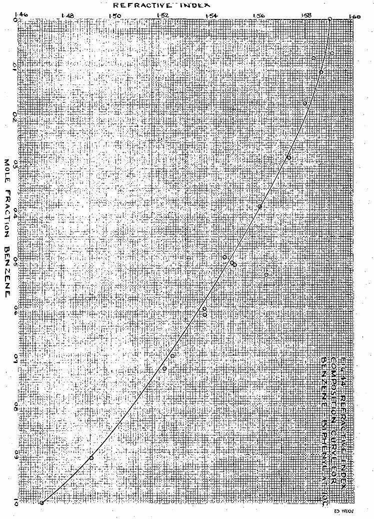
R EL. F'R ACTIVE-"" m D E . ^

s c a l e p l o t and are g i v e n i n Table 10.
TABLE 9
REFRACTIVE INDEX-COMPOSITION DATA EOR BENZENE-BIPHENYL AT 70°C
Run Moi F r a c t i o n Moi F r a c t i o n R e f r a c t i v e No. Benzene Bi p h e n y l Index
1 0.00 1.00 1.5904 2 0.1090 0.8910 I.5869 3 0.0813 0.9187 1.5836 4 0.5287 0.4713 1.5618
0.5090 0.4910 1.5506 6 0.5052 0.4948 1.5493 7 0.6000 0.4000 - 1.5378 8 O.6967 0.3033 1.5246 9 0.7232 0.2768 1.5205
10 0.9075 0.0925 1.4903 11 1.0 0.0 1.4697 12 0.0 1.0 1.5904 13 1.0 0.0 I.4694 14 0.2870 0.7130 1.5733 15 0.4942 0.5058 1.5463 16 0.1732 0.8268 I.5800 X2 O.3092 0.6108 I.5605 18 0.0701 Q.,9299 I.5856 19 0.6119 0.3881 1.5380
k Values 12 to 19 were taken as a check on rea d i n g s 1 t o 11.

TABLE 10 SMOOTHED REFRACTIVE INDEX COMPOSITION DATA FOR BENZENE-BIPHENYL
. AT 70PC. . Moi Fraction Moi Fraction Refractive Index
Benzene Biphenyl at 70°C
0.0 1.00 1.5904 0.05 0.95 1.5869 0.10 0.90 1.5835 0.15 O.85 1.5799 0.20 0.80 1.5762 0 . 25 0.75 1.5 7 24 0.30 0.70 I.5685 0.35 O.65 1.5642 0.40 0.60 1.5597 0.45 0.55 1.5549 0.50 0.50 1.5497 0.55 0.45 1.5440 0.60 0.40 1.5379 O.65 0.35 1.5314 0.70 O.30 1.5245 0 . 75 0 . 25 1.51 70 0.80 0.20 1.5091 O.85 0.15 1.5006 0.90 0.10 1.4916 0.95 0.05 1.4809 1.00 0.0 1.4697
In a l l , twenty six runs were made on the Gillespie-Fowler S t i l l for the determination of vapor-liquid equilibrium of benzene-biphenyl. The f i r s t f ifteen runs were taken at atmospheric temperature while the remainder were•obtained in an oven kept at 70°C. Table 11 gives a l l the experi;---yAe.nS<aA data obtained with temperatures corrected for calibration with the platinum resistance thermometer.

TABLE 11 EXPERIMENTAL VAPOR LIQUID EQUILIBRIUM FOR BENZENE-
BIPHENYL AT ATMOSPHERIC PRESSURE. „ „ , ; m „ , ...... l i q u i d Phase ' Vapor Phase Run Duration Temp. Atmos. — nn ."," •' " 7Q'. " No of Run PC Press. R.I. n^ Moi Fr. R.I. n^ Moi Fr.
Hours C£H6 C 6 H 6
1 2 80.10 760.3 1.4700 1.000 1.4700 1.0 2 1.5 80.28 759.9 1.4716 0.991 1.4696 1.0 3 1.5 80.94 758.3 1.4772 .966 1.4700 1.0 4 2.0 8I.8I 759.2 1.4820 .945 1.4700 1.0 5 2.0 83.65 760.7 1.4912 .902 1.4700 1.0 6 2.5 84.54 760.5 1.4932 .891 1.4700 1.0 7 2.5 85.98 760.7 1.5025 .838 1.4700 1.0 8 3.0 87.IO 760.4 1.5100 .794 1.4700 1.0 9 2.0 88.80 76O.6 1.5170 .750 1.4700 1.0
10 5.0 91.85 755.0 1.5235 .706 1.4700 1.0 11 2.0 9 3.65 754.0 1.5265 .685 1.4700 1.0 12 2.5 95.57 754.3 1.5322 .644 1.4700 1.0 13 2.5 97.53 754.2 1.5376 .602 1.4700 1.0 14 1.5 98.98 754.4 1.5425 .563 1.4700 1.0 15 2.5 101.06 757.0 1.5500 .497 1.4700 1.0 16 1 102.26 757.2 I.5482 .504 1.4714 0;992 17 1 104.36 757.7 1.5569 . 430 1.4718 .990 18 1 126.2 757.7 1.5741 .228 1.4714 .992
A 19 1 132.6 757.2 1.5748 . 218 , 1.49 1 2 . 99 2 A 20 1 141.8 757.4 1.5790 .162 I.4787 .960
21 1.5 151.6 75 7.3 1.5 809 .135 1.4 7 29 .985 22 1 167.3 757.3 1.5845 .085 1.4870 .922
it 23 1 187.8 756.7 1.5873 .045 1.4877 .919 24 1.5 199 . 6 756.2 1.58 75 . 041 1.5076 .809 25 2 211.4 757.2 1.5893 .016 1.5493 .503
/ 26 2 143.3 757.9 1.5802 .145 1.4782 .962 A Runs were definitely not at equilibrium when refractive
indices' were taken. / Run was taken primarily as a rough check on the particular
region of concentration. A large scale plot was made of a l l the experimental points
with the exception of three which were obtained when the system was definitely not at equilibrium. Figure 45 shows the general form of the curve obtained. Smoothed values were taken from the large graph and are tabulated in Table 12 for even intervals of concentration in the liquid phase.


TABLE 12
SMOOTHED VALUES FOR THE VAPOR-LIQUID EOJILIBRIUM OF BENZENE-BIPHENYL.:
Moi.Fr. C 6 H D i n Mol.Fr.C6H6in Liquid Phase Vapor Phase Temp.°C.
0.00 0.000 255.3°0 4 0.01 0.308
0.624 230.7""'
0.02 0.308 0.624 211.2
0.03 0.745 202.6 0.04 0.803 195.9 0.05 0.844 189.6 0 .06 0.875 133.5 0.07 0.899 178.2 0.08 0.920
0 .936 171.6
0 . 0 9 0.920 0 .936 167.7
0.10 0 .950 I 6 2 . 4 0.12 0 .971 151.5 0.14 0.9S4 140.6 0.16 0.96*9 133.3 0.18 0.990 129.8 0.20 0.991 I 2 6 . 5 0.25 0.992 121.4 0.30 0.993 116.4 0.35 0.994 112.2 0.40 0.995 108.4 0.45 0 .996 105.6 0 .50 0.997 102.7 0.55 0.998 99.4 0 .60 0.999 97.3 . O.65 1.000 95.0 0.70 1.000 92.9 0.75 1.000 90.7 0.80 1.000 88.6 0.85 1.000 8 6 . 5 0.90 1.000 34.3 0.95 1.000 82.2 1.00 1.000 80.1
A Temperature f o r the b o i l i n g point of pure biphenyl at 760 mm. taken from the l i t e r a t u r e (79) (18).

For c a l c u l a t i o n of a c t i v i t y c o e f f i c i e n t s from the
experimental d a t a , p r e s s u r e s o f pure benzene were taken from
F i g u r e 41 w h i l e those f o r b i p h e n y l were ob t a i n e d from F i g u r e
22. The experimental a c t i v i t y c o e f f i c i e n t s f o r a l l vapor
l i q u i d e q u i l i b r i u m data are t a b u l a t e d i n Table 13. Only the
s t a r r e d v a l u e s were p l o t t e d s i n c e they are the o n l y ones
which appear r e a s o n a b l e . Curves were drawn through these
v a l u e s and are shown i n F i g u r e 46. They were e x t r a p o l a t e d
t o 3 0 and x-j_ = 1 and the v a l u e s of A and B o b t a i n e d were
.415 and .393, r e s p e c t i v e l y . The v a l u e s of t h e o r e t i c a l
a c t i v i t y c o e f f i c i e n t s are t a b u l a t e d i n Table 14, and the
curves are drawn i n F i g u r e 46.
The temperature-composition data f o r benzene-
b i p h e n y l are p l o t t e d i n f i g u r e 47. A smooth curve has been,
drawn through the best p o i n t s .

L O G A C T I V I T Y C O E F F I C I E N T 0 4 O 5

O
YiOJFS
o 5 n
»+• 4 ^ "
0 3 b-4 O.5- O'fc M O L E . F R A C T I O N B E N Z E N E .
0 7

TABLE 13
ACTIVITY COEFFICIENTS OF BENZENE AND BIPHENYL FROM EXPERIMENTAL DATA
T°C P mm Hg P i mm Hg P 2 mm Hg x-j_ v l
do. 10 8 0 . 2 8 8 0 . 9 4 8 1 . 8 1 33.65 3 4 . 5 4 3 5 . 9 3 3 7 . 1 0 3 3 . 3 0 9 1 . 3 5 93.65 9 5 . 5 7 9 7 . 5 3 9 3 . 9 3
101.06 102.26 IO4.36 126 .2 1 3 2 . 6 1 4 1 . 3 151.6
I67.3 1 3 7 . 3 199 .6 2 1 1 . 4 143 .3
& P l o t t e d v a l u e s . xx E x t r a p o l a t e d v a l u e s .
7 6 0 . 3 7 6 0 1 . 5 0 1 . 0 0 0 1 . 0
7 5 9 . 9 7 6 3 1 . 6 0 0 . 9 9 1 £ 1 . 0
7 5 3 . 3 7 7 7 1 .75 . 9 9 6 1 . 0
7 5 9 . 2 300 1 . 9 0 . 9 4 5 1 . 0
7 6 0 . 7 345 2 . 0 0 . 9 0 2 t 1 . 0
7 6 0 . 5 365 2 . 0 5 . 3 9 1 1 . 0
7 6 0 . 7 905 2 . 1 5 . 3 3 3 t 1 . 0
7 6 0 . 4 9 3 6 2 . 2 5 . 7 9 4 1 . 0
7 6 0 . 6 9 9 0 2 . 4 0 . 7 5 0 t 1 . 0
7 5 5 . 0 1037 2 . 5 0 . 7 0 6 1 . 0
7 5 4 . 0 . 1 1 4 5 3 . 2 0 . 6 8 5 1 . 0
7 5 4 . 3 1203 3 . 6 0 . 6 4 4 1 . 0
7 5 4 . 2 ' 1 2 7 3 4 . 0 0 . 6 0 2 1 . 0
7 5 4 . 4 1 3 2 2 4 . 2 0 . 5 6 3 1 . 0
7 5 7 . 0 1 3 9 3 4 . 5 0 . 4 9 7 1 . 0
7 5 7 . 2 1 4 3 3 4 . 9 0 . 5 0 4 A 0 . 9 9 2
7 5 7 . 7 1514 5 . 4 0 . 4 3 0 A . 9 9 0
7 5 7 . 7 2 5 3 5 1 4 * 7 0 . 2 2 3 A . 9 9 2
7 5 7 . 2 3 0 0 0 . 1 9 . 0 0 . 2 1 3 . 9 0 2
7 5 7 . 4 3 6 6 4 2 6 . 7 0 . 1 6 2 t . 9 6 0
7 5 7 . 3 4492 3 7 . 2 0 . 1 3 5 . 9 3 5
7 5 7 . 3 6020 6 5 . 3 0 . 0 3 5 $ . 9 2 2
7 5 6 . 7 3470 1 2 9 . 2 . 0 4 5 . 9 1 9
7 5 6 . 2 10270 1 3 4 . 2 . 0 4 1 A . 3 0 9
7 5 7 . 2 1 2 6 1 0 2 5 7 . 0 . 0 1 6 . 5 0 3
7 5 7 . 9 3740 2 3 . 0 . 145 ft . 9 6 2
1 . 0 0 0
1.005 0 . 9 3 0 1.003 1 . 0 0 7 0 . 9 9 4 1 . 0 2 2 1 . 0 2 3 1 . 0 3 2 0 . 9 3 4 0 .961 0 . 9 6 3 0 . 9 3 4 1 . 0 1 3 1 . 0 9 2 1.039 1.151 1 .273 1 . 0 4 3 1.226 1 . 2 3 2 1.363 1 .545 1.456 1 . 3 3 7 1 . 3 4 4
2 . 5 0 xx t»
tt tt
tt
tt
tt
tt
tt
n tt
tt
tt
tt
' tt
2 . 4 9 1
2 . 4 6 I
0 . 5 3 4
0 . 4 9 9
1 . 3 5 4
0 . 3 5 3
0 . 9 3 9
0.313^ 1 . 4 9 0
1 . 2 0 3
TABLE 14
THEORETICAL ACTIVITY COEFFICIENTS OF BENZENE AND BIPHENYL
Van Laar Margules
x l i. V . a .
0 . 0 0 1 . 5 7 0 1 . 0 0 0 ~ " T : 5 W " 1 . 0 0 0
0 . 1 1 . 5 0 0 1 . 0 0 2 1 . 5 5 4 1 . 0 0 1
0 . 2 1 . 4 3 0 1 . 0 1 1 1 . 5 0 3 1 . 0 0 7
0 . 3 I . 3 6 O 1 . 0 2 3 1 . 4 2 9 1 . 0 2 4
0 . 4 1 . 2 9 2 1 . 0 5 3 1 . 3 4 5 1 . 0 5 9
0 . 5 1 . 2 2 5 1 . 1 0 5 1 . 2 5 7 1 . 1 1 9 0 . 6 1 . 1 6 1 1 . 1 3 0 1 . 1 7 5 1 . 2 1 6
0 . 7 1 . 1 0 3 1 . 2 9 9 1 . 1 0 4 1 . 3 6 7
0 . 3 1 . 0 5 2 1 . 4 9 6 1 . 0 4 9 1 . 5 9 6
0 . 9 1 . 0 1 5 1 . 3 4 0 1 . 0 1 3 1 . 9 4 3
1 . 0 1 . 0 0 2 . 5 0 0 1 . 0 0 0 2 . 5 0 0

102
CHAPTER V I I I
DISCUSSION OF RESULTS
A. Benzene-Butanol
From the p l o t of l o g o f t h e experimental a c t i v i t y -
c o e f f i c i e n t s versus mole f r a c t i o n , t h e p o i n t s o b t a i n e d appear
t o f a l l on smooth curves. Although t h i s i n i t s e l f i s not a
c r i t e r i o n o f thermodynamic c o n s i s t e n c y i t does g i v e a c e r t a i n
amount o f i n d i c a t i o n i n t h a t d i r e c t i o n ( 1 5 ) . A check on t h e
two curves' at x = 0 . 5 shows t h a t t h e l o g ^ curve f a l l s lower
than t h a t o f l o g . T h i s i s f u r t h e r evidence o f c o n s i s t e n c y
s i n c e the l o g tf^curve has the h i g h e r end v a l u e , as p o i n t e d
out i n the t h e o r e t i c a l d i s c u s s i o n .
A thermodynamic check on the c o n s i s t e n c y o f the
experimental curve shows a c e r t a i n amount o f d e v i a t i o n . The
t h e o r e t i c a l curves are completely dependent on the-accurate,-
e x t r a p o l a t e d end v a l u e s o f the experimental curves. I t may
be o n l y f o r t u i t o u s t h a t the experimental t e r m i n a l v a l u e s are
c o r r e c t and have been a c c u r a t e l y e x t r a p o l a t e d . However, s i n c e
the system does not form an azeotrope, these a r e about the
o n l y v a l u e s upon which a thermodynamic check can be based.
The van Laar and Margules curves do not c o i n c i d e too c l o s e l y .
T h i s can be expected s i n c e A, t h e r a t i o o f the c o n s t a n t s , B
d e v i a t e s c o n s i d e r a b l y from u n i t y .
The temperature-composition curves i n both t h i s
r e s e a r c h and t h a t of Emerson and C u n d i l l conformed v e r y w e l l
t o the types of curves o b t a i n e d f o r common non-azeotropic
mixtures. The experimental p o i n t s o b t a i n e d d e v i a t e d v e r y

103
l i t t l e from smooth curves, but i n the h i g h benzene concen
t r a t i o n end o f the diagram t h e y showed c o n s i d e r a b l e i n t e r e s t .
I t i s here t h a t the system appears t o come very c l o s e t o
forming an azeotrope.
B. B eh z en e- B i ph en v l
E v a l u a t i o n o f the a c t i v i t y c o e f f i c i e n t s from ex
p e r i m e n t a l data f o r benzene and b i p h e n y l gave o n l y a few
v a l u e s f a l l i n g above u n i t y . When p l o t t e d , the p o i n t s f o r
benzene were w i t h i n reason o f a curve. However, those f o r
b i p h e n y l were o f f c o n s i d e r a b l y , and o n l y a v e r y few had
v a l u e s above u n i t y . T h i s i n c o n s i s t e n c y may have been due t o
v a r i o u s reasons. In t h e e xperimental work, the temperature
readings c o u l d have been taken too h i g h r e s u l t i n g i n a h i g h
vapor p r e s s u r e f o r the pure components i n c a l c u l a t i o n s . Then
i n the e x p r e s s i o n •= Py2 the v a l u e o f ^would be c o n s i d e r a b l y
too low. I t appears 2 . X 2 t h a t almost i n a l l cases of
b i p h e n y l the r a t i o J2. was s m a l l e r than i t should have been.
T h i s would i n d i c a t e t h a t the vapor phase was not e x h i b i t i n g
a l a r g e enough c o n c e n t r a t i o n of b i p h e n y l . In the lower tem
per a t u r e s of d e t e r m i n a t i o n any e r r o r s i n the vapor p r e s s u r e
would manifest themselves t o a h i g h degree i n the a c t i v i t y
c o e f f i c i e n t s .
I t might be concluded from the r e s u l t s t h a t more
s p e c i a l i z e d type o f equipment i s necessary f o r v a p o r - l i q u i d
e q u i l i b r i u m d e t e r m i n a t i o n s o f benzene-biphenyl. Perhaps the
vapor r e c i r c u l a t i o n type of apparatus with constant temper
a t u r e c o n t r o l would be b e t t e r s u i t e d f o r t h i s system. A more

s e n s i t i v e means of a n a l y s i s i s r e q u i r e d s i n c e up to X]_ = 0.5
i t was i m p o s s i b l e t o detect b i p h e n y l i n the vapor phase u s i n g
the r e f r a c t o m e t e r . L a s t l y , i t may be necessary t o r e s o r t to
other mathematical r e l a t i o n s t o check the system thermodynam-
i c a l l y .

105
CHAPTER IX
BIBLIOGRAPHY
1. A l l e n , B.B., and Lingo, S.P., w i t h F e l s i n g , W.A. J . of-Phys. Chem., 41, 425 (1938).
2. A.S.T.M., Standards on Petroleum Products and L u b r i c a n t s , American S o c i e t y f o r T e s t i n g M a t e r i a l s , P h i l a d e l p h i a , 1947.
3. Badger, W.L., Moevrad, C C . , and Diamond, H.W., Ind. Eng. Chem., 22, 700 (1930). . • • " .
4. Baker, E.H., Hubbard, R.O.H., Huguet, J.H., and
Michalowski, S.S., Ind. Eng. Chem. 1 1 , 1260 ( 1 9 3 9 ) .
5. B e c h t o l d , I.C., Ind. Eng. Chem., A n a l . Ed., 14, 429 (1942).
6. Bishop, C A . , Ph.D. t h e s i s , Univ. o f P i t t s b u r g h , 1942.
7. Brown, F.D., Trans. Chem. S o c , 1£, 547 (1879).
8. Brown, F.D., I b i d . , 12, 517 (1881).
9. B r u n e l l , R.F., Crenshaw. J.L., and Tobin, E., J . Am. Chem. S o c , 41, 561 (1921).
10. Bushmakin, I.N., and Voeikova, E.D.., Zhur. Obshchei Khim. ( J . Gen. Chem.) 1 2 , 1615-26 (1949) Q.A. 44, 1317 e
(1950)} 11. Busse, J . , "Temperature, I t s Measurement and C o n t r o l i n
Science and In d u s t r y , " R e i n h o l d P u b l i s h i n g Corp.,1941.
12. B u t l e r , J.H.V., et a l , J . Chem. S o c , 138. 280-5 (1935).
13. C a l l e n d a r , H.L., P h i l . Mag., 12, 104 (1891).
14. Carey, J.S., and Lewis, W.K., Ind. Eng. Chem., 24, 882-3
(1932). " 15. C a r l s o n , H.C., and Colburn, A.P., Ind. Eng. Chem., 14,
581 (1942).
16. Carveth, H.R., J . Phys. Chem., 1, 193 (1899).
17. C h i l t o n , T.H., Proc. 4th Symposium, Chem. Eng., Ed u c a t i o n , Wilmington, D e l . , p.68, 1935.
18. Chipman, J . , and P e l t i e r , S.B., Ind. Eng. Chem., 21, 1106-
08 (1929). "~~ 19. Cohen, E., and B u i j , J.S., Z . physik. Chem., B35,270 (1937).

1 0 6
20. Colburn, A.P., Schoenborn. E.M., and Shilling, D., Ind. Eng. Chem., 3£, 1250 (1943).
21. Collins, E.C. and Lantz, V., Ind. Eng. Chem., Anal. Ed., 18, 637, (194-6).
22. Cottrell, F.C, J. Am. Chem. Soc., 41, 721 (1919). 23. Coulson, E. A., and Warne, A.J., J f l Sci. Instruments,
21, 122 (1944) \G.A. ^8 : 5693° U944.JJ.
24. Diehl, J.M., Hart, I i , Anal. Chem., 21, 530 (1949). 25. Dixon, 0.C, J. Soc. Chem. Ind. (London) 68, 299 (1949). 26. Dodge, B.F., and Huffman, J.R., Ind. Eng. Chem., 29, 1434
(1937). ~~ 27. Donahoe, H.B., Russell, K.R., and Vanderwerf, A.C.,
Ind. Eng. Chem., AnaL* Ed., 18, 156 (1946). 28. Doty, W.R., Anal. Chem., 21, 637 (1949). 29. Egloff, T., "Physical Constants of Hydrocarbons," Vol.1X1,
Reinhold Publishing Corporation, New York, 1946. 30. Emerson, H.L., and Cundill, T.C, B.A.Sc. Thesis, Univ.
of British Columbia, April, 1950. 31. Emerson, R.L. and Woodward, R'.B., Ind. Eng. Chem., Anal.
Ed., 2., 347 (1937).'
32. Eykman, J.F., Rec. Trav. chim., 14, 185 (1895k 33. Ferguson, T.B., Freed, M., and Morris, A.C., J. Phys.
Chem., 27, 87 (1933); 34. Ferguson, J.B., and Funnell, W.S., J. Phys. Chem., 33, 1-
(1929). 35. Fowler, R.T., Ind. Chemist, 24, 717, 824 (1948). 36. Fowler, R.T., J. Soc. Chem. Ind. (London), 68, L31 (1949). 37. Funnell, W.S., and Hoover, G.I., J. Phys. Chem., 31, 1029
(1927). 38. Garrick, F.J., Trans. Far. Soc, 2£, 5̂ 0 (1927). 39. Gehloff, G., Zeit. fttr physik chemie, £ i » 252 (1921). 40. Gibbons, L.O., et a l . , J . Am. Chem. Soc, 68_, 1130 (1946). 41. Gibson, R.E.. and Kincaid, J.F., J. Am. Chem. Soc, 60,
511 (1938). —

107
42. G i l l e s p i e , D.T.C., Ind. Eng. Chem., Anal. Ed., 18,575(1946).
43. G i l l i l a n d , E.R., Hughes, R.R., and Larkan, C.W., " D i s t i l l a t i o n and Adsorption" (Unpublished Works) course given i n (1947-48) at M.I.T.
44. Gilmann, H.H., and Gross, P., J. Am. Chem. S o c , 60, 1525 (1938). "~
45. Gilmont, R. et a l , Ind. Eng. Chem., 42, 120 (1950).
46* G l a n v i l l e , J.W., and Sage, B.H., Ind. Eng. Chem., 41, 1272 (1949). ~~
47. Glasgow, A. R., Murphy, E.T., Willingham, C.B., and Rossini, F.D.. J . Research Nat. Bur. Standard, 37, 141 (1946).
4 8 . Glasstone, S. "Thermodynamics f o r Chemists", D. Yan Nostrand Company, Inc., New York, 1947.
49. Gordon, A.R., and Benson, G.C., Can. J . Res. B., 24, 285 (1946). ~~
50. Gordon, A . R . a n d Hines, W.G., Can. J . Research, B.24: 285 (1946). —
51. Gornowski, E.J"., Amick, E.H., and Hixon, A.N., Ind. Eng. Chem., 3£, 1348 (1947).
52. Guggenheim, E.A., P r o c Roy. S o c , A I 8 3 , 203, 213 (1944).
53. Haehn, H., z. angew. chem., 12_, 1669 C A . 1: (1907)
54. Herz, and Neukirch, z. physik. chem., A140, 406 (1929). 55. Hodgman, CD., "Handbook of Chemistry and Physics",
30th ed., p.2538, Chemical Rubber Publishing Co., Cleveland, Ohio, 1946.
56. Huffman, H.M., Parks, G.S., and Daniels, A.C., J . Am. Chem. S o c , 52, 1547 (1930).
57. Human, J.P.E., and M i l l s , J.A., Anal. Chem., 21, 538 (1949).
58. International C r i t i c a l Tables, 29, 33, 221, 343 (1928).
59. Ibid., 4, 6 (1928).
60. Ibid., 3, 287 (1928).
61. Jacobs, G.W., Ind. Eng. Chem., Anal. Ed., 2> 7° (1935).
62. Jacquerod, A., and Wassemer, E., Ber., J57, 2531 (1904).

108
o3. Jones G., and Christian, S.M., J. Am. Chem. Soo., 6l, 82 (1939). ~~
64. Jones, C.A., Schoenborn, E.H.. and Colburn, A.B., Ind. Eng. Chem.., |5_, 666 (1943).
65. Kahlbaum, z. physik. chem., 13, 14 (1894). % 511 (1898).
66. Kendall, J.. and Monroe, K.P., J. Am. Chem. Soc, 39, 1787, 1802 (1917). ;
67. Kurtz, S.S., Jr., Amov, S., and Sankin, A., Ind. Eng. Chem., 42, 174 (1930).
68. Laar, J.J. van, z. physik. chem., 72, 723 (1910). 52, 399 (1913).
69. Lachowitz, B., Ber., 21, 2206 (l888)v
70. Langdon, W.M., and Keyes, D.B., .Ind. Eng. Chem., 34, 938, (1942). ~~
71. Lehfeldt, R.A., Ph i l . Mag., 46, 3, 42 (1898).. 72. Lewis, G.N., and Randall, M., "Thermodynamics and the
Free Energy of Chemical Substances", McGraw-Hill Book Company, Inc., New York (1923).
73. Linebarger, C.E., Am. Chem. J., 18, 429 (1896). 74. Moir, B.J., Glasgow, A.R., Jr., and Rossini, F.D.,
J. Research Natl. Bur. Standards, _26, 591 (1941). 75. Mangold, Sitzungsber, Math.-Nat. Klasse, Kaiserl. Akad.,
102 ( Ha) 1071 (1893).
76. Margules, M., Sitzungsber. Akad., Wissen. Wien, Math. natur. Klasse, II, 104, 1243 (1895).
77. McCabe, W.L. and Thiele, E.W., Ind. Eng. Chem., 17, 605 (1925). ~~
78. Mizuta, J. Soc. Chem. Ind. Japan, 3J_, 11 (1934). 79. Montillon, G.H., Kohrbach, K.L., and Badger, W.L. Ind.
Eng. Chem., 23, 763 (1931). 80. Morton, A.A., "Laboratory Technique in Organic Chemistry 0,
McGraw-Hill Book Company, Inc., New York, 1938. 81. Mueller, E.F., Bui. Bur". Stands., Ij5, 348 (1917).
82. Natl. Bur. Standards, "Selected Values of Physical Properties of Hydrocarbons", Am. Petroleum Inst.,Project 44(1947)

83. 84.
85.
86.
87.
88.
89.
90.
91.
92.
93. 94.
95.
96.
97-
98.
99. 100. 101.
102.
103.
104.
105.
Nelson, O.A., J. Am. Chem. Soc, £4, 1390 (1932). Newman, S., Ind. Eng. Chem., Anal. Ed., 12, 274 (1940).
Eaton. M.. and Huffman, H.M. J. Am. Chem. 1502 (1948).
Ind.Eng. Chem., 20 , 743 (1928). Ind. Eng. Chem., Anal. Ed., 4, 232 (1932). Ind. Eng. Chem., Jj5_, 614 (1943). Anal. Chem., 20, 763 (1948). and Gilmont, R., Ind.End. Chem. 36, 106l
and Gilmont, R., Ibid. 40, 2118 (1948). and Morley, E.R., Ibid.,^8, 751 (1946). and Savitt, S.A., Ibid., 40, 168, 435 (1948) Shleoher, N., and Koszalka, W.A., Ibid., 37,
Oliver, G.D. Soc, 70
Othmer, D.F.
Othmer, D.F. Othmer, D.F. Othmer, D.F. Othmer, D.F.
(1944).
Othmer, D*F. Othmer, D.F. Othmer, D.F. Othmer, D.F.
895 (1945). Parks, G.S., and Chaffee, C.S., J". Phys. Chem., 31, 439,
(1927). Pawlewski, Ber., 16, 2633 (1883).
Pesce, B., Gazz. Chem. i t a l . , 65, 440 (1935). Perry, E.S., and Fuguitt, R.E., Ind. Eng. Chem., 39, 782,
(1947). Redlick, 0., and Kister, A.T., Ibid., 40, 345 (1948). Regnault, mem. acad., 2_6, 4l6 (1862). Rieder, R.M., and Thompson, A.R., Ind. Eng. Chem., 41,
2905 (1949). """ Rogers, J.W., Knight, J.W., and Choppin, A.R., J. Chem.
Ed., 24 , 491 U947).
Rosanoff, M.A., and Easley, CM., J. Am. Chem. Soc, 31, 953 (1909).
Rosanoff, M.A., Lamb-, A.B., and Breithut, F.E., J. Am. Chem. Soc. 31, 448 (1909).
Rosenberg, P., Rev. Sci. Inst., 10, 131 (1939).

110
106. Sameshima, J., J . Am. Chem. S o c , 40, 1482 (1918).
107. Sanderson, R.T., "Vacuum Manipulation of V o l a t i l e Compounds",
John Wiley Sons, Inc., New York, 1948.
108. Scatchard, G., Chem. Rev., 8, 321 (1931).
109. Scatchard, G., and Hamer, W.H. J.Am. Chem. S o c , 57, 1805 (1935).
110. Scatchard, G., Raymond, C.L.. and Gilmann, H.H., J . Am. Chem. S o c , 60, 1275 (1938).
111. Scatchard,- G., Wood, S.E., and Mochel, J.M., J. Am. Chem. S o c , 62, 712 (1940).
112. Shriner, R.L., and Fuson, R.C., "The Systematic I d e n t i f i c a t ion of Organic Compounds", John Wiley Sons, Inc., New York (1948).
113. Smith, T.E. and Bonner, R.E., Ind. Eng. Chem., 41, 2867 (1949). ~~
114. Smith, A., and Menzies, A.W.C., J.Am. Chem.Soc, 32, . 1448 (1910).
115. Smyth, C.P., and Walls, W.S., J . Am. Chem. S o c , 54,1857 (1932). ~~
116. Smyth, CP., and Stoops, W.N., J . Am. Chem. S o c , 51, 331 2 (1929).
117. Spaght, M.E., Thomas, S.B., and Parks, G.S., J . Phys. Chem., 2i» 8 8 2 (1932).
118. Stockhardt, J.S., and H u l l , CM., Ind. Eng. Chem., 23, 1438-40 (1931).
119. Strong, J., "Modern Physical Laboratory P r a c t i c e " Blackie & Son, Limited, London (1942).
120. S t u l l , D.R., Ind. Eng. Chem., ^9, 522 (1947).
121. Stutzman, L.F., and Brown,G.M., Chem. Eng. Progress, 45, 139 (1949).
122. Swietoslawski, W,J. Chem. Ed., £, 469 (1928).
123. Swietoslawski, W., B u l l . S o c Chem., 4£, 469 (1928).
124. Swietoslawski, W., "Ebulliometrie Measurements", Rein-hold Publishing Corporation (1945).
125. Taylor, J.K., and Reid, J.G., Ind. Eng. Chem., Anal. Ed., 18, 79 (1946).

126. Theimer, E., J". Chem. Ed., 25_, 7A (1948). 127. Timmermans, J"., and Martin, F. S., J. chem. phys.,
23, 750 (1926).
128. Todd, F., Ind. Eng. Chem., Anal.Ed., 17., 173 (1945). 129. Todd, E., Anal. Chem., 20, 1248 (1948). 130. Tompa, H . , J. Chem. Phys., 16, 292 (1948). 131. Trimble, H.M., and Potts, W., Ind. Eng. Chem., 27, 66
(1935). T - .
132. Tyrer, J. Chem. Soc. London, £7, 2620 (1910). 133. Waldichuk, M., B.A. Thesis, University of British
Columbia, A p r i l , 1 9 4 8 . 134. Ward, A.F.H., and Brooks, L.H., Chemistry and Industry,
1-20, No.l, 16 (1950).
135. Ward, C.C., U.S. Bur. Mines, Tech. Paper 600 (1939). 136. Warner, J.C., Scheib, R.C., and Svirbely, W.J., J. Chem.
Phys., 2, 590 (1934). 137. Washburn, E.R., and Handorf, B.H., J. Am. Chem., Soc.
51, 441 (1935). 138. Washburn, E.W., and Read, J.W., Proc. Nat. Acad. Sci.,
1, 191 (1915).
139. Washburn, E.W., and Read, J.W., J. Am. Chem. Soc, 41, 729 (1919). ~~
140. Washburn, E.R., and Standshaw, G.V., J. Phys. Chem, 48, 241 (1944). ~"~
141. Webb, T.J., and Lindsley, C.H., J. Am. Chem. Soc, 56, 874 (1934).
142; White, R.R., Trans. Am. Inst. Chem. Engrs., 41, 539 (1945). 143. Williams, F.E., Ind. Eng. Chem., ,32., 779 (1947). 144. Wojciechowski, M., J. Research Nat. Bur. Stand., 19, 347,
(1937). ~~ 145. Wright, R.H., "Glass Blowing and Working", Chemical Pub
lishing Company, Inc., Brooklyn, N.Y., 1943. 146. Yamoguchi, Y., J. Tokyo Chem. Soc, J54, 691 (1931)

112
147- Young, H.D., and Nelson, O.A., Ind. Eng. Chem., Anal. Ed., £, 67 (1932).
148. Young, S., " D i s t i l l a t i o n P r i n c i p l e s and Processes", Macmillan and Co., 1903 (Revised 1922).
149. Ytt, H.A.. and Hickman, .J.B., J. Chem. Ed., 26, 207, (1949). "~
150. Zawidski, J. von, z. phys., chem.,35, 129 (1900).