Parallel Multi-Resolution Fusion Network for Image Inpainting
Upload
univ-poitiersCategory
view
2download
0
IEEE TRANSACTIONS ON GEOSCIENCE AND REMOTE SENSING, VOL. 47, NO. 7, JULY 2009 2363
A Bandelet-Based Inpainting Technique for CloudsRemoval From Remotely Sensed Images
Aldo Maalouf, Philippe Carré, Bertrand Augereau, and Christine Fernandez-Maloigne
Abstract—It is well known that removing cloud-contaminatedportions of a remotely sensed image and then filling in the missingdata represent an important photo editing cumbersome task. Inthis paper, an efficient inpainting technique for the reconstructionof areas obscured by clouds or cloud shadows in remotely sensedimages is presented. This technique is based on the Bandelettransform and the multiscale geometrical grouping. It consists oftwo steps. In the first step, the curves of geometric flow of differentzones of the image are determined by using the Bandelet transformwith multiscale grouping. This step allows an efficient repre-sentation of the multiscale geometry of the image’s structures.Having well represented this geometry, the information insidethe cloud-contaminated zone is synthesized by propagating thegeometrical flow curves inside that zone. This step is accomplishedby minimizing a functional whose role is to reconstruct the missingor cloud contaminated zone independently of the size and topologyof the inpainting domain. The proposed technique is illustratedwith some examples on processing aerial images. The obtainedresults are compared with those obtained by other clouds removaltechniques.
Index Terms—Image reconstruction, image restoration,wavelets.
I. INTRODUCTION
ONE OF THE major limitations of remote-sensing imagingcould be its sensitivity to weather conditions during the
image acquisition process. The resulting images are frequentlycontaminated by clouds and cloud shadows. Remote sensinghas to cope with the so-called cloud removal problem whichis an important difficulty affecting the observation of the Earthsurface. Diverse techniques have been proposed including dif-ferent methods to solve this problem. They can be grouped intwo categories. The first category regroups the measurement-based approaches. These approaches consist of selecting thebest measurement (the most cloud-free pixel) among a set ofmeasurements acquired over a limited time period to representthe considered multitemporal pixel over that time period. Ex-amples of these approaches are the recent work of Melagani andBenabdelkader [2], [6], [18] and the work of Liew et al. [10].
In [6], the author proposes a contextual prediction process inorder to determine the spectrotemporal relationships between
Manuscript received February 5, 2008; revised June 5, 2008 and October 14,2008. First published March 24, 2009; current version published June 19, 2009.
The authors are with the XLIM Laboratory, Unite Mixte de Recherche 6172,Centre National de la Recherche Scientifique, Signal-Image-CommunicationDepartment, University of Poitiers, 86034 Poitiers Cedex, France (e-mail:[email protected]; [email protected];[email protected]; [email protected]).
Color versions of one or more of the figures in this paper are available onlineat http://ieeexplore.ieee.org.
Digital Object Identifier 10.1109/TGRS.2008.2010454
the set of acquired images. These spectrotemporal relationshipsare deduced from cloud-free areas in the spatial neighborhoodof the cloud-contaminated region over the available series ofthe temporal images. The contextual prediction process is im-plemented using linear predictors and support vector machines.The major drawback of this approach is the assumption that thespatial structure of the image is identical over the image se-quence. For that, Benabdelkader et al. proposed in [18] and [2]to use a postreconstruction methodology that is based on acontextual spatiospectral postprediction system. The role of thispostreconstruction is to incorporate the spatial information bytaking advantage from the local properties between pixels in apredefined neighborhood system. However, the major limitationof this approach is that the acquisition dates should be closeto each other, and the spatial dynamics of the geographicalarea under analysis should be slow compared to the total timeinterval of the sequence.
In the other hand, the adaptive reconstruction techniqueproposed by Lee and Crawford [8] avoids this kind of problem.They assumed that the temporal signature of a given pixel iscontaminated by residual effects caused by imperfect sensingof the target and by spatially autocorrelated noise due to at-mospheric attenuation. However, this method showed a highcomputational complexity and is not easily applicable to thegeneral case of nonstationary temporal image series. Anothermethod was presented by Remund et al. [5] for recovering Ad-vanced Very High Resolution Radiometer measurements thatare modified by the effects not only of clouds but also of cloudshadows. This method is simple and effective, but presents thedrawback of being limited to data acquired over vegetated areas.
The second category regroups cloud-removal techniques thatconsist of filling in the clouds-contaminated region using tradi-tional synthesis and image inpainting techniques. An exampleof these approaches is the recent work of Peng et al. [4]. Thegoal of the approaches of this category is to seamlessly syn-thesize a complete, visually plausible and coherent image. Themain drawback of these methods is that most of the inpaintingtechniques are applicable for small-scale flaws like scratches orstains. Recently, there has been a major work for improving theinpainting techniques in order to achieve long region connec-tion and texture recovering. An example of the inpainting tech-niques are the ones presented in [3], [9], [12], [19], and [20].
In this paper, the strategy of the approaches of the secondcategory is pursued, and a new efficient inpainting techniquefor missing data synthesis is presented. The advantage of thisreconstruction technique is that it is capable of filling largeregions and synthesizing even highly textured missing regions.Thus, the drawbacks of the measurement-based approaches
0196-2892/$25.00 © 2009 IEEE
2364 IEEE TRANSACTIONS ON GEOSCIENCE AND REMOTE SENSING, VOL. 47, NO. 7, JULY 2009
as well as the limitations of the inpainting techniques of theapproaches of the second category are circumvented. Therefore,an efficient cloud-removing scheme is achieved. The proposedreconstruction technique is based on the Bandelet transform andthe multiscale geometrical grouping. It consists of two steps.In the first step, the curves of geometric flow of different zonesof the image are determined by using the Bandelet transformwith multiscale grouping. This step allows a better representa-tion of the multiscale geometry of the image’s structures thanother geometrical representations [11]. The Bandelet transformwith multiscale grouping is obtained by applying a bandele-tization process on the wavelet coefficients at each scale andorientation. This bandeletization with Multiscale grouping offermore flexibility in the sense that we can define geometry alongflow lines that are not parallel. This geometrical representationconverges toward singularities. Therefore, fine structures arewell represented, and the propagation of the represented geo-metrical data in the cloud-contaminated region may guaranteean efficient reconstruction of the hidden data. Having wellrepresented this geometry, the information inside the cloud-contaminated zone is synthesized by propagating the geometri-cal flow curves inside that zone. The latter step is accomplishedby minimizing a functional whose role is to reconstruct themissing or damaged zone independently of the size and topol-ogy of the reconstruction or inpainting domain. As a result, theflow lines are well tied inside the cloud-contaminated zone, andthe missing data are accurately synthesized.
The rest of this paper is organized as follows. In Section II,a review of the bandelet transform and multiscale grouping isgiven. In Section III, the reconstruction technique is described.Section IV is devoted for experimental results, and Section V isa conclusion.
II. REVIEW OF BANDELET TRANSFORM
AND MULTISCALE GROUPING
In this section, the bandelet transform with multiscale group-ing is described. This transform is then used to obtain a geo-metrical flow of the image. The propagation of this flow intothe cloud-contaminated regions synthesizes the missing data.
A. Orthogonal Bandelets Approximations
A sparse representation takes advantage of some kind ofregularity of the function to approximate. Geometric regularityalong edges in images is an anisotropic regularity. Although theimage may be discontinuous across a contour, the image can bedifferentiable in a direction parallel to the tangent of the edgecurve. The Bandelet transform exploits such an anisotropicregularity by constructing orthogonal vectors that are elon-gated in the direction where the function has a maximum ofregularity.
The first bandelet bases constructed by Le Pennec and Mallat[13], [14] have bring optimal approximation results for geo-metrically regular functions. Later works have enriched thisconstruction by the use of multiscale geometry defined overthe coefficients of a wavelet basis [16], [17]. These multiscalebandelet bases are described in the following section.
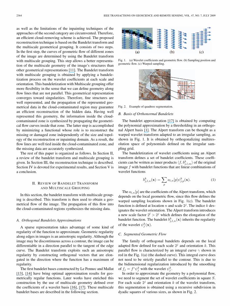
Fig. 1. (a) Wavelet coefficients and geometric flow. (b) Sampling position andgeometric flow. (c) Warped sampling.
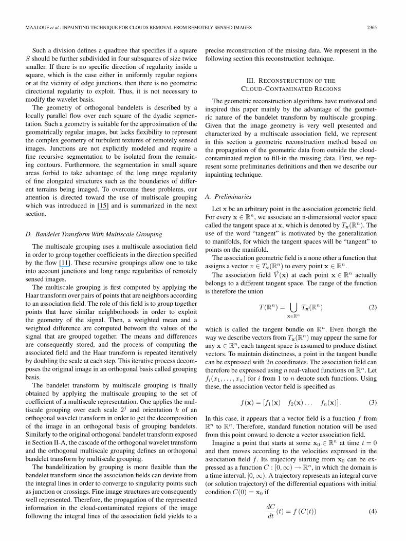
Fig. 2. Example of quadtree segmentation.
B. Basis of Orthonormal Bandelets
The bandelet approximation [17] is obtained by computingthe polynomial approximation by a thresholding in an orthogo-nal Alpert basis [1]. The Alpert transform can be thought as awarped wavelet transform adapted to an irregular sampling, asshown in Fig. 1. It is obtained by orthogonalizing multires-olution space of polynomials defined on the irregular sam-pling grid.
The bandeletization of wavelet coefficients using an Alperttransform defines a set of bandelet coefficients. These coeffi-cients can be written as inner products 〈f, bk
j,l,m〉 of the originalimage f with bandelet functions that are linear combinations ofwavelet functions
bkj,l,n(x) =
∑p
al,n[p]ψkj,p(x). (1)
The al,n[p] are the coefficients of the Alpert transform, whichdepends on the local geometric flow, since this flow defines thewarped sampling locations shown in Fig. 1(c). The bandeletfunction is defined at location n and scale 2j . The indice k des-ignates the wavelet orientation. The Alpert transform introducesa new scale factor 2l > 2j which defines the elongation of thebandelet function. The bandelet bk
j,l,n(x) inherits the regularityof the wavelet ψk
j (x).
C. Segmented Geometric Flow
The family of orthogonal bandelets depends on the localadapted flow defined for each scale 2j and orientation k. Thisparallel flow is characterized by an integral curve γ shown inred in the Fig. 1(a) (the dashed curve). This integral curve doesnot need to be strictly parallel to the contour. This is due tothe bidimensional regularization introduced by the smoothingof fj = f ∗ψk
j with the wavelet ψkj .
In order to approximate the geometry by a polynomial flow,we need to segment the set of wavelet coefficients in square S.For each scale 2j and orientation k of the wavelet transform,this segmentation is obtained using a recursive subdivision indyadic squares of various sizes, as shown in Fig. 2.
MAALOUF et al.: INPAINTING TECHNIQUE FOR CLOUDS REMOVAL FROM REMOTELY SENSED IMAGES 2365
Such a division defines a quadtree that specifies if a squareS should be further subdivided in four subsquares of size twicesmaller. If there is no specific direction of regularity inside asquare, which is the case either in uniformly regular regionsor at the vicinity of edge junctions, then there is no geometricdirectional regularity to exploit. Thus, it is not necessary tomodify the wavelet basis.
The geometry of orthogonal bandelets is described by alocally parallel flow over each square of the dyadic segmen-tation. Such a geometry is suitable for the approximation of thegeometrically regular images, but lacks flexibility to representthe complex geometry of turbulent textures of remotely sensedimages. Junctions are not explicitly modeled and require afine recursive segmentation to be isolated from the remain-ing contours. Furthermore, the segmentation in small squareareas forbid to take advantage of the long range regularityof fine elongated structures such as the boundaries of differ-ent terrains being imaged. To overcome these problems, ourattention is directed toward the use of multiscale groupingwhich was introduced in [15] and is summarized in the nextsection.
D. Bandelet Transform With Multiscale Grouping
The multiscale grouping uses a multiscale association fieldin order to group together coefficients in the direction specifiedby the flow [11]. These recursive groupings allow one to takeinto account junctions and long range regularities of remotelysensed images.
The multiscale grouping is first computed by applying theHaar transform over pairs of points that are neighbors accordingto an association field. The role of this field is to group togetherpoints that have similar neighborhoods in order to exploitthe geometry of the signal. Then, a weighted mean and aweighted difference are computed between the values of thesignal that are grouped together. The means and differencesare consequently stored, and the process of computing theassociated field and the Haar transform is repeated iterativelyby doubling the scale at each step. This iterative process decom-poses the original image in an orthogonal basis called groupingbasis.
The bandelet transform by multiscale grouping is finallyobtained by applying the multiscale grouping to the set ofcoefficient of a multiscale representation. One applies the mul-tiscale grouping over each scale 2j and orientation k of anorthogonal wavelet transform in order to get the decompositionof the image in an orthogonal basis of grouping bandelets.Similarly to the original orthogonal bandelet transform exposedin Section II-A, the cascade of the orthogonal wavelet transformand the orthogonal multiscale grouping defines an orthogonalbandelet transform by multiscale grouping.
The bandelitization by grouping is more flexible than thebandelet transform since the association fields can deviate fromthe integral lines in order to converge to singularity points suchas junction or crossings. Fine image structures are consequentlywell represented. Therefore, the propagation of the representedinformation in the cloud-contaminated regions of the imagefollowing the integral lines of the association field yields to a
precise reconstruction of the missing data. We represent in thefollowing section this reconstruction technique.
III. RECONSTRUCTION OF THE
CLOUD-CONTAMINATED REGIONS
The geometric reconstruction algorithms have motivated andinspired this paper mainly by the advantage of the geomet-ric nature of the bandelet transform by multiscale grouping.Given that the image geometry is very well presented andcharacterized by a multiscale association field, we representin this section a geometric reconstruction method based onthe propagation of the geometric data from outside the cloud-contaminated region to fill-in the missing data. First, we rep-resent some preliminaries definitions and then we describe ourinpainting technique.
A. Preliminaries
Let x be an arbitrary point in the association geometric field.For every x ∈ R
n, we associate an n-dimensional vector spacecalled the tangent space at x, which is denoted by Tx(Rn). Theuse of the word “tangent” is motivated by the generalizationto manifolds, for which the tangent spaces will be “tangent” topoints on the manifold.
The association geometric field is a none other a function thatassigns a vector v ∈ Tx(Rn) to every point x ∈ R
n.The association field �V (x) at each point x ∈ R
n actuallybelongs to a different tangent space. The range of the functionis therefore the union
T (Rn) =⋃
x∈Rn
Tx(Rn) (2)
which is called the tangent bundle on Rn. Even though the
way we describe vectors from Tx(Rn) may appear the same forany x ∈ R
n, each tangent space is assumed to produce distinctvectors. To maintain distinctness, a point in the tangent bundlecan be expressed with 2n coordinates. The association field cantherefore be expressed using n real-valued functions on R
n. Letfi(x1, . . . , xn) for i from 1 to n denote such functions. Usingthese, the association vector field is specified as
f(x) = [f1(x) f2(x) . . . fn(x)] . (3)
In this case, it appears that a vector field is a function f fromR
n to Rn. Therefore, standard function notation will be used
from this point onward to denote a vector association field.Imagine a point that starts at some x0 ∈ R
n at time t = 0and then moves according to the velocities expressed in theassociation field f . Its trajectory starting from x0 can be ex-pressed as a function C : [0,∞) → R
n, in which the domain isa time interval, [0,∞). A trajectory represents an integral curve(or solution trajectory) of the differential equations with initialcondition C(0) = x0 if
dC
dt(t) = f (C(t)) (4)
2366 IEEE TRANSACTIONS ON GEOSCIENCE AND REMOTE SENSING, VOL. 47, NO. 7, JULY 2009
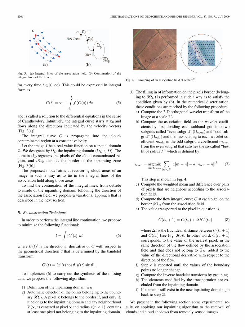
Fig. 3. (a) Integral lines of the association field. (b) Continuation of theintegral lines of the flow.
for every time t ∈ [0,∞). This could be expressed in integralform as
C(t) = x0 +
t∫
0
f (C(s)) ds (5)
and is called a solution to the differential equations in the senseof Caratheodory. Intuitively, the integral curve starts at x0 andflows along the directions indicated by the velocity vectors[Fig. 3(a)].
The integral curve C is propagated into the cloud-contaminated region at a constant velocity.
Let the image I be a real value function on a spatial domainΩ. We designate by ΩD the inpainting domain (ΩD ⊂ Ω). Thedomain ΩD regroups the pixels of the cloud-contaminated re-gion, and ∂ΩD denotes the border of the inpainting zone[Fig. 3(b)].
The proposed model aims at recovering cloud areas of animage in such a way as to tie in the integral lines of theassociation field along those areas.
To find the continuation of the integral lines, from outsideto inside of the inpainting domain, following the direction ofthe association field, we propose a variational approach that isdescribed in the next section.
B. Reconstruction Technique
In order to perform the integral line continuation, we proposeto minimize the following functional:
l =∫
|C ′(t)| dt (6)
where C(t)′ is the directional derivative of C with respect tothe geometrical direction θ that is determined by the bandelettransform
C ′(t) = (x′(t) cos θ, y′(t) sin θ) .
To implement (6) to carry out the synthesis of the missingdata, we propose the following algorithm.
1) Definition of the inpainting domain ΩD.2) Automatic detection of the points belonging to the bound-
ary ∂ΩD. A pixel x belongs to the border if, and only if,it belongs to the inpainting domain and any neighborhoodV (x, r) centered at pixel x and radius r(r ≥ 1), containsat least one pixel not belonging to the inpainting domain.
Fig. 4. Grouping of an association field at scale 22.
3) The filling in of information on the pixels border (belong-ing to ∂ΩD) is performed in such a way as to satisfy thecondition given by (6). In the numerical discretization,these conditions are reached by the following procedure.a) Compute the 2-D orthogonal wavelet transform of the
image at a scale 2j .b) Compute the association field on the wavelet coeffi-
cients by first dividing each subband grid into twosubgrids called “even subgrid” (Ωeven) and “odd sub-grid” (Ωodd) and then associating to each wavelet co-efficient modd in the odd subgrid a coefficient meven
from the even subgrid that satisfies the so-called “bestfit of radius P ” which is defined by
meven = arg minm∈Ωeven
∑|n|<P
|a[m − n] − a[modd − n]|2. (7)
This step is shown in Fig. 4.c) Compute the weighted mean and difference over pairs
of pixels that are neighbors according to the associa-tion field.
d) Compute the flow integral curve C at each pixel on theborder ∂ΩD from the association field.
e) The value transported to the pixel in question is
C(tn + 1) = C(tn) + ΔtC ′(tn) (8)
where Δt is the Euclidean distance between C(tn+ 1)and C(tn) [see Fig. 3(b)]. In other word, C(tn + 1)corresponds to the value of the nearest pixel, in thesame direction of the flow defined by the associationfield and that does not belong to ΩD, added to thevalue of the directional derivative with respect to thedirection of the flow.
f) Step e is repeated until the values of the boundarypoints no longer change.
g) Compute the inverse bandelet transform by grouping.h) The elements modified by the transportation are ex-
cluded from the inpainting domain.i) If elements still exist in the new inpainting domain, go
back to step 2).
We present in the following section some experimental re-sults on applying our inpainting algorithm to the removal ofclouds and cloud shadows from remotely sensed images.
MAALOUF et al.: INPAINTING TECHNIQUE FOR CLOUDS REMOVAL FROM REMOTELY SENSED IMAGES 2367
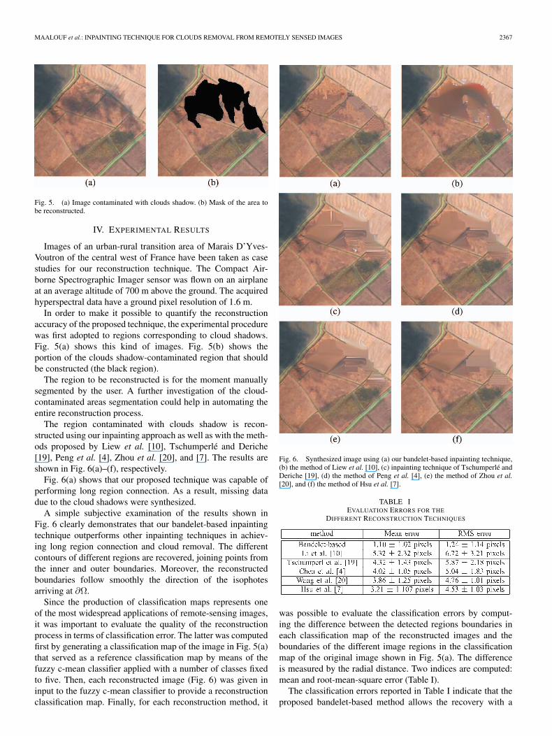
Fig. 5. (a) Image contaminated with clouds shadow. (b) Mask of the area tobe reconstructed.
IV. EXPERIMENTAL RESULTS
Images of an urban-rural transition area of Marais D’Yves-Voutron of the central west of France have been taken as casestudies for our reconstruction technique. The Compact Air-borne Spectrographic Imager sensor was flown on an airplaneat an average altitude of 700 m above the ground. The acquiredhyperspectral data have a ground pixel resolution of 1.6 m.
In order to make it possible to quantify the reconstructionaccuracy of the proposed technique, the experimental procedurewas first adopted to regions corresponding to cloud shadows.Fig. 5(a) shows this kind of images. Fig. 5(b) shows theportion of the clouds shadow-contaminated region that shouldbe constructed (the black region).
The region to be reconstructed is for the moment manuallysegmented by the user. A further investigation of the cloud-contaminated areas segmentation could help in automating theentire reconstruction process.
The region contaminated with clouds shadow is recon-structed using our inpainting approach as well as with the meth-ods proposed by Liew et al. [10], Tschumperlé and Deriche[19], Peng et al. [4], Zhou et al. [20], and [7]. The results areshown in Fig. 6(a)–(f), respectively.
Fig. 6(a) shows that our proposed technique was capable ofperforming long region connection. As a result, missing datadue to the cloud shadows were synthesized.
A simple subjective examination of the results shown inFig. 6 clearly demonstrates that our bandelet-based inpaintingtechnique outperforms other inpainting techniques in achiev-ing long region connection and cloud removal. The differentcontours of different regions are recovered, joining points fromthe inner and outer boundaries. Moreover, the reconstructedboundaries follow smoothly the direction of the isophotesarriving at ∂Ω.
Since the production of classification maps represents oneof the most widespread applications of remote-sensing images,it was important to evaluate the quality of the reconstructionprocess in terms of classification error. The latter was computedfirst by generating a classification map of the image in Fig. 5(a)that served as a reference classification map by means of thefuzzy c-mean classifier applied with a number of classes fixedto five. Then, each reconstructed image (Fig. 6) was given ininput to the fuzzy c-mean classifier to provide a reconstructionclassification map. Finally, for each reconstruction method, it
Fig. 6. Synthesized image using (a) our bandelet-based inpainting technique,(b) the method of Liew et al. [10], (c) inpainting technique of Tschumperlé andDeriche [19], (d) the method of Peng et al. [4], (e) the method of Zhou et al.[20], and (f) the method of Hsu et al. [7].
TABLE IEVALUATION ERRORS FOR THE
DIFFERENT RECONSTRUCTION TECHNIQUES
was possible to evaluate the classification errors by comput-ing the difference between the detected regions boundaries ineach classification map of the reconstructed images and theboundaries of the different image regions in the classificationmap of the original image shown in Fig. 5(a). The differenceis measured by the radial distance. Two indices are computed:mean and root-mean-square error (Table I).
The classification errors reported in Table I indicate that theproposed bandelet-based method allows the recovery with a
2368 IEEE TRANSACTIONS ON GEOSCIENCE AND REMOTE SENSING, VOL. 47, NO. 7, JULY 2009
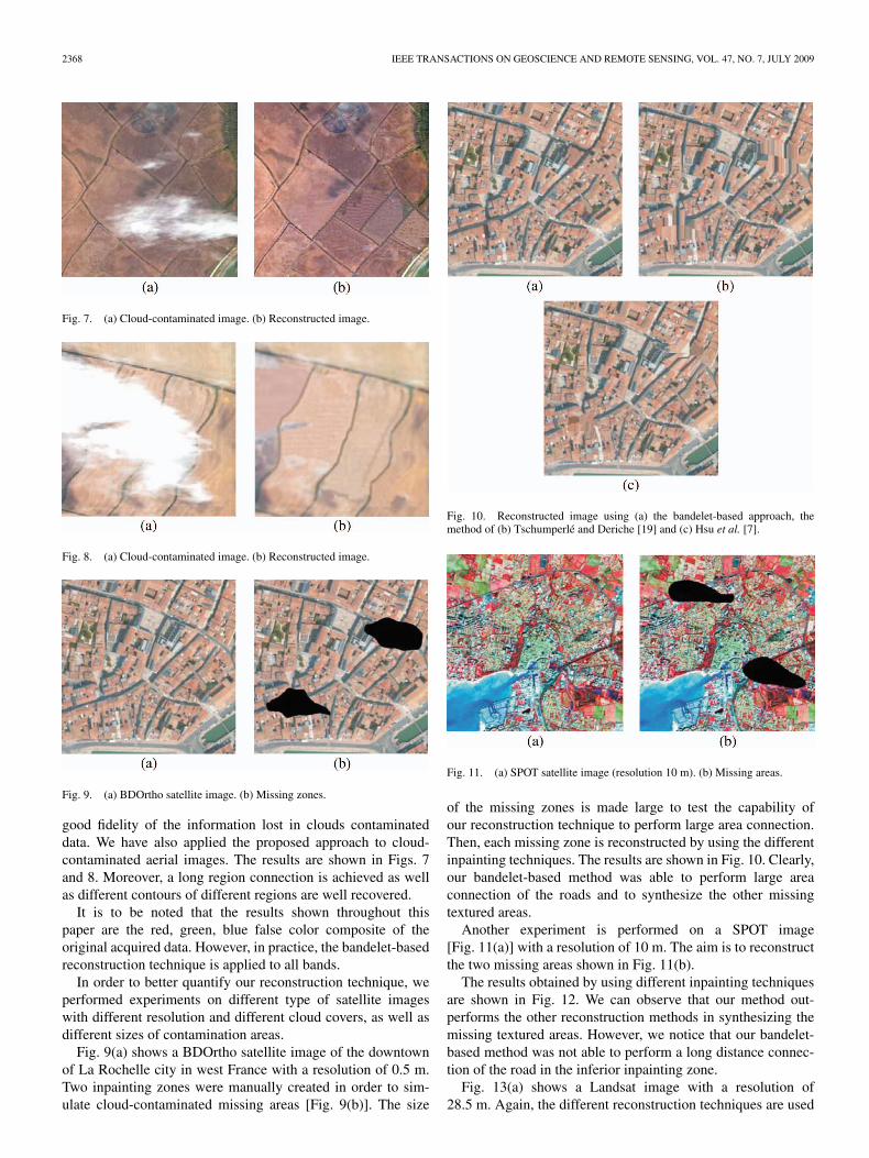
Fig. 7. (a) Cloud-contaminated image. (b) Reconstructed image.
Fig. 8. (a) Cloud-contaminated image. (b) Reconstructed image.
Fig. 9. (a) BDOrtho satellite image. (b) Missing zones.
good fidelity of the information lost in clouds contaminateddata. We have also applied the proposed approach to cloud-contaminated aerial images. The results are shown in Figs. 7and 8. Moreover, a long region connection is achieved as wellas different contours of different regions are well recovered.
It is to be noted that the results shown throughout thispaper are the red, green, blue false color composite of theoriginal acquired data. However, in practice, the bandelet-basedreconstruction technique is applied to all bands.
In order to better quantify our reconstruction technique, weperformed experiments on different type of satellite imageswith different resolution and different cloud covers, as well asdifferent sizes of contamination areas.
Fig. 9(a) shows a BDOrtho satellite image of the downtownof La Rochelle city in west France with a resolution of 0.5 m.Two inpainting zones were manually created in order to sim-ulate cloud-contaminated missing areas [Fig. 9(b)]. The size
Fig. 10. Reconstructed image using (a) the bandelet-based approach, themethod of (b) Tschumperlé and Deriche [19] and (c) Hsu et al. [7].
Fig. 11. (a) SPOT satellite image (resolution 10 m). (b) Missing areas.
of the missing zones is made large to test the capability ofour reconstruction technique to perform large area connection.Then, each missing zone is reconstructed by using the differentinpainting techniques. The results are shown in Fig. 10. Clearly,our bandelet-based method was able to perform large areaconnection of the roads and to synthesize the other missingtextured areas.
Another experiment is performed on a SPOT image[Fig. 11(a)] with a resolution of 10 m. The aim is to reconstructthe two missing areas shown in Fig. 11(b).
The results obtained by using different inpainting techniquesare shown in Fig. 12. We can observe that our method out-performs the other reconstruction methods in synthesizing themissing textured areas. However, we notice that our bandelet-based method was not able to perform a long distance connec-tion of the road in the inferior inpainting zone.
Fig. 13(a) shows a Landsat image with a resolution of28.5 m. Again, the different reconstruction techniques are used

MAALOUF et al.: INPAINTING TECHNIQUE FOR CLOUDS REMOVAL FROM REMOTELY SENSED IMAGES 2369
Fig. 12. Reconstructed image using (a) the bandelet-based approach, themethod of (b) Tschumperlé and Deriche [19] and (c) Hsu et al. [7].
Fig. 13. (a) Landsat satellite image. (b) Missing zones.
to synthesize the missing zones of Fig. 13(b). From the resultsshown in Fig. 14, we observe that our method outperforms otherreconstruction technique in texture synthesis. However, it wasnot able to perform the continuation of the road in the middleinpainting zone.
In general, from these experiments, it can be concluded thatthe quality of the reconstruction process using our bandelet-based technique is only affected by the resolution of the image.At a very high resolution, and for a more precise reconstruction,some measurements could be taken to improve our reconstruc-tion approach.
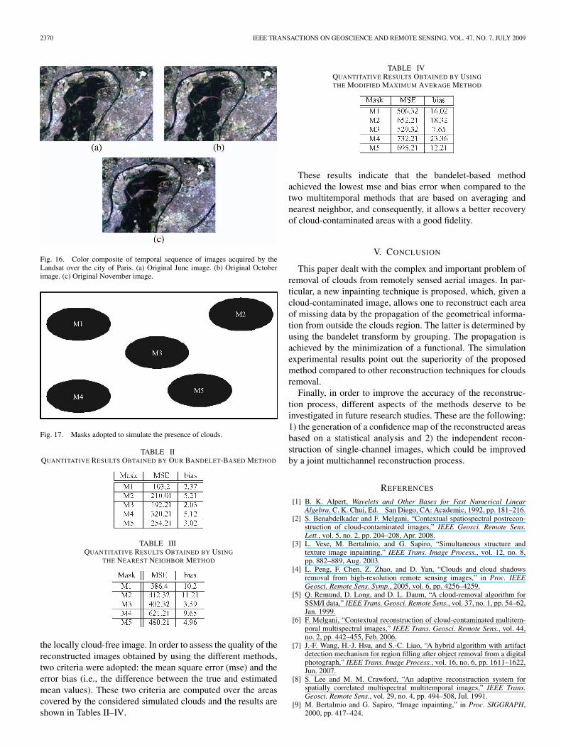
Experiments were also performed on a set of multitemporalimages. The multitemporal data set used is acquired by theLandsat satellite over the city of Paris in France. The data set ismade up of three registered images acquired in June, Octoberand November 2004 (Fig. 15).
The experimental procedure that was adopted consists ofselecting a cloud-free temporal sequence of images, simulating
Fig. 14. Reconstructed image using (a) the bandelet-based approach, themethod of (b) Tschumperlé and Deriche [19] and (c) Hsu et al. [7].
Fig. 15. Color composite of temporal sequence of images acquired by theLandsat over the city of Paris. (a) Original June image. (b) Original Octoberimage. (c) Original November image.
the presence of clouds by partially obscuring parts of thesequence, and comparing the reconstructed image with the orig-inal cloud-free image. A temporal cloud-free portion of the tem-poral sequence of images was used (Fig. 16). Fig. 17 shows fivedifferent masks that were used to simulate the clouds’ presence.
Each of the obscured region is reconstructed using ourbandelet-based method as well as two other multitemporalanalysis methods, namely, the modified maximum average [5]and the nearest neighbor method. While the former methodremoves the clouds by averaging part of the measurementscontained in the set of the multitemporal scene, the latterremoves clouds by substituting the cloud-contaminated pixelwith the spatially corresponding pixel of the nearest neighbor in
2370 IEEE TRANSACTIONS ON GEOSCIENCE AND REMOTE SENSING, VOL. 47, NO. 7, JULY 2009
Fig. 16. Color composite of temporal sequence of images acquired by theLandsat over the city of Paris. (a) Original June image. (b) Original Octoberimage. (c) Original November image.
Fig. 17. Masks adopted to simulate the presence of clouds.
TABLE IIQUANTITATIVE RESULTS OBTAINED BY OUR BANDELET-BASED METHOD
TABLE IIIQUANTITATIVE RESULTS OBTAINED BY USING
THE NEAREST NEIGHBOR METHOD
the locally cloud-free image. In order to assess the quality of thereconstructed images obtained by using the different methods,two criteria were adopted: the mean square error (mse) and theerror bias (i.e., the difference between the true and estimatedmean values). These two criteria are computed over the areascovered by the considered simulated clouds and the results areshown in Tables II–IV.
TABLE IVQUANTITATIVE RESULTS OBTAINED BY USING
THE MODIFIED MAXIMUM AVERAGE METHOD
These results indicate that the bandelet-based methodachieved the lowest mse and bias error when compared to thetwo multitemporal methods that are based on averaging andnearest neighbor, and consequently, it allows a better recoveryof cloud-contaminated areas with a good fidelity.
V. CONCLUSION
This paper dealt with the complex and important problem ofremoval of clouds from remotely sensed aerial images. In par-ticular, a new inpainting technique is proposed, which, given acloud-contaminated image, allows one to reconstruct each areaof missing data by the propagation of the geometrical informa-tion from outside the clouds region. The latter is determined byusing the bandelet transform by grouping. The propagation isachieved by the minimization of a functional. The simulationexperimental results point out the superiority of the proposedmethod compared to other reconstruction techniques for cloudsremoval.
Finally, in order to improve the accuracy of the reconstruc-tion process, different aspects of the methods deserve to beinvestigated in future research studies. These are the following:1) the generation of a confidence map of the reconstructed areasbased on a statistical analysis and 2) the independent recon-struction of single-channel images, which could be improvedby a joint multichannel reconstruction process.
REFERENCES
[1] B. K. Alpert, Wavelets and Other Bases for Fast Numerical LinearAlgebra, C. K. Chui, Ed. San Diego, CA: Academic, 1992, pp. 181–216.
[2] S. Benabdelkader and F. Melgani, “Contextual spatiospectral postrecon-struction of cloud-contaminated images,” IEEE Geosci. Remote Sens.Lett., vol. 5, no. 2, pp. 204–208, Apr. 2008.
[3] L. Vese, M. Bertalmio, and G. Sapiro, “Simultaneous structure andtexture image inpainting,” IEEE Trans. Image Process., vol. 12, no. 8,pp. 882–889, Aug. 2003.
[4] L. Peng, F. Chen, Z. Zhao, and D. Yan, “Clouds and cloud shadowsremoval from high-resolution remote sensing images,” in Proc. IEEEGeosci. Remote Sens. Symp., 2005, vol. 6, pp. 4256–4259.
[5] Q. Remund, D. Long, and D. L. Daum, “A cloud-removal algorithm forSSM/I data,” IEEE Trans. Geosci. Remote Sens., vol. 37, no. 1, pp. 54–62,Jan. 1999.
[6] F. Melgani, “Contextual reconstruction of cloud-contaminated multitem-poral multispectral images,” IEEE Trans. Geosci. Remote Sens., vol. 44,no. 2, pp. 442–455, Feb. 2006.
[7] J.-F. Wang, H.-J. Hsu, and S.-C. Liao, “A hybrid algorithm with artifactdetection mechanism for region filling after object removal from a digitalphotograph,” IEEE Trans. Image Process., vol. 16, no. 6, pp. 1611–1622,Jun. 2007.
[8] S. Lee and M. M. Crawford, “An adaptive reconstruction system forspatially correlated multispectral multitemporal images,” IEEE Trans.Geosci. Remote Sens., vol. 29, no. 4, pp. 494–508, Jul. 1991.
[9] M. Bertalmio and G. Sapiro, “Image inpainting,” in Proc. SIGGRAPH,2000, pp. 417–424.
MAALOUF et al.: INPAINTING TECHNIQUE FOR CLOUDS REMOVAL FROM REMOTELY SENSED IMAGES 2371
[10] S. C. Liew, M. Li, and L. K. Kwoh, “Automated production of cloud-freeand cloud-shadow image mosaics from cloudy satellite imagery,” in Proc.XXth ISPRS Congr., Istanbul, Turkey, Jul. 12–13, 2004.
[11] S. Mallat, “Geometrical grouplets,” Appl. Comput. Harmon. Anal.,vol. 26, no. 2, pp. 161–180, Mar. 2009.
[12] B. Bowen, M. Oliviera, and Y. Chang, “Fast digital image inpainting,” inProc. Int. Conf. Visulization, Imaging Image Process., 2001, pp. 261–266.
[13] E. Le Pennec and S. Mallat, “Bandelet image approximation and com-pression,” SIAM J. Multiscale Simul., vol. 4, no. 3, pp. 992–1039, 2005.
[14] E. Le Pennec and S. Mallat, “Sparse geometric image representation withbandelets,” IEEE Trans. Image Process., vol. 14, no. 4, pp. 423–438,Apr. 2005.
[15] G. Peyré, “Géometrie multi-échelles pour les images et les textures,” thèsecmap, Ecole Polytechnique, Palaiseau, France, 2005.
[16] G. Peyré and S. Mallat, “Discrete bandelets with geometric orthogonalfilters,” in Proc. ICIP, Sep. 2005, pp. 65–68.
[17] G. Peyré and S. Mallat, “Surface compression with geometricalbandelets,” ACM Trans. Graph., vol. 24, no. 3, pp. 601–608, Jul. 2005.
[18] F. Melgani, S. Benabdelkader, and M. Boulemden, “Cloud-contaminatedimage reconstruction with contextual spatio-spectral information,” inProc. IGARSS, 2007, pp. 373–376.
[19] D. Tschumperlé and R. Deriche, “Vector-valued image regularization withPDE’s: A common framework for different applications,” IEEE Trans.Pattern Anal. Mach. Intell., vol. 27, no. 4, pp. 506–517, Apr. 2005.
[20] F. Zhou, Z. Wang, and F. Qi, “Inpainting thick image regions usingisophote propagation,” in Proc. IEEE ICIP, 2006, pp. 689–692.
Aldo Maalouf received the B.Sc. degree (with dis-tinction) in computer engineering and the M.Sc.degree (with first-class honors) in electrical engi-neering from the University of Balamand, Tripoli,Lebanon, in 2003 and 2005, respectively, and thePh.D. degree (with high distinction) in signal andimage processing from the University of Poitiers,Poitiers Cedex, France, in 2008.
Currently, he is appointed as a Postdoc withthe XLIM Laboratory, Unite Mixte de Recherche6172, Centre National de la Recherche Scientifique,
Signal-Image-Communication Department, University of Poitiers, where he isworking on the optimization of stereoscopic image coding and image super-resolution in the context of the EDCINE European project. He has publishedmany papers relating to his specialist interest in multispectral image denoising,segmentation, inpainting, and video processing. His research interests are inthe area of image processing, particularly in the domain of multiresolutionapproximations and geometrical representations.
Philippe Carré received the Engineer degree incomputer engineering from the Compiegne Univer-sity of Technology, Compiegne, France, in 1995and the Ph.D. degree in signal processing and com-puter science from the University of Poitiers, PoitiersCedex, France, in 2000 for his work on the definitionof discrete atomic time–frequency representations.
He is currently an Associate Professor with theElectronic Department, University of Poitiers, anda Member of the Signal, Image, and Communi-cation Laboratory. His interests include signal and
image processing, wavelets, time–frequency and multiscale decompositionstheory, and their applications to the fields of denoising, segmentation, andwatermarking.
Bertrand Augereau received the Ph.D. degree insignal and image processing from the University ofPoitiers, Poitiers Cedex, France, in 1996.
Currently, he is an Assistant Professor with theSignal, Image, and Communications Laboratory,University of Poitiers, Poitiers Cedex, France. His re-search interests include image and video processing,computer vision, partial differential equations, scale-space analysis, and video processing.
Christine Fernandez-Maloigne received the M.S.degree in computer engineering and the Ph.D. degreein computer science from the Compiegne Universityof Technology, Compiegne, France, in 1986 and1989, respectively.
She is currently a Professor with the Universityof Poitiers, Poitiers Cedex, France. She manages aregional research federation of 260 researchers in thearea of imaging, data mining, and communicationsystems, PRIDES (Regional Research Program inImages, Datas, Systems) and one of its laboratories:
XLIM-SIC (Signal Image and Communication), joint unit of Centre Nationalde la Recherche Scientifique and University. Her research activities includefundamental research about the introduction of human visual system modelsin multiscale color image processing as well as industrial contracts.
Prof. Fernandez-Maloigne has been a member of the French National Bodyfor International Organization for Standardization Joint Photographic ExpertsGroup since 2000 and has been a French representative for the Division 8(Image technology) of the Commission Internationale de l’Eclairage since2006, where she manages a technical committee on color quality assessment.
Copyright © 2022 FDOKUMEN