An RFID-Based Point-and-Listen Interface Providing Library Access for the Visually Impaired
Upload
independentCategory
view
2download
0
A 2D Vibration Array as an Assistive Device for
Visually Impaired
D. Dakopoulos', S. K. Boddhu2, N. Bourbakis'College of Engineering and Computer Science
'Assistive Technologies Research Center, 2Computational Autonomy Research LabWright State University
Dayton, OH, USAdakopoulos.2(wright.edu, nikolaos.bourbakis(wright.edu
Abstract-This paper deals with the design, simulation andimplementation of a 2D vibration array used as a majorcomponent of an assistive wearable navigation device for visualimpaired. The 2D vibration array consists of 16 (4x4) miniaturevibrators connected to a portable computer, which is the maincomputing component of the entire wearable navigation system,called Tyflos. Tyflos consists of two miniature cameras (attachedto a pair of dark glasses), a microphone, an ear speaker, the 2Dvibration array, and a portable computer. The cameras captureimages from the surrounding environment and after appropriateprocessing 3D representations are created. These 3D spacerepresentations are projected on the 2D array, which vibrates invarious levels corresponding to the distances of the surroundingobstacles. The 2D array is attached to the user's chest in order toprovide the appropriate sensation (via vibrations) of the distancesfrom the surroundings.
Keywords-blind's navigation; visually impaired; vibrotactile;formal language; wearable system
I. INTRODUCTION
According to N.F.B. (National Federation for Blind), theestimated number of blind & visually impaired people of allages in the U.S., (including institutionalized and homelesspeople) is 5-6 millions, thus the need to for assistive deviceswas and will be important to them.
One of the assistive systems developed by researchers andpractitioners is the navigation devices [1-16, 21]. There is awide range of navigation systems and tools available forvisually impaired individuals. White cane and dog guides arethe most popular. Since 1960's evolving technology helpedmany researchers built electronic navigation devices. There arethree categories of navigation systems [21]: i) visionenhancement, ii) vision replacement and iii) vision substitution.Vision enhancement involves input from a camera, processingof the information, and output on a visual display. In itssimplest form it may be a miniature head-mounted camera withthe output on a head-mounted visual display (as used in somevirtual reality systems). Vision replacement involves displayingthe information directly to the visual cortex of the human brainor via the optic nerve. Vision substitution is similar to visionenhancement but with the output being non-visual - typicallytactual or auditory or some combination of the two. ETAs(Electronic Travel Agencies) belong to the vision substitution
systems. They transform information about the environmentthat would normally be relayed through vision into a form thatcan be conveyed through another sensory modality.
Our navigation system (Tyflos) belongs to the category ofvision substitution and one of important module is a 2Dvibration array, which offers to the blind-user a sensation of the3D surrounding space. Thus, here we present the 2D vibrationarray device and its advantages and disadvantages regardingthe information that provides to the user.
The paper is organized into seven sections. Section 2 offersa brief description of the Tyflos system. Section 3 presents themodeling of the 2D vibration array based on a formal language.Section 4 describes the hardware implementation of the 2Darray. Section 5 discusses the high to low resolutionrepresentation at the 2D array and information representationissues. Section 6 shows some experimental results and section7 concludes the overall presentation with future work.
II. THE TYFLOS NAVIGATION SYSTEM
A. The First PrototypeThe main role of the Tyflos mobility assistant is to capture
the environmental data from various sensors and map theextracted and processed content onto available user interfacesin the most appropriate manner. The Tyflos prototype willintegrate a wireless handheld computer, cameras, rangesensors, GPS sensors, microphones, natural languageprocessor, text-to-speech device, and a digital audio recorder.The audio-visual input devices and the audio output devicescan be worn (or carried) by the user. Data collected by thesensors is processed by the Tyflos' modules, each specializedin one or more tasks. In particular, it interfaces with externalsensors (such as GPS, if applicable, range sensors, etc.) as wellas the user, facilitating focused and personalized contentdelivery. The user communicates the task of interest to themobility assistant using a speech-recognition interface.
The preliminary design and development of the Tyflosprototype is already being carried out by the authors, "Fig. 1".This prototype consists of two cameras, a range scanner, an earspeaker, a microphone, a speech synthesizer, and a portablecomputer. This device has been evaluated by students withvisual disabilities and their feedback has been used in the
1-4244-1509-8/07/$25.00 02007 IEEE 930
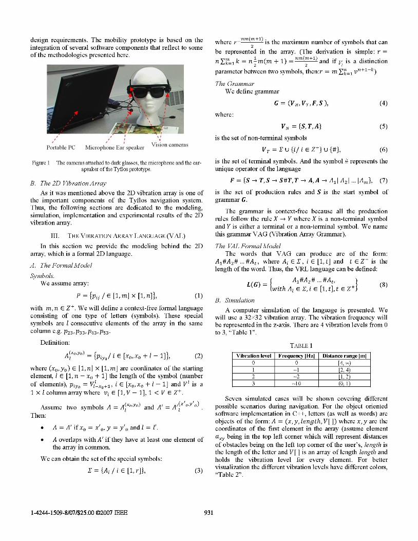
design requirements. The mobility prototype is based on theintegration of several software components that reflect to someof the methodologies presented here.
Portable PC MicroIhone Ear spea ker 9'1 1Q IL
Figure 1 The cameras attached to dark glasses, the microphone and the ear-speaker of the Tyflos prototype.
B. The 2D Vibration ArrayAs it was mentioned above the 2D vibration array is one of
the important components of the Tyflos navigation system.Thus, the following sections are dedicated to the modeling,simulation, implementation and experimental results of the 2Dvibration array.
III. THE VIBRATION ARRAY LANGUAGE (VAL)In this section we provide the modeling behind the 2D
array, which is a formal 2D language.
A. The Formal ModelSymbols.
We assume array:
P = {pij / E [1, m] x [1, n]}, (1)with m, n E ZV. We will define a context-free formal languageconsisting of one type of letters (symbols). These specialsymbols are 1 consecutive elements of the array in the samecolumn e.g. P23, P33J P43' P53
Definition:
A(xo°Yo) - {piyo/ i E [XO, XO + I -1], (2)
where (xo, yo) E [1, n] x [1, m] are coordinates of the startingelement, 1 E [1, n - xo + 1] the length of the symbol (numberof elements), Piyo = vil x +1 i E [xO,xo + 1 - 1] and V1 is a1xlcolumnarraywhere vi E [1,V-1],1 <VeZV.
Assume two symbols A = A(xOYo) and A' = A'(x OY o)Then:
* A = A' if xo = x'o, y = y'0 and I = 1'.* A overlaps with A' if they have at least one element of
the array in common.
We can obtain the set of the special symbols:
XE = {Ai / i Ei [1, r]}, (3)
where r=nm(m+1) is the maximum number of symbols that can2
be represented in the array. (The derivation is simple: r=nEm 1k = n m(m + 1) = nm(m+1) and if v is a distinctionk=2 ~~~~~~~~~2parameter between two symbols, then:r = m E n=p1n+1-k)
The GrammarWe define grammar
G = (VN, VT, F,S ),where:
VN = {S, T, A}is the set of non-terminal symbols
VT = X U {i/ i E Z } U {#},
(4)
(5)
(6)
is the set of terminal symbols. And the symbol # represents theunique operator ofthe language
F = {S -* T,S -* S#T,T -* A,A -* A1l A21 IAmi, (7)
is the set of production rules and S is the start symbol ofgrammar G.
The grammar is context-free because all the productionrules follow the rule X -* Y where X is a non-terminal symboland Y is either a terminal or a non-terminal symbol. We namethis grammar VAG (Vibration Array Grammar).
The VAL Formal ModelThe words that VAG can produce are of the form:
A1#A2# ... #At, where Ai E X, i E [1, t] and t E Z+ is thelength of the word. Thus, the VRL language can be defined:
L(G) = A,#A2# #At, ZLG with Ai E X, i E [1, t], t E Z+3 (8)
B. SimulationA computer simulation of the language is presented. We
will use a 32X32 vibration array. The vibration frequency willbe represented in the z-axis. There are 4 vibration levels from 0to 3, "Table 1".
TABLE 1I
LVibration level
0123
Frequency [Hz]0-1-2-10
Distance range [m][4, -)[2, 4)[1,2)(0, 1) I
Seven simulated cases will be shown covering differentpossible scenarios during navigation. For the object orientedsoftware implementation in C++, letters (as well as words) areobjects of the form: A = (x, y, length, V[ ]) where x, y are thecoordinates of the first element in the array (assume elementaxy being in the top left corner which will represent distancesof obstacles being on the left top corner of the user's, length isthe length of the letter and V[ ] is an array of length length andholds the vibration level for every element. For bettervisualization the different vibration levels have different colors,"Table 2".
1-4244-1509-8/07/$25.00 02007 IEEE
-t-
931
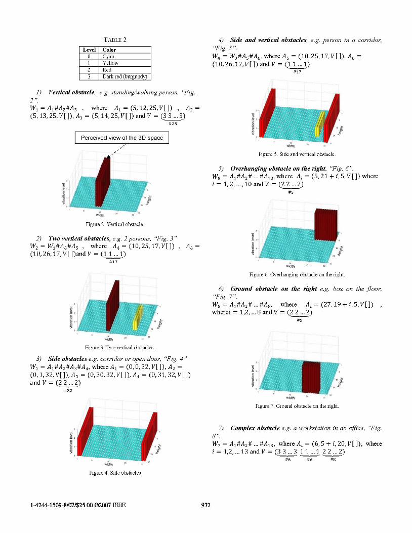
TABLE2 4) Side and vertical obstacles, e.g. person in a corridor,Level Color "Fig. 5
0 Cyan W4 = W3#A5#A6, where A5 = (10, 25,17, V[]), A6 =I Yellow (10, 26,17, V[ ])and V (1 1 ... 1)2Red #17
3 Dark red (burgundy)
1) Vertical obstacle, e.g. standinglwalking person, "Fig.2 ".W1 =A1#A2#A3 , where A1 = (5,12,25,V[]) ,A2(5, 13,25, V[ ]),A1= (5, 14,25,V[ and V (33...3)
#25
Perceived view of the 3D space
Figure 5. Side and vertical obstacle.
5) Overhanging obstacle on the right, "Fig. 6".Ws =A1#A2#...#A10, where Ai = (5, 21 + i, 5, V[]) where
t~ ~~~ ~ ~~~~~~~~~~~i 12 I10adV (22..2
Figure 2. Vertical obstacle.
2) Two vertical obstacles, e.g. 2 persons, "Fig. 3"W)WA#A where A ( 102517Vg[] A ml=
W2 = Wl 4#As 4 = (10, 25, 4 9~~~~~~~~~~~~~~~~eth 3.(10, 26, 17, V[])andV =(1 1...1)#17
Figure 6. Overhanging obstacle on the right.
6) Ground obstacle on the right e.g. box on the floor,"Fig. 7".Ws =A1#A2# ...#A8, where Ai=(27,19 +i,5,V[]where = 1,2,...8and V (2 2.2)
32~ ~ ~~ ~ ~~~~~~~~~~#
Figure 3. Two vertical obstacles.
3) Side obstacles e.g. corridor or open door, "Fig. 4"= A1#A2#A3#A where Al = (0, 0, 32, V[]), A2
(0, 1, 32,V[ ]),A = (0, 30, 32, VL])A4 (0, 31, 32, V[]and V =(22 ...2)
#32
Figure 7. Ground obstacle on the right.
1 8.7 Complex obstacle e.g. a workstation in an offce, "Fig.
W7 = A1#A2# ...#A13, whereAi = (6,5+ i,20,V[]), wherei =12,...13andV=(33...311...122...2)
#6 #6 #8
Figure 4. Side obstacles
1-4244-1509-8/07/$25.00 02007 IEEE 932

C. The Vibration ArrayThe prototype has 8 vibration modules, which means that
the resulting vibration array has 16 vibrators which it wasdecided to be arranged in a 4x4 form, "Fig. 11".
Figure 8. Complex obstacle.
The characteristic of the VAL is that it can represent anypossible obstacle (or combination of obstacles) in variousdistances. The array holds a word that is combination ofsymbols (row-type). The important characteristic is that everysymbol can hold more than one vibration level through thearray V[ ]. This is more evident in case 7.
IV. THE HARDWARE IMPLEMENTATION
To achieve scalability, a hiererarchical design procedure isfollowed.
A. VibratorsThe vibrators used (C1030B028F), "Fig. 9"
are of-the-shelf and their most commonapplication is for cell-phones. They are coin-type and with small size (3mm thick, lcmdiameter), which means that they can easilyattach on the clothes of the user. Additionallytheir vibration level is small enough, so that willnot harm the user, but on the other hand it will Figure 9give the desired information. The power consumption is smallwhich makes it appropriate for a wearable device and also safefor the user.
B. The Vibration ModuleThe basic unit of the vibration array is the vibration
module. Each module's major components are one digitalpotentiometer (DS1803) and two analog timers (555). Theoutput of the timers is square pulses which drive the vibratorsand whose frequency can be controlled by one digitalpotentiometer, "Fig. 10".
I I I
(Y9) (MI 0)
I I
(V1(1 12)
I I
V13) (V14)
I I
(V15) (V16)
Figure 11 The vibration array.
D. The InterfaceA 8051 microcontroller controls the 8 vibration modules
(practically the 8 digital potentiometers) using a standard 2-wire interface. The microcontroller is programmed in assemblylevel. Finally a portable computer and with proper interface(C++) through a USB port it controls the microcontroller,which means the vibration frequencies of the 16 vibrators,"Fig. 12" and "Fig. 13".
E. OperationThe vibrators can have frequencies between 1.25Hz and
10.5Hz. The duty cycle changes also with the frequency, givinga better perception of the vibrations from the user (lowerfrequencies have smaller duty cycle). Vibrators are controlledserially via a 2-wire interface: Vibrator-#1, Vibrator-#2,Vibrator-# 16, Vibrator-i, ... etc.
8051 microcontrollerde-velopmenit board
the vibration array
vibration module
Figure 12. The board with the 16 vibrators.
Figure 10. The vibration module.
1-4244-1509-8/07/$25.00 02007 IEEE
Y07 V08
ENn:LE BUS 9tol6w'1 1, r I Y I I I I t I Y Y I I I I t Y Y I I I I I s s s I I I I
933
I,-Ir
- - -
-. .? .. .. ., .a .. .. " ..'. .. .. ll.
I .,
I .
- .1:1 "I I.. .111 ... 1:1 "I - -11F I,,: 1.

7-USB port mi-rocontrollerWend dta (freq leWl) deVelopmlent
portable boardcomputer PA+PBPiil+F1
reset controllines 2} lines
coin01 type Vibrator4x4 Vibration array
Figure 13. The high-level design.
V. HIGH To Low RESOLUTION MAPPING
In this section we discuss the high to low resolutionrepresentation of the visual information captured by thecameras and converted into a low resolution array in order toprovide to the user a minimum piece of information from the3D surroundings. To accomplish this high to low representationwe tried several schemes, such as pyramids, selective points,etc.
A. Pyramidal Re-sampling [19, 20]The cameras attached to the glasses can capture
images/video of 512x512 pixels or more. The prototype'svibration array has a 4x4 resolution so a high-to-low resolutionalgorithm is needed. A lower resolution cannot carry the sameamount of information so the high to low resolution algorithmhas to be carefully selected so that we keep only the importantinformation. One basic high-to-low resolution algorithm is touse a pyramidal structure re-sampling. Recursively, 4 pixels(2x2 box) of the initial matrix are mapped to 1 in the newmatrix using a specific function. Here the maximum value ischosen. "Fig. 14" is a graphical example where from 16 16 weget 4 4 in 2 iterations.
Figure 14. Pyramidal re-sampling.
For the simulated results we apply the pyramidal re-sampling for all the 7 scenarios of the language simulation(starting with the 32i32 atray and ending with the 4 4, "Fig.15 21".
Figure 15. Scenario 1.
Figure 16. Scenario 2.
Figure 17. Scenario 3.
Figure 18. Scenario 4.
Figure 19. Scenario 5.
Figure 20. Scenario 6.
1-4244-1509-8/07/$25.00 02007 IEEE 934

Figure 21. Scenario 7.
The results are not so encouraging. For some simplescenarios (e.g. scenarios 1 and 3) the re-sampling seems tokeep the basic features of the original array but in otherscenarios (e.g. scenario 4) important information is lost ortransformed to a not useful form. A more sophisticatedalgorithm is needed.
B. The 32 x32 resolution Array.Getting to the 32X32 resolution from the camera's
resolution can be achieved with the pyramidal re-sampling,since 32X32 is high enough to represent information that theuser wants. Power of 2 is the most convenient from aprogrammer's and computer engineer's prospective but thereare other design parameters. The average maximum width of aman's chest is around 30cm (approx. 12inch). The diameter ofeach vibrator is lcm so 32 vibrators is the maximum ofconsecutive vibrators. For other experimental reasons (e.g.microcontroller restrictions, power consumption etc) or the factthat 2 vibrators cannot be very close because the user will notbe able to perceive distinct vibrations, the resolution has to bereduced to 4x4 (with a prospective in future work to beincreased to 4x4).
C. Improvedpyramidal resamplingIn order to get a lower resolution than 32X32, special rules
are required that will result to a more sophisticated algorithm.As mentioned before, the simple pyramidal re-sampling it's notefficient for that low resolution. These are some generalcharacteristics that the improved version should incorporate:
* Retain as much as possible the characteristics (shape,vibration levels) of the objects appearing in the initialarray. Objects are considered both the open and theblocked paths (obstacles).
* Emphasize special objects (position, shape) e.g. verticalobjects that can be people, 2 side vertical objects thatcan be walking in corridor or an open door.
* Hierarchically cluster objects depending on howimportant are for the navigation and finally,
* Give information about the open (and blocked)navigation paths.
Given the extremely low resolution of 4x4 and the differentpossible scenarios that can appear during navigation there aretwo basic categories of objects/paths: on the sides of thenavigation space (left and right) which are represented bypixels a.1 and a'4, and the ones in the center which arerepresented by pixels a,2 and a,3. Thinking in that way:
* Objects that in the sides have to be pushed to the sideof the array.
* Objects that are in the middle have to be pushed to themiddle of the array.
A possible implementation of those rules would be todivide the array in 16 regions (4x4 pixels each). While the 2X2box scans the array the new pixel will have the value of one ofthe old pixels, depending on the region the box is. In the arraybelow, the 16 regions are represented and the pixel that isselected is shown with red, "Fig. 22".
Figure 22. Regions and selection in improved re-sampling.
For example if the box is in region (row 1, column 2)then the bottom right pixel of the box is selected (theobject is pushed to the middle).
VI. SIMPLE EXPERIMENTAL RESULTS
A simple experiment was performed in order to simulateand present the system's operation. Two pictures from anindoor environment scenario were taken. Their initial size is512X512, "Fig. 23". The images were then re-sampled usingthe pyramidal algorithm to 32X32 resolution, "Fig. 24". Thenfor every pixel, a vibration level was assigned that correspondsto the distance from the user, "Fig. 25". And finally theresolution was dropped to 4x4 using first the basic, "Fig. 26"and the improved pyramidal re-sampling, "Fig. 27".
Figure 23. Initial 512X512 images.
Figure 24. 32X32 images after pyramidal re-sampling.
1-4244-1509-8/07/$25.00 02007 IEEE 935

Figure 25. Vibration levels for the 32X32 array.
Figure 26. Vibration levels after pyramidal re-sampling to 4x4.
Figure 27. Vibration levels after improved pyramidal re-sampling to 4x4.
The results are not encouraging for all algorithms (similarto the simulated results). The final vibration arrays seem tocarry more information than needed since they don't give userthe option of an open path which in practice exists. The 4x4resolution is not enough to hold information that the 32X32array can give, so there is a need for a more efficient high-to-low resolution algorithm.
We also did a selection of the values on certain positions (1,9, 17, ...) of the 32X32 array and the results were better thanthe pyramidal ones. This selection, however, does notconstitute it as a better method. On the other hand it gives to usthe idea to combine these in order to get better representationwith low resolution mappings, "Fig. 28".
Figure 28. Vibration levels after selection, to 4x4.
VII. CONCLUSION AND FUTURE
In this paper a 2D vibration array for representing at lowresolution the 3D shape of the perceived surrounding space waspresented. The 2D vibration array is a major part of the Tyflosnavigation system for visual impaired. The modeling of thearray, its simulation and its first 4x4 implementation were also
provided. The results of this study were very useful despiteseveral issues related with the high to low representation of the3D perceived space. These issues are under re-evaluation witha new implementation of 32X32 vibrators and their results willbe published at the Int. Conference on AT-08 [22]. We stronglybelieve that there is a way of representing information fromhigh to low resolution with an acceptable ratio. Somesuggestions on this direction are:
* Get information from neighbor cells (e.g. overlappingscanning)
* Memory (e.g. keeping track of objects from previouslevels of the pyramid).
* Non symmetrical regions
* Focus more on representing any open paths and not theobstacles.
The overall effort of this research work is directlyassociated with a study on biomedical brain patterns relevant tovibration sequences for visual impaired [23].
REFERENCES
[1] J. L. Gonzalez-Mora, A. Rodriguez-Hernandez, L. F. Rodriguez-Ramos,L. Diaz-Saco, N. Sosa, "Development of a new space perception systemfor blind people, based on the creation of a virtual acousticspace.".http://www.iac.es/proyect/eavi
[2] S. Shoval, J. Borenstein, Y. Koren, "Mobile robot obstacle avoidance ina computerized travel aid for the blind", Proceedings of the 1994 IEEERobotics and Automation Conference, San Diego, CA, May 8-13,1994,pp. 2023-2029.
[3] I. Ulrich, J. Borenstein, "The Guidecane - Applying Mobile RobotTechnologies to Assist the Visually Impaired People", IEEETransactions on Systems, Man and Cybernetics, -Part A: Systems andHumans, Vol.31, No2, March 2001, pp. 13 1-136.
[4] M. Adjouadi, "A man-machine vision interface for sensing theenvironment", Journal of Rehabilitation Research and DevelopmentVol.29, No2, 1992, pp.57-56.
[5] S. Cardin, D. Thalmann, F. Vexo, "Wearable Obstacle Detection Systemfor Visually Impaired People", VR Workshop on Haptic and TactilePerception of Deformable Objects, Hannover, Germany, December2005.
[6] P. B. L. Meijer, "An experimental System for Auditory ImageRepresentations", IEEE Transactions on Biomedical Engineering,Vol.39, No2, February-1992, http://www.seeingwithsound.com/
[7] D. Yuan, R. Mandulchi, "A tool for range Sensing and EnvironmentDiscovery for the Blind", IEEE Workshop on Real-Time 3-D Sensorsand Their Use, 2004.
[8] D. Aguerrevere, M. Choudhury, A. Barreto, "Portable 3D Sound / SonarNavigation System for Blind Individuals", Second LACCEIInternational Latin American and Caribbean Conference for Engineeringand Technology (LACCET 2004), Miami, Florida, 2-4 June 2004.
[9] A. Hub, J. Diepstraten, T. Ertl, "Design and development of an indoornavigation and object identification system for the blind", ACMSIGACCESS Accessibility and Computing, Issue 77-78 , Sept. 2003 -Jan. 2004.
[10] A. Helal, S. Moore, and B. Ramachandran, "Drishti: An IntegratedNavigation System for Visually Impaired and Disabled", Proceedings ofthe 5th International Symposium on Wearable Computer, Zurich,Switzerland, October 2001.
[11] GMV Sistemas (http://www.gmvsistemas.es/)[12] European Space Association (http:llwww.esa.int/)[13] Y. Sonnenblickm, "An indoor Navigation System for Blind Individuals",
CSUN Conference, Los Angeles, CA, USA, 1998.[14] http://www.tiresias.org/reports/mobicfhtm
1-4244-1509-8/07/$25.00 02007 IEEE 936

[15] S. Mann, C. Aimone, "Invention of Electric Eyeglasses as a Seeing Aidand Telecommunication Device", World ongress for Blind, Baltimore,Oct. 6-8, 2005. http://www.eyetap.org/
[16] N. Bourbakis, "Tyflos Navigator: Sensing the Surrounding 3D Spaceduring Navigation for Blind", IEEE Int. Symposium on BIBE-05,Minneapolis, MN, Oct. 2005.
[17] N. Bourbakis, C. Alexopoulos, "A fractal-based image processinglanguage: formal modeling", Pattern Recognition 32 (1999), pp. 317-338.
[18] Hopcroft, J. E. and Ullman, J. D., Formal Languages and their Relationto Automata, Addison-Wesley Longman Publishing Co., Inc., Boston,MA USA, 1969.
[19] Pavlidis, T, Algorithms for Graphics and Image Processing, ComputerScience Press, Rockville, Maryland, 1982
[20] N.Bourbakis and A.Klinger, "A hierarchical picture coding scheme",PR Society J. Pattern Recognition, vol.22,3, 1989, pp.317-329.
[21] N. Bourbakis, D. Dakopoulos, "A Comparative Survey on WearableSystems for Blinds' Navigation", 1st International IEEE-BAISSymposium on Research on Assistive Technologies, Dayton, OH, 16April 2007, pp. 3-12.
[22] D. Dakopoulos, N. Bourbakis, "Representing and analyzing high-to-low3D visual information", Int. Conf. on Assistive Technologies, Baltimore2008, unpublished
[23] N.Bourbakis, "Interpretation of Brain Patterns Associated with 3Dvibrations Sequences, Int. Biomedical Engr. Conference, also ATRC-TR2007, unpublished.
1-4244-1509-8/07/$25.00 02007 IEEE 937
Copyright © 2022 FDOKUMEN