86-Learning about fields and waves using visual electromagnetics
14
IEEE TRANSACTIONS ON EDUCATION, VOL. 33, NO. I. FEBRUARY 1990 81 Learning About Fields and Waves Using Visual Electromagnetic s RODNEY W. COLE, EDMUND K. MILLER, FELLOW, IEEE, SWAPAN CHAKRABARTI, MEMBER, Abstract-Electromagnetics education needs to take advantage of modern technology if it is to continue attracting adequate numbers of students to its study. A means of doing so is “visual electromagnetics” (VEM) which we define to be an interactive and visual learning envi- ronment to provide a more appealing and intuitive means of studying electromagnetics. VEM involves computer graphics with varying de- grees of interactivity available from stored results developed offline or generated online in real time. Designated as stored-solution modes (SSM) and generated-solution modes (GSM), both approaches are dis- cussed and illustrated with representative results from each, using as examples projects being conducted at the University of California, Davis, and the University of Kansas. A brief survey is given of projects at other U.S. universities and of some sources of instructional soft- ware. I. INTRODUCTION T WAS once observed that “teaching and learning 0’s I and 1’s is easier than teaching and learning electromag- netics” [ 151, which in a nutshell, summarizes the problem with electromagnetics education, and until it is resolved, electromagnetics is likely to inexorably continue its steady decline into the status of an academic backwater disci- pline. How did this happen, and more importantly, what can be done about it? The first part of that question is the eas- ier to answer, stemming as it does from technological and sociological changes which continue to affect society at an ever increasing rate. At about the same time the first transistor was made, television appeared on the scene, two unrelated but closely connected events in terms of their effect on society. TV has transformed how we regard and interact with the world around us, from one where we acquired information primarily via the written and spoken word to one where we expect events in real time from “live-cams’’ on the six o’clock news. One result is that we are becoming ever more visually oriented compared to our predecessors. We are absorbing more raw information because the transmission bandwidth of visual fields is in- herently parallel as opposed to the serial transmission of Manuscript received January 3, 1989. R. W. Cole is with the Department of Physics, the University of Cali- fornia, Davis, CA 95616. E. K. Miller was with General Research Corporation, Santa Barbara, CA 93160. He is currently with Los Alamos National Laboratory, Los Ala- mos, NM 87545. S. Chakrabarti and S. Gogineni are with the Department of Electrical and Computer Engineering, University of Kansas, Lawrence, KS 66044. IEEE Log Number 8930379. (Em, AND SIVAPRASAD GOGINEN1 the written word. Another effect is the expectation of im- mediate feedback and response in every aspect of our lives, referred to as “instant gratification. ” Development of the transistor, and its evolution into VLSI’s (very large scale integrated circuits) has lead to multimillion bit RAM’S and 32-bit microprocessors and is changing the content of science and education courses and the programs of study favored by today’s students. Because studying computer science and computer engi- neering is inherently more visual and interactive, provid- ing a more responsive feedback and greater sense of ac- complishment than abstract electromagnetics, studying computers is a much more popular choice than majoring in field theory. For reversing the decreasing popularity of electromag- netics, the germ of an answer lies in the very computer technology which has contributed to the present situation. As has happened in most other areas of science-indeed, in such disparate disciplines as art and economics-the computer has made numerical modeling and computation complementary tools for analysis and design. Abstract mathematics no longer need be the sole method of anal- ysis in electromagnetics. Those whose strengths might lie instead in numerical analysis, algorithm development, programming, and similar areas can become productive contributors to the discipline of electromagnetics as well. For example, experimental study of fluid dynamics can be assisted by dyeing fluids to visually enhance the flow [23]; however, electric and magnetic fields are not di- rectly accessible to our senses and must be inferred from analysis of the data. Through numerical simulation, the computer provides a “digital” laboratory which gives di- rect access to electromagnetic phenomena. In this way, computer simulation presents a natural and productive en- vironment for intuitive learning, i.e., learning by expe- rience. For instance, long before hearing about Newton and his falling apple, young children learn about gravity, learning to stand upright, run, jump, and throw. They do so not by solving partial-differential equations, but in a natural way, via trial and error. So, too, we might hope to interest prospective students in the physics and even to convey the beauty of electromagnetics by involving them in an interactive, visual learning environment where the underlying concepts are developed naturally, before con- fronting the abstract mathematical analysis which com- prises the present bulk of electromagnetics. The key in- 0018-9359/90/0200-0081$01 .OO @ 1990 IEEE
Transcript of 86-Learning about fields and waves using visual electromagnetics

IEEE TRANSACTIONS ON EDUCATION, VOL. 33, NO. I . FEBRUARY 1990 81
Learning About Fields and Waves Using Visual Electromagnetic s
RODNEY W. COLE, EDMUND K. MILLER, FELLOW, IEEE, SWAPAN CHAKRABARTI, MEMBER,
Abstract-Electromagnetics education needs to take advantage of modern technology if it is to continue attracting adequate numbers of students to its study. A means of doing so is “visual electromagnetics” (VEM) which we define to be an interactive and visual learning envi- ronment to provide a more appealing and intuitive means of studying electromagnetics. VEM involves computer graphics with varying de- grees of interactivity available from stored results developed offline or generated online in real time. Designated as stored-solution modes (SSM) and generated-solution modes (GSM), both approaches are dis- cussed and illustrated with representative results from each, using as examples projects being conducted at the University of California, Davis, and the University of Kansas. A brief survey is given of projects at other U.S. universities and of some sources of instructional soft- ware.
I. INTRODUCTION T WAS once observed that “teaching and learning 0’s I and 1’s is easier than teaching and learning electromag-
netics” [ 151, which in a nutshell, summarizes the problem with electromagnetics education, and until it is resolved, electromagnetics is likely to inexorably continue its steady decline into the status of an academic backwater disci- pline.
How did this happen, and more importantly, what can be done about it? The first part of that question is the eas- ier to answer, stemming as it does from technological and sociological changes which continue to affect society at an ever increasing rate. At about the same time the first transistor was made, television appeared on the scene, two unrelated but closely connected events in terms of their effect on society. TV has transformed how we regard and interact with the world around us, from one where we acquired information primarily via the written and spoken word to one where we expect events in real time from “live-cams’’ on the six o’clock news. One result is that we are becoming ever more visually oriented compared to our predecessors. We are absorbing more raw information because the transmission bandwidth of visual fields is in- herently parallel as opposed to the serial transmission of
Manuscript received January 3 , 1989. R. W. Cole is with the Department of Physics, the University of Cali-
fornia, Davis, CA 95616. E. K. Miller was with General Research Corporation, Santa Barbara,
CA 93160. He is currently with Los Alamos National Laboratory, Los Ala- mos, NM 87545.
S. Chakrabarti and S. Gogineni are with the Department of Electrical and Computer Engineering, University of Kansas, Lawrence, KS 66044.
IEEE Log Number 8930379.
( E m , AND SIVAPRASAD GOGINEN1
the written word. Another effect is the expectation of im- mediate feedback and response in every aspect of our lives, referred to as “instant gratification. ”
Development of the transistor, and its evolution into VLSI’s (very large scale integrated circuits) has lead to multimillion bit RAM’S and 32-bit microprocessors and is changing the content of science and education courses and the programs of study favored by today’s students. Because studying computer science and computer engi- neering is inherently more visual and interactive, provid- ing a more responsive feedback and greater sense of ac- complishment than abstract electromagnetics, studying computers is a much more popular choice than majoring in field theory.
For reversing the decreasing popularity of electromag- netics, the germ of an answer lies in the very computer technology which has contributed to the present situation. As has happened in most other areas of science-indeed, in such disparate disciplines as art and economics-the computer has made numerical modeling and computation complementary tools for analysis and design. Abstract mathematics no longer need be the sole method of anal- ysis in electromagnetics. Those whose strengths might lie instead in numerical analysis, algorithm development, programming, and similar areas can become productive contributors to the discipline of electromagnetics as well.
For example, experimental study of fluid dynamics can be assisted by dyeing fluids to visually enhance the flow [23]; however, electric and magnetic fields are not di- rectly accessible to our senses and must be inferred from analysis of the data. Through numerical simulation, the computer provides a “digital” laboratory which gives di- rect access to electromagnetic phenomena. In this way, computer simulation presents a natural and productive en- vironment for intuitive learning, i.e., learning by expe- rience. For instance, long before hearing about Newton and his falling apple, young children learn about gravity, learning to stand upright, run, jump, and throw. They do so not by solving partial-differential equations, but in a natural way, via trial and error. So, too, we might hope to interest prospective students in the physics and even to convey the beauty of electromagnetics by involving them in an interactive, visual learning environment where the underlying concepts are developed naturally, before con- fronting the abstract mathematical analysis which com- prises the present bulk of electromagnetics. The key in-
0018-9359/90/0200-0081$01 .OO @ 1990 IEEE

82 IEEE TRANSACTIONS ON EDUCATION. VOL. 33. NO. I . FEBRUARY 1990
gredient is that learning becomes intuitive and experimental.
Two key elements of this environment will be that it is both graphical (visual) and interactive (instant gratifica- tion), responding to the two cravings of our tele-society. We describe this approach as “visual electromagnetics” (VEM), borrowing from the similarly-named “visual mathematics” library of Prof. R. Abraham of the Uni- versity of California, Santa Cruz, [ l ] . The idea of incor- porating visualization in scientific work is gaining inter- est, as is further demonstrated by two recent books, The Picture Book of Quantum Mechanics [2] and Relativity Visualized [8], the May/June 1988 issue of Computers in Physics with the theme ‘‘scientific visualization,” and the November 1987 issue of ACM Computer Graphics which is dedicated to “visualization in scientific computing. ”
In the following presentation we discuss some of the issues that might be involved in developing a VEM learn- ing environment. We first consider man’s natural incli- nation for visualization, and how the growth of computer resources is rapidly transforming the technology of visual presentations for image generation and display, and ani- mation. Section I11 presents two approaches for VEM: stored-solution modes and generated-solution modes. Our discussion concludes in Section IV with a survey of some representative resources currently available for electro- magnetic instruction.
11. VISUALIZATION AND TECHNOLOGY Man has always been visually oriented, in part, due to
natural selection-our forebears’ need for keen eyesight and sensitivity to motion just to get their next meal. Pre- historic cave paintings attest to early man’s attempts to record visually the more important aspects of his sur- roundings. Later, graphic writing, hieroglyphics, consti- tuted the first attempt at developing a written language. Although effective, hieroglyphics was not a very practical form of written communication because its writing rate was slow. The sequential evolution towards using more abstract symbols for sounds rather than pictures for ideas culminated in our present alphabet-a revolution as sig- nificant as the industrial revolution. It also marked a tran- sition from right-brain intuitive thinking to left-brain an- alytic thinking, the difference between synthesis and analysis. This transition is ironic because we now suggest that words and symbols are not as effective as pictures for learning.
The driving force, again, is technology as computers and associated display hardware make feasible the gen- eration, manipulation, and presentation of numerical so- lutions and their graphical imagery, as augmentations to the mathematical representations of electromagnetic phe- nomena. The computer has not only greatly expanded the breadth and depth of problems which can be solved or quantified, but also how we access these solutions and thereby learn about the physics. For example, textbooks can only present static pictures, but the graphical results
of computer modeling can be animated, providing an un- paralleled degree of insight often unmatched even by di- rect experimentation.
Computing power and display technology are the com- mon keys to both aspects because the two processes of solution and presentation are both computer intensive. Computer-graphics display technology has progressed from its earliest form of Teletype carriage-plots to the present laser printouts and 32-bit color high-resolution monitors. However, hardware requirements on PC-based systems for computer animation are still quite demanding. Storing mimation for playback can require substantial amounts of disk storage space and computer RAM mem- ory. Using page flipping animation [6], [4], [9] where graphic images are presented to the screen at a rate of roughly 20 per second, a 10 min animated sequence in 16 colors (4-bit color) would require about 200 megabytes of disk space for the individual frames. Furthermore, since only the NEXT microcomputer has a virtual memory op- erating system, most PC-based animation programs re- quire the entire animated sequence be in RAM memory which is very expensive. A few programs, like Super 3-D for the MacIntosh, hand tailor segment-swapping routines into the program to get around RAM restrictions.
Using videotape as the storage medium is one alterna- tive to computer-basing the animation. Advances in ed- iting controllers have been critical to the development of computer-generated video technology. Video recording can be generated or edited a frame at a time without dis- tortion so that the source imagery need not be produced on the computer in real time. It is possible to configure a system which will record output from a VAX computer onto 3 / 4 in videotape for $35 000-$40 000, or a PC- based system using a 1/2 VHS editing recorder for ap- proximately one third that amount [5], [17]. The distinct advantage of this method of recording is that it can be done by the operator directly, without film-developing laboratory and film-editing support. The annotating com- mentary can be quickly dubbed directly onto the resulting recording using genlock technology.
Of comparable importance is the graphics software that has become available. This software has evolved from simple graphics languages with only vector and character- generation plot and display commands, which were unique to each computer system and program, past device-inde- pendent graphics standards like GKS or CORE, to third- generation high level object-oriented languages like Hypercard’s Hypertalk. Future evolutions in artificial-in- telligence software might provide software “smart agents” [13] in which the software does the majority of the programming.
Some good programs have been developed for produc- ing animation sequences on microcomputers. Hypercard and Videoworks I1 for the MacIntosh and Director for the Amiga are three easy-to-use programs that have both page- flipping and overlay animation capabilities. Hypercard requires some programming to implement animation, and because of its extensibility and scripting language is the

83 COLE er al. : USING VISUAL ELECTROMAGNETICS TO LEARN
more powerful of the three. Hypercard will also allow laserdisk and videotape output to run in a window. It is also the slowest and will not produce acceptable di- rect animation without a 68020 processor; however, soft- ware animation accelerators for Hypercard have been produced by the makers of Videoworks. All three pro- grams contain graphic editors that allow generation of bit- maps, and all contain sound capabilities.
111. STORED-SOLUTION AND GENERATED-SOLUTION APPROACHES .
A . Definition of Modes We can identify two complementary extremes from a
broad range of options for computer simulations, the “generated-solution mode’ ’ (GSM) and the “stored-so- lution mode” (SSM), each of which might employ a com- bination of still graphics and animated sequences. We use the acronym GSM for graphical displays that are achiev- able in real time using a given computer. “Real time” in our context means that the time needed for the system to respond is short enough to constitute an interactive envi- ronment in which the user could change parameters used in the computational model and see those changes re- flected in the display in an acceptable amount of time. (An upper bound would be on the order of a minute.) There should be a minimum of constraints on the values of the parameters, thus permitting the user to closely simulate the phenomenon and to experience the greatest degree of interactivity .
Alternatively, for solutions and graphical displays that cannot be achieved in real time, we coin the acronym SSM. Although the real-time interactivity of the GSM is generally preferable, there are several advantages to em- ploying the SSM. First, more complex and realistic prob- lems and graphics can be employed in the SSM. Second, the software needed for the computations and display need not be highly optimized. Third, the output is inherently less perishable in its dependence on changing technology. Finally, through media such as laser video disks, the SSM can be made very interactive.
In SSM, the results which provide the basis for the computer experiment are precalculated and often pre- graphed. The student’s choice of parameters would then be limited to those corresponding solutions that exist in the database. A computer is not mandatory for storing so- lutions which at the simplest could be still pictures or videotapes of animated sequences; however, such modes sacrifice interactivity making the student a passive partic- ipant in the “playback” process.
B. Simulation Structure
damental components of a simulation: Whether GSM or SSM is employed, there are three fun-
i) the numerical model that generates the results, ii) the storage and display hardware used for the re-
iii) the user interface to the results. sults, and of equal importance yet often overlooked:
i) The numerical model is the actual coding of the physics, and the execution of this code is one of the major factors determining whether the SSM or GSM is used. To generate the results in real time demands a clever algo- rithm that might not be very general, but is fast with highly optimized code.
ii) The storage device and display device and their in- teraction also determine which mode is used. Hard disks are very fast and can handle the large data transfer rates necessary for continuous page-flipping animation on a high resolution monitor in an SSM. However, with to- day’s megabyte monitor screens the data transfer rate of many devices such as CD-ROMs is not high enough to support continuous transfers of an entire screen bitmaps. In such cases, the entire animation sequence would have to be loaded into RAM before playing, thus limiting the animation to a much shorter length, defeating the purpose of using large CD storage capabilities. It might be pref- erable to use video tape which stores the information in an analog form or laser disks which support higher data transfer rates. Animation in which an entire bit map would not have to be generated is more conducive to GSM. By its very nature GSM requires that relatively small amounts of data be generated so the storage and transfer rates is not generally a problem. Usually the computer’s RAM is sufficient for storage requirements. This requirement tends to limit those problems that can be tackled by GSM.
iii) The interface to the results should be seamless and transparent to the user, allowing full interactivity without demanding a long learning period-because the time a typical student will spend using a program is at the least inversely proportional to the frustration level incurred. The interface should not obscure the material. The student should not spend twelve hours learning to use the com- puter for each hour spent studying the physics! Therefore, the interface should be intuitive, with a metaphor that will be understood by a wide range of students. For instance, the commands that control the animation might be repre- sented as buttons that work much like the buttons on a VCR or tape deck, thus providing a familiar control whose graphical representation strongly implies its function.
C. The Stored-Solution Mode In the SSM either the numerical calculations require
large enough amounts of time to make real time presen- tation impossible or the nature of the tutorial itself might not demand a wide variation in parameters. The following two examples are at the extremes of SSM. The first proj- ect uses tape with no computer interaction. The second project uses Hypercard and provides a large degree of interaction.
Noninteractive SSM Example: A program ‘‘Computer and Computer Graphic Applications in Engineering Ed- ucation” was held during the summers of 1984-1986 at Lawrence Livermore National laboratory [ 171. This pro- gram, funded by LLNL, Associated Western Universi- ties, and the U.S. Department of Energy, was initiated to make computer hardware and software resources at LLNL
1 1 -.

84 IEEE TRANSACTIONS ON EDUCATION, VOL. 33. NO. I . FEBRUARY 1990
available to summer visitors from various Universities. The stated objective of the program was to “promote the use of computers and computer graphics in science and engineering education through the development of soft- ware for interactive modeling and graphical display of ap- propriate problems and the production of computer-gen- erated movies for displaying physical phenomena. ”
A total of 16 modules, each comprised of a computer- generated movie of 5-15 min length and an accompany- ing instructional text, were produced during the program in the three general areas of circuits and systems (6), elec- tromagnetism (8), and optics (2), with authors and titles as follows:
Circuits and Systems
1) M. Seibert, Processor Pipelines 2) -, Grounding and Shielding 3) M. A. Soderstrand, Latching Operation of a Sim-
ple Latch 4) L. P. Huelsman and J. M. Moms, Magnitude and
Phase Characteristics of a Simple Network Func- tion
5 ) A. Iyer, Pole Position and Time Response 6) -, Sampling Theorem
Electromagnetism
R. W. Cole, Potentials, Gradients, and Fields - , Superposition A. Dienes, Propagation of Plane EM Waves of Linear and Circular Polarization R. W. Cole, Introduction of Classical Radiation -, Radiation and Relativistic Charges J. A. Landt and E. K. Miller, Near Fields of an Impulsively Excited Dipole E. K. Miller and C. G. Dease, The Electromag- netic Short-Pulse Behavior of Wires N. Madsen and J. Peterson, Scattering and Prop- agation of Impulsive Fields
Optics D. Chimino, ReJEection of Light at Dielectric Boundaries -, Optics of the Rainbow
The project is described by [17], and the text documen- tation that accompanies the computer movies is also avail- able [16].
Sample sequences from module 13 are included here. In Fig. 1 is shown the current at several instants of time on a straight wire excited at its center by a Gaussian pulse of voltage. The current pulse, initially also having a Gaussian shape in space, is seen to divide into two op- positely-propagating nearly Gaussian pulses. In another sequence for the same problem, the far-radiated fields are also shown as a function of time, from which conclusions can be drawn that the cause of late-time radiation is the reflection of charge which occurs at the open ends of the wire. The interaction of a narrow, planewave pulse inci- dent at an angle of 45” with a long, straight wire is illus-
DIPOLE ANT. 0- 0. T I M - E.89oE-IO
DIPOLE ANT. 0- 0. T I M - 1.222E-09
DIPOLE ANT. 0- 0. T I M - I.BBOE-09
DlPOCE ANT. .* 0 . T I M - S.OOOE-09
v
DIPOLE ANT. 0 - 0 . T I M - 6.501E-09
Fig. 1 . Current on a straight wire excited at its center by a Gaussian volt- age pulse at several instants of time.
trated in Fig. 2. The broadening of the induced current pulse demonstrates the difference between phase velocity and group velocity where the trailing edge propagates at near light speed while the leading edge “keeps up” with the faster-than-light phase progression of the incident wave along with wire.
An Interactive SSM Example: In the stacks “linear ra- diation” and ‘‘monopole oscillations” Hypercard is used as an aid to teaching the properties of radiation from ac- celerated charge. [These stacks may be obtained by send- ing $8 to Rodney Cole, Dep. Physics, University of Cal- ifornia, Davis, CA 956161 Although radiation is readily accessible by solving Maxwell’s equations, they consti- tute four coupled partial-differential equations that can leave a student with anything but an intuitive feel for the subject. The first stack starts with a simple example, a single point charge accelerated from rest for a short time by a constant force. The radiation can be seen in the field pattern emanating from the charge as it begins its accel- eration as shown in the time slices of Fig. 3(a)-(c). The

COLE er al. : USING VISUAL ELECTROMAGNETICS TO LEARN
A . Z X I ~ O M PIPE 3- P TIIS- *.oooE-oe
I
85
.2X120M PIPE 3% P T I I S - 1.231E-07
V .?XI= PIPE 3m-P TIWE. Y.OOOE-07
Fig. 2 . Current on a straight wire excited by a Gaussian plane-wave field incident at an angle of 45”.
field lines were obtained from the Lienard-Wiechert po- tentials. The student has a choice of two different ani- mated views: one is the field line view giving the vector information contained in the fields, the other is a “wire- frame” map of the field magnitude portraying the scalar information as shown in Fig. 4(a)-(c).
With the scripting capabilities of Hypercard it is easy to program graphical controls called “buttons” to control the animation and provide additional information such as explanatory material on the subject or a help file to ex- plain how to use the program. For example, a button that performs a needed function can be copied and pasted to another stack to replicate its function there, greatly re- ducing the programming effort needed to implement func- tional parts of the interface. In this example, a help but- ton, signified by the question mark icon, provides students
(C)
Fig. 3. Three frames are shown from a series which illustrate the electric- field lines of a charge which is impulsively set into motion. The radiated field caused by the charge acceleration appears as “kinks” in the field lines which would be seen as monopulses of radiation by a distant ob- server. These solutions were obtained using the rigorous Lienard- Wiechert potentials.
with on-line help in navigating the stack. The objective is to make the stack usable for the student without requiring help from the instructor or lab manager. All the major

IEEE TRANSACTIONS ON EDUCATION, VOL. 33, NO. I , FEBRUARY 1990 86
dent deems important. This also allows the student to print a card to bring to the instructor if the student has ques- tions. Whenever a command is invoked by the student, the stack attempts to provide direct feedback so he is not left wondering what happened.
By clicking with the mouse on a button the student can find further information on what is being displayed, other points of interest, the fundamental laws, and references where more information can be found. In Fig. 5 a ques- tion is posed to the student about a property of the field lines from an oscillating point charge. After the student has attempted an explanation, a click on the idea button will provide an answer. Controls can also be included in the stack to require a response from the student before the answer is accessible. Different levels of support can also be included in a given stack. For instance, there could be two or three levels of math labeled introductory, inter- mediate, and advanced, describing the radiation process from three different levels of rigor. This would make the same stack usable by undergraduate as well as graduate students.
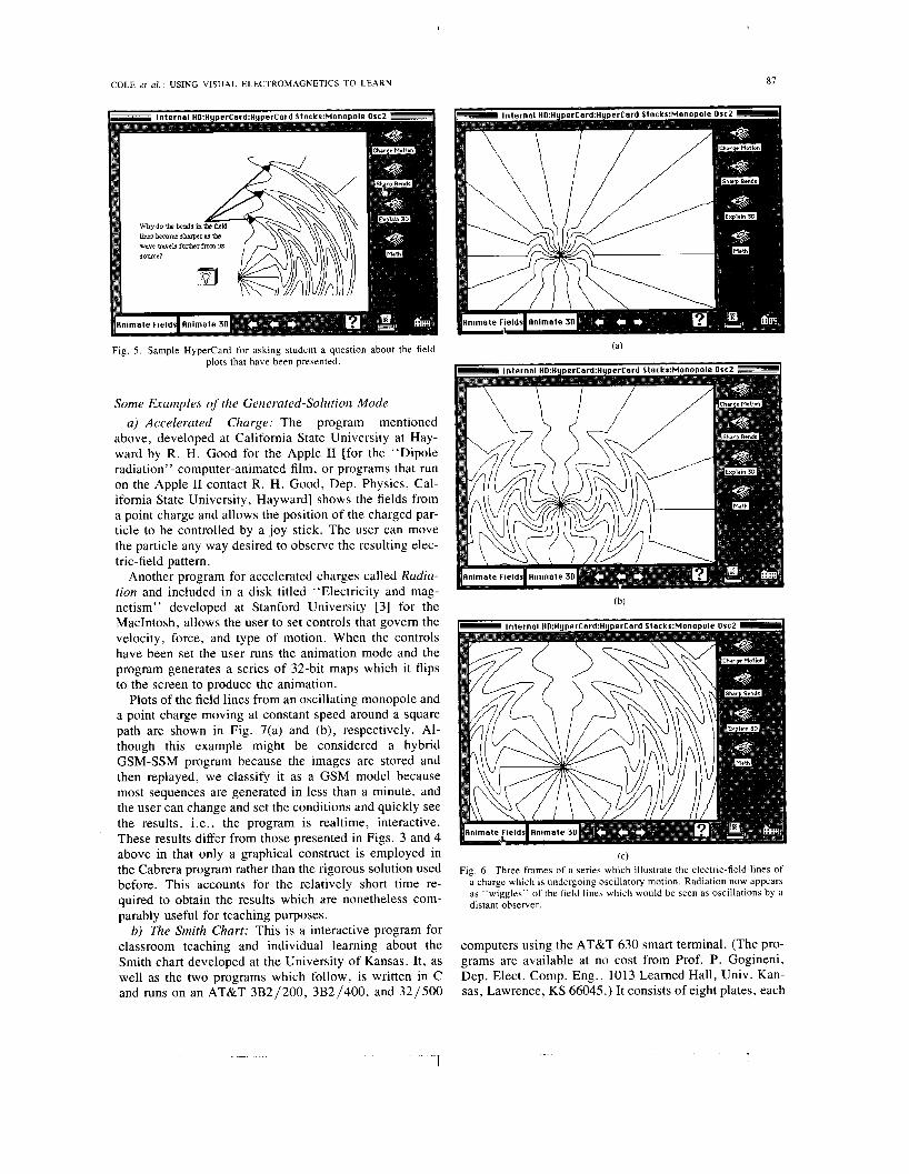
Multiple stacks on a subject can form a sequential se- ries of modules designed for a particular area of study in electromagnetics. For example, after the student acquires a basic understanding about the relationship between ac- celeration and radiation from the case just considered, the next step might be to examine dipole radiation. This is done in a computer animated film by [9] which uses a harmonically oscillating monopole as a bridge between a linearly accelerated monopole and a harmonically oscil- lating dipole. The oscillating monopole field is simpler to understand because the field lines to not “tear” off from the monopole as they do for a dipole. Thus, a monopole produces a field line pattern similar to the dipole but eas- ier to understand, and helps to ease the student into dipole radiation. A sequence from a stack on monopole oscilla- tions is shown in Fig. 6(a)-(c).
Hypertext programs allow a large degree of flexibility in presenting stored solutions and in providing a medium for exchanging stored-solution modes among educators and researchers alike.
(C) Fig. 4. The same three fields as Fig. 3 but presented as surface or “wire-
frame” plots.
buttons are therefore made part of the visible background so they are always present, making it less likely a student will become lost while browsing through a stack. The printer icon allows a student to print any card in the stack, thus obtaining a personal hard copy of any card the stu-
B. The Generated-Solution Mode
Most problems of interest to electromagnetics’ re- searchers require substantial enough solution times that even present-day supercomputers cannot be said to pro- vide an interactive, or realtime, environment. For teach- ing purposes, however, an increasing variety of problems are computable and their solutions presentable in a short enough time on even a PC so as to fall into the category of a generated-solution mode. As computer technology continues to improve, we can expect that the number of such problems can only increase. Some representative possibilities presently available in the GSM are discussed below, selecting examples that demonstrate both dynam- ics or animation, as well as more static situations, with each having the common ingredient of interactivity .
I
COLE et al. : USING VISUAL ELECTROMAGNETICS TO LEARN 87
Fig. 5. Sample Hypercard for asking student a question about the field plots that have been presented.
Some Examples of the Generated-Solution Mode a) Accelerated Charge: The program mentioned
above, developed at California State University at Hay- ward by R. H. Good for the Apple I1 [for the “Dipole radiation” computer-animated film, or programs that run on the Apple I1 contact R. H. Good, Dep. Physics, Cal- ifornia State University, Hayward] shows the fields from a point charge and allows the position of the charged par- ticle to be controlled by a joy stick. The user can move the particle any way desired to observe the resulting elec- tric-field pattern.
Another program for accelerated charges called Radia- tion and included in a disk titled “Electricity and mag- netism” developed at Stanford University [3] for the MacIntosh, allows the user to set controls that govern the velocity, force, and type of motion. When the controls have been set the user runs the animation mode and the program generates a series of 32-bit maps which it flips to the screen to produce the animation.
Plots of the field lines from an oscillating monopole and a point charge moving at constant speed around a square path are shown in Fig. 7(a) and (b), respectively. Al- though this example might be considered a hybrid GSM-SSM program because the images are stored and then replayed, we classify it as a GSM model because most sequences are generated in less than a minute, and the user can change and set the conditions and quickly see the results, i.e., the program is realtime, interactive. These results differ from those presented in Figs. 3 and 4 above in that only a graphical construct is employed in the Cabrera program rather than the rigorous solution used before. This accounts for the relatively short time re- quired to obtain the results which are nonetheless com- parably useful for teaching purposes.
b) 7’he Smith Chart: This is a interactive program for classroom teaching and individual learning about the Smith chart developed at the University of Kansas. It, as well as the two programs which follow, is written in C and runs on an AT&T 3B2/200, 3B2/400, and 32/500
(C) Fig. 6 . Three frames of a series which illustrate the electric-field lines of
a charge which is undergoing oscillatory motion. Radiation now appears as “wiggles” of the field lines which would be seen as oscillations by a distant observer.
computers using the AT&T 630 smart terminal. (The pro- grams are available at no cost from Prof. P. Gogineni, Dep. Elect. Comp. Eng., 1013 Learned Hall, Univ. Kan- sas, Lawrence, KS 66045.) It consists of eight plates, each

88 IEEE TRANSACTIONS ON EDUCATION, VOL. 33, NO. I . FEBRUARY 1990
& File Motion Control I
parameters ?ESZEZ C b d t y
"-1 no 1q 0.d nairun
6 File Motion Control
ZEZE Parameters ZZZZZ kbnty
0 1-1 DO
FJ 'lq Bast T.nq.nh.1
Spved Hbnty
4
0.05 0.36
olau
Square Motion
Fig. 7 . Example of a Generated-Solution Mode application. Sample frames of the electric-field lines about a charge oscillating along a straight line (a) and a charge moving at constant speed around a square path (b) ob- tained from the Radiation module of Electricity and Magnetism [3]. The peak speed relative to that of light is controlled by the right vertical bar and the playback speed by the left bar. Other parameters are set in the motion menu (impulse force, constant force, oscillation, circular path, square path) and the plotting area is set under the display menu.
of which brings out a specific attribute of the chart and is designed like a vugraph for class room use by an instruc- tor. The first plate contains only text that explains the con- struction of the chart and its applications. The second plate shows how constant-resistance lines in the Z plane are transformed into constant-resistance circles as shown in Fig. S(a). Several constant-resistant lines and circles are drawn one at a time showing the one-to-one correspon- dence between each circle and line. Fig. 8(a) also shows the third plate which illustrates the relationship between constant-reactance lines and circles. The fourth plate is shown in Fig. S(b) and explains construction of the chart by combining the constant-resistance and reactance cir- cles and then shows it graphically.
The fifth plate demonstrates interactively how to plot impedance on the chart. The plate is divided into three windows, two of which are used for text and the other for graphical illustration of the procedure. One of the text
windows provides instruction and the other accepts user input and displays the results of computations. The user provides as input a load impedance and characteristic impedance of a transmission line. The procedure to locate the appropriate point on the chart is listed and imple- mented step by step. For example, in the first step, the load impedance is normalized by dividing it by the char- acteristic impedance of the line, illustrating the result in the output window. The next message instructs the user to locate the impedance at the intersection of the constant- resistance and reactance lines which are then highlighted with accompanying arrow.
The sixth plate shows interactively how to determine the VSWR for a given load impedance by constructing a VSWR circle and reading the value from the chart at the point where this circle intersects the real axis. The last two plates demonstrate the use of the chart for impedance matching utilizing single- and double-stub tuners. These plates are also divided into three windows as shown in Fig. 8(c).
The Smith-chart program was made available to about 40 students enrolled in the second course in electromag- netics at the University of Kansas during Fall 1988. They were also given a questionnaire to rate the value (very helpful, somewhat helpful, or not helpful) of the program and indicate any problems in using it. Of the 40 responses received, all students rated the program as very helpful and or somewhat helpful. Some requested improvements on the double-stub tuner are being implemented.
c) Rejlection and Refraction of Plane Waves: This program, also developed at the University of Kansas, in- troduces students to the phenomena of reflection and re- fraction at a dielectric interface. It too consists of several plates, each one dealing with a different aspect of the topic with the student given the option of going through the whole package or skipping to a particular plate. The first plate, using text and graphics, provides a brief review of boundary conditions for electric and magnetic fields at an interface. The next deals with reflection and transmission of normally incident plane waves and is divided into three windows. One window contains explanatory text together with the associated mathematics. The second window contains a graphical presentation showing an incident wave together with reflected and transmitted waves shown in different textures. The third presents the results of any computations, questions for the student and responses.
The next three plates deal with oblique incidence. As shown in Fig. 9, the first of these three plates is divided into four windows. The plane of incidence is indicated, and polarization is illustrated by flashing electric vector on and off. The next plate illustrates the disappearance of the reflected wave as the incidence angle approaches the Brewster angle, and allows the student to provide differ- ent values of dielectric constant. When the Brewster angle is reached, the Brewster angle is calculated and displayed in the window dedicated to input and results. The last plate deals with total internal reflection and its application in

COLE et al. : USING VISUAL ELECTROMAGNETICS TO LEARN
( C )
Fig. 8. Three sample plates from a total of six used in an interactive pro- gram for learning about Smith charts, developed at the University of Kansas. The third plate, shown in (a), illustrates the relationship be- tween constant-impedance lines and circles, the fourth plate (b) dem- onstrates construction of the chart, and the \ixth plate (c) is an applica- tion for a stub tuner.
constructing optical waveguides. This plate illustrates the onset of a rapidly decaying transmitted wave whenever a wave is incident from a dense media on a less dense media at or in excess of the critical angle.
d) Waveguides: This Kansas University program dem- onstrates how waves propagate in waveguides by reflec- tion at the metal walls. It contains two plates. one of which demonstrates propagation between infinite parallel metal-
U-M-I Du to a lack of contrast between text and background, this p a g e did not reCjioduce we//.

YO
Fig. 9 . Sample plate from an interactive program f o r demonstrating phe- nomena associated with planewave reflectlon from a planar. dielectric interface developed by two of the authors at the Univerhity of Kan\a\.
Fig. 10. Sample plate from the University of Kansas (KU) interactive pro- gram for demonstrating waveguide propayation.
view of wave propagation in a rectangular waveguide shown in Fig. 10.
IV. SUMMARY OF SOME AV ULABLE GRAPHICS-BASED SOFTWARE
In 1988, letters were sent from the University of Kansas to about 60 U.S. schools requesting information about any software packages being used for teaching electromag-
netics, but the response has not been overwhelming. Only five written replies and two telephone calls were received, from which one might conclude that there is either little interest or little activity in instructional software. The software descriptions and sources given below are based partly on this survey and other activities about which we have learned. While this cannot be regarded as an ex- haustive list, we hope that it will give some idea to the kinds of software that are available. In keeping with the theme of this paper, we have attempted to include only software which is graphical and interactive, although the degree to which both of these characteristics are present may be quite variable.
A. Some Representative Progrurnr and ActivitieJ I ) Transmission Line Simulator (TLS): This program,
developed by Roth [20], runs on a MacIntosh computer with a memory of at least 128 kBytes. It is useful both for demonstration to a small group of students and interactive learning by students and simulates both the transient and steady-state response of transmission lines. Input excita- tion sources include dc, sine wave, and pulse waveforms. Users can set line parameters such as characteristic impedance, attenuation and line length, and generator and load impedances. Changes can be made during the sim- ulation to exhibit the effects of various types of discontin- uities.
This package has been used at the University of Kansas by students enrolled in a senior course in electroniagnetics that includes a detailed study of transmission lines, and elicited extremely favorable comments. Students felt it helped them to better understand the concept of standing and travelling waves. The program is available from Kin- ko’s Academic Courseware Exchange (see under sources below) at a cost of $2.5.00 which includes documentation.
2) PUFF: PUFF, a Pascal-based program for perform- ing microstrip analysis and design in a teaching or re- search setting [27], requires an IBM-compatible personal computer with a memory of 5 I2 k or more. The computer must have a math coprocessor and a graphics card and display. PUFF is an interactive package with a wide range of features. It is useful for laying out and analyzing strip- line and microstrip circuits and can handle lumped ele- ments. transmission lines and coupled lines in both in the frequency and time domains. This program also produces photographic artwork using a dot-matrix printer.
Students at the University of Kansas enrolled in a jun- ior-level graduate course in microwave engineering have been using this program both to solve homework prob- lems and design microstrip components such as filters and couplers. Also. a few students are using PUFF to design microwave components required to complete their mas- ter’s project. Overall. PUFF is a very good program for which student comments are generally favorable. The program does have some minor features that could be im- proved. For example. the program must be quit in order to change S parameters in a file and due to a lack of on- screen help, is less user-friendly than might be desired.
U - M - I Due to a lack of contran between text and backgroud, this page drd not r e p h u c e we/ / .

COLE et al.: USING VISUAL ELECTROMAGNETICS TO LEARN 91
Despite some of its limitations, we consider it a fine tool for teaching the use of computers in microwave circuit analysis and design. PUFF with its user’s guide can be obtained free of charge by writing to Prof. David Rut- ledge, Dep. Elect. Eng., California Institute of Technol- ogy, Pasadena, CA 91 125.
3) MZNZNEC: MININEC (mini numerical electromag- netics code), was developed at the Naval Ocean Systems Center in San Diego over past several years [21] initially to explore the feasibility of performing engineering-use- ful modeling on the Apple I1 personal computer. It is presently in version 3.0, now for IBM PC’s and compat- ibles, and has gained widespread acceptance because of its ease of use and the substantial growth in PC capabili- ties since it was first released. The program solves bound- ary-value problems for wires using the method of mo- ments to provide a self-consistent solution for the currents on wire scatterers and antennas using a discretized ap- proximation [lo].
company/institution letterhead, including a check for $25, to the above address. Foreign requesters other than Can- ada and Mexico should include an extra $23 for express airmail delivery.
5) DAFRAC: Another VEM-oriented program is DAF- RAC for computing and plotting 1-D and 2-D wave-dif- fraction phenomena, developed by Prof. G. Forbes, P. Hoch, and S. Cohen of the Institute of Optics at the Uni- versity of Rochester, Rochester, NY 14627. DAFRAC, selling for $20 from Kinko’s Courseware exchange, pro- vides the Fresnel and far-field diffraction patterns of stored apertures or diffracting obstacles, or those designed by using a mouse. The fields are computed using the fast Fourier transform at a distance from the diffraction plane which is selected by the user, and presented in 2-D plots whose intensity scale is also user selectable. (A 1-D ex- ample of using DAFRAC is shown below for the far-field pattern produced by two slits.)
The general diffraction integral being evaluated is given Although not briginally targeted for instructional pur-
practical digital antenna laboratories, giving students the poses, MININEC might be considered one of the first
possibility of “experimenting” with a fairly wide variety of wire antennas. Since solution times can be many min-
by
y 9 D l = - exp [ : D -
x exp [ i
i- y 2 ] ] s s T ( x ’ 7 y ’ ) AD
[x’2 + y’211 Utes for the more complex problems, MININEC is truly AD interactive for only the simpler problems like straight-wire dipoles, circular loops, etc. There is also a graphical in- terface called IGUANA (Interactive Graphics Utility for Army NEC Automation), designed to simplify and auto- mate input-data preparation needed for problem descrip- tion and presenting the results of a computation. Infor- mation about IGUANA can be obtained from Dr. R. W. Adler, Secretary, Applied Computational Electromagnet- ics Society, Naval Postgraduate School, Code 62AB, Monterey, CA 93943.
4) VMAP: Prof. Darko Kajfez of the University of Mississippi has developed VMAP, an interactive graphics program for generating and displaying field lines from an array of vector samples of a 2-D field. The user can select the starting points, number of field lines to be plotted, step size used in developing the streamline, and a limit value beyond which the lines will not be computed. The program will run on an IBM PC or compatible having at least 256 Kbytes memory running under DOS 2.0 or later operating system. An 8087 coprocessor is not required but does greatly speed execution. Access to an HP 7670A or 7475A plotter is desirable, but the plots can also be pre- sented as a screen dump.
The program is described in: “Plotting of two-dimen- sional vector fields with computer,” Technical Report, University of Mississippi, NTIS accession No. PB86-196318, April 1986; and in “Plotting of vector fields with a personal computer” in IEEE TRANSACTIONS ON MICROWAVE THEORY AND TECHNIQUES. November 1987 by D. Kajfez and J. A. Gerald. A program diskette containing the compiled version of VMAP is available from the Dep. Elect. Eng., Univ. Mississippi, Univer- sity, MS 38677. Send your request for VMAP using your
where T ( x ’ , y ’ ) is the transmission function of the aper- ture and D is the distance from the obstacle plane to the viewing screen. The far field can be expressed as
Depending on the problem, whether 1-D or 2-D, and near field or far field, DAFRAC can develop a plot from a few seconds to several minutes. It runs much faster on the Mac I1 than the original Mac or Mac + .
To quote from the introduction to DAFRAC, “In Fres- nel diffraction theory, the analytical evaluation of the in- tegrals which emerge is usually intractable. In those few special cases where one can make some headway (e.g., a rectangular aperture-where the ‘Cornu spiral’ is intro- duced), the results do not come easily and the ‘physics’ is often obscured by the mathematics.” I think that you will find DAFRAC to be a fascinating “experimental” tool, one that can provide insight into electromagnetic dif- fraction phenomena. Although the present version of DAFRAC permits T ( x ’ , y ’ ) to have only the values of 0 and 1, if simple amplitude and phase variations could be introduced, it would be an even more useful tool for an- tenna application.
B. Some Other University Activities 1 ) University of Michigan: A series of graphics-based
programs have been developed at the University of Mich-
1 I

92 IEEE TRANSACTIONS ON EDUCATION, VOL. 33. NO. I . FEBRUARY 1990
igan for use in undergraduate Electromagnetic courses, as follows :
CLOSE: To generate field maps of closed geometries using a finite-difference method.
STAMP: Generates field maps for either open or closed geometries using the method of moments.
TLINE: A transmission-line analysis program with realtime graphical display.
E FIELD: Graphical display of the E lines associated with a TE or TM mode in a rectangular waveguide.
H FIELD: Similar to the E field except that H lines are plotted.
These programs run on IBM XT/AT or compatibles. For further information, contact Prof. John L. Volakis at the Dep. Elect. Eng. Comput. Sci., Univ. Michigan, Ann Arbor, MI 48105.
2) University of Illinois: In two required course se- quences in electromagnetics at the University of Illinois, about 14 programs described by Rao [ 191 are available to provide numerical and graphical solutions of several EM problems, such as solution of Laplace’s equation and plotting of equipotentials, illustration of travelling wave concept, construction and application of smith chart, etc. These programs run on IBM PC’s or compatibles. For further information, contact Prof. N. Narayan Rao at the Dep. Elect. Comput. Eng., 1406 West Green Street, Ur- bana, IL 61801.
3) Brigham Young University: Several computer-aided microwave laboratory experiments have been developed at Brigham Young University. These experiments include graphical display of microwave radiation and propaga- tion, microwave antenna characteristics, etc. These pro- grams run on HP desktop computers and on IBM PC’s. This work is published by Prof. Earl F. Owen at the De- partment of Technology, BYU.
4) Drexel University/Harvey Mudd College: Hoole and Hoole [25] describe a set of finite element programs called KANTHAM developed for teaching EM courses at Drexel University. These programs are highly interactive and graphics based, and used to solve electrostatic and mag- netostatic problems, eddy currents and radiation fields. KANTHAM runs on the Apple MacIntosh. For further information, contact Prof. S. R. H. Hoole, presently on the faculty of Harvey, Clairmont, CA.
5) Carnegie-Mellon University: A number of graph- ics-based programs have been developed for interactively solving and displaying electrostatic and magnetostatics problems at Carnegie Mellon University [7], [ 111, [ 141. These programs are used as part of their regular class as- signments by the students in fields courses. Computers employed include the DEC VAX and HP Bobcat work- station.
6) Iowa State University: Prof. A. A. Read, has de- veloped an interactive graphics package that offers a num- ber of plotting options for displaying field data [ 181. In- cluded are wire-frame or surface plots, and vector and streamline plots. The software is written in Fortran and runs on a VAX under VMS as well as IBM PC’s and com-
patibles. For further information, contact Prof. Read, De- partment of Electrical and Computer Engineering, Ames, IA 5001 1 .
7) University of Tennessee, Chattanooga: A graphics program has been developed to illustrate standing waves, traveling pulses and group velocity for acoustic and elec- tromagnetic waves. The programs run on an Apple MacIntosh. For information contact Prof. E. T. Lane, Physics Department, The University of Tennessee, Chat- tanooga, TN 37403-2598.
B. Other Information Sources for Graphics-Based EM Software:
1) Wheels for the Mind: A publication providing in- formation concerning hardware and software for the MacIntosh computer, is “Wheels for the Mind,” which is prepared at Boston College for the Apple University Consortium. “Wheels,” published quarterly, is devoted to the stated goal of (fostering) creative thinking through creative computing with a yearly subscription price of $12. More information concerning “Wheels” can be ob- tained from either: Apple Computer, Inc., 20525 Mariani Avenue, Cupertino, CA 95014, (408) 996-1010; or the editor Peter Olivieri, Boston College, Computer Sci- ences, F-430, Chestnut Hill, MA 02167, (617) 552-3907.
While “Wheels” includes a variety of information for Mac users, the section on software-development projects is most relevant to this discussion. The projects are di- vided into various academic disciplines, e.g., astronomy, biology, chemistry, - - - , engineering, - * - designated by appropriate icons. Each project description gives the project name, a short description, its current status and a contact person. The variety of projects is quite impres- sive, and instructions on how to obtain the software de- scribed, if completed, are also given. In some case, the programs may be available directly from the author(s) or through a source such as Kinko’s as described below.
2) Kinko’s Academic Courseware Exchange: Programs for the Apple I1 and MacIntosh computers are available through the ACE operated by Kinko’s Copies. Prices are reasonable, ranging from $8 to $40 per package which includes usually good documentation. Kinko’s can be reached by mail at 255 West Stanley Avenue, Ventura, CA 93001, or by telephone at (800) 235-6919 [except California at (800) 292-6640], and credit cards are ac- cepted. Catalogs can be requested through these same numbers or at a local Kinko’s store. Among the Kinko’s programs that are electromagnetics oriented are Electric- ity and Magnetism from which the examples in Fig. 7 above were taken, and DAFRAC, which was developed at the University of Rochester.
3) Kern International, Inc. : Kern offers software for a variety of computers including IBM, Apple, and Mac- Intosh. Prices range from about $20 to $200. All the Kern software includes source code in Basic, C, or Pascal. Kern’s address is 575 Washington Street, Pembroke, MA 02359, and the telephone number is (617) 826-0095. Credit cards are accepted.

COLE et 01. : USING VISUAL ELECTROMAGNETICS TO LEARN 93
4) Dynacomp: Dynacomp lists over 200 pages of soft- ware for computers ranging from the Altos and Apple I1 to the HP Vectra as well as IBM PC’s and compatibles and MacIntosh. While only a relatively small proportion of the programs are engineering oriented, and fewer still EM related, quite a few Fourier-analysis programs with graphics interfaces are offered. Also of interest may be ray-tracing programs for analysis of optical systems and other mathematical applications such as matrix manipu- lation. Dynacomp, Inc. is located at 178 Phillips Road, Webster, NY 14580, telephone (800) 828-6772 (outside NY only). Credit cards are accepted.
5) Physics Courseware Laboratory: The Physics Courseware Laboratory (PCL), Department of Physics, North Carolina State University, Raleigh, NC 27695- 8202, telephone (919) 737-7059, is a laboratory facility designed to investigate courseware for physics instruc- tion. Its activities include full classroom integration of computer-assisted instruction, teaching students physics through the use of computer simulations and tutorials, in- vestigating learning using the microcomputer as a tool, and producing directories of commercial and public do- main courseware. The project began in 1982 and includes courseware for both high school and college levels. Some of the questions being investigated by PCL are as follows:
What kind of courseware is available? How can courseware be used effectively for instruc-
tion? What is the effective and meaningful way to utilize
new technology in education? How do students develop problem-solving skills? In what ways can courseware be used to help students
learn physics? Among the materials available from PCL, two in partic- ular might be of interest. These are as follows:
Commercial Physics Courseware-A list of over 900 commercial educational software packages in physics and related mathematical topics sorted by computer type (Ap- ple 11, Atari, Commodore 64, Commodore PET, Control Data 110, IBM PC, MacIntosh, and TRS-80), a total of 40 pages, priced at $2.50. Includes major and minor sub- jects, instructional level, type of usage, cost, and ad- dresses.
Public Domain Physics Courseware-A list of over 1100 individual programs on 150+ diskettes in physics and related topics sorted by computer type (Apple 11, Atari, Commodore 64, IBM PC, and TRS-80), 16 pages, priced at $2.00.
6) Computers in Physics: The New Products sections of Computers in Physics, published by the American In- stitute of Physics, includes a survey “where to buy elec- tricity and magnetism software” in the NovembedDe- cember 1988 issue. The survey contains 42 programs from 1 1 different vendors, in two basic categories: “programs that discuss no more than several topics, and those that contain a library of physics programs covering a wide range of units.” The programs listed are tutorials and
simulations, and are available for a variety of computers such as the Apple series, IBM PC and compatibles, Atari, Commodore Pet. and even the PLATO Delivery system 2, although most packages are individually targeted to specific PC’s. Most prices are less than $100.00.
CONCLUSION We have argued in this paper that electromagnetics ed-
ucation is reaching a crisis status because of a combina- tion of sociological and technological changes due to the development of television and the computer. We suggest that a potential solution is available from those same sources in the form of a visual, interactive learning me- dium we have called Visual ElectroMagnetics, which will make the study of electromagnetics less abstract and more intuitive, and thereby more appealing. Two extremes of a literal continuum of approaches were defined as the “gen- erated-solution” and “stored-solution” modes, based on whether the electromagnetic solutions and graphical dis- plays are developed on-line or off-line, with both being visually oriented and differing primarily in the degree of interactivity currently realizable. Examples of the possi- bilities presently available from both approaches were given, and a selection of sources of information and soft- ware was also presented.
Future directions in VEM will be determined partly by ongoing developments in computer and video technology, and partly by how receptive the electromagnetics com- munity will be to the opportunities that these develop- ments make available. Reference is being made to “the graphics revolution” and ‘‘the visual computer” [24], leading to computer-interactive video whose effects will be felt in all aspects of business and personal life. While these are developments which will occur without any ac- tion on our part, we would be well advised to exploit them for our own education and research needs, as the future wellbeing of the electromagnetics’ discipline may well depend on this.
ACKNOWLEDGMENT
Computers for their generous support. The authors would like to thank AT&T and Apple
REFERENCES [ l ] R. Abraham, Ed., The Visual Mathematics Library. Santa CNZ,
CA: Aerial Press, 1984. [2] S. Brandt and H. D. Dahmen. The Picture Book of Quantum Me-
chanics. New York: Wiley, 1985. [3] B. Cabrara, “Electromagnetism-Physics simulations 11,” Kinko’s
Academic Courseware Exchange, Santa Barbara, CA, 1987. [4] J . M. Centrella, “Using the computer as a camera,” Comput. Phys. ,
vol. 2 , no. I . , pp. 35-39, 1988. [5] R. W. Cole, M. A. Soderstrand, and E. K. Miller, “Animated com-
puter-generated instruction: How to make a movie,” ASEE Eng. Educ., pp. 276-281, 1986.
[6] R. W. Cole and E. K. Miller, “Computer animation of time domain problems: The key to understanding,” Proc. : IEEE & ASEE Fron- tiers in Educ. Conf., L. P. Grayson and J . M. Biedenbach, Eds., 1988.
[7] J . L. Davis and J . F. Hoburg, “Enhanced capabilities for a student- oriented finite element electrostatic potential program,” IEEE Trans. Educ., vol. 28, pp. 25-28, 1985.
‘1 -1 -

L. C. Epstein, Relativity Visualized. San Francisco, CA: Insight Press, 1988. R. H Good. “Simulation programs,’’ Comput. Educ., vol. 2. no. 5 . p. 76, 1988. R. F. Harrington, Firld Cotnputation by Moment Methods. New York: MacMillan, 1988. J . F. Hoburg, “Visualizations of the integral forms of Maxwell’s equations through interactive computer graphics,” IEEE Trans. Educ., vol. 31, pp. 251-256, 1988. S . R. H. Hoole and P. R. P. Hoole, “Finite elements programs for teaching electromagnetics,” IEEE Trans. Educ., vol. E-29, no. I , pp. 21-26, 1986. A. Kay. “Point of view is worth 80 IQ points,“ Invited plenary ses- sion presentation at Frontiers in Education 88. Santa Barbara, CA. 1988. P. L. Levin, J . F. Hoburg, and Z . J . Cendes, “Charge simulation and computer graphics in a first course in applied electromagnetics.” IEEE Trans. Educ.. vol. 30, pp. 5-8, 1987. R. M. Maclntosh, Column in the IEEE AP-S Newsletter, 1984. E. K. Miller and R. W. Cole, “Associated western universities sum- mer graphics project: Vol. I-Circuits and systems; Vol. 11-Elec- tromagnetism; Vol. 111-Optics. Lawrence Livermore Nat. Lab. Rep.
E. K. Miller, R. W. Cole and R. Merrill, “Computer movies for education,” IEEE Trans. Educ., pp. 58-68, May 1988. A. A. Read, “A set of PC graphic related programs for electromag- netics students,” Proc. Frontiers in Educ. Con&, L. P. Grayson and J . M. Biedenbach, Eds. IEEE & ASEE, 1988. R. Rao, Elements of Engineering Electromagnetics. Englewood Cliffs. NJ: Prentice-Hall, 1986. C. H. Roth, “TLS: Transmission line simulator,” Kinko’s Academic Courseware Exchange, Santa Barbara, CA, 1987. J . Rockway, J . Logan, D. Tam. and S. Li, The MININEC Systetn: Microcomputer Analysis of Wire Antennas. Nonvood, MA: Artech House, 1988. D. Rutledge, R. Compton. W. Williams. Z. Popovic, and K. Potter, “A class for computer-aided design and measurement of microstrip circuits,” presented at IEEE Antennas Propag. Soc. Symp.. Virginia Tech U , , Blacksburg, VA, 1987. M. Van Dyke, An Album ofFluid Motion. Stanford. CA: Parabolic Press. J . M. Verity and C. Brown “The graphics revolution,” Business Week M a p . . DD. 142-153. Nov. 28. 1988.
NO. M-190.
I
IEEE TRANSACTlONS ON EDUCATION, VOL. 33. NO. I . FEBRUARY I990
[25] S . R. H: Hoole and P. R. P. Hoole, “Finite element programs for teaching electromagnetics,” IEEE Trans. Educ., vol. E-29, no. I , pp. 21-26, Feb. 1986.
Rodney W. Cole received the B . S . degree from the University of Illinois, Urbana, in 1973 and the Ph.D. degree from the University of Wyoming, Laramie, in 1978.
He is currently an Adjunct Lecturer at the De- partment of Physics. the University of California, Davis, and a Senior Learning Skills Counselor for the Learning Skills Center. His research is in teaching physics methodology and computer ani- mation of time domain solutions in electromagne- tism. He has been involved with the Summer
Edmund K. Miller (S’60-M’66-SM’70-SM’81- F’84) received the Ph.D. degree in electrical en- gineering from the University of Michigan, Ann Arbor.
He is currently leader of Group MEE-3, Los Alamos National Laboratory, Los Alamos, NM. He was previously Director, Electromagnetics Research Operation, General Research Corpora- tion, Santa Barbara, CA, Manager of Electromag- netics at the Rockwell Science Center, and Re- gents-Distinguished Professor of Electrical and
Computer Engineering at the University of Kansas, Lawrence. His involve- ment in computational electromagnetics began at the University of Michi- gan during and after his doctoral dissertation and continued with three years at MB Associates and 15 years at Lawrence Livermore National Labora- tory. He has published and lectured widely in the area and has served as an IEEE National Distinguished Lecturer on the topic of numerical tech- niques. He writes a column “PC’s for AP” for the Antenna and Propa- gation Society Newsletter of IEEE. Besides computational electromagnet- ics, other interests include signal processing and computer-graphics applications in education and research.
Dr. Miller is past President of the Applied Computational Electromag- netics Society and present Chairman of U.S. URSI (International Scientific Radio Union) Commission A on Metrology.
image processing, c( techniques.
also participated in f ie
Swapan Chakrabarti (M’87) received the B.S. and M.S. degrees in physics from Calcutta Uni- versity, India, in 1976 and 1978, respectively, and the M.S. degree in computational physics and the Ph.D. degree in electrical engineering from the University of Nebraska, Omaha, in 1982 and 1986, respectively.
He is an Assistant Professor of the Department of Electrical and Computer Engineering at the University of Kansas, Lawrence. His fields of re- search are computer graphics, digital signal and
xnputational electromagnetics, and supercomputing
Sivaprasad Gogineni is currently an Assistant Professor in the Department of Electrical and Computer Engineering, University of Kansas, Lawrence. He has been involved in research on the application of radars to the remote sensing of sea ice, ocean, and land. He has been an author and coauthor of eight papers and several technical reports and conference presentations. He was ac- tively involved in developing instrumentation for radar systems currently being used at the Univer- sity of Kansas for backscatter measurements. He
:Id experiments in the Arctic and on towers in the . . Computer Graphics Project at Lawrence Livermore National Laboratory since its inception in 1984 and has produced several videotapes on electro- statics and electrodynamics. ing measurements.
open ocean. Currently, he is working on computer graphics packages for teaching electromagnetics and on developing mm-wave radars for scatter-


![4.1.1] plane waves](https://static.fdokumen.com/doc/165x107/6322513728c445989105b845/411-plane-waves.jpg)