
74. ONIE c'emmezum s MiLLIING - World Radio History
100
-
Upload
khangminh22 -
Category
Documents
-
view
1 -
download
0
Transcript of 74. ONIE c'emmezum s MiLLIING - World Radio History

HANDBOOK Nio. 4
74. ONIE c'emmezum s MiLLIING
CONSIECtIOF
Crystal, Battery, A.C. and Short Wave Circuits Valve Characteristics Wire Tables Call Signs

THE LISTENER IN SET CONSTRUCTOR
Price's Radio Service!! . . . . the oldest and most reliable Radio firm in the Commonwealth!!
Our "On Approval" mail order business is, to the country purchaser, a most satis-factory method of doing business—there be-ing no risk of unsuitable material being sup-plied—money is refunded or other goods suhstiul d wi h or argument—the same facilities as aflortied our counter customer.
Alum-:um cutting and bending service at id so. in.; All American Super Audio T. ans;ormers, usually 27/6, at 15/; Ceco 280 Full Wave Rectifier, 10/6; 224 Screened Grid, 15/; and 245 Amplifiers at 11/6. are among some of our fine-cut lines.
"IM MIM MEr
\BM,'
You will forget all other Firms once you become a "Price" client—their Service with Satisfaction will win your confidence.
PRICE'S RADIO SERVICE ANGEL PLACE, SYDNEY
(One thousand feet of floor space — Forty feet of Window Display).
Box 3326 pp. — Phone B4146 — Telegrams Price, Sydney
BANKERS: COMMONWEALTH
THE LISTENER IN SET CONSTRUCTOR 1
Ash abou New ¡'roces. Canoro at reall'er 3 Bi: Cash Stores, Harring ton's, or The Leviathan
Whole,ale Distributors
W. G. WATSON & CO. LIMITED 200 Queen Street,
Melbourne
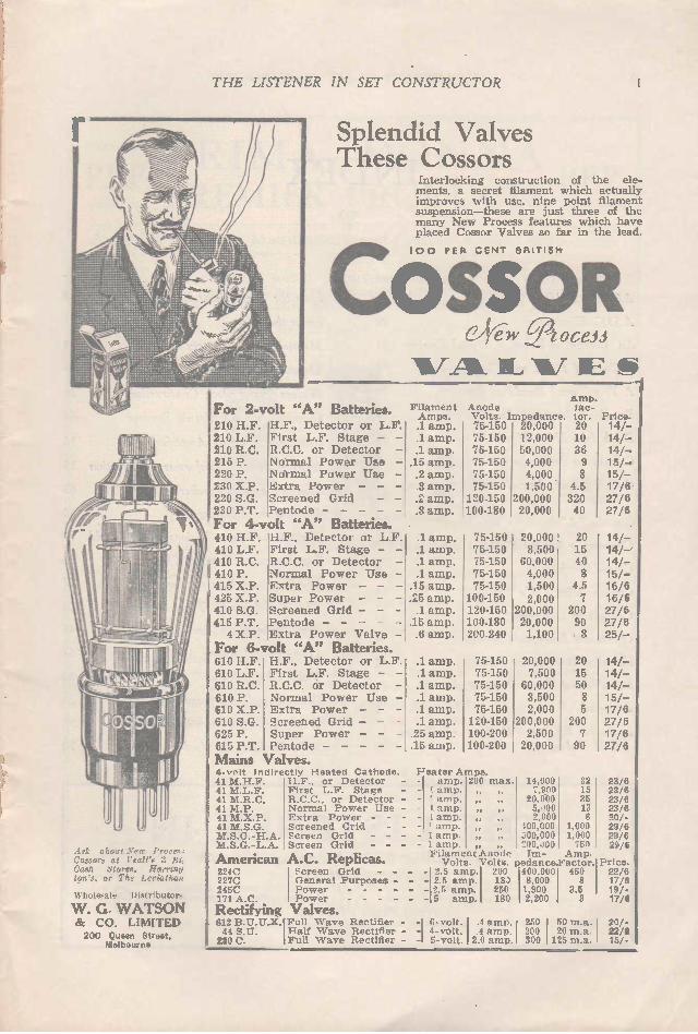
Splendid Valves These Cossors
Interlocking construction of the ele-ments, a secret filament which actually improves with use, nine point filament suspension-these are just three of the many New Process features which have placed Cossor Valves so far in the lead.
10 0 PER CENT BRITISPir
OSSOR C JÇ ÍW ‘Doceii
V AL 'IL -17- 1E S
For 2-volt "A" Batteries. 210 H.F. 210 L.F. 210 R.C. 215 P. 220 P. 230 X.P. 220 S.G. 230 P.T.
For 4-volt "A" Batteries. 410 H.F. H.F., Detector or L.F. 410 L.F. First L.F. Stage - 410 R.C. R.C.C. or Detector , 410 P. Normal Power Use 415 X.P. Extra Power - - 425 X.P. Super Power - 410 S.G. Screened Grid - 415 P.T. Pentode 4 X.P. Extra Power Valve
For 6-volt "A" Batteries. 610 H.F. 610 L.F. 610 R.C. 610 P. 610 X.P. 610 S.G. 625 P. 615 P.T. Mains Valves. 4-vrit indirectly Heated Cathode. 41 M. H.F. 41 M.L.F. 41 M.R.C. 41 M.P. 41 M.X.P. 41 M.S.G. M.S.G.- H.A. M.S.G.-L.A.
American 224C 227C 245C 171 A.C.
Rectifying Valves. 612 R.U.U.X.I Full Wave Rectifier 44 S.U. Half Wave Rectifier 280 C. Full W ave Rectifier
Normal Power Extra Power Screened Grid Pentode
ELF., Detector or L.F. First L.F. Stage - R.C.C. or Detector Normal Power Use
Use
H.F., Detector or L.F. First L.F. Stage - - R.C.C. or Detector Normal Power Use Extra Power - - Screened Grid - - Super Power - - Pentode
H.F., or Detector - First L.F. Stage - R.C.C., or Detector Normal Power Use Extra Power - - Screened Grid - Screen Grid - - Screen Grid - - A.C. Replicas. Screen Grid - - - General Purposes - - Power Power
Filament Amps .1 amp. .1 amp. .1 amp. .15 amp. .2 amp. .3 amp. .2 amp. .3 amp.
.1 amp.
.1 amp.
.1 amp.
.1 amp. .15 amp. .25 amp. .1 amp. .15 amp. .6 amp.
.1 amp.
.1 amp.
.1 amp.
.1 amp.
.1 amp.
.1 amp. .25 amp. .15 amp.
+ •••••
Arno. Anode tac-Volts. Impedance. tor. 75-150 20,000 20
Price. 14/-
75-150 12,000 10 14/-75-150 50,000 36 14/-75-150 4,000 9 15/-75-150 4,000 8 15/-75-150 1,500 4.5 17/6 120-150 200,000 320 27/6 100-180 20,000 40 27/6
75-150 20,000 20 14/-75-150 8,500 15 14/-75-150 60,000 40 14/-75-150 4,000 8 15/-75-150 1,500 4.5 16/6 100-150 2,000 7 16/6 120-150 200,000 200 27/6 100-180 20,000 90 27/6 200-240 1,100 3 25/-
75-150 20,000 20 14/-75-150 7,500 15 14/-75-150 60,000 50 14/-75-150 3,500 8 15/-75-150 2,000 5 17/6 120-150 200,000 200 27/6 100-200 2,500 7 17/6 100-200 20,000 90 27/6
}'eater Amps. - aamm pp.. 200 max. 14,000 32 23/6
7,900 15 23/6 ' amp. , „ 20,0.00 35 23/6
- it amp.. ," .: 5,.i00 13 23/6 - L 2,000 6 30/ - - ' amp. 100,000 1,000 29/6 - 1 amp. „ . 500,000 1,000 29/6 I amp. , " 200,.100 750 29/6 Filament Anode Im- Amp. Volts. Volts. pedance.Factor. Price. 2.5 amp. 200 400,000 450 22/6 2.5 amp. 18) 8,000 8 17/6 2.5 amp. 250 1,900 3.5 19/- 5 amp. 180 2,200 3 17/6
6-volt. 1 .4 amp. 1 250 50 m.a. 20/-4-volt. .4 amp. 200 20 m.a 22/6 5-volt. 2.0 amp. 300 125 m.a. 15/•
2 THE LISTENER IN SET CONSTRUCTOR
INDEX
A.C. Set Building
A D.C. Eliminator
Page
13
20
An Alternative Valve or Crystal Receiver 11
A Page of Hints and Tips
A Trap-Tuned Band-Pass Four
Broadcast Receiving Aerials
Break Into Short Waves
Calculating Resistance Values
Call Signs of Australasian Broadcasting Stations .. • • • • • • •
Can the "A" Battery Cause Noises
Choosing a Crystal Circuit
Circuit Symbols
Copper Wire Table
Crystals as Detectors
Don'ts and Emergency Measures
Electrical Interference Problems
Experimental Transmitting Stations
Foreword
Hints for Efficient Working of Screen Grid Valves
96
50
38
46
15
71
15
7
6
16
33
14
42
72
5
Page
How the Gramophone Pick-up Works 40
Learn the Code
Maintaining the Battery Set 44
Measuring Instruments 95
Modern Power Pack Construction 21
Operating the All-Electric Receiver 60
Resistance Coupled Amplifiers 36
93
Rules of Power Transformer Construction 16
Selecting a Loud Speaker 63
Short Wave Adaptors 34
Short-Wave Phone Stations of the World 59
The Improved Reinartz Three 64
The Improved Reinartz Two 17
The World—With Three Valves 26
Troubles in Short-Wave Sets 48
Underwriters' Rules 62
Valve Characteristics 80
Wave Length and Frequency 25
Where Does the Hum Come From? 58
41 Why Shielding Is Used 70
'PUBLISHED BY
E ILMTEN The Leading Radio Journal of Australia
SUBSCRIPTION RATES 3 months, 3/6; 6 months, 7/; 12 months, 14/. Including postage between Commonwealth and New Zealand. Overseas rates on application.
UNITED PRESS PTY. LTD. 62-74 Flinders Street, Melbourne; and Lisgar House, 30 Carrington St., Sydney.
Price
3D.

THE LISTENER IN SET CONSTRUCTOR 3
PRIMA DONNA PREMIER PRODUCTS
Australia's Leading Manufacturers of Quality Radio Components
PRIMA DONNA: — RADIO RECEIVERS, POWER UNITS, VOLTAGE DIVIDERS, RESISTORS, R.F. CHOKES, GUARANTEED MATCHED COILS, ALUMINIUM CHASSIS, COIL AND VALVE SHIELDS, CABINETS.
TRADE AND CHASSIS MANUFACTURERS SUPPLIED.
ffeee1/2,»
• .?:...Fg
Prima Donna Guaranteed Matched Coil Kits
Above is illustrated our latest high quality Coils which are guaranteed perfectly matched. Supplied in any combination required Standard Aerial Coils, Preselec-
tor and R.F. Coils. Price. Plain, 8'6; Shielded 10/6.
To Short Wave Enthusiasts
We have pleasure in announcing that Mr Don. B. Knock, the well known short wave radio engineer, is now associated with this company as Technical Adviser.
Advice on all Short Wave Subjects read il- invited.
"THE GREEN AND ORANGE PRODUCTS"
ASK FOR AND INSIST ON PRIMA DONNA PREMIER PRODUCTS.
Stocked by All High Class Stores
N. . Wholesalers: NOYES BROS. (SYD.) LTD., BLOCK & GERBER LTD.. FOX & MACG'LLYCUDDY LTD.
W. G. WATSON & CO. LTD.. WESTCOTT HAZ ELL LTD., HARRINGTONS LTD.
Newcastle and District Distribtitors: NOYES BROS. (SYD.) LTD., 11 Watt St., Newcastle.
Sth. Australian Distributors:
HARRIS SCARFE LTD.,
Greaten St., Adelaide.
Queensland Distributors:
J. B. CHANDLER & CO.,
Adelaide St., Brisbane.
Victorian Distributors:
HERBERT DEL COTT LTD.,
422 Little Collins St. Melbourne.
Prima Donna Radio &_ Cabinet Coy. Woollahra, Sydney, N.S. W.

4 THE LISTENER IN SET CONSTRUCTOR
QUALITY! 1-1 ERE'S a sturdy Wetless
fixed condenser, rigor-ously tested and contained in a strong metal case, completed with handy soldering lugs for connections.
There are seven different values: 0.1, 0.25, 0.5, 1, 2, 4, & 5 M.F. andyoucanuse each with confidence, as they are manufactured by the most modern methods and are fully guaranteed to give excellent service.
W ETLESS Midget Vari-able Condensers are
suitable for either neutralis-ing or balancing; they have correct minimum and maxi-mum capacity, perfect insu-lation, true alignment, and are one-hole fixing.
MADE IN AUSTRALIA BY
WETLESS ELECTRIC MFG. COMPANY 28 KING STREET, ROCKDALE, N.S. W.
Wholesale Distributors:
FOX & MACGILLYCUDDY LTD., 57 York St., Sydney. BLOCH & GERBER LTD., 48 York St., Sydney. TRACKS1N BROS. LTD., 157 Elizabeth St., Bi isbane. NATIONAL RADIO., C.C.M. Buildings, Brisbane.
Factory Representative: MESSRS ALAN S. DUKE PTY. LTD., 486 Bourke St., Melbourne.

THE LISTENER IN SET CONSTRUCTOR 5
FORE WORD
gOR the last twelve months many requests have been received by The Listener in for a comprehensive handbook which will embrace some of the outstanding circuits published, together with details of power-pack construction, and other such matters of value to set-builders generally.
The Listener In SET CONSTRUCTOR is the result. It should meet the requirements of most set-builders, in that it con-tains data concerning almost every type of receiver, from the modest crystal to a short-wave receiver employing screen-grid radio frequency amplification, thus catering alike for the novice as well as the advanced constructor. All the circuits have been carefully revised, and brought up-to-date, and may be followed without any fear of the ultimate result.
In addition, a wealth of valuable information has been gathered which is not to be found in any other book of this kind. Characteristics of the various types of valves common to Aus-tralia, wire tables, and general informatory hints are all included.
The latest List of Call-signs of the stations operating in Aus-tralia — both commercial and amateur — and the operating times of the many short-wave 'phone stations scattered through-out the world, will be of great and lasting value.
Should any set-builder experience difficulty in constructing any of the sets detailed in The Listener In Set Constructor, the columns of The Listener In are open to him to receive free help and advice.
TECHNICAL EDITOR, The Listener In.

6 THE LISTENER IN SET CO NSTR UCTOR
CIRCUIT SYMBOLS By becoming familiar with these signs used to represent the various components of a receiving circuit, no trouble will be experienced in
following any of the diagrams in this book.
17. Aerial
I Ground
Loop Aerial
l COunter-eminin Po 15e
12. Variable 7r- Edndensei-
_L_ Fixed -7 Etindenser
111.1 Condenser -r- blocI\
RF Inductance
or r2 F Choke
IPFTransforroer Van ometer
Tapped
Inductanee
A.f EtiOKE
1 Iron Core Transprrner
IL
Push-Pull Audio -
Frequency Transfor mer
Frequency Meter ' (Wave mel-er)
FI)<Ed Resistor
VariablE ReSisror
Potentiometer
Fila ment Balla51:
( -7: p "hree-
Element:
Valve
Three element Valve A.? Neared Eatnode Type
Screen &rid Valve
5creen ut-id A.C.Valve
Mall-Wave Reerifer Valve
Fliarngnr tYPle
Full -Wave R.ectifer Valve
Filament Type
Full -Wave
kectifer aseou5 Tvrze
Two- Element Voltage. Regulator
Valve.
0 e Three-Elemenr Voltage
Regulohor Valve
Photo--electric
EaLL
Neon Wow rube
El,rtrolvtic ' e r
Ammeter-
Voltmeter
9;01 494( E I ecrro Elyntunle 5peaker
6-?„ TeLeplione, Reeelver
Full-Wave Cry-
Lh • -Re tifIer Pi etc-. Lectrie. Crystal
Crystal Detector
- LighLn wig - Ari-PfitOr
FiLament 5witch (5 PSI)
) No Eonnection / between Wires
_l__. Connection berween Wires
Telephone Jachs
tvttcruphone Trangrn(tter
Fuse
batter ( Polarity Indicated)
Lamp
D.C. 5 enerator
Alternator
" Transmitting 9 LIL__ Key
u.3.er
Phonograph Piok-Up Magnetic 1\-1 Pe
heavy Cloned Lines To Indicate Grounded 5hiel cling
The above igns may differ in various diagrams, but fundamentally they remain the same.

THE LISTENER IN SET CONSTRUCTOR 7
CHOOSING A CRYSTAL CIRCUIT
There are many and varied circuits for the simple crystal set, and while three of these at the most would be sufficient to choose from for ordinary reception, the remainder are submitted for the bene-
fit of those who enjoy trying new arrangements.
/T may be of interest to many to know that 30 per cent. of the receivers used in Aus-tralia are comprised of the simple crystal set. Conditions here are ideal, and the
crystal receiver flourishes. In U.S.A. it is doubtful if more than five per
cent, of the receivers are of the crystal type. The reason for this is obvious. The most selective crystal set is broadly tuned when compared with the most selective valve detector. With the great number of broadcasting stations in opera-tion in America. satisfaction cannot be gained from a receiver which will not separate the transmissions.
The simple slider crystal set using a 150 turns coil and a slider for tuning. This circuit is particularly suitable for use in
the country.
The object of these notes is to impart to the crystal set enthusiast information which will enable him to choose a circuit suitable for his particular conditions. Every crystal circuit ever evolved has its coterie of followers, and each one has had its share of abuse. As many dis-illusioned set builders know, a receiver which puts up a creditable performance some distance away from a station will probably give no more than a meaningless jumble of three or four stations when used in the city. Acccompanying will be found many and varied
tried crystal circuits. Notes are given on each, and, if sufficiently enthusiastic, the constructor will pass many interesting hours in a study of the operation of each arrangement. Circuit No. 1 is the old single slider type, which
is still in use. This is the self-same circuit which puts up the d.x. performances. For cheap-ness the single slider set, while old fashioned, is ideal for country reception. It will make greatest use of the energy picked up by the aerial system and will, in every case, give greater
A slight improvement on the circuit shown in Fig. I. Two sliders are used here to obtain finer tuning. Enamelled wire is generally used in winding the coils for this circuit, three-inch diameter former
being used.
volume than any of multi-coil arrangements. Yet if the same set were to be used in the vicinity of two or more broadcasting stations, chaos would result. If the country listener finds that this circuit
is not sufficiently selective, he must resort to
The simple variometer circuit which uses a small former rotating in one of larger diameter for tuning. This circuit would be too broadly tuned for city reception, but would be satisfactory over 20 miles away from the nearest broadcasting station.

8 THE LISTENER IN SET CONSTRUCTOR
some other arrangements. The construction of the simple slider set is simple. On a three-inch diameter former wind a coil of 100 turns of gauge 22 d.c.c. wire, having a slider arranged in such a manner that contact can be maintained with any turn of the inductance. Circuit No. 2 shows a modification of this cir-
cuit. Sensitivity is improved by use of the second slider, which operates on the opposite side of the inductance.
1--/q. 4.
The single coil and condenser circuit using a plug-in honeycomb coil in conjunction with a tuning condenser. This circuit would be suitable for country use only.
Circuit No 3 is probably the simplest of all. It is rather more selective than the single or double slider arrangement. The variometer con-sists of a four inch diameter coil wound with gauge 24 d.c.c. wire the number of turns being 50. Inside this former a smaller former, wound with 50 turns of the same wire, is fitted in such a manner that it can be rotated by means of a knob or dial. The inside end of the first coil connects to the outside of the inner one. By using a short aerial the variometer circuit will
The aperiodic aerial circuit which is sufficiently selective to separate transmis-sions when situated within four or more miles of the nearest broadcasting station. This circuit would not be suitable for use
in the countiy.
By tapping the crystal detector connection down the secondary tuning coil better selec-tivity and sensitivity can often be obtained.
give good local reception, while in country places interstate reception is no uncommon performance. The selectivity of the single coil circuit as
shown in No. 4 is probably less than that of the single or double slider types, so that, as far as its use within 10 miles of a broadcasting station is concerned, it must be ruled right out. The same circuit, however, will give better re-
sults when used in the country than any multi-coil arrangement.
The loose coupled circuit which uses both tuned aerial and tuned detector circuits. Better volume than available in the aperio-dic circuit is obtained by tuning the aerial circuit, but selectivity may not be
improved.
Our remaining circuits cease to be of interest to anyone who is able to separate the stations he receives with any of the foregoing types. From now on our circuits concern the persons who are after maximum volume without interference from the local "A" and "B" class and amateur transmitters. Circuit No. 5 is merely the single coil con-
denser tuned type, as in No. 4, using aperiodic aerial coupling. This is a very commonly used circuit, yet in most cases it will not give sufficient selectivity with comfortable volume. The larger

THE LISTENER IN SET CO NSTR UCTOR 9
The loose coupled circuit using the sensi-tivity tapping on the detector tuning
coil.
coil consists of 45 turns of gauge 24 d.c.c. wound on a 3in. dia. former. The position of the aperi-odic aerial coil, in its relation to the tuning coil, calls for some experiment. The closer it is the greater will be the volume, but the selectivity will be less. A position should therefore be chosen where each station can be separated and heard at comfortable volume. The size of the aerial coil is another factor controlling selectivity and volume, and this should also be experimented with. The usual size of this coil is 15 turns.
The trap-tuned circuit, featured in many Listener In articles is one of the best for reception near a broadcasting station. The circuit is unsuitable for use in the country
however.
Circuit No. 6 shows how a simple alteration will improve the sensitivity of the circuit with an increase in the volume of all stations. In order to impress the greatest signal voltage upon the detector the detector lead is tapped along the tuning coil until best results are obtained. Circuit No. 7 is a little different from No. 5 in
that the aerial coil is tuned. This permits of a greater pick-up of energy by the detector circuit, but it is usually less selective than the aperiodic aerial. It is usual to mount the coils in honey-comb coil holders so that their relative positions
can be altered, but good results will be obtained if the coils are former wound with 24 d.c.c. On a three-inch diameter former wind the aerial
coil, consisting of 30 turns, and at a distance of one inch the detector circuit coil, consisting of 45 turns. Both the tuning condenser capacities are of .0005 mfd. The modification of this arrangement as in cir-
cuit No. 8 will improve sensitivity. The lead from
A simple wave-trap which may be used to help in separating any two transmissions.
the detector is tapped along the detector circuit tuning coil until greatest volume is secured. We come now to No. 9. This circuit is highly
selective and can be used with success where others fail to separate the "A" and "B" class trans-missions. It will prove successful up to 12 miles from a powerful broadcasting station. No 10 is the circuit of this simple wave trap.
The coils are 15 over 45 turns wound as usual on a 3in. former. The tuning capacity is .0005 mfd. To use the trap with any receiver, all that is re-
quired is to remove the aerial lead from the re-ceiver connecting it to the aerial terminal of the trap. The remaining trap terminal is then joined to the aerial terminal of the receiver. This type of trap may be used with any receiver to elimin-ate interference from a powerful station.
A double detecting circuit which experi-menters might try. The tuning coils are wound one on either side of the aerial roil.

10 THE LISTENER IN SET CO NSTR UCTOR
Here is an idea with which enthusiasts might try to obtain phenomenal volume from a crystal set. Two separate receiving aerial and two tuning and detecting circuits are used. The two sets of two coils should be built separately, the arrangement comprising actually two separate crystal receivers, each set operating a headphone
of a headset.
There are various forms of wave traps too nu-merous to deal with here, but the one just de-tailed will be found quite satisfactory.
From this we come to double circuit arrange-ments which will provide much field for experi-ment. We depict here two circuits which should be tried by the experimenter. No. 11 incorpor-ates a single aerial coil with two detector circuits, one to supply each headphone of a telephone headset. A pair of twin cords will be needed to connect the headphones to this novel receiver, the usual series connected cords being unsuit-able. Here the aerial coil is wound in the centre of
the former with a 45 turns pickup coil on either side. The two condensers can be of the gang type if both the tuning coils are of exactly the
Another photograph which will give the reader some idea of how to go about the actual assembling of a crystal set.
same size. The main trouble in this arrangement is to adjust the detectors to give an equal output from each detector circuit.
Various ideas will suggest themselves to the experimenter after a glance at No. 12. This de-picts two crystal receivers of the trap tuned type both constructed on exactly similar lines operated from different aerials.
There are many crystal set users (situated where they are able to obtain good volume from their local broadcasting stations) who have given up trying galena for a good sensitive spot. Galena crystal is probably the most sensitive to weak sig-nals of all mineral crystals, and is, therefore, recommended for use by country listeners. Its disadvantage lies in that a very light contact of the cat-whisker is needed. This contact is very easily jarred and the spot is soon lost, but not if the whole detector is fitted up on a rubber sponge, or some other form of shock-absorber which may suggest itself to the experimenter.
Most of the foregoing crystal circuits can be built up after this style.
The carborundum type of detector re-quires stabilising by application of a d.c.
voltage. This is how it is done.
T HE LISTE NER IN SET CO NSTR UCTOR 11
AN ALTERNATIVE VALVE OR CRYSTAL RECEIVER
An ideal little headphone set which will bring in all the broadcast
and amateur trans missions. W hen listening to the main stations
the crystal portion of the set may be used to conserve battery
consu mption.
DAY after day the question is asked: "How can I alter my crystal set to receive the smaller broadcasting stations and the ama-teur stations?"
The fact is we are expecting a little too much of the crystal receiver, and we invariably become disgruntled when we fail to pick up that elusive station behind a bacKground of the powerful local.
By dint of much experiment with various cir-cuits, aerials and aerial positions, we may occa-sionally succeed in picking up all the broadcast-ing stations and a few of the more powerful ama-teur stations on our crystal receiver, but these performances are few and far between. But in a receiver using the regenerative detec-
tor circuit we have a receiving arrangement which will bring in all broadcasting stations and the amateurs at good phone strength. The cost of operating a single valve receiver of this type is small. Many listeners are under the impression that
the crystal detector is capable of the most faith-ful reproduction, and for this reason we some-times find the crystal detector trying its hardest to handle the output from two or more R.F. stages, and preceding an expensive amplifier sys-tem. That this idea is a fallacy is obvious when we consider the fact that the signals which we are trying to pick up without distortion by means
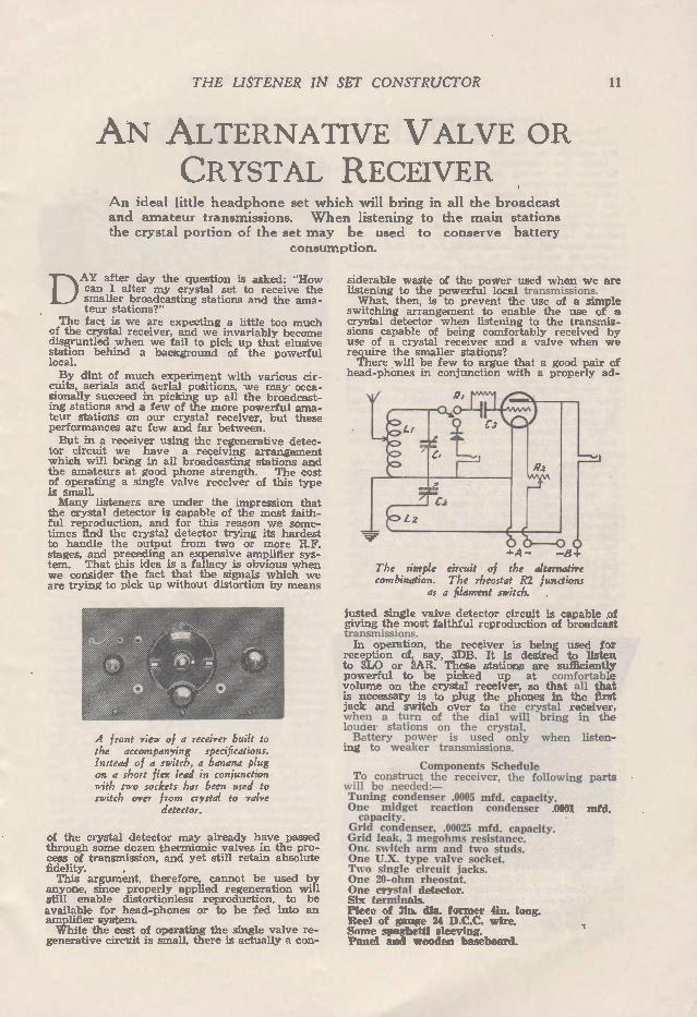
A front view of a receiver built to the accompanying specifications. Instead of a switch, a banana plug on a short flex lead in conjunction with two sockets has been used to switch over from crystal to valve
detector.
of the crystal detector may already have passed through some dozen thermionic valves in the pro-cess of transmission, and yet still retain absolute fidelity. This argument. therefore, cannot be used by
anyone, since properly applied regeneration will still enable distortionless reproduction. to be available for head-phones or to be fed into an amplifier system. While the cost of operating the single valve re-
generative circuit is small, there is actually a con-
siderable waste of the power used when we are listening to the powerful local transmissions. What, then, is to prevent the use of a simple
switching arrangement to enable the use of a crystal detector when listening to the transmis-sions capable of being comfortably received by use of a crystal receiver and a valve when we require the smaller stations? There will be few to argue that a good pair of
head-phones in conjunction with a properly ad-
R2
-1- A - -134
The simple circuit of the alternative combination. The rheostat R2 functions
as a filament switch.
justed single valve detector circuit is capable of giving the most faithful reproduction of broadcast transmissions. In operation, the receiver is being used for
reception of, say, 3DB. It is desired to listen to 3L0 or 3AR. These stations are sufficiently powerful to be picked up at comfortable volume on the crystal receiver, so that all that is necessary is to plug the phones in the first jack and switch over to the crystal receiver, when a turn of the dial will bring in the louder stations on the crystal. Battery power is used only when listen-
ing to weaker transmissions.
Components Schedule To construct the receiver, the following parts
will be needed:— Tuning condenser .0005 mfd. capacity. One midget reaction condenser .0001 mfd. capacity.
Grid condenser, .00025 mfd. capacity. Grid leak, 3 megohms resistance. Onc switch arm and two studs. One U.X. type valve socket. Two single circuit jacks. One 20-ohm rheostat. One crystal detector. Six terminals. Piece of 3in. dia. former 4in. long. peel of gauze 24 D.C.C. wire. Some spaghetti sleeving. 'Panel and wooden baseboard.
12 THE LISTENER IN SET CO NSTR UCTOR
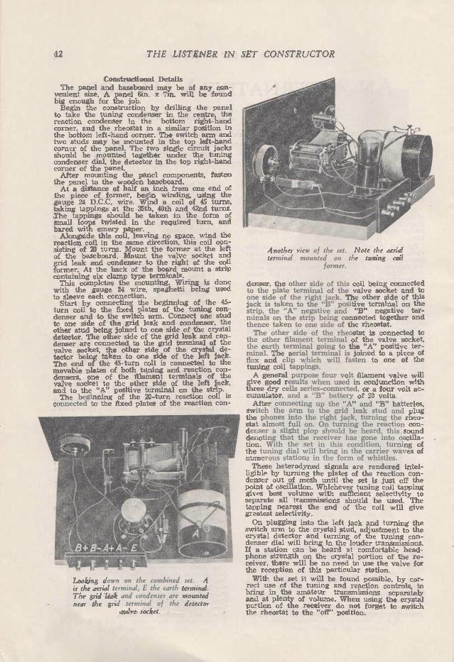
Constructional Details The panel and baseboard may be of any con-
venient size. A panel 6m. x 7m, will be found big enough for the job. Begin the construction by drilling the panel
to take the tuning condenser in the centre, the reaction condenser in the bottom right-hand corner, and the rheostat in a similar position in the bottom left-hand corner. The switch arm and two studs may be mounted in the top left-hand corner of the panel. The two single circuit jacks should be mounted together under the tuning condenser dial, the detector in the top right-hand corner of the panel. After mounting the panel components, fasten
the panel to the wooden baseboard. At a distance of half an inch from one end of
the piece of former, begin winding, using the gauge 24 D.C.C. wire. Wind a coil of 45 turns, taking tappings at the 35th, 40th and 42nd turns. The tappings should be taken in the form of small loops twisted in the required turn, and bared with emery paper. Alongside this coil, leaving no space, wind the
reaction coil in the same direction, this coil con-sisting of 20 turns. Mount the former at the left of the baseboard. Mount the valve socket and grid leak and condenser to the right of the coil former. At the back of the board mount a strip containing six clamp type terminals. This completes the mounting. Wiring is done with the gauge 24 wire, spaghetti being used to sleeve each connection. Start by connecting the beginning of the 45-
turn coil to the fixed plates of the tuning con-denser and to the switch arm. Connect one stud to one side of the grid leak and condenser, the other stud being joined to one side of the crystal detector. The other side of the grid leak and con-denser are connected to the grid terminal of the valve socket, the other side of the crystal de-tector being taken to one side of the left jack. The end of the 45-turn coil is connected to the movable plates of both tuning and reaction con-densers, one of the filament terminals of the valve socket to the other side of the left jack, and to the "A" positive terminal on the strip. The beginning of the 20-turn reaction coil is
connected to the fixed plates of the reaction con-
Looking down on the combined set. A is the aerial terminal, E the earth terminal. The grid leak and condenser are mounted near the grid terminal of the detector
valve socket.
Another view of the set. Note the aerial terminal mounted on the tuning coil
former.
denser, the other side of this coil being connected to the plate terminal of the valve socket and to one side of the right jack. The other side of this jack is taken to the "B" positive terminal on the strip, the "A" negative and "B" negative ter-minals on the strip being connected together and thence taken to one side of the rheostat. The other side of the rheostat is connected to
the other filament terminal of the valve socket, the earth terminal going to the "A" positive ter-minal. The aerial terminal is joined to a piece of flex and clip which will fasten to one of the tuning coil tappings. A general purpose four volt filament valve will
give good results when used in conjunction with three dry cells series-connected, or a four volt ac-cumulator, and a "B" battery of 30 volts. After connecting up the "A" and "B" batteries,
switch the arm to the grid leak stud and plug the phones into the right jack, turning the rheo-stat almost full on. On turning the reaction con-denser a slight plop should be heard, this sound denoting that the receiver has gone into oscilla-tion. With the set in this condition, turning of the tuning dial will bring in the carrier waves of numerous stations in the form of whistles. These heterodyned signals are rendered intel-
ligible by turning the plates of the reaction con-denser out of mesh until the set is just off the point of oscillation. Whichever tuning coil tapping gives best volume with sufficient selectivity to separate all transmissions should be used. The tapping nearest the end of the coil will give greatest selectivity. On plugging into the left jack and turning the
switch arm to the crystal stud, adjustment to the crystal detector and turning of the tuning con-denser dial will bring in the louder transmissions. If a station can be heard at comfortable head-phone strength on the crystal portion of the re-ceiver, there will be no need to use the valve for the reception of this particular station. With the set it will be found possible, by cor-rect use of the tuning and reaction controls, to bring in the amateur transmissions separately and at plenty of volume. When using the crystal pertion of the receiver do not forget to switch the rheostat to the "off" position.

THE LISTENER IN SET CONSTRUCTOR 13
A.C. SET BUILDING A few notes dealing with the home construction of the all-electric set.
SEVERAL vital points have to be watched in the construction of any completely A.C. operated receiver. A correctly constructed and adjusted A.C. set will have practically
no hum in its output, and will only be dis-tinguishable in its operation from a battery set when headphones are used. Presuming that the "B" eliminator is giving a
good pure output, hum can be brought into an A.C. receiver through faulty construction. Grid leads, especially if running close and parallel to an A.C. carrying lead, will produce a 60 cycle or a multiple of 60 cycles hum. If the detector grid lead is at fault, the hum will be amplified in the audio stages and will reproduce itself in the form of a loud and annoying rattle, which will all but drown the music. In the A.C. receiver all the old "haywire"
methods must be dispensed with. Many set-builders like to design their own layouts, but, d they have had no previous experience with A.C. set construction, it would be wise for them to save disappointment by following the lead of one who has. The valve sockets, coils, and audio coupling
apparatus should be placed with an object. This object is to keep all A.C. filament and heater leads together in the form of a twisted cable running right along the back of the baseboard. All the grid and plate terminals of the valve sockets and audio transformers, chokes, or re-sistances should face the panel of the set, thus allowing all the connections being made to these terminals without coming near any A.C. carry-ing leads. Do not attempt to wire in the A.C. filament and
heater circuits as you would in a battery set. Each pair of A.C. carrying leads must be tightly twisted so that the field surrounding each lead is confined within a distance of a fraction of an inch around the flex. In any A.C. receiver, the importance of short
grid leads cannot be over-stressed. Trouble will often arise when a pick-up switch is wired so that this instrument is connected to the grid of the detector valve. A pick-up switch, connected in this manner, must be located as close as pos-sible to the detector valve, thus having a short grid connection to the switch. A long lead here will result in distortion and a bad hum.
Perfect Wiring Necessary To illustrate the importance of perfect wiring
and insulation in an A.C. set, drive a screw into the wooden baseboard of any A.C. set, and con-nect it to the grid terminal of the detector valve socket. You are now getting the same effect as you would if the grid leak clips were screwed to the baseboard or the grid lead were touching the board. Trouble of this type may baffle the novice for
weeks, but he has only himself to blame as no connections should touch the baseboard, which, even if thoroughly dry. will sooner or later have a thin layer of dust over its surface. Correct placing of the heater transformer of
our A.C. set calls for some thought. If it is to
be located near the tuning coils, hum will be sure to originate in the detector grid circuit. The best plan will be to place it at the speaker end of the set, as far away as possible from any of the amplifier coupling devices, whether they be trans-formers, chokes or resistances. The heater transformer should be shielded with
iron or steel as this is the only material which will confine the field surrounding this com-ponent. The shield must also be earthed. So much for hum in the actual receiver.
Incorrect Centre-Tapping Incorrect centre-tapping of a heater trans-
former will result in a certain amount of hum in the final output. Our aim is to do away with all hum, and this can be done. Should a fila-ment or heater transformer secondary not give an absolutely equal voltage reading each side of the centre tap, a resistance must be used to obtain the centre tap connection. A 200-ohm potentiometer will take a current
of 30 mills when placed across a 6-volt secondary. This current is negligible. By connecting the centre-tap connection to the movable arm of the potentiometer, hum in this quarter can be entirely obviated as an absolutely accurate ad-justment can be obtained by the simple process of turning the potentiometer knob, and listening for the absence of hum in the final output when using headphones. So far, we have discussed likely sources of hum
in the circuit and heater supply. If a battery set is used with an eliminator to give a humless output, the eliminator need not be considered as a source of the hum. Still there are faulty elimi-nators, and we can discuss what can be done to eliminate hum from this source. If the faulty eliminator is of a commercially built type which normally gives a clean output, the best plan will be to change the job, unless, of course, it has broken down after having been in use for some time, and no guarantee was given with the unit. Faulty centre-tapping of a high voltage
secondary in an eliminator, when using full wave rectification, does not result in as great a hum in the output as would be expected. Centre-tapping of the high voltage secondary
by means of the resistance method is obviously impracticable, and if the transformer possesses this defect the trouble must be remedied by im-proving the filter circuit. This can be done, and, considering the work required in the balancing up of two high voltage secondaries after a trans-former has been finished and varnished or waxed, it is well worth the expense of the extra filter condensers.
By-passing Should be Watched Inadequate by-passing of resistance voltage
dividing tappings will result in hum. The usual capacity is .01 mfd., but on the detector and first amplifier tappings, this capacity should be .in-creased to two or four microfarads. When ther-mionic full-wave rectification is used, the centre tapping of the rectifier filament heater secondary does not call for the same accuracy as in the
14 THE LISTENER IN SET CONSTRUCTOR
receiver. However, a serious discrepancy in the voltage on either side of the centre tap might call for the substitution of the potentiometer method as the best means of obtaining the centre of the filament-heater secondary- voltage.
Improper Filtering Inadequate filtering after any rectifier will re-
sult in hum, and it is not a wise practice to try to save a few shillings by omitting a filter condenser here and there. The home-made elimi-nator should be shielded, not with copper, but with steel or iron, as this material will confine the field surrounding the transformers and chokes used in its construction. This shield
should also be earthed. Correct shielding will permit of the eliminator being used close to the receiver with no trace of hum. There is no doubt that the output from the
thermionic full and half wave rectifier is easier to filter than any of the gaseous types, but this should not prevent use of the latter type. I have, for the past four years, used a gaseous full-wave type rectifier which was one of the first to land here, when eliminators were practically in their infancy. This tube has been subjected to heavy overloads, but is still delivering a humless output with plenty of current, quite enough for any five-valve r.f. receiver using a power tube in its amplifier stage.
fflm1111 .1111 1111 1.11 .111 .111
DON'TS AND EMERGENCY MEASURES TT ERE are a few suggestions what not to do in
order to get the best out of a radio receiver, including the greatest operating life:— Do not increase plate voltage upon amplifier
valves in the system in the effort to secure greater amplification unless the grid bias voltage is in-creased in proportion, and you are certain even when the grid bias is increased that the tube will withstand the applied plate voltage. Do not feed the entire output of a powerful
receiver adjusted for maximum volume into a dynamic speaker voice coil unless the field is "on." Do not remove the "field" current in a dynamic
speaker installation until the input to the voice coil has been either reduced or completely shut off. Do not attempt to replace a 245 or 250 valve
with a 171 as an emergency measure. Do not operate a push-pull system normally em-
ploying two valves with only one valve in the socket unless you adjust the source of plate and grid potential so that it is suitable for the one valve being used. Do not remove the output valve from an am-
plifier system with the power "on" because the removal of the load represented by the output valve will increase the plate voltage applied to the other valve. This is particularly true when the plate supply is a power pack. Do not operate one valve from a transformer
which is designed for three or four valves, and plate supply and perhaps a few other types of valves with no load upon the other output wind-ings, unless you take some precautionary measure to assure the correct filament voltage at the tube terminals. Do not attempt to connect a "cone" type of
speaker in series with the voice coil of a dynamic speaker so as to operate both speakers at the same time. Do not replace filter condensers in a power
pack according to capacity rating. The important item is the voltage rating.
Emergency Measures In the event of condenser breakdown in a power
pack, particularly the filter condenser, you can operate the system by removing the plus or minus lead from the punctured condenser. The entire condenser need not be removed. Filtering will not be as perfect, nor will the output voltage be normal, but operation is possible until such time when a new filter condenser may be in-stalled.
In the event of a short circuit in a filter choke and the eliminator filter system makes use of two chokes, operation of the eliminator is possible by completely "shorting" the choke. Of course, If the "short" is between some part of the choke and the low potential side of the eliminator, or vice versa, in the event that the chokes are in the negative lead, operation is impossible unless the short is removed, because it shorts the output of the rectifier. In the event of an "open" in one of two chokes used in the eliminator a "short" across the choke will be satisfactory for the time, replace-ment to follow later. This "short" should be across the two terminals of the choke.
In the event of a breakdown or burnout of the output choke in a choke-condenser output sys-tem. the choke may be replaced by a resistance of approximately 4000 ohms in all valves other than the 210, in which case a 10,000-ohm resist-ance will be necessary. The resistance must be capable of passing the plate current. Of course, the signal output will be materially impaired, but any sort of reception is better than none.
An open transformer primary may be replaced until such time when a new transformer can be installed by a choke and condenser combination, the choke replacing the transformer primary and thc condenser connected between the plate end of the choke and the grid end of the transformer secondary, which, of course, is still in the re-ceiver. As an emergency unit, any choke from 30 to 100 henrys and any condenser from .01 to .1 mfd. will be satisfactory.
Workshop Hints WIDE cement which holds the glass envelope
and the cap of a valve together can be easily and cleanly removed by soaking in methylated spirit. Valves which are loose in their caps can also be tightened by soaking both cap and bulb in spirit until the cement softens, when the bulb may be pressed gently into position and allowed to reset. It will be advisable to drill a small hole in the base to drain off the surplus spirit. The cement will take several hou'rs to soften. Solder, from the insid,.s of the contact Pins,
can be removed by heating in a clean flame and blowing through with the mouth at the oppo-site end of the can. This will also usually re-move the fine wire leads.

THE LISTENER IN SET CONSTRUCTOR 15
CALCULATING RESISTANCE VALUES The simple Ohm's Law is used to determine the values
of resistors for any requirements.
T HE calculation of voltage dropping resistors is just as simple and makes use of the formula
E R equals
Where I equals the current in amps, E the volt-age, and R the resistance. Fer example, we design a power pack to deliver
a maximum voltage of 250, which is the voltage required for the operation of the type of final stage amplifier valve we are using. The first amplifier valve we are using is shown on the valve chart as requiring a plate voltage of 120, at which potential the valve draws 10 mills, when correctly biased. Now we require to know what series resistance will be required to drop the maximum 250 volts to 120. Subtracting 120 from 250 gives us 130 volts. Now the required resist-ance value equals voltage not required divided by the plate current in amps. The voltage not required is 130, the plate cur-
rent is 10 mills. or 1-100th of an amp., then 130 1
R equals — : equals 1 100
13,000 ohms. This type of resistance should be of the wire-wound tubular type. This resistance may appear to be high, but it is of the right value for this particular purpose. The method of using separate resistances in supplying each stage of a ccmbination with its required plate voltage serves a treble purpose. The method prevents
back coupling, with its resultant distortion, which can be eliminated only by use of costly by-pass condensers, which will occupy considerable space. The method prevents motor boating in a receiving circuit.
Further, this type of tubular resistance is mounted in sockets in the same manner as a huge grid leak. This means that in the event of the resistance breaking down it can be easily re-placed.
The breaking down of a paralleled voltage di-viding resistor will result in possibly hours of work in removing the resistor and its replace-ment. It will be seen, therefore, that the use of separate dividing resistances for each stage is advisable, since the method possesses every ad-vantage and not a single disadvantage.
Another point is that no "bleeder" current is taren when using this method of voltage drop-ping. This means that the rectifier will give longer life, since it does not require to pass this extra current, and no power is wasted. Since the final amplifier stage receives the maximum voltage available from the eliminator, the average num-ber of resistances required will be three.
Whenever more than one stage is to be sup-plied with the same plate voltage, a single resistor is used, the total plate current taken by the stages to be supplied by the single resistance be-ing used in calculating the resistance value. The whole thing is very simple, and should present no difficulties to the home set builder.
CAN THE "A" BATTERY CAUSE NOISES?
T HE answer to this question is that it most certainly can, and in more than one way is
likely to puzzle those who have had no pre-vious experience of its ability to provide "battery-spherics." Some batteries, particularly those in celluloid cases, are prone to gas excessively whilst under discharge.
If you examine such a battery you will notice that bubbles of different sizes form upon the plates, remain there for a varying period, and rise, singly and in masses, to the surface. This means that the internal resistance of the battery is continually varying; it increases as the bubbles form and decreases as they leave the plates. A fluctuating resistance means a fluctuating cur-rent. With modern dull-emitter valves these small
current changes may not be noticeable unless the set is in a sensitive condition or big amplifi-cation per stage is being obtained. In a short-wave set, however, where the filament potential
is sometimes rather critical, they can certainly give rise to a good deal of background noise. A common source of noise from a filament
accumulator is to be found in dirty or corroded connections between the cells, or between the battery and the receiving set. Some time ago an outburst of crackles was
traced to corrosion of the ends of the lead strap which connected the two cells in series. Keep all terminals of the filament accumulator clean and see that the ends of the straps and leads do not become corroded. The best way of ensuring this is to give both
the terminals and the connections to them a light dressing with ordinary vaseline whenever the battery comes back from the charging station, or, better still, arrange that the battery is properly cleaned and vaseline applied on each visit to the charging station. A fruitful source of corro-sion is the presence of splashes of electrolyte upon the terminals themselves and upon the top of the battery case.

16 THE LISTENER IN SET CONSTRUCTOR
COPPER WIRE TABLE inn and weight tables Turns per linear inch tables
p_d .º.,,.: c,..:
Diarn.
Inch
o" . ,. . a ,.., e ''.'¡Îó .....
Current ratings .-- in an, __ r Approx.
S.C.C. I D.C.C. I S.S.C. I D.S.C. lb. lb ' lb lb
77.:
à>
e r4
S.C.C. D.C.C. S.S.0 D.S.C. "74
weight per 1000 yds.
10 11 12 13 14
.128
.116
.104
.092
.080
1.865 2.272 2.826 3.612 4.776
12.868 10.568 8.495 6.648 5.027
152.32 125.44 99.8à 78.33 59.43
154.56 127.68 101.30 79.60 60.70
7.35 I 8.06 8.93 10.0 11.4
7.04 7.69 8.48 9.43 10.6
7.64 8.41 9.35 10.5 12.1
7.55 8.30 9.22 10.4 11.8
10 11 12 13 14
15 16 17
.072
.064
.056
5.897 7.463 9.747
4.072 3.217 2.463
48.30 38.40 29.20
49.10 39.00 30.00
37.46 28.71
37.66 28.89
15.0 17.1
12.5 14.1 15.9
11.6 13.2 14.7
13.3 14.9 16.9
13.1 14.6 16.5
15 16 17
18 .048 13.267 1.809 21.00 22.30 21.12 21.28 19.8 18.5 17.2 20.0 19.4 18
19 20
.040
.036 19.105 23.59
1.256 1.017
15.10 12.34
15.70 12.80
14.69 11.92
14.85 12.07
23.7 21.7 26.1 25.3
20.0 21.7
23.8 26.3
23.0 26.0
19 20
21 22
.032
.028 29.85 38.99
.804
.615 9.81 7.57
10.20 8.00
9.43 7.24
9.57 7.34
29.4 z6.3 33.3 29.4
23.8 26.3
29.4 33.3
28.2 31.8
21 22
23 24
.024
.022 53.07 63.16
.452
.380 5.56 4.70
5.94 5.07
5.33 4.49
5.38 4.54
38.8 38.3 42.1 35.7
29.4 31.3
38.5 42.1
36.4 40.0
23 24
25 .020 76.42 .314 3.91 4.25 3.72 3.76 46.0 38.5 33.3 46.0 43.5 25
26 .018 94.35 .254 3.13 3.51 3.02 3.06 50.6 41.7 36.7 50.6 47.6 26
27 .016 113.65 .211 2.67 2.83 2.51 2.55 55.9 44.6 37.9 55.1 51.6 27
23 .015 139.55 .172 2.2) 2.35 2.06 2.09 61.4 48.1 40.2 60.4 56.2 28
29 .013 165.27 .145 1.87 2.02 1.74 1.77 66.2 51.0 42.4 65.2 60.2 29
30 .012 198.80 .120 1.58 1.71 1.46 1.48 73..J 54.4 44.7 72.0 67.1 30
31 .011 227.2 .105 1.39 1.51 1.27 1.30 77.8 56.8 46.3 76.3 70.9 31
32 .0108 262.1 .091 1.22 1.33 1.11 1.14 83.0 63.3 50.5 81.3 75.2 32
33 .0100 305.7 .078 1.06 1.17 .95 .98 88.9 36.7 52.6 87.0 80.0 33
34 .0092 I 361.2 I .066 .91 1.01 .81 .84 98.0 10.4 54.9 93.4 85.5 34
35 .0084 433.2 .055 .75 .87 .68 .70 106.0 30.6 61.0 101.0 91.8 35
36 .0076 529.2 .045 .63 .74 .56 I .58 116.0 6.2 64.1 110.0 102.0 36
37 .0068 661.1 .036 .51 .62 .45 .47 128.0 2.6 67.6 120.0 110.0 37
38 .0060 849.1 .028 .41 .51 .36 .37 143 ,j 100.0 71.4 133.0 121.0 38
39 .0052 1130.5 .021 .32 .41 .27 .29 168.0 109.0 75.8 149.0 134.0 39
40 .0048 1326.7 .018 I 23 .37 .23 .25 180.0 114.0 78.1 1159.0 142.0 40
Rules of Power Transformer Construction A LWAYS wind transformer primaries and
secondaries with wire of sufficient gauge to carry the current required of it. In designing a transformer core always use
sufficient dimensions for the total secondary wattage to be drawn. Wherever feasible, use filter and by-pass con-
densers tested at twice the voltage they are to withstand in the receiver or power pack. Never use a paralleled voltage divider of in-
sufficient resistance. Calculate by means of de-tails supplied later the resistance required for the particular maximum voltage available from a power pack. The use of too low a paralleled dividing resistor will result in waste of power, possible damage to rectifier, heating and possible burning out of the dividing resistor, and finally inability of the power pack to deliver fl1 voltage. Always operate a rectifier underloaded. When
selecting a rectifier for a particular purpose make sure that you have calculated correctly the maxi-mum current it is to pass, and leave a margin. Never vary the output voltage of a power pack
by use of a filament controlling rheostat on the rectifier filament. This will result in what is knowr as crystallising of the filament and will result in short life of the rectifier. After calculating the wire gauges required for
filament heating secondaries, use wire two gauges heavier. The reason for this is that imme-diately the filament of a valve is switched on it draws a current of about twice the normal cur-
rent value of the valve. The resistance of the valve gradually increases until current drops down to its normal value. When operating a num-ber of valves from the one secondary, the wind-ing would be overloaded were the actual gauges calculated to be used. Remembering that in the "B" power supply unit we are handling fairly high d.c. voltages, insulate all leads accordingly. In wiring up a power-pack to deliver no more than 120 volts spaghetti sleev-ing may be safely used. In higher voltage jobs use good quality thick rubber walled flex. When attempting the shielding of transformer or filter choke gear, leave sufficient spacing between terminals and the shielding material, filling up the space between the device and the shield to pre-vent vibration. Don't lose sight of the fact that a high voltage
secondary winding, whether to supply 100 volts or 1000 volts, may be dangerous to human life. Act accordingly and keep your hands well away from apparatus when it is connected to the light socket. Don't be afraid of wearing out the light or power point switch. If you must handle gear while it is in operation, use only one hand, keeping the other well out of the road. A severe shock through the fingers of one hand is seldom fatal, but it will teach a lesson. If these rules are adhered to, long life of power-
pack apparatus, efficiency of operation free from all troubles associated with poor construction and design, will be secured.

THE LISTENER IN SET CO NSTR UCTOR 17
he IMPROVED REINARTZ TWO
A popular circuit described in the following notes for both a.c. and battery operation.
ATWO-VALVE receiver to give good speaker results is considered to be one of the most popular of circuits; it is economical to operate, can be constructed by the novice,
and has little in it to go wrong. Using the "Improved Reinartz" circuit, which
has become so popular, a sensitive screened grid detector and a pentode amplifier, the circuit is of the ideal two-valve combination, since with such a receiver, volume for all average requirements, coupled with selectivity and sensitivity, is avail-able The trend these days is towards self-contained
radios, particularly in the standing cabinet ranges, and the console is one of the most popular designs. It would have seemed strange several years ago to install a simple two-valve receiver in a stand-ing console type cabinet, but if the set is capable of delivering good speaker signals with good quality what does it matter what type of receiver is producing the signals? This two-valve receiver makes an excellent a.c.
or battery-operated set, and, fitted into a stand-ing cabinet with built-in electromagnetic type speaker and batteries, or power-pack—whichever form of supply is used—makes an ideal set. The reader will notice two circuits. They are
both the same excepting for the fact that one is
for battery operation and the other is for complete a.c. operation.
The reason for the two circuits will be apparent to the less fortunately situated country listener who must depend upon batteries as the source of supply for his receiver, and who has been left out in the cold in these days of the all-electric re-ceiver.
Parts Schedule Parts required for the battery set are as follow:— One tuning condenser, .000 mfd. capacity. One 13-plate midget reaction condenser. One vernier or plain dial for tuning condenser. Two U.X. type valve sockets. Grid leak 3 megohms, and holder. Grid condenser, .00025 mfd. capacity. One a.f. transformer, 3 or 5-1 ratio. Two ri. chokes. One by-pass condenser, .01 mfd. capacity. One filament switch. Four clamp type terminals. Piece of 3in. dia. former, 4in. long. Reel of gauge 24 d.c.c. wire. Reel of gauge 20 d.c.c. wire. Some spaghetti sleeving. Some lengths of different colored single flex. One panel about 12in. x 6in. One wooden baseboard about hin. x lin.
AC
The a.c. circuit of the two using a screened grid detector and stand-ard power pack as described later in this book. The actual con-structional details of the all electiic version of the circuit can be obtained from the de-scription and photo-graphs of the tin ee valve receiver described in the following pages. No alteration to the circuit will be needed to accommodate a general purpose indi-rectly heated valve in the detector stage, the screened grid connec-tion and by-pass being
omitted.
ilD
18 THE LISTENER IN SET CO NSTR UCTOR
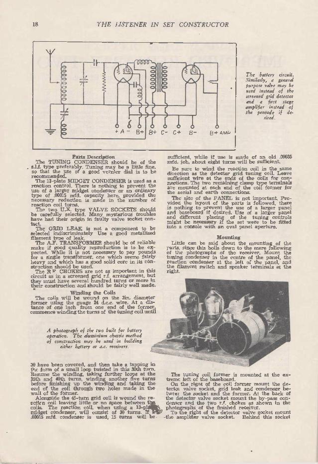
Parts Description The TUNING CONDENSER should be of the
s.l.f. type preferably. Tuning may be a little fine, so that the use of a good vernier dial is to be recommended. The 13-plate MIDGET CONDENSER is used as a reaction control. There is nothing to prevent the use of a larger midget condenser or an ordinary type of .00015 mfd. capacity here, provided the necessary reduction is made in the number of reaction coil turns. Tho two U.X. type VALVE SOCKETS should
be carefully selected. Many mysterious troubles have had their origin in faulty valve socket con-tact. The GRID LEAK is not a component to be
selected indiscriminately Use a good metaffised filament type of leak. The A.F. TRANSFORMER should be of reliable
make if good quality reproduction is to be ex-pected. While it is not necessary to pay pounds for a single transformer, one which seems fairly heavy and which has a good solid core in its cón-struction should be used. The R W CHOKES are not as important in this
circuit as in a screened grid r.f. arrangement. but they must have several hundred turns or more in their construction and should be fairly well made.
Winding the Coils The coils will be wound on the 3in. diameter
former using the gauge 24 d.c.c. wire. At a dis-tance of one inch from one end of the former, commence winding the turns of the tuning coil until
A photograph of the two built for battery operation. The aluminium chassis method of construction may be used in building
either battery or a.c. receivers.
30 have been covered, and then take a tapping in thc form of a small loop twisted in this 30th turn. Resume the winding, taking further loops at the 35th and 40th turns, winding another five turns before finishing up the winding and taking the end of the coil through two holes made in the wall of the former. Alongside the 45-turn grid coil is wound the re-
retina coil leaving little or no space between the coils. The reaction coil, when using a 13-plate midget condenser, will consist of 30 turns. If a .00015 mfd. condenser is used, 15 turns will be
The battery circuit. Similarly, a general purpose valve may be used instead of the screened grid detector and a first stage amplifier instead of the pentode if de.
sired.
sufficient, while if use is made of an old .00035 rnfd. job, about eight turns will be sufficient.
Be sure to wind the reaction coil in the same dil ection as the detector grid tuning coil. Leave sufficient wire at the ends of the coils for con-nections. The two remaining clamp type terminals are mounted at each end of the coil former for the aerial and earth connections. The size of the PANEL is not important. Pro-
vided the layout of the parts is followed, there is nothing to prevent the use of a larger panel and baseboard if desired. Use of a larger panel and different placing of the tuning controls might be necessary if the set were to be fitted into a console with an oval panel aperture.
Mounting Little can be said about the mounting of the
parts, since this boils down to the mere following of the photographs of the receiver. Mount the tuning condenser in the centre of the panel, the reaction condenser at the left of the panel, and the filament switch and speaker terminals at the right.
The tuning coil former is mounted at the ex-treme left of the baseboard. On the rignt of the coil former mount the de-
tectoi valve socket, grid leak and condenser be-twe e/ the socket and the former. At the back of the detector valve socket mount the by-pass con-denser and the two r.f. chokes as shown in the photographs of the finished receiver. To the right of the detector valve socket mount
the amplifier valve socket. Behind this socket

THE LISTE NER IN SET CONSTR UCTOR 19
mount the a.f. transformer. The valve sockets should be mounted with the filament terminals facing the panel. The transformer is mounted with its G. and P. terminals facing the detector valve. Wiring in this receiver will be done with
gauge 20 d.c.c. wire and spaghetti sleeving. The connections will be as follow:—Connect the
beginning of the 45-turn tuning coil to the fixed plates of the tuning condensor and to one side of the grid condenser. Connect the other side of the grid condenser to the grid terminal of the detec-tor valve socket and one side of the grid leak hclder. Connect the end of the 45th turn coil to the
movable plates of both tuning and reaction con-densers, the earth terminal, the other grid leak terminal, one terminal of each valve socket and to a flex lead marked A positive. • The beginning of the reaction coil is joined to
the movable plates of the reaction condenser, the other side of the reaction coil being taken to one side of the right R.F. choke and to a short flex lead to connect to the top of the S.G. detector valve. Connect the other side of this R.F. choke to the P terminal of the primary of the A.F. trans-former. Connect the plate terminal of the detector
valve socket to one side of the .01 ml d. capacity by-pass condenser and to one side of the first R.F. chcke, and a length of flex marked "B positive screened grid" to the other side of this R.F. choke. Join a length of flex marked B positive detector
to the B terminal of the primary of the A.F. transformer. Connect the G terminal of the secondary of the
transformer to the grid terminal of the amplifier valvc socket. Connect the F terminal of the transformer secondary to a length of flex marked C negative. The plate terminal of the amplifier valve soc-
ket is joined to one of the speaker terminals, and
Looking down on the battery circuit using the general purpose detector valve. Here bakelite sub-panel instead of the more
up-to-date method of chassis construction is used.
A photograph of the two built using an ordinary general purpose detector valve and the pentode amplifier for battery operation.
tile other speaker terminal to a length of flex marked "B positive maximum," and a shorter length of flex to connect to the terminal at trie side of the pentode valve. Connect one side of the filament switch to a
length of flex marked A negative, and the other side of the switch to the remaining F terminal of each valve socket, the other side of the .01 mfd. capacity by-pass condenser and to two lengths of flex marked B negative and C positive respec-t:ve ly. All that remains now is to connect the aerial
terminal by means of a piece of flex to one of the coil tappings, which should be bared of their in-sulation by use of emery or sand paper.
Operating the Receiver To put the battery receiver into operation is
merely a matter of inserting valves, connecting batteries, speaker and aerial and earth leads. An A442 was used in the detector stage and a
B443 in the amplifier stage. Connect B negative to the negative of three 45-
volt "B" batteries connected in series. The sc.reened grid positive lead should be connected to 45-volt positive. The "B" positive detector lead should be connected to "B" positive 90 volts, and the amplifier positive to the maximum of 135 volts. At this voltage a bias of 12 volts should be employed. Three flat torch batteries may be used fer bias. These should last for 18 months. Three dry cells, series connected, or a four-volt
accumulator, should be used for the "A" supply. In tuning the receiver connect the aerial to the
tapping nearest the grid end of the tuning coil. If stations overlap and interfere with one another when using this tapping, use one lower down which gives separate reception of the various stations. In operation, the A.C. version of the receiver is
the same.

20 THE LISTENER IN SET CONSTRUCTOR
A" D.C. ELIMINATOR Wherever a fairly constant d.c. supply is avail-able, plate current can be obtained by use of
this simple apparatus.
A D.C. eliminator consists essentially of a highly efficient filter system and a means of dividing the voltage into values suit-able for the operation of the various
stages of a receiver. D.C. hum can only be completely eliminated by
careful filtering, and the builder of such an elim-inator must be prepared to spend what he would have otherwise spent on transforming and recti-fying equipment, on the purchase of extra filter apparatus if required. A d.c. eliminator is then merely the filtering
and voltage dividing portion of an a.c. "B" elim-inator. Such an eliminator can therefore be used with an a.c. supply by the simple addition of a power transformer and full wave rectifier system. The actual construction of the d.c. eliminator
is very simple. It is the mere connecting up of a tapped resistance, a choke and a number of fixed condensers. There are no adjustments to be made, and the expense of the job is defrayed by the high cost of "B" batteries, especially in coun-try districts, where the use of multi-valve re-ceivers is a necessity in order that constant recep-tion of the broadcasting stations may be obtained during all sessions. In the majority of cases, the d.c. eliminator will
be successful. When the main supply fluctuates very badly, the use of extra filter may not im-prove matters. But, after ascertaining that the mains supply is fairly constant, the construction of an eliminator may be safely undertaken. The efficiency of the filter choke will play an
important part in obtaining an absolutely pure d.c. output from the eliminator. Four mfd. 600 volts test condensers should be used. With 200 volts across their terminals smaller condensers would be liable to break down.
To DC Supply
The eliminator is connected to the receiver in the same manner as a "B" battery would be con-nected. In order to ascertain the voltage avail-able at each positive terminal a the eliminator, a good voltmeter should be used. By using such an eliminator as this, unlimited
power is available for the operation of power am-plifying equipment. The use of high power pen-todes and the UX245 valve permits the obtaining of high, undistorted outputs when using the maxi-mum voltage available from the eliminator.
The apparatus required will be as follows:-
1 65 Henry centre tapped filter choke. 5 4-mfd. capacity 600 volt test filter condensers. 1 13 eliminator voltage dividing resistance. Some 2-mfd. capacity by-pass condensers. Some clamp type terminals. 1 tumbler switch. 2 light globes and bottom holders. Some spaghetti sleeving. A reel of gauge 22 d.e.e. wire. Panel and baseboard, any convenient size.
It is only in rare cases that the eliminator will fail to give satisfaction. This may happen when the mains' supply voltage is fluctuating very bad-ly, and the use of additional filter will not com-pletely eliminate a hum or fluctuation of the in-coming signals. The D.C. eliminator, in conjunction with an ac-
cumulator, will supply all the power required to operate any—receiver. The trouble of "B' bat-teries is eliminated, and the presence of a D.C. supply makes battery charging a simple matter. Should the D.C. supply be replaced by A.C. at
any time, the simple addition of an eliminator transformer and therrnionic rectifier will render the eliminator quite suitable for operation with this type of current source.
/77/c
11,e0-tet . +
r Td.. J., gi -r
The circuit of the d.c. eliminator. An ordinary lighting globe is connected in each of the leads from the mains to the eliminator. Whether either one of the globes will light when the eliminator is in operation will depend on whether it is used on the power or the light supply wires. The earth con-nection should be removed from the receiver and connected to the "B" negative of the. eliminator. Although, in some instances, neither globe will light, these components should not be omitted from the
circuit. The filter choke should have a value of not less than 60 henries.
0 +
0 +
0+
0 +
o -
THE LISTENER IN SET CO NSTR UCTOR 21
MODERN PO WER PACK CONSTRUCTION This article shows how total power for the operation of the up-to-date radio-gramophone can be obtained from the alternating current
mains supply.
WE maintain that, with home-built receiv-ers, it is a better proposition to build the power pack into the form of a separate unit which may be fitted into table or
console type cabinet with the receiver chassis. Here are a few reasons why such separate con-struction will give best results. The possibilities of hum in the circuit, intro-
duced by induction between power equipment and receiver parts, particularly a.f. transformers, is eliminated. Receiver or power-pack units are easily remov-
able for repair should a fault develop. Trouble finding within eliminator or receiver is
simplified considerably. The power pack may be used with other re-
ceivers. By far the most desirable of the foregoing fea-
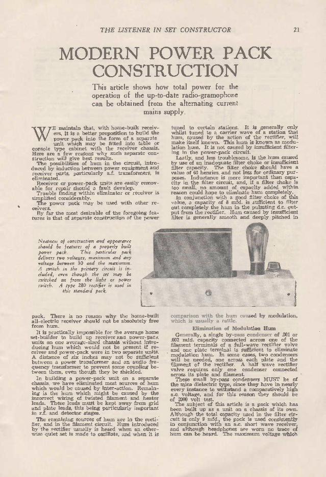
tures is that of separate construction of the power
Neatness of construction and appearance should be features of a properly built power pack. This particular pack delivers two voltages, maximum and any voltage between 30 and the maximum. A switch in the primary circuit is in-cluded, even though the set may be switched on from the light or power switch. A type 280 rectifier is used in
this standard pack.
pack. There is no reason why the home-built all-electric receiver should not be absolutely free from hum. It is practically impossible for the average home
set-builder to build up receiver anu Dower-pac_z units on one average-sized chassis without intro-ducing hum which would not be present if re-ceiver and power-pack were in two separate units. A distance of six inches may not be sufficient between a power transformer and an audio fre-quency transformer to prevent some coupling be-tween them, even though they be shielded. In building a power-pack unit on a separate
chassis, we have eliminated most sources of hum which would be caused by inter-action. Remain-ing is the hum which might be caused by the incorrect wiring of twisted ffiament and heater leads. These leads must be kept away from grid and plate leads, this being particularly important in r.f. and detector stages. The remaining sources of hum are in the recti-
fier, and in the filament circuit. Hum introduced by the rectifier usually is heard when an other-wise quiet set is made to oscillate, and when it is
tuned to certain stations. It is generally only whilst tuned to a carrier wave of a station that hum, caused by the action of the rectifier, will make itself known. This hum is known as modu-lation hum. It is not caused by insufficient filter-ing in the power-pack circuit. Lastly, and less troublesome, is the hum caused
by use of an inadequate filter choke or insufficient filter capacity. The filter choke should have a value of 60 henries, and not less for ordinary pur-poses. Inductance is more important than capa-city in the filter circuit, and, if a filter choke is too small, no amount of capacity added within reason could hope to eliminate hum completely. In conjunction with a good filter choke of this
value, a capacity of 8 mfd. is sufficient to filter out completely the hum in the pulsating d.c. out-put from the rectifier. Hum caused by insufficient filter is generally smooth and deeply pitched in
comparison with the hum caused by modulation, which is usually a rattle.
Elimination of Modulation Hum Generally, a single by-pass condenser of .001 or
.002 mfd. capacity connected across one of the filament terminals of a full-wave rectifier valve and one plate terminal is sufficient to eliminate modulation hum. In some cases, two condensers will be needed, one across each plate and the filament of the rectifier. A half wave rectifier valve requires only one condenser connected across its plate and filament. These small by-pass condensers MUST be of
the mica dielectric type, since they have in nearly every instance to withstand a comparatively high a.c. voltage, and for this reason they should be of 2000 volt test. The subject of this article is a pack which has
been built up as a unit on a chassis of its own. Although the total capacity used in the filter cir-cuit is only 9 mfd., the pack is used consistently in conjunction with an a.c. short wave receiver, and although headphones are worn no trace of hum can be heard. The maximum voltage which
22 THE LISTENER IN SET CO NSTR UCTOR
this pack will deliver is 290, and a load of 90 mills., 250 volts. A power Clarostat by-passed by a 1 mfd. capacity condenser provides a means of obtaining from 10 to almost the maximum voltage. The voltage available from this resistance is ad-
The filter and dividing circuit of a pack . using a paralleled voltage dividing
resistance.
justed to 180 for operation of the three valve a.c. short wave receiver described in this booklet. It would be well worth while, if several volt-
ages for the operation of a particular receiver were required to install two or three Clarostats to provide three voltages which may be varied between 10 and the maximum voltage. This method is known as the "anode feed" system, and is superior when the pack is to deliver volt-ages over 120, since a paralleled voltage dividing
it will be changed at some time or other, and different voltages will be required. The modern a.c. receiver seldom requires more
than two positive voltages when no screen grid valves are used. The maximum positive is ap-plied to the final stage power valve, the lower voltage operating the detector, r.f. or first ampli-fier stages. An extra voltage would be needed for operation of a screened grid valve or valves, so that, for ordinary purposes, two Clarostats are sufficient to provide the maximum and the two voltages which would be required for operation of the modern a.c. receiver. A pea lamp will be noticed on the chassis of
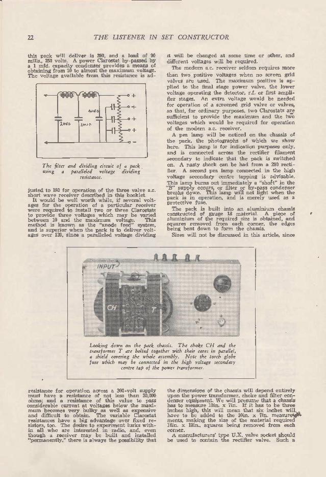
the pack, the photographs of which we show here. This lamp is for indication purposes only, and is connected across the rectifier filament secondary to indicate that the pack is switched on. A nasty shock can be had from a 280 recti-fier. A second pea lamp connected in the high voltage secondary centre tapping is advisable. This lamp burns out immediately a "shoft" in the "B" supply occurs, or filter or by-pass condenser breaks down. This lamp will not light when the pack is in operation, and is merely used as a protective fuse. The pack is built into an aluminium chassis
constructed of gauge 18 material. A piece of aluminium of the required size is obtained, and squares removed from each corner, the edges being bent down to form the chassis. Sizes will not be discussed in this article, since
Looking down on the pack chassis. The choke CH and the transformer T are bolted together with their cores in parallel, a shield covering the whole assembly. Note the torch globe fuse which may be connected in the high voltage secondary
centre tap of the power transformer.
resistance for operation across a 300-volt supply must have a resistance of not less than 30,000 ohms; and a resistance of this value to pass considerable current at voltages below the maxi-mum becomes very bulky as well as expensive and difficult to obtain. The variable Clarostat resistances have a big advantage over fixed re-sistors, too. The desire to experiment lurks with-in all who are interested in radio, and, even though a receiver may be built and installed "permanently," there is always the possibility that
the dimensions of the chassis will depend entirely upon the power transformer, choke and filter con-denser equipment. We will presume that a chassis has to measure 10in. x 7in. If it has to be three inches high, this will mean that six inches will have to be added to the 10in. x 7in. measure-ments, making the size of the material required I6in. x 13in., squares being removed from each corner. A manufacturers' type U.X. valve socket should
be used to contain the rectifier valve. Such a

THE LISTENER IN SET CO NSTR UCTOR 23
socket costs only a few pence, but it is satis-factory, and helps to keep down the cost of con-struction. In the original pack transformer and choke
have been mounted parallel with each other and bolted securely together. A crackle-finished ducoed shield covers the transformer, and choke
assembly. The shield does not vibrate and the transformer has a solidly built core, which does not hum. The transformer delivers 350 volts either side of the high voltage centre tapping, 5 volts centre-tapped for the rectifier filament, and two four volt secondaries for the operation of any of the receivers which we have described. One four-volt winding is wound to pass n amperes for the final stage power valve. The other four-volt secondary is wound to pass 4 amperes, and will carry four indirectly-heated valves. The rectifier filament secondary requires to pass
about 2 amps. Primary turns of this transformer are 5 per volt, secondary turns 5-.1 per volt. Secondary turns per volt will depend upon the efficiency of the core, however, and the actual number found by trial. The primary wire gauge is 24 s.c.c., high voltage secondary gauge 30 s.c.c., rectifier filament secondary gauge 18 d.c.c., 4 amp. four volt secondary gauge 14, 11 amp. four volt secondary gauge 18 d.c.c. For ordinary purposes the type 280 rectifier will
be the best type to use since, in conjunction with a transformer designed for this rectifier, the maximum of 300 volts may be used to supply a type 245 power valve, or smaller power valves
The output from the filter circuit may be divided into any number of lower voltages by the use of the paralleled resistance. The value of this resistance should not be low enough to draw a 'bleeder" current of more than 10 mills.
from the first Clarostat positive tapping should voltages below 300 be required.
In conjunction with the 60 henry choke in this eliminator, a capacity of 4 mfd. across the input side, and a capacity of 4 mfd. across its output side are used. A 1 mfd. capacity condenser is used to by-pass the Clarostat resistance. The
The standard type 280 power pack circuit. SW is the primary switch, Cl the hum eliminating condenser, and
CH the filter choke. The condensers C4 and C3 should both be of no less than 4 mfd capacity. The condenser C3 should be preferably of 8 mfd. The by-pass condenser C2 should be
of about 1 mfd.
accompanying circuit diagram shows how one hum eliminating condenser is connected across the rectifier. The single condenser will be ef-fective across one of the two plates, so that both plate connections to the rectifier must be tried. Wiring is done with rubber covered flex. Use
of thick rubber-walled flex is advisable, since the d.c. voltage is considerable. Positive terminals should be well bushed from the chassis. All ne-gative connections to filter condensers, high vol-tage secondary, by-pass condenser and the output terminals are connected directly to the aluminium chassis. The clarostats must also be bushed from the chassis metal. The a.c. input to the pack should be by means of a plug and socket connec-tion. All wires passing through the aluminium chassis must be bushed with short pieces of ebon-ite tubing in accordance with regulations. A switch is included in the make-up of the
pack. It is mounted on one edge of the chassis, and, although the set may be switched on from the normal power or light switch, its inclusion is advisable. A third pea lamp may be connected in series with the mains supply leading to the primary winding of the power transformer func-tions as an additional protection should a fault develop in primary or secondary windirigs which

24 THE LISTENER IN SET CO NSTR UCTOR
Looking up into the standard 280 type power pack. Note the 8 mfd of filter condensers and the smaller •2 mfd by-pass condenser. C4 is the modu-lation condenser which must have a very high breakdown voltage. R is the Clarostat voltage dropping resist-ance which delivers a lower positive voltage on the anode feed system.
would not be protected by the lamp fuse con-nected in the high voltage centre tapping. It has often been asked by constructors of
power-packs whether the positive connection from the thermionic rectifier should be taken from one end of the rectifier filament winding or from the centre of the winding. It is preferable to take the positive connection from the centre of the winding, since by so doing the possibilities of a breakdown of the filament are reduced to some extent, the heating of the filament being divided up across each half of the filament of a half-wave rectifier or the filaments of a full-wave rectifier. No hum results, however, by taking the positive connection to either end of the recti-fier filament heating secondary.
Shielding The shielding of properly constructed power
transformers and chokes offers no difficulty if the cores are clamped into solid blocks of lamina-tions. A stout steel cover may be made to cover both transformer and choke, which should be bolted together with their cores in parallel. The advantage of constructing the filter choke core to the same dimensions as the transformer core can be seen. Non-magnetic material must be used to bolt the two cores, however, and for this purpose brass, copper or aluminium may be used. Alloy mounting frames, such as shown in the photographs, could be made by any metal worker to specification. Looking at the photograph showing the view
underneath the pack, the filter condensers (four 2 mfd. and one 1 mfd. capacity) can be seen supported in position by a bus wire which holds them into the chassis, this mounting wire con-necting to chassis and soldered to one side of each of the five condensers. S.W. is the primary switch. Installation of a suitable switch here
is important, as all home-built power pack equip-ment must be constructed according to rules and regulations. A Cutler Hammer switch was used in the
original pack, but, if appearance does not count, an ordinary tumbler light or power switch may be installed. In this photograph the condenser, C4, for the elimination of modulation hum can be seen. V is the rectifier valve socket. The remaining two components to be seen are the indicating pea-lamp socket and the power Claro-stat. Mounted towards one edge of the chassis are the output terminals, two of which are bushed from the aluminium, the remainder being mounted directly to the metal. The two positive voltages (maximum and that available from the Clarostat control) are connected to the two bushed terminals. To the right of the terminals are the A.C. input connections, which take the form of a power plug socket fitted into the chassis. Wiring, as already mentioned, should not be
done by the old conventional bus-bar method, since this, in most cases, is a dangerous method in power supply circuits. Ordinary house light-ing flex stripped of its woven cloth covering is ideal for the purpose of wiring power-pack equip-ment. Such wiring is also simple and, without doubt, the best, right through the all-electric receiving circuit. If the transformer and choke are shielded, the
pack may be mounted within a few inches, but it is preferable to install the whole outfit into a standing cabinet, mounting the pack on the floor of the console. The necessity for shielding the transformer and the pack when mounting pack and receiver chassis within a few inches of each other is apparent when the shield is removed, the effect being noted in the operating receiver. If the power transformer is
Another photograph of the pack with the transformer and choke shield removed. Note the power input connections and voltage outlet terminals. Both the B positive terminals should be well bushed
from the aluminium chassis.

THE LISTENER IN SET CONSTRUCTOR 25
within about 7 inches of one of the audio frequency transformers, an induction hum will be set up in the receiver. The aluminium pack chassis may be finished
off by the use of emery paper and water. Small gauge paper should be used, the metal being rubbed in the one direction until a dull finish, free from the slightest irregularity, is obtained. The procedure may become a little tedious, but it is well worth while in the finished appearance of the chassis. The dull finish will keep its appearance for long periods. The original glossy surface of the aluminium is easily soiled and does not wear well. See the photograph of the top of the pack
chassis, and that of the finished pack. The unit
A
The circuit A shows how additional filter in the form of an a.c. transformer primary and an extra 4 mfd capacity filter conden-ser. B is the circuit of the anode feed method of obtaining different positive voltages from a power pack. Each by-pass condenser should have a capacity of preferably no less than half a microfarad. Larger capacities than this are desirable.
will be seen to be particularly "clean" and neatly arranged. Looking down the chassis the choke, transformer, rectifier valve socket, pea-lamp and Clarostat, as well as output and input terminals, can be clearly seen. All the transformer and choke connections are taken to a piece of fibre mounted between these two components: Referring to the standard circuit shown in the
diagram accompanying this article. Cl is the modulation condenser connecting to either one of the two plates of a full-wave rectifier, or the one plate of a half-wave rectifier. The con-denser, C2, by-passes the clarostat resistance, and should be of 2 mfd. capacity. The condensers C3 and C4 should each be of 4 mfd. It can be seen that by the use of clarostat voltage con-trols, any number of voltages for ordinary pur-poses can be obtained. Each resistance should be by-passed by use of a 2 mfd. capacity.
Cost is one of the main considerations in building this power pack. Correct designs, as we have shown, need not be costly; in fact, a poorly designed filter choke will actually send up the cost of a power pack, since a great deal of extra filter capacity would be needed to provide sufficient filtering in conjunction with a choke of insufficient inductance. Filter condensers of 1000 volt test can now be
purchased quite cheaply, while if the chance of securing a good rectifier is taken the types
available for 9/ generally prove quite satisfactory. From the average catalogue prices would be roughly as follows:—
Chassis and bending 5/-Manufacturers' valve socket .. .. 0/10 Filter condensers .. . 20/-One clarostat . . .. 12/-Power switch .. . . 3/-Transformer and choke .. 50/-One 280 type rectifier .. . . 9/-
A.C. input socket .. . . . . 1/-Condenser C4 ................ 3/-
105/10
For the sum of approximately £5/5/10 we are able to assemble a power pack to deliver more than sufficient voltage and current for average receiving and electric gramophone requirements. Reverting again to the receiver, and the possi-
bilities of hum in this quarter, hum is too often blamed on the power pack, although, in most cases, the whole cause of the trouble is poor design. Any tendency towards audio frequency oscillation in the two or more audio frequency amplifying stages would introduce hum into an A.C. circuit, even though the power pack equip-ment was ddjusted for perfect operation. This oscillation, in most instances, is plainly the fault of poor design, and is caused by feedback from the output to the input stages through the proximity of grid, plate or power wires or in-sufficient spacing between the various parts of the circuit.
Wave Length and Frequency T HERE appears to be some confusion in the --• minds of many regarding the meaning of the terms "wave length" and "frequency." Wireless signais are propagated in the form of a train of waves, a certain number of waves being sent out per second, depending on the frequency of the alternations. The wave length, then, is the distance from the crest of one wave to that of the next wave. Furthermore, wireless waves are measured in metres, and travel at the rate of 186.000 miles or 300,000,000 metres per second. which is also the velocity of light waves. Frequency is the number of complete cycles
which are produced by the transmitter in a second, and is measured in "cycles per second." The frequency is equal to the velocity divided by the wave length. We know that the velocity of wireless waves is 300.000,000 metres per second, and if we know the wave length it ,is an easy-matter to ascertain the frequency. Similarly, the wave length may easily be calculated if the frequency is known. For example, the frequency of the commercial
wave length of 600 metres will be found to be 3 0.000.000 divided by 600 or 500,000 cycles per second. As wireless frequencies are usually fairly high, it is the practice to express them in kilocycles—one kilocycle being equal to 1000 cycles. It will be seen, therefore, that a wave length of 600 metres will have a frequency of 500 kilocycles. A wave length of, say, 1200 metres. would have a frequency of 250 kilocycles, and so. on.

26 THE LISTENER IN SET CO NSTR UCTOR
THE WORLD- WITH THREE VALVES
A short wave receiver for battery or A.C. operation.
THE short wave receiver in the past has been a very shaky affair. It would squeal when approached, and hand capacity would often be sufficiently bad completely to prevent
satisfactory reception. The term low-loss" has been misconstrued,
and has been thought to include "wound on air coils," glass panels, heavy copper bus wire, etc. Provided certain rules are watched in building the short wave receiver, construction may be carried out after the style of the ordinary broadcast shielded receiver. The three valve, screened grid short wave
set described in the following notes is the result of some considerable experiment with short wave receiving circuits, and it can be safely said that it is the most ideal for ordinary recep-tion purposes. A screened grid r.f. stage pro-vides plenty of signal input for the high gain screened grid detector to handle, while a single amplifier stage gives the necessary gain for very satisfactory headphone work. Complete power is obtained from the light or power socket, and not a single battery is required. An additional amplifier stage for speaker work
will give sufficient amplification of signals from the three valve combination to provide any amount of volume from the majority of the inter-national phone stations, using a good speaker. The quality of reproduction from most stations may often be as good as, and sometimes better, than the signals from our local broadcasters. It is a general idea among owners of battery-
operated broadcast and short wave sets that the all-electric short wave receiver is an unsatis-factory arrangement. Nothing could be further from this, however, and in this original receiver, used in conjunction with a Philips B eliminator and filament supply transformer, ABSOLUTELY NO HUM CAN BE HEARD IN THE HEAD-PHONES, and without the illuminated dial to show that the receiver was in operation, it would not be possible to tell that the power was
The a.c. version of the circuit. None of the by-pass conden-sers should be omit-ted. The condenser CH is particularly im-portant. There are only four power input leads to the a.c. cir-cuit, these being from the negative and positive of the B eliminator or power pack, and from the heater transformer. The centre tapping of the secondary of this transformer con-nects to B negative.
switched on when the detector is not oscillating. The beauty of this three valve all-electric
set lies in its simplicity of control and stability. With the receiver tuned to a short wave tele-phone or Morse station on wave lengths as low down as 14 metres, the receiver can be picked up and moved around (providing power, aerial and earth leads are long enough) without affect-ing the tuning in the slightest degree. This three valve set is the ideal S.W. com-
bination, with which broadcast listeners may break into short wave reception. With the aid of the amplifier stake or stages of the all-electric or battery-operated broadcast receiver, reception of international stations at good speaker strength can be guaranteed with this receiver. In this article we will show both the a.c.
and battery circuits of the receiver. The con-structional notes and photographs deal with the all-electric version of the circuit, but the con-struction of the battery-operated arrangement will be the same, with the exception that UX valve sockets will be used and battery tappings for the two screened grid voltages will be used instead of the voltage divider. The filament by-pass condenser, C, will not be needed in the battery circuit. Organised shielding of the circuit will defi-
nitely prevent body capacity effects. Aluminium is, without a doubt, the best metal for the job, it being light and a really good shielding metal. The finished a.c. receiver, complete with 40-metre coils and valves, weighs very little. Complete shielding is by no means necessary,
and the set is built on a metal chassis with a metal panel and a piece of aluminium to isolate detector and r.f. circuits. The main work will lie in the assembly of
the chassis, and this will be the first part of the construction to be dealt with. The following shielding metal sizes are required:— R.F. shield 6m. x 73,in., gauge 16, aluminium. Panel 7in. x llin., gauge 14, aluminium. R.F. shield 6in. x nin., gauge 16, aluminium.
I F
tARTer
VV WV,

THE LISTENER IN SET CONSTRUCTOR 27
BE A BRITON!
500 Free Books to All Wireless Enthusiasts
Err a limited time you may get this won-der bock free, if you act quickly. Its message and its many illustrations will amaze you. It contains matter of vital im-portance, and information that you should know about. Rip the coupon out and post TODAY.
ALFRED J. BRITON, Dept. BH, 107 Pitt Street, Sydney. N.S.W.
MAKE THIS TEST TONIGHT ! "REFORE you hop into bed tonight, try this: Strip down to your
birthday suit and stand in front of your mirror. Look yourself over. What do you see? A fine, upstanding specimen of a MAN, splen-didly proportioned, superbly muscled, glowing with health and vitality? Or do you see a flabby, sickly sort of fellow, with sunken chest, blood-less-looking flesh, scrawny arms, neck and legs?
What I Can Do For You In Just 30 Days! TN the first 30 days I guarantee to add one whole inch of real live -I- muscle on each of your arms, and two whole inches of rippling strength across your chest. I'll take the kinks out of your back, strengthen and broaden your shoulders, give you a wrist of rteel, and a fighting' powerful personality, that just yells youth, vigor, an d vitality all over. I've done it for hundreds, and I can do it for you.
I Want You For 95 Days! W HAT I will have done for you in 30 days will be nothing to what
I shall do for you in 95 days! I am not called the "Manmaker" for nothing. My 03-stem scientifically builds real muscle faster than you ever imagined. I'll make you a healthy, forceful, red-blooded he-man. I not only say this —Pll guarantee it!
Mail Now! •
I.1. 107 Pitt Street, Sydney, N.S.W rr ALFRED J. BRITON, DEPT. B.H
Dear Sir, —Please send me abso-lluutteellyy FREE and without any ob-, ligation en my part whatsoever, a f-1 copy of your latest book, "TM
F Secrets of Muscular Strength and How to Acquire It." I enclose 4d
R in Stamps for Postage.
NAME
E FULL ADDRESS
E STATE
THE MAN WHO HAS REVITAUSED THOUSANDS OF NEURASTHENIC CASES.
POSITIVE PROOF! I must tell you how pleased I am with
your wonderful system, and do not hesitate to say what a different man I am now. Blush-ing and all traces of self-consciousness com-pletely cured. —Mr (N.S. W.).
I have reaped undreamt of "new energy". I have also more control of myself mixing with people. Your course is truly all you claimed it to be. —Miss I.C., (Qld.).
Batches of many more unsolicited testi-monials can be seen at my offices at any time.
SELF-CONSCIOUSNESS NERVOUSNESS BLUSHING!
A Startling New Book by a Former Sufferer Offered FREE to Every Nervous Reader.
THERE is no greater obstacle to social and business success than a nervous and shy disposition. There is no human weakness so
humiliating and responsible for so much secret misery and despair as this unfortunate affliction. Nervousness deprives you of the ability to reveal your real self, to develop your talents and make a headway in the battle of life. Neither ambition, talent, nor hard work can achieve success when handicapped by nervous fears.
If you are a victim of this distressing nuntal disorder, if you are nervous and shy, if you blush and stammer when spoken to, if you feel awkward and embarrassed in company, if you are letting opportunities slip by through being too nervous to step out of the crowd and be-come a leader instead of one of the led —here is a real ch mce to ..-conquer your weakness instead of letting it conquer you —here • e„
• .r. is your chance to become forceful and red-blooded! .. 4
FREE BOOK! e e e> A remarkably interesting book, explaining •# C' '''' ,e
how you can cure yourself privately at e ,S, ,...,,ce.,e',•:,‘.. home, as I did, will be sent in a p.ain • 4, sealed envelope to all sufferers sending 4d to cover cost of postage. Write at once in confidence to i9,?..e' •-e° e ,e,: \, .> . î % • FREDERICK GRAY ; e.t,p...,:•-1 • f c.,_,
DEPT. H.B. • c.42, ‘%,-,e,e, .4,„:,ocs,sb ,k55t . LOMBARD CHAMBERS ,,,_ ..k•O •\e.. ¡§) , .•
rç. :\/ :e;3 .. e i e. °Eee .e<e ' -. . • PITT ST., .• SYDNEY, N.S.W. e#0-v•Ç'ç -Ç -,sei •' %,.-ss' ee ei •
• .z\o'U .cdketsz›. --•'. ,?•.. • •
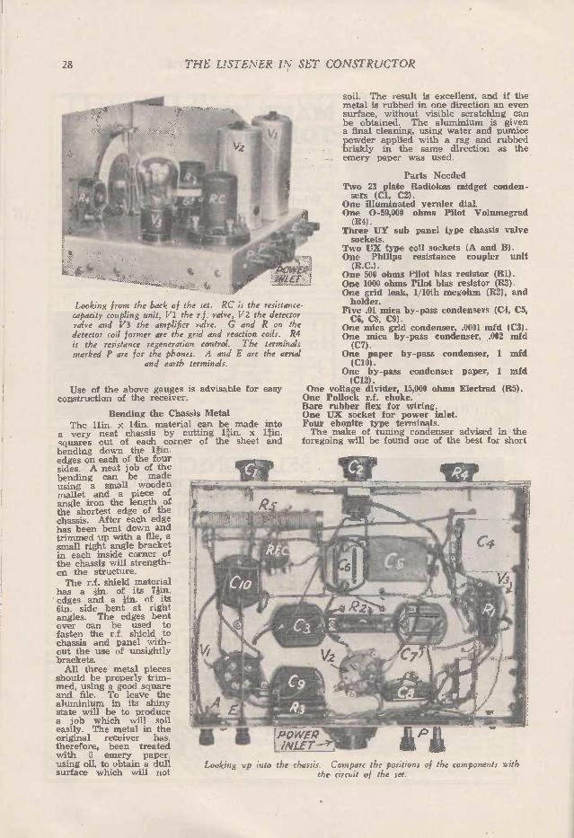
28 THE LISTENER IN SET CONSTRUCTOR
Looking from the back of the set. RC is the resistance-capacity coupling unit. Vi the r.f. valve, V2 the detector valve and V3 the amplifier valve. G and R on the detector coil former are the grid and reaction coils. R4 is the resistance regeneration control. The terminals marked P are for the phones. A and E are the aerial
and earth terminals.
Use of the above gauges is advisable for construction of the receiver.
Bending the Chassis Metal The hin. x 14M. material can be made
a very neat chassis by cutting 1fin. x squal es out of each corner of the sheet bending down the nin. edges on each of the four sides. A neat job of the bending can be made using a small wooden mallet and a piece of angle iron the length of the shortest edge of the chassis. After each edge has been bent down and trimmed up with a file, a small right angle bracket in each inside corner of the chassis will strength-en the structure. The r.f. shield material
has a iin. of its Tin. edges and a lin, of its 6in. side bent at right angles. The edges bent over can be used to fasten the r.f. shield to chassis and panel with-out the use of unsightly brackets. All three metal pieces
should be properly trim-med, using a good square and file. To leave the aluminium in its shiny state will be to produce a job which will soil easily. The metal in the original receiver has, therefore, been treated with 0 emery paper. using oil, to obtain a dull surface which will not
soil. The result is excellent, and if the metal is rubbed in one direction an even surface, without visible scratching can be obtained. The aluminium is given a final cleaning, using water and pumice powder applied with a rag and rubbed briskly in the same direction as the emery paper was used.
Parts Needed Two 23 plate Radiokes midget conden-sers (Cl, C2).
One illuminated vernier dial. One 0-59,000 ohms Pilot Volumegrad (R4).
Three UY sub panel type chassis valve sockets.
Two UX type coil sockets (A and B). One Philips resistance coupler unit (R.C.).
One 500 ohms Pilot bias resistor (R1). One 1000 ohms Pilot bias resistor (R3). One grid leak, 1/10th megohm (R2), and holder.
Five .01 mica by-pass condensers (C4, C5, C6, C8, C9).
One mica grid condenser, .0001 mfd (C3). One mica by-pass condenser, .002 mfd (C7).
One paper by-pass condenser, 1 mfd (C10).
One by-pass condenser paper, 1 mfd (C12).
One voltage divider, 15,000 ohms Electrad (R5). One Pollock r.f. choke. Bare rubber flex for wiring. One UX socket for power inlet. Four ebonite type terminals. The make of tuning condenser advised in the
foregoing will be found one of the best for short
easy
into
and
Looking up into the chassis. Compare the positions of the components with the circuit of the set.
• teiliew.roAly
R4c.

THE LISTENER IN SET CO NSTR UCTOR 29
wave tuning. Both condensers must be of the same size and make, since different makes have different minimum and maximum capacities. The Volumegrad regeneration control potentio-
meter has been chosen because of its evenness and fine adjustment. The UX type sockets are of the ordinary base-board mounting type, since by their use the tuning coils will not come too close to the metal chassis. The Pilot bias resistors are -reasonably
priced, and are very compact types. The grid leak value, when using the
s.g. detector, must be low, in order that the valve be operated for best detection. The value will lie between 500,000 ohms. 2 megohms. A megohm grid leak was used in the original receiver. Do not attempt to substitute a paper
condenser for a mica dielectric type. Sangamo mica dielectric condensers are a little more expensive, but will be the best for the job. Paper condensers have a certain inductance value, which may render them inefficient in the r.f. circuit. The voltage divider should be of the
bare wire type, which will permit tap-pings to be taken at the two voltages needed. Any good r.f. choke may be used. The terminals are for the phones.
aerial and eath connections.
Assembly First to be mounted will be the chassis
type UY sockets, and the two UX coil sockets. The positions for the five sockets can be seen in the photographs. Three holes must be made in the metal chassis
to mount the sub-panel type sockets. These can best be made by an adjustable boring bar to fit an ordinary brace, but, should one of these be unobtainable, the more tedious process of marking out with a compass, and drilling out with a small drill to remove the metal must be resorted to. Next, the illuminated dial, regeneration-con-
trolling resistance and r.f. stage tuning conden-ser should be mounted to the panel material. In the original receiver the dial was of such a type that metal had to be removed from the chassis to permit the celluloid dial disc to fit. The resistance coupler should next be mounted
The front view of the set has an excellent appearance.
Looking down on the finished set, valves and coils removed. Cl is the r.f. stage tuning condenser, C2 the
detector stage tuning condenser.
in the back right-hand corner of the chassis as shown in the photographs.
Correct Practice Chassis construction and wiring practice in the
past has been to take all connections to ground
or negative straight to the metal chassis, panel and shielding material. This is poor practice, since eddy current losses within shielding mat-erial may be considerable. Proper practice is to run a heavy bus wire along the length of the chassis, making all earth or negative con-
nections to this bus wire. This does not mean that a tuning condenser be bushed (insulated) from the panel, however. Instead of leading the movable plates connections of the tuning con-densers to the panel through the medium of the mounting screws, take, as well, a connection from each movable plates terminal by the shortest possible route to the earthed bus bar.
The earth bus bar should be of a length of gauge 14 copper wire. The bus bar is visible in the photograph of the underside of the chassis and wiring.
One side of the earth bus wire connects to chassis and the earth terminal, the other end of the bus bar being supported by means of a machine screw through the chassis.
Next comes the mounting of the by-pass con-densers, grid leak, bias resistors and the paral-leled voltage dividing resistance. The positions for the condensers can be seen in the photo-graph of the wiring. These positions should be approximated as nearly as possible, since they are so placed that connections will be short, and there will be no inter-coupling in the circuit. Spring push type terminals were selected for
the headphones. Extra large holes were drilled through the back edge of the chassis, so that these terminals could be fastened to a small block of ebonite mourned on the inner side of the chassis wall, without their touching the shielding material. Care must be taken to mount the phone terminals so that there will be no possibility of their touching the metal shielding material. The same care must be taken in mount-ing the aerial terminal, which should be insu-lated from the chassis metal by mounting through an extra large hole on a piece of ebonite bolted on the inside wall of the chassis.

30 THE LISTENER IN SET CONSTRUCTOR
Power Supply to the Receiver The power input to the receiver consists of
two wires from the 4-volt step-down transformer, and the negative and positive 200 volts from the eliminator. For simple connecting up a UX socket is used, as the power input connection instead of the four messy terminals which would be necessary otherwise and which would require to be bushed from the chassis metal. An ordinary UX type socket is quite suitable provided it is of small diameter. It is mounted as shown in the photographs to
the back edge of the chassis. The four flex supply leads are then soldered through the legs of a valve base, which can be plugged into the supply socket in a second. After mounting all chassis components, the
mounted panel can be fastened to the front edge of the chassis by means of two counter-sunk nickelled machine screws. The r.f. shield should then be fastened to the chassis by means of three machine screws, and to the panel by means of a single counter-sunk nickel plated machine screw. The r.f. shield, if properly bent and cut square, will keep the panel at right angles to the chassis. After all three metal pieces have been fastened together. the receiver will be very rigid, and will present a very neat appearance. Here are the connections:— Aerial terminal to left F terminal of r.f. coil
socket. Right F terminal of r.f. coil socket to earth (bus bar) G terminal of r.f. coil socket to G terminal of r.f. valve socket and fixed plates of r.f. stage tuning condenser (Cl). P terminal of r.f. valve socket to one side of
by-pass condenser C5 and 75 volt tapping on divider resistance. C terminal of r.f. valve socket to one side of
by-pass condenser C4 and one side of r.f. stage bias resistor Rl. Other side of condenser C4 and resistor R1 to
earth. P terminal of r.f. coil socket to movable plates
of r.f. stage tuning condenser and earth. One side of condenser grid C3 to G terminal of
detector coil socket, fixed plates of detector stage tuning condenser and a flex lead. The flex lead should come up through the chassis near the r.f. valve socket and connect to the terminal at the top of the s.g. r.f. valve. Other side of grid condenser C3 to G terminal
of detector valve socket and one side of the grid leak resistance R2.
R.f. and detector stage coil details showing how coil connections will be made to the four pins of each
base.
Other side of grid leak resistance R2 to earth. P terminal of detector coil socket to one side
of mica by-pass condenser C6 and one side of the r.f. choke. P terminal of detector valve socket to one side
of the by-pass condenser C10 and to the movable
A not h er photograph looking from the rear of the receiver, the r.f. valve shield
removed.
arm terminal of the regeneration potentiometer R4. C terminal of detector valve socket to earth. P terminal of resistance coupler to one side
of mica by-pass condenser C7 and right F ter-minal of the detector coil socket. Left terminal of detector coil socket to flex
lead coming up through the chassis near the de-tector valve socket and connecting to the ter-minal at the top of the s.g. detector valve. G terminal of resistance coupler to G terminal
of amplifier valve socket. C terminal of resistance coupler to earth. P terminal of amplifier valve socket to one
phone terminal. C terminal of amplifier valve socket to one side
of by-pass condenser C9 and one side of bias resistor R3. Other side of by-pass condenser C9 and bias
resistor R3 to earth. One side of voltage dividing resistor R5 to
earth. Other side of voltage dividing resistor R5 to
one side of by-pass condenser C12, second phone terminal, B terminal of resistance coupler other side of r.f. choke and P terminal of power inlet UX socket.
2,3,4
P of VALVE BASE
G ot VALVE BA5E
Fig 5
F+ - P }at VALVE BASE
B+ To TERMINAL
ON FORMER P CON T.? TER G et VALVE BASE

THE' LISTE NER IN SET CO NSTR UCTOR 31
G terminal of power inlet socket to earth. F terminals of each valve socket to the F ter-
minals of power inlet UX socket. One side of filament by-pass condenser C8 to
F terminal of detector valve socket farthest from cathode terminal. Other side of filament by-pass condenser C8
to earth. Second terminal of regeneration potentiometer
R4 to earth. Remaining terminal of regeneration potentio-
meter to 45 volts tapping on voltage dividing re-sistor R4. This completes the wiring, which should be
done in bare rubber flex wire, this being the most suitable material for the purpose. Keep the filament leads from inlet socket F terminals as near to the back edge of the chassis as possible, and tightly twist them.
The coils diagram will show plainly how each coil should be wound. Looking down on the U.X. type valve base, after glass and cementing material have been removed, and the pin point-ing away, we have the grid pin in the top- left-hand corner, opposite this the F negative of left F pin, in the top right-hand corner the plate pin, and opposite this the F positive or right F ter-minal. See that you have the left and right F terminals of the detector coil socket connected the right way round. In mounting coil sockets in different positions it
would be very easy to make the mistake of con-necting the F terminals of the coil sockets around the wrong way. This would not matter in the r.f. stage, but the detector valve would not oscillate if these connections were reversed in the detector stage. The coil diagrams show how the coils will be
wound. A spacing of 3-16th is allowed between aerial and r.f. tuning coils, and between reaction and detector stage tuning coil. The detector stage tuning coil is really the r.f. stage tuned anode coil, but it is also the detector grid circuit tuning coil.
Winding the Coils The ideal coils are those which can be plugged
into the receiver without the bother of connecting loose coil ends. The U.X. type valve base is par-ticularly suitable as a coil plug, and bases may be fitted with formers to enable large coils to be wound for broadcast reception. To wind complete coils to cover the 12-650
metre band of wave lengths, a total length of 30 inches of the former will be needed. The photograph of the coils shows pairs to cover
from 20-152 metres, the smallest pair, and larger
broadcast coils not being shown in the photo-graph. In the original receiver, grid coils were wound
with white wire of the gauges given in the coil chart, the reaction and aerial coils being wound with gauge 34 and 36 d.s.c. green wire. In preparing valve bases for coil making, re-
move element wires and solder from the valve base pins by holding a well-tinned soldering iron to each pin in turn, giving the base a sharp down-ward knock which will seldom fail to dislodge the solder and wire. It will help to put a little fluxite on each pin before applying the soldering iron. Although the formers fit tightly over the bases,
they should be securely fastened by use of secco-tine, wood or Le Page's glue applied sparingly. Use of this sticking medium will not affect the operation of the circuit. Begin each grid winding at a distance of a
quarter of an inch from the bottom end of each former. Use a 1-16in, drill to make the holes necessary to take the ends of each coil through the walls of the formers. Wind each coil tightly, and when beginning a grid, aerial or reaction coil, solder the beginning coil end into its base pin before starting the actual winding. This will allow tension to be put on the wire when winding and will result in tight coils. Thoroughly clean pins of flux after soldering.
It will be seen that each larger set of coils uses former slightly longer. This will avoid con-fusion since each pair of coils for any wave length below 250 metres is the same size, and all that is necessary is to distinguish between r.f. and detector coils for any required waveband. Aerial and reaction coils wound with different colored wires will enable r.f. and detector coils of any pair to be easily distinguishable without the ne-cessity of comparing the sizes of the windings before plugging into the receiver.
It will be noticed that only detector stage coils are wound for wave lengths above 152 metres. The circuit is essentially one for short wave re-ception, but it is also capable of excellent broad-cast reception, its only fault being a decided lack of selectivity when using coil pairs for reception above 250 metres, when using a normal sized aerial. Broadcast reception is excellent, however, when
using the r.f. stage as an untuned amplifier. This is done by using the r.f. coil of the 80-152 metre pair in the r.f. stage, plugging the three sizes of broadcast coils into the detector stage for recep-tion of stations between 152 and 650 metres. In referring to 12, 30 or 49 metre coils, this in-
dicates the coils which, when tuning capacities
Coil details showing the four sets which will be most used for the reception of overseas stations.
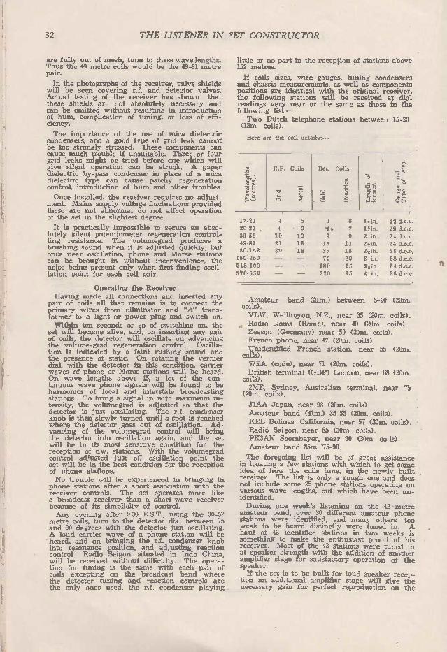
32 THE LISTENER IN SET CONSTRUCTOR
are fully out of mesh, tune to these wave lengths. Thus the 49 metre coils would be the 49-81 metre pair.
In the photographs of the receiver, valve shields will be seen covering r.f. and detector valves. Actual testing of the receiver has shown that these shields are not absolutely necessary and can be omitted without resulting in introduction of hum, complication of tuning, or loss of effi-ciency.
The importance of the use of mica dielectric condensers, and a good type of grid leak cannot be too strongly stressed. These components can cause much trouble if unsuitable. Three or four grid leaks might be tried before one which will give silent operation can be struck. A paper dielectric by-pass condenser in place of a mica dielectric type can cause patchy regeneration control, introduction of hum and other troubles.
Once installed, the receiver requires no adjust-ment. Mains supply voltage fluctuations provided these are not abnormal do not affect operation of the set in the slightest degree.
It is practically impossible to secure an abso-lutely silent potentiometer regeneration control-ling resistance. The volumegrad produces a brushing sound when it is adjusted quickly, but once near oscillation, phone and Morse stations can be brought in without inconvenience, the noise being present only when first finding oscil-lation point for each coil pair.
Operating the Receiver Having made all connections and inserted any
pair of coils all that remains is to connect the primary wires from eliminator and "A" trans-former to a light or power plug and switch on. Within ten seconds or so of switching on, the
set will become alive, and, on inserting any pair of coils, the detector will oscillate on advancing the volume-grad regeneration control. Oscilla-tion is indicated by a faint rushing sound and the presence of static. On rotating the vernier dial, with the detector in this condition, carrier waves of phone or Morse stations will be heard. On wave lengths above 45, a lot of the con-tinuous wave phone signals will be found to be harmonics of local and interstate broadcasting stations. To bring a signal in with maximum in-tensity, the volumegrad is adjusted so that the detector is just oscillating. The r.f. condenser knob is then slowly turned until a spot is reached where the detector goes out of oscillation. Ad-vancing of the volumegrad control will bring the detector into oscillation again, and the set will be in its most sensitive condition for the reception of c.w. stations. With the volumegrad control adjusted just off oscillation point the set will be in jhe best condition for the reception of phone stations. No trouble will be experienced in bringing in
phone stations after a short association with the receiver controls. The set operates more like a broadcast receiver than a short-wave receiver because of its simplicity of control. Any evening after 9.30 E.S.T., using the 30-52
metre coils, turn to the detector dial between 75 and 90 degrees with the detector just oscillating. A loud carrier wave of a phone station will be heard, and on bringing the r.f. condenser knob into resonance position, and adjusting reaction control. Radio Saigon. situated in Indo China, will be received without difficulty. The opera-tion for tuning is the same with each pair of coils excepting on the broadcast band where the detector tuning and reaction controls are the only ones used, the r.f. condenser playing
little or no part in the reception of stations above 152 metres.
If coils sizes, wire gauges, tuning condensers and chassis measurements, as well as components positions are identical with the original receiver, the following stations will be received at dial readings very near or the same as those in the following list:— Two Dutch telephone stations between 15-30 (12m. coils).
Here are the coil details: —
R.F. Coils Det. Coils
o ce,.6
- e.
12-21 4 5 3 6 len. 22 d.c.c.
20-31 . G 9 4a 7 lain. 22 d.c.c. 30-52 10 10 9 9 2 in. 24 d.c.c.
49-81 21 15 18 11 21in. 24 d.c.c.
80-152 39 •18 35 15 24in. 26 d.c.c.
150250 — 75 20 3 in. 28 d.c.e. 245-400 — 130 25 31in. 34 d.c.c.
370-650 — 220 35 4 in. 36 d.c.c.
Amateur band (21m.) between 5-20 (20m. coils). VLW. Wellington, N.Z.. near 35 (20m. coils). Radio —oma (Rome), near 40 (20m. coils). Zeeson (Germany) near 50 (20m. coils). French phone, near 47 (20m. coils). Unidentified French station, near 55 (20m.
coils). WEA (code), near 71 (20m. coils). British terminal (GBP) London, near 68 (20m.
coils). 2ME, Sydney, Australian terminal, near 75 (20m. coils).
J1AA Japan, near 98 (20m. coils). Amateur band (41m.) 35-55 (30m. coils). KEL Bolinas, California, near 57 (30m. coils). Radio Saigon, near 85 (30m. coils). PK3AN Soerabayer, near 90 (30m. coils). Amateur band 85m. 75-90.
The foregoing list will be of great assistance in locating a few stations with which to get some idea of how the coils tune, in the newly built receiver. The list is only a rough one and does not include some 25 phone stations operating on various wave lengths, but which have been un-identified. During one week's listening on the 42 metre
amateur band, over 30 different amateur phone stations were identified, and many others too weak to be heard distinctly were tuned in. A haul of 43 identified stations in two weeks is something to make the enthusiast proud of his receiver. Most of the 43 stations were tuned in at speaker strength with the addition of another amplifier stage for satisfactory operation of the speaker. If the set is to be built for loud speaker recep-
tion an additional amplifier stage will give the necessary gain for perfect reproduction on the

THE'. LISTENER IN SET CONSTRUCTOR 33
speaker of local broadcasters as well as interna-tional transmissions.
After winding all coils, the turns may be fixed securely by "doping" them using either shellac varnish thinly applied or acetone in which have been dissolved some small pieces of clear cellu-loid. The latter preparation is a colorless mix-ture, and, if care is taken to see that the windings are not soiled, the result will be a very neat set of coils.
If windings have been soiled during the con-struction of the coils, the thin shellac-methylated spirits preparation will color the windings, and will hold the turns firmly in place. To leave the windings "undoped" would be to
half-finish the job, since slightly loose windings will spoil completely the operation of the re-ceiver. A single loose turn can cause dial read-ings to change consistently. After logging a sta-tion it should be always possible to hear the sta-tion on the same dial reading whenever it is tuned in. The former and wire insulation, at ordinary
room temperatures, has a minute moisture con-tent. Before applying either "doping" mixtures to windings, leave all the coils in a warm oven for half an hour or so. The oven should not be hot enough to burn the formers. Apply the preparation immediately the coils are removed from the oven. All such preparations as seccotine, household
varnish. etc., are strictly taboo in fastening coil windings. Use either of the preparations we have mentioned.
Testing the Receiver
If all instructions have been carefully followed, the process of testing the receiver involves the mere connecting up of power leads, aerial and% earth and phone connections, and adjustment to the two voltage divider tappings. The two voltage divider tappings may be ad-
justed without the use of a voltmeter. The de-tector screened grid tapping, which is the one nearest the filament end of the voltage dividing resistance, is adjusted along the divider until the volumegrad is almost half way advanced for the detector to oscillate. The adjustment of the r.f. screened grid voltage is not critical, and the tapping may be taken at a position a little farther than half way along the resistance towards the positive end. Tappings can be made to the Electrad divider simply by twisting two pieces of gauge 22 bare wire around the divider at the required positions. Any eliminator to deliver between 180 and 210
volts may be used to supply the "B' current for this receiver. Any step-down transformer to de-liver 4 volts a.c. centre tapped may be used to supply the "A"' current. The U.X. inlet socket takes all power connec-
tions. In order to make a neat job of the com-bination of power gear and receiver, it is advis-able to have power leads some four or more feet long to keep the eliminator and transformer on the floor, or in the bottom of the receiver cabinet. The "A" transformer may be brought within several inches of the receiver without introduc-ing hum, however, while the "B" eliminator can be placed right next to the receiver without af-fecting the set's operation. The two "A" leads and two "B" leads to the transformer secondary ana 13 eliminator may be twisted together into a flex. A valve base is used as the plug for the power inlet socket. The "A" transformer secondary leads will connect to the two F pins of the power inlet plug, any way round; the B negative will connect to the G pin
of the power plug, and "B" positive will connect to the P pin of the plug. The centre-tapping of the "A" transformer
secondary will connect to B negative. Now we have four power supply connections
from the receiver, aerial and earth, and two headphones or speaker terminals. Two "B" power wires will connect to the negative and posi-tive terminals of the "B" eliminator. Two "A" power wires will connect to the secondary ter-minals of the four-volt step-down transformer. A wire will connect the "A" transformer second-ary centre tap terminal to "B" negative. Aerial and earth will connect to their respective ter-minals as with the two headphones leads, which will connect to their terminals at the right of the chassis.
81.. *re -eu -s
Crystals as Detectors T HE crystal detector, which has been used for
about 20 years, depends for its action on electrical heating effects. It is well known that the passage of an elec-
trical current through a conductor will increase the temperature of the conductor. This is called the Joulean effect, after Joule, an eminent scien-tist. Let us keep this fact in mind. Now another scientist, Peltier, discovered that if a steady cur-rent be passed from one conductor to another of a different substance, the temperature of the junction is raised if the current flows in one direction, and lowered when the direction is re-versed. Crystals that are used as detectors have the
characteristic of varying their resistance greatly according to their temperature. That is, a small variation of temperature causes a dispropor-tionately greater variation in resistance to the passage of an electric current. So far, we have considered what happens when
a steady current flows through the detector in one direction and then another. Imagine the effect of a current which rapidly
changes its direction, that is, an alternating or oscillatory current. When the current flows in one direction it heats the crystal and contact, according to the Joulean law, and by the Peltier effect. The result of the adding together of these two effects is a considerable rise in tem-perature. The heat thus engendered causes the resistance of the detector to drop considerably, thus allowing a large current to pass. Now let us consider what happens when the
current flows in the other direction. As before, the Joulean law operates, but in this case the Peltier effect is one of cooling, so no rise in tem-perature takes place, and the detector offers high resistance to the passage of an electric current. The greater the current, the greater the effect, whether cooling or heating, and this causes a crystal detector to give a disproportionate re-sponse to weak and strong signals.
Portable Receivers T HE -A" battery supply problem in portable
receivers deters many from constructing such a set. Using the .06 filament four volt type of valve, a torch or a "C" bias battery may be used to supply the filament current. Torch batteries may be secured for as low as one shilling, and a supply of a half dozen of these will provide filament çurrent for a week. The money spent in such an "A" supply is compensated for by the reduction in size of the receiver, and the much lower weight of the equipment.

34 T HE LISTE NER IN SET CO NSTR UCTOR
SHORT W AVE ADAPTORS Constructional details of a combination which can be used to receive short-wave broadcasts on an ordinary receiver.
THE ordinary broadcast receiver can be readily converted for the reception of inter-national transmissions. While the single valve adaptor will not
give the same strength of reception as the screened grid detector preceded by a tuned s.g.r.f. stage, it will give headphone reception of international stations. Satisfactory speaker reception from such an adaptor, if it is followed by two amplifier
The adaptor circuit for battery operated receivers. AC is the midget aerial coupling condenser, Si the grid tuning coil, S2 the reaction coil, Cl the tuning condenser. C2 the reaction condenser, and RFC the r.f. choke. The three connections to the UX socket are to the two filament pins
and the plate pin of the socket.
stages. is often possible, and the set will be a little more difficult to control, since there is no r.f. amplification which would render signals suffi-ciently strong to be tuned in easily on the de-tector stage. The single valve batter, or a.c. operated
adaptor. while usually difficult to control, will provide a means of hearing overseas stations at a minimum cost for apparatus. The adaptor consists merely of a short wave
detector circuit which is substituted for the ordi-nary broadcast detector circuit when it is desired to listen to short wave transmissions. The adaptor using no screened grid r.f. am-
plifier, although not the most reliable for the reception of phone transmissions, is highly satis-factory for the reception of c.w. Morse signals. and a single valve receiver with no amplifier stages and operated from "A" and "13- batteries would provide all the volume necessary for Morse code reception. Properly shielded, there is no reason why
hand capacity, which in the past has prevented satisfactory operation, should prevent easy tuning. A metal shield and a chassis, which may be easily bent out of a single piece of metal, will support all components, and will make a very neat job of the adaptor. While the all-electric adaptor is a possibility,
the extra cost of an a.c. detector valve and the
probability of hum being introduced into the output, due to the long adaptor leads, should not be risked. We publish the a.c. circuit of an adaptor, however, for those who wish to build the a.c. version. A filament by-pass condenser. connected between the filament terminal farthest from the cathode, and chassis should be used to prevent detector stage hum. In plugging an adaptor into the detector socket of an all-electric broadcast receiver, the normal detector valve may be plugged into the adaptor socket. In many in-stances the plate supply voltage to the detector will not be pure; an extra flaer will be neces-sary to obtain satisfactory operation. The ideal arrangement is to build the single-
valve short wave receiver, coupling it to the broadcast set by means of an audio frequency transformer. By doing this, the detector valve of the broadcast set may be included as an addi-tional a.f. amplifier, and the gain by the use of this valve as an amplifier will be much greater. For cheapness, it is recommended that the single-valve receiver be battery operated. A single 60-volt B. battery should be expected to give over 15 months' service, while three dry cells as an "A" supply should last for over eight months. If the broadcast receiver is battery operated, the A. and B. supply of the set may be used to supply the adaptor. The description here, is of an adaptor
to be plugged into a battery operated broadcast receiver. The same constructional details will apply if the adaptor is to be constructed for a.c. operation, the a.c. circuit being used, and the filament by-pass between filament and chassis being installed.
Chassis Construction Aluminium sizes, 6in. x 8in. and 9in. x
will be needed to construct the chassis. Both pieces of metal should be of gauge 16 material for simple working. Pieces len. x len. are cut out of each corner
of the 9in. x llin, material, and the len, edges are bent down and fastened on the inside with smah right-angle brass brackets to make a solid job of the chassis.
The adaptor circuit for all-electric receivers. The fourth connection to the adaptor plug is to the cathode pin of the five
prong socket.

THE LISTENER IN SET CONSTRUCTOR 35
Both pieces of metal should be squared up before assembly is attempted. The metal may be finished off by rubbing with very fine emery paper and oil.
This diagram shows how to connect either a.c. or d.c. adaptor circuits to include the detector valve of the broadcast receiver as an additional amplifier. An ordinary audio frequency transformer and resistance are needed. The value of this resistance for the average a.f. transformer will be 50,000
ohms.
Components Needed. One 23 - plate Radiokes midget condenser
(Cl). One 9 or 13 plate midget condenser (C2). One 3-plate midget condenser (AC). One chassis type valve socket, U.X. type. One baseboard type valve socket, U.X. type. One aerial terminal. Grid leak 2 megoluns and holder. Grid condenser .00025 mfd capacity. One r.f. choke. Some rubber-covered flex for connections. One high ratio vernier dial.
A photograph of the original battery adaptor built chassis fashion.
The 23-plate tuning condenser is mounted in the centre of the panel material. The 3-plate midget condenser is mounted to a piece of ebonite in the top left-hand corner of the panel. This condenser is the only one of the three which can-not be mounted directly on the panel. The midget reaction condenser should be mounted in a similar position to the 3-plate aerial condenser on the opposite side of the panel. The chassis type valve socket is mounted at
the right of the chassis, as shown in the photo-graphs. 'Phe baseboard type coil socket is mounted to the left of the valve socket. The aerial terminal is mounted to a small piece of ebonite in the back left-hand corner of the chassis. This terminal must not touch the chassis material. Underneath the chassis, mount grid leak and holder, the grid condenser and the r.f. choke.
Connections Aerial terminal to movable plates of 3-plate
aerial condenser. Fixed plates of aerial condenser to grid ter-
minal of coil socket, fixed plates of tuning condenser and one side of grid leak and con-denser. Other side of grid leak and condenser to
grid terminal of detector valve socket. Plate terminal of coil socket to chassis and
movable plates of tuning condenser. Plate terminal of valve socket to one side
of r.f. choke and right F terminal of coil socket. This terminal in the one opposite the P terminal of the socket. Other F terminal of coil socket to fixed plates
of reaction condenser. Other side of r.f. choke to a flex lead which
will connect to the plate pin of the adaptor plug.
Looking from the rear of the chassis with valve and one of the coils in position.
One F terminal of valve socket to chassis and second flex lead connecting to one of the F pins of the adaptor plug. Other F terminal of valve socket to a third
flex lead connecting to other F pins of adaptor plug. This completes the wiring. The adaptor plug
is an old valve base. The three flex leads to the plug should be
twisted into a single flex. The plug may be filled with sealing wax to finish off the job after the three flexes have been properly soldered into the plug. The connection to the movable plates of the
reaction condenser is through the medium of the metal panel. The adaptor plug flex may be made as long
as convenient for ordinary purposes. The length of the flex should not exceed about 10 feet, however.
Looking down on the adaptor. No stray wires are visible. This method of construc-tion renders the adaptor remarkably stable.

36 T HE LISTE NER IN SET CO NSTR UCTOR
Coils The beginning of the grid coil winding will
be at the bottom of the coil oase, and will con-nect to the G pin of the base. The end of the grid coil winding will be connected to the P pin of the coil base. The beginning of the reaction coil winding will connect to the left F pin of the coil base (pin opposite P pin). Reversal of the reaction coil ends will prevent the adaptor valve from oscillating. The end of the reaction coil winding will be
to the right. Here are the coil sizes to cover wave lengths
from 10 to 650 metres.
Wave Length of Wire length. Grid. Reaction, former. gauge.
10-21 4 20-31 5 30-52 9 50-81 17 80-152 32 150-250 70 240-400 130 400-650 220
6 8 10 10 15 20 25 35
22 d.c.c. 22 d.c.c. 22 d.c.c. 24 d.c.c. 24 d.c.c. 30 d.c.c. 34 d.c.c. 34 d.c.c.
Provided the adaptor is correctly wired, grid leak and condenser and the r.f. choke are in order, there is no reason why the adaptor should not oscillate on all the wavebands shown above. A good detector valve such as the Philips A415 should be used with a plate voltage of between 30 and 60.
Aerial Terminal
Three simple circuits which may be used in conjunction with the single valve a.c. or battery operated adaptor for the elimin-ation of "dead spots." The first consists merely of a coil and switch, the second of a coil in parallel with a tuning condenser,
and thirdly a simple varíometer.
The two filament flex leads to the adaptor plug should be reversed, whichever way giving greatest signal strength being used. It will be found that patches exist where the
adaptor cannot be made to oscillate. The effect is caused by "dead spots," or the fundamental or harmonics of the receiving aerial coming into tune with the adaptor grid circuit. The further the plates of the aerial condenser (AC) are in mesh the greater will be the signal strength of all transmissions, but, if carried too far, the im-pedance of the aerial will be sufficient to prevent the adaptor from oscillating. "Dead spots" make themselves a nuisance if
no means of shifting them is usen. A coil of 10 turns of gauge 22 d.c.c. wire wound on a 2in. diameter former and tuned by a .00015 mfd. capacity condenser should be connected between the aerial and the aerial terminal of the adaptor. As soon as a "dead spot" is struck, alteration to the position of the plates of the condenser of the "dead spot shifter" will shift the spot to another
part of the adaptor dial. The size of the "shifter" tuning condenser is not important. The adaptor may be fitted with an illuminated
dial if it is built for all-electric operation. In an accumulator A supply is used for the adaptor and a little extra filament consumption does not matter, the illuminated dial may be fitted to the battery operated adaptor. It is advisable to earth direct the shielding
of the adaptor. This will prevent the possibility of hand capacity effects spoiling operation. Mount an earth terminal directly to the chassis, and when using the adaptor disconnect both aerial and earth leads from the broadcast set and con-nect them to their respective terminals on the adaptor. Note the a.c. circuit of the adaptor. Here the
UY type valve base is used as an adaptor plug. the extra connection being to the cathode pin of the plug. Fig 3 shows how the adaptor may be con-
nected to include the detector valve of the broad-cast receiver as an additional amplifier. To do this, an ordinary audio frequency transformer is included in the adaptor chassis. The resistance connected across the transformer secondary ter-minals should be of 50,000 ohms grid leak type. A flex lead is twisted round the grid prong of the detector valve which is then inserted in its socket. The by-pass condenser C3 should have a capacity of between .01 and 1 mfd. AC in all circuits is the three plate aerial series condenser. Si and S2 are grid and reaction coils respectively, while Cl is the tuning condenser and C2 the reaction condenser.
Resistance Coupled Amplifiers IN building up resistance coupled amplifiers from
resistors and blocking condensers, it is the usual practice to use high capacity by-pass con-densers in order to obtain good bass-note re-production. It will be found, however, that if the capacities are too high—in the region of one microfarad, for instance—the reproduction is in-distinct and lacking. The happy medium in capacities must be
struck. Obviously, if the capacities are too low, the amplifier cannot possibly give satisfactory bass-note amplification. In the first stage of a three-stage arrangement a .006 mfd. capacity condenser should be used; in the second stage one of .008 mfd. capacity will prove satisfactory, and one of .01 mfd. capacity in the third stage should prove satisfactory. It is in order to use a high impedance valve
in the second stage of a three-stage resistance-coupled amplifier. The use of such a valve will result in a high gain without the distortion which would result if the same valve were to be used in a transformer-coupled amplifier. A high gain valve of this type should be operated with a fairly high plate voltage and a carefully adjusted bias value. It will be found that a valve of this type will seldom take more than three volts bias. The value of plate resistors when operating
from the single plate voltage socket is in the region of 100,000 ohms. It is advisable to take separate plate voltage terminals from each of the stages, however. The value of the grid resistance in the first stage will be a megohms; in the second stage megohm; and in the third stage a megohm. Resistance-coupled ampli-fication is very easly put into operation and seldom fails, when correctly adjusted, to give good quality amplification. Wire-wound plate resistances should be used if these can be afforded.

THE LISTENER IN SET CONSTRUCTOR 37
170 FLINDERS ST.ego. 148 SWANSTON ST. 4H BOURKE ST. M eTer •
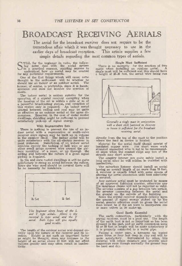
Tb Set
38 T HE LISTE NER IN SET CO NSTR UCTOR
BROADCAST RECEIVING AERIALS The aerial for the broadcast receiver does not require to be the tremendous affair which it was thought necessary to use in the earlier days of broadcast reception. This article supplies a few simple details regarding the most common types of aerials.
STILL for the beginner in radio, the follow-ing notes deal with the aerial system in a practical manner, enabling anyone to understand how an aerial may be erected
for any particular requirements. One of the first things which will cause some
thought to the enthusiast will be whether he should use an indoor or an outdoor aerial. The former, of course, is preferable, since it is incon-spicuous and does not involve the erection of masts. The indoor aerial is seldom suitable for the
operation of a crystal receiver excepting when the location of the set is within a mile or so of a powerful broadcasting station, and reception of this station only is required. An indoor aerial erected between ceiling and roof may be quite as effective as an outdoor aerial of the same di-mensions. However, in the case of metal roofed dwellings, shielding might be sufficient to prevent satisfactory pick-up of signal energy.
With Regenerative Sets There is nothing to prevent the use of an in-
door aerial with a regenerative or multi-valve receiver since signals may be built up in volume in the receiver itself. The indoor aerial will be quite satisfactory with the all-electric receiver in most instances. Installation of an indoor aerial involves merely the tacking of bell wire or any other small gauge covered wire around the pic-ture moulding of a room, or up through the ceiling and between the rafters if a great signal pickup is required. In tile and slate roofed dwellings it will be quite
satisfactory to string an aerial between the rafters. Since the wire used should be covered there will be no necessity for insulators.
To Set
The beginner often hears of the L and T type aerials. Above is the inverted L type aerial and the T aerial. Both types will give equally
good results.
The length of the outdoor aerial will depend en-tirely upon the nature of the receiver and its lo-cation. Height is not such an important factor as might be thought, since any increase to the height of an aerial above 30 feet will not affect volume greatly and may often result in inselec-tivity.
Single Mast Sufficient There is no necessity for the erection of two
masts when installing an outdoor aerial. A single mast will be sufficient and this should have a height of 25-30 feet, the aerial wire being run
Generally a single mast in conjunction with a short stick fastened to chimney or house is sufficient for the broadcast
receiving aerial.
directly from the top of the mast to the position where the lead in device is located. Material for the aerial itself should consist of
insulated copper wire. /*or short wave work stranded enamelled wire is not to be recommend-ed since when the enamel chips any two of the strands may short across. The country listener can quite safely install a
long aerial since he will seldom be troubled with inselectivity. The suburban listener should install an aerial
having an overall length of no more than 75 feet. A receiver is usually fitted with some means of altering the aerial connection until best selectivity is secured. Any outdoor aerial must be protected by means
of an approved lightning arrester, otherwise any fire insurance claims will not be regarded as valid. The arrester consists of a gap between two metals, the arrester connecting between the aerial and the ground on the outside of the building. Since the crystal receiver depends entirely upon
the amount of signal energy picked up by the aerial, greater attention must be given the aerial than would be if the set were to incorporate one or more valves in its make-up.
Good Earth Essential The earth connection, particularly with the
crystal receiver, must be a good one. The length of the earth lead is not as important as has been stressed in the past, and an earth connection some 15 or 20 feet in length will be quite satisfactory if it is properly connected to a water pipe. Failing a water pipe, a kerosene tin buried
some three or four feet deep in clay soil will be quite satisfactory. Surrounded by ashes, this material will retain moisture and provide good connection even though normally the ground may be hard and dry.

THE LISTENER IN SET CONSTRUCTOR 39
"CHANEX" LEADERSHIP There is a -CHANEX" fixed CONDENSER for every purpose
W ORKING VOLTAGE from 150 to 10.000 Volt D.C.
Most troubles in Radio-Re-ceivers can be traced to faulty
condensers.
DON'T RUN ANY RISK ! !
SPECIFY AND INSIST ON
"CHANE The Condenser with a
W ORLD REPUTATION We specially wish to draw your attention to the NE W "CHANEX"
for use in Receivers and Amplifiers of exacting specifications (Loftin-White and similar circuits). They are double tested on 2000 Volts D.C. and have a guaranteed W ORKING VOLTAGE of 609 Volts D.C.
Stocked by leading Radio Firms.
Sole Factory Representatives:
H. HECHT & CO. Melbourne and Sydney
Interstate Distributors:
Queensland: J. C. PRICE, Brisbane; TRACKSON BROS. LTD., Brisbane.
West Australia: CARLYLE & CO., Perth. South Australia: W M. T. MATTHE W, Adelaide.
Tasmania: W. & G. GENDERS PTY. LTD., Hobart and Launceston.

40 THE LISTENER IN SET CONSTRUCTOR
HO W THE GRAMOPHONE PICK-UP WORKS
The operation of the electro-magnetic pick-up is described simply in the following notes.
THE discovery by Dr. Lee De Forest that the introduction of a third element into the two-element valve could make the ther-mionic valve perform wonders undreamed
of at the time, was the beginning of a series of amazing leaps which have, within the space of a few years, brought radio transmission and recep-tion to its present state of near perfection. It is not so very long ago since the best of radio
receivers was classed as being able to produce
The vertical type of electro-magnetic reproducer.
music no better than that available from a poor gramophone, but the advent of radio, far from killing the industry, lifted the art of disc record-ing from out of the groove into which the in-ability to improve the mechanical recording methods had caused it to run. The advent of the broadcasting microphone,
speech amplifier, and electro-magnetic cutting methods, has combined with the manufacture of gramophone discs to produce recordings which, at the present day, may be said to be perfect. In order to get the most out of an electrical
recording—there being very few playable me-chanical recordings available now—we must re-produce them electrically by a reversal of the process used in the making of the record. The gramophone pick-up enables us to do this.
What is a gramophone pick-up? It can be defined as an instrument used to convert mechanical
vibrations of the sound track into alternating cur-rent voltages of the same frequency. How does it do this? Here you should refer to
Fig. 2, which represents a standard type of gramophone pick-up. The arrangement consists of a powerful horseshoe magnet, two pole pieces, a soft iron armature, and coils.
Theory of Pick-Up Operation Faraday's conception is that lines of force start
from one pole of a magnet and finish up in the other. These lines, as many schoolboys will know, can be seen by the sprinkling of fine iron filing over a sheet of paper placed over a magnet. There is a tremendous difference between the per-formance of these lines of force in air and in iron. Should soft iron be introduced into the field of a magnet, the lines of force will try to crowd into it and will increase in themselves. Changing the position of the soft iron, which will hereafter be recognised as the armature, will ma-terially affect the lines of force in the circuit formed by the pole pieces, air gaps between the armature and each pole piece, and the armature itself. The lines of force exist through the coils.
The needle is attached to the armature. A move-ment of the needle will incline the armature. the change of armature position altering the number of lines of force. As in the principle of all electrical generating
apparatus, the cutting of the lines of force per-meating a coil will, by induction, introduce a voltage in that coil, and a current will flow if the two ends of the coil are connected together. The voltage developed in the coil is in propor-tion to the speed at which the armature moves.
The horizontal type of electro-magnetic pick-up showing how lines of force crowd
into the soft iron armature.
What is the use of the pole pieces? These are used to concentrate the field of the magnet on to the armature, so that small changes in its position will produce large changes in the strength of the field existing across the air gap.

THE LISTENER IN SET CONSTRUCTOR 41
The operation of the gramophone pick-up is merely a reversal of the operation of the loud speaker. Alternating voltages through the speaker windings cause changing of the strength of the speaker magnets in accordance with the received signals. Changes in the strength of the field are responded to by the diaphragm, or the actuating reed which drives the cone, in this type of speaker. The electro-magnetic method of changing the
vibrations of a gramophone sound track into elec-trical currents of the same frequency has lived after discarding carbon, capacity, oscillator piezo electric, and hot wire systems which have been patented and used with some degree of success. The electro-magnetic method is simple, cheap and effective, but there are difficulties to be met with in securing distortionless reproduction. Conversation with a maker of magnetic pick-
ups will reveal that this instrument causes its manufacturer much worry. Two identical in-struments, because of slight difference in the characteristics of the magnets and metal used in their construction, will perform as equally unalike as two different makes. It is a wise plan, there-fore, when purchasing an instrument, to secure a guarantee that the instrument can be changed if desired, as trial with several will result in the best being obtained. Much experimenting by manufacturers is re-
sulting in improved construction and resultant efficiency in the latest types of pick-up. By cor-rect concentration of the field, by correct placing of the pole pieces—these consisting of thin lamina-tions and damping of the armature—greater out-puts, with no trace of distortion, have been ob-tained, and it is common knowledge that some types, feeding into the grid circuit of a small general purpose amplifier valve, will overload the valve. What is damping in a pick-up? The armature,
in many types of pick-up, is pivoted, while in other types it is supported by rubber, which func-tions as support. Obviously the armature cannot be left free to rotate on its pivot. What would happen if the armature were free? It would be immediately attracted to one of the pole pieces, and would be held there. Some means of sup-porting the armature between the pole pieces is needed. If the supporting is too rigid the arma-ture will not respond to the vibration of the sound track. Again, if the armature is too loosely sup-ported, a rattle and distortion will be introduced. The output from a pick-up is dependent to a
large extent upon the strength of the magnet. The armature, therefore, must be heavily damped to prevent the armature being drawn towards either of the pole pieces. In any pick-up it is important that the armature be centred. If it is several thousandths of an inch closer to one pole piece than it is to the other, the form of the current available at the pick-up output ter-minals will not be in exact accordance with the vibrations of the sound track, with resultant dis-tortion. Rubber is most used for the buffering of a
pick-up armature. The use of springs is usually unsuccessful, the results being harsh and dis-cordant, due to vibration of the springs, and un-even pull exerted under different pressures. In order that the output from a pick-up will be
an exact copy of the item recorded, several un-portant points must be considered. Firstly, the needle must follow the track. It will not follow the track unless the armature supporting it is correctly supported or damped. It will not follow
the track unless the whole instrument is in cor-rect alignment with the record track. Insufficient damping will result in the armature overshooting the mark and developing a motion of its own; this introduces a foreign voltage which causes dis-tortion. The strength of the magnet, the size of the armature, the size of the windings, the width of the air gaps, should all be in proportion if perfect results are to be expected. Of course, we cannot hope to look to these things ourselves, but an exchange of experiences with other experi-menters will soon give one an idea of what par-ticular job is the best value for the money. The reason for this brief discussion is that the
pick-up, being 'the essential part of any radio gramophone, needs explaining in order that one may choose the best pick-up to suit his pocket, and adjust an instrument to give the best results of which it is capable.
111••••••111 .1110 11.1
Hints for Efficient Working of Screen Grid Valves
LIKE all improvements in radio, the screen grid valve can be just as troublesome when
badly adjusted as it can be efficient under cor-rect conditions. In time, experimenters will have familiarised themselves with the peculiari-ties of the valve. Meanwhile a few tips on how to get the best out of a screen grid valve are not out of place.
Some of the battery-operated valves available today have astonishingly high magnification factors. Certain limiting factors in coil design make it impossible for us to obtain full benefit from these, but a little experimental work in matching coils will go a long way towards the desired end. We cannot alter the coils, but we can alter the impedance and amplification factor of the valve very easily. Do not starve the plate of volts. Nothing less than 120 is advisable, and much better results are often obtained with the full 150 allowed by makers. The valve is adjusted to give its best results
with ordinary coils by juggling with the screen voltage. The higher the screen volts for a given plate voltage, the lower is the impedance of the valve and the smaller its magnification factor. By reducing the screen volts a big increase in both impedance and amplification can be ob-tained, though, of course, at the expense of mutual conductance. If using only one screen-grid stage, it may be found worth while to tune in to the most distant station that you can get without the use of more than a touch of re-action, and follow this by trying the effect of varying screen-grid voltages. Very often a voltage will be found which renders the valve's characteristics a good match for the coils. When using two screen-grid stages it would
be advisable to place the most sensitive valve in the first stage. Best efficiency will be obtained by using separate high tension positive leads for each of the screen grids of the valves. In the first stage a high amplification factor may be used. The fact that by lowering the screen-grid volts the valve is rendered able to deal only with small swings on the control grid need not cause worry. In the second stage, however, much bigger grid swings have to be dealt with, and there must be no overloading of this valve when the first is producing really big amplifica-tion.

42 THE LISTENER IN SET CO NSTR UCTOR
ELECTRICAL INTERFERENCE PROBLEMS
Apparatus operated from the supply mains must often be treated to prevent the emanation of inter fering noises which would pre-
vent satisfactory reception in nearby receivers.
MOST electrically operated household and workshop equipment will set up disturb-ances which will be picked up in a radio receiver. Whether the noises will be
sufficiently bad to prevent satisfactory reception will depend upon the strength of the transmis-sions, and upon how bad the interference actu-ally is. In country towns particularly interference
noises caused by electrical motors, cleaners, ven-
A pair of chokes and by-pass condensers connected in the input leads from the
supply mains to the receiver.
tilators and other such things are often suffi-ciently bad to prevent satisfactory reception. In order that signals will be received at speaker strength in the country town, the receiver must be operated in a much more sensitive condition than would be necessary within several miles of a broadcasting station. In this condition for reception, interference noises would be received at much greater strength, and might even com-pletely obliterate transmissions. Whether an interfering noise can be eliminated
or minimised will depend mainly upon the nature of its source. Most generator and motor equip-ment, by simple treatment with by-pass con-densers, will cease to give further trouble in this direction. Interference caused by sparking motors or
generator brushes will be heard in the form of a regular harsh grating noise which may be heard as a background to received signals. These may even obliterate all transmissions. Motor and generator interference will usually be heard at greater strength as a receiver is tuned down the scale.
Testing the Set The question whether interference noise can
be eliminated at the receiving end will be settled by disconnecting the aerial and earth leads. If the interference disappears completely it will be known that the noise cannot be eliminated at the receiver, except. perhaps, to be minimised by altering the direction of the receiving aerial.
If the noise is still heard it is possible that it is being picked up through the medium of the main's supply wires. Interference may be very easily conducted
throughout a town by the main's supply wires, and may prevent satisfactory reception, particu-larly when power for a receiver's operation is derived from the supply. Use of the main's supply filter, as shown in Fig. 1, would completely eliminate interference picked up by a receiver from the main's supply wires. Details for build-ing this filter will be given shortly. The All-Electric receiver is particularly sus-
ceptible to noises brought in by the main's supply wires, and the switching on of a light several doors away might cause a severe disturbance in the average home-built receiver combination. Proper attention to details when installing or building an a.c. set will prevent interference of this type from affecting reception. Installation of the supply filter shown in Fig. 1 will prevent interference of any nature from reaching a re-ceiver from the main's supply. Noises caused by electric trams cannot be
eliminated at the receiver. The best that can be done is to acquaint the tramway authorities, asking them to endeavor to eliminate the trouble. Fig. 2 shows how a d.c. motor should be treated
to prevent it from causing interference. The condensers must be of a type to withstand
th voltage. Use 1000-volt a.c. test condensers of a mfd. capacity each. The fuses are neces-
Motors or generators can be treated by the simple connecting of by-pass condensers. All condensers used for such purpose as this must be of a type having an unusually
high breakdown voltage.
sary precautions since one never can tell when a condenser will break down. A condenser tested normally at 1000 volts could develop a fault which could cause it to burn up at 250 volts or less. The filter as shown will oftimes eliminate
broadness of tuning in addition to preventing in-terference noises from reaching the receiver. The filter consists of a pair of r.f. chokes of suitable

THE LISTENER IN SET CONSTRUCTOR 43
construction, and two by-pass condensers tested to withstand an a.c. voltage of not less than twice the main's supply voltage. This is important, since there is no saying what might happen should one of these condensers break down. The gauge of wire used in constructing the
ri. choke coils will depend upon the apparatus with which the filter is to be used. Naturally a motor drawing several amps would require coils using gauge 16 wire to carry the current. For ordinary eliminators and power packs, however, gauge 20 d.c.c. wire will be found quite suitable, the number of turns for each coil not being im-portant and between 150 and 300 turns. The by-pass condensers should each be of from
.01 to 2 mfd. capacity. Do not attempt to use
Similarly, interference from a motor can be prevented from reaching the mains supply wires by use of chokes and a
condenser.
a small condenser which you know will not handle the voltage without breaking down. In the country the house lighting supply equip-
ment may cause considerable trouble through in-terference noise. In the case of gas engines, a 10,000-ohm resistor in series with each plug lead should minimise or eliminate the annoying inter-ference. The generator should have a condenser of 2 rnfd. capacity connected in series with a fuse between each generator brush and ground. The frames of generator and motor equipment should be properly earthed. The importance of this cannot be overstressed. Use of the fixed condensers connected to gene-
rator or motor is an advantage and will help operation of the apparatus since by their use sparking is reduced and the necessity for clean-ing commutators and brushes will be eliminated for much longer periods. Many other forms of electrical equipment can
cause trouble. The filter method as shown in Fig. 3, or that shown in Fig. 2, or both, should in most cases eliminate the interference at its source, and it may only be in places when a good earth connection cannot be obtained that trouble will be struck. Surgical machinery operated by electricity can
cause considerable interference. In this case it would be best to see the owner of the anparatus, or write to the Radio Inspector, Treasury Build-ings, Melbourne.
Static Atmospherics have been with us ever since we
first saw radio, and probably it will be a number of years yet before we can outwit the natural phenomenon, "static," as it is called. The use of a small indoor aerial and a high gain receiver may often bring in a particular station better than with an outdoor aerial, but it can be safely said here that there is no remed- for static, and
we must take it as it comes, shutting the re-ceiver off when the noise is particularly bad. The a.c. supply may set up hum in a receiver
through incorrect placing of certain wires. In short wave receivers particularly, the trouble may prevent the clear reception of pure d.c. car-rier waves. By running the lead in or earth wires near a.c. carrying leads, a.c. ripple may be intro-duced into a receiver. The source of that mysterious crackling noise
may often be tracked down to a loose lead-in connection or touching guy wires, or wire hal-yards. Flapping or loose roofing material, or touch of clothes line wires in the vicinity of an aerial, can set up an annoying crackling which will manifest itself when the receiver is tuned to the carrier wave of a station, or when the detector is made to oscillate when the noise will be heard right around the tuning dial.
Receiver Troubles Other interference noises could be classed as
receiver troubles, since many of these can origi-nate in the receiving or power pack circuits. Here it is necessary to follow the usual process of elimination, using common-sense in the search. Naturally the set owner who knows absolutely nothing of his set cannot hope to be successful in locating a receiver trouble unless by some remarkable stroke of good luck he happens upon it. A receiver, if allowed to oscillate, can very
often cause interference in neighboring receivers. The single valve regenerative set in particular • is a very bad offender, and can cause just as much trouble as a bigger receiver, so have a thought for others and do not allow the set to "whistle" when listening to any transmission.
A Short Wave Tip T HERE is a mistaken idea that a short wave
aerial need only be a few feet of copper wire attached to the aerial binding post. It works, but because it does so is no indication that it is most efficient. It has been said that maybe this idea came from
the fact that short wave transmitters usually em-ploy an aerial about a half wave length long, which would be about a 25ft. aerial in the case of an aerial operating around 15 metres. The writer believes that the short wave receiv-ing aerial should be about as long and as high as you can make it, for it simply functions as an aperiodic pickup circuit to feed r.f. energy into the input circuit of the first receiving valve, through the medium of the coupling coil between the antenna circuit and the tuned input circuit to the first valve. The more wire you expose to the field of the
travelling radio wave the greater the amount of induced signal voltage in the receiving aerial; hence the greater the signal current flow through the aerial circuit and the greater the amount of signal voltage on the grid of the first receiving valve. It seems quite easy to understand how you can
expect to obtain a greater amount of signal energy pick-up with a long high aerial than with a low short aerial, and if you find that you can get good results with a short one you will also find that you can get better results with a long one. We are not forgetting the fact, also, that the longer the antenna the greater amount of extraneous dis-turbances picked up.

44 THE LISTENER IN SET CONSTRUCTOR
MAINTAINING THE BATTERY SET The A.F. amplifier stages must be carefully installed and
adjusted.
T is well to bear in mind that a good audio-frequency transformer requires the best of material and skilful design if it is to amplify without distortion. Good transformers are not
cheap, unfortunately, but, as they are the most important part of a broadcast receiver, a reputable make should be chosen. Do not be misled by so-called "high ratio" transformers. For instance, a transformer having 10,000 turns in its primary winding and 30,000 in its secondary has a ratio of only one to 3, but it is infinitely better than a transformer having only 1000 turns primary and 10,000 turns in its secondary—a ratio of 1 to 10! It is a practice among producers of cheap trans-formers to give a high primary-secondary ratio, the buyer often thinking he will get better results with such instruments. In the case of two stages of audio-frequency the first transformer should not have a ratio of more than 1-3 and the second 1-5 or 1-6.
Audio Frequency Howling Look first to see that the bias battery has not
"petered out" — a pea-lamp will give a fair indi-cation of its condition. Then test out for a break somewhere in the primary circuit. This can be done with a flash-light battery and a head-set after disconnecting with the "B" battery. Connect one terminal of the battery to one tip of the head-phones, the other terminal to one of the trans-former terminals. If a decided click is heard in the phones when the free cord-tip is placed on the free terminal of the transformer primary the winding is all right. The fault then probably lies in the "A" or "B" battery. A "flat" "A" battery will cause howling, and the remedy is obvious, but possibly rheostat or other connections are faulty, thus preventing a proper filament cur-rent.
A break in the transformer secondary some-times improves matters, but more often a falling off in volume and quality results. The secondary may be tested in the same way as the primary. If batteries and connections are all in good order, it is sometimes of advantage to reverse the secondary leads to one transformer.
Keeping Quality Good The audio frequency amplifier, having no ad-
justments beyond the rheostats, is frequently left to take care of itself, and listeners sometimes wonder why the quality of reproduction is not good. Even with the best components it is not possible to obtain pure reproduction unless they are correctly used.
The proper plate voltage as set out by the makers of any particular valve should be ad-hered to, and the correct biassing battery voltage should be determined by experiment. Once these conditions are established they should not be altered.
Overloading Valves If large volume is required, do not seek to ob-
tain it by tuning very precisely — unless in the case of distant stations — as this will probably de-liver more current to the audio-frequency valves than they can handle. This form of distortion does not seem to be generally recognised. If
you really do want large volume have proper power valves fitted to the set, and be content to abide by the conditions set out by the makers. The purest music comes from the set which is not pushed to the utmost, and the average re-ceiver is not designed to give extremely large volume.
Should it be found that a transformer primary or secondary has burnt out the case is not al-together hopeless. If a fixed condenser of from .002 to 1 mfd is available choke-coupling may be used. The good winding—whether primary or secondary—is connected between the "B" battery positive and the plate of one valve, while the condenser is connected between the plate end of the winding and the grid of the following valve. A grid leak is necessary, and should be connected between grid and filament, not across the con-denser. The test value for the condenser would appear about 5 mfd. though the capacity seems immaterial.
Loud Speakers As in the case of audio-frequency transformers,
good loud speakers are expensive. They can be —and most are—overloaded, and distortion is in-evitable. The tone of loud speaker can frequently be improved by connecting across its terminais a condenser of a resistance the value of which must be determined, by experiment. If an all-metal horn is used it should be damped, as other-wise it will produce a "tinny" tone. This can be done by sticking thin rubber or adhesive tape all over the "bell."
11. 1111 1111 1l
A "B" Eliminator Point TT is the habit of many set-users to switch off the filament battery of their receiver before
switching off the eliminator. Without taking a current drain from the eliminator, the voltage is liable to build up to a point where the filter condensers will break down. It is, therefore, always advisable first to switch off the eliminator, as should one forget to do this for some hours, without the set in operation, damage may be done.
Receiving Valve "B" Eliminator W HEN using a simple half wave type of elimi-' nator, using a 201A type valve as rectifier, it is advisable to check the current cánsumption of the receiver, as it must be remembered that the 201A will only pass 10 mills without overheating. The taking of greater currents from this type of rectifier will result in lost emission through overheating and burning out of the filament. If it is found that a receiver is taking more than the 10 mills, one or more rectifiers must be put in parallel with the existing rectifier. This will put a much smaller load on all valves, and they will operate at low and safe temperatures.

THE LISTENER IN SET CONSTRUCTOR 45
MAKE SURE OF
Tonight's Programme
EQUIP YOUR SET WITH
PADIOTRONS THE W OILDwSi STANDARD
OTRO NS
For over 10 years Radiotron
Valves have been recognised
throughout the world as the
standard valves of the entire
Radio Industry.
Every improvement making for
uniform operation, better per-
formance and long life has
been incorporated in their
manufacture. Every progres-
sive stage in the making of
Radiotrons is attended with
scientific precision.
For long life, distance, relia-
bility and faultless radio recep-
tion they are unequalled.
Obtainable from all Radio
Dealers.
AMALGAMATED WIRELESS
(A/SIA) LTD.,
Wireless House, 167-9 Queen
Street, Melbourne.

46 THE LISTENER IN SET CONSTRUCTOR
BREAK INTO SHORT WAVES Getting started is the hardest part about listening in on the lower wave lengths, but this article will provide all the information necessary to enable anyone to start a new hobby, that of long
distance reception.
ThE advent of the all-electric receiver, and the standardisation of both a.c. and bat-tery-operated receiver arrangements, have caused the scope for experiment by the
average home set builder to be narrowed consid-erably. The assembling and dissembling of dif-ferent all-electric receiver combinations is a slow and monotonous sort of business, besides being a very expensive one. There is just as much thrill and satisfaction at-
tached to trying out a newly home-built receiver and noting its performances, as in actual listen-ing in, and this is where short-wave reception offers unlimited possibilities for the enthusiast who has tired of listening to the broadcasting programmes.
Broadcast Receiver Design Broadcast receiver design has now settled down
into a groove. We have passed the experimental stages of reception for home entertainment pur-poses. Interstate reception is seldom bothered about, since the all-electric receiver is generally sensitive to power leaks and other supply noises which, although inaudible during the reception of a local station, would be sufficiently strong to prevent satisfactory'reception of an interstate pro-gramme. Nowadays, there is absolutely no reason for dis-
tortion in the broadcast receiver. Since we can usually obtain perfect reproduction in every cir-cuit we try out, there is really no satisfaction at-tached to building different broadcast sets, since the results are usually the same with any reliable circuit. Having built, and adjusted his broadcast re-
ceiver to his satisfaction, the enthusiast finds him-self with very little to do or bother about except to listen in, the properly built receiver being a reliable affair, requiring less attention than a gramophone. The trying out of new circuits, as in the old
days, has lost its attractiveness. Furthermore, the cost of continually rebuilding particularly in the case of the all-electric receiver may reach alarming proportions, as many already know.
Mystery of Short Waves Short wave reception, to the uninitiated at
least, is surrounded in mystery, and the object of these notes is to get the average broadcast set-builder interested so that he may find an outlet for his experiment in the extremely interesting pastime of picking up short-wave broadcasts from all quarters of the globe. Short wave reception wi...1 do a tremendous
amount to further general knowledge of radio, and the field for experiment is unlimited. Every day old theories applying to transmission and re-ception on wave lengths below 100 metres are found to be shaky, and even those who have been associated with the high frequencies (short waves) for years are forced to admit that they cannot account for many peculiar happenings on the channels which bring forth a new surprise every time we listen in.
The main requirement of the short wave en-thusiast has been that he have a working know-ledge of the Morse code, in order that he derive full measure of enjoyment from listening in on these wave lengths. Every month sees new short wave telephone stations on the air, and now there are sufficient phone transmissions for any-one to get a big thrill out of receiving long dis-tance signals without being able to read Morse. Short-wave reception is gripping in its effect
on the broadcast listener. Hitherto he, has been restricted to reception of statiQns within the Com-monwealth, while to pick up such a far distant station as Manila, or Tokio, or the New Zealand stations was considered to be a remarkable per-formance. Such reception is poor meat to the short-wave listener, who may listen to 2LO, Lon-don, before breakfast, and can tune in to Saigon almost any night he might like to listen. Perhaps the foregoing description might be
a little too colorful, and mislead the intending short wave enthusiast.
Tuning on the Short Waves Conditions change throughout the year, and
the short-wave listener has to go after his sta-tions. The business of tuning in a short-wave telephone station is a tricky one, and requires some skill in handling the controls of the re-ceiver. When as many as five short-wave tele-phone stations can be heard over two or three de-grees of the tuning dial, it will be seen that the business of tuning on the higher frequencies is no rough and ready turning of the dials as in the broadcast receiver. There is so much attached to the efficient re-
ception of short-wave telephone stations, that the enthusiast may never be at loss for something to do next. Different aerial systems, earths, etc., can be tried, and the effects of each arrangement noted until the ideal combination is secured. The short-wave receiver will very soon show up the defects in a receiving aerial. It must be admitted that, to put a short-wave
receiver into satisfactory operation, requires some knowledge of receiver construction. The en-thusiast who has, in his association with the radio art, built and adjusted a number of broadcasting receiving circuits, can undertake, with safety, the construction of a short-wave receiver. Not very long ago, the possibilities of operating
a short-wave receiver entirely from the light socket were regarded even by experts as being remote. The perfection of the indirectly-heated valve, and improved power-pack construction, has rendered the complete a.c. operation of the short-wave receiver a possibility, however, and highly satisfactory results are to be expected of a pro-perly designed circuit. Properly adjusted, there will be no hum in the output of an a.c. operated short-wave receiver.
Plenty of Phone Stations A little while ago, knowledge of the Morse
code was the first requirement of the short-wave listener, since he might go for a month or more before hearing a phone station. Now Morse is

THE LISTENER IN SET CONSTRUCTOR 47
only a secondary consideration, and can be learnt at leisure, since there are hundreds of such trans-missions handling news services and items of con-siderable interest.
Once the enthusiast has built a short-wave re-ceiver, and heard a station transmitting from the other side of the world, he becomes as ardent as a transmitting amateur, and usually ends up by sitting for the necessary examination, and secur-ing a call sign for himself.
Before the advent of the screened grid valve, the short-wave receiver was limited to a regen-erative detector stage, and one or more a.f. am-plifier stages. The screened grid valve has im-proved short-wave receiving models out of all recognition, and a good single r.f. screened grid amplifier stage is capable of boosting weak signals before they reach the detector. f or good head-phone reception, a three-valve combination, utilis-ing a screened grid r.f. detector and single ampli-fier, is all that is required. An additional ampli-fier stage would give the final amplification ne-cessary for the satisfactory operation of a loud speaker.
A great deal of the attraction attached to short-wave reception lies in the surprises to be met with in listening in on the higher frequencies. During the whole 24 hours, stations from other parts of the world get through. During the day-light, overseas' signals on wave lengths below 30 metres may often be of strength comparable with those from local long-wave broadcasting sta-tions.
After dark, other stations gradually improve in strength, while others fade away until the barest trace of a carrier wave can be heard with the detector valve oscillating. Unusual receiving con-ditions may often bring to light many foreign stations not heard with normal conditions pre-vailing. The newcomer to the short-waves may find
himself lost until he has become acquainted with his receiver. Usually he has no means of know-ing on what wave length he is listening. Once a number of stations have been heard between 15 and 60 or so metres, the newcomer gains con-fidence in the abilities of his receiver, and has a very fair idea of the wave lengths over which each set of coils will tune.
A general idea among those unfamiliar with the peculiarities of the short waves is that short-wave signals are erratic and unreliable. Nothing could be further from this, however.
Admittedly, during periods of the year, a cer-tain station may fail to get signals through to the required destination, but, when this happens, the wave length is usually changed, enabling communication to be established without diffi-culty. Short-wave signals come and go, and an observance during 12 months will soon reveal much interesting information on what is to be expected during the following 12 months.
Proper care in the installation of the tuning portion of the short-wave receiving circuit will enable simple and efficient control being avail-able in the short-wave receiver. Nothing is more annoying than to have a station elude you whilst endeavoring to tune in with a condenser suffering from backlash. A case of backlash in the tuning circuit is illustrated by the following: — Whilst tuning, say, between 40 and 50 degrees of the detector tuning dial in the search for a station, a carrier wave is heard on 43 degrees whilst moving the dial down from 50 degrees.
The dial is moved too far and the carrier wave is almost or completely passed over. Turning the dial back again, the station comes in this time at 44 degrees, and disappears back to 43 degrees again as soon as the dial is again moved in the opposite direction. This state of affairs in the detector tuning circuit will very soon sicken the enthusiast of short-wave receivers. The trouble would not be noticeable on the broad-cast band, where the slight difference in the con-denser capacity caused by the backlash would be insufficient to complicate tuning.
Backlash
Backlash in a vernier dial can cause the trouble, but more often the fault lies in side play in the movable plates shaft of the tuning con-denser. When the dial is moved in one direc-tion, the shaft, having play, causes the movable plates to move slightly away or towards the fixed plates. As soon as the dial is moved in the opposite direction the play is on the opposite side and the movable plates shift slightly side-ways in the opposite direction.
The changing space between the fixed and movable plates is sufficient to cause a station to shift some degrees on the tuning dial, sometimes complicating tuning to such an extent that sta-tions are only tuned right on to by accident.
Strict adherence to component types and values is essential in constructing a good short wave receiver. The substitution of a paper condenser for a mica dielectric type may often completely spoil the operation of a receiver.
The ease of control of the finished receiver will be mainly dependerit upon the suitability of the tuning condensers. When purchasing con-densers select a type in which there is no dis-cernible side play of the movable plates when force is exerted on the dial shaft. By this is meant that the movable plates of the condenser should remain centred between the fixed plates when the dial shaft is forced to left or right. The shaft should not be too stiff when turning since easy operation here will take a strain off the vernier dial.
While plain dials may be used for controlling the tuning circuits of the short wave receiver, the use of good quality high ratio vernier dials is to be recommended since they will simplify operation considerably. Dials also should be carefully selected, and it should be seen that there is an instant response on the part of the drum or disc when the controlling knob is turned from side to side. There should be no point, however small, between the movement from left to right where the dial scale is not moved by the controlling knob.
Valve sockets in which positive contact is assured should be selected. Grid leaks, too, are important components in the short wave receiver, and these should not be economised upon by the purchase of inferior types.
Good components, careful construction and common sense are all that are needed for any-one to meet with success at short-wave recep-tion. Too many have rushed into short-wave reception with such things as single valve ad-aptors, incorrectly adjusted, expecting to bring in overseas transmissions one after the other like local broadcasting stations, only to be dis-illusioned and to lose faith in this phase of radio after only a few hours' experience. As in all other things, we must become acquainted with conditions before criticising.

48 THE LISTENER IN SET CONSTRUCTOR
TROUBLES IN SHORT-WAVE SETS The newcomer to the lower wave lengths will often be puzzled by
simply rectified faults.
AS more and more newcomers enter the fas-cinating field of short-wave reception there comes a growing demand for in-formation regarding problems peculiar to
sets used upon wave lengths below 100 metres. There is nothing really difficult about short-wave work, at any rate down to about 16 or 17 metres, and there is no reason why, if proper care is taken, the receiving set should not be just as pleasant and easy to handle as that used for the medium and long-wave bands. Broadly speaking, the letters received from
puzzled beginners at short-wave reception de-scribe two kinds of woes. The first ,is that the tuning alters, or the set squeals, if the hands approach or leave the control knobs; the second, that there is difficulty in obtaining really smooth reaction.
Hand Capacity Effects The alteration in tuning, and the squealing pro-
duced by movements of the hands or body of the operator, are usually known as hand-capacity effects, and the cause is as follows:—An examina-tion of the average circuit diagram Will show that the grid of the detector valve is tuned by a condenser, in parallel with a coil. One set of plates of this condenser is at earth 'potential, whilst the other set is at the same high-frequency potential as the "top" of the tuning _coil. The movements of the control knob of this condenser increase or decrease the capacity to earth: ' Now the body and the hands of the operator
are at earth potential, or approximately so. When, therefore, his hands approach the tuned circuit there is an increase in the effective parallel capacity to earth, whilst a decrease is effected if they are moved further away from it. The frequencies involved in short-wave reception are so enormous that minute capacity changes have very noticeable effects upon the tuning. Unless, therefore, precautions are taken to .prevent the operator's hand from introducing capacity changes, tuning may become somewhat difficult. A similar effect is noticeable with regard to
the reaction coil and its controlling condenser. Here the degree of reaction coupling is controlled by varying the path to earth through the re-action condenser. It will be seen that the hands and body may thus have considerable effects upon the reaction coupling unless preventive measures are taken.
Earthing and Screening The first essential is to use tuning condensers
the moving plates of which can be earthed, for, in tuning, the hand must come near the spindle which actuates these plates. Secondly, a metal panel (or metal-lined panel), should be used. This, again, must be earthed and it then acts as a screen between the hands and the tuning and reaction circuits. In many cases a metal shield placed immedi-
ately behind the panel will completely abolish undesirable hand capacity effects. Any non-magnetic metal can be used, such as aluminium, copper or even zinc. Care must be taken to see that the spindles and end-plates of condensers make contact with this shield and that the high potential plates do not. Here it might be noted that a good aluminium panel generally costs less than an ebonite one of the same size and adds to the neatness of the set by eliminating a cer-
tain amount of internal wiring, as well as reduc-ing hand capacity effects. Still, there are many who prefer an ebonite panel, and in such cases a metal shield behind the panel can be used. When operating a receiver with headphones,
hand capacity effects will be noticed if H.F. cur-rents are getting into the output leads. A simple test for this is to tune in some station and then grasp the phone leads. If the tuning alters when this is done, it can be assumed that H.F. currents are in the phone leads. These can be effectively blocked by using the filter circuit in which two ordinary H.F. chokes and two fixed condensers of about .0005 mfd. each are used. The chokes are connected one in each phone lead, and the condensers one between each phone lead and the earthed metal panel. Although a poor earth connection will not make
so very much difference to actual signal strength in a short wave receiver, it will make a great deal of 'difference to hand capacity éffects, and a really good earth connection is essential to the smooth working of the receiver. Complaints about reaction troubles are perhaps
more frequently met with than those regarding capacity effects. To be of real use for short-wave work, the receiving set should have abso-lutely smooth reaction. A description of the behavior of the writer's set will give readers an idea of what is meant by properly controlled re-action. With the reaction condenser at zero, nothing is heard in the telephones. As the set-ting of this condenser is slowly increased, a slight rustling noise makes itself heard when a certain adjustment is reached. This indicates that the set is in mild oscillation. If the capacity is now reduced the set goes out of oscillation at exactly the same reading. There is no overlap, which, when present, causes a set to burst suddenly into violent oscillation at a reading of, say, 60 degrees, and to continue oscillating until the reading is reduced to, perhaps, 40 degrees. With the set thus mildly oscillating, carrier
waves are easily picked up. A telephony carrier having been found, the reaction control is ad-justed until the set is just on the verge of oscil-lation—this is the most sensitive point for recep-tion. Unless the reaction is so smooth that a set can be held in a condition which is just short of oscillation, good reception of short-wave long-distance telephony can hardly be obtained.
Threshold Howl A very common fault in short-wave sets is what
is known as threshold howl. Here the set cannot be kept just short of oscillation, for, if it is made to oscillate and the reaction is aen slightly re-duced, it misbehaves in the most unpleasant way. Sometimes there is an actual howl; sometimes a kind of grunting noise is heard; sometimes the sound is more of a chattering noise. The reason in all cases is the same; the set is wobbling into and out of oscillation. If the wobbling is very rapid a howl results; less rapid wobbling leads to grunting or chattering. One of the prime causes of threshold howl is
an unsuitable positive potential on the grid of the detector valve. Actually the amount of posi-tive bias required for the most effective rectifica-tion is usually not the same as that needed to obtain the smoothest reaction control.

THE LISTENER IN SET CONSTRUCTOR 49
B- BATTERIES
1 In the New "Diamonds" engineers have crea ted a range of battery types differing only in size and capacity, but identical in design, quality, ruggedness and service, that meets the requirements of all sets, from the smallest one-valver to the powerful multi-valve types, and expert engineers have specified the correct type for maximum service for each make of set.
o
DIAMOND LIGHT DUTY TYPES — SQUARE AND LONG — 45 VOLT — 60 VOLT — 90 VOLT. BATTERY DIS-CHARGE from 4-6 MILLIAMPERES. Cells lin. Diameter, 24in. High. These Batteries have small emission and are expressly designed to give excellent service on 1 or 2 valve receivers which take a plate current of 4 to 6 milliamperes.
DIAMOND HEAVY DUTY TYPES — UPRIGHT AND FLAT — 45 VOLT and 60 VOLT.. BATTERY DISCHARGE from 10-14 MILLIAMPERES. Cell 14in. diameter,
high. This battery is designed for and will give particularly economical results on receivers in which the total cur-rent drain does not exceed 14 Milliamperes.
DIAMOND TRIPLE CAPACITY TYPES — UPRIGHT AND FLAT, 45 VOLT. BATTERY DISCHARGE from 14-25 MILLIAMPERES. Cells 14in. diameter, 3 7-16in. high. This type of battery is capable of handling the power requirements of any correctly constructed modern set, being designed to stand up to continuous current drains of 20/25 Milli-amperes. Any set of 3 valves or more, draw-ing more than 14 milliamperes, should be equipped, for the sake of ultimate economy, with Triple Capacity Types.
Complete Catalogue of All Lines and Price List Free.
OBTAINABLE AT ALL RADIO DEALERS DIRECT FACTORY DISTRIBUTORS:
THE HENDON ELECTRICAL COMPANY Ground Floor—"Whitehall"—Bank Place, MELBOURNE, C.1 'Phone F4952.
W.-McF.

50 THE LISTENER IN SET CONSTR UCTOR
A front view of the finished chassis which is ready to be installed in a console type cabinet. Cl is the r.f. stage tuning condenser knob, C2, C3 the knob controlling
the station selection, R3 the volume control and C8 the reaction control.
A TRAP-TUNED BAND-PASS FOUR
This excellent circuit can be installed for battery or light socket operation, and will suit both country and city dwellers since it is highly sensitive and selective.
WITH the trap-tuned band-pass coupled cir-cuit described in this article, practically every interstate station in Australia has been received under adverse conditions
since the completion of the receiver, in addition to several foreign stations, only two of which could be identified. All this reception was on the loud speaker. Although the circuit utilises a directly heated
valve in the final amplifier stage, with headphones connected to the speaker output terminals (the volume control being almost fully retarded) hum was present in only a negligible quantity, this being rather extraordinary considering that a 245 valve is used in the final amplifier stage. Interstate reception can be guaranteed on any
set built in exact accordance with the construc-tional details provided in this article. This trap-tuned band-pass circuit is a further
improvement on the usual circuits, in that more of the high gain available in the screened grid r.f. amplifier is obtained through the medium of the better plate impedance match offered by the primary coil of the band-pass. In actual prac-tice, the primary coil of the band-pass is tuned a little below, and the secondary coil a little above, the signal to be received. This is accom-plished without complication by the simple ad-justment to paralleled adjusting condensers pro-vided with the shielded gang tuning condenser specified for this circuit.
The trap-tuned r.f. stage grid circuit offers a tremendous advantage over ordinary direct or aperiodic aerial coupling, and this advantage can be seen immediately by all who have had trouble due to oscillation in r.f. amplifier circuits. The aerial impedance is directly across the grid of the r.f. valve. This impedance is sufficient to pre-vent any tendency towards r.f. stage oscillation, which in accepted circuits has been preventable only by the use of perfect shielding, or some means of reducing efficiency of the r.f. circuit to eliminate the trouble. In the first days of broadcasting there was little
or no need for selectivity in a receiving circuit. Now we have numerous transmitters on the air at the same time, some near and high-powered. There is a decided lack of selectivity in the all-electric receiver comprising a regenerative de-tector and audio frequency amplifier stages. The only satisfactory solution to the problem of ob-taining sufficient selectivity is the addition of an r.f. stage or stages. In less selective circuits two r.f. stages would be needed before satis-factory reception of interstate stations could be secured. The degree of selectivity in this circuit is sufficient to require only one r.f. stage to separate nearly every Australian station. It would be thought that, in obtaining the high
degree of selectivity available within this new circuit, volume would be diminished seriously nnd that quality would not be of the best, but

THE LISTENER IN SET CO NSTR UCTOR 51
Looking from the r.f. end of the chassis. The r.f. coil shield has been removed. P is the r.f. grid coil and S the trap tuning coil. VI is the r.f. s.g. valve sur-rounded by its shield, C2-C3 the twin gang condenser, Cl the r.f.
stage tuning condenser.
actual results have disproved this idea. A par-ticular requirement of the band-pass has been that complete shielding of the r.f. and detector circuits be used. In using the trap-tuned grid circuit, all the shielding involved will be in a cover to fit over the r.f. stage coils, and a shield for the r.f. valve, provided metal chassis method of construction is used, and the tuning condensers of the band-pass are encased in metal. Many home set-builders have discovered, usually to their sorrow, that the screened grid valve will very easily oscillate in r.f. amplifier circuits, even though shielding may be carried out in accord-ance with instructions. This oscillation definitely prevents maximum r.f. stage gain being available, and results in complication of tuning caused by interlocking of the r.f. and detector tuning con-trols. From whichever angle this new circuit is ex-
amined, it will be found to possess all the re-quirements of a broadcast receiver suitable for Australian conditions. The foregoing details of the circuit are the result of actual association with the operating circuit for some three weeks. The circuit has put up an excellent performance, bringing in nearly every Australian broadcasting
station, several New Zealanders, Manila, Bangkok (Siam) and two Japanese, in addition to country and interstate amateurs broadcasting above 200 metres. Most of the work of constructing this receiver
is involved in making the chassis and removing metal to fit chassis valve sockets and the behind-panel dial.
Building the Aluminium Chassis Gauge 18 aluminium is used for the chassis, and
gauge 16 for the panel. To obtain a dull finish, rub the metal in one direction with size 0 emery paper, using machine oil as a lubricant. This process results in a dull finish, which will not soil as easily as the bright surface of new metal. Before beginning drilling or bending, use a good
square and trim up all edges with a file. The metal sizes needed are:-14in. x 18in. gauge 18 aluminium (chassis). 14in. x 7en. gauge 16 aluminium (panel).
To build the chassis requires use of a right angular metal edge upon which to do the bending of the metal. A small round wooden mallet should be used to bend down the chassis edges. This will leave no permanent marks upon the metal.
Looking from the rear of the receiver. The input socket X eliminates four terminals which would have to be bushed from the aluminium chassis metal. The input socket is for the two filament supply leads to the type 245 final stage amplifier and the first three valves which operate at the same heater voltage. P is the primary coil of the band-pass, S the secondary coil and R the reaction coil. V2 is the detector valve and V3 the first a.f. amplifier valve. The B positive and aerial ter-minals are bushed from
the chassis.

52 THE LISTENER IN SET CO NSTR UCTOR
speaker Looking from the a.f. end of the chassis. LS are the terminals, V4 the 245 final stage amplifier valve.
Remove 2en. x 2¡in. square from each corner of the 14M. x 18m, aluminium sheet, bending down each 2¡in. edge to form the chassis. The 2Fn. square pieces should be cut down to 2M. square, bent right angular from the centre, and used as strengthening brackets in each corner of the chassis. The brackets should be fastened into position with machine screws. This will make a solid job of the construction.
Components Required Here is a list of the parts needed to construct
the receiver:— One Vault-type two-gang .000375 mfd. tuning
condenser (C2-C3). One .0005mfd. capacity tuning condenser (Cl).
Looking dawn on the chassis. Note the posi-tions of r.f. and band-
pass coils and the valve sockets. The volume control resistance R3 should be bushed from the panel if any of its terminals connect to the movable shaft. The Volumegrad does not re-quire to be bushed from the panel. This is a Pilot volume control.
One 23-plate midget condenser (C8). One illuminated dial. Three UY chassis type valve sockets
(V1, V2, V3). One UX type valve socket (V4). Two A.F. 3-1 ratio transformers (Ti,
T2).) Output transformer (T3). Grid leak 2 megohms (R2) and holder. Grid condenser (C4), .00025 mfd. capacity. One 1000 ohms Pilot bias resistor (R1). One 2000 ohms Pilot bias resistor (R4). One 1500 Pilot bias resistor (R5). Three .01 mfd. capacity by-pass conden-
sers (C5, 6, 9). One .5 mfd. capacity by-pass condenser
(C7). One 500,000 ohms variable potentiometer
resistance (R3). Clamp type terminals. One S.G. valve shield for Vi. One coil shield. Rubber-covered flex for connections.
Coil Kit Material The coil construction details must be
followed in exact accordance with the information provided. The following material is needed to build the kit, which can be easily constructed by anyone:-611n. of 14in. diameter former.
One 4-ounce reel of gauge 30 d.s.c. wire. Two min. wide bakelite strips 5in. long. Two small brass angle brackets. Some machine screws.
Review of the Components The VAULT-TYPE GANG CONDENSER con-
tributes to the excellent performance of the ori-ginal receiver. Each section of the gang has a capacity of .00037 mfd., which, in conjunction with the coil details given here, will cover from 200 to 520 metres. This condenser is an essential part of the receiver, and should not be substi-tuted for unshielded types. The .0005 mfd. TUNING COINDENSER is the
trap tuning condenser Cl. The capacities C2 and

THE LISTENER IN SET CONSTRUCTOR 53
C3 comprise the two sections of the shielded gang condenser. The 23-plate MIDGET CONDENSER is the re-
action condenser C8. The 0-500,000 OHMS VARIABLE RESISTANCE
volume control is the resistance R3. This control
is necessary to prevent overloading of the am-plifier stages on loud signals. The ILLUMINATED DIAL is optional and an
ordinary panel type vernier control may be used if desired.
The .00025 MED. GRID CONDENSER, C4, should be a mica dielectric type. The three .01 MFD. BY-PASS CONDENSERS
comprise the capacities L. C6, and C9. The .5 MFD. CONDENSER is C7, and must
be of no less than this capacity.
The A.F. TRANSFOR-t: MERS should be of good
make. The 2000 ohm bias resis-
tor is R4, the 1000 ohms resistor is R1, and the 1500 ohms resistor is R5, the final stage bias resistor for the 245 if this valve is used. VALVE and C OI L
SHIELDS may be obtained from almost any radio dealer.
t+,3
(?) o
e
"c•
O• s
e
Coil Construction The home construction of the coil kit should offer no difficulty if the sizes given are followed exactly. Three pieces of former are needed, one 2!,in. long, and the other two 2in. On one of the 2in.
lengths of former will be wound the trap-tuning coils. Using the gauge 30 D.S.C. wire, and beginning a quarter of an inch from the end of the former, wind 95 turns. Fasten each end of the winding through two holes drilled through the former wall at each end of the coil. Over the centre of this coil, place a in. strip of paper, and over this wind 15 turns of the same wire, fastening the ends with a drop of seccotine. Fit one of the brass angles to the end of the former, connecting one end of the 15-turn coil to the bracket by fastening the wire between the head of the machine screw and the metal bracket. The remaining two pieces
of former are used in the band pass. The smaller former will contain the R.F. valve plate coil, which will consist of 95 turns of the gauge 30 wire. On the
length of former wind the detector grid coil, consisting of 95 turns. and leaving a space of about 1-8in., winding the reaction coil, consisting of 35 turns of the gauge 30 wire. All that remains is to
fasten the two finished formers end to end, as shown in the diagram, by
meLns of the two bakelite strips fitted in position by means of a machine screw through each end and one through the middle. A brass angle shculd be fitted to support the coils, and to this angle connect the end of the grid coil nearest

54 THE LISTENER IN SET CONSTRUCTOR
the reaction coil. The bracket will make the grid coil connection to chassis. All coils in the circuit, excepting the band-pass
plate coil, will be connected into the circuit by running the ends of the windings to their re-spective positions. The connections to the band-pass plate coil will need to be tried in both directions, so that for this reason solder lugs have been pro-vided for connection to the ends of this coil.
The 95-turn trap-tuned coil will probably be queried by builders of this receiver. Normally, this coil, in conjunction with a .0005 mfd. tuning condenser would not tune sufficiently low, but the total coil shield reduces the inductance of the coil sufficiently to require this num-ber of tuning coil turns.
Mounting the Parts Here the main difficulty will be
to fasten the vault-type condenser to the chassis and panel, so that the illuminated dial fits correctly. A little time spent in making measure-ments correctly will simplify this job considerably. The vault-type gang condenser is
mounted in the centre of the panel and chassis. At the left of the panel is mouni-
ed the r.f. tuning condenser. In a similar position on the right of the panel is mounted the volume con-trol resistance. Below this resis-tance, beneath the level of the chassis, is mounted the midget con-denser. The positions of the four talve
sockets and the coils may be seen in the photographs. In the original receiver, the fila-
ment supply leads for the four-volt indirectly-heated valves and the directly-heated type 245 have been made to a U.X. type valve socket mounted on the rear edge of the chassis to eliminate four extra ter-minals and to simplify connecting up. The four B positive, the aerial. and the two speaker terminals must be bushed from the chassis.
Bias Resistor and Valve Sockets Mount bias resistors near their
respective valve sockets. The bias resistance for the directly-heated final stage valve may be installed in the power-pack. The grid leak and condenser
should be mounted as near as pos-sible to the grid terminal of the detector valve socket. A.F. transformers should be placed so that grid and plate leads can be made as short as possible.
(5-0 60 CYO
Wiring
Connections 'should be made using the rubber-covered Ilex. All filament and heater leads should be tightly twisted and kept away from grid and plate terminals of valve sockets and transformers.
00 0.00 \
- LN
'NO 0 OM 0 \-1
d
I
Connections will be as follow:— Aerial terminal to grid of r.f. valve socket and
fre,i end of 15 turns r.f. stage coil P (the connec-tion to chassis of the other end of this coil is
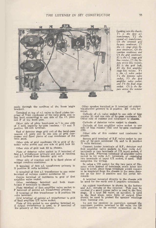
THE LISTENER IN SET CO NSTR UCTOR 55
made through the medium of the brass 'angle bracket).
Terminal at top of r.f, valve to fixed plates ter-minal of front condenser of the twin gang, and to flex lead connecting to one side of the r.f. plate coil P of the band-pass.
Other side of plate band-pass col to one side of .5 mfd. capacity by-pass condens. - C7 and B positive 150-volt terminal.
End of detector stage grid coil of the band-pass nearest r.f. plate coil to one side of grid con-denser and fixed plates of rear condenser of the twin gang.
Other side of grid condenser C4 to grid of de-tector valve socket and one side of grid leak R2.
Other side of grid leak R2 to chassis.
Plate of detector valve socket to P terminal of first a.f. transformer primary and end of reaction coil R furthest from detector grid coil.
Other side of reaction coil R to fixed plates of midget reaction condenser.
B terminal of first a.f. transformer primary to B positive 90 volts terminal.
G terminal of first a.f. transformer to one outer tel minal of volume control resistance R3. Centre terminal of resistance to grid of first
amplifier valve socket. Other resistance terminal and both trans-
former F terminals to chassis. Plate terminal of first amplifier valve socket to
P terminal of second a.f. transformer primary. B terminal of this transformer to B positive 150
volts terminal. Grid terminal of second a.f. transformer to grid
of final amplifier UX valve socket. Plate of this socket to one speaker terminal or,
if output transformer is used, to P terminal of the primary of this transformer.
Looking into the chassis. Ti is the first a.f. transformer, T2 the second a.f. transformer, C6 the screened grid by-pass condenser, C7 the r.f. stage plate by-pass condenser, C8 the reaction condenser and C4 the grid condenser. R1 is the r.f. stage grid bias resistor, C5 the by-pass across this resistor, R2 is the grid leak, R4 the first amplifier stage bias resistor. Vi is the r.f. valve socket V2 the detector valve socket, V3 the first amplifier valve socket, and V4 the final stage socket. C9. is the by-pass across the resistor
R4.
Other speaker terminal or B terminal of output transformer primary to B positive 250 volts ter-minal. Cathode of r.f. valve socket to one side of bias
resistor RI and one side of by-pass condenser C5. Other side of resistor and condenser to chassis.
Cathode of detector valve socket to chassis. Cathode of first amplifier valve socket to one
side of bias resistor (R4) and by-pass condenser (C9). Other side of this resistor and condenser to
chassis. Screen grid terminal of R.F. valve socket to one
side of by-pass condenser C6, and to B positive 75 volts terminal. Connect heater terminals of R.F., detector and
first amplifier valve sockets to four volts A.C. terminals or two terminals of UX input socket, if this is used. Filament terminals of amplifier valve socket to 2.5 volts A.C. terminals, or remaining two terminals of input UX socket, if used. This completes the wiring.
In using a UX socket for the two pairs of fila-ment wires instead of terminals, much labor and time is saved, since these terminals would require to be insulated from the chassis in the same man-ner as the four B positive and the aerial ter-minals. A terminal mounted directly to the chassis will
be used for the earth and B negative terminals.
An output transformer is shown in the battery and A.C. circuits of the receiver. This may be omitted if a small power valve is used in the final stage. If a type 245 valve, as specified, is used in the final stage, some form of output filter should be used to protect the speaker windings from burning out.
o put the receiver in operation connect the maximum positive terminal to 250 volts, the 150 volts positive to its correct connection on the

56 THE LISTENER IN SET CONSTRUCTOR
divider resistance, the detector positive terminal to about 90 volts, and the screened grid positive terminal to about 60 volts. Connect the 4 and 2.5 volts a.c. filament and
heater leads to the UX input socket or filament terminals. The bias resistor for the type 245 valve is inserted in the centre tap of the filament secondary supplying this valve. It is not im-portant that this resistor be by-passed. On switching on plate and filament power sup-
ply, the set should become "alive" after ten seconds, when, after connecting aerial and earth, and advancing volume control, signals will be brought in on rotating the vernier dial. On turning the reaction condenser knob the detector should go in and out of oscillation over the whole tuning range of the vernier dial. The weaker stations should be tuned in with
the detector just oscillating. As the r.f. timing condenser is brought into resonance an increase in signal strength will be noticed, when the re-action condenser should be turned back until the detedor is just off the point of oscillation. After tuning in an interstate transmission, turn
the adjusting screw of the rear condenser of the gang inwards and that of the front condenser outwards until an increase is noticed in signal strength. A distinct position where greatest vol-ume is obtained will be found and this adjust-ment may be retained for all time. Care must be taken not to advance the volume
control too far, since the signal strength avail-able from the high gain r.f. and detector stages is more than sufficient, even on most interstate transmissions, to overload the 245 power valve. The set will be found to be extremely selective
when the circuits are tuned to resonance.
Performance of the Set With the original receiver, 4QG and 2NC begin to come in each evening at 4.30. No trace of 3L0 can be heard when lis-tening to 2BL or 4QG. These two stations often come in at tremendous strength. 2NC is received like a local station, while several New Zea-land stations were received at speaker strength. There is no trace of hum in the speaker output, and, due to the efficiency of the circuit, tuning is a simple matt e r, since the position of the R.F. stage tuning condenser is positive for each station. One of the strongest stations to be received is 7LA, Launceston.
Conditions have been against interstate reception owing to static, but, during the absence of this interference, reception of most of the interstate transmitters is excellent. When listening to local trans-missions it is necessary to keep the volume control well retarded to prevent overloading of the amplifier stages. It should be very seldom that the volume control requires to be
fully advanced. The circuits and photographs should be self-explanatory, and little
difficulty should be experienced by anyone in getting the set into operation.
Pick-up Connections Pick-up connections may be provided by con-
necting one side of the pick-up to the chassis, and the other to a bushed terminal connecting to the G terminal of the secondary of the first A.F. transformer. The battery-operated circuit can be expected to
give the same excellent results as the all-electric version of the set. The finished receiver may be installed in a con-
sole or table type of cabinet with the power pack which we later describe.
Power Pack Details The a.c. circuit shows the standard 280 power
pack. A B eliminator in conjunction with an A transformer to deliver the filament and heater voltages may be used. It should be remembered that the directly-heated filament of the final stage valve MUST be from a separate transformer secondary and not from any secondary supplying a biased indirectly-heated valve. The power pack may be built up on an alu-
minium chassis after the fashion of the receiver. Transformer, choke and rectifier valve will be mounted above the chassis, while underneath will be wired the filter and by-pass condensers, the voltage divider and the rectifier valve socket. Output terminals should be mounted on one side of the chassis, all positive terminals being well bushed from the aluminium by mounting them on ebonite or bakelite through large holes drilled through the aluminium. The console type of cabinet will offer no difficulties in installing the receiver and power pack units. The pack should be mounted at the bottom of the cabinet with the speaker, the receiver unit on a shelf behind the escutcheon of the console panel.
/
-t
/57
/ 3
t ea/ass ANGLE BRACKET
95 7- 957
JE
Coil construction details. These former and coil sizes must be followed exactly.
-J
t BRAS-S APIGLE BRACKET
951-

THE LISTENER IN SET CONSTRUCTOR 57
CLIP THE COUPONS BELO W Post them direct now to LEVENSON'S RADIO, THEY WILL ADMIT YOU
TO THE REAL RADIO WORLD where stocks are thoroughly comprehensive, prices are cheaper, values are better and bargains are bigger.
These advantages are available to all as Levenson's mail order service of up-to-the-moment efficiency is always ready to serve you.
Make your nearest Post Box Levenson's Radio's Nearest Branch
LEVENSON'S i(i) 69ctge
CATALOGUE HANDBOOK.
U WORLD'S
FOREmELTT
RETAIL RADIO
Pusucarion.
Levenson's Radio's Gigantic Radio Catalogue and
Handbook
The Greatest Radio Publication Ever Produced. Lists Every Radio Article on the Market, Includ-ing Hundreds of Lines Stocked Only by Levenson's.
Many Pages of Tips and Topics.
Lots of Useful Information.
Log Card.
Trouble Finding Chart for Battery Sets.
Trouble Finding Chart for Electric Sets.
List of Short Wave Stations.
List of A & B Class Stations.
Thousands of Illustrations.
T.iEverything in Radio.
EACH HANDBOOK Also includes a coupon entitling you to 4,/ rebate on your first pound's purchase. 16/ buys £1 worth of goods! Clip the coupon below and post together with 1/6 in stamps for your copy.
Levenson's 500 Club ! ! All Goods Cheaper !! Have you heard of LEVENSON'S RADIO'S wonderful club. An innovation to
radio fans. It means that you may purchase all your radio requirements at a further 2/ in the pound off Levenson's already astounding values. Also entitles you to technical advice on all radio matters FREE.
MEMBERSHIP LIMITED TO 500 MEMBERS.
MEMBERSHIP FEE 5 per full year.
FILL IN APPLICATION FORM AND FORWARD NOW WITH 5/ POSTAL NOTE FOR ENROLMENT AND CERTIFICATE.
DEPARTMENT R
LEVENSON'S RADIO 226 PITT STREET, SYDNEY
LN( LOSED PLEASE FIND 1/6. Kindly post handbook-catalogue.
NAME ...
STREET ...
TO WN ...
STATE ... .
your
"500 CLUB"
LEVENSON'S RADIO 226 PITT STREET, SYDNEY
PLEASE FIND ENCLOSED 5/ FOR ENROLMENT TO LEVENSON'S "500 CLUB"
TO WN ...

58 THE LISTENER IN SET CONSTRUCTOR
WHERE DOES THE HUM COME FROM? The modern all-electric receiver should be silent in its operation, any humming noises to be heard without listening close to the
speaker being the result of poor design or construction.
W HEN current from the mains is available, what is there to prevent every receiver being converted for completely a.c. opera-tion? "But what about the hum and other
noises I hear in the majority of all-electric re-ceivers?" you will ask. There is no excuse for hum in any correctly built all-electric receiver. The man who builds a receiver just for the
pleasure of listening in does not wish to bother about the technicalities involved in such construc-tion, but even though he may follow an accur-ately worded description, he still has to rely on himself to make the necessary adjustments re-quired to put the finished article into commis-sion. Hum in an A.C. receiver can have numerous
sources. We will deal with these in the same manner as we would draw a circuit, starting from the radio frequency end of the receiver. Having finished the construction of a receiver,
you may be surprised to note that there is abso-lutely no hum until a station is tuned in. This effect may be noticed on every station. "This certainly is a puzzler" you will say. But the fault lies in the r.f. side of the circuit, and can be located if system is used in searching for its source. The puzzling part about this effect is that the hum can only be heard when the re-ceiver is tuned to the carrier wave of a station. Thd effect of such a fault in the rectifier system is to place the set in such a condition when a car-rier wave is tuned in, that the source of the hum will affect the mutual conductance of the valve. The theory of its origin will no doubt lack in-
terest to many; some suggestions for its elimina-iton will, however, be very welcome.
First comes the filament circuit. The filament supply leads must be tightly twisted to confine the field surrounding the A.C. carrying wires. These twisted leads must not come near r.f. grid or plate tuning coils, grid, plate or neutralising condenser leads. The r.f. valve must be a sufficient distance away from the power pack apparatus, and from r.f. stage by-pass condensers. The power pack rectifier must be by-passed, using small mica condensers.
A.C. Induction
Detector stage construction requires careful at-tention. Hum in this stage may be due to any of the following causes:—Leaking grid condenser, faulty grid leak, or incorrect placing of the de-tector valve so that it is within the fields of power pack apparatus. Heater leads to this valve must be carried through the set to the heater trans-former with the same care as the r.f. stage leads. Lead-covered wire is of little use in confining the field surrounding a pair of A.C. conducting wires. Tightly twisting spaghetti-covered bare copper wire will be highly effective. Care must be taken to see that all A.C. carrying leads are kept well away from the detector stage tuning coils. Hum which has its origin in the r.f. or detector
stages will often be heard at a very annoying volume. Obviously, the high gain available in the detector and amplifier stages of noises, which occur in or before the detector grid circuit, will render the slightest interaction audible at con-
siderable strength, when such trouble, were it occurring in the grid circuit of last stage ampli-fier, would be inaudible on the speaker.
Shielding the Transformer We now come to the first stage transformer.
This must be shielded and must be so placed that it is not within the field surrounding power equipment, speaker windings, or tuning coils. Hum or noises introduced into this component will have increased in magnitude a hundred times by the time it has reached the speaker. Plate and grid leads to this transformer should
be short and must be kept away from power carrying leads. A means of controlling volume should be used in the grid circuit of the first amplifier valve. We now come to the final stage amplifier, which
may be a push-pull job or a straight-out trans-former coupled type. Hum in this stage will in-variably be due to a poor power supply or an in-correct centre tap. Induction and other noises, if the amplifier has been poorly arranged and these occur, will be scarcely audible if they are located in the final stage. Were they in the detector or first audio stages, however, they would be sufficiently loud to completely spoil re-ception. Reverting again to the first amplifying trans-
former, it will be seen that this component is a target for all types of noises brought about by induction. For this reason, resistance coupling is used extensively in the first amplifier stage, followed up by a single stage amplifier using a s,pgle or push-pull tubes.
Two Classes of Hum
Induction hums sort themselves into two classes—magnetic induction and electrostatic in-duction. The main power transformer is the chief offender in the nrst instance. This trans-former should be placed so that there is no possi-bility of any of the receiving apparatus being within the field surrounding its core. A loose transformer core can introduce hum into the power supply. The first filter choke, even though preceded by
a filter capacity, carries an A.C. current com-ponent of considerable strength. This A.C. com-ponent. in conjunction with the air gap of the filter choke core, sets up a strong A.C. leakage field. A.C. noise may be induced in an amplifier by
the presence of A.C. carrying leads, especially when these are run parallel and not twisted to-gether. It must be remembered that a field surrounds
each valve in the receiving circuit. Sufficient spacing must therefore always be used, and the parts should not be crowded together more than is necessary. In a number of dynamic speaker units the fields
are supplied by poorly filtered D.C. This re-sults in a hum in the speaker, which will be in-dependent of the receiver itself. Matters here may be helped by improving the filter system of the field power supply. This can be done by the use of an "A" supply filter choke in conjunction with one or two 10th) mfd. capacity electrolytic condensers.
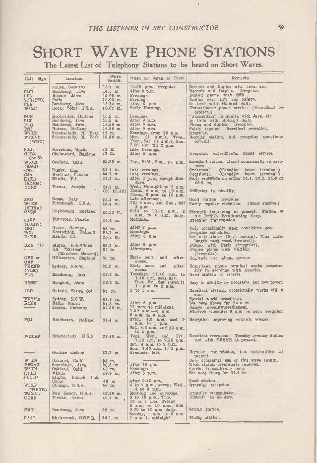
THE LISTENER IN SET CONSTRUCTOR 59
SHORT W AVE PHONE STATIONS The Latest List of Telephony Stations to be heard on Short Waves.
Call Sign Location Wave length.
%%lien to Listen to Them
PMB LP3 SFR/PW3 PLE W2XC
PCK PLF PLO PHI W2XK W2XAD (WGY)
EAJ4 02BX (or S)
W6XN (ROO) CBS CJA KlXR (KZRM) UOR2
3R0 W8XK (KDKA) 05SW
CJRZ (CJRW) DUC PCL KlXR
HZA (I)
GBX or GBP VK2ME (V LE) PLR
IIS2PJ
7L0
-VK2ME KlXR
PCJ
W2XAF
WORN PK3AN W6XN KlXR F0131)
W9XF (WEN-R)
W3XAL UOR2
PMY
RA97
Nauen, Germany Bandoeng, Java Buenos Aires Paris Bandoeng, Java Rocky Point, U.S.A.
Kootwijick, Holland Bandoeng, Java Bandoeng, Java Huizen, Holland Schenactady, N. York Schenactady, N. York
Barcelona, Spain Chel msford, England
Oakland, Calif.
Rugby, Eng. Montreal, Canada Manila, P.I.
Vienna, Austria
Rome, Italy Pittsburgh, U.S.A.
Chelmsford, England
Winnipeg, Canada
Nauen, Germany Kootwijick, Holland Manila. P.I.
Saigon, Indo-China S.S. "Elettra" (Marchese Marconi)
Hillmorton, England
Sydney, N.S. W.
Bandoeng, Java
Bangkok, Siam
Nairobi, Kenya Col.
Sydney, N.S. W. Radio Mania Zeeson, Germany
Eindhoven, Holland
Schenectady, U.S.A.
German station
Oakland, Calif. Sourabaya, Java Oakland, Calif. Manila Saigon, French China Chicago, U.S.A.
13.7 m. 14.5 ni. 15.02 m. 15.03 m. 15.74 m. 16.02 m.
16.3 m. 16.8 m. 16.88 m. 16.88 in. 17 m. 19.56 m.
21 m. 23 m.
23.35 m.
24.4 m. 24.7 m. 24.4 m.
24.7 m. (or 25.42)
25.4 m. 25.4 m.
25.53 m.
25.6 m.
26 m. 26.1 m. 26.2 m.
26.7 m. 27 m.
28 m.
28.5 m.
28.8 m.
29.5 m.
31 m.
31.2 m. 31.3 m. 31.38 na.
31.4 m.
31.48 m.
31.7 m.
34 m. 38.5 m. 46 m. 48.8 m.
Indo 49 m. 49 m.
New Jersey, U.S.A. Vienna, ustria
Bandoeng, Java
Khaboravsk, U.S.S.R.
49.18 m. 49.4 na.
58 m.
70.1 m.
10.30 p.m., irregular. After 9 p.m. Evenings. Evenings. After 9 p.m. Early Morning.
Evenings. After 9 p.m. After 9 p.m. After 9 p.m. Evenings, from 10 p.m. Mon. (4 a.m.), Tues., Thur., Sat. (4 a.m.), Sun. 7.10 a.m. till 2 p.m. Late Evenings. After 9 p.m.
Tue., Frid., Sun., 1-5 p.m.
La te evenings. Late evenings. After 6 p.m., except Mon-days.
Wed., Midnight to 2 a.m. Thurs., 8 a.m. to 10 a.m. Thurs., 8 p.m. to 10 p.m. Late afternoon. Till 6 a.m., and Sun., till 2 p.m.
9.30 to 10.30 p.m., 2 a.m, to 8 a.m. daily.
Mornings.
After 9 p.m. Evenings. After 6 p.m.
After 9 p.m. Afternoons.
Early mom. and After-noons.
Early morn. and After-noons.
Tuesdays, 11.40 p.m. to 1.40 a.m. next day. Tues., Fri., Sun (Wed.?) 11 p.m. to 2 a.m.
3 to 5 a.m.
After 6 p.m. 11 p.m. to midnight. 1.30 a.m. -3 a.m. 5 a.m. to 9 a.m. Frid., 4.6 a.m.. and 9 a.m. to 1 p.m.
Sat., 4.6 a.m. and 10 a.m. to 4 p.m.
Tues., Wed., and Fri., 7.10 a.m. to 2.30 p.m.
Sat., 4 a.m. to 2 p.m. Sun., 7.40 a.m. to 2 p.m. Evenings, late.
After 10 p.m. Evenings. After 6 p.m.
After 9.45 p.n.. 4 to 7 p.m.. except Wed., 4 to 6 p.m.
Morning and evenings. 8 to 10 p.m., Tues. 10 to 2 a.m., Friday. 8 a.m. to 10 a.m., Sun. 9.30 to 10 p.m. daily. Sunday, 1 a.m. to 3 a.m. 7 p.m. to midnight.
Remarks
Records and Duplex with Java, etc. Records and Duplex. Irregular. Duplex phone with SFR. Duplex with LP3 and Saigon. In tests with Holland daily. Transatlantic phone service. (Occasional re-ception.)
"Amsterdam" in duplex with Java, etc. In tests with Rolland daily. Phone and duplex. Irregular. Fairly regular. Excellent reception. Irregular. Regular station, but reception sometimes dUficult.
Irregular, experimental phone service.
Excellent station. Heard occasionally in early morn.
Occasional. (Canadian beam terminal.) Occasional. (Canadian beam terminal.) Daily reception on either 24.4, 26.2, 31.3 or 48.8 m.
Difficulty to identify.
Good station. irregular. Fairly regular reception. (Good station.)
Strength improving at present. Station of the British Broadcasting Corp.
Irregular transmission.
Only occasiona:ly when conditions good. Irregular schedules. See note above (24.4 metres). This wave-length used most frequently.
Duplex with Paris (irregular). Duplex phone with VK2ME. (irregular).
England/.'ust. phone service.
Eng./Aust. phone terminal works occasion-ally in evenings with America,
Good station to receive,
Easy to identify by programs, but low power.
Excellent station, occasionally works till 6 a.m.
Special world broadcasts. See note above for 24.4 m. Relays Koenigwusterhausen. Midweek schedules 9 a.m. to noon irregular.
Reception improving towards winter.
Excellent reception. Tuesday evening duplex test with VII2ME at present.
Regular transmission, but unidentified at present.
Only occasional use of this wave length. Weak station irregularly received. Special transmissions only. See note above for 24.4 m.
Good station. Irregular reception.
Irregular transmission. Difficult to identify.
Strong station.
Strong station.

60 THE LISTENER IN SET CONSTRUCTOR
OPERATING THE ALL-ELECTRIC RECEIVER
A few points that will help you to secure better reception.
WHEREVER a.c. is available from the light socket, we can use its power for the com-plete operation of a radio receiver. There are few difficulties to be met
with when using a good make of eliminator and step-down heater transformer. The main point to be watched in a.c. receiver design is the preven-tion of interaction. A field surrounds any a.c. carrying lead, the extent of the field increasing with the frequency. It is, therefore, necessary to twist all a.c. heater and filament leads in the form of a small flex, keeping these leads well away from a.f. coupling devices, tuning coils or tuning condenser, and all grid, plate and "C" leads. By the correct placing of valve sockets and other components, we can observe these rules, without adding to the difficulty of receiver construction.
The subject of power pack construction and ad-justment is one of considerable dimensions.
The correct selection of valves requires an article of its own, since this subject is one of complexity and many factors are necessarily in-volved. In the design of a receiver for our own particular requirements we want an instrument which will deliver just a little more volume than would be comfortable. It would be ridiculous to use, say, a pair of U.X.250 type valves to supply broadcast programmes and recorded music in the average home. The outfit for ordinary purposes would be cut back to normal volume for the best part of the time it may be used, power being wasted and maintenance costs being higher in the long run.
General Purpose Outfit
For ordinary purposes the simple three-valve radio-gramophone combination will suit all re-quirements, this type of receiver delivering usually more than sufficient volume from the majority of the broadcasting stations, and disc recordings when the pick-up is used. Operating and main-tenance costs of such a receiver as this, when valves are correctly operated, and power-pack voltages do not overload any particular stage, will be very low, the new a.c. valves lasting for as long as two years if carefully treated. If at any time we may require good volume
for dancing or other purposes, we can use a higher power combination incorporating say a pair of UX 245's in push-pull, this combination delivering all the volume we may require for the average-sized dance-hall.
It is a strange fact that many people seem to enjoy operating their receiver "flat out," so that it delivers sufficient volume to be heard some hundreds of yards away. In the a.c. receiver we usually have plenty of volume to spare, but this continual operating of the receiver so that sig-nals blare forth cannot help improve the tempers of the neighbors, and of the set user himself. Imagine ourselves in a music-hall. We have a
good seat at a point in the hall some 30 or 40
feet away from the stage. We listen to a violin solo. Consider ourselves at home and listening to a broadcast of the programme. We would be sur-prised to note that the volume of the speaker out-put would be required to be cut back considerably in order that the signals be no louder than they would be heard in the music-hall by any member of the audience.
Very Little Distortion
We have attained the point when the percentage of distortion in transmission and reception of broadcasting programmes is a negligible quantity. We will enjoy programmes far better if we use a little thought when considering just how loud we would hear a particular item were we at the broadcasting studio.'
The man who has his set blaring forth during a whole programme is seldom satisfied, and usually he is the programme growler. He has himself to blame, for a programme heard at many times the volume of the original items can do nothing but affect the nerves to such an extent that an im-pression of poor quality programmes be conveyed to the mind of the set-owner.
In any a.c. receiver a reserve of volume will permit the weaker amateur transmissions being brought in with almost the same volume as the big station broadcasts.
If we have a car whose maximum speed is 75 m.p.h. we would not dream of always running the car at this speed. The same principle applies to the receiver. High speed would tend to place a strain upon the nerves, and in the majority of cases the ride would not be as enjoyable as touring at a speed of, say, 35 m.p.h.
The aerial system seldom requires very great attention, since receiver sensitivity has improved greatly as far as signal pick-up of local transmis-sions is concerned. Usually, a wire around the picture-moulding or one strung between the ceil-ing and the roof will be found quite satisfactory. The outdoor aerial, unless properly erected, is usually an unsightly affair, and the appearance of property will be considerably enhanced if clothes-props and other contraptions are removed from chimneys and handy line-posts or trees. If pro-perty is insured against fire, it is necessary that all outside aerial equipment be fitted with an approved lightning arrester and aerial switch, in order to comply with the underwriters' regula-tions
In the design of a receiver, special care must be paid to the selection of valves and transform-ers, so that these can be matched as closely as possible. Particularly in the case of the output transformers, the correct type must be used, other-wise best results of the signal power available in the plate circuit of the power valve will not be forthcoming.

THE LISTENER IN SET CONSTRUCTOR 61
Perfect Radio Construction with
RADIO PARTS
VALVE TESTER A Multi-range Instrument essen-tial to every serious Experi-menter and Constructor. FROM ..
AUDIO TRANSFORMERS
PUSH PULL Transformers from . OUTPUT Transformers from .
42P48'-
50,-
Give your Re-ceiver a fair chance by con-structing it with the best ma-terials available. Ask for and see you get the world famous F ERR A NTI PARTS. The reliability o f FE RR A NTI equipment is un-questioned and assures perfect reception at all times.
FERRANTI RADIO METERS
from
58,-SOLE AGENTS—
MULTI-RANGE D.C. TEST SET Each instrument has eight ranges and is provided with a ten-way switch to select the required range, the com-bination forming a self-contained unit for the measurement of Direct Cur-rent, Voltage, Power and Res'stance
within wide limits. £ 1 6P 1 oP.
WIRE WOUND ANODE FEED RESISTANCES
These Resistances are of the wire-wound type, the windings being sectionalised and sup-ported on a moulded insulated bobbin within a bakelite tube with highly polished nickel-plated contact ends. FROM ..
NOYES BROS. (Melb.) Pty. Ltd 597-603 Lonsdale St., Melbourne, ca. 119 Pine Street. Adelaide.
'Phone: Cent. 10106 (11 lines). 36 Argyle Street, Hobart. 59 George Street. Launceston.
•
8P6

62 THE LISTENER IN SET CONSTRUCTOR
UNDER WRITERS' RULES Prescribing the quality of materials and methods to be adopted in connection with radio receiving equipment.
pRIMARILY drawn up for use in connec-tion with radio receiving equipment, these rules are intended to apply, where rele-vant, to all electro-acoustic reproducing
apparatus, and to small rectifying appliances not exceeding 1000 volt-amps, input rating used for charging storage batteries and similar purposes.
AERIALS A. Aerials (Exterior to Buildings). (1) Aerials, counterpoises and stay wires ex-
terior to buildings shall not pass over or under aerial electric light or power wires nor shall they be so located that failure of either aerial, counterpoise, stay wire, or of the above-men-tioned electric light or power wires could result in a contact between the aerial, counterpoise and/or stay wires and such electric light or power wires. Aerials, counterpoises and their supports shall
be constructed and installed in a strong and durable manner, and shall be so located as to prevent accidental contact between aerial or counterpoise wires, and light or power wires, or the wires of the Postmaster-General's Depart-ment or Fire Brigade, by sagging or swinging. (2) Aerial and counterpoise conductors shall be
stranded, and if of copper, shall be hard drawn and shall be of cross sectional area not less than that shown in Table 1.
TABLE 1.
Span (between supports Minimum Size
Approximate commonly known equivalent sizes
Not exceeding 120 feet Exceeding 120 feet
3/,036 7/.036
3/20 S.W.G. 7/20 S.W.G.
The stress in such conductors shall not exceed 25,000 pounds per sq. inch. Conductors of metals other than copper may be used provided that their breaking strength is not less than that of the copper conductors shown in Table 1 for the given spans.
Aerials (Within Buildings) (3) Aerials within buildings shall be so placed
and constructed that they cannot come into con-tact with wires or apparatus (other than the radio receiving set) connected to the electric light or power supply. Such portions of the aerial as are within
reach of the radio set shall be insulated wires of not less than 600 megohm grade.
B. Connections to Radio Receiving Sets Leading-in Wires. 1. Leading-in wires shall be of copper, copper
clad steel or other approved metal, which does not corrode excessively, and shall, in no case, be smaller than 11,044in. (No. 18 S.W.G.). 2. Inside buildings, the leading-in wires shall
be covered with insulation of not less than 600 megohm grade. 3. Leading-in wires, both inside and outside of
buildings, shall not come nearer than 12 inches to electric light or power wires, unless separated therefrom by a continuous and firmly fixed non-conductor with a well maintained permanent
separation; the non-conductor shall be in addi-tion to any insulation on the wire. 4. Leading-in wires shall enter a building
through a non-combustible non-absorbative, in-sulating bushing, so arranged as to prevent the entry of moisture. Each leading-in wire shall be provided with a protective device (lightning-arrester) of approved pattern, which shall be fixed outside the building near the point where the wire enters the building. The protective device shall be mounted on a non-combustible base away from inflammable material and shall provide an air gap not exceeding .005 inches between aerial and earth connections. 5. The use of an aerial grounding switch is
desirable, but does not obviate the necessity for the protective device required by this section. Such switch, if separate from the protective de-vice, may be placed within the building, and, if installed, shall, in the closed position, form a shunt around the protective device. Where situated within reach of the Radio Receiving Equipment, such ground switch shall be of the all-insulated type. 6. If fuses are used in the aerial circuit they
shall be placed so that they cannot interrupt the circuit from the aerial to ground.
Earthing Wires 7. Permanent earthing conductors (exclusive of
flexible earthing leads attached to portable sets) shall be of stranded copper, and shall not be smaller than 7 strands of .029. They shall, in all respects, conform with the provisions of the wir-ing rules with respect to earthing, and shall be covered with insulation of 600 megohm grade.
C. Electricity from Supply Mains: 1. Electricity from supply mains shall only be
conveyed to radio receiving sets through per-manent wiring or through a proper authorised outlet such as a power plug or lamp holder with an adaptor. 2. All flexible wires used for connection to the
supply side of radio appliances shall be of cir-cular type and of high insulation types and shall be taken direct on to suitably protected terminals on the appliance or connected thereto by means of a contact socket. 3. Flexible wires shall enter metal frames only
through holes which are bushed by durable in-sulating bushes permanently fixed in position and cord grips or other approved means shall be provided to relieve the strain from the connect-ing terminals. 4. In no case will exposed live terminals or
contacts, directly connected to the supply mains or energised to a pressure exceeding 100 volts, directly or indirectly from the supply mains, be permitted. Where the maximum voltage at any terminals
exceeds 100 volts such terminals shall be of the insulated pattern and shall have the extreme voltage distinctly marked. Such terminals, unless within the receiving set, shall be in some manner protected by a cover.
5. All switches used on the supply connections to radio receiving sets shall be of ample capacity
(Continued on Page 63)

THE LISTENER IN SET CONSTRUCTOR 63
SELECTING A LOUD SPEAKER Probably the most important part of the modern receiver, the speaker, should receive considerable attention when installing a new one.
IF we go to a great deal of trouble to secure a receiver which will deliver plenty of volume without distortion, we must make best use of this signal energy by the careful selection of
a reproducing instrument suitable for our re-quirements. . For average requirements the electro-magnetic
cone speaker is to be recommended. Fitted into a baffle-board, a magnetic speaker would be capable of delivering all the volume required to more than fill the average size room. Such a speaker will give faithful reproduction, provided the cor-rect type of output arrangement is used. The dynamic speaker is used in the more power-ful receiver combination, since the various types will handle practically all the undistorted power we may have available. In matching this type of speaker, it is necessary that its impedance be known. The impedance of the voice coil may be taken as twice the d.c. resistance of the coil. The d.c. resistance of the voice coil can be ascertained by use of a milliammeter and a small battery, the voltage of which is known. The simple formula R equals E divided by C is used, where R is the d.c. resistance of the coil, E the voltage of the bat-tery, and C the current in amperes when the coil is connected in series with the meter and the battery. It is usually undesirable to fix dynamic speakers into baffle-boards which would be used with the ordinary magnetic type speaker. The baffle-board for a dynamic type speaker should seldom re-quire to be bigger than 2ft. x 2ft.. while boards as big as 5ft. x 5ft. may be used with the mag-netic type speaker without over emphasis of the lower frequencies. Hitherto, the electro-dynamic speaker has suf-
fered from over emphasis of the lower range of audible frequencies. While in most cases pleas-ing to hear, such reproduction is not natural, and would not be apparent when listening to signals by means of headphones after the detector stage of a receiver. In later types design has enabled this effect to be practically eliminated, permitting the speaker to reproduce faithfully over the whole range of musical frequencies, with no undue pro-minence to any particular frequency or band of frequencies. Thi, dynamic type speaker requires a power
supply for its operation. This power is used to excite the field in the speaker's construction. The power may be derived from the power-pack of a receiver combination or amplifier, from a battery, or from a separate mains supply. The series power-pack method will be found
quite satisfactory when using fairly large power tubes. The field here is connected in place of or in series with the filter choke of the power-pack. The current drawn by the plates of the valve of the receiver combination is sufficient to gen-erate the magnetising force required for the speaker to operate. A trickle charger could be used to supply the
power necessary for the operation of a six-volt field winding. Trickle chargers which have been thrown out of commission, by the installation of an a.c. operated receiver, can be brought into use again, since it is cheaper to purchase a dynamic
speaker without a power supply. The ability of the charger to pass the current required must first be ascertained before purchasing a speaker. The electrolytic types will be particularly suitable, while those using a low voltage rectifier valve would require to be equipped with an electrolytic "A" supply filter condenser, which would require to be connected across the output of the charger. Some types of higher rate chargers cannot be used without extensive filter arrangements, the cost of which would not be worth while, the money being better spent in the purchase of a speaker which incorporates its own power supply. In many instances, the output transformer in-
corporated in a dynamic speaker which we may purchase, may not suit the plate impedance of the power valves we are using. This might require I he use of a separate output transformer installed in the receiver, the connections to the voice coil being removed from the secondary terminals of the speaker transformer, and connected instead to the secondary terminals of the new transformer. Unless the speaker is equipped with an output transformer having a centre-tapped primary wind-ing, it would be necessary to purchase a suitable push-pull output transformer.
Underwriters Rules (Continued from Page 62)
for the current to be carried and of suitable de-sign for the supply voltage. Only switches of approved pattern shall be used for this purpose.
6. All transformers including those in battery chargers, eliminators, etc., connected to supply circuits shall have independent primary and secondary windings not connected with one another, and with suitable high insulation be-tween windings. 7. Where the receiving equipment is operated
by electricity from the supply mains and is used in situations where accidental contact with earth is possible, metal containing cases and exposed metal frames shall be efficiently earthed. Where used in situations where accidental con-
tact with earth is not possible, such metal cases and exposed metal frames shall not be earthed. Metal covers and frames of transformers shall
be provided with special terminals for this pur-pose. Such earthing terminals shall be distinctly marked "Earth." 8. Every radio receiving set, which is operated
by connection to the electricity mains shall be provided with a suitably worded danger notice, which shall be permanently fixed on the inside of the lid, door or cover, by which access is obtained to the interior of the set. This danger notice shall draw attention to the fact that the set is operated from electric light or power mains at a pressure which may be dangerous and shall contain a warning to the user that no adjust-ments or alterations shall be made to the in-terior portions of the apparatus unless the set is disconnected from the electricity mains.

64 THE LISTENER IN SET CONSTR UCTOR
Front view of the finished a.c. chassis ready for installation. Cl is the tuning condenser knob, C2 the reaction condenser, and R2 the volume control resistance.
e,
G'he
IMPROVED REINARTZ THREE Ever popular, this circuit is used by hundreds of listeners throughout Australia.
It is described here for either a.c. or battery operation.
FEW circuits have been chopped and changed around so much as the original Reinartz which consisted of a single coil tapped to obtain regeneration by means of a variable
capacity. In the original circuit, both sides of the reaction tuning condenser were at an r.f. poten-tial above ground which resulted in hand capa-city when using the regeneration control knob.
Looking from the rear of the chassis. 171 is the detector valve, V2 the first amplifier valve, and V3 the power valve. T2 is the resist-ance-capacity coupler.
Without affecting the operation of the circuit in any way, the reaction controlling condenser was connected on the other side of the reaction wind-ing, this making two coils instead of the original single coil. The result of this alteration has been to eliminate hand capacity on the reaction con-trol since the movable plates of the reaction con-denser are connected to ground through the

THE LISTENER IN SET CONSTRUCTOR 65
EVERYTHING IN RADIO
VEALLS have the Largest Stocks of Radio and Electrical Goods in Victoria - 3 Big Stores packed with the latest and best.
LO WEST PRICES VEALLS CASH WITH ORDER POLICY EFFECTS MANY SAVINGS THESE SAVINGS ARE HANDED ON TO YOU - -
Write for Price Lists Radio Sets, Parts and Accessories
TRY VEALLS FIRST---AL WAYS
VEALLS Pty. 3 BIG Ltd. CASH STORES
243-249 SWANSTON ST., MELBOURNE
168-172 SWANSTON ST., MELBOURNE 302 CHAPEL STREET, WINDSOR
Cent. 2058 (5 lines)
Cent. 10524 (2 lines)
Win. 1605.

66 THE LISTENER IN SET CONSTRUCTOR
medium of the chassis. The circuit is one of the best for broadcast reception, and since it can be adapted for use in any locality by the simple adjustment to aerial tappings, it has had a popular demand in the past.
From time to time there have been many re-quests for the three valve Reinartz circuit de-signed for operation from the lighting mains. Actually, there is no difficulty attached to build-ing an a.c. receiver. The main troubles are to be found in the power pack since the only dif-
ference in receiver construction will be the in-corporation of five prong sockets in detector and first amplifier stages, and greater care in wiring in a.c. heater and filament leads. A greater gain in signal strength and the ability
to handle greater power characterise the modern valve, and, for this rea-son, resistance-capacity coupling has been used in the second amplifier stage of the receiver. The combination will give very faithful re-produttion of local broadcasting stations. The battery circuit makes a good receiver for the country since it
o can be adjusted to bring in interstate transmis-sions as well as any other detector-amplifier
e circuit. Following modern re-
ceiver design, the origi-- nal set has been built
up on an aluminium chassis, easily construct-ed from a sheet of the
-o metal.
.‘2 Building the Chassis
o In making the chassis, a piece of gauge 18
p>. sheet aluminium hin. x 13in. will be needed.
4z. Squares of the metal 24M. x 2lin are removed -
E.., from each corner of the chassis material. The 2,Un. edges are then bent down to form the chassis, which is made strong by fastening into
-'-• each inside corner of the chassis small right-
..0. angle brackets made n from the 2en. square e pieces. The aluminium
may be treated with O fine emery paper and
oil to obtain a dull fin-ish if required. The original chassis is
built for installation in a console cabinet, and
••,-; for this reason no panel was used. If the set is not installed in a cabinet, a panel 13M. x
should be fastened to the front of the chas-sis. The gauge of this material should be about 16. The alumin-ium may be obtained from Geo. White 8z Co., of Post Office Place, Melbourne.
Components Required In building the a.c.
receiver, the follow ng parts will be required:— Tuning condenser .0005 mfd. capacity (Cl). Illuminated dial. Tuning condenser .00025 mfd. capacity (C2). One 0-500,000 ohms volume control resistance (R2).

THE LISTENER IN SET CONSTRUCTOR 67
Two UY and one U.X. valve socket. Grid leak, 3 megohms (R1). Grid condenser and leak clips, .00025 mfd. capa-city (C3).
One a.f. transformer 3-1 ratio (Ti). One Philips resistance coupling unit (T2). Output transformer if needed (T3). One pilot bias resistance, 800 ohms (R3). One .01 mfd. capacity by-pass condenser (C5). Piece of ilin. dia. former, 3in. long. Reel of gauge 30 d.s.c. wire. Some rubber-covered flex wire. Four clamp type terminals.
Review of the parts The TUNING CONDENSER (Cl) should be of
the s.l.f. type. The ILLUMINATED DIAL may be replaced with an ordinary type if not required. The .00025 mfd. TUNING CONDENSER (C2) is
the reaction controlling condenser, and may be of any type. The VOLUME CONTROL (R2) is necessary. and
should not be omitted from the circuit. The GRID LEAK (R1) should be of reliable
make. The actual value needed will lie between 1 and 3 megohms. The GRID CONDENSER (C3) should be a mica
dielectric type for preference. The original A.F. TRANSFORMER (Ti) was a
Philips type. The RESISTANCE COUPLING unit (T2) may be constructed. The component values will be given later. The BIAS RESISTANCE (R5) has been selected for use with either the Philips E409 or the Cossor 41MLF valve in the first amplifier stage.
Winding the Coils Half an inch from one end of the former, com-
mence winding, using the 30 D.S.C. wire. Wind 65 turns, and then take a tapping in the form of a small loop. Wind a further five turns, taking a second loop. After taking the second loon finish off the coil after winding an additional 10 turns, making 80 in all. Next to this coil, at a distance of a quarter of an inch from the end of the first winding, wind the reaction coil, consisting of 15 turns. Leave sufficient wire at the end of each coil for connections. Fasten a small right angle bracket to the end of the former for mounting purposes. In the original receiver, the tuning coil was mounted underneath the chassis, care being taken to see that the windings did not come within three-quarters of an inch of the shielding. This leaves a very "clean" chassis, but beyond this there is no reason for not mounting the coil on the top of the chassis, the connections being taken down through a hole in the metal. All but the resistance coupler and the aerial
terminal will be mounted from underneath the chassis. The aerial terminal (A) and the sn,-aker terminals (LS) must be bushed from the shield-ing. This may be done by drilling an extra largc hole through the metal for each terminal, and mounting them on ebonite fastened behind the shielding with machine screws. The position for each component can be seen in
the photographs of the finished set. Positions will be the same in the battery version of the circuit.
The Wiring Connecting up the mounted components is a
simple operation. It will be easiest to take flex leads from the chassis to the power pack rather than mount bushed terminals at the back edge of
the shield for this purpose. Of the two pick-up terminals which should be mounted convenient to the detector valve socket, one should be bushed, the other mounting straight to the metal shield. The connections are as follow:— Beginning of tuning coil G to one side of grid
The circuit of the battery operated receiver
leak (R1) and condenser ((23) and fixed plates of tuning condenser (Cl). End of this coil to chassis. Other side of grid leak and condenser to bushed
pick-up terminal and grid terminal of detector valve socket Vi.

68 THE LISTENER IN SET CO NSTR UCTOR
Bushed aerial terminal to flex lead to either of the two tuning coil loops. Beginning of reaction coil R to fixed plates of
reaction tuning condenser C2. End of coil R to plate terminal of detector valve
socket and P terminal of primary of the trans-former Ti. B terminal of primary of transformer Ti to B
positive detector lead. G terminal of transformer Ti to one side of
volume controlling potentiometer (R2), F terminal of transformer Ti to chassis. Other side of volume control to chassis. Centre terminal of potentiometer to grid ter-
minal of first amplifier valve socket V2.
3
kg" f
80 7:
20 r PC
E
Coil details which will remain the same for both battery and a.c. circuits.
Cathode terminal of valve socket V2 to one side of bias resistor R5 and one side of by-pass condenser C5. Other sides of bias resistance and by-pass con-
denser to chassis. Plate terminal of amplifier valve socket V2 to
P terminal, of resistance coupler T2.
Looking into the chassis. G is the grid coil, R the reaction coil, C3 the grid condenser, Rl the grid leak. VI the detector valve socket, Ti the a.f. transformer, V2 the first amplifier valve socket, R3 the first amplifier bias resistance, C5 the bias resistance by-pass condenser, V3 the fina! amplifier valve socket. The bias resistance and by-pass condenser for the power valve are in-stalled in the power pack.
The a.c. chassis installed in a console type cabinet with power pack and speaker.
B terminal of coupler to B positive amplifier lead to power pack or eliminator. G terminal of resistance coupler to grid terminal
of amplifier valve socket V3. F terminal of resistance coupler to chassis. Plate terminal of amplifier valve socket V3 to
one speaker terminal or primary of output trans-former T3. Other speaker terminal or other output trans-
former primary terminal to B positive maximum lead. Tightly twisted flex leads should be used to con-
nect the a.c. heater connections of each valve (Continued at foot of page 70)
THE LISTENER IN SET CONSTRUCTOR
ALUMINIUM SHEETS : for Chassis and Shielding Work :
We stock a wide variety in Metals as required in Wireless Set building, and also for model engineering construction.
Let us construct your chassis and shields. All work carried out to your specification. We have always on hand aluminium tubes and wires, also
aluminium in flat, half-round, angle and round sections.
Brass and copper rods and tubes in all sizes and sections, as used in model engines.
Phosphor bronze, brass and copper sheets.
Zinc sheets as used for battery manufacture.
Send for price list of aluminium, copper, brass, phosphor bronze, and zinc sheets.
GEORGE W HITE & CO. 280 POST OFFICE PLACE MELBOURNE, C.1.
Established 77 Years. 'Phone Central 1100.
A.S.A. and ESSANAY A.C. POWER PACKS and A.C. SET PARTS are covered by Manufacturers' GUARANTEE and backed by 25 years' radio and engineering experience.
A.C. Transformer for 171 Valves A.C. Transformer for 245 Valves 2-V. Transformer, half-wave for 2.5-volt valves, 420 secondary
Push-pull Transformer Input Push-pull Output, Choke Super Audio Transformers Double Audios Med. Chokes Voltage Dividers Bias Resistors, Double Centretap
Double Chokes Heavy Chokes Impedance Chokes Condenser or complete Tuning Units S.L.F. Condensers. .005, .00035 Midget Condensers-
5-plate 11-plate 13-plate 17-plate 23-plate
Aerial Coils
Assembled and wired chassis in 3, 4, and 5 Valve sizes, with latest Screen Grid Circuits, or complete in various styles of Cabinets, on SALE PRACTICALLY
EVERYWHERE.
MAKE CERTAIN that quality A.S.A. and ESSANAY PARTS are used when building YOUR next SET, or incorporat ed in whatever set you buy. as they
assure you of absolute FREEDOM FRO M TROUBLE.
Wholesale Only — A.S.A. Equipment Co. Pty. Ltd.
Sole Distributors for —
Essanay Manufacturing Co. Pty. Ltd. 36 LITTLE LATROBE STREET, MELBOURNE, C.1

70 THE LISTENER IN SET CONSTRUCTOR
W HY SHIELDING IS USED Metal can be used to advantage in the construction of the modern receiver as proved by the high efficiency of
Listener In chassis built sets.
M ANY set builders wonder why it is necessary to use shielding. There are two forms of shielding, these being termed electro-static and electro-magnetic.
The object of shielding in its many forms is to prevent the interaction of various circuits. Every conductor carrying an alternating cur-
rent has an electro-magnetic field surrounding it. Every conductor having an electric charge has an electro-static field surrounding it. These fields produce charges or currents in any other conduc-tors in the neighborhood. The higher the fre-quency of the alternating currents the wider spread will be the field surrounding the con-ductor. In the radio frequency part of any receiver
every coil, condenser, or, in fact, every compon-ent, is surrounded by an intensive field because of the high frequency of the currents in these stages. In many cases these fields cannot prevent the satisfactory operation of a circuit, but in other cases currents may oppose each other with a con-sequent loss of efficiency.
Lines of Force The lines of force of which any electro-magne-
tic field or electro-static field is composed will generally pass readily through insulating sub-stances, as if these did not exist. The better the insulating qualities of a material the more readily will the fields penetrate the substance. Direct current may be confined within conductors by insulating the conductors, or by leaving them exposed in air. High frequency currents behave in a different manner, however. A field such as exists around a coil or a condenser, or any high frequency conductor, travels almost freely through insulating mediums. The placing of a piece of metal such as copper or aluminium with-
The Improved Reinartz Three (Continued from Page 68)
socket to the power pack. Each pair of heater and the final stage filaments leads may be taken sepa-rately to the power pack.
The original receiver was used in conjunction with a Philips B eliminator and two A transform-ers to deliver four volts for the first and second valves, and 2.5 volts for the filament of the final valve V3, which was a 245 type.
Provided a power type electro-magnetic speaker such as the Philips Baby Grand or the Mullard Music Master is used, any of the smaller power valves may be used in the final amplifier stage without installation of the output transformer T3.
Power Pack Details In the power pack, the components values are
as follows: C6, C7-1 mfd capacity, C8-6 mfd, C9-4 mfd, C10-4 mfd. The choke, CH, should have an inductance of not less than 60 henries.
in the field will cause the energy in the field to dissipate itself in the metal in the form of eddy currents in the metal. The field surrounding an inductance coil may
extend several inches in a receiving circuit, and as much as several feet in a transmitting circuit. The advisability of complete shielding of tuning inductances, as in present-day multi-stage re-ceiver practice, may be seen. The field sur-rounding a wire carrying h.f. currents may have a field extending several inches around it. Shielding must be done carefully, and with the
object on what is being accomplished by shield-ing m mind. The shielding of r.f. stages will render the tendency towards oscillation (instabil-ity) in the r.f. stages less.
How Shielding Helps It will be seen that there are many gains in
shielding a receiver, but these gains may be ac-companied by some loss. Since shields will ab-sorb fields in the form of eddy currents, this energy is lost. When shielding a two-stage r.f. receiver, the losses may be sufficiently great to re-quire the use of an additional r,f, stage. The effect of a shield around a coil is to reduce
the apparent inductance of the coil. Larger tuning inductances are therefore required if these are to be shielded completely. In coil shielding the coil must be separated at least fin, from the container. The effect of shielding a condenser will be to increase the effective resistance of the condenser. The losses here are less, the greater the capacity of the condenser. Copper, aluminium and brass are the materials
found best suitable for shielding. A shield must possess good condlicting qualities. Foil or lead sheet are unsuitable as shielding materials.
The type rectifier used for general purposes should be a 280. This will require that a power transformer to deliver 300 volts each side of the centre-tapping be used in conjunction with a five-volt rectifier filament heating secondary and two separate filament heating secondaries for the directly heated power valve and for the indirectly heated detector and first amplifier valves VI and V2.
It will be noted that the bias resistor for the final stage valve is mounted in the power pack. If transformer filament heating secondaries are not centre-tapped, the connection can be obtained by using a centre-tapped resistance across each secondary.
X is a torch globe fuse. Any sized torch globe may be used. The globe should not be omitted from the circuit since it will burn out immedi-ately a filter condenser breaks down or a direct short occurs somewhere in •the circuit.
Whichever of the aerial tappings gives best results without overlapping of the broadcasting stations should be used.
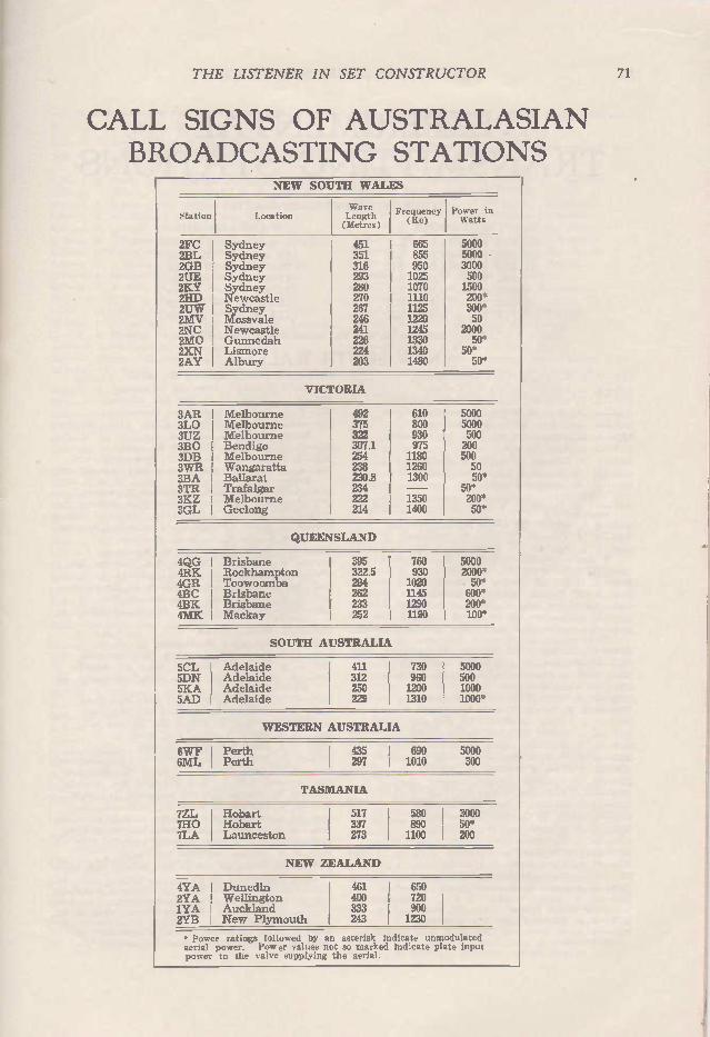
THE LISTENER IN SET CONSTRUCTOR 71
CALL SIGNS OF AUSTRALASIAN BROADCASTING STATIONS
NEW SOUTH WALES
•tation Location LWengtave h (Metres)
Frequency (Kc)
Power in Watts
2FC I Sydney 451 665 I 5000 2BL Sydney 351 855 5000 - 2GB Sydney 316 950 3000 2UE Sydney 293 1025 500 2KY Sydney 280 1070 1500 2HD Newcastle 270 1110 200* 2U W Sydney 267 1125 300* 2MV Mossvale 246 1220 I 50 2NC Newcastle 241 1245 2000 2M0 Gunnedah 226 1330 50* 2XN I Lismore 224 1340 50* 2AY I Albury 203 1480 50*
VICTORIA
3AR Melbourne 492 610 J 5000 3L0 Melbourne 375 I 800 5000 3UZ Melbourne 322 930 1 500 3B0 Bendigo 307.1 975 200 3DB Melbourne I 254 1180 500 3WR Wangaratta 238 1260 50 3BA Ballarat 230.8 1300 50* 3TR Trafalgar 234 — 50* 3KZ Melbourne 222 1350 200* 3GL Geelong I 214 1400 50*
QUEENSLAND
4QG Brisbane 395 J 760 I 5000 4RK Rockhampton 322.5 930 I 2000* 4GR Toowoomba 294 I 1020 50* 4BC I Brisbane 262 I 1145 600* 4BK I Brisbane 233 1290 200* 4MK Mackay 252 1190 I 100*
SOUTH AUSTRALIA
5CL Adelaide I 411 I 730 5000 5DN Adelaide 312 I 960 I 500 5KA Adelaide 250 I 1200 1000 5AD ' Adelaide 229 I 1310 I 1000'
WESTERN AUSTRALIA
6WF I Perth 435 I 690 5000 6ML Perth 297 I 1010 300
TASMANIA
7ZL Hobart 517 580 3000 7H0 Hobart 337 890 50* 7LA I Launceston 273 I 1100 200
NEW ZEALAND
4YA I Dunedin 461 I 650 2YA Wellington I 400 I 720 1YA I Auckland I 333 I 900 2YB I New Plymouth I 243 1 1230
. Power ratings followed by an asterisk indicate unmodulated aerial power. Power values not so marked indicate plate input power to the valve supplying the aerial.

72 THE LISTENER IN SET CONSTRUCTOR
EXPERIMENTAL TRANSMITTING STATIONS
AUTHORISED PO WER -25 W ATTS
FREQUENCIES
60,000 KC -56,000 KC 30,000 KC -28,000 KC 14,400 KC -14,000 KC 7,300 KC - 7,000 KC 4,000 KC - 3,500 KC 1,990 KC - 1,715 KC 1,715 KC - 1,200 KC
W AVE LENGTHS
(5 in. - 5.35 m.) (10 m. - 10.7 m.) (20.8 m - 21.4 m.) (41 in. - 42.8 en.) (75 m. - 85 m.) (150.8 m. - 175 m.) (175 m. - 250 m.)
Every call-sign in the list below bears prefix VK.
NEW SOUTH WALES 2AB -A. V. Badger, 10 Alfred Street, Rozelle.
2AC -A. C. Edwards, Wallace St., Eastwood. 2AF -A. F. Williams, "Moseley," Argyle Av., Ryde.
2AG -A. H. Gray, 35 Middle St.. McMahon's Point.
2AK -K. J. Claffey, Napier St., Deniliquin.
2AL -A. S. Littlejohn, 3 Emmerick St., Leichhardt.
2A0 -A. O. Friar, Ulmarra.
2AP -A. P. Reynolds, 10 Latitia St.. Oatley.
2AR -W. H. Hudson, 1 Terrace Rd., Dulwich Hill.
2AU -J. P. Cureton, Church St.. Burwood (formerl y VK2AY)•
2AV -A. W. Thurston, co J. Falconer, 14 Clarence St.. Penshurst.
2AX -G. C. Hellicar, 33 Selwyn St., Wallstonecraft.
2BA -B. A. Chapman, 1 Edgar St., Chatswood. 2BF -L. E. Forsythe, c/o N.S. W. Navy League. Nos. 5 to
8 Region Headquarters, Cary St.. Drummoyne. 2BH -W. C. Hall. Hay St., Abermain.
2BM -B. Martin, 59 Gardyne St., Bronte.
2BN -F. W. Kimpton, Moon St., Ballina.
28R -Rev. W. H. L. Brooke, Rectory, Terrigal.
2BU -C. Butterworth, 19 Thomas St., Wallsend. 2BV -Waverley Amateur Radio Club, 89 Macpherson St..
Waverley.
26 W -W. H. Barker, 12 Wallace St., Concord.
2BX -H. Brunsden, 47 Annesley St., Leichhardt.
2BZ -W, R. B. Forwood, 161 Allison St., Randwick.
2CC -University of Sydney. 2CD -C. W. Drew, 7 Roscrae Ave., Randwick.
2CF -C. J. F. Collard, King St., Lorn, West Maitland.
2CJ -C. J. Callaby, 26 Flavelle St., Concord.
2CK -G. A. Warner, Willyama, Wyong.
2CM -C. D. MacLurcan, Agnes St., Strathfield.
2CR -L, V. G. Todd, Denison St., West Tamworth, 2CS -L. T. Swain. 9 Frederick St., Waratah.
2CU -D. D. Campbell, Ulmarra, Clarence River.
2C W -C, J. WIliamson, Dutton St., Yass.
2DC -D. C. Sellinger, 9 Cecil St,. Hurstville.
2DD -L, Smith, 30 Coventry St., Homebush.
2DE -W. P. Renshaw, Lord St., Roseville.
2DG -D. G. Campbell, Sunny Ridge, Kyogle. 20H -D. Hutton Main Rd., Abbermain.
2DJ -F. B. Cooke. Namoi Rd., Northbridge.
2DL -W. J. Phelps, 14 Watkin St., Canterbury.
2DN -D. MacLaren, 56 Hawthorn Parade, Maberfield.
2DS -R. R. Davis, "Bognor," 5 Flat. Gladswood Gar-dens, Double Bay.
20 W -D. J. Wilson, 2 Cary St., Leichhardt. 2DX -K. A. W. Blair, cío Commercial Bank of Australia.
Balranald.
2DY -D. G. Lindsay, Burgoyne St., Gordon.
2E° -E. F. Fitzgerald, Penny Rd., Pagewood. 2EB -G. H. Brown. 14 Wrights Rd., Drummoyne.
2EC -E. C. Crouch, 7 Spencer Rd., Mosman,
2EF -Amalgamated Wireless (Asia) Ltd., Althorne„
Beaconsfield Parade, Lindfield.
2EJ -E. J. Cawthron, 250 Pitt St., Sydney. 2EK -E. F. Kenny. 30 Falconer St., Hyde.
2ES -E. N. Simpson. 128 Bellevue Rd.. Bellevue Hill, Sydney.
2FA -Australian Aero Club, 16 Barrack St., Sydney.
2FB -Australian Aero Club Barrick View, Sydney.
2FH -F. L. Henriques. Motor Launch "Amohine," Alwood.
2FP -E. J. Baker, 13 Veda St., E. Hamilton, Newcastle.
2FR -F, R. Bassett, 71 George St., Singleton.
2FS -A. C. Smith, 18 Sackville St.. Maroubra, 2FT -L. R. Filmer, 151 Parkway Ave., Hamilton Sth.
2FY -D. E. Hearps, 3 Hampden St., Lakemba.
2GA -Mrs C. R. McKenzie, 26 George St., Greenwich. 2GI -G. K. Blanch. Brush Grove, Clarence River.
2GL -Richmond River Listeners' League, 64 Ballina St., Lismore,
2GP -C. S. Macka-, Urunga.
2GQ -E. Barlow, Perry St., Mudgee.
2GR -A. Robin-on, 218 Hawthorne Pde., Haberfield,
2GS -A. G. Simmonds, "Gunton. - Marsh St., Arncliffe.
2G W -W, G. Woolnough, "Chip Chase," Greenwich Rd, Greenwich.
2GX -K. D. Allen, "Moira," Moira Ave., West Ryde.
2GZ -C, J. Heathers, 40 Raymond St., Bankstown.
2HB--J. Bonnington, 84 Birriga Rd., Bellevue Hill.
2HC -H. R. Carter, Yarraman Nth., Quirindi.
2HE -H. E. Miller, 8 York St., Bellmore.
2HG -J. F. Macke!, "Alster," Devonshire St., Chatswood,
2HH -H. H. Davis. "Mira," Torrington Rd., Strathfield.
2HJ -Wheelers Hall. Cr. Park and Hirst Sts., Arncliffe.
2HK -H. W. Nicolle, 127 The Boulevarde, Strathfield.
2HL -H. C. Lapthorne, 1 Bowen St., Chatswood.
2HM -H, A. Marshall, 94 Francis St., Bondi. 2HN -H. A. J. Nottingham, Waterloo Rd.. North Ryde,
2H0--H. Hart, 11A Fairlight Cres.. Manly.
2HP -H. F. Peterson, Hamilton St.. Coogee.
2HQ -N. C. Pottle, 86 Birriga Rd., Bellevue Hill (form.
erly VK2NC)•
2HR -Harrington'! Radio Club, 16 Stanley St., Waverley. 2HS -E. M. Fanker, 42 Jersey Rd., Woollahra, 2HT -H. K. R. Thomas. ''Rothesay," Lower Wycombe Rd.,
Neutral Bay. 2HU -R. Huey, 19 Centennial Ave., Chatswood. 2H W -R. A. Holt, '•Eeling," Cleo St., Lakemba.

THE LISTENER IN SET CONSTRUCTOR 73
2IC -A. I. K. Clarke, 76 Fricourt Ave., Earlswood.
2IJ -A. H. Gray. 5 Flat. The Mapes, Killara.
2JB -F. R. Bradley, 17 Ryrie St,, Mosman.
2JC -E. J. Cawthron, 14 Ballerian Court, Upper Bay View St., Neutral Bay.
2JD -..1. B. Davies, 109 Holborrow St., Croydon.
2JE -J. T. Evans, "Aberteifi," Adelaide St., Paxton.
2JF -J. D. Fraser Power Station, Nth. Rd., Quirindi.
2JFi -J. V, Hutchison, 1 Holbrook Ave., Kirribilli. 2JJ -J. W. Jennison, "Wallaroo," Mathoura.
2JK -.1. H. S. Brown, "Shadwell, - Chelmsford Ave., Botany.
2JL -J. L. Young, Cowabee, Coolemon.
2JN -J. P. J. Keone, 20 Merriman St., Millers Point.
2J0 -R. C. Caldwell, 17 Ruthven St., Waverley.
2JP -J. H. A. Pike, 14 Sarner Rd., Greenwich,
2JQ -Rev. G. A. M. Nell, The Rectory, Moruya.
2JR -J. G. Reed, 7 Henson St., Summer Hill.
2JT -C. F. A. Luckman, -A:dersey," Wangee Rd., Lakemba.
2JV -C. D. Roberts. 49 Greenwich Rd., Greenwich. 2J W -E. J. Williams, 51 Ocean Ave., Edgecliff.
2JX -P. Adams, 10 Edward St., Gordon.
ZJY -J. W. Young, -Yothahnee," Eastern Rd., Turra-mu rra.
2JZ -A. S. Mather, 14 William St., Singleton.
2KA -R. P. Truman, 48 Hilner Crescent, Wallstonecraft.
2KB -A. Fairhall, 7 Sturdee St., New Lambton.
2KC -R. H. Fry, Moontah Ave., Killara.
2KG -K. N. Greenhalg, ''Adaville," Rooty Hill. 2KH -S. R. Crichton, Cotterills Bldgs., Melbourne St.,
East Maitland.
2KJ -W. H. Cramond, 59 Bridge St., Lane Cove.
2KK -J. W. M. Dodds, 1 Maitland St., Kurri Kurri.
2KL -E. N. Maguire, 163 Victoria St., Dulwich Hill.
2KS -R. A. MaxWell, 152 Carrington Ave., Hurstville.
2KT -L. M. Seccombe, 43 Clarence Rd., Rockdale.
2KU -1. W. Archibald. 49 Fraser St., Dulwich Hill. 2KV -J. H. Roger, 33 Military Rd.. Newcastle.
2K W -A. Grant Taylor's Arm, Roadside, Macksville.
2KZ -E. M. Austin, Stanford St., Kurri Kurri. 2LA -D. St. J P. Soraghan, 2 Spencer St.. Rose Bay.
2LC -L. G. Curnock, "Dawn," Franklyn St. Matraville.
2L0 -L. H. Dodds, 29 Woodland St., Marrickville. 2LG -J. W. Wallace, 119 Faithful! St., Goulburn.
2LH -Leichhardt and District Radio Club, 35 Albert St., Leichhardt.
2LJ -J. Rayner, 43 Leyland Prde., Belmore. 2LK -H. C. M. Knowles, 100 Woolongong Rd., Arnecliffe.
2LL -L. S. Lane, Weethalle.
2LM -L. M. Wilson, Malboona Station, via Mudgee.
2LP -L. P. R. Bean, Artarmon Rd., Artarmon.
2LO -T. N. Griffin, 40 William St., Hornsby.
2LR -Lakemba Radio Club, 85 Haldon St., Lakemba.
2LS -L. H. Heflyer, 62 Farr St., Rockdale. 2LIJ -E. T. Prentice, "Malalah." Penrose St.. Lane Cove.
2LV -.1. Chessell, 419 New Canterbury Rd., Dulwich Hill.
2LW -H. H. Barnes, 25 Martin St.. Crow's Nest.
2LX -H. C. Crisp, 44 Patrick St., Hurstville.
2LZ -W. E. C. Bischoff, 180 Chandos St., Crow's Nest. 2MA -Amalgamated Wireless (A'sia) Ltd., 47 York St.,
Sydney.
2MB -Amalgamated Wireless (A'sia) Ltd., Radio-Electric Works, Knox St., Sydney.
2MC -Amalgamated Wireless (A'sia) Ltd., "Althorne," Beaconsfield Parade, Lindfield.
2MD -Amalgamated Wireless (A'sia) Ltd. (Portable Station).
2ME -Amalgamated Wireless (A'sia) Ltd.. Pennant Hills. Sydney.
2MF -Amalgamated Wireless (A'sia) Ltd., Radio Receiv-ing Centre. La Perouse.
2MG -Amalgamated Wireless (A'sia) Ltd., "Bryn," Kiss-ing Point Road, Turramurra.
2M H -C. E. Morton. "Saida," Underwood Road, Home-bush.
2M1 -Amalgamated Wireless (A'sia) Ltd., "Gunyah," King's Rd., Vaucluse.
2MM -R. Milles, 20 Gow St., Balmain.
2MP -C. F. Peddell, 5 Flat, "Craignish Hall," East Crescent St., North Sydney.
2MR -J. E. Stewart, Mayfield, Chatswood.
2MS -Mat. Spitzkowsk ,, 65 Everton St., Hamilton.
2MU -J. Nangle, Observatory, Sydney.
2M W -W. M. Manley, 10 Arthur St., Leichhardt.
2NA -A. T. Callaghan, 112 Bundock St., Coogee. 2NB -N. T. O. Buchanan, 21 Waratah St., Manly.
2NK -C. W. Ball. 520 Railway Parade, Hurstville.
2N0 -D. B. Knock, 102 Nelson Bay Rd.. Bronte.
2NR -J. B. Scott, 41 Carlingford Rd., Epping.
2NS -T. Evers, 193 Rockett St.. Bathurst.
2013 -L. W. Mashman, 41 Highworth Av., Boxley.
20C -0. G. Chapman, Rankin St., Wyong. 20G -G. J. Menon, 6 Grosvenor St., Croydon.
20J -E. N. Arnold. 610 Olive St., Albury. 20L -H. L. Watson, Manino St., Kiama.
20P -A. B. Roy, 8 Bronte St., Waverley. 20U -S. W. L. Wardle, Woodford Leigh, Clarence River.
20W -P. Evans. 15 Centenn ial Ave., Randwick.
20Z -J. D. 011e, 17 Eccles Ave.. Ashfield.
2PC -Proving Radio Club. 29 Blairgowrie St., Dulwich Hill.
2PP -J. C. P. Phillips, 22 East Crescent. McMahon's Pt.
2PS -P. C. Stephens, 81 Platform St., Lidcombe.
2PX -H. D. Ackling. 76 Market St., Bankstown, 2PY -W. H. Jones, 318 Victoria Rd., Marrickville.
2PZ -C. Cowan. 139 Congewai St., Aberdare.
2QL -H. N. Quodling, "Wolobrai." Copeland St., Beecroft.
2QT -A. H. Mutton, 31 Stafford St.. Stanmore. 2RA -R. A. Priddle, 158 Rockett St., Bathurst.
2RB -R. E. Beljon, 92 Lawrence St., Lithgow.
2RC -R. Chilton, Chilton Ave.. Wahroonga. 2RF -W. R. Felton, 44 Gladstone St., Belmore.
2RG -A. Rockberg. 477 Riley St.. Sydney.
2RJ -R. J. Fagan, Sunnyridge, Mandurama. 2RK -N. D. Carpenter, 58 Hurstville Rd.. Hurstville.
2RL -A. R. Litchfield, "Springwell." Contra.
2RM -R. A. MacFarlane, Wakaden St., Griffith. 2R0 -R. W. Turnbull, 2 Ethel St., Burwood.
2RP -R. R. Purdie, George St.. f fldsor.
2RS -R. O. Scott. "Spring Vale," Gundagai.
2RT -R. J. Turner. 250 Sloane St., Goulburn. 2R W -R. W. Cusiter, 38 Victoria St., Lewisham. 2RX -H. C. St. John. 82 Gibbes St., Rockdale.
2RZ -,J. M. Atkinson, "Kookaburra." Gnarbo Ave., Carrs Park.
2SA -W. E. Salmon, 51 Knowles Ave., North Bondi. 2SD -Second Divisional Signal Radio Club, Engineers'
Depot, Park Road, Paddington. 2SG -S. G. Tonkin, 610 Dean Street, Albury.
2SH -A. Short, 130 Young Street. Lambton.
2SK -S. D. Kaufman, 37 Waverley Street, Belmore.
2SM -W. W. Caldecott, "Broxbourne," Nield Avenue, Mar ly.
2SR -A. E. Emmelhaihz, 93 Todman Ave., Kensington.
2SS -A. E. Wright, Coledale. 2ST -S. E. Tatham. "Conmerah, - Coomerah Crescent
Darling Point.
2SW -C. L. Scuthwell, 40 Princess Street. Brighton-le-Sands.
2SX -C. W. Slade. Rockleigh, Lang Street, Croydon.
2TM -H. E. A. Turner, 13 Erith Street, Mosman.
2TR -R. E. Conrad, 79 Watkins Street., Bexiey.
2TW -T. R. W. Bushby, "Wakatipu,- Bateman's Road. Gladesville.
2TX -P. Levenspiel, "Braeside," Rankin Street, Wyong.
2TY -T. R. Troy, "Glenroy," Great Northern Road, West Maitland.
2UR -C. J. Henry, Bridge St., Uralla (formerly VK2CH). 21.1X -F. M. Goyen, 2 Brucedale Avenue, Epping.

74 THE LISTENER IN SET CONSTRUCTOR
2VF -R. Fourre, 19 Whitehead Street, Corowa.
2VJ -V. J. E. Jarvis, 90 Moulder Street, Orange.
2VS -V. S. Stanley, Radio Station, Carlingford.
2VW -V. Worswick, 67 Consett Street, West Concord. 2VZ -Reg. Garth. 1 Park Street, CloveIly. 2WB -W. N. Bullivant, West Wyalong. 2WD -G. W. Dukes, 43 Arundel Street, Forest Lodge.
2WE -Standard Telephones and Cables Ltd., Myrtle House, Myrtle Street, Chippendale.
2WF -R. W. Faulks, 207 Victoria Street, Ashfield. 2WH -W. H. R. Stitt. "Wandary," Forbes. 2W1 -Wireless Institute of Aust. (N.S.W. Division), 44
Gladstone St., Belmore. 2WJ--W. J. Peel, 224 Boyce Rd., Maroubra. 2WK -W. D. Kennedy (Rev.), The Rectory, Helensburgh.
2WM -R. M. E. Rees, 3 Aoba Court, East Crescent St. 2WP -W. F. Potter, Fletcher Street, Helensburgh. 2WS -W. S. Breden, 18 Kitchener Parade, Newcastle. 2WT -C. R. Watt, Warrenfels, Tenterfield. 2WU -L. Macdonald, 43 Catherine St., W. Maitland. 2VvX -R. Wray. "Esmar,' Jeilicoe St., Hurstville. 2WY -W. L. Butters, "Illawarra," Lamont Street, Ber-
magui South. 2XA -H. K. James, 12 Rosemount Ave., Summer Hill. 2X1 -W. A. Craig, 22 Irrara Street, Croydon. 2XK -J. A. Heavey. 59 Storey Street, Maroubra. 2XL -W. R. B. Forwood. 72 St. Mark's Road. Randwick. 2X0 -J. M. Retallick, Mary Street, Bellingen. 2XR -A. T. Halloran, 25 The Crescent. Mosman.
2XU -G. Pollock, The Towers, Belmore. , 2XY -S. W. Maguire, 21 Blake Street. Rose Bay. 2XZ -R. T. Vowles, 71 Links Avenue, Concord. 2YB -Croydon Radio Club, 12 Wallace St., Concord. 2YH -W. H. Hannam, 23 Prince Albert St., Mosman. 2YJ -R. H. Sainsbury. 6 Wallarcy St., Concord. 2YK -R. E. Abbott, Parkes St., Dorrigo. 2YR -W. S. Ringrose, 9 Victoria St., Epping. 2YZ -W. D. Johnston, 1 Searle St., Ryde. 2ZA -A. A. B. Slight, Catherine St.., Windsor. 2ZG -J. H. Cooper, 13 Selwyn St., Wollstonecraft. 2Z1 -A. L. K. Glasscock, 10 Station St., West Ryde. 2ZJ -A. W. Simpson, 23 Sibbick St., Five Dock, Sydney. 2ZK -A. G. Henry, Clareville Ave., Sandringham. 2ZL -W. Otty, "Hurst Villa," Killingworth. 2ZN -J. W. Cottrell, 106 Paine St., Maroubra Junction. 2Z0 -T. R. Willmott, Coramba Rd., Graft.on. 2ZR -J. C. Pinnell, 95 Livingstone Rd., Marrickville. 2ZU -N. S. Gilmour, 52 MacLeay St., Potts Point. 2ZW -S. Grimmett, 101 Tudor St.. Hamilton. 2ZY -H. F. Coffey, 20 Byng Rd.. Maroubra. 2ZZ -W. R. Clarke, 18 Superbia Parade, Mosman.
Federal Capital City 2ET -E. A. Tormey, Chapman Street, Canberra. 2GY -A. J. Higgs, Mt. Stromlo, Canberra. 2LE -A. J. Ryan, Block 7, Section 25 Kingston, Canberra. 2RR -Radio Research Board. Courcil for Scientific and
Industrial Research. Mt. Stromlo.
VICTORIA 3AB -J. W. Leonard, 18 Love St., Black Rock, S.9. 3AF -A, F. W. Bent, 33 Gritos Cres., W. Geelong.
3AG -A, J. G. Glover, 45 Watt St., Box Hill, E.11. 3AJ -E. Salamy, Timor St., Warrnambool. 3AK -N. V. C. Cansick, 14 Dalgety St., St.. Kilda, S.2. 3AL -A. D. Kerr, 1214 Start St., Ballarat. 3AM -A. Forecast, 22 St. George's Rd., Malvern, SES. 3AN -A. Newberry, Ind; Ave., Red CI:ffs. 3AQ -Marist Brothers' Coll. (Brother Gonzales), Kilmore. 3AS -A. F. Stow, 721 Rathdown St., N. Carlton, N.4. 3AT -A. W. Thomson, 10 Ridley St., Sunshine. 3AU -S. H. Milligan, 7ff Nicholas St., Chilwell. 3AW -A. Wilkins, 12 Kalymna Gr., E. St. Kilda, S.2.
3AX---H. D. Boast, 105 Cochrane St., Elsternwick, S.4. 3AY -W. W. Jenvey, Draper St., Ormond, S.E.14. 3AZ -A. E. Avard, 1 Hawthcrn Rd., Northcote, N.16. 3813 -W. F. Brown. 19 Mackay Cres., South Warrnambool.
3BD -E. H. Cox, 16 Talbot Ave., E. St. Kilda, S.2. 3BG -L. Osburne, Terang.
3BH -C. R. Whitelaw, Station St., Mitcham. 3BK -S. C. Baker, 237 Clarendon St., S. Melb., 6.0.5.
3BL -J. C. Fitchett, 13 Holmwood Ave., Brighton, S.S. 3BM -H. K. Love, Valency Rd., E. Malvern, S.E.6.
3BP---J. H. Hood, 6 Alexander St., E. St Kilda, S.2. 313Q -W. F. M. Howden, 13 Balwyn Rd., Canterbury, E.7. 3BR -Brodribb Bros., 6 Piedmont St., Box Hill, E.11. 3BW -A. Woolnough, Fenwick St., Portarlingtcn. 3BT -G. L. Barthold, 72 Unan St., Malvern, S.E.3. 3BY -H. Hoist, 27 Bambra Rd., Caulfield, S.E.7. 3BZ -G. I. Morris, c,o Mrs G. Harness, White St., Mor-
dialloc, S.12. 3CA -C. A. Hughes, 1 Vera St., Williamstown, W.16. 3CB -W. F. Sievers, 26 Lesney St., Richmond, E.1. 3CC -University of Melbourne, Carlton, N.3. 3CE -R. C. McNally, Berriwillock. 30F -C. I. Falconer, 13 Norris St., Surrey Hills, E.10. 3CH -A. C. Harris, Sherwood St., Birchip. 3CJ -C. J. Manning, 53 Marine Pole.. Elwood, S.3. 3CK -E. Cook, Boundary St.. Kerang.
3C0 -W. H. Conry, Centre Rd.. Brighton, S.6.
3CQ -F. G. Canning, 159 Domain Rd., S. Yarra, S.E.1.
3C W -C. A. Walters, 54 Normanby Ave., Thornbury, N.17.
3CX -A. G. Brown, 8 Ma”garra Rd., Canterbury, E.7.
3CZ -A. F, Berry, 15 Kembla St., Hawthorn, E.2. 3DC -S. A. Embling, 296 Williams Rd., Toorak, S.E.2. 3DH -I. Morgan, 21 Pastors St., E. Malvern, SES.
3DJ -D. A. J. Stocks. 49 Middlesex Rd., Surrey Hills. E.10. 3DL -D. Leber, 402 Bridge Rd.. Richmond, El. 3D0 -J. M. Dobbyn, 6 Wills St., Glen Iris, S.E.6. 3DQ -E. H. Barnes. 26 Cameron St., Moreland, N.13.
3DS -Age Radio Club, Age Office, Collins St.. Melbourne, Cl.
3DT -V, V. Petruchenia, 25 The Parade, Ascot Vale, W.2 3DX -L. J. Kermond, 4 Lava St., Warrnambool, 3EF--H. W. Maddick, 91 Spray St.. Elwood, S.3. 3EK -E. F. Kosseck, Torquay Rd., Belmont. 3EL -N. J. Boyd, 42 Ormond Rd., Elwood, S.3. 3EM -E. C. Manifold. 41 Horace St., Malvern, S.E.4. 3ER -E. H. W. Read. 147 Lygon St.. Brunswick, N. U. 3E5 -E. S. Yorston, 184 Hawthorn Rd., Caulfield, S.E.8. 3FC -F. T. Clark, 35 Lech St., St, Kilda, S.2. 3FM -C. G. Wildman. 22 Dennis St., Northcote, N.16. 3F0 -F. Olsen, 28 Yarra Grove. Hawthorn, E.2. 3FW -W. J. Nicholls, 76 Clarinda Rd.. Moonee Ponds, W.4. 3FY -Fitzroy Radio Club. 72 Newry St.. N. Fitzroy, N.7. 3GD -G. T. Davies, 165 Blyth St., Brunswick, N. U. 3GF -G. Fowles, 138 Mitford St., Elwood, S.3. 3GH -W. M. Hale. "Ben Nevis," Harvey St., Anglesea. 3GJ -A. J. Hoy, 115 Skene St., Warrnambcol. 3GK -S. C. McLean, 6 Hood St., Yarraville, W.13. 3GM -G. R. McCulloch, 511 Havelock St., Ballarat. 3GN -H. G. Selman, 171 Gordon St., West Coburg, N.13. 3GO -T. Stephens, "Ngarveno," Hcddle St., Essendon, W.5. 3GP -A. J. E. Shields, 94 Albion Rd., East Malvern, S.E.5. 3GR -R. G. Rowland. 1117 Sturt St., Ballarat. 3GS -G. S. C. Semmens. 16 Glengyle St.., Moreland, N.13. 3GT -G. Thompson. 62 Flinders St.. Melbourne, 0.1.
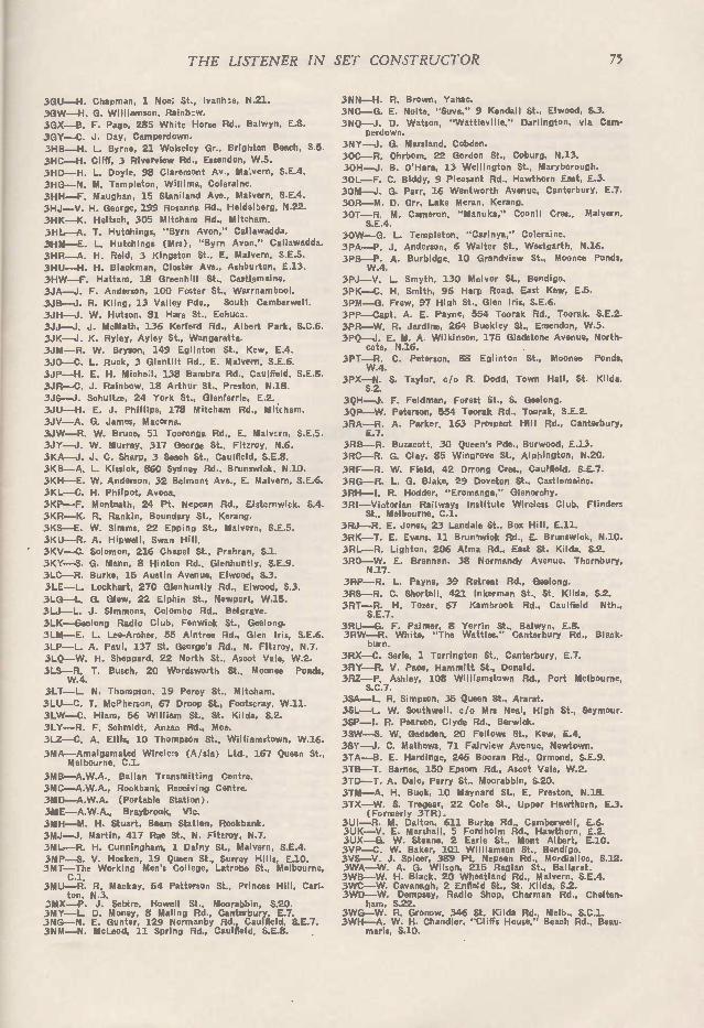
THE LISTENER IN SET CONSTRUCTOR 75
30U -H. Chapman. 1 Nov; St., Ivanhoe, N.21.
3GW -H. G. Williamscn, Rainbow.
3GX -B. F. Page, 285 White Horse Rd.. Balwyn, 3GY -C. J. Day, Camperdcwn. 3HB -H. L. Byrne, 21 Wolseley Gr.. Brighton Beach, S.5.
3HC -H. Cliff, 3 Riverview Rd., Essendcn, W.5.
3HD -H. L. Doyle, 98 Claremont Av., Ma:vern, S.E.4.
3HG -N. M. Templeton, Willima, Coleraine.
3HH -F. Maughan, 15 Staniland Ave., Malvern, S.E.4.
3HJ -V. H. George, 199 Rosanna Rd.. Heidelberg, N.22.
3HK -K. Heitsch, 305 Mitcham Rd., Mitcham,
31-1L -A. T. Hutchings, "Byrn Avon," Callawadda. 3HM -E. L. Hutchings (Mrs), "Byrn Avon." Caliawadda.
3HR -A. H. Reid, 3 Kingston St., E. Malvern, S.E.5.
3H11 -H. H. Blackman, Closter Ave., Ashburtcn, E.13. 3H W -F. Hattam, 18 Greenhill St., Castlemaine.
3JA -..I. F. Anderson, 100 Foster St.. Warrnambool.
3JB -J. R. Kling. 13 Valley Pde., South Camberwell.
3JH -J. W. Hutson, 81 Hare St.. Echuca. 3JJ -J. J. McMath, 136 Kerferd Rd., Albert Park, S.C.6.
3JK -J. K. Ryley, Ayley St., Wangaratta. 3JM -R. W. Bryson, 149 Eglinton St., KSW, E.4.
3J0 -C. L. Ruck, 3 Glentilt Rd., E. Malvern, S.E.6.
3JP -H. E. H. Michel, 138 Bambra Rd., Caulfield, S.E.S.
3JR -C. J. Rainbow, 18 Arthur St., Preston, N.18.
3JS -I. Schultze, 24 York St., Glenferrie, E.2. 3JU -H. E. J. Phillips, 178 Mitcham Rd., Mitcham.
3JV -A. G. James, Macorna. 3J W -R. W. Bruce, 51 Tooronga Rd., E. Malvzrn, SES.
3JY -J. W. Murray, 317 George St., Fitzroy, N.6.
3KA -J. J. C. Sharp, 3 Seach St., Caulfield, S.E.8. 3KB -A. L. Kissick. 860 Sydney Rd.. Brunswick, N.10.
3KH -E. W. Anderson, 32 Belmont Ave., E. Malvern, S.E.6.
3KL -C. H. Philoot, Avoca.
3KP -F. Monteath, 24 Pt. Nepean Rd., Elsternwick, S.4.
3KR -K. R. Rankin, Boundary St.. Kerang.
3KS -E. W. Simms, 22 Epping St., Malvern, SES.
3KU -R. A. Hipwell, Swan Hill.
3KV -C. Solomon, 216 Chapel St., Prahran, S.1.
3KY -S. G. Mann, 8 Hinton Rd., Glenhuntly, S.E.9.
3LC -R. Burke, 15 Austin Avenue, Elwood, S.3.
3LE -L. Lockhart, 270 Glenhuntly Rd., Elwood, S.3.
3LG -L. G. Glew, 22 Elphin St., Newport, W.15.
3LJ -L. J. Simmons, Colombo Rd., Belgrave.
3LK -Geelong Radio Club, Fenwick St., Geelong.
3LM -E. L. Lee-Archer, 55 Aintree Rd., Glen Iris, S.E.6.
3LP -L. A. Paul, 137 St. George's Rd., N. Fitzroy, N.7.
3LQ -W. H. Sheppard, 22 North St., Ascot Vale, W.2.
3LS -R. T. Busch, 20 Wordsworth St., Moonee Ponds. W.4.
3LT -L. N. Thompson, 19 Percy St., Mitcham.
3LLI--C. T. McPherson, 67 Droop St., Footscray, W.11.
3LW -C. Hiam, 56 William St., St. Kilda, S.2.
3LY -R. F. Schmidt, Anzac Rd., Moe.
3LZ -C. A. Ellis, 10 Thompson St.. Williamstown. W.16.
3MA -Amalgamated Wirelets (A/sia) Ltd.. 167 Queen St., Melbourne, C.1.
3MB -A. W.A., Bailan Transmitting Centre.
3MC -A. W.A., Rockbank Receiving Centre.
3MD -A. W.A. (Portable Station).
3ME -A. W.A., Braybrook, Vic.
3MH -M. H. Stuart, Beam Station, Rockbank.
3MJ -J. Martin. 417 Rae St., N. Fitzroy, N.7.
3ML -R. H. Cunningham, 1 DaIny St., Malvern, S.E.4.
3MP -S. V. Hosken, 19 Queen St., Surrey Hills, E.10. 3MT -The Working Men's College, Latrobe St., Melbourne,
Cl. 3MU -R. R. Mackay, 54 Patterson St., Princes Hill, Carl-
ton, N.3. 3MX -P. J. Sebire, Howell St., Moorabbin. S.20. 3MY -L, D. Money, 8 Maling Rd.. Canterbury, E.7. 3NG -N. E. Gunter, 129 Normanby Rd., Caulfield, S.E.7. 3NM -N. McLeod, 11 Spring Rd., Caulfield, S.E.S.
3NN -H. R. Brown, Yanac.
3N0 -G. E. Nolte, "Suva, - 9 Kendall St.. Elwood, S.3. 3NQ -J. D. Watson, "Wattleville." Darlington, via Cam-
perdown. 3NY -J. G. Marsland, Cobden.
30C -R. Ohrbom, 22 Gordon St., Coburg, N.13.
30H -J. B. O'Hara, 13 Wellington St., Maryborough. 30L -F. C. Biddy. 9 Pleasant Rd., Hawthorn East, E.3.
30M -J. G. Parr, 16 Wentworth Avenue, Canterbury, E.7.
30R -M. D. Orr, Lake Meran, Kerang. 30T -R. M. Cameron, "Manuka," Coonil Cres., Malvern,
S.E.4. 30W -G. L. Templeton, “Carinya," Coleraine.
3PA -P. J. Anderson, 6 Walter St., Westgarth, N.16.
3PB -P. A. Burbidge. 10 Grandview St., Moonee Ponds, W.4.
3PJ -V. L. Smyth, 130 McIvor St., Bendigo.
3PK -C. H. Smith, 96 Harp Road, East Kew, E.5.
3PM -G. Frew, 97 High St., Glen Iris, S.E.6.
3PP -Capt. A. E. Payne, 554 Toorak Rd., Toorak, S.E.2.
3PR -W. R. Jardine, 264 Buckley St., Etsendon, W.5. 3PQ -J. E. M. A. Wilkinson, 175 Gladstone Avenue, North.
cote, N.16.
3P1 -R. C. Peterson, 88 Eglinton St., Moonee Ponds, W.4.
3PX -N. S. Taylor. c'0 R. Dodd, Town Hall, St. Kilda, S.2.
3QH -J. F. Feldman, Forest St., S. Geelong.
3QP -W. Peterson, 554 Toorak Rd., Toorak, S.E.2. 3RA -R. A. Parker. 163 Prospect Hill Rd., Canterbury,
E.7. 3RB -R. Buzacott, 30 Queen's Pde., Burwood, E.13.
3RC -R. G. Clay, 85 Wingrove St., Alphington, N.20.
3RF -R. W. Field, 42 Orrong Cres., Caulfield, S.E.7. 3RG -R. L. G. Blake, 29 Doveton St., Castlemaine.
3RH -I. R. Hodder, "Eromanga," G'enorchy.
3R1 -Victorian Railways Institute Wireless Club, Flinders St., Melbourne, C.1.
3RJ -R, E. Jones, 23 Landale St., Box Hill, E.11.
3RK -T. E. Evans, 11 Brun-wick Rd., E. Brunswick, N.10.
3RL -R. Lighton. 206 Alma Rd., East St. Kilda, S.2. 3R0 - W. E. Brennan, 38 Normandy Avenue, Thornbury,
N.17. 3RP -R. L. Payne, 39 Retreat Rd., Geelong.
3RS -R. C. Shorten, 421 Inkerman St., St, Kilda, S.2.
3RT -R. H. Tozer, 67 Kambrook Rd., Caulfield Nth., S.E.7.
3RU -G. F. Palmer, 8 Yerrin St., Balwyn, E.S. 3RW -R. White, "The Wattles," Canterbury Rd., Black-
burn.
3RX -C. Serle, 1 Torrington St., Canterbury, E.7.
3RY -R. V. Pace, Hammitt St., Donald. 3RZ -P, Ashley, 108 Williamstown Rd., Port Melbourne,
S.C.7. 3SA -L. R. Simpson, 35 Queen St., Ararat.
3SL- -L. W. Southwell, c/o Mrs Neal, High St., Seymour.
3SP -I. R. Pearson, Clyde Rd.. Berwick.
3SW -S. W. Gadsden, 20 Fellows St., Kew, E.4,
3SY -J. C. Mathews, 71 Fairview Avenue, Newtown.
3TA -B. E. Hardinge, 245 Booran Rd., Ormond, S.E.9.
3TB -T. Barnes, 150 Epsom Rd., Ascot Vale, W.2.
3TD -T. A. Dale, Perry St., Moorabbin, S.20.
31M -A. H. Buck, 10 Maynard St., E. Preston, N.18.
3TX -W. S. Tregear, 22 Cole St., Upper Hawthorn, E.3. (Formerly 3TR).
3UI -R. M. Dalton, 611 Burke Rd., Camberwell, E.6. 3UK -V. E. Marshall, 5 Fordholm Rd., Hawthorn, E.2. 3UX -G. W. Steane, 2 Earle St., Mont Albert, E.10. 3VP -C. W. Baker, 101 Williamson St., Bendigo. 3VS -V. J. Spicer, 389 PC Nepean Rd., MoreliaHoc, S.12. 3WA -W. A. G. Wilson, 215 Raglan St., Ballarat, 3WB --W. H. Black, 20 Wheatland Rd., Malvern, S.E.4. 3WC -W. Cavanagh, 2 Enfie;c1 St., St. Kilda, S.2. 3WD -W. Dempsey, Radio Shop, Charman Rd., Chelten-
ham, S.22. 3W6 -W. R. Gronow, 346 St. Kilda Rd., Melb., S.C.1. 3WH -A. W. H. Chandler. "Cliffs House," Beach Rd., Beau.
maris, S.10.

76 THE LISTENER IN SET CONSTRUCTOR
3W1 -Wireless Institute of Australia, Kelvin Hall, 55 Col-lins Place, C.1.
3WJ -S. M. Sandford, High Street, Kyneton.
3WK -E. W. Soumprou, 917 1-I:gh St.. Thcrnbury, N.17.
3WL -J. E. de Cure, 35 Higginbotham St., Coburg, N.13.
3WM -W. J. M. McAuley, "Mia Mia," Union St., Brunswick. N.10.
3WC -G. G. Hall, 128 Milton Pde., Glen Iris, S.E.6.
3WS -W. M. Sweeney, 10 Fcam St., Elwood, S.3.
3WT -Wireless Institute cf Australia (Victorian Division) (Aero Section), Aerodrome, Bula Road, Essendon, W.5.
3WU -Wireless Institute cf Australia (Victorian Division), (Aero Section), Aerodrome, Bulla Road, Essendon. W.5.
3WX -W. J. Nicholls, 54 Bayview St.. Williamstown. W.16. 3WY -R. A. C. Anderson, 27 Rang. St., South Camber.
well, E.6. 3WZ -M. Folie, 8 Havelock Rd., Hawthorn East, E.3.
3XA -G. J. Waters, 32 Lorne Rd.. E. Prahran, S.1.
3XC. -Xavier College, Kew. 3X0 -G. Churn, 736 Mount Alexander Rd., Moonee Ponds,
W.4. 3X1 -H. Duggan, Raglan Pde., East Warrnambcol.
3XK -S. R. Colecten, 211 Beaconsfie:d Parad:, Middle Park, W.4.
3XM -J. M. W. Barry, 6 Kiora St., Essendon, W.5.
3X0 -F. J. Adams. "Bambra," 11 Moule Ave., Middle Brighton, S.5.
3X W -C. A. Culliran, Bayview, Diggers' Rest.
3XY -J. Givens, 19 Logan St., Canterbury, E.7.
3YK -G. C. Douglas, Hakea Hill, Stokes Rd., Bayswater.
3YL -Miss M. A. Marshall, 650 Dandenong Rd., Murrum-beena, S.E.9.
3YM -J. W. Jacobs. 51 McCracken St., Essendon, W.5.
3YN -D. J. Fiarkin, 19 Maghull St., East Brunswick, N.11,
3Y0 -C. Woodward. 21 Edward St., Coburg, N.13.
3YW -C. C. Waring, c o "Linda," 19 Canterbury Rd., Camberwell, E.6.
3YX -B. Hardie, 22 Missouri Ave., Garden Vale, 5.4.
3YZ -A. McKeown, Geelong "Exide" Battery Service, Little Malop St., Gee:ono.
3ZA -E. L. A. S:ms, 20 Seymcur St., Preston, N.18.
3ZB -H. M. Brown, SA Darling St., Oakleigh, S.E.12.
3ZK -F. R. Badley, "Worthing," Beach Cres., Sandringham, S.8,
3ZN -M. Israel, "Ellerslie," Humble St., East Geelong.
3Z0 -.1. A. Cunliffe, S Martin St., Croxtzn, N.17. 3ZR -L. Snaith, 41 William St., Newport, W.15.
3Z W -T. Lelliott, 8 Agnes St., Mont Albert, E.10.
3ZX -0. G. Oppcnheim, 33 Saturn St., Caulfield. SES.
3ZY -M. Ireson, "Yaldwin," Kyneton.
3ZZ -G. S. McLecd. 49 Abort St.. West Geelong.
QUEENSLAND
4AB -W. F. Bardin, Archibald Street, Fairfield.
4AC -A. C. Walker, Oxford Street, Sandgate.
4AD -A. L. Dixon, "Darcn," Agnew Street, Norman Park.
4AF -A. F. Marshall, Fisher Striet, Clifton,
4AH -A. L. T. Hadley, "Oval," Longueville Street, Ciifton Hill,
4AJ -A. C. Jackson, cr. Ashby and Gilbert Streets. Fair-field.
4AK -J. Milner, Woodland Street, Ashgrove, Brisbane.
4AL -B. W. Munro, Gordon Street, Hawthorne.
4AM -H. S. Mackenzie, Horatio Street. Annerley.
4AS -A. W. Stolen, Ipswich Road, Annerley, South Bris-bane.
4AT -A. Bauer, "Bauerville," Rose Street, Annerley.
4AW -A. E. Walz, Cr. Eton Street and Sandgate Road. Nundah.
4AZ -F. V. Sharpe, "Avening," Kandanga Road, Ashgrove.
4BB -R. J. Bcatscn, c/o A. P. Wynne. Kent Street. Mary-borough.
4BD -B. D. Grimes, Tarragindi Road, Annerley,
43J -J. G. Brown, Gordon Street, Aramac,
4BS--C. F. Grummitt, Proe Street, Fortitude Valley. 4B W -A. Couper, cff L:oyd Street, Mareeba,
4CF -C. Fcrtescue, "Matlock," Arthur Street, Toowoomba. 4CG -C. H. Y. God, Drake Strect, H11 End.
4CK -E. L. Norris, "Parkview," Hume Street, Tozwoomba. 4CM -Dr. V. McDowell, Observatory Tcwer, Wickham
Terrace, Brisbane. 4CU -C. Walker, c,o J. Miller, Ruthven Street, Too-
woomba. 4DA -E. Eggleton, Underwood Crescent, Bishop Park, Too-
woomba. 4DJ -D. W. Jones, River Terrace. Chelmer. 4D0 -H. L. Hcbler. 8 Lennox Str.et, Rockhampton. 4EG -E. E. Gold, Lindsay Street, Toowoomba,
4EM -E. B. Mars, Alfred Street, Charleville.
4FB -F. S. Beech, Bennett's Road, Coorparoc,
4FK -V. F. Kenna, "The Laurels," Allen Street, Hamilton.
4GA -G. A. Shearer, Mt. Nebo. via Sandford.
4GG -G. Heilbronn, "Euroa," C:ayton Street, Chinchilla.
4GH -G. N. Harley, Thorn Street, Ipswich.
40K -A. H. Mackenzie. Fire Station, Wynnum.
4GO -G. Oxlade, or. Badger Avenue and Irving Street. New-market.
4GVV -G. W. Ham, "Warrcon," Gympie Streit, Northgate.
4HG -H. G. Brown, Newtown Street, Bocval.
4HK -H. C. Kinzbrunner, Cloncurry,
4HR -H. Scholz, Jel:coe Street, Coorparoo.
4HS -H. G. Scott, "Mahalla," or, Lindsay and Argyle Streets, Tocwoomba.
4H W -H. D. Walsh, "Vailima," Toorak Hill, Hamilton.
4JA -J. E. F. Abbiss, Wilson Street, Morningside.
4JB -0. E. Alder, 16 Old Sandgate Road, Albion.
4JG -C. J. Grant, Cr. Victoria Parade and 0.1:1 Sandgate Road. Woolocwin.
4JH -J. H. Williams, 64 Nelson Street, Mackay.
4JK -F. R. D. Snape, Willis Island.
4JL -J. P. Love. "Glen Kedron," 1st Avenue, Kedron.
4JM -J. W. McDermott, Rosemount, via Nambcur. 4J0 -S. L. Fittell, Gympie.
4JU -F. W. Nolan, 71 Herbert Street, Brisbane.
4J W -H. P. C. Larsen, Cambr dge Street, Charters Towers.
4JY -J. W. Young, 114 Fernborg Rcad, Rosalie.
4KG -R. M. Nicholson, "Coombermartin," Ilfracombe.
4KH--W. S. Argazt, "Kingsley," Kingsley Terrace, Wynnum South.
4KO -N. V. Hart, Brisbane Road, Barcal, Ipswich,
4KX -M. R. Cran, "Ccdrington," 228 Boundary Street. West End.
4KZ -C. C. McG, Ccuchman, Kaimkillenbun, via Dalby.
4L1-1 -L. F. Hitchcock, 128 Kedron Park Road, Wooiozwin. 4LJ -L. J. Feenaghty. Dickson Street, Wooloowin,
4LL -L. J. Lamb, "Lolcma," Waterworks Read, Ashgrcve.
4LS -L. S. B. Williams, Salisbury Street, Indooroopilly.
4L W -C. R. Morris, 20 Elizabeth Street, Ro:alie.
4MF -D. C. Winterfcrd, "Morlancourt," Collins Street. An ne nay.
4MM -M. M. C'Brien, Fewings Street, Toowong.
4NJ -N. J. Hurl', Tallebudgera Creek, via West Burleigh, South Coa-t Line.
4NQ -Townsville Radio Club. Railway Department Reserve, Townsv i I le.
4N W -T. W. Starkie, "Pendarves," Sandgate Rd.. Nundah.
4PK -S. McIntosh, "Kia Ora,” O'Sullivan St.. Woodend, I pswich.
4PN -R. F. Roberts, Cambridge St., West End, South Brisbane.
4QL -The Queensland Listeners' League. c o V. King-ston. Central Avenue, Rosalie.

THE LISTENER IN SET CONSTRUCTOR 77
4RA -R. A. Atkinson. Burke Street. off Ipswich Road, South Brisbane.
4R8 -R. J. Browne. 25 Church Street, Toowong.
4RE -Regent Radio Club, Regent Buildings, Queen Street, Brisbane.
4RG -H. J. Stephenson and C. W. Stephenson, Thorrold St.. Wooloowin.
4RH -R. G. Haskard. Alexandra Terrace, Jamestown. 4RJ -Rev. R. J. R. Delbridge, Enoggera Terrace, Padding-
ton. 4RL -Central Technical College. George St., Brisbane. 4RN -J. W. Robinson, Clyde St., Kerston.
4R0 -P. Wood, Moffatt St., Ipswich. 4RV -R. M. Vickery. Alice Street, Cunnamulla.
4R W -W. Rohde, "Maranoa." McCook Street, Red Hill.
4SK -E. C. Riethmuller, Willis Island.
4SL -T. S. Luckman. c/o Mrs Scholz. Enoggera Terrace, Paddington.
4TA -T. M. Alexander, 19 Lindsay Street, Ashgrove.
4UK -H. V. Herschel, 54 Abbott Street, Cairns.
4VH -H. M. Wooster, or. Mitchell and McKinley Streets, Townsville.
4VJ -V. Jeff-.. Swan Road, Taringa.
4WA -W. A. Young, Granville St.. West End, Brisbane.
4WH -W. E. Hagerty, Woompoo St., Longreach.
4W1 -Wireless Inst. of Aust. (QId• Division), co Feenaghty .Dickson Street, Woo oowin.
4W0 -H. Tilse, Railway Parade, Yeronga.
4WS,- W. J. Sebley, Birdwocd Street, Ipswich.
4XK -G. Richards. Burnett Street, Ipswich.
4XN -V. E. L. Nissen, Condamine Street, Dalby.
4YG -I. H. Young, 212 Sandgate Road, Albion.
SOUTH AUSTRALIA
SAC -V. R. P. Cock, 10 Grant Avenue. Rose Park.
5AE -J. M. Honor. Alpha Road, Prospect.
5AJ -R. Levy, 33 Huntri ,-, Street, Torrensville.
5AM -P. Kennedy, 77 Edmund Avenue, New Parkside. Unley.
5AQ -,Sacred Heart College, Gleneig.
5A W -A. W. Kelly, c o Lyndale Winery, Lyndoch, S.A.
5AX -A. H. Traeger, Brigalow Avenue, Kensington Gardens.
5BF -F. G. Miller. Elepnor Terrace, Murray Bridge.
5BJ -R. A. Bruce, 1 Henry Street, Glene'g.
5BK -J. Grivell, Edithburgh Road, Yorketown,
580 -A. E. Williams. 50 Charles Street, Unley.
5BP -R. B. Caldwell, 53 Hughes Street, Unley.
5BR -Blackwood Radio Club, Waite Street, Blackwood.
5B W -J. G. Phillips, 31 Partridge Street, Glenelg.
5BX -A. L. Saunders, Kent Street, Glene'g.
5BY -D. R. Whitburn, ccr. Cudmore Avenue and Sprod
Avenue, Toorak Gardens,
5CF -C. F. Trott, P.O., Box 32, McLaren Vale.
5CM -R. M. Anthony, 3 High Street. Unley Park.
5CX -C. E. Moule. 146 Young Street, Parkside.
SDA -S. R. Buckerfield, Abbotsbury Place, Evendale.
5DC -E. Shepherd, 12 Capper Street. Kent Town.
5DO -D. O'Leary, 4 Hyde Street, Tusmore Gardens.
5DP -H. E. E. Brock, 2a Marlborough Street, Malvern.
5DQ -K. J. Horan, 22 Birks Street, Parkside.
5DR -P. W. Dear, 21 Maitland Terrace, Seacliff.
5DX -D. G. Taylor, 67 Victoria Street, Forestville,
5FT -J. S. Fitzmaurice, St. Andrew's Street, N. Walker. ville.
SGA -G. R. Anderson. 96 Cross Rd., Highgate.
5GH -Mt. Gambier High School, Mt. Gambier.
5GK -F. P. Carter, 55 Roebuck Street, Mile End.
5GR -G. B. Ragless, South Road, P.O., St. Marys.
5HG -H. M. Cooper, 51 Hastings Street, Glenelg.
5HY -A. A. Cotton, 15 Broadway, Colonel Light Gardens
51T -I. Thomas, 15 Eynesbury Avenue, Kingswood Park, Mitcham,
5JA -P. J. Brewer, 21 Douglas Street, Parkside. 5JH -V. Chennell. 53 Osmond Terrace, Norwood.
5JM -Wayville Radio Club, 313 Young Street, Wayville.
5J0 -A. A. Reimann, 20 Grenfel Street, Kent Town.
5JR -T. C. Kitto. 18 Rothbury Avenue, Tusmore. 5JU -H. A. Berry, 171 Gilbert Street, Adelaide.
5J W -J. W. Wilkin. 244 Portrush Road, Woodley Glen, Osmond.
5 KM -F. Kempster. Darwin, North Austral ia.
L. J.
5KW -K. Wadham. 16 Short Avenue, Da Co-ta Park.
5LA -L. M. Atkins. Brougham Street, Magill.
5LF -L. F. Sawford. "Lenalis," Alfred Road, West Croydon.
5LK -F. G. Annear, Carrow.
5LR -J. Lester. 15th Street, Renmark.
5LX -G. M. McGee. 21 Henley Beach Road, Mile End.
5LZ -W. A. Smith, Owen Terrace, Wallaroo,
5MB -H. M. Brown, 26 Welsh Street, Southwark.
5MF--A. C. Smythe, 15 Northcote Street, Torrensville.
5MH -R. Baty, 21 Port Road, Brompton.
SML -G. S. Coombe. 6 Manton Street, Hindmarsh,
5MY -H. M. Roberts, 58 Fourth Avenue, Alberton East.
5NC -Norwood Radio Club. 69 Osmond Terrace, Norwood.
50M -J. E. Vardon, 11 Be le Vue Place, Unley Park.
SPK -R. S. Nancarrow, Pitt Street. Georgetown.
5QP -K. M. Theel. 81 First Avenue, St. Peters.
5RA -R. A. Routledge, 16 Brooker Terrace, Richmond.
5RB -R. Bedford, Cottage Hospital, Kyancutta. 5RC -A. R. Cameron, 330 Kensington Road, Leabrook.
5RE -H. Hobcroft, Box 160, Renmark. 5R2 -R. C. Gurner, 11 Strathsprey Avenue, Linden Park
Gardens. 5R1-1 -R. G. Haskard, Alexandra Terrace, Jamestown.
SRI -South Australian Railway Institute, North Terrace. Railway Station, Adelaide.
5RJ -D. M. Hancock, 14 Railway Terrace, Kadina. SRK -M. Clayton, 15 Lindfield Avenue, Edwarchtown.
5RM -R. M. Barker, 57 Newbon Street, Prospect.
5RW -Westbourne Radio Club, 14 Thornbe.r Street, Unley Park.
5RX -G. W. Luxon, 8 Brook St•eet, West Mitcham.
5SF -S. F. Ackland, 74 John Road, Prospect.
5SL -L. V. Fiedle.r, Claire Street, Woodville.
5SR -Signals (South Aust.) Radio Club, Keswick Barracks. Adelaide.
5UX -L. W. Wallbridge. 20 Wattlebury Road, Lower Mitcham.
SWA -W. K. Adamson, 46 Woocfield Avenue, Fullerton.
5WH -W. H. Barber, 50 Somerset Avenue, Cumberland. 5WI -W reless Inst. of Aust., 15 Eynesbury Av., Mitcham.
5WJ -W. J. C. Wiseman, Port Lincoln.
5WP -W. S. Pitchford, 318 Wakefield Street, Adelaide. 5WR -W. M. Richards, 32 Cheri bury Road, Medindie
Gardens.
5WS -West Suburban Radio Club. 44 King St., Mile End.
5XK -A. J. Hewitt, 233 Henley Beach Rd., Torrensville. 5YK -The Eastern District Radio. 1 Biakewell, Tusmore.
5ZK -Adelaide Radio Club, 1 Prescott Terrace, Rose Park.

78 THE LISTENER IN SET CONSTRUCTOR
WEST AUSTRALIA 6AC -C. F. Cozins, 195 Newcastle Street. Perth.
6AG -W. E. Coxon, 5th Avenue, Inglewood.
6AK -University of West Australia, Perth. 6A W -A. Williams, Theatre Royal, Forrest Street, Collie.
6B8 -J. C. Park, 29 Suburban Road, Mill Pt., S. Perth.
6BC -B. Congdon, 75 Gloster Street, Subiaco.
6BN -A. E. Stevens, 27 Strickland St.. South Perth.
650 -A. E. Grey, 40 Archdeacon Street, Nedlands.
6BY -W. R. Woodley, 93 Kimberley Street, West Leeder-ville.
6CB -C. W. Brown. 11 May Avenue, Subiaco. 6CR -C. H. Reeves, 5 Prince's Road, Claremont. 6CX -C. Quin, 162 Subiaco Road, Subiaco.
6DA -F. W. Saw, Brunswick Road, Albany.
6DH -D, C. Hardisty, 2 Duncan Street, Victoria Park. 6D W -D. W. Edgar, Glentromie. New Norcia.
6DX -A. O'Donnell. 35 Harold Street, Perth. 6FG -F. H. Goldsmith, 27 Cooper Street, Nedlands Park.
6FH -F. A. Hull, Pincjup, via Katanning.
6FL -F. C. Lambert, 1 Brandon St.. South Perth.
6FM -F. May, c/o Post Office, Dwellingup.
6FT -F. Tredrea, 53 Fairfield Street, Mt. Hawthorn.
6GM -G. A. Moss. Willis St., Cottesloe Beach.
6HD -H. T. Davies, 19 Harley Street, Highgate Hill. 6HK -H. T. Kinsella, 47 Forrest Avenue, East Perth.
6JJ -T. J. Jewell, Telegraph Office, Kalgoorlie.
6JK -J. O. Dewan, 207 Crawford Road, Maylands.
6JR---F. G. Clinch, Mill Villa, Greenough. 6JS -J. Squires. Cannington Terrace, Cannington.
6KX -H. T. Simmonds, 10 Storthes Street, Mount Lawley.
6KZ -C. H. Vernon, R.A.A. Forts, Albany.
6LA -J. E. Jamieson, Cr. South and Curedale Streets. Beaconsfield.
6LG -L. G. Wilson, 19 Jubilee Street. South Perth.
6MN -S. J. Madden, 166 Chelmsford Road, North Perth.
6MO -Magnetic Observatory, Watheroo.
6MU -M. S. Urquhart. Marmion Street, Cottesloe.
6NJ -N. B. Johnston. 57 Solomon Street, South Fremantle,
6NK -D. B. Knock, Wyndham. 6N0 -N. Turnbull. 64 Heytesbury Road, Subiaco. 60W -H. O. Willis. 89 Jenkin Street. South Fremantle.
EPK -P. E. Kernick, 12 Fremantle Road, South Perth. 6RA -R. G. Agnew. 37 Myers Street, Nedlands,
6RH -R. A. Hull, Pingrup, via Katanning.
6RJ -J. R. Tapper, 24 Davies Road, Claremont.
ERK- -R. S. Choat, Eighth Street, Harvey. 6RL -R. F. Henwood, 31 Cliveden Street, North Perth.
6RM -R. G. Morgan. 211 Stirling Street, Perth. 6RX -S. W. Owen, 22 Hillview Road, Mount Lawley.
6SA -S. C. Austin. cor. Forrest and Hensman Streets, South Perth.
6SR--Subiaco Radio Society, 75 Gloster St., Subiaco, 6SW -S. E. Worth, Orrong Road. Rivervale. 6VK -J. Vincent, 124 Varden Street. Kalgoorlie.
6VP -Victoria Park Radio Club, 12 Fremantle Road, South Perth.
6WA -Amateur Radio Tran -mitters' League of W.A.. 82 Forrest Street, South Perth.
6W1 -Wireless Institute of Australia (West Aust. Divi-sion), Y.A.L. Buildings, Murray Street. Perth.
6WK -T. W. Rue, 138 Bennett Street, East Perth.
6WM -W, B. Morris, 5 Leura Street, Holywood. 6WP -W. R. Phipps, 31 Fremantle Road. Victoria Park.
6WR -W. D. Rodda, 17 Bay Road, Claremont.
6WW -S. W. Watson, 27 Clive Street, West Perth. 6WX -1. E. Waddell, "Aldinga." Amherst St., Katanning.
6XA -The University of Wet Australia and School of Engineering and Mining. Crawley,
6XF -E. M. Chaffer, 10 Storthes Street, Mount Lawley.
TASMANIA 7AG -J. C. Milne, "Askrigg." Gretna. 7AH -F. W. Medhurst, "Cranleigh," Beach Road, Lower
Sandy Bay.
7AR -C. F. Johnson, "Huendon," Ryder St., West Hobart.
7BC -R. B. C. Craw, 56 Mount Street, Burnie,
7BM -E. C. Sheldrick, 15 Richards Avenue, Launceston.
713Q -L. J. Crooks, 64 Frederick Street, Launceston,
7CB -Rev. Bro, J. A. Geraghty, St. Patrick's College. Launceston.
7CH -C. Harrison, Rokeby Road. Bel lerive.
7CS -A. C. Scott, 14 Law Street, Launceston.
7C W -C. Welch, 36 Bath Street, Battery Point,
7DR -Devonport Radio Club, Webb's Buildings, Esplanade, Devonport.
7DX -W, T. Watkirr. 146 Warwick Street, Hobart.
7ET -E, S. Howard, Emsleigh Road, Moonah,
7GH -G. L. Hall, Waddamana,
7HL -H. F. Lovett, 14 Summerhill Road, West Hobart. 7JK -J. F. Heine, co Mrs Paton, Queen Street, Bellerive.
7LJ -L. R. Jenson. 59a Pedder Street, Newtown.
70M -R. D. O'May, 55 Grosvenor Street, Sandy Bay.
7RS -R. S. Hope, 80 Elizabeth Street, Hobart.
7W1 -Wireless Institute of Aust. (Tasmanian Division), Room 12, 66 Liverpool Street. Hobart.
7WJ -W. J. Norman, Eddystone Point Lighthouse, N.E. Tasmania (c/o Customs House, Hobart).
7VVM -W. A. Martin, 2 Salvator Road, West Hobart.
FOR BEST TECHNICAL ARTICLES
And All RADIO NE WS See
The LISTENER IN EVERY FRIDAY PRICE 3d.

THE LISTENER IN SET CONSTRUCTOR 79
Insist on having the ne,t. . . Ever-Ready Batteries cost no more than other makes, and last longer than any batteries made . . . anywhere! Your radio retailer has full stocks for every
"A," "B," and "C" requirement.
Write for special 2-color Pamphlet and Rajo Guide, parked full of information, to THE EVER-READY CO. (GT. BRITAIN), LTD., 163 Pitt St., Sydney
VICTORIA Brooks, Robinson & Co. Ltd.,
59-65 Elizabeth Street, Melbourne.
J. L. Newbigin, 191 Queen St., Melbourne.
• WHOLESALE DISTRIBUTORS :
SOUTH AUSTRALIA S. Hoffnung & Co. Ltd.,
126-130 Grenfell Street, Adelaide.
TASMANIA. Wills & Co. Pty. Ltd.,
Hobart, Launceston, Burnie.
QUEENSLAND Edison Swan Electric Co. Ltd., 156 Creek Street, Brisbane.
WEST AUSTRALIA Harris, Scarfe and Sandovers Ltd.,
Perth.

80
CHARACTERISTICS OF NEW R.C.A. RADIOTRONS
THE LISTENER IN SET CONSTRUCTOR
l/
§ ° el 4'1 C'el 'cne.; t- t ea t-
U 0
ei 0 0
co o 4 4 cc csi I 4 0 4 eD
„- O e 0
d „,
crà o 0 Cr)
" 8 as,s› t". 4 4 el 0-4
cc uo ts. „ Cr) oCr) ,,, 4 ea
"i' 4 ^viro 1 ci Cr)
cs uo • . © o o tso 44 i 1,;1 * 0 0 O 0 I
* • 4 o =,
4 o
ss- * ce 4 d dód digsn —J'el I c9
.e., M
C? < u-
In
• • ao s.so
In
0
0 O I
4
i l e '
C:
1
ca
< C..) {e
tq
to
g3 I.A ,I., r,
C4 O /.11 ...I M I
o o
„ti:
,e
O O <I' Lt.) Il I".•
0 VD M CID CID
, C.: ,
CO , In el 0
12 i el
i Lis
_ s.so
o ,i co
sd.,1co 1 co i cq o 4 1 I
o o o
<1;
trà r- oo I
o trà t- _.., s-s .""J Ce'
RCA-230
eso O O cu ic::
u?
1 1
o o uo c,.j. C6>
1
03 I
.?..
.g'e: ‘.1-,., 5
Fil. or Heater Voltage
.
. „ .
Fil. or Heater Current ..
. Plate Voltage ..
Screen Voltage ..
Plate Current (M.A.) ..
Screen Current (M.A.) ...
Grid Bias (Volts) ..
Plate Resistance (Ohms) ..
.
Mutual Conductance (Micromhos)
Load Resistance (Ohms) ..
Undistorted Power Output (Milliwatts)
Amplification Factor ..
Grid to Plate Capitance (approx. mmf.) .
Ce
o
Q) O) •0
Q; as -o o ca
.9 4 .4
Q) "r0 c.s >s
C: 'Ci su Q) 75 41 A. tu .s., as o os
s. cu • a.s >, s... Q)
vi o .4 ''à p.
+. > >s ... .... Ó • s. Q . C) > SI su a) u C)
, .,t1 "C3 s. C) as -sy O 4 4 .0 1 ..9. "-1 s..
Q) C.. u
.¡ a -8 ..c u ,... . o mi ij > .-3 f... as -11, as as c, '1:1 ..,
.11 > 1a5s .., .,, ...., a; o CU C6
S.: j..r 0 "0 co s. „ ; u tU 0 o
5, 4 "e s... CO w O 4' = 4
Ú o
;EI 1,• 2 s., >' 1> E o 1 -g 111 E •-• ra'rt 11- < ›,•!:" 5,0, O 0 > 0 ,- „.;.• „e 1" >>• -,7,.
..., •-• > > ii., 2, E c.:: U ,
U It lÉ „ N >4 171
,, .. 0 e 0 o -a •-• •air. ,' •-, 7,s co .,_1),
I. pls 71' ' ee g. 11.Q-1 7:$ e slz u:u-e
9 T: C‘) E .F.: II, e Q. m .1, o _ e e ., ,
C.1 111 1 el '' 'a' ee g o o › m 0
41! e cli ul e. 1.), . › E., e, ° ©' " CV M O § ,, 1,3 ii m 0, R n F; 111 1,7, I ‘.
ea ea ea e3 ea csa • '-'
II- 11 e°, ‹' ., .,' «, *, •,k çE'-' nd * 1 C) C.) U C.) C) C) C) C) C) CD C' .s, ‹C e e pe ee ee ee pe ee PI Z
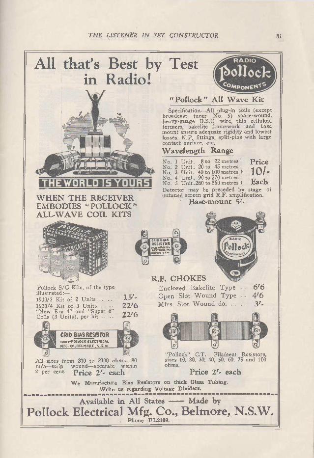
THE LISTENER IN SET CONSTRUCTOR 81
All that's Best by Test in Radio!
THE WORLD 15 YOURS
e
'\\* -;410stiiiL,pj 7,71-_
W HEN THE RECEIVER EMBODIES " POLLOCK " ALL- WAVE COIL KITS
Pollock S/G Kits, of the type illustrated: -1930/3 Kit of 2 Units .. • 1.51-•
1930/4 Kit of 3 Units .. 22'6 "New Era 4" and "Super 6" Coils (3 Units), per kit .. 22'6
All sizes from 200 to 2000 ohms -80 m/a—strip wound—accurate within 2 per cent. Price 2'. each
misorePOLLOCK ELECTRICAL
MFG- CO. BELMORE
Compoe jofl f eDelkS
R ADIO
"Pollock" All Wave Kit
Specification—All plug-in coils (except broadcast tuner No. 5) space-wound, heavy-guage D.S.C. wire, thin celluloid formers, bakelite framework and base mount ensure adequate rigidity and lowest losses, N.P. fittings, split-pins with large contact surface, etc.
Wavelength Range
No. 1 Unit. 8 to 22 metres No. 2 Unit. 20 to 45 metres No. 3 Unit. 40 to 100 metres No. 4 Unit. 90 to 270 metres No. 5 Unit. 260 to 550 metres Each Detector may be preceded by stage of untuned screen grid R.F. amplification.
Base-mount
Price
lo'.
GRID BIAS RESISTOR
n .tteTIUCAL nrc•
R.F. CHOKES Enclosed Bakelite Type Open Slot Wound Type Mfrs. Slot Wound do. ..
"Pollock" C.T. Filament Resistors, sizes 10, 20, 30, 40, 50, 60, 75 and 100 ohms.
Price 2'. each
We Manufacture Bias Resistors on thick Glass Tubing. Write us regarding Voltage Dividers.
6'6 4'6 3'.
Available in All States — Made by
Pollock Electrical Mfg. Co., Belmore, N.S. W. Phone UL2189.

82 THE LISTENER IN SET CONSTRUCTOR
MULLARD TYPES
Type Purpose Fil Plate
Volts Amps. Volts Ma's (max.) (normal)
Neg grid bias at normal plate
voltage. Impedance (ohms)
PM 252 PM 22 PM 4 PM 254 PM 24 PM 24a PM 6 PM 256 PM 26 DFA 8 DFA 6 DFA 7 DFA 9 DO 20 102 T AC 4 AC 3 S 4V 354 V 164 V 104 V
Amp. Pentode Amp. Amp. Pentode Pentode Amp. Amp. Pentode Amp. Amp. Amp. Amp. Amp. US Type US Type US Type S.G., R.F. Gen. pur. Gen. pur. Amp.
2.0 2.0 4.0 4.0 4.0 4.0 6.0 6.0 6.0 4.5 4.5 4.5 6.0 7.5 2.5 5.0 1.5 4.0 4.0 4.0 4.0
0.3 0.3 0.1 .18 .15 .275 .1 .25 .17 .85 .85 .85 .6 1.3 1.5 .25 1.1 1.0 1.0 1.0 1.0
150 150 150 150 150 300 150 180 150 400 400 400 250 425 180 180 180 150 180 180 180
_ 2,600 - 62,500 _ 4,450 - 2,000 - 28,000 33 53,000 - 3,550 - 1,850 - 25.000 9 15,000 36 4,500 150 2,850 30 2,000 48 2,000 12 6,650 25.5 1,450 9.0 7,800 4.5 1.33 meg 10 14,000 10.5 6,650 10.5 2,850
RAYTHEON TYPES 224 I S.G. Amp. 227 I Det. & Am 226 R.F. & A.F. 245 I Amp. 171A I Amp.
2.5 2.5 1.5 2.5 5.0
1.75 1.75 1.05 1.5 .25
180
180 250 180
4
7- .5 32 20
1.5 13.5 16.5 51.5 27
400,000 8.000 7.000 1.900 2,000
PILOTRON TYPES 112A Amp. 171A Amp. 224 I S.G. Amp. 226 R.F. & A.F. 227 Det. & Amp. 245 Amp.
5 1.25 5 I .25 2.5 I 1.75 1.5 I 1.05 2.5 1.75 2.5 I 1.5
150 180 180 180 180 250
9.5 I 10 I 4.700 20 I 40 I 2,000 4 1.5 I 400.000 7.5 13.5 I 7.000 - - 8.000 32 50 I 1,900
ARCTURUS VALVES
Type Purpose
Filament
Volts Amps.
Plate
Volt Max. Ma's Normal
Impedance (Ohms)
124 126 127 145 150
R.F. Amp. or Detector .. Amplifier .. Detector .. Power Amplifier .. .. • • Power Amplifier .. .. • •
2.5 1.5 2.5 2.5 7.5
1.75 1.05 1.75 1.5 1.25
180
180 250 450
5.0 34.0 55.0
400,000 7,000 9,000 1,750 1,800

THE LISTENER IN SET CONSTRUCTOR
NOW Standard Equipment
in most popular Australian-made
Sets
•
,ettyA SLOPE 3.5 MA/V • •
A Modern Giant Among Valves Designed primarily for R.F. ampli-fication in A.C. Receivers —having the iowest inter-element capacity yet attained.
CHARACTERISTICS Heater, 4 Volts, 1 amp. *Impedance - - - 430,000 Plate Volts (max.) 200 *Amplification - - 1,500
Screen Volts - 75-100 *Mut. Conductance, 3,5 mA/V
At Plate Volts 100, Screen Volts 75, Grid Volts, zero
UY Base. Plate Lead at Top. MORE NATURAL LIFE WITH
u a e uun* £r vrà P Ft. 0 D U C T of E N G L A N DA.19
Advertisement of the Mullard Radio Co mpany (Australia) Limited.
83
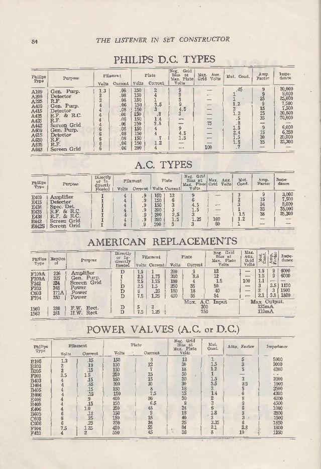
84 THE LISTENER IN SET CONSTRUCTOR
PHILIPS D.C. TYPES
Philips Type
Purpose Filament
Volts Current
Plate
Volts Current
Neg, Grid Bias at Max. Aux. Max. Plate Grid Volts Volts
Mut. Gond. Amp. Impe-Factor dance
A109 A209 A225 A409 A415 A425 A435 A442 A609 A615 A630 A635 A642
Gen. Purp. Detector R.F. Gen. Purp. Detector R.F. & R.C. R.F. Screen Grid Gen. Purp. Detector R.F. R.F. Screen Grid
1.3 2 2 4 4 4 4 4 6 6 6 6 6
.06
.08
.08
.06
.08
.06
.06
.06
.06
.08
.06
.06
.06
150 1 2 150 1 4 150 1 150 3.5 150 3 150 .8 150 1.4 150 2 . 8 150 4 150 4 150 .7 150 1.2 200 4
9 9 3 9 4.5 3
9 4.5 1.5
75
100
.45 9 20,000 1 9 9,000 1 25 25,000 1.2 9 7,500 2 15 7,500 1.2 25 20,800 .5 35 70,000 .8 - - 1.5 9 6,000 2.4 15 6,250 1.5 30 20,000 1.5 35 23,300 .7 - -
A.C. TYPES
Philips Type
Purpose
Directly or In. Filament directly Heated Volts Current
Neg. Grid Plate Bias at
Max. Plate Volts Current Volts
Max. Aux. Grid Volts
Mut. Cond.
Amp. Factor
Impe-dance
E409 I Amplifier E415 I Detector E424 I Spec. Det. E435 I R.F. 8z R.C. E438 I R.F. & R.C. E442 I Screen Grid E4425 I Screen Grid
4 I .9
4 '9 4 .9 4 .9 4 I .9 4 I .9 4 I .9
150 150 150 200 200 200 200
12 I 9 6 1 6 3 I 4.5 3 1 1.5 2.5 j 3 1.5 1.25 3 3
100 60
3 2 3 1
I 1.5 1.2 1
9 3,000 15 7,500 24 I 8,000 35 I 35,000 38 I 25,300
AMERICAN REPLACEMENTS
Philips Type
Replica of
Purpose
F109A 226 Amplifier F209A 227 Gen. Purp. F242 I 224 I Screen Grid F203 I 245 I Power C603 I 171A I Power F704 250 I Power
1560 I 280 F.W. Rect. 1562 I 281 H.W. Rect.
Directly or In-directly Heated
D
D D D
D D
Filament
Volts Current Volts
Plate
Current
Neg. Grid Max. Bias at Aux.
Max. Plate Grid Volts Volts
nu d _42'1 Impe-= dance C
1.5 1 I 200 2.5 1.75 200 2.5 1.75 180 2.5 1.5 250
.25 I 180 7.5 1.25 I 450
5 7.5
9 .8.8 4 35 18 55
12 12 1.5 50 40 84
Max. A.C. Input 2 300 1.25 I 750
- 1.5 9 6000 - 1.5 9 6000 100 1.1 - 3 3.5 11- 70 - 2 3 1500 - 2.1 3.8 1800 Max Output. 125mA 110mA
PO WER VALVES (A.C. or D.C.)
Philips Type
B105 B203 B205 F203 B403 D404 B405 B406 E408 B409 E406 B605 C603 C606 F704 F410
Filament
Volts Current
1.3 2 2 2.5 4 4 4 4 4 4 4 6 6 6 7.5 4
.15
.19
.15 1.5 .15 .65 .15 .15 .9 .15 1.0 .12 .25 .25 1.25 2
Plate
Volts Current
150 150 150 250 150 200 150 150 400 150 250 150 180 250 450 550
8 12 7 35 15 30 8 7.5 26 6.5 48 9 18 24 55 45
Neg. Grid Bias at
Max. Plate Volts
18 30 18 50 30 30 18 15 30 9 24 18 40 25 84 36
Mut. Cond.
1 1.5 1.2 1 1.5 3.5 2 1.4 2 2 6 1.8 2 3.35 2.1 8
Amp. Factor
5 3 5
3 3.5 5 6 8 9 6 5 3 6 3.8 10
Impedance
5000 2000 4200
2000 1000 2500 4300 4000 4500 1000 2800 1500 1850 1800 1250
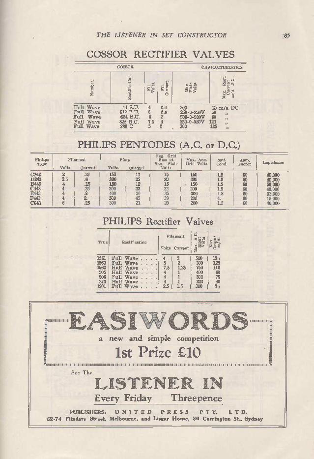
THE LISTENER IN SET CONSTRUCTOR 85
COSSOR RECTIFIER VALVES COSSOR CHARACTERISTICS
1,,
'i' -.
z!, .
e
.,.
Fil.
Current.
Max. Rect.
Current
rn/ a D.C.
Half Wave F1 ,11 IxT9ve Full Wave Full Wave Full Wave
44 S.U. 619 'n TT. 624 823 B U. 280 C
4 0.4 6 0.4 6 2 7.5 3 5 2
200 20 na/a I)C 250-0-250)7 50 „ 500-0-500)7 60 , 550-0-550)7 120 „ 300 125 ,
PHILIPS PENTODES (A.C. or D.C.)
Philips Type
Filament
Volts Current
Plate
Volts Current
Neg. Grid Bias at
Max. Plate Volts
Max. Aux. Grid Volts
Mut. Cond.
Amp. Factor Impedance
C243 2 .27 150 I 17 15 150 1.5 60 40,000 1)243 2.5 .6 300 25 20 200 1.5 60 40,000 13443 4 .15 150 12 15 150 1.2 60 50,000 C443 4 .25 300 22 22 200 1.5 60 40,000 E443 4 .9 400 J 30 35 300 1.8 60 33,000 F443 4 2. 500 45 39 200 4. 60 15,000 C643 6 .25 300 21 20 200 1.5 60 40,000
PHILIPS Rectifier Valves
Typo Rectification
Filament
Volts Current E
1561 Full Wave . . . .1 4 1 2 1 1560 Full Wave . . . . 5 2 1562 Half Wave . 7.5 1.25 505 Half Wave . . . 4 1 506 Full Wave . . . . 4 1 373 Half Wave . . . . 4 1 1 1201 Full Wave . . .1 2.5 1 1.5 1
500 1 125 300 125 750 400 300 220 40 300 1 75
110 60 75
.:.,,...iiii. . t e. el f ..:,, ,,,. li. ,,. , • .w..ik -...‘..,...‘„ ,-.,.
. 1 .,....._..,.4. N..,....., al 111i1111111fià
1-.
n -_J_-.; .7.
ii -- 1st Prize £10 .,. ., = : -. . Ill I IIIIIIIIIIII111111111111.111111111111111111111111•11111111111.1111111111111111111•11111•11.1111111111111111311111111,111 Ill,1111111,1•111111.111111IllIIIIIIII11 ,1 a ".
a new and simple competition
See The
LISTENE 1 IN Every Friday Threepence
PUBLISHERS: U NI T E D P R E S S P T Y. L T D.
62-74 Flinders Street, Melbourne, and Lisgar House, 30 Carrington St., Sydney
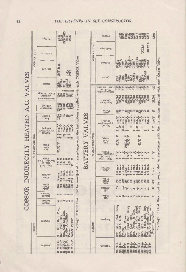
86 THE LISTENER IN SET CONSTRUCTOR
" SIMILAR TO *
sdil I tia
uo.4olptx
CII A RACITERISTICS
o Cf) Cf) o
aeeltoA ama 211 1110 A1
papuannuoaala
(sunI0) aoutpaclati
zo;ara 'd'uy
(aclu[S) opumanpuoD Irn4nri
s4-10A P1-10 "xtw
n10/1 a4Bia l'upuom
su m P1-19 '2aN
4uannj
slI0A alind urw
41.1a1211D aaveari
a2r.41021 Jaluari
asod.ma
0 0 0 0 Ca Ca jr v. 7. r-I 1-11-1 r-i
0 0 0 O 0 o o o o o o o o o o on ce.ecírjui g
Ca In In rn Cn I. 1.
CUCUC CUCUCU EE E E E E C) en un o.) tO
N N /4 •••:1 Cn
co
>>>>>>
14/. ,11 UU
c ci d E E E E É
1,1 to
cp e e c,c, R R g gis3
*Voltage of Grid Bias must be re-adjusted in accordance with the instructions s upplied with each COSSOR Valve.
BATTERY VALVES
• IMIL AR TO *
1.11?.150
In cn c,) in un 1n N In 0 1n ca cr <1' el Ca 1. -ecce) „, c„ CID VD Ce 0
C) c., X X
-Fi, ›,18. ;lo P4P4.1:14 P.111P-i PI
CJ Lr> O e 0 e cD e (Z1 o
es3 eq E-1 " 1-1 •a• tO Cf) M n4 iCn I 4Cn Z ZI 4
CH A RACTERISTICS
'ablnloA XuptioNt.
papteaunuoaau
(Jun[0) aoutpadmi
..1010 M .d171V
( 10 1S) aouslanpuoD pen;nw
410.1 '131-10 •xnv
aVeld 2uPi10 .11 selg
P110 '•eaK
lua.uno oluId
Imon •x13n
lualano 113
10A
•asodana
*.zaquing
C ifl 0c Ir L- Cr e ir Cr, el CV 0, N N Ca N Ca N
0 0 0 0 0 0 0 O O O O O 0 O O O 0 O O O C> O 0 0 O 0 C 0 0 0 0 /n C> Ln c o6c; Oc;'t-: O Ln N C> 0 e N eq
Ca
0 0 0 0 0 0 0 1n O C> t-C.1 .vr Ca Ca
CUQ)Q) LU CU CQ CQ CU CU CU CU CU CU
e E EE E E E E E E E E kn CO tr3
t- cm e t- oo eq
>> 0 C e e CO OI GO 00
,-i ',.., 0 .--- e 0 e O e e
0 .-I
>>>>>>>>>>>> In In In In LLCu /414 0 CO C1 el eD
ri ,c4 EEE4E EE E E o e, b, kr: ni In o In ,r e
00
O O CI 0 e 0 C e e 0 Cu Cu Cu 00 1n Cu jr ,rD Cu Cu Cu Cu v. v.-1 4,-1 e. v. I.
Cu Ln . . . . .
e 00.
eo to to co to
the instructions supplied with each Cossor Valve,
cn
u) CU
PI C-.
a) ti. ci.
41. cu .
— A < o 18 Mi.1 ájnj t; 0 13 4 e o u e o o.....,e._. o (1) n1 .,... . cu ee n o e-1 ..Pe n c3 <cl) ta
e
o'l d ,..esc' â àer.+'-' , o
ucu oco ve) n o u o nc,......m cre4P.P. M ege AC/21: =C2 =
dd. Fidd.r.ir.;ddr4re=i Cu O Cu c e c e e e e O O O
00 N N CV CV 'Irr' •Lr, <IN Cr:/ GO GeD

THE LISTENER IN SET CONSTRUCTOR
RENRADE
GRID LEAK RESISTOR
87
PRODUCTS
Renrade Grid Leak Resistors guarantee closer tolerances, greater overload capacity, maximum heat dissipation, greater safety factors, and pig tailed soldered in, insur-ing positive contacts.
ALSO MANUFACTURERS OF
CENTRE TAPPED RESISTORS
NEUTRALISING CONDENSERS
SEMI-VARIABLE BIASING
MIDGET CONDENSERS
FIXED CONDENSERS
VOLTAGE DTVIDERS
WIRE WOUND RESISTORS
I?F T MADE VALVE SOCKETS
TERMINALS
A. G. DAVIS Wembley House,
Rai lway Square,
SYDNEY
AGENTS: NE W ZEALAND, V'CTORIA
WEST AUSTRALIA
TASMAN' A
SCOTT & HOLLADAY
SOUTH AUSTRALIA
NEWTON McLAREN QuEENsLAND
NATIONAL RADIO
ADVERTISEMENT INSERTED BY R. W. REYNOLDS 200 CHALMERS ST., SYDNEY

88 THE LISTENER IN SET CONSTRUCTOR
* SIMILAR TO *
sdnum
110150113E n
In IC
000.10 0
mm .mm m .,..., mommrqm Pao u
<< N 4 ci m-f tm 4 4 XX
ci
M csI O M 4 , 4 N Ici ne gi Pk
in Ici
< ,mrco m m = E- IX tC.ZDi Ccó E-4 I:4 P4 R. ra4
CHARACTERISTICS
aermoA alrm 2npiJom
papuatuineDau
(sumo) aoirepadmi
enava •dcav
(ado's) aaumanpuo3 remniç
',TPA w o • xnv
suon aeid 2uppom e sma PPO '2O.K
(lrut) lnauno alrld
94.10A amd •x-eN
a oMmd
zaquInK
M OIO N 0 0 0 M 0 0 0 0 0 0 N OO N N M N O N M O N 0 0 09 4 4 4 4 4 4 N 4 4 N 4 mt.
0 0 O M M M
0 0 0 0 0 0 0 0 0 0 0 0 0 0 0 0 0 0 0 0 0 0 0 0 0 M M 0 0 0 M = p 4 M C M O Otm .M ..
in M
0.5 0 00 M 4- 0 M M mtm ? M M M mt.
CO COCO
eDee m oel 4cc
e“,1 ei e‘i UIc CU CU 4 ei
B
m R Ze 4 4 --, -- . ci ,. . . tm CO 4 4 •-• ,_,
M M M ci CO M C- M M O CCO M M O O M N.
4 4 !t. 4 4 mO N',-, 4 1 O
.1 1,1 e-ine..00 4‘n o m me n o 4 4 4 4 m cm 4 4eqc,1Lo
0 0 0 0 0 c 0 0 0 0 0 0 0 0 eDee nec ovDto o œ 0 00p 4 4 4 4 4 4c.1 4 4ea 4
in M M M M M
ri
Ici 03 mo mt. mt. me mo co co m m co m co
Q W 0 0) qd era4 Eeo 00 o 0 0 o cOà4 <
F 1:3 "C/ 0,2ockLómomt.so , 000x oxox000 z ada.a..wmta ma.P.4m0
fligl4E4 ts;Pàs; Na;><guMrs;r ›<E-M O O M M M.7. 0 0 M M 0 0 0 4 Mt 4 4 N 4 4 4 N ri OC CO Oa N Nne mt. m.,me CO M M OCO M M
with each COSSOR Valve.
in accordance with the instructions
'Voltage of Grid Bias must be re-adjusted
*SIMILAR TO*
CHARACTERISTICS
•aitullpA alum 2uptiojà
papuationoaall
• (m110) aatomadtal
W 50 M
ci Inv
.(adnIS) aous;onpuoo
sS10.1 PI40 'xnV
•nioe alu m muptiost esum
PIJO
.1fflazna
4C1,1
113
"SlIO A
thi
Palleag LIP-il ¡PUT 10 4 Pa.1110
•asodand
•iaqtunN
> > in in 4 4
>
CO CO 4
in
>>>.
. N O 4 4 M
ai E E E 00
o o o M O M 4 N N
M M in
4 4 4
M M M
CU osi
*Voltage of Grid Bias must be re-adjusted in accordance with the instructions supplied with each COSSOR Valve,

THE LISTENER IN SET CONSTRUCTOR 89 DETECTORS AND AMPLIFIERS
90 4.5
—
I
2.0
•—
10000
900
9.0
15000
18
10s
9.0
—
2.5
—
9000
1000
9.0
23000
95
150
10.5
—
2.7
—
8000 1060
9.0
26000
85
_ GENERAL
.1 .")
O d
.>)
d
<") 0
d
el 0
d
ll,
d
s.l,
d
e, 10
d
N el
d
01 F1
d
in
.-;
in
.--;
‘n
..
‘n
.-;
to
d
o
d
,
.-, .i,
dfl 1 2 b> ile. F.
.-. .-. o m en o o .
NI .
N .
al .
el .
el .
IA . in
.-, , . in
rn m ,, ,,, .
(,) .
CI .
N .
N
,,,, .
Ng
in .
N .
N .
N . -,.
N r _
F. .
rt.
Z.; D. C.
D.C.
D. C. Li
di D. C. d
di D. C.
D. C. •
IM
•
A
(j
n
r ...i
-,
6
à
ri
ü
à
ri
(i
à - C.)
Li A nt:1
.
•C.) • (-)
Mu. Overall
Dimensions . - .. . . . - - 1.1 .1 1-1 •-• .-.I 1-1 1-1 a-I 1,1 t
r
X. e e a- r•) e e e e .1 .,, ,,, ,.-•, e e - e L.,
›,.
e J
e as -
X X X >. ›. X >.; x X X
à „ à „. à , cl.,„ •cl „ .. à , à, ii; i'l '< 'e r'.5>á <
... à„.
d<
à
ai < e<
..
ei<
a -7. el
a el ::
œ a'
... ..,c cl, 6 c7, eu a> gi c9 e: gui
04 gi ..e• g1
e gi
CO
CI r. gI )'-
Fn 7
gi o
!.1 I
m 1 1 I I 1 I 1 1 I 1
0
9.2,2
C 0 0 0 0
0 .1 0
1 0 0 La 0 -
o
a.
0 0 0
g•F,.5%. U,•Tn'.
O O
O Iv)
0
Cie O O tri
o
o Li Q
211.
o
o
Li
co.;
(.;
•-•
Li
o Li
›
Li
o o
tag,' tel
ti X

90 THE LISTENER IN SET CONSTRUCTOR
ans2
o CM
tf)
o
X
SPECIAL PURPOSE
breK9
o
ifeE2 g"B%u I-
co r•-•
FOR AMATEUR AND EXPERIMENTAL TRANSMITTING USE
u<
-ierru If)
o o
o
o
gEe Èró CM
CO
o
tr)
nCS-c1:15 á
C e' zotT.e
o o
eE. o<2
gke
o o CM
-1 E.9e EFT). eb›
0
o V)
CM
C?

THE LISTENER IN SET CONSTRUCTOR 91
PILOT RULES THE SHORT WAVES
11.0T R A010 PARTS
Specialisation brings leadership! Pilot stands without rival in the short wave field through years of research and practical manufacture under the direction of the world's
most famous radio engineers. The benefit is yours Pilot Radio Parts have that built-in quality and precision that is essential — Pilot Specifications are the culmination of years of experimentation — Pilot "Radio Designs" (1/ per copy) brings you news of the latest developments in Short Wave Work —Pilotron P.227 is the only valve designed for a short wave detec-
tor — working smoothly and without hum. We are also sole distributors for the Pilot Super- Wasp Short and Long Wave Re-
ceiver, and for the Duffy Short Wave. Consult us on your Short Wave problems.
Harringtons Ltd. 266 COLLINS STREET, MELBOURNE
386 GEORGE STREET, SYDNEY BRANCHES IN ALL STATES
q1111111 iportunities in
...... • ... . . .;.::
Tr:LEVIniuN Our complete Course includes study of funda-
aientals of Television, and latest developments —starting in Australia next year. ALL without extra cost. Radio calls for MORE trained Engineers. Your age. amount of education, or
experience, makes no difference. If you are ambitious, you can succeed. You can learn at home, in your spare time. The Courses also include set building, com-
plete transmitters, broadcast and short wave, power transformer design, super hets., tele-vision and sound.
er This Adt 'LIP & MAIL THE COUPON TODAY
The Secretary, The Australian School of Radio Engineering, Keenes Chambers, 12 Oxford Street, SYDNEY.
Dear Sir,—Please forward me, without obli-gation, your FREE booklet, describing the course outlined in this ad.
Address .. . City .
State • ..... • • • • ......... • • • . • • • • •

92 THE LISTENER IN SET CONSTRUCTOR
OSRAM VALVES 2 VOLT
Type Purpose E t. -
- <.3 A
e o ...,
e Zi M ara ‘.ó' cñ q
a cc
H210 11L210 L210 P215 P240 S215 PT240
R.C.C. R.F. or Detector General Purpose Small Power Super Power Screen Grid Pentode
2.0 0.1 150 2.0 0.1 150 2.0 0.1 150 2.0 0.15 150 2.0 0.4 150 2.0 0.15 150 2.0 I 0.4 150
90 150
35 29 11 7 4
170 90
50,000 0.7 23,000 0.87 12,000 0.92 5,000 1.4 2,500 1.6
200,000 0.85 55,000 1.65
4 VOLT
H410 H1,410 L410 P410 P425 PX4 S410 PT425
R.C.C. R.F. or Detector General Purpose Small Power Super Power Large Power Screen Grid Pentode
4.0 4.0 4.0 4.0 4.0 4.0 4.0 4.0
0.1 0.1 0.1 0.1 0.25 0.6 0.1 0.25
150 150 150 150 150 200 150 200
90 150
40 I 60,000 0.67 25 30,000 0.83 15 8,500 1.77 7.5 5,000 1.5 4.5 2,300 1.95 3.5 1,050 3.3
180 200,000 0.9 100 50,000 2.0
6 VOLT
H610 HL610 L610 P610 P625 P625A S610 S625 PT625
R.C.C. R.F. or Detector General Purpose Small Power Surer Power Super Power Screen txrid Screen Grid rower Pentode
6.0 6.0 6.0 6.0 6.0 6.0 6.0 6.0 6.0
0.1 0.1 0.1 0.1 0.25 0.25 0.1 0.25 0.25
150 150 150 150 250 200 150 180 250
90 120 200
40 I 60,000 '0.67 30 30,000 1.0 15 7.500 2.0 8 3,500 2.3 6 2,400 2.5 3.7 1 600 2.3
210 200,000 1.05 110 175,000 0.63 80 43,000 1.85
SPECIAL POWER
LS5 LS5A LS5B LS6A DA60
Special Power Special Power Special Power Special Power Special Power
5.25 0.8 5.25 0.8 5.25 0.8 6.0 1.6 6.0 4.0
400 400 400 400 500
5 2.5 20 3 2.5
6,000 0.83 2,750 0.91 25,000 0.8 1,300 2.3 835 3.0
2.5 VOLT A.C. (American Replicas)
MY224 MY227 MX245
Screen Grid General purpose Super Power
2.5 I 1.75 2.5 I 1.75 2.5 I 1.5
180 75 180 250
420 400,000 1.05 9 9,000 i 1.0 3.5 1,900 I 1.85
4 VOLT A.C.
MH4
ML4 MS4
R.F. or Detector General Purpose Small Power Screen Grid
4.0 4.0 4.0 4.0
1.0 1.0 1.0 1.0
200 200 200 - 200 70
35 20 9
550
16,000 2.19 8,000 2.5 3,000 3.0
500,000 1.1
RECTIFIERS
Type Purpose Filament Volts
Filament Current
R.M.S. Plate Volts (Max.)
Max. Rectified Current (m.a.)
MX280 U8 139 GUI
Full Wave Full Wave Full Wave Half. Wave
5.0 7.5 4.0 4.0
2.0 2.4 1.0 3.0
r 400 + 400 1 L350 + 350J 500 + 500 250 + 250
1000

T HE LISTENER IN SET CO NSTR UCTOR 93
LEARN THE CODE Listening on long and short wave lengths, innumerable Morse
stations sending interesting news are to be heard.
THE shorter waves are becoming increasingly popular. It is only within the last six months that the public has awakened to the fact that it may partake of thrills of long-
distance reception. Previously, the experimenter who spoke of his achievements was regarded by his broadcast listener friends as a genius.
A single valve circuit for long wave recep-tion may be used to pick up long wave
code stations.
The order has changed, however, and now the B.C.L., long since tired of tuning in interstate stations, plugs a simple little affair into the de-tector valve of his battery-operated broadcast receiver, and tunes in Manila, California, or Chelmsford. But, although excellent reception of all these stations is possible with the simple little adaptor, the B.C.L. must first find them, and dis-. cover their schedules. The B.C.L. who has tackled the short waves in
hundreds of instances, is a very disillusioned per-son. He expects to tune in international trans-missions as he would 3LO, 3AR or 2FC. Even on the long wave lengths we require a certain amount of patience in order to tune in some of the weaker interstate transmissions. Why, there-fore, should the adaptor be abused for failing to do its work when the operator will not interest himself sufficiently to become accustomed tr the delicate operation of tuning on the higher fre-quencies—short waves? Truly we are taking too much for granted.
Here we are expecting a single-stage adaptor to give good speaker reception of international trans-missions, when such a receiver used for broad-cast reception as a standard single-valver, fol-lowed by a couple of amplifier stages, would not be expected to receive even the nearest interstate station satisfactorily. Yet, with careful manipulation, the inefficient-
looking adaptor can be made to perform wonders unthought of a few years ago. With it we are able to listen to the world. We cannot rely on these transmissions as a
regular feature, as we would tune to 3DB or
3UZ, for instance, and oft-times we may listen for hours every night of a week without hearing a sign of a single phone station. It may happen that schedules do not occur within this week, or that the regular stations are inaudible owing to unsuitable conditions. The aggravating part of the whole business is that no matter what wave length coil we may plug in, we will receive dozens of Morse stations all busily at work. These stations provide the reason for this article. What is to stop anyone reading these Morse
signals, if he is sufficiently interested, of course. Lack of interest will prevent a man from learning the Morse code in a lifetime. It is possible to memorise the whole code within
a week. All that comes after this, is the correct spacing of signals when sending, and constant listening to slow-speed Morse stations. It is the rule that a man who can receive fast
Morse is a good sender. From this it will be seen that the correct spacing of signals when learning how to handle a key will improve the ability of the mind to render intelligible the combinations of sounds used to represent the various letters, figures and signs. The learning of the Morse code requires appa-
ratus, usually in the form of a buzzer, to generate a sound of suitable frequency. If we can dupli-cate the sounds to be met with when listening in to Morse transmissions on a short wave receiver, the path towards perfect sending and the receiv-ing of radio signals will be considerably les-sened.
Layout details of the single honeycomb coil set.
An audio oscillator will give a wide range of audible frequencies by the adjustment of a rheo-stat. The oscillator can include one of the cheap-est and poorest audio transformers that ever was made. Obviously a component possessing these characteristics will cost very ltitle. Accompanying is the circuit of the oscillator.
Simple as a crystal set, isn't it? The original oscillator was built into a can and fitted with a

94 THE LISTENER IN SET CONSTRUCTOR
cetter
A
D
17
X
A4 A/ o
4? À? S
(I V MI A( Y
THE MORSE CODE
Signe/ How ie sounds.
mu a m dah MMI 13 dah dit dit dit — w • dah dít dah dit
da h dit dit-dit
▪ eu am a dit dit dah dit am ma dah dah dit U M M . dit dit dit dit la d// dit mi am lm am dit dah dah dah am a am dah dit dah 13 M'U M M dit dah dit dit zom dah dah m u dah ma am am dah dah dah
,dah dah dit M M M M Il MIIM dah ¿ah dit ¿ah ▪ ma a dit ¿ah dit
dit dit dit dah
▪ mi dit dit dab U M M M a dit dit dit dah • am am dit dah dah imam mu dah dit dit dah
lm ma ¿ah dit dah dah dah dah dit dit'
Numerals
111 dit ¿ah d'ah dgb dal; 2 u dit dit ¿ah dah dab 3 dit dit dit dah dgh
alm dit dit dit dit dah O M M . . Hit dit dit dit- oit
de dit dit dit dit ma amena dah dah dit dit dit
▪ IMI M IMMI • dah dah dah dit dit
11 • dah daA da!? dit IMID d'ah d'ah dah da!? dal'
4 5 6 7 8 9

THE LISTENER IN SET CO NSTR UCTOR 95
i:»-tONE S
- A -
'TE E PH ONE NI DUCT ION C011-
BATT ER'
- B
CoNTROL SW 'TE
1122E R
Two circuits which may be used for buzzer practice.
4¡-volt "C" battery to supply both "A" and "B" current to the oscillator valve, as in the circuit diagram.
A simple audio frequency oscillator for practice work.
This little unit is self-contained, and will soon brush up your sending speed, and improve your spacing. A jack is fitted to the baseboard to provide
simple connection for as many pairs of headphones as are required. Shilling torch batteries will give remarkably
long service when using a .06 four-volt valve. The use of a 45 or 60 volt "B" battery in place of the "C" battery as the "B" supply will give sig-nals of sufficient strength to operate a loud speaker.
MEASURING INSTRUMENTS The use of meters is essential in putting into operation any battery
or mains operated valve receiver.
(IF what use is the measuring instrument in receiver operation? It can enable more eco-
nomical operation; it can detect distortion and aid its cure; it can provide a check on the power supply equipment; and it will assist in the obtain-ing of all-round better results. Let us begin with the voltmeter. The volt-
meter will indicate immediately whether each valve is receiving its rated filament voltage. As certain makes of screened grid valves do not have within their range one which requires a filament voltage of 6, series resistors are used to drop the voltage of the "A" supply to the required value. The use of a voltmeter will permit correct adjust-ment to the series resistance and will save damage to the valve. Distortion may occur when an accumulator is
nearing the end of its charge. The meter will show immediately whether the voltage of the fila-ment supply is below normal. Plate voltages may be checked on the completion of the construction of a power-pack, and tappings may be taken at required voltages where otherwise this procedure would be done by guesswork. A point to note is always to test a power-pack for voltage when it is on load. The voltage outputs available at each of the positive tappings of an eliminator can soar to high values if there is no load on it. The low reading voltmeter may also be shunted with re-sistors and re-calibrated to read higher voltages. The milliameter is an important instrument, and
plays a big part in putting a receiver into opera-tion. It will show immediately whether an am-plifier valve is drawing more than its share of
plate current, and will indicate when adjustments should be made to the bias values. Furthermore, the meter will give an accurate idea of what power is required to supply the receiver—cer-tainly a useful piece of information when the design of a receiver and power-pack is contem-plated.
Expensive But Essential The A.C. voltmeter is an expensive piece of ap-
paratus, but, for the experimenter at least, it is an essential instrument. Transformer secondaries have an inconvenient habit of delivering far too high or far too low voltages decided upon when designing the job. Many a rectifier and A.C. valve has been ruined because of some unforeseen cir-cumstance entering into the scheme of things when going about the construction. Say, for in-stance, you have copied, core size for core size and turn for turn, and are duplicating a trans-former of commercial construction, you may ad-here strictly to the sizes, but a difference in the electrical characteristics of the transformer core may produce secondary voltages entirely different from those calculated. The A.C. voltmeter should therefore be on hand
if a habit is made of building transformers and trying new A.C. circuit arrangements. Finally, let it be mentioned that without meters
it is impossible to put a transmitting circuit into efficient operation. Visual means by use of meters is provided in transmitting arrangements to secure maximum efficiency. In the same manner meters are essential if a receiver is to be operated at maximum efficiency.

96 THE LISTENER IN SET CONSTRUCTOR
A PAGE OF HINTS AND TIPS Crystal Contacts
TiIFFERENT crystals require different types of cat-whiskers. It is most important to use
the right contact in conjunction with any par-ticular crystal, and a list to guide the amateur is given hereunder. With galena, use a silver, copper or brass whisker. With molybdenite, a silver strip makes the best form of contact. For silicon—sometimes termed the old-fashioned crystal, but which is still largely used—a gold or steel contact is best, while for carborundurn, a steel contact pressing heavily on the crystal is necessary. For constancy in action, carborundum and steel with a potentiometer and local battery remains supreme. In addition, there is the zincite-bornite com-
bination of crystals from which excellent results have been obtained. Other combinations not so well known, but equally as good are galena-tel-Iurium, tellurium-zincite, carborundum-silicon, copper pyrites-tellurium. Ordinary solder should not be used for mount-
ing crystals, owing to the fact that the applica-tion of the necessary heat to melt the solder is liable to destroy the sensitivity of a crystal. The crystal may be held in position by pack-
ing tinfoil around the inside of the cup, but the most efficient way is to employ a cup in which the crystal is tightly gripped by set-screws. With a holder of this type it is possible without any delay to change the crystal for a new piece.
An Output Transformer AN output transformer should be used in every
up-to-date broadcast receiver. The use of such an instrument will prevent damage to the loud speaker, and will also greatly improve re-ception. It will be found that a loud speaker, which will
not operate satisfactorily when connected in the plate circuit of the last amplifying valve, will function perfectly when an output transformer is installed. Although the use of the instrument causes a
slight drop in the volume of signals, the advan-tages outweigh this single disadvantage. The pri-mary of the transformer should be connected to the speaker terminals or jack of the receiver, and the secondary to the speaker leads.
Troubles in Valves IT is well known that all gases must be ex-
hausted from the bulb of a receiving valve. This has been a fairly simple operation with the older battery type valves, but has become a small problem since the advent of indirectly heated valves. The introduction of each extra element into the construction of the valve will increase the possibilities of vacuum being imperfect. The presence of gas in a valve will tend to
shorten its life if it is used in any other but the detector stage with the fairly high plate voltage to be met with in the a.c. receiver. When plate voltage is applied to a valve containing gas, elec-trons emitted by the cathode are attracted to the plate at very high velocities and collide with the gas particles. This produces ionization. When an electron is travelling at sufficient speed it may
cause one or more electrons to be separated from an atom, which it thus splits into two oppositely electric parts. The addition to the plate current of the liberated electrons is not detrimental, ex-cepting that it may make the operation of a valve somewhat erratic, but the bombardment of the cathode or filament by the heavy positively charged ions wears away that element and shortens the life of the valve. Since the cathode is negatively charged, ions are attracted strongly to it. For these reasons, valve manufacturers now
have among their equipment, instruments which can detect the presence of gas in a valve.
A Highly Efficient Wave Trap THE old two-coil wave trap, by the use of a .001 infd capacity fixed condenser, can be wired
into a much more effective circuit. The accom-panying diagram shows how the connections will be made. The coils Li and L2 consist of 45 and 15 turns
respectively, the smaller coil being wound over the larger in the centre of the 45 turn winding. Gauge 24 d.c.e. wire will be satisfactory. Three-inch diameter former should be used for these coil sizes. The tuning condenser should have a capacity of .0005 mfd. In operating the trap, time the trap condenser until the signals from the interfering station are reduced to minimum strength.
L2 /57/
/ Li 457:
Circuit and coil construction details of the trap

THE LISTENER IN SET CONSTRUCTOR
Radiokes VITREOUS WIRE-WOUND RESISTORS
Radiokes R. F. CHOKE
Radickes VERNIER DIAL
Radiokes SHIELDED COILS
'Whatever set you are building Xere are eadiokes 2arts that will interest you
Radiokes Precision Products now cover an almost complete range of components required by the set builder—all covered by a liberal 12 months' guar-antee of faultless quality and accuracy. Some of the most popular are illustrated.
Radiokes VITREOUS WIRE-WOUND RESISTORS (Fixed and Variable Tappings)
Made in 6 types—Anode, Light, Medium, Heavy, Extra Heavy Duty and Multiple Units—suitable for Power Pack work, Anode feed and for obtaining correct bias voltages for the newest popular types of tubes.
Radiokes RADIO FREQUENCY CHOKE Designed for lowest distributed capacity and maxi-
mum inductance. A very compact unit, being only in. in diameter. Price 7, 11.
Radiokes ILLUMINATED VERNIER ART DIAL The handsome, modern, embossed escutcheon plate
adds distinction to any set. Non-slip spindle and accurate construction ensure velvet-smooth tuning. All steel parts are rust proofed. Price 12/6.
Radiokes STANDARD SHIELDED COILS (Matched Before Leaving Factory in "Kits.") Small, neat, and thoroughly efficient; polished
aluminium shields. Fin,shed with colored leads 6 inches long for easy wiring. Made in the following types: Aerial Coil, Pre-selector or Band 'Pass Coil; R.F. Coil; Pre-selector or Band/Pass Coil with re-action. Price, each 9/11.
Free blue prints supplied with all except small parts. Send for new catalogue showing reduced prices of all Radiokes standard lines and compre-hensive range of modern circuits.
RADIOKES PRECISION PRODUCTS
Manufactured and Guaranteed by
METROPOLITAN ELECTRIC CO. LTD. 126 SUSSEX STREET — SYDNEY
THE LISTENER IN SET CONSTRUCTOR
THEY KEEP
ON 111111E JOB
ENGLIS H M A DE
Osram Valves
are ACTIVE
EVERLASTINGLY emitting electrons, Osram Valves give sterling performance
throughout an unusually lo ng life. It's because they're honestly made and thoroughly tested. There's an Osram Valve for every socket in your set, whatever the voltage.
Made in England " You can PROVE they're better"
Write for your copy of the Valve Guide to the complete Osram range; and the special brochure embodying the test for micro-phonicity.
City Distributors:
A. J. VEALL, 172 and 243 Swanston St., Melbourne; 302
Chapel St., Prahran.
OLIVER J. NILSEN and CO. PTY. LTD., 45 Bourke Street, Melts.
- Advertisement of the
BRITISH GENERAL ELECTRIC CO. LTD. "Magnet House," 590 Bourke Street, Melbourne.
Printed and Published by EDGAR IL BAILLIE, of 185 Balaclava Road, Caulfield, for United Press Proprietary Limited "Herald" Buildings, 62 to 74 Flinders Street, Melbourne. Sydney Office: Llagar House, Carrington Street. Wholesale
Distributors: Gordon & Gotch.