6th OOPSLA Workshop on Domain-Specific Modeling (DSM'06)
228
COMPUTER SCIENCE AND INFORMATION SYSTEMS REPORTS Technical Reports TR-37 Jeff Gray, Juha-Pekka Tolvanen, Jonathan Sprinkle (eds.) 6th OOPSLA Workshop on Domain-Specific Modeling (DSM’06) October 22, 2006 Portland, Oregon USA UNIVERSITY OF JYVÄSKYLÄ DEPARTMENT OF COMPUTER SCIENCE AND INFORMATION SYSTEMS 2006
-
Upload
khangminh22 -
Category
Documents
-
view
4 -
download
0
Transcript of 6th OOPSLA Workshop on Domain-Specific Modeling (DSM'06)
COMPUTER SCIENCE AND INFORMATION SYSTEMS REPORTS Technical Reports TR-37
Jeff Gray, Juha-Pekka Tolvanen, Jonathan Sprinkle (eds.)
6th OOPSLA Workshop on Domain-Specific Modeling
(DSM’06)
October 22, 2006 Portland, Oregon USA
UNIVERSITY OF JYVÄSKYLÄ DEPARTMENT OF COMPUTER SCIENCE
AND INFORMATION SYSTEMS 2006

COMPUTER SCIENCE AND INFORMATION SYSTEMS REPORTS Technical Reports TR-37
Jeff Gray, Juha-Pekka Tolvanen, Jonathan Sprinkle (eds.)
6th OOPSLA Workshop on Domain-Specific Modeling
(DSM’06)
October 22, 2006 Portland, Oregon USA
October 2006
University of Jyväskylä Department of Computer Science
and Information Systems P.O.Box 35
FIN 40351 Jyväskylä Finland

ISBN 951-39-2631-1 ISSN 1239-291X Jyväskylä University Printing House, Jyväskylä, Finland 2006

i
Welcome to the Sixth OOPSLA Workshop on Domain-Specific Modeling – DSM’06
Preface
Domain-Specific Modeling (DSM) raises the level of abstraction beyond programming by specifying the solution directly using domain concepts. In many cases, final products can be generated automatically from these high-level specifications. This automation is possible because both the language and generators need fit the requirements of only one company and domain.
Industrial experiences from applying DSM consistently show it to be 5-10 times faster than current practices, including current UML-based implementations of MDA. As Booch* et al. have stated, "the full value of MDA is only achieved when the modeling concepts map directly to domain concepts rather than computer technology concepts." For example, DSM for cell phone software would have concepts like "Soft key button", "SMS" and "Ring tone", and generators to create calls to corresponding code components.
More investigation is still needed in order to advance the acceptance and viability of domain-specific modeling. This workshop, which is in its six incarnation at OOPSLA 2006, features research and position papers describing new ideas at either a practical or theoretical level. On the practical side, several papers in these proceedings describe application of modeling techniques within a specific domain. In addition to industrial projects, several authors from academia present research ideas that initiate and forward the technical underpinnings of domain-specific modeling. In particular, the 22 papers included in this proceedings highlight the importance of metamodeling, which significantly eases the implementation of domain-specific languages and provides support for experimenting with the modeling language as it is built (thus, metamodel-based language definition also assists in the task of constructing generators that reduce the burden of tool creation and maintenance). We hope that you will enjoy the workshop and find the information within these proceedings valuable toward your understanding of the current state-of-the-art in domain-specific modeling.
Jeff Gray, Juha-Pekka Tolvanen, Jonathan Sprinkle
October 2006
* Grady Booch, Alan Brown, Sridhar Iyengar, Jim Rumbaugh, and Bran Selic, MDA Journal, May 2004

ii
6th WORKSHOP ON DOMAIN-SPECIFIC MODELING 22nd October, 2006, Portland, Oregon USA
Program committee
Scott Ambler, IBM Pierre America, Philips Philip T. Cox, Dalhousie University Krzysztof Czarnecki, University of Waterloo Andy Evans, Xactium Jeff Gray, University of Alabama at Birmingham Jack Greenfield, Microsoft Jürgen Jung, University of Duisburg-Essen Steven Kelly, MetaCase Jürgen Kerstna, St. Jude Medical Kalle Lyytinen, Case Western Reserve University Pentti Marttiin, Nokia Birger Møller-Pedersen, University of Oslo Matti Rossi, Helsinki School of Economics Arturo Sanchez, University of North Florida Jonathan Sprinkle, University of California, Berkeley Juha-Pekka Tolvanen, MetaCase Markus Völter, independent consultant
Organizing committee
Jeff Gray, University of Alabama at Birmingham Jonathan Sprinkle, University of California, Berkeley Juha-Pekka Tolvanen, MetaCase

iii
Table of Contents
Welcome Message from the Organizers
i List of Program and Organizing Committees ii Table of Contents iii-iv
Using Domain-Specific Modeling towards Computer Games Development Industrialization 1-14 André W. B. Furtado and André L. M. Santos
Building a Flexible Software Factory Using Partial Domain Specific Models 15-22 Jos Warmer and Anneke Kleppe
Conceptual design of web application families: the BWW approach 23-32 Roberto Paiano, Andrea Pandurino, and Anna Lisa Guido
Building End-User Programming Systems Based on a Domain-Specific Language 33-42 Herbert Prähofer, Dominik Hurnaus, and Hanspeter Mössenböck
Dart: A Meta-Level Object-Oriented Framework for Task-Specific Behavior Modeling by Domain Experts
43-55
Reza Razavi, Jean-François Perrot, and Ralph Johnson
Genie: a Domain-Specific Modeling Tool for the Generation of Adaptive and Reflective Middleware Families
56-66
Nelly Bencomo and Gordon Blair
Incremental Development of a Domain-Specific Language That Supports Multiple Application Styles
67-78
Kevin Bierhoff, Edy Liongosari, and Kishore Swaminathan
Programmatic Building of Models Just for Pretty Printing 79-86 Tero Hasu
Toward Families of QVT DSL and Tool 87-97 Benoît Langlois, Daniel Exertier, and Ghanshyamsinh Devda
Preserving Architectural Knowledge Through Domain-Specific Modeling 98-104 Femi G. Olumofin and Vojislav B. Miˇsi´c
Domain Model Driven Development of Web Applications 105-112 Dzenan Ridjanovic
Generative Programming for a Component-based Framework of Distributed Embedded Systems
113-122
Xu Ke and Krzysztof Sierszecki
Techniques for Metamodel Composition 123-139 Matthew Emerson and Janos Sztipanovits
On Relationships among Models, Meta Models and Ontologies 140-149 Motoshi Saeki and Haruhiko Kaiya
Roles in Software Development using Domain Specific Modelling Languages 150-158 Holger Krahn, Bernhard Rumpe, and Steven Volkel
Lightweight Domain-Specific Modeling and Model-Driven Development 159-168 Risto Pitkänen and Tommi Mikkonen
How to represent Models, Languages and Transformations? 169-176 Martin Feilkas
Model Integration in Domains Requiring User-Model Interaction and Continuous Adaptation of Metamodel
177-184
Peter Krall

iv
Table of Contents (continued)
The Practice of Deploying DSM Report from a Japanese Appliance Maker Trenches 185-196 Laurent Safa
A Model-Based Workflow Approach for Scientific Applications 197-203 Leonardo Salayandía, Paulo Pinheiro da Silva, Ann Q. Gates, and Alvaro Rebellon
Bootstrapping Domain-Specific Model-Driven Software Development within Philips 204-213 Hans Jonkers, Marc Stroucken, and Richard Vdovjak
Domain-Specific Model Composition Using a Lattice of Coalgebras 214-221 Jennifer Streb, Garrin Kimmell, Nicolas Frisby, and Perry Alexander

Using Domain-Specific Modeling towards Computer Games Development Industrialization
André W. B. Furtado, André L. M. Santos Center of Informatics - Federal University of Pernambuco
Av. Professor Luís Freire, s/n, Cidade Universitária, CEP 50740-540, Recife/PE/Brazil
+55 (81) 21268430
{awbf,alms}@cin.ufpe.br
ABSTRACT
This paper proposes that computer games development, in spite of its inherently creative and
innovative nature, is subject of systematic industrialization targeted at predictability and
productivity. The proposed approach encompasses visual domain-specific languages,
semantic validators and code generators to make game developers and designers to work
more productively, with a higher level of abstraction and closer to their application domain.
Such concepts were implemented and deployed into a host development environment, and a
real-world scenario was developed to illustrate and validate the proposal.
Categories and Subject Descriptors
D.1.7 [Programming Techniques]: Visual Programming.
D.2.2 [Software Engineering]: Design Tools and Techniques – Computer-aided software
engineering (CASE), Software libraries.
General Terms Design, Standardization, Languages.
Keywords Computer games, domain-specific languages, visual modeling, software factories
1. INTRODUCTION
Digital games are one of the most profitable industries in the world. According to the ESA
(Entertainment Software Association) [1], digital games (both computer and console games,
along with the hardware required to play them) were responsible in 2004 for more than ten
billion dollars in sales. These impressive numbers are a match even for the movie industry,
while studies reveal that more is spent in digital games than in musical entertainment [2]
The digital game industry, however, is as surrounded by success as it is continuously faced by
challenges. Software development industrialization, an upcoming tendency entailed by the
exponential growth of the total global demand for software, will present many new challenges
to game development.
Studies reveal that there is evidence that the current development paradigm is near its end,
and that a new paradigm is needed to support the next leap forward in software development
technology [3]. For example, although game engines [4], state-of-the-art tools in game
development, brought the benefits of Software Engineering and object-orientation towards
game development automation, the abstraction level provided by them could be made less
complex to consume by means of language-based tools, the use of visual models as first-class
citizens (in the same way as source code) and a better integration with development
processes.
1

This paper explores the integration between game development, an inherently creative
discipline, with software factories, which are concerned with turning the current software
development paradigm, based on craftsmanship, into a manufacturing process. The focus is
on how visual domain-specific languages and related assets (such as semantic validators and
code generators) can be used in conjunction within a software factory to make game
developers and designers to work more productively, with a higher level of abstraction and
closer to their application domain.
The remainder of this paper is organized as follows. Section 2 presents current digital games
development tools and techniques, and explains their lack of industrialization. Section 3
introduces a game software factory named SharpLudus, which is targeted at a specific game
genre. Section 4 details the SharpLudus Game Modeling Language, the most important
factory asset, along with its related assets. Section 5 presents a case study named Ultimate
Berzerk. Section 6, finally, concludes about the presented work and points out some future
directions.
2. CURRENT TOOLS AND TECHNIQUES
A major evolution in game development technologies has occurred since its early days.
Starting from assembly language, many tools and techniques evolved, culminating in game
engines. This section describes the most used game development technologies and explains
why they do not yet completely fulfill industrialization needs.
2.1 Multimedia APIs
Multimedia APIs (Application Program Interfaces), such as Microsoft DirectX [5] and
OpenGL [6], are programming libraries that can be used to directly access the machine
hardware (graphics devices, sound cards, input devices). Such APIs are not only useful for
providing means to create games with good performance, but also for enabling the portability
of computer games among devices manufactured by different vendors. Therefore, by using a
Multimedia API, game programmers are provided with a standard device manipulation
interface and do not need to worry about low-level peculiarities of each possible target device.
Multimedia APIs set a new stage in game development, by empowering programmers with
more abstraction to experience an easier game development process. They are heavily used
today and certainly will last for a very long time, being used either directly or indirectly.
Nevertheless, while these libraries handle almost all the desired low-level functions, the game
itself still has to be programmed. The APIs provide features that are generic for computer
games development and do not offer the abstraction level desired by game programmers. For
example, they do not provide features to trigger the transition between game states (phases),
entity behavior modeling or artificial intelligence. In other words, the semantic gap between
game designers and the final code remains too high if multimedia APIs are the only
abstraction mechanism used.
Besides that, interaction with such APIs can only be done programmatically, not visually.
This approach may prevent automation and productivity in the execution of some tasks (such
as specifying the tiles of a tiled background map), which would have to be executed by
exhaustive “copy and paste” commands and through counter-intuitive actions.
2.2 Visual Game Creation Tools
With the intention to simplify game development and make it more accessible to a broader
range of communities, visual game creation tools were created and soon became very popular.
They aim at creating complete games with no programming at all, sometimes by just clicking
2

with the mouse. The end user is aided with graphical and easy-to-use interfaces for creating
game animations, defining entity behavior, the flow of the entire game and to add sound,
menus, text screens and other resources to the game.
A visual game creation tool can be either generic or focused on the creation of games
belonging to a specific game genre, such as first-person shooters, role playing (RPG),
adventure games and so on. This last category includes one of the most popular visual game
creation tools: RPG Maker [7], presented in Figure 1.
Figure 1. RPG Maker
Being able to finish the creation of a complete game with a few mouse clicks is very
impressive indeed. However, although this sounds wonderful at first, the possibilities turn out
to be limited. Some types of games can certainly be made, but this approach does not seem
adequate for serious games [8]. Visual game creation tools currently do not address the
complexity required by the creation of more sophisticated games, and this is reflected by the
lack of their adoption by the game industry. Despite being very popular, most users of such
tools are beginner and amateur game designers and programmers.
Visual game creation tools try to address such a problem by offering to users script languages,
targeted at allowing more complex behaviors to be specified. However, while such languages
certainly provide more power to visual game creation tools, they require end-users to learn a
new language (perhaps their first language) and to have some programming skills. This may
diverge with the original purpose of such tools (to be “visual programming” environments).
Some may say that these built-in languages are not intended to be used by all users, but only
by advanced users. But once earning programming expertise, however, users might prefer to
have the benefits of true object-oriented programming languages, with the support of robust
integrated development environments with full editor and debugging support, instead of
working with error-prone scripting languages inside an environment which was not originally
conceived for codification.
Besides that, development productivity is much more than having script keywords
highlighted. It is composed by a set of complementary concepts, such as refactoring, code and
modeling synchronization, test automation, configuration management, quality assurance,
real-time project monitoring, domain-specific guidance and organizational process
integration, just to mention a few.
3

2.3 Game Engines
Game engines were conceived as a result of applying Software Engineering concepts to
computer games development. An engine can be seen as a reusable API, which gathers
common game development foundations (entity rendering, world management, game events
handling, etc.) and provides to developers a programmatic interface through which game
behavior can be specified. In other words, developers can be more focused on game-specific
features, such as its programming logic, intelligence, art and so on.
Differently from the scenario where multimedia APIs are called directly by the computer
game code, developers using a game engine are abstracted from low-level game
implementation details, while still not being restricted to the limitations of an exclusively
visual programming environment. As a matter of fact, the basic game functionalities provided
by game engines are built on top of multimedia APIs. Examples of popular game engines are
OGRE [9] and Crystal Space [10].
As with visual game creation tools, game engines can be either generic or targeted at a
specific game genre. However, in order to be more effective, even generic game engines
narrow their target domain by addressing only a subset of all possible computer game genres
(for example, a 3D game engine has many specific issues different from a 2D isometric game
engine). In fact, the main advantage of using a game engine is that, if it was built in a modular
architecture, it can be reused to create a great diversity of games, which consume only the
necessary game engine modules [11].
Game engines are the state-of-the-art tools in computer games development. By providing
more abstraction, knowledge encapsulation and a reusable game development foundation,
they allowed the game industry to reach an unparalleled productivity level. However, as with
any technology, some drawbacks can be identified.
First of all, due to the inherent complexity of game engines, it should be noticed that the
learning curve for mastering these tools is somewhat high. The demands for understanding
the game engine architecture, interaction paradigm and programming peculiarities can turn
their use into an unintuitive experience at first. That is the reason why many of today’s game
engines still present complexity and lack of usability as one of their most cited deficiencies.
Second, using a game engine may involve considerable costs, such as acquisition costs,
training costs, customization costs and integration costs [12]. If the discussion is raised from
the game developer point-of-view to the game engine developer point-of-view, additional
needs for a considerable amount of resources can be identified. Since a diversity of
requirements has to be satisfied, creating a game engine is a very complex and expensive
task, demanding a substantial infra-structure.
In addition, one of the major difficulties in game engine development is the industrial secrecy.
Since such projects involve great investments, many organizations hide their architectures and
tools in order to have some advantage over their competitors [13] (for example, it may be
difficult to find comprehensive studies about the applicability of design patterns in game
engines [11]). Public knowledge regarding the subject, therefore, is only available through
open source and academic initiatives. However, it has not been a long time since such
initiatives were born, and today’s game engine developers are far from having something like
“game engine workbenches” to aid the creation of such tools.
4
2.4 Game Development onto the Next Stage
In general, game development evolution has been compliant with one of the most important
software development tendencies: defining a family of software products, whose members
vary, while sharing many common features. According to Parnas [14], such a family provides
a context in which the problems common to the family members, such as games belonging to
a specific genre, can be solved collectively.
If automation in software development is further investigated, it is possible to notice that
game engines can still contribute even more to automation in game development. Roberts and
Johnson [15], for example, described a recurring pattern that reveals how software
development automation, in general, is carried out:
• After developing a number of systems in a given problem domain, a set of reusable
abstractions for that domain is identified, and then a set of patterns for using those
abstractions is documented.
• Then a runtime is developed, such as a framework or server, to codify the abstractions
and patterns. This allows the creation of systems in the domain by instantiating,
adapting, configuring, and assembling components defined by the runtime.
• Then languages are defined and tools are built to support the runtime, such as editors,
compilers and debuggers, which automate the assembly process. This helps a faster
response to changing requirements, since part of the implementation is generated, and
can be easily changed.
Game engines are situated in the second of these three “pattern-runtime-language” stages.
However, as Roberts and Johnson point out, although a framework (such as a game engine)
can reduce the cost of developing an application by an order of magnitude, using one can be
difficult. Mapping the requirements of each product variant onto the framework is a non-
trivial problem that generally requires the expertise of an architect or senior developer.
Language-based tools (the third stage) automate this step by capturing variations in
requirements using language expressions, encapsulating the abstractions defined by a
framework, helping users think in terms of the abstractions and generating framework
completion code. Language-based tools also promote agility by expressing concepts of the
domain (such as the properties or even features of computer games) in a way that customers
and users better understand, and by propagating changes to implementations more quickly.
Aligned with the creation of language-based tools, an emerging tendency is to make models
first-class citizens for game development, in the same sense that source code already is an
essential part of game development. Models can be described by visual domain-specific
languages (DSLs) [16], providing a richer medium for describing relationships between
abstractions and giving them greater efficiency and power than source code. By using a visual
DSL, models can be used not only as documentation but as input that can be processed by
tools in other stages of the development process, promoting more automation.
There is evidence, therefore, that game engines can be used together with domain-specific
processes, patterns, frameworks, tools and especially languages to create a software factories
approach that will situate game development in an industrial stage, by reusing these assets
systematically and automating more of the software life-cycle.
3. SHARPLUDUS SOFTWARE FACTORY
In order to illustrate how games development can be turn into a more productive and
automated process by means of software industrialization, a software factory named
5

SharpLudus was conceived. Its product line is focused on the adventure game genre, which
can be described as a genre encompassing games which are set in a “world” usually made up
of multiple, connected rooms or screens, involving an objective which is more complex than
simply catching, shooting, capturing, or escaping, although completion of the objective may
involve several or all of these. More information regarding the chosen domain is presented in
Table 1.
Table 1. SharpLudus Product Line Definition
Feature Description
Dimensionality Two-dimensional (2D). World rooms are viewed from above.
User interface
Information display screens containing textual and/or graphical
elements are supported. HUDs (heads-up display) can also be
configured and displayed.
Game flow
Each game should have, at least, a main character, an introduction
screen, one room and a game over screen (this last one is reached
when the number of lives of the main character becomes zero).
Sound/Music
Games will be able to reproduce sound effects (wav files) as event
reactions. Background music (mp3 files) can be associated with
game rooms or information display screens.
Input handling Keyboard only
Multiplayer
Online multiplayer is not supported by the factory. Event triggers
and reactions can be combined, however, to allow two-player
mode in a single computer.
Networking High scores can be uploaded to and retrieved from a web server.
Artificial
Intelligence
Enemies can be set to chase the player within a room. More
elaborated behaviors can be created visually by combining
predefined event triggers and event reactions, or programmatically
by developers.
End-user editors Not supported by the factory. Once created, a game cannot be
customized by its players.
Target Platform(s) PCs running Microsoft
Windows 98 or higher
The SharpLudus software factory provides to developers two visual domain-specific
languages (DSLs) as assets. The first one is the Game Modeling DSL, which together with a
room designer and an info display designer allows the specification of the game states flow
(info display screens, rooms and their exit conditions).
The second domain-specific language is the HUD Creation DSL, which allows developers to
specify how useful game information (score, remaining lives, hit points, etc.) will be
presented to the player by means of a heads-up display. Both DSLs are provided with
validators to ensure that semantic errors are caught in design time and shown in the IDE Error
List.
By using the factory DSLs, game designers can create a detailed game specification.
However, contrary to common game development approaches, such a specification is a set of
“live artifacts”. This means that they are not only used for documentation, but they can be
transformed into other artifacts by means of automation assets. For example, the VSTO [17]
technology is used to create a User Manual skeleton with information extracted from the
game specification, while code generators associated to the DSLs can be used to
6

automatically create the majority of the game implementation code. Developers, however, can
add their own code to the solution since the factory generated code provides extensibility
mechanisms such as partial classes1 and classes which are just ready for customization (for
example, special classes for providing custom event triggers and custom event reactions).
Both the factory generated code and the developer added code interacts with a game engine,
which consumes the DirectX Multimedia API. Once the solution implementation is
compiled, the factory generates the game executable file and a XML configuration file,
through which a high scores web server address and custom developer configuration can be
specified. Finally, built-in factory organizational assets, such as the runtimes of the game
engine and the multimedia API chosen, are automatically made available by the factory.
In order to illustrate how domain-specific modeling is carried out through the SharpLudus
factory, Section 4 details the SharpLudus Game Modeling DSL and Section 5 explores some
of its designers through the development of a real-world example.
4. GAME MODELING DSL (SLGML)
The SharpLudus Game Modeling Language (SLGML) is a visual DSL through which the
game designer can specify the main game configuration (resolution, screen mode, etc.), game
states (rooms and information display screens) and their flow, exit conditions and properties.
The SLGML underlying concepts are also manipulated by many factory designers (event
designer, entity designer, sprite designer, etc.).
According to Deursen, Klint, and Visser [16], the development of a domain-specific language
typically involves the following tasks:
• [Analysis] (1) Identify the problem domain; (2) Gather all relevant knowledge in this
domain; (3) Cluster this knowledge in a handful of semantic notions and operations on
them; (4) Design a DSL that concisely describes applications in the domain.
• [Implementation] (5) Construct a framework (library) that implements the semantic
notions; (6) Design and implement a compiler that translates DSL programs to a
sequence of framework calls. Obs: considering language workbenches and visual
modeling, Fowler [18] suggests an additional task to this stage: (7) the creation of a
visual editor to let developers to graphically manipulate the DSL. Considering a
software factory context, this research also suggests an additional step: (8) the creation
of semantic validators to identify modeling errors in design time.
• [Use] (9) Write DSL programs for all desired applications and compile them.
Tasks (1) and (2) are performed as part of the software factory product line definition and
product line design. The next subsections detail the other tasks, aside from task (9), which
will be explored by means of a case study presented in Section 5.
4.1 Concepts Design
The SharpLudusGame is the root domain concepts of the SLGML DSL. As Figure 2 presents,
it is related to six top-level elements, which will not be deeply detailed due to space
constraints but are explained below:
• AudioComponent: an abstract concept representing every sound that can be
reproduced in a SharpLudus game. It is specialized by SoundEffect and
BackgroundMusic concepts.
1 The concept of partial classes makes it possible to split the implementation of a single class in two files.
7

• Entity: an abstract concept which is the base unit of a SharpLudus game design. It is
anything that can react with anything else in any way. It is specialized by
MainCharacter, NPC (non-playable character) and Item concepts.
• EntityInstance: represents an instance of an entity, containing information such as
position, speed, number of remaining hit points, etc.
• Event: represents a special condition that occurs to a SharpLudus game, fired by one
or more Triggers (such as “collision between the main character and a specific item”),
and that cause one or more Reactions (such as “add item to main character
inventory”). The CustomTrigger and CustomReaction concepts, which inherit from
Trigger and Reaction respectively, make it possible to create custom-made events.
• Sprite: represents an animation that can be assigned to entities (such as “main
character walking”, “main character jumping”, etc.). It is composed by a Frame
collection and it may loop after it ends.
• GameState: abstract concept which represents the game flow. It is specialized by
InfoDisplay and Room concepts. InfoDisplays are used to display information (textual
or graphical) on the screen, containing a Purpose attribute to indicate if it is an
introduction, game over or ordinary information display screen (such as a menu,
credits or instructions screen). Finally, each GameState contains an ExitCondition
collection, which tells when the game should move from one state to another (e.g.,
when a key is pressed).
Figure 2. Top-level SLGML concepts
4.2 SLGML Syntax
Language syntax defines how the language elements appear in a concrete, human-usable
form. Visual languages syntax is not only purely textual, combining graphics, text and
conventions by which users may interact with the graphics and the text under the auspices of
tools. Table 2 presents the visual syntax elements of SLGML.
8

Table 2. SLGML Visual Syntax
Graphical
Representation Description
InfoDisplay: An information display screen is represented
by a picture (shown in the left), and contains a textual
decorator on its outer top, describing its name.
Intro Purpose Decorator: This image decorator is applied
to an info display, on its inner top, if the info display
purpose is Intro.
Game Over Purpose Decorator: This image decorator is
applied to an info display, on its inner top, if the info
display purpose is GameOver.
Room: A game room is represented by a picture (shown in
the left) and contains a textual decorator on its outer top,
describing its name.
Transition: State transitions are visually represented
as black arrows.
4.3 Semantic Validators
Besides aiding game designers with visual edition features, SLGML modeling experience
also ensures that the DSL semantics are respected by them. This is done through semantic
validators. The list below shows some examples of semantic rules associated with SLGML
and enforced by means of validators:
• A game state transition must have at least one exit condition;
• A SharpLudus game should contain one main character;
• A SharpLudus game should contain only one introduction InfoDisplay;
• A SharpLudus game should contain only one game over InfoDisplay;
• An entity should contain at least one sprite;
• All game states should be reachable.
9

4.4 Code Generator
A C# [19] code generator was created and associated to SLGML. The generated code
consumes a simple game engine developed with DirectX which was specially created for the
factory. In other words, the generator receives a SLGML diagram as input and generates the
following C# classes as output:
• AudioComponents, responsible for providing sound effect and background music
objects via C# properties compliant to the Singleton [20] design pattern.
• Sprites, responsible for providing sprite objects via C# properties. The Singleton
design pattern is not used in this case, since each sprite must be unique due to its own
animation information, such as its current frame.
• One class for each Entity concept specified by the game designer. Such a class inherits
from the Item, MainCharacter or NPC game engine classes.
• EntityInstances, responsible for providing entity instance objects via C#
properties compliant to the Singleton design pattern.
• States, responsible for providing room and information display screen objects via
C# properties compliant to the Singleton design pattern.
• The main game class, whose name corresponds to the Name property of the
SharpLudusGame root concept. Such a class inherits from the Game game engine
class. The code generator also creates a method in this class named
InitializeResources, where the game configuration is set and game events are
registered.
• Program, which contains the Main method and is responsible for instantiating and
running the game.
Besides the generated classes, the IDE project additionally provides two initial classes which
are not re-generated: CustomTriggers and CustomReactions. Developers should add
their own methods to these classes in order to implement custom triggers and custom actions
specified by the game designer in the SLGML model.
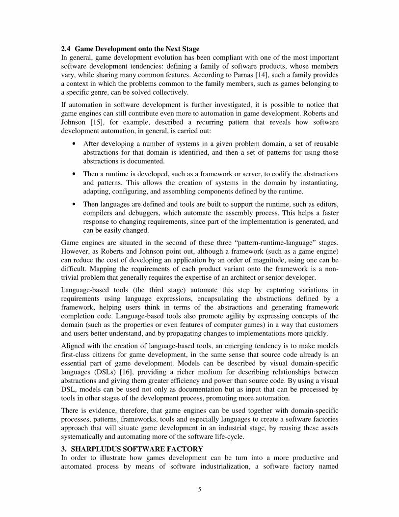
Figure 3 presents the complete SLGML modeling experience, hosted in the Visual Studio
.NET development environment [21]. The Toolbox (at the left) presents some domain
concepts that can be dragged and dropped to the SLGML designer (at the middle). The Error
List (at the bottom) presents errors risen from semantic validators. The Properties window (at
the right bottom) makes it possible to edit properties of the selected item in the diagram,
eventually launching factory designers (sprite designer, entity designer, room designer, etc.).
By using menu commands, users can launch the code generator as well as create their own
code.
5. CASE STUDY: ULTIMATE BERZERK
This section presents the creation of a real-world adventure game named Ultimate Berzerk,
which illustrates the use of the SharpLudus software factory. In Ultimate Berzerk, the player
controls a main character, using the arrows key, to move around a maze composed by
connected rooms. Once the player collects a special item (named Weapon), the spacebar can
be used to shoot fireballs against enemies. Enemies may have special behaviors (not
originally provided by the factory). The goal of the game is to collect the Diamond item and
find the exit sign. A screenshot of the game is presented in Figure 4.
10
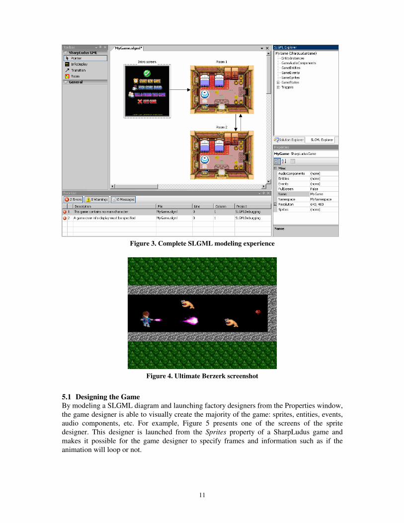
Figure 3. Complete SLGML modeling experience
Figure 4. Ultimate Berzerk screenshot
5.1 Designing the Game
By modeling a SLGML diagram and launching factory designers from the Properties window,
the game designer is able to visually create the majority of the game: sprites, entities, events,
audio components, etc. For example, Figure 5 presents one of the screens of the sprite
designer. This designer is launched from the Sprites property of a SharpLudus game and
makes it possible for the game designer to specify frames and information such as if the
animation will loop or not.
11

Figure 5. Sprite Designer
Figure 6, on the other hand, presents the room designer, where previously created sprites can
be assigned to a room as tiles and entity instances (such as enemies and items) can be added
to rooms based on previously created entities.
Figure 6. Room Designer
5.2 Custom Developer Code
Some NPCs (non-playable characters) of Ultimate Berzerk have special behaviors. For
example, the enemy known as Diamond Guardian (shown in Figure 4) has a special
movement in which it is bounced by room tiles of type “rock”. In order to implement such
behavior, factory users only need to add a class to the project named DiamondGuardian,
mark it as “partial” and override the desired methods. This will make the final class to be the
combination of the user DiamondGuardian class with the factory generated
DiamondGuardian class.
It is worth noticing that when adding their own code, users will have full IDE editing and
debugging support, as well as be able to make complex API calls, such as requesting
information from a web service or accessing a database, for example.
5.3 Discussion: Factory Effectiveness
Although Ultimate Berzerk is a relatively simple game, with a few rooms to be investigated
by the main character, its development explored many interesting SharpLudus software
12

factories assets and features that illustrate how the factory can be used to create real-world
games. Extending Ultimate Berzerk to a game with a better game-play and replay value is just
a question of adding more model elements which reflect the creativity of the game designer.
The automation and productivity provided by the SLGML modeling experience, its code
generator and consumed game engine is evident: in less than one hour of development effort,
16 classes and almost 3900 lines of source code were automatically generated for the
development team. What is most important is that such lines of source code mainly present
routine, boring and error-prone tasks, such as assigning pictures to frames, frames to sprites,
sprites to entities, entities to rooms, rooms to the game, events to the game and so on.
By using the SharpLudus software factory, especially the visual designers, the development
team experience was made more intuitive and accurate. At the same time, when more
complex behavior was required (such as specifying the Diamond Guardian movement) the
factory was flexible to allow developers to add their own code to the solution, using all of the
benefits of an object-oriented programming language and being aided by IDE features such as
editor support, debug support and so on. This contrasts the development experience of visual-
only game development tools, where weak script languages should be used under an
environment which was not originally conceived for codification.
Considering the generated code along with the consumed game engine, it can be concluded
that the SharpLudus software factory is able to provide, in one hour, a development
experience which would require, from scratch, the implementation of 61 classes and more
than 6200 lines of source code.
6. CONCLUSIONS AND FUTURE WORK
This paper presented a study, illustrated with a real example, of how digital games
development can better exploit an upcoming tendency: software industrialization. Different
aspects were encompassed by such a study, being the development of a visual domain-
specific language the most appealing subject.
Since the proposed approach and tools are focused on a specific domain, they may not be
suitable to other types of game development contexts. Therefore, one interesting future work
is the creation, based on previously acquired knowledge, of other factories targeted at other
game genres, such as racing games or first-person shooters. Some domain concepts, factory
designers, semantic validation rules and excerpts of the code generator may be reused, while
others will need to be recreated.
Extending the SharpLudus software factory architecture and code generator to support the
creation of games targeted at mobile devices, such as cell phones, seems to be quite
appealing, since a recognized issue is that porting the same game to different mobile phone
platforms is a burdensome and error-prone task. In such a case, once a code generator is
implemented for each platform, all platforms would be able to share a single game model
(specified with the SLGML visual domain-specific language) and maintenance would be
made much simpler.
While the results obtained so far empirically shows that the SharpLudus factory is indeed an
interesting approach, it is important to notice that deploying a complete software factory is
also associated with some costs. Return of investment may arise only after a certain amount
of games are produced. Besides that, despite being easy to use, software factories are complex
to develop. They will certainly require a mindset evolution of the game development industry.
A final remark is that the presented proposal alone will not ensure the success of game
development. In fact, no technology is a substitute for creativity and a good game design.
13

Game industrialization, languages, frameworks and tools are means, not goals, targeted at the
final purpose of making people have entertainment, fun and enjoy themselves. Players, not
the game or its constituent technologies, should be the final focus of every new game
development endeavor.
REFERENCES
[1] Entertainment Software Association, Essential Facts about the Computer and Video
Game Industry, 2005.
[2] Digital-lifestyles.info, Men Spend More Money on Video Games Than Music: Nielsen
Report, http://digital-lifestyles.info/display_page.asp?section=cm&id=2091.
[3] Greenfield, J. et. al., Software Factories: Assembling Applications with Patterns, Models,
Frameworks, and Tools, Wiley & Sons, 2004.
[4] Zerbst, S., Duvel O., 3D Game Engine Programming, Course Technology PTR, 1st
edition.
[5] Microsoft DirectX, http://www.microsoft.com/directx.
[6] OpenGL, http://www.opengl.org.
[7] RPG Maker XP, http://www.enterbrain.co.jp/tkool/RPG_XP/eng/index.html.
[8] Wiering, M. The Clean Game Library, MSc dissertation, University of Nijmegen, 1999.
[9] Ogre3d.org, OGRE 3D: Open Source Graphics Engine, http://www.ogre3d.org.
[10] Sourceforge.net, Crystal Space 3D, http://crystal.sourceforge.net.
[11] Rollings, A.; Morris, D.; Game Architecture and Design, The Coriolis Group, 2000.
[12] Albuquerque, M. Revolution Engine: 3D Game Engine Architecture, BS conclusion
paper, Federal University of Pernambuco, 2005.
[13] Rocha, E. Forge 16V: An Isometric Game Development Framework, MSc dissertation,
Federal University of Pernambuco, 2003.
[14] Parnas, D. On the Design and Development of Program Families, IEEE Transactions on
Software Engineering, March 1976.
[15] Roberts, D.; Johnson, R. Evolving Frameworks: A Pattern Language for Developing
Object-Oriented Frameworks, Proceedings of Pattern Languages of Programs, 1996.
[16] Deursen, A.; Klint, P.; Visser, J. Domain-Specific Languages: An Annotated
Bibliography, http://homepages.cwi.nl/~arie/papers/dslbib/.
[17] MSDN.com, VS Tools for Office Developer Portal,
msdn.microsoft.com/office/understanding/vsto/default.aspx.
[18] Fowler, M. Language Workbenches: The Killer-App for Domain Specific Languages?,
www.martinfowler.com/articles/languageWorkbench.html.
[19] Microsoft.com, C# Developer Center, http://msdn.microsoft.com/vcsharp/.
[20] Gamma, E.; Helm, R.; Johnson, R.; Vlissides, J. Design Patterns: Elements of Reusable
Object-Oriented Software, Addison-Wesley Longman, 1998
[21] MSDN.com, Visual Studio 2005 Team System: Overview,
http://msdn.microsoft.com/library/default.asp?url=/library/en-us/dnvsent/html/vsts-
over.asp.
14

Building a Flexible Software Factory Using Partial Domain Specific Models
Jos Warmer1, Anneke Kleppe23
1Ordina SI&D, The [email protected]
2University Twente, [email protected]
Abstract. This paper describes some experiences in building a software factoryby defining multiple small domain specific languages (DSLs) and having multiplesmall models per DSL. This is in high contrast with traditional approaches usingmonolithic models, e.g. written in UML. In our approach, models behave likesource code to a large extend, leading to an easy way to manage the model(s) oflarge systems.
1 IntroductionA new trend in software development is to use model driven techniques to develop softwaresystems. Domain specific models (DSMs), domain specific languages (DSLs), and the trans-formations from the DSMs to code need to be carefully designed to make them really useable.
An obvious observation is that one single model (in a single file or single repository) willnot suffice for describing a complete application. Such a model would be too large to handle;it would be unreadable and thus not understandable. Although obvious, this is something thathas not been acknowledged in the modelling world. Companies that apply model driven devel-opment on a large scale are having problems in managing models that are sometimes over 100MB size. We therefore argue for building smaller, partial models, each of which is part of acomplete model. This is much like the way a code file for a class is part of the complete sourcecode for the application. Each partial model may be written in either the same or a differentDSL, thus using the advantage of the fact that a DSL is designed to solve one specific part ofa problem as good as possible.
In this paper we show how partial models can be used to build large, complex applications.We also show the consequences of this approach on the DSL definitions and their accompany-ing model-to-code transformations. We will also show how managing models for large appli-cations is simplified by using partial models.
This paper is based on the industrial experience of one of the authors with building theSMART-Microsoft Software Factory at Ordina, a model driven development software factoryusing the Microsoft DSL Tools. At the time of writing this software factory included four dif-ferent DSLs. Typically several dozens of DSMs are created in a project that utilizes this soft-ware factory. Although the experience was gained using the Microsoft DSL Tools, theapproach can be applied in other environments (like e.g. Eclipse GMF).
This paper is structured as follows. Section 2 explains in short the development processwhen using a model driven software factory. Section 3 introduces the concept of partial mod-
3. The author is employed in the GRASLAND project funded by the Dutch NWO (project number 612.063.408).
15
els, and section 4 explains our approach to references between partial models. Section 5 ex-plains different forms of code generation from partial models.
2 The Software Development ProcessThe traditional development process, not using models, DSLs, or model transformations, can(simplified) be described as follows. Decide on the architecture of the application (1). Designthe application (2). Write the code, compile it, and link it (3). Run the application (4).
The model driven software factory process, as introduced in [GSCK04], using DSLs andmodel transformations, works in a different way. First, the software factory itself is designedas follows:
1. Decide on the architecture of the application.2. Design the DSLs for this architecture3. Write the transformations for these DSLs
The system developer does not need to determine the architecture any more, but starts directlywith modelling the application:
1. Model the application.2. Transform the models.3. Write additional code (if required).4. Compile and link the code, and run the application
This process is often done iteratively, meaning that after running the application in step 4 yougo back to step 1 and start modeling the next part of the application. The development of thesoftware factory is also done iteratively, but in the context of this paper that is not relevant.Also note that a software factory is more than just a collection of DSLs, however this paperfocuses on the DSL aspect, and what’s more we focus on the first part of the process: how tobuild a collection of DSLs and their transformations.
3 Developing a Flexible Software Factory The first step when developing a model driven software factory, is to determine the architec-ture of the applications that you are going to build with the software factory. Is it, for instance,a web-based, administrative application or is it a process control system? The answer to thisquestion determines the architecture. From the architecture we derive which DSLs are to bedefined for modelling the application.
The SMART-Microsoft Software Factory is targeting web-based, administrative applica-tions, of which the architecture is shown in Figure 1. Based on this architecture we have de-fined four different DSLs, each of which corresponds to a part of the architecture. Werecognise the following domains: the Web Scenario DSL for the Presentation layer, the Busi-ness Class DSL for the Business classes, the Services DSL for the Service Interface and Busi-ness Processes, and the Data Contract DSL for the Data Contract. There is no DSLcorresponding to the Data layer, because this layer is completely generated from the BusinessClass DSL. A developer who wants to build a compete system will use all DSLs together.
The different DSL are mostly independent, therefore it is possible to use a subset of theDSLs provided. We can also combine the DSLs in a different way. For example, we are plan-ning to develop a DSL for building Windows user interfaces, which can then be used insteadof the current Web Scenario DSL. This allows us to flexibly evolve the software factory.
16

3.1 Goals for Domain Specific Languages
1. A model is always executable in the sense that every aspect of a model is used to gen-erate code. We do not consider models used purely for design or documentation, these can be built effectively with UML or tools like Visio.
2. A concept only becomes part of a DSL if it is easier or less work to model it than to code it. This keeps the number of concepts small and ensures that the DSL is very pro-ductive.
3. Models (or better said the code generated from the models) are meant to be extended by code.
3.2 Introducing Partial Models
When using the software factory to build an application, a developer determines the numberand kind of DSMs that need to be built. One possibility, which we have seen used at severalplaces, is to create one DSM per DSL. This would mean that we have four DSMs for each ap-plication. Still, for a large application this still does not scale up. For instance, if we have oneDSM for the complete Web Scenario Domain, this will become an incredibly large model forany real application. The model would contain many Web Scenario elements, which each con-sists of a set of Web Pages and Actions. A model of such size is not readable, and certainly notunderstandable.
Working with one large model also introduces many practical problems relating to manag-ing such a model in a multi-user environment. Experience with traditional UML tools has
Fig. 1 The Web Application Service Architecture
17

learned us that this problem has not been solved by any of them. Even when a tool allows mul-tiple persons to work simultaneously on a model, the model must usually be divided before-hand in non-overlapping slices and the developers must be very disciplined while workingwith the tools.
The solution to this problem that we present here is to use multiple DSMs per DSL. We callthese models partial models, because they do not represent the complete system. Each partialDSM is stand alone and can be used in isolation. In the case of the Web Scenario DSL, the DSLhas been designed such that each DSM contains not more than one Web Scenario. If an appli-cation needs e.g. twenty Web Scenarios, twenty Web Scenario DSMs will be created. As a di-rect consequence of this choice each partial DSM has some unique and useful properties:• One partial DSM can be created and edited stand alone by one user.• The partial DSM is the unit of version control, and when the DSM is stored on file, ordi-
nary version control systems provide ample possibilities for version control.Our approach fits very well with the structuring of the Microsoft DSL Tools that we have beenusing, in which one model is stored in one file. Also, in the Microsoft DSL Tools one modelis identical to one diagram, and should therefore remain small. In the remainder of this paperall DSMs are partial models, the DSLs are designed to support this.
4 Combining Partial DSMs using References Allowing partial DSMs has direct consequences for the way that a DSL is defined. One suchconsequence is that we need a way to define references between DSMs. This section describesthe ins and outs of references.
4.1 References between Partial DSMs
A model element from a partial DSM may be referenced in another partial DSM just like class-es and their operations may be referenced in a code file. To ensure that a DSM remains a standalone artifact, references are always modelled explicitly and are always by name. There are nohard links between different DSMs, otherwise we would end up with one monolithic modelagain. To accommodate this we have introduced a metatype Reference to ModelElement foreach modelelement that we want to refer to in each of our DSLs. This metaclass may be sub-classed to create a reference to a particular type of modelelement. Thus, a model element in aDSM may be of type Reference to BusinessClassDto, holding the name (or path) of a businessclass in another DSM.
References may link DSMs written in the same DSL, e.g. a Reference to WebScenario in aWeb Scenario DSM, or they may link DSMs written in different DSLs, e.g. a Reference toBusinessClassDto in a Web Scenario DSM, that refers to a modelelement in a Data ContractDSM. An example of the first can be found in DSM 1 in Figure 2, an example of the secondcan be found in DSM 2.
4.2 Checking References
In a complete application the references within the DSMs should all be valid, e.g. the referredWebScenario in Figure 2 must be defined in another DSM. For this purpose we have developedinter-DSM validation support. With one button, a user can do a cross-check on all referencesto check whether the referred elements exist. This validation is based on a small run-time com-ponent, which is populated from the DSMs in the developers workspace. This component issimilar to a symbol table in a compiler and only holds the minimum information needed forvalidation purposes.
18

Note that a single DSM is still valid if a reference does not exist, but the collection of DSMsis not complete. The DSM with the unresolved reference can still be edited, checked in, and itsmodel elements can be referred to by other DSMs, etc.
4.3 Dealing with Changes in References
A change in the name of a referred model element is allowed, but will make existing refer-ence(s) dangling. This is an inherent feature, following directly from the way DSLs are de-signed. Tool support for coping with this kind of changes is not within the scope of languagedefinition, instead it should be provided by the IDE. There are various options for dealing withdangling references:• No support: the inter-DSM validation will result in an error message and the developer has
to “repair” the dangling reference.• Refactoring support: the user may explicitly perform a name change of the referred model
element as a refactoring. The IDE will find all references, and change them to refer to the new name.
• Automatic support: when the user changes the name of a referred element, all references will change automatically.
Having no support at all does work, but is cumbersome. Automatic support has the problemthat the developer does not know where automatic changes take place and he might thereforeencounter unexpected results. In the Plato model driven environment that we have built in the
Fig. 2 Example of references between partial models
19
past, we found that automatic changes also results in the need to re-test the whole system, be-cause the changes were not controlled.
The best option seems to be refactoring support. Note that in this case renaming a model el-ement works exactly as renaming a class in C# or Java code. Either the user changes the name,which results in dangling references, or the user requests an explicit refactoring and is offeredthe possibility to review the resulting changes and apply them. In the SMART-Microsoft Soft-ware Factory we have chosen the option of using explicit refactoring. The run-time componentfor cross-reference validation holds all the information needed to execute this.
In both automatic and refactoring support the following problem may occur. Specially inlarge projects, there will be many dozens of DSMs, and each DSM can be edited simultane-ously by a different user. To allow for automatic change propagation or refactoring the userperforming the change needs to have change control over all affected DSMs. Because we donot have a model merging feature available in the Microsoft DSL Tools, this problem cannotcurrently be solved.
5 Code GenerationIn this section we explain different forms of code generation from partial models. As our mod-els are meant to generate code, this is an essential part of the DSL definition. We do not useour models for documentation purposes only.
5.1 Different Types of Generation
In model driven development [MSUW04, Fra03, KWB03] multiple layers of abstraction areused. Inhabitants of the lowest layer are called code, inhabitants of all layers above the lowestare called models. There is no restriction on the number of layers that may be used, as shownin [GSCK04].
The definition of a DSL includes the code generation for that DSL. Interestingly, it is alsopossible to generate another model instead of code, thus making use of multiple layers of ab-straction. For DSLs defined at a higher level of abstraction, it is often more easy to generate alower level DSM than code, because the generation target itself is at a higher level of abstrac-tion. Therefore we distinguish the following two types of generation.
DSM to Code Generation. The first type of generation is code generation from a DSM. Thisis the most common way of generation. Template languages like T4 for Visual Studio or JETand Velocity for Java are often used for this purpose.
DSM to DSM Generation. The second type of generation is to generate another model froma DSM. This is possible when a DSM can be completely derived from another (higher level)DSM. Often the generated DSM takes the form of a partial model. The developer can add (byhand) other partial DSMs that refer to the generated DSM, thus extending or completing themodel.
5.2 Linking Partial Models or Linking Partial Code?
Another distinction that needs to be made is the moment when the partial descriptions of theapplication are brought together. There are two possibilities:
1. Link all partial models together to form the complete model. Transform the complete model into code.
2. Transform a single partial model into (partial) code. Link the generated code.
20

Within the SMART-Microsoft Software Factory we have chosen to use option 2. The code isgenerated immediately (and automatically) whenever a DSM is saved. Our experience is thatgenerating everything in one step from a complete model can become very time consuming,resulting in long waiting times to conclude the code generation process. Using option 2, wecan perform the transformation process incrementally, re-generating only those parts that havebeen changed. Also, option 2 fits much better in our philosophy that we do not need a completemodel at any point in time.
However, option 2 is not always feasible. When the information in two or more partial mod-els needs to be transformed into a single code file, only option 1 will suffice. In our case wegenerate C# code, which offers the notion of partial classes, which are used extensively in theSMART-Microsoft Software Factory.
5.3 Regeneration and Manual Additions
When something - either code or another DSM - is generated from a DSM we need to be ableto do at least two actions:• Regenerate whenever the source DSM changes.• Manually add something to the generated code or generated DSM.Besides, we must at any time be able to use the two options independently. That is, when wehave manually added code or DSMs, we must still be able to regenerate the generated partswhile maintaining the handwritten code or DSMs. This is implemented as follows.
Regeneration of Code. When we generate C# code, partial classes and abstract / virtual meth-ods are used to enable the user to add code without touching the file that was generated. Thisallows full regeneration without disturbing the handwritten code. For other types of artifacts,the situation is more complex, often handwritten code has to be in the same file as generatedcode (e.g. in XML configuration files). The handwritten code is then marked as a guardedblock and retained when the file is regenerated.
Regeneration of DSM. When we generate a DSM from a higher level DSM, we use the sameapproach as when generating C# code. One partial DSM (in one file) is generated, and this fileremains untouched by developers. Handwritten additions must be modelled in separate partialDSMs. Reference elements (see 4.1) may be used in the handwritten DSM to refer to modelelements in the generated DSM.
6 Other Views on ModelingIn the UML world the term model is often used rather loosely both for a diagram, and for theunderlying collection of interrelated modelelements. However, according to the UML lan-guage definition, there can be only one model - consisting of multiple diagrams - and each di-agram is a specific view on part of the underlying model. The UML offers no way to definereferences between different models, it assumes that you always work with one (large) model.
In the agile modeling community there is a tendency to create small models. However, thesemodels are typically used for documentation and design, but are rarely used for code genera-tion. The difference between this type of models and the ones presented here is that the agilemodels usually cannot be processed automatically to generate working code. Although humanreaders might recognise references between agile models, tools will not. Also, what is consid-ered to be a set of small models, often is a set of diagrams in one UML model.
The partial DSM as described in this paper always constitutes an executable model. Withina software development project these models have exactly the same status as source code.
21
They are the source from which the final system is generated. Before completely building thesystem all references in both the source code and the (partial) models must be resolved.
7 ConclusionWe have described the development of a model driven software factory using multiple DSLs.The approach takes a non-traditional view to modelling. Instead of having one monolithicmodel we use many smaller models of many different types. These models are called partialmodels or partial DSMs. In our approach one partial DSM has the same characteristics as onesource code file, which clarifies many things and leads to a different way of thinking aboutmodels. The following characteristics of partial DSMs are identical to source code files.• Storing a DSM in a file• Code generation per DSM• Version control per DSM• References between DSMs always by name• Refactoring in the IDE if requested by user• Intellisense / code completion for Reference elementsWhile building the SMART-Microsoft Software Factory, we found more and more advantagesof our approach. Although not discussed in this paper, each DSL can be used in isolation ofother DSLs. This opens up possibilities to use a subset of the DSLs whenever applicable or,for example, replace one DSL by another one in the software factory. We also see opportuni-ties to reuse both DSLs and DSMs in a relatively easy way.
We view the approach to building a software factory using DSLs as an approach to MDA.Although MDA is often related to UML, this is not mandatory. Using DSLs fits into this ap-proach as well. Also, we deal with model-to-model transformations as well, although we haveno fixed number of levels like the PIM - PSM - Code levels in MDA.
The SMART-Microsoft Software Factory also has strong connections with the idea of de-veloping product lines [CE00]. The software factory is a product line for administrative webapplications according to a defined architecture. We have ensured flexibility for building otherproduct lines by keeping the DSLs as independent entities. Apart from the DSLs, a SoftwareFactory also includes other things, like a specialized process and others. This paper focuses onthe DSL aspect only.
References
[CE00] Krzysztof Czarnecki and Ulrich W. Eisenecker. Generative programming: methods, tools, and ap-plications. ACM Press/Addison-Wesley Publishing Co., New York, NY, USA, 2000.
[Fra03] David Frankel. Model Driven Architecture: Applying MDA to Enterprise Computing. John Wiley & Sons, 2003.
[GSCK04] Jack Greenfield, Keith Short, Steve Cook, and Stuart Kent. Software Factories, Assembling Appli-cations with Patterns, Models, Frameworks, and Tools. John Wiley & Sons, 2004.
[KWB03] Anneke G. Kleppe, Jos Warmer, and Wim Bast. MDA Explained: The Model Driven Architecture: Practice and Promise. Addison-Wesley Longman Publishing Co., Inc., Boston, MA, USA, 2003.
[MSUW04] Stephen J. Mellor, Kendall Scott, Axel Uhl, and Dirk Weise. MDA Distilled, Principles of Model_Driven Architecture. Addison-Wesley, 2004.
[SMART06] http://www.ordinasoftwarefactory.nl/Default.asp/id,285/index.htm: SMART-Microsoft Website.
22

Conceptual design of web application families: the BWW approach
Roberto Paiano, Andrea Pandurino, Anna Lisa Guido University of Lecce
Via per Arnesano, 73100 Lecce (LE) Tel. +390832297229
Abstract: A good analysis of the application domain is the most complex and crucial phase in information system design, regardless of its dimensions. Many well-known methodologies exist for the following development phase, but to design a specific application domain many approaches follow one another: from UML to goal-oriented approach. All these became critical when the final application will be a large web application where it is important to also model the user experience. In this case it is not possible to isolate a well-structured conceptual model of the domain where the computer technology concepts are not taken in consideration but the modeling concepts map directly to the domain concepts. We explain here our experience of a research industrial project founded by the Italian Government about environmental monitoring. In this work, we adopt the UML-Like approach in order to obtain the domain specific conceptual model. The target is not a single application but a family of applications. After this phase, we adapt in an opportune way the BWW (Bunge-Wand-Weber) ontology to design the application domain and we evaluate which domain representation is more objective and useful for the following web information system design and development phases.
1. Introduction and background Web application became in the last years complex application where several actor, several type of information, several technologies, several roles are involved. In order to link together these different key aspects it is very important to provide a methodological approach to helps in the design and later in the development of web application. We focus on methodologies that consider the information, navigation and transactional aspects typical of web application with several user on several devices. Very often when methodologies are applied they result strictly related to the designer experience about the domain knowledge. When the application domain is very large and several application (not only a single application) can be obtained from the design, it is important to formalize in some way the domain knowledge in order to not lies the application of the methodology only on the experience of the designer but in order to provide a common knowledge on which designer can work. In a few words it is important to take into account the conceptual design. We can see in Fig. 1 three different layers of analysis: the first, the domain layer, allows us to acquire the rigth knowledge of the entire application domain (named conceptual model); in the second, the web application layer, several design methodologies such as IDM, P-IDM and AWARE provide an engineeristic approach to the well-known web application paradigm (in order to solve the information and navigation open issues); and finally in the application layer, implementation details are taken into consideration.
23

DomainKnowledge
ApplicationKnowledge
Conceptual Domain Model
Requirement Elicitation
ApplicationModel
User Experience Model
Conceptual Application Model
TechnologyModel
BWW/UML
AWARE/ Goal oriented approach
IDM
P-IDMW2000-UWA
Software Architecture
Model Methodology
Dom
ain
Laye
rW
eb A
pplic
atio
n La
yer
App
licat
ion
Laye
r
DomainKnowledge
ApplicationKnowledge
Conceptual Domain Model
Requirement Elicitation
ApplicationModel
User Experience Model
Conceptual Application Model
TechnologyModel
BWW/UML
AWARE/ Goal oriented approach
IDM
P-IDMW2000-UWA
Software Architecture
ModelModel MethodologyMethodology
Dom
ain
Laye
rD
omai
n La
yer
Web
App
licat
ion
Laye
rW
eb A
pplic
atio
n La
yer
App
licat
ion
Laye
rA
pplic
atio
n La
yer
Fig. 1: Layers of analysis In the modeling of an application family, surely a fundamental role is performed by the domain knowledge. The domain design must represent all the system complexity and, at the same time, the domain layer must be of high level of abstraction and must not take into consideration technology aspects. The conceptual model can be interpreted as the "broader view of information systems requirements engineering" [DIES00]. The conceptual model goal is to obtain a detailed domain analysis independent from the system functionalities, the processes, the information structures. Moreover the language used to describe the model must be near to the domain concepts. In practice, the conceptual model allows us to acquire the application domain knowledge and to store it using a well-defined grammar. The conceptual model will be the starting point from which to obtain the following analysis phase. Due to the conceptual model importance, it is essential to consider an efficient approach with several key aspects: • Complete: it covers all the aspects of the particular application domain; • Objective: it must represent the reality in its wholeness without focus on a particular aspect of
the reality as it can be seen by a particular actor involved in a specific aspect of it. The conceptual model could be the model where all the actors can recognize its own particular part of the application domain.
• Abstract: at this modeling level it is not important to go down to the detail, but rather to remain at a high abstraction level. This allows a simple and efficient information exchange between the conceptual model and the models obtained in the next phases for instance the process model, the user experience model etc. [CHEN99]
• Independent from the implementation technology: to be tied up to the implementation technology results, in some cases, in designing the application domain in terms of the selected implementation technology. As a consequence, this can put little emphasis on the critical application domain aspects (because they are, for example, hard to implement) or, contrarily, can emphasize irrelevant aspects. Both factors can result in a product of poor quality.
• Simple: Surely a model can not be simple if the application domain is complex, so it is important to think to a methodology and to a relative notation in order to manage the application domain complexity and to represent exactly the complexity of the application domain without add another complexity level.
In order to meet all these key aspects we focus on two different approaches to the conceptual domain model: • The use of classical techniques within software engineering. Due to the domain dimension and
complexity, it is too hard to use a full-compliant UML approach because it force to constraint often hard to take in consideration in order to provide the key aspects considered above. For this
24

reason we decided to adopt an UML-like approach that is to adopt the main concepts of Object Oriented customized for our purpose.
• The use of the formal ontology. We adapt, through a methodological approach that we propose, the classification of the concepts proposed by BWW in order to represent the domain concepts and its relationships with a well-known semantics.
In this paper we present in the section 2 an overview of the BWW approach that we propose for the conceptual model and in the section 3 we speak about the environmental domain as a case study of our research work. In the section 3.1 we discuss the conceptual model of the application domain an UML-Like approach and in the section 3.2 we discuss about the conceptual model of the same application domain with the proposed BWW approach. In the section 4 we compare the two approaches provided and finally we provide conclusion and future works.
2. The BWW approach To achieve an objective conceptual model, not tied up to a particular technology and whose modeling primitives allow us to provide for a suitable semantics to the model, we explored two possible directions tied up to the application of the Information Systems design philosophy. The first is proposed by Chisholm [CHI92][CHI96][LEW97] immediately rejected because it doesn't provide an objective model: the approach is based on the common sense, that is it leaves a lot of scope for free interpretation from who read the model without providing norms and interpretation rules. We follow in our research work another approach: the BWW approach [WEB97]. BWW provides an effective and suitable classification of the concepts that allows from one side to not flatten the whole modeling in a few concepts (classes, relationships and so on) and from the other side to assure a good level of objectivity and the correct semantics: each part of the domain model under analysis can be associated, without leaving scope for free interpretations, with the classification of the concepts implicit in BWW. In this way the model obtained is objective: the concept classification helps to represent the application domain without focus on a particular point of view but only categorize the application domain concept in a well specific classification. Furthermore it is easy to realize and easy to use for those who will deal with the following phases of analysis and implementation. The model obtained is not tied up to any implementation technology. Obviously we adopt the BWW approach not in the philosophy point of view but we adapt BWW concepts classification in order to define the conceptual model in a specific application domain. In this way it is possible to define the domain model direct using domain concepts. In order to define the domain model in the environmental domain (target of our research work) we defined the BWW ontological meta-model that reflects the concepts classification proposed by BWW and, on the base of this classification, we realized the environmental domain model. The language used to define both the meta-model and the model is OWL [W3C04]. The domain model so obtained has well-defined semantics: the concepts of the environmental domain have easily been classified among those proposed by BWW. It is clear that the realized meta-model is also valid for the definition of the conceptual modeling of other application domains.
3. Case study: enviromental domain We consider a very complex application domain: the environmental protection (understood as habitat of all the organisms and as organic structures of systems and subsystems). Environmental protection has evolved considerably in recent years. In the sixties, the public administration main goal was the control laid down by law. Today great importance is given to knowledge acquisition of the factors that heavily affect the environment quality; this choice is determined by the high growth rate of the population and by the evolution of the productive system that exercise pressure on the environment.
25

Today, monitoring activity and environmental control is not only developed by the government public administrations (Municipality, Provinces, Regions) but also by a number of associations and organizations and, above all, from several agencies for the protection of the environment in national and international territory. The great number of stakeholders and the necessity to acquire the knowledge about the quality of the environment and soil, force a coherent and reliable informative exchange. To achieve this goal, organization and institution nets were born in order to facilitate the collaboration for applying a common environmental policy. The efforts to collect and to deliver environmental knowledge in the Italian and European areas do not match at regional institutional level, because the technological infrastructures do not support informative exchange. In this context, the research project GENESIS-D1[MAIN05]. The project goal is the creation of a "framework" for the design and the development of software systems for environmental management at regional and/or sub-regional level. The software systems obtained starting from the framework Genesis-D, will be web application that will allow the exchange of environmental information among different institutional subjects such as Regions, Provinces, Municipalities, ARPA (Regional Agencies for the Environmental Protection), etc. The problems related to the application domain model are of two types:
• The application domain is very complex so it is hard to cover all the complexity and to take into consideration all the application domain aspects without guidelines;
• The applications obtained starting from the framework will be web-based applications so the design focus is not only on the data element (represented in the form of object or relational entity) but also on the user experience (end-user and his perception of the information). This constraint force to consider the user experience design that is to take under control simultaneously of all the aspects of the application domain, to acquire and to document a deepened domain knowledge in order to highlight the differences and the shared points among different stakeholders.
3.1 Conceptual modelling through UML-like approach At the conceptual modelling abstraction level it seem not correct to use a full-compliant Object Oriented approach; we define a class diagram but we can not speak about “object” as they are defined in the UML definition. In UML an object is an entity with a well defined boundary and identity that encapsulate state and behaviour [OMG]. Because in this phase we are not able to define state and behaviour we define the generic concept of “Entity” that may contain some attributes in order to characterize it. We define a static view of the overall system through the class diagram where we represent Entity and relationship between them. As it regards the dynamic view of the system, it could be defined using other UML diagram but this introduce to another important problem: the overall view of the application domain is fragmented, so a change in one diagram may make obsolete other diagrams[BOOCH]. We named this approach where we define a class diagram as relationships between Entity and without dynamic view of the system the “UML-like” approach. In the UML-like approach the modeling process is made up though several iterations: each iteration has the goal to refine the analysis and therefore to describe the application domain in a more and more precise way. Particularly, the first step aims to provide a description of the information entities and the relationships among them. These entity are refined in order to describe the overall application domain. After this phase entities are refined (through the definition of the attributes, of their type and of the methods), in order to define a class diagram that is the model of the application domain. This process starts from the "generalization" in which the designer is forced to aggregate 1 The leading company is Edinform SpA in collaboration with the University of Lecce and the Polytechnic of Milan
26

them in terms of shared attributes. At the end of this process abstract objects are specialized obtaining a full UML-compliant design useful for the implementation of the application. In a few word this process bring to a class diagram. These classes will be invoked in order to develop a single specific application. Obviously the application will be realized with an OO technology. Taking into consideration a scratch of the environmental domain (Fig 2) we consider several objects such as: alteration biological variety, climatic change, consumption of soils, soil degradation, eutrophication, pollution, wastes production and disposal, radiation, noise, and so on. Each of these phenomena is characterized by a variation of some environmental parameters which may or may not be homogeneous. In the UML-like approach the designer describes the phenomena creating the FIA class (Fact of Environmental Interest) and all the parameters are grouped in the IIP class (Indicator, Index, Parameter) strictly related to the Metrics class. It is clear that in the class diagram FIA, IIP and Metrics are Abstract Classes that must be specialized when they are instanced. Using an analogous procedure, other abstract classes are identified as Objects, Subjects and Structures (OSS) to which each FIA makes reference. The class OSS contains the Subjects (physical or juridical person that can be interested or involved in facts and environmental phenomena), the Objects (any object or territorial structure inside which the characteristic processes of the human social lifetime are based and are developed) and the Structures. The class OSS is directly connected with the class FIA and it will be decomposed in OST and SOI.
Fig. 2. A scratch of UML-Like model
3.2 Conceptual modelling through BWW In the conceptual modelling made by BWW approach, the language used to define the model is OWL and the classification of concepts that we adopt is defined by BWW ontology. To be precise, we adapt the BWW ontology to our goal and we follow several steps in order to obtain a complete conceptual model of the domain in a well-defined language (OWL) (see fig. 3). We explain here the steps followed to define a domain-specific model using BWW concepts in the environmental domain. Obviously these steps, here applied to the design of the environmental domain, can be followed in order to model any application domain. Having acquired the necessary knowledge of the application domain, in Step 1 it is possible to individualize the Things [WAND95] distinguishing them, as far as possible, from the Classes[WEB96](step 2). In the BWW approach the difference between Things and Classes is very subtle: the Things are well defined in reality in examination; they are tangible objects and therefore they are easily identified. Classes group together poorly defined Things that have some shared
27

properties (mutual property)[WAND95] (the definition of mutual property is in step 3). We, for instance, consider the Water Basin: it has the same properties as the Water Body. The properties shared between Water Basin and Water Body define a class (Hydrographic object): Water basin and Water Body are things and they have both mutual and intrinsic property. In the conceptual model phase it is also possible to know some mutual properties but to not know what things belong to this class, because their individualization requires a degree of specialization and detail in the model that would make it considerably complex and it would stray from the desired degree of abstraction.
Select different parts of the same conceptual modeling
7.System
Define what it happens in a particular application domain
6.Events
Select peculiar characteristics of mutual/intrinsic property
5. Characterization of mutual/intrinsic property
Select intrinsic property of things and classes
4. intrinsic property
Select mutual property of each class3.Mutual property
Highlight classes of the domain2. Analysis of classes
Highlight things of the domain1. Analysis of things
Step descriptionStep
Fig.3 Methodological steps to define a conceptual model using BWW The next step (Step 4) is to identify the related intrinsic properties. At this point the designer presents an initial description of the application domain; surely it is not complete but it succeeds in giving an idea of the application domain complexity. The following step (Step 5) consists of identifying the peculiar characteristics of each mutual and intrinsic property. Particularly, each mutual / intrinsic property is tied up to both human and natural laws. This characterization of the properties introduced by BWW, has led us to reflect them in the environmental domain and to reveal some concepts that in the UML-like approach had not been considered. The territorial competences of the Public Corporation are, for instance, defined by decrees. The decrees result, therefore, in a characterization of the Intrinsic Property territorial competences and, particularly they are Human Law: this means that territorial competencies are constraints by the Human Law decree. BWW attributes allow us to take into consideration the correct semantics of a concept (decree). In the UML-like approach, because decree is an instance of a DIA (Provision Intervention Action) it will be related to this class, so it is not highlighted that decree constraint the territorial competencies. We decide to not show the concept of decree (Fig. 4) because it should has the same characteristics of the DIA therefore cannot be connected with the Territorial Competencies with the correct semantic (Fig. 4). In the BWW approach the problem is solved thanks to the “BWW Law” concept. The concept of decree that naturally fits the concept of Law is hard to represent using UML notation, in fact a study in this field say that there is not a correspondence between the concept of BWW law and any kind of representation in UML[HOPDAL02].
28

BWW Property
BWW Law
Fig. 4:The two approaches compared The following step (step 6) is the identification of the Events. The concept of events allows us to define what happens in a particular application domain. BWW attributes well defined semantics to the event: the events are in partnership with a thing or class and, when they occur, change a well defined property of the Thing or of the class to which they are associated. The possibility to define the events induces the designer to understand thoroughly the functioning of the application domain and to identify the consequences that an event can provoke (which property the event modifies). When an event modifies the value of different properties of a same thing/class, the thing/class changes state. All the states make a history. In BWW the concept of history is defined to follow changes of state so the changes of state are associated to opportune semantics. At this point we have a complete conceptual model of the application domain in examination and in order to organize the obtained conceptual model, it is possible (but not obligatory) to define the systems (step 7). BWW defines the systems as the joining of things intending that the things belonging to the system influence the properties of each other: this is a guideline that facilitates the designer to define the subsystems and therefore to structure the model appropriately. The conceptual model obtained, as in the case of the conceptual modelling obtained from the UML-like approach, will be the starting point for the design and implementation of specific web application: at this point, because we are not lies in any way to the object oriented approach, we are free to design and develop the web application taking the knowledge stored in the model and without any constraint about the technology to adopt.
4. Comparison between the two approaches The UML-like approach allows us to describe a domain using an incremental method: the designer improves the analysis step by step; this option is very useful when, in an application domain such as the environmental domain, knowledge is very fragmented. In our case study, the project started with an analysis of environmental models (National, European and American models) that describe the environmental domain in general and then it has been possible to describe in detail all the information needed to produce the class diagram. The developer can directly use the output obtained through the UML standard notation to create the framework. The problem strictly related to this approach is that the output will be an Object Oriented model that will implement the typical constructs of this paradigm (generalization and specialization) but, although correct, it moves away from the objective reality. The process is strongly dependent on the experience of the designer who must analyze the application domain and must be skilled at OO modeling. The final output of UML-like approach, even if complete, is strongly tied up to the implementation logic. Furthermore, the output (the model and its notation) complex that is add to the complexity of
29

the application domain another level of complexity due to the fact that the semantic in the UML-like approach is flatten in the concept of entity and relationships between them. The concept of entity is used also to model very different concepts; for instance, a FIA is determined by varying a particular indicator. In the UML-like modeling, the FIA and the indicator are both modelled as classes but the FIA is not a pure class but a set of values (not a-priori defined) that the indicator can assume at the time: a FIA is registered when some value of an indicator change. Using the BWW approach the FIA has been modelled as a history of the value of indicators; thus, the concept of FIA has the correct semantics. This example makes it clear that the application domain model (particularly the environmental domain), using an UML-like approach, compresses the different semantics into the same concept of entity (or of relationship among entity). These make not only the creation of the model difficult but also its understanding from he who must use the conceptual modeling for the following phases of analysis and implementation. The model created using UML-like approach, gives freedom to understand the model because it is not tied up to a particular semantics, therefore the model is not objective. With BWW approach, it is possible to represent some relationships that in the UML-like vision it could be possible to characterize only by using other diagrams different from class diagram (in this case we obtain a fragmented design not useful in the conceptual modelling phase); for instance, an OSS creates a FIA that, in turn, is created when the variation of an indicator produces an alarm. The alarm condition is an input event to the public corporation that in response produces a DIA (Provision Intervention Action), a regulation that the OSS must respect. According with the DIA, OSS finishes the alarm and, hence, it produces another change to the indicator and so another FIA. In the UML-like approach it has not been possible to define this important aspect: it can describe only a relationship among OSS, FIA and DIA and the cause-effect relationship is not clear. We have to consider that the cause-effect relationship (in UML-like approach) could take place adding the specific methods to the objects but this is not compliant with the need to define a conceptual model of the domain without going in detail. On the contrary in the BWW approach the class OSS is related to the thing indicator and produces the event FIA. In the event FIA it is possible to see which properties of the thing indicator are modified by the event. The indicator produces the alarm condition (modelled through the property generateOutput of things), that is the Event source in the thing public corporation. The thing public corporation, related with DIA, issues the rules of DIA, modelled with an Event. At this point the DIA, engages the OSS and forces the OSS to conform to the new indicator value. To model this is very simple with the BWW approach thanks to the concept of “coupled” (that allows the joining of two classes: class modifies the value of one or more properties of the other), to the concept of Event and to the concept of input and output in relationship with the concept of thing. It is important that the relationship’s name (is coupled with, generate output and so on) is intrinsic in BWW approach so the right semantics is given directly by the BWW approach. Last, but not least, thanks to the BWW approach the domain model is directly expressed using well defined and categorized domain concept through real world concept such as thing, classes, law and so on where the domain concept is easy to map.
5. Conclusions and future trends The BWW approach allows the provision of the right semantics and therefore it expresses all the domain details directly using the domain concepts. The model is objective thanks to the classification of the concepts provided by BWW and it is not tied to a specific implementation technology. The conceptual model has been immediately understood in the correct way both from the stakeholders (who, helped by the classification of the concepts, have identified their own activities and goals), and from the buyer (who has succeeded in understanding all application details without having specific skills in BWW ontology). The modeling realized through the BWW approach meets, therefore, all the requirements described above.
30

The UML-like approach appears particularly effective because, being a lot close to an implementation technology, allows us to directly reach the realization of a family of applications in a particular application domain. Nevertheless, the objectivity and the simplicity of the BWW approach encourage the use of this approach for the conceptual modeling of application domains of great dimensions. Using the BWW approach, the effort and the elapsed time to define the application domain conceptual model, are smaller than those needed in the UML-like approach. In our research work the knowledge acquisition for the conceptual model of the environmental domain required 3 months and it has been realized both through interviews with the various stakeholders and through the study of several documentation pages. The team, composed of 3 units, after having acquired the domain knowledge, was split: 2 units used the UML-like approach while the third unit made the conceptual model with the BWW approach. The UML-like conceptual model required 3 months while the one using the BWW approach required just 1 month. The case study presented in this research work where we compare the UML-like approach with the BWW approach to the conceptual design is very complex, so we think that consideration made for this case study are also valid for other case study that we planning to conclude as soon as possible. In order to hold under control the typical aspects of web applications and therefore to manage the user experience, we design two web application starting from the conceptual modelling of the family of web application. Our efforts are focused on the definition of a methodology to obtain an IDM [PER05] design starting from the domain specific modeling of the whole application domain. To achieve this goal, it appears simpler to start from the conceptual model realized according to the BWW approach characterized by an elevated degree of objectivity that results independently from the implementation rather than to start from the UML-like model. As future work we plain to design and implement an editor in order to help in the application of the methodology that we define.
References [BOOCH99] Booch, G.; Rumbaugh, J.; Jacobson, I. “The unified Modeling Language User Guide” Addison Wesley 3rd Printing Febraury 1999. [CHEN99] Chen,P.P.; Thalheim, B;Wong,L. Y.:Future Directions of Conceptual Modeling. Lecture Notes in Computer Science 1565, Springer, 1999.[CHIS96]Chisholm,R. M: A Realistic Theory of Categories – An Essay on Ontology, Cambridge University Press,1996. [CHIS92]Chisholm,R. M.:In Language, Truth, and Ontology Kluwer. Academic Publishers, Dordrecht, 1992. [DIES00]Dieste O.; Juristo N; Moreno A.M.; Pazos J.; Sierra A: Conceptual Modelling in Software Engineering and Knowledge Engineering: Concepts, Techniques and Trends, Handbook of Software Engineering and Knowledge Engineering, World Scientific Publishing Company, 2000. [OPDAL02]Opdal, L. A; Henderson-Sellers, B.: Ontological Evaluation of the UML using the Bunge-Wand-Weber Model. Softw Syst Model, 43-47 Digital Object Identifier 10.1007/s1027-002-0003-9 [LEW97]Lewis, E. H.: Chisholm’s Ontology of Things The Philosophy of Roderick M. Chisholm, Lewis E. Hahn 1997. [MAIN05]Mainetti, L.; Perrone, V.: A UML Extension for Designing Usable User Experiences in Web Applications, Proceedings of V International Workshop on Web Oriented Software Technologies June 2005,Porto, Portugal [OMG] Object Management Group, UML 2.0 Superstructure Specification OMG Adopted Specification [PER05] Perrone, V.; Bolchini, D; Paolini, P.; A stakeholders centered approach for conceptual modeling of communication-intensive applications. Proceedings of the 23rd annual international
31

conference on Design of communication: documenting & designing for pervasive information pp: 25 – 33, ISBN:1-59593-175-9 2005, September 21, 23 2005, Coventry, United Kingdom [W3C04]W3C : OWL Web Ontology language Reference, W3C Recommendation, 2004. [WAND95]Wand, Y.;Weber, R.: On the deep structure of information systems. Information Systems Journal, 5 1995 [WEB97]Weber, R. :Ontological Foundations of Information Systems, Coopers and Lybrand Accounting Research Methodology. Monograph No. 4. Melbourne, 1997. [WEB96]Weber, R.; Zhang, Y.: An analytical evaluation of NIAM’s grammar for conceptual schema diagrams. Information Systems Journal, 6: 147–170, 1996
32

Building End-User Programming Systems
Based on a Domain-Specific Language1
Herbert Prähofer, Dominik Hurnaus, Hanspeter Mössenböck
Christian Doppler Laboratory for Automated Software Engineering
Johannes Kepler University, 4040 Linz, Austria
{hurnaus,praehofer,moessenboeck}@ase.jku.at
Abstract. End-users of automation software systems – which are the machine operators
– have the task to provide machine settings and program simple control algorithms to
adapt and optimize the machine to the specific automation tasks at hand. End-user pro-
gramming systems are therefore an intrinsic part of automation systems. In this paper we
report on a project with the goal to build a software framework which allows realizing
end-user programming systems with minimal effort. Our approach is based on a new
component-based programming language Monaco for event-based machine control, a
compiler-generator to realize a Monaco compiler, a virtual machine for execution of
Monaco programs, and an Eclipse- and GEF-based modelling and program development
environment.
1 Introduction
End-user programming as defined by [Nardi 1993] is the endeavour to give ordinary users
some of the computational power enjoyed by professional programmers. The goal of end-user
programming is that users are able to customize and adapt the software systems in use to their
particular needs at hand, so that they can perform their work more efficiently and effectively.
As we well know, programming is not a trivial task even for professionals. End-users, how-
ever, have in no way the capabilities of professional programmers and usually they are neither
able nor willing to acquire such skills. Providing limited programming capabilities to users in
a natural, intuitive manner is still an open issue and subject to active research [Myers and Ko
2003; Costabile, Piccinno, Fogli, Mussio 2003]. In contrast to ordinary programming envi-
ronments, from an end-user programming system we expect much better user support, like
domain-specific notations and presentations, user guidance, and, in addition to syntactic
checks, also semantic integrity checks of user programs [Won 2002].
Our work is concerned with end-user programming in the automation domain. The end-
user of the automation software system is the individual machine operator. His task is basic
handling and supervision of the machine operations, usually with the help of an electronic
control panel. Additionally, he is involved in configuring the machine to specific manufactur-
ing tasks and tooling equipments. And he eventually has the task of adapting or arranging
basic machine operations in defined sequences, so that a specific machining task can be per-
formed in a most efficient way. Providing all the machine parameter settings and defining an
operation sequence for a very specific manufacturing task usually requires deep knowledge of
1 This work has been conducted in cooperation with Keba AG, Austria, and has been supported by
the Christian Doppler Forschungsgesellschaft, Austria.
33

the domain and, due to its complexity, still represents a great challenge. Therefore, machine
automation software systems usually have to come with elaborate machine configuration and
end-user programming environments.
In this paper we present a project whose goal is the development of a software framework
which allows building end-user programming systems in the automation domain. The back-
ground for this work is a cooperation with Keba AG (www.keba.com) which is a medium-
sized company developing and producing automation solutions for industrial automation.
Keba is mainly a platform provider and development of automation solutions based on the
Keba platform is a multi-stage process involving several different stakeholders as follows:
� Keba develops and produces a hardware and software platform with associated tool sup-
port. This comprises a PC-based open hardware architecture, different programming lan-
guages with compilers and development environments and Java-based frameworks for
building visualization systems and control panels.
� The hardware and software platform enables the customers of Keba (OEMs of automa-
tion machines) to realize automation systems for their products.
� The OEMs also build customized software systems and electronic control panels for the
machine operators. Those also include customized, machine-specific configuration and
end-user programming systems for machine operators.
Project experience showed that the effort for OEMs for building those end-user program-
ming systems is tremendous. End-user systems are individually designed and always built
from scratch. Keba observes increased customer demands for an easier development of cus-
tomized end-user programming systems. A clear conception and a reusable software basis for
building end-user programming systems are therefore heavily desirable. As a consequence, in
this project we deal with the conception and the development of a software framework to en-
able customers of Keba to realize end-user programming systems with minimal effort. The
approach, which is outlined in Section 2 in more detail, is based on a new domain-specific
language for machine control, a compiler-generator framework to realize a compiler for the
Monaco language, a virtual machine for execution of Monaco programs, a visual notation for
the Monaco programs, and an Eclipse- and GEF-based integrated development environment
(IDE).
In this presentation we show the current developments and we discuss some additional fea-
tures which are required for a software platform facilitating realization of end-user program-
ming systems. The rest of the presentation will be structured as follows: In Section 2 we pre-
sent our approach in more detail. Section 3 gives a short introduction into the Monaco do-
main-specific language for automation control. Section 4 finally discusses additional features
required for an end-user programming framework and shows how all the discussed concepts
work together in the instantiation of a customized end-user programming system.
2 Approach
In this section we present the architecture and components of our software framework which
together with some additional features as discussed in Section 4 will facilitate the realization
of end-user programming systems.
The approach is based on the following concepts:
� A new domain-specific language for machine control – called Monaco (Modelling NOta-
tion for Automation COntrol) – is defined which serves as a basis for building control
flow programs. The language is similar to Statecharts in its expressive power, however,
adopts an imperative notation which is much closer to the perception of the domain ex-
perts.
34

� A compiler-generator framework is used to realize a compiler for the Monaco language
which constructs a parse tree object model (called CodeDOM) of the program as well as
a writer program to write the object model back to source code.
� A virtual machine has been designed and a prototype is realized in Java for the execution
of Monaco programs.
� A visual notation for the language has been defined which is usually preferred by domain
experts and end-users.
� An Eclipse- and GEF-based integrated development environment (IDE) for the Monaco
programming language is currently in development. The IDE allows a dual mode of pro-
gramming, i.e., visual programming as well as text based programming.
Coco/R
Generator
Monaco
Writer
Monaco
ATG
Monaco
Code
Monaco
CodeDom
Parser
Scanner
Main
Semantic Classes
Monaco Compiler
Monaco VM
States
Monaco IDE
Supervisorrun()
MoldCtrlclose()open()reset()
moveFwd()moveBack()reset()
NozzleCtrlerror
error
run -
if -
...
x>0
elseif -
...
x<0
else +
Figure 1: Architecture of domain-specific programming environment
Figure 1 gives an overview on the different components in the framework and their col-
laborations. The basis of the whole framework is the definition of the Monaco domain-
specific language in an attributed grammar (Monaco ATG) which defines concrete as well as
abstract syntax of the Monaco language. The attributed grammar serves as input to the
Coco/R [Mössenböck 1990; Wöß, Löberbauer, Mössenböck 2003] compiler-generator which
produces the Monaco compiler to read Monaco source code programs and generate parse tree
object models (Monaco code object model – Monaco CodeDOM) representing the abstract
syntax of Monaco programs in the form of a tree structure.
A Monaco CodeDOM then is input to the Monaco virtual machine (Monaco VM) which is
capable of executing Monaco programs. Currently a purely interpreted version of the virtual
machine in Java is available; however a version in C is envisioned to cope with real-time re-
quirements. The execution of Monaco programs is based on a simple API to the virtual ma-
35

chine which basically allows parallel execution of threads, installation of (temporary) event
handlers, handling of variable scopes, etc.
An Eclipse-based integrated development environment (Monaco IDE) is used to allow in-
teractive development of Monaco programs. A visual program editor is used to allow visual
interactive editing of Monaco programs. The visual editor operates directly on the Monaco
CodeDOMs. In difference to many visual programming systems, the visual programming
notation for Monaco is laid out automatically and the user has no control over positioning of
program elements. In fact, the visual presentation directly reflects the source code structure,
however, in a two-dimensional arrangement instead of a one dimensional as in the source
code. Moreover, collapsing and expansion of block elements are heavily used (see more in
Section 3.2).
Finally, a writer program (Monaco Writer) is generated from the Monaco attributed gram-
mar definition which is capable of taking a Monaco CodeDOM and producing Monaco
source code.
3 The Domain-Specific Programming Language Monaco
Monaco (Modelling NOtation for Automation COntrol) has been designed with the goal of
bringing programming of machine control system closer to the domain experts and finally the
end-users. It is not an end-user programming language itself, but is intended to form a basis
to finally support end-user programming.
Current languages in the automation domain, most notably the programming languages of
the IEC 61131-3 standard [IEC 2003], do not fulfill the requirements of a programming lan-
guage which can be used by domain experts or end-users. Moreover, those languages do not
show the characteristics of state-of-the-art programming languages from a software engineer-
ing perspective. Other formalisms, in particular the widely adopted Statechart [OMG 2004]
formalism or the IEC 61499 standard [IEC 2005], would have the expressive power and can
be regarded to be up-to-date regarding software engineering practices. However, the state
machine notation seems to be too complex and cluttered for domain experts.
The language Monaco has been designed to overcome those shortcomings. The language is
specialized to a rather narrow sub area of the automation domain, i.e., programming control
sequence operations of single machines. This narrow domain includes any type of automated
machines, but excludes bigger automation systems, like whole manufacturing systems.
Within the multiple layers of automation systems it should cover the layer of event-based
control of machine operations. Out of scope are therefore the continuous control and signal
processing layer, which are supposed to form the layer below, and manufacturing execution
layer, which could form the layer above.
Within this narrow domain, the language should allow expressing the desired control se-
quences in a natural and concise way. It has to allow expressing sequences of machine opera-
tions but also allow handling asynchronous events, exceptions, and errors. The language
should allow writing reliable programs, which are easy to comprehend and maintain also by
domain experts. With respective tool support, the language is supposed to form a basis for
end-user programming systems.
The language design has been driven by the following main assumptions on the perception
of the domain experts of automation machines. Those are:
� A domain expert views a machine as being assembled from a set of independent compo-
nents working together in a coordinated fashion.
� Each component normally undergoes a determined sequence of control operations. There
are usually one or several sequences which are considered to be the normal mode of op-
eration. Those are usually quite simple. Complexity is introduced by the fact, that those
36

normal modes of operation can be interrupted anytime by the occurrence of abnormal
events, errors and malfunctions.
� The control sequences of the different machine components are coordinated at a higher
level in fulfillment of a particular control task.
The language design reflects just those assumptions by pursuing the following language
concepts:
� Monaco pursues a strict component-based approach. Components are modular units
(black boxes) which exclusively communicate over defined interfaces.
� The language supports hierarchical abstraction of control functionality. The component
structure forms a strict hierarchy in that interaction of components only occurs with its
subordinate and superordinate components. A component relies on the operations, state
properties, and events from its subordinate components. It composes and coordinates the
behavior of its subordinates and provides abstract and simplified views to its superordi-
nates.
� Although the behavioral model of the language is very close to Statecharts, an imperative
style of programming is used. This, in particular, allows programming of control se-
quences as a sequence of statements. Moreover, the language supports procedural ab-
straction.
� Focus of the language is on event behavior. Statements have been introduced to express
reaction to asynchronous events, parallelism and synchronization, exception handling
and timeouts in a concise way.
In the following section we will briefly depict the language by an example control pro-
gram.
3.1 Example Monaco program
This example introduces some of the language concepts of the Monaco programming lan-
guage. The example is part of a larger application in the domain of injection molding. The
application is hierarchically composed of various components (Figure 2). Each of these com-
ponents represents either the control unit for one part of the real machine or a control unit that
aggregates the functionality of other components. This view of a machine exactly matches the
end-user perception of the automation system.
MoldCtrl EjectorCtrl
Supervisor
HeatingCtrl ScrewCtrl SledgeCtrl
NozzleCtrl
Figure 2: Component hierarchy
Each of these components implements a special interface to facilitate the assembly of those
components to a system of components. The code sample shows the implementation of the
upmost Supervisor component (Figure 3). This usually represents the level an end-user
37

would be involved with. This component implements the interface for Supervisor controls
(ISupervisor) and can be parameterized by two parameters which have to be set at start-
up time. All subcomponents of the Supervisor are only defined by their interfaces to al-
low easy exchange of components. The component has two routines run and stop. In the
following we will take a closer look at the run routine.
COMPONENT Supervisor IMPLEMENTS ISupervisor
PARAMETERS
coolingTime : INT := 1000;
plastFirst : BOOL := TRUE;
SUBCOMPONENTS
ejector : IEjectorCtrl;
mold : IMoldCtrl;
nozzle : INozzleCtrl;
ROUTINE stop()
BEGIN
mold.reset();
nozzle.reset();
ejector.reset();
END stop
ROUTINE run()
BEGIN
mold.open();
ejector.moveBackward();
nozzle.moveForward();
LOOP
BEGIN
mold.close();
IF plastFirst THEN
nozzle.plasticize(100);
PARALLEL
BEGIN
nozzle.inject();
IF NOT plastFirst THEN
nozzle.plasticize(100);
END
BEGIN
WAIT coolingTime;
END
END
mold.open();
ejector.moveForward();
ejector.moveBackward();
END
ON mold.error.FIRED OR nozzle.error.FIRED OR ejector.error.FIRED
stop();
END run
END Supervisor
Figure 3: Monaco source code sample – the Supervisor component
This routine describes the main control cycle of the automated machine. It orchestrates the
subcomponents by calling routines of those subcomponents, which in turn call routines on
their subcomponents or directly manipulate the machine by setting signals. Events/errors are
handled at the end of the routine prefaced by the keyword ON. Event handlers must be de-
38

clared using an event condition that consists of Boolean expressions and/or events. In our
example any error event fired by one of the subcomponents invokes the stop() routine that
stops all subcomponents.
This representation of a Monaco component is already quite straight-forward and, to some
extent, already understandable by end-users that are not familiar with programming lan-
guages. As a next step, a visual representation of this component can help end-users not only
to understand existing programs, but also to independently adapt existing Monaco compo-
nents or even create new components. The next section introduces ideas about a visual nota-
tion of Monaco programs.
3.2 Visual notation of Monaco programs
Domain experts and end-users prefer visual representations of control programs. We therefore
have defined a visual representation for Monaco programs and are in the process of develop-
ing an integrated development environment (IDE) based on the Eclipse RCP
(www.eclipse.org) and the Graphical Editor Framework (GEF, www.eclipse.org/gef). In this
section we describe the ideas behind this visual notation.
The visual notation of Monaco programs directly reflects the structure of Monaco pro-
grams. Rectangular visual elements are used for each statement and in particular reflect the
block structure of the program. Each visual element can be collapsed and expanded in order
to define the level of detail the user wants to see (Figure 4). Expansion of elements is not re-
stricted to vertical expansion, but can also be used horizontally to, for example, expand event
handlers defined for a block.
+forward
ejector.startForward();
ejector.stopForward();
WAIT ejector.isInFront;WAIT ejector.isInFront;
+
+
+
ejector.startForward();
ejector.stopForward();
WAIT ejector.isInFront;WAIT ejector.isInFront;
+
+
ON ejector.error.FIRED
ejector.stopForward();
FIRE error;
Figure 4: Visual representation of programming elements (collapsed and expanded)
A visual notation of a programming language is only meaningful if there is appropriate tool
support. The Monaco IDE is capable of automatically creating a visual program editor from
the Monaco CodeDOM without requiring any further positioning from the user, i.e., layout-
ing of elements is done automatically. The duality of the language representations (textual
39

and visual) will also be reflected in the IDE. Changes to the visual representation directly
change the underlying Monaco CodeDOM which in turn updates the textual representation of
the program.
4 Towards End-User Programming Systems
In Section 2 we have shown our approach for realizing a programming environment for the
Monaco domain-specific language. However, for a real end-user programming system for
machine control as envisioned in section 1, several features are still missing. In this section
we will discuss additional features, we think are required for an end-user programming
framework, and show ways for realizing those.
To support end-user programming the following features are required:
Configurable end-user presentation
Control programs should be presented in domain-specific terms and notations familiar to end-
users. This includes the use of icons for program elements [Bischoff and Seyfarth 2002], e.g.
components and control operations, the use of customized interactive dialogs for settings and
configurations, the use of technical terms and physical units instead of program data types,
and the support of the native language of the end-user.
How to tackle those issues actually seems quite straight-forward. Meta-modelling envi-
ronments [Zhu, Grundy, Hosking 2004; Luoma, Kelly, Tolvanen 2004; Greenfield and Short
2004] have shown how to customize the visual presentation of modelling elements. In dis-
tinction to those systems, our approach additionally supports layout management which can
be customized by the adaptation and introduction of layout managers, which are supported by
the GEF framework. From interactive GUI builders and GUI components, like JavaBeans
[Hamilton 1997] and Delphi [Mitchell 2002], we know how to introduce individual property
editors and customization dialogs for component properties. In [Praehofer and Kerschbaum-
mayr 1999] we have shown how a model of physical properties and units can be used advan-
tageously in the realization of domain modelling languages.
User roles and permissions
There usually exists not only one particular type of user of a machine. User types differ in the
permissions they have for changing machine settings and control algorithms. The everyday
operator of a machine might be allowed to watch the operation and react to malfunctions. An
advanced operator might have the permission to reconfigure the machine and make operation-
specific settings. A machine expert might be permitted to reprogram the machine in a limited
way. Maintenance staff then will have to change the control programs themselves, but may be
prohibited to change safety critical program parts.
To cope with those different user types, one requires a user administration and permission
concept and a means to clearly specify the permitted interventions. This has to go hand in
hand with strong program variability mechanisms as discussed next.
Program variability
A control program for an automation machine cannot be a rigid unit but has to show consid-
erable flexibility and variability with respect to reconfiguration, adaptation and reprogram-
ming. Moreover, a complex control program is usually not realized for one individual ma-
chine type but for a family of similar machines. As there exists usually a product family for
the machines themselves, the control programs have the characteristic of a software product
40

line [Clements and Northrop, 2002]. Expressive concepts for modelling program variability
are strongly required.
The Monaco language already supports some limited forms of variability. First, subcompo-
nents of components are polymorphic, i.e., they are declared by an interface and a subcompo-
nent can be replaced by another component implementing the same interface. Second, com-
ponents have parameters which allow the adaptation of components in a defined and limited
way. However, stronger concepts to model program variability are needed. We need means to
identify program parts which can be changed and to declare the constraints thereupon.
We intend to adopt mechanisms to represent code variability as introduced by the product
line engineering community [Bosch 2000; Bosch et al. 2001]. Together with the user role and
permission model as discussed above, this should give the information what a particular user
should be able to see from a control program, what parts the user should be able to change,
and how the user can change those parts.
User guidance and semantic integrity checks
End-user programming is mainly concerned with programming the up-most sequence of con-
trol operations. An end-user, however, normally has not the capabilities to check that a se-
quence of operations is correct and results in a semantically meaningful and complete control
program. A system which guides the user and checks the correct assembling of operations
into semantically meaningful, correct, complete, and secure control algorithm would be heav-
ily desirable.
Such an approach does not exist yet. However, recent work in formal software specification
and verification [de Alfaro and Henzinger 2001, 2005] provides promising results in that di-
rection. The application of such theoretical results in the realm of end-user programming,
therefore, will be an important research direction in the future.
5 Conclusion
In this paper we have presented a framework for domain-specific programming in the auto-
mation domain. The approach is based on a new domain-specific programming language
Monaco for event-based machine control. Monaco emphasized a component-based approach
with hierarchical structuring of control programs and mechanisms for programming with
events. It shows strong similarities to Statecharts with respect to its behavioural model, but
adopts a notion similar to classical imperative programming languages. Then a visual nota-
tion for Monaco programs has been defined and a visual editor is in development.
In section 4 we have discussed additional features which we consider to be required for an
end-user programming framework. Backed with the Monaco programming system and with
those additional features, an end-user programming system for a particular machine is instan-
tiated as follows:
� The basis is a Monaco program for a particular automation machine.
� User types and associated permissions are set up.
� This Monaco program is augmented with a variability model which precisely specifies
the ways the program can be changed, adapted, and extended by the different types of us-
ers.
� Configuration files are introduced which define domain-specific pictures, icons, physical
units, and language-specific settings to be used by the end-user.
� With all those configurations, a specific, individual end-user programming system for a
particular automated machine can be instantiated without further programming.
41

References
[Bischoff and Seyfarth 2002] Bischoff, R. Kazi, A. Seyfarth, M.: The MORPHA Style Guide for
Icon-Based Programming. Proc. of the 11th IEEE Int. Workshop on Robot and Human interactive
Communication, ROMAN2002, Berlin, Germany, September 25-27, 2002, pp. 482-487.
[Bosch, 2000] Bosch, J.: Design and Use of Software Architectures, Adopting and Evolving a Prod-
uct Line Approach. Addison Wesley, 2000.
[Bosch et al., 2001] Bosch, J., et al.: Variability Issues in Software Product Lines, Proc. Of the 4th
International Workshop on Product Family Engineering, 2001.
[Clements and Northrop, 2002] Clements, P. and Northrop, L.: Software Product Lines: Practice
and Patterns. Addison-Wesley 2002.
[Costabile, Piccinno, Fogli, Mussio 2003] M.F.Costabile, A. Piccinno, D. Fogli and P. Mussio. “Soft-
ware Shaping Workshops: Environments to Support End-User Development”, For the: CHI 2003
Workshop on Perspectives in End User Development
[de Alfaro and Henzinger 2001] Luca de Alfaro and Thomas A. Henzinger. Interface automata. Pro-
ceedings of the Ninth Annual Symposium on Foundations of Software Engineering (FSE), ACM
Press, 2001, pp. 109-120.
[de Alfaro and Henzinger 2005] Luca de Alfaro and Thomas A. Henzinger. Interface-based desig. In
Engineering Theories of Software-intensive Systems (M. Broy, J. Gruenbauer, D. Harel, and
C.A.R. Hoare, eds.), NATO Science Series: Mathematics, Physics, and Chemistry, Vol. 195,
Springer, 2005, pp. 83-104.
[Greenfield and Short 2004] Jack Greenfield and Keith Short. Software Factories. Wiley, 2004.
[Hamilton 1997] Graham Hamilton (Editor). JavaBeans. Sun Microsystems. 1997,
http://java.sun.com/products/javabeans/docs/spec.html.
[IEC 2003] IEC, Programmable controllers-Part 3:Programming languages. http://www.iec.ch/, 2003.
[IEC 2005] IEC, IEC 61499-1, Function blocks - Part 1: Architecture. http://www.iec.ch/, 2005.
[Luoma, Kelly, Tolvanen 2004] Janne Luoma, Steven Kelly, Juha-Pekka Tolvanen. Defining Do-
main-Specific Modeling Languages: Collected Experiences. OOPSLA Workshop on DSM 2004,
http://www.dsmforum.org/Events/DSM04/luoma.pdf.
[Mitchell 2002] Mitchell C. Kerman, Programming & Problem Solving with Delphi, Addison
Wesley, 2002.
[Mössenböck 1990] Mössenböck, H.: A Generator for Production Quality Compilers. 3rd intl. work-
shop on compiler compilers (CC'90), Schwerin, Lecture Notes in Computer Science 477,
Springer-Verlag, 1990, pp. 42-55.
[Myers and Ko 2003] Brad Myers and Andrew Ko. “Studying Development and Debugging to Help
Create a Better Programming Environment”, For the: CHI 2003 Workshop on Perspectives in End
User Development
[Nardi, 1993] Bonnie A. Nardi, A Small Matter of Programming: Perspectives on End User Comput-
ing, MIT Press, 1993. [OMG 2004] Unified Modeling Language: Superstructure, version 2.0, http://www.omg.org, 2004.
[Praehofer and Kerschbaummayr, 1999] Praehofer, H., Kerschbaummayr, J.: Development and Ap-
plication of Case-Based Reasoning Techniques to Support Reusability in a Requirement Engineer-
ing and System Design Tool. Engineering Applications of Artificial Intelligence, 12, 1999, pp
717-731.
[Won, 2003] Won, Markus: "Supporting End-User Development of Component-Based Software by
Checking Semantic Integrity", in: ASERC Workshop on Software Testing, 19.2.2003, Banff, Can-
ada, 2003.
[Wöß, Löberbauer, Mössenböck 2003] Wöß, A., Löberbauer, M., and Mössenböck, H.: LL(1) Con-
flict Resolution in a Recursive Descent Compiler Generator. Proceedings of the Joint Modular
Languages Conference (JMLC'03), Klagenfurt, August 2003, Lecture Notes in Computer Science.
[Zhu, Grundy, Hosking 2004] Zhu, N., Grundy, J.C. and Hosking, J.G., Pounamu: a meta-tool for
multi-view visual language environment construction, In Proceedings of the 2004 International
Conference on Visual Languages and Human-Centric Computing, Rome, Italy, 25-29 September
2004, IEEE CS Press, pp. 254-256.
42

Dart: A Meta-Level Object-Oriented Framework for Task-Specific Behavior Modeling by Domain Experts
Reza Razavi1, Jean-François Perrot2, Ralph Johnson3
1University of Luxembourg – FSTC LUXEMBOURG
2Université Pierre et Marie Curie – CNRS – LIP6 Paris – FRANCE
3University of Illinois at Urbana Champaign, Illinois – USA
Abstract We propose an object-oriented framework for complex behavior modeling by domain experts. It is set in the context of Adaptive Object-Models and Flow-Independent architectures. It is an evolution of Dragos Manolescu's Micro-Workflow architecture. We add to it several abstractions needed to reify a number of concerns common to modeling by domain experts. Our aim is to make it easier for domain specialists to write behavior models in their own terms, using sophisticated interfaces built on top of the framework.
1 Introduction An increasing number of object-oriented applications that we call Adaptive Object-Models (AOMs) [YJ02, RBYPJ05], integrate a Domain-Specific Modeling Language (DSML) [Tolvanen05] for behavior modeling. This language is dedicated to domain experts and available at run-time. In general AOMs deploy a DSML to cost-effectively and programmer-independently (1) cope with rapid business changes; (2) create a family of similar software; and (3) provide modeling and model operating functionality. More specifically, we focus on Flow-Independent AOMs (FI-AOM). A flow-independent architecture keeps the control flow outside the application domain, and thereby avoids intertwining process logic and application code, which is a hindrance to the software evolutive maintenance. The DSML embedded in an FI-AOM shares many characteristics with workflow languages and architectures [WMC99, LR2000]. They support both defining and executing processes in terms of a coordination of primitive tasks and their distribution between processing entities. What distinguishes such a DSML from a classical workflow language is that the processing entities tend to often be objects and not humans and applications. Both processing entities and primitive tasks belong to the domain’s concept and task ontologies. The language targets domain experts. To emphasize these important differences and avoid confusion with standard workflow languages, we propose to call this class of DSMLs expert languages. Both in industrial and academic settings, we have studied and also developed many successful FI-AOMs [AJ98, DT98, Raz00, GLS02, CDRW02, YBJ01]. Unfortunately, these applications required developing a custom expert language. In our opinion, the best approach for creating FI-AOMs is the Micro-Workflow architecture by Dragos Manolescu [Manolescu2000, Manolescu2002], hereafter denoted by “MWF”. Several characteristics distinguish MWF from traditional workflow architectures, notably, a lightweight, modular architecture, and dealing with processes in a pure object world, i.e., all workflow processing entities are objects. This feature is crucial when developing expert languages for FI-AOMs.
43

However, MWF mainly targets developers. Manolescu explains the choice of the activity-based process modeling methodology by the fact that there is resemblance between the modeling abstractions and control structures in structural programming languages. Our goal is to take advantage of the extensibility and modularity of the MWF architecture in order to propose a core process modeling component which targets also business experts. In the following subsections we explain our solution, called Dart, based on operating two separations of concerns through refactoring [Opd92], and some other amendments. Dart stands for Dynamic ARTifact-driven class specialization. It provides more flexibility and more desired features for programming by domain experts than MWF, while remaining compatible with it, but is harder to learn. We describe the design of Dart, as well as the reasons behind our design decisions using patterns (figure in slanted fonts). We use UML as a standard notation for presenting the meta-level abstractions that define Dart, as well their meta-level relationships. We postpone the description of our motivations and also achievements to section 4. Section 2 is dedicated to the presentation of an example, and section 3 to an overview of the MWF core. Section 4 exposes our solution. Section 5 discusses our results, before concluding in section 6.
2 A simple example For illustration purposes we adopt from [RTJ05] a simplified version of a banking system for handling customer accounts like checking or savings accounts. The system contains a class called SavingsAccount which provides a field called “interestRate” that provides the interest rate for the account, as well as other fields that are value objects, like “Money” and “Percentage”. Each day a method called accrueDailyInterest is executed and the interest is added to the account’s balance. The underlying algorithm is illustrated by Figure 1. The computation comprises five steps: (1) the current saving account is explicitly designated and named Account1; (2) and (3) the interest rate and the balance for that account are computed (could be done in parallel), and called respectively Balance and Interest Rate; (4) the daily interest is computed and called Daily Interest, and (5) finally, the daily interest is deposited on the selected account. No object is produced in this last step (result called Void).
Balance:Money
Get Balance
Account:SavingAccountSelect Account
Balance:Money
Get Balance
Void
Deposit
Daily Interest:Money
Calculate Daily Interest
Interest Rate:Percentage
Get Interest Rate
Interest Rate:Percentage
Get Interest Rate
2 3
4
5
1
Figure 1: A visual representation of the Accrue Daily Interest computation.
The graphical notation for steps corresponds to the association of two rectangles. The lower rectangle (in white) symbolizes the operation and the upper one (in yellow) its result (which 1 Could be what-ever else; the names are strings with no special semantics from the computation’s point of view.
44

is a part of a whole product). The arrows are directed from parts towards operations, and denote the data dependency between steps. For instance, the arrow from the step 4’s part to the step 5’s operation denotes the fact that the execution of the step 5’s operation requires the availability of the part of the step n° 4. This graphical notation is chosen since it reflects (1) the type of graphical interface that Dart supports (typically a spreadsheet interface), and (2) the cognitive approach of users when modeling by a Dart-based DSML (grosso modo, programming is done by relating together domain-specific operations and parts).
4
352
1
Accrue Daily Interest: Task Grid
organization
cm cm
cntcnt
cntcnt
cnt
cnt
cnt
cnt
cnt
cnt
cnt
Get Interest Rate: Primitive
Interest Rate: PartHolder
cm
Calculate Daily Interest: Primitive
cm
Select Account: Primitive
Account: PartHolder
cm
Daily Interest: PartHolder
Deposit: Primitive
Void: PartHolder
Get Balance: Primitive
Balance: PartHolder
‘cnt’ stands for contributes ‘cm’ stands for computation method (see Section 4.1.1)
Figure 2: The Dart representation of the example in Figure 1. The Dart representation of the same algorithm is given by the object diagram of Figure 2. The type of objects in this diagram is Task, Grid, Part Holder, and Primitive. These are Dart abstractions that we describe in the following sections. A secondary goal of this diagram is to illustrate the resemblance between the internal representation of algorithms by Dart, and their visual rendering on the screen (Figure 1). Figure 3 illustrates the same model represented according to the MWF through abstractions such as Sequence, Ordered Collection, and Primitive. We further describe and compare MWF and Dart abstractions in the following sections.
Steps: OrderedCollectionAccrue Daily Interest: Sequence
steps
2 3 4 5
Get Interest Rate: Primitive Get Balance: Primitive Deposit: PrimitiveCalculate Daily Interest: Primitive
Figure 3: The MWF representation of the example in Figure 1.
45

3 The Micro-Workflow core The MWF architecture leverages the object technology to bridge the gap between the type of functionality provided by current workflow systems and the type of workflow functionality required to implement processes within object-oriented applications. At the focal point of the architecture, the MWF core provides functionalities for workflow definition and execution.2 This section explains the underlying design based on Manolescu’s thesis [Manolescu2000].
3.1 Representation of workflow definitions A workflow definition specifies the activities that the workflow processing entities must perform to achieve a certain goal. From a theoretical point of view, MWF has adopted the activity-based process modeling methodology, where workflows are represented in terms of activity nodes and the control flow between them. The whole constitutes a directed graph called activity network, which captures how process activities coordinate. This representation places activities in the network nodes and the data passed between activities on the arcs connecting these nodes, showing the data flow between activities [GPW99]. From the framework design point of view, MWF represents the nodes of the activity map corresponding to the process definition with a set of Procedures (e.g. Figure 3). The MWF employs several procedure subclasses that together provide a range of procedure types. Our focus here is on core abstractions, i.e., Procedure, PrimitiveProcedure, and Sequence (Figure 4). PrimitiveProcedure enables domain objects to perform application-specific work outside the workflow domain.
Procedure
ProcedureWithSubjectSequenceProcedure
PrimitiveProcedureIterativeProcedure ProcedureWithGuard
ConditionalProcedure RepetitionProcedure
0..1
-steps
1..*1..1
0..1
-body
1..1
0..1
Figure 4: The MWF process component (comprises also Fork and Joint abstractions) [Manolescu2000, page 187]
As illustrated by Figure 5 using the Smalltalk language syntax, the implementation language of both the MWF and Dart, a primitive procedure is specified by providing the name of the method to invoke at runtime, the name of the receiver of the message, the name of the arguments, if any, and the name of the result. Names correspond to keys for storing the resulting objects and storing the arguments in the current execution context (a hash table). In this example, the message sent is called calcDailyInterest:with:, and the names are respectively called: balance, interestRate, myAccount, and interest. SequenceProcedure allows developers specifying sequences of activities by aggregating successive procedures. It is a Procedure subclass that has a number of steps, each of which is another procedure. Conditional and Repetition provide a means to alter the control flow. Iterative works on composite objects. Finally, Fork and Join spawn and synchronize multiple threads of control in the workflow domain. 2 Other components are added by extension to support history, persistence, monitoring, manual intervention, worklists, and federated workflow.
46

PrimitiveProcedure sends: #calcDailyInterest:with: with: #(balance interestRate) to: #myAccount result: #interest.
Figure 5: Instantiation of a primitive procedure in MWF.
The (simple) activity graph in Figure 3 is defined by creating a SequenceProcedure which holds an ordered collection of four primitive objects.
3.2 Representation of workflow executions Procedure execution relies on the interplay between a Procedure instance and a ProcedureActivation instance. There are two ways to trigger the execution of a procedure object. The execute message allows clients from the application domain to fire off a procedure. Typically they send this message to the root node of the activity map representing the process definition. The second entry point continueExecutionOf: serves the workflow domain. Composite procedures send this message to execute their components. A procedure reacts to the execute message by sending itself the continueExecutionOf: message. The control reaches the internal entry point. Next the procedure checks its Precondition by sending the waitUntilFulfilledIn: message with the current activation as the argument. In effect, this message transfers control to the synchronization component. The waitUntilFulfilledIn: message returns when the precondition manager determines that the precondition associated with the procedure is fulfilled. Next the procedure creates a new instance of ProcedureActivation. Then it transfers control to the new activation by sending the prepareToSucceed: message. On the workflow instance side, the activation handles the data flow. First it initializes the local variables from the initial context of its type. The first forwardDataFlowFrom: message moves data from the procedure initial context to the activation. Then the new activation extends its context with the contents of the current activation. Finally, it returns control to its Procedure object, on the workflow type side. The ProcedureActivation is here responsible for managing data flows. At this point, the procedure has all the runtime information and sends the executeProcedure: message to complete execution. However, Procedure is an abstract class and doesn’t implement computeStateFor: and executeProcedure:. Execution within the Procedure class ends here, and each of its concrete subclasses implements these messages in its own way. Thus inheritance allows all procedure types to share the same execution mechanism, while polymorphism enables them to augment this mechanism with the behavior specific to each type.
4 Refactoring the Micro-Workflow core In the following subsections we explain our solution based on operating two separations of concerns, and also some other amendments.
4.1 Separation of structural and semantic aspects MWF procedures combine simultaneously two important roles. First, they serve as building blocks for constructing the activity graph. Second, they hold information about the semantics of the operation. For instance, the procedure in Figure 3 is constructed by interconnecting primitive and sequence objects. The operational semantics of each step of the procedure is also held by each of these objects. We propose to separate these two roles by applying the Bridge [GHJV95] pattern. The result is that each step in the workflow is specified using two distinct abstractions as follows.
47

4.1.1 Representation of part holders
Part Holder
Procedure
1..1
-computation method0..1
-contributes
0..*
-argument 0..*
Figure 6: Design of steps in Dart.
-contributes
-argumentPart Holder
Procedure
Ontology Concept
-holds 0..10..*
-instantiates0..1
0..1
1..1
-computation method0..10..*
0..*
Figure 7: How procedures and part holders relate to the ontology.
As it is illustrated by Figure 6, we propose to delegate the structural role of the procedures to an abstraction called Part Holder. The specification of a step in a workflow, called task in our context (cf. the next subsection), is now achieved by associating a part holder (‘what’) to a procedure (‘how’). The association is twofold. On the one hand, part holders are related to the (new) procedures by a relation called computation method. A part holder is associated to at most one procedure. For instance, as illustrated by Figure 2, step 2 in Figure 1 is represented by associating a part holder named Interest Rate with a primitive called Get Interest Rate. On the other hand, part holders are related to procedures by a relation called contributes. Primitive procedures may in fact require arguments. A part holder may contribute to the computation of a primitive by providing ‘its’ part. The inverse relation is called argument. A part holder may in effect serve as argument to the definition of zero or more procedures. An argument for such a procedure is selected amongst the part holders associated to other steps in the task. For instance, the part holders called Balance and Interest Rate in Figure 2 contribute to the computation of the primitive called Calculate Daily Interest (that computes the value of a part holder of type Money, called Daily Interest). Further, for practical reasons it is important to be able to associate to the primitive nodes of a task definition to the object that results from their execution. This can for instance serve when fine-tuning the workflow definition by simulation. Or, when the workflow engine is used like a spreadsheet with two modes: showing the formula associated to a cell or the result of its execution. We therefore add a new abstraction, called ontology concept. Figure 7 illustrates how part holders and procedures relate to the ontology. Ontology concepts are instantiated by primitive procedures, and held by part holders. The domain ontology provides a specification of the target business product and its parts and their relationships. We assume here that the target system is provided with an explicit representation of the domain ontology, which is crucial for DSMLs in general. Dart allows expressing how a full product can be computationally obtained through partial computation of its parts. Now, we can explain in more detail the abstractions that underlay the object diagram in Figure 2. Each part holder (yellow rectangle) is connected to a primitive by a link called ‘cm’ that is an abbreviation for the ‘computation method’. Part holders are also connected to the primitives with the ‘contributes’ link. The association of a part holder and a (primitive) procedure creates a step. Furthermore, a grid structure contains the part holder of each step (link called ‘cnt’ for content). As explained in the next subsection, the grid is an example of organization and visual layout media for the steps of a task.
48

4.1.2 Representation of tasks The notion of task refers to a logical grouping of steps, defining a meaningful, but often partial, business procedure. Part holders and procedures already maintain two relationships called computation method and contributes (see the previous subsection). These relationships interconnect steps together. For instance step 4 in Figure 2 is connected to step 5 of the same figure, since the part holder of the former contributes to the procedure of the latter. This implicit organization de facto represents a task. However, it is not sufficient for a neat representation of tasks. This issue is addressed by the notion of a task, which allows explicitly organizing steps. To represent tasks, we first apply a variant of the Composite pattern [GHJV95] to the design presented in Figure 6. The result is two new abstractions (see Figure 8). The common abstraction is called Process-Conscious Product, and the composite is called Task. A task aggregates one or more steps by pointing to their part holders. In this design, steps are sequentially ordered (like in MWF). The relationships of part holders with ontology concepts and procedures remain as in Figure 7.
Process Conscious Product
Task Part Holder1 *
1 *
1*Association
Generalization
Aggregation
Figure 8: Preliminary representation of Tasks in Dart. This design imposes an overspecification of tasks by sequentially ordering and executing their steps. For optimization and business-related motivations, steps may be organized in different structures. For instance, the steps of the task in the example of Figure 2 can indifferently, from the operational semantics point of view, be visually organized in a list, grid or free shape. Therefore, we modify the design of tasks to separate the two step-organization and step-grouping aspects (see Figure 9). Now, a task aggregates one or more steps by pointing, indirectly, through its organization link, to their part holders. The order of steps in a task is by default irrelevant. The full definition of a business procedure is obtained by aggregating a set of task definitions into a Behavior definition (see also Figure 9).
Process Conscious Product
Task Part Holder
1
*
1
-dependents0..*
Structure
-organization 0..* 1..1
Grid List
Behavior1
*
Set Figure 9: Design of tasks in Dart.
49

4.2 Separation of the computation description from the execution strategy As explained in Section 3.2, MWF procedures are deeply involved in both (1) the description of the expected computation; and (2) the implementation of the execution technique for that procedure. For instance, the primitive in Figure 5 (1) holds the information about its purpose which is calculating the daily interest; and (2) also implements the rules that govern the realization of that computation (a method invocation). By applying the Strategy [GHJV95] patterns, we propose to further split the semantic role of the procedures into two distinct roles.
Execution Strategy
Part Holder
Procedure
Ontology Concept
-holds 0..10..*
-instantiates0..1
0..1 -policy
1..10..*
1..1
-computation method0..1-arguments 0..*
0..*
Figure 10: Design of execution strategies in Dart. A new abstraction called execution strategy is added to Dart (see Figure 10). Procedures have now only the role of representing the computation. The operational semantics of the executeProcedure: method from the MWF changes now to give the control to the execution strategy which is currently associated to the procedure (and can dynamically change). The execution strategies that we have currently identified and implemented are summarized in Table 1. Execution strategies are also associated to tasks. The default behavior consists in launching the execution of task steps taking into account their organization. Table 1: Different execution strategies currently identified in Dart.
Construct Execution strategy Primitive Invocation of a method with its arguments. Factory Invocation of a static method. Getter / Setter Invocation of a getter/setter method. Control Structure
Execution of the pre-condition behavior and accordingly the action behavior.
In-Pin Fetching the ontology instance (business object) which should be hold by the associated part in the execution environment.
Constant Returning the cached constant value. Component Invocation of the associated behavior definition.
4.3 Contracts We further suggest associating to procedures, and especially to primitives, a new abstraction called Contract (see Figure 11). The idea consists in enriching the modeling system with a set of metadata about the modeling primitives. Contracts hold in particular information about the signature of the primitives (default name, and when pertinent, name and type of parameters and the result). For instance, the fact that our DSML for a banking system has a primitive called Calculate Daily Interest that needs two arguments of type Percentage and Money is
50

stored in a contract. Table 2 provides the list of all contracts associated to the operations used in this example. Each line corresponds to a contract for a construct of type primitive. Contracts can further hold metadata about the medium and execution mode (the type and amount of hardware required, the name of the runtime library, etc.). The exact type of metadata hold by contracts is however application specific. Table 2: Description of the contracts used in specifying the Accrue DailyIinterest task.
Name Method Inputs Outputs Calculate Daily Interest calcDailyInterest Money, Percentage Money Get Balance getBalance N/A Money Get Interest Rate getInterestRate N/A Percentage Deposit deposit Money N/A Select Account selectAccount N/A Account
We consequently apply the Mediator pattern [GHJV95] to the design in Figure 9 to link the procedures to their execution strategy by the mediation of the contracts (see Figure 11). A specific type of contract should be designed for each specific type of procedure, execution context and strategy.
Procedure Contract
1..1
-spec
1..1
Execution Strategy
-policy
0..10..*
Figure 11: Associating procedures to execution strategies by mediation of contracts. Table 3: Description of the different constructs of Dart. Construct Description Primitive Allows specifying a step whose value is computed by calling a
‘primitive’ function, e.g., a method, a function in a library, even a task. Factory Allows specifying a step whose value is computed by
instantiating/selecting a specific business object. Getter Allows specifying a step whose value is computed by fetching the value
of an attribute of a given business object. Setter Allows specifying a step that sets the value of an attribute of a given
business object. Control Structure
Allows specifying a step that carries an iteration or a conditional.
In-Pin Allows creating a step whose value is received as argument. In-Pins are used in conjunction with components, in the sense that the behavior associated to a component contains steps of type In-Pin whenever some values should be passed to it at run-time. For instance, in the example illustrated in Figure 1, step 1 could be an In-Pin, allowing to the workflow to operate on any account received at run-time as argument. Such a behavior could then be wrapped as a reusable component and called by any part willing to ‘accrue the daily interest’ for a given account.
Constant Allows creating a step whose value, a string, date, number or any other business object, is provided at definition time and will not change at runtime.
Component Allows creating a step whose value is computed by executing a behavior specification.
51

4.4 Constructs Now that we have modified the design of MWF procedures, we must face the challenge of adapting other MWF modeling constructs, such as the control structures, to the new design philosophy, and also adding new constructs such as parameterized tasks. Recall that our ultimate goal is a system which targets both developers and domain experts. Adapting and adding new constructs should therefore keep the system easy to reuse and extend by programmers, and also easy to learn and to use by domain experts. We have achieved this goal by adopting ideas from the formula languages investigated by [Nardi93], where notably control structures are used seamlessly like primitives (an iteration or conditional is defined in the same way as an addition or an average). For space reasons we cannot describe the details of our design. Table 3 roughly describes the constructs that we have added. Figure 12 puts them in the context of our class diagram. As an example, the step 1 in the example in Figure 2 uses a factory construct. Other steps use a primitive one. From the design point of view these constructs are added by specializing Procedure by a new abstraction called Construct. All modeling constructs of Dart correspond then to specializations of Construct. Figure 12 provides an abstract view of the final design.
-argument
-holds-instantiates
-method
Process Conscious Product
Task Part Holder
1 1..*
Construct
1..1
0..1
Contract
Ontology Concept
0..1 0..*
1..1
-spec1..1
1
-dependents0..*
0..1
0..1
Execution Strategy
-policy
1..1 0..*
Behavior
1*
0..*
-contributes 0..*
Figure 12: The Dart process meta-model.
5 Putting It All Together The two separations of concerns that we operated by refactoring the MWF core are essentially motivated by the necessity to extend it to support End-user Programming [Nardi93]. These refactorings, together with the addition of contracts and constructs lead to a design (Figure 12) that is more consequent in terms of number of abstractions and their relationships than the MWF core (Figure 4). It is consequently harder to learn. The counterpart is that Dart provides more flexibility and more desired features for programming by domain experts, as follows.
52

5.1 End-user programming and adaptivity Contracts allow an explicit description of the language constructs and primitives in a human-readable format. Conforming to the analysis of B. A. Nardi concerning task-specific languages, it becomes possible to package business knowledge in a set of well-described primitives and then present them to experts in a neat and structured manner (cf. e.g. [GLS02]). Contracts can also serve for guiding experts at modeling and model fine-tuning at execution time. For instance, it becomes possible to automatically identify that the Calculate Daily Interest primitive requires two arguments of types Money and Percentage. By coupling a type system to Dart, it becomes possible to filter choices and to avoid type mismatches when selecting arguments. Contracts allow further automating the generation of graphical interfaces for editing primitive instances. Material for online help can also be associated to contracts. At runtime, contracts help automating type checking on effective arguments and produced results. They can also automate the selection of better execution strategies according to the primitive’s resource consumptions and the actual execution environment. We currently take advantage of this feature in developing ambient systems [RMSAP06]. Modeling steps by combining part holders with procedures (instead of uniquely procedures) brings several new possibilities. It allows developing modeling environments with a spreadsheet look & feel, well-known for their accessibility to domain experts [Nardi93]. Domain experts can model complex behavior by simply (1) selecting amongst the contracts, the primitive to instantiate, (2) selecting the grid cell to which the instance of the primitive should be attached, and (3) selecting the arguments for the primitive amongst other cells in the sheet. We have successfully tested this idea by developing a Web-based and Dart-compliant graphical interface for a research prototype called AmItalk [CRZ05]. Additionally, following the Observer pattern [GHJV95], Dart couples a dependency mechanisms with the reification of arguments (cf. the dependents link in Figure 12). If the part holder P1 serves as argument to the primitive that computes the value of the part holder P2, then P2 is automatically made dependent of P1 so as it computes its value upon to any significant change in the definition of the primitive associated to P1. This feature, also present in spreadsheets such as Excel, is also very appreciated by domain experts. It prevents them from manually keeping track of the consequences of a change in a primitive definition or value. Adding execution strategies which are used through the mediation of contracts, allows changing the execution policy at runtime, which is no more structurally attached to the task definition. It also allows deploying task definitions on non-object execution platforms. We are also exploiting this possibility in implementing ambient systems that feature runtime adaptivity to a changing execution context. From the domain experts’ point of view, this feature is appreciated, since Dart dissociates the operational semantics of the task from their definitions. In conformance with the DSM approach, it becomes possible for the domain experts to focus on the expression of the business logic in terms of an (object) workflow or task. The platform then transforms the definition and deploys it, based on the contextual data. Our industrial experience with FI-AOMs shows that experts use both artifact and activity-based modeling. It is often a question of perspective for them, and they need to be able to switch between these two perspectives. In effect, experts need to analyze both the products and the actions, for instance from cost and resource-effectiveness point of view. Thanks to the contracts, the reification of parameters, the management of dependencies and business objects types, it becomes also possible to recursively guide experts for finding the write
53

sequence of actions for achieving a specific product. Dart supports then the two activity modeling methodologies. Last but not least, Dart provides a full reification of behavior modeling abstractions. Even complex control structures are fully reified. This allows domain experts defining complex procedures without low-level programming.
5.2 Ities: expressivity, modularity, reusability and extendability The MWF primitives model also the formal arguments. However, an argument is represented as a symbol and not a full-fledged object. In Dart, arguments are represented by the part holders. This allows in particular designating as argument virtually any complex interpretable structure (Interpreter pattern) that implements the value protocol. We have used this feature in a successful metrology application [Raz00] to allow experts embedding mathematical expressions as arguments to other primitive calls. Consequently, it becomes possible to hierarchically structure a computation, while keeping the same spreadsheet-like programming look & feel. For instance, an IfElse conditional can be represented as a “primitive” that takes two arguments which are themselves workflows. At runtime, the predicate-workflow is executed first, and the action-predicate is executed only if it returns true. Programmers can relatively easily extend Dart to add specific control structures, adapted to the business domains and domain experts. The Mobidyc system [GLS02], which reuses an implementation of Dart, has taken advantage of this possibility to implement a variety of control structures. From the framework design point of view, having separated the different roles in the design of procedures makes the architecture more flexible by allowing the evolution of one aspect without being limited by the constraints imposed by the other aspect. In other terms, Dart decomposes the process model component of the MFW into several reusable, extensible and finer-grained components.
6 Conclusions and perspectives An extension to the MWF core component dedicated to workflow definition and execution is proposed. We show that the goals of a workflow architecture that targets both developers and domain experts is achievable. Many enhancements and more flexibility (including new hooks for dynamic adaptivity) are possible. To experimentally validate Dart, we have developed an object-oriented framework using VisualWorks Smalltalk, which we first used in an ecology simulation system [GLS02]. This prototype is being reused in a project related to the Ambient Intelligence and Ubiquitous Computing, where we are further deploying this architectural style for developing a macro-programming environment for Wireless Sensor-Actuator Networks [RMSAP06].
7 Acknowledgements This work has been partially funded by the University of Luxembourg, in the framework of the Åmbiance, a project in the field of Ambient Intelligence (R1F105K04). We would also like to acknowledge the valuable collaboration of G. Agha, I. Borne, A. Cardon, N. Bouraqadi, Ch. Dony, B. Foote, V. Ginot, Ph. Krief, M. Malvetti, D. Manolescu, K. Mechitov, S. Sundresh, and J.-W. Yoder.
54

8 References [YJ02] Yoder JW, Johnson R. The adaptive object-model architectural style. In: Bosch J, Morven Gentleman W, Hofmeister C, Kuusela J, editors. Third IEEE/IFIP conference on software architecture (WICSA3). IFIP conference proceedings 224. Dordrecht: Kluwer. p. 3–27. 2002. [RBYPJ05] Razavi, R., Bouraqadi, N., Yoder, J.W., Perrot, J.F., Johnson, R.: “Language Support for Adaptive-Object Models using Metaclasses”. In the Elsevier Int. journal Computer Languages, Systems and Structures. Bouraqadi, N. and Wuyts, R. (Eds.) Vol. 31, Number 3-4, ISSN: 1477-8424, October/December(2005). [Tolvanen05] Tolvanen, J.-P.: Domain-Specific Modeling for Full Code Generation. Methods & Tools - Fall 2005. [WMC99] The Workflow Management Coalition. Process definition model and interchange language. Document WfMC-TC-1016P v1.1. October 1999. [LR2000] Frank Leymann and Dieter Roller. Production Workflow—Concepts and Techniques. Prentice-Hall, Upper Saddle River, New Jersey, 2000. [AJ98] Francis Anderson and Ralph Johnson. "The Objectiva telephone billing system". MetaData Pattern Mining Workshop, Urbana, IL, May 1998. [DT98] Martine Devos and Michel Tilman. A repository based framework for evolutionary software development. MetaData Pattern Mining Workshop, Urbana, IL, May 1998. [Raz00] Razavi, R.: “Active Object-Models et Lignes de Produits – Application à la création des logiciels de Métrologie”. In proceedings of OCM’2000, 18 - May 2000, Nantes, France, pp 130-144 (2000) [GLS02] Ginot, V., Le Page, C., Souissi, S.: “A multi-agents architecture to enhance end-user individual-based modeling”. Ecological Modeling 157 pp.23-41 (2002). [CDRW02] Caetano H., De Glas M., L., Rispoli R, Wolinsky F.: The Importance of Fragility in the Realisation of Seismic Simulators: The Urban Risks Example. Assembleia Luso Espanhola de Geodesia e Geofisica (2002. [YBJ01] Yoder J, Balaguer F, Johnson R. Architecture and design of adaptive object-models. SIGPLAN Notices;36(12):50-60, 2001. [Manolescu2000] Manolescu, D.: “Micro-Workflow: A Workflow Architecture Supporting Compositional Object-Oriented Software Development”. PhD Thesis, University of Illinois at Urbana-Champaign, Illinois (2000). [Manolescu2002] Manolescu, D.: “Workflow enactment with continuation and future objects”. Proceedings of the 17th OOPSLA Conference. ACM Press, ISBN 1-58113-471-1. Pages 40 – 51. Seattle, Washington, USA (2002). [Opd92] William F. Opdyke. Refactoring Object-Oriented Frameworks. PhD thesis, University of Illinois at Urbana-Champaign, 1992. [RTJ05] Dirk Riehle, Michel Tilman, and Ralph Johnson. “Dynamic Object Model”. In: Pattern Languages of Program Design 5, Addison-Wesley (2005). [GPW99] Dimitrios Georgakopoulos, Wolfgang Prinz, and Alexander L. Wolf, editors. Proceedings of WACC99, volume 24 of Software Engineering Notes. ACM, March 1999. [GHJV95] Erich Gamma, Richard Helm, Ralph Johnson, and John Vlissides. Design Patterns---Elements of Reusable Object-Oriented Software. Addison-Wesley, 1995. [Nardi93] Nardi, B. A.: “A Small Matter of Programming: Perspectives on End User Computing”. MIT Press, Cambridge, MA (1993). [RMSAP06] Reza Razavi, Kirill Mechitov, Sameer Sundresh, Gul Agha, Jean-François Perrot: Ambiance: Adaptive Object Model-based Platform for Macroprogramming Sensor Networks. Poster session extended abstract. OOPSLA 2600 Companion October 22–26, 2006, Portland, Oregon, USA (to appear). [CRZ05] Stéphane Célet, Reza Razavi et Pouryia Zarbafian : “AmItalk: towards MDE/MDA Tool Support for Ambient Systems”. Communication to the ESUG Innovation Technology Awards (2005).
55

Genie: a Domain-Specific Modeling Tool for the Generation of Adaptive and Reflective Middleware Families
Nelly Bencomo and Gordon Blair
Lancaster University, Comp. Dep., InfoLab21, Lancaster, UK, LA1 4WA
[nelly, gordon] @comp.lancs.ac.uk
Abstract. At Lancaster University we are investigating about the two following challenges (i) how to develop new, scalable and adaptable middleware systems offering richer functionality and services, and (ii) how to do it in a more efficient, systematic, and if possible automatic way that guaranties that the ultimately configured middleware will offer the required functionality. This article is centered on how we face the second challenge. We describe Genie, our proposal of how to use Domain Specific Modeling (DSM) to support a development approach during the life cycle (including design, programming, testing, deployment and execution) of reflective middleware families. Keywords: Domain-Specific Modeling, Domain-Specific Languages, Model-Driven Engineering, Family Systems, Reflective Middleware.
1. Introduction
Middleware is a term that refers to a set of services that reside between the application and the operating system and its primary goal is to facilitate the development of distributed applications[13]. To pursue this goal many middleware technologies have been developed. All share the purpose of providing abstraction over the complexity and heterogeneity of the underlying distributed environment. With the advance of time other goals have been added, for example; adaptability is emerging as a crucial enabling capability for many applications, particularly those deployed in dynamically changing environments such as environment monitoring and disaster management [10, 19]. One approach to handling this complexity at the architectural level is to augment middleware systems with intrinsic adaptive capabilities [8, 18, 24]. Under these circumstances, the development of middleware systems is not straightforward at all. Application developers have to deal with a large number of complex variability decisions when planning middleware configurations and adaptations at various stages of the development cycle (design, component development, integration, deployment and even at runtime). These include decisions such as what kinds of components are required and how these components must be configured together. Tracing these decisions manually and using ad-hoc ways do not guarantee their validity to achieve the required functionality. Software engineers who work in the area of adaptive middleware development are consequently two-fold challenged in that they should (i) develop new, scalable and adaptable middleware systems offering richer functionality and services, and (ii) the approaches they use should be more efficient and systematic and should guarantee a formal foundation for verification that the ultimately configured middleware will offer the required functionality.
At Lancaster University we are researching how to meet these challenges. We use
reflection and system-level component technologies and the associated concept of component frameworks, in the construction of our open, adaptive and re-configurable middleware families to face the first challenge identified above. More information about this facet of our research can be found in [1]. This article focuses on how we face the second challenge. We use DSM to raise the level of abstraction beyond
56

programming by specifying solutions using domain concepts. We advocate working with DSM to improve the development of middleware families, systematically and in many cases automatically, generating middleware configurations from high level specifications. In this paper we describe the prototype tool Genie, our proposal of how to use DSM to support a development approach during the life cycle (including design, programming, testing, deployment and even execution) of reflective middleware families. The paper is organized as follows. Section 2 introduces the Lancaster’s middleware platform and its basic concepts. Section 3 presents Genie; relevant aspects and basic concepts of Genie are discussed. Section 4 discuses aspects related with different levels of abstraction in Genie and future work. Finally section 5 gives some final remarks.
2. Lancaster’s Reflective Middleware : Meeting the Family
Our notion of middleware families is based on three key concepts: components, components frameworks, and reflection. Both, the middleware platform and the application are built from interconnected sets of components. The underlying component model is based on OpenCOM [9], a general-purpose and language independent component-based systems building technology. OpenCOM supports the construction of dynamic systems that may require run-time reconfiguration. It is straightforwardly deployable in a wide range of deployment environments ranging from standard PCs, resource-poor PDAs, embedded systems with no OS support, and high speed network processors. Components are complemented by the coarser-grained notion of component frameworks [22]. A component framework is a set of components that cooperate to address a required functionality or structure (e.g. service discovery and advertising, security etc). Component frameworks also accept additional ‘plug-in’ components that change and extend behaviour. Many interpretations of the component framework notion foresee only design-time or build-time plugability. In our interpretation run-time plugability is also included, and component frameworks actively police attempts to plug in new components according to well-defined policies and constraints. Similar to product family area’s approach, we use component frameworks to design the middleware families that can be adapted by reconfiguration. The architecture defined by the component framework basically describes the commonalities and we achieve variability by plugging in different component.
Figure 1: The OpenCOM main concepts
The basic concepts of OpenCOM are depicted in Figure 1. Components are language-independent units of deployment that support
interfaces and receptacles (receptacles are “required interfaces” that indicate a unit of service requirement). Bindings are associations between a single interface and a single receptacle.
interfac
receptacle binding
57

Reflection is used to support introspection and adaptation of the underlying component/component framework structures [7]. A pillar of our approach to reflection is to provide an extensible suite of orthogonal meta-models each of which is optional and can be dynamically loaded when required, and unloaded when no longer required. The reflective services then provide generic support for target system reconfiguration—i.e. inspecting, adapting and extending the structure and behaviour of systems at runtime. The meta-models manage both evolution and consistency of the base-level system. The motivation of this approach is to provide a separation of concerns at the meta-level and hence reduce complexity. Three reflective meta-models1 are currently supported:
- The architecture reflective meta-model to inspect (discover), adapt and extend a set of components.
- The interface reflective meta-model to support the dynamic discovery of the set of interfaces defined on a component; support is also provided for the dynamic invocation of methods defined on these interfaces.
- The interception reflective meta-model to support the dynamic interception of incoming method calls on interfaces and the association of pre- and post-method-call code.
3. Genie
Genie is a prototype for a development-tool that offers a Domain Specific Language for the specification, validation and generation of artifacts for OpenCOM-based middleware platforms. Genie enables the construction and validation of models that drive the life cycle of the reflective middleware families at Lancaster University; this includes design, programming, testing, deployment, and even execution [4]. From the models specified not only source code can be generated but configuration and deployment files, results associated with model checking and validations, and documentation.
Genie has been developed using MetaEdit+ [20]. MetaEdit+ has proved to be a mature tool that offers a simple and elegant approach to develop DSLs. MetaEdit+ offers symbol and diagram editors that allow users to develop the same graphic concepts experts, designers, and programmers use. The generation of artifacts is done using reports. Reports access models information and transform it into various text-based outputs; in the case of Genie these outputs can be XML configuration files, programming code, or test code. The new version of MetaEdit use protected blocks in the text-based output. It means (i) manual changes to generated files are preserved each time new code is generated and (ii) the programmer who adds handwritten code knows exactly where to add it. This way, unwanted changes in the generated code is avoided. It was one of the drawbacks of our approach that has been fixed. The next sections discuss some relevant aspects of Genie.l
3.1. Modeling Process with Genie
DSM provides a systematic use of Domain Specific Languages (DSLs) to express different facets of information systems. In many cases DSM includes the creation of
1 Note that there is a potentially-confusing terminological clash here between the “meta-level” and “reflective meta-levels” terms.
These two concepts are entirely distinct; nevertheless we are forced to employ both of these terms because they are so well established in their respective communities.
58

domain-specific generators that create code and other artifacts directly from models [16, 17]. Getting the benefits of DSM was limited as it was common to develop the supporting tool besides the DSLs and the generators. Nowadays we have modern metamodel-based DSM tools available which are used by developers to just focus on the development of DSLs and the generators. Using these tools, the process for implementing model-based development generally presents the following four phases [23]:
- Identification of abstractions and concepts and specification of how they work
together - Specification of the language concepts and their rules (metamodel). These rules
will guide the modeling process that developers follow. - Creation of the visual representation of the language (notation); this is done in
the case we have a Domain Specific Visual Language. - Definition of generators. These generators will produce source code,
documentation, results related to model validation, etc.
The process in Genie essentially follows these steps (see Figure 2). More details are shown in the next sections.
Identification of abstractions:OpenCOM concepts:Components, Interfaces, Receptacles
Specification of rules:Example: Interfaces/Receptacles should have the same interface type
Creation of the visual representation of the language (notation)
Definition of generators:Examples:- Generation of the skeleton of a component- Generation of the XML file associated with a CF
Figure 2: Steps for implementing a Domain Specific Modeling Language
(DSML): Case study Lancaster Middleware Platform
3.2. Genie: basic Concepts
As in other program family techniques, our approach uses component frameworks to manage and accomplish variability and development of systems that can be adapted by re-configuration. A component framework enforces architectural principles (constraints) on the components it supports; this is especially important in reflective architectures that dynamically change. Reconfiguring a running system using our approach implies the insertion, deletion and modification of the structural elements represented in the component frameworks: components, interfaces, receptacles, binding components and constraints. Models associated with component frameworks are used
59

to represent the possible variants (configurations) of the different families. Models can be effective and valuable in this sense as they can be verified and validated a priori (before the execution of the reconfiguration).
Existing models of OpenCOM-based middleware families use a wide variety of notations that depend on the domain that is being modeled. However, the basic concepts of any OpenCOM-based model use the basic notions that OpenCOM dictates (i.e. components, interfaces and component frameworks). Genie offers a common modeling notation for all the models called the OpenCOM DSL. The specification of how these concepts work together is described in the graphs associated with the components and component frameworks. An example of a model associated to a component framework is shown in
Figure 3. The component framework specified is the Publisher [15]. In the figure we can see that components offer and require interfaces and interfaces can be bound together to connect components. Component frameworks can export interfaces from internal components. In the same way, component frameworks can require interfaces to satisfy the requirements of some of their internal components.
Figure 3: A Component Framework (Publisher) modeled in Genie Many artifacts can be generated from component-framework models. Some
examples of artifacts that can be generated from these models are: - the XML files associated to policies that rule the configuration and
reconfigurations of the component frameworks. - test code that use hardcode connections of the components in the component
framework. These test code is executed as isolated experiments before performing the tests that use reflective capabilities and do not use hardcode connections.
- reports of validations and checkings; for example, a report can show notifications of interface mismatches meaning that interfaces of different types are mistakenly connected. More details and examples are in Section 3.3.
- documentation
60

Figure 4 shows other examples and details of models, relations between models, and generation of different artifacts. Arrow (a) shows how from the graph of a component framework a component can be chosen to get more details. From the model (graph) associated to a component more details associated with required and offered interfaces, author, version, etc can be found . If the user wants to explore the interfaces associated with a component; she could open a window with the data associated with the interfaces (signature, parameters, etc.). In the same way, the user could open a window with the data associated with the author/responsible of the component. Arrow (b) shows how from the graph of a component, the skeleton code of the component can be generated and/or accessed. Finally, arrow (c) shows a policy (XML file) associated with the configuration of components shown in the graph of the component framework. These policies are stored in a Knowledge Repository that will be accessed by the middleware configurators at run-time. The configurators will read the policies to perform the re-configurations connecting and disconnecting components to perform adaptations [5].
Generation of XML file Configurations
(validated)Generation
Source Code (in this case Java code)
Figure 4: Generation of different artifacts
3.3. Validation of Models
In MetaEdit+, the validation of models can be performed while the modeler is editing a model or once the edition has been completed. The second option is faster and is the option we prefer to use. Any generation of artifacts (source code, XML file, etc.) does
61

require validation and checking. To understand the important role of validation in Genie let us focus on the case of component frameworks.
As noted above, a component framework imposes constraints on the components it supports. Consequently the basic checking is related to these architectural constraints. When designing the validations of the component frameworks we exploit known variabilities in architectural structures so that common checking infrastructure can be built once and then used by any user of Genie in the corresponding component framework. Not only does this approach decrease the cost of models validation, but it makes it easier the technology since the modeler needs just to be concern about the domain-specific aspects of the problem; in this case the behavior of components and specific domain-related constrains (architectural styles and new constraints).
An example of basic validation is the verification that all the connections between required interfaces and offered interfaces conform to the same type (therefore the configurator does not need to check these conditions at run-time). Examples of more specific validations are related to the specific constraints enforced by the component frameworks: a specific component may appear only once at the most, a connection between two components must exist, etc. These validations should be written for all the component-framework models.
4. Different levels of abstraction in Genie
OpenCOM DSL models in Genie are defined essentially in terms of configurations of OpenCOM components and individual components. These concepts are not about code but about much higher-level abstractions as shown in the previous sections. Genie offers the OpenCOM-based DSL but also allows the specification of models using UML [12]. Every OpenCOM component is specified using a UML class that inherits from the superclass called OpenCOM Component [3, 6]. In Figure 5, arrow (a) shows how a component is inspected and shows a partial view of the corresponding UML specification. The component Subscriber is specified by the class Subscriber that inherits from the superclass OpenCOMComponent. Arrow (b) shows how, from the graph of a component, the skeleton code of the component is generated and/or accessed. Genie will traverse the UML models related to the component to generate this source code. The code generated in the example is Java code. More detail can be found in [6]
62

Figure 5: OpenCOM DSL and UML
Figure 6 shows the different levels of modeling corresponding to different levels of abstraction. At the bottom level we have the models corresponding to the underlying code framework. This code framework offers modules (i.e. components) that will be used from the DSL environment at higher levels. At a high level of abstraction, models defined using the DSLs, are used to generate the code that relies on the code framework. Higher levels are at a more coarse level of granularity and it is here that we deal with concepts that are closer to the problem domain. Lower-level modeling entities are about source code and implementation details. In general, programmers will work at the lower level (programming level) or generating the underlying framework code. This fits well with the vision MetaCase has for domain-specific modeling where applications are built on top of a software platform and possibly a code generation framework [2].
Future Work It is on this specific aspect of Genie that we would like to focus our future work. We aim to introduce higher levels of abstraction in Genie to focus on different domains like grid computing [14, 21] (using more specific notions like overlay network frameworks, or resource management framework) and service discovery protocols. For example, we envisage having pre-designed and specialized components frameworks with characteristics and constraints focused on specific requirements of a class of applications (family). We are already working on the specification of models for families of service discovery protocols with a common architecture [11]. This way, we can minimize resource usage through not just component code re-use, but architecture too.
(a)
(b)
63

Figure 6: Level of modeling corresponding to different levels of abstraction
5. Final Remarks
Reflective and adaptive middleware platforms require the creation of multiple dynamically deployed variations of reconfigurable systems. A systematic approach is needed to model, generate and finally validate these variations. Genie represents the way in which we have met this challenge. Genie is a DSM environment prototype to support the development during the life cycle of reflective middleware families. The environment simplifies the development of middleware families offering a platform that guides the development process. Genie is proven to generate the policies for configuration of our Gridkit middleware platform [5].
In this paper, we have described the OpenCOM DSL offered by Genie, a domain specific language for the specification, validation and generation of artifacts for OpenCOM-based middleware platforms. Among the benefits of Genie are reusability of code and knowledge. Genie promotes valid code and artifacts offering a less error-prone approach.
Genie has been developed using MetaEdit+. DSM-based metamodeling tools like MetaEdit+ make it easier to construct DSL-based environments to automate software development. However, while DSL approaches raise the levels of abstraction and allow the development of systems considerably faster than UML-based approaches, UML has the advantage of visualizing code using the well understood UML models. We advocate combining both approaches [6]. DSLs and UML can give benefits by providing an intermediate representation that is validated and translated into well understood UML-based models. Following this philosophy, Genie offers tool support for different levels of abstraction using common semantics. It offers supports from the source code level up to domain-specific and higher levels, and consequently for different users. Our future work focuses on adding support for higher levels of abstractions including more specific domains and adaptability requirements [21]. We
UML Models
OpenCOM Components (underlying code framework)
Component Frameworks Middleware Platforms
Lower Levels of Abstraction
Concepts related to even more specific domains like Grid Computing, Discovery Protocols
Domain 1 Domain 2 Domain 3
Higher Levels of Abstraction
64

think this offers the additional advantage of better communication between participants in development projects and therefore generating potential for more successful projects. Acknowledgments
Grateful acknowledgment is made to MetaCase for permission to use their tool MetaEdit+. References 1. Next Generation Middleware @ Lancaster University.
http://www.comp.lancs.ac.uk/computing/research/mpg/reflection/index.php. 2. Ambler, S.W. Unified or Domain-Specific Modeling Languages? Sofware Developmet's Agile
Modeling Newsletter 2006. 3. Bencomo, N., Blair, G., Coulson, G. and Batista, T. Towards a MetaModelling Approach to
Configurable Middleware 2nd ECOOP'2005 Workshop on Reflection, AOP and MetaData for Software Evolution RAM-SE Glasgow, Scotland, 2005.
4. Bencomo, N., Blair, G. and France, R. [email protected]. Workshop in conjunction with MoDELS / UML 2006, 2006.
5. Bencomo, N., Grace, P. and Blair, G. Models, Runtime Reflective Mechanisms and Family-based Systems to support Adaptation submitted to Workshop on MOdel Driven Development for Middleware (MODDM), 2006.
6. Bencomo, N., Sawyer, P. and Blair, G. Viva Pluralism!: on using Domain-Specific Languages and UML Submitted to Multi-Paradigm Modeling: Concepts and Tools (MPM'06), Genova, 2006.
7. Blair, G., Coulson, G. and Grace, P., Research Directions in Reflective Middleware: the Lancaster Experience. in 3rd Workshop on Reflective and Adaptive Middleware, (2004), 262-267.
8. Blair, G., Coulson, G., Robin, P. and Papathomas, M., “An Architecture for Next Generation Middleware. in IFIP International Conference on Distributed Systems Platforms and Open Distributed Processing (Middleware'98), , (The Lake District, UK, 1998), 91-206.
9. Blair, G., Coulson, G., Ueyama, J., Lee, K. and Joolia, A., OpenCOM v2: A Component Model for Building Systems Software. in IASTED Software Engineering and Applications, (USA, 2004).
10. Floch, J., Hallsteinsen, S., Stav, E., Eliassen, F., Lund, K. and Gjorven, E. Using Architecture Models for Runtime Adaptability. Software IEEE, 23 (2). 62-70.
11. Flores, C., Blair, G. and Grace, P., Service Discovery in Highly Heterogeneous Environments. in 4th Minema Workshop, (Lisbon, Portugal, 2006).
12. Fowler, M. and Scott, K. UML Distilled, 1999. 13. Geoff, C. “What is Reflective Middleware?” IEEE Distributed Systems Online. 14. Grace, P., Coulson, G., Blair, G., Mathy, L., Duce, D., Cooper, C., Yeung, W.K. and Cai, W.,
GRIDKIT: Pluggable Overlay Networks for Grid Computing. in Symposium on Distributed Objects and Applications (DOA), (Cyprus, 2004).
15. Grace, P., Coulson, G., Blair, G. and Porter, B., Deep Middleware for the Divergent Grid. in IFIP/ACM/USENIX Middleware, (Grenoble, France, 2005).
16. Greenfield, J., Short, K., Cook, S. and Kent, S. Software Factories: Assembling Applications with Patterns, Models, Frameworks, and Tools Wiley, 2004.
17. Kelly, S. and Tolvanen, J.-P., Kelly, S., Tolvanen, J-P, "Visual domain-specific modelling: Benefits and experiences of using metaCASE tools", . in International workshop on Model Engineering in ECOOP 2000, (France, 2000).
18. Kon, F., Costa, F., Blair, G. and Campbell, R. The case for reflective middleware. Communications of the ACM, 45 (6). 33-38.
19. McKinley, P.K., Sadjadi, S.M., Kasten, E.P. and Cheng, B.H.C. Composing Adaptive Software. IEEE Computer, 37 (7). 56-64.
20. MetaCase. Domain-Specific Modeling with MetaEdit+ (http://www.metacase.com/). 21. Sawyer, P., Bencomo, N., Grace, P. and Blair, G., Ubiquitous Computing: Adaptability
Requirements Supported by Middleware Platforms. in Workshop on Software Engineering Challenges for Ubiquitous Computing, (Lancaster, UK, 2006).
22. Szyperski, C. Component Software - Beyond Object-Oriented Programming. Addison-Wesley / ACM Press, 2002.
65

23. Tolvanen, J.-P. Domain-Specific Modeling: How to Start Defining Your Own Language, DevX.com, 2006.
24. Wang, N., Schmidt, D.C., Parameswaran, K. and Kircher, M. Towards a Reflective Middleware Framework for QoS-enabled CORBA Component Model Applications. EEE Distributed Systems Online special issue on ReflectiveMiddleware.
66

Incremental Development of a Domain-Specific Lan-guage That Supports Multiple Application Styles
Kevin Bierhoff ISRI, Carnegie Mellon University
5000 Forbes Avenue Pittsburgh, PA 15213, USA
kevin.bierhoff @ cs.cmu.edu
Edy S. Liongosari Accenture Technology Labs
161 North Clark Street Chicago, IL 60601, USA
{ edy.s.liongosari, k.s.swam inathan } @ accenture.com
Kishore S. Swaminathan Accenture Technology Labs
161 North Clark Street Chicago, IL 60601, USA
ABSTRACT Domain-Specific Languages (DSLs) are typically built top-down by domain experts for a class of applications (rather than a specific application) that are anticipated in a domain. This paper investigates taking the opposite route: Building a DSL incrementally based on a series of example applications in a domain. The investigated domain of CRUD applications (create, retrieve, update, delete) imposes challenges including independence from application styles and platforms. The major advantages of an incremental approach are that the language is available for use much sooner, there is less upfront cost and the language and domain boundaries are defined organically. Our initial experiments suggest that this could be a viable approach provided certain careful design decisions are made upfront.
Keywords Domain-specific languages, incremental design, application style, CRUD applications.
1. INTRODUCTION Domain-specific languages (DSLs) have received a lot of attention over the last few years in the research community and in industry. They promise software development using lan-guages that provide higher-level abstractions that are particularly tailored to a domain. The ideal approach would involve a handful of highly skilled language developers and domain experts who would collaborate and define the boundaries of a domain and come up with op-timal abstractions for expressing concepts in the domain. Once the language is finalized, a “compiler” (code generator) for this domain-specific language would be developed to gener-ate code for a target platform or language. The compiler can then be used to generate applica-tions. The major advantage of this approach is that developers will—from the outset—work with a robust language designed by experts. The disadvantage is that it requires significant upfront investment in developing language and compiler while the usefulness of the DSL for specific applications is unknown. In this paper we investigate an alter-native “incremental” approach [12]. Rather than defining the domain or its boundaries, we choose a “typi-cal” application that we use as a seed to develop a DSL expressive enough to describe this application. Then we attempt to add additional features to the seed application and write other applications in the do-main. This may require extensions to tgenerator. Thus the DSL is driven by aing of the domain without specific appwould continue to evolve until it is no
Figure 1: Incremental DSL Design Approach
he language and corresponding extensions to the code series of examples rather than a detailed understand-lications in mind. The expectation is that the language longer fruitful or cost effective to extend it—thereby
67

defining the boundaries of the domain. The advantages of this approach are that the language is available for use much sooner, there is less upfront cost and the language and domain boundaries are defined organically. Moreover, the DSL is by definition useful for at least one application. The incremental approach is depicted in Figure 1. This paper reports on incrementally building a DSL that targets the domain of CRUD appli-cations (create, retrieve, update, delete). We design the language to cover multiple applica-tion styles and build two code generators to cover major style and platform choices. We evolve the language in three iterations. The incremental approach appears viable for this DSL; however, certain initial design decisions must be made carefully. Further investigation is necessary to understand some of the potential disadvantages of this approach such as lan-guage drift, proliferation of languages and their corresponding code generators and the dan-gers of language extensions made by novices. In the following section we introduce the domain and application we chose for our investiga-tion. The initial DSL we developed is discussed in section 3. Section 4 describes the code generators we implemented to target multiple platforms. Language evolution with additional features and examples is investigated in section 5. Section 6 summarizes related work and we conclude in section 7.
2. DOMAIN AND SEED APPLICATION To explore the incremental evolution of a DSL, we chose the “domain” of CRUD (create, retrieve, update, delete) applications. We deliberately left the definition of the domain vague. We chose a simple application that involves creating and maintaining data. The application was a “distributed to-do list” manager that allows a group of people to man-age their to-do list as well as to assign tasks to each other. The to-do list can contain dead-lines for the tasks and may be marked complete when done. The application did not have any security features other than login. Anybody can see everyone else’s to-do’s or assign tasks to anybody. Below are more detailed functional requirements: - Manage one to-do list that can be viewed and edited by the members of the group. All
members view and edit the same to-do list. - Each member of the group is represented by a separate user of the application (with initial
login of some sort). - The to-do list consists of to-do items. - To-do items have a number of attributes:
• title (required) • due date (required) • responsible group member (required) • completed flag (required) • free-text description (required)
- The to-do list can be viewed. - The to-do list view displays each to-do item with title, due date, responsible group mem-
ber, and completed flag. - A to-do item from the list can be selected to view individually. - The individual view of a to-do item shows all attributes of that item read-only. - A to-do item can be selected for editing from the individual view. All attributes are made
editable at the same time. Changes can be confirmed or cancelled. - New items can be created at any time with a form similar to the one for changing an ex-
isting item.
68

- Saving a new or edited item occurs transactional. If two members edit an item concur-rently there will be no warning and one member will override the changes of the other member.
3. A DSL FOR CRUD APPLICATIONS This section discusses the domain-specific language that we developed based on the seed ap-plication presented in the last section. The requirements define our seed application based on its user interface and the managed data. Therefore we decided to split the DSL into two parts, one describing the manipulated data and one for the user interface. The following subsection deals with the definition of data. Afterwards we describe the definition of user interfaces. Tool support for testing and debugging is beyond the scope of this paper.
3.1 Data: Entities and Relationships The vocabulary used for defining data (“to-do item”, “responsible group member”, etc.) is specific to the application. Unsurprisingly, the requirements distinguish different kinds of data (“to-do item”, “group member”) that are often called entities and represented as database tables. These entities have attributes (“completed flag” etc.) that sometimes refer to other en-tities (“responsible group member”). Since entity-relationship models are familiar to CRUD application designers we decided to borrow their principles for the definition of data in our DSL. We use a textual representation that is reminiscent of SQL statements for table creation. However, we sim-plify some aspects of the lan-guage. For example, we alleviate the developer from worrying about foreign key mappings. She can instead define relationships directly with keywords like “many-to-one” that cause auto-matic generation of appropriate foreign key constraints. Figure 2 shows the definition of entities for ouBy borrowing from existing conceptmain experts to use a framework theduce the problems of learning and asentation is very useful for automatisentation is probably more convenienOur definition of entities convenientlsome common base types to definethat can be used to type attributes (each attribute is effectively given inand Booleans). Treating entities as tytion of the user interface. It also simbenefits of a typed approach to desig
3.2 User Interfaces We now come to the definition of thtion essentially describe two things:
GroupMember = ( username : String key, password : String ) TodoItem = ( autokey, title : String, dueDate : Date, complete : Boolean, responsible : GroupMember manytoone, description : String )
Figure 2: To-do list example application entities
r seed application. s (entity-relationship models in this case) we allow do-y are already familiar with. We believe that this can re-dopting a domain-specific language. The textual repre-
c tools (like the code generator) while a graphical repre-t for the developer to use. y introduces the notion of types into our system. We use primitive attributes. Entities become types themselves essentially defining relationships). Note that the type of the requirements of our seed application (strings, dates, pes will allow us to perform static checks on the defini-plifies code generation. We believe that these are big
ning a DSL that are often worth the effort.
e user interfaces. The requirements of our seed applica-the different views (and edits) of the underlying data and
69

the control and data flow among them. We call the former interactions and the latter compo-sitions. Both are understood as processes. A process is defined as a part of the program that has input values and ends with an event. This certainly applies to interactions (see below). By extending this idea to compositions we achieve a more scalable model that allows compositions to define the flow between processes (including other compositions) because compositions and interactions have a common inter-face (inputs and events). The programmer has to explicitly write the signature (inputs and events) of each process. No-tice that it would be quite simple to inject code on the level of a process. For example, this code could implement a decision and therefore end with one of two possible events. Code injection on this level is simple because the interface of the injected code is defined by the process signature. Explicit signatures can also facilitate modular code generation. If the signature can be turned into constructs of the target platform then this representation is like a “calling convention” for processes in that platform. If one process invokes the other (when control flows from one to the other according to a composition) its generated code can use this calling convention and does not have to look beyond the signature of the invoked process. 3.2.1 Interactions An interaction communicates data to the user, optionally allows changing that data, and ends with an event that the user initiates. Thus an interaction consists of a screen that is presented to the user and the logic to query and update the presented data. Looking at the requirements of the to-do application it is interesting to notice that users can essentially only “view” or “edit” data. Thus the nature of user interactions is generic to the domain. Conversely, the exact information presented in an interaction is specific to an appli-cation. Thus we define an interaction in terms of what is presented to and edited by the user. Because the language should work both for Web and desktop applications we do not pre-scribe how data is presented. For the definition of interactions we had to decide how developers can express what data they want to show (or edit). For example, viewing a to-do item should show the title of the item. We chose to follow the analogy of field selection in Java and C# and use a “dot” notation. Thus if a variable called “item” is passed into the interaction then “item.title” denotes its title. Field selections can be nested, just like in Java or C#. We will call such a construct a term. Displaying a piece of data can be achieved by just writing the appropriate term, starting from a defined variable. Data can be made editable by surrounding a term with “edit”. Moreover, editing has to happen inside a “update” or “insert” construct that makes certain variables sub-ject to editing. Inside this construct, an event marked as “confirm” will commit changes into the database. Events that are not marked with “confirm” essentially discard any changes. These concepts are again motivated by the domain. SQL distinguishes between inserting a new row and updating an existing row.1 We combine this with the idea of “forms” in HTML that have the ability to submit or cancel any inputs made into the form by the user. However, in reflection on this work we think that the distinction between inserting and updating data could be hidden from the developer and silently addressed in the generated code. Labels can be put next to displayed or edited terms to give the user some context about what she looks at. This is common practice in user interface design. The interactions in our seed 1 While our language covers create and update operations, we did not need deletion for our example applications. Deletion
may cause runtime errors when relational constraints are violated and could therefore motivate language extensions.
70

application either are concerned with an individual data element or iterate over a list of ele-ments. We therefore define a “list” construct that implicitly iterates over the rows returned by a query. The “list” construct has a body that defines what should be displayed for each ele-ment in the list. Similar to the definition of entities (above), the code generation for interactions is based on a textual representation. An equivalent hierarchically nested graphical representation of display and edit elements with their labels could be defined that would look very similar to graphical tools for designing desktop applications. Figure 3 shows some of the interactions for viewing and manipulating to-do items in our seed application. Formally, an important concept in defining interactions is the scope of variables. Most vari-ables are introduced with names for input values in the signature of an interaction. The “list” and “insert” constructs introduce additional variables (for the current and new data element, respectively) that are only available in their bodies. This means that the types of all variables are known statically. Based on the information given in the definition of entities, the types of
terms can be inferred. This enables static checks to make sure that for example only primitive attributes are displayed. (It is not clear what displaying a “group member” would even mean, while display-ing its username is straightforward.)
interaction TodoList() emits SelectItem(TodoItem), NewItem(), NewUser(), Exit() { list(select TodoItem i) { "Title" i.title -> SelectItem(i), "Due" i.dueDate, "Completed" i.complete, "Responsible" i.responsible.username }, "New Item" -> NewItem(), "New User" -> NewUser(), "Exit" -> Exit() } interaction View(TodoItem item) emits Edit(TodoItem), Back() { "Title" item.title, "Due" item.dueDate, "Completed" item.complete, "Responsible" item.responsible.username, "Description" item.description, "Edit" -> Edit(item), "Back" -> Back() } interaction Edit(TodoItem item) emits Continue() { update(item) { "Title" edit(item.title), "Due" edit(item.dueDate), "Completed" edit(item.complete), "Responsible" edit(item.responsible), "Description" edit(item.description), "OK" confirm(Continue()), "Cancel" -> Continue() } }
Figure 3: To-do list example application interactions
We point out that we can also rely on the types to determine automatically how terms are formatted for display and what con-trols are used for editing them. For example, a term that is a date should be formatted as such. A Boo-lean term should probably be edited through a check-box while a term of entity type should be edited with a combo box that shows the available entries. How-ever, additional configura-tion could change these defaults. Thus we found that typing of terms not only enables static validity checks of programs written in our DSL; it also stratifies the DSL because the code
71

generator can infer the omitted information (such as appropriate edit controls and formatting) from the types. 3.2.2 Compositions Compositions define the flow of control between processes. They essentially “wire” each event of a process to another process that is invoked when the event occurs. Events can carry parameters that are transferred to the invoked process. Figure 4 shows how the interactions of our seed application are composed. The overall flow can be defined with hierarchically aggregated compositions. This seems helpful from an engineering point of view. For example, we used this idea to define the flow between the various interactions for displaying and manipulating to-do items in a composi-tion that is in turn composed with the login screen to form the complete to-do list application. We point out that a complete separation of flow and interactions as realized in our DSL is not commonly achieved in desktop or Web application frameworks. Although they typically fol-low a Model-View-Controller pattern [5], flow information “leaks” into the view where but-tons or links point directly to their following dialog or Web page. We strictly separate the two through our event abstraction that essentially represents clicks on buttons or links. This has in our view a number of benefits. Firstly, this approach provides separation of con-cerns and potentially allows better re-use of interactions or even compositions. Unfortunately we could not achieve this in our seed application even though the interactions for creating a new to-do item and editing an existing one look identical. The problem was our distinction of insert and update that is made inside the interaction. Dropping this distinction would open the possibility of reusing the interaction as discussed here. Secondly, we can conveniently define a graphical language that lets developers “wire” proc-esses in a kind of box-and-line diagram. In fact this is reminiscent of component-and-connector diagrams in UML2 [6] where processes are components and compositions define the connectors. Processes have exactly one “input” port and each of their events defines a separate port. This seems to suggest that CRUD applications (at least in our DSL) follow a particular architectural style [1]. Thirdly, we can use the wiring to bridge gaps between the event coming from one process
and the input values re-quired for another interac-tion. For example, we can perform conversions, run a database query or add ad-ditional parameter in be-tween. We used this fea-ture to verify credentials between the login screen and the rest of the seed ap-plication.
composition Todo(GroupMember user) { TodoList itemList; View viewItem; Edit editItem; New newItem; NewMember newUser; begin with itemList() { itemList.SelectItem(item)->viewItem(item); itemList.NewItem() -> newItem(); itemList.NewUser() -> newUser(); itemList.Exit() -> Exit(); viewItem.Edit(item) -> editItem(item); viewItem.Back() -> itemList(); editItem.Continue() -> itemList(); newItem.Continue() -> itemList(); newUser.Continue() -> itemList(); } }
Figure 4: To-do list example application composition
4. CODE GENERA-TION FOR MULTIPLE PLATFORMS An interesting aspect of CRUD applications is that they are sometimes imple-mented as desktop applica-
72

tions and sometimes as Web applications. Desktop and Web applications have different ar-chitectures and user interfaces. We refer to these as application styles. Desktop applications are thick clients that interact with the user through dialog boxes and can potentially access the database directly. Web applications, on the other hand, use Web browsers as thin clients that display a typically HTML-based user interface. The actual application resides within an application server that in turn accesses the database. (Variations of these characterizations are possible, but these are in our experience typical implementation techniques.) Our DSL supports both desktop and Web applications with their different application styles. Moreover, we are independent from a particular programming language and explicitly sup-port both Java and C#. In particular, we implemented two code generators for our DSL. One generates C# desktop applications that communicate directly with an underlying database through SQL commands (using ADO.NET). The C# desktop applications use the .NET Win-dows forms library for their user interface (Figure 5). An implementation in Java would use corresponding standard Java libraries (JDBC and Swing). The other code generator produces J2EE Web applications based on Enterprise JavaBeans (EJBs) and Java ServerPages (JSPs). EJBs provide a sophisticated way of representing and manipulating database rows through objects called Entity Beans. JSPs are essentially HTML files with interspersed Java code that are typically used for Java-based Web interfaces. The ASP.NET framework provides better support for handling state associated with Web pages than JSPs. On the other hand, .NET does not offer database abstractions that are as powerful as EJBs. We bridge these gaps by generating additional code. For example, our C# code gen-erator creates SQL commands while our J2EE code generator relies on EJBs. Independent from the problem of supporting multiple programming languages we had to ad-dress the discrepancies between desktop and Web applications in general. The differences in their architectures were relatively easy to handle. Conversely, their user interfaces are vastly different. We address this problem with two user interface representations specific to desktop and Web interfaces. In the case of desktop applications this representation is essentially a nesting of “panels” that contain atomic elements such as labels and buttons. In the case of Web applications the representation is HTML with special tags to represent concepts of our DSL. Thus these representations mostly capture the different natures of user interfaces (dia-log boxes vs. Web pages).
The concepts of our DSL could often be turned directly into corresponding user interface concepts. For example, an event corresponds to a button in a dia-log box and a link in a Web page. However, the treatment of lists posed a problem. In our DSL we allow to connect each ele-ment in the list with events that are pa-
Figure 5: Generated to-do list application dialog73

rameterized by that element. In a Web page this can be represented as a table with links in each row. In a dialog box, this is not the typical user interface. Thus we instead let the user select an item in the list and provide one button for each event next to the list.
4.1 Code Generator Design Both code generators use the same input language syntax and parser component. Code is typically generated in multiple steps. Each step is a transformation from one language into another. The most complicated transformations are required for generating code for interac-tions. Essentially we proceed in three steps. 1. We transform each interaction into a representation that reflects the desired type of user
interface (desktop or Web-based). For both user interfaces this step introduces unique names for all elements in a screen.
2. The user interface representation is transformed into a language-dependent form that for example denotes the C# classes to be used for displaying certain elements.
3. This language-dependent form is then written into files. The intermediate user interface representation output by the first step is intended to have a textual representation. It is designed to be checkable for consistency with the original interac-tion definition and could therefore be modified by the developer. Conversely, the subsequent steps should not be modified by the developer. Instead she can use the unique naming of ele-ments introduced in step 1 to provide separate configuration files. The calling convention of processes (section 3.2) opens another way of injecting code. We do not believe that all DSLs must provision these ways of influencing the code generator. We do believe that all three ways (direct editing of intermediate representation, configura-tion, and code injection) are viable options that have their individual tradeoffs. We think that explicit intermediate representations are particularly useful if they still carry domain con-cepts. Other ways of affecting a code generator become more useful once the code generation is tied to a particular programming language (because the developer can write code in that language directly). The introduction of types into our DSL proved very helpful in making sure the code genera-tor worked correctly. Essentially we could map types from the DSL into the target platform. The compiler of the generated code (Java or C#) could then use that information to typecheck our generated code. This helped detecting semantic errors in the code generator that are indi-cated by typing errors in the generated code. Of course this scheme still relies on test cases, but many code generator errors can be found before the generated code is executed. This idea of typed compilation [2] worked very well in our experience. It is quite interesting to notice that there are alternatives to generating all necessary code. A powerful runtime could essentially perform the same tasks as a code generator but without the trouble of printing code lines. For example it is conceivable to write a C# program that takes an interaction definition and constructs a corresponding Windows forms object graph. Such a runtime would work like a virtual machine. In contrast, our code generation works like a compiler into binary code. A third alternative in the middle is to generate (hopefully less) code that plugs into an appropriate framework such as Apple’s WebObjects or Ruby on Rails. Understanding the benefits and drawbacks of these alternatives to make informed decisions about DSL implementation strategies is an important aspect of future work. We do point out that runtime and framework approaches are fundamentally limited by language and architec-ture boundaries. We believe that part of the value of DSLs lies in their ability to bridge these gaps and tie different kinds of artifacts together.
74

5. LANGUAGE EVOLUTION In order to find out how incremental DSL design fares we employed the following methodol-ogy. 1. We chose a domain, in this case the domain of CRUD applications. The domain has the
interesting feature that it spans multiple user interface paradigms and software architec-tures.
2. We defined informal requirements for a seed application in that domain. The application manages a simple to-do list for a group of people.
3. We implemented the application by hand with available technologies. 4. One of the authors designed a DSL based on the seed application and implemented code
generators for the domain that cover the major user interface and architecture alternatives. 5. Another author then defined a new feature for the seed application that was implemented
using the DSL. 6. Finally, a third author (successfully) attempted to write a completely new application in
the DSL. This section reports on how the language evolved with the addition of a new feature to the original seed application and the creation of a new application. Additional Feature. The additional feature was to add a reporting facility to the to-do list application. It should be possible to look at the “unfinished business” of each group member, i.e. the incomplete to-do items the group member is responsible for. This reporting facility was not immediately expressible in the DSL because Boolean con-stants were not part of the language and were also not allowed within “where” clauses of que-ries. (A “where” clause restricts the list of selected rows.) These shortcomings could be ad-dressed easily. New application. The new application was a “customer update” application that maintains customer records. It was a very simple application with only one entity (“customer”), five interactions, and one composition.
The author who pro-posed this application wrote it himself. No-tice that he had not been involved in the development of the original DSL. He wrote the application by adapting the seed application in just 30 minutes. His imple-mentation was correct and had only minimal syntactic errors. We think that this is a somewhat surprising result.
Figure 6: Generated customer update Web page
The only construct that had to be added to the
75

original DSL was support for “like” in “where” clauses of queries. (Originally, we had only supported equality tests.) This supports our hypothesis that references to existing domain concepts helps in adopting a language. The author that developed the application was familiar with SQL and therefore assumed the presence of a “like” keyword (with the typically associ-ated semantics). Again, the additional keyword could be easily added.
5.1 Code Generator Evolution Every change to the DSL has to be reflected in its implementing code generators. In the worst case, new code generators have to be built from scratch. However, it seems desirable to evolve the code generators with the language. With our code generators and the two evolu-tion steps described above this was possible. In fact, the necessary changes to the code gen-erators were minimal and could be implemented in about two hours. Language changes could be reflected easily in these cases for two reasons. 1. We used a parser generator that localized changes to the language grammar. 2. Our code generators implemented the necessary transformations using visitor patterns [6].
(We used Java to implement the code generators.) Visitor patterns implement a recursive traversal of a data structure that calls a different method in the actual “visitor” depending on the type of node currently visited. Visitor pat-terns allow the compiler (of the language in which the code generator is implemented) to “drive” language extensions. Whenever a new kind of node is added to the data structure definition the compiler will require a traversal method for that node. The implementation of this traversal method will in turn require a new method in the abstract visitor interface. When this new method is added the compiler will point out all the places where concrete visitors need this additional method. Thus we could quickly find all places in the code generator that were affected by the addition of new language constructs. Modifying existing constructs is somewhat more dangerous be-cause the compiler cannot necessarily help with finding all places that have to be changed. We believe that the ability to evolve code generators together with the DSL they implement is crucial for the success of an incremental design approach to DSLs. More research is needed to determine how code generators can be designed to achieve this.
5.2 Incremental Language Development Our experiences with expressing additional requirements and a different application suggest that building DSLs incrementally is possible and useful in practice. We experienced two kinds of incremental language development. Firstly, the language itself can evolve (e.g., by defining new constructs) that in turn require changes to code generators. Secondly, code gen-erators can be built incrementally to support more and more language features. For example, our code generators do not currently support nested lists even though they are allowed by the language grammar. Nested lists are simply not needed in any of our applications and also te-dious to represent. Thus the code generators “trail” the language definition. We believe that both kinds of incremental development mentioned above are useful. Chang-ing the language itself is inevitable when facing requirements that cannot be expressed. Sup-porting only a subset of the language with code generators can potentially reduce the upfront investment in building a DSL. By first implementing more common constructs, a lot of the value of the DSL is available early. It even seems possible that some constructs will never be used. Of course, when constructs are not supported the code generator should detect these cases and notify the developer about the problem. When designing the original DSL we constantly faced the tradeoff between a simpler, more general language and a language that strictly only accommodates the seed application. This
76

tradeoff is probably inevitable in an incremental approach. We made choices in both ways along the way. However, whenever we chose a more expressive language we still had the op-tion of not fully supporting it in the code generation.
6. RELATED WORK Incremental approaches to application development are commonplace in software engineer-ing methodologies [11]. Tolvanen investigated “incremental method engineering” for indi-vidual companies [12]. We focus specifically on DSLs and investigate design challenges, in particular independence from application styles. “Bottom-up” programming is a theme in the Lisp community to build higher-level abstractions out of lower-level abstractions [6]. Some of the challenges there are similar to ours although independence from a programming lan-guage is not a goal when using Lisp macros. Finally, possible tools for DSLs such as Micro-soft Visio and Visual Studio as well as the Eclipse Modeling Framework (EMF) currently do not seem to provide a great deal of help in developing or even evolving the relatively com-plex transformations that we implemented using visitor patterns. A more in-depth analysis of these tools and in particular model transformation frameworks is future work. In order to understand the impact of our incremental design approach better, we deliberately did not perform an extensive literature search on existing DSLs in the targeted domain. We were familiar with Strudel [4], a Web-site management system that can generate static Web pages based on an SQL database. We build on Strudel’s syntax to define interactions with label-term pairs. In contrast to our work, Strudel does not support data updates and is only intended for Web applications. Other tools similar to Strudel ([2], [10]) have similar limits. We were also familiar with the domain itself and some of the technologies commonly used to implement CRUD applications. Luoma et al. categorized DSLs by their “looks”, i.e. the principle that was applied in defining their appearance [8]. Our language probably falls into the “expert’s or developer’s concepts” category. It is not apparent that any of the DSLs they surveyed was built incrementally. There has been work in the research community on using continuation-passing style (CPS) in Web applications (e.g., [6]). Our events are essentially continuations. We provide the sepa-rate concept of composition that is not necessarily achieved with continuations.
7. CONCLUSIONS DSLs are widely said to reduce development effort by providing high-level domain-specific abstractions. The reduced development effort, however, comes with high upfront investment into designing and implementing DSLs. In this paper we investigated an incremental ap-proach to designing a DSL that is driven by a series of example applications. We found that such an approach is viable in that it produces a DSL general enough to extend to new exam-ples. The DSL requires less careful initial design, possibly leading to reduced upfront design effort, and evolves incrementally. Even though developed for a seed application our DSL was able to span multiple platforms, user interface paradigms, and architectures. We believe a crucial condition for the success of such an approach is the ability to evolve code generators incrementally together with the DSL they implement. Our results are very preliminary and motivate a number of research directions. We are curi-ous to see how our language fares when applied to more applications. Moreover, it would be insightful to try an incremental approach on other domains. Arguably the domain we chose is a “horizontal” domain that provides computational and user interface abstractions. Applying an incremental approach to a vertical domain could be very beneficial because language de-signers need less initial domain knowledge. In addition, we make several observations about possible tradeoffs between language design and implementation alternatives that could be
77

investigated. Finally, an analysis of how DSL tools support developing and evolving com-plex transformation engines would be insightful.
8. ACKNOWLEDGMENTS The authors wish to thank Matthew Hellige, Scott Kurth, and the anonymous reviewers for their helpful feedback on this material.
9. REFERENCES [1] G. Abowd, R. Allen, and D. Garlan. Formalizing Style to Understand Descriptions of
Software Architecture. ACM Transactions on Software Engineering and Methodology, 4(4): 319-364, October 1995.
[2] P. Atzeni, G. Mecca, and P. Merialdo. To Weave the Web. In International Conference on Very Large Databases (VLDB), pp. 206-215, 1997.
[3] K. Crary. Toward a Foundational Typed Assembly Language. In ACM SIGPLAN Sym-posium on Principles of Programming Languages, 2003.
[4] M. F. Fernandez, D. Florescu, J. Kang, A. Y. Levy, D. Suciu. Catching the Boat with Strudel: Experiences with a Web-Site Management System. In ACM SIGMOD Interna-tional Conference on Management of Data, pp. 414-425. Seattle (WA), USA, June 2-4, 1998.
[5] E. Gamma, R. Helm, R. Johnson, and J. Vlissides. Design Patterns: Elements of Reus-able Object-Oriented Software. Addison-Wesley Professional, 1995.
[6] P. Graham. On Lisp. Advanced Techniques for Common Lisp. Prentice-Hall, 1993. [7] P. T. Graunke, R. B. Findler, S. Krishnamurthi, M. Felleisen. Automatically Restructur-
ing Programs for the Web. In IEEE International Symposium on Automated Software Engineering, 2001.
[8] J. Luoma, S. Kelly, J.-P. Tolvanen. Defining Domain-Specific Modeling Languages: Collected Experiences. In 4th Workshop on Domain-Specific Modeling (DSM), 2004.
[9] J. Rumbaugh, I. Jacobson, and G. Booch. The Unified Modeling Language Reference Manual (2nd ed). Addison-Wesley, 2005.
[10] J. Siméon and S. Cluet. Using YAT to Build a Web Server. In International Workshop on the Web and Databases (WebDB), Valencia, 1998.
[11] I. Sommerville. Software Engineering (7th ed). Addison-Wesley, 2004. [12] J.-P. Tolvanen. Incremental Method Engineering with Modeling Tools: Theoretical Prin-
ciples and Empirical Evidence. Ph.D. thesis, University of Jyväskylä, 1998.
78

Programmatic Building of Models Just for PrettyPrinting
Tero HasuHelsinki Institute for Information Technology
PO Box 9800, FI–02015 TKK, [email protected]
Abstract
In-memory object models of programs are commonly built by tools to facilitateprogram analysis and manipulation. We claim that for some applications it makessense to construct such models for the sole purpose of prettyprinting, and explain thereasoning behind our claim in this paper. We also describe a tool we have created tosupport this approach to pretty printing; the tool derives,from an annotated grammar,both an object-oriented API for model building, as well as corresponding routines forpretty-printing built models.
KEYWORDS: code generation, grammarware, object-orientedprogramming, prettyprinting, program representation
1 Introduction
Pretty-printing capability is required in tools intended to produce readable source code.There are a number of ways one might choose to implement pretty printing. In many toolsone requires an abstract syntax tree (AST) of each processedprogram for analysis and/ormanipulation, and in those cases it is natural to write a routine that traverses the AST toemit textual code. However, when implementing a tool that does not transform programs,but rather reads in some input and generates anewprogram based on the input, it is farless clear how pretty printing would best be implemented.
When an AST is not required for code analysis or manipulationpurposes, one may choosefrom a number of alternative approaches to pretty printing.In this paper we explore theidea of constructing an AST-like model of the program anyway, solely for pretty printingpurposes. We talk aboutmodels, as in object models specifying what is to be printed.We avoid talking about ASTs, so as not to imply that we are interested in the abstractsyntax of the target language; we want to know how to print an object, but not necessarilywhat specific target language construct it represents. We focus on model constructionthat is done imperatively and incrementally, by writing statements that instantiate and addobjects into a model, in any desired order.
79

The rest of this paper is organized as follows. In Section 2, we discuss our pretty-printingapproach in more detail, and consider potential applications. In Section 3 we introduce aspecific implementation of the approach, by describing a tool we created to facilitate theimplementation of pretty-printable model builders. We look at related work in Section 4,and conclude in Section 5.
2 Constructive Pretty Printing
We refer to our pretty printing approach asconstructive pretty printing(CPP); with thisterm we try to emphasize that the defining characteristic of the approach is that one ex-plicitly constructs, bit by bit, a model to be printed. The model objects may be of differentnative types, and to support incremental model building, they are likely to contain namedfields into which to insert more objects in any desired order.
An alternative way to “construct” a model is to essentially just list its contents, in a declar-ative fashion, allowing for variability by letting lists contain non-literal expressions. Thisapproach is widely used by Lisp programmers at least, and is likely to result in somewhatshorter model building code than in CPP. Theconvenienceof writing such code dependslargely on how conveniently one can express a named list in the language syntax.
A common code generation approach not involving model building is to use atemplateengine(e.g., Smarty, Velocity, Cheetah). Intemplate-based code generation[6], one spec-ifies what to generate using a textual template, but may embeddirectives within the text toaccount for variability. The directives—usually expressed in the engine implementationlanguage—are expanded by the engine. The concept of template engines is easy to un-derstand, and most implementations are straightforward touse. These are very desirableproperties, but we still argue that alternative solutions—such as CPP—are more suitablefor some applications. We believe CPP to be a good approach atleast in cases where:
• One prefers to program imperatively. It is natural for people to think in terms ofobjects and actions.
• One wants to concentrate on abstract syntax, without worrying about delimiters andother notation that can be automatically emitted as required.
• The data to be printed is highly variable. For example, a template engine is of littleassistance in printing arithmetic expressions of variablelength and content.
• One wants all formatting rules in one place. A major problem with template enginesis that formatting information is spread around all the templates being used, and thiscan easily lead to inconsistencies. In CPP, code specifyingwhat to print andhowtoprint it is kept separate.
• One requires indentation with variable levels of nesting. With template engines, onemust be very careful with whitespace and line breaks to get the formatting right, andeven then, producing variable levels of nesting gets difficult. In CPP, the semanticsto decide when to indent can be in the model.
80
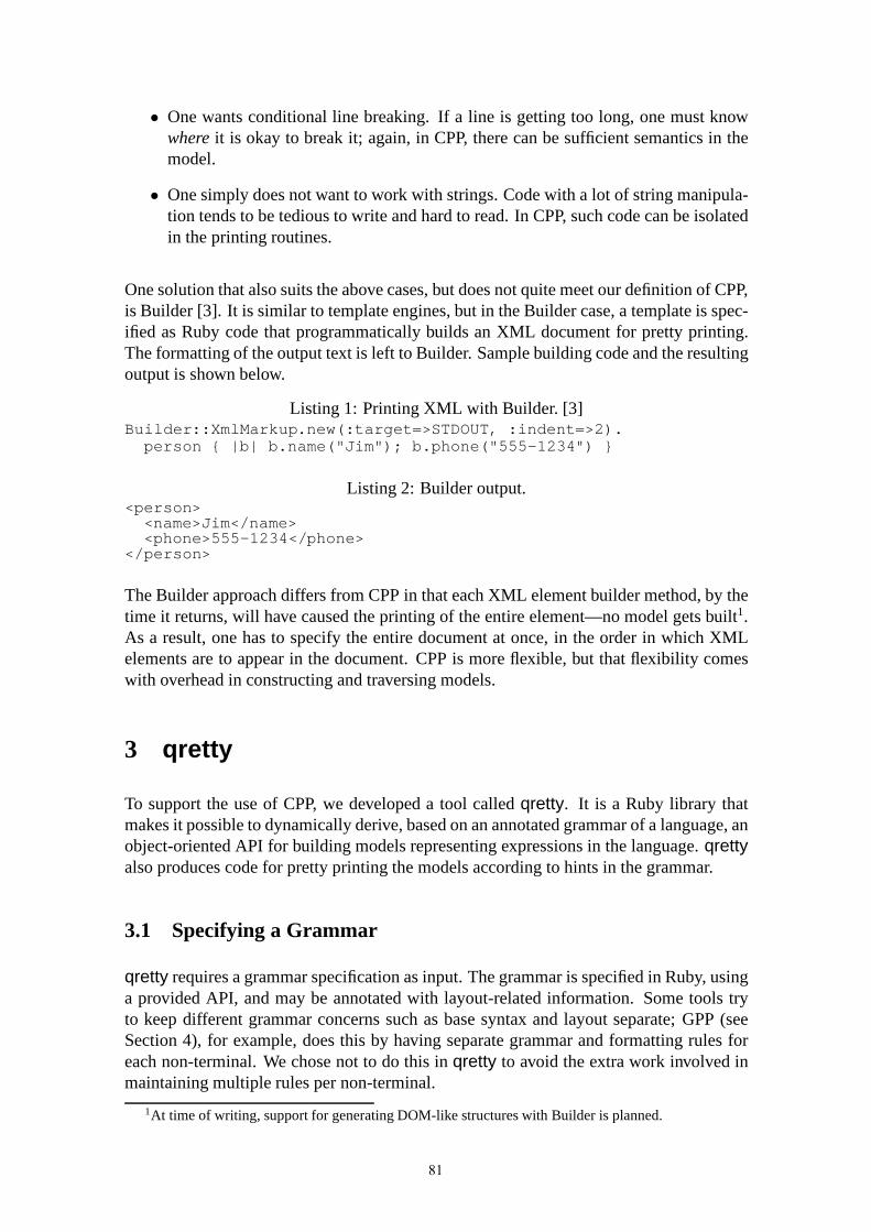
• One wants conditional line breaking. If a line is getting toolong, one must knowwhereit is okay to break it; again, in CPP, there can be sufficient semantics in themodel.
• One simply does not want to work with strings. Code with a lot of string manipula-tion tends to be tedious to write and hard to read. In CPP, suchcode can be isolatedin the printing routines.
One solution that also suits the above cases, but does not quite meet our definition of CPP,is Builder [3]. It is similar to template engines, but in the Builder case, a template is spec-ified as Ruby code that programmatically builds an XML document for pretty printing.The formatting of the output text is left to Builder. Sample building code and the resultingoutput is shown below.
Listing 1: Printing XML with Builder. [3]Builder::XmlMarkup.new(:target=>STDOUT, :indent=>2).person { |b| b.name("Jim"); b.phone("555-1234") }
Listing 2: Builder output.<person><name>Jim</name><phone>555-1234</phone>
</person>
The Builder approach differs from CPP in that each XML element builder method, by thetime it returns, will have caused the printing of the entire element—no model gets built1.As a result, one has to specify the entire document at once, inthe order in which XMLelements are to appear in the document. CPP is more flexible, but that flexibility comeswith overhead in constructing and traversing models.
3 qretty
To support the use of CPP, we developed a tool calledqretty. It is a Ruby library thatmakes it possible to dynamically derive, based on an annotated grammar of a language, anobject-oriented API for building models representing expressions in the language.qrettyalso produces code for pretty printing the models accordingto hints in the grammar.
3.1 Specifying a Grammar
qretty requires a grammar specification as input. The grammar is specified in Ruby, usinga provided API, and may be annotated with layout-related information. Some tools tryto keep different grammar concerns such as base syntax and layout separate; GPP (seeSection 4), for example, does this by having separate grammar and formatting rules foreach non-terminal. We chose not to do this inqretty to avoid the extra work involved inmaintaining multiple rules per non-terminal.
1At time of writing, support for generating DOM-like structures with Builder is planned.
81

Task CPU time (seconds)Grammar specification analysis (C++ grammar) 1.64Class hierarchy generation (C++ grammar) 0.17Model building (C++ declaration) 0.00Pretty printing (C++ declaration, 10 times) 0.16
Table 1:qretty performance measurements. Times listed are the average of 10 rounds, run on aPC with a 2.80 GHz Pentium 4 processor and 1 GB of memory. The measured program analyzed210 grammar rules, generated 134 Ruby classes based on the rules, built a model of a short C++class declaration (2 superclasses, two members), and printed the declaration 10 times. The analysistime does not include parsing performed by the Ruby runtime at program startup.
Below is an example grammar specification, extracted from anas-yet-unreleased tool inwhich qretty is used for pretty printing C++ type specifiers; we are using the tool toconvert GCC-XML generated C++ interface descriptions intoa different format.
Listing 3: A grammar specified in Ruby, us-ing theqretty API.crule(:type_spec,seq(basic(:typename),
opt(" ", :declarator)))crule(:ptr_declarator,seq("*", opt(:declarator)))
crule(:ref_declarator,seq("&", opt(:declarator)))
crule(:array_declarator,seq(opt(:declarator),
"[", opt(ident(:num)), "]"))crule(:func_declarator,seq("(", opt(:declarator), ")",
"(", opt(:funcargs), ")"))arule(:funcargs,commalist(:type_spec))
crule(:cv_declarator,seq(choice(namlit(:const),
namlit(:volatile)),opt(" ", :declarator)))
crule(:name_declarator,ident(:name))
arule(:declarator,basic(:declarator))
Listing 4: An approximate EBNF transla-tion.type_spec ::=
TYPENAME(" " declarator)?
ptr_declarator ::="*" declarator?
ref_declarator ::="&" declarator?
array_declarator ::=declarator?"[" NUM? "]"
func_declarator ::="(" declarator? ")""(" funcargs? ")"
funcargs ::=type_spec (", " type_spec)*
cv_declarator ::=("const" |"volatile")
(" " declarator)?name_declarator ::=
NAMEdeclarator ::=
ptr_declarator | ...
qretty includes an API for dynamically generating a set of classes corresponding to agrammar specification. Eachcrule gets its own class, whose instances getfields (foradding model objects) based on the named terms appearing on the right-hand side of therule.arules do not get a class; instead, their fields are folded into their containing rules.This is an important feature, as many “off-the-shelf” grammars result in deep grammartrees; one can achieve a shallower class hierarchy merely byjudiciously usingaruledeclarations instead ofcrule declarations.
qretty has a weakness in that it does not scale well to handle large grammars. For onething, given a complex grammar it can be difficult to create a corresponding class hier-archy that—despite the complexity—provides a usable modelbuilding API. Also,qrettyis slow in analyzing large grammars, as we noticed trying to use a fairly complete C++grammar. For related performance figures, look at Table 1.
82

3.2 Building a Model
Immediately after a class hierarchy has been generated, instances of the classes can beused to form tree structures constituting models for prettyprinting. qretty-generatedclasses have accessor methods for getting and setting childnodes, as one would expect.
Also, as described in Section 3.1,qretty knows the concept of a field, and each fieldhas what we call abuilder settermethod, intended to make model building convenient.Depending on the receiving field, a builder setter decides whether to create a new nodeobject. If so, it determines the type of object to create, passes its arguments to the con-structor of the object, and then assigns the resulting object to the appropriate instancevariable. If not, it simply uses its argument as the value to assign. The method returns theassigned object, and, if a Ruby block is passed, also passes the object to the block.
Below we give an example of model building, emulating the Builder example of Section 2.In addition to the model building code, both the used grammarspecification and the pro-duced output are shown. Two alternative syntaxes for defining aperson are included todemonstrate how the use of Ruby blocks makes the tree structure of the model clearer.
Listing 5: Grammar specification.crule(:xml_markup, opt(seplist(:person, nl)))crule(:person, choice(seq("<person>", nl, indent(one_or_more(seq(choice(:name, :phone), nl))), "</person>"), "<person/>"))
mfield [:name, :phone], :pname => :@listcrule(:name, seq("<name>", ident(:name), "</name>"))cfield :namecrule(:phone, seq("<phone>", ident(:phone), "</phone>"))cfield :phone
Listing 6: Model building code and a pretty printing request.model = ast::XmlMarkup.newmodel.person { |b| b.name "Jim"; b.phone "555-1234" }b = model.person; b.name "Tim"; b.phone "555-4321"CodePrinter::pp(model)
Listing 7: The pretty printed output.<person><name>Jim</name><phone>555-1234</phone>
</person><person><name>Tim</name><phone>555-4321</phone>
</person>
An obvious problem withqretty is that the produced model building API has no visibleinterface definition, forcing programmers to deduce it fromthe grammar specification.qretty uses runtime reflection for code generation, and there presently is no option togenerate API documentation either.
At no point during or after model building doesqretty validate tree structure [12], noris there static typing support in Ruby that could be used to prevent builder code frommistakenly placing a node into a context where the grammar does not allow it. We do notperceive this as a big problem, since the preferred way for building models is via buildersetters, which automatically create nodes of the correct type.
83
3.3 Pretty Printing a Model
qretty provides an API via which a model subtree may be pretty printed. Parameters canbe passed to choose an output stream, or to specify maximum line width, for instance.The implementation makes use of aprinter methodnamedqretty_print thatqrettyincludes in all the classes it generates. When invoked, a generated printer method matchesthe receiver’s instance data to the corresponding grammar rule to determine what to print.
During printing, an object we call aprinter visitor essentially walks the model depth-first, passing itself to the printer method of each node; the printer methods are expectedto print themselves using the API provided by the visitor. For purposes of flexibility,qretty allows a hand-coded class to be included in a model class hierarchy, as long as itimplements pretty printing in a compatible manner; in this case the right-hand side of thecorresponding grammar rule need not be given in the grammar specification.
There is no support for having generated printer methods pass or make use of any contextinformation, which makes it somewhat inconvenient to deal with language constructs thatprint differently depending on context. Should context information be required, one canattempt to encode it in the grammar, or implement select printer methods manually.
4 Related Solutions
There are many tools [1, 7] capable of generating APIs for operating on grammaticallystructured data, but we do not know of any tool apart fromqretty designed to generateclasses for the specific purpose of pretty printing. With such specialization, semanticsnot relevant in the context of pretty printing may be omitted, leading to shorter modelbuilding code. One just requires enough object semantics for correct coercion to stringsfor printing, and enough structural information to enable formatting.
Some grammar-based tools [10, 11] restrict themselves to so-calledstructured context-free grammars[11], which can—in generating classes—be mapped to a class inheritancehierarchy such that the presence of certain kind of non-terminals is implicit in the inheri-tance relationships, without concrete nodes for those non-terminals needing to appear inASTs. For similar shallowing of models, aqretty user must enhance the grammar withsufficient annotations.qretty accepts all context-free grammars—the classes it generatesdo not inherit from each other, nor do they have a statically typed interface; they only forma hierarchy through builder setters’ knowledge of what classes should be instantiated forwhich field.
GPP [8, 9] is one of the most powerful and generally applicable pretty-printing solutionsaround, but it does not generate a language-specific API for programmatic building ofmodels. The GPP toolset can handle a parse tree, an AST, or—indirectly—source-codetext as input, but if one has none of these, a solution similarto qretty might be helpfulfor building suitable input. GPP is part of the Stratego/XT [14] program transformationtoolkit. There are a number of others, such as DMS [2] and CodeWorker [4], and whilethese all are capable of pretty printing, they are rather large systems, and might be overkillto use just for that purpose.qretty is not a reengineering tool, but it integrates easily withinRuby applications that need to generatenewcode.
84

CodeDOM [5] provides a fixed API for building models of programs translatable to anyof multiple supported languages;qretty does not support multiple target languages for asingle model. While CodeDOM has better multi-language rendering support, its weak-nesses are that it does not provide elements to represent alllanguage features of all targetlanguages, and that CodeDOM model building code gets quite verbose. qretty avoidsthese problems by generating target language specific APIs designed for convenient modelbuilding.
5 Conclusion
In this paper, we have explored the idea of programmaticallyconstructing models just forpretty printing. We listed a number of situations where applying CPP might be warranted,but any benefits must naturally be weighed against implementation effort.qretty is a toolthat can help reduce the effort required, as it is capable of producing grammar-specificclass hierarchies and associated pretty-printing routines. Unlike most grammar-dependentsoftware, it even supports languages defined at runtime; a new grammar specificationcan be created and processed at any time, and the resulting classes can be put into ananonymous module to allow unneeded definitions to be discarded.
Aside from implementation effort, one must also consider whether it is possible to achieveconvenient model building in a given case. Either the model building language or theprinted language might make it hard to do so.qretty models are built in Ruby, whosesyntax seemed quite acceptable for the task, but we would have liked a language featuresimilar to the JavaScriptwith statement for specifying the default receiver for a set ofmethod calls.
For a friendly model building API, one probably requires memorable naming and a classhierarchy of reasonable depth.qretty’s grammar specification language can assist in mak-ing class hierarchies shallower than grammar trees. Namingcomes fairly naturally forsome languages; in our XML example, method names directly map to element names inthe XML document schema. There is no immediately obvious wayto map C++ languageconstructs to method names, however, as we found in trying todefine a C++ programmodel building API.
qretty is available for download [13], along with another library calledcodeprint. Thelatter provides functionality for printing and formattingtext, offering control over inden-tation and line breaking, for instance, andqretty depends on it for low-level formattingtasks. The reader should note that the present bad performance ofqretty excludes its usefrom many applications. It would be possible to drasticallyimprove performance, at leastby switching to compile-time code generation, but this is left for future work.
Acknowledgements
We thank Ken Rimey and the anonymous referees for constructive criticism on earlierrevisions of this paper, and Pekka Kanerva for feedback on the qretty documentation.
85

We gratefully acknowledge that this work has been funded under E!2023 ITEA S4ALL(Services for All).
References
[1] ANTLR. http://www.antlr.org/.
[2] I. Baxter, P. Pidgeon, and M. Mehlich. DMS: Program transformations for practical scalablesoftware evolution. InProceedings of the International Conference on Software Engineering.IEEE Press, 2004.
[3] Builder for Markup.http://builder.rubyforge.org/.
[4] CodeWorker.http://codeworker.free.fr/.
[5] .NET framework developer’s guide: Generating and compiling source code dynamically inmultiple languages.http://msdn.microsoft.com/.
[6] Jack Herrington.Code Generation in Action. Manning, 2003.
[7] H. A. de Jong and P. A. Olivier. Generation of abstract programming interfaces from syntaxdefinitions. Journal of Logic and Algebraic Programming (JLAP), 59:35–61, April-May2004. Issues 1–2.
[8] Merijn de Jonge. A pretty-printer for every occasion. InProceedings of the 2nd InternationalSymposium on Constructing Software Engineering Tools, Wollongong, Australia, 2000.
[9] Merijn de Jonge. Pretty-printing for software reengineering. InProceedings of InternationalConference on Software Maintenance (ICSM 2002), pages 550–559. IEEE Computer SocietyPress, October 2002.
[10] maketea theory.http://www.phpcompiler.org/doc/maketeatheory.html.
[11] The metaprogramming system – reference manual. Technical Report MIA 91-14, MjølnerInformatics, February 2002.
[12] Terence Parr. Translators should use tree grammars.http://www.antlr.org/article/1100569809276/use.tree.grammars.tml, November 2004.
[13] qretty.http://pdis.hiit.fi/s4all/download/qretty/.
[14] Eelco Visser. Program transformation with Stratego/XT: Rules, strategies, tools, and systemsin StrategoXT-0.9. InDomain-Specific Program Generation, volume 3016 ofLecture Notesin Computer Science, pages 216–238. Springer-Verlag, June 2004.
86

Toward Families of QVT DSL and Tool
Benoît Langlois, Daniel Exertier, Ghanshyamsinh Devda
Thales Research & Technology
RD 128 – 91767 Palaiseau, France
{benoit.Langlois, daniel.exertier, ghanshyamsinh.devda}@thalesgroup.com
Abstract QVT (Query/View/Model transformation) is a modeling core technology for the development of MDD
(Model-Driven Development) tools. Thus, it is strategic for a company to have QVT techniques
improving productivity of development teams, especially when standards, tools, user requirements, and
practices are ever evolving. The interest of introducing QVT DSL (Domain-Specific Language) is to
offer higher level QVT languages in order to produce QVT tools in a faster and safer way. For assessing
this position, this paper presents, at first, the case study of a view DSL for producing tools generating
model diagrams. From this proof of concept of QVT DSL, this paper studies the introduction of families
of QVT DSL and tool to fit to multiple project contexts.
Keywords MDD, DSL, PRODUCT LINE, QVT, SOFTWARE FACTORIES.
1. Introduction
To produce high quality software both on budget and schedule, companies usually face productivity
improvement issue. This is particularly true in the context of large-scale systems. In the current MDD
context, while projects encounter evolving environment of standards, tools, user requirements, and
practices, they have no other choice than to use low level QVT languages, essentially code-based, for
the development of MDD tools. Then, it then becomes judicious to introduce higher level languages, for
instance with wizards, easing QVT descriptions which contain sufficient information for translation
toward low level QVT languages. This is the purpose of DSL dedicated to QVT.
In order to validate this category of DSL, this paper presents the case study of Diagram DSL. From a
description conforming to a Diagram DSL can be deduced MDD tools generating model diagrams. The
interest is such that the diagram designer does not code anything, development and maintenance tasks
are easier and safer. However, this technique is limited to the production of one type of QVT DSL
development. The next step is the production of QVT DSL variants meeting contextual requirements.
For instance, a Diagram DSL cannot presume and contain all descriptions of diagram layout; such is the
case for a serializer for which it is impossible to determine all exchange formats. Then, from core QVT
assets, variations can be applied to produce the expected DSL and tool. For instance, a serialization
language can be specialized into several serialization languages for meeting specific model exchange
formats. This opens the way of families of QVT DSL and tool.
This paper is organized as follows. Section 2 studies the link between QVT and DSL. Section 3 presents
the case study of a view DSL for producing tools generating model diagrams. Section 4 extends this
result toward families of QVT DSL and tool. Section 5 presents further work and section 6 concludes.
87

2. Link between QVT and DSL
The MOF 2.0 QVT standard [18], a key technology for the OMG’s MDA™ (Model-Driven
Architecture), defines a language for model transformation, such as a PIM (Platform-Independent
Model) to PSM (Platform-Dependent Model) transformation. A query is an expression that is evaluated
over a model; it returns one or more instances of types defined in the metamodel of the model or defined
by the query language. A view is a model derived from the base model, such as diagrams or code; a
view does not modify the base model. A transformation generates a target model from a source model,
such as a PIM to PIM transformation. Source and target models conform to their metamodels [10]. In
this paper, we do not restrict our vision to the OMG’s standard. For instance, the Epsilon Object
Language (EOL) [7][13] of the Epsilon Model Management Framework provides all mechanisms for
model navigation and transformation. From this standalone language, specific languages can be
constructed, for instance for model merging or text generation from models. Kermeta is a metamodeling
language, compliant with EMOF [17], which provides an action language for specifying behavior and
for implementing executable metamodels, e.g. for implementing transformation languages, or action
languages. AMMA (Atlas Model Management Architecture) [1], built atop EMF, is a general-purpose
framework for model management. Based on ATL [2], it provides a virtual machine and infrastructure
tool support for combining model transformation, model composition and resource management into an
open model management framework.
A DSL, for its part, is a specialized, problem-oriented language [6], in that DSL focuses on a problem
contrarily to a general-purpose language, such as UML. From a DSL to target language, a problem-to-
solution transformation encapsulates complexity and hides decisions or irrelevant implementation
details. During transformation, automation avoids repetitive and tedious user tasks and guarantees
systematic practices. Regarding the process engineering, wizards can guide users in their development
tasks and domain rules ensuring that data are reliable. Thus, DSLs are means toward easing problem
expression. The objective of complementary DSLs is actually productivity improvement by
industrialization of modeling chains from requirements down to the packaging of produced assets, such
as models, model transformations, model views, configuration files, or documentation.
In the QVT context, a QVT DSL has for role to ease the development process where the considered
domain is QVT. For MDD end-users that means QVT DSLs ease domain modeling, such as consulting
model or applying patterns. For MDD users at the metamodel level that means QVT DSLs ease tool
creation, for instance for designing model transformations or defining modeling processes. A DSL
which is not a QVT DSL is a DSL which does not apply QVT action over a model. This is for instance
the case of a profiling tool which audits models from data contained in files without QVT action.
The following, non exhaustive, table proposes a categorization of QVT DSL. The levels of QVT usages
with DSL are presented in abscissa: 1/ The “Core technology” aspect covers the OMG’s QVT standard
and QVT languages which conform to it; 2/ The “Development” aspect covers the category of DSL
enriching the QVT languages for the development of MDD tools, such as a DSL for traceability
management; 3/ The “Business” aspect targets DSL for end-users, such as a Diagram DSL. In ordinate,
we find the Query, View, and Transformation aspects. By crossing the two dimensions, a Diagram DSL
is for instance a view DSL for business activities of development that a end-user can use in his modeler.
Development DSLs depend on core technology DSLs; business DSLs depend on development DSLs or
directly on core technology DSLs. As a consequence, core technology QVT DSLs evolve more slowly
and are less numerous than the others; business DSLs have on the contrary shorter lifecycles, they are
88

more numerous and business- or project-specific. For instance, a few QVT languages implement the
OMG’s standard while every project can decide to customize properties for its diagram presentations.
Table 1. Categories of QVT DSL
Core technology Development Business
Q Model information Model checking
V
–
Diagram
Documentation
T
QVT languages Merging
Traceability
Transformation pattern
Versioning
Abstraction/Refinement
Architecture
Business process
Domain wizard
Quality of Service
3. A DSL for producing tools for model diagram generation
This section presents the case study of a QVT DSL for producing tools generating model diagrams,
which has been developed by DAE, a Department of the Thales Software Research Group.
3.1 Paradigm shift from code to DSL with Software Factories
A few years ago, we started to manually develop tools generating model diagrams. After the
development of several one of these, we noticed duplications, redundancies in code, and non reliable
schedule. From a first refactoring emerged a diagram framework. This framework capitalized common
practices; it reduced but did not prevent the same error-prone defects of manual developments. Then, we
therefore decided to use MDSoFa [14], a DAE software factory tool. The objective was to realize a
paradigm shift from a handcrafted to an industrialized development.
Figure 1. MDD Tool Architecture
89

MDSoFa is a software factory tool for producing MDD tools in series. It generates for instance the
infrastructure of two large-scale MDD tools: MDSysE [8][16], a modeling tool for system-engineering,
and MDSoftE, a modeling tool for software engineering. For improving reusability, MDSysE and
MDSoftE, as well as MDSoFa, share a set of common core assets, gathered in a common product called
MDCorE. All of these MDD tools are in line with the product line approach. MDSysE and MDSoftE are
variations of MDCorE core assets. These core assets and the product lifecycle are managed by MDSoFa.
A Diagram DSL has typically its place in MDCorE because it can be fitted to different MDD tool
contexts.
3.2 Diagram DSL representation and usage
A first key point is to understand the relationship between a Diagram DSL and diagrams, and the
relationship between a Diagram DSL and a Diagram DSL tool.
3.2.1 A 3-level architecture
Regarding the relationship between a Diagram DSL and diagrams, we have adopted a 3-level
architecture (Figure 2), as MOF. The D2 level represents the language for describing a QVT domain, the
D1 level a description of this QVT domain to be applied at the model level, and the D0 level the
application of a D1 description at the model level. In the case study, the QVT domain is the diagram
management with the following levels.
D2 – Diagram
DSL
At the D2 level, the Diagram DSL represents the language for describing any type of
diagrams. It is solution- and platform-independent and contains all criteria
understandable by a user who wants to specify diagrams. This level is problem-oriented
for specifying diagrams.
D1 – Diagram
DSL instance
At the D1 level, a Diagram DSL instance describes a type of diagram. It contains the
view model description for producing a type of diagram, that is model elements to be
displayed with their layout properties. This description respects the language defined
by the Diagram DSL. This level contains all data for generating tools producing
diagrams.
D0 - Diagram At the D0 level, we have diagrams expected by end-users in their modeler.
The Diagram DSL is described by a model which defines the grammar for model diagrams. The one we
have developed contains simply four classes: 1/ Diagram root gives information for starting diagram
generation, 2/ Node specifies model elements displayed in diagrams with their layout, 3/ Navigation
specifies navigation in model, 4/ Condition, complementary to Navigation, specifies model element
selection. Attributes represent Diagram features, e.g. a color of a model element type. Associations
between classes declare possible relationships, e.g. a Node can contain Nodes, but a Node cannot
contain a Diagram root. At a Diagram DSL instance, there is one Diagram Root element by type of
diagram. The Nodes and Navigations describe the successive navigations in model and how model
elements are displayed in the diagram.
90

3.2.2 Diagram DSL and Diagram DSL Tool relationship
A Diagram DSL tool is the tool which puts the Diagram DSL in action. The principle for managing a
Diagram DSL instance with a Diagram DSL tool is the same than for editing a domain model, such as
MDSysE. Instead of editing a model, a Diagram DSL tool manages diagram DSL instances conforming
to the Diagram DSL. This means the DSL tool is always consistent with the language it implements, the
Diagram DSL. Thanks to this conformance and with a full generation adoption, the Diagram DSL tool
can be generated from a “Diagram DSL to Diagram DSL tool” translation. Therefore, when Diagram
DSL properties change, the DSL tool can be generated for a Diagram DSL / Diagram DSL tool
synchronisation.
3.3 Diagram DSL Lifecycle
This sub-section explains the process, which is depicted in the following figure, intending to produce
tools generating model diagrams from the Diagram DSL definition.
Figure 3. Analogy of domain and DSL models
Figure 2. Diagram DSL levels
91

:DSL Designer
Defining the Diagram DSL
:Diagram Designer
Defining a Diagram
:Diagram DSL Instance
:Model End-User
Generating Diagram
:Diagram
:Tool Developer
Producing the Diagram DSL Tool
:Diagram DSL Tool
Producing the Diagram
Generation Tool
:Diagram Generation Tool
:Diagram DSL
3.3.1 Defining the Diagram DSL
This activity, effectuated by the DSL Designer, consists in modeling the Diagram DSL. Starting either
from code, and abstracting it into the Diagram DSL, or starting directly from the Diagram user
viewpoint, eliciting the Diagram DSL is not a straightforward situation. It requires several iterations
before finding criteria meaningful for the Diagram Designer. These criteria must be simple, pertinent
and complete enough to deduce an implementation solution.
3.3.2 Producing the Diagram DSL Tool
The Diagram DSL tool, which serves to edit Diagram DSL instances, evolves as long as the Diagram
DSL does. Several presentations may exist for the same DSL. Its production can be generated from a
DSL to Tool transformation or developed manually by a Tool Developer. Here again, the DSL tool must
be simple and pertinent. Actually, its utility depends on its ability to increase the Diagram Designer
productivity. The progress, in this way, is when the user has no code to write. Even more, it is assisted
to reach faster what she/he expects to build.
3.3.3 Defining Diagram
Every Diagram DSL instance realized at this stage contains all criteria for creating and updating every
kind of diagram, e.g. all MDSysE diagrams (interface, domain element, component, deployment
diagrams, etc.). The actor of this activity is really a designer and not a developer.
3.3.4 Producing the Diagram Generation Tool
Every Diagram DSL instance is consumed by MDSoFa to produce a tool generating model diagrams.
After its production, the tool is packaged, ready to be deployed and integrated in a largest tool, e.g.
MDSysE. Diagram generation becomes a function among others.
Figure 4. Diagram DSL lifecycle
92

3.3.5 Generating Diagram
During this activity, the model end-user applies the diagram tool on his model, e.g. interface diagrams of
the model are generated. Diagrams created or updated conform to a Diagram DSL model, which
conforms to the Diagram DSL. For instance, diagram layout reflects layout specifications, which
conform to the properties defined in the Diagram DSL.
4. Stepping toward families of QVT DSL and tool
The case study of Diagram DSL focuses on the view aspect. It has been tested on more than 50 types of
diagram and is in production with MDSysE. However, from our previous lessons learned with MDSoFa,
a main point emerged: that one DSL can be, not necessarily specialized but, tailored in function of the
project context. With software factories, this opens the way for families of QVT DSL.
4.1 Need of QVT DSL and tool families
Several reasons justify the need of QVT DSL families.
[N1] From the functionality viewpoint, a QVT DSL in a project context can have more or less properties
that an original QVT DSL. Neither specialization nor parameterization is able to support multiple
structural modifications, especially for several projects managed in parallel.
[N2] From the process viewpoint, different processes are possible for the same QVT DSL in function of
the project context or the adopted methodology.
[N3] From the language viewpoint, it is illusory that one language addresses all types of modeling
problems with expressiveness and accuracy simultaneously. The need is the management of variation of
“abstract to concrete syntax” transformation. For low level languages, in function of user communities,
from the same QVT core language can be derived various forms of programming languages: textual vs.
graphical, declarative vs. imperative, etc. For high level languages, i.e. DSLs abstracting the most a
software description, a DSL can also adopt various forms: description with formal textual language,
wizard, or even with table.
[N4] From the design and implementation viewpoints, the solution can change in function of
architectural or non-functional decisions. The problem to solution transformation implies to have
variants of generation.
[N5] From the capitalization viewpoint, in order to meet the requirement of durability of the QVT
descriptions, the need is the management of the platform variability (standards, languages, frameworks,
tools).
[N6] From the reusability viewpoint, different QVT DSLs can share common features. For instance, a
view DSL and a model transformation DSL can be expressed in a tree form. Then, the need is to manage
common assets which can be reused in different QVT DSL contexts.
This list of needs justifies this interest of QVT families but simultaneously shows its complexity. We
can continue to develop QVT tools without product line but reusability and productivity will assuredly
decrease when specifications and environment evolve, or when project contexts are multiple. Managing
efficiently variability of QVT DSL and tool turns out to be profitable but also a real technical challenge.
93

4.2 QVT DSL and tool families
The software product line is “a set of software intensive systems sharing a common, managed set of
features that satisfy specific needs of a particular market or mission, and that are developed from a
common set of core assets in a prescribed way” [3]. This means that core assets are created to be reused
in the production of multiple products in order to reduce the cost and the time to produce an individual
product [4]. A product line uses two distinct but interacting processes: 1/ the product line development
process, which produces reusable assets, and 2/ the product development, which produces products. To
continuously improve the core assets, the product line development process uses the feedback of the
product development (promotion and improvement of core assets, architecture evolution, production
process improvement, etc.).
The main activities for the product line process are: i) for the domain analysis, domain scoping,
identification of the commonalities and variability among all products in the family, ii) for the domain
design, architecture development, production process and definition of the production plan, and iii)
implementation of the core assets for the domain implementation.
Activities of the product development have for objective the production a member of a product family.
Analysis, design, and implementation activities select, integrate, and customize the core assets.
4.2.1 A QVT DSL itself as domain
The key point for QVT DSL to reap profit from experience in product line engineering is to consider a
QVT DSL itself as a domain. Instead of applying variations on domains such as system or software
engineering, variations are applied on QVT domains. Section 3.1 has presented the experience of
product line with MDSoFa. MDSysE and MDSoftE are variations of a common domain located in
MDCorE, location of MDD core assets. This common domain is defined by a model. Section 3.2 has
presented the DSL Diagram defined by a model as well. The way for variations on the Diagram DSL is
similar than with the MDSysE and MDSoftE domains. On the other hand, the way for generating the
tool producing generating diagrams is the same than for generating the MDSysE and MDSoftE
infrastructures. Representation and tooling are the same. The strength of this reflexivity is auto-
consistency: end products are built in the same way than the development tool.
4.2.2 Core asset management
The level of reusability and durability of core assets comes from the ability to accept evolutions on core
assets from new requirements and product evolutions. This implies a rationale management both of
every core asset and the core asset architecture (modularity, asset lifecycle, interactions, etc.).
In the QVT context, a core asset can be:
• A domain description, i.e. a description at the D2 level for QVT DSL description, and at the D1
level for QVT DSL instance. A QVT DSL instance is a core asset when this QVT DSL instance can
be tailored, or for addressing variations, such abstract to syntax concrete derivations. Refer to needs
[N1] [N2][N3] in section 4.1.
• A QVT DSL tool description for QVT DSL tool families. Refer to needs [N1][N2][N3][N4][N5].
• Patterns, generations, frameworks, and tools required for building QVT DSL tools. Refer to need
[N4][N5].
94

• The QVT environment, such as the QVT standard or platform descriptions. Refer to need [N5].
Core asset evolution is a major issue when managing core assets. Four major impacts are possible:
• Impact on domain, with three kinds of impact:
o Intra-domain impact. Evolutions are located in the same QVT DSL, e.g. new layout
properties in the Diagram DSL. Refer to needs [N1][N2].
o Inter-domain impact. Evolutions are located in several QVT DSLs, e.g. several DSLs share
common elements. Refer to need [N6].
o Extra-domain impact. A feature is reusable by domains external to QVT DSL domains. For
instance, a tree-organization can be used by Diagram and model transformation (inter-
domain relationship) but also by interface description.
• Impact on feature model. In this case, the feature model evolves for taking into account new
requirements or product evolutions. Refer to needs [N1][N2][N3][N5].
• Impact on architecture. Architecture must be reconsidered for domain, or feature evolutions, but also
to take into account pattern, framework, or tool evolutions. Refer to need [N5].
• Impact on production plan. The production plan describes how products are constructed from the
core assets. It directly depends on the previous impacts.
Regarding the architecture, Epsilon [7] is illustrative for its tree-organization of QVT languages. EOL is
the core language from which other languages can be constructed atop. Epsilon is activity-oriented with
languages used for instance for merging, model transformation, or code generation. This tree-
organization can be reused for building a hierarchy of QVT languages with QVT DSL and tool variants.
Referring to Table 1, one can find core technology, development, and business derivations of DSL but
also “core technology to development”, “core technology to business” or “business to business”
derivations of DSL. The interest of such an organization is the robustness of the foundation: a branch
meet a MDD segment (a kind of activity, a technology, a project context, etc.) and each QVT derivation
is consistent thanks to a “QVT to QVT” translation.
4.2.3 Product production
A major stage is the production of product from core assets. A production plan describes how to manage
this production. It takes into consideration the production method of each asset, the available resources,
the linkage among the core assets, and the product line constraints.
Figure 4 describes an example of a Diagram DSL lifecycle. In order to be integrated in a product-line,
each activity must declare how to fit into product production contexts. For instance, for a platform
variability, the “Producing the Diagram DSL tool” needs to know the target platform, e.g. UML version,
modeling tool, programming language. Depending on these parameter values, the right generator is
selected.
95

4.3 Issues
Even if the core assets, the production method and the production plan are clarified, in the QVT context,
a set of issues must be settled.
1/ Unification of QVT DSL. For complexity reduction and efficiency of MDD tool development, the
QVT DSL architecture must be rationalized. We recommend the adoption of a reduced number of QVT
DSLs, a tree-organization with few bridges, and reflexivity according to the 3-level architecture
principle.
2/ Constitution of uniform QVT DSL workbench. When building MDD tools, a requirement is to have
the same ergonomics and logic of action among the DSLs. With a product line, the issue is to keep this
uniformity in function with the selected features.
3/ Full automation. The production plan can be a document, partially or completely automated. At a
managed maturity model level, automation of the product production is maximized.
4/ Standardization. Families of QVT DSL and tools can be developed by a company for internal or
external usage. Despite several open source initiatives and projects on model transformation, the lack of
standard for product line prevents any QVT DSL product line in the open source segment.
5. Further Work
Our future work will focus on the development of core assets for building DSL tools, and variants of
DSL tools.
6. Conclusion
This paper has presented the case study of a Diagram DSL allowing specification of model diagram.
From models conforming to this DSL, DSL tools are produced for generation of model diagrams. These
DSL tools are integrated afterward in MDD tools for end-users. Furthermore, in the context of software
production with software factories, we figured out that this Diagram DSL could be reused for other
purposes, such as model transformation. This clears the way toward families of QVT DSL and tool. We
have given in this paper elements for building such families. We believe this is the next step to meet
various companies and projects requirements, and to build customized QVT workbenches.
7. Acknowledgments
We thank Serge Salicki, head of DAE of the Thales Software Research Group, the members of DAE,
and especially Stéphane Bonnet, Sébastien Demathieu, and Catherine Lucas.
8. References
[1] AMMA (Atlas Model Management Architecture). http://www.sciences.univ-nantes.fr/lina/atl/AM-
MAROOT/.
[2] Atlas Transformation Language, official web-site. http://www.sciences.univ-nantes.fr/lina/atl.
[3] Clements, P., Northrop, L., Software Product Lines, Practices and Patterns, Addison-Wesley,
2002.
96

[4] Chastek, G., J., Mc Gregor, J.D., Integrating Domain Specific Modeling into the Production
Method of a Software Product Line, OOPSLA 2005, Workshop on DSM.
[5] Chauvel, F., Fleurey, F., Kermeta Language Overview. http://www.kermeta.org.
[6] Czarnecki, K., and Eisenecker, U.W. Generative Programming, Addison-Wesley, 2000.
[7] Epsilon, University of York. http://www-users.cs.york.ac.uk/~dkolovos/epsilon/.
[8] Exertier, D., and Normand, V. MDSysE: A Model-Driven Systems Engineering Approach at
Thales. Incose, 2-4 November, 2004.
[9] Fowler, M., Language Workbenches: The Killer-App for Domain Specific Languages?,
http://www.martinfowler.com/articles/languageWorkbench.html
[10] Gardner, T., Griffin, C., Koehler, J. , Hauser, R. A review of OMG MOF 2.0 Query / Views /
Transformations Submissions and Recommendations towards the final Standard. July, 2003.
[11] Greenfield, J., Short, K., Cook, S., and Kent, S., Software Factories, Assembling applications with
Patterns, Models, Framework, and Tools, Wiley, 2004.
[12] Hamza, H.S., On the Impact of Domain Dynamics on Product-Line Development, OOPSLA 2005,
Workshop on DSM.
[13] Kolovos, D.S., Paige R.F., Polack F.A.C., The Epsilon Object Language (EOL), Second
European Conference, ECMDA-FA 2006, Bilbao, Spain, July 2006, Springer, 2006.
[14] Langlois, B., Exertier, D., MDSoFa: a Model-Driven Software Factory, OOPSLA 2004, MDSD
Workshop.
[15] Langlois, B., Barata, J., Exertier, D., Improving MDD Productivity with Software Factories,
OOPSLA 2005, First International Workshop on Software Factories.
[16] Normand, V., Exertier, D. Model-Driven Systems Engineering: SysML & the MDSysE Approach
at Thales. Ecole d’été CEA-ENSIETA, Brest, France, September, 2004.
[17] OMG. Meta Object Facility (MOF) 2.0 Core Specification, ptc/04-10-15.
[18] OMG. MOF QVT Final Adopted Specification, ptc/05-11-0
97

Preserving Architectural Knowledge ThroughDomain-Specific Modeling
Femi G. Olumofin and Vojislav B. Misic ∗
University of Manitoba, Winnipeg, Manitoba, Canada
Abstract
We investigate the feasibility of applying the principles of domain-specific modeling tothe problem of capturing and preservation architectural modeling knowledge. The proposedsolution is based on the existing architecture assessment methods, rather than architecturemodeling ones, and it uses sequences of design decisions, rather than simple, unordered sets.We highlight how architecture-based development could benefit from the proposed approachin terms of both methodology and tool support.
1 Introduction
For many years, the two main objectives of software development were (and still are) howto improve the productivity of the development process and how to improve the quality of theresulting products. A recent addition to the wealth of techniques proposed to address thoseobjectives is the approach known as domain-specific modeling (DSM). The trademark featureof DSM is the shift from the traditional practice of specifying problem solution using lower-level programming constructs, to the one at a higher level of abstraction in which the solutionis spelled out in terms of concepts culled from the very domain of the problem being solved.A metamodel of the problem domain is constructed by an expert; subsequent development byless experienced developers uses this metamodel and the associated automated tools to buildactual solutions. Significant improvements in software development productivity (and, to alesser extent, software quality) can be achieved in this manner, mostly because the complexityis limited by focusing on a single, well defined problem domain [11].
In this paper, we investigate the feasibility of applying domain-specific modeling to soft-ware architecture – a highly abstract area which should be well suited for the DSM approach.Traditionally, the architecture of a software-intensive system presents a structure (or struc-tures) comprising the elements of the system, their externally observable properties, andstatic as well as dynamic relationships between those elements [1]. The architecture of asystem is the first, and arguably the most important, set of artifacts that sets the directionsfor subsequent product development and controls the quality attributes of the final product.Architecture is usually developed by established experts from both the problem domain andgeneral system domain. The domain experts ensure that quality goals such as performance,
∗The work presented in this paper was partially supported by the NSERC Discovery Grant.
98

reliability, security, and availability, among others, are properly addressed during the ar-chitecture definition stage of the metamodel development. The system experts cater to therequirements of feasibility and development efficiency, as well as maintainability and evolv-ability of the architecture and derived systems. Obviously, the process involves high-levelmodeling and, possibly, metamodeling. Thus, it is worth considering whether an architecturemetamodel could be developed to aid in this process, and what would be the benefits (and,possibly, drawbacks) of this approach.
The remaining part of the paper is structured as follows: Section 2 demonstrates the atten-dant problems of current architecture modeling practice through a small example. Section 3explores how we should model software architecture to be able to address those problems.Some implementation issues and possible uses of this approach are discussed in Section 4.Finally, Section 5 concludes this paper.
2 Components and Connectors Are Not Enough
The field of software architecture is maturing. Several modeling methodologies for soft-ware architecture development have emerged, most of which represent the concepts of com-ponents and connectors as first-class entities of the design. While those concepts are certainlycloser to the solution domain than the problem domain, they did help build highly success-ful architectural models for different kinds of systems. Documentation-wise, architecturesare typically documented as sets of views that correspond to different aspects of the archi-tecture [2]. But despite such advances, maintenance and evolution of an existing softwarearchitecture is still a difficult and error-prone task.
A possible explanation for this is the well known concept of knowledge vaporization [4, 8,12]. Namely, in the development process, explicit artifacts are constructed for the architectureby making a series of design decisions aimed at satisfying the requirements whilst addressingthe underlying quality goals. In this process, thorough knowledge about the problem domainis gradually accumulated, but the bulk of it remains implicit in the minds of the architect(s)rather than being captured and explicitly documented. Once the development is finished,architects move on to new tasks and this knowledge fades from memory. The relevance ofexplicit documentation also tends to diminish, on account of changes in the requirementsand/or actual implementation.
As an example, let us consider the runtime architectural view of a prepaid cell phoneairtime top-up application which is shown in Fig. 1. The customer uses her mobile clientto send an airtime top-up instruction in text format to the telco’s SMS Center. This textmessage is retrieved by the TextSender and forwarded to TextListener, or temporarily stored inTelco DB if TextListener can’t be reached at the moment. TextListener forwards this messageto TextParser, which processes it and delivers it (together with appropriate status information)to the Scheduler that invokes the necessary transaction processing components TX proc. Theresult of this processing, which involves interaction with the customer’s bank, is sent toTX Notifier, which formats the response and notifies TopupWriter to credit the customer’sairtime account and dispatch an appropriate status message back to the customer.
Subsequent evolution and maintenance activities are based on the existing architectural ar-tifacts, rather than on the knowledge that guided the design choices in the development phase.In the example above, neither the textual description nor the components-and-connectors di-agram provide clues as to why the decision to temporarily log customer’s instructions inTelcoDB was made in the first place.
99

client
main application
telco
mobile client
SMS_Center
TextSender TextListener
TextParser
Scheduler
TX_proc
TX_DB
TX_Notifier
Telco_DB
TopupWriter
Figure 1. A runtime view of the airtime top-up architecture.
While implicit domain knowledge can be, and usually is, re-created when necessary, theprocess is neither quick nor easy, and it incurs a substantial risk of changing the architecturein ways that counter the initial quality goals, rather than support and align with them.
The main reason behind the loss of crucial architectural knowledge obtained in the designprocess and used to shape the design is simple: the current paradigm for describing softwarearchitecture models does not support that task. The only things that can be recorded are thefinal artifacts, but not the road that led to them. Question is, can domain-specific modelinghelp alleviate the problem(s) outlined above? The need to apply the domain-specific mod-eling paradigm to architectural modeling—for example, by representing architectural designdecisions as first-class entities—has been recognized for a while [4]. In this context, a designdecision is an abstraction that is closer to the problem domain than the solution domain. Infact, modeling software architecture in terms of design decisions follows a direction whichis strikingly similar to the common DSM practice. The common activities of selection andinterconnection of components and connectors (both of which firmly based on the solutiondomain) are, then, just a necessary, but by no means sufficient, ingredient of architecturalmodeling.
But how do we arrive at such a modeling technique? And how do we allow architecturalknowledge to be captured explicitly within the model definition? According to [8], the solu-tion is a three-step process. First, we need to devise a way to move architectural knowledgefrom the tacit level to the documented level. Second, we should create a formal frameworkfor representing and reasoning about design decisions, just as has been done for componentsand connectors. Finally, tools should be developed to exploit a repository of such knowledgerepresentations in order to simplify architecture evolution activities. Furthermore, there isperhaps use for an ontology of architectural design decisions that should record, store, andprovide information about the varieties of design decisions and the connections between them[7].
A different solution has been advocated in [4], where architectural models are represented
100

as a set of design decisions. The relationship between a software architecture and associateddesign decisions uses a metamodel called archium, which consists of a combination of deltas,architectural fragments, and design decisions. A delta is used to track changes in componentbehaviors, whilst an architectural fragment is used to scope design decisions to some set ofinteracting components, possibly including appropriate deltas. Although the archium meta-model development is still at the preliminary stage, it appears fair to say that it is complex tounderstand, and a more simplified modeling approach might be more appropriate.
Some of the issues related to representing, capturing, and using design rationale in thegeneric context of design rationale systems have been discussed and systematized in [9].
3 Improving the Architectural Modeling Practice
Obviously, domain-specific modeling has a role to play; but architecture-specific domainconcepts have to be identified and refined to suit the task. Two main theses appear to be validin this context.
Our first thesis is that architecture assessment methods, rather than architecture develop-ment methods, should be used as the foundation for domain modeling of software architecturedesigns and related design knowledge. This is due to the fact that architecture assessmentmethods, a number of which have evolved over time [3, 5, 6, 10] already focus on architecturequality attributes and related design decisions. In fact, the most complete corpus of knowl-edge about the design decisions that lead to an architecture usually emerges as a by-productof the assessment exercise.
These design decisions are documented and collected in the form of architectural ap-proaches that correspond to different views. These decisions are also explored in detail toassess the fitness of a particular architecture to its stated requirements and quality goals. Inthis process, attendant risks, nonrisks, and sensitivity points are identified and analyzed. (Inthis context, sensitivity points are design decisions that shape the architecture in order to ad-dress one or more quality attributes; tradeoff points are sensitivity points where two or morequality attributes interact; finally, nonrisks are the assumptions that do not affect quality at-tributes in the current design, but that could become risks should some alternative designdecisions be applied.) One might almost say that we already have the tool we need; but itshould be used in a way that differs from the usual one.
To illustrate this point, let us look again at the example from previous Section. The finaloutcome—that ‘text message is retrieved by the TextSender and forwarded to TextListener,or temporarily stored in Telco DB if TextListener can’t be reached at the moment’—has beendecided after considering and discussing the following rationale in the following order:
i. Physical communication link between TextSenderand TextListeneris unreliable, there-fore recording customer’s instructions is necessary to avoid loss of messages in caseof link failure. This decision is a sensitivity point that stems from an attempt to satisfythe quality goal of reliability.
ii. On the other hand, customer’s instructions contain confidential data such as PIN issuedby their bank – keeping them in the database constitutes a security risk. The decisionis, then, a sensitivity point related to the quality goal of security.
iii. Since the two quality goals affected offer conflicting suggestions, we are dealing witha tradeoff point. Proper decision can only be reached by finding the optimum tradeoffbetween quality attributes [6].
101

Architecture
View
Goal
QAApproach
UtilityTree
UtilityItem
Scenario
Decision
SensitivityPoint
TradeoffPoint
Risk
Nonrisk
*
1collection of
1
*prioritized by
1*
shapes
*
1
documented as
*
*depicts
1 *
addressed by
*
1
consist of
1
*concretizes
*
1
reveals
*
1 reveals
*
1applies
* 1
reveals
RiskTheme
*
*refined as
1
*
Figure 2. ATAM-based meta-model of architectural knowledge.
iv. Fortunately, Telco DB is based on a particular DBMS technology that allows encryp-tion of data items kept in a particular data area. Such items may be labeled with aexpiration timeout, after which they ‘disappear’ from the database. A security breachof the Telco DB can compromise only a limited number of such messages. This no-tion, then, diminishes the impact of the security risk, effectively converting it into anon-risk.
v. As a final precaution, the customers should be made aware of the fact that every in-struction they issue has a predefined validity period; instructions not processed by thistime will be dropped without notice. This decision is related to the quality goals ofusability and reliability.
All of these decisions could easily be recorded using a suitable meta-model, and thus madeavailable for subsequent use and refinement in the process of maintenance and evolution.The meta-model shown in Fig. 2, which draws its motivation from software architectureassessment techniques such as ATAM [6], could serve as a good starting point.
Here, we emphasize the words ‘starting point’. Although techniques such as ATAM pro-vide a good foundation for the development of a domain-specific approach to architecturemodeling, they still need to be modified to maximize their effectiveness. First, facilities forcapturing design decisions as first-class entities have to be present. Second, outputs generatedby these methods have to be re-structured accordingly. Finally, domain-specific modeling hasto be applied as early as possible – i.e., right from the start of architecture development. (As abonus, the task of architecture assessment will be noticeably simplified if all relevant designrationale are properly recorded.)
Yet even a highly formalized meta-model such as the one shown in Fig. 2 may not allowfor accurate and usable recording of all kinds of design knowledge. The reason is that thismodel captures and represents design decisions in a static manner which is inappropriate—or, rather, insufficient—for capturing the essence of the process through which the actual
102

model is developed. Our second thesis is that the shift to a dynamic representation of designdecisions would allow for more productive architecture development, and at the same timefacilitate subsequent maintenance and evolution.
In other words, modeling architectures should employ a sequence of design decisions,rather than a simpler set structure without any temporal dependencies between its elements.The rationale for this choice is simple: first, the interdependencies do exhibit certain temporalordering, and second, the introduction of such ordering would facilitate and promote tool-based manipulations, whilst allowing for other uses of the architecture. In this manner, thefocus of architecture evolution activities can shift from secondary, descriptive artifacts (i.e.,documentation) to the more appropriate target: the sequence of design decisions that led tothe development of the said architecture in the first place.
4 Implementing and Using the DSM
We are currently investigating possible ways in which the knowledge about the design de-cisions can be formalized. A promising avenue seems to be the view/viewpoint/perspectiveapproach described in [13]. However, a new ‘knowledge’ view would need to be created,simply because the views described so far are unable to capture architectural knowledge forthe purpose of guiding the activities of maintenance and evolution at a later time. The knowl-edge view would seek to explicitly represent design decisions as first-class entities, includingtheir interdependencies, alternatives, constraints, rules, assumptions, and rationales, and todo so in a temporal ordering, thereby making it amenable to machine conversion and manip-ulation. The tasks of documenting design activities should be made an integral part of thedevelopment process, and automated as much as possible.
We note the well known developers’ reluctance to document design decisions during devel-opment [8], and architects are no different than ordinary developers in that respect. Moreover,the introduction of another type of documentation may appear to be a step in the wrong direc-tion. Providing automated tool support may also prove be a risky step, the more so becausemany such attempts in the past have failed to provide the promised benefits and gain wideracceptance. In authors’ opinion, both of these facts may be attributed to the fact that docu-menting, manual or automated, is not made a transparent part of the design process. As longas documenting is perceived as an additional activity of secondary importance, developerswill tend to focus on higher priority activity of design. Therefore, tool support should be anintegral part of the design process, and it should be made as transparent as possible. Domain-specific modeling offers the benefit of having the design and documentation activities tightlyintegrated and supported though the same tool, such as MetaEdit+ [11].
Uses of architectural knowledge repository can be systematized through a number of usecases, similar to the concise description given in [8]. For example, a repository of temporallyordered architectural design decisions would allow the architects to gain better understand-ing of the architecture, to review the set of quality attributes which were considered in theprocess of forming the current solution, and even investigate alternative decisions that werenot accepted. Developers can also benefit from being able to find out the path that led tosystem architecture, rather than just being handed the architecture with little justification.(This might essentially ease—or even remove—the ‘ivory tower’ syndrome which is a majorobjection to the conventional architecture modeling and development practices.)
In the context of domain-specific modeling, the possibility to review the design decisionsmade in the process of previous development is particularly important if the original domain
103

expert is no longer available.Another important application of the repository of architectural design decisions is the
training of architects and domain experts. In both cases, availability of a repository of ar-chitectural knowledge with a suitable tool interface would result in improved training and,ultimately, in the increase of the level of expertise available for the task.
5 Conclusion
In this paper, we outline an approach for applying the domain-specific modeling paradigmto the task of modeling architectural knowledge. We propose to model architectural knowl-edge and the resulting artifacts as a sequence of design decisions, and argue that this approachoffers possibilities above and beyond what the current approaches are able to provide.
We are currently exploring ways to adapt existing architecture assessment methods in orderto capture all required architectural knowledge for successful model evolution and trainingpurposes.
References
[1] L. Bass, P. Clements, and R. Kazman. Software Architecture in Practice. Addison-Wesley,Reading, MA, 2nd edition, 2002.
[2] P. Clements, D. Garlan, L. Bass, J. Stafford, R. Nord, J. Ivers, and R. Little. DocumentingSoftware Architectures: Views and Beyond. Pearson Education, 2002.
[3] P. Clements, R. Kazman, and M. Klein. Evaluating Software Architectures – Methods and CaseStudies. Addison-Wesley, Reading, MA, 2002.
[4] A. Jansen and J. Bosch. Software architecture as a set of architectural design decisions. In Proc.WICSA’05, pages 109–120, Pittsburgh, PA, Nov. 2005.
[5] R. Kazman, L. Bass, M. Webb, and G. Abowd. SAAM: a method for analyzing the properties ofsoftware architectures. In ICSE ’94: Proc. 16th Int. Conf. Software Engineering, pages 81–90,Sorrento, Italy, 1994.
[6] R. Kazman, M. Klein, M. Barbacci, T. Longstaff, H. Lipson, and J. Carriere. The architecturetradeoff analysis method. In Proc. ICECCS ’98, pages 68–78, Monterey, CA, Aug. 1998.
[7] P. Kruchten. An Ontology of Architectural Design Decisions. In J. Bosch, editor, Proceedingsof the 2nd Workshop on Software Variability Management, Groningen, NL, Dec. 2004.
[8] P. Kruchten. Building up and exploiting architectural knowledge. In WICSA ’05: Proceedings ofthe 5th Working IEEE/IFIP Conference on Software Architecture (WICSA’05), pages 109–120,2005.
[9] J. Lee. Design rationale systems: Understanding the issues. IEEE Expert: Intelligent Systemsand Their Applications, 12(3):78–85, 1997.
[10] C. U. Smith. Performance Engineering of Software Systems. Addison-Wesley Longman Pub-lishing Co., Inc., Boston, MA, USA, 1990.
[11] J.-P. Tolvanen. MetaEdit+: domain-specific modeling for full code generation demonstrated[GPCE]. In OOPSLA ’04: Companion to the 19th annual ACM SIGPLAN conference on Object-oriented programming systems, languages, and applications, pages 39–40, 2004.
[12] J. Tyree and A. Akerman. Architecture decisions: Demystifying architecture. IEEE Software,22(2):19–27, 2005.
[13] E. Woods and N. Rozanski. Using Architectural Perspectives. In WICSA 5: Proceedings of the5th Working IEEE/IFIP Conference on Software Architecture, Pittsburgh, PA, Nov. 2005.
104

Domain Model Driven Development of Web Applications
Dzenan RidjanovicUniversité LavalQuébec, Canada
Abstract
This paper provides a brief overview of two frameworks, Domain Model Lite and Domain Model RAD, which are used to develop dynamic web applications in a relatively short amount of time. Domain Model Lite is a framework that facilitates the definition and the use of domain models in Java. Domain Model RAD is a rapid application development framework that uses Domain Model Lite for domain models and Wicket for application views. Wicket is a web framework that provides web components to construct, in an object oriented way, web concepts, such as web pages and page sections. Domain Model RAD interprets the application model and creates default web pages based on the model.
Introduction
There are many Open Source Java web frameworks [1]. The most popular is Struts [2] from the Apache Jakarta Project. Struts relies more on external configuration files and less on Java code to speed up Web application development. It is an action based framework. As a consequence, the control part of Struts is rather elaborate for developers and is not suitable for rapid development of web applications.
There is a new web component based framework called Wicket [3]. A web component, such as a web page or a page section, is in the center of preoccupation in Wicket. The control part of Wicket is largely hidden from developers. Thus, Wicket is appropriate for rapid development of web application views.
A web application, as any other software has two major parts: a domain model and views. Although, a Wicket component requires a model for the component data, the actual model is outside of the Wicket realm. Wicket developers usually use Hibernate [4] to represent domain models and to persist them to relational databases. Hibernate is a complex object-relational mapping framework that uses several XML configuration files to support the mapping. However, the interaction of Wicket with Hibernate is not obvious. In addition, a Wicket developer must learn a complex framework before providing even some simple data to web components. Hence, Hibernate is not an appropriate choice for rapid application development.
I have developed a domain model framework, called Domain Model Lite or dmLite [5], to provide an easy support for small domain models, which are usually used in rapid web development. Its name reflects the framework objective to provide an easy to learn and easy to use framework. I have developed, in nine spirals, a simple web application with Domain Model Lite and Wicket [6], to allow less experienced developers to learn the basics of Domain Model Lite and Wicket quickly. In addition, I have developed a web component framework, called Domain Model RAD or dmRad [5], to produce rapidly a web application based on the given domain model.
105

Domain Model Lite
A domain model is a model of specific domain classes that describe the core data and their behavior [7]. The heart of any software is a domain model. When a model is well designed and when it can be easily represented and managed in an object oriented language, a developer can then focus more rapidly on views of the software, since they are what users care about the most.
There is a class of small projects where there is no need to elaborate on different design representations, such as sequence and collaboration diagrams in UML. In a small application, a domain model is the core part of the application software. Domain Model Lite has been designed to help developers of small projects in representing and using application domain models in a restricted way. The restrictions minimize the number of decisions that a domain modeler must make. This makes Domain Model Lite easy to learn.
In most cases, domain model data must be saved in an external memory. If a database system is used for that purpose, the software requires at least several complex installation steps. Since Domain Model Lite uses XML files to save domain model data, there is no need for any special installation. In addition, Domain Model Lite allows the use of a database.
Domain Model RAD
Domain Model Lite has a companion rapid web application development framework, called Domain Model RAD, which can be used to make a default Wicket application out of a domain model. Domain Model RAD uses the domain model configuration to find the model entry points and to provide a web page for each entry point, either for the display or for the update of data. An entry point is a collection of entities and it is presented in a web page as a table, a list, or a slide show of entities. This choice and other view presentation properties are defined in the XML configuration of the domain model. The traversal of the domain model is done by navigating from an entry entity to neighbor entities following the parent-child neighbor directions.
A default application may help developers validate and consequently refine the domain model. In addition, Domain Model RAD has a collection of web components that may be easily reused in specific web applications to display or update entities. For example, the component called EntityUpdateTablePanel is used to display entities as a table with a link to update the selected entity and a link to display child entities of the selected entity. The following is a list of the most important web components.
EntryUpdateTablePanel EntityAddFormPanel EntityUpdateConfirmRemovePanel EntityEditFormPanel EntryDisplayTablePanel EntityDisplayTablePanel EntityDisplayListPanel EntityDisplaySlidePanel EntityDisplayPanel EntityDisplayMinPanel EntityDisplayKeywordSelectionPanel EntityDisplayLookupTablePanel
106

Domain Model
A domain model is a representation of user concepts, concept properties and relationships between concepts. The easiest way to present a domain model is through a graphical representation [8]. The following is a domain model of web links (or urls) that are of interest to certain members.
The Urls domain model concepts are: Url, Category, Member, Interest and Comment. Url describes a web link. Urls are categorized. Members express their interests in categories of web links.
A concept is described by its properties and neighbors. The Url concept has a name, a link, a description, a creation date, the last update date and whether it is approved or not. The Url concept has only one neighbor, the Category concept. However, the Category concept has two neighbors: the Url and Interest concepts. A relationship between two concepts is represented by two neighbor directions, displayed together as a line. A neighbor direction is a concept special (neighbor) property, with a name and a range of cardinalities. The Category -- > Url direction is named urls, its minimal cardinality is 0 and its maximal cardinality is N. Note that cardinalities are characteristics of the (source) concept. Thus, they are expressed close to the concept, which is opposite in UML. A Url has exactly one category.
A concept is represented in Domain Model Lite as two Java classes, one for Entity and the other for Entities (or OrderedEntities if an order of entities is important). The Entity class implements the IEntity interface, and the Entities class implements the IEntities interface.
public interface IEntity extends Serializable {
107

public IDomainModel getDomainModel();public ConceptConfig getConceptConfig();public void setOid(Oid oid);public Oid getOid();public void setCode(String code);public String getCode();public Id getId();public void setProperty(String propertyCode, Object property);public Object getProperty(String propertyCode);public void setNeighborEntity(String neighborCode, IEntity
neighborEntity);public IEntity getNeighborEntity(String neighborCode);public void setNeighborEntities(String neighborCode,
IEntities neighborEntities);public IEntities getNeighborEntities(String neighborCode);public boolean update(IEntity entity) throws ActionException;public IEntity copy();public boolean equalContent(IEntity entity);public boolean equalOids(IEntity entity);public boolean equalIds(IEntity entity);
}
public interface IEntities extends Serializable {public IDomainModel getDomainModel();public ConceptConfig getConceptConfig();public Collection getCollection();public IEntities getEntities(SelectionCriteria selectionCriteria)
throws SelectionException;public IEntities getSourceEntities();public void setPropagateToSource(boolean propagate);public boolean isPropagateToSource();public IEntities union(IEntities entities) throws SelectionException;public IEntities intersection(IEntities entities) throws
SelectionException;public boolean isSubsetOf(IEntities entities) throws
SelectionException;public boolean add(IEntity entity) throws ActionException;public boolean remove(IEntity entity) throws ActionException;public boolean update(IEntity entity, IEntity updateEntity)
throws ActionException;public boolean contain(IEntity entity);public IEntity retrieveByOid(Oid oid);public IEntity retrieveByCode(String code);public IEntity retrieveByProperty(String propertyCode, Object
paramObject);public IEntity retrieveByNeighbor(String neighborCode, Object
paramObject);public Iterator iterator();public int size();public boolean isEmpty();public Errors getErrors();
}
The Category concept has two classes: Category and Categories. The Category concept is an entry point into the domain model. An entry point concept has a green border. Thus, the Url concept is not an entry point. That means that urls can be reached only through its category. However, an object of the IEntities type that represents all urls of all categories may be created by a specific method. The Category class describes the Category concept and the Categories class represents all categories. A specific category
108

may have from 0 to N urls. The urls for that category, and other urls for other categories are represented by the Urls class. The Url class is used to describe the Url concept. In the context of the Category -- Url relationship, the Category concept is a parent, and the Url concept is a child.
Every concept in Domain Model Lite has two predefined properties: oid and code. The oid property is mandatory, while the code property is optional. The oid property is used as an artificial concept identifier and is completely managed by Domain Model Lite. Its value is a time stamp and it is unique universally. In addition, a concept may have, at most, one user oriented identifier (id) that consists of the concept properties and/or neighbors. A simple id has only one property. In an entry concept, all entities must have a unique value for the concept id. However, in a non-entry child concept, the id is often unique only within the child parent. The Url concept id consists of the name property and the category neighbor (direction). Thus, a url name must be unique only within its category.
Entities as Plain Old Java Objects
The Category concept has two classes: Category and Categories. For the sake of space, only the Category concept and its relationship to the Url concept, will be considered in this example. The example is used to show the flavor of Domain Model Lite.
The Category class extends the Entity abstract class, which implements the IEntity interface. It contains three properties and one child neighbor with the corresponding set and get methods. All properties are typed by Java classes and not by Java base types. A Boolean property has also an is method that returns a boolean base value for convenience reasons. The class constructor passes the domain model to its inheritance parent. The neighbor is created in the class constructor. The neighbor setUrls method sets the current category as the neighbor parent.
public class Category extends Entity {
private String name;private String description;private Boolean approved;
private Urls urls;
public Category(IDomainModel domainModel) {super(domainModel);urls = new Urls(this);
}
public void setName(String name) {this.name = name;
}
public String getName() {return name;
}
public void setDescription(String description) {this.description = description;
}
109

public String getDescription() {return description;
}
public void setApproved(Boolean approved) {this.approved = approved;
}
public Boolean getApproved() {return approved;
}
public boolean isApproved() {return getApproved().booleanValue();
}
public void setUrls(Urls urls) {this.urls = urls;urls.setCategory(this);
}
public Urls getUrls() {return urls.getUrlsOrderedByName();
}}
The Categories class extends the OrderedEntities abstract class, which in turn extends the abstract Entities class, which implements the IEntities interface. The class constructor passes the domain model to its inheritance parent. The getCategory is a convenience method that uses the Domain Model Lite retrieveByProperty method. The getApprovedCategories method shows how a selection of entities is done in Domain Model Lite. The getCategoriesOrderedByName method shows how entities are ordered. Both selection and order produce a new specific entities object.
public class Categories extends OrderedEntities {
public Categories(IDomainModel domainModel) {super(domainModel);
}
public Category getCategory(String name) {return (Category) retrieveByProperty("name", name);
}
public Categories getApprovedCategories() {Categories approvedCategories = null;try {
SelectionCriteria criteria = SelectionCriteria.defineEqualCriteria(
"approved", Boolean.TRUE);approvedCategories = (Categories) getEntities(criteria);
} catch (SelectionException e) {log.error("Error in Categories.getApprovedCategories: "
+ e.getMessage());}return approvedCategories;
}
public Categories getCategoriesOrderedByName() {
110
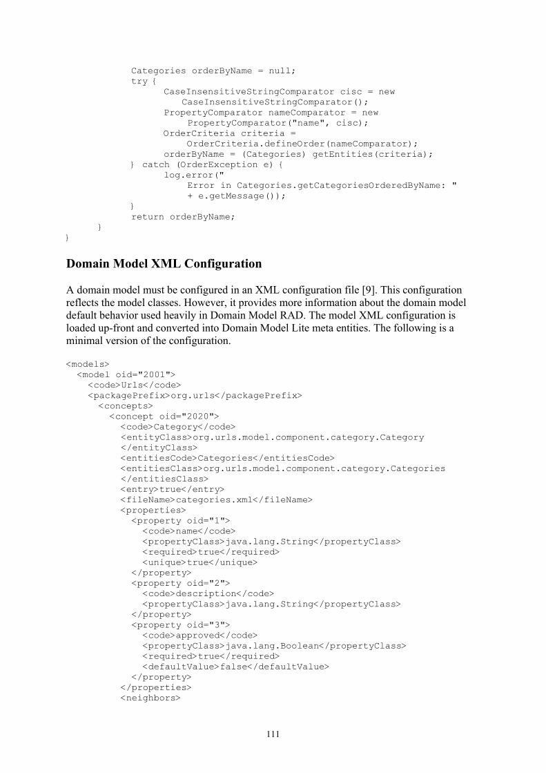
Categories orderByName = null;try {
CaseInsensitiveStringComparator cisc = new CaseInsensitiveStringComparator();
PropertyComparator nameComparator = new PropertyComparator("name", cisc);
OrderCriteria criteria = OrderCriteria.defineOrder(nameComparator);
orderByName = (Categories) getEntities(criteria);} catch (OrderException e) {
log.error(" Error in Categories.getCategoriesOrderedByName: " + e.getMessage());
}return orderByName;
}}
Domain Model XML Configuration
A domain model must be configured in an XML configuration file [9]. This configuration reflects the model classes. However, it provides more information about the domain model default behavior used heavily in Domain Model RAD. The model XML configuration is loaded up-front and converted into Domain Model Lite meta entities. The following is a minimal version of the configuration.
<models> <model oid="2001"> <code>Urls</code> <packagePrefix>org.urls</packagePrefix>
<concepts> <concept oid="2020"> <code>Category</code>
<entityClass>org.urls.model.component.category.Category </entityClass>
<entitiesCode>Categories</entitiesCode> <entitiesClass>org.urls.model.component.category.Categories
</entitiesClass> <entry>true</entry> <fileName>categories.xml</fileName> <properties> <property oid="1"> <code>name</code> <propertyClass>java.lang.String</propertyClass> <required>true</required> <unique>true</unique> </property> <property oid="2"> <code>description</code> <propertyClass>java.lang.String</propertyClass> </property> <property oid="3"> <code>approved</code> <propertyClass>java.lang.Boolean</propertyClass> <required>true</required> <defaultValue>false</defaultValue> </property> </properties> <neighbors>
111

<neighbor oid="1"> <code>urls</code> <destination>Url</destination> <internal>true</internal> <type>child</type> <min>0</min> <max>N</max> </neighbor> </neighbors> </concept> ...
</concepts> </model></models>
Web Applications
I have developed two different web applications for the same Urls domain model. The first web application uses Wicket for the application views [10]. The second web application uses Domain Model RAD for the application views [11]. Thanks to Domain Model RAD, only a small portion of the application is specific, which means that there is significantly less Java code in the second application.
Conclusion
I have developed a domain model framework, called Domain Model Lite, to provide an easy support for small domain models, which are usually used in rapid web development. Besides, I have also developed a web component framework, called Domain Model RAD, which makes it possible to produce quickly a web application based on the given domain model. With Domain Model Lite, a web application developer does not need to learn a complex framework, such as Hibernate, in order to create and save a domain model. With Domain Model RAD, a web application developer may create a small application quickly. For example, I have developed the Public Point Presentation web application in three spirals: ppp00 [12], ppp01, and ppp02 [13]. The ppp00 spiral has been created with almost no programming [14], while the ppp02 spiral has only a few specific classes.
Web Links
[1] http://java-source.net/open-source/web-frameworks[2] http://struts.apache.org/[3] http://wicketframework.org/[4] http://www.hibernate.org/[5] http://drdb.fsa.ulaval.ca/dm/[6] http://drdb.fsa.ulaval.ca/urls/[7] http://www.dsmforum.org/[8] http://drdb.fsa.ulaval.ca/mmLite/[9] http://drdb.fsa.ulaval.ca/dm07/web/config/specific-model-config.xml[10] http://drdb.fsa.ulaval.ca/urls08/code.html[11] http://drdb.fsa.ulaval.ca/dm07/code.html[12] http://drdb.fsa.ulaval.ca/ppp00/[13] http://drdb.fsa.ulaval.ca/ppp02/[14] http://drdb.fsa.ulaval.ca/ppp00/code.html
112

Generative Programming for a Component-based Framework of Distributed Embedded Systems
Xu Ke, Krzysztof Sierszecki
Mads Clausen Institute for Product Innovation, University of Southern Denmark Grundtvigs Alle 150, 6400 Soenderborg, Denmark
{xuke, ksi}@mci.sdu.dk
Abstract. COMDES-II is a component-based software framework which formally specifies the modeling concepts and constraints for distributed embedded systems in different aspects, such as component structures, interaction, hierarchy, etc. The paper presents an overview of the design philosophies of COMDES-II in the related aspects and a generative programming approach developed to enable the engineering applicability of the framework. The dedicated generative programming approach involves the formal definition of COMDES-II modeling language by means of meta-models which are instrumented by a meta-modeling tool – Generic Modeling Environment (GME), and the development of a specific code generation technique using CodeWorker tool to implement the automatic synthesis of system codes from system models.
1 Introduction
Complexity of software in embedded applications is continuously increasing, this situation is caused – primarily – by growing computational power of general-purpose microprocessors, which eliminates the need for special dedicated hardware solutions and therefore moves the emphasis from hardware to software design. An embedded software system is characterized by its tight interaction with the physical environment, restricted running resources (e.g. RAM, CPU, etc.), robust and strictly safe execution under hard real-time constraints [1]. These domain-specific features mandate the investigation of proper domain-specific modeling (DSM) techniques for various application domains of embedded systems, whereby the modeling concepts and abstraction rules of software that are provided in the solution space should accommodate the critical aspects in the problem space, such as system concurrency, environmental physicality, time, etc.
Component-based design (CBD) can be regarded as one of the most suitable design paradigms (if not the most suitable) for domain-specific modeling methodology. Due to the great profits brought by reusability of components, higher level of system abstraction (modeling systems rather than programming systems), an embedded software system can be efficiently and intuitively constructed from the prefabricated and reusable components. Moreover, from a software engineering point of view, CBD is an effective way to bridge the gap between the conceptual system design models and the concrete system implementation [2], provided that a proper generative programming approach is developed.
Generative programming is a software engineering methodology that automates the generation of system implementations from higher level abstractions represented as textual or graphical models [3]. In this context, meta-modeling and model-driven development (MDD) techniques provide great advantages for modeling domain-specific software systems at higher abstraction level, and on the other side, code generation and model transformation are the general approaches adopted to implement the automatic synthesis facilities for systems.
This paper intends to present such a generative programming method for a domain-specific, component-based software framework aiming at the development of distributed
113

embedded systems – COMDES-II (Component-based Design of Distributed Embedded Systems, version II) [4]. The focus is placed on the design philosophy and the meta-modeling approach of framework components in the component design aspect, and the code generation technique related to the component implementation aspect (as shown in Fig. 1).
The meta-models of COMDES-II components are represented as the special UML class diagrams provided by the meta-modeling tool GME (Generic Modeling Environment) [5, 11], a configurable toolkit that supports the creation of domain-specific modeling and program synthesis environments. The constraint language OCL (Object Constraint Language, a subset of UML 2.0) is also supported in GME, which can be used to help specify the complex static semantics of component models in COMDES-II.
For the development of code generation technique, the CodeWorker [12] tool is employed. CodeWorker is a versatile parsing tool and a universal generator, which provides a scripting language adapted both to the description of any input format and to the writing of any generation templates [6]. COMDES-II models are parsed by an extended-BNF script to create a parse tree, which is subsequently processed by template-based scripts that drive the code generation. The generated code and the reusable component execution algorithms are finally composed into the executable code by means of the GNU Compiler Collection (GCC) [13].
This engineering approach involving the graphical modeling of COMDES-II components and the automatic synthesis of component codes can be conceptually illustrated as in Fig. 1.
Fig. 1. The generative programming approach for COMDES-II components
Firstly, a component is designed in its application domain, at relatively high level, e.g. a controller of control system in MATLAB/Simulink [14]. Next, the domain component model that satisfies application requirements can be transformed into the COMDES-II framework model, e.g. by automatic mapping from Simulink components to COMDES-II components. The transformed framework components may have some supplementary information which will guide the implementation generation. Ultimately, the synthesized code can be deployed into embedded devices and tested against real environment.
The paper is organized as follows: Section 2 gives a brief introduction about the design philosophies of COMDES-II. Section 3 presents the meta-level definitions of COMDES-II components through an example. Section 4 describes the code generation technique developed under CodeWorker tool to automatically synthesize the framework code from the corresponding component models, and the concluding section summarizes this engineering approach for COMDES-II framework, discusses the related research and future work.
2 The COMDES-II Framework
COMDES-II is a component-based framework with its focus on the distributed control systems, as a result the framework places its root in the control engineering domain and
Software Design
Design of componentmodels in COMDES II
Implementation
Automatic synthesis offramework components
Do
mai
n D
esig
n
models
Dep
loym
ent
Meta-models andconstraints in GME
Framework templates in CodeWorkerExecutable component algorithms in GCC
114

borrows a number of software concepts that are popular in this domain, such as function blocks, state machines, etc. [7].
COMDES-II provides specific modeling techniques in the solution space by emphasizing two significant aspects of an embedded software system: 1) the openness and hierarchy of system architecture, and 2) predictable and deterministic system behaviour, by taking the following problem space issues into account:
� Component structures, interaction and hierarchy � System architecture, concurrency � Environmental physicality (e.g. external events etc.) and time
The framework employs a two-level architectural model to specify the system architecture:
at the first level (system level) an embedded application is conceived as a composition of actors (active components) that exchange signals asynchronously through a content-oriented, producer-consumer model of communication. An example of the system developed under COMDES-II for Production Cell Case Study [8] is shown in Fig. 2.
Fig. 2. Actors interaction in COMDES-II
At the second level (actor level), an actor contains multiple I/O drivers and a single actor task (execution thread). I/O drivers are classified as communication drivers and physical drivers, which are associated with the actor task by the dataflow connection relationship. As an example, the internal structure of feed belt actor shown in Fig. 2 is illustrated as in Fig 3.
Fig. 3. Internal structure of the feed belt actor The I/O drivers of an actor are assumed to be short pieces of code executed atomically
(zero time) at precisely specified time instants referred to as execution triggering instant and deadline instant respectively, hence the execution triggering instant of an actor is also the
RAr arm
RArmA
sta FBe
FBelt
FBS raw
FBSensor
RPoarmarm
RPosition
armarmraw
stasta
control_task
statearmAstate
raw_value
armAposition
feed belt
input communication driver
actor task local signal input physical driver output communication driver
depositbelt
feed belt
pressrobotRSwitchA
RRotation
RMotor
RMotorA
RMotorB
FBelt
RArmBPress
Press
FBelt
DBelt
DBelt
RSwitchB
DBSensor
DBMotor
PLamp
FBMotor
FBSensor
PSensor
RArmARPosition
RArmB
RArmARPosition
RArmARPosition
RArmBRPosition
LCDRCX1
ButtonsRCX1
ButtonsRCX2
envi
ronm
ent environm
ent
actor
115

control_task
inpinp
bri
light_sensor
EOpen
armarmbri
stasta
FB_control_SM
inpinp
arm
armA_state
ECovered
EFB state_updated
raw_value
armAstate
state
armAposition inpinp
arm
armA_position
input
constant
function block instance
output
releasing instant of the actor task. The actor tasks and I/O drivers are scheduled by the real-time kernel HARTEXTM
1 [9], which employs a preemptive priority-based timed multitasking (TM) technique [10]. TM guarantees the execution time of an actor is constant – nevertheless the actor task may be preempted by higher priority tasks in arbitrary times – as long as the task finishes execution before its deadline. This execution pattern of actor tasks is referred to as split-phase execution and illustrated by the diagram shown in Fig. 4.
Fig. 4. Split-phase execution of actor tasks under timed multitasking An actor task can be hierarchically composed from an aggregation of different function
block instances (passive components). Function block (FB) instances are instantiations of reusable FB types, which can be categorized into four FB kinds (meta-types) - basic, composite, modal as well as state machine FBs. A basic FB contains attributes, operations and associations that are common to all kinds of FBs, such as inputs, outputs, parameters, etc. Hence the definition of basic FBs is a root class which can be extended to define the other kinds of FBs. A more detailed description of each kind of FBs is referred to [4]. And as an example, the FB instances contained in the feed belt actor task (named control_task) are shown as in Fig. 5.
Fig. 5. Internal structure of the feed belt actor task The concrete operation dynamics of this actor and its constituents will not be explained
here since they are irrelevant to the focus of discussion, and we hope the diagram is intuitive enough to demonstrate the architectural and hierarchical features of COMDES-II framework.
1 HARTEXTM is a hard real-time kernel developed by Software Engineering Group, Mads Clausen Institute for Product
Innovation, University of Southern Denmark (SEG, MCI/SDU).
116

A FB type is a software component with an execution record containing its attributes and a set of operations defining its possible behaviour. A generic component model for all kinds of COMDES-II FBs is conceptually illustrated as in Fig. 6.
Fig. 6. Component model for COMDES-II FBs The execution record is actually the FB interface containing the information like input
pointers, parameters, internal variables and output buffers of a specific type of FB. FB execution record can be instantiated as well as reconfigured for the related FB instances of a given type. The operations are reentrant and relocatable functions performing some kinds of algorithms on an execution record, by accepting a pointer as the argument referring to the corresponding execution record of a specific FB instance.
In COMDES-II, the interface of a specific FB type can be automatically synthesized into the C files from the corresponding FB graphical design model. The operations of a given type of FB are predefined algorithms and implemented as C routines. The prefabricated operation and interface files of FB definitions are stored in the FB repository, in which the operation files are delivered as executable routines, e.g. as object files (.obj files).
3 Meta-level Definitions of COMDES-II Components
The description of COMDES-II framework presented in the previous sections is informal, which is helpful to intuitively understand this DSM framework though, it is yet insufficient to implement a DSM language that is compliant with the framework rules and constraints. A DSM language of COMDES-II enables the modeling of components and application systems under the framework, and in order to develop such a language, the meta-models formally describing the syntax and static semantics of the targeting domain modeling language should be defined with a consideration of various problem space issues (e.g. hierarchy, time etc.). Generally speaking, the formalization of modeling languages to be the corresponding meta-models is a recursive process which can be conceptually presented as in Fig. 7.
Meta-modeling COMDES-II framework involves the formal specification of following abstractions in different aspects:
• Meta-modeling HARTEXTM kernel and actors to accommodate the physicality (handling
external interrupts), actor task concurrency (primitive priority-based scheduling), actor interaction (actor communication, actor synchronization etc.) and timing aspects (timed multitasking).
• Meta-modeling various kinds of function blocks in terms of function block structures, function block interaction and hierarchy (e.g. a model function block can contain other function block instances).
• Integrating the meta-model of HARTEXTM kernel and actors with the function block meta-models to accommodate the architectural aspect of the framework.
Function Block
-input pointers -parameters -internal variables -output buffers
+init() +run() +stop()
Execution record
Relocatable operations
117

Fig. 7. General meta-modeling process
In order to better understand the above meta-modeling approach, an example for formalizing the models of state machine FBs (SMFBs) is given. A SMFB in COMDES-II employs a dialect of the finite state machine model with event-driven semantics to specify the sequential behavior of a system. The graphical representation of FB_control_SM function block instance in Fig. 5 is presented as in Fig. 8.
Fig. 8. FB_control_SM function block instance
This function block instance contains three inputs and two outputs, which are the common elements that all kinds of function blocks have and therefore are inherited from the basic function block definition. Additionally, an event-driven state machine model specifying the sequential behavior of the host actor is also integrated. The state machine model includes a dummy initial state pointing to the actual initial state of the machine, a graphical label with the name history meaning that the state machine is historic, a number of states as well as state transitions which are labeled by events, guards and transition orders. Transition order is a number indicating the importance of the transition, i.e. which transition should be fired when multiple transition triggers associated with the current state are evaluated as true (transitions are evaluated starting from 1).
FB_control_SM
armA_open
armA_over_FB
state_updated
state
brick_ready
operation
initialState
unloaded
error
unloading
ready
moving
history
1
[!armA_over_FB | !brick_ready]
1[]
2
[!armA_over_FB | !brick_ready]
1[armA_over_FB & !armA_open]
1 [brick_ready]
2[armA_over_FB & !armA_open]
1
[armA_over_FB & armA_open]
1
[!armA_over_FB | !brick_ready]
2 [!armA_over_FB & brick_ready]
118

The above informal abstractions of the state machine function block can be formalized by a meta-model as illustrated in Fig. 9.
Fig. 9. Meta-model of state machine function blocks
In addition to the meta-model defined as a class diagram, some extra constraints specifying
the static semantics for the state machine model are also defined in OCL, which are summarized as in Table.1. The meta-model in form of class diagram together with the constraints expressed in OCL provide a complete formal definition for the corresponding kind of function block.
Table 1. Example of constraints in OCL
Syntactic Constraint OCL Expressions Applying
Object Checking on
Event
The state machine is reactive.
self.models("State")->forAll(s | s.connectedFCOs("dst")->size >= 1) StateMachine_FB CLOSE_MODEL
The state machine is deterministic.
self.connectionPoint("src").target().attachingConnections("src","transition")->select(c : transition | c.event = self.event and c.guard = self.guard)->size = 1
transition CONNECT
All states are reachable
self.models("State")->forAll(s | s.connectedFCOs("src")->size >= 1) StateMachine_FB CLOSE_MODEL
4 Code Generation Technique of COMDES-II Framework
Implementation of COMDES-II system is achieved in two stages: firstly, CodeWorker generates source code files from GME models; secondly, GCC composes the generated source files with prefabricated codes into the final executable implementation. Execution of the first stage is controlled by an application written in Java accessing CodeWorker functionality via its Java interface, whereas the second stage is conducted by the Makefile generated in first stage.
COMDES-II implementation is built, or configured from predefined and reusable components stored in a repository. For each application component instance a data structure
transition<<Connection>>
guard : fieldorder : fieldevent : field
StateMachine_FB<<Model>>
historySM : bool
history<<Atom>>
State<<Model>>
initialState<<Atom>>
BasicFB_Proxy<<ModelProxy>>
src1
0..1
dst 1
0..*
0..* dst0..*
0..1
src0..*
119

(FB execution record) is generated, whereas the accompanying component algorithms (FB operations) are prefabricated in advance. In this way, during application synthesis no component executable code is generated.
In order to match the limited resources of embedded systems, COMDES-II framework is implemented in C language, which could be seen to some extent as a portable source code as long as the GCC tool chain is employed. Because some parts of the C code (e.g. FB operations) are only CPU architecture dependant and are compiled into an executable object codes for a particular CPU architectures, e.g. avr5 – ATmega128. Some parts, as usual, are dedicated to a particular hardware platform (e.g. hardware I/O drivers) and are written by an expert once (Fig. 10). In this way, portability and native platform performance is achieved rather easily, assuming existence of GCC tool chain for the platform of interest.
Fig. 10. Portability of COMDES-II system
An overview of the generation process is given in Fig. 11, with three different scenarios:
• Application synthesis (green, solid line) – models, which provide all necessary information, drive the configuration of an application.
• Component generation (blue, dashed line) – component execution record is generated, and then supplemented with the algorithms written by software expert. Final implementation is stored in a repository of reusable components in a form of executable object file.
• Reconfiguration (red, dotted line) – rather than generating the reconfigured application as a whole, only the updated part is created, which provides for faster application modification.
Fig. 11. Automatic synthesis of COMDES-II system
XMLGME .xme model
C sourcegenerated
coded by expert
elffinal code
object codecpu dependent
object codeplatform dependent
models parser parse tree generator
C source files
compilerlinkerfinal code or update
component instances
repository - component algorithms
linker script
pres
s a
butto
n
BNF scriptstemplate scripts
tree manipu-
lationC
odeW
orke
r Le
vel
GC
C L
evel
link map Makefile
application synthesis
component generation
re-configuration
120

5 Conclusion
COMDES-II is a component-based framework aiming at the software development in the domain of distributed embedded systems. The framework provides the modeling methods for domain-specific features of an embedded system in different aspects, including component structures and interaction, system concurrency and functionality under the hard real-time constraints, etc. The provided design methods in these aspects enable COMDES-II a framework accommodating both the open system architecture as well as the predictable and deterministic system behaviour.
In the paper a generative programming approach for COMDES-II has been presented, which involves the meta-modeling of framework modeling language and the development a dedicated code generation technique. A complete formal definition of the COMDES-II components carried out in GME consists of a meta-model specified as a class diagram and a set of constraints expressed in OCL, which is exemplified in the paper with a concrete state machine function block instance. Automatic synthesis of application implementation is a process consisting of parsing of models and generating source files in CodeWorker, next, compiling and linking of all codes in GCC. Ultimate result is the configuration of applications from reusable and reconfigurable components.
Throughout the development of the generative approach we follow a motto: let the best tool do the job, the tool that is designed for the job. And therefore we adopt: GME – rapid development of DSM editor prototypes, CodeWorker – generation of any output and GCC – compiling and linking of codes. There are also other options of tools which can be used to develop the graphical DSM editor, for instance, Eclipse EMF/GMF/GEF frameworks [16], or MetaCASE MetaEdit+ [15].
Eclipse EMF/GMF/GEF frameworks provide an excellent model-driven approach for creating domain-specific models from their meta-models, and allow developers to establish a very flexible graphical environment for editing the models, however, developing such a graphical editor is really a labor-intensive task. MetaEdit+ is a commercial meta-modeling product developed by MetaCASE, which offers a Symbol Editor that facilitates the customization of model visual effects and a promising code generation tool for easy automatic synthesis and documentation. However, the meta-modeling process in MetaEdit+ is not as straightforward as that in GME or Eclipse EMF, and moreover, only the cardinality constraints of relationships are supported in MetaEdit+, whereas the Object Constraint Language (OCL) is not implemented. GME enables a powerful meta-modeling capability by providing a number of unique meta-modeling concepts, such as sets, references and aspects etc., additionally the OCL language is fully implemented. Automatic synthesis of program is also possible in GME through user-defined plug-ins and Builder Object Network (BON) API. A deficiency of GME is that the graphical representation of models can not be dynamically changed, due to its fixed Model-View-Controller architecture.
The presented software framework has been experimentally validated through two case studies: the Production Cell Case Study [16] and the Steam Boiler Control Specification Problem [17]. The envisioned future work includes the development of a graphical editing toolset in Eclipse, and the meta-model as well as model transformations from GME to the developed graphical environment. Such transformations can be realized by using dedicated model transformation languages, just like GReAT – Graph Rewriting And Transformation language – for model transformations in GME [19].
121

References
1. Lee, E. A.: Embedded Software. Advances in Computers, Vol.56. Academic Press, London (2002)
2. Reekie, J., and Lee, E. A.: Lightweight Component Models for Embedded Systems. Technical Memorandum UCB/ERL M02/30, University of California, Berkeley, CA 94720, USA, October (2002)
3. Czarnecki, K., and Eisenecker, U. W.: Generative Programming: Methods, Tools, and Applications. Addison-Wesley Professional. 1st edition, June (2000)
4. Angelov, C., Xu Ke, and Sierszecki, K.: A Component-Based Framework for Distributed Control Systems, to be presented to the 32nd Euromicro Conference on Software Engineering and Advanced Applications (SEAA 2006), Cavtat-Dubrovnik, Croatia, August (2006)
5. Ledeczi, A., Maroti, M., and Bakay, A. et al.: The Generic Modeling Environment. Workshop on Intelligent Signal Processing, Budapest, Hungary, May (2001)
6. Lemaire, C.: CODEWORKER Parsing tool and Code generator. User’s guide & Reference manual, Release 4.2, May (2006)
7. Lewis, R.: Modeling Control Systems Using IEC 61499. Institution of Electrical Engineers, (2001)
8. Maraninchi, F., and Remond, Y.: Applying Formal Methods to Industrial Cases: the Language Approach (The Production-Cell and Mode-Automata). Proc. of the 5th International Workshop on Formal Methods for Industrial Critical Systems, Berlin (2000)
9. Angelov, C., Berthing, J., and Sierszecki, K.: A Jitter-Free Operational Environment for Dependable Embedded Systems. In A. Rettberg et al. (Eds.): From Specification to Embedded Systems Application. Springer, (2005) 277-288
10. Liu, J., and Lee, E.A.: Timed Multitasking for Real-Time Embedded Software. IEEE Control Systems Magazine: Advances in Software Enabled Control, Feb. 2003 65-75
11. GME: http://www.isis.vanderbilt.edu/projects/gme/ 12. CodeWorker: a parsing tool and a source code generator: http://codeworker.free.fr/ 13. GCC, the GNU Compiler Collection: http://gcc.gnu.org/ 14. MATLAB and Simulink for Technical Computing: http://www.mathworks.com/ 15. MetaCase - Domain-Specific Modeling with MetaEdit+: http://www.metacase.com/ 16. The Eclipse Graphical Modeling Framework: http://www.eclipse.org/gmf/ 17. F. Maraninchi and Y. Remond: Applying Formal Methods to Industrial Cases: the Language
Approach (The Production-Cell and Mode-Automata). Proc. of the 5th International Workshop on Formal Methods for Industrial Critical Systems, Berlin, 2000
18. J.-R. Abrial: Steam Boiler Control Specification Problem. http://www.informatik.uni-kiel.de/~procos/dag9523/dag9523.html
19. G. Karsai, A. Agrawal, F. Shi, J. Sprinkle: On the Use of Graph, Transformation in the Formal Specification of Model Interpreters. Journal of Universal Computer Science, Special issue on Formal Specification of CBS, 2003
122

Techniques for Metamodel Composition
Matthew Emerson and Janos SztipanovitsInstitute for Software Integrated Systems
Vanderbilt [email protected]
October 1 2006
Abstract
The process of specifying an embedded system involves capturing com-plex interrelationships between the hardware domain, the software domain,and the engineering domain used to describe the environment in which thesystem will be embedded. Developers increasingly turn to domain-specificmodeling techniques to manage this complexity, through such approachesas Model Integrated Computing and Model Driven Architecture. However,the specification of domain-specific modeling language syntax and seman-tics remains more of an art than a science. Typically, the syntax of a DSMLis captured using a metamodel; however, there are few best-practices formetamodeling and no public collection of reusable metamodel b to addresscommon language specification requirements. There is a need for an ad-vanced, comprehensive language design environment that offers tool sup-port for a wide range of metamodel reuse strategies and the preservation ofmetamodeling best-practices. We outline existing techniques for the reuseand composition of metamodels, and propose a new metamodel compositiontechnique we call Template Instantiation.
1 IntroductionIn its current state, the definition of new domain-specific modeling languages viametamodeling is more of an art than a science. Metamodeling best practices arenot well understood or documented. Most DSMLs are built completely fromscratch, using only the metamodeler’s personal experience in language definitionto guide the process. Consequently, we see a need for libraries of reusable meta-model fragments or patterns to serve as DSML building-blocks. Metamodel reuse
123

will bring to the realm of DSML specification benefits analogous to those thatsoftware reuse brought to the realm of software engineering:
• The avoidance of duplication of effort
• The emergence of high-quality reusable metamodel fragments
• The recognition of key metamodeling patterns and best practices
• A significant reduction in the time-to-market for new DSMLs
The cornerstone for metamodel reuse is tool support for a variety of meta-model composition techniques.
We envision a unified, comprehensive modeling language design environmentwhich provides direct support for every language design task. The full scope oflanguage design extends far beyond abstract syntax specification through meta-modeling. Especially for embedded systems modeling, there is a strong needfor domain-specific modeling languages with unambiguous semantics and built-in analysis capabilities. Consequently, a comprehensive language design environ-ment will also fully support the specification of formal structural and behavioralsemantics, semantic mappings, property-preserving model transformations, andlinks to external formal analysis tools. Wherever possible this environment shouldease the language design process by enabling at least partial automatic generationor composition for each of the aforementioned elements. Strong support for thereuse of syntactic metamodel fragments and patterns will greatly help in this ef-fort, because each composable metamodel fragment can have associated structuralsemantics, semantic mappings, and model transformations that can also be com-posed and reused. Of course, reusable syntactic pattners will also help languagedesigners rapidly construct new languages including time-tested, quality model-ing styles and patterns of expression.
The Model Integrated Computing toolsuite [9] includes tools that can be usedto address the capabilities mentioned above. The Generic Modeling Environment(GME) includes a metamodeling environment for the specification of DSML ab-stract syntax, and also has some support for the composition and reuse of meta-models [3]. The Graph Rewriting And Transformation tool (GReAT) is used tobuild model transformers [2]. The current MIC solution for the formal speci-fication of DSML behavioral semantics is called Semantic Anchoring [10][11].Semantic Anchoring mandates the use of GME for defining language syntax byformal metamodels, GReAT for creating semantic mappings using formal modeltransformations, formal models of computation represented as Semantic Units forcapturing behavioral semantics, and the formal Abstract State Machine [6] frame-work for expressing and executing the formal semantics specifications built using
124

the Semantic Units. Recent research advocates the use of Horne Logic to specifyDSML structural semantics, and describes the 4ml toolsuite for the generation andanalysis of structural semantics from GME metamodels [7][1].
This paper focuses on the reuse of DSML syntax via metamodel composi-tion. In Section 2 we review existing metamodel composition techniques, each ofwhich should be supported in a comprehensive language design tool. In Section 3we propose a new metamodel composition technique we call Template Instantia-tion. We also include a proof-of-concept demonstration of this technique using ametamodeling template instantiation tool built for use with GME. In Section 4 wediscuss some ideas for future investigation regarding the relationship between thereuse of metamodels and the reuse of semantic specifications.
2 Current Metamodel Composition MethodsIn this section, we describe three general techniques for metamodel compositionand discuss when each may be best applied. We also provide illustrative exam-ples of the different techniques using primarily the GME metamodeling language,MetaGME [4].
2.1 Metamodel MergeA metamodel may be thought of as a namespace for a set of modeling constructs.When composing two modeling languages together, name collisions between thetwo composed metamodels need to be dealt with in an intelligent way. Typically,name collisions between the elements of two metamodels implies that the domainsof those modeling languages intersect in some way; however, this “concept col-lision” may occur even between modeling constructs with different names. Anytime two DSMLs include modeling constructs that capture a shared set of real-world entities, those concepts can be used as “join points” to stitch the two lan-guages together into a unified whole. We refer to this metamodel compositiontechnique as Metamodel Merge.
MOF 2.0, the OMG standardized metamodeling language [8], dictates an algo-rithm for merging metamodels that fuses together the meta-objects with the samename and metatype from each metamodel. MOF terms this operation a PackageMerge because it operates at the Package level and recursively impacts all of theelements contained within the merging packages. The new metamodel resultingfrom a MOF Package Merge maintains no dependency relationships, such as in-heritance, importation, redefinition, or type conformance, with the metamodelsmerged to create it – each element belonging to the new metamodel is newly-created according to the Package Merge algorithm. The MOF specification pro-
125

vides specific rules for merging each of the different MOF metatypes, which wewill not review in depth here. However, Package Merge can be generally under-stood as a recursive unioning of model elements matched by name and metatype.
MetaGME enables Metamodel Merge through the use of three types of classinheritance and a special Class Equivalence operator. Class Equivalence is usedto show a full union between two classes. The unioned classes cease to existas distinct metamodel elements, instead fusing into a single class. This unionencompasses all the attributes and associations, including generalization, special-ization, and containment, of each of the fused classes. The union process is verysimilar to merging classes through MOF Package Merge, except that the opera-tion takes place at the class level instead of the package (or metamodel) level, thetwo merged classes do not need to have the same name, and the use of the ClassEquivalence operator does not produce a new derivative metamodel.
It is possible simply to use inheritance as a weaker mechanism for merg-ing metamodels - the “is-a-kind-of” specialization relationship is similar to, butweaker than, the “is-equivalent-to” Class Equivalence relationship. In addition tothe regular notion of class inheritance supported in both MetaGME and MOF 2.0,MetaGME also defines two special inheritance operators, implementation inheri-tance and interface inheritance. In implementation inheritance, the child inheritsall of the parent’s attributes, but only the containment associations where the par-ent functions as the container. No other associations are inherited. Interface inher-itance allows no attribute inheritance but does allow full association inheritance,with one exception: containment associations where the parent functions as thecontainer are not inherited.
Figures 1-3 provide an example of the metamodel merge with MetaGME. Fig-ure 1 shows part of a DMSL for modeling the properties of software componentsand their deployment onto abstracted hardware components for execution, andFigure 2 shows part of a DSML for modeling the details of hardware components.It might make sense to merge these two DSMLs and get a combined languagethat can capture details about both the hardware and the software of a particularsystem. In Figure 3, the Class Equivalence operator (the hollow diamond) is usedto fuse the top-level concepts from each language dealing with hardware. Thenew class resulting from this fusion will have a new name (specified on the ClassEquivalence object) and include the SecurityEnclave attribute from the Process-ingModule class.
2.2 Metamodel InterfacingThe metamodels of two DSMLs capturing two conceptually distinct but relateddomains may be composed to explore the interactions between the two domains.Performing this composition requires the delineation of an interface between the
126

Figure 1: Software deployment metamodel fragment
two modeling languages consisting of new modeling entities and relationships thatdo not strictly belong to either of the composed modeling languages.
For an example use case, imagine that we had a language for modeling sys-tem requirements and a separate language for modeling hardware and software.It would be useful to interface these two languages to enable the traceability ofrequirements to the hardware and software components that satisfy them. Figure4 below displays the additional metamodel fragment needed to interface the twoDSMLs. In this figure, Requirement originates from one metamodel while Hard-wareComponent and SoftwareComponent originate from a second metamodel.The interface between the two metamodels when composed consists of a newmodel view, TraceModel, which can contain references to Requirements, Soft-wareComponents, and HardwareComponents. A new type of connection, Re-quirementTrace, is also defined to relate the requirements to the components thatsatisfy them.
2.3 Class RefinementClass refinement may be utilized when one DSML captures in detail a modelingconcept that exists only as a “black box” in a second DSML. This technique isemployed similarly to metamodel interfacing, but the relationship between thetwo composed modeling languages is given by the hierarchical containment ofthe constructs of one metamodel within a single construct of another metamodel.
For example, consider a simple DSML for modeling the topologies of elec-tronic components of automobiles as depicted in Figure 5. Eventually, the detailsor behaviors of the components may need to be elaborated, so it may become nec-essary to further refine the Component language construct. Suppose we want toview the automobile model as a system of concurrent communicating finite statemachines. In that case, we would need to refine the Component model using theconstructs from the FSM metamodel shown in Figure 6. The composition of the
127

Figure 2: Hardware component metamodel fragment
128

Figure 3: Class merge
two metamodels is shown in Figure 7.
3 Template Instantiation: A New Metamodel Com-position Method
Template Instantiation is a new metamodel composition technique we propose toovercome a limitation of the previously-discussed techniques. It is intended tosupport the multiple reuse of common metamodeling patterns or styles in a sin-gle composite metamodel. In Template Instantiation, we record common meta-modeling patterns as abstract metamodel templates, then instantiate (replicate andconcretize) those templates in domain-specific metamodels. Our previous expe-rience with the definition of modeling languages has resulted in the discovery ofa number of commonly-occuring metamodeling patterns. These candidate meta-modeling templates include (but certainly are not limited to):
• Composition hierarchies of composite and atomic objects
• Modular interconnection, in which composite objects are associated throughexposed ports (a specific incarnation of this pattern would be component-based modeling)
• StateCharts-style modeling
• Data Flow graphs
• The proxy metamodeling pattern, in which a reference type is defined foran class with the same attributes, composition roles, and associations as theclass itself
Each of the above patterns repeatedly occur in new DSML specifications, andsome may potentially be used multiple times in the same metamodel, so they aregood candidates for metamodeling templates.
The previously-discussed metamodel composition techniques are not suitedtoward the multiple reuse of metamodel fragments within the same composite
129

Figure 4: Metamodel Interfacing
130

Figure 5: Automobile electronic component metamodel
Figure 6: FSM metamodel for capturing component behavior
Figure 7: Automobile electronic component refinement
131

metamodel. To demonstrate this limitation, we can consider a simple example:using Metamodel Merge to incorporate hierarchy into the metamodel shown inFigure 8. This metamodel captures a Data Flow language where the internal be-havior of the Data Flow Actors is captured using FSMs. Now, suppose we wantto be able to define hierarchical Actors that contain whole Data Flow graphs, andwe want the FSMs in this language to be hierarchical as well. We will attemptto do this by merging in the abstract Hierarchy metamodel depicted in Figure 9.The composition using Metamodel Merge (inheritance, in this case) is shown inFigure 10.
Figure 8: Metamodel for Data Flow with embedded FSM
132

Figure 9: Hierarchy metamodel fragment
Unfortunately, in the metamodel resulting from the merge the composition hashad an undesired side-effect: according to Figure 10, FSM States can contain DataFlow Actors! In fact, any time Metamodel Merge is used to merge in the samemetamodel in multiple places, as was done in this simple example with the Hierar-chy metamodel, these kinds of unintended consequences can occur. Furthermore,neither Metamodel Interfacing nor Class Refinement may be usefully applied inthis example. What we really need is a way to make use of the hierarchy patternwithout explicitly and repeatedly importing a metamodel that captures hierarchy.We need a templated approach.
Unlike the other metamodel composition techniques discussed here, TemplateInstantiation does not operate by importing an external set of entity types intoa target metamodel. Instead, it automatically creates new relationships betweenthe pre-existing entity types in a target metamodel to make them play roles in acommon metamodeling pattern. Tool support is key for Template Instantiation.We outline the following process for using this metamodel composition method:
1. The user indicates that they would like to instantiate a particular templatewithin a domain-specific metamodel.
2. A Template Instantiator tool looks up the appropriate template. The tem-plate is actually an abstract metamodel fragment specifying a set of roles(the classes) and relationships between the roles.
3. The Template Instantiator queries the user to determine which class in theuser’s metamodel should play each role proscribed by the selected template.If the user’s metamodel contains no class suitable for playing a given rolefrom the template, they may select “None”.
4. The Template Instantiator updates the user’s metamodel with the instanti-ated template by constructing new relationships between the classes in the
133

Figure 10: Adding in hierarchy using Metamodel Merge
134

user’s metamodel. The unbound template roles (those for which the userselected “None” in step 3 above) are also included as new classes withplace-holder names indicating the role to be played. It is up to the userto edit these newly-added classes as appropriate for the language’s intendeddomain.
We have implemented a simple prototype Template Instantiator tool for GME.For our tool, metamodeling patterns can be captured as templates using the stan-dard GME metamodeling language. Each pattern should be captured in a separatemodeling project. Our Template Instantiator guides users through the selection ofthe template to be used and the assignment of template roles to domain-specificlanguage concepts, then automatically edits the user’s domain-specific metamodelas appropriate to instantiate the template. Our prototype may be downloaded from[13] for experimentation.
Let’s try applying Template Instantiation for our hierarchy example above us-ing the GME Template Instantiator. We need to run the Template Instantiator twotimes, once for the FSM part of the language and once for the Data Flow part of thelanguage. In the first run of the Instantiator, the user selects class StateType to playthe roll of CompositeType Lib, the class State to play the role of Compound Lib,and leaves the Primitive Lib role unbound. In the second run of the Instantiator,the user selects the ActorType class to play the role of CompositeType Lib, theActor class to play the role of Compound Lib, and again leaves the Primitive Librole unbound. This results in the metamodel depicted in Figure 11. To finishout the metamodel, the user merely needs to replace the place-holder classes,ActorType Primitive and StateType Primitive, with appropriate domain-specificclasses. The final result does not have the unanticipated side-effects caused byusing the Metamodel Merge technique, and merges in the hierarchy capability inthe way the user intended. Furthermore, by employing a template, the user hastaken advantage of the experience and best-practices knowledge of the metamod-eler who made the template.
4 Related WorkA foundational metamodeling paper by Brinkkemper [5] describes most of the thebasic issues of modeling language composition (or in Brinkkemper’s terminology,method engineering) that we review. Brinkkemper considers the composition ofboth abstract syntax and static semantics (well-formedness rules). However, hisdefinition of metamodel composition is not expansive enough to include MOF’sPackage Merge technique or our Template Instantiation technique.
Other previous work by Zhang [14] developed a generic framework of model
135
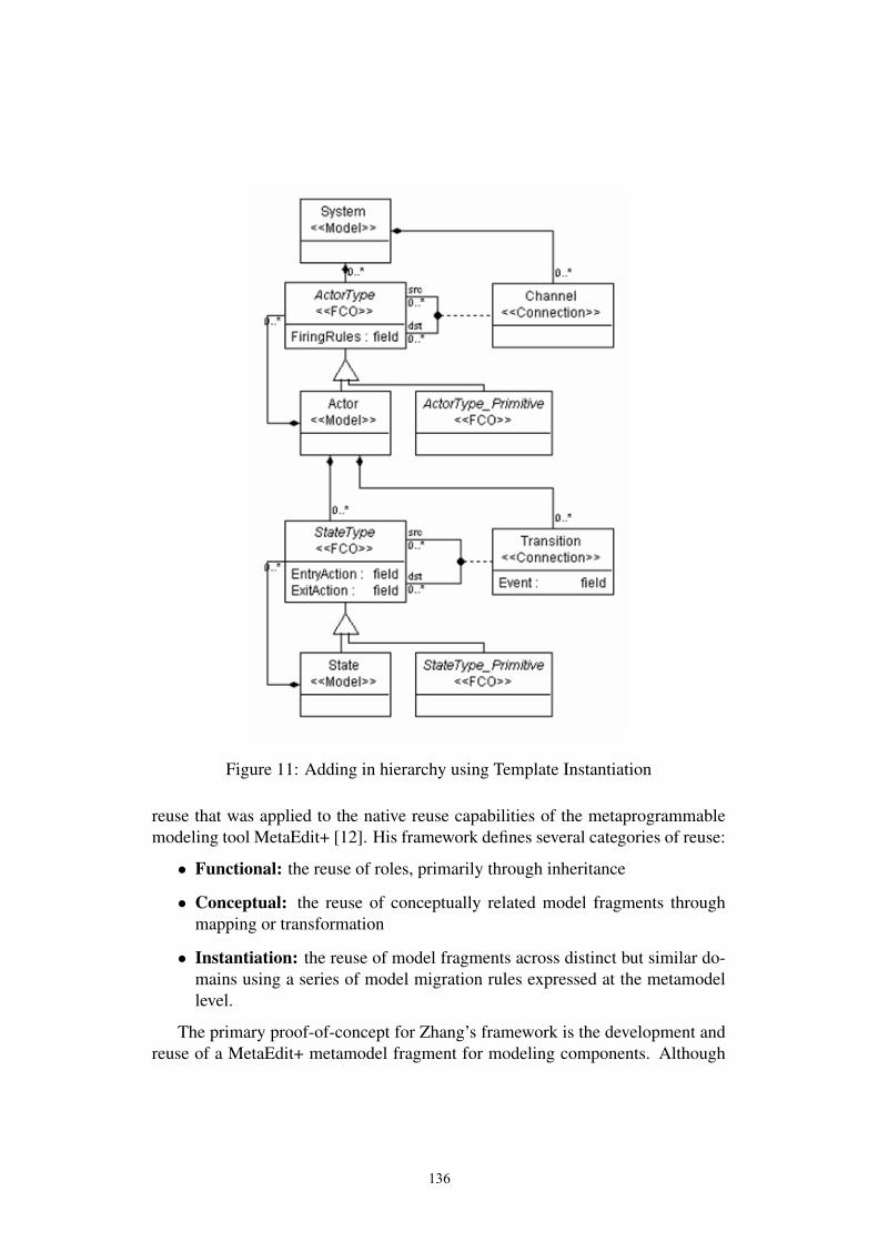
Figure 11: Adding in hierarchy using Template Instantiation
reuse that was applied to the native reuse capabilities of the metaprogrammablemodeling tool MetaEdit+ [12]. His framework defines several categories of reuse:
• Functional: the reuse of roles, primarily through inheritance
• Conceptual: the reuse of conceptually related model fragments throughmapping or transformation
• Instantiation: the reuse of model fragments across distinct but similar do-mains using a series of model migration rules expressed at the metamodellevel.
The primary proof-of-concept for Zhang’s framework is the development andreuse of a MetaEdit+ metamodel fragment for modeling components. Although
136

the framework is discussed and evaluated in the context of MetaEdit+, it could beadapted to apply to any metaprogrammable modeling tool because it is genericwith respect to the metamodeling formalism used and the details of how the reuseis actually accomplished.
While Zhang focuses on the general ways in which individual model artifactsmay be reused, the Metamodel Merge, Metamodel Interfacing, and Class Refine-ment techniques we reviewed above focus on the details of how multiple meta-model fragments may be composed or related in the context of class diagrams-style metamodeling. Our Template Instantiation technique can be classified as aspecific incarnation of Zhang’s Functional Reuse - both share a strong focus onentity roles.
5 Future Work: Composite Metamodel SemanticsThe formal specification of modeling language semantics is a key current issuefor model-based engineering. A wise approach to the specification of semanticsis to rely on well-established formal models of computation, such as finite statemachines, data flow, and discrete event systems. Semantic Anchoring is one suchapproach for the formal specification of DSML semantic domains and semanticmappings. It mandates the use of canonical, executable models of computationfor semantic domains and the use of graph transformation algorithms for seman-tic mappings. Because models of computation capture widely-used, standardized,formal patterns of execution, they are ripe for reuse. The question of reuse is es-pecially important when languages with heterogeneous semantics are considered- that is, languages with semantics defined by some combination of interactingmodels of computation. In the sections above we described the ways in whichmodeling language syntax may be composed, but what can the composition ofsyntax tell us about the execution semantics of the resulting unified modelinglanguage? If it is possible to compose and reuse syntax specifications, how cansemantic specifications similarly be composed and reused? It seems intuitive thatif the syntaxes of two semantically-anchored languages are composed using oneof the techniques outlined in this paper (for example, Metamodel Merge), then thestructural part of the composite semantic domain can be created using the sametechnique. Further work is needed to bear this idea out.
One of the key requirements to make the Semantic Anchoring approach prac-tical is the availability of a library of reusable Semantic Units to act as composablesemantic domains for DSMLs. However, even with such a library to draw on, thesemantic mappings must currently still be done completely by hand. In the com-prehensive DSML design environment we envision, users will enjoy tool supportthat enables the automatic generation of these mappings from DSML syntax. Of
137

course, this can only be possible where the syntax itself contains clues regardingits intended semantics. One way of providing these clues is to create a libraryof syntax fragments corresponding to the library of Semantic Units, where eachsyntax fragment has a pre-specified semantic mapping onto a Semantic Unit. By“mixing in” the syntax fragments with a DSML metamodel through MetamodelMerge composition, users could effectively tag each domain-specific modelingconcept with information about its role in the intended language semantics. Theuse of these mix-in syntax libraries would also help encourage the specification ofDSML syntax that maps cleanly onto available Semantic Units.
References[1] The 4mlWare project. Available from: www.isis.vanderbilt.edu/4ml.
[2] Agrawal A., Karsai G., and Ledeczi A. An end-to-end domain-driven de-velopment framework. In Proc. 18th Annual ACM SIGPLAN Conferenceon Object-Oriented Programming, Systems, Languages, and Applications,2003.
[3] Ledeczi A., Bakay A., Maroti M., Volgyesi P., Nordstrom G., and Sprin-kle J. Composing domain-specific design environments. IEEE ComputerMagazine, pages 44–51, November 1997.
[4] Ledeczi A., Maroti M., Bakay A., Karsai G., Garrett J., Thomason IV C.,Nordstrom G., Sprinkle J., and Volgyesi P. The generic modeling environ-ment. In Workshop on Intelligent Signal Processing, Budapest, Hungary,May 2001.
[5] Sjaak Brinkkemper, Motoshi Saeki, and Frank Harmsen. Meta-modellingbased assembly techniques for situational method engineering. Inf. Syst.,24(3):209–228, 1999.
[6] Borger E. and Stark R. Abstract State Machines: A Method for High-LevelSystem Design and Analysis. Springer-Verlag New York, Inc., Secaucus, NJ,USA, 2003.
[7] Jackson E. and Sztipanovits J. Towards a formal foundation for domainspecific modeling languages. To be published in the Proceedings of the sixthACM International Conference on Embedded Software (EMSOFT06), 2006.
[8] Object Management Group. Meta Object Facility Specification v2.0, 2002.Available from: www.omg.org/cgi-bin/apps/doc?ptc/03-10-04.pdf.
138

[9] Sztipanovits J. and Karsai G. Model-integrated computing. IEEE ComputerMagazine, pages 110–112, April 1997.
[10] Chen K., Sztipanovits J., Abdelwahed S., and Jackson E. Semantic anchor-ing with model transformations. In European Conference on Model DrivenArchitecture -Foundations and Applications (ECMDA-FA), Nuremberg, Ger-many, November 2005.
[11] Chen K., Sztipanovits J., Neema S., Emerson M., and Abdelwahed S. To-ward a semantic anchoring infrastructure for domain-specific modeling lan-guages. In Proceedings of the Fifth ACM International Conference on Em-bedded Software (EMSOFT05), Jersey City, New Jersey, September 2005.
[12] Steven Kelly, Kalle Lyytinen, and Matti Rossi. Metaedit+: A fully con-figurable multi-user and multi-tool case and came environment. In CAiSE,pages 1–21, 1996.
[13] Template Instantiator Tool. Available from: www.isis.vanderbilt.edu/TemplateInstantiator.zip.
[14] Z. Zhang. Model Component Reuse Conceptual Foundations and Applica-tion in the Metamodelling-Based Systems Analysis and Design Environment.PhD thesis, University of Jyvskyl, 2004.
139

On Relationships among Models, Meta Modelsand Ontologies
Motoshi Saeki† Haruhiko Kaiya‡†Dept. of Computer Science, Tokyo Institute of Technology
Ookayama 2-12-1, Meguro-ku, Tokyo 152, [email protected]
‡Dept. of Computer Science, Shinshu UniversityWakasato 4-17-1, Nagano 380-8553, Japan
Abstract
In this position paper, we discuss the relationships among domain specific models, do-main specific ontologies, meta models and a meta model ontology, in order to provideseamless semantics for both of models and meta models. By using the same semanticframework, we can detect semantic inconsistency included in models and meta models byusing inference rules on the ontologies.
1 IntroductionMeta modeling techniques play an important role of developing model description languagessuitable for problem domains, and they define abstract syntax of the model description lan-guages. In fact, the UML meta model defines abstract syntax of all kinds of UML diagrams.However, meta models can express the logical syntactical structures of domain specific models(simply models, hereafter) only, and cannot specify the semantics of the models. There aremany studies to combine modeling techniques with the formal methods having rigorous seman-tic basis, e.g. Class diagram and Z, and they provide transformation rules of a model descriptioninto a formal description like Z. In a broader sense, the transformation can be considered as aninterpretation and the semantics basis of the formal description provide the formal semanticsfor the model description. However, these approaches are for general purpose and do not con-sider domain-specific properties. In particular, semantics where domain specific properties areembedded, i.e. domain-specific semantics is very significant for domain-specific modeling de-scription languages.
On the other hand, there are a few works to provide the formal semantics for meta models,not for models. MEL (Method Engineering Language) [4] is a language to describe meta modelsand it gives the semantics to a meta model by using an ontology called method ontology. In[12], the schema of the rules to transform a model description such as a class diagram into aformal description like Z are defined with graph grammar and it presented that the semantics ofa meta model can be considered as these transformation rules. However, in these works, none
140

of logical relationships to the semantics of the models as instances of the meta model could befound. The semantics of the meta model should be seamlessly connected to the semantics ofthe models.
In this position paper, we propose the usage of ontologies for domain specific semantics ofmodels and for the semantics of meta models. By using two types of ontologies, we give se-mantics to both of a meta model and models as the instances of the meta model simultaneously.As a result, we can formally infer various properties of the meta model and the models in thesame framework.
The rest of the paper is organized as follows. In the next section, we introduce the basic ideaand clarify the relationships among models, domain-specific ontologies (domain ontologies),meta models and the ontology of meta models called meta model ontology. In our framework,a domain ontology play a role of a semantic domain for the models, while the meta modelontology provides a semantic basis on the meta models specifying abstract syntax of modelingdescription languages. To show the beneficial effects of our technique, we illustrate an exampleof consistency checking between a class diagram and a sequence diagram in the domain ofLift Control. By using this example, sections 3, 4 and 5 present the details of the semanticrelationships between meta models and a meta model ontology, between models and domainontologies, and between the meta model ontology and the domain ontologies, respectively. Insection 6, we list up research agenda for future work.
2 Basic IdeaOntology technologies are frequently applied to many problem domains nowadays [6, 14]. Asmentioned in [11], we consider an ontology as a thesaurus of words and inference rules onit, where the words in the thesaurus represent concepts and the inference rules operate on therelationships on the words. Each concept of an ontology can be considered as a semantic atomicelement that anyone can have the unique meaning in a problem domain [13]. That is to say, thethesaurus part of the ontology plays a role of a semantic domain in denotational semantics, andthe inference rules help a model engineer (an engineer for developing models) in detecting lacksof model elements and semantically inconsistent parts during his or her model-developmentactivities [8]. As mentioned above, we develop two types of ontologies; one is an ontology ofmeta models and another is an ontology of a problem domain, called domain ontology. A modelis an instantiation of a meta model and it is semantically interpreted by the domain ontology.A domain ontology is an instantiation of the ontology of meta models. Figure 1 depicts therelationships among these ontologies, a model and a meta model. Models are instances ofa meta model and their logical and syntactical structures should obey the meta model. Forexample, a sequence diagram shown in the left part of Figure 4 is an instance of the meta modelof sequence diagrams shown in the left bottom part of Figure 3. Constraints appearing in theleft part of the figure are imposed on the instances. For example, Constraints #2 attached toMeta Model are for the instances of the meta model, while Constraints #1 are for the instancesof the model, i.e. M0 layer in MOF. Semantic mappings appearing in Figure 1, including asimple example, will be mentioned in section 2.
As mentioned in section 1, an ontology plays a role of a semantic domain in denotationalsemantics. Basically, our ontology is represented in a directed typed graph where a node and anarc represent a concept and a relationship (precisely, an instance of a relationship) between twoconcepts, respectively.
141
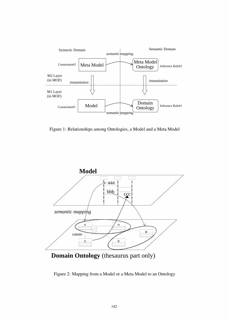
Syntactic Domain Semantic Domain
semantic mapping
semantic mapping
instantiation instantiation
Meta Model
ModelDomain
Ontology
Meta ModelOntology Inference Rule#2
Inference Rule#1
Constraints#2
Constraints#1
M1 Layer(in MOF)
M2 Layer(in MOF)
Figure 1: Relationships among Ontologies, a Model and a Meta Model
C D
A
E
B
cause
Model
Domain Ontology (thesaurus part only)
aaa
cccbbb
semantic mapping
Figure 2: Mapping from a Model or a Meta Model to an Ontology
142

Below, let’s consider how a modeling engineer uses a domain ontology for completing amodel. During developing the model, the engineer should map its model element into atomicconcepts of the ontology as shown in Figure 2. In the figure, the engineer develops a sequencediagram, while the domain ontology is written in the form of class diagrams. For example,the message “aaa” in the sequence diagram is mapped into the concepts A and B and an ag-gregation relationship between them. Formally, the engineer specifies a semantic mapping Fwhere F (aaa) = {A, B, an aggregation between A and B}. The sequence diagram may be in-crementally improved, and logical inference on the ontology suggests to the engineer what parthe or she should incrementally improve or refine. In the figure, although the model includesthe concept A at the item “bbb”, it does not have the concept C, which is caused by A. Theinference resulted from “C is caused by A” and “A is included” suggests to the engineer that amodel element having C, i.e. a message “ccc” should be added to the sequence diagram. In ourtechnique, it is important what kind of relationship like “cause” should be included in a domainontology for inference, and they result from an ontology of meta models as will be discussed inthe next section.
3 Meta Models and Meta Model OntologyThe technique mentioned in the previous section can help a meta-model engineer (engineer fordeveloping meta models) in constructing a meta model of semantically high quality. Supposea simple example of a meta model consisting of simplified versions of Class Diagram and Se-quence Diagram of UML. Following this meta model, another engineer, i.e. a model engineerconstructs a class diagram of the information system to be developed, and then develops the se-quence diagrams, each of which defines an scenario of the interactions among objects belongingto the classes appearing in the class diagram. The left part of Figure 3 illustrates the meta modelwritten with Class Diagram. For simplicity, we use Class Diagram for specifying meta models.Although context-free aspects of abstract syntax of models can be defined with Class Diagram,some of context-sensitive aspects cannot. For example, the constraint that the same class namecannot appear more than once in a class diagram cannot be specified in Class Diagram by itself,and therefore we use first order predicate logic to express this kind of constraints. The aboveexample constraint can be represented as follows;
∀c1, c2 ∈ Class · ((name(c1) �= name(c2)) ∨ (c1 = c2))where Class denotes a set of classes appearing in the class diagram and is from the meta
model Class Diagram. This constraint is an example of Constraints #2 in Figure 1. Althoughthe usage of OCL is natural to specify these kinds of constraints, we actually have used Prologfor implementation because of its query functions and interfaces to Java.
A meta model ontology can give the meaning of the elements of a meta model in the sameway as the technique mentioned in the previous section. The right part of Figure 3 depicts apart of a meta model ontology, which is a simplified version of [7]. During developing a metamodel, a meta-model engineer maps its elements into a part of the meta model ontology. Inthe example of the figure, the meta-model engineer maps Class and Object in the meta modelinto the concepts Class and Object respectively. Attribute is mapped into a set of {State, Data},because attributes in a class play roles of the states of the object belonging to the class and ofthe local data that the objects have. Let G be the semantics mapping of the this example, andwe can have
G : MetaModelElements �→ 2MetaModelOntologyElements
143

Class Diagram
Sequence Diagram
AggregationAttribute
Operation
Class
Object
instance_of
Message
send
receive
cause
Meta Model Ontology of Meta Models
AssociationClasssource
destination
Function Data
consume
produce
State
describe
Object
abstraction
manipulatedescribe
describe
Event
associate
change-from
change-to
participate
next
Figure 3: Meta Model and Meta Model Ontology
G(Class) = Class, G(Object) = Object, and G(Attribute) = {State, Data},where MetaModelElements and MetaModelOntologyElements are a set of meta model
elements such as Class and Message, and a set of elements of the meta model ontology such asFunction and State, respectively.
Note that the example meta model is the result of assembling the meta models Class Dia-gram and Sequence Diagram by adding a new association instance of. If a meta-model engineerdid not add this new association, he or she got two isolated meta models as a result. This re-sulting meta model was not considered as a useful one, because a model engineer can constructclass diagrams and sequence diagrams independently. The benefit of assembling Class Diagramand Sequence Diagram is the semantic relation between Class in Class Diagram and Object inSequence Diagram to specify the behavior of instances of classes with sequence diagrams. Theinference rule that a consistent meta model should not include isolated elements can be formal-ized with predicate logic and its detail was shown in [3]. This inference rule is an example ofInference Rule #2 in Figure 1.
The above example is a syntactical aspect of meta models. By establishing a semantic map-ping meta model elements into the ontology, we can avoid producing semantically meaninglessmeta models [3]. The meta model ontology has several inference rules to keep semantic consis-tency on meta models. In this example, the inference rule “If both Class and Object concepts areincluded in a meta model, the association whose type is abstraction among them should be alsoincluded in the meta model” suggests to add a association that can be mapped to abstraction.See the figure 3. This mechanism is the same as the logical inference of on models that domainontologies have, mentioned in the previous section.
4 Model and Domain OntologyThe left part of Figure 4 illustrates a model following the meta model of Figure 3, consistingof a class diagram and a sequence diagram. This example is a part of Lift Control System andthe right part of the figure shows a part of a domain ontology of Lift Control System domain.
144

Door<<Object>>
Lift<<Object>>
Doors<<Class>>
Lifts<<Class>>
Close<<Event>>
Move<<Event>>
Stop<<Event>>
Open<<Event>>
next
next
next
nextnext
next
Door<<Object>>
Lift<<Object>>
Doors<<Class>>
Lifts<<Class>>
Close<<Event>>
Move<<Event>>
Stop<<Event>>
Open<<Event>>
next
next
next
nextnext
next
Lift
position
up()down()stop()request()
Door
open()close()
Scheduler
arr ived()
Model (Class Diagram + Sequence Diagram)
Lift DoorScheduler
1: request
2: up
3: arrived4: open
cause
××
Domain Ontology in Lift Control Systems
Figure 4: Model and Domain Ontology
We will explain stereotypes attached in classes of the domain ontology in the next section. Themodel engineer maps the messages “up” and “open” in the sequence diagram into Move andOpen concepts of the ontology, during developing the model, as shown in Figure 4. And he orshe tries to map cause relationship between the messages “up” and “open” into the associationof type next. However, no events but Stop can be executed just after Move is executed becausethe domain ontology of Figure 4 specifies that Move has only one outgoing next relationshipto Stop. Thus the inference rule on the ontology suggests that there are no next relationshipsbetween Move and Open and some events should be added to keep semantic consistency ofexecution order next relationship. Obviously, in this case the engineer should add the messageStop between “up” and “open”, which a Lift object sends to a Door object. The used inferencerule is “If there is a next relationship between the concepts A and B in the domain ontology,then the elements mapped to A and B in the model, if any, should have the association mappedto next among themselves. This is also an example to detect semantic inconsistency, mentionedin section 2.
5 Meta Model Ontology and Domain OntologyThe meta model ontology can be considered as a meta model of domain ontologies. The stereo-types attached to the elements of a domain ontology express instantiated concepts of the metamodel ontology. In the example of Figure 4, the element Move has the stereotype <<Event>>and it is an instantiation of Event in Figure 3. By providing the instantiation mechanism fromthe meta model ontology to domain ontologies, we can get the following two benefits.
1. The meta model ontology helps a domain engineer in developing domain ontologies,and it can play a role of a development methodology for ontologies like Object-OrientedMethodology for software development.
2. Although semantic processing may be possible in an extent, the efforts of establishing themapping from elements to an ontology still remain human activities. Because only humancan understand the meaning of a model and a meta model. However, some supports todevelop the mapping are possible by using the combination of relations among the meta
145

model ontology, the domain ontology as its instance and the mapping from a meta modelto the meta model ontology. In Figure 1, if all of the instantiation relations and semanticmappings are isomorphic, we can infer the semantic mapping from the model into thedomain ontology, by using the other relations and other semantic mappings, i.e. theinstantiation from the meta model to the model, the instantiation from the meta modelontology to the domain ontology and the semantic mapping from the meta model to themeta model ontology.
We will illustrate the second benefit, by using Figure 5. Suppose that a meta-model engineerproduces a meta model combining Class Diagram and Sequence Diagram fragments and estab-lishing the semantic mapping from cause association in the meta model into next relationship inthe meta model ontology. The next relationship is instantiated to the “next” relationship betweenStop and Open events in the domain ontology. In this situation, a model engineer develops aclass diagram and a sequence diagram of Lift Control System following the meta model. Heor she adds the messages “stop” and “open”, which has the instance of cause association of themeta model, and then tries to map them into some elements of the domain ontology. Since themessage concept in the meta model is semantically mapped into Message in the meta model on-tology and Message is instantiated to Move, Stop, Open and Close in the domain ontology, themodel engineer can select the suitable ontological elements out of these four elements. After themodel engineer has mapped “stop” and “open” into Stop and Open respectively, he or she paysattention to the cause relationship between “stop” and “open”. This case is simple, because thecandidate of the mapping is only one, i.e. the mapping from cause to the “next” from Stop toOpen, as shown in the figure. Another example is to establish the mapping from instance of toabstraction between Lifts and Lift as shown in the figure, and it can be automatically decided.
As shown in these examples, the model engineers can be supported to establish the semanticmapping, in addition to detect semantic inconsistency by using inference rules on ontologies.
6 Research AgendaThis report discussed the relationships among domain specific models, domain ontologies, metamodels and a meta model ontology, and illustrated their application. We showed a techniqueto give semantics to both models and meta models by using ontologies and illustrated thatthe logical inference rules on the ontologies could automatically detect semantic inconsistencyincluded in the models and the meta models. We classified the ontologies into two types; domainontology and meta model ontology, and the same technique of semantic mappings helps modelengineers in providing the meaning of the models. Currently, we are elaborating the meta modelontology and developing the supporting tool for semantically inconsistency checking of models.The details of research agenda in this direction can be summarized as follows.
1. Elaborating the meta model ontology. We have diverted a simplified version of methodontology mentioned in [7] as our meta model ontology. However, we need more elab-orated version rather than it. There are several excellent works to construct ontologiesin the domain of information systems development and software engineering processes[10, 5, 14] and we may use their results. Another approach is the application of text-mining techniques to methodology manuals written in natural language to extract theconcepts and relationships so that wide varieties of meta models can be semantically de-scribed by using them.
146

Class Diagram
Sequence Diagram
AggregationAttribute
Operation
Class
Object
instance_of
Message
send
receive
cause
Meta Model Ontology of Meta Models
AssociationClass source
destination
Function Data
consume
produce
State
describe
Object
abstraction
manipulatedescribe
describe
Event
associate
change-from
change-to
participate
next
Lift
position
up()down()stop()request()
Door
open()close()
Scheduler
arr ived()
Model (Class Diagram + Sequence Diagram) Domain Ontology of Lift Control Systems
Lift DoorScheduler
1: request
2: up
3: arrived
4: stop
instance_of
cause
Door<<Object>>
Lift<<Object>>
Doors<<Class>>
Lifts<<Class>>
Close<<Event>>
Move<<Event>>
Stop<<Event>>
Open<<Event>>
next
next
next
next nextnext
abstraction
5: open
instantiate
instantiate
semantic mapping
semantic mapping
Figure 5: Meta Model Ontology and Domain Ontology
147

2. Supporting tool. Our inference rules are being described with Prolog because it can haveapplication interfaces to Java like tuProlog [2]. Thus it is easier to develop GUI of thetool using Java and to extend inference rules. As a standard, description logic and itsreasoning engines become more popular to specify ontologies and their inference rules.After establishing the ontologies and rules, we can shift our formalism from Prolog todescription logic.
3. The supporting techniques to develop domain ontologies. Although we have a metamodel of domain ontologies, developing various kind of domain ontologies of high qual-ity by hand is a time-consuming and harder task. Adopting text mining approaches areone of the promising ones to support the development of domain ontologies [1, 9].
References[1] KAON Tool Suite. http://kaon.semanticweb.org/.
[2] tuprolog http://lia.deis.unibo.it/research/tuprolog/ .
[3] S. Brinkkemper, M. Saeki, and F. Harmsen. Meta-Modelling Based Assembly Techniquesfor Situational Method Engineering. Information Systems, 24(3):209 –228, 1999.
[4] S. Brinkkemper, M. Saeki, and F. Harmsen. A Method Engineering Language for theDescription of Systems Development Methods. In Lecture Notes in Computer Science(CAiSE’2001), volume 2068, pages 473–476, 2001.
[5] E. Falkenberg, K. Lyytinen, and A. Verrijn-Stuart, editors. Information System Concepts:An Integrated Discipline Emerging, IFIP TC8/WG8.1 International Conference on Infor-mation System Concepts: An Integrated Discipline Emerging (ISCO-4).
[6] M. Gruninger and J. Lee. Ontology: Applications and Design. Commun. ACM, 45(2),2002.
[7] F. Harmsen. Situational Method Engineering. Moret Ernst & Young Management Con-sultants, 1997.
[8] Haruhiko Kaiya and Motoshi Saeki. Ontology Based Requirements Analysis: LightweightSemantic Processing Approach. In QSIC 2005, Proceedings of The 5th InternationalConference on Quality Software, pages 223–230, 2005.
[9] L. Kof. Natural Language Processing for Requirements Engineering: Applicability toLarge Requirements Documents. In Proc. of the Workshops, 19th International Confer-ence on Automated Software Engineering, 2004.
[10] M. Leppanen. Towards an Ontology for Information Systems Development.//http://emmsad06.idi.ntnu.no/, 2006.
[11] A. Maedche. Ontology Learning for the Semantic Web. Kluwer Academic Publishers,2002.
[12] M. Saeki. Role of Model Transformation in Method Engineering. In Lecture Notes inComputer Science (Proc. of CAiSE’2002), volume 2348, pages 626–642, 2002.
148

[13] M. Saeki, H. Horai, and H. Enomoto. Software Development Process from Natural Lan-guage Specification. In Proc. of 11th International Conference on Software Engineering,pages 64–73, 1989.
[14] Y. Wand. Ontology as a Foundation for Meta-Modelling and Method Engineering. Infor-mation and Software Technology, 38(4):281–288, 1996.
149
Roles in Software Development usingDomain Specific Modelling Languages
Holger Krahn Bernhard Rumpe Steven VolkelInstitute for Software Systems Engineering
Technische Universitat Braunschweig, Braunschweig, Germanyhttp://www.sse.cs.tu-bs.de
Abstract
Domain-specific modelling languages (DSMLs) successfully separate the conceptual andtechnical design of a software system by modelling requirements in the DSML and addingtechnical elements by appropriate generator technology. In this paper we describe the roleswithin an agile development process that allows us to implement a software system by usinga combination of domain specific models and source code. We describe the setup of such aprocess using the MontiCore framework and demonstrate the advantages by describing howa group of developers with diverse individual skills can develop automotive HMI software.
1 Roles in a DSML-based development
Domain-specific modelling enables developers to separate previously connected developmentactivities for a software system. Thus it allows them to concentrate on a single task at a timewhich leads to better results [4]. Furthermore, the development becomes more efficient, as partsof work can be reused from other projects more easily. In accordance to [4] we identify (in asimplified fashion) the following three activities during development:
• Domain specific modelling languages (DSMLs) are developed, reused or existing onesare enhanced to express the desired models of the problem domain.
• Code generators are implemented that transform models to an executable solution.
• The project specific knowledge or problem description is expressed in the DSMLs andthe generators are used to map these models into a running solution.
These development activities are usually applied by different people according to their in-dividual skills. By different code generators or even direct execution of the DSL instances themodels are first class artefacts within the development. They can be used for different taskslike documentation, automated tests and rapid prototyping [16]. Therefore it is worthwhile toseparate the activities mentioned above and assign them to specific roles:
150

• A language developerdefines or enhances a domain specific modelling language (DSML)in accordance with the needs of the product developers.
• A tool developerwrites code generators for the DSML which includes the generation ofproduction and test code as well as the analysis of the content and its quality. In additiontool developers integrate newly-developed or reused language processing components andgenerators to form tools used within the project.
• A library developerdevelops software components or libraries and simplifies therebythe code generator because constant reusable software parts do not have to be generated.Therefore this role is closely connected to thetool developerbut requires more domainknowledge. One aim of a library is to encapsulate detailed domain knowledge and providea simplified interface that is sufficient for the needs of the code generation.
• Theproduct developersuse the provided tools for different activities within the project.Mainly, they specify a solution using their domain knowledge expressed in DSMLs todirectly influence the resulting software.
The language developer not only defines the syntax of the modelling language respectivelythe newly added concepts in that language but also describes its meaning in terms of semantics,ensures that the new concepts are properly integrated in the existing language and provides amanual for their use. It is important that the semantics of a language is not only defined bydescribing how the generator handles it [9].
In conventional non-agile project settings both roles, language and tool developer, are notpart of the project team. In cases where a commercial off-the-shelf tool is used, they are com-pletely unavailable. However, the experiences we made so far indicate that it is recommendedto integrate these tool based service activities into the project, leading to a more agile form ofdevelopment.
The running system produced by the code generator allows the product developer to gaininsights into the system’s behaviour and thus gives the developers immediate feedback. Thenthe product developer might provide new feature requests and in turn the tool and languagedevelopers change the generator implementation or the DSML itself. In accordance to an agiledevelopment process, we argue that all developers should be able to easily adapt and immedi-ately compile the resulting system after each change to judge the influence of the applied changeeasily. This requirement corresponds to the agile principles ofimmediate feedbackandcontin-uous integration[2]. This is only possible, if the language and tool developers are availablewithin the project. Furthermore, in smaller projects the aforementioned roles might be taken bysingle person, thus the language, tool, library and product developer roles are unified.
The advantage of the development steps and roles is the strict separation of the descriptionof a solution on a conceptual level and its technical realisation. This is an example of the wellknow principleseparation of concerns[5] and permits the ability to independently evolve andpossibly reuse all artefacts. The approach gains its benefit from the fact that technical solutions,stored in libraries and code generators change less often than the requirements for a certainapplication.
Our experience is based on the development of the MontiCore framework [8] which we useto develop DSMLs and tools which process these DSMLs. MontiCore itself is developed in
151

an agile way, where the requirements of certain DSML descriptions (the input of MontiCore)often lead to changes in the generator itself and therefore evolve the MontiCore framework.MontiCore can be automatically rebuilt after any change in a MontiCore artefact and tests withdifferent type of granularity ensure the quality of the result.
Our agile model-driven method uses a lot more concepts of other agile methods likeExtremeProgramming[2]: on-site customer, test-first, early feedback, etc. However, instead of a code-centric approach we concentrate on executable models that we use for production and test codegeneration. The main idea as described in [3] is to detect errors as soon as possible and to getearly feedback from customers. Furthermore, the test cases we generate run in full automation,which makes the development process really agile. An on-site customer can act as a productdeveloper that is not only able to develop the system in an appropriate way but can also definetests using the same notation [19]. All roles should develop their artefacts in a test-first mannerregardless if they use or develop DSMLs or write source code. This makes an explicit test roleunnecessary.
To explain such a development process in more detail we have developed a tool chain fora Human-Machine-Interface (HMI) in an automotive context. Two DSMLs are developed andused by different roles to produce an HMI based software.
The rest of the paper is structured as follows. Section 2 describes the MontiCore frameworkwhich enables an agile development of domain-specific modelling languages and the tool sup-port for such a development process. Section 3 describes an illustrative example for the roles inthe process where DSMLs are used for the development of an automotive sub-system. Section4 relates our approach to other publications and Section 5 concludes this paper.
2 DSML-Framework MontiCore
As an intermediate step towards a fully model-based software development process we currentlyadvocate a development process that uses code and models at the same time and, more importantat the same level of abstraction. Several kinds of models and source code together expresssolutions in a problem-adequate way. This means, the developers do not round-trip engineer andswitch views between code and models, but use models and handwritten code as descriptionsof orthogonal parts. Developers do not look at or modify any form of generated code.
In [7] we have shown how to combine Statecharts and Java source code that exceeds theapproach current CASE tools provide. The developer modifies only the handwritten sourcecode and the Statecharts without considering the generated source code. This imposes syntacticconstraints between source code and Statecharts, like called events in source code must beaccepted by the Statechart and events have fitting parameters, which are directly displayed onbasis of the Statechart and the handwritten source code. This makes a generation tool muchmore useable, compared to a situation, where errors have to be traced back from the generatedsource code to the model.
This approach is different from the OMG MDA[13] approach, because MDA describes theusage of models at different levels of abstraction and basically one-shot model transformationsto transform each models from one level down to a less abstract level. The last transformationthen results in source code that forms the software system. Manual changes in the generatedmodels resp. source code are generally allowed and therefore, repeated generation becomes
152

difficult if not impossible. Figure 1 sketches the generation/transformation process as seenby MDA that is also similar to a classic CASE tool approach compared to our process (b)where constraints are checked between models and source code. The handwritten source codeis transferred to the generated source code and changed automatically where technical detailsare needed to interact correctly with the source code generated from models.
ComputationalIndependent
Model
PlatformIndependent
Model
PlatformSpecificModel
Models Hand-writtenSource Code
GeneratedSource Code
SW-LibrariesHand-writtenSource Code/SW-Libraries
GeneratedSource Code
(a) MDA- and Classic Case Tool-Approach (b) MontiCore-Approach
generation of
combined with (dependencies exist)
Figure 1: Comparison of MDA and the proposed approach
Executable UML [14] describes an approach where a well-defined subset of the UML isused to model a system. MontiCore completes this approach by additionally integrating a pro-gramming language as another kind of model and providing facilities to create new kinds ofmodels.
MontiCore allows the language developer to define a modelling language by specifyingthe concrete syntax in form a context-free grammar. It uses this definition first for generatinga lexer/parser pair with the parser generator Antlr [15]. In addition, it generates the internalrepresentation (abstract syntax, metamodel) of the language as derivation from the grammarin form of Java classes. Through an extension mechanism within MontiCore grammars thestandard derivation process can be flexibly adapted.
The language developer can express additional constraints and features that simplify the in-tegration of the resulting products in the DSLTool framework of MontiCore. This frameworkprovides standard solutions for tasks like file and error handling, execution order, tree traversal,template processing [12] or target code formatting. These techniques are a solid basis for thetool developer to define model transformations, code generation, analysis algorithms and syn-tactic checks based on the proper semantics and the intended use of the DSML. These solutionsare offered to simplify the development of specific DSML tools within the agile developmentprocess.
153

Consequently, MontiCore can be seen as a generator on the one hand and as a language pro-cessing support environment on the other hand. The development of the MontiCore frameworkitself is a proof of concept for this approach, because the framework is implemented using apartial bootstrap process.
3 DSMLs for HMIs
This section demonstrates a practical example that uses the proposed MontiCore method fordeveloping Human-Machine-Interfaces (HMIs) in cars. HMIs provide a user interface for thecomfort functions of a car and are able to provide various feedback to the user.
Nowadays most car companies use their own HMIs with differences in look and feel, func-tions, and handling. Even cars of a single company have various configurations with differentfeatures. Taking the project setting of developing an HMI software for a certain car manufac-turer with the agile MontiCore process, we have identified different activities in the developmentprocess and associate them with our identified roles.
The cooperation of the different artefacts can be found in Figure 2. The mentioned diagramtypes and languages are explained in the following.
generates
input
input
uses
DSLTool framework (Part of MontiCore)
HMISoftware
FeatureDSL processor
MenuDSL processor
Manuallydefined
generator
Manuallywritten HMI-Library
FeatureDiagram
MenuStructureDiagram
DSMLMenu Diagrams
DSML Feature
Diagrams
MontiCorecodegenerator
MontiCorecodegenerator
defineslanguagedeveloper
productdeveloper
defines
librarydeveloper
tooldeveloper
designs
designsprograms
assembles
programs
Figure 2: Generator structure for the HMI
After discussions with the product developers alanguage developerdesigns a DSML defi-nition for Menu Diagramsthat describe the menu structure of an HMI. This form of descriptionis specific for HMIs in cars and uses concepts like menus, dialogs, status boxes and user inputsthat correspond directly to the concept used by the manufacturer.
Another task for alanguage developeris to introduceFeature diagrams[4] to the project.These diagrams allow to model common and variable features and interdependencies between
154

them. Figure 3 shows such afeature diagram. It is essentially a tree of features, that can eitherbe mandatory or optional depending on the style of the edge: a black (mandatory) or a white(optional) circle. The edge decoration denotes alternative features. For the easier integration inthe text-based tools in our proposed development process a textual notation for feature diagramsis used.
AirConditioning
CommunicationAdapter
Ventilation
NavigationSystem
Organizer
Car
mandatory optional
alternative
Figure 3: Feature Diagram
A tool developerbuilds a tool that comprises both languages. MontiCore is used to generatethe language processing components and the DSLTool framework is configured to simplify theinternal workflow and the input file handling of the tool. In addition a manually written codegenerator for HMI code is added to complete the tool.
The implementation of the generator is simplified by alibrary developerwho develops anHMI-library that contains certain reusable code parts to program HMI software. The codegenerator simply configures the HMI library to form a specific HMI software.
The feature modellerdescribes feature sets which specify possible configurations of a typeseries and therefore is an instance of aproduct developer. An HMI-developerdesigns a menustructure for certain type series of cars. The HMI-developer therefore is another instance of aproduct developer. By using the developed tool and choosing a certain configuration for the car,he can directly generate the resulting software and simulate the result without further help of ITexperts.
4 Related Work
Frequentlymetamodellingis used to create the abstract syntax of a modelling language. TheMeta-Object Facilty [26] is the metamodelling technique standardised by the OMG where themetamodel is written as a simplified UML Class Diagram and OCL is used to define constraintson the abstract syntax. The MDA approach provides various ideas of integrating models intothe development process which are primarily described as an input for one shot generations andtherefore makes an agile process with continuous integration difficult. Due to the transforma-tional nature of the approach the additional roletransformation definition engineeris needed[11].
The Eclipse Modelling framework (EMF) [21] is another commonly used metamodellingframework. The meta-metamodel named Ecore can be used to create metamodels with theEMF framework itself, but also an import from a UML tool or textual notations like [10] and
155

[22] are possible options. Instances of the DSML can be created by a generic EMF editor. Moresophisticated graphical editors can be either handwritten or created using the Graphical Mod-elling Framework (GMF) [24]. No strictly defined role based development process is proposedfor the use with EMF.
The Generic Modeling Environment (GME) [23] is an integrated development environmentfor domain-specific modelling. The described MontiCore process could be adapted to be usedwith GME. A language developer would describe the abstract syntax of a language by a meta-model and define a graphical concrete syntax. GME is similar to MontiCore because a tool de-veloper is supported by the environment to develop code generations or model interpretations.These artefacts can be reused inside GME to support product developers with an individuallyconfigured tool.
MetaCase’s MetaEdit+ [25] uses a menu based editor to define metamodels. Models can becreated through a graphical editor by drag and drop, inputs such as model names are made ininput fields. MetaEdit+ uses its ownReport Definition Languageto navigate over a model in-stance and create code from it. The MetaEdit+ tool supports a variety of development processesand therefore does not go deep into process definition.
TheDomain-Specific Language Tools[20] initiative from Microsoft also aims at the designof graphical DSMLs. The development is divided into three parts: definition of the meta-model, definition of (graphical) design, and definition of constraints. The meta-metamodeloffers classes, value properties, and relations such as embedding (composition), reference (ag-gregation) and inheritance. Constraints are expressed in C#, code generation is supported bythe Template Transformation Toolkitwhich allows an iterative access to DSL instances. Sup-ported target languages for these templates are Visual Basic and C#. Sketches of an appropriatedevelopment process do exist e.g. in [6].
In [1] different roles for a model-driven development in general are presented. In compar-ison to our approach a more conventional software process is advocated with a separation in ameta and a project team. The paper mentions additional roles for testing and system analysiswhich are fulfilled by all developers in agile projects with activities like test-first design andconstant feedback.
5 Conclusion
In this paper we have explained how an agile development process that uses code and mod-els at the same level of abstraction can be used to efficiently develop a software system. Weexplained the different roles developers play in the realisation of a software when DSMLs areused to separate technological and application specific aspects. This technique also simplifiesthe integration of domain experts into a development team by giving them domain specific toolsto express their knowledge without the need to go deeply into software issues.
The MontiCore framework strongly simplifies the development of DSMLs by providingan infrastructure the developer can rely on. This simplification is assisted by easy to use andquickly executed tools that enable a much more agile development process. Therefore, insteadof a strict separation of tool and product developers, we are able to integrate those into the sameproject. In addition, we define new roles in a DSML-based project that will be carried out bydevelopers respectively domain experts.
156

In the future we will further enhance the features of the MontiCore framework to be able toquickly develop more complex DSMLs. Furthermore, we will provide a number of predefinedDSMLs that will serve as a basis for specific DSML definitions. Among others, we will developa framework which supports UML/P [18, 17] as a special UML profile to model properties of asoftware for both, production and test code generation.
References
[1] J. O. Aagedal and I. Solheim. New Roles in Model-Driven Development. InProceed-ings of Second European Workshop on Model Driven Architecture (MDA), Canterbury,England, 2004.
[2] K. Beck. Extreme Programming Explained: Embrace Change. Addison-Wesley, 1999.
[3] J. Botaschanjan, M. Pister, and B. Rumpe. Testing Agile Requirements Models.Journalof Zhejiang University SCIENCE, 5(5):587–593, May 2004.
[4] K. Czarnecki and U. W. Eisenecker.Generative Programming: Methods, Tools, and Ap-plications. Addison-Wesley, 2000.
[5] E. Dijkstra. A Discipline of Programming. Prentice Hall, 1976.
[6] J. Greenfield, K. Short, S. Cook, and S. Kent.Software Factories: Assembling Applica-tions with Patterns, Models, Frameworks, and Tools. John Wiley & Sons, 2004.
[7] H. Gronniger, H. Krahn, B. Rumpe, and M. Schindler. Integration von Modellen in einencodebasierten Softwareentwicklungsprozess. InProceedings of Modellierung 2006, Inns-bruck, Austria, pages 67–81, 2006.
[8] H. Gronniger, H. Krahn, B. Rumpe, M. Schindler, and S. Volkel. MontiCore 1.0 -Ein Framework zur Erstellung und Verarbeitung domanenspezifischer Sprachen. Tech-nical Report Informatik-Bericht 2006-04, Software Systems Engineering Institute, Braun-schweig University of Technology, 2006.
[9] D. Harel and B. Rumpe. Meaningful Modeling: What’s the Semantics of ”semantics”?.IEEE Computer, 37(10):64–72, 2004.
[10] F. Jouault and J. Bzivin. KM3: a DSL for Metamodel Specification. InProceedings of8th IFIP International Conference on Formal Methods for Open Object-Based DistributedSystems, LNCS 4037, pages 171–185, Bologna, Italy, 2006.
[11] A. G. Kleppe, J. Warmer, and W. Bast.MDA Explained: The Model Driven Architecture:Practice and Promise. Addison-Wesley Longman Publishing Co., Inc., Boston, MA, USA,2003.
[12] H. Krahn and B. Rumpe. Techniques For Lightweight Generator Refactoring. InR. Lammel, J. Saraiva, and J. Visser, editors,Proceedings of Summer School on Gen-erative and Transformational Techniques in Software Engineering (LNCS 4143), 2006. toappear.
157

[13] OMG MDA Website. http://www.omg.org/mda/.
[14] S. J. Mellor and M. J. Balcer.Executable UML: A Foundation for Model Driven Architec-ture. Addison-Wesley Professional, 2002.
[15] T. J. Parr and R. W. Quong. ANTLR: A Predicated-LL(k) Parser Generator.Softw., Pract.Exper., 25(7):789–810, 1995.
[16] B. Rumpe. Agile modeling with the UML. In M. Wirsing, A. Knapp, and S. Balsamo,editors,9th Monterey Workshop 2002 – Radical Innovations of Software and Systems En-gineering, Venice, Italy, October 7–11. Springer, 2004.
[17] B. Rumpe. Agile Modellierung mit UML : Codegenerierung, Testfalle, Refactoring.Springer, Berlin, August 2004.
[18] B. Rumpe.Modellierung mit UML. Springer, Berlin, May 2004.
[19] B. Rumpe. Agile Test-based Modeling. InInternational Conference on Software Engi-neering Research & Practice. CSREA Press, June 2006.
[20] DSL-Tools Website. http://msdn.microsoft.com/vstudio/DSLTools/.
[21] Eclipse Modeling Framework website. http://www.eclipse.org/emf/.
[22] Emfatic Website. http://www.alphaworks.ibm.com/tech/emfatic.
[23] The Generic Modeling Environment Website.http://www.isis.vanderbilt.edu/projects/gme/index.htm.
[24] Graphical Modeling Framework Website. http://www.eclipse.org/gmf/.
[25] MetaCase Metaedit+ Website. http://www.metacase.com/.
[26] Meta-Object Facilty Website. http://www.omg.org/mof/.
158

Lightweight Domain-Specific Modeling andModel-Driven Development
Risto Pitkänen and Tommi MikkonenInstitute of Software Systems, Tampere University of Technology
P.O. Box 553, FIN-33101 Tampere, Finland
{risto.pitkanen, tommi.mikkonen}@tut.fi
Abstract
Domain-specific modeling (DSM), especially when accompanied with powerful tools suchas code generators, can significantly increase productivity in software development. On the otherhand, DSM requires a high initial investment due to the effort needed for designing a domain-specific modeling language and implementing code generators. In this paper, a lightweight DSMapproach that uses somewhat more generic languages and developer-guided transformations bor-rowed from model-driven development is discussed. It is concluded that the lightweight approachcan be used as a bridge to full-blown DSM or in a context where sufficient economies of scaledo not exist to justify the investment required by the latterapproach.
1 Introduction
Domain-specific modeling (DSM) is commonly advocated as a means to raise the level of ab-straction in software development and to achieve higher levels of productivity than with con-ventional languages. DSM languages borrow their vocabulary from the problem domain, let-ting developers concentrate on defining the problem insteadof implementation-level details.Model transformations and code generators are then used forderiving an actual implentationin a computer-assisted fashion.
Model-driven development (MDD) is a related approach whereabstract models are incremen-tally refined through model transformations, starting witha problem domain centric model, thefinal goal being the production of a solution-centric platform-specific model. Mainstream MDDresearch is, however, tightly coupled with OMG’s Model Driven Architecture (MDA), where ageneric modeling language, UML, is usually utilized instead of domain-specific languages.
In this paper we investigate the relationship between DSM and MDD, more specifically theuse ofsomewhatdomain-specific models in a context where a highly specific language doesnot (yet) exist, and the introduction of concepts and constructs related to the implementation
159

domain using refinement and transformations. We refer to this approach aslightweight hybridDSM/MDD.A simple mobile robot will be used as a running example.
The structure of the rest of this paper is as follows. In Section 2 we define the scope of thediscussion more precisely and compare the lightweight approach to full-blown DSM. Section 3introduces a running example and discusses a somewhat domain-specific modeling language forreal-time control systems. In Section 4 it is shown how a somewhat domain-specific high-levelmodel can be combined with an architecture, and eventually transformed to an implementation.Section 5 concludes the paper with some discussion.
2 Lightweight Domain-Specific Modeling
Domain-specific modeling languages are usually built around a tool chain that includes automaticcode generation for a certain implementation platform. Provided that DSM languages, modelingtools, and code generation tools are well designed, significant increases in productivity can oftenbe achieved. With MetaEdit+ [4], for instance, five- to ten-fold productivity increases comparedto conventional coding have been reported [6].
The tradeoffs associated with the above approach are the high initial investment required fordesigning a domain-specific language, and the inflexibilitywith regard to the target platform.The latter disadvantage is of course partly due to the use of acode generator that normally onlysupports a certain target platform, but also to the fact thatDSM languages tend to reflect a certaintarget architecture. In other words, DSM languages often include concepts that do not actuallyoriginate in the problem domain, but in the solution domain.In fact, the vagueness of the termdomainis a known issue, and at least two different points of view have been identified: “domainas the real world” and “domain as a set of systems” [11].
For example, Tolvanen mentions [10] a MetaEdit+ based DSM language whose“modellingconcepts are directly based on the services and widgets thatSeries 60 phones offer for appli-cation development.”This reflects the “domain as a set of systems” view and is of course avalid and efficient approach when only Series 60 SmartPhonesare targeted, but consider a set-ting where a company wants to produce the same application for both Series 60 and MicrosoftWindows Smartphone platforms. In this situation, using a somewhat more generic specificationlanguage and perhaps adopting the “domain as the real world”view would make sense.
While we do not question the efficiency and usefulness of the full-blown DSM approach inmany applications, in some cases a lighter, “modular” approach might be required, where slightlymore generic specifications are refined in a systematic manner towards an implementation. Suchan approach might have to do with lower levels of productivity increase than actual DSM, but itmight be applicable in situations where DSM is not a feasiblesolution or defining a full-blownDSM language is simply not realistic due to the lack of experiences on the specific domain. Ourproposal is based on a method framework calledspecification-driven development[8] and ourexperience with using asomewhatdomain-specific specification language, DisCo [2, 1], for high-level specification in a context where architectural stylesare utilized in the process of producinga more detailed design of a system [8].
DisCo is actually a formal specification language for reactive systems. Thus, if it is viewed
160

Domain−SpecificModelingApproach
��
��
��
��
����
��
������������
������������
�����������������������������������������������������������������
�����������������������������������������������������������������
�����������������������������������������������������������������
�����������������������������������������������������������������
���������������������������������������������������������������������������������������������������������������������������������������������������������������������
���������������������������������������������������������������������������������������������������������������������������������������������������������������������
����������������������������������������������������������������������������������������������������������������������������������������������������������
����������������������������������������������������������������������������������������������������������������������������������������������������������
Somewhatdomain−specific
specification
designspecific
Architecture− Architecture−specificdesign
Architecture−specificdesign
ImplementationImplementation
Select architecture 1
Select architecture 2
Select architecture 3
Select platform 1 Select platform 2
Figure 1: Lightweight hybrid DSM/MDD compared with full-blown DSM.
as a domain-specific language, the problem domain is quite large: for instance, distributed en-terprise business logic fits the definition of a reactive system, as does a mobile robot controlapplication. The defining characteristic of a system whose modeling DisCo is suitable for isthat it is in continuous interaction with its environment. Real-time properties may or may notbe included. DisCo is not, however, as generic as UML, as the specification of a stereotypicaltransformational program such as a compiler using the language would not be feasible.
The proposed lightweight hybrid DSM/MDD approach and its relationship with full-blownDSM development are illustrated in Figure 1. In the lightweight approach, a somewhat domain-specific specification-level language is used for high-level modeling, and the resulting modelis then transformed into an architecture-specific design model, ideally using some kind of atransformation tool. The idea is that the sort of transformations required for this step are lesslaborious to define than a full-blown code generation strategy for a DSM language because thetransformation process is developer-guided. Furthermore, a more generic but still somewhatdomain-specific language has a wider scope of applicability, and therefore it can be used in acontext where defining a fully tailored language would be overkill.
In contrast, a full-blown DSM approach (whose scope covers the grey area in Figure 1)requires that architects and domain experts define a tailored specification language and specifyhow the different constructs are mapped into code, or even implement a code generator manually.Such a language-and-tool-chain is restricted to a particular combination of a problem domain,
161

architecture, and implementation platform. The raise in productivity can indeed be high, butthere are situations in which the approach is not applicable, for instance� if only one or a small number of similar projects are planned,and the high initial investment
required by DSM cannot be justified, or� if precise enough estimates about performance issues cannot be done without first writ-ing some sort of a specification, and if the results of this evaluation affect the choice ofarchitecture and/or implementation technologies, or� if several different implementation platforms are targeted.
In short, the lightweight hybrid DSM/MDD approach is perhaps more suitable than full-blown DSM for pilot type projects and environments where sufficient economies of scale do notexist. Additionally, the approach can be used in the initialphases, before a full-blown DSMtoolchain has been implemented, to aid in defining the scope and concepts of a DSM language,and selecting the right architecture and implementation platform to commit to.
3 Example: High-Level Model of Digibot
We will illustrate lightweight hybrid DSM/MDD using a simple mobile robot as an example. Themobile robot is based on Tutebot, a simple robot introduced by Jones and Flynn [3]. While theoriginal Tutebot was implemented using analogue electronics, our version is digital and thereforecalled Digibot. A more verbose discussion on the Digibot model can be found in [8], where alsoanimation and model-checking are used for validating and verifying the specification.
Like Tutebot, Digibot wanders around a room, traveling straight ahead until it encounters awall or some other obstacle. It has two sensor switches attached to the front bumper, one on theleft and one on the right. Depending on which side touches theobstacle, Digibot shall back up inan arc towards the left or the right before starting to travelstraight ahead again. Thus, the robotwill travel a route that resembles that in Figure 2.
3.1 DisCo Specification of Digibot
In a full-blown domain-specific development approach a tailored modeling language with con-cepts related to timers, sensors, actuators, motors, etc. would probably be utilized for specifyingDigibot. Ideally, a code generator would then produce a complete implementation for a certainhardware platform, such as an Atmel AVR based controller card.
In contrast, we use DisCo as a specification language that is biased towards reactive real-timesystems, but does not prescribe a single implementation platform or even a general architecture– there are modeling constructs for concepts such as deadlines, minimum separation, and atomicevent, but no architecture-specific constructs. The specifications can be implemented using hard-ware as well as software.
DisCo specifications are arranged inlayersthat are superimposed on each other. Each layertypically specifies anaspectof the problem, and rules of superposition guarantee that safety
162

Figure 2: Route of Digibot.
layer abstract_robot isconstant MIN_STOPPED: time := 0.5;
class Robot(1) ismode: (STOPPED, MOVING);allowed_to_move_at: time := 0.0;
end ;
action move(r: Robot) iswhen r.mode’STOPPED ^ now � r.allowed_to_move_at do
r .mode := MOVING();end ;
action stop(r : Robot) iswhen r.mode’MOVING do
r .mode := STOPPED() jjr .allowed_to_move_at := now + MIN_STOPPED;
end ;end abstract_robot;
Figure 3: Layerabstract robot.
properties (of the form“something bad never happens”) are preserved by construction. Layerscan introduceclasses, actions, and some other constructs, and they can refine classes and actionsintroduced in previous layers.
Digibot is specified in DisCo using three layers. The first layer calledabstract robot, depictedin Figure 3, specifies an abstract robot as a device that can only move or stop. The layer de-fines a constant time intervalMIN STOPPED that specifies the minimum duration of inactivitybetween periods of movement. This anticipates the capability to change direction that is to beadded later on; i.e. the robot must not change the direction of rotation of its electric motorstoo quickly to avoid causing damage to them. The literal constant ’1’ in parentheses after theclass nameRobot indicates that there must be exactly one instance ofRobot. State machinemode
inside the class specifies that the robot can either be stopped or moving, and the time-valued vari-ableallowed to move at is used for implementing a minimum separation between distinct periodsof movement.
Actionsmove andstop specify the behavioral part of the layer. The guard of actionmove spec-ifies that, when stopped, the robot may begin moving when the minimum duration of inactivityhas passed. The change of state is implemented using a simpleassignment statement in the actionbody. Actionstop is enabled whenever the robot is moving. The mode of execution is nonde-terministic: any action whose guard evaluates to true in thecurrent state can be exexuted. Inaddition to the change of state, the action body stores to thevariableallowed to move at the earliest
163

layer directional_robot isimport abstract_robot;
extend Robot byextend MOVING by
dir : ( FORWARD, BACKUP_LEFT,BACKUP_RIGHT);
end ;end ;
refined forward(r : Robot) of move(r) iswhen ... do
...r .mode’MOVING.dir := FORWARD();
end ;
refined backup_left(r : Robot) of move(r) iswhen ... do
...r .mode’MOVING.dir := BACKUP_LEFT();
end ;
refined backup_right(r : Robot) of move(r) iswhen ... do
...r .mode’MOVING.dir := BACKUP_RIGHT();
end ;end directional_robot;
Figure 4: Layerdirectional robot.
instant of time at which the robot is again allowed to move.Layer directional robot (Figure 4) adds the notion of direction of travel to the abstract specifi-
cation. When moving, Digibot is assumed to be heading forward, backing up towards the left,or backing up towards the right. This is specified by extending stateMOVING by three sub-statesthat indicate whether the robot is moving forward, backing up towards the left, or backing uptowards the right. In addition, three refinements of actionmove are given. They correspond to thethree different directions of movement, and activate the appropriate sub-state. Note that the baseactionmove ensures that each of these versions must respect the real-time constraint discussedabove. After the refinements, the puremove action will cease to exist.
This far, Digibot is just a nondeterministic entity that canexecute any sequence of stoppingand moving actions as long as the sole real-time constraint is honored. To add the actual controlpart to the robot, layerrobot with sensors is given in Figure 5. The time constantsBACKUP DL andSTOP BACKUP DL define maximum time intervals for starting to back up after running into andobstacle, and stopping the backup phase. These constants are used in actions. ClassRobot isextend with a state machine indicating backup mode, i.e. whether Digibot is about to back up ineither direction. The contact actions modeling the closingof sensor switches are refinements ofstop, i.e. sensor switch contact triggers an immediate stop. The actions modeling backing up areenabled in the corresponding backup mode, and they reset thebackup mode state machine to stateNO in addition to removing the deadline for starting the backupphase and setting a deadline forstopping the backup phase. The specification also needs an ordinary stop action that brings therobot to a halt after backing up. The guard of actionforward is refined to require that the robot isnot currently in either of the backup modes.
Digibot is of course a very simple and small example, and doesnot demonstrate the full powerof DisCo as a modeling language. For instance, timed automata could well be used for specifyingthe same system while still keeping it manageable. The advantages of layerwise refinement andadding one aspect at a time start to show in larger systems andsystems that include unboundedranges and structures or dynamic creation of objects.
164

layer robot_with_sensors isimport directional_robot;
constant BACKUP_DL: time := 1.0;constant STOP_BACKUP_DL: time := 3.0;
extend Robot bybackup_mode: (NO, LEFT, RIGHT);halt_dl : time;backup_dl: time;
end ;
refined contact_left ( r : Robot) of stop(r ) iswhen ... r .mode’MOVING.dir’FORWARD do
...r .backup_mode := LEFT() jjr .backup_dl @ BACKUP_DL;
end ;
refined contact_right( r : Robot) of stop(r ) iswhen ... r .mode’MOVING.dir’FORWARD do
...r .backup_mode := RIGHT() jjr .backup_dl @ BACKUP_DL;
end ;
refined backup_left(r : Robot) ofbackup_left(r ) is
when ... r .backup_mode’LEFT do
...r .backup_mode := NO() jjr .backup_dl @ jjr . halt_dl @ STOP_BACKUP_DL;
end ;refined backup_right(r : Robot) of
backup_right(r ) iswhen ... r .backup_mode’RIGHT do
...r .backup_mode := NO() jjr .backup_dl @ jjr . halt_dl @ STOP_BACKUP_DL;
end ;
refined stop(r : Robot) of stop(r ) iswhen ... now � r.halt_dl do
...r . halt_dl @;
end ;
refined forward(r : Robot) offorward(r ) is
when ... r .backup_mode’NO do...
end ;end robot_with_sensors;
Figure 5: Layerrobot with sensors.
4 Adding an Architecture to Digibot
In our approach, combining a specification and an architecture results in adesign. A designmodel is a solution domain oriented description of the structure and processing of a particu-lar system. To be complete, it has to take into account both behavioral and structural aspects.Application-specific data and behavior is imported from thespecification, while a suitable archi-tectural style is used as the source of more generic structural and behavioral elements.
We shall discuss two different architectural styles that can be applied to the Digibot specifi-cation. They are a hardware-based style, and an interrupt-driven software based style.
4.1 Hardware architecture for Digibot
An architectural style for hardware implementation of DisCo specifications (further discussedin [5]) is best described in terms of certain elements. The elements are: combinatorial blockfor computing the guard of an action, scheduler, sequentialblock corresponding to an object,and sequential block corresponding to a subsystem. A generic architecture resulting from suchcomponents is depicted in Figure 6.
The operating principle of a system based on the architecture is the following: the combina-torial blocksGAi ; i 2 [1; n℄ constantly evaluate the value of each action guard. The results areinput to a synchronously operating scheduler that selects one enabled action per each clock cycle
165

.. . .. . .. ... .
GA1GA2
GA3GAn
...
s c h e d u l e r
logn
variablesneeded
inevaluation
of GA1
neededin
evaluation
variablesneeded
inevaluation
variablesneeded
inevaluation
variables
of GA2of GA3
of GAn
enabledA1enabledA2
enabledA3enabledAn
clk
.
.
.
inputvariablesneeded
to executeactions . . .
sequentialblock
(actionbodies)
.
.
.
inputvariablesneeded
to executeactions . . .
sequentialblock
(actionbodies)
.
.
.
inputvariablesneeded
to executeactions . . .
sequentialblock
(actionbodies)
selected_action
output variablesof o1 neededelsewhere
by o1 by o2 by om
object o1 object o2 object om
output variables
elsewhere
output variables
elsewhereof o2 needed of om needed
clk clk clk
Figure 6: Hardware style.
according to some scheduling strategy. The selected actionis then communicated to the objectblocks using a bus that can be implemented e.g. usinglog n one-bit signals. Each synchronouslyoperating object block then executes its share of the actionbody, and the cycle is then repeatedfrom the beginning.
Each guard of a basic action maps to a combinatorial network (shown in the top part ofFigure 6) that takes as its input signals corresponding to all the variables that the action guarddepends on, and outputs a single bit indicating whether the action is currently enabled or not.This mapping is usually straightforward, as it in effect means the transformation of a logicalformula to a logic network.
The outputs of the combinatorial networks are input to a scheduler component that picks thenext action to be executed. The scheduler operates synchronously, triggered by a an edge of aclock signal. The scheduler might also have additional inputs that are used in the computation(for example, some of the signals representing variables ofthe system), and it can utilize manydifferent kinds of scheduling strategies. Finally, the scheduled action and all needed input vari-ables are communicated to the sequential blocks that correspond to objects that synchronouslyexecute action bodies. Each object block is responsible forexecuting those parts of the bodythat result in state changes in its own variables. The objectblocks must also output the values ofthose variables that are needed elsewhere.
Transforming a DisCo specification to such a hardware-baseddesign can either be carriedout manually or with the aid of an experimental compiler [7].The approach is discussed furtherin [9], [5], and [7].
166

4.2 Interrupt-Driven Architecture for Digibot
The interrupt-drivenstyle is a software-based architectural style suitable forthe implementa-tion of real-time control applications. It is widely used for small-scale embedded systems, andespecially useful if there is no operating system that supports processes or threads. The architec-tural style is very simple and can be described as follows:1) There is a main loop that is oftenempty or performs some background tasks.2) Interrupts are generated by timers and input/out-put events.3) When an interrupt occurs, control is transferred to an interrupt handler for thatparticular interrupt.4) The actual application functionality resides in the interrupt handlers.
The interrupt-driven style can be used for implementing relatively simple DisCo specifica-tions. It is particularly useful for specifications that contain real-time aspects, and where actionsare effectively triggered by the passing of time or by eventsthat are conceptually controlled bythe environment. Examples of events of the latter kind are inputs coming from sensors.
When applying the interrupt-driven style to a DisCo specification, one first needs to identifythe variables, events, and timing constraints that are usedto trigger interrupts, and determinewhich actions are executed on which interrupt. An action maymodel an external event thatgenerates an interrupt; for example the closing of a sensor switch. Potentially nondeterministictiming constraints often map into deterministic timer interrupts: for instance, if actionA setsboth a minimum separation and a deadline for actionB, this can be realized by setting a timerthat expires somewhere in between these time instances and causes an interrupt. Actions thatare not interrupt-triggered can be placed in the backgroundloop of the program, their guardsimplemented using conditional statements. However, oftenin control-oriented specificationssuch actions do not exist.
5 Conclusion
Lightweight hybrid DSM/MDD is an approach where a somewhat domain-specific specificationlanguages are used in conjunction with transformation techniques and tools that enable computer-assisted implementation of specifications. Compared to a full-blown DSM approach based e.g.on a tool such as MetaEdit+ [4], the lightweight method requires a smaller initial investmentand offers flexibility with regard to choosing an architecture and a target platform. On the otherhand, the process of deriving an implementation based on a specification requires more developerintervention, and thus the productivity increase is probably lower.
Lightweight hybrid DSM/MDD can be used as a bridge from generic methods and tools toa domain-specific workflow, as it allows incremental development of the modeling languages,model compilers and transformators that are required for a full-blown DSM toolchain. A spe-cialized DSM language and automatic code generators can be based on experience and partialtransformators that have been developed when applying the lightweight approach.
References
[1] DisCo WWW site. Athttp://disco.cs.tut.fi on the World Wide Web.
167

[2] H.-M. Järvinen and R. Kurki-Suonio. DisCo specificationlanguage: marriage of actionsand objects. InProceedings of the 11th International Conference on Distributed ComputingSystems, pages 142–151. IEEE Computer Society Press, 1991.
[3] J. L. Jones and A. M. Flynn.Mobile Robots: Inspiration and Implementation. A K PetersLtd, 1993.
[4] S. Kelly, K. Lyytinen, and M. Rossi. MetaEdit+: A fully configurable multi-user and multi-tool CASE and CAME environment. InCAiSE ;96: Proceedings of the 8th InternationalConference on Advances Information System Engineering, pages 1–21, London, UK, 1996.Springer-Verlag.
[5] H. Klapuri. Hardware-Software Codesign with Action Systems. PhD thesis, Tampere Uni-versity of Technology, 2002.
[6] The MetaCase website. http://www.metacase.com.
[7] J. Nykänen, H. Klapuri, and J. Takala. Mapping action systems to hardware descriptions.In Proceedings of the International Conference on Parallel and Distributed ProcessingTechniques and Applications (PDPTA’03), Las Vegas, Nevada, USA, pages 1407–1412.CSREA Press, June 2003.
[8] R. Pitkänen.Tools and Techniques for Specification-Driven Software Development. PhDthesis, Tampere University of Technology, 2006.
[9] R. Pitkänen and H. Klapuri. Incremental cospecificationusing objects and joint actions.In Proceedings of the 1999 International Conference on Parallel and Distributed Process-ing Techniques and Applications, pages 2961–2967, Las Vegas, Nevada, USA, June 1999.CSREA Press.
[10] J.-P. Tolvanen. Making model-based code generation work - practical examples.EmbeddedSystems Europe, pages 38–41, March 2005.
[11] A. van Deursen, P. Klint, and J. Visser. Domain-specificlanguages: An annotated bibliog-raphy.ACM SIGPLAN Notices, 35(6):26–36, June 2000.
168

How to represent Models, Languages and Transformations?
Martin Feilkas Technische Universität München
[email protected] Abstract
One of the main goals of domain-specific languages is to enable the developer to define completely new languages for special domains in order to get the advantages of programming on a higher level of abstraction. Nowadays languages are represented in different ways: by metamodels specified in some data modelling technique or by formal grammars. This position paper examines the influence of the representation of languages on language construction and transformation. Introduction
In the last few years domain-specific languages (DSL) have been getting more and more attention in the software industry. DSLs could be a technique to develop software in shorter time and in better quality. DSLs promise to be a good solution to the problem of reuse not only on technical but also on architectural and design level. The usual way of handling this kind of reuse is the adoption of design or architecture patterns. DSLs can be seen as executable patterns. DSLs and generative techniques give the chance of defining the variability in specific software domains. Best practices, such as patterns, can be included as static parts in the generators and variable parts of a software system can be specified in some kind of model or language [GP]. Thus, DSLs present new perspectives on the development of software product lines. But DSL development is still hard because domain and language development knowledge are required [WaH]. To make a DSL usable three tasks have to be carried out:
• Definition of an abstract syntax Most DSL-tools (also called language workbenches [LW]) allow the definition of the abstract syntax as a metamodel [MOF]. This metamodel is defined by a data modelling technique (the meta-metamodel) similar to class diagrams or ER-diagrams.
• Definition of a concrete syntax To make the language usable some concrete syntax has to be defined. Many language workbenches like the Microsoft DSL-Tools focus on graphical languages [MSDT, SWF]. For every language element there has to be a graphical icon that represents the abstract model element. Finally some kind of development environment needs to be provided. In the case of textual languages the syntax can be described by a grammar. A grammar describes both concrete and abstract syntax by specifying terminals, non-terminals and production rules.
• Definition of semantics Possibly the most important part of language specification is the formulation of semantics. An informal description of the language may be given in natural language by describing the domain itself. But the actual definition of these semantics is done by implementing the generator backend. Thus, the semantics of the DSL is defined by giving a translation (translational semantics) into some target language which already has some behaviour definition for its elements (operational semantics).
The generator backend is most often realized by one of the following three kinds of approaches [LOP]:
169

� Templates The most preferred approach to code-generation in language workbenches is the use of template techniques. As the name suggests code-files in the target language are the basis. Expressions of a macro language are inserted that specify the generator instructions. Often ordinary programming languages are used to specify the behaviour of the generator, e.g. C# in the Microsoft DSL-Tools [MSDT]. Other template languages like openArchitectureWare’s functional Xpand language [oAW] specify a specific path through the model graph in each template by using recursion.
� Patterns This approach allows specifying a search pattern on the model graph. For every match a specific output is generated. This approach is used in BOTL [Botl1, Botl2] or ATL [ATL03].
� Graph-traversing (visitor approach) This kind of code generation approach specifies a predetermined iteration path over the syntax graph. For every node type, generation instructions are defined which are executed every time such a node is passed. This kind of generation approach is mainly used in classical compiler construction and textual languages.
Most language workbenches offer poor assistance for the specification of the generator back-ends. Ordinarily there are only little syntax-highlighting (only for the generator language but not for the target language) or code-completion features. The reason lies in the independency of the generator backend from the target language and the missing definition of the target language. Today many languages are developed that are incomplete in the sense that manual coding is still needed to get an executable program. The adoption of DSL technologies is useful especially when the target code doesn’t need to be touched after generation. Otherwise the developer using the DSL must still have full knowledge of the platform and the architecture of the generated code. In this case the benefits of the DSL’s higher level of abstraction don’t really take effect. In the early days of compiler construction generated machine code was also manually modified. This inconvenient practice was no longer necessary when the optimization techniques evolved in compiler construction. The same effect will probably take place when DSL techniques are further developed. But nowadays the reasons for manual coding in generated code are not performance issues but the difficulty to specify languages that are capable of expressing more than architectural and design decisions (like component or service structures). It would often be useful to be able to write logical or arithmetical expressions in a DSL. But it is cumbersome to specify this in a metamodel. Such common language constructs would be useful in many domains so the demand for reuse of language concepts arises. Manual modifications in generated code should be forbidden not only because of convenience reasons. It is a prejudice that generated code is less maintainable than hand written code. Manual interference may possibly destroy the architectural decisions specified in the DSL and its generator. Also, some typical technical round-tripping problems [RTE] could be avoided. For example, manually written code is lost when the generator needs to be run again due to changes of the model. Common solutions to this problem often lead to poor designs and bad program structures because of the inappropriate use of the target language’s concepts (e.g. inheritance). This problem becomes obsolete if complete code could be generated out of DSL specifications. In most language workbenches graphical languages are formulated as data models as the metamodelling technique of the workbench. These are usually simplified class diagrams or entity-relationship models (ER-models). In the vocabulary of the Meta Object Facility [MOF]
170

this would be the meta-metamodel. Textual languages on the other hand are usually defined by their grammar, e.g. in Backus-Naur-Form (BNF). The next section will compare these different representations of languages. Class diagrams can easily be transformed into ER-diagrams. Due to that we will not distinguish between these data modelling techniques anymore and only talk about ER-modelling and relational models in the next sections. After that we will describe the effects of a uniform meta-metamodel on the generation and transformation techniques. At last we want to address the composition of languages out of language components. Data Modelling vs. Grammars
As mentioned above the big difference between classical compiler construction and language workbenches is the formulation of the metamodel. Compilers use formal languages whereas generators use ER-models. The problems compiler construction is facing arise because of the linearity of text. It is difficult to encode and decode information into a linear representation (parsing). Recognizing and reconstructing the information which is encoded into text makes it necessary for every compiler to solve the word problem to decide whether a given program is syntactically correct and in order to reconstruct what the programmer had in mind when writing the program. An interesting question concerns which is the better or more expressive way of formulating metamodels. We will examine this topic using a small example. Figure 1 shows a simplified part of an abstract syntax tree of an ordinary imperative language.
Identifier Identifier IdentifierIdentifierIdentifier
Declaration DeclarationDeclaration Expression
Statement_Block
context sensitive rules
Figure 1: A simplified abstract syntax tree This simple example shows the definition and the use of identifiers. An ER-schema whose stored data represents the same information as the syntax tree (without the context sensitive rules) would look like this:
Declaration Expression
1
Identifier
n n
1
Identifier
Statement_Block
11
n n
Figure 2: An ER-model as a metamodel for the syntax tree in Figure 1
171

But a better way of expressing all the information needed for the concept of usage and declaration of identifiers would be the following:
This shows a simple example of the weaknesses of compiler construction: It is impossible to express all the information needed in context free grammars. In almost every (non-trivial) language there are context sensitive rules that must be integrated and checked by manually coding the compiler. A similar example would be the definition of interfaces in Java or C#. If a class implements an interface it has to implement all the methods declared in this interface. This rule is also context-sensitive and cannot be expressed in a BNF notation of these programming languages. In every case where information (identifiers or method-signatures) is specified more than once in programs a relational structure can be found that eliminates this redundancies and expresses both, the information within the syntax tree and the context-sensitive information. This is possible because a database schema is not only capable of storing trees but also universal graph structures (with typed nodes). The presence of context-sensitive rules of course lowers the maintainability of the compiler. Using context sensitive grammars is not possible either, because they are not easy to handle and the word problem (check if a given word is part of a language) cannot be solved efficiently. The examples above already show the assumption that ER-models are more expressive than context free grammars. But the expressiveness of ER-models is limited, too. In the second example (interface implementation) there could also be the restriction that the interface-methods implemented by the class must be declared as public. This exceeds the expressive power of ER-modelling and constraints formulated in predicate logic would be needed. Our goal is to define a way to translate context-free grammars into ER-schemata and optimize them towards the context-sensitive rules. By using normal form theory we will try to find a way to store programs without redundancy. More research is needed to formalize this topic. Further work will discuss this in more detail. Now we want to have a look at the advantages that could possibly be gained by using a relational representation of a language. Benefits of relational metamodels
Keeping these advantages of data-modelling compared to grammar-based definition of languages in mind, the question arises if this technique could also be used in ordinary programming languages. The formulation of a programming language as an ER-schema and the storage of programs in a relational database would demand an extra definition of concrete syntax in a textual or graphical way. Formulating languages as relational data schemata can make the use of a parser unnecessary because the programs would directly be stored as abstract syntax graphs and the construction of the program could be done syntax-driven. If a graphical program representation is preferred, the operations of dragging and dropping language elements onto the drawing board have to take care that either no incorrect models can be produced or at least that no incorrect model can be stored or executed by the generator backend. In the case of a textual representation of the programs ordinary parsing-techniques may be used before storing the abstract syntax graph or structured editors could be applied like it is done in the Meta Programming System [LOP]. Programming in this kind of relationally represented language
Identifier Expression n m
Declaration n 1
Figure 3: An ER-diagram representing the declaration and usage of identifiers
172

would at last be a sequence of insert, update and delete operations whereas DSL composition would be done using add, alter and drop table operations. Another advantage of storing programs in a relational format is much easier refactoring. For example, in a conventional programming language, a simple renaming of a method declaration would cause the programmer to identify and consistently change all of the usages of this method. This phenomenon is comparable to update anomalies known in database theory. In an ER-schema of a programming language, a method call could be realized by references (numeric primary key) without storing the method name twice [Sim06, Sim96]. Versioning systems (like CVS, Subversion) work on simple pattern matching practices and are unable to identify the reason of conflicts. With ER-based programming languages merge conflicts could be solved much more easily because the versioning system has all the details necessary to determine the exact reason for the conflict. Not only differences in the text lines can be shown, but detailed information on what the differences really rely on (e.g. a new method is declared or an old one has been moved). The developer could be informed of conflicts in a much more detailed way and do a kind of “semantic merge” [LW, Sim06, Sim96]. It is no longer possible to destroy the syntactic correctness of the code base by doing merging operations. Even scenarios are imaginable where developers work synchronously on the same copy of code stored in a central database. For every statement the author could be stored. Two developers would immediately notice when working on the same piece of code. This could avoid merge conflicts totally. Data modelling is much easier than dealing with grammars. Software engineers are usually experienced at building data models. One of the main ideas behind DSLs is to give the programmer the ability to modify his own tool, the programming language. Compiler construction know-how is not very common in average software companies but if the modification of a language could be done via simply changing a relational schema this idea would get better acceptance. Some simple modification could be the implementation of company specific coding conventions by restricting the programming language used. Model Transformation
After this reasoning about the way of defining metamodels, these observations should now be examined towards their influence on the generator backends and model transformation capabilities. DSL-workbenches generate just plain unstructured text, and it is not ensured, that the generator output really fits the grammar of the target language. The used generation techniques do not respect the target language syntax (respectively its metamodel). A formal mapping between the source and target language elements is very important because it specifies the semantics of a newly developed DSL. If not every word in the new language can be translated into an equivalent and syntactical correct target language word, how is the semantic of these words defined? In our opinion the semantics of DSLs must be specified as translational semantics. This leads to the need for syntax respecting code generation. By specifying a translation to a target language that has operational semantics a newly developed language implicitly gets a formal definition of its own semantics. To ensure the syntactical correctness of the output of a transformation it would be necessary to define a separate transformation language for every pair of source and target language. Such a transformation language would consist of the syntax definitions of the source and the target language and some language elements needed to be able to define the mapping. The synthesis of such a transformation language is always the same process and could therefore be automated.
173

Usually people distinguish between model-to-code and model-to-model transformations. One of the difficulties in syntax-respecting model-to-code transformations relies on the different representations of models and code. Models are usually defined relationally and code by its underlying grammar. Actually four kinds of transformations should be distinguished:
1. ER-defined language to Grammar defined language 2. ER-defined language to ER-defined language 3. Grammar defined language to Grammar defined language 4. Grammar defined language to ER-defined language
If a language workbench would have a (relational) representation of a target language (e.g. a 3rd generation programming language) then the task of model-to-code generation could be treated equally to model-to-model transformations and techniques like ATL [ATL03] or QVT [QVT] could be applied. Several other concepts for model-to-model transformations have been submitted to the QVT request for proposals of the OMG [QVTr]. But these model-to-model transformation techniques have a different methodology than template based code generation. It is questionable if these would really fit the needs because most examples of model-to-model transformations just show transformations between models that have almost the same level of abstraction. Code generation on the other hand often has to deal with a huge gap between the levels of abstraction of the source and target language. Component c � insert Java-Class(Name = c.Name, Visibility = public ) jc {
insert Constructor(Name = jc.Name);
Port (Type == "sender") p � insert Method(Name = c.Name+"_"+p.Name){…};Port (Type == "receiver") p � insert Method(Name = c.Name+"_"+p.Name){…},
insert Method(Name = "CS"+c.Name+"_"+p.Name){…},insert Attribute(Name = "isCalled_"+p.Name, Type = b oolean);
DataElement d � GenAttr;}
GenAttr : DataElement d � insert Attribute(Name = d.Name, Type = string);
Figure 4: Example of a fictitious transformation language
The example for a transformation language illustrated in Figure 4 can be read equally to ordinary template approaches and is inspired by the Xpand language used in openArchitectureWare [oAW]. The left hand side of the transformation rules can be thought of as model elements over which is iterated in a for-each-loop and the right hand side as the body of the loop which ordinarily generates the textual output. The right hand side specifies the abstract syntax elements that should be inserted into the target model when the rule is executed. In contrast to approaches like ATL [ATL03], this kind of transformation is traversal based rather than pattern based. The transformation specifies a spanning-tree in the syntax graph of both the source and the target language, which is constructed by the right hand side of the transformation rules. So the transformation can be executed as a depth-first search over the abstract syntax graph of the source language word and at every node parts of the abstract syntax graph of the target language word are constructed. A real complex transformation may need several of these passes. An important thing about the specification of the transformation is that it is done in a declarative manner. Unlike text generation the transformation doesn’t create a concrete syntax representation of the resulting target language word but its abstract syntax graph.
174

This transformation language is composed out of the source and target language and elements for defining the transformations. It is very context-sensitive because the transformation rules have to take care of the source and target language syntax and mapping constraints. But if it can be shown that a word is in the transformation language, this word is a complete definition of translational semantics for the source language. Especially in cases where the source and target languages have a huge difference in their level of abstraction the transformation language in this example is not very useful, because many target elements have to be generated from single source elements and the transformation gets very hard to read. Ordinary templates have the advantage that the concrete syntax of the target language gives a good impression of what generator output is to be expected [PTM]. The example of the textual transformation language above is just meant to show in which manner transformations should be expressed. Of course the transformation language itself could (just as every other language) be represented as an ER-schema and a good GUI-concept could ease the task of specifying transformations by offering only the appropriate elements like code completion does in modern IDEs. The definition of the semantics of the transformation language itself can be defined in a bootstrapping way by formulating a transformation from the transformation language to a programming language (with operational semantics) in the transformation language. Language Composition
One of the big goals of this approach to code generation/model transformation is to make it possible to identify the dependencies between target elements and source elements to identify free elements. In the example the DataElement that corresponds to the attribute doesn’t need information (fields) of the component in whose context it is generated. You can say that in this simple example the DataElement concept is independent of the component concept. This could be a first conceptual step toward a composition of languages in a building blocks approach. By introducing new blocks of an existing language (e.g. arithmetic expressions) into a new language, all of the transformation rules that do not depend on other elements of the existing language can be taken over into the generator of the new language. So this is an approach to semantic conserving DSL-composition. Through similar concepts the development of complete DSLs can be done with less effort. Conclusion and further work
In this position paper we have shown a new perspective on the differences between models and code. The main difference lies in the representation of their metamodels by relations or grammars. After that we explained what advantages could be expected, if ordinary programming languages are formulated as relational models. Translations between relationally represented languages have been proposed and discussed towards the goal of developing transformations that verify the syntactical correctness of the target words. This kind of transformation could also be an exact definition of the (translational) semantics of a newly developed language. In the future we will work on an implementation of a relational programming IDE with a transformation language like the one presented. It has to be formally shown where relational modelling is situated in the Chomsky hierarchy.
175

References:
[ATL03] J. Bézivin, G. Dupé, F. Jouault, and J. E. Rougui. First experiments with the ATL model transformation language: Transforming XSLT into XQuery. In the online proceedings of the OOPSLA’03 Workshop on Generative Techniques in the Context of the MDA, www.softmetaware.com/oopsla2003/mda-workshop.html.
[Botl1] P. Braun, F. Marschall: Transforming object oriented models with BOTL, Electronic Notes in Theoretical Computer Science 72, 2003.
[Botl2] F. Marschall, P. Braun: Model Transformations for the MDA with BOTL, Univeristy of Twente, 2003.
[GP] K. Czarnecki, U. Eisenecker: Generative Programming, Addison Wesley, 2000.
[LOP] S. Dmitriev. Language oriented programming: The next programming paradigm. Onboard Magazine, www.onboard.jetbrains.com/is1/articles/04/10/lop/index.html, November 04.
[LW] M. Fowler: Language Workbenches: The Killer-App for Domain Specific Languages?, www.martinfowler.com/articles/languageWorkbench.html, Jun 05.
[ML] A. Gerber, M. Lawley, K. Raymond, J. Steel, A. Wood: Transformation: The missing link of MDA, In A. Corradini, H. Ehrig, H.-J. Kreowski, and G. Rozenberg, editors, Proc. Graph Transformation - First International Conference, ICGT 2002.
[MOF] Object Management Group: Meta-Object Facility (MOF™) Version 2.0, www.omg.org/technology/documents/modeling_spec_catalog.htm#MOF.
[MSDT] Microsoft DSL-Tools, http://msdn.microsoft.com/vstudio/DSLTools, August 06.
[MTA] K. Czarnecki, S. Helsen: Classification of Model Transformation Approaches. In Proceedings OOPSLA Workshop on Generative Techniques in the Context of Model-Driven Architecture, 2003.
[oAW] Open ArchitectureWare, Generator Framework, www.openarchitectureware.org.
[PTM] J. van Wijngaarden, E. Visser: Program Transformation Mechanics: A classification of Mechanisms for Program Transformation with a Survey of Existing Transformation Systems, May 2003.
[QVT] Object Management Group: MOF QVT Final Adopted Specification, July 7, 2006, www.omg.org/docs/ptc/05-11-01.pdf.
[QVTr] Object Management Group: 2.0 Query / Views / Transformations RFP, April 24, 2002, www.omg.org/docs/ad/02-04-10.pdf.
[RTE] S. Sendall and J. Küster: Taming Model Round-Trip Engineering. In Proceedings of Workshop ’Best Practices for Model-Driven Software Development’, Vancouver, Canada, October 2004.
[Sim06] Ch. Simonyi, M. Christerson, S. Clifford: Intentional Software. Proceedings of OOPSLA’06, 2006.
[Sim96] Ch. Simonyi, Intentional Programming - Innovation in the Legacy Age. Presented at IFIP WG 2.1 meeting, June 4, 1996.
[SWF] J. Greenfield et al.: Software Factories: Assembling Applications with Patterns, Models, Frameworks and Tools. John Wiley & Sons, 04.
[WaH] M. Mernik, J. Heering, A. M. Sloane: When and How to Develop Domain-Specific Languages, ACM Computing Surveys, Vol. 37, No. 5, December 2006.
176

Model integration in domains requiring user-model interaction and continuous adaptation of meta-model
Peter Krall, 2006-10-01 Cortex Brainware Consulting & Training GmbH, Kirchplatz 5, D-82049 Pullach, Germany
Abstract Possible architectures for meta-models for domain specific model driven development are compared in the context of a domain – exploration engines for patterns in the dynamics of financial markets – that require interaction between domain expert and model, continuous development of the meta-model and yield the necessity to provide the domain expert with means to express rather abstract mathematical concepts. The focus will be on the decisions for structural integration versus dynamic integration, and for integration within an object oriented meta-model versus integration by mapping between formal grammars. It will be argued that structural integration within an object oriented meta-model is the most promising approach for the particular task.
Motivation Domain specific modelling is a concept for increasing productivity in software development by integrating the development of models based on domain specific concepts and executable models. Ideally, the domain expert should not need to bother with the development of an executable implementation model from their domain model as the mapping will be predefined in the meta-model. However, in practice it will often be more or less impossible to define the mapping in advance, yielding the question how can the architecture of a meta-model be designed to support model integration and allow for continuous development of the meta-model at the same time. Moreover, it will often be an important task of the model to interact with the user and assist them with the design of the solution, yielding the demand for something like a design-time executable functionality of the model. Tools for research in the financial markets are examples of these types of situations: Many experts believe, that the dynamics of speculative markets show recognizable patterns that can be exploited by interpreting initial segments of the patterns as triggers for own action [Sw95]. The working hypothesis is that such patterns are statistical side effects of invariance in the momentums of a dynamic system that is constituted by superposition of interactions between many agents and occasional perturbations, such as national bank interventions. Such systems are unlikely to be predictable by a closed theory. Yet they will often expose considerable constraints on the set of possible trajectories through state space that allow negative assertions on trajectories [Ba91]. Although assertion of such constraints is logically negative – the system will not do this or that - they may yield exploitable assertions in particular situations – e.g. “If development of some ratio x/y becomes directed after a period of strong fluctuations, then it will not pass a threshold t without a previous outburst into the opposite direction, where t depends on the strength of previous fluctuation by ….” This will say nothing about future development most of the time but may be sufficient to identify profitable trades occasionally, which is enough to justify considerable efforts. The logical structure of assertions on constraints is that of statements with quantifications on sets of trajectories through state space of a complex system. Such statements – e.g. the one cited above – need to be expanded into sets of empirically testable formula by crawling parameter spaces and generating closed formulas for empirical verification. That motivates
177

the idea to provide the domain expert with the computational power of exploration engines that generate and test manifolds of hypotheses on market dynamics. Domain expertise is needed to identify interesting hypotheses. Taking into account that the domain model will already be formalized, the question arises, whether this job may be a candidate for automatic model transformation. This yields the idea to use model driven development techniques for providing the domain expert with the facilities for generic rapid exploration engine development (greed). Essentially solutions in this domain are models of AI-systems (admittedly rather dull AI), that search for patterns in the dynamics of a complex system.
The key observation concerning requirements for greed is that the development of the domain model is actually the goal. The implementation serves as a vehicle for the domain expert to explore the domain and the executable basically serves as an instrument for development of the domain model. This situation has a number of consequences:
The objects to be developed in the domain will show 'rich' behavior. The behavior of such machines needs to be definable in much more domain-specific concepts than those of traditional programming languages.
The designer will often switch between different levels of abstraction, e.g. between definition of a meta-strategy for exploration of trading strategies and specification of parameter sets for instantiation of model-level trading strategies as instances of the meta-level types.
The process of development will often be interactive in the sense, that the domain expert's ideas for specification of new exploration engines will be inspired by observation of previously designed ones.
There is no chance to develop the complete domain meta-model and it’s mapping to corresponding executable implementation models in advance, even if this would be desirable. The development strategy thus must support integrated development on domain view-, implementation- and meta-model-level.
On the other hand, aspects like adaptability to different target platforms or interoperability are irrelevant here and no trade-off should be accepted in favor for such aspects.
The needs sketched above constitute the context for considerations concerning an adequate architecture of the meta-model for domain specific modelling in the respective domain. In this paper the focus will be on two aspects of the meta-model:
Is the meta-model based on structural integration in the sense of a single model principle[Pa02] or does it work with separate domain- and implementation models and explicit transformation?
Is the integration of views defined within an object-oriented meta-model or on basis of a mapping between formal languages?
To proceed with, the consequences of these two logically independent questions will be sketched out and the structural integration within an object oriented meta-model for projects like greed will be argued.
Views Many scenarios for MDD can be described in terms of integration of design models that specify the solution in domain-specific concepts and platform/language-specific
178

implementation models [St05]. The transformation is done automatically or semi-automatically by code generators which specialize given domain model for a particular platform by adding information needed for a complete implementation model. MDD concepts therefore often focus on generalization / specialization relations between models. This looks very natural when starting from the idea that model driven development and domain specific modelling serve to increase productivity by providing the designer with an environment that allows them to describe their model using domain-adequate concepts rather than low-level abstractions. [Gr04, St05, To06] The automatic generation of the implementation – or at least a skeleton thereof – can then be seen as a specialization of the design for a particular platform or machine – e.g.: a domain model of functions for a smart phone can be automatically expanded into an implementation model for a particular device through a tool chain that itself can be developed using a meta-CASE tool. Strictly speaking, it is often a simplification to call the implementation view a specialization of the domain view because the former contains information which is not contained in the latter – from diagram layouts to references to formula, video clips illustrating game-theoretical considerations through visualization of computer simulations, or whatever kind of things which are important for the domain model developer but not executed at runtime. Notwithstanding that this point may be irrelevant for much of the practical work in model driven development, it is important for the meta-level issues of concepts for the integration of development in different views. For this purpose domain and implementation view actually need to be conceived as different generalizations of the underlying complete solution without presupposing that one view were a specialization of the other:
Since domain view and implementation are not orthogonal abstractions of the integrated solution, it may make sense to derive both views from a common base:
Moreover, there will often be more than two relevant views, not only in the trivial sense of expanding and collapsing regions of code in an IDE, but also in a non-trivial sense. For the
Solution
DOV : Domain oriented view
IV : Implementation
Diagram 2: General scheme of views with common basic view.
Basic view
Solution
DOV : Domain oriented view
IV : Implementation view
Diagram 1: General scheme of views
179

sake of simplicity, the following considerations will nevertheless be formulated on base of the assumption of only two views:
The domain view: This is the solution as the domain expert sees it, formulated in domain specific concepts.
The implementation view: This is a description of the solution in a form, which allows transformation into an executable program with means that are considered stable for the purpose of development of solutions within the domain.
The implementation view does not need to be a complete standard-language solution, but may still presume arbitrary complex frameworks, libraries, compilers, code-generators or other tool chain elements. To the extent that these prerequisites are considered as an invariant part of the meta-model, their development nevertheless does not need to be integrated with that of the solution - but is an independent task. It may be noted, though, that confidence in the sufficiency of the tools as they are at the beginning of the project need not be unlimited.
Structural vs. dynamic view integration Obviously, a pair of different abstract models must fulfill many constraints in order to have an interpretation as two views on the same solution. Outside model driven development environments it’s the task of the software engineer to maintain consistency with little support for preventing the notorious tendency of model views from drifting apart. Model driven development aims at providing mechanisms for integration of development of different views in a way that helps to prevent consistency. One of the basic decisions is, to determine the need to separate the domain and implementation model with a mechanism for propagation of information between the two, or to adopt the single model principle [Pa05]. The single model principle is characterized by the existence of only one model at any time. The different views present different aspects of this unique model. The integration is defined by the structure of the relation between the integrated model and the individual views. This motivates the term ‘structural’ integration. Alternatively, different views may be built from model elements with different individual identity. This implies a potential for semantic incoherency. Therefore a mechanism is needed, that is able to transform a pair of incoherent views into a coherent pair of modified views by modification of either one or both views, using either one or both views as input. The possible mechanisms range from one-way code generation to complex bi-directional synchronization mechanisms. In any case there are explicit transformations from one model state to another one. This motivates the term ‘dynamic’ integration. The main differences may be summarized as follows: Structural integration Dynamic integration Shared properties of model elements in domain and implementation view exist as properties of underlying elements of an integrated model. Views therefore only provide access to differently filtered properties of the same unique model.
Domain view and implementation view actually correspond to two separate models which consist of disjoint sets of model elements with different identity. Correspondence between both views thus means that constraints for values of properties of different objects are fulfilled.
Scheme for the structure of meta-model classes representing a <Type> for structural
Scheme for the structure of meta-model classes representing a <Type> for dynamic
180

integration:
integration:
The structural integration scheme for construction of model elements corresponds to a single model, extended by two types of annotations, whereas the scheme for dynamic integration corresponds to construction of two structurally independent models, which need mechanisms for reaching consistency by explicit transformations. Structural as well as dynamic integration may be combined with either object oriented or grammar oriented representation, as will be demonstrated below. Dynamic integration allows for isolation of the views’ meta-models as such and the transformations between them. The meta-models of different views may be captured in two grammars or two meta-model type systems. Transformations may then be represented by templates or by specialized synchronization methods. There are natural slots for adaptation of mappings between domain- and implementation meta-model through adaptation of templates. Dynamic integration is flexible and may boost productivity [Ko05, To06]. However, the arguments for explicit transformation depend to some extent on the completeness of code generation. If this is 100%, then the arguments are convincing [To06]. In a scenario where the domain meta-model is unlikely to be completely understood in advance, this is probably not realistic. This can lead to subtle problems like consolidation of incoherent views – the type of problems which sometimes pops up in form of the notorious ‘generated code – do not modify – modified nevertheless’ files. This poses the question, whether conditions for integration of simultaneous development of different (editable) views may be better in the structural approach is worth a second consideration. Another interesting feature of the structural integration idea is, that it allows for maintenance of an executable interface, e.g. if the model elements implement something similar to the component interface of Microsoft’s CTS. This will facilitate providing the domain expert with design time support, something very important in a scenario where the domain expert actually uses model driven development techniques to generate tools needed to build the domain model.
<Type>Model {abstract=false}
<Type>Impl {abstract=true}
<Type>DesignAnnotation
<Type>ImplAnnotation
<Type>BaseView <Type>BaseView
<Type>Domain {abstract=false}
<Type>Impl {abstract=false}
Semantic dependency
<Type>Domain {abstract=true}
181

Since greed will become well understood only through doing solution development, it needs to be possible to organize integrated development of solutions and the meta-model of both views and their relations. Also is it more important to support the domain expert in building the domain models themselves than boosting productivity in terms of production of implementation from design – which is a consequence of the somewhat paradoxical situation where domain model development is performed through implementation model development, so that the latter actually becomes a vehicle for the first.
Object oriented vs. grammar oriented integration The term ‘language’ is often used in a more general way than that of formal logics and includes graphical languages and general rules for handling and combining symbols [Fo05] [St05]. Nevertheless the question remains, what kind of thing a model element is considered to be with respect to its role in view integration: Is it considered as an instance of a meta-model class? If so, then it can show behavior, manifest itself as an instance of different interfaces or base classes, which exhibit different abstractions, change state, maintain references to other model elements and so on. Or is the model element considered a production of a formal grammar? In this case, it may appear in the input stream of a parser or the output stream of the code generator but cannot show behavior and there will not be a class hierarchy. Both approaches can coexist and it is possible, to switch between them: a model that exists in form of XML-code may be transformed into a DOM, and a model, that exists as an interwoven lattice of objects may be persisted as a XML file. Yet, even if grammar-oriented and object oriented meta-models coexist, it must be decided which of the two representations will be used for integration of different views. The distinction between object oriented and grammar oriented integration can be summarized in the table below: Object oriented integration Grammar oriented integration Model elements are considered instances of meta-model classes for the transformation between views.
Model elements are considered productions of formal grammars for the transformation between views.
The models are general graphs containing of nodes and references. Relations between elements are represented directly by associations or by class-class relations.
Relations between elements are represented indirectly. The algebraic structure of the web of relations extends the set of production rules of the formal grammar.
Shared properties of model elements of both views are represented by object oriented mechanisms, e.g. by deriving classes of both views from a common base class or by realizing views as interfaces of an underlying integrated model.
Shared properties of model elements of both views are represented by relations between the views’ languages, e.g. by defining these languages by application of filters to an underlying integrated model language.
Explicit transformations are based on message exchange between model objects.
Explicit transformations are based on parsing, merging and code generation.
Both object oriented and grammar oriented integration techniques are compatible with structural as well as with dynamic integration:
Object-oriented + structural: Concrete types in the meta-model type system are complete solution types. The domain- or implementation specific types are abstract type or interfaces implemented by the solution type. Shared properties of the domain-
182

and implementation type are represented as properties of a common base-class of these abstract types.
Object-oriented + dynamical: In this case the domain- and implementation types are concrete. Domain and implementation specific information is thus represented by different object instances that must have methods for synchronization. Shared properties are either redundant in both views or there are references to specialized shared-property types.
Grammar oriented + structural: Here the code of the solution is a production of one formal grammar. The languages of the views are defined by homomorphisms from the complete solution language in- or onto the languages of the individual views.
Grammar oriented + dynamical: The view models are represented in domain- or implementation specific languages, the latter often being a standard language. Coherency of views is assured by parse, code-generation and merge algorithms.
The grammar oriented approaches have a long tradition of mathematical analyses [Ha71] [Ag05]. Formalizations of object oriented approaches have recently been motivated by the demand for a theoretical base for object oriented MDD [OMG01]. Grammar oriented integration yields an explicit representation of relations between views in templates or grammar files. The object oriented alternative represents the relation between views in the class system of the meta-model. This is a trade off between the flexibility and transparency of grammar oriented techniques on the one hand, the power of object oriented concepts and the support for the development of object oriented meta-models – which also are object oriented solutions – by modern IDEs on the other hand.
Discussion Structural versus dynamic and grammar-oriented versus object oriented MDD-approaches yield four combinations with different advantages and drawbacks.
Object oriented structural integration allows optimal support for the domain expert through interaction with the model elements and helps to integrate synchronous co-evolution of the application and it’s meta-model. The most obvious disadvantage is the necessity of strong domain-expert – meta-modeler interaction and continuous participation of the latter in solution development, implied by the definition of domain/implementation-mapping in the Meta model’s type system.
Dynamic integration within an object oriented meta-model simplifies the task of addressing different target platforms from the same domain model, compared with structural object oriented integration. The drawback is, that it is more difficult to maintain coherency between domain and implementation meta-model, if neither is stable from the beginning.
Structural integration within a grammar oriented meta-model is theoretically well understood but the concepts of grammar-to-grammar homomorphism and/or tree-rewriting are rather abstract. Tool support for practical work is also less elaborated than modern IDEs for object oriented software development.
Dynamic integration on a grammar based meta-model can increase productivity a lot if a high degree of completeness in code generation can be achieved. The precondition for this is, that the domain meta-model is understood in advance. Also, while it is possible to provide the domain expert with design time support through the development environment, it is
183

somewhat complicated to integrate functionality provided by the generated implementation model into design time support functionality.
Conclusion Recalling that the task is to build a development environment for the domain expert within which generated implementations are immediately available to provide them with design time support and that knowledge will be insufficient to define a complete meta model in advance, the preceding consideration suggest a recommendation for object oriented and structural integration. This approach appears to be most suitable for a project like greed, where the domain expert shall be supported with the means to explore their domain with machines that are generated from the ideas that they can formulate in terms of domain specific concepts and where the meta-model continuously has to be adapted to new requirements.
References Ag05: Agrawal A., Karsai G., Kalmar Z., Neema S., Shi F., Vizhanyo A. The design of a language for model transformations. Vanderbilt University, http://www.isis.vanderbilt.edu/publications/archive/Agrawal_A_0_0_2005_The_Design.pdf Ba91: Bateson, Gregory: Cybernetic Explanation. In: Klir, George J. (ed) Facets of System Science. ISBN 0-306-43959-X Plenum Press, New York and London 1991 Fo05 Fowler, Martin: Language Workbenches: The Killer-App for Domain Specific Languages? http://martinfowler.com/articles/languageWorkbench.html Gr04: Greenfield J. Short K., Cook S., Kent S. Crup J. Software Factories: Assembling Applications with Patterns, Models, Frameworks, and Tools. ISBN: 0471202843 Wiley, 2004 Ha71: Harrison, M. Introduction to Formal Language Theory, Addison Wesley, 1978. Ko05: Kovse, Jernej. Programmieraufwand mit Generatoren drastisch reduzieren. Computerwelt, 2005. http://www.computerwelt.at/detailArticle.asp?a=97529&n=2&s=97526 OMG01 Architectur Board ORMSC; Miller, Joaquin & Mukerji, Jishmu (eds): Model Driven Architecture. http://www.omg.org/docs/ormsc/01-07-01.pdf, 2001. Pa02: Paige, Richard & Ostroff, Jonathan: The Single Model Principle. Journal of object technology, 2002. http://www.jot.fm/issues/issue_2002_11/column6 St05: Stahl, Tom & Voelter, Modellgetriebene Softwareentwicklung. ISBN 3-89864-310-7 dPunkt, 2005. (English: Model-Driven Software Development, Wiley 2006) Sw95: Schwager, Jack D. Schwager on Futures. Technical Analysis. ISBN: 0471020567 John Wiley & Sons 1995. To06 Tolvanen, Juha P. Domain-Specific Modeling for Full Code Generation. Software Developer’s Journal 2006. http://en.sdjournal.org/products/articleInfo/86
184

The Practice of Deploying DSM Report from a Japanese Appliance Maker Trenches
Laurent Safa EMIT Middleware Laboratory Matsushita Electric Works, Ltd.
1048, Kadoma, Osaka 571-8686, Japan +81-6-6908-6752
safa at mail dot mew dot co dot jp
Abstract: Domain-specific modeling (DSM) and code generation technologies have been around for decades yet are not widely used when compared to traditional software development practices of using general purpose languages (“C”, Java...) and design techniques (sketches, UML, OOP...). This is surprising considering the availability of mature tools capable of generating p oduct quality application code, configurations, documentations, test suites and other artifacts, from a unique source, a domain-specific model [1]. Why is it so? The problem may lie in the difficulty of integrating DSM into legacy processes and mindsets. Based on real exp rience in the domains of home automation and embedded device netwo ks developments, we pre ent some key aspects of deploying DSM. After describing our context of modeling and the rationales behind our decision to usDSM, we describe our solutions to the p oblems of p omotion, p ocess integration, usability and sustainable deployment of custom programming languages. W conclude with the recognition that most challenges to deploy DSM are not technical but human by nature, and we elaborate on the perceived advantages of using Cognitive Dimensions to help build better software modeling languages.
r
er s
e r r r
e
Introduction
The home and building automation divisions of Matsushita Electric Works, Ltd., Japan (MEW) are contemplating a steady increase of software development costs combined with growing difficulties to satisfy quality requirements for appliances. These problems are caused by the constant growth in scope, size and complexity of the features implemented by way of embedded software, while the fundamental practices and tools have not significantly evolved.
185

More embedded features Same old development tools
Internet connectivity Multi-media Ubiquitous computing Plug-and-play behavior Peer-to-peer networks Mesh networks Application mashups
Text-based editor Low-level programming language “C” Limited use of patterns Ad-hoc approaches to problem solving
- - - - - - -
- - - -
Table 1: Poor practices for today's challenges
MEW has engaged several projects to address this challenge, the so-called “Software crisis”: CMM-based software process improvement (SPI) -
- -
Definition of common development platforms and modules Deployment of software automation practices and tools.
This paper discusses the later project. We start with an explanation of our rationales for selecting domain-specific modeling (DSM). We subsequently describe our promotional approach based on the resolution of measurable problems related to the use of software in products. We then discuss the issue of process integration and propose a life-cycle for software development with DSM. Next we analyze the problem of devising visual languages that do not get in the way of the practitioners, and we introduce the concept of escape semantics that allows for creative modeling and collegial language construction. Finally we present a test-driven approach to facilitate the deployment of families of custom languages.
The Context of Modeling and the Decision to Use Domain-Specific Modeling
At MEW, new technologies and disciplines are created in the Advanced R&D Lab before being transferred to product divisions to help these enter new markets. The phases of creating appropriate new technologies and deploying these in time to product divisions constitute two major challenges (cf. {C} for creation and {D} for deployment in Diagram 1).
MEW had mixed experiences with past attempts to use CASE tools and UML-based modeling to facilitate the new technology creation phase {C}.
AdvancedR&D Lab
technologies
tools
methods
productdivision
A productdivision
B
productdivision
C
market B
market A
market CC
D
Diagram 1: Position and role of the R&D lab
186

The following table lists the most significant attempts at using modeling tools to develop better software. Although these were local successes, each one failed to go beyond the category of early adopters.
Tool type Design method Generation Platform Application state-transition
matrix 8-16bit CPU
No RTOS Room control
commercial UML
“C” 16-32bit CPU
RTOS IP routing and
filtering in-house
development sequential
functional chartsASM
4-8bit CPU No RTOS
Remote sensors and actuators
Table 2: Past experiences of software modeling
The first reason of failure to deploy software modeling invoked by practitioners is specific to off-the-shelf commercial tools: for full code generation, it is necessary to use the tool vendor’s underlying framework which raises questions of suitability (does the vendor’s framework perform correctly within the product specifications), adaptability (recurrent cost of porting the vendor’s framework to new hardware platforms), availability (MEW products for home and building automations have a typical lifespan of 10 to 20 years), and loss of differentiation factor (use of same framework as competitors who purchased the same vendor’s tool).
A second reason is specific to UML: practitioners consider UML’s object-oriented notations too far apart from the “C” procedural world in which they evolve. Instead of class-centric designs, practitioners think in terms of concurrent tasks, interlock mechanisms, software stacks, data formats and communication protocols.
A third reason is the lack of support over the long period of product developments. It happens innovators did not have sufficient organizational support to pursue the promotion long enough neither to integrate their new methodology into the organization’s development process. Active promotions of these methodologies were abandoned after their initiators were assigned new responsibilities.
After previously promising methods felt short of expectations, users built-up natural defenses against novelty and focused instead on known-practices: assembly language and “C” programming. With these, the team can program on the bare metal, be in control of the detailed implementation, so that predictable behavior can be produced.
A corporate language has evolved naturally over the years to express requirements, designs and implementations matters. It has notations, conventions and semantics that map precisely the problem domains, and it evolves incrementally when the problem domain changes as described in following table.
187
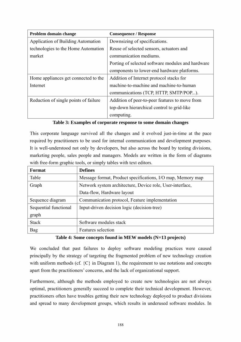
Problem domain change Consequence / Response
Application of Building Automation technologies to the Home Automation market
Downsizing of specifications. Reuse of selected sensors, actuators and communication mediums. Porting of selected software modules and hardware components to lower-end hardware platforms.
Home appliances get connected to the Internet
Addition of Internet protocol stacks for machine-to-machine and machine-to-human communications (TCP, HTTP, SMTP/POP...).
Reduction of single points of failure Addition of peer-to-peer features to move from top-down hierarchical control to grid-like computing.
Table 3: Examples of corporate response to some domain changes
This corporate language survived all the changes and it evolved just-in-time at the pace required by practitioners to be used for internal communication and development purposes. It is well-understood not only by developers, but also across the board by testing divisions, marketing people, sales people and managers. Models are written in the form of diagrams with free-form graphic tools, or simply tables with text editors. Format Defines Table Message format, Product specifications, I/O map, Memory map Graph Network system architecture, Device role, User-interface,
Data-flow, Hardware layout Sequence diagram Communication protocol, Feature implementation Sequential functional graph
Input-driven decision logic (decision-tree)
Stack Software modules stack Bag Features selection
Table 4: Some concepts found in MEW models (N=13 projects)
We concluded that past failures to deploy software modeling practices were caused principally by the strategy of targeting the fragmented problem of new technology creation with uniform methods (cf. {C} in D ), the requirement to use notations and concepts apart from the practitioners’ concerns, and the lack of organizational support.
iagram 1
Furthermore, although the methods employed to create new technologies are not always optimal, practitioners generally succeed to complete their technical development. However, practitioners often have troubles getting their new technology deployed to product divisions and spread to many development groups, which results in underused software modules. In
188

other words, previous modeling promotion efforts aimed at improving what was working (creation), failing to provide solution for what was not working (deployment).
With that respect, we decided to focus our new software modeling project on the issue of deploying new technologies to product divisions (cf. {D} in D ), and to use the on-going CMM-based process improvement effort as our organizational support. To adapt to the needs of stakeholders from various backgrounds, we selected Domain-Specific Modeling (DSM) for its versatility and adaptability. To enable quick development of solutions with few resources, we selected a DSM tool with a metamodeling facility (language definition and visual editing) based on configuration rather than programming. To reduce the risk of losing support over a long period of time, we selected a commercial tool from a well-established vendor. The promotion of general purpose modeling was delegated to our Software Engineering Group (SEG) within the software process improvement project.
iagram 1
DSM Medicine
In the course of our DSM developments, we found evidences of a wide range of problems that can be solved with DSM technologies, although these are not necessarily defined in terms of application code generation. Hereafter we list the problems we encountered, and we briefly describe the DSM solution we proposed to the respective stakeholders.
Stakeholder Activity Needs DSM Solution Complex system configuration
Generation of configuration files from system model Product
engineer Development of systems of systems Too many misuse cases
to take in account Automated discovery of misuse cases from models
Product developer
Porting of existing software to new hardware (re-targeting)
Quality issues Injection of generated code into code templates
Test suite development is costly Product tester Development of test
suites Possibility to overlook test cases
Automated generation of test suite from models
Development team Product development Late requirement
changes
Provide agility by way of visual modeling and code generation as visual models are closer to the requirements than source code
Development manager
Pass-over of a working software to the product division
Up-to-date design documentations
Generate up-to-date design and architecture documents from the model
R&D planning office
Measure of gap between current development practices and foreseeable market needs
Visibility of current development practices
A central model repository that can be scanned (a special model compilation) to extract information such as usage frequency of a module, of an operating system, of a combination of domain concepts…
189

Stakeholder Activity Needs DSM Solution
Core technology developers
Develop new technologies for tomorrow’s products
Reduce learning curve of innovative technologies to help deploy these to the developers
Reduce learning curve by embedding new APIs and guidelines into the code generator, and by providing a familiar visual language atop of it.
Software Process Improvement Group
Promotion of best coding practices
A method to enforce code layouts, naming conventions, folders conventions, etc…
Automated code generation according to well-defined rules.
A method to avoid dangerous code structures (scanf…)
Automated code generation that complies with the corporate security policy Software
Security Group Reduction of software security risk Difficulty to analyze
risks induced by design A special model compiler that derives risks from the model
Costly software development Software automation
Top management Strategic planning Difficulty to enforce
reuse of common platforms across the company
Automated selection of reusable models
Table 5: A selection of problems that can be addressed by way of DSM
Note that care should be given to select pains (problems) which resolution can be measured to demonstrate progress to both practitioners and management. Our pain killing method is composed of six steps:
Get embedded into the practitioner team - - - - - -
Observe the way people work to understand their context Ask practitioners for the few problems that most disrupt their core activity Select the problems that can be measured Present the DSM solution as a pain killer Deploy the DSM solution and verify the problem reduction with the practitioners
Process Integration of Modeling
Contrary to what happened with past efforts to promote general purpose modeling, where practitioners questioned the ability of specifying their software particularities, or the opportunity of replacing in-house frameworks with the tool vendor’s, we found no such resistance to our DSM effort. The perceived reason is that DSM tools adapt to the methodology in place, allowing us to use the domain concepts and frameworks that practitioners have been developing for years. This seems to corroborate Seth Godin when he writes [2] “a key element in the spreading of the idea is the capsule that contains it. If it’s easy to swallow, tempting and complete, it’s far more likely to get a good start”.
In order to clarify the positioning of DSM into the corporate process, we defined the three activities of creation {C}, deployment {D} and evolution {E}. As illustrated in the following
190

diagram, new technologies are first created using appropriate software engineering techniques {C}, and later deployed to the product domain with the help of DSM {D}. Finally, necessary evolutionary steps {E} are engaged to keep both technologies and DSM capsules up to date with the constantly changing market needs.
SoftwareEngineering Framework DSM
capsuleProduct
Variations
Market Evolution
Marketing
technologistdomain
productdomain
“classic” designand modeling
C D
E
Diagram 2: DSM capsule fills the gap between technologists and marketers
When looking from a lifecycle perspective (cf. Diagram 3), the creation activity {C} corresponds to new product developments, while deployment activity {D} represents domain-specific modeling. Finally, the evolution activity {E} maps to the incremental changes applied to both framework and modeling tool to follow the domain changes. Furthermore, this view reveals a well-established practice we have no plan to change: during the fundamental research phase practitioners often use off-the-shelf DSM tools for algorithm research purposes (ex: Simulink®).
SoftwareEngineering
Domain-SpecificModeling
Metamodeling
Research New ProductProduct Variations
Product Line
SoftwareEngineering
ProductLine
Development
Only OnceDevelopment
Sim
ulin
k, e
tc... C
D
E
Diagram 3: Life-cycle for software development aimed at deployment with DSM
Agile Modeling
Language agility is critical to the tool-smith, because lack of language agility puts the DSM tool at risk of being abandoned by practitioners for more convenient methods. After all, what matters most to practitioners is producing a working product, not using modeling tools.
The following diagram illustrates the gap between present needs, practices and available
191

tools. Due to the metamodeling delay necessary to define visual languages, editors and compilers, the DSM tool lags behind practices, so it is at risk of being perceived as constraining, especially for practitioners used to drawing with free-format whiteboards, pen and paper and general purpose diagram tools like Microsoft© PowerPoint.
Tomorrow’stool
Today’spracticesYesterday’s
practices
Today’stool
well-knownproblem range
lower value
new problem rangehigher value
metamodelingdelay
escape semanticsbridge the gap
Diagram 4: Reduce the gap between tool and practices
To address this issue we implemented escape semantics in our languages, with the purpose of improving the modeling tool’s stickiness by making it applicable to new problems not taken in account at language-design-time. The escape semantics allow for free-form modeling within boundaries set by the tool-smith, letting the modeler augment the official notation as necessary, typically when devising designs for new market segments. This opens the door to a collegial form of custom language construction where the DSM tool-smith and the domain expert initiate the reflection and practitioners add their thoughts and knowledge from field applications.
We identified several escape semantics that can empower the tool user: 1. Joker objects to augment the official language with new concepts 2. Joker links to augment the official language with new kinds of relationships 3. Overwritable list-boxes that can be augmented on the fly with new entries 4. Code generator aspects to let tool users augment the model compiler 5. The ability to extend model concepts with properties created on the fly
We noticed that young practitioners are more inclined to “invent” new notations to represent the world as they see it, while senior practitioners have been trained to the corporate notation and limit their usage of escape semantics to fixing purposes. Typical usage patterns of escape semantics we identified include:
192

Add a concept that had been overlooked by the tool-smith and expert. - - -
Augment the expressiveness of an existing language to enter a new domain. Adapt existing models to new corporate regulations.
Following is a real example of escape semantics occurrence. A Field-bus Definition language had been defined to declare the type, cardinality and mapping of data points found on communication protocols used to interface sensors and actuators. Because this language was too simple to describe Full2Way field-bus, Mr. Tanaka proposed the addition of a union relationship by using one Joker object (yellow box) and three Joker links (red dashed lines) to represent the fact that terminal unit data points (tu) and lighting dimmer data points (dimmer) are interchangeable.
tu : bit
dimmer : integer[0..127]
dimmer : integer[0..127]
group : bit
pattern
Lightingequipment
256
16
127
72
Full2Way
Unionby: A. Tanaka (2006/01/25 16h30)With Full2Way, the address space from 0 to 255 is shared between “tu” and “dimmer” equipment.Each address within that space can be either bit or integer[0..127]. The selection can be changed at run-time by loading a new configuration file.
Diagram 5: Using escape semantic to convey the meaning of union which does not exist in the language yet
In addition to language adaptability via escape semantics, we find necessary to design the languages for modeling flow. That means reducing the number of double-clicks, text-field editions, list and menu navigations necessary to draw a complete model.
As a rule of thumb, all activities introduced by the DSM but not found in sketching should be minimized, because practitioners will compare modeling with tool to sketching models. Some form of automation can be introduced into the modeling language to protect the modeling flow:
Default values (object name, property value) allow separating the creative activity of drawing pictures from the activity of specifying attributes. This can be facilitated by following the principle of convention over configuration [3] in the language design.
-
- Special values undefined and unknown allow practitioners to make progress in modeling a problem even thought some specifications remain unclear.
193

Connecting the DSM tool to corporate IT system to avoid duplicate input of information -
- - - -
- - -
Sustaining Deployment of Many Custom Languages
By introducing home-made tools into the product development process, the DSM tool-smith is exposed to several risks, including but not limited to:
A broken visual editor does not load old models The visual editor does not support current modeling practices A broken code generator produces malfunctioning software A valid code generator has not been updated to support changes in the target framework
These risks are worsened by several factors specific to DSM: Most domain-specific languages (DSL) are proprietary and maintained by a limited team Proprietary DSLs suffer from limited scrutiny and peer-reviews Proprietary DSLs have a limited user base and are applied to a limited number of applications when compared to main-stream languages like UML, “C”
To address these issues we implemented some test-driven practices from the agile software development community.
For example, the opposite diagram illustrates our solution to test the correctness of (modeling tool, frameworks) pairs by generating executables from well-known models and by running these against well-known data sets. Doing so, the tool-smith can periodically verify all well-known model compilation cases after each modification of existing DSLs, reducing the risk of releasing broken model compilers to the user.
Another step consists in checking the models repository for occurrences of escape semantics by way of daily model analysis. For example, the tool-smith could be emailed an alert on his mobile phone whenever a user would have used escape semantics, due either to some limitation in the modeling language, or to lack of knowledge from the practitioner, which either is bad news. This mechanism could prove to be a powerful communication means between the tool-smith and his users.
appli.source
appli.model
metamodel
input
expectedoutput
actualoutput
modelingtool
buildsystem
test management system
executableproduct
testresult
framework
Diagram 6: Test-driven language development
194

Finally, we use Scrum to manage the development of visual language editors and code generators. The product backlog proved to be a very practical tool to negotiate work items between the tool-smith and the stakeholders. For that purpose, we slightly customized the backlog format by adding columns Example models and Generation samples. Backlog items with more Example models and Generation samples are given priority because the more variation samples, the better DSL we can devise. The message is well understood by stakeholders who naturally do their homework to find or create more samples to get their problem higher in the list. Holding monthly Sprint Reviews open to all stakeholders and interested persons is also an efficient way to demonstrate progress, to keep stakeholders and users interested and involved, and to expose other practitioners to the DSM, fostering inquiries and requests for help.
The DSM Tool-smith’s Commandments
We propose to summarize this paper in the form of seven principles for the DSM tool-smith: You shall find the measurable pain of each user. -
- -
- - - -
You shall promote DSM as the medicine for each user’s pain. To product and solution developers, you shall give DSM. To technology developers, you shall offer well-known software engineering practices. To all you shall give Agility. You shall keep your tool up-to-date with your user’s changing practices. You shall offer escape semantics to your users. You shall design your languages for ease of modeling. You shall daily-test your languages and code generators.
Conclusion
We described key aspects of MEW’s approach to deploy domain-specific modeling (DSM) in the developments of systems of embedded devices, and we proposed practices to support the DSM tool-smith. We found that most challenges are not technical but instead human and organizational, and we interpret this as a testimonial of the maturity of DSM tools, but also as recognition of the lack of associated methods and practices.
Usability of home-made DSM tools remains the most challenging issue, because these tools are typically developed internally by a limited pool of software engineering specialists who lack expertise in ergonomics.
To address this problem we are exploring the discipline of human-computer interaction (HCI), and we found in Cognitive Dimensions (CD) [4] a promising candidate as some cognitive dimensions map precisely to several topics we discussed in this paper. For example, premature commitment and viscosity relate to our effort for preserving modeling flow, when
195
secondary notation relates to our escape semantics. And progressive evaluation could correspond to the ability of simulating models with undefined and unknown values.
Further research will tell whether Cognitive Dimensions can help build DSM tools that are not only efficient in solving technical problems, but also comfortable to work with.
References [1] Juha-Pekka Tolvanen, Steven Kelly. (2006). “Defining Domain-Specific Modeling
Languages to Automate Product Derivation: Collected Experiences” (SPLC05). [2] Seth Godin. (2006). “What makes an idea viral?”
http://sethgodin.typepad.com/seths_blog/2005/09/what_makes_an_i.html [3] Dave Thomas, David Heinemeier Hansson. (2005). “Agile Web Development with
Rails”, Pragmatic Bookshelf. [4] Alan F. Blackwell, Thomas R.G. Green. (2006). “Cognitive Dimensions of Notations:
A Tutorial” (VL/HCC06).
196

A Model-Based Workflow Approach for Scientific Applications
Leonardo Salayandía, Paulo Pinheiro da Silva, Ann Q. Gates, Alvaro Rebellon The University of Texas at El Paso, Computer Science Department
El Paso, TX, 79902, USA {leonardo, paulo, agates, arebellon}@utep.edu
Abstract
Productive design of scientific workflows often depends on the effectiveness of the communication between the discipline domain experts and computer scientists, including their ability to share their specific needs in the design of the workflow. Discipline domain experts and computer scientists, however, tend to have distinct needs for designing workflows including terminology, level of abstraction, workflow aspects that should be included in the design. This paper discusses the use of a Model-Based Workflow (MBW) approach as an abstract way to specify workflows that conciliate the needs of domain and computer scientists. Within the context of GEON, an NSF cyberinfrastructure for Earth Sciences, the paper discusses the benefits of using a Gravity Map MBW generated from an ontology about gravity. The Gravity Map MBW is based on terms derived from the gravity ontology that was developed by geophysicists; it does not include some of the workflow properties that tend to make workflow specifications look too complex for discipline domain experts to understand; and it provides a framework for developing strategies to derive executable Gravity Map workflow encodings with only limited interaction from computer scientists.
1 Introduction
Workflows specify the composition of software services, including data and control flow, to achieve a particular result or complete a task. In the case of scientific applications, the design of a workflow typically requires the involvement of at least two domain experts—one from the scientific field of interest (e.g., a geophysicist or biologist) to specify how scientific products (e.g., maps, graphs, data analysis reports) may be derived from datasets and another from a computer scientist, who understands the process of composing a workflow and encoding the derivation in a format that machines can execute.
Productive design of scientific workflows often depends on the effectiveness of the communication between the discipline domain experts and computer scientists—in particular, on their ability to clarify and reconcile their specific needs in the design of the workflow. Because domain experts and computer scientists have distinct terminology to describe workflow elements, including requirements, effective communication is a challenge. For instance, domain experts may base their workflow descriptions on objects of complex types that the computer scientist may not know how to translate to primitive types that are supported by executable workflow languages such as OWL-S [1] and MoML [2].
A domain expert’s workflow description is often more abstract than a computer scientist’s encodings of a workflow. Additional communication problems arise when the domain expert is expected to understand and further refine workflow specifications prepared by computer scientists. At the same time, computer scientists need to understand the entailments of the domain expert’s abstract workflow if computer scientists (with the help of software systems) are supposed to translate the abstract descriptions into executable workflows. For instance, domain experts may be concerned with the specification of partially ordered sequences of
197
services even if such sequences of service do not provide a perfect matching between services’ inputs and outputs. In this case, abstract specifications may require further refinement by computer scientists to be executed, e.g., the workflows may require additional steps such as translation services to match input and output information from services.
In this paper we discuss the use of a Model-Based Workflow (MBW) as a means to increase productivity during the design of workflows in support of scientific applications. Following the reasoning from the Domain-Specific Modeling (DSM) community [3], MBW is also about using a level of abstraction for modeling workflows that is consistent with the target domain, and then using such models (at best) to automatically generate executable workflows, that is, workflow implementations, or (at least) to guide the development of workflow implementations. In this paper we focus on the latter. We present the Workflow-Driven Ontology (WDO) approach1 to describe the domain and how WDOs can be used to create MBWs. In a scientific domain with the WDO approach in combination with the service-oriented paradigm, we claim that we diminish the intervention of computer scientists on the software development process by providing tools for domain-experts to produce specifications using the expert’s discipline-specific terminology that the computer scientist can employ to create the service-oriented modules necessary to achieve the intended results.
The remainder of this paper is organized as follows. Section 2 describes the technologies involved in representing and executing scientific workflows. Section 3 presents our approach for building model-based workflows and is exemplified through a use case. Section 4 discusses further benefits of model-based workflows when compared to approaches to develop scientific workflows. Section 5 summarizes the paper and identifies future work.
2 Background
Service Oriented Architectures (SOA), in combination with scientific workflows and ontologies are being used in efforts such as GEON to create cyberinfrastructure [4] that will provide the necessary tools to drive the next generation of scientific research. By developing service-oriented components, the scientific community is developing independent and distributed modules of functionality that are accessible and reusable through the web. Service-orientation enhances the design of low-coupled components by hiding implementation details from users and exposing only an interface specification that serves as a contract between service providers and service users. Ontologies are used first as “an explicit specification of a conceptualization” [6]. Later, they are used to support the composition and matching of services.
Scientific workflows are used to specify the composition of such service modules to achieve some complex scientific endeavor. There are many workflow specification languages and execution engines. Here we mention two: MoML and OWL-S. MoML or the Modeling Markup Language is the language used by the Kepler Scientific Workflow engine [5] and is a simple markup language that allows the specification of workflows that include actors and a director. Each actor carries on the execution of a step in the workflow, and the director gives the semantics of the control flow. With the Semantic Web as its basis, OWL-S [1] is a web service ontology that is based on the Ontology Web Language (OWL). OWL-S provides a service provider with constructs to describe properties and the functionality of a service in an unambiguous manner that is interpretable by a machine. OWL-S is composed of three different parts: the service profile that provides additional information about the services, such as functionality, inputs and outputs; the process model that provides information about
1 http://trust.utep.edu/ciminer/wdo/
198

how services are composed into a workflow; and the grounding that presents details about how to access the service.
Ontologies are used to describe knowledge about a domain such that its representation can be interpreted and reasoned about by a computer. Workflow-Driven Ontology (WDO) is an ontology design approach to represent knowledge about scientific domains that thus make them amenable to creating scientific workflows [7]. WDO-specific tools such as the WDO Assistant are used for capturing knowledge. Use cases typically drive the specification of ontologies [8]. In the WDO approach, abstract workflow specifications drive the elicitation and specification of classes and their relationships. For example, domain experts begin the knowledge acquisition process by identifying a product and from the product identify methods that can generate the product. Further, domain experts can identify data that are required as input for the identified methods. We claim that abstract WDO-derived workflow specifications are indeed the use cases for WDOs. Such use cases are the basis to create Model-Based Workflows (MBWs) and these are further described in Section 3.2 below. Furthermore, a WDO is an OWL ontology and as such it can be used to represent knowledge that is not workflow-specific, including domain knowledge.
3 Approach
Once a scientist has represented knowledge about a domain of interest by using the WDO
approach, the scientist can extract abstract workflow specifications from the WDO that can serve as a guide to implement an application to produce desired information. These abstract workflows are referred to as Model-Based Workflows (MBWs), and are created with the aid of workflow generator assistant software that can interpret the knowledge represented in a WDO. The scientist would identify the information desired from the WDO and the assistant software would then build an MBW to obtain the information based on the concepts and relationships defined in the WDO.
The next section discusses a use case that is used to exemplify the approach, followed by a description of an MBW.
3.1 Use Case
Assume that a geoscientist wants to obtain a Contour Map of Bouguer Anomaly Gravity Data for a given region of interest. The scientist starts by obtaining a WDO that represents knowledge from the geophysics domain; more specifically about “gravity data.” By using assistant software, the scientist identifies Contour Map as the intended information desired, and the assistant software produces as many MBWs as possible from the captured knowledge that identify the abstract steps to produce the map. One of the possible MBWs, referred as the Gravity Map MBW, is shown in Figure 1.
To show the relationship to the WDO, the workflow in Figure 1 is divided into two main sections. The left-hand side represents the classes of type Information that are associated with the workflow, and the right-hand side represents the classes of type Method that are involved in the transformation of the information required to achieve the desired outcome, i.e., a contour map. The left-hand side of the diagram is divided further into three sections: Product, Processed Dataset and Data. The distinction between these classes and their intention is explained elsewhere [7].
199

Fig. 1: The Gravity Map MBW generated from the Gravity WDO to produce a Simple Bouguer Anomaly Contour Map.
The arrows in Figure 1 shows the data flow of the workflow as the information is transformed starting from information of type Simple Bouguer Anomaly Contour Map to Grid, and finally to Contour Map. The information is transformed through the application of the Gridding and Contouring Methods, respectively. 3.2 Model-Based Workflows (MBWs)
MBWs are the resulting specifications obtained from a WDO to produce some information desired by the scientist. They are referred to as MBWs because the specifications use the knowledge represented by an ontology, and as a result, the terminology is based on the target domain, not computer science terminology.
Scientific workflows typically involve the sequential transformation of information from a simple information type towards a more complex information type such as an end product. Each step is of the form:
Output Info ← Method (Input Info List) Output Info defines the type of the information that will result once the Method of a step
finishes execution. When an Output Info type is used as an Input Info type in a subsequent statement, it means that the resulting information from this statement is used as input to the subsequent step. Any Input Info types that are not bound by previously executing steps require that the user inputs the corresponding type when the execution reaches the given step.
This simple “type-binding” mechanism illustrates the data flow of the workflow specification. The different types of information that will flow through the workflow are: datasets, products, and any other domain-specific concept defined in the WDO to clarify details about the workflow execution.
For example, consider the “Contour Map” use case presented in the previous section. The MBW produced by the assistant software would be as shown in Figure 2. All the concepts in the workflow specification are derived from the Gravity WDO.
200

Grid ← Gridding (Simple Bouguer Anomaly, Region of Interest); Contour Map ← Contouring (Grid).
Fig. 2: Model-Based Workflow specification to create a Simple Bouguer Anomaly Contour Map.
Currently we are in the process of formalizing MBW’s as an ontology. It is our intension to utilize OWL as a base framework and to have a tight integration between MBW’s and our concurrent work on WDO’s. The ontology that will be used to represent MBW’s will include constructs to specify basic sequential control flow, as well as concurrent control flow to allow workflow specifications with partial order method execution.
4 Discussion
A vision of cyberinfrastructure efforts such as GEON [4] is to provide scientists with tools that would allow them to access and use resources to further their research, education, and professional goals. A short term goal and the focus of this work is to allow domain and computer scientists to communicate better to produce the desired software systems required for scientific endeavors in a more efficient manner. The longer term goal is to provide sophisticated tools that would allow scientists to accomplish their tasks with limited interaction with computer scientists, if any.
Position1: MBWs provide a base for interaction between domain and computer scientists to facilitate communication towards implementing a workflow.
MBWs allow domain scientists to specify their tasks using terminology with which they
are familiar, while at the same time assisting computer scientists to understand what needs to be done to implement such specification. After a workflow specification is extracted from the WDO and represented as one or more MBWs, the domain and computer scientists work together to select and refine the MBWs, resulting in an executable specification of a desired system functionality.
The conversion process from an MBW to an executable specification is not straightforward, since the MBW is at a higher level of abstraction and, as a result, will lack details necessary for implementation. For instance, in the Gravity Map MBW presented in Section 3.1, the scientist uses the term Region Of Interest as input for the Gridding method. This requires interaction between the domain and computer scientists to map the abstract data type to one or more primitive data types, e.g., Double, Integer, and String. In one context, a scientist may desire to represent the Region Of Interest as two points, i.e., the upper-left and lower-right coordinate values (Latitude/Longitude) of a rectangular area. The computer scientist may decide to represent the coordinate values with a Double primary data type. In a different context, the scientist may decide that the best representation of the Region Of Interest may be the name of a county or state. In this case, the computer scientist may choose to map the Region Of Interest to a String primary data type. In any case, with the help of MBWs, domain experts can specify and refine workflow specifications without specifying a type for the Region Of Interest concept or composing a complex type for this concept from the primitive types of a workflow language. Furthermore, existing implementations of the Gridding method may only handle Region Of Interest represented as a Latitude/Longitude coordinate value and a Radial Distance value. The domain and computer scientists would then have to decide whether to adapt to the existing resource restrictions, or to create
201

additional resources to convert the current needs to match the signature of the existing resources.
Position2: While executable code cannot automatically be generated from MBWs, MBWs guide the code development process.
OWL-S is one executable language that can be used to implement workflows from
service-oriented components. Like other executable workflow languages, OWL-S is a sophisticated language that a domain scientist may find discouraging to learn, thus emphasizing the importance of Domain-Specific Modeling approaches. The process of creating an OWL-S workflow or composite service consists of 1) identifying the individual service components to be used in the workflow, and 2) creating the composition process for the workflow.
OWL-S supports a mechanism to create semantic descriptions for service components through “profiles”. Following the SOA approach, it is the job of the service provider, who has knowledge of the implementation details of the service component, to provide the description “profile” to the service user, who remains unaware of the implementation details. Once the domain and computer scientists have refined the requirements of the service components to be involved in the implementation of the MBW, the identification of service components is done by matching the requirements to profile descriptions of service components.
The composition process creation follows directly from the composition of methods involved in the MBW, in addition to any intermediary service components that the domain and computer scientists might have identified through the MBW refinement phase. For example, in the contour map use case, the workflow components are the Gridding and Contouring services, executed sequentially in that order, as described in the MBW.
While tools exist that automatically generate executable scientific workflows from models, e.g., Kepler [5] generates MoML code from a graphical model, such tools do not support Domain-Specific Models, and as a result, lack the consequent benefits of DSM.
Position3: MBWs open doors to additional work that will eventually result in scientists being able to produce workflows with only limited interaction from computer scientists.
Additional complementing work can facilitate the workflow generation process for the
scientist. One area that shows promise is preferences [9]. Preferences are useful whenever a user has to make a decision, and is an approach that can be used to filter through potentially many options. Preferences may apply both at the model level, as well as at the implementation level. For example, in the contour map use case, the scientist has to decide what is the best representation of the Region Of Interest for the context at hand. Once this decision is made, it can be documented as a preference to automate a similar decision for future development in the same context. Similarly, preferences can be captured for the decisions made by the computer scientist that map abstract information types to primary data types. The combination of preferences at all levels of abstraction brings the MBW approach closer to the ideal situation of automating code generation from domain-modeling. 5 Summary
This paper introduced the use of Model-Based Workflow (MBW) approach to facilitate the design of scientific applications. Derived from Workflow-Driven Ontologies built by
202

domain experts, MBWs are described in terms that the experts can understand. Thus, domain experts can be more active in the process of improving workflow specifications and less dependent on their ability to communicate to computer scientists. Although MBWs are very abstract with respect to their implementations, they can still be used as a framework for computer scientists to build executable workflows.
Previous work on expert systems has dealt with the problem of communicating domain knowledge to computer systems. Liou [10] breaks the expert system development effort into four primary tasks: acquiring knowledge from experts; representing that knowledge in a computer-readable form; implementing a prototype of the system; and verifying and validating the system. Even though our goal is not to develop expert systems but to develop scientific workflows, the tasks involved in expert system development contain some parallelism to our work. Our concurrent work on WDO’s [7] addresses the issues of knowledge acquisition and knowledge representation through the use of OWL ontologies. WDO’s also contemplate validation by allowing domain experts to review and provide feedback about the workflow generation process. The work discussed in this paper deals with prototype building based on the captured domain knowledge. Finally, other work on property specification and runtime monitoring of properties [11] complements the task of verification. 6 Acknowledgements
This work is funded in part by the National Science Foundation (NSF) through grant NSF EAR-0225670. The authors would like to thank Dr. Randy Keller from the Geological Sciences Department at the University of Texas at El Paso for his valuable input in developing the gravity data ontology. Finally, the authors would like to acknowledge the recommendations of two anonymous referees.
7 References [1] “OWL-S: Semantic Markup for Web Services”, The OWL Services Coalition, December, 2003. [2] E.A. Lee, and S. Neuendorffer, “A Modeling Markup Language in XML – Version 0.4”,
University of California at Berkley, Technical Report ERL-UCB-M-00-12, March 2000. [3] DSM Forum, http://www.dsmforum.org/, August 2006. [4] The Geosciences Network: Building Cyberinfrastructure for the Geosciences,
http://www.geongrid.org/, July 2006. [5] B. Ludäscher, I. Altintas, C. Berkley et al., “Scientific workflow management and the Kepler
system”, Concurrency and Computation: Practice and Experience, Special Issue on Workflow in Grid Systems, 18(10):1039-1065, 2005.
[6] T.R. Gruber, “A Translation Approach to Portable Ontology Specification”, Knowledge Acquisition 5(2):199-220, 1993.
[7] L. Salayandia, P. Pinheiro da Silva, A.Q. Gates, and F. Salcedo, “Workflow-Driven Ontologies: An Earth Sciences Case Study”, University of Texas at El Paso, Department of Computer Science, Technical Report UTEP-CS-06-38, August 2006.
[8] N.F. Noy, and D.L. McGuinness, “Ontology Development 101: A Guide to Creating Your First Ontology”, Stanford Knowledge Systems Laboratory Technical Report KSL-01-05, March 2001.
[9] M. Bienvenu, and S. McIlraith, “Specifying and Generating Preferred Plans”, Seventh International Symposium on Logical Formalizations of Commonsense Reasoning, May 2005.
[10] Y.I. Liou, “Knowledge Acquisition: Issues, Techniques, and Methodology”, Proc. 1990 ACM SIGDBP conference on trends and directions in expert systems, pp. 212-236, 1990.
[11] A.Q. Gates, S. Roach, I. Gallegos, O. Ochoa, and O. Sokolsky, “JavaMac and Runtime Monitoring for Geoinformatics Grid Services”, Proc. 10th IEEE International Workshop on Object-oriented Real-time Dependable Systems, February, pp.125–136, 2005.
203

Bootstrapping Domain-Specific Model-Driven Software Development within Philips
Hans Jonkers
Marc Stroucken Richard Vdovjak
Philips Research
High Tech Campus 31 5656 AE Eindhoven, The Netherlands
{Hans.Jonkers,Marc.Stroucken,Richard.Vdovjak}@philips.com
Abstract Philips recognizes the importance of model-driven software development (MDD). Unfortunately, there seems to be a lack of mature tools that would support domain-specific MDD and allow their deployment in an incremental fashion. This paper describes the ongoing MDD research efforts at Philips, introducing VAMPIRE1 − a light-weight model-driven approach to domain-specific software development. The VAMPIRE MDD framework is developed by Philips Research and it is currently being deployed at several Philips product divisions. The paper elaborates on the VAMPIRE modeling environment, focusing on its meta-modeling facilities, editors, and generators. Further, we summarize the lessons learned during the process of deploying our MDD framework into the product divisions.
1. Introduction To be a successful player in a competitive business environment such as consumer electronics, medical systems, or healthcare solutions, one needs to deliver integrated and interoperable software-intensive systems, and fulfill the ever-growing demand for new and improved features in ever-decreasing time to market. Moreover, the whole range of product families is required to exhibit a similar look and feel towards the end-user. These requirements affect the product’s hardware as well as its software. The proliferation of software in Philips products has been substantial and the amount of software still continues to grow at a great pace. As a consequence, the whole process in which the software is designed and constructed needs to address the aforementioned requirements efficiently.
The struggle to increase the software productivity and reliability has accompanied software development efforts since the very beginning. Among the remedies that proved to be (at least partially) successful was the raising of the abstraction level for writing code. Throughout the evolution of programming languages and design techniques (e.g. procedural languages, object-orientation, and design patterns) one can clearly see an increase in the level of abstraction at which software was written. The booming proliferation of software across many fields makes the demand for software higher than
1 Visual Agile Model-driven Product-oriented Integrated Research Environment
204

ever before. The demand currently exceeds the ability to produce software by a large margin, and this “software-gap” steadily increases in time.
To address this issue, the conventional development means need to be augmented by new approaches that would enable to raise the level of abstraction even further, while bringing the software engineering discipline closer to the actual domain where it is to be applied. The combination of a higher abstraction level closely coupled with the domain knowledge introduces a so-called model-driven development (MDD) − a paradigm shift in software engineering that has the potential to become a solution to the software-gap problem. To make this happen, we need to gradually move from writing code to creating domain-specific models and generating code and other related artifacts, such as documentation, etc., from them. Using small domain-specific modeling languages, as opposed to a universal modeling language such as UML, brings the modeling discipline much closer to the domain experts and at the same time enables simpler maintenance and evolution of such models, which contributes to the desired productivity increase as well as to the agility of the model-driven development.
The rest of the paper is structured as follows. Section 2 introduces the VAMPIRE modeling framework, section 3 elaborates on VAMPIRE’s meta-modeling features defined by the Meta Object Model, section 4 focuses on model editors , and section 5 explains the ideas behind our code generator. Section 6 summarizes the lessons learned during the process of applying this framework in Philips product divisions. Finally, section 7 gives an overview of related work, and section 8 presents our conclusions.
2. VAMPIRE modeling framework VAMPIRE is a light-weight model-driven approach to domain-specific software development. The VAMPIRE framework is being developed by Philips Research. It primarily aims at raising the level of abstraction at which the software for Philips products is produced, trying to increase productivity and reliability. The main idea is to capture the domain knowledge by means of models and to develop (parts of) applications by instantiating these models and generating the code, documentation, and other artifacts. VAMPIRE consists of a collection of loosely-coupled tools and in some sense represents a minimalist approach that allows us to apply MDD now and not wait till tools that would fit our needs appear.
The VAMPIRE framework is based on a very simple pattern, involving object models, editors and generators (see Figure 1). Object models define the essential entities in the domain(s) of interest. There need not be a single object model capturing a complete application domain, but there can be several small object models such as models capturing the variation points of specific products. Editors enable manual construction of model instances conforming to an object model. The editors allow users to construct these model instances in an intuitive and domain-specific way and completely hide the underlying implementation technology. Generators facilitate the generation of various artifacts from model instances. The generators allow (parts of) the software development process to be automated, i.e. to be “driven” by the models.
205

Editor Generator
ObjectModel
Instance
conforms to
inputcreates
Figure 1: VAMPIRE modeling pattern.
Setting up an MDD approach like VAMPIRE requires the definition of a meta-model − a modeling language defining the class of models that the framework supports. In VAMPIRE, this is represented by the Meta Object Model (see section 3) which is used to formally describe models of a certain domain. These models can be viewed as abstractions of entities within the given domain. In VAMPIRE, a model constitutes a network (graph) of types that capture domain knowledge in a certain area (e.g., medical systems). Object models thus serve as languages for defining instances of models and are therefore also referred to as domain-specific languages [1]. An important feature of VAMPIRE is that it considers models not just as abstractions but as concrete objects from which artifacts such as executable code and documentation can be automatically generated.
The models we develop for our product domains are relatively small in size, usually not exceeding 50 mostly product-specific type definitions. However, given the fact that there are many related products (creating groups of so-called product families) it is often the case that various (related) models need to be reused, combined, or their elements simply have to refer to other models’ elements.
In VAMPIRE, it is possible to combine models in different ways. Models can reference types in other models, thus building separate but linked models. Models can extend existing models, which allows the sharing of common parts (model inheritance). Finally, types can be extended with different aspects, which facilitates building models incrementally while separating concerns (Aspect Oriented Modeling).
A2
A1 M1
T1
T2
T3
M2
T4
T1
T2
M3
cross-model type inheritance
model extension
Figure 2: Aspect orientation and model reuse.
206

Figure 2 depicts three models (M1, M2, and M3). Models typically contain several interrelated type definitions, e.g. M1 contains types T1, T2, and T3. As mentioned, models can be extended by various aspects. An aspect is also a model; it defines (extensions to) types that are combined with the types of the model to which the aspect is associated. For instance, aspect A1 defines T1 which is combined with the definition of T1 from model M1; this mechanism to some extent resembles partial-classes from C# 2.0 but then at model level. The advantage of aspect orientation is the clear separation of concerns. One can simply define different aspects to already existing models, e.g. XML serialization details can be captured as an independent aspect. Models can be also combined with, extended, or reused by other models. For instance, model type T4 from M2 refers to (inherits from) a type T1 from M1, and model M3 inherits all types from M1.
3. Meta Object Model (MOM) The Meta Object Model (MOM) is defined as a combination of different aspects. Current aspects include the model itself, documentation and XML serialization. The documentation aspect supports the annotation of models with summaries, status, etc. The XML aspect allows for customization of the XML language of the instances. This even makes it possible to model existing XML languages like XML Schema (XSD), SVG, XML and XSLT. By so doing, the generation of such an XML file is reduced to a model transformation followed by a save-to-file operation. The MOM is an instance of itself which brings great flexibility. It is possible to transform any object model to a MOM instance and vice versa. This enables building tools such as validators to perform additional semantic checks, normalizers that resolve model extensions by creating a single self-contained model, and so-called defaults-resolvers that add or remove default values, which makes navigating through the MOM instances easier from the code. In the code, any MOM instance can be accessed by the graph it represents. When saving an instance of an object model, the graph representation is mapped to a tree-structure imposed by XML. This is done by a special model construct that allows indicating at which location a definition of a certain item is expected and at which other locations in the model references to that item may exist. A stubs-resolver replaces all reference stubs by real references, so that at any location the item’s definition becomes transparent to the programmer. Since the MOM is a generic meta-model, it is very small with just 5 basic constructs: class, union, list, enumeration and value type. Classes contain attributes that can be optional. This makes it possible to test for the presence of (and even remove) an attribute from a class object. The MOM currently supports single-inheritance, but the work on supporting multiple-inheritance is in progress. This is possible because the generated C# code is fully interface-based and multiple interface inheritance is supported in C#. Unions represent a special kind of forward type declaration. They define (closed) sets of classes or other unions; the instance of a union type is in fact an instance of exactly one type within the defined set. From the modeling perspective, unions can also be seen as a (type) choice. Unions do not have attributes of their own and support a weak form of multiple inheritance.
207

Lists are modeled closely to the generic list type of C# 2.0. Enumerations contain literal values. Value types are types that restrict some other basic types, e.g. the name of a C# identifier may subtype string with the restriction that it does not contain spaces. The generated C# programming library enables a MOM-oriented reflection. So in code it is possible from any model instance to access and explore its object model, which brings more flexibility for writing artifact generators (see section 5).
Figure 3: The MOM meta-modeling pyramid.
The MOM is extensible. Since it is described in itself, an extension to the MOM is achieved in 2-pass iterations. In the first pass the MOM is extended and new code is generated from it. In the second pass the code generator is extended to start using the new constructs. Extensions that are independent of the C# model are even simpler and can be added at any time. Therefore, extending the MOM with new aspects, e.g. layout metadata for a graphical editor is very easy. Figure 3 illustrates the extension pyramid of MOM. It starts with the MOM itself as the basic building block followed by general–purpose meta-modeling extensions such as serialization; this layer can be (optionally) extended with domain specific meta-modeling extensions. These meta-modeling facilities are then used to describe concrete domains in terms of Object Models and their instances (Models).
4. Editors The first letter from the VAMPIRE acronym stands for “Visual”, emphasizing that the visual aspect plays a crucial role in the MDD way of working. The fact that models and their instances are edited visually (as opposed to writing code or hand-crafting XML files) makes the learning curve much less steep and the actual process of modeling much more appealing. The visual aspect also contributes to the desired agility of our approach, as it is much easier for people to reason and change models if they are represented visually. There are several approaches to model / instance visualization, browsing, and editing. These approaches range from more generic table-based model editors (such as the one depicted in Figure 4) to more diagrammatic or pictorial editors. The latter have the potential
208

to offer more (domain) specific elements in the visualization, but of course then they become model dependent and therefore need to be individually tailored for every single application domain.
Figure 4 InfoPath-based Application Editor.
The VAMPIRE framework offers an extensible set of loosely-coupled generic tools for editing and browsing models and their instances. Most of these tools are currently based on existing XML-enabled editing suites such as InfoPath2 or XMLspy3. The generic editors provided by the framework can be made more domain-specific by extending the default generators. Future development includes a customizable suite of diagrammatic and pictorial tools for visual model editing.
5. Generators The VAMPIRE framework includes a C# code generator which takes an object model as its input and produces a C# library of types occurring in the model together with a set of interfaces for access and manipulation. The library is fully interface-based implying that instances of model types can only be accessed / modified by interfaces [6]. The generated code provides an easy-to-use programming model for instances of an object model, where all constructs defined in the object model, are also available in C# using Intellisense of VS.NET (see Figure 5). This strongly-typed approach of model instance to C# conversion brings the benefit of compile-time checks and an early discovery of potential inconsistencies (which may occur especially when models are instantiated by humans).
2 http://www.microsoft.com/office/infopath 3 http://www.Altova.com/XMLSpy
209

Figure 5: Model-aware Intellisense support.
Multiple views in the code provide a value-oriented, object-oriented, and an attribute-oriented way of working. The adopted interface-based approach allows switching between the different views. Construction methods are generated for the types to reduce the lines of code you have to write in a generator.
Editor Generator
ObjectModel
Instance
conforms to
inputcreates
C# Code Generator
Model API
Artifact
createsinput
creates
has knowledge ofuses
Figure 6: Artifact Generator.
Every model has its own XML representation for which an XML schema file can be generated. The generated C# code provides load and save methods for the instances of the model that conform to their XML representation. The default XML representation makes efficient use of XML attributes, elements or anonymous constructs. Besides the C# code generator, the VAMPIRE framework offers a number of other tools such as XML schema generator, HTML documentation generator, and a generator of an SVG graphical model browser. On top of the “built-in” generators (which are generic for all instances of the MOM), one can write domain-specific generators that create domain-specific artifacts. Figure 6 shows such a generator; the generator uses the model API created by the C# generator and processes the instances of the model, creating domain-specific artifacts.
6. Applying VAMPIRE In the past three years we have successfully applied our approach in several domains which, because of the proprietary nature of the products involved, we can only describe briefly in this paper.
210

During this time the approach has reached a maturity level where it can be transferred to other departments within Philips. Some departments are going to use the approach to research new models and description languages, while others will use the development environment to implement tools for their customers. Because of the fast development of models and transformations more time can be spent focusing on the content instead of the tooling. The complexity of using MDD in existing software-intensive product lines is mainly identifying those parts in the software architecture that can be replaced by models with generated code. Certain skills, and a different way of thinking about software in general, are required. A trained eye sees possibilities for code generation almost everywhere, which requires switching between several meta-level views. A typical target for applying MDD is the class of software that exists in many varieties in one product line, or software that changes a lot over time, e.g. with every new release. It may also be applied to develop architecture description languages (ADLs) [7]. Below we shortly summarize the lessons learned during the last few years when we were trying to introduce the VAMPIRE framework in Philips. This (not exhaustive) list can be seen as necessary prerequisites without which it would be very hard to apply MDD within an industrial environment like the Philips product divisions. • Incremental deployment of MDD.
It is important to be able to introduce MDD in small evolutionary steps (as opposed to a sudden 100% MDD conversion). This is important especially in an environment which possesses a long history of products and usually has many obligations to third parties w.r.t. that.
• Very simple meta-modeling facility. It is necessary to realize that the ultimate user of MDD will eventually be a (technically savvy) domain expert rather than a “purist” programmer4. Therefore, the learning threshold for embracing the MDD approach must be as low as possible and the actual models must be close to the domain where they are to be applied.
• The ability to combine/reuse/extend models. Multitude of related products require their models to be also related. The agility of MDD brings even more benefits if one is able to reuse and combine existing models.
• Support the rapid development of generators (using MDD). Tools like an efficient C# code generator or editor generators must be present in the framework to increase its usefulness, its ease of use, and ultimately to make it embraced by the community of modelers and developers.
• Software development paradigm shift. The introduction of any paradigm shift takes time. We have to change the way in which developers perceive software, the way they think about development, and prove that the changes will bring benefits in the long run. Developers are often reluctant to change the way they work. MDD focuses on developing tools that generate (parts of) the end-product, instead of developing the product manually.
4 Excellent software developers will still be needed to develop MDD tools like (domain-specific) generators etc.
211

We believe that MDD has the potential to improve the way we create software and above all to make this process more efficient. However, as any new technology, also MDD must overcome the inertia of existing approaches, and even if all the technical ingredients are in place, it also requires the management support and their devotion to make the change happen.
7. Related work In this short comparison we chose to focus on two MDD initiatives advocated by OMG and Microsoft, respectively. We note that there are a number of other model-driven frameworks and approaches that VAMPIRE can relate to. However, to our knowledge no existing approach offers an aspect-oriented way of modeling combined with (pure) interface-based C# code generation, features which are very important in our application domain. MODEL DRIVEN ARCHITECTURE (OMG) The OMG promotes model-driven architecture [2, 3]. In simple terms, their approach states that applications are developed by creating platform-independent models (PIMs) in UML. PIMs conform to domain-specific meta-models defined by UML profiles or by means of the meta-object facility (MOF). Model transformations map PIMs to platform-specific models (PSMs) and from there to code, etc. Tools exchange data by means of the XML Metadata Interchange (XMI) language. The OMG itself does not develop tools and the tool support is (to be) delivered by third parties. MDA in some sense represents an MDD vision that other approaches can relate / comply to. VAMPIRE too adopts some of the MDA ideas, however, we consider our approach being more of a bottom-up nature (starting with a concrete domain) than top-down nature of MDA (having the universal language that needs some tailoring). SOFTWARE FACTORIES / DSL (Microsoft) Microsoft’s software factories initiative [4] and the associated DSL tools [5] are very close to our approach therefore we compare it in more detail. The Microsoft approach uses a meta-language to define domain-specific languages (DSLs), which is not very different from our Meta Object Model. One important difference though, is that the VAMPIRE framework facilitates various ways of combining and reusing models; this feature is, to our knowledge, missing in DSL. The type of reflection provided by VAMPIRE and DSL also differs. While VAMPIRE allows for reflection at model level, DSL provide reflection at C# level only. Another difference is that DSL use a tem7plate-oriented approach to artifact generation while VAMPIRE uses a (full-fledged) code-based approach. The former fits well in simpler types of artifacts such as documentation reports; however, writing templates that generate C# code is much more tedious, especially since (at the time of writing) supporting tools like Intellisense or the syntax highlighting are missing. On top of that, DSL tools are still undergoing radical changes (to the better we believe) and their meta-model and APIs are not yet stable enough for use in production quality code. We continue to monitor the developments of the DSL tools and do not exclude the possibility to port our VAMPIRE framework onto this platform some time in the future.
212

8. Conclusions In this paper we have described the essence of the VAMPIRE framework developed at Philips Research. Our approach targets both new product architectures as well as existing software intensive product lines, where the handwritten code can be incrementally replaced by generated code from models. The framework is based on a pattern involving models, editors, and generators and the paper elaborated on these MDD “ingredients” in more detail. We have also summarized the lessons learned from applying our framework in Philips product divisions. Below we list some of the distinguishing features of VAMPIRE. • By incorporating Aspect-Oriented Modeling and supporting multiple inheritance,
VAMPIRE provides an easy way to build new models on top of existing ones, facilitating model extensibility and reuse.
• The generators are implemented as loosely-coupled tools associated with different model instances, and can also be combined into file- or memory-based generator pipelines, where output of one generator serves as input for another one.
• Flexible XML serialization format allows for modeling of existing standardized XML languages such as XML Schema. Creating output in such a standard XML language is as easy as building a model-to-model generator.
• Using a minimalist approach, we tailored VAMPIRE to the needs of our industrial applications. However, the framework proved to be powerful and extensible enough to be applied in different (unrelated) contexts.
In our experience, MDD has the potential to make the process of software creation much more efficient. In order to achieve that, the MDD way of thinking needs to be adopted by the developers and domain experts, some of whom will actually become application modelers.
Acknowledgements We would like to thank our colleagues both from Philips Research and Philips product divisions for providing their valuable feedback on this work.
References [1] Czarnecki, K., Eisenecker, U. Generative Programming: Methods, Techniques and Applications.
Addison-Wesley, 1999. [2] OMG Model Driven Architecture (MDA) URL: http://www.omg.org [3] Mellor, S., Scott, K., Uhl, A. Weise, D. MDA Distilled, Principles of Model Driven Architecture.
Addison-Wesley Professional, 2004. [4] Greenfield, J., Short, K., Cook, S., Kent, S. Software Factories. Wiley, 2004. [5] Microsoft Domain-Specific Languages Tools. URL: http://msdn.microsoft.com/vstudio/DSLTools/, June
2006. [6] Steimann, F., Mayer, P. Patterns of Interface-Based Programming, Journal of Object Technology (JOT)
Vol. 4, No. 5, July-August 2005. [7] Clements, P., C. A survey of architecture description languages, Proceedings of the 8th International
Workshop on Software Specification and Design, Page(s):16 - 25, March 1996.
213

Domain Specific Model Composition Using ALattice Of Coalgebras
Jennifer Streb, Garrin Kimmell, Nicolas Frisby and Perry AlexanderInformation and Telecommunication Technology Center
The University of Kansas{jenis,kimmell,nfrisby,alex}@ittc.ku.edu
Abstract
This paper presents a semantics for domain-specific modeling in support ofsystem-level design of reactive, embedded systems. At the core of the approach isthe use of a lattice of coalgebras to define the semantics of individual models andreusable specification domains. The lattice provides formal support for assessingthe correctness of specification transformation. Additionally, using pullbacks andfunctors within the lattice provides semantic support for specification transforma-tion and composition. Although developed for the Rosetta specification language,the lattice of coalgebras provides general semantic support that could be used todefine any system-level design language.
1 IntroductionThe Rosetta system-level design language and semantics [1, 2] are designed explic-itly to support the needs of system-level design for reactive, embedded systems. Toachieve this, Rosetta supports domain-specific, heterogeneous specification by provid-ing a collection of domains that define vocabulary and semantics for domain specificdesign facets and a domain lattice that organizes domains to support abstract interpre-tation, transformation and composition of specifications. In this paper we present asemantic infrastructure supporting these system-level design activities.
2 Domain Specific Modeling SemanticsFacets are the fundamental unit of Rosetta specification representing one aspect orview of a multi-aspect system using domain-specific semantics. Information such ascomponent function, performance constraints, and structure are represented using facet
214

models. Facets use a domain-specific semantic basis appropriate for the informationbeing represented explicitly supporting heterogeneous modeling.
Figure 1 shows two facet models describing power and function for a simple sig-nal processing component. The power model defines a simple activity-based powerconsumption model that observes changes in the output value. The function modeldefines the interface of a functional model whose body is omitted for space consider-ation. The system-level design objective is to define a single model that satisfies bothspecifications.
facet power(o ::output top;leakage::design real;switch :: design real ):: state based is
export power;power::real ;
beginpower’ = power + leakage +
if event(o) then switchelse 0
end if ;end facet power;
facet interface function( i :: input real ; o ::output real;clk :: in bit ;uniqueID::design word(16);pktSize::design natural):: discrete time is
uniqueID :: word(16);hit :: boolean;bitCounter :: natural ;
end facet interface function;
Figure 1: Rosetta specification fragments defining power consumption and functionalmodels for a TDMA unique word detector.
2.1 Coalgebraic SemanticsJacobs [3] observed that coalgebras provide an excellent basis for defining computa-tions that are event driven and non-terminating. Every coalgebra ψ has the form:
ψ :: X → F(X )
where X is the carrier and F defines constraints on the carrier. Running a coalgebraicsystem involves unfolding X with respect to ψ using an anamorphism defined for allsuch coalgebras. Specifically, given X the next state is ψ(X ) = F(X ), the next isψ(ψ(X )) = F(F(X )), and so forth. This is precisely the semantics we want forevent-driven, continuously operating systems. The application of ψ is associated witha system event, causing a state change when that event occurs.
It is useful to contrast the coalgebra with an algebra having the form:
φ :: G(b)→ b
where b is the carrier and G defines constraints. Here, evaluation is takes the form of afold of G over b using a catamorphism. Given any finite number of applications of G,
215

the value b can be calculated. Thus, if we use an algebraic model, we are restricted toexamining only finite prefixes of potential state sequences.
The semantics of a Rosetta facet is denoted by coalgebra defining observations onchanges over an abstract state. The facet’s signature defines the coalgebra signaturewhile its terms define its transformation by placing constraints on abstract state obser-vations. For example, when denoting the power facet from figure 1, F is next observedby facet declarations while a is the facet state. Thus, given a state a, the sequence ofstates is observed as a, next(a), next(next(a)) and so forth as expected. The terms inthe facet constrain next providing a definition of the sequential computation. The ap-plication of next is constrained to occur only when an event is observed on the systemoutput. This is embodied by the predicate event used in the definition.
The signature of coalgebra denoted by the power facet in figure 1 has the form:
<o,leakage,switch,power,s,next> :: X →(state time → top)× (state type→ real)× (state type→ real)× state type× (state type→ state type)
where o, leakage, switch, and power are observations on X defined in the facet whiles and next are defined by the state based domain. The corresponding types of thoseobservations comprise the product.
What we are defining in the facet is the observation of the next X as observed bynext. Examining the denotation of the power term reveals the coalgebraic nature of thefacet:
power(next(s(X )) = power(s(X ))+ leakage(s(X ))+ if event(o(s(X ))) then switch(s(X )) else 0 end if;
Here, the next function is being defined by embedding it in the observer power, com-monly called a destructor. As long as X does not change, the observation remainsthe same. These characteristics – defining functions in destructors and observing statechange – lead us to a coalgebraic semantics over the more traditional algebraic seman-tics [3].
In a Rosetta facet coalgebra, X is always held abstract with no associated concretetype. It is never directly visible to the specifier or even to the Rosetta facet that observesit. Instead, a Rosetta facet’s state is denoted as an observation of X . For example, ifs :: state type defines a state in some domain, then its value in the coalgebra is denoteds(X ) :: state type – a function over the abstract state. If an item x :: integer is definedin a facet from the domain of s, then it is denoted x(s(X )) :: integer.
Because facet state is simply an observation of X , it is possible to define multi-ple state observations with multiple semantics. As sequencing of state is the criticalelement distinguishing models-of-computation, defining different state observations
216

results in multiple, heterogeneous models-of-computation. When models defining dif-ferent state semantics observe the same abstract state, then those observations may berelated. This is precisely what is needed in system-level design where the distinctionbetween modeling domains is rooted in the underlying computational model.
2.2 Specification CompositionThe primary specification composition mechanism in the Rosetta semantics is definedby the category theoretic pullback construction. In the traditional specification litera-ture where algebraic specifications dominate presentations, the coproduct and pushoutdefine specification composition [4]. As Rosetta models are coalgebraic, their duals,the product and pullback, define model composition. Intuitively, the pushout formsthe union of two algebraic specifications defined around a collection of shared decla-rations. The pullback forms the intersection of two coalgebraic specifications, againdefined around a collection of shared declarations. Making X the minimum shareddeclaration ensures that specifications involved in the pullback reference the same ab-stract state. They may observe that state differently, but they observe the same state.
Given two Rosetta models f1 and f2 a product is formed as the disjoint combina-tion of f1 and f1 much like a record. In contrast, a pullback forms a product arounda common, shared specification, d. We say that d is shared between specifications be-cause when properties from f1 and f2 refer to declarations in d, they refer to the sameelement. Properties placed on symbols of d from each specification mutually constraind implying f1 and f2 are no longer orthogonal.
In our power modeling example, we would like to understand how the function be-ing performed impacts power consumption. Thus, a pullback is formed is formed fromthe power specification and the original function specification. This product modelformed by the pullback is defined as a new Rosetta facet in Figure 2.
facet power and function( i :: input real ; o ::output top; clk :: in bit ; uniqueID::design word(16);pktSize::design natural; leakage,switch::design real ):: discrete time is
gamma(power(o,leakage,switch))∗ function( i ,o,clk ,uniqueID,pktSize);
Figure 2: Creating the composite specification by forming the product of the func-tional specification with the application of gamma to the power specification.
The product treats the discrete time domain as a shared specification among thepower and function models. The specification objects that t , delta and next refer toare shared between the specifications. Edges that indicate state change and power con-sumption are common to both components implying that processing in the functionalspecification results in power consumption in the power model. Any property definedon these items in one specification must be consistent with definitions in the other –
217

they are literally shared between the specifications. Other symbols remain orthogonal,but when referenced in properties relating them to shared symbols they are indirectlyinvolved in sharing properties across domains.
2.3 The Domain LatticeBecause Rosetta facets are first-class items, they must have an associated type, calleda domain. In figure 1 the domain of the function facet is discrete time while the powerfacet is of type state based. Rosetta domains encapsulate vocabulary and semanticsfor domain specific specification style. Each domain encapsulates units of semanticdeclarations, a model of computation, and a domain specific modeling vocabulary forreuse among similarly structured specifications.
Domains are simply distinguished facets that represent specifications that are ex-tended. When a new domain is defined, it extends another domain in a manner identicalto facet definition. The new domain is aptly call a subtype or subdomain of the originaldomain. For example, the discrete time domain is defined as a subtype of state based.The concepts of state and change present in the state based domain are inherited andrefined within the state based domain. The distinction between defining a domain anddefining a facet is the domain can be further refined to define facets or other domains.
The set of legally defined domains together with the homomorphism relationshipsresulting from extension define a partially ordered set (D,⇒) referred to as the do-main lattice. The domain lattice obeys the formal definition of a lattice requiring thedefinition of meet (u), join (t), the minimum domain the maximum domain. nulldefines primitive Rosetta semantics including X and is the least domain in D with alldomains inheriting from it. Similarly, bottom is the greatest domain and inherits fromall domains, making it inconsistent.
For any domain pair D1 and D2, D1 u D2 and D1 t D2 are defined as the leastcommon supertype and greatest common subtype. The existence of null and bottomensures that every domain pair will have at least one common superdomain and sub-domain. Thus, (D,⇒) defines a lattice.
2.4 Specification TransformationA functor is a function specifying a mapping from one domain to another. The primaryrole of functors is to transform a model in one domain into a model in another. Viewingeach domain and facets comprising its type as a subcategory of the category of allRosetta specifications, a functor is simply a mapping from one subcategory to anothercorresponding to the classic definition of functors in category theory.
When defining domains by extension, two kinds of functors result. Instances ofconcretization functors, Γ, are defined each time one domain is extended to defineanother. Abstraction functions, A, are the dual of concretization functions and areknown to exist for each Γ due to the multiplicative nature of extension. So, Γ instancesmove down in abstraction while A instances move up. Each arrow in the domain
218

lattice moving from one domain down to another defines both an instance of Γ and A.However, A and Γ do not form an isomorphism because A is lossy – some informationmust be lost or A cannot truly be an abstraction function.
3 Implications of the Domain LatticeA major application of Rosetta functors is to add or remove detail to support predictiveanalysis and specification composition. Thus, it is critical to assure that functor appli-cation results in correct models. To achieve this, we view functor application from theperspective of abstract interpretation [5] where programs and specifications are stati-cally analyzed by focusing only on necessary details. An abstraction is safe when themodel resulting from it is faithful to the original model.
Because Rosetta focuses on domain-specific specification composition, we need toverify the safety of functors moving specifications within the lattice. More specifically,we want to verify that by moving a specification or model between Rosetta domainswe do not sacrifice correctness. One technique common in the abstract interpretationcommunity is establishing a Galois connection [6] between domains in the lattice.
A Galois connection (C, α, γ, A) exists between two complete lattices (C, v) and(A, v) if and only if α : C → A ∧ γ : C ← A are monotone functions that satisfyγ ◦ α w λc.c and α ◦ γ v λa.a. Typically, α is an abstraction while γ is an associatedconcretization. Within the Rosetta domain lattice, the initial focus on the functors Aand Γ formed when one domain is extended to define another. This gives the Galoisconnection we are initially interested in the form (D,A,Γ, D).
The extension of one domain to form another gives us a concretization functor, Γ,that defines a homomorphism between domains. Because Γ is multiplicative, we knowfrom lattice theory that an inverse abstraction functor, A, exists and can be derivedfrom it. With A and Γ and the homomorphism, we can define a Galois connectionbetween any Rosetta domain, D0, and any of its subdomains, D1, as (D0, A1,Γ1, D1).Knowing the Galois connection exists we are guaranteed any transformation betweenD0 and D1 using Γ of A is safe. We are also guaranteed that the original model is aninstance of the abstract model and the abstract model is truly an abstraction.
We also know that the functional composition of two Galois connections is also aGalois connection [6]. Formally, if (D0, A1,Γ1, D1) and (D1, A2,Γ2, D2) are Galoisconnections then (D0, A2◦A1,Γ1◦Γ2, D2) is also a Galois connection. Not only can weassure safety between any domain and its subdomain, but we are also guaranteed safetyof any transformation within the entire Rosetta domain lattice that follows abstractionlinks.
219

4 Related WorkThe use of products for specification composition is well established in the literaturefor both specification [4] and synthesis [7]. Although the coalgebra and pullback areless frequently used, there has been work using coalgebras to define composable spec-ification systems [8] and the use of coalgebraic specification is seeing acceptance inthe specification community [9]. Brevity prevents complete discussion of coalgebraictechniques – see Jacobs’ and Rutten’s excellent tutorial for more details [3].
UML meta-models define semantics that has been exploited for domain specifictool development and model-integrated design [10]. The model-integrated approachreflects our approach to model refinement and abstraction as the central features indesign synthesis and analysis respectively. The model-integrated approach uses UMLas its modeling language, although like the coalgebraic semantics presented here itshould not be limited to UML models.
Viewpoints are a software specification technique applied to domain specific mod-eling [11]. Viewpoints are less formal than Rosetta and focus primarily on softwaresystems. However, interaction between models searching for inconsistencies has beenexplored extensively giving Viewpoints a similar system-level focus[12].
An alternative approach using operational modeling is the Ptolemy [13] project.Ptolemy (now Ptolemy Classic) and Ptolemy II successfully compose models usingmultiple computation domains into executable simulations and software systems. PtolemyII introduces the concept of a system-level type [14] that provides temporal informa-tion as well as traditional type information. Like Rosetta, Ptolemy II uses a formal se-mantic model for system-level types. Unlike Rosetta, Ptolemy models are executableand frequently used as software components.
5 DiscussionThis paper provides an overview of the approach to domain specific model composi-tion embodied in the Rosetta specification system. With a formal semantics for het-erogeneous models supporting composition and transformation functions, it becomespossible to define heterogeneous models, compose them and generate abstract analysismodels. Further details are available in System-Level Design with Rosetta [2] one ofseveral overview papers [15].
References[1] Perry Alexander and Cindy Kong. Rosetta: Semantic support for model-centered
systems-level design. IEEE Computer, 34(11):64–70, November 2001.
[2] Perry Alexander. System-Level Design with Rosetta. Morgan Kaufmann Publish-ers, Inc., 2006.
220

[3] Bart Jacobs and Jan Rutten. A tutorial on (co)algebras and (co)induction. EATCSBulletin 62, 1997. p.222-259.
[4] H. Ehrig and B. Mahr. Fundamentals of Algebraic Specifications 1: Equationsand Initial Semantics. EATCS Mongraphs on Theoretical Computer Science.Springer–Verlag, Berlin, 1985.
[5] Patrick Cousot. Abstract interpretation. ACM Computing Surveys, 28(2):324–328, June 100.
[6] Flemming Nielson, Hanne RIIS Nielson, and Chris Hankin. Principles of Pro-gram Analysis. Springer-Verlag, 2005.
[7] Douglas R. Smith. Constructing specification morphisms. Journal of SymbolicComputation, 15:571–606, 1993.
[8] A. Kurz and R. Hennicker. On institutions for modular coalgebraic specifications.Theoretical Computer Science, 280(1-2):69–103, May 2002.
[9] J. Rothe, H. Tews, and B. Jacobs. The coalgebraic class specification languageCCSL. Journal of Universal Computer Science, 7(2):175–193, March 2001.
[10] A. Misra, G. Karsai, J. Sztipanovits, A. Ledeczi, and M. Moore. A model-integrated infomration system for increasing throughput in discrete manufac-turing. In Proceedings of The 1997 Conference and Workshop on Engineeringof Computer Based Systems, pages 203–210, Montery, CA, March 1997. IEEEPress.
[11] S. Easterbrook. Domain modeling with hieararchies of alternative viewpoints. InProceedings of the First International Symposium on Requiremetns Engineering(RE-93), San Diego, CA, January 1993.
[12] Steve Easterbrook and Mehrdad Sabetzadeh. Analysis of inconsistency in graph-based viewpoints: A category-theoretic approach. In Proceedgings of The Au-tomated Software Engineering Conference (ASE’03), pages 12–21, Montreal,Canada, October 2003.
[13] J. T. Buck, S. Ha, E. A. Lee, and D. G. Messerschmitt. Ptolemy: A frameworkfor simulating and prototyping heterogeneous systems. Int. Journal of ComputerSimulation, 4:155–182, April 1994.
[14] Edward A. Lee and Yuhong Xiong. System-level types for component-baseddesign. Technical report, University of California at Berkeley, February 2000.
[15] J. Streb and P. Alexander. Using a lattice of coalgebras for heterogeneousmodel composition. In Proceedings of the Multi-Paradigm Modeling Workshop(MPM’06), Genova, Italy, October 2006.
221