6dct450-470-service-menu.pdf - WordPress.com
99
INDEX WWW.ATSG.COM WWW.ATSG.BIZ 6DCT450 International vehicle application per Transtec's Original Guide to Automatic Transmissions by Vehicle Global edition ................................................................................ 6DCT 450 Introduction........................................................................................................... The Getrag Portfolio............................................................................................................... Line Pressure Tap.................................................................................................................... Drain Plugs............................................................................................................................. Fill Plug, Check Plug and Fluid Information........................................................................... Transmission Range Sensor .................................................................................................... Computer Modes and Strategies............................................................................................. Powerflow .............................................................................................................................. Dog Clutch............................................................................................................................. Clutch Housing Removal....................................................................................................... Valve Body Removal.............................................................................................................. Case Passage Identification.................................................................................................... Fork Identification................................................................................................................. Solenoid Identification and Function...................................................................................... Valve Body ............................................................................................................................. TCM/Inputs/Wire Diagram.................................................................................................... 6DCT470 Significant differences compared to the 6DCT450 6DCT470 Transmissions by Vehicle Global edition ................................................................................ International vehicle application per Transtec's Original Guide to Automatic Transmission Range Sensor .................................................................................................... Wiring Diagram/TCM Terminal ID........................................................................................ Shaft to Case Orientation/Gear and Shaft Identification.......................................................... Clutch Identification............................................................................................................... Valve Body Removal.............................................................................................................. Case Passage Identification.................................................................................................... Solenoid Identification and Function...................................................................................... Valve Body ............................................................................................................................. TCM Topography/Fork Assignments..................................................................................... Diagnostic Trouble Codes...................................................................................................... 3 4 5 7 8 9 10 12 14 20 21 29 30 31 33 35 41 45 46 47 49 51 52 53 54 56 62 63 Copyright © ATSG 2012 6DCT450/470 Hydraulic Schematics 6DCT450 6DCT450 Valve body Mapping text..............66 6DCT450 Valve body Mapping schematic....74 6DCT450 Park/Nerutral schematic................75 6DCT450 Reverse schematic.........................76 6DCT450 1st Gear schematic.........................77 6DCT450 2nd Gear schematic........................78 6DCT450 3rd Gear schematic........................79 6DCT450 4th Gear schematic.........................80 6DCT450 5th Gear schematic.........................81 6DCT450 6th Gear schematic.........................82 6DCT470 6DCT470 Valve body Mapping text..............83 6DCT470 Valve body Mapping schematic....91 6DCT470 Park/Nerutral schematic................92 6DCT470 Reverse schematic.........................93 6DCT470 1st Gear schematic.........................94 6DCT470 2nd Gear schematic........................95 6DCT470 3rd Gear schematic........................96 6DCT470 4th Gear schematic.........................97 6DCT470 5th Gear schematic.........................98 6DCT470 6th Gear schematic.........................99
-
Upload
khangminh22 -
Category
Documents
-
view
0 -
download
0
Transcript of 6dct450-470-service-menu.pdf - WordPress.com
INDEX
WWW.ATSG.COMWWW.ATSG.BIZ
6DCT450 International vehicle application per Transtec's Original Guide to Automatic Transmissions by Vehicle Global edition ................................................................................6DCT 450 Introduction...........................................................................................................The Getrag Portfolio...............................................................................................................Line Pressure Tap....................................................................................................................Drain Plugs............................................................................................................................. Fill Plug, Check Plug and Fluid Information...........................................................................Transmission Range Sensor....................................................................................................Computer Modes and Strategies.............................................................................................Powerflow..............................................................................................................................Dog Clutch.............................................................................................................................Clutch Housing Removal.......................................................................................................Valve Body Removal..............................................................................................................Case Passage Identification....................................................................................................Fork Identification.................................................................................................................Solenoid Identification and Function......................................................................................Valve Body.............................................................................................................................TCM/Inputs/Wire Diagram....................................................................................................
6DCT470 Significant differences compared to the 6DCT4506DCT470 Transmissions by Vehicle Global edition ................................................................................
International vehicle application per Transtec's Original Guide to Automatic
Transmission Range Sensor....................................................................................................Wiring Diagram/TCM Terminal ID........................................................................................Shaft to Case Orientation/Gear and Shaft Identification..........................................................Clutch Identification...............................................................................................................Valve Body Removal..............................................................................................................Case Passage Identification....................................................................................................Solenoid Identification and Function......................................................................................Valve Body.............................................................................................................................TCM Topography/Fork Assignments..................................................................................... Diagnostic Trouble Codes......................................................................................................
3 4 5 7 8 9 10 12 14 20 21 29 30 31 33 35 41
4546474951525354566263
Copyright © ATSG 2012
6DCT450/470
Hydraulic Schematics6DCT450
6DCT450 Valve body Mapping text..............66
6DCT450 Valve body Mapping schematic....74
6DCT450 Park/Nerutral schematic................75
6DCT450 Reverse schematic.........................76
6DCT450 1st Gear schematic.........................776DCT450 2nd Gear schematic........................78
6DCT450 3rd Gear schematic........................79
6DCT450 4th Gear schematic.........................806DCT450 5th Gear schematic.........................816DCT450 6th Gear schematic.........................82
6DCT470
6DCT470 Valve body Mapping text..............83
6DCT470 Valve body Mapping schematic....91
6DCT470 Park/Nerutral schematic................92
6DCT470 Reverse schematic.........................93
6DCT470 1st Gear schematic.........................946DCT470 2nd Gear schematic........................95
6DCT470 3rd Gear schematic........................96
6DCT470 4th Gear schematic.........................976DCT470 5th Gear schematic.........................986DCT470 6th Gear schematic.........................99
1st PrintingSeptember 20126DCT450/70 GETRAG TRANSMISSION
IntroductionThe DCT450 (Ford/Volvo) and the DCT470 (Mitsubishi) are a double wet clutch 6 speed automatically controlled manual shift gearbox by Getrag. This transmission is referred to as the Powershift transmission in both Ford and Volvo while Mitsubishi calls it their Twin-Clutch Sportronic Shift Transmission (TC-SST). Technical data from Ford may refer to this transmission as DPS6, Volvo; MPS6 and Mitsubishi; W6DGA or SPS6. These two transmissions may look very similar externally but there are many significant differences. This manual provides the major differences between these two very similar gearboxes by Getrag with complete valvebody breakdowns and hydraulics. One such notable difference is that the DCT450 uses a double input shaft with the inner shaft providing power to the odd gears and the outer shaft for the even gears. Mitsubishi's DCT470 is just the opposite. The Inner input shaft is used for the even gears and the outer for the odd.
Many thanks to Automatic Choice in the Netherlands for providing these transmissions and for ALTO Products for shipping them to our research center in Miami Florida.
AUTOMATIC TRANSMISSION SERVICE GROUP18635 SW 107TH AVENUE
CUTLER BAY, FLORIDA 33157(305) 670-4161
No part of any ATSG publication may be reproduced, stored in any retrieval system or transmitted in any form or by any means, including but not limited to electronic, mechanical, photocopying, recording or otherwise, without written permission of Automatic Transmission Service Group. This includes all text illustrations, tables and charts.
JIM DIALSENIOR CONSULTANT
ED KRUSETECHNICAL CONSULTANT
WAYNE COLONNAPRESIDENT
GERALD CAMPBELLTECHNICAL CONSULTANT
DALE ENGLAND TECHNICAL CONSULTANT
GREGORY LIPNICKTECHNICAL CONSULTANT
JERRY GOTTTECHNICAL CONSULTANT
JON GLATSTEINTECHNICAL CONSULTANT
DAVID CHALKERTECHNICAL CONSULTANT
GREG CATANZAROTECHNICAL CONSULTANT
CLAY WICKHAMTECHNICAL CONSULTANT
The information and part numbers contained in this booklet havebeen carefully compiled from industry sources known for their
reliability, but ATSG does not guarantee its accuracy.
Copyright © ATSG 2012
PETER LUBANTECHNICAL SUPERVISOR
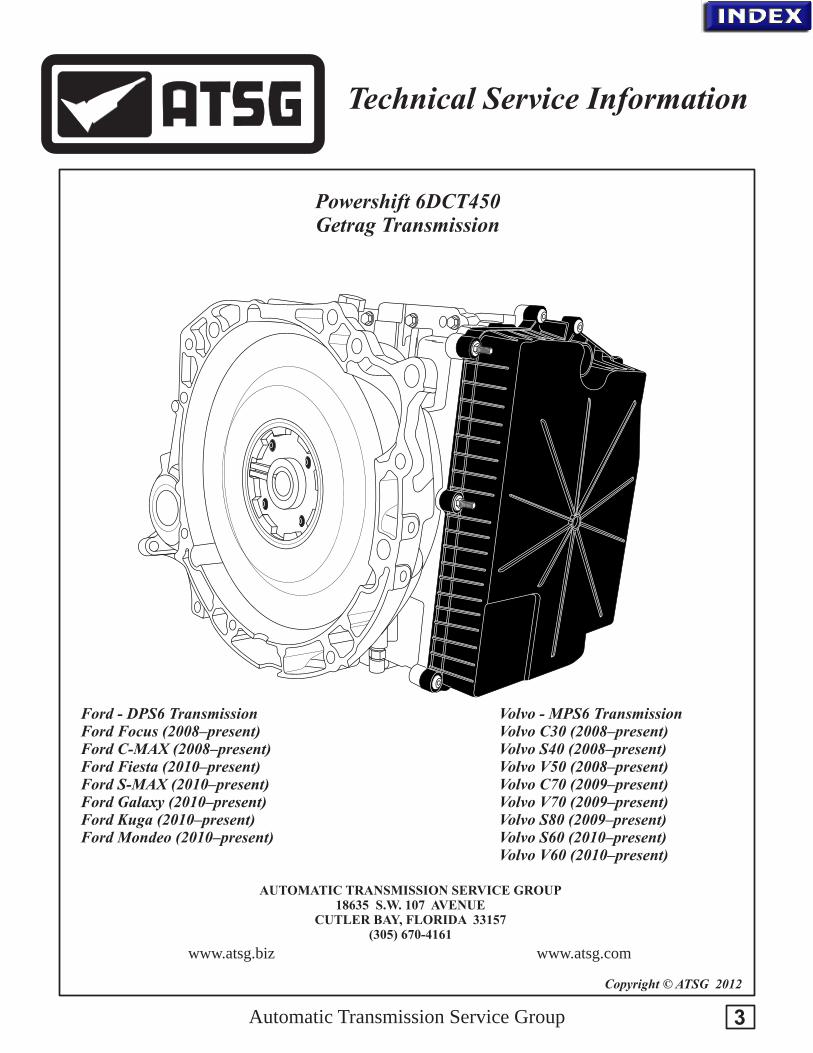
Powershift 6DCT450 Getrag Transmission
Automatic Transmission Service Group
www.atsg.comwww.atsg.biz
AUTOMATIC TRANSMISSION SERVICE GROUP18635 S.W. 107 AVENUE
CUTLER BAY, FLORIDA 33157(305) 670-4161
Copyright © ATSG 2012
Ford - DPS6 TransmissionFord Focus (2008–present)Ford C-MAX (2008–present)Ford Fiesta (2010–present)Ford S-MAX (2010–present)Ford Galaxy (2010–present)Ford Kuga (2010–present)Ford Mondeo (2010–present)
Volvo - MPS6 TransmissionVolvo C30 (2008–present)Volvo S40 (2008–present)Volvo V50 (2008–present)Volvo C70 (2009–present)Volvo V70 (2009–present)Volvo S80 (2009–present)Volvo S60 (2010–present)Volvo V60 (2010–present)
Technical Service Information
3

The 6DCT450 is a 6-speed electronically controlled transmission otherwise referred to as a Powershift transmission. It may also be referred to as a DPS6 with Ford or an MPS6 with Volvo. It has the same function as an automatic transmission but is more similar to a manual transmission. The design of the transmission includes three shafts and two clutches (wet double clutch) but no clutch pedal. Electronics and hydraulics control the clutches just like in a conventional automatic transmission. The transmission features a split (divided) input shaft with a clutch for each shaft that work independently of each other. Clutch 1 transmits the power to the input shaft for the Odd gears 1, 3, 5, and R while. Clutch 2 transmits the power to the input shaft for the even gears 2, 4, and 6.
The transmission has 4 gearshift forks which are controlled by the Transmission control module (TCM) via solenoids. Electronics and hydraulics also control the clutches via the Transmission control module (TCM) or via manual shifting in the same way as in a conventional automatic transmission. In case of manual shifting, the driver handles gearshifting.
The gears are pre-selected, that is, one clutch makes sure that the current gear ends up in the correct position while simultaneously the other clutch prepares the next gear. This set-up means that the power transfer from the engine to the transmission is not interrupted when shifting. This also allows shifting to take place while under load, thus a permanent power transfer can be maintained, which is the meaning of Powershift.
The gearshift lever is of the same type as for conventional automatic transmissions and has positions P, R, N, D, and M.
The transmission fluid is a high-quality synthetic oil which is unique for this type of transmission.
The transmission is intended to be a part of a transverse drivetrain with front-wheel drive.
The transmission weighs 91 kg with oil and has a maximum torque of 450 Nm.
Automatic Transmission Service Group
Technical Service Information
4
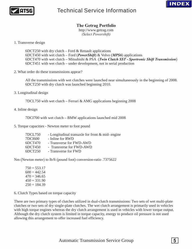
The Getrag Portfoliohttp://www.getrag.com
(Select Powershift)
1. Transverse design
6DCT250 with dry clutch – Ford & Renault applications 6DCT450 with wet clutch – Ford (PowerShift) & Volvo (MPS6) applications 6DCT470 with wet clutch – Mitsubishi & PSA (Twin Clutch SST - Sportronic Shift Transmission)
6DCT451 with wet clutch – under development, not in serial production
2. What order do these transmissions appear?
All the transmissions with wet clutches were launched near simultaneously in the beginning of 2008. 6DCT250 with dry clutch was launched beginning 2010.
3. Longitudinal design
7DCL750 with wet clutch – Ferrari & AMG applications beginning 2008
4. Inline design
7DCI700 with wet clutch – BMW applications launched mid 2008
5. Torque capacities - Newton meter to foot pound
7DCL750 - Longitudinal transaxle for front & mid- engine 7DCI600 - Inline for RWD6DCT470 - Transverse for FWD-AWD 6DCT450 - Transverse for FWD-AWD 6DCT250 - Transverse for FWD
Nm (Newton meter) to lb/ft (pound foot) conversion-ratio .7375622
750 = 553.17600 = 442.54470 = 346.65450 = 331.90250 = 184.39
6. Clutch Types based on torque capacity
There are two primary types of clutches utilized in dual-clutch transmissions: Two sets of wet multi-plate clutches or two sets of dry single-plate clutches. The wet clutch arrangement is primarily used in vehicles with high torque engines whereas the dry clutch arrangement is used in vehicles with lower torque output. Although the dry clutch system is limited in torque capacity, energy to produce oil pressure is not used allowing this arrangement to offer increased fuel efficiency.
Automatic Transmission Service Group
Technical Service Information
5
Automatic Transmission Service Group
Technical Service Information
6
Parallel ClutchConfiguration
Nested or Concentric ClutchConfiguration
Drive Input
C1 Clutch
C2 Clutch
C1 Piston
C2 Piston
C1 Piston
C2 Piston
Drive Input
Drum Support
Oil Feed
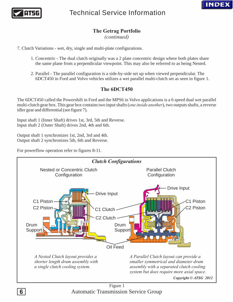
Clutch Configurations
A Nested Clutch layout provides a shorter length drum assembly witha single clutch cooling system.
A Parallel Clutch layout can provide a smaller symmetrical and diameter drum assembly with a separated clutch cooling system but does require more axial space.
Drum Support
The Getrag Portfolio(continued)
7. Clutch Variations - wet, dry, single and multi-plate configurations.
1. Concentric - The dual clutch originally was a 2 plate concentric design where both plates share the same plane from a perpendicular viewpoint. This may also be referred to as being Nested.
2. Parallel - The parallel configuration is a side-by-side set up when viewed perpendicular. The 6DCT450 in Ford and Volvo vehicles utilizes a wet parallel multi-clutch set as seen in figure 1.
The 6DCT450
The 6DCT450 called the Powershift in Ford and the MPS6 in Volvo applications is a 6 speed dual wet parallel multi-clutch gear box. This gear box contains two input shafts (one inside another), two outputs shafts, a reverse idler gear and differential (see figure 7).
Input shaft 1 (Inner Shaft) drives 1st, 3rd, 5th and Reverse. Input shaft 2 (Outer Shaft) drives 2nd, 4th and 6th.
Output shaft 1 synchronizes 1st, 2nd, 3rd and 4th. Output shaft 2 synchronizes 5th, 6th and Reverse.
For powerflow operation refer to figures 8-11.
Copyright © ATSG 2012
Figure 1
Automatic Transmission Service Group
Technical Service Information
Copyright © ATSG 2012
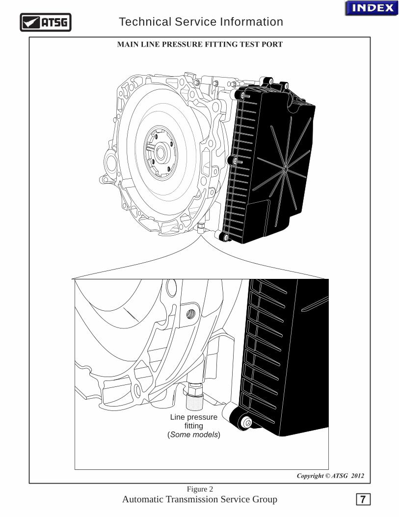
Line pressure fitting
(Some models)
MAIN LINE PRESSURE FITTING TEST PORT
Figure 2
7
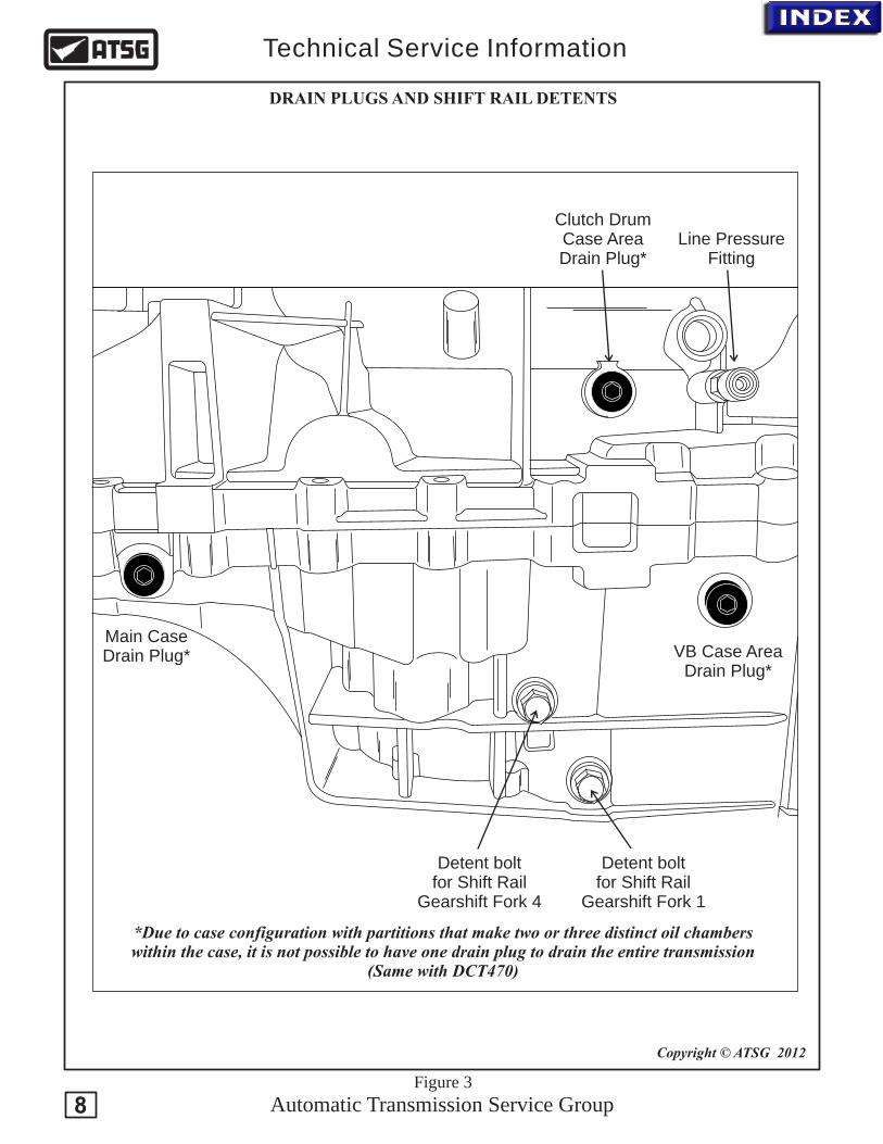
Detent bolt for Shift Rail
Gearshift Fork 4
Detent bolt for Shift Rail
Gearshift Fork 1
Line PressureFitting
Clutch Drum Case Area Drain Plug*
VB Case AreaDrain Plug*
Main CaseDrain Plug*
Automatic Transmission Service Group
Technical Service Information
Copyright © ATSG 2012
DRAIN PLUGS AND SHIFT RAIL DETENTS
*Due to case configuration with partitions that make two or three distinct oil chamberswithin the case, it is not possible to have one drain plug to drain the entire transmission
(Same with DCT470)
Figure 3
8

External Oil Filter(Filters lube fluidand is part of the
cooler bypass strategy)
.03
9"
.03
8"
.03
8"
TCM Cooler
x
x
x
To Heat Exchanger
From Heat Exchanger
.050"
Po
rt 3
Fil
ter
Se
con
da
ry P
. R
. V
alv
e
Lube Relief Valve
Po
rt 1
Fil
ter
Po
rt 2
Fil
ter
x
Th
erm
al
By-
pa
ss V
alv
eP
ress
ure
Cu
t S
afe
ty V
alv
e
Re
gu
late
d L
ine
Pre
ssu
re
Clutch Assembly Lube
C1 BalanceC2 Balance
To Heat ExchangerHeat
ExchangerReturn Fill
Plug
Level CheckPlug
Automatic Transmission Service Group
Technical Service Information
Copyright © ATSG 2012
CHECK AND FILL PLUGS
Transmission Fluid Type: BOT 341Ford part number: XT-11-QDC Volvo part number: 1161838Mitsubishi part number: MZ320065Mitsubishi calls this Dia Queen SSTF-IApproximately $28.00 for 1 liter Full fill - 7.5 liters (8 qt)(includes cooler)Drain fill - 5.5 liters (6 qt)
Figure 4
9

The gear selector assembly positioned in the center console is mechanically connected to the transmission by a cable which is used to engage and disengage the Park gear. It does not move a manual valve in the valve body for there is not a manual valve to move. The shaft inside the transmission which the gear selector lever rotates to engage and disengage park has a detent plate with a toothed disk that rotates a range sensor integral to the TCM. This provides a direct P/R/N/D signal into the TCM.
In addition to the P/R/N/D position signals, the gear selector assembly with Geartronic has a position for manual shifting (M). This signal is generated in the gear selector assembly and is sent to the TCM over the CAN BUS network. The manual gear positions can be selected at any time on the move. For downshifting, the gear selector shall be moved to minus (-). For upshifting, the gear selector shall be moved to plus (+). At start, 3rd gear is the highest possible gear. The engine can only be started in position P or N.
Automatic Transmission Service Group
Technical Service Information
Copyright © ATSG 2012
Figure 5
N
P
RD
+
M position
A toothed disk integral to the detent plate engages with a toothed wheel that rotates a magnetic wheel. This magnetic wheel excites hall effect sensors in the Transmission Range sensor to provide the P/R/N/D position signal to the TCM.
TRS
Magnetic wheeland gear
Toothed wheel
TRANSMISSION RANGE SENSOR
10

Automatic Transmission Service Group
Technical Service Information
11
Copyright © ATSG 2012
TRANSMISSION RANGE SENSOR
TRS: This transmission does not have a manual valve. The transmission range sensor (TRS) is directly connected to the TCM providing the signal it needs to know if the selector lever is placed into Park, Reverse, Neutral or Drive. This sensor contains a wheel with magnets strategically located around approximately half the wheel to excite hall effect sensors with which its position can be determined. This makes aligning the sensor critical when you install the Mechatronic unit into the transmission. This is done by locating an alignment hole in the rotating wheel which then needs to be aligned with the hole in the housing. A .120" alignment pin can then be inserted through the housing hole into the rotating wheel hole to hold this wheel in proper position as you install the assembly into the case. Caution: IMPORTANT: The signal wheel is rotated by a gear which is engaged with a rotating gear on the manual arm shaft. Witness marks on the gear that rotates the signal wheel suggest that the manual lever needs to be in the DRIVE position when aligning the TRS with the .120" pin through the housing into the rotating wheel. When you disassemble one of these for the first time, take notice to be sure this is correct as we were unable to locate manufacturer information documenting this process.
Rotating signal wheel
AlignmentHoles
TRS
PlaceSelector
Lever intoDRIVEAlignment Pin
Securing bolt
Rotate wheel to align holes and insert an alignment pin
Holesaligned
Drum Speed Sensor Connector - ERPM

Normal program
When driving with normal throttle application, the TCM uses a pre-set shifting program, optimized to shift for economic driving. The shifting program adapts automatically to different driving conditions, e.g., driving on a grade with a trailer or driving at high altitude. Also, the transmission's oil pressure is adapted to give smooth engagement of gears.
Adaptation
The TCM monitors every shift to give consequent and smooth shifts under all driving conditions. This is done by the TCM either lowering or increasing the hydraulic system pressure that is used during actual shifting. The changed pressure levels are stored in the control module's memory when the vehicle is turned off, and are retrieved when the vehicle is started. This gives the transmission better shifting comfort and life. Before the components become too worn, an adaptation can also be used to compensate for wear of components in the transmission.
Powershift uses 4 different adaptations:
· Gear adaptation. Condition, gear engaged and engine's static torque within ±30 Nm.
· Adaptation of clutch application pressure. Condition, no gear engaged, Even or Odd, as well as the clutch not in a torque transfer mode (torque control mode).
· Adaptation of clutch preparation pressure. Condition, clutch pressure not above application pressure.
· Adaptation of clutch torque. Condition, temperature of hydraulic oil (value from sensor in oil sump) and clutch surface within specified interval, clutch in torque control mode and clutch torque within specified interval.
Driving uphill
The TCM can change the gearshift pattern slightly when driving uphill. This is to avoid close gearshifts.
Neutral control
This is a function that is activated when the driver stops and the vehicle is stationary, e.g., at a red light. The TCM disengages the clutches, which means that the transmission's forward drive is reduced, as well as the engine load.
The function reduces both fuel consumption and vibrations. When the driver releases the brake, the clutch torque increases on the clutch for which the gear is engaged, and drive increases.The following conditions must be met in order for the neutral function to activate:
· gear lever in D or R.
· throttle position 0%
· brake pedal pressed down.
· speed 0 km/h.
Automatic Transmission Service Group
Technical Service Information
GEAR SHIFT PROGRAMS
12
Automatic Transmission Service Group
Technical Service Information
13
Hot mode
When driving for a long time with high load, e.g., slow driving on steep grades or with a trailer, the transmission and clutch work hard, which leads to increasing temperature in the transmission oil and clutch. A function called Hot mode is used to prevent damage to the transmission due to too high temperature in the oil and in the clutch.
The function is controlled by the TCM that, through different steps, tries to prevent the temperature from becoming too high:
· The flow in the transmission increases by increased idle rpm for better cooling. Gearshifts are made harsher to reduce heat generation in the transmission.
· A message is sent to the Driver information module (DIM) to brake to relieve the clutches.
· The clutch starts to oscillate to warn the driver before the clutches open.
· The clutches open.
Alternative driving programs
There are driving programs that are implemented in the transmission but that only are active on certain variants.
Kick-down
When the accelerator pedal is pressed down past a certain point, the Kickdown function is activated. This means that downshifting takes place to get faster acceleration. The pedal position for Kickdown is designated as 110%.
Quick step
Quick step makes the gearshifting function sportier when the driver is more aggressive on the pedal. Lower gears are used for better acceleration.
Fast Off
Fast Off is used to reduce the number of shifts due to heavy traffic in, e.g., city traffic.The function is activated at fast releases of the accelerator pedal. Even the vehicle's speed, brake pedal, and curve detection affect its function. By keeping a lower gear than normal, unnecessary shifts are avoided. For aborted passing, a lower gear is maintained to be able to take the initiative for future passing.
Gearshifting with Geartronic
When the gear selector is moved to the Geartronic-position (M), the automatic transmission is still hydraulically in position D. By moving the gear selector up (+) the Gear selector module (GSM) sends a signal to Transmission control module (TCM) to upshift.
If the gear selector is moved down (-) a signal is sent to the TCM to downshift. The Driver information module (DIM), when gear selector is in manual shifting mode, switches symbols in the DIM from D to current gear position, e.g., 3. A signal is also sent to Gear selector module (GSM) to light both LEDs for + and -, to and turn off the other LEDs. The TCM decides if shifting can be performed and the DIM will indicate the current gear. If shifting is allowed, the different solenoids are activated according to the specific pattern for each gear.
GEAR SHIFT PROGRAMS

However, in certain situations the TCM will take over responsibility for determining shifting. The follow applies:
· If the maximum engine rpm should be exceeded when downshifting, then the TCM will prevent a downshift.
· Start from a standstill can take place in 1st or 2nd gear in Geartronic-mode. 3rd gear can be selected at speeds above25 km/h, 4th gear at speeds above 40 km/h, 5th gear at speeds above 50 km/h, as well as 6th gear at speeds above 60 km/h.
· Change between automatic and manual can be performed in both directions under all driving conditions.
· Automatic upshifting takes place at maximum rpm and at kickdown.
· Automatic downshifts take place in all gears when driving slower than a certain speed and at kickdown. Example: 2nd gear is selected. Automatic downshifting takes place from 2nd gear to 1st at 2 km/h if the speed before that has been above 20 km/h. Otherwise 2nd gear remains. E.g., situations may arise where 3rd gear still is engaged even when the vehicle has been stopped.
· After automatic downshifting, manual upshifting is required except when kickdown is used and the pedal position remains in kickdown position.
· Allowed rpms for manual downshifts match those for kickdown upshifts, that is, maximum engine rpm.
· If the transmission's temperature should become too high, the TCM assumes the decisions about gearshifting.
POWERFLOW
As mentioned previously this MPS6 transmission has 2 separate input shafts one inside another along with a clutch for each shaft. Clutch 1 transmits the power to input shaft 1 for the Odd gears 1, 3, 5, and R while Clutch 2 transmits the power to input shaft 2 for the even gears 2, 4, and 6. The TCM adapts shifting so that the correct gear is always selected with consideration of driving manner, engine load, driver's wishes, speed, etc. This style transmission gives better fuel economy compared from conventional automatic transmissions with a torque converter. The TCM receives information on desired gear position and desired driving manner (driving program) from the driver. The TCM then adapts the gear ratio to the individual driving manner and current load. Gear ratio is selected automatically by the Transmission control module (TCM) or via manual shifting. In case of manual shifting, the driver handles gearshifting. The TCM receives information on the following to enable exact determination of shifting points based on selected driving program:
1. Gear position sensor2. Vehicle speed from the BCM via the CAN network3. Engine RPM, 4. Both shaft speed sensors 5. Engine Torque from the ECM over the CAN network6. Brake apply signal7. Accelerator Pedal position8. Transmission fluid temperature9. Engine temperature10. Steering wheel position via the Steering Wheel Module (SWM) over the network to prevent up- shifting when cornering.
Automatic Transmission Service Group
Technical Service Information
GEAR SHIFT PROGRAMS AND POWERFLOW
14
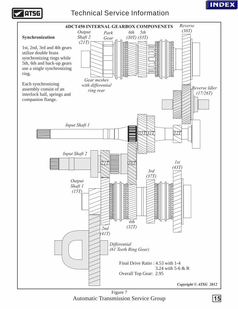
Differential(61 Teeth Ring Gear)
Reverse(38T)5th
(33T)6th
(30T)ParkGear
OutputShaft 2(21T)
Reverse Idler(17/26T)
Input Shaft 1
Input Shaft 2
OutputShaft 1(15T)
1st(43T)
3rd(37T)
4th(32T)2nd
(41T)
21T 38T
35T 31T 12T
Automatic Transmission Service Group
Technical Service Information
Copyright © ATSG 2012
Figure 7
6DCT450 INTERNAL GEARBOX COMPONENETS
Gear mesheswith differential
ring rear
Synchronization 1st, 2nd, 3rd and 4th gears utilize double brass synchronizing rings while 5th, 6th and back-up gears use a single synchronizing ring.
Each synchronizing assembly consist of an interlock ball, springs and companion flange.
15
Final Drive Ratio : 4.53 with 1-4 3.24 with 5-6 & ROverall Top Gear: 2.95
C2 C1
C2 C1
Input 2 Input 1
Output 2
Output 1
Input 2 Input 1
Output 2
Output 1
Automatic Transmission Service Group
Technical Service Information
Copyright © ATSG 2012
Figure 8
6DCT450 POWERFLOW
16
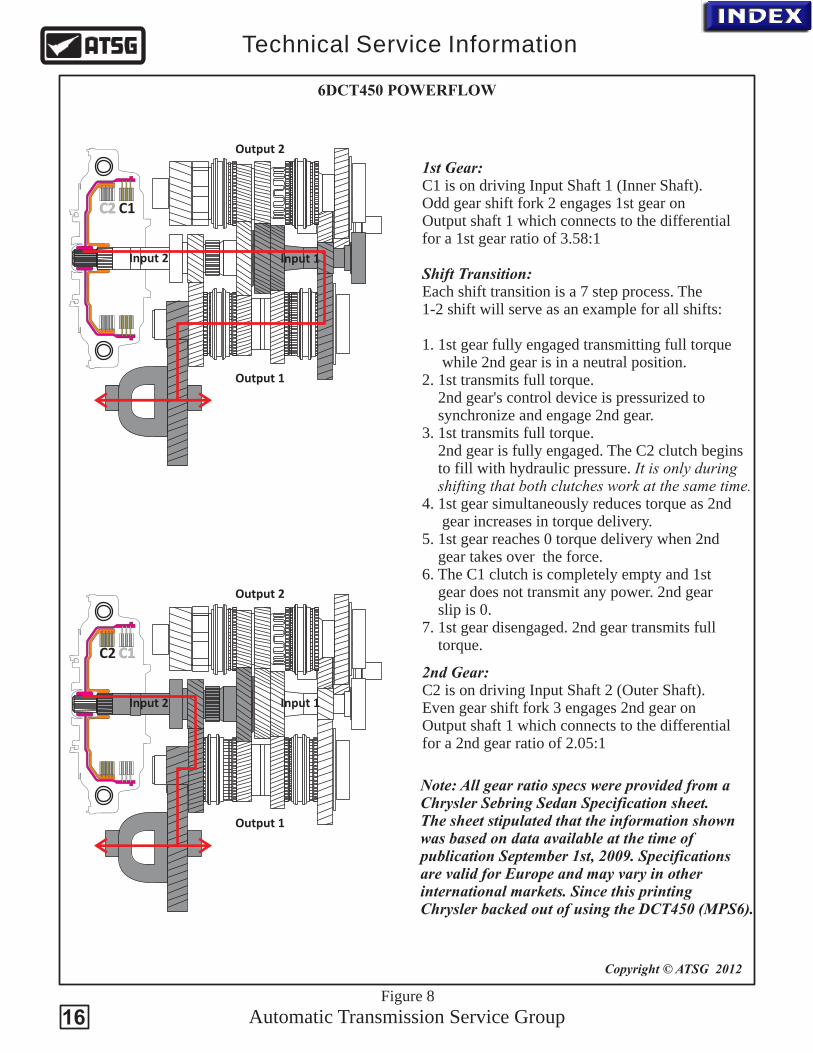
1st Gear:C1 is on driving Input Shaft 1 (Inner Shaft).Odd gear shift fork 2 engages 1st gear onOutput shaft 1 which connects to the differentialfor a 1st gear ratio of 3.58:1
Shift Transition:Each shift transition is a 7 step process. The1-2 shift will serve as an example for all shifts:
1. 1st gear fully engaged transmitting full torque while 2nd gear is in a neutral position. 2. 1st transmits full torque. 2nd gear's control device is pressurized to synchronize and engage 2nd gear.3. 1st transmits full torque. 2nd gear is fully engaged. The C2 clutch begins to fill with hydraulic pressure.
4. 1st gear simultaneously reduces torque as 2nd gear increases in torque delivery.5. 1st gear reaches 0 torque delivery when 2nd gear takes over the force.6. The C1 clutch is completely empty and 1st gear does not transmit any power. 2nd gear slip is 0.7. 1st gear disengaged. 2nd gear transmits full torque.
It is only during shifting that both clutches work at the same time.
2nd Gear:C2 is on driving Input Shaft 2 (Outer Shaft).Even gear shift fork 3 engages 2nd gear onOutput shaft 1 which connects to the differentialfor a 2nd gear ratio of 2.05:1
Note: All gear ratio specs were provided from a Chrysler Sebring Sedan Specification sheet.The sheet stipulated that the information shownwas based on data available at the time of publication September 1st, 2009. Specificationsare valid for Europe and may vary in otherinternational markets. Since this printing Chrysler backed out of using the DCT450 (MPS6).
C2 C1
Input 2 Input 1
Output 2
Output 1
C2 C1
Input 2 Input 1
Output 2
Output 1
Automatic Transmission Service Group
Technical Service Information
Copyright © ATSG 2012
Figure 9
6DCT450 POWERFLOW
17
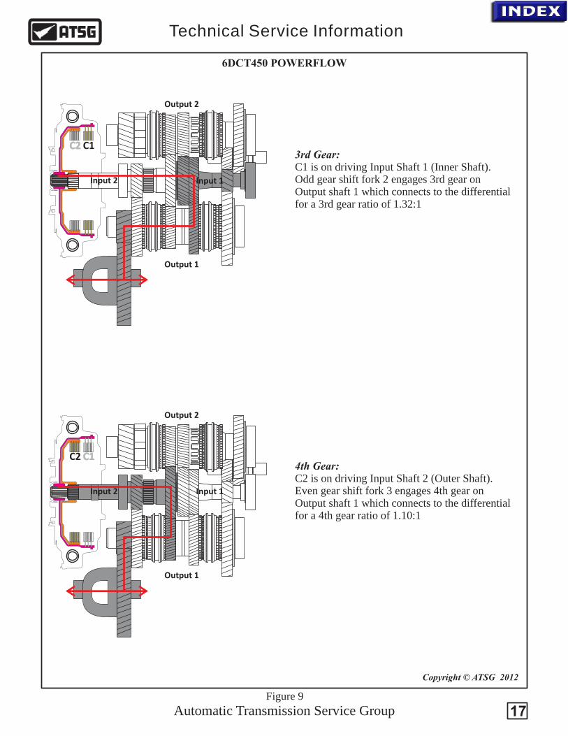
3rd Gear:C1 is on driving Input Shaft 1 (Inner Shaft).Odd gear shift fork 2 engages 3rd gear onOutput shaft 1 which connects to the differentialfor a 3rd gear ratio of 1.32:1
4th Gear:C2 is on driving Input Shaft 2 (Outer Shaft).Even gear shift fork 3 engages 4th gear onOutput shaft 1 which connects to the differentialfor a 4th gear ratio of 1.10:1

C2 C1
Input 2 Input 1
Output 2
Output 1
C2 C1
Input 2 Input 1
Output 2
Output 1
Automatic Transmission Service Group
Technical Service Information
Copyright © ATSG 2012
Figure 10
6DCT450 POWERFLOW
18
5th Gear:C1 is on driving Input Shaft 1 (Inner Shaft).Odd gear shift fork 1 engages 5th gear onOutput shaft 2 which connects to the differentialfor a 5th gear ratio of 0.97:1
6th Gear:C2 is on driving Input Shaft 2 (Outer Shaft).Even gear shift fork 4 engages 6th gear onOutput shaft 2 which connects to the differentialfor a 6th gear ratio of 0.91:1
C2 C1
Input 2 Input 1
Output 2
Output 1
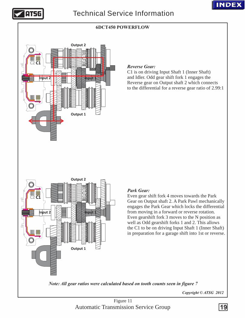
Reverse Gear:C1 is on driving Input Shaft 1 (Inner Shaft) and Idler. Odd gear shift fork 1 engages the Reverse gear on Output shaft 2 which connects to the differential for a reverse gear ratio of 2.99:1
C2 C1
Input 2 Input 1
Output 2
Output 1
Park Gear:Even gear shift fork 4 moves towards the Park Gear on Output shaft 2. A Park Pawl mechanicallyengages the Park Gear which locks the differentialfrom moving in a forward or reverse rotation. Even gearshift fork 3 moves to the N position as well as Odd gearshift forks 1 and 2. This allows the C1 to be on driving Input Shaft 1 (Inner Shaft) in preparation for a garage shift into 1st or reverse.
Automatic Transmission Service Group
Technical Service Information
Copyright © ATSG 2012
Figure 11
6DCT450 POWERFLOW
Note: All gear ratios were calculated based on tooth counts seen in figure 7
19
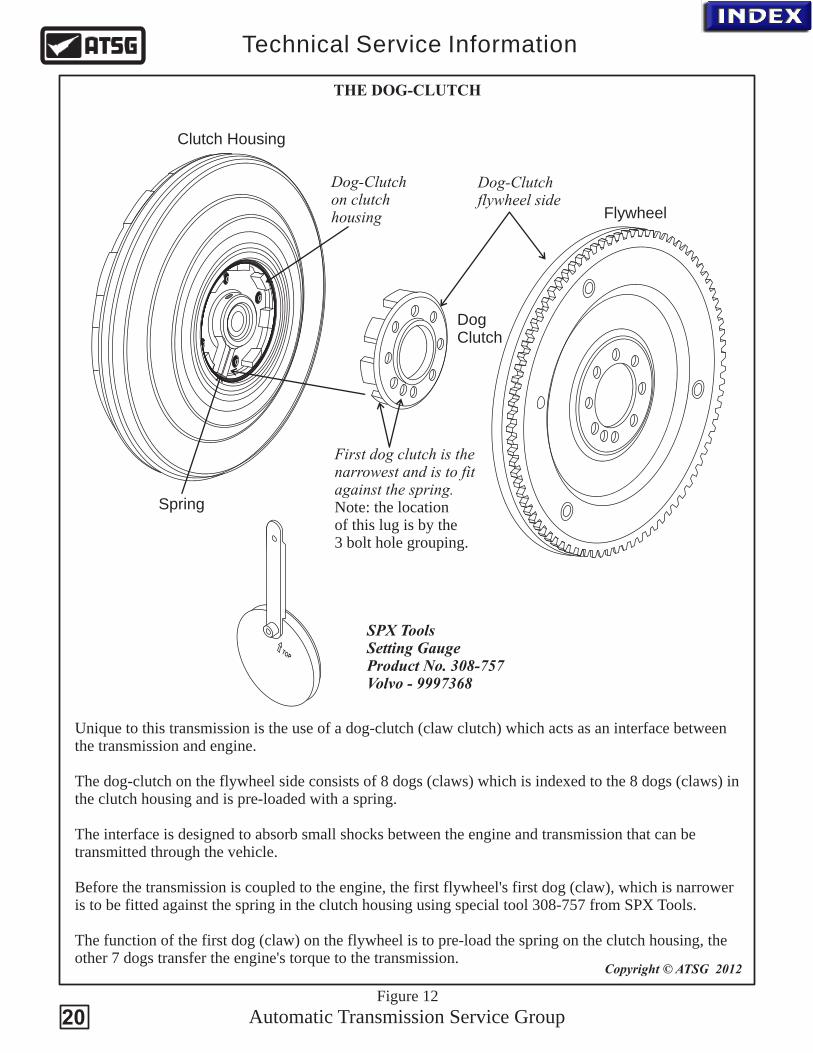
Unique to this transmission is the use of a dog-clutch which acts as an interface between the transmission and engine.
The dog-clutch on the flywheel side consists of 8 dogs (claws) which is indexed to the 8 dogs (claws) in the clutch housing and is pre-loaded with a spring.
The interface is designed to absorb small shocks between the engine and transmission that can be transmitted through the vehicle.
Before the transmission is coupled to the engine, the first flywheel's first dog (claw), which is narrower is to be fitted against the spring in the clutch housing using special tool 308-757 from SPX Tools.
The function of the first dog (claw) on the flywheel is to pre-load the spring on the clutch housing, the other 7 dogs transfer the engine's torque to the transmission.
(claw clutch)
First dog clutch is thenarrowest and is to fit against the spring.Note: the locationof this lug is by the3 bolt hole grouping.
Dog-Clutch flywheel side
Dog-Clutch on clutch housing
Clutch Housing
Flywheel
Spring
DogClutch
Automatic Transmission Service Group
Technical Service Information
Copyright © ATSG 2012
THE DOG-CLUTCH
TOP
SPX Tools Setting GaugeProduct No. 308-757Volvo - 9997368
Figure 12
20
PPPP
Park Reverse NEUTRAL Drive
Copyright © ATSG 2012
Automatic Transmission Service Group
Technical Service Information
REMOVING THE CLUTCH HOUSING
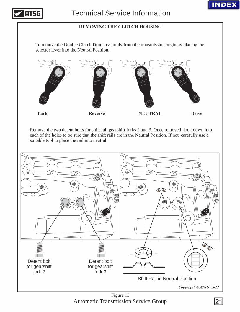
To remove the Double Clutch Drum assembly from the transmission begin by placing theselector lever into the Neutral Position.
Remove the two detent bolts for shift rail gearshift forks 2 and 3. Once removed, look down into each of the holes to be sure that the shift rails are in the Neutral Position. If not, carefully use asuitable tool to place the rail into neutral.
Detent bolt for gearshift
fork 3
Shift Rail in Neutral Position
Figure 13
Detent bolt for gearshift
fork 2
21
Copyright © ATSG 2012
Automatic Transmission Service Group
Technical Service Information
REMOVING THE CLUTCH HOUSING
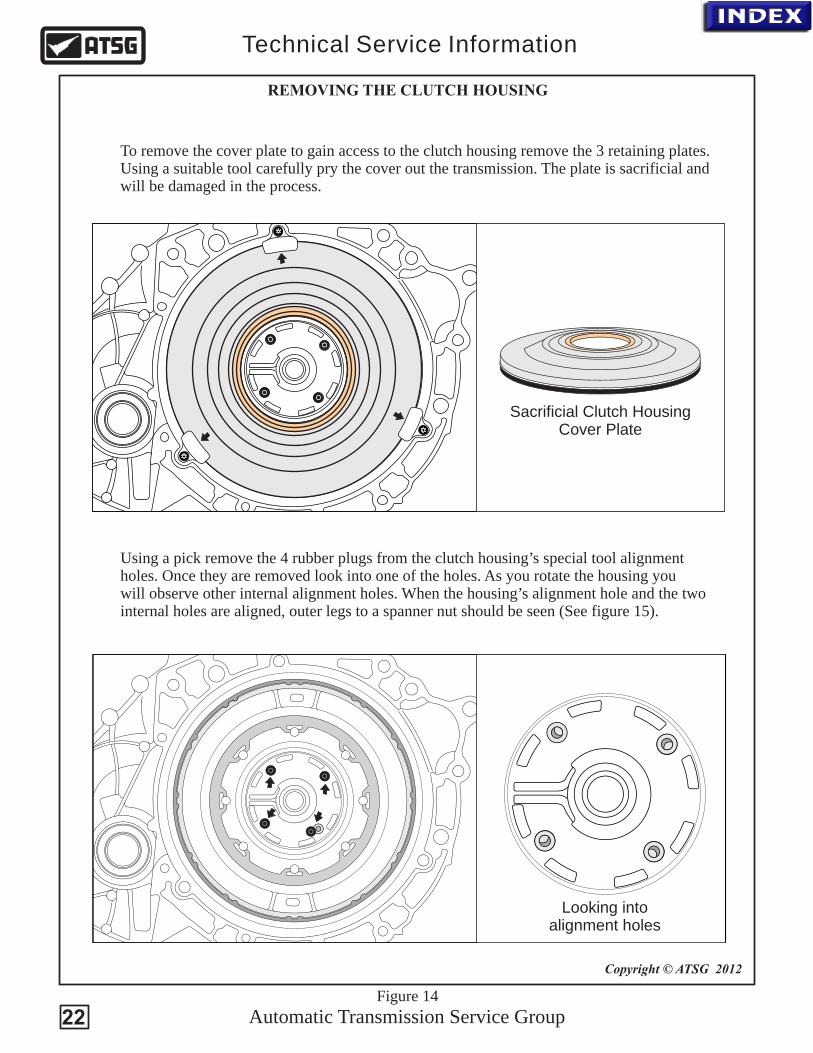
To remove the cover plate to gain access to the clutch housing remove the 3 retaining plates.Using a suitable tool carefully pry the cover out the transmission. The plate is sacrificial andwill be damaged in the process.
Sacrificial Clutch HousingCover Plate
Using a pick remove the 4 rubber plugs from the clutch housing’s special tool alignment holes. Once they are removed look into one of the holes. As you rotate the housing youwill observe other internal alignment holes. When the housing’s alignment hole and the two internal holes are aligned, outer legs to a spanner nut should be seen (See figure 15).
Figure 14
Looking intoalignment holes
22

Automatic Transmission Service Group
Technical Service Information
C2C1
Spanner Nut
Alignment Holes
Copyright © ATSG 2012
Figure 15
Drum Support
The double-clutch system has a damping device that connects the engine to the input side of the wet clutch system.
C1 = Clutch 1, Odd gears & reverse
C2 = Clutch 2, Even gears
REMOVING THE CLUTCH HOUSING
DCT450
C1 Balance
C2 Balance
C1
Clutch Assembly Lube
C2
C2 Clutch
C2 Balance
C1 Balance
C1 Clutch
Circuit Identification
23
Copyright © ATSG 2012
Automatic Transmission Service Group
Technical Service Information
Figure 16
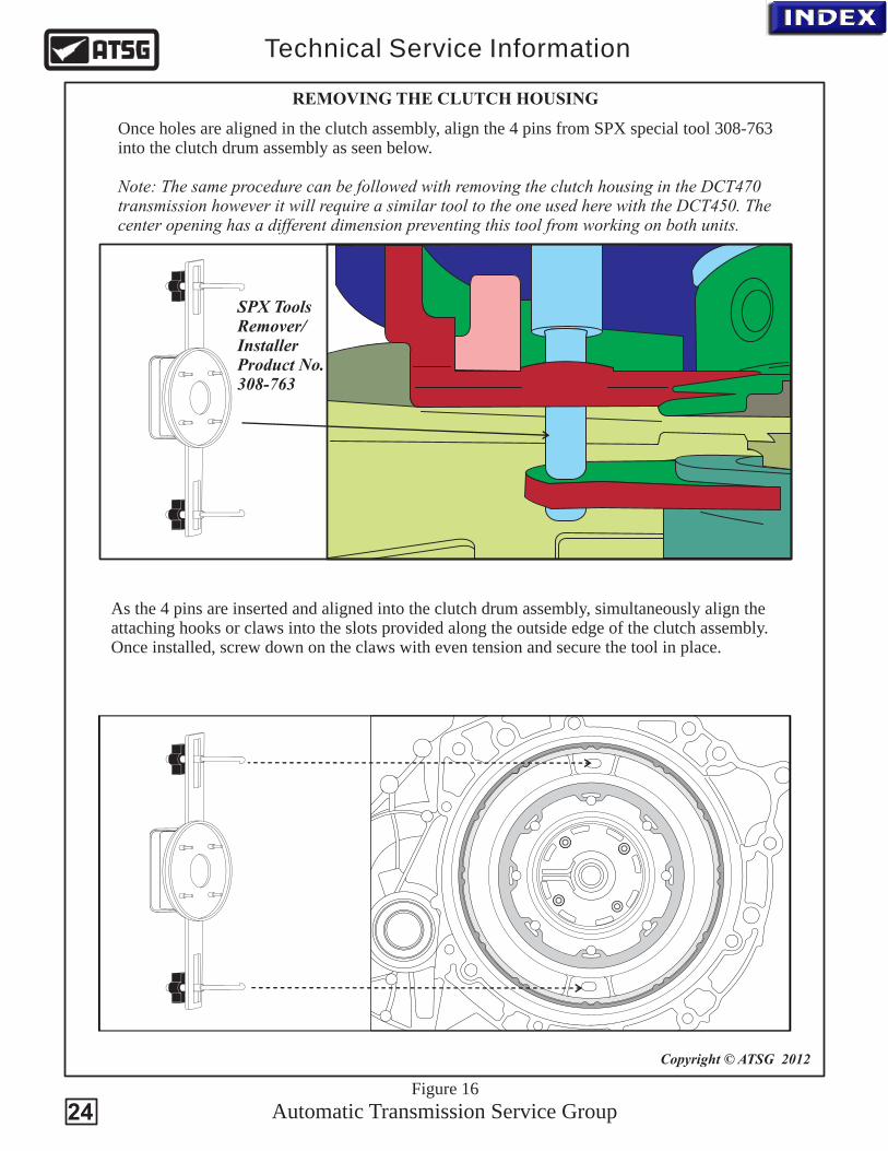
Once holes are aligned in the clutch assembly, align the 4 pins from SPX special tool 308-763into the clutch drum assembly as seen below.
Note: The same procedure can be followed with removing the clutch housing in the DCT470 transmission however it will require a similar tool to the one used here with the DCT450. Thecenter opening has a different dimension preventing this tool from working on both units.
SPX Tools Remover/InstallerProduct No. 308-763
As the 4 pins are inserted and aligned into the clutch drum assembly, simultaneously align the attaching hooks or claws into the slots provided along the outside edge of the clutch assembly. Once installed, screw down on the claws with even tension and secure the tool in place.
REMOVING THE CLUTCH HOUSING
24
Copyright © ATSG 2012
Automatic Transmission Service Group
Technical Service Information
Figure 17
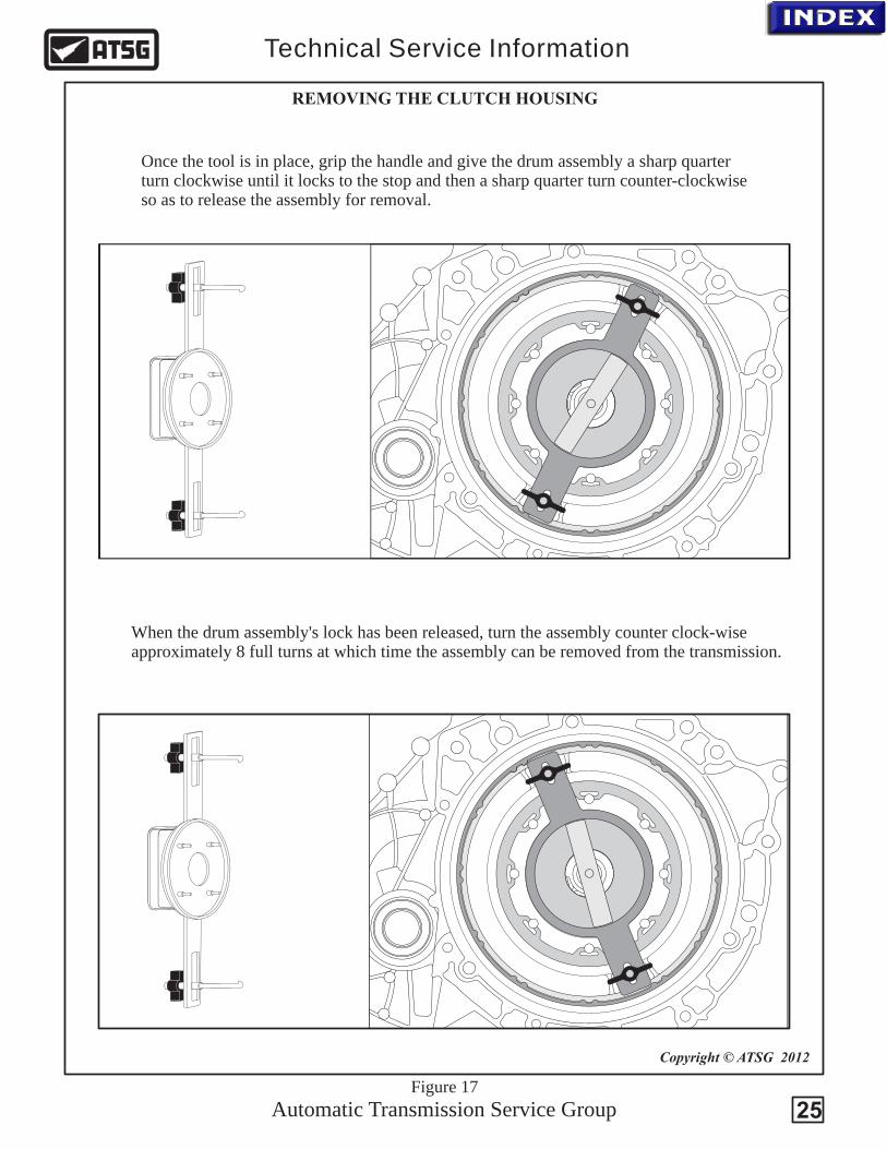
Once the tool is in place, grip the handle and give the drum assembly a sharp quarterturn clockwise until it locks to the stop and then a sharp quarter turn counter-clockwise so as to release the assembly for removal.
When the drum assembly's lock has been released, turn the assembly counter clock-wiseapproximately 8 full turns at which time the assembly can be removed from the transmission.
REMOVING THE CLUTCH HOUSING
25

Copyright © ATSG 2012
Automatic Transmission Service Group
Technical Service Information
Figure 18
After approximately 8 full counter-clockwise rotations, the weight of the drum assembly should be felt. This indicates that the spanner nut has been fully unscrewed from the drumsupport at which time the assembly can be carefully removed from the transmission housingand set aside.
With the drum assembly out of the transmission, the special tool can be removed. The drum support to clutch drum assembly needle bearing usually remains inside the drumassembly. Be sure to locate it and set it aside to prevent it from being lost or damaged.
REMOVING THE CLUTCH HOUSING
26

Automatic Transmission Service Group
Technical Service Information
27
2
3
13
4
5
6
7
8
11
12
14
16
17
18
19
20
21
22
23
24
Copyright © ATSG 2012
9
15
1
10
Figure 19
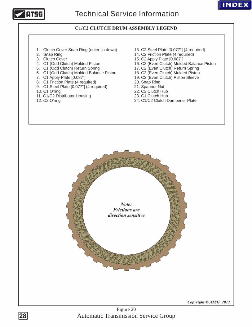
1. Clutch Cover Snap Ring (outer lip down)2. Snap Ring3. Clutch Cover4. C1 (Odd Clutch) Molded Piston5. C1 (Odd Clutch) Return Spring6. C1 (Odd Clutch) Molded Balance Piston7. C1 Apply Plate [0.087"] 8. C1 Friction Plate (4 required)9. C1 Steel Plate [0.077"] (4 required)10. C1 O'ring11. C1/C2 Distributor Housing 12. C2 O'ring
Automatic Transmission Service Group
Technical Service Information
13. C2 Steel Plate [0.077"] (4 required)14. C2 Friction Plate (4 required)15. C2 Apply Plate [0.087"]16. C2 (Even Clutch) Molded Balance Piston17. C2 (Even Clutch) Return Spring18. C2 (Even Clutch) Molded Piston 19. C2 (Even Clutch) Piston Sleeve20. Snap Ring21. Spanner Nut22. C2 Clutch Hub23. C1 Clutch Hub24. C1/C2 Clutch Dampener Plate
Note:Frictions are
direction sensitive
C1/C2 CLUTCH DRUM ASSEMBLY LEGEND
Figure 20
Copyright © ATSG 2012
28

X
X
X
X
XX
X
X
X
X
X
Figure 21
Copyright © ATSG 2012
Automatic Transmission Service Group
Technical Service Information
BOLT ID FOR REMOVING THE VALVE BODY ASSEMBLY
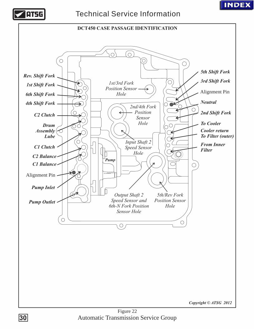
To remove the valve body assembly, first unplug the clutch drum speed sensor (which is also an engine speed sensor) from the Mechatronic unit. Then remove that TRS attaching bolt from the top of the case (See Figure 6). The 11 valve body to case bolts identified by the X marks seen above can now be removed (same with the DCT470). Once removed carefully pull the valve body far enough towards you to clear the sensors on the TCM that protrude deep into the case. There are long alignment pins mounted in the case to assist in this process. The locations of these pins are identified in figure 22.
29
Pump Outlet
Pump Inlet
C2 Balance
C1 Clutch
C2 Clutch
DrumAssembly
Lube
4th Shift Fork
6th Shift Fork
1st Shift Fork
Rev. Shift Fork5th Shift Fork
3rd Shift Fork
Neutral
2nd Shift Fork
To Cooler
Cooler returnTo Filter (outer)
From Inner Filter
Copyright © ATSG 2012
Automatic Transmission Service Group
Technical Service Information
Figure 22
DCT450 CASE PASSAGE IDENTIFICATION
5th/Rev ForkPosition Sensor
Hole
Output Shaft 2Speed Sensor and
6th-N Fork PositionSensor Hole
Input Shaft 2Speed Sensor
Hole
2nd/4th ForkPosition SensorHole
1st/3rd ForkPosition Sensor
Hole
Pump
Alignment Pin
Alignment Pin
C1 Balance
30
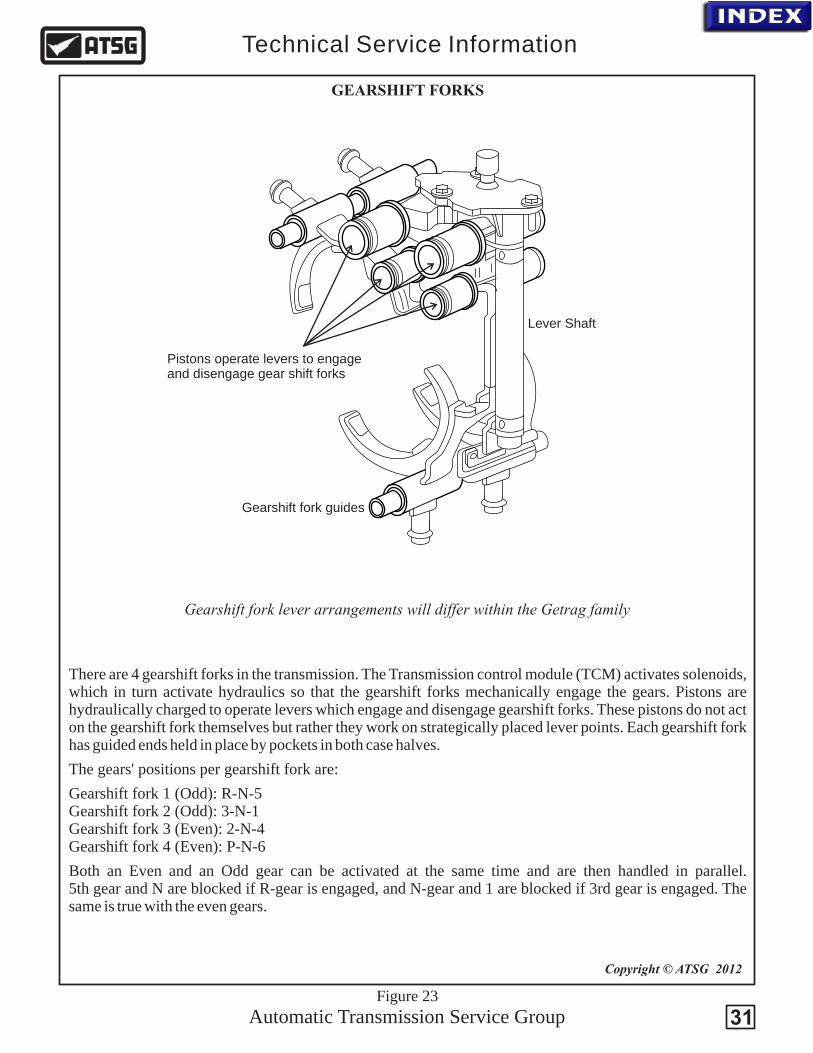
There are 4 gearshift forks in the transmission. The Transmission control module (TCM) activates solenoids, which in turn activate hydraulics so that the gearshift forks mechanically engage the gears. Pistons are hydraulically charged to operate levers which engage and disengage gearshift forks. These pistons do not act on the gearshift fork themselves but rather they work on strategically placed lever points. Each gearshift fork has guided ends held in place by pockets in both case halves.
The gears' positions per gearshift fork are:
Gearshift fork 1 (Odd): R-N-5 Gearshift fork 2 (Odd): 3-N-1 Gearshift fork 3 (Even): 2-N-4 Gearshift fork 4 (Even): P-N-6
Both an Even and an Odd gear can be activated at the same time and are then handled in parallel.5th gear and N are blocked if R-gear is engaged, and N-gear and 1 are blocked if 3rd gear is engaged. The same is true with the even gears.
Copyright © ATSG 2012
Automatic Transmission Service Group
Technical Service Information
Figure 23
GEARSHIFT FORKS
Gearshift fork lever arrangements will differ within the Getrag family
Pistons operate levers to engage and disengage gear shift forks
Lever Shaft
Gearshift fork guides
31
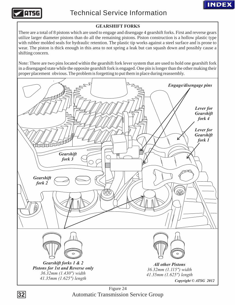
Gearshift fork 2
Gearshift fork 3
Lever forGearshift
fork 1
Lever for Gearshift
fork 4
Gearshift forks 1 & 2 Pistons for 1st and Reverse only
36.32mm (1.430") width41.35mm (1.625") length
All other Pistons36.32mm (1.115") width41.35mm (1.625") length
Copyright © ATSG 2012
Automatic Transmission Service Group
Technical Service Information
Figure 24
Engage/disengage pins
32
There are a total of 8 pistons which are used to engage and disengage 4 gearshift forks. First and reverse gears utilize larger diameter pistons than do all the remaining pistons. Piston construction is a hollow plastic type with rubber molded seals for hydraulic retention. The plastic tip works against a steel surface and is prone to wear. The piston is thick enough in this area to not spring a leak but can squash down and possibly cause a shifting concern.
Note: There are two pins located within the gearshift fork lever system that are used to hold one gearshift fork in a disengaged state while the opposite gearshift fork is engaged. One pin is longer than the other making their proper placement obvious. The problem is forgetting to put them in place during reassembly.
GEARSHIFT FORKS

Automatic Transmission Service Group
Technical Service Information
7M
5R
-7H
0B
5-B
A
BL8V
A6917
>A
ISi9
Cu3<
06
F9
35
Clutch Shift Multiplex Solenoid 1
(Odd Gear Pressure Control)
CSMS1
Shift Select Solenoid
(Forks 1 & 3)SHSS1
Shift Cooling Multiplex SolenoidSHCMS
Shift Select Solenoid
(Forks 2 & 4)SHSS2
Cutch CoolingFlow Solenoid
CCFS
Line PressureSolenoid
LPS
Clutch Shift Multiplex Solenoid 2
(Even Gear Pressure Control)
CSMS2
Clutch Shift Pressure Solenoid 1
(Odd Gear Pressure Control)
CSPS1
Clutch Shift Pressure Solenoid 2
(Even Gear Pressure Control)
CSPS2Copyright © ATSG 2012
Figure 25
DCT450 GEARSHIFT FORKS
CSMS1 (Odd Even Clutch Valve)
SHCMS (Gearshift Fork Position)
R - N - 5 (Gearshift Fork 1)
3 - N - 1 (Gearshift Fork 2)
2 - N - 4 (Gearshift Fork 3)
X - N - 6 (Gearshift Fork 4)
SHSS2 (Gearshift Fork Activation)
SHSS1 (Gearshift Fork Activation)
Odd Gear Clutch Even Gear Clutch
All solenoids measure 3 ohms
at room temperature
33
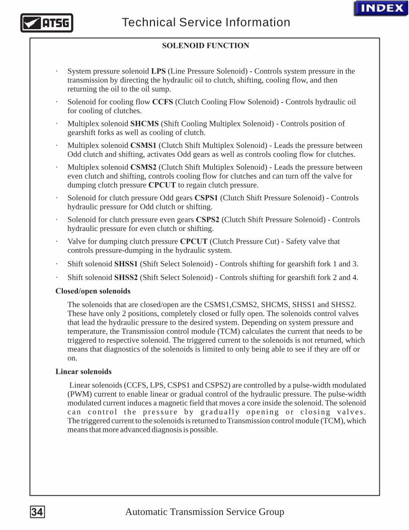
· System pressure solenoid LPS (Line Pressure Solenoid) - Controls system pressure in the transmission by directing the hydraulic oil to clutch, shifting, cooling flow, and then returning the oil to the oil sump.
· Solenoid for cooling flow CCFS (Clutch Cooling Flow Solenoid) - Controls hydraulic oil for cooling of clutches.
· Multiplex solenoid SHCMS (Shift Cooling Multiplex Solenoid) - Controls position of gearshift forks as well as cooling of clutch.
· Multiplex solenoid CSMS1 (Clutch Shift Multiplex Solenoid) - Leads the pressure between Odd clutch and shifting, activates Odd gears as well as controls cooling flow for clutches.
· Multiplex solenoid CSMS2 (Clutch Shift Multiplex Solenoid) - Leads the pressure between even clutch and shifting, controls cooling flow for clutches and can turn off the valve for dumping clutch pressure CPCUT to regain clutch pressure.
· Solenoid for clutch pressure Odd gears CSPS1 (Clutch Shift Pressure Solenoid) - Controls hydraulic pressure for Odd clutch or shifting.
· Solenoid for clutch pressure even gears CSPS2 (Clutch Shift Pressure Solenoid) - Controls hydraulic pressure for even clutch or shifting.
· Valve for dumping clutch pressure CPCUT (Clutch Pressure Cut) - Safety valve that controls pressure-dumping in the hydraulic system.
· Shift solenoid SHSS1 (Shift Select Solenoid) - Controls shifting for gearshift fork 1 and 3.
· Shift solenoid SHSS2 (Shift Select Solenoid) - Controls shifting for gearshift fork 2 and 4.
Closed/open solenoids
The solenoids that are closed/open are the CSMS1,CSMS2, SHCMS, SHSS1 and SHSS2. These have only 2 positions, completely closed or fully open. The solenoids control valves that lead the hydraulic pressure to the desired system. Depending on system pressure and temperature, the Transmission control module (TCM) calculates the current that needs to be triggered to respective solenoid. The triggered current to the solenoids is not returned, which means that diagnostics of the solenoids is limited to only being able to see if they are off or on.
Linear solenoids
Linear solenoids (CCFS, LPS, CSPS1 and CSPS2) are controlled by a pulse-width modulated (PWM) current to enable linear or gradual control of the hydraulic pressure. The pulse-width modulated current induces a magnetic field that moves a core inside the solenoid. The solenoid c a n c o n t r o l t h e p r e s s u r e b y g r a d u a l l y o p e n i n g o r c l o s i n g v a l v e s .The triggered current to the solenoids is returned to Transmission control module (TCM), which means that more advanced diagnosis is possible.
Automatic Transmission Service Group
Technical Service Information
SOLENOID FUNCTION
34

5M7H0
-
7
-
5A
R
BB
M5H0
-
7
75
A
R-B
B
L8VABL
V8A
B
76
19 7169
AI i>
S 93<
Cui
>AI9
3<
SCu
4DA
7M5R-7G
48-
827 TM
07234
0
/
6006
F9
35
MR-7G
36CA
75
1-
07 T
0
6
70
M7/22
MR-7G
36CA
75
1-
7T
0
700
M7/226
(2 Required)CSPS solenoids
(5 Required)All other solenoids
(2 Required)LPS & CCFS solenoids
7070 TM07/226 8270 TM07/234 8270 TM07/2967M5R-7G136-CA 7M5R-7G484-DA 7M5R-7G383-DA
DCT450 COMPLETE VALVE BODY AND SOLENOID IDENTIFICATION
SHCMS
Automatic Transmission Service Group
Technical Service Information
CSMS1
SHSS2SHSS1
CCFSLPS
CSMS2
CSPS1
CSPS2
Gearshift Patterns
Activated Solenoids
SHCMS SHSS1 SHSS2 CSMS1 CSMS2 CSPS1 CSPS2
Engage 1
Engage 2
Engage 3
Engage 4
Engage 5
Engage 6
Park/Neutral
Engage R
On
Off
Off
On
On
On
Off
Off
Off
On
Off
On
On
Off
Off
On
On
Off
On
Off
Off
Off
On
On On
On
On
On
Off
Off
Off
Off
Off
On
On
On
On
Off
Off
Off High
High
High
High
High
High
High
HighX
X
X
X
X
X
X
X
Copyright © ATSG 2012
The Line Pressure Solenoid not listed in the chart is turned on to drop line pressure throughout various shift sequences as needed for smooth shift transitions.
The SHCMS On/Off sequence listed below is different than what Volvo information provides. This sequence was determined via a hydraulic schematic produced by ATSG.
Figure 26
35
5H0
7M7
5- A
R-B
B
5M
H0-
7
75
A
R-B
B
VL8
ABL
VAB
8
769176
19
AI i9>
Su3<
CI i
>A S 93<
Cu
MR-7G
84DA
75
4-
7T
0
820
M7/234
6060
F9
35
7M5R-7G
136CA
-
07 TM
072
6
70
/2
7M5R-7G
36CA
1-
07 TM
072
6
70
/2
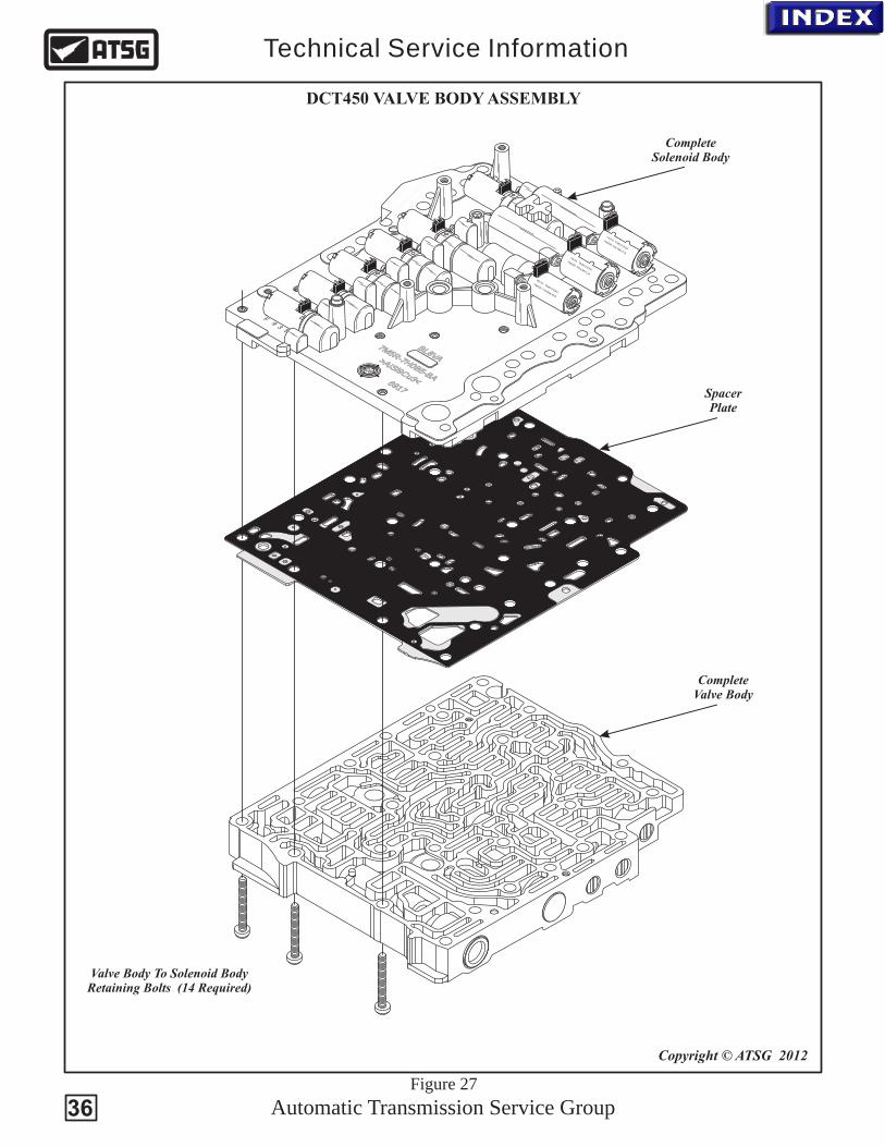
Valve Body To Solenoid BodyRetaining Bolts (14 Required)
CompleteValve Body
SpacerPlate
CompleteSolenoid Body
Copyright © ATSG 2012
Automatic Transmission Service Group
Technical Service Information
DCT450 VALVE BODY ASSEMBLY
Figure 27
36
Automatic Transmission Service Group
Technical Service Information
37
M5H0
-
7
75
A
R-B
B
M5H0
-
7
75
A
R-B
B
LV8A
BV
L8A
B
71691769
i>AI
93<
SCu
AI i93
>S
Cu<
0660
F9
35
6CA
7M5R-7G
13-
770
TM07/226
0
4
7M5R-7G
48DA
-
27 TM
072
4
80
/3
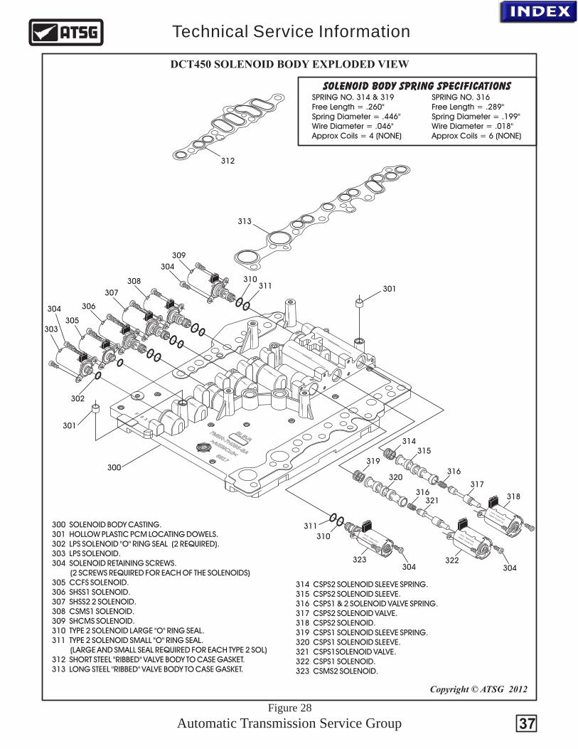
DCT450 SOLENOID BODY EXPLODED VIEW
300
301
301
302
303
304
304
304 304
305
306
307
308
309
310
310
311
311
312
313
314315
316
317
318
319
320
321
322323
SPRING NO. 316Free Length = .289"Spring Diameter = .199"Wire Diameter = .018"Approx Coils = 6 (NONE)
SPRING NO. 314 & 319Free Length = .260"Spring Diameter = .446"Wire Diameter = .046"Approx Coils = 4 (NONE)
SOLENOID BODY SPRING SPECIFICATIONS
300 SOLENOID BODY CASTING. 301 HOLLOW PLASTIC PCM LOCATING DOWELS. 302 LPS SOLENOID "O" RING SEAL (2 REQUIRED). 303 LPS SOLENOID. 304 SOLENOID RETAINING SCREWS. (2 SCREWS REQUIRED FOR EACH OF THE SOLENOIDS) 305 CCFS SOLENOID. 306 SHSS1 SOLENOID. 307 SHSS2 2 SOLENOID. 308 CSMS1 SOLENOID. 309 SHCMS SOLENOID. 310 TYPE 2 SOLENOID LARGE "O" RING SEAL. 311 TYPE 2 SOLENOID SMALL "O" RING SEAL. (LARGE AND SMALL SEAL REQUIRED FOR EACH TYPE 2 SOL) 312 SHORT STEEL "RIBBED" VALVE BODY TO CASE GASKET. 313 LONG STEEL "RIBBED" VALVE BODY TO CASE GASKET.
314 SOLENOID SLEEVE SPRING. 315 CSPS2 SOLENOID SLEEVE. 316 CSPS1 & 2 SOLENOID VALVE SPRING. 317 CSPS2 SOLENOID VALVE. 318 CSPS2 SOLENOID. 319 CSPS1 SOLENOID SLEEVE SPRING. 320 CSPS1 SOLENOID SLEEVE. 321 CSPS1SOLENOID VALVE. 322 CSPS1 SOLENOID. 323 CSMS2 SOLENOID.
CSPS2
Copyright © ATSG 2012
7M5R-7G
36CA
1-
07 TM
072
6
70
/2
316
Figure 28
Automatic Transmission Service Group
Technical Service Information
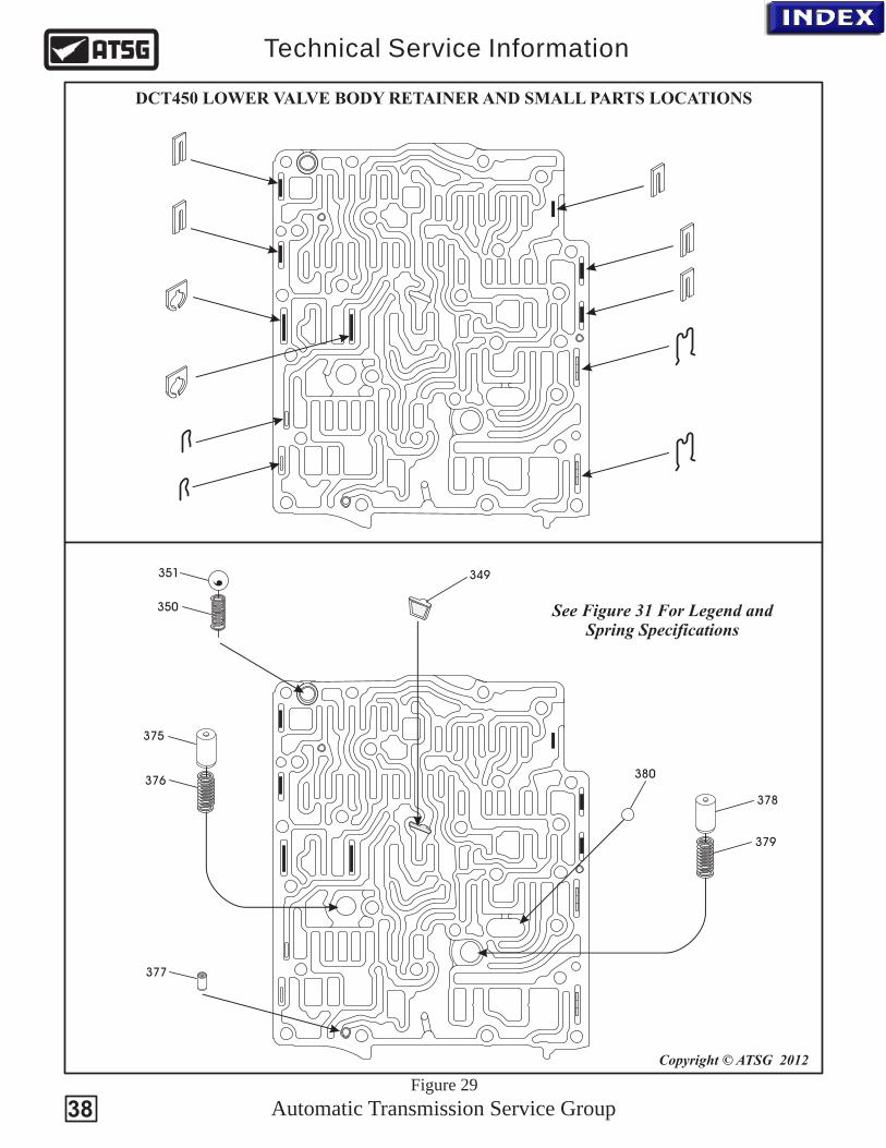
DCT450 LOWER VALVE BODY RETAINER AND SMALL PARTS LOCATIONS
Copyright © ATSG 2012
349
350
375
376
377
378
379
380
351
See Figure 31 For Legend andSpring Specifications
Figure 29
38

330
331
332
333
334
335
336
337
338
339
340
341
342
343
344
345
346
347
348
349
350
351352
353
354
355
356
357
358
359
360
361
362
363364
365
366
367
368
369
370
371
372
373
374
375
376
377
378
379
380
See Figure 31 For Legend andSpring Specifications
Copyright © ATSG 2012
Automatic Transmission Service Group
Technical Service Information
DCT450 MAIN VALVE BODY, EXPLODED VIEW
Figure 30
39
Automatic Transmission Service Group
Technical Service Information
40
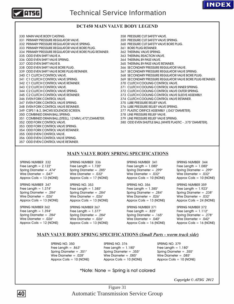
330 MAIN VALVE BODY CASTING. 331 PRIMARY PRESSURE REGULATOR VALVE. 332 PRIMARY PRESSURE REGULATOR VALVE SPRING. 333 PRIMARY PRESSURE REGULATOR VALVE BORE PLUG. 334 PRIMARY PRESSURE REGULATOR VALVE BORE PLUG RETAINER. 335 ODD EVEN SHIFT VALVE A. 336 ODD EVEN SHIFT VALVE SPRING. 337 ODD EVEN SHIFT VALVE B. 338 ODD EVEN SHIFT VALVE BORE PLUG. 339 ODD EVEN SHIFT VALVE BORE PLUG RETAINER. 340 C1 CLUTCH CONTROL VALVE. 341 C1 CLUTCH CONTROL VALVE SPRING. 342 C1 CLUTCH CONTROL VALVE RETAINER. 343 C2 CLUTCH CONTROL VALVE. 344 C2 CLUTCH CONTROL VALVE SPRING. 345 C2 CLUTCH CONTROL VALVE RETAINER. 346 EVEN FORK CONTROL VALVE. 347 EVEN FORK CONTROL VALVE SPRING. 348 EVEN FORK CONTROL VALVE RETAINER. 349 CSPS 1 & 2, SHCMS SOLENOID SCREEN. 350 COMBINED DRAIN BALL SPRING. 351 COMBINED DRAIN BALL (STEEL), 12 MM (.472") DIAMETER. 352 ODD FORK CONTROL VALVE. 353 ODD FORK CONTROL VALVE SPRING. 354 ODD FORK CONTROL VALVE RETAINER. 355 ODD EVEN CONTROL VALVE. 356 ODD EVEN CONTROL VALVE SPRING. 357 ODD EVEN CONTROL VALVE RETAINER.
358 PRESSURE CUT SAFETY VALVE. 359 PRESSURE CUT SAFETY VALVE SPRING. 360 PRESSURE CUT SAFETY VALVE BORE PLUG. 361 BORE PLUG RETAINER. 362 THERMAL VALVE SPRING. 363 THERMAL REACTION VALVE. 364 THERMAL BY-PASS VALVE. 365 THERMAL BY-PASS VALVE RETAINER. 366 SECONDARY PRESSURE REGULATOR VALVE. 367 SECONDARY PRESSURE REGULATOR VALVE SPRING. 368 SECONDARY PRESSURE REGULATOR VALVE BORE PLUG. 369 SECONDARY PRESSURE REGULATOR VALVE BORE PLUG RETAINER. 370 CLUTCH COOLING CONTROL VALVE. 371 CLUTCH COOLING CONTROL VALVE INNER SPRING. 372 CLUTCH COOLING CONTROL VALVE OUTER SPRING. 373 CLUTCH COOLING CONTROL VALVE SLEEVE ASSEMBLY. 374 CLUTCH COOLING CONTROL VALVE RETAINER. 375 LUBE PRESSURE RELIEF VALVE. 376 LUBE PRESSURE RELIEF VALVE SPRING. 377 PLASTIC ORIFICE ASSEMBLY (.043" DIAMETER). 378 LINE PRESSURE RELIEF VALVE. 379 LINE PRESSURE RELIEF VALVE SPRING. 380 ODD EVEN SHUTTLE BALL (WHITE PLASTIC - .375" DIAMETER).
DCT450 MAIN VALVE BODY LEGEND
SPRING NO. 356Free Length = 1.385"Spring Diameter = .284"Wire Diameter = .026"Approx Coils = 13 (NONE)
SPRING NO. 353Free Length = 1.385"Spring Diameter = .284"Wire Diameter = .026"Approx Coils = 13 (NONE)
SPRING NUMBER 336Free Length = 1.720"Spring Diameter = .285"Wire Diameter = .032"Approx Coils = 17 (NONE)
SPRING NUMBER 344Free Length = 1.080"Spring Diameter = .299"Wire Diameter = .032"Approx Coils = 10 (NONE)
SPRING NUMBER 341Free Length = 1.080"Spring Diameter = .299"Wire Diameter = .032"Approx Coils = 10 (NONE)
SPRING NUMBER 367Free Length = 1.377"Spring Diameter = .284"Wire Diameter = .026"Approx Coils = 13 (NONE)
SPRING NUMBER 372Free Length = 1.112"Spring Diameter = .278"Wire Diameter = .042"Approx Coils = 16 (NONE)
SPRING NUMBER 371Free Length = .825"Spring Diameter = .165"Wire Diameter = .040"Approx Coils = 16 (NONE)
SPRING NUMBER 347Free Length = 1.374"Spring Diameter = .284"Wire Diameter = .026"Approx Coils = 13 (NONE)
SPRING NUMBER 359Free Length = 1.923"Spring Diameter = .238"Wire Diameter = .032"Approx Coils = 24 (NONE)
SPRING NUMBER 362Free Length = 1.394"Spring Diameter = .284"Wire Diameter = .026"Approx Coils = 12 (NONE)
SPRING NUMBER 332Free Length = 2.122"Spring Diameter = .474"Wire Diameter = .047"Approx Coils = 13 (NONE)
MAIN VALVE BODY SPRING SPECIFICATIONS
Copyright © ATSG 2012
MAIN VALVE BODY SPRING SPECIFICATIONS (Small Parts - worm track side)
SPRING NO. 350Free Length = .863"Spring Diameter = .351"Wire Diameter = .028"Approx Coils = 10 (NONE)
SPRING NO. 376Free Length = 1.180"Spring Diameter = .355"Wire Diameter = .085"Approx Coils = 10 (NONE)
SPRING NO. 379Free Length = 1.180"Spring Diameter = .355"Wire Diameter = .085"Approx Coils = 10 (NONE)
Figure 31
*Note: None = Spring is not colored

Automatic Transmission Service Group
Technical Service Information
41
The Transmission control module (TCM) is part of the Mechatronic unit (Valve body assembly, solenoids and TCM) located inside the transmission housing on the front of the transmission.
Two voltage supplies are provided to the TCM as well as a primary ground. It also connected to the newtwork via CAN BUS. The TCM evaluates input signals from different sensors and control modules controlling the solenoids based on these signals.
The following components are integral to the TCM:
· Speed sensors
· Temperature sensor
· Pressure sensor
· Position sensors
Speed sensors:
· Engine RPM Sensor - Gives the TCM engine rpm's via the clutch drum housing.
· Speed sensor input shaft Odd gears - Gives the TCM information on input shaft rpm (after the C1 clutch) for Odd gears, 1, 3, 5, and R.
· Speed sensor input shaft even gears - Gives the TCM information on input shaft rpm (after the C2 clutch) for even gears, 2, 4, and 6.
Temperature sensors:
· Oil temperature sensor - Located on the TCM which provides information on transmission oil temperature.
· Temperature sensor control module (Hybrid sensor) - Integrated in the TCM gives information on the TCM's ambient temperature (also a Temperature sensor redundancy signal). The TCM uses temperature information to determine correct system pressure, for controlling clutch, for cold starts, and in position for overheating protection.
Pressure sensor:
· Pressure sensors - Give the TCM information on hydraulic pressure by the clutches. The TCM supplies the sensors with 5 volts. The sensors register the oil pressure for control of the clutch pressure so that the TCM can control the solenoids to provide correct clutch pressure for each clutch.
Position sensors:
· Position sensor gearshift fork - Give the TCM information on the position of the four gearshift forks that handle shifting in the transmission.
An important component belonging to the control system, but is located in the lever carrier in the middle console is the Gear Select Module (not to be confused with the internal TRS).
· Gear selector module (GSM) - Gives Transmission control module (TCM) information on locking of P as well as manual shifting.
· Inside the transmission and part of the TCM is the Transmissions Range Sensor (TRS) that provides that actual P R N D gear selection.
THE TRANSMISSION CONTROL MODULE (TCM)

Copyright © ATSG 2012
Figure 32
C1 and C2 Pressure Sensorsare located on VB side of the TCM
The Temperature Sensor is built into TCM
Reads 1st-3rdFork Position
Reads 2nd-4thFork Position
Reads Input Shaft 2 Speed
Reads Input Shaft 1 Speed
via Output Shaft 2
Reads 6th - NFork Position
Reads 5th - ReverseFork Position
FORD/VOLVO TCM SENSOR IDENTIFICATION AND LOCATION
Automatic Transmission Service Group
Technical Service Information
Engine RPM sensor(Reads Clutch
Drum Assembly)
Copyright © ATSG 2012
42
The TCM supplies this Hall Effect sensor with 7.2 volts. The sensor generates square waves of direct voltage at the rate that the input shaft's gear teeth pass the sensor. When a gear tooth passes, the signal becomes high (higher than 4.9 V), and when the gap between teeth passes the signal becomes low (lower than 1.6 V).
The TCM interprets the frequency which may vary between 3.5 Hz - 8 kHz to determine the rpm of the input shaft from the engine.
The sensors are designed to handle speeds between 0 - 12000 rpm.
The Sensor is hard wired into the TCM.

13
2
456
7
8
9
10
1314
17 2019
1215
18
11
16
Copyright © ATSG 2012
Figure 33
Automatic Transmission Service Group
Technical Service Information
TCM TERMINAL IDENTIFICATION AND LOCATION
TCM (Volvo 4/28)Connector A
43

TCMMPS6
A:1A:13A:17
3330 22 64/90
1
2
3
64/111
GSM
21
3
3/156
8/36
6
63/25
A:2A:5
63/53A:19
63/227
63/226
ECM
B:2
5B
:17
A:1
1
A:6
4/28
BCM
15 (CAN-H)
11 (CAN-L)
4/16
233 64/90
4/46.8
4/56 15/31
F52 F23
1 1
22
DIE
SE
LP
ET
RO
L
63/1
25
A:17
E:3
Distribution box in engine compartment
Central ElectronicModule near glove
box
Copyright © ATSG 2012
Automatic Transmission Service Group
Technical Service Information
TYPICAL VOLVO WIRING DIAGRAM
Figure 34
44
Ignition power supply Keep alive power

Copyright © ATSG 2012
Mitsubishi DCT470
cX (2010-present)Galant Fortis (2008-present)Lancer (2008-present)Outlander (2007-present)
Automatic Transmission Service Group
Technical Service Information
6DCT470 GETRAG TRANSMISSIONW6DGA - SPS6
Twin Clutch-Sportronic Shift Transmission (TC-SST)
Gear Ratios
1st.................................. 3.6552nd................................. 2.3683rd................................. 1.7544th................................. 1.3225th................................. 0.9836th................................. 0.731Reverse.......................... 4.011Final Gear Ratio............ 4.062
At first glance this transmission looksvery much the same as the Ford/VolvoDCT450 however, the DCT470 has afew significant differences whichthis portion of the handout will point out.
45
PND
Automatic Transmission Service Group
Technical Service Information
Copyright © ATSG 2012
P
R
ND
+
.
Twin Clutch
TSS
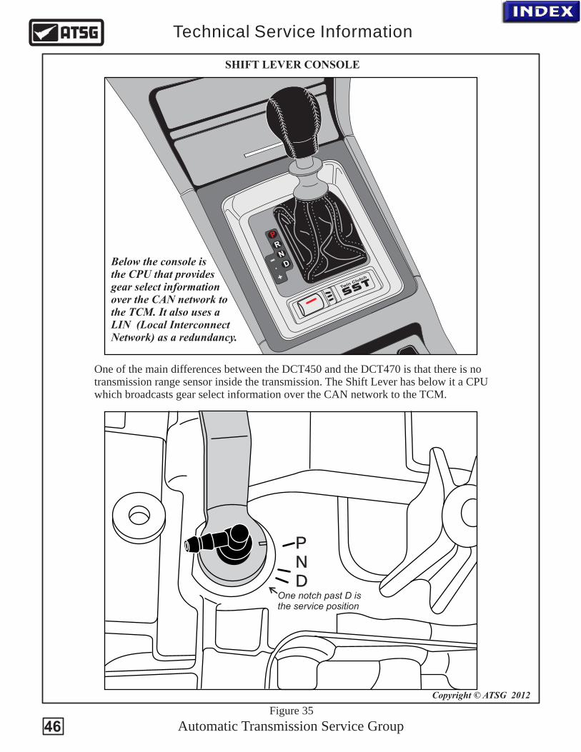
SHIFT LEVER CONSOLE
One of the main differences between the DCT450 and the DCT470 is that there is notransmission range sensor inside the transmission. The Shift Lever has below it a CPUwhich broadcasts gear select information over the CAN network to the TCM.
Below the console isthe CPU that provides gear select informationover the CAN network tothe TCM. It also uses a LIN (Local InterconnectNetwork) as a redundancy.
Figure 35
One notch past D is the service position
46

TCMSPS6
17
CPU
25
19
ECM
11
ETACS-ECU
9 (CAN-H)
8 (CAN-L) (C-301)
F320A
Keep alive power through fusiblelink # 36
Power supplythrough fusible
link # 34
IG1 Relay
Copyright © ATSG 2012
Automatic Transmission Service Group
Technical Service Information
TYPICAL MITSUBISHI WIRING DIAGRAM
6
F127.5A
RELAY BOX(Engine Compartment)
9190
SHIFT LEVERCONSOLE
ETACS-ECU*(Fuse and relay
center under dash)
16 LIN12
21
*ETACS-ECU has three main functions1. Gateway function2. Coding function3. Body electrical equipment control function
Figure 36
47

Automatic Transmission Service Group
Technical Service Information
Copyright © ATSG 2012
TCM CONNECTOR - NO TRS
13
2
456
7
8
9
10
1314
17 2019
1215
18
11
16
TCM Connector
B-107
Figure 37
48
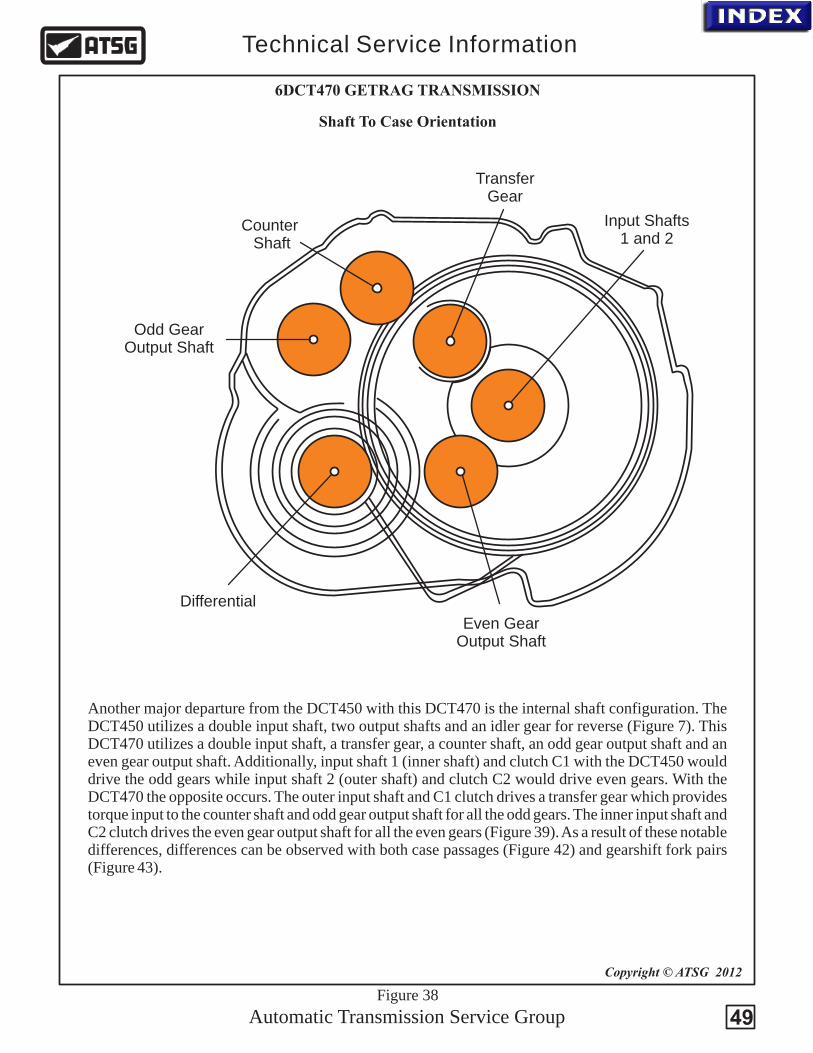
Differential
Odd GearOutput Shaft
Counter Shaft
Even GearOutput Shaft
TransferGear
Input Shafts1 and 2
Automatic Transmission Service Group
Technical Service Information
Copyright © ATSG 2012
Shaft To Case Orientation
6DCT470 GETRAG TRANSMISSION
Another major departure from the DCT450 with this DCT470 is the internal shaft configuration. The DCT450 utilizes a double input shaft, two output shafts and an idler gear for reverse (Figure 7). This DCT470 utilizes a double input shaft, a transfer gear, a counter shaft, an odd gear output shaft and an even gear output shaft. Additionally, input shaft 1 (inner shaft) and clutch C1 with the DCT450 would drive the odd gears while input shaft 2 (outer shaft) and clutch C2 would drive even gears. With the DCT470 the opposite occurs. The outer input shaft and C1 clutch drives a transfer gear which provides torque input to the counter shaft and odd gear output shaft for all the odd gears. The inner input shaft and C2 clutch drives the even gear output shaft for all the even gears (Figure 39). As a result of these notable differences, differences can be observed with both case passages (Figure 42) and gearshift fork pairs (Figure 43).
Figure 38
49
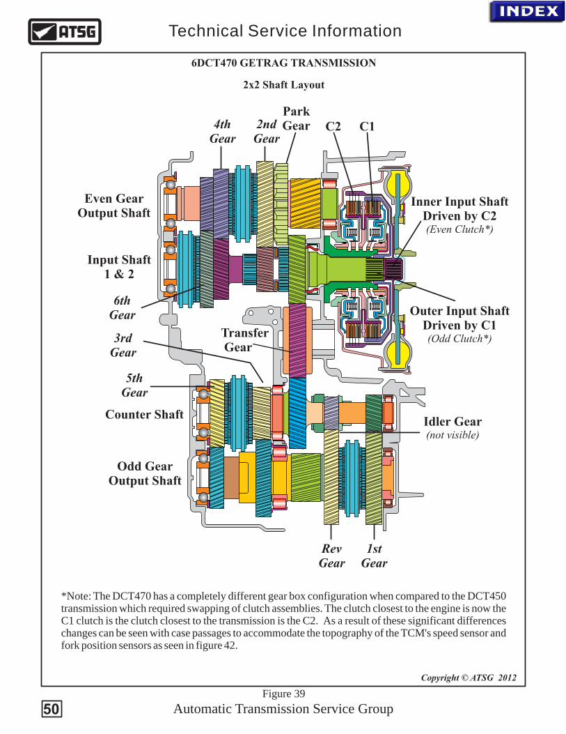
Park Gear
6thGear
Even GearOutput Shaft
Transfer Gear
Counter Shaft
C2 C1
Inner Input ShaftDriven by C2(Even Clutch*)
Outer Input ShaftDriven by C1(Odd Clutch*)
Input Shaft 1 & 2
Automatic Transmission Service Group
Technical Service Information
2x2 Shaft Layout
Copyright © ATSG 2012
4thGear
2ndGear
5thGear
3rdGear
Odd GearOutput Shaft
RevGear
1stGear
Idler Gear(not visible)
6DCT470 GETRAG TRANSMISSION
*Note: The DCT470 has a completely different gear box configuration when compared to the DCT450 transmission which required swapping of clutch assemblies. The clutch closest to the engine is now the C1 clutch is the clutch closest to the transmission is the C2. As a result of these significant differences changes can be seen with case passages to accommodate the topography of the TCM's speed sensor and fork position sensors as seen in figure 42.
Figure 39
50

Automatic Transmission Service Group
Technical Service Information
C1C2
Copyright © ATSG 2012
Figure 40
C1 = Clutch 1, Odd gears & reverse
C2 = Clutch 2, Even gears
REMOVING THE CLUTCH HOUSING
DCT470
C1 Balance
C2 Balance
C1
Clutch Assembly Lube
C2
C1 ClutchC1 BalanceC2 BalanceC2 Clutch
When compared to the DCT450 (figure 15), the DCT470 swapped the use of the two clutch assemblies. The clutch assembly closest to the engine is the C1 odd gear clutch while the clutch assembly closest to the transmission is the C2 even gear clutch.
This swapping of the clutches was accomplished by providing a different routing of the oil circuits through the drum support.
DCT470 Drum SupportCircuit identification
51

Copyright © ATSG 2012
Automatic Transmission Service Group
Technical Service Information
BOLT ID FOR REMOVING THE VALVE BODY ASSEMBLY
Remove the 11 valve body to case bolts identified by the X marks seen above (same with the DCT450). Once removed carefully pull the valve body far enough towards you to clear the sensors on the TCM that protrude deep into the case. There are long alignment pins mounted in the case to assist in this process. The locations of these pins are identified in figure 42.
Ford/Volvo DCT450 does not have this exhaust passage making the valve body casting different.
The spacer plate and channel plate (solenoid housing) are the same
Figure 41
52

Automatic Transmission Service Group
Technical Service Information
Copyright © ATSG 2012
Pump Outlet
Pump Inlet
C1 Balance
C2 Balance
C1 Clutch
C2 Clutch
DrumAssembly
Lube
Neutral
4th Shift Fork
5th Shift Fork
Rev. Shift Fork1st Shift Fork
3rd Shift Fork
2nd Shift Fork
6th Shift Fork
To Cooler
Cooler returnTo Filter (outer)
From Inner Filter
Alignment Pin
Alignment Pin
CASE PASSAGE IDENTIFICATION
Input Shaft 2Speed Sensor
Hole
Input Shaft 1Speed Sensor
Hole
2nd/4th Fork Pos.
SensorHole
All other sensors on the TCM enter
through this open case area
Figure 42
53
Automatic Transmission Service Group
Technical Service Information
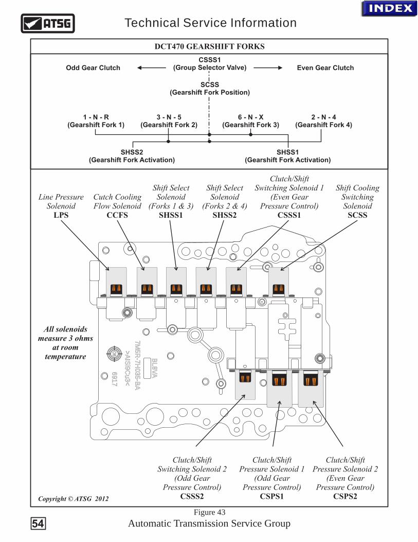
DCT470 GEARSHIFT FORKS
CSSS1 (Group Selector Valve)
SCSS (Gearshift Fork Position)
1 - N - R (Gearshift Fork 1)
3 - N - 5 (Gearshift Fork 2)
6 - N - X (Gearshift Fork 3)
2 - N - 4 (Gearshift Fork 4)
SHSS2 (Gearshift Fork Activation)
SHSS1 (Gearshift Fork Activation)
Odd Gear Clutch Even Gear Clutch
Figure 43
54
7M
5R
-7H
035-B
A
BL8V
A6917
>A
ISi9
Cu3<
06
F9
35
Clutch/Shift Switching Solenoid 1
(Even Gear Pressure Control)
CSSS1
Shift Select Solenoid
(Forks 1 & 3)SHSS1
Shift Cooling Switching Solenoid
SCSS
Shift Select Solenoid
(Forks 2 & 4)SHSS2
Cutch CoolingFlow Solenoid
CCFS
Line PressureSolenoid
LPS
Clutch/Shift Switching Solenoid 2
(Odd Gear Pressure Control)
CSSS2
Clutch/Shift Pressure Solenoid 1
(Odd Gear Pressure Control)
CSPS1
Clutch/Shift Pressure Solenoid 2
(Even Gear Pressure Control)
CSPS2Copyright © ATSG 2012
All solenoids measure 3 ohms
at room temperature

· System pressure solenoid LPS (Line Pressure Solenoid) - Controls system pressure in the transmission by directing the hydraulic oil to clutch, shifting, cooling flow, and then returning the oil to the oil sump.
· Solenoid for cooling flow CCFS (Clutch Cooling Flow Solenoid) - Controls hydraulic oil for cooling of clutches.
· Multiplex solenoid SCSS (Shift Cooling Switching Solenoid) - Controls position of gearshift forks as well as cooling of clutch.
· Multiplex solenoid CSSS1 (Clutch Shift Switching Solenoid) - Leads the pressure between even clutch and shifting, activates even gears as well as controls cooling flow for clutches.
· Multiplex solenoid CSSS2 (Clutch Shift Switching Solenoid) - Leads the pressure between odd clutch and shifting, controls cooling flow for clutches and can turn off the valve for dumping clutch pressure CPCUT to regain clutch pressure.
· Solenoid for clutch pressure Odd gears CSPS1 (Clutch Shift Pressure Solenoid) - Controls hydraulic pressure for Odd clutch or shifting.
· Solenoid for clutch pressure even gears CSPS2 (Clutch Shift Pressure Solenoid) - Controls hydraulic pressure for even clutch or shifting.
· Valve for dumping clutch pressure CPCUT (Clutch Pressure Cut) - Safety valve that controls pressure-dumping in the hydraulic system.
· Shift solenoid SHSS1 (Shift Select Solenoid) - Controls shifting for gearshift fork 1 and 3.
· Shift solenoid SHSS2 (Shift Select Solenoid) - Controls shifting for gearshift fork 2 and 4.
Closed/open solenoids
The solenoids that are closed/open are the CSSS1,CSSS2, SCSS, SHSS1 and SHSS2. These have only 2 positions, completely closed or fully open. The solenoids control valves that lead the hydraulic pressure to the desired system. Depending on system pressure and temperature, the Transmission control module (TCM) calculates the current that needs to be triggered to respective solenoid. The triggered current to the solenoids is not returned, which means that diagnostics of the solenoids is limited to only being able to see if they are off or on.
Linear solenoids
Linear solenoids (CCFS, LPS, CSPS1 and CSPS2) are controlled by a pulse-width modulated (PWM) current to enable linear or gradual control of the hydraulic pressure. The pulse-width modulated current induces a magnetic field that moves a core inside the solenoid. The solenoid c a n c o n t r o l t h e p r e s s u r e b y g r a d u a l l y o p e n i n g o r c l o s i n g v a l v e s .The triggered current to the solenoids is returned to Transmission control module (TCM), which means that more advanced diagnosis is possible.
Automatic Transmission Service Group
Technical Service Information
SOLENOID FUNCTION
55
5M7H0
-
7
-
5A
R
BB
M5H0
-
7
75
A
R-B
B
L8VABL
V8A
B
76
19 7169
AI i>
S 93<
Cui
>AI9
3<
SCu
4DA
7M5R-7G
48-
827 TM
07234
0
/
6006
F9
35
MR-7G
36CA
75
1-
07 T
0
6
70
M7/22
MR-7G
36CA
75
1-
7T
0
700
M7/226
(2 Required)CSPS solenoids
(5 Required)All other solenoids
(2 Required)LPS & CCFS solenoids
7070 TM07/226 8270 TM07/234 8270 TM07/2967M5R-7G136-CA 7M5R-7G484-DA 7M5R-7G383-DA
DCT470 COMPLETE VALVE BODY AND SOLENOID IDENTIFICATION
SCSS
Automatic Transmission Service Group
Technical Service Information
CSSS1
SHSS2SHSS1
CCFSLPS
CSSS2
CSPS1
CSPS2
Copyright © ATSG 2012
The Line Pressure Solenoid not listed in the chart is turned on to drop line pressure throughout various shift sequences as needed for smooth shift transitions.
The solenoid sequence listed below has been determined via a hydraulic schematic produced by ATSG.
Figure 44
Gearshift Patterns
Activated Solenoids
SCSS SHSS1 SHSS2 CSSS1 CSSS2 CSPS1 CSPS2
Engage 1
Engage 2
Engage 3
Engage 4
Engage 5
Engage 6
On OffOn
Off Off On
Off Off On
On Off On
On Off On
Off On Off
On High X
On X
On XHigh
On X
On Off XHigh
High
Off
Off
High
Off
Off
On X HighOff
Park/Neutral
Engage R
On Off OnOn
Off
X
OffOn
Off High
High XOn Off
56

5H0
7M7
5- A
R-B
B
5M
H0-
7
75
A
R-B
B
VL8
ABL
VAB
8
769176
19
AI i9>
Su3<
CI i
>A S 93<
Cu
MR-7G
84DA
75
4-
7T
0
820
M7/234
6060
F9
35
7M5R-7G
136CA
-
07 TM
072
6
70
/2
7M5R-7G
36CA
1-
07 TM
072
6
70
/2
Valve Body To Solenoid BodyRetaining Bolts (14 Required)
CompleteValve Body
SpacerPlate
CompleteSolenoid Body
Copyright © ATSG 2012
Automatic Transmission Service Group
Technical Service Information
DCT470 VALVE BODY ASSEMBLY
Figure 45
57

Automatic Transmission Service Group
Technical Service Information
58
M5H0
-
7
75
A
R-B
B
M5H0
-
7
75
A
R-B
B
LV8A
BV
L8A
B
71691769
i>AI
93<
SCu
AI i93
>S
Cu<
0660
F9
35
6CA
7M5R-7G
13-
770
TM07/226
0
4
7M5R-7G
48DA
-
27 TM
072
4
80
/3
DCT470 SOLENOID BODY EXPLODED VIEW
300
301
301
302
303
304
304
304 304
305
306
307
308
309
310
310
311
311
312
313
314315
316
317
318
319
320
321
322323
SPRING NO. 316Free Length = .289"Spring Diameter = .199"Wire Diameter = .018"Approx Coils = 6 (NONE)
SPRING NO. 314 & 319Free Length = .260"Spring Diameter = .446"Wire Diameter = .046"Approx Coils = 4 (NONE)
SOLENOID BODY SPRING SPECIFICATIONS
300 SOLENOID BODY CASTING. 301 HOLLOW PLASTIC PCM LOCATING DOWELS. 302 LPS SOLENOID "O" RING SEAL (2 REQUIRED). 303 LPS SOLENOID. 304 SOLENOID RETAINING SCREWS. (2 SCREWS REQUIRED FOR EACH OF THE SOLENOIDS) 305 CCFS SOLENOID. 306 SHSS1 SOLENOID. 307 SHSS2 2 SOLENOID. 308 CSSS1 SOLENOID. 309 SCSS SOLENOID. 310 TYPE 2 SOLENOID LARGE "O" RING SEAL. 311 TYPE 2 SOLENOID SMALL "O" RING SEAL. (LARGE AND SMALL SEAL REQUIRED FOR EACH TYPE 2 SOL) 312 SHORT STEEL "RIBBED" VALVE BODY TO CASE GASKET. 313 LONG STEEL "RIBBED" VALVE BODY TO CASE GASKET.
314 SOLENOID SLEEVE SPRING. 315 CSPS2 SOLENOID SLEEVE. 316 CSPS1 & 2 SOLENOID VALVE SPRING. 317 CSPS2 SOLENOID VALVE. 318 CSPS2 SOLENOID. 319 CSPS1 SOLENOID SLEEVE SPRING. 320 CSPS1 SOLENOID SLEEVE. 321 CSPS1SOLENOID VALVE. 322 CSPS1 SOLENOID. 323 CSSS2 SOLENOID.
CSPS2
Copyright © ATSG 2012
7M5R-7G
36CA
1-
07 TM
072
6
70
/2
316
Figure 46
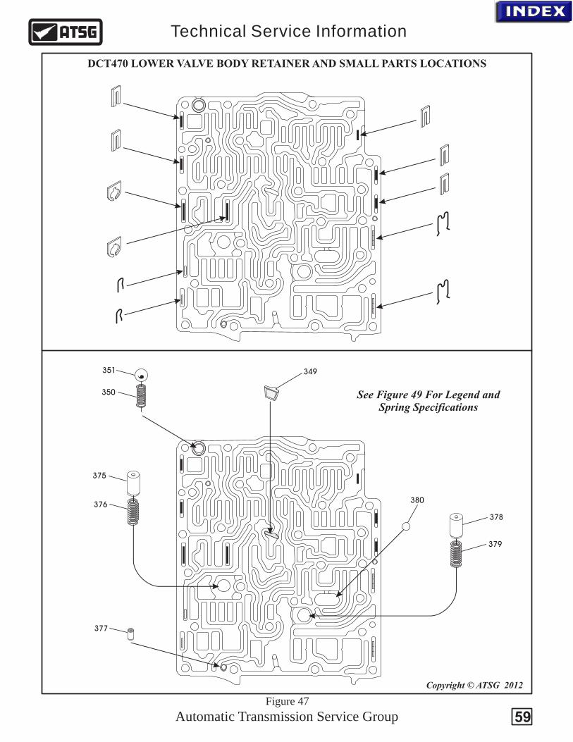
Automatic Transmission Service Group
Technical Service Information
DCT470 LOWER VALVE BODY RETAINER AND SMALL PARTS LOCATIONS
Copyright © ATSG 2012
349
350
375
376
377
378
379
380
351
See Figure 49 For Legend andSpring Specifications
Figure 47
59
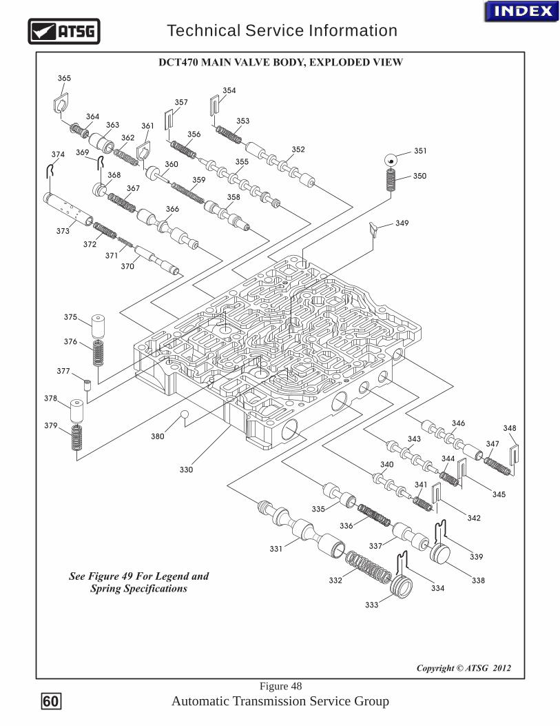
330
331
332
333
334
335
336
337
338
339
340
341
342
343
344
345
346
347
348
349
350
351352
353
354
355
356
357
358
359
360
361
362
363364
365
366
367
368
369
370
371
372
373
374
375
376
377
378
379
380
See Figure 49 For Legend andSpring Specifications
Copyright © ATSG 2012
Automatic Transmission Service Group
Technical Service Information
DCT470 MAIN VALVE BODY, EXPLODED VIEW
Figure 48
60
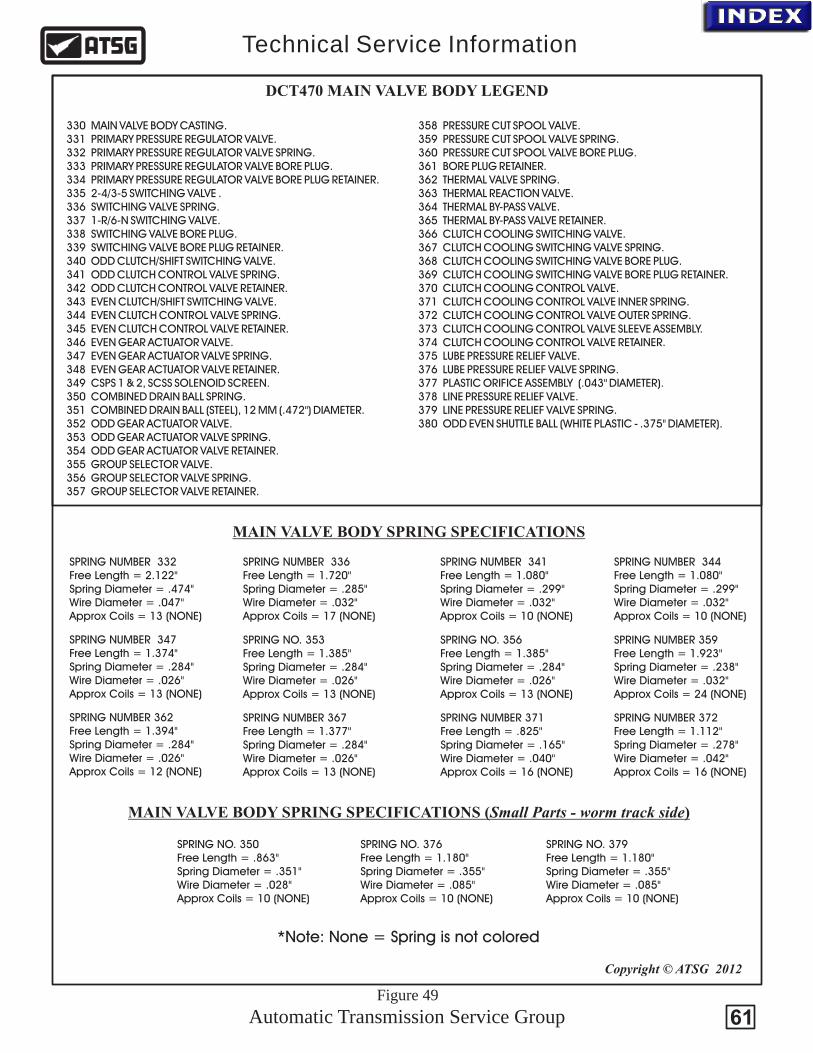
Automatic Transmission Service Group
Technical Service Information
61
330 MAIN VALVE BODY CASTING. 331 PRIMARY PRESSURE REGULATOR VALVE. 332 PRIMARY PRESSURE REGULATOR VALVE SPRING. 333 PRIMARY PRESSURE REGULATOR VALVE BORE PLUG. 334 PRIMARY PRESSURE REGULATOR VALVE BORE PLUG RETAINER. 335 2-4/3-5 SWITCHING VALVE . 336 SWITCHING VALVE SPRING. 337 1-R/6-N SWITCHING VALVE. 338 SWITCHING VALVE BORE PLUG. 339 SWITCHING VALVE BORE PLUG RETAINER. 340 ODD CLUTCH/SHIFT SWITCHING VALVE. 341 ODD CLUTCH CONTROL VALVE SPRING. 342 ODD CLUTCH CONTROL VALVE RETAINER. 343 EVEN CLUTCH/SHIFT SWITCHING VALVE. 344 EVEN CLUTCH CONTROL VALVE SPRING. 345 EVEN CLUTCH CONTROL VALVE RETAINER. 346 EVEN GEAR ACTUATOR VALVE. 347 EVEN GEAR ACTUATOR VALVE SPRING. 348 EVEN GEAR ACTUATOR VALVE RETAINER. 349 CSPS 1 & 2, SCSS SOLENOID SCREEN. 350 COMBINED DRAIN BALL SPRING. 351 COMBINED DRAIN BALL (STEEL), 12 MM (.472") DIAMETER. 352 ODD 353 SPRING. 354 RETAINER. 355 . 356 SPRING. 357 RETAINER.
GEAR ACTUATOR VALVE.ODD GEAR ACTUATOR VALVEODD GEAR ACTUATOR VALVEGROUP SELECTOR VALVEGROUP SELECTOR VALVEGROUP SELECTOR VALVE
358 PRESSURE CUT SPOOL VALVE. 359 PRESSURE CUT SPOOL VALVE SPRING. 360 PRESSURE CUT SPOOL VALVE BORE PLUG. 361 BORE PLUG RETAINER. 362 THERMAL VALVE SPRING. 363 THERMAL REACTION VALVE. 364 THERMAL BY-PASS VALVE. 365 THERMAL BY-PASS VALVE RETAINER. 366 CLUTCH COOLING SWITCHING VALVE. 367 SPRING. 368 BORE PLUG. 369 BORE PLUG RETAINER. 370 CLUTCH COOLING CONTROL VALVE. 371 CLUTCH COOLING CONTROL VALVE INNER SPRING. 372 CLUTCH COOLING CONTROL VALVE OUTER SPRING. 373 CLUTCH COOLING CONTROL VALVE SLEEVE ASSEMBLY. 374 CLUTCH COOLING CONTROL VALVE RETAINER. 375 LUBE PRESSURE RELIEF VALVE. 376 LUBE PRESSURE RELIEF VALVE SPRING. 377 PLASTIC ORIFICE ASSEMBLY (.043" DIAMETER). 378 LINE PRESSURE RELIEF VALVE. 379 LINE PRESSURE RELIEF VALVE SPRING. 380 ODD EVEN SHUTTLE BALL (WHITE PLASTIC - .375" DIAMETER).
CLUTCH COOLING SWITCHING VALVECLUTCH COOLING SWITCHING VALVECLUTCH COOLING SWITCHING VALVE
DCT470 MAIN VALVE BODY LEGEND
SPRING NO. 356Free Length = 1.385"Spring Diameter = .284"Wire Diameter = .026"Approx Coils = 13 (NONE)
SPRING NO. 353Free Length = 1.385"Spring Diameter = .284"Wire Diameter = .026"Approx Coils = 13 (NONE)
SPRING NUMBER 336Free Length = 1.720"Spring Diameter = .285"Wire Diameter = .032"Approx Coils = 17 (NONE)
SPRING NUMBER 344Free Length = 1.080"Spring Diameter = .299"Wire Diameter = .032"Approx Coils = 10 (NONE)
SPRING NUMBER 341Free Length = 1.080"Spring Diameter = .299"Wire Diameter = .032"Approx Coils = 10 (NONE)
SPRING NUMBER 367Free Length = 1.377"Spring Diameter = .284"Wire Diameter = .026"Approx Coils = 13 (NONE)
SPRING NUMBER 372Free Length = 1.112"Spring Diameter = .278"Wire Diameter = .042"Approx Coils = 16 (NONE)
SPRING NUMBER 371Free Length = .825"Spring Diameter = .165"Wire Diameter = .040"Approx Coils = 16 (NONE)
SPRING NUMBER 347Free Length = 1.374"Spring Diameter = .284"Wire Diameter = .026"Approx Coils = 13 (NONE)
SPRING NUMBER 359Free Length = 1.923"Spring Diameter = .238"Wire Diameter = .032"Approx Coils = 24 (NONE)
SPRING NUMBER 362Free Length = 1.394"Spring Diameter = .284"Wire Diameter = .026"Approx Coils = 12 (NONE)
SPRING NUMBER 332Free Length = 2.122"Spring Diameter = .474"Wire Diameter = .047"Approx Coils = 13 (NONE)
MAIN VALVE BODY SPRING SPECIFICATIONS
Copyright © ATSG 2012
MAIN VALVE BODY SPRING SPECIFICATIONS (Small Parts - worm track side)
SPRING NO. 350Free Length = .863"Spring Diameter = .351"Wire Diameter = .028"Approx Coils = 10 (NONE)
SPRING NO. 376Free Length = 1.180"Spring Diameter = .355"Wire Diameter = .085"Approx Coils = 10 (NONE)
SPRING NO. 379Free Length = 1.180"Spring Diameter = .355"Wire Diameter = .085"Approx Coils = 10 (NONE)
Figure 49
*Note: None = Spring is not colored

MitsubishiControl Module
Copyright © ATSG 2012
Reads 1st-ReverseFork Position
Reads 2nd-4thFork Position
Reads 6th - NFork Position
Reads 3rd-5thFork Position
Reads Input Shaft 2 Speed
Reads Input Shaft 1 Speed
Automatic Transmission Service Group
Technical Service Information
Fork #1 is the 1st and Reverse Shift ForkFork #2 is the 3rd and 5th Shift ForkFork #3 is the 6th and Neutral Shift ForkFork #4 is the 2nd and 4th Shift Fork
Gearshift fork 1 Pistons for 1st and Reverse only
36.32mm (1.430") width41.35mm (1.625") length
All other Pistons36.32mm (1.115") width41.35mm (1.625") length
Figure 50
TCM SENSOR TOPOGRAPHY
FORK ASSIGNMENTS
62
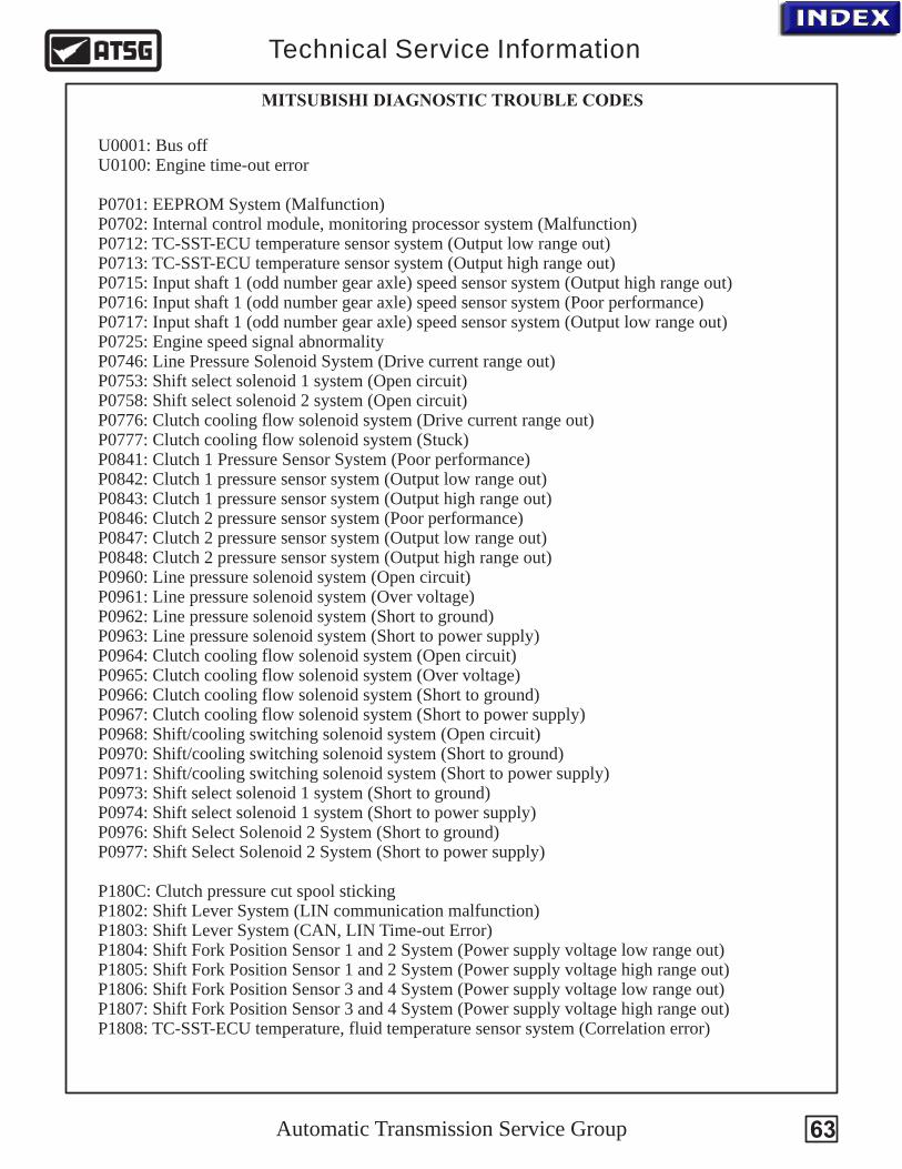
Automatic Transmission Service Group
Technical Service Information
63
U0001: Bus off U0100: Engine time-out error
P0701: EEPROM System (Malfunction) P0702: Internal control module, monitoring processor system (Malfunction) P0712: TC-SST-ECU temperature sensor system (Output low range out)P0713: TC-SST-ECU temperature sensor system (Output high range out) P0715: Input shaft 1 (odd number gear axle) speed sensor system (Output high range out) P0716: Input shaft 1 (odd number gear axle) speed sensor system (Poor performance) P0717: Input shaft 1 (odd number gear axle) speed sensor system (Output low range out) P0725: Engine speed signal abnormalityP0746: Line Pressure Solenoid System (Drive current range out) P0753: Shift select solenoid 1 system (Open circuit) P0758: Shift select solenoid 2 system (Open circuit) P0776: Clutch cooling flow solenoid system (Drive current range out) P0777: Clutch cooling flow solenoid system (Stuck) P0841: Clutch 1 Pressure Sensor System (Poor performance)P0842: Clutch 1 pressure sensor system (Output low range out) P0843: Clutch 1 pressure sensor system (Output high range out) P0846: Clutch 2 pressure sensor system (Poor performance) P0847: Clutch 2 pressure sensor system (Output low range out) P0848: Clutch 2 pressure sensor system (Output high range out) P0960: Line pressure solenoid system (Open circuit) P0961: Line pressure solenoid system (Over voltage) P0962: Line pressure solenoid system (Short to ground) P0963: Line pressure solenoid system (Short to power supply) P0964: Clutch cooling flow solenoid system (Open circuit) P0965: Clutch cooling flow solenoid system (Over voltage) P0966: Clutch cooling flow solenoid system (Short to ground) P0967: Clutch cooling flow solenoid system (Short to power supply) P0968: Shift/cooling switching solenoid system (Open circuit) P0970: Shift/cooling switching solenoid system (Short to ground) P0971: Shift/cooling switching solenoid system (Short to power supply)P0973: Shift select solenoid 1 system (Short to ground) P0974: Shift select solenoid 1 system (Short to power supply) P0976: Shift Select Solenoid 2 System (Short to ground)P0977: Shift Select Solenoid 2 System (Short to power supply)
P180C: Clutch pressure cut spool stickingP1802: Shift Lever System (LIN communication malfunction)P1803: Shift Lever System (CAN, LIN Time-out Error)P1804: Shift Fork Position Sensor 1 and 2 System (Power supply voltage low range out) P1805: Shift Fork Position Sensor 1 and 2 System (Power supply voltage high range out)P1806: Shift Fork Position Sensor 3 and 4 System (Power supply voltage low range out) P1807: Shift Fork Position Sensor 3 and 4 System (Power supply voltage high range out) P1808: TC-SST-ECU temperature, fluid temperature sensor system (Correlation error)
MITSUBISHI DIAGNOSTIC TROUBLE CODES
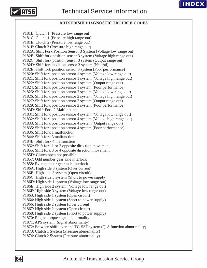
Automatic Transmission Service Group
Technical Service Information
64
P181B: Clutch 1 (Pressure low range out P181C: Clutch 1 (Pressure high range out)P181E: Clutch 2 (Pressure low range out) P181F: Clutch 2 (Pressure high range out)P182A: Shift Fork Position Sensor 3 System (Voltage low range out)P182B: Shift fork position sensor 3 system (Voltage high range out) P182C: Shift fork position sensor 3 system (Output range out) P182D: Shift fork position sensor 3 system (Neutral) P182E: Shift fork position sensor 3 system (Poor performance) P1820: Shift fork position sensor 1 system (Voltage low range out) P1821: Shift fork position sensor 1 system (Voltage high range out) P1822: Shift fork position sensor 1 system (Output range out) P1824: Shift fork position sensor 1 system (Poor performance) P1825: Shift fork position sensor 2 system (Voltage low range out) P1826: Shift fork position sensor 2 system (Voltage high range out) P1827: Shift fork position sensor 2 system (Output range out) P1829: Shift fork position sensor 2 system (Poor performance) P183D: Shift Fork 2 MalfunctionP1831: Shift fork position sensor 4 system (Voltage low range out) P1832: Shift fork position sensor 4 system (Voltage high range out) P1833: Shift fork position sensor 4 system (Output range out) P1835: Shift fork position sensor 4 system (Poor performance) P1836: Shift fork 1 malfunctionP1844: Shift fork 3 malfunction P184B: Shift fork 4 malfunctionP1852: Shift fork 1 or 2 opposite direction movement P1855: Shift fork 3 or 4 opposite direction movement P185D: Clutch open not possibleP1857: Odd number gear axle interlock P1858: Even number gear axle interlock P186A: High side 3 system (Over current)P186B: High side 3 system (Open circuit) P186C: High side 3 system (Short to power supply) P186D: High side 1 system (Voltage low range out) P186E: High side 2 system (Voltage low range out) P186F: High side 3 system (Voltage low range out) P1863: High side 1 system (Open circuit)P1864: High side 1 system (Short to power supply)P1866: High side 2 system (Over current) P1867: High side 2 system (Open circuit)P1868: High side 2 system (Short to power supply)P1870: Engine torque signal abnormality P1871: APS system (Signal abnormality) P1872: Between shift lever and TC-SST system (Q-A function abnormality)P1873: Clutch 1 System (Pressure abnormality)P1874: Clutch 2 System (Pressure abnormality)
MITSUBISHI DIAGNOSTIC TROUBLE CODES
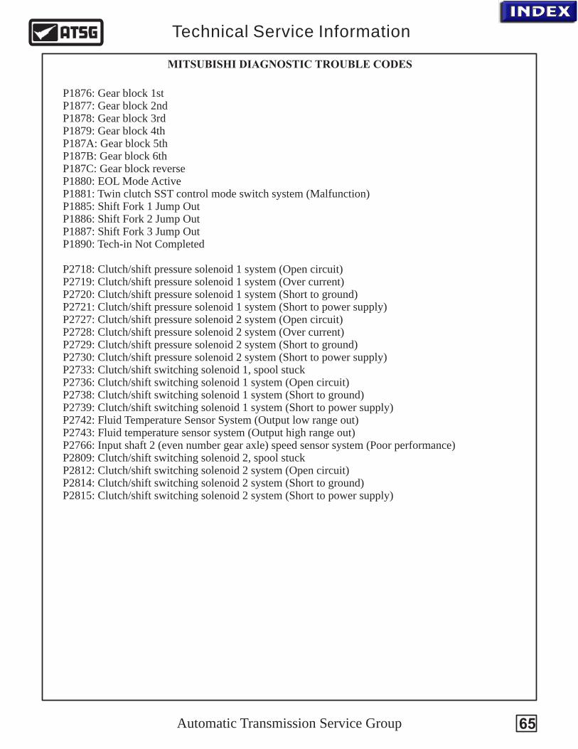
Automatic Transmission Service Group
Technical Service Information
65
P1876: Gear block 1st P1877: Gear block 2nd P1878: Gear block 3rd P1879: Gear block 4th P187A: Gear block 5th P187B: Gear block 6th P187C: Gear block reverseP1880: EOL Mode ActiveP1881: Twin clutch SST control mode switch system (Malfunction) P1885: Shift Fork 1 Jump OutP1886: Shift Fork 2 Jump OutP1887: Shift Fork 3 Jump OutP1890: Tech-in Not Completed
P2718: Clutch/shift pressure solenoid 1 system (Open circuit) P2719: Clutch/shift pressure solenoid 1 system (Over current) P2720: Clutch/shift pressure solenoid 1 system (Short to ground) P2721: Clutch/shift pressure solenoid 1 system (Short to power supply) P2727: Clutch/shift pressure solenoid 2 system (Open circuit)P2728: Clutch/shift pressure solenoid 2 system (Over current) P2729: Clutch/shift pressure solenoid 2 system (Short to ground)P2730: Clutch/shift pressure solenoid 2 system (Short to power supply) P2733: Clutch/shift switching solenoid 1, spool stuck P2736: Clutch/shift switching solenoid 1 system (Open circuit) P2738: Clutch/shift switching solenoid 1 system (Short to ground) P2739: Clutch/shift switching solenoid 1 system (Short to power supply) P2742: Fluid Temperature Sensor System (Output low range out)P2743: Fluid temperature sensor system (Output high range out) P2766: Input shaft 2 (even number gear axle) speed sensor system (Poor performance)P2809: Clutch/shift switching solenoid 2, spool stuck P2812: Clutch/shift switching solenoid 2 system (Open circuit) P2814: Clutch/shift switching solenoid 2 system (Short to ground) P2815: Clutch/shift switching solenoid 2 system (Short to power supply)
MITSUBISHI DIAGNOSTIC TROUBLE CODES
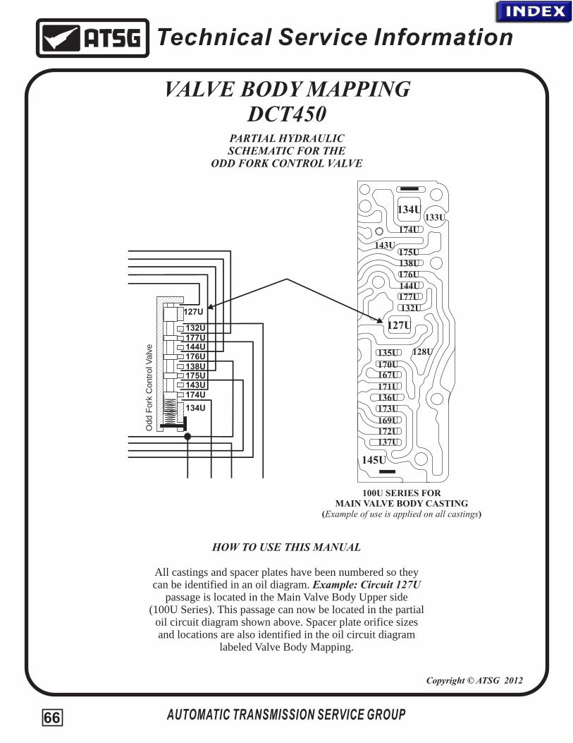
Technical Service Information
VALVE BODY MAPPINGDCT450
PARTIAL HYDRAULIC SCHEMATIC FOR THE
ODD FORK CONTROL VALVE
AUTOMATIC TRANSMISSION SERVICE GROUP
100U SERIES FORMAIN VALVE BODY CASTING
(Example of use is applied on all castings)
HOW TO USE THIS MANUAL
All castings and spacer plates have been numbered so theycan be identified in an oil diagram. Example: Circuit 127U
passage is located in the Main Valve Body Upper side(100U Series). This passage can now be located in the partial
oil circuit diagram shown above. Spacer plate orifice sizes and locations are also identified in the oil circuit diagram
labeled Valve Body Mapping.
Copyright © ATSG 2012
127U
128U
132U
133U134U
135U
136U
137U
138U
143U
144U
145U
167U
169U
170U
171U
172U
173U
174U
175U
176U
177U
132U
134U
138U
143U
144U
127U
174U
175U
176U
177U
Odd F
ork
Contr
ol V
alv
e
66
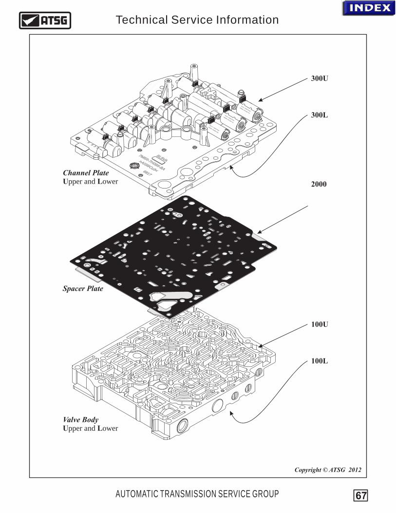
5M
H0-
7
75
A
R-B
B
M5H0
-
7
75
A
R-B
B
LVA
8B
VL8
AB
76
19 7169
I i>A S 9
3<Cu
iAI
93
>S
Cu<
7M5R-7G
484DA
-
27 TM
072
4
80
/3
0606
F9
35
R-7
6CA
7M5
G13
-
770
0 TM07/226
-7
6CA
7M5R
G13
-
770
0 TM07/226
100U
100L
2000
300U
300L
Valve Body Upper and Lower
Spacer Plate
Channel Plate Upper and Lower
AUTOMATIC TRANSMISSION SERVICE GROUP
Technical Service Information
Copyright © ATSG 2012
67
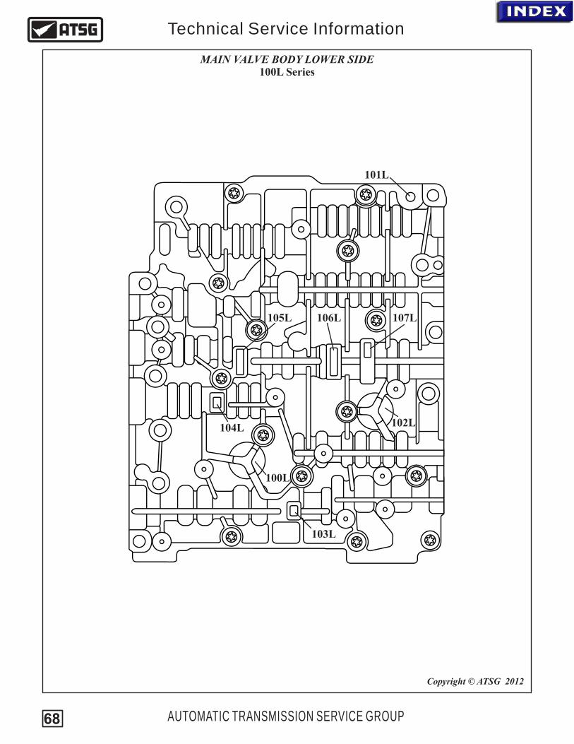
100L
103L
104L
105L 106L 107L
102L
101L
AUTOMATIC TRANSMISSION SERVICE GROUP
Technical Service Information
MAIN VALVE BODY LOWER SIDE100L Series
Copyright © ATSG 2012
68

100U
101U10
2U
103U
104U
100U
105U
106U
107U 10
8U
109U
110U
111U
112U
113U
114U
115U
116U
117U
118U
119U
120U
121U
122U
123U
124U
126U
127U
128U
129U
130U
131U
132U
133U
134U
135U
136U
137U
138U
139U
140U
141U
142U
143U
144U
145U
146U
14U714
8U
149U
150U
151U
152U
153U
154U
155U
156U
157U
159U
160U 16
1U
162U
163U
164U
165U
166U
167U
168U
169U
170U
171U
172U
173U
174U
175U
176U
177U
AUTOMATIC TRANSMISSION SERVICE GROUP
Technical Service Information
MAIN VALVE BODY UPPER SIDE100U Series
Copyright © ATSG 2012
69
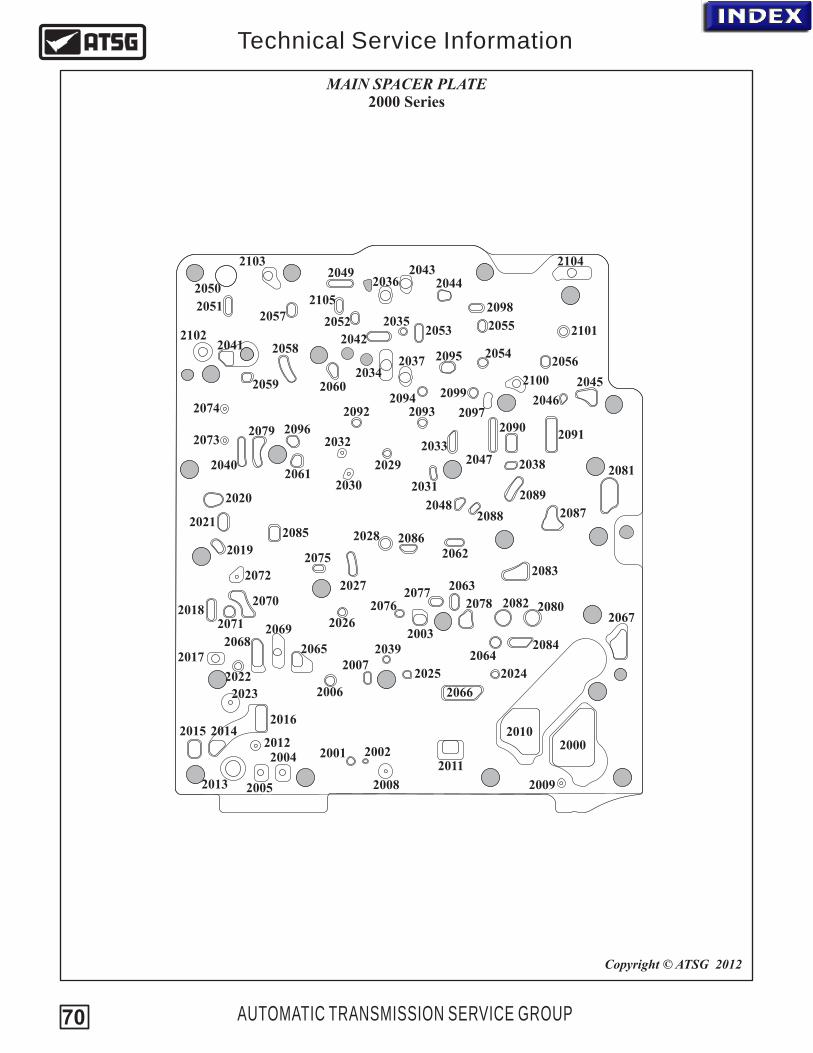
20002001 2002
2003
2004
2005
2006
2007
2008 2009
2010
2011
2012
2013
201420152016
2017
2018
2019
2020
2021
2022
2023
20242025
2026
2027
2028
2029
2030 2031
2032 2033
2034
2035
2036
2037
2038
2039
2040
2041 2042
20432044
2045
2046
2047
2049
2048
2050
20512052
2053
2054
2055
2056
2057
2058
2059 2060
2061
2062
2063
20642065
2066
2067
20682069
2070
2071
2072
2073
2074
2075
20762077
2078
2079
2080
2081
2082
2083
2084
2085 2086
20872088
2089
20902091
2092 20932094
2095
20962097
2098
20992100
2102
2103 2104
2101
2105
AUTOMATIC TRANSMISSION SERVICE GROUP
Technical Service Information
MAIN SPACER PLATE2000 Series
Copyright © ATSG 2012
70
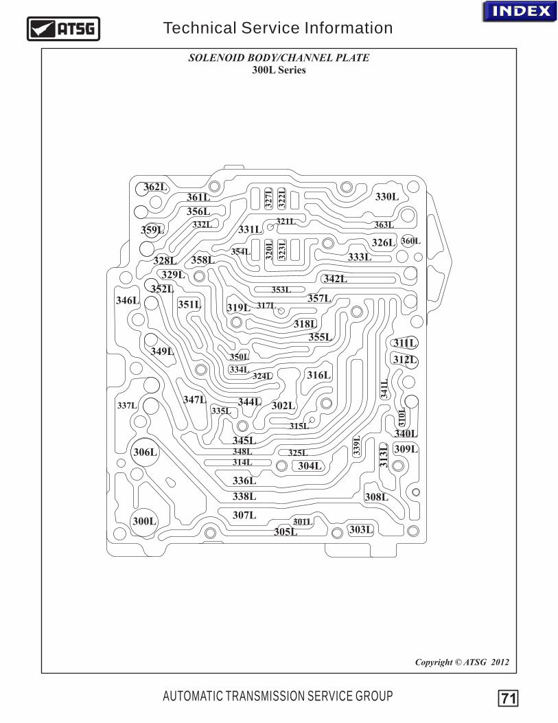
300L
AUTOMATIC TRANSMISSION SERVICE GROUP
Technical Service Information
SOLENOID BODY/CHANNEL PLATE300L Series
Copyright © ATSG 2012
301L
302L
303L
304L
305L
306L
307L
308L
309L
310L
311L
312L
313L
314L
315L
316L
317L
318L
319L
320L
321L
322L
323L
324L
325L
326L
327L
328L
329L
330L
331L332L
333L
334L
335L
336L
337L
338L
339L
340L
341L
342L
344L
345L
347L
346L
348L
349L350L
351L
352L 353L
354L
355L
356L363L
358L
359L
361L
360L
362L
357L
71
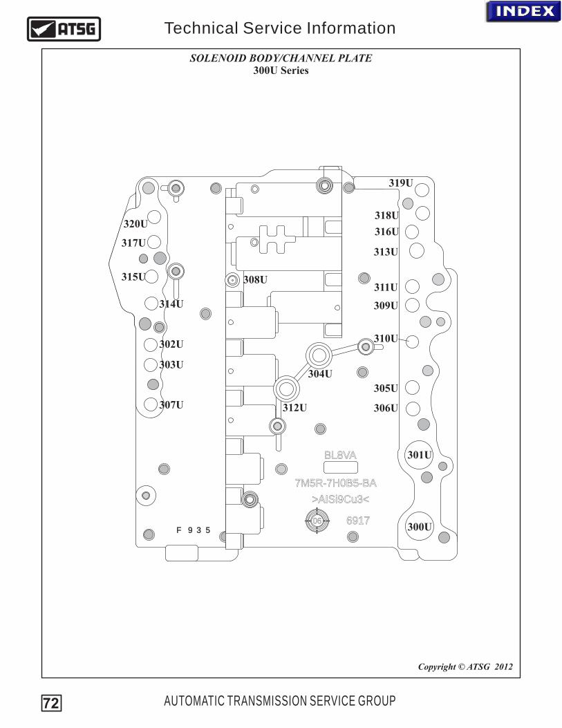
7M5R-7H0B5-BA
BL8VA
6917
>AISi9Cu3<
06F 9 3 5 300U
AUTOMATIC TRANSMISSION SERVICE GROUP
Technical Service Information
SOLENOID BODY/CHANNEL PLATE300U Series
Copyright © ATSG 2012
301U
302U
303U304U
305U
306U307U
308U
309U
310U
311U
312U
313U
314U
315U
316U317U
319U
318U320U
72

CP18
CP17
CP15
CP12
CP11
CP9
CP10
CP5
CP6
CP2
CP1
CP19
CP16
CP14
CP13
CP3
CP4
CP7
AUTOMATIC TRANSMISSION SERVICE GROUP
Technical Service Information
CASE PASSAGE IDENTIFICATIONCP Series
Copyright © ATSG 2012
73

From CP17
From CP16
From CP13
From CP15
From CP14
300U
306L
7070
TM
07/2
26
7M
5R
7G
136-C
A
xx
7070
TM
07/2
26
7M
5R
7G
136-C
A
xx
8270TM07/234
7M5R-76484-DA
CS
MS
1
x
x
SH
SS
1
CC
FS
LP
S
xx
xx
Reverse 5th
1st 3rd 2nd 4th
Neutral 6th
Sump Filter
Pump IntakePump
Case side view of pump
CP2
301U
300L
2000
100U
20012002
301L
.046"
101U
100U
100L2003
302L 302L
.042"
303L
102U
304L
103U
104U
305L
100U
105U
CP1
106U
107U
308L
108U
309L
109U
311L
302U
From CP3 - Port 1
312L
303U
CP3 CP4
ToCooler Port 1
FromCooler Port 2
112U
112U
112U
313L
113U
114U
115U
315L
116U
316L
317L
103U
110U
111U
117U
124U
318L
118U
119U
119U
319L
120U
120U
121U
122U
320L 321L 322L
323L
123U
126U
326L
127U
128U
327L
328L
129U
130U
131U132U
330L
133U
101L
134U
136U
332L
137U
138U
2004 2005 2006 2007
304L
2008.039"
305L
2009.039" 2010 2011
2012.039"
307L
2013 2014 2015 2016 2017 2018 2019
310L
2020 2021 20222023.050" 2024 2025 2026
314L
2027 2028 20292030.050" 2031
2032.050" 2033 2034 2035 2036 2037 2039 2040 2041 2042 2043 2044 2045 2046 2047
329L
2048 2049 2050 2051 2052 2053
331L
2054 2055 2056 2057
138U
2058
333L
2059 2060
139U
140U
2061
334L
2062
141U
2063
335L
2064
142U
143U
143U 144U
144U
X
X
145U
145U146U
2065
336L
2066
147U
2067
337L
305U
CP5
148U
2068
338L
306U
CP6
2069
149U
339L
2070
102L
150U
2071
340L
307U
CP7
2072.039"
341L
2073.038"
2074.038"
151U
342L
308U
2075
343L
2076
152U
2077
344L
309U
CP9
153U
2078
345L
2079
154U
155U
155U
2080
346L
2081
156U
2082
347L
2083
157U
155U
2084
348L
2085
159U
x
x
x
x
x
160U
2086 2038
324L
325L
(2038listed
above)
(324Llisted
above)
2087
161U
349L
310U
CP10
2088
350L
304U
2089 2090
351L
1863U
162U
2091
352L
311U
CP11
312U
165U
2092
353L
2093
166U
2094
354L
2095
167U
168U
2096
355L
2097
169U
170U135U
2098
356L
313U
CP12
2099
357L
314U
CP13
171U
127U
172U
2100
358L
315U
CP14
2101
359L
316U
CP15
173U
174U
2102
360L
317U
CP16
2103
361L
318U
CP17
2104
362L
319U
CP18
2105
363L
320U
CP19
175U
176U
177U
C1 Balance
C2 Balance
C1
Clutch Assembly LubeC2
Clutch Assembly Lube (CP9)
C2 (CP11)C2 Balance (CP5)C1 Balance (CP6)
C1 (CP10)
From CP18
From CP19
From CP12
From CP4 - Port 2
To Heat Exchanger
From Heat Exchanger
To CP7 - Port 3
FromCooler Filter
Port 3
SHCMS - Shift Cooling Multiplex Solenoid
LPS - System Pressure Control SolenoidCCFS - Clutch Cooling Flow Solenoid
SH
SS
2
CS
PS
1
CS
MS
2
SH
CM
S
CS
PS
2
Gearshift PatternsActivated Solenoids
SHCMS SHSS1 SHSS2 CSMS1 CSMS2 CSPS1 CSPS2
Engage 1 (Disengages 3)
Engage 2 (Disengages 4)
Engage 3 (Disengages 1)
Engage 4 (Disengages 2)
Engage 5 (Disengages R)
Engage 6
Disengages 6
Engage R (Disengage 5)
On
On
Off
Off
On
Off
On
Off
Off
On
Off
On
On
Off
Off
On
On
Off
On
Off
Off
Off
On
On On
On
On
On
Off
Off
Off
Off
Off
On
On
On
On
Off
Off
Off High
High
High
High
High
High
High
HighX
X
X
X
X
X
X
X
SHSS1 - Shift Select Solenoid (Forks 1 & 3)
SHSS2 - Shift Select Solenoid (Forks 2 & 4)
CSMS1 - Clutch Shift Multiplex Solenoid (Uneven Gear Pressure Control)
CSMS2 - Clutch Shift Multiplex Solenoid (Even Gear Pressure Control)
CSPS1 - Clutch Shift Pressure Solenoid (Uneven Clutch Pressure Control)
CSPS2 - Clutch Shift Pressure Solenoid (Even Clutch Pressure Control)
Clutch DrumSupport
Passage ID
Getrag Powershift Transmission
Volvo - MPS6Ford - DPS6
Copyright © 2012 ATSG
6DCT450 Dual Wet Clutch
C2C1
Primary P. R. Valve
Secondary P. R. Valve
Lube Relief Valve
Clutch Cooling Flow Valve
Odd E
ven C
ontr
ol V
alv
e
Eve
n F
ork
Contr
ol V
alv
e
Uneve
n F
ork
C
ontr
ol V
alv
e
C2 C
lutc
h C
ontr
ol V
alv
e
C1 C
lutc
h C
ontr
ol V
alv
e
Therm
al
By-
pass
Valv
e
Odd EvenShuttle Ball
O E Shift Valve
CombinedDrain Ball
Pre
ssure
Cu
t S
afe
ty V
alv
e
LP Relief Valve
(CP8-not used)To TCM
x
x
x
103L
104L
105L
106L
107L
F1 - Reverse & 5thF2 - 3rd & 1stF3 - 2nd & 4thF4 - N & 6th

.03
9"
.03
8"
.03
8"
TCM Cooler
xx
Reverse
5th
1st
3rd
2nd
4th
Neutral
6th
Sump Filter
Pump IntakePump
Case side view of pump
Prim
ary
P. R
. V
alv
e
.042"
X
Xx
x
x
x
C2C1
Clutch Assembly Lube
To Heat Exchanger
From Heat Exchanger
Getrag Powershift Transmission
Volvo - MPS6Ford - DPS6
Copyright © 2012 ATSG
6DCT450 Dual Wet Clutch
Gearshift Patterns
Activated Solenoids
SHCMS SHSS1 SHSS2 CSMS1 CSMS2 CSPS1 CSPS2
Engage 1
Engage 2
Engage 3
Engage 4
Engage 5
Engage 6
Park/Neutral
Engage R
On
Off
Off
On
On
On
Off
Off
Off
On
Off
On
On
Off
Off
On
On
Off
On
Off
Off
Off
On
On On
On
On
On
Off
Off
Off
Off
Off
On
On
On
On
Off
Off
Off High
High
High
High
High
High
High
HighX
X
X
X
X
X
X
X
.046"
.039"
.039"
.03
9"
.050"
.050"
.050"
L. P. Relief Valve
Po
rt 3
Filte
r
Seco
ndary
P. R
. V
alv
eLube Relief Valve
Po
rt 1
Filte
r
Po
rt 2
Filte
r
C1 Transducer
7070
TM
07/2
26
7M
5R
7G
136-C
A
xx
7070
TM
07/2
26
7M
5R
7G
136-C
A
xx
8270TM07/234
7M5R-76484-DA
x
x
CS
PS
1
CS
MS
2
SH
CM
S
CS
PS
2
C2 Transducer
C1
C2TCM Cooling
x x
SH
SS
1
CC
FS
LP
S
SH
SS
2
CS
MS
1
Park/Neutral
Clu
tch C
oolin
g F
low
Valv
e
x
x
Odd E
ven C
ontr
ol V
alv
e
Eve
n F
ork
Contr
ol V
alv
e
Uneve
n F
ork
C
ontr
ol V
alv
e
C2 C
lutc
h C
ontr
ol V
alv
e
C1 C
lutc
h C
ontr
ol V
alv
e
Therm
al
By-
pass
Valv
e
Odd EvenShuttle Ball
O E
Shift
Valv
e
CombinedDrain Ball
Pre
ssure
Cu
t S
afe
ty V
alv
e
.039" C2 Clutch
C1 BalanceC1 Clutch
C2 Balance
CSMS1 CSMS2 CSPS1 CSPS2 - Clutch Shift Pressure Solenoid (Even Clutch Pressure Control)
- Clutch Shift Pressure Solenoid (Uneven Clutch Pressure Control)- Clutch Shift Multiplex Solenoid (Even Gear Pressure Control)- Clutch Shift Multiplex Solenoid (Uneven Gear Pressure Control)
LPS
SHSS2
- Line Pressure Control SolenoidSHCMS CCFS
SHSS1
- Shift Cooling Multiplex Solenoid- Clutch Cooling Flow Solenoid
- Shift Select Solenoid (Forks 1 & 3)- Shift Select Solenoid (Forks 2 & 4) Legend
Line & Solenoid Feed Pressure
From Cooler Pressure/Lube
Connected circuit
Clutch Balance Pressure
Clutch Pressure
Fork Pressure
Circuit blocked by spacer plate
Exhaust
Pump Suction
To Cooler Pressure
**
**
**
**
**
**
**
**
**
**
RANGE"P/N”
F1 - Reverse & 5thF2 - 3rd & 1stF3 - 2nd & 4thF4 - N & 6th
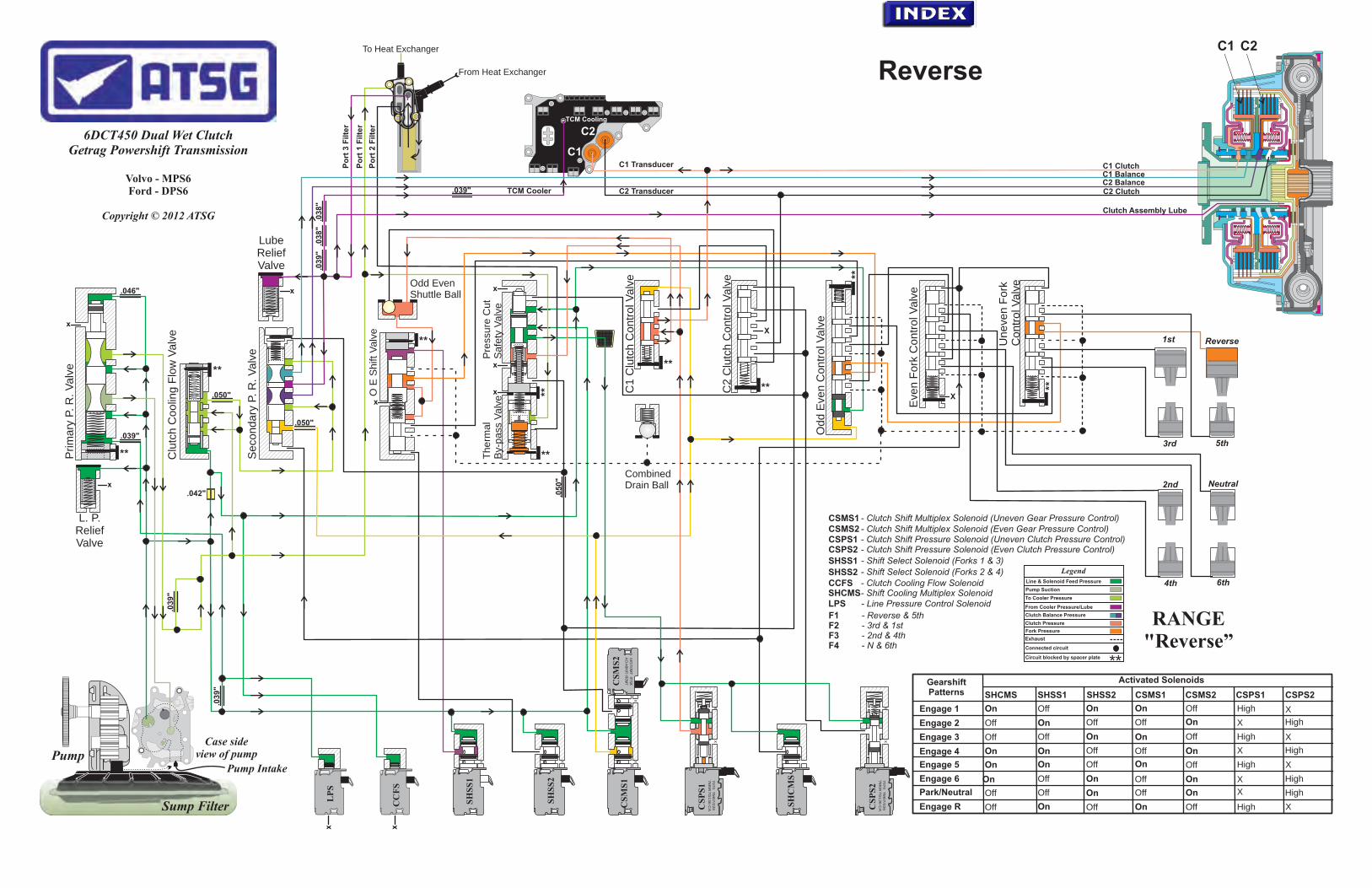
.03
9"
.03
8"
.03
8"
TCM Cooler
SH
SS
1
CC
FS
LP
S
xx
Reverse
5th
1st
3rd
2nd
4th 6th
Sump Filter
Pump IntakePump
Case side view of pump
.042"
X
X
x
x
x
x
x
Clutch Assembly Lube
To Heat Exchanger
From Heat Exchanger
SH
SS
2
.046"
.039"
.039"
.03
9"
.050"
.050"
.050"
L. P. Relief Valve
Po
rt 3
Filte
r
Lube Relief Valve
Po
rt 1
Filte
r
Po
rt 2
Filte
r
7070
TM
07/2
26
7M
5R
7G
136-C
A
xx
7070
TM
07/2
26
7M
5R
7G
136-C
A
xx
8270TM07/234
7M5R-76484-DA
CS
MS
1
x
x
CS
PS
1
CS
MS
2
SH
CM
S
CS
PS
2
TCM Cooling
x x
ReverseP
rim
ary
P. R
. V
alv
e
Seco
ndary
P. R
. V
alv
e
Clu
tch C
oolin
g F
low
Valv
e
x
x
Odd E
ven C
ontr
ol V
alv
e
Eve
n F
ork
Contr
ol V
alv
e
Uneve
n F
ork
C
ontr
ol V
alv
e
Therm
al
By-
pass
Valv
e
Odd EvenShuttle Ball
Pre
ssure
Cu
t S
afe
ty V
alv
e
CombinedDrain Ball
O E
Shift
Valv
e
.039"
C1 Transducer
C2 Transducer
C1
C2
C2 C
lutc
h C
ontr
ol V
alv
e
C1 C
lutc
h C
ontr
ol V
alv
e
C2 Clutch
C1 BalanceC1 Clutch
C2 Balance
C2C1
Getrag Powershift Transmission
Volvo - MPS6Ford - DPS6
Copyright © 2012 ATSG
6DCT450 Dual Wet Clutch
Gearshift Patterns
Activated Solenoids
SHCMS SHSS1 SHSS2 CSMS1 CSMS2 CSPS1 CSPS2
Engage 1
Engage 2
Engage 3
Engage 4
Engage 5
Engage 6
Park/Neutral
Engage R
On
Off
Off
On
On
On
Off
Off
Off
On
Off
On
On
Off
Off
On
On
Off
On
Off
Off
Off
On
On On
On
On
On
Off
Off
Off
Off
Off
On
On
On
On
Off
Off
Off High
High
High
High
High
High
High
HighX
X
X
X
X
X
X
X
CSMS1 CSMS2 CSPS1 CSPS2 - Clutch Shift Pressure Solenoid (Even Clutch Pressure Control)
- Clutch Shift Pressure Solenoid (Uneven Clutch Pressure Control)- Clutch Shift Multiplex Solenoid (Even Gear Pressure Control)- Clutch Shift Multiplex Solenoid (Uneven Gear Pressure Control)
LPS
SHSS2
- Line Pressure Control SolenoidSHCMS CCFS
SHSS1
- Shift Cooling Multiplex Solenoid- Clutch Cooling Flow Solenoid
- Shift Select Solenoid (Forks 1 & 3)- Shift Select Solenoid (Forks 2 & 4) Legend
Line & Solenoid Feed Pressure
From Cooler Pressure/Lube
Connected circuit
Clutch Balance Pressure
Clutch Pressure
Fork Pressure
Circuit blocked by spacer plate
Exhaust
Pump Suction
To Cooler Pressure
**
**
**
**
**
**
**
**
**
**
RANGE"Reverse”
Neutral
F1 - Reverse & 5thF2 - 3rd & 1stF3 - 2nd & 4thF4 - N & 6th
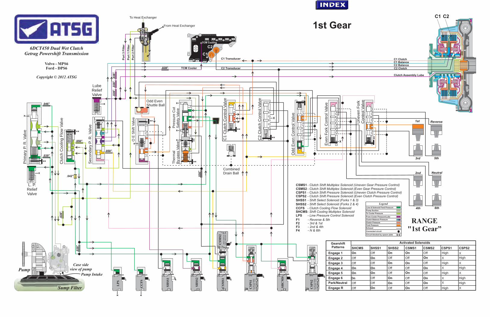
.03
9"
.03
8"
.03
8"
TCM Cooler
xx
Reverse
5th
1st
3rd
2nd
4th 6th
Sump Filter
Pump IntakePump
Case side view of pump
.042"
X
X
x
x
x
x
x
Clutch Assembly Lube
To Heat Exchanger
From Heat Exchanger
.046"
.039"
.039"
.03
9"
.050"
.050"
.050"
L. P. Relief Valve
Po
rt 3
Filte
r
Lube Relief Valve
Po
rt 1
Filte
r
Po
rt 2
Filte
r
7070
TM
07/2
26
7M
5R
7G
136-C
A
xx
7070
TM
07/2
26
7M
5R
7G
136-C
A
xx
8270TM07/234
7M5R-76484-DA
x
x
CS
PS
1
CS
MS
2
SH
CM
S
CS
PS
2
TCM Cooling
x x
SH
SS
1
CC
FS
LP
S
SH
SS
2
CS
MS
1
1st GearP
rim
ary
P. R
. V
alv
e
Seco
ndary
P. R
. V
alv
e
Clu
tch C
oolin
g F
low
Valv
e
x
x
Odd E
ven C
ontr
ol V
alv
e
Eve
n F
ork
Contr
ol V
alv
e
Uneve
n F
ork
C
ontr
ol V
alv
e
Therm
al
By-
pass
Valv
e
Odd EvenShuttle Ball
O E
Shift
Valv
e
CombinedDrain Ball
Pre
ssure
Cu
t S
afe
ty V
alv
e
.039"
C1 Transducer
C2 Transducer
C1
C2
C2 C
lutc
h C
ontr
ol V
alv
e
C1 C
lutc
h C
ontr
ol V
alv
e
C2 Clutch
C1 BalanceC1 Clutch
C2 Balance
C2C1
Getrag Powershift Transmission
Volvo - MPS6Ford - DPS6
Copyright © 2012 ATSG
6DCT450 Dual Wet Clutch
Gearshift Patterns
Activated Solenoids
SHCMS SHSS1 SHSS2 CSMS1 CSMS2 CSPS1 CSPS2
Engage 1
Engage 2
Engage 3
Engage 4
Engage 5
Engage 6
Park/Neutral
Engage R
On
Off
Off
On
On
On
Off
Off
Off
On
Off
On
On
Off
Off
On
On
Off
On
Off
Off
Off
On
On On
On
On
On
Off
Off
Off
Off
Off
On
On
On
On
Off
Off
Off High
High
High
High
High
High
High
HighX
X
X
X
X
X
X
X
CSMS1 CSMS2 CSPS1 CSPS2 - Clutch Shift Pressure Solenoid (Even Clutch Pressure Control)
- Clutch Shift Pressure Solenoid (Uneven Clutch Pressure Control)- Clutch Shift Multiplex Solenoid (Even Gear Pressure Control)- Clutch Shift Multiplex Solenoid (Uneven Gear Pressure Control)
LPS
SHSS2
- Line Pressure Control SolenoidSHCMS CCFS
SHSS1
- Shift Cooling Multiplex Solenoid- Clutch Cooling Flow Solenoid
- Shift Select Solenoid (Forks 1 & 3)- Shift Select Solenoid (Forks 2 & 4) Legend
Line & Solenoid Feed Pressure
From Cooler Pressure/Lube
Connected circuit
Clutch Balance Pressure
Clutch Pressure
Fork Pressure
Circuit blocked by spacer plate
Exhaust
Pump Suction
To Cooler Pressure
**
**
**
**
**
**
**
**
**
**
RANGE"1st Gear”
Neutral
F1 - Reverse & 5thF2 - 3rd & 1stF3 - 2nd & 4thF4 - N & 6th

.03
9"
.03
8"
.03
8"
TCM Cooler
xx
Reverse
5th
1st
3rd
2nd
4th 6th
Sump Filter
Pump IntakePump
Case side view of pump
.042"
X
X
x
x
x
x
x
Clutch Assembly Lube
To Heat Exchanger
From Heat Exchanger
.046"
.039"
.039"
.03
9"
.050"
.050"
.050"
L. P. Relief Valve
Po
rt 3
Filte
r
Lube Relief Valve
Po
rt 1
Filte
r
Po
rt 2
Filte
r
7070
TM
07/2
26
7M
5R
7G
136-C
A
xx
7070
TM
07/2
26
7M
5R
7G
136-C
A
xx
8270TM07/234
7M5R-76484-DA
x
x
CS
PS
1
CS
MS
2
SH
CM
S
CS
PS
2
TCM Cooling
x x
SH
SS
1
CC
FS
LP
S
SH
SS
2
CS
MS
1
2nd GearP
rim
ary
P. R
. V
alv
e
Seco
ndary
P. R
. V
alv
e
Clu
tch C
oolin
g F
low
Valv
e
x
x
Odd E
ven C
ontr
ol V
alv
e
Eve
n F
ork
Contr
ol V
alv
e
Uneve
n F
ork
C
ontr
ol V
alv
e
Therm
al
By-
pass
Valv
e
Odd EvenShuttle Ball
O E
Shift
Valv
e
CombinedDrain Ball
Pre
ssure
Cu
t S
afe
ty V
alv
e
.039"
C1 Transducer
C2 Transducer
C1
C2
C2 C
lutc
h C
ontr
ol V
alv
e
C1 C
lutc
h C
ontr
ol V
alv
e
C2 Clutch
C1 BalanceC1 Clutch
C2 Balance
C2C1
Getrag Powershift Transmission
Volvo - MPS6Ford - DPS6
Copyright © 2012 ATSG
6DCT450 Dual Wet Clutch
Gearshift Patterns
Activated Solenoids
SHCMS SHSS1 SHSS2 CSMS1 CSMS2 CSPS1 CSPS2
Engage 1
Engage 2
Engage 3
Engage 4
Engage 5
Engage 6
Park/Neutral
Engage R
On
Off
Off
On
On
On
Off
Off
Off
On
Off
On
On
Off
Off
On
On
Off
On
Off
Off
Off
On
On On
On
On
On
Off
Off
Off
Off
Off
On
On
On
On
Off
Off
Off High
High
High
High
High
High
High
HighX
X
X
X
X
X
X
X
CSMS1 CSMS2 CSPS1 CSPS2 - Clutch Shift Pressure Solenoid (Even Clutch Pressure Control)
- Clutch Shift Pressure Solenoid (Uneven Clutch Pressure Control)- Clutch Shift Multiplex Solenoid (Even Gear Pressure Control)- Clutch Shift Multiplex Solenoid (Uneven Gear Pressure Control)
LPS
SHSS2
- Line Pressure Control SolenoidSHCMS CCFS
SHSS1
- Shift Cooling Multiplex Solenoid- Clutch Cooling Flow Solenoid
- Shift Select Solenoid (Forks 1 & 3)- Shift Select Solenoid (Forks 2 & 4) Legend
Line & Solenoid Feed Pressure
From Cooler Pressure/Lube
Connected circuit
Clutch Balance Pressure
Clutch Pressure
Fork Pressure
Circuit blocked by spacer plate
Exhaust
Pump Suction
To Cooler Pressure
**
**
**
**
**
**
**
**
**
**
RANGE"2nd Gear”
Neutral
F1 - Reverse & 5thF2 - 3rd & 1stF3 - 2nd & 4thF4 - N & 6th

.03
9"
.03
8"
.03
8"
TCM Cooler
xx
Reverse
5th
1st
3rd
2nd
4th 6th
Sump Filter
Pump IntakePump
Case side view of pump
.042"
X
X
x
x
x
x
x
Clutch Assembly Lube
To Heat Exchanger
From Heat Exchanger
.046"
.039"
.039"
.03
9"
.050"
.050"
.050"
L. P. Relief Valve
Po
rt 3
Filte
r
Lube Relief Valve
Po
rt 1
Filte
r
Po
rt 2
Filte
r
7070
TM
07/2
26
7M
5R
7G
136-C
A
xx
7070
TM
07/2
26
7M
5R
7G
136-C
A
xx
8270TM07/234
7M5R-76484-DA
x
x
CS
PS
1
CS
MS
2
SH
CM
S
CS
PS
2
TCM Cooling
x x
SH
SS
1
CC
FS
LP
S
SH
SS
2
CS
MS
1
3rd GearP
rim
ary
P. R
. V
alv
e
Seco
ndary
P. R
. V
alv
e
Clu
tch C
oolin
g F
low
Valv
e
x
x
Odd E
ven C
ontr
ol V
alv
e
Eve
n F
ork
Contr
ol V
alv
e
Uneve
n F
ork
C
ontr
ol V
alv
e
Therm
al
By-
pass
Valv
e
Odd EvenShuttle Ball
O E
Shift
Valv
e
CombinedDrain Ball
Pre
ssure
Cu
t S
afe
ty V
alv
e
.039"
C1 Transducer
C2 Transducer
C1
C2
C2 C
lutc
h C
ontr
ol V
alv
e
C1 C
lutc
h C
ontr
ol V
alv
e
C2 Clutch
C1 BalanceC1 Clutch
C2 Balance
C2C1
Getrag Powershift Transmission
Volvo - MPS6Ford - DPS6
Copyright © 2012 ATSG
6DCT450 Dual Wet Clutch
Gearshift Patterns
Activated Solenoids
SHCMS SHSS1 SHSS2 CSMS1 CSMS2 CSPS1 CSPS2
Engage 1
Engage 2
Engage 3
Engage 4
Engage 5
Engage 6
Park/Neutral
Engage R
On
Off
Off
On
On
On
Off
Off
Off
On
Off
On
On
Off
Off
On
On
Off
On
Off
Off
Off
On
On On
On
On
On
Off
Off
Off
Off
Off
On
On
On
On
Off
Off
Off High
High
High
High
High
High
High
HighX
X
X
X
X
X
X
X
CSMS1 CSMS2 CSPS1 CSPS2 - Clutch Shift Pressure Solenoid (Even Clutch Pressure Control)
- Clutch Shift Pressure Solenoid (Uneven Clutch Pressure Control)- Clutch Shift Multiplex Solenoid (Even Gear Pressure Control)- Clutch Shift Multiplex Solenoid (Uneven Gear Pressure Control)
LPS
SHSS2
- Line Pressure Control SolenoidSHCMS CCFS
SHSS1
- Shift Cooling Multiplex Solenoid- Clutch Cooling Flow Solenoid
- Shift Select Solenoid (Forks 1 & 3)- Shift Select Solenoid (Forks 2 & 4) Legend
Line & Solenoid Feed Pressure
From Cooler Pressure/Lube
Connected circuit
Clutch Balance Pressure
Clutch Pressure
Fork Pressure
Circuit blocked by spacer plate
Exhaust
Pump Suction
To Cooler Pressure
**
**
**
**
**
**
**
**
**
**
RANGE"3rd Gear”
Neutral
F1 - Reverse & 5thF2 - 3rd & 1stF3 - 2nd & 4thF4 - N & 6th

.03
9"
.03
8"
.03
8"
TCM Cooler
xx
Reverse
5th
1st
3rd
2nd
4th 6th
Sump Filter
Pump IntakePump
Case side view of pump
.042"
X
X
x
x
x
x
x
Clutch Assembly Lube
To Heat Exchanger
From Heat Exchanger
.046"
.039"
.039"
.03
9"
.050"
.050"
.050"
L. P. Relief Valve
Po
rt 3
Filte
r
Lube Relief Valve
Po
rt 1
Filte
r
Po
rt 2
Filte
r
7070
TM
07/2
26
7M
5R
7G
136-C
A
xx
7070
TM
07/2
26
7M
5R
7G
136-C
A
xx
8270TM07/234
7M5R-76484-DA
x
x
CS
PS
1
CS
MS
2
SH
CM
S
CS
PS
2
TCM Cooling
x x
SH
SS
1
CC
FS
LP
S
SH
SS
2
CS
MS
1
4th GearP
rim
ary
P. R
. V
alv
e
Seco
ndary
P. R
. V
alv
e
Clu
tch C
oolin
g F
low
Valv
e
x
x
Odd E
ven C
ontr
ol V
alv
e
Eve
n F
ork
Contr
ol V
alv
e
Uneve
n F
ork
C
ontr
ol V
alv
e
Therm
al
By-
pass
Valv
e
Odd EvenShuttle Ball
O E
Shift
Valv
e
CombinedDrain Ball
Pre
ssure
Cu
t S
afe
ty V
alv
e
.039"
C1 Transducer
C2 Transducer
C1
C2
C2 C
lutc
h C
ontr
ol V
alv
e
C1 C
lutc
h C
ontr
ol V
alv
e
C2 Clutch
C1 BalanceC1 Clutch
C2 Balance
C2C1
Getrag Powershift Transmission
Volvo - MPS6Ford - DPS6
Copyright © 2012 ATSG
6DCT450 Dual Wet Clutch
Gearshift Patterns
Activated Solenoids
SHCMS SHSS1 SHSS2 CSMS1 CSMS2 CSPS1 CSPS2
Engage 1
Engage 2
Engage 3
Engage 4
Engage 5
Engage 6
Park/Neutral
Engage R
On
Off
Off
On
On
On
Off
Off
Off
On
Off
On
On
Off
Off
On
On
Off
On
Off
Off
Off
On
On On
On
On
On
Off
Off
Off
Off
Off
On
On
On
On
Off
Off
Off High
High
High
High
High
High
High
HighX
X
X
X
X
X
X
X
CSMS1 CSMS2 CSPS1 CSPS2 - Clutch Shift Pressure Solenoid (Even Clutch Pressure Control)
- Clutch Shift Pressure Solenoid (Uneven Clutch Pressure Control)- Clutch Shift Multiplex Solenoid (Even Gear Pressure Control)- Clutch Shift Multiplex Solenoid (Uneven Gear Pressure Control)
LPS
SHSS2
- Line Pressure Control SolenoidSHCMS CCFS
SHSS1
- Shift Cooling Multiplex Solenoid- Clutch Cooling Flow Solenoid
- Shift Select Solenoid (Forks 1 & 3)- Shift Select Solenoid (Forks 2 & 4) Legend
Line & Solenoid Feed Pressure
From Cooler Pressure/Lube
Connected circuit
Clutch Balance Pressure
Clutch Pressure
Fork Pressure
Circuit blocked by spacer plate
Exhaust
Pump Suction
To Cooler Pressure
**
**
**
**
**
**
**
**
**
**
RANGE"4th Gear”
Neutral
F1 - Reverse & 5thF2 - 3rd & 1stF3 - 2nd & 4thF4 - N & 6th
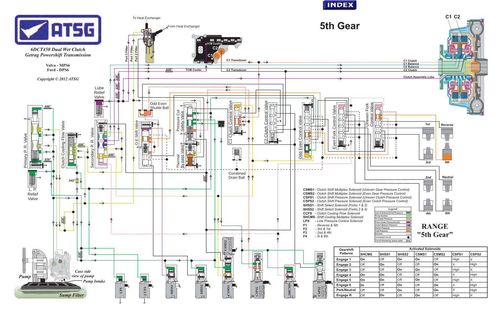
.03
9"
.03
8"
.03
8"
TCM Cooler
xx
Reverse
5th
1st
3rd
2nd
4th 6th
Sump Filter
Pump IntakePump
Case side view of pump
.042"
X
X
x
x
x
x
x
Clutch Assembly Lube
To Heat Exchanger
From Heat Exchanger
.046"
.039"
.039"
.03
9"
.050"
.050"
.050"
L. P. Relief Valve
Po
rt 3
Filte
r
Lube Relief Valve
Po
rt 1
Filte
r
Po
rt 2
Filte
r
7070
TM
07/2
26
7M
5R
7G
136-C
A
xx
7070
TM
07/2
26
7M
5R
7G
136-C
A
xx
8270TM07/234
7M5R-76484-DA
x
x
CS
PS
1
CS
MS
2
SH
CM
S
CS
PS
2
TCM Cooling
x x
SH
SS
1
CC
FS
LP
S
SH
SS
2
CS
MS
1
5th GearP
rim
ary
P. R
. V
alv
e
Seco
ndary
P. R
. V
alv
e
Clu
tch C
oolin
g F
low
Valv
e
x
x
Odd E
ven C
ontr
ol V
alv
e
Eve
n F
ork
Contr
ol V
alv
e
Uneve
n F
ork
C
ontr
ol V
alv
e
Therm
al
By-
pass
Valv
e
Odd EvenShuttle Ball
O E
Shift
Valv
e
CombinedDrain Ball
Pre
ssure
Cu
t S
afe
ty V
alv
e
.039"
C1 Transducer
C2 Transducer
C1
C2
C2 C
lutc
h C
ontr
ol V
alv
e
C1 C
lutc
h C
ontr
ol V
alv
e
C2 Clutch
C1 BalanceC1 Clutch
C2 Balance
C2C1
Getrag Powershift Transmission
Volvo - MPS6Ford - DPS6
Copyright © 2012 ATSG
6DCT450 Dual Wet Clutch
Gearshift Patterns
Activated Solenoids
SHCMS SHSS1 SHSS2 CSMS1 CSMS2 CSPS1 CSPS2
Engage 1
Engage 2
Engage 3
Engage 4
Engage 5
Engage 6
Park/Neutral
Engage R
On
Off
Off
On
On
On
Off
Off
Off
On
Off
On
On
Off
Off
On
On
Off
On
Off
Off
Off
On
On On
On
On
On
Off
Off
Off
Off
Off
On
On
On
On
Off
Off
Off High
High
High
High
High
High
High
HighX
X
X
X
X
X
X
X
CSMS1 CSMS2 CSPS1 CSPS2 - Clutch Shift Pressure Solenoid (Even Clutch Pressure Control)
- Clutch Shift Pressure Solenoid (Uneven Clutch Pressure Control)- Clutch Shift Multiplex Solenoid (Even Gear Pressure Control)- Clutch Shift Multiplex Solenoid (Uneven Gear Pressure Control)
LPS
SHSS2
- Line Pressure Control SolenoidSHCMS CCFS
SHSS1
- Shift Cooling Multiplex Solenoid- Clutch Cooling Flow Solenoid
- Shift Select Solenoid (Forks 1 & 3)- Shift Select Solenoid (Forks 2 & 4) Legend
Line & Solenoid Feed Pressure
From Cooler Pressure/Lube
Connected circuit
Clutch Balance Pressure
Clutch Pressure
Fork Pressure
Circuit blocked by spacer plate
Exhaust
Pump Suction
To Cooler Pressure
**
**
**
**
**
**
**
**
**
**
RANGE"5th Gear”
Neutral
F1 - Reverse & 5thF2 - 3rd & 1stF3 - 2nd & 4thF4 - N & 6th
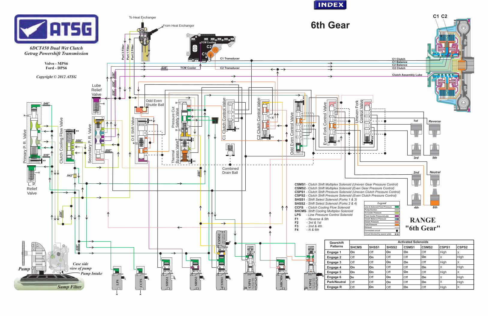
.03
9"
.03
8"
.03
8"
TCM Cooler
xx
Reverse
5th
1st
3rd
2nd
4th 6th
Sump Filter
Pump IntakePump
Case side view of pump
.042"
X
X
x
x
x
x
x
Clutch Assembly Lube
C2 Clutch
C1 BalanceC1 Clutch
To Heat Exchanger
From Heat Exchanger
.046"
.039"
.039"
.03
9"
.050"
.050"
.050"
L. P. Relief Valve
Po
rt 3
Filte
r
Lube Relief Valve
Po
rt 1
Filte
r
Po
rt 2
Filte
r
7070
TM
07/2
26
7M
5R
7G
136-C
A
xx
7070
TM
07/2
26
7M
5R
7G
136-C
A
xx
8270TM07/234
7M5R-76484-DA
x
x
CS
PS
1
CS
MS
2
SH
CM
S
CS
PS
2
C2 Balance
TCM Cooling
x x
SH
SS
1
CC
FS
LP
S
SH
SS
2
CS
MS
1
6th GearP
rim
ary
P. R
. V
alv
e
Seco
ndary
P. R
. V
alv
e
Clu
tch C
oolin
g F
low
Valv
e
x
x
Odd E
ven C
ontr
ol V
alv
e
Eve
n F
ork
Contr
ol V
alv
e
Uneve
n F
ork
C
ontr
ol V
alv
e
Therm
al
By-
pass
Valv
e
Odd EvenShuttle Ball
O E
Shift
Valv
e
CombinedDrain Ball
Pre
ssure
Cu
t S
afe
ty V
alv
e
.039"
C1 Transducer
C2 Transducer
C1
C2
C2 C
lutc
h C
ontr
ol V
alv
e
C1 C
lutc
h C
ontr
ol V
alv
e
C2C1
Getrag Powershift Transmission
Volvo - MPS6Ford - DPS6
Copyright © 2012 ATSG
6DCT450 Dual Wet Clutch
Gearshift Patterns
Activated Solenoids
SHCMS SHSS1 SHSS2 CSMS1 CSMS2 CSPS1 CSPS2
Engage 1
Engage 2
Engage 3
Engage 4
Engage 5
Engage 6
Park/Neutral
Engage R
On
Off
Off
On
On
On
Off
Off
Off
On
Off
On
On
Off
Off
On
On
Off
On
Off
Off
Off
On
On On
On
On
On
Off
Off
Off
Off
Off
On
On
On
On
Off
Off
Off High
High
High
High
High
High
High
HighX
X
X
X
X
X
X
X
CSMS1 CSMS2 CSPS1 CSPS2 - Clutch Shift Pressure Solenoid (Even Clutch Pressure Control)
- Clutch Shift Pressure Solenoid (Uneven Clutch Pressure Control)- Clutch Shift Multiplex Solenoid (Even Gear Pressure Control)- Clutch Shift Multiplex Solenoid (Uneven Gear Pressure Control)
LPS
SHSS2
- Line Pressure Control SolenoidSHCMS CCFS
SHSS1
- Shift Cooling Multiplex Solenoid- Clutch Cooling Flow Solenoid
- Shift Select Solenoid (Forks 1 & 3)- Shift Select Solenoid (Forks 2 & 4) Legend
Line & Solenoid Feed Pressure
From Cooler Pressure/Lube
Connected circuit
Clutch Balance Pressure
Clutch Pressure
Fork Pressure
Circuit blocked by spacer plate
Exhaust
Pump Suction
To Cooler Pressure
**
**
**
**
**
**
**
**
**
**
RANGE"6th Gear"
Neutral
F1 - Reverse & 5thF2 - 3rd & 1stF3 - 2nd & 4thF4 - N & 6th
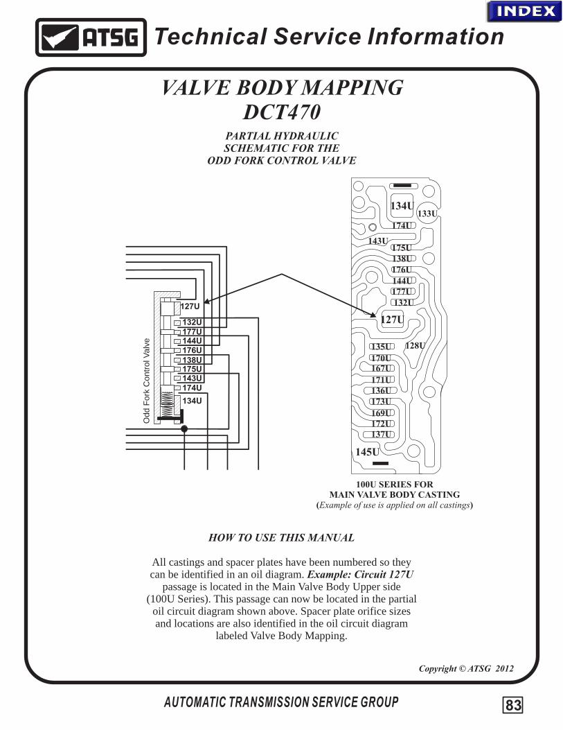
Technical Service Information
VALVE BODY MAPPINGDCT470
PARTIAL HYDRAULIC SCHEMATIC FOR THE
ODD FORK CONTROL VALVE
AUTOMATIC TRANSMISSION SERVICE GROUP
100U SERIES FORMAIN VALVE BODY CASTING
(Example of use is applied on all castings)
HOW TO USE THIS MANUAL
All castings and spacer plates have been numbered so theycan be identified in an oil diagram. Example: Circuit 127U
passage is located in the Main Valve Body Upper side(100U Series). This passage can now be located in the partial
oil circuit diagram shown above. Spacer plate orifice sizes and locations are also identified in the oil circuit diagram
labeled Valve Body Mapping.
Copyright © ATSG 2012
127U
128U
132U
133U134U
135U
136U
137U
138U
143U
144U
145U
167U
169U
170U
171U
172U
173U
174U
175U
176U
177U
132U
134U
138U
143U
144U
127U
174U
175U
176U
177U
Odd F
ork
Contr
ol V
alv
e
83
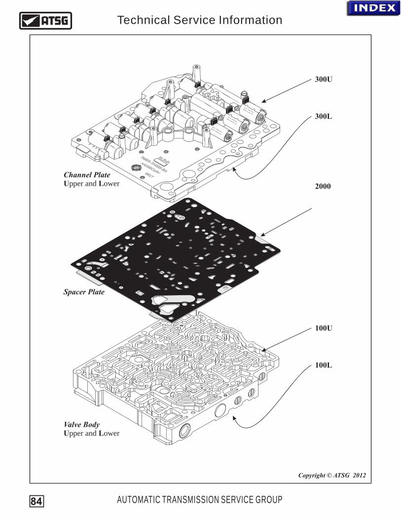
5M
H0-
7
75
A
R-B
B
M5H0
-
7
75
A
R-B
B
LVA
8B
VL8
AB
76
19 7169
I i>A S 9
3<Cu
iAI
93
>S
Cu<
7M5R-7G
484DA
-
27 TM
072
4
80
/3
0606
F9
35
R-7
6CA
7M5
G13
-
770
0 TM07/226
-7
6CA
7M5R
G13
-
770
0 TM07/226
100U
100L
2000
300U
300L
Valve Body Upper and Lower
Spacer Plate
Channel Plate Upper and Lower
AUTOMATIC TRANSMISSION SERVICE GROUP
Technical Service Information
Copyright © ATSG 2012
84
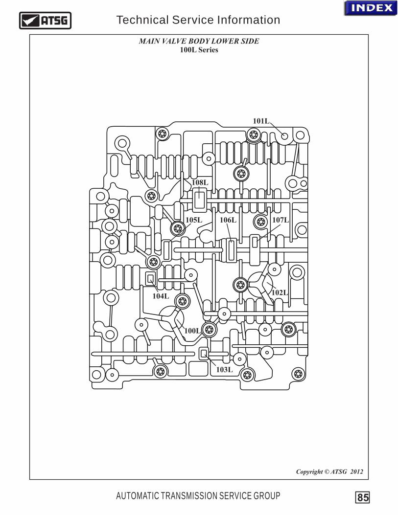
100L
103L
104L
105L 106L 107L
102L
101L
AUTOMATIC TRANSMISSION SERVICE GROUP
Technical Service Information
MAIN VALVE BODY LOWER SIDE100L Series
Copyright © ATSG 2012
108L
85

100U
101U10
2U
103U
104U
100U
105U
106U
107U 10
8U
109U
110U
111U
112U
113U
114U
115U
116U
117U
118U
119U
120U
121U
122U
123U
124U
126U
127U
128U
129U
130U
131U
132U
133U
134U
135U
136U
137U
138U
139U
140U
141U
142U
143U
144U
145U
146U
14U714
8U
149U
150U
151U
152U
153U
154U
155U
156U
157U
159U
160U 16
1U
162U
163U
164U
165U
166U
167U
168U
169U
170U
171U
172U
173U
174U
175U
176U
177U
AUTOMATIC TRANSMISSION SERVICE GROUP
Technical Service Information
MAIN VALVE BODY UPPER SIDE100U Series
Copyright © ATSG 2012
86
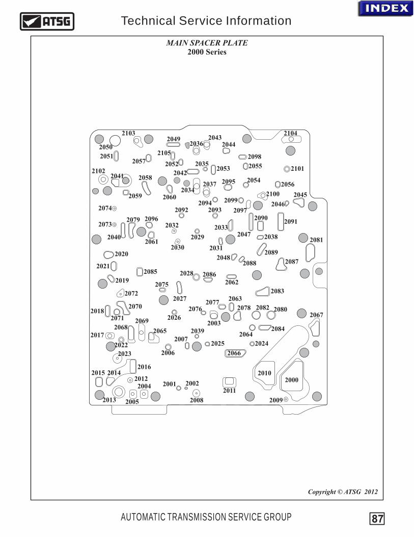
20002001 2002
2003
2004
2005
2006
2007
2008 2009
2010
2011
2012
2013
201420152016
2017
2018
2019
2020
2021
2022
2023
20242025
2026
2027
2028
2029
2030 2031
2032 2033
2034
2035
2036
2037
2038
2039
2040
2041 2042
20432044
2045
2046
2047
2049
2048
2050
20512052
2053
2054
2055
2056
2057
2058
2059 2060
2061
2062
2063
20642065
2066
2067
20682069
2070
2071
2072
2073
2074
2075
20762077
2078
2079
2080
2081
2082
2083
2084
2085 2086
20872088
2089
20902091
2092 20932094
2095
20962097
2098
20992100
2102
2103 2104
2101
2105
AUTOMATIC TRANSMISSION SERVICE GROUP
Technical Service Information
MAIN SPACER PLATE2000 Series
Copyright © ATSG 2012
87

300L
AUTOMATIC TRANSMISSION SERVICE GROUP
Technical Service Information
SOLENOID BODY/CHANNEL PLATE300L Series
Copyright © ATSG 2012
301L
302L
303L
304L
305L
306L
307L
308L
309L
310L
311L
312L
313L
314L
315L
316L
317L
318L
319L
320L
321L
322L
323L
324L
325L
326L
327L
328L
329L
330L
331L332L
333L
334L
335L
336L
337L
338L
339L
340L
341L
342L
344L
345L
347L
346L
348L
349L350L
351L
352L 353L
354L
355L
356L363L
358L
359L
361L
360L
362L
357L
88
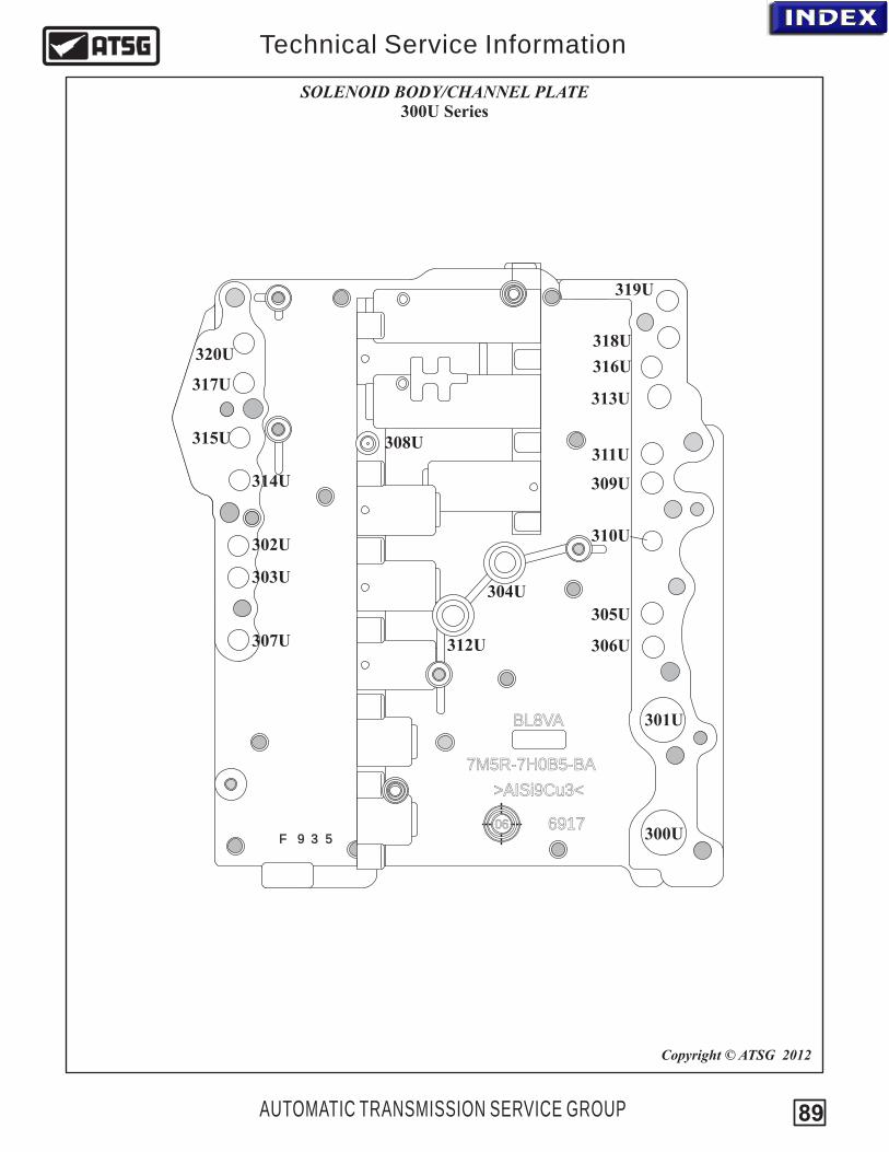
7M5R-7H0B5-BA
BL8VA
6917
>AISi9Cu3<
06F 9 3 5 300U
AUTOMATIC TRANSMISSION SERVICE GROUP
Technical Service Information
SOLENOID BODY/CHANNEL PLATE300U Series
Copyright © ATSG 2012
301U
302U
303U304U
305U
306U307U
308U
309U
310U
311U
312U
313U
314U
315U
316U317U
319U
318U320U
89
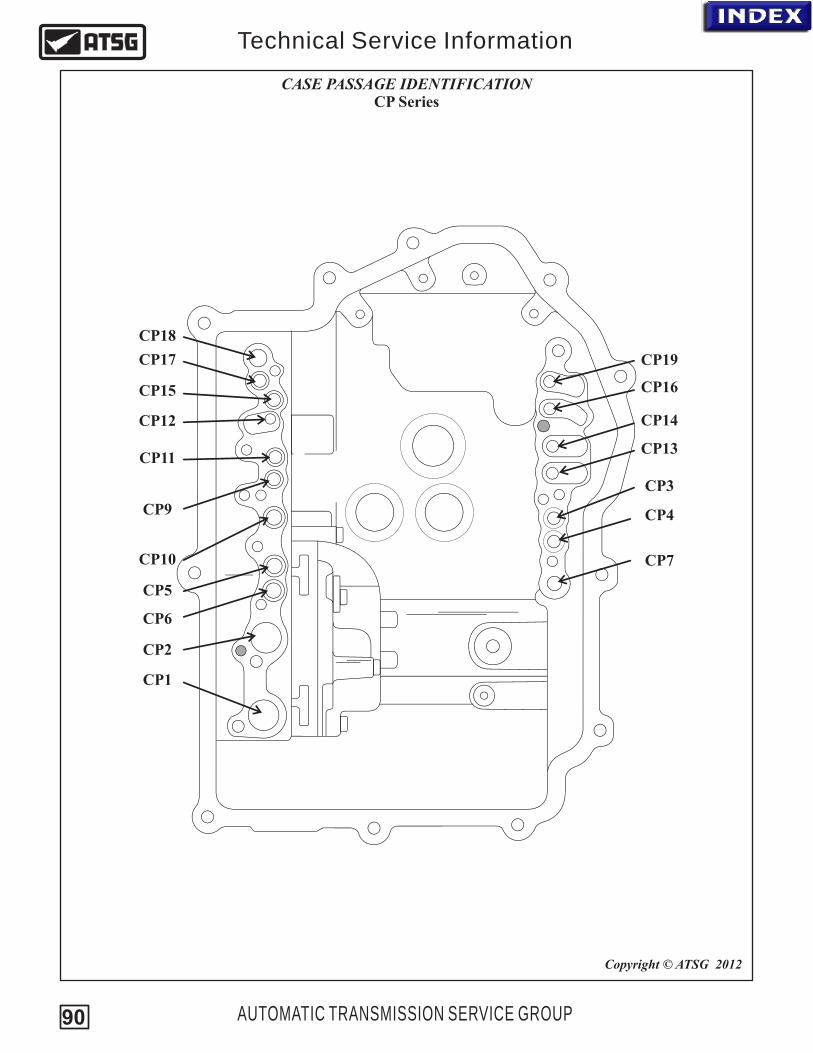
CP18
CP17
CP15
CP12
CP11
CP9
CP10
CP5
CP6
CP2
CP1
CP19
CP16
CP14
CP13
CP3
CP4
CP7
AUTOMATIC TRANSMISSION SERVICE GROUP
Technical Service Information
CASE PASSAGE IDENTIFICATIONCP Series
Copyright © ATSG 2012
90
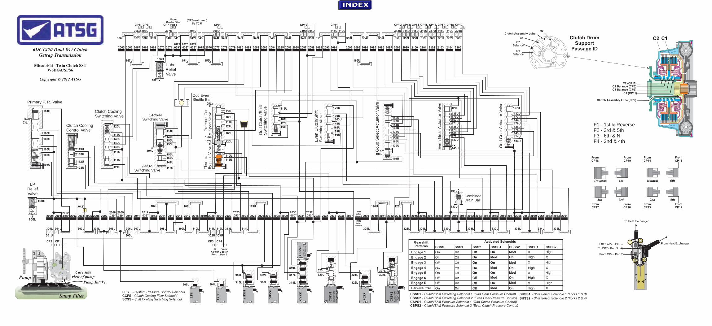
From CP17
From CP16
From CP13
From CP15
From CP14
300U
306L
7070
TM
07/2
26
7M
5R
7G
136-C
A
xx
7070
TM
07/2
26
7M
5R
7G
136-C
A
xx
8270TM07/234
7M5R-76484-DA
CS
SS
1
x
x
SH
SS
1
CC
FS
LP
S
xx
xx
Reverse 1st
5th 3rd 2nd 4th
Neutral 6th
Sump Filter
Pump IntakePump
Case side view of pump
CP2
301U
300L
2000
100U
20012002
301L
.046"
101U
100U
2003
302L 302L
.042"
303L
102U
304L
104U
305L
100U
105U
CP1
106U
107U
308L
108U
309L
109U
311L
302U
From CP3 - Port 1
312L
303U
CP3 CP4
ToCooler Port 1
FromCooler Port 2
112U
112U
112U
313L
113U
114U
115U
315L
116U
316L
317L
103U
110U
111U
117U
124U
318L
118U
119U
119U
319L
120U
120U
121U
122U
320L 321L 322L
323L
123U
126U
326L
127U
128U
327L
328L
129U
130U
131U132U
330L
133U
134U
136U
332L
137U
138U
2004 2005 2006 2007
304L
2008.039"
305L
2009.039" 2010 2011
2012.039"
307L
2013 2014 2015 2016 2017 2018 2019
310L
2020 2021 20222023.050" 2024 2025 2026
314L
2027 2028 20292030.050" 2031
2032.050" 2033 2034 2035 2036 2037 2039 2040 2041 2042 2043 2044 2045 2046 2047
329L
2048 2049 2050 2051 2052 2053
331L
2054 2055 2056 2057
138U
2058
333L
2059 2060
139U
140U
2061
334L
2062
141U
2063
335L
2064
142U
143U
143U 144U
144U
X
X
145U
145U146U
2065
336L
2066
147U
2067
337L
305U
CP5
148U
2068
338L
306U
CP6
2069
149U
339L
2070
150U
2071
340L
307U
CP7
2072.039"
341L
2073.038"
2074.038"
151U
342L
308U
2075
343L
2076
152U
2077
344L
309U
CP9
153U
2078
345L
2079
154U
155U
155U
2080
346L
2081
156U
2082
347L
2083
157U
155U
2084
348L
2085
159U
x
x
x
x
x
160U
2086 2038
324L
325L
(2038listed
above)
(324Llisted
above)
2087
161U
349L
310U
CP10
2088
350L
304U
2089 2090
351L
1863U
162U
2091
352L
311U
CP11
312U
165U
2092
353L
2093
166U
2094
354L
2095
167U
168U
2096
355L
2097
169U
170U135U
2098
356L
313U
CP12
2099
357L
314U
CP13
171U
127U
172U
2100
358L
315U
CP14
2101
359L
316U
CP15
173U
174U
2102
360L
317U
CP16
2103
361L
318U
CP17
2104
362L
319U
CP18
2105
363L
320U
CP19
175U
176U
177U
C1 Balance
C2 Balance
C1
Clutch Assembly LubeC2
Clutch Assembly Lube (CP9)
C1 (CP11)C1 Balance (CP5)C2 Balance (CP6)
C2 (CP10)
From CP18
From CP19
From CP12
From CP4 - Port 2
To Heat Exchanger
From Heat Exchanger
To CP7 - Port 3
FromCooler Filter
Port 3
SCSS - Shift Cooling Switching Solenoid
LPS - System Pressure Control SolenoidCCFS - Clutch Cooling Flow Solenoid
SH
SS
2
CS
PS
1
CS
SS
2
SC
SS
CS
PS
2
Clutch DrumSupport
Passage ID
C1C2
Primary P. R. Valve
Lube Relief Valve
Clutch Cooling Control Valve
Goup S
ele
ct A
ctuato
r V
alv
e
Eve
n G
ear A
ctuato
r V
alv
e
Odd G
ear A
ctuato
r V
alv
e
Odd C
lutc
h/S
hift
S
witc
hin
g V
alv
e
Therm
al
By-
pass
Valv
e
Odd EvenShuttle Ball
1-R/6-N Switching Valve
CombinedDrain Ball
Pre
ssure
Cu
t S
pool V
alv
e
LP Relief Valve
(CP8-not used)To TCM
Clutch Cooling Switching Valve
2-4/3-5 Switching Valve
Eve
n C
lutc
h/S
hift
S
witc
hin
g V
alv
e
Getrag Transmission
Mitsubishi - Twin Clutch SST
Copyright © 2012 ATSG
6DCT470 Dual Wet Clutch
W6DGA/SPS6
CSSS1 CSSS2 CSPS1 CSPS2 - Clutch/Shift Pressure Solenoid 2 (Even Clutch Pressure Control)
- Clutch/Shift Pressure Solenoid 1 (Odd Clutch Pressure Control)- Clutch Shift Switching Solenoid 2 (Even Gear Pressure Control)- Clutch/Shift Switching Solenoid 1 (Odd Gear Pressure Control)
SHSS2
SHSS1 - Shift Select Solenoid 1 (Forks 1 & 3)- Shift Select Solenoid 2 (Forks 2 & 4)
Gearshift Patterns
Activated Solenoids
SCSS SSS1 SSS2 CSSS1 CSSS2 CSPS1 CSPS2
Engage 1
Engage 2
Engage 3
Engage 4
Engage 5
Engage 6
On OffOn
Off Off On
Off Off On
On Off On
On Off On
Off On Off
On X High
On High
On HighX
On High
On Mod HighX
X
Mod
Mod
X
Mod
Mod
On High XMod
Park/Neutral
Engage R
On Off OnOn
Off
High
OffOn
Mod X
X HighOn Mod
x108L
F1 - 1st & ReverseF2 - 3rd & 5thF3 - 6th & NF4 - 2nd & 4th
100L
102L
103L
104L
105L
106L
107L
x
x
101L x

.03
9"
.03
8"
.03
8"
TCM Cooler
xx
3rd
5th
1st
Reverse
2nd Neutral
Sump Filter
Pump IntakePump
Case side view of pump
Prim
ary
P. R
. V
alv
e
.042"
X
Xx
x
x
x
Clutch Assembly Lube
To Heat Exchanger
From Heat Exchanger
Getrag Transmission
Mitsubishi - Twin Clutch SST
Copyright © 2012 ATSG
6DCT470 Dual Wet Clutch
W6DGA/SPS6
.046"
.039"
.039"
.03
9"
.050"
.050"
.050"
L. P. Relief Valve
Po
rt 3
Filte
r
Clu
tch C
oolin
g S
witc
hin
g V
alv
eLube Relief Valve
Po
rt 1
Filte
r
Po
rt 2
Filte
r
7070
TM
07/2
26
7M
5R
7G
136-C
A
xx
7070
TM
07/2
26
7M
5R
7G
136-C
A
xx
8270TM07/234
7M5R-76484-DA
x
x
TCM Cooling
x x
Park/Neutral
Clu
tch C
oolin
g C
ontr
ol V
alv
e
x
x
Gro
up S
ele
ctor
Valv
e
Eve
n G
ear A
ctuato
r V
alv
e
Odd G
ear
Act
uato
r V
alv
e
Therm
al
By-
pass
Valv
e
Odd EvenShuttle Ball
1-R
/6-N
Sw
itchin
g V
alv
e
CombinedDrain Ball
Pre
ssure
Cu
t S
pool V
alv
e
.039"
2-4/3-5 Switching
Valve
X
CS
PS
1
CS
SS
2
SC
SS
CS
PS
2
SS
S1
CC
FS
LP
S
SS
S2
CS
SS
1
CSSS1 CSSS2 CSPS1 CSPS2 - Clutch/Shift Pressure Solenoid 2 (Even Clutch Pressure Control)
- Clutch/Shift Pressure Solenoid 1 (Odd Clutch Pressure Control)- Clutch Shift Switching Solenoid 2 (Even Gear Pressure Control)- Clutch/Shift Switching Solenoid 1 (Odd Gear Pressure Control)
LPS
SHSS2
- Line Pressure Control SolenoidSCSS CCFS
SHSS1
- Shift Cooling Switching Solenoid- Clutch Cooling Flow Solenoid
- Shift Select Solenoid 1 (Forks 1 & 3)- Shift Select Solenoid 2 (Forks 2 & 4) Legend
Line & Solenoid Feed Pressure
From Cooler Pressure/Lube
Connected circuit
Clutch Balance Pressure
Clutch Pressure
Fork Pressure
Circuit blocked by spacer plate
Exhaust
Pump Suction
To Cooler Pressure
**
RANGE"P/N”
**
**
**
****
**
**
****
**
F1 - 1st & ReverseF2 - 3rd & 5thF3 - 6th & NF4 - 2nd & 4th
C1C2
C1 Clutch
C2 BalanceC2 ClutchC2 Transducer
C1 BalanceC1 Transducer
C2
C1
Odd Clutch/Shift Switching Valve
Even Clutch/Shift Switching
Valve
Gearshift Patterns
Activated Solenoids
SCSS SSS1 SSS2 CSSS1 CSSS2 CSPS1 CSPS2
Engage 1
Engage 2
Engage 3
Engage 4
Engage 5
Engage 6
On OffOn
Off Off On
Off Off On
On Off On
On Off On
Off On Off
On High X
On X
On XHigh
On X
On Off XHigh
High
Off
Off
High
Off
Off
On X HighOff
Park/Neutral
Engage R
On Off OnOn
Off
X
OffOn
Off High
High XOn Off

.03
9"
.03
8"
.03
8"
TCM Cooler
xx
3rd
5th
1st
Reverse
2nd
4th
Neutral
6th
Sump Filter
Pump IntakePump
Case side view of pump
.042"
X
Xx
x
x
x
Clutch Assembly Lube
To Heat Exchanger
From Heat Exchanger
Getrag Transmission
Mitsubishi - Twin Clutch SST
Copyright © 2012 ATSG
6DCT470 Dual Wet Clutch
W6DGA/SPS6
.046"
.039"
.039"
.03
9"
.050"
.050"
.050"
L. P. Relief Valve
Po
rt 3
Filte
r
Lube Relief Valve
Po
rt 1
Filte
r
Po
rt 2
Filte
r
7070
TM
07/2
26
7M
5R
7G
136-C
A
xx
7070
TM
07/2
26
7M
5R
7G
136-C
A
xx
8270TM07/234
7M5R-76484-DA
x
x
TCM Cooling
x x
Reverse Gear
x
xOdd EvenShuttle Ball
CombinedDrain Ball
.039"
4th 6th
Prim
ary
P. R
. V
alv
e
Clu
tch C
oolin
g S
witc
hin
g V
alv
e
Clu
tch C
oolin
g C
ontr
ol V
alv
e
Gro
up S
ele
ctor
Va
lve
Eve
n G
ear A
ctuato
r V
alv
e
Odd G
ear
Act
uato
r V
alv
e
Therm
al
By-
pass
Valv
e1-R
/6-N
Sw
itchin
g V
alv
e
Pre
ssure
Cu
t S
pool V
alv
e
2-4/3-5 Switching
Valve
X
CS
PS
1
CS
SS
2
SC
SS
CS
PS
2
SS
S1
CC
FS
LP
S
SS
S2
CS
SS
1
**
**
**
****
**
**
****
**
CSSS1 CSSS2 CSPS1 CSPS2 - Clutch/Shift Pressure Solenoid 2 (Even Clutch Pressure Control)
- Clutch/Shift Pressure Solenoid 1 (Odd Clutch Pressure Control)- Clutch Shift Switching Solenoid 2 (Even Gear Pressure Control)- Clutch/Shift Switching Solenoid 1 (Odd Gear Pressure Control)
LPS
SHSS2
- Line Pressure Control SolenoidSCSS CCFS
SHSS1
- Shift Cooling Switching Solenoid- Clutch Cooling Flow Solenoid
- Shift Select Solenoid 1 (Forks 1 & 3)- Shift Select Solenoid 2 (Forks 2 & 4) Legend
Line & Solenoid Feed Pressure
From Cooler Pressure/Lube
Connected circuit
Clutch Balance Pressure
Clutch Pressure
Fork Pressure
Circuit blocked by spacer plate
Exhaust
Pump Suction
To Cooler Pressure
**
RANGE"Reverse"
F1 - 1st & ReverseF2 - 3rd & 5thF3 - 6th & NF4 - 2nd & 4th
C1C2
C1 Clutch
C2 BalanceC2 ClutchC2 Transducer
C1 BalanceC1 Transducer
C2
C1
Odd Clutch/Shift Switching Valve
Even Clutch/Shift Switching
Valve
Gearshift Patterns
Activated Solenoids
SCSS SSS1 SSS2 CSSS1 CSSS2 CSPS1 CSPS2
Engage 1
Engage 2
Engage 3
Engage 4
Engage 5
Engage 6
On OffOn
Off Off On
Off Off On
On Off On
On Off On
Off On Off
On High X
On X
On XHigh
On X
On Off XHigh
High
Off
Off
High
Off
Off
On X HighOff
Park/Neutral
Engage R
On Off OnOn
Off
X
OffOn
Off High
High XOn Off
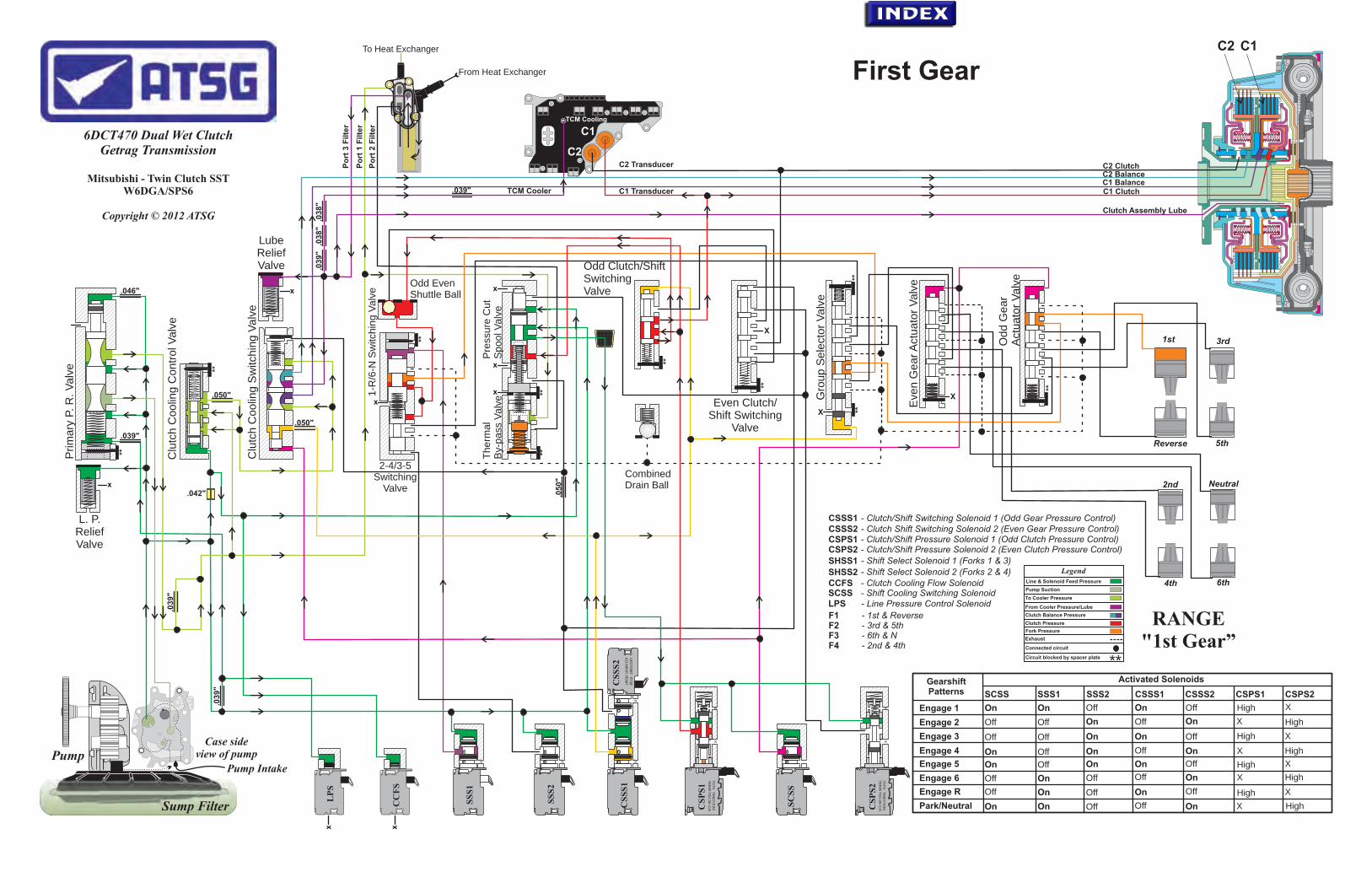
.03
9"
.03
8"
.03
8"
TCM Cooler
xx
3rd
5th
1st
Reverse
2nd
4th
Neutral
6th
Sump Filter
Pump IntakePump
Case side view of pump
.042"
X
Xx
x
x
x
C1C2
Clutch Assembly Lube
C1 Clutch
C2 BalanceC2 Clutch
To Heat Exchanger
From Heat Exchanger
Getrag Transmission
Mitsubishi - Twin Clutch SST
Copyright © 2012 ATSG
6DCT470 Dual Wet Clutch
W6DGA/SPS6
.046"
.039"
.039"
.03
9"
.050"
.050"
.050"
L. P. Relief Valve
Po
rt 3
Filte
r
Lube Relief Valve
Po
rt 1
Filte
r
Po
rt 2
Filte
r
C2 Transducer
7070
TM
07/2
26
7M
5R
7G
136-C
A
xx
7070
TM
07/2
26
7M
5R
7G
136-C
A
xx
8270TM07/234
7M5R-76484-DA
x
x
C1 BalanceC1 Transducer
C2
C1TCM Cooling
x x
First Gear
x
xOdd EvenShuttle Ball
CombinedDrain Ball
.039"
Prim
ary
P. R
. V
alv
e
Clu
tch C
oolin
g S
witc
hin
g V
alv
e
Clu
tch C
oolin
g C
ontr
ol V
alv
e
Gro
up S
ele
ctor
Va
lve
Eve
n G
ear A
ctuato
r V
alv
e
Odd G
ear
Act
uato
r V
alv
e
Therm
al
By-
pass
Valv
e1-R
/6-N
Sw
itchin
g V
alv
e
Pre
ssure
Cu
t S
pool V
alv
e
2-4/3-5 Switching
Valve
X
CS
PS
1
CS
SS
2
SC
SS
CS
PS
2
SS
S1
CC
FS
LP
S
SS
S2
CS
SS
1
**
**
**
****
**
**
****
**
CSSS1 CSSS2 CSPS1 CSPS2 - Clutch/Shift Pressure Solenoid 2 (Even Clutch Pressure Control)
- Clutch/Shift Pressure Solenoid 1 (Odd Clutch Pressure Control)- Clutch Shift Switching Solenoid 2 (Even Gear Pressure Control)- Clutch/Shift Switching Solenoid 1 (Odd Gear Pressure Control)
LPS
SHSS2
- Line Pressure Control SolenoidSCSS CCFS
SHSS1
- Shift Cooling Switching Solenoid- Clutch Cooling Flow Solenoid
- Shift Select Solenoid 1 (Forks 1 & 3)- Shift Select Solenoid 2 (Forks 2 & 4) Legend
Line & Solenoid Feed Pressure
From Cooler Pressure/Lube
Connected circuit
Clutch Balance Pressure
Clutch Pressure
Fork Pressure
Circuit blocked by spacer plate
Exhaust
Pump Suction
To Cooler Pressure
**
RANGE"1st Gear”
F1 - 1st & ReverseF2 - 3rd & 5thF3 - 6th & NF4 - 2nd & 4th
Odd Clutch/Shift Switching Valve
Even Clutch/Shift Switching
Valve
Gearshift Patterns
Activated Solenoids
SCSS SSS1 SSS2 CSSS1 CSSS2 CSPS1 CSPS2
Engage 1
Engage 2
Engage 3
Engage 4
Engage 5
Engage 6
On OffOn
Off Off On
Off Off On
On Off On
On Off On
Off On Off
On High X
On X
On XHigh
On X
On Off XHigh
High
Off
Off
High
Off
Off
On X HighOff
Park/Neutral
Engage R
On Off OnOn
Off
X
OffOn
Off High
High XOn Off

.03
9"
.03
8"
.03
8"
TCM Cooler
xx
3rd
5th
1st
Reverse
2nd
4th
Neutral
6th
Sump Filter
Pump IntakePump
Case side view of pump
.042"
X
Xx
x
x
x
Clutch Assembly Lube
To Heat Exchanger
From Heat Exchanger
Getrag Transmission
Mitsubishi - Twin Clutch SST
Copyright © 2012 ATSG
6DCT470 Dual Wet Clutch
W6DGA/SPS6
.046"
.039"
.039"
.03
9"
.050"
.050"
.050"
L. P. Relief Valve
Po
rt 3
Filte
r
Lube Relief Valve
Po
rt 1
Filte
r
Po
rt 2
Filte
r
7070
TM
07/2
26
7M
5R
7G
136-C
A
xx
7070
TM
07/2
26
7M
5R
7G
136-C
A
xx
8270TM07/234
7M5R-76484-DA
x
x
TCM Cooling
x x
Second Gear
x
xOdd EvenShuttle Ball
CombinedDrain Ball
.039"
Prim
ary
P. R
. V
alv
e
Clu
tch C
oolin
g S
witc
hin
g V
alv
e
Clu
tch C
oolin
g C
ontr
ol V
alv
e
Gro
up S
ele
ctor
Va
lve
Eve
n G
ear A
ctuato
r V
alv
e
Odd G
ear
Act
uato
r V
alv
e
Therm
al
By-
pass
Valv
e1-R
/6-N
Sw
itchin
g V
alv
e
Pre
ssure
Cu
t S
pool V
alv
e
2-4/3-5 Switching
Valve
X
CS
PS
1
CS
SS
2
SC
SS
CS
PS
2
SS
S1
CC
FS
LP
S
SS
S2
CS
SS
1
**
**
**
****
**
**
****
**
CSSS1 CSSS2 CSPS1 CSPS2 - Clutch/Shift Pressure Solenoid 2 (Even Clutch Pressure Control)
- Clutch/Shift Pressure Solenoid 1 (Odd Clutch Pressure Control)- Clutch Shift Switching Solenoid 2 (Even Gear Pressure Control)- Clutch/Shift Switching Solenoid 1 (Odd Gear Pressure Control)
LPS
SHSS2
- Line Pressure Control SolenoidSCSS CCFS
SHSS1
- Shift Cooling Switching Solenoid- Clutch Cooling Flow Solenoid
- Shift Select Solenoid 1 (Forks 1 & 3)- Shift Select Solenoid 2 (Forks 2 & 4) Legend
Line & Solenoid Feed Pressure
From Cooler Pressure/Lube
Connected circuit
Clutch Balance Pressure
Clutch Pressure
Fork Pressure
Circuit blocked by spacer plate
Exhaust
Pump Suction
To Cooler Pressure
**
RANGE"2nd Gear”
Odd Clutch/Shift Switching Valve
Even Clutch/Shift Switching
Valve
F1 - 1st & ReverseF2 - 3rd & 5thF3 - 6th & NF4 - 2nd & 4th
C1C2
C1 Clutch
C2 BalanceC2 ClutchC2 Transducer
C1 BalanceC1 Transducer
C2
C1
Gearshift Patterns
Activated Solenoids
SCSS SSS1 SSS2 CSSS1 CSSS2 CSPS1 CSPS2
Engage 1
Engage 2
Engage 3
Engage 4
Engage 5
Engage 6
On OffOn
Off Off On
Off Off On
On Off On
On Off On
Off On Off
On High X
On X
On XHigh
On X
On Off XHigh
High
Off
Off
High
Off
Off
On X HighOff
Park/Neutral
Engage R
On Off OnOn
Off
X
OffOn
Off High
High XOn Off

.03
9"
.03
8"
.03
8"
TCM Cooler
xx
3rd
5th
1st
Reverse
2nd
4th
Neutral
6th
Sump Filter
Pump IntakePump
Case side view of pump
.042"
X
Xx
x
x
x
Clutch Assembly Lube
To Heat Exchanger
From Heat Exchanger
Getrag Transmission
Mitsubishi - Twin Clutch SST
Copyright © 2012 ATSG
6DCT470 Dual Wet Clutch
W6DGA/SPS6
.046"
.039"
.039"
.03
9"
.050"
.050"
.050"
L. P. Relief Valve
Po
rt 3
Filte
r
Lube Relief Valve
Po
rt 1
Filte
r
Po
rt 2
Filte
r
7070
TM
07/2
26
7M
5R
7G
136-C
A
xx
7070
TM
07/2
26
7M
5R
7G
136-C
A
xx
8270TM07/234
7M5R-76484-DA
x
x
TCM Cooling
x x
Third Gear
x
xOdd EvenShuttle Ball
CombinedDrain Ball
.039"
Prim
ary
P. R
. V
alv
e
Clu
tch C
oolin
g S
witc
hin
g V
alv
e
Clu
tch C
oolin
g C
ontr
ol V
alv
e
Gro
up S
ele
ctor
Va
lve
Eve
n G
ear A
ctuato
r V
alv
e
Odd G
ear
Act
uato
r V
alv
e
Therm
al
By-
pass
Valv
e1-R
/6-N
Sw
itchin
g V
alv
e
Pre
ssure
Cu
t S
pool V
alv
e
2-4/3-5 Switching
Valve
X
CS
PS
1
CS
SS
2
SC
SS
CS
PS
2
SS
S1
CC
FS
LP
S
SS
S2
CS
SS
1
**
**
**
****
**
**
****
**
CSSS1 CSSS2 CSPS1 CSPS2 - Clutch/Shift Pressure Solenoid 2 (Even Clutch Pressure Control)
- Clutch/Shift Pressure Solenoid 1 (Odd Clutch Pressure Control)- Clutch Shift Switching Solenoid 2 (Even Gear Pressure Control)- Clutch/Shift Switching Solenoid 1 (Odd Gear Pressure Control)
LPS
SHSS2
- Line Pressure Control SolenoidSCSS CCFS
SHSS1
- Shift Cooling Switching Solenoid- Clutch Cooling Flow Solenoid
- Shift Select Solenoid 1 (Forks 1 & 3)- Shift Select Solenoid 2 (Forks 2 & 4) Legend
Line & Solenoid Feed Pressure
From Cooler Pressure/Lube
Connected circuit
Clutch Balance Pressure
Clutch Pressure
Fork Pressure
Circuit blocked by spacer plate
Exhaust
Pump Suction
To Cooler Pressure
**
RANGE"3rd Gear”
F1 - 1st & ReverseF2 - 3rd & 5thF3 - 6th & NF4 - 2nd & 4th
C1C2
C1 Clutch
C2 BalanceC2 ClutchC2 Transducer
C1 BalanceC1 Transducer
C2
C1
Odd Clutch/Shift Switching Valve
Even Clutch/Shift Switching
Valve
Gearshift Patterns
Activated Solenoids
SCSS SSS1 SSS2 CSSS1 CSSS2 CSPS1 CSPS2
Engage 1
Engage 2
Engage 3
Engage 4
Engage 5
Engage 6
On OffOn
Off Off On
Off Off On
On Off On
On Off On
Off On Off
On High X
On X
On XHigh
On X
On Off XHigh
High
Off
Off
High
Off
Off
On X HighOff
Park/Neutral
Engage R
On Off OnOn
Off
X
OffOn
Off High
High XOn Off
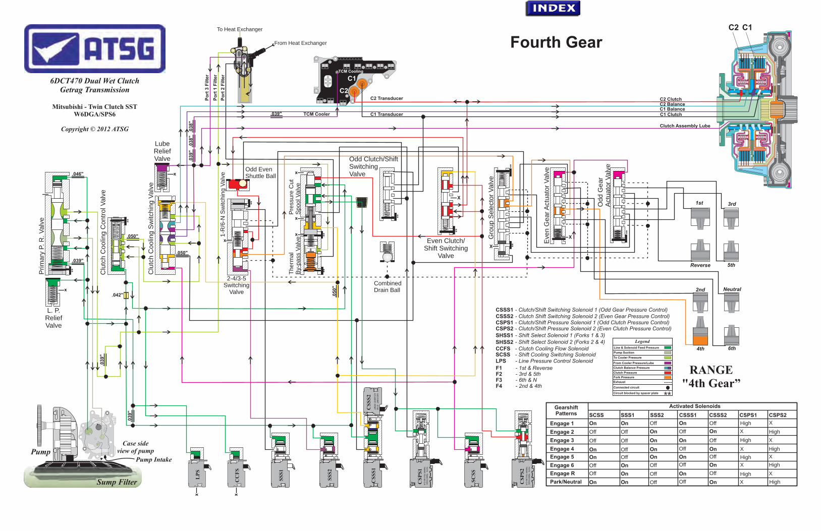
.03
9"
.03
8"
.03
8"
TCM Cooler
xx
3rd
5th
1st
Reverse
2nd
4th
Neutral
6th
Sump Filter
Pump IntakePump
Case side view of pump
.042"
X
Xx
x
x
x
Clutch Assembly Lube
To Heat Exchanger
From Heat Exchanger
Getrag Transmission
Mitsubishi - Twin Clutch SST
Copyright © 2012 ATSG
6DCT470 Dual Wet Clutch
W6DGA/SPS6
.046"
.039"
.039"
.03
9"
.050"
.050"
.050"
L. P. Relief Valve
Po
rt 3
Filte
r
Lube Relief Valve
Po
rt 1
Filte
r
Po
rt 2
Filte
r
7070
TM
07/2
26
7M
5R
7G
136-C
A
xx
7070
TM
07/2
26
7M
5R
7G
136-C
A
xx
8270TM07/234
7M5R-76484-DA
x
x
TCM Cooling
x x
Fourth Gear
x
xOdd EvenShuttle Ball
CombinedDrain Ball
.039"
Prim
ary
P. R
. V
alv
e
Clu
tch C
oolin
g S
witc
hin
g V
alv
e
Clu
tch C
oolin
g C
ontr
ol V
alv
e
Gro
up S
ele
ctor
Va
lve
Eve
n G
ear A
ctuato
r V
alv
e
Odd G
ear
Act
uato
r V
alv
e
Therm
al
By-
pass
Valv
e1-R
/6-N
Sw
itchin
g V
alv
e
Pre
ssure
Cu
t S
pool V
alv
e
2-4/3-5 Switching
Valve
X
CS
PS
1
CS
SS
2
SC
SS
CS
PS
2
SS
S1
CC
FS
LP
S
SS
S2
CS
SS
1
**
**
**
****
**
**
****
**
CSSS1 CSSS2 CSPS1 CSPS2 - Clutch/Shift Pressure Solenoid 2 (Even Clutch Pressure Control)
- Clutch/Shift Pressure Solenoid 1 (Odd Clutch Pressure Control)- Clutch Shift Switching Solenoid 2 (Even Gear Pressure Control)- Clutch/Shift Switching Solenoid 1 (Odd Gear Pressure Control)
LPS
SHSS2
- Line Pressure Control SolenoidSCSS CCFS
SHSS1
- Shift Cooling Switching Solenoid- Clutch Cooling Flow Solenoid
- Shift Select Solenoid 1 (Forks 1 & 3)- Shift Select Solenoid 2 (Forks 2 & 4) Legend
Line & Solenoid Feed Pressure
From Cooler Pressure/Lube
Connected circuit
Clutch Balance Pressure
Clutch Pressure
Fork Pressure
Circuit blocked by spacer plate
Exhaust
Pump Suction
To Cooler Pressure
**
RANGE"4th Gear”
F1 - 1st & ReverseF2 - 3rd & 5thF3 - 6th & NF4 - 2nd & 4th
C1C2
C1 Clutch
C2 BalanceC2 ClutchC2 Transducer
C1 BalanceC1 Transducer
C2
C1
Odd Clutch/Shift Switching Valve
Even Clutch/Shift Switching
Valve
Gearshift Patterns
Activated Solenoids
SCSS SSS1 SSS2 CSSS1 CSSS2 CSPS1 CSPS2
Engage 1
Engage 2
Engage 3
Engage 4
Engage 5
Engage 6
On OffOn
Off Off On
Off Off On
On Off On
On Off On
Off On Off
On High X
On X
On XHigh
On X
On Off XHigh
High
Off
Off
High
Off
Off
On X HighOff
Park/Neutral
Engage R
On Off OnOn
Off
X
OffOn
Off High
High XOn Off

.03
9"
.03
8"
.03
8"
TCM Cooler
xx
3rd
5th
1st
Reverse
2nd Neutral
Sump Filter
Pump IntakePump
Case side view of pump
.042"
X
Xx
x
x
x
Clutch Assembly Lube
To Heat Exchanger
From Heat Exchanger
Getrag Transmission
Mitsubishi - Twin Clutch SST
Copyright © 2012 ATSG
6DCT470 Dual Wet Clutch
W6DGA/SPS6
.046"
.039"
.039"
.03
9"
.050"
.050"
.050"
L. P. Relief Valve
Po
rt 3
Filte
r
Lube Relief Valve
Po
rt 1
Filte
r
Po
rt 2
Filte
r
7070
TM
07/2
26
7M
5R
7G
136-C
A
xx
7070
TM
07/2
26
7M
5R
7G
136-C
A
xx
8270TM07/234
7M5R-76484-DA
x
x
TCM Cooling
x x
x
xOdd EvenShuttle Ball
CombinedDrain Ball
.039"
4th 6th
Prim
ary
P. R
. V
alv
e
Clu
tch C
oolin
g S
witc
hin
g V
alv
e
Clu
tch C
oolin
g C
ontr
ol V
alv
e
Gro
up S
ele
ctor
Va
lve
Eve
n G
ear A
ctuato
r V
alv
e
Odd G
ear
Act
uato
r V
alv
e
Therm
al
By-
pass
Valv
e1-R
/6-N
Sw
itchin
g V
alv
e
Pre
ssure
Cu
t S
pool V
alv
e
2-4/3-5 Switching
Valve
X
CS
PS
1
CS
SS
2
SC
SS
CS
PS
2
SS
S1
CC
FS
LP
S
SS
S2
CS
SS
1
**
**
**
****
**
**
****
**
CSSS1 CSSS2 CSPS1 CSPS2 - Clutch/Shift Pressure Solenoid 2 (Even Clutch Pressure Control)
- Clutch/Shift Pressure Solenoid 1 (Odd Clutch Pressure Control)- Clutch Shift Switching Solenoid 2 (Even Gear Pressure Control)- Clutch/Shift Switching Solenoid 1 (Odd Gear Pressure Control)
LPS
SHSS2
- Line Pressure Control SolenoidSCSS CCFS
SHSS1
- Shift Cooling Switching Solenoid- Clutch Cooling Flow Solenoid
- Shift Select Solenoid 1 (Forks 1 & 3)- Shift Select Solenoid 2 (Forks 2 & 4) Legend
Line & Solenoid Feed Pressure
From Cooler Pressure/Lube
Connected circuit
Clutch Balance Pressure
Clutch Pressure
Fork Pressure
Circuit blocked by spacer plate
Exhaust
Pump Suction
To Cooler Pressure
**
RANGE"5th Gear”
F1 - 1st & ReverseF2 - 3rd & 5thF3 - 6th & NF4 - 2nd & 4th
C1C2
C1 Clutch
C2 BalanceC2 ClutchC2 Transducer
C1 BalanceC1 Transducer
C2
C1
Odd Clutch/Shift Switching Valve
Even Clutch/Shift Switching
Valve
Gearshift Patterns
Activated Solenoids
SCSS SSS1 SSS2 CSSS1 CSSS2 CSPS1 CSPS2
Engage 1
Engage 2
Engage 3
Engage 4
Engage 5
Engage 6
On OffOn
Off Off On
Off Off On
On Off On
On Off On
Off On Off
On High X
On X
On XHigh
On X
On Off XHigh
High
Off
Off
High
Off
Off
On X HighOff
Park/Neutral
Engage R
On Off OnOn
Off
X
OffOn
Off High
High XOn Off
Fifth Gear

.03
9"
.03
8"
.03
8"
TCM Cooler
xx
3rd
5th
1st
Reverse
2nd Neutral
Sump Filter
Pump IntakePump
Case side view of pump
.042"
X
Xx
x
x
x
Clutch Assembly Lube
To Heat Exchanger
From Heat Exchanger
Getrag Transmission
Mitsubishi - Twin Clutch SST
Copyright © 2012 ATSG
6DCT470 Dual Wet Clutch
W6DGA/SPS6
.046"
.039"
.039"
.03
9"
.050"
.050"
.050"
L. P. Relief Valve
Po
rt 3
Filte
r
Lube Relief Valve
Po
rt 1
Filte
r
Po
rt 2
Filte
r
7070
TM
07/2
26
7M
5R
7G
136-C
A
xx
7070
TM
07/2
26
7M
5R
7G
136-C
A
xx
8270TM07/234
7M5R-76484-DA
x
x
CS
PS
1
CS
SS
2
SC
SS
CS
PS
2
TCM Cooling
x x
SS
S1
CC
FS
LP
S
SS
S2
CS
SS
1
Sixth Gear
x
xOdd EvenShuttle Ball
CombinedDrain Ball
.039"
Prim
ary
P. R
. V
alv
e
Clu
tch C
oolin
g S
witc
hin
g V
alv
e
Clu
tch C
oolin
g C
ontr
ol V
alv
e
Gro
up S
ele
ctor
Va
lve
Eve
n G
ear A
ctuato
r V
alv
e
Odd G
ear
Act
uato
r V
alv
e
Therm
al
By-
pass
Valv
e1-R
/6-N
Sw
itchin
g V
alv
e
Pre
ssure
Cu
t S
pool V
alv
e
2-4/3-5 Switching
Valve
X
**
**
**
****
**
**
****
**
CSSS1 CSSS2 CSPS1 CSPS2 - Clutch/Shift Pressure Solenoid 2 (Even Clutch Pressure Control)
- Clutch/Shift Pressure Solenoid 1 (Odd Clutch Pressure Control)- Clutch Shift Switching Solenoid 2 (Even Gear Pressure Control)- Clutch/Shift Switching Solenoid 1 (Odd Gear Pressure Control)
LPS
SHSS2
- Line Pressure Control SolenoidSCSS CCFS
SHSS1
- Shift Cooling Switching Solenoid- Clutch Cooling Flow Solenoid
- Shift Select Solenoid 1 (Forks 1 & 3)- Shift Select Solenoid 2 (Forks 2 & 4) Legend
Line & Solenoid Feed Pressure
From Cooler Pressure/Lube
Connected circuit
Clutch Balance Pressure
Clutch Pressure
Fork Pressure
Circuit blocked by spacer plate
Exhaust
Pump Suction
To Cooler Pressure
**
4th 6th
RANGE"6th Gear”
F1 - 1st & ReverseF2 - 3rd & 5thF3 - 6th & NF4 - 2nd & 4th
C1C2
C1 Clutch
C2 BalanceC2 ClutchC2 Transducer
C1 BalanceC1 Transducer
C2
C1
Odd Clutch/Shift Switching Valve
Even Clutch/Shift Switching
Valve
Gearshift Patterns
Activated Solenoids
SCSS SSS1 SSS2 CSSS1 CSSS2 CSPS1 CSPS2
Engage 1
Engage 2
Engage 3
Engage 4
Engage 5
Engage 6
On OffOn
Off Off On
Off Off On
On Off On
On Off On
Off On Off
On High X
On X
On XHigh
On X
On Off XHigh
High
Off
Off
High
Off
Off
On X HighOff
Park/Neutral
Engage R
On Off OnOn
Off
X
OffOn
Off High
High XOn Off