
69-AIRComHRV - Maxivent
36
69-AIRComHRV 081016 Commercial Heat Recovery Ventilators (HRV) Models AIR550-F/D AIR850-F/D Operation and Installation Manual Models AIR750-F/D AIR1250-F/D
-
Upload
khangminh22 -
Category
Documents
-
view
0 -
download
0
Transcript of 69-AIRComHRV - Maxivent

69-AIRComHRV081016
Commercial Heat Recovery Ventilators (HRV)
Models AIR550-F/D AIR850-F/D
Operation and Installation Manual
Models AIR750-F/D AIR1250-F/D
2
The Benefits of HRVs Location of the HRV for Mounting ..........................3Specifications - Model AIR550-F/D ........................ 4
Specifications - Model AIR750-F/D .........................5
Specifications - Model AIR850-F/D .........................6
Specifications - Model AIR1250-F/D .......................7
The Ductwork System
Outside Weatherhoods ..........................................8
Stale Air Return System
Fresh Air Supply System
Adjustable Grilles ..................................................9
The Integrated HVAC System ...............................10
Drain Connections
Electrical Connections ..........................................11
HRV Defrost Strategies
Defrost Time Adjustment .....................................12
Reversing the Supply and Defrost Air Ports............13
Optional Ventilation Control
Optional 3 Speed Control......................................14
Optional Dehumidistat .........................................15
Optional Wireless Timer ..................................16-17
Function And Controls............................................19
Connecting Optional Digital Controls ..................20-21
Balancing the HRV .................................................22
Service and Maintenance....................................23-24
Aircom Relays (Models AIR550, AIR750, AIR850, AIR1250) ..............................................................27
Troubleshooting your HRV System...........................28
Wiring Diagrams ...............................................29-32
Warranty ...............................................................33
Leave this manual with your customer!
Installing Contractor
Telephone / Contact
Serial Number
Installation Date Model
TO BE COMPLETED BY CONTRACTOR AFTER INSTALLATION
Table of Contents
Never install an HRV in a situation where its normal operation, lack of operation or partial failure may result in the backdrafting or improper functioning of vented combustion equipment!
CAUTION
Assess how the operation of an HRV may interact with already installed vented combustion equipment (ie. Gas Furnaces, Oil Furnaces, Wood Stoves, etc.).
CAUTION
Do not apply electrical power to the unit until installation has been fully completed (including low voltage control wiring).
Reverse Installation of the HRV..........................25-26
Optional Timer ......................................................18
Optional Wireless Repeater

Heat Recovery Ventilators (HRV) are designed to supply fresh air to a building while exhausting an equal amount of stale air from the building. An energy savings is experienced during the process by reducing the heating (or cooling) requirements.
HRV - Aluminum CoreDuring the winter months, the incoming cold fresh air is warmed by utilizing the heat recovered from the stale air before it is exhausted to the outdoors. During summer months when the indoor space is air conditioned, the Heat Recovery Ventilator will help in cooling the incoming fresh air with the stale air that is being exhausted.
3
The Benefits of HRVs
FreshOutdoor Air
Stale Airto Outside
Stale Airfrom Pool Room
Fresh Airto Pool Room
Location of the HRV for Mounting
The HRVmust be located in a heated space where the surrounding air temperature does not fall below 60°F (16°C). The unit must be mounted level (horizontal) to obtain proper drainage of water from the heat exchange element and drip pans. The warranty will be void if these conditions are not met.Typically, the HRV is positioned close to an outside wall or the roof to simplify the connections and keep the length of insulated ducting required for the fresh air intake to a minimum.
A minimum clearance of 30 inches (76 cm) in front of the HRV is recommended to service the heat exchanger cores and the filters. The HRV may be mounted on an equipment platform providing the drain hoses are clear and there is sufficient space to open the doors for servicing.
Flexible duct connectors should be installed between the HRV and the galvanized ductwork.
ATTENTION
Saddle Installation
Hang unit with suspended rods and "U" channel members.
Threaded rod (Supplied by others)
Vibration Isolators(Supplied by others)
Curb Mounted
Curb is wood or metal(Supplied by others)
Mount unit on wooden or metal curb assembly. Unit must be raised an adequate height for installation and slope of drain lines.
May be anchored to floor,leaving space for drain connections
Vibration Isolators(Supplied by others)
4
70%
60%
50%
200(94)
AIRFLOW IN CFM (L/s)
EFFE
CT
IVE
NE
SS
PERFORMANCE AIRFLOWS (Each Air Stream)
450 (212)
400 (189)
350 (165)
300 (142)
250 (118)
0.1 0.2
500 (236)
0
550 (260)
600 (283)
0.7 0.8 0.9
29 5/8" (753 mm)
8"(200 mm)
FRONT VIEW
25 5/8"(650 mm)
28 3/4"(730 mm)
14"(356 mm)
8 1/4"(210 mm)
INLET SIDE
DRAIN CONNECTION
8"(200 mm)
28 3/4"(730 mm)
14"(356 mm)
6 1/4"(159 mm)
MOUNTING POINTSCONTROLS
DISCHARGE SIDE
EXHAUST AIRTO OUTSIDE
EXHAUST AIRFROM BUILDING
SUPPLY AIRTO BUILDING
SUPPLY AIRFROM OUTSIDE
NOTE:Service clearanceis 30 in. (760 mm )from front accessdoors
D MODEL ONLY
SUPPLY AIRFROM OUTSIDE
F MODEL ONLY
6 1/2"(165 mm)
6 1/2"(165 mm)
DEFROST AIRDD MODEL ONLY
DIMENSIONS inches (mm)
Specifications AIR550-F/D
Date: ___________________________________________
Tag: _____________________Qty:___________________
Project: _________________________________________
Engineer: _______________________________________
Contractor: ______________________________________
Supplier: ________________________________________
Quote#: _________________________________________
Submitted by: ____________________________________
300(143)
400(190)
500(235)
AHRI 1060 Certified Core: Contains two 68-222
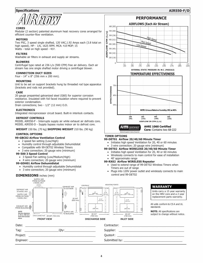
CORESModular (2 section) patented aluminum heat recovery cores arranged for efficient counter-flow ventilation.
MOTORSTwo PSC, 3 speed single shafted, 120 VAC,1.92 Amps each (3.8 total on high speed). HP - 1/6, 1625 RPM. MCA: 4.8 MOP: 15Watts - total on high speed - 437.
FILTERSWashable air filters in exhaust and supply air streams.
BLOWERSCentrifugal type rated at 236 L/s (500 CFM) free air delivery. Each air stream has one single shafted motor driving a centrifugal blower.
CONNECTION DUCT SIZESFour - 14" x 8" (356 mm x 200 mm).
MOUNTINGUnit to be set on support brackets hung by threaded rod type apparatus (brackets and rods not provided).
CASE20 gauge prepainted galvanized steel (G60) for superior corrosion resistance. Insulated with foil faced insulation where required to prevent exterior condensation.Drain connections; two - 1/2" (12 mm) O.D.
ELECTRONICSIntegrated microprocessor circuit board. Built-in interlock contacts.
DEFROST CONTROLSMODEL AIR550-F - Interrupts supply air while exhaust air defrosts core. MODEL AIR550-D - Supply bypass routes indoor air to defrost core.
WEIGHT 150 lbs. (70 kg) SHIPPING WEIGHT 210 lbs. (90 kg)
CONTROL OPTIONS99-GBC02 Airflow Ventilation Control
• 2 speed fan setting (Low/High)• Humidity control through adjustable Dehumidistat• Compatible with 99-DET02 Wireless Timers• 3 wire connection; 20 gauge wire (minimum)
99-500 3 Speed Control• 3 Speed Fan setting (Low/Medium/High)• 4 wire connection; 20 gauge wire (minimum)
99-GDH01 Airflow Dehumidistat• Humidity control through adjustable Dehumidistat• 3 wire connection; 20 gauge wire (minimum)
All units conform to CS A and UL standards
NOTE: All specifications are subject to change without notice.
TIMER OPTIONS99-DET01 Airflow 20/40/60 Minute Timer
• Initiates high speed Ventilation for 20, 40 or 60 minutes• 3 wire connection; 20 gauge wire (minimum)
99-DET02 Airflow WIRELESS 20/40/60 Minute Timer• Initiates high speed Ventilation for 20, 40 or 60 minutes• Wirelessly connects to main control for ease of installation• 40' approximate range
99-RX02 Airflow WIRELESS Repeater• Used to extend range of 99-DET02 Wireless Timers when
Timers are out of range• Plugs into 120V power outlet and wirelessly connects to main
control and 99-DET02
WARRANTYUnits carry a 15 year warranty on the HRV core and a 2 year replacement parts warranty.
AIR
FLO
W C
FM
(L/s)
High SpeedMed SpeedLow Speed
EXTERNAL STATIC PRESSURE IN. W.C. (PASCALS)
TEMPERATURE EFFECTIVENESS
0.3 0.4 0.5 0.6 (25) (50) (75) (100) (125) (150) (175) (200) (225)
5
PERFORMANCE AIRFLOWS (Each Air Stream)
AIR
FLO
W C
FM
(L/s)
70%
60%
50%
EXTERNAL STATIC PRESSURE IN. W.C. (PASCALS)
TEMPERATURE EFFECTIVENESS
AIRFLOW IN CFM (L/s)
EFFE
CT
IVE
NE
SS
0
100 (42)
200 (94)
300 (143)
400 (190)
500 (235)
600 (282)
700 (329)
800 (378)
900 (425)
0,1 0,2 0,3 0,4 0,5 0,6 0,7 0,8 0,9 1,0(25) (50) (75) (100) (125) (150) (175) (200) (225) (250)
DIMENSIONS inches (mm)
EXHAUST AIRFROM BUILDING
NOTE:Service clearanceis 30 in. (760 mm)from frontaccess doors
SUPPLY AIRFROM OUTSIDE
FD MODEL ONLY
DEFROST AIRD MODEL ONLY
SUPPLY AIR FROM OUTSIDE (D MODEL ONLY)
SUPPLY AIRTO BUILDING
EXHAUST AIRTO OUTSIDE
FILTER OPTIONS99-65-183 2" pleated MERV 8 filter for fresh air stream
300(143)
400(190)
500(235)
600(282)
700(329)
AHRI 1060 Certified Core: Contains two 68-222
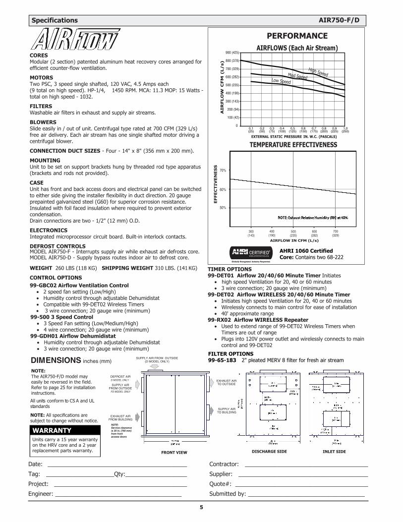
CORESModular (2 section) patented aluminum heat recovery cores arranged for efficient counter-flow ventilation.
MOTORSTwo PSC, 3 speed single shafted, 120 VAC, 4.5 Amps each(9 total on high speed). HP-1/4, 1450 RPM. MCA: 11.3 MOP: 15 Watts - total on high speed - 1032.
FILTERSWashable air filters in exhaust and supply air streams.
BLOWERSSlide easily in / out of unit. Centrifugal type rated at 700 CFM (329 L/s) free air delivery. Each air stream has one single shafted motor driving a centrifugal blower.
CONNECTION DUCT SIZES - Four - 14" x 8" (356 mm x 200 mm).
MOUNTINGUnit to be set on support brackets hung by threaded rod type apparatus (brackets and rods not provided).
CASEUnit has front and back access doors and electrical panel can be switched to either side giving the installer flexibility in duct direction. 20 gauge prepainted galvanized steel (G60) for superior corrosion resistance. Insulated with foil faced insulation where required to prevent exterior condensation.Drain connections are two - 1/2" (12 mm) O.D.
ELECTRONICSIntegrated microprocessor circuit board. Built-in interlock contacts.
DEFROST CONTROLSMODEL AIR750-F - Interrupts supply air while exhaust air defrosts core. MODEL AIR750-D - Supply bypass routes indoor air to defrost core.
WEIGHT 260 LBS (118 KG) SHIPPING WEIGHT 310 LBS. (141 KG)
CONTROL OPTIONS
Specifications AIR750-F/D
99-GBC02 Airflow Ventilation Control• 2 speed fan setting (Low/High)• Humidity control through adjustable Dehumidistat• Compatible with 99-DET02 Wireless Timers • 3 wire connection; 20 gauge wire (minimum)
99-500 3 Speed Control• 3 Speed Fan setting (Low/Medium/High)• 4 wire connection; 20 gauge wire (minimum)
99-GDH01 Airflow Dehumidistat• Humidity control through adjustable Dehumidistat• 3 wire connection; 20 gauge wire (minimum)
DISCHARGE SIDEFRONT VIEW INLET SIDE
Date: ___________________________________________
Tag: _____________________Qty:___________________
Project: _________________________________________
Engineer: _______________________________________
Contractor: ______________________________________
Supplier: ________________________________________
Quote#: _________________________________________
Submitted by: ____________________________________
WARRANTYUnits carry a 15 year warranty on the HRV core and a 2 year replacement parts warranty.
High SpeedMed SpeedLow Speed
TIMER OPTIONS
•99-
•
DET01 Airflow 20/40/60 Minute Timer Initiates high speed Ventilation for 20, 40 or 60 minutes
3 wire connection; 20 gauge wire (minimum)
•99-
•
DET02 Airflow WIRELESS 20/40/60 Minute Timer Initiates high speed Ventilation for 20, 40 or 60 minutes
•Wirelessly connects to main control for ease of installation40' approximate range
•99-RX02 Airflow WIRELESS Repeater
•
Used to extend range of 99-DET02 Wireless Timers when Timers are out of rangePlugs into 120V power outlet and wirelessly connects to main control and 99-DET02
NOTE:The AIR750-F/D model may easily be reversed in the field. Refer to page 25 for installation instructions.
All units conform to CS A and UL standards
NOTE: All specifications are subject to change without notice.

6
46 3/4"(1188 mm)
8"(200 mm)
FRONT VIEW
41 1/2"(1055 mm)
20"(508 mm)
6 3/4"(172 mm)
INTERIOR DUCTCONNECTION SIDE
24 5/8"(625 mm)
EXTERIOR DUCTCONNECTION SIDE
MOUNTING POINTS
DRAIN CONNECTION
26"(660 mm)8"
(200 mm)
8"(200 mm)
20"(508 mm)
5 7/8"(149 mm)
EXHAUST AIRTO OUTSIDE
EXHAUST AIRFROM BUILDING
SUPPLY AIRTO BUILDING
SUPPLY AIRFROM OUTSIDE
NOTE:Service clearanceis 30 in. (760 mm)
20"(508 mm)
8"(200 mm)
DEFROST AIRD MODELS ONLY
CONTROLS
7 1/2 "(190 mm)
10 3/8"(263 mm)
10 3/8"
(263 mm)
AIRFLOWS (Each Air Stream)1000 (475)
900 (425)
800 (378)
700 (329)
600 (282)
500 (235)
400 (190)
300 (143)
200 (94)
100 (42)
AIR
FL
OW
CF
M(L
/s)
25 (.1) 50 (.2) 75 (.3) 100 (.4) 125 (.5) 150 (.6) 175 (.7)EXTERNAL STATIC PRESSURE IN PASCALS (in. W.C.)
TOTA
LC
UR
RE
NT
DR
AW
(AM
PS
)@
120
VAC
7.0 MED
7.9 HIGH
6.6 LOW
90%
80%
70%
600(282)
700(329)
TEMPERATURE EFFECTIVENESS
AIRFLOW IN CFM (L/s)
NOTE: Exhaust Relative Humidity (RH) at 40%
EF
FE
CT
IVE
NE
SS
800(378)
900(425)
500(235)
PERFORMANCE
CORESModular (6 section) patented aluminum heat recovery cores arranged for high efficiency crossflow ventilation.
MOTORSTwo PSC, 3 speed double shafted, 120 VAC, 3.8 Amps each(7.6 total on high speed). HP - 1/4, 1625 RPM. Watts - total on High Speed - 912. MCA: 9.5 MOP: 15
FILTERSWashable air filters in exhaust and supply air streams.
BLOWERSCentrifugal type rated at 950 cfm (448 L/s) free air delivery. Each air stream has one double shafted motor driving two centrifugal blowers.
CONNECTION DUCT SIZESThree - 20" x 8" (508 mm x 200 mm). Stale air intake - 26" x 8"(660 mm x 200 mm). Model 650DD - additional 20" X 8" defrost port
MOUNTINGUnit to be set on support brackets hung by threaded rod type apparatus (brackets and rods not provided).
CASE20 gauge prepainted galvanized steel (G60) for superior corrosion resistance. Insulated with foil faced insulation where required to prevent exterior condensation.Drain connections are two - 1/2" (12 mm) O.D.
ELECTRONICSIntegrated microprocessor circuit board. Built-in interlock contacts. Automatic Self Test.
DEFROST CONTROLSModel AIR850-F - Interrupts supply air while exhaust air defrosts core. Model AIR850-D - Supply bypass routes indoor air to defrost core.
WEIGHT 270 lbs. (120 kg) SHIPPING WEIGHT 350 lbs. (156 kg)
CONTROL OPTIONS
Specifications AIR850-F/D
Date: ___________________________________________
Tag: _____________________Qty:___________________
Project: _________________________________________
Engineer: _______________________________________
Contractor: ______________________________________
Supplier: ________________________________________
Quote#: _________________________________________
Submitted by: ____________________________________
DIMENSIONS inches (mm)
99-GBC02 Airflow Ventilation Control• 2 speed fan setting (Low/High)• Humidity control through adjustable Dehumidistat• Compatible with 99-DET02 Wireless Timers• 3 wire connection; 20 gauge wire (minimum)
99-500 3 Speed Control• 3 Speed Fan setting (Low/Medium/High)• 4 wire connection; 20 gauge wire (minimum)
99-GDH01 Airflow Dehumidistat• Humidity control through adjustable Dehumidistat• 3 wire connection; 20 gauge wire (minimum)
WARRANTYUnits carry a 15 year warranty on the HRV core and a 2 year replacement parts warranty.
High SpeedMed SpeedLow Speed
•
TIMER OPTIONS99-DET01 Airflow 20/40/60 Minute Timer
•Initiates high speed Ventilation for 20, 40 or 60 minutes3 wire connection; 20 gauge wire (minimum)
•99-DET02 Airflow WIRELESS 20/40/60 Minute Timer
•Initiates high speed Ventilation for 20, 40 or 60 minutes
•Wirelessly connects to main control for ease of installation40' approximate range
•99-RX02 Airflow WIRELESS Repeater
•
Used to extend range of 99-DET02 Wireless Timers when Timers are out of rangePlugs into 120V power outlet and wirelessly connects to main control and 99-DET02
All units conform to CS A and UL standards
NOTE: All specifications are subject to change without notice.
7
PERFORMANCE AIRFLOWS (Each Air Stream)
AIR
FLO
W C
FM
(L/s)
0,0 0,1 0,2 0,3 0,4 0,5 0,6 0,7 0,8 0,9 1,0(0) (25) (50) (75) (100) (125) (150) (175) (200) (225) (250)
1600 (755)
1400 (660)
1200 (566)
1000 (472)
800 (378)
600 (282)
400 (190)
NOTE:Service clearanceis 30 in. (760 mm)from frontaccess doors
SUPPLY AIRFROM OUTSIDE
F MODEL ONLY
DEFROST AIRD MODEL ONLY
SUPPLY AIRTO BUILDING
EXHAUST AIRTO OUTSIDE
EXHAUST AIRFROM BUILDING
SUPPLY AIRFROM OUTSIDE
D MODEL ONLY
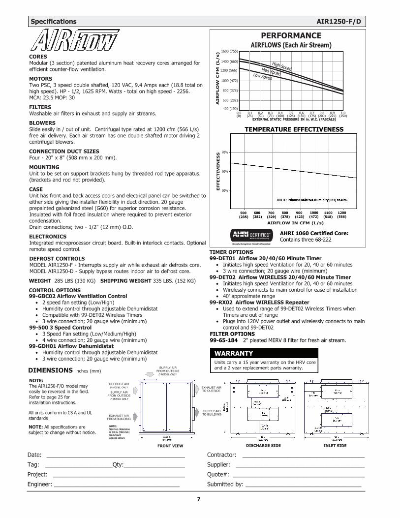
CORESModular (3 section) patented aluminum heat recovery cores arranged for efficient counter-flow ventilation.
MOTORSTwo PSC, 3 speed double shafted, 120 VAC, 9.4 Amps each (18.8 total on high speed). HP - 1/2, 1625 RPM. Watts - total on high speed - 2256. MCA: 23.5 MOP: 30
FILTERSWashable air filters in exhaust and supply air streams.
BLOWERSSlide easily in / out of unit. Centrifugal type rated at 1200 cfm (566 L/s) free air delivery. Each air stream has one double shafted motor driving 2 centrifugal blowers.
CONNECTION DUCT SIZESFour - 20" x 8" (508 mm x 200 mm).
MOUNTINGUnit to be set on support brackets hung by threaded rod type apparatus.(brackets and rod not provided).
CASEUnit has front and back access doors and electrical panel can be switched to either side giving the installer flexibility in duct direction. 20 gauge prepainted galvanized steel (G60) for superior corrosion resistance. Insulated with foil faced insulation where required to prevent exterior condensation. Drain connections; two - 1/2" (12 mm) O.D.
ELECTRONICSIntegrated microprocessor circuit board. Built-in interlock contacts. Optional remote speed control.
DEFROST CONTROLSMODEL AIR1250-F - Interrupts supply air while exhaust air defrosts core. MODEL AIR1250-D - Supply bypass routes indoor air to defrost core.
WEIGHT 285 LBS (130 KG) SHIPPING WEIGHT 335 LBS. (152 KG)
CONTROL OPTIONS
500(235)
600(282)
700(329)
800(378)
900(423)
1000(472)
1100(518)
1200(566)
AIRFLOW IN CFM (L/s)E
FFE
CT
IVE
NE
SS 70%
60%
50%
AHRI 1060 Certified Core: Contains three 68-222
Specifications AIR1250-F/D
EXTERNAL STATIC PRESSURE IN in. W.C. (PASCALS)
TEMPERATURE EFFECTIVENESS
FILTER OPTIONS99-65-184 2" pleated MERV 8 filter for fresh air stream.
DISCHARGE SIDEFRONT VIEW INLET SIDE
Date: ___________________________________________
Tag: _____________________Qty:___________________
Project: _________________________________________
Engineer: _______________________________________
Contractor: ______________________________________
Supplier: ________________________________________
Quote#: _________________________________________
Submitted by: ____________________________________
WARRANTYUnits carry a 15 year warranty on the HRV core and a 2 year replacement parts warranty.
99-GBC02 Airflow Ventilation Control• 2 speed fan setting (Low/High)• Humidity control through adjustable Dehumidistat• Compatible with 99-DET02 Wireless Timers• 3 wire connection; 20 gauge wire (minimum)
99-500 3 Speed Control• 3 Speed Fan setting (Low/Medium/High)• 4 wire connection; 20 gauge wire (minimum)
99-GDH01 Airflow Dehumidistat• Humidity control through adjustable Dehumidistat• 3 wire connection; 20 gauge wire (minimum)
High SpeedMed SpeedLow Speed
•
TIMER OPTIONS99-DET01 Airflow 20/40/60 Minute Timer
•Initiates high speed Ventilation for 20, 40 or 60 minutes3 wire connection; 20 gauge wire (minimum)
•99-DET02 Airflow WIRELESS 20/40/60 Minute Timer
•Initiates high speed Ventilation for 20, 40 or 60 minutes
•Wirelessly connects to main control for ease of installation40' approximate range
•99-RX02 Airflow WIRELESS Repeater
•
Used to extend range of 99-DET02 Wireless Timers when Timers are out of rangePlugs into 120V power outlet and wirelessly connects to main control and 99-DET02
DIMENSIONS inches (mm)
NOTE:The AIR1250-F/D model may easily be reversed in the field. Refer to page 25 for installation instructions.
All units conform to CS A and UL standards
NOTE: All specifications are subject to change without notice.

The weatherhoods must have built-in “bird” screen with 1/4 in (6.35 mm) minimum mesh to prevent birds and rodents from entering into the ductwork. Do not use smaller mesh as it will be very susceptible to plugging up. Gravity dampers at the vents must not be used as they will restrict air flow and often “seize up”. The preferred location of the outside weatherhoods is:• no less than 10 ft. (3 m) apart from each other
• at least 18 in (46 cm) above snow line or groundlevel
• away from sources of contaminants, suchas automobile exhaust fumes, gas meters,garbage cans, containers, etc.
• not exposed to prevailing winds
The outside perimeter of the weatherhood must be caulked to prevent leakage into the building.
The design and size of the weatherhoods or louvers chosen by the installer must allow for adequate free area. Water and debris penetration of the system is minimized when the airflow does not exceed 1000 FPM (5.08 m/s) free area velocity.
Ducting from the WeatherhoodsGalvanized sheet metal ducting with sufficient cross section with an integral single piece vapor barrier should be used to connect the HRV to the weatherhoods. All ducting must meet UL Class 1 requirements.A minimum R value of insulation should be equal to 4 (RSI 0.75)A good bead of high quality caulking (preferably acoustical sealant) and taping with a high quality aluminum foil tape is recommended to seal the duct to both the HRVand the weatherhood.
A properly designed ducting system will allow the HRV to operate at its maximum efficiency. (Air flow will be restricted by undersized ducting, use of too many elbows, tees, bends, etc.). Always try to keep duct runs as short and straight as possible.NOTE: Fully insulated ducting with an integral vapor
barrier must be used on all runs passing through unheated areas in order to avoid condensation problems and energy losses from the air steams.
All joints must be airtight, sealed and impervious to moisture. See specification sheets for each unit for exact duct sizes and location.To minimize pressure drop and noise, galvanized metal ducts, properly sized, are recommended. Keep ducting as short as possible and use a minimum of elbows and tees. Connecting sections and shorter runs may be flexible
ducting one size larger than the metal equivalent. Use flexible duct connectors at the HRVto avoid noise transmission.All duct joints must be secured with screws, rivets or duct sealant and sealed with aluminum duct tape to prevent leakage.
The Ductwork System
Outside Weatherhoods
Fully insulated ducting with an integral vapour barrier must be used on all runs passing through unheated areas in order to avoid condensation problems and energy losses from the air systems.
ATTENTION
8
The fresh air supply ductwork from the HRV may be directly connected to the return air duct of the forced air system. Check the air flow balance of the HRV with the air handler blower both “ON” and “OFF” to determine that it does not imbalance the HRVmore than 10%. Also, it is advisable to include a short length of flex duct or other non-metallic connector in this hard ducted line in order to keep the HRVacoustically isolated and separately grounded (electrically) from the air handler. This will avoid a possible shock hazard to service people if a short to ground develops in one of the devices.It may be necessary to install a separate fresh air supply ductwork system if the heating is other than forced air.
When installing an HRV, the designer and installer should be aware of local codes that may require smoke detectors and/or firestats in the HVAC or HRVductwork.Because an HRVis designed to bring fresh air into the building, structures may require supply voltage interrupt when smoke or flame sensors are triggered, or when a central fire alarm system is activated.Supply air grilles may be ceiling or high wall mounted. Avoid locating incoming fresh air grilles that could cause a direct draft on the occupants as the incoming air may be below room temperature. A reheat duct heater can be installed to improve occupant comfort.
The stale air return system is used to draw air from the points in the building where the worst air quality problems occur. Balancing dampers and/or adjustable grilles are recommended on all return air lines which are used during installation to help balance the “draw” from different areas of the building.Alternately, the stale air may be drawn directly from the return air duct. When this system is used, the air handler’s blower must constantly operate. The exhaust take-off connection must be at least 3 ft (1 m) from a directly connected HRVsupply duct if bothare connected to the same duct run. Note andcompensate for the static pressure of the air handlersreturn system if the static pressure of the return inthe air handler exceeds .1 to .15” W.C.A damper located just prior to the HRVis required to balance the stale air exhausted with the fresh air supply entering the building.Return air suction points should be located on the opposite side of the room from the fresh air inlet. The
inlets may be located in the ceiling or high on the walls and fitted with inlet grilles.Many commercial activities produce air contaminants in the form of dusts, fumes, mists, vapors and gases. Contaminants should be controlled at the source so they are not dispersed through the building or allowed to increase to toxic concentration levels. The ventilator allows for economical operation of the HVAC system while effectively removing contaminants from the space. In designing the exhaust portion of the system the exhaust grilles are situated to remove the contaminants while not allowing them to enter the breathing zone of the occupants.For contaminants lighter than air, grilles should be located high on the wall. If contaminants are heavier than air, a lower placement of the grilles will be required. Information on a contaminants specific gravity and toxicity should be available from chemical data sheets.
Stale Air Return System
Fresh Air Supply System
Adjustable Grilles
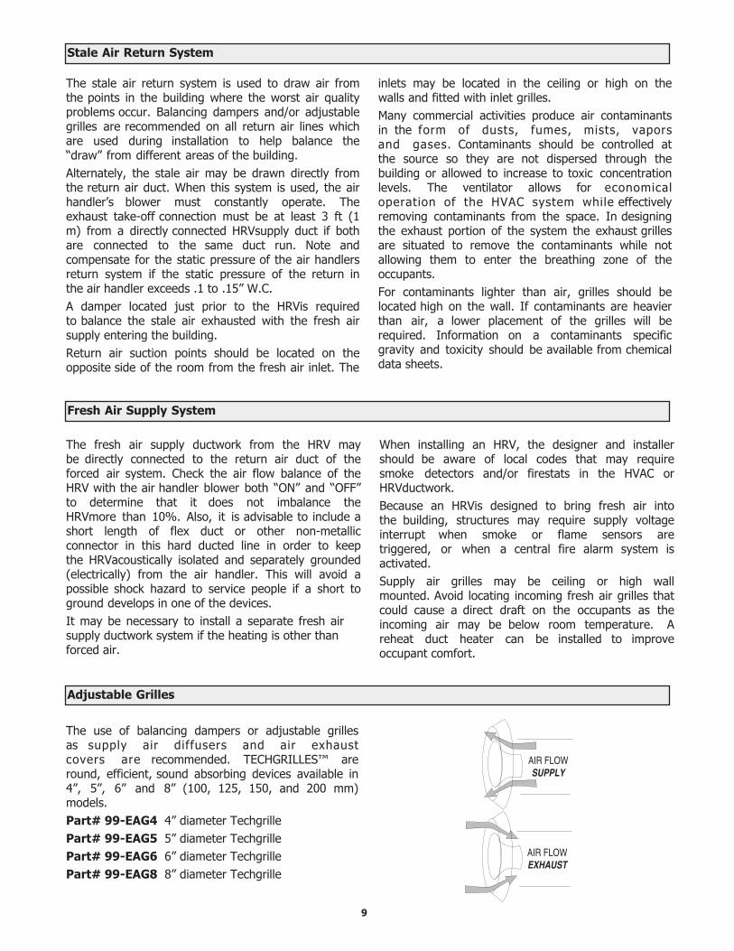
The use of balancing dampers or adjustable grilles as supply air diffusers and air exhaust covers are recommended. TECHGRILLES™ are round, efficient, sound absorbing devices available in 4”, 5”, 6” and 8” (100, 125, 150, and 200 mm) models.Part# 99-EAG4 4” diameter TechgrillePart# 99-EAG5 5” diameter TechgrillePart# 99-EAG6 6” diameter TechgrillePart# 99-EAG8 8” diameter Techgrille
9
ECONOMIZER
HRV/ERV FRESHAIR SUPPLY
HRV/ERV UNIT
STALE AIREXHAUST TO HRV/ERV
SUPPLY DUCTRETURN AIR DUCT or
BREATHER T
ROOFTOPUNIT
B.D.
B.D.FRESH AIRSUPPLY
STALE AIREXHAUST
FRESH AIRSUPPLY
STALE AIREXHAUST
HRV/ERV FRESH AIR SUPPLY
HRV/ERV UNIT B.D.
B.D.
STALE AIR EXHAUST
ECONOMIZER
ROOFTOPUNIT
12” BREATHERSPACE
ROOF DECK
CEILING RETURN AIR PLENUM SUPPLY DUCTWORK
Figure A
Figure B
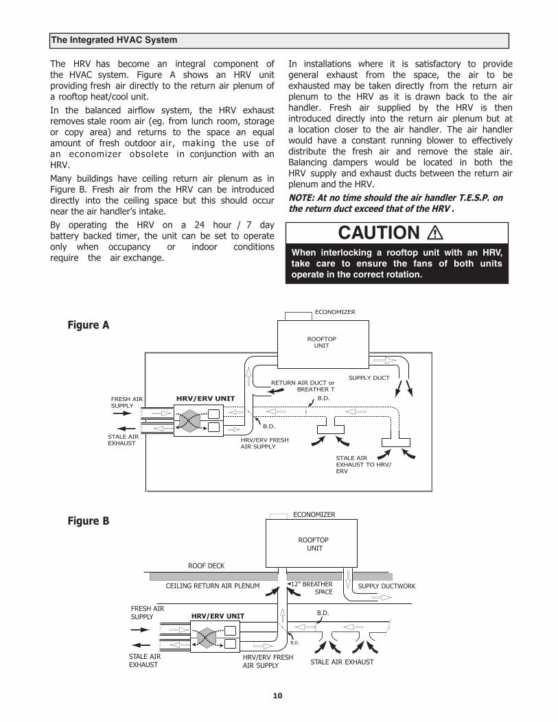
The HRV has become an integral component of the HVAC system. Figure A shows an HRV unit providing fresh air directly to the return air plenum of a rooftop heat/cool unit.In the balanced airflow system, the HRV exhaust removes stale room air (eg. from lunch room, storage or copy area) and returns to the space an equal amount of fresh outdoor air, making the use of an economizer obsolete in conjunction with an HRV.Many buildings have ceiling return air plenum as in Figure B. Fresh air from the HRV can be introduced directly into the ceiling space but this should occur near the air handler’s intake.By operating the HRV on a 24 hour / 7 day battery backed timer, the unit can be set to operate only when occupancy or indoor conditions require the air exchange.
In installations where it is satisfactory to provide general exhaust from the space, the air to be exhausted may be taken directly from the return air plenum to the HRV as it is drawn back to the air handler. Fresh air supplied by the HRV is then introduced directly into the return air plenum but at a location closer to the air handler. The air handler would have a constant running blower to effectively distribute the fresh air and remove the stale air. Balancing dampers would be located in both the HRV supply and exhaust ducts between the return air plenum and the HRV.NOTE: At no time should the air handler T.E.S.P. on the return duct exceed that of the HRV .
The Integrated HVAC System
When interlocking a rooftop unit with an HRV,take care to ensure the fans of both unitsoperate in the correct rotation.
CAUTION
10

The HRV must be level for proper drainage of condensate from the drain pans.
Install a loop or "P Trap" in the condensate line and pour a cup of water into the drain pan. This will create a water seal which will prevent odors from being drawn up the hose and into the fresh air supply of the HRV.
Install the drain pans in the bottom of the HRV so the drain connections protrude through the holes provided. Use drain hoses with hose clamps to connect the drain pan outlets to a floor drain or standpipe. Make sure the drain line slopes down to the outlet. If this is not possible, a condensate pump will be required for positive removal of the water. Protect the drain line from freezing.
Drain Connections
Electrical Connections
DRAINSPOUT
TAPE
TO DRAIN
TEECONNECTOR
DRAINSPOUT
HRV CABINET
The HRV and all condensate lines must be installed in a space where the temperature is maintained above the freezing point.
CAUTIONDrain trap and tubing MUST be below bottom of door with 1/4" per foot downwards slope away from unit.
CAUTION
Forming the “P” Trap
11
Electrical ConnectionsIt is recommended that a licensed electrician make all electrical connections. It is very important that the unit be properly grounded. The circuit must be sized to handle the F.L.A. indicated on the name tag for the circuit.WARNING: In order to prevent electric shock when cleaning or servicing the HRV, it is extremely important to confirm the polarity of the power line that is switched by the safety (disconnect) switch whose control arm is located on the outside of the electrical control box area. The hot line (black) is the proper line to be switched. To confirm the proper polarity, use a voltmeter or test lamp to make sure there is no power after the switch when the door is open. Check between that point and ground (on the cabinet). This must be done as occasionally some buildings are improperly wired. Always make sure the HRV is properly grounded.
CAUTIONThe HRV is designed to operate with ducting. When first starting the HRV, measure the amp draw to each motor at each speed to ensure it is operating at or below the max rating.
Maximum AMP Rating
HIGH MED. LOW
1200DD, 1200FD 9.4 6.0 4.5
700DD , 700FD 4.5
650DD, 650FD
455DD , 455FD
4.6 3.0 2.3
2.0
Fan DefrostModels AIR550-F, AIR750-F, AIR850-F, AIR1250-F
Fan defrost HRV's are equipped with an electronically controlled fan defrost system to remove frost that collects on the warm air side of the aluminum heat transfer surfaces of the heat exchanger core. When the outside air temperature drops below 27°F (-3°C), defrost is activated which provides for an automatic defrost cycle. During the automatic defrost cycle the fresh air supply is shut off while the exhaust fan continues to operate. This allows warm inside air to flow through the heat exchanger core melting frost accumulation. After the defrost period, the fresh air supply fan automatically returns to the normal speed and fresh outside air continues to be drawn into the building. Water from the melted frost collects in the bottom drip pans and drains out through the bottom drain connections. The defrost cycle repeats automatically until the air temperature rises above 27°F (-3°C).
Damper DefrostModels AIR550-D, AIR750-D, AIR850-D, AIR1250-D
These damper defrost HRV's an have electronically controlled damper defrost mechanism. If the outside temperature drops below 27°F (-3°C ), the defrost timer is activated. A motor driven damper door mechanism opens the defrost port and at the same time closes off the supply air from outside. After the defrost period, the damper operates in the opposite direction to close off the defrost port and reopen the fresh air at the supply port. Defrost cycle repeats until the temperature again rises above 27°F (-3°C).
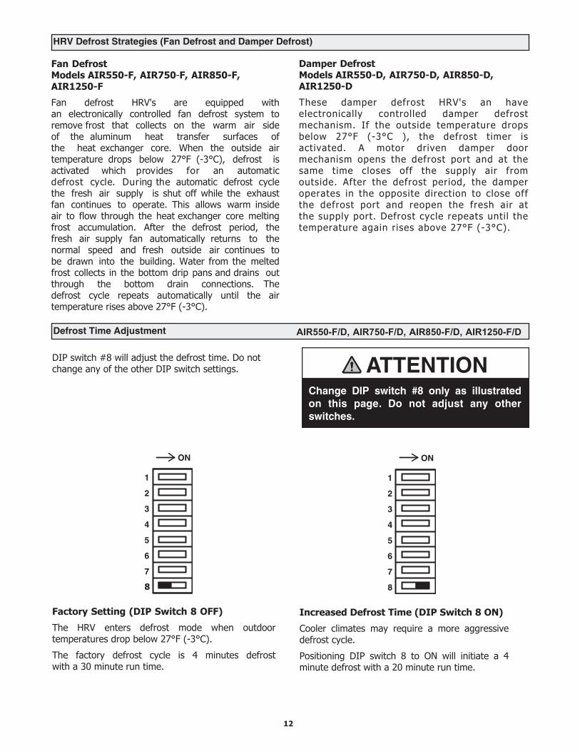
Defrost Time Adjustment AIR550-F/D, AIR750-F/D, AIR850-F/D, AIR1250-F/D
HRV Defrost Strategies (Fan Defrost and Damper Defrost)
DIP switch #8 will adjust the defrost time. Do not change any of the other DIP switch settings.
Increased Defrost Time (DIP Switch 8 ON)
Cooler climates may require a more aggressive defrost cycle.
Positioning DIP switch 8 to ON will initiate a 4 minute defrost with a 20 minute run time.
Change DIP switch #8 only as illustrated on this page. Do not adjust any otherswitches.
ATTENTION
ON
1
2
3
4
5
6
7
Factory Setting (DIP Switch 8 OFF)
The HRV enters defrost mode when outdoor temperatures drop below 27°F (-3°C).
The factory defrost cycle is 4 minutes defrost with a 30 minute run time.
ON
1
2
3
4
5
6
7
8
12
8
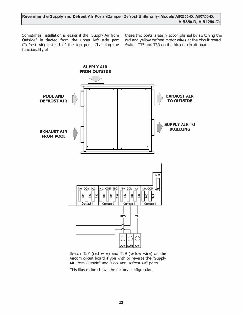
Reversing the Supply and Defrost Air Ports (Damper Defrost Units only- Models AIR550-D, AIR750-D,AIR850-D, AIR1250-D)
Sometimes installation is easier if the "Supply Air from Outside" is ducted from the upper left side port (Defrost Air) instead of the top port. Changing the functionality of
these two ports is easily accomplished by switching the red and yellow defrost motor wires at the circuit board. Switch T37 and T39 on the Aircom circuit board.
13
SUPPLY AIRFROM OUTSIDE
EXHAUST AIR TO OUTSIDE
SUPPLY AIR TO BUILDING
POOL AND DEFROST AIR
EXHAUST AIR FROM POOL
Switch T37 (red wire) and T39 (yellow wire) on the Aircom circuit board if you wish to reverse the "Supply Air From Outside" and "Pool and Defrost Air" ports.
This illustration shows the factory configuration.
T31
T32
T33
T34
T35
T36
T37
T38
T39
T40
T41
T42
Contact 1
N.0. COM N.C. N.0. COM N.C. N.0. COM N.C. N.0 . COM
Contact 2 Contact 3 Contact 4
N.C
RED YEL
CCW COM CW
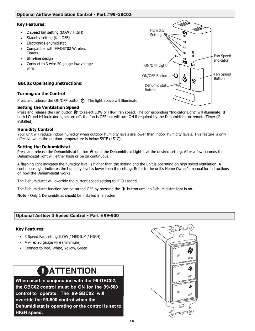
Optional Airflow Ventilation Control - Part #99-GBC02
14
2 speed fan setting (LOW / HIGH) Standby setting (fan OFF) Electronic Dehumidistat Compatible with 99-DET02 Wireless
Timers Slim-line design Connect to 3 wire 20 gauge low voltage
wire
Humidity Setting
Fan Speed Indicator
ON/OFF Light
Fan Speed ON/OFF Button Button
Dehumidistat Button
GBC02 Operating Instructions:
Turning on the Control
Press and release the ON/OFF button . The light above will illuminate.
Setting the Ventilation SpeedPress and release the Fan button to select LOW or HIGH fan speed. The corresponding “Indicator Light" will illuminate. If both LO and HI indicator lights are off, the fan is OFF but will turn ON if required by the Dehumidistat or remote Timer (if installed).
Humidity ControlYour unit will reduce indoor humidity when outdoor humidity levels are lower than indoor humidity levels. This feature is only effective when the outdoor temperature is below 59˚F (15˚C).
Setting the DehumidistatPress and release the Dehumidistat button until the Dehumidistat Light is at the desired setting. After a few seconds the Dehumidistat light will either flash or be on continuous.
A flashing light indicates the humidity level is higher than the setting and the unit is operating on high speed ventilation. A continuous light indicates the humidity level is lower than the setting. Refer to the unit's Home Owner’s manual for instructions on how the Dehumidistat works.
The Dehumidistat will override the current speed setting to HIGH speed.
The Dehumidistat function can be turned OFF by pressing the button until no Dehumidistat light is on.
Note - Only 1 Dehumidistat should be installed in a system.
Key Features:
Optional Airflow 3 Speed Control - Part #99-500
HIGHOFF
OFF
OFF
MED
LOW
• 3 Speed Fan setting (LOW / MEDIUM / HIGH)• 4 wire; 20 gauge wire (minimum)• Connect to Red, White, Yellow, Green.
ATTENTIONWhen used in conjunction with the 99-GBC02, the GBC02 control must be ON for the 99-500 control to operate. The 99-GBC02 will override the 99-500 control when the Dehumidistat is operating or the control is set to HIGH speed.
Key Features:

Key Features• The Dehumidistat measures the indoor humidity level and
will initiate high speed ventilation when the moisture levelin the building exceeds the set point on the control.
• Once the humidity in the building is reduced, the HRV willrevert back to its previous setting.
• The Dehumidistat should be set to OFF for all seasonexcept the heating season.
• Connect to 3 wire 20 gauge low voltage wire.
Humidity ControlYour HRV will produce a dehumidifying effect when outdoor humidity levels are lower than indoor humidity levels. Never use the Dehumidistat feature when outdoor temperatures are above 59 F (15 C).
Note: The indoor humidity level is measured at the control.
Setting the DehumidistatPress and release the Dehumidistat button until the Dehumidistat Light is at the desired setting. After 5 seconds the Dehumidistat light will either flash or be on continuous.
A flashing light indicates the humidity level is higher than the setting and the unit is operating on high speed ventilation. A continuous light indicates the humidity level is lower than the setting. Refer to the unit's Operation & Installation Manual for instructions on how the Dehumidistat works.
Note - Only 1 Dehumidistat should be active on a system.
Optional Airflow Dehumidistat - Part #99-GDH01
%
80
20
Instruction card
Dehumidistat Indicator LEDsSet to the desired humidity level. High speed ventilation will initiate when the indoor moisture level exceeds the set point on the control.
DehumidistatAdjust button
15
16
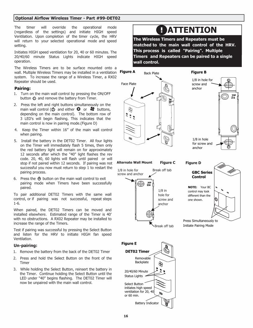
Optional Airflow Wireless Timer - Part #99-DET02
ATTENTIONThe Wireless Timers and Repeaters must be matched to the main wall control of the HRV. This process is called "Pairing". Multiple Timers and Repeaters can be paired to a single wall control.
GBC Series Control
NOTE: Your BC control may look different than the one shown.
Press Simultaneously to Initiate Pairing Mode
Figure A Figure B
1/8 in hole for screw and anchor
1/8 in hole for screw and anchor
Break off tab
Alternate Wall Mount
1/8 in hole for screw and anchor
Figure C
Back Plate
Face Plate
1/8 in hole for screw and anchor
Break off tab
Figure E
Figure D
DET02 Timer
20/40/60 Minute Status Lights
Select Button initiates high speed ventilation for 20, 40 or 60 min.
Battery Indicator
Removable Backplate
The timer will override the operational mode (regardless of the settings) and initiate HIGH speed Ventilation. Upon completion of the timer cycle, the HRV will return to your selected operational mode and speed setting.
Initiates HIGH speed ventilation for 20, 40 or 60 minutes. The 20/40/60 minute Status Lights indicate HIGH speed operation.
The Wireless Timers are to be surface mounted onto a wall. Multiple Wireless Timers may be installed in a ventilation system. To increase the range of a Wireless Timer, a RX02 Repeater should be used.
Pairing:
To pair additional DET02 Timers with the same wall control, or if pairing was not successful, repeat steps 1-6.
When paired, the DET02 Timers can be moved and installed elsewhere. Estimated range of the Timer is 40’ with no obstructions. A RX02 Repeater may be installed to increase the range of the Timers.
Test if pairing was successful by pressing the Select Button and listen for the HRV to initiate HIGH fan speed Ventilation.
Un-pairing:
1. Turn on the main wall control by pressing the ON/OFFbutton and remove the battery from Timer.
2. Press the left and right buttons simultaneously on themain wall control ( and either or buttons,depending on the main control). The bottom row of3 LED's will begin flashing. This indicates that themain control is now in pairing mode.(Figure D)
4. Keep the Timer within 16” of the main wall controlwhen pairing.
5. Install the battery in the DET02 Timer. All four lightson the Timer will immediately flash 5 times, then onlythe red battery light will remain on for approximately12 seconds after which the "40" light flashes the revcode. 20, 40, 60 lights will flash until paired or willstop if not paired within 12 seconds. If pairing was notsuccessful you now must return to step 1 to restart thepairing process.
6. Press the button on the main wall control to exitpairing mode when Timers have been successfullypaired.
1. Remove the battery from the back of the DET02 Timer
2. Press and hold the Select Button on the front of theTimer
3. While holding the Select Button, reinsert the battery inthe Timer. Continue holding the Select Button until theLED under "40" begins flashing. The DET02 Timer willnow be unpaired with the main wall control.

Optional Wireless Timer - Part #99-DET02 Continued
Installation of Wireless Timer1. Separate the Face Plate from the Back Plate by firmly pulling apart (Figure A).
2. For mounting the control without a Decora plate, break off top and bottom tabs and refer to Figure C for mounting.
3. Place the Back Plate of the control in the desired location on the wall and pencil mark the top and bottom screw holes (Figure Bor C). Drill two 1/8" holes.
4. Attach the Back Plate to the wall using the 2 supplied screws and anchors.
5. Attach the Face Plate to the Back Plate (Figure A).
17
Overview of Airflow Wireless 20/40/60 Minute Timer
Initiates HIGH speed Ventilation for 20, 40 or 60 minutes. The 20/40/60 minute Status Lights indicate HIGH speed operation.
Wireless Timers have an estimated range of 40' with no obstructions. To increase the range of a Wireless Timer a 99-RX02 Repeater may be used.
Using the Wireless Timer
When paired to the main wall control, the Wireless Timer may be moved to a remote location in the home such as a bathroom.
Pressing the Select Button on the Timer will initiate HIGH speed fan operation. The corresponding Status Light will illuminate under the number on the Timer to indicate either 20, 40 or 60 minutes of HIGH speed fan operation. To cancel the call for HIGH speed fan operation, press the Select Button until the Status Lights are no longer illuminated.
Replacing the Battery
When the battery needs to be replaced in the Wireless Timer, the red LED Battery Indicator will illuminate.
To replace the battery, first remove the Face Plate by pulling it off the wall. On the back of the Timer Face Plate the battery will be exposed. Replace the battery and re-attach the Face Pate to the Back Plate. Be careful not to damage the tabs on the Back Plate when re-attaching the Face Plate.
Removable Backplate
20/40/60 Minute Status Lights
Select Button initiates high speed ventilation for 20, 40 or 60 min.
Battery Indicator
Back Plate
Face Plate
Back of 99-DET02Face Plate
Battery

18
Installation and Pairing of Wireless Repeaters: 99-RX02
The RX02 Repeaters are to be plugged directly into a 120V power outlet.
1. Turn on the main wall control by pressing the ON/OFF button .
2. Press the left and right buttons simultaneously on the main wall control ( and either or buttons, depending on the main control). The bottom row of 3 LED's will begin flashing. This indicates that the main control is now in pairing mode.
RX02
Repeater
PowerPlug
3. The RX02 Repeater must be powered within 16” of the main wall control for pairing. If an outlet is not available an extensioncord should be used to power the repeater initially for pairing.
4. Plug the RX02 Repeater into the power outlet. The green light will flash after approximately 12 seconds indicating that therepeater is paired with the main wall control.
5. Press the ON/OFF button on the main wall control to exit pairing mode and the Repeater may now beunplugged and moved to its permanent location.
To pair additional RX02 Repeaters with the same wall control, repeat steps 1-5 until all Repeaters have been paired.
When installed in its permanent location, the green LED will remain solid to indicate the best location and the Repeater can be moved farther if required. The green LED will flash to indicate it is in a good location. A red light indicates the Repeater is out of range and needs to be moved closer to the main wall control.
NOTE: Wireless Repeaters cannot be used in a network to extend the range of another Wireless Repeater.
Optional Airflow 20/40/60 Minute Timer - Part #99-DET01
Optional Airflow Wireless Repeater - Part #99-RX02
Operating your Airflow 20/40/60 Minute Fan Timer
Press and release the Select Button to activate a 20, 40 or 60 minute high speed override cycle. The High Speed Status Light will illuminate and the unit will run on high speed ventilation for the selected time.
The High Speed Status Light will dim after 10 seconds of run time.
The High Speed Status Light will flash during the last 5 minutes of the cycle.
All timers connected to the unit will illuminate for the duration of the override when the Select Button is pressed.
Lockout ModeLockout Mode is useful if you wish to disable the timers.
The timer can be set to lockout mode by pressing and holding the Select Button for five seconds. After five seconds, the High Speed Status Light will flash; release the Select Button. The timer is now in lockout mode. If the Select Button is pressed during lockout mode the High Speed Status Light will momentarily illuminate but no override will be initiated.
If lockout mode is initiated when the timer is activated, the timer will continue its timed sequence but will not allow any further overrides to be initiated. Lockout mode can be unlocked by pressing and holding the Select Button for five seconds. After five seconds the High Speed Status Light will stop flashing. Release the Select Button and the timer will now operate normally.
High SpeedStatus Lights
Select Button initiates high speed ventilation for 20, 40 or 60 minutes.
Yellow
Red
Green
NOTE ABOUT TIMERS• Timers mount in standard 2” x 4” electrical boxes.• Wire multiple timers individually back to the unit.• Use 3/20 low voltage wire
RE
DG
RN
YE
L
DE
T
Dig
ital
Co
ntr
ols
Terminal strip on Aircom circuit board
• Yellow to YEL• Red to RED• Green to GRN• Use 3/20 wire
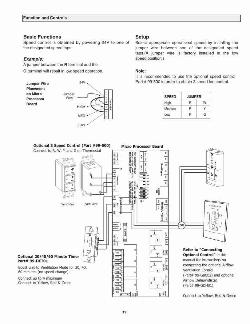
Function and Controls
Basic FunctionsSpeed control is obtained by powering 24V to one ofthe designated speed taps.
Example:A jumper between the R terminal and the
G terminal will result in low speed operation.
SetupSelect appropriate operational speed by installing the jumper wire between one of the designated speed taps.(A jumper wire is factory installed in the low speed position.)
Note:It is recommended to use the optional speed control Part # 99-500 in order to obtain 3 speed fan control.
Refer to “Connecting Optional Control” in this manual for instructions on connecting the optional Airflow Ventilation Control(Part# 99-GBC02) and optional Airflow Dehumidistat(Part# 99-GDH01)
Connect to Yellow, Red & Green
OG
YW
RC
Thermostat
24V
Jumper Wire
HIGH
MED
LOW
Jumper WirePlacementon MicroProcessorBoard
SPEED
High R W
Medium R Y
Low R G
JUMPER
19
Optional 20/40/60 Minute TimerPart# 99-DET01
Boost unit to Ventilation Mode for 20, 40, 60 minutes (no speed change).
Connect up to 4 maximumConnect to Yellow, Red & Green
HIGHOFF
OFF
OFF
MED
LOW
Optional 3 Speed Control (Part #99-500) Connect to R, W, Y and G on Thermostat
T18T5
T13C
4T17
T19T1
T2T3
T4T6
T14T15
T16C
3C
2C
1R
ELAYFan H
iFan M
edFan Low
FEEDLine/Ligne
Neutral/N
eutreT20
CH
ASSIS
T11T12
T44N
.O.
N.O
.N
.O.
N.O
.
COM
COM
COM
COM
K6K3
K4K5
87
65
43
21
T21T22
T23T24
AU
X 1
AU
X 2
ON
SW1
SPARE
DIP
SWITC
HES
TO B
ESEU
L UN
TECH
NIC
IENK8
K7K1
K2T43
AD
JUSTED
BY
QU
ALIFIED
QU
ALIFIÉ P
EUT A
JUSTÉ LES
TECH
NIC
IAN
S O
NLY
.C
OM
MU
TATEU
RS
DIP
.N
.C
2 A
MP
S
P1
Digital C
ontrolsN
.0. COM
N
.C.N
.0. COM
N
.C.N
.0. COM
N
.C.N.0
.COM
P2 P3
T42
12VacCom
CTherm
ostatD
ETR
24Vac
T25T26
T27C
RW
YG
OYEL
GR
NR
EDT28
T29T30
Contact 1Contact 2
Contact 3Contact 4
Defrost
Freeze
%
80
Micro Processor Board
Back View
T31
T32
T33
T34
T35
T36
T37
T38
T39
T40
T41
20
Front View
OR
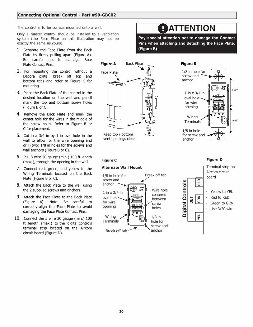
Connecting Optional Control - Part #99-GBC02
The control is to be surface mounted onto a wall.
Only 1 master control should be installed to a ventilation system (the Face Plate on this illustration may not be exactly the same as yours).
ATTENTIONPay special attention not to damage the ContactPins when attaching and detaching the Face Plate.(Figure B)
RE
DG
RN
YE
L
DE
T
Dig
ital
Co
ntr
ols
Figure D
Terminal strip on Aircom circuit board
• Yellow to YEL• Red to RED• Green to GRN• Use 3/20 wire
20
1. Separate the Face Plate from the BackPlate by firmly pulling apart (Figure A).Be careful not to damage FacePlate Contact Pins.
2. For mounting the control without aDecora plate, break off top andbottom tabs and refer to Figure C formounting.
3. Place the Back Plate of the control in thedesired location on the wall and pencilmark the top and bottom screw holes(Figure B or C).
4. Remove the Back Plate and mark thecenter hole for the wires in the middle ofthe screw holes. Refer to Figure B orC for placement.
5. Cut in a 3/4 in by 1 in oval hole in thewall to allow for the wire opening anddrill (two) 1/8 in holes for the screws andwall anchors (Figure B or C).
6. Pull 3 wire 20 gauge (min.) 100 ft length(max.), through the opening in the wall.
7. Connect red, green, and yellow to theWiring Terminals located on the BackPlate (Figure B or C).
8. Attach the Back Plate to the wall usingthe 2 supplied screws and anchors.
9. Attach the Face Plate to the Back Plate(Figure A). Note: Be careful tocorrectly align the Face Plate to avoiddamaging the Face Plate Contact Pins.
10. Connect the 3 wire 20 gauge (min.) 100ft length (max.) to the digital controlsterminal strip located on the Aircomcircuit board (Figure D).
Figure A
Keep top / bottom vent openings clear
Figure B
1.625"
0.75"
1"
1.625"
1/8 in hole for screw and anchor
1 in x 3/4 in
for wire opening
WiringTerminals
1/8 in hole for screw and anchor
oval hole
Break off tab
Alternate Wall Mount
1/8 in hole for screw and anchor
1 in x 3/4 in 0.75"
oval hole
1/8 in
for wire
hole for
opening
screw and anchor
WiringTerminals
Break off tab
Figure C
1"
Wire hole centered between screw holes
Back Plate
Face Plate
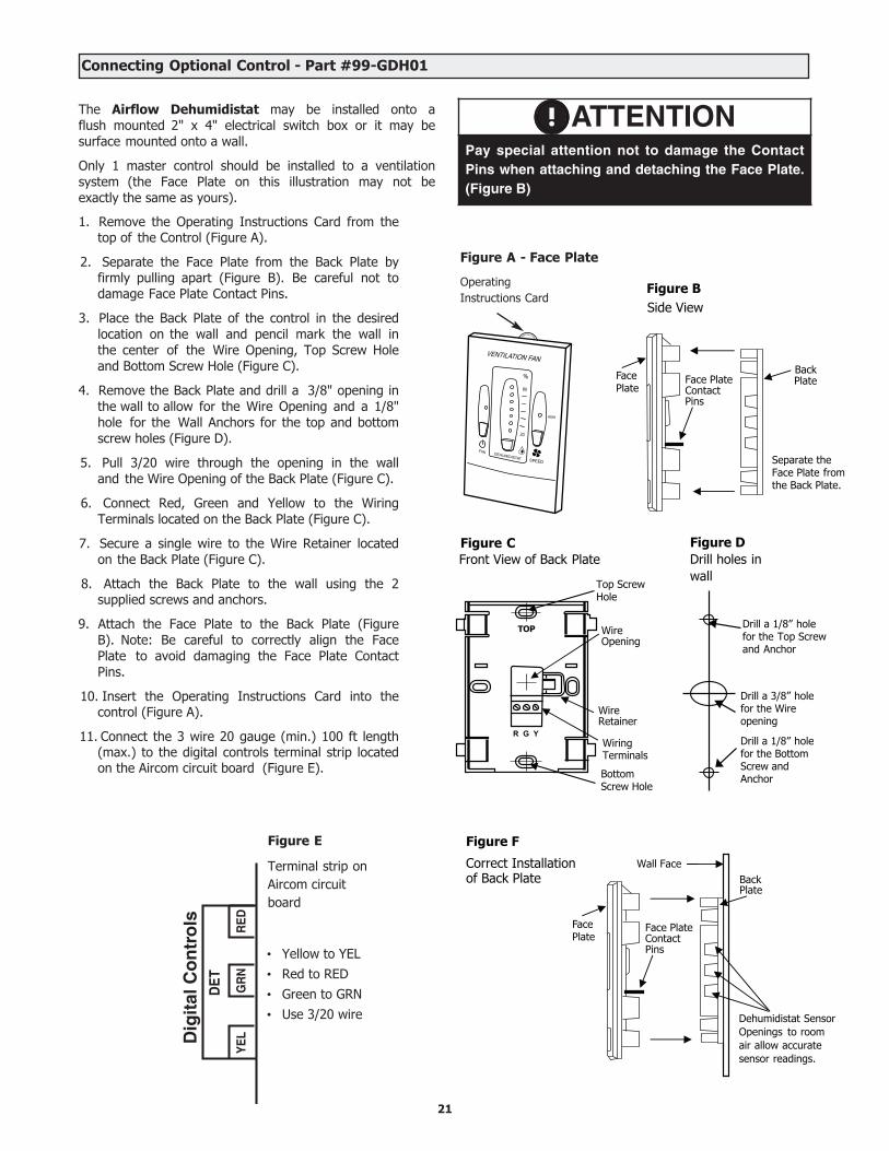
Connecting Optional Control - Part #99-GDH01
The Airflow Dehumidistat may be installed onto a flush mounted 2" x 4" electrical switch box or it may be surface mounted onto a wall.
Only 1 master control should be installed to a ventilation system (the Face Plate on this illustration may not be exactly the same as yours).
1. Remove the Operating Instructions Card from thetop of the Control (Figure A).
2. Separate the Face Plate from the Back Plate byfirmly pulling apart (Figure B). Be careful not todamage Face Plate Contact Pins.
3. Place the Back Plate of the control in the desiredlocation on the wall and pencil mark the wall inthe center of the Wire Opening, Top Screw Holeand Bottom Screw Hole (Figure C).
4. Remove the Back Plate and drill a 3/8" opening inthe wall to allow for the Wire Opening and a 1/8"hole for the Wall Anchors for the top and bottomscrew holes (Figure D).
5. Pull 3/20 wire through the opening in the walland the Wire Opening of the Back Plate (Figure C).
6. Connect Red, Green and Yellow to the WiringTerminals located on the Back Plate (Figure C).
7. Secure a single wire to the Wire Retainer locatedon the Back Plate (Figure C).
8. Attach the Back Plate to the wall using the 2supplied screws and anchors.
9. Attach the Face Plate to the Back Plate (FigureB). Note: Be careful to correctly align the FacePlate to avoid damaging the Face Plate ContactPins.
10. Insert the Operating Instructions Card into thecontrol (Figure A).
11. Connect the 3 wire 20 gauge (min.) 100 ft length(max.) to the digital controls terminal strip locatedon the Aircom circuit board (Figure E).
%
80
20
HIGH
ATTENTIONPay special attention not to damage the ContactPins when attaching and detaching the Face Plate.(Figure B)
Figure A - Face Plate
OperatingInstructions Card
BackPlate
Figure B
Face PlateContactPins
Face Plate
Separate theFace Plate fromthe Back Plate.
Side View P
Figure CFront View of Back Plate
WireOpening
WiringTerminals
WireRetainer
TOP
Top ScrewHole
BottomScrew Hole
Drill a 1/8” holefor the Top Screwand Anchor
Figure DDrill holes in wall
Drill a 3/8” holefor the Wireopening
Drill a 1/8” holefor the BottomScrew and Anchor
Wall Face
Dehumidistat Sensor Openings to room air allow accurate sensor readings.
Figure F
Correct Installation of Back Plate Back
Plate
Face PlateContactPins
Face Plate
21
RE
DG
RN
YE
L
DE
T
Dig
ital
Co
ntr
ols
Figure E
Terminal strip on Aircom circuit board
• Yellow to YEL• Red to RED• Green to GRN• Use 3/20 wire
22
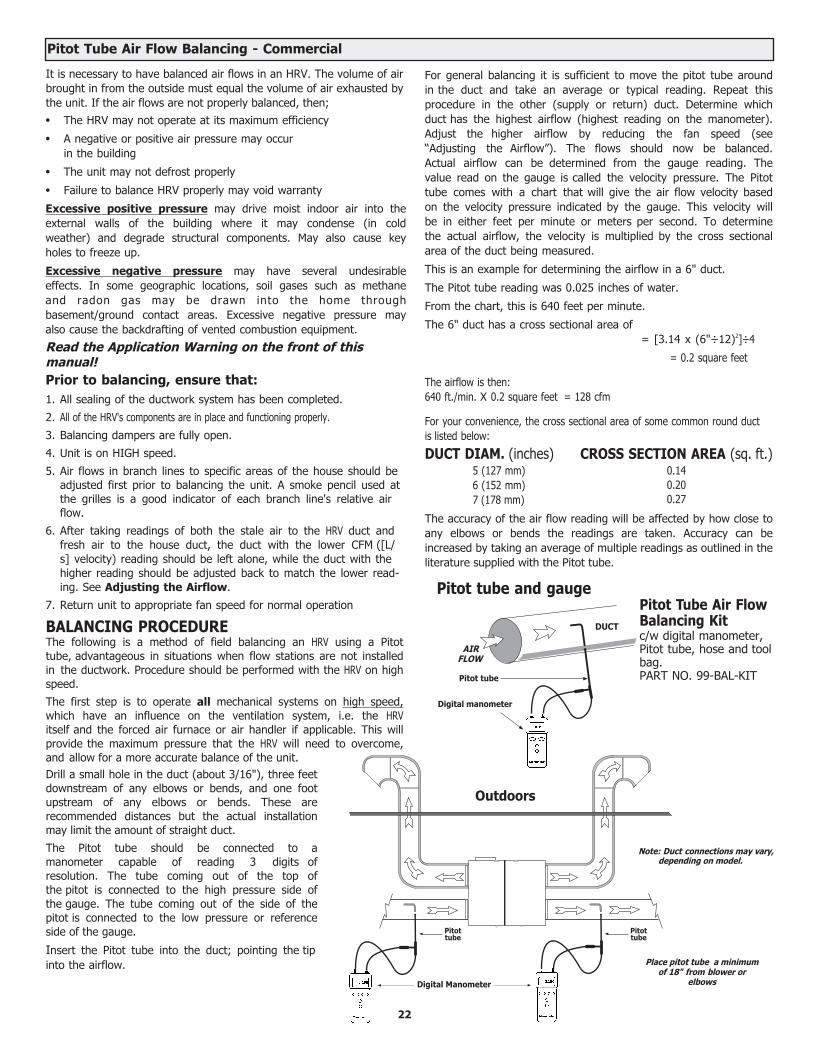
It is necessary to have balanced air flows in an HRV. The volume of air brought in from the outside must equal the volume of air exhausted by the unit. If the air flows are not properly balanced, then;• The HRV may not operate at its maximum efficiency
• A negative or positive air pressure may occurin the building
• The unit may not defrost properly
• Failure to balance HRV properly may void warranty
Excessive positive pressure may drive moist indoor air into the external walls of the building where it may condense (in cold weather) and degrade structural components. May also cause key holes to freeze up.
Excessive negative pressure may have several undesirable effects. In some geographic locations, soil gases such as methane and radon gas may be drawn into the home through basement/ground contact areas. Excessive negative pressure may also cause the backdrafting of vented combustion equipment.
Read the Application Warning on the front of this manual!Prior to balancing, ensure that:1. All sealing of the ductwork system has been completed.
2. All of the HRV's components are in place and functioning properly.
3. Balancing dampers are fully open.
4. Unit is on HIGH speed.
5. Air flows in branch lines to specific areas of the house should beadjusted first prior to balancing the unit. A smoke pencil used atthe grilles is a good indicator of each branch line's relative airflow.
6. After taking readings of both the stale air to the HRV duct andfresh air to the house duct, the duct with the lower CFM ([L/s] velocity) reading should be left alone, while the duct with thehigher reading should be adjusted back to match the lower read-ing. See Adjusting the Airflow.
7. Return unit to appropriate fan speed for normal operation
BALANCING PROCEDUREThe following is a method of field balancing an HRV using a Pitot tube, advantageous in situations when flow stations are not installed in the ductwork. Procedure should be performed with the HRV on high speed.
The first step is to operate all mechanical systems on high speed, which have an influence on the ventilation system, i.e. the HRV itself and the forced air furnace or air handler if applicable. This will provide the maximum pressure that the HRV will need to overcome, and allow for a more accurate balance of the unit.Drill a small hole in the duct (about 3/16"), three feet downstream of any elbows or bends, and one foot upstream of any elbows or bends. These are recommended distances but the actual installation may limit the amount of straight duct.
The Pitot tube should be connected to a manometer capable of reading 3 digits of resolution. The tube coming out of the top of the pitot is connected to the high pressure side of the gauge. The tube coming out of the side of the pitot is connected to the low pressure or reference side of the gauge.
Insert the Pitot tube into the duct; pointing the tip into the airflow.
For general balancing it is sufficient to move the pitot tube around in the duct and take an average or typical reading. Repeat this procedure in the other (supply or return) duct. Determine which duct has the highest airflow (highest reading on the manometer). Adjust the higher airflow by reducing the fan speed (see “Adjusting the Airflow”). The flows should now be balanced. Actual airflow can be determined from the gauge reading. The value read on the gauge is called the velocity pressure. The Pitot tube comes with a chart that will give the air flow velocity based on the velocity pressure indicated by the gauge. This velocity will be in either feet per minute or meters per second. To determine the actual airflow, the velocity is multiplied by the cross sectional area of the duct being measured.
This is an example for determining the airflow in a 6" duct.
The Pitot tube reading was 0.025 inches of water.
From the chart, this is 640 feet per minute.
The 6" duct has a cross sectional area of= [3.14 x (6"÷12)2]÷4
= 0.2 square feet
The airflow is then:640 ft./min. X 0.2 square feet = 128 cfm
For your convenience, the cross sectional area of some common round duct is listed below:
DUCT DIAM. (inches)5 (127 mm) 6 (152 mm) 7 (178 mm)
CROSS SECTION AREA (sq. ft.) 0.140.200.27
The accuracy of the air flow reading will be affected by how close to any elbows or bends the readings are taken. Accuracy can be increased by taking an average of multiple readings as outlined in the literature supplied with the Pitot tube.
DUCT
AIRFLOW
Pitot tube
Digital manometer
Pitot tube and gauge
Place pitot tube a minimum of 18" from blower or
elbows
Note: Duct connections may vary,depending on model.
Outdoors
Pitottube
Pitottube
Pitot Tube Air Flow Balancing - Commercial
Pitot Tube Air FlowBalancing Kitc/w digital manometer, Pitot tube, hose and tool bag.PART NO. 99-BAL-KIT
Digital Manometer
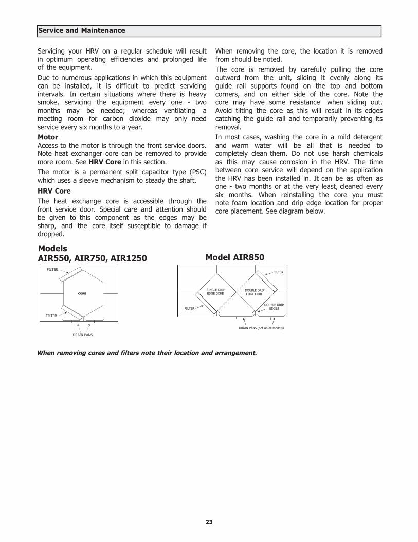
Servicing your HRV on a regular schedule will result in optimum operating efficiencies and prolonged life of the equipment.Due to numerous applications in which this equipment can be installed, it is difficult to predict servicing intervals. In certain situations where there is heavy smoke, servicing the equipment every one - two months may be needed; whereas ventilating a meeting room for carbon dioxide may only need service every six months to a year.MotorAccess to the motor is through the front service doors. Note heat exchanger core can be removed to provide more room. See HRV Core in this section.The motor is a permanent split capacitor type (PSC) which uses a sleeve mechanism to steady the shaft. HRV CoreThe heat exchange core is accessible through the front service door. Special care and attention should be given to this component as the edges may be sharp, and the core itself susceptible to damage if dropped.
When removing the core, the location it is removed from should be noted.The core is removed by carefully pulling the core outward from the unit, sliding it evenly along its guide rail supports found on the top and bottom corners, and on either side of the core. Note the core may have some resistance when sliding out. Avoid tilting the core as this will result in its edges catching the guide rail and temporarily preventing its removal.In most cases, washing the core in a mild detergent and warm water will be all that is needed to completely clean them. Do not use harsh chemicals as this may cause corrosion in the HRV. The time between core service will depend on the application the HRV has been installed in. It can be as often as one - two months or at the very least, cleaned every six months. When reinstalling the core you must note foam location and drip edge location for proper core placement. See diagram below.
DRAIN PANS
FILTER
FILTER
CORE
When removing cores and filters note their location and arrangement.
Service and Maintenance
SINGLE DRIPEDGE CORE
FILTER
FILTER
DRAIN PANS (not on all models)
DOUBLE DRIPEDGE CORE
DOUBLE DRIPEDGES
Models AIR550, AIR750, AIR1250 Model AIR850
23
FiltersOpen front service door to access the filters located in both supply and exhaust air streams. Note to remove and install filters, it may be easier to first remove the core(s). Refer to HRV Core.The filters are designed to stop large particles from entering in the core. The filters are fastened in place by a metal spring rod. To remove filters from core(s) simply pull the rod from one end, outward until free from core lip, and remove.Only use warm water with a mild detergent to wash the filters. Do not use harsh chemicals.The time between filter service will depend on the application the HRV has been installed in. It can be as often as one - two months or at the very least, cleaned every six months.
Condensate DrainsThe condensate drains consist of two drain pans which may collect water after the HRV initiates a defrost cycle, and a drain line to remove the condensate.Maintenance on this portion of the system should be done as often as possible and should not exceed six months. Note bacterial growth in standing water is a major concern to healthy indoor air quality, and should be avoided whenever possible.To clean these components, open the front service door and flush the pans with water. Ensure that the pans drain completely and in a reasonable amount of time. Note if the water does not drain right away, check for blockage in the drain line, also check that the drain line has a good slope to it. (1/8 - 1/4” per foot)The drain line itself should have a “P” trap in it below the HRV which is to be filled with water to prevent odors or gases from entering back into the unit.
Duct WorkIt is a good idea to inspect ducting, outside weather hoods (wall caps), and grilles for blockage and dirt buildup, at least every six months.Outside weatherhoods should be protected by a bird screen which can plug up with debris. Also, it is a good idea to visually confirm that the fresh air supply is free from any sources of contamination, such as other vented combustion equipment added after the fact.
Damper MotorThe damper motor, (if applicable) is a self contained motor and does not require service. The damper door attached to the motor could use a little lithium grease on the shaft opposite the motor, where it enters its holder, once every two - three years.
General MaintenanceAs a final step in a routine maintenance schedule, it is a good idea to confirm operation of the system, checking speed control functions and remote control operation, if applicable.Wipe the inside of the cabinet to remove dust and cob webs as needed.It is a good idea to keep a service/maintenance log of the unit.
Service and Maintenance
24
Reverse Installation of the HRV
Damper Removal:
Reinstalling the Damper Motor:
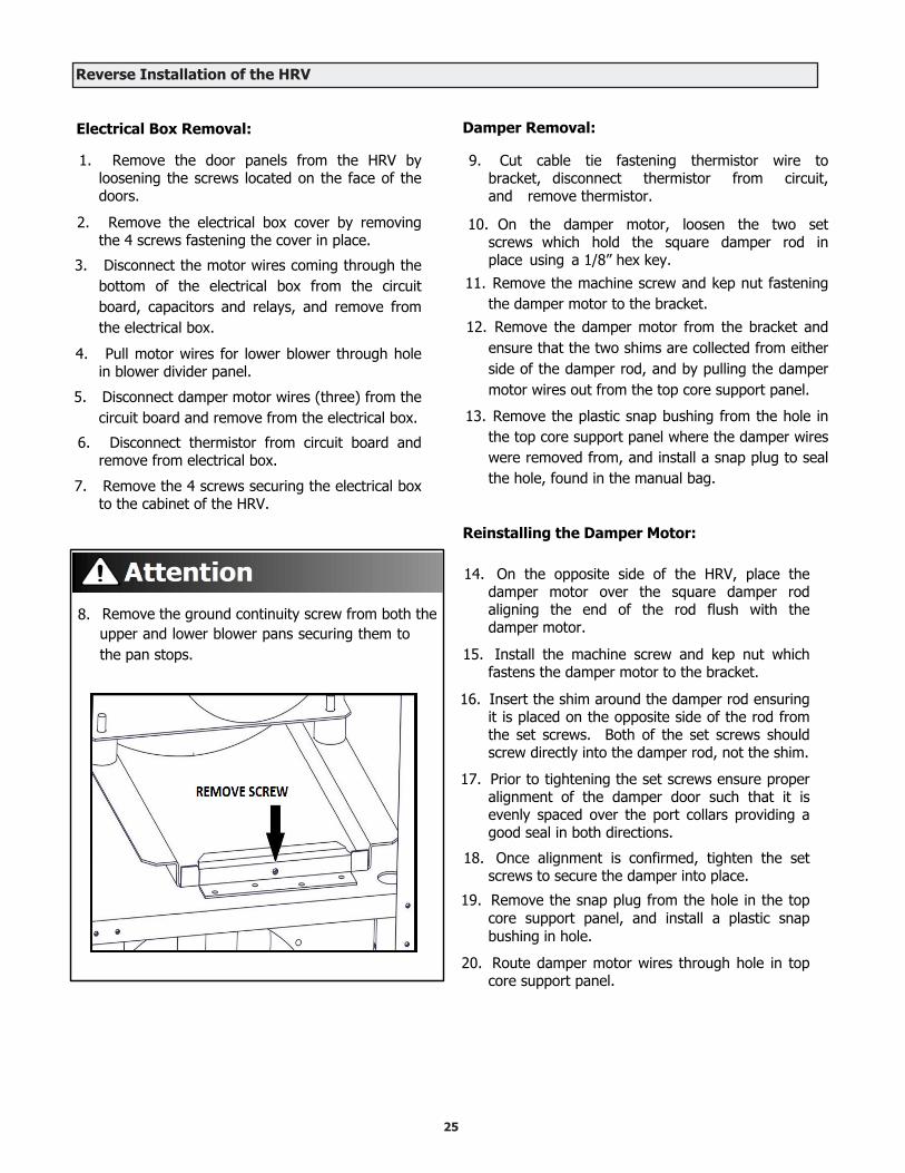
Electrical Box Removal:
1. Remove the door panels from the HRV byloosening the screws located on the face of thedoors.
2. Remove the electrical box cover by removingthe 4 screws fastening the cover in place.
3. Disconnect the motor wires coming through thebottom of the electrical box from the circuitboard, capacitors and relays, and remove fromthe electrical box.
4. Pull motor wires for lower blower through holein blower divider panel.
5. Disconnect damper motor wires (three) from thecircuit board and remove from the electrical box.
6. Disconnect thermistor from circuit board andremove from electrical box.
7. Remove the 4 screws securing the electrical boxto the cabinet of the HRV.
8. Remove the ground continuity screw from both theupper and lower blower pans securing them tothe pan stops.
25
14. On the opposite side of the HRV, place thedamper motor over the square damper rodaligning the end of the rod flush with thedamper motor.
15. Install the machine screw and kep nut whichfastens the damper motor to the bracket.
16. Insert the shim around the damper rod ensuringit is placed on the opposite side of the rod fromthe set screws. Both of the set screws shouldscrew directly into the damper rod, not the shim.
17. Prior to tightening the set screws ensure properalignment of the damper door such that it isevenly spaced over the port collars providing agood seal in both directions.
18. Once alignment is confirmed, tighten the setscrews to secure the damper into place.
19. Remove the snap plug from the hole in the topcore support panel, and install a plastic snapbushing in hole.
20. Route damper motor wires through hole in topcore support panel.
9. Cut cable tie fastening thermistor wire tobracket, disconnect thermistor from circuit,and remove thermistor.
10. On the damper motor, loosen the two setscrews which hold the square damper rod inplace using a 1/8” hex key.
11. Remove the machine screw and kep nut fasteningthe damper motor to the bracket.
12. Remove the damper motor from the bracket andensure that the two shims are collected from eitherside of the damper rod, and by pulling the dampermotor wires out from the top core support panel.
13. Remove the plastic snap bushing from the hole inthe top core support panel where the damper wireswere removed from, and install a snap plug to sealthe hole, found in the manual bag.
Reinstalling the Electrical Box:
21. Remove the two snap plugs from the oppositeside of the cabinet for electrical and control wires.
22. Install the two snap plugs in the cabinet holes onthe side of the HRV which electrical box wasoriginally removed from.
23. Route wires for both blower motors to oppositeside of HRV cabinet where electrical box is to beinstalled.
24. Install the grounding continuity screw in boththe upper and lower blower assemblies on theopposite side of the HRV where electrical boxis now installed.
25. Fasten the electrical box to the cabinet ofthe HRV using the 4 screws that werepreviously removed.
26. Remove the snap plug from the blower dividerpanel and install plastic snap bushing providedin manual bag.
27. Install snap plug in hole in blower dividerpanel where lower blower motor wires wereoriginally removed from.
28. Route the lower blower motor wires through thehole in the divider panel into the electrical box.
29. Route upper motor wires into the electrical box.
30. Route damper motor wires into e-box andconnect the motor wires to the circuit board,relays and capacitors using wiring diagram foundin manual for reverse installations.
31. Connect damper motor wires to circuit boardusing wiring diagram found in manual for reverseinstallations.
32. Route thermistor wire from electrical box,through hole in the top core support panel,and secure the blue end to the thermistorbracket in front of the damper motor using aplastic cable tie.
33. Connect the thermistor to the circuit boardin the electrical box.
34. Putty holes closed in blower divider panel andtop core support panel with wires protrudingthrough.
35. Install the large single door panel on the nowback of the cabinet where electrical box wasremoved from and fasten using the eightmachine screws.
36. Reversing of the HRV is now complete.Continue with the installation of the HRV.
Reverse Installation of the HRV (Continued)
26

Aircom Relays Models AIR550, AIR750, AIR850, AIR1250
The Aircom circuit board has three available “dry contact” relays. Contact 3 is not available.Maximum 115V 10 amp resistive load.
Interlocking the HRV to an Air Handler with a Thermostat
Use contact 2 or 4 to interlock the HRV to an Air Handler or Furnace.Connecting the HRV as illustrated will ensure the Air Handler Blower Motor is operating whenever the HRV is ventilating.
T30T29T28
T43
SPARE
P2 P3
F2 MAX 2 amp
R 24Vac
Defrost
Freeze
K7 K1 K2K8
T31
T32
T33
T34
T35
T36
T37
T38
T39
T40
T41
T42
Contact 1
N.0. COM N.C. N.0. COM N.C. N.0. COM N.C. N.0 . COM
Contact 2 Contact 3 Contact 4
N.C
Contact 2 and 4These relays initiate whenever the HRV fans are operating.
T30 T31 T32 T33 T34 T35 T36 T37 T38 T39 T40 T41 T42T29
Contact 1
N.0. COM N.C. N.0. COM N.C. N.0. COM N.C. N.0 . COM N.C.
Contact 2 Contact 3 Contact 4
T28
T43
SPARE
P2 P3
F2 MAX 2 amp
R 24Vac
Defrost
Freeze
K7 K1 K2K8
R G W Y C
R G W Y
Air Handler/Furnace Terminal Strip
Thermostat
wireconnector
Consideration must be given to competing airflows when connecting the HRV in conjunction with an Air Handler/Furnace Blower system.
CAUTION
27
Models AIR550, AIR750, AIR850, AIR1250
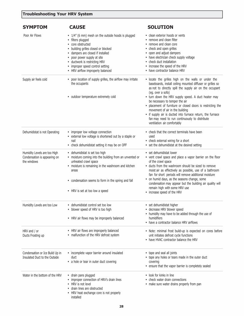
CAUSE SOLUTIONSYMPTOM
Poor Air Flows
Supply air feels cold
Dehumidistat is not Operating
Humidity Levels are too High Condensation is appearing on the windows
Humidity Levels are too Low
HRV and / orDucts Frosting up
Condensation or Ice Build Up in Insulated Duct to the Outside
Water in the bottom of the HRV
• 1/4” (6 mm) mesh on the outside hoods is plugged• filters plugged• core obstructed• building grilles closed or blocked• dampers are closed if installed• poor power supply at site• ductwork is restricting HRV• improper speed control setting• HRV airflow improperly balanced
• poor location of supply grilles, the airflow may irritatethe occupants
• outdoor temperature extremely cold
• improper low voltage connection• external low voltage is shortened out by a staple or
nail• check dehumidistat setting it may be on OFF
• dehumidistat is set too high• moisture coming into the building from an unvented or
unheated crawl space• moisture is remaining in the washroom and kitchen
areas
• condensation seems to form in the spring and fall
• HRV is set at too low a speed
• dehumidistat control set too low• blower speed of HRV is too high
• HRV air flows may be improperly balanced
• HRV air flows are improperly balanced• malfunction of the HRV defrost system
• incomplete vapor barrier around insulatedduct
• a hole or tear in outer duct covering
• drain pans plugged• improper connection of HRV’s drain lines• HRV is not level• drain lines are obstructed• HRV heat exchange core is not properly
installed
• clean exterior hoods or vents• remove and clean filter• remove and clean core• check and open grilles• open and adjust dampers• have electrician check supply voltage• check duct installation• increase the speed of the HRV• have contractor balance HRV
• locate the grilles high on the walls or under thebaseboards, install ceiling mounted diffuser or grilles soas not to directly spill the supply air on the occupant(eg. over a sofa)
• turn down the HRV supply speed. A duct heater maybe necessary to temper the air
• placement of furniture or closed doors is restricting themovement of air in the building
• if supply air is ducted into furnace return, the furnacefan may need to run continuously to distributeventilation air comfortably
• check that the correct terminals have beenused
• check external wiring for a short• set the dehumidistat at the desired setting
• set dehumidistat lower• vent crawl space and place a vapor barrier on the floor
of the crawl space• ducts from the washroom should be sized to remove
moist air as effectively as possible, use of a bathroomfan for short periods will remove additional moisture
• on humid days, as the seasons change, somecondensation may appear but the building air quality willremain high with some HRV use
• increase speed of the HRV
• set dehumidistat higher• decrease HRV blower speed• humidity may have to be added through the use of
humidifiers• have a contractor balance HRV airflows
• Note: minimal frost build-up is expected on cores beforeunit initiates defrost cycle functions
• have HVAC contractor balance the HRV
• tape and seal all joints• tape any holes or tears made in the outer duct
covering• ensure that the vapor barrier is completely sealed
• look for kinks in line• check water drain connections• make sure water drains properly from pan
Troubleshooting Your HRV System
28

T30
SW1
T29
T28
RED
OG
YW
RC
T25
T17
K3K4
K5
COM
N.O.
K6
COM
N.O.
COM
N.O.
COM
N.O.
T18
T19
T20
RELA
YFE
ED T43
SPAR
E
T26
T27
GRN
YEL
P2P3
R24
Vac
12Va
cCo
mTh
erm
osta
tDE
TC
Defrost
Freeze
Fan
HiFa
nM
edFa
nLo
w
ON
P1
C4C3
K7K1
K2K8
87
65
43
21
C2C1
T31
T32
T33
T34
T35
T36
T37
T38
T39
T40
T41T42
Cont
act1
N.0.
COM
N.C.
N.0.
COM
N.C.
N.0.
COM
N.C.
N.0
.COM
Cont
act2
Cont
act3
Cont
act4
Dig
italC
ontr
ols
DIP
SWIT
CHES
TOBE
AD
JUST
EDBY
QU
ALI
FIED
TECH
NIC
IAN
SO
NLY
.
SEU
LU
NTE
CHN
ICIE
NQ
UA
LIFI
ÉPE
UT
AJU
STÉ
LES
COM
MU
TATE
URS
DIP
.
N.C
Tran
sfor
mer
12/2
4Vac
Fan
Low
erFa
nU
pper
Com
mer
cial
Wiri
ngD
iagr
amfo
rFan
Def
rost
Doo
rSw
itch
BLAC
KBL
ACK
WHI
TE
GND
BLAC
K
BLUE
BLAC
K
BLUE
RED
RED
WHI
TE
BLUE
BLAC
K
BLAC
K
WHI
TE
BLAC
K
98-F
D-0
2
THER
MIS
TOR
BLACK
COM
N.O.
COM
N.O.
COM
N.O.
RED
BLAC
K
WHI
TE
RED
BLUE
BLAC
K
WHI
TE
CHA
SSIS
T44
T3T4
T5T6
Line
/Lig
ne
T1T2
T13
T14
T15
T16
Neu
tral
/Neu
tre
T11
T12
2A
MPS
T21
T22
T23
T24
AU
X1
AU
X2
Fan Defrost Wiring Diagram Model AIR550-F, AIR850-F
29

98-D
D-0
1
T30
SW
1
T29
T28
RE
DO
GY
WR
CT2
5
T17
K3
K4
K5
CO
M
N.O
.
K6
CO
M
N.O
.
CO
M
N.O
.
CO
M
N.O
.
T18
T19
T20
RE
LAY
FEE
D
T43
SPA
RE
T26
T27
GR
NY
EL
P2
P3
R24
Vac
12Va
cC
omTh
erm
osta
tD
ET
C
Defrost
Freeze
Fan
Hi
Fan
Med
Fan
Low
ON
P1
C4
C3
K7K1
K2K8
87
65
43
21
C2
C1
T31
T32
T33
T34
T35
T36
T37
T38
T39
T40
T41T42
Con
tact
1
N.0
.C
OM
N.C
.N
.0.
CO
MN
.C.
N.0
.C
OM
N.C
.N
.0.C
OM
Con
tact
2C
onta
ct3
Con
tact
4
Dig
ital
Co
ntr
ols
DIP
SW
ITC
HE
STO
BE
AD
JUS
TE
DB
YQ
UA
LIF
IED
TE
CH
NIC
IAN
SO
NLY
.
SE
UL
UN
TE
CH
NIC
IEN
QU
AL
IFIÉ
PE
UT
AJU
ST
ÉL
ES
CO
MM
UTA
TE
UR
SD
IP.
N.C
Tran
sfo
rmer
12/2
4Vac
Fan
Up
per
Fan
Lo
wer
Co
mm
erci
alW
irin
gD
iag
ram
for
Dam
per
Def
rost
Doo
rS
witc
h
BLA
CK
BLA
CK
BLA
CK
BLA
CK
WH
ITE
GN
D
TH
ER
MIS
TOR
CW
CC
WC
OM
RED
RE
D
YELLOW
RE
D
WH
ITE
BLU
E
BLA
CK
WH
ITE
WH
ITE
BLACK
BLUE
BLA
CK
BLU
E
RE
D
RE
D
N.O
.N
orm
ally
op
en
N.C
.N
orm
ally
clo
sed
CO
MC
om
mo
n
T#
Term
inal
P#
Plu
g
K#
Rel
ay
F#
Fu
se
SW
#S
wit
ch
CH
AS
SIS
T44
T3T4
T5T6
Line
/Lig
ne
T1T2
T13
T14
T15
T16
Neu
tral
/Neu
tre
T11
T12
T21
T22
T23
T24
2A
MP
S
AU
X1
AU
X2
Damper Defrost Wiring Diagram Models AIR550-D, AIR850-D
30
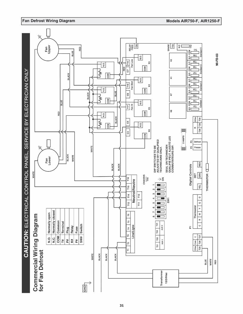
Fan Defrost Wiring Diagram Models AIR750-F, AIR1250-F
31

Damper Defrost Wiring Diagram Models AIR750-D, AIR1250-D
32
COMMERCIAL AIRFLOW® HEAT RECOVERY VENTILATORS
• 2 Year Limited Warranty • 15 Year HRV Core Warranty
AIRIA BRANDS INC.® (AIRIA) warrants to the original purchaser of the Commercial AIRFLOW®
model and accessories referred to below, to be free from manufacturing defects.This Warranty is personal to AIRIA® and is in effect from the date of the original
purchase for a period of two years, save and except that a 15 YEAR WARRANTY is given to the AIRFLOW® HRV core should it develop a condensation leak or become damaged during normal use.
Damage resulting from all other causes, including but not limited to: lightning, hurricane, tornado, earthquake or any other acts of God; improper installation, modification, alteration or misuse of the AIRFLOW® or its operation in a manner contrary to the instructions accompanying the unit at the time of sale; accidental or intentional damage, neglect, improper care, or other failure by the owner to provide reasonable and necessary maintenance of the product; any attempt at repair by an unauthorized service representative or not in accordance with this warranty; or any other causes beyond the control of AIRIA®, are excluded from this warranty.
If you feel that the AIRFLOW® you purchased is not free from manufacturing defects, please contact AIRIA BRANDS INC.®, 511 McCormick Blvd., London, Ontario N5W 4C8, 519-457-1904 or fax 519-457-1676 to find the name of your nearest dealer in order to repair the product. The labour required to install any replacement part(s) shall be dealt with at the option of the customer in either of the following ways:
(a) the customer may supply labour at their own expense: or(b) if the product was purchased from a dealer, then the dealermay supply labour at cost to the customer.
AIRIA® reserves the right to replace the entire unit or to refund the original purchase price in lieu of repair.AIRIA® MAKES NO EXPRESS WARRANTIES, EXCEPT FOR THOSE THAT ARE SET FORTH HEREIN AND SHALL NOT BE LIABLE FOR ANY INCIDENTAL, SPECIAL OR CONSEQUENTIAL DAMAGES WITH RESPECT TO AIRFLOW® COVERED BY THIS WARRANTY. AIRIA’S COMPLETE LIABILITY AND THE OWNER’S EXCLUSIVE REMEDY BEING LIMITED TO REPAIR OR REPLACEMENT ON THE TERMS STATED HEREIN. ANY IMPLIED WARRANTIES, INCLUDING BUT NOT LIMITED TO THE IMPLIED WARRANTY OF MERCHANTABILITY AND OF FITNESS FOR ANY PARTICULAR PURPOSE, ARE EXPRESSLY EXCLUDED.NO PERSON IS AUTHORIZED TO CHANGE THE WARRANTY IN ANY WAY OR GRANT ANY OTHER WARRANTY UNLESS SUCH CHANGES ARE MADE IN WRITING AND SIGNED BY AN OFFICER OF AIRIA®.
MODEL NO.: ____________________________________________________________________
UNIT SERIAL NO.:________________________________________________________________
INSTALLED BY: _________________________________________________________________
DATE:__________________________________________________________________________
TI-38HRV/ERV
33

34

35