65bdl4510d_00_dfu_eng.pdf - Support location selector
43
www.philips.com/welcome User Manual (English) Professional Display Solutions D Line 65BDL4510D/75BDL4510D 86BDL4510D
-
Upload
khangminh22 -
Category
Documents
-
view
5 -
download
0
Transcript of 65bdl4510d_00_dfu_eng.pdf - Support location selector

www.philips.com/welcomeUser Manual (English)
ProfessionalDisplay Solutions
D Line
65BDL4510D/75BDL4510D86BDL4510D

65BDL4510D_75BDL4510D_86BDL4510D
ii
Safety Instructions
Safety precautions and maintenance
WARNING: Use of controls, adjustments or procedures other than those specified in this documentation may result in exposure to shock, electrical hazards and/or mechanical hazards.
Read and follow these instructions when connecting and using your display:
Operation:
• Keep the display out of direct sunlight and away from stoves or any other heat sources.
• Keep the display away from oil, otherwise the plastic cover may be damaged.
• It is recommended to set the display up in the well-ventilated place.
• Ultra-violet ray filter is necessary of outdoor operation.
• If the product will be used in extreme conditions such as high temperature, humidity, display patterns or operation time etc... It is strongly recommended to contact Philips for Application engineering advice. Otherwise, its reliability and function may not be guaranteed. Extreme conditions are commonly found at Airports, Transit Stations, Banks, Stock market, and Controlling systems.
• Remove any object that could fall into ventilation holes or prevent proper cooling of the display’s electronics.
• Do not block the ventilation holes on the cabinet.
• When positioning the display, make sure the power plug and outlet are easily accessible.
• When turning off the display by detaching the power cord, wait 6 seconds before re-attaching the power cord for normal operation.
• Ensure the use of an approved power cord provided by Philips at all times. If your power cord is missing, please contact your local service center.
• Do not subject the display to severe vibration or high impact conditions during operation.
• Do not knock or drop the display during operation or transportation.
• The eye bolt is for usage in short-time maintenance and installation. We suggest not to use the eye bolt for more than 1 hour. Prolong usage is prohibited. Please keep a clear safety area under the display while using the eye bolt.
Maintenance:
• To protect your display from possible damage, do not put excessive pressure on the LCD panel. When moving your display, grasp the frame to lift; do not lift the display by placing your hand or fingers on the LCD panel.
• Unplug the display if you are not going to use it for an extensive period of time.
• Unplug the display if you need to clean it with a slightly damp cloth. The screen may be wiped with a dry cloth when the power is off. However, never use organic solvent, such as, alcohol, or ammonia-based liquids to clean your display.
• To avoid the risk of shock or permanent damage to the set, do not expose the display to dust, rain, water or an excessively moist environment.
• If your display becomes wet, wipe it with dry cloth as soon as possible.
• If a foreign substance or water gets in your display, turn the power off immediately and disconnect the power cord. Then remove the foreign substance or water, and send the unit to the maintenance center.
• Do not store or use the display in locations exposed to heat, direct sunlight or extreme cold.
• In order to maintain the best performance of your display and ensure a longer lifetime, we strongly recommend using the display in a location that falls within the following temperature and humidity ranges.
Environmental absolute ratings
Item Min. Max. UnitStorage temperature -20 65 °C
Operation temperature 0 40 °C
Glass Suraface temperature (Operation)
0 65 °C
Storage humidity 5 90 % RH
Operating humidity 20 80 % RH
• LCD panel temperature need to be 25 degrees Celsius at all time for better luminance performance.

65BDL4510D_75BDL4510D_86BDL4510D
iii
• Only the lifetime of the display stated in this specification is guaranteed if the display is used under the proper operation conditions.
IMPORTANT: Always activate a moving screen saver program when you leave your display unattended. Always activate a periodic screen refresh application if the unit will display unchanging static content. Uninterrupted display of still or static images over an extended period may cause “burn in”, also known as “after-imaging” or “ghost imaging”, on your screen. This is a well-known phenomenon in LCD panel technology. In most cases, the “burned in” or “after-imaging” or “ghost imaging” will disappear gradually over a period of time after the power has been switched off.
WARNING: Severe “burn-in” or “after-image” or “ghost image” symptoms will not disappear and cannot be repaired. This is also not covered under the terms of your warranty.
Service:
• The casing cover should be opened only by qualified service personnel.
• If there is any need for repair or integration, please contact your local service center.
• Do not leave your display under direct sunlight.
If your display does not operate normally, having followed the instructions set out in this document, please contact a technician or your local service center.
Stability Hazard.
The device may fall, causing serious personal injury or death. To prevent injury, this device must be securely attached to the floor/wall in accordance with the installation instructions.
Read and follow these instructions when connecting and using your display:
• Unplug the display if you are not going to use it for an extensive period of time.
• Unplug the display if you need to clean it with a slightly damp cloth. The screen many be wiped with a dry cloth when the power is off. However, never use alcohol, solvents or ammonia-based liquids.
• Consult a service technician if the display does not operate normally when you have followed the instructions in this manual.
• The casing cover should be opened only by qualified service personnel.
• Keep the display out of direct sunlight and away from stoves or any other heat sources.
• Remove any object that could fall into the vents or prevent proper cooling of the display’s electronics.
• Do not block the ventilation holes on the cabinet.
• Keep the display dry. To avoid electric shock, do not expose it to rain or excessive moisture.
• When turning off the display by detaching the power cable or DC power cord, wait for 6 seconds before re-attaching the power cable or DC power cord for normal operation..
• To avoid the risk of shock or permanent damage to the set do not expose the display to rain or excessive moisture.
• When positioning the display, make sure the power plug and outlet are easily accessible.
• IMPORTANT: Always activate a screen saver program during your application. If a still image in high contrast remains on the screen for an extended period of time, it may leave an ‘after-image’ or ‘ghost image’ on the front of the screen. This is a well-known phenomenon that is caused by the shortcomings inherent in LCD technology. In most cases the afterimage will disappear gradually over a period of time after the power has been switched off. Be aware that the after-image symptom cannot be repaired and is not covered under warranty.
• If provided with a 3-pin attachment plug on the power cord, plug the cord into a grounded (earthed) 3-pin outlet. Do not disable the power cord grounding pin, for example, by attaching a 2-pin adapter. The grounding pin is an important safety feature.
EU Declaration of ConformityThis device complies with the requirements set out in the Council Directive on the Approximation of the Laws of the Member States relating to Electromagnetic Compatibility (2014/30/EU), Low-voltage Directive (2014/35/EU), RoHS directive (2011/65/EU), ErP directive (2009/125/EC).
This product has been tested and found to comply with the harmonized standards for Information Technology Equipment, these harmonized standards published under Directives of Official Journal of the European Union.
ESD Warnings
When user close to the monitor may cause the equipment discharge and reboot to the display of main menu.

65BDL4510D_75BDL4510D_86BDL4510D
iv
Warning:
This equipment is compliant with Class A of EN55032/CISPR 32. In a residential environment this equipment may cause radio interference.
Federal Communications Commission (FCC) Notice (U.S. Only)
NOTE: This equipment has been tested and found to comply with the limits for a Class A digital device, pursuant to part 15 of the FCC Rules. These limits are designed to provide reasonable protection against harmful interference when the equipment is operated in a commercial environment. This equipment generates, uses, and can radiate radio frequency energy and, if not installed and used in accordance with the instruction manual, may cause harmful interference to radio communications. Operation of this equipment in a residential area is likely to cause harmful interference in which case the user will be required to correct the interference at his own expense.
Changes or modifications not expressly approved by the party responsible for compliance could void the user’s authority to operate the equipment.
Use only an RF shielded cable that was supplied with the display when connecting this display to a computer device.
To prevent damage which may result in fire or shock hazard, do not expose this appliance to rain or excessive moisture.
This device complies with Part 15 of the FCC Rules. Operation is subject to the following two conditions: (1) This device may not cause harmful interference, and (2) this device must accept any interference received, including interference that may cause undesired operation.
Envision Peripherals Inc. 490 N McCarthy Blvd, Suite #120 Milpitas, CA 95035 USA

65BDL4510D_75BDL4510D_86BDL4510D
v
Polish Center for Testing and Certification NoticeThe equipment should draw power from a socket with an attached protection circuit (a three-prong socket). All equipment that works together (computer, display, printer, and so on) should have the same power supply source.
The phasing conductor of the room’s electrical installation should have a reserve short-circuit protection device in the form of a fuse with a nominal value no larger than 16 amperes (A).
To completely switch off the equipment, the power supply cable must be removed from the power supply socket, which should be located near the equipment and easily accessible.
A protection mark “B” confirms that the equipment is in compliance with the protection usage requirements of standards PN-93/T-42107 and PN-89/E-06251.
Electric, Magnetic and Electromagnetic Fields (“EMF”)1. We manufacture and sell many products targeted at consumers, which, like any electronic apparatus, in general have the
ability to emit and receive electromagnetic signals.
2. One of our leading Business Principles is to take all necessary health and safety measures for our products, to comply with all applicable legal requirements and to stay well within the EMF standards applicable at the time of producing the products.
3. We are committed to develop, produce and market products that cause no adverse health effects.
4. We confirm that if its products are handled properly for their intended use, they are safe to use according to scientific evidence available today.
5. We play an active role in the development of international EMF and safety standards, enabling us to anticipate further developments in standardization for early integration in its products.

65BDL4510D_75BDL4510D_86BDL4510D
vi
Information for U.K. only
(A)
(B)WARNING - THIS APPLIANCE MUST BE EARTHED.
Important:
This apparatus is supplied with an approved moulded 13A plug. To change a fuse in this type of plug proceed as follows:+
1. Remove fuse cover and fuse.
2. Fit new fuse which should be a BS 1362 5A,A.S.T.A. or BSI approved type.
3. Refit the fuse cover.
If the fitted plug is not suitable for your socket outlets, it should be cut off and an appropriate 3-pin plug fitted in its place.
If the mains plug contains a fuse, this should have a value of 5A. If a plug without a fuse is used, the fuse at the distribution board should not be greater than 5A.
NOTE: The severed plug must be destroyed to avoid a possible shock hazard should it be inserted into a 13A socket elsewhere.
How to connect a plug
The wires in the mains lead are coloured in accordance with the following code:BLUE - “NEUTRAL” (“N”)
BROWN - “LIVE” (“L”)
GREEN & YELLOW - “EARTH” (“E”)
1. The GREEN & YELLOW wire must be connected to the terminal in the plug which is marked with the letter “E” or by the Earth symbol or coloured GREEN or GREEN & YELLOW.
2. The BLUE wire must be connected to the terminal which is marked with the letter “N” or coloured BLACK.
3. The BROWN wire must be connected to the terminal which marked with the letter “L” or coloured RED.
Before replacing the plug cover, make certain that the cord grip is clamped over the sheath of the lead - not simply over the three wires.
North Europe (Nordic Countries) Information
Placering/Ventilation
VARNING:
FÖRSÄKRA DIG OM ATT HUVUDBRYTARE OCH UTTAG ÄR LÄTÅTKOMLIGA, NÄR DU STÄLLER DIN UTRUSTNING PÅPLATS.
Placering/Ventilation
ADVARSEL:
SØRG VED PLACERINGEN FOR, AT NETLEDNINGENS STIK OG STIKKONTAKT ER NEMT TILGÆNGELIGE.
Paikka/Ilmankierto
VAROITUS:
SIJOITA LAITE SITEN, ETTÄ VERKKOJOHTO VOIDAAN TARVITTAESSA HELPOSTI IRROTTAA PISTORASIASTA.
Plassering/Ventilasjon
ADVARSEL:
NÅR DETTE UTSTYRET PLASSERES, MÅ DU PASSE PÅ AT KONTAKTENE FOR STØMTILFØRSEL ER LETTE Å NÅ.

65BDL4510D_75BDL4510D_86BDL4510D
vii
China RoHS
根据中国大陆《电器电子产品有害物质限制使用管理办法》,以下部分列出了本产品中可能包含的有害物质的名称和含量。
部件名称
有害物质
铅(Pb)
汞(Hg)
镉(Cd)
六价铬(Cr (VI))
多溴联苯 (PBB)
多溴二苯醚(PBDE)
外壳 O O O O O O
液晶显示屏 X O O O O O
电路板组件* X O O O O O
电源适配器 X O O O O O
电源线/连接线 X O O O O O
遥控器 X O O O O O
本表格依据SJ/T 11364 的规定编制。
*: 电路板组件包括印刷电路板及其构成的零部件,如电阻、电容、集成电路、连接器等。
O: 表示该有害物质在该部件所有均质材料中的含量均在 GB/T 26572规定的限量要求以下。
X: 表示该有害物质至少在该部件的某一均质材料中的含量超出GB/T 26572规定的限量要求。
上表中打“X”的部件,应功能需要,部分有害物质含量超出GB/T 26572规定的限量要求,但符合欧盟RoHS法规要求(属于豁免部分)。
备注:上表仅做为范例,实际标示时应依照各产品的实际部件及所含有害物质进行标示。
10环保使用期限
此标识指期限 ( 十年 ),电子电气产品中含有的有害物质在正常使用的条件下不会发生外泄或突变,电子电气产品用户使用该电子电气产品不会对环境造成严重污染或对其人身、财产造成严重损害的期限。
《废弃电器电子产品回收处理管理条例》提示性说明
为了更好地关爱及保护地球,当用户不再需要此产品或产品寿命终止时,请遵守国家废弃电器电子产品回收处理相关法律法规,将其交给当地具有国家认可的回收处理资质的厂商进行回收处理,不当利用或者处置可能会对环境和人类健康造成影响。
警告 此为 A 级产品。在生活环境中,该产品可能会造成无线电干扰。在这种情况下,可能需要用户对干扰采取切实可行的措施。

65BDL4510D_75BDL4510D_86BDL4510D
viii
單元
限用物質及其化學符號
鉛 (Pb)
汞 (Hg)
鎘 (Cd)
六價鉻 (Cr+6)
多溴聯苯 (PBB)
多溴二苯醚(PBDE)
塑料外框 ○ ○ ○ ○ ○ ○
後殼 ○ ○ ○ ○ ○ ○
液晶面板 - ○ ○ ○ ○ ○
電路板組件 - ○ ○ ○ ○ ○
電源線 - ○ ○ ○ ○ ○
其他線材 - ○ ○ ○ ○ ○
遙控器 - ○ ○ ○ ○ ○
喇叭(選配) - ○ ○ ○ ○ ○
風扇(選配) - ○ ○ ○ ○ ○
備考1.〝○〞係指該項限用物質之百分比含量未超出百分比含量基準值。
備考2.〝-〞係指該項限用物質為排除項目。
警語 : 使用過度恐傷害視力。
注意事項 :
(1) 使用30分鐘請休息10分鐘。
(2) 未滿2歲幼兒不看螢幕,2歲以上每天看螢幕不要超過1小時。
警告使用者 :
此為甲類資訊技術設備 ,於居住環境中使用時 ,可能會造成射頻擾動 ,在此種情況下 ,使用者會被要求採取某些適當的對策。
Turkey RoHS:Türkiye Cumhuriyeti: EEE Yönetmeliğine Uygundur
Ukraine RoHS:Обладнання відповідає вимогам Технічного регламенту щодо обмеження використання деяких небезпечних речовин в електричному та електронному обладнанні, затвердженого постановою Кабінету Міністрів України від 3 грудня 2008 № 1057
End-of-Life DisposalYour new Public Information Display contains materials that can be recycled and reused. Specialized companies can recycle your product to increase the amount of reusable materials and to minimize the amount to be disposed of.
Please find out about the local regulations on how to dispose of your old display from your local Philips dealer.
(For customers in Canada and U.S.A.)
This product may contain lead and/or mercury. Dispose of in accordance to local-state and federal regulations. For additional information on recycling contact www.eia.org (Consumer Education Initiative)

65BDL4510D_75BDL4510D_86BDL4510D
ix
Waste Electrical and Electronic Equipment-WEEEAttention users in European Union private households
This marking on the product or on its packaging illustrates that, under European Directive 2012/19/EU governing used electrical and electronic appliances, this product may not be disposed of with normal household waste. You are responsible for disposal of this equipment through a designated waste electrical and electronic equipment collection. To determine the locations for dropping off such waste electrical and electronic, contact your local government office, the waste disposal organization that serves your household or the store at which you purchased the product.
Attention users in United States:
Please dispose of according to all Local, State and Federal Laws. For the disposal or recycling information, contact: www.mygreenelectronics.com or www.eiae.org.
End of Life Directives-Recycling
Your new Public Information Display contains several materials that can be recycled for new users.
Please dispose of according to all Local, State, and Federal laws.
75BDL4510D:
ENERGY STAR is a program run by the U.S. Environmental Protection Agency (EPA) and U.S. Department of Energy (DOE) that promotes energy efficiency.
This product qualifies for ENERGY STAR in the “factory default” settings and this is the setting in which power savings will be achieved.
Changing the factory default picture settings or enabling other features will increase power consumption that could exceed the limits necessary to qualify for ENERGY STAR rating.
For more information on the ENERGY STAR program, refer to energystar.gov.
Restriction on Hazardous Substances statement (India)
This product complies with the “E-Waste (Management) Rules, 2016” CHAPTER V, rule 16, sub-rule (1) . Whereas New Electrical and Electronic Equipment and their components or consumables or parts or spares do not contain Lead, Mercury, Cadmium, Hexavalent Chromium, polybrominated biphenyls and polybrominated diphenyl ethers beyond a maximum concentration value of 0.1% by weight in homogenous materials for lead, mercury, hexavalent chromium, polybrominated biphenyls and polybrominated diphenyl ethers and of 0.01% by weight in homogenous materials for cadmium. except of exemptions set in Schedule 2 of the Rule.
E-Waste Declaration for India
This symbol on the product or on its packaging indicates that this product must not be disposed of with your other household waste. Instead it is your responsibility to dispose of your waste equipment by handing it over to a designated collection point for the recycling of waste electrical and electronic equipment . The separate collection and recycling of your waste equipment at the time of disposal will help to conserve natural resources and ensure that it is recycled in a manner that protects human health and the environment. For more information about E -waste please visit http://www.india.philips.com/about/sustainability/recycling/index.page and to know where you can drop off your waste equipment for recycling in India please contact on below given contact details.
Helpline number: 1800-425-6396 (Monday to Saturday, 9 a.m. to 5:30 pm)
E-mail: [email protected]

65BDL4510D_75BDL4510D_86BDL4510D
x
Batteries
For EU: The crossed-out wheeled bin implies that used batteries should not be put to the general household waste! There is a separate collection system for used batteries, to allow proper treatment and recycling in accordance with legislation.
Please contact your local authority for details on the collection and recycling schemes.
For Switzerland: The used battery is to be returned to the selling point.
For other non-EU countries: Please contact your local authority for correct method of disposal of the used battery.
According to EU directive 2006/66/EC, the battery can’t be disposed improperly. The battery shall be separated to collect by local service.
Após o uso, as pilhasdeverão ser entregues aoestabelecimento comercial ou
e/ou baterias
rede de assistência técnicaautorizada.
Information for EAC
Month and year of manufacturing please refer information in Rating label.
Name and location of manufacturerООО “Профтехника”Адрес: 3-й Проезд Марьиной рощи, 40/1 офис 1. Москва, 127018, Россия
Importer and information
Наименование организации: ООО “Профтехника”Адрес: 3-й Проезд Марьиной рощи, 40/1 офис 1. Москва, 127018, РоссияКонтактное лицо: Наталья Астафьева, +7 495 640 20 [email protected]

65BDL4510D_75BDL4510D_86BDL4510D
xi
Table Of Contents
1. Unpacking and Installation ........................................ 1
1.1. Unpacking ........................................................... 1
1.2. Package Contents ............................................. 1
1.3. Installation Notes .............................................. 1
1.4. Mounting on a Wall ......................................... 2
1.4.1. VESA Grid ............................................. 2
1.5. Mounting in Portrait Orientation .................. 3
1.5.1. How to remove the logo ................... 3
2. Parts and Functions ....................................................4
2.1. Control Panel ....................................................4
2.2. Input/Output Terminals.................................. 5
2.3. Remote Control ................................................ 7
2.3.1. General functions ............................... 7
2.3.2. ID Remote Control .............................8
2.3.3. Inserting the batteries in the remote control ...................................................9
2.3.4. Handling the remote control ...........9
2.3.5. Operating range of the remote control ...................................................9
2.4. USB Cover ........................................................ 10
2.5. AC Switch Cover ...............................................11
3. Connecting External Equipment ............................12
3.1. Connecting External Equipment (DVD/VCR/VCD)..........................................................12
3.1.1. Using HDMI video input ...................12
3.2. Connecting a PC ..............................................12
3.2.1. Using DVI input ..................................12
3.2.2. Using HDMI input ..............................12
3.2.3. Using DP input ....................................13
3.3. Connecting Multiple Displays in a Daisy-chain Configuration ........................................13
3.3.1. Display control connection .............13
3.4. IR connection ...................................................13
3.5. IR Pass-through Connection ........................14
3.6. Wire-connecting to Network .......................14
4. Operation ....................................................................15
4.1. Play multimedia files from USB device ......15
5. OSD Menu ...................................................................16
5.1. Navigating the OSD Menu .............................16
5.1.1. Navigating the OSD menu using the remote control ...................................16
5.1.2. Navigating the OSD menu using the display’s control buttons .................16
5.2. OSD Menu Overview ......................................16
5.2.1. Picture menu ......................................16
5.2.2. Screen menu ......................................17
5.2.3. Audio ....................................................18
5.2.4. Configuration1 menu .........................18
5.2.5. Configuration2 menu ........................19
5.2.6. Option ................................................ 20
6. Supported Media Formats .....................................23
7. Input Mode .................................................................24
8. Pixel Defect Policy ....................................................25
8.1. Pixels and Sub-Pixels ...................................25
8.2. Types of Pixel Defects + Dot Definition ....25
8.3. Bright Dot Defects ..........................................25
8.4. Dark Dot Defects ............................................26
8.5. Proximity of Pixel Defects ............................26
8.6. Pixel Defect Tolerances ................................26
8.7. MURA ................................................................26
9. Cleaning and Troubleshooting ...............................27
9.1. Cleaning ...........................................................27
9.2. Troubleshooting .............................................28
10. Warranty Statement .................................................29
11. Technical Specifications ......................................... 30

65BDL4510D_75BDL4510D_86BDL4510D
1
1. Unpacking and Installation
1.1. Unpacking• This product is packed in a carton, together with the standard accessories.
• Any other optional accessories will be packed separately.
• As this product is high and heavy, the operation of moving the device is recommended to be performed by two technicians.
• After opening the carton, ensure that the contents are complete and in good condition.
1.2. Package ContentsPlease verify that you received the following items with your package content:
• LCD display
• Quick start guide
• Remote control with AAA batteries
• Power cord
• RS232 cable
• RS232 daisy chain cable
• IR Sensor cable
• AC Switch cover
• USB cover
• Philips logo plate
* The supplied power cord varies depending on destination.
Quick start guide Remote Control and AAA Batteries
LCD display
FORMATSOURCE
INFOLIST
OPTIONSADJUST
VOL
NORMAL ID
ID SET ENTER
RS232 Daisy Chain CableRS232 Cable
USB Cover x 1
Power Cord
Philips logo plate AC Switch Cover x 1IR Sensor Cable
* Differences according to regions.
Display design and accessories may differ from those illustrated above.
NOTES:
• For all other regions, apply a power cord that conforms to the AC voltage of the power socket and has been approved by and complies with the safety regulations of the particular country.
• You might like to save the package box and packing material for shipping the display.
1.3. Installation Notes• Only use the power cable provided with this product. If an extension cord is required, please consult your service agent.
• The product should be installed on a flat surface, or the product may tip over. Leave a space between the rear of the product and the wall for proper ventilation. Do not install the product in a kitchen, bathroom or a place exposed to moisture, failure to do so may shorten the life of the internal parts.
• Do not install the product where it is 3000m and higher in altitude. Failure to do so may result in malfunctions.

65BDL4510D_75BDL4510D_86BDL4510D
2
1.4. Mounting on a WallTo mount this display on a wall, a standard wall-mounting kit (commercially available) is required. It is recommended that you use a mounting interface that complies with TUV-GS and /or UL1678 standard in North America.
Protective Sheet
Table
VESA Grid
1. Spread a protective sheet which was wrapped around the display when it was packed on a flat surface. Lay the display face-down on the protective sheet to facilitate your operation without scratching the screen.
2. Ensure that you have all accessories necessary for any type of mounting (wall-mounting, ceiling mounting etc).
3. Follow the instructions that come with the base mounting kit. Failure to follow correct mounting procedures could result in damage to the equipment or injury to the user or installer. Product warranty does not cover damage caused by improper installation.
4. For the wall-mounting kit, use M8 mounting screws (with a length 15 mm longer than the thickness of the mounting bracket) and tighten them securely.
1.4.1. VESA Grid
65BDL4510D 400(H) x 400(V) mm
75BDL4510D 600(H) x 400(V) mm
86BDL4510D 600(H) x 400(V) mm
Caution:
To prevent the display from falling:
• For wall or ceiling mounting, we recommend that you install the display with metal brackets which are commercially available. For detailed instructions about the installation, refer to the guide that come with the bracket.
• To prevent the display from falling in case of earthquake or other natural disaster, please contact the manufacturer of the bracket for the mounting location.
Required space for ventilation
Leave a space of 100 mm at the top, rear, right and left for ventilation.
100 mm 100 mm
100 mm
100 mm

65BDL4510D_75BDL4510D_86BDL4510D
3
1.5. Mounting in Portrait OrientationThis display can be installed in portrait orientation.
Rotate the display 90 degrees Counterclockwise. The “ ” logo should be on the right side when facing the display.
90° 90°
1.5.1. How to remove the logo
1. Prepare a piece of paper with a cutting area of logo as a protector to prevent the front bezel from scratching.
2. Use a knife and carefully remove the logo sticker with the paper placing beneath.
3. Tear off the logo sticker.
1 2 3
NOTE: We recommend you contact a professional technician when installing the display on a wall. We are not responsible for any damage to the product if the installation is not performed by a professional technician.

65BDL4510D_75BDL4510D_86BDL4510D
4
2. Parts and Functions
2.1. Control Panel
1 2 3 4 5 6 7 8
9
1 [ ] buttonPress this button to turn the display On or turn the display to standby mode.
2 [MUTE] buttonPress this button to mute the sound or reactivate sound.
3 [INPUT] buttonChoose the input source.
Confirm a selection in the OSD menu.
4 [ ] buttonIncrease the adjustment while OSD menu is on, or increase the audio output level while OSD menu is off.
5 [ ] buttonDecrease the adjustment while OSD menu is on, or decrease the audio output level while OSD menu is off.
6 [ ] buttonMove the selected item one level up while the OSD menu is On.
7 [ ] buttonMove the selected item one level down while the OSD menu is On.
8 [MENU] buttonReturn to the previous menu while the OSD menu is On. This button can also be used to activate the OSD menu when the OSD menu is Off.
9 Remote control sensor and power status indicator• Receives command signals from the remote control.
• Indicates the operating status of the display:
- Lights green when the display is turned on
- Lights red when the display is in standby mode
- Lights amber when the display enters APM mode
- When {SCHEDULE} is enabled, the light blinks green and red
- If the light blinks red, it indicates that a failure has been detected
- Lights off when the main power of the display is turned off

65BDL4510D_75BDL4510D_86BDL4510D
5
2.2. Input/Output Terminals 65BDL4510D
100-240V 50/60Hz 2.5A
2 31 4 5 6 7 8 10 11 12
IR-IN
IR-OUT
PC LINE IN
USB 2.0
USBService Port
RJ45
AUDIO OUT
13
1514
16171819
RS232IN
RS232OUTHDMI OUTHDMI 2 INHDMI 1 IN
DP OUTDP INDVI-I IN
9
HDMI 3 IN
1 AC INAC power input from the wall outlet.
2 MAIN POWER SWITCHSwitch the main power between On and Off.
3 AC OUTAC power supply to the AC IN jack of a media player.
4 DisplayPort IN / 5 DisplayPort OUTDisplayPort video input / output.
6 DVI-I INDVI-I video input.
7 HDMI 1 IN / 8 HDMI 2 IN / 9 HDMI 3 IN / 10 HDMI OUT HDMI video/audio input /output
11 RS232 IN / 12 RS232 OUTRS232 network input / output for the loop-through function.
13 IR IN / 14 IR OUTIR signal input / output for the loop-through function.
NOTES: • This display’s remote control sensor will stop working
if the jack [IR IN] is connected.
• To remotely control your A/V device via this display, refer to page 14 for IR Pass Through connection.
15 AUDIO OUTAudio output to external AV device.
16 PC LINE INAudio input for VGA source (3.5mm stereo phone).
17 USB SERVICE PORTConnect to USB storage for main board Firmware update.
NOTE: It’s for updating firmware only.
18 USB 2.0 PORTConnect your USB storage device and service port.
19 RJ-45 INLAN control function for the use of remote control signal from control center.

65BDL4510D_75BDL4510D_86BDL4510D
6
75BDL4510D/86BDL4510D
2 31 4 5 6 7 8 10 11 12
IR-IN
IR-OUT
PC LINE IN
USB 2.0
USBService Port
RJ45
AUDIO OUT
13
1514
16171819
RS232IN
RS232OUTHDMI OUTHDMI 2 INHDMI 1 IN
DP OUTDP INDVI-I IN
9
HDMI 3 IN100-240V 50/60Hz 2.5A
1 AC OUTAC power supply to the AC IN jack of a media player.
2 AC INAC power input from the wall outlet.
3 MAIN POWER SWITCHSwitch the main power between On and Off.
4 DisplayPort IN / 5 DisplayPort OUTDisplayPort video input / output.
6 DVI-I INDVI-I video input.
7 HDMI 1 IN / 8 HDMI 2 IN / 9 HDMI 3 IN / 10 HDMI OUT HDMI video/audio input /output
11 RS232 IN / 12 RS232 OUTRS232 network input / output for the loop-through function.
13 IR IN / 14 IR OUTIR signal input / output for the loop-through function.
NOTES: • This display’s remote control sensor will stop working
if the jack [IR IN] is connected.
• To remotely control your A/V device via this display, refer to page 14 for IR Pass Through connection.
15 AUDIO OUTAudio output to external AV device.
16 PC LINE INAudio input for VGA source (3.5mm stereo phone).
17 USB SERVICE PORTConnect to USB storage for main board Firmware update.
NOTE: It’s for updating firmware only.
18 USB 2.0 PORTConnect your USB storage device and service port.
19 RJ-45 INLAN control function for the use of remote control signal from control center.

65BDL4510D_75BDL4510D_86BDL4510D
7
2.3. Remote Control
2.3.1. General functions
FORMATSOURCE
INFOLIST
OPTIONSADJUST
VOL
NORMAL ID
ID SET ENTER
1 10
11
12
13
14
15
16
17
18
2
3
4
5
6
7
8
9
1 [ ] POWER buttonTurn the display on or put the display to standby mode.
2 [PLAY] buttonsControl playback of media files.
3 [ ] SOURCE buttonChoose input source. Press [ ] or [ ] button to choose from USB, Network, HDMI 1, HDMI 2, HDMI 3, DP or DVI-D. Press [ ] button to confirm and exit.
4 [ ] HOME buttonAccess the OSD menu.
5 [ ] LIST buttonReserved.
6 [ ] [ ] [ ] [ ] NAVIGATION buttonsNavigate through menus and choose items.
7 [ ] ADJUST buttonAccess currently available options, picture and sound menus.
8 [ ] MUTE buttonPress to turn the mute function on/off.
9 [ ] [ ] [ ] [ ] COLOR buttonsChoose tasks or options.
10 [NORMAL] buttonsSwitch to normal mode.
11 [ID] buttonsSwitch to ID mode.
12 [ ] FORMAT buttonChange zoom mode.
13 [ ] BACK buttonReturn to the previous menu page or exit from the previous function.
14 [ ] INFO buttonDisplay information about current activity.
15 [ ] buttonConfirm an entry or selection.
16 [ ] OPTIONS buttonAccess currently available options, picture and sound menus.
17 [ ] [ ] VOLUME buttonIncrease or decrease the volume level.
18 [NUMERIC] buttonsEnter text for network setting, and set up ID for ID mode.

65BDL4510D_75BDL4510D_86BDL4510D
8
2.3.2. ID Remote ControlSet the remote control ID if you intend to use this remote control on several different displays.
Press [ID] button. The red LED blinks twice.
1. Press [ID SET] button for more than 1 second to enter the ID Mode. The red LED lights up. Press the [ID SET] button again to exit from ID mode. The red LED lights off.
Press the digit numbers [0] ~ [9] to select the display you want to control. For example: press [0] and [1] for display No.1, press [1] and [1] for display No.11. The numbers available are from [01] ~ [255].
2. Not pressing any button within 10 seconds will exit the ID Mode.
3. If a wrong button is pressed, wait 1 second after the red LED lights off and then lights up again, then press the correct digits again.
4. Press [ENTER] button to confirm. The red LED blinks twice and then lights off.
NOTE:
• Press [NORMAL] button. The green LED blinks twice, indicating the display is in normal operation.
• It is necessary to set up the ID number for each display before selecting its ID number.
• Use “ ” (pause) key on the remote control to freeze the screen. Use “ ” (play) key on the remote control to unfreeze the screen.
• The “freeze” feature only can be adopted on “real” video sources like VGA, AV, YPbPr, HDMI, DVI, DP.
• Any operation on the remote control or video mode change will unfreeze the screen.

65BDL4510D_75BDL4510D_86BDL4510D
9
2.3.3. Inserting the batteries in the remote controlThe remote control is powered by two 1.5V AAA batteries.
To install or replace batteries:
1. Press and then slide the cover to open it.
2. Insert batteries with the correct polarity (+) and (-).
3. Replace the cover.
Caution:
Incorrect use of batteries may cause leakage or explosion. Be sure to follow the instructions below:
• Insert “AAA” batteries with the correct polarity (+ and -).
• Do not mix battery types.
• Do not use a new battery with a used one together. Otherwise, it may cause leakage or shorten the life of the batteries.
• Remove the dead batteries immediately to avoid battery leakage in the battery compartment. Do not touch exposed battery acid, as it may cause injury to your skin.
• Disposal of a battery into fire or a hot oven, or mechanically crushing or cutting of a battery, that can result in an explosion; leaving a battery in an extremely high temperature surrounding environment that can result in an explosion or the leakage of flammable liquid or gas; and a battery subjected to extremely low air pressure that may result in an explosion or the leakage of flammable liquid or gas.
NOTE: Remove the batteries from the battery compartment when not using for an extended period of time.
2.3.4. Handling the remote control• Do not drop or apply shock to the remote control.
• Do not allow any liquid to get inside the remote control. If water has entered the remote control, wipe the remote control with a dry cloth immediately.
• Do not place the remote control near heat and steam sources.
• Do not attempt to disassemble the remote control, unless you need to place batteries in the remote control.
2.3.5. Operating range of the remote controlPointing the remote control at the remote sensor on the display.
Use the remote control within 5 m from the sensor on the display at an angle of 20 degrees from the left and right.
NOTE:
• The remote control may not function properly when the remote control sensor on the display is under direct sunlight or strong illumination, or when an obstacle blocks the signal transmission.
• Use an IR sensor cable for better performance of the remote control. (Refer to 3.5. IR connection for details)
20° 20°
65BDL4510D_75BDL4510D_86BDL4510D
10
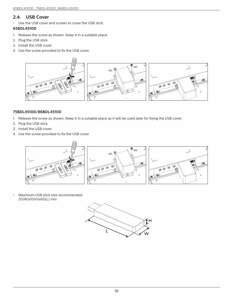
2.4. USB Cover• Use the USB cover and screws to cover the USB stick.
65BDL4510D
1. Release the screw as shown. Keep it in a suitable place.
2. Plug the USB stick.
3. Install the USB cover.
4. Use the screw provided to fix the USB cover.
M3M4
75BDL4510D/86BDL4510D
1. Release the screw as shown. Keep it in a suitable place as it will be used later for fixing the USB cover.
2. Plug the USB stick.
3. Install the USB cover.
4. Use the screw provided to fix the USB cover.
M3M4
• Maximum USB stick size recommended: 20(W)x10(H)x60(L) mm
L
H
W

65BDL4510D_75BDL4510D_86BDL4510D
11
2.5. AC Switch Cover• Use AC Switch Cover to cover the AC switch..1. Install the AC Switch Cover.
2. Fix the AC Switch Cover with the screw in step1.
65BDL4510D
75BDL4510D/86BDL4510D

65BDL4510D_75BDL4510D_86BDL4510D
12
3. Connecting External Equipment
3.1. Connecting External Equipment (DVD/VCR/VCD)
3.1.1. Using HDMI video input
DVD / VCR / VCD
HDMI Out
[HDMI IN]
DVI-IHDMI 2 IN HDMI 3 INHDMI 1 INRS232OUT
RS232IN
3.2. Connecting a PC
3.2.1. Using DVI input
[DVI IN]
PC[PC LINE IN]
Audio Out DVI Out
DVI-IRS232OUT
RS232IN
PC LINE IN
3.2.2. Using HDMI input
PCHDMI Out
[HDMI IN]
DVI-IHDMI 2 IN HDMI 3 INHDMI 1 INRS232OUT
RS232IN

65BDL4510D_75BDL4510D_86BDL4510D
13
3.2.3. Using DP input
PCDP Out
[DP IN]
DVI-IRS232OUT
RS232INDP IN
3.3. Connecting Multiple Displays in a Daisy-chain ConfigurationYou can interconnect multiple displays to create a daisy-chain configuration for applications such as a menu board.
3.3.1. Display control connectionConnect the [RS232 OUT] connector of DISPLAY 1 to the [RS232 IN] connector of DISPLAY 2.
DISPLAY 1 DISPLAY 2
PC
[RS232 IN][RS232]
[RS232 OUT] [RS232 IN]
3.4. IR connection
FORMATSOURCE
INFOLIST
OPTIONSADJUST
VOL
NORMAL ID
ID SET ENTER
DISPLAY 1
[IR IN]
ExternalIR Receiver
NOTE:
This display’s remote control sensor will stop working if the [IR IN] is connected.

65BDL4510D_75BDL4510D_86BDL4510D
14
3.5. IR Pass-through Connection
DVD / VCR / VCD
(DVD / VCR / VCD)
Remote Control
FORMATSOURCE
INFOLIST
OPTIONSADJUST
VOL
NORMAL ID
ID SET ENTER
[IR OUT]
[IR IN]
3.6. Wire-connecting to Network
PC
[RJ-45][RJ-45] ROUTER
INTERNET
Network Settings:
1. Switch the router on and enable its DHCP setting.
2. Connect the router to this display with an Ethernet cable.
3. Press [ ] HOME button on the remote control, then select Setup.
4. Select Connect to network, then press [ ] button.
5. Wait until this display finds the network connection.
6. If the “End User License Agreement” window prompts, accept the agreement.
NOTE: Connecting with a shielded CAT-5 Ethernet cable to comply with the EMC directive.

65BDL4510D_75BDL4510D_86BDL4510D
15
4. OperationNOTE: The control button described in this section is mainly
on the remote control unless specified otherwise.
4.1. Play multimedia files from USB device1. Connect your USB device to the USB port on the display.
USB
IR-IN
IR-OUT
PC LINE IN
USB 2.0
USBService Port
RJ45
AUDIO OUT
2. Press [ ] SOURCE button, choose USB, and press [ ] button.
VGA
DVI
DP
HDMI 1
HDMI 2
HDMI 3
USB
3. The playable files for the connected USB device will be detected automatically. The files are automatically sorted into 3 types: Photo, Music and Movie.
USB 2.0
MUSIC MOVIEPHOTO
4. Press [ ] or [ ] button to choose the item. Press [ ] button to enter its play list.
5. Press [ ], [ ], [ ] or [ ] button to choose a file. Press [ ]or [ ] button to start playing.
6. Follow the on-screen instruction to control the play option.
7. Press [PLAY] buttons ( ) to control playing.
1 / 2
Return aaa1
xxx1 xxx2 xxx3 123
aaa2 aaa3
8. Press [ ], [ ], [ ] or [ ] button to choose “Return" item then press [ ] button to return to the top layer.

65BDL4510D_75BDL4510D_86BDL4510D
16
5. OSD MenuAn overview of the On-Screen Display (OSD) structure is shown below. You can use it as a reference for further adjustment of your display.
5.1. Navigating the OSD Menu
5.1.1. Navigating the OSD menu using the remote control
FORMATSOURCE
INFOLIST
OPTIONSADJUST
1. Press [ ] button on the remote control to display the OSD menu.
2. Press [ ] or [ ] button to select the item to adjust.
3. Press [OK] or [ ] button to enter the submenu.
4. In the submenu, press [ ] or [ ] button to toggle between items, press [ ] or [ ] button to adjust the settings. If there is a submenu, press [OK] or [ ] button to enter the submenu.
5. Press [ ] button to return to the previous menu, or press [ ]button to exit from the OSD menu.
5.1.2. Navigating the OSD menu using the display’s control buttons
1. Press [MENU] button to display the OSD menu.
2. Press [ ] or [ ] button to select the item to adjust.
3. Press [ ] button to enter the submenu.
4. In the submenu, press [ ] or [ ] button to toggle between items, press [ ] or [ ] button to adjust the settings. If there is a submenu, press [ ] button to enter the submenu.
5. Press [MENU] button to return to the previous menu, or keep pressing [MENU] button to exit from the OSD menu.
5.2. OSD Menu Overview
5.2.1. Picture menu
Audio
Screen
Picture
Con�guration 1
Con�guration 2
Option
Contrast
Sharpness
Color
Tint
Brightness
Black Level
Gamma
Color Temperature
Smart Picture
Smart Power
Smart Mode
Noise Reduction
50
50
50
50
Native
Standard
o�
50
50
0
Low
BrightnessAdjust the brightness of this display’s backlight.
Contrast Adjust the contrast ratio for the input signal.
SharpnessThis function is digitally capable to keep a distinct image at all times.
Adjust the sharpness of the picture for each picture mode.
Black LevelAdjust the image brightness for the background.
NOTE: sRGB picture mode is standard and cannot be changed.
Tint (Hue)Adjust the tint of the screen.
Press + button the flesh tone color becomes greenish.
Press - button the flesh tone color becomes purplish.
NOTE: VIDEO mode only.
Color(Saturation)Adjust the color of the screen.
Press + button to increase color depth.
Press - button to decrease color depth.
NOTE: VIDEO mode only
Noise ReductionAdjust the noise reduction level.
GammaSelect a display gamma. It refers to the brightness performance curve of signal input. Choose from {Native} / {2.2} / {2.4} / {s gamma} / {D-image}.
NOTE: sRGB picture mode is standard and cannot be changed.
Color TemperatureIt is used to adjust the color temperature.
The image becomes reddish as the color temperature decreases, and becomes bluish as the color temperature increases.

65BDL4510D_75BDL4510D_86BDL4510D
17
Smart PicturePQ setting
PC mode: {Standard} / {Highbright} / {sRGB}.
Video mode: {Standard} / {Highbright} / {Cinema}.
Smart PowerSmart Power control is not relative to brightness control:
1. Initial setting Brigthness 70 (in the range from 0-100) Power consumption 70% of maximum power consumption
2. Smart Power OFF: no adaptation MEDIUM: 65% of power consumption relative to current settings HIGH: 80% of power consumption relative to current settings
Picture ResetReset all settings in the Picture menu.
Select “Yes” and press “SET” button to restore to factory preset data.
Press “EXIT” button to cancel and then return to the previous menu.
5.2.2. Screen menu
Audio
Screen
Picture
Con�guration 1
Con�guration 2
Option
V. Position
Clock
Zoom Mode
Custom Zoom
H. Position
Clock Phase
Auto Adjust
Screen Reset
Full
H positionControl Horizontal Image position within the display area of the LCD.
Press + button to move screen to right.
Press - button to move screen to left.
NOTE: VGA input only.
V positionControl Vertical Image position within the display area of the LCD.
Press + button to move screen to up.
Press - button to move screen to down.
NOTE: VGA input only.
ClockPress + button to expand the width of the image on the screen to the right.
Press - button to narrow the width of the image on the screen to the left.
NOTE: VGA input only.
Clock PhaseImproves focus, clarity and image stability by increasing or decreasing this setting.
NOTE: VGA input only.
Zoom modePC mode: {Full} / {4:3} / {1:1} / {16:9}/ {21:9}/ {Custom}.
Video mode: {Full} / {4:3} / {1:1} / {16:9}/ {21:9}/ {Custom}.
*Zoom mode setting is defined by input. If input in multi-windows, the setting will apply for windows with the same input.
The INFO OSD will show the latest setting.
Full This mode restores the correct proportions of pictures transmitted in 16:9 using the full screen display.
4:3 The picture is reproduced in 4:3 format and a black band is displayed on either side of the picture.
1:1 This mode displays the image pixel-by-pixel on screen without scaling the original image size.
16:9
The picture is reproduced in 16:9 format and a black band at the top and bottom.
21:9 The picture is reproduced in 21:9 format and a black band at the top and bottom.
Custom Choose to apply the custom zoom settings in the Custom Zoom submenu.
Custom zoomYou can use this function to further customize the zoom settings to suit the image you want to display.
NOTE: This item is functional only when the {Zoom mode} is set to {Custom}.
Zoom Expands the horizontal and vertical sizes of the image simultaneously.
H zoom Expands the horizontal size of the image only.
V zoom Expands the vertical size of the image only.

65BDL4510D_75BDL4510D_86BDL4510D
18
H position Moves the horizontal position of the image left or right.
V position Moves the vertical position of the image up or down.
Auto adjustPress “Set” to detect and adjust H position, V position, Clock, Phase automatically.
NOTE: VGA input only.
Screen resetReset all settings in the Screen menu to factory preset values.
5.2.3. Audio
Audio
Screen
Picture
Con�guration 1
Con�guration 2
Option
Treble
Bass
Volume Minimum
Balance
Volume
Audio Out Volume
Volume Maximum
Mute
50
50
50
30
O�
O�
On
30
0
100
Audio source
Audio Reset
Speaker
Sync.Volume
Digital
BalanceAdjust to emphasize left or right audio output balance.
TrebleAdjust to increase or decrease higher-pitched sounds.
BassAdjust to increase or decrease lower-pitched sounds.
VolumeAdjust the volume.
Audio Out VolumeAdjust to increase or decrease the line out audio output level.
Minimum volume ≤ Volume ≤ Maximum volume
NOTE: This function will be disabled when Audio Out Sync is ON.
Volume MaximumAdjust your own limitation for the maximum volume setting.
Volume MinimumAdjust your own limitation for the minimum volume setting.
MuteTurn the mute function on/off.
SpeakerTurn the internal speaker on/off.
NOTE: This function is only availavle when “Audio Out Sync” is on.
Sync. VolumeEnable/disable audio out (line out) volume adjustability to sync with internal speakers volume, but PD Internal speaker sound will be forced to be mute.
Audio sourceSelect the audio input source.
Analog: audio from audio input.
Digital : audio from HDMI/DVI audio.
Displyport: audio from DP
Audio ResetReset all settings in the Audio menu to factory preset values.
5.2.4. Configuration1 menu
Panel Saving
RS232 routing
WOL
Switch on state Last status
RS232
Last Input
O�
On
O�
O�
Boot On Source
Light Sensor
Power LED Light
Network Settings
Con�guration1 Reset
Factory Reset
Human Sensor
Audio
Screen
Picture
Con�guration 1
Con�guration 2
Option
Switch on StateSelect the display status when you connect the power cord next time.
• {Power off} - The display will remain off when the power cord is connected to a wall outlet.
• {Forced on} - The display will turn on when the power cord is connected to a wall outlet.
• {Last status} - The display will return to the previous power status (on/off/standby) when removing and replacing the power cord.
Panel savingChoose to enable the panel saving functions and thus reduce the risk of “image persistence” or “ghost-imaging”.
• {Brightness} - Select {On} and the image brightness will be reduced to an appropriate level. The Brightness setting in the Picture menu will be unavailable when selected.
• {Pixel shift} - Select the time interval ({Auto} / {10 - 900} Seconds / {Off}) for the display to slightly expand the image size and shift the position of pixels in four directions (up, down, left, or right).
RS232 routingSelect the network control port.
Choose from: {RS232} / {LAN ->RS232}.
Boot on sourceSelect the source when booting up.

65BDL4510D_75BDL4510D_86BDL4510D
19
WOLChoose to turn on or off the wake on LAN function.
Choose from : {Off} / { On}
Light sensor (require Philips accessory CRD41 External Sensor Box)Choose to turn on or off backlight adjustment according to environment brightness.
Choose from : {Off} / { On}
Human sensor (require Philips accessory CRD41 External Sensor Box)This function will turn the backlight On when it senses the presence of human and turn it off after a specified period of time.
The options are:
• {Off} (Default), {10 Min.}, {20 Min.}, {30 Min.}, {40 Min.}, {50 Min.}, {60 Min.}
Power LED LightSelect {Off} to turn off the indicator.
Network settings• DHCP Enable -> Cannot modify IP address/Subnet
mask/Default gateway
• DHCP Disable-> Can manually input IP address/Subnet mask/Default gateway.
Configuration1 resetReset all settings in Configuration1 menu to the factory preset values.
Factory resetReset all settings in the OSD menus of {Picture}, {Screen}, {Audio}, {PIP}, {Configuration1}, {Configuration2}, and {Advanced option} to the factory preset values.
Press [ ] or [ ] button to select {Reset}, and press [OK] button to do the reset.
5.2.5. Configuration2 menu
Audio
Screen
Picture
Con�guration 1
Con�guration 2
Option
Information OSD
Logo
OSD turn o�
OSD transparency
Monitor ID
Monitor Info
HDMI EDID
Heat Status
OSD Rotation
Language
Con�guration2 Reset
0
15
On
English
Landscape
1 . 4
4 Sec
OSD turn offSet the period of time the OSD (on-screen display) menu stays on the screen.
The options are: {5 ~ 100} seconds.
OSD TransparencyAdjust OSD transparency.
• {0} - Transparency off.
• {1-100} - Transparency level 1-100
Information OSDSet the period of time the information OSD is displayed on the upper right corner of the screen. The information OSD will display when input signal is changed.
The information OSD will remain on the screen with {Off} selection.
The options are: {1 - 60} seconds.
LogoChoose to enable or disable the picture of Logo when turning on your display.
The options are: {Off} /{On}
Monitor IDSet the ID number for controlling the display via the RS232 connection. Each display must have a unique ID number when multiple sets of display are connected. Monitor ID number range is between 1 to 255.
• {1-255} – {Monitor ID} The default setting is 1.
• {1-255} – {Monitor group} The default setting is 1.
• {1-15} – {Tiling matrix} The default setting is 1.
• {Auto ID} The {Auto ID} setup function enables setting up {Monitor ID} of connected machine according to {Tiling matrix} settings. Example: Tiling matrix sets as 4
• {Tiling matrix}: Tiling matrix number range is between 1 to 15. The default setting is 1.
Monitor Id
Monitor Id
Monitor group
1
1
• {Auto ID}: The option are: {Start} / {End}. The default is {End}.
• Switch to Start option to set up IDs of machines backward from current one. Once the setup is completed, the option exits to End automatically. To use this function, serially connect all machines with RS-232 cable and set their Control ports to RS-232 too.
1 2
5 6
3 4
7 8
9 10 11 12
13 14 15 16Heat statusThis function allows you to check the thermal status at any time.

65BDL4510D_75BDL4510D_86BDL4510D
20
Monitor informationShows information about your display, including Input source, Resolution, Model name, SW version, serial number, operation hours and MAC address.
Monitor informationModel nameSerial NO.Operation hoursSW VersionMAC address
XXXXXXXXXXXXXXXXXXXX
HDMI EDIDSwitch HDMI EDID type: {HDMI 1.4}, {HDMI 2.0}.
OSD RotationLandscape/Portrait
LanguageSet OSD menu language.
Configuration2 resetReset all settings in Configuration2 menu to the factory preset values.
5.2.6. Option
IR Control
Keyboard Control
O� Timer O�
O�
O�
5 Sec
Date and Time
Input Resolution
Tiling
Schedule
Auto Signal Detection
Power Save
USB Autoplay
Slideshow Duration
HDMI with One Wire
Audio
Screen
Picture
Con�guration 1
Con�guration 2
Option
Input resolutionSet the resolution of the VGA input. This is only required when the display is unable to detect the VGA input resolution correctly.
NOTE: This item is functional for VGA input only.
The options are:
• {1024x768 / 1280x768 / 1360x768 / 1366x768}
• {1400x1050 / 1680x1050}
• {1600x1200 / 1920x1200}
• {Auto}: Determines the resolution automatically.
The selected settings will become effective after turning off the power and turning it on again.
IR controlSelect the operation mode of the remote control when multiple displays are connected via an RS232C connection.
• {Normal} - All displays can be operated normally by the remote control unit.
• {Primary} - Designate this display as the primary display for remote control operation. Only this display can be
operated by the remote control. (In primary mode, IR key will always be processed regardless the monitor id/group settings).
• {Secondary} - Designate this display as the secondary display. This display can not be operated by the remote control, and will only receive the control signal from the primary display via the RS232C connection.
• {Lock All} / {Lock all but Volume} / {Lock all but Power} / {Lock all except PWR & VOL}- Lock the remote control function of this display. To unlock, press and hold the [] INFO button on the remote control for 6 (six) seconds.
Keyboard controlChoose to enable or disable the display keyboard (control buttons) function.
• {Unlock} - Enable the keyboard function.
• {Lock All} / {Lock all but Volume} / {Lock all but Power} / {Lock all except PWR & VOL} - Disable the keyboard function.
NOTE: “Keyboard Control Lock Mode” This function completely disables the access to all Keyboard Control functions. To enable or disable the keyboard control lock, press both [ ] and [ ] buttons and hold down continuously for more than 3 seconds.
TilingWith this function you can create a single large-screen matrix (video wall) that consists of up to 225 sets of this display (up to 15-sets on the vertical and 15-sets on the horizontal sides). This function requires a daisy-chain connection.
1
1
1
13
22
7
7
Off TimerSet automatically power off time (in hours).
Date and timeSet the current date and time for the display’s internal clock.
NOTES:
The definition and behavior of the Daylight saving time:
The current implementation of daylight saving is a reminder tool for the user who doesn’t know how to adjust the clock of daylight saving.
It does not adjust the real time clock automatically. The problem is that there are no standard rules on when to adjust the clock defined by region or country. To solve this problem, the user must be able to set the daylight saving start/end date. When daylight saving correction is on (user selectable) then the real time clock should be adjusted at the time set of the daylight saving on/off date. At the start date of daylight saving, the clock should be adjusted 1 hour forward at 2 o’clock. At the end date of daylight saving, the clock should be adjusted 1 hour backward at 2 o’clock.

65BDL4510D_75BDL4510D_86BDL4510D
21
The existing daylight on/off menu should be replaced by the following menu structure:
The menu item {Daylight saving} opens the submenu that contains the following items:
• Menu item {Daylight saving start date} Selection item {1st, 2nd, 3rd, 4th, last} Sunday of selection item {1-12 month}
• Menu item {Daylight saving stop date} Selection item {1st, 2nd, 3rd, 4th, last} Sunday of selection item {1-12 month}
• Menu item {Correction time} Selection item {0.5, 1.0, 1.5, 2.0} hour
• Menu item {Daylight saving} Selection item {on, off}
When “daylight saving” is “on”, the real time clock will be adjusted automatically at the daylight saving time (e.g. April 5, 2015, 02.00 o’clock: time will be set 1 hour later or October 25, 2015, 02.00 o’clock: time will be set 1 hour earlier).
ScheduleThis function allows you to program up to 7 (seven) different scheduled time intervals for the display to activate.
You can select:
• The time for the display to turn On and Off.
• The days in a week for the display to activate.
• Which input source the display will use for each scheduled activation period.
NOTE: It is recommended that you set up the current date and time in the {Date and time} menu before using this function.
1. Press [OK] or [ ] button to enter the submenu.
Schedule 1
Schedule 2
Schedule 3
Schedule 4
Schedule 5
Schedule 6
Schedule 7
Schedule
2. Press [ ] or [ ] button to select a schedule item (item number 1 - 7), and press [OK] or [ ] button to enter the submenu.
Schedule 1
Schedule 2
Schedule 3
Schedule 4
Schedule 5
Schedule 6
Schedule 7
Schedule
Status
Source
On Time
Off Time
Repeat modes
USB Play List
Off
HDMI1
-- : --
-- : --
None
• {Status} - Press [ ] or [ ] button to select the status On or Off.
• {Source} - Press [ ] or [ ] button to select the input source.
• {On Time} - Press [ ] or [ ] button to adjust and the display will turn on at the specified time.
• {Off Time} - Press [ ] or [ ] button to adjust and the display will turn off at the specified time.Leave hour and minute options empty if you do not want to use the function of power-on or power-off schedule.
• {Repeat modes} -Press [ ] button to select which day in a week this schedule item will take effect, and then press the [OK] button.
3. For additional schedule settings, press [ ], then repeat the steps above. A check mark in the box next to the number of the schedule item indicates that the selected schedule is in effect.
NOTES:
• If the schedules overlap, the scheduled power-on time takes priority over scheduled power-off time.
• If there are two schedule items programmed for the same time, the highest numbered schedule takes priority. For example, if schedule items #1 and #2 both set the display to power on at 7:00 AM and off at 5:00 PM, then only schedule item # 2 will take effect.
HDMI with One WireCEC control.
• {Off} - Disable CEC.(Default)
• {On} - Enable CEC.
Auto signal detectionThis function allows the display to detect and display available signal sources automatically.
• {Off} - Once an input is connected, it can only be selected manually.
If the selected input has signal, set the system to display the image automatically according to the search order of each option.
The options are: {Auto} / {Failover}
• {Auto}: Dispalyport->VGA->DVI-I->HDMI1->HDMI2 ->HDMI3->USB
• {Failover}
- Failover 1: User-defined setting. Default:HDMI 1.
- Failover 2: User-defined setting. Default:HDMI 1.
- Failover 3: User-defined setting. Default:HDMI 1.
- Failover 4: User-defined setting. Default:HDMI 1.
- Failover 5: User-defined setting. Default:HDMI 1.
- Failover 6: User-defined setting. Default:HDMI 1.
- Failover 7: User-defined setting. Default:HDMI 1.
If the primary signal is lost then the display begin failover by searching the next available source that is defined in the priority list.Please note that failover will suspend under the following conditions and failover will resume when signal is lost again.- Boot On Source : When the display is powered on, it
will go to the source defined in this OSD option.- Scheduler: When the display is powered on by
scheduler, it will go to the corresponding source according to the current time.
- User operation: No matter what current source it is, when user manually changes source, the failover will
65BDL4510D_75BDL4510D_86BDL4510D
22
suspend.To make sure failover starts from the 1st priority source after powering on, please set the 1st priority source as boot on source too.
Power SaveMode 1 [TCP off, WOL on, auto off]
Mode 2 [TCP off, WOL on, auto on/off]
Mode 3 [TCP on, WOL off, auto on/off]
Mode 4 [TCP on, WOL off, no auto on/off]
USB AutoplayChoose to play source type. The options are: {Off} / {On}.
Slideshow DurationDuration of each picture for USB autoplay and USB Play List.
USB Play ListChoose 1 playlist to play, support up to 7 playlists.
USB CloningCopy PD settings from one set to another. Import: Import settings from another set. Export: Export settings to another set.
Firmewre updateUpdate firmware via USB disk.
Option ResetReset all settings in the Option menu to factory preset values.

65BDL4510D_75BDL4510D_86BDL4510D
23
6. Supported Media FormatsUSB Multimedia Formats
Video formatVideo Codec Resolution Bit Rate
MPEG1/2 1080P@30fps 40Mbps
H.264 1080P@30fps 50Mbps
WMV3 1080P@30fps 40Mbps
Motion JPEG 640x480@30fps 40Mbps
Audio formatAudio Codec Sampling Rate Channel Bit Rate
MPEG1/2 Layer1 16KHz-48KHz Up to 2 32Kbps-448Kbps
MPEG1/2 Layer2 16KHz-48KHz Up to 2 8Kbps-384Kbps
MPEG1/2 Layer3 16KHz-48KHz Up to 2 8Kbps-320Kbps
AAC, HEAAC 8KHz-48KHz Up to 5.1 32Kbps-448Kbps
Photo formatImage Photo Resolution
JPEGBase-line
15360x8640
(1920x8 x 1080x8)
Progressive 1024x768
PNGnon-interlace 9600x6400
interlace 1200x800
BMP 9600x6400
NOTES:
• Sound or video may not work if the contents have a standard bit rate/frame rate above the compatible Frame/sec listed in the table above.
• Video content with a Bit rate or Frame rate larger than the rate specified in the table above can cause choppy video during playback.
HDCP support table
Input Source HDMI Ver HDCP 1.4 HDCP 2.2
DVI HDMI 1.4b V X
HDMI1HDMI 1.4b V X
HDMI 2.0 V V
HDMI2HDMI 1.4b V X
HDMI 2.0 V V
HDMI3HDMI 1.4b V X
HDMI 2.0 V V

65BDL4510D_75BDL4510D_86BDL4510D
24
7. Input ModeTiming support:
Item Resolution H.Freq. (KHz) V.Freq. (Hz)
1 720×400 @70Hz DOS 31.469 70.087
2 640×480 @60Hz DMT 31.469 59.94
3 640×480 @67Hz MAC 35 66.667
4 640×480 @72Hz DMT 37.861 72.809
5 640×480 @75Hz DMT 37.5 75
6 800×600 @56Hz DMT 35.156 56.25
7 800×600 @60Hz DMT 37.879 60.317
8 800×600 @72Hz DMT 48.077 72.188
9 800×600 @75Hz DMT 46.875 75
10 1024×768 @60Hz DMT 48.363 60.004
11 1024×768 @70Hz DMT 56.476 70.069
12 1024×768 @75Hz DMT 60.023 75.029
13 1152×864 @75Hz DMT 67.5 75
14 1152×870 @75Hz MAC 68.681 75.062
15 1280×720 @60Hz CVT16:9 44.772 59.855
16 1280x800 @60Hz CVT16:10 49.702 59.81
17 1280×1024 @60Hz DMT 63.981 60.02
18 1440×900 @60Hz CVT16:10 R 55.469 59.901
19 1440×900 @60Hz CVT16:10 55.935 59.887
20 1600×1200 @60Hz CVT16:9 75 60
21 1680×1050 @60Hz CVT16:9 R 64.674 59.883
22 1680×1050 @60Hz CVT16:9 65.29 59.954
23 1920×1080 @60Hz CVT-RB /
XBOX36066.7 60
24 1920×1080 @60Hz DMT-RB 67.5 60
25 480P@60Hz 31.469 59.94
26 720P@60Hz 44.955 59.94
27 1080I@60Hz 33.716 59.94
28 1080P@60Hz 67.433 59.94
29 576P@50Hz 31.25 50
30 720P@50Hz 37.5 50
31 1080I@50Hz 28.125 50.08
32 1080P@50Hz 56.25 50
33 3840x2160@30 67.5 30
34 3840x2160@60 135 60
• The PC text quality is optimum in UHD mode (3840 x 2160, 60Hz). • Your PC display screen might appear different depending on the manufacturer (and your particular version of Windows).• Check your PC instruction book for information about connecting your PC to a display.• If a vertical and horizontal frequency-select mode exists, select 60Hz (vertical) and 31.5KHz (horizontal). In some cases,
abnormal signals (such as stripes) might appear on the screen when the PC power is turned off (or if the PC is disconnected). If so, press the [INPUT] button to enter the video mode. Also, make sure that the PC is connected.
• When horizontal synchronous signals seem irregular in RGB mode, check PC power saving mode or cable connections.• The display settings table complies to the IBM/VESA standards, and based on the analog input.• The DVI support mode is regarded as same to the PC support mode.• The best timing for the vertical frequency to each mode is 60Hz.

65BDL4510D_75BDL4510D_86BDL4510D
25
8. Pixel Defect PolicyWe strive to deliver the highest quality products and use some of the industry’s most advanced manufacturing processes whilst practicing stringent quality control. However, pixel or sub-pixel defects on the PDP / TFT panels used in Plasma- & LCD- displays are sometimes unavoidable. No manufacturer can guarantee that all panels will be free from pixel defects, but Philips guarantees that any Plasma- & LCD- displays with an unacceptable number of defects will be repaired during the warranty period in line with your local guarantee conditions.
This notice explains the different types of pixel defects and defines the acceptable defect level for the LCD screen. In order to qualify for repair under warranty, the number of pixel defects must exceed a certain level as shown in the reference table. If the LCD screen is within specification a warranty exchange / claim back will be refused. Additionally, because some types or combinations of pixel defects are more noticeable than others, Philips sets even higher quality standards for those.
8.1. Pixels and Sub-Pixels
subpixel
pixel
A pixel, or picture element, is composed of three sub-pixels in the primary colors of red, green and blue. Many pixels together form an image. When all sub-pixels of a pixel are lit, the three colored sub-pixels together appear as a single white pixel. When all are dark, the three colored sub-pixels together appear as a single black pixel. Other combinations of lit and dark sub-pixels appear as single pixels of other colors.
8.2. Types of Pixel Defects + Dot DefinitionPixel and sub-pixel defects appear on the screen in different ways. There are three categories of pixel defects and several types of sub-pixel defects within each category.
Dot definition = What is a defective “Dot”? :One or more defective, adjacent sub-pixel are defined as one “dot”. The no. of defective sub-pixels are not relevant to define a defective dot. This means that a defective dot can consist of one, two or three defective sub-pixels which can be dark or lit.
RR G B
One dot = One Pixel; consists of three sub-pixels of Red, Green, and Blue.
8.3. Bright Dot DefectsBright dot defects appear as pixels or sub-pixels that are always lit or “on”. These are the examples of bright dot defects:
One lit red, green or blue sub pixel Two adjacent lit sub pixels:
Red + Blue = Purple
Red + Green = Yellow
Green + Blue = Cyan (Light Blue)
Three adjacent lit sub pixels (one white pixel)

65BDL4510D_75BDL4510D_86BDL4510D
26
8.4. Dark Dot DefectsBlack dot defects appear as pixels or sub-pixels that are always dark or “off”. These are the examples of black dot defects:
One dark dot Two adjacent dark dots = 1 pair of dark dots
Two dark dots, specifications defines the minimum distance between dark
dots
8.5. Proximity of Pixel DefectsBecause pixel and sub-pixels defects of the same type that are nearby one another may be more noticeable, Philips also specifies tolerances for the proximity of pixel defects. In the table below you can find specifications about:
• Allowed amount of adjacent dark dots = (adjacent dark dots =1 pair of dark dots)
• Minimum distance between dark dots
• Total no. of all defective dots
8.6. Pixel Defect TolerancesIn order to qualify for repair due to pixel defects during the warranty period, a PDP / TFT panel in a Philips Plasma / LCD- display must have pixel or sub-pixel defects exceeding the tolerances listed in the following table.
BRIGHT DOT EFFECT ACCEPTABLE LEVEL
1 lit sub pixel 2
BLACK DOT EFFECT ACCEPTABLE LEVEL
1 dark sub pixel 10
TOTAL DOT DEFECTS OF ALL TYPES 12
NOTE: * 1 or 2 adjacent sub pixel defects = 1 dot defect
8.7. MURADark spots or patches may occasionally appear on some liquid crystal display (LCD) panels. This is known within the industry as Mura, which is a Japanese term for “unevenness.” It is used to describe an irregular pattern or area in which uneven screen uniformity appears under certain conditions. Mura is a result of the deterioration of the liquid crystal alignment layer and is most commonly caused by long-term operation under high ambient temperatures. It is an industry- wide phenomenon and Mura is not repairable. It is also not covered by our warranty terms.
Mura has been around since the introduction of LCD technology and with screens getting bigger and in operation 24/7, many displays are running in low light conditions. This all adds to the possibility of Mura affecting displays.
HOW TO SPOT MURAThere are many symptoms of Mura and also multiple causes. Several of these are listed below:
• Impurities or foreign particles in the crystal matrix
• Uneven distribution of LCD matrix during manufacturing
• Non-uniform luminance distribution of the backlight
• Panel assembly induced stress
• Flaws within the LCD cells
• Thermal induced stress - high temperature operation over long periods of time

65BDL4510D_75BDL4510D_86BDL4510D
27
HOW TO AVOID MURAAlthough we can not guarantee the complete eradication of Mura every time, in general the appearance of Mura can be minimized by these methods:
• Lower the backlight brightness
• Use a screen saver
• Reduce the ambient temperature around the unit
9. Cleaning and Troubleshooting
9.1. Cleaning
Caution When Using the Display• Do not bring your hands, face or objects close to the ventilation holes of the display. The top of the display is usually very
hot due to the high temperature of exhaust air being released through the ventilation holes. Burns or personal injuries may occur if any body parts are brought too close. Placing any object near the top of the display could also result in heat related damage to the object as well as the display itself.
• Be sure to disconnect all cables before moving the display. Moving the display with its cables attached may damage the cables and thus cause fire or electric shock.
• Disconnect the power plug from the wall outlet as a safety precaution before carrying out any type of cleaning or maintenance procedure.
Front Panel Cleaning Instructions• The front of the display has been specially treated. Wipe the surface gently using only a cleaning cloth or a soft, lint-free
cloth.
• If the surface becomes dirty, soak a soft, lint-free cloth in a mild detergent solution. Wring the cloth to remove excess liquid. Wipe the surface of the display to remove dirt. Then use a dry cloth of the same type to dry.
• Do not scratch or hit the surface of the panel with fingers or hard objects of any kind.
• Do not use volatile substances such as insert sprays, solvents and thinners.
Cabinet Cleaning Instructions• If the cabinet becomes dirty, wipe the cabinet with a soft, dry cloth.
• If the cabinet is extremely dirty, soak a lint-free cloth in a mild detergent solution. Wring the cloth to remove as much moisture as possible. Wipe the cabinet. Use another dry cloth to wipe over until the surface is dry.
• Do not allow any water or detergent to come into contact with the surface of the display. If water or moisture gets inside the unit, operating problems, electrical and shock hazards may result.
• Do not use solution that contains oil to clean the plastic parts. Such product damage the plastic parts and void the warranty.
• Do not scratch or hit the cabinet with fingers or hard objects of any kind.
• Do not use volatile substances such as insert sprays, solvents and thinners on the cabinet.
• Do not place anything made from rubber or PVC near the cabinet for any extended periods of time.

65BDL4510D_75BDL4510D_86BDL4510D
28
9.2. Troubleshooting
Symptom Possible Cause Remedy
No picture is displayed 1. The power cord is disconnected.
2. The main power switch on the back of the display is not switched on.
3. The selected input has no connection.
4. The display is in standby mode.
1. Plug in the power cord.
2. Make sure the power switch is switched on.
3. Connect a signal connection to the display.
Interference displayed on the display or audible noise is heard
Caused by surrounding electrical appliances or fluorescent lights.
Move the display to another location to see if the interference is reduced.
Color is abnormal The signal cable is not connected properly.
Make sure that the signal cable is attached firmly to the back of the display.
Picture is distorted with abnormal patterns
1. The signal cable is not connected properly.
2. The input signal is beyond the capabilities of the display.
1. Make sure that the signal cable is attached firmly.
2. Check the video signal source to see if it is beyond the range of the display. Please verify its specifications with this display’s specification section.
Display image doesn’t fill up the full size of the screen
1. The zoom mode is not set correctly.
2. Scan Mode may be set incorrectly to underscan.
3. If the image exceeds the screen size, Scan Mode may need to be set to Underscan.
Use the Zoom mode or Custom zoom function in the Screen menu to fine tune display geometry and time frequency parameter.
Can hear sound, but no picture Source signal cable is connected improperly.
Make sure that both video inputs and sound inputs are correctly connected.
Can see picture but no sound is heard 1. Source signal cable is connected improperly.
2. Volume is turned all the way down.
3. {Mute} is turned on.
4. No external speaker connected.
1. Make sure that both video inputs and sound inputs are correctly connected.
2. Press [ ] or [ ] button to hear sound.
3. Switch MUTE off by using the [ ] button.
4. Connect external speakers and adjust the volume to a suitable level.
Some picture elements do not light up
Some pixels of the display are off. This display is manufactured using an extremely high level of precision technology: however, sometimes some pixels of the display may not display. This is not a malfunction.
After-Images can still be seen on the display after the display is powered off. (Examples of still pictures include logos, video games, computer images, and images displayed in 4:3 normal mode)
A still picture is displayed for an over extended period of time
Do not allow a still image to be displayed for an extended period of time as this can cause a permanent after-image to remain on the display.

65BDL4510D_75BDL4510D_86BDL4510D
29
10. Warranty StatementWarranty period for PHILIPS signage display is listed as below, for areas not covered in this table, please follow their warranty statement.
Region Warranty Period
USA, Canada 3 years
China 1 year
Asia Pacific 3 years
Europe 3 years
Brazil 3 years

65BDL4510D_75BDL4510D_86BDL4510D
30
11. Technical SpecificationsDisplay:Item Specifications
65BDL4510D 75BDL4510D 86BDL4510D
Screen Size (Active Area) 1639 mm / 64.5 inch 1893 mm / 74.5 inch 2174 mm / 85.6 inch
Aspect Ratio 16:9 16:9 16:9
Number of pixels 3840 (H) x 2160 (V) 3840 (H) x 2160 (V) 3840 (H) x 2160 (V)
Pixel pitch 0.372 (H) x 0.372 (V) [mm] 0.4296 (H) x 0.4296 (V) [mm] 0.4935 (H) x 0.4935 (V) [mm]
Displayable colors 8 bits+FRC, 1.07 Billion colors 8 bits+FRC, 1.07 Billion colors 8 bits+FRC, 1.07 Billion colors
Brightness (typical) 500 cd/m2 500 cd/m2 500 cd/m2
Contrast ratio (typical) 1200:1 1200:1 1200:1
Viewing angle 178 degrees 178 degrees 178 degrees
In/Out Terminals:Item Specifications
Speaker Output Internal Speakers 10W (L) + 10W (R) [RMS]/8Ω
82 dB/W/M/160 Hz - 13 KHz
Audio Output 3.5mm phone jack x 1 0.5V [rms] (Normal) / 2 Channel (L+R)
Audio Input 3.5mm phone jack x 1 0.5V [rms] (Normal) / 2 Channel (L+R)
RS232 2.5mm Phone jack x 2 RS232 in/RS232 out
RJ-45 RJ-45 Jack x 1 (8 pin) 10/100 LAN Port
HDMI Input HDMI Jack x 3 (Type A) (19 pin)
Digital RGB: TMDS (Video + Audio) MAX: Video - 720p, 1080p, 3840 x 2160/60 Hz
Audio - 48 KHz/ 2 Channel (L+R)Supports LPCM only
HDMI Output HDMI Jack x 1 (Type A) (19 pin)
Digital RGB: TMDS (Video + Audio) MAX: Video - 720p, 1080p, 3840 x 2160/60 Hz
Audio - 48 KHz/ 2 Channel (L+R)Supports LPCM only
DP Input /Output DP Jack x 2
(DP in x 1 & DP out x 1)
Digital RGB: TMDS (Video + Audio)MAX: Video - 720p, 1080p, 3840 x 2160/60 HzAudio - 48 KHz/ 2 Channel (L+R)
DVI-I Input DVI-I Jack Digital RGB: TMDS (Video)
Analog RGB: 0.7V [p-p] (75Ω), H/CS/V: TTL (2.2kΩ),
MAX: 1920 x 1080/60 Hz (WUXGA)
IR Input/Output 3.5mm x 2 IR pass through
USB Input USB x 2 (Type A) USB 2.0, Multimedia play and service port

65BDL4510D_75BDL4510D_86BDL4510D
31
General:Item Specifications
65BDL4510D 75BDL4510D 86BDL4510D
Power Input 100 - 240V~, 50/60Hz 100 - 240V~, 50/60Hz 100 - 240V~, 50/60Hz
Power Consumption (Max) 310 W 370 W 625 W
Power Consumption (typ.) 150 W 185 W 350 W
Power Consumption (Standby & Off)
<0.5 W <0.5 W <0.5 W
Dimensions [W x H x D] 1462.3 x 837.3 x 89.9 mm 1683.5 x 961.7 x 91.8 mm 1929.0 x 1100.0 x 91.8 mm
Weight 27.8 Kg 35.9 Kg 50.2 Kg
Gross Weight 34.5 Kg 59.2 Kg 79.6 Kg
Energy Efficiency Class B B B
Visible Screen Size 1639 mm / 64.5 inch 1893 mm / 74.5 inch 2174 mm / 85.6 inch
On Mode Power Consumption (W) 163 W 205 W 372 W
Annual Energy Consumption (kWh) 238 kWh 299 kWh 543 kWh
Standby Power Consumption (W) 0.5 W 0.5 W 0.5 W
Off Mode Power Consumption (W) 0.3 W 0.3 W 0.3 W
Display Resolution (Pixels) 3840 x 2160 3840 x 2160 3840 x 2160
Environmental Condition:Item Specifications
Temperature Operational 0 - 40°C
Storage -20 - 60°C
Humidity Operational 20 - 80% RH (No condensation)
Storage 5 - 95% RH (No condensation)
Altitude Operational 0 - 3,000 m
Storage / Shipment 0 - 9,000 m

2021 © TOP Victory Investments Ltd. All rights reserved.
This product has been manufactured by and is sold under the responsibility of Top Victory Investments Ltd., and Top Victory Investments Ltd. is the warrantor in relation to this product. Philips and the Philips Shield Emblem are regis-tered trademarks of Koninklijke Philips N.V. and are used under license.
Specifications are subject to change without notice.