Computer vision based eyewear selector
13
Déniz et al. / J Zhejiang Univ-Sci C (Comput & Electron) 2010 11(2):79-91 79 Journal of Zhejiang University-SCIENCE C (Computers & Electronics) ISSN 1869-1951 (Print); ISSN 1869-196X (Online) www.zju.edu.cn/jzus; www.springerlink.com E-mail: [email protected] Computer vision based eyewear selector Oscar DÉNIZ †1,2 , Modesto CASTRILLÓN 1 , Javier LORENZO 1 , Luis ANTÓN 1 , Mario HERNANDEZ 1 , Gloria BUENO 2 ( 1 Instituto Universitario de Sistemas Inteligentes y Aplicaciones Numéricas en Ingeniería, Universidad de Las Palmas de Gran Canaria, Edificio Central del Parque Científico-Tecnológico 35017 Las Palmas, Spain) ( 2 E.T.S. Ingenieros Industriales, Universidad de Castilla-La Mancha Campus Universitario, Avda. Camilo José Cela, s/n 13071 Ciudad Real, Spain) † E-mail: [email protected] Received June 26, 2009; Revision accepted Nov. 28, 2009; Crosschecked Dec. 8, 2009 Abstract: The widespread availability of portable computing power and inexpensive digital cameras are opening up new possi- bilities for retailers in some markets. One example is in optical shops, where a number of systems exist that facilitate eyeglasses selection. These systems are now more necessary as the market is saturated with an increasingly complex array of lenses, frames, coatings, tints, photochromic and polarizing treatments, etc. Research challenges encompass Computer Vision, Multimedia and Human-Computer Interaction. Cost factors are also of importance for widespread product acceptance. This paper describes a low-cost system that allows the user to visualize different glasses models in live video. The user can also move the glasses to adjust its position on the face. The system, which runs at 9.5 frames/s on general-purpose hardware, has a homeostatic module that keeps image parameters controlled. This is achieved by using a camera with motorized zoom, iris, white balance, etc. This feature can be specially useful in environments with changing illumination and shadows, like in an optical shop. The system also includes a face and eye detection module and a glasses management module. Key words: Face detection, Eye detection, Perceptual user interfaces, Human-computer interaction doi: 10.1631/jzus.C0910377 Document code: A CLC number: TP391.4 1 Introduction The widespread availability of portable computing power and inexpensive digital cameras are opening up new possibilities for retailers in some markets. One ex- ample is in optical shops, where a number of systems exist that facilitate eyeglasses selection. These systems are increasingly necessary as the market is saturated with an increasingly complex array of lenses, frames, coat- ings, tints, photochromic and polarizing treatments, etc. (Roberts and Threlfall, 2006). The number of clients can increase only if the selection process is shortened or au- tomated. A number of deployed systems have already demonstrated that eyeglasses selectors can increase sales and customer satisfaction (Kuttler, 2003; Morgan, 2004). From a research viewpoint, such systems represent an interesting application of Computer Vision, Multi- c Zhejiang University and Springer-Verlag Berlin Heidelberg 2010 media and Human-Computer Interaction. The Aug- mented Reality (see a survey in Azuma (1997)) of watch- ing ourselves and trying different ‘virtual’ spectacles can be achieved by combining computer vision and graphics. The Magic Lens and Magic Mirror systems, for example, use the ARTag toolkit (Fiala, 2004), which mixes live video and computer-generated graphics. People can wear cardboard patterns that ARTag can detect. The graphics are placed in the visible positions of the patterns. The system can work in real time on general-purpose hard- ware, although people have to wear the cardboard. An- other approach was taken by Lepetit et al. (2003), where virtual glasses and moustaches are added to live video. Although the system works with an impressive frame rate of 25 Hz, the user must start the tracker by reaching a po- sition close to a generic triangle-based face model shown on the screen. The ARMirror is a kiosk-based entertain- ment setup that shows live video overlaying virtual hats,
Transcript of Computer vision based eyewear selector
Déniz et al. / J Zhejiang Univ-Sci C (Comput & Electron) 2010 11(2):79-91 79
Journal of Zhejiang University-SCIENCE C (Computers & Electronics)ISSN 1869-1951 (Print); ISSN 1869-196X (Online)www.zju.edu.cn/jzus; www.springerlink.comE-mail: [email protected]
Computer vision based eyewear selector
Oscar DÉNIZ†1,2, Modesto CASTRILLÓN1, Javier LORENZO1, Luis ANTÓN1,Mario HERNANDEZ1, Gloria BUENO2
(1Instituto Universitario de Sistemas Inteligentes y Aplicaciones Numéricas en Ingeniería, Universidad de Las Palmas de
Gran Canaria, Edificio Central del Parque Científico-Tecnológico 35017 Las Palmas, Spain)
(2E.T.S. Ingenieros Industriales, Universidad de Castilla-La Mancha Campus Universitario,
Avda. Camilo José Cela, s/n 13071 Ciudad Real, Spain)†E-mail: [email protected]
Received June 26, 2009; Revision accepted Nov. 28, 2009; Crosschecked Dec. 8, 2009
Abstract: The widespread availability of portable computing power and inexpensive digital cameras are opening up new possi-bilities for retailers in some markets. One example is in optical shops, where a number of systems exist that facilitate eyeglassesselection. These systems are now more necessary as the market is saturated with an increasingly complex array of lenses, frames,coatings, tints, photochromic and polarizing treatments, etc. Research challenges encompass Computer Vision, Multimedia andHuman-Computer Interaction. Cost factors are also of importance for widespread product acceptance. This paper describes alow-cost system that allows the user to visualize different glasses models in live video. The user can also move the glasses toadjust its position on the face. The system, which runs at 9.5 frames/s on general-purpose hardware, has a homeostatic modulethat keeps image parameters controlled. This is achieved by using a camera with motorized zoom, iris, white balance, etc. Thisfeature can be specially useful in environments with changing illumination and shadows, like in an optical shop. The system alsoincludes a face and eye detection module and a glasses management module.
Key words: Face detection, Eye detection, Perceptual user interfaces, Human-computer interaction
doi:10.1631/jzus.C0910377 Document code: A CLC number: TP391.4
1 Introduction
The widespread availability of portable computingpower and inexpensive digital cameras are opening upnew possibilities for retailers in some markets. One ex-ample is in optical shops, where a number of systemsexist that facilitate eyeglasses selection. These systemsare increasingly necessary as the market is saturated withan increasingly complex array of lenses, frames, coat-ings, tints, photochromic and polarizing treatments, etc.(Roberts and Threlfall, 2006). The number of clients canincrease only if the selection process is shortened or au-tomated. A number of deployed systems have alreadydemonstrated that eyeglasses selectors can increase salesand customer satisfaction (Kuttler, 2003; Morgan, 2004).
From a research viewpoint, such systems representan interesting application of Computer Vision, Multi-
c© Zhejiang University and Springer-Verlag Berlin Heidelberg 2010
media and Human-Computer Interaction. The Aug-mented Reality (see a survey in Azuma (1997)) of watch-ing ourselves and trying different ‘virtual’ spectacles canbe achieved by combining computer vision and graphics.The Magic Lens and Magic Mirror systems, for example,use the ARTag toolkit (Fiala, 2004), which mixes livevideo and computer-generated graphics. People can wearcardboard patterns that ARTag can detect. The graphicsare placed in the visible positions of the patterns. Thesystem can work in real time on general-purpose hard-ware, although people have to wear the cardboard. An-other approach was taken by Lepetit et al. (2003), wherevirtual glasses and moustaches are added to live video.Although the system works with an impressive frame rateof 25 Hz, the user must start the tracker by reaching a po-sition close to a generic triangle-based face model shownon the screen. The ARMirror is a kiosk-based entertain-ment setup that shows live video overlaying virtual hats,
80 Déniz et al. / J Zhejiang Univ-Sci C (Comput & Electron) 2010 11(2):79-91
skulls, etc. (Lyu et al., 2005). Only the face as a whole,however, is tracked.
Commercial systems for eyeglasses selection can beroughly classified according to (1) the use of live videoor snapshots, and (2) 3D- or 2D-based rendering. Withsnapshots, two options are possible. Some systems use aphoto of the user without glasses and then superimposemodels on the image. Other systems simply take photosof the users wearing the different glasses, allowing themto select the frame they like by a direct comparison of thecaptured images.
The use of snapshots is particularly convenient forWeb-based software. A number of sites are currentlyavailable that allow the user to upload his/her photo andsee the glasses superimposed on it (see a brief list inGlassEyes (2009)). Some systems can automatically ex-tract facial features from the picture. In most of them,however, the user has to mark the pupils in the photo. Insome cases the pupillary distance in millimeters has tobe entered by the user.
Three-dimensional systems model the user head andhave the advantage that a depiction can be rendered fromdifferent viewpoints (Activisu, 2007; Rodenstock, 2007;Visionix, 2007). 2D-based rendering does not work wellfor large out-of-plane rotations. 3D systems can also beof great help to opticians, as they can take measurementsneeded to manufacture the frames. However, 3D systemsuse special hardware and computing power, which canmake them too expensive for most optical shops. Thesystem described in Visionix (2007), for example, usessix digital cameras; the system in Activisu (2007) re-quires the user to wear a special plastic frame withmarkers.
Other possible features include: visual effect oftinted lenses on the whole displayed image, simulationof colored contact lenses, touch screens, compactness ofthe system, active sensing of the eyes (i.e., infrared illu-mination for eye localization), etc.
Most commercial 2D systems use static pictures(ABS, 2007; Carl Zeiss Vision, 2007; CBC Co., 2007;CyberImaging, 2007; OfficeMate Software Systems,2007; Practice, 2007). This paper describes a 2D live-video eyeglasses selection system. Live video has anadvantage over static photos. Even if the user remainspractically still, the experience is more realistic: otherpeople near the user appear on the image; glasses can beplaced on the face by the user; etc. Live video effectivelycreates the illusion of a mirror.
2 System overview
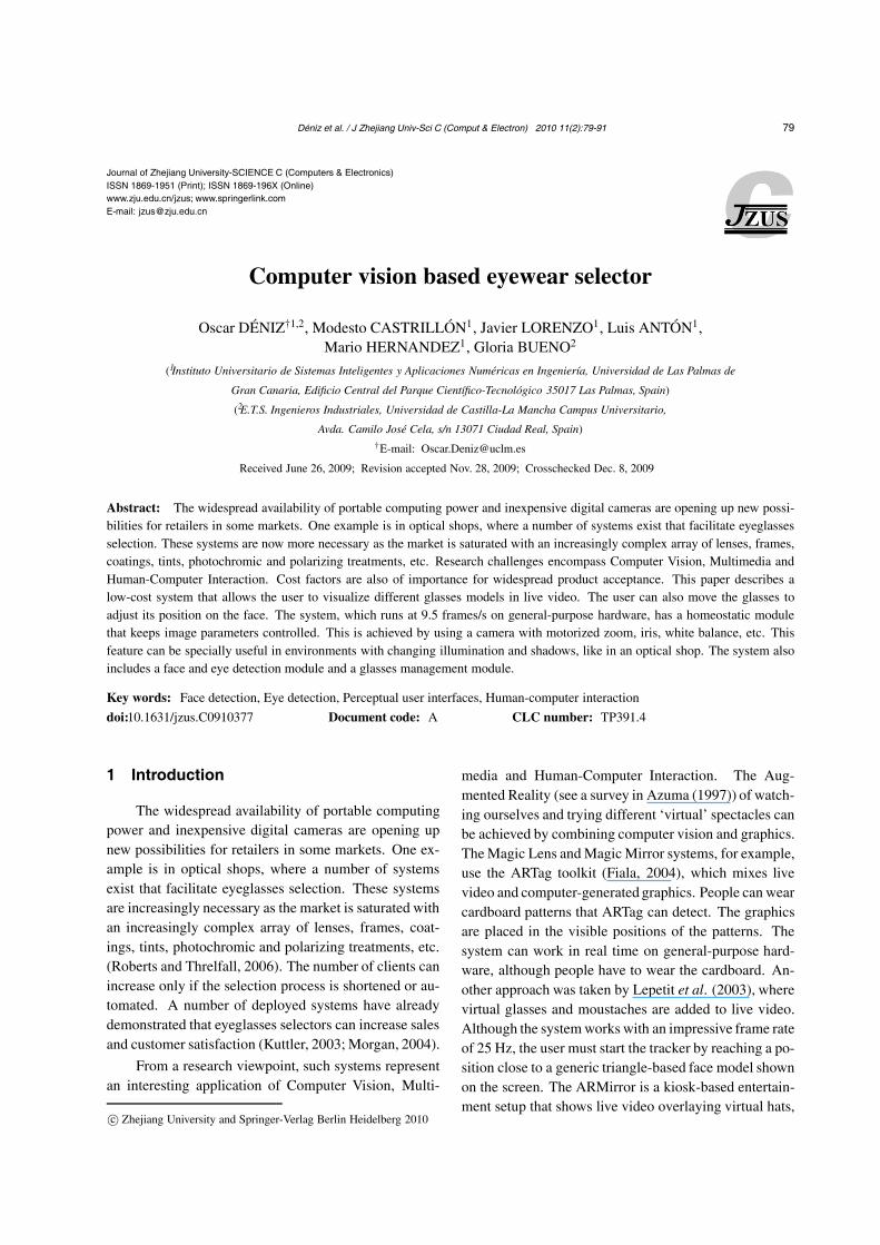
The hardware system has the following compo-nents: a Windows box and two Sony FCB cameras withmotorized zoom, focus, white balance and shutter speed.The cameras are placed together on top of the screen(either a computer monitor or a projector can be used).Camera 1 has a resolution of 384×288 pixels and makesno use of the zoom, while camera 2 (352×288 pixels)uses a (fixed) zoom such that only the user’s face appearsin the image (Fig. 1). Camera 2 captures only gray scaleframes. The monitor displays the full-screen live videoof camera 1 with overlaid glasses and on-screen buttons.
(a) (b)
Fig. 1 (a) Image of camera 1; (b) Image of camera 2
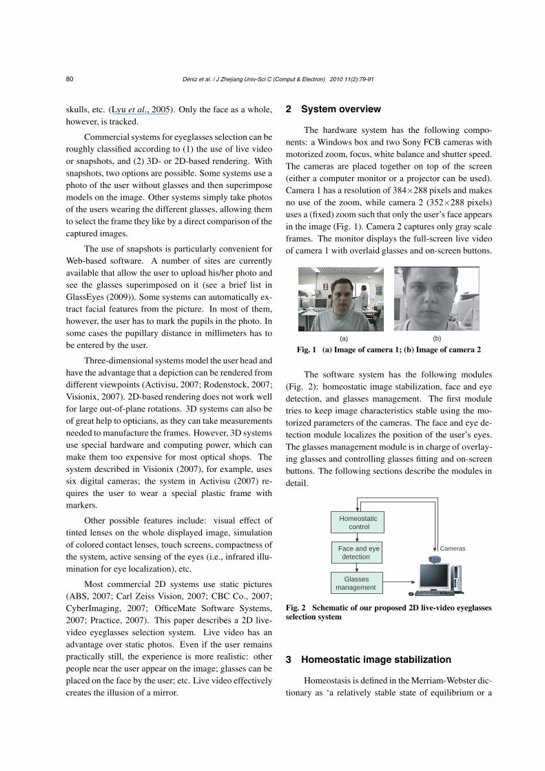
The software system has the following modules(Fig. 2): homeostatic image stabilization, face and eyedetection, and glasses management. The first moduletries to keep image characteristics stable using the mo-torized parameters of the cameras. The face and eye de-tection module localizes the position of the user’s eyes.The glasses management module is in charge of overlay-ing glasses and controlling glasses fitting and on-screenbuttons. The following sections describe the modules indetail.
Cameras
Homeostatic
control
Face and eye
detection
Glasses
management
Fig. 2 Schematic of our proposed 2D live-video eyeglassesselection system
3 Homeostatic image stabilization
Homeostasis is defined in the Merriam-Webster dic-tionary as ‘a relatively stable state of equilibrium or a

Déniz et al. / J Zhejiang Univ-Sci C (Comput & Electron) 2010 11(2):79-91 81
tendency toward such a state between the different butinterdependent elements or groups of elements of an or-ganism, population, or group’. The state of equilibriumis normally related to the survival of the organism in anenvironment. Organisms are endowed with regulationmechanisms, generally referred to as homeostatic adap-tation, in order to maintain this state of equilibrium.
This idea has been used by some authors for build-ing systems that carry out their activity in a complexenvironment (Velasquez, 1997; 1998; Breazeal, 1998;Gadanho and Hallam, 2001). Arkin and Balch (1997) intheir AuRA architecture proposed a homeostatic adapta-tion system that modifies the performance of the overallmotor response according to the level of internal param-eters such as battery or temperature. Another work thatincludes a homeostatic adaptation mechanism is the pro-posal by Low et al. (2002) who introduced it to regulatethe dynamic behavior of the robot during task execution.
In most computer vision systems, performanceheavily depends on the quality of the images supplied bythe acquisition subsystem. Face detection systems thatmake use of the skin color depend on the white balance;Edge detection based tracking systems depend on imagecontrast; etc. On the other hand, image quality is affectedby environmental conditions, namely lighting conditionsor the distance from the object of interest to the cam-era. A typical scenario for an eyewear selection system isan optical shop, where environmental conditions changesignificantly throughout the day. Homeostatic adaptationwill try to compensate for these effects on the image byusing the adjustable parameters of the cameras.
In the affective computing framework (Picard,1997), systems must be ‘embodied’ because human emo-tions involve both the body and the mind. As the pro-posed system does not have a body, like an anthropo-morphic robot, we simulate the physiological changesthat influence the homeostasis mechanism. Cañamero(1997) proposed synthetic hormones to imitate physio-logical changes in the body of a robot which evolves ina 2D world and whose motivations respond to the levelsof the synthetic hormones. We adopted this approach inour system by implementing the synthetic hormones thatreflect the internal state of the vision system (Fig. 3).
The internal state of the vision system is rep-resented by four hormones associated to luminance(h_luminance), contrast (h_contrast), color constancy(h_whitebalance) and size of the object (h_size). Thehomeostatic mechanism will be in charge of keeping thisinternal state into a regime, which will allow the sys-
Zoom Focus Red gain
Blue gainIris Shutter speed
Size Contrast White balance Lurninance
Internal state
(Hormones)
High level tasks
External
inputs
Drive
parameters
Adapta
tion
Fig. 3 Elements of the homeostatic adaptation mechanism
tem to operate with acceptable performance. The inter-nal state of the system also modifies high level behaviors(Fig. 3). If the image is too dark, for example, it makesno sense to carry out any visual process on it.
An important element in a homeostatic mechanismis its adaptive aspect. When the internal state of the bodyis too far away from the desired regime, the homeostaticmechanism must recover it as soon as possible.
The adaptive response of the homeostatic mecha-nism is governed by the hormone levels that are com-puted from the controlled variables by means of sigmoidmapping (Fig. 4). In this way, we can implement adap-tive strategies more easily in the drives since the hormonelevels that define the normal and urgent recovery zonesare always the same, independent of the values of con-trolled variables.
Urgent recovery
Normal recovery
Normal recovery
Urgent recovery
Hormone value
Understimulated Homeostatic Overwhelmed
regime regime regime
Fig. 4 Hormone value mapping from the variable ofinterest
The luminance of the image is computed by divid-ing the image into five regions, similar to the method pro-posed by Lee et al. (2001): an upper strip (R0), a lowerstrip (R4), and the central strip is divided into three re-gions (R1, R2 and R3 from left to right) (Fig. 5). Thesefive regions allow us to define different auto exposure

82 Déniz et al. / J Zhejiang Univ-Sci C (Comput & Electron) 2010 11(2):79-91
Region 0
Region
2
Region
3
Region 4
Region
1
Fig. 5 Regions used to compute the luminance of the image
(AE) strategies according to the nature of the object of in-terest giving different weights to the average luminancein each region.
We have tested three different strategies for auto ex-posure that we have called uniform, centered and selec-tive. The luminance for each of these strategies is com-puted as follows:
Luniform = (L0 + L1 + L2 + L3 + L4)/5, (1)
Lcentered = 0.8L2 + 0.2(L0 + L1 + L3 + L4)/4, (2)
Lselective = 0.8(L2 + L4)/2 + 0.2(L0 + L1 + L3)/3, (3)
where L is the total luminance of the image and Li de-notes the average luminance of region i. The Lcentered
strategy is suitable for tracking tasks where the object ofinterest is in the center of the image, whereas Lselective issuitable for human-computer interaction because it con-siders the part of the image where normally a person ap-pears when he/she is sitting in front of a computer. Asfor white balance, we assumed a ‘grey world’ scenario(Nanda and Cutler, 2001), which tries to make the aver-age amount of green, blue and red in the image constantby adjusting the red and blue gains.
4 Face and eye detection
Several approaches have recently been described totackle reliable face detection in real time (Schneidermanand Kanade, 2000; Li et al., 2002; Viola and Jones,2004), making face detection less environment depen-dent. Cue combination usually provides greater robust-ness and higher processing speeds, particularly for livevideo stream processing. This is evidenced by the factthat a face detector based on cue combination (Castrillónet al., 2007) outperforms single cue based detectors (Vi-ola and Jones, 2004), providing a more reliable tool forreal-time interaction.
The face detection system developed for the selec-tor (called ENCARA2, see Castrillón et al. (2007) fordetails) integrates, among other cues, different classifiers
based on the general object detection framework by Vi-ola and Jones (2004): skin color, multi-level tracking,etc. The detection system provides not only face detec-tion but also eye location in many situations. This ad-ditional feature reduces the number of false alarms, be-cause it is less probable that both detectors, i.e., face andeyes, are activated simultaneously with a false alarm.
In order to further minimize the influence of falsealarms, we extended the facial feature detector capabil-ities, locating not only eyes but also the nose and themouth. For that reason, several Viola-Jones’ frameworkbased detectors have been computed for the chosen in-ner facial elements. Positive samples were obtained byannotating manually the eye, the nose and the mouth lo-cation in 7000 facial images taken randomly from theInternet. The images were later normalized by means ofeyes information to 59×65 pixels (Fig. 6a). Five differ-ent detectors were computed: (1)–(2) Left and right eyes(18×12), (3) eye pair (22×5), (4) nose (22×15), and (5)mouth (22×15). These detectors are publicly available(Reimondo, 2007).
(a) (b) (c)
Fig. 6 Normalized face sample (a) and likely locations fornose (b) and mouth (c) positions after normalization
The facial element detection procedure is appliedonly in those areas that bear evidence of containing aface. This is true for regions in the current frame, wherea face has been detected, or in areas with detected facesin the previous frame. For video stream processing,given the estimated area for each feature, candidates aresearched for in those areas not only by means of Viola-Jones based facial features detectors, but also by SSD-tracking previous facial elements. Once all the candi-dates have been obtained, the combination with the high-est probability is selected and a likelihood based on thenormalized positions for the nose and the mouth is com-puted for this combination. To this end, two probabilitymaps were computed for the location of the nose and themouth (given a normalized location for both eyes). Thesetwo estimated probability maps (Figs. 6b and 6c) werecomputed based on the information achieved after man-ually annotating around 6000 frontal face images.

Déniz et al. / J Zhejiang Univ-Sci C (Comput & Electron) 2010 11(2):79-91 83
Thus, during detection, different eye, nose andmouth candidates are obtained making use of trackersand detectors in specific areas. For each eye, nose andmouth candidate their transformation to the normalizedlocation and scale is computed. The positions with thehighest total likelihood (using the estimated probabilitymaps) are selected. Fig. 7 (see p.84) shows the possibili-ties of the described approach with a sequence extractedfrom DaFEx (Battocchi and Pianesi, 2004).
The face and eye localization system describedabove works with images provided by camera 1. Thezoom camera (camera 2) is used to capture the user’s facewith a larger resolution compared with camera 1. Thiscan potentially provide a more precise and stable local-ization. Both eyes are searched for in the images taken bythe zoom camera. A Viola-Jones detector is used alongwith tracking of eye patterns. ENCARA2 and complexeye localization methods are discarded to keep an accept-able frame rate of the whole system. As the glasses willhave to be superimposed in the images taken from cam-era 1, the localizations found in each camera-2 framehave to be mapped onto the camera-1 frame. Wheneveran eye pair localization is obtained, the eye patterns inthose localizations are scaled down. The scale factor isthe ratio of inter-eye distances found in frames of the twocameras. The scaled eye patterns are then searched for inthe images captured by camera 1 (the cameras are notsynchronized, though the speed of head movement is nothigh enough to cause significant differences in the im-ages). This search is carried out in the vicinity of the lasteye pair localization obtained for camera 1. In order toavoid strange positions and sizes of the glasses for sig-nificant out-of-plane head rotations, the glasses are notshown whenever the inter-eye distance is smaller than athreshold. Fig. 8 shows the process.
Scaling ratio
Frame i
Search
Scale down
Frame i
Fig. 8 Eye localization with the zoom camera
5 Glasses management
Glasses are superimposed on camera-1 imagesthrough alpha blending. This process is a mixing of twoimages, with the mixing weights given by a third im-age. The models are made up of two images: the glassesand the alpha channel. The alpha channel defines thezones of the glasses that are translucent (i.e., the mixingweights) (Fig. 9). The glasses models are obtained bytaking frontal photographs of real glasses of a local op-tical shop. The pictures are cropped and the alpha chan-nels extracted using image editing software.
Fig. 9 (a) Glasses model; (b) Associated alpha channel
Glasses models are scaled according to the inter-eye distance, rotated, and finally placed on the screenaccording to the eye midpoint. Blending is performedonly in the affected image region. Note that eye local-ization has an inherent error, which is also present in themidpoint. The eye midpoint has to be obtained robustly.The glasses should move with the face; otherwise, therendition will appear unrealistic. Thus, a Lucas-Kanadepyramidal tracker (Bouguet, 1999) tracks strong cornerswithin the face region (Fig. 10). The average displace-ment vector pm of the n tracking points is used in eachframe to correct the displacement of the eye midpoint:
pm =1n
n
∑i=1
(pi(t)−pi(t −1)), (4)
e∗ = e + pm. (5)
The current glasses model can be changed with on-screen previous-next buttons (Fig. 11). Button pressingdetection is achieved by detecting skin color blobs withinthe button zones. Each button press is followed by a feed-back sound. With on-screen buttons there is no need touse keyboard or mouse to control the system (note thatthe system is activated as soon as a face is detected bythe system; no other user interaction is necessary). Inour case the subjects are separated from the screen. Ifthe subject can be closer, a touch screen can be used in-stead. Additional buttons may be added to change tints,coatings, frame thickness, etc.

84 Déniz et al. / J Zhejiang Univ-Sci C (Comput & Electron) 2010 11(2):79-91
Fig. 7 Facial element detection samples for a sequence extracted from DaFEx
Fig. 10 Facial tracking
Fig. 11 Selecting the next glasses model
Glasses models are stored as images. The center ofthe glasses image is placed on the eye midpoint. Thismay lead to undesired results if the glasses image is notwell centered. Horizontal centering is not difficult toachieve, though the vertical center is subjective. Besides,each user’s facial characteristics may require differentplacements over his/her nose. To tackle this, glassesplacement gesture detection is added to the system.
Robust and efficient hand pose detection in video isa challenging problem, mainly due to the inherent vari-ability and flexibility of the articulated hand structure,the large domain of gestures, the restriction of real-timeperformance, varying illumination conditions, and com-plex background clutter. Therefore, different restrictionsare commonly considered or even manual initializationis performed for this task.
The literature is rich in hand detection approaches.These approaches have traditionally been based on skincolor segmentation (Storring et al., 2004), basically dueto their reduced processing cost. Recent approaches(Kölsch and Turk, 2004; Stenger et al., 2004; Just et
al., 2006; Wagner et al., 2006), however, have uti-lized Viola-Jones’ object detection framework (Viola andJones, 2004). Although frontal faces share common fea-tures (eyes, eyebrows, nose, mouth, hair), hands are notthat easy to describe. They are highly deformable ob-jects, so training a single cascade classifier for detectinghands is a complex and arduous task. For that reason, adifferent classifier for each recognizable gesture has beentrained (Stenger et al., 2004), but also a single classifierfor a limited set of hands has been proposed (Kölsch andTurk, 2004).
Considering the unrestricted context of this applica-tion, in terms of hand gestures, the use of multiple de-tectors would produce an approach not suitable for real-time processing. In consequence, we have chosen theskin color approach for faster processing. Instead of us-ing a predefined color space definition, the informationobtained from the face blob (see the previous section)is used to estimate the histogram-based (Swain and Bal-lard, 1991) skin color model for that individual (see asimilar technique in Sanchez-Nielsen et al. (2005)). Theskin color model is employed to locate other skin-likeblobs in the image, and in consequence to find the handsfor a given face using coherent skin blobs and consid-ering anthropomorphic dimensions. This is done onlyfor a robustly detected face, for which at least three fa-cial features—the face itself, its eyes, and the nose orthe mouth—have been detected as a trusted result. Thisconsideration is used to reduce the possibility of falsedetections, i.e., false positives. A color model is thenlearned or updated (if already created for that individual)only from these trusted faces, reducing the probability ofusing erroneous face detections.
The glasses placement algorithm is based on de-tecting the placement gesture on the skin-color image.Along the vertical sides of the face rectangle a series ofsmall lateral rectangles are considered (Fig. 12). Theirsize is proportional to the size of the detected face, con-sidering anthropomorphic relations.
The skin-color image is softened using a Gaussianfilter with an aperture that equals the detected face width.

Déniz et al. / J Zhejiang Univ-Sci C (Comput & Electron) 2010 11(2):79-91 85
(a) (b)
Fig. 12 Glasses placement gesture detection. (a) Thebiggest white rectangle represents the face area. Along itssides (dotted area), the rectangle R with the highest sum ofskin pixels is found. Inside R, columns are analyzed fromthe face side through half this rectangle to check skin-colorcontinuity. The same operation is performed on the otherside of the face. An integral image is used to speed up thesumming of skin pixels. (b) Gesture detection in action
Thus, isolated pixels and small blobs are removed, whilethe face and hand blobs create consistent high-valued re-gions. The hand vertical position is given by the positionof the rectangle R containing the highest sum of skin-color pixels. However, the hand must be in contact withthe head. In order to check the ‘touching the head’ condi-tion, pixel values are analyzed in R. Skin-color continuityis checked from the face side through half the width ofR. Every column should contain at least one pixel with ahigh enough skin-color value (32 on normalized condi-tions). Otherwise, the hand may be still approaching theface or leaving it. Once the hand is detected as ‘touch-ing the head’, its relative displacement is used to movethe glasses upward and downward. When the hand nolonger touches the head, the final relative displacementis stored with the current glasses model. Fig. 13 shows asequence in which the user is fitting the glasses.
Fig. 13 Glasses placement sequence
6 Experiments
For completeness, we first show results for the facedetection task. Seventy-four sequences corresponding todifferent individuals, cameras and environments with a
resolution of 320×240 were recorded. They representeda single individual sitting and speaking in front of thecamera or moderating a TV news program. The facepose was mainly frontal, but it was not controlled; i.e.,lateral views and occlusions due to arm movements werepossible. The eyes were not always visible. The total setcontained 26 338 images.
To test the detector performance, the sequenceswere manually annotated; therefore, the face containerswere available for the whole set of images. However,eye locations were available only for a subset of 4059images. The eyes location allows us to compute the ac-tual distance between them, which will be referred to be-low as ‘EyeDist’. This value will be used to estimate thegoodness of eye detection.
Two different criteria have been defined to establishwhether a detection is correct:
(1) Correct face criterion: A face is considered cor-rectly detected if the detected face overlaps at least 80%of the annotated area, and the sizes of the detected andannotated areas do not differ by more than a factor of 2.
(2) Correct eye criterion: The eyes of a face de-tected are considered correctly detected if for both eyesthe distance to manually marked eyes is lower than athreshold that depends on the actual distance between theeyes, EyeDist. The threshold considered was EyeDist/4,similar to Jesorsky et al. (2001).
Table 1 shows the results obtained after processingthe whole set of sequences with different detectors. Thecorrect detection ratios (TD) are given considering thewhole sequence, and the false detection ratios (FD) arerelated to the total number of detections. Rowley’s detec-tor was notably slower than the others, but it provided eyedetection for 78% of the detected faces, feature whichis not considered by Viola-Jones’ detector. As for EN-CARA2, it is observed that it performed at least twice asfast as Viola-Jones’ detector, and almost ten times fasterthan Rowley’s. Speed is the main goal in our application,and the face detector is critical for the live-video selector.More details of ENCARA2 can be found in Castrillón etal. (2007).
Another important part of the system is homeostaticregulation. Fig. 14 shows the effect of the uniform, cen-tered and selective strategies for luminance control (seeSection 3). With the uniform strategy the face appeareddarker because the bright zone on the left made the av-erage luminance level larger. With both the centered andselective strategies the face was more clearly visible.
To test the effect of homeostatic regulation in the

86 Déniz et al. / J Zhejiang Univ-Sci C (Comput & Electron) 2010 11(2):79-91
Table 1 Results for face and eye detection processing using a Pentium IV 2.2 GHz CPU*
Detector TD (%) FD (%) Processing time
Faces Left Eye Right Eye Faces Left Eye Right Eye (ms)
Rowley 89.27 77.51 78.18 2.16 0.80 1.00 422.4Viola-Jones 97.69 0.00 0.00 8.25 117.5ENCARA2 99.92 91.83 92.48 8.07 4.04 3.33 45.6
∗ Taken from Castrillón et al. (2007). TD: correct detection ratio; FD: false detection ratio
face detection task, a performance measure was definedas the ratio between the number of detected faces ina second and the number of images per second. AsENCARA2 depends heavily on skin color and patternmatching to detect faces, we studied the influence of lu-minance and white balance on performance.
50
100
150
200
250
300
350
400
450
50
100
150
200
250
300
350
400
450
50
100
150
200
250
300
350
400
450
(a)
(b)
(c)
100 200 300 400 500 600
Fig. 14 Luminance regulation using (a) the uniform strat-egy, (b) the centered strategy, and (c) the selective strategy
Fig. 15 shows the values of the h_luminance andh_whitebalance hormones along with the face detectionrate for an individual moving in front of the camera. Thedashed lines represent the changes in the environmental
condition (lighting). When the system started, the detec-tion rate was high, and it decreased slightly when morelights were switched on (30–57 s). When the lights wereswitched on, both the h_luminance and h_whitebalancehormones went out of their desired states but the homeo-static mechanism recovered them after a delay, larger forthe h_whitebalance hormone than for the h_luminanceone.
With regulation Without regulation
h-lu
min
an
ce
h-w
hite
ba
lan
ce
Fa
ce
de
tectio
n r
ate
1.00.8
0.20.0
-0.2
-0.8-1.0
1.5
1.0
0.5
0.0 0 20 40 60 80 100 120 140
Time (s)
1.00.8
0.20.0
-0.2
-0.8-1.0
Fig. 15 h-luminance, h-whitebalance, and the face detec-tion rate with and without homeostatic mechanism
The homeostatic mechanism was deactivated after70 s, so when the conditions changed again, the state ofthe hormones was not recovered and the performance ofthe system decreased with a low rate of detections.
To speed up the recovery, we implemented an adap-tive strategy using the two recovery levels of the hor-mones. When a hormone went into the urgent recoveryzone we applied a more aggressive recovery strategy (in-creasing the aperture of the iris or the red and blue gains)than when hormones were in the normal recovery zone(Fig. 4). We repeated the experiment, but we were in-terested in only the delay until the hormones returned tothe homeostatic regime. Fig. 16 shows the results withthe adaptive strategy and it can be noted that the recoverytime has been reduced.
Déniz et al. / J Zhejiang Univ-Sci C (Comput & Electron) 2010 11(2):79-91 87
0 20 40 60 80 100 120 140
h-lu
min
an
ce
h-w
hite
ba
lan
ce
1.00.8
0.20.0
-0.2
-0.8-1.0
1.00.8
0.20.0
-0.2
-0.8-1.0
Time (s)
0 20 40 60 80 100 120 140
Fig. 16 Effect of the introduction of an adaptive strategyon the recovery time
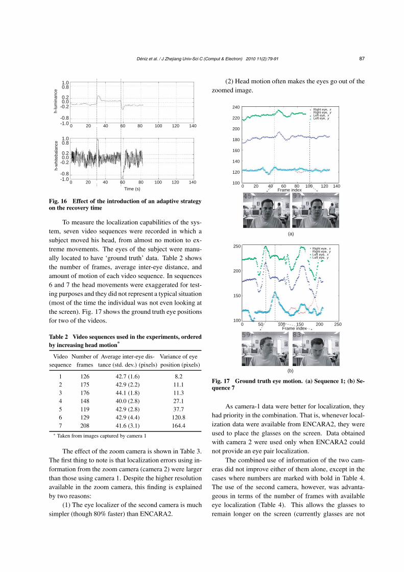
To measure the localization capabilities of the sys-tem, seven video sequences were recorded in which asubject moved his head, from almost no motion to ex-treme movements. The eyes of the subject were manu-ally located to have ‘ground truth’ data. Table 2 showsthe number of frames, average inter-eye distance, andamount of motion of each video sequence. In sequences6 and 7 the head movements were exaggerated for test-ing purposes and they did not represent a typical situation(most of the time the individual was not even looking atthe screen). Fig. 17 shows the ground truth eye positionsfor two of the videos.
Table 2 Video sequences used in the experiments, orderedby increasing head motion*
Video Number of Average inter-eye dis- Variance of eyesequence frames tance (std. dev.) (pixels) position (pixels)
1 126 42.7 (1.6) 8.22 175 42.9 (2.2) 11.13 176 44.1 (1.8) 11.34 148 40.0 (2.8) 27.15 119 42.9 (2.8) 37.76 129 42.9 (4.4) 120.87 208 41.6 (3.1) 164.4
∗ Taken from images captured by camera 1
The effect of the zoom camera is shown in Table 3.The first thing to note is that localization errors using in-formation from the zoom camera (camera 2) were largerthan those using camera 1. Despite the higher resolutionavailable in the zoom camera, this finding is explainedby two reasons:
(1) The eye localizer of the second camera is muchsimpler (though 80% faster) than ENCARA2.
(2) Head motion often makes the eyes go out of thezoomed image.
Right eye, xRight eye, yLeft eye, xLeft eye, y
240
220
200
180
160
140
120
1000 20 40 60 80 100 120 140
Frame index
(a)
250
200
150
1000 50 100 150 200 250
Frame index
(b)
Right eye, xRight eye, yLeft eye, xLeft eye, y
Fig. 17 Ground truth eye motion. (a) Sequence 1; (b) Se-quence 7
As camera-1 data were better for localization, theyhad priority in the combination. That is, whenever local-ization data were available from ENCARA2, they wereused to place the glasses on the screen. Data obtainedwith camera 2 were used only when ENCARA2 couldnot provide an eye pair localization.
The combined use of information of the two cam-eras did not improve either of them alone, except in thecases where numbers are marked with bold in Table 4.The use of the second camera, however, was advanta-geous in terms of the number of frames with availableeye localization (Table 4). This allows the glasses toremain longer on the screen (currently glasses are not

88 Déniz et al. / J Zhejiang Univ-Sci C (Comput & Electron) 2010 11(2):79-91
Table 3 Average eye localization errors in pixels
Video REE LEE
sequence Camera 1 Camera 2 Combination Camera 1 Camera 2 Combination
1 1.68 (1.01) 3.08 (2.41) 1.61 (1.01) 1.53 (0.87) 2.85 (1.78) 1.53 (0.87)2 2.78 (2.91) 5.44 (5.17) 2.71 (2.92) 2.81 (1.21) 4.27 (3.25) 2.73 (1.25)3 2.39 (1.00) 1.38 (0.93) 2.36 (0.98) 2.03 (0.80) 2.37 (1.23) 2.03 (0.78)4 1.86 (1.21) 2.96 (2.94) 1.99 (1.19) 2.69 (1.41) 2.22 (1.43) 2.40 (1.27)5 2.63 (1.39) 2.48 (1.57) 2.54 (1.34) 2.37 (1.16) 2.69 (1.78) 2.33 (1.51)6 3.03 (2.75) 6.82 (7.86) 6.14 (7.22) 2.64 (1.76) 9.81 (10.03) 7.79 (9.27)7 2.29 (1.24) 5.36 (4.82) 2.82 (2.13) 2.22 (1.55) 7.91 (11.48) 4.81 (9.93)
REE=right eye error, LEE=left eye error. In parentheses is the standard deviation. Note that all values are referenced to camera 1
(for camera-2 localizations the mapping depicted in Fig. 8 is used). The bold number represents an improvement from the use of
either camera-1 or camera-2 data alone
Table 4 Number of frames with available eye pairlocalization
Video Number of frames
sequence Camera 1 Camera 2 Combination
1 124/126 109/126 124/1262 173/175 57/175 173/1753 174/176 126/176 174/1764 76/148 81/148 111/1485 100/119 89/119 113/1196 51/129 71/129 83/1297 165/208 157/208 203/208
The bold number represents an improvement from the use of either
camera-1 or camera-2 data alone
drawn if no eye localization can be obtained, although itis also possible to draw them using the last known posi-tion), even if the individual is moving (Fig. 18).
In another experiment, facial tracking (see Section4) as a localization aid was tested. Table 5 shows that itsuse is specially advantageous when there are large headmotions. The tracker was reinitialized every 60 frames.
Table 5 Squared errors of the eye midpoint position*
Video Squared error (pixels) Improvement
sequence No tracking With tracking (%)
1 1.451 (0.677) 1.307 (0.648) 9.912 2.286 (1.515) 2.189 (1.467) 4.253 1.505 (0.626) 1.413 (0.732) 6.134 2.112 (1.147) 1.775 (0.951) 15.995 2.079 (1.057) 2.037 (1.062) 2.006 6.835 (12.112) 7.026 (11.346) –2.807 3.349 (6.230) 3.334 (5.788) 0.43
∗ The tracking of facial points was given a weight equal to the no-
tracking eye midpoint localization
0 50 100 150
(a)
(c)
(b)
250
200
150
100
250
200
150
100
250
200
150
100
Fig. 18 Video sequence 4. (a) Camera-1 data; (b) Camera-2 data; (c) Combination of (a) and (b)
Figs. 19 and 20 show examples of situations in which noeye localization was obtained for at least two consecu-tive frames (only the first frame is shown). This situationhappened only in sequences 6 and 8. Note that in mostof the situations the subject was not frontal.
Currently, the whole system runs at 9.5 frames/s,with peaks of 12.8 frames/s, on a Core 2 DuoTM CPUat 1.86 GHz. Fig. 21 shows a subject trying six glassesmodels.
7 Conclusion
The affordability of cameras and portable comput-ing power is facilitating the introduction of computervision in optical shops. Retailers are particularly inter-ested in automating or accelerating the selection process.Most commercially available systems for eyewear selec-tion use static pictures. This paper describes a patent-pending live-video eyeglasses selection system based on

Déniz et al. / J Zhejiang Univ-Sci C (Comput & Electron) 2010 11(2):79-91 89
Fig. 19 Situations in sequence 6 in which no eye localizationwas obtained for at least two consecutive frames (only thefirst frame is shown)
Fig. 20 Situations in sequence 8 in which no eye localizationwas obtained for at least two consecutive frames (only thefirst frame is shown)
Fig. 21 Six glasses models
computer vision techniques. The system, running at 9.5frames/s on general-purpose hardware, has a homeostaticmodule that keeps image parameters controlled. This isachieved using cameras with motorized zoom, iris, whitebalance, etc. This feature can be specially useful in envi-ronments with changing illumination and shadows, suchas in an optical shop. The system also has a face and eyedetection module and a glasses management module.
Further improvements are possible. On the onehand, image resolution can be enhanced with more com-puting power. On the other hand, other interaction ca-pabilities can be added to the system, such as zoom andmirror-like glasses. The system described can be eas-ily adapted to the available hardware. Modern laptops,for example, include an integrated webcam and sufficientcomputing power to be used as a low-cost, portable eye-wear selector.
Acknowledgements
The authors wish to thank Dr. Cayetano Guerra andJ. Tomás Milán for providing the glasses models.
ReferencesABS, 2007. Smart Look. Available from http://www.smart-
mirror.com [Accessed on July 30, 2007].
Activisu, 2007. Activisu Expert. Available from http://www.activisu.com [Accessed on July 30, 2007].

90 Déniz et al. / J Zhejiang Univ-Sci C (Comput & Electron) 2010 11(2):79-91
Arkin, R.C., Balch, T., 1997. AuRA: Principles and practicein review. J. Exper. Theor. Artif. Intell., 9(2-3):175-189.[doi:10.1080/095281397147068]
Azuma, R.T., 1997. A survey of augmented reality. Presence,6:355-385.
Battocchi, A., Pianesi, F., 2004. Dafex: Un Database di Espres-sioni Facciali Dinamiche. SLI-GSCP Workshop Comuni-cazione Parlata e Manifestazione delle Emozioni, p.1-11.
Bouguet, J., 1999. Pyramidal Implementation of the LucasKanade Feature Tracker. Technical Report, OpenCVDocuments, Intel Corporation, Microprocessor ResearchLabs.
Breazeal, C., 1998. A Motivational System for RegulatingHuman-Robot Interaction. AAAI/IAAI, p.54-61.
Cañamero, D., 1997. Modeling Motivations and Emo-tions as a Basis for Intelligent Behavior. Proc. 1stInt. Conf. on Autonomous Agents, p.148-155.[doi:10.1145/267658.267688]
Carl Zeiss Vision, 2007. Lens Frame Assistant. Available fromhttp://www.zeiss.com [Accessed on July 30, 2007].
Castrillón, M., Déniz, O., Hernández, M., Guerra, C.,2007. ENCARA2: real-time detection of multiplefaces at different resolutions in video streams. J.Vis. Commun. Image Represent., 18(2):130-140.[doi:10.1016/j.jvcir.2006.11.004]
CBC Co., 2007. Camirror. Available from http://www.camir-ror.com [Accessed on July 30, 2007].
CyberImaging, 2007. CyberEyes. Available from http://www.cyber-imaging.com [Accessed on July 30, 2007].
Fiala, M., 2004. Artag, an Improved Marker System Based onArtoolkit. Technical Report, ERB-1111, NRC Canada.
Gadanho, S.C., Hallam, J., 2001. Robot learningdriven by emotions. Adapt. Behav., 9(1):42-64.[doi:10.1177/105971230200900102]
GlassyEyes, 2009. Trying Eyeglasses Online. GlassyEyesBlog. Available from http://glassyeyes.blogspot.com[Accessed on Dec. 23, 2009].
Jesorsky, O., Kirchberg, K.J., Frischholz, R.W., 2001. Ro-bust face detection using the Hausdorff distance. LNCS,2091:90-95. [doi:10.1007/3-540-45344-X_14]
Just, A., Rodriguez, Y., Marcel, S., 2006. Hand Pos-ture Classification and Recognition Using the Modi-fied Census Transform. Proc. Int. Conf. onAutomatic Face and Gesture Recognition, p.351-356.[doi:10.1109/FGR.2006.62]
Kölsch, M., Turk, M., 2004. Robust Hand Detec-tion. Proc. Sixth IEEE Int. Conf. on Au-tomatic Face and Gesture Recognition, p.614-619.[doi:10.1109/AFGR.2004.1301601]
Kuttler, H., 2003. Seeing Is Believing. Using Virtual Try-ons to Boost Premium Lens Sales. Available fromhttp://www.2020mag.com [Accessed on Dec. 23, 2009].
Lee, J.S., Jung, Y.Y., Kim, B.S., Ko, S.J., 2001. An advancedvideo camera system with robust AF, AE and AWB con-trol. IEEE Trans. Consum. Electron., 47(3):694-699.[doi:10.1109/30.964165]
Lepetit, V., Vacchetti, L., Thalmann, D., Fua, P., 2003. FullyAutomated and Stable Registration for Augmented Re-ality Applications. Proc. 2nd IEEE and ACM Int.Symp. on Mixed and Augmented Reality, p.93-102.[doi:10.1109/ISMAR.2003.1240692]
Li, S., Zhu, L., Zhang, Z., Blake, A., Zhang, H., Shum, H.,2002. Statistical learning of multi-view face detection.LNCS, 2353:67-81. [doi:10.1007/3-540-47979-1_5]
Low, K.H., Leow, W.K., Ang, M.H.Jr., 2002. IntegratedPlanning and Control of Mobile Robot with Self-Organizing Neural Network. Proc. 18th IEEE Int.Conf. on Robotics and Automation, p.3870-3875.[doi:10.1109/ROBOT.2002.1014324]
Lyu, M.R., King, I., Wong, T.T., Yau, E., Chan, P.W., 2005.ARCADE: Augmented Reality Computing Arena forDigital Entertainment. Proc. IEEE Aerospace Conf., p.1-9. [doi:10.1109/AERO.2005.1559626]
Morgan, E., 2004. Dispensing’s New Wave. Eyecare Business.Available from http://www.eyecarebiz.com [Accessed onDec. 23, 2009].
Nanda, H., Cutler, R., 2001. Practical Calibrations for a Real-Time Digital Omnidirectional Camera. Proc. ComputerVision and Pattern Recognition Conf., p.3578-3596.
OfficeMate Software Systems, 2007. iPointVTO. Availablefrom http://www.opticalinnovations.com [Accessed onJuly 30, 2007].
Picard, R., 1997. Affective Computing. MIT Press, Cam-bridge, MA.
Practice, P., 2007. FrameCam. Available from http://www.pa-perlesspractice.com [Accessed on July 30, 2007].
Reimondo, A., 2007. OpenCV Swiki. Available fromhttp://www.alereimondo.no-ip.org/OpenCV/ [Accessedon Dec. 23, 2009].
Roberts, K., Threlfall, I., 2006. Modern dispensing tools. Op-tions for customised spectacle wear. Optometry Today,46(12):26-31.
Rodenstock, 2007. ImpressionIST. Available from http://www.rodenstock.com [Accessed on July 30, 2007].
Sanchez-Nielsen, E., Anton-Canalis, L., Guerra-Artal, C.,2005. An autonomous and user-independent hand pos-ture recognition system for vision-based interface tasks.LNCS, 4177:113-122. [doi:10.1007/11881216_13]
Schneiderman, H., Kanade, T., 2000. A Statistical Method for3D Object Detection Applied to Faces and Cars. IEEEConf. on Computer Vision and Pattern Recognition,p.1746-1759.
Stenger, B., Thayananthan, A., Torr, P., Cipolla, R., 2004.Hand pose estimation using hierarchical detection. LNCS,3058:105-116. [doi:10.1007/b97917]

Déniz et al. / J Zhejiang Univ-Sci C (Comput & Electron) 2010 11(2):79-91 91
Storring, M., Moeslund, T., Liu, Y., Granum, E., 2004. Com-puter Vision Based Gesture Recognition for an Aug-mented Reality Interface. 4th IASTED Int. Conf. on Vi-sualization, Imaging, and Image Processing, p.766-771.
Swain, M.J., Ballard, D.H., 1991. Color indexing. Int. J. Com-put. Vis., 7(1):11-32. [doi:10.1007/BF00130487]
Velasquez, J., 1997. Modeling Emotions and Other Motiva-tions in Synthetic Agents. Proc. AAAI Conf., p.10-15.
Velasquez, J., 1998. Modeling Emotion-Based Decision Mak-ing. In: Canamero, D. (Ed.), Emotional and Intelligent:The Tangled Knot of Cognition. AAAI Press, Springer
Netherlands, p.164-169.
Viola, P., Jones, M.J., 2004. Robust real-time face de-
tection. Int. J. Comput. Vis., 57(2):137-154.
[doi:10.1023/B:VISI.0000013087.49260.fb]
Visionix, 2007. 3DiView 3D Virtual Try-on. Available from
http://www.visionix.com [Accessed on July 30, 2007].
Wagner, S., Alefs, B., Picus, C., 2006. Framework for a
Portable Gesture Interface. Proc. 7th Int. Conf. on
Automatic Face and Gesture Recognition, p.275-280.
[doi:10.1109/FGR.2006.54]