Lucky Lotto Selector - World Radio History
100
THE MAGAZINE FOR THE ELECTRONICS ACTIVIST! Build Your Own Dice -Roulette Game This little light chaser is two fun projects in one! Lucky Lotto Selector Do those lucky numbers keep escaping you? Build our electronic selector and change your luck! A Hot Socket A shocking little project that's loads of laughs! Test Equipment on the Cheap Bring those golden oldies back to life! Cord Buster Headphone listening without a cord! Radiostrology Are you and your radio made for each other? Your Hobby and the IRS Tax tips that can save you dough! $2.50 U.S. $2.95 CANADA 3 NEW FactCards IN THIS ISSUE GERNSBACK AmericanRadioHistory.Com
-
Upload
khangminh22 -
Category
Documents
-
view
3 -
download
0
Transcript of Lucky Lotto Selector - World Radio History

THE MAGAZINE FOR THE ELECTRONICS ACTIVIST!
Build Your Own Dice -Roulette Game This little light chaser is two fun projects in one!
Lucky Lotto Selector Do those lucky numbers keep escaping you? Build our electronic selector and change your luck!
A Hot Socket A shocking little project that's loads of laughs!
Test Equipment on the Cheap Bring those golden oldies back to life!
Cord Buster Headphone listening without a cord!
Radiostrology Are you and your radio made for each other?
Your Hobby and the IRS Tax tips that can save you dough!
$2.50 U.S.
$2.95 CANADA
3 NEW FactCards IN THIS ISSUE
GERNSBACK
AmericanRadioHistory.Com

/CORPORA
8 0
701 Brooks Ave. South
M
TION Quality Name Brand Electronic Components
Computerized Order Processing & Inventory Control
Volume Discounts - OEM Pricing - Toll Free Wats Line
P.O. Box 677 Thief River Falls, MN 56701-0677
,*, OF THE TOP 100 ELECTRONIC MANUFACTURERS IN THE UNITED STATES ARE DIGI-KEY CUSTOMERS
'Source: Electronic Business 200, "Electronic Business'. Maaanne, July 15, 1988
This might seem incredible until you realize that . .
5014.10AVAILABLE FOR "OFF -THE -SHELF" DELIVERY - AND THE OTHER 5% ARE ON THE WAY!!
OF THE ITEMS IN DIGI-KEY'S CATALOG ARE
901Ç OF ORDERS ARE SHIPPED TO DIGI-K CUSTOMERS WITHIN 24 HOURS!!
EY
100% COMMITMENT TO CUSTOMER SATISFACTION!!
To receive your complimentary copy of the current Digi-Key Catalog or for pricing and Availability on your current or future needs - Contact Digi-Key today
1-800-344-4539 Easy To Remember: 1-800-DIGI-KEY
AK, PR: 218-681-6674; Easylink: 62827914; Telex II: 9103508982 "DIGI-KEY CORP; FAX: 218-681-3380
Serving A National Market With Quality Electronic Components Since 1972
Ri.WMYkY
M11»PVe^^yw sIe,amq,,,.
k? ;.O , ,: II,,
_r,w. II
'4\ a
3
r m
c
m
o :
9 v
m x ó 3
ñ 3 o 3
m
00 m
3
3 o á
O
Panasonic Amp 3M/Associated Electronics Omron Texas Instruments International Rectifier CIRCLE 10 ON FREE INFORMATION CARD
AmericanRadioHistory.Com

APRIL 1989, VOLUME 6, NO.4
Popular Electronics THE MAGAZINE FOR THE ELECTRONICS ACTIVIST.!
CONSTRUCTION ARTICLES LUCKY LOTTO SELECTOR Charles D. Rakes 29
Build this lucky -number selector and change your luck.
DICE -ROULETTE GAME Jan Axelson and Jim Hughes 32 Combine the thrill of roulette with the odds of a crap shoot.
HOT SOCKET Walter W. Schopp 39 This easy -to -build circuit is bound to generate a shocking response!
CORD BUSTER Charles D. Rakes 44 Get rid of those unsightly patch cords.
FEATURE ARTICLES YOUR HOBBY AND THE IRS Mark E. Battersby 36
When can a hobby be considered a business?
TEST EQUIPMENT ON THE CHEAP Joseph J. Carr 42 Sometimes old is better!
GIZMO 47 Including: Nintendo Power Set, Hitachi Stereo Cassette Receiver/Compact Disc player, and more.
RADIOSTROLOGY Carl Kohler 59 Learn your radio's personality, and you'll both live in astral harmony.
SUPERCONDUCTING MICROPROCESSOR Paul Yorlegg 61 Important breakthrough announced on the first of April!
BEGINNERS GUIDE TO RADIO COLLECTIBLES Marc Ellis 62 There's a lot more out there than old radios.
REPLACING YOUR PC'S FAN Marty Knight 68 It's easier than you think.
E -Z MATH Louis Frenzel 70 Binary numbers and arithmetic.
COLUMNS THINK TANK Byron G. Wels 22
ANTIQUE RADIO Marc Ellis 80 The Philco mystery is solved.
CIRCUIT CIRCUS Charles D. Rakes 82 Fun and game circuits.
COMPUTER BITS Jeff Holtzman 84 What video format is right for you?
HAM RADIO Joseph J. Carr 86 How long is a long-wire antenna?
SCANNER SCENE Marc Saxon 88 A converter can extend the range of your scanner.
DX LISTENING Don Jensen 92 Being big doesn't make it well known.
HANDS-ON REPORTS dBASE III PLUS TRAINING AIDS FOR THE BEGINNER AND PRO 46
DEPARTMENTS EDITORIAL Julian S. Martin 2
LETTER BOX 4
ELECTRONICS LIBRARY 6
NEW PRODUCTS 15
FACTCARDS 37
FREE INFORMATION CARD 71
ADVERTISER'S INDEX 106 Popular Electronics including Hands-on Electronics, (ISSN 1042-170X; Published monthly by Gernsback Publications, Inc., 500-B Bi -County Boulevad, Farmingdale, NY 11735. Second -Class postage paid at Farmingdale. NY and at additional mailing offices. One-year, twelve issues, subscription rate U.S. and possessions $21.95, Cana- da $26.95, all other countries $29.45. Subscription orders payable in U.S. funds only, International Postal Money Order or check drawn on a U.S. bank. U.S. single copy price $2.50. a 1989 by Gemsback Publications, Inc. All rights reserved. Hands-on Elec- tronics and Gizmo trademarks am registered in U.S. and Canada by Gernsback Publications, Inc. Popular Electronics trademark is registered in U.S and Canada by Electronics Technology Today and is licensed to Gernsback Publications. Printed in U.S.A.
Postmaster. Please send address changes to Popular Electronics, including Hands- on Electronics, Subscription Dept., PO. Box 338, Mount Morris. IL 61054-9932.
A stamped self. addressed envelope must accompany all submitted manuscripts and or artwork or photographs if their return is desired should they be rejected. We disclaim any responsibility for the loss or damage of manuscripts and/or artwork or photographs while in our possession or otherwise.
As a service to readers, Popular Electronics including Hands-on Electronics pub- lishes available plans or information relating to newsworthy products, techniques and scientific and technological developments. Because of possible variances in the quality and condition of materials and workmanship used by readers, Popular Electronics including Hands-on Electronics disclaims any responsibility for the safe and proper functioning of reader -built projects based upon or from plans or information published in this magazine.
1
AmericanRadioHistory.Com

Popular Electronics Larry Steckler
EHF, CET
Editor -In -Chief & Publisher
Art Kleiman Editorial Director
Julian S. Martin, KA2GUN Editor
Carl Laron Managing Editor
Robert A. Young Associate Editor
John J. Yacono Associate Editor
Byron G. Wels, K2AVB Associate Editor
Teri Scaduto Assistant Editor
Kathryn Campbell Editorial Assistant
Joseph J. Carr, K4IPV Marc Ellis
Jeffrey K. Holtzman Don Jensen
Charles D. Rakes Marc Saxon
Contributing Editors
Ruby M. Yee Production Director
Karen S. Tucker Production Manager
Robert A. W. Lowndes Editorial Associate
Marcella Amoroso Production Assistant
Andre Duzant Technical Illustrator
Injae Lee Assistant Illustrator
Jacqueline R Cheeseboro Circulation Director
Michele Torrillo P -E Bookstore
BUSINESS AND EDITORIAL OFFICES
Gernsback Publications, Inc. 500-B Bi -County Blvd. Farmingdale, NY 11735
1-516-293-3000 Fax: 1-516-293-3115
President: Larry Steckler Vice President: Cathy Steckler
Advertising Sales Offices listed on page 106.
,1P,1
Cover photography by Diversified Photo Services
Composition by Mates Graphics
e The publisher has no knowledge of any proprietary rights
which will be violated by the making or using of any items disclosed in this issue.
-____ . ' Editorial
ARE HARD DISKS IN FOR HARD TIMES? Remember when hard disks were referred to as Winchester drives? You can still be under 30 years of age, and go back to the beginnings of personal computers. It took time for hard disks to come down to a reasonable price level. And now that they are here in 20-, 30-, 40 -megabyte, and larger capacities for home use, hard disks are facing obscurity!
Enter the erasable CD-re-writeable optical media. As 1988 came to an end, Sony announced a magneto -optical disk - drive system with a removable 51/4 -inch disk capable of storing up to 650 megabytes. The new disks no longer require a micro -laser beam to wallop pulses of coherent light onto a polished surface, marring it permanently.
The magneto -optical process relies on the ability of a micro - laser to pinpoint a minute spot on a single magnetized disk. The disk contains magnetized crystals whose orientation can be altered when the crystal material is heated. The laser warms to the spot to its "Curie point," the point at which the disk's magnetic field is reversed. Each field reversal corresponds to a "0" or a "1," and each piece of data is packed closely together as only the micro -laser can do it.
Reading the stored data is practically a reverse effect-a low- level laser scans the rotating disk, the reflected light changes polarizations as it passes over magnetic islands (the physicists refer to that phenomenon as the Kerr effect), and the detected light is read as digital material. Read -back rates of 7 to 9 -megabits per second are currently possible- admittedly, that's a bit slower than a magnetic disk.
Now the big question is, "Should I junk my hard disk and buy an erasable CD drive?" Not just yet; most of the newly developed units are aimed at the business user, who can afford to pay a price for the unit that will cover the cost, research and development, and profit. In other words, the price is high! Wait until the competition gets tight, production expands, and the market demands low-cost units.
That's when hard disks are in for hard times.
Julian S. Martin, KA2GUN Editor
2
AmericanRadioHistory.Com

., TN HOW üECiROMCf TEMES
Beyond the Transistor 133 Electronics Projects
Take the 5 Volume TAB Hobby
Electronics Library for only 5395
(a S110.70 value!) and get a FREE Gift!
TAa.,pap+ Etfr:rw,na[ urn,
How to Test o` Almost Everything
Electronic Editen
J , Dan a. peeps T. Mom
The TAB Hobby Electronics Library is an all inclusive set of self - teaching guides for electronics hobbyists.
Basic Electronics
Course ind ENtlon
aoaanM M. OIOWMJ0.ST
These updated and revised hardbound editions provide an excellent blend of all aspects of electronics including: electronics theory, reading electronic diagrams, troubleshooting and testing, project building and a whole lot more!
Membership Benefits Big Savings: In addition to this introductory offer, you keep sav- ing substantially with members' prices of up to 50% off the pub- lishers' prices. Bonus Books: Starting immediately, you will be eligible for our Bonus Book Plan, with savings of up to 80% off publishers' prices. Club News Bulletins: 14 times per year you will receive the Book Club News, describing all the current selections-mains, alter- nates, extras-plus bonus offers and special sales, with hundreds of titles to choose from. Automatic Order: If you want the Main Selection, do nothing and it will be sent to you automatically. If you prefer another selection, or no book at all, simply indicate your choice on the reply form provided. As a member, you agree to purchase at least 3 books within the next 12 months and may resign at any time thereafter. Ironclad No -Risk Guarantee: If not satisfied with your books, return them within 10 days without obligation! Exceptional Quality: All books are quality publishers' editions es-
pecially selected by our Editorial Board.
(Publishers' Prices Shown) c 1989 ELECTRONICS BOOK CLUB, , Blue Ridge Summit, PA 17284-0810
r
44 Power Sti
frn VC=
Electronic Projects Naeen J. TrNaur aM Jerutha^ L. Maya
How to Read Electronic Circuit
Diagrams 204 E4itbn
Rnbe' Lawrence.
and James A. WMtstn
FREE when you join! 15 Easy Electronic Projects From Delton T. Horn Projects you can build-some unique, some old favorites-from the author's vast treasury of electronics know-how.
ELECTRONICS EOOK CLUE Blue Ridge Summit, PA 17294-0810
Please accept my membership in the Electronics Book Club® and send the 5
volume TAB Hobby Electronics Library (5282C) plus my FREE copy of Delton T.
Horn's All -Time Favorite Electronic Projects (3105P), billing me $3.95 plus ship- ping/handling charges. If not satisfied, I may return the library within ten days without obligation and have my membership cancelled. I agree to purchase at least
3 books at regular Club prices (plus shipping/handling) during the next 12 months and may resign at any time thereafter.
DeltonT.Horn's All -Time Favorite
Electmnic Projects
Name
Address
City
State Zip Phone
Signature
Signature of parent or guardian required for all new members under 18.
Valid for new members only. Foreign applicants will receive special ordering instructions. Canada must remit in U.S. currency. This order subject to acceptance by the Electronics Book Club"' .
RESP489 L
AmericanRadioHistory.Com

Lr // Letters
BASIC ACNAP
I'd like to answer a question that I received about my article, "AC -Network Analysis Pro- gram," which appeared in the October 1987 issue of Hands-on Electronics. To convert ACNAP to run under Commodore BASIC, try eliminating the magnitude function (FNMAG) altogether. Replacing the original lines with the following ones should do the trick: 1040 REM 3010 B=SQR(A(I,I,0)^2+A(1,1,1)^2) 3030 T=SQR(A(K,I,0)^2+A(K,I,1)^2) 3035 IF T)B THEN B=T : HF=K 3440 MAG = SQR(A(I,N 1,0)^2 + A(I,N 1,1)^2)
James E. Tarchinski
LOST AND FOUND
I would like to build the "Access Two Tone Dialer" that appeared in the June 1988 issue of Hands-on Electronics. However, I have not been able to locate a source for the TP53130 DTMF touch-tone generator IC.
The company listed in the article's Parts List doesn't seem to exist any more. Do you know where I can purchase that chip?
S. T.
Warren, VT
Companies come in all shapes and sizes. Some are multi -national, multi -billion -dollar - a -year concerns. Others are part-time op- erations whose place of business is the owner's garage. Most often, companies who put together kits of parts for magazine arti- cles are closer to the latter, and many don't even have a business telephone listing (be- cause there is no one around to answer it most of the time). Therefore, just because you can't find a listing in the phone book or through directory assistance, doesn't mean the company doesn't exist. It only means that all of your contact with that com- pany must be through the mails.
That's the case here. The company you are looking for, Syntronics, is still around and supplying the IC. However, their address has changed: the new address is 2310 Sweet - wood Rd, Nashville, TN 37214. In addition, the listed alternate, the MM53130, is avail- able from Jameco (1355 Shoreway Rd., Belmont, CA 94002) and elsewhere.
PERSONAL POCKET PAGER
In reference to my article, "Personal Pocket Pager," (Popular Electronics, January
1989), please note the following corrections. In Fig. 6, resistor R16 (immediately below U2) is incorrectly labeled R6. In the Parts List for the RF Receiver, resistor R16 should be 130 ohms, and resistor R14 should be 10 megohms.
I'd also like to thank you for the excellent comments about Herb Friedman; he will be missed by all of us.
Dan Becker
JOIN THE CLUB
I'm 17 -years old, and have been an elec- tronics hobbyist and an avid reader of your magazine for many years. I am also the presi- dent of an electronics club that was recently formed at my high school. Popular Elec- tronics has been an invaluable educational tool for the construction of projects.
My problem is that no one on the staff at school knows very much about electronics. As a result, I'm faced with the great task of answering every possible question on the subject that happens my way. I know a few people in the field, so outside help really isn't a problem-but that doesn't help much when an answer is expected immediately. Despite that little difficulty, the club is proving to be very successful. We recently mounted a light show for one of the school dances, and we plan to use lasers later on.
I would greatly appreciate any advice that any of my fellow readers could give regard- ing managing and teaching an electronics club. It might provide even better ways to help the club explore the fascinating world of electronics.
John Balderson 2243 Eglinton Ave. E., Apt. 513
Scarborough, Ontario Canada, M1K 2N2
PAD PROBLEM
I have discovered a problem in the PC - board pattern in my article, "DTMF Field Phone," which appeared in the February, 1989 issue of Popular Electronics. Two pads that must be kept separate have bled together. Please alert your readers that the pad for R4 must not touch the group of pads that connect to the positive side of buzzer BZ1. If it does, the buzzer will not sound.
My goal is to always make my project arti- cles as trouble -free as possible. I hope that this error hasn't discouraged anyone.
By the way, I grew up reading Popular Electronics and I am happy to see that you have revived the name. I am proud to have had my article published under such a distin- guished banner.
Sam Allen
HAVES AND NEEDS
A friend of mine receives Popular Electron- ics; when I visited him recently I had the pleasure of reading a few issues. The "Haves and Needs" section prompted me to write this.
I have some old radios, including a mint - condition Detrola AM/FM/SW (model TS - 125L), and a Stromberg -Carlson AM/FM/TV console (model 326). I need to find a sche- matic for the console, and any other infor- mation I can get my hands on so that I can start checking the unit out. As for the Detrola, although I have the original book that came with it, it doesn't contain a schematic. If some- one has either of those schematics, I'd be very happy to receive a copy!
Joel Lautzenheiser P.O. Box 8083
Toledo, OH 43605
I have a question for the readers of Popular Electronics. I recently purchased a used tube tester at a swap meet. It was made for the U.S. Army Signal Corps by the Daven Com- pany of Newark, NJ; its model number is I -177-B. I tried to contact the manufacturer by mail and by phone, but they are no longer in business. I am looking for an owner's/ operating manual for the unit. Can any read- ers help me out?
Bob Plante 1032 Oneida
E/ Paso, TX 79912
I'm looking for any information you or your readers might have on an oscilloscope. It's an EICO model 460 that was built from a kit. I've had it for two years, and I'd like to be able to use it. Thanks for printing my re- quest.
Tom Boswell Jr. 38 Sharon Drive
West Pittsburg, CA 94565
A NEW DIMENSION
A small error appeared in my article "Sound Activated Kaleidoscope" (Popular Electron- ics, January 1989). On page 67, in the para- graph that describes the cylinder that holds the kaleidoscope to the speaker should read: "...to form a cylinder that's about 1/2 -inch larger than the center of the speaker cone...".
Don Anderson
SEQUENTIAL LIGHT CIRCUIT
I have constructed the "Mini -Marque" circuit that appeared in the September 1988 issue. I like it, but I am now interested in a circuit that would have 24 or 32 LED's operating sequentially and continuously. Do you know where I can obtain such a schematic?
I also wanted to tell you how much I enjoy Popular Electronics. As soon as I receive it, I open it and don't put it down until I've read every interesting item. Please keep up the good work.
E.A.B. North Hollywood, CA
Take a look at the "Dice -Roulette Game" story, which appears elsewhere in this is- sue. That circuit is designed to light 36 LED's in sequence; however, as explained in the article, it can be modified to work with any number of LED's. Perhaps that will do what you seek.
4
AmericanRadioHistory.Com
r 7
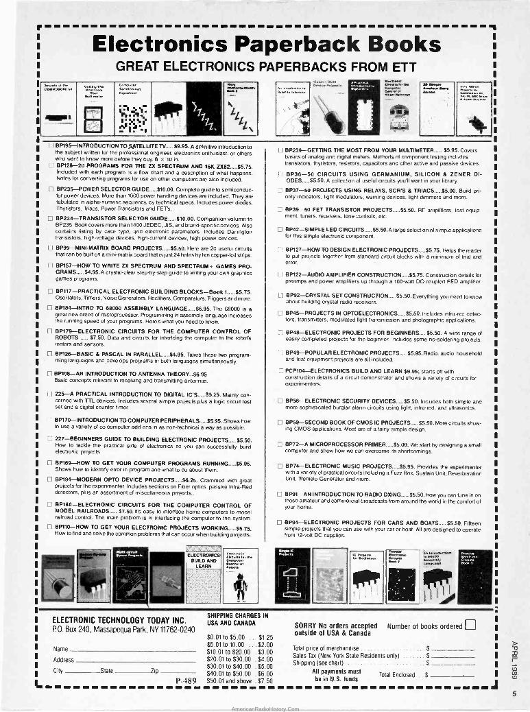
Electronics Paperback Books GREAT ELECTRONICS PAPERBACKS FROM ETT
CecretoellM COMMODORE ie
OettNqTM
YUVow MmeMr
Comp terml EveMMe
WY i,iMeebepeMto NM 11
1 11
I. Z
L
L .
An InleotluctIon to Selene TelevIslon
Rv-v-,r Pe'olx-cts Pqn.rtcp
ElecbeMo CNca1M ter Me Cempvtoe CMtrq el MNYRWrmce
m aRnRM
Amiga bind
BP195-INTRODUCTION TO SATELLITE TV $9.95. A definitive introduction to the subject written for the professional engineer, electronics enthusiast, or others who want to know more before they buy. 8 x 10 in. BP128-20 PROGRAMS FOR THE ZX SPECTRUM AND 16K 2X82 $5.75. Included with each program is a flow chart and a description of what happens. Notes for converting programs for use on other computers are also included.
n BP235-POWER SELECTOR GUIDE $10.00. Complete guide to semiconduc- tor power devices. More than 1000 power handling devices are included. They are tabulated in alpha -numeric sequency, by technical specs. Includes power diodes, Thyristors. Triacs, Power Transistors and FET's.
BP234-TRANSISTOR SELECTOR GUIDE $10.00. Companion volume to BP235. Book covers more than 1400 JEDEC, JIS, and brand -specific devices. Also contains listing by case type, and electronic parameters. Includes Darlington transistors, high -voltage devices, high -current devices, high power devices.
BP99-MINI-MATRIX BOARD PROJECTS $5.50. Here are 20 useful circuits that can be built on a mini -matrix board that is just 24 holes by ten copper -foil strips.
BP157-HOW TO WRITE ZX SPECTRUM AND SPECTRUM+ GAMES PRO- GRAMS $4.95.A crystal-clear step-by-step guide to writing your own graphics games programs.
BP117-PRACTICAL ELECTRONIC BUILDING BLOCKS-Book 1 $5.75. Oscillators, Timers, Noise Generators, Rectifiers, Comparators, Triggers and more.
BP184-INTRO TO 68000 ASSEMBLY LANGUAGE $6.95. The 68000 is a great new breed of microprocessor. Programming in assembly language increases the running speed of your programs. Here's what you need to know.
BP179-ELECTRONIC CIRCUITS FOR THE COMPUTER CONTROL OF ROBOTS $7.50. Data and circuits for interfcing the computer to the robot's motors and sensors.
Bp126-BASIC & PASCAL IN PARALLEL $4.95. Takes these two program- ming languages and develops programs in both languages simultaneously.
H BP198-AN INTRODUCTION TO ANTENNA THEORY...$6.95 Basic concepts relevant to receiving and transmitting antennas.
225-A PRACTICAL INTRODUCTION TO DIGITAL IC'S $5.25. Mainly con- cerned with TTL devices. Includes several simple projects plus a logic circuit test set and a digital counter timer.
BP170-INTRODUCTION TO COMPUTER PERIPHERALS $5.95. Shows how to use a variety of co computer add-ons in as non -technical a way as possible.
227-BEGINNERS GUIDE TO BUILDING ELECTRONIC PROJECTS $5.50. How to tackle the practical side of electronics so you can successfully build electronic projects.
BP169-HOW TO GET YOUR COMPUTER PROGRAMS RUNNING $5.95. Shows how to identify error in program and what to do about them.
H BP194-MODERN OPTO DEVICE PROJECTS $6.25. Crammed with great projects for the experimenter. Includes sections on Fiber optics, passive Infra -Red detectors, plus an assortment of miscellaneous projects..
1 I BP180-ELECTRONIC CIRCUITS FOR THE COMPUTER CONTROL OF MODEL RAILROADS $7.50. It's easy to interface home computers to model railroad control. The main problem is in interfacing the computer to the system.
BP110-HOW TO GET YOUR ELECTRONIC PROJECTS WORKING $5.75. How to find and solve the common problems that can occur when building projects.
Mettemeceit armed Pew«M ELECTRONICS
BUILD AND LEARN
ILICdeasc GviceiteIer toe
cMtteel w Rwetc
L] BP239-GETTING THE MOST FROM YOUR MULTIMETER..... $5.95. Covers basics of analog and digital meters. Methods of component testing includes transistors, thyristors, resistors, capacitors and other active and passive devices.
BP36-50 CIRCUITS USING GERMANIUM, SILICON & ZENER DI- ODES $5.50. A collection of useful circuits you'll want in your library
BP37-50 PROJECTS USING RELAYS, SCR'S & TRIACS $5.00. Build pri- ority indicators, light modulators, warning devices, light dimmers and more.
BP39-50 FET TRANSISTOR PROJECTS $5.50. RF amplifiers, test equip- ment, tuners, receivers, tone controls, etc.
BP42-SIMPLE LED CIRCUITS $5.50.A large selection of simple applications for this simple electronic component.
D BP127-HOW TO DESIGN ELECTRONIC PROJECTS $5.75. Helps the reader to put projects together from standard circuit blocks with a minimum of trial and error.
BP122-AUDIO AMPLIFIER CONSTRUCTION $5.75. Construction details for preamps and power amplifiers up through a 100 -watt DC -coupled FED amplifier
BP92-CRYSTAL SET CONSTRUCTION $5.50. Everything you need to know about building crystal radio receivers.
] BP45-PROJECTS IN OPTOELECTRONICS $5.50. Includes infra -red detec- tors, transmitters, modulated light transmission and photographic applications.
BP48-ELECTRONIC PROJECTS FOR BEGINNERS.... $5.50. A wide range of easily completed projects for the beginner. Includes some no -soldering projects.
H BP49-POPULAR ELECTRONIC PROJECTS.... $5.95. Radio, audio, household and test equipment projects are all included.
PCP104-ELECTRONICS BUILD AND LEARN $9.95; starts off with construction details of a circuit demonstrator and shows a variety of circuits for experimenters.
BP56-ELECTRONIC SECURITY DEVICES $5.50. Includes both simple and more sophisticated burglar alarm circuits using light, infra -red. and ultrasonics.
BP59-SECOND BOOK OF CMOS IC PROJECTS..... $5.50. More circuits show- ing CMOS applications. Most are of a fairly simple design.
BP72-A MICROPROCESSOR PRIMER $5.00. We start by designing a small computer and show how we can overcome its shortcomings.
BP74-ELECTRONIC MUSIC PROJECTS $5.95. Provides the experimenter with a variety of practical circuits including a Fuzz Box. Sustain Unit, Reverberation Unit, Tremolo Generator and more.
BP91-AN INTRODUCTION TO RADIO DXING $5.50. How you can tune in on those amateur and commercial broadcasts from around the world in the comfort of your home.
Li BP94-ELECTRONIC PROJECTS FOR CARS AND BOATS $5.50. Fifteen simple projects that you can use with your car or boat. All are designed to operate from 12 -volt DC supplies.
Smote lt ProN.te
1=n
IC PerMc'Ic Iw Se.* b
apiY t
lnInMpdoctbn te 00000 4eemiMp t.anmag
POWi.r
ELECTRONIC TECHNOLOGY TODAY INC. PO, Box 240, Massapequa Park, NY 11762-0240
Name
Address
City State Zip
SHIPPING CHARGES IN
USA AND CANADA
$0.01 to $5.00 ...$1.25 $5.01 to 10.00 ... $2.00
Total price of merehandise $ $10 01 to $20.00 .$3.00
Sales Tax (New York State Residents only) $ $20.01 to $30.00 .$4.00
Shipping (see chart) $30.01 to $40.00 .$5.00
All payments must $40.01 to $50.00 .$6.00 Total Enclosed $ P-489 $50 01 and above . $7.50 be in U.S. funds
SORRY No orders accepted Number of books ordered I I
outside of USA & Canada
5
AmericanRadioHistory.Com

Electronics Library To obtain additional information on the books and publications covered in this section from the publisher. please circle the item's Bode num-
ber on the Free Information Curd
50 CMOS IC PROJECTS
by Delton T. Horn
Written for the intermediate experimenter or hobbyist, this book provides practical pro- jects designed to use CMOS IC's (comple- mentary metal -oxide semiconductor inte- grated circuits). CMOS IC's are popular be- cause they can function within a wide range of voltages, are inexpensive, and are read- ily available on the hobbyist market. In this book, Delton T. Horn prefaces the projects with a broad introduction to digital electron- ics and CMOS IC's.
The projects are all designed to be con- structed in one or two evenings. Full sche-
SO CNIOS IC - 1Peercts
matics, including working diagrams and parts lists are provided, and construction hints and project variations are offered. A sampling of the projects includes time- keeping circuits, music -making projects, bi- nary circuits, LED flashers, test equipment, control circuits, signal -generator projects, and game circuits.
50 CMOS /C Projects is available for $16.95 from Tab Books Inc., Blue Ridge Summit, PA 17294-0850; Tel. 1-800-233-1128.
CIRCLE 98 ON FREE INFORMATION CARD
ACOUSTICS SOURCE BOOK
edited by Sybil B. Parker
This book examines the science of sound,
including its production, transmission, and detection. Significant applications, ranging from architectural acousticsto medical acous- tics, are also discussed. The book is de- signed to provide quick, convenient access to reliable and up-to-date material for pro- fessionals, students, and educators.
Following a brief introduction, the book is divided into sections on basic concepts, the physics of sound, the measurement of sound, sound transducers, the control of sound, applications, sound reproduction, and human sound production and repro- duction. Within each of those sections there are in-depth studies of related topics, each one written by an expert in that particular area.
Acoustics Source Book is available in hardcover for $35.00 from McGraw-Hill Book Company, 11 West 19th Street, New York, NY 10011.
CIRCLE 96 ON FREE INFORMATION CARD
manuals. The text is interspersed with charts, diagrams, illustrations of typical screens (showing commands and menus), and cartoons that novice users will surely relate to.
The Frozen Keyboard: Living With Bad Soft- ware is available for $17.95 from Tab Books Inc., Blue Ridge Summit, PA 17294-0850; Tel. 1-800-233-1128.
CIRCLE 98 ON FREE INFORMATION CARD
THE FROZEN KEYBOARD:
Living With Bad Software
by Boris Beizer
With the idea that when things get bad enough, your best bet is to laugh, the author takes a tongue-in-cheek approach to a se- rious subject: coping with bad software. Aimed primarily at frustrated, novice PC users, the book strives to remove some of the obstacles they face. It tries to help the beginner to recognize the difference between his own errors and those that are caused by ill-conceived and poorly tested software. The book is unique in that it pre- sents a great deal of concrete information in a non -technical, humorous manner.
The layout is different as well. The first chapter is an overview of the book; subse- quent chapters deal with independent top- ics, and need not be read in order to be meaningful. A combination glossary/index does a good job of pointing the reader to precisely the right spot in the text, while providing brief explanations of each term. For those who require a more in-depth ex- planation, there is a tutorial section that covers such basic subjects as getting started, the various hardware components, installation, and "bugs" or "glitches." The glossary and tutorials keep the main text from getting bogged down with repetitive definitions and basic concepts. If the reader encounters an unfamiliar term, a quick check of the glossary should clear things up; further information will most likely be found in one of the tutorials.
With an insider's perspective of software, the book discusses how to rate the quality of various programs; how and why bugs exist, and what to do about them; why pro- grams crash; menu -driven and command - driven software; and how to interpret user's
ILLUSTRATED PAGEMAKER
by Phyllis Moore
This book is intended to help readers mas- ter the skills needed to create typeset - quality books, brochures, and newsletters using PageMaker-a desktop publishing pro- gram that runs under Microsoft Windows on IBM PC's and compatibles. Detailed de- scriptions of all the PageMaker commands are included, along with examples and prac- tical suggestions for applying those com- mands to real situations.
After a brief introduction and an expla- nation of how to get the program up and
running, the topics discussed are arranged alphabetically, in "learning modules." De- signed to be both a handy reference guide and a comprehensive user's manual, the alphabetic arrangement makes it easy for experienced users to find what they're look- ing for quickly. For beginners, there is a recommended learning sequence; by fol- lowing that sequence, a beginning user is guided from the simplest, most -often used commands through the more advanced, less common commands.
Each module contains a description of the typical operations of the command, and learn -by -doing exercises. The self-contained modules (each begins with starting up Page - Maker and ends with leaving it) can each be used as an isolated unit, although it is integrated into the recommended learning sequence.
Illustrated PageMaker is available for $19.95 from Wordware Publishing Inc., 1506 Capital Avenue, Plano, TX 75074.
CIRCLE 71 ON FREE INFORMATION CARD
6
AmericanRadioHistory.Com

MODERN RECORDING TECHNIQUES
Second Edition
by Robert E. Runstein and David Miles Huber
The first edition of this book, which was
written to bridge the information gap be-
tween sound engineers, record produc- ers, and recording artists, has been used
as a teaching and reference manual by thou-
sands of professionals in the popular - music industry. It introduces readers to re-
cording -studio equipment and controls, and to recording techniques and their role in
creating a finished product. The second edition has been updated
to include information on the latest digital - recording and -processing techniques, in-
cluding digital mastering to compact disc; new digital -effects devices; and the equip- ment, controls, and problems that are en- countered in modern, multitrack recording studios. The major shift in studio acoustic design is discussed, along with the "mar- riage" of video and multitrack studios.
The central concept of a transducer and
its place in the recording process is ex-
plored, as are amplifier basics, noise re-
duction, signal processing, microphone tech-
niques, and the conversion of sound en- ergy into electrical energy. The book ex- plains the setup, operation techniques, and
procedures used in the process of record- ing, overdubbing, and mixing, and the the- ory of disc recording, cassette duplication, and compact -disc production.
Modern Recording Techniques: Second Edition is available for $24.95 from How- ard W. Sams & Company, 4300 West 62nd St., Indianapolis, IN 46268; Tel. 800 -428 - SAMS.
CIRCLE 95 ON FREE INFORMATION CARD
DIGITAL COMMUNICATIONS
WITH AMATEUR RADIO:
The Complete Book of Packet Radio
by Jim Grubbs, K9EI
If you're a computer enthusiast looking for new ways to communicate with other hack- ers, or a ham who wants to expand your amateur -radio network, packet radio could be just the ticket. Packet data communica- tions can be used to exchange anything that can be digitized-text, images, music, and voice at high data -transfer rates. Com- bining the freedom of radio with the power of the computer, packet has been likened to networking without wires, or to a modem that links computers by radio instead of by
wires. This comprehensive book presents the
vital information needed to get into packet radio. For those who are familiar with com- puters, but not with amateur radio, there are explanations of amateur -radio links and
CABLE -TV
BONANZA! ITEM UNIT
10 OR MORE
HAMLIN MCC 3001136 CORDED REMOTE CONVERTER CIS + only, 2900 1800
PANASONIC WIRELESS CONVERTER foul hest huyl 9800 7900
STAR GATE 2000 88 00 69 00
'JERROLD 400 COMBO 16900 119 00
JERROLD 400 HAND REMOTE CONTROL 2900 1800
-JERROLD 450 COMBO 19900 13900
'JERROLD 450 HAND REMOTE CONTROL 2900 1800
JERROLD SB -ADD-ON 9900 6300
JERROLD SB -ADD-ON WITH TRIMODE 10900 7500
M-35 B COMBO UNIT ,Ch 3 output only, 9900 7000
'M-35 B COMBO UNIT WITH VARISYNC 10900 7500
MINICODE IN -121 9900 6200 'MINICODE IN -121 WITH VARISYNC 10900 6500
'MINICODE VARISYNC WITH AUTO ON-OFF 14000 10500
ECONOCODE 1,mn,co0e suhyl1111b-1 6900 4200
ECONOCODE WITH VARISYNC 7900 4600 'MLD-1200-31Ch 3outpul1 9900 6200 'MLD-1200-2f Ch 201117111, 9900 6200
'ZENITH SSAVI CABLE READY 170 00 125 00
INTERFERENCE FILTERS ICY 3111117. 24 00 14 00
EAGLE PD -3 DESCRAMBLER ICY :411111(1111 only, 11900 6500 ' --CIENTIF Ir'. All ANTA ADD ON REI') ACEMENT IDE`,d Il AM R1 ER 11900 H500
'CALL FOR AVAILABILITY
Quantity Item Output Channel
Price Each
TOTAL PRICE
California Penal Code #593-0 torb ds us from shipping any cable descrambling unit to anyone residing in the state of California.
Prices subject to change without notice.
01 CACC 0011.11.
SUBTOTAL Shipping Add $3.00 per unit
COD & Credit - Add 5% TOTAL TOTAL
Name
Address City
State Zip Phone Number (
E Cashier's Check E Money Order COD Visa Mastercard
Acct # Exp. Date
Signature
FOR OUR RECORDS: DECLARATION OF AUTHORIZED USE - I, the undersigned, do hereby declare under penalty of peryury that all products purchased, now and in the future, will only be used on cable TV systems with proper authorization from local officials or cable company officials in accordance with all applicable federal and state laws. FEDERAL AND VARIOUS STATE LAWS PROVIDE FOR SUBSTANTIAL CRIMINAL AND CIVIL PENALTIES FOR UNAUTHORIZED USE.
Dated- - Signed:
Pacific Cable Company, Inc. 73251/2 RESEDA BLVD., DEPT. # P-4 RESEDA, CA 91335
(818) 716-5914 No Collect Calls (818) 716-5140
IMPORTANT: WHEN CALLING FOR INFORMATION Please have the make and model # of the equipment used in your area. Thank You
7
AmericanRadioHistory.Com
Electronics Library
interfaces, as well as packet -radio tech- niques, protocols, and licensing. For ama- teur -radio operators, there is a review of the basics of telephone -line digital commu- nications, and how to interface digital equip- ment and ham gear. For all readers, the book presents a look at how to get every- thing connected and actually operating. The
book describes packet -radio accessories, innovations, and organizations, and ex- plores packet satellite operation.
Digital Communications with Amateur Ra- dio: The Complete Packet Radio Book is published by Master Publishing, Inc., 14
Canyon Creek Village MS 31, Richardson, TX 75080. It is available at local Radio Shack stores for $6.95.
CIRCLE 72 ON FREE INFORMATION CARD
WORDPERFECT 5 INSTANT REFERENCE
by Greg Harvey and Kay Yarborough Nelson
This book is designed to give WordPerfect users the essential information needed to get the most out of version 5, as quickly as possible. Intended for people who are familiar with WordPerfect 5's basic opera- tions, it provides quick and easy access to both simple and complex information whether the user is "stuck" on a certain function, or just needs a refresher on a par- ticular procedure.
All WordPerfect commands are featured, arranged alphabetically. For each one, the book shows the exact keystroke sequence, how the command is used, a list of avail- able options, additional notes, and a refer- ence to any related functions. There is a
brief discussion of the differences between version 5 and earlier versions, and appen- dices cover installation, hidden formatting codes, and WordPerfect's new macro com- mand language. All desktop -publishing fea -
(Continued on page 12)
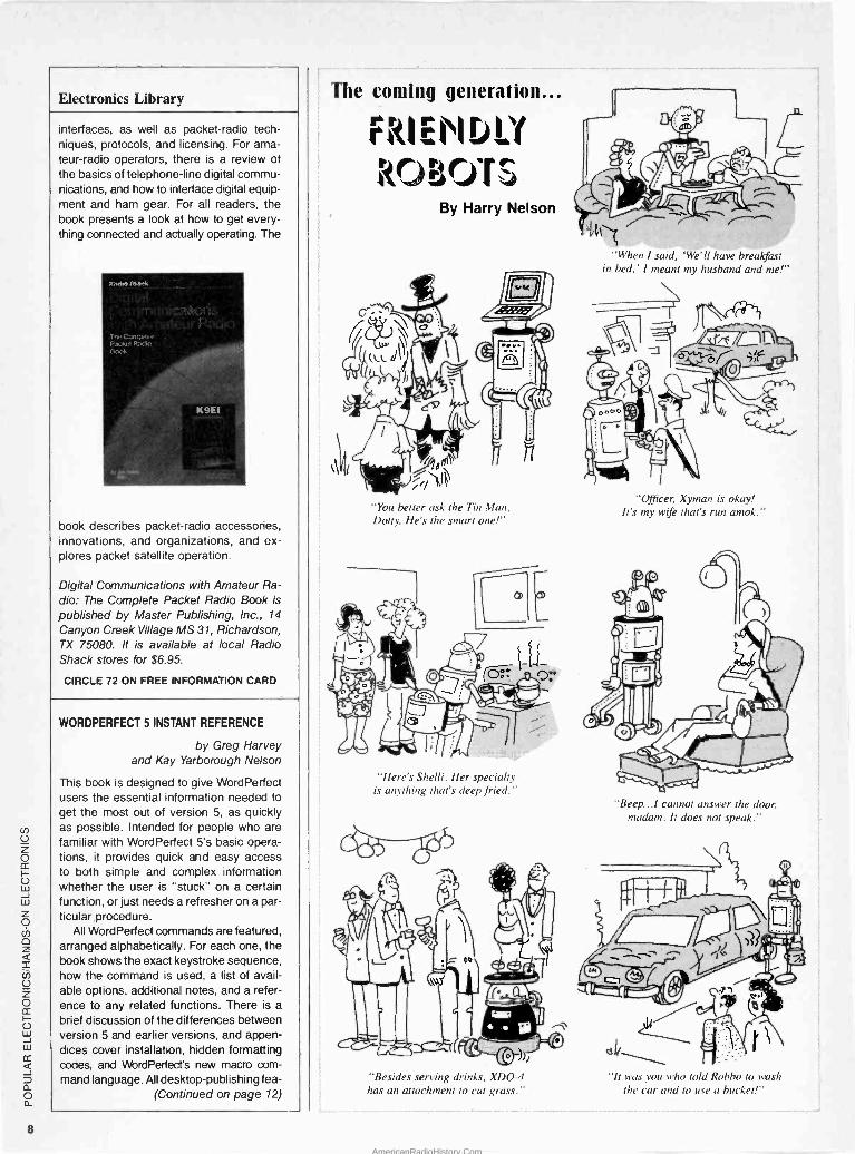
The coming generation...
FRI EH D!'F YAMS
By Harry Nelson
"You better ask the Tin Man, Dotty, He's the smart one!"
"Here's Shelli. Her specialty is anything that's deep fried."
"Besides serving drinks, XDO-4 has an attachment to cut grass."
"When I said, 'We'll have breakfast in bed,' I meant my husband and me!"
"Officer, Xyman is okay! It's my wife that's run amok."
"Beep.../ cannot answer the door. madam. It does not speak."
"It was you oho told Robbo to oasi, the car and to use a bucket!"
8
AmericanRadioHistory.Com

EXPAND YOUR CAREER HORIZONS...
ELECTRONICS EDUCATION
OF TOMORROW
TODAY
START WITH CIE. Microprocessor Technology. Satellite Communications. Robotics. Wherever you want to go in electronics... start first with CIE.
Why CIE? Because we're the leader in teaching electronics through independent study. Consider this. We teach over 25,000 students from all over the United States and in over 70 foreign countries. And we've been doing it for over 50 years, helping thousands of men and women get started in electronics careers.
We offer flexible training to meet your needs. You can start at the beginner level or, if you already know something about electronics, you may want to start at a higher level. But wherever you start, you can go as far as you like. You can even earn your Associate in Applied Science Degree in Electronics.
Let us get you started today. Just call toll -free 1-800-321-2155 (in Ohio, 1-800-362-2105) or mail in
CIRCLE 7 ON FREE INFORMATION CARD
The CIE Microprocessor Trainer helps you to learn how circuits with microprocessors function in computers.
the handy reply coupon or card below to: Cleveland Institute of Electronics, 1776 East 17th Street, Cleveland, Ohio 44114.
C I E World Headquarters AHO-113
Cleveland Institute of Electronics, Inc. 1776 East 17th Street Cleveland, Ohio 44114
H Please send your independent study catalog. For your convenience, CIE will try to have a representative contact you - there is no obligation.
Print Name
Address Apt.
City State Zip
Age Area Code/Phone No.
Check box for G.I. Bill bulletin on Educational Benefits E Veteran Active Duty MAIL TODAY!
Just call toll -free 1-800-321-2155 (in Ohio, 1-800-362-2105)
AmericanRadioHistory.Com

Electronics Library (Continued from page 8)
on to examine systems, business, military. be represented edge base, gies, including ward -changing, searches.
Frenzel actually
in detail. in programming' the use of guages and to deal specifically LISP and
different types of along with their applications industry, government,
It looks at how knowledge in an expert system's
and at various search breadth -first, depth -first,
and backward -changing
describes how expert systems work, exploring their architecture
expert in
and the can
knowl- strate-
for-
used
Ian- created such as
follow
in creating an expert system are detailed; the reader is led through those steps to create a hypothetical system.
Understanding Expert Systems is available for $16.95 from Howard W. Sams & Com- pany, 4300 West 62nd St., Indianapolis, IN 46268; Tel. 800 -428 -SAMS.
CIRCLE 95 ON FREE INFORMATION CARD
tures-including mixing graphics and tables with text, and how to work with columns, bullets, fonts, and other special effects to enhance finished documents-are included.
WordPerfect 5 Instant Reference is avail- able for $12.95 from Sybex, Inc., 2021 Chal- lenger Drive #100, Alameda, CA 94501.
CIRCLE 73 ON FREE INFORMATION CARD AMATEUR RADIO: Theory
and Practice
by Robert L. Shrader
This book is aimed at anyone who wants to get an amateur -radio license, but has little or no previous experience in radio or electronics. It explains the basic theory that is necessary to pass all of the FCC's ama - teur-radio license exams-from the simplest subjects to the more advanced topics that the FCC will probably be using to develop new tests. The information needed to prop- erly operate an amateur -radio station and its equipment is also included.
The book opens with a discussion of the scope of the Amateur Radio Service, the grades of amateur licenses, and some in- teresting aspects of amateur radio. Most
w 4,
--m
UNDERSTANDING EXPERT SYSTEMS
by Louis E. Frenzel, Jr.
Lou Frenzel brings his down-to-earth teach- ing style and writing skills to the world of expert systems-problem-solving computer software that enables computers to reason like humans. The text is supported by am- ple illustrations and self -quizzes, and rein- forced by a glossary, bibliography, and ven- dor list.
An overview of expert systems explains the basics of artificial intelligence (Al) and the broad field of problem -solving comput- ing, and describes some well-known, pio- neering expert systems. The book goes
An examination of the tools expert systems includes
conventional programming the special languages
with Al needs, Prolog. The ten steps to
n patiefn AA
NO MASTER NO CAMERA NO FILM NO DEVELOPER
(-15- DIRECT ETCH dry transfers make quality circuit 5 without formal artwork. A new Master Assortment includes over O 4000 donuts from .050" to .250" and 118 trace lines from .014" to c .125". It also contains all sizes of through hole and surface mount o devices including DIP, TO, DIN, D and edge card connectors, i SO, SOL, PLCC, flatpacks, SOT's, 2 terminal tubular and flat w SM D's. The Master Assortment has 69 cut apart dry transfer sheets á with complete instructions. Works with all common etchants. -J DE -973 Master Assortment (69 pattern sheets) $34.95 a- (Add $2.00 shipping. NJ and CA residents also add sales tax) a DATAK Corp. 3117 Paterson Plank Rd. N. Bergen, NJ 07047
CIRCLE 11 ON FREE INFORMATION CARD 12
boards fast
Great for the Experimenter!
I o f_ 117 -- Pioneer Laser Disc Player
1-2 mW Helium -Neon Laser Laser Power Supply 2 Front Surface Mirrors Two 1/2' Voice Coil Actuated Oscillating Mirrors One Beam Splitter
' Two Optical Lenses ' One Optical Detector
Mini Gear Reduction Motor All Controlling Electronics Assorted Switches, Fan, Solenoid
THESE UNITS ARE OEM MODELS AND REQUIRE A COMPUTER CONTROLLER (NOT AVAILABLE FROM HALTED). THEY CANNOT BE. MANUALLY CONTROLLED!
"As -/s" $99.00
We stockTHOUSANDS of parts' TRAN ISTORS, MORE...
CALL!
Mitsumi UVE .A
UHF 1 VHF V
ARACTOR
TUNER 3(2.x2" x1/2" Pinout on Case
FOR $17.95
A
Call the Halted Specialties Electronic Forum
BBSI 408-732-2814
510 MINIMUM ORDER. QUANTITIES LIMITED.
CA RES. ADD SALES TAX
HSC Since '63!
RS -232 BREAKOUT BOX
Switchable Lines
LED Indicators Patch Terminals & Jumpers
Compact Size
$2995 THIS MONTH
DE AC LINE CO I 400 wñTTIONER Ideal for your PC or Any Equipment Eliminates AC: Line Noise Regulates
to a Constant VAC Reliable Ferroresonant
Transformer Attractive Case with Power Outlets, and Switch/Circuit Breaker Cord,
WOWS $149.00 available00W also
.w>
D PAGING RECEIVISPLAYER.-
Dual Conversion Superher 450 MHz In!)
Crystal Controlled Receiver Module (Plug-
Twenty Char Alpha -Nomen LED Display
(ASCII Encoded, ANSI Char. Sett
$9.95ao<h RCA GDP 1602 Based
Peizoelecmc'Beaper' viUsed, Silent Alert Iwo $17.95
Used, llnte.led.
HSC of Santa Clara 3500 Ryder Street Santa Clara, CA 95051
Cali =800 -4 -HALTED Now! ésdZ.:408-732-1573
CIRCLE 12 ON FREE INFORMATION CARD
AmericanRadioHistory.Com

of the other chapters present the basic elec- each has its own good points and draw- There are also step-by-step instructions
trical, electronic, and radio theory that is backs. This book explores those features on how to build a Kapellmeister loudspeaker
needed to pass the written license exams and, in particular, examines what causes enclosure. That design involves unique fea -
and that will give the reader a firm under- strengths and weaknesses in different en- tures that overcome many of the disadvan-
standing of modern radio communications. closure designs. With an understanding of tages of more conventional speakers. The
Each chapter in the book ends with sample the principles involved, readers will be bet- Kapellmeister is a transmission -line speaker
test questions that differ from the official ter able to make informed choices of loud- that offers remarkable stereo imaging and
questions only in wording. speaker design -or even design their own an uncolored musical sound. It takes up
A "how to" section outlines how to send loudspeaker enclosures. minimal floor space, and is inexpensive to
and receive the required radio code needed The book describes the moving -coil driver build.
for any of the amateur licenses, and briefly in detail, as well as alternative drivers. Cross -
explains amateur communicating and mes- over units are discussed, including the vari- An Introduction to Loudspeakers and En -
sage handling. There is also a condensed ous types, how they work, the distortions closure Design (Order No. BP256) is avail -
version -in non -technical language -of the FCC amateur -radio rules and regulations.
they produce, and how to avoid them. able for $7.95, including shipping, from Elec- tronics Technology Today, P.O. Box 240, Massapequa, NY 11762.
Amateur Radio: Theory and Practice is avail- able for $28.95 from McGraw-Hill Book Corn- An Introduction to CIRCLE 97 ON FREE INFORMATION CARD
pany, 11 West 19th St., New York, NY Loudspeakers and 10011; 1-800-2-MCGRAW. Enclosure Design SUCCESSFUL ENGINEERING
CIRCLE 96 ON FREE -FORMATION CARD A Guide to Achieving Your Career Goals
by Lawrence J. Kamm AN INTRODUCTION TO
LOUDSPEAKERS
AND ENCLOSURE DESIGN
by V. Capel
¡
I
G., j: Taking engineers a step beyond their tech - nical classroom training, this book concen- trates on the intangible, qualitative skills that are needed to excel in the field of engi- neering design. It provides solid advice on
just a box to hold speakers. There are many
types of enclosures and drive units, and
îb.=- ` ways for design engineers -in such fields as mechanical, electrical, industrial, and
WALNUT SPEAKER CABINET KIT Super quality, genuine walnut veneer cabinet. Kit includes: routed and mitred top, sides, and bottom in unfinished 3/ 4" walnut veneer. Cut your own custom holes in the front and rear to match your drivers. 15"
x 24" x 11". Volume: 1.9
cu. ft.
#260-350 $22.50
(1-3)
$19.95 (4 up)
15" THRUSTER 1A-1 WOOFER
,e14. Thruster by Eminence. Made in U.S.A. For- ward poly roll foam surround, 56 oz. magnet. 2-
1/2", 2 layer voice coil. 150 watts RMS, 210 watts max. 4 ohm. fs - 23.5 Hz, QMS - 9.86, QES = .34, QTS = .33, VAS - 17.9 cu. ft. SPL - 94.8 dB 1W/ 1M. Net weight: 15 lbs. #290-180 $43.50 $39.80
(1-3) (4 -up)
SUBWOOFER CROSSOVER 200 watts RMS.
12 dB per octave 150 Hz at 8 ohm crossover point.
$28.80 #260-220 (1-5)
124.40 (6 -up)
340 E. First St.. Dayton, OH 45402 Local 1-513-222-0173 FAX 513 222-4644
SPEAKERS AND COMPONENTS
PIONEER AA MOTOROLA
ELECTRONIC>>
EMINENCE
12" POLY WOOFER
Pe,r) PIONEER Super duty, 40 oz. magnet. Polypropylene cone. 100 watts RMS, 145 watts max. 4 and 8
ohm compatible (6 ohm). 2" voice coil. fs - 25
Hz. VAS- 10.8 cu. ft., QTS =.166. Response: 25-1,500 Hz. Net weight: 9 lbs.
#290-125 $36.80
(1-3)
$34.50 (4 -up)
12" PIONEER SUB WOOFER -
PIONEER Dual voice coil sub woofer. 30 oz. magnet, 2"
voice coil. 100 watts RIvIS, 145 watts max. fs - 25
Hz. 6 ohm (4 and 8 ohm compatible). SPL - 89
dB 1W/1M. Response: 25-700 Hz. QTS-.31, VAS = 10.3 cu ft. Pioneer #A30CU30-55D. Net weight: 6 lbs.
#290-145 $39.80
(1-3)
$36.80 (4 -up)
15" 3 -WAY, 125 WATT SYSTEM
Our "Top -of the Line" system. The system features elements specifically selected to pro- duce a balanced output throughout the full frequency bandwidth of the system. System includes: (1) #290-155 15" polypropylene woofer rated at 145 watts max, (2) #280-020 cup midranges, (1) #270-035 4" soft dome tweeter, (1) #260-215 200 watt 3 -way cross- over, (2) #260-265 100 watt mid, tweeter "L"
pad attenuators, (1) #260-300 speaker termi- nal, and (1) #260-340 grille cloth.
#15-125
CALL TOLL FREE
1-800-338-0531
18" EMINENCE WOOFER
EMINENCE
MADE IN U.S.A.
100 oz. magnet, 3" voice coil. 250 watts RMS,
350 watts max. 8 ohm, 30 Hz resonant fre- quency. 22-2700 Hz response. Efficiency: 95
dB 1W/1M. Paper cone treated accordion surround. Net weight: 29 lbs.
#290-200 $98.80 $89.50 (1-3) (4 -up)
PIONEER HORN TWEETER Mylar dome, 2.93 oz. barium ferrite magnet. Bohm. Response: 1,800- 20,000 Hz. 35W RMS, 50W max. fs - 2,000 Hz,
SPL = 106 dB. Pioneer #AHE60-5IF.
#270-050 $6.50 $5.90 (1-9) (10 -up)
3 -WAY 100W CROSS- OVER .. 12 dB / octave rolloff. 800 Hz, 5000 Hz. 8 ohm. 100
watts RMS. $12.50 $9.95 #260-210 (1-9) (10 -up)
15 day money back guarantee. $10.00 minimum order. We accept Mastercard, Vlse, Discover, and C.O.D. orders. 24 hour shipping. Shipping charge = UPS chart rate ($2.50 minimum charge). Hours: 8:30 am - 6:00 pm EST, Monday - Friday. Mall order customers, please call for shipping estimate on orders exceeding 5 lbs.
FREE CATALOG
CIRCLE 18 ON FREE INFORMATION CARD 13
AmericanRadioHistory.Com

AMAZIIG SCIENTIFIC & ELECTRONIC
PRODUCTS PLANS Build Yourself - All Parts Available in Stock
LC7- BURNING CUTTING CO2 LASER $20.00
RUN- PORTABLE LASER RAY PISTOL $20.00
TCC1- 3 SEPARATE TESLA COIL PLANS TO 1.5 MEV $25.00
1061- ION RAY GUN $10.00
GRA1- GRAVITY GENERATOR $10.00
EML1- ELECTRO MAGNET COIL GUN/LAUNCHER $8.00
KITS With All Necessary Plans
MFT3K- FM VOICE TRANSMITTER 3 MI RANGE $49.50
VWPM7K-TELEPHONE TRANSMITTER 3 MI RANGE $39.50
BTC3K-250,000 VOLT 10-14" SPARK TESLA COIL $249.50
LHC2K- SIMULATED MULTICOLOR LASER $44.50
BLS1K-100,000 WATT BLASTER DEFENSE DEVICE $69.50
MAW- 100,000 VOLT 20' AFFECTIVE
RANGE INTIMIDATOR $69.50
PSP4K- TIME VARIANT SHOCK WAVE PISTOL $59.50
STA1K- ALL NEW SPACE AGE ACTIVE PLASMA SABER $59.50
MVP1K- SEE IN DARK KIT $199.50
PTG1K- SPECTACULAR PLASMA
TORNADO GENERATOR $149.50
ASSEMBLED With All Necessary Instructions BTC10- 50.000 VOLT -WORLD'S SMALLEST TESLA COIL $54.50
LGU40-1MW HeNe VISIBLE RED LASER GUN $249.50
TAT30- AUTO TELEPHONE RECORDING DEVICE $24.50
GVP10- SEE IN TOTAL DARKNESS IR VIEWER $349.50
LIST10- SNOOPER PHONE INFINITY TRANSMITTER $169.50
IMO- INVISIBLE PAIN FIELD
GENERATOR MUTLI MODE $74.50
CATALOG CONTAINING DESCRIPTIONS OF ABOVE PLUS
HUNDREDS MORE AVAILABLE FOR $1.00 OR USE OUR
PHONE FOR "ORDERS ONLY' 603-673-4730.
PLEASE INCLUDE $3.00 PH ON ALL KITS AND PRODUCTS
PLANS ARE POSTAGE PAID. SEND CHECK, MO, VISA, MC IN
US FUNDS.
INFORMATION UNLIMITED P.O. BOX 716 DEPT. HO AMHERST, NH 03031
ATTENTION!
CNN c -a r EARN YOUR \ "-
B.S.E.E. DEGREE
THROUGH HOME STUDY Our New and Highly Effective Advanced -Place- ment Program for experienced Electronic Tech- nicians grants credit for previous Schooling and Professional Experience, and can greatly re- duce the time required to complete Program and reach graduation. No residence schooling re- quired for qualified Electronic Technicians. Through this Special Program you can pull all of the loose ends of your electronics background together and earn your B.S.E.E. Degree. Up- grade your status and pay to the Engineering Level. Advance Rapidly! Many finish in 12 months or less. Students and graduates in all 50 States and throughout the World. Established Over 40 Years! Write for free Descriptive Lit-
erature.
COOK'S INSTITUTE OF ELECTRONICS ENGINEERING
C'WE 4251 CYPRESS DRIVE JACKSON, MISSISSIPPI 39212
Electronics Library
chemical engineering -to capitalize on their natural abilities, adapt to on-the-job pressures, and plan rewarding career paths.
The book describes how to cultivate in-
ventiveness while developing an eye for de-
signs that combine quality, reduced cost, re-
liability and simplicity. It demonstrates how to design within the constraints imposed by budgets, legal contracts, specifications, and other practical considerations. Keeping up-to- date is essential; continuing formal studies, and using consultants, vendors, and librar- ies are examined as ways to broaden the engineer's knowledge base. There is also a strong focus on dealing with people - company politics, the art of persuasion, ethi- cal dilemmas, efficient use of time, making smart career choices, and coping with cor- porate accountants are some of the human factors covered in the book.
The author considers "successful" engi- neers to be those who produce the best de- signs of which they are capable; get those designs accepted and used; are well re- warded in terms of money, position, and se- curity; and enjoy their work. The advice he presents is based on his own long engineering career; the text is filled with real -life exam- ples and anecdotes.
Successful Engineering: A Guide to Achiev- ing Your Career Goals is available in hardcover for $39.95 from McGraw-Hill Book Company, 11 West 19th Street, New York,
NY 10011; Tel. 1-800-2-MCGRAW.
CIRCLE 96 ON FREE INFORMATION CARD
available from Radio Shack, and tips are included on soldering, finding parts, and general construction techniques. The ba- sics of theory, design, and application are explained, and readers are encouraged to adapt the circuits for their own specific needs.
Enhanced Sound: 22 Electronics Projects for the Audiophile is available for $9.95 from Tab Books Inc., Blue Ridge Summit, PA 17294-0850; Tel. 1-800-233-1128.
CIRCLE 98 ON FREE INFORMATION CARD
ENHANCED SOUND: 22 Electronics Projects
for the Audiophile
by Richard Kaufman
Here's a book for anyone who's looking to get better sound from his audio systems without spending a lot of money. But sav- ing money isn't the only benefit -some of these projects simply aren't commercially available.
All of the projects presented are designed to boost the performance and capabilities of different types of audio systems. They include a practical infinite -slope crossover network using pole -zero cancellation, com- puter programs for designing speaker en- closures, indoor FM antennas, rhombic an- tennas, multiple -pole feedback filters, and stereo -image enhancers. Also included are a surround -sound decoder, an auxiliary in-
put switch, tone controls, a shuffler, an am- plifier -bridging circuit, and helical antennas.
While some previous kit -building experi- ence might be helpful, those readers who are complete beginners will find all the in-
formation needed to build each project. Any printed circuit boards that are called for are
THE ILLUSTRATED DICTIONARY OF
ELECTRONICS:Fourth Edition
by Rufus P. Turner and Stan Gibilisco
More than 27,000 terms used in today's electronics can be found in this reference book. The comprehensive dictionary in-
cludes all practical electronics and com- puter terms. The fourth edition has been updated to reflect the newest advances in
the field. The 650 -page book includes over 450
detailed drawings and diagrams, along with the textual definitions. It also features ta- bles and data on those subjects that are most often consulted for projects and ex- periments. There are Fahrenheit/Celsiustem- perature-conversion charts and English/ metric and metric/English conversions for units of measure of energy, power, and vol- ume. Illustrations of schematic symbols are included. Tables and data charts include resistor -color codes; mathematical signs, symbols, and operations; and electronic ab- breviations.
The Illustrated Dictionary of Electronics: Fourth Edition is available for $23.95 from Tab Books Inc., Blue Ridge Summit PA
17294-0850; Tel. 1-800-233-1128.
CIRCLE 98 ON FREE INFORMATION CARD
"The real computer error happened when it placed you in this class!"
CIRCLE 8 ON FREE INFORMATION CARD 14
AmericanRadioHistory.Com

New Products Tn 01)1(1111 arlditinnul 11(11'
prrrzlu( (tried in rhi% s(Nirur %rrlm rllr mmu%urturrr, plru%r (ir(Ir the ilcin',\ (Ndr nunrh(r r,n Ill(' Fier ("aid
EMERGENCY CB RADIO
Midland's Model 77-909 is a 40 -channel, emergency CB radio. It is small enough to stow easily in a glove compartment or under a car seat, and a one -touch Channel - 9 memory button provides instant access to the emergency -communications chan- nel that can bring help quickly on the road.
The 77-909's has ETR frequency con- trol for pinpoint channel -tuning accuracy,
fully variable squelch control, and a high - intensity green LED readout system. Sepa- rate up and down channel -selector buttons with two speeds provide fast tuning. The unit includes a ,built-in condenser micro- phone for improved audio transmissions, a pre -tuned telescopic antenna with mag- netic -mount base, and a rugged vinyl car- rying case.
The 77-909 emergency two-way radio has a suggested retail price of $149.00 For further information, contact Midland In-
ternational, Consumer Products Division, 1690 North Topping, Kansas City, MO 64120.
CIRCLE 75 ON FREE INFORMATION CARD
the power flowing through the master out- let, so that when any equipment that is con- nected to the master outlet is switched on, the other four outlets are switched on si- multaneously. That allows the monitor-or whatever peripheral is plugged into the mas- ter outlet-to serve as a convenient control point for the entire workstation, while the surge -suppressor strip and power cords are hiddei neatly out of sight.
The RW-500 offers computer -grade pro- tection in the normal mode (line -to-neutral), and in both common modes (line -to -ground and neutral -to -ground). It responds in one nanosecond, and has a maximum energy dissipation of 480 joules, 160 in each mode. The surge suppressor's clamping thresh- old is 225 -volts peak, and it is rated for a
maximum transient voltage of greater than 6,000 volts.
The UL -listed RW-500 remote surge sup-
pressor has a suggested retail price of $99.90. For further information, contact Perma Power Electronics, 5601 West How- ard Avenue, Chicago IL 60648.
CIRCLE 76 ON FREE INFORMATION CARD
HEAVY-DUTY DMM'S
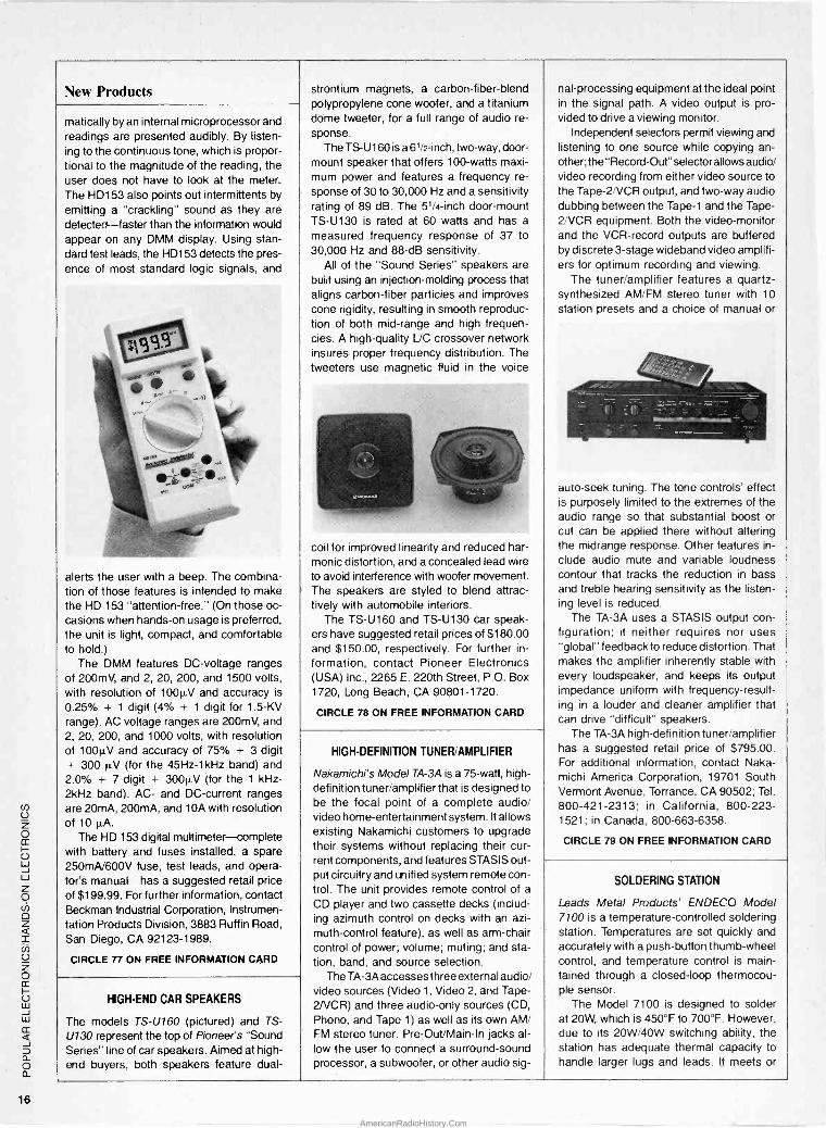
Beckman Industrial's HD153 is one of their HD150 Series of 31/2 -digit, auto -ranging digi- tal multimeters. Offering hands -free usage and audible signaling, those heavy-duty me- ters are designed to go anywhere, under all conditions. Beckman claims that the DMM's are rugged enough to survive a 10 -
foot drop to concrete; they warranty the meters against outside contamination for five years and for two years against other damage (except in the case of abuse).
The meters are designed so that the user can keep his hands and eyes on the job. The HD153 features a "Skyhook" that can be flipped out from its back so that the me- ter can be hung up, as well as a tilt stand. With the auto -ranging feature, after func- tion selection the proper range is set auto -
REMOTE SURGE SUPPRESSOR
The Model RW-500 remote surge suppres- sor from Perma Power Electronics protects a computer workstation from transient surges on the power line, and permits the entire system to be turned on or off from the computer monifor switch.
The surge suppressor has five outlets- a master and four auxiliaries. Its design incorporates a unique circuit that monitors
KepioCkxi y Kepro Circuit Systems. Inc -
The Power and
The Glory
1-800-325-3878
1-314-343-1630 MO For the dealer nearest you.
Make PCB's In Your Home! KeproClad TMgives you the power to produce industrial quality printed circuit boards at home. PCB's you can use for nearly any electronic construction project - from simple power supplies to
sophisticated lasers. And when you're done, you'll know the glory that comes from top performance assured by the use
of KeproClad PCB's.
KeproClad is the quick, easy and inex- pensive system for production of quality printed circuit boards. KeproClad has all the supplies and instructions you need to
create professional boards at home.
All KeproClad products are safe, easy to use and come with an unconditional guarantee. When you want to build the best, choose KeproClad. KeproClad gives you the power. You get the glory.
For your free KeproClad catalog and
name of the KeproClad dealer nearest you, call Kepro.
Kepro Circuit Systems, Inc. 630 Axminister Drive, Fenton, MO 63026-2992
I I I I IPIMIIB\JIII= I I I 21 1 r 131113 I I I I I W I I MI 111111
" I I
CIRCLE 17 ON FREE INFORMATION CARD 15
AmericanRadioHistory.Com
New Products
matically by an internal microprocessor and readings are presented audibly. By listen- ing to the continuous tone, which is propor- tional to the magnitude of the reading, the user does not have to look at the meter. The HD153 also points out intermittents by
emitting a "crackling" sound as they are detected-faster than the information would appear on any DMM display. Using stan- dard test leads, the HD153 detects the pres- ence of most standard logic signals, and
alerts the user with a beep. The combina- tion of those features is intended to make the HD 153 "attention -free." (On those oc- casions when hands-on usage is preferred, the unit is light, compact, and comfortable to hold.)
The DMM features DC -voltage ranges of 200mV, and 2, 20, 200, and 1500 volts, with resolution of 1000V and accuracy is
0.25% + 1 digit (4% + 1 digit for 1.5 -KV range). AC voltage ranges are 200mV, and 2, 20, 200, and 1000 volts, with resolution of 100µV and accuracy of 75% + 3 digit + 300 µV (for the 45Hz-1kHz band) and 2.0% + 7 digit + 3000V (for the 1 kHz- 2kHz band). AC- and DC -current ranges are 20mA, 200mA, and 10A with resolution of 10 µA.
The HD 153 digital multimeter-complete with battery and fuses installed, a spare 250mA/600V fuse, test leads, and opera- tor's manual-has a suggested retail price
of $199.99. For further information, contact Beckman Industrial Corporation, Instrumen- tation Products Division, 3883 Ruffin Road, San Diego, CA 92123-1989.
CIRCLE 77 ON FREE INFORMATION CARD
strontium magnets, a carbon -fiber -blend polypropylene cone woofer, and a titanium dome tweeter, for a full range of audio re- sponse.
The TS -U160 is a 61/2 -inch, two-way, door - mount speaker that offers 100 -watts maxi- mum power and features a frequency re-
sponse of 30 to 30,000 Hz and a sensitivity rating of 89 dB. The 51/4 -inch door -mount TS -U130 is rated at 60 watts and has a
measured frequency response of 37 to 30,000 Hz and 88 -dB sensitivity.
All of the "Sound Series" speakers are built using an injection -molding process that aligns carbon -fiber particles and improves cone rigidity, resulting in smooth reproduc- tion of both mid -range and high frequen- cies. A high -quality L/C crossover network insures proper frequency distribution. The tweeters use magnetic fluid in the voice
coil for improved linearity and reduced har- monic distortion, and a concealed lead wire to avoid interference with woofer movement. The speakers are styled to blend attrac- tively with automobile interiors.
The TS -U160 and TS -U130 car speak- ers have suggested retail prices of $180.00 and $150.00, respectively. For further in-
formation, contact Pioneer Electronics (USA) Inc., 2265 E. 220th Street, P.O. Box 1720, Long Beach, CA 90801-1720.
CIRCLE 78 ON FREE INFORMATION CARD
HIGH -END CAR SPEAKERS
The models TS -U160 (pictured) and TS -
U130 represent the top of Pioneer's "Sound Series" line of car speakers. Aimed at high - end buyers, both speakers feature dual -
HIGH -DEFINITION TUNER/AMPLIFIER
Nakamichi's Model TA -3A is a 75 -watt, high - definition tuner/amplifier that is designed to be the focal point of a complete audio/ video home -entertainment system. It allows existing Nakamichi customers to upgrade their systems without replacing their cur- rent components, and features STASIS out- put circuitry and unified system remote con- trol. The unit provides remote control of a
CD player and two cassette decks (includ- ing azimuth control on decks with an azi- muth -control feature), as well as arm -chair control of power; volume; muting; and sta- tion, band, and source selection.
The TA -3A accesses three external audio/ video sources (Video 1, Video 2, and Tape- 2/VCR) and three audio -only sources (CD, Phono, and Tape 1) as well as its own AM/ FM stereo tuner. Pre-Out/Main-In jacks al- low the user to connect a surround -sound processor, a subwoofer, or other audio sig-
nal -processing equipment at the ideal point in the signal path. A video output is pro- vided to drive a viewing monitor.
Independent selectors permit viewing and listening to one source while copying an- other; t he "Record -Out" selector allows audio/ video recording from either video source to the Tape-2/VCR output, and two-way audio dubbing between the Tape -1 and the Tape- 2/VCR equipment. Both the video -monitor and the VCR -record outputs are buffered by discrete 3 -stage wideband video amplifi- ers for optimum recording and viewing.
The tuner/amplifier features a quartz - synthesized AM/FM stereo tuner with 10
station presets and a choice of manual or
auto -seek tuning. The tone controls' effect is purposely limited to the extremes of the audio range so that substantial boost or cut can be applied there without altering the midrange response. Other features in- clude audio mute and variable loudness contour that tracks the reduction in bass and treble hearing sensitivity as the listen- ing level is reduced.
The TA -3A uses a STASIS output con- figuration; it neither requires nor uses "global" feedback to reduce distortion. That makes the amplifier inherently stable with every loudspeaker, and keeps its output impedance uniform with frequency -result- ing in a louder and cleaner amplifier that can drive "difficult" speakers.
The TA -3A high -definition tuner/amplifier has a suggested retail price of $795.00. For additional information, contact Naka- michi America Corporation, 19701 South Vermont Avenue, Torrance, CA 90502; Tel.
800-421-2313; in California, 800-223- 1521; in Canada, 800-663-6358.
CIRCLE 79 ON FREE INFORMATION CARD
SOLDERING STATION
Leads Metal Products' ENDECO Model 7100 is a temperature -controlled soldering station. Temperatures are set quickly and accurately with a push-button thumb -wheel control, and temperature control is main- tained through a closed -loop thermocou- ple sensor.
The Model 7100 is designed to solder at 20W, which is 450°F to 700°F. However, due to its 20W/40W switching ability, the station has adequate thermal capacity to handle larger lugs and leads. It meets or
16
AmericanRadioHistory.Com

exceeds Mil. Spec. WS 6536E para 3.2.3, with a 3 -wire ground to prevent potential differences greater than 2 mV at the solder tip. Resistance reading from tip to ground
less than 20 ohms, and ± 10° of prese lected temperature at idle is guaranteed.
j((((YT¡{r »... ,,
CASSETTE DECK
Sansui's D X301 i cassette deck, featuring the company's exclusive Computerized
Function Control (CDFC), provides an Dualis
impressive array of computerized functions including 20 -song Automatic Music Program Search (AMPS), bi-directional music scan, and two repeat modes.
Designed to easily handle the dynamic range of compact discs, the D -X301 i offers both Dolby B/C and HX-Pro for noise free dubbing. Also featured are a fine -bias ad- justment control to set the deck according to the type of tape being used, and a switch
record mute, bi-directional music scan, re -
peat of a single song or all songs, and mem-
ory stop. The D -X301 i interfaces with other Sansui components for complete remote- control operation. Its frequency response is 30 to 20 kHz (±3 dB), and its signal -to - noise ratio is 75 dB (Dolby C).
The D -X301 i cassette deck costs $339.95. For more information, contact San- sui Electronics Corporation, Home Audio Division, 1250 Valley Brook Avenue, Lyndhurst, NJ 07071.
CIRCLE 81 ON FREE INFORMATION CARD
able multiplex filter. Sansui's CDFC design concept allows
PORTABLE CELLULAR PHONE
the addition of extra features without add- With the addition of its optional battery and ing separate controls for each. The result carrying -case system, the Nokia M-10 cel-
The unit is housed in a sturdy, industrial, nylon coated steel case. Every unit is fac
is a clean, uncluttered look. The front panel has a minimum number of controls; each
lular telephone becomes truly portable. The Portable Kit comes with a gray Cordura
tory calibrated and tested, and carries a performs multiple functions. Besides the 20- carrying case, a cigarette -lighter adapter,
one-year warranty on the temperature -song AMPS, the unit offers other comput- and a swivel antenna. The battery has a
control unit. erized functions, such as tape lead-in, auto pouch that matches, and snaps onto, the
The ENDECO Model 7100 temperature- carrying case. Together, with the M-10, it
controlled soldering station costs $265.00. - all adds up to a complete, modular port- able system.
For further information, contact Leads Metal
Products, Inc., 5127 East 65th Street, Indi-
anapolis, IN 46220.
- .) r -llaüw
The Nokia M-10 includes 832 -channel capacity, hands -free operation, and A/B sys- tem select. The handset's LCD display and
__
CIRCLE 80 ON FREE INFORMATION CARD 16 -key pad are backlit for evening use. The
-- MCM FINECTROMC6
MCM ELECTRONICS Cl71L06
InOver 500 New Products
All items Are Stocked
Convenient
Toll -Free Ordering
Filler - Up! With MCM Electronics Your
FULL SERVICE Electronic Parts Supplier High -Quality Products are all you'll find in MCM Electronics' giant catalog. Never any "low -test" items to "knock" down our reputation - or yours! A Huge Assortment of over 11,000 items keeps you "on the road" to success, whatever your needs may be! Great Values on every item, with a commitment to quality. Exceptional Service means we'll keep you "pumped -up" with all the help you need...when you need it!
For Your FREE subscription to our MCM Electronics Catalogs and Flyers
CALL TOLL -FREE 1-800-543-4330 .or write...
MCM ELECTRONICS 650 CONGRESS PARK DR. CENTERVILLE, OH 45459-4072
A PREMIER Company SOURCE NO. HO -25
CIRCLE 13 ON FREE INFORMATION CARD 17
AmericanRadioHistory.Com

cr) U z o a:
U w -J w z 0 Ch
z _ ìn U z O ¢ U w J w ¢
a O a
New Products
display indicates system select, electronic - lock status, roaming, no -service indication, alert, in use, and "select" (used prior to activating any of the phone's functions). The phone also features a call timer, single keystroke redial, unanswered -call indica- tor, and touch-tone compatibility (DTMF) to allow use of such special services as
voice mailboxes, answering machines, and an external speaker jack.
The battery provides up to four hours of standby or 20 minutes of talk time. A
one -hour "quick charge" provides 80% of the power. The battery can be attached- in its pouch-for complete mobility, or re-
moved for simple car -to-car transfers and
operation (powered through the cigarette - lighter adapter).
The M-10 cellular telephone has a sug- gested retail price of $875.00. The com- plete Portable Kit and battery has a sug- gested retail price of $170.00. For more information, contact Nokia-Mobira Inc., 2300 Tall Pines Drive, Suite 100, Largo, FL 34641.
CIRCLE 82 ON FREE INFORMATION CARD
DUST REMOVER
Chemtronics' E -Series Ultrajet gas duster offers high purity, low toxicity, and inert- ness in a non-flammable and environmen- tally safe formula that meets Environmental Protection Agency ozone -safety standards. It quickly and safely removes dust, lint, and oxide particles from electronic equipment, including computers and automated office equipment; optical surfaces; and precision mechanisms.
E -Series Ultrajet delivers powerful jet blasts for cleaning electronic systems. It
offers a higher -gauge pressure (120 PSI) than conventional dusters. Ultrajet is non- abrasive; it won't contaminate or scratch surfaces, and leaves no residue.
,,,,._
. x`
tree,,,, 3,000
match
'
ake matches.
¡
Here's the hunter hobbyist:
uer... a m zine
active treas and electro
for a s,i. Electronic
Detecting metal
Learn how to find coins, gold and jewelry with a metal detector;
t. C5'SREUCSGûLDCOUECTA8U$ p l'. íj iJ D 4-«r4r4'
R ' »` ' Read expert advice A '^-,r ',c.'--------
'"" on enhancing and R adapting equipment for A
g your treasure hunting .- needs;
Stay up-to-date on the latest in detector technology.
III!i
,. . f' Discover... Western Call Western for If not, FREE.
I Eastern Treasure "Send FREE SAMPLE ISSUE of us todayand say,my
& Eastern Treasures. If I like it, I'll pay just $13.95 12 more issues (13 in all -$11.40 off the newsstand price).
I'll cancel and owe nothing. My first issue is absolutely
Call 1-800-435-0715 In IL: 1-800-892-0753 TR89PE
It is packaged in 12 -ounce cans that fea- ture extra -wide, push-button valves for im- proved flow control, and an extension tube for precise application. For high -volume us- ers, E -Series Ultrajet duster is also avail- able as a complete, reusable system. The system includes a surgical -grade chrome trigger valve for precise flow control; a rigid, 4 -inch stainless -steel nozzle; a final filtra- tion disc for maximum contamination con- trol; a flexible, 36 -inch extension hose for hard -to -reach areas; and a refillable can.
E -Series Ultrajet costs $5.45 in 12 -
ounce cans; the reusable system costs $24.50 (12 -ounce refills are $5.00). For more information, contact Chemtronics, Inc.,
681 Old Willets Path, Hauppauge, NY 11788; Tel. 800-645-5244.
CIRCLE 83 ON FREE INFORMATION CARD
EPROM ERASER
Contact East's Palmerase is an EPROM eraser that is designed for field -service and for engineering applications where space is at a premium. The compact unit meas- ures 4- x 2- x 2 -inches and weighs just 7
ounces. The fast -acting Palmerase can erase a
single EPROM in less than three minutes. It has a built-in tray that can accommodate
one 24- or 28 -pin EPROM, with 600 -mil pin spacing. The unit operates at 110 -volts AC.
The Palmerase EPROM eraser costs $49.95. For more information, write to Con- tact East, 335 Willow Street South, P.O. Box 786, No. Andover, MA 01845.
CIRCLE 84 ON FREE INFORMATION CARD
18
AmericanRadioHistory.Com

How to build a high -paying career, even a business of your own, in computer programming.
CARL BARONE, NRI PROGRAMMER/ANALYST
Start with training that gives you hands-on programming experience -at home and at your own pace. Training that begins with BASIC, then continues with Pascal, C, and COBOL-today's hottest computer languages. Training that even includes a powerful IBM-compatible computer, modem, and program- ming software you keep.
Start with real -world training. The kind of training only NRI provides. Now with NRI's new at-home training in Computer Programming, you can be one of today's highly paid, creative team of computer wizards who give computers the power to carry out an astonishing range of business, profes- sional, and personal applications. Now, with NRI, you can be a computer programmer, ready to build a high - paying career-even a business of your own-making computers do anything you want them to do.
The only programming course that includes a powerful
computer system and software you keep.
Unlike any other school, NRI gives you hands-on programming ex- perience with a powerful IBM- compatible Packard Bell com- puter system, including 2400
baud internal modem, 512K RAM, disk drive, monitor, and invaluable programming software-BASIC, Pas- cal, C, and COBOL-all yours to keep.
You get the experience and the know-how, the computer and the software to get to the heart of every programming problem, design imagi- native solutions, then use your choice of four key computer languages to build original, working programs.
No matter what your background, NRI gives you everything you
need to succeed in programming, today's top -growth
computer career field. You need no previous experience to build a successful programming career with NRI training. Indeed, your NRI lessons start by walking you step by step through the fundamentals, giving you an expert understanding of the programming design techniques used every day by successful micro and mainframe programmers. And then the fun really begins.
C, and COBOL. Then, rounding out your training, you use your modem to "talk" to your instructor, meet other NRI students, even download pro- grams through NRI's exclusive pro- grammers network, PRONET.
Your career in computer programming begins with
your FREE catalog from NRI.
For all the details about NRI's at-home training in Computer Programming, send the coupon today. Soon you'll receive NRI's fascinating, information - packed, full -color catalog.
Open it up and you'll find vivid descriptions of every aspect of your NRI training. You'll see the computer system included in your course up close in a special, poster -sized foldout section. And, best of all, you'll find out how your NRI training will make it easy for you to build that high -paying career-even a business of your own-in computer programming.
You master today's hottest computer languages, gaining the skills you need to build programs for a wide variety of real -world applications.
With your personal NRI instructor on call and ready to help, you use your computer and software to actually
design, code, run, debug, and document programs in BASIC, Pascal,
Send for your NRI catalog today. It's yours, free.
If the coupon is missing, write to us at the NRI School of Computer Program- ming, McGraw-Hill Continuing Educa- tion Center, 4401 Connecticut Avenue, NW, Washington, DC 20008.
IBM is a Registered Trademark of the IBM Corporation
MAW, School of Computer Programming McGraw-Hill Continuing Education Center 4401 Connecticut Avenue, NW itniä Washington, DC 20008
YES! Please rush me my FREE catalog describing NRI's at-home training in Computer Programming.
Only NRI gives you an IBM-compatible computer with modem, 512K RAM, disk drive, monitor, and software-BASIC, Pascal, C, aTY/STATE/ZIP
1
NAME (please print) AGE
ADDRESS
and COBOL-all yours to keep! 5413-049
Accredited by the National Home Study Council J
D
F co (c.
21
AmericanRadioHistory.Com

OP -AMP APPLICATIONS
he mail keeps pouring in, and the Fips Books keep going out. We
even got a letter from one reader who became so entranced with the idea of the Fips Book that he wanted to know if he could buy a copy at his local news- stand. Well if you really want one, but don't want to submit a circuit to this column, we could probably sell you one if you wrote in asking for it and enclosing a check or money order for $ 7.50, plus $ 2.00 for postage and han- dling in US funds. (Sorry, no order will be shipped to locations outside of the U.S.A. and Canada.)
There's nothing wrong with that, of course. But the easier way is to submit an original schematic and write-up. So, just in case you're keeping score, chalk up one Fips book the hard way-paid for!
This month, we've got a nice assort- ment of projects all based on op - amps (short for operational amplifiers). You're going to find some good ap- plications here, all for circuits you can easily build, and make good use of once you've assembled them. That's the important part of our game, too.
You not only get to occupy your time in a worthwhile hobby, but when friends see what you've put together and ask where you got it, you can hon- estly (and pridefully) tell them that you built it yourself. That has happened so often that I've learned to etch more than one circuit board at a time. Sure as shootin', somebody's going to ask me to build one for them too.
After building my own, I place the extra circuit boards into an envelope, mark them for what they are, and then when the need arises, I'm all set. But now, let's take a close look at what we have available for this month...
Scratch Filter. Byron, even with the coming of compact disc, there are still
a lot of old-fashioned record players around, and we all know how they can decay records with each play. The first
By Byron G. Wels
time you play one of the old -type discs, the stylus begins to knock the highs off. The smart listener tape rec- ords each brand-new disc on the first play. Still, in time, you start to get scratching, making the records almost annoying to listen to. Annoyance is not the reason that we listen to music!
This scratch filter not only removes some of the scratch noise, it also re- moves some of the annoyance. See Fig. 1. The circuit is built around an LM3900 quad op -amp (U1), which contains four Norton or current -dif- ference amplifiers. The LM3900 differs from conventional op -amps, in that the output responds to relative input currents instead of input voltages.
The schematic shows only one channel for simplicity. The other is es- sentially the same; it simply uses the other two sections of the quad unit in an identical circuit. Op -amp U1 -a is an inverting buffer stage with unity volt- age gain, which establishes that the active filter is fed from a low source impedance and functions properly. In
the inverting mode, resistors R1 and R3
set voltage gain at unity. The non -inverting input is set with a
bias current from the positive supply and via a series resistor (R2) has a val- ue of about double the resistor con -
Cl IN 1
2
112)
+ R1
33K
3
(11) U 1-a
We R2
68K
nected between the output and the inverting input (R3). That value is not super critical, and the nearest stan- dard -value resistor can be used for R2.
Op -amp U1 -b serves as a unity volt- age -gain buffer and is used as the basis for a conventional 12 -dB -per -oc- tave active filter. Resistors R6, R7, and R8 bias U1 -b and set its input imped- ance and voltage gain to the required values. That's the same as the inverting mode. The ratio of R6 to R8 is what sets the amplifier's voltage gain. Any change in input voltage will change the current to the non -inverting input if R6 and R8 are of the same value.
By, it works and works well. I hope I
can look forward to receiving one of the Fips books. I've heard from others that it's fun reading! -Marvin Rosen, Bronx, NY
Marv, the only comment I'd like to make on your circuit, is that it will prob- ably be noise -sensitive if there's noise on the supply lines to the non -inverting inputs from R2 and R7. I'd suggest that any readers who elect to build this cir- cuit make sure they power it from a low -noise power supply. The only alter- native is to take the bias currents through decoupling networks rather than directly from the + supply. And yes, your Fips book is on the way. I know you're going to like it!
Central Image Canceler. "Sure she sounds better than me!" my daughter said while listening to a stereo record- ing of a famous singer. "She's got a 16 - piece orchestra backing her up!" Well, no way am I about to hire a 16 -piece orchestra to back up my daughter's singing!
Then I realized that the soloist is cen- ter stage, and by eliminating the cen- ter, I also eliminate the singer's voice.
4 R4 R5 22K 22K (10
R6 1MEG
R7
1.8MEG
113)
1/4 LM3900
R3 33K
C2 1
C3
.0033 R8 1MEG
6
181
14
o--. +9v st ON/OFF
1/4 LM3900
a is
7
5
19) C5
10 our
_ C4 .001
Fig. 1. The Scratch Filter is built around a LM3900 quad op -amp (U1).
22
AmericanRadioHistory.Com

The following circuit works, and now my daughter can sing along with the band, without hearing the soloist!
Look at Fig. 2. The circuit has to mix the two channels which have to be 180° out of phase so the signals that form the center -stereo image is can- celed out. Those signals usually ap- pear in phase. Resistor R3 biases the non -inverting input of U1 from a center tap formed by resistors R1 and R4, and capacitor C3. Resistor R4 and capaci- tor C3 along with potentiometer R6
form a negative -feedback circuit that establishes the closed -loop voltage gain of U1 at unity. The signal is inverted between the input and output.
Signals applied to the right input are coupled to the non -inverting input of U1
through C4 and attenuating resistor R5.
Resistors R3 and R5 make up a 6 -dB attenuator so once again there is unity voltage gain between the input and the output. However, the right input sig- nal is not inverted.
Therfore, a signal appearing at both inputs is phased out by the circuit and will not appear at the output. Even if
the two input signals are at slightly dif- ferent levels due to different source im-
pedances, you can still adjust for full
cancellation by carefully tweaking R6.
Anyway, with this unit, my daughter puts on a record or tape, and plugs in
her mike and sings along with the band. I suppose that this unit could just as well be used where any solo instru- ment is used, such as a clarinet, sax, or
trumpet solo, just so the soloist is stand- ing center stage. Got a Fips book handy? -George Frackson, New York, NY
George, looking over your circuit, I'd venture to say that with a steady-state tone applied to the inputs, you'd prob- ably get a lot of attenuation, but with a complex input signal, a lot of assorted frequencies, and the phase shift that occur in the circuit, you might not get quite as much. However, with the pot adjusted for optimum, you should get about 60 dB and that should be more than enough to keep your soloist happy. And yes, it's also enough to get you a copy of the Fips book. I know you'll enjoy it.
Simple Function Generator. This
handy circuit can output sine, square, and triangular signals of from 15 Hz to 25 kHz in three ranges. The circuit is
more than adequate for most hobbyist test benches. An output -level control
lets you set voltages from zero to the maximum.
Look at Fig. 3. The circuit is built around an 8038 function generator that produces the triangular and squarewave outputs directly from an oscillator. The triangular output is then processed to develop the sinewave. While that method doesn't provide a sufficiently low level of distortion to let you make distortion measurements on audio gear, the degree of purity is high enough for frequency -response tests
and a lot of other audio analysis.
Three switched capacitors, C2 -C4, set the circuit's frequency range via switch S1. Variable resistor R9 and re-
sister R1 provide the voltage for control- ling the charge and discharge rates of the timing capacitor selected. Re-
sistors R4 -R6 control the charge and discharge currents. Resistor R5 can be adjusted to provide a 1.1 mark/space ratio.
Byron, I can't say that this is the handiest tool on my own test bench, but since I've put it together, it seems to find a lot of use around the place. I sure
*QUALITY PARTS *DISCOUNT PRICES *FAST SHIPPING
ALL ELECTRORICS CORP. 10 AMP SOLID
STATE RELAYS ELECTROL# S2181 CONTROL: Rated 5.5 to 10 Vdc (will operate on 3-32 Vdc). LOAD: 10 amp @ 240 Vac 2 1/4" X 1 3/4" X 7/8"
CAT# SSRLY-10B $9.50 each QUANTITY DISCOUNT
10 for $85.00 25 for $175.00 50 for $300.00 100 for $500.00
STROBE KIT
fel Variable rate strobe kit, flashes be-
tween 60 to 120 times per minute. Will operate on either 6 or 12 Vdc depend-
ing upon how you wire the circuit. Comes complete with P.C. board and
instructions for easy assembly. CAT# STROBE -1 $7.50 each
CASSETTE MECHANISM Alpine cassette transport mechanism. Includes stereo tape head, Mitsubishi # MET-3RF28 13.2 Vdc motor, belt, pulleys, capstan, fast - forward, rewind and eject actuator. Does not include amplifier section. 6 1/2" X 5 1/4" X 1 3/4".
CAT# CMEC-5 $7.50 each 10 for $65.00
PIEZO WARNING DEVICE
Murata Erie I P088IA0 High psched suable alarm Op-
eraleaon3-20 Vdc 020rr.11 high it 7/8 Ma_ P.C. board mount.
CATO PRZ414 $1.75 each
XENON --TUBE
I. long IOUatuub. wih 3 7 tsd
ant black leads. Ideal I. aledr.ib flash or strobe protects.
CAT/ FLT4 210 $1.00
NICKEL-CAD BATTERIES
(RECHARGEABLE)
SPECIAL!! AAA SIZE Ptn4onica P-18AAA
.2 volt 0100 MM CATI NCB-AAAX $1.50 each 1010 513.50 1001018125.00
® e AA SCZE 6200 each
1.25 cols 500 rias CATO NCB -AA
AS SIZE $220 each WITH SOLDER TABS CATI NCB -SAA
C SIZE $4.25 EACH 1.2 cons 1200 ran
CATO NCB -C
0312E $4.50 we 1.2 volt. 1200 chah
CATO NCB -D
CALL OR WRITE
FOR OUR
FREE CATALOG
OVER 4000
PARTS!
TRANSISTORS CAT/ TYPE cafe PRICE
PN22222 NPN T092 5 lar 751
252904 PflP 10.5 3 for 51.00
252906 PIP TO -18 31or $1.90
PN2907 MOP T0-92 Stn 750
2N3055 NPN T03 $1.00 each
PN3569 NPN TO -92 5 to 504
253904 NPN TO -92 510751 253008 PNP TO92 51.750 254400 NPN TO -92 6ór754 2.44402 PNP TO -92 61.754 255400 PNP TO -92 4lot $1.00
255880 PNP 10.3 $2.00 each
255882 NPN TO -3 62.00 etch 11J2055 PNP 103 51.50 each
1.4JE2955T PNP TO -220 754 each
MJE3055T NPN TO -220 751 each
TIP30 PIF T0220 751 each
TIP31 NPN TO -220 751 each
T1P33 PNP TO -220 754 each
TIP41 NPN TO -Z20 754 each
TIP42 me 10220 754 each
TIP121 NPN TO -220 754 each
TIP128 PIF TO -220 754 each
WIDE BAND AMPLIFIER NEUUPC16510. 1200 Mho 030b. Gen: 1900 01-500 ho. 5 von operation.
Smell package Orton die X 2.5 mm thick CATO UPC -1661 2 to 61.00 IO la $4.50 1001.635.00
N -CHANNEL MOSFET IRF-511 TO -220 cene
CAT/ IRF 611
$1.00 each 101. P.00 \j LARGE QUANTITY AVAILABLE
OPTO SENSOR UUshaped package with mounting
1/8 openng. 3/4 mounting
holes. CATI OSO -e 50e each
ID for 64.50 1001ar $40.00
WALL TRANSFORMERS
ALL PLUG
DIRECTLY
NTO 120 VAC
OUTLET
6 Vdc 0203 ma CAT/ DCTXI20 6225 6 Vdc 0,750 ma CAT/ DCTXI75 6350 9 Vdc 0250 ma CATI SETO -929 6250
12 Vac0630 nu CAT/ ACTX-1293 3.150
18 Vac 0 1 fine CAT/ ACTX-1985 $150
SWITCHES ITT PUSH BUTTON ITT MDPL aerie.. 3'4 X
I/C gray raaangubr key tip S.P.S.T. N.O. Pun Iodate. RATED:0.1 arto, needling. 0.25
arty carry wn.m. P.C. mount. CAT/ PBI 651 each 101.66.00 1001.650.00
10 POSITION MINI -ROTARY GrayhilI 56P38 -01.1-105-C Mini racy pwnch.
positionsN epis k, .125' din hart x .375 bro. a77' behind
the path depth. P.C. pins.
CATO MRS -l0 $2.50 each
HALL EFFECT SWITCH MICROSWITCHI 48E3 Slanted keyboard switch vMn MA
effect serca. Snaps Imo 5/8 5
suare chassis hole. Hall elect . elides easily from switch
and can be used in other application..
CATO HESW 4 tor 81.00
101.6200 1001.615.00
SPDT PUSHBUTTON Marquardt 1843 I Rated 6 arms 0 125250 Vac.
Black plastic pusrotMon. VJY Sete body: .92 X R4 X .85 CAT. PSIS $1.65 each 101.61.50 each
i MAIL ORDERS TO:
ALL ELECTRONICS P.O. BOX 567
VAN NUYS, CA 91408
TWX5101010163 (ALL ELECTRONIC)
OUTSIDE THE U.S.A. SEND $2.00 POSTAGE
FOR A CATALOG!!
LED'S STANDARD JUMBO DIFFUSED T 13/4 the
REO CATO LED -1
101. 61.50. 10012.613.90 GREEN CAT., LED -2
10 to $2.00. 1001.617.00 YELLOW CATI LEDs 101. 62.00 1001.617.00
FLASHING LED with bulk In flashing ckwa operatet on 5 was... REO $1.00 tech CATO LED -4 10 for 3850 GREEN $1.00 each
CATI LED -4G 10 to $9.50
BI -POLAR LED Lights RED one direction.
GREEN IM Cher. Teo bads.
CATO LED -8 2 lar $1.70
LED HOLDER Two piece holder.
CATI NLED 101. 851
RELAYS 12 VOLT D.C. COIL S.P.D.T. OmronI G2E-184P 4 Arco, contact. 335 ohm coil.
Sugar cube aloe.
.81 X.42 X.44 high.
P.C. mount with pins on DIP sparing.
CATO RLY-767 61.50 each
120 VOLT A.C. - D.P.D.T. GUAR DIANI 122011-04
10 Arty mnlaals. 1.100 ohm mil 1.707 X 1.576 X
Leer. Char
005901bonate cover. Gold plated
solder of socket mount terminals. CAT. RLY-220 63.50 each
ORDER TOLL FREE
800-826-5432 INFO: (818)904-0524
FAX: (818)781-2653 MINIMUM ORDER $10.00 QUANTITIESSET
CALIF. ADDDDSALES TAX USA: 33.00 SHIPPING FOREIGN ORDERS
INCLUDE SUFFICIENT
SHIPPING. NO C.O.D.
0 Clvea
CIRCLE 5 ON FREE INFORMATION CARD
23
AmericanRadioHistory.Com

THINK TANK
hope it gets me a copy of the Fips book, since I've worked long and hard. Now I'm going to get away from the typewriter and back to my solder- ing iron, with which I'm a lot more com- fortable! -Ben Sable, Kean, NH
Okay Ben! I just feel we ought to add that circuits using the 8038 usually need a voltage of around 18 volts, but we found that this one works well with as little as nine volts. If you're going to
put the circuit to a lot of use, it might be a good idea to use a heftier battery.
Battery Monitor. A friend of mine, many, many years ago, took the car- bon rods out of three dry cells and sharpened them to a point at one end using a pencil sharpener. He then drilled 1Y4 -inch breather holes in each of the three battery caps in his car, and stuck a rod into the enlarged hole so the pointed tip of the rod just touched the electrolyte.
Using the old grid clamps we had on radio tubes, he attached each rod to
c1 100
C2
L.H. IN 1
(2 )1+
R1
27K R6
R2
33K
VVr
C3 *R4 2.2 27K
R3
33K
3
R5
33K
C4
1
R.H. IN
u
4
7
+9v S1
ON/OFF
100K
6
C5
10
LF351
OUT
Fig. 2. The Central Image Canceler allows you to eliminate the vocal portion of an audio signal, while leaving the instrumental portion.
= C1 ^ 100 R9
10K
R7
10K
o'' S3
ON/OFF
+9V
R5 2.2K
7 R4 1.8K
R6 1.8K
4 15 6 7 C5
47pF
U1
8038CC
R3 47K
9 SQUARE
SINE0 U2
CA3130T
6
8 o -- 2
S2
R2
47K
12 TRIANGLE
C6
100 10 11
S1
RANGE
R1
27K
3 R8
1K OUT
C2
0047 1°-71
2 47
C3
T .047
Fig. 3. Built around an ICM8038 function generator, the circuit can produce triangle wave, squarewave, and sinewave output signals.
a panel on his dashboard fitted with small pilot lamps. He explained that this would tell him not only about the quality of each cell, but whether or not additional electrolyte was needed. It
was, on the surface, a good idea. But in use, a wet cell gives off hydrogen gas. The first time he hit a bump, the electrolyte parted company with the rod, a small spark was generated, and he was parted from his battery. What a mess that was!
However, this circuit does the job right. It uses four LED's that switch on if the supply voltage falls below preset thresholds, which were set at about 10,
11, 12, or 13 volts. The circuit is built around an MC3302 quad comparator (see Fig. 4). One comparator from the MC3302 package is used to form each stage of the circuit. Each stage is
almost identical to the others except for the value of the Zener diodes used.
The load for the output of UI -a is LEDI, along with its series current -limiting re- sistor R4. There is no output current limit- ing in each stage's output. Discrete components are used to make sure the maximum allowable 20 -mA output isn't exceeded.
The inverting input of U1 -a is taken from the supply line through the volt- age divider formed by resistors R1 and R2. The voltage to the inverting input changes with changes in the supply voltage and it probably will not ex- ceed 0.1 volt. This bias voltage goes to the inverting input of each com- parator.
Comparator U1-a's non -inverting in- put is provided by the supply lines through Zener diode D1 with load re- sistor R3. Usually, the supply voltage should be a few volts or more above the avalanche voltage of D1 and two volts should be present at the non -in- verting input of UI -a. That means the output of U1 -a is switched off and LEDI is not turned on.
If the supply falls below about 10 volts, D1 stops conducting and the volt- age to the non -inverting input falls be- neath the bias voltage of the inverting input. The output of U1 -a switches on, lighting LEDI. Incidently, any Zener di- ode with the proper voltage rating can be used for D1 -D4 (which are rated for 10, 11, 12, and 13 volts, respectively). I
happened to have had the ones shown on hand. -Jerry Hathaway, Duluth, MN
Okay Jerry. I just wanted to point out to the readers that all four of the U1
comparator stages operate the same
24
AmericanRadioHistory.Com
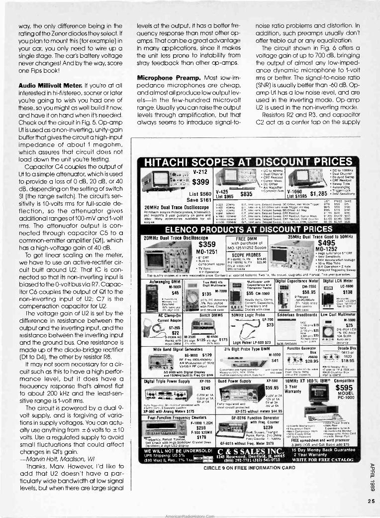
way, the only difference being in the rating of the Zener diodes they select. If
you plan to mount this (for example) in
your car, you only need to wire up a single stage. The car's battery voltage never changes! And by the way, score one Fips book!
Audio Millivolt Meter. If you're at all interested in hi-fi/stereo, sooner or later you're going to wish you had one of these, so you might as well build it now, and have it on hand when it's needed. Check out the circuit in Fig. 5. Op -amp U1 is used as a non -inverting, unity -gain buffer that gives the circuit a high -input impedance of about 1 megohm, which assures that circuit does not load down the unit you're testing.
Capacitor C4 couples the output of U1 to a simple attenuator, which is used to provide a loss of 0 dB, 20 dB, or 40 dB, depending on the setting of switch S1 (the range switch). The circuit's sen- sitivity is 10 -volts rms for full-scale de- flection, so the attenuator gives additional ranges of 100 -mV and 1 -volt rms. The attenuator output is con- nected through capacitor C5 to a common -emitter amplifier (QI), which has a high -voltage gain of 40 dB.
To get linear scaling on the meter, we have to use an active -rectifier cir- cuit built around U2. That IC is con- nected so that its non -inverting input is
biased to the 0 -volt bus via R7. Capac- itor C6 couples the output of Q1 to the non -inverting input of U2; C7 is the compensation capacitor for U2.
The voltage gain of U2 is set by the difference in resistance between the output and the inverting input, and the resistance between the inverting input and the ground bus. One resistance is
made up of the diode -bridge rectifier (D1 to D4), the other by resistor R8.
It may not seem necessary for a cir- cuit such as this to have a high perfor- mance level, but it does have a frequency response that's almost flat to about 200 kHz and the least -sen- sitive range is 1 -volt rms.
The circuit is powered by a dual 9 - volt supply, and is forgiving of varia- tions in supply voltages. You can actu- ally use anything from ± 6 volts to -±10
volts. Use a regulated supply to avoid small fluctuations that could affect changes in Qt's gain. -Marvin Holt, Madison, WI
Thanks, Marv. However, I'd like to add that U2 doesn't have a par- ticularly wide bandwidth at low signal levels, but when there are large signal
levels at the output, it has a better fre- quency response than most other op - amps. That can be a great advantage in many applications, since it makes the unit less prone to instability from stray feedback than other op -amps.
Microphone Preamp. Most low -im- pedance microphones are cheap, and almost all produce low output lev- els-in the few -hundred microvolt range. Usually you can raise the output levels through amplification, but that always seems to introduce signal-to-
noise ratio problems and distortion. In
addition, such preamps usually don't offer treble cut or any equalization.
The circuit shown in Fig. 6 offers a voltage gain of up to 700 dB, bringing the output of almost any low -imped- ance dynamic microphone to 1 -volt rms or better. The signal-to-noise ratio (SNR) is usually better than -60 dB. Op - amp U1 has a low noise level, and are used in the inverting mode. Op -amp U2 is used in the non -inverting mode.
Resistors R2 and R3, and capacitor C2 act as a center tap on the supply
HITACHI SCOPES AT DISCOUNT PRICES V-212 h ..1 DC to 40MHz
:. Dual Channel ( ' ''.4 CRT Readout
Cursor Maas ' DC Offset amemilm `.
DC to 100MHz _ Dual Channel
y s Delayed Sweep CRT Readout Sweep Time Autoranging
>VO b - $399 I Ip 4:7'7,,
1.40110111.1.11.101"3 List $560
Save $161
20MHz Dual Trace Oscilloscope All scopes include probes schematics and
HitachiHitac
c 3 year uderent onparts and YV.1065 labor. Many accessories available for all 9C0pe3.
Compactlsize V-425 List $995 $835
Trigger V-1060 gger Lock
List $1595 $1, 285 ' zmv sen3ltiylty
LIST PRICE SAVE
V-223 20MHz 0 T. ImV sans, Delayed Sweep. DC 011se, Vert Mode Trigger 5770 $695 $75 V.422 40MHz D?., ImV sens. DC Offset Vert Mo a Trigger, Alt Meg $675 $695 5180 V-423 40MO, D.T., ImV sens, Delayed Sweep, DC Offset. All Meg $955 3795 $160 V.680 60MHz OE T., 2mV sans, Delayed Sweep. C T Readout 51,105 $990 $205
100MHz D.T.. 2mV sens, Delayed Sweep, C T Readout, Cursor Mees '1,895 $1.670 3225 V.1100A100MHz O.T., Imo sens, Delayed Sweep. C T Readout. DVM. Counter $2,295 $1.995 $300 V.1150 150MHz O.T., ImV sens Delayed Sweep, C rsor Meas, DVM, Counter 33,100 $2,585 $535
ELENCO PRODUCTS AT DISCOUNT PRICES 20MHz Dual Trace Oscilloscope
-1 $359 - -
FREE DMM with purchase of
MO -1251/1252 Scope
35MHz Dual Trace Good to 50MHz
$495 -
MO -1252 -- [-Y'_ ti
MO -1251 8" CRT
,J. '' Built In Component tester
SCOPE PROBES P 1 65MHz 14. toe :19.95 P-2 160MHz tx.10x :23.95 Fits
_ ; , - - G; ..
1 f Highlumnance 6'CRT ImV Sensitivity 6KV Acceleration Voltage 1Ons Rise Time -?
_ _ -' I
e}: TV Sync
,
all scopes with BNC connector
- ,
=1'
%-V Operation ZAxis Delayed Triggering Sweep
x -V Operation Top qualify scopes at a very reasonable price. Contains all desired features. Two 1 , 10x probes, diagrams and manual. Two year guarantee.
Autoranging OMM
® M-5000
$ 45M"7000 9 lons9
- morn and Data hold .r% basic ecc 31 digll LCD
True RMS 416
SMIN Digit MuI11mNr
$135 .05% DC AccuracyReads .1% Resistance
- with Freq. Counter and deluxe case
Multimeter with __ Capacitance and Transistor Tester
$55CM-1500 Volts, Ohms,
It Current, Capacitors,
e e a'A Transistors and mini Diodes with case
Digital Capacitance Meter
CM -1550
$58.95 Ranges
1 f-20,000uld .5% basic accy Zero control with case
Digital LCR Meter ® LC -1800
$138 Measures Cons tuHSOOH cape 1 pr2oout Res.or-20V
AC Clamp -On
Current Adapter
ST -285
$22 -611000A AC
Works with most OMM
Bench DMMS 50MHz Logic Probe LP -700
s $23
A'
Logic Pulser LP -600 523
Solderless Breadboards Low Cost
ill)1% w M l w
Multimeter
M-1600
$25 31h digit LCD
DC Acct' 10A Scale Auto Zero /polarity
emminwhe9438 0o ems
2170 pins s25 9436 2.860 pins 444 All have color
a ld
M-3500 M,4500 3N cl,n 5125 ay/ di it 8175 t% accn un'o coy 9436 SHOWN
coded posi'
Wide Band Signal Generators 31/ Digit Probe Type OMM
M-1900 "' iw ""izi $41 M
Donvenlent one hand operation with battenes Measures DC, ACV, Ohms and case Audmle conlinmty check, Data hold
Function Generator Bloc
Decade Bloc -- 9610 or ' }_" 9620
- - $18"95 x9610 Resistor 910, 47 ohm to 1M a 100K pot x9620 Capacitor elox Opt to ,nMFD
i el00 .4- 528"95
Provides 9me,tn squ wave From 1Hz to 154,17 AM or FM capability
--- SG -9000 $129 RF Freq 00K-450MHz RF Modulation000-4of Hz
ag - I' 1 Variable RF output
SO -9500 with Digital Display and 150MHz builTin Frog Cir:249
Digital Triple Power Supply XP -765
$249
Quad Power Supply XP -580
+++ $59.95
220V 2A
10MHz XT 100% IBM' Compatible
5 Year $595 Warranty MODEL
PC -1000
1111111111111 - w Power supply
5/10MHz Motherboard 256K RAM 8 Expansion Slots Expandable fo 640K
Main Compressor Slot. Monochrome Morn., 'J80K Floppy D11ve Monographic video Card
AT 81y1E Keyboard Parallel Printer Port
FREE spreadsheet and word processor
3.3MS DOS and GW Basic add $75
- '!*' _ 0206 at 1A ! 4ï_ 41r_ ü 0-20V at 1A 5V at 5A
Fupy itRegulated. Short circus protected with 2 L Cont. 3 Separate supplies
XP -660 with Analog Meters $175
at V _
12V at 1A - 5V at 34 Fully regulated and .5V at 5A short circuit protected XP -575 without meters $44.95imit
Four -Function Frequency Counters GF -8016 Function Generator with Freq. Counter
) $239 Sine, Square, Triangle PUI9e. Ramp, .2 10 2MHz Freq Counter .1' 10MHz
GF -8015 without Freq. Meter 5179
` '"- - -" " - 3- F-1000 1.208 $259 ] F-100 120MH
$t79 Frequency, Period. Totalize, Sell Check with High Stabilized Crystal Oven Oscillator, 8 digit LED display
WE WILL NOT BE UNDERSOLD! UPS Shipping: US 59'0
($10 Max) IL Res., 7% Tax r-Leem C & S SALES INC 15 Day Money Back Guarantee
1245 Rosewood. Deerfield, IL 60015 2 Year Warranty (800) 292-7711 (312) 541-0710 WRITE FOR FREE CATALOG
CIRCLE 9 ON FREE INFORMATION CARD
25
AmericanRadioHistory.Com

I BUILD -IT BOOKS 1
FOR EXPERIMENTERS Modern Op-Awp 4 BP106-MODERN OP -
',.....H AMP PROJECTS .... $5.75. Wide range of build - it projects that use op - amps. Easy to build board layouts
projects for most. A varietyors of all
kinds are included.
Cì #223 -PROJECTS USING THE CA3130 .... $5.00. 50 different ways to put this op -amp to work in- cluding audio, RF, test equipment, household and miscellaneous projects.
IC 555ProJai.is r »Prolests tl.awtt%CAatso
4 rl BP44-IC 555 PROJ- ECTS .... $5.95. Included are basic and general timer circuits, automobile and model railroad circuits, alarms and noise makers, as well as a section on 556. 558, and 559 timers.
11 #224-50 CMOS ICO PROJECTS .... $5.25. These IC's are suitable for an extraordinary range of applications. This book shows you just how much you can do with them.
Second Souk of CMOS IC Projects
scC1We IC Projects
IF Hl BP59-2ND BOOK OF CMOS IC PROJECTS.... $5.50. Still more ways to use these versatile devices. None of these projects over- lap those in book #224. The pair make a wonderful circuit reference set.
[ 1 BP84-DIGITAL ICI PROJECTS .... $5.50. Both simple and more ad- vanced projects to help the reader develop a knowl- edge of the workings of digi- tal circuits. A number of board layouts are included.
GIYIIM t Prqeeb
MAIL TO' Electronic Technology Today Inc. RO. Box 240 Massapequa Park, NY 11762-0240
SHIPPING CHARGES IN USA AND CANADA
$0.01 to $5.00 . . . $1.25 $5.01 to 10.00 . . . $2.00 $10.01 to $20.00 $3.00 $20.01 to $30.00 $4.00
$30.01 to $40.00 $5.00 $40.01 to $50.00 $6.00 $50.01 and above $7.50
SORRY, No orders accepted outside of USA and Canada
Total price of merchandise $
Shipping (see chart) $
Subtotal $
Sales Tax (NYS only) $
Total Enclosed $
Name
Address
City State Zip
IL
THINK-TANK
and are used to bias the non -inverting input of U1. Resistors R1 and R4 are the negative -feedback network, which set the input impedance at about 1000 ohms and the closed -loop gain to about 40 dB.
Potentiometer R7 serves as a gain control and couples a DC -bias volt- age to the non -inverting input of U2.
Resistors R5 and R6 set the audio -volt- age gain of U2 at about 27 dB, but C4 provides 100% negative feedback (and unity voltage gain at DC). The output of U2 is, therefore, biased to half the level of the supply voltage.
The device selected for U2 features a very low noise level and it should be realized that the noise performance of U2 isn't as important as the noise level
produced by U1, since any noise pro- duced in UI will be amplified by U2. -Bob Small, Enid, OK
Bob, this is an extremely interesting circuit, and will solve a lot of problems for people who plan to use teensy- weensy electret microphones! Nice job, and your Fips book is on the way!
Slide Show Timer. Sometimes, when you're doing a slide show for friends, you have to be more of a juggler than anything else! But this little circuit (see Fig. 7) takes some of the- burden off you, by automatically changing the slides at pre-set intervals. You can set the interval from about five to 30 sec- onds. A relay operates the slide - change mechanism.
Op -amp U1 forms a sort of Schmitt trigger. Resistors RI and R2 bias the non -inverting input (pin 3) of U1 to half
+V
Fig. 4. This Battery Monitor contains four LED's that are set o switch on if the supply voltage falls below any of the preset thresholds, which were se at 10, 11, 12, and 13 volts by Zener diodes Dl through D4, respectively.
IN
C1
.1
fe_3_
C2
.1
e
U1
4
R1
1MEG
C4
7 33
TCG857M
R3 10052
R2
1K 10mV
100mVo° Si
1V
R6
5.6K
R5 C6
1.2MEG 10
-9v--)17*--3 2
C5
33 O1
ECG123A
U2
+9V
C7 D2 03 68pF 1'84148 1N414B
-iC I NI
010µA
8 6
NE531 04 01 1N4148 1N4148
It I R7
e 10K
C3 1
-______1(
R4 1152
R8
22K
0V
-9V
Fig. 5. In the Audio Millivolt Meter, integrated circuit U/ is used as a non -inverting, unity - gain buffer to provide a high input impedance, ensuring that circuit doesn't load down the unit under test, throwing off the reading.
26
AmericanRadioHistory.Com

R2
12K
R1
1K
C1 ^33
9 MIC
5
U
4
C3 -100pF íT
8
NE5534A
C2
100
eR3 12K
R4 20K R5
10K 2
R7 47K
C4 10
U2
R6 i 220K
+9-18V Cero->
SI ON/OFF
>° +I(_-9 OUT
LF351 C5 C6
10 1
Fig. 6. This phono preamp offers a voltage gain of up to 700 dB, with a signal-to-noise ratio (SNR) of usually better than -60 dB.
the supply voltage. Feedback resistor R3 increases or reduces the bias to pin 3, depending on whether the output of U1 is high or low.
When power is first applied to the circuit, C2 has a zero charge and the inverting input of the op -amp is at a lower voltage than its non -inverting in- put. When the output of U1 is high, C2 begins to charge through R5 and DI. It
takes about one second for the charge on C2 to reach the same volt- age as that at the non -inverting input of U1. At that time, the output of U1 be- gins a negative swing.
Because of the positive feedback through R3, the voltage at the non - inverting input is reduced and the out- put goes more negative. The voltage at the non -inverting input is at about 1/4
of the supply voltage and C2 begins to discharge through the resistor bank. The timing is controlled by Rb.
The resulting pulses are fed to the base of Ql (configured as an emitter - follower buffer stage), which is used to activate relay Kl. Transistor 671 is neces- sary because op -amps usually have an output current in the 20 -mA range-which is too low to activate the relay. -Barney Selwyn, Tulsa, OK
You know Barney, when I first saw your circuit, I wondered why you didn't just use a current -sensitive relay for the output and save the transistor. But you've explained that problem away very nicely. Nice job, and your Fips book is in the mail.
That's a "wrap" for this month (whew!), but I hope you guys will keep sending your pet circuits and descrip- tions to Think Tank, Popular Elec- tronics, 500-B Bi -County Blvd., Farm- ingdale, NY 11735. Catch you on the rebound.
c1 100
R1
100K R3 68K
7
R2
100K
2
U1 741
4 R4 39K
D1
1N4148
C2 +
100`
N
1
Q1
80108
R6 R5
220K 8.2K
o* +9V S1
ON/OFF
- 02 A1N4148
+v
lOUTPUT
(L)
K1
9 VOLT RELAY
Fig. 7. The Slide Show Timer, built around a 741 op -amp, can be set to change frames at intervals that can be varied from about 5 to 30 seconds.
Put Professional Knowledge and a
COLLEGE DEGREE in your Technical Career through
Add prestige and earning power to your technical career by earning your Associate or Bachelor degree through directed home study.
Grantham College of Engineering awards accredited degrees in
electronics and computers.
An important part of being pre- pared to move up is holding the right college degree, and the abso- lutely necessary part is knowing your field. Grantham can help you both ways-to learn more and to earn your degree in the process.
Grantham offers two degree pro- grams one with major emphasis in electronics, the other with major emphasis in computers. Associate and bachelor degrees are awarded in each program, and both pro- grams are available completely by correspondence.
No commuting to class. Study at your own pace, while continuing on your present job. Learn from easy -to -understand lessons, with help from your Grantham instruc- tors when you need it.
Write for our free catalog (see ad- dress below) or telephone us at (213) 493-4423 (no collect calls) and ask for our "degree catalog."
Accredited by the Accrediting Commission of the
National Home Study Council
GRANTHAM College of Engineering 1>
10570 Humbolt Street Los Alamitos, CA 90720
27
AmericanRadioHistory.Com

Where can I turn for he1pV,,
There is a way to get help when you need it. The American Home Satellite Association. An organization created exclusively to protect and enhance your enjoyment of your satellite TV system.
'Iáke our toll free "Helpline; for example. Rom locating satellite signals to locating a reputable dealer, help is just a phone call away. AHSA provides educational videotapes and informative books, too. At very special member prices.
Plus, 10 times a year, AHSA's official newsletter, Sky Report, will bring you the latest word on products, legislation, programming, and more. Not to mention reviews of new products and services. And that's not all AHSA has in store for you.
Programming shouldn't cost a fortune. With AHSA's group buying power,
you can save on premium services, superstations and basic programming services. Enjoy savings on accessories, equipment, and programming guides, too.
You're not alone anymore! With your voice behind us, AHSA is
promoting legislation to guarantee fair access at reasonable prices. Addressing zoning and piracy issues. Even sending expert witnesses to Congressional hearings. Join other dish owners around the nation, and become a force to be reckoned with.
3 Rush my free information kit Name
Address
City State Zip
Sign me up right away and send my complete membership 1át.
Check enclosed for $36 (made out to AHSA) Bill my VISA D MasterCard Card e
Exp. Date Authorized Signature X
30 -day Money Back Guarantee
Return completed coupon to: American Home Satellite Association, Inc.,
Ten Suite 800, 500108th Ave. NE,
American Home Bellevue, WA 98004-5560 Or call Toll Free
Satellite Association 1-800-321-AHSA (2472). CA
AmericanRadioHistory.Com

LUCKY LOTTO SELECTOR
Do those lucky numbers keep eluding you. Build this lucky -number selector
circuit and change your luck!
If you've run out of fingers, thumbs, toes, and birth dates trying to come up with a winning combina-
tion of numbers for your favorite lottery without much success, let our Lucky Lotto Selector do the picking for you. The circuit can be programmed by a simple wiring change to select num- bers in three of your favorite lottery games by merely rotating a selector switch.
Naturally there's no guarantee that the Lucky Lotto Selector will pick the winning combination, but it will help take the drudgery out of coming up with the numbers every time a new game comes to town.
The circuit is designed around three low-cost IC's, and to keep it simple, the numbers are indicated by individual LED's instead of complicating the cir- cuit with additional IC's and support components that would be needed to drive a seven -segment display. In fact, once you become accustomed to using the circuit, the readout scheme used in this project will seem like a natural path to follow in the numbers game.
A three -pole, three -position switch allows up to three different lottery sys- tems to be hard -wired into the circuit. As shown, in the schematic diagram of Fig. 1, ours is programmed so switch position '1" allows numbers 1 to 33 to be selected; in position "2" numbers 1 to 40; and in the third position, numbers 1
to47. And because the circuit draws very
little current, it can be powered by a
BY CHARLES D. RAKES
standard 9 -volt, transistor -radio bat- tery.
How It Works. The schematic di- agram for the Lucky Lotto Selector is
shown in Fig. 1. Two gates (half of a 4001 quad, 2 -input NOR gate), Ul-a and U1 -b, are configured as a simple oscillator circuit. Switch S2 (a normally -open pushbutton switch) is connected across the two inputs of UI -a, making it function as an inverter.
When SI is depressed, a positive volt- age is applied to pins 1 and 2 of U1 -a, causing it to output a low. That low is
then applied to both inputs of U1 -b (which is also configured as an inver- ter), causing it to output a high.
The output of U1 -b then travels along two paths. In one path, a portion of the output signal is fed back through Cl, after which the signal again splits, with a portion of the feedback signal going to the input of Ut -b and the rest to U1 -a, causing the circuit to oscillate at about 18 kHz.
In the other path, the output of U1 -b is
fed to the clock input of U2 (a 4017 decade counter) at pin 14. Integrated circuit U2 counts each pulse and lights up an LED to indicate its position as it goes on its merry way. After counting ten pulses, U2 pin 3 goes high, causing LEDI (which represents the numeral 0) to light.
The output of U2 at pin 3 is also fed to the clock input of a second 4017 de- cade counter, U3, causing it to ad- vance one count. That causes U3 pin 2 to go high, lighting LEDI 1, which repre-
Popular
Electronics® APRIL 1989
sents al. Together, the two lighted LED's
represent the number "10." Transistors Q1 and Q2, along with
U1 -c determine the maximum number indicated for a given position of S3.
When the bases of both Q1 and Q2 go high, grounding pins 8 and 9 of U1 -c, a high is applied to U2 at pin 15, causing it to reset to zero. With S3 in position 1,
the circuit counts to a maximum of 33; in position 2, the maximum count is 40; and in position 3, the maximum count is 47.
The base of Q1 is connected through S3 to pin 10 of U2, which goes high only when the number 4 digit is lit. The base of Q2 is connected to pin 7 of U3, which only goes high when the number 3 lights.
At the count of 33, pin 7 of U3 goes high, turning on transistor Q2, which then pulls pin 8 of U1 -c low. Transistor Q1
remains off until the count tries to go to 34, when pin 10 of U2 goes high. At that point, both transistors are turned on, grounding both inputs to U1 -c. With both inputs to 1.11-c tied low, its output goes high, resetting U2 and the count- ing process is repeated. The transition time is so very fast that the number 34 never shows up on the display.
>71
F
29
AmericanRadioHistory.Com

R5
47K
TO U2 PIN 9
TO U2 PIN 2
TO U2 = PIN 10
SR1
S 10K
o TO U3 PIN 7
S3a
31 I
i
TO U3 PIN 10
1/4 4001
e R3 R4 ` 4.7K 4.7K
8
01 2N3904
S3 -b R2
10K
9
1/4 4001
C2
47
14
- Cl
10 15
02
2N3904
13
16
U2 4017 DECADE COUNTER
1 ®xfi
Cr)'
O fi
8 ... LED1-LED10
R6 1K
S3 MAXIMUM POSITION COUNT
1 33 2 40 3 47
TO U3 PIN 100
Fig. 1. The Lucky Lotto Selector is built around three readily available CMOS IC's and uses a rather simple switching arrangement to force the circuit to reset after the maximum count is reached.
Switch S3 -c is configured to reset U3
at the proper count. With S3 in position 1, the reset input of U3 is connected to pin 10 of U3. That allows numbers be- low 40 to be counted and displayed. When U3 tries to count to 4, a reset pulse is applied through S3 to the reset
U input of U3 at pin 15, causing the count o to start over. cr Programming S3 for any lottery sys-
w tem with a maximum number of less w than 50 is easy. Lets take, for example,
ó a lottery that uses the numbers 1 to 47.
ch Starting with S3 -a, connect the posi - o
ç lion -1 terminal to the output pin of U2 = that is one digit higher than the digit c(-1-3 you want to count to.
In other words, we want the count to cc reset at 48. So S3 -a position 1 connects
w to pin 9 (output 8) of U2. Switch S3 -b, position 1, connects to pin 10 (output 4)
cc of U3. Switch S3 -c position 1 also con- nects to pin 10 of U3. Sounds compli-
0_ cated? Not really if you follow the
d scheme outlined and study the three
i 4 INCHES
st
16
14
15
13
U3 4017 DECADE COUNTER
B1
9V
1 LED11-LED14
R7
1K u
I
Fig. 2. Here is a full-scale template of the printed -circuit pattern used by the author. Printed -circuit construction makes assembly of the project simple and also helps to cut down on wiring errors.
systems shown in the schematic di- agram of Fig.1.
The circuit can also be expanded to accommodate Lotto 54 (New York's bi -weekly, multi -million dollar lottery
game) by connecting a fifteenth LED to output 5 (pin 1) of U3. Of course, you'll also have to figure out which switch contacts go where.
Let's take a look at how that's ac -
30
AmericanRadioHistory.Com

LEM LED3 LED5 r /iv
LEDI LED9
//v /iv B1
o
S3 -c
C2
-v-
U3
-R6-
LED11
LED2 LED4
U2
LEDE LED8
C1
R3
R5
-R7- D2 b
U1
LED10
---R4_ J
LED 13
LED 1 1t\1 %d
S3 -b
LED 14
3
Fig. 3. Once you've etched your own printed -circuit board (or obtained one from the sup- plier given in the Parts List), install the components using this diagram as a guide.
PARTS LIST FOR THE LUCKY LOTTO SELECTOR
SEMICONDUCTORS U1-4001 quad two -input nor gate U2, U3-4017 decade counter/divider QI, Q2 -2N3904 general-purpose NPN
silicon transistor LEDI-LED14-Jumbo light -emitting
diode (any color)
RESISTORS (All resistors are' -watt, 5% units,
unless otherwise noted.) Rl, R2 -10,000 -ohm R3, R4 -4700 -ohm R5 47,000 -ohm R6, R7 -1000 -ohm
CAPACITORS C1 -0.0015-µF, 100-WVDC, mylar or
similar C2 -47-µF, 16-WVDC, electrolytic
complished, using the number 54 as an example. Starting with S3 -a, con- nect switch position 1 to U2 pin 5. Switch position 1 of S3 -b should be connected to pin 1 of U3, and wire pin 15 of U3 through S3 -c to pin 5 (output 6). That's all there is to it-and it doesn't take a genius to figure it out.
ADDITIONAL PARTS AND MATERIALS B1 -9 -volt transistor -radio battery SI-SPST miniature toggle switch S2-Normally closed pushbutton switch S3-3P3T rotary switch Printed -circuit or perfboard materials,
enclosure, IC sockets, battery and snap connector, wire, solder, hardware, etc.
A complete kit of parts (excluding the enclosure) is available for $29.95 (postage paid); printed -circuit board only for $9.95 (postage paid) from Krystal Kits, PO Box 445, Bentonville, AR 72712. All Arkansas residents please add appropriate sales tax. Please allow 6 to 8 weeks for delivery.
Building Your Own. Since the circuit is as uncomplicated as you can get and the component count is low, al- most any construction scheme will do, although using a printed -circuit board will certainly make the project easier to put together. However, if you choose to use the perfboard approach, IC
R1
D1 b
53-a
Z425.1 U
S2
sockets would be a worthwhile addi- tion. In any case, study the schematic diagram, photos, and the parts layout before starting construction.
The author's prototype unit was built on a printed -circuit board; see Fig. 2
for details. If you opt to go the printed - circuit route, follow the parts -place- ment diagram shown in Fig. 3 for com- ponent positioning and orientation. Be particularly careful when installing the transistors (Q1 and Q2). If those compo- nents are misoriented, the circuit will give some strange results: For instance, incorrectly installing 671 or Q2 would result in U2 not resetting at the proper time, if at all.
The off -board wire connections ap- pear a little confusing (and they are). Your best bet here is to take your time and (perhaps) use some sort of color - coding scheme-the use of multi -col- ored insulated hook-up wire is recom- mended.
The author's prototype was housed in a plastic cabinet, measuring about 6 x 3 x 13/4 inches, but any similar size cabinet will do. The 14 LED's, and the three switches may be arranged in any pattern desired. Just remember
(Continued on page 100) o
31
AmericanRadioHistory.Com

Dice -Roulette
E lectronic dice and roulette wheels have long been popu- lar projects for electronics ex-
perimenters. The Dice -Roulette Game presented here combines the two proj- ects into one; because its a roulette wheel that gives the same odds as a pair of traditional six -sided dice.
Thirty-six LED's are arranged around the wheel, each labeled with a number from 2 to 12. Pressing the spin switch starts the wheel spinning actu- ally, the wheel stands still and the LED's
light in rapid sequence to simulate spinning. Release the spin switch, and the spin slowly comes to a stop, leav- ing just one randomly chosen LED lit.
The spin and suspenseful spin -down are generated by a CMOS voltage - controlled oscillator. High-speed CMOS outputs directly drive the LED's
at 20 milliamps, giving a bright dis- play. And the circuit can easily be customized for any number of LED's,
spin frequency, or spin -down time you'd like.
Game Build an exciting game that
combines the thrill of roulette with the odds of
a crap shoot!
BY JAN AXELSON & JIM HUGHES
Inside Dice -Roulette. A complete schematic of the Dice -Roulette Game is shown in Fig.1. In the circuit, U1 clocks a series of decade counters (U3 -U7). Integrated circuit U1 is a 4046 phase - locked loop (PLL), here used for its
VCO (voltage -controlled oscillator). The output at pin 4 of U1 is a square wave whose frequency is determined by R2, C2, and the voltage at pin 9.
Resistor R2 and capacitor C2 deter- mine the spin frequency, or the fre- quency of the signal at pin 4 when S2 is
pressed. With the components shown, the spin frequency is around 350 Hz.
Switch S2 ties pin 9 of U1 to V + to initiate spinning. Pin 9 provides the
control voltage for the VCO. When S2 is
released, the voltage at pin 9 de- creases slowly as C1 discharges through RI. As the voltage at pin 9 falls, the frequency at pin 4 also decreases. Figure 2 illustrates that effect. When pin 9 has dropped to about 1 volt, the VCO stops oscillating. With the component values shown in Fig. 1, the circuit takes about five seconds to come to a stop.
The PLL provides clocking pulses for a 36 -step counter made from five 74HC4017 decade counters. Figure 3
shows the operation of one 74HC4017. When enabled and clocked, the out- puts go high in sequence for one clock period each. A high on pin 13 of any counter stops it, freezing all outputs in
their current states A high on pin 15
resets the counter, causing pin 3 to go high and the other 9 outputs to go low. (There's also a carry output, though it isn't used by the Dice -Roulette Game.)
The five 74HC4017's really make up one counter with 36 outputs. The wheel may be at any position-with any of
32 AmericanRadioHistory.Com

_t_. o --i + V
52R2 2K
11
Li R1 C2 5.8MEG- .1
4M, C1
1.47
+
131
4.5V
I
1/4 74HC08
1/4 74HC08
1/4 74HC08
1/4 74HC08
1
U4 74HC4017
EN
15 - RST
74HC4017
EN
15 RST
74HC4017
U7 74HC4017
LED1-LED9
LED10-LED17
i _ I LED18-LED25
LED26-LED33
R3
710K
Q1
LED34-LED36 R5 5652
3
14
(SEE TEXT)
Fig. I. The Dice -Roulette's clocking is performed by he voltage -controlled oscillator of a 4046 phase -locked loop. Five 74HC4017 decade counters control the game's 36 LED's.
4.5V
VOLTAGE ON PIN 9 OF U1
OV
4.5V
VOLTAGE ON PIN 40FU1
OV
SPIN SWITCH PRESSED
A -SPIN SWITCH RELEASED
SPIN STOPS
TIME
A
TIME
B
Fig. 2. The output frequency at pin 4 of the the 4046 depends on the voltage at pin 9 as shown in A. As the voltage drops, so does the frequency, causing the oscillations to slow to a stop (B).
the LED's lit-when the spin switch is
pressed. For simplicity, assume that the wheel starts with LEDI on, and all the other LED's off. On the first clock pulse at pin 14 of U3, pin 3 goes low, turning LEDI off, and pin 2 goes high, lighting LED2.
Succeeding clock pulses light LED's
3-9 in sequence, then pin l l of U3 goes high. That disables U3, But at the same time, U2 -a now allows U4 to be clocked. Light-emmiting diodes 10-17 light in sequence, then LED's 18-25, 26-33, and 34-36, as U5, U6, and U7
are clocked in sequence.
Resetting the Counters. After LED 36 lights, the next clock pulse resets U3
and the count starts again at LEDI. To
get the circuit ready to count again, U4 -U7 are also reset at this time. The high on pin 3 of U3 causes transistor Q1
to saturate, bringing pin 3 of the xoR
gate in UI low. Pin 2 of U1 then goes high, resetting U4. Pin 3 of U4 in turn resets U5, U5 resets U6, U6 resets U7, and U7 resets U3.
Note that the XOR gate used in reset- ting is actually part of UI. The gate is
normally used as a phase comparator for the IC's phase -locked loop. Since we don't need the phase comparator to use only the VCO in UI, we can press the gate into service elsewhere. (By tying one input high, we're actually using the gate as an inverter.)
Why not connect pin 3 of U3 directly to U4's reset? Pin 3 has two jobs-reset- ting the counters and turning on LEDI.
The 20 milliamps of current used by LEDI pulls pin 3 down to about 3 volts, which isn't high enough to provide a
33
AmericanRadioHistory.Com
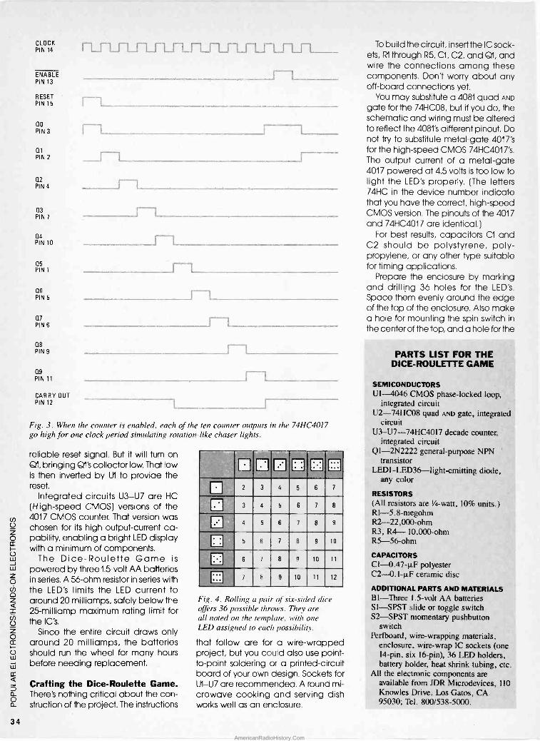
CLOCK PIN 14
ENABLE PIN 13
RESET PIN 15
IZFL .-L LTL5-1
f- no PIN 3
ii Lr_ QI PIN 2
Q2 PIN 4
O3 PIN 7
n4 PIN 10
05 PIN 1
06 PIN 5
m PIN 6
08 PIN 9
C19
PIN 11
CARRY OUT PIN 12
L
_
Fig. 3. When the counter is enabled, each of the ten counter outputs in the 74HC4017 go high for one clock period simulating rotation -like chaser lights.
reliable reset signal. But it will turn on 01, bringing O1's collector low. That low is then inverted by U1 to provide the reset.
Integrated circuits U3 -U7 are HC (High-speed CMOS) versions of the 4017 CMOS counter. That version was chosen for its high output -current ca- pability, enabling a bright LED display with a minimum of components.
The Dice -Roulette Game is powered by three 1.5 -volt AA batteries in series. A 56 -ohm resistor in series with the LED's limits the LED current to around 20 milliamps, safely below the 25-milliamp maximum rating limit for the IC's.
Since the entire circuit draws only around 20 milliamps, the batteries should run the wheel for many hours before needing replacement.
Crafting the Dice -Roulette Game. There's nothing critical about the con- struction of the project. The instructions
. . Ei Q El 11' El2 3 4 5 6 7
3 4 5 6 7 8
ri4 5 6 7 8 9
C35 6 7 8 9 10
6 7 8 n 10 11
ri7 8 9 10 11 12
Fig. 4. Rolling a pair of .s"x-sided dice offers 36 possible throws. They are all noted on the template, with one LED assigned to each possibility.
that follow are for a wire -wrapped project, but you could also use point- to-point soldering or a printed -circuit board of your own design. Sockets for U1 -U7 are recommended. A round mi- crowave cooking and serving dish works well as an enclosure.
To build the circuit, insert the IC sock- ets, Rl through R5, Cl, C2, and 01, and wire the connections among these components. Don't worry about any off -board connections yet.
You may substitute a 4081 quad AND
gate for the 74HC08, but if you do, the schematic and wiring must be altered to reflect the 4081's different pinout. Do not try to substitute metal -gate 4017's for the high-speed CMOS 74HC4017's. The output current of a metal -gate 4017 powered at 4.5 volts is too low to light the LED's properly. (The letters 74HC in the device number indicate that you have the correct, high-speed CMOS version. The pinouts of the 4017 and 74HC4017 are identical.)
For best results, capacitors Cl and C2 should be polystyrene, poly- propylene, or any other type suitable for timing applications.
Prepare the enclosure by marking and drilling 36 holes for the LED's. Space them evenly around the edge of the top of the enclosure. Also make a hole for mounting the spin switch in
the center of the top, and a hole for the
PARTS LIST FOR THE DICE -ROULETTE GAME
SEMICONDUCTORS UI 4046 CMOS phase -locked loop,
integrated circuit U2-74HC08 quad AND gate, integrated
circuit U3-U7-74HC4017 decade counter,
integrated circuit Ql-2N2222 general-purpose NPN
transistor LEDI-LED36-light-emitting diode,
any color
RESISTORS (All resistors are %a -watt, 10% units.) R1-5 .8-megohm R2 -22,000 -ohm R3, R4- 10,000 -ohm R5 -56 -ohm
CAPACITORS C1 -0.47-µF polyester C2 -0.1-µF ceramic disc
ADDITIONAL PARTS AND MATERIALS BI-Three 1.5 -volt AA batteries S1-SPST slide or toggle switch S2-SPST momentary pushbutton
switch Perfboard, wire -wrapping materials,
enclosure, wire -wrap IC sockets (one 14 -pin, six 16 -pin), 36 LED holders, battery holder, heat shrink tubing, etc.
All the electronic components are available from JDR Microdevices, 110 Knowles Drive, Los Gatos, CA 95030; Tel. 800/538-5000.
34
AmericanRadioHistory.Com
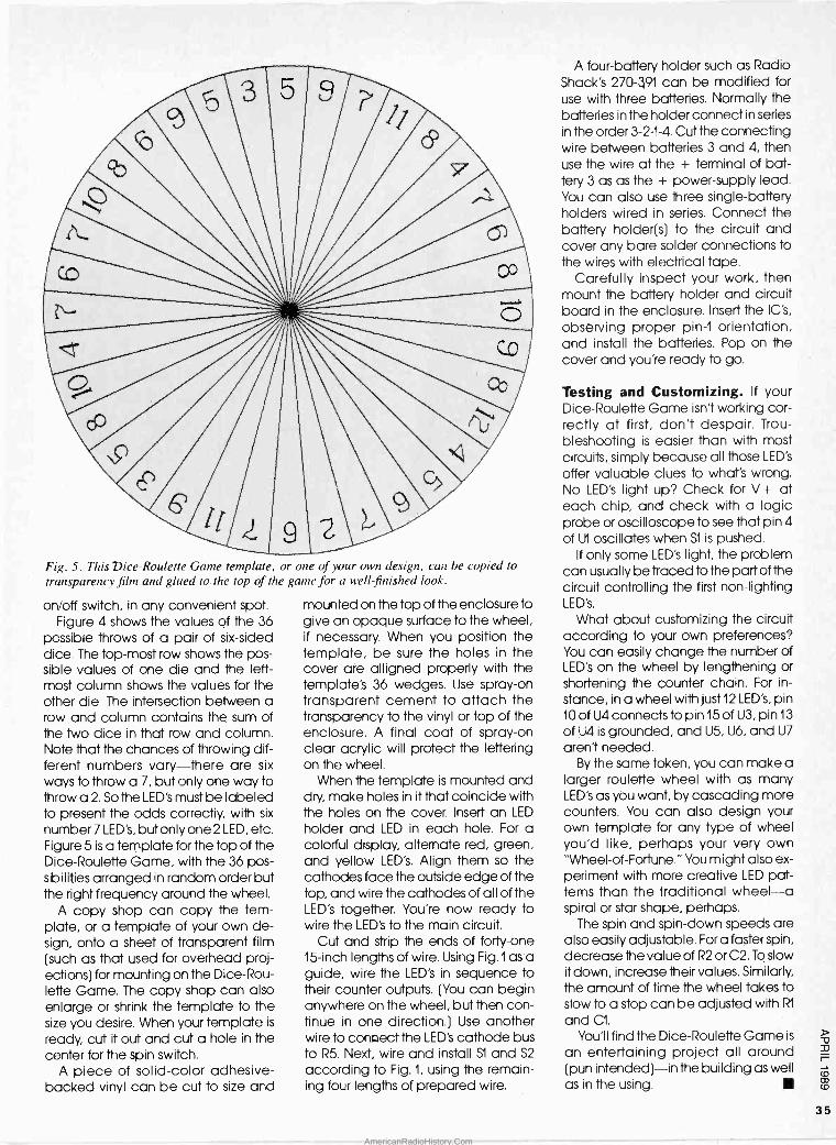
Fig. 5. This Dice -Roulette Game template, or one of your own design, can be copied to transparency film and glued to the top of the game for a well -finished look.
on/off switch, in any convenient spot. Figure 4 shows the values of the 36
possible throws of a pair of six -sided dice. The top -most row shows the pos- sible values of one die and the left- most column shows the values for the other die. The intersection between a row and column contains the sum of the two dice in that row and column. Note that the chances of throwing dif- ferent numbers vary-there are six
ways to throw a 7, but only one way to throw a 2. So the LED's must be labeled to present the odds correctly, with six
number 7 LED's, but only one 2 LED, etc. Figure 5 is a template for the top of the Dice -Roulette Game, with the 36 pos- sibilities arranged in random order but the right frequency around the wheel.
A copy shop can copy the tem- plate, or a template of your own de- sign, onto a sheet of transparent film (such as that used for overhead proj- ections) for mounting on the Dice -Rou- lette Game. The copy shop can also enlarge or shrink the template to the size you desire. When your template is
ready, cut it out and cut a hole in the center for the spin switch.
A piece of solid -color adhesive - backed vinyl can be cut to size and
mounted on the top of the enclosure to give an opaque surface to the wheel, if necessary. When you position the template, be sure the holes in the cover are alligned properly with the template's 36 wedges. Use spray -on transparent cement to attach the transparency to the vinyl or top of the enclosure. A final coat of spray -on clear acrylic will protect the lettering on the wheel.
When the template is mounted and dry, make holes in it that coincide with the holes on the cover. Insert an LED
holder and LED in each hole. For a colorful display, alternate red, green, and yellow LED's. Align them so the cathodes face the outside edge of the top, and wire the cathodes of all of the LED's `ogether. You're now ready to wire the LED's to the main circuit.
Cut and strip the ends of forty-one 15 -inch lengths of wire. Using Fig.1 as a guide, wire the LED's in sequence to their counter outputs. (You can begin anywhere on the wheel, but then con- tinue in one direction.) Use another wire to connect the LED's cathode bus to R5. Next, wire and install S1 and S2
according to Fig. 1, using the remain- ing four lengths of prepared wire.
A four -battery holder such as Radio Shack's 270-391 can be modified for use with three batteries. Normally the batteries in the holder connect in series
in the order 3-2-1-4. Cut the connecting wire between batteries 3 and 4, then use the wire at the + terminal of bat- tery 3 as as the + power -supply lead. You can also use three single -battery holders wired in series. Connect the battery holder(s) to the circuit and cover any bare solder connections to the wires with electrical tape.
Carefully inspect your work, then mount the battery holder and circuit board in the enclosure. Insert the IC's,
observing proper pin -1 orientation, and install the batteries. Pop on the cover and you're ready to go.
Testing and Customizing. If your Dice -Roulette Game isn't working cor- rectly at first, don't despair. Trou- bleshooting is easier than with most circuits, simply because all those LED's
offer valuable clues to what's wrong. No LED's light up? Check for V+ at each chip, and check with a logic probe or oscilloscope to see that pin 4 of U1 oscillates when S1 is pushed.
If only some LED's light, the problem can usually be traced to the part of the circuit controlling the first non -lighting LED's.
What about customizing the circuit according to your own preferences? You can easily change the number of LED's on the wheel by lengthening or shortening the counter chain. For in-
stance, in a wheel with just 12 LED's, pin 10 of U4 connects to pin 15 of U3, pin 13
of U4 is grounded, and U5, U6, and U7
aren't needed. By the same token, you can make a
larger roulette wheel with as many LED's as you want, by cascading more counters. You can also design your own template for any type of wheel you'd like, perhaps your very own "Wheel -of -Fortune." You might also ex- periment with more creative LED pat- terns than the traditional wheel-a spiral or star shape, perhaps.
The spin and spin -down speeds are also easily adjustable. Fora faster spin, decrease the value of R2 or C2. To slow it down, increase their values. Similarly, the amount of time the wheel takes to slow to a stop can be adjusted with R1
and C1.
You'll find the Dice -Roulette Game is
an entertaining project all around (pun intended)-in the building as well as in the using.
-0
P
co CD
35
AmericanRadioHistory.Com
.. mmeTaxReturn 1Y3"e v aeaw
nweea
S iolyteoeltt3c OK a. ral °" Dec.31 198. U'ar
. º~"
o
waa o' a l y mlsesafiuconr Label
_
R
aameºt,.wn aaddg
Cna °t,r.+ nO 21Pc"M No
W ^°ahnw
I E
No C,n.ta+^a'
und' ototnlstun^' d s ewsntflto
/resi0ential It Olr^ rlturn, dols tnoomel ygIWI nee'eeasa' _--- nd W1 no,
\--7-1F0ilingliStatus
lectin UmPartn ç,elum.levddmb onelsesard p°'e. M the
.HI^g nR°" s
IMarrwdtVì^Ypdntr
3
Mer,anntaroem,a°1ela 1' ' 7oYlnshuct1O"al ooa'-iructmrs lw^^
nn,^. ann" see page
(Sa ' NeadlaeaneuselM<erchdld'sMmeherl?ld e
medl9 check box My Hecxomr a^deM.doMic uea
me pos
m
wchasyW M33.onDagegetn RoAFuI
4 G YWrselt i e (toc^ecathe.o+` uA9ü .n°
a,X _.
e swdeM1etu+ ttre+eV"
dw mna n Dee - ar°,a,r.
4°y°,.h anea
m.l
aÓm ._" naw+.._'
EaemYt¡ons
{S" tens onpage8)
more loen.
lapene<uaae Insvoc^°"f 0" Huge 8.
o your r wdn..- dentc' pdmyouasade . uan . rMrMtlunc e2
on V
U1nKKq0rroa° s c
11
r
edmvad+wtoe-- .
A
MyW,ydqnlirve sclnme^- a total num.d at eab^' Fym) W'Zl )
ylanö.li{ril MaCnMpeleadeaMNOO .
7 TuyynnwestdM y<na8e111DONTlncluG.onnM.a
.
Ine.M1K ti
in.awnPt,nurenmcondel ^epweeno.arfao0> aheela^wga11oY1r.K^°"a
`oRyO w.2G. 10 asele`etundsotAstele
ndoNldncomellaea.daM.h°^'wot
b3PMe AomonYre<eivao eEukl 11 (Ims1(artd^Sc
deywdonatnave 12
GWlaes)(attac.SCMduM)IIM13(Napagp111 W'2oj 13 - - .bamgynl(seePeg° 1T1 Upìndyt:iWtwnsMtn reported
797) 1pTW 11)
ru [wns. U (Ipases)(aMd pyamauMlseaPoe
IS Omdgad.uor -IIgiW
lW T1IRAddpntwtons ScnNuyE)
17a Totalpenvo^e and annutws lH.tt9sta.ele.(aMM
In RenC.,oyand<a.Pan:ersNM.pyleF)
19 Egon ,ncom.mlw*sl(aMM pce)(sdDa4a13) 1. pen,dw"O"'u
UnemoloYR`aM_ t3) ! 9'''' amWnt, f anY`M1°m oaga0+0.13 .
..
Pmaae sttacncnds Ot.er ^ea^aOis
type Nmela.lcoWnvdtad 13 ,,_3.-..L.-
.
22 ..der 23 a^ ^*asro,ysmorn
Fmm210..;a«15'.se. - neet a'. Y6
15; 2a . .
21 ''''''''''''''''''..''''.."097"tpnawgvs.Hto^G+galau 27a Ylur 1M
pamdioon }rom apd nn page l3
pdjustments . s000aes wom
to Ineome neam`dmmanudeaut{10"' sEPdedoctw^ ga
K R, mlpynande.u-emdaa*a oft, wdndrs+r 29 27 Ndsaw
ApeMYy Dea Oddment's
last neme .
usn^a^b
1 e 1M3(ltmmnM
esno aMsu"`¡ ( .
zl
secunty no 9Trwaee
l.orm< _...... .
weldMaza a, 3t f1g.576e^d ,°" mr un
fMlnstnrctM^a
c
.em
Adjusted Gross Incorne
of too long ago, a couple that operated an Amway dis- tributorship were denied a tax
eduction for business expenses and epreciation because they failed to
show the U. S. Tax Court that they had engaged in the activity with the objec- tive of making a profit. But for that cou- ple-and thousands of enthusiasts
Iwho might not be able to qualify their electronics -related activities as a "business" for tax purposes-all de-
o ductions are not lost.
2 Under our tax laws, special limita - o cr tions are imposed on the deductibility o of expenses incurred in an activity that w w is not engaged in for a profit. In other zo words, a "hobby." Often referred to as
a "hobby -loss limitation," losses arising
°z from a hobby generally cannot be de-
a ducted unless such loses are due to a casualty. The phrase "hobby -loss lim-
o2 itation" erroneously conveys the im-
o pression that any loss from a hobby i- cannot be deducted. 0 w Fortunately, some of the expenses in - in
in any electronics -related ac- tivity can be deducted, either as
O
0- *Financial and Tax Consultant
a Ardmore. PA
22 tea
i -- w
12 _
o md
19 31, --
YOUR HOBBY AND THE
IRS
personal expenses or used to offset any income from that activity. Natu- rally, deciding which hobby expenses qualify as personal or which can or should be used to offset hobby income can be quite confusing particularly since shifting those expenses between the two categories can have a notice- able impact on the bottom -line of an electronics enthusiast's annual income tax return.
The Expense Categories. In order to eliminate some of the potential con- fusion, as well as to ensure that all elec- tronics -activity expenses are treated in
the same manner, the IRS has estab- lished three general categories into which all hobby expenses fall:
Type One Expenses. Into this catego- ry fall all expenses for which a deduc- tion would be allowable regardless of whether the activity was a hobby. For
instance, items such as interest, and casualty losses are deductible.
Type Two Expenses. These are ex- penses that, when deducted, do not require an adjustment to the book val- ue of an item. Those include the cost of utilities, rent, or other expenses for the activity. Type two expenses are de- ductible to the full extent that the gross
Who says having a hobby can't put money in your
pocket? Would you belive it can be acne with
Uncle Sam's help?
BY MARK E. BATTERSBY*
income from the activty exceeds the `ully deductible expenses.
Type Three Expenses. These are the expenses that do result in c book value adjustment, such as depreciation, property losses. etc. Type three ex- penses are deductible to the extent that the income from the hobby ex- ceeds the amounts deductible in the two other categories.
Thus, every enthusiast can deduct some of their electronics -related inter- est expenses (although that will be phased out), and casLaltw losses (sub- ject to IRS rules) regardless of whether they receive any income. f the activity does produce incorre, that income may be offset by cctecory two ex- penses, such as fees, rents, utilities, etc. If income from the activity still remains after deduct°ng the expenses from those two oct egories, the remaining balance can be offset with deprecia- tion deductions. Of course, as a hob- by, deductions can -lot exceed in- come, and no loss can be used to offset income from other sources. How- ever, if you can satisfy the IRS that your electronics activity is performed for a profit, the potential for tax savings is
much greater. (continued on page 102)
36 AmericanRadioHistory.Com

111
Here's a fun project that's bound to generate a shocking response!
What would you think if you saw a small box that had an AC socket mounted on it, just lay-
ing on a desk? Your first impression might be "this can't be real so why is it
here?" The next thing you'd do is pick it
up for closer examination. About that time you'd be the recipient of a small jolt that will make you put it down in a hurry, most likely while mumbling a few choice words to yourself.
The circuit described in this article- the Hot Socket-is designed to deliver a mild shock to anyone inquisitive enough to pick it up. Shocks can be dangerous when they are received across a vital organ such as the heart. But with the Hot Socket, the startle fac- tor is much greater than the actual danger.
In fact, the voltage and current gen- erated (about 70 to 80 volts) by the Hot
Socket is but a fraction of that pro- duced by a stun gun or cattle prod. But, it is enough to establish in your mind that you just received a shock from an outlet that, from all ap-
BY WALTER W. SCHOPP
pearances, has no power connected to it.
However, as safe as the unit may be, common sense should prevail when using the project. Don't leave it turned on and accessible to just about any- one who might happen along (such as a heart patient). Use it only under con- trolled circumstances.
Power for the circuit is turned on and off via a slide switch hidden on the bottom of the project's enclosure. When the switch is flipped to the on position, the circuit goes into sort of a semi -dormant condition until it is
picked up and tilted slightly. The actu- al turn on is accomplished by way of four miniature -mercury switches ori- ented in four different directions.
When the Hot Socket is tilted, one of those switches closes, applying power to the circuit. At that point, a low -fre- quency oscillator is activated, which energizes a relay, causing its contacts to close momentarily. That produces a short pulse through the primary of a home-made transformer.
The secondary of the transformer is
connected to the four aluminum -foil plates mounted on the sides of the en- closure. The opposing plates are con- nected across the secondary of the transformer.
How It Works. Figure 1 shows the schematic diagram of the Hot Socket. The circuit consist of two general-pur- pose transistors (Q1 and Q2) and a few support components, including a home-made transformer. When S1 is
flipped to the on position and the cir- cuit is not tilted in any direction, no power is delivered to the circuit. But
when the circuit is tilted, power is ap- plied through one of the mercury switches and a voltage divider net- work (consisting of R2 and R4) to the base of transistor 671, turning it on. At the same time, a short -duration pulse is
applied to the emitter of that transistor via capacitor C1.
With 671 turned on, the base of tran- sistor Q2 is pulled low. Normally that would turn on Q2, but the short pulse
39
AmericanRadioHistory.Com

R4 22K
Cl 33
eR2 2.2 K
R3
10052 AV
0.1
2N3903
R1
4.7 K
Q2
2N3905
S5
K1
B1
9V Fig. 1. The Hot Socket consist of nothing more than two general-purpose transistors (Q1 and Q2) and a few support components, including a home-made transformer.
Si I S2
SEE TEXT T1 t - HV
HV
3-1/2"
3-1/2" )111
Fig. 2. Here is a template of the Hot Socket's printed -circuit board. The board has a dual role: it serves as the chassis on which the components are mounted, and as the bottom cover for the enclosure.
through capacitor Cl momentarily holds Q2 off. As Cl starts to charge toward the supply potential, Q2 turns on, delivering a pulse of energy to re- lay KI, energizing it. Relay Kl, which is
connected across the positive and negative supply rails, applies a short burst of energy across the primary of transformer T1. That causes a higher voltage to be induced in the second- ary winding of the transformer. The out- put of T1 is then applied across the four aluminum -foil plates.
Construction. The author's prototype of the Hot Socket was built on printed - circuit board, measuring about 31/2
square. All components were surface mounted to the foil side of the board. Figure 2 shows a template of the Hot Socket's printed -circuit board. The PC board has a dual role: it serves as the chassis on which the components are mounted, and as the bottom cover for the enclosure.
The parts -placement diagram for the Hot Socket's printed -circuit board is
shown in Fig. 3. The 9 -volt battery, B1, is
held in place by two loops of No. 14
solid -copper wire formed around the battery and soldered to the board. A small loop is also soldered to the board at the bottom of the battery to keep the battery from sliding into the mercury switches located near the bottom end of the battery.
The leads of a snap -on battery con- nector are cut short and soldered to the terminals marked plus and minus on the PC board. The resistors were vertically mounted to the board to conserve space. The electrolytic ca- pacitor, CI, can be of either radial- or axial -lead type. However, if an axial - lead unit is used, it will be necessary to mount it vertically.
The pins of the relay were bent out- ward and soldered to the pads on the board. A small slot was cut in the PC board to allow access to the slide switch handle and the slide switch was soldered to the pad provided. Small foot pads were mounted on the cor- ners of the board to keep the project from resting on the slide switch handle when the project is completed.
The four miniature mercury switches are mounted with the lead ends ele- vated about Y+e inch above the board with the tops pointing downward. That mounting scheme guarantees that no power is applied to the circuit when it is
laying on a flat, level surface. The mini- ature mercury switches (S1 to S4) are not readily available from most elec- tronic -parts suppliers, but are avail- able in sets of four from the supplier given in the Parts List.
The miniature mercury switches are encased in metal and the metal cover is not insulated from the circuit. In order to prevent the cover from shorting against other board components or circuit -board traces, slip a small piece of heat -shrinkable tubing over each unit before mounting. When the switch- es are mounted and adjusted, secure them to the board with a drop of epoxy cement.
The transformer is not available from any supplier and must be made by the experimenter. Figure 4 gives details for the construction of the home-made transformer used in the Hot Socket. Start by cutting two small pieces of single -sided printed -circuit board ma- terial to a half inch square. Drill a hole, using a No. 35 bit, in the center of each square.
Next, heat a 3 -inch No. 10D finishing nail over the burner of a kitchen stove
40
AmericanRadioHistory.Com

K1
S3
S4
b R3 c e
Cl Q2 Qi R1
e c R4 R2
QS2
CSI i 131
o
o
Fig. 3. This parts -placement and orientation diagram makes assembly of the Hot Socket a snap. Just be careful when installing the transformer; incorrect installation of that component will result in step-down operation, instead of step-up operation.
PARTS LIST FOR THE HOT SOCKET
Q1 -2N3903 general-purpose NPN silicon transistor
Q2 -2N3905 general-purpose PNP silicon transistor
R1 -4700 -ohm, y4 watt, 5% resistor R2 -2200 -ohm,''/ watt, 5% resistor R3 -100 -ohm, '/4 watt, 5% resistor R4 -22,000 -ohm, '/ watt, 5% resistor CI -33-µF, 16-WVDC, electrolytic
capacitor KI--12-volt micro -miniature relay
(Radio Shack 275-241) S1-S4-Miniature mercury switch, see
text S5-SPST or SPDT miniature slide
switch TI-see text Printed -circuit materials, wood, hard
board, nail, battery, No. 36 AWG magnet wire, No. 14 wire, snap -on battery connector, etc.
Note: A set of four miniature mercury switches (part No. 3004) is a available at $10.00 (postage paid) from Electronic Enterprises, 3305 Pestana Way, Livermore, CA 94550. California residents please add appropriate sales tax. Please allow 6 to 8 weeks for delivery.
until it is cherry red, and let it cool slow- ly without quenching. That annealing process improves the ferromagnetic properties of the nail. After it has cooled, remove any scale by the placing it in an electric power drill and sanding it.
Once that's done, push the nail into one of the small circuit -board squares
FINAL CUT OFF LINE
CORE SUPPORT
il
11i2
ALUMINUM -
FOIL STRIPS
ALUMINUM - FOIL STRIPS
Here is the fully assembled printed -circuit board ready to be joined with its wooden enclosure. The white strips on the enclosure are actually the aluminum foil. When the project is
fully assembled, the foil contacts the L-shaped circuit traces on the board, which are connected to the secondary of the transformer. When the project is tilted in any direction, a mild shock is delivered through the strips.
FINAL CUT-OFF LINE
to -1 7i8--1
SOLDER
-e100 BRITE ALL DIMENSIONS IN INCHES FINISHING NAIL
Fig. 4. The form on which TI is wound must be fabricated by the builder. This illus- tration shows construction details for fab- ricating the form.
from the foil side until the head is about a quarter -inch above the copper sur-
face. Solder the nail to the copper sur-
face of the board. Next, drive the nail into the other square from the fi- berglass side until the two squares are about two inches apart, as measured from the outside edges of the square end pieces.
Set the form on a flat surface and align the second square with the first so
that it can be mounted on two flat edges. Solder the nail to the square to complete the coil form. Do not cut the excess nail length off at this time.
Cover the nail between the two ends with a single layer of scotch tape to keep the wire from shorting to the nail during winding. Wind a single layer of No. 36 AWG magnet wire the full length of the form (about 325 turns) between the end squares. That wind- ing wit serve as the primary of the transformer.
Next, place the pointed end of the nail into an electric drill and wind about 100 feet of No. 36 wire over the full length of the form. Lightly sand the insulating varnish from the ends of the four transformer leads and solder them to short pieces of light -gauge stranded wire and tape them to the coil with masking tape. That allows for easier handling without the fear of breaking off the fine magnet wires.
The ends of the nail can now be cut off almost flush to the printed circuit squares. The primary of the transformer is soldered to their pads on the printed - circuit board. The secondary wires are soldered to the pads and also con- nected to the L-shaped, printed -circuit traces. Those traces, when the board is
fitted into its enclosure, contact the aluminum strips that are glued to the project's enclosure.
Building the Enclosure. The en- closure itself can be made from scraps of wood that you may have laying around. Start by making a frame about 31/2 -inches square, and 7/8 -inch high (see Fig. 5) from a 3/s -inch thick piece of wood. The author's enclosure was made from molding strips of the type that is readily found at most lumber yards.
Cover the top of the frame with a Vs -
or 1/4 -inch thick square piece of hard- wood. Sand smooth and paint the en- closure. The side plates-which are made from aluminum foil-are glued
(Continued on page 106)
41
AmericanRadioHistory.Com

One major reason why most electronic hobbyists don't own more test equipment is that
such equipment is costly. Flip through any test -equipment catalog if you thrill over heart -thumping shocks. There are two ways to obtain test equipment (le- gally that is): First, you can save your pennies and then go buy it new. Today we have avail- able a selection of not - too -unreasonably priced models that perform better than similarly priced mod- els of yesteryear. Over time, you should be able to build up a decent work- bench full of test gear. Sec- ond, you can buy used test equipment and refurbish it
yourself. "Used gear? Me? Refur-
bish it myself? Only dino- saurs are available; right?"
First of all, no; that's not correct. Second: So what if the equipment's been used? If I have to pay $ 400 for a modern service -shop grade RF -signal gener- ator, or $25 for an "oldie but goodie" dinosaur from another era, then I'll save the bucks and sacrifice a little extra benchtop space for the of dinosaur.
In this article we are going to talk about sprucing up a signal generator, but keep in mind that the remarks and methods discussed can be applied equally well to most other types of old test equipment.
Making the Purchase. There are sev- eral ways to obtain used but usable test equipment. There are a number of dealers around the country who spe- cialize in used test equipment, both "as is" and refurbished. Another source is TV -repair and other service shops that may have surplus equipment on hand. Pick a shop that has been in
business a long, long time. Such shops are most likely to have old equipment gathering dust under the workbench, immediately beneath the glitzy new solid-state instruments that replaced them.
Still other sources of old equipment are events such as hamfests, comput- erfests, swap meets (and not neces- sarily only electronic swap meets),
natr,tsNix eevxpatnS c@4eº+rn a1tt,. ar x v e s r II N. Y(t 5 A
You can feed your champagne tastes in test
equipment, even if you only have beer pockets!
BY JOSEPH J. CARR
estate sales, and yard sales. I once saw a venerable Hewlett-Packard Model 608 signal generator on sale for about $25 in a yard sale (and I was broke at the time). There was also an estate sale that listed "miscellaneous electronic equipment" in the adver-
tised list. The gear turned out to be a complete Collins S -line amateur -radio set and a benchfull of high-grade mili- tary -surplus test equipment, all of which went for a song to a friend of mine who was starting a repair shop business. It seems that most of the bid- ders were more interested in the an-
tiques, furniture, and col- lectibles.
You will also find hams and other electronics en- thusiasts offering used equipment for sale. Check any local ham -club news- letters, club bulletins, and the bulletin board at the local parts and equip- ment dealer for ads.
I obtained two RF -signal generators in recent years. One is a 1947 Measure- ments, Inc. Model 65 (that covers 2 to 400 -MHz AM/ CW), and the other is a Precision Instruments, Inc. Model E -200-C (which covers 100-KHz to 30 -MHz on fundamentals, and into the VHF region on harmon- ics).
A Case History. The Pre- cision E -200-C RF signal generator was purchased for ten bucks at the annual Gaithersburg (MD) Ham -
fest. When selecting a purchase, make a few visual, aural, tactile, and olfactory checks. First, eyeball the piece to see if it is complete. Make sure that the power cord, the knobs, the cabinet screws, and anything else that should be present, is present.
Next, give the knobs and controls a twirl (gently-you don't own it yet!). Do a tactile test: make sure that the con- trols operate without binding. Perhaps the most important controls are the ro- tary switches. If those are broken, then it is unlikely that a replacement can be easily obtained. Specifically in the case of a signal generator, check the tuning capacitor also. In other words, tune the main frequency selector dial. An "aural" test should be made while shaking the equipment (if practical). Listen for any large pieces clunking around, or a large amount of small debris. Now for the olfactory test: smell the equipment to detect the acrid odor of a burned -out power trans- former. Again, the transformer is one of
42
AmericanRadioHistory.Com

V1
5Y3 R1
those parts that is hard to find (not im- possible, but difficult).
Don't overlook the most obvious test. If power is available, then turn the equipment on and see if it works. Be- fore plugging in, however, visually in-
spect the AC power -line cord to make sure that it is not frayed or in bad shape. Only plug it in if the power cord seems in good safe shape.
After you get the gem -in -the -rough home you will want to take it out of its
cabinet and give it a look-see. Again, you are looking for obviously missing pieces. In the case of my Precision E -200-C, everything seemed to be present. A bench test showed that the unit could output unmodulated RF, but not modulated RF (the MOD RF position on the selector switch produced only unmodulated RF).
Cleaning. After many years of service, or unforgiving storage under a work- bench or in a garage, the controls and switches are likely to be filthy. Oxide coating will cause intermittent opera- tion, or prevent it all together. It may be necessary to remove shields to access some of the controls and switches. Use
a good quality switch -contact and control cleaner. Aerosol cans of the stuff can be bought at electronics - parts outlets that cater to TV -service shops. Spray the control or switch and then vigorously work it through its entire range.
The main tuning capacitor, if any, may also need cleaning. Two prob- lems present themselves at this point: First, you might find debris between the capacitor plates causing short circuits. A blast of dry air will clean out the
0.o
RED GREEIC2 BLUE
8
Cl T8 cx ?-
BLACK
COMMON Fig. 1. /f you're smart you can overcome the limited range of your test equipment. Shown is a method for measuring the capacitance of a large section in a multi -section capacitor.
ACS{ 0
4
o
5 -VAC FILAMENT VOLTAGE
Fig. 2. Here are the two sections of the large capacitor connected to VI. From the specifications of VI, it was determined they should be 450-WVDC units.
5.6K
GREEN
+ C2 8
BLACK
D1
1N4007
AC
EITHER 2 OR 8
Fig. 3. A rectifier tube can easily be replaced with two diodes as shown.
capacitor plates in most cases. Dry air or nitrogen is available from the same stores that sell control cleaner. Alter- natively, boat- and bicycle -supply outlets often sell canned air as well. It is
used to power portable air horns. Alter- natively, do what I did with one piece of equipment: take it to the gas station where you do business and use their air hose (provided they like you). If an air blast doesn't work, then clean be- tween the plates with a relay -contact burnishing tool or an auto mechanic's feeler gauge.
The second common fault with tun- ing capacitors is poor grounding of the rotor. In receiver and signal generators alike, that will cause microphonic os- cillation that is sensitive to light tap- ping. There are two ends to the rotor. Under one end there is a spring clip that grounds the rotor to the frame. Using a relay -burnishing tool, carefully (without bending it) lift the ground spring and clean underneath it. Very carefully spray some contact cleaner into the ball bearings at the front end, being careful to not spray too wildly. A little blast of dry air will clean it out. After the bearings are cleaned, re - lubricate them with a dab of Lubrip- late or some similar servicer's white grease. I generally use a toothpick to apply the lubricant.
It may also be necessary to clean any tube pins and sockets you find. A little piece of No. 600 emery cloth or sandpaper will clean the crud off the vacuum -tube pins. Remove the tube from its socket, and clean the pins. Next, spray the pins with a little contact or switch cleaner, and reinsert the tube
o
into its socket. Pull the tube out of its
socket and reinsert several times to clean the tube socket well. If, when you test the equipment, you find that it is
intermittent, then use a pair of long - nose pliers (with the power off and the AC plug removed from the socket!) to gently re -tension the pin receptacles on the tube sockets.
Other Problems. The signal gener- ator worked (almost) when I bought it,
but there were still some things that needed replacement. The audio modulation was regained simply by replacing the modulator tube (a 6C5). The price of tubes will utterly shock you if you go to a regular distributor. That 6C5 "lists" for $27 when you can find it at a retail outlet, and $15 is not an "unreasonable" wholesale price. How- ever, check the small display ads and the classified ads in magazines like Popular Electronics and Radio -Elec- tronics. Mail-order dealers sell new and used "classic" tubes for a whole lot less. I paid $4.50 for a new 6C5 by mail order.
The power supply and audio section of the E -200-C, contains the 6C5 tube and a large capacitor. That capacitor is a multi -section electrolytic capaci- tor used as a ripple filter in the high - voltage DC power supply. Although there did not appear to be any hum modulating the RF output, the paper body of the capacitor was discolored. I decided that was a good enough reason to replace it, but there were no ratings on the outside. What to do?
My portable digital multimeter (DMM) is capable of measuring ca- pacitance up to 20 µF. Two sections read 8µF, and I knew from past experi- ence to expect some value in the 4- to 16-µF range for the DC power supply. The other section, however, over - ranged the meter. I used an interesting scheme to indirectly "read" the value of that section (see Fig. 1): Mathe -
(Continued on page 100)
43
AmericanRadioHistory.Com

CORD BUSTER
Now you can eliminate the need for headphone umbilical cords that keep you tethered to your stereo system.
BY CHARLES D. RAKES
4a
If you have ever tripped over a dan- gling headphone cord, or had one tangle around something valu-
able and wipe it out, you'll be forever grateful for our Cord Buster. The Cord Buster can make a cord -free person out of you, all for an investment of a few bucks and a couple of hours work. Sim- ply plug the Cord Buster into any head- phone -output jack, mount an FM headphone receiver on the "old bean," and presto! No more umbilical cord to tie you down or tangle you up.
The Cord buster might be con- nected to your TV, letting you listen to the program without bothering others in the same room, or being tethered to the set via an umbilical cord. In like manner, the Cord Buster could be con- nected to a scanner so that you can listen in without being tied down. And how about plugging the Cord Buster into the Listening Tube (an electronic listening device presented in the Janu- ary, 1988 issue of this magazine), or some similar device.
There is also a stand-alone version- which we'll call the Ear Extender-that can be used to transmit audio that's picked up by a built-in electret con- denser microphone to a nearby FM receiver. For instance, you might place the Ear Extender next to junior's bed so that you can monitor from another room.
The two circuits are very similar. So much so that both can be built using the same printed -circuit layout. Both versions have a range of 50- to 100 - feet, and can be used in conjunction with just about any signal source de- signed to drive a speaker or head- phones. The actual operating range depends more on the quality of the receiver than on the RF output of the circuit.
How It Works. The schematic di- agram for the Cord Buster is shown in Fig. 1. The circuit is built around two transistors (Q1 and Q2) and a handful
of support components. Transistor Q1 (a 2N3904 NPN unit), configured as a buffer, isolates the audio -input circuit from the oscillator circuit (Q2) and sets the modulation level.
Resistors Rl and R2 form an imped- ance -matching network, which is set to match the impedance of most of today's modern headphone -driver cir- cuits. Such a network is necessary to prevent overdriving the audio source. A voltage -divider network, consisting of R3 and R4, provides base -bias volt- age for Ql. With the values shown, a bias of about half the supply voltage is
applied to the base of Q1.
The input signal is fed through R1 and coupling capacitor C1 to the base of Ql. The output of Q1 (at its emitter) is fed through R6 and C2 to the base of Q2. Transistor Q2, along with components LI (a home-made coil), C5, and C6 form an RF -oscillator circuit that oper- ates within the FM -broadcast band. Bias for Q2 is provided by a second voltage -divider network, consisting of R7 and R8.
Resistors R7 and R8, together with R9, determine the RF output level of the circuit. Capacitor C4 supplies an RF
bypass path for the base of Q2, while allowing the audio modulation signal to pass through.
Ear Extender. The Ear Extender circuit (see fig. 2) is simply a modified version of the original Cord Buster circuit. Note that only the front end of the circuit is
shown in that illustration. That's be- cause that is the only portion of the circuit that differs from the one in Fig.1.
Actually, only two components have been changed or eliminated. In Fig. 2, instead of the audio input signal being fed through R1 and C1 to the base of Q1, the signal is input to the circuit via a small electret microphone element (MICI). The microphone element, MICI, connected in series with Rl, is
used to bias Q1. As was the case in Fig. 1, the output of Ql (at its emitter) is then fed to through R6 and C2 to the base of Q2, whose function has not changed. And R5 (which was present in Fig. 1) has been eliminated.
Construction. There is nothing critical about the
`*e construction of the circuit. In fact, the author's prototype was built on perfboard and later transferred to printed - circuit board. Printed -circuit
AmericanRadioHistory.Com

R1 Cl PLY' 4752 .1
Q We I(
R2
1052
R3
>100K
al
R4 S R5
100K í2.2K
`SEE TEXT
C3
.1
C5 15pF
81 9V
Fig. 1. This schematic diagram of the Cord Buster demonstrates he simplicity of the circuit.
The circuit is built around two general-purose NPN transistors, and a handful of support
components, including a hand -wound coil, Ll.
MIC1 01 2N3906
TO +9V
TO R6
OF FIG. 1
R4
2.2K
Fig. 2. Only the front-end of the Ear Extender circuit is shown here because that's the only part of the Cord Buster circuit that has to be modified.
construction simplifies assembly and reduces the chance of a wiring error.
Figure 3 shows a template of the foil pattern used by the author to build the final versions of this two -in -one project; as mententioned, that pattern may be used to build both the Cord Buster and the Ear Extender versions of the circuit. Figure 4 shows the parts -placement diagram for the Cord Buster.
Figure 5 shows the parts -placement diagram for the Ear Extender circuit. When installing the microphone for the Ear Extender, be sure to observe prop- er polarity. After etching the circuit board(s), install the components using the proper layout pattern for the ver- sion desired.
Inductor L1 can be made by winding a 61/2 -inch length of number 19 or 20 enamel -covered copper wire around a Y4 -inch diameter form. Before wind- ing the coil, remove about Y4 -inch of the enamel coating from each end of the wire and tin the ends. When com- pleted, the coil should be close to 1/4-
inch in length.
2-7/8 INCHES
Fig. 3. This printed -circuit template can be used to build both versions of the cir- cuit. Refer to the layout pattern that pertains to the version of the circuit that you want to build.
Since the circuit is somewhat com- pact, all components are mounted in
an upright position. Start by soldering LI
in place, then the trimmer capacitor, and transistors (Q1 and Q2). When in-
stalling the components be mindful of the proper orientation for the tran- sistors. Improper installation of the tran- sistors will render the circuit in- operative, or possibly even damage those units.
Next install the remaining resistors and capacitors. Don't overlook the jumper from the collector of Q1 to + V.
The prototype was housed in a plastic cabinet-measuring 3Y4 x 21/8 x 1Ys
inches-with an aluminum lid, but al- most any similar enclosure will do. The circuit boards were held in place with two grooved 3/4 -inch lengths of 5/8 -inch dowel rods mounted with contact ce- ment to the bottom of the cabinet.
Switch SI is mounted at one end of the cabinet. A Y4 -inch hole is drilled in
the cabinet's side opposite the tuning capacitor, C6. If you are building a Cord Buster, a 12 -inch length of
PARTS LIST FOR THE CORD BUSTER
SEMICONDUCTORS QI, Q2 -2N3904 NPN transistor.
RESISTORS (All resistors are 1/4 -watt, 5% units,
unless otherwise noted.) R1 -47 -ohm R2-l0-ohm R3, R4 -100,000 -ohm R5,R6-2200-ohm R7 -10,000 -ohm R8 -4700 -ohm R9 -470 -ohm
CAPACITORS CI, C2, C3-O.l-µF, 100-WVDC,
ceramic disc C'i 680-pF, 100-WVDC, ceramic disc C5-15-pF, 100-WVDC, ceramic disc C6-3-35-pF, trimmer
ADDITIONAL PARTS AND MATERIALS B1 -9 -volt transistor -radio battery LI-See text S1-SPST miniature toggle switch PLI-Phono plug, see text Printed circuit o'r perfboard materials,
enclosure, IC sockets, battery connector, wire, solder, hardware, etc.
S1
MIC1 Qi Q2 L1 C6
The Ear Extender is identical to the Cord Buster, except that the input jack was replaced by M1C1, R5 has been eliminated, and transistor QI-an NPN unit in the Cord Buster-has been replaced by a PNP unit in this circuit.
shielded mike cord, with a suitable plug attached to one end, is used to connect the unit to some audio source. Either an 1/8 -inch or 1/4 -inch input plug may be used, but if the 1/2 -inch size is
selected, an adapter can be used to go to the larger Y4 -inch size plug if nec- essary. If you are building the Ear Ex-
tender, be sure to drill a hole in the side (Continued on page 103)
AmericanRadioHistory.Com

CIRCLE 69 ON FREE INFORMATION CARD
Two inexpensive training aids from Individual Software, Inc. make mastering dBase III Plus an easier and enjoyable task.
Everyone should become famil- iar with Ashton-Tate's dBase Ill
Plus because it is one of the most common programs used by hackers and professionals for collecting and managing data. That can be a prob- lem because dBase Ill Plus, like so many other humungus programs, is so extensive, the casual user who doesn't use the program frequently is sure to forget much about running the pro- gram. Every dBase session becomes a refresher course. Additionally, the two- inch thick Learning and Using dBase Ill Plus manual requires extensive read- ing time and is complex. It is not the ideal text for discovering dBase Plus Ill
and learning dBase from scratch.
Individual Training. Ashton-Tate filled most of dBase user's initial learning gap with The Assistant, a collection of menus to perform your day-to-day data -management tasks. The As- sistant does the job of prompting the user with choices that are familiar if
e Ma to use The harm Deports .nd Ube Is
e Oa.M.. Iasio The Cot Pratt OesiFLet , Database System e Mltlele rlle.
eCreatiM O.t.b... eile e dMSt Prae.aly - hot I
e Ent età, Iecoeds e dOeSt Pryr.aiy - hrt 11
e .etri.viy b.t e aeeeeraes
e Sortie, and e hit
nrisrora.b.e,a
Here's the main menu. It allows you to access a submenu that contains a list of helpful texts you can call up.
you have some previous training, thus giving the users memory a rest. Individual Training for dBase III Plus by Individual Software, Inc. (ISI) offers sim- ulated dBase Assistant menus in a carefully assembled training program. The user will believe that he is in dBase, because the menus are identical in appearance.
The manual consists of 11 pages, and that is a credit to ISI's training -pro- gram philosophy. After the brief pro- gram description, license agreement, and copyright protection are dis- cussed, the user is informed of how to either run the program from two cop- ied floppy disks, or from a subdirectory from the system's hard disk. Once the program is running, the user need only refer to page 8 in the manual for spe- cific control -key inputs-seven control keys to be exact-that make the pro- gram totally flexible. If you are a fast reader, just tap the space bar when you finish a screen's worth of informa- tion, and the program advances to the next screen. You learn at your own pace.
The program introduces the user to database concepts and terminology. Then follows with in-depth coverage of The Assistant's menus and Dot -Mode commands. The course offers infor- mative lessons on creating, modifying, retrieving, editing, and sorting databases. There's much more, but we'll leave that as a bonus for the first- time user.
A few screens are presented in this
Gata. Reporta CeeatiM Report
Croups Mee je Ex t ®5,, CIIT
THE 00r PROMPT
¡ME Commie Ont Pratt CaM,.ea Seleely Semmes Comma Syntax C.ttlat Help fee OM Mint xittay
MSS PIta.YnlPC - I
I Intro t. dMS1 Trarrly Creatlet dIM[ Pryran.
StYliy TecArt,ye Iunely /MSS P.Mran. iarlan Protean Streeten Testiy aM MM,tiM
MULTI/SS FUSS dIPSI PIIOCIIYIIIPC - 11
Multiple /Ilea .MSS Met bean SIT RELATION T0 Smelly , Ulan Mahlet with View Catalo0t
The Four Tro,ran The Protean Emitement Mao, Variable, Prema Chapel Commit Accerti, her Input Practice Exercise
/me z or 2
'Pu, roe Pat. I
SS TPC PLO LOCe OPCE
This is one of the two submenus. There are several topics to choose from for each main -menu selection. A choice is made by positioning the highlighted area.
article to show the reader what the user sees. There is a help function that is
at first very useful, but is made obsolete by the acquired knowledge of the user.
Unlike many other programs, ISI's
dBase Ill Plus Training Program can be stopped in the middle and returned to later. If you have some knowledge of dBase's Assistant operation you know that if you want to jump to a particular portion of the course, say label mak- ing, it is possible.
101 dBase Programs, The real power in dBase Ill Plus is in the Com- mand or Dot Mode, in which a pro- grammer can shape and form the database information into reports that are useful. Help is needed here for the casual user. There are many utilities available that will help a user of dBase
(Continued on page 95)
46
AmericanRadioHistory.Com

G I A CHRONICLE OF CONSUMER ELECTRONICS
APRIL 1989
VOLUME 2, NUMBER 4
Get Physical NINTENDO ENTERTAINMENT SYS- TEM POWER SET. Manufactured by: Nintendo of America, Inc., P.O. Box 957, Redmond, WA 98052. Price: $149.95.
The progress of video games, regardless of the ups and downs of the marketplace has been from the arcades to the living room. Players, naturally, have followed, which means that they have progressed from standing to reclining. The flabbing of America, some observers maintain, has been accompanied by the electronic beeps and flashes of video games as youngsters (and others) retreat to the couch for yet another round of "Super Mario Broth- ers."
With the introduction of its Entertain- ment System Power Set, featuring a new Power Pad, Nintendo apparently intends to get players out of their chairs and back into the action without having to leave the vicinity of the television set, or of any of the company's electronic games.
The idea seems to be that users will be able to get back into shape without don- ning exercise togs, going to a gym, or even straying very far from a favorite chair or couch. Introduced with a new game, "World Class Track Meet," the Nintendo Power Pad appears to have been designed with the consumer's cardiovascular system in mind.
The Nintendo Entertainment System Power Set is described as the brand's "top of the line system" and it justifies its posi- tion (and its slightly higher price than the Nintendo "Action Set") with the Power Pad accessory and inclusion of the Zapper Light Gun (see GIZMO, August, 1988).
Connected to the control deck via con- troller socket number two (a standard con- troller is plugged into number one), the power pad is fabricated of some sort of plastic material and measures about 3 feet, 3 inches by 3 feet 2 inches. Divided into two halves, the top surface is marked with a series of red and blue circles numbered 1
through 12. One line of circles represents the "super speed positions." The next are advanced speed, and the bottom row (9 through 12) are the normal -speed posi-
tions. Instead of moving a controller stick or trigger, with the power pad the players move themselves. Pressing or standing on "one or more of the circles" activates the pad and the game. The top speed of each runner on the screen (in the power pad's "World Class Track Meet" game) varies depending upon which row of circles the player uses, making it easy to adjust for players of uneven ability or different ages.
Users are warned not to use the pad while wearing shoes or on any "thickly padded surface." Rugs and carpeting are okay, but the instructions caution to be sure that the control deck is off when changing game cartridges. Static elec- tricity build-up :n the pad circuitry could, under some conditions, damage the Nin- tendo Entertainment System.
Using the "World Class Track Meet" to introduce us to this new controller, we watched as the TV screen displayed an Olympic -style torch and the titles of six athletic events. The standard hand control is used to select one of the competitions - 100 -meter dash, long jump, 110 hurdles, triple jump, a tournament contest, and the final "World Class Track Meer."
After selecting an event, the user enters the number of players (up to six) and the competitors' names. The controller "start" button begins the game. The screen displays the information entered before play, as well as each runner's number, color, and position. Time is dis- played on the right side of the screen, along with an indicator that appears when there's a false start or incomplete jump by one of the athletes. A display on the left shows each runner in relation to the start and finish lines.
if a player lifts a foot before the starting signal (a whistle and gun), that counts as a "false start." Players must begin running in place on the Power Pad as soon as the starting gun is fired. Two false starts and the player loses a turn. On screen, each player's representative runner increases speed gradually as the participants run in place on the power pad. Played solo, com- petition is against a runner projected by the Nintendo system.
In the "Track Meet" jumping events, the Power Pad proved to be an easy -to - abuse competitive device. It didn't take
(Continued on page 6)
TURN PAGE FOR CONTENTS
GBZMO/Page 1 47
AmericanRadioHistory.Com

This Month
In
GIZMO Nintendo Entertainment System
Power Set pg. 1
Hitachi Stereo -Cassette/ Receiver/CD Player pg. 2
Jamo Art Speakers pg. 3
Apogee/1 Digital Copier pg. 4
Sharp Facsimile Transceiver pg. 5
Auto -Changer Double -Cassette Deck pg. 6
Panasonic Stereo HQ VCR pg. 7
Electronic Scrabble Game pg. 8
Cordless Headset Telephone pg. 8
Tangential Tracking Turntable pg. 8
Weather Receiver pg. 8
Compact Flashlight pg. 9
Four -Head VCR pg. 9
Entertainment Console pg. 9
Tape Deck Care Kit pg. 9
Telephone Answering System pg. 9
Car Music System pg. 10
Elementary Spelling Ace pg. 10
Remote -Control Stereo Receiver pg. 10
Stereo Rack System pg. 10
27 -Inch Television pg. 10
Blood Pressure Monitor pg. 11
Home -Office Answering System pg. 11
Portable CD Player pg. 11
35mm Camera pg. 11
Compact Video Light pg. 12
Financial Calculator pg. 12
Hand-held LCD Color TV pg. 12
Holographic Calculator pg. 12
Remote -Control AM/FM Tuner pg. 12
Gizmo is published by Gernsback Publica- tions, Inc., 500-B Bi -County Blvd., Farm- ingdale, NY 11735. Senior Writer: George Arthur. Contributors to this issue: Marilyn Ciafone, Rick Hammer, Bruce R. Olson. ©Copyright 1989 by Gernsback Publications. Gizmo is a registered trademark. All rights reserved.
Audio Visual HITACHI STEREO CASSETTE RE- CEIVER/COMPACT DISC PLAYER (MX - W50). Manufactured by: Hitachi Sales Corp. of America, 401 W. Artesia Blvd., Compton, CA 90220. Price: $899.
Cosmetically speaking, most home -au- dio and -video equipment comes down to a box with a series of knobs, controls, and indicators concentrated on the front panel. Handy enough for stacking, storage, and shipping, but visually a little monotonous. The same thought apparently occurred to the design (or marketing) department of Hitachi and the result is something be- tween a space -ship control panel and the DJ booth at a high-tech disco.
Either way, there's no mistaking the MX -W50 Stereo Cassette Receiver/CD Player for the standard home -audio oblong of entertainment. Three -inches high at the rear, the unit (251/4 -inches long and 15 -inches deep) contains a CD player, dual -cassette decks (both beneath their own plastic pop-up covers), an AM/FM receiver, and a 50 -watt amplifier under its sleek, futuristic exterior. Assisting the user in controlling all that home -audio power is an infrared remote unit and what can only be described as a colorful array of unit -mounted controls-red, white, green, and amber signal lamps and indica- tor panels.
The CD player features direct, manual, skip, and random -memory search (of up to 15 tracks), as well as repeat and program- mable play of up to 32 disc selections. An illuminated display (the "CD music ta- ble") above and behind the top surface panel indicates the tracks that are being entered into memory (programming can only be done via the remote control) or that are being heard during play. The main CD display furnishes track and disc -duration information. The CD player is also equipped with a pause/standby function.
Programming is per play, which is to say that once the system is switched off, or to another function, the memorized tracks are erased.
With its close proximity to a tape deck, this CD player's memory proves its prac- ticality in duplicating selections from a disc. With just two controls, the user can put together cassette selections-which, for anyone still using the antique vinyl -LP medium, would mean laborious cuing and platter flipping. (The unit does include a turntable input, which may seem to future audio generations as archaic as the old 78 - and 16 -RPM turntable settings appear to current users.)
The MX -W50, in another combination of CD and tape functions, offers what the instructions call "Long Play," allowing the user to listen to a CD, followed by cassettes one and two. With the decks' cassette -reverse capabilities, that can add up to very long play indeed. In the "one- way" tape mode, the CD plays, followed by sides A or B of tapes one and two, followed again by the CD, which "is played repeatedly." In "endless mode," the CD plays, both sides of each tape are played through, and then the entire CD - tape sequence is "performed repeatedly."
Concealed under the cassette covers are controls for a graphic equalizer, audio bal- ance, Dolby noise reduction, and "feather touch double -reverse deck" controls. Hitachi's nomenclature is almost as color- ful as the unit's multi -hued lighting.
The dual -cassette component is of the master/slave variety; only tape two is a recording unit, although tape one can be used in tandem as the audio source in tape- dubbing operations, at either regular or high speed. There's the usual recording mute for eliminating unwanted material from a tape being recorded or to create a pause (of approximately 4 seconds) be- tween music selections.
The AM/FM receiver features 20 station presets, signal lock, and a "phase -locked loop digital synthesizer." It comes equipped with an AM loop antenna, and the MX -W50 includes a 75 -ohm FM -an- tenna terminal. As usual, we found our- selves slightly confused by the unit's elaborate pre-set, signal -lock, and auto - scanning features, but with time the com- binations of indicators and buttons mesh -
(Continued an page 7)
48 Page 2/GIZMO
AmericanRadioHistory.Com

Slim Sound JAMO ART SPEAKERS. Manufactured by: Jamo Hi-Fi U.S.A., Inc., 425 Huehl Road, Northbrook IL 60062. Price (per pair): $398.
If there's one thing consumers seem to know about loudspeaker systems it's that bulk equals bass. Although the develop- ment of various bass -boost features and tiny portable -speaker systems of surpris- ing fidelity is undermining this convic- tion, a couple of generations of home - music buffs have grown up believing the
bigger the box the boomier the bass.
But not all home listeners subscribe to that audiophile creed. Introduced at last
year's Summer Consumer Electronics Show, the Jamo Art Speaker reconfigured the standard home speaker in a relatively flat, rectangular form, suitable for wall mounting or floor use (the units include a
folding bracket attached to the back). De- veloped in Europe, where the Danish firm Jamo (pronounced "Yamo") is a leading consumer -audio brand, these two-way speakers are described as "the same size and shape as a modern 20 -inch color TV set." The design allows a speaker just over 31/4 inches from the middle of its slightly curved grill' to the mounting -hole - equipped back. Hanging on the wall, an
Art speaker takes up a space of 153/4 by 133/4 inches, remarkably unobtrusive as
full-size home speakers. Jamo's explanation of how the Art
speaker works is suitably general: "The cabinet volume is surprisingly large." Hung on the wall, "the acoustic amplifica- tion from the wall plane is utilized to pro- duce the deepest possible bass from the compact enclosure." The design and fab- rication of the unit is said to "eliminate cabinet resonances" with a front baffle "cast in one piece from a synthetic mate- rial...furnished with a computer calcu- lated grid of stiffening ribs." To "enhance the deepest bass, the Jamo Art cabinet incorporates a balanced bass reflex sys- tem," with an "internal canal replacing the traditional bass reflex tube," with ports located on. the speaker's "heavy steel rear panel." At least informally, we were able to confirm some of that with our own ears.
In GIZMO'S use of a pair of Art Speak- ers, reproduction was easily within our internalized standards of fidelity. Which is
to say that listening to music through them for a month was neither more nor less
pleasurable than listening to more con- ventional speakers. We mounted them rather high on the wall. As happens in real life, our placement was dictated in part by available -space considerations. Jamo pro- vides the usual paragraphs on speaker placement, but suggests the "trial and er- ror" method.
We found one drawback in everyday lis- tening with these Jamo products. One of the tuners we connected them to was
equipped with a bass -extender feature, a
capability available under a variety of des-
ignations on numerous brands and models of tuner and amplifier units. Used in con- junction with the Jamo Art speakers, the effect was to discernibly muddy the sound, giving it an unpleasant, hollow quality.
Devotees of really massive bass repro- duction are probably not going to be satis- fied with the Art Speaker's performance. Bass is heard, but it is its own version of the thump and pow of contemporary big bass. One audiophile suggested that the speakers depend on "psycho -acoustics," using bass and low -note overtones to which listeners add the expected underly- ing deep bass, processing the sound in their own heads. It's an intriguing idea, but not one that we're equipped to evaluate (if anyone really can).
But we have logged many hours of lis- tening to amplified music, and nothing in the Jamo Art performance made us wince. Although we did notice a slight metallic tendency in the bass sound (or was this only after we found out that the speakers were housed in steel plate?), for all sorts of music, these speakers did their job well enough, and certainly unobtrusively.
These strike us as excellent speakers for
TV or video connection, and only mar- ginally less so for some music installa- tions. As to appearance, some will clearly love these TV -tube speakers while others won't care for them in the slightest. GIZMO's test pair were in white: for those who don't like that color, and they're alse
available in black. Designer item or audio -design innova-
tion, Jamo says its Art Speakers have met with consumer acceptance since their in- troduction last summer. While we'll leave
it to the technicians to test these speakers under laboratory conditions, we will quote GIZMO's audio consultant: "What it all comes down to is what sounds good to you." A sentiment right in line with Jamo's own test methods, described in its catalog as a "real life test method." Be-
sides the usual factory and lab tests, "most of the measurements upon which the tech- nical specifications are based are made in a
normally designed living mom." For those with a taste for the technical, Jamo gives the following specs for the Art Speaker: 60 watts of power (90 for music), a frequency range of 40 to 20,000 Hz, a
cross -over frequency of 3,000 Hz, and 8 -
ohm impedance. Beyond the objective data, consumers will have to make up their own minds (or ears) regarding the speak- ers' sound quality, and their rather unusual appearance.
RCLE 38 ON FREE INFORMATIÒN CARO
GIZMO Page 3 49
AmericanRadioHistory.Com

Screen Stealer APOGEE/1 DIGITAL COPIER (FN -
P300). Manufactured by: Panasonic In- dustrial Co., Two Panasonic Way, Secaucus, NJ 07094. Price: $799. VID- EO INTERFACE (FN-PA10). Manufac- tured by: Panasonic Industrial Co. Price: Not Available.
In the sense that the description is or- dinarily used, Panasonic Industrial's Ap- ogee/I Digital Copier is a "plain paper copier." But the paper it uses appears to be just about the only thing plain about this unusual duplicating unit.
Priced competitively with other brands of "personal copiers," the Apogee/I of- fers some capabilities unavailable with more conventional systems. Although the unit duplicates images directly, some rather sophisticated editing techniques are within its range of functions. Its color - cartridge system also allows relatively simple multi -color copying, a feature fur- ther enhanced by its digital capabilities.
With a fixed platen, the Apogee/I re- quires no more space than the 143/4 by 16
inches it takes up on a surface. A lift -up panel (the "platen cover") protects the glass copying surface, with blank paper fed via a slot in the rear of the machine that is also concealed when not in use. On the left of the unit is the power switch. On the right, next to the paper feed, are the "print" and "edit" controls, with an ex- posure -adjustment wheel just below at the side.
Copier color cartridges are installed in a compartment in front of the paper feed. To access it, a cover (the "roller cover") is raised and the cartridge is slipped into its
cradle. Although the original is placed length -wise on the glass platen, the blank sheet is fed in vertically.
As with other small copiers, the Ap- ogee/1 will copy only sheets measuring 81/2 by II inches and smaller. The instruc- tion specifications call for "plain paper, colored paper, transparency film, mailing labels, thermal transfer paper, and type -set paper." The unit can also handle card stock. "Continuous copies" can be made by this single -sheet -feed copier by feeding blank paper into the feed slot "within 12
seconds after the previous copy was com- pleted."
In its editing capabilities, the Apogee/I begins to show its sophisticated stuff. To delete, or to copy only a particular area on an original, the user takes a blank sheet of paper, places it over the image to be dupli- cated, and diagonally marks off an area with two black dots, "3mm or larger." That guide sheet is then placed, with the dots on the underside, onto the glass platen. A single depression of the "edit' button will mark the indicated area as the only one to be copied. A push of the "print" control activates the unit's memo- ry. The indicator light designated "copy" blinks as the Apogee/1 notes the marked area in memory. When the light stops flashing, the user removes the dotted guide sheet and puts the original onto the platen. When paper is fed into the rear slot and the print button is depressed, the duplicate copy will roll out with just the indicated area copied.
To delete an area (telling the machine not to copy it), the same guide sheet is prepared, but the "edit" control is pushed twice, activating a green signal light marked "delete." After the delete pro- cess, when the copied image exits the ma-
chine the area marked on the original will be blank. In combination with the unit's various color cartridges (available in red, blue, green, brown, gold, silver, and black), that capability allows for a rela- tively easy approach to multi -color copies and complex layouts and designs.
Further expanding the Apogee/I 's ca- pabilities in an interesting direction is the FN -PALO Video Interface. The accessory, only slightly larger than a personal -cas- sette player, connects to a VCR video -out jack, a TV or monitor video -in jack, and the Apogee/I copier. It draws power from a standard outlet with a transformer. On its top surface are three controls-a contrast adjustment, a "video/scanner," and "memory." The user, after turning on the interface's power switch, engages "video/ scanner" and then presses the "memory" key. The memory -indicator light comes on for about two seconds while the video im- age is being read.
When the memory -key light goes off, the user slips a sheet into the copier feed, presses "print," and makes a black -and - white (or whatever -color -and -white) "copy" of the video image.
The quality of the image is reminiscent of old-style wire -transmitted photographs, just a little less detailed than a contempo- rary facsimile -transmission picture. The still -video image doesn't fill a standard - sheet of paper, measuring instead 6 by 43/4
inches. Cross -hatchings are faintly visible and, occasionally, details from the video original will drop out. Image quality can be adjusted by using the interface's and copier's contrast adjustments and with the TV's or monitor's contrast control.
Despite its limitations, this screen -to - paper copying seems a remarkable ca- pability-or at least it would have been not so long ago. While applications may be limited, the FN -PALO connected to the copier makes a video -still copy of accept- able quality. Devices costing much more perform in a more sophisticated manner, producing an image of greater detail, and even in color. But this simple video inter- face is both smaller and more economical. Although Panasonic Industrial doesn't fur- nish a suggested list price for the Ap- ogee/l's video interface, it is said to usually retail for a few hundred dollars.
In general, the Apogee/l's standard du- plications were only very slightly less de- tailed than those produced by a more conventional copier. The difference was barely visible to the eye. Photos, although not as finely duplicated, can be copied with the FN -P300, as well as all manner of typed and written material. As an intrigu- ing piece of video -age equipment, the Ap- ogee/I's video -still capabilities make it a fascinating harbinger of technology wait- ing in the wings. What only a few years ago would have seemed a science-fiction invention has become consumer -tech- nology fact.
50 Page 4/GIZMO
AmericanRadioHistory.Com

CIRCLE 40 ON FREE INFORMATION CARD
No Frills Fax SHARP FACSIMILE TRANSCEIVER (UF -50). Manufactured by: Sharp Elec- tronics Corp., Sharp Plaza, Mahwah, N) 07430. Price: $1399.
The Sharp UX-50 Facsimile Transceiver is described by the company as "a new compact...plain vanilla fax designed to meet user demand for low-cost ma- chines...". It's not as fast as others, and it doesn't offer a lot of special features just a few extras and no frills. But it's easy to operate, it's lightweight (just under 10
pounds), it fits on any desk, and it's useful for tasks like instantly transmitting a re- sume across town, to another city, or to another country.
Fax machines work slowly or quickly depending primarily on the operation and transmission times. Operation time is how long the unit needs to read the document being transmitted. Transmission time is
how long the document takes, via phone lines, to reach its intended receiver. In our experience, operation is one kind of prob- lem and transmission another.
Our first experience with fax machines was some months ago. The technology of the machine we used was cruder, and oper- ation was tedious. Facsimile transmission appears to have advanced remarkably in a
short time. Our second fax encounter was
away from the job and entailed finding a
copy shop that offered facsimile -transmis- sion service and waiting while the clerk operated the machine. That alone added about half an hour to operation time. Then the transmitted document itself wasn't re- ceived after six attempts.
Our third experience was using the Sharp UX-50 on our own. We first used it at home, after a half ,lour spent with the instructions, and then, needed about 20
further minutes of fiddling to operate the unit correctly and transmit successfully for the first time.
After that initial run-through, operation was reduced to three to five minutes. Most of that was spent waiting as the document feeder slowly drew the original sheet through and fed it out toward us. That process seemed to take as long as our old office model did, and took about twice as
long as the new fax machines-which, in- cidentally, are also twice as expensive and nearly twice as big.
Transmission itself took about 45 sec-
onds per standard -size page, as stated in the instruction manual's specifications. Transmission was accomplished on the first try. We reduced transmission time by calling ahead and arranging to send after regular office hours, assuring an open re- ceiver line. That and other tricks of fax transmission deserve to be collected into an electronic etiquette guide of fax do's and don't's.
Our first transmission test was a Popu- lar Electronics cover. The result was ex- cellent for headline type, but the photos on the cover became sketchy and unrecog- nizable, inadequately representing the dif- ferences in the depth of perspective. Print transmission, of course, was better than photo, while black -and -white pictures were superior to color.
When we transmitted the first page of a
GIZMO section, the black and white was
more subtly shaded and looked more three-dimensional than the transmitted color cover had. But in the text, some clarity was lost in the fine print. The letters were pixilated-broken down into dots that didn't always align perfectly, but fell apart like slats unstacking. They were legi- ble, but demanded some persistent eye- balling to make them out. It took twice as
long to read the fax transmission as it took to read the original page.
Magazine type printed on glossy paper transmitted the best of all the test pages we
sent. It arrived as clear and readable as the typical weekly newspaper. The glossy black -and -white of the original page was
reduced in shade by about 50 percent, but that created no legibility problems. The photos were muddy, though, and one line of text was completely lost. Alas, it ap- pears that such inexplicable glitches are
one price that must be paid for consumer - electronics progress.
In our experience, the UX-50 suffers from one design flaw: Closing the opera- tion panel is difficult, awkward, and con- fusing. When we first unwrapped the unit, we thought the machine was broken be- cause the panel flipped up and we couldn't figure out how to close it. The necessary instruction was buried on page 13 of the
manual: "Close the operation panel...by pressing down hard the center of the opera- tion panel (at the power indicator light) until a click is heard." This is slam-bang consumer electronics in the most literal sense: The user has to slam down the oper-
ation panel in just the right spot to get it to stay closed. It took us three to six (gentle) slams to get a click.
Our other difficulty with the UX-50 was
actually the result of a mental block on our part. We expected to be told where to find the unit's power switch. We had to make minor leaps of logic to to follow the in- structions in the operation manual; and eventually we had to read the description of the operation panel itself to locate the on/off button on the unit.
The UX-50 comes in the currently stan- dard black finish, which looks very se-
rious. It would actually look forbidding, but for a green start button and pink stop control, which brighten its high-tech dour- ness a little. Black surfaces are practical, though, for sending messages via fax, since hands soiled by newsprint would soon leave unsightly smudges on brighter surfaces.
The Sharp UX-50 measures a relatively small 131/2 by 93/4 inches and is just 33/4 -
inches high. Power is supplied to the unit through a three -prong, 120 -volt outlet. The unit is a basic model, but it does offer a few extras. It can send a reduced image of an
original. The handset offers on -hook dial and redial. There's both manual and auto- matic receiving, and the unit works with any G3 -designated receiving facsimile.
At least in casual use, its limitations weren't terribly noticeable. As an intro- duction to the growing world of facsimile transmission and reception. the UX-50 would do just fine. Sharp even maintains a
toll -free number on weekdays for user as-
sistance if it should prove necessary; it was
busy when we called. Fortunately. we didn't really have a problem-we just wanted to ask if the "Sharp Technical Ac- tion Center" would fax information to UX-50 users.
GIZMO/Page 5 51
AmericanRadioHistory.Com

CIRCLE 41 ON FREE INFORMATION CARD
The Music Goes Round and Round AUTO -CHANGER DOUBLE -CAS- SETTE DECK (M -T4100). Manufactured by: Mitsubishi Electric Sales America, Inc., 5757 Plaza Dr., P.O. Box 6007, Cypress, CA 90630-0007. Price: $349.
A few mon 'ns ago, syndicated colum- nist Bob Greene was lamenting the pas- sage of the jukebox, that once ubiquitous public source of colored lights, enjoy- ment, and endless music. After using the Mitsubishi Auto -Changer Double -Cas- sette Deck, we think the spirit of the jukebox lives on-embodied in this con- temporary, double audio -cassette deck's ingenious seven -cassette auto -changer mechanism.
Slightly bulky, this deck lacks the high- tech gloss of other dual -deck machines. It's downright utilitarian in appearance. The job it does is to allow the user to program and listen to both sides of seven audio cassettes in a row. With the proper tapes it can be programmed to play se- lected sections of each tape. With its re- cording, second -cassette unit, the M - T4100 can dub tapes at double or normal speed and offers synchronized recording from deck one (which carries the changer mechanism) to deck two. Missing is relay play, which would bring the machine's total capacity up to eight fu'.I cassettes-a trick we're surprised Mitsubishi missed.
The changer door is at he left of the front pane''t. A push of whit would nor- mally be =he ` eject" button brings the seven -slot drawer sliding out. Although the magazine door is mad to resemble deck one's cassette door, the actual deck one is at the center of the front panel, behind a plastic transparent cover, backlit
in green. Once cassettes one tlfrough seven are leaded, the "play" button puts the M - T4100 's micro -computer -controlled changer into gear. The drawer slides out slightly to position the cassette so that it
can be moved into the tape deck. With a slight click, the cassette to be
played is transferred to the deck and play begins. in its back -and -torti drawer action and with cassettes sliding irto playing po- sition, the auto changer seems a descen- dant of the mechanics of the jukebox. Which is fine by us, as that was a tech- nology brought to a high degree of perfec- tion over the decades.
Electronics rears its sometimes con- fusing head in the pro.zramming of cas- sette and selection pl iy. A7 though not equipped with a remit ° control, the M - T4100 can he harnessed to the remote fur- nished with Mitsubishi receivers.
The primary controls used in program- ming the unit (program, rremor'y, call, clear, tape number. side, track, anc Dolby NR) are arrayed beneath the vertically ar- ranged controls for deck one. A display helps guide the user through the program sequence: "program" then the "tape number;" "side A/B.." to select either double- or single -side ,play; "track number," to select specific tape sections; followed by "memory.'
Track selection is possible only if the cassette's various sections are separated by silent intervals. creating the necessary ref- erence points for programmed track play. Intervals, as we interpret the rather vague directions, need to be at least 12 seconds in duration.
Deck two, the recording unit, has the standard tape player/re_ ardcr controls (for some reason, deck ore has no "pause" button) and a set of ,ndicator lights. A "peak level" light stands in nor the more elaborate level meters of other decks, while a "tape positior-special" indica- tor lights if a chrome tape i.s being used. There is no tape -reverse mechanism except for rewind, so the cassette has to be flipped
manually for play on both sides. On the rear of the unit is a small knob labeled "rec. volume." The instructions explain, "adjustment of the recording level may be necessary when using this unit with other components," which doesn't explain too much.
in using the M -T4100 with other com- ponents, we noticed a drop in volume level during playback. The same cassette played in both this and another tape deck required a higher volume setting with the Mit- subishi.
But in its speciality, uninterrupted tape play of luxurious length, the M -T4100 is unsurpassed. Seven 90 -minutes cassettes could produce up to 10t/2 hours of music, while a full magazine of 120 minute tapes would bring the musical count up to 14
hours. The unit may well be descended from a model aimed at the commercial market, stores and other businesses want- ing uninterrupted background sounds. Both its strictly -business appearance and its rather opaque instruction manual sug- gest a non -consumer -oriented product. Still, consumers interested in hours of mu- sic at a stretch will be interested in this unique dual deck. And jukebox afi- cionados. we can guarantee, will find its changer mechanism fascinating.
NINTENDO POWER SET (Continued from page 1)
our testers (aged 6 and 14) long to figure out that if they simply jumped off the mat and then stepped back onto the circle, the jump's distance was easily increased. Fun, however, is the point-not the racking up of points. After discovering that easy - score system, the two went back to playing the game the proper way.
Rambunctious fun was characteristic of sessions with the power pad, and it is cer- tainly more physically involving than the usual round of zaps and bleeps via an ordi- nary stick control or even a Nintendo "zapper." Although not likely to convert a generation of couch potatoes into Olym- pian athletes, it's a sign that designers are finally taking their eyes off the screen and looking at the humans playing the games. Imagination should extend beyond pro- gramming and the power pad is a simple but welcome innovation.
Also intended for use with the Pad are two Nintendo games announced last fall; "Dance Aerobics" is aimed at kids aged 6 through 12, and "Super Team Games" is described by the company as allowing "up to six players to compete in summer -camp - type games and obstacle events such as a long run, wall jump, crab walk, tug-of-war and skateboard race." Sold separately, those games retail for around $30. The Power Pad, with "World Class Track Meet," is scheduled for stand-alone sales, retailing for $79.95.
52 Page 6/GIZMO
AmericanRadioHistory.Com

Bar Exam HQ VIDEO CASSETTE RECORDER (PV -4862). Manufactured by: Pan- asonic Co., One Panasonic Way, Secaucus, NJ 07094. Price: $660.
We hunted around for quite a while be- fore deciding to purchase the Panasonic HQ Video Cassette Recorder (PV -4862). As happy owners of various Sony Beta units, we believed their image quality to beat anything offered by VHS.
Eventually we were forced to concede the defeat of the Beta system, as hardly any local rental shops carry pre-recorded Beta cassettes; and if the outlet does, it's a pitiful selection. As Beta partisans, we've been pleasantly surprised in the months since we purchased the PV -4862. We could have bought a cheaper model, but splurged because decks with Hi-Fi stereo sound had been highly touted. This, our first VHS, stereo, HQ VCR has proved to be a fantastic home -entertainment invest- ment.
If you watch a lot of rental movies, hear- ing the sound via stereo will double your viewing pleasure. It's comparable to the- ater sound in its quality. Another advan- tage is that the deck is equipped with MTS broadcast stereo. When watching "Late Night with David Letterman" for in- stance, you can hear Paul Schaffer's studio band in stereo, even if you're still using a monaural television. Just send the TV sig- nal through the VCR and turn on your stereo system. For those who don't own a
stereo -TV receiver, it adds up to a bonus upgrade of the television set.
By the way, the hook-up is extremely easy-even for the non -electronically in- clined consumer. It's important to re- member that an extra length of patching cable will probably be necessary if the audio system is any distance from the TV.
We've talked a lot about the deck's Hi - Ft audio capabilities because that's what finally sold us on the PV -4862. Rental cassettes of Full Metal Jacket or Top Gun haven't really been fully seen and heard unless the soundtrack booms and jets have blasted in stereo through the viewer's liv- ing room. In our household we've even been fooled by the ringing of the phone in a movie, rushing to answer our own when nobody was calling.
The deck can also be used to tape music from your stereo system. A friend has been duplicating his CD's onto VHS cassettes, claiming the sound quality reaches DAT- like fidelity. Of course, that gives the con- sumer the option of using the VCR as yet another audio source.
Because this Panasonic unit is a four - head model, it's got the usual special effects-fast search with minimal image distortion, and single -frame advance and "pause" that both provide a picture with -
CIRCLE 42 ON FREE INFORMATION CARD
out any screen static. On this deck, how- ever, there are two features that stand out, besides the excellent Hi-Fi/MTS sound- on-screen and bar-code programming.
We found the system's on -screen pro- gramming to be extremely user-friendly and even useful. After pushing a "grog/ clock" button, a menu appears that guides the user along with simple, logical instruc- tions. With some VCR's, it can take half an hour to figure out the time shift pro- cedure. With this one, we never even both- ered to crack open the instruction manual (an equally well -designed guide to VCR usage). On -screen programming, of course, is hardly an innovation at this point, but even skeptics will be surprised to find that this "gimmick" is actually a shortcut to viewing pleasure.
This particular model makes use of Pan- asonic's bar-code programming. The deck arrives with a separate scanner, about the size of a pocket flashlight (with four "AAA" batteries), and with two sheets of bar-code labels. The VCR can be pro- grammed to record eight different unat- tended events over a one -month period. All the user does is spend a few minutes tracing those codes with the scanner and entering time and channel information in the usual way.
The bar-code system is supposed to make programming the VCR as easy "as drawing a line." It works this way: the scanner, grasped pencil -like, is traced over data represented in bar coding on a sheet provided with the unit-date, start time, stop time, and channel. The scanner then is pointed toward the VCR from, in our case, the couch, about ten feet away. A "scanner transmit" control sends the en- coded information stored in the unit to the VCR, which then answers with a series of confirmation beeps. That's all there is to it.
Frankly, we prefer using the remote con- trol for programming instead of running the scanner over the provided bar codes like a supermarket clerk. Programming can only be carried out via the remote control or scanner; there are no controls on the VCR itself for those functions. On- screen information also means that the TV must be turned on for such tasks as setting the N CR's clock. While we have our doubts about remote -control dependency, it appears to be the wave of the future.
Bar coding can be used to program the PV -4862 to record every day, every week, or at whatever intervals are desired. The scanner includes a timer -activation button. It can also be used to program the record- ing of movies shown on the pay channels, if the local cable guide includes bar codes printed for selected movies and specials (as an increasing number do). Where we live, this comes down to three or four pay - channel movies each month.
Although the bar code is a great gim- mick, we don't use it that much. Perhaps video viewers who are masters of pre - planned viewing will get more out of this single-step programming system.
AUDIO VISUAL (Continued from page 2)
ed into a more -or -less logical whole. Our confusion would have been even shorter in duration if this otherwise cutting -edge product came equipped with an instruction booklet that wasn't such a chore to con- sult. Unit diagrams are separated from in- structional text by the main body of the 20 - page booklet, requiring extensive thumb- ing back and forth (at least in our case) before the numerical identities of various controls were fixed in our mind.
Perhaps our major disappointment in
the MX -W50 was the discovery that it's equipped only for a single pair of speak- ers-a shortcoming for a good many audio consumers. Although (as it's dubbed by Hitachi) a "CD slimline system," this home -entertainment powerhouse is any- thing but compact. Its very different exte- rior makes it an unusually long component.
Hitachi offers an optional stand (LX- MXW50, $199) for the unit. It's also sold with its own floor -standing speakers, as the MX -W51 ($1,299). As an alternative design incorporating four components, the Hitachi Stereo Cassette Receiver/CD Player offers consumers another shape for their home -audio experience. It may not fit everyone's home -audio needs, either in terms of power (although 50 watts is more than ample for most everyday listening sit- uations) or cosmetics. But as a break from the endless boxes of home -audio and -
video components, it's a welcome depar- ture from the norm.
GIZMO/Page 7 53
AmericanRadioHistory.Com

ELECTRONICS WISH LIST
Bang & Olufsen Tangential Tracking Turntable
Maxon Weather Receiver
Plantronics Headset Cordless Telephone
Haverhilis Electronic Scrabble Game
For more information on any product in this section, circle the appropriate number on the Free Information Card.
Tangential Tracking Turntable
To hear the recorded -music industry tell it, the LP is just about due for retirement. Time will tell, but for those still using vinyl, the Beosystem 3300 Tangential -Tracking Turntable from Bang & Olufsen of America (1150 Feehan- ville Dr., Mount Prospect, IL 60056) would seem the ultimate in turntable performance. All functions can be operated by infrared remote control. For ease of cuing, the tone arm can be moved in 3/s -inch increments and there's a built-in light to automatically illuminate the disc. The unit also offers repeat play, and stop/start with a single button. Tangential tracking offers the advantage of tracking records the way they're cut-in a straight line, eliminating potential distortion and stereo imbalance. The servo drive on the tone arm is isolated from the stylus to prevent any vibrations from affecting the music. Using B&O's proprietary technology, Datalink, the Beogram 3300 turntable can be linked with other audio compo- nents. Price: $439.
CIRCLE 43 ON FREE INFORMATION CARD
Weather Receiver It may not be the Old Farmer's Almanac, but the Weather Receiver/Alert
(WX-3) from Maxon (10828 NW Airworld Drive, Dept. 777, Kansas City, MO 64153) can keep the user up-to-date on climactic conditions on a minute -by - minute basis. The unit receives the latest weather -information broadcasts on 162.550-, 162.475-, or 162.400 -MHz U.S. Weather Service bands. If a severe - weather bulletin is issued, the monitor blasts a loud warning tone and illuminates an "Alert" indicator. A telescopic antenna provides drift -free reception within 50 miles of an N.O.A.A. (weather -information) broadcast transmitter and a second terminal allows the use of an external antenna. The WX-3 is marine -tested to resist moisture and draws power from 120 -volts AC, backed up by a 9 -volt battery in case of a power failure. Price: $49.95.
CIRCLE 44 ON FREE INFORMATION CARD
Cordless Headset Telephone
Cordless telephones have been criticized for a variety of shortcomings, among them not offering all the features of their less mobile counterparts. But, according to Plantronics, Inc. (345 Encinal St., Santa Cruz CA 95060), the SP 4 Cordless Headset Telephone is an instrument that can "completely replace the standard telephone." It's described as a full -feature telephone (including automatic last - number redial, tone/pulse, mute, and hold functions, and adjustable volume) with a lightweight headset for completely "hands free" telephone use. Easily user - installable, Plantronics calls the SP 4 "ideal for phone -intensive professionals in home -office and small-business environments, as well as for personal use at home." Price: $89.95.
CIRCLE 45 ON FREE INFORMATION CARD
Electronic Scrabble Game
Scrabble, the decades -old word game, also comes in an electronic version that can be played solo. Monty Scrabble, available from Haverhill, (131 Townsend St., San Francisco, CA 94107), is a hand-held game that gives the user an opportunity to play against three other human players-or against the game computer itself, which is programmed to play at four different skill levels, and has a Scrabble vocabulary of 12,000 words. Monty keeps track of the tiles, keeps score, chal- lenges incorrect words, and runs on 4 "C" batteries. The unit doesn't hide tiles or make up nonexistent words, which puts it at least a couple of steps ahead of some human Scrabble players we have known. Price: $99.95.
CIRCLE 46 ON FREE INFORMATION CARD
5 4 Page 8'GIZMO
AmericanRadioHistory.Com

For more information on any product in this section, circle the appropriate number on the Free Information Card.
ELECTRONICS WISH LIS Telephone Answering System
Not so many years ago, telephone answering systems were often bulky devices. Today's compact versions, like the Telephone Answering System (GTE 7520) from GTE Consumer Products Corp. (One Stamford Forum, Stamford, CT 06904) do much more in much less space. The GTE 7520 uses a digital voice -recording system for outgoing messages, eliminating the outgoing -message cassette. In- stead, a tiny computer chip carries the user message. The answering machine allows remote playback of messages from any tone phone. one-step playback, call monitor, and message interrupt. There is also a remote turn -on feature and non - telephone messages can be left by members of the household. The GTE 7520 has a
speaker phone, a 13 -number memory, last -number redial, a hold button, and switchable pulse/tone dialing. Price: $189.95. CIRCLE 48 ON FREE INFORMATION CARD
Entertainment Console Using a combination of solid oak and fine oak veneers and laminates, the Oak
Classic Entertainment Center (AV1810) from Bush Industries (One Mason Drive, Jamestown, NY 14702) gives an "upscale appearance" through its "generous proportions." The unit has plenty of room for a 26 -inch television set, a complete sound system, and a variety of records, tapes, and accessories. Solid oak is
highlighted on the doors, rails, caps, and frames. The system measures 491/4 -
inches wide by 48 -inches high by 191/2 -inches deep. Tempered -glass doors feature solid -oak door pulls in front of the storage area. Price: $499.95. CIRCLE 50 ON FREE INFORMATION CARD
Four -Head VCR
Super VHS circuitry, Hi-Fi sound, and a four -head design are among the features of the "flagship model" VCR (YV-II10-S introduced by Yamaha Elec- tronics Corp. USA (6660 Orangethorpe Ave., Buena Park, CA 90620) as part of the roll -out of three new video recorders. The YV-1110-S includes a picture -in - picture that can be moved, enlarged, and switched with the TV screen's main picture. Besides S -VHS, other special circuitry includes index coding and sea ch. allowing the user to single -touch search from the unit's remote control. A rêal- time counter displays hours, minutes, and seconds and can operate with the search function to automatically find a program on the cassette. Price: $899. CIRCLE 51 ON FREE INFORMATION CARD
Tape Deck Care Kit It's important to keep tape decks clean, especially in the car, but that is precisely
the location consumers often overlook when taking care of electronic gear. The Tape Deck Care Set from Discwasher, Inc. (4310 Transworld Rd., Schiller Park, IL 60176) is.designed to make maintenance of a car or truck tape deck easy. The kit includes Discwasher's "Perfect Path" tape -deck cleaner, the capstan and pinch roller cleaner, cleaning fluid, and a case to hold everything that is "no bigger than a paperback book." It can easily be stashed in a car glove compartment or door - side pocket. Price: $12.95. CIRCLE 52 ON FREE INFORMATION CARD
Compact Flashlight Any camper or hiker knows that space is at a premium when planning an outing
into the woods, be it for an afternoon or for a month. Lighter is just about always better, and the manufacturers of the Tekna-Lite 4 Flashlight have found a way to "provide the same voltage as one that uses 4 D -size batteries but is only a fourth the size." The Tekna-Lite uses 4 AA -size batteries, is only 41/2 -inches long, and is waterproof. It is available through the New York Museum of Modern Art's Museum Store (Mail Order Dept., 11 W. 53rd St., New York, NY 10019). Price: $30. CIRCLE 53 ON FREE INFORMATION CARD
GTE Telephone Answering System
Bush Industr es Enterainneent Console
Yamaha Four -Head VCR
Tekna-Lite Compact Flashlight
GIZMD'Page9 55
AmericanRadioHistory.Com

ELECTRONICS WISH LIST
Sherwood Remote Control St?reo Receiver
Ecrse Car Music System
Ssangyong S-ereo Rack System
rs .. L-77 Ltit°_ ` L'_ 1~ j, i_ t `
--.
F-anklin Computer Elementary Spelling Ace
For more information on any product in this section, circle the appropriate number on the Free Information Card.
Remote -Control Stereo Receiver
A full range of features are available in the 50 -Watt Remote -Control Stereo Receiver (RA -1145R) from Sherwood (13845 Artesia Blvd., Cerritos, CA 90701). Full remote control, quartz -locked computerized tuning, 30 station presets, and surround sound are among the more -or -less deluxe features of the unit. The Sherwood component also uses "a motorized pure -analog volume control with an LED pointer." Equipped with inputs for video, a loudness control, tape monitor, and a headphone jack, the amplifier has a frequency response of 8 Hz to 40 kHz. The FM tuner has a usable sensitivity of 11.2 dB, stereo separation at 1 kHz of 45 dB. and (mono) THD of 0.2 percent. The RA-1145R's midrange price is a definite plus. Price: $299.
CIRCLE 54 ON FREE INFORMATION CARD
Automotive Music System
Readers considering the purchase of a 1989 Cadillac De Ville, Ses We. or Eldorado will be offered the option of an amplifier that puts out up to 200 watts, with the Delco/Bose Gold Series Automotive Music System from Bose (The Mountain, Framingham, MA 01701). The system includes loudspeakers, ampli- fier/equalizer modules, and standard ETR/cassette. It also comes with an optional digital compact -disc player. Designed to match the car, it also includes 41/2 -inch full -range drivers in the front door panels, 6- x 9 -inch full -range drivers in the rear shelf, and new equalization circuitry for smoother acoustic frequency re- sponse. Price: Not Available.
CIRCLE 55 ON FREE INFORMATION CARD
Stereo Rack System Billed by its makers as "big on sound and big on value," the Stereo Rack
System (TCM-501M) is the first such component ensemble from Ssangvung L' SA
(601 16th St., Carlstadt, NJ 07072). It features a semi -automatic turntable. an
AM/FM stereo tuner, an amplifier with a five -band graphic equalizer, a dual - cassette deck, and twin two-way speakers. The speakers handle up to 10 watts of power, and the cassette deck offers continuous play from tape 2 to tape I. The radio and turntable offer "additional options." Price: $169.95.
CIRCLE 56 ON FREE INFORMATION CARD
27 -Inch Television
Television sets continue to get bigger and bigger, and in that spirit, Sharp Electronics Corp. (Sharp Plaza, Mahwah, NJ 07430), has introduced its first 27 - inch televisions, including the 27RV79. This model features circuitry to receive stereo broadcasts and an audio -out jack for connection to a complete audio -video system. The set offers 600 lines of resolution and a comb filter for bright, detailed images. It also has auto channel memory, sleep timer, a 209 -channel direct -cable tuner, TV/VCR remote control, and on -screen display of channel information. Price: $899.95.
CIRCLE 57 ON FREE INFORMATION CARD
Elementary Spelling Ace
There's no doubt that this is the age of the computer, and both manufacturers and consumers are interested in ways to introduce kids to the wonders of the PC. The Elementary Spelling Ace (ES -90) from Franklin Computer (122 Burrs Road, Mt. Holly, NJ 08060), can be a gentle, and useful, introduction to computer skills. The device comes equipped with Merriam-Webster's Elementary School Diction- ary and, like Franklin's grown-up spelling computers, phonetically corrects misspelled words and then refers the child to the page number in the dictionary where the word is listed. The computer contains an exclusive phonetic spelling algorithm designed for children 6 to l2. The child can keep a self -generated special word list and can play, with other children, a series of games such as Hangman, Anagrams, and Jumble-all designed to improve spelling and help the young user become familiar with an elementary computer. Price: $99.
CIRCLE 58 ON FREE INFORMATION CARD
5 E Page 1 O GIZMO
AmericanRadioHistory.Com
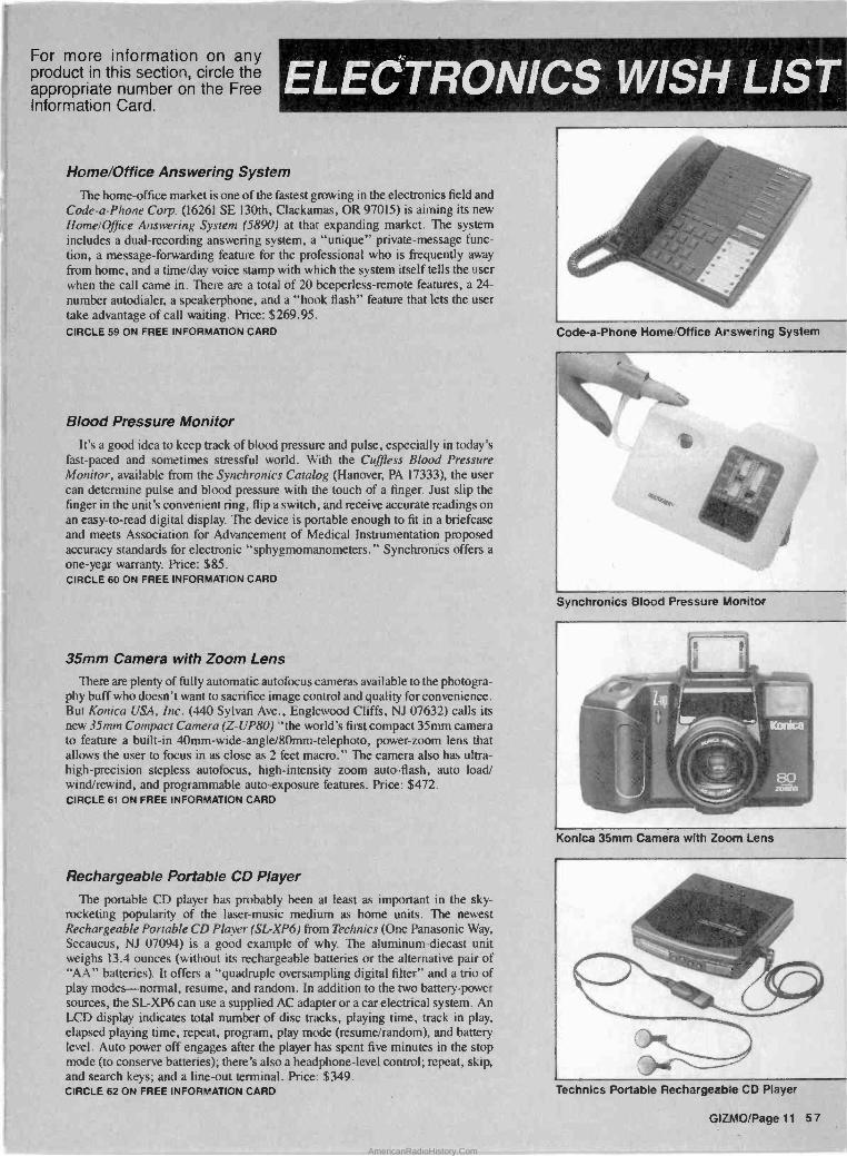
For more information on any product in this section, circle the appropriate number on the Free Information Card.
ELECTRONICS WISH LIST
Home/Office Answering System
The home -office market is one of the fastest growing in the electronics field and Code -a -Phone Corp. (16261 SE 130th, Clackamas, OR 97015) is aiming its new Home/Office Answering System (5890) at that expanding market. The system includes a dual -recording answering system, a "unique" private -message func- tion, a message -forwarding feature for the professional who is frequently away from home, and a time/day voice stamp with which the system itself tells the user when the call came in. There are a total of 20 beeperless-remote features, a 24 -
number autodialer, a speakerphone, and a "hook flash" feature that lets the user take advantage of call waiting. Price: $269.95. CIRCLE 59 ON FREE INFORMATION CARD
Blood Pressure Monitor It's a good idea to keep track of blood pressure and pulse, especially in today's
fast -paced and sometimes stressful world. With the C'uffless Blood Pressure Monitor, available from the Synchronies Catalog (Hanover, PA 17333), the user can determine pulse and blood pressure with the touch of a finger. Just slip the finger in the unit's convenient ring, flip a switch, and receive accurate readings on an easy -to -read digital display. The device is portable enough to fit in a briefcase and meets Association for Advancement of Medical Instrumentation proposed accuracy standards for electronic "sphygmomanometers." Synchronies offers a one-year warranty. Price: $85. CIRCLE 60 ON FREE INFORMATION CARD
35mm Camera with Zoom Lens There are plenty of fully automatic autofocus cameras available to the photogra-
phy buff who doesn't want to sacrifice image control and quality for convenience. But Konica USA, Inc. (440 Sylvan Ave., Englewood Cliffs, NJ 07632) calls its new 35mm Compact Camera (Z-UP80) "the world's first compact 35mm camera to feature a built-in 40mm-wide-angle/80mm-telephoto, power -zoom lens that allows the user to focus in as close as 2 feet macro." The camera also has ultra- high -precision stepless autofocus, high -intensity zoom auto -flash, auto load/ wind/rewind, and programmable auto -exposure features. Price: $472. CIRCLE 61 ON FREE INFORMATION CARD
Rechargeable Portable CD Player
The portable CD player has probably been at least as important in the sky- rocketing popularity of the laser -music medium as home units. The newest Rechargeable Portable CD Player (SL-XP6) from Technics (One Panasonic Way, Secaucus, NJ 07094) is a good example of why. The aluminum-diecast unit weighs 13.4 ounces (without its rechargeable batteries or the alternative pair of "AA" batteries). It offers a "quadruple oversampling digital filter" and a trio of play modes-normal, resume, and random. In addition to the two battery -power sources, the SL-XP6 can use a supplied AC adapter or a car electrical system. An LCD display indicates total number of disc tracks, playing time, track in play, elapsed playing time, repeat, program, play mode (resume/random), and battery level. Auto power off engages after the player has spent five minutes in the stop mode (to conserve batteries); there's also a headphone -level control: repeat, skip, and search keys; and a line-out terminal. Price: $349. CIRCLE 62 ON FREE INFORMATION CARD
Code -a -Phone Home/Office Answering System
Synchronics Blood Pressure Monitor
Konica 35mm Camera with Zoom Lens
Technics Portable Rechargeable CD Player
GiZMO!Page 11 57
AmericanRadioHistory.Com

ELECTRONICS WISH LIST
CBM America Hand-held LCD Color TV
Sharper 'mace Holograph c Calculator
Photo Systems Compact Video Light
For more information on any product in this section, circle the appropriate number on the Free Information Card.
Hand-held Color TV
The march of electronic miniaturization continues, and with the hand-held Color LCD -TV (TC -53 -OA) from CBM America Corp. (2999 Overland Ave., Los Angeles CA 90064), Citizen returns to the tiny TV market it helped establish. The company says that the TC -53 -OA features "unsurpassed picture clarity, contrast and color vibrancy - even in broad daylight," thanks to a built-in backlight. The unit weighs under a pound and the screen measures 21/2 -inches diagonally. Other features include a 23 -inch rod antenna; earphone; black, hooded, soft carry case; and four sample batteries. Optional accessories are an AC adapter, a car adapter, and a connector for use with an external antenna. Price: $299.95.
CIRCLE 63 ON FREE INFORMATION CARD
Financial Calculator For the person on the go who needs fast fiscal calculations, the traditional
calculator sometimes takes too long to solve complex, multi -step problems. The Financial Consultant Calculator (FC -100) from Casio, Inc. (570 Mt. Pleasant Ave., Dover, NJ 07801) has a 10 -digit display that shows a 7 -digit mantissa plus a two -digit exponent. It can calculate mark-up, margin, internal rate of return, net present value, percentage rate, and effective rate. It can also perform statistical and finance register calculations, linear regressions, and discounted cash flow. Price: $34.95.
CIRCLE 64 ON FREE INFORMATION CARD
Holographic Calculator Here's an unusual calculator that should help users visualize the underlying
reality of their financial calculations, and keep their attention on the glittering prize even as the sometimes monotonous work of calculation goes forward. Available from the Sharper Image (650 Davis St., San Francisco, CA 94111), the Holographic Calculator features a three-dimensional apparition of "stacks of coins from around the world." As the product description puts it, "this impressive collection lies forever beyond your touch, in the realm of perfect illusion created by holography." The calculator keys seem to float in space above the coins, through a high -quality dichromate reflection hologram of 27,000 lines per inch - 500 times finer than conventional printing. A four -function calculator with eight - digit display, square root and percent keys, and three -key memory. The device is solar -powered, so batteries aren't required. The Holographic Calculator is sold with a stand and one-year warranty. Price: $59.
CIRCLE 65 ON FREE INFORMATION CARD
AM/FM Stereo Tuner
The combination of "low -profile design" and "audiophile quality perfor- mance" is an attractive one. Those, anyway, are the characteristics claimed for the new AM/FM Stereo Tuner (T -2000E) from Audio Dynamics Corp. (851 Traeger Ave. , San Bruno, CA 94066). Features include 20 -station preset, divided between AM and FM signals; Schotz noise reduction; and "efficient interference rejec- tion" because of a "low 1.5 dB caption ratio over the entire signal strength range of 25-65 dB." The T -2000E can be used with Audio Dynamics' CD -2000E CD player and CA -2000E integrated amplifier, making for a component system with "armchair operation" capabilities, using the remote control supplied with the amp. Price: $349.
CIRCLE 66 ON FREE INFORMATION CARD
Compact Video Light In the world of portable video -camera lights, weight is everything, and the DC
Camcorder Video Light (LT -3) from Photo Systems, Inc. (7200 W. Huron River Dr., Dexter MI 48130), weighs in at a feathery 11 ounces. According to Photo Systems, the light is "extremely versatile" and "completely portable." It has a 50 -watt DC lamp with computer -matched bulb and reflector. The unit attaches via a "hot shoe" mount directly onto the camcorder. The light is powered by a rechargeable lead -acid battery. The cigarette plug connects to an optional 12 -volt battery pack, which allows 45 minutes of continuous operation. Price: $79.95.
CIRCLE 67 ON FREE INFORMATION CARD
58 Page 12 GIZMO
AmericanRadioHistory.Com
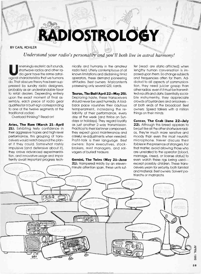
BY CARL KOHLER
Understand your radio's personality and you'll both live in astral harmony!
Unnervingly esoteric as it sounds, shortwave radios and other ra- dio gear have the same astrol-
ogical characteristics that we humans do. That obscure theory has been sup- pressed by sundry radio designers, probably as an understandable favor to retail dealers. Depending entirely upon the exact moment of final as- sembly, each piece of radio gear qualifies for a built -sign corresponding to one of the twelve segments of the traditional zodiac.
Overload thinking? Read on!
Aries, The Ram (March 21-April 21). Exhibiting testy confidence in their aggressive hopes and high-level performance, this grouping of trans- ceivers would reach beyond the plan- et if they could. Somewhat rashly impulsive (and defensive about it), they crave advanced experimenta- tion, and innovative usage and impa- tiently await important progress tech-
nically and humanly in the amateur radio field. Utterly contemptuous of all known limitations and disdaining timid operators, these demand pioneering attitudes. Best owners: Malcontents possessing only several QSL cards.
Taurus, The Bull (April 22-May 20). Deploring haste, these transceivers should never be used hurriedly. A laid- back pace nourishes their cautious temperament, increasing the re- liability of their performance, every day of the week (and thrice on Sun- days or holidays). They regard loyalty as just another 2 -way transmission. Practical to their last inner component, they expect good maintenance and careful re -adjustments when needed. Profit -talk is their language. Best owners: Bank executives, stock- brokers, mint managers, and sal- vagers of buried treasure.
Gemini, The Twins (May 21-June 21). Hampered mildly by an eleven - minute attention span, these units suf-
fer (read: are static -afflicted) when lengthy human conversation is im- posed upon them. So change subjects and frequencies often for them. Ad- dicted to all aspects of communica- tion, they need juicier gossip than other radios: even if it must be transmit- ted via dits and dohs. Essentially socia- ble instrumentry, they appreciate crowds of bystanders and onlookers- at both ends of the broadcast. Best owners: Speed talkers with a million things on their minds.
Cancer, The Crab (June 22-July 22). Although this breed appears to be just like all the other shortwave radi- os, they're much more sensitive and moody than even the most neurotic microphone. Never discuss their foibles in the presence of strangers. For that matter, avoid allowing those who are unrelated to the operator (blood, marriage, creed, or license status) to even watch these rigs being used except possibly children. These trans- ceivers yearn for security, both familial and material. Best owners: Solvent pa- triarchs or matriarchs.
59
AmericanRadioHistory.Com
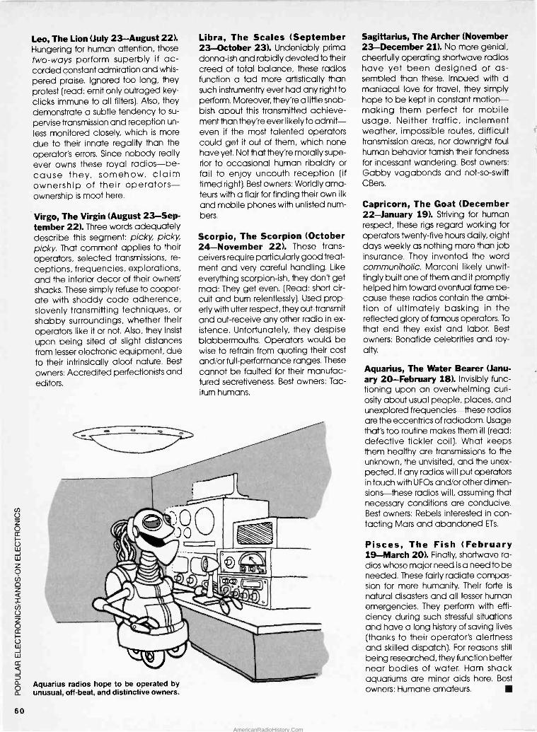
Leo, The Lion (July 23-August 22). Hungering for human attention, these two -ways perform superbly if ac- corded constant admiration and whis-
pered praise. Ignored too long, they protest (read: emit only outraged key - clicks immune to all filters). Also, they demonstrate a subtle tendency to su-
pervise transmission and reception un-
less monitored closely, which is more due to their innate regality than the operator's errors. Since nobody really ever owns these royal radios-be- cause they, somehow, claim ownership of their operators- ownership is moot here.
Virgo, The Virgin (August 23-Sep- tember 22). Three words adequately describe this segment: picky, picky, picky. That comment applies to their operators, selected transmissions, re-
ceptions, frequencies, explorations, and the interior decor of their owners' shacks. These simply refuse to cooper- ate with shoddy code adherence, slovenly transmitting techniques, or
shabby surroundings, whether their operators like it or not. Also, they insist
upon being sited at slight distances from lesser electronic equipment, due to their intrinsically aloof nature. Best
owners: Accredited perfectionists and editors.
Aquarius radios hope to be operated by unusual, off -beat, and distinctive owners.
Libra, The Scales (September 23-October 23). Undeniably prima donna-ish and rabidly devoted to their creed of total balance, these radios function a tad more artistically than such instrumentry ever had any right to perform. Moreover, they're a little snob- bish about this transmitted achieve- ment than they're ever likely to admit- even if the most talented operators could get it out of them, which none have yet. Not that they're morally supe- rior to occasional human ribaldry or fail to enjoy uncouth reception (if timed right). Best owners: Worldly ama- teurs with a flair for finding their own ilk
and mobile phones with unlisted num- bers.
Scorpio, The Scorpion (October 24-November 22). These trans- ceivers require particularly good treat- ment and very careful handling. Like
everything scorpion-ish, they don't get mad: They get even. (Read: short cir- cuit and burn relentlessly). Used prop- erly with utter respect, they out -transmit and out -receive any other radio in ex- istence. Unfortunately, they despise blabbermouths. Operators would be wise to refrain from quoting their cost and/or full -performance ranges. These
cannot be faulted for their manufac- tured secretiveness. Best owners: Tac- iturn humans.
Sagittarius, The Archer (November 23-December 21). No more genial, cheerfully operating shortwave radios have yet been designed or as- sembled than these. Imbued with a maniacal love for travel, they simply hope to be kept in constant motion- making them perfect for mobile usage. Neither traffic, inclement weather, impossible routes, difficult transmission areas, nor downright foul human behavior tarnish their fondness for incessant wandering. Best owners: Gabby vagabonds and not -so -swift CBers.
Capricorn, The Goat (December 22-January 19). Striving for human respect, these rigs regard working for operators twenty-five hours daily, eight days weekly as nothing more than job insurance. They invented the word communiholic. Marconi likely unwit- tingly built one of them and it promptly helped him toward eventual fame be- cause these radios contain the ambi- tion of ultimately basking in the reflected glory of famous operators. To
that end they exist and labor. Best owners: Bonafide celebrities and roy- alty.
Aquarius, The Water Bearer (Janu- ary 20-February 18). Invisibly func- tioning upon an overwhelming curi- osity about usual people, places, and unexplored frequencies-these radios are the eccentrics of radiodom. Usage that's too routine makes them ill (read: defective tickler coil). What keeps them healthy are transmissions to the unknown, the unvisited, and the unex- pected. If any radios will put operators in touch with UFOs and/or other dimen- sions-these radios will, assuming that necessary conditions are conducive. Best owners: Rebels interested in con- tacting Mars and abandoned ETs.
Pisces, The Fish (February 19-March 20). Finally, shortwave ra- dios whose major need is a need to be needed. These fairly radiate compas- sion for mere humanity. Their forte is
natural disasters and all lesser human emergencies. They perform with effi- ciency during such stressful situations and have a long history of saving lives (thanks to their operator's alertness and skilled dispatch). For reasons still
being researched, they function better near bodies of water. Ham shack aquariums are minor aids here. Best
owners: Humane amateurs.
60
AmericanRadioHistory.Com

BY PAUL YORLEGG
It was just over two years ago that the world's most prestigious re- search facilities announced signifi-
cant new breakthroughs in supercon- ductivity-the ability of materials at very low temperatures to conduct electricity without resistance and with- out shivering. At that time, designers at Intelski International, a major eastern European semiconductor firm, began working on the first microprocessor to utilize those new research develop- ments.
After spending $500 million on re- search and development-nearly half of the company's total assets-Intelski is expected to formally announce their new microprocessor, the PI -4U28, on the first of April.
The PI -4U28 is an ultra-high-speed,1- bit microprocessor. It is a PMOS (Peat- MOS) device fabricated using Intelski's patented Duel Inline Package Super- conductive Technology Integrated Carbon Kaolin (DIP -STICK) process. When the unit is eventually marketed, hopefully by late in the second quarter, it is expected to be available in a 39 -pin DIP package, a 144 -pin flat -pack, and a six -chip snack -pack.
The maximum clock frequency for the PI -4U28 is 20,000 GHz, about a mil- lion times faster than today's typical microprocessor. To obtain that ex- tremely high internal clock frequency, however, designers had to make some compromises in the device's instruc-
The World's first superconductive processor, to be announced this April First,
promises to revolutionize the computer industry!
SUPERCONDUCTING MICROPROCESSOR
tion set-it doesn't have one. That complete lack of instructions also gives the chip another notable distinc- tion: it is the ultimate machine in the area of Reduced Instruction Set Com- puter (RISC) technology.
The Controversy. Many industry ob- servers have stated that the lack of instructions is the chip's third- (possibly even it's second-) most serious draw- back. In actuality, the lack of an in- struction set is not really that bad considering the fact that a 1 -bit pro- cessor only has two possible op -codes anyway.
A company insider, requesting that his identity be kept secret, has indicat- ed that future versions of the PI device may have an expanded instruction set. The uncertainty is due to a great deal of internal bickering at Intelski about how many and what type of instructions should be added.
Engineers would like to add ac- cumulator -load and -store com- mands, while management only wants to add a NOP instruction. By
adding only one instruction, manage- ment hopes to keep from wasting the hundreds of hours it took to design an illegal op -code trap for a micro- processor. The trap causes the micro- processor to jump to a known address whenever an unassigned op -code is
encountered, as might happen when- ever the processor erroneously jumps
LISTING 1
1000 CLEAR : CLS : ER=O 1010 PRINT "***** PI -4U28 ASSEMBLER *****" 1020 PRINT "(c) 1988 - All Rights Reserved" 1030 PRINT 1040 INPUT "File name: ",N$
into the middle of a data table. If there are no illegal op -codes, then the il- legal op -code trap is completely useless; it's that simple.
Two Bits Adds Up. There is also a small faction at Intelski (specifically the mail -room employees) who tend to disagree with both management and the engineers on the matter. In
their opinion, one of the op -codes should definitely be an AND instruc- tion. Because the PI -4U28 is a one bit machine, the AND instruction could also be used as a 1 -bit multiply instruc- tion. That way engineers could get two instructions for the price of one. Along a similar line of reasoning, the second possible command should be an ex- clusive -OR (XOR) instruction, which could double as a 1 -bit ADD instruction (without a carry, of course).
While there are some limitations due to the lack of instructions, there are also some important benefits. For one, there is no need to memorize a lot of complex commands in order to pro- gram the processor. Another advan- tage is the fact that an assembler for the micro is very easy to write.
Listing 1 contains a printout of one such assembler. The assembler is writ- ten in BS -BASIC, but is easily modifia- ble to run under any BASIC language with at least 1K of RAM.
Clouding the Issue. Not only is its
instruction set (or rather, its complete lack of an instruction set) a problem, taking advantage of the PI-4U28's su- perconductive capabilities are a source of concern for computer com- panies wishing to integrate the micro- processor into their products. The
(Continued on page 102)
61
AmericanRadioHistory.Com
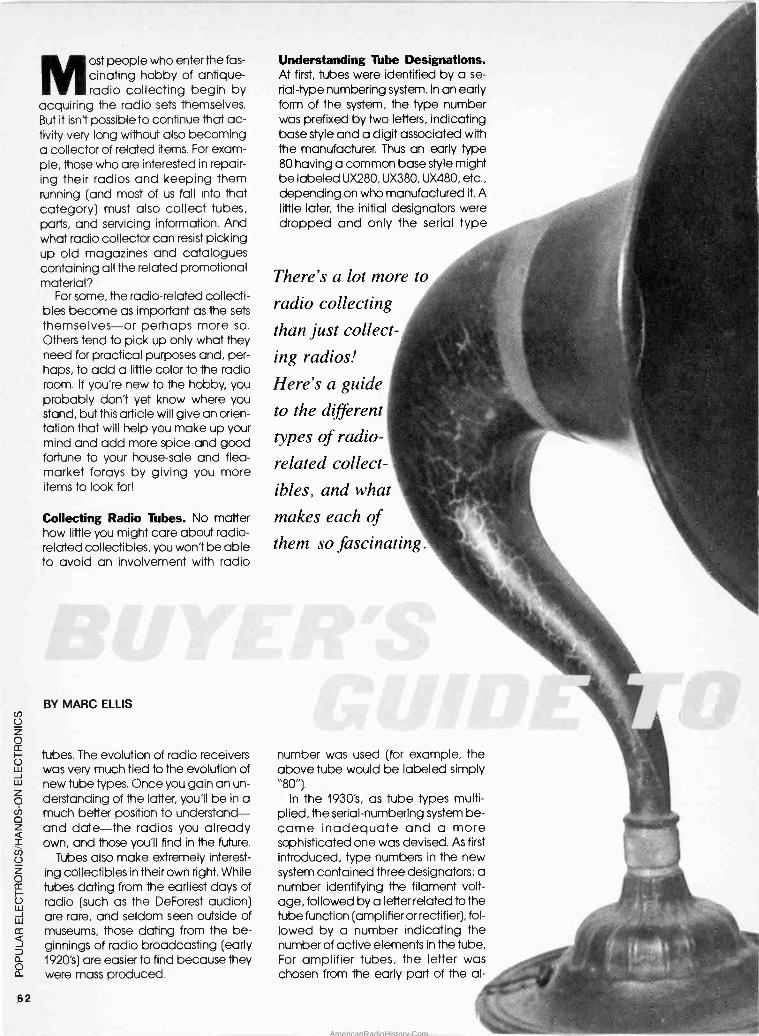
Most people who enter the fas - cinating hobby of antique - radio collecting begin by
acquiring the radio sets themselves. But it isn't possible to continue that ac- tivity very long without also becoming a collector of related items. For exam- ple, those who are interested in repair- ing their radios and keeping them running (and most of us fall into that category) must also collect tubes, parts, and servicing information. And what radio collector can resist picking up old magazines and catalogues containing all the related promotional material?
For some, the radio -related collecti- bles become as important as the sets themselves-or perhaps more so. Others tend to pick up only what they need for practical purposes and, per- haps, to add a little color to the radio room. If you're new to the hobby, you probably don't yet know where you stand, but this article will give an orien- tation that will help you make up your mind and add more spice and good fortune to your house -sale and flea - market forays by giving you more items to look for!
Collecting Radio Tubes. No matter how little you might care about radio - related collectibles, you won't be able to avoid an involvement with radio
BY MARC ELLIS
tubes. The evolution of radio receivers was very much tied to the evolution of new tube types. Once you gain an un- derstanding of the latter, you'll be in a much better position to understand- and date-the radios you already own, and those you'll find in the future.
Tubes also make extremely interest- ing collectibles in their own right. While tubes dating from the earliest days of radio (such as the DeForest audion) are rare, and seldom seen outside of museums, those dating from the be- ginnings of radio broadcasting (early 1920's) are easier to find because they were mass produced.
62
Understanding Tube Designations. At first, tubes were identified by a se-
rial -type numbering system. In an early form of the system, the type number was prefixed by two letters, indicating base style and a digit associated with the manufacturer. Thus an early type 80 having a common base style might be labeled UX280, UX380, UX480, etc., depending on who manufactured it. A little later, the initial designators were dropped and only the serial type
There's a lot more to
radio collecting
than just collect-
ing radios!
Here's a guide
to the different
types of radio -
related collect-
ibles, and what
makes each of
them so fascinating.
number was used (for example, the above tube would be labeled simply "80").
In the 1930's, as tube types multi- plied, the serial -numbering system be- came inadequate and a more sophisticated one was devised. As first
introduced, type numbers in the new system contained three designators: a number identifying the filament volt- age, followed by a letter related to the tube function (amplifier or rectifier), fol- lowed by a number indicating the number of active elements in the tube. For amplifier tubes, the letter was chosen from the early part of the al-
AmericanRadioHistory.Com
phabet; for rectifiers, from the latter part of the alphabet.
For example, the 6C6 has a 6 -volt filament; is an amplifier; and contains 6 active elements (a filament, a cath- ode, three grids and a plate). On the other hand, a 5Z3 has a 5 -volt filament; is a rectifier; and contains three active elements (a filament and two plates). The 6D6 and 5Y3 (an amplifier and a rectifier, respectively) perform func- tions similar to the tubes just discussed, but have different operating charac- teristics. That is reflected by the dif- ferences in identifying letters.
Physical Changes in Radio Tubes. The evolution of physical tube charac- teristics is also of interest to the collec- tor. The glass envelopes of the earliest tubes were like those of contemporary light bulbs; pear shaped with a point- ed seal at the top. Later, following trends in light -bulb design, the seal was moved to the bottom of the tube so that it could be hidden in (and pro- tected by) the base.
Still later, in the 1930's, pear-shaped envelopes gave way to the "double- dome" or "ST" style. And a little later in
the same decade, more compact tube designs made it possible to re- lease new types (and some older ones) in the "bantam" or "GT" style. That envelope was much shorter than previous ones, straight sided, and had a rounded top. Some manufacturers released the same types in metal -en- closed glass envelopes, having rough-
ly the same outer dimensions as the "GT" style.
Tube bases also changed over the years. Brass gave way to bakelite as a base material, and the original short - pin, bayonet -lock style was changed to the longer -pin type that engaged with friction contacts in the tube sock- et. Some transition -period tube bases had the longer, friction -contact pins,
but could also bayonet -lock into the older sockets.
Tube cartons can be as interesting to collectors as the tubes they contained. From the plain generic -looking styles of the early 1920's to the colorfully lithographed ones of later years, they can make a very interesting display.
A detailed discussion of radio -tube history is beyond the scope of this arti- cle. But for more information on tubes from the early years of broadcasting through the early 1930's, check your back issues of Hands-on Electronics. You'll find the Ellis On Antique Radio columns of February, March, and April 1987, as well as May, 1988, to be very helpful.
John Rider's Mighty Manuals. As mentioned a little earlier, your preoc- cupation with printed radio literature will begin almost immediately after acquiring your first few sets. Because once you start working on the radios, you'll want to acquire schematics and other servicing information.
There are individuals and organiza- tions who will look up information and photocopy it for you for a nominal fee. But if you have the space and the in-
clination, you can build your own per- sonal library of original service data.
In my opinion, the best way to do that is to begin acquiring volumes of John Rider's Perpetual Trouble Shooter's Manual. Rider began pub- lishing the manual some time in the late 1920's or early 1930's, and added
a new volume to it approximately every year (with some breaks during World War II).
Each new book provided sche- matics and service information for vir- tually every radio released since publication of the prior one. The com- plete set contains 23 hefty tomes covering radios from the early 1920's through the early 1950's.
63
AmericanRadioHistory.Com

These three versions of the familiar type - 80 tube show the evolution of bulb styles. At far left is an original pear-shaped bulb: in the center is an "ST" (double -dome) style; and at the right is a "GT" (straight -sided) bulb.
Rider volumes still turn up regularly at antique -radio swap meets and ham - fest flea markets, and they're easy to spot. Look for a distinctive dark -blue binder with a quaint cover illustration of an antenna strung between two towers. A separate Rider series, sim- ilarly bound, covered television sets- but they are plainly marked as such, and you can avoid them (unless, of course, you are into early TV's).
The Rider manuals of most practical interest to collectors are probably vol- umes 1 through 13. (The latter bears a 1942 copyright, and covers the last of the pre-war radios). However, if you look at the Rider set as a collectible in
its own right, you'll obviously want to acquire as many of the volumes as possible.
Price and Availability. The earliest volumes in the set (1 thru 4 or so) don't seem to turn up very often, and are expensive. The volumes towards the end of the series are also hard to come by. I suspect that the manuals de- clined in popularity towards the end of the run, and not as many were printed. Asking prices for the more common volumes seem to be from six to fifteen dollars each, depending on the mood of the owner.
Rider also published an abridged version of volumes one though five, complete in one book that is bound uniformly with the rest of the set. It was probably intended for repairmen who got into the business some years after the series was instituted and didn't have as much need for the earliest data. The abridged version is much more common than the individual vol- umes, and would be a good alter- native for those who can't find the latter. I've seen it priced at about $40.00.
Though I didn't realize what I was buying at the time, I was lucky enough
to purchase the complete volumes 1-3
bound in one book. It was originally offered by RCA as part of a tube deal, and the binder is the same physical size and type as that used in the stan- dard Rider manuals. However, the cover is red instead of blue and shows a vacuum tube instead of the tradi- tional antenna and towers. I've never seen another one like it.
Finding Your Way Through Rider's. Without an index, locating sets in
Rider's is something of a pain in the
softbound pamphlet form. The indexes don't seem to turn up as often as the manuals, but some have been made available in reprint form by Antique Electronic Supply (688 W. First St., Tem-
pe, AZ). Current prices are $17.95 for the index to Volumes 1-15 (205 pages, spiral bound) and $7.95 for the index to volumes 16-22 (48 pages, spiral bound).
An interesting alternative to the Rider indexes is offered by The P.R.
Mallory Radio Service En- cyclopaedia-a radio -receiver index
Colorfully lithographed radio -tube cartons can be as interesting as the tubes they once contained.
neck. You're pretty much reduced to guestimating the year that your set was manufactured, then looking it up, trial and error fashion, in the volumes that most closely correspond. Since the books tend to be big, heavy and clumsy, doing so can be an unpleas- ant task.
Every few years, Rider published an index for the books that had been re- leased up to that time; they were in
Rider's "Perpetual Trouble Shooter's Man- ual" series is not only the most exhaus- tive reference source available to col- lectors today, but is also a collectible item in its own right.
compiled for the purpose of recom- mending the correct Mallory controls, capacitors, or vibrator for every model. But each entry also includes the correct Rider's reference!
My Sixth Edition was copyrighted 1948 and, I suspect, is based on the Rider index to Volumes 1-15, which ap- peared in 1947. If you can find one of them, you may be able to get it for very little money since its value is not gener- ally known (mine cost two bucks!). Some time after purchasing it, I bought a serviceman's assortment of Mallory controls in a metal storage cabinet. The cabinet had a compartment ob- viously intended to accept the man- ual-which must have been included with the deal.
The Supreme Series. Another source of schematics and service in- formation was the "Most -Often Needed" series offered by Supreme Publications. Like Rider, Supreme re- leased a new compilation each year. But while Rider published huge binders covering virtually every set ever pro- duced, Supreme published relatively slim soft-cover books containing an
6a
AmericanRadioHistory.Com
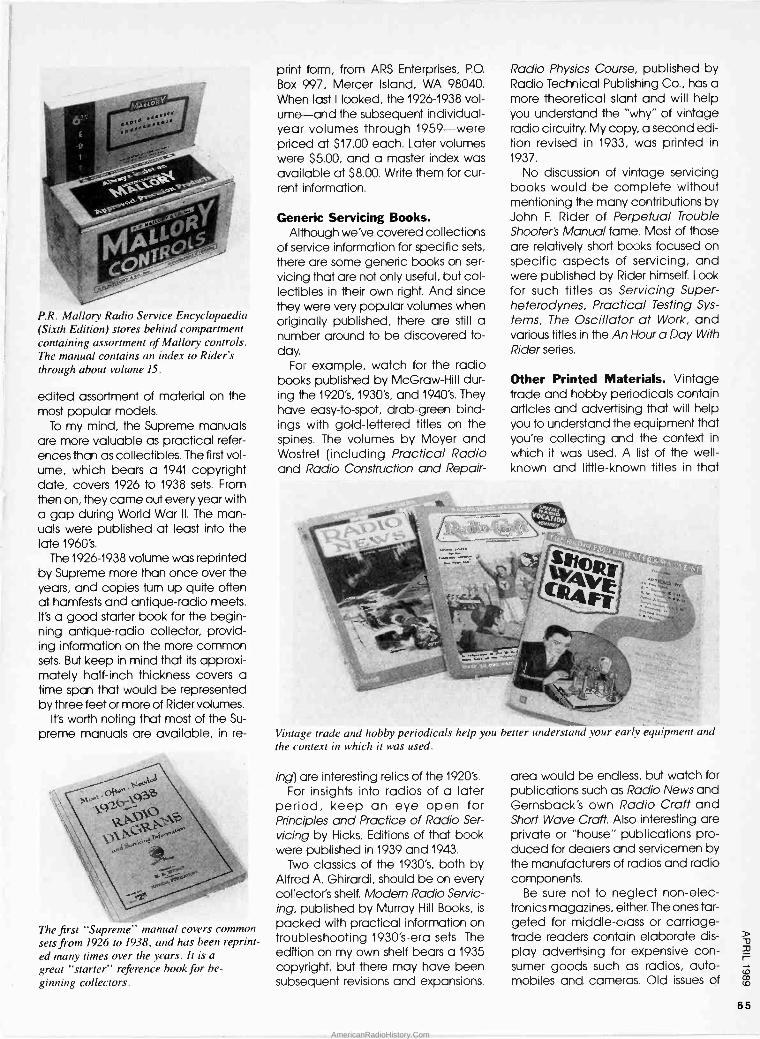
P.R. Mallory Radio Service Encyclopaedia (Sixth Edition) stores behind compartment containing assortment of Mallory controls. The manual contains an index to Rider's through about volume 15.
edited assortment of material on the most popular models.
To my mind, the Supreme manuals are more valuable as practical refer- ences than as collectibles. The first vol- ume, which bears a 1941 copyright date, covers 1926 to 1938 sets. From then on, they came out every year with a gap during World War II. The man- uals were published at least into the late 1960's.
The 1926-1938 volume was reprinted by Supreme more than once over the years, and copies turn up quite often at hamfests and antique -radio meets. It's a good starter book for the begin- ning antique -radio collector, provid- ing information on the more common sets. But keep in mind that its approxi- mately half -inch thickness covers a time span that would be represented by three feet or more of Rider volumes.
It's worth noting that most of the Su-
preme manuals are available, in re -
The first "Supreme" manual covers common sets from 1926 to 1938, and has been reprint- ed many times over the years. It is a
great "starter" reference book for be-
ginning collectors.
print form, from ARS Enterprises, P.O.
Box 997, Mercer Island, WA 98040. When last I looked, the 1926-1938 vol- ume-and the subsequent individual - year volumes through 1959-were priced at $17.00 each. Later volumes were $5.00, and a master index was available at $8.00. Write them for cur- rent information.
Generic Servicing Books. Although we've covered collections
of service information for specific sets,
there are some generic books on ser-
vicing that are not only useful, but col- lectibles in their own right. And since they were very popular volumes when originally published, there are still a number around to be discovered to- day.
For example, watch for the radio books published by McGraw-Hill dur- ing the 1920's, 1930's, and 1940's. They have easy -to -spot, drab -green bind- ings with gold -lettered titles on the spines. The volumes by Moyer and Wostrel (including Practical Radio and Radio Construction and Repair -
Radio Physics Course, published by Radio Technical Publishing Co., has a more theoretical slant and will help you understand the "why" of vintage radio circuitry. My copy, a second edi- tion revised in 1933, was printed in
1937. No discussion of vintage servicing
books would be complete without mentioning the many contributions by John F. Rider of Perpetual Trouble Shooter's Manual fame. Most of those are relatively short books focused on specific aspects of servicing, and were published by Rider himself. Look for such titles as Servicing Super - heterodynes, Practical Testing Sys-
tems, The Oscillator at Work, and various titles in the An Hour a Day With Rider series.
Other Printed Materials. Vintage trade and hobby periodicals contain articles and advertising that will help you to understand the equipment that you're collecting and the context in
which it was used. A list of the well- known and little-known titles in that
Vintage trade and hobby periodicals help you better understand your early equipment and
the context in which it was used.
ing) are interesting relics of the 1920's.
For insights into radios of a later period, keep an eye open for Principles and Practice of Radio Ser-
vicing by Hicks. Editions of that book were published in 1939 and 1943.
Two classics of the 1930's, both by Alfred A. Ghirardi, should be on every collector's shelf. Modem Radio Servic- ing, published by Murray Hill Books, is
packed with practical information on troubleshooting 1930's -era sets. The edition on my own shelf bears a 1935 copyright, but there may have been subsequent revisions and expansions.
area would be endless, but watch for publications such as Radio News and Gernsback's own Radio Craft and Short Wave Craft. Also interesting are private or "house" publications pro- duced for dealers and servicemen by the manufacturers of radios and radio components.
Be sure not to neglect non -elec- tronics magazines, either. The ones tar- geted for middle-class or carriage - trade readers contain elaborate dis- play advertising for expensive con- sumer goods such as radios, auto- mobiles and cameras. Old issues of
65
AmericanRadioHistory.Com

These interesting parts from the early 1920's include a Rauland audio transform- er (far left); a Dubilier RF transformer (far right); a CLE-RA-TONE tube socket with original box (top center); and a vernier dial (bottom center).
The National Geographic are still fairly easy to find, and are a very rich source of such advertising. I've found a lot of fascinating information on the sets in
my collection in old issues of that púb- lication.
Anything like a complete discussion of collectible printed materials relat- ing to antique radio would be impossi- ble in an article of this scope. The volume of books, periodicals, cata- logues, instruction manuals, promotion pieces, and other types of advertis- ing-aimed at both the general pub- lic and the electronics professional-is huge.
My advice is keep your eyes open at the book stores and swap meets. If a piece interests you and you can afford it, make the purchase. I continue to enjoy all of the printed items I've picked up over the years.
Parts: Collectible and Otherwise. Most of the collectibles covered so far have a definite dual purpose. They're not only interesting in themselves, but also useful-or even necessary-for radio maintenance and repair. Oddly enough, that isn't always the case with radio parts. The collectible ones tend not to be the ones most needed for practical radio service, while the ones needed to keep the radios running tend not to be collectibles. Admittedly, I've made something of a forced dis- tinction here, and there'll be plenty of exceptions, but let me explain what I
mean. I associate collectible parts and ac-
cessories with the radios of the 1920's
period. During that era, many people built their own sets from plans pub- lished in books and magazines. The parts, much larger in size than the comparable electronic components of today, were individually packaged, advertised, and sold.
There were many competing man- ufacturers, and they vied with each other in the extravagance of their per- formance claims and the colorfulness of their advertising and packaging. The parts themselves, crafted of bakelite, glass, silk- or cotton -covered wire, and polished or brightly painted metal, were definitely made to be looked at. Among the parts of interest to collectors are knobs, dials, tuning capacitors, audio- and radio -fre- quency transformers, tube sockets, rheostats, resistors, plugs, and jacks.
* POWER WHEN
it oinking kmdspeuker deliverthe grald., there's nothing liken pair of Amer7rans.
Built i , operate by the pair, they secure from two stages ail you could possibly hope fnr in audio a,nphfic pion. /
Look fora oairof Amer7rans in the sef you buy-use them ' in the >ela you Will Leoe,,jo t whatt he famous Amer- i Tran"kicl'
mul aand
ten gar ainudepea ker.hda, , Am . taro afaroyAp_ nent i ratio l. Bay Mein be the pair!
AMERICAN TRANSFORMER COMPANY teit tarn,r rirnantyr.,.
AMEN 1920's -era radio -parts advertising some- times resembles today's advertising for high-performance auto parts.
People bought parts not only to build new sets, but to improve the per- formance or convenience of existing sets. Parts in the latter category in- cluded not only straightforward com- ponents such as vernier -dial drives and "high-fidelity" audio transformers, but also a colorful assortment of more fringe apparatus, such as antenna substitutes, variable grid leaks, self- adjusting filament rheostats, and multi- ple -headphone adapters.
The radio sets of that era were so simple, and the parts so basic and generally well -made, that break- downs due to component failure were relatively uncommon. It's true that re- storers of 1920's radios sometimes have to deal with such problems as burned - out audio transformers and grid -leaks whose resistance has escalated over the years. But most performance diffi- culties can be traced to poor contacts caused by dirt and corrosion, not a
part failure. Therefore, parts that have been acquired as collectibles can generally stay on the display shelf.
The Changes of the 1930's. I've al- ways thought that the marketing of ra- dio parts in the 1920's had a lot in common with the marketing of certain kinds of auto parts today; particularly the ones intended to improve perfor- mance or convenience and simple enough to be installed by the "back- yard mechanic" set. But by the 1930's, radio receivers had become much more complex. Most sets were factory built, rather than home made-and the average radio listener was less apt to be in the market for parts to improve performance.
As you might expect, then, radio parts became more functional in physical design. They were being made to do their jobs, and not es- pecially to be looked at. But with in- creased circuit complexity and higher component operating voltages, parts failures were, and are, much more common in the more -modern sets.
It's certainly true that proper resistors, capacitors, transformers, speakers, and other components suitable for use in repairing vintage radios are be- coming harder and harder to come by. So most radio collectors'acquire them as they can. But parts for repair- ing 1930's -and -later sets could hardly be called collectibles. They're usually not displayed, but stored in drawers and cabinets until needed.
Special radio furniture was designed to provide storage for the early battery set, its power sources and the other ac- cesories required for its operation. Such furniture can be used to display the most prized items in your collection.
66
AmericanRadioHistory.Com

Only $25 Better than "B"
Batteries Perfect t e ont.rol of "P, voltage to detector and
Advantages lifter tines: elimination of snap and crackle. dii
eberniral action in battery; a uniformsteady, n
Battery eliminators and chargers were heavily marketed prior to the introduction of AC -
powered sets. There are many still around to be discovered today.
Batteries, Chargers, and Elim- inators. Vintage accessories can add yet another colorful and fascinat- ing dimension to your collection of ra- dio items. This is another category so rich in collecting potential that even a partial list of possibilities would be diffi- cult to compile. But, just as in the case of parts, your most interesting "finds" are apt to date from the 1920's.
One important group of accessories is associated with the batteries used to power most radios of that period. First
of all, there are the batteries them- selves although because of the cor- rosive chemicals they contained-not many of them survive today. The lead - acid storage "A" batteries used to light the filaments were generally 6 -volt au- tomobile types. However, I've seen special versions designed for radio use; some had beautiful teakwood outer cases incorporating handles for easy carrying.
The "B" and "C" batteries that pro- vided plate and grid -bias power were generally of the non -rechargeable dry -battery type. Today, they are prob- ably harder to find than the filament batteries because they were thrown away when exhausted. Those that were kept were generally quickly ren- dered unsightly after the chemicals in-
side ate their way through the outer casing. Yet, for some unaccountable reason, some of those dry batteries have survived (though quite dead, of course) in good cosmetic condition. Most have colorful, lithographed wrappers, and certainly look interest- ing when displayed along with exam- ples of the radios they once powered.
Battery chargers and eliminators also make interesting collectibles. Both of those types of units plugged into normal, commercial, AC -power lines. The former-scaled-down ver- sions of the commercial types then in
use-made it possible for radio enthu- siasts to replenish their "A" batteries at home-thereby, avoiding the discom- fort and the danger of lugging them to the neighborhood gas station. The lat- ter actually took the place of "A" and/ or "B" and "C" batteries.
A word to the wise: avoid the temp- tation of trying to operate one of your prized battery sets from a vintage bat- tery eliminator. The regulation of the old units was generally far from ideal even when new. Today, after many years of aging, the values of the car- bon resistors and controls used to es- tablish the correct voltages may be nowhere near original specification. The result could be dangerously high voltages that might well pop tube fila- ments and/or burn out AF -transformer windings.
Modern battery eliminators, using semiconductor regulators, are avail- able from several sources. They pro- vide stable, well -filtered DC power that is not only safer for your set, but will make it perform better.
Before leaving the subject of bat- tery -radio accessories, I'd like to touch on a couple of other collectible cate- gories that you might find of interest. With battery condition so crucial to proper set operation, most radio owners equipped themselves with some kind of a battery tester. The typ- ical tester was a "watchcase" style
meter housed in a highly chromed, round case a few inches in diameter. Some models tested for voltage; some for current; and some for both. They came in a variety of brands and styles, and an assortment of them makes a fine addition to any collection of sets from that period.
Finally, you might like to look for spe- cial radio furniture. Back in the 1920's, a typical radio installation consisted of the radio unit itself, plus a separate speaker, an array of batteries, possibly a charger, and/or eliminator. The natu- ral setting for that novel, and very im- portant, collection of apparatus was the family living room. But some house- wives understandably felt it to be an eyesore. The answer, for many families, was a cabinet that would house all that stuff much like the hi-fi system or- ganizers on the market today.
The typical unit contained compart- ments for storing (and concealing) ra- dio, batteries, speaker, charger, etc. Many took the form of a drop-leaf desk, with the drop leaf serving as the radio operating table when open. If
you can find one of those, and have the space to show it off properly, it can be a focal point for your collection- providing display space for some of your most prized pieces.
Reproducing Equipment. This could easily be one of the largest and most important categories in your collection of radio accessories. But why do I con- sider such things as headsets and speakers to be accessories? Because, back in the 1920's, such items were generally not packaged with the ra- dio, but sold separately, much as hi-fi components are today. If the radio manufacturer offered them for sale, they might be purchased along with the set, or they might not. There were many makers competing for the set - buyer's dollar, and the buyer might well be tempted by a better price, a style more to his or her liking, or claims of improved performance.
The earliest speakers in common use with broadcast sets were of the horn type. The sound -reproducing unit with- in the base of most horns was essen- tially an overgrown earphone. The sounds were produced by vibrations induced in a metal diaphragm by the action of a pair of electromagnets. The horn then acted as an acoustical am- plifier, very much in the manner of a megaphone.
(Continued on page 96)
67
AmericanRadioHistory.Com

Isensed that there was something wrong with my computer, but I just couldn't put my finger on what it
was. It powered -up very well, the memory check was always faultless, and the programs ran to perfection. So
what was wrong? One day I sat planning a BASIC pro-
gram with the computer powered -up. I
heard nothing, or almost nothing. The
ventilating fan was too quiet, almost as though it wasn't there. I placed my hand behind the computer where the regulated power -supply vents to the room and felt nothing. No draft was felt. Remembering an old Boy Scout wind test, I wet my finger and felt the slightest of breezes from the vent on the rear apron of the computer chassis.
Obviously, something was wrong.
Getting Inside. Immediately I
powered -down the computer and un- plugged the AC power cord. (Those
readers who have a hard -disk drive should park the hard disk's heads first,
and then power down.) I removed a few screws from the rear panel and removed the top cover of the comput- er by sliding it forward. You will proba- bly need to follow a similar procedure for your computer, although some computer cabinets will obviously be somewhat different.
Replacing your
PC's Fan
The regulated power supply used in
IBM and clone computers is easy to spot. The unit is usually in a chrome - finished metal box about 8 -Y2 -in. long, 5 -3/4 -in. wide and 5 -Y2 -in. high. The fan's circular vent is near the ON/OFF switch on the top surface of the regulated power supply.
On one side, there is a bunch of ca- bles that connect it to the computer via plastic plugs. Not all of those ca- bles may be connected and used in
your computer. It makes sense to iden- tify each used plug and jack there. My computer has two cables connecting
The regulated power supply is connected to the AC power cord and the switch is
set to the on position. The ventilating fan will suck air through the circular grille at lower right and exhaust it through louvers at top in photo.
It's easy to do because an exact replacement for your fan is available everywhere!
BY MARTY KNIGHT
it to the mother board. I numbered them cablel and 2 by writing on mask- ing tape that I attached to the cables and to the motherboard. I have two floppy -disk drives and one hard - disk drive that are also connected to the power supply. The cables are iden- tical, however, so I numbered them also. It would be silly to have to unbut- ton the computer's cabinet un- necessarily to reconnect a cable when one of the disk drives failed to operate.
Inspect the computer for screws that secure the regulated power supply in
place. Usually, removing four screws from the rear panel will release the power supply so that it can be lifted from the interior chassis. Remove the screws and carefully take out the sup- ply. First-time computer repairers are advised that everything you have done so far can be performed in re- verse order to restore the computer to its original condition.
Recheck. With the regulated power supply removed, connect the AC - power cord and turn the power -supply switch to the "on" position. The ventilat- ing fan should come on immediately and create a breeze you can detect at the vent louvers. Mine was defec- tive, as evidenced by the weak
68
AmericanRadioHistory.Com

breeze and slow motion. A voltmeter told me that the regulated power sup- ply was still good because the power to the floppy- and hard -disk drives measured exactly +5- and +12 -volts DC. If the voltages were off, I would have replaced the entire regulated power supply. That would've been easy enough to do since the regulated power supply is a common model. Check the voltages on your own power supply and then unplug the unit before proceeding.
About ten or fewer screws need to be removed to open the supply case- ment. The ventilating fan will be on the removed cover, and the rest of the parts and the circuit board will be on the chassis. Plug the supply back in and measure the voltage supplied to the fan. The reading should be almost exactly 12 -volts DC-it's regulated. Mark the positive lead with some masking tape; it should be color -co- ded, but don't trust your memory by just memorizing which wire is which. Now, power -down the supply again and re- move the power cord.
Remove the ventilating fan and be sure to save the mounting hardware. I
took the fan to a local Radio Shack store and purchased an exact re- placement from a peg -board display. I didn't know how exact the replace- ment was until I compared the plastic casing of the old and new-they were from the same mold, and both were made in Taiwan. I compared the two fan's air -flow by powering up the sup -
The rear panel has four mounting screws to secure the regulated power supply to the chassis. There are no mounting screws on the bottom surface of the chassis. The cables to the printer, modem, and monitor need not be disconnected.
ply and applying voltage to each, carefully observing polarity. The Radio Shack replacement fan really pushed air. Check the direction of air flow for the replacement unit and see if there is
an arrow on the plastic frame that points in the same direction. If not, pen- cil an arrow on the plastic frame to indicate the direction of flow as a re- minder.
A few drops of clear nail polish (one dab per nut) on the mounting hardware will prevent them from working loose.
The ventilating fan is shown with the fan rotor removed and the electronics revealed. Embedded magnets in the rotor are repelled by magnetic fields generated by four coils in the stator, causing the fan blade to rotate.
Reassembly. Mount the replacement ventilating fan to the cover using the saved hardware being sure that its ori- entation is correct. The air flow should be from outside the case to inside. Do not over -tighten the nuts-you might warp the plastic frame. Connect the wires for the power -supply and power - up the unit for a moment to check the air flow. If everything checks out okay, shut everything off and unplug the power cord. Use a drop of clear nail polish on each mounting nut to pre- vent them from working loose. Re- place the cover of the power supply, insert it into the computer, and mount it as it was when you began. That com-
With the regulated power supply's chrome cover removed, the strip of paper will be bent toward you by the ventilating fan's air flow if it operares at all.
pletes the mechanical part of the re- construction.
Reconnect all plugs using the labels as a guide. The computer can be op- erated safely now. Reconnect the AC power cord and turn the power switch on. Since you did not have to discon- nect the monitor or printer, everything should operate as it did before except that a slight breeze will be felt coming from the louvers at the rear panel, indi- cating that the ventilating fan is oper- ating. When the cover is installed, the fan will remove air from inside the cab- inet, pass it through the power supply, and push it into the room through the rear panel. Cooler room air will seep in through the various ports in the chassis, thus providing a degree of cooling for the electronics outside the power -sup- ply encasement.
Having Some Fun. You may be curi- ous about the innards of a DC ventilat- ing fan. You can start to take the old one apart by peeling off the manufac- turer's label in the center of the unit's body. Underneath the label is a shaft with a retaining clip that you must re- move. The fan -blade pops out to re- veal components on a circuit board. The circuit energizes a series of coils in sequence so that the coils will repulse/ attract permanent magnets located on the rotor, causing the blade to ro- tate. Without the power on, spin the fan by hand; it will skip from magnet posi- tion to magnet position coming to an abrupt stop each time. If you can de- termine what's wrong with your fan, you may end up with a replacement fan in your junk box for some other task. If not, throw it away.
Besides saving me the expense of a costly regulated power supply, replac- ing my PC's fan taught me a valuable lesson, to wit: With just a reasonable degree of care, you can open up your computer, perform simple repairs, and save lots of money.
AmericanRadioHistory.Com

Practically every piece of elec- tronic equipment in use today uses digital techniques. Digital
circuits such as logic gates and flip- flops work with binary signals and numbers. To understand the operation, application, and troubleshooting of digital equipment, you need a basic working knowledge of the binary - number system and binary arithmetic. 1You won't get too far working on com- puter equipment without such essen- tial knowledge.
Binary numbers are those made up of just two digits, 0 and 1. Because they are seemingly so simple, you would think that everyone would be familiar with them. But while the concepts of binary numbers are indeed simple, they are a bit tricky to handle at first. In
this article I will introduce you to the binary -number system and show you how to work with binary numbers. It is
not all that difficult, and once you learn a few tricks, you will be able to keep up with the experts.
First I will talk about what binary numbers are and how to make con- versions between binary numbers and the more familiar decimal -number sys- tem. Then I will show you how to per- form basic arithmetic operations with binary numbers. Finally, I will conclude with information on the octal and hex- adecimal -number systems, both of which are closely related to the binary - number system. Octal and hex nota- tions are widely used in computers and you will find them a useful short- hand when programming and de- bugging computers.
BINARY NUMBERS AND ARITHMETIC BY LOUIS E. FRENZEL, JR.
Become an expert of the three number systems you'll have under your belt after reading this easy -to -follow lesson.
The Decimal Number System. Before we talk about the binary - number system, let's review the number system you are most familiar with: the decimal -number system. It is
the one we use every day to represent quantities. As you know, the decimal - number system uses the ten digits 0 through 9. They are combined in vari- ous ways to represent any numerical value. Because the decimal -number system uses ten digits to represent quantities, we say that its "base" or "radix" is 10. Other number systems use a different base. The binary -number system has a base of 2 because it uses two digits (0 and 1) to represent any value.
The decimal -number system is also what we call a positional or weighted number system. All that means is that each digit's position in a number has a specific weight or significance. In the decimal -number system, the posi- tional weights increase from right to left: units, tens, hundreds, thousands, and so on.
Take a look at the decimal number 19052. You can see the meaning of the position weights if we break the number down into its component parts. That is done as follows:
2 x1= 2 (units) 5 x 10 = 50 (tens)
0 x 100 = 0 (hundreds) 9 x 1000 = 9000 (thousands)
1 x 10000 =10000 (tens of thousands)
As you can see, the right -most or units position has a weight of 1. In that posi- tion, we have the digit 2. To get the
total value of that position, we multiply the weight by the figure giving, in that case, 2.
The next digit is 5 and is in the tens position. Therefore, that position has a total value of 5x10=50. Once each position has been evaluated, all of them are added together te give the final value.
One way to express the above in a more mathematical form is to show the calculations like this:
(1x 10000) + (9 x 1000) + (0 x100) +(5x10)+(2x1)=19052
We can also use powers of ten to replace the units, tens, hundreds, and other weights giving the expression:
(1x10⁴)+(9x10³)+(0x102) +(5x100+(2x100)=19052
Note we are using scientific notation with powers of 10 to represent the weight of each position. Ten, of course, is the base of the decimal -number sys- tem. Also, remember that 100=1. Bin- ary numbers can be expressed in a similar format, as you will see.
The binary -number system is also a weighted or positional system. The po- sition weights, as in the decimal sys-
tem, are some power of the base of the number system. In binary, the weights are powers of 2. The position weights in binary from right to left are 20=1, 21= 2, 22=4, 23= 8, 24=16, and so on. As you can see, the weight of each position is two times the weight of the previous position to the right.
The binary -number system has a base or radix of 2 and uses the two
70
AmericanRadioHistory.Com
symbols 0 and 1 to represent quantities. Each position in a binary number is
referred to as a binary digit or a bit. An example is the binary number 10011011.
Although you may not be able to tell by just looking at that number what value it represents, its equivalent is the decimal quantity 155.
You can use the technique de- scribed here earlier for decimal num- bers to break down and analyze the binary number given above. The breakdown is:
(1 x 27) + (0 x 26) + (0 x 25) + (1 x 24) +1x 23) + (0 x 22) +
(1x21)+(1x2°)=155
As in the decimal -number system, you simply multiply the bit value in each position by its position weight, then add all of the resulting numbers to get the decimal equivalent.
One last thing of importance. The first and last digits in a number have special names. In the decimal number 7526, the right -most number (the 6) is in
the one's position so it has the least weight in determining the total value. We call it the least -significant digit (denoted LSD). On the other hand, the left -most number (7) is in the thousands position. It has the most weight so we refer to it as the most -significant digit (denoted MSD). That idea also applies to binary numbers. In the binary number 101010, the right -most bit (the last 0) is called the least -significant bit (abbreviated LSB). The left -most bit (a 1) is called the most -significant bit (ab- breviated MSB). The terminology lets us
conveniently refer to those key posi- tions in a number.
Fractional Binary Numbers. The procedures outlined earlier are fine for dealing with whole numbers, but what about fractional values? In the binary - number system, as in the decimal sys-
tem, there is a method of expressing fractional quantities by using binary fractions. One or more positions to the right of a binary point-the same as a decimal point in decimal numbers -in a binary number are used to express the fractional part of the number. Each position to the right of the binary point has a specific weight. In the decimal - number system, those weights are again powers of 10, but the exponents are negative. That gives positional weights of tenths, hundredths, thou- sandths, and so on. We can express the weights as powers of ten, or '/,o
=10-1, 3/400 =10-2, 3/4000=10-3, etc.
Consider the decimal fraction 0.6743. It can be expanded using the technique described earlier:
(6x10 -1)+(7x10⁻²)+ (4x10 -3)+(3x10⁻⁴)
= .6 + .07 + .004 + .0003 = .6743
Fractional values can also be ex- pressed in the binary -number system using the same method. Bits to the right of the binary point in a number desig- nate the fractional portion of the number. The weights of those positions have negative exponents with a base of 2. The positional weights from left to right are '/2, 1/4, Y8, 1/46, and so on. Ex-
pressed as powers of 2, those are Y2
= 2-1, y4= 2_2, '/a = 2-', Y16=2-4, etc. To evaluate a fractional binary
number, you express it as you would a whole number. Simply multiply the bit in each position by its weight ex- pressed as a negative power of 2, then add up all of the resulting figures. The sum will be the decimal equivalent. Let's try that with the number 0.1011:
(1 x 2-1) + (0 x 2-2) + (lx 20+(1x2-4)
=.5+0+.125+.0625=.6875
Binary/Decimal Number Con- versions. You have already seen how it is possible to evaluate a binary number to determine its decimal val- ue. The process is simple. All you do is
multiply the bit value in each position by its position weight, then add all the results together. Because the value in
each position is either 0 or 1, you will simply be adding the values of the po- sition weights in those positions where a binary 1 occurs. All you have to do is
remember the position weights. That is
pretty easy since the weight of each position is simply twice that of the posi- tion to the right of it. The position weights starting at the binary point and moving left are 1, 2, 4, 8, 16, etc. That sequence is pretty easy to re- member.
As an example, consider the binary number 11010. The position weights from right to left are 1, 2, 4, 8, and 16. As you can see, there are binary 1's in the 2, 8 and 16 positions. To get the value of the number then, all you have to do is
add those weights. The resulting deci- mal number is:
2+8+16=26
Converting a decimal number into its binary equivalent is a little trickier. However, the procedure is generally straight -forward, so with a little prac-
tice it should give you little difficulty. The basic procedure is to divide the decimal number by 2 repeatedly making note of any remainder. When you divide any number by 2, the re- mainder will always be either a 0 or 1.
The series of remainders written in re-
verse order is the equivalent binary number.
Below we show how to convert the decimal number 209 into its binary equivalent:
Remainder 209/2 = 104 1 (LSB)
104/2 = 52 0
52/2 = 26 0 26/2 = 13 0
13/2 = 6 1
6/2 = 3 0 3/2 = 1 1
1/2 = 0 1 (MSB)
The resulting binary equivalent is
11010001.
Practice Problems. The best way to learn number conversion is to try it your- self. 1. Convert 101101 to decimal. 2. Convert 110101101010 to decimal. 3. Convert .0101 to decimal. 4. Convert 119 to binary.
Why Binary Numbers? A question you may be asking is why is the binary - number system used in electronic equipment rather than the decimal - number system, which we are all so familiar with. The answer lies in the hardware. It is difficult, complex, and expensive to implement the decimal - number system with electronic hard- ware. There would have to be some means of generating ten discrete states, each to represent one of the digits 0 through 9. One way to do that would be to use waveforms that can assume one of 10 voltage levels. Win- dow -comparator circuits would be re- quired to recognize which value the waveform represents. Other ten -state electronic circuits would also have to be developed.
When we use the binary -number sys-
tem, the electronic circuits become extremely simple. Since only two states have to be represented, on/off switch- ing circuits can be used. That's be- cause in binary circuits, only two voltage levels are needed; one to rep- resent a 1 and another to represent a 0.
D v 33 r=
c-o` w co
73
AmericanRadioHistory.Com

Any signal switches between those two levels. Circuits for processing such signals are easy to implement and are extremely less complex. Another major benefit is that their speed of operation is significantly greater than circuits with ten states. Binary circuits can be imple- mented with switch or relay contacts, but in most cases transistors are used to switch between the on and off or 0 and 1 states.
So, while the conversion between binary and decimal is a nuisance, there are real benefits to using the bin- ary system. As you will see later, some special binary codes have been cre- ated to simplify the binary -to -decimal interface.
Quantity vs. Bit Length. In the deci- mal -number system, the total number of digits in a number determines the maximum quantity that can be repre- sented. For example, with five digits, numbers between 00000 and 99999 can be represented. Higher values ob- viously require more digits. The same is
true of binary numbers. The total number of bits in a binary number de- termines the maximum value that can be represented. The greater the number of bits in a binary number, the higher the value you can represent.
You can determine the total number of states that can be represented for a given number of digits by using the simple formula given below:
M=10N
For instance, with 5 digits, N = 5. We can represent a maximum number of states (M) of:
M =105=100,000
As we stated earlier, those 100,000 states are 00000 through 99999.
You can do exactly the same thing with binary numbers. The maximum number of states (M) for a given number of bits (N) is:
M=2N
For example, with four bits you can represent a maximum of 16 states:
M=2N=24 =2x2x2x2=16
Table 1 shows those 16 states. Each 4 -bit binary number and its decimal equiv- alent is given. Note that the numbers 0
through 15 can be represented. That is
a total of 16 states: the values 1 through 15, and the value 0.
By modifying the basic formula
TABLE 1-BINARY EQUIVALENTS
Decimal Binary
0 0000 1 0001 2 0010 3 0011 4 0100 5 0101 6 0110 7 0111 8 1000 9 1001
10 1010 11 1011 12 1100 13 1101 14 1110 15 1111
above, you can calculate the max- imum decimal value you can repre- sent with a given number of bits. That formula is:
M=2N-1
The maximum decimal value you can represent is simply one less than the total number of states that can be rep- resented with a given number of bits.' With 4 bits, the maximum number of states is 16 as you saw above. The max- imum value is one less or:
16-1=15
That is 1111 as Table 1 shows. With 8 bits, you can represent numbers up to 255:
M=28-1=256-1=255
Sometimes you would like to know how many bits it will take to represent a specific binary number. You can use the formula given here to do that:
B = 3.32Log10N
You can find the base -ten or common logarithm from a set of log tables or with a scientific calculator.
To see how the formula works, as- sume we wish to determine how many bits it takes to represent the decimal number 395. All you do is punch in 395 on your scientific calculator and press the LOG key. The result is then multiplied by 3.32:
B = 3.32Log10(395) B = 3.32(2.5966)
B = 8.62
According to the result, it takes 8.62 bits to represent 395. Obviously we can't have fractional parts of a bit, so we simply round off to the next highest integer value. Thus we can represent the number 395 with 9 bits.
Practice Problems. 5. How many states can you represent with 6 bits? 6. What is the maximum value that can be represented with 12 bits? 7. How many bits does it take to repre- sent the number 10,000?
Number Designations. When you are working with more than one type of number, it is necessary to have some means of identifying the base of that number. For example, consider the number 1010. In decimal, of course, it is
the value one thousand and ten; in
binary, it represents the decimal equiv- alent of ten. The question is, what value is it? If you happen to be working with all decimal or all binary numbers, then there is no confusion. But if you happen to be working with both, it is necessary to indicate the base of the number to avoid confusion.
That is usually done by adding a small subscript to the number that identifies the base. For example, 10102=1010. Also, 101010=11111100102.
Verify the equivalence for yourself using the conversion procedures de- scribed earlier.
Binary -Coded Decimal. Binary-co- ded decimal (abbreviated BCD) is an attempt to combine the binary and decimal -number systems. The BCD system was developed in an effort to simplify the human/machine interface. Humans are familiar with decimal, but machines work best in binary. By using BCD, the benefits of binary are ob- tained, but a human can more easily understand the code.
The binary numbers we discussed previously are generally known as pure binary numbers. Each quantity is
represented by a single multi -bit number. In BCD, each decimal digit is
represented by a 4 -bit group. To represent any decimal digit, 0
through 9, a maximum of four bits are needed. Those four -bit codes for the decimal digits are shown in Table 2.
The codes in the table are known as BCD codes. Using the procedure de- scribed earlier, you can easily convert each 4 -bit binary number into its deci- mal equivalent. Those 4 -bit codes are used to represent each digit in a larger decimal number. For example, the decimal number 5029 is represented in BCD as follows:
74
AmericanRadioHistory.Com
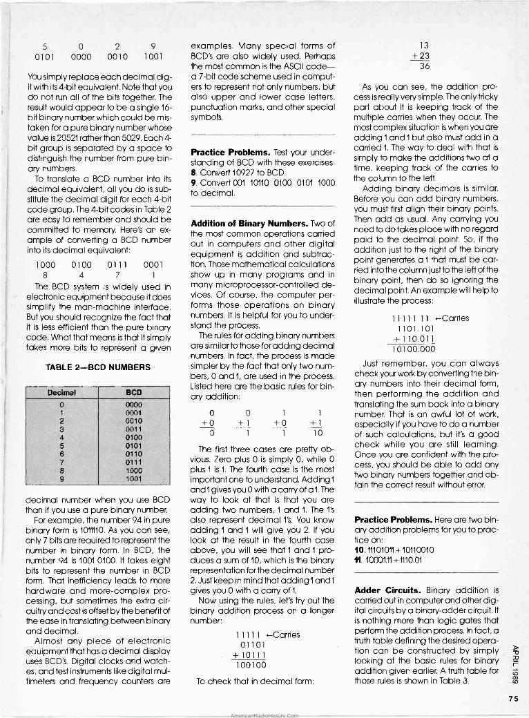
5 0 2 9 0101 0000 0010 1001
You simply replace each decimal dig- it with its 4 -bit equivalent. Note that you do not run all of the bits together. The result would appear to be a single 16 - bit binary number which could be mis- taken for a pure binary number whose value is 20521 rather than 5029. Each 4 - bit group is separated by a space to distinguish the number from pure bin- ary numbers.
To translate a BCD number into its
decimal equivalent, all you do is sub- stitute the decimal digit for each 4 -bit code group. The 4 -bit codes in Table 2
are easy to remember and should be committed to memory. Here's an ex- ample of converting a BCD number into its decimal equivalent:
1000 0100 0111 0001 8 4 7 1
The BCD system is widely used in electronic equipment because it does simplify the man -machine interface. But you should recognize the fact that it is less efficient than the pure binary code. What that means is that it simply takes more bits to represent a given
TABLE 2-BCD NUMBERS
Decimal BCD
0 0000 1 0001 2 0010 3 0011 4 0100 5 0101 6 0110 7 0111 8 1000 9 1001
decimal number when you use BCD than if you use a pure binary number.
For example, the number 94 in pure binary form is 1011110. As you can see, only 7 bits are required to represent the number in binary form. In BCD, the number 94 is 1001 0100. It takes eight bits to represent the number in BCD form. That inefficiency leads to more hardware and more -complex pro- cessing, but sometimes the extra cir- cuitry and cost is offset by the benefit of the ease in translating between binary and decimal.
Almost any piece of electronic equipment that has a decimal display uses BCD's. Digital clocks and watch- es, and test instruments like digital mul- timeters and frequency counters are
examples. Many special forms of BCD's are also widely used. Perhaps the most common is the ASCII code- a 7 -bit code scheme used in comput- ers to represent not only numbers, but also upper and lower case letters, punctuation marks, and other special symbols.
Practice Problems. Test your under- standing of BCD with these exercises: S. Convert 10927 to BCD. 9. Convert 001 10110 0100 0101 1000 to decimal.
Addition of Binary Numbers. Two of the most common operations carried out in computers and other digital equipment is addition and subtrac- tion. Those mathematical calculations show up in many programs and in many microprocessor -controlled de- vices. Of course, the computer per- forms those operations on binary numbers. It is helpful for you to under- stand the process.
The rules for adding binary numbers are similar to those for adding decimal numbers. In fact, the process is made simpler by the fact that only two num- bers, 0 and 1, are used in the process. Listed here are the basic rules for bin- ary addition:
0 0 1 1
+0 +1 +0 +1 0 1 1 10
The first three cases are pretty ob- vious. Zero plus 0 is simply 0, while 0 plus 1 is 1. The fourth case is the most important one to understand. Adding 1
and 1 gives you 0 with a carry of a 1. The way to look at that is that you are adding two numbers, 1 and 1. The l's also represent decimal l's. You know adding 1 and 1 will give you 2. If you look at the result in the fourth case above, you will see that 1 and 1 pro- duces a sum of 10, which is the binary representation for the decimal number 2. Just keep in mind that adding land 1
gives you 0 with a carry of 1.
Now using the rules, let's try out the binary addition process on a longer number:
11111 -Carries 01101
+10111 100100
To check that in decimal form:
13
+23 36
As you can see, the addition pro- cess is really very simple. The only tricky part about it is keeping track of the multiple carries when they occur. The most complex situation is when you are adding land 1 but also must add in a carried 1. The way to deal with that is
simply to make the additions two at a time, keeping track of the carries to the column to the left.
Adding binary decimals is similar. Before you can add binary numbers, you must first align their binary points. Then add as usual. Any carrying you need to do takes place with no regard paid to the decimal point. So, if the addition just to the right of the binary point generates a 1 that must be car- ried into the column just to the left of the binary point, then do so ignoring the decimal point. An example will help to illustrate the process:
11111 11 -Carries 1101.101
+110.011 10100.000
Just remember, you can always check your work by converting the bin- ary numbers into their decimal form, then performing the addition and translating the sum back into a binary number. That is an awful lot of work, especially if you have to do a number of such calculations, but it's a good check while you are still learning. Once you are confident with the pro- cess, you should be able to add any two binary numbers together and ob- tain the correct result without error.
Practice Problems. Here are two bin- ary addition problems for you to prac- tice on: 10. 11101011 +10110010 11. 10001.11 +1110.01
Adder Circuits. Binary addition is
carried out in computer and other dig- ital circuits by a binary -adder circuit. It is nothing more than logic gates that perform the addition process. In fact, a truth table defining the desired opera- tion can be constructed by simply looking at the basic rules for binary addition given earlier. A truth table for those rules is shown in Table 3.
75
AmericanRadioHistory.Com
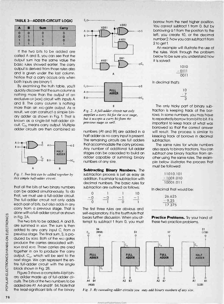
TABLE 3-ADDER-CIRCUIT LOGIC
A B Sum Carry
0 0 0 0 0 1 1 0 1 0 1 0 1 1 o 1
If the two bits to be added are called A and B, you can see that the output sum has the same value the basic rules showed earlier. The carry output is derived from those rules also and is given under the last column. Notice that a carry occurs only when both inputs are binary 1.
By examining the truth table, you'll quickly discover that the sum column is
nothing more than the output of an exclusive-oR (xoR) circuit with inputs A and B. The carry column is nothing more than an AND -gate output. As a result, we can construct a simple bin- ary adder as shown in Fig. 1. That is
known as a single -bit half -adder cir- cuit. Co means carry output. Multiple adder circuits are then combined so
A B
Fig. 1. Two bits can be added together by this simple half -adder circuit.
that all the bits of two binary numbers can be added simultaneously. To do that, we must use a full -adder circuit. The full -adder circuit not only adds each pair of bits, but also adds in any carry from a previous stage. That is
done with a full -adder circuit as shown in Fig. 2A.
The two bits to be added, A and B,
are summed in xorzl. The sum is then added to any carry input C; from a previous stage. The final sum, S, is pro- duced by xOR2. Both of the AND gates produce the carries associated with xoal and x0R2. Those carries are ()Red together in oal to produce the carry output, Co, which will be sent to the next stage. We can represent the en- tire full -adder circuit with the single block shown in Fig. 2B.
Figure 3 shows a complete 4 -bit bin- ary adder made up of full -adder cir- cuits. The bits of the two numbers to be added are Al -A4 and B1 -B4. Note that the least -significant bits of the binary
A
B
Fig. 2. A full -adder circuit not only supplies a carry bit for the next stage, but it accepts a carry bit from the previous stage as well.
numbers (Al and B1) are added in a half adder as no carry input is present. The remaining circuits are full adders that accommodate the carry process. Any number of additional full -adder stages can be cascaded to build an adder capable of summing binary numbers of any size.
Subtracting Binary Numbers. The subtraction process is just as easy as addition. It is similar to subtraction with decimal numbers. The basic rules for subtraction are outlined as follows:
o 10 -0 -0 -1 -1
o 0 1
The first three rules are obvious and self-explanatory. It is the fourth rule that bears further discussion. When you at- tempt to subtract 1 from 0, you must
S4
(MSB)
A4 B4
(MSB)
S3
o
FULL ADDER
A3 B3
borrow from the next higher position. You cannot subtract 1 from O. But by borrowing a 1 from the position to the left, you create 10, or the decimal number 2. Now you can subtractI from 2 to get 1.
An example will illustrate the use of the rules. Work through the problem below to be sure you understand how it is solved:
1010 -0111
0011
In decimal that's:
10
=7 3
The only tricky part of binary sub- traction is keeping track of the bor- rows. In some numbers, you may have to repeatedly borrow from bit to bit. It is
important to keep track of what was borrowed so that the correct answer will result. The process is similar to keeping track of borrows in decimal subtraction.
The same rules for whole numbers also apply to binary fractions. You can subtract one binary fraction from an- other using the same rules. The exam- ple below illustrates the process that must be followed:
11010.101 - 1001.010 10001.011
In decimal that would be:
26.625 - 9.25 17.375
Practice Problems. Try your hand at these two practice problems.
S2
co
FULL ADDER
A2 B
Si
(LSB) o
HALF ADDER
Al B1
(LSB)
Fig. 3. By cascading adder circuits you may add binary numbers of any size.
76
AmericanRadioHistory.Com

12. 11000101 13. 101 1 1 1.100 An example will illustrate the pro-
- 1001 1 10 - 10101.001 cers. Let's subtract 10110 from 11101011:
11101011 -00010110 Subtracting By Adding. A binary
subtractor circuit may be made out of logic gates just like an adder. In prac- tice, however, you will find that binary subtractor circuits are just not used. Any computer would have to have separate circuits for subtraction and addition. That is not really necessary, as special techniques permit subtrac- tion to be performed with a binary ad- der. That is done by using number complements. Remember that in bin- ary terminology complement means the opposite. The complement of 0 is 1,
and the complement of 1 is 0. You can perform binary subtraction by simply complementing the number to be sub- tracted, and then adding. You com- plement the subtrahend (the number being subtracted), add it to the min- uend (the number you're subtracting from), and the result is their difference. Remember, the subtrahend is the number you take away from the min- uend to get the difference.
There are two types of binary com- plements, l's complement and 2's
complement. To create the l's comple- ment of a binary number, you simply change each 1 to a 0 and each 0 to a 1.
Note the binary number below and its
complement:
11001010 (Number) 00110101 (l's complement)
The 2's complement is simply the l's
complement of a binary number to which 1 has been added. The 2's com- plement of the binary number is:
001 10101 (1's complement) + 1 (add 1)
00110110 (2's complement)
It is the 2's complement of the sub- trahend that is added to the minuend to get the difference. Listed here are the basic rules of subtracting by adding complements: 1. If the subtrahend has fewer bits than the minuend, add leading 0's to the subtrahend so that it has the same number of places as the minuend. 2. Find the 2's complement of the sub- trahend. 3. Add the minuend and the 2's com- plement of the subtrahend. 4. Discard any carry bit out of the most significant bit position. 5. The result is the correct difference expressed in binary form.
Note that three lead zero's were add- ed to the subtrahend. Find the l's com- plement of the subtrahend:
0001 011 0 =111 01 001
Adding 1 to get the 2's complement of the sub*rahend:
11101001 +1
11101010
Perform the addition:
11101010 (Subtractend) +111101011 (Minuend)
111010101
And if we ignore the most significant bit, we get the result 1 1010101, which is
correct.
You can always verify the correct result
by ccnverting to decimal. In the above example, we subtracted 22
from 235 to get 213.
Subtracting by adding comple- ments greatly simplifies the computer hardware needed for subtraction. Separate subtractor circuits are not re-
quired. However, you do have to gen- erate the complement. The comple- ment, of course, can be generated simply by inversion. In some cases, the complement of a binary number may already be available at the output of flip-flops at which the number is stored. Otherwise, the l's complement can be generated with inverters or by an ex-
clusive-oR circuit as shown in Fig. 4. The
circuit will pass a binary number A if
CONTROL
Fig. 4. A control signal determines whether or not this gate inverts the incoming signal or leaves it alone.
the control input is O. If the control input is 1, the output will be the complement of the input.
Figure 5 shows a 4 -bit adder/sub- tractor circuit that uses the 2's comple- ment method. When the SUB control line is 0, the XOR circuits do not invert the
bits B1 -B4, so the circuit adds. The sum
appears at S1 -S4. If SUB is 1, the XOR
circuits invert the B1 -B4 bits producing the l's complement that is added to the A1 -A4 bits. The carry input to the LSB from SUB, which is 1, is added in to produce the 2's complement. The out- puts, D1 -D4, are the difference.
Multiplying Binary Numbers. Occasionally you will also need to multiply binary numbers. The rules are the same as those for decimal num- bers. They are summarized as follows:
x0 0 1
The process of multiplying in binary is exactly the same as that used for decimal numbers. Each multiplication by one of the bits in the multiplier pro- duces a partial product. The partial products are shifted from one another one bit to the left by padding zeroes to the right. As soon as all of the partial products have been written, they are added to produce the final product. This example shows the process:
10101 x1101 10101
00000 (Partial products) 10101
10101
100010001 (Final product)
As you can see, when you multiply by 0, the partial product will be a series of 0's. Of course, you can simply omit that partial product as it adds nothing to the final result. Just be sure that if you omit the 0 partial products, that you correctly line up the remaining partial products, otherwise the final product will not be correct.
The multiplication of fractional bin- ary numbers is similar. The multiplica- tion process is the same, and the rules
for placing the binary point is similar to the rule for placing the decimal point with decimal fractions. This example shows that:
0.1011 0.0010
0000 1011
0000 0000
0.000101 10
For the example above, you deter- mine the position of the binary point by
77
AmericanRadioHistory.Com

SUB
B4 B3 B2 BI
Fig. 5. When the XOR gates receive a 1 signal on the SUB line they take the ones complement of B. A 1 is sent to the first bits "carry" input to turn the l's compliment into the 2's complement, so B is ready to be subtracted.
adding the number of binary places in the multiplier and the multiplicand. In the example, there are four places to the right of the binary point in both numbers giving a total of eight. You count off that many places from the right of the least significant digit, and that's where the binary point belongs. You can check the result by converting to decimal:
0.6375 x 0.125= 0.0859375
Practice Problems. Here are a cou- ple of binary multiplication problems to test your newly gained knowledge: 14. 1100011 x 10110= 15. 0.101x 0.01=
Dividing Binary Numbers. It is not too often that you will be called upon to do binary division. As with the other math functions, binary division is sim- ilar to decimal division. The process is
a little trickier when using l's and 0's. If
you remember the procedure for long division with decimal numbers, you should have no trouble with binary di- vision. Just keep in mind that the pro- cess also involves binary multiplication and subtraction along the way.
An example is to divide 45 by 4. Using a calculator or standard deci- mal long division, we discover that 45 divided by 4 is 11.25. Now let's do it in
binary. The entire process is as follows:
1011.01 100)101101.00
100 110 100
101
100 100 100
0
First note that the divisor (100) is com- posed of three bits. You want to at- tempt to divide it into the first three bits of the dividend, so you are dividing 100 into 101. Of course, 4 (100) will go into 5 (101) one time. Therefore, you record the first bit of the quotient. Next you write the divisor under the first three digits of the dividend and subtract. The result is 1.
Now you bring down the next digit from the dividend producing 11. That is
only two bits and the divisor 100 will not go into 11. For that reason you record a 0 in the quotient. Then you bring down the next bit from the dividend, a 0. That creates the number 110. The divisor, 100, will go into110 one time. Again you must record a i in the quotient. Then put the divisor under 110 and subtract as before. The result is 10. You bring down the remaining 1 in the dividend to form 101.
Again the divisor goes into 101.
Therefore you can record another 1 in
the quotient. Subtracting 100 from 101
produces 1. Then, you bring down a zero from the dividend producing 10.
The divisor 100 will not go into it so you record a 0 in the quotient. Bringing down the next 0 produces 100. The di- visor goes into it evenly one time, there- fore, you add the final 1 to the quotient. The quotient is 1011.01. If you convert that into decimal form, you will find that it is 11.25.
Practice Problem. Even though you won't be doing binary division that much, try your hand at the practice problem below. 16. 100011/101
Octal and Hexadecimal Numbers. One of the main problems in working with binary numbers is that it is so easy to make a mistake. It is easy to miss a bit when copying a number or per- forming some arithmetic operation. All those l's and 0's can make you go crazy.
One way to overcome the problem is simply to convert all of the binary numbers into decimal form and per- form whatever operations must be done in decimal. Of course, a lot of translating back and forth between binary and decimal will be necessary, but it may make you a little more com- fortable and hopefully fewer errors will occur.
A better solution for the problem is
simply to use octal and hexadecimal numbers. The octal -number system has a base or radix of 8. That means that eight different symbols are used to represent quantities. The octal -number system uses the digits 0 through 7. Like the binary and the decimal systems, the octal system is a weighted posi- tional system, and all of the rules de- scribed earlier apply to octal digits and numbers.
The hexadecimal -number system uses the base 16. Sixteen symbols are used to represent quantities. In hex- adecimal, the decimal digits 0 through 9 and the letters A through F
are used to represent hex values. The hexadecimal system is also a weight- ed positional system, so all of those previous rules also apply.
However, you should understand that the octal- and hexadecimal - number systems are useful because they are related to the binary -number
78
AmericanRadioHistory.Com

system. The bases of the octal and hex- adecimal systems are powers of 2.
Eight is the third power of 2, while 16 is
TABLE 4-OCTAL/BINARY EQUIVALENTS
Octal Binary
0 0000 1 0001 2 0010 3 0011 4 0100 5 0101 6 0110 7 0111
the fourth power of 2. Without going into all of the mathematical mumbo - jumbo, we can easily show how the octal and hex systems are related to binary. Let's start with the octal -number system.
To convert a binary number into its
octal equivalent, all you have to do is
mark off the binary number in groups of three bits beginning with the binary point on the right. Then, replace each 3 -bit binary group with its octal equiv- alent. The octal numbers and their 3 -
bit binary equivalents are given in Ta-
ble 4.
Let's talte an example to show the conversion of a binary number into its
octal equivalent; To convert 110101010
to octal, all we do is group the bits in
threes and substitute:
110 101 010 6 5 2
So in octal that's 652. Changing a number from octal to
binary is just as easy. Simply replace
TABLE 5-HEX/BINARY EQUIVALENTS
Hex Binary
0 0000 1 0001 2 0010 3 0011 4 0100 5 0101 6 0110 7 0111 8 1000 9 1001 A 1010 B 1011 C 1100 D 1101 E 1110 F 1111
each octal digit with its 3 -bit binary equivalent as this example shows:
4 0 5
100 000 010
The conversion process between binary and hex numbers is also easy. To
convert binary into hex, you separate the bits beginning with the binary point into 4 -bit groups. Then you replace each 4 -bit group with its hex equiv- alent. Table 5 shows the binary and hexadecimal equivalents. The num- bers 0 through 9 have the same binary equivalents as decimal numbers. The letters A through F have decimal equivalents of 11 through 15,
As an example of how a binary number is converted to hex, let's con- vert 10001110101 to hex:
0100 0111 0101 4 7 5
Note that a leading zero was added to complete a group of four.
Going the other way, from hex- adecimal to binary is just as easy. Take
the hex number and replace each of its digits with the 4 -bit binary group from the table. For example, let's con- vert 7A4E to binary:
7 A 4 E
0111 1010 0100 1110 =111101001001110
Converting to octal or hexadecimal is a very easy process. The result is a much shorter and easier to remember number. Just keep in mind that it is not a decimal number and you certainly cannot use it as such in any kind of calculation. But fewer digits allow you to work with the same information in a slightly easier -to -handle form.
While both octal and hexadecimal numbers are widely used, hex is by far the more popular. That is because most binary word sizes in computers and other digital equipment are some multiple of 4. Typical word sizes are 8,
16, and 32 bits. That makes hex- adecimal the predominant method of expressing numbers stored in memory registers.
Whenever an octal or hexadecimal number is used, typically a subscript will be applied to it indicating the cor- rect base. Octal numbers have a sub- script of 8, while hexadecimal numbers have a subscript of 16. That prevents confusion if you are dealing with numbers in more than one number system. Sometimes you may see a hex number followed by an H instead of a subscript as shown:
56816= 5B8H
The capital H is often used because the subscript is difficult for most com- puter printers to produce.
Octal and Hex Arithmetic. Yes, you can perform the basic mathematical operations on octal and hex numbers. Luckily you won't have to do it too often, so I will not show that here.
On the other hand, many program- mers and field service technicians offen need to perform additions and subtractions on hex numbers in debug- ging a program or troubleshooting some computer fault. Hex numbers are widely used for both data and ad- dresses in a computer. Many times in
calculating a result of an arithmetic operation or determining an address as part of an indexing or relative -ad- dressing scheme, hex addition and subtraction must be done. Of course, you can always convert your hex num- bers to binary and perform the addi- tion or subtraction, but that is messy.
You are probably thinking that it is also messy to add or subtract hex numbers. You are right. How in the world do you do addition and subtraction with let- ters of the alphabet? Just don't ask, as I
don't plan to explain it here. Instead, I
offer you the table shown in Table 6.
With that simple table, you can per- form one digit additions and subtrac- tions with hex numbers. A couple of examples will illustrate the use of the table.
Let's suppose you want to add the hex digits B and 6. The addend, B, will be found in the vertical left hand col- umn while the augend, 6, will be found in the top horizontal row. Locating B on the vertical axis and 6 on the horizontal axis follow each row and column until they intersect at the correct sum, 11.
(Remember, 11 is a hex number.) To use the table for subtraction, you
use the top horizontal row for the sub- trahend and you locate the minuend in the same vertical column in which the subtrahend occurs. For example, if you wish to subtract 6 from 9, the min- uend is 9 and the subtrahend is 6. Lo- cate the subtrahend, 6, on the top horizontal row. Then locate the min- uend, 9, in that same vertical column. Then follow the row in which 9 appears over to the left until you come to the difference column. The difference is, of course, 3. Six minus nine is the same in
hexadecimal as it is in decimal. Take another example just to be
sure. Let's subtract E from 1A. Locate E in
(Continued on page 94)
79
AmericanRadioHistory.Com

cr) U z o
U w J W z o v o z _ U z o cc
U W J W ¢ g a O a
80
Antique Radio
THE MYSTERY IS SOLVED
Back in the November, 1988 col- umn, I described a mysterious -
looking Philco gadget owned by reader Larry Lovell. Larry wanted some information about the device. But beyond observing that it looked like some kind of a wireless remote -control unit, I wasn't able to be of much help. So I appealed to the readers for as- sistance, and your letters have been coming in a steady stream ever since!
Starting with the bottom line, the little Philco unit really is a wireless remote - control unit for a radio receiver. Dub- bed the "Mystery Control," the gadget contains a one -tube radio transmitter that sends out pulses from a built-in telephone -style dial. When picked up by a special receiver within the radio, the transmitted pulses control the sta- tion -selection and volume of the re- ceiver.
But I don't want to get too far ahead of our story. Thanks to Larry, who gra- ciously loaned me the device for a while so I could take detailed photos; and thanks to the many readers who sent schematics, service notes, and other information, I have enough ma- terial to devote this entire column to the Philco Mystery Control.
The story you are about to read was pieced together from all of the mate- rial I've received from readers so far. But each individual contribution will be recognized at the end of the article.
System Overview. The Philco Mystery Control system was introduced with two top -of -the -line 1939 sets: Models 39-55 (standard broadcast) and 39-1 16 (broadcast and shortwave). Those two console sets appear to be very similar in design, except that the "116" included a stage of RF ampli- fication, accompanied by slightly more sophisticated audio circuitry.
Operating on a self-contained bat- tery pack, and with no electrical con- nection to the radio, the Mystery
By Marc Ellis
The Mystery Control as received from reader Larry Lovell.
Control generated a pulsed radio sig- nal. Depending on the number of pulses sent (as determined by the tele- phone -style rotary dial), the control could be used to select any of eight pre -tuned stations in the standard broadcast band.
The Mystery Control could also
make volume adjustments and- when a listening session came to an end-shut off the set's power. However, for reasons that will be explained later, the set had to be turned on manually.
The signals from the Mystery Control unit operated the radio via a special "control amplifier" built into the set. That amplifier received the radio -fre- quency signal pulses from the control unit and converted them into DC pulses strong enough to operate an on -board stepping relay (similar to the ones used in a pre -electronic dial tele- phone exchange). That relay, in turn, controlled both an eight -position sta- tion -selector switch and a reversible motor that drove the volume control and power switch.
The nominal range of the control sys- tem was 25 feet. However, the receiver stage of the control amplifier had a sensitivity control that could be ad- justed to shorten the unit's range if elec- trical interference was causing false triggering. The sensitivity could also be increased if conditions (such as the presence of large metal objects) were attenuating the control signal.
The control unit and control amplifier could be adjusted to work on any fre- quency between 350 and 400 kHz. In
that way, according to the manufac- turer, two Mystery Control radios oper- ating in the same home, or apartment building, could be set up on different frequencies. Otherwise, signals from your neighbor's control box might re - tune your set to Blondie and Dogwood while you were trying to listen to the philharmonic.
Opening the cabinet reveals the oscillator circuitry mounted on the rear cover (right). The batteries were housed within the cabinet, below the dial mechanism.
AmericanRadioHistory.Com
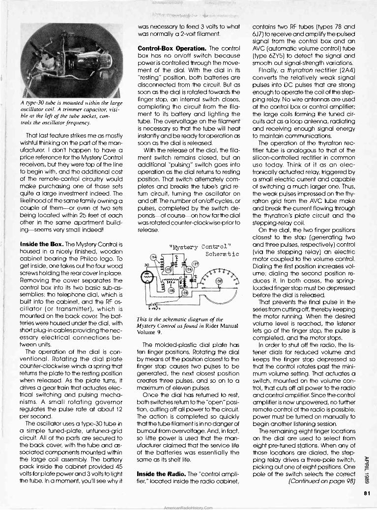
A type -30 tube is mounted within the large oscillator coil. A trimmer capacitor, visi- ble at the left of the tube socket, con- trols the oscillator frequency.
That last feature strikes me as mostly wishful thinking on the part of the man- ufacturer. I don't happen to have a price reference for the Mystery Control receivers, but they were top of the line to begin with, and the additional cost of the remote -control circuitry would make purchasing one of those sets quite a large investment indeed. The likelihood of the same family owning a couple of them-or even of Iwo sets being located within 25 feet of each other in the same apartment build- ing-seems very small indeed!
Inside the Box. The Mystery Control is
housed in a nicely finished, wooden cabinet bearing the Philco logo. To get inside, one takes out the four wood screws holding the rear cover in place. Removing the cover separates the control box into its two basic sub -as- semblies: the telephone dial, which is
built into the cabinet, and the RF os- cillator (or transmitter), which is mounted on the back cover. The bat- teries were housed under the dial, with short plug-in cables providing the nec- essary electrical connections be- tween units.
The operation of the dial is con- ventional. Rotating the dial plate counter -clockwise winds a spring that returns the plate to the resting position when released. As the plate turns, it
drives a gear train that actuates elec- trical switching and pulsing mecha- nisms. A small rotating governor regulates the pulse rate at about 12
per second. The oscillator uses a type -30 tube in
a simple tuned -plate, untuned-grid circuit. All of the parts are secured to the back cover, with the tube and as- sociated components mounted within the large coil assembly. The battery pack inside the cabinet provided 45 volts for plate power and 3 volts to light the tube. In a moment, you'll see why it
was necessary to feed 3 volts to what was normally a 2 -volt filament.
Control -Box Operation. The control box has no on/off switch because power is controlled through the move- ment of the dial. With the dial in its
"resting" position, both batteries are disconnected from the circuit. But as soon as the dial is rotated towards the finger stop, an internal switch closes, completing the circuit from the fila- ment to its battery and lighting the tube. The overvoltage on the filament is necessary so that the tube will heat instantly and be ready for operation as soon as the dial is released.
With the release of the dial, the fila- ment switch remains closed, but an additional "pulsing" switch goes into operation as the dial returns to resting position. That switch alternately com- pletes and breaks the tube's grid -re- turn circuit, turning the oscillator on and off. The number of on/off cycles, or pulses, completed by the switch de- pends-of course-on how far the dial was rotated counter -clockwise prior to release.
"/estery Control" Schemt is
This is the schematic diagram of the Mystery Control as found in Rider Manual Volume 9.
The molded -plastic dial plate has ten finger positions. Rotating the dial by means of the position closest to the finger stop causes two pulses to be generated, the next closest position creates three pulses, and so on to a maximum of eleven pulses.
Once the dial has returned to rest, both switches return to the "open" posi- tion, cutting off all power to the circuit. The action is completed so quickly that the tube filament is in no danger of burnout from overvoltage. And, in fact, so little power is used that the man- ufacturer claimed that the service life of the batteries was essentially the same as its shelf life.
Inside the Radio. The "control ampli- fier," located inside the radio cabinet,
contains two RF tubes (types 78 and 6J7) to receive and amplify the pulsed signal from the control box and an AVC (automatic volume control) tube (type 6ZY5) to detect the signal and smooth out signal -strength variations.
Finally, a thyratron rectifier (2A4) converts the relatively weak signal pulses into DC pulses that are strong enough to operate the coil of the step- ping relay. No wire antennas are used at the control box or control amplifier; the large coils forming the tuned cir- cuits act as a loop antenna, radiating and receiving enough signal energy to maintain communications.
The operation of the thyratron rec- tifier tube is analogous to that of the silicon -controlled rectifier in common use today. Think of it as an elec- tronically actuated relay, triggered by a small electric current and capable of switching a much larger one. Thus,
the weak pulses impressed on the thy - ration grid from the AVC tube make and break the current flowing through the thyratron's plate circuit and the stepping -relay coil.
On the dial, the two finger positions closest to the stop (generating two and three pulses, respectively) control (via the stepping relay) an electric motor coupled to the volume control. Dialing the first position increases vol- ume; dialing the second position re- duces it. In both cases, the spring - loaded finger stop must be depressed before the dial is released.
That prevents the final pulse in the series from cutting off, thereby keeping the motor running. When the desired volume level is reached, the listener lets go of the finger stop, the pulse is
completed, and the motor stops. In order to shut off the radio, the lis-
tener dials for reduced volume and keeps the finger stop depressed so that the control rotates past the mini- mum volume setting. That actuates a switch, mounted on the volume con- trol, that cuts off all power to the radio and control amplifier. Since the control amplifier is now unpowered, no further remote control of the radio is possible; power must be turned on manually to begin another listening session.
The remaining eight finger locations on the dial are used to select from eight pre -tuned stations. When any of those locations are dialed, the step- ping relay drives a three -pole switch, picking out one of eight positions. One pole of the switch selects the correct
(Continued on page 98)
81
AmericanRadioHistory.Com
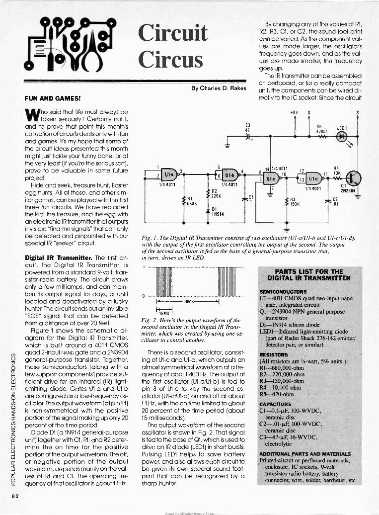
Circuit Circus
FUN AND GAMES!
ho said that life must always be taken seriously? Certainly not I,
and to prove that point this month's collection of circuits deals only with fun and games. It's my hope that some of the circuit ideas presented this month might just tickle your funny bone, or at the very least (if you're the serious sort), prove to be valuable in some future project.
Hide and seek, treasure hunt, Easter egg hunts: All of those, and other sim- ilar games, can be played with the first three fun circuits. We have replaced the kid, the treasure, and the egg with an electronic IR transmitter that outputs invisible "find me signals" that can only be detected and pinpointed with our special IR "seeker" circuit.
Digital IR Transmitter. The first cir- cuit, the Digital IR Transmitter, is
powered from a standard 9 -volt, tran- sistor -radio battery. The circuit draws only a few milliamps, and can main- tain its output signal for days, or until located and deactivated by a lucky hunter. The circuit sends out an invisible "SOS" signal that can be detected from a distance of over 20 feet.
Figure 1 shows the schematic di- agram for the Digital IR Transmitter, which is built around a 4011 CMOS quad 2 -input NAND gate and a 2N3904 general-purpose transistor. Together, those semiconductors (along with a few support components) provide suf- ficient drive for an infrared (IR) light - emitting diode. Gates UI -a and U1 -lo
are configured as a low -frequency os- cillator. The output waveform (at pin 11)
is non -symmetrical with the positive portion of the signal making up only 20 percent of the time period.
Diode D1 (a 1N914 general-purpose unit) together with Cl, R1, and R2 deter- mine the on time for the positive portion of the output waveform. The off, or negative portion of the output waveform, depends mainly on the val- ues of R1 and Cl. The operating fre- quency of that oscillator is about 11 Hz.
2
By Charles D. Rakes
1
C3
47
By changing any of the values of R1,
R2, R3, Cl, or C2, the sound foot -print can be varied. As the component val- ues are made larger, the oscillator's frequency goes down, and as the val- ues are made smaller, the frequency goes up.
The IR transmitter can be assembled on perfboard, or for a really compact unit, the components can be wired di- rectly to the IC socket. Since the circuit
1/44011 1/44011
R2
R1 saoK
220K -Ci .1
D1 A 1N914
9
14
Fig. 1. The Digital IR Transmitter consists of two oscillators (UI-a/UI-b and Ul-c/UI-d), with the output of the first oscillator controlling the output of the second. The output of the second oscillator is fed to the base of a general-purpose transistor that, in turn, drives an IR LED.
o
90MS
Fig. 2. Here's the output waveform of the second oscillator in the Digital IR Trans- mitter, which was created by using one os- cillator to control another.
There is a second oscillator, consist- ing of U1 -c and UI -d, which outputs an almost symmetrical waveform at a fre- quency of about 400 Hz. The output of the first oscillator (U1-a/U1-b) is fed to pin 8 of Ut -c to key the second os- cillator (Ut-c/U1-d) on and off at about 11 Hz, with the on time limited to about 20 percent of the time period (about 15 milliseconds).
The output waveform of the second oscillator is shown in Fig. 2. That signal is fed to the base of Q1, which is used to drive an IR diode (LEDI) in short bursts. Pulsing LEDI helps to save battery power, and also allows each circuit to be given its own special sound foot- print that can be recognized by a sharp hunter.
PARTS LIST FOR THE DIGITAL IR TRANSMITTER
SEMICONDUCTORS UI 4011 CMOS quad two -input nand
gate, integrated circuit Q1 -2N3904 NPN general purpose
transistor D1 -1N914 silicon diode LEDI-Infrared light -emitting diode
(part of Radio Shack 276-142 emitter/ detector pair, or similar)
RESISTORS (All resistors are la -watt, 5% units.) R1 -680,00 -ohm R2 -220,000 -ohm R3 -150,000 -ohm R4 -10,000 -ohm RS '170 ohm
CAPACITORS C1 -0.1-µF, 100-WVDC,
ceramic disc C2-.0I-µF, 100-WVDC.
ceramic disc C3 47-µF, 16-WVDC,
electrolytic
ADDITIONAL PARTS AND MATERIALS Printed -circuit or perfboard materials,
enclosure, IC sockets, 9 -volt transistor -radio battery, battery connector, wire, solder, hardware, etc.
82
AmericanRadioHistory.Com

is non -critical, just about any con- struction scheme should suffice. The completed circuit can be housed in a small plastic cabinet with the IR diode mounted facing outward. Or for a really clever arrangement, you might conceal the transmitter circuit in some nondescript item that's found around the house and let its obvious location be its best hiding place.
If a greater range and/or a multi- directional output is desired from the transmitter, additional IR diodes can be added to the circuit. For each add- ed output just duplicate the R5/LEDI portion of the circuit and connect the additional emitter circuit to the points labelled "X" and "Y" in Fig. 1.
To keep the battery and Q1 cool, no more than four IR diodes should be connected to the circuit. But if more outputs are desired, a different driver transistor (Q1) and a larger current -ca- pacity battery should be used.
Simple IR Transmitter. Our next IR
transmitter circuit, shown in Fig. 3, is
LECH*
6 5
U1
3909 FLASHER OSCILLATOR
Cl .47 T
- C2
'-. 220
*SEE TEXT
Fig. 3. This IR transmitter is built a- round a 3909 LED flasher/ oscillator- an IC most often used to drive LED's in a variety of fi ht-segnenrin,L circuits.
81 1.5V
PARTS LIST FOR THE SIMPLE IR TRANSMITTER
SEMICONDUCTORS U1 -3909N LED flasher/oscillator,
integrated circuit LEDI-Infrared light -emitting diode
(part of Radio Shack 276-142 emitter/ detector pair, or similar)
C1 -0.47-11F to 47-µF, 10-WVDC, electrolytic capacitor (see text)
C2 -220-µF, 10-WVDC, electrolytic capacitor
131 -1.5 -volt Alkaline "C" cell Printed -circuit or perfboard materials,
enclosure, IC sockets, battery, holder, wire, solder, hardware, etc.
R1
100K
13
4
UI a
1ï4 LM324
R4
R2 2.2K
1M
4.7 K
83 220K
H^
Ui -b
11
R9
2.5K
1/4 LM324
R7
220K
ovo Si
+ C5
T220
C2 R6 .1 2.2K
R5
4.7K
C3
*SEE TEXT
Fig. 4. The IR Interceptor, built around a phototransistor and a quad op -amp, is a key
player in the electronic hide-and-seek game.
Uic
1/4 LM324.
13
14 Old
1/4 LM324
I
e
B1
9V
88 27052
= C4
47
I
built around a 3909 LED flasher/os- cillator-an IC most often used to drive visible LED's in an array of projects. All that's necessary to turn that simple inte- grated LED flasher into an IR transmitter is to replace the standard LED with an IR light -emitting diode.
The IR diode's flash rate is deter- mined by the value of Cl, a 220-µF capacitor that sets the rate of oscilla- tion at better than 1 -Hz per second. Re- ducing the value of Cl will increase the frequency of the circuit, while larger values will decrease the frequency.
Since the circuit only sends out sin- gle, narrow pulses of invisible light, the IR receiver only responds with a click for every output pulse. That, along with the relatively low output power, makes the circuit more difficult to find with its
limited pickup range of less than 15
feet. The few components that comprise
the circuit can be wired directly to an IC socket and the single 1.5 -volt cell can be permanently connected to the transmitter circuit. There's no need for a switch here because the battery will operate the unit for close to its normal shelf life.
J1
IR Interceptor. The heart of the hide and seek electronic game is the de- tector. The circuit in Fig. 4-dubbed the IR Interceptor-uses a phototran- sistor, Q1, to detect IR emissions. The circuit is built around an LM324 quad op -amp that's supported by a handful of passive components. Op -amp UI -a is configured as a voltage -follower cir- cuit, and it is specifically used to match the high output impedance of the phototransistor to the low input im- pedance of UI -b.
Infrared emissions detected by Q1
are fed through U1 -a to UI -b, which am- plifies the signal by a factor of 100. The amplified output of U1 -b is fed to U1 -c through R9, C2, and R6. Potentiometer R9 serves as a volume control. With R9
set to pass the maximum signal, U1 -c provides a gain of 100, for a total sys-
tem gain of 10,000. The output of U1 -c is connected to
another voltage follower circuit (U1 -d) to better match and drive head- phones that can be plugged into JI.
For a slick IR Interceptor, the circuit can be assembled on perfboard and housed in a two- or three -cell flashlight
(Continued on page 94)
AmericanRadioHistory.Com

Computer
-:___" Bits COMPUTER VIDEO FORMATS
ast month I promised a discussion of buying a hard disk for your first
PC. Unfortunately, my research has taken me a little deeper than I ex- pected; consequently, I have to delay the write-up until next month. So for now, let's talk about video standards.
Video Formats. Video systems for IBM-compatible PC's come in four basic flavors: Hercules, CGA, EGA, and VGA. Hercules provides text and medium -resolution graphics (720 x
348) on monochrome monitors; the others provide text and graphics in
varying degrees of resolution on color monitors. In order of increasing resolu- tion: CGA (640 x 200 in 2 colors), EGA (640 x 350 in 16 colors), and VGA (640 x 480 in 16 colors).
In addition, the latest generation of "extended" VGA cards have modes that extend to 600 x 800 and beyond. The extended modes provide the most economical means of doing CAD (computer -aided design) and desk- top publishing on a professional basis.
Each video standard requires its
own type of monitor. You can buy an acceptable Hercules -compatible monitor for about $100; color monitors start at about $250 and keep on go- ing. However, a $250 color monitor gets you only CGA resolution and, practically speaking, that's so low that it's impossible to do serious work on it.
Moving up, EGA monitors start at about $350, VGA monitors at about $450, and multi -frequency monitors at about $550. (A multi -frequency monitor can display everything from CGA to extended VGA.)
One intriguing option is a mono- chrome VGA monitor. Models are available from IBM, NEC, Magnavox, and others starting at about $150. Un-
like a traditional Hercules -style monitor, which has only three inten- sities, colors are displayed on a mono- chrome VGA monitor as sixteen different intensities.
By Jeff Holtzman
Whichever monitor you choose, you will need a video adapter to drive it.
Adapters start at $50 (for Hercules -only models), to $150 for EGA, to $250 and up for VGA and extended VGA mod- els.
Until recently, most video cards inter- acted with the PC via an 8 -bit bus. Recently, however, the market has been flooded with 16 -bit video cards that in theory promise twice the perfor- mance of 8 -bit cards. In reality, they cost about 50% more, and typically provide a speed increase of only about 15% in graphics modes.
What to Buy? If you're on a tight bud- get, there's no choice: get a Hercules compatible system. If your budget is
more robust, you can choose either a monochrome VGA system or a color EGA system for about $500. I'd go with VGA, because it provides 40% more resolution, and because most VGA
cards (except those from IBM and Compaq) can display all standard video modes on a VGA monitor. In ad- dition, if your needs change (and your budget increases), you can upgrade to a color monitor later without wasting your video -card investment.
If you've got money to bum and are serious about graphics, an NEC MultiSync monitor and a card with a 600 x 800 mode is the best buy. To go beyond 600 x 800, you've got to spend much more for a monitor. In ad- dition, screen updates beyond 600 x 800 take so long that an adapter with its own on -board processor is required to avoid slowing the system.
Specifically, a good buy is the Para- dise VGA Plus, which is widely avail- able for about $250. It's an 8 -bit card that's compatible with all previous vid- eo standards (Hercules, CGA, EGA, VGA) and that also has a 600 x 800 mode that works well on a MultiSync. You'll have to spend about $ 850 for the NEC/Paradise combination, but your eyes will thank you if you spend much time doing graphics.
I've looked at most of the 16 -bit cards on the market, and if you've got your heart set on one, the Paradise VGA Plus 16 and Video Seven's FastWrite are quality boards. Expect to pay about $350 by mail order.
Q&A Write. One of my big interests when I was a kid (reading Popular
he o# nu t, Çc ; Lct r_;
and other elecIrOPlin>
Although integrated cus
features, there was r
turntable from ua
ma speakers f ro m''
some extra work
all working togel
the effort.
The past couple
software package
Choice). They're
integrated stere Total
lack pouer and
with my uau of working.
,.t1lelilCl:ie
ai question; 1 btm PQ
Up to cursor
After cursor
DOCUMENT STATISTICS
I fords
63
870
333
127
ï;
1?
25
(
Like building a stereo system from components,
building a library of computer software takes some experimentation, sone frustration, sone time, and some money, but when you' re through, you've got what you 111111íi1!itttTitt2i!!!!T11131!i!iT1ii!ti!!!!!io!ut1LLL:.tt!!!t!!t7îi.!ìï!''
PE0003.QU Insert 2 'a Line 24 of 151
Esc -Cancel
Q&A Write is an easy -to -use word processor with surprising power and tow cost. Among the software's highlights are fast editing, macros, extensive printer support, a spelling checker, and a special line- and box -drawing mode.
84
AmericanRadioHistory.Com

Electronics and other electronics magazines) was hi-fi equipment. Al- though integrated systems provided some convenience features, there was really no question; I'd buy my turntable from one company, my amplifier from another, my speakers from another, and so on. It might take some extra work to figure out what I wanted and get it all working together, but the re- sults would justify the effort.
The past couple of months I've dis- cussed integrated software packages (Microsoft Works and PFS: First Choice). They're better than the poorly de- signed integrated stereo systems of my youth, but they still lack power and flexibility, and simply don't fit in with my way of working.
Like building a stereo system from components, building a library of computer software takes some experi- mentation, some frustration, some time, and some money, but when you're through, you've got a system that really fits you.
Choosing a word processor is a good example. Do you go for power? Ease of use? Do you really need all the features that the big (and expensive) packages provide?
Up until recently, my answer to that last question was a resounding yes. At different points in my life, I really did need many of those features. However, when I looked at my present needs, I
realized that I no longer needed the features I needed as a student (bibli- ography, foreign language support), as a writer of technical manuals (table of contents and index generators), etc.
I realized that what I wanted was a fast, clean way of creating and edit- ing files; formatting and document - management features were unimpor- tant because I seldom used the word processor to produce final copy. Other than business letters, most of my copy is either uploaded by modem for type- setting and publication elsewhere, or else it is imported into PageMaker for production locally.
I'd gladly give up page preview (a highly touted feature of the latest gen- eration of word processors, page pre- view shows a graphical image of how each page will appear) for an editor that worked fast and reliably.
I also realized that some chores I
was doing manually (typing enve- lopes and converting files between ASCII and my word processor's own format) were wasting lots of time. In
addition, the latest edition of the word
processor I was using was full of bugs (some of which I had reported while beta -testing the product!), slow in op- eration, and poorly supported by the company.
In short, I was ready to trade in my banged up old Cadillac for a sleek new Porsche. In fact, I was literally at the point of writing my own word pro- cessor when someone recommended Symantec's Q&A Write. It was a case of love at first sight. I glanced at the manual one night after dinner, and ended up reading it cover to cover that same night.
Q&A Write is an upgraded version of the word -processor from another Sym- antec product, Q&A, a database manager that allows you to create databases and reports using English - like phrases rather than arcane pro- gramming verbs.
Primarily what I like about Q&A Write is that it's fast and simple. It doesn't have half a dozen menus filed with commands; instead, a single menu provides necessary capabilities: load, save, edit, and print files, set up the editor, and edit a card file (a miniature database).
That's not to say that Q&A Write lacks features; rather, it manages to pack them in without cluttering up the program. Here's a partial list: spelling checker, macros, powerful search and replace, row/column math, word/line/ paragraph count, optional thesaurus ($50) and document conversion util- ities ($30), ASCII input and output for program editing and modem transfer, and more.
Print features include: mail merge (from the card file or an external ASCII database), multi -column printing, sup- port for about 150 printers (including laser printers), 1 -2 -3 -compatible spreadsheet and graph merging, en- hanced text (bold, italic, etc.), auto- matic envelope printing, and more.
In operation, the program displays your text unjustified, but it does (op- tionally) show margins, page breaks, and headers and footers. The bottom line of the screen shows the most im- portant function -key options (print, page set-up, etc.); you can also press <F1> to display a screen summarizing the major options. A status line shows the current file name, percentage of memory used, and line and page numbers. Above it is a ruler line that you can edit directly to set tabs (reg- ular and decimal).
A nice range of cursor -movement
functions is provided. The WordStar cursor -control diamond provides movement by character, word, and screen; a unique set of commands al- low other types of movement. For ex- ample, press the <HOME> key once and the cursor moves to the left side of the screen, a second time to the top of the screen, a third time to the top of the page, and a fourth time to the begin- ning of the file. The <END> key works in the opposite direction. Movement is
fast too; you can move from top to bottom and bottom to top of a 70 - page document instantly. In addition, you can use any and all cursor -move- ment keys in block operations: mov- ing, copying, and deleting.
A nice touch is that you can customize the program's main menu so that you can run your own programs and Q&A Write macros from it. A rather neat trick is the program's ability to convert an ASCII file (with a car- rage-return/line feed ending every line) to word-processing format (with carrage-return/line feed's present only at paragraph ends). Q&A Write can also export text in either line- or para- graph -delimited ASCII form, and it can read files in WordStar, PFS, and several other formats. (Naturally, the extra -cost file -conversion program ex- tends your import/export options.)
Q&A Write's search and replace is
quite powerful; in addition to the usual features, you can use it to search for patterns composed of text, numbers, non -text, etc. For example, you could search for social security numbers (123-44-5678), telephone numbers (123-456-7890), etc. However you can't search for (or replace) control charac- ters, which is the program's single ma- jor limitation.
The card file allows you to create a database with a maximum size of 1000 records, each of which may contain a maximum of 2000 characters. That's a rather small database, but if you need anything larger, you'd probably want to use the full version of Q&A anyway.
The program lists for $199 and can be had for about $120. It requires 384K and two floppy drives, but 512K and a hard disk are recommended. If you're in the market for a fast, clean editor without a lot of useless bells and whis- tles, Q&A Write is probably what you're looking for. For more information on Q&A Write, contact Symantec, 10201 Torre Ave., Copertino, CA 95014 (408/253-9600), or circle no. 68 on the Free Information Card.
D
F
co co
85
AmericanRadioHistory.Com

Ham Radio
HOW LONG IS A LONG-WIRE?
or many years, the long wire has been a popular form of antenna.
It's cheap, easy to build, and-al- though reports vary-it has the poten- tial to perform well. Properly set up, it
has a lot of utility. But what is a "real" long-wire antenna?
In past columns I have used the term to mean an antenna like that shown in
Fig. 1, which is popularly called a "long-wire" if it is more than a quarter wavelength (x/4). I and other authors have used the term "long-wire" to mean such an antenna...but that's not rigorously correct.
A "true" long-wire antenna is one that is many wavelengths long, or to be a little more precise, an antenna that is more than two wavelengths long. While I'll still use the term "long- wire" for both forms of wire antenna, even though proper rigor requires Fig.1
to be called a "random -length anten- na."
ANTENNA TUNER
VSWR METER
TRANSMITTER
Fig. 1. While the form of antenna illustrated here is popularly called a "long-wire," a more accurate name for it is "random -length antenna."
True to Form. Figure 2 shows the true long-wire antenna. It is a horizontal an- tenna that, if properly installed, is not simply attached to a convenient sup- port (as is true with the random -length antenna). Rather, the long-wire is in -
By Joseph J. Carr, K4IPV
stalled horizontally like a dipole. The ends are supported (dipole -like) from standard end insulators and rope.
The feedpoint of the long-wire is one end, so we expect to see a voltage anti -node where the feeder is at- tached. For that reason we do not use coaxial cable, but instead use either parallel transmission line (also some- times called "open-air" line or some such name) or 450 -ohm twin -lead. The transmission line can be excited from any of several types of balanced an- tenna -tuning units.
Alternatively, a standard antenna - tuning unit designed for coaxial cable can be used if a 4:1 balun transformer is
used between the output of the tuner and the input of the feedline.
What does "many wavelengths" mean? That depends upon just what you want the antenna to do. Figure 3
illustrates a fact about long-wire an- tennas that excites many of its users: it
has gain relative to a dipole! Although a two wavelength antenna only has a slight gain over a dipole, the longer the antenna the greater the gain.
In fact, it is possible to obtain gain figures greater than a three -element
ROPE INSULATORS
OPEN -WIRE LINE OR 4502TWIN LEAD
beam using a long-wire antenna of only nine or ten wavelengths long. What does that mean? One wave- length in feet is 984/fMHZ; so at 10 meters (29 MHz), one wavelength is about 34 feet; at 75 -meters (3.8 MHz) one wave- length is 259 feet long.
In order to meet the "two wave- lengths" criterion, a 10 -meter antenna would need to be only 68 feet long, and a 75 -meter antenna would be 518 feet long! For a 10 -wavelength anten- na, we would need 340 feet for 10
meters; for 75 -meters, the antenna is
nearly 2,600 feet long. Now you see why the long-wire isn't more popular!
Of course, there are always people like my buddy (now deceased) John Thorne, K4NFU. He lived near Austin, TX
on a multi -acre farm that has a 1,400 - foot property line along one side. John installed a 1,300 -foot long-wire anten- na and found it worked exceedingly well. He fed the thing with home-brew, 450 -ohm, parallel ("open-air") line and a Matchbox antenna tuner.
John's_long-wire antenna had an ex- tremely low angle of radiation, allow- ing him to regularly work ZL, VK, and other southeast Asia and Pacific -basin DX with only 100 watts of output power from a Kenwood transceiver.
Oddly enough, John also found a little problem with the long-wire anten- na that textbooks and articles rarely, if
ever, mention: electrostatic fields build up a high -voltage DC charge on long- wire antennas! Thunder storms as much as 20 miles away produce se- rious levels of electrostatic, and those fields can cause a build-up of elec- trostatic charge on the antenna con- ductor.
ANTENNA TUNER
VSWR METER
>2x
TRANSMITTER
ROPE
{ 1
INSULATOR
Fig. 2. The true long-wire antenna 's installed horizontally like a dipole, with the ends supported (dipole -like) from standard end insulators and rope.
86
AmericanRadioHistory.Com

16
14
12
l0
8
6
4
2
1 2 3 4 5 6 7 8 9 1
GAIN RELATIVE TO DIPOLE (dB)
Fig. 3. The long-wire antenna has gain relative to a dipole! Although a two - wavelength long-wire antenna has only a slight gain over a dipole, the longer the antenna the greater the gain.
The electrostatic charge can cause damage to the receiver. John solved the problem by connecting one end of the antenna through a resistor-actu- ally a multi -resistor network-to ground. The resistor network was com- posed of ten to twenty 10-megohm, 2 -
watt resistors. That network bled off the charge, thereby preventing damage to the receiver.
There is a common misconception about long-wire antennas that relates to their normal radiation pattern. I have heard amateurs on the air claim that maximum radiation fora long-wire an- tenna is broadside (i.e., 90 -degrees) with respect to the wire run. On other occasions, I've heard it said that the maximum radiation is in -line with the wire run. Neither is correct, although ordinary intuition would seem to indi- cate one or the other.
Figure 4 shows the approximate ra- diation pattern of a long-wire antenna when viewed from above. There are four main lobes of radiation from the long-wire (A, B, C, and D). There are also two or more, and in some cases many, minor lobes (E and F) in the an- tenna pattern. The radiation angle with respect to the wire run (G -H) is a function of the number of wavelengths found along the wire. Also, the number and extent of the minor lobes is also a function of the length of the wire.
Antenna Gain? In this article, other articles, and most textbooks on anten- nas (including my forthcoming TAB book, Practical Antenna Handbook), the term "gain" is used. What does that term mean? Unfortunately, antenna
gain is an area where unscrupulous salespeople can distribute a little salt- water taffee! "Gain" and "directivity" with respect to antennas are basically the same thing. The term "gain" must always raise two questions:
t Gain relative to what? 2. How and where was gain mea-
sured?
Gain is always a function of the spe- cific direction of comparison. For ex- ample, measuring a low angle of
%ILENNA 1),,ANTE
C E D
Fig. 4. This is a close approximation of the radiation pattern of a long-wire an- tenna when viewed from above.
radiation antenna at a high angle would give poor results...and the com- parison with the super antenna being touted made invalid. Always com- pare two antennas at the same an- gle both horizontally and vertically. (An antenna radiates in three dimen- sions, not two, as normally shown in
plots like Fig. 4.) The best gain figure is that above an
isotropic radiator. The isotropic radi- ator is a hypothetical spherical source of radiation. When the spherical wave - front propagates outwards from the center point, it expands to become a giant sphere in space. A spherical sur- face contains about 41,253 "square degrees." A "gain antenna" does not create new power; it focuses the avail- able power into a limited direction.
If you can calculate the surface area of the wave front from an anten- na, then you can calculate the gain in that direction only! For example, in The Amateur Radio Vertical Antenna Handbook, Capt. Paul Lee, USN, gives an example of a beam antenna that has a beamwidth of 60 -degrees hori- zontal and 30 -degrees vertical. That means a wave front of 30 x 60 = 1800 degrees. The "gain" is 41,253/1,800 = 22.9 times, or 10 LOG 22.9 = 13.6 dB.
Well that does it for this month. Until next time, if you have any comments and suggestions for this column, write to Ham Radio, Popular Electronics, 500-B Bi -County Blvd., Farmingdale, NY 11735.
r NEW FROM ETT E RATCHET - ELEVEN - PIECE RACHET TOOL KIT $10.00. Includes re- versible ratchet handle, ex- tension bar, six bits, two precision screwdrivers, and a cutter. Comes in fitted case. Get one for your shop, another for your car an- other for your tool kit.
E TOOL KIT-NINE- PIECE TOOL KIT $9.50. Includes saw, bub- ble level, three screw- drivers, torque multipier, calipers for inside and out- side measurements, nip- pers, and a tape measure.
BP233-ELECTRONIC HOBBYISTS HANDBOOK .... $9.95. Provides an inex- pensive single source of easily located data that the electronics enthusiast is likely to need in his day-to- day hobby activiites. 8 x 10
inches.
BP232-CONCISE IN- TRODUCTION TO MS- DOS $5.95. If you are a
PC user and want to get the most out of your computer, you must learn its MS/PC- DOS operating system. That's what this book shows you.
Concl.e
;on,ren rs-POS
BP194-MODERN OPTO DEVICE PROJ- ECTS.....$6.25. Provides a number of practical designs that use opto -electronic de- vices such as fiber optics, LED's, and passive IR de- tectors.
BP234-TRANSISTOR SELECTOR GUIDE.... $10.00. Prepared from a
vast database of specifica- tions. Unique guide offers a
wide range of selection ta- bles. More than 1400 de- vices are listed along with specs.
MAIL TO: Electronic Technology Today Inc. P.O. Box 240 Massapequa Park, NY 11762-0240
SHIPPING CHARGES IN USA AND CANADA
$0.01 to $5.00 ...$1.25 $30.01 to $40.00 $5.00 $5.01 to 10.00 ... $2.00 $40.01 to $50.00 $6.00 $10.01 to $20.00 $3.00 $50.01 and above $7.50 $20.01 to $30.00 $4.00 SORRY, No orders accepted outside of USA and Canada Total price of merchandise Shipping (see chart)
Subtotal Sales Tax (NYS only)
$
Total Enclosed $
Name
Address
City State Zip
87
AmericanRadioHistory.Com

Scanner Scene
CONVERTER EXTENDS SCANNER RANGE
A letter from Vincent Venezia of Elverta, CA touches upon several
questions that we are regularly asked. Vince says he heard about scanner accessories that act as converters, and can apparently extend a scan- ner's frequency coverage into regions not previously covered, such as 600 to 420 MHz, 72 to 76 MHz, 806 to 894 MHz,
etc. Yes, they're called converters and
several companies produce them. They work just fine and do not require any internal connections to the scan- ner in order to make them function. Those devices simply plug into the an- tenna -input connector of the scanner. You then attach your antenna lead-in to the converter instead of directly to the scanner.
A switch on the converter activates the unit, or else returns your scanner to normal operation. When activated, the converter might (for instance) bring in 806 to 894 MHz signals, while your scanner was operating between 424 and 512 MHz.
Vince then poses the question that while some scanners cover virtually all frequencies between 30 and 1200 MHz, others have large gaps in their frequency coverage. For instance, he can't understand why his scanner was designed not to receive between 54 and 108 MHz, or 174 to 380 MHz, as well as several other groups of frequencies.
The majority of scanners are de- signed to pick up the basic two-way communications bands. Between 54 and 72 MHz, there are TV Channels 2
through 4; from 72 to 76 MHz, there are fixed and aeronautical marker beacons; between 76 and 88 MHz, there are TV Channels 5 and 6; and from 88 to 108 MHz, there is the FM -
broadcast band. Those are just a few examples of the
frequency ranges that are omitted from many scanners. They are deleted because most people have little rea- son to want to pick up such services on
By Marc Saxon
In a postcard from Van Nuys, CA, Marc Barbani inquires about railroad frequencies used by Amtrak in his area. We'd suggest taking a listen on 452.90 MHz for Amtrak's Car Depart- ment, and on 161.055 MHz for Amtrak's police activities.
Car Thieves Beware. Bob Becker of Pensacola, FL reports that his state's Department of Motor Vehicles is ex- perimenting with a new stolen -vehicle recovery system that uses radio. Bob
The AR -160 miniature mobile scanner from AOR, Ltd. features frequency -synthesized keyboard control, a fused DC -power cable, telescoping whip antenna, mobile mounting bracket, and an AC -power supply.
a scanner. The only real loss to scanner owners is the exciting military UHF -
aeronautical band that goes from 225 to 400 MHz, and the federal -agency band that extends between 406 and 420 MHz.
Only certain scanners include all or some of those bands, which (in my opinion) are worthy of being included in all scanners.
Where to Tune? Don Hawkins wants to know something about the General Mobile Radio Service (GMRS) and where to tune it in. That service grew out of what they used to call the Class - A CB service, and is used by business users as well as REACT teams and other emergency groups.
Although the GMRS appears to be in
the process of undergoing some changes in the way it is structured on the FCC's books, basically it is a ser- vice with repeaters in the 462 MHz band. To check out GMRS activity, monitor between 462.55 and 462.725 MHz. There are eight channels there and you never know what you might find. They're at 25 -kHz intervals.
saw it demonstrated on TV and now he wonders what frequency that system uses. He called the DMV and got no answers. Either they don't know, or won't tell.
We know, however, and will tell. Park your scanner on 173.075 MHz. If any of those signals are in your general area, you'll probably hear them. On the other hand, we suspect that they'll sound more like coded tones rather than a voice screaming out, "Help! Help! I'm a yellow 300-ZX and some- one just ripped me off!"
What is It? Washington, DC reader E.P.J. reports that he has noted a federal -agency frequency referred to as Channel 5 on 173.125 MHz. He says that frequency appears to be active primarily at night and sounds like it's
being used for surveillance or under- cover operations of some kind by an unidentified agency. They talk of switching to other channels, but he doesn't know what any of the other channels are. In all, E.P. hopes that we can fill in the blanks.
(Continued on page 101)
88
AmericanRadioHistory.Com

Discover-Explore-Experience Today's Electronics With ...
McGraw-Hill's
Contempa Electro Series
Now you can meet the challenges of today's electronics quickly and easily. This professional level learning series is as innovative as the circuitry it explains and as fascinating as the experiments you build and explore! And it's for anyone who has an interest in electronics .. .
from the hobbyist to the professional.
Thousands Have Already Experienced the Excitement! Today's high-tech world demands an entirely new and innovative approach to understanding elec- tronics. That's why McGraw-Hill has developed this unique "hands-on" learning method that brings to life the dynamics of the new electronics. It's a unique combination of interactive materials that gets you involved as you build and exper- iment with today's latest electronic circuitry.
Just how well this innovative learning approach meets the challenge of the new electronics is confirmed by those who have already completed the Series... "You have put me right into the middle of an extraordinary learning experience. With each lab exercise I have gained a new understanding of the intricacies of today's electronics." Or .. .
"For me, the Series was just the answer. I felt confident within my specialty, but my grasp of other areas of electronics was slipping away. Your Series helped me upgrade my knowledge of the latest electronics concepts." Or this from a company director of training... "We manu- facture sophisticated electronic products, with a lot of people in sales, assembly and purchasing. McGraw-Hill has answered a real need in helping our employees see the total picture. They now communicate with customers and each other more effectively."
Your Involvement in the New Electronics Begins Immediately. You master one subject at a time with 15
McGraw-Hill Concept Modules, sent to you one
every 4 to 6 weeks. You waste no time on extraneous materials or outdated history. ft's an entertaining, lively, nontraditional approach to the most modern of subject matter.
Your very first module takes you right to the heart of basic circuit concepts and gets you ready to use integrated circuits to build a digital oscillator. Then, you'll verify the operation of different electronic circuits using a light emitting diode (LED).
And each successive module brings you up to speed quickly, clarifying the latest advances in today's electronics .. .
from digital logic and micro- processors to data communica- tions, robotics, lasers, fiber optics, and more.
Unique Combination of Interactive Instruction Materials Makes Learning Easy. Laboratory experiments, vividly illustrated text and interactive cassette tapes all blend together to give you a clear, simplified understanding of contemporary electronics.
With each module, you receive a McGraw- Hill Action Audio Cresette that brings to life the facts and makes you feel as if you're partici- pating in a lively dialogue with experts.
Your ability to quickly make this knowledge your own is further aided by strikingly illustrated texts that use diagrams, explanations, illustra- tions, and schematics to drive home and rein-
With your first module, you'll build this solderless breadboarding system. As you add additional boards, you create increasingly complex circuits easily and quickly, bringing today's electronics concepts to life.
force the meaning of each important point. Carefully indexed binders conveniently house all this material, as well as the instruc- tions that will guide you through your "hands-on" lab experiments.
Throughout your Series, laboratory experiments reinforce every significant concept. With this essential "hands-on" experience using actual electronic components, you master prin- ciples that apply all the way up to tomorrow's VLSI (Very Large Scale Integrated) circuitry.
Discover, Explore, Experience for Yourself-
site 15 -Day Trial. In all ways, the Contem- porary Electronics Series is
an exciting learning experience that offers
you the quickest and least expen- sive method available to master today's
electronics .. .
and the only one with "hands-on"
experience.
To order your first module for a 15 -day
trial examination, simply complete the card and send today! If the card is missing, write to us for ordering information.
Af l4 McGraw-Hill
I y Continuing ra h 11 Education Center
3939 Wisconsin Avenue, NW Washington, DC 20016
91
AmericanRadioHistory.Com
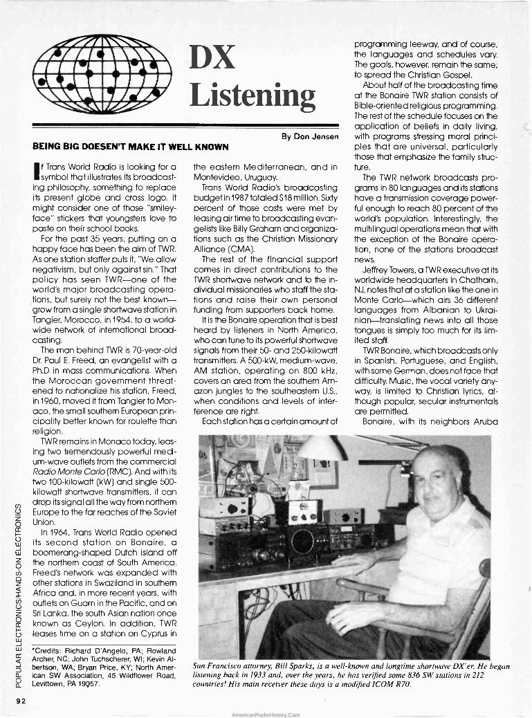
////\\\ /JZwca111\ /1111hrllAMILS MP.MI.1/// rii DX
Listening BEING BIG DOESEN'T MAKE IT WELL KNOWN
I f Trans World Radio is looking for a symbol that illustrates its broadcast-
ing philosophy, something to replace its present globe and cross logo. It
might consider one of those "smiley- face" stickers that youngsters love to paste on their school books.
For the past 35 years, putting on a happy face has been the aim of TWR.
As one station staffer puts it, "We allow negativism, but only against sin." That policy has seen TWR-one of the world's major broadcasting opera- tions, but surely not the best known- grow from a single shortwave station in Tangier, Morocco, in 1954, to a world- wide network of international broad- casting.
The man behind TWR is 70 -year -old Dr. Paul E. Freed, an evangelist with a Ph.D in mass communications. When the Moroccan government threat- ened to nationalize his station, Freed, in 1960, moved it from Tangier to Mon- aco, the small southern European prin- cipality better known for roulette than religion.
TWR remains in Monaco today, leas- ing two tremendously powerful medi- um -wave outlets from the commercial Radio Monte Carlo (RMC). And with its
two 100 -kilowatt (kW) and single 500 - kilowatt shortwave transmitters, it can drop its signal all the way from northern Europe to the far reaches of the Soviet Union.
In 1964, Trans World Radio opened its second station on Bonaire, a boomerang -shaped Dutch island off the northern coast of South America. Freed's network was expanded with other stations in Swaziland in southern Africa and, in more recent years, with outlets on Guam in the Pacific, and on Sri Lanka, the south Asian nation once known as Ceylon. In addition, TWR
leases time on a station on Cyprus in
`Credits: Richard D'Angelo, PA; Rowland Archer, NC; John Tuchscherer, WI; Kevin Al- bertson, WA; Bryan Price, KY; North Amer- ican SW Association, 45 Wildflower Road, Levittown, PA 19Q57.
By Don Jensen
the eastern Mediterranean, and in Montevideo, Uruguay.
Trans World Radio's broadcasting budget in 1987 totaled $18 million. Sixty percent of those costs were met by leasing air time to broadcasting evan- gelists like Billy Graham and organiza- tions such as the Christian Missionary Alliance (CMA).
The rest of the financial support comes in direct contributions to the TWR shortwave network and to the in- dividual missionaries who staff the sta- tions and raise their own personal funding from supporters back home.
It is the Bonaire operation that is best heard by listeners in North America, who can tune to its powerful shortwave signals from their 50- and 250 -kilowatt transmitters. A 500 -kW, medium -wave, AM station, operating on 800 kHz, covers an area from the southern Am- azon jungles to the southeastern U.S.,
when conditions and levels of inter- ference are right.
Each station has a certain amount of
programming leeway, and of course, the languages and schedules vary. The goals, however, remain the same; to spread the Christian Gospel.
About half of the broadcasting time at the Bonaire TWR station consists of Bible -oriented religious programming. The rest of the schedule focuses on the application of beliefs in daily living, with programs stressing moral princi- ples that are universal, particularly those that emphasize the family struc- ture.
The TWR network broadcasts pro- grams in 80 languages and its stations have a transmission coverage power- ful enough to reach 80 percent of the world's population. Interestingly, the multilingual operations mean that with the exception of the Bonaire opera- tion, none of the stations broadcast news.
Jeffrey Towers, a TWR executive at its
worldwide headquarters in Chatham, NJ, notes that at a station like the one in Monte Carlo-which airs 36 different languages from Albanian to Ukrai- nian-translating news into all those tongues is simply too much for its lim- ited staff.
TWR Bonaire, which broadcasts only in Spanish, Portuguese, and English, with some German, does not face that difficulty. Music, the vocal variety any- way, is limited to Christian lyrics, al- though popular, secular instrumentals are permitted.
Bonaire, with its neighbors Aruba
San Francisco attorney, Bill Sparks, is a well-known and longtime shortwave DX'er. He began listening back in 1933 and, over the years, he has verified some 836 SW stations in 212 countries! His main receiver these days is a modified 1COM R70.
92
AmericanRadioHistory.Com

and Curacao, form the A -B -C islands of the Netherlands Antilles. It is a pearl of an island, surrounded by clear wa- ters and coral reefs, with a population of just 10,000. It's a 21 -by -7 -mile isle where it's always summer, but a bit dull, except for the tourists who come to scuba dive or view the famed flamingo breeding grounds.
Tuning in the shortwave signals from TWR Bonaire is easy for listeners any- where in the U.S. and Canada. Chuck Roswell, the station's frequency coor- dinator, offers SWL's some times and frequencies to tune for TWR Bonaire's English programming to North Amer- ica.
Try 9,535 kHz from 0300 to 0430 UTC (until 0530 UTC Sundays and Mon- days) or 2300 until 0030 UTC (until 0130 UTC Sundays and Mondays). Or you can tune 11,815 or 15,345 kHz from 1 1 10
to 1257 UTC and 0710 to 0857 UTC (run- ning Sundays until 1332 and 0932 UTC, respectively).
TWR Bonaire is happy to send QSL- card replies in response to SWL recep- tion reports, provided that they cover a period of at least 15 minutes of listening and indicate in some detail the pro- gramming heard and the conditions of reception, Roswell notes. Listeners' letters may be sent to Trans World Ra- dio, Bonaire, Netherlands Antilles.
Feedback. Our first letter this month comes from Alex Wiecek of Mis- sissauga, Ontario, Canada. "In the shortwave spectrum," Alex writes, "I have encountered many interesting transmissions, but the ones I can't un- derstand the purpose of are those numbers stations.
For instance, last year I picked up a numbers station on 5,090 kHz at 2300 UTC with a woman reading a series of numbers in English. Now that station is
gone, but I have also heard another one on 4,050 kHz at around 0200 UTC. But that one reads numbers in German. And most recently, I received a trans- mission on 5,815 kHz at 0500 UTC with numbers in Spanish.
"Do you have any idea as to what the purpose of such transmissions are? I have heard that they are intended for espionage agents or smugglers. Is that true?"
Those are questions that have puzzled shortwave listeners for at least 25 years, for that's how long the so- called numbers stations have been around. Little is known for sure, but there is some evidence that numbers
ABBREVIATIONS
AM amplitude modulation (modulated)
CMA Christian Missionary Alliance
CST UTC + 6 hours DX long distance (over 1000
miles) DX'ing listening to shortwave
broadcasts EST UTC + 5 hours kHz kilohertz (1000 hertz or
cycles) kW kilowatt (1000 watts) MST UTC + 7 hours MW Medium wave PST UTC +8 hours QSL verification reply from
broadcaster RHC Radio Havana Cuba RMC Radio Monte Carlo RTVS Radiodifusion TV Senegal SRI Swiss Radio International SW Shortwave TWR Trans World Radio US United States USSR Russia (Union of Soviet
Socialist Republics) UTC/GMT Universal Time Code/
Greenwich Mean Time VON Voice of Nicaragua
read at dictation speed were used, at least several decades ago, to com- municate coded espionage mes- sages. At least one American con- victed of spying for the USSR in the 1960's so testified.
Without any great change in format over the years, they continue today- in an era of more sophisticated equip- ment and almost instantaneous, diffi- cult -to-monitor "burst" transmissions. Apparently they still have a purpose.
Direction finding and other research indicates that some transmissions have originated in EasfGermany and Cuba. But many of those numbers transmis- sions appear to be from U.S. govern- ment or military facilities, especially in the Washington, D.C. area and in Flori- da.
Extensive analysis of the numbers patterns by enthusiastic SWL's has shown that often the same "messages" are repeated again and again over long periods of time. That could sug- gest that many of them are just dummy transmissions with no communications purposes.
Why? It's a great mystery. Maybe some day we'll find out what they are all about. But I wouldn't count on it!
Down the Dial. What are you hear- ing? Do you have any questions or comments? This is a two-way street - a forum for the exchange of information
(Continued on page 106)
IF YOU HAVEN'T SEEN THE FREE MARK V ELECTRONICS CATALOG? HURRY UPI YOU'LL FIND EVERYTHING SUITABLE AND ESSENTIAL FOR FACTORIES, SCHOOLS, PROFESSIONALS AND ENTHUSIASTIC AMATEURS. OVER 60'S OF ASSEMBLES AND KITS WITH DIFFERENT LEVEL OF DIFFICULTY FOR KIT ASSEMBLY
BEGINNERS: 6WX2 STEREO MINI AMP., LIGHT CONT. ROLLER, BATTERY FLUORESCENT LIGHT DRIVER, AND MORE.
INTERMEDIATE: 4'/, D.P.M., 0-50V 3A POWER SUPPLY, 120W MOSFET POWER AMP.. VEDIO/ AUDIO SURROUND SOUND PROCESS- OR AND MORE.
PROFESSIONALS:1.2GHZ FREQ. COUNTER, 300W HQ AMP., 4680W 4 CHANNEL PRO. COLOR LIGHT CONTROLLER, AND MORE.
ANYWAY, THE SELECTION IS INCREDIBLE. THE VALUES ARE EVEN BETTER. AFTER ALL, ASK FOR YOUR OWN COPY TODAY AND YOU'LL HAVE MORE THAN A CATALOG, MORE THAN A REFERENCE.
YES, PLS SEND ME A COPY OF THE ALL -NEW FREE MARK V CATALOG.
NAME
ADDRESS
CITY STATE _ZIP _
MARK V ELECTRONICS, INC. 0019, E.SLAUSON AVE.,MONTEBELLO, CA 90640.
ORDER BY FAX: (213) 888-6868 SHOWROOM HOURS: (PACIFIC TIME, MON. -FRI. 9:30 to 5'.00 SAT. 10:00 to 5:00
INFORMATION: (213) 888-8988 CIRCLE 14 ON FREE INFORMATION CARD
r
CHEMICAL SOLUTIONS
FREE CHEMTRONICS CATALOG! Comprehensive new source for over 200 products used in electronic man- ufacturing and field service. Precision cleaning agents, flux removers, bulk solvents, circuit refrigerants, precision dusters, non -residual wipers, foam swabs, premoistened pads/swabs, antistatic compounds, conformal coat- ings, lubricants, adhesives, desolder- ing braids, rosin core solder and solder masking agents. Complete with tech- nical specifications and application guide.
Chemtronics Inc. C681 Old Willets Path Hauppauge. N.Y. 11788
516-582-3322
CIRCLE 20 ON FREE INFORMATION CARD 93
AmericanRadioHistory.Com

EZ -MATH (Continued from page 79)
the top horizontal row of the table and follow it on down until you locate the minuend 1A in the same vertical col- umn. Then follow that row over to the left until you locate the difference in
the left-hand column. The result is C.
Practice Problems. Here are a few
practice problems to ensure that you understand the use of octal and hex- adecimal numbers. 17. Convert 1 011 00011 01 0 to octal and hex. 18. Convert 70538 to binary. 19. Convert 2C8D16 to binary.
Answers to Practice Problems. 1.1+4+8+32=45 2. 2+8+32+64+256+1024+2048 = 3434
TABLE 6 -HEX ADDITION/SUBTRACTION
0 1 2 3 4 '5 6 7 8 9 ABCDEF 1 2 3 4 5 6 7 8 9 A BCD E F 10
2 3 4 5 6 7 8 9 AB CDE F 10 11
3 4 5 6 7 8 9 ABC DEF 10 11 12
4 5 6 7 8 9 A BCD E F 10 11 12 13
5 6 7 8 9 AB CDE F 10 11 12 13 14
6 7 8 9 ABC DEF 10 11 12 13 14 15
7 8 9 A BCD E F 10 11 12 13 14 15 16
8 9 AB CDE F 10 11 12 13 14 15 16 17
9 ABC DEF 10 11 12 13 14 15 16 17 18
A BCD E F 10 11 12 13 14 15 16 17 18 19 BCDE F 10 11 12 13 14 15 16 17 18 19 1A
C DE F 10 11 12 13 14 15 16 17 18 19 1A 1B
D E F 10 11 12 13 14 15 16 17 18 19 1A 1B 1C
E F 10 11 12 13 14 15 16 17 18 19 1A 1B 1C 1D
F 10 11 12 13 14 15 16 17 18 19 1A 1B 1C 1D 1E
3. 0.25+0.0625=0.3125 4. Starting with the number to convert:
Remainder 119/2 = 59 1 (LSB)
59/2 = 29 1
29/2 = 14 1
14/2 = 7 0 7/2 = 3 1
3/2 = 1 1
1/2 = 0 1 (MSB)
119,0=11101112
5 The answer is 64, because 26 = 64 6. The answer is 4095, because 212-1=4096-1=4095 7.14 bits B = 3.32Log10,000 B = 3.32(4) =13.28 And the next highest integer is 14.
8. 0001 0000 1001 0010 01 kc011
9. 36458 10. 110011101
11 100000.00 12. 10001111
13. 11010.101
14. 100110110110
15. 0.00101 16.111
17, 54328, BIAH 18. 111000101011
19.0010110010001101
HOT BOOKS FOR HOBBYISTS REMOTECONIROLLEO
ROBOT FOR UNDER $300
26177 -BUILD A REMOTE. CONTROLLED ROBOT FOR
UNDER 6300 59.95. Fool-
proof instructions for putting together your own full-size robot.
- 62 HOME REMOTE CONTROL
AOrOMA11ON PROTECTS
2735T-62 HOME REMOTE
CONTROL ANO AUTOMATION
PROJECTS $12.95. A fas-
cinating collection of projects to make your Ide safer. more convenient, and more tun.
BUILD A REMOTE -CONTROLLED ROBOT FOR UNDER $300
26171 -If you're fascinated by the home robots in- creasingly available on today's market .... but are stopped by their price tags .... here's your solution. Build your own home robot -and a full size unit at that -for less than $300. No advanced electronics or computer skills are needed to put together"Ouestor", a robot butler especially designed to be both affordable and easy -to - build. -Order your copy for $9.95 plus $2.00 shipping.
62 HOME REMOTE CONTROL AND AUTOMATION PROJECTS
2735T -A device that automatically dims the lights when you turn on your stereo ... an automatic guest greeter ... sensors that keep your air-conditioning at ideal levels automatically ... voice -operated transmitters, door and window controllers and more. Complete instruc- tions, wiring diagrams, and show -how illustrations for each device. $12.95 plus $3.00 shipping.
Send 40 -page catalog -FREE with order. L] I've included $2.00 Send catalog and coupon good for $2.00 on first order.
Electronic Technology Today P.O. Box 240
Massapequa Park, NY 11762
CIRCUIT CIRCUS (Continued from page 83)
PARTS LIST FOR THE IR INTERCEPTOR
SEMICONDUCTORS U-LM324 quad op -amp, integrated
circuit QI -Infrared phototransistor (part of
Radio Shack 276-142 emitter/detector pair, or similar)
RESISTORS (All fixed resistors are 1/4 -watt, 5%
units.) R1 -100,000 -ohm R2, R6 -2200 -ohm R3, R7 -220,000 -ohm R4, R5 -4700 -ohm R8 -270 -ohm R9 -2500 -ohm potentiometer
CAPACITORS CI, C2 -0.1-µF, 100-WVDC, ceramic
disc C3, C4-47 µF, 16-WVDC, electrolytic C5 -220-µF 16-WVDC, electrolytic
ADDITIONAL PARTS AND MATERIALS BI -9 -volt transistor -radio battery JI -Headphone jack S1-SPST toggle switch Printed -circuit or perfboard materials.
enclosure, IC sockets, battery clips, knob, wire, solder, hardware, etc.
case with the phototransistor (Q1) cen- tered at the focal point of the flash- light's bulb location. No matter what scheme is used in building the circuit, the phototransistor must be shielded from ambient light.
Another way to accomplish that end is to mount the phototransistor in one end of a small opaque tube with the cell facing outward -giving Q1 a tun- nel -vision view of the outside world. That arrangement works somewhat like a rifle scope in aiming at and se- lecting the incoming light that's di- rectly in front of the tube.
To play electronic hide-and-seek, conceal the IR transmitter so that IR
radiation is unrestricted in a direction that can be seen with the hunter's Inter- ceptor. Keep the location of the IR
transmitter away from brightly lit areas. If possible, place it in a dark or shad- owy area. Not only will the location be oblivious to the hunter, its operating range will be at its greatest due to the differential in IR and the ambient -light levels.
Alas, we've filled our perfboard for this month, but be sure to tune in next month when we'll have another batch of fun and educational circuits for you to examine. Until then have fun.
94
AmericanRadioHistory.Com

TRAINING AIDS (Continued from page 46)
Ill achieve improved performance. A large selection is offered by ISI in their 101 Utilities for dBase Ill Plus. Those pro- grams will save keystrokes, time, and menu steps; and eliminate repetitive operations by automating frequently used dBase Ill Plus commands. Those routines have a variety of uses. They can save the user the trouble of re- membering the syntax of dBase com- mands, add math functions to dBase, provide a menu -driven approach to manipulating database files, add useful utilities to deal with text files, and offer additional facilities not thought to be available from dBase Ill Plus.
The 101 utilities are provided on two non -copy -protected floppy disks, which should be copied onto back-up floppy disks, and installed on a hard -
CURSOR <- -A Cher:
fielt: lime CS
UP DOWN
beed 1
t.º.: '!R" r,, Nelº:
R[
Heir RecoN' 'O
Oiliest Esc
Set Opt..'Moue
COSDf KEENED START END- ROOM------ - N -- 60c® Rrlla.em Bbelfetla 11110 IMO Garden Rom Joke 0E,11417 CRIB UN MirY Court IES Anni.eee.ry
12,11487 13R11 IMO º_,_ Greve EBB . Ll Scheel Elks Club
SYphe.y Seery Madigan Rlw.ie Go -Travel
01,z2,07 1E811 INN Junele hou 1E0 Bee., 03,0I4,7 1411 EROS Garden Rau 775 Banquet 13,1X _ , The R,e. Gamed e5,0,,
04,114 Tie is the º[RIEZ seen.. The selection b., I.
07,25, ns tlo cod. The record .umber
leans seAun_J in the States Bee
1613313 31111 031E11111M-
Ol_ _X e11í liar.
This is an example of how on-line help screens pop up to provide information on any screen (the Browse Screen).
disk drive should you have one in your computer.
The concise, compact manual is in- valuable. It introduces the newcomer to database program work. In it, a sim- ple program is illustrated that places a small, double -rule box on the screen with the time indicated. The manual instructs the user in a step-by-step fash- ion as he writes the program in a dBase edit mode-it's a real confidence builder.
The utilities are broken down into seven categorical groups and a mis- cellaneous group of 34 utilities. No one user can fully expect to make full use of all 101 utilities, but a good number will find practical application. This re- viewer used the RATING.PRG program (in dBase the .PRG extension indicates dBase programs) to rate his computer. (Interesting; he needs a new mother- board, but he knew that anyway.)
Other interesting programs that got used almost immediately upon review
were ROLDXPRN.PRG which prints Rolodex cards, LOAN.PRG an internal selectable options lets you compare two loans or analyze a loan, N!.PRG to compute factorals up to N = 34, ROOT.PRG which calculates the Nth root of a number, and ALARM.PRG an all-purpose reminder capable of working with dates and memos. You can triple the power of dBase by let- ting it draw bar and X vs. Y graphs, adding math functions such as sine, cosine, and tangent, and adding util- ities to manipulate text files. Consider- ing that there are 101 programs, this paragraph best end here.
PRINTING EASELS
Labe .1Xth: 35 Lake heeRht: S
Left .er91.: e
Lin. Mt.«, 1.be1f. 1
Space. bst.wee I.be.: e
Lebel. .o e. º.n: 1
On Ohs Opt ion. .e nu
u a
It her choose hu Pive preset Inca 1, bel
format's, o create one of y
p
As you press the enter Ley IC 1
you we!I seethe predefined l .hels ices.
Here's one of the help screens. You
request them from one of the submenus.
Where They're At! Individual Train- ing for dBase Ill Plus and 101 Utilities for dBase Ill Plus are both available from Individual Software, Inc.,125 Shoreway Drive, Suite 100, San Carlos, CA 94070-2704 for $69.95 each. Tele- phone orders can be placed by call- ing 800/331-3313; in California call 415/598-8855. For more information on the packages, contact the company directly, or circle 69 on the Free Infor- mation Card. By the time this article is
in print the training course for dBase IV will be available. The training course for dBase III Plus and the 101 utilities are compatible with the advanced form of dBase.
FREE! New Catalog of Hard -To -Find Precision Tools
Jensen's new catalog is jam-packed with more than 2,000 quality items. Your single source for hard -to -find precision tools used by electronic technicians, scientists, engineers, schools, instrument mechanics, laboratories and government agen- cies. This popular catalog also con- tains Jensen's world-famous line of more than 40 tool kits. Call or write for your free copy today!
JENSEN? 7815 S. 46th Street Phoenix, AZ 85044
TOOLS INC. (602) 968-6231
CIRCLE 15 ON FREE INFORMATION CARD
CIRCLE 6 ON FREE INFORMATION CARD 95
AmericanRadioHistory.Com
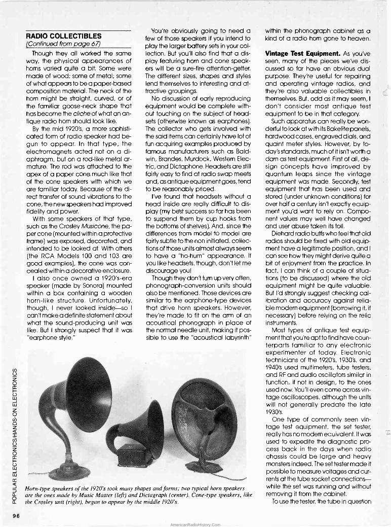
RADIO COLLECTIBLES (Continued from page 67)
Though they all worked the same way, the physical appearances of horns varied quite a bit. Some were made of wood; some of metal; some of what appears to be a paper -based composition material. The neck of the horn might be straight, curved, or of the familiar goose -neck shape that has become the cliche of what an an- tique radio horn should look like.
By the mid 1920's, a more sophisti- cated form of radio speaker had be- gun to appear. In that type, the electromagnets acted not on a di- aphragm, but on a rod -like metal ar- mature. The rod was attached to the apex of a paper cone much like that of the cone speakers with which we are familiar today. Because of the di- rect transfer of sound vibrations to the cone, the new speakers had improved fidelity and power.
With some speakers of that type, such as the Crosley Musicone, the pa- per cone (mounted within a protective frame) was exposed, decorated, and intended to be looked at. With others (the RCA Models 100 and 103 are good examples), the cone was con- cealed within a decorative enclosure.
I also once owned a 1920's -era speaker (made by Sonora) mounted within a box containing a wooden horn -like structure. Unfortunately, though, I never looked inside-so I
can't make a definite statement about what the sound -producing unit was like. But I strongly suspect that it was "earphone style."
You're obviously going to need a few of those speakers if you intend to play the larger battery sets in your col- lection. But you'll also find that a dis- play featuring horn and cone speak- ers will be a sure-fire attention -getter. The different sizes, shapes and styles lend themselves to interesting and at- tractive groupings.
No discussion of early reproducing equipment would be complete with- out touching on the subject of head- sets (otherwise known as earphones). The collector who gets involved with the said items can certainly have lot of fun acquiring examples produced by famous manufacturers such as Bald- win, Brandes, Murdock, Western Elec- tric, and Dictaphone. Headsets are still
fairly easy to find at radio swap meets and, as antique equipment goes, tend to be reasonably priced.
I've found that headsets without a head inside are really difficult to dis- play (my best success so far has been to suspend them by cup hooks from the bottoms of shelves). And, since the differences from model to model are fairly subtle to the non initiated, collec- tions of those units almost always seem to have a "ho -hum" appearance. If
you like headsets, though, don't let me discourage you!
Though they don't turn up very offen, phonograph -conversion units should also be mentioned. Those devices are similar to the earphone -type devices that drive horn speakers. However, they're made to fit on the arm of an acoustical phonograph in place of the normal needle unit, making it pos- sible to use the "acoustical labyrinth"
Horn -type speakers of the 1920's took many shapes and forms; two typical horn speakers are the ones made by Music Master (left) and Dictagraph (center). Cone -type speakers, like the Crosley unit (right), began to appear by the middle 1920's.
within the phonograph cabinet as a kind of a radio horn gone to heaven.
Vintage Test Equipment. As you've seen, many of the pieces we've dis- cussed so far have an obvious dual purpose. They're useful for repairing and operating vintage radios, and they're also valuable collectibles in themselves. But, odd as it may seem, I
don't consider most antique test equipment to be in that category.
Such apparatus can really be won- derful to look at with its Bakelite panels, hardwood cases, engraved dials, and quaint meter styles. However, by to- day's standards, much of it isn't worth a darn as test equipment. First of all, de- sign concepts have improved by quantum leaps since the vintage equipment was made. Secondly, test equipment that has been used and stored (under unknown conditions) for over half a century isn't exactly equip- ment you'd want to rely on. Compo- nent values may well have changed and user abuse taken its toll.
Diehard radio buffs who feel that old radios should be fixed with old equip- ment have a legitimate position, and I
can see how they might derive quite a bit of enjoyment from the practice. In
fact, I can think of a couple of situa- tions (to be discussed) where the old equipment might be quite valuable. But I'd strongly suggest checking cal- ibration and accuracy against relia- ble modern equipment (borrowing it, if necessary) before relying on the relic instruments.
Most types of antique test equip- ment that you're apt to find have coun- terparts familiar to any electronic experimenter of today. Electronic technicians of the 1920's, 1930's, and 1940's used multimeters, tube testers, and RF and audio oscillators similar in function, if not in design, to the ones used now. You'll even come across vin- tage oscilloscopes, although the units will not generally predate the late 1930's.
One type of commonly seen vin- tage test equipment, the set tester, really has no modern equivalent. It was used to expedite the diagnostic pro- cess back in the days when radio chassis could be large and heavy monsters indeed. The set tester made it possible to measure voltages and cur- rents at the tube socket connections- while the set was running and without removing it from the cabinet.
To use the tester, the tube in question
96
AmericanRadioHistory.Com
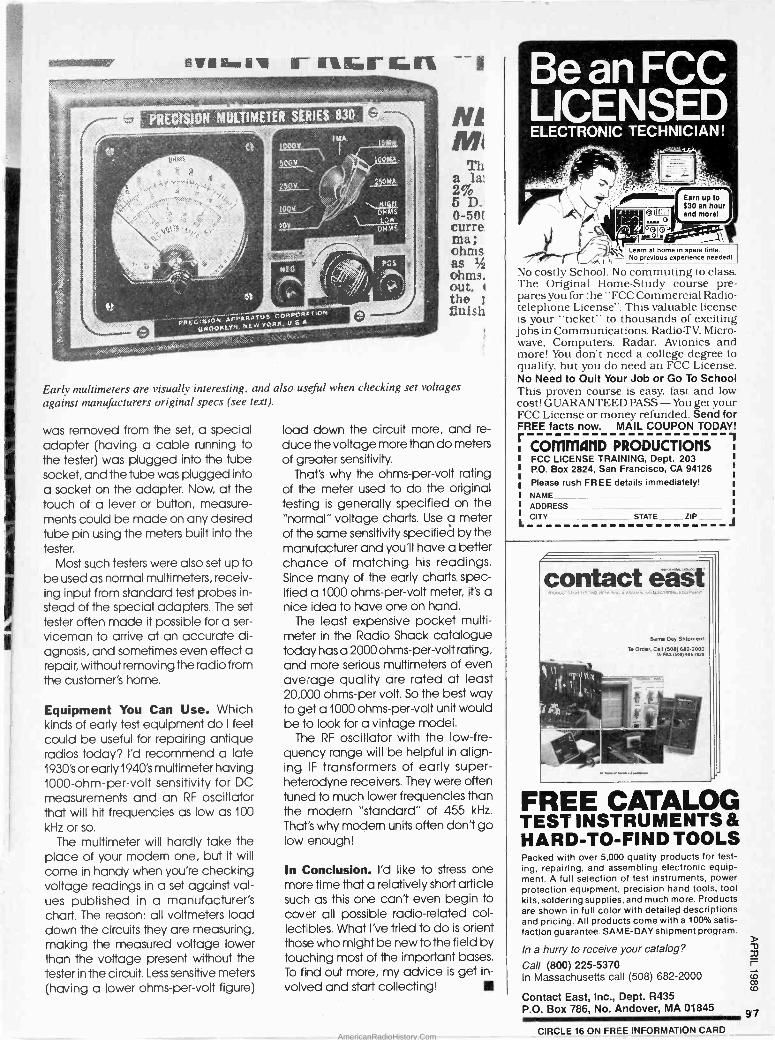
.lia.e r nGrGn PRECISION MULTIMETER SERIES 830
..._._... .... R,ttr:4.N . ._.........,,..a+`-Afit.aRATr3KCö
PRtt.._s kr:wY.TNks;.itSA t,iHC7OKi.YFi. ...... ,:,,..,.;.,._ :.
Ni! +1
Th a la! 2ro 5 D. b -5Q( curre II?1a; ohms as 14;
ohms. out. 1
the finish
Early multimeters are visually interesting, and also useful when checking set voltages
against manufacturers original specs (see text).
was removed from the set, a special adapter (having a cable running to the tester) was plugged into the tube socket, and the tube was plugged into a socket on the adapter. Now, at the touch of a lever or button, measure- ments could be made on any desired tube pin using the meters built into the tester.
Most such testers were also set up to be used as normal multimeters, receiv- ing input from standard test probes in- stead of the special adapters. The set tester often made it possible for a ser- viceman to arrive at an accurate di- agnosis, and sometimes even effect a repair, without removing the radio from the customer's home.
Equipment You Can Use. Which kinds of early test equipment do I feel could be useful for repairing antique radios today? I'd recommend a late 1930's or early 1940's multimeter having 1000 -ohm -per -volt sensitivity for DC measurements and an RF oscillator that will hit frequencies as low as 100
kHz or so.
The multimeter will hardly take the place of your modern one, but it will come in handy when you're checking voltage readings in a set against val- ues published in a manufacturer's chart. The reason: all voltmeters load down the circuits they are measuring, making the measured voltage lower than the voltage present without the tester in the circuit. Less sensitive meters (having a lower ohms -per -volt figure)
load down the circuit more, and re-
duce the voltage more than do meters of greater sensitivity.
That's why the ohms -per -volt rating of the meter used to do the original testing is generally specified on the "normal" voltage charts. Use a meter of the same sensitivity specified by the manufacturer and you'll have a better chance of matching his readings. Since many of the early charts spec- ified a 1000 ohms -per -volt meter, Ft's a nice idea to have one on hand.
The least expensive pocket multi - meter in the Radio Shack catalogue today has a 2000 ohms -per -volt rating, and more serious multimeters of even average quality are rated at least 20,000 ohms -per volt. So the best way to get a 1000 ohms -per -volt unit would be to look for a vintage model.
The RF oscillator with the low -fre- quency range will be helpful in align- ing IF transformers of early super- heterodyne receivers. They were often tuned to much lower frequencies than the modern "standard" of 455 kHz.
That's why modern units offen don't go low enough!
In Conclusion. I'd like to stress one more time that a relatively short article such as this one can't even begin to cover all possible radio -related col- lectibles. What I've tried to do is orient those who might be new to the field by touching most of the important bases. To find out more, my advice is get in-
volved and start collecting!
Be an FCC LICENSED ELECTRONIC TECHNICIAN!
',r1.2,:ie1/4
pollllll ..a.o
Earn up to E30 an hour and more!
Ow-
Learn at home in spare time. No previous experience needed!
No costly School. No commuting to class. The Original Home -Study course pre- pares you for the "FCC Commercial Radio- telephone License". This valuable license is your "ticket" to thousands of exciting jobs in Communications, Radio-TV, Micro- wave, Computers, Radar, Avionics and more! You don't need a college degree to qualify, but you do need an FCC License. No Need to Quit Your Job or Go To School This proven course is easy, fast and low cost! GUARANTEED PASS - You get your FCC License or money refunded. Send for FREE facts now. MAIL COUPON TODAY!
7 commanu PRODUCTIONS FCC LICENSE TRAINING, Dept. 203 P.O. Box 2824, San Francisco, CA 94126
Please rush FREE details immediately! NAME ADDRESS CITY STATE ZIP
FREE CATALOG TEST INSTRUMENTS & HARD -TO -FIND TOOLS Packed with over 5,000 quality products for test- ing, repairing, and assembling electronic equip- ment. A full selection of test instruments, power protection equipment, precision hand tools, tool kits, soldering supplies, and much more. Products are shown in full color with detailed descriptions and pricing. All products come with a 100% satis- faction guarantee. SAME -DAY shipment program.
In a hurry to receive your catalog? -0
Call (800) 225-5370 F In Massachusetts call (508) 682-2000
co to
Contact East, Inc., Dept. R435 P.O. Box 786, No. Andover, MA 01845 97
CIRCLE 16 ON FREE INFORMATION CARD AmericanRadioHistory.Com

ANTIQUE RADIO (Continued from page 81)
oscillator coil; another selects the matching antenna -padding capaci- tor; and the third lights an indicator lamp on the front panel correspond- ing to the selected station.
And that about sums up what I've been able to learn about Larry Lovell's "Mystery Control." At some future time, maybe I'll have an opportunity to dis- cuss the associated radios, but now I'd like to recognize the many readers who contributed information to this column!
Our Contributors. W.J. Brown (Thomaston, ME) sent schematic di- agrams and offered some personal memories of a "Mystery Control" radio that his family purchased in 1939. He kept the set going until about five years ago, when a tragedy occurred: the chassis was accidentally dropped while the electrolytic capacitors and dial cord were being replaced.
Robert E. Chapman (Ventura, CA), who was an active service technician (Minneapolis -St. Paul area) in the late 1930's, worked on several of those radi- os. He considered the design of the Philco set to be very advanced for its
time, and contributed several interest- ing technical details to the story you've just read.
Frank Krantz, who retired after 54 years as a radio repairman, now re- pairs old sets as a hobby. After identify- ing the control unit for us, he included some interesting information on Philco model and part numbers. For one thing, Frank confirmed an earlier re- mark of mine about the model num- bers. He agrees that prefixes were used to indicate year of manufacture (for example, a model 37-620 was made in 1937), but says that the system was only used from 1937-1942.
Warren Baker (Albany, NY) tells us that the telephone -type dial on the control unit may have evolved from a similar station -selector dial on an ear- lier model. The earlier dial was mounted directly on the cabinet, and was not part of a remote -control sys- tem.
Ray Shetrone (Fort Myers, FL) also remembers the control unit well. His in- terest in radio dates from the early 1930's, when his dad was operating a radio and appliance repair shop in Baltimore, Ohio (the shop is still operat- ing today under the family name). Ray
This rear view of the dial assembly shows the gear train, governor, and some of the puls- ing contacts.
speaks ruefully of the many "golden oldies" he and his dad dismantled for parts over 50 years ago!
J. Beck (Zion, IL) sent along an infor- mative article on the Mystery Control system (from a 1939 Lincoln Engineer- ing School publication). He also identi- fied some of the Philco radio models that used that control unit and says that he picked up one of them (a Model 39-55) at a flea market, intending to strip it for parts. When he realized what he had, however, he canceled the tear -down and located a control unit for the radio. Restoration is now pro- ceeding.
I'm also indebted to the following people for technical literature on the Philco Mystery Control system: Alfonso E. Patron sent Philco service notes covering the Models 39-55 and 39-1 16 all the way from Mazatlan, Mexico.
Larry Kenan (Westlake Village, CA) contributed a very informative article he wrote in 1984 for Radio News, the journal of the Arizona Antique Radio Club. Larry credits Rider Perpetual Troubleshooter's Manual Volume 9 (Philco Models 39-55 and 39-1 16) for much of his information.
And Scott Holderman (Sherman Oaks, CA) sent along a write up on the Mystery Control taken from a special supplement to Rider Volume 9.
Finally, I'd like to credit the unsung heros of this article: the people who wrote Larry Lovell directly with informa- tion about the mystery control. Larry mentioned that he had received let- ters from several retired radio ser-
vicemen, and other antique -radio enthusiasts. Just as I sat down to write this, I realized that I should have con- tacted him to get their names. But my deadline looms and I have to get the column in the mail. Many thanks, guys, and sorry, but you'll have to be anony- mous for now!
Good-bye until next month, when we'll open more mail and discuss, among other things, the many reader answers to my other Philco mystery (the highly chromed device, resembling a miniature speaker, shown in the De- cember 1988 column). And be sure to keep your comments and questions coming. As you can see, the input I get from readers is a real enhancement to this column.
Almost everything I receive is even- tually credited, or discussed, in print. Regrettably, however, it's almost im- possible for me to respond to letters personally. Time just doesn't permit it!
Send your letters to Antique Radio, Popular Electronics, 500-B Bi -County Blvd., Farmingdale, NY 11735.
98
AmericanRadioHistory.Com

Enter A World Of Excitement with a Subscription to
Popular Get the latest electronic technology
and information monthly! Now you can subscribe to the magazine that plugs you into. the exciting world of electronics. With every issue of Popular Electronics you'll find a wide variety of electronics projects you can build and enjoy.
Popular Electronics brings you informative new product and literature listings, feature articles on test equipment and tools-all designed to keep you tuned in to the latest devel- opments in electronics. So if you love to build fascinating electronics, just fill out the subscription form below to sub- scribe -to Popular Electronics ...It's a power -house of fun for the electronics enthusiast.
EXCITING MONTHLY FEATURES UKE: CONSTRUCTION-Building projects from crystal sets to electronic roulette FEATURES-Educational training on digital electronics, Ohm's Law, Antennas, Communications, Antique Radio, Simplified Theory HANDS-ON-REPORTS-User test comments on new and unusual consumer products SPECIAL COLUMNS-Think Tank, Circuit Circus, Com- puter Bits, DX Listening, Antique Radio, Amateur, Scanner Scene
PLUS: ALL OUR GREAT DEPARTMENTS! You'll get 12 exciting and informative issues of Popular Elec- tronics for only $18.95. That's a savings of $11.05 off the regular single copy price. Subscribe to Popular Electronics today! Just fill out the subscription order form below.
r
44744
J rPlor.atr.nrdpv* COMBINED
WITH
THE MAGAZINE FOR THE ELECTRONICS ACTIVIST!
Expand your hearing range and explore the exciting world of ultrasonic sound!
Update your camp or work telephone system!
Read those low -Value resistors on any OMM!
E,ra-nn(I d-'. ui itë.ai a'.
t? ecetvee A classic design updated for today's technology!
Put those useful IC's to work for you!
3 New FacICards This Issue
l'EBRUAfiY 1989
Build The Lightning Bulb
Spectacular effects, easy conatrueIIOn, and a budget 'ACC make this a Winner of a proper
Antique Radio An in-depth look at an old-time circuit!
FOR FASTER SERVICE CALL TODAY
1-800-435-0715 IN ILLINOIS 1-800-892-0753 (7:30AM-8:30PM)
EASTERN STANDARD TIME '
Popular Electronics SUBSCRIPTION ORDER FORM P.O. Box 338, Mt. Morris IL. 61054
YES! I want to subscribe to Popular Electronics for 1 Full year (12 Issues) for only $18.95. That's a savings of $11.05 off the newstand price.
Payment Enclosed Bill me later Please charge my: Visa Mastercard
Acct # I I I I
Signature Exp. Date
PLEASE PRINT BELOW:
NAME
ADDRESS
CITY STATE ZIP
Allow 6 to 8 weeks for delivery of first issue. U.S. Funds only. In Canada add $5.00 Postage. All Other Foreign add $7.50 Postage.
99 AmericanRadioHistory.Com
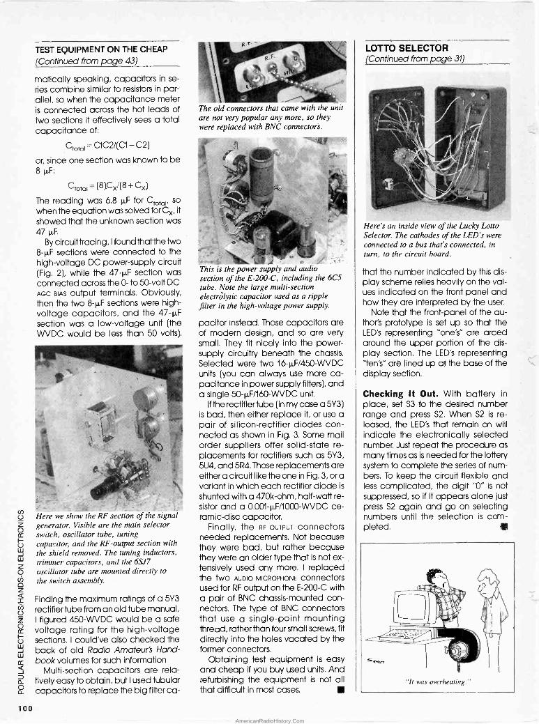
TEST EQUIPMENT ON THE CHEAP
(Continued from page 43)
matically speaking, capacitors in se-
ries combine similar to resistors in par- allel, so when the capacitance meter is connected across the hot leads of two sections it effectively sees a total capacitance of:
°total = C1C2/(C1 + C2)
or, since one section was known to be 8 µF:
°total = (8)Cx/(8 + Cx)
The reading was 6.8 µF for °total, so
when the equation was solved for Cx, it
showed that the unknown section was 47 µF.
By circuit tracing, I found that the two 8-µF sections were connected to the high -voltage DC power -supply circuit (Fig. 2), while the 47-µF section was connected across the 0- to 50 -volt DC AGC BIAS output terminals. Obviously, then the two 8-µF sections were high - voltage capacitors, and the 47-µF section was a low -voltage unit (the WVDC would be less than 50 volts).
Here we show the RF section of the signal generator. Visible are the main selector switch, oscillator tube, tuning capacitor, and the RF -output section with the shield removed. The tuning inductors, trimmer capacitors, and the 6SJ7 oscillator tube are mounted directly to the switch assembly.
Finding the maximum ratings of a 5Y3 rectifier tube from an old tube manual, I figured 450-WVDC would be a safe voltage rating for the high -voltage sections. I could've also checked the back of old Radio Amateur's Hand- book volumes for such information.
Multi -section capacitors are rela- tively easy to obtain, but I used tubular capacitors to replace the big filter ca -
The old connectors that came with the unit are not very popular any more, so they were replaced with BNC connectors.
This is the power supply and audio section of the E -200-C, including the 6C5 tube. Note the large multi -section electrolytic capacitor used as a ripple filter in the high -voltage power supply.
pacitor instead. Those capacitors are of modern design, and so are very small. They fit nicely into the power - supply circuitry beneath the chassis. Selected were two 16-µF/450-WVDC units (you can always use more ca- pacitance in power supply filters), and a single 50-µF/160-WVDC unit.
If the rectifier tube (in my case a 5Y3) is bad, then either replace it, or use a pair of silicon -rectifier diodes con- nected as shown in Fig. 3. Some mail order suppliers offer solid-state re- placements for rectifiers such as 5Y3, 5U4, and 5R4. Those replacements are either a circuit like the one in Fig. 3, or a variant in which each rectifier diode is
shunted with a 470k -ohm, half -watt re- sistor and a 0.001-µF/1000-WVDC ce- ramic -disc capacitor.
Finally, the RF OUTPUT connectors needed replacements. Not because they were bad, but rather because they were an older type that is not ex- tensively used any more. I replaced the two AUDIO MICROPHONE connectors used for RF output on the E -200-C with a pair of BNC chassis -mounted con- nectors. The type of BNC connectors that use a single -point mounting thread, rather than four small screws, fit directly into the holes vacated by the former connectors.
Obtaining test equipment is easy and cheap if you buy used units. And refurbishing the equipment is not all that difficult in most cases.
LOTTO SELECTOR (Continued from page 31)
Here's an inside view of the Lucky Lotto Selector. The cathodes of the LED's were connected to a bus that's connected, in turn, to the circuit board.
that the number indicated by this dis- play scheme relies heavily on the val- ues indicated on the front panel and how they are interpreted by the user.
Note that the front -panel of the au- thor's prototype is set up so that the LED's representing "one's" are arced around the upper portion of the dis- play section. The LED's representing 'ten's" are lined up at the base of the display section.
Checking It Out. With battery in place, set S3 to the desired number range and press S2. When S2 is re- leased, the LED's that remain on will indicate the electronically selected number. Just repeat the procedure as many times as is needed for the lottery system to complete the series of num- bers. To keep the circuit flexible and less complicated, the digit "0" is not suppressed, so if it appears alone just press S2 again and go on selecting numbers until the selection is com- pleted.
100 AmericanRadioHistory.Com
SCANNER SCENE (Continued from page 88)
We don't have any definite informa- tion, but the Registry of U.S. Govern- ment Radio Frequencies does show that the U.S. Treasury Department is a user of that particular frequency at its
training center in Georgia. They may well be using it elsewhere, too. Monitors in various areas might wish to check it out to see what it might have to offer. Let us know what you find and we'll pass the information along.
Several issues ago we mentioned that several programmable VHF -FM marine transceivers could be set up to operate on many frequencies un- authorized for maritime purposes. We also noted that sometimes doing so caused interference to stations in other radio services who happened to be licensed to operate on those frequen- cies. Well, it looks as though the FCC has decided to prohibit the manufac- ture, sale, and use of VHF -FM marine transceivers that are capable of being programmed outside of the autho- rized band.
We are always looking to hear from our readers with questions, loggings, news clippings, and other scanner -re- lated material that might be of interest. Write to Scanner Scene, Popular Electronics, 500-B Bi -County Blvd., Farmingdale, NY 11735.
Scanner Report. AOR, Ltd. has come up with yet another of their interesting and unusual scanners. This time, it's a miniature mobile unit -the AR -160 - that features frequency -synthesized keyboard control.
This is a case where the word "mini- ature" really applies. The AR -160 is very small; an inch and a half high, less than five inches wide, just over six inches deep. Weighing in at just over 26 ounces, the unit can be mounted in almost any vehicle, even those with the smallest available area to devote to scanner placement.
Yet, thanks to the latest in electronic hybridization and integration tech- niques, AOR has fit lots of good things inside -such as frequency coverage of 29 to 52 MHz, 136 to 174 MHz, and 436 to 512 MHz.
The most often used operating con- trols are on the front panel of the AR -160, but space is saved by placing the twenty programming keys that ac- cess the on -board microcomputer on top of the case. A row of sixteen LED's
provide a bright notification of which channel the unit is monitoring. And a battery retains memory so the AR -160 doesn't develop instant programming "amnesia" in the event of a momen- tary power loss.
The AR -160, despite its tiny size, offers specs that match or clobber those of other mobile scanners of larger girth and carrying a heftier price tag. For $189 (suggested retail price), you get
the scanner, a fused DC -power cable, telescoping whip antenna, mobile mounting bracket, and an AC -power supply.
For more information on the AOR Model AR -160, write to Ace Communi- cations (Monitor Division), 10707 East 106th Street, Indianapolis, IN 46256; or call toll -free (outside of Indiana) 800/445-7717, or (in Indiana) 317/842-7115.
Popular Electronics
REPRINT BOOKSTORE
SPt Special Projects #1 (Winter 1980) SP4 Special Projects #4 (Summer 1982) SP5 Special Projects #5 (Winter 1983) SP6 Special Projects #6 (Spring 1983) SP7 Special Projects #7 (Summer 1983) SP8 Special Projects #8 (Fall 1983)
$6.00 $6.00 $6.00 $6.00 $6.00 $6.00
E 106 Radio -Electronics back issues (1986)..$3.75 Write in issues desired
E 105 Radio -Electronics back issues (1985) .. $4.25 (Jan. 85 not available) Write in issues desired
E 104 Radio -Electronics back issues (1984) .. $5.25 SP9 Special Projects #9 (Winter 1984) $6.00 (December 1984 issue is not available) SPI0 Special Projects #10 (Spring 1984) $6.00 Write in issues desired 111 Hands -On Electronics #1 $5.00 103 Radio -Electronics back issues (1983)....$5.50 112 Hands -On Electronics #2 $5.00 (Jan., Feb., May are not available) 113 Hands -On Electronics #3 $5.00 Write in issues desired 114 Hands -On Electronics #4 $5.00 102 Radio -Electronics back issues (1982). $5.75 115 Hands -On Electronics #5 $5.00 (Jan., Feb.) is not available) 115A Hands -On Electronics #6 $4.50 Write in issues desired 116A Hands -On Electronics (Jan -Feb '86) $4.50 153 Etch your own PC boards $3.00 1168 Hands -On Electronics (Mar/Apr '86) $4.50 154 How to Repair VCR's $3.50 116C Hands -On Electronics (May/Jun '86) $4.50 155 IBM Typewriter to Computer $3.00 116D Hands -On Electronics (Jul/Aug '86) .. $4.50 125 Radio -Electronics Annual 1985 $5.95 116E Hands -On Electronics (Sep/Oct '86) .. $4.50 126 Radio -Electronics Annual 1986 $4:95 1161( Hands -On Electronics (Nov '86) $4.00 156 How to Make PC Boards $2.00 116L Hands -On Electronics (Dec '86) $4.00 157 All About Kits $2.00 117 Hands -On Electronics 158 Electro Importing Co. Catalog (1918) $5.95
(1987 back issues) $3.75 159 Low Frequency Receiving Techniques Write in issues desired Building and using VLF Antennas $6.00
118 Hands -On Electronics 160 New Ideas - 42 Circuits $3.50 (1988 back issues) $3.50 161 Descrambling (Feb., 1984) $3.00 Write in issues desired 162 Build Your Own Satellite TV Receiver $7.00
150 TV Descrambler $3.00 163 Receiving Satellite TV $7.00 EH87 Experimenters Handbook $3.95 164 Modern Electrics (April, 1908) $3.00 152 8 -Ball Satellite TV Antenna $5.00 165 How to Repair CD Disc Players $5.00 108 Radio -Electronics (1988 back issues) .. $3.00 166 Collected Works of Mohammed Ullyses Fips
Write in issues desired (62 pages, April Fools Collection) $7.50 107 Radio -Electronics back issues (1987) $3.25 167 Designing With IC's $4.00
To order any of the items indicated above, check off the ones you want. Complete the order form below, include your payment, check or money order (DO NOT SEND CASH), and mail to Popular Electronics, Reprint De- partment, P.O. Box 4079, Farmingdale, NY 11735. Please allow 4-6 weeks for delivery.
If you need a copy of an article that is in an issue we
indicate is unavailable you can order it directly from us.
We charge 50e per page. Indicate the issue (month &
year), pages and article desired. Include payment in
full, plus shipping and handling charge. Make checks payable to Gernsback Publications, Inc.
ARTICLE
PAGES MONTH YEAR
TOTAL PAGES @50C each TOTAL PRICE
t.
$0.01 to $5.00 $1.25 $5.01 to 10.00 $2.00 $10.01 to $20.00 $3.00 $20.01 to $30.00 $4.00 Total price of merchandise
MAIL TO: Popular Electronics Reprint Bookstore, P.O. Box 4079, Farmingdale NY 11735
SHIPPING CHARGES IN USA & CANADA $30.01 to $40.00 .
$40.01 to $50.00 .
$50.01 and above .
$5.00 $6.00 $7.50
All payments must be in U.S. funds
SORRY - We only ship to
USA & Canna
Sales Tax (New York State Residents only) $ Shipping Charge (see chart)
Name
Address
City State Zip
Total Enclosed $
P4-89 J
101
AmericanRadioHistory.Com

IRS (Continued from page 36)
What's a Business? The married cou- ple that operated the Amway dis- tributorship were denied a deduction for business expenses and the de- preciation of cars and household fur-
nishings because they were unable to show that they had operated the dis- tributorship to produce a profit. In fact, according to the U.S. Tax Court, the most -significant part of the case was the singularly un -businesslike manner in which they operated the "business."
That leads to the question of whether your own electronics -related activity is
operated in a businesslike manner and with an intent to make a profit? If
those conditions exist, the expenses that exceed income may be used to offset income from other sources. In
other words, the losses may be carried over to the personal income tax return of the enthusiast.
When determining whether an elec- tronics activity is actually operated for profit, the IRS uses certain objective standards, usually taking into account special facts and circumstances in
each case. Technically speaking, al- though the expectation of a reasonable profit is not required, the enthusiast must have entered into the activity, or continued in it, with the ob- jective of making a profit in order for it to be considered as a "business" for tax purposes. In fact, the chance of making a profit may be small, as long as the anticipated profit is large.
Proof of Intent. The nine factors that the IRS maintains are relevant are:
1) The manner in which the taxpayer carries on the activity. Maintaining complete and accurate books and records indicates, at least to the IRS,
that the activity is being carried on for profit. Even better, a change in the method of operation in order to im- prove profitability is more acceptable.
2) The expertise of the taxpayer-or his advisers. Preparation for the activity by learning about accepted business practices and procuring expert ad- vice also indicate a profit objective, unless, of course, the enthusiast fails to follow such advice.
3) Time and effort expended. An electronics enthusiast who devotes a substantial amount of time and effort to carrying on an activity, particularly if the activity does not have significant personal or recreational aspects, or if
the taxpayer has withdrawn from an- other occupation, evidences an intent to derive a profit. Although a taxpayer may personally devote only a limited amount of time to an endeavor, he may nevertheless still have a profit ob- jective when he employs qualified persons to carry on the activity.
4) Expectation that assets used in the activity may appreciate in value.
5) Success in carrying on other ac- tivities. A situation where a taxpayer has engaged in other activities-sim- ilar or dissimilar-in the past and con- verted them from unprofitable to profitable enterprises also demon- strates to the IRS a profit objective.
6) Income history. Losses during the start-up of any electronics activity are not necessarily an indication that the activity is a hobby. However, con- tinued losses beyond the period cus- tomarily necessary to show a profit are an indication of a hobby. Of course, losses due to unforeseen circum- stances such as fire, theft, or even de- pressed market conditions, do not indicate a hobby.
7) Amount of occasional profit. An occasional small profit for an activity generating large losses, or in which the enthusiast has a large investment, is
not sufficient to establish a for-profit objective. Naturally, an occasional, but substantial, profit generally indi- cates the necessary profit objective.
8) The taxpayer's financial status. Lack of any other source of income indicates, even to the IRS, that an ac- tivity is engaged in for profit.
9) Elements of personal pleasure or recreation. Although the fact that an electronics enthusiast enjoys or derives personal satisfaction from an activity does not mean that there isn't a profit objective-but it does suggest that the activity might be a hobby.
Let the IRS Work. The limitations im- posed on hobbies and the burden of proving a profit objective can be avoided if an activity is profitable in
three out of five consecutive tax years. Although the presumption that an ac- tivity is for profit can be rebuffed by the IRS, the effect of the "profit presump- tion" is to shift to the Internal Revenue Service the burden of proving that the electronics activity is a hobby. That shift can enhance an enthusiast's chance of escaping hobby -deduc- tion limitations.
Finally, any electronics enthusiast can choose to delay a determination
of whether the profit presumption ap- plies until the close of the fourth tax year after the year the individual first
engages in the activity. Unfortunately, the enthusiast must also execute a waiver extending the statute of limita- tions for those years. By doing so, a taxpayer also gives a general consent to an extension of the assessment rather than a limited one. In other words, the statute of limitations is ex- tended on the entire return, not just the hobby portion of it. So at anytime with- in the extended period, the IRS can legally send you a "notice of deficien- cy" arising from tax matters that are unrelated to the activity for which the extension was requested.
Tax deductions should not be ig- nored merely because profits do not exist or proving a profit objective is im- possible. While the deductions for a hobby may be limited, they can pro- vide a welcome relief for every elec- tronic enthusiast.
SUPERCONDUCTING (Continued from page 61)
problems stem from the fact that in
order to operate the PI -4U28 properly, it must be kept at a temperature of - 70°C (- 94°F).
Until a few years ago, the highest temperatures at which superconduc- tivity took place were very near abso- lute zero (- 273°C). Those tem- peratures could easily be obtained in
the laboratory by submersing the ma- terial under study in a bath of liquid oxygen. Obtaining those levels of cold inside an integrated circuit, on the other hand, were considered to be im- practical if not impossible.
Because the PI -4U28 only needs to be cooled to - 70°C, however, it can be adequately chilled by being bathed in a small bath of liquid smog. Board developers wishing to use the superconductive processor will have to develop small, economical devices capable of converting atmospheric smog into the liquid state. The smog must then be applied to the micro- processor and presto!, instant super- conductive computing.
If superconductive microprocessors are the wave of the future, and if the computer companies can develop smog liquefiers, then one thing is a sure
bet: Los Angeles is destined to be- come the computer capital of the world.
102
AmericanRadioHistory.Com
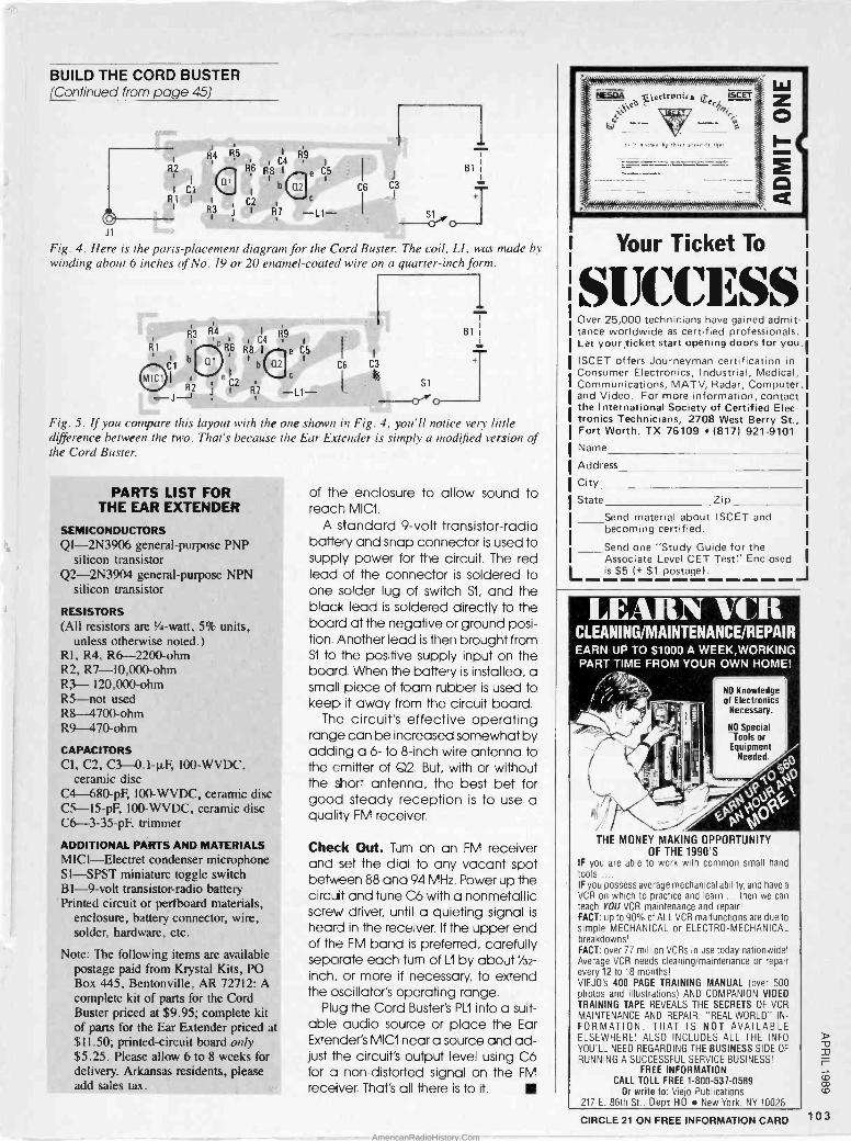
BUILD THE CORD BUSTER (Continued from page 45)
R9 R4 , C4 1
R2 86 p8 I e C5
I ClI Q 1
t b Q2 r
R1 I I C2 c
R3 J 1 R7 -L1-
C6 C3
i B1
J1
Fig. 4. Here is the parts -placement diagram for the Cord Buster. The coil, LI, was made by winding about 6 inches of No. 19 or 20 enamel -coated wire on a quarter -inch form.
R1
Cl
R3
_ J2 J
R4 c r R6
1
r C4 R9
1
B1
R8 I
1
e C5
1
t
b Q2 c
C6 C3
si R7 -L1-
1
T Fig. 5. If you compare this layout with the one shown in Fig. 4, you'll notice very little difference between the two. That's because the Ear Extender is simply a modified version of the Cord Buster.
PARTS LIST FOR THE EAR EXTENDER
SEMICONDUCTORS Ql-2N3906 general-purpose PNP
silicon transistor Q2 -2N3904 general-purpose NPN
silicon transistor
RESISTORS (All resistors are Y4 -watt, 5% units,
unless otherwise noted.) R1, R4, R6 -2200 -ohm R2, R7-l0,000-ohm R3- 120,000 -ohm R5-not used R8 1700 -ohm R9 -470 -ohm
CAPACITORS Cl, C2, C3 -0.1-µF, 100-WVDC.
ceramic disc Cl 680-pF, 100-WVDC, ceramic disc C5-15-pF, 100-WVDC, ceramic disc C6-3-35-pF, trimmer
ADDITIONAL PARTS AND MATERIALS MICI-Electret condenser microphone SI-SPST miniature toggle switch B1 -9 -volt transistor -radio battery Printed circuit or pertboard materials,
enclosure, battery connector, wire, solder, hardware, etc.
Note: The following items are available postage paid from Krystal Kits, PO Box 445, Bentonville, AR 72712: A complete kit of parts for the Cord Buster priced at $9.95; complete kit of parts for the Ear Extender priced at $11.50; printed -circuit board only $5.25. Please allow 6 to 8 weeks for delivery. Arkansas residents, please add sales tax.
of the enclosure to allow sound to reach MIC1.
A standard 9 -volt transistor -radio battery and snap connector is used to supply power for the circuit. The red lead of the connector is soldered to one solder lug of switch Si, and the black lead is soldered directly to the board at the negative or ground posi- tion. Another lead is then brought from Si to the positive supply input on the board. When the battery is installed, a small piece of foam rubber is used to keep it away from the circuit board.
The circuit's effective operating range can be increased somewhat by adding a 6- to 8 -inch wire antenna to the emitter of Q2. But, with or without the short antenna, the best bet for good steady reception is to use a quality FM receiver.
Check Out. Turn on an FM receiver and set the dial to any vacant spot between 88 and 94 MHz. Power up the circuit and tune C6 with a nonmetallic screw driver, until a quieting signal is
heard in the receiver. If the upper end of the FM band ¡s preferred, carefully separate each turn of 121 by about Y32 -
inch. or more if necessary, to extend the oscillator's operating range.
Plug the Cord Buster's PLI into a suit- able audio source or place the Ear Extender's MICI near a source and ad- just the circuit's output level using C6 for a non -distorted signal on the FM receiver. That's all there is to it.
Your Ticket To
SiJCC13SS Over 25,000 technicians have gained admit- tance worldwide as certified professionals. Let your ticket start opening doors for you.
ISCET offers Journeyman certification in Consumer Electronics, Industrial, Medical, Communications, MATV, Radar, Computer, and Video. For more information, contact the International Society of Certified Elec- tronics Technicians, 2708 West Berry St., Fort Worth, TX 76109 (817) 921-9101
Name
Address
City
State Zip
Send material about ISCET and becoming certified.
Send one "Study Guide for the Associate Level CET Test" Enclosed is $5 (+ $1 postage). J
LEARN VCR CLEANING/MAINTENANCE/REPAIR EARN_ UP TO $1000 A WEEK,WORKING PART TIME FROM
j r
-v 1a. Alittk ,,
¡ ".
.
THE MONEY MAKING OF THE
IF you are able to work tools .... IF you possess average mechanical VCR on which to practice teach YOU VCR maintenance FACT: up to 90% of ALL simple MECHANICAL or breakdowns! FACT: over 77 million VCRs Average VCR needs cleaning/maintenance every 12 to 18 months! VIEJO's 400 PAGE TRAINING photos and illustrations) TRAINING TAPE REVEALS MAINTENANCE AND REPAIR. FORMATION, THAT ELSEWHERE! ALSO INCLUDES YOU'LL NEED REGARDING RUNNING A SUCCESSFUL
FREE INFORMATION CALL TOLL FREE
Or write to: Vie¡o 217 E. 86th St., Dept HO
YOUR
f; 'p._
OWN HOME!
NO Knowledge of Electronics Necessary.
NO Special Tools or
Equipment Needed. o
X05 9 JQ P
CPPepÓ`G
OPPORTUNITY 1990'S
with common small hand
ability, and have a
and learn ... then we can and repair!
VCR malfunctions are due to ELECTRO -MECHANICAL
in use today nationwide! or repair
MANUAL (over 500 AND COMPANION VIDEO
THE SECRETS OF VCR "REAL -WORLD" IN-
IS NOT AVAILABLE ALL THE INFO
THE BUSINESS SIDE OF
SERVICE BUSINESS!
1-800-537-0589 Publications
New York, NY 10028
1 03 CIRCLE 21 ON FREE INFORMATION CARD
AmericanRadioHistory.Com

ELECTRONICS MARKET PLACE
FOR SALE CABLE TV equipment S.A., Jerrold, Zenith, Hamlin, Oak, Eagle fitters remotes and more. Best prices. C.O.D 's accepted. Dealers needed. Ours work where others tailed and we guarantee it! TRANS -WORLD CABLE, CO., 1-{800)-442-9333.
DESCRAMBLERS. All brands. Special: combo Jer- rold 400 and SB3 $165. Complete cable de - scrambler kit $39.00. Complete satellite de - scrambler kit $45.00. Free catalog. MJH INDUS- TRY, Box 531, Bronx, NY 10461-0531
ALARM SUPPLIES. Wholesale Prices, Save 60% 1000 items. Catalog $2.00, ALARM DISCOUNT- ERS, P.O.Box 215, Kingsville, MD 21087.
PICTURE flyer lists quality electronic parts at low prices. Send for 3 sample issues. Star-Tronics, Box 683, McMinnville, OR 97128.
CABLE DESCRAMBLER LIQUIDATION. Major makes and models available. Industry pricing! (Ex- ample: Hamlin Combo's, $44 each...minimum 10
orders). DEALERS ONLY! Call WEST COAST ELECTRONICS, (818) 709-1758.
ELECTRONIC test equipment and parts. Free cata- log. E.F. ELECTRONICS, Box 326, Aurora, IL 60507.
TUBES - 2000 TYPES DISCOUNT PRICES!
Early, hard -to -find, and modern tubes. Also transformers, capacitors and parts for tube equipment. Send $2.00 for 24 page wholesale catalog.
ANTIQUE ELECTRONIC SUPPLY 688 W. First St. Tempe, AZ 85281.602/894-9503
ALUMINUM image transfer process, your artwork to aluminum. Write: J & E ENTERPRISES, 2457 N. Marmora, Chicago, IL 60639.
IC's digital and linear, transistors, sockets, led's for sale. Very low prices. No minimum order. For free parts list write to: ARLI ELECTRONICS, 1052 Eilinita Ave, Glendale, CA 91208.
CABLE TV DESCRAMBLERS, Jerrold, Scientific Atlanta, Zenith. Most major brands. Dealer Inquiries Welcome. Visa -M/C Accepted. E & O VIDEO, 9691 E. 265th Street, Elko, MN 55020, 1 (800) 638-6898.
CB RADIO OWNERS! We specialize in a wide variety of technical information, parts and
services for CB radios. 10 -Meter and FM conversion kits, repair
books, plans, high-performance accessories. Over 12 years of
satisfied customers! Catalog $2.
CBC INTERNATIONAL P.O. BOX 31500H, PHOENIX, AZ 85046
CABLE equipment - If you want some of the best prices on filters, SSAVI, Hamlin, Z -Tac, SA, SB, THMode, Pioneer. Call 1(313) 979-8356. No Michi- gan sales.
TUBES, New, old stock from Radio-TV stores. Send $1.00 (refundable) for extensive lists. DIERS, 4276- H3, North 50 Street, Milwaukee, WI 53216-1313.
PLANS & KITS BUILD this five -digit panel meter ana square wave generator including an ohms, capacitance and fre- quency meter. Detailed instructions $2.50. BAG- NALL ELECTRONICS, 179 May, Fairfield, CT 06430.
PORTFOLIO of 25 schematic diagrams for elec- tronic surveillance and countermeasures devices. Includes parts list. Send $12.95, postpaid. L. M. SMITH, P. O. Box 286, Phoenix, AZ 85001.
KITS! 49 MHz XTAL FM transmitter, $24.95; RMS- to-DC converter $24.95 postpaid. Free information. ANDROMEDA ELECTRONICS 125N Prospect, Washington, NJ 07882.
CLASSIFIED AD ORDER FORM
To run your own classified ad, put one word on each of the lines below and send this form along with your check to:
Popular Electronics Classified Ads, 500-B Bi -County Boulevard, Farmingdale, N.Y. 11735
PLEASE INDICATE in which category of classified advertising you wish your ad to appear. For special headings, there is a surcharge of $11.00. ( ) Plans/Kits ( )Business Opportunities ( )For Sale ( ) Education/Instruction ( )Wanted( )Satellite Television
)
Special Category: $11.00
PLEASE PRINT EACH WORD SEPARATELY, IN BLOCK LETTERS. (No refunds or credits for typesetting errors can be made unless you clearly print or type your copy.) Rates indicated are for standard style classified ads only. See below for additional charges for special ads. Minimum: 15 words.
1 2 3 4 5
6 7 8 9 10
11 12 13 14 15 ($23.25)
16 ($24.80) 17 ($26.35) 18 ($27.90) 19 ($29.45) 20 ($31.00)
21 ($32.55) 22 ($34.10) 23 ($35.65) 24 ($37.20) 25 ($38.75)
26 ($40.30) 27 ($41.85) 28 ($43.40) 29 ($44.95) 30 ($46.50)
31 ($48.05) 32 ($49.60) 33 ($51.15) 34 ($52.70) 35 ($54.25)
We accept MasterCard and Visa for payment of orders. If you wish to use your credit card to pay for your ad fill in the following additional information (Sorry, no telephone orders can be accepted.):
Card Number Expiration Date
PRINT NAME SIGNATURE
IF YOU USE A BOX NUMBER YOU MUST INCLUDE YOUR PERMANENT ADDRESS AND PHONE NUMBER FOR OUR FILES. ADS SUBMITTED WITHOUT THIS INFORMATION WILL NOT BE ACCEPTED.
CLASSIFIED COMMERCIAL RATE: (for firms or individuals offering commercial products or services) $1.55 per word prepaid (no charge for ZIP code)...MINIMUM 15 WORDS. 5% discount for same ad in 6 issues within one year; 10% discount for 12 issues within one year if prepaid. NON-COMMERCIAL RATE: (for individuals who want to buy or sell a personal item) $1.25 per word, prepaid....no minimum. ONLY FIRST WORD AND NAME set in bold caps at no extra charge. Additional bold face (not available as all caps) 306 per word additional. Entire ad in boldface, $1.85 per word. TINT SCREEN BEHIND ENTIRE AD: $1.90 per word. TINT SCREEN BEHIND ENTIRE AD PLUS ALL BOLD FACE AD: $2.25 per word. EXPANDED TYPE AD: $2.05 per word prepaid. Entire ad in boldface, $2.45 per word. TINT SCREEN BEHIND ENTIRE EXPANDED TYPE AD: $2.55 per word. TINT SCREEN BEHIND ENTIRE EXPANDED TYPE AD PLUS ALL BOLD FACE AD: $2.95 per word. DISPLAY ADS:1" x 21/4"-$175.00; 2" x 21/4-$350.00; 3" x 21/4"- $525.00. General Information: Frequency rates and prepayment discounts are available. ALL COPY SUBJECT TO PUBLISHERS APPROVAL. ADVERTISEMENTS USING P.O. BOX ADDRESS WILL NOT BE ACCEPTED UNTIL ADVERTISER SUPPLIES PUBLISHER WITH PERMANENT ADDRESS AND PHONE NUMBER. Copy to be in our hands on the 15th of the fourth month preceding the date of issue (i.e.; Sept. issue copy must be received by May 15th). When normal closing date falls on Saturday, Sunday or Holiday, Issue closes on preceding work day. Send for the classified brochure. Circle Number 49 on the Free Information Card.
104
AmericanRadioHistory.Com

CATALOG: hobby/broadcasting/HAM/CB: Cable TV, transmitters, amplifiers, bugging devices, com- puters, more! PANAXIS, Box 130-F4, Paradise, CA 95967.
VIDEOCIPHER II, manuals. Volume 1- hardware, Volume 2 -software. Either $32.45. Both $54.95. Volume 3 - Projects/software - $42.45. NEW! Vol- ume 4 - Repair - $89.95. CODs -1 (602) 782-2316. Catalog -$3.00 TELECODE Box 6426-H. Yuma, AZ 85366-6426.
DIGITAL project: Build yourself an electronic car dashboard. Free details, $1.00 P & H. MODERN LABS, 2900d Ruisseau, St. Elizabeth, QC, JOK 2J0, Canada.
ELECTRONIC kits! Transmitters! Recorders! Phone Devices! Bug detectors! Surveillance Items! More! Catalog $1.00: XANDI ELECTRONICS, Box 25647, 32AA, Tempe AZ 85285-5647.
SPEAKERS subwoofers, woofers, midranges, tweeters for auto, home, MI, commercial applica- tions. 88 page color catalog -$2.00. Amplifiers, mi- crophones, DJ equipment. McGEE RADIO, 1901 McGee, Kansas City, MO 64108.
PROJECTION T.V. Convert your TV to project 7 foot picture... Easy!... Results comparable to $2,500 projectors... Plans and 8" Lens $24.95... Profes- sional Systems available... Illustrated Catalog free MACROCOMA 15HH Main Street, Washington Crossing, PA 18977. Creditcard Orders 24 HRS. (215) 736-3979.
P.C. boards for the experimenter. Details -SASE. EPROM programmer project, $3.50. Free semicon- ductor bonus! GALLIUM JUNCTION 540-C N.E.Northgate Way, Suite 542, Seattle, WA 98125.
EXPERIMENTERS crystal set and one -tube radio. Free catalog. BOB RYAN, R.O.Box 3039, Anaheim, CA 92803.
DISCOUNT plastic model kits. Send $1.00 for cata- log. LAURA KITAGAWA CO.1287 Dorner Dr., Mon- terey Park, CA 91754.
EDUCATION/INSTRUCTION MAGIC! Four illustrated lessons plus inside infor- mation shows you how. We provide almost 50 tricks including equipment for four professional effects. You get a binder to keep the materials in, and a one- year membership in the International Performing Magicians with a plastic membership card that has your name gold -embossed. You get a one-year sub- scription to our quarterly newsletter, "IT'S MAGIC!" Order now! $29.95 for each course + $3.50 postage and handling. (New York residents add applicable state and local sales tax). The Magic Course, 500- B BiCounty Blvd., Farmingdale, NY 11735.
LEARN IBM PC assembly language. 80 pro- grams. Games, quizzes, animation, utilities. In- cludes license. 360K $5.00, 720K $6.00, Book $18.00. ZIPFAST Box 12238, Lexington, KY 40581-2238.
BE a recording engineer; train at home for high paying - exciting careers. Free information. AUDIO INSTITUTE 2174 Union St. Suite 22Z, San Fran- cisco, CA 94123.
DO It yourself guide on how to maintain & clean your VCR. Cable/TV/VCR hookup diagrams. Basic problems & solutions. Illustrations In- cluded. Send $7.80 to: AMERICAN GIFTS, 1445 W. Morse Ave., Chicago, IL 60626.
NO gimmicks: Professional serviceman explains methods to prevent appliance repair calls. Details $1.00. HARMON, P.O. Box 55603, Trenton, NJ 08638. Since 1980 - Guaranteed savings!
BUSINESS OPPORTUNITIES YOUR own radio station! AM, FM, TV, Cable. Li- censed/unlicensed. BROADCASTING, Box 130 F4, Paradise, CA 95967.
CABLE TV CONVERTERS CABLE TV CONVERTERS. Scientific Atlanta, Jer- rold, Oak, Zenith, Hamlin. Many others. "New" VIDEO HOPPER "The Copy Killer". Visa, M/C and Amex. 1 (800) 826-7623. B & B Inc. P.O. Box 21-327, St. Paul, MN 55121.
CABLE TV CONVERTERS RECEIVE MORE CHANNELS Stocking all types of converters - Panasonic, Jerrold, Tocom, Pioneer, Scientific Atlanta, Zenith, Oak, Hamlin, Eagle, and others brands available.
Call or write for FREE CATALOG 10 a.m. to 6 p.m. Eastern Time
Monday thru Friday
AC/DC Inc. Suite 310, 366 N. Broadway
Jericho, N.Y. 11753 Tel: (516) 625-3550
SATELLITE TV FREE CATALOG Systems, Upgrades, Houston, Uniden, Chapparal, etc. SAVE $$$$$. SKYVISION 2008 Collegeway, Fergus Falls, MN 56537. (218) 739-5231.
WANTED SCHEMATIC needed Kintel model 204A Electronic Galvanometer WAYNE WATCHOUS, 5548 So. For- esthill, Littleton, CO. 80120.
WANTED Timex TI 1000 computers, peripherals, parts, etc. Send info/items to C. E. RAY, 646 Main, El Centro, CA 92243.
CABLE -TV BOXES Descramblers Converters
FREE CATALOG TRANS -WORLD CABLE CO.
12062 Southwest 117th Ct., Suite 126 Miami, Florida 33186
800-442-9333
COMPUTERS COMMODORE/Amiga Chips, (direct distributor, guaranteed new, low cost). Send for complete cata- log. Low cost national repair (eg. $49.95 plus UPS). Heavy duty C64 power supply - $27.95 plus UPS. "The Commodore Diagnostician" a fantastic new aid for fixing Commodores - $7.95. Visa/MC. KA - SARA MICROSYSTEMS, INC., 24 West Street, Spring Valley, NY 10977. 1 (800) 248-2983 or (914) 362-3131.
CABLE EQUIPMENT CABLE TV Secrets - the outlaw publication the cable companies tried to ban. HBO, Movie Channel, Showtime, descramblers, converters, etc. Sup- pliers list included. $8.95. CABLE FACTS, Box 711- H, Pataskala, OH 43062.
PROGRAMMABLE CONTROLLERS
POCKET CONTROLLER: Versatile, low cost, Pro- grammable Digital Controller. Designed for everyone that deals with electronics. Only $99.95. For literature, call (800) 533-7159, in CT 791-8220, or write, POCKET CONTROLLER COMPANY, Box 232, Seymour, CT 06483.
HIGH TECH ELECTRONICS SCRAMBLER PHONES! Phone bug detectors! Electronic countermeasures equipment! Executive and personal protection products! And much more!!! Catalog $3.00 (refundable with first order). DIVER- SIFIED WHOLESALE PRODUCTS, P.O. Box 1275 - HE, Redondo Beach, CA 90278.
TV FILTERS T.V. Tunable notch filters. Free brochure. D. K. VID- EO, Box 63/6025, Margate, FL 33063. 1 (305) 752-9202.
Cable TV Converters Why Pay A High Monthly Fee?
Jerrold Products include "New Jerrold Tri -Mode," SB -3. Hamlin, Oak VN -12, M -35-B, Zenith, Magnavox, Scientific At- lanta, and more. (Quantity discounts) 60 day warranty. For fast service C.O.D. or- ders accepted. Send SASE (60 cents_ postage) or call for info 1-800-648-3030. MIDWEST ELECTRONICS, INC., 5143-H W. Diversey, Chicago, IL 60639. MC/Visa orders accepted. No Illinois orders ac- cepted. Mon. -Fri. 8 A.M.-5 P.M. CST
A Disability
Can Be An Asset.
The President's Committee on Employment of the Handicapped
Washington, D.C. 20036
OPPORTUNITY WITHOUT RISK.
The biggest improvement in 40 years has made U.S. Savings Bonds an ideal investment.
A variable interest rate lets you share in rates offered by today's securities market. No limit on how much you might earn.
What makes this improved Bond ideal is that you're protected by a guaranteed minimum. And if the Bond is held to maturity, you'll double your money.
Take another look at this opportunity without risk.
r"'Take
stocAk in eric
'Sß ma. , A public service of this publication CI and The Advertising Council.
105 AmericanRadioHistory.Com

ADVERTISING INDEX POPULAR ELECTRONICS magazine does not assume any responsibility for errors that may appear in the index below.
Free Information No. Page
6 AMC Sales 95
5 All Electronics 23 - Amazing Concepts 14 - American Home SAT. Assoc 28 - Antique Electronic Supply .... 104 - Atlantic Cable Distribution... 105
9 C & S Sales 25 - CB City 104
7 CIE 11
20 Chemtronics 93 - Command Productions 97
19 Contact East 97
8 Cook's Institute 14
10 Digi-Key CV2 - Electronics Book Club 3 - Electronic Tech. Today .. 5, 26, 94 - Electronic Tech. Today ... 87, CV3 - Grantham College of Engineering 27
12 Halted Specialties 12 - ISCET 103
15 Jensen Tools 95
17 Kepro Circuit Systems 15
13 MCM Electronics 17
14 Mark V. Electronics 93 - McGraw Hill Cont. Education Series 91 - Midwest Electronics 105 - NRI 21 - Pacific Cable 7
18 Parts Express 13 - P.E. Bookstore 101
16 Radio Shack CV4 11 The Datak Corporation 12 - Trans World 105
21 Viejo Publications 103
ADVERTISING SALES OFFICE Gernsback Publications. Inc. 500-B Bi -County Blvd. Farmingdale, NY 11735 1-1516) 293-3000 President: Larry Steckler Vice President: Cathy Steckler For Advertising ONLY 516-293-3000 Fax 1-516-293-31 15 Larry Steckler
publisher Arline Fishman
advertising director Christina Estrada
advertising assistant Shelli Weinman
advertising associate Lisa Strassman
credit manager
SALES OFFICES EAST/SOUTHEAST Becky Akers Pattis/3M 310 Madison Ave., Suite 1804 New York, NY 10017 1-212-953-2121 Fax 1-212-953-2128 MIDWEST/PACIFIC Joe Shere 1507 Bonnie Doone Terrace Corona Del Mar, CA 92625 1-714-760-8697
BUILD THE HOT SOCKET (Continued from page 41)
to the sides of the enclosure with con- tact cement. The foil pieces are folded around the bottom edge of the en- closure and extend about Y4 inch in-
ward from the outside edge. Contact is made between the foil
and the secondary of the transformer when the printed -circuit board is in-
stalled. The aluminum foil at the bot- tom edge of the enclosure is painted the same color as the enclosure itself to hide the fact that it goes around the bottom and into the enclosure. When completed, the aluminum plates .3 1/2->1 T
3-1/2
3/8
1 I -e - 3/8
w- 1/4
ALUMINUM-( 1/8 OR 1/4
FOIL e
7/8
4-21/2-4 PAINT OVER FOIL BELOW LINE
Fig. 5. When making the enclosure for your Hot Socket, start forming a frame (about 31/2 -inches square, and 2/s -inch high) from a 3/s -inch thick piece of wood. All dimensions here are in inches.
should appear as though they were applied for decoration only.
The AC socket was salvaged from an old 117 -volt AC double socket. It
was sawed in half to get a single sock- et and then the top of the socket was cut off with a hack saw. The back sur-
face was sanded down until the face of the plug was about 3/6 -inch thick. That part must be made thin enough so that it is difficult to pick up the box by the socket. The socket is then fastened to the top of the box with epoxy.
Once the enclosure is completed, the board can be screwed to the bot- tom of the enclosure with four No. 2
wood screws about Y4 -inch long. Pre-
drill the pilot holes to keep from split- ting the glue joint at the corners of the enclosure.
DX LISTENING (Continued from page 81)
and views on this interesting hobby. Send your letters to DX Listening, Pop- ular Electronics, 500-B Bi -County Blvd., Farmingdale, NY 11735.
Here's what some of your fellow SWL's
have been hearing on the shortwave frequencies. All frequencies are in kHz
(kilohertz), and all times are give in UTC
(Universal Coordinated Time), which is
the same as EST + 5 hours, CST + 6
hours, MST + 7 hours, or PST + 8 hours.
Brazil -17,815 kHz. Radio Cultura is
a Brazilian shortwaver noted around midnight UTC (2400) with jazz and a talk program in Portuguese.
Cuba -5,965 kHz. Radio Habana Cuba (RHC) heard on a Thursday eve- ning, or Friday UTC, from 0400 to 0410 with news at the top of the hour.
Nicaragua -6,120 kHz. Radio Zinicaon Nicaragua's Atlantic Coast is
a tough station to hear, compared to the Voice of Nicaragua, which oper- ates on 6,100 kHz, just 20 kHz away. But
it has been logged tentatively with Spanish news at 1 100 UTC.
Pakistan -15,1 15 kHz. Radio Pakistan is noted with programming in
both Urdu and English from 0200 until sign off at 0246 UTC.
South Africa -4,760 kHz. Trans World Radio, Swaziland. This TWR sta- tion in southern Africa has been log- ged around 0420 UTC in German with a sermon, followed by English pro- gramming.
Switzerland -12,035 kHz. Swiss Ra- dio International (SRI) noted at 0410 UTC with a current affairs program on Angola.
West Africa -4,890 kHz. Radiodifusion TV Senegal (RTVS) is a west African station reported here with French programming, including news, around 0650 to 0725 UTC.
"This cord is polarized-that means that you can use it in colder weather."
106
AmericanRadioHistory.Com
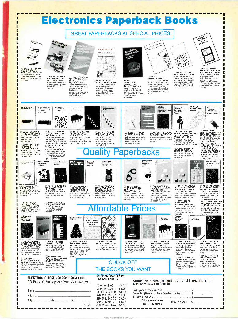
Electronics Paperback Books 1
CJ13P173-COMPUTER MUSIC PROJECTS $6.95. Shows how to use your lame computer to
Maprole. electronic music. rre
ce 000uils. Mostly jar-
gon
PAPERBACKS AT SPECIAL PRICES
BP178-TV DXING C1 PCP7o3-PRACTICAL FOR THE ENTHUSE MIDI HANDBOOK AST-... $7.95. Practical. $9.95. Explains what authoritative intro to this MIDI (the Musical unusual aspect of elec- Digital Interlace) can do troncs. 912 x 11 in ara how you can put It
144 PP to work. Covers Keyboards, drum machines, sequencers, mixers, guitars and computer music.
RADIO'S FIRST
TWO DECADES
RFTD-RAIDIO'S FIRST TWO DECADES
$3.50. This story of radio's early days makes for fascinating reading. Spark -gap transmitters, KDKA's begimtogs, and much Rare.
I PCP102- INTRODUCING DIGITAL AUDIO .,,. $9.95. CD, DAT, and sampling. What is involved in pie digital pan of audio signals. Principles and practices of digital audio techniques.
I 1 BP195- INTRODUCTION TO SATELLITE TV.....$9.95. A definitive introduction to the subject Ashen for the professional engineer. electronics enthusiast, or others who want to know more before they buy. B
10 in.
Cam'' L1 BP239-GETTING THE MOST FROM YOUR
BPI46-THE PRE- MUTLIMETER..... $5.95. BASIC BOOK ..... 86.95. Covers basics of analog A book on the BASIC and digital meters. programming for those Methods of component who have not yet bought testing (Includes a computer as eel) as transistors, thyristors, those who have trouble resistors, capacitors and learning how to program. other active and passive
devices.
A.snt..t trr. An ruueducuen Computer >. .. .. 0011191000nE f/ io rna
1M A1Ae V.....«.. «plain« .. ... ..
600 MO xc ''' k;`' , I )1
171, , i. ,. h1,. ee
n BP135-SECRETS OF THE COMMODORE 64 ...... $5.75. Masses of useful info and program- ming lips not hound in any userS manual.
.13P130-MICRO IN- TERFACING CIIRCUITS-BOOK 1 ..... $5.75. Practical add-ons transform your computer
Into control or measure- r equipment.
BP143-INTRO TO PROGRAMMING THE ATARI 600/800 XL
$5.95. Perfect comple- ment to the Atan users manual. Even shows how to use animated graphics.
BP13I-MICRO IN- TERFACING CIRCUITS-BOOK 2 $5.75. Interfacing sound and speech generators, temperature and optical sensors, motor control- lers, and more.
lbw t.. Omit» Kierotemete I4y.st
rm.wr a`áo.
CIBP183-AN INTRO- DUCTION TO CO M $6.95. To run and use programs operations under CP/M you need this book
L
I. I BP104-ELEC- TRONIC SCIENCE PROJECTS $5.75. Simple to complex, a
stronglygroup ) sg cienl c flavor
90 Peoºrotts toe the n A tac Eiten
BP120-20 PRO- GRAMS FOR THE ZX SPECTRUM 8 18K 7X81
$5.75. All programs run on both machines. Include how charts and into on how to modify to run on other computers.
I PCP104- ELECTRONICS BUILD AND LEARN $9.95; starts oh with construction details of a circuit demonstrator and shows a variety of circuits for experimenters.
BPI27-HOW TO DE- SIGN ELECTRONIC PROJECTS ..... $6.75. How to use standard cir- cuit elements to make custom electronic prof acts.
BP92-CRYSTAL SET CONSTRUCTION
$5.50. A variety of crystal radio receivers for the experimenter and hobbyist
OoaY of CROOK Projpcl.
Lt BPI 0f -MODERN
OP -AMP PROJECTS ..... $5.00. Includes a Slide Timer. AF Signal Gen. Mike Pre -amp Scratch Filter, end much more.
C BP185-ELEC- TRONIC SYNTHESISER CONSTRUCTION $5.95. Shows how to build a monophonic syn- thesizer, section by section. Replaces BP81.
LI BP148-COMPUTER TECHNOLOGY EX- PLAINED $5.50. Explanations for comput- er terms often encountered. A dictionary for computer lingo
I I BP152-INTRO TO Z-80 MACHINE CODE .-...55.95. Speed up your programs. They may be harder to wale, but its worth learning how. Some demo programs are Included.
us CJ BPI05-ANTENNA PROJECTS ..... $5.50. Practical radio antenna designs that deliver good performance and are rel- ativelysimple and inexpensive to build.
Formulae Central or
25 ample Anwtaur Bend a.
BP198-AN INTRO- BP144-FURTHER DUCTION TO ANTENNA PRACTICAL ELECTRONICS THEORY $6.95 CALCULATIONS AND Basic concepts relevant to FORMULAEe 89.00. receiving and transmitting cep....
Book 0010 erston o
antennas care with new data not found in earlier edition. 450 page.
U BPI25-25 SIMPLE AMATEUR BAND AN- TENNAS $5.50. All kinds of antennas for all kinds of amateur radio reception
Quality Paperbacks How to
Yotm o. PCBs arte M taearcne
fctame Prqecb
BP110-HOW TO GET YOUR ELEC- TRONIC PROJECTS WORKING $5.75. How to find the feuds in your projects. repair them and get them working.
CJ BP121-DESIGN 6 MAKE YOUR OWN PC BOARDS $5.75. Ev- erything
be(ë need to you make
prented.circuit I
your projects.
INi.'n1.r11 I, i
a. ed 1 ri ! I BP56-ELEC- LI BP65-INTERNA- TRONIC SECURITY TIONAL TRANSISTOR DEVICES ..... $5.50. EQUIVALENTS Three basic sections $7.50. Locates possible Switch activated alarms. substitutes for a popular infrared 8 ultrasonic sys- userohenttd selection of terns, smoke, gas, water modem transistors. Jape -
detection. nese. European and American types.
or a e - rices ELECTRONICS
BUILD AND LEARN
'i BP59-SECOND BOOK FOR CMOS IC PROJECTS 55.50. Multiwbrators, smpoers, triggers 8 gates. special domes including reac- tion timer. simple electronic organ, and more
BP182-MIDI PROJ- ECTS $6.95. Details
of how to interlace many popular home computers with MIDI music systems.
BP65-SINGLE IC PROJECTS ..... 55.75. All profecis in this took are based on one IC and are simple to construct. Great way to get started with IC's.
LI BP49-POPULAR ELECTRONIC PROJ- ECTS $5.95. A collection of a wide range of electronic projects and circuits tir the experi- menter.
CHECK OFF THE BOOKS YOU WANT
ELECTRONIC TECHNOLOGY TODAY INC. 13.0. Box 240, Massapequa Park, NY11762-0240 SORRY, No orders accepted Number of books ordered
$0.01 to $5.00 ... $1.25 outside of USA and Canada
Name $5.01 to 10.00 ... $2.00
Total price of merchandise $ $10.01 to $20.00 . $3.00
Sales Tax (New York State Residents only) $ Addles $20.01 to $30.00 . $4.00 Shipping (see chart) $
$30.01 to $40.00 . $5.00 pP g City State 7ip
$40.01 to $50.00 . $6.00 All payments must
Total Enclosed $ P489 $50.01 and above .$7.50 be In U.S. funds
BP117-PRACTICAL ELECTRONIC BUILD- ING BLOCKS. Book 1
$5.75. Build the blocks and then combine them to form almost any custom project of your choice. LJ BP77-MICRO- PROCESSING SYSTEMS AND CIR- CUITS $5.95. Guide to the elements of micro- pracessirg systems. Teaches all the funda- mentals.
hdow SL Archive
yeerce vie -M,
ee w fee Ace
LI BP179-ELEC- TRONIC CIRCUITS FOR THE COMPUTER CON- TROL OF ROBOTS ..... 67.50. Data and circuits for interlacing the com. puler to the robot's motors and sensors.
CI BP134-EASY ADD- ON PROJECTS FOR COMMODORE 64, VIC-20, BBC MICRO 8 ACORN ELECTRON..... $8.95. Picture digitizer, light pen, model control- ler and more.
h..oasYen Mee.« ern Ma*.
C BP118-PRACTICAL ELECTRONIC BUILD- ING BLOCKS. Book 2
$5.75. Amplifiers for all kinds to add to the crrcuils from Book 1 of this series.
BP169-HOW TO GET YOUR COMPUTER PROGRAMS RUNNING
$5.95. Have you ever written your own pro- grams only to find that they do not work? This book shows you how to find errors
I 04
flectwr.c Circuity Meta º
Cì BP97-IC PROJ- BP8O-POPULAR ECTS FOR BEGINNERS ELECTRONIC CIR -
$5.50. Written es. CUITS. Book 1 .... $5.95. pecially for the less More ircuits for hob - experienced aspen- sts Audio, rada, test. mentor. Complete pans music household and layouts and wiring di- more. oignants.
CI BP98-POPULAR r BP181-INTO THE ELECTRONIC CIR - OL ARCHIVE $4.95. CUITS. Book 2 Presents the powerful 55.95. More useful on - database for the Sinclair cuits. None of these OL. Step-by-step ap- projects duplicate those proach includes practical in Book 1 of this sens. examples.
SHIPPING CHARGES IN
USA AND CANADA
AmericanRadioHistory.Com

Radio Shack -The Technology Store® SUPER VALUES IN PARTS AND ACCESSORIES!
"Hotline" Special -Order Service
One -Week Delivery Time on Most Items
Your Radio Shack store manager can special -order a wide variety of parts and accessories not shown in our catalog- tubes, ICs, phono cartridges and styli, microprocessor, scanner and CB crys- tals, even SAMS Photofacts° There's no minimum order or handling charges.
Novice Ham Course
Prepared by Gordon West, WB6NOA
1995
Everything you need to earn the new Novice Amateur Radio license with voice and digital privileges. Includes two self - paced code cassettes, a study guide with sample exam ques- tions and answers, FCC Form 610, and binder. #62-2402
RS -232 Plugs and Accessories (2)
(1) Solder RS -232 Connectors. Positions Type Cat. No. Each
9 Male 276-1537 1.49 9 Female 276-1538 2.49 9 Hood 276-1539 1.19 25 Male 276-1547 1.99 25 Female 276-1548 2.99 25 Hood 276-1549 1.29
(2) Inline RS -232 Tester. Dual -color LEDs help you spot line problems fast. #276-1401 14.95 (3) Inline RS -232 Spike Protector Guard computer, peripherals. #276-1402 16.95
(1) Solar Cell and Project Kit
Put Your Sun to Work
Har (1) Flexible Solar Cell. This 31/4 x 1V/e" cell pro- duces about 1.2VDC, 65 mA. #276-138 .... 5.95
(2) Solar Project Kit. Mini panel, motor, propel- ler, educational booklet. #277-1201 9 95
Project Tools (1) (2) 6 (3)
tot (1) Mini Vise. #64-2094 3 99 (2) Adjustable Project Holder. For easier soldering, gluing, painting and assembly. #64-2093 7 99
(3) Mini Drill. #64-2097 3 49
Power Buys! (1) (2)
rotj.,
(3)
(1) RFI-Busting Toroid Choke Cores. Easy to install on AC power cords, coax, phone lines. #273-104, Pkg. of 2/6.95 (2) 0.1 mH RF Choke. #273-102, 998 (3) Heavy -Duty MOV. #276-568, 1.99
R & C Bargains (2)
(1)
(3)
1
(1) Pkg. of 50 Low-pF Capacitors. 50 WVDC. 2 to 33 pF. #272-806 ... 2.99 (2) Pkg. of 500 t/4 -W, 5% Resistors. 54 popular values. #271-312 ....7.95 (3) 12 Trimmer Pots. #271-1605, 1.98
Unusual Items (1) (2)
IMP /(3)
(1) PC -Mount Mini Speaker. 29/32" diameter! 8 ohms. #273-090 .. 4.99 (2) Trimmer Capacitor. 95-420 pF Compression type. #272-1336, 1.69
(3) Thermistor. #271-110 .... 1.99
FM Receiver
TDA7000. RF amplifier, mixer, IF and demod stages on one 18 - pin DIP. Perfect for a small FM broadcast or public-service band receiver-requires a mini- mum of support parts. 70 kHz IF eliminates IF transformers. With circuit data. #276-1304
Mini Audio Amp 1195
Built -In Speaker High -Gain IC Design
Ideal test amplifier, it's also great for computer voice and music syn- thesis, circuit tracing, and line testing. Has 1/e" headphone jack, 1/e" input jack and volume control. Battery extra. #277-1008
Switch Values (1) (2) (3)
(1) SPST Rocker Switch. Rated 6 amps at 125VAC. #275-690 1 99 DPDT Rocker. #275-691 2 59
(2) DPDT Knife. #275-1537 .... 1.29
(3) Mercury Bulb. #275-027 . 1.29
LED Indicators (1) (2) r .
(3)
(1) Super -Bright Red LED. 2000 mcd output! #276-087 1 69 (2) Blinking Red LED. Built-in flasher IC. #276-036 1 29 (3) Blinking Green LED. Flash rate:
1 Hz. #276-030 1 29
More Project Parts (1) (2) (3)
(1) PC -Mount Electret Mike Element. Hi-fi re- sponse. 2-10VDC. #270-090 1 49 Element With Leads. #270-092 2 99
(2) 0-15 VDC Voltmeter. #270-1754 7 95
(3) Transmitter Case. Perfect for a pocket-size IR or RF controller. #270-293 3 99
Many other styles and sizes of project housings available at our store near you-at low prices!
Board, Project Book
Our Best Breadboard
Universal Breadboard. Molded socket ac- cepts DIPs, discretes and 22 -gauge wires. Mounted on a heavy metal base with rubber feet. #276-169 19.95 Getting Started in Electronics. By Forrest Mims M. The perfect introduction to electronics project building. 128 pages. #276-5003 ... 2.49
G.'tting Started' úi Eles -tramos
Bench Instrument
almgolloggmlizinsigoi
9995 Incredible Value!
Precise LCD digital display plus 31 -segment analog bargraph. Displays transistor gain directly. Diode - check, memory and continuity functions. Measures to 1000VDC, 750VAC, 10 amps AC as well as DC, and resistance. With leads and manual. #22-195 .. 99.95
Over 1000 items in stock! Binding Posts, Books, Breadboards, Buzzers, Capacitors, Chokes, Clips, Coax, Connectors, Fuses, Hardware, ICs, Jacks, Knobs, Lamps, Multitesters, PC Boards, Plugs, Rectifiers, Resistors, Switches, Tools, Transformers, Transistors, Wire, Zeners, More! Rache lhaek
Prices apply at participating Radio Shack stores and dealers A DIVISION OF TANDY CORPORATION
CIRCLE 16 ON FREE INFORMATION CARD
AmericanRadioHistory.Com