60 cfm/150 psig standard rotary screw compressor ...
100
60 CFM/150 PSIG STANDARD ROTARY SCREW COMPRESSOR ©2014 Iowa Mold Tooling Co., Inc. All rights reserved. PART NUMBER: 99905395 Effective Date: 3/14 ® An Oshkosh Corporation Company INSTALLATION, OPERATION, MAINTENANCE AND PARTS MANUAL NOTE Read this manual before installing, operating or servicing this equipment. Failure to comply with the operation and maintenance instructions in this manual WILL VOID THE EQUIPMENT WARRANTY. NOTE Making unauthorized modifications to the compressor or system components WILL VOID THE WARRANTY! Always inform Iowa Mold Tooling Co., Inc., before making any changes to the CAS60R hydraulic system. NOTE Use only IMT Premium Synthetic Oil and Genuine IMT Parts. Inspect and replace damaged components before operation. Substituting non-IMT Oil or non-genuine IMT filter components WILL VOID THE COMPRESSOR WARRANTY! Iowa Mold Tooling Co., Inc. 500 Highway 18 West Garner, Iowa 50438 Phone: 641.923.3711 Fax: 641.923.6063
-
Upload
khangminh22 -
Category
Documents
-
view
1 -
download
0
Transcript of 60 cfm/150 psig standard rotary screw compressor ...
60 CFM/150 PSIG STANDARD ROTARY SCREW COMPRESSOR
©2014 Iowa Mold Tooling Co., Inc.All rights reserved.
PART NUMBER:99905395
Effective Date: 3/14
®
An Oshkosh Corporation Company
INSTALLATION, OPERATION, MAINTENANCE AND PARTS MANUAL
NOTE
Read this manual before installing, operating or servicing this
equipment. Failure to comply with the operation and maintenance
instructions in this manual WILL VOID THE EQUIPMENT WARRANTY.
NOTEMaking unauthorized modifications to
the compressor or system components WILL VOID THE WARRANTY!
Always inform Iowa Mold Tooling Co., Inc., before making any changes to the
CAS60R hydraulic system.
NOTEUse only IMT Premium Synthetic Oil and Genuine IMT Parts. Inspect and
replace damaged components before operation. Substituting non-IMT Oil or
non-genuine IMT filter components WILL VOID THE COMPRESSOR
WARRANTY!
Iowa Mold Tooling Co., Inc.500 Highway 18 West Garner, Iowa 50438
Phone: 641.923.3711 Fax: 641.923.6063

NOTICE TO CUSTOMERThis manual is the final version and some of the information and specifications are subject to changewithout notice.
CAS60R 60 CFM / 150 PSIG TABLE OF CONTENTS
Manual #99905395 PAGE - I
TABLE OF CONTENTS
®
An Oshkosh Corporation Company
SECTION 1: SAFETY.........................................................11.1 GENERAL INFORMATION ............................................................................................................11.2 DANGERS, WARNINGS, CAUTIONS AND NOTES .....................................................................11.3 SUMMARY OF WARNINGS, CAUTIONS AND NOTES................................................................1
1.3.1 DANGERS........................................................................................................................................................... 1
1.3.2 WARNINGS ......................................................................................................................................................... 1
1.3.3 CAUTIONS .......................................................................................................................................................... 3
1.3.4 SAFETY DECALS ............................................................................................................................................... 3
SECTION 2: DESCRIPTION ..............................................52.1 GENERAL INFORMATION ............................................................................................................52.2 COMPONENT DESCRIPTIONS ....................................................................................................5
2.2.1 COMPRESSOR ASSEMBLY............................................................................................................................... 6
2.2.2 OIL INJECTED, SINGLE STAGE ROTARY SCREW COMPRESSOR ............................................................... 6
2.2.3 OIL RESERVOIR AND PRIMARY OIL SEPARATION......................................................................................... 7
2.2.4 AIR INLET VALVE AND VALVE CONTROL SOLENOID..................................................................................... 7
2.2.5 COMPRESSOR AIR FILTER............................................................................................................................... 7
2.2.6 SPIN-ON OIL COALESCER/SEPARATOR FOR SECONDARY SEPARATION ................................................. 8
2.2.7 SPIN-ON OIL FILTER.......................................................................................................................................... 8
2.2.8 MINIMUM PRESSURE/DISCHARGE CHECK VALVE ASSEMBLY.................................................................... 8
2.2.9 PRESSURE SWITCH.......................................................................................................................................... 8
2.2.10 PRESSURE RELIEF VALVE .............................................................................................................................. 9
2.3 HYDRAULIC DRIVE SYSTEM.......................................................................................................92.4 COMPRESSOR COOLING SYSTEM ............................................................................................102.5 INSTRUMENTATION SYSTEM......................................................................................................11
2.5.1 HOUR METER .................................................................................................................................................... 12
2.5.2 AIR PRESSURE GAUGE.................................................................................................................................... 12
2.5.3 AIR TEMPERATURE GAUGE............................................................................................................................. 12
2.5.4 RESET BUTTON................................................................................................................................................. 12
2.6 ELECTRICAL CONNECTIONS......................................................................................................13
2.7 MAIN FRAME AND ENCLOSURE.................................................................................................13
Continued on next page...
TABLE OF CONTENTS CAS60R 60 CFM / 150 PSIG
PAGE - II MANUAL #99905395®
An Oshkosh Corporation Company
SECTION 3: SPECIFICATIONS.........................................15TABLE 3A: CAS60R SPECIFICATIONS.............................................................................................. 15TABLE 3B: PRIME LUBRICANT CHARACTERISTICS ...................................................................... 16TABLE 3C: RECOMMENDED TORQUE SPECIFICATIONS .............................................................. 16
SECTION 4: INSTALLATION.............................................174.1 MACHINE PACKAGE RECEIPT/INSPECTION............................................................................. 174.2 GENERAL INSTRUCTIONS.......................................................................................................... 174.3 DETERMINING THE CAS60R UNIT MOUNTING LOCATION...................................................... 174.4 HYDRAULIC SYSTEM REQUIREMENTS..................................................................................... 184.5 INSTALLATION .............................................................................................................................. 20
4.5.1 MACHINE LOCATION ......................................................................................................................................... 20
4.5.2 CLEARANCE....................................................................................................................................................... 20
4.5.3 MOUNTING ......................................................................................................................................................... 20
4.5.4 SERVICE CONNECTIONS.................................................................................................................................. 21
4.5.5 ELECTRICAL CONNECTIONS ........................................................................................................................... 21
4.5.6 HYDRAULIC SUPPLY CIRCUIT.......................................................................................................................... 21
4.5.7 ROUTING ............................................................................................................................................................ 21
SECTION 5: OPERATION..................................................255.1 GENERAL INFORMATION............................................................................................................ 255.2 PURPOSE OF CONTROLS........................................................................................................... 255.3 INITIAL START-UP PROCEDURE................................................................................................. 265.4 ROUTINE START-UP PROCEDURE............................................................................................. 285.5 ROUTINE SHUTDOWN PROCEDURE......................................................................................... 285.6 OPERATING CONDITIONS........................................................................................................... 28
SECTION 6: MAINTENANCE ............................................296.1 GENERAL INFORMATION ............................................................................................................ 296.2 MACHINE MAINTENANCE SCHEDULE....................................................................................... 306.3 ROUTINE MAINTENANCE SCHEDULE ....................................................................................... 316.4 REPLACEMENT PARTS ............................................................................................................... 326.5 PARTS REPLACEMENT AND ADJUSTMENT PROCEDURES ................................................... 32
6.5.1 REMOVING PANELS FOR MACHINE MAINTENANCE ACCESS ..................................................................... 34
6.5.1.1 REMOVING AND REPLACING THE ROOF (TOP) PANEL ....................................... 34
6.5.1.2 REMOVING AND REPLACING THE MAIN CANOPY PANEL ................................... 36
6.5.1.3 REMOVING AND REPLACING THE COOLER ANDINSTRUMENTATION ACCESS PANEL...................................................................... 36
Continued on next page...
CAS60R 60 CFM / 150 PSIG TABLE OF CONTENTS
Manual #99905395 PAGE - III®
An Oshkosh Corporation Company
SECTION 6: MAINTENANCE (CONTINUED)6.5.2 COMPRESSOR OIL MAINTENANCE................................................................................................................. 37
6.5.2.1 ADDING OR CHANGING THE COMPRESSOR OIL ..................................................... 37
6.5.3 PERFORMING AN OIL FILTER CHANGE.......................................................................................................... 39
6.5.3.1 REMOVING THE OIL FILTER ........................................................................................ 39
6.5.3.2 REPLACING THE OIL FILTER................................................................................... 40
6.5.4 COALESCER (AIR/OIL SEPARATOR) REPLACEMENT.................................................................................... 40
6.5.4.1 REMOVING THE COALESCER ELEMENT................................................................ 41
6.5.4.2 REPLACING THE COALESCER ELEMENT .............................................................. 41
6.5.5 COMPRESSOR AIR FILTER MAINTENANCE ................................................................................................... 41
6.5.5.1 REMOVING THE AIR FILTER..................................................................................... 41
6.5.5.2 COMPRESSOR AIR FILTER INSPECTION ............................................................... 42
6.5.5.3 REPLACING THE AIR FILTER ................................................................................... 43
6.5.6 REPAIRING THE INLET CONTROL SYSTEM ................................................................................................... 43
6.5.6.1 REBUILDING THE AIR INLET VALVE ASSEMBLY.................................................... 43
6.5.7 PERFORMING MAINTENANCE ON THE DRIVE BELTS .................................................................................. 46
6.5.7.1 ADJUSTING THE DRIVE BELTS................................................................................ 46
6.5.7.2 DRIVE BELT TENSION DATA..................................................................................... 47
6.5.7.3 REPLACING THE DRIVE BELTS ............................................................................... 48
6.5.8 CLEANING THE COOLER CORE ...................................................................................................................... 49
6.5.9 PRESSURE SWITCH.......................................................................................................................................... 50
6.5.10 SERVICING THE MINIMUM PRESSURE/DISCHARGE CHECK VALVE........................................................... 51
6.5.10.1 REBUILDING THE MINIMUM PRESSURE/DISCHARGE CHECK VALVE ................ 52
6.5.10.2 SETTING THE MINIMUM PRESSURE VALVE........................................................... 53
6.5.11 COMPRESSOR THERMAL CONTROL VALVE.................................................................................................. 54
6.5.12 SERVICING THE FUSES AND CIRCUIT BREAKER ......................................................................................... 54
6.5.13 SAFETY SHUTDOWN SYSTEMS ...................................................................................................................... 55
6.5.13.1 TESTING THE GAUGES’ SHUTDOWN FEATURE.................................................... 56
6.5.13.2 PRESSURE RELIEF VALVE ....................................................................................... 56
6.5.14 LONG TERM STORAGE..................................................................................................................................... 56
SECTION 7: TROUBLESHOOTING ..................................577.1 GENERAL INFORMATION ............................................................................................................57
7.2 TROUBLESHOOTING GUIDE.......................................................................................................57
Continued on next page...
TABLE OF CONTENTS CAS60R 60 CFM / 150 PSIG
PAGE - IV MANUAL #99905395®
An Oshkosh Corporation Company
SECTION 8: ILLUSTRATED PARTS LIST........................ 618.1 PARTS ORDERING PROCEDURE............................................................................................... 61
TABLE 8A:RECOMMENDED SPARE PARTS LIST............................................................................................................62
TABLE 8B: MAINTENANCE TRACKING LOG....................................................................................................................63
8.2 COMPRESSOR ASSEMBLY AND REPLACEMENT PARTS........................................................ 648.3 HYDRAULIC MOTOR AND DRIVE ............................................................................................... 668.4 COOLING AND CONTROL SYSTEM (1 OF 3) (12V) ................................................................... 688.4 COOLING AND CONTROL SYSTEM (2 OF 3) (12V) ................................................................... 708.4 COOLING AND CONTROL SYSTEM (3 OF 3) (12V) ................................................................... 728.5 COOLING AND CONTROL SYSTEM (1 OF 3) (24V) ................................................................... 748.5 COOLING AND CONTROL SYSTEM (2 OF 3) (24V) ................................................................... 768.5 COOLING AND CONTROL SYSTEM (3 OF 3) (24V) ................................................................... 788.6 FRAME AND PARTS (12V) ........................................................................................................... 808.7 FRAME AND PARTS (24V) ........................................................................................................... 828.8 CANOPY AND PARTS (1 OF 2) .................................................................................................... 848.8 CANOPY AND PARTS (2 OF 2) .................................................................................................... 848.9 CANOPY PANELS......................................................................................................................... 868.10 THERMAL CONTROL ................................................................................................................... 888.11 DECAL LOCATIONS (PART 1 OF 2 / DECAL SHEET #95724529).............................................. 908.11 DECAL LOCATIONS (PART 2 OF 2 / DECAL SHEET #95724529).............................................. 91
CAS60R 60 CFM / 150 PSIG SECTION 1: SAFETY
Manual #99905395 PAGE - 1®
An Oshkosh Corporation Company
IMPORTANT
Read this manual before operating or servicing the CAS60R AIR
COMPRESSOR SYSTEM. Failure to do so could result in damaged equipment,
bodily injury, or death.
1.1 GENERAL INFORMATIONThe products provided by Iowa Mold Tooling Co., Inc.,are designed and manufactured for safe operation andmaintenance. But it is ultimately the responsibility of theusers and maintainers for safe use of this equipment.Part of this responsibility is to read and be familiar withthe contents of this manual before operation orperforming maintenance actions.
1.2 DANGERS, WARNINGS, CAUTIONS, AND NOTESSee information boxes at right column.
1.3 SUMMARY OF DANGERS, WARNINGS, CAUTIONS AND NOTESThese boxed inserts are placed throughout this manualin the sections where they apply. This subsection is ageneral summary of their contents.
1.3.1 DANGERS• Keep tools or other conductive objects away from live
electrical parts. • Never touch electrical wires or components while the
machine is operating. They can be sources of electrical shock.
1.3.2 WARNINGS• DO NOT EVER use this compressor as a breathing air
source. IMT disclaims any and all liabilities for damage or loss due to fatalities, personal injuries resulting from the use of an IMT compressor to supply breathing air.
• DO NOT perform any modifications to this equipmentwithout prior factory approval.
• DO NOT operate the compressor or any of itssystems if there is a known unsafe condition. Disablethe equipment by disconnecting it from its power
SECTION 1:SAFETY
WARNINGIdentifies actions or conditions which
may cause death, severe injury, or equipment damage or destructive
malfunctions.
CAUTIONIdentifies actions or conditions which will or can cause injuries, equipment
damage or malfunctions.
NOTEAdditional information (or existing
information) which should be brought to the attention of operators/maintainers
affecting safety, operation, maintenance, or warranty requirements.
DANGERIdentifies actions or conditions which
will cause death, severe injury, or equipment damage or destructive
malfunctions.
SECTION 1: SAFETY CAS60R 60 CFM / 150 PSIG
PAGE - 2 Manual #99905395®
An Oshkosh Corporation Company
source. Install a lock-out tag to identify the equipmentas inoperable to other personnel.
• DO NOT operate the compressor with any by-pass orother safety systems disconnected or renderedinoperative.
• DO NOT operate the equipment while you are under the influence of alcohol or drugs.
• DO NOT operate the equipment while you are feeling ill.• DO NOT attempt to service the equipment while it is
operating.• Before performing maintenance, or replacing parts,
relieve the entire system pressure by opening a service valve which will vent all pressure to the atmosphere: remove all electrical power.
• DO NOT use the compressor for purposes other thanfor which it is intended. High pressure air can causeserious and even fatal injuries.
• DO NOT operate the compressor outside of itsspecified pressure and speed ratings. (See Section3: Specifications or refer to the equipment dataplate.)
• DO NOT use flammable solvents or cleaners forcleaning the compressor or its parts.
• DO NOT operate the compressor in areas whereflammable, toxic, or corrosive fumes, or otherdamaging substance can be ingested by thecompressor intakes.
• Keep arms, hands, hair and other body parts, and clothing away from fans, drive shafts, and other moving parts.
• DO NOT wear jewelry, unbuttoned cuffs, ties, or loose-fitting clothing when you are working near moving/rotating parts.
• ALWAYS confine long hair when working near moving/rotating parts.
• NEVER operate the equipment while wearing a headset to listen to music or the radio.
• Wear personal protective equipment such as gloves, work shoes, and eye and hearing protection as required for the task at hand.
• DO NOT operate the compressor with any guardsremoved or damaged, or other safety devicesinoperative.
• DO NOT operate the compressor in enclosed orconfined spaces where ventilation is restricted orclosed-off.
• DO NOT install shut-off valves between thecompressor and the compressor receiver tank(sump).
• Ensure that hoses connected to service valves arefitted with correctly sized and rated flow limitingdevices which comply with applicable codes.
CAS60R 60 CFM / 150 PSIG SECTION 1: SAFETY
Manual #99905395 PAGE - 3®
An Oshkosh Corporation Company
Pressurized broken or disconnected hoses can whip,causing injuries or damage.
• DO NOT use tools, hoses, or equipment that havemaximum ratings below that of this compressor.
• Keep metal tools, and other conductive objects awayfrom live electrical components.
• Before performing maintenance or repair operationson the compressor, ensure that all power has beenremoved and been locked out to prevent accidentalapplication.
• DO NOT assume that because the compressor is ina STOPPED condition that hydraulic power has beenremoved.
• Use this compressor only to compress atmosphericair. Use of this equipment as a booster pump and/orto compress any other gaseous or aerosol substanceconstitutes improper use. It can also cause damageor injuries. Such misuse will also void the warranty.
• Install, operate, and maintain this equipment in fullcompliance with all applicable OSHA, other Federal,state, local codes, standards, and regulations.
• When lifting objects, be aware of proper lifting techniques to avoid injury.
• ALWAYS read and follow safety related precautions found on containers of hazardous substances.
1.3.3 CAUTIONS• Check all safety devices for proper operation on a
routine basis.• Ensure that no tools, rags, or other objects are left on
compressor drive systems or near intakes.• Keep the equipment clean when performing
maintenance or service actions. Cover openings toprevent contamination.
• DO NOT operate the compressor if cooling air is notavailable (fan/cooler not operating) or if lubricantlevels are below their specified minimum levels.
• Ensure all plugs, hoses, connectors, covers, andother parts removed for maintenance actions arereplaced before applying power to the compressor.
• Avoid touching hot surfaces and components.• Ensure that electrical wiring, terminals; hoses and
fittings are kept in serviceable condition throughroutine inspections and maintenance. Replace anydamaged or worn components.
1.3.4 SAFETY DECALSSafety decals are placed onto, or located near, systemcomponents that can present a hazard to operators orservice personnel. All pertinent decals listed in Section8.11, Decal Locations are located near a component
SECTION 1: SAFETY CAS60R 60 CFM / 150 PSIG
PAGE - 4 Manual #99905395®
An Oshkosh Corporation Company
which is subject to respect in terms of safety precautions.Always heed the information noted on the safety decals.
WARNINGDO NOT REMOVE OR COVER ANY
SAFETY DECAL. Replace any safety decal that becomes damaged or illegible.
CAS60R 60 CFM / 150 PSIG SECTION 2: DESCRIPTION
Manual #99905395 PAGE - 5®
An Oshkosh Corporation Company
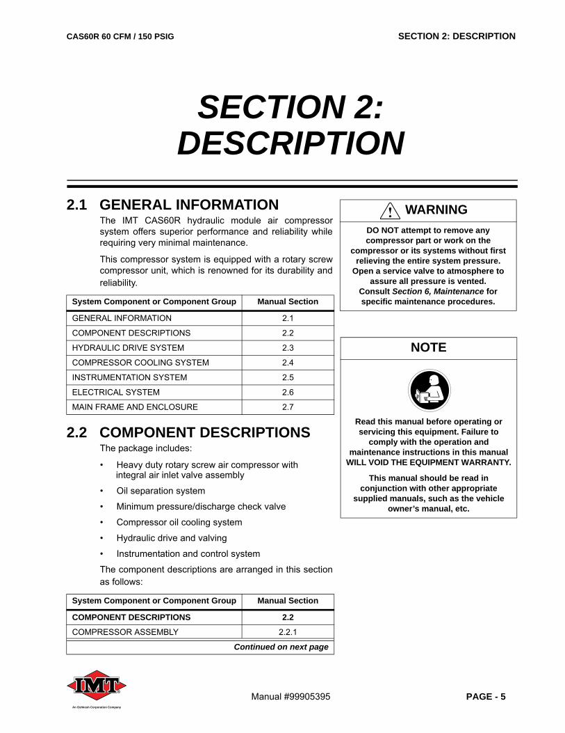
2.1 GENERAL INFORMATIONThe IMT CAS60R hydraulic module air compressorsystem offers superior performance and reliability whilerequiring very minimal maintenance.
This compressor system is equipped with a rotary screwcompressor unit, which is renowned for its durability andreliability.
2.2 COMPONENT DESCRIPTIONSThe package includes:
• Heavy duty rotary screw air compressor with integral air inlet valve assembly
• Oil separation system
• Minimum pressure/discharge check valve
• Compressor oil cooling system
• Hydraulic drive and valving
• Instrumentation and control system
The component descriptions are arranged in this sectionas follows:
System Component or Component Group Manual Section
GENERAL INFORMATION 2.1
COMPONENT DESCRIPTIONS 2.2
HYDRAULIC DRIVE SYSTEM 2.3
COMPRESSOR COOLING SYSTEM 2.4
INSTRUMENTATION SYSTEM 2.5
ELECTRICAL SYSTEM 2.6
MAIN FRAME AND ENCLOSURE 2.7
System Component or Component Group Manual Section
COMPONENT DESCRIPTIONS 2.2
COMPRESSOR ASSEMBLY 2.2.1
Continued on next page
WARNINGDO NOT attempt to remove any compressor part or work on the
compressor or its systems without first relieving the entire system pressure.
Open a service valve to atmosphere to assure all pressure is vented.
Consult Section 6, Maintenance for specific maintenance procedures.
SECTION 2:DESCRIPTION
NOTE
Read this manual before operating or servicing this equipment. Failure to
comply with the operation and maintenance instructions in this manual
WILL VOID THE EQUIPMENT WARRANTY.
This manual should be read in conjunction with other appropriate
supplied manuals, such as the vehicle owner’s manual, etc.
SECTION 2: DESCRIPTION CAS60R 60 CFM / 150 PSIG
PAGE - 6 Manual #99905395®
An Oshkosh Corporation Company
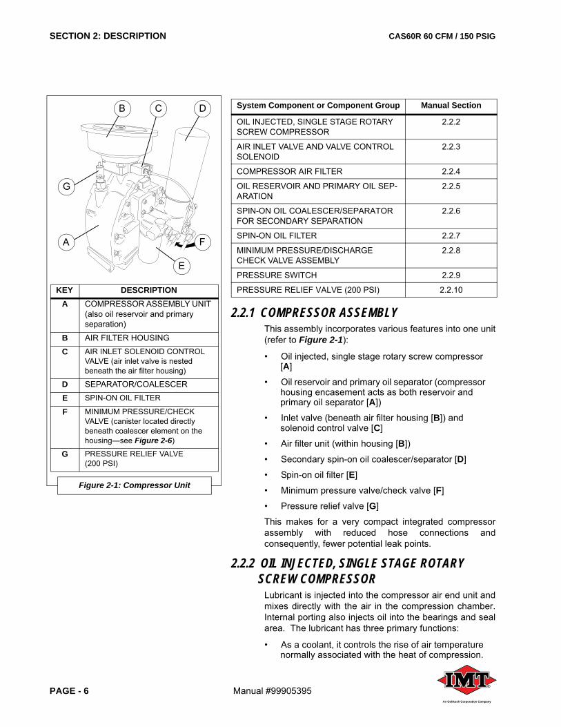
2.2.1 COMPRESSOR ASSEMBLYThis assembly incorporates various features into one unit(refer to Figure 2-1):
• Oil injected, single stage rotary screw compressor [A]
• Oil reservoir and primary oil separator (compressor housing encasement acts as both reservoir and primary oil separator [A])
• Inlet valve (beneath air filter housing [B]) and solenoid control valve [C]
• Air filter unit (within housing [B])
• Secondary spin-on oil coalescer/separator [D]
• Spin-on oil filter [E]
• Minimum pressure valve/check valve [F]
• Pressure relief valve [G]
This makes for a very compact integrated compressorassembly with reduced hose connections andconsequently, fewer potential leak points.
2.2.2 OIL INJECTED, SINGLE STAGE ROTARY SCREW COMPRESSOR
Lubricant is injected into the compressor air end unit andmixes directly with the air in the compression chamber.Internal porting also injects oil into the bearings and sealarea. The lubricant has three primary functions:
• As a coolant, it controls the rise of air temperature normally associated with the heat of compression.
OIL INJECTED, SINGLE STAGE ROTARY SCREW COMPRESSOR
2.2.2
AIR INLET VALVE AND VALVE CONTROL SOLENOID
2.2.3
COMPRESSOR AIR FILTER 2.2.4
OIL RESERVOIR AND PRIMARY OIL SEP-ARATION
2.2.5
SPIN-ON OIL COALESCER/SEPARATOR FOR SECONDARY SEPARATION
2.2.6
SPIN-ON OIL FILTER 2.2.7
MINIMUM PRESSURE/DISCHARGE CHECK VALVE ASSEMBLY
2.2.8
PRESSURE SWITCH 2.2.9
PRESSURE RELIEF VALVE (200 PSI) 2.2.10
System Component or Component Group Manual Section
KEY DESCRIPTIONA COMPRESSOR ASSEMBLY UNIT
(also oil reservoir and primaryseparation)
B AIR FILTER HOUSING
C AIR INLET SOLENOID CONTROL VALVE (air inlet valve is nested beneath the air filter housing)
D SEPARATOR/COALESCER
E SPIN-ON OIL FILTER
F MINIMUM PRESSURE/CHECK VALVE (canister located directly beneath coalescer element on the housing—see Figure 2-6)
G PRESSURE RELIEF VALVE(200 PSI)
Figure 2-1: Compressor Unit
B C D
G
A
E
F
CAS60R 60 CFM / 150 PSIG SECTION 2: DESCRIPTION
Manual #99905395 PAGE - 7®
An Oshkosh Corporation Company
• Seals the leakage paths between the rotors and the stator, and also between the rotors themselves.
• Acts as a lubricating film between the rotors allowing one rotor to directly drive the other, which is an idler. It also lubricates the bearings and seal.
The screw compressor assembly is mounted inside themain casting and consists of a male and female rotor,supported with anti-friction bearings suitably sized forlong life.
2.2.3 OIL RESERVOIR AND PRIMARY OIL SEPARATION
The main casting, which contains the screw compressor,is also the oil reservoir and primary oil separation unit.The initial (primary) oil separation is caused by bothchanges in velocity and direction. The main casting alsocontains the oil level/fill plug and oil drain connection. Aseparate oil reservoir is not required.
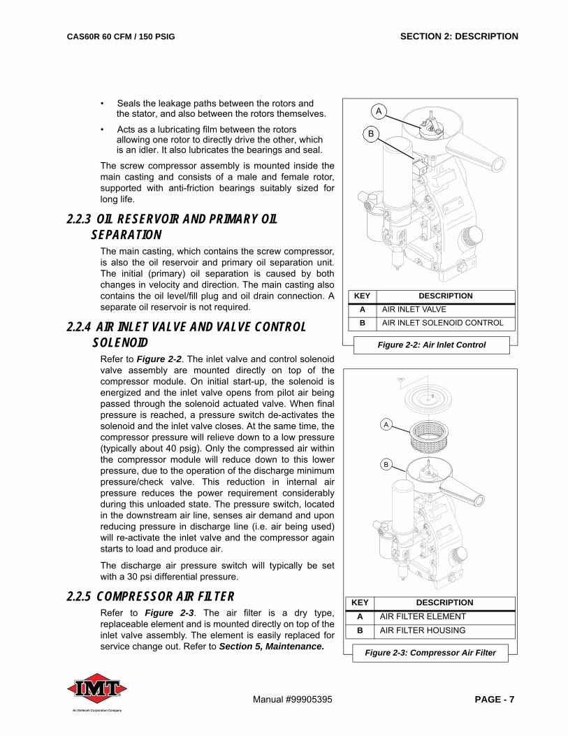
2.2.4 AIR INLET VALVE AND VALVE CONTROL SOLENOID
Refer to Figure 2-2. The inlet valve and control solenoidvalve assembly are mounted directly on top of thecompressor module. On initial start-up, the solenoid isenergized and the inlet valve opens from pilot air beingpassed through the solenoid actuated valve. When finalpressure is reached, a pressure switch de-activates thesolenoid and the inlet valve closes. At the same time, thecompressor pressure will relieve down to a low pressure(typically about 40 psig). Only the compressed air withinthe compressor module will reduce down to this lowerpressure, due to the operation of the discharge minimumpressure/check valve. This reduction in internal airpressure reduces the power requirement considerablyduring this unloaded state. The pressure switch, locatedin the downstream air line, senses air demand and uponreducing pressure in discharge line (i.e. air being used)will re-activate the inlet valve and the compressor againstarts to load and produce air.
The discharge air pressure switch will typically be setwith a 30 psi differential pressure.
2.2.5 COMPRESSOR AIR FILTERRefer to Figure 2-3. The air filter is a dry type,replaceable element and is mounted directly on top of theinlet valve assembly. The element is easily replaced forservice change out. Refer to Section 5, Maintenance.
KEY DESCRIPTIONA AIR INLET VALVE
B AIR INLET SOLENOID CONTROL
Figure 2-2: Air Inlet Control
B
A
KEY DESCRIPTIONA AIR FILTER ELEMENT
B AIR FILTER HOUSING
Figure 2-3: Compressor Air Filter
A
B
SECTION 2: DESCRIPTION CAS60R 60 CFM / 150 PSIG
PAGE - 8 Manual #99905395®
An Oshkosh Corporation Company
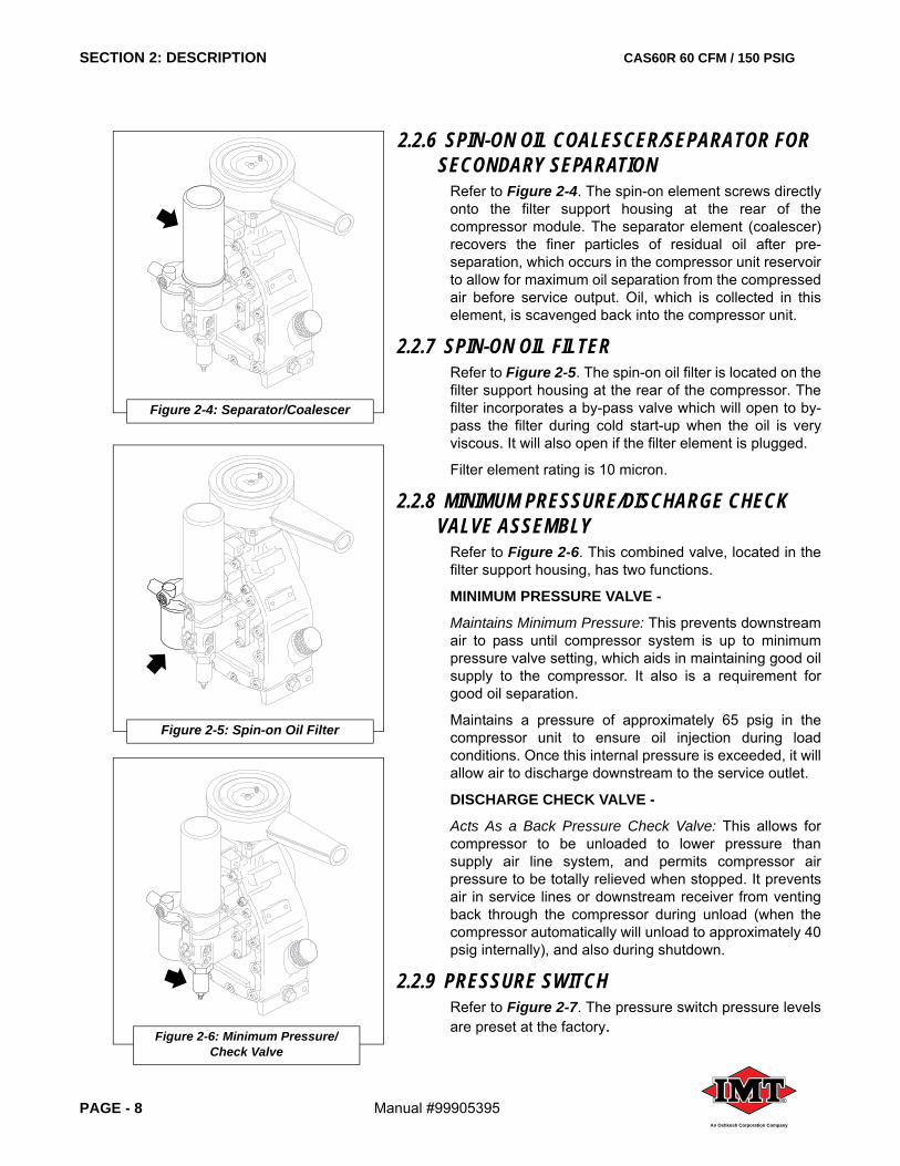
2.2.6 SPIN-ON OIL COALESCER/SEPARATOR FOR SECONDARY SEPARATION
Refer to Figure 2-4. The spin-on element screws directlyonto the filter support housing at the rear of thecompressor module. The separator element (coalescer)recovers the finer particles of residual oil after pre-separation, which occurs in the compressor unit reservoirto allow for maximum oil separation from the compressedair before service output. Oil, which is collected in thiselement, is scavenged back into the compressor unit.
2.2.7 SPIN-ON OIL FILTERRefer to Figure 2-5. The spin-on oil filter is located on thefilter support housing at the rear of the compressor. Thefilter incorporates a by-pass valve which will open to by-pass the filter during cold start-up when the oil is veryviscous. It will also open if the filter element is plugged.
Filter element rating is 10 micron.
2.2.8 MINIMUM PRESSURE/DISCHARGE CHECK VALVE ASSEMBLY
Refer to Figure 2-6. This combined valve, located in thefilter support housing, has two functions.
MINIMUM PRESSURE VALVE -
Maintains Minimum Pressure: This prevents downstreamair to pass until compressor system is up to minimumpressure valve setting, which aids in maintaining good oilsupply to the compressor. It also is a requirement forgood oil separation.
Maintains a pressure of approximately 65 psig in thecompressor unit to ensure oil injection during loadconditions. Once this internal pressure is exceeded, it willallow air to discharge downstream to the service outlet.
DISCHARGE CHECK VALVE -
Acts As a Back Pressure Check Valve: This allows forcompressor to be unloaded to lower pressure thansupply air line system, and permits compressor airpressure to be totally relieved when stopped. It preventsair in service lines or downstream receiver from ventingback through the compressor during unload (when thecompressor automatically will unload to approximately 40psig internally), and also during shutdown.
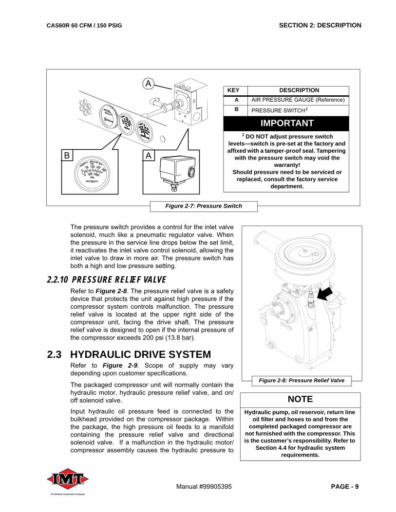
2.2.9 PRESSURE SWITCHRefer to Figure 2-7. The pressure switch pressure levelsare preset at the factory.
Figure 2-4: Separator/Coalescer
Figure 2-5: Spin-on Oil Filter
Figure 2-6: Minimum Pressure/Check Valve
CAS60R 60 CFM / 150 PSIG SECTION 2: DESCRIPTION
Manual #99905395 PAGE - 9®
An Oshkosh Corporation Company
The pressure switch provides a control for the inlet valvesolenoid, much like a pneumatic regulator valve. Whenthe pressure in the service line drops below the set limit,it reactivates the inlet valve control solenoid, allowing theinlet valve to draw in more air. The pressure switch hasboth a high and low pressure setting.
2.2.10 PRESSURE RELIEF VALVERefer to Figure 2-8. The pressure relief valve is a safetydevice that protects the unit against high pressure if thecompressor system controls malfunction. The pressurerelief valve is located at the upper right side of thecompressor unit, facing the drive shaft. The pressurerelief valve is designed to open if the internal pressure ofthe compressor exceeds 200 psi (13.8 bar).
2.3 HYDRAULIC DRIVE SYSTEMRefer to Figure 2-9. Scope of supply may varydepending upon customer specifications.
The packaged compressor unit will normally contain thehydraulic motor, hydraulic pressure relief valve, and on/off solenoid valve.
Input hydraulic oil pressure feed is connected to thebulkhead provided on the compressor package. Withinthe package, the high pressure oil feeds to a manifoldcontaining the pressure relief valve and directionalsolenoid valve. If a malfunction in the hydraulic motor/compressor assembly causes the hydraulic pressure to
NOTEHydraulic pump, oil reservoir, return line
oil filter and hoses to and from the completed packaged compressor are
not furnished with the compressor. This is the customer’s responsibility. Refer to
Section 4.4 for hydraulic system requirements.
Figure 2-7: Pressure Switch
A
A
B
KEY DESCRIPTIONA AIR PRESSURE GAUGE (Reference)
B PRESSURE SWITCHI
IMPORTANTI DO NOT adjust pressure switch
levels—switch is pre-set at the factory and affixed with a tamper-proof seal. Tampering
with the pressure switch may void the warranty!
Should pressure need to be serviced or replaced, consult the factory service
department.
Figure 2-8: Pressure Relief Valve
SECTION 2: DESCRIPTION CAS60R 60 CFM / 150 PSIG
PAGE - 10 Manual #99905395®
An Oshkosh Corporation Company
rise, it will bypass to the return line to safeguard damageor potential injury.
The directional solenoid valve is normally activated bythe on/off selector switch mounted in the instrumentcluster on the package. This valve is also connectedthrough the compressor safety circuits for over-temperature and over-pressure. If either conditionoccurs, it will shut the unit down by diverting oil back tothe tank. It is possible to add a remote on/off switch inparallel with the instrument cluster to permit on/offoperation from another location on the vehicle.
Hydraulic oil from the manifold is hosed directly to thehydraulic motor and the outlet from the motor passes tothe return line connection on the package. Customer isresponsible for providing both hydraulic feed and returnlines.
The hydraulic motor powers the compressor via a beltdrive system.
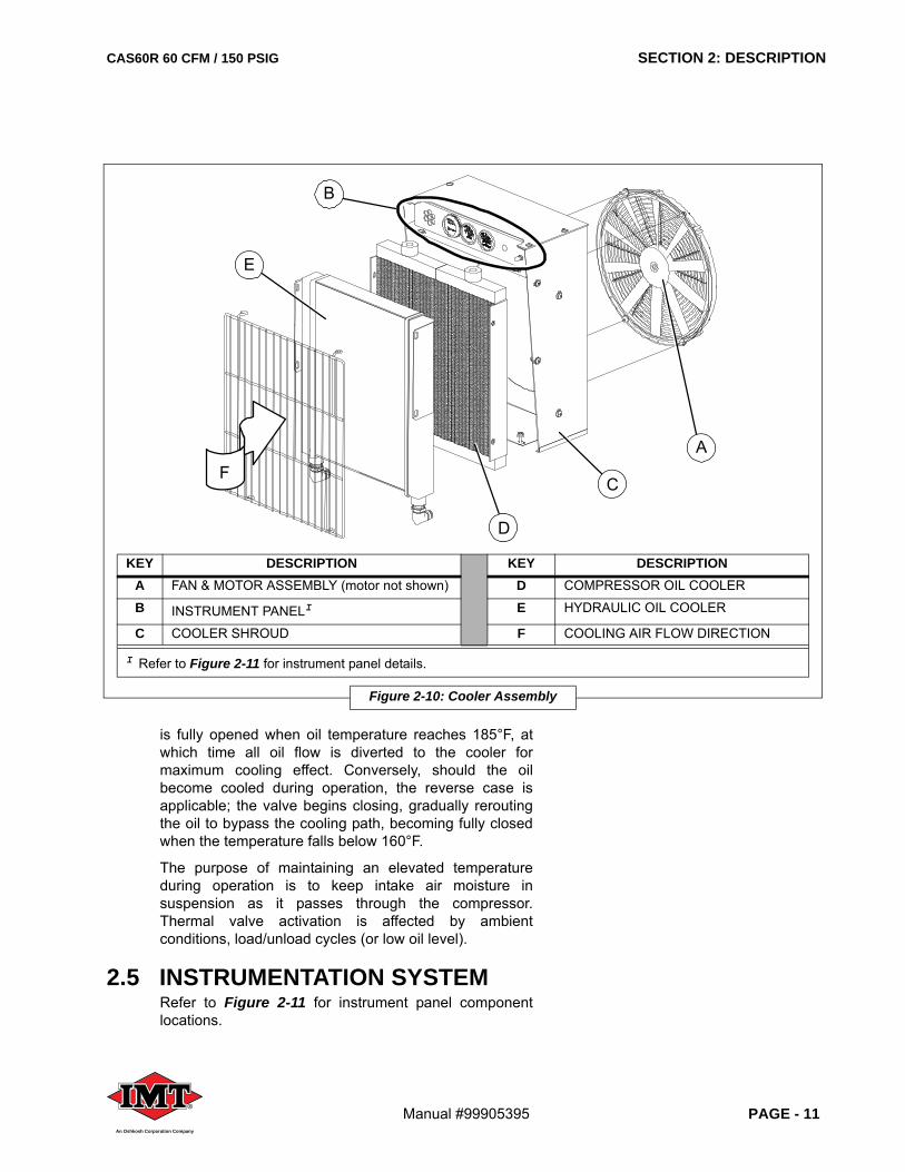
2.4 COMPRESSOR COOLING SYSTEMRefer to Figure 2-10. The package contains a coolerassembly powered by an electric fan. Oil from thecompressor sump passes through this cooler beforebeing filtered for re-injection into the compressor. Whenthe oil temperature reaches 160°F, the thermal valveactivates to gradually begin rerouting progressiveamounts of heated oil to the cooler to maintain the correctoperating temperature for the compressor oil. The valve
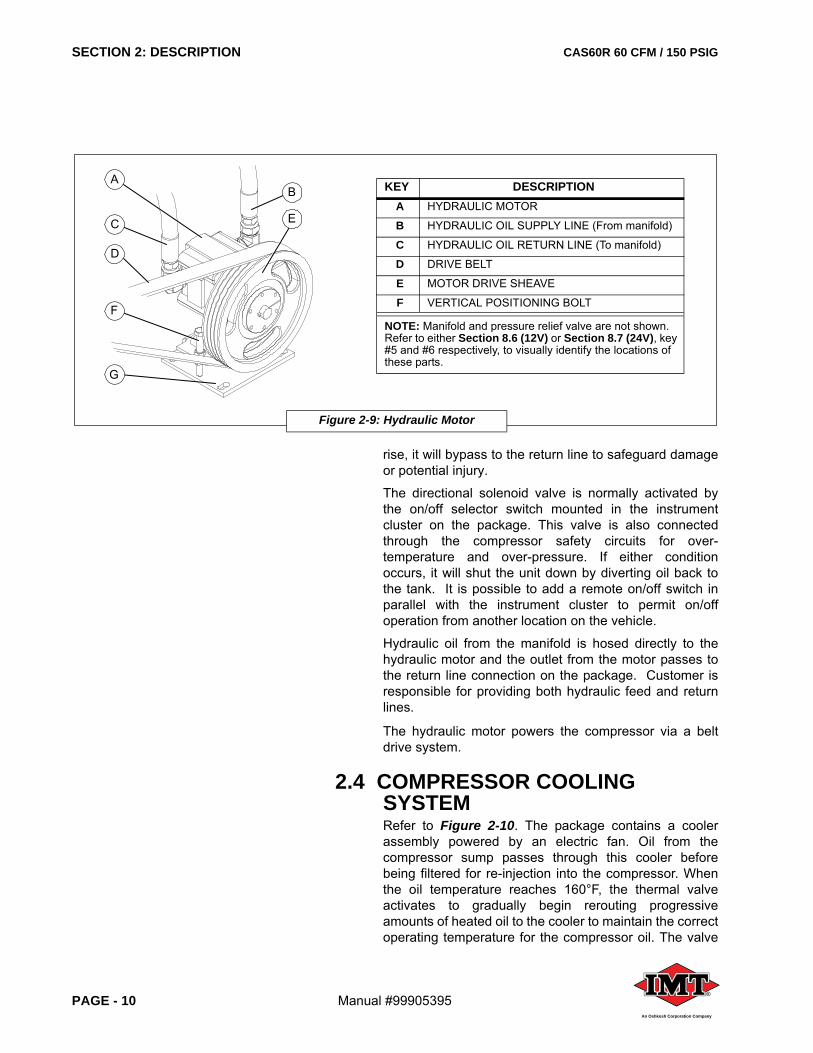
Figure 2-9: Hydraulic Motor
AB
EC
D
F
G
KEY DESCRIPTIONA HYDRAULIC MOTOR
B HYDRAULIC OIL SUPPLY LINE (From manifold)
C HYDRAULIC OIL RETURN LINE (To manifold)
D DRIVE BELT
E MOTOR DRIVE SHEAVE
F VERTICAL POSITIONING BOLT
NOTE: Manifold and pressure relief valve are not shown. Refer to either Section 8.6 (12V) or Section 8.7 (24V), key #5 and #6 respectively, to visually identify the locations of these parts.
CAS60R 60 CFM / 150 PSIG SECTION 2: DESCRIPTION
Manual #99905395 PAGE - 11®
An Oshkosh Corporation Company
is fully opened when oil temperature reaches 185°F, atwhich time all oil flow is diverted to the cooler formaximum cooling effect. Conversely, should the oilbecome cooled during operation, the reverse case isapplicable; the valve begins closing, gradually reroutingthe oil to bypass the cooling path, becoming fully closedwhen the temperature falls below 160°F.
The purpose of maintaining an elevated temperatureduring operation is to keep intake air moisture insuspension as it passes through the compressor.Thermal valve activation is affected by ambientconditions, load/unload cycles (or low oil level).
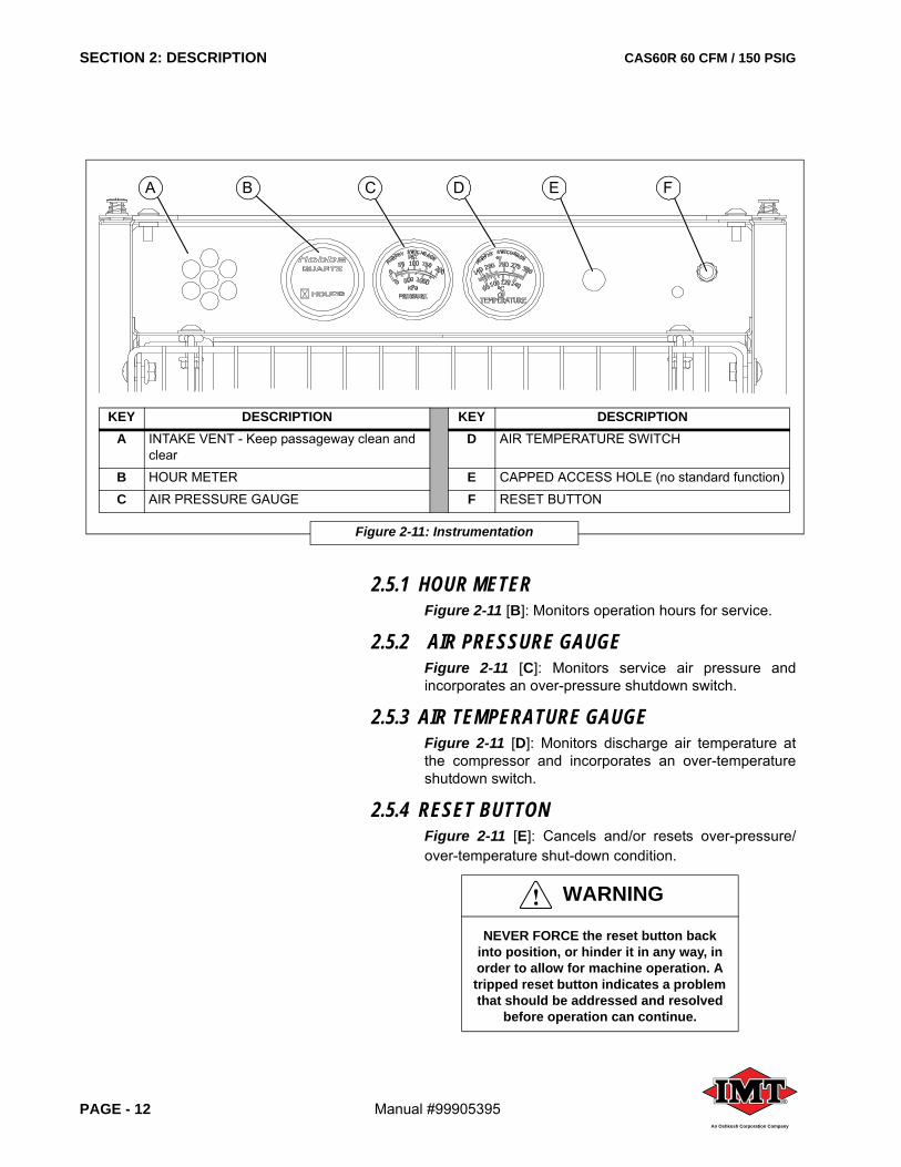
2.5 INSTRUMENTATION SYSTEMRefer to Figure 2-11 for instrument panel componentlocations.
KEY DESCRIPTION KEY DESCRIPTIONA FAN & MOTOR ASSEMBLY (motor not shown) D COMPRESSOR OIL COOLER
B INSTRUMENT PANELI E HYDRAULIC OIL COOLER
C COOLER SHROUD F COOLING AIR FLOW DIRECTION
I Refer to Figure 2-11 for instrument panel details.
Figure 2-10: Cooler Assembly
FA
B
C
D
E
SECTION 2: DESCRIPTION CAS60R 60 CFM / 150 PSIG
PAGE - 12 Manual #99905395®
An Oshkosh Corporation Company
2.5.1 HOUR METERFigure 2-11 [B]: Monitors operation hours for service.
2.5.2 AIR PRESSURE GAUGEFigure 2-11 [C]: Monitors service air pressure andincorporates an over-pressure shutdown switch.
2.5.3 AIR TEMPERATURE GAUGEFigure 2-11 [D]: Monitors discharge air temperature atthe compressor and incorporates an over-temperatureshutdown switch.
2.5.4 RESET BUTTONFigure 2-11 [E]: Cancels and/or resets over-pressure/over-temperature shut-down condition.
WARNING
NEVER FORCE the reset button back into position, or hinder it in any way, in order to allow for machine operation. A tripped reset button indicates a problem that should be addressed and resolved
before operation can continue.
KEY DESCRIPTION KEY DESCRIPTIONA INTAKE VENT - Keep passageway clean and
clearD AIR TEMPERATURE SWITCH
B HOUR METER E CAPPED ACCESS HOLE (no standard function)
C AIR PRESSURE GAUGE F RESET BUTTON
Figure 2-11: Instrumentation
BA C D FE
CAS60R 60 CFM / 150 PSIG SECTION 2: DESCRIPTION
Manual #99905395 PAGE - 13®
An Oshkosh Corporation Company
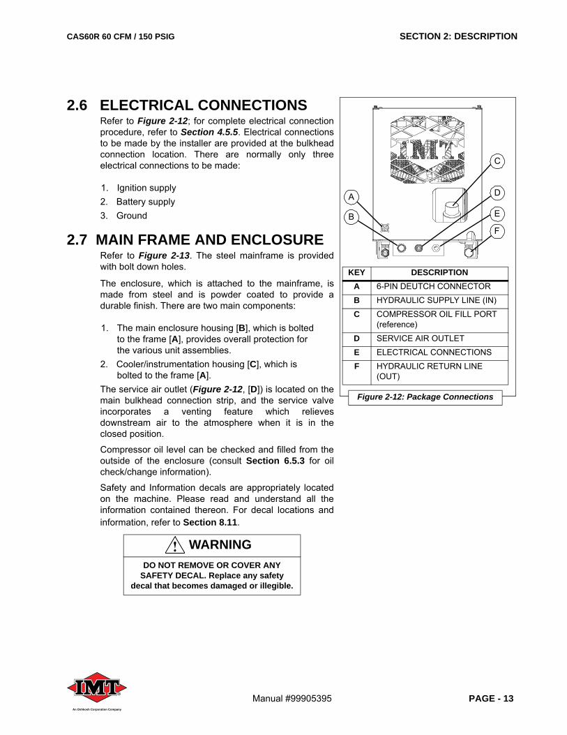
2.6 ELECTRICAL CONNECTIONSRefer to Figure 2-12; for complete electrical connectionprocedure, refer to Section 4.5.5. Electrical connectionsto be made by the installer are provided at the bulkheadconnection location. There are normally only threeelectrical connections to be made:
1. Ignition supply2. Battery supply3. Ground
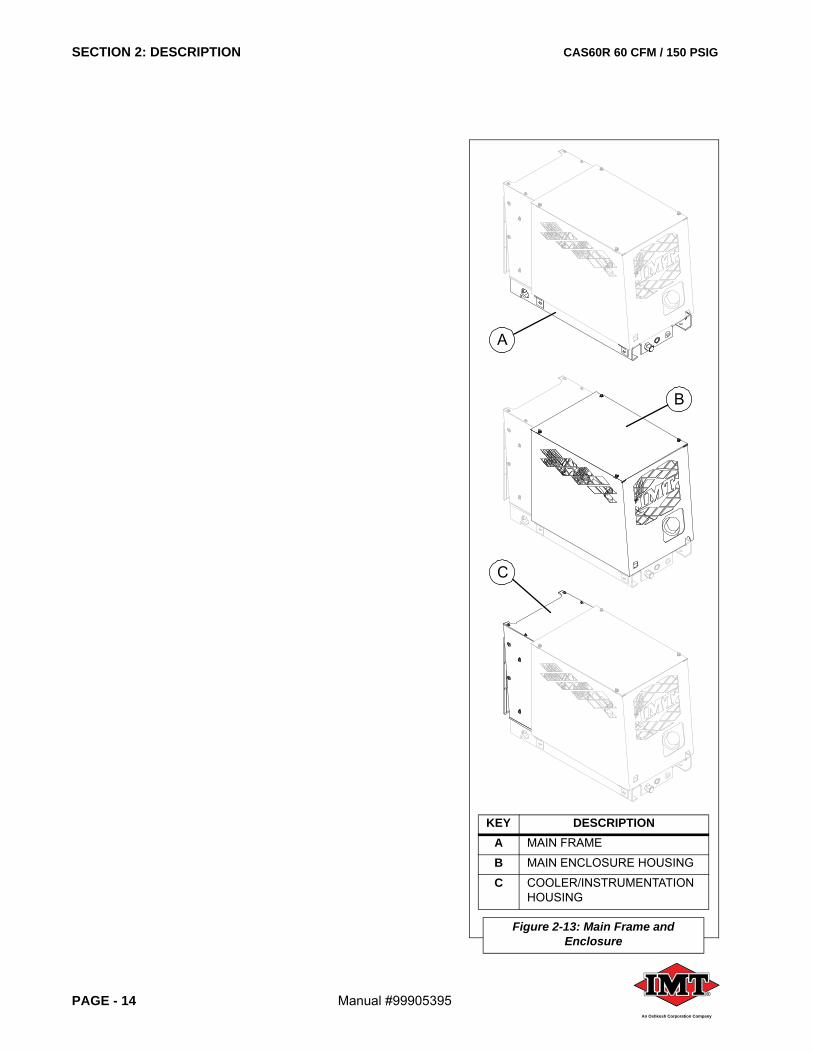
2.7 MAIN FRAME AND ENCLOSURERefer to Figure 2-13. The steel mainframe is providedwith bolt down holes.
The enclosure, which is attached to the mainframe, ismade from steel and is powder coated to provide adurable finish. There are two main components:
1. The main enclosure housing [B], which is bolted to the frame [A], provides overall protection for the various unit assemblies.
2. Cooler/instrumentation housing [C], which is bolted to the frame [A].
The service air outlet (Figure 2-12, [D]) is located on themain bulkhead connection strip, and the service valveincorporates a venting feature which relievesdownstream air to the atmosphere when it is in theclosed position.
Compressor oil level can be checked and filled from theoutside of the enclosure (consult Section 6.5.3 for oilcheck/change information).
Safety and Information decals are appropriately locatedon the machine. Please read and understand all theinformation contained thereon. For decal locations andinformation, refer to Section 8.11.
WARNINGDO NOT REMOVE OR COVER ANY
SAFETY DECAL. Replace any safety decal that becomes damaged or illegible.
KEY DESCRIPTIONA 6-PIN DEUTCH CONNECTOR
B HYDRAULIC SUPPLY LINE (IN)
C COMPRESSOR OIL FILL PORT(reference)
D SERVICE AIR OUTLET
E ELECTRICAL CONNECTIONS
F HYDRAULIC RETURN LINE (OUT)
Figure 2-12: Package Connections
C
B
D
E
F
A
SECTION 2: DESCRIPTION CAS60R 60 CFM / 150 PSIG
PAGE - 14 Manual #99905395®
An Oshkosh Corporation Company
KEY DESCRIPTIONA MAIN FRAME
B MAIN ENCLOSURE HOUSING
C COOLER/INSTRUMENTATIONHOUSING
Figure 2-13: Main Frame andEnclosure
A
C
B
CAS60R 60 CFM / 150 PSIG SECTION 3: SPECIFICATIONS
Manual #99905395 PAGE - 15®
An Oshkosh Corporation Company
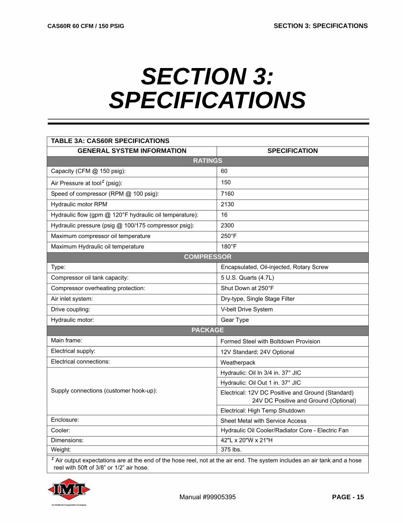
TABLE 3A: CAS60R SPECIFICATIONSGENERAL SYSTEM INFORMATION SPECIFICATION
RATINGSCapacity (CFM @ 150 psig): 60
Air Pressure at toolI (psig): 150
Speed of compressor (RPM @ 100 psig): 7160
Hydraulic motor RPM 2130
Hydraulic flow (gpm @ 120°F hydraulic oil temperature): 16
Hydraulic pressure (psig @ 100/175 compressor psig): 2300
Maximum compressor oil temperature 250°F
Maximum Hydraulic oil temperature 180°F
COMPRESSORType: Encapsulated, Oil-injected, Rotary Screw
Compressor oil tank capacity: 5 U.S. Quarts (4.7L)
Compressor overheating protection: Shut Down at 250°F
Air inlet system: Dry-type, Single Stage Filter
Drive coupling: V-belt Drive System
Hydraulic motor: Gear Type
PACKAGEMain frame: Formed Steel with Boltdown ProvisionElectrical supply: 12V Standard; 24V OptionalElectrical connections: Weatherpack
Supply connections (customer hook-up):
Hydraulic: Oil In 3/4 in. 37° JIC
Hydraulic: Oil Out 1 in. 37° JIC
Electrical: 12V DC Positive and Ground (Standard)24V DC Positive and Ground (Optional)
Electrical: High Temp ShutdownEnclosure: Sheet Metal with Service AccessCooler: Hydraulic Oil Cooler/Radiator Core - Electric Fan
Dimensions: 42"L x 20"W x 21"HWeight: 375 lbs.I Air output expectations are at the end of the hose reel, not at the air end. The system includes an air tank and a hose reel with 50ft of 3/8” or 1/2” air hose.
SECTION 3: SPECIFICATIONS
SECTION 3: SPECIFICATIONS CAS60R 60 CFM / 150 PSIG
PAGE - 16 Manual #99905395®
An Oshkosh Corporation Company
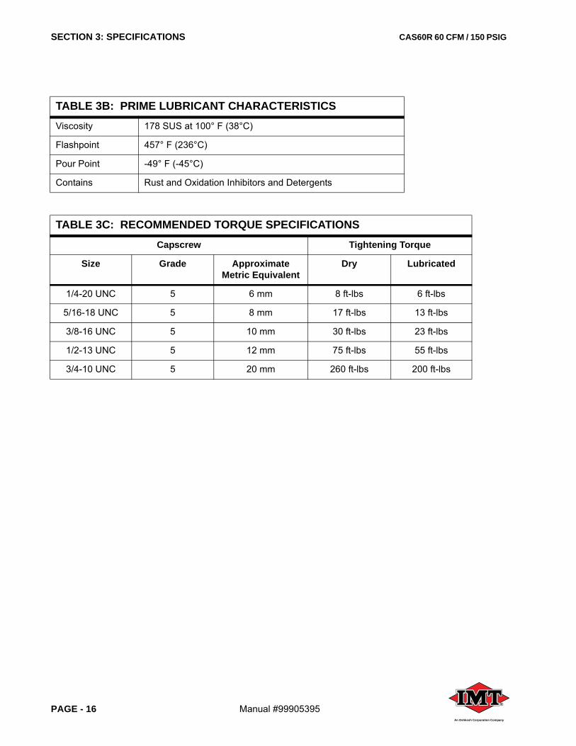
TABLE 3B: PRIME LUBRICANT CHARACTERISTICSViscosity 178 SUS at 100° F (38°C)
Flashpoint 457° F (236°C)
Pour Point -49° F (-45°C)
Contains Rust and Oxidation Inhibitors and Detergents
TABLE 3C: RECOMMENDED TORQUE SPECIFICATIONSCapscrew Tightening Torque
Size Grade Approximate Metric Equivalent
Dry Lubricated
1/4-20 UNC 5 6 mm 8 ft-lbs 6 ft-lbs
5/16-18 UNC 5 8 mm 17 ft-lbs 13 ft-lbs
3/8-16 UNC 5 10 mm 30 ft-lbs 23 ft-lbs
1/2-13 UNC 5 12 mm 75 ft-lbs 55 ft-lbs
3/4-10 UNC 5 20 mm 260 ft-lbs 200 ft-lbs
CAS60R 60 CFM / 150 PSIG SECTION 4: INSTALLATION
Manual #99905395 PAGE - 17®
An Oshkosh Corporation Company
4.1 MACHINE PACKAGE RECEIPT/INSPECTIONUpon receipt of the machine package, inspect theexterior of the shipping crate for signs of shipping/transitdamage. Any damage should be reported immediately tothe shipping company. Open the lid and inspect thecomponent parts and supports to ensure that there hasbeen no internal movement of assemblies or componentswhich may have caused damage. To install the CAS60Rcompressor system, refer to the following sections:
4.2 GENERAL INSTRUCTIONSThis section provides general guidance for locating andpreparing the CAS60R compressor package foroperation. Each installation is unique and can be affectedby location, ventilation, and other factors such aselectrical and hydraulic power supply availability andlocation.
4.3 DETERMINING THE CAS60R UNIT MOUNTING LOCATIONWhen determining the location to mount the CAS60Runit, the following criteria must be taken intoconsideration:
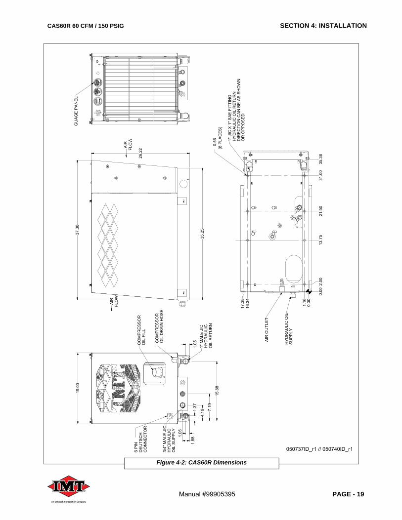
• Refer to Section 4.5. The location must allow for the machine dimensions (Figure 4-2), and additional space requirements for minimum cooling, access and maintenance. Refer to Figure 4-3 to determine the minimum space requirements.
System Component or Component Group Manual Section
GENERAL INSTRUCTIONS 4.2
DETERMINING THE CAS60R UNIT MOUNTING LOATION
4.3
HYDRAULIC SYSTEM REQUIREMENTS 4.4
INSTALLATION 4.5
SECTION 4:INSTALLATION
WARNINGInstall, operate, and maintain this
equipment in full compliance with all applicable OSHA, other Federal, state,
local codes, standards, and regulations.
WARNINGDO NOT perform any modifications to this equipment without prior factory
approval.
WARNINGDO NOT use plastic pipe, or incorrectly rated piping or hose. Incorrectly rated connection material can fail and cause
injury or equipment damage.
WARNINGDO NOT operate the compressor in enclosed or confined spaces where
ventilation is restricted or closed off.
WARNINGBefore performing maintenance or repair
operations on the compressor, ensure that all power has been removed and
locked out to prevent accidental application.
DO NOT assume that because the compressor is in a STOPPED condition
that power has been removed.
SECTION 4: INSTALLATION CAS60R 60 CFM / 150 PSIG
PAGE - 18 Manual #99905395®
An Oshkosh Corporation Company
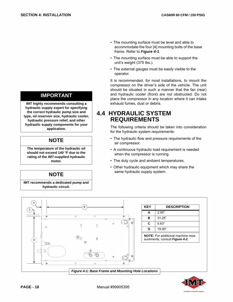
• The mounting surface must be level and able to accommodate the four [4] mounting bolts of the base frame. Refer to Figure 4-1.
• The mounting surface must be able to support the unit’s weight (375 lbs.).
• The external gauges must be easily visible to the operator.
It is recommended, for most installations, to mount thecompressor on the driver’s side of the vehicle. The unitshould be situated in such a manner that the fan (rear)and hydraulic cooler (front) are not obstructed. Do notplace the compressor in any location where it can intakeexhaust fumes, dust or debris.
4.4 HYDRAULIC SYSTEM REQUIREMENTSThe following criteria should be taken into considerationfor the hydraulic system requirements:
• The hydraulic flow and pressure requirements of the air compressor.
• A continuous hydraulic load requirement is needed when the compressor is running.
• The duty cycle and ambient temperatures.
• Other hydraulic equipment which may share the same hydraulic supply system.
IMPORTANTIMT highly recommends consulting a hydraulic supply expert for specifying the correct hydraulic pump size and
type, oil reservoir size, hydraulic cooler, hydraulic pressure relief, and other
hydraulic supply components for your application.
NOTEThe temperature of the hydraulic oil should not exceed 140 °F due to the rating of the IMT-supplied hydraulic
motor.
Figure 4-1: Base Frame and Mounting Hole Locations
BA
C
D
KEY DESCRIPTIONA 2.00”
B 31.25”
C 0.63”
D 19.00”
NOTE: For additional machine mea-surements, consult Figure 4-2.
NOTEIMT recommends a dedicated pump and
hydraulic circuit.
CAS60R 60 CFM / 150 PSIG SECTION 4: INSTALLATION
Manual #99905395 PAGE - 19®
An Oshkosh Corporation Company
Figure 4-2: CAS60R Dimensions
CO
MP
RE
SS
OR
OIL
DR
AIN
HO
SE
6 P
IND
EU
TSC
HC
ON
NE
CTO
R
HY
DR
AU
LIC
OIL
RE
TUR
N
1" M
ALE
JIC
HY
DR
AU
LIC
OIL
SU
PP
LY
3/4"
MA
LE J
IC
35.2
5
26.2
2
19.0
0
OR
OP
PO
SE
DD
IRE
CTI
ON
CA
N B
E A
S S
HO
WN
HY
DR
AU
LIC
OIL
RE
TUR
N1"
JIC
X 1
" SA
E F
ITTI
NG
13.7
521
.50
31.0
035
.38
17.3
8
(8 P
LAC
ES
)0.
56
SU
PP
LYH
YD
RA
ULI
C O
IL
GU
AG
E P
AN
EL
AIR
FLO
W
AIR
FLO
W
OIL
FIL
LC
OM
PR
ES
SO
R
1.05
1.88
1.37
4.19 7.
19
15.8
8
37.3
8
1.05
AIR
OU
TLE
T
0.00
0.00
2.00
1.16
16.3
4
050737ID_r1 // 050740ID_r1
SECTION 4: INSTALLATION CAS60R 60 CFM / 150 PSIG
PAGE - 20 Manual #99905395®
An Oshkosh Corporation Company
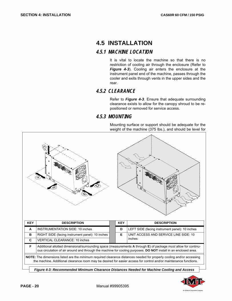
4.5 INSTALLATION4.5.1 MACHINE LOCATION
It is vital to locate the machine so that there is norestriction of cooling air through the enclosure (Refer toFigure 4-3). Cooling air enters the enclosure at theinstrument panel end of the machine, passes through thecooler and exits through vents in the upper sides and therear.
4.5.2 CLEARANCERefer to Figure 4-3. Ensure that adequate surroundingclearance exists to allow for the canopy shroud to be re-positioned or removed for service access.
4.5.3 MOUNTINGMounting surface or support should be adequate for theweight of the machine (375 lbs.), and should be level for
KEY DESCRIPTION KEY DESCRIPTION
A INSTRUMENTATION SIDE: 10 inches D LEFT SIDE (facing instrument panel): 10 inches
B RIGHT SIDE (facing instrument panel): 10 inches E UNIT ACCESS AND SERVICE LINE SIDE: 10 inchesC VERTICAL CLEARANCE: 10 inches
F Additional allotted dimensional/surrounding space (measurements A through E) of package must allow for continu-ous circulation of air around and through the machine for cooling purposes. DO NOT install in an enclosed area.
NOTE: The dimensions listed are the minimum required clearance distances needed for properly cooling and/or accessing the machine. Additional clearance room may be desired for easier access for control and/or maintenance functions.
Figure 4-3: Recommended Minimum Clearance Distances Needed for Machine Cooling and Access
CAS60R 60 CFM / 150 PSIG SECTION 4: INSTALLATION
Manual #99905395 PAGE - 21®
An Oshkosh Corporation Company
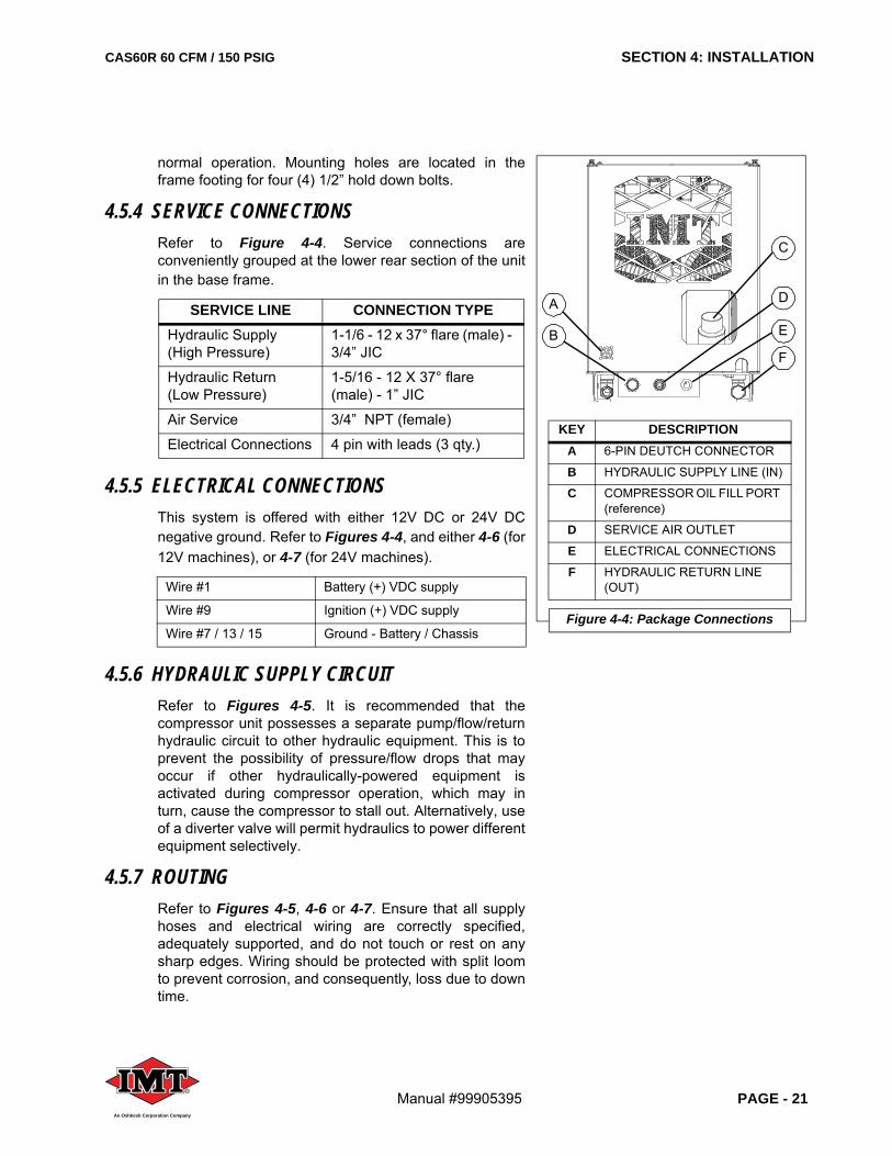
normal operation. Mounting holes are located in theframe footing for four (4) 1/2” hold down bolts.
4.5.4 SERVICE CONNECTIONSRefer to Figure 4-4. Service connections areconveniently grouped at the lower rear section of the unitin the base frame.
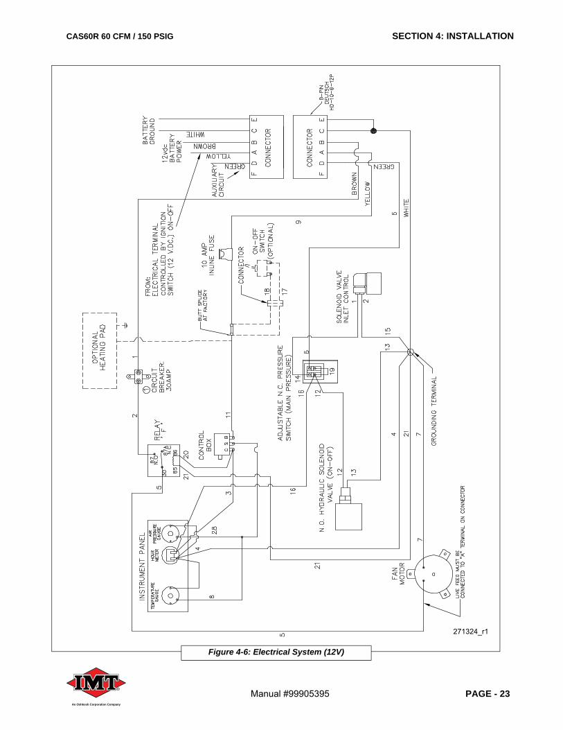
4.5.5 ELECTRICAL CONNECTIONSThis system is offered with either 12V DC or 24V DCnegative ground. Refer to Figures 4-4, and either 4-6 (for12V machines), or 4-7 (for 24V machines).
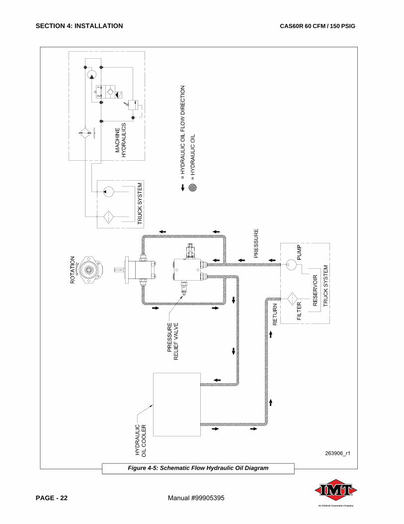
4.5.6 HYDRAULIC SUPPLY CIRCUITRefer to Figures 4-5. It is recommended that thecompressor unit possesses a separate pump/flow/returnhydraulic circuit to other hydraulic equipment. This is toprevent the possibility of pressure/flow drops that mayoccur if other hydraulically-powered equipment isactivated during compressor operation, which may inturn, cause the compressor to stall out. Alternatively, useof a diverter valve will permit hydraulics to power differentequipment selectively.
4.5.7 ROUTINGRefer to Figures 4-5, 4-6 or 4-7. Ensure that all supplyhoses and electrical wiring are correctly specified,adequately supported, and do not touch or rest on anysharp edges. Wiring should be protected with split loomto prevent corrosion, and consequently, loss due to downtime.
SERVICE LINE CONNECTION TYPEHydraulic Supply(High Pressure)
1-1/6 - 12 x 37° flare (male) - 3/4” JIC
Hydraulic Return(Low Pressure)
1-5/16 - 12 X 37° flare (male) - 1” JIC
Air Service 3/4” NPT (female)
Electrical Connections 4 pin with leads (3 qty.)
Wire #1 Battery (+) VDC supply
Wire #9 Ignition (+) VDC supply
Wire #7 / 13 / 15 Ground - Battery / Chassis
KEY DESCRIPTIONA 6-PIN DEUTCH CONNECTOR
B HYDRAULIC SUPPLY LINE (IN)
C COMPRESSOR OIL FILL PORT (reference)
D SERVICE AIR OUTLET
E ELECTRICAL CONNECTIONS
F HYDRAULIC RETURN LINE (OUT)
Figure 4-4: Package Connections
C
B
D
E
F
A
SECTION 4: INSTALLATION CAS60R 60 CFM / 150 PSIG
PAGE - 22 Manual #99905395®
An Oshkosh Corporation Company
Figure 4-5: Schematic Flow Hydraulic Oil Diagram
263906_r1
CAS60R 60 CFM / 150 PSIG SECTION 4: INSTALLATION
Manual #99905395 PAGE - 23®
An Oshkosh Corporation Company
Figure 4-6: Electrical System (12V)
271324_r1
SECTION 4: INSTALLATION CAS60R 60 CFM / 150 PSIG
PAGE - 24 Manual #99905395®
An Oshkosh Corporation Company
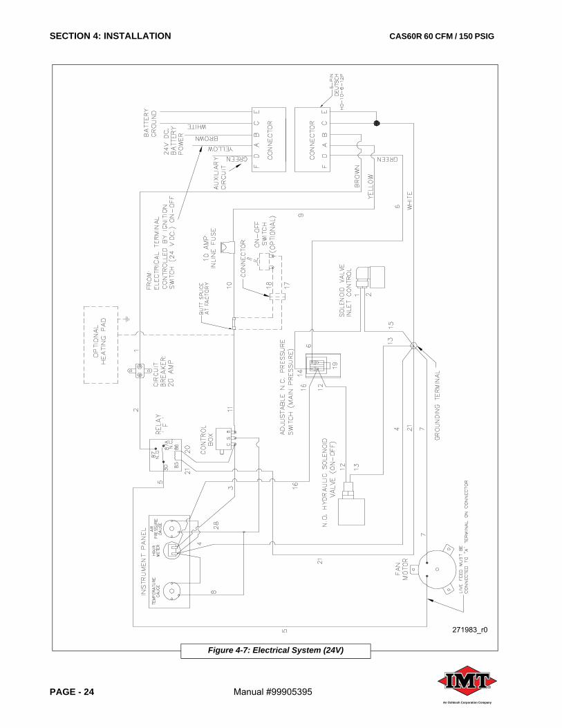
Figure 4-7: Electrical System (24V)
271983_r0
CAS60R 60 CFM / 150 PSIG SECTION 5: OPERATION
Manual #99905395 PAGE - 25®
An Oshkosh Corporation Company
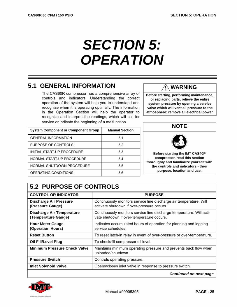
5.1 GENERAL INFORMATIONThe CAS60R compressor has a comprehensive array ofcontrols and indicators. Understanding the correctoperation of the system will help you to understand andrecognize when it is operating optimally. The informationin the Operation Section will help the operator torecognize and interpret the readings, which will call forservice or indicate the beginning of a malfunction.
System Component or Component Group Manual Section
GENERAL INFORMATION 5.1
PURPOSE OF CONTROLS 5.2
INITIAL START-UP PROCEDURE 5.3
NORMAL START-UP PROCEDURE 5.4
NORMAL SHUTDOWN PROCEDURE 5.5
OPERATING CONDITIONS 5.6
SECTION 5:OPERATION
WARNINGBefore starting, performing maintenance,
or replacing parts, relieve the entire system pressure by opening a service
valve which will vent all pressure to the atmosphere: remove all electrical power.
5.2 PURPOSE OF CONTROLSCONTROL OR INDICATOR PURPOSEDischarge Air Pressure (Pressure Gauge)
Continuously monitors service line discharge air temperature. Will activate shutdown if over-pressure occurs.
Discharge Air Temperature (Temperature Gauge)
Continuously monitors service line discharge temperature. Will acti-vate shutdown if over-temperature occurs.
Hour Meter Gauge (Operation Hours)
Indicates accumulated hours of operation for planning and logging service schedules.
Reset Button To reset latch-in relay in event of over-pressure or over-temperature.
Oil Fill/Level Plug To check/fill compressor oil level.
Minimum Pressure Check Valve Maintains minimum operating pressure and prevents back flow when unloaded/shutdown.
Pressure Switch Controls operating pressure.
Inlet Solenoid Valve Opens/closes inlet valve in response to pressure switch.
Continued on next page
NOTE
Before starting the IMT CAS40P compressor, read this section
thoroughly and familiarize yourself with the controls and indicators - their
purpose, location and use.
SECTION 5: OPERATION CAS60R 60 CFM / 150 PSIG
PAGE - 26 Manual #99905395®
An Oshkosh Corporation Company
WARNINGDO NOT remove caps, plugs and/or other
components when compressor is running or pressurized. Stop compressor
and de-pressurize system prior to maintenance of system. Relieve the
entire system pressure by opening the air tank drain/vent valve, which will vent
all pressure to the atmosphere.
Wear personal protective equipment such as gloves, work boots, and eye and
hearing protection as required for the task at hand.
Refer to Figure 5-1. Open fill cap SLOWLY (contents under pressure) to
make sure all pressure has been relieved.
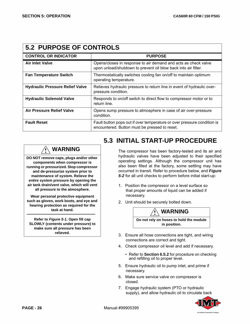
5.3 INITIAL START-UP PROCEDUREThe compressor has been factory-tested and its air andhydraulic valves have been adjusted to their specifiedoperating settings. Although the compressor unit hasalso been filled at the factory, some settling may haveoccurred in transit. Refer to procedure below, and Figure5-2 for all unit checks to perform before initial start-up:
1. Position the compressor on a level surface so that proper amounts of liquid can be added if necessary.
2. Unit should be securely bolted down.
3. Ensure all hose connections are tight, and wiring connections are correct and tight.
4. Check compressor oil level and add if necessary.
• Refer to Section 6.5.2 for procedure on checking and refilling oil to proper level.
5. Ensure hydraulic oil to pump inlet, and prime if necessary.
6. Make sure service valve on compressor is closed.
7. Engage hydraulic system (PTO or hydraulic supply), and allow hydraulic oil to circulate back
WARNINGDo not rely on hoses to hold the module
in position.
Air Inlet Valve Opens/closes in response to air demand and acts as check valve upon unload/shutdown to prevent oil blow back into air filter.
Fan Temperature Switch Thermostatically switches cooling fan on/off to maintain optimum operating temperature.
Hydraulic Pressure Relief Valve Relieves hydraulic pressure to return line in event of hydraulic over-pressure condition.
Hydraulic Solenoid Valve Responds to on/off switch to direct flow to compressor motor or to return line.
Air Pressure Relief Valve Opens sump pressure to atmosphere in case of air over-pressure condition.
Fault Reset Fault button pops out if over temperature or over pressure condition is encountered. Button must be pressed to reset.
5.2 PURPOSE OF CONTROLSCONTROL OR INDICATOR PURPOSE
CAS60R 60 CFM / 150 PSIG SECTION 5: OPERATION
Manual #99905395 PAGE - 27®
An Oshkosh Corporation Company
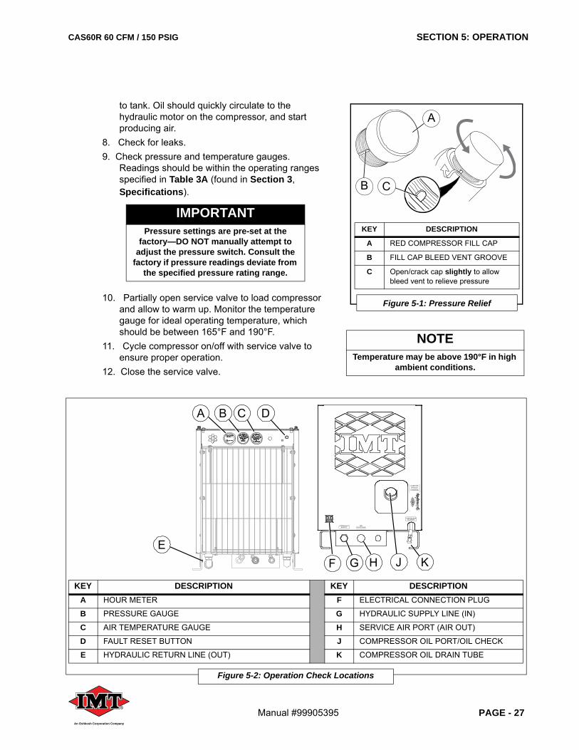
KEY DESCRIPTION KEY DESCRIPTIONA HOUR METER F ELECTRICAL CONNECTION PLUG
B PRESSURE GAUGE G HYDRAULIC SUPPLY LINE (IN)
C AIR TEMPERATURE GAUGE H SERVICE AIR PORT (AIR OUT)
D FAULT RESET BUTTON J COMPRESSOR OIL PORT/OIL CHECK
E HYDRAULIC RETURN LINE (OUT) K COMPRESSOR OIL DRAIN TUBE
Figure 5-2: Operation Check Locations
®
GF H JE
A B C D
K
to tank. Oil should quickly circulate to the hydraulic motor on the compressor, and start producing air.
8. Check for leaks.9. Check pressure and temperature gauges.
Readings should be within the operating ranges specified in Table 3A (found in Section 3, Specifications).
10. Partially open service valve to load compressor and allow to warm up. Monitor the temperature gauge for ideal operating temperature, which should be between 165°F and 190°F.
11. Cycle compressor on/off with service valve to ensure proper operation.
12. Close the service valve.
IMPORTANTPressure settings are pre-set at the
factory—DO NOT manually attempt to adjust the pressure switch. Consult the
factory if pressure readings deviate from the specified pressure rating range.
KEY DESCRIPTION
A RED COMPRESSOR FILL CAP
B FILL CAP BLEED VENT GROOVE
C Open/crack cap slightly to allow bleed vent to relieve pressure
Figure 5-1: Pressure Relief
A
B C
NOTETemperature may be above 190°F in high
ambient conditions.
SECTION 5: OPERATION CAS60R 60 CFM / 150 PSIG
PAGE - 28 Manual #99905395®
An Oshkosh Corporation Company
13. Disengage hydraulic system; compressor ceases to produce air.
14. Allow air to vent to atmosphere. Check compressor oil level and add if necessary. Check and correct any leaks, tighten any loose fittings and check drive belt tension.
5.4 ROUTINE START-UP PROCEDURE1. Check compressor oil level and add if necessary.
Refer to Section 6.5.2.2. Close the air service valve.3. Engage hydraulic system (PTO or hydraulic
supply). This will activate the compressor.4. Allow machine to warm up for several minutes
before operating.
5.5 ROUTINE SHUTDOWN PROCEDURE1. Close service valve and allow compressor to
unload and cool down (approximately five [5] minutes.).
2. Shut off hydraulic power supply.
5.6 OPERATING CONDITIONS1 . Operate only in well ventilated areas.2. Ensure there are no obstructions of cooling air
intakes and outlets around the unit.3. Do not leave anything resting on top of the
machine. Hot cooling air will generate high heat and must not be restricted.
4. Be sure to leave sufficient room around the unit for cooling air circulation. A minimum of ten (10) inches clearance is needed for the cooler intake and sides, and ten (10) inches for the rear of the unit. Heated air must be able to vent away from the intake.
5. Operate machine with top cover closed.6. Refer to specifications for operating parameters.
WARNINGIf the reset button on the instrument
panel has been tripped, NEVER FORCE the button back into position, or hinder it in any way, in order to allow for machine
operation. A tripped reset button indicates a problem that should be
addressed and resolved before operation can continue.
CAS60R 60 CFM / 150 PSIG SECTION 6: MAINTENANCE
Manual #99905395 PAGE - 29®
An Oshkosh Corporation Company
6.1 GENERAL INFORMATIONA good maintenance program is the key to longcompressor life. This section contains a program that,when adhered to, should keep the compressor in topoperating condition. However, it should be understoodthat these intervals are for normal operation in a goodclean environment. More frequent inspections, oilchanges and general maintenance should be carried outin dusty environments, high ambient temperatures orextended light load conditions.
Follow the prescribed periodic maintenance schedulesgiven in this section as recommended. Failure to followthe prescribed periodic maintenance at therecommended intervals will impair the package safety,performance characteristics, shorten the package’s life,and will negatively affect the warranty coverage of thepackage.
Before starting the compressor system, inspect themachine package for any suspect condition that maycause a safety hazard or hamper operation. Replacedamaged components with Genuine IMT ReplacementParts.
NOTEIt is important to keep in mind that
operating the compressor package in a severe environment may require more
frequent service intervals than prescribed in the periodic maintenance
schedule.
System Component or Component Group Manual Section
GENERAL INFORMATION 6.1
MACHINE MAINTENANCE SHEDULE 6.2
ROUTINE MAINTENANCE SHEDULE 6.3
REPLACEMENT PARTS 6.4
PARTS REPLACEMENT AND ADJUSTMENT PRO-CEDURES
6.5
SECTION 6:MAINTENANCE
WARNINGDO NOT remove caps, plugs and/or other
components when compressor is running or pressurized. Stop compressor
and de-pressurize system prior to maintenance of system.
Wear personal protective equipment such as gloves, work shoes, and eye and
hearing protection as required for the task at hand.
WARNINGFollow all applicable safety
recommendations as outlined in Section 1: Safety of this manual.
WARNINGDO NOT work on any electrical
components unless the battery is disconnected.
CAUTIONAlways wear personal protective
equipment such as gloves, work shoes, eye, and hearing protection as required
for the task at hand.
CAUTIONCompressors and drive motors generate
heat and create hot surfaces. Use caution when operating or servicing the compressor system. Some surfaces and
components may be hot.
SECTION 6: MAINTENANCE CAS60R 60 CFM / 150 PSIG
PAGE - 30 Manual #99905395®
An Oshkosh Corporation Company
6.2 MACHINE MAINTENANCE SHEDULERefer to Section 6.3, Routine Maintenance Schedule.A routine maintenance schedule based on time and/orhours logged, is given in Section 6.3. The intervals aredetermined from machine usage under typical operationconditions. However, the operator must be aware thatoperating conditions will vary depending on such thingsas specific customer requirements, environmentaltemperatures and cleanliness of the ambient air. With thisin mind, the specifications given in Section 6.3 should beused as a guideline instead of a fixed agenda. A safeapproach to routine maintenance would be to perform thegiven maintenance task more frequently under harsherconditions.
IMT provides a routine maintenance parts list in Section8, Table 8A. Should a non-routine part need replacementor servicing, peruse the various parts list illustrations inSection 8 to help determine the exact part and partnumber in question. Our parts and service departmentsare ready to assist in identifying and/or replacing non-routine parts.
WARNINGIt is important that the compressor oil be
of a recommended type and that it is inspected and replaced together with the oil and air filters, in accordance with this
manual.
CAUTIONDo not mix oils of different types.
CAUTIONUse only original IMT equipment filters.
Other filters may not have correct pressure rating or may have different
thread.
NOTEUsing replacement parts other than
Genuine IMT Replacement Parts will void the warranty.
CAS60R 60 CFM / 150 PSIG SECTION 6: MAINTENANCE
Manual #99905395 PAGE - 31®
An Oshkosh Corporation Company
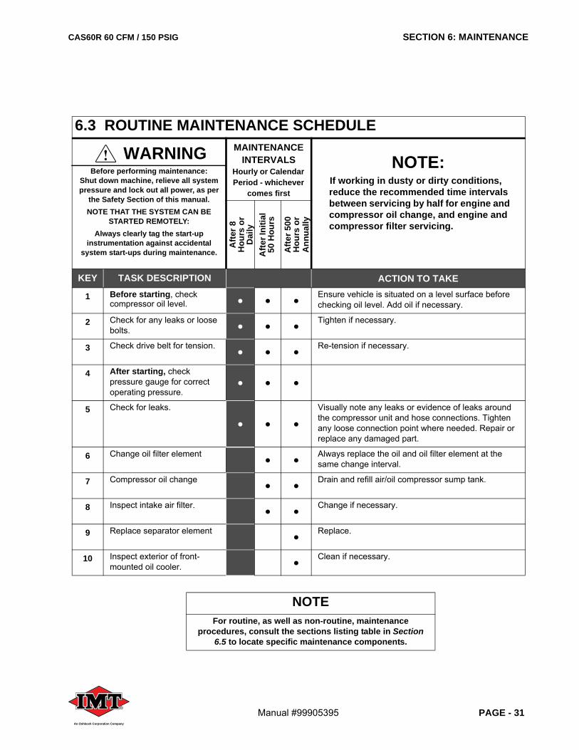
6.3 ROUTINE MAINTENANCE SCHEDULE
WARNINGBefore performing maintenance:
Shut down machine, relieve all system pressure and lock out all power, as per
the Safety Section of this manual. NOTE THAT THE SYSTEM CAN BE
STARTED REMOTELY:Always clearly tag the start-up
instrumentation against accidental system start-ups during maintenance.
MAINTENANCE INTERVALS
Hourly or Calendar Period - whichever
comes first
NOTE:If working in dusty or dirty conditions, reduce the recommended time intervals between servicing by half for engine and compressor oil change, and engine and compressor filter servicing.
Afte
r 8
Hou
rs o
r D
aily
Afte
r Ini
tial
50 H
ours
Afte
r 500
H
ours
or
Ann
ually
KEY TASK DESCRIPTION ACTION TO TAKE
1 Before starting, check compressor oil level. • • • Ensure vehicle is situated on a level surface before
checking oil level. Add oil if necessary.
2 Check for any leaks or loose bolts. • • • Tighten if necessary.
3 Check drive belt for tension. • • • Re-tension if necessary.
4 After starting, check pressure gauge for correct operating pressure.
• • •5 Check for leaks.
• • •Visually note any leaks or evidence of leaks around the compressor unit and hose connections. Tighten any loose connection point where needed. Repair or replace any damaged part.
6 Change oil filter element • • Always replace the oil and oil filter element at the same change interval.
7 Compressor oil change • • Drain and refill air/oil compressor sump tank.
8 Inspect intake air filter. • • Change if necessary.
9 Replace separator element • Replace.
10 Inspect exterior of front-mounted oil cooler. • Clean if necessary.
NOTEFor routine, as well as non-routine, maintenance
procedures, consult the sections listing table in Section 6.5 to locate specific maintenance components.
SECTION 6: MAINTENANCE CAS60R 60 CFM / 150 PSIG
PAGE - 32 Manual #99905395®
An Oshkosh Corporation Company
6.4 REPLACEMENT PARTSReplacement parts should be purchased through yourlocal IMT representative or where the compressorsystem was purchased. If, for any reason, parts are notavailable in this manner, they can be purchased throughIMT directly.
6.5 PARTS REPLACEMENT AND ADJUSTMENT PROCEDURES
NOTEIf additional spare parts are being stored for future use, make certain that they are stored in proper containers that allow for
protection against contamination, and kept in a clean area of moderate
temperature reading. For information on storing the machine package for periods of non-use, consult Section 6.5.14, Long
Term Storage.
DANGERAdjustments should be made with compressor switched OFF since
electrical terminals inside pressure switch will be exposed, and opening the canopy exposes the belt drive system.
WARNINGBefore performing maintenance:
Shut down machine, relieve all system pressure and lock out all power, as per
the Safety Section of this manual. NOTE THAT THE SYSTEM CAN BE
STARTED REMOTELY:Always clearly tag the start-up
instrumentation against accidental system start-ups during maintenance.
NOTEIt may be necessary to change the
compressor fluid and fluid filter more frequently if the compressor fluid has
water contamination, or if the compressor system is operated in a dirty
environment.
Iowa Mold Tooling Co., Inc.
500 Highway 18 WestGarner, Iowa 50438
Phone: 641.923.3711Fax: 641.923.6063
CAS60R 60 CFM / 150 PSIG SECTION 6: MAINTENANCE
Manual #99905395 PAGE - 33®
An Oshkosh Corporation Company
System Component or Part Group Task
Manual Section
Parts Replacement and Adjustment Procedures 6.5
Removing Panels for Machine Maintenance Access 6.5.1
Removing and Replacing the Roof (Top) Access Panel 6.5.1.1
Removing and Replacing the Main Canopy Panel 6.5.1.2
Removing and Replacing the Cooler and Instru-mentation Access Panel 6.5.1.3
Compressor Oil Maintenance 6.5.2
Lubrication Guide 6.5.2.1
Adding or Changing the Compressor Oil 6.5.2.2
Oil Filter Replacement 6.5.3
Removing the Oil Filter 6.5.3.1
Replacing the Oil Filter 6.5.3.2
Coalescer (Air/Oil Separator) Replacement 6.5.4
Removing the Coalescer Element 6.5.4.1
Replacing the Coalescer Element 6.5.4.2Compressor Air Filter Maintenance 6.5.5Removing the Air Filter 6.5.5.1Compressor Air Filter Inspection 6.5.5.2Replacing the Air Filter 6.5.5.3Repairing the Inlet Control System 6.5.6Rebuilding the Air Inlet Valve Assembly 6.5.6.1Performing Maintenance on the Drive Belts 6.5.7Adjusting the Drive Belts 6.5.7.1Drive Belt Tension Data 6.5.7.2Replacing the Drive Belts 6.5.7.3Cleaning the Cooler Core 6.5.8Pressure Switch 6.5.9Servicing the Minimum Pressure/Discharge Check Valve 6.5.10
Rebuilding the Minimum Pressure/Discharge Check Valve 6.5.10.1
Continued on next page
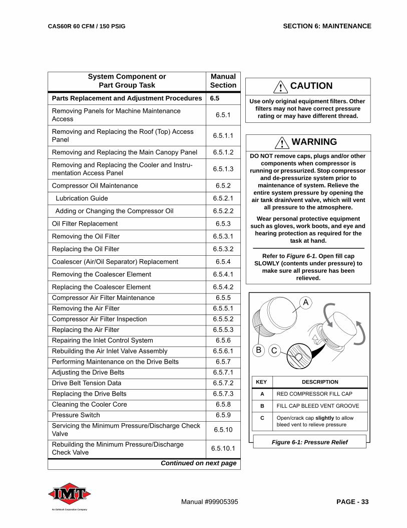
KEY DESCRIPTION
A RED COMPRESSOR FILL CAP
B FILL CAP BLEED VENT GROOVE
C Open/crack cap slightly to allow bleed vent to relieve pressure
Figure 6-1: Pressure Relief
A
B C
WARNINGDO NOT remove caps, plugs and/or other
components when compressor is running or pressurized. Stop compressor
and de-pressurize system prior to maintenance of system. Relieve the
entire system pressure by opening the air tank drain/vent valve, which will vent
all pressure to the atmosphere.
Wear personal protective equipment such as gloves, work boots, and eye and
hearing protection as required for the task at hand.
Refer to Figure 6-1. Open fill cap SLOWLY (contents under pressure) to
make sure all pressure has been relieved.
CAUTIONUse only original equipment filters. Other
filters may not have correct pressure rating or may have different thread.
SECTION 6: MAINTENANCE CAS60R 60 CFM / 150 PSIG
PAGE - 34 Manual #99905395®
An Oshkosh Corporation Company
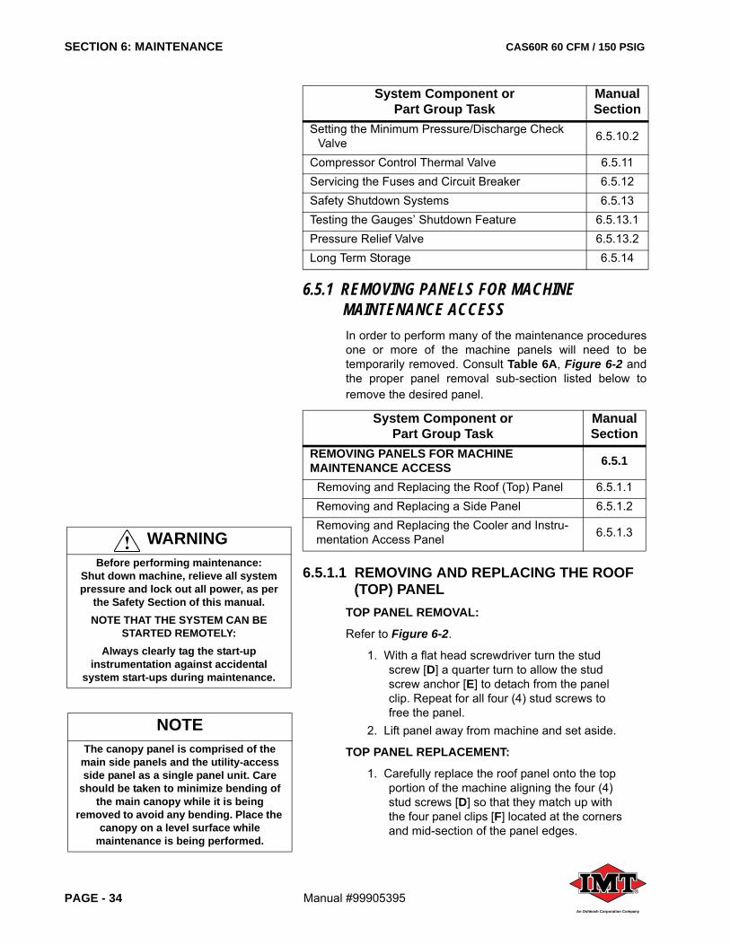
6.5.1 REMOVING PANELS FOR MACHINE MAINTENANCE ACCESSIn order to perform many of the maintenance proceduresone or more of the machine panels will need to betemporarily removed. Consult Table 6A, Figure 6-2 andthe proper panel removal sub-section listed below toremove the desired panel.
6.5.1.1 REMOVING AND REPLACING THE ROOF (TOP) PANEL
TOP PANEL REMOVAL:
Refer to Figure 6-2.
1. With a flat head screwdriver turn the stud screw [D] a quarter turn to allow the stud screw anchor [E] to detach from the panel clip. Repeat for all four (4) stud screws to free the panel.
2. Lift panel away from machine and set aside.
TOP PANEL REPLACEMENT:
1. Carefully replace the roof panel onto the top portion of the machine aligning the four (4) stud screws [D] so that they match up with the four panel clips [F] located at the corners and mid-section of the panel edges.
Setting the Minimum Pressure/Discharge Check Valve 6.5.10.2
Compressor Control Thermal Valve 6.5.11Servicing the Fuses and Circuit Breaker 6.5.12Safety Shutdown Systems 6.5.13Testing the Gauges’ Shutdown Feature 6.5.13.1Pressure Relief Valve 6.5.13.2Long Term Storage 6.5.14
System Component or Part Group Task
Manual Section
REMOVING PANELS FOR MACHINEMAINTENANCE ACCESS 6.5.1
Removing and Replacing the Roof (Top) Panel 6.5.1.1Removing and Replacing a Side Panel 6.5.1.2Removing and Replacing the Cooler and Instru-mentation Access Panel 6.5.1.3
System Component or Part Group Task
Manual Section
NOTEThe canopy panel is comprised of the
main side panels and the utility-access side panel as a single panel unit. Care
should be taken to minimize bending of the main canopy while it is being
removed to avoid any bending. Place the canopy on a level surface while
maintenance is being performed.
WARNINGBefore performing maintenance:
Shut down machine, relieve all system pressure and lock out all power, as per
the Safety Section of this manual. NOTE THAT THE SYSTEM CAN BE
STARTED REMOTELY:Always clearly tag the start-up
instrumentation against accidental system start-ups during maintenance.
CAS60R 60 CFM / 150 PSIG SECTION 6: MAINTENANCE
Manual #99905395 PAGE - 35®
An Oshkosh Corporation Company
WARNINGBefore removing any access panel for maintenance:
Shut down machine, relieve all system pressure and lock out all power, as per the Safety Section of this manual.
NOTE THAT THE SYSTEM CAN BE STARTED REMOTELY:Always clearly tag the start-up instrumentation against
accidental system start-ups during maintenance.
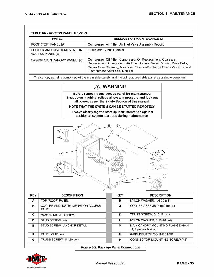
TABLE 6A - ACCESS PANEL REMOVAL
PANEL REMOVE FOR MAINTENANCE OF:
ROOF (TOP) PANEL [A] Compressor Air Filter, Air Inlet Valve Assembly Rebuild
COOLER AND INSTRUMENTATION ACCESS PANEL [B]
Fuses and Circuit Breaker
CAS60R MAIN CANOPY PANELI [C] Compressor Oil Filter, Compressor Oil Replacement, Coalescer Replacement, Compressor Air Filter, Air Inlet Valve Rebuild, Drive Belts, Cooler Core Cleaning, Minimum Pressure/Discharge Check Valve Rebuild Compressor Shaft Seal Rebuild
I The canopy panel is comprised of the main side panels and the utility-access side panel as a single panel unit.
KEY DESCRIPTION KEY DESCRIPTIONA TOP (ROOF) PANEL H NYLON WASHER, 1/4-20 (x4)
B COOLER AND INSTRUMENATION ACCESS PANEL
J COOLER ASSEMBLY (reference)
C CAS60R MAIN CANOPYI K TRUSS SCREW, 5/16-18 (x4)
D STUD SCREW (x4) L NYLON WASHER, 5/16-18 (x4)
E STUD SCREW - ANCHOR DETAIL M MAIN CANOPY MOUNTING FLANGE (detail: x4; 2 per each side)
F PANEL CLIP (x4) N 6-PIN DEUTCH CONNECTOR
G TRUSS SCREW, 1/4-20 (x4) P CONNECTOR MOUNTING SCREW (x4)
Figure 6-2: Package Panel Connections
D
G
H
E
A
F
J
KL
M
N P
B
C
SECTION 6: MAINTENANCE CAS60R 60 CFM / 150 PSIG
PAGE - 36 Manual #99905395®
An Oshkosh Corporation Company
2. Once all stud screws are set in their panel clips, turn each stud screw a quarter turn to fasten the roof plate to the machine.
6.5.1.2 REMOVING AND REPLACING THE MAIN CANOPY PANEL
Most routine and non-routine maintenance issues can beaccessed by the removal of the main canopy. Refer toFigure 6-2 and the following procedure.
MAIN CANOPY PANEL REMOVAL:
1. With a Phillips head screwdriver remove the four (4) fastening sets consisting of the 5/16-18 truss screws [K], and the 5/16-18 nylon washers [L], from the four mounting flanges [M] used to fasten the main canopy to the base frame.
2. Remove the four connector screws [P] securing the 6-pin Deutch connector [N] to the frame.
3. Carefully disengage the connector from the panel, from the inside.
4. Remove panel from the frame and set aside.5. Retain all screws and washers for re-
assembly.
MAIN CANOPY PANEL REPLACEMENT:
1. Carefully re-set the main canopy panel into position so that the slots on each of the four (4) mounting flanges [M] aligns to the mounting holes on the base frame.
2. Secure into place with four (4) pairs of 5/16-18 nylon washers [L] and 5/16-18 truss screws [K], as shown in Figure 6-2.
3. Position the 6-pin Deutch connector [N] in alignment from the inside with the connector access and screw holes at the corner of the main panel, as indicated in Figure 6-2.
4. Replace the four (4) connector mounting screws [P] from the panel-side into the connector’s mounting holes.
5. Tighten the connector mounting screws to secure the connector.
6.5.1.3 REMOVING AND REPLACING THE COOLER AND INSTRUMENTATION ACCESS PANEL
The cooler and instrumentation access panel is removedin order to change a fuse or the circuit breaker. Refer toFigure 6-2 and the following procedure.
CAS60R 60 CFM / 150 PSIG SECTION 6: MAINTENANCE
Manual #99905395 PAGE - 37®
An Oshkosh Corporation Company
COOLER AND INSTRUMENT ACCESS PANEL REMOVAL:
1. With a Phillips head screwdriver remove the four (4) fastening sets consisting of the 1/4-20 truss screws [G], and the 1/4-20 nylon washers [H], from the cooler and instrumentation access panel [B].
2. Retain screws and washers for re-assembly.3. Remove panel from the frame and set aside.
COOLER AND INSTRUMENT ACCESS PANEL REPLACEMENT:
1. Carefully re-set the cooler and instrumentation access panel [B] into position so that the four (4) mounting holes align with the mounting holes on the top edges of the cooler assembly [J].
2. Secure into place with four (4) pairs of 1/4-20 nylon washers [H] and 1/4-20 truss screws [G], as shown in Figure 6-2.
6.5.2 COMPRESSOR OIL MAINTENANCEHaving the proper amount of oil in the compressorsystem is essential to prolonging the equipment’s usefullife. Checking the compressor oil is the most importantservice to perform on the CAS60R package. Thecompressor is fully charged at the factory with IMTPremium Synthetic Oil.
6.5.2.1 ADDING OR CHANGING THE COMPRESSOR OIL
Consult Figure 6-1, Figure 6-3 and the followingprocedure to check the compressor oil.
System Component or Part Group Task
Manual Section
Compressor Oil Maintenance 6.5.2
Adding or Changing the Compressor Oil 6.5.2.2
WARNINGThe result of poorly maintained
lubrication and/or filters may produce hazardous conditions resulting in
overheating, which could cause machine shutdown. Damage to equipment and
serious bodily harm may result.
IMPORTANTDO NOT mix different types of
compressor oil—mixing oil will void the warranty! Use ONLY genuine IMT
Premium Synthetic Oil.
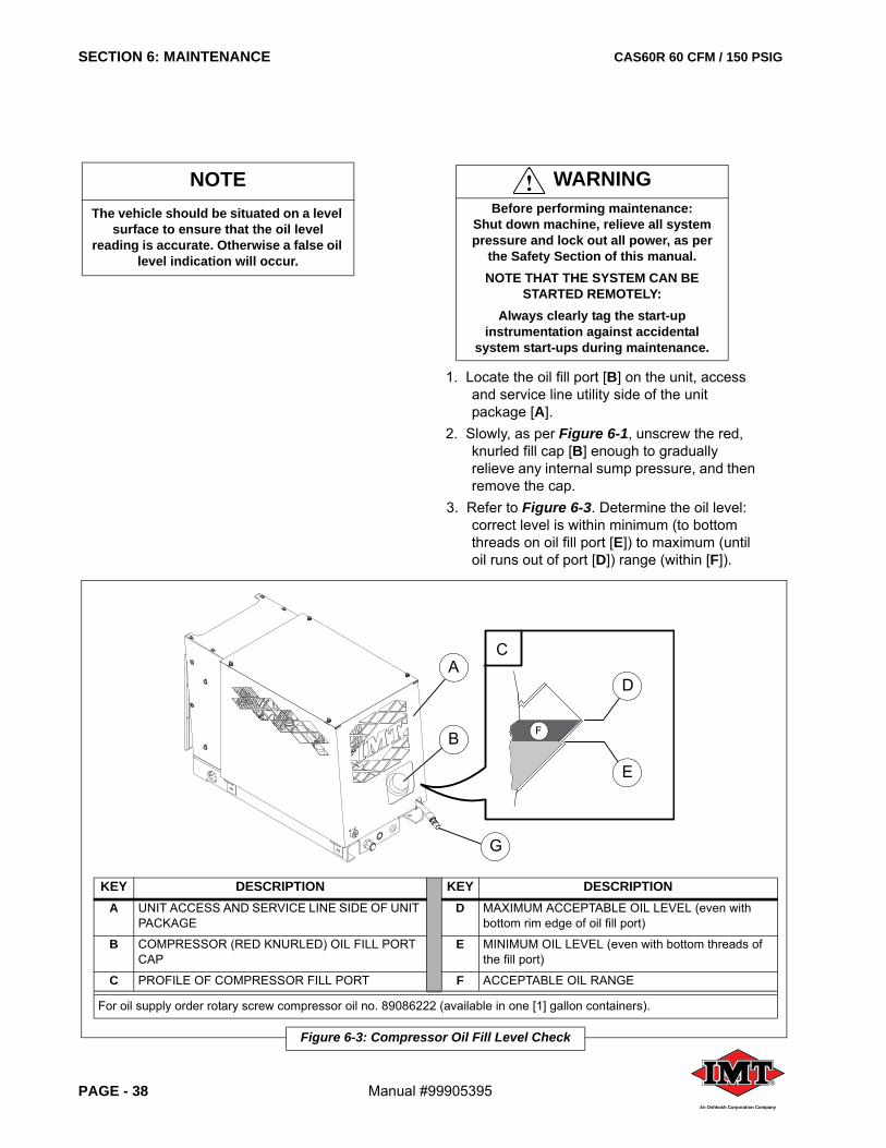
SECTION 6: MAINTENANCE CAS60R 60 CFM / 150 PSIG
PAGE - 38 Manual #99905395®
An Oshkosh Corporation Company
1. Locate the oil fill port [B] on the unit, access and service line utility side of the unit package [A].
2. Slowly, as per Figure 6-1, unscrew the red, knurled fill cap [B] enough to gradually relieve any internal sump pressure, and then remove the cap.
3. Refer to Figure 6-3. Determine the oil level: correct level is within minimum (to bottom threads on oil fill port [E]) to maximum (until oil runs out of port [D]) range (within [F]).
WARNINGBefore performing maintenance:
Shut down machine, relieve all system pressure and lock out all power, as per
the Safety Section of this manual. NOTE THAT THE SYSTEM CAN BE
STARTED REMOTELY:Always clearly tag the start-up
instrumentation against accidental system start-ups during maintenance.
NOTEThe vehicle should be situated on a level
surface to ensure that the oil level reading is accurate. Otherwise a false oil
level indication will occur.
KEY DESCRIPTION KEY DESCRIPTIONA UNIT ACCESS AND SERVICE LINE SIDE OF UNIT
PACKAGED MAXIMUM ACCEPTABLE OIL LEVEL (even with
bottom rim edge of oil fill port)
B COMPRESSOR (RED KNURLED) OIL FILL PORT CAP
E MINIMUM OIL LEVEL (even with bottom threads of the fill port)
C PROFILE OF COMPRESSOR FILL PORT F ACCEPTABLE OIL RANGE
For oil supply order rotary screw compressor oil no. 89086222 (available in one [1] gallon containers).
Figure 6-3: Compressor Oil Fill Level Check
D
E
C
FB
A
G
CAS60R 60 CFM / 150 PSIG SECTION 6: MAINTENANCE
Manual #99905395 PAGE - 39®
An Oshkosh Corporation Company
Note that overfill can only occur if unit is not level.
4. If adding oil...Carefully add lubricant and monitor oil level,allowing time for oil to level out. A complete refill isapproximately 5-1/4 quarts.
If changing oil...A) Place a vessel capable of containing at least
six quarts of oil below the oil drain tube (Fig-ure 6-3, [G]) to catch the oil as it discharges.
B) Unscrew the end cap of the oil drain tube and allow the oil to completely drain from the compressor unit.
C) Replace and tighten the oil drain tube cap to the oil drain tube [G].
D) Replace the oil filter per the procedural steps given in Section 6.5.3. Once the oil filter element has been replaced, add new system oil.
5. Replace the red oil fill cap [B] tightly by hand.6. Run unit and recheck oil level after shutdown,
allowing time for oil to settle.7. Add appropriate amount of oil to achieve
acceptable range [F]. Oil drain is provided with short drain hose [G]. This canbe routed to a more convenient location if required,dependent upon installation. Use only 80 pipe or suitablyrated hose.
6.5.3 PERFORMING AN OIL FILTER CHANGERefer to Figure 6-4. The compressor oil filter is a spin-on, throw away type.
Access the compressor unit by removing the roof paneland the main CAS60R canopy panel, per Section 6.5.1.
6.5.3.1 REMOVING THE OIL FILTER1. Drain oil from compressor unit per Section
6.5.2.1.
System Component or Part Group Task
Manual Section
Performing an Oil Filter Change 6.5.3Removing the Oil Filter 6.5.3.1Replacing the Oil Filter 6.5.3.2
NOTEWhen performing a system oil change
the oil filter element and coalescer elements should also be changed at the same time. Refer to Sections 6.5.3, Oil
Filter Replacement, and 6.5.4, Coalescer (Air/Oil Separator) Replacement
respectively.
WARNINGBefore performing maintenance:
Shut down machine, relieve all system pressure and lock out all power, as per
the Safety Section of this manual. NOTE THAT THE SYSTEM CAN BE
STARTED REMOTELY:Always clearly tag the start-up
instrumentation against accidental system start-ups during maintenance.
NOTEDispose of used oil and worn filter
element appropriately and in accordance with any pertinent environmental
regulations.
IMPORTANTAlways change the oil when changing the oil filter element. Refer to Section
6.5.2.1.
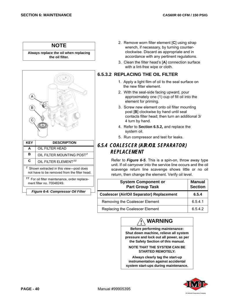
SECTION 6: MAINTENANCE CAS60R 60 CFM / 150 PSIG
PAGE - 40 Manual #99905395®
An Oshkosh Corporation Company
2. Remove worn filter element [C] using strap wrench, if necessary, by turning counter-clockwise. Discard as appropriate and in accordance with any pertinent regulations.
3. Clean the filter head’s [A] connection surface with a lint-free wipe or cloth.
6.5.3.2 REPLACING THE OIL FILTER1. Apply a light film of oil to the seal surface on
the new filter element.2. With the seal-side facing upward, pour
approximately one (1) cup of fill oil into the element for priming.
3. Screw new element onto oil filter mounting post [B] clockwise by hand until seal contacts filter head; then turn an additional 3/4 turn by hand.
4. Refer to Section 6.5.2, and replace the system oil.
5. Run compressor and test for leaks.
6.5.4 COALESCER (AIR/OIL SEPARATOR) REPLACEMENTRefer to Figure 6-5. This is a spin-on, throw away typeunit. If oil carryover into the service line occurs and the oilscavenge return line scavenge shows little or no oilreturn, then change the element. Verify oil level.
System Component or Part Group Task
Manual Section
Coalescer (Air/Oil Separator) Replacement 6.5.4
Removing the Coalescer Element 6.5.4.1
Replacing the Coalescer Element 6.5.4.2
WARNINGBefore performing maintenance:
Shut down machine, relieve all system pressure and lock out all power, as per
the Safety Section of this manual. NOTE THAT THE SYSTEM CAN BE
STARTED REMOTELY:Always clearly tag the start-up
instrumentation against accidental system start-ups during maintenance.
KEY DESCRIPTIONA OIL FILTER HEAD
B OIL FILTER MOUNTING POSTI
C OIL FILTER ELEMENTII
I Shown extracted in this view—post does not have to be removed from the filter head.
II For oil filter maintenance, order replace-ment filter no. 70048249.
Figure 6-4: Compressor Oil Filter
A
B
C
NOTEAlways replace the oil when replacing
the oil filter.
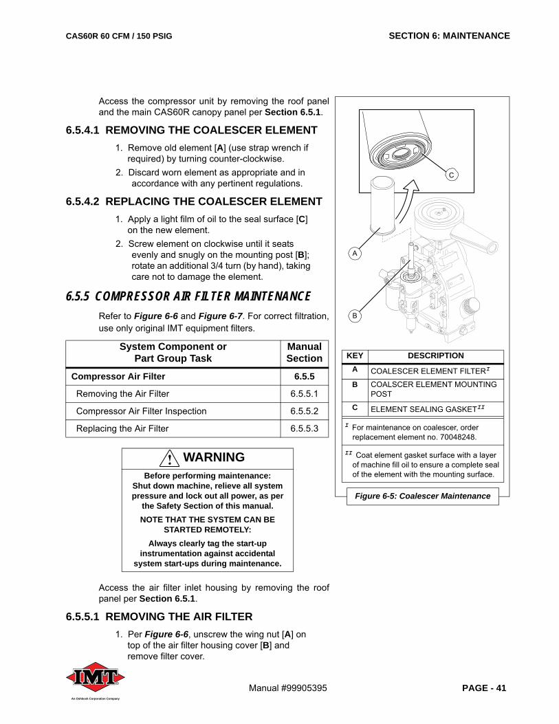
CAS60R 60 CFM / 150 PSIG SECTION 6: MAINTENANCE
Manual #99905395 PAGE - 41®
An Oshkosh Corporation Company
Access the compressor unit by removing the roof paneland the main CAS60R canopy panel per Section 6.5.1.
6.5.4.1 REMOVING THE COALESCER ELEMENT1. Remove old element [A] (use strap wrench if
required) by turning counter-clockwise.2. Discard worn element as appropriate and in
accordance with any pertinent regulations.
6.5.4.2 REPLACING THE COALESCER ELEMENT1. Apply a light film of oil to the seal surface [C]
on the new element.2. Screw element on clockwise until it seats
evenly and snugly on the mounting post [B]; rotate an additional 3/4 turn (by hand), taking care not to damage the element.
6.5.5 COMPRESSOR AIR FILTER MAINTENANCERefer to Figure 6-6 and Figure 6-7. For correct filtration,use only original IMT equipment filters.
Access the air filter inlet housing by removing the roofpanel per Section 6.5.1.
6.5.5.1 REMOVING THE AIR FILTER1. Per Figure 6-6, unscrew the wing nut [A] on
top of the air filter housing cover [B] and remove filter cover.
System Component or Part Group Task
Manual Section
Compressor Air Filter 6.5.5
Removing the Air Filter 6.5.5.1
Compressor Air Filter Inspection 6.5.5.2
Replacing the Air Filter 6.5.5.3
WARNINGBefore performing maintenance:
Shut down machine, relieve all system pressure and lock out all power, as per
the Safety Section of this manual. NOTE THAT THE SYSTEM CAN BE
STARTED REMOTELY:Always clearly tag the start-up
instrumentation against accidental system start-ups during maintenance.
KEY DESCRIPTIONA COALESCER ELEMENT FILTERI
B COALSCER ELEMENT MOUNTING POST
C ELEMENT SEALING GASKETII
I For maintenance on coalescer, order replacement element no. 70048248.
II Coat element gasket surface with a layer of machine fill oil to ensure a complete seal of the element with the mounting surface.
Figure 6-5: Coalescer Maintenance
A
B
C
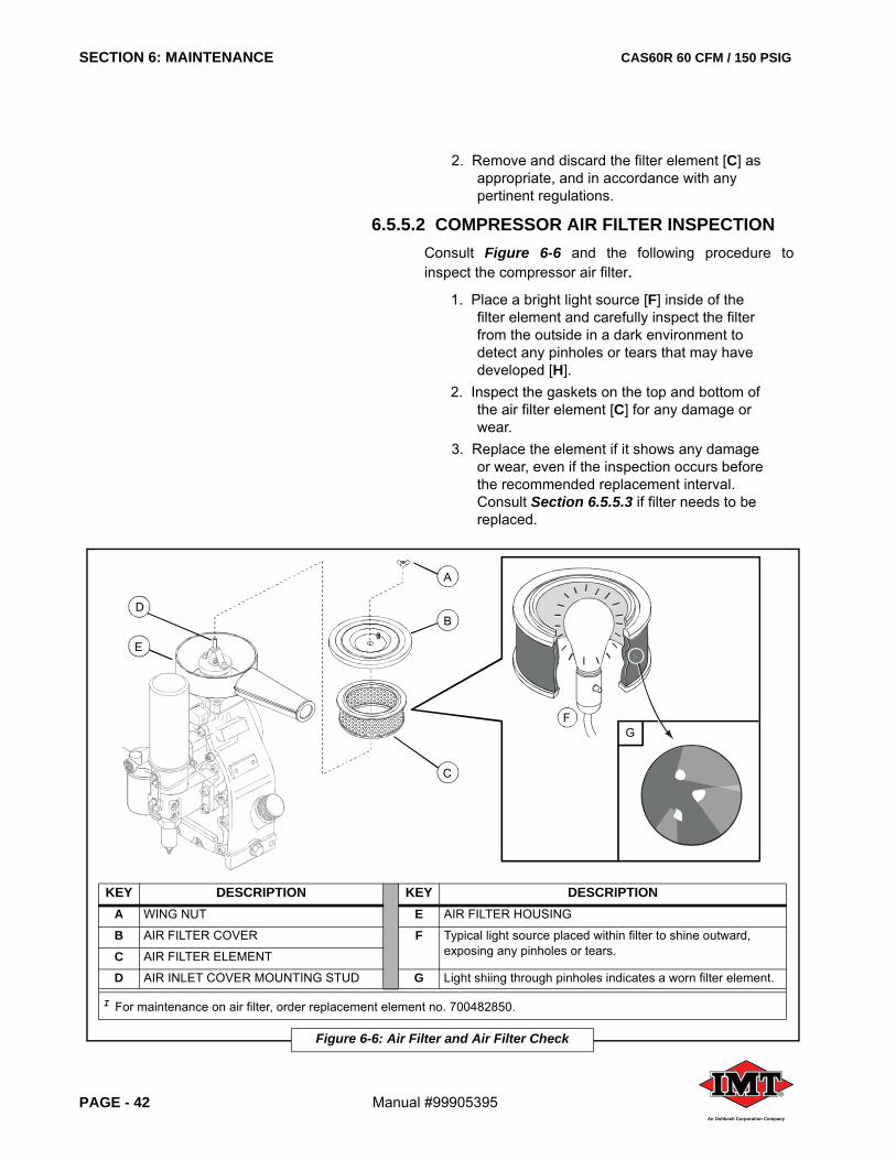
SECTION 6: MAINTENANCE CAS60R 60 CFM / 150 PSIG
PAGE - 42 Manual #99905395®
An Oshkosh Corporation Company
2. Remove and discard the filter element [C] as appropriate, and in accordance with any pertinent regulations.
6.5.5.2 COMPRESSOR AIR FILTER INSPECTIONConsult Figure 6-6 and the following procedure toinspect the compressor air filter.
1. Place a bright light source [F] inside of the filter element and carefully inspect the filter from the outside in a dark environment to detect any pinholes or tears that may have developed [H].
2. Inspect the gaskets on the top and bottom of the air filter element [C] for any damage or wear.
3. Replace the element if it shows any damage or wear, even if the inspection occurs before the recommended replacement interval. Consult Section 6.5.5.3 if filter needs to be replaced.
KEY DESCRIPTION KEY DESCRIPTIONA WING NUT E AIR FILTER HOUSING
B AIR FILTER COVER F Typical light source placed within filter to shine outward, exposing any pinholes or tears.C AIR FILTER ELEMENT
D AIR INLET COVER MOUNTING STUD G Light shiing through pinholes indicates a worn filter element.
I For maintenance on air filter, order replacement element no. 700482850.
Figure 6-6: Air Filter and Air Filter Check
E
DB
A
C
FG
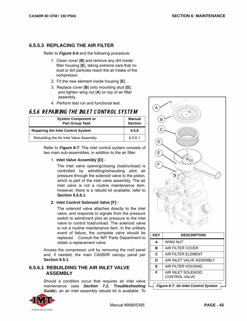
CAS60R 60 CFM / 150 PSIG SECTION 6: MAINTENANCE
Manual #99905395 PAGE - 43®
An Oshkosh Corporation Company
6.5.5.3 REPLACING THE AIR FILTERRefer to Figure 6-6 and the following procedure:
1. Clean cover [B] and remove any dirt inside filter housing [E], taking extreme care that no dust or dirt particles reach the air intake of the compressor.
2. Fit the new element inside housing [E].3. Replace cover [B] onto mounting stud [D],
and tighten wing nut [A] on top of air filter assembly.
4. Perform test run and functional test.
6.5.6 REPAIRING THE INLET CONTROL SYSTEM
Refer to Figure 6-7. The inlet control system consists oftwo main sub-assemblies, in addition to the air filter:
1. Inlet Valve Assembly [D] -The inlet valve opening/closing (load/unload) iscontrolled by admitting/exhausting pilot airpressure through the solenoid valve to the piston,which is part of the inlet valve assembly. The airinlet valve is not a routine maintenance item.However, there is a rebuild kit available; refer toSection 6.5.6.1.
2. Inlet Control Solenoid Valve [F] -The solenoid valve attaches directly to the inletvalve, and responds to signals from the pressureswitch to admit/vent pilot air pressure to the inletvalve to control load/unload. The solenoid valveis not a routine maintenance item. In the unlikelyevent of failure, the complete valve should bereplaced. Consult the IMT Parts Department toobtain a replacement valve.
Access the compressor unit by removing the roof paneland, if needed, the main CAS60R canopy panel perSection 6.5.1.
6.5.6.1 REBUILDING THE AIR INLET VALVE ASSEMBLY
Should a condition occur that requires air inlet valvemaintenance (see Section 7.2, TroubleshootingGuide), an air inlet assembly rebuild kit is available. To
System Component or Part Group Task
Manual Section
Repairing the Inlet Control System 6.5.6
Rebuilding the Air Inlet Valve Assembly 6.5.6.1
KEY DESCRIPTION
A WING NUT
B AIR FILTER COVER
C AIR FILTER ELEMENT
D AIR INLET VALVE ASSEMBLY
E AIR FILTER HOUSING
F AIR INLET SOLENOIDCONTROL VALVE
Figure 6-7: Air Inlet Control System
D
F
E
A
B
C
SECTION 6: MAINTENANCE CAS60R 60 CFM / 150 PSIG
PAGE - 44 Manual #99905395®
An Oshkosh Corporation Company
rebuild the air inlet valve, order air inlet rebuild kit no.73744210. Refer to Figure 6-8, and the followingprocedure:
1. Locate the compressor’s air filter compartment housing [E] at the top of the compressor unit, and remove the wing nut [B] from cover [C].
2. Remove air filter [D], and put it aside temporarily so it will not get damaged or soiled; the full air filter inlet valve [A1] is now accessible.
3. Loosen the two (2) pan head screws [F] to free the nested air inlet assembly.
4. Grasp the valve [A1] and pull upwards to disengage it from its seating.
5. Disassemble the valve and replace used parts with new parts found in the kit. Refer to Figure 6-8 to assure correct integration of replacement parts and part re-assembly positions.
6. Replace the base flange o-ring [Y] with new o-ring into air inlet base flange [Z] seating.
7. Once the valve’s parts have been replaced with the kit parts and re-assembled, place the rebuilt, complete inlet valve assembly into position on the valve seating within the air filter housing.
8. Replace the two (2) pan head screws [F] and tighten securely.
9. Replace the air filter housing [C] into position on the inlet base flange [Z].
10. Inspect the air filter: exchange it for a new one if air filter is soiled (refer to Section 6.5.5.2, Compressor Air Filter Inspection
WARNINGBefore performing maintenance:
Shut down machine, relieve all system pressure and lock out all power, as per
the Safety Section of this manual. NOTE THAT THE SYSTEM CAN BE
STARTED REMOTELY:Always clearly tag the start-up
instrumentation against accidental system start-ups during maintenance.
NOTEUse all of the parts provided in the kit regardless of the old part condition.
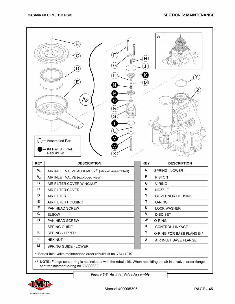
CAS60R 60 CFM / 150 PSIG SECTION 6: MAINTENANCE
Manual #99905395 PAGE - 45®
An Oshkosh Corporation Company
KEY DESCRIPTION KEY DESCRIPTION
A1 AIR INLET VALVE ASSEMBLYI (shown assembled) N SPRING - LOWER
A2 AIR INLET VALVE (exploded view) P PISTONB AIR FILTER COVER WINGNUT Q V-RINGC AIR FILTER COVER R NOZZLED AIR FILTER S GOVERNOR HOUSINGE AIR FILTER HOUSING T O-RINGF PAN HEAD SCREW U LOCK WASHERG ELBOW V DISC SETH PAN HEAD SCREW W O-RINGJ SPRING GUIDE X CONTROL LINKAGEK SPRING - UPPER Y O-RING FOR BASE FLANGEII
L HEX NUT Z AIR INLET BASE FLANGEM SPRING GUIDE - LOWER
I For air inlet valve maintenance order rebuild kit no. 73744210.
II NOTE: Flange seat o-ring is not included with the rebuild kit. When rebuilding the air inlet valve, order flange seat replacement o-ring no. 76399332.
Figure 6-8: Air Inlet Valve Assembly
B
C
E
D
F
G
STUV
W
L
N
PQ
R
H
A1
Y
Z
J
K
M
X
A2
Assembled Part
Kit Part: Air Inlet Rebuild Kit
SECTION 6: MAINTENANCE CAS60R 60 CFM / 150 PSIG
PAGE - 46 Manual #99905395®
An Oshkosh Corporation Company
for air filter condition check, etc.). If filter is in satisfactory shape, or if using a replacement filter element, seat the air filter [D] into position in the housing [E].
11. Replace the cover [C].12. Replace the wing nut [B], and secure tightly.
6.5.7 PERFORMING MAINTENANCE ON THE DRIVE BELTSCorrect tensioning and alignment is important for belt life,bearing life and power transmission. Drive belt tensioningand alignment is performed at the factory at time ofshipment. However, since maximum belt elongation willoccur within the first 50 hours of operation (of new belts),the belts’ tension should be checked several times duringthis period and corrected as required. The belts should,thereafter, be checked periodically in order to obtainmaximum life and performance.
Access the drive system by removing the roof panel andthe main CAS60R canopy panel per Section 6.5.1.
6.5.7.1 ADJUSTING THE DRIVE BELTSRefer to Figure 6-9 and the following procedure:
1. Slightly loosen the vertical tap bolt [B].2. Back off adjusting bolt lock nut [E]; screw the
adjusting bolt clockwise to tighten belts or
System Component or Part Group Task
Manual Section
Performing Maintenance on the Drive Belts 6.5.7
Adjusting the Drive Belts 6.5.7.1
Drive Belt Tension Data 6.5.7.2
Replacing the Drive Belts 6.5.7.3
WARNINGBefore performing maintenance:
Shut down machine, relieve all system pressure and lock out all power, as per
the Safety Section of this manual. NOTE THAT THE SYSTEM CAN BE
STARTED REMOTELY:Always clearly tag the start-up
instrumentation against accidental system start-ups during maintenance.
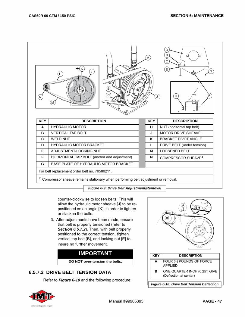
CAS60R 60 CFM / 150 PSIG SECTION 6: MAINTENANCE
Manual #99905395 PAGE - 47®
An Oshkosh Corporation Company
counter-clockwise to loosen belts. This will allow the hydraulic motor sheave [J] to be re-positioned on an angle [K], in order to tighten or slacken the belts.
3. After adjustments have been made, ensure that belt is properly tensioned (refer to Section 6.5.7.2). Then, with belt properly positioned to the correct tension, tighten vertical tap bolt [B], and locking nut [E] to insure no further movement.
6.5.7.2 DRIVE BELT TENSION DATARefer to Figure 6-10 and the following procedure:
IMPORTANTDO NOT over-tension the belts.
KEY DESCRIPTION KEY DESCRIPTIONA HYDRAULIC MOTOR H NUT (horizontal tap bolt)
B VERTICAL TAP BOLT J MOTOR DRIVE SHEAVE
C WELD NUT K BRACKET PIVOT ANGLE
D HYDRAULIC MOTOR BRACKET L DRIVE BELT (under tension)
E ADJUSTMENT/LOCKING NUT M LOOSENED BELT
F HORIZONTAL TAP BOLT (anchor and adjustment) N COMPRESSOR SHEAVEI
G BASE PLATE OF HYDRAULIC MOTOR BRACKET
For belt replacement order belt no. 70580211.
I Compressor sheave remains stationary when performing belt adjustment or removal.
Figure 6-9: Drive Belt Adjustment/Removal
A
J
JK
H F
M
N
L
B
C
B
D
C
E G
KEY DESCRIPTIONA FOUR (4) POUNDS OF FORCE
APPLIED
B ONE QUARTER INCH (0.25”) GIVE (Deflection at center)
Figure 6-10: Drive Belt Tension Deflection
BA
SECTION 6: MAINTENANCE CAS60R 60 CFM / 150 PSIG
PAGE - 48 Manual #99905395®
An Oshkosh Corporation Company
• Deflection at center of belt span: 0.25 inches with a force of 4 (four) pounds.
• Pulley alignment is set at factory and should not need to be adjusted. If it is found necessary to adjust the pulley alignment, loosen the four bolts that hold down the base plate to the frame and adjust per the following instructions:
1. Ensure sheaves are aligned by using a long straight edge that will span the length of both pulleys.
2. Position the straight edge on the sides of the sheaves; if they are in line, there should be no gaps between the straight edge and the sheaves (for the full contact distance across each sheave side).
3. Adjust as necessary to get correct alignment and tension.
4. It may be necessary to repeat and check several times before both tension and alignment are satisfactory.
6.5.7.3 REPLACING THE DRIVE BELTSAlthough the drive belts should be checked for fit andwear on a routine basis, they are not considered routinemaintenance items. However, the drive belts are subjectto wear out over a period of time and use, and should bereplaced if worn, cracked or otherwise damaged. Thebelt is loosened by pivoting the hydraulic motorassembly’s bracket, which temporarily repositions thehydraulic motor sheave enough to loosen the belt. Referto Figure 6-9 and the following procedure.
1. Loosen the horizontal tap bolt [F] and securing nut [H] enough to allow movement, but DO NOT remove the tap bolt.
2. Loosen the adjustment/locking nut [E].3. Loosen the vertical tap bolt [B] to allow for the
hydraulic motor bracket [D] to pivot the motor assembly toward the compressor unit, which causes the belts to slacken.
4. When the belts are slackened enough to be slipped off of the sheaves, remove all of the belts from the compressor sheave [N] and motor sheave [J].
IMPORTANTDO NOT over-tension the belts.
WARNINGBefore performing maintenance:
Shut down machine, relieve all system pressure and lock out all power, as per
the Safety Section of this manual. NOTE THAT THE SYSTEM CAN BE
STARTED REMOTELY:Always clearly tag the start-up
instrumentation against accidental system start-ups during maintenance.
CAS60R 60 CFM / 150 PSIG SECTION 6: MAINTENANCE
Manual #99905395 PAGE - 49®
An Oshkosh Corporation Company
5. Discard worn belts appropriately.6. With the bracket still in the “loosened”
position, thread new serpentine belts into place over the compressor sheave [N] and motor drive sheave [J].
7. Re-position the motor bracket angle [K] to tighten the belts, checking at intervals for a proper tension deflection.
8. When the belt has been adjusted to proper tension, tighten the adjustment/locking nut [E].
9. Hold horizontal tap bolt nut [H] in place with a wrench while tightening the horizontal tap bolt [F].
10. Recheck the belt tension, and adjust as necessary until proper tightness is achieved.
6.5.8 CLEANING THE COOLER CORERefer to Figure 6-11.
COOLER EXTERIOR:
Remove leaves, paper, and debris from outside face [A]of cooler assembly.
COOLER INTERIOR:
NOTEBELT TENSION DEFLECTION DATA:
Deflection at center of belt span is 0.25 inches with a force of four (4) pounds
(Refer to Figure 6-10).
IMPORTANTDO NOT over-tension the belts.
WARNINGBefore performing maintenance:
Shut down machine, relieve all system pressure and lock out all power, as per
the Safety Section of this manual. NOTE THAT THE SYSTEM CAN BE
STARTED REMOTELY:Always clearly tag the start-up
instrumentation against accidental system start-ups during maintenance.
NOTEDo not use high pressure air or pressure
washer to clean cooler core.
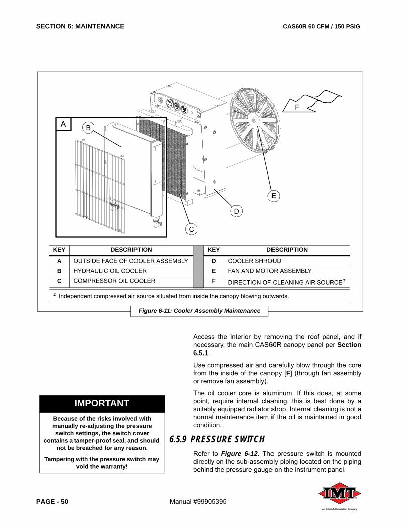
SECTION 6: MAINTENANCE CAS60R 60 CFM / 150 PSIG
PAGE - 50 Manual #99905395®
An Oshkosh Corporation Company
Access the interior by removing the roof panel, and ifnecessary, the main CAS60R canopy panel per Section6.5.1.
Use compressed air and carefully blow through the corefrom the inside of the canopy [F] (through fan assemblyor remove fan assembly).
The oil cooler core is aluminum. If this does, at somepoint, require internal cleaning, this is best done by asuitably equipped radiator shop. Internal cleaning is not anormal maintenance item if the oil is maintained in goodcondition.
6.5.9 PRESSURE SWITCHRefer to Figure 6-12. The pressure switch is mounteddirectly on the sub-assembly piping located on the pipingbehind the pressure gauge on the instrument panel.
IMPORTANTBecause of the risks involved with manually re-adjusting the pressure switch settings, the switch cover
contains a tamper-proof seal, and should not be breached for any reason.
Tampering with the pressure switch may void the warranty!
KEY DESCRIPTION KEY DESCRIPTION
A OUTSIDE FACE OF COOLER ASSEMBLY D COOLER SHROUD
B HYDRAULIC OIL COOLER E FAN AND MOTOR ASSEMBLY
C COMPRESSOR OIL COOLER F DIRECTION OF CLEANING AIR SOURCEI
I Independent compressed air source situated from inside the canopy blowing outwards.
Figure 6-11: Cooler Assembly Maintenance
E
D
C
BA
F
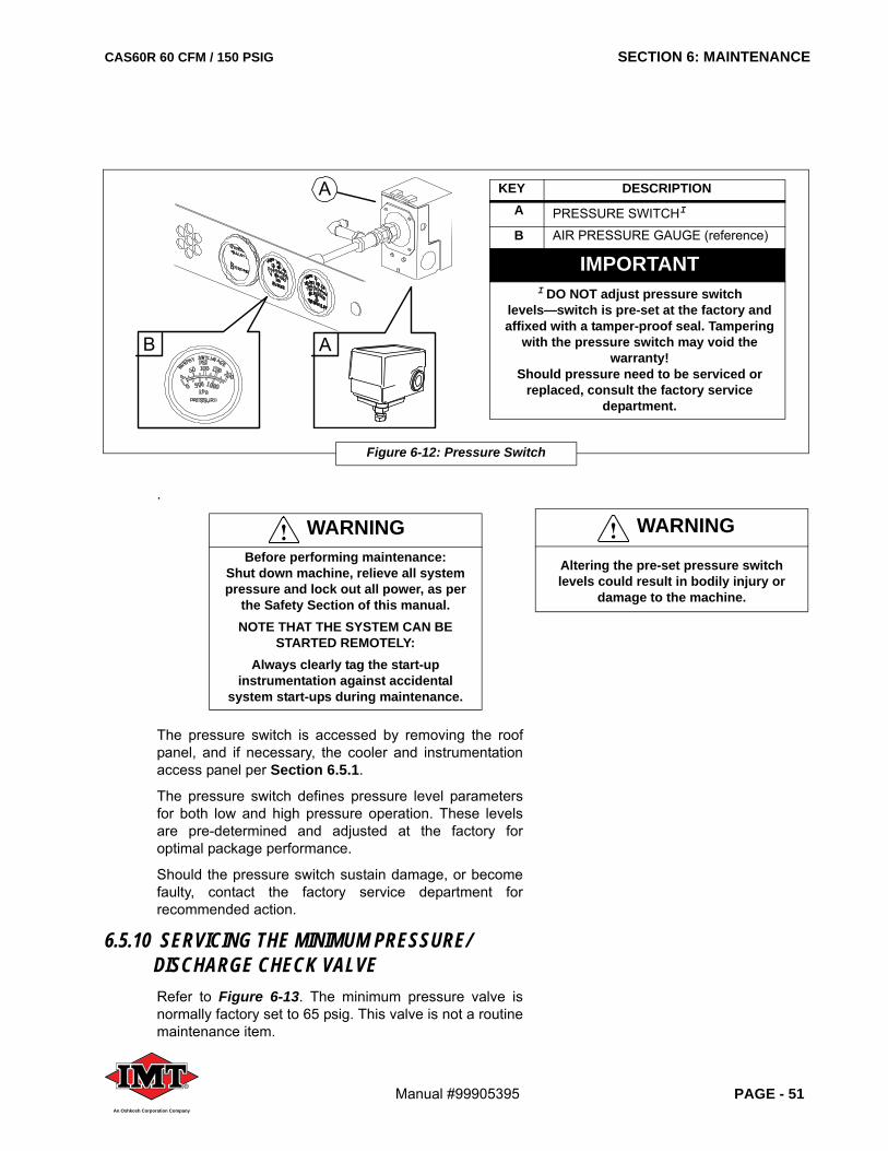
CAS60R 60 CFM / 150 PSIG SECTION 6: MAINTENANCE
Manual #99905395 PAGE - 51®
An Oshkosh Corporation Company
.
The pressure switch is accessed by removing the roofpanel, and if necessary, the cooler and instrumentationaccess panel per Section 6.5.1.
The pressure switch defines pressure level parametersfor both low and high pressure operation. These levelsare pre-determined and adjusted at the factory foroptimal package performance.
Should the pressure switch sustain damage, or becomefaulty, contact the factory service department forrecommended action.
6.5.10 SERVICING THE MINIMUM PRESSURE/DISCHARGE CHECK VALVERefer to Figure 6-13. The minimum pressure valve isnormally factory set to 65 psig. This valve is not a routinemaintenance item.
WARNINGBefore performing maintenance:
Shut down machine, relieve all system pressure and lock out all power, as per
the Safety Section of this manual. NOTE THAT THE SYSTEM CAN BE
STARTED REMOTELY:Always clearly tag the start-up
instrumentation against accidental system start-ups during maintenance.
WARNING
Altering the pre-set pressure switch levels could result in bodily injury or
damage to the machine.
Figure 6-12: Pressure Switch
A
A
B
KEY DESCRIPTIONA PRESSURE SWITCHI
B AIR PRESSURE GAUGE (reference)
IMPORTANTI DO NOT adjust pressure switch
levels—switch is pre-set at the factory and affixed with a tamper-proof seal. Tampering
with the pressure switch may void the warranty!
Should pressure need to be serviced or replaced, consult the factory service
department.
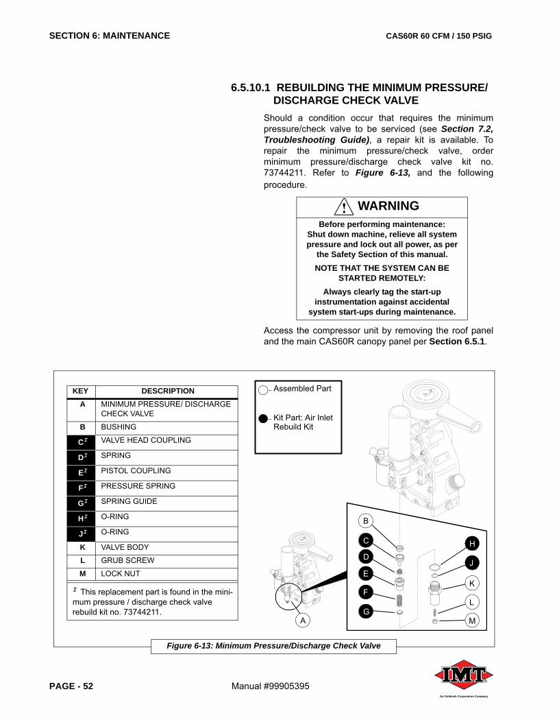
SECTION 6: MAINTENANCE CAS60R 60 CFM / 150 PSIG
PAGE - 52 Manual #99905395®
An Oshkosh Corporation Company
6.5.10.1 REBUILDING THE MINIMUM PRESSURE/DISCHARGE CHECK VALVE
Should a condition occur that requires the minimumpressure/check valve to be serviced (see Section 7.2,Troubleshooting Guide), a repair kit is available. Torepair the minimum pressure/check valve, orderminimum pressure/discharge check valve kit no.73744211. Refer to Figure 6-13, and the followingprocedure.
Access the compressor unit by removing the roof paneland the main CAS60R canopy panel per Section 6.5.1.
WARNINGBefore performing maintenance:
Shut down machine, relieve all system pressure and lock out all power, as per
the Safety Section of this manual. NOTE THAT THE SYSTEM CAN BE
STARTED REMOTELY:Always clearly tag the start-up
instrumentation against accidental system start-ups during maintenance.
Figure 6-13: Minimum Pressure/Discharge Check Valve
B
H
J
K
L
M
C
D
E
F
GA
KEY DESCRIPTIONA MINIMUM PRESSURE/ DISCHARGE
CHECK VALVE
B BUSHING
CI VALVE HEAD COUPLING
DI SPRING
EI PISTOL COUPLING
FI PRESSURE SPRING
GI SPRING GUIDE
HI O-RING
JI O-RING
K VALVE BODY
L GRUB SCREW
M LOCK NUT
I This replacement part is found in the mini-mum pressure / discharge check valve rebuild kit no. 73744211.
Assembled Part
Kit Part: Air Inlet Rebuild Kit
CAS60R 60 CFM / 150 PSIG SECTION 6: MAINTENANCE
Manual #99905395 PAGE - 53®
An Oshkosh Corporation Company
1. Locate the minimum pressure/discharge check valve [A] situated beneath the coalescer element on the compressor unit.
2. Loosen and remove the hex nut [M] securing the grub screw [L] in position.
3. Loosen the grub screw [L] to relieve any spring tension in the valve.
4. Loosen and carefully remove the valve body [K], which holds the internal parts in place. The internal parts will be free to drop out with the removal of the valve body.
5. Wipe internal surface of valve body [K] with a clean cloth.
6. Consult Figure 6-13, and re-assemble the kit by replacing all old parts with corresponding part provided in the kit. Use all parts provided in the kit regardless of current part condition.
7. Once the kit parts (parts C through J) have been situated in correct order into the valve body, replace the valve body back into the mounting position. Retighten body securely.
8. Replace the grub screw [L] into position on valve body [K], and hand-tighten. Replace the lock nut [M] over the grub screw, and position it loosely over the grub screw.
6.5.10.2 SETTING THE MINIMUM PRESSURE VALVE
Refer to Figure 6-13 and the following procedure:
1. Start the machine and allow it to assume idle speed.
2. Start the compressor and allow it to accumulate pressure build-up.
3. Using the panel pressure gauge as a guide, adjust the grub screw [L] until minimum pressure level is achieved.
4. Tighten the lock nut [M] to secure the grub screw at the proper minimum pressure level.
IMPORTANTRefer to the IMT Service Department for
the minimum pressure reset level settings.
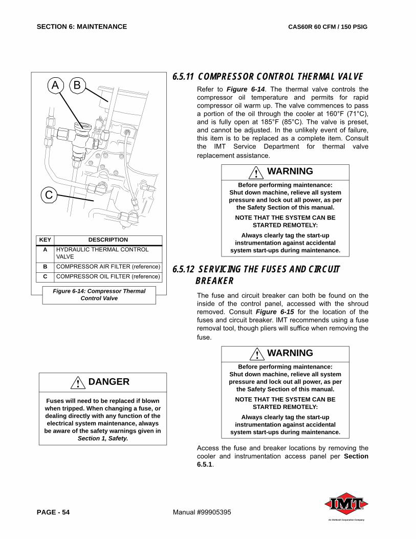
SECTION 6: MAINTENANCE CAS60R 60 CFM / 150 PSIG
PAGE - 54 Manual #99905395®
An Oshkosh Corporation Company
6.5.11 COMPRESSOR CONTROL THERMAL VALVERefer to Figure 6-14. The thermal valve controls thecompressor oil temperature and permits for rapidcompressor oil warm up. The valve commences to passa portion of the oil through the cooler at 160°F (71°C),and is fully open at 185°F (85°C). The valve is preset,and cannot be adjusted. In the unlikely event of failure,this item is to be replaced as a complete item. Consultthe IMT Service Department for thermal valvereplacement assistance.
6.5.12 SERVICING THE FUSES AND CIRCUIT BREAKER The fuse and circuit breaker can both be found on theinside of the control panel, accessed with the shroudremoved. Consult Figure 6-15 for the location of thefuses and circuit breaker. IMT recommends using a fuseremoval tool, though pliers will suffice when removing thefuse.
Access the fuse and breaker locations by removing thecooler and instrumentation access panel per Section6.5.1.
WARNINGBefore performing maintenance:
Shut down machine, relieve all system pressure and lock out all power, as per
the Safety Section of this manual. NOTE THAT THE SYSTEM CAN BE
STARTED REMOTELY:Always clearly tag the start-up
instrumentation against accidental system start-ups during maintenance.
WARNINGBefore performing maintenance:
Shut down machine, relieve all system pressure and lock out all power, as per
the Safety Section of this manual. NOTE THAT THE SYSTEM CAN BE
STARTED REMOTELY:Always clearly tag the start-up
instrumentation against accidental system start-ups during maintenance.
KEY DESCRIPTIONA HYDRAULIC THERMAL CONTROL
VALVE
B COMPRESSOR AIR FILTER (reference)
C COMPRESSOR OIL FILTER (reference)
Figure 6-14: Compressor Thermal Control Valve
A
C
B
DANGER
Fuses will need to be replaced if blown when tripped. When changing a fuse, or dealing directly with any function of the electrical system maintenance, always
be aware of the safety warnings given in Section 1, Safety.
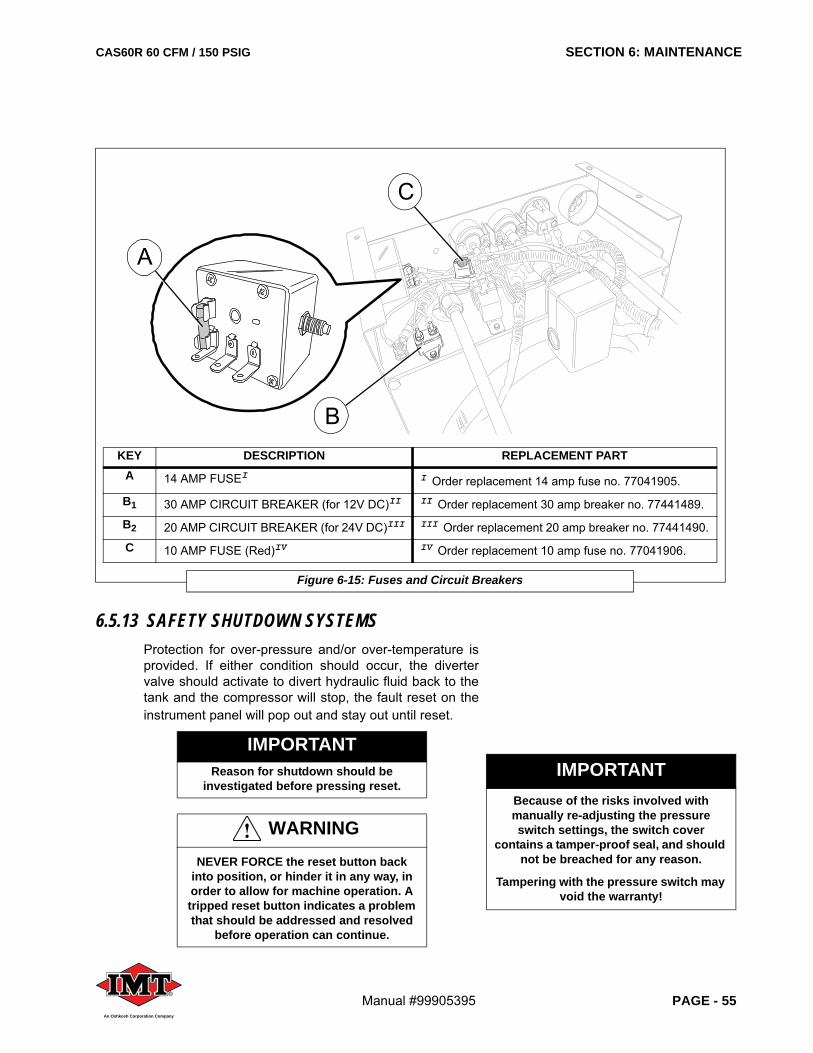
CAS60R 60 CFM / 150 PSIG SECTION 6: MAINTENANCE
Manual #99905395 PAGE - 55®
An Oshkosh Corporation Company
6.5.13 SAFETY SHUTDOWN SYSTEMSProtection for over-pressure and/or over-temperature isprovided. If either condition should occur, the divertervalve should activate to divert hydraulic fluid back to thetank and the compressor will stop, the fault reset on theinstrument panel will pop out and stay out until reset.
IMPORTANTReason for shutdown should be
investigated before pressing reset.
WARNINGNEVER FORCE the reset button back
into position, or hinder it in any way, in order to allow for machine operation. A tripped reset button indicates a problem that should be addressed and resolved
before operation can continue.
KEY DESCRIPTION REPLACEMENT PARTA 14 AMP FUSEI I Order replacement 14 amp fuse no. 77041905.
B1 30 AMP CIRCUIT BREAKER (for 12V DC)II II Order replacement 30 amp breaker no. 77441489.
B2 20 AMP CIRCUIT BREAKER (for 24V DC)III III Order replacement 20 amp breaker no. 77441490.
C 10 AMP FUSE (Red)IV IV Order replacement 10 amp fuse no. 77041906.
Figure 6-15: Fuses and Circuit Breakers
B
C
A
IMPORTANTBecause of the risks involved with manually re-adjusting the pressure switch settings, the switch cover
contains a tamper-proof seal, and should not be breached for any reason.
Tampering with the pressure switch may void the warranty!
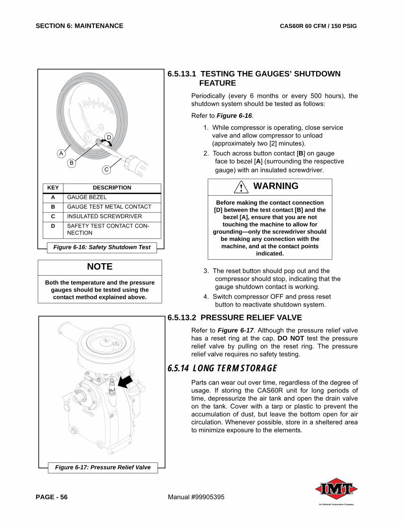
SECTION 6: MAINTENANCE CAS60R 60 CFM / 150 PSIG
PAGE - 56 Manual #99905395®
An Oshkosh Corporation Company
NOTEBoth the temperature and the pressure
gauges should be tested using the contact method explained above.
6.5.13.1 TESTING THE GAUGES’ SHUTDOWN FEATURE
Periodically (every 6 months or every 500 hours), theshutdown system should be tested as follows:
Refer to Figure 6-16.
1. While compressor is operating, close service valve and allow compressor to unload (approximately two [2] minutes).
2. Touch across button contact [B] on gauge face to bezel [A] (surrounding the respective gauge) with an insulated screwdriver.
3. The reset button should pop out and the compressor should stop, indicating that the gauge shutdown contact is working.
4. Switch compressor OFF and press reset button to reactivate shutdown system.
6.5.13.2 PRESSURE RELIEF VALVERefer to Figure 6-17. Although the pressure relief valvehas a reset ring at the cap, DO NOT test the pressurerelief valve by pulling on the reset ring. The pressurerelief valve requires no safety testing.
6.5.14 LONG TERM STORAGEParts can wear out over time, regardless of the degree ofusage. If storing the CAS60R unit for long periods oftime, depressurize the air tank and open the drain valveon the tank. Cover with a tarp or plastic to prevent theaccumulation of dust, but leave the bottom open for aircirculation. Whenever possible, store in a sheltered areato minimize exposure to the elements.
WARNINGBefore making the contact connection
[D] between the test contact [B] and the bezel [A], ensure that you are not touching the machine to allow for
grounding—only the screwdriver should be making any connection with the machine, and at the contact points
indicated.
KEY DESCRIPTIONA GAUGE BEZEL
B GAUGE TEST METAL CONTACT
C INSULATED SCREWDRIVER
D SAFETY TEST CONTACT CON-NECTION
Figure 6-16: Safety Shutdown Test
AB
D
C
Figure 6-17: Pressure Relief Valve
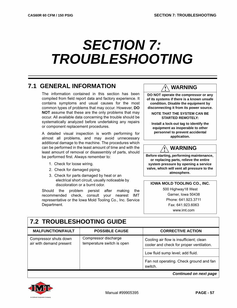
CAS60R 60 CFM / 150 PSIG SECTION 7: TROUBLESHOOTING
Manual #99905395 PAGE - 57®
An Oshkosh Corporation Company
7.1 GENERAL INFORMATIONThe information contained in this section has beencompiled from field report data and factory experience. Itcontains symptoms and usual causes for the mostcommon types of problems that may occur. However, DONOT assume that these are the only problems that mayoccur. All available data concerning the trouble should besystematically analyzed before undertaking any repairsor component replacement procedures.
A detailed visual inspection is worth performing foralmost all problems, and may avoid unnecessaryadditional damage to the machine. The procedures whichcan be performed in the least amount of time and with theleast amount of removal or disassembly of parts, shouldbe performed first. Always remember to:
1. Check for loose wiring.2. Check for damaged piping.3. Check for parts damaged by heat or an
electrical short circuit, usually noticeable by discoloration or a burnt odor.
Should the problem persist after making therecommended check, consult your nearest IMTrepresentative or the Iowa Mold Tooling Co., Inc. ServiceDepartment.
SECTION 7: TROUBLESHOOTING
WARNINGDO NOT operate the compressor or any of its systems if there is a known unsafe
condition. Disable the equipment by disconnecting it from its power source.
NOTE THAT THE SYSTEM CAN BE STARTED REMOTELY:
Install a lock-out tag to identify the equipment as inoperable to other personnel to prevent accidental
application.
WARNINGBefore starting, performing maintenance,
or replacing parts, relieve the entire system pressure by opening a service
valve, which will vent all pressure to the atmosphere.
7.2 TROUBLESHOOTING GUIDEMALFUNCTION/FAULT POSSIBLE CAUSE CORRECTIVE ACTION
Compressor shuts down air with demand present
Compressor discharge temperature switch is open
Cooling air flow is insufficient; clean cooler and check for proper ventilation.
Low fluid sump level; add fluid.
Fan not operating. Check ground and fan switch.
Continued on next page
IOWA MOLD TOOLING CO., INC.500 Highway18 West
Garner, Iowa 50438Phone: 641.923.3711
Fax: 641.923.6063www.imt.com
SECTION 7: TROUBLESHOOTING CAS60R 60 CFM / 150 PSIG
PAGE - 58 Manual #99905395®
An Oshkosh Corporation Company
Compressor shuts down air with demand present(Continued)
Plugged oil filter Replace oil filter.
Dirty cooler core Clean cooler core.
Contaminated cooler core Remove and clean cooler core.
Hydraulic pressure and flow incorrect
Adjust and reset.
Compressor will not build up pressure
Air demand is too great Check service lines for leaks or open valves. Too much air demand.
Dirty air filter Check the filter and clean or change element if required.
Pressure switch out of adjustment
DO NOT ATTEMPT TO ADJUST. Contact the IMT Service Department for assistance.
Defective pressure switch Replace pressure switch.Motor does not speed up Check hydraulic flow and pressure and
adjust if necessary.Belts slipping Readjust or tighten belts.Service valve wide open Close service valve.Solenoid valve stuck Replace solenoid valve.Leak in air pilot line Check for leaks and correct.
Compressor over pres-sures
Pressure regulator out of adjustment
Contact factory service department.
Defective pressure switch Replace pressure switch; Contact factory service department.
Leak in air control line Check line and correct.Inlet valve jammed Free or replace valve.Restriction in control line Dirt or ice present. Clean or free up.Solenoid valve not energized or faulty
Check for power. Replace if necessary.
Faulty gauge Check using an auxiliary air source. Replace if necessary.
Defective safety valve Replace safety valve.
Plugged coalescer Replace coalescer.
Continued on next page
7.2 TROUBLESHOOTING GUIDEMALFUNCTION/FAULT POSSIBLE CAUSE CORRECTIVE ACTION
CAS60R 60 CFM / 150 PSIG SECTION 7: TROUBLESHOOTING
Manual #99905395 PAGE - 59®
An Oshkosh Corporation Company
Insufficient air delivery Plugged air filter Replace air filter.Plugged coalescer Replace coalescer element.Motor speed to low Check hydraulic flow and pressure and
adjust if necessary.Inlet valve stuck Free or replace inlet valve. Order rebuild
kit if necessary.Belts slipping Readjust belt tension.
Oil carryover Oil level overfull Drain to proper level.
Plugged oil scavenge line Remove and clean tube thoroughly.Discharge pressure too low Check minimum pressure valve and
adjust. Replace if necessary.Defective coalescer Replace coalescer element.
Compressor overheating Insufficient oil Check oil level and fill to proper level.Restricted cooling air flow Reposition machine to assure proper air
flow.Fan not operating Check ground connection and ensure
proper connection.Check fan switch.Check air pressure switch.Check circuit breaker.Check for short in wires.Check fan motor.
Plugged oil filter Replace oil filter.Cooler core plugged Clean cooler core.Pressure set too high Contact factory service department.Contaminated cooler core Remove and clean cooler core.Unit running too fast Check hydraulic flow and pressure and
adjust if necessary.Thermal valve Faulty valve; replace thermal valve.
System retains pressure after shutdown
Solenoid valve stuck Should be no power to solenoid valve.Replace solenoid valve.Pressure switch faulty; replace.
Leak back from air line Check minimum pressure valve for leaks.
Continued on next page
7.2 TROUBLESHOOTING GUIDEMALFUNCTION/FAULT POSSIBLE CAUSE CORRECTIVE ACTION
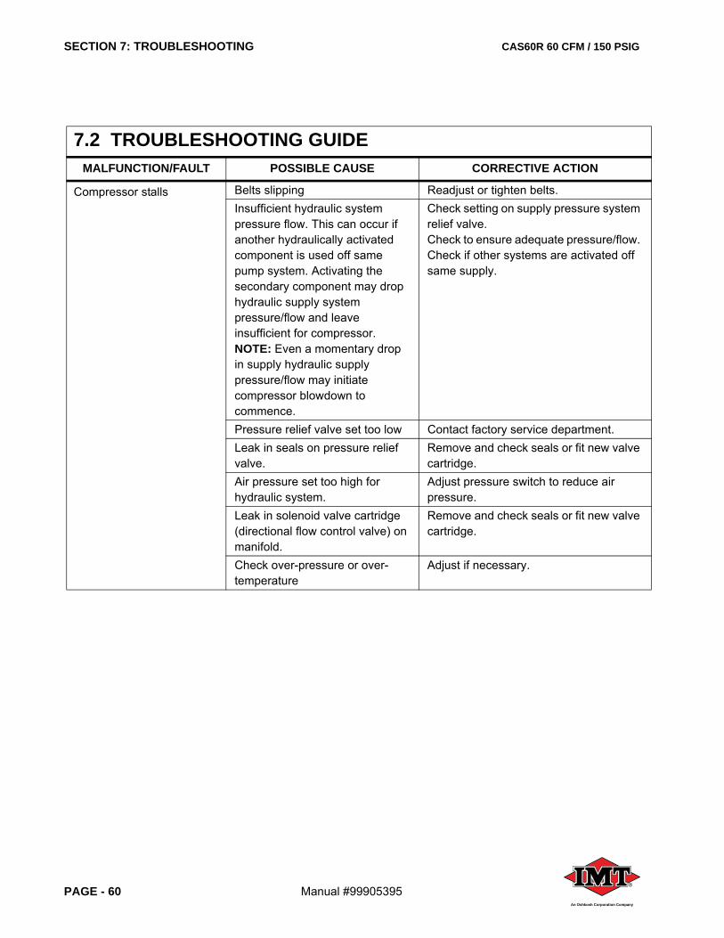
SECTION 7: TROUBLESHOOTING CAS60R 60 CFM / 150 PSIG
PAGE - 60 Manual #99905395®
An Oshkosh Corporation Company
Compressor stalls Belts slipping Readjust or tighten belts.Insufficient hydraulic system pressure flow. This can occur if another hydraulically activated component is used off same pump system. Activating the secondary component may drop hydraulic supply system pressure/flow and leave insufficient for compressor.NOTE: Even a momentary drop in supply hydraulic supply pressure/flow may initiate compressor blowdown to commence.
Check setting on supply pressure system relief valve. Check to ensure adequate pressure/flow. Check if other systems are activated off same supply.
Pressure relief valve set too low Contact factory service department.Leak in seals on pressure relief valve.
Remove and check seals or fit new valve cartridge.
Air pressure set too high for hydraulic system.
Adjust pressure switch to reduce air pressure.
Leak in solenoid valve cartridge (directional flow control valve) on manifold.
Remove and check seals or fit new valve cartridge.
Check over-pressure or over-temperature
Adjust if necessary.
7.2 TROUBLESHOOTING GUIDEMALFUNCTION/FAULT POSSIBLE CAUSE CORRECTIVE ACTION
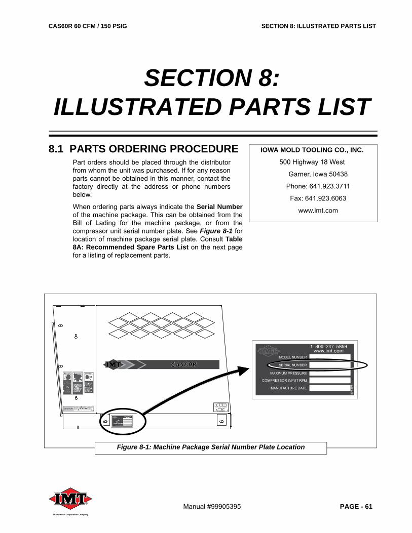
CAS60R 60 CFM / 150 PSIG SECTION 8: ILLUSTRATED PARTS LIST
Manual #99905395 PAGE - 61®
An Oshkosh Corporation Company
8.1 PARTS ORDERING PROCEDUREPart orders should be placed through the distributorfrom whom the unit was purchased. If for any reasonparts cannot be obtained in this manner, contact thefactory directly at the address or phone numbersbelow.
When ordering parts always indicate the Serial Numberof the machine package. This can be obtained from theBill of Lading for the machine package, or from thecompressor unit serial number plate. See Figure 8-1 forlocation of machine package serial plate. Consult Table8A: Recommended Spare Parts List on the next pagefor a listing of replacement parts.
SECTION 8:ILLUSTRATED PARTS LIST
Figure 8-1: Machine Package Serial Number Plate Location
PSIG
IOWA MOLD TOOLING CO., INC.
500 Highway 18 West
Garner, Iowa 50438
Phone: 641.923.3711
Fax: 641.923.6063
www.imt.com
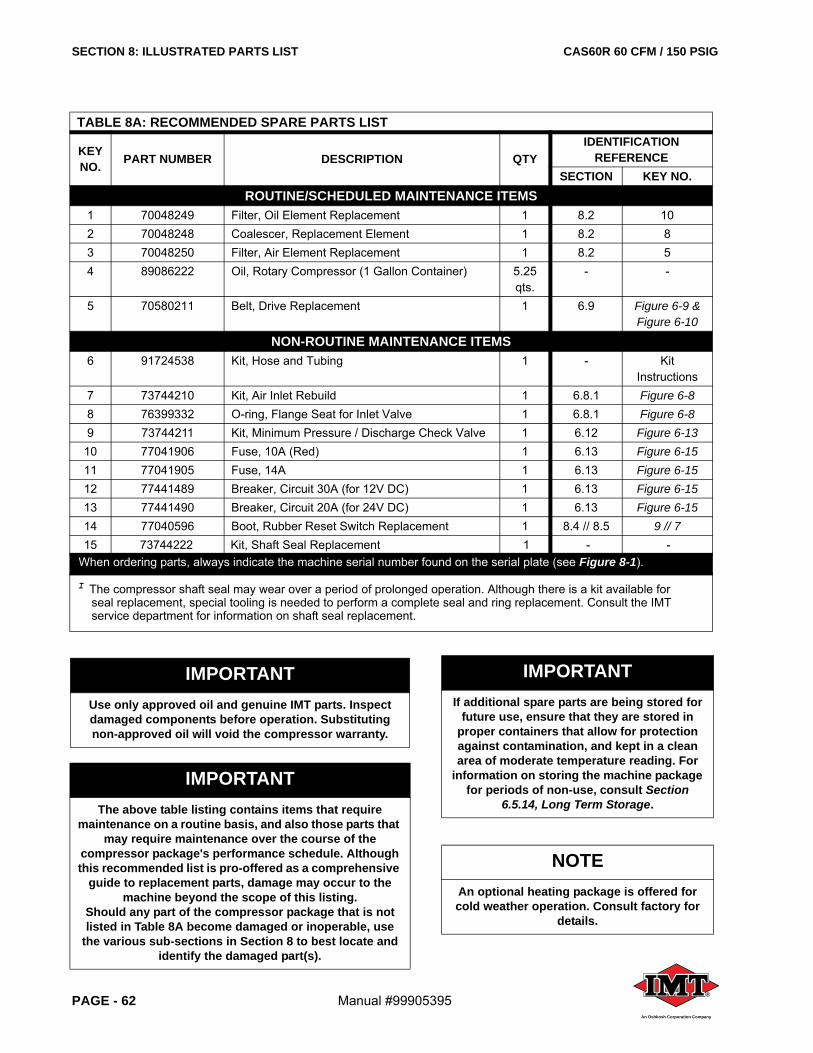
SECTION 8: ILLUSTRATED PARTS LIST CAS60R 60 CFM / 150 PSIG
PAGE - 62 Manual #99905395 ®
An Oshkosh Corporation Company
TABLE 8A: RECOMMENDED SPARE PARTS LIST
KEY NO. PART NUMBER DESCRIPTION QTY
IDENTIFICATION REFERENCE
SECTION KEY NO.ROUTINE/SCHEDULED MAINTENANCE ITEMS
1 70048249 Filter, Oil Element Replacement 1 8.2 102 70048248 Coalescer, Replacement Element 1 8.2 83 70048250 Filter, Air Element Replacement 1 8.2 54 89086222 Oil, Rotary Compressor (1 Gallon Container) 5.25
qts.- -
5 70580211 Belt, Drive Replacement 1 6.9 Figure 6-9 & Figure 6-10
NON-ROUTINE MAINTENANCE ITEMS6 91724538 Kit, Hose and Tubing 1 - Kit
Instructions7 73744210 Kit, Air Inlet Rebuild 1 6.8.1 Figure 6-88 76399332 O-ring, Flange Seat for Inlet Valve 1 6.8.1 Figure 6-89 73744211 Kit, Minimum Pressure / Discharge Check Valve 1 6.12 Figure 6-13
10 77041906 Fuse, 10A (Red) 1 6.13 Figure 6-1511 77041905 Fuse, 14A 1 6.13 Figure 6-1512 77441489 Breaker, Circuit 30A (for 12V DC) 1 6.13 Figure 6-1513 77441490 Breaker, Circuit 20A (for 24V DC) 1 6.13 Figure 6-1514 77040596 Boot, Rubber Reset Switch Replacement 1 8.4 // 8.5 9 // 715 73744222 Kit, Shaft Seal Replacement 1 - -
When ordering parts, always indicate the machine serial number found on the serial plate (see Figure 8-1).
I The compressor shaft seal may wear over a period of prolonged operation. Although there is a kit available for seal replacement, special tooling is needed to perform a complete seal and ring replacement. Consult the IMT service department for information on shaft seal replacement.
IMPORTANTUse only approved oil and genuine IMT parts. Inspect damaged components before operation. Substituting non-approved oil will void the compressor warranty.
IMPORTANTIf additional spare parts are being stored for
future use, ensure that they are stored in proper containers that allow for protection against contamination, and kept in a clean area of moderate temperature reading. For
information on storing the machine package for periods of non-use, consult Section
6.5.14, Long Term Storage.
IMPORTANTThe above table listing contains items that require
maintenance on a routine basis, and also those parts that may require maintenance over the course of the
compressor package's performance schedule. Although this recommended list is pro-offered as a comprehensive
guide to replacement parts, damage may occur to the machine beyond the scope of this listing.
Should any part of the compressor package that is not listed in Table 8A become damaged or inoperable, use
the various sub-sections in Section 8 to best locate and identify the damaged part(s).
NOTEAn optional heating package is offered for cold weather operation. Consult factory for
details.
CAS60R 60 CFM / 150 PSIG SECTION 8: ILLUSTRATED PARTS LIST
Manual #99905395 PAGE - 63®
An Oshkosh Corporation Company
TABLE 8B: MAINTENANCE TRACKING LOGDATE DESCRIPTION OF MAINTENANCE PART(S) REPLACED
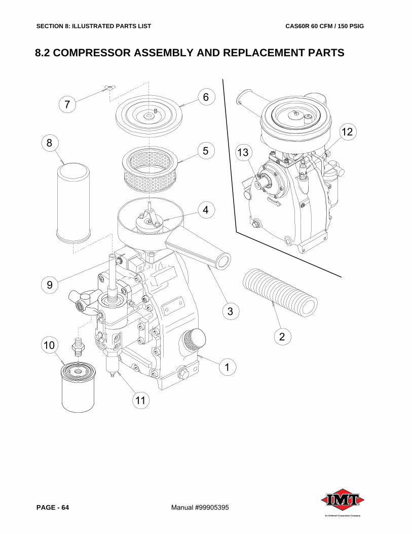
SECTION 8: ILLUSTRATED PARTS LIST CAS60R 60 CFM / 150 PSIG
PAGE - 64 Manual #99905395 ®
An Oshkosh Corporation Company
1
11
8
102
3
67
5
4
9
12
13
8.2 COMPRESSOR ASSEMBLY AND REPLACEMENT PARTS

CAS60R 60 CFM / 150 PSIG SECTION 8: ILLUSTRATED PARTS LIST
Manual #99905395 PAGE - 65®
An Oshkosh Corporation Company
8.2 COMPRESSOR ASSEMBLY AND REPLACEMENT PARTS
ITEM DESCRIPTION PART NUMBER QTY
1 COMPRESSOR ASSEMBLY 70734662 1
2 FLEX HOSE 1
3 AIR FILTER BODY 1
4 AIR INLET VALVE 73744210 1
5 AIR FILTER 70048250 1
6 AIR FILTER COVER 1
7 WING NUT 1
8 COALESCER ELEMENT FILTER 70048248 1
9 SOLENOID AND INLET VALVE ASSEMBLED Consult Factory 1
10 OIL FILTER 70048249 1
11 MINIMUM PRESSURE/CHECK VALVE 73744211 1
12 PRESSURE RELIEF VALVE (200PSI) 1
13 DRIVE SHAFT (MALE ROTOR) 1
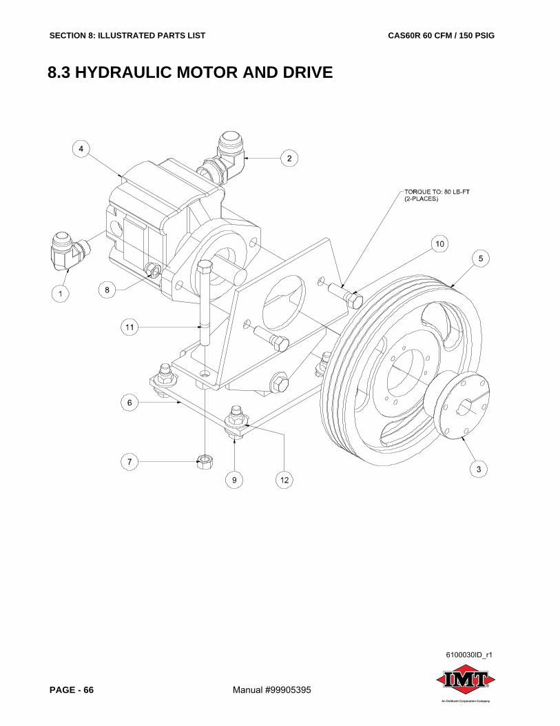
SECTION 8: ILLUSTRATED PARTS LIST CAS60R 60 CFM / 150 PSIG
PAGE - 66 Manual #99905395 ®
An Oshkosh Corporation Company
8.3 HYDRAULIC MOTOR AND DRIVE
6100030ID_r1
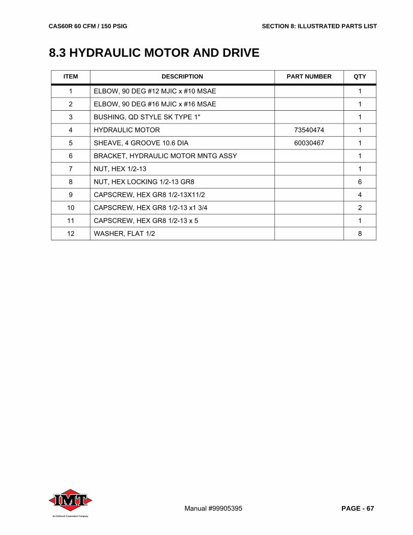
CAS60R 60 CFM / 150 PSIG SECTION 8: ILLUSTRATED PARTS LIST
Manual #99905395 PAGE - 67®
An Oshkosh Corporation Company
8.3 HYDRAULIC MOTOR AND DRIVE
ITEM DESCRIPTION PART NUMBER QTY
1 ELBOW, 90 DEG #12 MJIC x #10 MSAE 1
2 ELBOW, 90 DEG #16 MJIC x #16 MSAE 1
3 BUSHING, QD STYLE SK TYPE 1" 1
4 HYDRAULIC MOTOR 73540474 1
5 SHEAVE, 4 GROOVE 10.6 DIA 60030467 1
6 BRACKET, HYDRAULIC MOTOR MNTG ASSY 1
7 NUT, HEX 1/2-13 1
8 NUT, HEX LOCKING 1/2-13 GR8 6
9 CAPSCREW, HEX GR8 1/2-13X11/2 4
10 CAPSCREW, HEX GR8 1/2-13 x1 3/4 2
11 CAPSCREW, HEX GR8 1/2-13 x 5 1
12 WASHER, FLAT 1/2 8
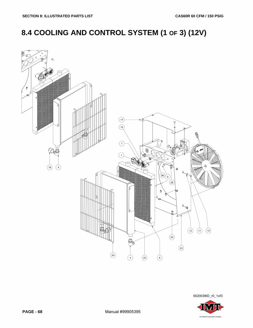
SECTION 8: ILLUSTRATED PARTS LIST CAS60R 60 CFM / 150 PSIG
PAGE - 68 Manual #99905395 ®
An Oshkosh Corporation Company
8.4 COOLING AND CONTROL SYSTEM (1 OF 3) (12V)
6020038ID_r0_1of3

CAS60R 60 CFM / 150 PSIG SECTION 8: ILLUSTRATED PARTS LIST
Manual #99905395 PAGE - 69®
An Oshkosh Corporation Company
8.4 COOLING AND CONTROL SYSTEM (1 OF 3) (12V)
ITEM DESCRIPTION PART NUMBER QTY
1 GAUGE, HOUR METER 77441491 1
2 ELBOW, 90 DEG 1/8P x 1/4JIC LONG 1
3 RELAY, NO/NC WEATHERPROOF w/RESISTOR 1
4 ELBOW, 90 DEG #12 MJIC x #12 MSAE 2
5 SWITCH, HIGH TEMP. SHUTDOWN 70734663 1
6 BREAKER, CIRCUIT w/ STUDS 30A 77441489 1
7 GAUGE, AIR PRESSURE w/ SWITCH 70048247 1
8 COOLER, OIL 60 CFM 51724560 1
9 BOOT, RUBBER RESET SWITCH 77040596 1
10 WASHER, NYLON FLAT 1/4 4
11 WASHER, NYLON 5/16-18 10
12 SCREW,TRUSS HD 5/16-18 x 3/4 SS 10
13 SCREW, TRUSS HD 1/4-20 x 3/4 4
14 BUMPER, RUBBER 9/16 DIA 2
15 GAUGE, TEMP. MURPHY 70734664 1
16 SWITCH, PRESSURE ADJUSTABLE 77041904 1
17 PLATE, COOLER SHROUD TOP HYD SRS65 1
18 CAP, FEMALE JIC 1 5/16-12 #16 1
19 SEAL, KNOCKOUT 1/2” 1
20 FAN AND MOTOR ASSY. 51724557 1
21 GROMMET, RUBBER 1 x 1 3/32 x 3/32 1
22 COOLER, OIL 2.00 CORE SINGLE PASS SPCL 51724558 1
23 SHROUD, COOLER 1
24 GUARD, OIL COOLERS 1
25 TEE, PIPE GALV 1/8 1
26 COUPLING, PIPE GALV 1/8 300# 1
27 NIPPLE, PIPE GALV 1/8 x 3 1
28 NUT, HEX FLANGE 5/16-18 13
29 NUT, HEX LOCKING 5/16-18 1
30 SCREW, SER WASH 5/16-18 x 0.75 2
31 SCREW, SER WASH 5/16-18 x 1 1
32 SCREW, HEX SELF THREAD 1/4 x 3/4 4
33 SCREW, SELF-DRILL #8 x 1/2 3
34 ELBOW, 37FL/90M #08 x 1/2 2
35 NIPPLE, HEX RED 1/4 x 1/8 1
36 PLUG, 1/2, PUSH IN, BLACK PLASTIC 1
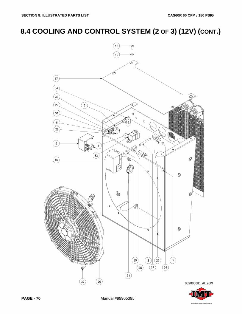
SECTION 8: ILLUSTRATED PARTS LIST CAS60R 60 CFM / 150 PSIG
PAGE - 70 Manual #99905395 ®
An Oshkosh Corporation Company
8.4 COOLING AND CONTROL SYSTEM (2 OF 3) (12V) (CONT.)
6020038ID_r0_2of3

CAS60R 60 CFM / 150 PSIG SECTION 8: ILLUSTRATED PARTS LIST
Manual #99905395 PAGE - 71®
An Oshkosh Corporation Company
8.4 COOLING AND CONTROL SYSTEM (2 OF 3) (12V) (CONT.)
ITEM DESCRIPTION PART NUMBER QTY
1 GAUGE, HOUR METER 77441491 1
2 ELBOW, 90 DEG 1/8P x 1/4JIC LONG 1
3 RELAY, NO/NC WEATHERPROOF w/RESISTOR 1
4 ELBOW, 90 DEG #12 MJIC x #12 MSAE 2
5 SWITCH, HIGH TEMP. SHUTDOWN 70734663 1
6 BREAKER, CIRCUIT w/ STUDS 30A 77441489 1
7 GAUGE, AIR PRESSURE w/ SWITCH 70048247 1
8 COOLER, OIL 60 CFM 51724560 1
9 BOOT, RUBBER RESET SWITCH 77040596 1
10 WASHER, NYLON FLAT 1/4 4
11 WASHER, NYLON 5/16-18 10
12 SCREW,TRUSS HD 5/16-18 x 3/4 SS 10
13 SCREW, TRUSS HD 1/4-20 x 3/4 4
14 BUMPER, RUBBER 9/16 DIA 2
15 GAUGE, TEMP. MURPHY 70734664 1
16 SWITCH, PRESSURE ADJUSTABLE 77041904 1
17 PLATE, COOLER SHROUD TOP HYD SRS65 1
18 CAP, FEMALE JIC 1 5/16-12 #16 1
19 SEAL, KNOCKOUT 1/2” 1
20 FAN AND MOTOR ASSY. 51724557 1
21 GROMMET, RUBBER 1 x 1 3/32 x 3/32 1
22 COOLER, OIL 2.00 CORE SINGLE PASS SPCL 51724558 1
23 SHROUD, COOLER 1
24 GUARD, OIL COOLERS 1
25 TEE, PIPE GALV 1/8 1
26 COUPLING, PIPE GALV 1/8 300# 1
27 NIPPLE, PIPE GALV 1/8 x 3 1
28 NUT, HEX FLANGE 5/16-18 13
29 NUT, HEX LOCKING 5/16-18 1
30 SCREW, SER WASH 5/16-18 x 0.75 2
31 SCREW, SER WASH 5/16-18 x 1 1
32 SCREW, HEX SELF THREAD 1/4 x 3/4 4
33 SCREW, SELF-DRILL #8 x 1/2 3
34 ELBOW, 37FL/90M #08 x 1/2 2
35 NIPPLE, HEX RED 1/4 x 1/8 1
36 PLUG, 1/2, PUSH IN, BLACK PLASTIC 1
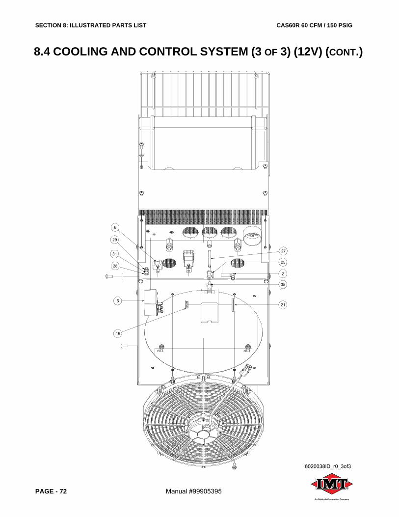
SECTION 8: ILLUSTRATED PARTS LIST CAS60R 60 CFM / 150 PSIG
PAGE - 72 Manual #99905395 ®
An Oshkosh Corporation Company
8.4 COOLING AND CONTROL SYSTEM (3 OF 3) (12V) (CONT.)
6020038ID_r0_3of3

CAS60R 60 CFM / 150 PSIG SECTION 8: ILLUSTRATED PARTS LIST
Manual #99905395 PAGE - 73®
An Oshkosh Corporation Company
8.4 COOLING AND CONTROL SYSTEM (3 OF 3) (12V) (CONT.)
ITEM DESCRIPTION PART NUMBER QTY
1 GAUGE, HOUR METER 77441491 1
2 ELBOW, 90 DEG 1/8P x 1/4JIC LONG 1
3 RELAY, NO/NC WEATHERPROOF w/RESISTOR 1
4 ELBOW, 90 DEG #12 MJIC x #12 MSAE 2
5 SWITCH, HIGH TEMP. SHUTDOWN 70734663 1
6 BREAKER, CIRCUIT w/ STUDS 30A 77441489 1
7 GAUGE, AIR PRESSURE w/ SWITCH 70048247 1
8 COOLER, OIL 60 CFM 51724560 1
9 BOOT, RUBBER RESET SWITCH 77040596 1
10 WASHER, NYLON FLAT 1/4 4
11 WASHER, NYLON 5/16-18 10
12 SCREW,TRUSS HD 5/16-18 x 3/4 SS 10
13 SCREW, TRUSS HD 1/4-20 x 3/4 4
14 BUMPER, RUBBER 9/16 DIA 2
15 GAUGE, TEMP. MURPHY 70734664 1
16 SWITCH, PRESSURE ADJUSTABLE 77041904 1
17 PLATE, COOLER SHROUD TOP HYD SRS65 1
18 CAP, FEMALE JIC 1 5/16-12 #16 1
19 SEAL, KNOCKOUT 1/2” 1
20 FAN AND MOTOR ASSY. 51724557 1
21 GROMMET, RUBBER 1 x 1 3/32 x 3/32 1
22 COOLER, OIL 2.00 CORE SINGLE PASS SPCL 51724558 1
23 SHROUD, COOLER 1
24 GUARD, OIL COOLERS 1
25 TEE, PIPE GALV 1/8 1
26 COUPLING, PIPE GALV 1/8 300# 1
27 NIPPLE, PIPE GALV 1/8 x 3 1
28 NUT, HEX FLANGE 5/16-18 13
29 NUT, HEX LOCKING 5/16-18 1
30 SCREW, SER WASH 5/16-18 x 0.75 2
31 SCREW, SER WASH 5/16-18 x 1 1
32 SCREW, HEX SELF THREAD 1/4 x 3/4 4
33 SCREW, SELF-DRILL #8 x 1/2 3
34 ELBOW, 37FL/90M #08 x 1/2 2
35 NIPPLE, HEX RED 1/4 x 1/8 1
36 PLUG, 1/2, PUSH IN, BLACK PLASTIC 1
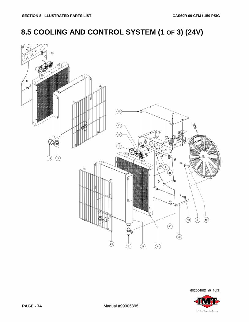
SECTION 8: ILLUSTRATED PARTS LIST CAS60R 60 CFM / 150 PSIG
PAGE - 74 Manual #99905395 ®
An Oshkosh Corporation Company
8.5 COOLING AND CONTROL SYSTEM (1 OF 3) (24V)
6020048ID_r0_1of3
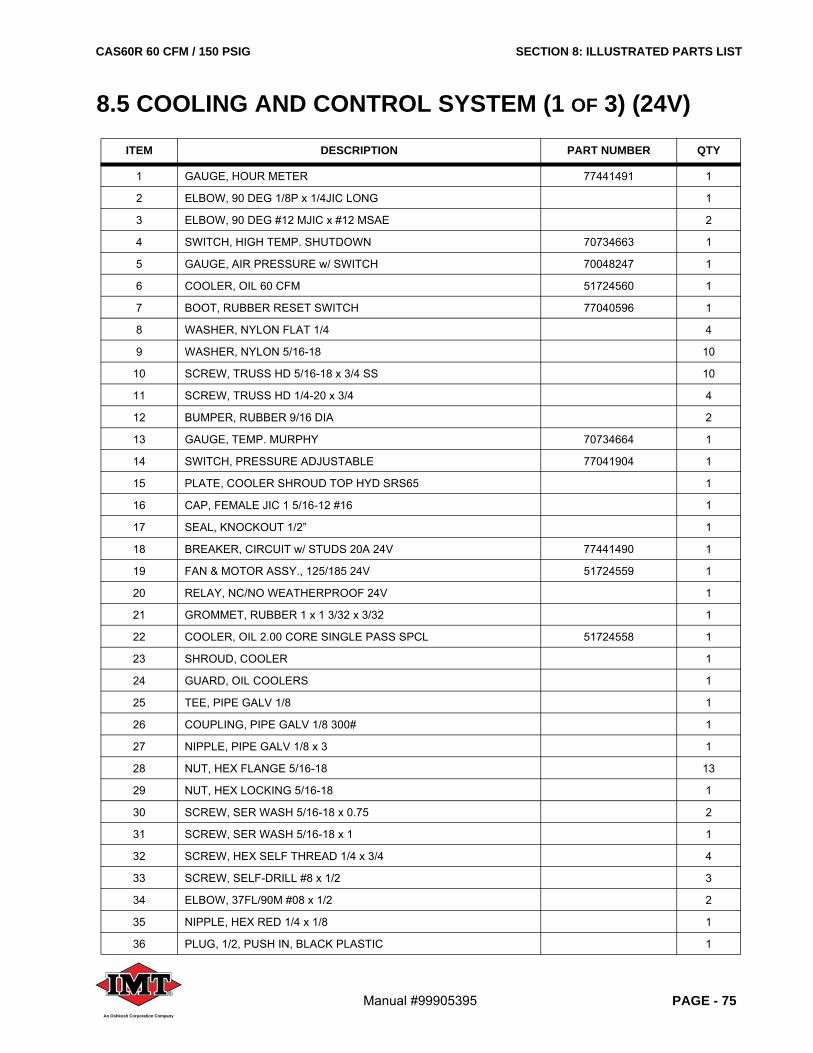
CAS60R 60 CFM / 150 PSIG SECTION 8: ILLUSTRATED PARTS LIST
Manual #99905395 PAGE - 75®
An Oshkosh Corporation Company
8.5 COOLING AND CONTROL SYSTEM (1 OF 3) (24V)
ITEM DESCRIPTION PART NUMBER QTY
1 GAUGE, HOUR METER 77441491 1
2 ELBOW, 90 DEG 1/8P x 1/4JIC LONG 1
3 ELBOW, 90 DEG #12 MJIC x #12 MSAE 2
4 SWITCH, HIGH TEMP. SHUTDOWN 70734663 1
5 GAUGE, AIR PRESSURE w/ SWITCH 70048247 1
6 COOLER, OIL 60 CFM 51724560 1
7 BOOT, RUBBER RESET SWITCH 77040596 1
8 WASHER, NYLON FLAT 1/4 4
9 WASHER, NYLON 5/16-18 10
10 SCREW, TRUSS HD 5/16-18 x 3/4 SS 10
11 SCREW, TRUSS HD 1/4-20 x 3/4 4
12 BUMPER, RUBBER 9/16 DIA 2
13 GAUGE, TEMP. MURPHY 70734664 1
14 SWITCH, PRESSURE ADJUSTABLE 77041904 1
15 PLATE, COOLER SHROUD TOP HYD SRS65 1
16 CAP, FEMALE JIC 1 5/16-12 #16 1
17 SEAL, KNOCKOUT 1/2” 1
18 BREAKER, CIRCUIT w/ STUDS 20A 24V 77441490 1
19 FAN & MOTOR ASSY., 125/185 24V 51724559 1
20 RELAY, NC/NO WEATHERPROOF 24V 1
21 GROMMET, RUBBER 1 x 1 3/32 x 3/32 1
22 COOLER, OIL 2.00 CORE SINGLE PASS SPCL 51724558 1
23 SHROUD, COOLER 1
24 GUARD, OIL COOLERS 1
25 TEE, PIPE GALV 1/8 1
26 COUPLING, PIPE GALV 1/8 300# 1
27 NIPPLE, PIPE GALV 1/8 x 3 1
28 NUT, HEX FLANGE 5/16-18 13
29 NUT, HEX LOCKING 5/16-18 1
30 SCREW, SER WASH 5/16-18 x 0.75 2
31 SCREW, SER WASH 5/16-18 x 1 1
32 SCREW, HEX SELF THREAD 1/4 x 3/4 4
33 SCREW, SELF-DRILL #8 x 1/2 3
34 ELBOW, 37FL/90M #08 x 1/2 2
35 NIPPLE, HEX RED 1/4 x 1/8 1
36 PLUG, 1/2, PUSH IN, BLACK PLASTIC 1
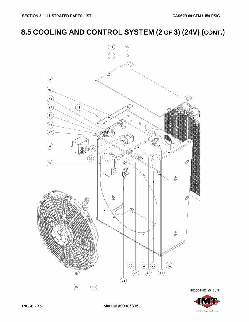
SECTION 8: ILLUSTRATED PARTS LIST CAS60R 60 CFM / 150 PSIG
PAGE - 76 Manual #99905395 ®
An Oshkosh Corporation Company
8.5 COOLING AND CONTROL SYSTEM (2 OF 3) (24V) (CONT.)
6020048ID_r0_2of3
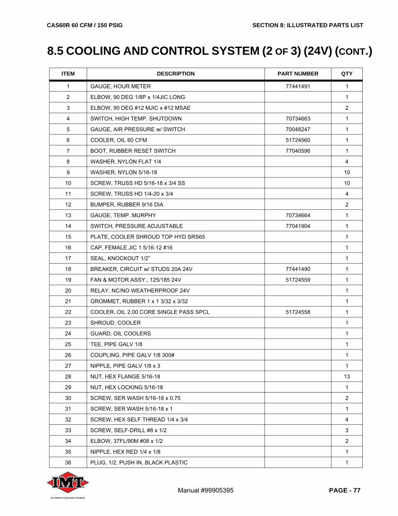
CAS60R 60 CFM / 150 PSIG SECTION 8: ILLUSTRATED PARTS LIST
Manual #99905395 PAGE - 77®
An Oshkosh Corporation Company
8.5 COOLING AND CONTROL SYSTEM (2 OF 3) (24V) (CONT.)
ITEM DESCRIPTION PART NUMBER QTY
1 GAUGE, HOUR METER 77441491 1
2 ELBOW, 90 DEG 1/8P x 1/4JIC LONG 1
3 ELBOW, 90 DEG #12 MJIC x #12 MSAE 2
4 SWITCH, HIGH TEMP. SHUTDOWN 70734663 1
5 GAUGE, AIR PRESSURE w/ SWITCH 70048247 1
6 COOLER, OIL 60 CFM 51724560 1
7 BOOT, RUBBER RESET SWITCH 77040596 1
8 WASHER, NYLON FLAT 1/4 4
9 WASHER, NYLON 5/16-18 10
10 SCREW, TRUSS HD 5/16-18 x 3/4 SS 10
11 SCREW, TRUSS HD 1/4-20 x 3/4 4
12 BUMPER, RUBBER 9/16 DIA 2
13 GAUGE, TEMP. MURPHY 70734664 1
14 SWITCH, PRESSURE ADJUSTABLE 77041904 1
15 PLATE, COOLER SHROUD TOP HYD SRS65 1
16 CAP, FEMALE JIC 1 5/16-12 #16 1
17 SEAL, KNOCKOUT 1/2” 1
18 BREAKER, CIRCUIT w/ STUDS 20A 24V 77441490 1
19 FAN & MOTOR ASSY., 125/185 24V 51724559 1
20 RELAY, NC/NO WEATHERPROOF 24V 1
21 GROMMET, RUBBER 1 x 1 3/32 x 3/32 1
22 COOLER, OIL 2.00 CORE SINGLE PASS SPCL 51724558 1
23 SHROUD, COOLER 1
24 GUARD, OIL COOLERS 1
25 TEE, PIPE GALV 1/8 1
26 COUPLING, PIPE GALV 1/8 300# 1
27 NIPPLE, PIPE GALV 1/8 x 3 1
28 NUT, HEX FLANGE 5/16-18 13
29 NUT, HEX LOCKING 5/16-18 1
30 SCREW, SER WASH 5/16-18 x 0.75 2
31 SCREW, SER WASH 5/16-18 x 1 1
32 SCREW, HEX SELF THREAD 1/4 x 3/4 4
33 SCREW, SELF-DRILL #8 x 1/2 3
34 ELBOW, 37FL/90M #08 x 1/2 2
35 NIPPLE, HEX RED 1/4 x 1/8 1
36 PLUG, 1/2, PUSH IN, BLACK PLASTIC 1
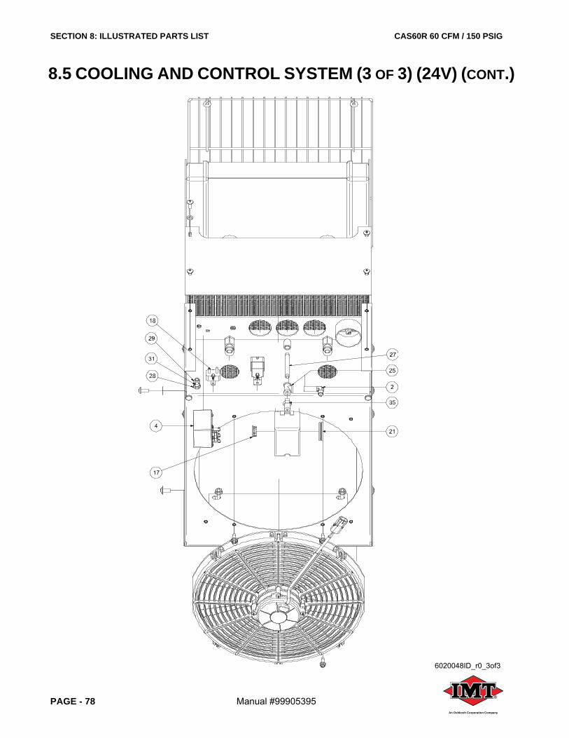
SECTION 8: ILLUSTRATED PARTS LIST CAS60R 60 CFM / 150 PSIG
PAGE - 78 Manual #99905395 ®
An Oshkosh Corporation Company
8.5 COOLING AND CONTROL SYSTEM (3 OF 3) (24V) (CONT.)
6020048ID_r0_3of3

CAS60R 60 CFM / 150 PSIG SECTION 8: ILLUSTRATED PARTS LIST
Manual #99905395 PAGE - 79®
An Oshkosh Corporation Company
8.5 COOLING AND CONTROL SYSTEM (3 OF 3) (24V) (CONT.)
ITEM DESCRIPTION PART NUMBER QTY
1 GAUGE, HOUR METER 77441491 1
2 ELBOW, 90 DEG 1/8P x 1/4JIC LONG 1
3 ELBOW, 90 DEG #12 MJIC x #12 MSAE 2
4 SWITCH, HIGH TEMP. SHUTDOWN 70734663 1
5 GAUGE, AIR PRESSURE w/ SWITCH 70048247 1
6 COOLER, OIL 60 CFM 51724560 1
7 BOOT, RUBBER RESET SWITCH 77040596 1
8 WASHER, NYLON FLAT 1/4 4
9 WASHER, NYLON 5/16-18 10
10 SCREW, TRUSS HD 5/16-18 x 3/4 SS 10
11 SCREW, TRUSS HD 1/4-20 x 3/4 4
12 BUMPER, RUBBER 9/16 DIA 2
13 GAUGE, TEMP. MURPHY 70734664 1
14 SWITCH, PRESSURE ADJUSTABLE 77041904 1
15 PLATE, COOLER SHROUD TOP HYD SRS65 1
16 CAP, FEMALE JIC 1 5/16-12 #16 1
17 SEAL, KNOCKOUT 1/2” 1
18 BREAKER, CIRCUIT w/ STUDS 20A 24V 77441490 1
19 FAN & MOTOR ASSY., 125/185 24V 51724559 1
20 RELAY, NC/NO WEATHERPROOF 24V 1
21 GROMMET, RUBBER 1 x 1 3/32 x 3/32 1
22 COOLER, OIL 2.00 CORE SINGLE PASS SPCL 51724558 1
23 SHROUD, COOLER 1
24 GUARD, OIL COOLERS 1
25 TEE, PIPE GALV 1/8 1
26 COUPLING, PIPE GALV 1/8 300# 1
27 NIPPLE, PIPE GALV 1/8 x 3 1
28 NUT, HEX FLANGE 5/16-18 13
29 NUT, HEX LOCKING 5/16-18 1
30 SCREW, SER WASH 5/16-18 x 0.75 2
31 SCREW, SER WASH 5/16-18 x 1 1
32 SCREW, HEX SELF THREAD 1/4 x 3/4 4
33 SCREW, SELF-DRILL #8 x 1/2 3
34 ELBOW, 37FL/90M #08 x 1/2 2
35 NIPPLE, HEX RED 1/4 x 1/8 1
36 PLUG, 1/2, PUSH IN, BLACK PLASTIC 1
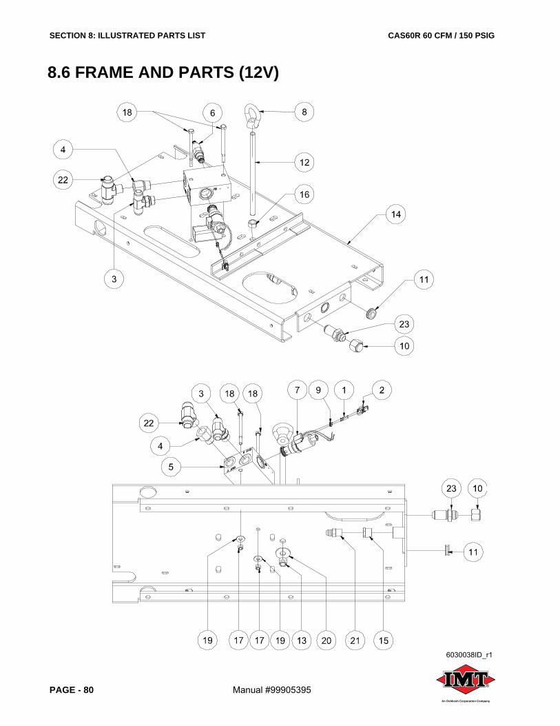
SECTION 8: ILLUSTRATED PARTS LIST CAS60R 60 CFM / 150 PSIG
PAGE - 80 Manual #99905395 ®
An Oshkosh Corporation Company
8.6 FRAME AND PARTS (12V)
6030038ID_r1
CAS60R 60 CFM / 150 PSIG SECTION 8: ILLUSTRATED PARTS LIST
Manual #99905395 PAGE - 81®
An Oshkosh Corporation Company
8.6 FRAME AND PARTS (12V)
ITEM DESCRIPTION PART NUMBER QTY
1 TERMINAL, FEMALE 2
2 CONNECTOR, FEMALE 1
3 TEE, JIC/JIC/SAE 3/4 1
4 ADAPTER, #12 MSAE O-RING x 3/4 FNPT 1
5 MANIFOLD, HYDRAULIC SOLENOID 71414997 1
6 VALVE, PRESSURE RELIEF 73540470 1
7 VALVE, SOLENOID WITH 12V. COIL 73540471 1
8 EYENUT, 5/8-11 1
9 SEAL, CABLE GREEN 16-14 GA 2
10 CAP, FEMALE JIC 1 1/16-12 #12 1
11 GROMMET, RUBBER 11/16 x 1 x 3/16 1
12 ROD, TIE DOWN BODY 5/8-11 x 12 1
13 NUT, HEX LOCKING 5/8-11 GR8 1
14 FRAME, HYDRAULIC VIKING 1
15 BUSHING, RED STEEL 3/4 x 1/2 1
16 NUT, HEX 5/8-11 1
17 NUT, HEX LOCKING 3/8-16 2
18 CAPSCREW, HEX GR8 3/8-16 x 5 2
19 WASHER, FLAT 3/8 2
20 WASHER, FLAT 5/8 1
21 CONNECTOR, 37FL/MPT #08 x 1/2 1
22 TEE, 37FL M BR 1 JIC X 3/4NPT 1
23 BULKHEAD, MJIC x MJIC #12 1
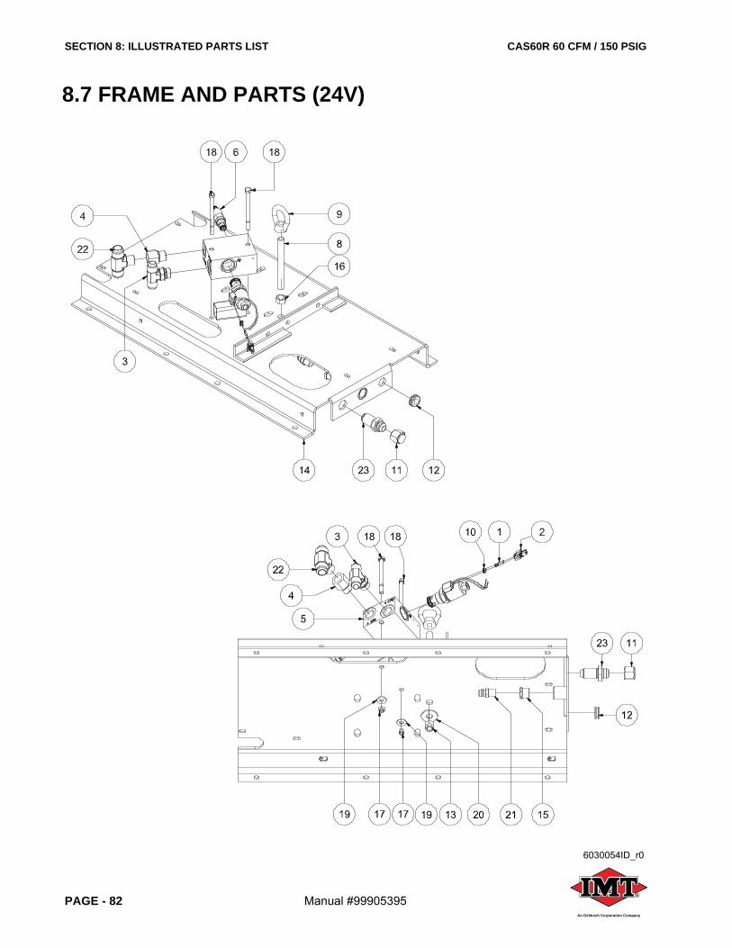
SECTION 8: ILLUSTRATED PARTS LIST CAS60R 60 CFM / 150 PSIG
PAGE - 82 Manual #99905395 ®
An Oshkosh Corporation Company
8.7 FRAME AND PARTS (24V)
6030054ID_r0
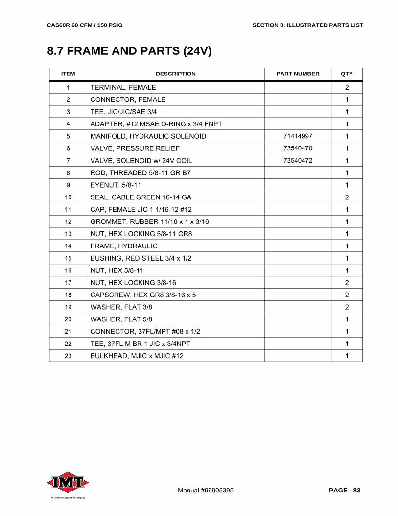
CAS60R 60 CFM / 150 PSIG SECTION 8: ILLUSTRATED PARTS LIST
Manual #99905395 PAGE - 83®
An Oshkosh Corporation Company
8.7 FRAME AND PARTS (24V)
ITEM DESCRIPTION PART NUMBER QTY
1 TERMINAL, FEMALE 2
2 CONNECTOR, FEMALE 1
3 TEE, JIC/JIC/SAE 3/4 1
4 ADAPTER, #12 MSAE O-RING x 3/4 FNPT 1
5 MANIFOLD, HYDRAULIC SOLENOID 71414997 1
6 VALVE, PRESSURE RELIEF 73540470 1
7 VALVE, SOLENOID w/ 24V COIL 73540472 1
8 ROD, THREADED 5/8-11 GR B7 1
9 EYENUT, 5/8-11 1
10 SEAL, CABLE GREEN 16-14 GA 2
11 CAP, FEMALE JIC 1 1/16-12 #12 1
12 GROMMET, RUBBER 11/16 x 1 x 3/16 1
13 NUT, HEX LOCKING 5/8-11 GR8 1
14 FRAME, HYDRAULIC 1
15 BUSHING, RED STEEL 3/4 x 1/2 1
16 NUT, HEX 5/8-11 1
17 NUT, HEX LOCKING 3/8-16 2
18 CAPSCREW, HEX GR8 3/8-16 x 5 2
19 WASHER, FLAT 3/8 2
20 WASHER, FLAT 5/8 1
21 CONNECTOR, 37FL/MPT #08 x 1/2 1
22 TEE, 37FL M BR 1 JIC x 3/4NPT 1
23 BULKHEAD, MJIC x MJIC #12 1
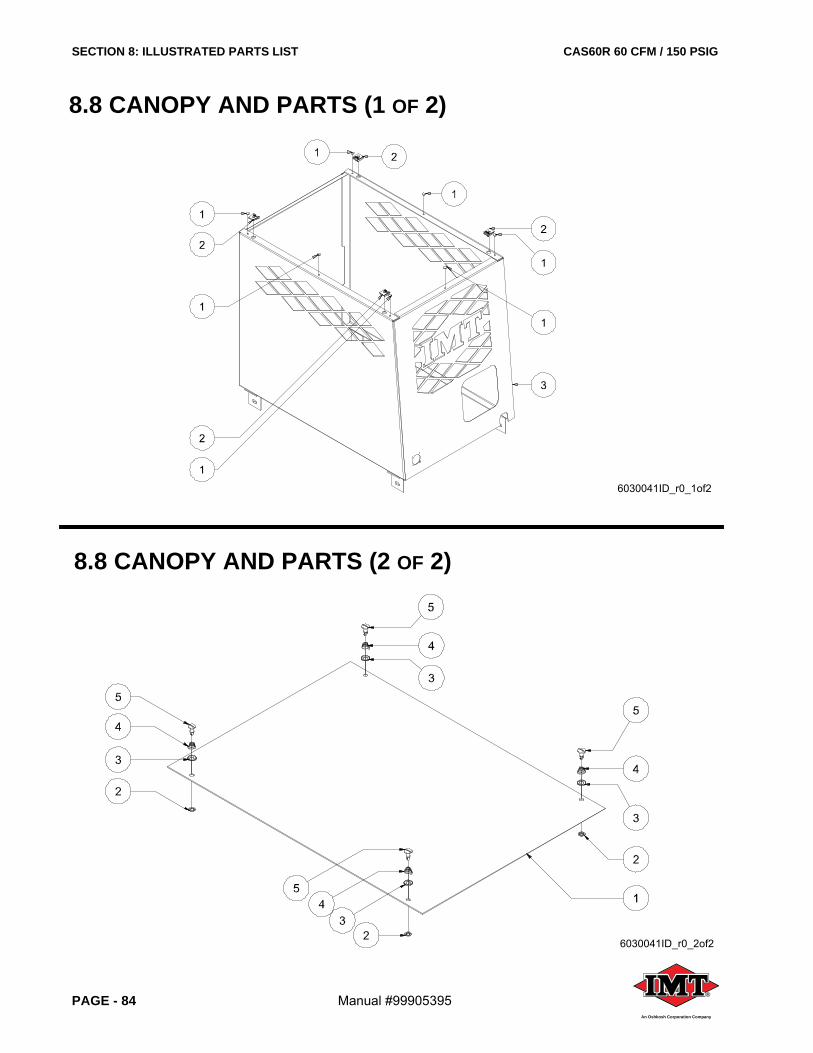
SECTION 8: ILLUSTRATED PARTS LIST CAS60R 60 CFM / 150 PSIG
PAGE - 84 Manual #99905395 ®
An Oshkosh Corporation Company
8.8 CANOPY AND PARTS (1 OF 2)
8.8 CANOPY AND PARTS (2 OF 2)
6030041ID_r0_1of2
6030041ID_r0_2of2
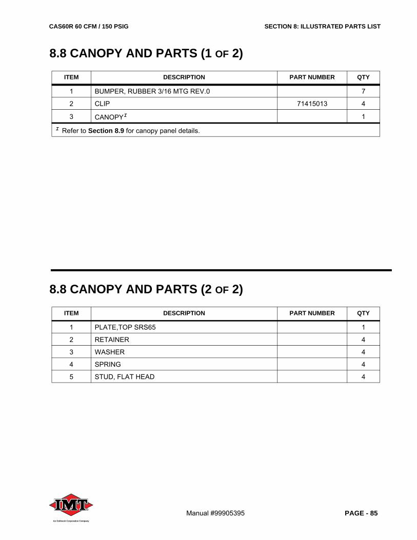
CAS60R 60 CFM / 150 PSIG SECTION 8: ILLUSTRATED PARTS LIST
Manual #99905395 PAGE - 85®
An Oshkosh Corporation Company
8.8 CANOPY AND PARTS (1 OF 2)
ITEM DESCRIPTION PART NUMBER QTY
1 BUMPER, RUBBER 3/16 MTG REV.0 7
2 CLIP 71415013 4
3 CANOPYI 1
I Refer to Section 8.9 for canopy panel details.
8.8 CANOPY AND PARTS (2 OF 2)
ITEM DESCRIPTION PART NUMBER QTY
1 PLATE,TOP SRS65 1
2 RETAINER 4
3 WASHER 4
4 SPRING 4
5 STUD, FLAT HEAD 4
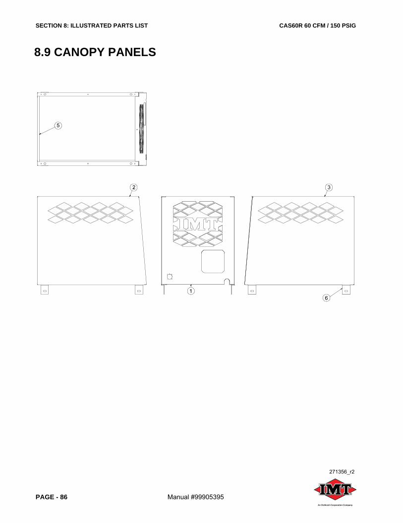
SECTION 8: ILLUSTRATED PARTS LIST CAS60R 60 CFM / 150 PSIG
PAGE - 86 Manual #99905395 ®
An Oshkosh Corporation Company
8.9 CANOPY PANELS
271356_r2
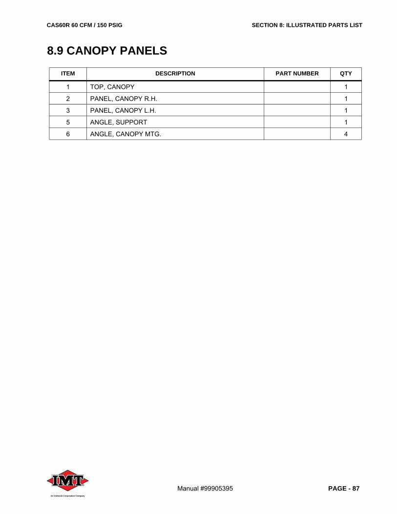
CAS60R 60 CFM / 150 PSIG SECTION 8: ILLUSTRATED PARTS LIST
Manual #99905395 PAGE - 87®
An Oshkosh Corporation Company
8.9 CANOPY PANELS
ITEM DESCRIPTION PART NUMBER QTY
1 TOP, CANOPY 1
2 PANEL, CANOPY R.H. 1
3 PANEL, CANOPY L.H. 1
5 ANGLE, SUPPORT 1
6 ANGLE, CANOPY MTG. 4
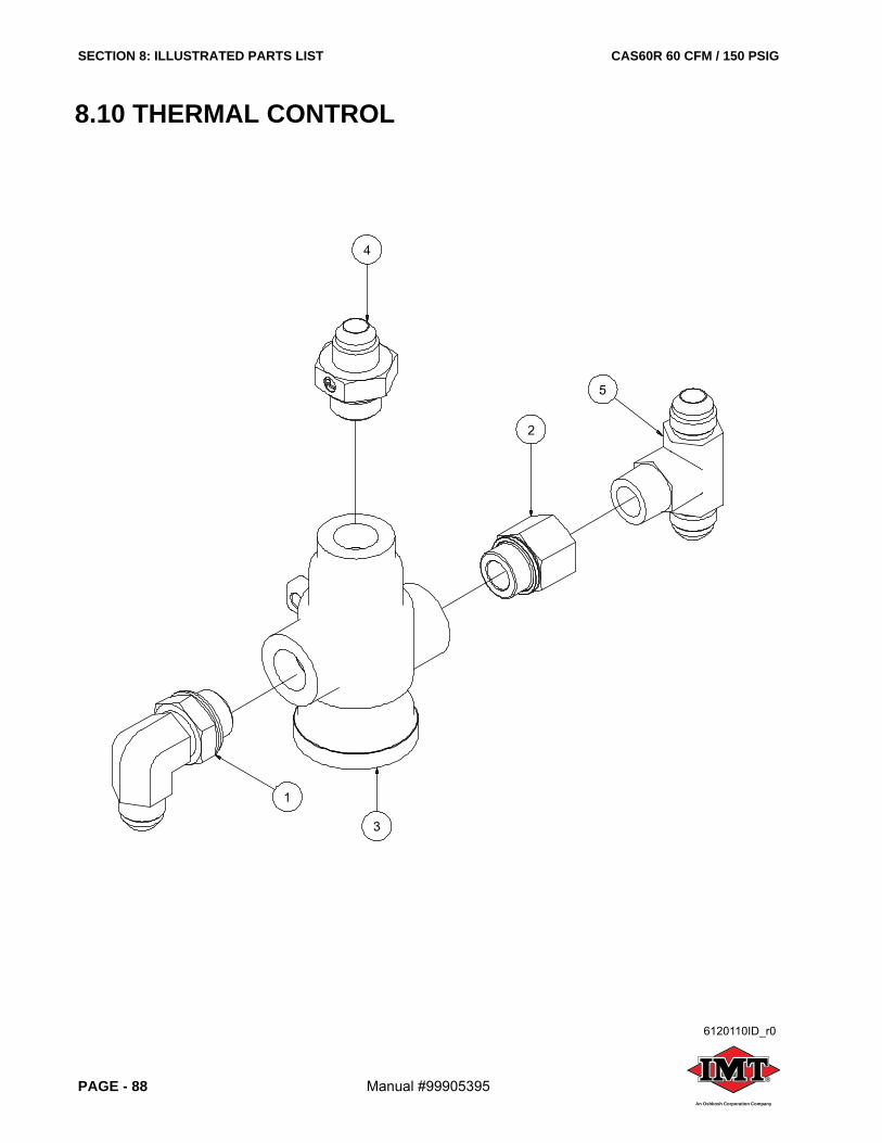
SECTION 8: ILLUSTRATED PARTS LIST CAS60R 60 CFM / 150 PSIG
PAGE - 88 Manual #99905395 ®
An Oshkosh Corporation Company
8.10 THERMAL CONTROL
6120110ID_r0
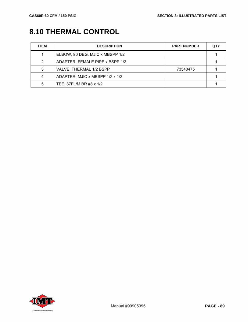
CAS60R 60 CFM / 150 PSIG SECTION 8: ILLUSTRATED PARTS LIST
Manual #99905395 PAGE - 89®
An Oshkosh Corporation Company
8.10 THERMAL CONTROL
ITEM DESCRIPTION PART NUMBER QTY
1 ELBOW, 90 DEG. MJIC x MBSPP 1/2 1
2 ADAPTER, FEMALE PIPE x BSPP 1/2 1
3 VALVE, THERMAL 1/2 BSPP 73540475 1
4 ADAPTER, MJIC x MBSPP 1/2 x 1/2 1
5 TEE, 37FL/M BR #8 x 1/2 1
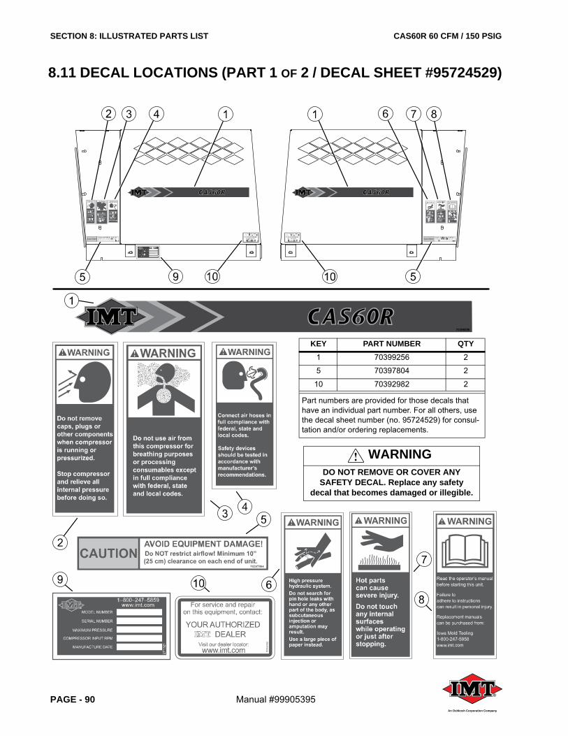
SECTION 8: ILLUSTRATED PARTS LIST CAS60R 60 CFM / 150 PSIG
PAGE - 90 Manual #99905395 ®
An Oshkosh Corporation Company
8.11 DECAL LOCATIONS (PART 1 OF 2 / DECAL SHEET #95724529)
KEY PART NUMBER QTY1 70399256 2
5 70397804 2
10 70392982 2
Part numbers are provided for those decals that have an individual part number. For all others, use the decal sheet number (no. 95724529) for consul-tation and/or ordering replacements.
WARNINGDO NOT REMOVE OR COVER ANY
SAFETY DECAL. Replace any safety decal that becomes damaged or illegible.
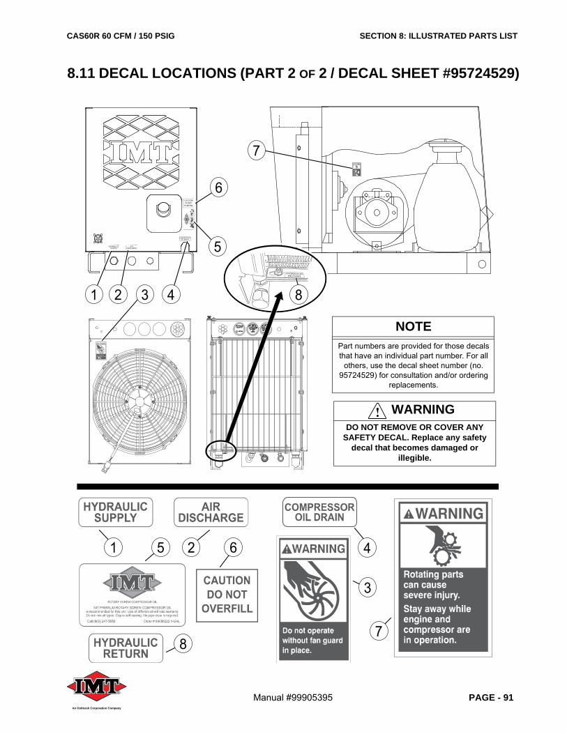
CAS60R 60 CFM / 150 PSIG SECTION 8: ILLUSTRATED PARTS LIST
Manual #99905395 PAGE - 91®
An Oshkosh Corporation Company
®
1 2 3 4
5
7
78
2 6 4
3
1 5
8
6
8.11 DECAL LOCATIONS (PART 2 OF 2 / DECAL SHEET #95724529)
NOTEPart numbers are provided for those decals that have an individual part number. For all
others, use the decal sheet number (no. 95724529) for consultation and/or ordering
replacements.
WARNINGDO NOT REMOVE OR COVER ANY
SAFETY DECAL. Replace any safety decal that becomes damaged or
illegible.
SECTION 8: ILLUSTRATED PARTS LIST CAS60R 60 CFM / 150 PSIG
PAGE - 92 Manual #99905395
BLANK PAGE
®
An Oshkosh Corporation Company

BLANK PAGE

Printed in the U.S.A.
Specifications Subject to Change Without Prior Notice
050737050740090033_r0
®
An Oshkosh Corporation Company
IOWA MOLD TOOLING CO., INC.
500 Highway 18 West
Garner, Iowa 50438
Phone: 641.923.3711
Fax: 641.923.6063
www.imt.com