4QO\ \35 - DTIC
288
TT- 3;ý- WADC TECHNICAL REPORT 52-49 '7,'RA AIRCRAFT ELECTRICAL SYSTEM STUDY H. 1. FINISON L. W. MATSCH L. 1. STRATTON ARMOUR RESEARCH FOUNDATION ILLINOIS INSTITUTE OF TECHNOLOGY APRIL 1952 Reproduced From Best Available Copy WRIGHT AIR DEVELOPMENT CENTER AF-WP-(B).O- 13 FEB 53 50 4QO\ \35
-
Upload
khangminh22 -
Category
Documents
-
view
0 -
download
0
Transcript of 4QO\ \35 - DTIC
TT- 3;ý-
WADC TECHNICAL REPORT 52-49
'7,'RA
AIRCRAFT ELECTRICAL SYSTEM STUDY
H. 1. FINISONL. W. MATSCH
L. 1. STRATTON
ARMOUR RESEARCH FOUNDATION
ILLINOIS INSTITUTE OF TECHNOLOGY
APRIL 1952
Reproduced FromBest Available Copy
WRIGHT AIR DEVELOPMENT CENTER
AF-WP-(B).O- 13 FEB 53 50 4QO\ \35
NOTICES
When Government drawings, specifications, or other data are usedfor any purpose other than in connection with a definitely related Govern-ment procurement operation, the United States Government thereby in-curs no responsibility nor any obligation whatsoever; and the fact thatthe Government may have formulated, furnished, or in any way suppliedthe said drawings, specifications, or other data, is not to be regardedby implication or otherwise as in any manner licensing the holder orany other person or corporation,or conveying any rights or permissionto manufacture, use, or sell any patented invention that may in anywaybe related thereto.
The information furnished herewith is made available for studyupon the understanding that the Government's proprietary interests inand relating thereto shall not be impaired. It is desired that the JudgeAdvocate (WCJ), Wright Air Development Center, Wright-PattersonAir Force Base, Ohio, be promptly notified of any apparent conflict be-tween the Government's proprietary interests and those of others.
uu412u13pu=.

WADC TECHNICAL REPORT 52-49
AIRCRAFT ELECTRICAL SYSTEM STUDY
H.J. FinisonL. W. Matsch
L. J. Stratton
"Armour Research Foundation
Illinois Institute of Technology
April 1952
Equipment LaboratoryContract No. 33(038)-30511
RDO No. :656-2112
"Wright Air Development Center
Air Research and Development CommandUnited States Air Force
Wright-Patterson Air Force Base, Ohio

FOREWUORD
This report was prepared by Armour Research Foundation ofIllinois Institute of Technology to incorporate the results of astudy project entitled, "Study, Aircraft Electrical Systems."The study was conducted for the Equipment Laboratory, Directorateof Laboratories, Wright Air Development Center, under RDO 656-2112,"Aircraft Electrical System Evaluation," on Air Force Contract33-(038)-30511. Mr. C. T. Hackler acted as WADC Project Engineer.
Other personnel of Armour Research Foundation who assisted inthe preparation of this report were Messrs. R. M. Bergslien,J. A. Granath, A. K. Hawkes, and R. F. Zenner.
/
WADC TR 52-49

AIRCRAFT PIECTRICAL SYSTM STUDY
ABSTRACT
The results of a study, to evaluate the performance of aircraft
electrical systems are presented in this report. &mphasis has been on the
400-cycle, a-c system. Analytical and experimental studies using the facil--
ities of the Air Force Equipment Laboratory at Wright Air Development Center
were made by personnel of the Armour Research Foundation. These studies were
made to determine the performance characteristics of the 40 KVA alternators
and their associated regulating equipment as well as protective equipment
with a view to determine methods of improving the performance and reliabil-
ity of the electrical system.
From these studies it is concluded that practical improvements in
the reliability of the electrical system can be effected, and that detailed
study should be directed toward simplifying the system layout and augmenting
and improving the means of protecting the electrical system.
PUBLICATION REVIW.
This report h2 s been reviei ed and is ai roved.
FOR TH-t• COkMAhDING GEICF.RAL:
H. A.kOUHEŽ\Colonel, USAFChief, Equipment LaboratoryDirectorate of Laboratories
WADC TR 52-49 iii

TABLE OF CONTENTS
Page
I* INTRODUCTION . . . .• • • .• • • * . * . . .• • * * * * 1
II. PRESENT 400-CYCLEA-C SYSTEMk. . . •....... .... 3
A* Alternator . . . . . . .* e e * *. . . . . . . . . 3
B. Voltage Regulator. . . . . . ....... . 6
C. Exciter Control RlRelay.................. 6
D. Circuit Breaker.. * .. ..... ... ... 7
E. Exciter Protection Relay . ........ *. .. . 8
F. Differential Protection Relay. . . . . .. * .. 9
G. Load Transfer Contactor. o e. . . . .. 9
III. SYSTEM PERFORMANCE *. . . . . . . . . 11
A* Introduction .* . . . . . . . . . . . . . . . .o .9 . 11
I. Function of a Constant Frequency System....... e*
a. Steady-State Operation ... . . . .. .
b. Transient Conditions .... ......... 13
c. Short-Time-Continuous Operation.. .. . . 14
2. Applications of Parameters * * * . . . &. .... 14
a. Saturated and Unsaturated Synchronous Reactance. 15
b. Quadrature-Axis Synchronous Reactance.*. . . . . 18
c. Amplification Factor-Reactive Load Division. e . 19
d. Amplification Factor-Real Load Division.. • . . 19
e. Transient Impedance............... 19
f. Negative-Sequence and Zero-Sequence Impedances . 21
WADC TR 52-49iv
TABLE OF CONTENTS (cont'd)
Page
3- Analytical vs. Experimental Methods . • • • . • • . 26
4- Extent of Present Study, ., .•. . • 27
B. Alternator Characteristics. o o s o e • • • • . .o o • 28
1. Steady State- Balanced Operation ... .. .o 28
a. No Load Saturation Curve. . . . 0, 0, * • 32
b. Three-Phase Short-Circuit Saturation Curve.s. . 32
c. Synchronous Reactance . .. * .o • . * • 0 35
d. Short-Circuit Ratio * * o * o * i o o * o s, 35
e. Zero Power-Factor Saturation Curve.*. . . . . . 37
f. Potier Reactance and Armature DemagnetizationFactor. s . . o . • • . • . • • • • • • • • • 38
g. Direct-Axis and Quadrature-Axis Synchronous
Reactance .o .• .o . .o . • . *. o *. o o o 39
2. Transient- Unbalanced Operation. . 0 0 ... • • • 41
a. Positive-Sequence Impedance . . . . . . . a . . 41
b. Negative-Sequence Impedance . . . , . . . . . .0 48
c. Zero-Sequence Impedance.. . ... . . . • . . 50
3. Discussion. a . . o o . a o * * • • . . & * . # o * 53
a. Potier Reactance and Transient Reactance. * e . 53
b. Short-Circuit Currents, Observed and Calcu-lated ............... *00000 55
Co Regulators. a • .e .o o .* * . . . . .* . . .e • . 56
1. Voltage Regulator e * # . .. . . . . .s . . .& . 56
2. Speed Regulator o * *. . . . . . . . . . .* . . .o 60
3* Equalizer Circuits.o. .. . . .e o . . o . . e o • 66
WADO TB 52-49v
TABLE QF CONTENTS (conttd)
Page
a. Reactive Power Equalizer .... .......... . ... 66
b. Real Power Equalizer .............. 76
4. Malfunctioning of Regulating Systems ............. 85
a. Abnormal Excitation. ... ................. 86
b. Open Circuit in Reactive Current EqualizerConnection .......... ................. . . 109
c. Open Circuit in Current Transformer Connection . 110
d. Failure of Tachometer or Tachometer Circuit. . . 111
e. Short Circuit of Frequency Droop Circuit . . . . 111
f. Failure of Potential Transformers in FrequencyDroop Circuit. . . . . ............. 1.
g. Summary. . . . . . . . ............. 112
D. Short-Circuit Currents ......... ................... . 113
E. Blocked Rotor Tests. . . . . . . . ........... 121
F. Synchronizing Disturbances ........ .............. . 127
G. Overvoltage ............. ......................... 135
1. Overvoltage Due to Voltage Regulator Failure . . . . 135
2. 400-Cycle Overvoltage Due to Load Switching andFault Clearing . . . ....... ................. . 137
3. Overvoltage Due to Errors in Regulator . . . . . . . 142
4. Transient Overvoltages ...... ............. . 143
APPENDIX A Name Plate Data .......... ..................... 144
APPENDIX B Frequency Droop Circuit Sensitivity. . . . . . . . . . 145
IV. METHODS OF PROTECTION OF A-C SYSTEMS .... .......... . . . 148
A. General Protection Problems. . . . . . . . . . . . . . . 148
WADC TR 52-49vi

TABLE OF CONTENTS (cont'd)
Page
1. Nature of Short Circuits .1.4......... . 8
2. Fail Safe... * * . . . . . . . . . 149
3. Types of Protection. . . ..... . ... .... 151
B. Overcurrent Protection . .e.. .......... 152
C. Directional protection ...... . .......... 159
D. Differential Current protection. ............ 159
1. Single Current Transformer Arrangement . . . . . . . 160
a. Tripping Checks. . . * # .. . .. . . . . . . . 162
b. Through Fault Checks.. ... * e . . . . . . . 164
bc. Summary° . . . . .e. . . . .* . . . .. o . .. . . 168
2. Two Current Transformer Arrangement .. . . o. . . . 168
a. Steady-State Differential Current. . * . a . . . 170
3. Two pilot Wires for All Three Phases . . ° ..... 190
a. Advantages ...... . ........ • • • • 192
4. Two Pilot Wires, Two Relays for All Three phases . . 192
a. Sensitivity. .s. . . . # ..&. . . . . . . . • • 195
b. Through Fault. , . *. . . • .*. . . . . . . . 195
5. Modified Two Pilot Wire Scheme ...... . . . .. 197
a. Through Fault. . .. . . . . . . . . . . . 199
b. internx27 ault .............. • • • 199
6. Direct Acting Trip ................ 200
7. Current Transformer Design .......... • • . 201
Vo APPLICATION OF SYSTEM PROTECTION ....... . .... . 203
A. Alternator Protection*. ......... ••... 203
WADOC TR 52-49vii

TABLE OF CONTENTS (cont 'd)
Page
1. Types of Failure . . . . . . . . . . * * * * • • . . 203
a. Electrical Failures.. . . . . . . . . . . . . . 203
b. Mechanical Failures. . o o . .0. . . . . . . . . 204
2. Directional protection .e . . .* . .e . . * .o o . 204
a. Real Power Sensing. . .o .e . .o .* .. . . .. 205
b. Reactive Power Sensing . . ..... . * ... 206
c. Disadvantages of Directional Protection .*. . . 207
d. Application of Directional protection.o. . . . . 209
3. Generator Differential Current Protection.. .. . . 210
4. Comparison of Two Types of Generator Circuit Pro-tectione e . i a * m e. .e * a • o .e .& * .e . 210
a. Generator Circuit Description .. . .. . . . . 212
b. Factors of Comparison. .. . . # o o o . . . . . 214
c. Summary. .o. . e ... . . . . . . . . . . . . . 227
B. Main Bus, Feeder, and Tie Circuit protection . . . . . . 228
1o Main Buses .. .. . . . . . • * • . .*. . e ... .. 228
a. Vain Bus Protection Methods. .. . . . . . . o . 230
2. Tie Circuits . . . . . . .. .. . • 0 • • .. . . 237
a. Two Main Buses ....... . . . ....... 239
b. Four Main Buses.... . . . .......... 239
3. Feeder Circuits. ... . .. . ......... 241
a. Single Channel Feeder ........ . .... . 244
b. Double Channel Feeders . . . .... • • • • • 244
c. Sumrmary. .* . . . . . .. . . . . . . . . 251

TABLE OF CONTENTS (contd)
Page
4. Comparison Between Fuse Mesh Network and Differ-ential Current protected Bus and Tie Lines .... . 251
VI. GENFRATOR CONTROL SYSTEM. o . o o a ••.. ... . . 255
VII. CONCLUSIONS. 259
VIII. RECOIiIMENDATIONS. .. ... ••. .• . . .... .o 262
IX. LOGBOOKS . . . . . . . . . . . . . . . . . . . . . . . . . 265
ADX TR 52-4ix

LIST OF FIGURES
Figure Title Page
1 Alternator Controls and Complete-Differential Protection... 4
2 Alternator Controls and Fuse Protection . . . . .... • • • 5
3 Volt-Ampere Characteristic for Ceiling Excitation andZero Power-Factor Current . . ........ ....... 17
4 photograph of Alternator and Constant Speed Drive . . . . . . 29
5 photograph of Control panel for Alternator and Drive. . . . . 30
6 Equivalent Circuit and Vector Diagram of an Alternator. . . . 31
7 Alternator Characteristics.... .. .............. 34
8 Three-phase Short Circuit on One Alternator # . . . . 43
9 Three-phase Short Circuit on One Alternator . ....... . 44
10 Determination of Transient Reactance. ............ 46
11 Determination of Transient Reactance. . . . . ........ 47
12a Wattmeter Method of Determining Negative-Sequence Impedance , 51
12b Connections for Measuring Zero-Sequence Impedance . . . . . . 51
13 Schematic Diagram of Voltage Regulator...... .. . . . . 58
14 General Vector Diagram for Voltage Regulator... .. .. .. 59
15 Vector Diagrams for Voltage Regulator-Various power Factors . 61
16 Schematic Diagrams of Constant Speed Drive . . . . . . . . . 62
17 Governor Control Circuit ................... 63
18 Schematic Diagram of Equalizer Connections for Real LoadDivision . .. .. .. .. .. .. .. .. . .. .. .... 65
19 Schematic Diagram of Reactive Equalizer Connections ..... 67
20 Reactive Equalizer Droop Characteristic ........... 72
21 Frequency Droop Characteristics . . . . . . . . . . . .... 80
22 Droop Circuit Response to In-Phase Current . . . . . . ... 82
WADC TR 52--49X

LIST OF FIGURES (contd)
Figure Title page
23 Zero P.F. Characteristics ............... . ° 89
24 Saturated Volt-Ampere Characteristic . . . . . . . . . . . . 90
25 Load Characteristic-Ceiling Excitation ........... 95
26 Circuit for Loss of Field Tests. .... . . ........ 98
27 Effect of Opening Field of One of Two Alternators inParallel. System Load 24.4 KVA, 0.65 p.f. . . . . . . . . . 99
28 Effect of Opening Field of One of Two Alternators inparallel. System Load 36.0 KVA, 0.66 p.f. . . . . . . . . . 100
29 Effect of Opening Field of One of Two Alternators inparallel. System Load 76.0 KVA, 0.71 p.f .... • • . . . 101
30 Effect of Opening Exciter Field of One of Two Alternators inparallel. System Load 38.8 EVA, 0.74 p.f. .... • • • • • 107
31 Effect of Opening Exciter Field of One of Two Alternators in
parallel. System Load 63.2 KVA, 0.74 p.f. • . • a .0. . . . 108
32 A-Phase, Single-Line-to-Ground Fault on One Alternator . . . 115
33 B-Phase, Single-Line-to-Ground Fault on One Alternator . . . 116
34 C-Phase, Single-Line-to-Ground Fault on One Alternator . . . 117
35 B-C Phases, Line-to-Line Fault on One Alternator . . . . . . 118
36 A-B Phases, Line-to-Line Fault on One Alternator . . . . . . 119
37 A-C Phases, Line-to-Line Fault on One Alternator . . . . . . 120
38 Vector Diagram for Rotor Position 1. . . . . . . . . .. 124
39 Vector Diagram for Rotor position 2 ............. 125
40 Vector Diagram for Rotor position 3 . . . . . . . .. .. . 126
41 Conditions at time of Synchronizing ..... . ...... . 129
42 Power Relationships on Synchronizing ........... . 131
43 Effect of Synchronizing Two Alternators out of phase . . . . 133
WADC TR 52-49xi.

LIST OF FIGURES (cont'd)
Figure Title page
44 Ceiling Excitation on One of Two Alternators in parallel.. 136
45 Removal of a Three-Phase Short Circuit from One Alternator. 139
46 Overvoltage Curves* * a & * o * s s * * * • * & * e * • • e 141
47 Melting Time-Current Curves for 400 Cycle Single PhaseFuses (NIL-F-5372(USAF) * * * * • * o @ * * * • * * F * • * 153
48 Typical Fuse Characteristics for 400 Cycle, Singlephase Fuses . . • • * . ..*. . . . . . . . . . .*. . * * * 156
49 Characteristic Curves Showing Manufacturing and Clearing
Tolerances of 1400 Cycle, Single phase Fuses ........ 157
50 Differential Current protection Schemes ......... • 161
51 Circuit Diagrams for Tripping Checks on DifferentialProtection . . . . . . . . ... 0.. *... . . .. • 163
52 Circuit Diagrams for Thru-Fault Checks on Differentialprotection. . . . . . . . . . . . * . . . .. * .. * 165
53 Thru-Fault Check on Single C.T. Differential Scheme.IF = 760 Amperes ............ ....... . . 166
54 Thru-Fault Check on Single C.T. Differential Scheme.I = 1520 Amperes ........... . ........ . 167F
55 Thru-Fault Check on Double C.T. Differential Scheme.Large Unbalanced Secondary Burdens. IF = 760 Amperes . . . 171
56 Double C.T. Differential Circuit. . . . * e * o # • * • • 173
57 Thru-Fault Check on Double C.T. Differential Scheme.IF -1520 Amperes .. .... ..... . . . . . • • 174
58 Current Transformer Characteristics . . . . . . .. .. . . 177
59 Thru-Fault Check on Double C.T. Differential Scheme.Excessive Balanced Burden. IF = 1520 Amperes . . .. . . . 186
60 Double C.T. Differential Scheme with 2 pilot Wires forall 3 phases. .0.. 00.. .. .. . . .. . ........ . * 191
61 Comparison of Tripping Currents. . . . . . . . . . ..... 194
•VIADC TR 52-49xii
LIST OF FIGURES (contd)
Figure Title page
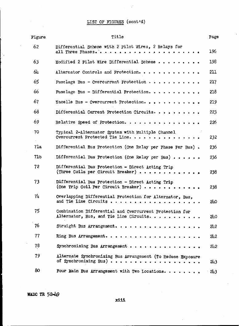
62 Differential Scheme with 2 pilot Wires, 2 Relays forall Three phases.- .... . . . .* . . . . ... . 196
63 Modified 2 pilot Wire Differential Scheme ........ . 198
64 Alternator Controls and protection ............ . 211
65 Fuselage Bus - Overcurrent protection . . . . . . . . . . . 217
66 Fuselage Bus - Differential Protection. . . . . . . . . . . 218
67 Nacelle Bus - Overcurrent Protection. . . . * o .. . . . . 219
68 Differential Current Protection Circuits . . . . . . . . . 223
69 Relative Speed of Protection. . . . . *....... ... 226
70 Typical 2-Alternator System with Multiple ChannelOvercurrent protected Tie Line.... . . .. . . . . . .. 232
71a Differential Bus Protection (One Relay per phase per Bus) . 236
71b Differential Bus protection (One Relay per Bus) . . . . . . 236
72 Differential Bus protection - Direct Acting Trip(Three Coils per Circuit Breaker) . . . . .... . . . . . 238
73 Differential Bus protection - Direct Acting Trip(One Trip Coil Per Circuit Breaker) . . . . . . . . . . . . 238
74 Overlapping Differential Protection for Alternator, Bus,and Tie Line Circuits .... ...... ........ 240
75 Combination Differential and Overcurrent protection for
Alternator, Bus, and Tie Line Circuits . ......... 240
76 Straight Bus Arrangement ................. 242
77 Ring Bus Arrangement .................... 242
78 Synchronizing Bus Arrangement ............. 242
79 Alternate Synchronizing Bus Arrangement (To Reduce Exposureof Synchronizing Bus) . . . . . 0 0 . .. ..0. . . . . ... 243
80 Four Main Bus Arrangement with Two Locations. - . . . . . , 243
WADOC TR 522-49xiii

LIST OF FIGURES (cont d)
Figure Title Page
81 Single Channel Feeders .................. o 245
82 Multiple Channel Feeder Circuits. . . . . . . . . . . . . . 247
83 Dual Channel Feeder Circuits. ............... 248
84 Dual Channel Feeder Circuit Emergency Throwover Method... 250
85 Three-Line Diagram of Ring Bus with Fuse Mesh protection. . 253
86 Three-Line Diagram of Ring Bus with DifferentialProtection .. .. .. .. .. .. .. .. .. .... • 254
87 Automatic A-C Generator Control System .......... . 256
WADC TR 52-49xiv

LIST Of TABLES
Table Title Page
I Alternator Specifications ............... 3
II A-C Voltage Regulator Specifications. . . . . . . . .. 6
III Exciter Control Relay Specifications. . . . . . . ... 7
IV Circuit Breaker Specifications. . .. . . ... .. 8
V Exciter Protection Relay Specifications * . ..... . . 9
VI Differential Protection Relay Specifications ..... 9
VII Load Transfer Contactor Specifications ........ 10
VIII No Load Test Data on Alternator D ..... . ..... 33
IX Three-Phase Short-Circuit Test Data on Alternator D .. 36
X Zero Power-Factor Test Data on Alternator D . .. . .. 36
XI Three-Phase Short-Circuit Data on Alternator A. . . 45
XII Subtransient Impedance and Negative-Sequency ImpedanceTest Data .. .. .. .. .. .0. .. .... ... 49
XIII Negative-Sequency Impedance of Alternator D from
Wattmeter Method . ........... .. .... 52
XIV Zero-Sequence Impedance of Alternator D. . . . .. . .. 52
XV Alternator Parameters s. .. ...... .... 54
XVI Test Data for Reactive Power Amplification Factor . .. 71
XVII Effect of Voltage Error on System Capacity ...... 75
XVIII Test Data for In-Phase Current Equalizer AmplificationFactor . .. .. .. .. .. ... . . ... 79
XIX Tests of Frequency Droop Response ........... 81
XX Effect of Frequency Error on System Capacity. . . . . . 85
XXI Ceiling Excitation - Two Alternator System. . 9 ..e. . 94
XXII Load on Alternator D Before Opening Alternator Field. . 102
XXIII Load on Alternator D Before Opening Exciter Field . . . 106
WADC TR 52-49xv

LIST qw TABLES (cont 'd)
Table 2itle Page
XXIV -Short-Circuit Currents (Alternator A) . . . . .. 114
XXV Blocked Rotor Data for Three Positions . . . . . . 122
XXVI Blocked Rotor Data for Two Excitations . . . . . . 123
XXVII Owervoltage Calculations on Removal of a Three-Phase Short Circuit .............. .. 140
XXVIII Melting Currents Expressed in Per Unit of theNominal Fuse Rating. . . . . . ..0. . . . .. ... 154
XXIX Curreat Transformer and Relay Characteristics. . . 176
XXX Comparison of Fault Currents to Trip Relay . . . . 193
XXXI Comparison of Generator Circuit Weights. . . . . . 215
XXXII Comparison of Generator Circuit EXposure Areas . . 220
WADC TR 52-49
xvi

I. INTRODUCTION
This report summarizes the results of a study of aircraft electri-
cal systems. The objectives of the study were to analyze present standard
aircraft electrical systems from the standpoint of overall system reliabil-
ity.
The work was carried out for the Electrical Branch, Equipment
Laboratory, Wright Air Development Center under Contract AF 33(038)-30511.
The contract covered a 6 months study ending March 20, 1952.
The emphasis in the study has been on the constant frequency 400
cycle, 200Y/ll volt system. This emphasis resulted from considerations of
relative importance of review of the systems and stem from the following
considerations:
(a) There has been extensive field experience on 24 volt d.c.
systems and has been the subject of several previous studies.
(b) Higher voltage d.c. systems are to be studied under a
separate system study contract.
(c) The 400 cycle AC constant frequency system is now coming
into considerable use and its application is being extended.
Experimental phases of the program were carried out in the Wright
Field Laboratories. Performance of the machines and their controls includ-
ing constant speed drives was determined under both normal and abnormal
conditions. The power generating equipment included two 40 KVA alternators
while the utilization devices were represented by resistive and inductive
passive loads. Measurements were made with indicating instruments and an
oscillograph to determine appropriate parameters for analytical studies. In
addition, tests were staged to determine the performance of the system under
_;JAW TR 5"2-49-l-i-

conditions which could not be readily analyzed on the basis of system para-
meters.
WADC TR 52-49-2-

II.* PRESET 4OO-cycLE A-C.SYST1MS
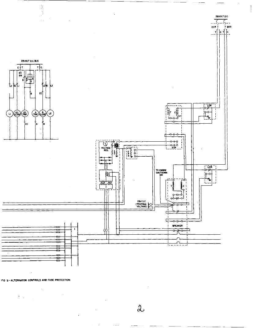
Figures 1 and 2 show complete source sections of an a-c power
system including an alternator, controls, protective devices, and leads to
the main circuit breaker at the fuselage bus as are used or contemplated at
the present time. Two diagrams are shown for each arrangement, an elemen-
tary diagram from which sequence of operation can be obtained, and an inter-
connection diagram which shows the physical configuration of the system.
A. Alternator
The alternator, usually with an integral exciter, is designed to
operate from a constant speed drive unit and so generates voltage at con-
stant frequency which permits parallel operation with other alternators.
Alternator characteristics for a 40 and a 60 KVA unit are listed
in Table I.
Table I
ALTERNATOR SPECIFICATIONS
(From USAF Spec. No. 32509 Amended 13 December 1949 and USAF Exhibit MCREXE-21-48 Revised 16 January 1948)
Type A-1
Ratings
Voltage volts 120/208 120/208Frequency cps 400 400
Continuous 40 60Power KVA Five minutes 60 90
Five seconds 72 120
Power factor 0.75 0.75
Nominal 6000 6000Speed, rpm Range 5400-6600 3000-9000
Overspeed 9000 10500
Exciter field voltage volts 52 -Weight lbs 80 -
Cooling 210 cfmat 6" water
WADC TR 52-49-3-

-A 28VOLT DC BUS
I CT TC
• ~c
s LJ
°
D
EC EC m.FL I LIIP E
A2
EXC TE
AlAA
FIG. I -ALTERNATOR CONTROLS ANIDIFFERENTIAL PROTECTIC
WADC TR 52-49

28V DIC
ECR( S K
T CT C
6 VOLT DC BUS
T T C
TRIP TRIP2
EC I I
kc
I
B
T7 'm
T c
DCC
28 0 ~
rERNATOR CONTROLS AND COMPLETEDIFFERENTIAL PROTECTION

28VOLT D.C. BUS
TTI I I I IC T T C
FEC
LI EC EC EC
FIG. 2CO AN
ADTR5-
L--r: +AA
FIA+ATENTRCOTOSA
A-5
28 VOLT D.C.
EC R ] BKR
T OT C
28 VOLT D.C.Bus
ECE
L LI B
LI ~ C B BTC IC
LI L---
EC B
I~ y1
REG.IP
TO ENGINE LII ~SHUTDOWN
I TI
I I I_
FIG, 2 -ALTERNATOR CONTROLS AND FUSE PROTECTION

Alternator controls are comprised of a voltage regulator and an
exciter control relay.
B. Voltage Regulator
The voltage regulator adjusts the carbon stack which is in series
with the exciter field to maintain the average line-to-neutral voltage of
the three phases at the desired value. The regulator also incorporates a
current transformer and mutual reactor which, when interconnected with the
regulators of the other alternators on the system, corrects the regulator
action to provide equal division of reactive load between alternators. The
voltage regulator characteristics are listed in Table II.
Table II
A-C VOLTAGE REGULATOR SPECIFICATIONS
(From IMIL-R-5292A 25 April 1951)
Normal adjusted voltage 208 voltsRange of adjustment 195 to 215 voltsAccuracy 2.5%Working range of variable resistance 1 to 30 ohmsCurrent at min. resistance 8 ampspower dissipation, continuous 90 wattsWeight, max. 12 lbsCompensation - 0.5 per unit, zero p.f. lagging,
single machine shall cause a dropof 5 to 7% of adjusted voltage
C. Exciter Control Relay
The exciter control relay is provided to open the field circuit
either manually or by action of the protective devices. The close coil of
the main circuit breaker is in series with a pair of auxiliary ECR contacts
so that the breaker can be closed only if the ECR is closed. An engine shut-
down switch is also provided to prevent closure of the ECR when the exciter
WADO TR 52-49- 6-

and alternator are not rotating. A lockout relay is used to prevent recycling
in event the circuit breaker is tripped. The ECR is closed by a manually oper-
ated switch. The characteristics of the exciter control relay are listed in
Table III.
Table III
EXCITER CONTROL RELAY SPECIFICATIONS
(From USAF Speco No. 32579 Amended 1 May 1947)
Type H-I, 2 phase, 400 cycle 200/115 volt
Close coil
Operating voltage 12-30 volts d-cTime duration to withstand voltage 1 min.
Trip coilOperating voltage 6-30 volts d-c
Speed of auxiliary contacts to trip circuit breaker 0.008 sec.
D. Circuit Breaker
A circuit breaker connects the alternator to the main bus. The
breaker can be tripped by a manually operated switch, by the protective de-
vices, or by the action of the exciter control relay. It is closed by a
manually operated switch. The characteristics of the circuit breaker are
listed in Table IV.
WADC TR 52-49-7-

Table IV
CIRCUIT BREAKER SPECIFICATIONS
(From USAF Spec. No. 32502A 19 Aug. 1946)
Type A-I Electrically operated, 3 pole, 208/120 volt 400 cycle air circuitbreaker
Continuous 120 amp.Rating Five minutes 165 amp.
Five seconds 245 amp.Interrupting rating 4000 amps.Interrupting time 0.01 sec. max.Closing time 0.05 sec. max.Nominal coil voltage 24 volts d-cAuxiliary contact rating a-c 1 amp. at 240 volts
d-c 10 amp. at 30 volts
Protective devices include an exciter protection relay, differen-
tial protection and current limiting fuses. In Fig. 2 the alternator leads
have differential current protection from the alternator terminals to the
nacelle bus, and overcurrent protection in the form of a fuse mesh network
from the nacelle to fuselage bus. The nacelle bus is partially protected
by the fuse system. Another system, shown in Fig. 1, is covered by differ-
ential protection from the alternator terminals to the main bus. Both
systems include exciter protection.
E. Exciter Protection Relay
The exciter protection relay is a thermally actuated device which
trips the exciter control relay and circuit breaker when the excitation ex-
ceeds a certain limit for a sustained period of time. The characteristics
of the exciter protection relay are listed in Table V.
WADC TR 52-49 - 8-

Table V
EXCITER PROTECTION RELAY SPECIFICATIONS
(From USAF Spec. 32664 Amended 25 February 1950)
Type A-I
Contact rating.Current 10 amps d-c
Voltage 30 volts d-cNominal rating 44 voltsTime delay at nominal rating 6 + 1 sec.Minimum operating voltage 20 voltsAdjustment range 34 to 44 volts
F. Differential Protection Relay
The differential protection relay trips the circuit breaker and
exciter control relay on ground or phase-to-phase faults. Table VI lists
the characteristics of the differential protection relay.
Table VI
DIFFERE1TIAL PROTECTION RELAY SPECIFICATIONS
(From MIL-R-5296 10 April 1950)
Type S-1 200/115 volt 400 cycle
Operating time (40 amps differential current) 0.004 secDifferential current range 30-4000 ampsCurrent capacity of contacts 10 amps
G. Load Transfer Contactor
In systems where the load feeders are multiple channel, the more
essential loads are connected to the system by alternate channel feeders
switched by a load transfer contactor. In case the feeder supplying the
load thru a load transfer contactor fails, the load transfer contactor
WADOC TR 52-49-9-

automatically switches to the alternate feeder. Table VII lists the
characteristics of this device.
Table VII
LOAD TRANSFER CONTACTOR SPECIFICATIONS
(From USAF Exhibit MCREXE-21-59 18 November 1946)
RatingCurrent 150 ampsVoltage 200 voltsFrequency 380-460 cps
Trip rating pull in 100 volts (line-to-neutral)drop out 80 volts (line-to-neutral)
Overvoltage, continuous 10%Time delay 0.15 to 0.20 sec.Holding current, relay 1 ma. maximumHolding current, solenoid 0.5 amp at ll5 volts
WADC TR 52-49- 10 -
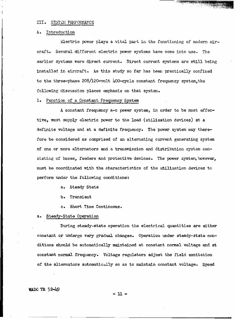
III. SYSTEM PERIFORMACE
A. Introduction
Electric power plays a vital part in the functioning of modern air-
craft. Several different electric power systems have come into use. The
earlier systems were direct current. Direct current systems are still being
installed in aircraft. As this study so far has been practically confined
to the three-phase 208/120-volt 400-cycle constant frequency system,the
following discussion places emphasis on that system.
1. Function of a Constant Frequency System
A constant frequency a-c power system, in order to be most effec-
tive, must supply electric power to the load (utilization devices) at a
definite voltage and at a definite frequency. The power system may there-
fore be considered as comprised of an alternating current generating system
of one or more alternators and a transmission and distribution system con-
sisting of buses, feeders and protective devices. The power system, however,
must be coordinated with the characteristics of the utilization devices to
perform under the following conditions:
a. Steady State
b. Transient
c. Short Time Continuous.
a. Steady-State Operation
During steady-state operation the electrical quantities are either
constant or undergo very gradual changes. Operation under steady-state con-
ditions should be automatically maintained at constant normal voltage and at
constant normal frequency. Voltage regulators adjust the field excitation
of the alternators automatically so as to maintain constant voltage. Speed
WADN TR 52-493.1

governors in the prime mover maintain constant normal (synchronous) speed
thus maintaining constant frequency.
Generally alternating current power systems must furnish two
kinds of power, namely, real power (watts or kilowatts) and reactive power
(vars or kilovars). When two or more alternators are operating in parallel
provision must be made to assure division of load current in accordance
with the ratings. In the case of aircraft installations, to accomplish
this the alternators divide automatically the real power in proportion to
their respective ratings and divide automatically the reactive power in pro-
portion to the respective ratings of the alternators. If the alternators
all have the same ratings then both the real power and the reactive power
should be shared equally. Division of real power is regulated by adjusting
the mechanical output of the prime mover, usually by modifying the signal
from the tachometer to the speed governor when the real power is divided
improperly among the alternators. Division of reactive power is regulated
by modifying the voltage to the voltage regulator when there is unequal
division of reactive power.
The transmission and distribution system must transmit the real
and reactive power to the load (utilization devices) with negligible voltage
drop.
The required performance of the power system during steady-state
operation may be summarized as follows:
1) Constant Normal Voltage at the Load
2) Constant Normal Frequency
3) Proper Division of Current Between Alternators
In order to analyze the performance under steady-state conditions
WADC TR 52-h9- 12 -

certain parameters of the alternators should be known. These include:
1) Potier Reactance
2) Direct-Axis Synchronous Reactance
3) Quadrature-Axis Synchronous Reactance
4) Amplification Factor of the Reactive Load Division Circuit
5) Amplification Factor of the Real Load Division Circuit.
b. Transient Conditions
Transient conditions may be defined as those which follow the
sudden application or sudden removal of large loads including the applica-
tion and clearing of short circuits. Under these conditions voltage dips
and during most short circuits, voltage dips and voltage unbalances between
phases cannot be avoided. The protective devices should remain inoperative
during momentary or short time overloads but must operate on short circuits
to remove the faulty part of the system. The system must remain stable dur-
ing these conditions which means that if there are two or more alternators
in parallel they should not fall out of synchronism. In order to assure
stability the duration of voltage dips must be limited within certain values
and short circuits should be cleared as quickly as possible. In order to
analyze the behavior of the system under transient conditions the following
characteristics of the alternators and transmission system should be known:
1) Transient Impedance
2) Negative-Sequence Impedance
3) Zero-Sequence Impedance
4) Voltage Regulator Response
5) Speed Regulator Response
WADC TR 52-49- 13 -

c. Short-Time-Continuous Operation
Short-time-continuous operation may be considered as operation
under severe overload. The duration and intensity of the overload is largely
a matter of permissible temperature rises in the supply-system components
and also a matter of permissible voltage reduction due to the regulation of
the power system. In order to evaluate the performance of the system under
these conditions it is necessary to know the thermal characteristics as well
as the steady-state electrical characteristics of the system.
2. Applications of Parameters
The parameters which govern the behavior of the system under
steady-state operation and under transient conditions as outlined above can
be obtained from tests. These parameters are highly useful in determining
the performance of the system for a large variety of conditions. However,
some discretion in the selection and application of these parameters is nec-
essary. A case in point is the behavior of the system when an alternator is
connected to a live bus with its voltage appreciably out of phase. In that
case there will be swings of power in which the operation of the alternator
alternates between generator action ard motor action. These oscillations
gradually die out. The reactance of the alternator during these swings is
not constant even if the degree of magnetic saturation were constant. Dur-
ing these oscillations there will also be fluctuations in the field current
so that we might say that the apparent reactance oscillates between values
of saturated synchronous reactance and the transient reactance. Any
analysis of synchronizing swings based upon the above parameters is at best
rather approximate.
In spite of the fact that some of these parameters are not too
WADC TR 52-49- 14 -

clear cut and, in a manner of speaking, have strings tied to them, it is
almost impossible to effectively plan, analyze and coordinate a power system
with its load without making use of these parameters. It would indeed be
impractical to attempt mockups in order to determine experimentally the per-
formance of a system under all possible conditions. However, mockups are
practically indispensable for determining the behavior of a power system
under certain conditions. As an example consider a fault which is inter-
mittent due to vibration or perhaps other causes. Here a condition exists
where the impedance of the fault may vary thru a range of values, perhaps a
number of times in a second, all the way from a fraction of an ohm to infin-
ity.
a. Saturated and Unsaturated Synchronous Reactance
1) Saturated Synchronous Reactance
The synchronous reactance of an alternator even with a fixed value
of field current may vary over a wide range of values. A hypothetical case
which might be considered extreme, although entirely possible, is that of an
alternator delivering load at or above rated voltage with its field excita-
tion sustained at ceiling level. Under this condition the hO-KVA alternators
used in these studies have a saturated synchronous reactance of 0.15 per
unit. Suppose that a three-phase short circuit of at least one secondts
duration is applied to this alternator with the field excitation maintained
at ceiling level. During this short circuit, the flux linking the field
winding of this alternator drops from a high value to such a low value,
although the final field current is still at ceiling value, that the magnetic
circuit is now unsaturated. For this final condition the synchronous react-
ance (unsaturated) has a value of 1.5 per unit or ten times its original
WADC TR 52-49- 15 -

saturated value. Figure 3 shows the zero power-factor voltampere character-
istic of the hO-kva alternator for ceiling excitation. This large variation
of reactance from the saturated state to the unsaturated state is not pecul-
iar to synchronous machines but is prevalent in any magnetic circuit which
contains ferromagnetic materials. For steady-state analyses in which the
synchronous reactance plays a part it is usually necessary to take into
account the degree of magnetic saturation. One widely used method is that
of obtaining the air-gap voltage. In the case of a generator the Potier re-
actance drop is added vectorially to the terminal voltage to give the air-
gap voltage. For motors the Potier reactance drop is subtracted from the
terminal voltage to give the air-gap voltage. The degree of saturation is
then determined by locating the air-gap voltage on the open-circuit satur-
ation curve. There are several ways in which corrections can be applied for
saturation each usually best suited for its particular application. Two
examples of this application are the following methods for determining the
voltage regulation of an alternator:
a) The General Method
b) The A.S.A. Method
Both of these methods are described in standard textbooks on a-c machinery.
2) Unsaturated Synchronous Reactance and Alternator Size
The use of the unsaturated synchronous reactance is generally re-
stricted to applications where very approximate and usually very pessimistic
results suffice. However, the value of unsaturated synchronous reactance
affords some measure of the quality of performance of an alternator. Gener-
ally for equally sensitive automatic voltage regulators the alternator vith
the lower value of unsaturated synchronous reactance is more stable and
WADOC TR 52-49- 16 -

40 KVA WESTINGHOUSE ALTERNATORSERIAL AF-47-296CONTRACT W33-038-AC- 14194
1.6
1.4
1.2
1.0
0.8
0
0O.4I.
0.2
00 1.0 2.0 3.0 4.0
PER UNIT ZERO P.F. CURRENT
FIG. 3 - VOLT-AMPERE CHARACTERISTIC FOR CEILINGEXCITATION AND ZERO P.F. CURRENT.
WADO TR 52-49- 17 -

imposes less severe duty upon the voltage regulating system. The penalty
for this superior performance is that for a given speed and KVA rating the
alternator with the lower reactance is the larger in size making it heavier.
The correlation between the size and unsaturated synchronous reactance of an
alternator can be verified as follows. Consider an alternator with a certain
length of air gap and a certain value of unsaturated synchronous reactance.
If we double the length of the air gap in that alternator the unsaturated
synchronous reactance drops to practically one-half the original value. This
follows in any magnetic circuit with an air gap if the magnetic reluctance
of the iron circuit is negligible. However, as soon as we double the length
of the air gap in the alternator it is necessary to double the field ampere
turns to obtain the same no load voltage. This means that the size of the
field has to be increased. In order to prevent excessive temperature rises
and at the same time to accommodate the larger field it is necessary to in-
crease the overall size of the alternator.
b. Quadrature-Axis Synchronous Reactance
In the salient-pole alternator such as is used on aircraft the
length of air gap is far from uniform. The air gap is shortest under the
center of the field pole and very large halfway between field poles. The
armature mmf then can be considered as being comprised of two parts, one re-
acting upon the direct axis, thru the center of the field poles, and the
other component reacting upon the quadrature axis, thru the space midway be-
tween pole centers. From this division of the armature mmf we get the two
synchronous reactances i.e. direct axis and quadrature axis. The two-
reactance concept provides a tool by means of which the effect of saliency
can be taken into account to a fair degree of approximation. The behavior
WADC TR 52-49 - 18 -

of a salient-pole alternator operating, with an open field, in parallel with
other alternators can be readily analyzed particularly for light load con-
ditions. In addition the two-reactance method makes possible the analysis
of the transient behavior of synchronous machines to a degree which was not
possible before this method was introduced.
c. Amplification Factor - Reactive Load Division
In order to determine the effectiveness of the reactive load
division circuits of alternators, it is necessary to determine the change in
excitation with unbalance of reactive load. In addition this amplification
factor is required to predict the value of bus voltage and alternator loads
in the event that the voltage regulator of one of several alternators oper-
ating in parallel loses its voltage sense. The use of such a factor in ana-
lytical methods provides an overall picture of the effects of unbalanced re-
active load and malfunctioning of the excitation system of an alternator
with much less expenditure of time and effort than is possible by test
methods alone.
d. Amplification Factor - Real Load Division
The argument which has been applied to the reactive load division
circuit and its effect upon excitation applies equally well to the real load
division circuit and its effect upon speed governing. It applies also to
the malfunctioning of the governor on the prime mover of one alternator
operating in parallel with other alternators.
e. Transient Impedance
The transient impedance of an alternator is comprised of the a-c
armature resistance and the transient reactance.
WADC TR 52-h9- 19 -

1) Transient Reactance
Under transient conditions there is still a further complication
which is introduced by a transient in the field current. If we consider the
same alternator which is delivering load at ceiling excitation, it wll be
appreciated that a relatively large amount of magnetic flux links the field
winding. At the instant the short circuit is applied these flux linkages
with the field must be the same as before short circuit. However, upon
short circuit the armature current exerts a large opposing mmf upon the
field and in order to maintain the flux linkages in the field winding, the
field current rises possibly to several times its value before short cir-
cuit. Figure 8 shows oscillograms of a three-phase short circuit. The in-
crease in field current and the a-c component in the field current are both
evident in that figure* During short circuit both the field current and the
armature current fall off in value until the field current attains the value
it had before short circuit. The initial armature current during short cir-
cuit, if the current in the damper windings and pole faces of the field is
negligible, is called the transient current. If the current in the damper
windings or in the pole faces is appreciable, then the initial short-circuit
armature current is even higher and is called the subtransient current. The
transient current is said to be limited by the transient impedance and the
subtransient current is said to be limited by the subtransient impedance.
It should be emphasized that the initial short-circuit current,
i.e. the transient current or subtransient current whichever the case may
be, is greater than the final steady-state current even if there were no
magnetic saturation before short circuit, the increase over the final steady
value of armature current being due to the initially increased field current.
WMJC TR 52-49- 20 -

Since circuit breakers and other fault clearing devices should clear faults
as rapidly as possible, the interrupting duty for short-circuit currents is
based on the initial value of the fault currents. Where large salient-pole
alternators, with damper windings embedded in the field poles, are involved,
the positive-sequence impedance is taken as the subtransient impedance. No
appreciable subtransient effects were detected in these system studies with
the 40-KVA, 400-cycle aircraft alternators and the transient impedance
should therefore, be used for the positive-sequence impedance.
f. Negative-Sequence and Zero-Sequence Impedances
Under balanced three-phase conditions the only impedance we are
concerned with is the positive-sequence impedance. Under normal conditions
the positive-sequence impedance of an alternator is comprised of the a-c re-
sistance of the armature (often neglected) and the synchronous reactance
(direct-axis and quadrature-axis). However, under a balanced three-phase
short circuit, for the initial conditions the transient impedance or sub-
transient impedance, whatever the case may be, is used. Under normal bal-
anced operation, the armature mmf (if harmonics are neglected) rotates at
synchronous speed in the same direction as the rotor and does not induce any
current in the field circuit. However, under the initial conditions of a
three-phase short circuit the current in at least two of the phases has a
d-c component in addition to the a-c component. The a-c components in the
three phases combine to produce an armature mmf which rotates at synchronous
speed. The d-c components, however, in the three phases produce an armature
muf which is stationary and which induces a component of current in the
field circuit which has fundamental frequency. This fundamental component
in the field current produces a double-frequency (second harmonic),
WADC TR 52-49- 2± -

component in the armature current. This second harmonic in the armature
current, usually negligible, exists only during the transient period. The
steady-state armature current is free of harmonics on a three-phase short
circuit.
The d-c component on short circuit will increase the current to
be interrupted by protective equipment. The effect of the d-c component on
the magnitude of the current to be interrupted depends upon the time con-
stant of the system and the operating time of the protective device.
1) Line-to-Line Short Circuit
If a short circuit is applied from line to line without involving
neutral, the fault current in two of the phases will be identical and the
fault current in the third phase will be zero* This single-phase armature
current in the two phases gives rise to a nmf which oscillates along a fixed
axis in the stator. This oscillating mmf can be split into two constant
equal components which rotate in opposite directions at synchronous speed.
We now have one of these components rotating in the direction in which the
field rotates. This component of mmf is stationary with respect to the field
and is said to be produced by the positive-sequence armature current.
a) Negative-Sequence Impedance
The component of mmf rotating in the opposite direction rotates
at twice synchronous speed relative to the field and is said to be produced
by the negative-sequence armature current. The alternator impedance assoc-
iated with the positive-sequence current is known as the positive-sequence
impedance. For short-circuit studies involving interrupting duty of circuit
breakers, the transient impedance or subtransient impedance, whichever the
case may be, is taken as the positive-sequence impedance. The alternator
WADC TAL 52-49- 22 -

impedance associated with the negative-sequence current is defined as the
negative-sequence impedance. The negative-sequence impedance is different
from the positive-sequence impedance of a rotating a-c machine. These con-
siderations then show us that a line-to-line fault involves the positive-
sequence impedance and the negative-sequence impedance of a power system.
b) Harmonics in Line-to-Line Fault Current
As the mmif, in the armature of an alternator, produced by the
negative-sequence current rotates in a backward direction at synchronous
speed, its speed relative to the rotor is twice synchronous speed. The fun-
damental component of the negative-sequence current then induces an alter-
nating current in the alternator field which has twice fundamental frequency.
This double-frequency component of field current then produces a field flux
which oscillates at double frequency in the axis of the field poles. This
oscillating field flux can also be split into two equal but oppositely ro-
tating field fluxes each rotating at twice synchronous speed relative to the
field. Taking into account the rotation of the field structure at synchron-
ous speed in the forward direction, the forward rotating component of the
oscillating field flux rotates at three times synchronous speed relative to
the armature, and the backward rotating component of the oscillating field
flux rotates at synchronous speed relative to the armature. The forward
component of the oscillating field flux then generates a triple frequency
voltage in the armature resulting in a triple frequency component in the
fault current. Continuing this reasoning we find that the triple frequency
component of the armature induces in the field winding a double frequency
component of current and a component of four times fundamental frequency.
From this it follows that theoretically the fault current and the voltage in
iIADC TR 52-49- 23 -

the unfaulted phase contains an infinite series of odd harmonics and the
field current contains an infinite series of even harmonics. However, as a
result of leakage inductances and the damping effects of damper windings,
and paths for eddy currents in the field poles, the higher harmonics become
negligible very rapidly. Figure 35 shows oscillographic records taken on a
line-to-line fault. There is a pronounced second harmonic in the field
current and there are odd harmonics in the armature voltages. These har-
monics in the voltage of the unfaulted phase, in the absence of damper wind-
ings in the faces of the field poles, have been known to rise to destructive
values as a result of series resonance with the capacitance of the system,
in the case of hydroelectric alternators connected to long transmission
lines*
2) Line-to-Ground Fault
In the case of the line-to-line fault it was shown that the arma-
ture develops two constant equal but oppositely rotating mmfs. Each of these
mmfs is produced by an equivalent balanced three-phase system of currents.
One of these systems of current has positive phase sequence and the other
has currents of the same magnitude as the positive-sequence currents but of
negative phase sequence. Further the phase relationships of these systems
of currents is such that the positive-sequence component in the unfaulted
phase is equal and opposite to the negative-sequence component of current in
the unfaulted phase. Neither of these balanced system of currents can give
rise to neutral current. However, in the case of the single line-to-ground
fault the armature produces an oscillating mmf but there is also neutral
current. This oscillating mmf in only one phase cannot be explained on the
basis of two sets of three-phase currents of opposite phase sequences because
WADM TR 52-49- 24 -

there is neutral current. If, however, we consider this mmf as being pro-
duced by three systems of balanced current in all three phases we can take
neutral current into account simply by adding to the positive-sequence cur-
rents and negative-sequence currents three equal single-phase currents, one
for each phase, known as zero-sequence current. Furtherthe phase relation-
ships and magnitudes are such that when the three different sequence compo-
nents of current are combined, the resultant current in the unfaulted phases
is zero. The effect of the positive-sequence and negative-sequence compo-
nents of current are very much the same as in the case of the line-to-line
fault. The effect of the negative-sequence component of armature current
is such as to produce a series of even harmonics in the field current which
in turn produces a series of odd harmonics in the armature current. These
effects are evident in Fig. 32 which shows an oscillographic record of a
single-line-to-ground fault.
a) Zero-Sequence Impedance
First of all let it be emphasized that in order for zero-sequence
current to exist there must be a neutral path. In aircraft alternators this
is practically always the case as the neutrals of the alternators are usually
grounded. The resultant mmf produced by the zero-sequence current as far as
the rotor or field structure is concerned is zero as we have three equal
nmfs in time phase with each other but directed along magnetic axes which
are displaced 120 electrical degrees from each other in space. The zero-
sequence impedance is the impedance which is associated with the zero-
sequence current and includes the effect of the neutral path external to the
alternator.
WLAC TR 52-49- 2-

3. Analytical vs. Experimental Methods
In order to make a systematic study it is necessary to have a
thorough understanding of the parameters involved. Their magnitudes and lim-
itations must be known. With the proper application of such knowledge reli-
able results can be obtained quickly by means of analytical methods which
otherwise involve excessively time consuming and costly staged tests on a
power system. In analytical short-circuit studies, for example, use is
made of the sequence impedances. The sequence impedances of rotating ma-
chines are usually obtained from tests but can also be predicted from ma-
chine design data. In studies of large and complex power systems, a-c net-
work calculators are used to a large extent. In such calculators networks
adjusted to the proper values of the various sequence impedances are con-
nected so as to simulate different types of faults. Such methods i.e. those
which are purely analytical and those which make use of the network calcula-
tor are particularly advantageous if the parameters may be held constant.
It is true that expressions have been developed which theoretically take
into account fault currents expressed as simple exponential functions of
time. However, such analyses can become tedious and they also suffer from
such inaccuracies as not taking changes of magnetic saturation into account.
In such cases staged tests on the actual power system or its mockup yield
reliable results at a saving in time. Staged tests on large power systems
are not always practical because of the tremendous amounts of power involved.
However, in the case of aircraft power systems, mockups using conventional
aircraft alternators and conventional conductors, buses, circuit breakers,
fuses and relays are convenient, economical and reliable for obtaining infor-
mation which cannot be obtained as readily or as exactly by purely analytical
WADC TR 52-49- 26 -

means. Such mock'ups backed by analytical studies are more economical than
would be the installation and use of a conventional a-c network calculator
for aircr-,ft power system studies.
The chief limitation of staged tests on full scale system mockUps
is the lack of flexibility in adjusting characteristics of the system compo-
nents. At present analytical methods must be used to determine effects of
changing system parareters.
h4 Extent of present Study
The study described in this section covers the determination of
those parameters which govern the system performance under
a. Steady-State Conditions
b. Transient Conditions.
The parameters which determine the behavior of the system under short-time-
continuous conditions are usually determined in machine acceptance tests.
The transient conditions in a broad sense would include operation during
short circuit and alternator blocked rotor in addition to synchronizing
disturbances and overvoltages.
The analysis of the voltegc regulator, speed regulator, and equal-
izing circuits deals with the steady-state response. The transient response
can be determined by treating these systems as servomechanisms. This in-
cludes considering the hydraulic action of the constant speed device,
mechanical gearing, and electrical circuits as a whole system,
VWADC TR 52-49- 27 -

B. Alternator Characteristics
The experimental investigation in these system studies were con-
ducted at Wright-Patterson Air Force Base, Dayton, Ohio in building T-h7,
on a 4OO cycle a-c system which included wiring, alternators, controls, con-
stant speed drives, and drive stands. Two WO KVA alternators designated as
alternator A and alternator D driven by constant speed drives were used in
these tests. In addition use was made of two similar alternators connected
to drive stands in building T-h7 without intervening constant speed trans-
missions. The name plate data of alternator D, its associated constant speed
drive, and drive stand appear in Appendix III-A. Figure It shows the alter-
nator, constant speed drive, and a part of the drive stand. The control
panel as well as a general view shoiing the specific items mentioned above
are shown in Fig. 5.
1. Steady State-Balanced Operation
The alternator may be considered an ideal voltage source feeding
the load through a variable impedance. Under balanced conditions only one
phase of the alternator need be considered, and the equation for the termi-
nal voltage of the alternator is
V = E - I Zd (1)
where:
V = terminal voltage per phase,
E = generated voltage per phase,
I = armature current per phase,
Zd = synchronous impedance per phase.
Figure 6 shows the equivalent circuit and vector diagram of an alternator.
In order to obtain the steady state parameters, tests were made on
alternator D to determine the following:
WADC TR 52-49- 28 -

>4I
K
0)fr
n-I
C)
147iLLm4 a
0
s-I
-p
41
60n-I
it <2>
At
/ 4
WADO TR 52-49 29

S4)
LO)
WADC R 5249-3

+ Zd +
E 1V
E
d
FIG. 6 -EQUIVALENT CIRCUIT AND VECTORDIAGRAM OF AN ALTERNATOR
WADC TR 52-49 - 31-

1) No load saturation curve
2) Three-phase short-circuit saturation curve
3) Zero power-factor saturation curve.
a. No Load Saturation Curve
In order to determine this characteristic, alternator D was driven
without load at synchronous speed (6000 rpm), with its field excited by
supplying the exciter field from a battery through an adjustable resistance.
A current shunt was placed in series with one of the leads to the alternator
field slip rings in order to measure the alternator field current. The
terminal voltage of alternator D for various values of alternator field cur-
rent was measured. The results are given in Table VIII. The per unit
values for a base field current of 15.8 amps and a base voltage of 120 volts
are also listed in Table VIII. It is common practice to take that value of
field current as a base i.e. one per unit which corresponds to rated voltage
or one per unit voltage on the air-gap line. This makes the air-gap lines
of all alternators identical when plotted in per unit.
Figure 7 shows the no load saturation curve which was plotted
from the results given in Table VIII. Also shown is the air-gap line which
would be the relationship between the terminal voltage and the field cur-
rent, if the iron had negligible reluctance.
b. Three-Phase Short-Circuit Saturation Curve
With alternator D at a standstill, the three phases were short
circuited at the terminals, one phase through a current transformer in order
to measure the armature short-circuit current. The alternator field current
was measured as in the no load saturation test. In the short-circuit test,
alternator D was separately excited and driven roughly at synchronous speed.
WADC TR 52-49- 32 -

Table VIII
NO LOAD TEST DATA ON ALTERNATOR-D(Name Plate Data Listed in Appendix III-A)
Synchronous Speed = 6000 RPM
Line-to-Neutral Voltage Alternator Field Current
Volts Per Unit Amperes Per Unit
?4.5 0.204 3.33 0.21141.5 0.346 5.33 0.33745.5 0.379 5.93 0.37549.5 0.412 6.50 O.41152.5 0.437 6-93 0.43857-5 0-479 7.50 0.47461.0 0.508 7.67 0.48565.0 0.541 8.67 0.54772.8 0.606 9.83 0.62278.0 0.650 10.7 0.67584.4 0.706 11.9 0.75491.3 0.760 13.2 0.83298.5 0.820 14.6 0.923
106.0 0.883 16.5 1.04111i 4 0.930 18.0 1.14113.0 0.941 18.6 1.18115.5 0.962 19.6 1.24116.0 0.966 19.9 1.26118.0 0.984 20.4 1.29119.6 0.995 21.1 1-33121.4 1.010 22.0 1-39123.0 1.025 22.6 1-43125.0 1.04 23.8 1.50127.0 1.06 24.5 1.55129.2 1.075 26.2 1.66133.0 .1.11 29.2 1.84137.2 1.143 33.2 2.10140.0 1.165 36.5 2.30149.2 1.242 49.4 3.12
'v'ADC TR 52-49
- 33 -

1.6
1.4 -C.lo NO LOAD
__ SATURATION CURVE-- I
1.2 -
7' "AT 0.79 P.U. CURRENTI- ZERO POWER-__FATOR__POINT
21.0-a-
w0.I
• 0.84.0
-J0>
wU)
0..
I-2w
0.4 2.0
SYNCHRONOUS REACTANCE CURVE 20
0.2 -3-PHASE SHORT-CIRCUIT CURVE 1.0 'ZERO %%..-j-1ZERO POWER- FACTOR POINT
AT 0.79 P.U. CURRENT0 r I I I 0
0 1.0 2.0 3.0 4.0 5.0 6.0
FIELD CURRENT-PER UNIT
FIG. 7 -ALTERNATOR CHARACTERISTICS
V-ADC Td 52-49 - 34 -

For the short-circuit test, the effect of speed upon the short-circuit cur-
rent is not critical, since both the induced voltage and reactance are di-
rectly proportional to the speed. At speeds as low as 1/4 synchronous speed,
the effect of armature resistance on the short-circuit current is negligible.
Readings of armature short-circuit current and field current were
taken. The measured values are shown in Table IX and the results are shown
graphically in Fig. 7. Rated armature current of 111.1 amps was used as the
base armature current or one per unit. In the short-circuit test the arma-
ture mmf is practically in direct opposition to the field mmf causing the
resultant air-gap flux to be too low to produce saturation.
c. Synchronous Reactance
For low values of field current, the no load saturation curve is
a linear characteristic since the iron of the alternator is unsaturated.
The unsaturated synchronous impedance is the ratio of the voltage on the
air-gap line to the armature current on a three-phase short-circuit for a
given value of field current. From Fig. 7 the unsaturated synchronous re-
actance, Xdu I dul 1.50 per unit.
For higher values of field current, the synchronous reactance Xd
does not remain constant because of the effect of saturation. The variation
in the synchronous reactance Xd is indicated on Fig. 7 by the dashed line.
This reactance is obtained from the no load saturation curve and the short-
circuit saturation curve.
d. Short-Circuit Ratio
The short-circuit ratio is defined by the following quotient:
SCR = Field current for rated open-circuit voltageField current for rated short-circuit current
If there were no saturation, the short-circuit ratio would be the reciprocal
WADC TR 52-49

Table IX
TEREE-PHASE SHORT-CIRCUIT T$ST DATA ON ALTERNATOR D(Name Plate Data Listed in Appendix Ill-A)
Armature Current Alternator Field Current
Amperes per Unit Anperes Per Unit
35.6 0.321 7.60 0.481
44.2 0.397 9.33 0.590
53.0 0.477 11.3 0.716
70.6 0.635 14.8 0.935
100.0 0.90 21.4 1.353
Table X
ZERO POVvR-FACTOR TEST DATA OY ALTERNATOR D
Phase voltage Field Current Armature Current
Volts Per Unit Amperes per Unit Amperes Per Unit
126.5 1.05 49.7 3.15 88 0.79
WADO TR 52-49 - -

of the unsaturated synchronous reactance expressed in per unit* The greater
the short-circuit ratio of an alternator, the greater is its steady-state
stability. However for a given speed and KVA rating, the weight and size
of the alternator increase with increasing short-circuit ratio.
The short-circuit ratio of alternator D was found to be 0.90.
According to Crary, where dependence is placed on manual control of excita-
tion, a short-circuit ratio of around unity is used. In Europe, with the use
of automatic voltage regulators, short-circuit ratios as low as 0.4 are not
uncommon. A smaller and lighter alternator can therefore be used if greater
responsibility is placed on the voltage regulator. Although detailed
analyses of stability for the aircraft a-c system, were not made for the
present study, it appears that machines with a lower short-circuit ratio
could be tolerated.
e. Zero power-Factor Saturation Curve
Under normal operating conditions the armature current reacts upon
a magnetic circuit in which there is some magnetic saturation. As mentioned
in the foregoing the iron of a conventional alternator is unsaturated in the
short-circuit test. Therefore the performance, of the alternator under
load, cannot be predicted with reasonable precision on the basis of the Xd
versus If characteristic in Fig. 7. More reliable data can be obtained by
making use of the zero power-factor saturation curve which is obtained under
conditions in which the armature current is present when the iron is saturated.
In order to obtain the zero power-factor characteristic, the no
S.B. Crary, Power System Stability (John Wiley and Sons, 1950), Vol. 1,
p. 199.
WADC Ti 52-49 3

load saturation curve is required and in addition two values of field cur-
rent, one to produce a certain value of three-phase short-circuit current
and the other the same value of armature current for zero power-factor at
rated terminal voltage or above.
In the zero power-factor tests made at Wright Field, alternator D
was loaded by using alternator A as an underexcited, unloaded synchronous
motor in order to obtain a zero power-factor load at about rated voltage.
The test data are shown in Table X. The point corresponding to 1.05 per
unit terminal voltage and 0.79 per unit current is indicated in Fig. 7.
The other point for the zero power-factor characteristic corresponds
to zero terminal voltage and 0.79 per unit armature current. This point was
obtained from the three-phase short-circuit test on alternator D. Since the
impedance of the alternator is largely reactive, a short circuit at the
alternator terminals involves a zero power-factor current. This point is
shown on Fig. 7 and corresponds to an armature current of 0.79 per unit at
zero terminal voltage.
From these two points the Potier triangle may be constructed and
thus the entire zero power-factor saturation curve may be determined by mov-
ing the Potier triangle parallel to itself along the no load saturation
curve. Because Potier triangles for different values of armature current
for the same alternator are similar, the zero power-factor characteristic
can be drawn for any value of armature current once the Potier reactance and
armature demagnetizing factor are found.
f. Potier Reactance and Armature Demagnetizing Factor
In order to determine the Potier reactance and the demagnetizing
effect of the armature current, the Potier triangle is constructed by using
WADC TR 52-49- 38 -

the two zero power-factor points and the slope of the air-gap line as showM
in Fig. 7. The vertical side of the Potier triangle represents the Potier
reactance drop; and the horizontal side the demagnetizing effect of the
armature current. Since the triangle was constructed for an armature cur-
rent of 0.79 per unit the Potier reactance = .084/0.79 = 0.106 per unit and
the armature demagnetizing factor = 1.13/0.79 = 1.43 per unit. For any
other armature current, the Potier triangle may be constructed and the cor-
responding zero power-factor curve drawn.
g. Direct-Axis and Quadrature-Axis Synchronous Reactance
For a salient-pole alternator, the air-gap is not uniform and it
is convenient to use quadrature-axis and direct-axis quantities. Therefore
the voltage equation for a salient-pole alternator, neglecting armature re-
sistance, is
V = E - j Xd Idj Xq Iq (2)
where:
V = terminal voltage per phase,
E = generated voltage per phase,
Xd = direct-axis synchronous reactance per phase,
Xq = quadrature-axis synchronous reactance per phase,
Id = direct-axis armature current per phase,
lq = quadrature-axis armature current per phase.
In order to determine the quadrature-axis synchronous reactance, a slip test
was made on alternator D.
1) Slip Test
The slip test was performed by using alternator D and one of the
other alternators which was coupled directly to its drive stand. The other
WADC TR 52-49
- 39 -

alternator which was mounted on drive stand 4 was used as a three-phase
source of voltage of rated frequency. This alternator was separately ex-
cited and reduced voltage of about 0.47 per unit was applied to the armature
of alternator D. With the field winding open-circuited, alternator D was
driven slightly above synchronous speed. In this way the field poles of
alternator D slipped past the magnetic poles which were produced by the arm-
ature current and which were revolving at synchronous speed. As the two
sets of poles change their relative position the reactance varies and the
armature current and armature voltage oscillate. When the voltage is a max-
imum and the current is a minimum, the poles are lined up and the ratio of
voltage to current gives the direct-axis reactance. Similarly the ratio of
the minimum voltage and the maximum current gives the quadrature-axis react-
ance. From the slip test the following values were obtained:
Xq = 0.91 per unit for the quadrature-axis synchronous reactance
Xd = 0.97 per unit for the direct-axis synchronous reactance.
The speed of alternator D could not be maintained at a constant
value slightly above synchronous speed because of the action of the free-
wheeling clutch. The free-wheeling clutch is a safety device incorporated
in the constant speed drive which disengages the alternator from the constant
speed drive when the alternator is operating as a motor.
The field poles would tend to line up in the direct-axis so as to
keep the electrical energy at a minimum. Therefore, the rotor of alternator
D did not slip slowly past the magnetic poles, but had a pulsating motion.
This resulted in a relatively high slip speed and currents were induced in
the damper windings. Since the damper windings are not interconnected, the
induced currents only circulated in the direct-axis. Therefore, the value
WAD TR 52-49 - -
"T~
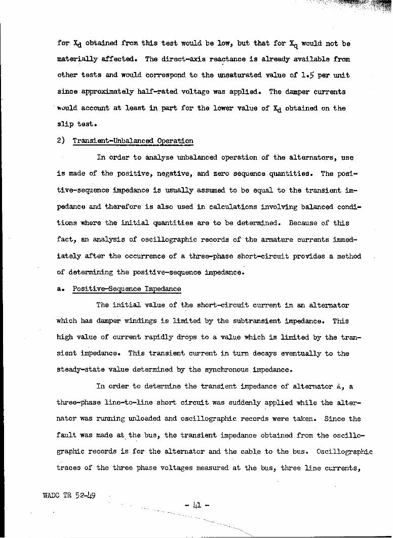
for Xd obtained from this test would be low, but that for k would not be
materially affected. The direct-axis reactance is already available from
other tests and would correspond to the unsaturated value of 1.5 per unit
since approximately half-rated voltage was applied. The damper currents
-ould account at least in part for the lower value of Xd obtained on the
slip test.
2) Transient-Unbalanced Operation
In order to analyze unbalanced operation of the alternators, use
is made of the positive, negative, and zero sequence quantities. The posi-
tive-sequence impedance is usually assumed to be equal to the transient im-
pedance and therefore is also used in calculations involving balanced condi-
tions where the initial quantities are to be determined. Because of this
fact, an analysis of oscillographic records of the armature currents immed-
iately after the occurrence of a three-phase short-circuit provides a method
of determining the positive-sequence impedance.
a. Positive-Sequence Impedance
The initial value of the short-circuit current in an alternator
which has damper windings is limited by the subtransient impedance. This
high value of current rapidly drops to a value which is limited by the tran-
sient impedance. This transient current in turn decays eventually to the
steady-state value determined by the synchronous impedance.
In order to determine the transient impedance of alternator A., a
three-phase line-to-line short circuit was suddenly applied while the alter-
nator was running unloaded and oscillographic records were taken. Since the
fault was made at the bus, the transient impedance obtained from the oscillo-
graphic records is for the alternator and the cable to the bus. Oscillographic
traces of the three phase voltages measured at the bus, three line currents,
WADC TR 52- 4 9- 41 -
and alternator field current were recorded. Figures 8 and 9 are reproduc-
tions of two different oscillographic records obtained on three-phase faults.
Since the rate of decay of the transient component of fault current
approximates an exponential function, a graph of this transient component on
semi-log paper as a function of time approximates a straight line. To deter-
mine the transient impedance the envelopes of the phase currents and arbi-
trary spaced time markers are sketched in on the oscillographic records.
Since the armature currents are offset due to a d-c transient, half of the
peak to peak value is taken as the basis for the total a-c short-circuit
current. From this current, the steady-state short-circuit current is sub-
tracted. The steady-state value of short-circuit current would be the cur-
rent when the field current drops to the value it had before the fault. As
may be seen by the oscillograms the field current then increases to a high
value through the action of the voltage regulator. The result of subtract-
ing the steady-state value from the short-circuit current leaves the tran-
sient component. These values are listed in Table XI and are plotted as a
function of time in Fig. 10 and Fig. 11.
The intercept on the vertical axis of a straight line drawn through
the points gives the peak value of the initial transient current minus that
of the steady-state current. The transient impedance is then obtained by
dividing the peak value of the rated phase voltage by the initial transient
current. The transient reactance of the alternator and the cable to the
bus is thus found to be 0.15 per unit. If the positive-sequence reactance
of the cable is taken to be 0.005 per unitl, then the transient reactance
iArmy Air Force Report, "A-C System Fuse Coordination Study" (Dec. 1945),p.23.
WADC TR 52-49 - 42 -

E-1
00
E-4
2310-0
0010*0- E4
SLOO'o ---
00 00 00 0 00 cj 0 0 00000J 00L w o00a0
'SIIOA 'SdNV 'Sd"N Si1OA 'SdK~V Si'1OA 'SdA
LA J
w 0
WA2DC TR 52.49 -43

4k-
4r4)
10
r4
419=7
'-4
0
cn
0010*00
93 ý8000- --- E4
4- -- 4- 4-
C,) 000C ýor 000 0 000Oc) 0~ Lo 00i 0 ) N- 0
SIflOA SdINV SdiNV SI71QA 'SdVV Sf1OA 'SdINV
C)I 1
LJlC
'-C r CA
WADC TR 52-49 4

Table XI
THREE-PHASE SHORT-CIRCUIT DATA ON ALTERNATOR-A(Name Plate Data Listed in Appendix III-A)
Tabulation Refers to Fig. 8 and Fig. 10
Time ia ia - 160* ib ib - 160 ic ic- 160
Ms. Armeres Amneres Amneres Amperes Amperes Axmperes
2.5 780 620 700 540 780 620
5.0 550 390 510 350 540 380
7.5 430 270 390 230 390 230
10.0 350 190 310 150 310 150
12.5 290 130 270 110 260 100
Tabulation Refers to Fig. 9 and Fig. 11
Time ia i& - 160 ib ib - 160 ic le - 160
IMs. Amperes Amperes Amperes Amneres Amperes Amperes
2.5 780 620 730 570 760 600
5.0 560 400 510 350 560 400
7.5 440 280 390 230 440 280
10.0 340 180 310 150 330 170
12.5 260 100 230 70 260 100
*Note: Steady-state short-circuit current 160 amperes before regulator
action increases field excitation.
WADC TR 52-49- 45 -

I2 mmL
0 C-U
4-N 8 Z 1CD
0 is O it .LL
co 0 0C
W I-0tL1 0W/
w z -z
W~00
/ i-
w wo
/~ LL
00
0000~ 00
0 0 0 0
S3M3dIVdV- 3A1VA 3.LV.S-AaV3J.S JIO SS3Z3X1 NI 1N~~iflD
WADO TR 5 2-49.-,-46 -

CO,
IL 00
00
0~ of 0
(L.0
-J w w< -
W 00
woc
4*w 000
U-
100
00 0 00 0 0 0 0 000 0 00 0 0 0 0 00O 0 c t- D 10 V f N
S38I3d~V- 3MVA 31VIS -AOV31s :10 SS3OX3 NI 1N3uflZo
WVADO TR 52-49 4 7 -

of the alternator = O.145 per unit. The d-c resistance of the alternator and
the cable has been used for the positive-sequence resistance.
b. Negative-Sequence Impedance
Negative-sequence currents flow during line-to-line, double line-
to-ground, and single-line-to-ground faults* Two different methods were
used to determine the negative-sequence impedance of alternator D.
1) Average of Zd" and Zg"
A single-phase voltage was applied across two phases of alternator
D. Alternator A, separately excited, was used as the source for the voltage.
With the field of alternator D short-circuited, the rotor was slowly rotated.
As the magnetic axes of the field poles were made to approach the magnetic
axes of the armature, the armature current increased and the armature voltage
decreased reaching maximum and minimum values respectively when the two sets
of magnetic axes coincided. The ratio of one half the minimum voltage to
the maximum current yields the magnitude of the direct-axis subtransient
impedance Zd". This magnitude was found to be O.146 per unit. Under this
single-phase condition when the magnetic axes of the armature and field poles
coincide the impedance is a minimum because of the current induced in the
field circuit and damper windings. When the magnetic axes of the field poles
lie half way between the magnetic axes of the armature, the armature current
is a minimum and the voltage is a maximum. From the values of maximum volt-
age and minimum current the magnitude of the quadrature-axis subtransient
reactance was found to be Zq" = O.538 per unit. Under this condition the in-
duced field current is negligible. The negative-sequence impedance neglect-
ing inequalities in impedance angles is the average of Zq" and Zd" and so
Z2 = 0.342 per unit. The readings and calculations are shown in Table XII.
WAXO TR 52-49- 48 -

Table XII
SU3TRA1,TSI2aIT IhIP)ANCE AND NEGATIVE-SEQU12NCE !P MI-ANCE TILT DATA(Name Plate Data Listed in Appendix III-A)
Line-to-Line Voltage Current ImpedanceVolts Amperes Ohms P.U.
27.7 48 0.578 0.535
28.1 48 o.586 0.52
Average Value: Zq" = O.538
16-5 85 0.194 0.180
12.0 100 0.120 0.111
Average Value: Zd" = O.146
Negative-Sequence Impedance: Z2 Zd" + ZQ11 0.342 P.U.2
WADC TR 52-e - 49 -

2) Wattmeter Method
Another method for determining the negative-sequence impedance of
an alternator is perhaps more realistic than the foregoing method in that
the alternator is operated under line-to-line fault condition. Further, by
means of the wattmeter measurement, the negative-sequence resistance and
negative-sequence reactance can be determined in addition to the negative-
sequence impedance.
Two phases of alternator D were short-circuited at the terminals
as shown in Fig. 12a. A voltmeter and the potential coil of a wattmeter
were connected from the un-faulted phase to one of the short-circuited
phases. The current coil of the wattmeter and an ammeter were connected to
the secondary of a current transformer which in turn was placed in one of
the short-circuited phases. With alternator D running at synchronous speed
and the field separately excited, reduced excitation was applied. For dif-
ferent values of excitation, readings of voltage, current, and power were
taken, and the results appear in Table XIII. From this wattmeter method,
the negative-sequence impedance is Z2 = (0.137 + j 0.217) per unit for an
armature current of 1h8 amperes as indicated in Table XIII.
c. Zero-Sequence Impedance
Since the neutrals of aircraft alternators are grounded, a path
for zero-sequence current is provided. To determine the zero-sequence im-
pedance, the three phases of alternator D were connected in series as shown
in Fig. 12b. A single-phase voltage obtained from alternator A was applied
across the series combination. With alternator D running near synchronous
speed and with the alternator field short-circuited, readings of the applied
voltage and the current through the series combination were taken. The
WADC TR 52-49- 50 -

If
VOLTMETE
IW 'WATTMETER
FIG.120- WATTMETER METHOD OF DETERMINING THENEGATIVE- SEQUENCE IMPEDANCE.
^^E
FIG. 12b- CONNECTIONS FOR MEASURING THEZERO-SEQUENCE IMPEDANCE.
1:AfC TR 52-49- 51 -

Table XIII
NEGATIVE-SEQUENCE IMPEDANCE OF ALTERNATOR-D FROM WATTMETER METHOD(Name plate Data Listed in Appendix III-A)
E W E
Volts Amperes Watts EP •U. F.U•
26.5 52 1240 0.272 o.245 0.119
46.o 94 3760 0.262 0.228 0.129
71.0 1148 8920 0.257 0.217 0.137
Table XIV
ZERO-SEQUENCE IMPEDANCE OF ALTERNATOR-D
E I Zo
Volts P.U. Amperes P.U. P.U.
4.13 0.0345 78.8 0.709 0.0487
4.60 0.0383 85.4 0.768 0.0498
4.50 0.0375 83.0 0.748 0.0502
Average Value: zo= 0.0496
WADOC TR 52-49 52

results are shown in Table XIV. Generally the zero-sequence resistance is
taken equal to the positive-sequence resistance of the alternator hence the
zero-sequence impedance is Zo = (O.02h + j 0.043) per unit.
3. Discussion
The various values of reactance, short-circuit ratio and demagnet-
ization factor determined in this study are listed in Table XV, along vith
values of reactance submitted by the W'Oestinghouse Electric Corporation for
the same type alternator. The values of unsaturated synchronous reactance
Xdu are in exact agreement. This is rather to be expected as the procedure
for determining the unsaturated synchronous reactance is rather simple and
straightforward. There is some disagreement between the values obtained for
the transient, subtransient, and sequence reactances. With the exception of
the unsaturated synchronous reactance, Xdu, the values obtained in this study
are consistently lower than the values for the corresponding quantities sub-
mitted by Westinghouse. Exact agreement between these values however need
not invalidate one set of results or the other as there are such variables
as degrees of magnetic saturation, inherent inaccuracies in obtaining and
interpreting oscillographic records, which are not duplicated exactly by
different observers or necessarily by the same observer making tests at dif-
ferent times on two separate alternators of the same design and manufacture.
There are however some approximate relationships which serve as rough checks
.on the exactness of some of these reactances.
a. Potier Reactance and Transient Reactance
Table XV lists a value of 0.106 per unit for the Potier reactance.
The Potier reactance, also known as the leakage reactance, of a synchronous
machine results from two leakage fluxes, namely, armature leakage flux and
WADC TR 52-49

Table XV
ALTERNATOR PARAYETERS
Quantity Symbol Value
ARF "W" *
Unsaturated Synchronous Reactance Xdu 1.50 1.50
Short-Circuit Ratio SCR 0.90
potier Reactance Xp 0.106
Armature Demagnetizing Factor --- 1.443
Quadrature-Axis Synchronous Reactance Xq 0.91
Direct-Axis Transient Reactance Xdt 0.1145 0.21
Direct-Axis Subtransient Reactance Xd" 0.1 4 6 0.214
Quadrature-Axis Subtransient Reactance Xq"t 0.538 0.649
Negative-Sequence Reactance (average ofXd"t and Xq") X2 0.342 0.432
Negative-Sequence Impedance (148 amp onKattmeter MIethod) Z2 (0.137 + j 0.217) ---
Zero-Sequence Reactance X0 0.043 O.08h
*These values were submitted in a letter dated July 23, 1951 from Mr. R. H.Keith of Westinghouse Electric Corporation to Mr. L. W. Matsch of ArmourResearch Foundation.
WADC TR 52-49- 54 -

field leakage flux. If it were not for the increased field leakage flux due
to the transient increase in field current during short circuit, the transient
reactance would have the same value as the Potier reactance. This increase
in field leakage flux causes the transient reactance to be somewhat higher
than the Potier reactance. Sterling BeckwithI gives the following empirical
relationship between Potier reactance and transient reactance: Xd' - 1.25 xp.
On the basis of a Potier reactance of 0.11 per unit the transient reactance
should be approximately 0.14 per unit as compared with our value of 0.145
per unit. This relationship however is not hard and fast and is therefore
not to be taken too literally. However, it does serve as a rough check.
b. Short-Circuit Currents, Observed and Calculated
Table XXIV shows a comparison of values of short-circuit current
obtained by short-circuit tests with values of current computed from the
parameters determined in this study. These values are in fair agreement as
the calculated value for single-line-to-ground fault current is 673 amperes
compared with a measured value of 631 amperes. The manufacturer's data
would give a calculated value of 461 amperes not including the impedance of
the line and neglecting the resistance of the alternator and line entirely.
In addition to these discrepancies between different observers, different
methods used by the same observer lead to different values of negative-
sequence reactance. In our studies the negative-sequence reactance, com-
puted on the basis of the average of Xd" and Xq", was 0.342 per unit and the
value obtained with the wattmeter test was found to be 0.217 per unit for
one value of field current; for lower values of field current the negative-
iSterling Beckwith, "Approximating Potier Reactance", AIEE Transactions(July 1937), p.813.
WADO TR 52-49-55.-

sequence reactance had a greater value indicating that the negative-sequence
reactance decreases with magnetic saturation. These variations in the re-
sults obtained by different observers and the variations in results ob-
tained by the same observer using different methods indicate a need for
establishing test procedures which will lead to more consistent and more
useful data.
C. Regulators
In order for the electric power system to deliver power to the
utilization devices at the proper voltage and proper frequency, it is neces-
sary to make adjustments in the field excitation of the alternators and in
the output of the prime movers. In aircraft both of these types of adjust-
ments should be made automatically. It is common practice to adjust field
excitation automatically by means of a voltage regulator and to adjust the
prime mover output automatically by means of a speed governor.
1. Voltage Regulator
The function of a voltage regulator is to maintain nearly constant
terminal voltage on a generator with varying loads. The method of voltage
regulation employed on the present a-c system is that of controlling exciter
output by use of a variable resistance in series with the shunt field of the
exciter. This resistor is a carbon stack, the resistance of which is con-
trolled by a solenoid acting against a spring. The change in pressure on
the carbon discs changes the resistance. In order that the regulator be
complete and self operating, a method is required whereby under normal con-
ditions a potential proportional to the terminal voltage of the alternator
is applied to the solenoid such that a change in terminal voltage will cause
a corresponding change in exciter field circuit resistance which will return
WADC TH 5 2-49- 5 6 -

the terminal voltage to the desired value.
The circuit for the voltage regulator system is shown in Fig. 13.
Alternator terminal voltage is applied to a potential transformer connected
in V-V (TRl and TR2). The reduced secondary voltage, proportional to the
line-to-line voltage of the machine, is applied to a three phase dry-disc
rectifier. The d-c output of the rectifier is supplied to the solenoid
(regulator coil) in a series network with temperature compensating resistors
and other auxiliary components including a stabilizing transformer TR3. The
output of the rectifier is proportional to the average of the three line-to-
line voltages. This arrangement makes use of three-phase voltage sensing.
Three-phase sensing, though requiring a heavier and more complex regulator,
gives better regulation with unbalanced loads.
Figure lh is a vector diagram showing the pertinent current and
voltage relationships in the circuit. The current transformer and mutual
reactor of the equializer are placed in the same phase. During parallel
operation the primary winding of the reactor in the equalizer circuit carries
current only if the division of current among alternators is improper. With
only one alternator on the system the primary of the reactor is automatically
short circuited. 1'ihen the circuit breaker of an alternator is open the pri-
mary of the mutual reactor is short circuited. Thus the open circuit break-
ers on all the other alternators short circuit not only their own reactors
but also that of the one alternator on the system. If an alternator delivers
more than its share of reactive current, a 90 degree lagging current will
flow through the primary of its mutual reactor and a corresponding 90 degree
leading current will flow through the mutual reactors of the other alter-
nators which causes the voltage regulators to take corrective action.
WADC TR 52-49-5-

04 o
It-40
4 I-
Z -A-r 0z I-
a: -i;
01
w IaJ) w
I- w'0 CD
ra 40w Ix
ui 0i(
40 04Ilox 0
J3 0
N 0 wx ~xX
cc La I
WADO TR 52-49

I/+4
4- 5
NOS. 1,28k3 -ALTERNATOR LINE-TO- NEUTRAL VOLTAGESNOS. (5-4),(4-6) &(6-5) -LINE-TO-LINE VOLTAGES
AT SECONDARY OF POTENTIAL TRANSFORMER1131 - CURRENT IN CT1131XM- VOLTAGE INDUCED IN SECONDARY OF MUTUAL
REACTOR TR 4
FIG. 14 -GENERAL VECTOR DIAGRAM FORVOLTAGE REGULATOR
WAWO TR 52-49

Figures 15a, 15b, 15c, show vector diagrams for unity p.f., zero
p.f. lagging, and zero p.f. leading current. For unity power-factor, the
numerical average value of the voltage applied to the rectifier and conse-
quently rectifier output is approximately the same for zero current (normal
operations under balanced conditions) as for normal values of unity p.f.
current.
For zero p.f. lagging, the numerical average value of the three
voltages applied to the rectifier is increased which raises the voltage on
the regulator coil and decreases excitation. For zero p.f. leading, the
rectifier output decreases, increasing excitation. The effect of any inter-
mediate power factor between zero and unity can be obtained by resolving the
current vector into real and reactive components.
2. Speed Regulator
Figure 16 shows a schematic diagram of the constant speed drive.
The output from the engine is geared to a rotating drum which houses two
hydraulic elements comprised of an interconnected hydraulic pump and hydraulic
motor. The output of the hydraulic motor is geared to the input shaft of
the alternator through a free-wheeling clutch. The rated output speed is
6000 rpm. When the input speed is 6000 rpm., there is no pumping action.
Deviations in the input speed from 6000 rpm cause the angle of the adjusta-
ble wobble plate to be such that the proper pumping action is obtained so
that the output speed is 6000 rpm.
The position of the wobble plate is determined by a governor shown
schematically in Fig. 16 which is actuated by an electrical solenoid com-
prised of three coils. These coils are the pilot valve operating coil VX,
droop coil V'ID, and an overspeed coil OC, as shown in Fig. 17.
The pilot valve operating coil is energized through rectifiers
WADe TR 52-49- 60 -

13
/
//3•
131
x m
7
6I
/ A
S4
b-o P.F. LAGGING C-0 P.F. LEADING
NOS. 4,5,6, a7 CORRESPOND TO WIRE NUMBERS ONSCHEMATIC DIAGRAM FIG. 13
VOLTAGES (6-4) ,(5 -6) a (4-5)ARE 30 OUTPUTVOLTAGES OF LINE TRANSFORMER BANK(TR I aTR2 FIG. 13)
VOLTAGES ( 7- 4), (5 -T) & (4- 5 )ARE 30 VOLTAGES
APPLIED TO A- C TERMINALS OF RECTIFIER
FIG. 15 - VECTOR DIAGRAMS FOR VOLTAGE REGULATOR -
WADC T 5240VARIOUS POWER FACTORS
46 5
(TR BTR ,FI- 13VOTAES(74)5-)84-)AE ].LTGE

DRIVE ALTERNATORINPUT INPUT ALTERNATOR
AIRCRAFT - CONSTANT N POWER OUTPUT
ANIRCAF SPEED ALTERNATOR
I [• TACHOMETER
AND CONTROL
HYDRAULIC CIRCUIT
TRANSMISSIONTO CONTROL
PISTON
PILOT VALVE DROOP CIRCUITAND SOLENOID
ASSEMBLY
BLOCK DIAGRAM OF CONSTANT SPEEDDRIVE AND ASSOCIATED EQUIPMENT
OIL OUTOILINPILOT VALVE IT _SOLENOIDCONTROL PISTON VARIABLE DISPLACEMENT BOAS SPRING- M 7
MOVEMENT REVERSIBLE HYDRAULIC______ELEMENT
WOBBLE SOLENOIDPLATEARMATUREADJUSTABLEPLATE
FIXED DISPLACE- CONTROLMENT HYDRAUUC ALTERNATOR PISTON
LEMEN Z 1 6000 RPM
DRIVE INPUT
FROM ENGINE- WOBBLE2400 TO 9000 RPM FREEWHEELING PLATE
CLUTCH
SCHEMATIC MECHANICAL DIAGRAM SCHEMATIC MECHANICAL DIAGRAMOF CONSTANT SPEED DRIVE OF PILOT VALVE AND SOLENOID
ASSEMBLY AND CONTROL PISTON
FIG. 16 - SCHEMATIC DIAGRAMS OF CONSTANT SPEEDDRIVEWADe TR 52-49 62

4X Isc C--
0 05
00 II> co)
I-U I +
It) C.)
0 0 C0C--J
0
Neu
z
3dto'~ moýl- 't 0
CMC
_ _ _ 44 ___0
I- 0
NID 6- 52-49C
63

from a three-phase tachometer, and is so adjusted that when acting alone
(coils WID and OC inactive), the output speed is maintained nominally at 6000
rpm.
The droop coils in a parallel system of alternators can be ener-
gized in various ways. In the early use of systems of parallel alternators,
the droop coil WD was connected directly to the droop circuit of its respec-
tive alternator, by connecting output terminals 1 and 2 of the droop circuit
to terminal D and C of the droop coil in the governor solenoid in Fig. 17,
thus deliberately incorporating a droop characteristic such that the speed
decreased with increasing real power load. This was done with a view toward
effecting proper division of real power load between the alternators. This
arrangement has two disadvantages: one is the decrease in frequency in go-
ing from no load to full load, the other is the extreme precision required
to make the droop adjustments of all alternators identical. A much improved
arrangement for dividing real power load without sacrificing accuracy in
frequency has been introduced by the Air Materiel Command. This arrangement
makes use of an equalizer circuit which is shown schematically in Fig. 18.
With this arrangement there is no current in the droop coils except when
there is unequal division of real power between alternators. The effect of
such a current in the droop coils is to initiate corrective action which re-
duces this current to zero. Under equal real load conditions regardless of
the magnitude of this load, only the pilot valve operating coil which is
energized from the tachometer is effective in the operation of the governor.
If the speed governor were ideal, departures from normal frequency would be
transient existing only during periods in which the division of real power
undergoes readjustment.
WA.C TR 52-49- 6h -
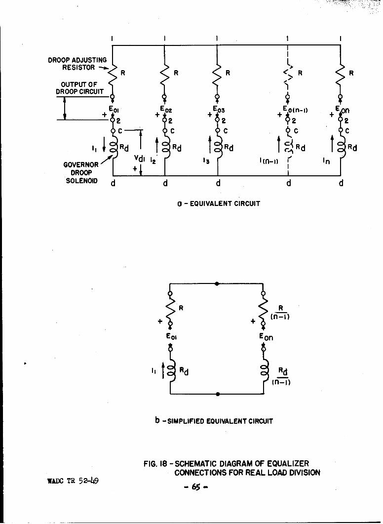
DROOP ADJUSTINGRESISTOR R RR
OUTPUT OFDROOP CIRCUIT
I1 E01 + Eol+ 0 + Eo(fl...) +En
Cd C C ~
AVdi 1,* 13 1(fl-i) f' InGOVERNOR +1 1DROOPI
SOLENOID d d d d d
a - EQUIVALENT CIRCUIT
1,t Rd Rd(fl-I)
b -SIMPLIFIED EQUIVALENT CIRCUIT
FIG. 18 - SCHEMATIC DIAGRAM OF EQUALIZERCONNECTIONS FOR REAL LOAD DIVISION
WADC TR 52-49 - 6 -

The overspeed coil in the governor solenoid is energized by means
of a centrifugal switch from an auxiliary d-c power system (usually 28 volts)
when the output speed rises above 7500 rpm (125 percent rated speed). Under
this condition the adjustable wobble plate in the constant speed drive is
shifted to the full underdrive position and the plunger of the solenoid be-
comes latched in this position. In order to restore normal operation of the
drive, it is necessary to reset the latch manually.
3. Equalizer Circuits
For efficient parallel operation of alternators it is necessary
that both real and reactive load be distributed equally among the alternators.
The present system employs both reactive and real power equalizers which are
interconnections of the respective voltage and speed regulating systems be-
tween the paralleled alternators so that unbalances in load can be corrected
automatically.
a. Reactive Power Equalizer
To achieve equal division of reactive load among alternators, the
equalizer current transformers of the alternators are connected in series as
shown in Fig. 19. When each alternator on the bus is delivering its share
of current, the same current flows through all of the current transformers
and zero current flows in the equalizer coils (mutual reactor primary, TRh,
Fig. 13).
An analysis of the reactive load equalizer circuit is presented
in the following.
1) Analysis of Reactive Load Equalizer Circuit
Figure 19 shows the schematic diagram for the interconnection of
n current transformers each supplying the primary of a mutual reactor to
WADC TR 52-49
- 66 -

- zW oi 0
w0Z LL > :10 NCf 0Z
00cr.)
Z a >
Ix.0 0
_ 4-0 Nt I-
Mz 4~ z 4x
0
wo 0-10 ~0
cr0 CD
WADO TR 5 2-49 -67-

form the reactive load equalizer circuit for an n-alternator system.
If the currents in each of the n machines are I1, 12, .... In and1 1 1
the current transformer ratios are all c, tnIL , L I2, .... 0 In are the
currents in the n current transformers* If machine I has its load increased
for any reason then I1 will be different from the other (n-1) currents.
Thus I1 # 12 = 13 = .... - In-
If the currents are summed at points A and N in Fig. 19 two ex-
pressions are obtained.
= il + i (3)
cIn in + i (4)
Subtracting the second equation from the first gives
1 (I1 -In) -il - in (5)c
The sum of the voltages around the loop containing the primaries
of the n mutual reactors, if the impedance of the interconnecting leads is
negligible is expressed by
iI Z1 + i 2 Z2 + .. + in Zn 0 (6)
or if Z1 = Z2 = .... = Zn this reduces to
iI + (n-1) in - 0 (7)
since i2 = 23 = 2. in
and on transposing iI = - (n-1) in (8)
Substituting Eq. (8) in (5) yields
1in = - c-l (I1 - In) (9)
Substituting Eq. (9) in Eq. (8) we get
(n-1)il= cn (I1 - In) (10)
WADC TR 52-49 - 68 -

Equations (9) and (10) express the mutual reactor currents as func-
tions of the difference current (I1 - In), which is in general a vector with
both real and reactive components. Under normal conditions, only the re-
active components of this difference affect the operation of the voltage
regulator.
When only one alternator is on the system and its mutual reactor
is not short circuited,the polarities of the current transformer and mutual
reactor are correct if the voltage droops when reactive power is fed to the
load. Only reactive component of current in the mutual reactor affects the
voltage regulator. hence, if Im is the current in the mutual reactor
lVI = IVOl JB1 lImi sin (11
where:
IVI = magnitude of terminal voltage,
IVoi = magnitude of reference voltage,
9 = angle by which the current lags the voltage,
II = magnitude of mutual reactor current,
iBI = constant which combines the ratio of the current trans-former and the mutual reactance of the mutual reactor.
The quadrature component of each of the mutual reactor currents
corresponds to lIml sin 0 in equation (11) and can be determined from the
quadrature component of the difference current (I, - In) which is expressed
by:
Ill sinl 01 - lInil sin On (12)
where:
@i = angle by which il lags the terminal voltage,
On = angle by which In lags the terminal voltage.
WADC TR 52-9- 69 -

Making use of Eqs. (9) and (10) and substituting Eq. (12) in Eq.
(11), the terminal voltage of alternator 1 is expressed by
lVI = IVol - K n- (( I 1i1sin @l - IIn1 sin 9n) (13)
and that of the other (n-l) alternators is expressed by
IVI = IVoni + n (IIl sin 01 - IIni sin Qn) (lh)
where:
IVoll = reference voltage for alternator 1,
IVonI = reference voltage for the (n-l) alternators,
K = IBI , the amplification factor of the reactive loadc
equalizing circuit.
2) Determination of Reactive Current Equalizer Amplification Factor
The value of the amplification factor K of regulator alternator D
was determined by test. The equalizer connections from alternator D were
disconnected so that all the secondary current from the current transformer
flowed in the mutual reactor of that alternator. Alternator 1 was under-
excited and used as a low power-factor load for alternator D and results of
the test are shown in Table XVI. Figure 20 shows graphically the relation-
ship between the terminal voltage, V, and the quadrature component of current,
III sin @,based on the test results. This graph shows a straight line re-
lationship. The magnitude of the amplification factor K is equal to that of
the slope of this line. Although the slope of the line is negative, the
factor K is positive and has a value of 0.106 per unit. The equation of the
line in Fig. 20 is expressed by
V = Vo - K III sin 0 (15)
According to the specification for this type of voltage regulator
(MIL-R-5292A) the value of this constant is such as to give a drop of from
WADC TR 52-49- 70 -

Table XVI
TEST DATA FOR REACTIVE POWER AMPLIFICATION FACTOR
Phase Voltage Current power III sin Q
Volts P.U. Amperes P.*U. KW P.U. KVARS P.U. P.U.
123.2 1.027 26.0 .234 2.4 0.060 -9.57 -0.239 -0.228
120.3 1.003 2.0 .018 1.92 o.048 -0.693 -0.017 -0.006
117.7 0.981 22.6 .204 2.16 0.054 7.48 0.187 0.196
116.8 0.974 31.0 .279 2.4 0.060 10.5 0.263 0.273
114.6 0.955 49.4 .444 2.4 0.060 16.9 0.423 0.442
113.8 0.949 59.4 .535 2.4 0.060 20.2 0.505 0.533
112.9 0.941 65.8 .593 2.4 0.060 22.3 0.558 0.591
WADC TR 52-49- 71 -

to 00 0-1. 1 (I)
1010
I X:00
0) cl 00
1+ *0a:
zNwNKr -j
UJ w
I-
0
0 0
-39V.L1OA IVNIPYE13J. IC
9 I;;tol-8- ---
VIADO TR 5 2-49-72 -

5 to 7% rated voltage when the alternator is supplying half rated current at
zero power-factor lagging. The value of 0.106 for K gives a drop of 5-3%
rated voltage for the specified current condition.
3) Errors in Reference Voltage and Reduction in System Capacity
The total available capacity of a system in which paralleled
alternators do not share load equally is less than the sum of the capacities
of the individual machines, since one or more alternators will be overloaded
before full system capacity is reached. Division of reactive load can be
achieved by making use of voltage droop characteristics. This method is
less desirable than one using an equalizer circuit, because the voltage droop
method depends upon an appreciable variation of voltage with load.
In the equalizer method, a loss of available system capacity due
to current unbalance can be caused by errors in the voltage regulator setting.
These errors may be due to drifts such as are caused by changes in resistance
of the regulator coil circuit or may be due to inaccuracies in the original
settings. Specifications used by the Air Force (MIL-R-5292A) place a limit
of 2.5 percent in the deviation from rated value due to inaccuracies in the
regulator itself.
Suppose that in a system of n alternators operating in parallel,
the regulator of one alternator is in error by 2.5 percent and the regulators
on the other alternators are at their proper setting. For this condition the
capacity of the system can be determined by calculating the total system load
at the time that any alternator reaches its rated capacity.
The expression relating bus voltage, regulator setting and equalizer
currents has been derived for each of the n alternators and are as follows:
lv IVolI - K -) (I'll sin 91 - lInI sin on) (13)
WADC TR 52-49
- 73 -

and for each of the other (n-1) alternators
IVi = lVonj + K 1 (lIli sin Ql - lIn' sin Qn) (14)
Since the terminal voltages of the two machines must be equal and if Eq.
(14) is subtracted from Eq. (13).
there results
0 1Vol1 - lo - K (lIIll sin Qj - lIni sin G~n)
or
I1 sin 1- lIni sin Gn (Ivoil - IVonl) (16)
The KVA capacity will be computed for (1) the regulator setting in alternator
1 2.5% below normal and (2) for a setting 2.5% above normal with the regu-
lators of each of the other alternators normal. It is also assumed that the
alternators share real load equally and that none of the alternators be over-
loaded.
An example for the case where IVolI is set 2.5% low is as follows:I 1
Ill sin 01 IIn( sin Qn -- O. (-0.025)
lIl1 sin 01 - IInl sin On - -0.236
when lVoll is low IIn1 sin On = 0.661 (current is 1.00 p.u. at .75 P.F.)
and lIll sin Q1 0o.25
The total quadrature current supplied to the load
I kj sin QL Ill sin 01 + (n-1) lIni sin On
If n 4
lILl sin 0L - *425 + 1.98 - 2.41
The in-phase component of load current is
I LI cos O - 4 x .75- 3.00
Neglecting the change in system voltage which is 0.6 percent, we get for the
WADM TR 52-4e9- 74 -

total load power in per unit
SL = 3.00 + j 2.41
= 3.85 /38.8-
and the percent installed capacity is
3.85Sx
100 = 96.2%
In Table XVII are tabulated the values of system capacity for values of n
from 2 to 6 and for settings of Vol 2.5 percent above and 2.5 percent below
normal values.
Table XVII
EFFECT OF VOLTAGE ERROR ON SYSTEM CAPACITY
Number of Vol = 1.025 P.U. Vol = 0.975
Alternators, n % Cap. V % Cap. V
2 93 1.013 93 0.988
3 91 1.008 95 0.992
4 89 1.006 96 0.994
5 88 1.005 97 0.995
6 88 1.004 98 0.996
00 86 1.000 100 1.000
If the regulator setting is 2.5 percent low, the reduction in the
system capacity is small particularly as the number of generating units is
increased. However, if the regulator setting is 2.5 percent high, the reduc-
tion in system capacity becomes sizeable, approaching 86 percent as a limit.
An increase in the value of K decreases the reduction in system capacity re-
sulting from errors in reference voltage. However, there is a hazard of in-
creasing K to a value where hunting of the voltage regulating system would
WADC TR 52-49

result. The determination of the optimum value of the amplification factor
K is complex, but is a problem which deserves further study.
b. Real Power Equaliw
The equalizer circuit for dividing real power among alternators is
shown in Fig. 18a. For an n alternator system there are n branches in par-
allel and each branch is comprised of the droop circuit in series with its
own solenoid droop coil. Thus when all of the alternators are carrying the
same real load, each droop circuit has the same output voltage and no cur-
rent flows in any of the branches. If one alternator should pick up an
increment of real load and each of the other machines still carry the same
loads, current will flow in each branch in such a direction as to correct
the unbalance and tend to restore the equal load division.
1) Analysis of Real Load Equalizer Circuit
Let Ipl be the in-phase component of current being supplied by
alternator 1 and Ipn be the in-phase component of current being supplied by
each of the other alternators. Eol is the D.C. voltage across the resistor
R2 in Fig. 17 in the droop circuit of alternator 1, and Eon is the corres-
ponding voltage for each of the (n-l) machines. It is shown in Appendix
III-B that Eol is substantially proportional to Ipl as Iql the reactive cur-
rent has negligible effect on the division of real power. If the constant
of proportionality is called M., then
Eol - M Ip1 (17)
Eon - M IPn (18)
Figure 18a shows the circuit to be analysed. This circuit can be
reduced to the simple network of Fig. 18b.
If R is the resistance of the droop adjusting resistor of each
WADC TR 52-49- 76 -

alternator (R4 in Fig. 17), and Rd the resistance of each solenoid droop coil,
then the simplified circuit yields:
n R+ d (19)
where i is the current in the droop coil of machine 1.
From Equations (17) and (18)
Eol - Eon - M (Ipl - Ipn) (20)
so(n-l) (
n R + Rd (IP1 - IT) (21)
and the voltage across the droop coil of alternator 1 is expressed by:
Vdl- - 1n ( ) d (IPl - Tp) (22)
n (R +Rd)M(~In
The frequency of an alternator is almost a linear function of the
voltage across the droop coil and if fo is the reference frequency (i.e. the
frequency when the droop coil voltage, Vd, is zero) then the frequency can
be expressed by
f- fo+ N Vd
where N is a constant.
The system frequency of the n-machine system in terms of the ref-
erence frequency of machine 1 and its droop coil voltage:
f - fol + N Vdl (23)
If Eq. (22) is substituted into Eq. (23)
f - fol - N M (R+Rd) (n-l1__) (Ipl -Ipn) (24)
If a new constant K' is defined by
K' IL(R +Rd
WADC TR 52-49- 77 -

then Eq. (24) is reduced to
f = fol - K' (n-1) (ipl - ipn) (25)n
Eq. (25) states that the system frequency will be constant at the
value of the reference frequency fo, if the difference current, (Ipl - Ipn)
is zero at any system load. Zero difference current can be achieved only if
all speed governors are set for the same reference frequency, fo, by the
proper adjustment of the engineer's rheostat R3 , R5 Fig. 17, on each unit.
When there is an inaccuracy in the setting of one of these rheostats, a sus-
tained difference current will exist and a loss of system capacity will re-
sult.
2) Determination of In-Phase Current Equalizer Amplification Factor
Tests were made on alternator D and its associated constant speed
drive to determine the speed droop characteristics for the following con-
ditions:
1. Droop circuit disconnected
2. Droop circuit adjusted for minimum droop
3. Droop circuit adjusted for maximum droop.
1. For the first test, the droop circuit was opened in order to render
it ineffective and to determine the droop inherent in the pilot valve con-
trol arrangement. With alternator D carrying no load, the reference fre-
quency was adjusted to 400 cycles per second. Alternator D was then loaded
with a unity power-factor load and measurements of frequency and power were
made. The results are shown in Table XVIII and are plotted in Fig. 21.
2. The droop coil of alternator D was connected to its own droop cir-
cuit and the resistance R4 shown in Fig. 17 was adjusted to its maximum
value so that the droop would be a minimum as the load on alternator D was
WADC TR 52-49- 78 -

Table XVIII
TEST DATA FOR IN-PHASE CURRENT EQUALIZER AMPLIFICATION FACTOR
Unity power-Factor
Condition Frequency Three-Phase Powerof Test Cycles Per Unit KW per Unit
399 .998 0 0398 .995 9.95 .249
Droop Circuit 395 .988 22.1 .553Open 393 .983 28.8 .72
388.5 .971 36.8 .92
399.7 .999 0 0397.5 .994 3.84 .096
Min. Droop 393.8 .985 11.6 .29Adjustment 388 .970 20.2 .505
380.5 .951 29.5 .738371 .928 38.2 .945
398.7 .998 0 0384.5 .961 10.1 ,252
Max. Droop 371 .928 19.7 .492Adjustment 355 .889 29.3 .732
335 .838 37.7 .942
WADC TR 52-49 79

CURVE A - DROOP CKT OPEN K' IOOO- 0.970 a 0.030CURVE B -MIN. DROOP ADJ. K' 1.000 -0.937 0.063CURVE C - MAX DROOPADJ. K'. LOO-0.852 a0.158
1.00
0.98 ,,•A
0.96
!:Q94w
I' Q92 ,
zwQ90
I," 0.88
0.86
0.84
0.82
0.80
0 0.1 0.2 0.3 0.4 0.5 0.6 0.7 0.8 0.9 1.0
IN-PHASE CURRENT-PER UNIT
FIG. 21 - FREQUENCY DROOP CHARACTERISTICS
WADC 'R 52-49- 80-

increased. Measurements of real power versus frequency were repeated.
3. These measurements were again repeated with the resistance R4 ad-
justed for its minimum value in order to obtain maximum droop.
In Fig. 21, the curves are approximated by straight lines in order
to obtain constant values for the amplification factors K'. On that basis
K' - 0.063 per unit when the circuit is adjusted for mininmu droop; and K' -
0.158 per unit when the circuit is adjusted for maximum droop.
3) Output Voltage of Frequency Droop Circuit
Tests were made on alternator D to determine the relationship be-
tween the d-c output voltage of the frequency droop circuit and the real
power output at unity power-factor. The data obtained in these tests are
listed in Table XIX, and are shown by the circled points in Fig. 22.
Table XIX
TESTS OF FREQUENCY DROOP RESPONSE
Unity Power Factor
Three-Phase Power Output Voltage, Eo
KW Per Unit Volts
0 0 08.65 o.216 1.0
15.1 0.377 1.726.2 0.655 3.034.3 0.856 3-94o.0 1.000 4.5
4) Effect of Error in Reference Frequency
Drifts in the reference frequency can result from changes in the
resistance of the tachometer and the pilot valve control winding circuit.
Perhaps the most common cause for variations in resistance is a change in
the temperature of the pilot valve control winding. The resistance of this
WALE TR 52-49- 81 -

LINE 1
CURRENTIhIp-jIQ-
CURVES SHOWING DROOPCIRCUIT OUTPUT VOLTAGEAS A FUNCTION OF IN -PHASE/ / "{ QCURRENT FOR VARIOUS VALUES /. 0.25
5.00 OF QUADRATURE CURRENT // 0.75
SOBTAINED I1.50FROM TESTI
0Q1020> 4.00
0
o/
3 3.00
0-J
0200 //
w
0-0
0 0.20 0.40 0.60 0.80 1.00 1.20
I p -IN-PHASE CURRENT- PER UNIT
FIG. 22 - DROOP CIRCUIT RESPONSE TO IN-PHASE CURRENT
WADCTR 52-4~9
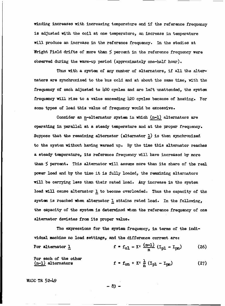
winding increases with increasing temperature and if the reference frequency
is adjusted with the coil at one temperature, an increase in temperature
will produce an increase in the reference frequency. In the studies at
Wright Field drifts of more than 5 percent in the reference frequency were
observed during the warm-up period (approximately one-half hour).
Thus with a system of any number of alternators, if all the alter-
nators are synchronized to the bus cold and at about the same time, with the
frequency of each adjusted to 400 cycles and are left unattended, the system
frequency will rise to a value exceeding 420 cycles because of heating. For
some types of load this value of frequency would be excessive.
Consider an n-alternator system in which (n-l) alternators are
operating in parallel at a steady temperature and at the proper frequency.
Suppose that the remaining alternator (alternator 1) is then synchronized
to the system without having warmed up. By the time this alternator reaches
a steady temperature, its reference frequency will have increased by more
than 5 percent. This alternator will assume more than its share of the real
power load and by the time it is fully loaded, the remaining alternators
will be carrying less than their rated load. Any increase in the system
load will cause alternator 1 to become overloaded. Thus the capacity of the
system is reached when alternator 1 attains rated load. In the following,
the capacity of the system is determined when the reference frequency of one
alternator deviates from its proper value.
The expressions for the system frequency, in terms of the indi-
vidual machine no load settings, and the difference current are:
For alternator 1 f 0 fol" -'S (-- (Ip1 - Ip) (26)
For each of the other(n-l) alternators f - fen + K' 1 (Ipl- ipn) (27)n
WADC TR 52-49- 83 -

The system frequency mast satisfy both equations and if f is eliminated
1p1 - Ipn - (fol -fon) (28)
If fol is high, machine 1 will reach its rating first and the other machines
will carry less than their ratings; while if fol is low, then the (n-i) ma-
chines will be at rated load first and only machine 1 will carry less than
its rating. It is obvious that there is less capacity reduction in the
latter case than in the former.
Suppose that the reference frequency, fol, of alternator 1 has
drifted to 1.05 per unit (420 cycles) and that the droop circuits are ad-
justed for maximum droop i.e. K' - 0.158 per unit. Under this condition
when alternator 1 carries rated load at 0.75 power factor we have
II - 0.75 -J O.66 per unit, where
Ipl - 0.75
From Eq. (27) the in-phase current in the other alternators is expressed by
Ipn Ip1 - r (fol - fon)
- 0.75 - 0.05 0.1O434 per unit= 0.5 -o.158=
If the reactive current equalizers are functioning properly the total cur-
rent in each of the other alternators is expressed by
in = 0.434 -J 0.66 per unit.
The total generated power then becomes
STH - 0.75 + (n-i) 0.434 + j 0.66 n
If the reference frequency fol of alternator 1 were reduced to 0.95 per unit
it can be shown that the total generated power becomes
STL = 0.434 + (n-i) 0.75 + J 0.66 n
WADN TR 52-49- 84 -

The reduced values of system capacity due to errors in the reference
frequency of one alternator are listed in Table IX.
Table XX
EFFECT OF FREQUENCY ERROR ON SYSTEM CAPACITY
Number of fol 1.O5 per unit fol 0.95 per unitAlternators, n % Catf % Capacity f
2 0.89 1.025 0.89 0.9753 0.85 1.017 0.92 0.9834 0.84 1.013 0.94 0.9875 0.83 1.010 0.95 0.9906 0.82 1.008 0.96 0.992oe 0.79 1.000 1.00 1.000
The reduction in the system capacity can be decreased by increas-
ing the amplification factor K' at the possible risk of incurring instabil-
ity in the speed governing system. In the analysis upon which the values in
Table XX are based, a deviation in the reference frequency of 5 percent was
taken. An excess of 5 percent in the reference frequency can easily result
from increased resistance in the pilot value control coil due to increased
temperature. Rather than increasing the value of K' to minimize the reduc-
tion in system capacity, the effect of temperature on the resistance of the
control circuit should be reduced. This might be accomplished in the exist-
ing circuit by means of compensating resistors with negative temperature
coefficient or by devising some other method of regulation in which tempera-
ture effects are negligible.
4- Malfunctioning of Regulating Systems
The characteristics of the systems which regulate the voltage,
frequency, real power division, and reactive power division have been de-
scribed in the foregoing sections with emphasis on normal operation. The
WADOC TR 52-49
- 85 -

results of combat damage or other accidents can cause the regulating systems
to malfunction. The voltage regulating system which also equalizes the re-
active current would malfunction under the following conditions:
a. Abnormal excitation of one of several alternators operating in
parallel
1) Ceiling excitation
2) Loss of field excitation
b. Opening of reactive current equalizer connection
c. Opening of current transformer in reactive load equalizing circuit
The frequency regulating system would malfunction under the following condi-
tions:
d. Failure of tachometer or tachometer circuit
e. Short circuit of frequency droop circuit
f. Failure of potential transformers in frequency droop circuit.
a. Abnormal Excitation
There are two extremes of abnormal alternator field excitation.
One of these extremes occurs when the fielc excitation goes to ceiling value
and if substained at that value, the exciters and alternators would overheat.
To prevent such damage, the exciter protection relay is set to operate in
about 2 seconds causing the armature circuit breaker to open and the exciter
field circuit to be de-energized. The other extreme is that of complete
loss of field excitation. Under this condition the alternator draws ex-
cessive reactive power from the other alternators on the system and its real
power output becomes limited to 25% of its rated value or less.
1) Ceiling Excitation
If the voltage to the voltage regulator coil is reduced to a low
WADC TR 52-49
- 86 -

value, the regulator will raise the field excitation of the alternator to
ceiling value. Such a reduction in the voltage to the regulator coil may be
caused erroneously by: (1) loss of one or more leads connecting to the V-V
transformer (2) an open circuit or (3) a substantial increase in resistance
in the regulator coil circuit (4) a complete or partial short circuit in the
regulator coil (5) damage to the regulator mechanism. Ceiling excitation
may also result from a short circuit of the regulating resistor in series
with the exciter field.
When the excitation of one alternator operating in parallel with
others goes to its ceiling value, that alternator delivers more than its
share of reactive power. The reactive power equalizer circuit indicates a
deficiency of reactive power output from the other alternators, causing the
exciters of these machines to increase excitation. This action sustains the
bus voltage at a value above normal. Figure 25 shows the calculated effect
of ceiling excitation on bus voltage graphically. This figure shows that,
in the case of 2 alternators in parallelwith one at ceiling excitation, the
bus voltage can have a value which is 13 percent above normal. The time re-
quired (2 seconds) for the exciter protection relay to clear the defective
alternator, thus restoring the system voltage to normalis rather long and
some faster means of protection for this type of failure is desirable.
Suppose that one alternator of an n-alternator system has its
excitation at ceiling value. There are three characteristics which must be
considered in calculating the system voltage and division of reactive power
between alternators. They are as follows:
a) Volt-ampere characteristic of the faulty alternator
b) Voltage regulator characteristic
WADC TR 52-49
- 87 -

c) Load characteristic.
a) Volt-Ampere Characteristic of Faulty Alternator
In the faulty alternator the voltage regulator is not effective
and the excitation goes to ceiling value. The relationship between the
alternator terminal voltage and its armature current is determined by the
ceiling voltage and the saturated synchronous reactance of the alternator.
This relationship was obtained by using the results of alternator tests.
Figure 23 shows the air-gap line, no load saturation curve., and zero power-
factor curves calculated for different load currents with the aid of the
Potier triangle. The characteristics shown in Fig. 23 were obtained by
methods outlined previously. Once the no load saturation curve and the
Potier triangle are obtained, the zero power-factor curves may be constructed
because all Potier triangles for a given machine are practically similar.
The volt-ampere characteristic in Fig. 24 was determined from the
characteristics shown in Fig. 23 using values which correspond to ceiling
field current. The slope of the line gives a magnitude of saturated direct-
axis synchronous reactance. This value corresponds to zero power-factor
conditions, but is used throughout this analysis as the over-excited alter-
nator operates at a lagging power factor and since the field current is a
maximum, the degree of saturation changes only slightly at different values
of power factor.
The voltage equation for an alternator (neglecting saliency and
armature resistance) is written as follows:
V - E1 - j Xdl Il (29)
The subscript 1 refers to alternator 1 which has the faulty regulator. In
that equation:
WADC TR 52-49- 88 -

AMR - GAP
UWE
1.6
1.4 I
1.2CURVES
.504
I 1.0.5
09
wz
z
.4
0 L0 1.0 2.0 3.0 4.0 5.0 6.0
FIELD CURRENT- PER UNIT
FIG. 23- ZERO P.F. CHARACTERISTICS
WADC TR 52-49 - -

1.6
1.4
9[> 1.0
"w' .8IF ZERO POWER FACTOR
I.-
a LOAD CHARACTERISTICz"3 .6
.4
I.2
0
0 .2 .4 .6 .8 1.0 1.2 1.4
ARMATURE CURRENT- PER UNIT
FIG. 24 - SATURATED VOLT-AMPERE CHARACTERISTIC
""00.

V - terminal voltage
El = internal voltage
Xdl - direct-axis reactance
II - armature current of alternator 1
b) Voltage Regulator Characteristic
Since the excitation of alternator 1 in the n-alternator system is
forced to ceiling,its reactive component of current is increased. The ex-
pression for the current in the mutual reactor of any one of the (n-1) alter-
nators is expressed byin 1_- (Ii - In) (9)
c n
In this case, the difference (I1 - In) is such that the (n-l) alternators in
order to correct the unbalance increase their excitation thus raising the
terminal voltage. The bus voltage must satisfy equation (14).
IVi - IVoni + E (il sin Q - lInl sin On) (14)
which can be rewritten as follows because the in-phase components are equal.
IVi" Ivn I+ J j (Il - In) (30)
c) Load Characteristic
The current drawn by the load is the sum of the currents supplied
by the n machines so
IL - I + (n-i) In (31)
since 12 = 13 = ..... -In
If ZL is the load impedance, then the bus voltage, is expressed by
V - ZL ilI + (n-1) In] (32)
The load impedance expressed in complex form is ZL (cos O + j sin OL)
where OL is positive when IL lags V.
WADC TR 52-4j9- 91 -

d) Overvoltage and Power Equations
Eqs. (29), (30), and (32) yield the following expression for the
bus voltage.
IICost•l .Vj K (n-1) + J3 l jsinl
v- n-i + +. cosa k - IvI (1+ j+ ) (33)
Idj K n IZLi n IZLI
The angle 6 1 is the torque angle and is the angle by which the internal volt-
age of the alternator 1 leads the terminal voltage. The vertical bars signify
magnitude.
Both the numerator and denominator of equation (33) are complex
numbers. Since the bus voltage was assumed to lie along the real axis, the
quotient of the two complex numbers must be real, which means V is given by
either the quotient of the reals or imaginaries. For the alternator which
has gone to ceiling excitation the angle SI is small (about 70), which means
cos 6 1 may be assumed equal to unity with negligible error. Therefore, the
quotient of reals can be approximated as
J I + IVoi (n-i)V 1 n-i sin@ (34)
Xdj K niJZLl
Equations for real and reactive power may be derived. The real
power supplied by each of the n machines is given by
P1 = Pn = 1V12 cos @Ln JZLJ 35
The expressions for the reactive power from the machine which has gone to
ceiling excitation and from the other machines on the system are
Q1=- lV IVI sin O + (n-i) (lVi - lVoI) (36)
WADC TR 52-449- 92 -
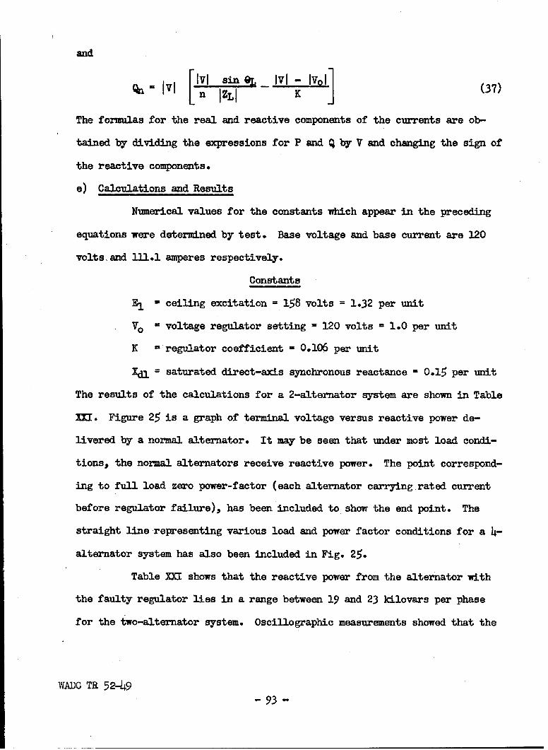
and
0" = [lIVI sinzfLt IvI -v01 (37)
The formulas for the real and reactive components of the currents are ob-
tained by dividing the expressions for P and Q by V and changing the sign of
the reactive components.
e) Calculations and Results
Numerical values for the constants which appear in the preceding
equations were determined by test. Base voltage and base current are 120
volts, and 111.1 amperes respectively.
Constants
S- ceiling excitation =.158 volts = 1.32 per unit
Vo - voltage regulator setting = 120 volts = 1.0 per unit
K -regulator coefficient - 0.106 per unit
Xdl = saturated direct-axis synchronous reactance - 0.15 per unit
The results of the calculations for a 2-alternator system are shown in Table
Mi. Figure 25 is a graph of terminal voltage versus reactive power de-
livered by a normal alternator. It may be seen that under most load condi-
tions, the normal alternators receive reactive power. The point correspond-
ing to full load zero power-factor (each alternator carrying rated current
before regulator failure), has been included to show the end point. The
straight line representing various load and power factor conditions for a 4-
alternator system has also been included in Fig. 25.
Table XXI shows that the reactive power from the alternator with
the faulty regulator lies in a range between 19 and 23 kilovars per phase
for the two-alternator system. Oscillographic measurements showed that the
WADC TR 52-49
- 93 -
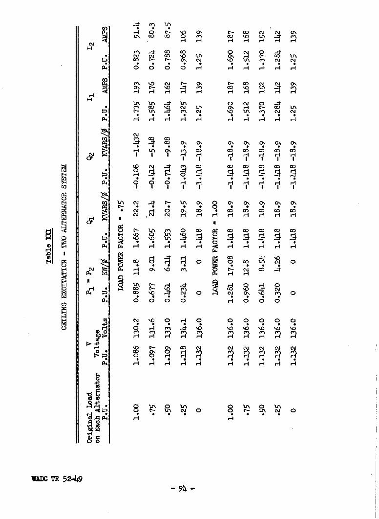
o% -c a~~ o co, co \0 I ---*r- OJ H' 0 'A H C'-
_: 0 0 0 0 0 cm 0 0 0cm 0o 0 0 IA 0\ H -H 3 H H
m 0 C C Y - co CQi C\J r
H- - - H H HHH
'J I^ _zt V\' 0 c'i 0 --1* 0 \ C\J *Lr\ (7 H C- 00 Ltr
t' '\ - ~ Cv' CM' b'0 mI cm~' 04 C~
* ~~~ 0 S *D0
A S 0 0ý 6; 0 0
I I ri rI ri rI y
P40 * 0o H H H HmE1rI i i ~i
p ~ *C 8i \3 H H10 H H H 0 H HA
N P4 r4 Hm H- H- H H 4 H Hi H H- Hi
0 EIE-4~r r! 140 H 0 ) 'I
o ~* 0 0 0 0 0 0
H C~j P4 H O\ in 'r~ - CMI OD -:I
E-4 r"I 0
C. 00 \ 0 0 0 004 0 0 0n 0 H ~ 010\
0 AJ 80 0 8
4) 0~ ý0 0 H 0 0 0 0 0 0
SO C~I - co cm CY cq' cmV~(''
4 03 0 *Y 0
-94

I-
1.10~
NO LOAD OA
FULL P.F.=.75 'LOAD
LOAD 0'1.002
FIG. 25-L LOAD CHRATEISIC- CELIG XCTAIO
WADFUL LOA5-D4P. F. 0

faulty alternator delivered approximately 18 kilovars per phase. Even with-
out any real load, the armature current exceeds rated value. Also for loads
at or near unity power-factor, the other alternator on the system has ex-
cessive armature current because not only is it supplying a real power com-
ponent of current but it is also receiving a reactive component.
The bus voltage of a 4-alternator system does not rise to as high
a value as that for a 2-alternator system.
2) Loss of Field Excitation
An alternator may lose its field excitation due to an open circuit
in either its own field circuit or in the exciter field circuit. A salient-
pole alternator without field excitation can carry some real load without
losing synchronism when operating in parallel with other synchronous
machines* The expression for the real power delivered by a salient-pole
alternator is given below:
P v II sin& + IV12sin 29 (38)Xd 2XdXq
where:
V = the terminal voltage of the alternator
E - the internal voltage
Xd, Xq are, respectively, the direct-axis and quadrature-axis
unsaturated synchronous reactances
Sthe angle between V and E
When the alternator loses its excitation, E becomes zero, and the expression
for real power becomes
p Xd - X- IV12 sin 2E (39)2XdXq
WADC TR 52-49- 96 -

The maximum electrical load which this alternator can supply to the system
without falling out of synchronism is
Pmax - - IV12 (40)
If the prime mover input to the unexcited alternator exceeds the
value of Pmax in Eq. (4o) (plus the rotational losses), the alternator will
be driven above synchronous speed. In this sense synchronous speed is con-
sidered proportional to the system frequency whether the frequency is normal
or abnormal. If there were no induction generator effects the equation for
the real power under this condition would be expressed by
2Z.d E Iv12 in2 21r(fI - f t(41)
where:
f C system frequency (corresponds to synchronous speed)
fl - frequency corresponding to speed of faulty alternator
However, there are currents induced in the damper windings embedded in the
field-pole faces. The frequency of these currents is the difference fre-
quency (fl - f) and their effect increases the electrical output of the al-
ternator by virtue of induction generator effect.
The effect of opening the field circuit of one alternator when
operating in parallel with another is shown in the oscillograms of Fig. 27
and Fig. 28. In the tests from which these oscillograms were obtained the
field of alternator D was opened as indicated in Fig. 26. Alternator A was
operated in parallel with alternator D in these tests with the real load
division and reactive load division equalizer circuits in operation.
The load conditions for Fig. 27 and Fig. 28 on alternator D just
prior to opening its field are shown in Table XXII.
WADC TR 52-49- 97-

ALTERNATORFIELD
CONTACTOR TO OPEN CONTACTOR TO OPENALTERNATOR FIELD EXCITER FIELD
lA 2 - -REGULATORI CARBONI STACK
EXCITER SHUNTO ,FIELD
TO 6VOLTAGE '
REGULATOR . oo------ 0- .. ,,
FIG.26-CIRCUIT FOR LOSS OFFIELD TESTS.
WADC TR 52-49- 98-

04Z,
4-3
0 0
0 4E-4 PK~000)
*43
bD Wc>.
4)"-4,r-i
r+4
000 000 0 )0 00 ')w0 0000 00000 It N00
SJ1OA 'dV3SVHd 83d 8VAN SI171A SIIOA 'SdiWV
0
L&J w
0 w w W 0cr~J 0 : --t.
WADC TR 52-419
99

I0LII
- ~E-4.44
-~HO
-4 )
0 r-4H
4~-4
P41-
4-4-] 4j]-it00 o 0 00 0 W) 0 0 W) 0 W~0 0000 0000 qN-- ocl 000
N~ -SiL1OA SdV3SVHd 8d HdVA>4 s~iQ1A S.LC1A SdYVV
X xw 0Lli C) Lu LU -
w (ij wd
> x w crCr 7 WiLu ww
4 ~~ll 4 )Q C 0w O
WADC TR 52-49
100

-. 0
0
w
IL, rH
a 4-1
- VA
4-4
~4-4
080 000 In0~ O0 oo 0000 000
S±IOA *SdivE 3SVHd H3d 8A)4 SJJOA SJJA Sb4
S.- U 0
0 0!a~ w w c
O< w 0
w týa
Jz > 4LL 0( La C O
WADC TR 52-49 101

Table XXII
LOAD ON ALTERNATOR D BEFORE OPEI'ING ALTERNATOR FIELD
(Name Plate Data Listed in Appendix Ill-A)
Fig. 27 Synchronism Maintained Fig. 28 Synchronism Lost
KVA 12.2 (O.305 p.u.) 18.0 (0.45 p.u.)
KW 8.o (0.20 p.u.) 12.0 (0.30 p.u.)
KVARS 9.2 (0.23 p.u.) 13.4 (0.335 p.u.)
P.F. o.65 0.66
In Fig. 27 the traces of reactive power, bus voltage, and armature current
are quite steady after the field of alternator D is opened. This shows
that synchronism is maintained. The same traces in Fig. 28 show slight
oscillations which indicate that synchronism is barely lost. Alternator D
is driven at about 2 revolutions per second faster than alternator A. A
more pronounced case in which synchronism is lost after the opening the
field is shown by the oscillograms in Fig. 29. Alternator D carried a load
of 38 KVA at a power factor of 0.71. The traces in Fig. 29 show marked
oscillations and that alternator D is driven at about 6 revolutions per
second faster than alternator A.
The condition under which the oscillograms in Fig. 27 were
obtained might be considered the limiting condition for which synchronism
is maintained when the field of alternator D is opened. Opening the field
of an alternator produces a reduction in the system voltage due to the effect
of the reactive load equalizer circuit. Fig. 27 shows that the voltage is
0.9 per unit after the field is opened, and Fig. 28 shows the voltage to
vary between 0.6 per unit and 0.9 per unit. As the load used in these tests
WADC TR 52-49
- 102 -

was passive its magnitude varies approximately as the voltage squared and a
reduction in the real and reactive loads occurred after the field was opened.
Hence, for Fig. 27 the real power after the field is opened is
P 0.20 x (0.9)2 - 0.16 p.o. (42)
In order to approximate the load for the conditions of Fig. 28 the average
of 0.6 and 0.9 is taken and is 0.75 peu. Hence the real power for this con-
dition is
P - 0.30 x (0.75) 2 0.17 p.u. (43)
These values of real power indicate that the value of real load beyond which
synchronism is lost is 0.16 per unit for the two alternators under test.
This can also be verified by using Eq. (40). The values to be used in Eq.
(40) are:
Xd- 1.50 p.u.
S= 0.91 p.u.
lvJ = 0.9 p.u. for Fig. 27
Hence for the voltage recorded in Fig. 27
Pmax - 1.50 - 0.91 (0.9)2 0.175 p.u. (44)
2 x 1*50 x 0.91
Eq. (44) is in good agreement with Eq. (42) and Eq. (43).
The real power limit for sustained synchronism on opening the
field of one alternator in the 2-alternator system investigated at Wright
Field is approximately 0.16 per unit or about 6.4 kw. However for a systan
with more than two alternators the reduction in the system voltage is less
and as a result a larger real power load can be delivered by the alternator
with the open field without loss of synchronism.
a) Analysis of Performance with Open Alternator Field
In the case of an alternator losing its field excitation, the
WADC TR 52-49- 103 -

effect of the equalizer circuit is opposite to its effect in the case of
ceiling excitation. In order to analyze the effect of an open alternator
field under load conditions during which synchronism is maintained, Eq. (34)
which was derived for the case of ceiling excitation can be modified by
letting El = 0 and by substituting (Xdu + Xq)/2 for Xdl
where:
Xdu = unsaturated direct-axis synchronous reactance
kq = unsaturated quadrature-axis synchronous reactance.
The substitution of (Xdu + Xq)/2 for Xdl is based on the fact that under the
conditions for loss of field the amount of magnetic saturation is small and
also that the torque angle 6, approaches 45 degrees as the real power load
approaches 0.17 per unit beyond which loss of synchronism results. Eq. (34)
then is reduced to
IvoI (n-l)
Ivi = 2 + +n-l sin L (45)Xdu + Xq K n IZLI
Rearranging the data in Table XXII for Fig. 27 we have
sin OL = 0.76
IZLI = 4o = 1.64 p.u.
The other quantities are as follows:
IVol = 1.00 p.u. Xdu = 1.50 p.u.
n = 2 Xq = 0.91 p.u.
K = 0.106
If these values are substituted in Eq. (45) the value of lvi is found to
0.9 per unit which checks the value shown in Fig. 27. Theoretically a mod-
ification of Eq. (45) should make it possible to determine the upper and
lower value of the bus voltage IVI during its oscillations when synchronism
WADC TR 52-49- 104 -

is lost. When the alternator with the open field is driven above synchron-
ous speed the armature mmf acts alternately along the direct axis and along
the quadrature axis of the field poles. Hence, for the maximum value of IVI
the value of Xdu should be in place of (Xdu + Xq)/2 and for the minimum
value of IVI the value of Xq should be substituted for (Xdu + Xq)/2 and we
have
Ivol (n-l)KIVI max = 1 n-l sin 4 (46)
S _K n I ZL I
IVo1 (n-l)K
IVI min= 1 n- K ine• (47)Xq K n IZLI
If these values are substituted for the conditions obtaining for Fig. 28 we
get
IVI max'= 0.90 p.m.
IVI min = 0.88 p.u.
The value of IVI max compares with the value of 0.90 obtained from Fig. 28.
However, the same figure yields a value of 0.64 per unit for IVI min- It is
possible that when the armature mmf lies in the quadrature axis that the tips
of the shoes of the field poles saturate as under this condition one half cf
the total flux per pole is driven across the axis of the field pole. The
pole shoes where they project beyond the pole core offer a relatively small
area to the magnetic flux. The effect of saturation reduces the value of
xq.
b) performance with an Open Exciter Field
The effect of an open exciter field is similar to that of an open
alternator field except that with the open exciter field there is a small
WADM TR 52-49- lO5 -

amount of current in the alternator field caused by the residual magnetism
in the exciter. This means that the maximum real power which an alternator
can deliver with an open exciter field is slightly greater than for an open
alternator field, since E in the first term of equation (38) is not zero.
Oscillograms showing the effect opening the exciter field of one alternator
of a two-machine system are included in Fig. 30 and Fig. 31.
The data for these conditions are listed in Table XXIII.
Table XXIII
LOAD ON ALTERNATOR D BEFORE OPENING EXCITER FIELD
(Name Plate Data Listed in Appendix III-A)
Fig. 30 Synchronism Maintained Fig. 31 Synchronism Lost
KVA 19.4 (0.485 p.u.) 31.6 (0.79 p.u.)
KW 14.4 (0.36 p.u.) 23.3 (0.583 p.u.)
KMARS 13.0 (0.325 p.u.) 21.0 (0.525 p.u.)
P.F. 0.74 0.74
For the conditions obtaining for Fig. 30, the system voltage was
reduced to 0.85 per unit and for Fig. 31 the voltage fluxtuated between 0.62
and 0.82 per unit. On the basis of these voltages the real power load
dropped from 0.36 per unit to 0.36 x (0.85) 2 = 0.26 per unit after the ex-
citer field was opened for the case of Fig. 30. Similarly the real power
load fluctuated between 0.39 per unit and 0.22 per unit for the case of Fig.
31. These data indicate that synchronism can be maintained for real power
loads up to about 0.26 per unit when one of the two alternators operates
with an open exciter field. This limit exceeds that for operation of an
open alternator field by roughly 50 percent.
WADC TR 52-49- 106 -

0
43
0El
K~0*
0 0
ooc
4-,
4-1
0
Ii)
4-4J 0 04H
04-
x xU. 0
4J4 Y w4
a: w : x0 < D Z Z> c
U) ~w _j cr ý15ac!Ljtr4t3:J )d0 K- O.0a
-jz> .0rr0. 0 w U. > WO> (
WADO TR 52-49 1og

U)- IV)
0 wi
-j-
c 0*
co 4ý
0,
o -4
%0 Er
( 4-4-4-4
g 00 000 0 0 00 0 01~ 0000 C+)OC0, ItN W - -- Pf W- 800
S1710A 'SdW 3SVHd Hi3d ?JVA)f SIIc& SIIOASd4
'8 L& 0
0 0 W
w rWW (D w Dw
_) W
wo .4 7)wo xoL x :O
WADC TR 52-49 108 W>4
After synchronism is lost, the action is similar to that in the
case of an open alternator field. However, the slip speed is smaller when
the exciter field is opened than when the alternator field is opened, be-
cause in the case of the open exciter field, current is induced in the field
circuit of the alternator which is closed through the armature of the ex-
citer.
When an alternator loses its field excitation when operating in
parallel with other alternators, it draws reactive power from the system
for its excitation. If the effects of residual magnetism in the exciter
are neglected, the reactive power drawn from the system when there is no
field excitation is expressed by
Ivl2Q 2-"" (xd + Xq- (Xd Xq) cos 2S ) (48)
The limiting value of Q would be
-IV1__2 IV12 11 V2(9qax Xq 0.91 (h9)
-i AY•- = 0.- 2 o.67 Iv12 (50)
Xd 1.5 0
In Fig. 27, IVI = 0.9 per unit for that value of voltage the reactive power
during loss of field excitation will have some value between 0.89 per unit
and 0.54 per unit. The reactive power indicated in Fig. 27 is 0.53 per unit.
In view of this large drain of reactive power and the reduction in
system voltage wvhen an alternator loses its field excitation, and the field
excitation cannot be immediately restored, that alternator should be discon-
nected from the system immediately.
b. Open Circuit in Reactive Current Equalizer Connection
If the equalizer connection between any two current transformers
WADC TR 52-49
- 109 -
shown in Fig. 19 is opened, all the secondary current in each current trans-
former will flow in the primary of the corresponding mutual reactor. If the
system load is reactive then reactive current flows in each of the mutual
reactors. The reactive regulating circuit in each alternator is affected as
though each alternator delivers more than its share of reactive load. The
result is reduced excitation and reduced system voltage. The greater the
value of the reactive amplification factor K the greater will be the reduc-
tion in system voltage in case the reactive equalizer circuit is opened.
c. Open Circuit in Current Transformer Connection
If a connection between the current transformer secondary and the
primary of the mutual reactor should become open or if the secondary winding
of the current transformer itself becomes open, current will result in the
primaries of the mutual reactors. If there are n alternators in parallel
feeding a reactive load, the current in the primary of the mutual reactor
associated with the open circuited current transformer is I(n-l)/cn where I
is the current in each of the other current transformer primaries. The cur-
rent in the primary of each of the other mutual reactors is I/cn and its
reactive component is such that the reactive current equalizer circuit causes
a reduction in excitation in the corresponding alternators. The direction
of the current in the primary of the remaining mutual reactor is opposite
and causes an increase in the excitation of its alternator. Equilibrium is
reached when the alternator with the open circuited current transformer
carries the total reactive load as under these conditions there is no re-
active component of current in any of the mutual reactors. This situation
could cause the alternator, with the open circuited current transformer, to
become overloaded.
WADC TR 52-49
- 110 -

d. Failure of Tachometer or Tachometer Circuit
If the tachometer or its circuit should fail in such a manner that
the voltage to the pilot valve control goes to zero, the governor would in-
crease the output speed of the constant speed drive. The speed of all alter-
nators would increase in synchronism, for at least light load conditions.
The real power equalizing circuit in the healthy units would indicate a de-
ficiency of real power and cause their prime mover inputs to increase. The
constant speed drives would increase their output speeds, one of them be-
cause the tachometer voltage is zero and the others because of the action of
the real power equalizer circuit. It may be possibleat least under light
load conditionsfor the over-speed trip on any of the units to operate. In
order to determine the exact behavior of the system under this condition,
additional analytical and experimental studies should be made.
e. Short Circuit of Frequency Droop Circuit
From Fig. 18 it is evident that a short circuit of the frequency
droop circuit of one alternator operating in parallel with others will re-
duce the output voltage, for example Eol, to zero. This will cause the
droop circuits of the other alternators to circulate current in such a
direction that real power load is shifted to the faulty alternator and the
system frequency becomes lowered.
f. Failure of Potential Transformer in Frequency Droop Circuit
This effect is quite similar to that of a short circuit in the
frequency droop circuit. In order to determine the exact behavior of the
system when the frequency droop circuit fails, more test data are required.
Future work should include experimental studies from -which such data can be
obtained.
WADC TR 52-49

If the excitation of an alternator operating in parallel with
others becomes abnormal, the excitation of the other alternators will become
abnormal in the same direction as a result of the action of the reactive
power equalizing circuit. Thus if the voltage regulator of an alternator
loses its sense of voltage, the exciter on that alternator will raise its
excitation to ceiling value, and as a result this alternator will deliver
more than its share of reactive power. Consequently the effect of the re-
active load equalizing circuit will be such as to indicate a deficiency in
the reactive power output in the other alternators, thus causing their ex-
citers to increase excitation. As a result the bus voltage is sustained at
a value above normal.
By the same process, loss of excitation in one alternator will
produce a reduction in the excitation of the other alternators, thus causing
the bus voltage to be sustained at a value below normal.
In the 2-alternator system, the voltage may rise to 13 percent
above normal on over-excitation and decrease as low as 20 percent below
normal on underexcitation if synchronism is maintained. Loss of synchronism
produces a greater reduction of bus voltage.
Under conditions of abnormal excitation, the faulty alternator
should be disconnected from the system.
Analytical and experimental work should be directed toward obtain-
ing precise information governing the behavior of the electrical system dur-
ing malfunctioning of the real power equalizing circuit and the speed regu-
lating apparatus.
WADC TR 52-49

D. Short-Circuit Currents
Short-circuit currents were calculated for different types of
faults using the alternator parameters presented in Section III-B. In the
calculations, the transient impedances rather than the steady-state imped-
ances are used and therefore the calculated results give values for the
short-circuit currents immediately after the fault. The voltage regulator
does not immediately act to increase the excitation of the alternator, and
therefore its effect need not be considered for calculations of initial
short-circuit currents.
The calculated results are compared with oscillographic records
of single-line-to-ground and line-to-line faults in Table XXIV. Since data
from oscillograms of a three-phase short circuit were used in determining
the positive-sequence impedance as discussed in Section Ill-B, the calculated
value of the three-phase fault current is not listed.
The short-circuit tests were made in the laboratory at Wright
Field by applying solid faults to the bus, alternator A operating without
load. Calculated and experimental values of short-circuit current are shown
in Table XXIV. The oscillograms of the short-circuit currents from which the
experimental values were evaluated are shown in Figs. 32, 33, 34, 35, 36, 37,
8, and 9.
The experimental and calculated results are in fair agreement.
Some differences between the experimental and calculated results may be ex-
pected as some of the parameters upon which the calculations are based vary
with magnetic saturation. There is also the difficulty of determining the
exact value of the initial short-circuit current because the current de-
creases with time. The accuracy by which the magnitudes can be obtained from
WADC TR 52-49-13-

Table XI'V
SHORT-CIRCUIT CURRETS (AiLTMAOR-A)
(Name Plate Data Listed in Appendix IIl-A)
Type of Figure Ia Ib Ic Average CalculatedFault Number AR Ap Ap # M Amp(R1M) )
Single-Line 32 632to-Ground 33 549 631 673
34 714
Line-to-Line 35 494 60436 549 6O4 559 45537 576 549
Three-Phase 8 7139
The values of short-circuit current were calculated using the following
values of impedance.
Transient Impedance of Alternator = 0.024 + JO.145 P.U.Positive-Sequence Impedance of Line* = 0.019 + JO.005 P.U.
ZI = 0.043 + JO.150 P.U.
Negative-Sequence Impedance of Alternator - 0.137 + JO.217 P.U.Negative-Sequence Impedance of Line* = 0.019 + JO.005 P.U.
Z2 - 0.156 + jO.222 P.U.
Zero-Sequence Impedance of Alternator - 0.024 + JO.01-3 P.U.Zero-Sequence Impedance of Line* - 0.O21 + jO.O14 P.U.
Zo = 0.045 + JO.057 P.U.
*The line simulated the impedance of 45 feet of 4-number 12 wires per
phase as given in Air Force Report, "A-C System Fuse Coordination Study"(December 1945), PP. 23.
WADC TR 52-49-- Ji•--

A-4-3
'44D
A r-
N a i
cr-A
Cc C)'A- w4 4.'
cr a w'A _j 0:
A4
C) C =).:j" '">'q
WAD R 52-4
115- ''

wL
0)
II
P4
oj 4.4'- - oci -
oIO 'SM HO SW iO SW
00
7 a)J M c- w 0 wH
A Z>
WADC T 52-4116)

0
'4-
w(I
0-
00
$4
C.).
W4
P4
+-41 4A 2 - 2 +±0Q o ~ 0 0o coo0 0 00 0
00 00 (Df 00 0 00 00
;I K)A 'SdMi 'S dIN.V SIJIOA 'SdV4V SJJIOA '$dV4
0-
wJ
WADC TR 52-4~9 11.7
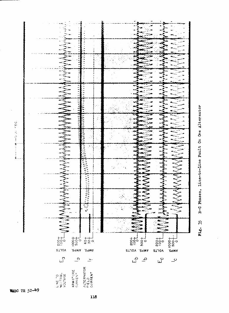
-4w - V.ý
_ *;
-a----
C.)
(Dr) 00 0 00 0
0i
118L
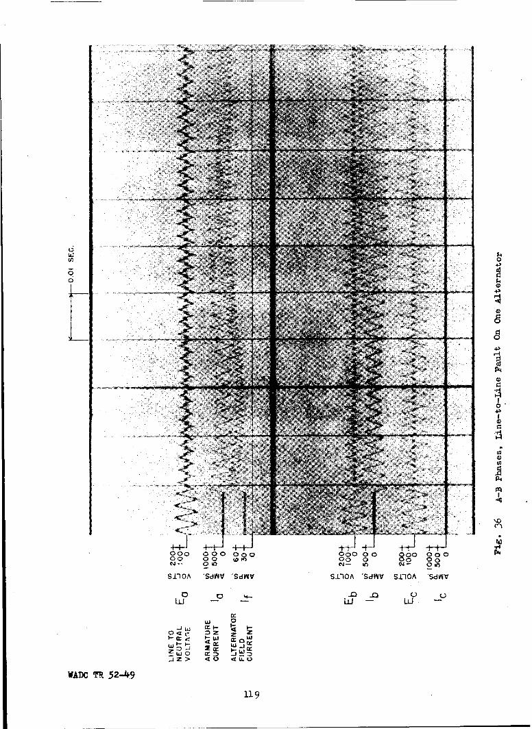
77,,
00
0H4-
0)
CJ2
000 000 020 0000 9o 00 000 P00 00 00 0o o 0 00W- 0W) Ni- %n oi- 0Oio
S 1-1 A Sd'd SdA'V Sl"IOA 'SdMV SJJOA 'SdINV
¶w& 0J U, C - t -
04c ~Z zI. act jw
JZ> <0 4L
WADC 7R 52-49
119
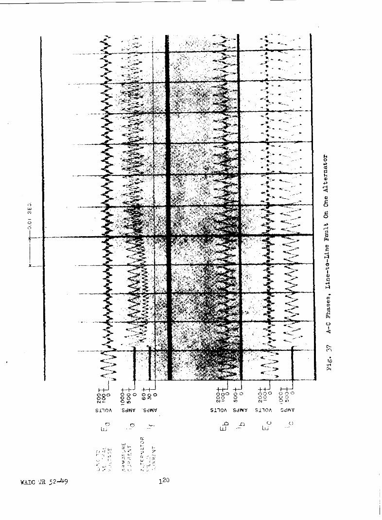
00
I42
"r co,
6 4 jj7 Lii1 L00 Q 0 0 0
4)4
.C4
WADC--- +R_+L~ j2

the oscillograms is somewhat limited.
The oscillograms in Fig. 32 to 37 inclusive show a strong double
frequency component in the field current and a pronounced third harmonic
component in the voltages of the unfaulted phases. The causes of these har-
monics are discussed in Section III-A.
The values of short-circuit current shown in Table XXIV are sym-
metrical rms values. In addition, the d-c component must be considered for
fast circuit breaker or fuse protective drives. The time constant of the
d-c transient was found to be approximately 1 cycle (0.0025 sec.). It is
probable that operating times as short as 1/4 cycle will be significant to
fuse application. In 1/4 cycle the d-c component will decay to 0.7 of its
initial value. Hence for completely offset waves the values of short-
circuit current listed in Table XXIV should be multiplied by/(1)2 + (• x 0.7)2
= 1.4.
E. Blocked Rotor Tests
For some types of mechanical failure, the rotor of an alternator
may become blocked (stalled) while the alternator is operating in parallel
with others. In order to obtain data for this condition, tests were made
with the rotor of one 40-KVA alternator held in a blocked position while be-
ing 'fed by a similar alternator which was separately excited. The blocked
rotor data for each phase are shown in Tables XXV and X1VI.
The data listed in Table XXV were obtained for three different
standstill positions of the rotor of alternator I. Alternator I was
selected because its rotor shaft was accessible. Alternator D was used as
the source of power. Figures 38, 39, and 40 are vector diagrams correspond-
ing to the three rotor positions.
WADO TR 5 2-49

Table XXV
BLOCKED ROTOR DATA FOR THREE POSITIONS - ALTERNATOR T
(Name Plate Data Listed in Appendix Ill-A)
Ea Ta Pa Qa 9a Ra Xa
Rotor Position Volts Amps Watts Vars Dpegees Ohms Ohms
1 20 105 2020 578 16 .183 0.0525
2 15-3 119 940 1555 58.9 .0665 0.110
3 33 57 1360 1260 42.8 . 4 18 0.387
Eb Ib Pb Qb 9b Rb Xb
Rotor Position Volts Amps Watts Vars Degrees Ohms Ohms
1 24.9 94.5 270 2330 83.4 0.0302 0.263
2 33-5 68 -110 2250 92.8 -. 0238 0.487
3 24 96 2060 952 26.7 0.223 0.100
Ec Ic Pc Qc 9c R
Rotor Position Volts Amps Watts Vars Degrees Ohms Ohms
1 41-5 59 90 207 68.4 0.0259 0.0655
2 36 74-4 1680 2100 51-3 0.304 0.379
3 31 104 -1090 3110 109.3 -. 099 0.283
Note: The alternator with the blocked rotor is treated as a load. (Whenthe machine is receiving real and reactive power, P and Q are pos-itive).
WADC TR 52-49
- 122 -
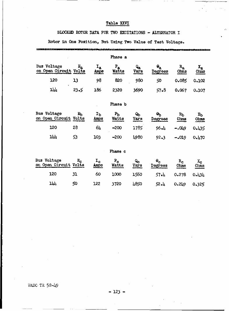
Table XXVI
BLOCKED ROTOR DATA FOR TWO EXCITATIONS - ALTERNATOR I
Rotor in One Position, But Using Two Value of Test Voltage.
Phase a
Bus Voltage Ea la Pa Qa Pa Ra Xaon Open Circuit Volt__ms s Watts Vars Degrees Ohms Ohms
120 13 98 820 980 50 0.085 0.102
.144 23.5 186 2320 3690 57.8 0.067 0.107
Phase b
Bus Voltage Eb Ib Pb Qb @b Rb Xbon Open Circuit Volts Amps Watts Vars Degrees Ohms Ohms
120 28 64 -200 1785 96.4 -. 049 0.435
144 53 103 -200 4980 92.3 -. O19 0.470
Phase c
Bus Voltage Ec Ic Pc Qc Qc Re Xcon Open Circuit Volts As ps Watts Vars Degrees Ohms Ohms
120 31 60 1000 1560 57.4 0.278 0.434
144 50 122 3720 4850 52.4 0.249 0.325
WADC TR 52-49
- 123 -

Ecic
Ea
6 Eb
SCALE, Eb
I INCH = 10 VOLTSI INCH = 40 AMPERES
FIG. 38 - VECTOR DIAGRAM FOR ROTOR POSITION I
"-1214-

Ec
ic
Ob a
SCALE:I INCH = 10 VOLTSI INCH= 40 AMPERES
FIG. 39- VECTOR DIAGRAM FOR ROTOR POSITION 2
WADC TR 52-49 - 125 -

Ec I C
lb a'a
Eb
SGALE:I INGH 10 VOLTSI INGH =40 AMPERES
FIG.40 - VECTOR DIAGRAM FOR ROTOR POSITION 3
WADeCTR 52-49 - 126 -

Table XXVI lists data obtained with the rotor of alternator I in
one standstill position but with the excitation of alternator D adjusted for
an open circuit voltage of 120 volts and for an open circuit voltage of 144
volts.
Under the actual operating conditions for a 2-alternator system
when the rotor of one becomes blocked, the excitation of the other will go
to ceiling value. At that value of excitation 158 volts on open circuit~the
value of the saturated synchronous reactance will probably be considerably
lower than that corresponding to the excitation which produces 144 volts on
open circuit. Therefore, values of current can be expected which are greater
than the ratio 158/144 times the values listed in Table XXVI for an open
circuit bus voltage of 144 volts. In a system with more than two alternators
the bus voltage would suffer less reduction and the blocked rotor currents
would be higher than in the system of two alternators.
Negative values of real power are shown in both Tables XXV and
XXVI. This apparent negative real power is caused by the unequal mutual
reactances between the phases of the alternator with its rotor at standstill.
This unbalance is due to the uneven air gap resulting from the saliency of
the rotor.
F. Synchronizing Disturbances
In order to connect a three-phase alternator to a live three-phase
bus without causing fluctuations of bus voltage and power swings between the
incoming alternator and those on the bus, the following conditions must be
satisfied:
1. The phase sequence must be correct.
2. The voltage of the incoming alternator must be in phase with thatof the bus.
WADC TR 52-49- 127 -

3. The frequency of the incoming alternator must equal that of the bus.
4. The magnitude of the voltage of the incoming alternator must equalthat of the bus.
The correct phase sequence of the alternator is assured at the time
of its installation. In the case of large alternators such as are used in
the central station industry; a phase angle meter known as a synchroscope is
used to indicate the phase angle between the incoming alternator and the bus.
For smaller alternators, such as are used in present aircraft installations,
synchronizing lamps are used between the bus and the incoming alternator.
As the frequency of the incoming alternator approaches that of the bus the
lamps flash on and off at a slow rate and the armature circuit breaker should
be closed when the lamps are dark since this indicates that the voltages are
in phase. Unfortunately because of the stress of an emergency or negligence
on the part of the operator an alternator may be connected to the bus when
its voltage is out of phase with that of the bus. If this phase displace-
ment is large, severe fluctuations in the system voltage and large power
swings between the incoming alternator and the system result.
Consider an unloaded bus supplied by (n-l) alternators and to
which an alternator (alternator 1) is connected when its voltage leads that
of the bus by the angle C. Figure 41 shows a diagram of the equivalent
circuit of the bus and the incoming alternator, and also a vector diagram
which shows the voltage, El, of the incoming alternator to lead the bus volt-
age En by the angle S.
Let En IEI + JO
El = IJE (cos 6+ j sin
wTAC TR 52-49- 128 -

~El
E n
a - VOLTAGE RELATIONSHIP
Zd
n-I Zd
E+ +En vI
b- EQUIVALENT CIRCUIT
FIG. 41 - CONDITIONS AT TIME OF SYNCHRONIZING
WADC TR 52-49-129 -

If the effect of saliency is neglected the current is expressed by
IEl (1-cos e'- j sin ) (51)Zd + &L
n-I
where:
n - total number of alternators including incoming alternator on thesystem
Zd R + j Xd'
R = the resistance of the armature plus that of the leads to the bus
Xd' - the transient reactance of the alternator plus the reactance ofthe leads to the bus.
The terminal voltage, V, in terms of E and 6 is
V Z - -Z = I El [ l i - os + J C s (52),n -n-n_ n n(2
The expressions for real and reactive power are respectively
P-1 = - (n-i) E12 [R ( ) (1-cos ) - sin (53)
Qj = - (n-1) E , (n-2) (1-cos&') + R sin (54)
If values of 6 are substituted into the power expressions with
typical values of resistance and reactance, and the results plotted on rec-
tangular coordinates as in Fig. 42, with real power as the abscissa and re-
active power as the ordinate, it can be seen that two families of ellipses
result. For a given value of n there are two ellipses which are the loci
for the power vector. The dotted ellipses represent the loci of the power
vector for each of the machines of the bus and the solid ellipses are the
loci for the incoming machine.
For a two machine system (nu2), the two ellipses become one
WADOC TR 52-49- 130 -

4--
Iw
o 2
n =4)\
-9 -8 -7 -6 -4 -3 -2 -1I 2 3 4 5
P-REAL POWERPER -UNIT•n=
-8
-9'
-18
FIG.42-POWER RELATIONSHIPS ON SYNCHRONIZING
WADC TR 52-49- .31 -

straight line through the origin. For the case where a machine is synchron-
ized to an infinite bus (ni0o) the ellipse for the incoming alternator be-
comes a circle and the ellipse for any one of the other machines degenerates
to a single point at the origin. This means that for the infinite-machine
case none of the machines already on the bus are affected by the incoming
machine, whereas the largest flows of reactive power to, and real power to
and from the incoming machine, occur.
For a system composed of three or more machines it can be seen
that a very small amount of reactive power is received by any one of the
machines originally on the system, just as the reactive power delivered by
the incoming machine is also very small. Real power is both delivered and
received by the incoming machine and all the other machines. The incoming
machine receives comparatively large amounts of reactive power.
Figure 43 shows oscillograms of field current, armature current,
voltage and reactive power when alternators A and D at Wright Field are syn-
chronized out of phase. If n=2 is substituted in Eq. (53) and Eq. (54) the
real power and reactive power for the incoming alternator are expressed by
Eq. (55) and Eq. (56) below:
JEl 2P, 2 17dI Xd' 1 in (5
IE 2
Q= - 2E 2 R sin6 (56)
The equations for the alternator which was originally on the bus are
P2 - lEI 2 (57)
2IZdJ2 Xd i
Q2 - E12 R sin (58)
2IZdI2
wADC TR 52-49
- 132 -

$4D
N -eL ~jSilO 'Sd4V SV~dS~dMX 3'V~ 83dSV4
00
z1 >
wo 0
0~ > 00 00
WAD SF1O 52-49 133 ~~ )43~H

From these equations it is evident that the ratio of P to Q is Xd'A for the
2-alternator system. In this analysis transient reactance Xd' was chosen as
that parameter which would give a good degree of approximation. The curves
shown in Fig. 42 are based on the following values:
R - 0.003 p.u.
X~d'= .0150 p.u.
Zd - o.l56 p...
The ratio of
K o.0150o. 3.5R 0.043
From the oscillograns of Fig. 43 the ratio of E is found to be 3.7. These
ratios are in good agreement. The values of power in Eq. (55) and Eq. (56)
are the initial values which oscillate and gradually die out. Eq. (52) for
the bus voltage shows that the power oscillations are accompanied by oscil-
lations in the bus voltage. The most severe case is that of synchronizing
180 degrees out of phase i.e. 6 = 180. Under this condition the bus volt-
age goes to zero and the armature current from Eq. (51) is 6.5 per unit for
the 2-alternator system. For an infinite system the bus voltage is un-
affected but the current is 13.0 per unit or twice the available three-phase
short-circuit current. The effects of reduced voltage and high circulating
currents should be investigated to determine their effects on load equipment
and protective devices.
Such an extreme transient current as 13.0 per unit would probably
cause the exciter to reverse its polarity. Because of the large rise in
alternator field current, the resistance drop in the exciter armature cir-
cuit could well be greater than the voltage induced in the exciter armature.
This would cause the terminal voltage of the exciter to reverse, which in
"WADflC TR 52-49- 134 -

turn would produce a reversal of exciter field current. The voltage regu-
lator will not function properly with reverse exciter field because the
action of the stabilizing transformer TR3 in Fig. 13 will be in the wrong
direction. Normal operation of the voltage regulator can be restored by re-
versing the polarity of the stabilizing transformer. It may be better to
prevent the reversal of polarity by use of an appropriate series field on
the exciter. A series field may also be advantageous by preventing polarity
reversals on short circuits and by increasing the exciter response. 1
G. Overvoltage
A-C electric power systems are subject to two general kinds of
overvoltage. The first of these is caused by overexcitation of the alterna-
tors on the system. This overvoltage is less than twice rated voltage and is
sustained for relatively long periods of time at system frequency. The other
kind of overvoltage is transient and on a 3-phase, 208 volt, 400 cycle sys-
tem; may have values of several thousand volts for very short durations.
These may result when current is interrupted at other than zero value and
are due to the inductance of the system.
1. Overvoltage Due to Voltage Regulator Failure
If the voltage regulator on one of two alternators operating in
parallel fails, so as to drive the excitation of that alternator to ceiling
value, the bus voltage will attain a maximum sustained value of 136 volts
line-to-neutral as shown in Section III-C-4. If there is reactive load on
the system the overvoltage is not as great. Figure 44 shows an oscillogram
1Rudenberg - Transient performance of Electric Power Systems - McGraw Hill1950 p. 776.
WADC TR 52-49
- 135 -

I0
-I-
0
4-,
P-+
W 0
00
I.- -
880 t 00 0~) u 0 >0 0 0r
nI cc 0 wr
-j z> 41&.0 nDO .> W0> 40
WADC 7!R 52-49 136

of the effect of regulator failure on one of two alternators when there is
no load on the bus. The excitation reaches ceiling value 0.0 h seconds after
the regulator fails. After a period of about 2 seconds the exciter protec-
tion relay operates and causes the alternator to be disconnected from the
system. The overvoltage on the bus in the case of one alternator attaining
ceiling excitation is determined by the number of alternators on the .system,
the system load, and the strength of the reactive load equalizer. The
greater the number of alternators on the system, the smaller will be the
overvoltage. The stronger the reactive load equalizer, the greater will be
the overvoltage.
Under-light load conditions with only one alternator connected to
the bus, ceiling excitation would produce a line-to-neutral voltage in the
order of 158 volts. Even on a multiple alternator system, there may be only
one alternator connected to the bus at a given time. Therefore the single
alternator case must always be considered for determining possible overvolt-
age.
2. hOO-Cycle Overvoltage Due to Load Switching and Fault Clearing
If a short circuit persists for a period greater than 0.03 seconds,
the excitation of the alternators increases and approaches ceiling value.
Removal of the fault will give rise to an overvoltage. A similar situation
is created when a heavy load is switched off. Should the entire load be
suddenly removed, the terminal voltage of each alternator would rise to the
open circuit voltage corresponding to its excitation. This will result in
a high bus voltage that will last until the voltage regulator restores it to
normal. The removal of a short circuit defines the maximum overvoltage that
would result on heavy load switching.
WADC TR 52-49- 137 -

A test was run where alternator A was connected to the bus, and
while it was running as an unloaded machine, a three-phase short circuit was
applied. Figure 9, an oscillogram of a three-phase fault at the bus, shows
that ceiling excitation is reached 0.07 seconds after application of the
fault. The alternator field current remains constant at the ceiling value.
The fault was cleared after 0.54 seconds and produced the overvoltage shown
in the oscillogram of Fig. 45. For the situation represented by this oscil-
logram, after the fault was removed 0.07 seconds were required before the
voltage regulator started to reduce the alternator field current.
To evaluate the heating effect due to the overvoltage, the envelope
of phase a voltage was sketched on the oscillogram in Fig. 45. The instan-
taneous voltages at the various times after the fault is cleared were obtained
from the oscillogram and are shown in Table XXVII. Since the heat produced
in a constant resistance is proportional to the voltage squared, the energy
during a time interval is proportional to the square of the voltage multi-
plied by the time. The total accumulated energy at any time after the fault
is removed is obtained by summing the energy over each time interval up to
that time. The equivalent constant voltages that would also produce the
same accumulated energy when maintained for different durations are also cal-
culated in Table XXVII, and their effective values are plotted in Fig. 46.
An interpretation of the curve means that after 0.1 seconds the amount of
heat produced by the type of overvoltage whose envelope is indicated on the
oscillogram is the same as that produced by a constant voltage whose effec-
tive value is 155.5 volts line-to-neutral and is applied for a period of
0.10 second.
These data help to define a portion of the general voltage-time
WVADC TR 52-49 - 138 -

-* 0
4-4
(p 4a
CC
04'H 4-
-~ 0
-a
4+~~~- ... 4' j 4
0OO o000~ 00 000 00 000 o 0000 00 00 0 00ý 00-
$1'10A 'SdV4V 'SdAV SDiQA 'SdWV SIOA 'SdVIV
Lk i - LI
w 0r
-wo owow
~J> 40 wo
WADO TR 52-49 139

Table XXVII
OVERVOLTAGE CALCULATIONSON REMOVAL OF A THREE-PHASE SHORT CIRCUIT
Time Instantaneous Proportional Accumulated Square ofin Sec. Voltage to Energy Energy Max. Volt. Effective
t e (e 2 ) (t) . W - W/t Voltage
.005 170 288
.01 288 28800 120
.015 217 471
.02 759 37950 138
.025 226 511.03 1270 42300 146•035 226 511.04 1781 44500 149•.045 226 511.05 2292 45800 151.5•055 226 511.06 2803 46700 153.065 226 511.07 3314 47300 153-5•075 226 511.08 3825 47800 154•085 226 511•09 4336 48200 155.095 226 511.10 4847 48500 155-5.105 217 470.11 5317 48400 155-5.115 207 428.12 5745 47900 155.125 207 428.13 6173 47500 154.135 198 392.14 6565 46800 153•145 198 392•15 6957 46300 152.155 188 354.16 7311 45700 151.50165 179 320•17 7631 44800 150.175 170 288.18 7919 44000 148.5.185 170 288.19 8207 43200 1470195 170 288.20 8495 42500 146.40 170 11520.60 20015 33300 129.80 170 11520
1.00 31535 31500 125
WADC TR 52-49 - 140 -

0 -0
z4w
w
w40 z,..
bJ 0 0 00oI
wI 2 zU) 0c
w w, 4 wi 0w zx X4x
03 CL tiw0 >
I-W 4 Iilb I
0 Z >
> Z M
4g I4 LLii
0F0 0 0 0.70 < w
SfO 9J.O VL3N-OL31
WADC TB52.44.- 1.
curve that equipment operating on the system must withstand. The particular
curve shown in Fig. 46 is based on the removal of a three-phase short cir-
cuit after the alternator has reached ceiling excitation, but as previously
stated',it also provides the upper limit for load switching. The overvolt-
ages due to load switching would in most cases be lower since the excitation
may not be at as high a value prior to the switching. The duration of the
overvoltage could be reduced if the voltage regulator response were faster.
Overvoltages may occur on the non-faulted phases during a single-
line-to-ground fault. This results from action of the voltage regulator to
increase excitation in response to the reduced voltage on one phase of the
V-V transformer. This voltage will not exceed the ceiling voltage of 158
volts line-to-neutral and will occur only if the fault is not cleared prior
to regulator action. The voltage will persist until the fault is cleared.
3- Overvoltage Due to Errors in The Voltage Regulator
On the present 400 cycle a-c system the bus voltage is normally
maintained at a value of 208 volts line-to-line through the action of the
voltage regulator. The accuracy of this setting of 208 volts will depend
upon both the human error of the operator in setting the voltage prior to
synchronizing, and the accuracy of the instrument used for the setting.
Even though the setting is accurately made, the bus voltage may drift. The
specified allowable error in the voltage regulator is 2.5% of 208 volts
(IMIL-R-5292A) throughout the operating range of the alternator. Therefore,
if the regulator setting on one alternator is at one value and the others
at a different value or values, the resulting bus voltage will be some
average of the various settings. All these factors may combine to produce
a bus voltage that may be higher than normal.
WADC TR 52-49- 1142 -

4. Transient Overvoltages
Transient overvoltages last for only a short time, and are due to
interrupting the current at a time other than when it is passing through
dizero. In this way a voltage proportional to L Z is produced. This voltage
persists for an extremely short time but may be of such magnitude that flash-
over and insulation puncture result.
The interruption of the current at a time other than zero occurs
if current limiting fuses are used. With ordinary fuses, the current may
also be interrupted other than when it is zero providing the current pass-
ing through the fuse is large enough (Section IV-B). Such large currents
might flow during short circuits on a multi-alternator systen.
The energy associated with these transient voltages is small and
will not cause appreciable overheating. However, the magnitudes of such
voltages may rise to several thousand volts and unless the components of the
system and the utilization devices are insulated properly, dielectric break-
down will occur. These overvoltages should be investigated in future studies
with a possible view toward finding methods for suppressing them or to de-
termine what the insulation levels of aircraft electrical systems should be.
Y,•ADC TR 52-49-143-
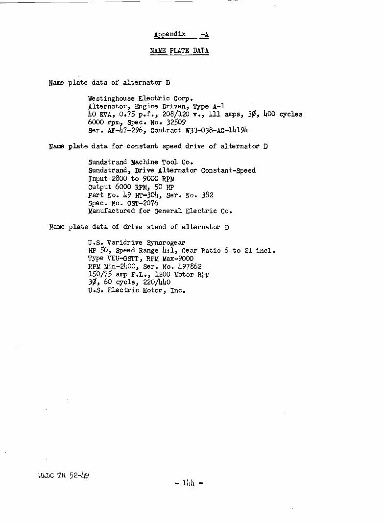
Appendix -A
NAME PLATE DATA
Name plate data of alternator D
Westinghouse Electric Corp.Alternator, Engine Driven, Type A-140 KVA, 0.75 p.f., 208/120 v., 111 amps, 3$, 400 cycles6000 rpm, Spec. No. 32509Ser. AF-47-296, Contract W33-038-AC-14194
Name plate data for constant speed drive of alternator D
Sundstrand Machine Tool Co.Sundstrand, Drive Alternator Constant-SpeedInput 2800 to 9000 RPMoutput 6000 RPM, 50 HPpart No. 49 HT-30h, Ser. No. 382Spec. No. OST-2076Manufactured for General Electric Co.
Name plate data of drive stand of alternator D
U.S. Varidrive SyncrogearHP 50, Speed Range 4:i, Gear Ratio 6 to 21 incl.Type VEU-GSTT, RPM Max-9000RPM Min-2400, Ser. No. 497862150/75 amp F.L., 1200 Motor RPM3$, 60 cycle, 220/440U.S. Electric Motor, Inc.
iJADC TR 52-49- 144 -
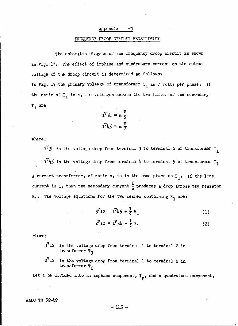
Appendix -B
FREQUENCY DROOP CIRCUIT SENSITIVITY
The schematic diagram of the frequency droop circuit is shown
in Fig. 17. The effect of inphase and quadrature current on the output
voltage of the droop circuit is determined as follows:
In Fig. 17 the primary voltage of transformer T 1 is V volts per phase. If
the ratio of T1 is m, the voltages across the two halves of the secondary
T1 are
1V34 = m V
v45 = m2
where:
1V3 4 is the voltage drop from terminal 3 to terminal 4 of transformer T1
1745 is the voltage drop from terminal 4 to terminal 5 of transformer T1
A current transformer, of ratio c, is in the same phase as T 1 . If the line
current is I, then the secondary current produces a drop across the resistor
R1 . The voltage equations for the two meshes containing R1 ares
31- + RI (1)
2V2_ 1V4 I2712- I V 1 (2)
where:
12 is the voltage drop from terminal 1 to terminal 2 in
transformer T3
2712 is the voltage drop from terminal 1 to terminal 2 intransformer T2
Let I be divided into an inphase component, Ip and a quadrature component,
WADC TR 52-49-145-
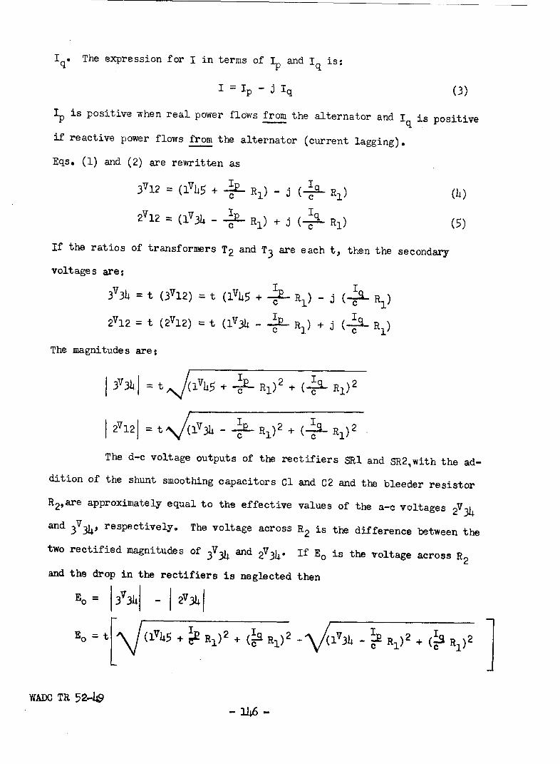
Iq* The expression for I in terms of IP and lq is:
I = Ip Iq (3)
Sis positive when real power flows from the alternator and Iq is positive
if reactive power flows from the alternator (current lagging).
Eqs. (1) and (2) are rewritten as
3V12 = (1V45 + -ý-- (lc I_ R1)(4
=12 = (1 V3 - cP Rl) + J (---l) (5)
If the ratios of transformers T 2 and T3 are each t, then the secondary
voltages are:
34= t (3V12) = t (1V45 + - ) (-s- Rl)
2V12= t ( 2 V1 2 ) = t (1V3 - IP R1 ) +J (-j4-R
The magnitudes are:
373Lj t (hS+~f-Rj) 2 + (4q R9)2
272 t (1 V) --- R 2 + (_EL RI) 2
The d-c voltage outputs of the rectifiers SRI and SR2,with the ad-
dition of the shunt smoothing capacitors Cl and C2 and the bleeder resistor
R2 ,are approximately equal to the effective values of the a-c voltages 2 V34
and 3V34, respectively. The voltage across R2 is the difference between the
two rectified magnitudes of 3V34 and 2V34. If Eo is the voltage across R2
and the drop in the rectifiers is neglected then
BE = 13ý3h - I 2V3341
Eo tL (1v45 + •R1)2 + ( l)2~ A lV3 4 1)2+ R 1 2 JWADO TR 52-L9
-146 -

or since IV34 = mV2
and v745 = '2
Eot + 2 RI) 2 +(22) + R 2
The constants for the droop circuit have the following values.21
c=125 t =--=.84025
m = 30 = .144 R1 = 3 ohms
E= .84o V/(.072 V + .024 + (.024 lq)2 -
SV (.'072V - .024 10)2 + (.024 1q)2j
Fig. 22 shows the family of curves of Eo versus Ip which result
from variation of the parameter I . This family of curves shows that theq
reactive current, lq, has negligible effect upon the output voltage EO and
consequently on the droop characteristic within the normal current range.
For example, if two alternators are operating in parallel and one
of these, alternator 1, goes to ceiling excitation and carries 0.8 per unit
inphase component of current and 1.50 per unit reactive component of cur-
rent the output voltage of the frequency droop circuit Eol is 3.32 volts
from Fig. 22. The action of the governors on the two alternators is such
as to make the droop circuit output voltages equal i.e. E = Eo 2. If the
reactive current in alternator 2 is negligible the inphase current corre-
sponding to a value of 3.32 volts for Eo2 in Fig. 22 is 0.75 per unit. The
inphase current in each alternator if divided equally would be 0.775 per
unit. The error in the division of real current for an unbalance in reac-
tive current of 1.5 per unit is 0.025 per unit.
WTADC TR 52-49- 147 -

IV. METHODS OF PROTECTION OF A-C SYSTEMS
A. General Protection problems
1. Nature of Short Circuits
Reliable information on short circuits that occur in the field
seldom can be. obtained. The examples on which information is available
emphasize the importance of adequate short circuit protection which will
detect and clear the short circuit in the shortest possible time. The
power system engineer should assume that a short circuit can occur in any
part of the electric power system and should install protective equipment
to minimize the consequences of the faultshould it occur.
Several series of short circuit tests have been carried out by a
l,2,3,4,5number of investigators in the laboratory. For each of these tests
it has been necessary to artificially apply the short circuit. Various
techniques of applying the fault have been used with the hope that the fault
would be representative of those that occur in practice.
"I ,A-C System Fuse Coordination Study", AAF Memorandum Report Serial No.TSEPE-656-669BV (4 December 1945).
2P.E. Toomire and M. Trbovich, "Intermittent Faults in 120/208-Volt A-Cand 120-Volt D-C Aircraft Electrical Systems", NRL Report 3819 (Iray 9,1951).
3 P.E. Toomire and Y. Trbovich, "Investigation of Intermittent Faults in30 Volt D-C Aircraft Electrical Systems", NRL Report 3643 (April 3, 1950).
4C. CM. Faust and J. G. Hutton, "Electric Circuit Burning-Clear and Damagephenomena on Aircraft Structures,, AIEE Trans., 63 (1944), pp. 920-925.
5 H. J. Finison and R. H. Kaufman, "Electrical Systems Tests - B-29 Airplane",
AAF Technical Report No. 5812 (1945).
WADC TR 52-49
- 48-

Any of the above series of tests could be objected to on the
basis that the particular method of applying the short circuit was not a
typical fault. It is believed that such an objection might miss the sig-
nificant point that although the short circuit may not be typical it certain-
ly might occur. Adequate protective schemes should be capable of clearing
that particular type of short circuit as well as other perhaps more repre-
sentative types.
It is evident, however, that still additional short circuit in-
vestigations are desirable. These tests should attempt to explore the range
of possible short circuit conditions by applying faults in many different
manners. Such tests would permit more intelligent applications of protective
devices to provide protectiqn for the most extreme possible faults.
2. "Fail safe"
The term "fail safe" is not completely self-descriptive and is sub-
ject to some confusion in interpretation. Possible interpretations are:
(1) Protection failure trips circuit. Failure of the protectivecircuit results in opening of the protected circuit.
(2) protection failure does not trip circuit. Failure of theprotective circuit results in the protected circuit remainingin operation without protection.
The former would be considered unsafe if such a failure and con-
sequent loss of the circuit will result in unsafe operation of the airplane.
The latter would be unsafe if a subsequent fault should occur on
the unprotected circuit.
It should be noted that no system completely meets one or the other
of the "fail safe" definitions. Each system can fail in several ways and
tripping or non-tripping will depend on the nature of the failure. This
factor will be illustrated in Section IV-D in the discussion on differential
WALC TR 52-49-3-9 -

protection. However, in most cases, some types of failure can be expected
to be more likely than other failures. Hence it is probably possible to
conclude whether failure of a protective scheme is more likely to meet one
of the definitions than the other.
Circuit failures on a well installed power system are a relatively
rare occurence whether the failure is an open circuit or a short circuit.
None-the-less since such failures may at some time occur alternate sources of
supply to essential loads must be used. For example more than a single power
source is desirable and should be adopted wherever at all possible. Similar-
ly multiple channel feeder circuits will be used.
Such duplication must be made in order to provide continuity of
power supply in spite of failure of the circuits for any cause. In the case
of an alternator in particular there are many different devices and circuits
whose failure will result in loss of the machine. Once the power supply sys-
tem is properly designed to admit such a failure without loss of the airplane,
tripping of the circuit on the rare occasion of failure of the protection
will--except in still more rare circumstances--result in no hazard to the
aircraft. Failure of the circuit or protective equipment will have been in-
dicated by tripping the circuit and corrective maintenance will be assured
before a subsequent flight*
Where protection failure will not trip the circuit breaker there
will be hazard to the aircraft only if a short circuit subsequently occurs on
the unprotected circuit. Although the dual circumstance of protection fail-
ure and circuit faults may be rare, it may be quite possible for the follow-
ing reasons:
(1) In combat operation, the externally inflicted damage which
may cause failure of the protective circuits may be extensive enough to cause
WADC TR 52-49-150

a fault on the protected circuit, and at least some points the circuits
must be in close proximity.
(2) Failure of the protective circuit will not be indicated by
tripping of the main circuit. It is doubtful if war-time maintenance con-
ditions will result in the preventative maintenance checks necessary to in-
dicate repair of the protective circuit immediately following the flight
during which the failure occurred. It is more likely that the aircraft
will continue in operation without adequate short circuit protection.
It is judged that for the normal aircraft where duplication of
power supply service is possible, protection should be adopted of such
nature that failure of the protection is most likely to trip the circuit.
Systems of protection whose failure is likely to leave the circuit in oper-
ation without protection should be adopted only on those aircraft where
weight is of extreme importance, where adequate duplication of service is
not possible.
3. Tyes of Protection
Methods of detection of faults on a-c systems have been extensive-
ly considered for utility and industrial a-c systems. Because of complexity
not all of these methods should be considered for aircraft systems. Some
of those types of protection which appear applicable include:
(1) Overcurrent
(2) Directional power
(a) Real
(b) Reactive
(3) Differential current
(4) Balanced current
WADOC TR 52-49- 151 -

(5) Ground current
(6) Impedance or Reactance
Since the fundamentals of these methods are adequately described in the
1,2,3literature no attempt will be made to cover them in detail in this re-
port. Application of the above listed methods will be reviewed. Because
of its relative importance, considerable work has been carried out on dif-
ferential protection.
B. Overcurrent Protection
Overcurrent protection may involve either circuit breakers or
fuses. The use of fuses on a-c distribution systems for aircraft has been
extensively considered. The characteristics of the fuses now used are
described in Specification MIL-F-5372(USAF) dated 23 October 1950. The
melting characteristics of Fig. 1 of that report are reproduced here as
Fig. 47 with the time scale extended into the area below 0.01 seconds as-
suring the I 2t energy for melting is a constant for such short time.
Table XXVIII gives values determined from the fuse characteris-
tics with melting current expressed as a multiple of the nominal current
"1 'Silent Sentinels", Westinghouse Electric Corporation Meter Division,Newark, N.J., 1949.
2 "The Art of Protective Relaying", Publication GEA-2558A, General ElectricCo., Schenectady, N.Y., 1947.
3 ,,DC Power Systems for Aircraft", Chap.9 Circuit Protection Methods, R. H.Kaufmann and H. J. Finison, John Wiley and Sons, 1952.
4,,AC System Fuse Coordination Study", AAF Memorandum Report Serial No.TSEPw-656-669BV (4 December 1945).
VWAC TR 52-49 - 152 -

10 ___
10
001
0000 -l I -
10 000 1000 10,000
CIMENT WN AMPERESFIG. 47 - MELTING TIME - CURRENT CURVES FOR 400 CYCLE,
SINGLE PHASE FUSES (MIL -F -5372 (USAF)
WADC TR 52-49-153-

Table XXVIII
MELTING CURI-?ENTS EXPRESSED IN PER UNIT OF THE NOMINAL FUSE RATING
Melting Required per unit current for fuses of different ratingsTimeSec. lOAmp 20Amp 30Amp 4OAmp 50Amp 6OAmp 8oAmp lOOAmp
.001 101 91 87 85 84 87 84 88
.01 32 29 27 27 26 28 26 28
01 10 9.0 8.3 8.5 8.0 8.7 8.3 8.4
1.0 3.7 3.4 3.5 3.b 3.b 3.7 3.6 3.6
10.0 2.4 2.5 2.6 2.6 2.6 2.7 2.6 2.6
100 2.2 2.b 2.b 2.b 2.1t 2.3 2.3 2.3
1000 2.2 2.. 2.3 2.3 2.2 2.3 2.3 2.2
WADC TR 52-49 - 1

rating. It will be noted that these values are very nearly the same for
the full range of ratings and hence the fuse characteristics can be shown
by a single curve. Figure 4 8 applies specifically to the 100 ampere rating
but it is representative of all of the fuses.
The specified maximum clearing time and manufacturing tolerances
of the fuses are shown in Fig. 49. The curves in this figure indicate that
if the clearing time required by various fuses may range from extremely
fast operation up to specified limit of 1/2 cycle, co-ordination between
fuses in a fuse protected network might be difficult to obtain where high
fault currents are possible.
Fuses are normally considered to have current limiting action.
Some of this results from the resistance of the fuses itself. However, in
true current limiting fuses, current is limited by the rapidity with which
the fuse interrupts the circuit. That is the fuse operation is sufficiently
rapid that it acts before the short-circuit current reaches a peak value.
For 400-cycle a-c systems true current limiting action could occur only for
a melting time of less than 1/4 cycle (0.6 milliseconds). As shown by the
fuse characteristics this will require short-circuit currents in excess of
125 times nominal rating. Such currents are available in multigenerator
systems.
It is important to note that current limiting fuse action may also
induce high transient overvoltages because of the high rate of change of
current as the short-circuit current is interrupted. (see Section III-G).
Current limiting fuses need not be capable of interrupting the
actual maximum current that may occur in a system since they are effective
in limiting the current to a lower value. As vwith other protective devices,
WADC TR 52-49- 155 -

100
10
1.0
01
00
0.001
CURRENT IN PER UNIT RATED AMPERESFIG. 48. -TYPICAL FUSE CHARACTERISTIC FOR 400 CYCLE,SINGLE PHASE FUSES
17ADC TR 52-49 16

1000
100 LLL
10
1.0
0.1
001
10 100 m00 10,000
CUJRRENT IN AMMIERS
FIG. 49 -CH4ARACTERISTIC CURVES SHOWING MANUFACTUINWG ANDCLEARING TOLERANCES OF400CYCLE,SINGLE PHASE FUSES
WADO TR 52-40 17
the interrupting rating should be expressed in terms of available short-
circuit currents. Available short-circuit current is that current which
would flow if the protective device were replaced by a bar of negligible
impedance. Specification MIL-F-5372 should be revised to define the fuse
rating in terms cf available currents.
Because of the very fast action of fuses at high currents they may
interrupt the circuit before the d-c component has had time to decay. The
fuses therefore should be rated to interrupt an available current assuring
a fully off-set short-circuit current. If no decay of the d-c component
occurs during the interrupting time the assymmetrical rms current would be
1.73 times the symmetrical rms fault current. Since some decay does occur
a multiplying factor of 1.4 is suggested in Section III-D. Specification
MIL-F-5372 should be revised to designate the appropriate multiplying factor.
In order to check protective devices with offset d-c components,
methods for closing in faults at any desired point in the cycle should be
developed for laboratory use,
The fault current available on large a-c systems now in use and
contemplated may be sufficient to result in melting times of less than 0.01
seconds. Because of differences in interrupting time, co-ordination is
usually more difficult at the higher fault currents. Specification IMIL-F-
5372 does not specify accuracy of melting characteristics at times of less than
0.01 seconds or at more than 50 times normal current. It is desirable to ex-
tend the requirements on melting characteristics and accuracies down to melt-
ing times representative of the maximum available short-circuit current. For
4000 amp available current this would represent the following melting times.
WADC TR 52-4915 - l8-

Fuse Rating-Amp. per Unit Current Melting Time-Sec.
10 400 0.0000720 200 0.0002330 133 0.0005040 100 o.ooo8550 80 0.001360 67 0.001880 50 0.0033
100 40 0.0050
It is doubtful if melting time of less than 1/4 cycle will be
significant. Variations in interrupting time will probably prevent co-ordi-
nation at such low values of time even though accurate melting characteristics
could be attained. Hence, the requirements should extend down to the values
shown above for the larger ratings but not lower than 0.0006 second for the
smaller rating.
C. Directional protection
Directional protection has been studied only in connection with
generator circuit protection. Its characteristics are discussed in Section
V-A. However, directional current protection may also be applicable for
feeder protection as discussed in Section V-B.
D. Differential Current Protection
Differential current protection involves a comparison of currents
at the two terminals of a circuit. For generator or motor protection the
currents of each phase are compared at the neutral and at the interconnection
of the phase lead with its associated bus. This affords protection for both
the generator or motor itself and for any of the cable circuit included in
the zone between current comparison points--the protected zone. For line
protection the currents at the two ends of the line are compared. For bus
protection the current flowing into and out of the bus are compared.
The following discussion relates particularly to differential pro-
WADO TR 52-49- 159 -

tection for generator and line circuits. Two systems of differential pro-
tection have been proposed for use on aircraft alternators:
1. Single current transformer arrangement-Fig. 50a
2. Two current transformer arrangement--Fig. 5Ob.
The former method makes use of one thru-type current transformer in each
phase with the bus-end lead and neutral-end lead brought thru the window of
the current transformer so that the net mmf applied to the core is zero when
the currents in the two ends of the phase are the same. The secondary wind-
ing of the current transformer connects to a simple current relay as shown
in Fig. 50a. The other system of differential protection is shown in Fig.
50b. In that arrangement one thru-type current transformer is connected
into the bus-end and another identical current transformer connected into
the neutral-end. The secondaries of the two current transformers are con-
nected in series by means of pilot wires. A simple current relay is con-
nected across the secondary of one of these current transformers. Connec-
tions are made with the polarities so that under normal conditions, i.e.
the same primary current in each of the two current transformers flowing in
the same direction, negligible current will flow in the relay.
1. Single Current Transformer Arrangement
The single-current transformer arrangement shown in Fig. 5Oa is
generally used in installations in which the distance from the alternator
to the bus is relatively short as the current transformer is usually placed
as close to the bus as possible in order to protect the leads from the alter-
nator to the bus as well as the armature of the alternator. For large dis-
tances between the alternator and the bus, the length and weight of neutral
lead in the primary of the current transformer becomes excessive.
VIADC TR 52-49- 160 -

U- SINGLE CURRENT TRANSFORMER DIFFERENTIAL PROTECTIVESCHEME. ONE CURRENT TRANSFORMER AND ONE RELAYFOR EACH PHASE.
b -STWO CURRENT TRANSFORMER DIFFERENTIAL PROTECTIVESCHEME. TWO CURRENT TRANSFORMERS AND ONE RELAYFOR EACH PHASE.
b - CONSTRUCTION OF CURRENT TRANSFORMER CORE
FIG. 50- DIFFERENTIAL CURRENT PROTECTION SCHEMEWADC TR 5249 -2-

The chief advantage of the single current transformer arrangement
is its simplicity and its freedom from nuisance operations provided the
secondary winding of the current transformer is distributed uniformly around
the core. The current transformers tested in this investigation have a
secondary winding of 27 turns occupying less than one-half the circumfer-
ence of the core. The core is in the form of a hollow cyclinder as shown in
Fig. 50c.
The name plate data on the case which houses three such current
transformers (Fig. 50b) and three relays follow:
Relay, Alternator Differential Current protection
Order No. (33-038) 46-4251-P
Exhibit TSEPE-6E-37
Mfr. Part No. 10346 ser. No.
Standard Electrical products Co.
Dayton, Ohio
a* Tripping Checks
Tripping and thru fault checks were made. The tripping check
was made by placing one primary turn thru the window of the current trans-
former, Fig. 51a. The following values of 400-cycle current caused relay
operation.
Current Transformer Primary Amperes
A 25.9B 35.0C 27.9
The tripping check was repeated on current transformer A but with
the secondary windings of current transformers B and C in parallel with the
secondary winding of current transformer A as shown in Fig. 51b. The pri-
mary current in current transformer A to produce tripping of the relay was
WADO TR 52449- 162 -

I---
O - TEST CIRCUIT FOR TRIPPING CHECK
vv
A
R
b -TEST CIRCUIT FOR TRIPPING CHECK. SECONDARIESOF TWO CURRENT TRANSFORMERS IN PARALLELWITH RELAY UNDER TEST.
THE RELAY IS REPRESENTED BY RTHE AMMETER A IS IN THE SECONDARY
OF AN INSTRUMENT CURRENT TRANSFORMER
FIG. 51 - CIRCUIT DIAGRAMS FOR TRIPPING CHECKSON DIFFERENTIAL PROTECTION.
WALC TR 52-49- 163 -

found to be 32.2 amp. The object of this test was to determine the sensi-
tivity of the protection if only one relay is used in conjunction with three
current transformers. Such an arrangement mould not clear line-to-line
faults if the ratios of the three current transformers are equal. Hawever,
line-to-ground faults would be cleared with somewhat lower sensitivity than
in the three-relay scheme.
b. Thru-Fault Checks
In the thru-fault test, normal connections were simulated by bring-
ing a lead and its return thru the window of the current transformer as
shown schematically in Fig. 52a. Single-line-to-ground faults were applied
thru this arrangement to one 400-cycle alternator and to two 400-cycle alter-
nators in parallel. Fig. 53 shows oscillograms of primary current and sec-
ondary current for a thru fault of 760 amp a-c supplied by one alternator.
The secondary current i.e. the relay current was 0.07 ampere rms. The relay
did not trip. Fig. 54 shows oscillograms for a thru-fault current of 1520
amp a-c supplied by two alternators in parallel. The relay current was found
to be 0.19 ampere rms which is insufficient to trip the relay. The relay
tripping current is of the order of 1.0 ampere based on the tripping checks.
The relay current on thru fault checks is probably dce to the un-
symmetrical arrangement of the secondary winding. Because of this dissymmetry
the coupling between the secondary winding and one of the primary conductors
is different from the coupling with the other primary conductor. Although
the relay current on thru fault seems to be well below the value required to
trip the relay it could probably be eliminated almost entirely if the sec-
ondary winding were distributed uniformly around the circumference of the
core of the current transformer. Such an arrangement would practically guar-
WADC TH 52-49 - 164 -
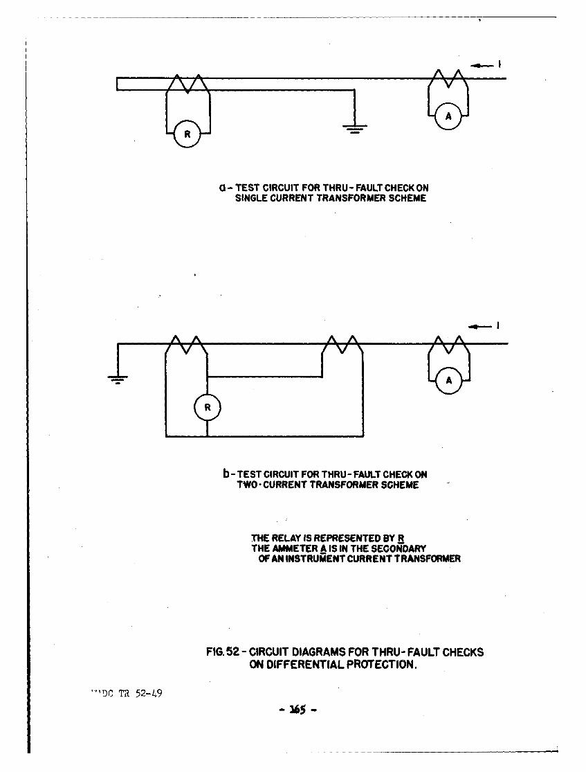
AA
R
0 - TEST CIRCUIT FOR THRU - FAULT CHECK ONSINGLE CURRENT TRANSFORMER SCHEME
- A
b-TEST CIRCUIT FOR THRU- FAULT CHECK ONTWO -CURRENT TRANSFORMER SCHEME
THE RELAY IS REPRESENTED BY RTHE AMMETER A IS IN THE SECONDARY
OF AN INSTRUMENT CURRENT TRANSFORMER
FIG. 52 - CIRCUIT DIAGRAMS FOR THRU - FAULT CHECKSON DIFFERENTIAL PROTECTION.
""Dr, 'i 52-49- 165 -

(4-4
14
li4)0
P.4
0 4)
0 0 P0
C)Pi
t >- I-
WAlDC TR 52-49 166

00
- 54-
0
0 )O
L4
E
V4
00
4d~
z0 Z
w z4~ ~>-W
WJ c
WATDC TR 52 ~4~9 167

antee against nuisance operations on thru fault.
c* Summary
The differential scheme using only one current transformer has
the following advantages:
(1) Simplicity
(2) Higher Sensitivity
(3) Freedom from nuisance operation without any sacrifice in sensitivity.
If the secondary wire becomes open circuited or short cirnuited the protected
circuit is not tripped but continues in operation without differential pro-
tection.
The single transformer arrangement is applicable only where the
neutral can readily and economically be available. Hence, differential cur-
rent protection using the single transformer type will be applicable only
to motor or generator protection.
2. Two-Current Transformer Arrangement
A schene of differential current protection involving two-current
transformers per phase is shown in Fig. 5Ob. This principle has been used
in various farms for many years and is considered perhaps the most effective
in the electric power industry. The single-current transformer scheme shown
in Fig. 50a has not come into appreciable use for protection of large alter-
nators such as are used in the electrical power industry for the following
reasons:
(1) Great distance between the alternator and the station bus. In
many installations the bus is in a different building than the alternator.
(2) Limitations in physical size of the current transformer. The pri-
mary conductors are large and a large amount of dielectric would be required
WADC TR 52-49- 168 -

to insulate the two primary conductors from each other.
Theoretically, the two-current transformer arrangement is somewhat less
sensitive than the single-current transformer arrangement. It is evident
that on an internal fault check (minimum trip current) the scheme of Fig.
50a would require somewhat less primary current than the value applied to
the primary of only one of the two-current transformers in Fig. 50b as in
the latter the secondary of its companion current transformer is in paral-
lel with the relay R. This small difference in sensitivity however has no
practical significance.
The two-current transformer arrangement requires some precautions
to prevent tripping on thru faults if the relay is to be kept as small and
as simple as possible. These precautions, unnecessary in the single-current
transformer schemeare as follows:
(1) The two current transformers must have very nearly equal ratio and
phase angle characteristics for a large range of current values. The cur-
rent transformers must be matched* They must have the same number of second-
ary turns, the same core dimensions and the cores must be of the same mag-
netic material.
(2) It is necessary to avoid large differences in the impedance of the
leads from the secondary terminals of one current transformer to the relay
and the impedance of the leads from the secondary terrinals of the companion
current transformer to the relay.
Unequal lead impedances impose different secondary burdens on the
two current transformers. The current transformer with the greater second-
ary burden requires a higher value of core flux and therefore a correspond-
ingly greater exciting current which causes its ratio of transformation to in-
crease beyond that of its companion. Under the extremes of a heavy thru-
VIrALC TR 52-49- 169 -

fault current and large unbalance in secondary burden the difference in cur-
rent transformer ratios may become sufficient to produce a value of differ-
ential current more than sufficient to cause relay operation. This differ-
ential current is actually the difference between the exciting current of
the two transformers. In the early use of differential relaying on alter-
nators in the electrical power industry a simple type of relay,with only one
current elenient,was used. The impedances of the secondary burdens were care-
fully balanced by inserting a compensating resistance between the current
transformer having the lower secondary burden, and the relay. This method
has been superseded by one which makes use of a relay,which in addition to
a differential coilhas one or more restraining coils. The amount of restrain-
ing force which opposes the tripping force is a function of the thru current.
In aircraft, neither of these schemes is desirable. In order to
keep the secondary wiring as simple as possible the relay preferably should
be connected directly across the secondary of one of the current transformers.
The relay should be kept as small and simple as possible and restraining
elements should preferably be aToidod.
a. Steady-State Differential Current
Fig. 55 is an oscillographic record showing traces of fault cur-
rent, relay current and tripping operations for a thru fault in which the
final steady-state current is 760 amperes 400 cycles. This record was ob-
tained under extreme, perhaps very much exaggerated, conditions. These
conditions were exaggerated in the following respect.
A resistance of 5.0 ohms was connected between the secondary of one
current transformer and the relay, whereas the resistance between the other
current transformer and the relay was negligible. The largest resistance be-
WADC TR 52-49 - 170 -

4-2-f
4-1 "'.
0 0i
P1 P4
'.4-N
""'.P4
s4,'..
"WADC TR5Z4917
tween a current transformer and the relay in an actual aircraft would
probably be less than 1.0 ohm which corresponds to about 150 feet of
AN-18 copper wire or a distance of 75 feet between the alternator and the
bus. Fig. 55 shows that the initial (transient) fault current was al-
most completely offset. This means that the fault current had an initial
d-c component almost equal to crest value of the a-c component. The ini-
tial relay current which is also the initial differential current contains
a relatively large d-c component. It is noteworthy that the relay tripped
momentarily after about the first cycle following the application of fault
current. However, as both a-C and d-c components of the transient current
fell off during the first 0.025 second, following application of fault cur-
rent, the relay current also fell off and was insufficient to hold the re-
lay in the tripped position. By about this time the voltage regulator
started action causing the fault current to increase and after about 0.10
second the differential current was sufficient to cause the relay contacts
to chatter until about 0.13 second after which the relay contacts remained
closed. This final closing of the relay was caused by the excess of ex-
citation in the current transformer with the 5-ohm resistance between its
secondary and the relay, over that of the other current transformer.
1) Theory for Steady-State Condition
Fig. 56 shows a schematic diagram of the two-current transformer
arrangement. In Fig. 56 the relay R is connected across the secondary of
the current transformer designated as C.T. 1 and interconnected to the sec-
ondary of C.T. 2. Resistance r represents the resistance of the intercon-
necting pilot wires. Fig. 56b shows the approximate equivalent circuit of
the two-current transformer arrangement of Fig. 56a viewed from the second-
ary side.
WADOC TR 52-49- 172 -

R C.T. I C.T. 2
f AvA )A A
r~ V •rV
$t
0 - DIAGRAM OF CONNECTIONS FOR TWO CURRENTTRANSFORMER DIFFERENTIAL PROTECTIVESCHEME. (ONE PHASE ONLY IS SHOWN)
I Im ._ _
++
E "1 Y-i "R l E
b- APPROXIMATE EQUIVALENT CIRCUIT OF TWO-CURRENT TRANSFORMER DIFFERENTIAL SCHEMEVIEWED FROM SECONDARY.
FIG. 56- DOUBLE CURRENT TRANSFORMER DIFFERENTIAL CIRCUIT
""'lADC TR 52-49- 173 -
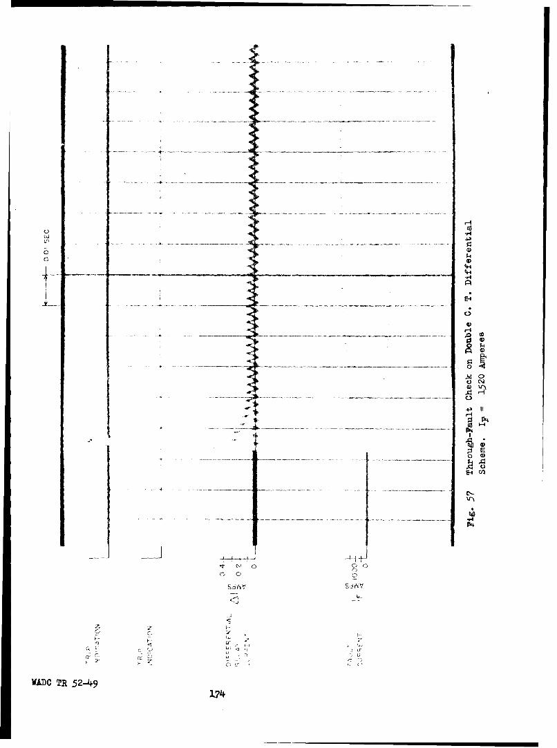
4-4
P4
C) 0
174)

In Fig. 56a
I = primary steady state current
I, = exciting current in C.T. 1 viewed from the secondary side
12 = exciting current in C.T. 2 viewed from the secondary side
A I = 12 - I1 relay current or differential current
It should be noted that the relay current IR is the difference between the
exciting current in C.T. 2 and in C.T. 1. The factors which determine IR
are derived in the following:
I + = &i+ I + IM (59)
1 + E2 = r I (60)
I1 + &I = 12
(Yel + YR) El = Ye2 E2
E2 = Yel + TR El (61)
Ye2
Yel + Ye2 + YR E1 = r IM
Ye2E1 Ye2 I r (62)
Yel + Ye2 + YR
I
M~ NAI. r YR Ye2 I/N
Yel + Ye2 + YR
For the oscillogram of Fig. 55, a resistance of five ohms was
placed in series with the two current transformers, and the resulting dif-
ferential current is 0.25 ampere for a fault current of 760 amperes. From
the data listed in Table XXIX, the impedance of the relay is approximately
58 ohms and therefore the voltage across the relay is approximately 0.25 x
58 = 14.5 volts. If this voltage is taken into account, both current trans-
WADC TR 52-49- 175 -

Table XXIX
CURRENT TRANSFORMER AND RELAY CHARACTERISTICS
1. Excitation Characteristic of 40/0.333 amp Current Transformer
P 1307085 at 400 cycles.
Note: The current transformer was excited from the secondary winding.
AdmittanceVolts Amp Mhos.
2.36 0.02 0.0085 1,110
6.9 0.04 0.0058 3,240
13.9 0.06 0.0042 6,54o
18.0 0.08 0.0045 8,470
22.2 0.10 0.0045 10,400
28.o 0.25 0.0089 13,200
32.0 0.50 0.0156 15,100
38.1 1.00 0.0263 17,900
2. Relay Characteristics
Name plate Data:
Differential protective Relay - Type AVp-208-A
Mfg. part No. A18B2232
Serial No. LU-126
For use with 200/115 V a-c system only
400-cyle Test:
Volts = 10.5
Amp = 0.18
Impedance = 58.14 ohms
D-C resistance = 7.0 ohms
WALU TR 52-409- 176-

40-
35-
30
25
320-
10
15
0 0.1 0.2 0.3 0.4 0.5. 0.6 0.7 0.8 0.9 1.0 AMP.
(0) EXCITING CURRENT (RMS) VS VOLTAGE (RMS)
18-
16-
14-
U) 2wz0-10
x
6
4
2
0 0.1 0.2 0.3 0.4 0.5 0.6 0~7 08 0.9 1.0 AMP.
(b) EXCITING CURRENT (RMS) VS FLUX (MAX.)
FIG, 58 -CURRENT TRANSFORMER CHARACTERISTICSWADO, TR 52-49-17
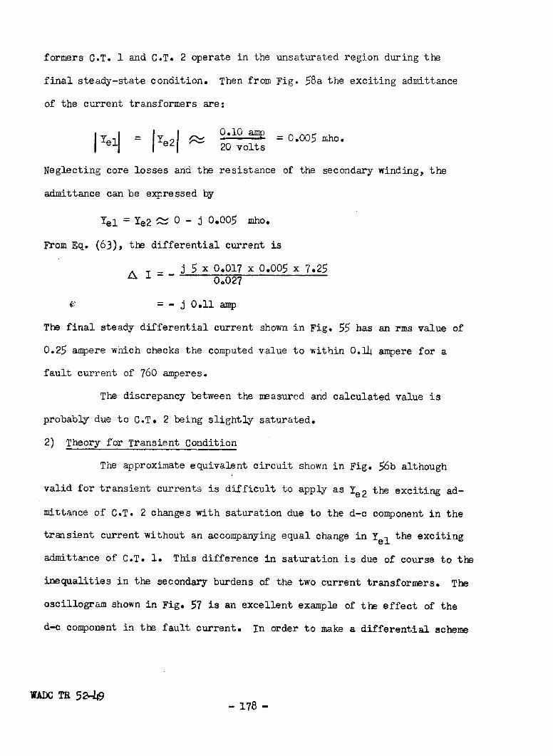
formers C.T. 1 and C.T. 2 operate in the unsaturated region during the
final steady-state condition. Then from Fig. 58a the exciting admittance
of the current transformers are:
=yd j~~ 0.10 amp = 0-0 mhoYei = Ye2I • 20 volts
Neglecting core losses and the resistance of the secondary winding, the
admittance can be expressed by
Yel = Ye2 ý O - j .005 mho.
From Eq. (63), the differential current is
j 5 x 0.017 x 0.005 x 7.250.027
-j O.ll amp
The final steady differential current shown in Fig. 55 has an rms value of
0.25 ampere which checks the computed value to within 0.l1 ampere for a
fault current of 760 amperes.
The discrepancy between the measured and calculated value is
probably due to C.T. 2 being slightly saturated.
2) Theory for Transient Condition
The approximate equivalent circuit shown in Fig. 56b although
valid for transient currents is difficult to apply as Ye2 the exciting ad-
mittance of C.T. 2 changes with saturation due to the d-c component in the
transient current without an accompanying equal change in Yel the exciting
admittance of C.T. 1. This difference in saturation is due of course to the
inequalities in the secondary burdens of the two current transformers. The
oscillogram shown in Fig. 57 is an excellent example of the effect of the
d-c component in the fault current. In order to make a differential scheme
WADC TR 52-49 178

of this kind fool proof it is necessary to reckon with fault currents which
are completely offset as this type of current imposes the most severe duty
on the current transformers.
A rigorous treatment which takes into account the non-linear ex-
citing characteristics, if it were at all possible, would lead to an extreme-
ly difficult analysis and to final equations which would probably be so cum-
bersome as to obscure the essentials. Therefore, in order to simplify the
analysis, let us investigate how the flux in the core of the current trans-
former must build up so that the secondary current is a completely offset
wave.
Let N = number of secondary turns
r + jX = impedance of the secondary burden, including the resistance ofthe secondary winding but neglecting the secondary leakagereactance
i = instantaneous secondary current
T = time constant of primary circuit
e = induced secondary voltage
= core flux in webers
I = rms value of a-c component of fault current, considered constant
iI= (cosWt - et/TN
Before proceeding with the derivation it might be well to indicate that we
are imposing two conditions which are not satisfied in practice, a fact
which however does not invalidate the following analysis. For one thing we
are assuming here that the secondary current is the primary current divided
by the turns ratio, Secondly we are assuming that the alternating component
of the fault current remains constant while actually the a-c component starts
out at its transient value and in a few cycles dies down to what would be its
WADC TR 52-49- 179 -

final steady-state value, but by about that time the voltage regulator in-
creases excitation and the fault current increases. In this analysis we are
primarily concerned with that time interval during which the d-c component
of fault current has appreciable magnitude i.e. before regulator action
starts. Taking into account the decrement of the a-c component would un-
necessarily complicate the derivation. We may therefore proceed as follows:
Nd e ri + X di (64)ut dt (4
t X diS= J e dt =ju(ri + - -, dt
0 0
•sn w t I F cos wt
- C. - rT (1 - C (65)
If we neglect the reactance of the pilot wire and consider that value of
time t by which the transient component of current has become negligible, we
get
Sr sin wt - rT) (66)
0 Vac + Odc
The a-c component of core flux is
= 47I r sin wt, webers (67)
and the d-c component of core flux is
dc= 2 rT, webers (68)N
It should be noted that both components of flux vary:
a) directly as the secondary resistance which includes theresistance of the secondary winding
WADC TR 52-49- 180 -

b) directly as the primary current
c) inversely as the secondary turns squared
In addition the d-c component of flux varies directly as the time constant
of the primary circuit.
For example consider a line-to-ground fault similar to that re-
presented by the oscillogram in Fig. 57 except that the fault current wave
is completely offset. In order to reproduce a completely offset secondary
current the magnetic flux in the current transformer must satisfy the fol-
lowing condition
(= t sin w t - rT),webers (69)N 2 ,W
The numerical values for Eq. (69) are
I = 1520 amperes from Fig. 57
N = 105 secondary turns
")U = 2 iT f = 2 7r x 400 = 2520 radians per sec.X2
T =2 time constant of d-c transient (70)
From Table XIII
X2 = X2G + X2L negative sequence reactance
X2G = 0.217 per unit negative sequence reactance of thealternator
X2L = 0.005 per unit negative sequence armature leads to bus
R = Ra + RL
Ra = 0.024 per unit d-c resistance of armature at 750C
RL = 0.019 per unit d-c resistance of armature leads to bus
Substituting these numerical values in Eq. (70) we get
T 5 0.222 -0 = 0.00205 second
,WA.C TR 52-49- 181 -

Current Transformer C.T. 1
Referring to the circuit shown in Fig. 56 and neglecting the im-
pedance of the relay, the secondary burden on C.T. 1, as far as the core is
concerned, is the resistance of its secondary winding. As the secondary
winding is uniformly distributed around a circular core, the secondary leak-
age reactance can be neglected.
r = 0.30 ohm, the resistance of the secondary winding
Substituting all the above numerical values in Eq. (69) we get for the flux
in the core of C.T. 1
= 105)X 2 520 sin WJt - 0.30 x 0.00205)01 ~(105) 2 22
= (2.32 sin Wt - 12.00) 10-5 webers (71)
It should be noted that the d-c component requires 12.0 5.17 times the2.32
maximum value of flux required by the a-c component of current. If we ex-
press 0l in kilolines we get
0l =(2.32 sin wt - 12.0) kilolines.
Current Transformer C.T. 2
The secondary burden as far as the core of current transformer
C.T. 2 is concerned, if the impedance of the relay is neglected, is the re-
sistance of its secondary winding plus the resistance of the pilot wire.
If we consider a rather extreme, although not impossible, case i.e. that
of the two current transformers 50 feet apart, we have a total length of
100 feet of pilot wire. If this pilot wire is comprised of AN-18 copper
as for the conditions under which the oscillograms in Fig. 57 were ob-
tained, its resistance is about O.64 ohm. Therefore, if the impedance of
the relay is neglected, the secondary burden of C.T. 2 as far as its core
WAl TR 52-149- 182 -

is concerned is that due to the resistance of the pilot wire and the re-
sistance of the secondary winding. Hence r = 0.30 + 0.64 = 0.94 ohm.
Substituting the proper numerical values in Eq. (69) we get
x1520 sin [t - 0.94 x 0.00205
2(105) 2 [ 2520j
= (7.27 sin w t - 37.5) l-5 webers (72)
Expressed in kilolines
02 = (7.27 sin wt - 37.50) kilolines (73)
Effect of d-c Component and a-c Component in Fault Current
Summarizing we have the equations for the fluxes in the two cur-
rent transformers as followss
01 = (2.32 sin wt - 12.00) kilolines
OImax = 14.32 kilolines (74)
02 = (7.27 sin Wt - 37.50) kilolines
02max = 44.77 kilolines (75)
It must be borne in mind that Eq. (7Mi) and Eq. (75) which are for the
fluxes in the respective current transformer cores are derived on the basis
that the secondary currents will be completely offset,
The value of 14.32 for Oimax' the flux in the core of C.T. 1, is
realistic although somewhat greater than would be the case for a completely
offset wave of 1520 amp a-c. Fig. 58b shows that under these conditions
C.T. 1 has started to saturate and that the exciting current would vary
from a minimum instantaneous value of abouat 0.10 x V/"= 0.14 ampere
(for 0I = 2.32 - 12.00 = - 9.68) to about a maximum instantaneous value of
0.35 x */2 = 0.50 ampere. The current scales in Fig. 58 are in rms values.
WADC TR 52-49
- 183 -
i

In the case of C.T. 2, because of its greater secondary burden,
we get a correspondingly greater value maximum value of flux, namely h4.77
kilolines. Inspection of Fig. 58b discloses that such a value of flux is
unrealistic and that the practical matter of the case is that the flux in
the core of C.T. 2 fell far short of attaining such a high value. As a re-
sult C.T. 2 did not reproduce the fault current in its secondary with the
same degree of fidelity as C.T. 1 and the difference shows up as differ-
ential current, sufficient to cause relay operation. However, the d-c com-
ponent in the primary current decays quite rapidly causing the d-c compo-
nent in the flux of the two current transformers to fall to its residual
value which allows the current transformers to recover in a large measure
their proper ratio characteristics.
Referring again to Fig. 57, it can be seen that the fault cur-
rent decreased somewhat immediately after the short circuit was initiated.
This is to be expectedas during the initial part of the short circuit
the positive-sequence reactance is equal to the transient reactance and
starts to increase, eventually approaching the direct-axis synchronous re-
actance. However,the voltage regulator, which senses the average voltage
of the three phases, increases the excitation,increasing the fault current
to a final steady value wiich is actually sonewhat greater than the initial
value of the a-c component. It is extremely significant that, in the face
of this greater final value, the differential current is much less than its
initial value. This,of course,is explained by the fact that there is no d-c
con•onent in the steady value of fault current and the fluxes in the cores
of the two current transformers need be sufficient only to take care of the
a-c component of fault current. Hence the steady fluxes are:
NALC TR 52-49- i8h-
L

2.32 sin Wt kilolines
42 7.27 sin w t kilolines
The exciting currents taken from Fig. 58b are respectively
iI = 0.02 amp rms
i 2 = 0.07 amp rms
•i = i2 - iI
= 0.07 - 0.02 = 0.05 amp relay current.
Fig. 57 shows a differential current of A i = 0.054 amp.
The computed value and the measured value of relay current are in good a-
greement. It might be argued that the fault current developed by two alter-
nators has twice the magnitude possible in practice where the current trans-
formers can be subjected to only the current from one alternator. On the
other handthe fault current wave shown in Fig. 57, although somewhat offset,
is not nearly completely offset which means that for a completely offset
wave of one-half the magnitude a greater d-c component could be expected.
In that case the relay would trip.
Precautions Against Thru Fault Operation
Several different steps may be taken to render the two-current
transformer arrangement of differential protection proof against operation
on thru fault. These may be outlined as follows:
a) Equalize the burdens on the secondaries of the current transformers.
This can be effected by inserting resistance between the relay and the sec-
ondary of the current transformer with the lesser burden. Fig. 59 shows
the trace of a fault current of 1520 amp a-c rms when the burdens on the two
current transformers was comprised of a 2.5 ohm resistance each. This burden
does not include the resistance of the secondary winding. The differential
'V.'AIJ TR 52-49- 185

-- -
o 0o
43-1
00)
0 P4
I -r
WADC R ,5 2 - 9 -18

current shown in Fig. 59 is negligible.
b) Desensitize the relay so that a higher value of internal fault
current is required for tripping.
c) Increase the cross-sectional area of the core of t he current
transformers to reduce the exciting current.
d) Increase the size of the pilot wire to reduce its resistance.
e) Without changing the core and the amount of copper in the sec-
ondary winding of the current transformer and in the relay coilincrease
the number of turns on both the transformer secondary and the relay coil.
The most practical of these methods is e), increasing the number
of secondary turns. Method a) requires the addition of a carefully meas-
ured amount of resistance which increases installation and maintenance dif-
ficulties which in turn present the hazard of errors. Method b) reduces
the effectiveness of the protection against internal faults. Method c) in-
creases the weight of the current transformers unless the circumference is
decreased. Method d) increases the weight of pilot wires and is therefore
objectionable. Method e) does not decrease sensitivity for internal faults
nor does it increase the weight of wiring or of the current transformer but
does decrease the danger of operation on thru fault. The disadvantage of
increasing the secondary turns arises when the secondary becomes open cir-
cuited. Under the abnormal condition,the secondary voltage can rise to high
values. Doubling the secondary turns probably does not naturally increase
the hazards, but this factor should be checked further.
4) Secondary Burden of Pilot Wire as a Function of Secondary Turns
In order to analyze the effect of increasing the secondary turns
in the current transformer and the turns in the relay without increasing
the total copper in eitherilet us consider Eq. (6.3) which expresses the dif-
WADC TR 52-h9-187-

ferential current as follows:I
r YR Ye2 N (63)A I = el + Ye2 + YR
The amount of flux in the relay is proportional to the ampere turns in the
relay coil if non-linearity of the iron is neglected.
Suppose that we have an existing system in which
N = the number of secondary turns in the current transformers
n = the number of turns in the relay coil
then if we multiply Eq 0 (63) by n we get
nIr Y• Ye2 N-•
nAI = rel Ye2 + Y (76)
Let r = Rt + Rp (77)
where:
Rt = resistance of secondary winding of N turns and
Rp = resistance of pilot wire.
For a given pilot wire, R remains constant, regardle ss of the number of turns
in the current transformer secondaries and the relay coils.
HencenI
(Rt + Rp) YR Ye2 N (78)n AI = '(8
Yel + 'e2 + YR
Suppose that we reduce the wire size of the windings and increase the number
of turns by a factor a keeping the winding copper weight the same then we
get
(a 2Rt + Rp) YR Ye2 n Ia 2 a 2 N
a I,= 1-- 2 (Yel + Ye2 + YR)a
WADC TR 52-49- 188 -

R nnI(Rt + YR Ye2 N
anAI' = (79)Ye1 + Ye2 + YR
the ratio of new relay ampere turns to original relay ampere turns is now
Ran l'_ Rt + (80)an&I Rt + ap
The current transformers used in this investigation have 105 turns of #21
AWG copper wire. Fig. 57 shows that with the relay connected directly a-
cross the secondary of one such current transformer and 100 feet of AN-18
pilot wire between the relay and the secondary of the other current trans-
former, a primary thru current of 1520 amp, not completely offset, caused
the relay to trip. If these current transformers were used in the same
location with the same length of pilot wire, but rewound VVith 210 second-
ary turns of #24 AWG copper wire and with the relay coil rewound with twice
as many turns of #29 AWG copper as those of #26 AWG copper wire in the ex-
isting coil, the effect would be equivalent to having the original 105 turn
current transformers connected with 25 feet of AN-18 copper pilot wire in-
stead of 100 feet of the same size of copper pilot wire. The primary cur-
rent applied to one current transformer necessary to trip the relay would
be the same for the 210 secondary-turn current transformers as for the 105
secondary turn current transformers. Thus in going to twice the secondary
turns and twice the turns in the relay, a great gain in safety against thru
fault operation is achieved without any sacrifice in sensitivity as far as
internal fault tripping is concerned. In addition the increased number of
turns involves practically no increase in weight. Theoretically another
method of safeguarding against tripping on thru fault is to add a com-
pensating resistor between the relay and the secondary of the current trans-
'XADC TR 52-49- 189 -

former to which the relay is normally connected directly. This has been
done for large alternators in the electric power industry, each installa-
tion requiring its own exact value of compensating resistance depending
upon the distance between the bus-end current transformer and the neutral-
end current transformer. While such an arrangement is feasible for large
stationary installations it is too complicated to be used on aircraft from
the standpoint of ease of installation and maintenance.
3. Two-pilot Wires for All Three phases
Fig. 60a shows a diagram of connections for a scheme of differ-
ential protection for all three phases which uses only one relay and only
one pair of pilot wires. This scheme affords practically the same degree
of protection for single-line-to-ground faults as the scheme in which there
is a relay and pair of pilot wires for each phase. However, it does not
protect against line-to-line faults if the ratios and polarities of all the
current transformers are alike. On an internal line-to-line fault, the cur-
rents in the secondaries of the current transformers in the faulted phases,
are 180 degrees out of phase and as a result no current flows in the relay.
Fig. 60b shows a modification of the single-relay and two-pilot wire scheme
shown in Fig. 60a. In Fig. 60b the current transformers in A and C phases
have the same ratio N but they have opposite polarities so that relay cur-
rent does result on a line-to-line fault between A and C phases. The cur-
rent transformers in B phase Fig. 60b have the same polarities as the A
phase current transformers but have a different ratio namely k N instead of
N. With this arrangement relay current results from line-to-line faults
between A and B phases and between B and C phases. With such an arrangement
different values of sensitivity result depending upon the type of fault and
the phases involved. These values are listed in Table XXX and are shown
WADC TR 52-49 - 190 -

N N,, A A A A
v NN N
N Nv
" _x _/ A NA _AN.
a - IDENTICAL CURRENT TRANSFORMERS -INEFFECTIVE
FOR LINE TO LINE FAULTS.
N N-~_/ A. -- AvA
kNB k
N NC A AI A A ,_ / v _ _. _/ v _
R
b- DISSIMILAR CURRENT TRANSFORMERS- DETECTLINE TO LINE FAULTS.
FIG. 60- DOUBLE CURRENT TRANSFORMERS DIFFERENTIALSCHEME WITH 2 PILOT WIRES FOR ALL 3 PHASES
WADC TR 52-49-191-

graphically in Fig. 61. Expressions for the relative sensitivities can
be determined as follows:
Let A&I = current required to trip the relay
Then IF = N AI, the fault current on A or C phases on a single-line-to-ground fault to trip the relay (The exciting currentsof all the current transformers are neglected).
kIF = N&I, the fault current for single-line-to-ground faulton B phase to trip the relay
IF_= NA I, the fault current for a line-to-line fault between
2 A and 0 phases to trip the relay
k IF = NA I, the fault current for a line-to-line fault betweenl+k A and B phases
k In = NA I, the fault current for a line-to-line fault betweenl+k - B and C phases.
From Fig. 61 it appears that a practical value for k is between 0.5 and
0.7. B phase current transformers would have one-half to seven tenths the
turn ratio of the current transformers in A and C phases.
a. Advantages
The chief advantage of the two-pilot wire arrangement shown sche-
matically in Fig. 60b is that only one-third as much pilot wiring is re-
quired as for the conventional arrangement in which a pair of pilot wires
is required. for each phase. The advantages are:
(1) Reduced vulnerability because of reduced exposure of pilotwires
(2) Saving in weight
(3) Simpler.
In addition only one relay, as compared with three relays, is required.
4. Two-pilot Wires, Two Relays for All Three Phases
Where a line has available power at both ends, circuit inter-
WADOC TR 52-49- 192 -
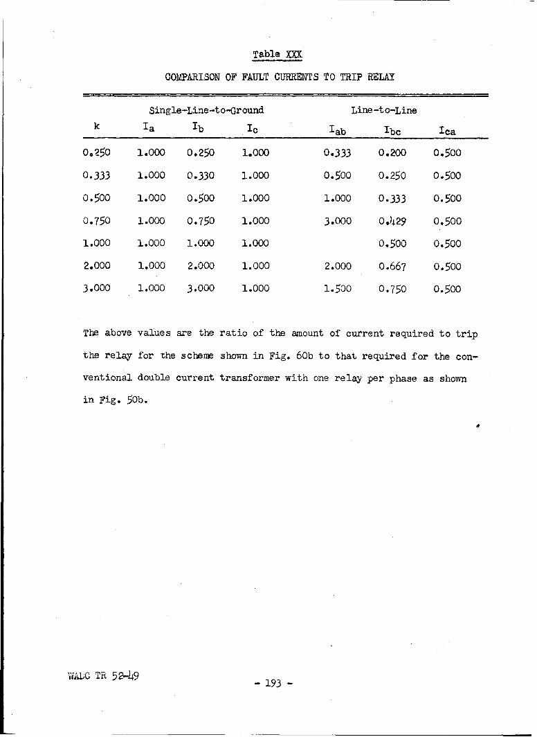
Table XXX
COMPAýRISON OF FAULT CURRENTS TO TRIP RELAY
Single-Line-to-Ground Line -to-Line
k Ia Ib I ab Ibc Ica
0.250 1.000 0.250 1.000 0.333 0.200 0.500
0.333 1.000 0.330 1.000 0.500 0.250 0.500
0.500 1.000 0.500 1.000 1.000 0.333 0.500
0.750 1.000 0.750 1.000 3.000 0.429 0.500
1.000 1.000 1.000 1.000 0.500 0.500
2.000 1.000 2.000 1.000 2.000 0.667 0.500
3.000 1.000 3.000 1.000 1.500 0.750 0.500
The above values are the ratio of the amount of current required to trip
the relay for the scheme shown in Fig. 60b to that required for the con-
ventional double current transformer with one relay per phase as shown
in Fig. 50b.
WALC TR 52-49 - 193 -

20 - - - - -- - - -_ _
10 _ _
I I -I
, B,
zz
ILI
C-)c
I-I
; -.
I--
0.10.1 1.0 k10
FIG 61- COMPARISON OF TRIPPING CURRENTS
VJADC TR 52-49- 194&-
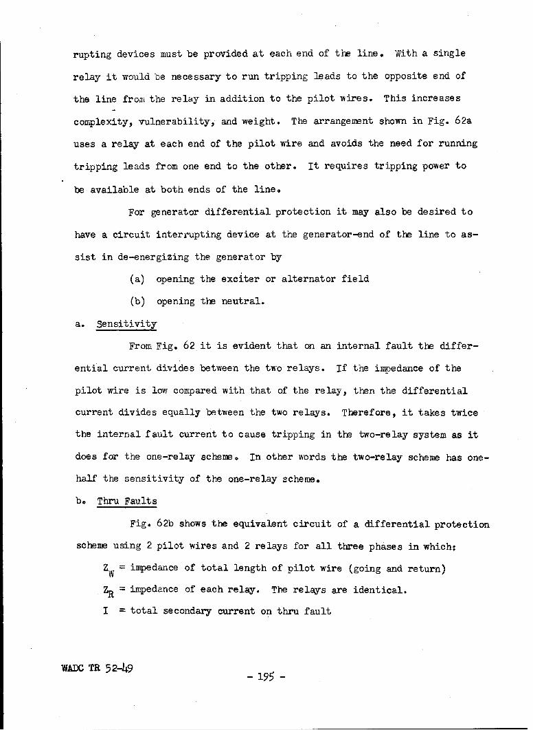
rupting devices must be provided at each end of the line. With a single
relay it would be necessary to run tripping leads to the opposite end of
the line from the relay in addition to the pilot wires. This increases
complexity, vulnerability, and weight. The arrangement shown in Fig. 62a
uses a relay at each end of the pilot wire and avoids the need for running
tripping leads from one end to the other. It requires tripping power to
be available at both ends of the line.
For generator differential protection it may also be desired to
have a circuit interrupting device at the generator-end of the line to as-
sist in de-energizing the generator by
(a) opening the exciter or alternator field
(b) opening the neutral.
a. Sensitivity
From Fig. 62 it is evident that on an internal fault the differ-
ential current divides between the two relays. If the impedance of the
pilot wire is low compared with that of the relay, then the differential
current divides equally between the two relays. Therefore, it takes twice
the internal fault current to cause tripping in the two-relay system as it
does for the one-relay scheme. In other words the two-relay scheme has one-
half the sensitivity of the one-relay scheme.
be Thru Faults
Fig. 62b shows the equivalent circuit of a differential protection
scheme using 2 pilot wires and 2 relays for all three phases in which:
Z, = impedance of total length of pilot wire (going and return)
ZR = impedance of each relay. The relays are identical.
I = total secondary current on thru fault
WAXC TR 52-49 - 195 -

N N
_L_ x • v v __xN N
0 - SCHEMATIC DIAGRAM OF CONNECTIONS
jw+Z
EZ R IR IR ' R E
b - EQUIVALENT CIRCUIT
FIG. 62 - DIFFERENTIAL SCHEME WITH 2-PILOT WIRES,
WADC TR 52-49 2 RELAYS FOR ALL THREE PHASES
- 196 -

'R = current in each relay
IW = current in the pilot wire.
The currents in the circuit ares2 (81)
EE (82)
I =w + IR = E E [2ZR +ZW (83)
The ratio of the relay current to the secondary current is:
'R +w8f- - 2Z +Z (7,)
From Eq. (84) it is evident that, in order to prevent operation on thru
fault, the impedance of the relay must be sufficiently great in relation
to that of the pilot wires so that the differential current is well below
that required to trip the relay. Considerations of economy of weight dic-
tate that the size of the pilot wire be kept as small as possible. There-
fore, in order to effect a high ratio of ZR to Z the impedance ZR of the
relay must be made high, if necessary by increasing the number of turns in
the operating coil and by increasing the number of secondary turns in the
current transformers. Increasing the relay impedance in that manner does
not decrease the sensitivity to internal faults.
5. Modified Two-pilot Wire Scheme
An alternative to the two-pilot wire two-relay scheme described
above is one which is shown schematically in Fig. 63a. The secondaries of
the thru current transformers on each end feed into the center tap of the
primary winding of a transformer T. The secondary winding of transformer TRw
is connected to the relay R. A compensating resistance -• equal to one-half
WADOC TR 52-49- 197 -

NA vA Aa v A
kN AT CT
_•, v X_ _v XA. N A A A .
"FIGv 6 I 3 I - TFv-_EM
L"SCHEMATIC DIAGRAM OF CONNECTIONS
+ +- f FEI EII
b - EOUIVALENT CIRCUIT
FIG. 63 - MODIFIED 2- PILOT WIRE DIFFERENTIAL SCHEME
WADC TR 52-49

the total pilot wire resistance is used as shown. The reactance of the
pilot wire is small and can usually be neglected.
The equivalent circuit of this arrangement is shown in Fig. 63b.
a. Thru Fault
In the case of a thru fault II = Iii and II divides equally in the
two halves of the primary winding. This is evident from the following. If
the leakage impedance between the two halves of the primary windings (Fig. 63b)
are neglected and I, = Ii = I then because of symmetry:
I I EIIEI= Ei= E
Rw
R+ (II - II') R
+ EII = e, +ei + I'Rw
2E 2e + II, Rw
I II
Note: When IIe = I eI= e 0
Under this condition the relay current I is zero as the equal currents in
the two halves of the primary winding flow in opposite directions.
b. Internal Fault
On an internal fault let II - III = I be the difference in current.
The effect of such an unbalance is similar, as far as relay current is con-
cerned, to the condition that
Iii = 0
and II =I
Then we have
E1 = eI + (I - II') Rw
2
WADC TR 52-49
- 199 -

E, =-e + R - 2e + II'I I W II 2
Rw+1 - -21'2(eI + eiI) + I 2 2II
1 ZRe = -
ei = - II •
II Rw(I- 41') ZR + i - - 211 Rw =0
41w ( +Rw)I' (ZR +1-II = t
The differential current in the left hand relay is
I - 21' = I21~I 2
and that in the right hand relay is
21 1 = I1 2
hence the currents in the two relays are the same.
on an internal fault the differentia2 current theoretically divides evenly
between the two relays. This modified scheme has been used in under-
ground transmission lines where the resistance of the pilot wire, because
of its great length, was quite high.
This scheme however, is not recommended for use on aircraft as
it requires the adjustment of the compensating resistance -i.e. one-hal
the total resistance of the two pilot wires.
6. Direct Acting Trip
Availability of power for tripping a circuit breaker under fault
must be carefully considered in the application of protection.
Separate d-c tripping batteries may be used, but complicate the
electrical system and increase vulnerability. Use of a-c voltage from the
WADC TR 52-49 - 200 -

protected system may also be considered. Reasonable assurance of tripping
power for phase-to-ground faults can be provided by appropriate circuit
connections. Assurance of tripping power for phase-to-phase and three-
phase faults is more difficult.
Direct acting trip removes the danger of failure of tripping
power source and reduces the number of interconnections which must be made.
Direct acting trip means that the short-circuit currents themselves act to
trip the circuit breaker. Direct acting trip would be particularly ad-
vantageous for the scheme shown in Fig. 62 and 63. Investigations should
be carried out to determine the feasibility of direct acting trip circuit
breakers for differential current protection. This investigation would
involve determination of whether reasonable tripping forces could be a-
chieved without use of excessively large current transformers and tripping
solenoid while retaining reasonable sensitivity and speed.
7. Current Transformer Design
The present design of the current transformers can probably be
improved without seriously increasing their -eight, by
a) making the window smaller. This decreases the length of themagnetic circuit
b) increasing the cross sectional area of the core
c) increasing the number of secondary turns.
Each of the above three items would decrease the excitation re-
quired by the core. By properly co-ordinating the design of the current
transformers with modifications of the operating coil in the relays now in
use, nuisance tripping on thru faults can be avoided. However, the sen-
sitivity would be such that the minimum thru fault current to cause trip-
WADC TR 52-49- 201 -

ping would be about twice that required in the scheme using only one re-
lay per pair of pilot wires.
Studies should be made to determine the optimum design of cur-
rent transformers and differential relays.
WADC TR 52-49- 202 -

V. APPLICATION OF SYSTEM PROTECTION
The arrangement of a power generation and distribution system is
greatly influenced by the type of protection that appears best adapted to
the needs of the system. Hence, this section will describe the application
of various protective methods to the system elements.
Exact evaluation of the relative merits of different circuit ar-
rangements and protective schemes is virtually impossible with available
information on failures. It is doubtful that such information will become
available and if it were it would rapidly become out dated by changing com-
bat conditions. Hence, comparisions between systems will inevitably be made
largely on intangible factors of "judgement". In the discussions of pro-
tective schemes in this report comparisons of those factors w~hich can be
measured are presented. But to a large degree the results are dependent
upon the weighting given to the various factors by "judgement".
A. Alternator protection
l. Types of Failures
The failures which may occur in an a-c generator can be classified
as electrical or mechanical failures as followss
a. Electrical Failures
1) Armature and Leads to Bus
1,) Short Circuits
a') Single line to ground
bt) Line to line
ct) Double line to ground
d') Three phase
el) Turn to turn
WADC TR 52-49- 203 -

2') Open Circuits
a') One or more phases open circuited.
2) Field and Regulating Circuit
1') Loss of Field Excitation
a') Short circuit in alternator field
b,) Short circuit in exciter field
cl) Open alternator field circuit
d,) Open exciter field circuit
2') Loss of voltage control
b. Mechanical Failures
All the possible kinds of mechanical failure are too numerous
to list in detail although they may be classified as follows:
1) Loss of primn mover
1) Engine failure
21) Constant speed transmission failure
at) Speed below synchronous speed
bi) Speed above synchronous speed
c,) Blocked rotor
2) Generator Failure - (Blocked Rotor)
2. Directional protection
Since an alternator should not be disconnected from the electrical
system in case of external faults, overcurrent protection by itself is in-
adequate as such protection cannot discriminate between internal and external
faults. Such discrimination however is afforded when directional power sen-
sing is used. The problem of directional power protection is receiving de-
tailed study in project 90-1054E under Contract No. AF 33(038)25738 in con-
WADC TR 52-49- 204 -
nection with the development of an Aircraft Directional Circuit Breaker.
Generally directional protection makes use of a wattmeter type
relay which has a current coil and a voltage coil. Such a relay can be
adjusted to sense real power or reactive power or a combination of real and
reactive power. In order for this type of protection to be effective where
the load on the bus is entirely passive, (no rotating equipment such as
motors on the bus) two or more alternators must be operating in parallel.
No reversal of real or reactive power can occur in the case of only one al-
ternator supplying a passive load.
a. Real power Sensing
One wattmeter element in each phase is so connected as to sense
only real power and ignore reactive power. The relay would operate only
when the real power flows from the bus into the alternator. The relay could
therefore be made to operate on the following electrical failures in the
armature and the leads to the bus.
1) Single line to ground
2) Line to line
3) Double line to ground
4) Three phase.
Typical values of currents in faults near the bus on a 2-alter-
nator system are listed in Table XXIV. In addition the relay could operate
on the following mechanical failures.
1) Loss of prime power without loss of synchronism
2) Blocked rotor.
Tests made on alternator D, which has an overrunning clutch, in-
dicate a reverse flow of real power of approximately 3.4 kw. when its prime
WADOC TR 52-49- 205 -

mover is at standstill. This amount of power is less than 0.10 per unit
and a directional protective device which has sufficient sensitivity to
trip the alternator for this condition could remove alternators already on
the bus when another alternator is synchronized out of phase with the sys-
tem. Fig. h2 shows that with three alternators on the system, the reverse
real power in them can be well above 1.0 per unit when a fourth alternator
is connected out of phase to the system (broken ellipse for n=h). With
only one alternator on the bus and a second alternator is synchronized out
of phase the reverse real power in the alternator on the bus may be greater
than 3.0 per unit.
The results of blocked rotor tests are listed in Tables XXV and
XXVI. The values of real power listed in those tables indicate that the
sensitivity required of a real power sensing directional device is such that
alternators already on the system might be tripped off when another alter-
nator is synchronized out of phase to the system. Such nuisance operations
can however be prevented by means of adequate time delay.
be Reactive power Sensing
If the voltage to the voltage coil, of the wattmeter type relay
discussed above, is retarded 90 degrees the relay becomes sensitive to re-
active and ignores real power. The same types of electrical failures can
be cleared with reactive power sensing as with real power sensing. In ad-
dition reactive sensing will cause relay operation in the case of:
1) Complete or partial loss of field excitation.
Complete loss of field excitation could be caused by an open circuit in the
alternator field circuit. In the case of an open circuit in the exciter
field circuit, the alternator would receive some excitation because of the
VIADC TR 52-49- 206 -

residual magnetism in the exciter. partial loss of field excitation could
be caused by
a) Faulty voltage regulating circuit
b) partial short circuit in the alternator field winding.
Reactive power sensing would also cause relay operation in the case of
blocked rotor, but would not cause operation in the case of prime mover
failure without loss of synchronism.
Eq. (49) and Eq. (50) Section III-C-4 show that in the case of
complete loss of field excitation the reverse reactive power lies somewhere
between a value of 0°54 and 0.89 per unit. A reactive power sensing direc-
tional device could be made sufficiently sensitive to remove the alternator
from the system with little likelihood of nuisance operation during synchro-
nizing on a system operating with more than one alternators on the bus.
In general greater sensitivity might be expected for reactive
power sensing than for real power sensing except in the case of faults with
appreciable resistance.
There might be some advantage in a directional protective device
which is sensitive to some combination of real and reactive power. This can
be achieved by retarding the voltage to the voltage element of a normally
real power sensing device thru an angle smaller than 90 degrees.
C. Disadvantages of Directional Protection
The speed and sensitivity of directional protective schemes is
limited by precautions against nuisance tripping. To prevent nuisance trip-
ping the relay is made insensitive to values of reverse power below a cer-
tain limit. In addition a time delay can be incorporated to prevent tripping
on normal short time reversals of power flow. Reverse power flow can take
WADC TR 52-49- 207 -

place where there is no failure under the folloving conditions:
1) Synchronizing
If an alternator is switched to a Jive bus when its voltage is
appreciably out of phase with the bus voltage, swings of real and reactive
power result (Fig. 43). If the relays are too sensitive the incoming alter-
nator and the alternators already connected to the bus would be tripped off.
This is particularly true if real power sensing is used. If reactive power
sensing is used, the incoming alternator would be tripped off under some
conditions of synchronizing, but there would be little likelihood of trip-
ping alternators already on the bus as shown in Fig. h2. Removing the in-
coming alternator from the system when synchronized far out of phase is
probably desirable.
2) Sudden Change in Prime yover Speed
In the case of two or more paralleled alternators driven from the
main engines through constant speed drives, if the speed of one engine is
suddenly changed, the division of real power between the alternators is al-
so changed for an appreciable time period because the governor response of
the constant speed drive is fairly slow. Under light load conditions such
a change in speed could produce reversal of real power flow and if the di-
rectional relay senses real power it would operate. If reactive power is
sensed relay operation would be unlikely for this condition. Relay opera-
tion under this condition would be undesirable and would be considered a
nuisance operation.
3) Loss of Speed Sense
If the indication to the governor is improperly one of a loss of
speed or large deficiency in speed the governor will increase the amount of
WADC TR 52-49- 208 -

prime power to that alternator. As a result this alternator will generate
more than its share of the real power and under light load conditions the
real power in the healthy units may reverse. If real power sensing is used
the directional relays would cause the healthy units to be disconnected from
the system. Relay operation under these conditions is undesirable. The same
situation would result from one alternator oeing driven above synchronous
speed for any reason whatsoever.
4) Loss of Voltage Sense
If the voltage sense in one of several alternators operating in
parallel is lost, the excitation of that alternator will go to ceiling value.
Under light load conditions this can cause reactive power to flow into the
healthy alternators and if the directional relays use reactive power sensing
the relays on the healthy alternators would operate and disconnect them from
the system. Under this condition the reverse reactive power in a healthy
alternator may be as much as lo4 per unit as shown in Fig. 25.
d. Application of Directional protection
Directional protection will take care of faults not covered by dif-
ferential relays such as loss of field excitation and blocked rotor* Such
faults do not give rise to differential current. In addition to such cover-
age directional circuit breakers can afford back-up protection to differential
relays on short circuits except for low impedance three phase faults. However,
since it is necessary to sacrifice sensitivity and speed in order to prevent
nuisance operations the directional protective schemes are less sensitive
and slower than differential schemes and are not suitable for replacing dif-
ferential protective schemes.
WADOC TR 52-49- 209 -

3. Generator Differential Current protection
Methods of differential protection have been discussed in
Section IV-D. Those methods that appear best adapted to generator circuit
protection are:
1. one current transformer and relay per phase (Fig. 50a)
2. Two current transformers and one relay per phase (Fig. 56)
3. Double current transformer method with pilot wires for allthree phases (Fig. 60).
The former method is applicable only where the distance to the main bus is
shcrt or where it is used in combination with multiple channels of over-
current protection.
The latter method using only two pilot wires appears to have
considerable advantage. This arrangement applied to the generator circuit is
shown in Fig. 64. This method would be particularly effective if the fol-
lowing design features can be achieved.
1. Neutral current transformers housed in generator terminal box.
2. Current transformers at the main bus circuit breaker anintegral part of the circuit breaker.
3. Direct acting trip.
Building the current transformers into their respective associated
equipment should avoid difficulty with incorrect polarity and turns ratio.
The number of leads which must be brought out of the equipment is also there-
by reduced.
4o Comparison of Two Types of Generator Circuit protection
There has been considerable discussion regarding the choice between
the two possible arrangements of generator circuit protection where the main
bus is located at some distance from the generator. One arrangement shown in
WADO TR 52-49- 210 -
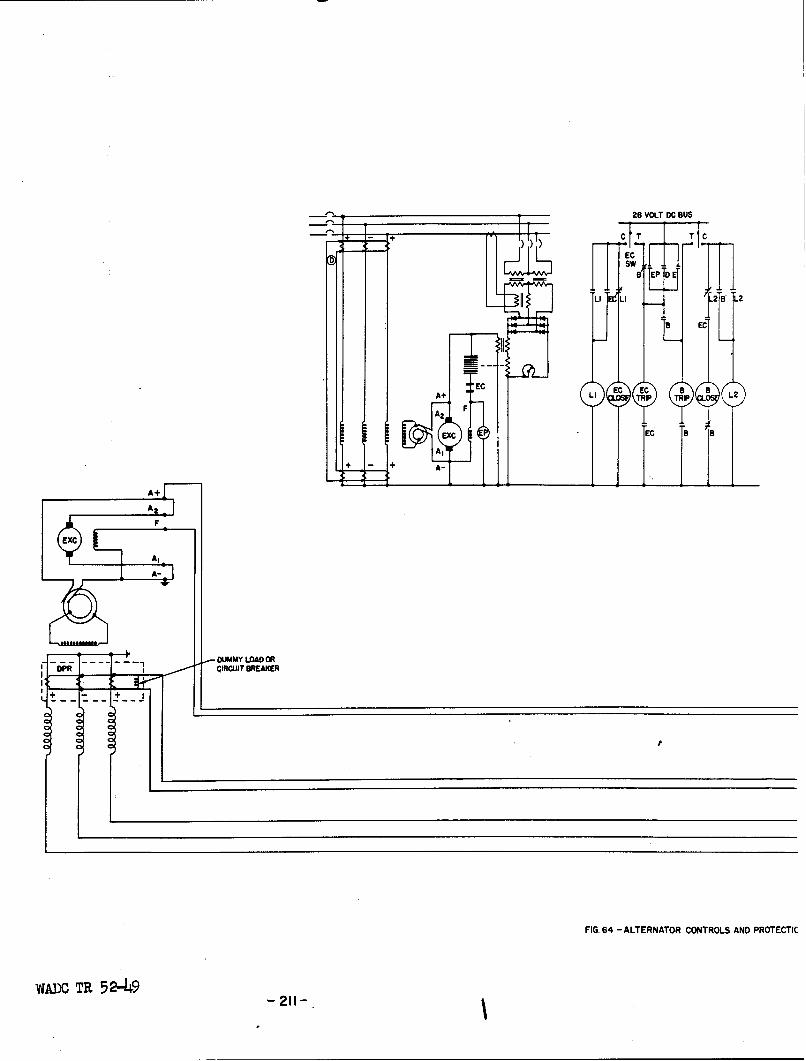
28 VOLT DC BUS
-- . 4_,. C T
:;S •
8 EP DE
LI I28 L2
B EC
LI EC EC B L2
AZ F
IG EC a C
A I
+ + A- _
AZ5
F
EXC
A-
FA-
'OPR DMMY LOAD ORI - ____ ICIRCUIT BREAKER
FIG. 64 - ALTERNATOR CONTROLS AND PROTECTIC
WADO TR 5 2-149

28V DC
T Cr C
OLT DC BUS
T C
B.I E_
2 IL2
a EI
r
a I
P
TO ENGINE L Q-aSHUTDOWNI
IT
o III I
I I l I BREAKER IR ,.RL AND P CII .II
'lATOR CONTROLS AND PROTECTION

Fig. I uses only differential protection. The other arrangement shown in
Fig. 2 uses a combination of differential current and overcurrent protection.
The obvious advantage of the circuit shown in Fig. 2 is the provision of a
multiple number of individually protected channels for the generator current.
Hence, in the event of a fault on one of these cables the overcurrent pro-
tectors of the faulted cable would remove the cable from the circuit without
removing the generator from the system. Thus the generator would continue
to deliver its normal share of power to the system. For the differential
protection shown in Fig. 1, a fault on any power cable would cause the gener-
ator to be removed from the system. This generator would be unavailable for
further service until the fault had been cleared by maintenance.
However, several other factors should be considered in comparing
these two arrangements. This section of the report will be devoted to a dis-
cussion of the relative merits of these two methods of generator circuit pro-
tection. All comparisons will be based on the assumption that the overcurrent
devices indicated are current limiting fuses as described in specification
MIL-F-5372 dated 23 October, 1950.
a. Generator Circuit Description
1) Differential protection
All physical comparisons between the two protection arrangements
will be based on a 40-KVA alternator mounted at the engine and driven by a
constant speed drive. The distance from the alternator to the winding or na-
celle bus will be assumed to be 10 feet and the distance from this bus to
the main bus in the fuselage will be assumed to be 50 feet. The arrangement
shown in Fig. 64 will be used for the comparisone Differential protection
is provided throughout the full length of the generator leads by three cur-
rent transformers mounted close to the generator circuit breaker and three
WAmO TR 52-49- 212 -

current transformers mounted internally on the alternator. Mounting the
current transformers internally on the alternator permits only one common
neutral lead to be brought out of the machine. Since this lead needs only
to be connected to ground, at some point on the engine it can be made very
short. This type of connection permits a material saving in weight. The
current transformers at each end of the line are connected in parallel with
polarities arranged to detect all types of faults. A complete description
of the physical arrangement and sensitivity of this type of differential
protection is covered in Section IV-D. This type of differential scheme
requires only two control leads* The voltage regulator, exciter control
relay, circuit breaker, and other control devices shown in Fig. 64 are
standard controls connected in the circuit in the usual manner.
The generator circuit shown in Fig. 64 can be modified so that
multiple circuits are used for the greater portion of the transmission line.
No fuses are used in these multiple channels or any other part of the power
circuit. The advantage of this arrangement is that it permits a consider-
able saving in the weight of the power cables over the single cable per phase.
2) Differential and Overcurrent Protection
Fig. 2 shows the arrangement of controls and the power circuits
used in this type of protection scheme. In this arrangement differential
protection is provided for the generator leads which run from the alternator
to the wing or nacelle bus. The differential current relay is mounted close
to the nacelle bus. Since this relay uses only three current transformers
the neutral lead of each phase must be brought out to the relay. Thus with
this type of differential protection, six power leads must be brought out
from the alternator.
The power circuit from the nacelle bus to the fuselage bus is a
WADC TR 52-49-213-

multiple channel arrangement with four wires per phase. Each wire is pro-
vided with overcurrent protection at both ends.. These cables are selected
such that if one circuit becomes open the remaining intact circuits will be
capable of delivering normal power to the system. This type of network re-
quires a fairly extensive bus arrangement at both ends of the circuit.
b. Factors of Comparison
To obtain a complete picture of the advantages of one system
over the other the generator circuits sho%%n in Fig. 64, Fig. 2, and the
multiple cable modification of the system shown in Fig. 64 will be com-
pared with respect to weight, main bus exposure, effect of faults on both
the power and control systems, relative speed of protection, and maintenance
and operation of the system. The systems shown in Fig. 64, Fig. 2, and the
modified system of Fig. 6L will be designated as Systems I, II, and III re-
spectively.
1) Wfeight
The weights of the three systems are compared in Table XXXI. The
table does not show total weights, but indicates quantitatively only the net
saving in pounds of Systems I and III over System II. The table shows that
a material weight saving can be made using differential protection in con-
junction with a multiple number of cables. Even the single cable per phase
shows weight saving over System II. The cables were selected on the basis
that the generator was a hO-KVA machine mounted in the aircraft as previous-
ly mentioned. It was assumed in each system that the power cables were bun-
dled in groups of three over the greatest part of the circuit to maintain
exposure area to a minimum. The cable sizes were determined from the paper
WALC TR 52-49- 214

Table XXXI
COkPARISON OF GENERATOR CIRCUIT WEIGHTS
Generator System Weights in Lbs
Item I II III
1. Multiple Channel Leads None 28.5 21.5
2. Single Channel Leads 49.7 8.3 8.3
3. Neutral Leads Negligible 8.3 Negligible
4. Fuses and Fuseblocks None 3.0 None
5. Buses Other Than Main Bus None 8.0 None
6. Differential protection Leads 1.4 1.2 1.4
7. Weight of all other items inGenerator Circuit x X X
Total Weight X+51.J1 X+57.3 X+31.2
Net Saving over System No. II 6.2 0 26.1
WALC TR 52-49- 215 -

by Schach and Kidwell* which bases the cable current rating on the number
of cables in the bundle. The weights of the differential control leads
are considered in Table XXXI and it is assumed that these leads would be
bundled with the power leads to maintain exposure to a minimum.
2) Main Bus Exposure
The comparable part of the main bus exposure of the two methods
of protection is considered to be the areas shown in Fig. 65 and Fig. 66.
A fault or sufficient damage in this area would cause the generator to be
lost and also any distribution buses supplied only from the main bus. There-
fore, it is highly desirable to keep the exposure area of this bus to a min-
imum. The areas of main bus exposure of the three systems are shown in
Table XXXII under item No. 1. As can be seen from the table the main bus
exposure of the differential protection scheme is only 65% of the bus ex-
posure area of the overcurrent protection scheme. In both types of genera-
tor circuits the main bus should be provided with its own differential pro-
tection circuit to eliminate the possibility of a prolonged fault on the bus.
Such a fault might very well cause the system to pull apart at several points.
This would be especially true of a system which employs overcurrent protection
extensively. (See section on main bus and tie circuit protection, V-B).
3) Nacelle Bus Exposure
System II is the only one of the three systems which has a nacelle
bus and its subsequent exposure problems. A typical arrangement of this bus
is shown in Fig. 67. The approximate value of this area is listed in Table
XXXII. A fault on this bus could have very serious effects on the rest of
*"Continuous Current of Bundled Cable for Aircraft" by M. Schach and R. E.
Kidwell, Jr. presented at AIEE Conference on Air Transportation. LosAngeles, California, October 1951.
WADC TR 52-49- 216 -

-00
IIL
Ir-
wC
z
at5 I Ir
0
U I-0~
I La,
CLa
___ _________ __U
WAW TR5 2-4

-In
I'I,
0-
a--
z
w
I-
L-J
at:
L*J I-D
I 0
U-)
z C3
I CD
WAD I-' 2-4
I I218 -

u-IC
I Ir
0 -
wzCL 0
CL-
I OD
Ic-I8
Ifl0 IxI
ILd
.44
I~ adI. .W ... -
WADC T 52-4 -219

Table lXII
COMPARISON OF GENERATOR CIRCUIT EXPOSURE AREAS
Exposure Area Sq. Ft. Result of Faultin this area
Location System I System II System III
1. Main bus .93 1.42 .93 Loss of bus andgenerator
2. Nacelle bus 0 1.11 0 Fault may not becleared. Good gener-ator may be lost
3. Differentially pro- 4.46 1.49 5.76 Loss of generatortected power Leads
4. Differential pro- 1.15 .92 1.15 (See explanation undertection Control Leads types of differential
protection)
5. Total Exposure to 6.52 11.7 7.80- ------------Faults
WADC TR 52-49- 220 -

the system. Such a fault would be supplied from both the generator and
the system. If the impedance of the fault permitted excitation to reach
ceiling, the exciter protection relay would open the field and generator
circuit breaker. However, the minimum time in which this relay could oper-
ate would be several seconds. This is much too long to allow a fault of
this nature to remain on the system. This amount of time would be long
enough to permit a fuse protected system to pull apart at several possible
points. (A more complete explanation of this phenomena is given in a sep-
arate Section V-B-l). If the impedance of a fault on the nacelle bus is
large enough to prevent the exciter from going to its ceiling voltage the
fault may persist. Under these conditions the generator could be damaged
beyond repair and the rest of the system would probably break down in the
manner previously mentioned. Therefore, elimination of this bus exposure
is obviously one of the big advantages of the differential protection scheme
over the overcurrent systemo
4) Effect of a Fault on Generator power Leads
If a fault occurs on any of the power leads of a generator cir-
cuit which employs complete differential protection (Systems I and III),
the circuit breaker will be immediately tripped and the generator will be
removed from the system. If the generator circuit uses a combination of dif-
ferential and overcurrent protection a fault which occurs in that part of
the circuit which has differential protection will cause the generator to be
removed from the system. A fault which happens in that part of the circuit
which is protected by fuses will cause only the faulted cable to be removed
from the generator circuit. The generator will continue to supply power to
the rest of the system. This is the outstanding advantage which the com-
WADC TR 52-49- 221 -

bined differential and overcurrent scheme has over the generator circuit
which use complete differential protection. The exposed areas (protected
area) which are differentially protected are listed under item 3 in Table
XXXII for the three systems.
5) Effect of a Fault on Differential Control Leads
Systems I and III which employ only differential protection have
a control circuit similar to that shown in Fig. 68a. In this scheme only
one relay is required which is connected in parallel with the control leads
as shown in the figure. If one of the control leads becomes faulted to
ground (Case 1) the control circuit will continue to function properly. If
one of the control leads accidentally opens, (Case 2) the differential re-
lay will be energized and consequently remove the generator from the system.
In the event that the two control leads become shorted to each other (Case
3) the differential relay will be shorted and the generator circuit will be
without any protection. The most conmmon fault in this circuit would prob-
ably cause the loss of the generator rather than the loss of only the pro-
te ction.
System IIwhich uses differential protection cver only a portion
of the power circuithas a control circuit similar to that shown in Fig. 68b.
In this circuit each current transformer operates its own relay. The con-
tacts of each relay are connected in parallel. Therefore, only two control
leads are required to run from the differential relay to the circuit breaker.
If one of these leads is faulted to ground (Case 1), the system loses its
protection. If an open circuit occurs in one of the control leads (Case 2),
the system will also lose protection. In the event that the two control
leads become short circuited together (Case 3) the circuit breaker will be
WADC TR 52-49- 222 -

______ ____z
0
foa--- II
w CLwI
4q
4 a. 0 0
W4 4
uiL I z a ,ML 0 r 0 Ic
0 -J W 0.
ww40 IJ 0i _j o4
C L IL oi
z
0 z" I
S I w w ,.. w
z ILI
zw w
Li.
I-34 4
w 4
VJADC TR 5 2-4923

tripped and the generator will be removed from the system. It is probable
that a fault on this control circuit, is more likely to cause loss of pro-
tection rather than the loss of the generator. The relative disadvantages
of these failures are discussed in Section IV-D.
The exposure area of the control leads is listed under item four
in Table XXXII.
6) Total Exposed Area Subject to Faults
Item 5 in Table XXXII gives the total fault exposure area of each
system. This area is the total projected area of the power cables, differ-
ential control cables, and bus exposure areas from the alternator terminals
to the main bus. From the table it can be seen that %rstems I and III have
considerably less exposure than System II. This is another distinct advan-
tage of the differential scheme over the overcurrent protection system
since any energized conductor no matter how well protected represents some
hazard.
7) Maintenance and Operation
The combination differential and overcurrent protected system is
considerably more complex than the generator circuit which use only differ-
ential protection. This factor is apparent when Fig. 64 is visually com-
pared to Fig. 2. In order to ascertain that the circuit in Fig. 2 will
function properly the fuses in the primary system should be checked after
every flight. It is doubtful if such maintenance checks would be followed
in practice. Therefore, it is very likely that many aircraft which are not
consistently checked would operate with the protection scheme in a dangerous
condition such that should a fault occur the major portion of the primary
system would be lost.
WADC TR 52-49- 22) -
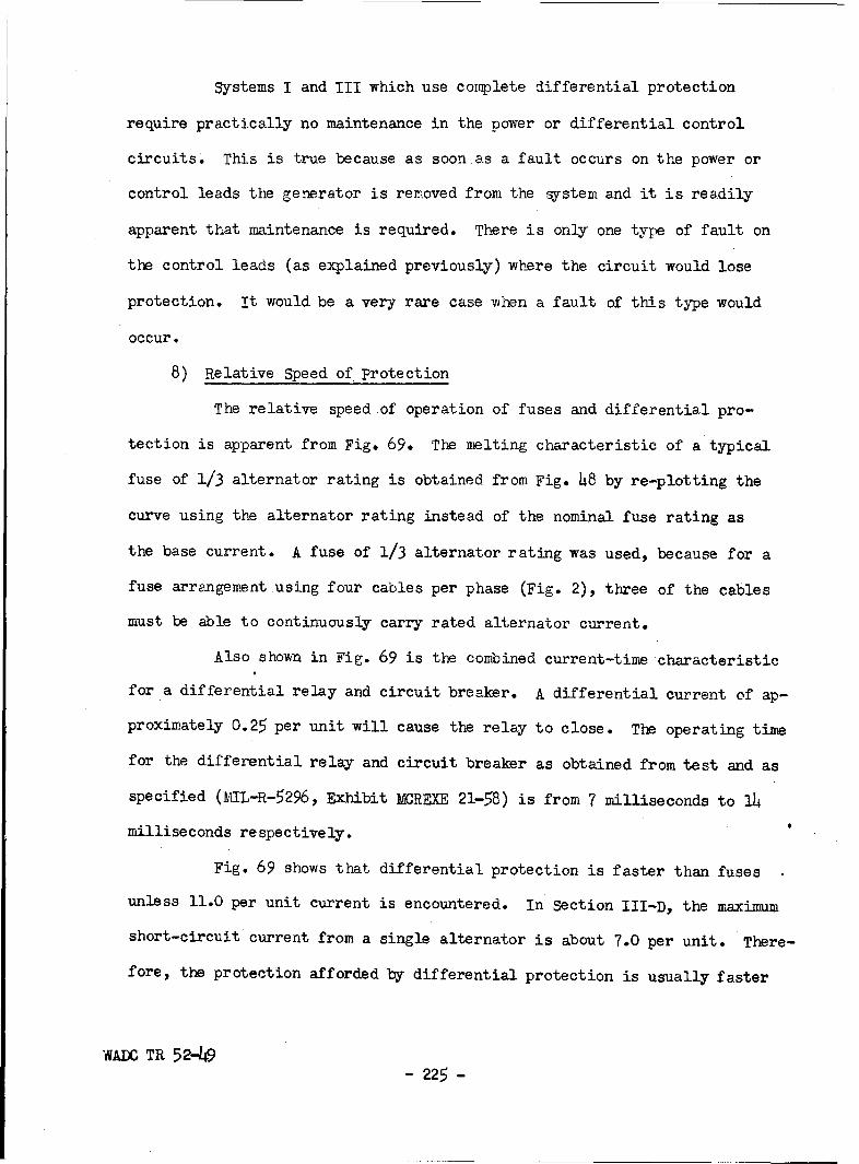
Systems I and III which use complete differential protection
require practically no maintenance in the power or differential control
circuits. This is true because as soon as a fault occurs on the power or
control leads the generator is removed from the system and it is readily
apparent that maintenance is required. There is only one type of fault on
the control leads (as explained previously) where the circuit would lose
protection. It would be a very rare case when a fault of this type would
occur.
8) Relative Speed of protection
The relative speed of operation of fuses and differential pro-
tection is apparent from Fig. 69. The melting characteristic of a typical
fuse of 1/3 alternator rating is obtained from Fig. 48 by re-plotting the
curve using the alternator rating instead of the nominal fuse rating as
the base current. A fuse of 1/3 alternator rating was used, because for a
fuse arrangement using four cables per phase (Fig. 2), three of the cables
must be able to continuously carry rated alternator current.
Also shown in Fig. 69 is the combined current-time characteristic
for a differential relay and circuit breaker. A differential current of ap-
proximately 0.25 per unit will cause the relay to close. The operating time
for the differential relay and circuit breaker as obtained from test and as
specified (MIL-R-5296, Exhibit MCREXE 21-58) is from 7 milliseconds to 14
milliseconds respectively.
Fig. 69 shows that differential protection is faster than fuses
unless 11.0 per unit current is encountered. In Section III-D, the maximum
short-circuit current from a single alternator is about 7.0 per unit. There-
fore, the protection afforded by differential protection is usually faster
WAME TR 52-49- 225 -

1.0 -
/-MELTING CHARACTERISTIC OFA TYPICAL FUSE OF 1/3ALTERNATOR RATING
0.1
wI
SPEC. LIMIT
0.01
MINIMUMONTEST
_LOPERATING TIME OF DIFFERENTIALRELAYAND CIRCUIT BREAKER
0.00110.1 0.2 0.4 C6 0.8 1.0 2 4 6 81 0 20 40
CURRENT- PER UNIT ALTERNATOR RATING
FIG 69- RELATIVE SPEED OF PROTECTIONWADC TR 52-49
- 226 -

than that afforded by fuses.
Fig. 69 also shows that since differential protection detects
differential currents of 0.25 per unit, it is more sensitive than fuses.
c* Summary
The advantage of the combination differential and overcurrent
protection scheme is:
(1). A short circuit on the overcurrent protected feeders will not
result in loss of the generator.
In this method, failure of the differential protection is not likely to
trip the generator.
The advantages of the differentially protected scheme are:
(1) Less weight
(2) Less main bus exposure
(3) No nacelle bus exposure
(4) Less total exposure
(5) Simpler for ease of understanding and maintenance
(6) Faster action for most faults
(7) No co-ordination problems with protection in other circuits.
In this method, failure of the differential protection is likely to trip
the generator.
It is judged that the advantages of differentially protected
schemes of System I or III outweigh those of the combination differential
and overcurrent scheme of System II.
The advantages of the differentially protected system as compared
with the combination overcurrent and differentially protected system de-
creases as the distance from the generator to the main bus is shortened.
WADC TR 52-49- 227 -

However, in the interest of standardization, the differentially protected
system should be adapted for all a-c aircraft power systems.
B. Main Bus, Feeder, and Tie Circuit Protection
1. Main Buses
The main bus system with its associated tie circuits is the back-
bone of the power supply system. Arrangements of this part of the power
system should consider the following factors:
(1) Minimum bus exposure
(2) Simplicity of operation
(3) Alternate sources of supply for essential loads
(4) Relationship to source and distribution system protection problems.
The vulnerability of a main bus is undoubtedly related to the area
or volume which it occupies. Hence, electrical circuit arrangements that
permit the most compact physical bus structure are highly desirable.
In military aircraft the conditions most conducive to main bus
failure are those occuring in combat. Under the stress of battle successful
manual operation of the electrical system can hardly be expected. Therefore,
any protective or throwover schemes for the electrical system should be
capable of automatic operation.
Military aircraft must also be capable of operating with a mini-
mum amount of maintenance. Since an armed forces activity must be expanded
rapidly in time of need, it is very likely that the training of maintenance
personnel will always be less than would normally be desirable. Hence, there
is considerable advantage in using the simplest possible systems consistent
with weight and reliability requirements.
It is considered necessary that essential loads be supplied from
WADC TR 52-49- 228 -

more than one source. However, more than two sources of supply would seldom
be justifiable from the standpoint of reliability. In fact more thantwo
paths may be more disadvantageous because of the increased complexity with
a relatively small improvement in useable reliability. Short circuits in a
well designed system should be a rare event even under combat operating con-
ditions.
The incoming source and outgoing feeder circuits are connected to
the main bus. In the event of a short circuit on the main bus all of these
related circuits may be lost. Therefore, it is important that the maximum
possible reliability be obtained for the main bus by careful installation
techniques. But even with the best possible methods a main bus fault may
still occur and adequate bus protection is needed to rapidly divorce the
faulted bus from the rest of the system. The main bus system and protec-
tion must be closely co-ordinated with the arrangement and protection methods
used by the source and load circuits. This is particularly true where over-
current protective devices are used, as these devices are responsive to short
circuits in other parts of the system. Main bus systems which use a protec-
tion scheme that permits the simplest possible arrangement of feeder, source,
and load circuits have many obvious advantages.
The main bus is a vital part of the power supply system due to the
many interconnections at that point. Since a short circuit on the main bus
means the loss of connected circuits, it would appear that maximum reliabil-
ity would be obtained by having one main bus for each generating source.
However, for a large number of sources such an arrangement would have the fol-
lowing disadvantages compared to a system using a fewer number of buses.
WADO TR 5249- 229 -

(1) More physical and electrical complexity
(2) Greater weight due to interconnecting circuits
(3) Larger exposed area of the source system.
The selection of the number of main buses is largely a judgement
evaluation. For non-combat operation there is little doubt that a system
with two main buses possibly at a single location would be the preferable
arrangement. For combat operation there is insufficient factual data on
which to base a decision. However, experience with malfunction of elec-
trical systems in non-combat operation tends to favor the simplest possible
system. It is believed that far more failures will result from improper
operation and inadequate maintenance of complex systems than will result
from other causes on a simple doable source system with fast trouble-free
protective schemes. Therefore, serious consideration should be given to
the adoption of systems utilizing two main buses at two different physical
locations.
a. Main Bus protection Methods
Methods of protecting the main bus include the following types:
1) Overcurrent
2) Ground current
3) Differential current.
The advantages and disadvantages of these types of main bus pro-
tection will be discussed briefly in the following paragraphs.
1) Overcurrent protection
Some of the fuse-mesh networks that have been used depend on
overcurrent protection in the source and feeder circuits to provide bus
protection. This form of protection has the following disadvantages:
WADOC TR 52-49- 230 -

(1) poor Selectivity
(2) Slow protection.
To illustrate the selectivity problem the system shown in Fig.
70 will be used. This system shows a two-generator system using multiple
channel overcurrent protection devices in the generator, feeder, and tie
circuits. Although this circuit shows only a two-generator system with
direct tie circuits, it can be shown that any multiple-generator system
with any interconnected network between the buses can be resolved to the
same simple arrangement. Hence, the comments which follow will apply in
general to systems with overcurrent protection in the circuits connected
to the main buses.
For this system it will be necessary to determine the relation-
ships between fuse ratings for generator circuit fuses A and B and the tie
line fuses. This relationship should indicate whether the fuses provide
both bus and line protectiono To study these rating relationships it will
be helpful to assume short circuits at several line and bus locations as
shown in the Fig. 70. Fuse ratings and circuit ratings will be used inter-
changeably in this discussion, although they may actually differ due to dif-
ferent rating methods for the fuses, generators, and cables. Three channels
are used in the example in Fig. 70, although four channels are preferable
to give better selectivity.
a) Line Protection
Fault 1 in Fig. 70 requires that the A1 and B1 fuses in the
faulted line blow earlier than the T1 fuses. That is, one B1 fuse must be
faster than three T1 , two A2 , or two B2 fuses. This should be no problem.
Even if there were, trouble could be avoided by the use of more than three
WADC TR 52-49- 231 -
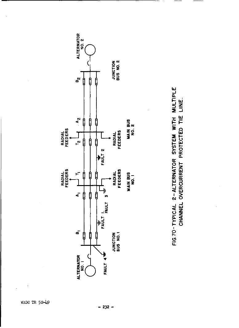
0
IXzw
-JC-
0 c;
zj
N~ U,
so 4
U.A
C41
0L 04w z
WL. Cc.
<4W oxw 0 'Ir W ~w z
crJ
I-i
m 000
Fz LL
232

channels in the generator circuit.
Similarily with fault 2 it is required that one T1 fuse oper-
ate faster than two TI, three Al, or three B1 fuses. This likewise should
be no problem. Hence, for the generator system shown there should be no
serious line protection problem.
b) Bus protection
Consider first fault 3 on main bus 1. For this fault the three
A1 and three T, fuses must trip, but the three A2 and three B2 fuses must
not trip. Therefore, the T1 fuses must be faster than the A2 or A1 fuses.
If fuses with the same current-time characteristics are used for A1 and TI,
then the TI fuses will have to be of a lower rating probably by a factor of
2 or more for safety. This may be an adequate tie line transfer rating but
it is a factor that would have to be carefully checked. Thus main bus pro-
tection requires that the tie line fuses be faster than the generator cir-
cuit fuses.
Next consider a short circuit on junction bus 1 - fault 4. It is
important to note that if no other form of bus protection is used this fault
would be detected and removed from the rest of the system only if generator
2 is in operation. If generator 1 is the only generator on the system at
the time the fault occurs, power to the whole system would be lost and the
short circuit would persist until the exciter protection relay opened the
circuit breaker. Depending on the type of fault it may be a relatively long
period of time before the exciter protection relay operates. This is ob-
viously a hazardous condition.
For fault 4 it would be desirable that the three B1 fuses trip be-
fore the three A1 fuses for clarity to maintenance personnel. However, this
WADC TR 52-49- 233 -

is not essential. It is essential that the three B1 or three A1 fuses
trip before the three T1 fuses. This means that the T1 fuses should have
a slower trip characteristic or higher rating than the A1 fuses. But pro-
tection of the main bus required exactly the opposite relationship between
the tie line and generator circuit fuses. Thus, faults on the junction
bus and main bus present conflicting requirements. Whichever, relationship
is adopted as the best compromise inproper co-ordination will be obtained
for the other fault condition.
Even more serious co-ordination problems are evident where there
is only one other generator connected to the line at the time of short cir-
cuit on the nacelle bus - fault 4. Since A1 , B1 , A2 , and B2 fuses all
have the same rating and carry the same fault current, it is possible for
A2 or B2 fuses to open before A1 or B1 and hence, divorce that phase of
the good machine from the system.
This discussion shows that proper co-ordination cannot be ob-
tained with overcurrent devices in both the generator and tie line circuits
for bus faults. Therefore, other forms of fast protection should be con-
sidered. Differential protection is one possible type that could be con-
sidered for either the generator or tie line circuits. In either case these
circuits though differentially protected will not provide bus protection.
Thus forms of bus protection must be considered. Bus protection can prob-
ably be very fast. Hence, overcurrent line protection in combination with
fast bus protection would still be a feasible arrangement.
2) Ground Current
Ground current protection of the main bus can be obtained by in-
WADO TR 52-49- 234 -

sulating the housing Which incloses the bus from ground except for one
connection through a current relay. In the event of current flow through
the relay a ground fault on the bus is indicated and the relay should trip
all sources of current from the bus. However, ground protection would be
sensitive only to ground faults and thus may not be widely applicable to
three phase systems.
3) Differential Current
Several types of differential current protection schemes have
been described in Section IV. Differential protection can be effectively
applied to bus protection as will be illustrated by the description of
the following four methods.
a) One Relay per phase per BusFig. 71a
In this method the current transformers of each phase are in-
terconnected to a current relay. This is the most straight forward method
and since the circuit breakers are physically close together there is
little disadvantage in the six leads between current transformers as is
true for generator or line differential protection. Three differential
relays are required and a reliable source of tripping power must be assured.
Still further reliability can be assured for the relays by using a fourth
one in a neutral connection. This assures that all faults will be detected
by two relays and thus provides greater assurance of tripping the circuit
breakers.
b) One Relay Per Bus, Fig. 71b
This method of differential bus protection employs one current
transformer with a different turns ratio and one current transformer with
polarity reversed. This method of connecting the transformers has been
WADC TR 52-49- 235-
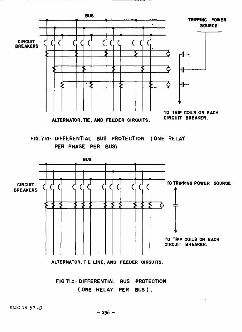
BUSTRIPPING POWER
"_ __SOURCE
CIRCUITBREAKERS
TO TRIP COILS ON EACH
ALTERNATOR, TIE, AND FEEDER CIRCUITS. CIRCUIT BREAKER.
FIG.71u- DIFFERENTIAL BUS PROTECTION (ONE RELAY
PER PHASE PER BUS)
BUS
CIRCUIT TO TRIPPING POWER SOURCE.BREAKERSiI
TO TRIP COILS ON EACHCIRCUIT BREAKER.
ALTERNATOR, TIE LINE, AND FEEDER CIRCUITS.
F IG,71 b - DIFFERENTIAL BUS PROTECTION
(ONE RELAY PER BUS).
WADC TR 52-49-236-

previously discussed. Its advantages are the elimination of two relays
and in the simplification of the interconnections. Reliable tripping
power must still be assured for this method of protection.
c) Direct Acting Trip - Three Trip Coils per Circuit Breaker, Fig. 72
The problem of providing a reliable source of tripping power
gives emphasis to the desirability of a direct acting trip on the circuit
breaker. This might be accomplished by some form of differential relay
with a mechanical linkage to each circuit breaker; Fig. 72 shows an ar-
rangement with a separate differential trip for each circuit breaker.
This method is not as sensitive as the arrangements previously discussed.
But since bus faults are likely to involve substantial currents, some
reduction in sensitivity may not be serious. The number of circuit breakers
that could be connected to each main bus would necessarily be limited to
that for which adequate sensitivity could be attained.
d) Direct Acting Trip - One Trip Coil per Circuit Breaker, Fig. 73
This arrangement may simplify the tripping mechanism on the cir-
cuit breaker and hence may posess some advantage over that shown in Fig. 72.
As previously mentioned, it is not yet known whether direct acting trip fcr
differential protection is feasible.
2. Tie Circuits
The discussion which has already been presented on generator and
bus protection indicates that the following methods are desirable forms of
protection.
(a) Generator - Differential and directional current
(b) Bus - Differential
It is desirable to have double channel feeder service to load
WADO TR 52-49- 237 -

BUS
CIRCUIT 1-BREAKERS (
- -' - -TRIP COILS ONCURRENT CIRCUIT BREAKERS
TRANSFORMERS < - ,
ALTERNATORTIE LINE, a FEEDER CIRCUITS.
FIG.72.DIFFERENTIAL BUS PROTECTION-DIRECT ACTING TRIP(THREE TRIP COILS PER CIRCUIT BREAKER)
BUS
CIRCUIT (1 7t71j (BREAKERS
ALTERNATOR, TIE LINE, 8 FEEDER CIRCUITS
FIG.73- DIFFERENTIAL BUS PROTECTION- DIRECT ACTING TRIP(ONE TRIP COIL PER CIRCUIT BREAKER)
WAC TR 52--49 238

buses provided from different main buses. Feeder protection is sirplified
if transfer currents between main buses do not need to occur through the
feeder circuits. Hence, a reliable tie system between main buses is con-
sidered essential. The arrangement and protection of the tie system will
depend greatly on the number of main buses used. Some typical arrangements
will be discussed.
a. Two Main Buses
With two main buses, the buses should be interconnected with two
or more tie circuits. These tie circuits can be protected by either over-
current or line differential current protection. The latter arrangement
may be the arrangement using a single trip coil on each circuit breaker as
shown in Fig. 74. For overcurrent protection (Fig. 75) the circuit pro-
tective element preferably should be capable of being tripped by bus dif-
ferential protection, as this would be faster than the overcurrent protec-
tion in the tie circuits and the fault would be more definitely located for
the maintenance personnel. With overcurrent protection in the tie circuits
the number of lines should be not less than three and preferably four per
phase to assure selectivity. If the feeder circuits uses overcurrent pro-
tective devices, the co-ordination between these circuits and the tie cir-
cuits must be checked.
b. Four Main Buses
Although there appears to be a definite advantage in the sim-
plicity of two main buses a greater number than two may sometimes be con-
sidered desirable. A greater number of buses also reduces the number of
circuits per bus which may help in sinplifying bus differential current
protection.
WADC TR 52-49- 239 -

('1 N
00
z 4
00
o 0Ir- Ir
w I: 0
:) > 0r
0 j0 Z- LL wzw W LL w 0U.-
w IL 3! a
IL w0ý )cWW L W z 00
Za L16 a P 0 z.0
I w0 Z Zw
N-000-A
-3 u v -A I CO
z 04
w w.. -. w*IL. LL~ w IL
0. _ LL c
wu 00c4Za 4ZOI
Li <
wI II IX
WADC TR 52-49-20

Four buses may be interconnected in a number of arrangements.
Three common arrangements ares
(1) Straight bus (Fig. 76)
(2) Ring bus (Fig. 77)
(3) Synchronizing bus (Fig. 78 and Fig. 79).
For systems such as these the co-ordination problems with over-
current protection on the tie circuits become very difficult and may often
result in insensitive or slow protection. Therefore, for these more com-
plex arrangements overlapping differential protection is considered desir-
able.
A four-main bus arrangement which offers advantages for a system
having four or more generators is shown in Fig. 80. In this arrangement
four main buses are used but they are at only two plysical locations. Thus
this arrangement offers some of the added reliability of four buses and
also retains the simplicity of the two-bus arrangement. Either differential
or multiple channel overcurrent protected tie circuits may be used with this
circuit.
3. Feeder Circuits
The feeder circuits are those circuits which feed power from the
main power buses to individual load buses throughout the airplane. For load
buses not surplying equipment essential to Tlight single channel feeder ser-
vice may be adequate. However, on military aircraft most load buses require
multiple channel service to assure continuous power. The number of channels
should be limited to two for simplicity of operation and maintenance unless
a greater number are required to permit the use of a particular protection
scheme. In the following discussion several methods and arrangements of
WADC TR 52-49- 241 -

MAIN MAIN MAIN MAINBus Bus (us Bus
FIG. 76 - STRAIGHT BUS ARRANGEMENT.
( (
MAIN MAIN MAIN MAINBeus( e Ls s(~ BUS BuCu
FIG. 77- RING BUS ARRANGEMENT.
MAIN MAIN MAIN MAINBUS BUS BUS BUS
SYNCHRONIZINGBUS
FIG. 78- SYNCHRONIZING BUS ARRANGEMENT.
... • 5 -! 9
-242 -

us( (u ( (
MA IN MA IN MAIN (MAINBUS BUS BUS
SYNCHRONIZINGBUS
FIG. 79- ALTERNATE SYNCHRONIZING BUS ARRANGEMENT.(TO REDUCE EXPOSURE OF SYNCHRONIZING BUS).
BUS TIE -- ( TIE LINE CIRCUITS (ICIRCUIT BREAKER
FIG. 80 -FOUR MAIN BUS ARRANGEMENT WITH TWOLOCATIONS.
WADO TR 52-49

protection for feeder circuits will be considered.
a. Single Channel Feeder
A single channel radial feeder may use overcurrent protection as
shown in Fig. 81a. Co-ordination between overcurrent protective devices in
the load circuits and feeder circuit must be closely checked to insure
proper operation under all types of faults. In some cases overcurrent pro-
tection of a single channel radial feeder will not be adequate as the avail-
able normal and short circuit currents vary between wide limits when both
the load and sources are switched on and off. This is particularly true on
long lines where there may be instances when the maximum short-circuit cur-
rent under some conditions may approach the normal load current under other
conditions. For this case other forms of protection such as the three-
phase two-wire differential current scheme previously described may be
desirable (Fig. 81b). This differential scheme also has the advantages of
being faster and more responsive to low currents than is overcurrent pro-
tection.
Another type of protection for single channel feeders using bal-
anced current protection is shown in Fig. 81c. This method should also be
fast and sensitive. Detection of short circuits near the load bus with
this scheme is the most difficult problem and it would probably be necessary
to install reactors at the load bus. Balanced current protection may have
the advantage of a high order of protection with out the disadvantage of
pilot wires as required for differential current.
b. Double Channel Feeders
Double channel feeder service requires switching equipment at
both the load and source ends of each feeder. The feeders may be supplied
WADC TR 52-4924 -

z
0I-L
CC W 0400: 0.
sliwo wIL
z a
Zr-, 0
z
Im
00
z Id0 w
F '-j0w
hiIL z
oz
(1) 40 z
O OD
0
00
Ix.
0
I-0cc
0)0
TiAD TR 2-49245

from the same main bus although it is preferable that each channel be sup-
plied from a separate main bus. This latter scheme requires that the main
tie system be reliable and have low impedance, since it is undesirable that
transfer currents between main buses pass through the load buses. Several
arrangements of multiple channel service are covered in the following para-
graphs.
1) Overcurrent protection - Fig. 82
Multiple channel service with overcurrent protection supplied
from two main buses must have the feeder overcurrent devices carefully co-
ordinated with both the load and tie circuit protection. Note in the fig-
ure that in the event of a main bus fault it is likely that the tie pro-
tective devices will be tripped first. Then the fault is fed through the
feeder circuits and it is likely that the channel connected to the good bus
will have its protective device tripped first leaving the load buses con-
nected to the faulted main bus without useful power. This difficulty is of
course avoided where the main bus is provided with fast protection such as
differential current which will trip the feeder as well as the source and
tie circuits. Hence, Fig. 82a is applicable only where circuit breakers
are used at the source end and should not be used with fuse protection.
Fig. 82b can be used regardless of the form of main bus protection.
2) Overcurrent and Directional protection - Fig. 83a
In this arrangement the directional devices at the load bus are
made fast compared to the overcurrent devices at the sending end of the
line, present evidence from the study of directional protection indicates
that adequate directional protection would be obtained for all faults ex-
cepting low impedance three phase faults. It now appears probable that the
WADC TR 52-49- 2h6 -

TIE SYSTEM
MAIN BUS ,t MAIN BUS MAIN BUS
4 OR MORE/CHANNELS
LOADS LOADS
A-OVERCURRENT PROTECTION B -OVERCURRENT PROTECTIONSERVICE FROM TWO MAIN BUSES. SERVICE FROM ONE MAIN BUS.
FIG.82-MULTIPLE CHANNEL FEEDER CIRCUITS.
WADC TR 52-49- 2h7 -

C, U) z
a - I-I
0 00
II
1-- 0z wI0
AA, IX
*00 zR0
z00
cooz~
ow
M00
caD TR 52- 9

directional device should sense reactive power to give the best sensitivity
to short circuits. Application of this form of protection requires consider-
ation of selectivity between the overcurrent devices in the feeder and load
circuits. The effects of directional flow from motor loads must also be con-
sidered.
3) Differential Current protection - Fig. 83b
Since differential current protection senses faults only in its
own protected zone it. can be used in any combination of feeder circuits.
Fig. 83b shows its use in dual channel feeder service. This scheme has the
advantage of being the easiest system to apply. Its disadvantage is the
necessity of using pilot wires. In spite of this disadvantage it is be-
lieved to have considerable merit for aircraft application. In the ar-
rangement shown a direct acting trip on each circuit breaker is contemplated.
4) Balanced Current protection - Fig. 83c
Balance current protection as previously explained for single chan-
nel service is also applicable to dual channel service as shown in Fig. 83c.
5) Emergency Throwover Arrangements - Fig. 84
Various emergency thrawover schemes are possible. The arrange-
ment shown in Fig. 84 has previously been suggested. Arrangements of this
type should be satisfactory. It is considered desirable that the throwover
be automatic and not require operator attention. The chief disadvantages of
such a system are:
'Fig. l, Page 12, Exhibit MOREXE 21-72
WADC TR 52-49-249

TIE CIRCUIT
MAIN BUS I ,/'MAIN BUS P
(I (I
TRANSFERCONTACTOR
LOADS
FIG.84 DUAL CHANNEL FEEDER CIRCUIT
EMERGENCY THROWOVER METHOD.
WADC TR 52-49- 250 -

(a) No advantage is taken of the alternate channel to obtain bettervoltage regulation under normal conditions.
(b) Failure of the contactor on the load end is not self indicatingand may remain in an unusable condition between overhaul checks.
(c) Contactor operates each time system is energized. Thus there issome danger of the contacts becoming welded in a closed positionduring this operation on fault conditions. Again such a failurewould not be self indicating.
c. Summary
It is believed that the two arrangements which show the most promise
for early development are:
(1) Differential current
(2) Combination overcurrent and directional current.
The former has the outstanding advantage of freedom from co-ordi-
nation problems with the rest of the system. Differential protection can
also be used with several buses in sequence and permit more economical dis-
tribution system arrangements. The disadvantages of differential protec-
tion are:
(1) pilot wires
(2) Other forms of load bus protection must be provided.
Combination overcurrent and directional protection avoid these
two difficulties but do introduce co-ordination and time delay problems.
It is believed that development of suitable protective devices
using the above methods should be initiate& and vigorously persued. These
devices are essential to obtaining a reliable trouble free a-c electric
power system.
4. Comparison Between Fuse Mesh Network and Differential Current protected
Bus and Tie Line
Fuse mesh networks have been used in aircraft a-c electrical sys-
yWADC TR 52-49- 251 -

tems. The major advantage of such systems is that they provide several
possible channels for current flow. Their chief disadvantage is their rel-
ative complexity particularly where they are associated with remote electri-
cally operated switching circuits. One ring bus arrangement which has been
proposed is shown in Fig. 85 in a three line diagram.
The previous discussion in this section emphasized the simplicity
which other methods of protection would lend to the bus and tie line system.
To illustrate this fact a three line diagram of the power circuits of a dif-
ferential current protected system is shown in Fig. 86. It is believed that
the differential current protected system will offer the following advan-
tages over the fuse mesh system:
(1) Ease of operation
(2) Ease of maintenance
(3) Faster protection
(4) Freedom from co-ordination problems
(5) Lower weight
(6) Less exposure of power system.
1Fig. 1, page 12, Exhibit MCREJE 21-72
WADC TR 52-49
- 252 -
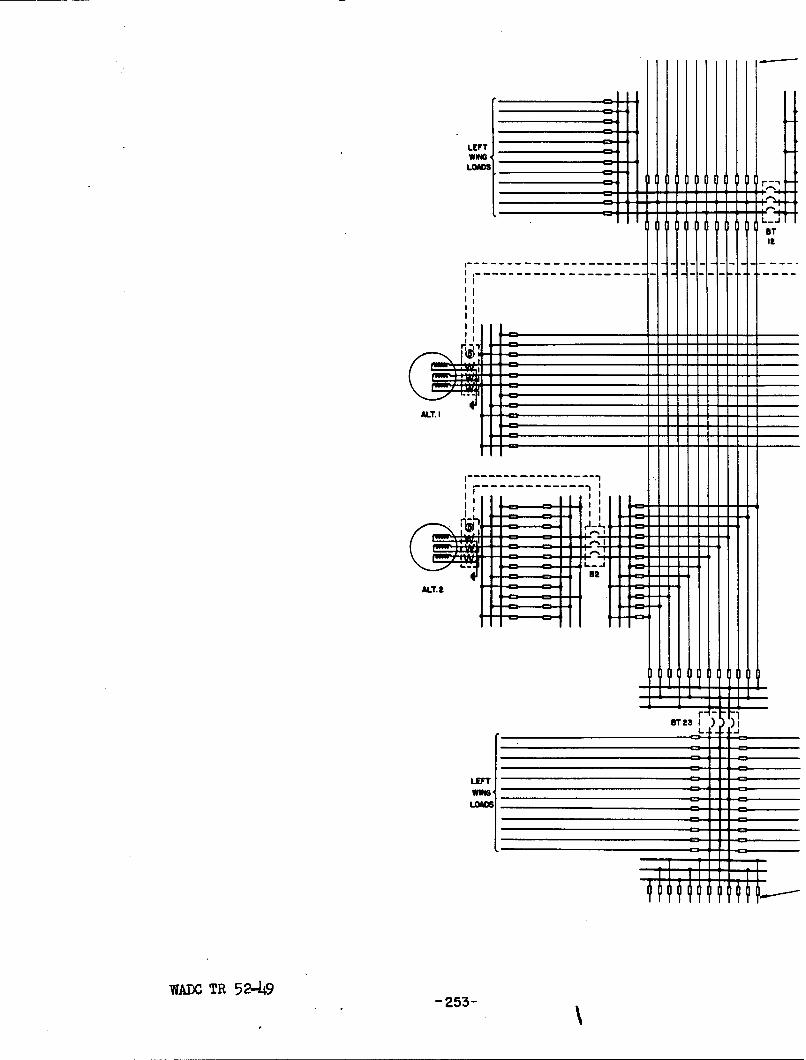
LEFTwhonLOADS
BT
IIt
III
ALT. I
U a I ) )II
LEFTWoe
LOADS
WADC TR 5 2-49-23

FORWARD LOADS
TON
-WINGLOADS
L) J
I L=
ISTt3 I ) )
AFT LOADS
:NV,-'_P16.85-_3 L'INE DIAGRAM OF RING BUS WITHFUSE MESH PROTECTION

FORWARD LOAD BUSES
-, II
IIIIIIII
II
I'
III
WADC~ TR52-9-24
SI I It
=J r(=zI i I I
II. - -
-- J
IiI
IIII
\ .I i

FORWARD LOAD BUSES
I
-~~ -------XIII Ii
------ -----------..
II
------------ L
'K - \\ 2-)_/\,// \ 4
-l--1 I
RELAY
AFT LOAD BUSES
OVERCURRENT
PROTECTION
-E
DIAGRAM OF RING BUS WITH
IAL PROTECTION.

VI. GNMNRATOR CONTROL SYSTEM
The controls for the a-c generators are shown in Fig. 1 and Fig.
2. The exciter is switched separately from the main circuit breaker which
connects the generator to the system. Manual synchronizing is used.
A serious disadvantage of the 400-cycle a-c system is the relative
complexity to the operator. In the d-c aircraft systems the operator has to
operate a single on-off switch for each generator. From there on operation
is automatic. (Some systems incorporate a manual voltage control although
this is not considered essential and, in fact, may be undesirable).
There appears to be advantage in automatic operation of an a-c
generator control system following closing of the operator's control switch.
Some consideration has been given to such a system and one approach to the
problem will be discussed. A schematic diagram of the arrangement is shown
in Fig. 87.
In this arrangement the operator's control and protective switch-
ing functions are carried out by separate devices. With this separation of
functions, several advantages worthy of consideration appear.
The circuit breaker need not be designed for repetitive operation
and since it will be operated only in the event of a short circuit, it should
be capable of interrupting the short-circuit current. In many cases the cir-
cuit breaker could be a manually closed device, in fact there may be safety
advantages in using a circuit breaker that can only be closed manually.
The contactor need not be made suitable for interrupting full a-
vailable fault current, although there is some advantage in having the higher
interrupting ability. Then the protective relays may be made to operate the
WAOC TR 52-49- 255 -

CS
"Vsc V R
A LT. ( C S
T Cs
EXC.
B - PROTECTIVE CIRCUIT BREAKER
B C - CONTACTOR, 3 POLE AUXILIARY CONTACTS 3NO, 3NCV -VOLTAGE RELAYV5 - VOLTAGE RELAY
SC - SYNCHRONISM CHECK RELAYM - SHADED POLE MOTOR WITH GEAR DRIVE
FOR VERNIER SPEED CONTROL
R - VERNIER SPEED CONTROL RHEOSTATCS - CONTROL SWITCH SPST (ON - OFF)
FIG. 87 -AUTOMATIC A- C GENERATOR CONTROL SYSTEM
WADOC TR 52-49- 2%6 -

contactor as well as the circuit breaker. In this way, even though tripping
power were not available for the main circuit breaker during a fault, the
circuit would be cleared.
Operation of the control circuit is described as follows:
At all times, except when the protective devices indicate "trip", the exciter
field circuit and the main circuit breaker are closed. After starting an
engine, the generator voltage builds up as engine speed increases until the
generated voltage reaches the normal level as set by the voltage regulator.
As the generated voltage approaches normal level relay V picks up. This
places switching of the contactor C under control of the operator control
switch CS and the synchronism check relay SC.
During this period the frequency of the incoming generator is
determined by the setting of a vernier rheostat, R, in the governor circuit.
The speed will increase to a value determined by the then existing setting
of the rheostat. When V and CS are both closed, regardless of which occur-
red first, (the operator may close the control switch at any time before
or after the engine is started) the small shaded-pole motor M is energized.
This motor drives the vernier speed control rheostat so as to alternately in-
crease and decrease the speed of the incoming machine from normal as the
rheostat is continuously rotated through 360 degrees. The vernier rheostat
may be a variable ratio transformer if this is advantageous in obtaining
the plus-minus speed control or in securing long life. The motor M may oper-
ate for some time if the engines are run at subnormal speed during ground
operation.
When the proper frequency and phase relationships are reached the
synchronizing check relay SC will close to energize the contactor C which
WADC TR 52-49- 257 -

seals itself in. When contactor C operates, the alternator is connected
to the bus, the speed vernier drive-motor M is de-energized and the speed
vernier rheostat shorted out leaving the load setting as determined by the
normal speed adjusting rheostat.
In order to connect the first machine to a dead bus, another
voltage relay, VBy is used. When VB is energized, the V contacts inB B
series with contacts of V are closed, permitting the sequence of operations
previously described. If VB is not energized (as when the bus is dead)
contacts V and SC are shorted out by the normally closed contacts of VB
permitting contactor C to be energized directly by operating switch CS.
Obviously, considerable study needs to be given to the character-
istics of the synchronism check relay, particularly with regard to pickup
values and speed of operation. These in turn will be related to the speed
and range of control of the vernier speed control driven by motor M.
The above control system has been sketched only in brief and
several variations are possible.
Further study of the objectives of generator control systems for
simplified operation should be carried out and techniques investigated for
accomplishing them.
VWADC TR 52-49 258

VII. CONCLUSIONS
1. Alternators having a lower short-circuit ratio than the present
40 KVA machines can probably be tolerated without endangering
system stability*
2. Test methods of determining alternator characteristics should be
studied and standardized.
3. The present reactive current amplification factor gives a loss
of 11% in capacity on a four-alternator system due to an error
voltage of +2.5%.
4. With the present frequency governing system using the equalizer
circuit and the maximum droop setting, the loss in system capac-
ity in a four-alternator system is 16% due to an error of +5% in
the reference frequency.
5. In case of loss of regulator sense on one alternator of a 2-alter-
nator system, voltage may increase to 13% above normal and may per-
sist until cleared by the exciter protection relay in about 2 sec-
onds.
6. Overvoltage protection (i.e. protection against sustained over-
voltage resulting from loss of regulator control) is presently ac-
complished only by the exciter protection relay. The exciter pro-
tection relay must be inherently slow to avoid nuisance operation
on heavy load conditions.
7. Loss of field excitation results in large reactive power flow from
remaining good machines and produces subnormal voltage. For con-
tinued successful operation of the system, it is essential to re-
move the underexcited alternator from the system.
WADC TR 52-49- 259 -

8. Failure of speed control would result in overspeeds of all alter-
nators connected to the system.
9. The available symmetrical rms fault currents from the 40 KVA al-
ternators studies are as follows:
a. Single-line-to-ground is 6 per unit.
b. Line-to-line is 4 to 5 per unit.
c. Three-phase is 6 1/2 per unit.
10. If the rotor of an alternator becomes blocked, it imposes a
severe drain of real and reactive power on the system and results
in a reduced system voltage. Automatic means of disconnecting
the faulty machine are essential.
ll. Synchronizing disturbances may give rise to reduced system volt-
age and to excessively high currents.
12. On a single alternator system, with overvoltage protection pro-
vided only by the exciter protection relay, load equipment would
need to be designed to withstand approximately 160 volts (133
percent) line-to-neutral for a duration determined by the speed
with which the exciter protection relay operates - 2 seconds or
more. All other overvoltage conditions found were much less se-
vere for overheating effects,
13. Both differential and directional protection are desirable for al-
ternator protection.
14. Protection is needed to remove an alternator which has lost its
field excitation. Directional reactive protection would be desir-
able providing methods of discriminating between loss field ex-
citation and voltage sense can be determined.
WADOC TR 52-49- 260 -

15. Differential protection using the double current transformers per
phase with two pilot wires for all three phases appears to offer
possibilities for protection of aircraft alternators and leads
to the bus.
16. Differential current protection for main buses is desirable.
17. Differential current or combinations of directional and overcurrent
devices appear to offer possibilities for distribution feeder pro-
tection.
WADC TR 52-49
- 261 -

VIII. RECOM1AENDATIONS
1. Studies should be carried out to determine acceptable short-cir-
cuit ratios for aircraft alternators.
a. Influence of short-circuit ratio on alternator weight.
b. Minimum acceptable values for system stability.
2. Studies should be initiated to establish standardized test pro-
cedures for determining alternator characteristics.
3. The values of pertinent alternator time constants should be deter-
mined for future analytical studies.
4. Economic studies should be made to determine the optimum value for
both the reactive power equalizer and the real power equalizer
amplification factors.
5. Methods of reducing the temperature effects on regulated frequency.
should be investigated.
6. Investigations should be carried out to determine better and faster
methods of protection against overvoltages caused by loss of regu-
lator control.
7. There is need for additional study of possible methods to remove
the underexcited alternator from the system on loss of field ex-
citation.
8. Additional investigations should be carried out to determine the
effects of loss of frequency control.
9. Additional investigations should be carried out to determine the
effects of failures in the reactive load and real load equalizer
circuits.
WADC TR 52-49- 262 -

10. Automatic means of detecting a blocked rotor should be developed.
11. Methods of automatic synchronizing should be developed.
12. Studies of transient overvoltages should be made.
13. Aircraft electrical systems should be designed with the following
statements as guides
.(a) Failure of any device or circuit may occur. *
(b) The system should be so arranged that it will continue
to operate successfully in spite of such a failure.
14. Arcing, bouncing, solid., pinched and any other faults should be
further investigated to determine characteristics which can be
utilized for system protection.
15. Specification MIL-F-5372 should be revised to specifically define
the interrupting rating in terms of available fault current.
16. Fuse application should be based on using a multiplying factor of
1.4 to account for the d-c offset.
17. MIL-F-5372 should be revised to specify accuracy of melting char-
acteristics down to melting times representative of the maximum
short-circuit currents but not less than 0.0006 seconcs.
18. Additional studies should be given to directional reactive protec-
tion for alternators. (This study is closely related to that sag-
gested in Recommendation 6).
19. All elements of a unit system, a failure in any one of which would
cause the loss of the same system component, should be arranged
physically so that the exposure area is a minimum. For example, if
the control leads of an alternator are run widely separated from
WADC TR 52-49
- 263 -
the main power leads, there is an increase in the vulnerable area.
20. Improved differential protection devices should be developed for
application to alternators, buses, tie circuits, and feeders.
21. Overcurrent and directional protective devices should be developed
for feeder service.
22. Studids should be directed toward improved control systems which
are more nearly automatic.
23. The speed-sensing tachometer and overspeed limit switch should
not be operated from the same shaft and gears, since a failure of
either the shaft or gears would cause the simultaneous loss of
both the speed controlling and protective devices.
2LJ. A study should be made to determine whether the rotating exciter
can b0 eliminated in favor of a magnetic amplifier-rectifier
system.
WADOC TR 52-49- 264 -

IX. LOGBOOKS
Detailed data are recorded in Armour Research FoundationLogbooks C-1718, C-1719, C-1975, D-1124, and C-1986.
WADC TR 52-49
- 265 -