4-Head Electric Pressure Fryer - Henny Penny
170
FM06-082A SERVICE MANUAL MODEL 500 MODEL 561 44--HHeeaaddEElleeccttrriicc PPrreessssuurree FFrryyeerr
-
Upload
khangminh22 -
Category
Documents
-
view
0 -
download
0
Transcript of 4-Head Electric Pressure Fryer - Henny Penny

FM06-082A
SERVICEMANUAL
MODEL 500MODEL 561
44--HHeeaadd EElleeccttrriiccPPrreessssuurree FFrryyeerr


Con
tents
i
Table of Contents
Safety and Compliance............................................................................................... vii
Chapter 1 Troubleshooting..............................................................................................11.1 Introduction ...........................................................................................................11.2 Diagnostics............................................................................................................1
Chapter 2 Maintenance ................................................................................................ 112.1 Introduction ......................................................................................................... 112.2 Maintenance Hints ............................................................................................... 112.3 Preventative Maintenance Schedule...................................................................... 112.4 Lower the Control.................................................................................................122.4.1 Raise the Control ...........................................................................................122.4.2 Replace the Control .......................................................................................122.4.3 Configure the Serial Number...........................................................................132.4.3.1 Verify the Serial Number .............................................................................132.4.3.2 Adding or Correcting a 9 Character Serial Number........................................142.4.3.3 Adding or Correcting a 7 Character Serial Number........................................15
2.5 Transformer Replacement ....................................................................................152.6 Temperature Probe Replacement ..........................................................................162.7 Temperature Regulation (Single Stage) .................................................................182.7.1 Front Panel Thermostat ..................................................................................182.7.2 Internal Operation ..........................................................................................182.7.3 Drain Microswitch ..........................................................................................192.7.4 High Limit Temperature Control .......................................................................19
2.8 Calibrating The Standard Single Stage Thermostat.................................................192.9 Testing The Thermostat ........................................................................................192.9.1 Procedure .....................................................................................................19
2.10 Thermostat Replacement....................................................................................202.11 High Temperature Limit Control ...........................................................................232.11.1 Description ..................................................................................................232.11.2 Checkout .....................................................................................................242.11.3 Replacement ...............................................................................................24
2.12 Heating Elements...............................................................................................262.12.1 Description ..................................................................................................262.12.2 Maintenance Hint .........................................................................................262.12.3 Checkout.....................................................................................................262.12.4 Replacement ...............................................................................................27
2.13 Heating Contactors ............................................................................................302.13.1 Description ..................................................................................................302.13.2 Checkout (Power Removed) .........................................................................302.13.3 Checkout (Power Supplied) ..........................................................................322.13.4 Replacement Square D ................................................................................332.13.5 Replacement Mercury ..................................................................................34
2.14 Electrical Components........................................................................................352.14.1 Drain Switch ................................................................................................352.14.1.1 Electric Models.........................................................................................35
2.14.2 Main Power Switch.......................................................................................36

Con
tents
ii
2.14.3 Continuity Check Procedure..........................................................................372.14.4 Replacement ...............................................................................................372.14.5 Indicator Lights ............................................................................................382.14.6 Fuse Holder.................................................................................................382.14.7 Checking Procedure For Fuses .....................................................................382.14.8 Cord & Plug Check.......................................................................................382.14.9 Wall Receptacle (Voltage Check) ..................................................................382.14.9.1 Electric Models.........................................................................................38
2.15 Timing Control ...................................................................................................392.15.1 Description ..................................................................................................392.15.2 Checking Procedure.....................................................................................392.15.3 Replacement ...............................................................................................402.15.4 Timer Light ..................................................................................................412.15.5 Buzzer Coil ..................................................................................................412.15.6 Timer Switch................................................................................................42
2.16 Pressure Regulation/Exhaust ..............................................................................422.16.1 Solenoid Valve .............................................................................................422.16.2 Coil Check Procedure...................................................................................422.16.3 Replacement ...............................................................................................432.16.4 Deadweight Valve ........................................................................................482.16.5 Cleaning Steps ............................................................................................482.16.6 Removal & Cleaning of Safety Relief Valve ....................................................492.16.7 Pressure Gauge...........................................................................................492.16.7.1 Calibration Steps ......................................................................................492.16.7.2 Cleaning Steps.........................................................................................50
2.16.8 Condensation Box Assembly ........................................................................502.16.9 Condensation Box Bottom Removal ..............................................................512.16.10 Lid Cover Assembly....................................................................................522.16.10.1 Description.............................................................................................522.16.10.2 Lid Cover Removal .................................................................................522.16.10.3 Lid Cover Installation ..............................................................................53
2.16.11 Lid Hinge Spring.........................................................................................532.16.12 Latch Spring Installation..............................................................................542.16.13 Lid Liner ....................................................................................................572.16.14 Reversing The Lid Gasket...........................................................................572.16.14.1 Purpose .................................................................................................572.16.14.2 Process .................................................................................................58
2.16.15 Lid Limit Stop Adjustment ...........................................................................592.17 Filtering System .................................................................................................602.17.1 Filter Rinse Hose .........................................................................................602.17.2 Removal......................................................................................................602.17.3 Installation...................................................................................................612.17.4 Filter Valve Description .................................................................................612.17.5 Removal......................................................................................................612.17.6 Filter Pump Repair .......................................................................................622.17.7 Cover Removal ............................................................................................622.17.8 Pump Removal ............................................................................................632.17.9 Filter Pump Motor Protector - Manual Reset ...................................................65
2.18 Electrical Conversions ........................................................................................652.18.1 Procedures..................................................................................................65
2.19 Wiring Diagrams ................................................................................................662.20 Caster Replacement Procedure..........................................................................66

Con
tents
iii
2.21 Solenoid Valve ...................................................................................................662.21.1 Replace Solenoid Valve Assembly.................................................................67
Chapter 3 Pressure Assist Features and Function ...........................................................713.1 Software..............................................................................................................713.1.1 C8000 Controller............................................................................................71
Chapter 4 Programming ...............................................................................................73
Chapter 5 Wiring Diagrams............................................................................................815.1 500 EF, 208-240v, 50/60Hz, 1P (63192E) (Before 04/01/06)....................................815.2 500 EF, 208-240v, 50/60Hz, 1P (71995C) (After 04/01/06) ......................................825.3 500 EF, 208-240v, 50/60Hz, 1P (63199F) (Before 04/01/06) ....................................835.4 500 EF, 208-240v, 50/60Hz, 1P (71988D) (After 04/01/06) ......................................845.5 500 EF, 380-415v, 50Hz, 3P, (63197E) (Before 04/01/06) ........................................855.6 500 EF, 380-415v, 50Hz, 3P, (71993B) (After 04/01/06)...........................................865.7 500 EF, C1000 & 2000, 208-240v, 50/60Hz, 3P, 240v Con. (78541C) .......................875.8 500 EF, C1000 & 2000, 208-240v, 50/60Hz, 1P, 240v Con. (79421B) .......................885.9 500 EF, C1000 & 2000, 208-240v, 50/60Hz, 1P, 240v Con. (79422B) .......................895.10 500 EF, C1000 & 2000, 380-415v, 50/60Hz, 3P, 240v Con. (79414C) .....................905.11 500 EF, C1000 & 2000, 480v, 50/60Hz, 3P, 240v Con. (79415A) ............................915.12 500 EF, 208-240v, 50/60Hz, 1P (51672N) (Before 04/01/06)..................................925.13 500 EF, 208-240v, 50/60Hz, 1P (69647C) (After 04/01/06).....................................935.14 500 EF, 208-240v, 50/60Hz, 3P (63596K) (Before 04/01/06) ..................................945.15 500 EF, 208-240v, 50/60Hz, 3P (69624C) (After 04/01/06).....................................955.16 500 EF, 380-415v, 50/60Hz, 3P (63355M) (Before 04/01/06) .................................965.17 500 EF, 380-415v, 50/60Hz, 3P (69449D) (After 04/01/06).....................................975.18 500 EF, 400v, 50Hz, 3P (51300N) (Before 04/01/06) .............................................985.19 500 KFC EF, 380-415v, 50Hz, 3P (63211K) (Before 04/01/06) ...............................995.20 500 KFC EF, 380-415v, 50Hz, 3P (71819B) (After 04/01/06) ................................ 1005.21 500 SC EF, 208/240v, 50/60Hz, 3P (18311F)...................................................... 1015.22 500 SC EF, 208/240v, 50/60Hz, 1P (18309D) ..................................................... 1025.23 500 SMS EF, 208-240v, 50/60Hz, 1P (73309E)................................................... 1035.24 500/561 EF, 208-240v, 50/60Hz, 3P (63131F) (Before 04/01/06).......................... 1045.25 500/561 EF, 208-240v, 50/60Hz, 3P (71998C) (After 04/01/06) ............................ 1055.26 500/561 EF, 480v, 50/60Hz, 3P (63194G) (Before 04/01/06)................................ 1065.27 500/561 EF, 480v, 50/60Hz, 3P (71994C) (After 04/01/06)................................... 1075.28 500/561 EF, 380-415v, 50/60Hz, 3P (63200F) (Before 04/01/06).......................... 1085.29 500/561 EF, 380-415v, 50/60Hz, 3P (72002B) (After 04/01/06) ............................ 1095.30 561 EF, 13.5kW, 3P, 208/240v (48184E) ............................................................ 1105.31 561 EF, 13.5kW, 3P, 480v (48193E)................................................................... 1115.32 561 EF, 13.5kW, 3P, 220v (48198E)................................................................... 1125.33 561 EF, 13.5kW, 3P, 220/380v or 240/415v (48200E) .......................................... 1135.34 561 EF, 11.25kW, 3P, 208/240v (55653B)........................................................... 1145.35 561 EF, 11.25kW, 3P, 220v (55652B) ................................................................. 1155.36 561 EF, 11.25kW, 3P, 220v (55650B) ................................................................. 1165.37 561 EF, 11.25kW, 3P, 220/380v or 240/415v (55661B) ........................................ 1175.38 561 EF, 11.25kW, 3P, 220/380v or 240/415v (55659B) ........................................ 1185.39 561 EF, 11.25kW, 3P, 480v (55651C) ................................................................. 1195.40 561 EF, 11.25kW, 3P, 480v (55649B) ................................................................. 1205.41 561 EF, 11.25 kW, 3P, 208/240v (55422B).......................................................... 121
Chapter 6 Annual Inspection........................................................................................ 1236.1 Henny Penny Start-Up Provider Information......................................................... 123

Con
tents
iv
6.2 Store Information ............................................................................................... 1236.3 Equipment Information ....................................................................................... 1236.4 Signatures......................................................................................................... 1236.5 Checklist ........................................................................................................... 1236.6 Inspect the Fry Pot ............................................................................................. 1286.7 Inspect the Casters and Frame ........................................................................... 1296.8 Inspect the Power Cord ...................................................................................... 1296.9 Inspect the Condensation Box............................................................................. 1306.10 Inspect the Solenoid and Deadweight Plumbing ................................................. 1306.10.1 Clean the Dead Weight Plumbing ................................................................ 1316.10.2 Clean the Solenoid Plumbing ...................................................................... 131
6.11 Inspect the Drain Switch.................................................................................... 1326.12 Test the Filtration System.................................................................................. 1336.13 Inspect the Drain Pan ....................................................................................... 1336.14 Inspect and Tighten the Spreader Bar and High Limit .......................................... 1346.15 Inspect the High Limit ....................................................................................... 1356.16 Inspect the Temperature Probe ......................................................................... 1366.17 Inspect for Oil Leaks......................................................................................... 1376.17.1 Oil Migration .............................................................................................. 1376.17.2 Plumbing Leaks in Filtration ........................................................................ 1386.17.3 Plumbing Leaks During Cooking ................................................................. 139
6.18 Measure AMP Draw ......................................................................................... 1396.19 Inspect Deadweight.......................................................................................... 1406.20 Inspect Latch, Catch and Spring........................................................................ 1416.21 Inspect Cross Arm Component.......................................................................... 1436.22 Lubricate Cross Arm Components ..................................................................... 1466.23 Pressure Regulation and Exhaust System.......................................................... 1476.23.1 Clean the Lid Liner ..................................................................................... 1476.23.2 Reverse the Lid Gasket .............................................................................. 1486.23.3 Adjust the Lid Limit Stop ............................................................................. 1486.23.4 Removal and Cleaning of Safety Relief Valve ............................................... 1496.23.5 Pressure Gauge Calibration........................................................................ 1506.23.6 Coil Check Procedure................................................................................. 1516.23.7 Locking Pin Test Procedure ........................................................................ 151

Con
tents
v

Con
tents
vi
List of TablesTable 1-1 Troubleshooting..................................................................................................1Table 2-1 Preventative Maintenance Schedule .................................................................. 11Table 2-2 Heating Element Ohm Checkout ........................................................................27Table 2-3 Continuity Check Procedure - Off Position ..........................................................37Table 2-4 Continuity Check Procedure - Power Position .....................................................37Table 2-5 Continuity Check Procedure - Pump Position ......................................................37Table 2-6 Checking Procedure - ON/OFF Switch ...............................................................39Table 2-7 Checking Procedure - Buzzer Coil......................................................................40Table 2-8 Checking Procedure - Microswitch .....................................................................40Table 2-9 Checking Procedure - Motor ..............................................................................40Table 2-10 Checking Procedure - Reset Coil......................................................................40Table 2-11 Coil Check Procedure......................................................................................43Table 4-1 Programming....................................................................................................73
List of FiguresFigure 2-1 Thermostat Test Points ....................................................................................20Figure 2-2 Thermostat Sensing Bulb - Electric ...................................................................20Figure 2-3 Thermostat & Control Panel Diagram................................................................21Figure 2-4 Screw Nut Assembly........................................................................................22Figure 2-5 High Limit Reset Button - Electric......................................................................23Figure 2-6 High Limit Capillary Tube - Electric....................................................................25Figure 2-7 Heating Element Assembly ..............................................................................28Figure 2-8 Heating Element Spreaders .............................................................................29Figure 2-9 Primary Contactor Test Points ..........................................................................31Figure 2-10 Heat Contactor Test Points .............................................................................32Figure 2-11 Circuit Breaker...............................................................................................32Figure 2-12 Drain Switch Assembly ..................................................................................36Figure 2-13 Continuity Check Test Points ..........................................................................37Figure 2-14 Solenoid Valve Assembly ...............................................................................43Figure 2-15 Exhaust Fitting ..............................................................................................46Figure 2-16 Conduit Fitting ...............................................................................................47Figure 2-17 Solenoid Valve Diagram .................................................................................47Figure 2-18 Latch Spring Assembly ..................................................................................55Figure 2-19 Lid Cover Screws ..........................................................................................58Figure 6-1 PFG 600 Weld Locations ............................................................................... 128

Preface
vii
SSaaffeettyy aanndd CCoommpplliiaanncceeHenny Penny fryers have many safety features incorporated. However, the only wayto ensure safe operation is to fully understand the proper installation, operation, andmaintenance procedures. The instructions in this manual have been prepared to aidyou in learning the proper procedures. Where information is of particular importanceor is safety related, the words DANGER, WARNING, CAUTION, or NOTICE are used.Their usage is described as follows:
DDAANNGGEERR!! indicates hazardous situation which, if notavoided, will result in death or serious injury.
DDAANNGGEERR!!
WWAARRNNIINNGG!! indicates hazardous situation which, if notavoided, could result in death or serious injury.
WWAARRNNIINNGG!!
CCAAUUTTIIOONN!! indicates hazardous situation which, if notavoided, could result in moderate or minor injury.
CCAAUUTTIIOONN!!
NOTICENOTICE is used for information considered importantregarding property damage.

Preface
viii
These are the original version controlled Henny Penny instructions for Pressure FryerElectric (PFE) model 500, 561 (PFE 500, 561).This manual is available on the Henny Penny Public website (www.hennypenny.com).Read these instructions completely prior to installation and operation of this applianceto ensure compliance to all required installation, operation and safety standards. Readand obey all safety messages to avoid damage to the appliance and personal injury.
• TThhiiss ffrryyeerr mmuusstt bbee iinnssttaalllleedd aanndd uusseedd iinn aa wwaayy tthhaattwwaatteerr ddooeess nnoott ccoonnttaacctt tthhee ooiill wwhhiicchh ccaann ccaauusseessppllaasshhiinngg aanndd bbooiilliinngg oovveerr ooff ooiill aanndd sstteeaamm lleeaaddiinnggttoo ppeerrssoonnaall iinnjjuurryy;; eexxcclluuddeess nnoorrmmaall pprroodduuccttmmooiissttuurree..
• BBuurrnn rriisskk!! DDoo nnoott mmoovvee tthhee ffrryyeerr oorr ffiilltteerr ddrraaiinn ppaannwwhhiillee ccoonnttaaiinniinngg hhoott ooiill.. PPeerrssoonnaall iinnjjuurryy oorr sseerriioouussbbuurrnnss ccaann rreessuulltt ffrroomm ssppllaasshhiinngg hhoott ooiill..
This appliance is intended for commercial use in kitchens of restaurants, bakeries,hospitals, etc. but not for the continuous mass production of food such as in a factorysetting. During use the units airborne A-weighted emission sound pressure is below70 db(A). All repairs must be performed by the manufacturer, its service agent orsimilarly qualified persons in order to avoid a hazard.
Always use strain relief. The provided power cord must be installed with a strain reliefin a way that if the strain relief fails, wires L1, L2, L3 and N must draw taunt and failfirst. If the supplied power cord or an existing one becomes damaged, do not use it;rather, replace it with a known good power cord. The power cord must be replaced bythe manufacturer, its service agent or similarly qualified persons in order to avoid ahazard.
Proper daily, weekly, monthly, quarterly and yearly maintenance must be performedon this appliance to ensure safe and continuous operation. This appliance must neverbe cleaned with a water jet or steam cleaning tool. Cleaning brushes are shipped withthe appliance and proper cleaning instructions are included in this manual.
Proper maintenance also increases the usable life of the appliance and oil, whichreduces lifetime operating costs. Additionally, old oil increases the possibility of surgeboiling and fire due to the reduced flash point of the oil. The oil temperature mustnever exceed 450⁰ F (230⁰ C).
This appliance is not intended for use by persons (including children) with reducedphysical, sensory or mental capabilities, or lack of experience and knowledge, unlessthey have been given supervision or instruction concerning use of the appliance by a

Preface
ix
person responsible for their safety. Children should be supervised to ensure that theydo not play with the appliance.
This appliance is not intended to be operated by means of an external timer or aseparate remote control system.
This appliance must be installed in accordance with the manufacturer’s instructionsand the regulations in force and only used in suitably ventilated location. Read theinstructions fully before installing or using the appliance.
This appliance must be installed with suitable ventilation in accordance with themanufacturer’s instructions and the regulations in force to prevent the occurrence ofunacceptable concentrations of substances harmful to health. Proper air flow isessential to permit efficient removal of the steam exhaust and frying odors. Air flow forthis model is 33.3 cfm (56.6 m3/h) of air flow.
WWAASSTTEE EELLEECCTTRRIICCAALL AANNDD EELLEECCTTRROONNIICC EEQQUUIIPPMMEENNTT ((WWEEEEEE)) As of August16, 2005, the Waste Electrical and Electronic Equipment directive went into effect forthe European Union. Our products have been evaluated to the WEEE directive. Wehave also reviewed our products to determine if they comply with the Restriction ofHazardous Substances directive (RoHS) and have redesigned our products asneeded in order to comply. To continue compliance with these directives, this unitmust not be disposed as unsorted municipal waste. For proper disposal, pleasecontact your nearest Henny Penny distributor.

Preface
x

Trou
blesho
oting
1
CChhaapptteerr 11 TTrroouubblleesshhoooottiinngg11..11 IInnttrroodduuccttiioonnThis section provides troubleshooting information in the form of an easy to read table.If a problem occurs during the first operation of a new fryer, recheck the installationper Section 2 Unpacking/Installation of the Operator’s Manual. Beforetroubleshooting, always recheck the operating procedure per Section 3 OperatingInstructions of the Operator’s Manual.
11..22 DDiiaaggnnoossttiiccssTo isolate a malfunction, proceed as follows:
11.. Clearly define the problem (or symptom) and when it occurs.
22.. Locate the problem in the troubleshooting table.
33.. Review all possible causes. Then, one-at-a-time, work through the list ofcorrections until the problem is solved.
WWAARRNNIINNGG!!
RReeffeerr ttoo tthhee mmaaiinntteennaannccee pprroocceedduurreess iinn CChhaapptteerr 22MMaaiinntteennaannccee,, ppaaggee 1111.. IIff mmaaiinntteennaannccee pprroocceedduurreessaarree nnoott ffoolllloowweedd ccoorrrreeccttllyy iinnjjuurriieess aanndd//oorr pprrooppeerrttyyddaammaaggee ccaann rreessuulltt..
TTaabbllee 11--11 TTrroouubblleesshhoooottiinngg
Problem Cause Correction
CCooookkiinngg SSeeccttiioonn
Product Color Not Correct:
A. Too dark. Temperature too high.• Reduce thermostat setting.
• Remove and replace defectivethermostat per 2.10 ThermostatReplacement, page 20.
Shortening too old. Change shortening.
Shortening too dark.• Filter shortening.
• Shortening taste test, see theOperator’s Manual.
• Change Shortening.
Trou
blesho
oting
2
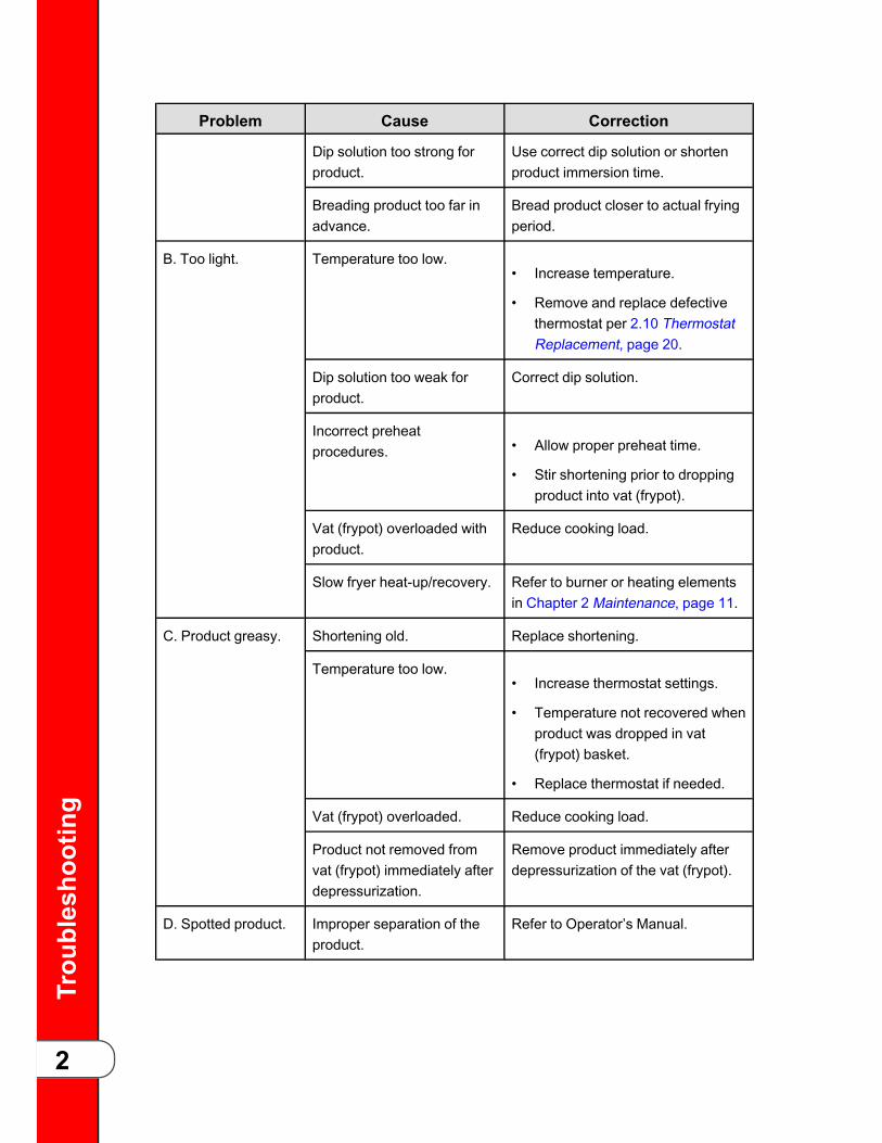
Problem Cause Correction
Dip solution too strong forproduct.
Use correct dip solution or shortenproduct immersion time.
Breading product too far inadvance.
Bread product closer to actual fryingperiod.
B. Too light. Temperature too low.• Increase temperature.
• Remove and replace defectivethermostat per 2.10 ThermostatReplacement, page 20.
Dip solution too weak forproduct.
Correct dip solution.
Incorrect preheatprocedures. • Allow proper preheat time.
• Stir shortening prior to droppingproduct into vat (frypot).
Vat (frypot) overloaded withproduct.
Reduce cooking load.
Slow fryer heat-up/recovery. Refer to burner or heating elementsin Chapter 2 Maintenance, page 11.
C. Product greasy. Shortening old. Replace shortening.
Temperature too low.• Increase thermostat settings.
• Temperature not recovered whenproduct was dropped in vat(frypot) basket.
• Replace thermostat if needed.
Vat (frypot) overloaded. Reduce cooking load.
Product not removed fromvat (frypot) immediately afterdepressurization.
Remove product immediately afterdepressurization of the vat (frypot).
D. Spotted product. Improper separation of theproduct.
Refer to Operator’s Manual.

Trou
blesho
oting
3
Problem Cause Correction
Product was incorrectlydipped in water beforebreading.
Agitate product during the dippingprocedure.
Breading not uniform onproduct. • Sift breading during breading.
• Refer to Operator’s Manual.
Burned breading particles onproduct.
Filter the shortening more frequently.
Product sticking together. Separate product prior to pressurecooking, see the Operator’s Manual.
E. Dryness ofproduct.
Moisture loss prior tocooking. • Use fresh products.
• Keep product covered with amoist cloth to reduceevaporation.
Over cooking the product.• Reduce cooking time.
• Reduce cooking temperature.
Low operating pressure. Check pressure gauge reading;check for pressure leaks.
Product load too small. Increase quantity to obtain correctoperating pressure and productquality.
Product Flavor (Taste):
A. Salty taste. Breading mixture is too salty.• Sift breading after each use.
• Incorrect breading mixture.
• Discard old breading.
Marination mixture tooconcentrated.
Reduce the concentration of themarination mixture.
Incorrect choice of breading. Use breading designed for the de-sired product.
B. Burned taste. Burned shortening flavor. Replace shortening.

Trou
blesho
oting
4
Problem Cause Correction
Shortening needs filtering. Filter shortening more frequently.
Vat (frypot) not properlycleaned.
Drain and clean vat (frypot).
C. Bland taste. Raw product not fresh. Use fresh raw products.
Breading mixture incorrectfor product (spice content toolow).
Use breading designed for desiredproduct.
Cooking temperature toohigh (spice flavor lost).
Use correct temperature for breadingused.
Breading does not adhere toproduct.
Use correct dip and breading, anduse correct procedure for theproduct.
D. Rancid taste. Shortening too old. Replace shortening, and follow rec-ommended care and use of shorten-ing, see the Operator’s Manual.
Non-compatible productscooked within the sameshortening.
• Replace shortening.
• Use compatible products, andfollow recommended care anduse of shortening; refer toOperator’s Manual.
Infrequent filtering. Replace shortening and follow rec-ommended care and use of shorten-ing; refer to Operator’s Manual.
Raw product not fresh. Use fresh product.
General:
A. Meat separationfrom bone.
Incorrect meat cut. Use correct meat cutting procedures.
Overcooking. Reduce cooking time.
Raw product contains toomuch water.
Allow product to drain aftermarinating.
Product not fresh. Use fresh product.
B. Bone color notproper.
Using frozen product (blackbone).
Use fresh product.

Trou
blesho
oting
5
Problem Cause Correction
Improper handling of product(black bone).
Use proper handling procedures forproduct.
Product not thoroughlycooked (red bone).
Increase cooking time.
C. Breading falls off. Incorrect breadingprocedures.
Use correct breading procedure, seethe Operator’s Manual.
Product partially frozen dur-ing breading.
Thoroughly thaw the product beforebreading.
Improper handling of cookedproduct.
Handle cooked product carefully.
Excessive stirring of productprior to closing the lid.
Separate the product, see the Oper-ator’s Manual.
D. Product stickingtogether.
Product breaded too long pri-or to cooking.
Refer to breading & fryinginstructions.
Improper separation proce-dures prior to closing the lid.
Separate the product, see the Oper-ator’s Manual.
Vat (frypot) overloaded withproduct.
Reduce the cooking load.
Improper loading procedure. Load product properly into vat (fry-pot), see the Operator’s Manual.
PPoowweerr SSeeccttiioonn
With switch inPOWER position,the fryer is com-pletely inoperative(NO POWER).
Open circuit.• Check to see that unit is plugged
in.
• Check breaker or fuse at supplybox.
• Check control panel fuses per2.14 Electrical Components,page 35 section (electric moduleonly).
• Check voltage at wall receptacle.
• Check MAIN POWER switch per2.14 Electrical Components,page 35; replace if defective.
Trou
blesho
oting
6
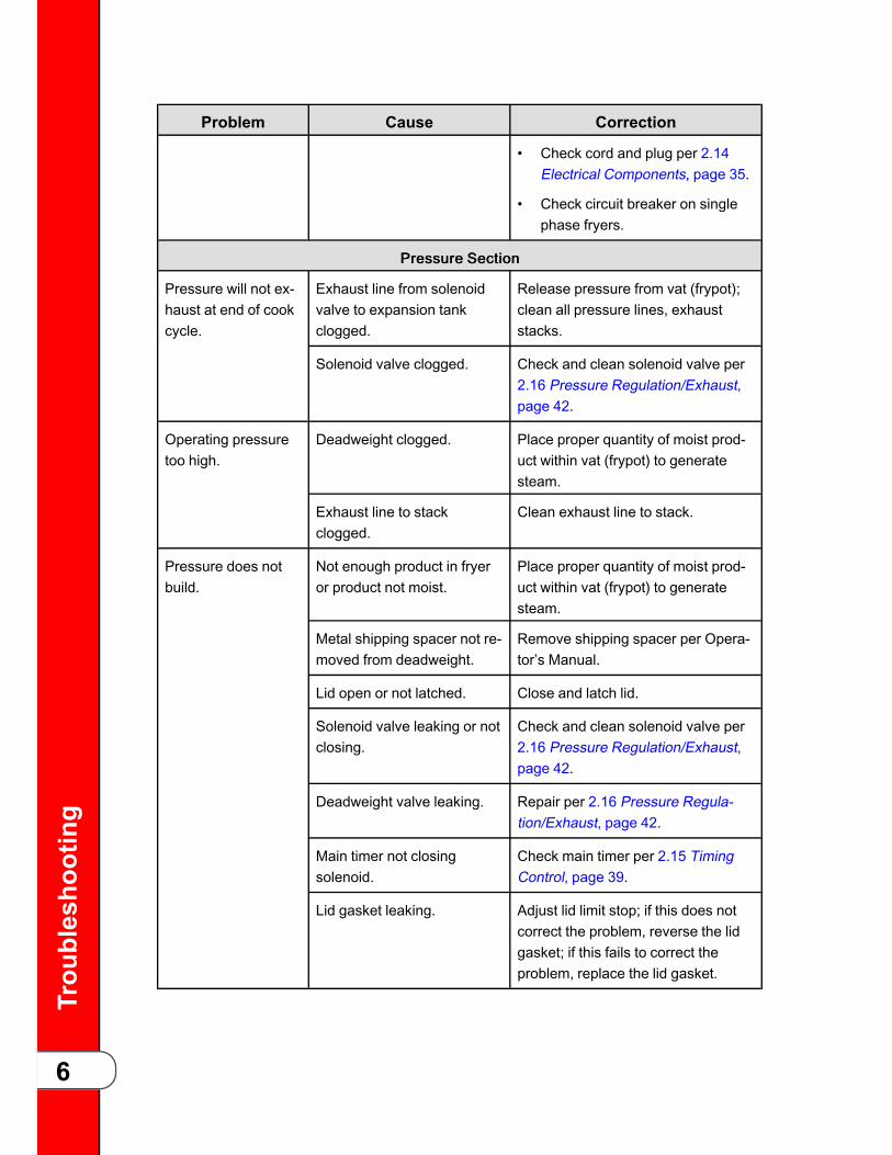
Problem Cause Correction
• Check cord and plug per 2.14Electrical Components, page 35.
• Check circuit breaker on singlephase fryers.
PPrreessssuurree SSeeccttiioonn
Pressure will not ex-haust at end of cookcycle.
Exhaust line from solenoidvalve to expansion tankclogged.
Release pressure from vat (frypot);clean all pressure lines, exhauststacks.
Solenoid valve clogged. Check and clean solenoid valve per2.16 Pressure Regulation/Exhaust,page 42.
Operating pressuretoo high.
Deadweight clogged. Place proper quantity of moist prod-uct within vat (frypot) to generatesteam.
Exhaust line to stackclogged.
Clean exhaust line to stack.
Pressure does notbuild.
Not enough product in fryeror product not moist.
Place proper quantity of moist prod-uct within vat (frypot) to generatesteam.
Metal shipping spacer not re-moved from deadweight.
Remove shipping spacer per Opera-tor’s Manual.
Lid open or not latched. Close and latch lid.
Solenoid valve leaking or notclosing.
Check and clean solenoid valve per2.16 Pressure Regulation/Exhaust,page 42.
Deadweight valve leaking. Repair per 2.16 Pressure Regula-tion/Exhaust, page 42.
Main timer not closingsolenoid.
Check main timer per 2.15 TimingControl, page 39.
Lid gasket leaking. Adjust lid limit stop; if this does notcorrect the problem, reverse the lidgasket; if this fails to correct theproblem, replace the lid gasket.
Trou
blesho
oting
7
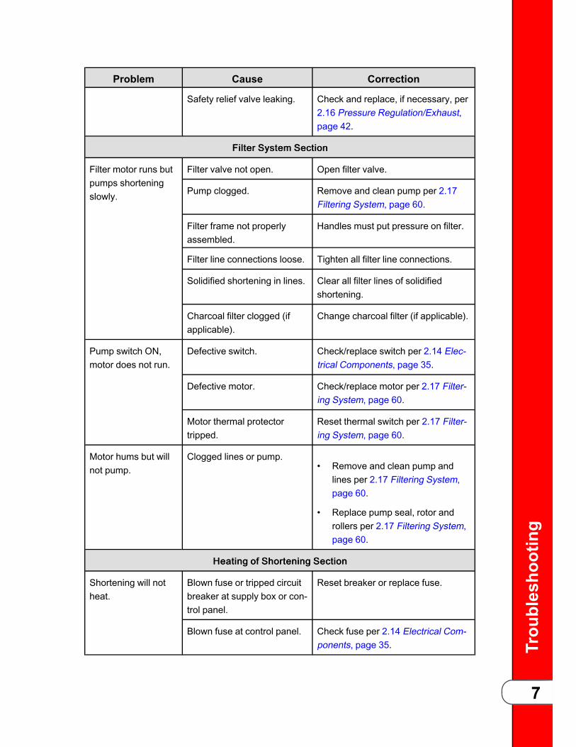
Problem Cause Correction
Safety relief valve leaking. Check and replace, if necessary, per2.16 Pressure Regulation/Exhaust,page 42.
FFiilltteerr SSyysstteemm SSeeccttiioonn
Filter motor runs butpumps shorteningslowly.
Filter valve not open. Open filter valve.
Pump clogged. Remove and clean pump per 2.17Filtering System, page 60.
Filter frame not properlyassembled.
Handles must put pressure on filter.
Filter line connections loose. Tighten all filter line connections.
Solidified shortening in lines. Clear all filter lines of solidifiedshortening.
Charcoal filter clogged (ifapplicable).
Change charcoal filter (if applicable).
Pump switch ON,motor does not run.
Defective switch. Check/replace switch per 2.14 Elec-trical Components, page 35.
Defective motor. Check/replace motor per 2.17 Filter-ing System, page 60.
Motor thermal protectortripped.
Reset thermal switch per 2.17 Filter-ing System, page 60.
Motor hums but willnot pump.
Clogged lines or pump.• Remove and clean pump and
lines per 2.17 Filtering System,page 60.
• Replace pump seal, rotor androllers per 2.17 Filtering System,page 60.
HHeeaattiinngg ooff SShhoorrtteenniinngg SSeeccttiioonn
Shortening will notheat.
Blown fuse or tripped circuitbreaker at supply box or con-trol panel.
Reset breaker or replace fuse.
Blown fuse at control panel. Check fuse per 2.14 Electrical Com-ponents, page 35.

Trou
blesho
oting
8
Problem Cause Correction
Faulty main switch. Check main switch per 2.14 Electri-cal Components, page 35.
No power. Check cord and plug and power atwall receptacle per 2.14 ElectricalComponents, page 35.
Faulty contactor. Check contactor per 2.13 HeatingContactors, page 30.
High limit control switchopen.
Press red high limit reset per 2.11High Temperature Limit Control,page 23.
Faulty thermostat. Check thermostat per 2.10 Thermo-stat Replacement, page 20.
Faulty high limit controlswitch.
Check high limit control switch per2.11 High Temperature Limit Control,page 23.
Heating of shorten-ing too slow.
Low or improper voltage. Use a meter and check the recep-tacle against data plate.
Weak or burnt out element(s).
Check heating element(s) per 2.12Heating Elements, page 26.
Points in contactor bad. Check contactor per 2.13 HeatingContactors, page 30.
Wire(s) loose. Tighten.
Burnt or charred wireconnection.
Replace wire and clean connectors.
Shorteningoverheating.
Check thermostat. Check faulty thermostat per 2.10Thermostat Replacement, page 20.
Check faulty contactor per2.13 Heating Contactors,page 30.
Check contactor for not opening.
SShhoorrtteenniinngg FFooaammiinngg//DDrraaiinniinngg
Foaming or boilingover of shortening.
Water in shortening. At end of cook cycle, drain shorten-ing and clean vat (frypot), add fresh

Trou
blesho
oting
9
Problem Cause Correction
shortening, and check procedure forraising lid.
Condensation line stoppedup.
Condensation line stopped up.
Improper or bad shortening. Use recommended shortening.
Improper filtering. Refer to the procedure covering fil-tering the shortening.
Improper rinsing after clean-ing the fryer.
Clean and neutralize the vat (frypot);rinse with vinegar to remove alkalinethen rinse with hot water, and dry vat(frypot).
Shortening will notdrain from vat(frypot).
Drain valve clogged withcrumbs.
Open valve - force cleaning brushthrough drain opening.
Drain valve will not open byturning handle.
Replace cotter pins in valvecoupling.
MMaaiinn TTiimmeerr SSeeccttiioonn
Timer fails to run. No power input.• Check timer switch.
• Check timer motor.
Buzzer continues tobuzz.
Timer set at zero. Set timer indicator to a setting otherthan zero.
Faulty microswitch. Check and replace faulty micro-switch per 2.14 Electrical Compo-nents, page 35.
Buzzer will not buzz. Possible faulty buzzer. Check buzzer per 2.15 Timing Con-trol, page 39.
Timer indicator not returningto zero.
Replace timer per 2.15 Timing Con-trol, page 39.
Timer will not reset. Faulty timer. Replace timer.
Timer light out. Faulty lamp. Replace lamp per 2.15 Timing Con-trol, page 39.
LLiidd SSeeccttiioonn

Trou
blesho
oting
10
Problem Cause Correction
Gasket coming out oflid liner.
Crumbs under gasket.• Remove gasket and clean per
2.16 Pressure Regulation/Exhaust, page 42.
• Clean top rim of vat (frypot).
• Replace worn or damagedgasket per 2.16 PressureRegulation/Exhaust, page 42.
Lid spindle will notturn or turns hardwith lid open.
Spindle dry. Lubricate spindle per 2.16 PressureRegulation/Exhaust, page 42.
Worn acme nut. Replace cross arm
Lid will not unlatchfrom closed position.
Lid gasket not seated prop-erly or idle nut not adjusted.
To check the problem, performthe following procedures:
11.. Remove pressure from vat(frypot).
22.. Turn main switch to off position.
33.. Drain shortening from vat(frypot).WWAARRNNIINNGG!! TThhee nneexxttpprroocceedduurree mmuusstt bbee ppeerrffoorrmmeeddwwhhiillee hhoollddiinngg tthhee lliidd cclloosseedduunnttiill tthhee lliidd llaattcchh iiss ffrreeee ffrroommtthhee ccrroossss--aarrmm.. ffaaiilluurree ttoo hhoollddddoowwnn tthhee lliidd wwiillll rreessuulltt iinn tthhee lliiddsspprriinnggiinngg bbaacckk ttoo aa ffuullll ooppeennppoossiittiioonn.. ppeerrssoonnaall iinnjjuurryy,, oorrddaammaaggee ttoo tthhee hhiinnggee mmaayyrreessuulltt..
44.. Remove Tru-Arc ring. Drive latchpin out. Lid will open.
55.. Raise lid slowly.
66.. Reinstall latch.
77.. Adjust limit stop, per 2.16Pressure Regulation/Exhaust,page 42.
88.. Lid gasket should be properlyseated in lid liner.

Maintenance
11
CChhaapptteerr 22 MMaaiinntteennaannccee22..11 IInnttrroodduuccttiioonnThis section provides procedures for the checkout and replacement of the variousparts used within the fryer. Before replacing any parts, see Chapter 1Troubleshooting, page 1. It will aid you in determining the cause of the malfunction.
22..22 MMaaiinntteennaannccee HHiinnttss• You may use two test instruments to check electric components:
– A continuity light
– An ohmmeter
• When the manual refers to the circuit being closed, the continuity light will be illuminated orthe ohmmeter should read zero unless otherwise noted.
• When the manual refers to the circuit being open, the continuity light will not be illuminatedor the ohmmeter will read 1 (one).
NOTICE: A continuity tester cannot be used to check coils or motors.
22..33 PPrreevveennttaattiivvee MMaaiinntteennaannccee SScchheedduulleeTo ensure a long life of the fryers and their components, regular maintenance shouldbe performed, see the chart below.
TTaabbllee 22--11 PPrreevveennttaattiivvee MMaaiinntteennaannccee SScchheedduullee
Frequency Action
Daily (3-4 loads) Filter shortening.
Daily Clean deadweight valve cap, weight, andorifice.
30 Days Lubricate spindle threads and ball seat.
90 Days Reverse lid gasket.
90 Days Check limit stop adjustment.
90 Days Check and tighten element spreader bars.
Once A Year Annual preventative maintenance, seeChapter 6 Annual Inspection, page 123.
Maintenance
12
22..44 LLoowweerr tthhee CCoonnttrroollTToo aavvooiidd eelleeccttrriiccaall sshhoocckk oorr pprrooppeerrttyy ddaammaaggee,, mmoovvee tthheeppoowweerr sswwiittcchh ttoo ooffff aanndd ddiissccoonnnneecctt mmaaiinn cciirrccuuiitt bbrreeaakkeerr,, oorruunnpplluugg ccoorrdd aatt wwaallll rreecceeppttaaccllee..
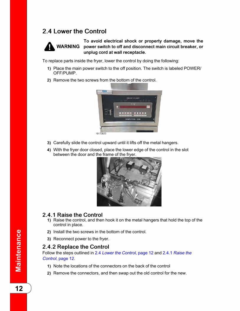
To replace parts inside the fryer, lower the control by doing the following:
11)) Place the main power switch to the off position. The switch is labeled POWER/OFF/PUMP.
22)) Remove the two screws from the bottom of the control.
33)) Carefully slide the control upward until it lifts off the metal hangers.44)) With the fryer door closed, place the lower edge of the control in the slot
between the door and the frame of the fryer.
22..44..11 RRaaiissee tthhee CCoonnttrrooll11)) Raise the control, and then hook it on the metal hangers that hold the top of the
control in place.22)) Install the two screws in the bottom of the control.33)) Reconnect power to the fryer.
22..44..22 RReeppllaaccee tthhee CCoonnttrroollFollow the steps outlined in 2.4 Lower the Control, page 12 and 2.4.1 Raise theControl, page 12.
11)) Note the locations of the connectors on the back of the control22)) Remove the connectors, and then swap out the old control for the new.

Maintenance
13
33)) Reconnect the connectors on the back of the control.
22..44..33 CCoonnffiigguurree tthhee SSeerriiaall NNuummbbeerrNOTICE: The serial number must be added correctly in to the control or the WiFimodule cannot receive or transmit data, including automated software updates.
22..44..33..11 VVeerriiffyy tthhee SSeerriiaall NNuummbbeerr11)) Set the power switch to the OFF position.22)) Locate the machine data plate on the inside of the filter pan door, and then
record the serial number displayed on it.
NNOOTTEE: Serial numbers may be one of two formats:• AAXXXXXXX (AA followed by seven digits)• BCXXXDE (Two letters followed by three digits followed by two more letters)
The serial number may also be etched in to the rear top left corner of the pot(see image below).
33)) Press and hold for 7-8 seconds until L-2 LEVEL 2 displays. CFA PROG /ENTER CODE displays.
44)) Press twice. SETUP / ENTER CODE displays.55)) Using the left product buttons, press 1,2,3. - SETUP MODE - briefly displays.66)) Compare the serial number displayed in SM-1 with the number you recorded.77)) Perform one of the two actions:
•
If the serial number matches, press and hold until - OFF - displays. Thecontrol resumes normal operation.
•
If the serial number is missing or does not match, follow either the 9 or 7character serial number correction procedure.

Maintenance
14
22..44..33..22 AAddddiinngg oorr CCoorrrreeccttiinngg aa 99 CChhaarraacctteerr SSeerriiaall NNuummbbeerr
NNOOTTEE: You only need to enter the first four and last three digits; the “AA” is alreadypopulated.
11)) Press the left-side button.
22)) Press the right-side for standard (STD).33)) Press the product keys to enter the first four digits of the serial number you
recorded.
NNOOTTEE: The value of each product key is represented by the number below theproduct key (see above image).
44)) Press to continue.55)) Press the product keys to enter the last three digits of the serial number
recorded in 2.4.3.1 Verify the Serial Number, page 13.
66)) Press . SAVE ? YES NO displays.77)) Do one of the following:
- If the serial number is correct, press the right-side for YES.
- If the serial number is incorrect, press the right-side for NO, and thenrepeat steps 2-6 of this procedure.
88)) Press and hold until - OFF - displays. The control resumes normaloperation.

Maintenance
15
22..44..33..33 AAddddiinngg oorr CCoorrrreeccttiinngg aa 77 CChhaarraacctteerr SSeerriiaall NNuummbbeerr
11)) Press the left-side button.
22)) Press the on the right side for custom (CUST). EDIT, and then the currentserial number display.
33)) Press either once. The , and LEDs flash rapidly.
44)) Press either to find the letters and digits corresponding to the serialnumber recorded in 2.4.3.1 Verify the Serial Number, page 13.
55)) Once you have the correct letter or digit displayed, press . To go back to a
previous letter or digit, press .
NNOOTTEE: If , and LEDs stop flashing, restart at step 2.
66)) After entering the 7th character of the serial number, press to find theunderscore (_) which acts as a space character. Enter the space character inthe last two places.
EEXXAAMMPPLLEE: If your serial number is IB018JC, after entering all nine characters,“IB018JC ” displays. There are two trailing spaces after the serial number.
77)) Press until SM-1 and the serial number you entered displays.
88)) Press and hold until - OFF - displays. The control resumes normaloperation.
22..55 TTrraannssffoorrmmeerr RReeppllaacceemmeenntt
WWAARRNNIINNGG!!TToo aavvooiidd eelleeccttrriiccaall sshhoocckk oorr pprrooppeerrttyy ddaammaaggee,, mmoovvee tthheeppoowweerr sswwiittcchh ttoo ooffff aanndd ddiissccoonnnneecctt mmaaiinn cciirrccuuiitt bbrreeaakkeerr,, oorruunnpplluugg ccoorrdd aatt wwaallll rreecceeppttaaccllee..
The transformer reduces the voltage down to accommodate those components withlow voltage.

Maintenance
16
1. Remove electrical power supplied tothe fryer.
2. Remove the control panel. See 2.4Lower the Control, page 12.
3. Disconnect the white box connector.
4. Remove the two screws securingtransformer to the unit and removetransformer.
5. Replace with new transformer inreverse order.
22..66 TTeemmppeerraattuurree PPrroobbee RReeppllaacceemmeenntt
WWAARRNNIINNGG!!TToo aavvooiidd eelleeccttrriiccaall sshhoocckk oorr pprrooppeerrttyy ddaammaaggee,, mmoovvee tthheeppoowweerr sswwiittcchh ttoo ooffff aanndd ddiissccoonnnneecctt mmaaiinn cciirrccuuiitt bbrreeaakkeerr,, oorruunnpplluugg ccoorrdd aatt wwaallll rreecceeppttaaccllee..
The temperature probe relays the actual shortening temperature to the control. If itbecomes disabled, “E-6” shows in the display. Also, if the temperature is out ofcalibration more than 10° F, or 10° C, the temperature probe should be replaced. AnOhm check can be performed also, see 6.16 Inspect the Temperature Probe, page136.
Maintenance
17
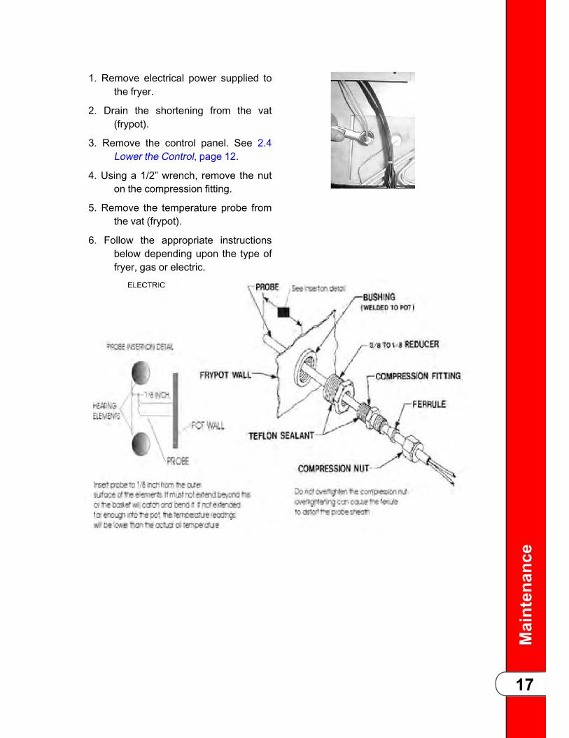
1. Remove electrical power supplied tothe fryer.
2. Drain the shortening from the vat(frypot).
3. Remove the control panel. See 2.4Lower the Control, page 12.
4. Using a 1/2” wrench, remove the nuton the compression fitting.
5. Remove the temperature probe fromthe vat (frypot).
6. Follow the appropriate instructionsbelow depending upon the type offryer, gas or electric.

Maintenance
18
7. Tighten the compression nut hand tight and then a half turn with wrench.
8. Connect new temperature probe to PC board and replace control panel.
9. Replace shortening and turn power on and check out fryer.
22..77 TTeemmppeerraattuurree RReegguullaattiioonn ((SSiinnggllee SSttaaggee))22..77..11 FFrroonntt PPaanneell TThheerrmmoossttaattThe cooking temperature is controlled by the front panel thermostat and monitored byits sensing bulb mounted just inside the vat (frypot). Various thermostats areavailable, but all work on the same principle.
22..77..22 IInntteerrnnaall OOppeerraattiioonnThe thermostat bulb is connected to the thermostat by a thin capillary tube. When thetemperature rises, the fluid inside the bulb expands (as in a thermometer) and pushes

Maintenance
19
fluid through the tube into the control panel thermostat. When the vat (frypot)temperature is lower than the thermostat setting, the TEMP light is illuminated and vat(frypot) is being heated. When the temperature setting is reached, a switch inside thethermostat opens the circuit to the heat source and turns off the TEMP light. When thevat (frypot) starts to cool, the switch closes the circuit to the heat source.
22..77..33 DDrraaiinn MMiiccrroosswwiittcchhThis interlock provides protection for the vat (frypot) in the event an operatorinadvertently drains the shortening with the switch in the power position. The heat willautomatically shut off when the drain valve is opened.
22..77..44 HHiigghh LLiimmiitt TTeemmppeerraattuurree CCoonnttrroollThe high limit temperature provides the safety feature of interrupting the heat if thetemperature ever exceeds the safe operating limits. On electric models it must bemanually reset when the vat (frypot) cools, see 2.11 High Temperature Limit Control,page 23 for maintenance of the high limit temperature control.
22..88 CCaalliibbrraattiinngg TThhee SSttaannddaarrdd SSiinnggllee SSttaaggee TThheerrmmoossttaattHenny Penny does not recommend that a field calibration be performed on thethermostats mentioned above. The reasons for this are as follows:
• The thermostat is calibrated in a controlled environment from the factory. Thethermostat manufacturers do not recommend any adjustments to the thermostat inthe field, as this will affect the factory calibration.
• The difference between a hand-held thermometer and an installed thermostat canbe quite large due to shortening temperature variation.
• The adjustment of a thermostat is not precise, since the dial reads only in 25°Fincrements. The accuracy of a thermostat needs to be less than 5°F.
If a thermostat is not reading accurately and suspected to be faulty, Henny Pennysuggests that the thermostat be replaced. If you have any questions, please do nothesitate to call the Technical Services Department.
22..99 TTeessttiinngg TThhee TThheerrmmoossttaattTToo aavvooiidd eelleeccttrriiccaall sshhoocckk oorr pprrooppeerrttyy ddaammaaggee,, mmoovvee tthheeppoowweerr sswwiittcchh ttoo ooffff aanndd ddiissccoonnnneecctt mmaaiinn cciirrccuuiitt bbrreeaakkeerr,, oorruunnpplluugg ccoorrdd aatt wwaallll rreecceeppttaaccllee..
22..99..11 PPrroocceedduurreeIf the thermostat fails to work properly, perform the following checks before replacingthe thermostat:
11)) Remove electrical power supplied to the fryer.22)) Remove the control panel.

Maintenance
20
33)) With an ohmmeter or continuity light, check for continuity as follows.44)) On a standard single temperature thermostat (Henny Penny Part No. 14293),
check between terminals 52 and 53. Move the temperature knob from off tomaximum.
Figure 2-1 Thermostat Test Points
• At off position, the circuit should be open.• At maximum, the circuit should be closed.
22..1100 TThheerrmmoossttaatt RReeppllaacceemmeennttTToo aavvooiidd eelleeccttrriiccaall sshhoocckk oorr pprrooppeerrttyy ddaammaaggee,, mmoovvee tthheeppoowweerr sswwiittcchh ttoo ooffff aanndd ddiissccoonnnneecctt mmaaiinn cciirrccuuiitt bbrreeaakkeerr,, oorruunnpplluugg ccoorrdd aatt wwaallll rreecceeppttaaccllee..
11)) Remove electrical power supplied to the fryer.22)) Drain the shortening from the vat (frypot).33)) Remove the thermostat sensing bulb from the bulb holder inside the fryer.
Figure 2-2 Thermostat Sensing Bulb - Electric
Maintenance
21
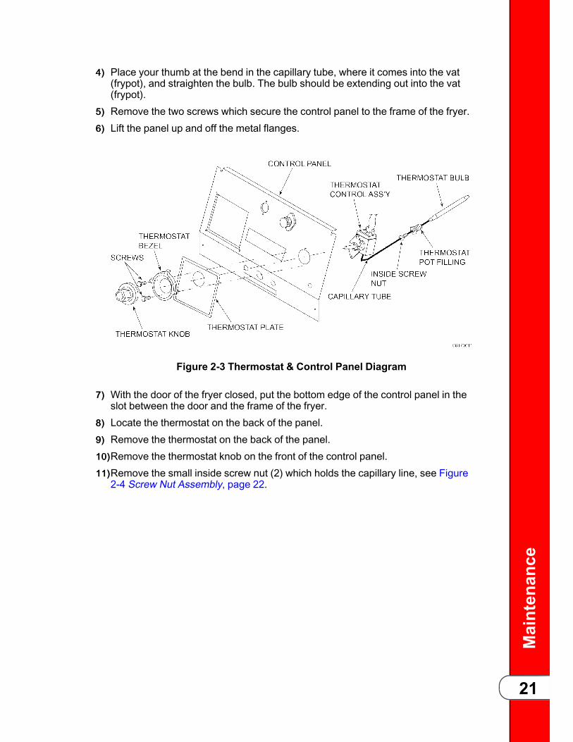
44)) Place your thumb at the bend in the capillary tube, where it comes into the vat(frypot), and straighten the bulb. The bulb should be extending out into the vat(frypot).
55)) Remove the two screws which secure the control panel to the frame of the fryer.66)) Lift the panel up and off the metal flanges.
Figure 2-3 Thermostat & Control Panel Diagram
77)) With the door of the fryer closed, put the bottom edge of the control panel in theslot between the door and the frame of the fryer.
88)) Locate the thermostat on the back of the panel.99)) Remove the thermostat on the back of the panel.1100))Remove the thermostat knob on the front of the control panel.1111))Remove the small inside screw nut (2) which holds the capillary line, see Figure
2-4 Screw Nut Assembly, page 22.

Maintenance
22
Figure 2-4 Screw Nut Assembly
1122))Remove the large screw nut (1).1133))Label the wire connections to the thermostat for correct identification when the
new thermostat is installed.1144))Disconnect the wires.1155))Remove the defective thermostat.1166))Install the new thermostat.1177))Connect the wires to the new thermostat.
CCAAUUTTIIOONN!!BBee ccaarreeffuull nnoott ttoo ccrroossss tthhee wwiirreess oorr tthheerrmmoossttaatt wwiillllnnoott ooppeerraattee pprrooppeerrllyy..
1188))Uncoil the capillary tube.1199))Insert the bulb through the wall of the vat (frypot).
WWAARRNNIINNGG!!
TToo aavvooiidd eelleeccttrriiccaall sshhoocckk oorr ootthheerr iinnjjuurryy,, tthhee ccaappiillllaarryylliinnee mmuusstt rruunn uunnddeerr aanndd aawwaayy ffrroomm aallll eelleeccttrriiccaallppoowweerr wwiirreess.. TThhee ttuubbee mmuusstt nneevveerr bbee iinn ccoonnttaacctt wwiitthhtthhee eelleeccttrriiccaall ppoowweerr wwiirreess oorr tteerrmmiinnaallss..
2200))Install the thermostat pot fitting into the wall of the vat (frypot) and tighten.2211))Replace the thermostat sensing bulb into the mounting bracket.
CCAAUUTTIIOONN!!DDoo nnoott bbeenndd tthhee ccaappiillllaarryy ttuubbee wwhheerree iitt ccoonnnneeccttss ttootthhee sseennssiinngg bbuullbb oorr ddaammaaggee ttoo ccaappiillllaarryy wwiillll rreessuulltt..
2222))Slip the bulb holder in place. With bulb in place, tighten the clamp screw.2233))Pull the excess capillary tube from the inside of the vat (frypot).2244))Insert and tighten the inside screw nut into the thermostat.
Maintenance
23
2255))Install the two screws on the front of the control panel, which secure thethermostat to the back of the panel. Install the thermostat bezel.
2266))Install the thermostat knob.2277))Secure the control panel with the 4 screws.2288))Reconnect power to the fryer.2299))Calibrate the thermostat 2.8 Calibrating The Standard Single Stage Thermostat,
page 19.
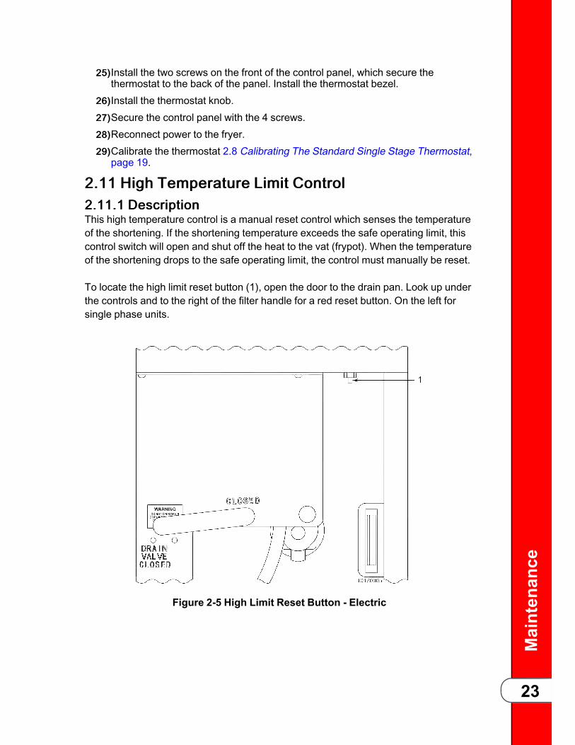
22..1111 HHiigghh TTeemmppeerraattuurree LLiimmiitt CCoonnttrrooll22..1111..11 DDeessccrriippttiioonnThis high temperature control is a manual reset control which senses the temperatureof the shortening. If the shortening temperature exceeds the safe operating limit, thiscontrol switch will open and shut off the heat to the vat (frypot). When the temperatureof the shortening drops to the safe operating limit, the control must manually be reset.
To locate the high limit reset button (1), open the door to the drain pan. Look up underthe controls and to the right of the filter handle for a red reset button. On the left forsingle phase units.
Figure 2-5 High Limit Reset Button - Electric

Maintenance
24
22..1111..22 CChheecckkoouuttTToo aavvooiidd eelleeccttrriiccaall sshhoocckk oorr pprrooppeerrttyy ddaammaaggee,, mmoovvee tthheeppoowweerr sswwiittcchh ttoo ooffff aanndd ddiissccoonnnneecctt mmaaiinn cciirrccuuiitt bbrreeaakkeerr,, oorruunnpplluugg ccoorrdd aatt wwaallll rreecceeppttaaccllee..
NOTICE:The shortening temperature must be below 380º F toaccurately perform this check.
Before replacing a high temperature limit control, check to see that its circuit is closed.
11)) Remove electrical power supplied to the fryer.22)) Remove the control panel and insert it in the slot above the door, see 2.4 Lower
the Control, page 12.33)) Remove the two electrical wires from the high temperature limit control.
44)) Check for continuity between the two terminals after resetting the control. If thecircuit is open, replace the control, then continue with this procedure. If thecircuit is closed, the high limit is not defective. Reconnect the two electricalwires.
22..1111..33 RReeppllaacceemmeennttTToo aavvooiidd eelleeccttrriiccaall sshhoocckk oorr pprrooppeerrttyy ddaammaaggee,, mmoovvee tthheeppoowweerr sswwiittcchh ttoo ooffff aanndd ddiissccoonnnneecctt mmaaiinn cciirrccuuiitt bbrreeaakkeerr,, oorruunnpplluugg ccoorrdd aatt wwaallll rreecceeppttaaccllee..

Maintenance
25
Figure 2-6 High Limit Capillary Tube - Electric
11)) If the capillary tube (1) is broken or cracked, the control will open, shutting offelectrical power. The control cannot be reset.
22)) Drain shortening from the vat (frypot).33)) Remove control panel.44)) Loosen small inside screw nut on capillary tube.55)) Remove capillary bulb from bulb holder inside the vat (frypot).66)) Straighten the capillary tube.77)) Remove larger outside nut that threads into pot wall.88)) Remove the two screws that secure the high limit to the high limit bracket.99)) Remove defective control from control panel area.1100))Insert new control and replace screws.1111))Uncoil capillary line, starting at capillary tube, and insert through vat (frypot)
wall.
WWAARRNNIINNGG!!
TToo aavvooiidd eelleeccttrriiccaall sshhoocckk oorr ootthheerr iinnjjuurryy,, tthhee ccaappiillllaarryylliinnee mmuusstt rruunn uunnddeerr aanndd aawwaayy ffrroomm aallll eelleeccttrriiccaallppoowweerr wwiirreess.. TThhee ttuubbee mmuusstt nneevveerr bbee iinn ccoonnttaacctt wwiitthhtthhee eelleeccttrriiccaall ppoowweerr wwiirreess oorr tteerrmmiinnaallss..

Maintenance
26
1122))Carefully bend the capillary bulb and tube toward the bulb holder on the heatingelements.
1133))Slip the capillary bulb into the bulb holder located on the heating elements. Pullexcess capillary line form pot and tighten nut into vat (frypot) wall, see Figure 2-2 Thermostat Sensing Bulb - Electric, page 20 for proper installation.
CCAAUUTTIIOONN!!
BBee ssuurree ccaappiillllaarryy bbuullbb ooff hhiigghh lliimmiitt iiss llooccaatteedd bbeehhiinnddccaappiillllaarryy bbuullbb ooff tthheerrmmoossttaatt.. BBootthh ccaappiillllaarryy bbuullbbss aannddbbuullbb hhoollddeerrss sshhoouulldd bbee ppoossiittiioonneedd aass nnoott ttoo iinntteerrffeerreewwiitthh bbaasskkeett oorr wwhheenn cclleeaanniinngg tthhee vvaatt ((ffrryyppoott)) wwaallll,, oorrddaammaaggee ttoo ccaappiillllaarryy ttuubbee ccoouulldd rreessuulltt..
1144))With excess capillary line pulled out, tighten smaller nut.1155))Replace front panel.1166))Refill with shortening.
22..1122 HHeeaattiinngg EElleemmeennttss22..1122..11 DDeessccrriippttiioonnEach fryer uses three heating element assemblies. Heating elements are available for208, 220/240, or 440/480 voltage. Check the data plate inside the door to determinethe correct voltage.
22..1122..22 MMaaiinntteennaannccee HHiinnttIf the shortening’s temperature recovery is very slow, or at a slower rate than required,this may indicate defective heating element(s). An ohmmeter will quickly indicate if theelements are shorted or open.
22..1122..33 CChheecckkoouuttTToo aavvooiidd eelleeccttrriiccaall sshhoocckk oorr pprrooppeerrttyy ddaammaaggee,, mmoovvee tthheeppoowweerr sswwiittcchh ttoo ooffff aanndd ddiissccoonnnneecctt mmaaiinn cciirrccuuiitt bbrreeaakkeerr,, oorruunnpplluugg ccoorrdd aatt wwaallll rreecceeppttaaccllee..
11)) Remove electrical power supplied to the fryer.22)) Remove the control panel and insert it in the slot above the door, see 2.4 Lower
the Control, page 12.33)) Perform ohm check on one heating element at a time, with wires disconnected
from element. If the resistance is not within tolerance, replace the element.

Maintenance
27
TTaabbllee 22--22 HHeeaattiinngg EElleemmeenntt OOhhmm CChheecckkoouutt
Heater P/N Power Voltage Resistance in Ohms(Cold)
18233-1 4500W 208VAC 9±1
18233-2 4500W 230VAC 11±1.5
18233-4 3750W 208VAC 11±1.5
18233-5 3750W 220VAC 12±2
18233-6 3750W 480VAC 60±5
18233-7 4500W 480VAC 50±4
18233-8 4500W 380VAC 32±3.5
22..1122..44 RReeppllaacceemmeenntt11)) Drain the shortening.22)) Remove the thermostat bulb holder from the heating element inside the vat
(frypot).33)) Remove the heating element wires from the terminals by removing nuts (5) and
washers (6 and 7). Label each so it can be replaced in the same position on thenew element, see Figure 2-7 Heating Element Assembly, page 28.

Maintenance
28
Figure 2-7 Heating Element Assembly
44)) Loosen the bolts on the four element spreaders (1), see Figure 2-8 HeatingElement Spreaders, page 29.

Maintenance
29
Figure 2-8 Heating Element Spreaders
55)) Slide the elements spreaders (1) to the center of the heating element.
Maintenance
30
66)) Remove the brass nuts (4) and washers (3), which secure the ends of theelements through the vat (frypot) wall, see Figure 2-7 Heating ElementAssembly, page 28.
77)) Remove the heating elements from the vat (frypot) as a group by lifting the farend and sliding them up and out toward the rear of the vat (frypot).
NOTICE:Always install new rubber O-rings (2) when installingheating elements.
88)) Install new heating elements with new rubber O-rings (2) mounted on terminalends, and spreaders loosely mounter in the center of the stacked elements.
99)) Replace the heating elements, terminal end first at approximately 45º angle,slipping the terminal ends through the front wall of the vat (frypot).
1100))Replace the brass nuts (4) and washers (3) on the heating element terminals.Tighten the brass nuts to 30 foot lbs. of torque.
1111))Move the element spreaders from the center of the element, into a positionwhich will spread each element apart evenly on all four sides, and tighten.
1122))Replace the thermostat bulb holder on the top element, and position the bulbbetween the top and second element midway from side to side, and tightenscrew which holds the bulb in place.
1133))Reconnect the wires to the appropriate terminal as labeled when they wereremoved.
1144))Replace the front control panel.1155))Connect the power cord to the wall receptacle or close wall circuit breaker.
CCAAUUTTIIOONN!!HHeeaattiinngg eelleemmeennttss sshhoouulldd nneevveerr bbee eenneerrggiizzeedd wwiitthhoouuttsshhoorrtteenniinngg iinn tthhee vvaatt ((ffrryyppoott)),, oorr ddaammaaggee ttoo eelleemmeennttssccoouulldd rreessuulltt..
1166))Check the heating elements as described in Operator’s Manual.1177))Replace the shortening in the vat (frypot).
22..1133 HHeeaattiinngg CCoonnttaaccttoorrss22..1133..11 DDeessccrriippttiioonnEach electric fryer requires two switching contactors. One is the primary contactor andthe second in line is the heat contactor. When open, the primary contactor allows nopower to flow to the heat contactor. When closed, the primary contactor completes thetimer circuit and the high limit (heat) circuit. It also supplies power to the heatcontactor which is controlled by the thermostat.
22..1133..22 CChheecckkoouutt ((PPoowweerr RReemmoovveedd))TToo aavvooiidd eelleeccttrriiccaall sshhoocckk oorr pprrooppeerrttyy ddaammaaggee,, mmoovvee tthheeppoowweerr sswwiittcchh ttoo ooffff aanndd ddiissccoonnnneecctt mmaaiinn cciirrccuuiitt bbrreeaakkeerr,, oorruunnpplluugg ccoorrdd aatt wwaallll rreecceeppttaaccllee..

Maintenance
31
11)) Remove electrical power supplied to the fryer.22)) Remove the control panel and insert it in the slot above the door, see 2.4 Lower
the Control, page 12.33)) Perform a check on the contactor as follows:
Test Points Resultsfrom 23 to 29 open circuit
from 24 to 28 open circuit
from 25 to 27 open circuit
from 30 to 34 open circuit
from 31 to 35 open circuit
from 32 to 36 open circuit
from 22 to 26 ohm reading 415
from 33 to 37 ohm reading 415
See Figure 2-9 Primary Contactor Test Points, page 31 and Figure 2-10 HeatContactor Test Points, page 32 for test point locations.
Figure 2-9 Primary Contactor Test Points

Maintenance
32
Figure 2-10 Heat Contactor Test Points
22..1133..33 CChheecckkoouutt ((PPoowweerr SSuupppplliieedd))TToo aavvooiidd eelleeccttrriiccaall sshhoocckk,, mmaakkee ccoonnnneeccttiioonnss bbeeffoorreeaappppllyyiinngg ppoowweerr,, ttaakkee rreeaaddiinngg,, aanndd rreemmoovvee ppoowweerr bbeeffoorreerreemmoovviinngg mmeetteerr lleeaaddss.. TThhee ffoolllloowwiinngg cchheecckkss aarreeppeerrffoorrmmeedd wwiitthh tthhee wwaallll cciirrccuuiitt bbrreeaakkeerr cclloosseedd aanndd tthheemmaaiinn ppoowweerr sswwiittcchh iinn tthhee oonn ppoossiittiioonn..
11)) With power re-applied, set the thermostat to its maximum temperature.22)) On fryers using single phase power, check voltage as follows:
Figure 2-11 Circuit Breaker
• From pin D (1), see Figure 2-11 Circuit Breaker, page 32. On circuit breakerto terminal 34, see Figure 2-10 Heat Contactor Test Points, page 32.
• From pin D (1) on circuit breaker to terminal 35, see Figure 2-10 HeatContactor Test Points, page 32.
• From pin D (1) on circuit breaker to terminal 36, see Figure 2-10 HeatContactor Test Points, page 32.
Maintenance
33
The voltage should read the same at each terminal. It should correspond to thevoltage rating stated on the data plate, see Figure 2-9 Primary Contactor TestPoints, page 31.
NOTICE:If voltage is not present, check output of primarycontactor at terminals 27, 28, and 29.
33)) On fryers using three-phase power, check voltage as follows:
HHeeaatt CCoonnttaaccttoorr::• from terminal 34 to 35, see Figure 2-10 Heat Contactor Test Points, page 32.• from terminal 35 to 36, see Figure 2-10 Heat Contactor Test Points, page 32.• from terminal 24 to 36, see Figure 2-10 Heat Contactor Test Points, page 32.
The voltage should read the same at each terminal. It should correspond to thevoltage rating stated on the data plate, see Figure 2-9 Primary Contactor TestPoints, page 31.
PPrriimmaarryy CCoonnttaaccttoorr::• from terminal 27 to 28, see Figure 2-9 Primary Contactor Test Points, page31.
• from terminal 28 to 29, see Figure 2-9 Primary Contactor Test Points, page31.
• from terminal 27 to 29, see Figure 2-9 Primary Contactor Test Points, page31.
The voltage should read the same at each terminal. It should correspond to thevoltage rating stated on the data plate, see Figure 2-9 Primary Contactor TestPoints, page 31.
22..1133..44 RReeppllaacceemmeenntt SSqquuaarree DDTToo aavvooiidd eelleeccttrriiccaall sshhoocckk oorr pprrooppeerrttyy ddaammaaggee,, mmoovvee tthheeppoowweerr sswwiittcchh ttoo ooffff aanndd ddiissccoonnnneecctt mmaaiinn cciirrccuuiitt bbrreeaakkeerr,, oorruunnpplluugg ccoorrdd aatt wwaallll rreecceeppttaaccllee..
If either contactor is defective, it must be replaced as follows:
11)) Remove only those wires directly connected to the contactor being replaced.Label the wires.
22)) Remove the two mounting screws on the base plate and remove contactor.33)) Install the new contactor and tighten the two mounting screws.44)) Connect the labeled wires to their respective positions.55)) Install the control panel per 2.4.1 Raise the Control, page 12.66)) Reconnect power to the fryer and test the fryer for proper operation.

Maintenance
34
22..1133..55 RReeppllaacceemmeenntt MMeerrccuurryyTToo aavvooiidd eelleeccttrriiccaall sshhoocckk oorr pprrooppeerrttyy ddaammaaggee,, mmoovvee tthheeppoowweerr sswwiittcchh ttoo ooffff aanndd ddiissccoonnnneecctt mmaaiinn cciirrccuuiitt bbrreeaakkeerr,, oorruunnpplluugg ccoorrdd aatt wwaallll rreecceeppttaaccllee..
NNOOTTEE:Mercury contactors were used on all fryers until 2011.Replacement contactors cannot be shipped to states whereregulations forbid use.
Replace contactor as follows:
11)) Remove only those wires directly connected to the contactor being replaced.Label the wires.
22)) On the mercury heat contactor, use a 5/16” socket or nut- driver and loosen fournuts securing contactor to shroud. Slide contactor up and then pull out throughthe slotted holes in the base of the contactor.
33)) On the primary contactor, remove two mounting screws on the base plate andremove contactor.
44)) Install the new contactor and tighten the two mounting screws.55)) Connect the labeled wires to their respective positions.66)) Install the control panel.77)) Reconnect power to the fryer and test the fryer for proper operation.

Maintenance
35
22..1144 EElleeccttrriiccaall CCoommppoonneennttssDDoo nnoott ddiissccoonnnneecctt tthhee ggrroouunndd ((eeaarrtthh)) pplluugg.. TThhiiss ffrryyeerr mmuussttbbee aaddeeqquuaatteellyy aanndd ssaaffeellyy ggrroouunnddeedd ((eeaarrtthheedd)) oorr eelleeccttrriiccaallsshhoocckk ccoouulldd rreessuulltt.. RReeffeerr ttoo llooccaall eelleeccttrriiccaall ccooddeess ffoorrccoorrrreecctt ggrroouunnddiinngg ((eeaarrtthhiinngg)) pprroocceedduurreess oorr iinn aabbsseennccee ooffllooccaall ccooddeess,, wwiitthh TThhee NNaattiioonnaall EElleeccttrriiccaall CCooddee,, AANNSSII//NNFFPPAA NNoo.. 7700--((tthhee ccuurrrreenntt eeddiittiioonn)).. IInn CCAANNAADDAA,, aalllleelleeccttrriiccaall ccoonnnneeccttiioonnss aarree ttoo bbee mmaaddee iinn aaccccoorrddaannccee wwiitthhCCSSAA CC2222..11,, CCaannaaddiiaann EElleeccttrriiccaall CCooddee PPaarrtt 11,, aanndd//oorr llooccaallccooddeess..
NOTICE:Electric motor bearings are permanently lubricated and do notrequire attention during normal service life of this fryer.
22..1144..11 DDrraaiinn SSwwiittcchhTToo aavvooiidd eelleeccttrriiccaall sshhoocckk oorr pprrooppeerrttyy ddaammaaggee,, mmoovvee tthheeppoowweerr sswwiittcchh ttoo ooffff aanndd ddiissccoonnnneecctt mmaaiinn cciirrccuuiitt bbrreeaakkeerr,, oorruunnpplluugg ccoorrdd aatt wwaallll rreecceeppttaaccllee..
22..1144..11..11 EElleeccttrriicc MMooddeellss
All fryer models have a drain microswitch in line with the gas control valve or heatcontactor and thermostat. When the drain valve is opened to drain the shortening, thiscauses drain switch to open, shutting off electrical power to the heating elements.
11)) The following check should be made to determine if the drain switch is defective.All checks should be made with the drain valve in the closed position, with theactuator pushed in.• Fryers with standard thermostat part number 14293, the continuity checkmust be made between terminal 52 on the thermostat, and terminal 33 on theheat contactor. if circuit is open, the drain switch is bad and needs to bereplaced, see Figure 2-1 Thermostat Test Points, page 20 and for terminallocations.
22)) To replace the drain switch, remove the two screws and nuts (1) securing switchand switch cover, see Figure 2-12 Drain Switch Assembly, page 36.

Maintenance
36
Figure 2-12 Drain Switch Assembly
33)) Label and disconnect wires.44)) Connect wires to new drain switch.55)) Position actuator (2) and attach drain switch and switch cover with two screws
and nuts. Tighten nuts to 3-4 inch-pounds of torque.66)) Test to see if drain valve extension and rod (3) actuates the switch.
NOTICE:Listen for an audible click of switch while rotating drainvalve extension rod (3).
22..1144..22 MMaaiinn PPoowweerr SSwwiittcchhTToo aavvooiidd eelleeccttrriiccaall sshhoocckk oorr pprrooppeerrttyy ddaammaaggee,, mmoovvee tthheeppoowweerr sswwiittcchh ttoo ooffff aanndd ddiissccoonnnneecctt mmaaiinn cciirrccuuiitt bbrreeaakkeerr,, oorruunnpplluugg ccoorrdd aatt wwaallll rreecceeppttaaccllee..
The Main Power switch is a three way switch with a center OFF position. With theswitch in POWER position, the fryer will operate. With the switch in the PUMPposition, the filter pump will operate but the heating unit will not.

Maintenance
37
22..1144..33 CCoonnttiinnuuiittyy CChheecckk PPrroocceedduurree
Figure 2-13 Continuity Check Test Points
TTaabbllee 22--33 CCoonnttiinnuuiittyy CChheecckk PPrroocceedduurree -- OOffff PPoossiittiioonn
Test Points Results
#60 to #59 then #60 to #67 Open circuit
#61 to #58 then #61 to #66 Open circuit
#62 to #57 then #62 to #65 Open circuit
#63 to #56 then #63 to #64 Open circuit
#60 to #61 Closed circuit
#62 to #63 Closed circuit
TTaabbllee 22--44 CCoonnttiinnuuiittyy CChheecckk PPrroocceedduurree -- PPoowweerr PPoossiittiioonn
TTeesstt PPooiinnttss RReessuullttss
#60 to #59 Closed circuit
#61 to #58 Closed circuit
#62 to #57 Closed circuit
#63 to #56 Closed circuit
TTaabbllee 22--55 CCoonnttiinnuuiittyy CChheecckk PPrroocceedduurree -- PPuummpp PPoossiittiioonn
TTeesstt PPooiinnttss RReessuullttss
#60 to #67 Closed circuit
#61 to #66 Closed circuit
#62 to #65 Closed circuit
#63 to #64 Closed circuit
22..1144..44 RReeppllaacceemmeenntt11)) Remove control panel per 2.4 Lower the Control, page 12.22)) Label wires at the Main Power switch and disconnect wires at switch.33)) Remove faulty switch and install new switch.

Maintenance
38
44)) Reconnect wires to switch in the same position as noted on the labels.55)) Replace control panel per 2.4.1 Raise the Control, page 12.
22..1144..55 IInnddiiccaattoorr LLiigghhttssTToo aavvooiidd eelleeccttrriiccaall sshhoocckk oorr pprrooppeerrttyy ddaammaaggee,, mmoovvee tthheeppoowweerr sswwiittcchh ttoo ooffff aanndd ddiissccoonnnneecctt mmaaiinn cciirrccuuiitt bbrreeaakkeerr,, oorruunnpplluugg ccoorrdd aatt wwaallll rreecceeppttaaccllee..
The indicator lights for HEAT-PUMP-POWER, are identical assemblies consisting of aneon light and mounting clip, and are replaced as assemblies.
11)) Remove control panel per 2.4 Lower the Control, page 12.22)) Disconnect indicator light wires from the individual power source.33)) Squeeze the retaining clip while removing the indicator light and discard the
light.44)) Install the new indicator light.55)) Connect the wires from the new indicator light.66)) Replace control panel per 2.4.1 Raise the Control, page 12.
22..1144..66 FFuussee HHoollddeerrTToo aavvooiidd eelleeccttrriiccaall sshhoocckk oorr pprrooppeerrttyy ddaammaaggee,, mmoovvee tthheeppoowweerr sswwiittcchh ttoo ooffff aanndd ddiissccoonnnneecctt mmaaiinn cciirrccuuiitt bbrreeaakkeerr,, oorruunnpplluugg ccoorrdd aatt wwaallll rreecceeppttaaccllee..
There are two fuse holders on each model of the electric fryers.
22..1144..77 CChheecckkiinngg PPrroocceedduurree FFoorr FFuusseessCCOONNTTRROOLL PPAANNEELL FFUUSSEESS 33 PPhhaassee::Check from #54 to #55 and #68 to #69 on fuse assembly. The circuit should beclosed. If not, replace the fuse (HP# EF02-007).
22..1144..88 CCoorrdd && PPlluugg CChheecckkPerform a check on the cord and plug as follows:Test from each plug prong to the corresponding wire lead on the other end of the cordat junction box. The result should be a closed circuit on each line tested.
22..1144..99 WWaallll RReecceeppttaaccllee ((VVoollttaaggee CChheecckk))22..1144..99..11 EElleeccttrriicc MMooddeellss
Check the voltage across the following lines: L1-L2; L2-L3; L1-L3.

Maintenance
39
The voltage should read the same for each line test. It should correspond to thevoltage shown on the data plate.
22..1155 TTiimmiinngg CCoonnttrroollTToo aavvooiidd eelleeccttrriiccaall sshhoocckk oorr pprrooppeerrttyy ddaammaaggee,, mmoovvee tthheeppoowweerr sswwiittcchh ttoo ooffff aanndd ddiissccoonnnneecctt mmaaiinn cciirrccuuiitt bbrreeaakkeerr,, oorruunnpplluugg ccoorrdd aatt wwaallll rreecceeppttaaccllee..
22..1155..11 DDeessccrriippttiioonnThe TIMER CONTROL consists of a microswitch, indicator light, buzzer, reset timer,and timer motor.
22..1155..22 CChheecckkiinngg PPrroocceedduurreeTTaabbllee 22--66 CChheecckkiinngg PPrroocceedduurree -- OONN//OOFFFF SSwwiittcchh
Test Points Results
SSwwiittcchh iinn OOFFFF PPoossiittiioonn
Check from #74 to #75 Open circuit
SSwwiittcchh iinn OONN PPoossiittiioonn
Check from #74 to #75 Closed circuit

Maintenance
40
TTaabbllee 22--77 CChheecckkiinngg PPrroocceedduurree -- BBuuzzzzeerr CCooiill
Test Points Results
SSwwiittcchh iinn OOFFFF ppoossiittiioonn
Check from #14 to #75
• 120 volt 50/60 Hz1550 ohms
• 208-240 volt 50/60 Hz5880 ohms
TTaabbllee 22--88 CChheecckkiinngg PPrroocceedduurree -- MMiiccrroosswwiittcchh
Test Points Results
TTiimmeerr SSeett AAtt 1100 MMiinn..
Check from #70 to #72 Closed circuit
Check from #70 to #14 Open circuit
TTiimmeerr SSeett AAtt 00 MMiinn..
Check from #70 to #72 Open circuit
Check from #70 to #14 Closed circuit
TTaabbllee 22--99 CChheecckkiinngg PPrroocceedduurree -- MMoottoorr
Test Points Results
Check from #70 to #75
120 volt 50/60 Hz 290 ohms
208-240 volt 50/60 Hz 3990 ohms
TTaabbllee 22--1100 CChheecckkiinngg PPrroocceedduurree -- RReesseett CCooiill
Test Points Results
Check from #70 to #75
120 volt 50/60 Hz 280 ohms
208–240 volt 50/60 Hz 3950 ohms
22..1155..33 RReeppllaacceemmeenntt11)) Remove control panel per 2.4 Lower the Control, page 12.22)) Label the wires and remove them from the timer.33)) Remove four screws securing the timer to the control panel.
NOTICE:
Replacement of timer may not be necessary if lamp isburned out, if buzzer coil is burned open, or if ON/OFFswitch is bad, timer motor and timer microswitch can bereplaced separately.
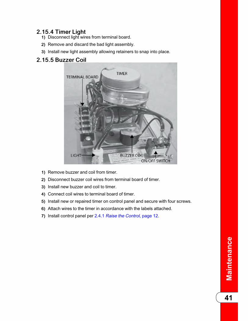
Maintenance
41
22..1155..44 TTiimmeerr LLiigghhtt11)) Disconnect light wires from terminal board.22)) Remove and discard the bad light assembly.33)) Install new light assembly allowing retainers to snap into place.
22..1155..55 BBuuzzzzeerr CCooiill
11)) Remove buzzer and coil from timer.22)) Disconnect buzzer coil wires from terminal board of timer.33)) Install new buzzer and coil to timer.44)) Connect coil wires to terminal board of timer.55)) Install new or repaired timer on control panel and secure with four screws.66)) Attach wires to the timer in accordance with the labels attached.77)) Install control panel per 2.4.1 Raise the Control, page 12.

Maintenance
42
22..1155..66 TTiimmeerr SSwwiittcchh
11)) Connect light leads to terminal board of timer.22)) Remove switch nuts and remove switch from panel.33)) Disconnect switch wires from terminal board.44)) Install new switch on panel and secure with switch nut.55)) Connect switch wires to the terminal board of timer.
22..1166 PPrreessssuurree RReegguullaattiioonn//EExxhhaauussttTToo aavvooiidd eelleeccttrriiccaall sshhoocckk oorr pprrooppeerrttyy ddaammaaggee,, mmoovvee tthheeppoowweerr sswwiittcchh ttoo ooffff aanndd ddiissccoonnnneecctt mmaaiinn cciirrccuuiitt bbrreeaakkeerr,, oorruunnpplluugg ccoorrdd aatt wwaallll rreecceeppttaaccllee..
22..1166..11 SSoolleennooiidd VVaallvveeThis is an electromechanical device that causes pressure to be held in the vat (frypot).The solenoid valve closes at the beginning of the cook cycle and is openedautomatically by the timer at the end of the cook cycle. If this valve should becomedirty or the Teflon seat nicked, pressure will not build up. The fryer uses a 208/240 volt60 Hz coil. The 440/480 volt electric model uses a transformer to drop voltage to 220/240 volts.
22..1166..22 CCooiill CChheecckk PPrroocceedduurree11)) Remove wires from terminals 73 and 72 and check across solenoid wires.

Maintenance
43
TTaabbllee 22--1111 CCooiill CChheecckk PPrroocceedduurree
Test Volts/Phase Results
24 volt 2.2 Ohms
120 volt 60 Hz 50 Ohms
208-240 volt 60 Hz 150 Ohms
208-240 volt 50 Hz 245 Ohms
22..1166..33 RReeppllaacceemmeenntt
Figure 2-14 Solenoid Valve Assembly
11)) Remove Tru-Arc retaining clip on top of the coil housing.22)) Remove the nameplate and cover.33)) If only the coil is replaced, disconnect two coil wires at the wire nuts in the coil
housing, and remove the coil from the housing. Then replace nameplate, cover,and Tru-Arc clip. If the complete solenoid or seal are being replaced, continue tostep 4.
NOTICE: The wires may be connected in any order.
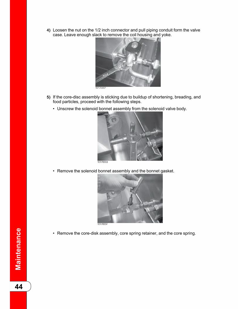
Maintenance
44
44)) Loosen the nut on the 1/2 inch connector and pull piping conduit form the valvecase. Leave enough slack to remove the coil housing and yoke.
55)) If the core-disc assembly is sticking due to buildup of shortening, breading, andfood particles, proceed with the following steps.• Unscrew the solenoid bonnet assembly from the solenoid valve body.
• Remove the solenoid bonnet assembly and the bonnet gasket.
• Remove the core-disk assembly, core spring retainer, and the core spring.

Maintenance
45
• Wash all parts in soap and hot water.
NOTICE:
If replacing Teflon seals, or complete valve, proceed tostep 6, otherwise assemble in reverse order ofdisassembly.Assemble valve core and blade (6), with the smoothside of the hole towards the disc spring guide (9), seeFigure 2-17 Solenoid Valve Diagram, page 47.
66)) A repair kit, Henny Penny Part No. 17120, is available if any of the seals need tobe replaced. If any one seal is defective, all seals should be replaced.
NOTICE:Remove the solenoid body from fryer to replace seals,see Figure 2-17 Solenoid Valve Diagram, page 47 to helpidentify all parts.
• Remove back cover.

Maintenance
46
• Loosen both conduit and exhaust fittings.
Figure 2-15 Exhaust Fitting

Maintenance
47
Figure 2-16 Conduit Fitting
• Remove nipple from solenoid body.
• Unthread body from fryer.• A new solenoid can now be placed on the fryer, and reassembled in reverseorder of previous steps, or continue onto step 7 to change the seals.
77)) To change seals:
Figure 2-17 Solenoid Valve Diagram
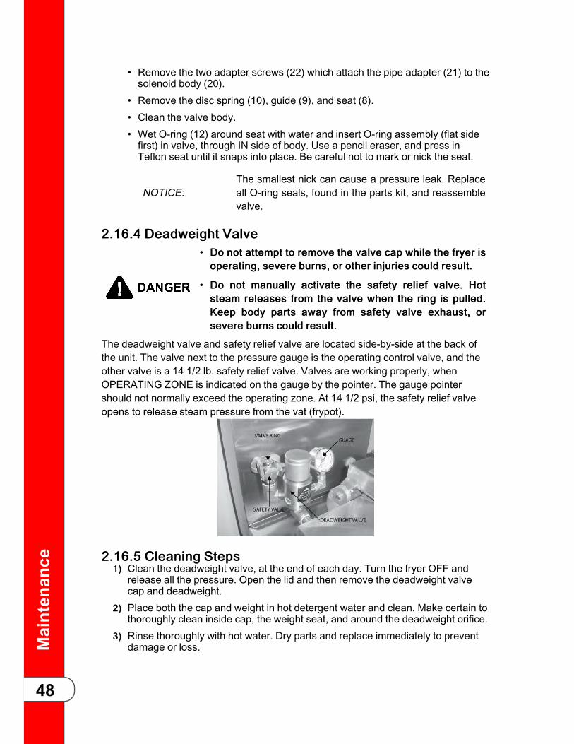
Maintenance
48
• Remove the two adapter screws (22) which attach the pipe adapter (21) to thesolenoid body (20).
• Remove the disc spring (10), guide (9), and seat (8).• Clean the valve body.• Wet O-ring (12) around seat with water and insert O-ring assembly (flat sidefirst) in valve, through IN side of body. Use a pencil eraser, and press inTeflon seat until it snaps into place. Be careful not to mark or nick the seat.
NOTICE:The smallest nick can cause a pressure leak. Replaceall O-ring seals, found in the parts kit, and reassemblevalve.
22..1166..44 DDeeaaddwweeiigghhtt VVaallvvee• DDoo nnoott aatttteemmpptt ttoo rreemmoovvee tthhee vvaallvvee ccaapp wwhhiillee tthhee ffrryyeerr iissooppeerraattiinngg,, sseevveerree bbuurrnnss,, oorr ootthheerr iinnjjuurriieess ccoouulldd rreessuulltt..
• DDoo nnoott mmaannuuaallllyy aaccttiivvaattee tthhee ssaaffeettyy rreelliieeff vvaallvvee.. HHoottsstteeaamm rreelleeaasseess ffrroomm tthhee vvaallvvee wwhheenn tthhee rriinngg iiss ppuulllleedd..KKeeeepp bbooddyy ppaarrttss aawwaayy ffrroomm ssaaffeettyy vvaallvvee eexxhhaauusstt,, oorrsseevveerree bbuurrnnss ccoouulldd rreessuulltt..
The deadweight valve and safety relief valve are located side-by-side at the back ofthe unit. The valve next to the pressure gauge is the operating control valve, and theother valve is a 14 1/2 lb. safety relief valve. Valves are working properly, whenOPERATING ZONE is indicated on the gauge by the pointer. The gauge pointershould not normally exceed the operating zone. At 14 1/2 psi, the safety relief valveopens to release steam pressure from the vat (frypot).
22..1166..55 CClleeaanniinngg SStteeppss11)) Clean the deadweight valve, at the end of each day. Turn the fryer OFF and
release all the pressure. Open the lid and then remove the deadweight valvecap and deadweight.
22)) Place both the cap and weight in hot detergent water and clean. Make certain tothoroughly clean inside cap, the weight seat, and around the deadweight orifice.
33)) Rinse thoroughly with hot water. Dry parts and replace immediately to preventdamage or loss.

Maintenance
49
22..1166..66 RReemmoovvaall && CClleeaanniinngg ooff SSaaffeettyy RReelliieeff VVaallvveeDDoo nnoott aatttteemmpptt ttoo rreemmoovvee vvaallvvee wwhhiillee ffrryyeerr iiss ooppeerraattiinngg,,sseevveerree bbuurrnnss oorr ootthheerr iinnjjuurriieess ccoouulldd rreessuulltt..
The safety relief valve should be cleaned once a year.
11)) Open the lid and then remove the deadweight valve cap and deadweight.
NOTICE: Do not use a pipe wrench. Use thread sealant sparingly.
22)) Use a wrench to loosed the valve from the pipe elbow, turn counterclockwise toremove.
33)) Clean the inside of the pipe elbow with hot detergent.44)) Immerse the safety relief valve in a soap water solution for 24 hours. Use a 1:1
dilution rate. The valve cannot be disassembled. It is factory preset to open at14 1/2 pounds of pressure. If it does not open or close it must be replaced.
TToo aavvooiidd ppeerrssoonnaall iinnjjuurryy,, ddoo nnoott ddiissaasssseemmbbllee oorrmmooddiiffyy tthhiiss vvaallvvee.. TTaammppeerriinngg wwiitthh tthhiiss vvaallvvee wwiillll vvooiiddaaggeennccyy aapppprroovvaallss aanndd tthhee aapppplliiaannccee wwaarrrraannttyy,, aannddccoouulldd ccaauussee sseerriioouuss iinnjjuurriieess..
22..1166..77 PPrreessssuurree GGaauuggeeThe pressure gauge can be re-calibrated should it be out of adjustment.
22..1166..77..11 CCaalliibbrraattiioonn SStteeppss11)) Remove the rim and glass.22)) If the indicating hand shows a pressure or vacuum reading when it should stand
at “0”, turn the re-calibrator screw in the same direction in which the indicatinghand is to be moved until the hand stands at proper “0) position.
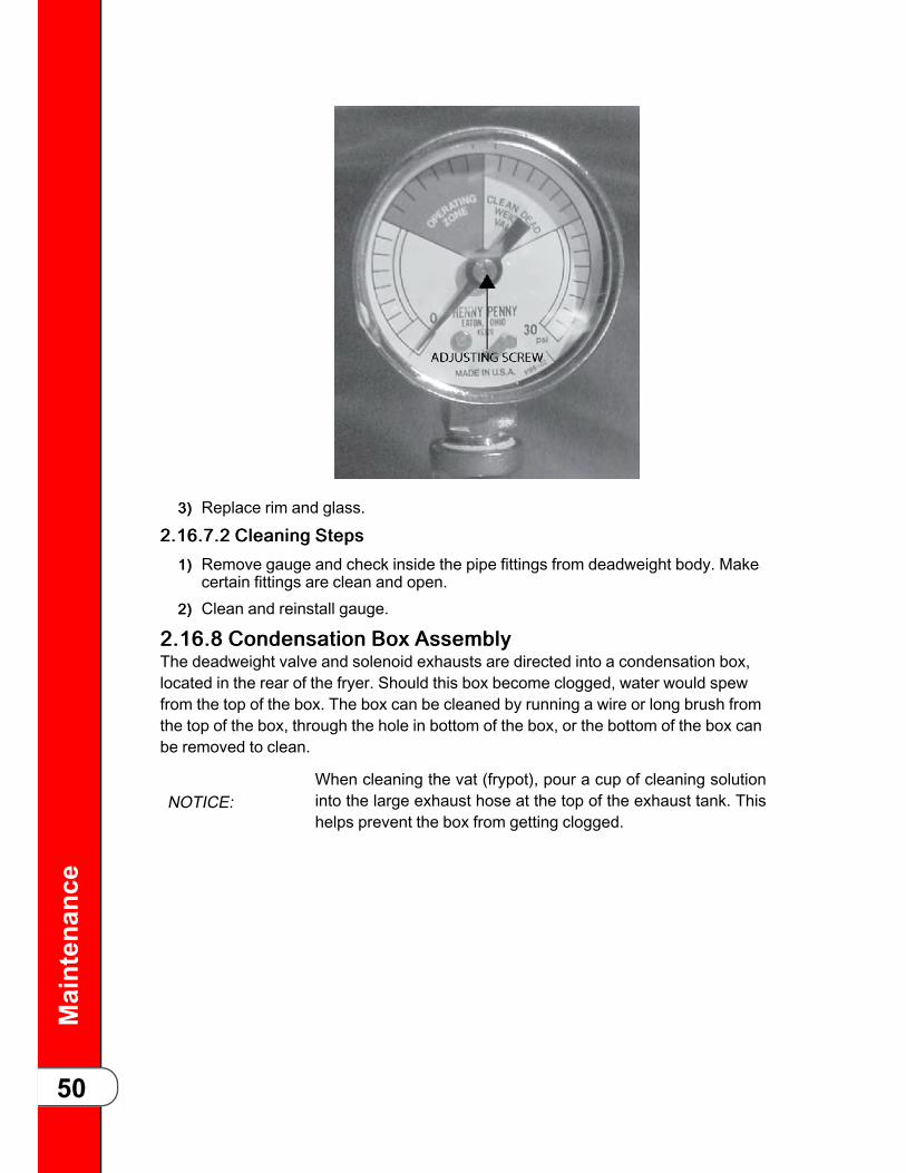
Maintenance
50
33)) Replace rim and glass.
22..1166..77..22 CClleeaanniinngg SStteeppss11)) Remove gauge and check inside the pipe fittings from deadweight body. Make
certain fittings are clean and open.22)) Clean and reinstall gauge.
22..1166..88 CCoonnddeennssaattiioonn BBooxx AAsssseemmbbllyyThe deadweight valve and solenoid exhausts are directed into a condensation box,located in the rear of the fryer. Should this box become clogged, water would spewfrom the top of the box. The box can be cleaned by running a wire or long brush fromthe top of the box, through the hole in bottom of the box, or the bottom of the box canbe removed to clean.
NOTICE:When cleaning the vat (frypot), pour a cup of cleaning solutioninto the large exhaust hose at the top of the exhaust tank. Thishelps prevent the box from getting clogged.

Maintenance
51
22..1166..99 CCoonnddeennssaattiioonn BBooxx BBoottttoomm RReemmoovvaall11)) Loosen fitting at the bottom of the box.
22)) Using Phillips head screwdriver, remove 4 screws securing the bottom of thebox and pull bottom from assembly.
33)) Clean outlet hole in box bottom and check condensation tube for clogs, andclean, if necessary.
44)) Reinstall box bottom and condensation line.55)) Seal box bottom with silicone sealant and unit is now ready for operation.

Maintenance
52
22..1166..1100 LLiidd CCoovveerr AAsssseemmbbllyy
22..1166..1100..11 DDeessccrriippttiioonn
In general, the spindle, the limit stop, the cover, the hinge, the inner and the reversiblegasket comprise the lid cover assembly.
22..1166..1100..22 LLiidd CCoovveerr RReemmoovvaall
The lid cover is easily removable for cleaning or service.

Maintenance
53
11)) Close the lid cover and turn spindle counterclockwise until it stops.22)) Pull the lid release pin on front of crossbar, lift the latch, and raise the crossbar.
33)) The cover can now be removed from vat (frypot).
22..1166..1100..33 LLiidd CCoovveerr IInnssttaallllaattiioonn11)) Place the lid cover on the vat (frypot).22)) Thread the spindle counterclockwise until it is completely extended.33)) Align the rear retaining hook on lid cover in the center slot of the crossbar. Push
the crossbar down and pull out on lid release pin.44)) Push the lid to rear of vat (frypot) and latch the crossbar to the lid cover.
Release the pin.55)) Check that lid cover is fastened properly before raising.
22..1166..1111 LLiidd HHiinnggee SSpprriinnggThe hinge spring needs to be replaced if it is broken, cracked or otherwise loses itstension. A special spring installation tool which greatly simplifies this procedure isavailable from the factory. (Henny Penny part number 14960)
11)) Pull out on the retaining pin knob on the front of the crossbar to release lidcover.
22)) Lift the cross bar up and away from the lid.33)) Remove Tru-Arc locks and hinge pin if the spring is broken. If the spring is not
broken, use spring tool as described in steps 5, 6, and 7, then remove Tru-Arclock and hinge pin.

Maintenance
54
44)) Remove the broken spring.55)) The new spring is placed in the loading tool so that the spring coil is laying in the
u-shaped center of the tool. The perpendicular shaft is placed in the stationaryhook of the tool, and the parallel shaft is placed so the adjustable hook willtighten it down.
66)) Tighten the handle on the tool as far as it will go.77)) Place the spring (loaded in the tool) into position so that the u-shaped center of
the tool is towards the front of fryer and the tool handle is toward the top of thefryer.
88)) Replace hinge pin and Tru-Arc locks. Loosen and remove the tool.99)) Reinstall the lid, see 2.16.10.3 Lid Cover Installation, page 53.
22..1166..1122 LLaattcchh SSpprriinngg IInnssttaallllaattiioonnTToo aavvooiidd sseevveerree bbuurrnnss aanndd iinnjjuurriieess mmaakkee ssuurree tthhee lliidd iisssseeccuurree dduurriinngg aa ccooookk ccyyccllee.. TThhee llaattcchh sspprriinngg mmuusstt bbee iinnggoooodd wwoorrkkiinngg oorrddeerr aanndd pprrooppeerrllyy iinnssttaalllleedd,, sseeeeiilllluussttrraattiioonnss bbeellooww.. IIff tthhee llaattcchh sspprriinngg iiss wweeaakk,, bbrrookkeenn,, oorrmmoouunntteedd bbaacckkwwaarrddss,, iitt wwiillll pprroovviiddee lliittttllee ffoorrccee aaggaaiinnsstt tthheellaattcchh..
The latch on the crossbar must have the external coil-type latch spring mounted onlatch pin. If a latch spring is weak or broken, it must be replaced with a new spring,part number 33480.

Maintenance
55
Figure 2-18 Latch Spring Assembly
11)) Replace the crossbar from the lid.22)) With the crossbar in the upright position, remove one of the two Tru-Arc rings
from latch pin.33)) Tap out pin from latch while grasping latch, and remove latch and latch spring.44)) Install new latch spring with the coils of spring extending forward.

Maintenance
56
55)) Secure spring in place with Tru-Arc ring.

Maintenance
57
22..1166..1133 LLiidd LLiinneerr
11)) Remove the four lid liner screws.22)) Use a thin blade screwdriver to pry lid from the cover.33)) Clean the liner and the inside of the cover. Replace the liner and screws.
22..1166..1144 RReevveerrssiinngg TThhee LLiidd GGaasskkeettThe gray rubber gasket surrounding the inside of lid is designed to be reversed.Henny Penny recommends that this be done on a quarterly basis.
22..1166..1144..11 PPuurrppoossee
Because of heat expansions and the pressure used for the cooking process, thegasket is constantly under extreme stress. Reversing the lid gasket on a quarterlybasis will help to assure that the fryer will not lose pressure through leakage.
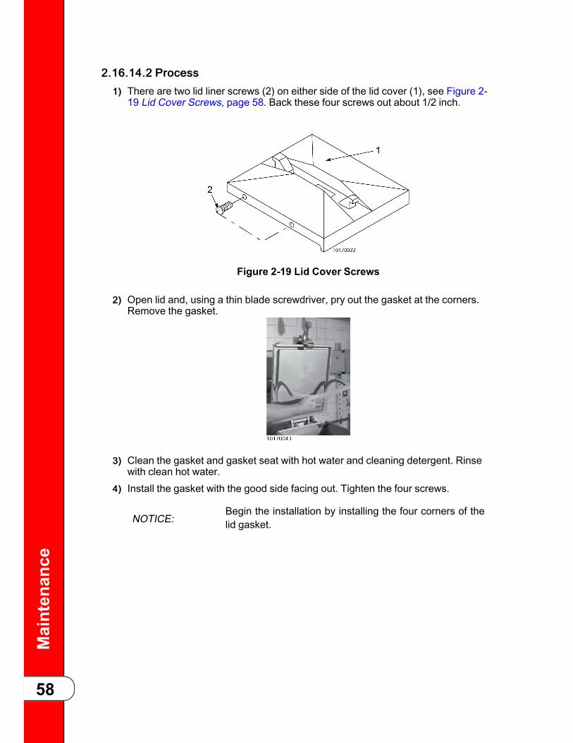
Maintenance
58
22..1166..1144..22 PPrroocceessss11)) There are two lid liner screws (2) on either side of the lid cover (1), see Figure 2-
19 Lid Cover Screws, page 58. Back these four screws out about 1/2 inch.
Figure 2-19 Lid Cover Screws
22)) Open lid and, using a thin blade screwdriver, pry out the gasket at the corners.Remove the gasket.
33)) Clean the gasket and gasket seat with hot water and cleaning detergent. Rinsewith clean hot water.
44)) Install the gasket with the good side facing out. Tighten the four screws.
NOTICE:Begin the installation by installing the four corners of thelid gasket.

Maintenance
59
22..1166..1155 LLiidd LLiimmiitt SSttoopp AAddjjuussttmmeennttThe lid limit stop, with proper adjustment, prevents unnecessary overtightening of thespindle, and as a result, extends the life of the lid gasket.
11)) Loosen the Allen set screws on the bottom of the collar of the limit stopassembly.
22)) Turn the inner collar of the limit stop clockwise as far as possible. Find the smallhole in the inner collar and use a small Allen wrench or Phillips head to help inturning the collar.
33)) Close lid and turn spindle until lid gasket meets the top of the vat (frypot) rim.44)) From this position, turn spindle at least 3/4 of a turn, but not over one full turn.55)) After rotating spindle to this point, slightly extend the spindle past this position.
The spindle should then be at the seven o’clock position. It may be necessary toremove knobs and change their position in order to align the red knob with the

Maintenance
60
red knob on the lid cover latch. When in the normal operating position, both redknobs should be aligned.
NOTICE:
The seven o’clock position is only to allow slightadditional turning of the spindle to relieve any sidepressure that could hold the locking pin in the lockingcollar after all pressure has been released from the vat(frypot).
66)) Adjust the limit stop by turning it clockwise until it stops against the bottom hubof the spindle.
77)) Tighten Allen set screws.88)) If the lid cover fails to seal properly, steam will escape around the gasket during
the frying operation. The limit stop should be readjusted. This time turn thespindle screw one full turn after the initial contact of the lid gasket against top ofthe vat (frypot) rim.
22..1177 FFiilltteerriinngg SSyysstteemm22..1177..11 FFiilltteerr RRiinnssee HHoossee
SShhoorrtteenniinngg wwiitthh tteemmppeerraattuurree iinn eexxcceessss ooff 220000ººFF fflloowwsstthhrroouugghh tthhiiss ffiilltteerr rriinnssee hhoossee.. HHeeaatt ccaauusseess tthhee rruubbbbeerr hhoosseettoo aaggee aanndd ddeetteerriioorraattee.. SSeevveerree bbuurrnnss wwiillll rreessuulltt iiff tthhiiss rriinnsseehhoossee aasssseemmbbllyy lleeaakkss oorr rruuppttuurreess.. TThhee hhoossee aanndd ffiittttiinnggsssshhoouulldd bbee cchheecckkeedd ddaaiillyy.. IIff aaggiinngg oorr ddiissccoolloorraattiioonn iiss sseeeenn,,tthhee hhoossee sshhoouulldd nnoott bbee uusseedd..
The filtering system consists of the filter valve, motor and filter pump assembly, filterscreen assembly, and tubing.
22..1177..22 RReemmoovvaallTThhee hhoossee aanndd ffiittttiinngg wwiillll bbee hhoott.. UUssee pprrootteeccttiivvee gglloovveess oorrccllootthh wwhheenn ffoolllloowwiinngg tthhiiss pprroocceedduurree oorr sseevveerree bbuurrnnss ccoouullddrreessuulltt..
NOTICE: This hose is not connected to fryer during normal operation.
11)) Close the filter valve.22)) Turn the pump switch to the OFF position.33)) Detach the hose.

Maintenance
61
22..1177..33 IInnssttaallllaattiioonn11)) Attach the filter rinse hose with its quick disconnect female fitting to the other
half male fitting inside the door, next to the filter valve handle.
22)) To do this slide back the spring ring on the female end of the quick disconnectfitting and let it snap into place over the other half male fitting.
33)) With a quick tug on the hose, insure the quick disconnect is locked into position.
22..1177..44 FFiilltteerr VVaallvvee DDeessccrriippttiioonnTThhee hhoossee aanndd ffiittttiinngg wwiillll bbee hhoott.. UUssee pprrootteeccttiivvee gglloovveess oorrccllootthh wwhheenn ffoolllloowwiinngg tthhiiss pprroocceedduurree oorr sseevveerree bbuurrnnss ccoouullddrreessuulltt..
The filter valve is 3/8 inch two-way stainless steel ball valve. If this valve shoulddevelop leaks the entire valve must be replaced.
22..1177..55 RReemmoovvaall11)) Drain the shortening from the vat (frypot).22)) Remove the filter drain pan from the fryer.33)) Remove the cotter pin, handle, and extension rod.44)) Remove the pipe from between the filter pump and valve.
NOTICE:If fryer is equipped with optional filter rinse hoseattachment, disconnect pipe from filter valve.
55)) Use an adjustable wrench and remove the valve.

Maintenance
62
66)) Replace the valve and reassemble in reverse order.
22..1177..66 FFiilltteerr PPuummpp RReeppaaiirrTToo aavvooiidd eelleeccttrriiccaall sshhoocckk oorr pprrooppeerrttyy ddaammaaggee,, mmoovvee tthheeppoowweerr sswwiittcchh ttoo ooffff aanndd ddiissccoonnnneecctt mmaaiinn cciirrccuuiitt bbrreeaakkeerr,, oorruunnpplluugg ccoorrdd aatt wwaallll rreecceeppttaaccllee..
The two most common causes for a fryer’s inability to pump shortening is that thepump is clogged with breading or solid shortening has cooled and solidified in thelines and pump.
22..1177..77 CCoovveerr RReemmoovvaall11)) Loosen the four Allen head screws on the end of pump and remove the cover.
22)) The inside is now exposed leaving a rotor and five Teflon rollers. Clean the rotorand rollers.

Maintenance
63
33)) To reassemble, place rotor on drive shaft, and place roller into rotor.
NOTICE:A small amount of grease might be needed to hold thebottom roller into place until cover plate is put on. Makesure O-ring is in proper position on plate.
22..1177..88 PPuummpp RReemmoovvaall11)) If the pump needs to be replaced, loosen one inch nuts from the outflow and
inflow lines. Then remove the two bolts holding the pump to the motor with a 1/2inch wrench.
22)) Shaft seal should remain on the motor shaft, or if leaking, could be replaced atthis time.

Maintenance
64
33)) To replace the pump, remove the four Allen screws, front plate, rotor, and rollersfrom pump. Place the pump onto shaft and against the seal shaft. Place the 1/2inch bolts through the pump and into the motor and tighten. Then replace rotor,rollers, front plate, and tight Allen screws.
CCAAUUTTIIOONN!!
WWhheenn rreemmoovviinngg aa ppuummpp ffrroomm aa mmoottoorr;; nnoottee tthheeppoossiittiioonnss ooff tthhee iinnlleett aanndd oouuttlleett ppaarrttss.. IInnssttaallllaattiioonn oofftthhee ppuummpp oonn tthhee mmoottoorr iinn aannyy ootthheerr ppoossiittiioonn ccoouullddccaauussee ddaammaaggee ttoo tthhee ffrryyeerr.. TThheerree iiss aann iinnddiiccaattoorr oonntthhee ssiiddee ooff tthhee ttwwoo hhaallvveedd ooff tthhee ppuummpp,, tthhiiss mmaarrkkmmuusstt bbee ttooggeetthheerr aanndd ffaaccee ttoo tthhee ffrroonntt ooff tthhee ffrryyeerr..
44)) To replace the pump and motor assembly, insure the main power has beenremoved from the fryer.
WWAARRNNIINNGG!!TToo aavvooiidd eelleeccttrriiccaall sshhoocckk oorr pprrooppeerrttyy ddaammaaggee,, mmoovveetthhee ppoowweerr sswwiittcchh ttoo ooffff aanndd ddiissccoonnnneecctt mmaaiinn cciirrccuuiittbbrreeaakkeerr,, oorr uunnpplluugg ccoorrdd aatt wwaallll rreecceeppttaaccllee..
55)) Remove the cover from the junction box and remove the wire nuts attachingwires leading into the flexible conduit going to the motor.
66)) Loosen the two screws securing the flexible conduit to the 90º conduit connector(8), see .
77)) Remove tubing to the pump, see and .88)) Remove hardware attaching the motor to the motor base bracket and remove
motor and pump assembly.

Maintenance
65
22..1177..99 FFiilltteerr PPuummpp MMoottoorr PPrrootteeccttoorr -- MMaannuuaall RReesseettTToo pprreevveenntt bbuurrnnss ccaauusseedd bbyy ssppllaasshhiinngg sshhoorrtteenniinngg,, tthheeuunniitt’’ss mmaaiinn ppoowweerr sswwiittcchh mmuusstt bbee iinn tthhee ooffff ppoossiittiioonn bbeeffoorreerreesseettttiinngg tthhee ffiilltteerr ppuummpp mmoottoorr’’ss mmaannuuaall rreesseett pprrootteeccttiioonnddeevviiccee..
The filter pump motor is equipped with a manual reset button in the event the motor’sthermal protector actuates. This reset button is located on the rear of the motor. Waitapproximately 5 minutes before attempting to reset this protector device.
22..1188 EElleeccttrriiccaall CCoonnvveerrssiioonnssOn occasion, it may be necessary to make electrical conversion to a fryer. Factoryconversion kits are available and should be used. The following procedures describethese conversions.
22..1188..11 PPrroocceedduurreess220088 VVoollttss ttoo 222200//224400 VVoollttss::The only change necessary is to remove the 208 volt heating elements and replacethem with 220/240 volt heating elements. Delay timers must be changed on variabletemperature models.222200//224400 VVoollttss ttoo 220088 VVoollttss::The only change necessary is to remove the 220/240 volt heating elements andreplace them with 208 heating elements. Delay timers must be changed on variabletemperature models.SSiinnggllee PPhhaassee ttoo TThhrreeee PPhhaassee::A factory conversion it (Part No. 14034) is available for this conversion. This kitincludes all necessary components and a wiring diagram.TThhrreeee PPhhaassee ttoo SSiinnggllee PPhhaassee::A factory conversion kit (Part No. 14033) is available for this conversion. This kitincludes all necessary components and a wiring diagram.Refer to the proper figure in the illustrated parts listing (Section 3), and Section 2 formaintenance assistance for the fryer being converted to and from.

Maintenance
66
22..1199 WWiirriinngg DDiiaaggrraammssIllustrations of the wiring diagram for Henny Penny Models 500, 561, and 600Pressure Fryers are found in Chapter 5 Wiring Diagrams, page 81.If there is any doubt about which wiring diagram to use, please contact yourdistributor. As with all contacts to the distributor, include the model number and serialnumber form the data plate on your unit.
NOTICE: Refer to to explain the wire naming system for April 1, 2006and after.
22..2200 CCaasstteerr RReeppllaacceemmeenntt PPrroocceedduurreeCasters on the fryer cannot be adjusted. Replace any damaged or broken casters bydoing the following:
11)) Discard oil from the fryer.22)) Using two floor jacks, position jacks near casters under the frame at point A.
Both jacks must be positioned near casters on the same side of the fryer. Forexample, lift both the front casters off of the ground if replacing a front caster.
33)) Block the casters on the opposite side of the fryer with small wheel chocks.44)) Raise fryer approximately 2.5” (63mm).55)) Use an adjustable wrench at point B. to remove the existing caster.66)) Install the new caster in reverse order.
22..2211 SSoolleennooiidd VVaallvveeTToo aavvooiidd eelleeccttrriiccaall sshhoocckk oorr pprrooppeerrttyyddaammaaggee,, mmoovvee tthhee ppoowweerr sswwiittcchh ttooOOFFFF aanndd ddiissccoonnnneecctt mmaaiinn cciirrccuuiittbbrreeaakkeerr,, oorr uunnpplluugg ccoorrdd aatt wwaallllrreecceeppttaaccllee..
NNOOTTEE: Most Controls use 24 volt solenoids. TheC1000 & C2000 Controls use line voltage
This is an electromechanical device that causes pressure to be held in the vat (frypot).The solenoid valve closes at the beginning of the cook cycle and is openedautomatically by the timer at the end of the cook cycle. If the valve should becomedirty or the te-Aon seat nicked, pressure will not build up. The solenoid valve used onall models is the same with the exception of the coil. The gas model fryer uses a 120volt, 60 Hz, coil. The electric model fryer uses a 208/240 volt 60 Hz coil. The 440/480volt electric model uses a transformer to drop voltage to 220/240 volts.

Maintenance
67
22..2211..11 RReeppllaaccee SSoolleennooiidd VVaallvvee AAsssseemmbbllyy1. Remove Tru-Arc retaining clip on topof the coil housing.
2. Remove the nameplate and cover.
3. Do one of the following:
A. If only the coil is replaced, disconnect twocoil wires at the wire nuts in the coilhousing, remove the coil from thehousing, and then replace with the newcoil. Then replace nameplate, cover,and Tru-Arc clip.
B. If the complete solenoid, or seals arebeing replaced, continue on to step 4.
NOTICE: The wires may be connectedin any order.
4. Loosen the nut on the 1/2 inchconnector and pull piping conduit fromthe valve case. Leave enough slack toremove the coil housing and yoke.
AA
5. If the core-disc assembly is stickingdue to buildup of shortening, breadingand food particles proceed with thefollowing steps.
A. Unscrew the solenoid bonnet assemblyfrom the solenoid valve body.
B. Remove the solenoid bonnet assemblyand the bonnet gasket.
C. Remove the core-disc assembly, corespring retainer, and the core spring.
D. Wash all parts in soap and hot water.

Maintenance
68
BB
CC
6. Do the following:A. If replacing Teflon seals, or complete valve, proceed to step 7.
B. If not, assemble the core-disc in reverse order of disassembly. Assemble valvecore and blade (6), with the smooth side of the hole towards the disc springguide (9). Refer to step 8.
7. A repair kit (Part No. 17120) isavailable if any of the seals need to bereplaced. If any of the seals aredefective, all seals should be replaced.
NOTICE: Remove the solenoid bodyfrom the fryer to replace seals. Refer toexploded view of solenoid in figure 3-14to help identify all parts.A. Remove back cover.
B. Loosen both conduit and exhaustfittings.
C. Remove nipple from solenoid body.

Maintenance
69
D. Unscrew body from fryer.
E. Install a new solenoid, and thenreassembled in reverse order. Orcontinue onto step 8 to removeand replace the seals.
8. To replace the seals, do the following:A. Remove the two adapter screws (22)
which attach the pipe adapter (21)to the solenoid body (20).
B. Remove the disc spring (10), guide(9), and seat (8).
C. Clean the valve body.
D. Wet O-ring (12) around seat withwater and insert O-ring assembly(flat side first) in valve, through INside of body. Use a pencil eraser,and press in Teflon seat until itsnaps into place. Be careful not tomark or nick the seat.
NOTICE: The smallest nick can cause apressure leak. Replace all O-ring seals,found in the parts kit, and reassemblevalve.

Maintenance
70

Pressure
AssistF
eaturesandFu
nctio
n
71
CChhaapptteerr 33 PPrreessssuurree AAssssiissttFFeeaattuurreess aanndd FFuunnccttiioonnPressure Assist is an optional, purchasable feature that allows operators to cooksmall loads and still maintain the required vat pressure necessary for pressurecooking. In the past, full loads were required in order for the fryer to build the requiredvat pressure. Pressure Assist adds additional pressure, as needed, to raise the vatpressure to the required 12 PSI cooking pressure. Low vat pressure will not allow thefood to cook properly and consistently. But with Pressure Assist, small loads can becooked with the same consistency as full loads. This feature provides the operatorwith more flexibility in meeting both customer and business needs by reducing wasteand providing fresh cooked, high quality product in smaller amounts as needed.
33..11 SSooffttwwaarree33..11..11 CC88000000 CCoonnttrroolllleerrAccess the Pressure Assist settings by doing the following:
1. Access Tech Mode T-2A, HAS PR ASSIST and set to YES. PRESSURE ASSIST: YES/NOdisplays when the fryer is initially powered on.NOTE: If NO is selected, the fryer’s cook cycle operates as normal. The air pump staysoff for the entire cook cycle.
2. Select YES, the setting 2. PR ASSIST DELAY SECONDS: 0 ... 120 seconds displays inProduct Programming mode. A delay can be set between when the pressure solenoidvalve turns on and the pressure assist pump also turns on:
• Delay = 0: As soon as the pressure solenoid valve turns on, the pressure assist pump alsoturns on. The air pump cycles on and off as needed to maintain pressure for the rest of thecook cycle.
• Delay = 1: During a cook cycle, when the pressure solenoid valve is first closed, the controlinitiates the programmed delay period. As soon as the delay expires, the pressure assistpump turns on. The air pump cycles on and off as needed to maintain pressure for the restof the cook cycle.
3. Select desired delay. If 1 or more seconds of delay are chosen, the setting 3. PR ASSISTNOT NEEDED IF ‘X’ PSI: 0.0 ... 12.0 psi. 0.0 shown as “- - -” displays in Product Pro-gramming mode.
4. Select desired P.S.I. During a cook cycle, when the pressure solenoid valve is first closed,the control initiates the programmed delay period. As soon as the delay expires, the con-trol assesses the naturally achieved pressurization level. If the pressure reading is at orabove the “Not Needed” psi threshold, no pressure assist is performed at all for that cookcycle; otherwise, the pressure assist pump turns on and runs as needed to maintain pres-sure for the rest of the cook cycle.
EXAMPLE: (PrAssist = YES) and (Delay >= 1 second) and (NotNeededPSI >= 0.1psi)
Air Pump Constraints:

Pressure
AssistF
eaturesandFu
nctio
n
72
11.. The air pump is always off during the first (10) seconds of the cook cycle, because theuser might still be trying to close the lid.
22.. The air pump is always off if the pressure solenoid valve is off (open). The solenoidvalve cycles on and off according to the programmed cook cycle.

Prog
ramming
73
CChhaapptteerr 44 PPrrooggrraammmmiinnggProgramming information is provided in this section. Operator menus are described inthe Operator’s manual and are not included in this manual. All menus that pertain tomaintenance are described in this section. To enter the menus, perform the followingsteps:
11)) Press and hold the PROGRAM button for five seconds.22)) Release the PROGRAM button as soon as “LEVEL 2” shows in the display.33)) Press the PROGRAM button until “TECH” is displayed (you are in tech mode
now).44)) Enter the code 11221122.
The only menu used for maintenance for the Computron 8000 control is Tech Mode.TTaabbllee 44--11 PPrrooggrraammmmiinngg
Menu Step Description
T-1 SoftwareID’s
View software ID’sPress and hold [1]: HP P/N = 32609J (HP part number for software.)Press and hold [2]: ID = HP C8000 (The specific customer or model num-ber, etc.)Press and hold [3]: SRL = 1.50 (Software Release Level (version) for thissoftware.)
T-2 Fryer Type Auto-detected by the controller, based on I/O board and wiring harnessconnections. (This is not a setting you can adjust.)Auto-detection can complete only if the fryer is turned ON and the high-limit and drain switch interlocks are closed. If the display indicates“NEED VHDS”, then one of the interlocks is not satisfied and the auto-detect routine is unable to proceed.
T-3 Push-ButtonTest
Push-button test mode.Press and release buttons (starting with any button other than INFO orPROG) to activate test mode. Main display shows an indicator letter foreach button that is pressed:Number buttons 1-0, Info, Down, Up, Prog, Left-side (Idle), Right-side(Timer)
T-4 All-On Dis-play Test
Press and hold any number button to cause all display digit segments,decimal points, LED’s, and light bars to be lighted. Release button to re-turn to normal mode.
T-5 SegmentsTest
Tests each individual display segment (all digits simultaneously) in orderto assess whether any segments might be bridged together.Press and release any number button to step through the test sequencemanually, or press and release the Timer button to run the test sequenceautomatically one time through.
T-6 Digits Test Tests each individual display digit (all segments on, one digit at a time) inorder to assess whether any solder bridges between digits exist.

Prog
ramming
74
Menu Step Description
Press and release any number button to step through the test sequencemanually, or press and release the Timer button to run the test sequenceautomatically one time through.
T-7 Decimal PTSTest
This step tests each individual display digit decimal point.Press and release any number button to step through the test sequencemanually, or press and release the Timer button to run the test sequenceautomatically one time through.
T-8 LED’s Dis-play Test
This step tests each individual discrete LED.The test pattern is as follows:Wait, Ready, Idle, Heat, Pressure, Info, Down, Up, Prog, Timer, 1, 2, 3,4, 5, 6, 7, 8, 9, 0.Press and release any number button to step through the test sequencemanually, or press and release the Timer button to run the test sequenceautomatically one time through.
T-9 Oil Temp -Calib/Offset/Highest
View/set calibration offset for oil temperature probe. Also, view/resetmax recorded oil temperature.Press and hold [1]: CALIB ADJ 327°F - UP/DOWN to adjust calibrationviewed as a temp.Press and hold [2]: OFFSET ADJ+2°F - UP/DOWN to adjust calibrationviewed as an offset.Press and hold [3]: HIGHEST 341°F - View highest recorded oil tempera-ture. Reset max temp by pressing the DOWN button while viewing.
T-9A Aux Temp -Calib/Offset/Highest
View/set calibration offset for auxiliary (dry-fire) temperature probe. Also,view/reset max recorded aux temperature.Press and hold [1]: CALIB ADJ 418°F - UP/DOWN to adjust calibrationviewed as a temp.Press and hold [2]: OFFSET ADJ+0°F - UP/DOWN to adjust calibrationviewed as an offset.Press and hold [3]: HIGHEST 463°F - View highest recorded aux tem-perature. Reset max temp by pressing the DOWN button while viewing.
T-10 CPU Temp- Calib/Offset/Highest
View/set calibration offset for CPU board temp.Also, view/reset max recorded CPU board temp.Press and hold [1]: CALIB ADJ 87°F - UP/DOWN to adjust calibrationviewed as a temp.Press and hold [2]: OFFSET ADJ +0°F - UP/DOWN to adjust calibrationviewed as an offset.Press and hold [3]: HIGHEST 121°F - View highest recorded CPU tem-perature. Reset max by pressing the DOWN button while viewing.
T-11 View A-DChannels
This feature allows direct viewing of any channel of the analog-to-digitalconverter chip. This is mainly useful for troubleshooting.The channel can be selected using the UP or DOWN buttons.<0> CPU temperature (thermistor)<1> Safety Circuit Comparator Ref.<2> Safety Circuit Comparator Output<3> Aux. RTD input (unused)<4> Oil Tmp RTD input

Prog
ramming
75
Menu Step Description
<5> Transformer secondary (P6-14)<6> Amp Sensor auto-detect (P10-6)<7> unused (P10-5)<8> Amp sensor #3 (P10-4)<9> Amp sensor #1 (P10-2)< A > Amp sensor #2 (P10-3)< B > 1/2 Scale (2.5v)< C > Neg Vref (0.0v)< D > Pos Vref (5.0v)The displayed value can be toggled between Volts and Bits by pressingthe number 0 button.If the displayed value has a decimal point and is followed by a “V” it isvoltage (0 to 5 VDC).If no decimal point is shown, the value is a-to-d bits (0 - 4095).
T-12 View TheStatus Of The24v Interlock Cir-cuit DigitalInputs:
Each interlock input has an associated indicator digit.If the input signal is currently detected, an identifying letter is displayed.If the signal is not detected, an underscore (“_”) is displayed.44--HHdd EElleecc:F & M are hard-wired on. P is hard-wired off.44--HHeeaadd EElleeccttrriicc FFrryyeerrss:DIGITAL INPUTS - AB VHDSFPMNormal Display: A_ VHDSF_M44--HHdd GGaass:F & P are hard-wired on. M is hard-wired off.44--HHeeaadd GGaass FFrryyeerrss:DIGITAL INPUTS - AB VHDSFPMNormal Display: A_ VHDSFP_
The “C” (pressure solenoid) input can only be readwhen the pressure output is turned OFF. When thepressure output is turned ON, the “C” inputnormally disappears.
AA == Power switch “COOK” (ON) position input signal. There are two“power switch on” input signals, ‘A’ and ‘S’. The ‘A’ one is not dependenton the interlock chain, so the controller is always able to read the On/Offstatus of the power switch even if the high limit is tripped or the drain isopen.BB == Power switch “PUMP” position input signal. Should not have A and Bat the same time*.Note that this continuity signal can only be read when the pressure out-put is OFF. The “C” signal disappears whenever the pressure solenoidoutput is turned ON.VV == VOLTS – 24v detected at start of interlock chain. If “V” is missing, the24v current limiter (fuse) might be tripped. This “fuse” device (located onthe I/O board) automatically resets as soon as the short condition isfixed.

Prog
ramming
76
Menu Step Description
HH == HIGH LIMIT – If “H” is present, the high limit is good. If “H” is missing,the high limit is tripped out (overheated) or disconnected.DD == DRAIN SWITCH – If “D” is present, the drain handle is closed. If “D”is missing, the drain switch is open or disconnected.SS == Power switch “on” interlock circuit: If “S” is present, the power switchis in the ON position. If the “S” is missing, the power switch is either off,failed, or wired incorrectly.44--HHeeaadd EElleeccttrriicc aanndd 44--HHeeaadd GGaass FFrryyeerrss:FF == The “F” input is always hardwired ON. (These fryers do not have fanvacuum sensors.)PP == “Gas” auto-detect jumper.
• 4-Hd Gas Fryers: This signal is hardwired ON.
• 4-Hd fryers: This signal is hardwired OFF and should never bepresent.
MM == “Electric” auto-detect jumper.
• 4-Hd fryers: This signal is hardwired ON.
• 4-Hd Gas Fryers: This signal is hardwired OFF and should never bepresent.
The two sets of P & M signals are interlocked by relays on the I/O boardinside the controller. The controller cannot turn on the gas pilot valve un-less both PV signals are present. The controller cannot turn on the gasmain valve (main burners) unless both MV signals are present.FF == FAN - This is the Fan sensor (vacuum switch) interlock input. When‘F’ is present, the vacuum sensor is closed (continuity). When ‘F’ is miss-ing, the vacuum switch is open or is disconnected.PP == The PV (Pilot Valve) output from the ignition module. The ignitionmodule turns PV on when it is trying to establish or maintain the pilotflame.MM == The MV (Main Valve) output from the ignition module. The ignitionmodule turns MV on only when the module has a confirmed “flamesense” of its pilot flame. Keep in mind that the MV signals are simply “en-abling” signals for the gas burners – the burners are not actually acti-vated unless the controller turns the Heat output on.
T-13 Outputs View/set the status of the controller outputs. If an output is currently on, a“star” follows the ID letter. If an output is currently off, a line follows theletter.F = FAN OUTPUTI = IGNITION MODULES OUTPUTH = HEAT OUTPUTP = PRESSURE OUTPUTThe outputs may be manually controlled using the lighted number but-tons. The #1 button toggles the first output on and off, the #2 button tog-gles the second output on and off, etc.

Prog
ramming
77
Menu Step Description
For example, on a Gas 4 Head fryer the #1 button toggles the Fan outputon and off, while on an Electric 4 Head fryer, the #1 button toggles theHeat on and off.Under manual control, the Heat output will shut off automatically if nobuttons are pressed for 30 seconds.44--HHeeaadd EElleeccttrriicc FFrryyeerrss:OUTPUTS - F* H * P _(Fan output only used on PVS fryers)4-Head Gas Fryers:OUTPUTS - F* H * P _(Fan output is for cooling fan)
T-13A Outputs View/set the status of the Pump and Air Valve outputs. If an output is cur-rently on, a “star” follows the ID letter. If an output is currently off, a linefollows the letter.PMP = PUMP OUTPUTAIR = AIR VALVE OUTPUTThe outputs may be manually controlled using the lighted number but-tons. The #1 button toggles the Pump output on and off, and the #2 but-ton toggles the Air Valve output on and off.
T-14 AmpsCalibrate
If the Amp Sensor Detect Jumper in the amp sensors assembly is not de-tected, the controller shows “XX XX XX “ / “ -NOT- DETECTED” and allAmp Sensor warnings and errors are disabled.EElleeccttrriicc 44 HHeeaadd FFrryyeerrss:The amp sensors monitor the current (amperes) in the heating elements.Depending on the fryer wiring, each amps reading corresponds to eitherthe current in one leg of the supply lines, or to the current to one heatingelement coil.Consequently, the amps readings here don’t necessarily match the ampsreadings of an individual heater, since each leg on the line cord normallydrives two elements (120° out of phase).Press the DOWN button to view the present Nominal, Low Limit, andHigh Limit settings for amps. (These values are programmed in SpecialProgram mode.)This step allows manual control of the heat output by pressing the #1 but-ton. The heat is turned on unconditionally, so make sure there is oil inthe vat (frypot) and take care to not overheat it.Press the #0 button to view the un-calibrated readings.CCaalliibbrraattiioonn:Press the TIMER button to perform the calibration sequence, which al-lows each of the three readings to be adjusted to match reference ampreadings. This calibration requires a meter with an amp clamp to takereadings at each of the three amp sensors in the fryer.During the calibration sequence, one of the readings is blinking. Use theUP and DOWN buttons to adjust that reading as necessary. Press thePROG button to advance to the next reading.The displayed values, left to right, match the amp sensor order black,red, and orange. For each amp sensor, the displayed value should beadjusted to match a reading taken with an amp clamp on the same wirethe amp sensor is on.
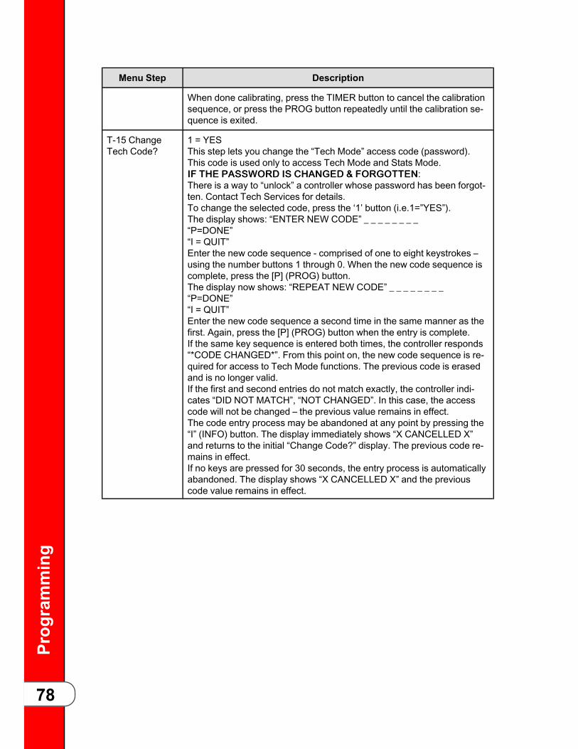
Prog
ramming
78
Menu Step Description
When done calibrating, press the TIMER button to cancel the calibrationsequence, or press the PROG button repeatedly until the calibration se-quence is exited.
T-15 ChangeTech Code?
1 = YESThis step lets you change the “Tech Mode” access code (password).This code is used only to access Tech Mode and Stats Mode.IIFF TTHHEE PPAASSSSWWOORRDD IISS CCHHAANNGGEEDD && FFOORRGGOOTTTTEENN:There is a way to “unlock” a controller whose password has been forgot-ten. Contact Tech Services for details.To change the selected code, press the ‘1’ button (i.e.1=”YES”).The display shows: “ENTER NEW CODE” _ _ _ _ _ _ _ _“P=DONE”“I = QUIT”Enter the new code sequence - comprised of one to eight keystrokes –using the number buttons 1 through 0. When the new code sequence iscomplete, press the [P] (PROG) button.The display now shows: “REPEAT NEW CODE” _ _ _ _ _ _ _ _“P=DONE”“I = QUIT”Enter the new code sequence a second time in the same manner as thefirst. Again, press the [P] (PROG) button when the entry is complete.If the same key sequence is entered both times, the controller responds“*CODE CHANGED*”. From this point on, the new code sequence is re-quired for access to Tech Mode functions. The previous code is erasedand is no longer valid.If the first and second entries do not match exactly, the controller indi-cates “DID NOT MATCH”, “NOT CHANGED”. In this case, the accesscode will not be changed – the previous value remains in effect.The code entry process may be abandoned at any point by pressing the“I” (INFO) button. The display immediately shows “X CANCELLED X”and returns to the initial “Change Code?” display. The previous code re-mains in effect.If no keys are pressed for 30 seconds, the entry process is automaticallyabandoned. The display shows “X CANCELLED X” and the previouscode value remains in effect.

Prog
ramming
79
Menu Step Description
T-16 Do TotalInit
This step allows all programmable settings, all product settings, and allstatistics values to be initialized to factory preset values.(The Activity Log, however, is not reset by this initialization, and in factwill log a record of the “init” function itself.)To totally initialize the controller – including all cook settings – back tofactory default values, press and hold the DOWN button for about 2seconds.Calibration data will not be affected by this initialization, unless valuesare found to be outside of acceptable limits.
Statistics values, the Error Log, Review Usagedata, etc., will be reset by this “total” initialization.All of the operating history data will be lost. For thisreason, the normal “Init” step in Special Programmode is generally recommended, unless onespecifically intends to completely reset all thestatistics data.

Prog
ramming
80

Wiring
Diagram
s
81
CChhaapptteerr 55 WWiirriinngg DDiiaaggrraammss55..11 550000 EEFF,, 220088--224400vv,, 5500//6600HHzz,, 11PP ((6633119922EE)) ((BBeeffoorree0044//0011//0066))

Wiring
Diagram
s
82
55..22 550000 EEFF,, 220088--224400vv,, 5500//6600HHzz,, 11PP ((7711999955CC)) ((AAfftteerr0044//0011//0066))

Wiring
Diagram
s
83
55..33 550000 EEFF,, 220088--224400vv,, 5500//6600HHzz,, 11PP ((6633119999FF)) ((BBeeffoorree0044//0011//0066))

Wiring
Diagram
s
84
55..44 550000 EEFF,, 220088--224400vv,, 5500//6600HHzz,, 11PP ((7711998888DD)) ((AAfftteerr0044//0011//0066))

Wiring
Diagram
s
85
55..55 550000 EEFF,, 338800--441155vv,, 5500HHzz,, 33PP,, ((6633119977EE)) ((BBeeffoorree 0044//0011//0066))

Wiring
Diagram
s
86
55..66 550000 EEFF,, 338800--441155vv,, 5500HHzz,, 33PP,, ((7711999933BB)) ((AAfftteerr 0044//0011//0066))

Wiring
Diagram
s
87
55..77 550000 EEFF,, CC11000000 && 22000000,, 220088--224400vv,, 5500//6600HHzz,, 33PP,,224400vv CCoonn.. ((7788554411CC))

Wiring
Diagram
s
88
55..88 550000 EEFF,, CC11000000 && 22000000,, 220088--224400vv,, 5500//6600HHzz,, 11PP,,224400vv CCoonn.. ((7799442211BB))

Wiring
Diagram
s
89
55..99 550000 EEFF,, CC11000000 && 22000000,, 220088--224400vv,, 5500//6600HHzz,, 11PP,,224400vv CCoonn.. ((7799442222BB))
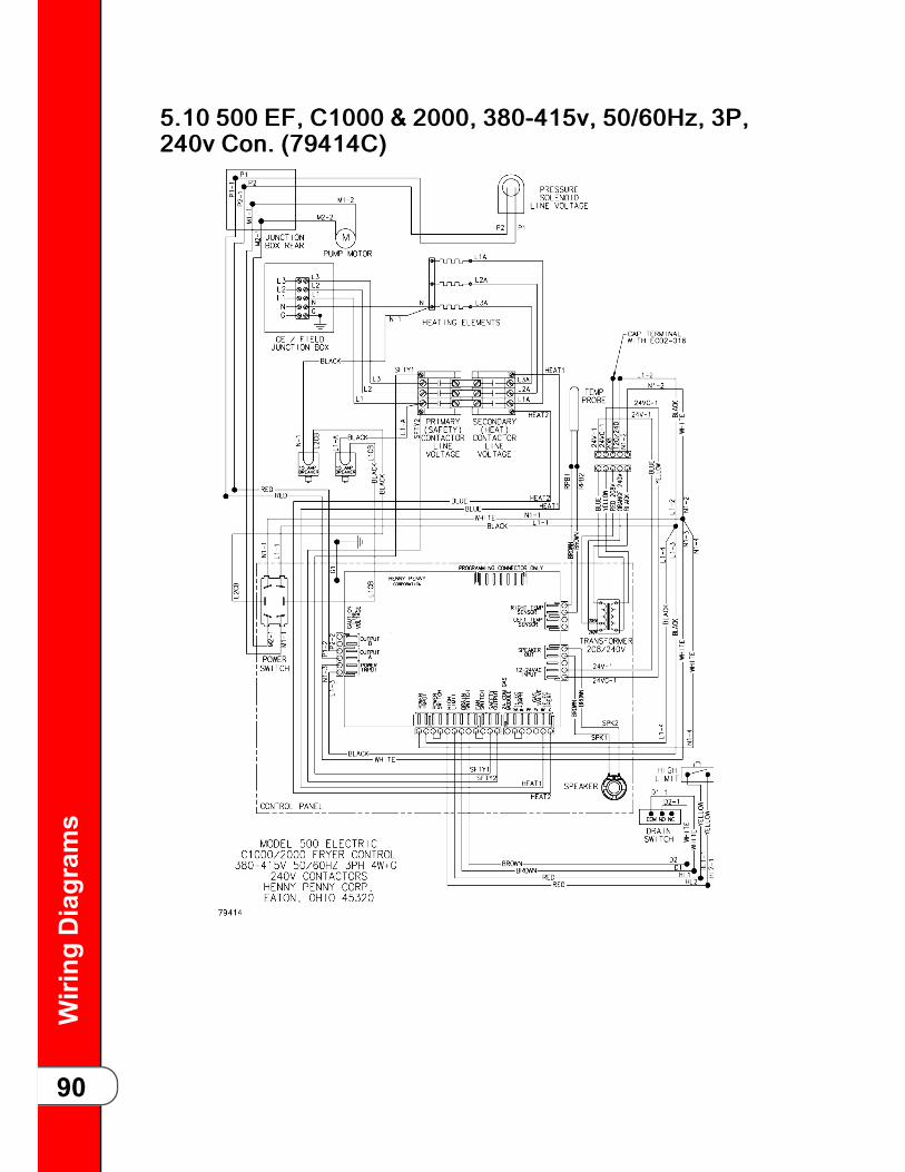
Wiring
Diagram
s
90
55..1100 550000 EEFF,, CC11000000 && 22000000,, 338800--441155vv,, 5500//6600HHzz,, 33PP,,224400vv CCoonn.. ((7799441144CC))

Wiring
Diagram
s
91
55..1111 550000 EEFF,, CC11000000 && 22000000,, 448800vv,, 5500//6600HHzz,, 33PP,, 224400vvCCoonn.. ((7799441155AA))

Wiring
Diagram
s
92
55..1122 550000 EEFF,, 220088--224400vv,, 5500//6600HHzz,, 11PP ((5511667722NN)) ((BBeeffoorree0044//0011//0066))

Wiring
Diagram
s
93
55..1133 550000 EEFF,, 220088--224400vv,, 5500//6600HHzz,, 11PP ((6699664477CC)) ((AAfftteerr0044//0011//0066))
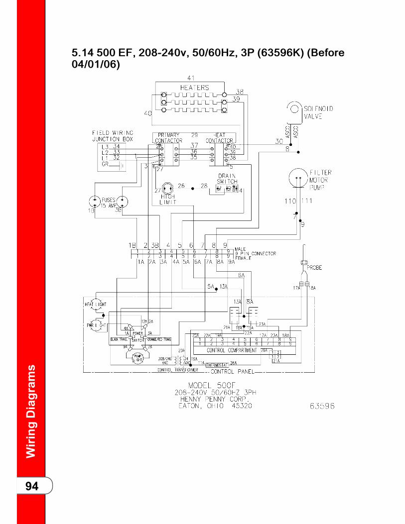
Wiring
Diagram
s
94
55..1144 550000 EEFF,, 220088--224400vv,, 5500//6600HHzz,, 33PP ((6633559966KK)) ((BBeeffoorree0044//0011//0066))

Wiring
Diagram
s
95
55..1155 550000 EEFF,, 220088--224400vv,, 5500//6600HHzz,, 33PP ((6699662244CC)) ((AAfftteerr0044//0011//0066))

Wiring
Diagram
s
96
55..1166 550000 EEFF,, 338800--441155vv,, 5500//6600HHzz,, 33PP ((6633335555MM))((BBeeffoorree 0044//0011//0066))

Wiring
Diagram
s
97
55..1177 550000 EEFF,, 338800--441155vv,, 5500//6600HHzz,, 33PP ((6699444499DD)) ((AAfftteerr0044//0011//0066))

Wiring
Diagram
s
98
55..1188 550000 EEFF,, 440000vv,, 5500HHzz,, 33PP ((5511330000NN)) ((BBeeffoorree 0044//0011//0066))

Wiring
Diagram
s
99
55..1199 550000 KKFFCC EEFF,, 338800--441155vv,, 5500HHzz,, 33PP ((6633221111KK))((BBeeffoorree 0044//0011//0066))
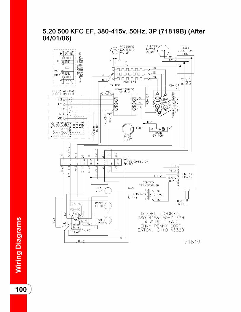
Wiring
Diagram
s
100
55..2200 550000 KKFFCC EEFF,, 338800--441155vv,, 5500HHzz,, 33PP ((7711881199BB)) ((AAfftteerr0044//0011//0066))

Wiring
Diagram
s
101
55..2211 550000 SSCC EEFF,, 220088//224400vv,, 5500//6600HHzz,, 33PP ((1188331111FF))

Wiring
Diagram
s
102
55..2222 550000 SSCC EEFF,, 220088//224400vv,, 5500//6600HHzz,, 11PP ((1188330099DD))

Wiring
Diagram
s
103
55..2233 550000 SSMMSS EEFF,, 220088--224400vv,, 5500//6600HHzz,, 11PP ((7733330099EE))

Wiring
Diagram
s
104
55..2244 550000//556611 EEFF,, 220088--224400vv,, 5500//6600HHzz,, 33PP ((6633113311FF))((BBeeffoorree 0044//0011//0066))

Wiring
Diagram
s
105
55..2255 550000//556611 EEFF,, 220088--224400vv,, 5500//6600HHzz,, 33PP ((7711999988CC))((AAfftteerr 0044//0011//0066))

Wiring
Diagram
s
106
55..2266 550000//556611 EEFF,, 448800vv,, 5500//6600HHzz,, 33PP ((6633119944GG)) ((BBeeffoorree0044//0011//0066))

Wiring
Diagram
s
107
55..2277 550000//556611 EEFF,, 448800vv,, 5500//6600HHzz,, 33PP ((7711999944CC)) ((AAfftteerr0044//0011//0066))
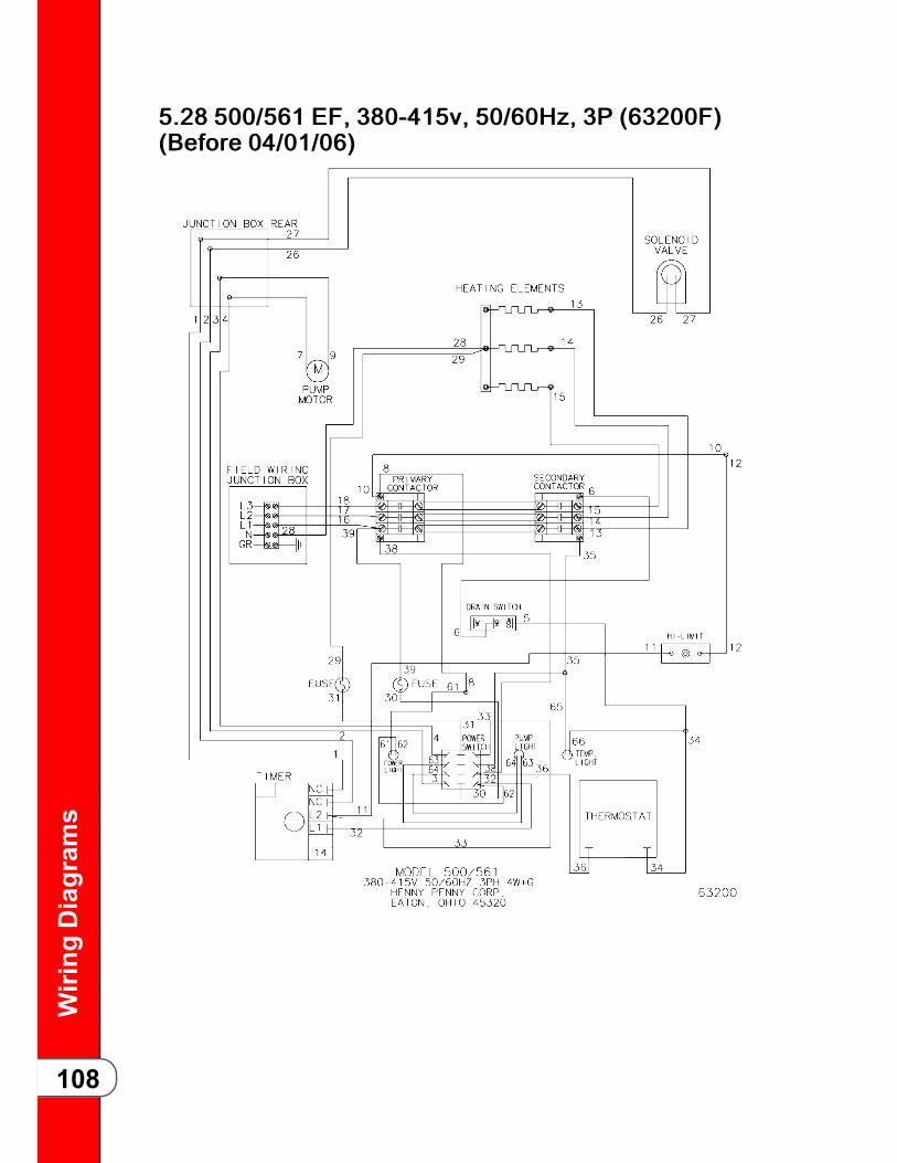
Wiring
Diagram
s
108
55..2288 550000//556611 EEFF,, 338800--441155vv,, 5500//6600HHzz,, 33PP ((6633220000FF))((BBeeffoorree 0044//0011//0066))

Wiring
Diagram
s
109
55..2299 550000//556611 EEFF,, 338800--441155vv,, 5500//6600HHzz,, 33PP ((7722000022BB))((AAfftteerr 0044//0011//0066))
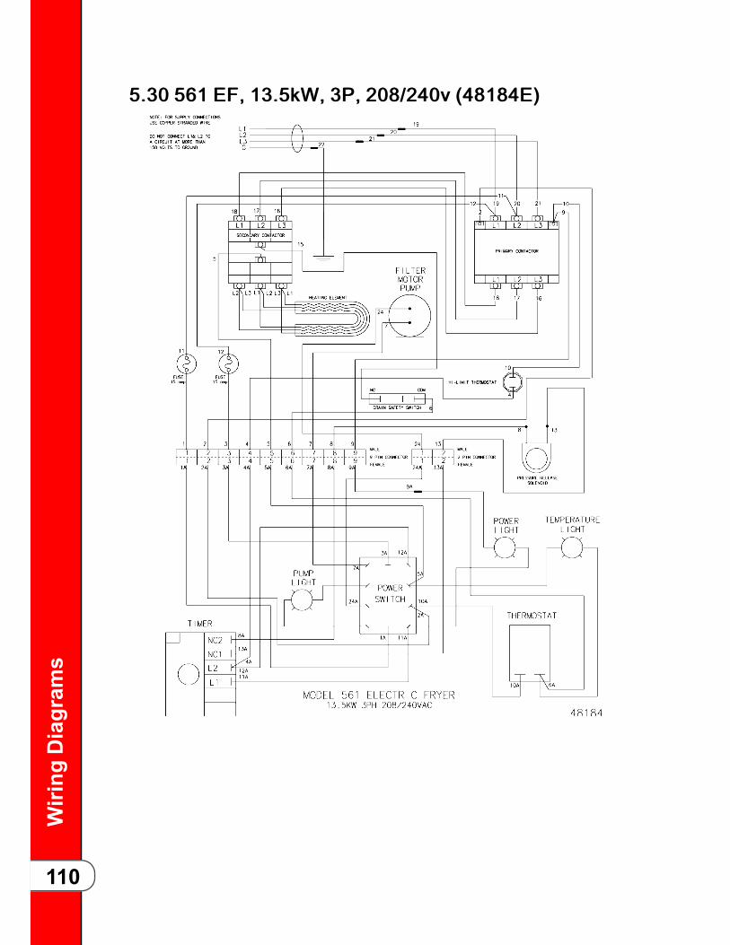
Wiring
Diagram
s
110
55..3300 556611 EEFF,, 1133..55kkWW,, 33PP,, 220088//224400vv ((4488118844EE))

Wiring
Diagram
s
111
55..3311 556611 EEFF,, 1133..55kkWW,, 33PP,, 448800vv ((4488119933EE))

Wiring
Diagram
s
112
55..3322 556611 EEFF,, 1133..55kkWW,, 33PP,, 222200vv ((4488119988EE))

Wiring
Diagram
s
113
55..3333 556611 EEFF,, 1133..55kkWW,, 33PP,, 222200//338800vv oorr 224400//441155vv((4488220000EE))

Wiring
Diagram
s
114
55..3344 556611 EEFF,, 1111..2255kkWW,, 33PP,, 220088//224400vv ((5555665533BB))

Wiring
Diagram
s
115
55..3355 556611 EEFF,, 1111..2255kkWW,, 33PP,, 222200vv ((5555665522BB))

Wiring
Diagram
s
116
55..3366 556611 EEFF,, 1111..2255kkWW,, 33PP,, 222200vv ((5555665500BB))

Wiring
Diagram
s
117
55..3377 556611 EEFF,, 1111..2255kkWW,, 33PP,, 222200//338800vv oorr 224400//441155vv((5555666611BB))

Wiring
Diagram
s
118
55..3388 556611 EEFF,, 1111..2255kkWW,, 33PP,, 222200//338800vv oorr 224400//441155vv((5555665599BB))

Wiring
Diagram
s
119
55..3399 556611 EEFF,, 1111..2255kkWW,, 33PP,, 448800vv ((5555665511CC))

Wiring
Diagram
s
120
55..4400 556611 EEFF,, 1111..2255kkWW,, 33PP,, 448800vv ((5555664499BB))

Wiring
Diagram
s
121
55..4411 556611 EEFF,, 1111..2255 kkWW,, 33PP,, 220088//224400vv ((5555442222BB))

Wiring
Diagram
s
122

Ann
ualInspection
123
CChhaapptteerr 66 AAnnnnuuaall IInnssppeeccttiioonn66..11 HHeennnnyy PPeennnnyy SSttaarrtt--UUpp PPrroovviiddeerr IInnffoorrmmaattiioonnCompany: Company Phone:
Address: City:
State / Province: Postal Code:
Country: Store E-mail:
66..22 SSttoorree IInnffoorrmmaattiioonnStore ID Number: Store Phone:
Address: City:
State / Province: Postal Code:
Country: Store E-mail:
66..33 EEqquuiippmmeenntt IInnffoorrmmaattiioonnModel: Serial Number:
66..44 SSiiggnnaattuurreessTTrraaiinneerr-- II hhaavvee ccoommpplleetteedd aallll sstteeppss ooff tthhee ssttaarrtt--uupp aanndd ttrraaiinniinngg cchheecckklliisstt ttoo tthhee ccuuss--ttoommeerr’’ss ssaattiissffaaccttiioonn..
Signature: Printed Name: Number of Attendees / Date:
Comments:
SSttoorree MMaannaaggeerr -- II aamm ssaattiissffiieedd wwiitthh tthhee ssttaarrtt--uupp aanndd ttrraaiinniinngg rreecceeiivveedd..
Signature: Printed Name: Date:
Comments:
66..55 CChheecckklliisstt
Use the following checklist to rate the fryers operation.

Ann
ualInspection
124
Red Flag /Op. No.
Remove Side Panel and RearCover
OK CLEAN REPLACE
1 Inspect vat (frypot) for any signs ofleakage.
2 Inspect that the fryer sits level. In-spect casters and ensure fryer frameis not cracked or bent.
RReeaarr ooff FFrryyeerr
3 Inspect electrical cord and plug.
4 Inspect gas line, quick disconnectand tether (600 only).
5 Perform a flue inspection (600 only).
6 Disassemble condensation box andclean, seal seams w/silicone.
7 Rear of Fryer and front of the fryer -Check that the condensation boxdrain line, dead weight tube, pressurerelease tubing is free and clear fromclogs. Also that each is not damagedor leaking.
IInnssppeecctt ddrraaiinn ppaann,, ffiilltteerr mmoottoorr aanndd ddrraaiinn ooiill
8 Verify the drain valve handle micro-switch is in working condition.
9 Inspect that drain pan is empty, allcomponents present (filter screen,clips, crumb catcher, standpipe, lid)and it is assembled correctly.
10 Test filter pump motor to ensureoperation.
11 Drain oil to drain pan. Ensure nodrain obstructions.
HHeeaatt SSyysstteemm
12 Tighten heating element spreaderbars and high limit bracket (500 only).
13 Inspect temperature probe, verify it isnot bent or damaged. Check the in-sertion depth of the probe with agauge – adjust if necessary.
14 Inspect Burner Jets (600 only).

Ann
ualInspection
125
Red Flag /Op. No.
Remove Side Panel and RearCover
OK CLEAN REPLACE
15 Inspect and clean pilot assembly. Ad-just pilot if necessary (600 only).
16 Inspect for excessive oil migration be-hind the control board.
17 Following all instructions, inspect thehigh limit.
PPuummpp OOiill // FFiillll FFrryy PPoott
18 Test filtration system when pumpingoil back up – no obstructions, leaks orexcessively slow pumping.
19 Check amp draw of heating elementsare consistent and when added up,match the amp draw listed on the da-ta plate (500 only).
20 Check that manifold pressurematches the data plate and gas typeof the fryer (600 only).
PPrreessssuurree SSyysstteemm ((ffrroonntt ooff ffrryyeerr))
21 Inspect deadweight including orifice,O-ring, cap, and weight) ensure theyare in good working condition.
22 Following all instructions, perform lidlatch, catch and latch springinspection.
23 Clean and lubricate safety pin, thrustball, locking collar and spindle.
24 Lubricate cross arm retaining pin.
25 Inspect the lid cross arm.
26 Inspect the lid gasket and reverse ifwear is acceptable.
27 Perform a limit stop adjustment.
28 Clean safety relief valve.
29 Remove solenoid valve and cleanand reassemble.
30 Verify the existing pressure gaugerests at zero and is free and clear

Ann
ualInspection
126
Red Flag /Op. No.
Remove Side Panel and RearCover
OK CLEAN REPLACE
from obstructions. (verify during pres-sure test).
PPrreessssuurree TTeesstt
31 Following all instructions, pressuretest with at least 2-head OR and veri-fy lid locks at pressures greater than2 psi and then unlocks only whenpressure drops below 2 psi.
Verify in this test if pressure is regu-lating in the green zone. Verify that allpressure releases prior to the timerreaching 0:00. This will help to identi-fy if there is still any pressure releaseand deadweight tubing obstructions.
DDuurriinngg PPrreessssuurree TTeesstt
32 Verify pressure gauge is functioningin a similar range as the calibratedtest fixture.
33 Inspect the oil return valve for leakswhile under pressure. Verify there isno oil leaking back through the oil re-turn plumbing to the drain pan whileunder pressure.
34 Inspect the drain valve for leaks whileunder pressure.
GGeenneerraall FFrryyeerr
35 Verify all labels are in place and legi-ble on fryer.
What are the tools required prior to doing this job?
• Temperature probe depth gauges
• 4-HD latch gauge
• Pipe snake
• Manometer
• Amp Clamp
• Imperial size Socket Set
• Imperial size set of hex key wrenches
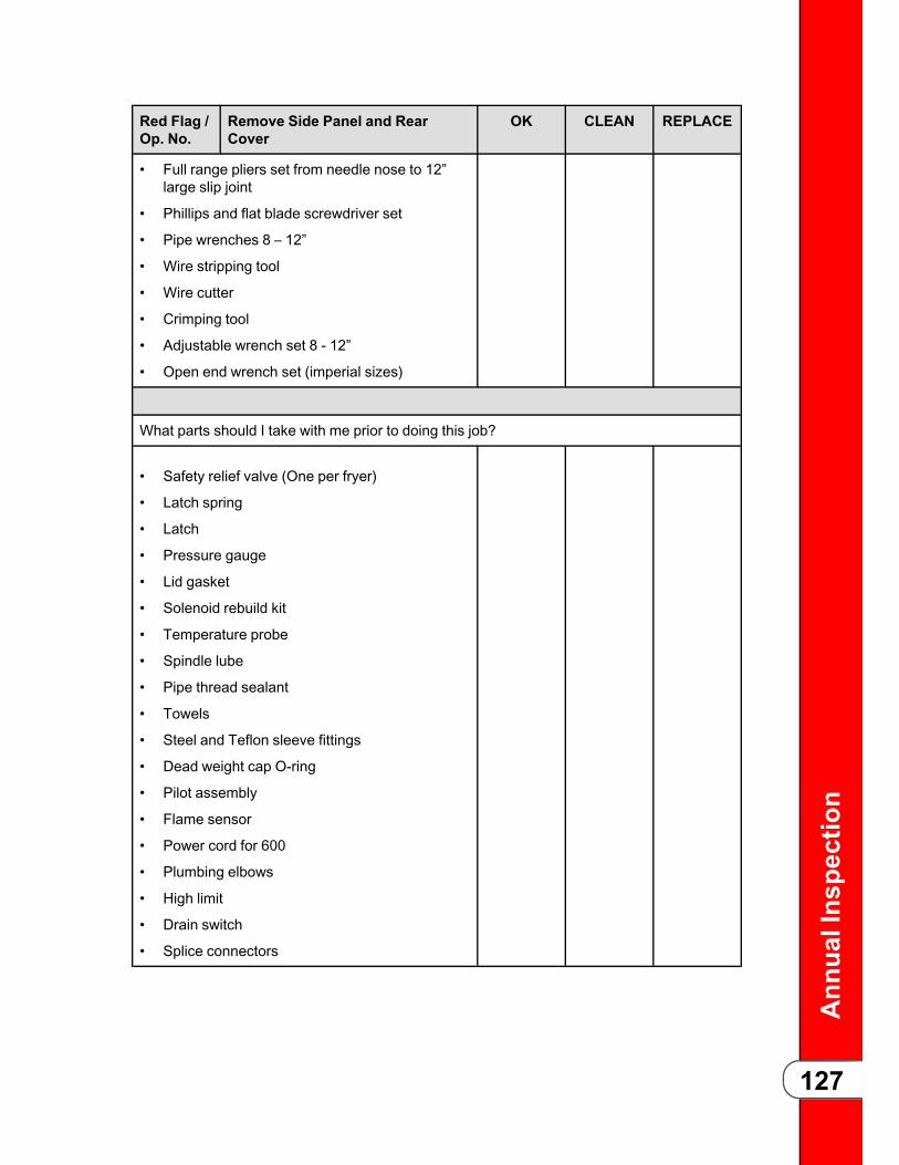
Ann
ualInspection
127
Red Flag /Op. No.
Remove Side Panel and RearCover
OK CLEAN REPLACE
• Full range pliers set from needle nose to 12”large slip joint
• Phillips and flat blade screwdriver set
• Pipe wrenches 8 – 12”
• Wire stripping tool
• Wire cutter
• Crimping tool
• Adjustable wrench set 8 - 12”
• Open end wrench set (imperial sizes)
What parts should I take with me prior to doing this job?
• Safety relief valve (One per fryer)
• Latch spring
• Latch
• Pressure gauge
• Lid gasket
• Solenoid rebuild kit
• Temperature probe
• Spindle lube
• Pipe thread sealant
• Towels
• Steel and Teflon sleeve fittings
• Dead weight cap O-ring
• Pilot assembly
• Flame sensor
• Power cord for 600
• Plumbing elbows
• High limit
• Drain switch
• Splice connectors
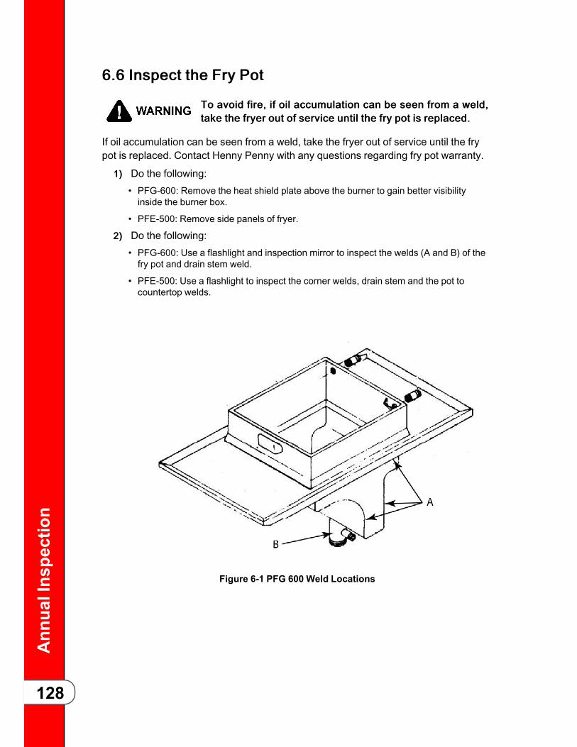
Ann
ualInspection
128
66..66 IInnssppeecctt tthhee FFrryy PPoott
TToo aavvooiidd ffiirree,, iiff ooiill aaccccuummuullaattiioonn ccaann bbee sseeeenn ffrroomm aa wweelldd,,ttaakkee tthhee ffrryyeerr oouutt ooff sseerrvviiccee uunnttiill tthhee ffrryy ppoott iiss rreeppllaacceedd..
If oil accumulation can be seen from a weld, take the fryer out of service until the frypot is replaced. Contact Henny Penny with any questions regarding fry pot warranty.
11)) Do the following:• PFG-600: Remove the heat shield plate above the burner to gain better visibilityinside the burner box.
• PFE-500: Remove side panels of fryer.
22)) Do the following:• PFG-600: Use a flashlight and inspection mirror to inspect the welds (A and B) of thefry pot and drain stem weld.
• PFE-500: Use a flashlight to inspect the corner welds, drain stem and the pot tocountertop welds.
Figure 6-1 PFG 600 Weld Locations

Ann
ualInspection
129
66..77 IInnssppeecctt tthhee CCaasstteerrss aanndd FFrraammeeAA ccrraacckkeedd ffrraammee ccrreeaatteess aa ttiippppiinngg rriisskk.. IIff ccrraacckkeedd ffrraammee iissffoouunndd,, iimmmmeeddiiaattee aatttteennttiioonn iiss nneeeeddeedd ttoo rreeppaaiirr tthhee ffrraammeebbyy hhaavviinngg iitt pprrooffeessssiioonnaallllyy rreeppaaiirreedd bbyy aa wweellddeerr,, oorr hhaavviinnggtthhee ffrryyeerr rreeppllaacceedd..
To inspect the casters and frame do the following:
• Inspect casters and the tube steel frame by removing side panels and using aflashlight to look for cracking or bent frame (Figure 1).
• Inspect that the fryer sits level, casters are mechanically sound to hold the weight ofthe fryer and the tube steel frame is not cracked or bent.
• If the fryer is sitting out of level, inspect the condition of the floor. Have any missingor cracked tiles replaced.
• If there is a slope due to a floor drain, the fryer may need to be repositioned so thecaster is not near this slope.
66..88 IInnssppeecctt tthhee PPoowweerr CCoorrddFFiirree RRiisskk aanndd EElleeccttrriiccaall SShhoocckk PPoossssiibbllee.. IIff aannyy ooff tthheesseeccoonnddiittiioonnss aarree ffoouunndd,, ttaakkee tthhee ffrryyeerr oouutt ooff sseerrvviiccee uunnttiill aanneeww ppoowweerr ccoorrdd oorr pplluugg ccaann bbee iinnssttaalllleedd.. AAllwwaayyss aaddhheerree ttoollooccaall eelleeccttrriiccaall ccooddee uuppoonn iinnssttaallllaattiioonn ooff tthhee ppoowweerr ccoorrdd..
Replace any power cord with torn or damaged sheathing, exposed wire or fraying.Replace the plug if there are any signs of damage, cracking, loose wires, burntconnections.• Check the data plate mounted just above the lid, on the left side of the back shroud,to determine the correct power supply.
• Ensure the appliance is equipped with an external circuit breaker which willdisconnect all ungrounded (unearthed) conductors. The main power switch on thisappliance does not disconnect all line conductors.

Ann
ualInspection
130
66..99 IInnssppeecctt tthhee CCoonnddeennssaattiioonn BBooxxClean the condensation box and drain lines, removing all debris. Use a flexible wirebrush to remove debris from the condensation drain line.
11)) Remove the fryer’s rear cover.22)) Disconnect the deadweight tube (A).33)) Disconnect the condensation drain line (C).44)) Disconnect the plumbing from the pressure solenoid (B).55)) Remove the condensation box mounting screws.66)) Cut the silicone, which seals the rear cover.77)) Remove the six screws fastening the interior of the box to the exterior (D).88)) Remove any debris from the inside of the condensation box and clean.99)) Remove any debris in the condensation drain line (not shown) and in the
condensation drain outlet.1100))Slide assembly back together and seal with silicone.1111))Reassemble in reverse order.
66..1100 IInnssppeecctt tthhee SSoolleennooiidd aanndd DDeeaaddwweeiigghhtt PPlluummbbiinnggInspect that the plumbing from the dead weight valve and the pressure solenoid areclean, and free from debris.• During the lid locking safety inspection if pressure exceeded 14 psi, this wouldindicate blockage in either the dead weight assembly or in the dead weightplumbing.

Ann
ualInspection
131
• If pressure were slow to release at the end of the lid locking safety inspection, thiswould indicate that either the solenoid valve needs to be cleaned or there is anobstruction in the pressure solenoid plumbing.
66..1100..11 CClleeaann tthhee DDeeaadd WWeeiigghhtt PPlluummbbiinngg11)) Remove rear cover of fryer.22)) Disconnect deadweight tube from dead weight hose (Figure 1).33)) Disconnect the dead weight tube from the dead weight assembly by loosening
the compression nut at the rear of the dead weight assembly.44)) Clean the dead weight tube.55)) Clean the dead weight valve using a small pipe snake.66)) Clean from the outlet in the fry pot to the deadweight valve (Figure 2).77)) Reassemble in reverse order.
66..1100..22 CClleeaann tthhee SSoolleennooiidd PPlluummbbiinngg11)) Inspect and clean the plumbing from the outlet in the fry pot to the pressure
solenoid.22)) Clean from the solenoid to the condensation box, see instructions for removal
and cleaning of the condensation box.
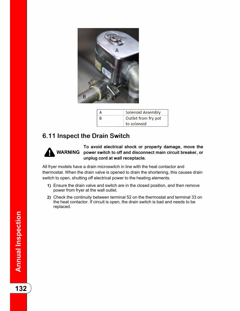
Ann
ualInspection
132
66..1111 IInnssppeecctt tthhee DDrraaiinn SSwwiittcchhTToo aavvooiidd eelleeccttrriiccaall sshhoocckk oorr pprrooppeerrttyy ddaammaaggee,, mmoovvee tthheeppoowweerr sswwiittcchh ttoo ooffff aanndd ddiissccoonnnneecctt mmaaiinn cciirrccuuiitt bbrreeaakkeerr,, oorruunnpplluugg ccoorrdd aatt wwaallll rreecceeppttaaccllee..
All fryer models have a drain microswitch in line with the heat contactor andthermostat. When the drain valve is opened to drain the shortening, this causes drainswitch to open, shutting off electrical power to the heating elements.
11)) Ensure the drain valve and switch are in the closed position, and then removepower from fryer at the wall outlet.
22)) Check the continuity between terminal 52 on the thermostat and terminal 33 onthe heat contactor. If circuit is open, the drain switch is bad and needs to bereplaced.

Ann
ualInspection
133
66..1122 TTeesstt tthhee FFiillttrraattiioonn SSyysstteemmCClloossee tthhee lliidd,, uussiinngg iitt aass aa sshhiieelldd dduurriinngg tthhee iinniittiiaall ssuurrggee ooffooiill ffiilllliinngg tthhee vvaatt ttoo pprreevveenntt ssppllaasshhiinngg,, pprreevveennttiinngg ppeerrssoonnaalliinnjjuurryy..
Run a filtration to test the system and ensure:• Plumbing and pump is free of clogs and is working properly.
• Air is not leaking in to the system.
• Test for leaks in the system.
11)) With the oil hot, turn the main power switch to the OFF position.22)) Open the drain valve and let the oil drain in to the drain pan.33)) Open the filter valve, and then turn the main power switch to the pump position.44)) Listen to the pump. If the pump is to quiet, this can indicate air in the system. If
the pump is to loud, this indicates a clog in the system.55)) Close the filter and drain valve. Ensure oil fills the vat.66)) Empty the condensation pan.
66..1133 IInnssppeecctt tthhee DDrraaiinn PPaann
UUssee PPeerrssoonnaall PPrrootteeccttiivvee EEqquuiippmmeenntt ((PPPPEE)) ssuucchh aass gglloovveess,,ffaaccee sshhiieelldd,, eettcc.. ttoo pprreevveenntt bbuurrnnss ffrroomm hhoott ooiill..
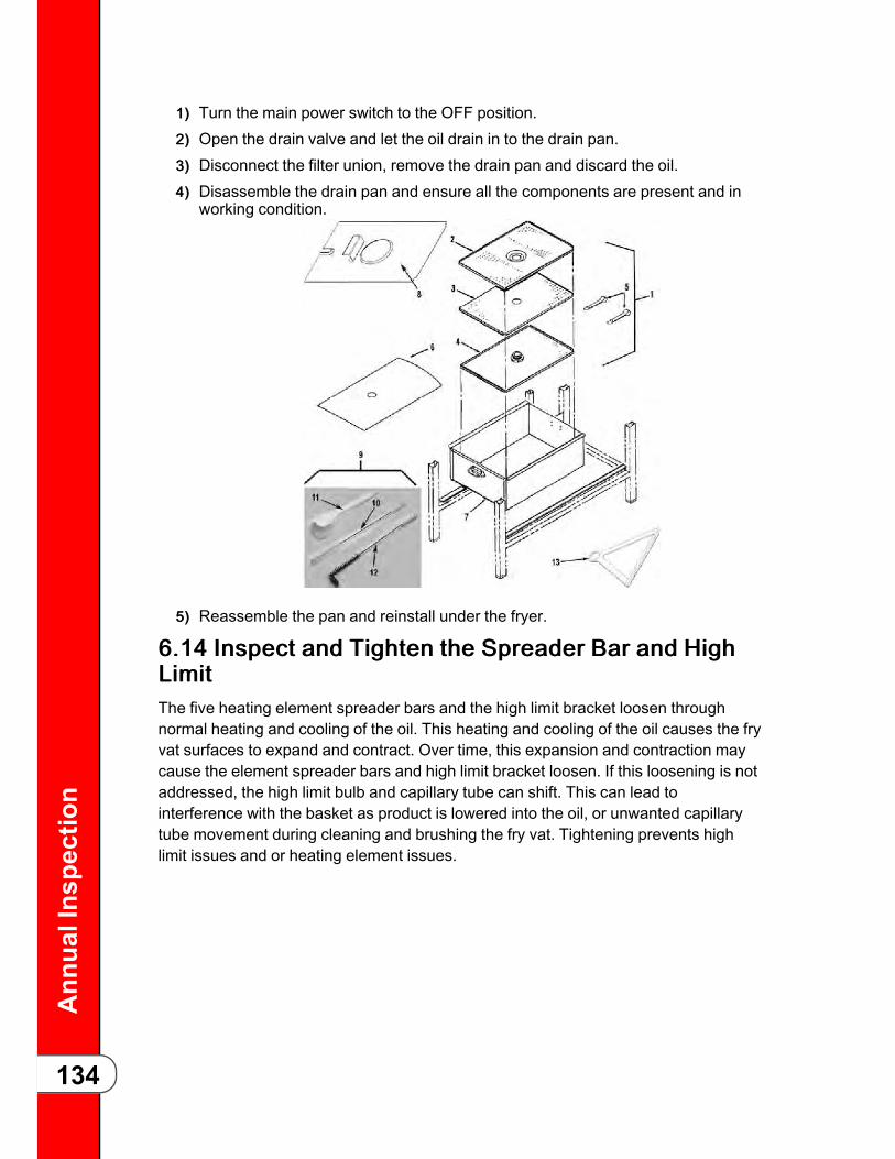
Ann
ualInspection
134
11)) Turn the main power switch to the OFF position.22)) Open the drain valve and let the oil drain in to the drain pan.33)) Disconnect the filter union, remove the drain pan and discard the oil.44)) Disassemble the drain pan and ensure all the components are present and in
working condition.
55)) Reassemble the pan and reinstall under the fryer.
66..1144 IInnssppeecctt aanndd TTiigghhtteenn tthhee SSpprreeaaddeerr BBaarr aanndd HHiigghhLLiimmiittThe five heating element spreader bars and the high limit bracket loosen throughnormal heating and cooling of the oil. This heating and cooling of the oil causes the fryvat surfaces to expand and contract. Over time, this expansion and contraction maycause the element spreader bars and high limit bracket loosen. If this loosening is notaddressed, the high limit bulb and capillary tube can shift. This can lead tointerference with the basket as product is lowered into the oil, or unwanted capillarytube movement during cleaning and brushing the fry vat. Tightening prevents highlimit issues and or heating element issues.
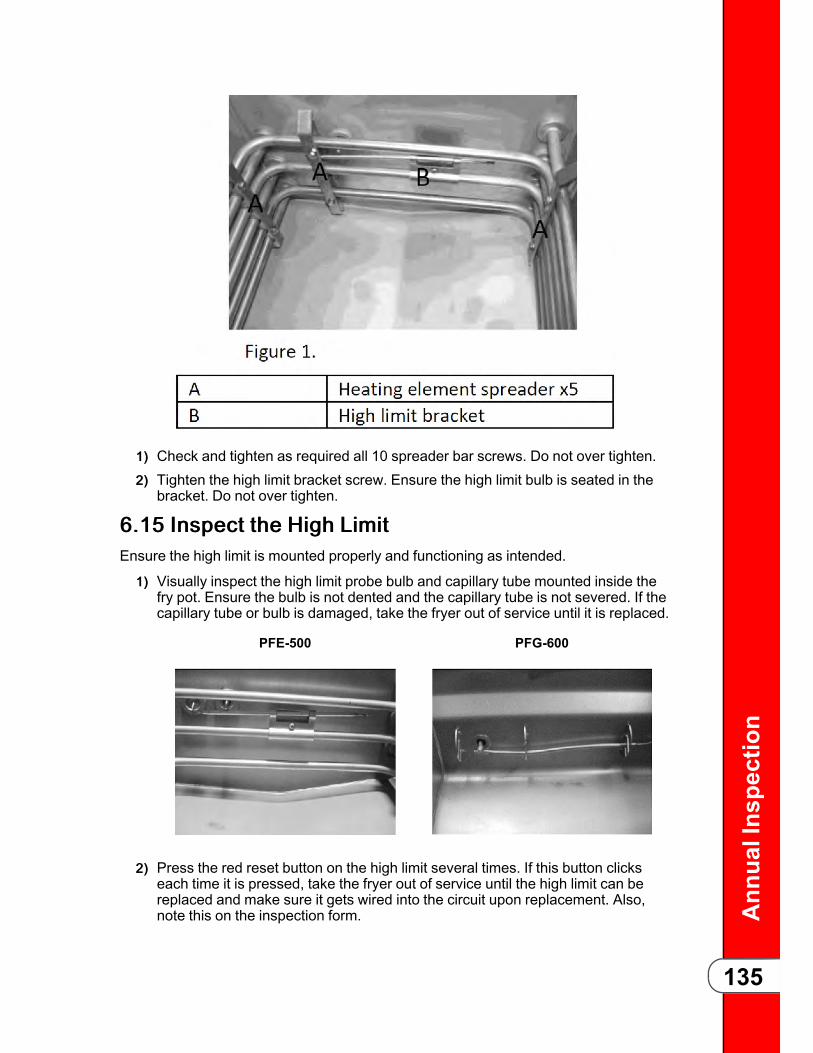
Ann
ualInspection
135
11)) Check and tighten as required all 10 spreader bar screws. Do not over tighten.22)) Tighten the high limit bracket screw. Ensure the high limit bulb is seated in the
bracket. Do not over tighten.
66..1155 IInnssppeecctt tthhee HHiigghh LLiimmiittEnsure the high limit is mounted properly and functioning as intended.
11)) Visually inspect the high limit probe bulb and capillary tube mounted inside thefry pot. Ensure the bulb is not dented and the capillary tube is not severed. If thecapillary tube or bulb is damaged, take the fryer out of service until it is replaced.
PFE-500 PFG-600
22)) Press the red reset button on the high limit several times. If this button clickseach time it is pressed, take the fryer out of service until the high limit can bereplaced and make sure it gets wired into the circuit upon replacement. Also,note this on the inspection form.

Ann
ualInspection
136
33)) Remove power from fryer at the wall outlet.
44)) Lower the controls, and then remove the two mounting screws that secure thehigh limit body to the fryer.
55)) Remove the high limit and make sure the high limit wiring is properly connectedto the high limit.
Inspect that each high limit wire is attached to separate terminals on the highlimit. If both wires are attached to the same terminal, or if one or both of theterminals are missing wires, this indicates that the high limit has been bypassedin the circuit. If bypassing is found, take the fryer out of service until the wiring iscorrected and high limit replaced if defective.
66..1166 IInnssppeecctt tthhee TTeemmppeerraattuurree PPrroobbeeInspect the temperature probe for damage. If the probe is damaged or broken, replaceit with the correct part. A damaged probe can lead to inconsistent cooking issues andintermittent temperature fluctuation.
NNOOTTEE: There are two probes for KFC units depending on which control board isinstalled in the fryer: Fastron or SMS. Fastron probes are not interchangeable withSMS probes.
IInnssppeecctt tthhee TTeemmppeerraattuurree PPrroobbee
11.. Drain and discard oil from vat.
22.. Visually inspect the temperatureprobe.
• The probe should be clean andstraight. If not, replace theprobe.
• If the probe is not bent ordamaged continue with theadjustment inspection.

Ann
ualInspection
137
AAddjjuussttmmeenntt IInnssppeeccttiioonn
NNOOTTEE: Fastron probes are set to a fixeddepth into the vat (frypot).Use a probe gauge or ruler to set theSMS probe to a depth of:
• 500 (Electric) 5/8”
• 600 (Gas) 7/8”
Adjust the depth if needed by looseningthe compression fitting on the probe andsliding the probe either in or out to thecorrect depth. Then tighten the probe’scompression fitting.
66..1177 IInnssppeecctt ffoorr OOiill LLeeaakkss
UUssee PPeerrssoonnaall PPrrootteeccttiivvee EEqquuiippmmeenntt ((PPPPEE)) ssuucchh aass gglloovveess,,ffaaccee sshhiieelldd,, eettcc.. ttoo pprreevveenntt bbuurrnnss ffrroomm hhoott ooiill..
66..1177..11 OOiill MMiiggrraattiioonn11)) Remove power from fryer at the wall outlet.22)) Remove both side panels and lower the control board.33)) Inspect the area behind the control board, sides and rear of the vat for oil that
has seeped through any of the fittings:• If oil is seeping through the temperature probe, thermostat fitting, the high limitfitting or any of the heating element fittings (electric only). If oil is found seepingthrough fittings but not touching contactors, clean as soon as possible.
• If oil is excessive enough that it is touching either contactor (Figure 1 & 2), shutdown the fryer until the oil migration issue is taken care of. In this situation, thecontactors need to be replaced, the oil needs to be cleaned up and the fittings needto be cleaned and resealed.
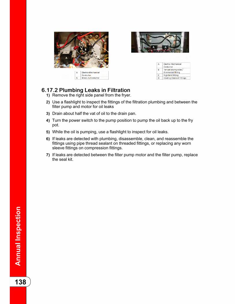
Ann
ualInspection
138
66..1177..22 PPlluummbbiinngg LLeeaakkss iinn FFiillttrraattiioonn11)) Remove the right side panel from the fryer.22)) Use a flashlight to inspect the fittings of the filtration plumbing and between the
filter pump and motor for oil leaks33)) Drain about half the vat of oil to the drain pan.44)) Turn the power switch to the pump position to pump the oil back up to the fry
pot.55)) While the oil is pumping, use a flashlight to inspect for oil leaks.66)) If leaks are detected with plumbing, disassemble, clean, and reassemble the
fittings using pipe thread sealant on threaded fittings, or replacing any wornsleeve fittings on compression fittings.
77)) If leaks are detected between the filter pump motor and the filter pump, replacethe seal kit.
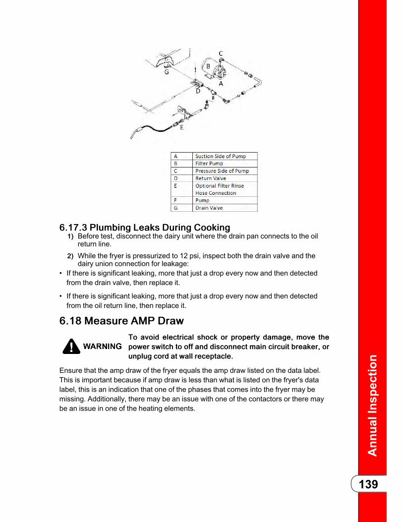
Ann
ualInspection
139
66..1177..33 PPlluummbbiinngg LLeeaakkss DDuurriinngg CCooookkiinngg11)) Before test, disconnect the dairy unit where the drain pan connects to the oil
return line.22)) While the fryer is pressurized to 12 psi, inspect both the drain valve and the
dairy union connection for leakage:• If there is significant leaking, more that just a drop every now and then detectedfrom the drain valve, then replace it.
• If there is significant leaking, more that just a drop every now and then detectedfrom the oil return line, then replace it.
66..1188 MMeeaassuurree AAMMPP DDrraawwTToo aavvooiidd eelleeccttrriiccaall sshhoocckk oorr pprrooppeerrttyy ddaammaaggee,, mmoovvee tthheeppoowweerr sswwiittcchh ttoo ooffff aanndd ddiissccoonnnneecctt mmaaiinn cciirrccuuiitt bbrreeaakkeerr,, oorruunnpplluugg ccoorrdd aatt wwaallll rreecceeppttaaccllee..
Ensure that the amp draw of the fryer equals the amp draw listed on the data label.This is important because if amp draw is less than what is listed on the fryer's datalabel, this is an indication that one of the phases that comes into the fryer may bemissing. Additionally, there may be an issue with one of the contactors or there maybe an issue in one of the heating elements.
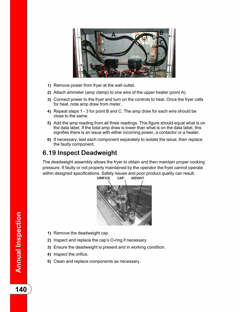
Ann
ualInspection
140
11)) Remove power from fryer at the wall outlet.22)) Attach ammeter (amp clamp) to one wire of the upper heater (point A).33)) Connect power to the fryer and turn on the controls to heat. Once the fryer calls
for heat, note amp draw from meter.44)) Repeat steps 1 - 3 for point B and C. The amp draw for each wire should be
close to the same.55)) Add the amp reading from all three readings. This figure should equal what is on
the data label. If the total amp draw is lower than what is on the data label, thissignifies there is an issue with either incoming power, a contactor or a heater.
66)) If necessary, test each component separately to isolate the issue, then replacethe faulty component.
66..1199 IInnssppeecctt DDeeaaddwweeiigghhttThe deadweight assembly allows the fryer to obtain and then maintain proper cookingpressure. If faulty or not properly maintained by the operator the fryer cannot operatewithin designed specifications. Safety issues and poor product quality can result.
11)) Remove the deadweight cap.22)) Inspect and replace the cap’s O-ring if necessary.33)) Ensure the deadweight is present and in working condition.44)) Inspect the orifice.55)) Clean and replace components as necessary.

Ann
ualInspection
141
66..2200 IInnssppeecctt LLaattcchh,, CCaattcchh aanndd SSpprriinnggTo make sure the latch, catch and latch spring are properly installed and are withintolerances for safe operation. Refer to the Annual Inspection Video on Vimeo.
OObbjjeeccttiivveeTo make sure the latch, catch and latchspring are properly installed and arewithin tolerances for safe operation.A. CatchB. LatchC. Latch Spring
CCaattcchh IInnssppeeccttiioonn
1. Slide gauge #162410 along the entirewidth of the pot catch.
2. If this gauge does not slide over thecatch, or the lip of the catch doesnot match the profile of the gaugeas shown, the catch is out oftolerance. Take the pressure fryerout of service until the fry pot hasbeen replaced.

Ann
ualInspection
142
LLaattcchh IInnssppeeccttiioonn
1. Separate the lid and the cross arm.Notice the gap in the middle of thelatch.
2. Slide the “GO” side of the gauge overthe entire width of the latch. Thelatch should fit in the groove,except for the gap in the middle.

Ann
ualInspection
143
3. Slide the “NO GO” side of the gaugeover the entire width of the latch. Ifthe lip of the latch inserts into thecut out in the gauge, this latch failsinspection and needs to bereplaced.
LLaattcchh SSpprriinngg IInnssppeeccttiioonnMake sure the latch spring and all of itscomponents (latch spring, latch pin,spacers, and C-clip retainer) are notbroken, not missing and installedcorrectly. If any components are broken,damaged, missing or installedincorrectly, this fryer would need to betaken out of service until which time thecomponents can be replaced andinstalled correctly. The latch spring isinstalled correctly if the label “FRONTTHIS SIDE” is mounted to the front ofthe latch.A. C-Clip Retainer
B. Spacers
C. Latch Spring
D. Latch Pin
66..2211 IInnssppeecctt CCrroossss AArrmm CCoommppoonneennttRefer to the Annual Inspection Video on Vimeo.

Ann
ualInspection
144
1. Separate the lid and crossarm.2. Inspect the cross arm. Crackson the bottom surface of thecross arm are acceptable, butanything rounding the corners,coming up the sides, or foundon top would fail inspection.
WWAARRNNIINNGG!!: If any cracks arefound in the top or sides of thecross arm, the fryer must betaken out of service until thecross arm assembly is replaced.

Ann
ualInspection
145
3. Inspect to make sure all of the spindlecomponents are in place: acmenut, idle nut, thrust ball, lockingcollar. Inspect the gap between theacme nut and the idle nut. Thesetwo components should be within1/16” of each other. If any of thesecomponents are excessively worn,damaged or missing, this step ofthe inspection would fail.
WWAARRNNIINNGG!!: The fryer must be takenout of service until the cross armassembly is replaced.
WWAARRNNIINNGG!!: The pin should be stakedto prevent it from shifting. If this pin is notproperly staked, damaged or missing,severe burns could result. The fryermust be taken out of service until thecross arm assembly is replaced.
4. Inspect the locking collar pin. If the pinhas shifted, is missing, broken,take the fryer out of service until anew cross arm assembly can beinstalled.
5. Inspect the hinge pin to ensure it isnot missing, damaged or broken. Makesure that the retaining clips are securelyin place on each side of the pin. If any ofthese situations are true, take the fryerout of service until the components arereplaced.A. Retaining Clip
B. Hinge Pin
C. Spring Cover

Ann
ualInspection
146
6. If the hinge spring is broken. It will notfail the inspection but the spring wouldneed to be replaced ASAP.A. Retaining Clip
7. Ensure four bolts are installed in thehinge plate at the rear of the fry pot.Check to make sure these bolts aresnug. If any bolts are missing, take thefryer out of service until they can bereplaced.
66..2222 LLuubbrriiccaattee CCrroossss AArrmm CCoommppoonneennttssFollow these steps to reduce wear on the spindle, thrust ball, ball seat, hinge spring,and locking pin. Refer to the Annual Inspection Video on Vimeo.
OObbjjeeccttiivvee: Reduce wear on the spindle, thrust ball, ball seat, hinge spring, andlocking pin.
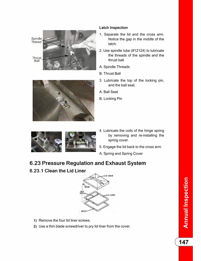
Ann
ualInspection
147
LLaattcchh IInnssppeeccttiioonn
1. Separate the lid and the cross arm.Notice the gap in the middle of thelatch.
2. Use spindle lube (#12124) to lubricatethe threads of the spindle and thethrust ball.
A. Spindle Threads
B. Thrust Ball
3. Lubricate the top of the locking pin,and the ball seat.
A. Ball Seat
B. Locking Pin
4. Lubricate the coils of the hinge springby removing and re-installing thespring cover.
5. Engage the lid back to the cross arm.
A. Spring and Spring Cover
66..2233 PPrreessssuurree RReegguullaattiioonn aanndd EExxhhaauusstt SSyysstteemm66..2233..11 CClleeaann tthhee LLiidd LLiinneerr
11)) Remove the four lid liner screws.22)) Use a thin blade screwdriver to pry lid liner from the cover.

Ann
ualInspection
148
33)) Clean the liner and the inside of the cover. Replace the liner and screws.
66..2233..22 RReevveerrssee tthhee LLiidd GGaasskkeettBecause of heat expansion and the pressure used for the cooking process, the gasketis constantly under extreme stress. Reversing the lid gasket on a quarterly basis willhelp to assure that the fryer will not lose pressure through leakage. Reverse thegasket by doing the following:
1. There are two lid liner screws oneither side of the lid cover. Backthese four screws out about 1/2inch.
2. Open the lid and using a thin bladescrewdriver, pry out the gasket atthe comers. Remove the gasket.
3. Clean the gasket and gasket seat withhot water and cleaning detergent.Rinse with clean hot water.
4. Install the gasket with the good side(reverse side) facing out.
5. Begin the installation by installing thefour comers of the lid gasket.Continue by pressing the gasket into the channel from the cornersoutward.
6. Tighten the four screws.
66..2233..33 AAddjjuusstt tthhee LLiidd LLiimmiitt SSttooppThe lid limit stop, with proper adjustment, prevents unnecessary overtightening of thespindle extending the life of the lid gasket.
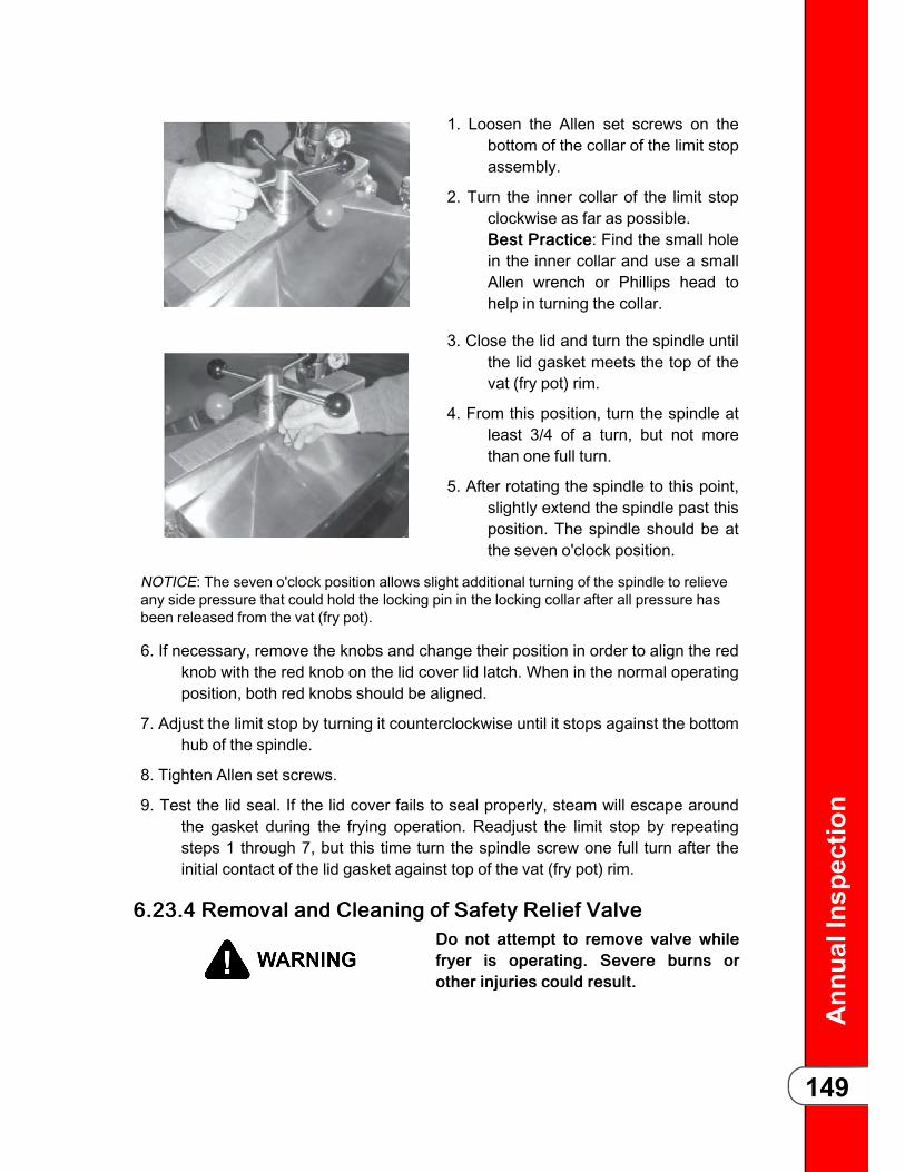
Ann
ualInspection
149
1. Loosen the Allen set screws on thebottom of the collar of the limit stopassembly.
2. Turn the inner collar of the limit stopclockwise as far as possible.BBeesstt PPrraaccttiiccee: Find the small holein the inner collar and use a smallAllen wrench or Phillips head tohelp in turning the collar.
3. Close the lid and turn the spindle untilthe lid gasket meets the top of thevat (fry pot) rim.
4. From this position, turn the spindle atleast 3/4 of a turn, but not morethan one full turn.
5. After rotating the spindle to this point,slightly extend the spindle past thisposition. The spindle should be atthe seven o'clock position.
NOTICE: The seven o'clock position allows slight additional turning of the spindle to relieveany side pressure that could hold the locking pin in the locking collar after all pressure hasbeen released from the vat (fry pot).
6. If necessary, remove the knobs and change their position in order to align the redknob with the red knob on the lid cover lid latch. When in the normal operatingposition, both red knobs should be aligned.
7. Adjust the limit stop by turning it counterclockwise until it stops against the bottomhub of the spindle.
8. Tighten Allen set screws.
9. Test the lid seal. If the lid cover fails to seal properly, steam will escape aroundthe gasket during the frying operation. Readjust the limit stop by repeatingsteps 1 through 7, but this time turn the spindle screw one full turn after theinitial contact of the lid gasket against top of the vat (fry pot) rim.
66..2233..44 RReemmoovvaall aanndd CClleeaanniinngg ooff SSaaffeettyy RReelliieeff VVaallvveeDDoo nnoott aatttteemmpptt ttoo rreemmoovvee vvaallvvee wwhhiilleeffrryyeerr iiss ooppeerraattiinngg.. SSeevveerree bbuurrnnss oorrootthheerr iinnjjuurriieess ccoouulldd rreessuulltt..

Ann
ualInspection
150
The safety relief valve should be cleaned once a year.1. Open the lid and then remove the deadweight valve cap and deadweight.
2. Use a wrench to loosen the valve from the pipe elbow, turn counterclockwise toremove.
3. Clean the inside of the pipe elbow with hot detergent.
4. Immerse the safety relief valve in a soap water solution for 24 hours. Use a 1:1dilution rate. The valve cannot be disassembled. It is factory preset to open at14 1/2 pounds of pressure. If it does not open or close it must be replaced.
66..2233..55 PPrreessssuurree GGaauuggee CCaalliibbrraattiioonnTToo aavvooiidd ppeerrssoonnaall iinnjjuurryy,, ddoo nnoottddiissaasssseemmbbllee oorr mmooddiiffyy tthhiiss vvaallvvee..TTaammppeerriinngg wwiitthh tthhee vvaallvvee wwiillll vvooiiddaaggeennccyy aapppprroovvaallss aanndd tthhee aapppplliiaanncceewwaarrrraannttyy,, aanndd ccoouulldd ccaauussee sseerriioouussiinnjjuurryy..
The pressure gauge can be recalibrated if out of adjustment.1. Remove the rim and glass.
2. If the indicating hand shows a pressure or vacuum reading when it should point to"O", turn the calibration screw until the hand stands at the "O" position.
3. Replace the rim and glass.

Ann
ualInspection
151
66..2233..66 CCooiill CChheecckk PPrroocceedduurreeTToo aavvooiidd eelleeccttrriiccaall sshhoocckk oorr pprrooppeerrttyy ddaamm--aaggee,, mmoovvee tthhee ppoowweerr sswwiittcchh ttoo OOFFFF aannddddiissccoonnnneecctt mmaaiinn cciirrccuuiitt bbrreeaakkeerr,, oorr uunnpplluuggccoorrdd aatt wwaallll rreecceeppttaaccllee..
1. Remove power from the fryer by unplugging from the power source.
2. Remove wires from terminals 73 and 72 and check ohms across the solenoid wires.
VVoollttss//PPhhaassee: RReessuullttss::
- 120 volt 60 Hz- 208-240 volt 60 Hz- 208-240 volt 50 Hz
- 50 ohms- 150 ohms- 245 ohms
66..2233..77 LLoocckkiinngg PPiinn TTeesstt PPrroocceedduurreeEnsure the lid locking pin engages the locking collar of the spindle when the pressurein the fry pot reaches 2 psi and greater and also to ensure the lid locking pin remainsengaged as pressure releases at 2 psi. Refer to the Annual Inspection on Vimeo.
Figure 1
1. Remove the reducer from the testfixture (Figure 1).
Figure 2
2. Install the supplied elbow from the testfixture into the t-fitting with pipethread sealant (Figure 2).

Ann
ualInspection
152
Figure 3
3. Remove the existing safety reliefvalve (Figure 3).
Figure 4
4. Install the test fixture into the safetyrelief valve elbow using pipethread sealant (Figure 4).
Figure 5
5. Insert the existing pressure gauge intothe elbow of the pressure testfixture (Figure 5).
7:00 Position
6. Adjust the limit stop so that the redball reaches the 7:00 positionwhen closing and locking down thelid (Figure 6). See 6.23.3 Adjustthe Lid Limit Stop, page 148.

Ann
ualInspection
153
Figure 6
6:00 Position
Figure 7
7. Have the store bread and cook atleast two head of chicken.
8. When the pressure on the calibratedtest gauge reaches 2 psi, gentlyturn the spindle counter clockwiseusing two hands so the red balllines up with the 6:00 position(Figure 7). The locking pin shouldengage the locking collar causingthe spindle to lock in place (red ballat 6:00).

Ann
ualInspection
154
5:00 Position
Figure 8
9. If the spindle continues to turn pastthe 5:00 position (Figure 8), thelocking pin test would fail. Take thefryer out of service until the lockingpin issue is addressed or the lidreplaced.
10. During the cook cycle when pressure reaches the 12 psi range. Compare theexisting pressure gauge with the calibrated test gauge. The existing pressuregauge should read in a similar range. If it is not, replace the existing pressuregauge after the test.
11. If pressure during the cook cycle exceeds 14 psi, this does not fail the test aslong as the locking pin engagement and disengagement steps pass. However,after the test, the deadweight and all related plumbing would need to bethoroughly cleaned or replaced.
12. When pressure exhausts and nears the 2 psi mark, using two hands, gently turnthe spindle counterclockwise. If you are able to turn the spindle to the 5:00position (Figure 8), this inspection fails. Take the fryer out of service until thelid assembly can be replaced. To pass the inspection, the spindle shouldremain locked at 2 psi when trying to turn counterclockwise. If the lid is locked,the spindle should remain in the 6:00 position (Figure 7).
13. If the pressure was slow to release during the cook cycle and did not reach 0 psiwhen the timer reached 0:00, this does not fail the inspection, however this isan indication that the pressure solenoid and/or its related plumbing may besticking or obstructed. After the test, clean the solenoid and the relatedsolenoid plumbing back to the steam exhaust stack.
14. Remove the test fixture.
15. If the existing safety relief valve passed the inspection, re-install it. If not, installa new valve with pipe thread sealant.

Ann
ualInspection
155

Ann
ualInspection
156

blank page

HHeennnnyy PPeennnnyy CCoorrppoorraattiioonnPP..OO..BBooxx 6600EEaattoonn,, OOHH 4455332200wwwwww..hheennnnyyppeennnnyy..ccoomm
IInnssiiddee tthhee UU..SS..::11--880000--441177--88440055tteecchhnniiccaallsseerrvviicceess@@hheennnnyyppeennnnyy..ccoomm
OOuuttssiiddee tthhee UU..SS..11--993377--445566--88440055iinnttlltteecchhssuuppppoorrtt@@hheennnnyyppeennnnyy..ccoomm