3rd - CONFERENCE ON MILITARY ROBOTIC APPLICATION S
349
Proceedings of th e 3 rd CONFERENCE ON MILITARY ROBOTIC APPLICATION S MILITARY R OB OTIC VEHICLES MRV9 1 September 9-12, 1991 Medicine Hat, Alberta Canad a DRES Special Publication 149 ALBERTA RESEARC H COUNCI L Defence Research Establishment Suffiel d C a, n d d a Depa rtment of National Defence
-
Upload
khangminh22 -
Category
Documents
-
view
0 -
download
0
Transcript of 3rd - CONFERENCE ON MILITARY ROBOTIC APPLICATION S

Proceedings of the
3 rdCONFERENCE ON MILITARY ROBOTIC APPLICATIONS
MILITARY R OBOTIC VEHICLES MRV9 1
September 9-12, 1991Medicine Hat, Alberta
Canada
DRES Special Publication 149
ALBERTARESEARCH
COUNCI LDefence ResearchEstablishment Suffield
Ca,n dda Depa rtment of National Defence

DRES Special Publication 149
Proceedings of theThird Conference on
Military Robotic Applications
Medicine Hat, Alberta, Canada9 - 12 September 199 1
co-hosted by
Defence Research Establishment Suffielû Alberta Research Counci l
edited by
David J . MackayDRES

* Cover Photograph : Medicine Hat City Hall viewed from across the South Saskatchewan River .
ii

Table of Content s
Acknowledgements
Introduction
Keynote AddressCol . Conrad J . Mialkowski, Associate fJirector General Research and Development Operation s
Invited AddressAutonomous Intelligent Military Robots : Army Ants, Killer Bees, and Cybernetic SoldiersRobert Finkelstein, Robotic Technology Inc .
13attlefield RoboticsC'hriirperson : I,t:'ct J . G . Lindsay, DLAEf M 4
U .S . `t':retical Unmanned ( ;round Vehicle Projec tM . L. Swinson, Majoi U .S . Army, and L . M. liennebeck, Major USMC,UGV Joint Project Office, U .S . Army Missile Command, Redstone Arsenal, Alabam a
Robotics and the Battletïeld of the FutureE . Solem ,Operational Research and Analysis Establishmen t
The Army Approach go Robotic ApplicationsMajoi S . Bcarc, DLR 2-3 ,i)ircctorate of Land Requirements, N1){ IQ, Ottawa, Ontari o
Military Robot les Technologies at Sandia National LaboratoriesR . If . Byrne and P . R . Klarcr,Sandia National Laboratories, Albuquerque, New Mexic o
1)Rh:V Activities Related fi) Military Vehicles RobotizationB . Montrainy ,Ucfcnce Research Establishment Valcartic r
Autonomous Robotic Refueling Sy s tem (ARRS) for Rapid Aircraft TurnaroundO. R . Williams, E . Jackson, I .S .E . Ltd ., Port Cociuitlarn, B .C . ;K . Rueb, Virtek Corporation, Waterloo, Ontario ;B . Thompson, RedZone Robotics Inc„ Pittsburgh, PA ; andK . Powell, Wright-Patterson AFB
Guidance and NavieationChairperson : David Saint, DRE S
The NRC Mobile Robot ProjectR . Liscano, D . Green, A. Manz', L . Korba, and S . Lang,Autonomous Systems Lab., NRC, Ottawa, Ontario' Graduate student, University of Saskatchewan, Saskatoon, Saskatchewa n
Extended Occupancy Grid Method for Modelin g Unknown Dynamic EnvironmentsR. E . Webber and Y. Zhang, Department of Computer Science ,University of Western Ontario, London, Ontario
vii
1
4
1 2
1 9
26
28
3 7
4 2
47
54
iif

Navigation of Military and Space Unmanned Ground Vehicles in Unstructured Terrains 61P. Lescoe, US Army TACOM, Warren, Michigan; D. Lavery, NASA, Washington, D.C . ; andR . J . Bedard Jr., JPL, Californ ia Ta stitute of Technology, Pasadena, California
A Generic Semi-Autonomous Ground Vehicle Control SystemR . Eirich. DRES ; and A . Kramer, Oliphant Management Se rv ice s
Payload Centred Control for Unmanned AircraftD. R. Weiler and M . G . Henders, Combustion Dynamics Ltd ., Medicine Hat, Alberta ;R . H. Chesney, DRES; and D . Ehman, Boeing Canada Technology Ltd ., Winnipee, Manitoba
68
74
The Use of Low Cost Diffcrential Mode GPS Receivers in Unmanned Vehicles 81T. Ollevier, URE S
Encoding Technique for Automated (,uided Vehicle POSE Recovery in a Structured Environment 86E. M. Petriu, T . Bieseman, N. Trif, Department of Electrical Engineering ,University of Ottawa, Ottawa, Ontario ;W . S . McMath and S . K. Yeung, Directorate of Space Mechanics,Canadian Space Agency, Ottawa, Ontari o
An Optimal Obstacle Avoidance Path Planning Algorithm for the Excalibur RobotV . K. Banerjee, C. S . Earl, T . 0. Looke, and M . Farooq ,Fhpanment of Electrical and Cumputer F.ngin"ering, RM C
Robotic Arm ControlChairperson : M Farotxl, RM C
Maestro : An Open System Architccture for Multi-Robot ControlS . Filgazzar, Autonomous Systems Lab ., NRC Ottawa, Ontario); andA . Castonguay, Department of Systems and Computer Engineering,Carleton University, Ottawa, Ontari o
Coordinated Control of Multiple Robot ManipulatorsS . Kalaycioglu, Thomson-CSF Systems Canada, Nepean, Ontario ; and1) . S . Nccsulescu, Department of Mechanical Engineering, Univcrsity of Ottawa, Ottawa, C)n!ario
93
99
10 7
Three Methods to Improve the Accuracy of' a Puma 560 Robot 114G. Hardy, DRE P
Force Control Techniques for Robot Manipulators and their Military Applications 122P. Wojcik and K . Chrystall, Advanced Computing and Engineering, AR C
An Inverse Kinematics Algorithm for the aREP/Philips Real-time RadiographicManipulator SystemK . K. Yeung, DREP
129
HATT-X : A High Performance Flying Laboratory for Autonomous Unmanned Aircraft R&D 136A . B . Markov, DRE S
Simulation of lightweight robots and their controllers 143J .-C. Piedboeuf and R. J . Ferguson, Department of Mechanical Engineering, RMC
The Response of Flexible Mainpu!a!grs to a New Computed Torque Control Strategy :Simulation ResultsT. D. Looke, Department of Electrical and Computer Engineering, RMC ;M. M. Bayoumi, Department of Electr:cal Engineering, Queen's University, Kingston, Ontario; andM. Farooq, Department of Elec.icat and Computer Engineering, RMC
150
iv

Symbolic Generation of Dynamics Equations for Manipulators Mounted on Moving Bases 157R . W. Toogood, L. El-Rayyes, Department of Mechanical Engineering, University of Albena ; an dD. J . Mackay, DRE S
Sensin¢Chairpersons : Keith Yeung, DREP and John McFee, DRE S
Activities in Machine Vision at Imago Manufacturing Ltd. 165R . Ball, T. Folinsbee, and L. Pelkowitz, Imago Manufacturing Ltd ., Ottawa, Ontari o
Variable-Resolution Stereo Matchin gA. Basu, Department of Computing Science, University of Alberta, E.dinonlon, Albert a
Motion and Structure from Planar Motion in Noisy Monocular Image SequencesV . C . Aitken and H . M . Schwartz, Department of Electrical Engineering ,Carleton University, Ottawa, Ontari o
Vision Guidance Systems for Off-Road Agricultural Oprrat ion sI1 . C . Wood and J . N . Wilson, Cot!egc of Engineering, University of Saskatchewan ; andN. Brown, Atomic Energy of Cavada Ltd ., C'halk Rive :-, Ontario
169
17 7
1t ; 5
Thermal Imaging for a Mobile Robot 191C. Caillas, ETCA/CRI--A/SP, Franc e
Sonar and Obstacle Modellin gG. Dudek, McCRIM, McGill University, Montreal, Quchcc ;M. Jenkin, E . Milios, l.)epartment of Computer Science, York University, Downsview, Ontario ; andD. Wilkes, Departrnent of Computer Science, University ol''Foronto, Toronto, Ontari o
Obstacle Detcction for an Autonomous Vehicl eR . N . Braithwaite and M . P . 13eddoes, I)eparunent of Electrical Enginecring,University of British Columbia, Vancouver, B .C .
Supervisory ControlChairpersorr: Piotr Wojcik, ARC.
19 8
206
Elements of Supervisory Control fol Military Robotic Applications 214A . Dagnino, P . Feighan, and K. Chrystall, Advanced Computing and Engineering, AR C
Aspects of the Operator Interface for Military Robotic Applications in Unstructured Environments 220P. Feighan, P. Wojcik, and K . Chrystall, Advanced Computing and Engineering, AR C
Supervised Autonomous Control for the Space Station Special Purpose Dextrous Manipulator(SPDM) RobotG. lmmega, Kinetic Sciences Inc ., Vancouver, B .C .
227
A Testbed for the Development of Ground-Based Control of Space Based Manipulators 233E. Jackson, K. Buchan, D. Eddy, G . Springle, I .S .E . Ltd ., Port Coquitlam, B .C . ;K . Chrystall, P . Feighan, and A . Dagnino, Advanced Computing and Engineering, AR C
Achieving Robot Autonomy 242E. Jackson, O. Wililiams, and K . Buchan, I .S .E . Ltd., Port Coquitlam, B .C.
V

Improving the E;xcecution Speed of Robot Control Computations:An Allocation Scheme for Ile( erogeneous ProcessorsM. McKay, M . harooq, and C, Wortley ,Department of Electrical and Computer Engineering, RM C
Motion Control of Mobile RobotsD . S . Necsulescu, R . Kim, Department of Mechanical Engineering,University of Ottawa, Ottawa, Ontario; andS . Kahtyciogba, 'ihomson-CSF Systems Canada, Nepean, Ontari o
Unmanned VehiclesChairperson : Robert Chesney, DRI : S
'Terrain Previewing for an Active Suspension Syste m
1) . 1lanna, nRf;S ; R . J . Anderson, and J . E . Tragenra . Queen's University, Kingston, Ontario
249
255
26 1
A Mulliplexed 'Two-way Solid Communications I .ink for Teleoperated Robots 266
J . J . Grodski and D. Stampe, DCIF. M
( ;round Vehicle Automatio nJ . 7'. Dawson, The Boeing Company, Seattle, Washingto n
Simulating Shock and Vibration Qualification of Unmanned ( ;round Vehicles
Negotiating Off-Road 'Terrain sS . Sankar and A . Uhir, CONCAVF., Cuncordia University, Montreal, Quebec : and
V . S . Shnnkla, DRES
272
28( )
Design Sunnnary and Potential Applications of a Naval 'l'arget Control System 2 88
J . Funk and G . (.üllis, Boeing Canada "l'echnc7liigy Inc ., Winnipeg, Manitob a
AUV Fiber Optic Cable Laying - Front Concept to Reality 2 96
P . liartley and B . liutler, I S .U . Reseatch l .td ., Port C'oluillam, B .C .
Unmanned Vchicle Mohility : I,imits of Autnnontutas Navi g ation
A . W. McCotrmae, D . M . I lanna, and J . h1cT-ee, l)Rl? S
Ileat Driven Power Syslent5 for Small Auionotnous Underwater Vehicles
G . 1' . Reader and I . J . Potter, Department of Mechanical Engineering,University of Calgary, Calgary, Alberta ;
J . G . Hawley, Royal Naval Engineering College, U K
Electrochemical Power Source (EPS) Selection for Energetically Independent Robots (EIR),
A Systematic Approac h
P . R . Roberge and K . A . Sosin, Department of Chemistry and Chemical Engineering, RM C
ISTC Session
Doing Business with Governmen tmoderated by Sultan M . Akhtar, ISTC, Ottawa, Ontari o
List of Attendee s
Author Index
30 1
31 1
31 8
327
33()
340
vi

Acknawlcdgements
On behalf of the i>rganizers of the 3r° Conference on Military Robotic Applications, Military Robotic Vehicles'91 (MRV91), I wish to thank the Chief of Research and Development (CRAI)), Industry Science and TechnologyCanada, Alberta Economic Development and Trade, and Alberta Technology, Research and Telecommunications forsupporting the Conference . I would also like to acknowledge the Royal Military College (RMC) and the Defence andCivil Institute of Environmental Medicine (UC1F?M) for partially funding the reception, Medicine Hat Exhibition andStampede Co . I .td ., the Toronto Dominion Bank, Medicine I lat Mall, the Canadian Imperial Bank of Commerce, and
Medicine IFat Wholesale Faxls Ltd . for sponsoring the coffee breaks during the c<7nf+-'reace, and the City of Medicine
f lat for donating transportation for the delegates attendinF; the Robotics Exposition and the Western Night .
I wish to extend special thanks to the authors and invited sl;eakcrs, Col . C . Mialkowski, Associate Director
6eneral Research and Development Operations, and Mr . Robe il Finketstein, President of Robotic 'l'echnologyIncurporatcd, for presenting their views on military robotics and to the session chairpersons for keeping theproceedings on time . I also wish to thank F)r . Bob Suart, Director of the Defence Technologies Division at DRES,
for acting as mttste.r of ceremonies and Sultan Akhtar, from Industry Science and Technology Canada, for organiiing
the special session, ])oing Business r+, ith (loverwnenr.
Numerous other individuals contributed to MRV91, I am indebted to my F'rogram Co-chaimian, KeithChrystall at ARC, for assistance in reviewing abstracts and organizing the program . I also acknowledge Clément
Laforce, David Saint, and Terry Meidinger at DRF :S, Hal Fredericks from the City of Medicine I lat, Leslie Mayerand Bonnie B, mes from the Medicine Hat Lixlge, and Dave Oliphant from Oliphant Management Services for theirorganizational efforts and for actually running the show . And I must make special mention of the masterful
orchestraticn of the Western Night by Glenda F ..eitch of the Southeast Albena Travel and Convention Association and
her cadre of volunteers .
David J . MackayDRE: S
Vii

Introduction
The :3'd Conference on Military Robotic Applications, Military Robotic Vehicles 91 (MRV91), co-hosted byDefence Research Establishment Suffield (DRES) and the Alberta Research Council (ARC), was held in MedicineIlat, Alberta September 9 - 12, '91 . MRV91 focused on developments in intelligent robotic systems for militaryapplication and on advances in component technologies, such as vision systems and processing of visual information .
The intent of this meeting was to provide a forum in which representatives from government, industry, anduniversities could meet and discuss freely advances in the field of intelligent robotic systems . It was the hope of theorganizers that this meeting N ould identify areas of common interest and potential mutual benefit to the military andcivilian communities and thaï as a result of contacts made at this meeting that cooperative ptojects would be initiated .
Program highlights iru;luded a keynote address by Col . Conrad Mialkowski, Associate Director General ofResearch and Development Operations, and an invited address by Robert Finkelstcin, l'reside.nt of Robotic'C'echnologyInc ., outlinirig recent developments in military rotxitics . 'lite papers presented were arranged into six sessions :Battlefield Robotics, Guidance and Navigation, Robotic Arrn Control, Sensing, Supervisory Control, and UnmannedVehicles spanning a wide ra,iç ;c of topics related to the application of robotic technologies to the rnilitarl . Conferenceattendees were also given the opportunity to view examples of military and industrial robotic technology at theRobotics Exposition hosted by the City of Medicine Hat .
All sessions at the conference were UNCLASSIFIED .
Viii

Third Conference on Military Robotic Applications
Opening Keynote Addressfor the
Third Conference on Military Robotic Applications
delivered b y
Colonel Conrad J . Mialkowsk iAssociate Director General Research and Development Operations
National Defence Headquarter sOttawa, Ontari o
Mr. Chairman, distinguished guests, ladies and gentlemen :
I am delighted to have been invited to address this ThirdConference on Military Robotic Applications . For all of youwho have :an interest in, or responsibilities f ) r ,ertain aspectsof robotic technologies, this is an event whit, t I am certainyou have been anxiously awaiting . This is tne third DNDconference on robotics which I have had the pleasure ofattending, and as such, I look forward to joining you forsome of the sessions and viewing the various exhibits . Theconference organizers have prepared a stimulating program,I am sure that we will all find this year's conference a veryworthwhile experiencr .
I must now tell you that the origiiEal keynote speakerMGen i'e.ter Woods, the Associate Assist rnt Deputy Minis(erMateriel at National Defence headquarters was obliged torepresent Canada at a senior NATO logistics confereace in
Europe and as of last Friday noon this too was cancelled andhe must be in Ottawa this week . Likewise 13Gen BobFischer, the Director General of Land Engineering andMaintenance, who was looking forward to being yourkeynote speaker, is also obliged to be in headquarters thisweek . I want to assure you that I spoke at some length withboth Generals Woods and Fischer so that I am able to giveyou the benefit of their views on robotics during this
p re sentation .
It is significant to note that this is the first roboticsconference to have been co-sponsored by other than a DNDresearch establishment or military college . We are delightedthat the Alberta Research Council has agreed to co-sponsorthis year's conference with the Defence ResearchEstablishment Suffield. The participation of the Alberta
Research Councii exemplifies the interest and commitment ofa number of provincial agencies and private sectorcorporationF . The Alberta Research Council is particularlywell suited f- this role since it boasts a wide range ofscientific, engineering and technological capabilities . The
Robotics Exposition presented in conjunction with theconference is also a first and should provide a uniqueopportunity for you to view some state-of-the-an hardware .
September 199 1
This conference is part of an on-going series, the aim ofwhich is to expose re presentatives of government, industry
and academia to advances in the various robotic technologiesfor military applications as well as to allow the free exchange
of ideas . It is irnponant that we understand these
technologies if we are to find appropriate and cost-effectiveapplications for robotics in the defence environment .
Since the first conference in 1987, robotics hascontinued to make dramatic advances . Despite this progress,
the term robotics is not always clearly understood withinDNI) . To the layperson, robotics conjures up the idea of afully anthropomorphic machine, something like R2 02 in the
rnovie Star l'/urs . For this audience, it can mean anythingfrom an auto-loader or remotely piloted vehicle to acompletely autonon-ious land or underwater vehicle . It alsohas to be understood that robotics is not a single technologybut rather the integration of many disciplines . It wasn't toolong ago that the vision of robotics on the battlefield wasonly found in science fiction literature . Today the concept isflot so far fetchcd .
At the 1989 conference on military robotics, MGenPeter Woods, gave an overview of the field of robotics froma military perspective . He stated that in the defenceenvironment, the main purpose of robotics is to increace theoperational capability and effectiveness of the armed forces,while reducing exposure of the soldier to the risks andhazards of military operations . Such operations can rangefrom internal security tasks to the lethality of today's highintensity battlefield .
Indeed, as the gulf war so graphically demonstrated,robotic applications are becoming more common in modemweapon systems . The Tomahawk cruise missile proved thatit could effectively integrate sensor, image processing,command and control and air vehicle technologies . I knowthat development versions of robotic tele-operated systemsfor obstacle breaching were deployed in small numbers .However, I do not know to what extent they were used inactual operations . After action reports from operation DesertStorm did identify a number of deficiencies in equipment and

capability which could be filled by future robotic systems .This short war has clearly demonstrated a vital role foradvanced integrated technology systems in a high riskenvironment and, will no doubt fuel increased interest inmany forms of robotic systems .
The primary interest of the Canadian Forces in roboticsis as we said to limit the exposure of soldiers, sailors andairmen to the inherent dangers of their operationalenvironments and act as a force multiplier . This is a majorconsideration by armed forces around the world, especiallyas today's military planners try to cope with significant forcereductions and continually shrinking budgets. Thisnotwithstanding, the reality is that from a military viewpoint,robotics is generally only a background consideration duringthe formulation of equipment requirements . In the near term,it is unlikely that the operator will call for a specific roboticdevice . More likely, there will be military requirements andprojects in which robotics could play a significant role . It isin the development process that transforms a requirementstatement into fielded equipment that robotic sub-systems andsystems have been thus far introduced and I expect willcontinue to be evolved and integrated .
There are some (and this includes a few of the staff atN0IIQ) that hold the view that robotics is a solution in
search of a problem . This raises the issue of awareness ofrobotics amonl; the military operations staff who develop therequirements and amongst the engineers who try to satisfythetn . If robotics is to play in ittcreasingly meaningful rolein the solution of tomorrow's military reetuirements, then thelevel of awareness must be increased . Conferenc.es such as
this oi-X certainly help . I would ask that military officers inpartic,rlar and other 1)ND taff attending these proceedingsmake a special effort on returning to their place of duty tofurther disseminate what they have learned here . If a pictureis worth rnatry words then it working example is evcn more
valuable . Commanders at all levels must have theopportunity to develop their understanding and see roboticsystems in use which demonstrate that they can effectively
replace a soldier within a given set of circumstances . Once
this has been achieved, then we will start to see more hard
requirements for robotic equipment . To a certain extent this
kind of demonstration was achieved in operation Desert
Storm . We must capitalize on tnese successes and extract the
maximum possible value fro m the publicity already given to
robotic applications .
The land battle takes place in what is potentially the most
unstructured and uncon trolled environment and dangerous
imaginable . This ce rtairt re presents the ultimate challenge
for the successful c re ation of a fully autonomous robotic
system including fire power, protection, mobility, C11 and so
on. However the battlefieid is a large place with many
facets . There are a re as within that same battlefield in which
the environment is less h o stile and more nearly structu re d .
I have already mentioned some of the more obvious
applications for robotic technology within fighting vehicles,
but perhaps an area of very worthwhile focus and high
potential payoff is stightl) to the rear of the actual fighting .
The responsibilities of the combat support and logistics staff
of the forcea' services are assccir.ted with the acquisition,care for and r,urturing of complex equipment and for thesoldiers, sailors and airmen and wome r who use it . I suspewt
we all saw the pictures of the massive quantities cf fuel food,spare parta, ammunition and varicus other ite-ns which werenecessary for the gulf battle . The figures I have s :..en on thenumber of tonnes moved and the number of supportpersonnel necessary are quite fia ikly staggering. While
perhaps not as glamorous as an autonomous unmannedreconnaissance vehicle, robotic sipport to this part of thebattlefield is perhaps more easily achievable in the mid term,since the environment that must be contended with is lessunstructured . In addition, this type of military requirementfor robotic application is much closer to those of industryand other non-military users .
There are a limited number of non-stuliuuy opportunitiesfor robotic systems which could face an unstructuredenvironment that is equivalent to a battlefield : except that
no one is shooting at you . The recent revelations atx)ut theheroic damage control efforts inside the C.hernobyl reactor
revealed such an envuonment . Lives of soldiers and civilianswere certainly lost perfonning tasks which no available robotcould manage, but for which there was a very certair need .
Given my perception of the cond ;tions inside the reactorbuilding and the urgency of the situation, I'm not sure thatany existing robot systems, anywf,ere in the world, couldhave done the work that was required . I am confident thatthere are a number of other sirnil ;tr, but probably smallerscale examples of extremely hostile and unstructuredenvironments, for which there is no direct military link . Itmight be inappropriate to restrict a search for challengingrobotic applications solely to the ntilitaty environment . Ishall return to this point of the degree of distinction betweenmilitary and other applications for robotics .
The need for DNI) to have an active robotics research anddevelopment knowledge base means maintaining close tieswith industry and academia . This should help take advantageof collabotative efforts and also help stay abreast of tl~is fast
advancing technology . The investment of DND resources inrobotics development will help strengthen the industrial basein robotic technologies and ultimately have a kneficial effectupon Canada as a whole . Unfortunately, DND hasinsufficient resources to support a complete program ofrobotics research and development devoted to militaryapplications .
Financial restraint is a fact of life in the immediatefuture . We must therefore be prudent and careful on how we
proceed . One means of maxtmizing the use of our funds isto reduce duplication of effort . Most assuredlycomplimentary research is valuable and necessary, butprograms must be coordinated to prevent needlessduplication . There is a need to focus our efforts in therobotics field and a need to judge accurately the time whenrobotic technology is ready for application to a y;iven military

requirement . Failure to do so will most likely waste limitedfinancial resources and will become counter-productivebecause of the frustration of delays or outright failures indevelopment .
Another means of addressing the problem of fiscalresuaint is through increasing spc,cializatton . Canada has astrong rtcord of maintaining world class expertise in anumber of state•of-the-art technologies . I believe robotics inCanada does, and can further benet"it from just this approach .Specialization can help to emure the best use of ourresources now and in the future . Specialization necessarilyimplies cocperation to cover off those areas in which wehave chosen not to specialize . National and internationalcooperation and coordination in robotics is therefore one ofthe mechanisms for obtaining the most from our limitedresources as it further helps avoid unnecessary and costlyduplication of effort .
In fact, cooperation in many forms already exists in therobotics field :
The Pre-Competitive Applied Research Net,vark (orPRECARN), of which DND's Chief of Research andDevelopment is a member, will link the efforts of federal andprovincial gc.vernments, and industry in preliminary researchin areas of advanced technology including robotics andartificial intelligence .
The Canadian Space Agency, in a program calledSTEAR which is an acronym for Strategic Technologies inAutomation and Robotics, is funding efforts in robotictechnology that are similar to those being performed in theDND research establishments except that they are focused onthe space station remote manipulator system .
NATO's Defence Research Group or DRCi has asub-group active in the area of man-robot interaction .
Recently one of its seminars revealed that there aresignificant robotics R&D programs in rnember countries butthere is also considerable duplication of effort . To counter
this it has been proposed that NATO establish a cooperative
robotics program .The 1 echnical Cooperation Program or'1"I'CP, in its group
looking at generic weapon system effectiveness, has a focusarea that should serve as a valuable means of gaininginformation on the robotics programs of those other nationswhich have significant research and development ac .tivity .
It is recognised that there have been insufficient newR&D iritiatives in the field of robotics within theDepartment of National Defence since the last conference
two years ago . This is largely becau .e of fiscal restraint andprogramme uncertainty which has led to some tapering off ofthe effoit and even enthusiasm, both within 1)ND and
industry . F-iowever the Defence Research Establishmentshave been continuing to actively develop expertise andcapability in robotic technologies including sensors, patternrecognition, navigation, vision, control systems andintelligence . A feasibility study into the application of robotictechnology fot army operational use was completed andalthough these programs are somewhat modest they do exist
and they are contracted to Canadian industry .
During the gulf war many very high technology
weapons were deployed : some with startling success .Robotic technologies were to the forefront in many of thesesystems which proved not only their own capabilities but theincreasing maturity of the technologies involved . This short
violent war has demonstrated a vital role for advancedintegrated technology systems in a military environment and,I believe, will likely fuel increased interest in robotic systemsin many forms .
DND must remain a vitally interested participant in theapplication of robotics even in these days of financial
restraint . While the scale of individual technology areas is
inc ► et :sing rapidly, the advent of autonomous robotic systemsin military applications will remain a goal to be workedtowards . Military requirements and engineering staffs mustcontinue to better their understanding of robotics with yourhelp and conferences like this . The Defence ResearchEstablishments will continue to conduct R&D and helpexpand our expertise and understanding within the militaryenvironment .
Industrial and other non-military applications can andmust play a significant role in continuing the development ofincreasingly capable roboti~: systems . There is a great dealof similarity in requirements and most systems developed forcivilian use should be adaptable to military applications .
'lhere is a continuing need for R&D in robotics inCanada, Specialization in particular portions of thetechnologies is a possible way ahead for Canada . There a .,:a number of opportunities for cooperative work and sharingof information, both nationally and internationally, and wemust learn how to increase the benefit we receive from suchopportunities .
On behalf of MGen Woods, and the ADM(Mat) group,I would like to convey that the F)cpartrnent of National
Defence and the Canadian Forces greatly app reciate your
efforts and dediration in robotics, an advancing technology .I wish you it successful conference -und look forward to thesessions, and the exposition, as well as the opportunity fordiscussions with you .
:3

Third ("onfereace on Military Robotic Applications
Autonomous Intelligent Military Robots :Army Ants, K iIler Bees, a nd Cybernetic Soldier s
Robert FintcelsteinC1'residen t
Robotic Technology Inc .
Rational e
The title of this presentation is not necessarily meantto invoke the iniage of insect-sized robots, although progressis being made in the c;-,velopment of micro-robots . Rather,
army artts and killer 1.,ees are metaphors for robotk withinsect-level intelligence . Robots having general, human- ►evelintelligence will not exist for many decades to conte, butinsect-ievel intelligence is a possibility in the next decade ortwo . Ant-brained tanks and bce-brained aircraft would beformidable foes and quite terrifying to an enemy forceequipped with conventional weapons . Insects, small brainedas they are, nevertheless can recognize their friendF andenemies, manoeuvre appropriately, attack fearlessly, andknow how to survive - as they have done for two hundredmillion years or more ,
The title is not mcant to slight autunomousunderwater vehicler,, but adding something lik e salacious
sharks would have made the title excessively long . As with
autonomous land and air vehicles, autonomous underwatervehicles with small brains ( like those of the shark, or even a
crustacean) would be fearsome foes .
The objective of the technology of autonomousintelligent robots is to cause a revolution (not an evolution)in the nature of warfare : to render convcntional aircraft,armoured vehicles, submarines, and surface ships ineffectiveand indefensible against a new generation of intelligent,autonomous weapon systems . The consequences cannot bepredicted with clarity at this early date, but they will he
profound . While unmanned vehicles have been developedand used by the military since World War 1, I)esen Stonnwas the first conflict to include unmanned vt:hicles in major
roles . Cruise missiles were employed to attack targets .Unmanned air vehicles (UAVs) provided reconnaissance,surveillance, target acquisition, and battle damage assessment .
Unmanned ground vehic.les (UGVs) and unmannedunderwater vehicles (UUVs) cleared mines and uncx-)lodedordnance . The unmanned vehicles were primarily
teleoperated (i .e., remotely-controlled), and the autonomousot,es (cruise missiles) were pre-programmed and incapable of
Sepce ►nber 199 1
responding to unexpected threats or opportunities . They were
about as smart as amoeba . Nevertheless, they contributedsignificantly to the success of the allies in Desert Storm andoffered a glimmer of what robotic technology might offer inthe future .
The lessons of Desert Storni were reflected in thesuccess of AUVS-r)l, the 1991 symposium of the Associationfor Unmanned Vehicle Systems (AUVS), which was the bestatreneled in ne .r ,- ly twenty years and had more exhibitors thanever before . Desert Storm showtd what unrnanned, sensor-dependent, ( i .e ., smart) systems could accomplish .
Geopolitical shifts ( the New World Order) and budgeta ryconstraints have gotten the belated attention of those havingvested interests in conventional manned systerns and ongoing
programs . The technology of combat robotics, on a mundanelevel, offers those in the aerospace industry a new way tornake a living; on a more exalted level it promises to be a
},>np filler, a way for the U .S . milituy to maintain forceeffectiveness while the defense budget shrinks . As evidence,the Department of Defense (DoD) program officesdeveloping unmanned vehicle technology are unscathed bybudget cuts, and combat units organized around unmannedvehicles have increased in number and size even asconventional units are being decimated or extinguished .
Definitions
The word robot is a twentieth century neologismderived by Karel C'apek from robotcr, Czech for work, forcedlabour, or servitude . In Capek's 1917 short story, Opilec,and 1920 play, R .U .R . (Rossum's Univer.ca! Robots), therobots revolted again5t their human masters - a cautionarylesson now as then . While the term covers many kinds ofsystems, including preprogrammed automatons and remotelycontrolled telerobots, its ultirnate mc:aning is that of a sensor-dependent machine, one in which sensory information isprocessed and leads to action by effectors on the externalenvironment . The e.ffectors, which may be wheels ortyrol>cliers as well as anns, distinguish the robot from thecomputer (which may also have sensors) . The robot caninteract with - and alter - the environment . There are those ,
4

such as Rodney Brooks of MIT, who maintain thatconventional artificial intelligence (AI) is sterile, that thetechnology will not progress beyond a few useful niches . Itwill take physically-grounded systems (i .e ., robots) whichinteract with their environment in order to achieve truemachine intelligence . This is because a machine movingthrough an environment, which is often hostile, interactscontinuously with that environment . Inappn,priate behaviour(machine stupidity) will soon become apparent as themachine falls into a hole or smashes into a tree . Therichness of the sensed environment, and continuous feedbackfrom it, provides the basis for learning in organisms ormachines which are capable of learning .
Unmanned vehicles are vehicles which behave as ifthey were intelligent (to be defined later in this presentation),without a human aboard. They may be remotely operated(piloted) by a remote human controller or computer, or anonboard computer . Their intelligence, when remotely pilotedby a human, is, not surprisingly, that of a human . But theintelligence may be that of an insect, which would be fine formany missions . Unmanned vehicles operate in space(exploration spacecraft, lunar and planetary rovers), air,ground, ind water .
Intelligent machines are a form of system, ' . . . a set ofvariables selected by an observer .'I Ashby) . Robots are aform of cybernetic system, a man/machine system, designedfor a purpc <, having negative feedback . It is a principle ofcybernetics that a control system, to be effective over a rangeof conditions, must be capable of achieving the variety(number of different relevant states) of the system it iscontrolling . If the control systern cannot achieve sufficientvariety, as is the case with most societal control systems, theattempt is made to reduce the variety of the system undercontrol . The consequence is ther, the rigid rules of themilitary and bureaucracy, or the use of constraining prisonsfor lawbreakers . If the number of possible states of themembers of a societal system can be reduced, the controlsystems can be simpler, with less variety, albe:t at the cost ofhuman freedom . Likewise, a traffic signal which achievesthe states of necl, yellow, or green on a fixed clock interval,has an insufficient variety to control traffic suitably over allthe varied t.affic conditions in the course of a day .Frustrated drivers may go through red lights and receivetraffic tickets, a mechanism which attempts to reduce thevariety of the driver system under control . For example, adriver at a long red light at two in the morning, with not acar in sight for miles around, might be tempted to go throughthe light . The control signal might achieve another varietalstate by blinking yellow after a set time, perhaps aftermidnight. This would be appropriate under most conditions .But if, for example, a football game were to end late andthousands of attendees were to converge on the intersectionwith its blinking lights, a traffic mess could ensue . Thecontrol signals would need the ability to achieve anothercontrol state . A sensor-dependent traffic light, having loopdetectors or video sensors, could respond with red or greenor flashing lights, based on the traffic detected at the
intersection in each direction . Its signal timing could beoptimized for the sensed traffic . But what of conditions atother nearby or distant intersections? Optimizing eachinterse~:tion would often mean suboptimizing the trafficnetwork as a whole . Thus the need for systemic controlsolutions . Control should be decentralized whenever andwherever it makes sense, like an autonomie nervous system,but it should otherwise be centralized to optimize (or at leasts :ttisty) ►he system as a whole .
Cyhernetics is, like robot, a twentieth 4entury neologism . Itrefers to the science of communication and control and hasits root in kyhernetes, Greek for steersman or helmsman .Part of its focus is on intelligent machines, with the machine(and organism) treated more as information than limiter orenergy .
The Need
The U .S . military, as well as those of other countries,needs robotic combat vehicles . Recent conflicts, especiallythose in the Middle East (Southwest Asia), havedemonstrated the high combat attrition rate inflicted bymodern weapons, especially those which are remotely-controlled or sensor-dependent . Thousands of expensivesystems - tar.ks, helicopters, air defense sites, aircraft, etc . -can be lost in a few davs of non-nttclear combat . Evenwithout war, personnel osts and problerns relating topersonnel have become b,irdensome . Materiel costs are suchthat an anny might soon he able to afford only one tank andan air force a single aircraft . And voters are becomingincreasingly wary of engaging in wars where their sons anddaughters might lose their lives or become prisoners of war,regardless of we geopolitical merits of engaging in a conflict .
Military robotics promises to solve these problems .Unmanned vehicles can be smaller than manned platformsbecause they do not need protection or life-support systemsfor fragile human occupants . They can be more sophisticatedth•.tn conventional vehicles, while being less complicated forthe user to operate . They can be less expensive becaase theyare smaller and do not have life-support systems . They canbe expendable because there are no humans on board andthey are rclativcly inexpensive . Alternatively, unmannedvehicles can N. more, survivable than manned vehiclesbecause they are inherently stealthy (with low visible,infrared, radar, and acoustic signatures because they are smalland can easily be made of low signature composite materials)and can perform manoeuvres which are difficult for mannedvehicles . They are fearless - the telerobotic operator does notfear for his life, nor does the autonomous robot have fear(although it should not behave recklessly) . Also, anautone-nous robot can have the equivalent of the elusiveextrasensory perception (ESP) it humans . That is, themachines can communicate with each other at the speed oflight and each vehicle can sense everything any other vehiclesenses . Each vehicle can share its data, analysis, plans, andthoughts with every other vehicle . All of the vehicles canengage in distributed processing, forming an extende d
S

computational ability far greater than that of any singlevehicle . i'ewer, lower-skilled, personnel can operate andservice these systems (the cost of training a pilot forunmanned aircraft may be less than a tenth of one percent ofthe cost of conventional pilot training) . And, finally, the
technology of unmanned vehicles relies on the technologicalstrength~ of the U .S . in computer hardware and software, insensors, sensor processing, and artificial intelligence .
Recent advances in the technology of unmanned
vehicles were shown at it U .S . Marine Corps facility atQuantico, Virginia in November of 1990 in which the tirstjoint UGV and UAV integrated operations were
demonstrated . A variety of unmanned vehicle functions wcredemonstrated, including reconnaissance, surveillance, andtarget acquisition (RSTA), target designation, chemical,biological, and radiological (CI1R) detection, and battlefielddamage assessment .
lntelligçnt ti s ty t_nis
As mentioned earlier, the variety of it systent is the
number of di s tinguishoble states of the system and is given
by :
wltere :
S is the system variety,O is the output variety ,v is the variety for a single input andi is the the number of inputs .
Cu.uplex behaviour (high variety) can arise f :om a small
number of variables . A finite state machine with a smallnumber of input variables (say £i), each with a meagrenumber possible values (say 2), and with but a single outputvariable having 2 possible values, will have, a variety aboutequal to the number of atoms in the universe . Organisms
and machines are generally more complicated than that .
Intelligent systems are needed by the niilitary becauseintelligence (as nature discovered) is a usef'ul mechanism forsurviving hostile and adversarial environments . Various
kinds of failures as a function of environmental contplexityare shown in Figure 1 . Prototypes tend to fail
catastrophically when immersed in the real world, althougheven systems designed for the real environment can failsuddenly and totally (catastrophically) . Graceful degradation
allows a system to survive or complete at least a portion ofa mission even though some of its subsystems have failed,and is a reasonuble failure mode for autonomous systemv .
The most desirable failure tnotie, however, is the robustfailure distribution where the system perfonns at a high levelunder any environmental situation until it faits suddenly and
totally (i .e ., a catastrophic failure after the expected lifetime
or mission of the system has been achievcd) . This is
analogous to Oliver Wendell tiolmes's poem about the one
horse shay . £very part ( subsystem) of the shay was built
equally strong se that no part failed before any other . Then,
after a hundred years, the shay suddenly disintegrated in a
heap of dust . This is a metaphc,: °or the end of life desi re d
by most people - live a healthy, productive life and then, at
the very end, die suddenly . No gradual decay and bodily
failures, no prolonr ;ed pain and humiliation - just a heap of
dust .
1001 k:i ROBUS T
SUCCESSRATE
fOIVPtRRITTL f
1,/Y fl14LVlIl4N1 N 1 Ililit,l 11i,,~lll ~( ,YIkSAl11 A 1
1 . roulw,m E NVIRUNMENTAL COMPLE%nV__ ._~Wt~kl,i
FAILURE MODALITIE S
Figure 1
lines agree) . A muscle, with n dr'tinct muscle strands for n
agree .
It is possible. to build reliable systems with unreliable
contponent~, - nature does it all the time . John -ion Neumannshowed how reliable organisms can he made from unreliable
components : use. n redundant paths for all operations (i .e .,
use n computing elements, each with an input and outputline, and accept the result if a given percentage of the output
parallel outputs, flexes if a certain percentage of strands
processed into information which is used, in conjunction with
and behaving : terrain database, cultural artifacts, threats an d
An abstract intelligent machine is diagrammed in
Figure 2 . Fvenis in the environment are sensed by sensors
(vision, touch, acoustic, radar, etc .) . The sensed data is
values (priorities or priority algorithms) to select goals and
intermedi ;ae objectives and the method to be used to achieve.
the goals and objectives . The world model contains data an6information needed by the system for planning, evaluating,
targets, simulator, etc . . Each goal or objective is decomposed
into bite .rized tasks, just as they are in a human organization .
The tasks lead, eventually, to specific commands to actuatorsto control wheels, propellers, amts, sensors, etc . .
The control system for the autonomous intelligen tmachine will generally be hierarchical because hierarchiesenable complex systems to evolve more rapidly by providingintermediate stable forms . But it may be heterarchical, wherethe element (subsystem) which commands the system i s
r5
PRrCiP~TOUsUR CATASTROPHICFAILURE
GRACErUEecRAOAT~ON

PERCEIVF DSITUATIONS /
, WONLLI
MODE I
GOALSrII CT ION
TASKS\ PRIORITIL S
Ik
SENSORYFEEDBACK DECISIONSENSOR I LEVEL n
REOUEST '*
STATUS REPORTFROM LOVERCONTROL LEVE L
Figure 3
NATIONAL INSTITUTE OF STANDARDS AND TECHNOLOGYHIERARCHICAL REALTIME CONTROL SYSTEM : INFORMAT, ION AND COMMAND FLOW S
Figure 2
AN ABSTRACT INTELLIGENT MACHIN E
determined by a criterion other than assigned position (i .e .,assigned authority), such as knowledge or fL:nctiun .Autonomous intelligent machines h,lilt to date have notachieved insect level intelligence, but insect intelligence inmachines might he only a decude or so away . NxistingautonC)nlous land vet,icles can travel on it highway (withoutother moving vehicles) at highway speeds (9(1 kph) and staywithin their lanes . They can detect obstacles in their pathand either stop in from of, or manoeuvre around, theobstacles . Some can move slowly cross-country, avoidingcollisions with trees ; but ant-brained tanks are still a fewyears in the future .
An exanTpl e of a hierarchical control system, the
National Institute of Standards :w_1 'Cechnuingy LNIS'l')
llierarchical Real -tin ;e C(ltti)l System ( RCS), is illustrated
in Figure 3 . Each level ( there ntight be six, or eight)
receives commands from the level ab<)ve, give s status reports
to the level ab o ve, and gives orders to the level below . Fach
level receiv:r• th e sensC)ry input it needs to do its job, and
requests sensory input as needed . The planning and event
time horizon of the control system decreases with the level ;
from perhaps days or weeks at the top, to hours, minutes,
,ecrmds, milliseconds, and microseconds toward the bottom .
Another view of the N1S'l' RCS hierarchical controlprocess is shown in Figure .4 . Sensory information about theerrvironment enters the various hierarchic,tl levels within the
world model . Fach level in the world model providesupprapriate information to the corresponding level involve d
FVALUAtION S
~~. PRLD~GTED\SrTUATiONS
SENSORYPROCESSIN G
f SENSORS
OU1PU1rOMMAND TONEXTLOVER
_ LEVEI .
CONTROL
IDECISION
tEVEL n 1
LCONTROLDECISIONLEVEL n 2
Figure 4
0, SERVOMECHANISM S
r----~---_.ACTUATORS
MULTIVEHICLETA `,TICS
SIN6LEVEHICLETACTIC S
NATIONAL INSTITUTE OF STANDARDS AND TECHNOLOGYHIERARCHICAL REALTIME CONTROL SYSTEM: A"PLICATIONTO AIJTONOMOUS VEHICLE S
STATUSREPORT TO
NEXT HIGHER
LEVEL
.[ CONTRO L
WORLDMODE L
MISSION
PROGRESS
POTENTIALTARGETS
STAT E3 TACTICS
~ MANEUVE R ER 2 . MOVAEMEN T
VEHtCLE ~ i. VEHICLEORIENTATION ~ IIYNAMIC S
iii. - __ - -
_CONTROL-~S
ANRFACE' S
GLES
INPU TCOMMAND FROMNCXT HIGHER LEVE L
TASKDECOMPOSITIO N
5 . MISSIONSTRATEGY
PLANNErt
4: RESOURCE
SCHEDULE R
7

in task decomposition . In this example, task decompositionflows from a mission planning strategic level, down througha multi-vehicle tactical planner (as for a tank company oraircraft squadron), to a single-vehicle tactical planner, toindividual vehicle functional sub-elements (including,ultimately, individual servo-mechanisms) .
There are numerous existing control system architectures :
• Autonomous Land Vehicle (ALV) ,• NIST Hierarchical Real-time Control System
(RCS) ,• Control in Operational Space of a Manipulator
with Obstacles Systern (COSMOS) ,• Communication I)atabase with Geometric
Reasoning (CODGER) ,• Generic Vehicle Autonomy (GVA),• Intelligent Task Automation (ITA) ,• Manufacturing Automation System/Controller
(MAS/C) ,• Robot Control 'C' Library (RC.CL) ,• Standard Army Vetronic Architecture (SAVA),• Subsumption Architecture ,• Task Control Architecture, an d• University of New Hampshire Marine Systems
Engineering I .aboratcrry (MSEL) TimeHierarchical Architecture .
All of these architectures are in various stab .;s ofdevelo,nnent none has yet been implemented in fieldedsystems. A particularly interesting architecture is theSubstu,iption Architecture developed at MI'l' . With it,intelligence approaching insect-level intelligence has beendemonstrated at MIT and the U .S . Naval ResearchLaboratory (NRL) Al Center .
A reminder of the complexity of the human brain isshown in Figure S(and note that brain power can light arefrigerator bulb) . Ant brai :is are somewhat smaller thanhuman brains, but they are sufficient to enable theirpossessors to survive and prosper for more than a hundredmillion years . Ant-brained machines would be extremelyuseful, and, as combat systems, quite fearsome . RodneyBrooks at MIT, among others, is developing insect and gnat-
sized robots . Squirt, for example, is a working robot withthe subsumption architecture and with a volume of 1 .25 cubic
inches and a weight 1 .8 ounces . The NRL Al (.enter hasapplied genetic algorithms (more below) to the subsumptionarchitecture to achieve a near bee-brained intelligent controlsystem able to land a (simulated) aircraft on the (simulated)deck of a carrier unassisted by human intervention . Inprinciple, the control system could be implanted in an
unmanned aircraft .
The subsumption architecture is layered, like theevolutionary layers in the human brain . In one commonly-held view (described, for example, by Carl Sagan), thehuman brain has three functional, layers, the so-called rriunr
brain . This is the notion that the human brain comptises
• AVERAGE WEIGHT: 1 .36 kg (3 lbs .)• HEAVIEST: 2 .0C kg 14.5Ibs . l• SIZE OF A GRAPEFRUI T
• RELATIVE SIZE : 2 .5% OF BODY WEIGHT• 100 billion CELLS• 10 billion ACTIVE NEURONS (100 DIFFERENT TYPES)
• NEURON DIAMETER : 10 ° m 0 .004 in, )• NEURON LENGTH : 1 ni (OR MORE)
• POWER : 10 W• INFORMATION TRANSMISSION SPEED : 9 -108 mis• SWITCHING TIME : 5 X10 ° s
• CONNECTIVITY: 1 - 10.00 0• VARIETY: (2 EXP 10 EXP 6) EXP (2 EXP 10 EXP 7 )
THE VARIETY OF HUMAN BRAIN IS'. . THE LARGEST NUMBER
THAT HAS EVER BEEN TAKEN SERiOULSY.' fSTAFFORD BEERI .
Figure 5
COMPLEXITY OF THE HUMAN BRAI N
three separately evolved and to some degree independentlyfunctioning cognitive systems :
• the neural chassis responsible for :reproductionself-preservationbasic life functions (respiration andcirculation) ,
• the R-complex responsible for :ritualistic behaviouraggressive behaviourterritorialitysocial hierarchies, and
• thc limbic system / neocortex responsible for:
emotions,memoryvisio nolfactionsymbolic processingcognition .
(Note that notions of hierarchy, ritualistic behaviour,territoriality and pecking order arise in the reptilian (R)complex ; thus are our politicians driven mainly by thereptilian part of their h-tin .) Analogous to this triune (threepart) brain is a potential triune machine brain consisting ofsymbolic, connectionist, and genetic algorithms (GAs)portions Symbolic processes (expert systems) have not ledso far to the creation of generalized artificial intelligence, aswas first promised two decades ago . Expert systems haveproved useful for narrow domains of expertise in someapplications, but otherwise have been disappointing .Connectionist processes (neural networks) have also beentouted as the means of achieving human-level intelligence ,
8

but so far has not achieved insect-level intelligence . Geneticalgorithms, described below, provide a means by which amachine may evolve behaviour in a way analogous tobiological evolution . Perhaps an integration, a grandsynthesis, of these processes can achieve useful levels ofmachine intelligence . A machine, such as an unmanned tankmight function generally with insect-level intelligence, butuse expert systems (with human :ntetligence) as needed incertain tactical situations .
Genetic Aleorithms
The robustness of a system depends on the interactionof the system and its environment . The tiger, superblyadapted and robust for millions of years, honed by evolutionfor its mission in life, is now reduced to aear extinctionbecause the environment changed . Humans came on thescen-. . Intelligence is an adaptive mechanism beyond pte-programmed behavioral responses which might provide thesurvival mechanism if the environment changes in waysunfurseen by nature or a human programmer .
Genetic algorithms are a means of achievingappropriate levels of intelligence in a system without theneed for a programmer to foresee every contingency (as isthe case for expert systems) . They are bas°d on the optimal
properties of evolutionary processes . GAs allow the robotitself to optimize its performance in the context of its
environment . GAs use a meta-strategy to develop stratcgies,allowing the system to adapt to a broad range of
environments .
lntelliaencg
Sufficiently intelligent robots may become, as aninevitable byproduct, self-conscious, self-aware . V:'hile onecan debate what this means, or whether it is possible, it ispossible to define behavioral criteria, analogous to the Turingtest for human intelligence, which could indicate machineconsciousness. A robot is behaving conciously if it :
• receives information about its environment,• recalls and compares past experiences ,• evaluates the quality of its experiences ,• makes conceptual models of its environment,• projects the consequences of alternative future
actions, and• chooses and implements actions which further its
goals .
If a machine acts if had free will, who is to say it does not'?
Minds are what brains do . Natural evolution is a atochas''c
process : random mutation and deterministic natural selection,which leads to the survival of the frttest . Punctuated
equilibrium means that species arise and are generally stablein stable environments ; evolution occurs chiefly at the
margins, in isolated populations . Darwinian evolution isslow, whether compared to a human lifespan or the age of
the earth . Lamarckian evolution asserts that changes to an
organism's structure or behaviour can be passed on Lo itsoffspring, i .e ., a short-necked creature strives to eat leavesjust beyond reach, causing its neck to stretch a bit, and so onfor each of many generations, so the creature evolves into along-necked giraffe . This hypothesis has been discredited fornatural evolution, but it is true for technological evolution .Improvements in a machine are reflected in subsequentgenerationS of the machine, because humans are directing itsevolution, noi random processes (although random processescan play a :ole) . Machine evolution can be exponentially
fast . Robots can become intelligent in a much shorter spanthan it took for insects or humans.
There are no satisfactory deEnitions of humanintelligence, so it not surprising that there are no generallyaccepted definitions of machine intelligence either . One
definition, ' . . . the ability to cope with the unexpected, and theability to bring about the unexpected .', is from a comment in
the Economist about the major attribute for a good U .S .
President . It seems an ideal definition of intelligence .
Another suitable definition of machine intelligence is ' . . . theability to make an appropriate choice or decision .' . Ofcourse, intelligence need not be at human level . The ability
to make an appropriate choice is common ►o all long-time
survivors, including roaches and rats . Appropriate, fororganisms, usually means enhancing the ability to reproduce,the primal goal in life . A chicken is an egg's way of making
another egg . Appropriate intelligence for a combat robotmight mean the ability to accomplish the typical missionunder a variety of conditions.
Intelligence can be decomposed into the ability to make a
correct decision ( the optimum decision given completeknowledge), a right decision ( the optimum decision givenlimited knowledge), and learning (the ability to adapt to theenvironment, without necessarily making a decision whichleads to altered external behaviour) . While intelligence is animportant measure of merit for an autonomous intelligentrobot, there are (in my view) two other key measures:
efficiency ( a measure of how well the autonomous vehicledoes things right) and effectiveness (a mea bure of how wellthe vehicle does the right thing) . These measures take into
account other systrm variables and characteri stics, includin; ;
mate ri als, power suppty, p ro pulsion system, reliability, ec . .An intelligent robot with a failed engine or broken se rvo
motors cannot move to accomplish its mission no matter how
well it has planned its path . 1'hese ineasuies of merit can bequantified and used to test the performance of anyautonomous intelligent system, as presc ribed in Figure 6 .
Potential Impacts
'fechnology forecasting is not much beyond the teeleaf reading stage (otherwisc technology forecasters would beve ry rich people, which they are not) . However, combat
robotics will uncoubtedly affect many a re as of the milita ry,as well as the civil sector, even if we cannot we exactly how.
To try and guess at the impact, we can consider first, second,and third order impacts . A first order impact is just a linea r
9

INTELLIGENCE . EFFECTIVENESS, AND EFFICIENCY FORAUTONOMOUS VEHICLES CAN BE QUANTIFIED :
7 . DETERMINE THE MEASURE OF MERIT (MOM ; AND
MEASURE OF PERFORMANCE (MOP) RELATIVF WEIGHTS.
2 . DESIGN SCENARIO S
3 . RUN AUTONOMOUS INTELLIGENT CONTROL SYSTEM ON
SIMULATOR .
4 . OBrA1N DATA .
5 . TEST IN PHYSICAL ENVIRONMENT. IN SCEM4RIOS .
6 . DEVELOP MOM AND MOP ALGORITHMS, EACH AS A
FUNCTION OF MEAr•)SED VARIABLES ,
7 . EVALUATE VEHICLE'S INTELLIGENCE, EFFFCTIVENESS .
AND EFFICIENCY.
' iqure 6
EVALUATING INTELLIGENT SYSTEM PERFORMANC E
extrapolation of curent technolugy to the near-tcrm impactof the replacing technology . For excmple, trying to predictthe impact of automobiles in 19(N) might have led to theconclusion (correct or otherwise) that they would be faster,cheape.r, more reliahle, more cornfortable, and safer thanhorse and buggies . We can do a similar extrapolation forcombat robots and preciict that the near-term impact ofcombat robots will be :
• more accurate reconnaissance, surveillance, and
target acquisition ,• more accurate weapons,• more flexible weapons ,• f^.ster, cheaper weapons manufacture,• improved Cl, and• replacement of' humans in hazardous tasks .
This forecast certainly seents reasonable and, based on theinitial introduction of comhat telerubins, accurate . Secondorder impacts are more reniovcd in time than first order, and
they tend to he nun-linear . Who could have predicted, in19(X), the rise of the automobile industry and relatedindustries (oil, tires, concrete, asphalt, and road construction,etc .) . Who could have predicted the impact of theautomobile on the structure and culture of society (the rise ofsuburbia and shopping malls, the change in relationshipsbetween parents and teenagers, the automobile as a hecirocnnon wheels and the impact on sex, clothing, behaviour, etc .) .
Likewise, we can only guess at the second order impactsrobotics will have :
• reduction of rear echelon personnel ,• changes in or-anitation, composition, and
structure of forces :smaller units,rapid deployment,
mixed forces ,multi-media platforms, and
• changes in tactics :increased dynamics,increased coordination,information as a force multiplier,offensive defense ,non-nuclear deterrent.
('ertctinly there will be some kind of change in organizationalstructure, and most likely the ability to reduce rear echelonpersonnel . There may be no need to distinguish units bytnedium of operation (air, land, sea), but rather by function .
l'latfonns may accept interchangeable control system modulesand be able to operate in more than one medium (asamphibious vehicles do now) . The essence of a human is hisintelligence, not physical structure or ability . The essence ofit robot will be its intelligence, not external structure ormobility mechanism (i .e ., wheels or propellers) . Withoutrisking lives, the units can be more s+ggressive . Withcontinuous communication among intelligent platforms,information becomes power, platforms could movecontinuously and rtilentlessly . Striking deep will be effective
and safe - the offensive defense . And as eernventionalweapons become tnort: cost/effective, the need for nuclearwe.apuns (which historically delivered the biggest bang forthe buck) diniini,hes . Evcn ttxlay's anxx•ba-smart weapons
have rendered t ;tctieul nukes obsolete and worth withdrawingfrom 1?urope . If you can send a smart brick to a speciticintersection in a distant country to hit a designated person onthe hend, what do you need with nuclcar weapons 7
Personnel changes will be significant . Humans willtrain robots, and robots will train humans . The population
pool for niilitary service will increase : able-bodied males willno longer be necessary to operate combat systems . Females,teenagers, retired folk, and the physically challenged couldcontrol combat vehicles thousands of miles away in a kind ofdeadly serious video panic .
There might he three kincls ot military unit :
• rapicl "leployment unit"" :smallerdecentralired, self-cont,tined,bio-rohotics, exttskeletunti ,
• tclerobotic units :largerce.ntrAizcd hurnan control centres,sensor information to all echelons,gcographically dispersed operations, an d
• autonomuus robotic units :small to mid-sizeddecentralizedhuntans concerned with doctrine, strategicplanning, and training .
Rapid deployment units would consist of bio-robotic human
figh. .ers, enhanced by exoskeletal force and movemen t
10

amplificrs, and onbody sertsors . These small ►;uman unitswill be needed, into the foreseeable future, to handle difficultor highly unusual situations . Telerobotic units will prevailover the first few decades of the coming millennium .Virtually all major combat vehicles and systems will beteleoperated, with semiautonomy or supervisory autononty .In the beginnings of the robotic age for the military, therewill be some autonomous units . The vehicles will haveinsect-level intelligence . Being autonomous, they will be freeof any interference with command, control, andcommunications (C3) links needed for telerobotic systems .Human commanders will be needed to niaintain overallcontrol of the autonomous systems .
Ultintate.ly, there will be third order effects (analogousto predicting, in 19(X), the alteration, in 1990 , of geopoliticsdue to the availability of oil in the middle east) :
• changes in doctrine and strategy :elimination of mutual assured destructionblurring of tactical / strategic warfaredistinctionparity of offense with defens e
• changes in warfare philosophy and modes :potlach warfaresuper-power vs . third world vulnerabiliticsmoral/legal repercussions of intelligentmachine smore/less belligerencemont/less powe r
• peace :- more, less, or no change .
It is possible robotic technology will cause leaders tointerfere more readily in other countries, because of thelowered risk of losing lives in combat and sufferingconsequent domestic political repercussions . Or that war willbecome common, with each side churning out and losingmachines at a prodigious and costly rate (potlatch warfare) .Btocxl may not be lost, but wealth could dissipate rapidly .(interrstinf;ly, the U .S . has already engaged in a form ofpotlatch cold warfare with Soviet union and won - the firstto go broku on weapons systems was the loser) .
By what right will humans send intelligent, se(J 'consciotu machines into war'? Perhaps the technology willlead superpowers to become increasingly oppressive, orperhaps the technology, whilc sophisticated, will besufficiently cheap for any second or third world country topossess and proliferate wildly . Will the technology lead to
more or less U .S . power? Will the technology lead to moreor less peace in the w,arld'? No one has yet exatrtined these
issues. Thk~y shou .tf be contemplated before it is too late .
//

Third Conference on Military Robotic Application s
U.S . Tactical Unmanned Ground Vehicle Project
Mark L. Swinson, Major, U . S. Army&
Lawrence M. Hennebeck, Major, USMC
CJnmanned Ground Vehicle Joint Project Offic eU . S . Anny Missile Command, Redstone Arsenal, Alabam a
ti iEàJjliit: l
The tlnited States Department of Defense (Dol))currer,tly has an acquisition project to field a first generationUnmanned (iround Vehicle (U( ;V) . With the fusion of theU .S . Army's and the U .S . Marine Corps' previous efforts inthe tactical U(ïV arena, a joint program aimed at refining andsatisfying a single, initial requirement is ongoing . Themanagement of this effort is vested with the UnmannedGround Vehicle Joint Project Office (UGV JPO) located atthe U . S . Army Missile Command, Redstone Arsenal,Alabama . Many technical and operational tradeoff questionsabout U(ïVs are yet to he fully explored . Prototype systemshave been demonstrated (Sep . 'i19 and Nov . '90) and 14Surrogate Tcleoperated Vehicles (STVs) are now underdevelopment for employment concept validation and testing .Additional considerations for development and fielding willalso be investigated by employing these surrogate vehicles inrealistic operational scenarios exercised by U .S . groundforces, including both soldiers and marines .
H3 'S.ûL:Gtllllld
The terni "unmanned ground vehicle (U( ;V)" refersto a range of systems that span a spectrum of operationalconcepts from explosiv e ordnance dispo s al and rapid runwayre pair ( relatively narrow functions conducted in re i+sonablystructured or at least fairly henign environments) to thetactical unmanned ground vehicle ( performing missionsranging from surveillance, target acquisition and NB Cdetection to weapons employment on a dynamic and highlylethal airland battlefield) . This paper will confine itselfprimarily to a discussion of the tactical unmanned groundvehicle (TUGV) program .
Perhaps the most cogent question with regard toTUGVs is that of why they aren't al re ady preva!ent on thebattlefield . The equipment requi re d to field them, althoughsteadily improvi ag, has been available since the 1950s . Anobvious application in light of f)eserr Storm is that ofminefield b re aching . However, i t is only within the last f:wyears that the ' IUüv has ne.gwn ; .• the kind of supportnecessa ry to field a system . Originally born largely out of an
September 1 99 1
anti-armor program, as depicted by a mural at SandiaNational l .ahs and shown in Figure I, the first generationT(JGV program focuses primarily upon the reconnaissance,surveillance and target acquisition mission for maneuverforces . This TUGV will provide the tactical commander atcompany and battalion level with the ability to operate inhazardous environments ranging from desert sands (Figure2) to built-up areas (Figure 3 ), without exposing U . S .personnel to direct obti ;~rvation or hostile tire .
In the third quarter of 1"Y1990, a Memorandum ofAgreement (MOA) establishcd the Joint Anny/M .4rine CorpsTU(iV program with the Army as lead service and theMarine Corps providing the project manager and actionofficer . Within the Army, the principal proponent is the U .S .Army Infantry School at Ft . F3enning, Georgia .Theproponency within the U .S . Marine Corps rests with theWarfighting ('enter at Quantico, Virginia . The need for theTUGV arises from the convergence of two major trends .First, the lethality of the modern battlefield has increaseddrarnatically . Proliferation of modvn precision-guidedmunitions and chemical and biological weapons anddevelopments in directed-energy weapons necessitatecommer.surate improvements in technology to extend thesurvivability oi individual soldiers and marines . Second,reductions in force structure require materie? advances thatare force multipliers . The overall purpose of the TUGVprogram is to increase the effectiveness and survivability ofcombined arms forces by extending the control radius ofhuman presence on the battlefield .
The long term objective of the TUGV program is toextend the operational capability to perfonrr RSTA-relatedmisternative manned systems . This can only be accomplishedthrough increased automation . Future TUGVs will allow anoperator to control multiple vehicles and oversee severalmissions . Other TUGV characteristics such as mobility,deployability, and endurance should match or exceed thoseof comparable manned systems .
The first genera,ion TUGV will be 2 teleoperated,lightweight, hel'icopter transportable, mobile system . Underthe control of a safely positioned remote operator, it can benavigated to its position. and can perform forwardobservation over prolongcd time periods . in achievingforward presence, this system will significantly lessen theexposure of combat soldiers and marines to hazardous andlethal environments . Potential TUGV r: ;ssions includeRSTA with laser designation and weapon targeting ; NBC
12

Fig . l .'l'hc','UGV SuLTOgt:te Test Vehicle (STV )
Fig . 2. TUGV in a Dese rt Settin g
13

Fig . 3 . TUGV in an Urban Settin g
detection and survcillance ; and obstacle detection andbreaching .
Although unmanned air vehicles (UAVs) are notincluded in this p,tpcr, UGV/UAV interoperability of rernotecommand and control stations and commonality ofarchitectures is being pursued . Note that the UAV projectOffice is also located at the U .S . Army Missile Command,Redstone Arsenal, Alabama . Technologies underdevelopment such as arti(icial intelligence that other programsare developing are being used for UGV systems . Similarly,the technology ha s e projects within the UGV program applyto other programs such as the physical security program .
The potential payoffs of UGVs include the following :
• Reduced risk to huntan life and rncre,neiluperational flexibility in combat or other hazardousenvirunrnent s
• I :comny of manpower or reduced costs inoperations done repetitively (e .g ., logistics) wheremtunpower s avings more than offset W,luipmentinvestment s
• Reduced training costs and increased trainingrcalis m
• Improved performance whete automated systemseither perform bettcr than humans or elirninate thesystem compromises required by humanphysiological limits (creature comfort, fear, fatigue,hunger, thirst, shock, vibration, etc . )
• Force multiplication wbere operators with UGVsbring substantially gteater capability to bear than
would be possible by individual troops withoutU(; Vs .
There are strong reasons for believing that thestructure and operations of future land forces will dependheavily on robotic systems :
•'l'here are a vs%riety of potential applications ofrobotics to land operrnions that can increase efficiencyand safety . These include reconnaissance, targetengagement, logistics, runw,ry repair, minefielddetection and neutralization, and operations int .ontaminated environments . (The threat ofencountering chemical and biological weapons inThird World con(licts is growing rapidly . )
• Force sire will be substantially smaller (e .g .,forward-deplo, .d forces in f;urope) but withoututrtespunding reductions in area of responsibility .
•"I`he hardware that is ncces4ary for many of theseapplications is dcvchrping rapidly . Modern sensors,computers, and communication links can acquire,prcxess, and transmit data far beyond the capabilitiesof individuals restricted to manual operations .
• Robots and robot-like devices continue to grow inimportance with commercial applications that rangefrom cruise control of automobiles to complex autopi-lots and from manufacturing to medicine .
In a number of ways, I)ese.rt Storm reinforces th-view that future land forces will depene; on robotic systems :
• For the first time, lJA Vs were wide!y used i n
14

combat .
• Land forces confronted the immediate threat ofchemical weapons .
• A hurried request for remotely operated, rnine-clearinl; tar.kti was ntack .
• Hif ;h technology weapons demonstrated theuffectiveness of autonornous guidance and the impacton survivability provided by "stand-off" systems .
• Desert Storni revealed the political significance ofind :vidual weapon systems in regional conflicts,SCU0,11A"l'RIOT txirtp, the most dramatic example .
• f)ese.rt Storm set a standard of minimal friendlycasualties against which the results of future conflictswill be measured .
Although the potential applications and payoffs ofUGV systems are apparent and although toetay's sensors andcomputers, coupled interactively with huntans, can meet therequirements for many of these applications, for many otherapplications the software and processing power that isrequired to approxirnate huntan capability to integrate dataand exercise full control authority does not exist . 1)evelopingsuch software is the major challenge for future autonomoussystems . Non-line-of-sight (Nl .OS) teleoperation avoidssome of the severe challenges of autonormws operation butraises significant communications, man-machine interface,and huntan factors issues . Nevertheless, teleope.tation isfeasible tod :ty; except for it few limited applications,autonomous operation is not .
Given the st,uus of robotics technology and userrequireruents, current Dol) planning for UGV systemsstresses two types of system development . The first typeinvolves UGVs that must operate on the battlefield with otherland combat systems tnd forces . The TUGV developmentrepresents the near-ter-n thrust of the UGV program in thiscate-,,try . The second type involves relatively narn,w, buteo .;t-effective applications other than land combat that havelimited and achiev,tble reyuirentents for automating certainfunctions . These well rlcfined but narrower projects developspecific robotics technques and also support the goal ofgaining user accepCtnce of robotir systems .
The UGV progran, strategy is based on a coordinatedevolution of demonstrated capabilitics and user re .quirentents .In the near ternt, teleoperation and teleassistance areemphasized, together with extensive user opportunities togain experience with prototypes . In the mid-term, supervisedrobotics will be dc,monstrat ;•d and introduced fcr navigationand/or reconnaissance, surieiliance, and target acquisition(RSTA) functions. In the far term, highly autonomousrobotic systems based on ti,tificial intelligence will bedevektped . Far tenn robotics research is being supported byDARPA .
Considerable attention has been given to fosteringorganizational relationships (amnng DoD components andbetween them and other agencies, universities, and industry)that will help assure technology transfer an'! maximi7e . theproductivity of the funds expended under the Joint RoboticsProgrnm :
• I :kvelopntent of the "l'U(iV under a ntemorandunt ofagreement (MOA) between the Army and Marine
Corps
• Collaboration among the advanced systemdevelopment and technology projects fordemonstration and intekration of technology prior toEngineering and Manufacturing Development (EMl))
• 1)evelrrpment of robotic UGV navigation tettnolof ;yunder 1)ARPA sponsorship that incorporatestechnology transfer from academia to industry andgovernrrmen t
a Pursuit of joint 1)o1) and DoE developmentoprx)rtrmitie s
• Co-location of the UGV and UAV (close and shortrange) Joint Project Offices (JPOs) at Redstonc.Arsenal to facilitate cooperation in the development ofemployment concepts and common controlarchitectures .
LSrr,Ccnt jVor k
"I'hc following thrce svstern developntent prqjects arein advanced clevcloptnent and are tx inE funded :
• 'l'tctic tl Unm'tnned (~dü m tbl Jr. ("l' ~--'l'hisis a joint Army/Marine Corps project to develop,produce, and procure UGVs for battlefielddeployment . Initially, this project will develop atcleoperated/tcleassisted system in which the operatoris capable of tterfornting rem<xely the functions ofreconnai .sartce, surveillance, and target acquisit ;on
(RSTA), nuclear, biological and chemical (NB(')detection, laser riesif;nation and weapons em-ployntent . The nenr-ternt program includes extensiveuser familiariration with surrogate teleoperatedvehicles (S'1`Vs) in order to assess operationalbenefits and liabilities and to assist in refining re-ciuirentents before entering F,Mf) . This is the flagshipeffort of the Dol) Joint Robotics Progrant . Its ProjectManager (l'M) is Lieutenant Colonel Robert J .Iiarper, USMC .
• j; ;tpi i Rtmw tv Reo tir (RRR1 -'lTtis is a project todevelop a teleassisted repair system capable ofdriving to a d :tntage site, findinf; craters, ntappingdantage, removing debris, breaking and removingupheaved paventent, backfilling, and compacting an4grading backfill materials . Its purpose is to rentovepersonnel from a hazardous environment . Thisproject is cooperatively funded with the Air Force .The l'M is Mr Al Nease .
• Rentote Qrc)n•ttas.e Nslltrali~ttis n Duvice (~121This project is oriented toward the development of ate.leoperttccl/teleassisted cystent to provide ExplosiveOrcinance 1 .)di<posnl (1i 0,1)) personnel safe separatittnfront hazardotn accident/incident sites whereexplosive, chentical, or radiation risks are present .•l'his project is developing a remotcly operated mobileplatfrtrnt with closed circuit TV, a stx-degree-of-freed.mt rrtanipul ;uor, and it suite of E©D-uniquetools with automatc•d tool exchange. The l'M is Mr .'l'erry Burke .
Alth,ru);h RRR and ROND have relative.ly narrowapplicati,,nti, each will ntake a contribution to th e
/j

development of UGVs. Both programs involve theintegration of sensor and effector technology and bothprograuns have potential civil applications .
The TUGV is the principal effort of the current UGVadvanced development program This program is beingplanned and manalr„d with an awareness that it represents aninitial step in the, evolution and fielding of UGV, for combatapplications and that its success or failure may have far-teaching consequences . Important features of the programconcept include the following :
• The development and use of the STV to fosterintegration of user, technology, and developerperspectives .
• Concepts of employment and us,~r requirementstrade-offs based on extensive experience with theSTV .
• Technology maturation programs, both near termand longer te.rnt, focusing heavily on 'l'l .1GVapplications .
• Integration of demonstrated technology into theSTV. The resulting configuration, designated asSTV(I), will provide a high fidelity repr„sentation ofthe system to be developed and will ensure that thissystem has strong user support . It will include a basicsensor suite for driving and RSTA, fit,cr optic cableand RF coin munication links, remote operatorcontrol, and subsystem algorithms nd software .
• Emphasis on event-oriented schedules that reduccrisk and generate program support .
The longer term goals of the TUGV prograuns are asfollows :
• Realization of mature technology for a supervisedUGV by the year 2(XX), and
• Fielding of highly autonomous UGV systems bythe year 2011) .
These (and future) projects are supported by UGVTechnology Enhancement ano r.•:ploitation (UGVTEE) tasksthat are addressing technologies critical to the timelydevelopment of UGV systems, especially the TUGV . Twoextensive series of technology demonstrations are underway .These efforts arc reterred to as Demo I and Demo H . Theydirectly support the various UGV functional needs, planneddernonstrations, and future product irnprovernents .
The RRR project has less demanding requirementsfor navigation and communications than the TUGV . Becauseof the structured setting in which it will operate, RRRnavigation can incorporate more robotic features . The guidedrobotic positioning and operation of heavy equipmentrepresents a unique set of requirements that bring effectortechnology for civil engineering into the overall roboticsprogram. Potential civilian applications of this technology,especially for work in hazardous environments, are beingexplored with DoE .
While the RONI) can be expected to operate in a farless structured environment than RRR, the task is wellstructured . Further, the RONIa is envisioned primarily foruse in a relatively benign (non-tactical) environment,
The `,V is being built to formulate and evaluateconcepts of emplaymen, at .d to engage the user in early testanc; evaluation . A paralle' program of technology maturitydePronstration, provides important data on technologicalcapabilities as well as operational and human factors . Basedon the results of ong.,i,tg technology maturationdemorstrations (()emo i ) , the performance of the basic STV,and updated user re.quirements, the most promisingtechnological capahiliti,•,s will `re integrated into the STV andtcsted . The STV(I) phase wol reduce risk and provide asound basis for FMD . The tnchnology demonstrationprogram will continue beyond Dcrno I . in parallel with EMD,to lay the basis i<>r both Pre !'lanned Product Improvement
(A3I) of the first generation TUGV and for a possible secondgeneration TUGV .
As pirtured in Figures 2 and 3, the STV is a small,'ightweight, modular, teleoperated UGV . It can betransported internally by a High Mobility Mulp' ;+urposeWheeted Vehicle (IIMMWV), towed by smaller veirwles, ordriven either by an onboard driver or under remote commandand control . It also can be air-transported by rotary- andfixed-wing aircraft .
Structurally, the basic STV is composed of fourmajor components : (I) a Mobile Base Unit (MBU), (2) anOperator Control Unit (OCU), (3) a RSTA module and/orother modular mission payloads, and (4) a datacomnitinications link .
•'Ihe Mobile Base Unit is a six-wheel-drive, fullyarnphibious platform . It contains all automotive andnavigational components, including sensors andcontrols for teleopetated driving under day, night,and adverse environmental conditions . The platformi, powered by a hybri d 25 hp diesel engine and a 3hp clectric motor systetn . he latter provides quietlocomotion whenever required . Automotively, theSTV will be able to traverse roads at 35 miles perhour (mph) and travel off-road at 25 mph . Its remotewiving speeds will depend on the skill of the operatorand on the sophistication of the software that controlsthe driving . The STV's functional architecture ishierarchic with information processing done at anumber of levels . The processor allows incorporationof increased levels of machine autonomy asappropriate software matures . The navigator relies ona Global Positioning System (GPS), with aconventional meas :neotent system as backup, toprovide location and direction of travel . The STV alsocontains a sensor and antenna platform that can beelevated to about 5 meters above ground level . Theplatform is designed for quick interchange of modularmission payloads .
• The Operator Control Unit is a man-portablemonitor and control console equipped withappropriate control interfaces, Power supply,processor, and communication links to control theM PU and mission modules . The operator receivesvideo, audio, and vehicle status information from theSTV location at the OCU .
•'I'he STV has two complementary datacommunication links to transmit information andcommands between the re mote operator and the STV .They are a fiber optic ( FO) link and a wireless radi o
16

frequency (RF) link . The FO bandwidth allows non-line-of-sight transmission of high resolution videodata . It cannot be jammed, interrupted, or monitoredand allows numerous vehicles to operate in the samearea without mutual interference . The maindisadvantage of FO links is that they restrictoperational mobility of UGVs . The tactical RF datalink provides 2-way wireless communication insituations where the remote operator has to movefrom location to location or where the FO link issevered or not desired . Like all RF communications,however, it is subject to interruption, interception andfrequency mailability .
• The STV RSTA mission modulP consists of a suiteof sensors used for both driving and RSTA . Thesensor suite 'includes day and night sight, FLIR, laserrange finder and. designator, and acoustic sensors .The sensors art ab :e to acquire targets out to at least 2kms with 360 degree coverage . Incorporation of anNBC detection system is also planned . The STVequipped with a RSTA module is readily adaptable tophysical security applications .
The STV contract, awarded in December 1990, callsfor tF delivery of 14 STVs . Two of these will be usedinitialy for safety and technical tests . The STVs will be usedin a series of force development test and evaluation (FLT&E)efforts . A Concept of Employment Evaluation (COEE) willtest and refine cperational and organizational concepts forboth the Army and Marine Corps . Additional userevaluations will be conducted at various military facilities(Fort Sill, Fort Knox, JTF6 and Fort McClellan) . The COEEwill include STV employment under controlled conditionsand in field exercises that simulate operational scenarios . TheCOEE will be followed by a joint Early User Tes : andEvaluation (EUT&E) . Hands-on user experience will clarifythe operational role, value, and requirements of the TUGV .The results will be used to develop the OperationalRequirements Document (ORD) and to assess the combatvalue of the TUGV.
Based on the results of the COEE, EUT&E andDemo l, selected technologies will be integrâted into the STVand tested . The STV(I) DT&E results will help determinewhether the TUGV is ready for EMD.
Future
The TUGV program rests on a number of earlierUGV technology base programs, such as the Army',Teleoperated Mobile All-Purpose Platform (TMAP) and theMarine Corp's Teleoperated Vehicle (TOV) . Nevertheless,the TUGV is a pionee ri ng program in the sense that no UGVto perform a combat mission has ever been fielded by U .S .rorces . Hence, the re is little operational experience with sucha system . The COEE and EUT&E are designed to help fillthis gap .
In addition to operational issues, there are signifi canttechnological limitations on the performance of certainTUGV functions . The first generation system will beconstrained by current technology limitations with re spect to :
• Software algorithms for autonomous navigation,target acquisition, and other functions, and
• Available communication alternatives for widebandwidth data communications .
The results of ongoing and future technology effortswill eliminate or reduce the impact of some of theselimitations, but the near-term goal is to arrive at a practicalfirst generation design within the constraints of currenttechnology and affordability .
The TUGV project will use the UGVTEE program toprovide component technology options . The heart of thetechnology transition efforts are two technology maturitydemonstrations, Demo I and Demo lf . The first usesteleoperated IIMMWVs and is oriented primarily towardsubsystem development . The second is oriented primarilytoward subsequent P3I and second generation capabilities .Demo 1 will be completed during the third quarter of FY1992 . Demo 1 is directed by Mr. Charles Shoemaker of theU .S . Army Laboratory Command. It examines a number ofoperational, technological, and man-machine interfacefactors .
Some of the questions Demo I will specificallyaddress include:
• Can automatic target acquisition ease human fatigueby cueing the operator only when a target is detected,thus allowing him to focus his energy and con-centration only when it is needed ?
• Which is the best method to display drivingin~agery to the operator?
• Is it possible through data/image compression, toallow teleoperatd driving and full mission modulefunctioning using a relatively secure, narrowbandwidth, low data rate RF link ?
• Will semi-autonomous path following and routeplanning techniques allow the operator to tend morethan one vehicle simultaneously?
The purpose of Demo 11 is to develop and matu rethose navigation technologies that a re c ri tical to evolvingUGVs from labor intensive teleoperation to superv isedautonomy. These technologies will enable TUGV's tooperate in a bandwidth limited tactical communicationsen v ironment, by incorporating a cost-effective, semi-autonomous navigation system which removes therequirement for the UGV operator to maintain continuouscon trol of dri ving and RSTA functions . Program emphasis ison exploiting emerging hardware and software advances inpassive and active sensing, autonomous navigation, and highperformance computing and in demonstrating their maturityfor acquisition programs of second generation UGVs by1995 . To assess comparative performance with the firstgeneration TUGV, DEMO li will integrate the:e technologieson the STV .
Lieutenant Colonel Erik Mettala, U .S . Army, of theDefense Advanced Research Projects Agency (DARPA) isdirecting Demo II . This effort directly feeds the UGV JPO .An artist's concept of the Surrogate Semi-autonomousVehicle (SSV) is shown in Figure 4 .
17

Fig . 4 . Surrogate Se.mi-auton o mous Vehicle (SSV )
Summary
The "l'UGV project is the major nrtr- terni thrust o fthe Dol7 UGV program . A detailed program plan has beendeveloixd and is being executed . This plan :
• Supports two higly focused, hi gh payoff efforts for
F:OD and the rapid repair of bornb damaged ntnways,
• Rec ognize s and addre"es both technological limita-tions and the absence of previous operational experi-
ence in combat rowfics ,
• Is based on in event-oriented schedule that reducesri ..k ,
• Requires solid confirmation of the technologicalreadiness and combat value of the first generation"l'UGV before entering the EMD phase, an d
• Provides a logical path for system growth .
/8

Third Conference on Military Robotic Applications September 199 1
ROBOTICS AND THE BATTLEFIELD OF THE FUTURE
Erik Solem
ORAE, Department of National Defence
Ottawa, Ontario, KIA OF2, Canada
AtJstract
Robotics will likely Flay a majorrole in military operations in thefuture . Increased use of roboticequipment on the battlefield ; aboardships, on land and in air and spaceapplications will be the order of theday . Potential application areas, whichare numerous, go be m ond minefieldclearing, ammunition handling,construction tasks and reconnaissance,operations which by themselves are ofcontinued importance .
The future battlefield itself willchange with the introduction of newforms and factors of combat . There willbe qualitatively different forms ofconflict in which Robotics may playspecific and impcrtant roles, such as"masked clashes," anti-terroristactivities and anti-industrial sabotageoperations . The battlefield itself willwiden and include new strategic factorsof increasing importance . Ourunderstanding and use of Robotics willalso change . rton-conventionalstrategies are needed ac are new anddifferent conflict scenarios, some ofwhich are attempted here .
Introduction
Artificial Intelligence (AI)" . For thesake of convenience and easy referencetheir titles are appended to this reportas Annex A . Finally the paper alsomakes references to some of the findingsfrom a recently completed CRAD Fponsoredproject on Technological Trendri, Threatsand Opportunities (T30 ) . 2
The present paper consists of threeparts . The first part discussespossible future roles for Robotics froma military and strategic point of view .Since this includes battlefieldscenarios, the use of Robotics andMachine Intelligence will of npcessitybe different from non-combat usage .There are, however, numerous potentialapplication areas and some of these arediscussed .
The second part looks at the futurebattlefie]d itself and some of theanticipated (and perhaps unanticipated)changes which may take place . In partthese relate to the introduction of newforms and factors of combat . Some ofthem may be qualitatively different fromwhat has gone on before . Also, thebattlefield itself will likely widen toincludn a variety of now strategicfactors .
This paper continues and developsfurther some of the ideas set forth bythe present author in his presentationto the First and the Second Workshops onMilitary Robotics Applications , tizeld atRoyal Roads Military College, Victoriain August 1987 and at Royal MilitaryCollege of Canada, Kingston, Ontario inAugust 1989 respectively .1 To a lesserextent it draws on a series of reportsproduced at ORAE, Ottawa in a project on"Social and Economic Implications of
Finally, the way we vi^w Roboticsand machine Intelligence in the generalsrheme of things will likely alsochange, in part as a consequence of theabove factors . what will be needed arenew, different perhaps counter-conventional conflict scenarios to helpus understand what may happen before ithappens and - hopefully - allow us totry to influence the sequence of eventswhile there is still time to do so .
19

Future Roles of Robotics and Machine
intelligence
In the presentation to the twoprevious Workshops on Military RoboticsApplications an effort was made todocument - in a detailed manner - andtrace the uses and origins of Robotics,as well as to examine critically itsoperational definition ; hence this will
not be pursued in the present context .3
Whereas definitions vary from onecountry to the next as well as amongusers themselves, a short, precise yetsufficiently wide working definition ofa Robot when dealing with defence R&Dpolicy may be as follows :
"A Robot is a sysLem whichgathers information about itsenvironment by means of itsown sensors, uses thisinformation to modify its owninternal program and, as aresult, controls theinformation of mechanical orelectronic devices so as 11
.4obtain a desired objective .
It is not expected, either, thatthis particular definition will meetwith universal approval, but it will beargued that it is a generally usefulversion . Furthermore, this operationaldefinition was accepted by the SecondWorkshop on Military RoboticsApplications two years ago, the resultsof which will be re-iterated for presentpurposes .
As a critical technolc,qy Machine
Intelligence and Rootics incorporatesaspects of human intelligence intocomputational devices which enableintelligent function of mechanicaldevices .5 This critical technology
a ,:ea's principal fields are :
° Image Understanding° Autonomous Planning° Navigation° Speech and Text Processing
° "Machic:e" Learning° Knowledge Representatio n° Adaptive Manipulation and
Control6
Clearly not all of these havedirect military applications, but itwill be argued that most or all of themmay have significant indirect military
and/or strategic applications or
implications . It is also important tonote that these systems may greatlyassist human operations by functionina
as decision-making aids . It is
therefore important to consider thefield of Robotics and Machineintelligence broadly, as this paper will
do . But now to some direct militaryapplication areas of the future .
The U .S . Department of Defense,which looks at evolving technologies asseriously and in as detailed a fashionas anyone anywhere anticipates thefollowing milestones with respect toRobotics and Machine Intelligence :
Technology Objectives - Machine Intelligence and Robotics
Technical Armes By 1996 by 2001 By 2006
Unmanned ground • One operator contro l sRCV
• Robotic combat vehicle ( on e
C Vs
• Substantially expandedt~on ofautonomous
vehicle stwog• Robot vehicle net orkRn nnanned groundu
and interfacing family of vehiclesRCV s
Robotic manuplator • Field demonstration of • Light- iyeight robotic vehicle 0 ,~Widespready
tank loadingstemss
Data rate reduction 0 Tele robotic vehicl e• Automatic planning and
! Robotic security patrol wit hremote display and control
• Continuing reduction in sizeand increase in power of
control of assembly from 0 Autonomous capability to data reduction capabilities
CAD models reason and react
20

The links between Robotics,Artificial Intelligence and Knowledge-Based cystems are many and necessary .The use of several specific exampleshave already been examined in a detail3dfashion elsewhere,7 but three of theseshould perhaps be briefly mentionedhere .
The first example is the Pilot' s
Associate , which attempts to provide thepilot of a single-fighter aircraFt withthe expert support services of an entire
crew . By providing an AI--baseddecision-aid it will significantlyreduce the information load on militarypilots by the year 2000 . This systemhas four major interactiveKnowledge-Based Systems, each with a'manager' for the following functions :
° Situation Assessment° T2chn.ical Plannin g° Mission Planning, and° System Statu s
Special emphasis is given to thepilot-vehicle interface, which includesadvanced combat, display and automation'technologies . Also speech recognition,natural language understanding and voicesynthesis are aimed at . 8
The second specific examplP of thistype of application (AI and Robotics) isthe autonomous robotic ground vehicle,
or an unmanned aerial vehicl.e . The
so-called Autonomous Land vehicle (ALV),for example, is both a highly publicizedand, as far as this author is corcerned,
a somewhat misunderstood case . Several
AI-based technologies, such as ComputerVision and Image Understanding wouldhelp to interpret the vehicle'senvironment enabling it to moveautonomously . The ultimate goal in thisinstance - and of particular importanceto the army - would be to make ALV (or asimilar vehicle) not only sense andreact to its environment --1 i .e .
terrain -- but also to interpret these
so as to be able to adapt its ownmiss.on accordingly .
'Aork on this device has beenfr.-Jught with initial difficulties,althovgh it has been moving slowly butsurely along the path anticipateci by itsproponents . Critics, on the other hand,have expressed thomGelves forcefullyagainst w;at 'chey argve is eKcessiveoptimism regarding ALV and likeminded
devices . The opinion of this author isthat within this field - as elsewh°ra -it would be useful to consider thelarger context . For example, it tookboth time and a series of re-directed
efforts to get a man to the moon ; andcertain similarities exist with regardto attitudes and the way they are attimes forced to change .1 0
The third specific example of alarge-sale future use of Al-relatedtechnologies, including Robotics andMachine Intelligence, is the Navy BattleManagement programme, which aims atdeveloping maritime-intelligencetechnology for U .S . Naval Commanders .There are probable several good reasonsfor attempting this, the most obvious ofwhich would be that the type of problemfacing, say, a big naval carrier ismultidimensional . Therefore, thedefensive postures must be adopted earlyenough to counter a wide variety ofthreats, such as ballistic missiles,cruise missiles and torpedoes, all ofwhich should be neutralized during aseries of complex combinations of eventsand decisions .l l
According to the U .S . Department ofDefense Artificial Intelligence forautonomous weapons and vehicles will bedemonstrated by the year 2005 . Combined
with several other rapidly advancingcritical technologies, e .g . PassiveSensors or High Performance Computing,Machine intelligence could provideautomatic target recognitioncapabilities as well as allow trulyeffective diagnostic aids and permit thedevelopment of robotic combat systems .1 2
Robotics and Machine Intelligenceis a critical. technology cluster withgreat military prospects in severalbattlefield application areas . Whenthis set of technologies is fullydeveloped it will permit the productionand applications of semi-autonomous,possibly even fully autonomous weaponssystems or weapons delivery systems .13However, one should note that progressin the future military uses of Roboticswill to a large extent depend on severaltechnolog .:cal developments under way .Examples of some of these are AdvancedSensors, Image Processing (MachineVision) and Knowledge-Based Systems forsituation assessments, planning,training and so on .1 4
The Battlefield of the Futire
The battlefield of the future willbe fast paced ; this gene :al assumptionis held by most observe:rs .15 It isbypected that sensors and weapons willident!fv targets in a real-time basis,while ' in celii,ent' machines will fuse,process, and analyze data, presentinguseable results almostinstantaneously .1 6
~r

According to the U .S . CriticalTechnologies Plan, enhanced speechsystems will permit rapid, hands-freeweapons control, data retrieval ., andreporting in tactical envirc,nments ;computer-aided maintenance in depots andin the field ; as well as simulatedpartners for training exercises . Inaddition, enhanced text processingsystems will be needed ;and areexpected) to enable automatic scanningand routing of large volumes ofmessages . This is required to increasethe Department of Defense's ability torespond to crises, as well as to reduceits manpower costs .
As we have noted, militaryoperations take place in highlyunstructured and dynamic environments .This trend will. likely increase in thefuture . Therefore, pressures whichunderlie military applications ofRobotics will be dissimilar to tnose atthe base of industrial Robotics .Consequently, it is unreasonable toexpect that methods used in, say,manufacturing industry would applyequally to defence or direct militaryusage . The distinction betweenteleoperators and telerobotics, pointingout the specific utility of the latterfor defined application areas istherefore usefu1 .17 Telerobotic systemsare defined a s
"those in which a human andmachine develop a symbioticrelationship to accomplishspecific tasks ; portions ofthe system can be enactedremotely . Human and non-humanelements in the system provideservices and functions forwhich the are mostappropriate . "~- 8
However, we should not let industrialtype definitions of Robotics limit ourunder :~tanding of and concern fornon-industrial including military anddefence uses .
Since speed, accuracy and uniformquality are important elements to beconsidered in warfare, any machine orrobot which can perform a militaryfunction faster, more accurately and/orwith improved quality is worthy ofserious consideration. For thebattlefield of the future it is far frominconceivable that Robotic technologymay be available for sale (or rent?) atmultiple locations around the world .This means that if an adversary isun-interested in developing particularRobotics systems, he (or she) could buy
or ~ossible rent - these off theshelf .l Combined with the notion of
'war by proxy', this should give us asobering insight into possibl3 futureaspects of Robotics .
The future uses of. Robotics andMachine intelligence will likely cover ascale of activities, from support tosubstitution for humans . At one end,unmanned "tele-operated" vehicles,remotely controlled by a soldier at asafer location can carry surveillancesensors as well as weapons into areasdeemed too dangerous for humans . At theopposite end of the scale, machinessimilar to industrial type robots couldreplace humans for specific tasks, suchas ammunition loading for howitzers andtanks . These already exist and will beincreasingly utilized . However, newpotential military roles can also beanticipated, such as reconnaissance,urban warfare, anti-armour attack,minefield clearance, deception by meansof decoys, NBC warning and monitoring,logistics, ammunition resupply, sentryduty, and explosive--ordinance disposal(EOD) . 2 U
The automated battlefield of thefuture has evolved some distance sinceGeneral westmoreland, Chief of Staff ofthe U .S . Army for the first timepublicly outlined its contours i n 1969 :
"On the battlefield of thefuture, enemy forces will belocated, tracked and targetedalmost instantaneously throughthe use of data-links,computer assisted intelligenceevaluation, and automated firecontrol . With first roundkill probabilities approachingcertainty, and withsurveillance devices that cancontinually track the enemy,the need for large forcus tofix the opposition physicallywill be less important ."21
As we have seen, this vision of anautomated, electronically based army hasalready started to become reality . Howmuch further will this go? It wouldseem that microelectronics, for example,
and their applications ir, computertechnology will continue to play anincreasingly dominant role in the futurebattlefield .
what are some of the implicationsof this? Not only will the futurebattlefield itself change with theintroduction of new forms ind factors ofcombat, there may well be quantitativelydifferent forms of impact for which wewill have to prepare ourselves . Ourthinking about conflict and warfare willalso chanqe . For example, the
22

relationship between technolo gy anddoctrine will increasingly take on new,perhaps different meanings . As s•everalobservers have argued, no simplerelationship exists, or should beexpected to exist . On the contrary,military doctrine is shaped by a varietyof factors .22 Since these would includenew threat perception analyses, changesin political and sccio-economicconditions, and inter-agency competitionand/or rivalries, new strategies -perhaps counter-conventional ones - aretherefore needed .
New operational concepts forconducting air and ground warfare willcontinue to be developed . To a largeextent these will be technology-driven .However, there are some paradoxes ofwhich we should be aware . Militaryapplications of advanced computing andAI techniques ( and this includesRobotics and Machine Intelligence to alarge extent) may have to be looked atin different ways . Since the technicalfeasibility of large-scale comolexprojects i s still uncertain, and thespectre of automation in decision makingcould lead to crisis instabi l ity, thepossibility of accidental war andrun-away escalation cannot be totallydiscard id .23
It could be argued that decisionmakers will likely continue to be muchmore comfortable with huma.nintelligence, however inadequate it isin many situations, than allowingintelligent machines to take over evenonly soecific cases . However, it seemsto this author that such an approachignores many advantages arising out ofthe application of Al technologies . Therobustness in many application areas isstill superior to anything humans canhope to achieve . As we have seen,Robotics is an ideal medium for avariety of dangerous uses, such as mineclearing or NBC warfare, as alreadydiscussed .
F'inally, it go I)s without saying (orit should) that the strategic importanceof Robotics and Machine intelligencefalls within both the industrial anddefence application areas . Are we ableto develop and make use of Robotics ineither case? Some of this has alreadybeen the concern of the arrangers ofthis year's Military RoboticsApplication workshops as it continuesthe train of thought initiated invictoria ;n 1987 . By building uponconsensus already achieved and focussingour attention on the broadened conceptof strategy which now incorporatestechnological and socio-economicconsiderations chances are that we willarrive at a better balanced long-termplan of action for defence and security .
2.3

REFERENCES
1 . Solem, Erik, "Social and EconomicFactors of Robotics Systems" inProÇeedinqs of the DREP/RRh_ÇM .ilitary Robotic Applicationswnrkshop , victori.a, B .C ., Canada,11-13 Augusc 1987, DREP SpecialReport 87-1, RRMC Proceedings 87-1 ;and (with Eric Sadler) "Robotics asa Strategic Technology" inProçeedings of the Second Worksh opon Military Robotics Application,;,Kingston, Ontario, Canada,
8--11 August 1989, DCIEM SpecialReport 90-1, RMC Proceedings 90-1 .
2 . See the series of Discussion Paperson Technology Trends, Threats andOpportunities (T O) produced at theDirectorate of Scientific Policy,CRAD, Ottawa, 1991, in particularTechnologyForecasts byJ .G .G . Dionne, R.W . MacPherson,1 .0 . Moen and J .P . Landolt (Eds .),June 1991 and Technology Trends,Threats and Opoortunities_(T-JO) forUse in Lonq Term Planning : AFutures Perspective by G .D . Kayeand K .E . Solem, June 1991 .
3 . Solem, E ., Op . cit ; Footnote 3 inthe full definition distinguishesthree types, i .e . RemoteManipulators, "Programmable Robots"and Autonomous or "true" Robots(see also Footnote 17) .
4 . Ibid .
5 . The U .S . Department of Defense,Critical Technologies Plan, for theCommittees on Armed Services,United States Corgress, 1 May 1991 .
6 . Ibid .
7 . Solem, E ., "Some Longer-TermTechnological Trends in Artificialintelligence (AI) and ExpertSystems (ES) - An Overview" InProceedings 2nd Symposium/Workshopon Applications of Expert _!lKatemq,in DND , 10-11 May, 1990, RoyalMilitary Col.leye of Canada .
8 . Ibid .
9 . Ibid .
10 . So1em, E . and Isbrandt, S ., Socialand Economic Implications of AI :Recent Applications and NewTheoretical Developments inArtificial Intelligence Tools,Directorate of Social and EcnnomicAnalysis (DSEA) Staff Note 14/86(also issued as DMOR Staff Note
1/87) and Social and ECImplications of AI : The"Technology" Argû ment, DSEA StaffNote 3/87 (also issued as DMORStaff Note 2/87, ORAF,, Ottawa .
11 . P.in, 411en, H . (Ed .), Arms andArtificial Intelligence ; weapon andArms Controi Applications ofAdvanced Computing, StockholmInternational Peace ResearchInstitute (SIPRI), OxfordUniversity Press, 1987 .
12 . The U .S . Department of Defense,Critical Technologies Plan , Op .cit .
13 . For a detailed discussion onmulti-u :ses see "Robotics as aStrate~lic Technology : A FuturesPerspective" by Erik Solem andEric Sadler, in Proceedings of theSecond Workshop on MilitaryRobotics Applications, Kingston,Ontario, 8-11 August 1989 issued asDCIEM Special Report 90-1 and RMCProceedings 90-1 by J .J . Grodskiand M . Farooq (Eds .), 1990 .
14 . Ibid .
15 . See for example Din ; Solem andIsbrandt ; and U .S . Department ofDefense, Op . cit .
16 . Critical Technolodies Plan , Op .cit .
17 . Grodski, J .J ., "Robotics in DefenceEnvironments ; A Def.n^,.tion "
18 . Ibid . See also Wilson, J . andMacdonald, D ., "Tolepresence - Goalor Byproduct of Remote Systems" inRobotics 10 , pp . 51-58, 1986 .
19 . Discussed in greater detaLls inSolem, E ., "Social and EconomicFactors in Robotics Systems", Op .cit .
20 . Hewish, M . and Turbé, G ., "Europeand U .S . Pursue BattlefieldRobotics" in Int ernational DefenceReview, 1/1991 .
21 . Dickson, P ., The ElectronicBatt lefield , Indiana UniversityPress, 1976 .
22 . For a good discussion on this pointsee Nikutta, Randolph, "ArtificialIntelligence and the AutomatedTactical Battlefield" inDin, Allan, M . (Ed .), Arms andArtificial Intelliqence , Op . cit .
24

23 . This is a central thesis inDin, Allan (Ed .), op . cit . Theauthor is in partial agreement withsome of the concerns arising out ofthese observations but disagreeswith any thesis which impliesautomaticity .
ANNEX A
PAPERS PUBLISHED UNDER PROJECT 96732 ON
SOCIAL AND ECONOMIC IMPA CTS OF
ARTIFICIAL INTELLIGENCE (AI), BY
ERIK SOLEM SINCE AUGUST 198 6
- Social and Economic Implicati ons of
AI : An Overview, Directorate ofSocial and Economic Analysis, ORAE,Staff Note 6/86, August 1986 .
- Social and Economic Implications ofAI : _Expert Systems , DSEA StaffNote 8/8G, October 1986 .
- Social and Economic Implications of
AI : Robotics, DSEA Staff Note 13/86,December 1986 .
- Social and Economic Implications of
AI : Recent Applications and NewTheoretical Developments of ArtificialIntelligence Tools , DSEA StaffNote 14/86 with Stan Isbrandt,December. 1986 . (Also issued as DMORStaff Note 1/87) .
Social and Economic Implications of
AI : Military Applications , DSEA Staff
Note 2/87, February 1987 .
- Social and Economic Implications o f
AI : The Technology Arqqtunent , DSEAStaff Note 3/87 with Stan Isbrandt,
March 1987 .
- Social and Economic Implications of
AI : Artificial Neural Networks( ANNS ),, Joint Staff Note 87/A withSimon Jacobs, June 1987 .
- Social and Economic _Implications of
AI : Artificial Intelligence atComputas - A Case Study , DSEA Staff
Note 8/87, October 1987 .
- "Social and Economic Factors ofRobotics Systems" in Pr oceedincLs ofthe DREP/RRh?Ç ___Military RoboticsApplications workshop , Victoria, B .C .,11-13 August 1 987, published as DREPS ecial Report 87-1 and RRMCProceedings 87 - 1 , Defence ResearchEstablishment Pacific, FMO, victoria,B .C . and Royal Roads Military College,FMO, Victoria, B .C ., 1988 .
- Social and Economic Implications ofÂI: 12ea raisinq ArtificialIntelligence , DSEA Staff Note 4/88,September 1988 .
- Military Use of "Expert Systems : SomeFuture Perspectives" in P roceedings ofthe Sy.mposium/workshop on Applicationsof Expert Sys tems in DND , RoyalMilitary College of Canada, Kingston,Ontario, 2-3 March 1989 .
- "Robitics as a Strategic Technology :A Futures Perspective" withEric Sadler in P.roce edinqs of theSecond Workshop on Militarv Ro bqticsApplications , Kingston, Ontario,8-11 August 1989 .
"Some Longer Term Technological Trendsin Artificial Intelligence (AI) andExpert Systems (ES)" in Proceedinas2 nd Svmposium/workshop on Applicationsof Expert Systems in DND , RoyalMilitary College of Canada, Kingston,Ontario, 10-11 May 1990 .
25

Third Conference on Military Robotic Applications
The Army Approach to Robotics Application s
Major S. Beare, DLR 2-3Directorate of Land Requirements
National Defence HeadquartersOttawa, Ontari o
This paper will provide insight into the Armyoperational environment by describing its missions andorganizations . It introduces the process that has beenfollowed to investigate potential robotic applications for theArmy and outlines the Army's intentions with respect torobotic systems development and implementation .
Current Army missions include:• Territorial and Continental Security
- to defend Canadian territory, assist in themaintenance of Canadian sovereignty and contributeto the collective defence of North America ;
• Domestic Operation s- to aid in the maintenance of public order andsecurity, emergency relief and the pursuit of nationaldevelopment goals ;
• Collective Defence in Europe- to deter, and should deterrence fail, respondadequately to Canadian interests by contributing tocallective in Western Europe ;
• Peacekeepin g- to assist in the maintenance of peace by deployingland forces or military observers between belligerents ;an d
• Contingency Opera0on s- to support Canadian interests in unforeseencircumstances through the application of militaryforce or the provision of military assistance .
The Army consists of branches organized intooperational units and formations to fulfil these missions .
They include the following combat, combat support andcombat service support arms :
• armour ;• infantry ;• field artillery ;• air defence artillery;• field engineers ;• signals :• aviation ;• intelligence ;
• logistics ;• maintenance ;• medical ; and• military police .
September 199 1
It is to aid our soldiers in these services to fulfil thiswide range of missions that we consider employing roboticswithin the Army . The Department of National Defence tookits first step to investigate the feasibility of potential roboticapplications in the fall of 1989 . The feasibility study wasawarded to Thomson CSF who completed the work early thisyear. The purpose of the study was to investigate the Armyoperational and robotic environments to investigate potentialapplications, and to assist our R&D staff in directing whererobotic R&D should be applied .
The recently completed study consists of four parts :
• Pan 1 reports on the army operational environment todetermine a structure for investigating applications andprovides a description of the current and projected state ofenabling technology areas ;
• Part 2 is a report on the brainstorming of potentialapplications, their functional breakdown and evaluation andrecommendations on a short list of applications forevaluation ;
• Part 3 is a report on the detailed analysis of threeapplications to recommend one for future development ; and
• Part 4 produced the system specification and statementof work for a selected application .
Mr Jim Youngs, the Thomson CSF project manager,can describe the details of the report in more detail, however,some elements considered in carrying out the study a re ofsome interest .
In order to appreciate the variety of areas that couldbenefit from the attributes of robotics, the project teamstudied the combat functions listed here :
• firepower• mobility• protection• communication s
26

• combat service support• combat intelligence ; and• command and control .
Consideration of these combat functions inconjunction with the tactical threats to battlefield systemswas the first step in studying robotic system applications andthe limitations imposed upon them . To prcxiuce a fairlyexhaustive list of potential applications a brainstormingsession was convened which included representatives fromthe user, engineering, defence science and industrialcommunities . This group produced a list of 31 possibleapplications within these categories :
• close recce ;• distant recce ;• target neutralization and destruction ;• mobility applications ;• protection ;• communications;• combat service support ; and• command and control applications .
This list was evaluated ta rank order the potentialapplications for their relative merit . Factors considered to dothis are worth noting as they provide some insight intoDND's decision making process . These factors inchide :
• The rol e
- the application must fulfil a function identified aspart of the combat system in a range of threatenvironments, and must be tied to a rcquirvment ;
• The operational concep t- how will, the application be employed and how willit benefit the army? Will it reduce manpower andsave lives ;
• System effectiveness- how much will it contribute to overall combatsystem effectiveness and how well will it fulfil itsrole ;
• The operational ris k- what is the risk to the army if the applicationsystem fails to perform ;
• Feasibility and development ris k- what are the chances of successful development andimplementation ;
• Multiple role s- can the application system be employed in morethan one mission area in a range of threat scenarios ;and
• Cost .
Based on the list of applications and these evaluationcriteria, DND selected 3 robotic concepts to be studied inmore detail . These application concepts are :
• close recce ;• fighting in built-up areas; and• automated sentry .
For each concept a range of autonomy, sensor,
mobility, and effector options was developed . Each ;ystemwas analyzed by its performance characteristics, cost,schedule, and risk, with a view to selecting one operwionaland system concept for future experimental development .The results of this analysis as well as a copy of the report areavailable from the project manager, Captain Ron Stone,DLAEEM 4-2-2, upon request . These reports may be ofinterest as they provide :
• An understanding of the Army operational environmentin terms of time, geometry, physical environment and threms;
• A feel for the army's views on some applications tosupport the range of Army missions ;
• An appreciation of the criteria DND considers whmevaluating applications for development and implementation ;and
• An insight of the risk items that were identified withrespect to the development and implementation of roboticsystems .
The question remains, where do we go from here .'Here are some of the factors to be contemplated whendeve .oping an Army robotics programme :
• The Army is being driven to reduce its manpowerlevels while maintaining current capabilities. This supportspotential robotic systems implementation ;
• We continue to have the need to reduce the risk tosoldiers in operations ;
• A specific requirement for a robotic system does notexist ; and
• It is not expected that the limited capital fundsavailable to the army will be allocated to procuring a roboticsystem in the near term .
Given these factors, and realizing the immensepotential robotic systems have, tLe Directorate of LandRequirements will continue to support the realization ofrobotic systems in the following ways :
• DLR will continue to encourage R&D establishmentsand staffs to pursue activities in enabling technology areasand will promote development projects in areas identified ashaving major capability deficiencies ;
• We will continue to participate in the exchange ofinformation with Defence Research Establishments, Industry,anc Universitics ;
• We will take every reasonable opportunity tofar iiliarize experts with the user requirement and operationalen, :ironment ; and
• We will support efforts to educate users and engineerswir!t robotic technology capabilities .
It is hoped that the Robotics Workshop forum willcowinue to form part of the solution to realizing theexpa,ctations of all concerned with respect to theimplementation of robotic technologies within the field army .DLR remains an interested partner in these endeavours andhope:, to be a contributing member herein .
27

Third Conference on Military Robotir Application s
Military Robotics Technologiesat
Sandia National Laboratorie s
Raymond H . BvnePaul R. Klarer
Sandia National Laboratorie sP .O . Box 5 9 0 0 , Albuquerque, New Mexico 9 718 5
9bst~i
Sandia National Laboratories' Advance dTechnologies Division has been developing mobilerobotics technologies for the U .S . Department ofFnergy and the U .S . Department of Defense since 1984 .The systems developed at Sandia over the past severalyears which have high potential for military applicationsare described in this paper. Those applications includereconnaissance, antiarmor, NBC detection, hazardousinspection duty, and physical security . The cooperationof multiple veh i cles has also been demonstrated atSandia, and the milita ry applications of this capabilityare reviewed . The technical a pproach taken with all ofthe systems described use a li>w-cost\low-complexityphilosophy, which has translated into very reliablesystems . Although several levels of autonomy havebeen demonstrated by researchers in recent years, themost mature technology for militar y applicationscontinues to be teleoperation and telemanagement .Tclemanagement is a "mix" of teleoperation andautonomous operations which relies on humaninteraction with semi-autonomous systems to combinethe benefits of human perception and decision-makingwith the lower operator workloads associated witha u tonomous systems .
Introduction
Sandia National Laboratories (SNL) has had a nactive mobile robotics progr a m since 1984 . During thattime, the Advanced ' I'echnology Division 5267 has beeninvolved with many aspects of robotic systemdevelopment including mobile platform development,position estimation, autonomous path planning andfollowing, obstacle detection and avoidance, vehiclecontrol, sensor integration and data fusion,communications, and operator interface research anddevelopment . Considerable effort has been spent inutilizing existing technology, off-the-shelf hardware, andin keeping overall system costs to a minimum .
SNL's Robotic Vehicle Range ( RVR) coversapproximately 200 acres on the eastern ed ge of KirtlandAir Force Base in Albuquerque, New Mexico . TheRVR includes a central compound of offices andsupport shops, and varies in terrain from relatively flatto quite hilty . The RVR's features include open
September 199 1
country, improved dirt roads, unimproved dirt trails,and a motociass track . Additional support at nearbySandia sites includes fabrication and testing facilities,and a mountainous test range .
Sandia has established an extensive fleet of roboticvehicles at the RVR as shown in Figure 1 . Capabilitiesrange from sim p le teleoperated vehicles toautonomously navigated vehicles, and include bothconventional rear-drive, front steered vehicles andmulti-wheeled, skid-steered vehicles . Additionalcapabilities include multispectral sensor suites, elevatedmast platforms, remote, high strength mobilemanipulators, realtime multitasking software, andmultiprocessor architectures .
In conjunction with the vehicle fleet, Sandia hasdeveloped a set of control stations employing a widevariety of operator interface hardware and software,which are available for use in support of alldevelopment programs and activities at the RVR. Alldriving stations are computer controlled so they areeasily reconfigurable to meet new requirements .Considerable research has also been done to investigatethe human factors issues in driving station design[1,2,3,41 .
Sandia first became involved in the militaryrobotics arena in 1987 when it conducted a study onRobotic Combat Vehicle S y stems for the U .S. ArmyTank Automotive Command (TACOM) [5j . The reportidentifies seventeen missions that might be appropriatefor a robotic combat vehicle . The report also assessessix technology areas, emphasizing technical practicali tyrather than technical possibili ty . The technology areasdiscussed are weapons, target acquisition, mobility,command and control, communications, and navigation .A feasibilit study on an attachable robotic convoycapability ~ARCC) system was also conducted forTACOM in 198716] .
Current activities at the RVR in-i olve bothinternally funded research and development efforts andmultiyear programs for outside s ponsors . Thosesponsors include the US Defense Nuclear A gency, USArmy MICOM, Department of Energy Office ofSafeg uards and Security, Department of Ener gyAccident Response Group, an d the US ARMY/USMCJoint Program Office for Unmanned Ground Vehicle s
LO

Figure 1 . SNL Robotic Vehicle Flee t
(JPO/UGV). Some onyoing areas of research areautonomous navigat i on, various aspects oftelemanagement, human factors investigations, remotemanipulation, sensor fusion, hazardous materialhandl iq, battlefield applications, and physical securityapplications.
The goal of this paper is to present an overview ofseveral robotic systems currently under development atSandia that have milita ry applications . The first tworobots, Dixie and RAYBOT, are based on Honda 125-TRX all-terrain vehicles and are discussed in Sections 2and 3 . TMSS, a larger security robot based on a Honda350 all-terrain vehicle, is discussed in Section 4. Finally,RETRIVR, a remote mani p ulation andtelemanagement testbed vehicle, is mentioned inSection 5. The advantages of telemana gement arediscussed in Section 6 and a summary of the paper isfound in Section 7.
Exit
Dixie was the first computer controlled roboti cvehicle developed at Sandia to investigate outdoormilita ry robotic applications, primarily reconnaissanceand su rveillance . The mobility chassis is based on aHonda TRX-125 four-wheeled all-terrain vehicle . Thevehicle is fully actuated so that steering, brake, throttle,and gear selection can be remotel y controlled by anoperator over an RF link or locally by a handheldpendant . A telescopin$ mast can raise the color videocamera and Pan-tilt unit up to 10 feet above the vehiclefor observation and su rveillance . Th_- vehicle controlsystem is built around a Motorola 6805 microcontrollerprogrammed in assembly language . The electronicswere desi gned for low power consumption so that therobot can loiter in the field for extended periods (up toa year if the engine is started periodicall y to rechargethe batte ry) . The abili ty to stay in the field for extendedperiods greatly improves the su rveillance capabilities ofthe robot .
29

Figure 2 . Dixic (right) in Super Scout Configuratio n
Sensors onboard the platform measure headin g ,roll angle, pitch angle, engine temperature, vehiclespeed, battery voltage, and en~ine speed . Thisinformation, as well as audio and video, are presentedto the operator at the remote driving station . Digitalma p s, made as Dixie is driven, may be generated, storedand retrieved . A fluxgate magnetometer is used todetermine vehicle heading, and m aps generated fromdead reckoning are accurate to about 1 percent of thetotal distance travelled. Map displays aid in navigationand dead reckoning errors can be reduced bytriangulation off known landmarks . The operator maydesignate waypoints on the map using a cursor and thena heading to best reach the waypoint ► s computed . The
operator is then notified when the waypoint has beenreached. The navigational capabilities of the Dixiecontrol system have been used to demonstrate how asoldier might keep track of a robot in a battlefieldenvironment.
In addition to the navi gational aids, Dixie has alsobeen used to demonstrate the "Super Scout" concept tothe U.S . Army. In the "Super Scout" concept, Dix ►e istowed by a manned ATV until the operator determinesthat the situation is becoming too dangerous tocontinue . At that point, he dismounts, unhitches Dixie,and remotely drives Dixie ahead to assess the situation.
3()

A fully functional driving station which occupies lessthan two cubic feet is used to control Dixie in the "Su p erScout" application . The miniature version of the fullsize controller is batte ry operated and can control Dixiefor up to 8 hours, With custom electronics, thepackapng size can probably be cut in half. The "SuperScout' system is shown in Figure 2 .
Another military application of a Dixie type robotdemonstrated at Sandia is the Fie Ant concept . Aremotely operated Honda 125 similar to Dixie wasequipped w i th an ex p losively formed projectile (EFP)antiarmor warhead . The robot was remotely operatedto a vantage point overlooking a road . Then a videomotion detector ( VMD) was used to autonom ksusly firethe weapon to destroy a movin~ tank . This capabilitywas successfully demonstrated in 1987 . At that time,the video motion detector could not discriminatetargets ; however, improvements in target recoynitionand video trackin g developed since the initialdemonstration could be used to make a ve ry usefulantiarmor weapon . Because the EFP destroys the robotwhen fired, lowering the cost of the robot is also acritical issue .
Since May of 1990, Dixie and RAYI3OT (describedin more detail in the next section) have beensuccessfully teleoperated from a single driving station .The robots are operated serially, and control can berapidly switched from one robot to the other . Thedrivin g station does not allow the operator to switchcontrol without applying the parking brake and stoppingthe en g ~ne, thus ensuring that the robot is left in a safestate when control is relinquished .
In th e dual use mode, the map display shows therelati ve position of both robots as well as their currentheadings. The paths generated by both robots are alsoshown on the map display . A triangulation feature wasadded so that by presstn a single button the computerwill triangu
~late off the ~eadings of both observati o n
cameras to determine the coordinates of the objectbeing observed by both robots ( the positions of bothrobots are already known on the map) . This featurecould be used to passively locate targets foren~agement. Although the system is demonstrated withon y two robots, the capability of serially controllingrobots from a single driving station can be extended upto ten vehicles with the current software . Otherapplications of multiple vehicle control are discussed inthe next section .
Dixie was loaned to the U .S . Army/USMC JointPro g ram Office for Unmanned Ground Vehicles(JPO/UGV) in April of 1991 to help them d oerminethe requirements for a low cost internally developedmilitary robot. Dixie was also demonstrated at theInfantry School Commander's Conference at FortBenning, GA in April of 1990 . The robot was display edat the DOE Special Operations/l.ow Intensity Cont7ictExposition in March of 1990 . Dixie is demonstrated ona regular basis for visitors at Sandir,'s Robotic VehicleRange, and inexperienced drivers become familiar withthe system usually in less than 15 minutes of operation .
~-l;SL~
RAYBOT is a general purpose testbed teleroboticvehicle based on the same Honda 125 all-terrain-vehicleas Dixie . The project was funded by internal R&Dfunds to develop a low cost, economical, modularcontrol system for telerobotic vehicles that could still beeasily upgraded to increase performance . This wasachieved by using a multiple processor architecturewhere dedicated processors handle low level functionssuch as servo control and data acquisition while a highlevel processor handles vehicle "intePigence" . The highlevel processor communicates with the low levelprocessors through shared dual ported RAM .
The system capabilities may be increased by eitheradding more slave processors or by upgrading the highlevel master processor . The current configuration usesa single slave procesaor to handle vehicle control andsensrng in conjunction with a high level masterprocessor, which handles driving stationcommunications . All software was developed on thevehicle in the C computer lan&uage (changes are madeby adding a keyboard and monitor to the system and themaster processor doubles as a development system) .
RAYBOT is controlled from the Dixie drivingstation over the 1200 baud RF modem link . Sensorinformation, indicating the vehicle heading, roll anele,pitch angle, en*ine tempcrature, battery voltage, vehicles eed, and engine speed, is displayed for the operator atthe driving station . Although Dixie's and RAY[3OT'sonboard control systems are very different, they sharethe same communications protocol and are equippedwith the saine type of sensors .
RAY13OT also carries a 5 degree of freedom arm,which currently has a videc, caniera on the end for closeobservation of objects in tho field . The ability to controlDixie and RAYI3OT from the sarne driving stationgrcatly enhances the performance of the arm . Byposirioninf! Dixie to one side of the object to be viewedwith the ann camera, Dixie',; observation camera can bechecked pcriodically to ensure that the arm is beingpositioned correctly . Thus, when remotely controllingthe RAYBOT arm, the operator can switch betweenboth driving ca :aeras (Dixie's and RAYBOT's) andRAYI3O't's arm camera to verify arm position relativeto the object of interest . This approach offers analternarivè to stereoscopic vision .
The Dixie - RAYBOT system has been used todemonstrate an accident response capability for theDepartment of Energy's Accident Response Group(AItG) . For the demonstration, both robots werecontrofle+l from a single driving station and were usedto explore a simulated F-4 plane crash . This is depictedin Figure 3 . By using robots for the preliminaryinspection and assessnienr, humans are not endangeredby the hasards of the accident sit ;. . This type of systemcould also have direct applications for military EODmissions where a robot (or robots) could inspect andattempt to disable an explosive d,--vice . Further workfor the Department of Energy will focus on dextrousremote manipulation .
3 /

Figure 3 . RAYB(YI' (foreground) ind Dixie Exploring aSimulated Plane Cras h
Another milita ry application of a Dixie - RAYBOTtype system is NBC ( nuclear, biological, chemical)detect ion. A fleet of robots scattered across thecount ryside reporting to a single driving station couldmonitor the onset and movement of chemical,biological, or nuclear clouds . If the robots could bemade cheaç~ly enough, they could be disposable,eliminating the need for decontamination .
Future plans for Dixie and RAYBOT in c ludeinvestigations into multi-robot cooperation, mobilemanipulation, and im provements to dkad reckoningnavigation with Global Pos i tioning Satellites (GPS) .
TMSS
The Telemanaged Mobile Security Station (TMSS )is a mobile robot system designed for securityapplications. The mobility platform is a Horda 350 4-whtel-drive all-terrain vehicle fitted with actuators,computers, and snnsors onboard to pe:rform security-
related missions, including the surveillance anddetection of personnel and vehicles. TMSS is shown inFigure 4 .
The onboard computer control system consists of ahardware interface com puter and a mission controlcomputer . The hardware interface computer is an 8 bitMotorola 6805 microprocessor which is programmedentirely in assembly langua*e and is interfaced to themission control computer via a serial data link . Themission control computer is an Intel 80286 processorand is used for "high level" programming and controlfunctions . Although TMSS is currently limited toteleoperation, the capability for au :onomous navigationis bems added. The autonomous navigation algori thmsare bemg transferred from a previously developed semi-autonomous robotic security vehicle [7,8] .
32

Figure 4 . TMSS with Mast Extende d
The sensors on TMSS include a video camera withVideo Motion Detection ( VMD) capability, amicrowave motion sensor, a Passive Infrared MotionSensor (PIMS), and a covert infrared (IR) illuminationspo tlight . The video camera is sensitive to both visibleand near IR light, and is used at ni &ht in conjunctionwith the IR spotlight . The sensor suite ►s mounted onan extendable pneumatic mast to enable the vehicle toremain hidden in low areas while p erfot~mingsurveillance missions . One of the main thrusts of thisdeveiop ment prqram is the incorporation of "sensorfusion to minimize the number of nuisance alarmscaused by an unstable sensor platform .
Two different ap p roach cs to sensor fusion areincorporated in the TMSS s ystem. The first is aweighted summation approach implemented on thecontrol console, which senses environmental conditionsand relates their effects on the various securitydetection sensors . Each security sensor is affected to adifferent degree by certain weather conditions, and itseffectiveness will be degraded accordin g to thoseeffects . A total of each sensor's weighted output iscompared to a variable threshold value to determine ifa 'true alert' or a 'false alert' condition exists, and theresult is presented to the operator for evaluation andaction.
33

T h e second sensor fusion approach is the use of anAdap tive Learning Network (ALN) device onboard thevehicle, which takes the various sensor inputs andrelates their states to a set of 'learned' res ponses(somewhat similar to that used by Artificial NeuralNets) which differentiate 'trur., alerts' from ' false alerts' .
The applications for this technology in the militaryarena are primarily directed towards physical security inhazardous or restricted access areas that reyuire hi hvigilance and a mobile patrol capability . E;xtreme~ysensitive security zones that require a'two•man rule' aregood candidates for this technology, since direct humanaccess is eliminated and the indirect access provided bythe robotic system can be controlled and monitored viathe control console, software and data link . Rearechelon battlefield areas are another candidate, wherethe need for security, surveillance and mobility arerequired, and the drain on manpower otherwise neededfor combat provides justification for the use of robotics .The replacement or augmentation of existing p hysicalsecurity forces for low or medi u m security facilities isunlikely untii the financial costs o~ robotics can competewith the cost of human guards .
RETRIV R
RETRIVR ( Remote Telerobotic IntelligentVehicle for Retrieval) was developed to investigatetelemanagement and remote man i pulation conceptsrequiring extensive onhoard com puting power . Therobot is based on a Honda Pilot al l -terrain vehicle thathas been retrofitted for remote operation . Thecomputer control system has two Motorola 68020processors as well as dedicated motion controlcomputers . The VxWc;, rks Real Time Operating Syçternis used for software development and code is written inC.
The KRITIC (Knowledge•ba :tied Review andIntervention To Impose Constraints) architecture,developed at Sandia for interior manipulators, wasimplemented c : RETRIVR . The KRITIC is a modularcontrol system architecture which allows new behaviorsto be easily added . Using the KRITIC architecture, itwas hoped that a"Drtver's Assistant" could beimplemented which perturbs operator commands toavoid obstacles and dangerous vehicle state.s using realtime sensor information and vehicle models . This workis currently in progress and efforts have focussed onobstacle avoidance in an unstructured exteriorenvironment. The "Driver's Assistant" concept can beapplied to milita ry robotic vehicles to keep the operatorfrom damaging the robot while still perfor nung theoperator's basic intent .
RETRIVR is also equipped with a Schilling sevendegree of freedom hydraulic manipulator arm capableof picking up 1200 lbs in the optimum configuration.'fTte hydraulic pump is powered 'u N the vehicle engine .A pic=e of the robot ptckin g u p a 55 gallon drum isshown in Fi gure 5 . The KRITIC architecture improvesthe manipulator performance by allowing the controlsystem to keep the arm away from joint sing ularities andcollisions with the vehicle . The benefits of the KRITICarchitecture for manipulator control in a structuredenvironment have already been demonstrated in the lab
and the software is beiq transferred to RETRIVR .Applications for the manipulator system include toxicwaste cleanup and explosive ordnance disposal . Futurework will focus on improved remote manipulation andtelernanagement concepts such as the "Driver'sAssistant" .
Teleo ep ration vs . Teleman a gemen t
While many researchers have been attem p ting todevelop purely autonomous systr.ms, the efforts atSandia have been more pragmatic and focus sed ondeveloping systems that are field able today or in thenear future . Teleoperation is technology that isavailable now, and advances in computing and sensortechnology have made different types of semi-autonomous systems more and more practical . Thisleads to the concept of telemanagement, a mix ofteleoperation and autonomous operation whereonboard sensing and com puting power are used toreduce the operator's workload and improve systemperformance . In addition to being more p ractical fornear term development, telemanagement also will helpdetermine a smooth transition from teleoperatedsystems to purely autonomous systems developed in thefuture .
Simple examples of telemanagement alreadyimplemented at Sandia include variable rate steeringfor high speed driving and reversing the driving cameraand steering commands automatically while driving inreverse . Both these features have been implementedsuccessfully on Dixie . The operators steeringcommands are attenuated at higher speeds to preventthe operator from making a sudden sharp turn androlling the vehicle . liigh speed driving performance isalso i ~6iproved, allowing teleoperation on dirt roads ats 4 ~eeds up to 34 miles per hour . It' the transmission issttifted into reverse, the driving camera automaticallyswings around to the rear and faces the direction ofmotion. Steering commands are also reversed so thatdriving in reverse is no more difficult than normalforward driving .
More advanced telemanagement conceptscurrently under development include the "Driver'sAssistant" on RETRIVR . The goal is to develop anonboard "Driver's Assistant" that monitors sensorinformation and uses vehicle models to perturboperator commands to avoid obstacles and dangerousvehicle states ( roiling over for example) . Prelimina rywork focussed on obstacle detection and avoidanceusing ultrasonic sensors . Because of the limited range(about 40 feet, slight , y further for large flat surfaces)and wide beamwidth, ultrasonics were not verysuccessful except for large obstacles. Further work isp lanned usin g microwave, scanning laser, and visionbased sensors for obstacle avoidance and detection .
Telemanagement concepts are ve ry applicable formilita ry robotic systems because they represe n t a nearterm fieldable solution . By using onboard sensing andcomputing to reduce the operator's workload, overal l
stem performance is increased at a reasonable cost .ther than making the quantum leap from
teleoperation t o auto :~omous operation, emphasis isbeing placed on telervanagement concepts whichimprove teleoperation and pave the way towards hybridautonomous systems .
34

Figure 5 . RE;TRIVR Picking up a 55-Gallon Dru m
S ummarv and Concl usion s
The robots described in this paper, Dixie,RAYBOT, TMSS, and RETRIVR, are functioningresearch vehicles which have been operational for atotal of ten robot-years. Dixie and RAYBOT have eachbeen teleoperated over 150 miles . Although they arenot autonomous battlefield robots, they do have mrl ► taryapplications including : reconnaissance, antiarmor, NBCdetection, hazardous inspection duty, and physicalsecurity to name a few . The technolo is availabletoday to field a first generation of battlef~d robots . Byremoving soldiers from the line of fire, lives may besaved . In addition, force multiplication achieved byhaving a single operator control multiple robots canincrease military effectiveness.
The low cost, low complexity approach taken onDixie, RAYBOT, and TMSS has yielded systems thatare reliable and easy to maintain . By using a provenmobility chassis (Honda ATV's), the problems of ac ustom designed base platform have been avoided . Inadditi on, the computer systems on RAYBOT andTMSS utilize off-the-shelf low cost computers which stillprovide a modest amount of computin~ capability. Byus in~ as much off-the-shelf computtng as possible,deve opment times are shortened and reliability isincreased ( as opposed to a prototype computer design) .
The main stumbling block to a robust tieldablesystem remai ns the communications link between theoperator and the robot . Fiber optic links have theadvantages of covertness and high bandwidth, but suffe r
35

from limited range and susceptibility to being easilysevered . KF links can have greater range, but aresubject to detection and jamming . Also, the highbandwidth of the video link usually necessitates line ofsight rommunications . Until a good commenicationslink is developed, communications will always limit theperforma n ce of milita ry robotic vehicles. Some workhas been done at Sandia on reduced bandwidthcommunications [9~, but much more work has to bedone before an effective communications link isdeveloped . By adding more intelligence on the robotthrough telemanagement, some of the bandwidthrequirements may be reduced .
REFERENCES
1. D. P. Miller, "Evaluation of Vision Systems forTeleo perated Lard Vehicles," 1987 IEEE Systems Manand Cybernetics Conference, October 20-23, t987,Alexandria, Virg,inia .
2. D. E. McGovern, "}luman Interfaces in ►<emoteDriving," SAND88-0562, Sandia National Lab o ratories,Albuquerque, New Mexico, March 1988 .
3. D. P . Miller, "Distance and Clearanc~ PerceptionUsing Forward-Looking, Vehicular Televi , ion Systems,"SAND88-1958, Sand i a National Caboratories,Albuquerque, New Mexico, April 1988 .
4. D. E. McGovern and D . E . Millt .r, "Vision SystemTesting for Teleo perated Vehicle ,, ," SAND88-3123,Sandia National Laboratories, A lbuquerque, NewMexico, 1988 .
5. B. C. Caskey and E . R . â lo .wer, "Robotic CombatVehicle System Study," SANDt,1-1140, Sandia NationalLaborator i es, Albuquerque, New Mexico, July 1987 .
6. J. B. Pletta, "Feasibiiit y Study for an AttachableRobotic Convoy CaPah ;lit y•(ARCC) System," SAND87-2595, Sandia National l-âboratories, New Mexico,December 198' .
7. D. E. McGovern, P. R . Klarcr, and D. P. Jones, "ADemonstration of Retr o -Traverse Usin g a Semi-Autonomous Land Vehi -:le," SAND88-1222, SandiaNational Laboratories, Albuquerque, New Mexico,1988.
8. P. R . Klarer, "Autonomous Navigation in aStructured Environment," Proceedings of the 1989IEEE International Conference on Systems, Man, andCybernetics, November 14-17, 1989, Cambridge,Massachusetts .
9. J. L. Schoenem.an and D. E . McGovern, "LandVehicle Teleoperation Under Conditions of ReducedVideo Resolution," SAND89-12 56, Sandia NationalLaboratories, Albuquerque, New Mexico, 1 9 89 .
.36

Third Conference on Military Robotic Applications
DREV Activities Related To Military Vehicles Robotization
B. Montmin y
Defence Research Establishment ValcartierP.O. Box 8800, Courcelette, Québec, GOA IR O
A6sLISSt
The Defence Research Establishment Valcartier isinvolved in a number of activities aimed at improving theperformance of systems installed aboard military vehicles,automating functions that are normally carried out by humanoperators, and add'vn;3 new functions that become essential tocope with new scena.rios and threats . T`itese activities, whichrelate to the developtaent A sensors that sense thesurrounding envirotvnent, of processors that interpret thesensors data, and of actuators that perform different actions,can be associated with robotics activities as they contributeto increase the portion of vehicles' functions that are carriedout autonomously . The aim of this paper is to discuss someDREV research activities in the fields of sensors, processorsand actuators, that could be of interest to the Canadiandefence robotics R&D community . The DREV CF aircraftprotection pioject is given as an example of a militaryvehicle robotization project as it embod,.es the passivesurveillance of the surrounding environment, the processingof multisensor data, the triggering of sensing-aid devices,and the actuation of countermeasures that modify theenvironment so as to keep the vehicle alive .
September 1 99 1
robotics, the enabling technologies, the tech base work donein the area of robotics, the tasks for robotics that are in placeor being contemplated, and their relations with industry,universities, and other government departments in the areaof robotics .
The consultation showed that although no formalrobotics projects were being worked on at DREV, a numberof DREV activities which are related to the development ofsensors, processors and materials, were closely related torobotics . It was also noted that many activities related to thedevelopment of systems that react automatically to a threatcould be coMidered as robotics a#-tivities .
This paper is based on the work that was done atDREV for the CRAD consultation . It defines the terms"robotics" and "military robot" as they are perceived by theauthor, presents a number of DREV tech base activities inthe fields of sensors, processors and actuators that could findapplications in robotics, and discusses the robotization of theCF aircraft protection system .
jïsriniljsns
Introduction
There is increasing CF interest in robotics, motivatedby the desire to remove military personnel from laboriousand hazardous environments and to obtain a force multipliereffect . At the same time, CRAD ldranch is developing aconsiderable expertise in various aspects of robotics and itsenabling technologies. A study was carried out recently toreview CRAD activities in robotics and their enablingtechnologies with a view to identifying options andrecommending a coordinated CRAD approach to robotics .The study was made through consultation with the DREs,CRAD HQ directorates and other NDHQ directorates . Theaim of the study was to ascertain present and future CFrequirements for robotics, Identify supporting technologyrequirements, identify relevant capabilities and activities ofthe DREs and Canadian industry, and recommend acoordinated CRAD approach to robotics . The consultationwith the DREs focussed on their formal definition of
A robot is defined in Webster's dictionary as anautomatic apparatus or device that performs functionsordinarily ascribed to human beings or operates with whatappears to be almost human intelligence . The first part ofthis defuùtion relates to telemanipulators which can work inenvironments that are hostile to humans, and industrialrobots which repetitively perform programmed operations ;the second one encompasses the machines that can operatemore or less autonomously . Although there is still room forresearch in the field of telemanipulators and industrialrobots, much of it is done in industry, driven by the inter-industry competition for better and lower cost consumerproducts, which requires replacing the human operator in theproduct manufacturing lines . There are certainly militaryneeds for telemanipulators and robots of the industrial type,but they can be met by adapting industrial robots that canperform the required operations for the particular militaryrequirements . On the other hand, the research in the field ofautonomous machines seems to be much more application-
37

specific, which means that a machine developed for oneparticular application will rarely be usable for another one .That is why we cannot count too much on non-militaryindustrial research to meet specific military requirements forautonomous machines . This created a requirement formilitary research in the field of robotics for the developmentof autonomous or semi-autonomous military machines . Thisled to the following defence research working definitir its ofrobotics and military robot. Robotics can be defi.ned as theart of mixing the latest technologies in a synerg~t .,c fa .hinnto develop me~chines that mimic the reasoning of t'h_ humanbeing and exceed his sensorial and effectual capabilities . Amilitary robot is an autonomous or semi-autonomousmachine that can perform functions which surpass thecapability of the human being or cannot be safely performedby military personnel ; the machine is autonomous in thesense that it can perceive the environment and its own state,make decisions, and take actions by itself.
DREV Activities Related to Robotic Sens al
Multiband Infrared Imager y
A multiband infrared imagery facility was developedin the Electro-optics Division for the acquisition of' perfectlyregistered and calibrated infrared (IR) images in four bands .It is based on a multiband electro-optical scanner developedunder contract by Leitz Optical Technologies Ltd . inMidland, Ontario [1] . The facility was developed 'or testingmultiband missile detection and clutter rejection techniquesto be applied in a missile approach wwning (MAW) systemfor CF aircraft protection [2] . However, the image s acquiredby this system could also be used to develop multibandfeature recognition algorithms for robotic applications- . Forexatnple, a multiband IR robotics vision system coulddiscriminate objects based on their real temperature (asopposed to single-color IR systems which give only theapparent temperature of the objects'I, their ernissivity, andother special IR emission features . The pixel ievel fusion ofmultispectral IR data could also provide newtarget/background discrimination caFabilities [3] .
Range-gated Underwater Imagery
A range-gated underwater imager prototype is beingdeveloped in the Electro-optics Division in collaborationwith Laval University [4] . Range-gated underwater imagerymakes it possible to increase the viewing distance underwater by an order of magnitude . The imager emits shortlight pulses that travel towards the : targ,.-t, are reflected fromit, and return to the sensor . While the pulses travel to thetarget, and during part of their tmvel back to the sensor, thesensor is gated off, thus preventing backscatter from beingsensed ; the sensor is gated on orJy at the time of arrival ofthe light pulses reflected from the target . The theoreticalaspects are covered in [5] . There are good indications thatrange-gated imagers will be pn,sent in future autonomousunderwater robots.
Infrared Eye
DREV is initiating the development of an IR eye forthe automatic detection, recognition, and identification oftargets . The 1R eye will mimic the human eye in the sensethat it will have high-sensitivity peripheral vision for long-range target detection, and high-resolution central vision fortarget recognition and identification . This is achieved by anarrangement of two focal-plane arrays of detectors coveringco-axial narrow and wide fields of view ; variable-integration-time and micro-scanning techniques are used toobtain the required peripheral sensitivity and centralresolution . Such an eye :ould improve the man-machineinterface in remotely piloted vehicle applications byproviding scene displays which are more natural to thehumatt operator than those provided by conventionalimagers.
Laser Rangerinder s
DREV is developing medium- and long-range laserrangefinders for operation under various atmosphericconditions and in the presence of man-made obscurants . Astudy was carried out to investigate the possibility ofintegrating a laser rangefinder to the Leopard C1 tank gunsight [6] ; this study resulted in a ta-k for the development ofa rangefinder for the Leopard tank . The feasibility ofintegrating a laser rangefinder to a thermal imager (NODLR)was also investigated [7J . The study showed that a laserrangefinder would, in many cases, improve the overall targetdetection, recognition and identification capability of thesystem . Similar laser rangefinders could thus findapplications in unmanned vehicles for ranging on obstaclesand targets and as part of 3-D vision systems for suchvehicles . Other laser rangefinder technologies withinDREV's reach could also be used to produce high-resolution(<1 mm), short-distance (tens of cm) rangefinders forrobotics 3-D vision in applications that relate to themeasurement or inspection of object shapes [8] .
Laser Direction Finding Sensor Chips
DREV is spousoring the development ofminiaturized high angular resolution laser irradiationdetectors (HARLID) [9] involvirg th~ee different anglecoding techniques : a shadow mask (analog approach), aGray code mask (digital approach) and a high-speed spotposition sensor . Such sensors could be part of futureautonomous military vehicles to protect them against lasersand laser-guided threats, and to gather precious informationabout enemy laser activities .
Superconductive Sensors
DREV has a rese7~Oh program in the field ofsuperconductot-s capable of operation above the benchmarktemperature of 77 K, thus permitting the use of liquidnitrogen as a coolant, or the use of small and inexpensiveclosed cycle cryocoolers . A lab has been set up in theArmaments Division [1 0J for the development of thin- an d
38

thick-film superconductors which could be used as magnetic,microwave, millimeter wave, and infrared detectors.Applications of the new sensors include submarinedetection, ordnance detection and target identification .
Sensor Protec•rio n
Battlefield military robots will require good sensorprotection against lasers in order to remain effective . TheDREV activities in the field of eye and sensor protection arethus fully relevant to m :;irary robotics . These activitiesconsist of th,! develo!-.aent of devices that will prevent theradiation recetvc: irorn enemy laser weapons from reachi .gthe sensitive elements of the robot sensors . Differenttechnologies are pursued such as the multiline rejectionfilters that cut predefined laser waveleng :hs, the opticallimiters in which radiation exceeding a certain energythreshold is limited or scattered, and the fast optical switchesmade of a transparent material that becomes a mirror when apreset input energy level is exceeded .
Atmospheric Propagation
One of the goals of the DREV atmosphericpropagation studies is to obtain a better knowledge of theaerosol extinction coefficient for the various atmosphericconditions that may be encountered during militaryoperations . This knowledge makes it possible to predict theperformance of EO systems mounted on-board militaryplatforms, and may also give indications about thecapabilities of the enemy weapons . A four field of viewlidar was developed to measure the multiple scatteringcontributions to lidar returns [111 . The system makes itpossible to measure aerosol properties that affect thepropagation •) f the IR radiation through natural and man-made obscurants [ 121 . This system, which makes it possibleto interrogate the atmosphere, might constitute an essentialelement of an autonomous military vehicle that would relyon it to obtain the atmospheric propagation data required toproperly deploy its armnrttents.
DREV Activities Relat ed to Robotic Processor s
Real-time Optical Image Processing Syste m
The University of Toronto has developed undercontract from DREV [13) a real-time optical front-endprocessor based on the Forward Radon transform where 2-C)image data are converted into l-D projections that are muchmore manageable for a real-time digital processor . Severaldigital processing operations can be performed much fasteron the projection data than on the original image, thuseliminating the computational bottleneck of digitalprocessing . Also, the Radon tranFform makes it possible tofind moments that are invariant to image distortions such asrotation, translation, and image size . The new processor isthus of utmost interest to robotics for applications requiringobject identification and feature recognition under differentviewing distances and angles .
Digital Image Processing for RPV Surveillance
A contract sponsored by DREV is being carried outby Computing Devices Company, Ottawa, to study theprocessing of data from imaging sensors carried byremotely-piloted vehicles (RPVs) . The first aspect of thestudy is assoc iated with the flight path of the RPV and thesecond one with the effect of high-frequency, low-amplitudevibrations of the line of sight vector from the imagingsystem . The missions considered in the study are those ofartillery fire spotting, as well as area an d linear surveillanceand search . This contract is considered to be an entry intothe new discipline of search scanning strategies for completearea coverage . The contract c an be considered to he arobotics related activity since the results obtained might beapplicable to future development of autonomous flyingrobots for the su rv eill ance of large areas like the Can adi anno rt h coasts .
Estimation of 3-D Ground Structure and AircraftMotion from Aerial Image Sequences
This activity consists in using aerial imagerycaptured by a pair of video cameras mounted on an aircraftto generate a depth map of the ground being sensed [14] .The depth maps, in conjunction with airplane motion data,can be used to assist a human pilot for navigation, collisionavoidance, and target tracking . They can also be employedas visual data for a robot pilot to perform completelyautonomous navigation . This work is being performedunder a DREV contract to the Department of ElectricalEngineering of the École Polytechnique in Montreal .
Pattern Recognition Using Circular I-NarmonicExpansio n
Pattern recognition techniques using circularhannonic expansion were developed at Laval Universityunder the sponsorship of DREV . The circular harntonicexpansion technique makes it possible to detect objectswhatever their position and rotation in an image . A DREVcontract to Lavai University for the automatic detection ofaircraft using the circular harmonic expansion techniqueshowed that the technique was good for detecting aircraftagainst uniform backgrounds, but that its sensitivity todisturbances caused by clutter would limit its use for patternrecognition in a military environrnent . However, the newpatient recognition technique can be of great value inapplications where the contrast of an object to be recognizedwith respect to its background can be controlled . Thisactivity may thus be of great interest for certain roboticapplications involving the automatic recognition of objectsfor manipulation purposes .
Cinetheodolije Tracking Syste m
A cinetheodolite tracking sys :em was developed byDREV for the Primrose Lake Evaluation R an ge ( PLER) inCe'd Lake, Alberta, where each cinetheodolite tracks a targetusing data of its own combined with data from the other
39

cinetheodolites, and a model of the target trajectory . Thetracking algorithms developed for this project could beapplicable to autonomous robotic manipulation systems thatmust move objects following trajectories that cannot hepreprogrammed .
Man-machine Interfac e
The Command and Control Division has been activefor a long time in the field of man-machine interfacing .Voice recognition systems have been experimented . AnImagery Analysis Environment was developed in which adigitally processed image can be combined with the realimage of the scene on the same display .
Expert Systems
A Command and Control Division contract on theapplication of expert system techniques to tactical problemswas completed with recommendations on the potential ofthese techniques in a variety of tactical intelligenceapplications . The indicators and warnings announcing anenemy attack were identified as particularly suitable forrecognition by an expert system . Current activities consist indevelop .ng tactical decision aid tools making use of multi-sensor information that is processed by expert systems .
9RFV Actiyitifg Related to $Qb,gtjç & ors
Laser Sources
DREV is sponsoring the development of fiber lasersources that are of interest to robotics becausr they promiseto be small, cheap and efficient . Such sources will easily fit,with their integrat^d optics, onto the tip of a manipulator forperforming a variety of functions including active imagingand ranging . Their eye-safe feature will permit theirunrestricted use in robots that work in the presence of humanbeings .
Optical Identification Friend or Foe (OIFF) Syste m
One of the problems that will affect the autonomousmilitary platforms is the positive identification of the targetsdetected within the reach of their weapon systems beforetheir engagement . An original approach proposed by DREVinvolves an optical system containing a laser thatinterrogates the eventual targets through the weapon aimingsight and decides on the release of the weapon based on theresponse of the target .
Fiber-reinforced Composite Materials
The DREV Energetic Materials Division conductsresearch on new lightweight fiber-reinforced materials forlightweight recoilless guns and rocket raotor cases . Thesematerials could also find application ; in military robot armsthat must operate in harsh environmente
Igginn of the. CF Aircra
In the earlier days, aircraft protection was insuredentirely by the pilot who had to detect a .l obstacles andthreats, and eact to them mainly by maneuvering . Later,aircraft were fined with radars, Electron ;c Support Measures(ESM) systems, and radar warning receivers thatdramatically increased the capability of the pilot to detect thetbreats . These incrcased detection capabilities wereharmonized with better countermeasares which consisted ofchaff and radar jammers . The advent of infrared-homingmissiles gave back to the pilot the responsibility of detectingthe threats and brought up the requirement for another tvpeof countermeasures, the flare . They also created arequirem-nt for MAW systems that vvart the pilot of anapproaching missile and automatically trigger flaredispensint•, Since these MAW systems were developed, newtypes of threats have emerged that are- guided by a laserbeam on which decoy flares will not have any effect . Theselaser-beam-rider missiles lead to new requirements for laserwarning receivers, optics detection systems, and new typesof countetmeasures that will affect the guiding optics ratherthan the incoming missile . The burden of data to beprocessed and the fast reaction times involved havesurpassed the pilot's capability . That is why complete CFaircraft protection against current and future threats will onlybe possible through an autonomous integrated robotic systemthat will detect and counter the rhreats without any humanintervention . Such a system will be composed of a suite ofsensors that will sense the environment of the platform andits own state . The sensors outputs will be processed by therobot processor which will trigger various actuators forbetter sensing the environment, or for modifying it so as todefeat the incoming threats .
Aircraft Protection Sensor s
The aircraft protection sensors c an be dividc.ti intotwo categ,or •xes : the external sensors and the internal ones .
'Mc e,rtemal sensors are a combination of UV, visible, 1R,radar and laser sensors that provide background and target
infom~ation to the robot p ro cessor. The internal sensor.tprovide it with the p il ot's commands, the aircraft state, an dthe mission computer directives . The fusion of theinformation obtained from the sensors a ll ows the processorto positively detect, re cognize and identify the threats, andhence to decide on the app ropriate countermeasures .
Aircraft Protection Actuators
The aircraft protection actuators fall into twocategories : the sensing aid actuators and the countermeasure sones . The sensing aid actuators c an be laser or radaremitt e rs whose function is to augment the signatures ofpotential targets with respect to the background in order toease their detection by the external sensors and their positiveidentification by the robot processor through the processingof the emitted signal re flected off the targets . Examples ofsuch actuators are pulse Doppler radars that emit radarpulses whose re turrts from the targets arr, used to determin e
40

their range and range rate, and laser emitters that enabledetection of enemy optical systems . The countermeasuresactuators perform actions required to counter the detectedthreats and keep the platform alive . These actions can takethe form of a warning to the pilot; a maneuver automaticallyinduced to the aircraft (automatic terrain avoidance) ; arelease of smoke, chaff or flare which will momentarily hidethe aircraft from enemy surveillance and tracking systems ordecoy a seeker; the emission of radar or laser jammingsignals ; the release of conventional weapons ; or theactivation of a directed energy weapon .
Conclusion
The expertise gained by the DREV scientists andtechnologists in the fields of sensors , processors andactuators through the activities briefly described in this papermakes DREV a desirable partner for projects related to therobotization of m il itary vehicles . The CRAD study referredto in the introduction also addressed the question of howrobotics related material and expe rtise could be exch an gedbetween DREs . The answer to this question is: by settingup robotics projects that require the expe rtise of manyestablishments and forming teams that work towardscommon goals . The sho rt -term pay-off of such teams couldbe the cost re duction of t. i ïlitary operations due to theautomation, using adapted industrial robots, of functionsnormally ascri bed to mil itary personnel ; this sho rt-term pay-off should make it possible to keep the teams alive . Theexistence of defence robotics teams in C an ada would alsohave a long-term pay-off, which is the development of asound Canadian expe rt ise in the field of autonomous m il itaryvehicles .
References
[1) E.S . Cameron, "Development of a MultibandElectro-Optical Scanner (MEOS)", Ernst Leitz(Canada) Ltd ., Midland, Ontario, final report of SSCcontract no . W7701-9-1355/01-XSK, March 1990 .
[21 B . Montminy, J .-P . Ardouin and M . Lessard, "DesignConsiderations for the Development of an InfraredMissile Approach Warning System", DREV M-3059/91, July 1991, UNCLASSIFIED .
[3) J.Y .D . Pomerleau, "EO Sensor Augmentation Part 2 :Proposed Research and Development Activities",final report of SSC Contract no . W7701-9-2118/01-XSK, September 1990, PROTECTED A .
[4] D. Bonnier and D. Laurendeau, "Imagerie activesous-marine : utilisation d'une source laser à 532 nmet d'une caméra à délai commandé pour augmewsr laportée des systèmes de reconnaissance", UniversitéLaval, Vision et systèmes numériques, Rapportannuel d'activités 1940-1991 , mai 1991, pp . 41-42 .
[5] L. H. Gilligan, "Range gated underwater viewing",SPIE Vol. 980 Underwater ImaYina 1198$) , pF. 36-40 .
[6] J.M . Cruickshank, V. L.arochetle, P . Pace, D. Vincentand R. Noïl, "Investigation of a CO2 Laser
Rangefinder for the Leopard Cl Tank: FinalReport", DREV R-4468/87, September 1987,UNCLASSIFIED .
[7] V. Larochelle, J .M. Cruickshank, P. Pace, D .Bonnier, R . Noël and A . Deslauriets, "Feasib il ity of aCO2 Laser Rangefmder for NODLR : Final Report -
Part I (U)", DREV R-4606/90, July 1990,CONFIDENTIAL
[8] I . Moring, T . Heikkinen and R . Myllyl8, "Acquisitionof Three-Dimensional Image Data by a ScanningLaser R an ge Finder", Q➢tical Eneinee Vol . 28,No. 8, August 1989, pp. 897-902 .
[9] "Development of High Angular Resolution LaserIrradiance Detectors (HARLID)", EG&G CanadaLimited, Optoelectronics Division, Vaudreuil,Quebec, final report of SSC contract no . W7701-8-3534/01-XSK, March 1991 .
[10] N. Fortier and G . Drouin, "On a DREV ResearchDirection in Superconductivity", DREV M-3046/91,February 1991, UNCLASSIFIED .
[III L . R . Bissonnette and D .L . Hutt, "Multiple ScatteringContributions to Lidar Returns Measured with a FourField of View Receiver", Proceedinas of the 4thI,~gat ionid Workshopon Multiple ScatteringExne►•jm= , University of Flo rence ( Italy), October1990, pp. 10-21 .
[12] L . R . Bissonnette and D.L. Hutt, "Remote Sensing ofthe Aerosol Scattering Coefficient with a Multi-Field-of=View Lidar", AGARD Proceedings Na. 453 .
ration;al j2ggisi~q,ids for Exploiting or
M[11ga1jt1g Fdectromacrnetic Propagation Effects , pp.39-1 to 39-13 .
[13] "Study of the Radon Transform and WignerDistribution and their Implementation to MRTDMeasurement", University of Toronto, Faculty ofApplied Science and Engineering, Acousto-OpticResearch Laboratory, progress report of SSC contractno . 97701-7-5753/01-XSK, March 1988 .
[ 14] J . Weng, P . Cohen and N. Rebibo, "Fusion ofStereoscopic View in Long Image Sequences", jAgEWorkshup on Multisensor Fusion and EnvironlgentalMQdçjjjpg, October 1989, Toulon, France
41

Third Conference on Military Pobolic Applications
Autonomous Robotic Refueling System (ARRS)for Rapid Aircraft Turnaround
O.R. Williams', E . Jackson' ,K . RuebZ, B . Thompson 3 , and K. Powell°
Inte rnational Submarine EngineLring Ltd .Virtek Vision Corporatio n
' Red'l.one Robotic s° Wright-Patterson AF B
Abstrac t
International Submarine Engineering Ltd . has beencontracted by Wright Laboratory of Wright-PattersonAFB to design, build, and test and AutonomousRobotic Refueling System (ARRS) for Rapid AircraftTurnaround . The system, once completed will be oneof the most advanced robotic systems in existence .Being autonomous, the ~ystem will incorporateadvanced computer control, computer vision, andmanipulator trajectory planning and obstacleavoidance . Furthermore, the system will be designedin such a manner that to upgrade the system toperform additional tasks will be a relatively straightforward exercise .
September 199 1
Research was performed at Wright-Patterson toinvestigate flightline automation . Tasks were studiedthat are especially amenable to robotics . Based on thestudy, the Wright Laboratory decided to pursuerobotic refueling .
International Submarine Engineering Ltd . was thencontracted by the Wright Laboratory to design, buildand test an Autonomous Robotic Refueling System forRapid Aircraft Turnaround .
ARRS Svstenn
ISl has proposed a robotic system to fully meet theobjectives of Wright Patterson AFB . The subsystemsare :
IntrQductio,
Aircraft turnaround for multiple sorties is the processby which consumables and ordinances are replenishedto allow succeeding aircraft sorties . The status offailed or damaged aircraft is evaluated and repairsperformed as the situation permits . Integrated combatturnaround (ICT) (the process used to optimize sortiegeneration in a combat environment) includes :
I . quick aircraft inspection ;2 . refueling and other systems replenishment ;an d3 . munitions loading and rearming .
The time required for ICT is especially critical incombat situations . Furthermore, when there is a treatof chemical/biological warfare, ground crews arehampered due to the requirement for restrictiveprotective clothing . Due to the labour intensiveness ofthe tu rnaround function, and the time required toperform the tasks, the Wright-PattPrson AFB WrightLaboratory decided to investigate the use of robotics toperform ICT .
Gantry Positioner ;Robotic Manipulator ;Sensing ;Operator Interface ;Control Software and Hardware ; andPower Supply .
The ARRS concept is illustrated in Figure 1 . Thesubsystems shall now be described .
42

Gawlry
The gantry positioner will have sufficient reach andwork envelope to position the iobotic arm to perrormall the refueling tasks . The gantry 5upershucturc willbe sufficiently far apan to permit the aircraft to bepositioned underneath .
The gantry positioner will be equipped with electricservo motors, integral brakes and absolute positionfeedback .
Manimt ;'!at-r
The gantry will be equipped with a 6 degree-of-freedom (dot) manipulator . This will be a customdesigned, articulated arm suspended from the gantry .The arm will have an approximate reach of 8 feet . Thetentative payload is 100 pounds . The actuator will bea DC torque motor equipped with an harmonic drivegear reducer and a position resolver . A brake will beadded to the actuator package to prevent themanipulator from damaging the aircraft in case ofpower failure .
The manipulator will be equipped with a remote centreof compliance (RCC) . The RCC provides passivecompliance in 3 degrees of freedom . The RCC offersadjustable stiffness, and limit switches to warn that thedevice has travelled beyond its limits . Compliance isrequired during the refueling nozzle insertion anddisengagement operations .
A torque sensor will be mounted to the manipulator .The primary purpose of the torque sensor is to monitorforces on the end-effector .
Mounted to the manipulatcr will be a universal paralleljaw . The gripper will be designed to grasp any numberof standard tools .
n i n
The ARRS will be equipped with computer vision .There are three fundamental task required of visionsystem . There are :
1 . 3-D aircraft location and guidance ofthe refueling nozzle ;
2 . inspection of the refueling nozzle ; and3 . verification of the free-space trajectory
for collision avoidance .
The vision algorithms for the first two tasks are modelbased . The system is capable of identifying andlocating the 3-D position and orientation of an objectwith known 3-D geometric definition from one or
more 2-1) images . The system will be capable oftracking objects at near frame rate of 20 to 30irnages{second . Models of the aircraft and the refuelingvents wili be stored in a library .
14 task of collision avoidance is a more difficult raskthan the formei two. In th~s case model basedapproaches are ineffective because the nature ofunexpected obstacle implies that they have no prec .'~ciydefined 3-D geometry . Computer vision for collisionavoidance is currently undergoing rapid development .Competing methods will be evaluated as part of thisproject .
Sonar is one method used in robotics to solve thecollision avoidance problem . However, in the noisyenvironment of "hot" aircraft refueling, this method isunreliable.
One obvious choice for the dv A.,ction of unknownobstacles is the use of active range sensors . Suchsensors scan a light source (typically a laser) over asurface, detecting the range at each position eitherthrough triangulation of the reflected light ormeasurement of time of flight through phase detection .However, laser range finding become uncertain as theobject range, is increased .
The most promising method would be to identify the3-D position of visible image features from theviewpoint of a moving camera . Knowledge of relativecamera movement, combined with matching of featuresin subsequent images, allows precise calculation of 3-Dpositions . In this case, only natural object features arerequired. The physical 3-D geometry of theenvironmsnt can be obtained without relying on the useof specialized active lighting sources .
Qperator lfnterP e
If the system operators are uncomfortable, the ARRSwill be a failure . The operator interface must bedesigned in such a manner that the operators mayoperate the system efficiently and with confidence . Theoperator interface will be located in a room separatefrom the hanger . However, with little additional effortit could be located thousands of miles away .
The operator interface console will be used for bothautonomous and teleoperated control . Withteleoperated control, an operator will perform therequired work using the console teleoperationequipment . In the autonomous mode, the system willperform refueling entirely on its own .
The operator interface will be equipped with videodisplays . On top of the video image will be videooverlays . For teleoperated tasks, the operator mus t
43

carefully watch a video display of the robot beingcontrolled . In mary circumstance it is inconvenient tolook at another display to see some other informationthat an operator may require . In these cases, systeminformation is overlaid on top of the video image in atidy manner. Another reasons to use video overlay isbecause the mission video is often used as an officialrecord of the work task . Important historicalinformation such as time, date, fuel loading, andaircraft type can be recorded on video .
The graphics display will be laid out in accordancewith existing in-flight refueling systems . This willreduce the time required for operators to adjust to : leAR125 . It should be noted that ISE make the greatatpossible used of graphic soft switches . In this way, itis easy to re-configure the graphics display to includeadditional functions, tu imitate different refuelingconsoles, and to customize as required .
I OGGIr"J
FAULTIDf NTIFICATI ')N
symplems
~---
;LNSORYf R( CESSING
HUYA NINIlRfPCE o
esnnolm
e . d
~ __-...._ ..~ ..._ .~
RUT E - bASE DFAISrb)N
EYEt .'JTIO N
COLLISION
DETECT!O NI
~eh~demorementcommonrfs
obflo o C idunc e
- ee pon_s~ C00PE RATION
&--~- SUf3SUUPT10 N
C-no~ gobons<Ippnt sTRAJECTORI
PLANNING AN DGENERATIO N
SENSORINTF:RFAC1_
L'
row datu L ACTUATORINiE RF AC E
~.-----,~--'~ ..."--_
SYSTEMCON iR01 .
Control Architecture
Control Systeln Sotïwoa
ISE has produced a large number of teleoperatedrobotic systems, and has been involved in thedevelopment of autonomous robotics for 8 years . Thecontrol of these systems has improved significantlyover the past few years partly because ISE has adoptedan object-oriented software architecture and hasrecognized the requirement for mission configuration
Ill .
The mission of the ARRS will be decomposed into alarge number of ft:nctional components, each of whichare represented as a black box with well-definedinputs, outputs and parameters . This library ofcomponents will comprise operator interface, sensoryprocessing, communication, control, trajectoryplanning and obstacle avoidance, fault diagnosis andemergency response . This architecture is illustrated inFigure 2 . Once these components are implemented, therohotic system's mission is completely configurable ina :.et of mis,_ion script files •+rhos :. syntax is simple anddeclarative .
r• _ _ .- .~ ._ ._-.'~~ se,po~nt o~ „~d e
1
I
44

Conventional software architectures can be classifiedas hierarchical or layered . Hierarchical control is basedon systematic decomposition of the robots task and theworld model . Top-down design leads to a softwarearchitecture that matches the conceptual hierarchy ofthe task, and he :ice software functionality can oeexplained in less technical terms .
The strength of hierarchical designs, however, can beimpaired by the fact that hierarchical designs are notsuitable for rapid prototyping and incrementaldevelopment . Furthermore, these designs often makeimplementation of mission planning and executionunnecessarily cumbersome and formidable . A layeredarchitecture, on the other hand, stresses that thefunctionality of a robot is developed incrementally, andthus the robot exhibits multiple behaviours, some ofwhich appear to be more competent than others . Bylayering these incrementally developed and simple-minded centrol components in a "subsumption"architecture, the robot can be programmed to performcomplex tasks .
For the ARRS, ISE will use a hybrid hierarchical andlayered architectt :re . The robot's task will bedecomposed in a loosely defined hierarchy based onrequired response times . Some high- level functions,however, are layered and their conflicts resolved bysubsumption and weighted combination . As ISE hasdemonstrated on existing robotic systems, rnissior.configuration capability will be designed into thesystem right from the beginning .
Some of the irdividual components of tl.z softwarearchitecture will now be described .
Trgjectq ry PlgrtninE gn~ Trgl( :y Çg. r i n
Trajectory planning is the problem of finding a pathfrom a given manipulator configuration to a given finalconfiguration that avoids collisions with a known set ofobstacles in the workspace .
The ARRS trajectory planning algorithm will differfrom traditional planning algorithms in that it exhibitsa linear rather than a exponential relatonship betweenthe number of degrees of freedom of the manipulatorand the computational time .
Trajectory generator converts commands specified bya programming level into a stream ef setpoints suitablefor tracking by a feedback controller . The typicalprogramming command will specify constraints for themanipulator to satisfy, such as target positions,velocities, path shape, arrival times, and stiffness orcompliant forces. The trajectory generator must thenproduce setpoint paths that meet these constraints asclosely as possible.
ÇQl lision Detection
Collision detection is the set of techniques use toascertain whether moving objects collide with eachother, given their shapes and trajectories . In therobotic ; field, such techniques may be used to planlegal trajc: .tories using heuristic path planner based ona "generate and test approach" . This is in contract topath planning techniques which perform a searchthrough the gr,-ph of legal configuration .
&mr _In rf
Sensor interface components are responsible forsampling analog, digital and "smart" sensors . Theyproduce raw sensor data 4s outputs and propagate thernto sensory processing components as events . Actuatorinterface components, on the other hand, receive datafrom the ARRS control components and send thesevalues to actuators through analog and digital outputboards or serial channels .
Sensory processing components are responsible forcalculating the systems state variables from the rawsensor data provided by the car.-=_- .3 and proximitysensors . Some of these components apply simple lineartransformation and filters on raw values . Other predictnew sensor reading based on a mathematical model ofthe systern, and then compare the predictions withactual sensor data . Small discrepancies are treated aseither sensor noise or modelling error, and arecorrected accordingly . Large discrepancies areregarded as symptoms of potential sensor or actuatorfailures, and this information is passed on to faultidentification components for diagnosis .
H r~m_gn . tn rf c
Human interface components include communicationchannels, surface console graphics and an operatorinterface for initiating mission over rides . Ifcommunication exists, these components may producevehicle control commands that overri de outputs fromcomponents on lower levels . They may also generatecommands that force the mission executor to enter aspecific state.
Conclusions
There will be working Autonomous Robotic RefuelingSystem in the summer of 1993 . The result of thisproject will be one of the most sophisticated roboticsystems in existencz . Furthermore, it will be designedin such a manner that upgrading the system to performadditional tasks will be a relatively straight forwardexercise .
45

[1] Zheng, X, Jackson, E . and Kao, M ., 1990,"Object-Oriented Software Architecture for MissionConfigurable Robots", , International AdvancedRobotics Program, First Workshop .1rogramme MobileRobots for Subsea Environrr.ents, pp . 66-73, MontereyBay Aquarium and Research Institute, California
46

Third Conference on Military Robotic Application s
The NRC Mobile Robot Project '
Rarniro Liscano, David Green, Allan ManzlLarry Korba and Sherman Lang .
Autonomous Systems Lab, Institute for Information TechnologyNational Research Council of Canada, Ottawa, Ontario, Canada, K1A OR 6
Anstrac t
This paper presents an overview of the autonomousmobile robot project underway at the National ResearchCouncil . The main area of investigation is autonomousnavigation of a vehicle in an indoor environment . A briefoutline is given of a. ln :e-of-sight path planning algorithmwhich uses line rep .esentations of data from a laser rangescanner to compute a collision-free path through a clut-tered environment . This is followed by a description of a
reflexive collision avoidance algorithm based on a histo-gram representation of ultrasound data that is extractedfrom a certainty grid . Implementation details of these twocollision avoidance methods on an autonomous platformare also presented .
Introductio n
Research being conducted at NRC. into mobile ro-botics addresses the problems associated with self-guidednavigation through partially known, structured, indoorenvironments . Such environments are composed not onlyof fixed man-made structures such as walls, door open-ings and hallways that are known in advance, but alsomovable objects which are not . Navigation is defined (1]as the science of getting ships, aircraft, or spacecraft fromplace to place . Modern navigation [2] goes beyond this
and is mainly c.)ncerned with : selecting a course andfollowing it ; avoiding collisions with objects along the
course ; minimising energy consumption ; and conforming
to a timetable . In this paper we address the problem ofcollision avoidance and give examples of two differentmethods used to achieve this .
Two ways of interacting with the system have beenenvisioned : a supervised mode and an intelligent tele-op-
erational mode. . In a supervised mode of operation thevehicle is capable of some autonomous operations, likeplanning a path around a number of obstacles, but stillrequires human supervision to perform the higher level
t NRC No . 3183 7zGraduate student, University of Saskatchewan, Saskatoon Sk . S7N OWO
September 199 1
decisions that the robot is not capable of performing . Inan intelligent tele-operational mode the vehicle is underhuman control at all times but is assisted in the operationby local sensing on the vehicle .
The operator of a supervised vehicle would be ableto interact with the system through a graphical interfacewhich would consist of a floor plan of the operationalarea show;ng the location of all fixed structures as wellas the current position of the vehicle . The operator woulduse a mouse to click the desired path on the displayscreen . In this way, a complete path would be entered asa sequence of path segtnents . In this system, the operatorwould be required to plan and to specify aci :ievable pathsegments, assuming no obstacles . In reality, unknownobstacles would interfere with the sequential path seg-nients, and the position and orientation of the vehiclewou'.d not correspond precisely with the representationon the operator's display screen . Therefore, collisionswith objects and structures in the environment would beinevitable without the path corrections provided by thesensor-driven collision avoidance system .
In a tele-operation tn )de the operator provides con-tinuous speed and directioa commands with a joystick .For position feedback, the operator relies either on thedisplay screen or on the i :nage from a video cameramounted on the vehicle . Thc user's commands are aug-me,;red by the reflexive collision avoidance capability ofthe vei ;icle . This improves thr. ability of the operator tooperate the vehicle safely in a cluttered environment . Atpresent . reflexive collision avcidance has been demon-strated in a supervised mode of operation where the op-erator enters a desired velocity and destination directionfor the vehicle .
In the initial system implementation, the location ofthe vehicle at any time is based cri dead-teckoning thatrelies on vehicle odometry . In the future, as senscr-basednavigational capability is developed and integrated intothe system, the accuracy with which the vehicle positioncan be determined will improve, and so collisions due t o
47

navigational errors will diminish . This will represent amajor step towards fully autonomous navigation . The de-velopntent of autonomous path planning will be the finalmajor component required to demonstrate fully autono-mous vehicle operation .
This paper outlines the research that has been un-dertaken at the Institute for Information Technology ofNRC that addresses the issue of collision avoidance fornavigation . Two distinct methods are described, one thatuses traditional path planning techniques and another thatuses reflexive techniques . In addition, it describes thecurrent state of the system under development .
The research activities currently underway includethe development and evaluation of : range sensors andsensor data representation methods suitable for naviga-tional purposes ; local path planning methodologies forcollision avoidance ; reflexive collision avoidance algo-rithms ; and a system architecture suitable for coordinat-ing and monitoring the operation of the vehicle wnilesupporting complex decision making in real time .
System Hardwar e
Figure 1 is a photo of the Experimental :A,atono-mous VEhicle (EAVE) at the National Research Council .The platform is cor*mmercia!iy available from Cybermo-tion Inc . [3] and utilises a unique syncro-drivc mecha-nism for driving and steering the vehicle . This
14 11 0 i * o r lo t
Figure 1 . Experimental Autonomous VEhicle (EAVE) equipped withlaser scanner and ring of ultrasound sensors,
48
configuration prevides good vehicle performance and al-lows us to use the platform's odometer for reliable mea-surement of the position of the vehicle . For safetyreasons, the `latform has been equipped with a physicalbumper that increases the maximum width from 0 .81 to1 .2 m . The platform motors are controlled by algorithmsimplentent.ed by the manufacturer using a Z-80 micropro-cessor. Communication with this controller uses a serialline and is synchronised to the 10 Hz vehicle servo rate .
The vehicle has been equipped with a 0 .6 m diam-eter ring of 24 Polaroid ultrasound transducers [4] con-trolled by three ultrasound controllers from DenningRobotics [5] which are each connected to eight transduc-ers. These three controllers are in turn connected to acustom built command interpreter that communicates viaa serial line to the main processor [6] . The commandinterpreter then allows a user the flexibility to configurethe ultrasound sensors and firing pattern in several dif-ferent ways . For out experiments the controllers havebeen configured so that each transducer has an effectivebeam width of approximately 16° and a range of opera-tion of from 0 .1 m to 1 .0 m . To improve performance,the system fires three sensors, each offset by 120°, simul-taneously.
7he wide beam width of the sonar transducers pro-duces sonar data that are useful for collision avoidanceand for some mapping applications, these data are how-ever inadequate for precise path planning activities . Fur-thermore, sonar is susceptible to multiple acousticreflections which often give rise to missing data or erro-neous range readings under certain cond±tions . To allevi-ate for these problems, the vehicle has been equippedwith an experimental laser slit scanner mounted on topof the vehicle's turret .
The experimental laser slit scanner emits a verticalstripe of infrared laser light and uses a CCD video camerato observe the light reflected from nearby objects . Trian-gulation is used to compute the distance to the nearestobject . Useful range detection to about 3 .5 m is achieved .The laser emitter and camera are ntechanically scannedhorizontally over a 90° azimuth in about 3/4 s . The scan-ner is sampled at the video field rate . (1/60 s) and conse-quently an a7imuth resolution of about 2° is achieved .
The laser scanner is very susceptible to ambientlight and consequently is only suitable for experimentalpurposes . Nevertheless, it has been fully integrated intothe system control architecture . It was developed to pro-vide a source of real data that would support experimentsin realtime collision avoidance . At this time, work is inprogress to replace the scanner with a robust laser rangesensor called $iris [7] that has been developed andproven at the Institute for Information Technology ofNRC .

The laser scanner and the sonar sensors complementeach other. The sonar system offers longer range, about7 . 0 m, but the laser scanner provides much higher azi-muth resolution, Ultimately, these differences will lead .through data fusion, to an improved representation of thevehicle's environment . At this time however, the differentcharacteristics of the sensors are exploited through theuse of separate representations for the sensor data .
All the system software resides on a 4-processor68020 VME based multiprocessor system that runs underthe Harmony' operating system . Both the vehicle control-ler and the ultrasound command interpreter are connectedby serial lines to the 68020 processors . The laser slitscanner is connected to the system using a parallel inter-face .
Navigation
The ultimate goal of research into mobile robots i sto achieve robust, sensor-based autonomous n,-.vigationconsisting of selecting a course and following it whileavoiding collisions with objects along the course . Thisproject has emphasised obstacle avoidance capabilitysince safe vehicle motion depends upon it .
Two experimental methods for obstacle avoidancehave been investigated . The first uses a conventional pathplanning technique to compute an alternate course aroundthe obstacles viewed by the sensor. The second takes intoaccount the dynamics of the vehicle and is reflexive, innature .
Path_~lanning.N,a~~i~atis~.n
The higher resolution laser slit scanner data has ledto the use of a boundary representation method . Here,basic geometric features (lines) are used to construct asimple map of the space in front of the vehicle . Dataprovided by the sensor are grouped and estimates aremade of the size and orientation of the major axis of eachgrouping . The grouped objects are then used for pathplanning purposes . The position, orientation and lengthof the major axis of a rectangle are used to represent anobject . Circles, with diameters slightly larger than thewidth of the vehicle, are placed at the end points of eachline and a line-of-sight algorithm [8,9] is used to computea collision-free path to the destination point . The algo-rithm first projects a straight line path from the vehic!e'spresent position to the destination point . The path is con-sidered a safe path if it does not intersect an object butif an intersection with an object does occur, then alternatecandidate paths are generated that are tangent to the r.ir-cles that lie at each end of the object . From the end ofeach candidate path the procedure is repeated until all
3 Harmony is a mark reserved for the exclusive use of Her Maje,ty th eQueen in right of Canada by the National Research Council Canada
possible paths to the destination point are generated . Thefull set of candidate paths is then representea by a treestructured graph of possible solution paths from thevehicle's present position to the destination point . Fig-ure 2 shows a detour point that the algorithm computedafter it detected that the line of sight view from thevehicle's present point to the goal was blocked by anobject . In this figure the laser data are shown as smalldots . Approximations of the objects are shown as linesthrough the points . The bold line to the detour pointrepresents the chosen path that minimizes the distancerequired to reach the goal point . At this time, computedpaths beyond the first point are not used since the com-putation of a free path is based solely on the currentsensor view .
The chosen straight line paths are executed by thevehicle using a trajectory generator which compu3es theappropriate sequence of drive and steer velocities . Thestraight line paths are joined by clothoid curves [10]which are curves of constant velocity and linearly chang-ing curvature . The critical function of the trajectory gen-erator is to compute the proper time to begin a transitionphase from one straight line path to the other while takinginto account the physical limitations of the vehicle .
So far, only static demonstrations of this methodhave been tested, The line representations of the laserdata are compt•ted either before the vehicle begins itsmotion or after the vehicle has stopped upon detecting animminent collision while in motion . This method pro-duces good vehicle behaviour especially for isolated ob-jects surrounded by free space .
Figure 2 . Detour point computed by the path planning collisionavoidance algorithm using range data from the t zi ser scanner.
49

Reflexive j`'-viYatio n
The reflexive collision avoidance method combinesa command vector with input from the ultrasound sensorsto compute a new instantaneous direction of motion whenthe sonar data indicates that an object lies on the intendedpath of the vehicle . This algorithm is vector driven anddoes not generate a tree of alternate paths nor does it usethe trajectory generator to compute vehicle paths .
A "histogram in motion" certainty grid 111, 1 21 rep-resentation is used to accommodate the false readings thatoften occur with ultrasound data [13,14] . Two grids, cen-tered about the vehicle, are used for data representation .A polar grid 1 .3 m in radius is divided into 48 sectorseach composed of 10 range cells spaced at 0 .1 m radially .This is superimposed on a square grid 2 .6 in on each sidewith individual square cells measuring 0 .1 m on each sideas shown in Fig . 3 . fhis figure illustrates how sonar datais mapped into the grid cells . Only half of the grid hasbeen displayed for clarity . When an echo is received, thesquare grid cells associated with the polar cell corre-sponding to the range and azimuth of the detected objectare incremented by a fixed value . After multiple sonarreadings, if the object persists, the contents of the gridcells associated with the object location are augmentedindicating the greater certainty that those locations areindeed occupied . Conversely, if the echo fails to reappear,the grid cells are decremented untit they eventually indi-cate an unoccupied location . Thus the certainty grid rep-resentation is a simple method for dealing withproblematic sonar data that represents objects in a dy-namic environment . Furthetmore, the occupancy gridmethod offers a means for combining range data fromdifferent sensors to further increase the robustness of thesystem .
The certainty grid represcntation of the sonar datais used to generate a histogram of occupancy values ver-sus azimuth as shown in Fig . 3 as two arcs around thecertainty grid . The histogram is analysed in realtime todetermine a direction of travel that is free of obstructions .The analysis is comprised of choosing the closest openin g
certaintyrang e
Figure 3 . Certainty grid and polar histog,~am showing certainty val-ues of data acquired from the ultrasound ~ensors .
to the the desired direction of motion . The differencebetween the direction to the c .osest valley and the presentvchicle heading is used as the steering error to steer theplatform . This method is rr.latively uncomplicated . Dem-onstrations of obstacle avoidance in open space, as wellas hallway traversals have been very successful . How-ever, experiments in passing through narrow openingssuch as doorways often result in unpredictable behaviourwhich occasionally inc iudes oscillations . Currently othermethods to exploit certainty grids, including the use ofvirtual potential fields, are being evaluated [15 1 .
System Softwar e
At present the path planning and reflexive collisionavoidance algorithms have been develop~] separately,with the intent of their integration in the future . Forclarity the systems are described separately . Later a meth-odology will be proposed to combine the methods .
I3oth systems exploit the task structure and messagepassing structure [16] supported by the Harmony operat-ing system . Harmony has been used in the demonstrationof sevetal different robotic systems at NRC [17] . Theseinclude a dual arm robot system, a robot tracking systemand the mobile robot system . Harmony offers a numberof advantages [18) for designing a system for mobilerobots . It is designed for realtime computing and canservice events such as those generated by sensors withinpredictable time. It can dynamically access computingresoutces to accommodate changing demands . It helps toreduce system complexity by using a multitasking ab-straction along with message passing for intertask com-munic,.tion . 'the performance of the system can beimproved by easily increasing the number of processorsas required and by reallocating the tasks to improve par-allelism .
Each collision avoidance s y stem communicateswith the platform through the K2A server task whichaccepts as input a sequence of velocities for the steeringand drive motors . The K2A server is also responsible forcoordinating the presentation of these values to the K2ACybermotion platform .
path .Ÿlanniny; Systent
Figure 4 shows the system structure used for thepath planning system . The main tasks in the system arethe slit scanner, the collision avoidartce, and the control-ler . The arrow associated with each intertask connectionpoints in the principal direction of information flow inthe system. In reality information flows both ways due toHannony's .senrl-receive-reply protocol that is used formessage passing .
The slit scanncr task is a special type of task calleda server and has been designed to collect and manage th e
50

li
Use r
D&C
Informatio n
C - CommandsL7 - DestinationsV - VelocitiesP - PositionsR - Range ,~A - AzimuthsS- Statu sW - Waf'tltnLt
Collision-'-`(Avoidanc e
R&A
LaserScanner
.,Sc:rver
S c .nnC
Tra;cctorÿ
R& A~-J
Laser
Generatc~r~
K2A
Vehic Ic
Figure 4 . System architecture and communications for the path plan-ning collision avoidancc demonstration .
s ;it scanner data . Data are generated periodically at 1160s . Each data sample includes the range and azimuth ofthe closest detected object . The server records these datain a buffer and at the completion of a scan the data aresen ; to the collision avoidance task for processing . Thistask uses the proviously described path planning algo-rithm to compute an alternate destination point if neces-
sary . This alternate point is sent to the controller and iseventually routed to the trajectory generator .
The controller does more than merely route infor-mation . It is a state-based machine which accepts many
commands . For example, commands exist to turn the ve-hicle on, add a destination point, preempt a destinationpoint, set the drive velocity and so on . Entries in thecontroller's state table include the current operating stateof the vehicle, the vehicle's error condition and the stateof the sensors . When a cot l-lland is issued to the control-ler, its response is determined by the entries in the state
table . User commands are entered through a console pro-gram running on a Macintosh computer . Figure 5 is asample of the typical operator's screen . The user enterscommand destination points for the vehicle by using themouse to click goal points on a graphical display repre-sentation of the plan view of the room . These destination
points are indicated by crosses . A single click specifies apoint added to the rest of the defined path . A double click
indicates a change in destination . With this command thevehicle commences to turn towards that corresponding
point in the :oom. The use of a double click to preempta motion is illustrated in the figure by the abrupt devia-tion in the vehicie's path away from the top right pointtowards the top left point in the screen .
51
~ ï11B Idlt Vlel.u Sp~101 folor,,,- (~(,~i! wg
Rvalu6e Un .! 1
Sl 66
Rrlmalh laeq .l
K 20 On
~__ . . .. __-~. .~_._..
KiR ileta.
« - 1/IOPneI Sl01ur,
Lu
figure 5 . User interface to path planning system showing a trace ofthe %ehicle's path .
R f 0 c x.iv._ç_ 14-Y st (°.sil
The system structure of the reflexive collisionavoidance system is shown in Fig . 6 . The key tasks in the
system are named coordinator, sonar controller, cer-
tainty grid, and collision avoidance . Unlike the path plan-ning system the whole system centers about thecoordinator task which simply receives commands fromthe other tasks and synchronizes the distribution of thesecommands, along with other needed information, to therest of the tasks . Again the arrow on each connectionpoints in the direction of information flow. In general, afull seau of ultrasound sensory data is acquired by thesonar controller task every 400 ms . This information ispassec' to the coordinator task which passes it the cer-taintÿ g-id task .vhcrc the data are used to update the
certainty grid . 'ihe polar histogram is computed by theccrtainty grid task and retu/ned to the coordinator for theuse of the collision avoidance task . The collision avoid-ance task computes a new direction of travel for th e
InÎorm;rti.om
C- Coli I Ultra.wun lRingl) - Dircctions L
Colour( Morlitor
Gd
<iiricl t)isplaÿ~--- - --''
V - Vclocitics t2fiA (idP - Ptl.ilion, -' k&A
Sonar \\R - [Zan(;eti
A - Ainnuuls \,-
t'h - Polar Ilislot:ranl - ( / Pli
(id - (irid Datallscr / D~ ('cllision
( Interface } ~Vl)Id:lr~
v ~
C
--K2A\V K2A
Scrvcr~ i-Vçhicle -
Figure 6 . System architecture and communications for the reflexivecollision avoidance demonstration

vehicle if an obstacle is present in the current directionof travel . The error in the v ehicle direction passes directlyto the K2A server as the platform steering veiocity .
The user initialises the vehicle operation by enter-ing commands through a Macintosh computer that acts asa terminal . For testing, the vehicle is only issued a direc-tion of motion and a velocity . No destination point is usedin this situation and the algorithm will simply servo to-wards a specified azimuth. Typically after avoiding anobstacle the vehicle will travel along a path that is paral-lel to but offset from he original path . For an indoorenvironment this type of specification is adequate be-cause there are enough constraints within the environ-ment to enable the vehi,ae to achieve the intended goal .This is not the case for an open environment where thevehicle may encounter a number of obstacles which mayprogressively force the vehicle away from the desiredgoal . This is not a difficult problem to solve and will beaddressed in the future .
Future Directions
Proposed research on collision avoidance is con-cerned with the combination of the two methods de-scribed above . One po ! sible approach is to replace theexisting trajectory gene .- ator with a vector generator trialproduces vectors that drive the robot towards a destina-tion point . In this mann ,,r, a point-to-point path planningalgorithm may be used for medium range collision avoid-ance while the low ievel behaviour may hc managed bythe reflexive algorithm .
A combination of the two collision avoidance meth-ods will likely be more robust than any one of the algo-rithms by itself. Each method has a different limitationthat the other may solv, ; . The reflexive collision avoid-ance algorithm can easily become confused or trappeddepending on the direct on of the destination point . Forexample, if the destination point is blocked by a largeobject it is possible that the vehicle may oscillate backand forth in front of the object looking for an openingeven though one may exist farther to the right or left ofthe obstacle . This is caused mainly by the fact that onlya local view of the environment is kept . Eventually thevehicle is drawn back in the direction of the goal pointand since the algorithm has no recollection that returningtowards that direction is also a dead end it allows themotion to occur. By augmenting this algorithm withhigher level path planning, intermediate destinationpoints may be set to continue to drive parallel to theobstacle to see if an opening could be det .ected . Con-versely, the path planning algorithm requires longer pro-cessing times with more complex decision making andconsequently is less capablc for dynamic collision avoid-ance than is the reflexive algorithm .
Effective collision avoidance requires more thanmere use of a hierarc .tiical structure where the path
planning algorithm is at a level higher than the re flexivemethod . Ultimately the most effective form of collisionavoidance requires that the high level path planner pos-sesses a more complete understanding of its surroundingsand a better history of the vehicle's paths to make moreintelligent decisions .
Relationship to Military Application s
This research has concentrated on applications in anindoor environment whereas military interests are oftenconcerned with outdoor environments . Whether the ap-plication is indoors or outdoors the vehicle must still beable to avoid collisions with unknown objects . The re-flexive collision avoidance algorithm could operate inany environment mainly due to the fact that no a prioriknowledge about that environment is required . The pathplanning algorithrc presumes that objects can be approx-imated by straight lines which is perhaps more realisticfor an indoor environment . However, this may not be aserious problem since for collision avoidance purposes,rough approximations of the objects may be adequate inorder to compute an alternate collision-free path . Themain problem in coping with outdoor environments is insensing the environment properly in order to make deci-sions that do not lead the vehicle into a dangerous situa-tion . In general the terrain is far more unpredictable andunstructured than for indoor environments and the needfor a more complete definition of an "obstacle" to includethings that wheels can traverse over in contrast to thingsthat the vehicle should not collide with is required .
Conclusion s
The mobile robot project at the National ResearchCouncil is developing the systems technology for auton-omous mobile robot navigation with an initial emphasison human supervised control . Progress has been reportedon the use of ultrasound and laser range sensors for col-lision avoidance . These sensors have been integrated witha computer controlled vehicle to demonstrate path plan-ning and reflexive methods for collision avoidance . Theresearch direction is to eventualiy design a system tonavigate in an indoor environment autonomously and berobust enough to do this reliably .
References
[1] Webster's 9th New Collegiate Dictionary, Merriam-Webster, Springfield, MA, 1986, p . 789 .
[21 The New Encyclopaedia Britannica, EncyelopaediaBritannica, Chicago, IL, vol . 24, pp . 750, 760,1989 .
[3) K2A Mobile Platform, Cyberrrotion, Roanoke, VA,1987 .
52

(4] Ultrasonic Ranging System, POLAROID Corpora-tion, Ultrasonic Components Group, Cambridge,MA .
[5] Range Transducer Control Module Product Specifi-cation, Denning Mobile Robotics Inc ., Boston, MA .
[6] S .T. Lang, L .W. Korba, and A.K .C. Wong, "Char-acterizing and Modelling a Sonar Ring", in Proc . ofSPIE, Advances in Intelligen! Robotics Systems :Mobile Robots IV, Philadelphia, PA, November1989, pp . 291, 304, NRC 30928 .
[7] F . Blais, M . Rioux, and J . Domey, "Optical RangeImage Ac,luisiNon for the Navigation of a MobileRobot", in Proc . of the 1991 IEEE Int . Conf. onRobotics and Automation, Sacramento, CA, April9-11, 1991, pp . 2574, 2580, NRC 31787.
(8] Y. Ichikawa and N . Ozaki, "Autonomous mobilerobot," Journal of Robotic Systems, vol . 2, no . 1 .pp . 135, 144, 1985 .
[9] Y. Ichikawa and N . Ozaki, "A Heuristic Planner andan Executive for Mobile Robot Control," IEEETrans. on Systems, Man, and Cybernetics, vol, smc-15, no . 4, pp, 558, 563, July/August 1985 .
[10] R . LiF .:ano ar:,i D . Green, "Computing a ContinuousCurv iture Transu :on Curve Between a Sequence ofStraight Line Paths for an Autonomous Vehicle," inProc . of the Canadia,, CAD/CA M & Robotics Con-ference, Toronto, Cana&, turl, ~-7, 1990, pp . 113,120, NRC 31513 .
[11] J . Borenstein and Y. Koren, "Real-time ObstacleAvoidance for Fast Mobile Robots in Cluttered En-vironrnents .", in Proc. of the 1990 IEEE Interna-tional Con,°-rence on Robotics and Automation,Cincinnati, Ohio, May 1990, pp . .572, 577 .
[12] U. Rascke and J . Borenstein, "A Comparison ofGrid-type Map-building Techniques by Index ofPerformance,°, in Proc . of the 1990 IEEE Interna-tional Con,ference on Robotics and Automation,Cincinnati, Ohio, May 1990, pp . 1828, 1832 .
[13] L . Matthies and A . Elfes, "Integration of Sonar andStereo Range Data Using a Grid-Based Representa-tion .", in Proc, of the 19881EEE International Con-ference on Robotics and Automation, Philadelphia,PA, April 1988, pp . 727, 733 .
[14] H . P. Moravec and A. Elfes, "High Resolution Mapsfrom Wide Angle Sonar .", in Proc . of the 19851Eï;'EInternational Conference on Robotics and Automa-tion, St . Louis, MO, March 1985, pp .19 ., 24 .
115] A. Manz, R . Liscano, and D . Green, "A Comparisonof Realtime Obstacle Avoidance Methods for Mo-bile Robots", presented at the Second InternationalSymposium on Experimental Robotics, Toulouse,France, June 25-27, 1991, NRC 31826 .
[16] W. M. Gentleman, "Message Passing Between Se-quential Processes : the Reply Primitive and theAchninistrator Concept", ,Software-Practice and Ex-perience, vol . 11, pp, 435, 466, 1981 .
[17] W. M . Gentleman, C . Archibald, S . Elgazzar, D .Green, and R . I .iscano, "Case studics of realtimemultiprocessors in rcbotics", in Proc . of the SecondInternational Specialist Seminar on the Design andApplications of Parallel Digital Processors, Lis-bon, Portugal, April 1991, In press . NRC 31813 .
[18] D. Green and R . Liscano, "Real-Time Control of anAutonomous Mobile Platform using the HarmonyOperating System.", in Proc . IEEE InternationalSymp. on Intelligent Control, Albany, NY, Septem-ber 1989, pp . 374, 378, NRC 30554 .
53

Third Cunfcren: e on Military Robotic Application s
1'A'I'f ;~1)I';1) OÇ.'(~~~I''C'l" C,L~I1) ~II~:"l'IIOI) FOR\IOI) E 1 .1 NG UNIli\tOkVIN [)~'N :~ï~tl C
I' :1' V I R()N 1 I EIN 'l'S
Robert 1" .
7`Itl , of Western Ornfarl .m tr((tlt, O Iltrlrltr N6A 3 1, i
Abyt)_tc t
I'h" Or(lilrlu,~' ( ;ti11 Mr'lhud (I .'',a] rry,lr,r'n'~,
ih(' n'giun iri I,r u .rcig,llet l 1' . it gri,l of 1'II~ . li
rrll, ihr•n' is ,ui tln, , . , i : ltl'rl I,n,l,,il,ililv O(; tint; t he likr'lih„o(I t li ;lt t h,tt , r'll is o r r Itf,ir',l gi\r'n i h,
rnl,ut' . knuwlrllgl' ;,t tinte It . I he ruLr,t's knr,%ch'dgl'
colnr, fruut ncnsol . rlarlings (fr,r l'x,irul,ll', flof n .,)u,us)t ;lkl'n o% ( .1 it lu'li0irl of ttnll' . 'lhr' I,r .h ;lviut' r,f IIn',1• on
>"r11 is IlIf rlr'lIf ',1 rof r,'pi llit ll~I,%' ❑ rt if rl .r)' of 1,1" 14I1i111
tirs .`+'rr) tlitlt irt,lirilt,~, l11 :11 Ir,i,liti}{ r( n itt, illi
I n u l , , , l r . y, r ) w lu'n I , , 1 < , t iun g I ill,ilvl . .AIl,il'.,i,iu uniinL~ nu„vlul,' [ 2] lln,,i,li .1,ul i- -,if I
ing St tu I„' ,,,tnLinr,I willi csi>tin,q Itnmclr'rle,, ( 1(,'r i
tu lit ,dn,r tIu' nl'w veurl,l eil'w l)( ;, . l'etll pI ;Inliing , ;,n
Uuen Iu• I,rtt~,rlnr,l [I] 'lir"( 11v on Ilir inGuln,lti,~li ni Ih,
t;ri,l U( ;< <citL„ut .I,I,liti,mal Sr ,'n,' uiel .% si" In„r,'-int;
(sil( h is wgIlIcIll al Till ) .
he (iri,l IncIli„d vrn, rlr„'lol„'ll lotli ;Inllliug a w,nl,l Mucrr tlir n,L,,l %%-il" thl' unly ni„vinF,t,l,j,'rt . 'Ilins, it kicks tln' IlLilit,: to Inr',lirt tlir Ir,r ;iÙ,mof it Inmin)!, ul,tnr Ir at ~I,iuu fntirt,' tinlr . Wc li,,%, ,I,'vl'loln'll an nl,lrr„arll to rxirnrlilip, flic ( ;Ii,luni liull I„ h ;tnrllinE; uL .tadcn nnmiuf; al r,,ti~t ;ult velumiti,'~ . A1'l'r'\trn,l tlir t~%~„-,lilnrn,ir,n ;,l t+li d rr'I,r,',rnt ;Itiw i
of vl,ar,' to be it funrrlirur'nsioual Rrid rel,rl'~r'nt ;,tiun of
local iun-vi'lurit v r I,ntl,inat iun .~ . Al l'iuü (4,11 ( .r, y, r, , r',, )Ill titr, funr-rünlr'nsi,lual griri, we st„tr II1c I,r„Ir ;+hilit, vl',C)( ;,( .r,?/, t+„ r'y) indicat ing that tlil're in not ~In,>I,st ;lcIllat linte If at local Mil (r, y ) ut„viti} vvith vr'Iru it, v (t'„ ry) .
I?xpr•rinuutlts witll it nurulx'r of rulv, for n,niLiniril; tlil'wrn :.ur inf„rrn ;tti"n .`+', vit lu tlir' gri,l I to
hru<lm r new gril v .+lur. 1 ;U( ;1 will he rl'I,urt v ,l ;,u,l l' % .11uat e rl .
Backgroun d
The Ur c ul, .rn, y ( : ricl Mydhr,rf [1, '! . :i] is an ;11 )prulr c II to intrl'ul c nt a ll .~itltr'gratint; .r'Ilmury Lita (,1]( 11
September 199 1
r, S >.,,n,ir Ir'rtrlint;s) into ;,n r'xititirlt; wurl,l rurl,'I . 'I hisvvI,tlll ru„rlr'l iti n'fl'11r11 t„ is the (h, itl, ;uir y ( ;lid . Ill 1114 .1 :1 m ' of Issu rlinucli'iuns, tlit' Off 111),111(y (irirl is it tworlirnr'n'iunal ir'>,r•Il,rlil,rl (if s Itrr , intu cclls . tahr'rr ,'a1 1i
1 ' I1 is a'm,ri .rtl',l a it h .1 I,rol,,lhilit Y of ( '.t(11 uli t its I,u"iLll 'st at,ti . 5 ! Il,l,u ' ,' tll :lt ~((') is Ilu' ntatl' ~drial,ll' ol ,rll (' .I lien , ((') i, a~lisl n'tv t,uirl„lu c;ni :lblr' witll t~% u St ale';,"lurul,irlI" ;ui,l J'." tll'uutr',l r,rr a nll rrrrp . 'Ille u, -c ulrin e t' f.',ri,l i5 i rli~rwir'>tntl' Liu ;ll ~' r .in,lutn li,'Irl wit ITthe I,rul,r'rt y l'[~((') = of'('] { ') = lirrp] = I, Mhrt,'1 ) 1, III(- 11rU11lll,lllt Y of t r'll ( , 1)r'lllg Uf 1 IIpH`tl or l'rlll,t V',,Irl fit ,liiiglY . f„ inl,'rl ;r,'t ',r'risur n',Illilit ;" .1 ,lurh .,Iti,:1'ti 1 ,,,r niurl , I i~ dr'linrli as it l,n,l,>,I,iIlt v rfutr-~itY frnlrtinti(if tIlr' funli l'(r I~ ), w h,vr' r is tlir' ~ u n s or 14',1,ling ;Inri z1111' rlVll [IItiI ;ltlr,' I,rl LV,'rll 111 e til'tl'or and the iu'llm'd I,ultllo n an ul,~f,lr l,' .
Iv c unil, o„- „•n~„r~' itif,nulrltir,n inrmrn c r l t ;lll v ,
Akri ; Ilir' rurr,'nl ,-tinrltl' „f thl' s tat/' „I .1 rr•II (',
l'I"l(') - „tr i ,1 . lia seul (III ti C t I ti„1 tcA(lillti, YI =
r1, r . . . . . , r , ;u i , l g icl'n it n,' c,rn~ut rradink, )'f+], fill' fol
Iurcilil; 13 ;1
,
\'r''i ;ln nl„! .Itint; fe,tnillla i, It .,',I it, ,Irljil,t tlil'
Iv'll I,r, ~Il,,lnc y In„I,,il,ilit irti :
l'[r~r+r~ ` (( ~) _ „rr]l'[~((') -- utr~{rÎr ]
P [r., +1 1 '((~) = nlr']l'[ .(l') _ ul'r' I f v it] i ~
i'[r'r+ll .((') ~ nul,]1'[ ..((') _ rtrrpj{r}r ]
w I11'rr' tlil' I,riur l'[((') = „r I r'] is Ili e I,n' v iults V .Ilu,'„fthe r„ I Iit,,lnr}' gri,l 11'll (' . 'I he new I,tuLo-lhilit,v
uc r l j r}r+i] is~ul,si'qur'nt IV att,rl'll as tltt'rl e w value of hegrill cell l' . Ohtlininq or r] frl,rn l'(r j r) i s111'tict iLr'rl in [ :S] .
I'hl•Ixc r nl, .lncy grill frlnirw ru4. outlinrrl al,c, v l'ranhe It w ll to I,nil,l ;i tn ;rp of tlu - rulx,t' . c n v innun o rit . Infurni ;lll v , tli c In "„ r' ;, of tur,l,f,int; 1 111 be uuflin c ,l its 1 1 I-lu w .< . l'ir ' t, fur r'aI If >rn,ur, r,r : nl,ant y grok (rallr'ri sinsot v ir' w ti in ['!, a]) iuc oht,iinr'rl one I y un(, I,)• Itsing rhr•I,r• o l, ;tbilint if er'n m n tnurll'I . :1a'NI, t h, sr " r'nsur v irw,; a ri ,( (mll,+r,rll into a lural .e'u sur rn;ip . And th f 'n tnuitil, '
54

local maps ohtained from different sensors are ctnnl,u ." t'c1 -
into it single Iruap, c'allc'cl robot view . l'initll nulltil,lt'
robot eit•H' s uhtaitu-tl ill tlilfr•rrut I,Inr r'ti am rr,nllx"r'ciinto a klul,al tnal, . All th e c'utnlxis itiunti ;sl,nv'r' nt' rlnllt'
Fht' furntnlat' tiinlilar to tilt' t'yll :ltiull rrhuvt' . I 'lutlu'1 rit't<til s eau I,t' fotnlrl in [ :5 ] ,
I ' ht' Occ'nl,anr )' ( ; ritl 11r•tlwtl ullilinc•tl a l,t,cr' vca,
cle•;c'lul,t'll fol h,ultllin}; <I ~tatir vv'urlrl vcllt'rt' tllt' lol,t,t
is tll c ulllt' nln v in g t,l,jt'tl . AV'llc'it ul,jrr Is luu k t', Illis t'f-
fc'ctivc'I v presc'ntti tlle it',t Yrsinn moult'! vvith t'untlarlirlun-
infurntatiun n'sultink in cuufu s icnl . I hi s i, hr'(.,Il,c' tllt'
I,rul,ahiiitic•s, of the inrlicitln .+l rrll', Lt'nl g utrlll,ir'rl nlc'
inclrl,t'ntlt'nt of r•,Irll c,tllt•r, rlel„'nrlitl g uul)' un !Il c lutill
hi s tt>r v of nanti mll . I'+, rr,rr,'rt this I,t<,I,Ir•In, tlue I ; x
tt'nclt ' tl O r c nlr.lnt y 0 111 is tlr°v't•It,ltrcl in tlu• taxi ,r~tlit,n .
[?x teuclecl Oc•ruprtnry ( :ric i
As clrn.'ril,cvl ill tllr liltit srrtiull, tllt' Urrul, :ult)'
( ;ri,1 ntrtllucl [I, 2, 31 tlk'iri- it t\cn rlinit'n,it,u,ll .I, :Ir r
Illtt/ ('('H, and i1~sl,lliitl•ti % 1'illl 1 " 1 d 1 t!'ll .i I,rllll ;ll11111 i f
living u(rnl,ic•tl ( l and Illat of Lt'iun t'ntl,tvII o%v~t' \ t'r, Ihi s nlt'tLurl unl v I c lnt,r•nt, <I ~tetlr vct,rlrl,
that is, it ducs nut r'ultt'tll v illlr't pnr't Inuviut, ; uh,tn
Clt'ti . Ili llittltllt' Illt,~ III°, UI,'•t ; ir'11',, At't' f'SI!'t111 tIH' ,141~ l'
of the t) t c'U1,E111t l ( ,t'Irl lui Iilt'lllrlt' C c lr,tl) lt'• . S l,rv'I t
irtlll, v . tcr t'xtt'n,1 Illr' tvct, tlitnr'n~irm :ll P,litl n•I,tr•,rut .l
tiun of sI,ruv' to .t fuln'-Jilnrn,it,nnl t•,rid n'Inr',rvt,lti"n
of ltn'RtlUll-Ce•lui'lll' rmlll,Ill .ctlulls . I III, t'\tr91[Ir'il ~I,,trt'
15 r@111(tl "lt,t'ltiull-A'(lur'itV' hl>Ytt'' . 'I Ill, rr,Ilr~I,ulltltilpt,
Occul,,lnry ( ;tirl for I,It,l, .ll,llitir, ,,-(m i,rtt•tl vrilih rI•II,
in lllt' Itr( ;Itiutt~ct'ltxit)' r,l,,trt' is rAlrrl "l'xtt'ndr,{ 0i1 II
pan(y ( ;litl . ., •Iht' (t)t,triin :ltt's of tlli, lot ,llitnl vrlr,rit
.Irc r' .tir' rli'ur,lt'tl .\', . .- ( r . g , r , . r „ )
'l hr ,tn(t' cariitl,lr' s((') .Iti,ur i .ltrcl vt'itll t'.t ' II tt'll
(' (If tllc' t'xtrntlt'tl t,rt'lll,anl y gti,l is tirlin,vi is it Ili,
c'n'tt' renrlrntl r,tliahlt• vcitll Iv%'t, ~t,llc ., ",>rv'nl,it•,I" .In . l
Inl,i1' .- clt'ttc,tt'cl ucr-,In<1 crrrl, ( :1', in tllc'oti,~in,tl (hrll -
I,atlrv ( ;ritl \lt'thtnl) . For >utuc' rull (' _ ( .r,+t, r, .r',,) .
if IÎH'rt' is If(, t,l„tatlc' at tiltuc• I in lot ,ltir,n ( .1' .!/) tuuv-
irlg vi'ith v'c'lurit .',' iht'n tllt' (-'Il (' i, t„ Lt•
„c•uIl,tv .. (and t,llit'nv'inr', it is •airl tt, i,c -oc' Itl,ir''I" ) nt
lime l . :At;aitl wt'r,h,c'rv't' Illirt : )= c,tv] -I ') =
crrrp) = I, wht'n• l'[ ,((') = utr] is Illt' I,It,l,al,illlY (If tllt'
t'ell (" living uc't-IIltircl nid ml, ] Ih+' l,tolt,ll,ilit
}of thr reil (' ht•itlg c'ntpty'.
In this I,al,rr . the fullrncint; :,,mnnltti„n is tn,lrlc• :
t'cdorifirv of r,l„t .lrltti a rr intc (;rr t~rrfurn. llli,
causes prul,letnv wL't'n :+n c,l„I .Irlr is nu,\'inI ; al it \v'ir,t it ,
that is not arc-w'alr•I, v rt'I,n'sc•tttrtl l,, N . tilt- gril ctn ;lutir,,
tit,cl . A sintilar I,rul,lt'In aukt',ti i,eilll tLt' I{t,rll,ll Fi :,n,
fortn, ahll w• nrr illvI .,lit ;+ling vca~', to rx lt'ntl vcurl: rlrrllr'
in that clutnain [ 1] lu tllt' Extt'nclt'rl (hrultnll~'~ ( ;l ill .
1)etertnin ing the Extended Sensor R1ap
I`siug I he tntl hurl tlr•,t l il,r•tl in [3], it t\cu
rlitut'n>iutl,il St'll,nr 11r1p (,'01 ) of tlu' rul,ot', cnvitun
]III-III ran be ol,tainwl fr'oin sc'n,t,rs . Let 5'al Lt' ,t tvcu
rlitnc'tl,iunill tirnsur .'vLll, t,htilinr'rl ftutn :, ,t•tlvur aurl
1 ; .ti' .ll Lr ihc rt,r'Ir°,I,t,ttrliu~ futn rlitnr•n,iunill I ;xtt'nrlt•cl
SI( if Al .,l, Ihal w' vciSh to (1(, ;,i% A' . In urrlrl tu Jrlitt'
{ S\I flt,ln S11. ., we must tlrriclt' fn,lu it ~irl};It' ~rtlvur rc•arl
ing ilt tilt' rllrlrnt titut', \t•Ilat \t'lut'it}' iht' cuntt'Ilts of it
l,artirllliu' t't'lI is Iltc,cill); al L .tsc't! cml, N . t,n Illr' I,ttrl,ilhility
tllat lil,tt c'll is tttt'rtl,it'rl . If tllt' Irrt,l,alnlilv that Iht•rc'
i~ iul t,h,taclr in t't'IÎ (' is 7t•rr,, I Ilt•u il is Ir .rr I Ilitt Illc•
I,rul,al,ilit 1' I Il .ll I Ilr•It• is all t,f„IItlr in t r'll (' nlr,v'itlg vv'itll
vt'lu,ity (t'„r„) is aku ic'l'u . Ilc,tcrvrr, if tllc I,rul,.lbilit, N~
of it I,i,rtit'lllar ct'II I,c'ing utrul,irti is I, tllr'n tlit'w i : no
r, I,I irtl i nt,tiun of v+ ilitt the ~c•It,tity of t Ilal oblat It• is .
Illn,, vvt•,I,tillnu' IItat va( If ct'luril~' (I" . I") tunll,inntiun
is vclnttllY likt'I1\' . I~~ntht'rtnt>n', wu lui not rt,n~trüin th<'
rt'll to Ix' on'IIl,irrl Irt' nul}' one ul,,,inrlt' . I'lliy I,rl mils ll,
t o as,i};n till' v .11 nr t o r',Irll t r'll l:' .ti .1 f [ .r . }l, r, . c'j
(fol all v .Ilm ., if r-, anrl r'y) .
living tlt'livl' .I Illt' l'' .tiJl, lie n,,lurttl nt'xI ,tcl,
i , A,-,- ,itun, . IIit' I,,,,t- t,it ;t, ; „r,n, . , , 1, „n ,n it " I ,
th ..rt of Illc' I :xtt'ntlt'rl (hrul,anr~ ( : rirl /iO( ; . To
it, tlliti, rct' uL,r'rvr tllitt thr' I,tul,,thililv \nluc' ill 'cil
l ; .ti' .llr[ .c', u, r , r 4] ,lunll,i nuit l,t' rtmll,iuc'rl vcit h t hc' I,It,L
:cl,llltc calllr' l :U(~~-I~ .r_ rl .r,, r„] . ~Itur Illr uua~u Ir tll .lt
l ;0 ( ;1_ rlrnrriLc", tc,l, ill spii(ial location
( .r .ll) ill tinu• P -- I, l,lll :,t tinle / is nt,tc ill ~I,;,ri ;,l It,
cation ( .r f r•_, y j - r'j . 'I 1111s. should
ht• ruluhinc'cl vcitll liOt" , I I[ .r .-,', .l/ - tt, I,It
tlnrr (Il,itlt; tllr 11 .1 w'~ian G,tnlnlr, lisru-cd r .ulit't I . 1'11Gnlntwtt'Ic, 1:'ti' .1f is ,1 punir t',tintat+•
of Illt' crlt,ritv infurntaliun at tinlt• t inul 114,11( A, thr'
Ill,rl,t(r'tl frunl Illi~ inftnnllttltm ubacs nit cunv~r•rp',t' wr1l .
;A I,c'itrr c',tint .,tr k,,tvl un rllr t'c,lliuni, Ali, nnti
/' .1~ 'tl, is Jc•v't•I„t,r•r1 Ilurlc'r Ihr' n+anlt, "I :xIr'nrlt•d Sr'n,t,r
\'it'\r . . .
1)etern tining tlle I?xtvncl ecl Sensor V iew
( ;i\'rn an}' Iwo r uu,r•c Ilti\c' l'.xtr•nrb'rl St'n't,r A1a1„I :' .ti .1/r 1,Intl l'' .ti .l/r, if it tc'll ('i" I_( .r'--r' . .+/ 4+'n .l', .1'v )
\\' ;1s ut'rrll,it'rl al t--- I, tllrll tllr roll ('1 =( .r .y . r„ r•v) in 'Iltntlrl lot, t,tc Ilpit•tl at I lu' in,tant Iantl vice vc r~ll . If t,nt'of iht'nl i,t•Inl,tY, Ihr ulllt'r sIluulr)
be r•nll,lv tt'u . IIIn,, vct' vciull I,rul,,thilitir•s tLilt alt• II
flic r'.anlt' t•nJ of li ;<' /cm It, unt' range to rt•infun-c t'u'ht,lllt'r . l'lli .s is doua' in Iht' ft,llu\cint; n' :n Fin' tt'lls ('~- IMid (' ; is clr'linrrl :tbt,vt'tu I,rt,rlllrt'tllr I:xit•nrlr'rl "'r'n,r)t\'it•\c /:'til' .
55

I . If P[ .+(I:' .yA1r_i[Ci- I ] ) emp] is Icss thanl'[ .'(1; s Arr .r[(' ; r]) = e>cC ] artrf l'[ .,(r;sAl,l('iU _rmp] is less than N j .,(1sSAlr[ Cz]) = orc) , tlu'tiP [ .,(1 f [ ( 'z]) = ttetnl = /'[ .s( ,"'Of, I( "Dcmp] x l'[ .~( E .50 fc_t[(i"']) = r>np] .
2 . Ifrith e r 1 '[ .,(1ti,tiAfe t[( .' 11 --r]) = cm lr] i .sKr eatt e r tlt .t
- ']) = occ] or l'[ s (l'; .SArr[('il) _rrrr7>] is greater thr,n l'[x(l',' .y'Air[("t]) oc"r'], tltct ir'[ .S(rS .S~l ;f( 2]) = Off] Off] ,
-tf(' j' -'1) = r,r'c1 .
:3 . If vit hier ( a) l'[ .,(1~;SA1t--t(Ci ~]) - rncp] e cfual .•.r'[,c(!s'Salt . t[(i r]) - ucc] and P~ .,(1; .S,11r[(~2]) _ :c ?Ill)] Irss i ltan or eyual to P[s( VS 111, 1 (ore] or ( 1>) l'~ .c(/~:5,11e .-t(( i t]) = e>npl les
than or c rlu a l tu l'[ .¢(l';SA1e . i[(`~ tl) = ucr~] Mid.~ .u,[('21) == -t,>r>] [(~lU =
then l'[,,(FSft[ ( !J) = Ur'e') -= 0 .5 .
T Itus, (case ;) if hoth cells are oecul>ic•cl, ihvrt we
say that the pt'ohal>i~ity of tltetn hcing vrrtptv is the 1>tob
al>ilit_y th .+t lhr'y are both vntpiy (assurtringthttt the 1>rolt
abilitics art, indepetufc•nt) . Aualogously, (part of casw2) if
bot h tells appear to hec•rtqa v, rhrn wr• say t lrnt fit(' f>rol>
ability that, they are occupiecl is the I>rohal>ility of tlrotu
bC>th beiug uccupieel . This (anses ronsititceul ve'locit l' in-
formation to he n•infüre'evl . 'I'hr re•tnaining .tvlxect of e'ase•
2 is that if unc• ntra,nn'ntrnt apl>e'ars lu iutlirate• that tlir'
cell is empty and the othcr that it tihoulci be full, the'n wr•
hias in favo,tr of theetnplv information . This bias cornes
from the ol>scrvatiun that if it spatial location is c'ntpty,
thwn all the location ve•luc ily cnc,rclinates th,+t ptujcrt tcc
it are al~o entpty ; howc•vc'r, if a ;pal ial location is cu r'o-
1>ird, tlten it is nticlc•ar w'hich uceupicrl lutaticm-velueitY
position is actnally oerupievl (hrne~e, large cntl>ty Inc,l,a
1 . 0
bilitics are more rclial>le• thau large occuf>irrl fnuf>,thilit ivs 0 .9
One question that arises is ho%v to lianrllr• crlls itt-
the sanue issue ariscs a};ain latcr with regard,,, to tlu' ri o
in the I .' .5'rlls) . W lu'u ( case :3) r'on s ielrritif; c cunur'ction
b etwc e n a c'e ll nf rtnknownt clisl>ositiou (i . c ., its lrrul> ;tbility
of hoin g e n>pty e qti .+l .e its prol>abilily of hc•inh urrnl>i cel)
and tt tell that appears occnpicd, the rc•snltittg Ityl>othe't-
ical v e loc'ity is g iv e n an tntiriave'cl f>roLa b ility ( i .e ., U .5) .
dc•xevl by spatial location, ( .r -- t',.,g - t~y) whrn th c ~r'
valu es arc, ontsielc• tlte , I>e>ttuclarv of the l' ' .ti,11 . Of rout .r "
trial[[ of the l .1,0( ; . 'l'wc> convcutiorts havc• be c•n in o c•sti .
gatcd and each hc'havrs rrast>itably . By default . we will
usc th e convention of assigning th e 1>rohafriiity of on c to
all cells outsirie• file cforuain of a maf> . T his er>rte' .punelti
0.8
0 . 7
0.6
0. 5
0.4
0. 3
0. 2
to fil(, assumption that no new ohje•rts ar e e'rratcel out- 0. 1
g r of tltc• vicwer . An alternative is to a~>,il;nsidc, the r,tn pthe value 0 .5 to all cells outsirl" tltr' do"Mill of ;' 111 a 11inc3icaling that they are ..unknowrt" in the sense of heing
equally like ly to be occupiecl or c'tnl>ly (fit(- c•ffc•r I of' i his
is to prcve•r,t the syslern from eve r treating the border
area as an known (-ml,ty rvKion) .
0.0
Updating Fxter.ded 2ccupanEX Grid
We are now rrady to update the Extendrd Occu-
t>ancy Gricf along the lines cliscusseci in the °3hetr•rntinitty
III(- 1?xtcmclcd Sensor Map" section, only this tirnr° usink
the 1?xtcnded Sonsor view ;St", instc`ad of the I';xteucfed
Sensor Map IsSAIr . licfcrring again to the I3aye,tiiau up-
clating formula :
l'['S( C ) =- rr,rl> I {r}t+r1 =P[re}rl .v(G') .= c r>ep1/'is((') = t't>rp I {r}e ]
/'[rr+r~s((') = cmp]r'[ S ((') = r71tp1{r{e] +
l'[r- r+r1 .5((') -_ ucc')l'[ ..((') = ur'cl{r}r l
we observe that any time if cc•ll is kuuwn <tl>sahtrly to
he cntl>ty (or occupiurl), thcn no fntttrc iufortnatiun cati
rfisturb that clrtertnination . This can cause problenvi if
the Sensor Maps are ternary (as in the rase of our sitn
ulation runs wherc• all sensor irtforruatiun is c•ither 0 .0,
0 . 5 , or 1 .0) . Also, alt ► rough the rnodel asanrnes c'ortstaut
velocities, it is possible that an obstacle Illighl change
vclocitic, and it woulr ► be nive to have the old f>rohaki
liltc•ti as5ocitilc•cf with the pli-vious velocity to cfer'roaue in
sigrtificanr c with tirne and lhc• n(,%%, pruhal>ilitics to t .ckr
over . Also, as showtt in Figurc l, the respousc• curvr' of
thwahocc• fc>nnula i . hypcrholic in natureand Itce>cc whrn
onw prof>ability i5 close tc> c>nr• or zero, tlren thcrr arc, rr-
gionti of the curve whc're a ~ntall c hangr in the ot hc•r prol>-
ability causcs it large change in t he -e,rtlt wltcn'a, other
portions of the curve show large changes in the sec-oncl
prr,l>al>ility !tavint; liltlc vffc'ct out the ne5ult .
l'igurc~ I . (tcsponsr curvr for 13ay<^tiian formula.
56

To keep the respcrose curve n a re•a,unahk• range
and to age• uld informeticrn, it nnrrnaliznt iun fwtcl i( tu
which linearly ntaps Off raut ;<' from zcru to unc to thf•
range from (1 .1 to 0 .9 h ..s bien suloutnl . This nunn .ciiza
tion is apltlit°d to both fit,- h'xtrniicd Occnltancy ( ;rid
F'O(a_t and the h:xtrncird Scnsur View l:' S l l hwGtte
ceanhitting t .hctn with the f3 ;>yctiittn uleelatt• rnlt' to Itr .
) duce the new 1?xicnde•cl Off ul>ancy (: rid h;O( ;t .
Simulation Result s
In this section, we observe thr Lrli ;tviur of thwahuv-h'~criltcd nt .,thwi iu . . stan(!aid mcur' . 'I hi . ticcnw
cottl titr; tltrc'e rc'ctangular obje'ctti . 6n thc' ultlwr rig ht-
hanrl corncr, thcn' is, an unmoving 5 h v G rrctanwlr . In
the uppcr lc'flhand rurrntv, thrn~ s a 8 by l ; rcrt ;cnllr
rnewintç downwarrl at on(- Krid +•II tror tinte ,,tep . On the'lowcr side•, the're is <<, I by 4 syu .-te - tuvirnl ; uhw~trd at if,,,
rate of ottc And (-('Il per titt' strl, ,
Figure 2 shows how this inilial tiec'ne aplroars tetthe robot . 'I,hr ru{tot's locatio't (wüiclt +lorsn't in ovr (Ittt-in% t hcsestt,dirs ) is rr'pre'sontc,t hva solid hlaek sqnam at
!(ï cclls down and 20 cclis uver . l ;th~'r ce~lis contniet t m
tvalue's (nut, partieulr+rly t,ulin~,ihlein Figure 2) indi~at-
ing thr' prol.t~hüity r>f t ltc' rcgion ht•ittt; rtnfrty ( ;ight v,thn•sntean entpt.vauel dat k values indic ;te• likely pn'sencc of allobstacle) . 'l'he' ce ' lis with diak ciWs iu th c m indir,+t~ ce~llsthat the ] :Y)C, cttrrcntly indücatrn aw oc(nlric'd . Thecrosses indic'<rtt' iclis tl,at th,' f• ;f)li j indictttes (frotn its
velocity infurtoation) will I,(, ,-->cc,tltied in the ne'xl titnc
step . ('c'll .ti art, v'e't~m~l its on"r,pit'd if their prolrtbility ofbe'ing occnpie'd is grratcr ti'an titcir ltrulr .tlrilily' of bcint ;entpty .
The sc'nscrr data was dE'lcrtnint'd by sending rays
front the, robait 's location tu t'a(h cut nt'r uf e'ach grid cell .
If no corner of it pttrtictd :,r ktiel ce-Il was visible tu the
robot at liait time sle•I), thrn ll w se•n,or rc'purte•d 0 .5
for that grill crll . If a turucr was vistttlr, thi'tt the sensor
rcpurtetl 0 .0 1 or (L 9 1l depc'nding titi wl't hrr vr not the ce-Il
wa s aclnally uccuhicd . For irali~tir Srnvor models have
hwc'n invi'stigatt'd [1,33) for the static case . For thwsc
trsts, we wnntt•cl to illntitratc huw thr tiystc-Ill I>c'haw's
whcrn thc salins all, simple onough to be handehe'ckrd .
'lhc first Scyut•nne of nuages shows ihc I?xte•nde'd
Ocrultancy (irid Int'thud workinK on ihcahocc(h'scribrd
s-nc' . Finnrr•+ 2, 1, 5 . (i, and 7 tihuw thr• serne at litnr
,tt•lts 1, 5 , ll), IS . 20, and 2a rcslx•r f ivrly . We ultst'rvc
that thcrt' is it sh<tduw of 0 . 5 valais that c,tu5cd by the
viSilrlc Ixn de r of tlio . ol>at ;trlt' irltscttrittl; the rest of tilt'
uhtitaelc' . In 'Figure 2, lhenv is it Uange Ittttirt'n uni the
ulrh c r lift ubject whcn' ( hcrc' am t xie~nrlctl rowti of crotitios
in an altrtnatiny pattern . This pattern cati be wtder-
tilood by re•(c•nin}; to Figute 3 . In Figure 3, a circle• rep-
rcve'nts a tic'nsrd spatial luraliun at tinte 11 ai,i! it te•rtan-
gnlnr box t'cl>rcsi'ntti a s e nsecl spatial al tilliv 1 .
We'st'e that t hc citc le' at location (1,7) intc'r ;tctti with the
box at lur ;ttion (6 . 5) ter Itn'dict lhiet at 'intc 2 crll (s . 3)
;cill hr• uccttlricd . tiitnilarlv . it intcrnct~ With tli e box at
(G,(i) lo prcclict t hcoccupatiun of cell (8,5) . ('onsidorin ;;
it, nc'igt .bcuing cirt Ic• at (5,5) intc'rec'ting with boxes at
(6,5) and (6,6) trt Itredict the occnpation of .(,Ils (7, 3 )
and (7, 5 ), it elnickly hr•c-crntc•s altlrurut that the're• is no
pair of cirelc•s nnel boxes that prcdicts the occupation of
locations (7,4) or (8,4) . 'l'hie rt'snlts in the oddc'ven
shilling that is vi"il,le uu the , fringe of some of the' u!t-
jcc•ts in l'iy,ntv 2 . In thwse simulations, the filaximmil
ditil,lacvtncnt in cithe'r the x or file :!i,',klloII in 3. bil l
1
8
9
1 0I 1
12
o9
U.
r-A,Pj , n
I 3 4 5 6 7 8 9 10 II 1 2
I'tgnrv 3 . Illustration of exldity in pre'dietittg ne'xt titr>e -
v ~ Ic~r' ;tliuliti .f`ipnm 2 . ' l'itttr stc~p 1 in scquc'ncr•. tt•I
57

gie timr strp is two, floweve•r, increa.tiing li,i :, vaille to
3 or more does not distnrb lhe initial ocld cwen I, ;itlern .
This pattern is caused by local velocity infonni,tion b e -
ing predicted which rstient.ially causcs portion!; of ml (A)
jrct to pass through thc, curners of an objet t . As secn
in later figures, such predications I;et. littli• neinfurcenwnt
and fade out of the intagv . It should be nutc•il th :,t thi,
sort of c'ro5atalk betwern cells that (-c„rlcl uut c,nitain tluc
saine obstacle at differc•ut time st :cgos fut t;!oh .,l rra .Som s
InrrCaAP5 as the r118xIIlUltll ve'IUCity IIl[~R'a .5e'h . {IUwI'1'vi ,
the normalization proress rlaurr!,rn tliis O f,rt .
BY time titc•p 5(Fignm 1), most o f Ih c ,,,Id c vc•n
pattcrns have vank}icd . At tue curncrv c,f Ih c rrct,1i i
Fignre 1 . T irnc , Mrp 5 in s (1 cluc•nce, .
gnlar c,bjci'tti, we see predicated extensions that are not
plausible . This also comcs from the "local, Ilature 'if the
vclocity chevki n g . 11ost. of thrse• issu es cle ar III) when the
two oh,vt i ,r!rs oit Ihe , bit w,d .tiid e ruuvc• p n~s c .rr1 . other
(Fignn• ( ; lirnc ~t v p ! 5 ) at whirh point iiifutnzatiun rcbuut
both sid e s of the uhjcct is availahl v within the nystrm .
In Figures 7 an,I ~( , w e s ee , some l,ugu s I,rci !ictiun4
front th e croti5uvc•r !,a•rsi s t ing as t hoy steiv in t fu , shscdow
o f th e obj e ct ( without cx tra sensor data, r e calling th e
[iay vsi .cn u{!a tr, formula, it velocity of 0 .°. w ill combine
with an olcl v c•lucity pruhahility r to fo r m (II .ti x .r {q .! ) x
iL 7, / (tt . .5 x((0 . 8 x,c• 0) .1)+ 0 . 5 x(1 .0 - lt .!ix .r }O .i )) w'liich
r e ,lncv•stutt .iix x {11 .I rau s in g thruu,gnituil e tu,le•,ie•~e :,,~ .
-
Fin,irr G . I iine• s tr•!> I ) in 'c yurncc• .
Fignrr 5 . T inrr 4 te ti It) in ve•yw•nr<• . Pigrrm 7 . I inrr stc•p 20 in ~ryuenrr ,
58

l,ut t ►'u° dctvrtninrrti,n, ,>f Iv hvtlet of nut it i, ,u, rit,i< -,1 Iostfi}' the s m rue. As ~.,,tr in p,uinf!, I~,~anr iit;nre• T t<, Fit;u,r8, trutc tlte•,e• ,Iiuiitii-,Ii,,,I Inrq,r5 v,,Itrrs rulnr tilt of Ilr,shrz,ie3w, they y,rirkl' ; tli„rlrl,ar . (}u Ilir th,, lrnu,l, ifthey werr not hugit . (a, lialrprnrtl ,trtrïnt; the , ruswMi•r&n the obstacle, that was firth,' lift I) ;a .at•,I , I,neut;h theshcrluw of tlie „h .,t,,tle, nrar !h,• rrt,tvt), thon un, e, tlr, .ttb:;tarlr l,,rsti v s t,ut of tlu• Nh .r,lttw, its rzi~ten, c is ,lilirkl}rrinG~nr,i . ~
Fol the final e xt> e riutrnt, we In c e, - nt th,• t,, III is „f
%lran g int; rlie Nit n ili+s if ti w ,ehst a„ it . in tli , • nri,l,ll, (i f
the• , rtrrritt ,,Ill-11,• . 5p r c i(irall y . at 4iui,• ' t,•t, 111 . t
nt .rtir r ) l,jo ( t in tin- uiaicr tight "N dl ~.Irttl nu,~in}; to I
I ) [',nrr S . 1 inw ,ty '?i in MvlMtit v ,
F i}{ut,• !t . ' Inu,• ,t,•le 9 in dhan g rng v e lurity m lu e n„'.
I,•ft . tit e +,letl,i,Ir „ii tiu• l e ft t h rtt was ttr„viny, eluwnwanl
will Sl+,p 1u10, irrt!„ and 1114' oi„t,rrlt• i hat was tncrvinp ult
war,i %N Of o-. f a tt nuits ut to tlre ' r'i),;I ;t . l'i} ;ure•ti !1, II), 11, 1'.?,
a n,) ! ; t ;;It, l x• tlnv er`,tr,rnt V S tart.in g Just br•furr 1111 , vr•lucitV rlr,ut ge at titnr stop t) and thrn r,rtrtinrrihf; Lu Iitne.tite•1~~, It, 1 1, 12 . and I ;t . 13y iinr,~strlr Ia, wr ;tv~tirat theIrrubnLilü i,•~ as wue'irirei wit h vi~ilrl o putt iuns ttf the of)statl, .ti all, „~nv,~tt,er{ to tlir n e w tiitrrnti,nr, a lthunp,lr, asti .,t c ,i rruiirr, Lug u ~ inf,rrni ;rtit,u Irrr~i s tti in tlrr• shatl,ew,t~.int e i( ,; hnsi c , .r ❑ lut , httn[ ;~ - 1111 trl it nruce, iut„ .r
po- iti,m ti N hw t,• tlie ruhut e .ui ,lit,•,lI~„l"orve• it. .
I
I
I 1 1
IIli i iirn . ~I,•I, In i l i ,
- i a y y -
of f
I'M------- z . .
i it y' ~.,•,tur,i, ,
it I I . I irtue stel, I I in ,'li,in};itt}; ve•ltx it .y
59

(r~l)11i'I138101 1
In thk p,il>rt, we have r,>u"i,l,,l,"l v,lli„u, ,• x f, tl
sicros Ltt tht-(hrltpa.ncy ( ;ri,l 11sth„rl jl,'1,31 t„ ailt,w it tu
trw k the vrlurif ics of nloving uLtita,l,~ . . hi,, was ,l„uw
by rxtrn,lint; tht• twu,litticniun,ll O„nl,nu,y ( ;ti,l t„ a
four dincnsic,nal 1 ;it,-n,le,l Uc,Itluln, y I ho n, st
pruhfcttt w .+, t„ infl•r volu,itv inG,rlti ;rtiun hotu ,,t•It,c,t
rca,linr's 111,11 w, ut,i ultlY I,u~,iLlr ~ .l,,lt 1,11 II„ ,Ii iotl unir
nlafi„tl fur .ul ul,tita( Iv . I)Illiulltirs atiu• Ill ,1,•veI„l,iug
r Its r•Înl ruI, - I„v,lu, t• km,wl,, ,lgt, tlial a r,II i ~ , ,, nipt}' ,if
iinl .~ ! nrlrn „nt Ih+~ t,u~.: .il,ilily of ritiv Iw rlti„ii v :•I,,,itY
ruutLitl .ltitul th ;,t wnlll,l 1, .~ ti nn „b51 .i,1,~ tfn„~it~,h tlt,lt
, e ll a t time 1, hui kn„w!e•,It,r that a crll arts o , rtll .i„1
at lintc k~i~,rv ttot Gli(l,°r ~'i)~,uill, .uitly (nnl+ I .k nt
ktl,nvlurlge as t„ wilrtlwr „t umt tilt, 4,411 4tian u- Itpi-i
,it titu,, i üt 14-rtn4 of t•,tiut,ttirtg luc,ltU„tt vvi,,, ity l>roha
hilitit-s . We :,vttl,'ti on ;t ritlr tllat 11 ' w two rvmst't'ut.iv<•
,,,•tt~ur rr,,,linw+,n t„ get po-;wil;lv Ill( al wviu,itics thnt wa,
hi,t."•,I it f<I % 'uut of lot atwn % rdurlty' t,rinl,in<Itinn" th,lt
w o r,•,'ml,t v ( ,'Yl„• ( w ,l not to 1•Xt,i ) nt'e•r ilir tinot'r t,l,tl
nlir:ti, t)tr,ii,,&„uvof vc l„ ( itY (u<,Iti,m uulLination, that
w C r,• u,, itl,ic, l
li v ,<,Int,ininv t Ili~ al,{,t,, .u h wii h .t tu an4,t um
11"n t,,, an~r f h, I„ L,I vr Ira, ünlnl, t„li
ilirlt,utnlllatc,l r,r.itlt, v;, l,rutln,rrl it tn, I {iu d that ,,,i!
"vc t g ,•4, 11 ti, kl)' .Ako . ti w alluw , f I11• tut lita i
I•, d,l,lpt 1 " ,1 .`I111 d 1'11 , IIoIIt!l' 111 \ ', 1„ , ItV`. I', 1"11 1,i11ti
iititi wurk to li .lu!Ilt . ,l f clrt .,tiunti .in,l lot xUunti • :,, . lni!l u t
,I, - ~ , , I,il,nuc lit .
Iti~frren,•c s
11 l' . 11a,r .1 %c , ,In,l r\ l ;l(, " , "lllp ;li tt~ul,ttiu n
h,ttn u 6,1 • ntlgtr „n,u " ll 1• :1 lut 7('„nL „n
N„h„rirv ,Ir„} tut,nu .lti o n . (' S
f,, ;, (~,IIiE Mat, It l,t,• I It, - 121 .
A . I .IfcS, =~1 " irtt; o( t i I t,nn C ~• gui lk fin iiu,Lil e ruh, .t
l„ n,~t,lun lu,l t w ~ip,,,tl~~tt,~~ I1'I :C ('r,tul,utrr .lun v
I!tr,t1, I,l, . If> - 5i .
(aj ,\ . fl(, "s . -O, ( n( ) Itl,, ; t ok .i l't„I,at,ilt ' tl,
lIk f ➢ % 1 1 ,1 1 ,' Iitrl, ( t t I't Itl`I,tlVil lil(1 ,L ' , \ '1
I ' ; i it t ? , , , . l a r , t t i , . l 1 ., n . I (', , tn I ,ill ( r Il i
i',i w- riti p, I)rl1f11*~ ln`•t . . (' ,ln i , g tr M r° I lu n
,11,• 12 . 1 ;ni,, •,h• I, l'' Ill , Il .ultn~ r
-
~
. . - :. . .. . . .
t
,
Vi},nrr 13 . fitrnr -,te-1) 13 in cit, :ul;i!tg it~ .ryil<vi„V .
\ . hitYntl .,lt,l . A . 1I . litu,k " t c ili, " : Anti,+li a, in v;tiuc
tluu p' II tt,tn s (urnt " r( ; ral,hirrtl ,AI„al " l.' al rtl
ltnal;r l'rurc.esitrg , May 19')1, pl, . 213 - 'L'L'> .
60

7hird Conferent'e on Military Rufrotie .Appli(,atic ),zv S'elatemher 1991
Navigation of Military and Space Unmanned t .round Vehiclesin Unstructured Terrain s
Paul Lescoc David Lavery Roger BedardU .S . Arrny National Aeronautics and Jet Propulsion Laborator y
Tank-Automotive Command Spacc Administration 48(X) Oak ( ;rove DriveWt.rren, MI 48397-5(liX) Washington, DC 20546 l'a .;adena, C'A e11 1(K )
; . 1N'fïtOt)UCTION
The Jet Vropuision I,aborttory (ll'f,) is developing advancedtrnrnanned ground vehicle navigation technology for militaryrnd space applications under the respective powsorship ofthe U .S . Anny Tank-Automotivr• Command (TA( OM.) andthe National Aeronautics and Space Admntistration (NASA)Office of Aeronautic's, lixpluration and 'l'echnolol ;y (t) A ( ;'1 ) .
Between the cxtretnes of tclco}-lcration (r_e, no autononiy) andfull autonotny, various degrees of ,tutonoinouti navigation im ;possible . Two in particulsu, cumputer-ai<icd remote drivïr ;g(C'A}it1) and iemiautonotnous navigation (SAN), hitverecently been dentonstrau^d to be feasible by PL . -fhis pa ;rcr(Icscribes the ctnrent imltlemc:nt,ttir>n of C'ARl) on a miht,uyHigh Mobility Multillurpose Wheeled Vehiclc 1Iih1MWV)and SAN on a pl .rnetary rover navigation testhcd vehicl- .Future cSevelrrpn .nt plans, tncluCding, iuiplementation ofCARI) on the planetary rover wrhtcle, are also de~cnbed .
Passive rnachine stetro vision is it key enal>liug technrrlogyfor autonomous navigation . It ofiers it compact, lowpowrrsolution for real-tirne r,tugittg without energy eniis5ion ormechanical scanning . Passive stetco, however, has not beenpractical in unstructured terrains due to limitations inreliability, generality and cornputational speed . 1f'L hasrecently achieved a major breakthrough which has resulted ina stereo vision systetn with high reliability and near real-timeperformance using compact, commercial computer hardware ,
1"1, long-term goals are to evolve ur,manned ground vehicletechnology to allow higher :evels of goal•directed supervisedbehavior and to develop the man-machine interface to permitthe efficient use of thk~ human resource in di re ct ;ng andsupervising the remote vehicle systetn .
The TACOM and NASA OAET programs are highlysynergistic and offer significant leveraging ( in terms oftechnology, equipment, facilities and personnel investments)to the benefit of both agencies .
2 . BACKGROUN D
2 .1 . N,frigAiçrrt 1)tfitiçd
We rlefine r ;tvigatiun in it's brr>adcst sense - it is the prot :essof detennining and dirccting the rnuvement of a vehtcle (inour case a land vehicle) liorn sottie st,ut point ur itric"ttn,ttion . It rncompa5see the functions of positiondete,rnimuion, scn~tng, perception, p,ith planning, guidance .cuntrol, execution and executton monitoring .
Flic act of n,rvtp;,ninw, it vehtcle fient it start point to a tin :rldc°,tinanon involves a tticr,rrchy of navigation Ievelti orco,urol Irxps . At tlrt: highest lcvcl is global navigation ; thinis, the use o f coarse resolution data from off-hoatd scosors(r° 1, ., acn,tl phtxos,, inilitary ntap s , satellite imagery) to plana global rotitc . -the global toute is the basis for the ne.xtleve l in the navigation hicr.trchy ; that is, the local nilvigatiovlevel . 'ftte hx•at navigation sytitcrn u w s on-board sensors tofx;rccive the lck~.tl Ici rani and to plan it local ImiEi for thevehicle whir .h avoids obsGUles and iv consistent with theglobal route . "tite vchicle then executes the local path .
The focus of this palxr is on local navigation and speciftcallyon the use of ntachiric sterco vision as a component of thelocat navigation system .
The scope of this paper is limited to the local navigati,)n inunstructurcd terrains ; that is, terrain that has not beenstructured by ntan . I :xamples of terrain that has beenstructured by nian inclnde roads, tank trails and railroadtrac k s .
2 .2 . Modes of Local Navigation
Rem ote Control
In remote control, the human operator is physically remotebut within direct visual sight of the vehicle . The operatorgenerates continuous steering and speed commands andtiansmits them to the vehicle over a simplex or one-waycommand link .
hl

"feleo~,,~rtir m
tn continuous ti•letrperation, a nmorely hx. .uc:rl driver,without direct visual Ct:nttact with the vehicle, viewscontinuous video (and possibly other sensory inforniation)transmitted from the vehicle over a video and teienretry link .The operator generates continuous steering and speedcommands and transmits them to the vehicle over a commandlink . Teleoperation implies a full duplex or sirnulutneoutitwo-way communication system .
With conventional renrote control and teleol>tratiirn, thehuman Ix:rfonns all re(liiired sensing, perception, planningand execution ftinCU4)M nit it ContinnUUS b :1siS .
Ç'Akl )
If) C'Altf), a remotely lrwatecl hunt,tn path planner, withoutdirect visuat contact wrth the vehicle, plans local path, huseaou stereo imagery Ir,:nsintttecl front the vehicle over acommunication link, .
The sccluence of CAl21) oper .tüons i ,~ a\ fotlows: Stenconuages are tran .ntntcd triait the vehii .le to the operator . 'I ticolurator perccaves the tcrrain, in stereo, and using a three-dimen,ional curtior, designates a sate prth for the vehicle tofailow as fa ; ahead as cari be seen reliably . The computeraides the htim ;.tn by ptoviding range and anç,,r nrea~tne!r,entsfront the cut~,ordesif;n,tted path characteristics . Titi!. ,>atliplan is trantiittitted to ihe vchicle which then auto ;tr>sr,rnrsiyexcr.utes (lie p .tth . A new sterea pair of' picuart•+, is ta6,enfrom the riew position and the, proce .,s relu:at5 itr.cif .
C'Altl) repress`nts a cl; ;x,ree of autononny; i .e ., Of,. rornputcr
peifrrirns the p,tth cxroution functron . M tnr, impott ;intly,
huwe.ver, is that the CARI) conc-Y : ch-uigeti tire furtdanicrital
ttaturc o! , the rcmotc opcrat :n front, in tclcoperation, ,t
reirtotely h>c,ttcd ctrivcri-,suing contiOwrius >,ta:erinft and Spctd
commands to an intetinittcnt, higher-level, parti planner and
sul)crvilor .
SA N
In the SAN methcxi, local paths are pltrrned autnnomously .'l'hese local paths, houever, are basec' upon global routesplannetl by human operators .
The sequence of SAN operations i5 as follows : The locaisensors on-board the vehicle view the local scene and a high:esolution local topographic map is gencrated . For purposesof position dete-mination, the local map can be rnatched toa global ma.tp (on Earth, position detenrination could beperformed using the Global Positioning Sy:,tem) . The highresolution local topographic map is then analyzed by on-board computers to determine the safe areas over which todrive . A local path plan is then computed, consistent withthe goals of the global route . The local path traverse is thensimulated in order to prcxtuce a temporal sequence of sensorexpectations . The expectations are used for execution
monitoring during the traverse scr that anornalies which causesen .ors to responc, in unexpected ways can be i dentified .fhis path plan is executcd ,with execution monitoring) andthen the prcces~ repeats until the global route goal is reached .
The SAN concept is a profound change from CARD in that,with SAN, a htu77an no longer views the local scene . Inteleoperation and CARD, the human operator viewed imagesfrom on-board cameras, however, in SAN, the human onlyviews coarse re.soltition global triaps .
huliy rtutonomgtis
A fully autonr,ntonti vehicle woiild he one tirai is able tooper .ue for long periixls of lime (days to year~,) with nooperator intervention except for providing very high levelf,,nalti ('cit,iinly, ,tll global ;uul local n :rvigation functiottswould be pc•rt o rrncd autonomouSly .
' .3 . ti ;~vi~ :atirrn,Reg~t's,t,çniçnl s
1here is a high dcl;rcr of sinül .trity in navigationtcyuircntent5 fnr . . , :,,tary and space tutntanned f;roundvc hiclev . Both most olxrate in rtaturtd uns,ttrtctured tc°t-rain,with navigation syïterns coveriug the "pectfuln of' possibledel ;rees of autononry . 13oth must have the ability to senseand perceive the local terrain environ,nent, to reason aboutthat environrnent trrid to „enerate a plan uz acroniplitih a highle.v(l goal that reqtrires purprxeful execution of a pa!h .
I)tssinrilarities in specific technictil nyuitt!uent', do exi,t .The crises of key intpottauce are terrain, vehicle speed,ctrmr,iunicatiorts linritation ; and reliability .
Milit<sry vclnclc n,rvi, ;auun rnu,t take pl,+ïe in both snucturedand unwirurwreel terrain,, . The unsirw_tured te,-tain maycot;tain I yrirohrgi,at, vçl>et,tiuon, anrl cultural featuscs . l .unaror P.13's rrrvcr vehick n .wig. .ttiotr Will t~, ke place only inunstructured tut tins with no hydrolo,;ical, vegettttion „rcultural fe,u!ires .
Recause of on-board powcr limitations, the speed of a
pianetztr,, rover wril be less than 5 km/lu and probably close:rto I krn/nr . Miïitary vehicle applications, on the other hand,
may require iro ;s country speeds up to 40 knt/hr . The on-board power limitation : of a planetary rover also constrain
the navigation ranging sensor to be a passive device .Military applications may also require a passive ranging
sensor for rea~o ;ts of concealment and reducing vulnerability
to antiradtatiorr weapons .
Limitations associated with communication round-trip lighttinte and bandwidth (i .e ., maximum data rate) have asignificant effect on unmanned ground v;hicle navigation .Military unmanned ground vehicles are limited bycommunication bandwidth considerations, whereas planetaryrovers are limited by both bandwidth and round-trip lighttime considerations .
62

Lastly, it planetary rover navigation systern will be reyuiredto have extremely high reliahiltty . A loss of a single roverwould be a national incident vi s ible to the entire world . There liabiGty requirements imposed on a miliuuy urtmannedground vehicle would not be as g re at .
2 .4 . Itaticonale and Benelita
The key rnilitary limitation :rffecting the navigation ofunmanned ground vehicles is that high bandwidthcommunications are not practical on the m(kiern battlefieldbecauw of line-of-sight and slaec tr u :n availabilityconsicierations. '17 .in :,mission of'standard video retluires highbanÙwi<ith (appr.)ximately 6 Ml lr for monoculat and 12 hlIiifor stere~ .;) .
C'Altt) , *educes th e ban ( v.irlth ricluiremenls r)y a factor of:•~, ;7r,rtiimately six hundrerl ( G(X)) cornpared 'v stercotele , alre.rntion ln ~tandctrd wtcr,~o tcleope rat ion, (4) t'y ailles persecond are tr,tn~nittted, whcrc•as ("ARU operation rcyuiresapproxirnate(y 2 framcs ro be rruntimittcd evety 2 0 seconds .SAN reduces the hanclwiû .l : reyuirements evcn further,1~4rause the humait is no longer itiv o lvc(l in flic localnavigation lilliction .
A k .y hinuatio ;r aflecting pl~inei .rry rovers is flic roundtriplit;ht rire dc•i,ty coupled wrth the finie delays (hic 10
banclwidth iïmnatiuns . '1he f.unar round ttip finie dclayiti 1 s u .' rmds wtrercas th e 11,utzan round trip lil;ht lime cicl,rvtvçr;~t,es ?O miriutc'ti . 13,rnriwic ih r~ I ;tted dclayti Clin va!yfrom t,ecuncl .ti tir ruinute~ dt°I~endrng on flic available data r,rW .
Una of the performance inrlicsuor-, for in unntanriol pl ;tnctary
tovcr navigatrrrrr systcrn is the tFu,tnce traveled pet a Z~1 tiroirday is it func liait of the navil,anort mrxlr . . AS,,uming avehicle pccd of I krn/hr . I,igur~ I show-, tirai teleoperuinnAllows traversing only a couple of kiltnrnctcrs per day on t)'e
hlrx';n and is not a practical option for hlars . CARI) allo~4s
about 7 kiiometers per cl,ry on ihe N•trwn, but, only a few
hundrcclti of aciers per day on Mars . SAN is rcyurred for 24
kihcrneter per r1,ry traverses on cither the iVfrxrn or R1ars .
MOON
F
LJ-trELEOi
M,°~`
SA N
TELEOv
MARS OCARD
SAN . .
5 10 15 20 25DISTANCE TRAVELED PER DAY (KM )
Figure 1 . Distance Traveled per Day - Lunarand Mars Rover (Earth Control)
3. 'i'iiE 'I5A('(1M / RI, CAR() 4Yti`i'f? N1
3 .1 . Existïr Irrtp,lenren ttrtirrn
CARI) is intended to be a generic descriptor of a set oftechnologies that will lead to increasing levels of autonomousnavigation . The Robotic Technology Test Vehicle (RTTV)system provides it hardware and software facility fordeveloping, testing and validating CARI) technology for U .S .Army unmanned ground vehicle applications .
'l'lie RT`l'V is cornposed of u mobile segment and a stationarysegment . 'l'lie mobile segment is a 1114141WV, shown inFigure 2, which has bec in rncxJilied for t"ARU ope.r :uion . 'l'lie11N1M`NV cont,rins stereo carncrati, guul .rrice sensors, tetttotedriving servoactuator" and on-bo,rrd crrrnput .+tional res.,~,~ces .'l'he stationary 4<,gment is an qperator dis,ptay and carntrr>l"talion ((K'S) . "('lie C)C`i coruists of a titerco clisplay, ihre
edtrnensional curaor controls ancl conrputers. (`ommunicationbctween the two segtnents iti proviriect hy ttivri radiofteynency links : a video artti telemeuy chownlink (floin Illevchicle Io the U(`S) and a conrrnand anal r ;ontrol upiink (frontflic C)C'S to the vehicle7 .
ftgure 2 . ,If'UTACC}M IiMNlW V
'l'lie ür5t If"I"l'V 1sy,(em i ni plcnreut :=tion (wr- :v ;fl c'all itCARI) 1) w ;rti completcd lit the .umnrer of I 98 8 wrth a one-month test proltratn at the JI'1, test facility ai l'dw .trds AirForce Ratie, ('alifornia . ln that test program, (.'Alt[)%asibility wm dernonstr,ttcd and important C'ARI) 1 syatemcharactcristics, such as path de~ifnation time-, irathdesignation accuracy and vehicleexecution accuracy for 1 00 -nieter, multisegtnent path', were measureci .
In C'ARD 1, stereo pictures were transmitted to a renr rotelylocated hurnan operator . The operator perceived the tert~ainin stereo and, using it three-dimensional cursor, designated asafe path for the vehicle to follow as far ahead as could beseen . The computer aided the human operator by providingrange and angle measurements from the cursor-designatedpath characteristics . The path plan was transmitted to thevehicle which autonomously executed the path by deadreckoning .
CARD I represented a first step in automating localnavigation functions ; i .e ., the human performed the sensing,perception and planning functions, whereas the compute r
63

performed the execution funcdc>n . CARI) 1 alio providedcomputerii,ed aids to the operator for performing thertonautennated sentiing, Iri~,rception and planning f mutions ,
3 .2 . Planned Enhancements
A C ARI) enhancement program began in the late 199 0 . Thisnext version of CARI) ( which we will call C,1R1) 2)incorporates two major new capabilities :
• Iligh-resolution stereographic displays(which have recently becorrtecommercially available) and ,
• Passive stere.o vision (which hasrccently been developed at Ji'l, inthe NASA I'l .ta :tary Rover proe r .un) .
The new stereographic systems w'ome with powCrfut softu areenvironments that signifrcantly reduce the developrnent coststo implentcnt graphics. 'Ihis capability, such as very l ;rstrencierinrr ofthree dimensional nta,ek, will be applied in theR"i"l'V system tcy inrplement enhancentents such as extendeclicons (i .e. ., a velticle-shapcrl icon that bec.olw. ., .ur.r;!er atincreased ranges into the stereo display), curvecl pathovcrlaya and other gtaphies that inrprove the ox•r .uorimet face .
The new passive stereo vision system using c :omp,u,t,commercial üarelware (6X,020 single boaid computer andVR9I :bawti image prcx-etising boards) has recently bcondevelopvd and demonsuated in the 11'i, NASA I'lanetaryRover prol,ram . "I7ris technology is heinl, applied in t 110R'I'I'V ystetn (with uhgratlecl 68040h,t,;ed prrxa•ssing), inonlcr to rmplernem a ter .rin lirilo<,ing cursor in the OCS andit tettex control loop on ur,ard the vehicle .
The tt•rrairt-tollowing cur,;ar control changes thr operatorinterface from three dimen~ional downrange., crossrangc andelev,ttiorr) cursor coritrol to two riitttensional (downrange andcrosstange) cursor control . "l'}re stereo vi ~ ion system willcontrol the elevation dimension of tire cursor so that itfollows or stays on the terrain . This will simplify theoperator interface and reduce the path designation time .
The teal-time reflex control Irxrp will run as the vehicle isexecuting paths previously plat=necl by the hurnan operator .
If that path contains an obstacle (c .ther because the humandid not perceive the hazard or because of a dynamicsituation ; e .g., a rock rolls into the path), the reflex control
loop will safely stop the vehicle . The existence of thiscapability relieves the operator from being the soledetermincr of the path safety and therefore allows theplanning of longer paths and shorter path planning times .
The on-board +ehicle functions that deterni :ne the reflex-initiated stopping distance are illustrated in Figure :; . Thestopping distance is a function of the reaction time, brakingtime and vehicle speed . The reaction time can be divided
into thrce primary eorrtlx>nents : narnely, stereo vision,obstacle dctuction and actuator latency .
Figure 3 . Reflex Ûtopping Distanc e
Once intaf;,:s ar e acynuerl and stored lit trnernrrry, Ille stervovivirrtt y~tern crc ;rtes a multi-rLVOlution image pyramid andperfrrrnr i 4tcrcv corre,lation resulting in range and confidencentaps . Starting with binocular, 512 X 4 90 X$bit greyscalepixel data, the stereo vi % ion system is I w ing designed toprtxlut:e 61 X(iO pixel range and confidence malrs ai a rateof about 0 .5 seconds Ilc r fcrtrr r . This sterco vision systent isdeti u ribed in nrore, detail tri the next section which arJdresvesflic NASA SAN tc c hnrylug,y . The next prr,rxe v4ing step isob .racle dett'ction . Obstacle tietec.t i rm is acconthlivhed usingsiopr and curvatut c analysis of the range mal) data . Basedon expcricnce Io date, the nul tir w projection for th e slolx.and curvatttrr obstacle detection analysis Ès about 0 .2seconds . Once an <rt» .tacle is detccted, a~.tap comrnand iss o nt to rite vehict u control computer . "['lie 11%9h9WV uses asingle electrumecir~,tnical ar.'tuator to control lx-'th the. thrrntleand lrraking functions . llependinf>, ulxnr Ille siMe of Illeat :tu .uor at tire tuTre that the braking cotnnrand iï sent, ditlatency timc ( the finie until the full brake positron lias bccilar:lrievccl) nray b e front 1 to 2 seconds . Lastly, file vehiciedecclcrateti and cornes to a full stop . The total reaction plusbraking tinte is estimated to be approxim at ely 3 seconds . Ata vehicle speed of 10 km/lrr, the total stopping distancewould he approximatcl,v 1 0 n,eters .
Our experience indicates that an obstacle must subtendgreater than or equal to 4 pixels in order to he detectedreliably . With the currently designed angular roolution of0.5 degrees per pixel in the range image, this translates totwo degrees . The approximate detectable step height, for atwo-degree subtended angle, yields 36 ctn at a 1 0 meterdistance .
Preliminary experiments with the stereo vision system havebeen performed using 36 cm rocks in both high and lowcontrast situations. The test results indicate that the standarddeviation of the measured boulder size is around I cm forhigh contrast images and 6 crn for low contrast images .
This preliminary analysis a'td expe ri mental evaluation of th e
64

reflex ~,ystent design in(' ~ates that, at a vehicle speed of 10ktn/hr, this first reflex control lixtp irnple .rnentatiort will becapable of detecting and r e flexively stopping the vehicle fora 36 cm high step-type obstacle . Urter irnplementations oft he reflex control system, with faster general-purpose ands pecial-purpose computers, will allow smaller obstacles to hedetected at longer distances and higher speeds
. 4. T11 E NASA / JPI, SAN SYSTE M
4 .1 . F:xistine ImMementafio n
SentiautononTous navigation (SAN) is intended to be agcneric descriptor of a set of technologies which fullyautomate the local n ;ivif;ation functions of urrrnanne<1 groundvehicles . kecent SAN accomplishnients ,tt JPL include theinTplernentation of a whceled rover vetliclc navigationtcvrtwd, de.vclopnient of SAN algori(hiiis and code,imc.gration of SAN software onto Ille rovcr vehicle and asuccessful feasibility dernonsuatiort .
The key 1990 experimcrttal goal was to succetisfully conducta I(X) meter SAN traverse, througlr nwgh naturtl terrain inthe arroyo ((fry watih) adjacen : no the rf`I_ facility . That goalwas first achieved in Septc :nk><r 1990 it! a test that totrk alittlr° over 4 hrTUr~ to cotnplctc . 'llri,; rnile . tone rcprescntti thestate -of- the•art in off road navigation wrth s creo vision andis a laudrnark :tep towarcl ; tire ter.hnology rerluired ,`or longrange exploration of the l,unar or h9artian suif-ace . It is theonly htudwaTe and software 5ystem that has the ievet ofcorn,te .ence reyuirccf to traverse unstructrireci, rough, naturalterctin with power and volume compatihie with the on-boardresources avatla3,le to a plamotary rover vehicle .
The construction of the whecled rover unvif;,+non testt>zd,named `Rohby', was conlpleted in I3eceniber 1939 . Robbyis a six-wheel, three-body artirrd,tted vehicle which offerssulrerior rTTobrl :ty over convenlional four-wjieel, single-bodyvehicles . It is about 4 rneters long, I and 1 1 2 meters wideand 2 and 1/2 meters high and weighs a little over I(Hx) kg .A commercial robot arm, which is used for manipulationexpcriments, is mounted on the front body . The middle bodycontains the electronics rack housing the on-board processorsand other electronics, while serving as a mounting pedestalfor the stereo camera navigation sensors . The rear bodycontains a commercial motor generator .
Figure 4 . Robby
A high level functional architecture of tire SAN zilgorithmic
systcm is shown in Figure 5 . 'ilic following paragraphs
dcscribe each of the SAN modules .
STERFO GLOBAL GLOW
CAMERAS DATABASE ROUTE
SAN ALGORTNYS
S7ERE0 ~
ORRELAI'!ON
TERRAIN
4ATCNr.A
-i
[I'AWIEF
VCUnO N
YOHTO R
PATH
P4ANNE R
7------EOTNEA
NAVIGATIO NINPUT
VEwCLECONTROL
Figure 5 . SAN Architectur a
Stereo ('rxnc. louo n
'I he swrco culrclation module converts the catnert intensityintaf;cs into gcornetriral and uncertainty estimaterepresentatiuns of the local tctririn . Uncertainty measures areesxntlal bec,tu5e autunorrtous vision systems must havemcasure, of the rcliabilitv of the scene mcxiel in order toknow wltcn to trust the uur,fel and when to utake additional~Icn4inf, actions to iatpruvr: the confidence .
Two paradip;ms exist for stereo vi+tion : area-basc-d andfeaturc-ba ;ed int ;lge nitttching . Feature-hase.d ;)Ill)r o ache stypicaliy r`xtract hnc mr1;n;ent4, or other features, front cachimage and ln,nch or c<,nelate just those te .nures . Areaha .ed.rppro ;l~hes perform siereo t.orrelation of individual pixels inan entire ratiter representation . Area-b:ued nethods areapplicable to is wide tla,.s of images and praluce den :,errange maps than rlo feature-based mettrods . la the lastdecade, it was widely helieve.d that area based nTethods weretoo \low for real time unmanned ground vehicle olx'ration .Ilowe.ver, as descritx:d later in this paper, recent work at JI'Lhas demonstrated area-based stereo matching with near real-[irne operation .
The first area-based stereo correlation sys,em implementedon Robby JWilcox 891 tcxik three image pairs (two 320 X240 X 8-bit pixel images per image pair) a,td performed area-based stereo matching on a single 68020-based generalpurpose computer that included a 68881 floating pointcoprocessor (about 150 thousand floating point operations persecond) . The output of this stereo con•elation system was a43 X 33 range map per image pair which was used toconstruct three elevation maps at varying resolution, standarddeviation and range in front of the vehicle (1(x), 30 and 10cm resolutions and standard deviations of 3 0, 10 and 3 cmfor ranges ahead of the vehicle of 20, 10 and 5 meters,respectively) . The observed run-time performance ( Wilcox90 1 was that stereo correlation, including uncertainty

estimation, took 27 minutes per frarnc pair .
The second area-based stereo correlation systern implementedon Robby jMatthies 911 first constructed multiresolutionpyramids from one pair of 320 X 240 X X-bit images andthen used an area-ba .sed corre lation algori urm on a 64 X 60X 8-bit image to produce a64 X00 range map which wasthen used to construct a single elevation map . The observedrtm ,-time performance was about two seconds per frante usinga 68024-based single board computer and `1Mf?-o ;,secl imageprocessing boards .
Multiresolution I,aplacian pyrarnids were used b,,catts' theyovercome pragmatic rlifficulties such as misalif ;nrnent,misfcrcus artcl differences in the mean intensuy levels betwc .enthe two cameras. 'ilte rnultiresolution approach pruvides aIxrwcrful tool that allow5 correlation first at low resolution(and high speed) and then uses that to cocstr-rin any furtherrequired higher resolution stereo matching .
Tcrtain Matçhi !%
The terrain matcher nreri;es the local elevation rna p genctated
by stereo corrclarion front the on-board sen mrs with the
global elevation rnap in the datatr .se auul prrKluces it best
estimate o f vehicle lxrsition, which is usetl to update the
estimate of rover position from rlead rec'koning . The terra in
matcher perfortns a variable -resoltttion search, biginning at
tire lowe.st re so ltuion to produce it rougir nratch, rc- fining the
nratch as the rctiolutiorr is increased . 1 r v! uocert,tinty
estimates a ,; sr c iatc d with each point iri the eli•.vation rnaps
were incorporatcci into the represcntations !rscd tilt niatching .
The observed run-tinre ( n.rfornrance. ( Wilcox 90), using, a
resolution of 0 .25 mcr c r s and alhrwing the terrain nratcher to
search over it region of about 20 mctcrs by 20 m c t c rs, was,
approxirnately IR minutes on a single bMU :?0 basc.d gener ;zl-
purpose computer that included a 688 8 1 ktoaring point
COptocessor.
Path i'larryu
The first path planner implementation on Robby was ithierarchical path-planning system (Miller 89( . For a givensource / destination pair, the system produccd it path byapplying traversability and path length criteria to global andlocal elevation maps . The result was a vector field that gavethe preferred direction .
The planner began by generating a global route from theglobal terrain map using a spreading algorithm which
propagaud information from the goal to other locations of
the global rnap . The global gradient was used to guide thesecond phase of planning, which was a repeated incrementalheuristic search through the local maps that would move the
vehicle closer to the goal . The approach exploited the
hierarchical structure of the local terrain maps in a way tht.t
allowed the vehicle to f ind local paths very quickly where theterrain was relatively free of obstacles, while retaining theability to navigate cluttered areas through the use of
prrrf;ressively more refined planning techniques . The
observed run-tinre perforrnance ( Wilc.ox 9(1( was about 38
minutes per path plan (nominally tr meters in distance) usinga single 68020-based general-purpose computer including a68881 floating point coprocessor.
Recent research in the area of behavior modification controlhas resulted in significantly reducing the computationalrequirements for path planning {Miller 91 1 . Experimentshave been conducted which use path planning / reactivecontrol based on symbolic rrtaps (i .e ., maps in which thefeatures of the envirunmcnt are extracted from a grid basedheight nrap) . The exititenct• of it semantic reprelenl .rtiorr ofthe terrain enables the use of new real little planningn.active controi techniques to guide the vehicle .
l~~iecut ion F'l anner Monito r
The path e .xecut'tarn plirnner [Miller $9 1 uses the lociII terrainelti.vation nrap and the path selecie-d by tire path ,rlanricr to..imulate the traverse and to pnxluce it set oS exec.utionmonitoring prut~ii . "fhcsc profil,--s define acceptable rangesfor the values of vehicle sensors during the travers,. .Whenever lite value of it vehicle sensor goes out of thehounds 4pecitiecl by an execution rnonitorinl, profile, thevchicle inrmediatcly exccutcs a preestablishecl reflex action
as,<x:iated wtth that profile .
The path +'escriptiun, annutated with execution r11criritoring
profiles, is passctl on to (lie vc(ricle control subsytitenr for
exec'ution .
4 .2 . i'l .anni: fl ),ihrTnçerneitt s
SAN euhunccnn;,rts are planned to irnprove the prrctic .rlityof the syaerrr, imprrrve the I_mrwlerit;e about the limits ofttppticability of the systcrn, and to extend the cxistingfunctionality .
'I lie main issue relative to practicality is ,tverage speed . TheSeptember 1990 test provided 1(X) rneters in a little over 4hours, or about 6(X) rneters per 24hour day . The bottlerreckwas cornputational delay . '['!le goal is to increasecornputational capacity so it docs not lirnit the vehicle, andthe vehicle cari rnove continually, at about I km/hr, toachieve 24 knl in it 24-hour day . This will be achieved bythe use of faster processors, the use of ~pecral purpose andmultiple prrxessors, and by improved algorithmicformulations of the stereo vision and planning functions .
Another practical issue is that serniautonomous vehiclesshould allow human operation at lower degrees ofautonornous control . Therefore, a planned enhancement ofthe current planetary rover testbed vehicle is to provide atcleoperation and CARD control capability in addition to thecurrent SAN control capability .
The limits of aprlicability of the SAN system must be better
underst<xxl . Specific research issues to be addressed include
66

the value and linritations associateti with the use of colo "
carrteras, extra carnera scts, coarse to fine Seurch jr, stere,,rnatching and behavior contrul .
The functionality of the SAN t :ystem must be exteride.d tomeet the requirements of operation on Lunar or Man'ansurfaces . Currently, the sensing and perception systen, islimited to geometrical terrain features . The Lunar andMartian surfaces, however, may contain non-geornetricalhazards (e .g ., duricrust, holes filled with fine dust, etc .) .Surface properties, in addition to surface topography, mustthere:fr>rr be sensed and lx.rct:ived . A limitation of thecurrern stereo vision system is that stereo corn.lation is onlypossible in textured tertain . Certain are as of tire Lurraj- andMartian sur-faces (e .g ., rtx.kless sand dunes) may not cont.rinthe necessary tcxture . Finally, in order to nteet pm-~ihletraverse distance per day requiremcnt4, operatinb at 7ibhtmay he necess .uy .
5 . SUh9 IM ;i1tY
.II'l, is developirig CARI) u.•chnology for military unmannedI;rotnt ' vehicle applications and C'ARL) and SAN technologyfor spacc exploration (f,unar and !Mattian surface)applications . CARI) and SAN, as cnrrently defined, are twodiscrete points on the continuous spectrurn of autonomousnavigation from te.le,opetation to full autonomy . ('ontinueddevelopment is expected to lead to unification of the twotechnologies into a mature systern for supervised, intelligentunm .rnnc.d ground vehiclc operation .
Passive stereo vitirr+n is a key enabling technology for both('A12ll and SAN mocle.s of navigation . Jl'I . has rectntlyachieved it major brUtrktluouF,h which has resulted in a steroovision system with high rcliability and near real-timcperformance usinl; compaet, commercial computer hardware .
1PL long-ternt goals are to evolve robotic vehicte technologyto allow higher ïevels Of gaal-drrected supcrvised behaviorand to develop the man--nachine interface to pernrit theefficient use of the human resource in direc(ing andsupervising the rernote unmanned ground vehicle system .
The rnilitary and space unmanned grouad vehicle navigationtechnology programs are highly syneigistic and offersignificant leveraging (in terr.is of technology, equipment,facilities and personnel investments) to the bent rit of bothagencies .
Acknowledgemen t
The work desctibed in this paper was carried out by the letPropulsion Laboratory, California Institute of Technology,under a contract with the National Aeronautics and SpaceAdministration and under the sponsorship of the U .S . ArmyTank-Automotive Command .
Rererences
(Matthies 91 1 Matthies, I., ., Stereo Vis;on for PlanetaryRovers - JPI, L) - 8131, January, 199 1
(Miller 891 Miller, t) .P ., Wilcox, 13 .11 . & Varsi, G :, PlanetaryRover local Navigation and Hazard Avoidance, in theProceedings of the XXXXth f"ongress of the InternationalAstronautical Federation, Spain, October, 198 9
(Miller 911 Miller, D .P . & Slack, M,6 ., Global SymbolicMaps from Local Navigation, in the Proceedings of theArncrican Association of Artificial Intelligence, 1uiy, 1491
[L4itcox 891 Wilcox, 1) .It ., Mishktn, A,Gennary, L> .,Cooper, `r3 ., Nyugen,T. & F:atruiann, S ., Vision and Contiolfor l'lant°tary Rovers, in the Prt>ueexiings of the 28th Ii ;lïl'sCt»tfrrt°ntr on I)cci5ion and ('ontrol, Tampa, FL, I)eccmbe .r131i, !989
(Wilcox 90 1 Wrlcox, U .13 ., l'Irrnetrtry Rover Vision, in the1'rocceding's of the International ('onte.rence on Vision andfinage l'rocessinl;, Lausanne, Swit/a°tlarrd, (ktober, 1990
67

Tiurd Cr,rtjerrrnce on Mi :ihtry Ruhotic Appticr,tion s
A GENERIC SEMx -AUTaN®MOUS GROUND VEHICLE
CONTROL SYSTEM
MR . RON URIrN * AND Mk . ALAN KRAMER * *
" i :Icctr<rrtic Design & In s trumentation ( truul>lcfcncc Research F'stahlishntcnt Suflielt i
P .U . 14rrx 40(I, tifet.ücinc Fl .u, AIherta,TIA hK( r
'• Ohlrh autt Managcment Service st,t17 -tth St . 5F, Wtlicinr lLrt, nfherta, l IA I11 1 )
'\h~tr,tc t
'Most ntilitary application" of mhutic5 wytrire avehicle or nruhilc lil ;ufr,ntt ttt tran~lxrrt a Ir,r:trrarl fronnune place to another . A gcncric contint ,,~Ntctn which iscapahie of Irilutin€; tiirtualiy nry s urface tic'liicle ;rntlnavif;ating <enti ~tutnnnrn~ :ntilv tu dc~li~~~r ;r I~ :ry lrrrc) wnultibe of crrntiiclcrahle value in th c clc~vcluitmcnl of ntilitoryruhuticti . Such asytitern is berne rlc%elrrjrcrl at UctcnccResearch t--st,rhli"lrrnrnt SuftirId .
Scptember 199 1
nN('AEUS Gvill provide the ntilitarv with a lowcrrat, high pcrftrrnr .rttcc and e,tsily cuttttnritcci cuntrul,y .S tern . Ihc mot(uLtr nature of the sy tcnt will retluceobsolescence antf f,reatly c•xtr'ntl ils life cxl-,ectancy . t-icldtrials have shuwn flN('A ia1S to rrpcr.rtc reliahly merloin, clitit,+nces and cleveluhrnent<rl work continues tircxpanci the tiystcttt .
IN`l'EtOF)t1("11O N
I hiti paper (1c~cnhcs a c+rntrul ~.~~ic+n and contrul:,tatitrrr whrr",e dcv<,Inlnncnt sens nruti~atccl hv f;,~nerici,i,rtltrrnt control retluircntcnt' . Ihe AN( 'AI- I 's(hnnNruncct! ",AN-S1 ~~(rnr cmlit=tt trrrnractivities associated with the I ;R~cifcr t,~rl~,rt ,~wtcrn . I heAN('taF :F1S sti,,tcm I>crntit,, an incrcm,nt,rl aplrru .rci toautuntnny intirrf,rr a, "uftcs,rrc and h :rrrkk,irc nir,cEulc, crnbe casily atlclecl to the ~y,icnt as cic•vclnln,unt5 occur .'file fir~t phases of tiek"tolYn ;ent imrrkcrl c\trn,i~csy"tcnt (Ietinition and cun'.ti uctït,n of harthtiitre to ert ;rhletele•oi;e rated contrtri . '1 hc sccuncl liha,c a<1cfcd senti-auttmuint,uti ulscmtiun hy ritiliting (iP5 Iru,iiitrn .rlinformation . Suhserluent phases will .rcid uh,tae!edetcctistn nncl :vtticlancc, mrrltilrle vehic'le rrrntn~l androute planning,
/\N(' ;AI :US can he cieplnyctl on any groundvehicle by rc-tlesikninl; ju,,t unc control module . Ireaddition of application hanlwarc/suftware to the systcntsuch as in chemical reconnaissance sensor array or laserdesignation unit cati he acccrmplitiltecl sintply byconnecting the new modules to the onhtrarcl data linkand adding the control port to the cuntrol station . 'F'hecontrol station allows crtnnectiem to crther controlcomputers by using industry standard interfaces . Thiswould allow the control station to he connected tobattlefield management computers or specializedapplication cuntruller~ . ' I lie p,ther cükcusseti the merallsystent design and inclucleti an analytiis of the techuic,aviability of AN CAEh)S in operational roles .
As applications frtr rnilitary rtrhntics ahpe.ar, arirhtrtit, f.;cneric cuntrirl S ys tcnt will he rctluirecl . AVenelle kiuulef reduce cmt< Iry incrc . k ,irrp,hnrdu .tirrn rrn74, rrriuinrirïng tilrare~ irr~t ntr,ne~ .rnd makclraininpr, et :~irr . As ~~ ith all ntifilary e yniltnr~: nt thwcuntrol yatirrt ntutit be inunune to cnvirr,runc~,ral facto, s,tu'h a s tcrnlrcrature . humidity .urd viluatiun . 'l ire da+alink for ~uch in cuntrul wst c nt ntust also he rohust andhe hi ghly re ." i .,tant to FMI ( F lectru Ivl,#bncti,-tnte, rferrnce) .rnd f? W(lacctronic ~4'arfare) . r~uditionalrvthe sy " tctn s hcrulcl be easily expanelahie at huth t tcvchicle and cuntr o l s tati o n to reaclilv adapt trt rewapplication',
The "nN('AFt)S" project uncicrta'~cn at Defe.nceResearch Establishment Suffield ( F)iZI :S) is tlevel o pinf;such a robust, generic tnilitarire. d svtitem . TheANCAF:US hrt,ject huild ', upun prior wurk done al1)IZ F S for the F311UGER land ta r Lm . Currently1N('AE1'S is capahle of heing r;peratecl in a telc-
rr petated nn ocle as well as in a s cnti-autontrntuus modeusing waypoint navigation .
The modular nature of the sytitetn allows anincremental approach to increa s ing v ehicle autonomy. A sdevelopments occur they can he ~ asily added to thetiystem without incurring large rede s :gn and integrationctrsta. The prtrject has been hrttken clown into variousItha~es . The first phasc winch involved svstc.t,i definitionand elcveln pment of software and hardware to enahl e
68

figure 1 ch icle Electronics Packag e
icle~~il~cruicc! cuntrul, w,t , complcied in Ille ofl')91 . The ~,cccmrl phase which ul,f;rirlc~s the clilic. ~,of Ille sy~teni tu Mcn~i autr~nErnluus navif ;,,uui : r sinf;(ilc~lia-', I'oqtirinint; Systetn (( ;I'°5) data was r .Ilnirleterl inthe catly sommer of !991 . In (!litinitiatives will lie I,>ursued which relate to clr,itrclcdetection ancJ avt~iclance, multi-vehicle curntrul, ;Ilid touteplanning .
THE V E :1 I{('l, l
The vehicle electrortics package (fiFure 1) ismodular in nature which facilitatcs yuick repair of thevehicle an d ul?timizes the phy ', ic .rl placement iii muclule* .For imttuicc, the vehicle personality module iti plaiccelnear the engine comhartment since most of this modulesfonction is related to engine control .
The modular nature of Cie system alluws thecontrol system to he easily intitallcci on any Krtiunclvehicle just by redesigning a personality module for thatvehicle . The design of a vehicle personality modulercqtrires approximately 4 weeks of w<r ; k . Other modulesin the vehicle electronics package rem ..in the svne anddo not require redesign . This approach ;;reatly reclucesthe effort that is required to place the cuntrul system unanother vehicle .
69
,111 modules aie interc.'m,,cctcrl ts ith ,t hiy~lt speedtihie ol tic data iink . 'Ille Icuchileti cuniniunic,ac. by
high lcvcl cr~innulnd : whitll ic~tia 'rn c~~u~tant forall vcltir l e type" . I frc optic cl ;rttr link, Illilize .s IlleIIigh-icvcl O,tta l .ink (' )ntrul (Il1)1_(') Irrotocol forCUu7itlUnlc~It1U11 .
Ihc vehicie clcctrcrnics package conSi~u, of fourIrrimary modules hlu, any application nwdules that m :rybe reyuint<l . "I'he four primary modules arc the vehiclecontrol pr~,res,ur, vehicle permnnality module, videocontrol modale ancl velii(:Ic navigation module .
Vehiçle (~jjitn~l Pr o c o~r
"fhc vchicle con troi I i n)ce«cir nodule functio is asa network gatew .ry hetween the control data link and thevehicle fibre optic data link . f[igh iuvei functions of tl,evehicle much as semi-autlintrntcius navigation altio re,,iclein Ibis module .
The vehicle control processor is housed in arugged temperattlre controlled weather proof enclosure(figure 2) . The main processor (a 68(13 0 s :ngle boardcomputer) is plugged into the 12 slot VML backplane .As the system develops, more processors and/or specialhardware such as vision processors can he easily added .Sufficient room has been reserved to allow he additionof up to four 3 .5 inch liard disk or floppy drives .

ftgu I ~ ? - v , hicte Contt , , l Prc~~ s S r
uA novel❑ }flrrtr,trh to ternlieratnre control of th eenclosure .filo ~v ti cornnterri .rl ltrattr, compunents tofunctïrm wltere niilit ;try f;r,file ctr l nlxsnettts wercI>rrviou~ly reyuiretl . 'Hic t(,ntl)i,ranire is m ;rint :rincrl h5using thernto-elertric he,rt Iru1I7p~ . Whcn rite unitreyuire~ ctrirlirspt, :r Iruttic ~.iritir nioihilatcd courent i ;aplrlicrl Io the ho :rt trnut!a~ . :1ti Ri+t>tc c~tt~lif ;g is requiredthe pulse xvidth inc~rcatie, trr mole t'tiircilt .hr ;Uirrp, is reriuireti the ctrrrent throtugh the he~rt Irnnrl~sà~, rcversetl .'Ifltc 6hrrnta uico'Yrii ho .tt Iru!nrr~ tio: capableof renu,ving 2 00 w,ftt~, ttf hc ;+t load ;nul f.rcping theinterior temlrcrftr~re 1!1 dcgreex cel~iu~ luxticr th,tn theanrhient air tc n~perature .
llie vehicie ct ;uuol Irroce"tiur module u s e s anumher uf 1?C'-1)(' cunver!cr~ to couvert the 12 voitveinule power tic the 5, 12 and -12 voltr that is reytriredby the Ivoce"or hoardti rnd rli>k drives .
I ho Irermrn :rlity mtr,.Julc is the only motlolc° xrhichsnt ",t lie retlc .igndri when ANC'AI ;US is placed onanother vti•hicic clrrtssi,, . This is the rcsult of the largenunrher rafvtrryin), control ntc°chanismx,
,ntii Iw=,verIrlartts
availatrie on currcnt vehicles . One rtriry fin<I skid, t \x rrxvheel or four xvhcel rteering cmployed . Power plantrtlr!ionti could he g :r,, diesel or elt ..ctric . Tran~ntit,tiirfn
tvpe~ nciucle direct drive, titaniltrrcl, autornatic orfrtclro t,ttie . 1)er.ignirrr, a cotnrol nrotlule uhïch wouldw_ , Cl)( ril types of coiitrol and engïl!e options would hetiritictrlt .rnd rxltcn'.itie .
Itic etfrrtr!rt Module control~ ;tri AR( ;O ~,i,xtixheei .•ci tikiel .tcercri vrhicle . Ilte tfnit ernlrio` tv,rb~till( ~~I I nticr .r)rrui'rs~orti xxhich are Irrognrtntnecl int„cnthlv la rigu,t)te . One prorevtior is usetl to
cornmunictuc v ;ith the high tihccd libre optic data Ili-ikv:itile the ~cconrl I,roceswr a c tuallv rontrois the veliicle .
Software for the vehicle control proee~sor iswritten in C and sliecd critical routines have beenwritten in assembler . The code can retiitle in t ;rascahlel'rogrtrnuble Reati Only tilemory (FTROM) or can heloaded t :om a disk drive .
Vehiçle Personality Modul e
The vehicle personality module controls allvehicle related ttctivities such as startirig and stoppingthe vehicle engine, steering, crui s e control, and braking .The personality module also nrnnitors ve.hicleinformation such as vehicl e speecJ, engine trmlreratureand speed, charging current and voltage for the primarybattery and other useful vehicle parameten .
Vit.leo M rrilul e
"IIte viderr ntorlule alloxvS np to ?jf, video andtiound inputs to he Mwitched to up to four different RFvideo tr .insnritterti and/or fibre optic video channels . Asxvell a . Sxvitching video and wunrl, each ch,tnnet ha s anassoci,tted pan, tilt, zoorn and flood Iamp controlchannel .
`Ihe vidco module can also proce .ss video forstereoscopic uses it, x+ell as transmit single trame video .Singl . frame video is nseful in reducing the vehiclesRadio i rcyuency (RF) emitsionx thereby making thevehicle more difficult to tr,fck .
70

r---,G I, L181 Ar
ItPP11CATIUNSYnNirnR
~ .. _~
OPTIONALAPPLICATIONS
PRÜ)MnR
PRAi[E BtJé~~R
M'RAII)? BUFFI3R
PRA1tû 9UfF6R
VIDEO RX # I
YtIISO f( zy_T0
VI ]60 RX 0 3__ t
Y1D80 RX 1 4FRAYE BUFFiSR
~ _--_ .__.~21V
~CONrRnI____
. . ~CONSOLE
figure 3
All fonctions tt .tisrrcï :rteel "tiith ri c tcrruinin y, thevehicles position reside in the na+if;,itiun urudule . ,1nymodule reyuiring navigation data can rcyuctit it fromthis module ,
' Hhe module u ses a M agn Xrr.r MM" O4) (i['Sreceiver to ohtain global positioning data as well as pitchand roll sensors to alert the vehicle to danf;errru"attitudes . flht^ N1X42(10(;FS receiver used can also nrakeuse <3f+Jifferenti ;il GPS data to increase its accuracy .
~~tjtliç_uir~n h3u~lulçti
'I'he application module(s) connect tu the vehiclefibre Optic data link in the ~amr manner as the fourprimary rnutlules . ,1plrlication modules are reyuirecl Urirnplemc:nt any function,; not included in flic primaryfour modules . Typical functions foi an applicationmodifie may he the control of a robotic arnn or controlfor a land rnine detectinK unit . 111) tu 252 applicationmodules rnav be connecte(] to the s~s,cm .
Control data for the application mudule is fir5tpassed from the application control station software to
Control Station
RF 1fnDU
(9600 BD)
LoLXTI?"t1iAL
P18ER IINK(S )
the c~rritrul ~tatinn . Ille C uutrrtl station srrfmare thenrvtr(ti thi~ rlata trr the cutrect vehïcle and ;rlrl,rtrlrriatemoclnle . N+lrlicirtinn s tatu< data rettuns hv reat rning thisprtrccclu rc .
' 1 1 11 : (Y)N"l'12t)1 . SI A P() N
' I lie cuntrul station, lik.e the rest of theAN('ri1a ;S s~titem, is modulai in nature (figure 3) . Thedesign aUrr.vs different control consoles to he connectedas weil as allowing ca,y interfacing for the application .BY utiliring high level commands a cnninwn interfaceprotocol is establisheei . By adherinf; to this protocolcontrol station software clt>e!, not have to he re-written .'l'he control station transmits data to and front thevehicle,; either thnrugh it RF modem or a fibre opticcontrol link whrch could also carry %icierr . '17te type ofdata link used clepencl,, upon the mission of the vehicle,If there is no danger of data link twrpering, RFtransmission may he the desired nrrx.te . If the vehiclemust rrherate in an area where an RF signal ce,ulcl heinterfered with either interttirrnallv or uttintentirrnallv oroperation is reyuirerl intiirle a huiirling the fibre opticlink mav he more rlesirahle .
71

l'he atutrul station i~ curttl,ruved of tlirce truciul e s .f'he modules are the control station Vidicotttntrul module and the controil console module .
('c>,rttr!>j. .5taficr)) Ç'!-mtfautç r
The computer used for the rrnttrttl tit ;ttirt , ; is intlMI( ;A 31}110 . This ltl ;ttfttrm was chttsro hccaure of theatf:c number of video acrc>sttric .,, such as f.trrtlut'ks th ;t'are ;tv;tilahie for it, n geuluck is used to nos thencumirtf, video ;u,~ ; ('utttltuter y;cnerated tl ;u ;t . One gual
of the av .ten; ti ;tv to he able to record the returnintg,viclt' .r !of Lttet use .
Ihc utfm;tre is ~.titittrit in (' and is divided into
t~tiu t ;t5ks . One t,14 . is clrtiiratcct to cunntunicatittf; k4ith
the vehiclc(,) . Iltiti taok t ;tke~ the t,trtuu~ hi Ol locicmm l t :rnth dircctrri it, it . ,t ;+c) .ctize,, the c'~r~tttn ;tncl5, ;!lttt
u ;ttt,itttt~ the tt,tta to the Srlrrtrtl vc•hi :!r . ;1tidütiutt ;tlh
fit(, t ;t~l. ;tl,u ntttint,iitt . ;t vrhtc'Ir ,i ;nu, li~t loi ; dl~ehiclet currcntlti in th ", rtr'tnti o rl. .
! he 1COlnd t,t " k lriuvirl o :, the Ittt"ir u,ri intstt ;tcc
to the cttntrttl "I .ttiun . I his Cuk suit tli"ltlm' t',cu tliffcn"nt
vehic'Ie tCttus One ~+inciuµ° is u w tl fo r w )c-
upc°ratiun ant! cli~l,la« ~u,h information as %chwiciclc'tttificatiurt, ti{u'c~.ï . It<'atlin~ . )raitittn tu(rUuttall I n1 ;ttJi uttq ; ~~r tn t'ni~t'r~ ;tl ~1 r,tn~~c~«c 11rrv ;Ut,r (t i 1 ti{i)
and c ;tnt ;r,t infurrttatittn -ticlt ;i , (lit ;tnci l)an artt~lt~, ;t~,
~tell ;t . nrunt ratio, . S. ~coutcl %kïnt3ow can ;tftrt he c,tllrtl
ttlr ttr tli~)tl ;tv m .trc• tlctaii c tl tehitlc infolm ;ItIon "mil o,cttp,ini ti p ea'tl, c'itxrin c icrttlsri,tturc', :ur ( l chatg in g
~~ullatlelcttrrr'~it tttt the %chi~lt' h;tttc:ric', . S. mtr :in} ; iti ;ilt
tli')tl :t)i . ;ttu ;tv .tiM ;;i>Ic to s!ttrk t t)t, iritr c ttt Itri .Etintt ut
ttny of the vchirlc•, itt the nrt W trk . HIC ttt .tl> ia ;ti .r) u~ttf
to ittliut w ;:~ltnint infurnt ;uiut ; lot ~ehiclr tt ;n6f; ;t,itr,t .
('urrc•ntl}, ttt ;rlr ittiornt,ttirrn i~ siml>l~ ~r,inuetl ttff "I am;tv :til ;rhle rualt ; o t d ï" tltr ;t "culerl b .N inaltlrittf; F,nrncit
ltht',itHt ctt-utclin,tt~~ tri nt ;tl l iCaturc'~ . 116, ntcIhocl ut
luutlinf, tt malt into ihe control t ;tttun i,, yttrck and
ineyett"ke . Future initi :tti%cs rna~ in~trl~r ihc u~e uf
c ;iy;~t ;tl tcrr.tin tn ;tltR .
Application', ctn intc'rf;tcct in the cuntntl ,tatiunn three <lifferrnt The tir>t imnke~
sttfmurc as It separate t ;tsk Miich rur-, in the cuntrtrlstation atntl,uter. (he ;tltltlie.'atitrn. ta~l cancmmitunicate ttt the control station ta .k hN usine .~stcrnnte ti ;tfr~. User interface' to the : .nk can he madethrough pnll cluktin mrnu• or iite computer kcyhuarcl .'fhe tiecnncl wethtttl uses :; custom built iurt>ttle fur the;tltplicatiun . C't,ntntunica'ittn fur the console i, thrtru ;hthe ctrnwle control port . I lie third method of inte'rf ;tcint:places the application ~,,rlt~+arc/h ;trtl%+are on a tntalhseparate curnputer ; cttntrut cunatle ;tnc1 cutnntunic ;ue, t ()the control station computer via r,~23' ur rthirnc't tlatalinks . In all ca ,~ e ,; the control . tatiun ~ttfmare ;tct, as annterntediary hetttieen the application and the %chicle
network .
Virlrço Sitl>q~tç)ri
The video suh.ytitettt receives incoming videofront either the RF receivers or the fibre optic link andri-routes this to the desired monitor . The control stationutiliieti a genlock ;tr titis ittcurninf; video with cttntputergenerated statu` infttnnatic>n .
The ~tthtiyvit rn ;tlsrt dcc'utlc'ti any ,terertv;ttpic
vitlEU tord prctvitir~ the ttperator with u titarcrtticttpic'
view . 1-raille Gufferi are utied Io httffer vin~.le frartte
tiitlcu hur .tv fur ~ic~5 ing ;Il the npcratnr, lcitiure .
C'utitrul ('tnt•nl c
'I tic itrtttrcrl tnn m rlr module ;tli ow, tlhe r.l c ratttrto interface to the cuntrul cnn .i l utrr . *l)tc curttif;urati o nof lite t+tntrul console nt ;t v chan7e (ICImikling ()If the
tylte of scinde hcrittg to rt(rtI lletl or if vltecial ctrntruls or
all application are rc tluirctl .
('tf ntatrl cun~ulr . lot thc v;triuu, c' ; ;ntlitlntevehicïc, utie It cuntntu,t ~utntnunic;tt 'n utrtttrcul . In thi"\t ;t y rc mitinf; control >t ;utrn ; m ttwue c'at he avuitlctl .
IYltic .tliv the continu colutins ;III lit thettc•cc'ti1arv cttntrulti to tart?>tttlr, tcrr, ,ttttl It Iju,t vehïcletiltectl . ('untruls fnr :tttjtttitinf, thc vehic'tc v ' t)c'u ;uc ;tktrItrttvidcd .
ti Y5I1 :1-lt;ti1 S
Ihr fir~t tests ui thW ,4 .tcnt h ;tvc c~etc~i~ .~~ct hisIcvci tnnc(itr w, wt i ch a , titc~~rin :_, hr ;tkint, rrui c o rttUul,ctr . I c•tit . h,i< c .,ht v,n th ;ti lit e trtrt,e' control ,tlgtrriilititticati nt ;tint ;titt veh ;clc. ~p eetl , front I t+t 40 ktnlhr wi ;lt ;tI k ntJhr err o r . Once theb c ltnv lc~el ittttctiutr, ic c rtfttttnti to he ul7critin,t ( trntt ;•r!v ,strrk Itrugre s •eti to thetti rhcr It' % e! functinn~, Such a , fJht h ,tl n,trigatit,n .
t e s t~ of thc mcnti - ;ttitnn,tinttu s Cil'S navigationtnutlc Ita t. c shuun the G 1'S ,~~ICnt to cuntrihute the
1ttrLe,,t rfrrrr. (il'S inel,icctt errnr~ ttf tilt to ?S metern
ha e been cyrriencr<t . Ihe naeiuatittna! ttlf;trrithrrts used
in the %ehicle have e0hti-iteel errur :, on the urdcr of 2 to3 nteter> . A large part tt ; the n ;t%if;cttitmal alput tht".crrryr can he ;tttrihutcd ttt the ski,1 ,tcerin4 cntpluyeti in
tite % c•hicle . Plan, are unJer .%aN to intltlentctt ;tlifferential GIS ttt retluce the C ;PS i .ttlucecl errur . . It is
hnlu•cl that the GIS errur can he reduced !u Ica , than bmeter~ . 1)uring the tc,t period the vehicle has tteen!,hm~n to na~igate rcli ;th!} ttiittin the accurtc~ ailtnkeci
h y (il'S oicr tt I ;trçc are ;t .
Ol'I :(ZA'l'It)\At, Ro l F S
A generic control >- t e nt such as A\(,lE:l :ti
72

could find many uses in both r,tïlitary and civilian roles .Its first uses huwcver will probably be limited tofunctions which can he justifred on the grounds of safety .
Typical rnilitary functirrru wouicl be ninedetection and renluval, N13(' (uclcr, chemical,biological) surveillan, e and t7ecuritanr :natiun,surveillance, and fire fi-hting .
Mine detectimi and rernrrval cnuicl heaccrrmplished hy uain~ a ntnnher of inet{t,rrl~ . The tintntethrrel (if clctecting mines wuulci invrrlvc exanlining Illearea of cnncern thrurrgh Ille vehicie vide() . Wileil Illeuperatr>r vitiu ;tlly (IctcctN a mine thc location cuul1 hephysically markecl and the c ;PS crrurclinatr', rccurdrrl .Many mines used during the l'ertiian (Julf war wcresimply ticattered un the surface wrth no cuncern given tuconcealment . Finding such mines wtreld he rciativeltieasy . Mines which are huried could hc detected hv u,,inginfra-red cameras tiince disturbed mnil uften h•rti adifferent lR signature or a magnetic ,en~,ur arra~ couldhc u4ed . 'l-lie ntagnctic tien~rrr w m .ld hc of Iiiiiited il-,,huwever since manv of flic modern mine~, arc heint;crtitstructecl of ❑ un f ;rrrruti mah;rials . >1 lie hurietl rtirne ~1would he marked and recorded in a Sirnilar fashion tuthe visible fnilie,1 .
aine rcmcnal t-üicallc irnr,lvc, either ti,ricirtf ; themine or blowing the mine up in ti1akinf_ the minesafe for later destruction may be a job he,t Irft luihuma>,, >incc some cle .xteritti wnnlcl be required w)ichwould he chfficull trr accumlrli,h rnhnUcally . Or .trrryrn) ;a mine irr ~,itu iuultl OC accrnnpl :~hcil hy clnrpping ancxplrt .ivc chargc near thc mine with a robotic arm,withdrawink the vehicle to a Safc distance ancl thendetrrnatirtg the charge . Au .ypplic-rtirrn~ package tooperate a•i arm anu detnrtate a charge ~{uulcl berelativcly simple to design .
IN13('stirveillancc and decutttarninatirrn is anothermilitary application in which it f;eneric c<rntrrrl w~terncould he of benefit . Sentirrrs currentlv exist for thedetection of such hazarcls . .` .n applications module crtuldhe designed to interface to such scnstrrs and prnvitleinformation to an operator who would lie situated in asaf- location . The `;enri-atnnnnmms mode,, of the;\NCAEUS system coulel he used to scan a ~,ea,rh grid .Data from the sensors wu,,ld then he relayed hack to tiiecontrol station and together with GPS information ,Imap of the contaminated area could he made . Suchdetection would be of greut benefit since currentprotective clothing allows a h;urnan doing suchsurveillance to work for only a few hnurs . A rcrncrtelypiloted vehicle could Full C0116111JOLJNI~ .
Decrtntaminatiun for chcmical and biologicalagents generally re.cluircs asulutiun of >urne. tvr)e to hesprayed un the cerntctn7inatecl area . Such all operationcrtulcl he eaSily accrnnmirdatecl with an ;tpplicatirrns
coulcl be easily accurnrnoclatecl w :th in applicationsmodulo: which could control a spraycr .
Surveillance cttulcl be accomplisher.1 by using tirevideu system uuhuanl ANCAFUS . An applicationsmodule rvtulcl be huilt to cictect motion in the video andsentJ an ulert t o the lrperatrrr . Addititrnally getrphimescrrulci he connected to the saine applications ntndrrle totletect trc-nurrs from muvirtg equipment .
Fil,: fighting cuulci be accumpli~hed by buildingan applications module .{hich cuulcl cuntrul anarticulated ntrerle in(] the ;tssrtci :uccl pumps and valves .A henrfit of' such a vchicle is that it cnulti get ntuchclrrtier to the lire and rcrn ;un rrn ,talion much longerthan the I .runan cnuntcrp ;ut curi!<I .
Civili :-•j apt,!icaturnw, of the Ati('AFa,S ,ytitemwrrulcl include >uch functirrnti , , rnini o ft, f :O1), and tirefiRhtin g st, rtictttirrnccl ahcne .
l'ranium rnining i,, a hai ;trclrrus operation rince ainitier cuuici acyuirr~ hi, lifetinte radiation elu,e in a fewveau, t,me . A tele upe r.tlecl nv,,tern wuul~ relli4ne fileinitier innn the haiarclrtu~ ore huclv . 'l 'lie controls foraanriani mininr, ntachinery cuul d ire crtnnectccl via anapplication module t u
('urnnt l' OU nrhrrt, are lintitecl in rai,) ;c hy theirIrrrw•, and cuntrrd tethcr . 13x u,i ;tg ANCAIJ,S filevehiclcs range crruld h_^ cxtC111cc1 .
'_'( ) N (-I .t.itiI( ) \
lin d :rre the A\('AI?i1 I y, ;crn has prtr~c'rt tu liea reliable uni' nrhtr .t cuntrul ,y,tern . ' I lie muclular nature.if thc >y,tem rnal .cs the -m it ea,y tu maintain, add
:epirlicatinn mird ulca trr and in s tal! un different vehicleti .'I lie design ; tf the main processor module allows forcxpcrimentat i un in obstacle clctectiun and avuidance hvusing relativcly incxrrcn s ive off the shelf processorboards . Near tnil spec I,erfurmanee is obtained frurrrcommercial grade crnnpunent ., by using a nuvel app roachto control tetrtperature of the main processor module .
:Ati'('AF:US will protide the rnilitary with a luwcrrtit, highperformance and eatiily customized crrntrul
sy'stern . The modular nature of the tivstera w ill reduceuhu :i ,-,cence and greatly extentl it s life expectancy . Fieldtrials have huwn ANCAFL'S to ope rate reliably overlong distances and developmental wr,rk cuntïnue~ toimpruve and expand the tiystem . Such work entailtiimproving the cornrnunicatitm prtttitcols used a s well inmaking the unit immune from failure of a module . Worki s, also pru g rc s sing in the area s of obstacle detection andavuidance .
7.3

7hird ('c,crferrnre oir Milt7ctry kuLotic• Application s
Payload Centred Control for Unmanned Aircraft
D.R. Weiler, M .G. HendersComb ustion Dynamics l.,td .
lf2O3, l32 4th Avenue SE, Medicine Ifat AB, Canada, "l'lA 8135
R .1-1 . Chesneyf)efence Research Establishment Suffïeld
Box 4(XX), Medicine A B , Canada . T'IA RK( .
U . F.hma nBoeing Canada Teclrnolop Ltd .
99 Murray P,trk Road, Winnipeg, ( anasa, RiJ 3 M 6
Abstrait
'l'radittonally, operation of an unmannedsurveillance aircraft is a two-pcrson job . Frum the groundcontrol station, an "Air Vehicle OIx.rator" Input,, hcatLngor waypoint demands . from which the arrcralt autopilotderives the low level control surface demands (typic ;tllyailerons and elevator) . A"Sensor (')perator" in the sameground (crntn)1 station tndelxndently cuntrols the payloaii.which is typically it titeerahle video camera orforward-]cxoking infrared 11-1 .IR) tienscrr . klcallv, the AirVehiclc (1lxrator chtxtsce a flight path that .tllows theSenuor (llrer .Ucrr a gcxxl view of the grcrund targets (ifintere .t . To rr.,duce coordination prublernti ati,,txrated wuhhavtn,,; two operatorti, a single trper,rtor °puyluael centretlcnntrol" concept has been nttr,xlucctl . *1 he limitations ofthis appttn~ch and the pntctic,{I re .rlttreti of rmplernentrngthe centt.ept are expltirea . St,nul,rucm re'sults a`scx'itrtrtlwrth tmplemcnttng payload centretl control as a laserabove an exrwng air vchicle control rnethcxlohrgy areprc"entetl .
i?II1rSi ocfion
The military reyuirement for intelligence about theactivities of opposing forces may he addressed, in part, byunmanned air vehicles operating in reconnaissance andsurveillance roles . Several variants of these tivstemx ha),ebeen operated, most recently by U .S . and U .K . forces inthe Persian Gulf conflict, Large area coverage can be metby high speed air vehicles with fixed reconnaissanceimaging systems doing "photo-mupping"; however, smallarea and more immediate reconnaissance requirements canbest be met by a real-time surveillance system amenable tointeractive operator guidance-
Operator guidance for Unmanned Air Vehicle(UAV) systems, as currently fielded, has beenimplemented with very straightforward control strategies .Traditional air vehicle control loops, similar to autopilotcontrols used in manned aircraft, provide for air vehiclestabilization and navigation . Entirely separate controlloops or systems are added for the control of thesurveillance --ayload, which is generally a st~erableimagin_p sensor. In this approach, two operators areemployed ; one to control the air vehicle and one to controlthe payload . The Air Vehicle Oper.ttor controls theattitude and direction of the air vehicle, while the Sensor
.Septemher 199 1
Operator contrirl,, the attitude and field of view of theimaging sensor.
"I'hrs le-es the two operators with the task ofcexrrdrn,ttrng the actions of two independent systems, eachwith rnultiple tlegmex of freedom, often unsuccessfully .l'he use of t w o operators detractx from the perfonnance ofa`urvetllancc ~ystem's principle task, that of imaging agiven area w tth Nutf ïctent resolution to detect and len ate allsignificant threat forces in the area .
I he comt .ept rifpayload centred control tieekti toautomate tht ru .uragernent of ail of the avariable degree~ offreedom, retlucrng the operator's task t<i that of specrfyingcontnol p,rr,trneter . that an: rele%ant to the systerrt's ultimategoal . For ,! .urtieill :,nce ~yStem the logical controlp .uanteters are, ulum,uely, the definition of the area to bese,rrchetl ,tnrl the retiol0tion cnterta that must be met nr grveadequate e~tiurance that threat forces tan be detecteti . Ifrnteracuse operatucm i, required, operator control of thegeographrr position of the tien`or fcx,tprint may besuh~trtutecl for the definition of the search area . Thisapproach ctunhtncs two prevrously proposed controltitrategic . . ` 111 ~ Rs Senwr] I I and automated searchnianagernentl 2 j , to'provise a flexible and robust controlstratefty .
('ntler !lie Fly By Sen~or concept a single operatorcon trois the "s tare point", i .e . the geographic positionavstniate. : with th - centre of the sensor image, andspecifïes a re s olution criterion adequate to his requirementsor detection or identification . The air vehicle flight path,
s ensor pointing angles, and the sensor field of view (ifcontrollable) are then automatically controlled to maintainthe camera view position . The operator may adjust theview position using a simple two axis joystick, withcommands being interpreted as position change (rate)reyuirement .; . Resolution criteria may be speci fi ed directl y(e .g . in mctres per pixel), or in more general tennis such aslow/medium/high . If the imager is a conventional dayl ;ghtvideo camera, it may additionally be beneficial to allow theoperator to specify a nomim , ' look angle to the search areato benefit from re fl ection or glint phenomena. This is lesscritical, if not irrelevant, in the case of thermal (infrared)imagers which do not rely on illumination from the sun .
While lois concept is effective in reducing operatorworkload, it does not fully address the surveillancereyuirement While an intuitive control structure will allow
ii

the operator to control the sensor more readily, it does notensure that he uses this control to look where he issupposed to look . Ensuring that the entire search area isadequately covered is critical to the surveillance task . Tothis end, the concept of payload centred control has to beextended to incorporate automated generation of a sensorfootprint track, to ensure that all arEas designated forsurveillance will be imaged with adequate resolution anddwell tirnet . In this mode, the operator specifies the searcharea and the -,;~olution requirement, and then concentrateson interpreting the imagery . Operator interaction isrequired only to interrupt the search pattern .
This concept 's extremely attractive as a controlstrategy for surveillance l1AVs ; it provides for thorougharea searches, with effective real-time operator controlwhen required . If the control system is implemented in theair vehicle autopilot it also has the beneficial effect ofminimizing communications originating from the controlstation, thereby reducing the probability of intercept andenemy force interference . Unfonunately, the real world,especially the flight dynamics of fixed wing air vehicles,introduces significant implementation problems . Theremainder of this paper discusses the implementationreouirements and the results of simulation tests run toexplore potential implementation diffrculties .
[mnlementation S;once s
Payload centred control adjusts the sensor pointingangles and field of view to compensate for changes in theair vehicle attitude and position (relative to the groundpoint being imaged) . In turn, the vehicle position iscontrolled to maintain the distance from the sensor to thetarget within a range allowing the resolution criteria to bemet . Ideally, this requires that the imager mount be able todrive the sensor axis throughout the entire range of motionof the carrying vehicle, and that the carrying vehicle becapable of maitaining a static position (or a sma!l radiuslocal orbit) .
For a rotary winged vehicle2, exhibiting lowamplitude attitude dynamics _- ..d no minimum speed, this isstraightforward ; however, a fixed wing vehicle introduceslarge amplitude attitude dynamics, especially in the bodyroll axis . Body roll angles of 45 to 60 degrees can occurduring unconstrained turn manoeuvres for a fixed wingUAV. This motion can readily exceed the capability of thesensor mount to compensate . The mount is often limited,in the tilt axis, to the lower hemisphere below the airvehicle body . More capable mounts, allowing for motionwell into the upper hemisphere still suffer during this typeof motion as the air vehicle wing (or other components ofthe body) may occlude the sensor field of view. I-urther,vehicle rates must be considered in relation to the steeringrates available from the sensor . Limiting the vehiclemotion to reduce the time during which the sensor is unableto image the desired point is therefore an importantconsideration in implementation .
1 . the amount of urne that an object in the field of view spcnd` in
the image . The relative motion of the object in the image mustbe relatively tow .
2 . rotary winged UAVs include the Canadair ('t 227 Scntrnrlczraxral rotor vehicte and the Boeing Tracer tait rotor ~chjcle .
Constraining the vehicle position to meet theresolution criteria can also he difficult in a fixed wingvehicie . The frequent turn manoeuvres required to placethe vehicle in a local "orbit" run c.ounicr to the desire tolimit the vehicle motion . Altering the sensor field of viewby small increments to counter distance changes, is oftennot possible . Thermal imagers (F1.,lRs) often incorporatefixed optics allowing for two or three fixed fields of viewrather than continuous zoom. In these systems, the changein the field of view is substantial, often changing rheangular field of view by a factor of two or three . Further,the mechanism of switching the fixed optics is disruptive,blocking the image for a short period .
Together, these limitations of the systemcomlxments present a significant challenge to thesuccessful irnplenientation of the payload centred controlconcept in a fixed wing vehicle .
Fvaluation Tool s
Two primary evaluation tools are being used to testthe algori thms under development : a computer-basedsimulation, and a twin-engined general aviati on aircraftfitted with a steerable video camera .
`imulatior t
The simulation software that is being used consistsof three parts :
l . it six degree of freedom mrxiel of the aircraftdynamic s
a simulation of the autopilot control law algorithms
an "elcctronic map" displa y
The aircraft model -sed is that of a conventionalfixed wing aircraft, with a low-level autopilot . The modelaccepts pitch and roll angle c!emands as its inputs, ratherthan elevator and aileron Jemands; this is done forsimplicity, and also to rnak° the model somewhat generic .Some significant aircraft parameters, such as airspeed androll angle limits, can be readily changed to investigate thecharacteristics of particular aircraft .
The higher level portion of the autopilot issimulated using algorithms which arc very much the sameas the actual algorithms which would be used in a UAV . Alayered approach is used, such that basic aircraft andsteerable sensor control laws are us :d as building blocksfor higher level payload centred control law , .
The ongoing progress of the simulation ismonitored using computer graphics it the form of a map, asshown in the figure below . Much of the code used in this"electronic rnap" is derived from software developed forBoeing Canad t'Technology Ltd . as part of a ground controlstation for the Vindicator aerial target system . A tail isdrawn following the aircraft to show where it has been,with it result similar to what would he seen if a pen plotterwere used to follow the aircraft . A rotating aircraft symbolshows the current aircraft heading . The display includes,optionally, it roll angle display, and a display of the currentstate of various aircraft and steerable sensor parameters . Asignificant feature added for the purposes of this study is

•n,l w«f«( 1--
96 97 98 9 9
Hg . I lilectronic Map Displa y
the display of the sensor "ftxrtprint", i .e . th, portion ofground included in the sensor imugery .
Air s:l: fç
Beyond simulation, trials in realistic environmentsare desirable to fully validate the cffecnveness of thealgorithms and the tmplenientation . Especialiy in the caseof the Fly By Sen .or concept, it grrat deal of the e-ealuauonand tuning will be as a result of user trials in which apayload operator is coritrolling the tiytitem to perforrn anactual reconn :nti,(tnce n?ItiSIon Ille s1N.1n,Ors of this wr)tt, 1ope rate a"surroFate t1AV" system compri .mg a niait nidaircraft (Piper Seneca 11 ) equthper7 wtth asteeruble senurr
mnunt, a f;ruund control ~t .rtton, and radio data links Acomputer on board the aircraft controls the titcerable v,ntirrr,rnd performti all of the funttons of a IAV autopilot
(navigation, path followinF:, etc) with the excepnom thatmovement cornrnards for the flight surfacc~ are p .ititieo to
the pilot . The pilot lites the atrcraft, rnatchrng thereyuetited attitude demandti front the autupih7t .
'1'his approach has provided an excellent e°.aluauontool for the assessment of control systems, both in the airvehicle and in the ground control station . fhe system hasbeen used in this configuration in the Canadian Forces fieldexercises RendezVous 87, Waincon 8 8 artd RendezVous89 . Feedback from the participation in these exercises hasbeen crucial in the definition of the detailed reyuirementsfor the payload centred control concept . Further trials ofthis nature will be conducted to validate the implementationof this control strategy .
The payload centred control law algorithms that arebeing developed depend on lower level algorithmslesig,ned to indepcndently control the air vehicle and wesensor platform . The air vehicle control laws required for aUAV equipped with a steerable sensor are similar to controllaw algorithms used in other UAVs, although some specialconsideraâons are required to address the particularrequirements of the steerab ; . sensor .
3 . the Advanced Guidance Concepts Group of the DefeneeResearch Establishment Suffield, l'alston, Alberta, Canada.
0 0
9 9. , . . . . . . . . . . ..,,~ . .. ~ «
Roll Angle Dema n
The lowest level control mode that would normallybe used with a UAV is "Roll Angle Demand" . In thi~,mode, the ailerons are controlled i .i proportion to the rollangle error (roll angle demand minus measured roll angle) .The control loop gain is typically constant, but could alsobe a function of airspeed (using 'gain scheduling") . Rateand integral feedback terms are also often used in thecontrol law. The input to this control law may be specifieddirectly by the air vehicle operator, or it may result from ahigher I - vel control loop .
When a steerable sensor is used on the aircraft,some modifications to this basic algorithm may berequin.-d . If the aircraft has particularly quick roll response,such that the camera mount may have trouble moving fastenou .,h to compensate, it may be desirable to limit the rateof cl-ange of roll angle demand .
Another problem which must he considered issensur view bhckage . Typically, the sensor is mounted onthc hononn of the aircraft, ;o that with wings level, allgriund targets are visible . liowever, at even motlerate rollargles the wings could block the view to some groundti rgets . This prrtblem is compounded if the mount is notcapable of pointing well into th- uplx.r hemisphere of the,ehicle body ctordinates . Roll angle limiting can beutrhied to allevrate this effet.t : however, the achievable turnrates wtll he greatly reduced unless the vehicle has lateraltntddert control and ucapable of skidding turns .
Sen,or hhxka fe, and hence the requtrement for rollangle limuttng, tan be rletected by examining the sc,l .or tiltangle demanrl versus a pre-established tilt angle Itmit that isa function nW" the sensor pan angle (sensor heading relativeto the air ~ehtcle body ) If this limit is approached, the rolldentand should he reduced accordingly . A rudder demandcan he adcle ;l in proportion to the reduction in roll angledemand to m ;unta :n the turn rate .
}le ;tvliny ( .)gniirid
The next higher level of control is "Heading!k°mand" m< .de . In this case, a roll angle demand isgenerated in proportion to headittg error . A rate term is notreWuired, since heading rate is inherent in the "inner" RollAngle Demanti loop . An integral term is often used toreduce the steady state error .
If a steerable sensor that does not allow full '160degree rouuion is used, then it is desirable to avoid panangles near the mount dead zone . The fieading Demandmode can, to a limited extent, cater to this requirement ifthe dead zone is aligned to the aft of the vehicle . In caseswhere heading demand has changed by a large arnount(more than 9() degrees), it is possible to acquire the newheading either by turning to .lie left or to the right . Oneturn will be ger;erally toward the stare point, and the otherturn generall ;• away from the stare point . To avoid themount dead zone, the Heading, Demand algorithm shouldchoose the turn toward the stare point .
Wavno int Deman c
The "Waypoint Demand" mode is used when theintention is to have the aircraft fly to a part icular waypoin t
70

by the shortest route possible, without concern as -i theapproach direction . [mplementation of this modt isparticularly simple, given a Heading Demand capabilr ;v .The bearing from the current aircraft position to the desiredwaypoint is continuously updated, and used as the input tothe Heading Demand mode algorithm .
It is necessary to irclude in this algorithm somemethtxi of decreasing sensitivity as the aircraft approachesthe waypotnt, as otherwise the heading demand changeswill be become too violent . One way to do this is byestablishing a circular region around the waypoint, suchthat if the aircraft is within this area, the heading dentand isno longer updated .
Zrack .rn n
In "Track f)etnand" mode, the aircraft t~ directed tofly along a particular track, defined in ternis of a trackheading and a set of coordinates defining any one pointalong the track . Usually the coordinates are tho,e of thetrack end point, althoug,,h they could equally well be thecoordinates of the track start point .
The algunthm calculates the heading error (trackheading demand rntnu- ; measured heading) and the "crosstrack error", i .e . the distance to the left or right of the trtvkThese are multiplied by their correslxmdrng prolxirtitrnalgain constants, and the results +urnrned to give the rollangle demand, The heading ertt)r ternis as "rate" ternt ;in fact, if rnea~ured hei~dtng is not a% atl,rble, cross track raicmay be substituted . An integral tenu may .tl~ci he added toreduce the steadv state .rror.
Special consideration is rtiyutred it the cross trjckerror term is ~cry large, e .g . when the alg<rnthrn r . firststarted . In this cau . the desirable course of action is to flvat riaht angles to the detnanded track, in onler to regain thetrack as yuickly as possible . In our implementation, this isdone by calculating a roll demand usinf, the abovealgorithm, and again using lieadtng t)emmnd mrxJcassuming the aircraft is approaching the tra,:k at a 9(tdegree angle . If the aircraft is to the left of the track, thenthe more negative (i .e . more "left") roll demand is chosen,if to the right the more positive roll demand is cho .en .
A waypoint navigation scheme can be constructedfrom this Track Demand mode . In our tniplententattctn, atable of waypoint coordinates is maintained . The trackdemand is formed by calculating the track heading usin g
. . . . . . . . ' 03
the coordinates of waypoint N-1 and waypoint N, alongwith the coordinates of waypoint N . The "along trackdistance" (measured in the direction of the " .ack heading,i .e . orthogonal to the cross track distance) is calculated, andused to determine when waypoint N has been reached, andhence when to update the track demand to correspond tothe waypoint N / waypoint N +I leg.
'ir IC-I OTR n 1
Although it is possible to construct a loiter p .atecnusing Waypoint Demand or Track f)cmand modes, if acircular pattern is reyuired, it can done more smaxh .vusing a mode designed specifically for this purpose, i .e ."Circle Demand' mtxlr .
A circular loiter pattern is defined in terms of thectxtrdinates of its rentre, its radius, and the direction oftravel (clockwise or counter-clrxkwise) . This mode hasbeen implemented as a variation of 'f'rack Demand mode .The algorithm first determines the point on the circleclosest to the current aircraft position ; the coordinaies ofthis lxrtnt, and the bearing of the tangent to the circle at thispoint, are then used as tnputs to'I-rack D.-mand mode . Thecross ,ack error term in this catie corresponds to thedistance between the aircraft position and the desiredcirculai track .
In \ tnne cases the u s e of Circle Ikrnand mode maybe limited by the cap,thtltty of' the vertical gyro tir attitudeand heading reference ti~ .trm to cope u ith continuous turnsin one direction
. Camera ContiuLAjudi~
I III,, tiectiun devcntks the basic crmtrot rn<xleti for a.tcerable .en .or platf<rnn . "Ilrex basic modes are used asbuilding blocks for the higher levcl payload centmd controlnicx3es .
R_ttUcmant l
For an untitabilired mount, the basic manual modeof operation is pan!tilt "Rate Demand", where the mountslews at a rate proportional to the joystick deflection . Thism<xlr. is generally only usable when the aircraft is instraight and level flight .
For a stabilized r,tount, the basic command mode isalso a Rate Demand, but in this case :'re rates are defined interms of a siteline stabilized to earth c ordinates .
Angle Demand
00
99
96 9 7 98 99_r_60 Ô 77.
Fig . 2 Waypoint NLvigation
In "(Euler) Angle Demand" mode, the platform iscommanded to move to a position defined in terras of Eulerangles (heading, pitch, and roll) in the ground coordinatesystem. For a non-stabilized mount, it is necessary toconveri tnese demands from ground coordinates to aircraftcoordinates, i.e . to pan/dit angle demands . This is arelatively straightforward calculation, using the measuredEuler anglPs of the aircraft .
With •he angle demands converted fromheading/pitch to n/tilt, error terms are created bysubtracting measured pan and tilt angles, and these errorterms are multiplied by proportional gain constants to
77

generate appropriate pan/tilt rate demands to the cameramount .
This is actually a type of camera stabili z ation, sincegiven constant Euler angle demand inputs, the algorithmcontinuously adjusts the pan/tilt rate demand outputs inresponse to fluctuations in aircraft pitch, roll, and heading .
Angle Demand rmxle is of limited usefulness on itsown, but is a useful building block for higher le vel controlalgorithms .
It i s often de s irable to track a parti c ular point of'inter ,st on the grourtd , i .e . to mairttain a constant "starepoint" . Previous wvrk l i l has shown this ut he a usefuloperating mode, although pronlertts have been experienceddue to poor precision in the measured variables and due toslow sensor muant response ,
Stare Point Demand mode is implemented by firstcalculating the coordinates of the stare point with re s pect tothe aircraft, and then calculating the camera heading andpitch angles required to centre the camera ima g e on thesecoordinates . The resultant angle demands are used asinputs to (Euler) Angle D emand mode .
This mode could be used by the Sensor Operatordirectly entering the c oordinates of the ground target hewishes to look at . It is also useful when searching for atarget, in this case the operator enters rate cornrnandti,generally using a joystick, to indicate the diretion andspeed he wants the stare point to move . When the joystickis released, the 5 tare point remains fixed to allow chierexamination of the sensor ini agery . The re s ult is that theSensor Operator "steers" the sensor footprin t
Stare Point Demand mode is fundatnental to thepayload centred control modes described below .
Parload Centred ('ontroj
P,tyload certtred control refers to a controlmethodology whereby operator control input, are etprestiedin parameters that are meaningful to the surveillance task,i .e . the surveillance image location and the irnageresolution . In other words traditional UAV controlfunctions such as heading and altitude demands, alon- withsensor dernands relative to the air vehicle platforrn, arereplaced with demands formulated in terms of payloadrequirements . The task of determining the aircraft controlr .quired to meet these requirements is left compietely to theat .topilot .
Two types of payload centred control are beingexamined, both involving a single operator . The first ofthese, Fly By Sensor mode, requires operator input to "steerthe footprint", but no operator input to control the aircraft .The other mode is Automated Search, where the operatordoes not directly ,:ontrol either sensor or aircraft, butinstead defines his requirements at a higher level, and thenfocuses on image analysis/target detection .
Fly By ns r
In "Fly By Sensor" mode, the operator steers the
sensor footprint in Stare Point Demand mode, as describedabove . However, instead of having a second operatorcontrol the aircraft flight path, the flight path is chosen bythe control law algorithrn .
The af.rproach typically taken for tmplementation ofthis mode is to establish a loiter pattern whose centre is tiedto the sensor stare point . The loiter pattern then shifts withthe stare Point .
It may be desirable to offset the loiter pattern to oneside of the stare Point for a number of rcasons :
I lhe change in aspect angle is less, so that theopetator sees a more consistent view of the targetarea .
Lighting nnay be more favourable from onedirection, i .e . it may be desirable to avoid 1tx>ktnginto the sun .
The location of anti-aircraft guns may make somelocations more haz.trdous than others .
This type of Fly By Sensor mode has beenimplemented in the simulation, and is now being evaluated .Two loiter patte rn s are bei ng used : circular, an d alterr;atingwaypoint . the circular pattern requires generally lower rollangles, and hence is less subject to view blockage . Thealternating waypoint pattern, on the other hand, offers someother advantages . By alternating left and ri ght tu rn s, lowerdemands are placed on the attitude and heading referencesystem (AIIRS) of the aircraft . A! .ser, if the camera mountis incapable of continuous ;00 degrr° rotation, thealternating waypoint pattern can he arrar,bed such that thesensor pan angle tieed never pa.,s throubh the "dead zone"of the mount .
'I he circular loiter pattern is achieved with Circlefhrnand mode described above, using a varying centrepoint . The centre point is positioned at some offsetdistance and direction from the stare print . The offset is anoperator-entered parameter, which can be varied e .g . asItghtrng conditions change .
The f ;gure below shows the aircra t followi~,g alinear scarch pattern The stare point was dvance+L at arate of 10 r,r/s (rmrvcd n 1(Xl metre increrner is, wirl, a tensecond pause at each atep). Because the , entre of thecircular loiter pattern is a fixed offset from tre star : point ,
. , . . . . . ._ . . . . . . . : . . . . . ._ .----~~-- ._ . . . . . . . .---- 9 9
98 99 00 01 07.
Fig . 3 Linear Search Pattern
78

it advances at the same rate (10 m/s) . It could be said thatthe "effective airspeed" of the airc,,aft has been slowed to10 m/s .
Fly By Sensor mode using the alternating waypointloiter pattern is implemented using Waypoint Uemandmode . The waypoints are offset from the stare point, aswas the case with the circular loiter pattern . The HeadingDemand algorithm is directed to favour turns toward ratherthan away from the state. point, which generally results inalternating left and right turns .
The figure below shows simulation rcsults obtainedusing this algorithrn . With the titare point srationary, theloiter pattern is in the shape of a"figure H" ; with it linearsearch pattern advancing in the direction opposite to theoffset direction, the flight path takes on a windtng,sn ;tke like pattern .
s, ., ., . .,1„1 . . 9 9
,it va.1 01 1 ) 1) ot
I t)t . 4 Alternating N'avpt~tnt I utte r
Ses irai tttiterent eialuatton crttcrt .t ire Ix•tttg usedto ntca,ure alf,<mthtn Icriortn .uue . Onr ut these Is thepercent .et:e of tinte that the camera tixxiurttt is ccntreri unthe rle,tred .tare point . p .,n ;cul,trlv for the altern,ttingwavpornt pattern, stew hhki; .tf:e could result from tih .rrplvbankrcl turn, at the cntl 0Ir .ti h leg tsi the pattern . It is alsonecestiar} to con,tJer whether the rest ltuitm c,rtcrta arebeing met : tf the ;urcraft tr,ti6clti nxt tür ,tw,tv from thetarget, the sensor restitution may be tnaderluate tuaccomplish the sIx•ct,-ied ta4 . Sortie mtrre subjectivecriteria are also being used . One of these is the rate ofchan)- . t ; view perspective, i .e . the stability v of theorientation of the .eusor fixitprint
. Aqlomated Sear h
in Automated Search mode, the UAV mustautonomously search it l;eogr .+phic area defined by it set ofvertices . Image interpretation ! responsibility ofthe human operator, but the autopilot must : nsure thatadequate resolution is achieved, that the sensor ,xitprintremains fixed for a sufficient "dwell time" at each hocmion,and that the entire defined region is covered .
The one approach to this problem that has bee .iimplemented to date is actually a modification of the FlyBy Sensor mode described above . Operator stare pointdemands are replaced by it computer generated scanpattern . For example, the stare point can be automaticallyshifted east in I(X) metre steps, with it lf) second pause ateach step . After 10 steps (I km), it can be moved, say,
south 1 00 metres, and then back west in 100 metre steps .Meanwhile, the aircraft flies its loiter pattern, with thecentre of the loiter pattern shifting with (but offset from)the stare point, no differently than if an operator weremethodically stepping through .he scan pattern .
If the operator sees something he wishes to examinemore closely, or if he is given new orders to temporarilydivert his attention to another task, then he can interrupt thesensor scan pattern to "manually" steer the footprintelsewhere, while leaving the aircraft in Fly By Sensormode . When ready to resume, he need only press theappropriate button, and the search continues .
A hmited amount of testing has been done usingthis mode of operation . Results have been generally g(x)d,although the algortthm often ch<xrties an inopportunemoment to tiwttch waypvints .
('onceptualiv . one weakness of this approach is thatthe aircraft control algorithm doe s not rnake any use ofknowledge that would he avatlable to it concerning wherethe stare point is about to move A more sophisticatedapproach tct this problem would be to corttrol the .aircraftand .tare point in ,vnchronisnt . Algortthrns to accomplishthis are nrw kx tnf! de%clulxed ,
The alFnrtthmti de-,.luted will be evaluated basedun the ttlktwtnt; crtterta ,
1 l cngth of toue t o complete the searc h
l'ercem,,~c t,i tlehneti area rm,tged for the minimumd~k ell time at the mtntrnum rerlutted re,u,uhu n
A ke~ - elu .tuun cntctum should o! course be thepruh .thtltty of dc•tecttun With the stmulatur, it is onlypossible to en .ure that the re .oluuon and rlwell timerrqutrcrnent~ cone~lwntltng to a gt%en 1•rohahthty otdetection are ntrt, Ill .uhtieyt .ent tests uang the Seneca test.urcratt with ,tcer .thle %tdett c .tmera, tunher algorithrne%aluauom will be }x'rti,rrned by ;ictu ;tllv measuring theprobability of deteetwn of vancrus mthtarytype targetsuncier it %anety t f contrulled conditions 'Thi~ wtlt be it,nrnewh .tt le ss trbjectt,.e evaluation, since It will involve ahuman ol-ler;ttor in the locrp .
Conclusions
A control wtitem concept is being developed for usein unmanned surveillance aircraft to manage the aircraftcontrol functions autoniatic,tlly in resfxmse to thereyuirements of the itnaging ven,or payload . Initialsimulation results have -shown this paylo-td centredapproach to unmanne.d aircraft control to be verypromising .
Work is ongoing to further develop the automaticsearch algorithms, and to evaluate the approach throughtests using it steerable imaging sensor mounted in a mannedtest aircraft .

tAckno3xled, crtielutThis mater.al is based upon work supported by the
Canadian pepartment of National Defence under SSCcontract No . w/7702-0-R211lC)1-XSG, Payload CentredControl of Unm.anned Air Vehicles .
RefRCt:IICeSï
III M If . Rejman, et al, "Fly By Sensor. IntegratedControl for Air Vehicles and Sensor Platforms",presented at the Bristol RPV C'aiference, Bristol,LIl(, 6-8 April 1997 .
121 R.L. Moly and J .L . Thompson, "AutomatedSearch Techniques Applied to Optical Payloads inUnmanned Air Vehicles", A(jARI) _~~nfere nyçPnxgç in aii, presented at the ACIARUGuidance and Control Symposium, San Francisco,CA, 4 7 October 1998 .
131 J .P . L1eCruyenacre, " A Sensor Stabrlrrauon/Tracking Systern for Unm a nned Air 'Jehicles",
af fie ld ~~çrnorandum N . 1 ;?1, May l'>`It ).
80

Third Conference on Military Rohotic Applications
'Flic Use c)t'I ..(3w Cost DitTerential ModeGPS Receivers in Ur i r7';an ned Vchicies
Thomas F . 011evie r
1)efen e Research I : s tablr,hrnent Suffteltll' .O Box -1t)tNl, Medicine Ilat, Alberta, 'I IA tiEt 6
'I h~ I)rtrnce k.r,c•ar~h L.,tahlt,hntrnt SutitcldlUEtl[S)
has a rnanelate 10 c m lu,:t re,ran h III unrnanned \ehrile,
(liV•til . One aspect t i t this research is to enhance the
effectnc•nc„ of I\, thrnu h rn%rsr,t.; :Ung uttl>nr\emrntti tn
the guidance tnt1 romtrtrl ,j,tcnt, c•nrptoyecl . A cnttcul
contptment the l ;uul .ut~x and control sy ;trnt is the position
and attitude &trrtnt'ung ,"tc•m l ht, ,\ stcnt cictrnntne`, the
accuraip wtth wlu .h the I. \' Sy,tetit can ctetentune the
position tut the ~chtcl, and hcnx the po,ttwn tif the oF)lc',:t
in the sensor field +.rt I he use ut a(ilobal l'rr'ttumtng
Systent ((il'S) rccc'~ : :r %cttlan the scinde pros ides a rracl~'
solution to the Ir ;ic>tt l,rrz!rlcna .%nhtn the at.~:ura .te,
achte\ahlc by in un,nrlrkl rr~rt\e•r l ltc e,-cutacrr~ tientancled
in a typtcai l\' •-cn .tno rrautre the u,e cit an c•niknr.a\e and
not reaciil\ a~all,tble l' ~rxlc Ci1'S tecrnrr rctther than the
cheaplr ;rnel more rracirly ,natlahle C'/A code rr•cervcr . An
economical sub,utute for the l' Code (il'S tecetver must be
de\cttrpeci fol use In l\' na % tgatton S t sti :fu\, The solution
to this prcrhlrm wa, in~e,ttgatcti u11n,4 a Nl .trna\crx \1\-
42(N)t) tiix ch ;rnnrl C7 :\ crxie rcc4t\rr ut the IN and it 1 2
Channel \4 .ti;n .tv~w A1X -1!(iii tn the I:rouncl station, to
compute it cltfferc•nttal GI'S position r,ttntute for the \ehicle .
CUtfferential carrier ,nuxothecl range .utcl rarigc-ia(~ corrections
were tran,mttterl tu the ontnrl station o\er the , :tnle httk .
Initial results are prontt .rng . In~rc•mrnt .tl ~\ork is ongoing for
the tntc•graurm of acicliti<m,tl nav igattt7n .enstrr, .
hilrotim lio n
C)R[:S initially in\e\tigated GPS sensors batird on areyuirentent for it na\if;atitm sent sur for use on unmannedaerial vehicles . The research which was carried out isdirectly applicable to ground tirnmanned vehicles also . Theprime reason for integrating a G PS navigation sensor into aUV guidance system is to provide the UV with a relativelyaccurate self contained navigntion system . By providing anautonomous vehicle with a self contained navigation systemit will be possible for the vehicle to carry out a largeproportion of its mission without operator intervention . Itwill make it possible to program the vehicle to carry out a
septcrnher 199 1
ta,k w uhtn a ci ttnrd ;11L-,l Hic oper,rtor u tll nnl have to
cumntunicatr %+tth titi ,chiclc chen it reports on its progress
or whcn the tryrerattu Icci,lr, it, <Ie .rnze the mission profile,
By pr .» icltnz the ~c lu~ lc, ~%rth is ntuc h atuononty ctsIxn,tblc•
it wtll nta'ne the )oh of the crmtrullcr vmplrr and allcrw theoprratur to ccmtrol rn .rtr tlran one %ehicte at a urne .
•I tic f,lLm tnt; ,c , utm of this piper consists of a brtet
description of , hat !il'ti is and boss it worky . The main
hxxlv of the palier of a r1c•,cripttun of the work whicit
was c,trrned nut in otrlcr to valt,i,itc the perlrrrntance of a low
ccr,t clttferenttat (il'S s }~tcm "I tic tin,tl secuixt ul the paper
ciescrtbe, the rr,r .rrt-lt tt,,,t tlir ,\ch,utceci (iuidancC C'oncrpt .
(irntup tACi(~(it at 1) R l S is ~utr.ntly doing in the arca of
(il'S
(i!_S O ~'~t• r,rttV!I t
the (il'S is ,n 'l'ace b .nel it iv ;gatum syvtern which
will pru%ufe pO,ruun Mid time t1,11,r to u,er : 2•1 hour~ a day
,utv .\here In tire m rrl t1 •Ih, (il'S is run by the 1_' .S
Ucpartntent of I)rtcn Ct• 1 0 r hoth mthtaty and crntltan users
the >y~ic•nt is compo,c•d of tt,rce seginenr s : space, co .urol,
and user . 1hc• ,\,t(:111 ticiil hccotne full .'. opc•ratton ;t : by the
end of l992 . liouc\rr, the prr•c•et partial constellation of
s .ttelltte, pros ides utttCietrt coverage to allow the
develupement of GPti application, .
The tipace cnmpmrnt will consist of IR activesatellites plus 3 slrare satellites . The satellites broadcastnavigation rnr .,ares tm two freyuencies L1=1575 .4~ M11zand 1_2=1227 .6 N 111 / . The transmissions are spread spectrummodttlated with two differcnt s preading codes, C/A- code and11-code un 1 .1 and P-code only on 1 .2 . The C/A orC'oarse/nccluitiiuon code messages are available to all userswhile the l' or Precise code messages are available only toauthorized users . 'File broadcast messages contain time andsatellite clock information along with satellite epherneris dataand satellite h e alth data .
The ctmtrol segment ctrnsi~ts of the ground trackingstations and communication networks reyuired to control the
til

satellites . The puuntl cuntrtrl ,egntent is respon s ible formonitoring the operation tIF the ,atelittcs and for uNatin g thesatellite n m t v ,tutm ntc„aees to rc•tle :t the current ` talus ofthe sy,tent .
'I Ire u,er >rpte•nt ccmtit,iti of ((l'S rrcetwrs of A Fuch
there are titi tn :un is l?e,• 1'-rexic and ('/j\ ctxje . Aspreviously ntttCtl the l' 10tie .,ueiltte tnunmt .<ion, are
restricted to luthurvcd u,er, onlti ti hrle C/A codetrctnstnitivotts are ,tt•uLthle to thc public, The main
cltflercnïc hetaren the t%tl, twtn,ttti is the accuracy
u<uLthlr ttt the u,rt l' ,ni e tetencn are d-.-rurale to
tthprtt\tnt,ne!~ Ir i nnrtrr, .,!oie the mnut,tl tciurac % ,t%,nl .thlefront (7 .,vwt!,~ teLc•ttt•t, t, ItNI !nctrr, (7 .A code' re•ieti,ers
are actu,!Ii~ t,:,tpal,lc t,1 .t~tw .l .t•., on the ortier of 2 5 mrter,
but the (7:\ itxlr tnr,••tt,c•, arc 'wrtrt,tll~ tntenttun ;tll}derr,ttlcd tiuuu'-,h t I , ro' c„ kntt "k n ,t. ti-A
(Selr~ incr;Ac,~ti .i!+tht~ t
'I tic ( ;t'ti t!•tt .t ic•nrt .itctt h', t h e rcie•t,t'r 1,h«t,rli on mr,t,tinn lhr tiinc• it the (it'S mc•',, .rgG,Inuit f nun ;het of te , thr rrcritet l tic tintetaken ft,r thr to tr .t.h ti,r rr~ettrr is dtre ,- ti~pru(tt,ttt o n,ll t o W": iront t ; lc "OcIllics Io !tic
recet % er , f~ic,l~.t,r th " ' tr .r~t .r kr,t .t, the lw,ntcm of thesatellites it T .r, . I t t .tn tf~~n c .!It't~l . :t : ;, , uun ht,,,utm . Inorder tir the r,,rl~rr to w e .t,ure t! :e ,r .tn,it tinle•,, lit e
fc'!c'rt'?A'C tilrAt. tt ) ;!!r rctit'l1 ;t llür,t he c't .ftlt .. % n dhrtlrltVtl l
cttttt tl,tt,< t+! l't ;Iii-t t!x• ïit k k is rot.ynt! .ruruir .i a" .1 : en,•,•, : O !tt,tin hta, cirons
and are Lnm+n is I+,,: - t o :,tn~~.,•, If the t .tr«, .,cre l.;ur,tnex t .t ;ti t,!li~ 1h,',' ,~a~•liltc, .,u,il , l h,: retlzltrc'cf It, t1t•tirtn,nc
the h .ll ~~~ ;nj~t~!tc~~h o 1 tt• .'Ct,it, I,w .itir!t 1#e•~ . :u,C thec hxk Is not n,hn~nacc! . 'Lrt,t ttu!n a tuutth ,ac•lltte is
rc•yuttett tu tictrtttn!t~ th -,- tille ci,,, ) : 4 c•nrr,uc•,4 its the chKk
bt,l, error I( 't,) A\ ith trt ; rrn .r It, Ir , ttrr I the position IN
clc tc'nntneti h~ ,t,l % nt -, the fil ': rt of lotir ,unult,tnc'uu,etju,tti : n, t,r ti : c tour wilknw,%ri, ,
It('1t (11R (' .\t. (?)!Z, C\t, l~)R, (' \t; 1-t)
(Xi-l',t'1(l't l'l)'+(l il\, l~)'~(1", t!,1'+l%, l',}`=((L (~n1 (6 )(X IT, )'*(Yi-l', )'+(%j',)"=(K j - Cls)' (7)
l'+(%,
Where K„ is the pseuciuctn~e to the n i' ~ a tellite, C i s the
veltxity of light, and ,\t„ is the apparent tran,it time of the
navigation nte5 s agc trunt the n"' satellite ;rti tihcntin in F i g ure
l . The coorclin ;itc•, of the Satellite X,,, Y ,, , G , , are cleterrnined
from the mm-ation tne»age hro .tdea,t by the nih satellite .
The receiver sol ws for its position 1,1 , UY, U/ and the. ran g e
bias generated by the receivers clock bias, Cil .
E- ?
E~l t_1 t_-. 7
I•t :,uc I (iI'S (l,nttpratton
'I he ce'lrk tn of the GI'ti recviirr is determined by
nte,t,erua t`te t!oI,r!er shift of the rt,tNig .tttun message
c ;trr,c•r, troll . r,t .h tut the ,,!icllttt, 'Ihe treyuenc'. of each
c .:rrter IN httta•ti 1,~ .111 antonnt p :oltorttun,tl tu the %ei<xtrv of
[tic re•t,e•tt .t 10 Ca'." satellite \\'iten the %elcKttv
,ttil,r, to ; . 'J t ,,tlCll :'. ,- .,l e L0 nli`trl .c! . All ,ICItltatC e,tntt .lte
ut the hot ~ch : ;lc• '.cl,nltt -sn lie nt,a'. c
lhe ,t. .ur .iu~ it .! .t- .t t!ht .u : ;rc't tn [tic O .A, code
,1,111 :1 .llt, :tr tr,hfr :, Ltnltc<f it, IfNI nteter, ?_'> nt.tc•n titth
S . .A u!I i I tt; tr; the !.as s:rnt•r,ttc•tl h~ th e
Ittitt'rCti t
t,!c'nt .l ;t enu', ~,na,at,ttc,! t~~ t! .c ctrttt'u! ,tnt: ~p,tir
,c"nlrnt, ,trrd tl,~- tr .t~l~'ui„tnn Of the ,tÿ:n .tl thnurih tite
Itttt,,,phir~ l' .c ,t~i?!t•rl .t, .,i ~_,~ .il ;t . trt,i, i~+tt,tlt of errttt,
t!t the ,,tirik ;t• !tat ;ttttf cuirs III the
, .!ttïttti c(hc!nc',u Lit,i t\ •,!t . . .. ,!t :n ;rl Is .r ,tn,tntttecl
thtout;h the tunn-phc•tc .+ntl tilt: ttut)u,l`hc•re, .untu,hhertc
paoll ;tg,tuun rlcL,v, tic utu+ ltl .'rtL (ïI'S re - :ctucrs are
;yul I~I,;r,l •,t :th ,!t,ttu,l,hc•rnc listels to ,t,d it the rc'trtu~ .tl of
the,e tilt c•rtv;, trr; ~,till Ivev:nt ittter th e
ct,rrc,tton Int>lr„ dix tt> thc• r,lntioln n .littre of the ttelayS .
A largr hrr~cnt,t,r of Ihc,r ertor, r,!n he remttiea by using
,t ,e tlrnl t,"Ctl (il'ti re .etcer tith .1 tl,tt,t link to the mobile
re cttcr . I h : hv; .1 :,- .citer ;, It,~,t ;rt1 at d tiurw~ccl location
,tnd cunlp,ue, the 1„rut!,!t,utA', th,tt it ralculateS to each
,,ttcllttc h .t,rd tul (tic Il•t~lC,ruun nlc',,,i,,c, to tire range that
it r,iliul .ttr, to t• .r,h satellite 'tl,neJ un knuc4lecige of its own
position ;tntl Ili(- position, tit the ,,ttrlhtrs . The dtffcrenceti
in the c .tlruLlirtt titi it tu .ll t .!ngc,, or It,entitx,tnke c•rror-,, ; :rc
tran,lnttietl tt, the flottille tecenrt ul correct the position clata .
•I'he,e corrections aie ~ .thcl t„cr ranges of hundreds of
l,iltmtetrcs . A further tic1% .!nt ;t_e of this technique is that it
also retnu%eti thc• i!lt•c•t, of S/ .\ at the saute time . The
over,tll accuracy of the mobile GI'S receiter is improvcti toappruxintatrly 5 nt . The inttrnt%ement it : the accuracy of thesystem enahlev the use of 1<nv cttst C'/A code GPS receive*sin roles where nonnttlly a P-c,aie rt'reiver would be required .
82

C;F'S SvstCTTI Design
A block dt ;rgr,tnt Of the O I'S tiystern as it would heused in an air or grcrunct %rhtcle is shown in Figure 2 . "F'hefixed G PS receiver c .tlcul,ues the pseudorange correctionsand passes thern to the vchtc le control station computer . 'Filecontrol station entbecls these coirections Ili the data messageto the vehicle . the t .n board autoptlot of the schicle passes
on the corrections to the ~ehieles GPS receiver whichCat,:ulateti the pustnun of the sehtcic. . The corrected positiondata is p :t»ed back to the autopiltu tir use by the .ehicle .The autopilot uses the position data to plan its mission and
also sendti the position data back to the control station foruse by the sv .t4nt oper,uo r
TN .ï
G I"> n{ .~ ~r1_ . . .~
IlstelinL l l~n~abnk
1
._ .
I
Figure 2 : Block l)tngr ;un Of A UV [)tffcrential GPSSvstcm
"1 he dtfter>vnt : .rl corrccnons are tr-,trrvn :tted to the UV
through the contrstl data channel ,%htle the corrected UV
position data is transmttted to tire Uonuol station over the
~tatus data channel .
( ;P5 S,- [,:ni 1-,~,tl uauon
HIC GPS ,~ .trm r', .tiu ;ruun \% e, r .trneci uut tn threephases by Pulse .trch C<rnutltcl,ued Technolo g y Ltd . (P(TL)of Calgary undcr iontr,t .t tcr the Defence ResearchE.Sta U tuhment Suttieh l
Ph a se I
The first phase of the conuuct consisted of identifyingsuitable GPS receivers titr use in a C1V system and thencarrying out preliminary esaluations of the receivers in thefield . PCTL investig,ttrd the effects of the update rate of thedifferential data on the accuracy of the position data availablefrom the UV rcceiver . They also investigated the effects ofvehicle motion and acceleration on the accuracy of theposition data and the effects of temporarily losing satellitedata due to GPS antenna shadowing .
PCI'1 . c~,tluatcd tnc frtlluwtnl, three low cost GPS
receivers ; a h1agrrt~or t•1X- 42 5(t, ;t 'l'rirnble TANS, and a
Motorola Uolrien I ;,tglc VIII Th,: "frtnthle receiver was a'_
channel se:eluenual recrner whtle the Magnavox and
Motorola ret'mers were 6 and }i channel parallel receivers
respectively . The Magn :teu,t rrccitrr was selected for further
testing on the ha .i . Of priLe, prrtrrrtaancc and features . The
Rtagnako~, rcic'i%rr ~ r, also the only one which used the
Rl'C ;tt-S('-10-3 st .utrl .trd for dilicickmal correction message
format 1?,ccause the %1 .\ 12~0 cannot generate differential
corrections, a dtttcrcnt reciner had w be chosen for the
control station A \l .qp,rsov \1!(-48ItZ GPS receiver was
choscn for usc it the cOxtttul station The'\1 X --1t{IK Is a 12
chrnnel 0A code GPS recerccr whiLh is full) compatible
with the M\1'iU
PC"I1 . vrlrtitcci U,rt .u,uho nurdcr is for the data linkused to transmit tlte ( itflcrenttal correction data The data
ratc of the dtttrrenu .tl correction data throuf!h the D;ttaradtomodems rrtc ccas .tl+prrrstntately 40 bWtes per second. A
Type I dtticrenu,+l GI'S message containing cctrrecCUns for8 satellite,, is -iti(l bits long . This en .tbled a complete set of
corrections to be transmitted in less th an the 2 second uNate
rate of the StX--iSlli receiser This update rate would
account for an error due ttir Sr'A of less than 2 metres . The
RTCM dtfferenual GPS standards recommend a minimum
data rate of 50 baud cchtch would result in the message
transmission t,tlltn, 1) F, seconcl . %ctth r i esulurtg error due to
S/A of 3 metre s
I he time rryurrea for ;(,I'S recetcer to acquire
satellites for trace•.tng stries .~uh the number of satellites
whtch are .t,thlt ut the recercer P(."11 . found that, to starttr .tcktnK all ststblc s .ttcll tc:s, oit tcer .i ;e it tcxtk
approtrtn,ttely I % ) 6(1, 6K and 91) sccrmds for 4, 5 and 6
s ttellttcN respectt :il~ Once the GPS recet~er is in track
mode it unl y t .r 'K es r te~c scconcls tr> re enter tracking modeif the .mtenna is hloxkr,f ior :t short pencxi If the antenna is
ble>Ll.ed f~tr less than (dl srcrmcl s it t :tkcs less than 1 0 seconds
to re .tcyuire the satellites Once the antenna is blocked for
rnore than 90 ,rc<mri, the rrcriser foeti b :tck into search
mode and it may t_the t rnutute or more tu stan tracking all
of the satellites ag,u n
The. second ph,ur of the contr .tct consistcd ofpurchasing one A1X- :> I(and two MX-42(x)1) GPS receiversalong ctiittt the rl,(t :a ltnk for use trt the Phase III evaluationtrial, . 'the data link consists Of 1) .ttar :tdio nttxiems andJohnson mobile t,iciios upcr :tung in [tic t :! [I-' freyuency band .Laptop comput rs t+crc uscd to setup artd monitor theperfortn ;tnce of the GPS recetcers . The GPS receiver datawas stored on the I ;tptop computer hard disks for post trialan .avsis .
The ftlecl GPS differential reference station wasinstalled on the rootof PCTL'N offic : building and interfaceswere designed and constructed to en :tble the laptop computers
83

to communicate wnh the rcceivers . PCt7, assembled a
second GPS sy .tent t% htch generated reference data which
was compared to that ot the tttiferenttal systcm during the
evaluation . The sy•,tern consisted of two survey standard
Ashtech XIl 6 1 1 S rc•ct:t~ern . Data was recorded by the
reference recet vcrs and wa s Liter po s t processed using a
software pro g rant callecl SE M IK LN cchich cs' .t. acquired from
the l'niticr>uy of <' .tl}tan . Tho: arcur,tcy of the reference
s}'titem tia s sentteti tt> he cctthtn 1 5 'll cnt by coin paring the
prnxe Ss cd data .+tth I,nu~tin points oser ~evrr,tl rurts oser the
te s t course l'(°l 1 . .t!,tt +„rnth!c,l , t portable % ers um of the
chftetrnttal rc•terence ,} s tc•nt it use in .ur c r,ttt ba s e d field
trial,, at Sutttrlc l
Phase II I
'the third ph,r,e ut the ~ntrttact Cun~ntecl ut hoth
krottncl and atrcr .ttt h .t,ed tests ot the dtltcrc•nual GPS
tiytitrrn the ntohtlc: rcltut„nc ;~t tca, tnttt .tll4 in,talletl in a
\ . :n tctn .h ~.c .t . cln ,, en alunt; a{`rdlCtennlnC .l network of
>ur-,eScc1 rc•tcren,e 110111 t, lit l•al~ .u~ The test course is
appru~tu! .t! .l~ .11 kilt lutte and td t«c'i%c• SurSeyt•cl
station' i he n"ulrs it thc• trt,t! :Ire hots rt ut I ah!t.• I
Ishle I A1 .A i_txt~Icst ft r,u lt .
('tx+rJ :n_tt c_ \titn trn)k\1s unl \l .t,, lm )
l .attt .,c,r ..
17 tr ~
,- , ,7 Z._.. . . . ._ . . . . ~. . . . . ._-... _ . . .._.
I he l .sttttt .tc' data tc•nci, to hc' ttrurr .tccur .!tc th .tn that
ht :h!sof the lttr,,ttcn!c or h :iLht lht lvn~ttu~!data i s
corrc't.ttetl to the ,!; t,t in the ctx+rdtnate
determtttattun pnKe- u :.i thi: rl .•% .ttton data tencis to he the
most tnaicur,ue p .tramrtrr Ii': large rnavmum errors
cxt.'urre C whcn the re,rt%er re-tr .1 to 2 1) po,ttu+nmg trom
31) ,+hen le„ than -i satellites %ere ,ttatl .thle \\'hen this
happcn . . the rcccii,rr ,„ntne . that it is uperattng at the
heir;ht %tihtch as used tlurnt; tniti .tlti .tuon . 1his tntrextuceti
errors it,. the X and 1cuor . :~u,tte . of the receitier When a
fourth , :atelltte is acyuuec! .tnrl the re,:et,,er goes back into 31)
posiuoning the hei~ht is ,ttll ccm,tr.uned by the recei%ers'
Kalntan filter such th .u it ri!.e, at lca,t 3(1 second" to
generate correct rle•tianon el .tta . Front the experimental
resttlts it s ;tti founti that tile c!ilt .renual corre,:tions must be
transmittcd at lea,t once r~c•ry 24 seconds to maint ;tin an
error in the pttNinontnr acctrrac) of less than 1(1 m .
fhc second sene. of trials were carried out on boardan aircraft to tietennine the suitability of the sy3tem for useon an Unmanned Aerial Vehicle (UAV) . For the final series
of trials two MX-4200D receivers were installed in theaircraft so that GPS signals could be obtained front two
antennas simut.t :+neously . This was done in an attempt tolocate an optimum location for a GPS antenna on the aircraft .
The two recet,,er` are tiupplic'ei with the same differential
.orrection meSsageti by a custom designeci interface vhich
Split the data output frunt the Datantcho modern into two
ic!cnticel titre,itns . I lie tnteri ;tce also had the capability of
tltgtuun g thr output trtrnt an accut ;tte baronte.trtc sensor and
outputting the nr,ulttntt alutucle data to the GPS recetvers .
The altitude data tc,t~ tnrd to en .tblc• 3L) positioning when
ttnlv I satellites %S ere :ic,ttl,thl . . I)urrng the tnal the positions
output by the tti+o rcret,,rrs awriecl fairly well with the
difference in cle•c .tut+n being leNti than 2 in most ot the time .
I)urin g the ui .t!, a nuntbc•r of probletns wtth the
recener . " e•re tc!etttttted ' lhe s e problems we. re promptly
ct+rrectect by \Ltgn :+~<» %~t!en they tcc•re notified At nrnes
the ahtm c ter data «a . ut , aarrct k chktu :ed hy the interface
btts ,shtch leatt, t o o tt,c! t~ III the altitude data genc'ratecl by the
recet S er . l hr 1) .t! . ;r .+ ht rtt+Klrm, p viS c•tt to he relatively
prohlent lice ~ctth ct~mtn~~nt~ .tuttnti c•vtenc4uts: out to 35 km
ctt .nn g the
t_.,_ttç•- N t~r{,
I) K l 2 ti is it, thc nr~acsti kit t„tnct! a,eittnil contract
to l'C'I I tt~ !, . ;r,r~,ttr the :c,t,thtltt~ ttt t ;~tnr tt+ 0 k+w iost
GPS reiettier, _t l .t{l l .,t irW_etS+er tu pros tr!e anmuth clat,t front
a,l,tuvn .tr} (\ ~! .+n,i .ud lit'S n•,:rt%cr, pruSu!e an e .ttrnat e
rr.n!am, h ;twe~.cr .kit the br,uin!k , t the .`« : ,ctlt?r it Is i n
III,, tnttiu-:nattntt t, !t),t ~• .hcrt :hc ~ehtc'le [op, Ihe heading
cl .tta t, tlers,._ . . triau tt; :• ntotioti it fie St:hiclr and ~+tten the.
cihtzle is t. .u :rn .trt c ,r t,irntnt; on the ,{l it the heading data
is not . .thd Ili, Jeta also rc . .t~ no . ;•, . .il ; .'. t„a ,a :ehtc{e
wtth a+ern nia'1 tur t, :, t .:c! ;u . such as a tiehtcle Hhtcit
turns bs oit one .t or cins ;: +heel, . In the past
I)k FS has u,_ t :u,+ ect,.u!tcirr, un ;urhorne ehtclLti to
tnc'aSure he .ultn : dura l t ;r .tccur,t .~ of the dat .+ at .nlable
from m,tenrt~ztn~!,r, Rr.t~ur,tc~! on l .u r ntrtalltc ochtcies on
the grv .tnd t, rrt,t -u ;t .thlr ' .,r }•r o~ tchng Input to ca!culattons
t ' + c!c•tenn :ne the pki,tunn ttt t ~I :,tant objcct in the field of
, iew or a t A uuo untc• k l ~rn,nt I ho: ko .el or the _-nntract is to
r!etcrmtne the leSc•l tit a,curac~ of the hc• .tc!tnk data which
can obt .uneel trtmt t lil'S h .t,eci ftc• .tcltng estimation System .
Hic cuntr .tct also has rnt~ t,urns for use of external
trans!ucerti such as aicelert+meters and odometers as inputs
into the wltuiem vt the %eht .les headtng and position .
Ç'tmcil i,itxt s
GPS recei\en are suitable for use as navigationsensors on both ground and aerial unmanned vehicles . Theaccuracy of the position data will enable the vehicle tooperate in an autonomous Cashion within a prede fi ned area.Differential C!A-code based positioning systems a re viablealternatives to f'-code based systems under most conditions,The research done on cietennining the position of the vehicleup to the present time will he extended to include accurateheading data in the future .
84

Re ferencr ,;
(1 J TE:. Olle-~ier, The Application of the G lobal}'otitt ioning S \ acm
11'ti l~n m;urrett Acr.ul Ve hieles,
Sut Field Memuranclunt 1333, Uctcrber 1 990 .
121 NATO Team, NAV51'A (2 (iPS l ;~s er E<~tiLe nt,lntrrrducütin, LIS Air Force Spaie Divirion, ANP-2,
September lr)Kli .
141
Pul~e~u~h ('rrmohd .ttrcl ~1'eclrntrlcr~y~ Ltd_, 1_n~etitif,ahnnuf the Ad ;r ~_t .th tluv Of a lt+ w Cu,[ (iPS Rrcei% cr u+}hR'ere nt :,tl \l uklc Upc•ranun for 1',,c in Unma,med_\ir \chtc lry ;l,t,} I . til,trch 199 0
Pul,r .uch (l+n,r lul .rtr i Icchnriucc Lui , Ir) Ç,l ~rttim
t i f the. ('i+,t ( ; P5 Riic• rtiçr toI)sf terentr,~l_\tt+clr ~rr .rtrnn !nr t',e tn 1'nn r,rnned
Air Arht+ !c•, 1 rn .r1 kc +rrr1, U}iE~ C untr,r . 1 Report31/'1i, March I 91 )I

Oro :! CcvaJèrr :^nre on Military Ruhotic Applications Septe mher 199 /
Encodint; "I'erhniyue For A utomated ( èuidr<.~d V ehic0ePOSE IZecr),.~.zrv in it Structured E n v ironme n t
V . l'etritt . , 1{iesem : i n . ` . "l'rif' W .S . titcM.ith, S .K . ti'eunt;
Urht or Hhxtn .al I nt ;tnecnn g .
truce • ;t°, ~,t O n .iw,t,
C)tt,iv .e .Ont K f\t,A i
:i15 u31i
Iht~ papcr prewent, a ne~c Po,tttnn Ortent,tttnn and
S~ .tltn~ }i~ttmatir~n tP(`rE) recrt~crv tnethtki for a tree-
ranLtng Autortrttcd Gui i :d Vehicle (Ai ;V) tttucrrig in in
en .rxled circtronment using .i,ton The enctruntncnt is
,tnictured by perr*.t,tne,ttl) encrkitnK the i1cK)r µtth the tcnti,
trn ;trkecl by distinct g,aphtcal yrnboftii of t P .eu<to R .tn .fr .rrn
Htnary Array ( PRi`i A i requiring only one bit of code per
yuantiratton inter,. .J, indeperrdent ut the de`trcd reu?lun+ m
tntrU"ïltlill
\ia .t rnclu,trr .rt urunanned ceh ;i:tc, :u,renttc are txtnl;,
rlestr;ned and t .trketcd tor :r?ntrcllec', ,tru .turcd
en%tro, .taent, An e\amp:e is the use of NOV . .cht,:h are
rounnel~ empto~cct tor ru .etert .ti uan,pvrt .+tt, n o r a, mobile
pmdu .-tton ,>l ..tttonms ln mu,t e \ i .ttnk A . ;% ' tn .tallattcm,,
thc %chtile, foHt .c pre .',ctr~rmned route, >pecttttd b y burted
cablc~ or b~ tloor p.unted guwt+, p,tth . \t ç-e,eitt, tno~t
M iA" control N~Nterri, rel) on trtdtreit ntea~urtr :~, tnethod,,
such Al .acad recF, mtng ', in oider to itncl their Ixost(tun . I l j
(3J Since the crvors en,:uuntered in this ;neihu.l arc
cumuLur\e, the ï\t ;\' tn,tv e"entualiN io,e it, po,ttiun I he
ehtttt\ tr tne,tNure .ih• ,lutl, pu,ttton ,tn~cchere In the %%r rF.tr,~
;tr : ^,c oulet he a not,ibie t,set to, -A( iAn .rc t);,uwn t ht, t .
r lrc' .'t,tllc ,it.:ntttc .utt in situations cherc the >\G\' mu,t
n 10. te,ite tct ac o tel ob s t,tcle~ on it, :,,idc- ttlt or to
uttet,tct ~ctth other nt .inu(.uttu'tn unit".
"fhi . papcr dt,,ru,~e . a PRB ;A-ha .ed t,~ ., citntrn, ;cm .tl
(3-0i cnct+titnl; method .tlloccing t tree-r,tn ;cing 1G V to
re ;tt\er it . ahl,olute prt•ittun tin}~chcre on the floor tt,1n1'
~ c~tUn
P s eudo- Randt)m S~y u çnces and thcir.,\ gylir i tion to 1•1) Absolute Po S itiyn_Re Mu1'1
This section presc'nh a re-, iew of the Pseudo-RanclutttBtntu'~, Sequences (PRBS), 14 1, and their application to theA(ïVunidirnen-sitrnal (1-D) ab,,ulute pool ion recoc'en', 15 ; -
191 .
The AGV'ï L1,uide-path is encoded ( one bit perquurttization step) with the ternis of it PRBS : ( S(p) I p=
0, 1, . . ., 211 _2 1 . Such a sequence is generated by an n-bit
Can .idt .tn tit),tee Agenct
i, OICarling :1c•• .,
Oli,t,c .r . Ont , K211 SS ?
Ohrtt reciNter ltttn), . .Kt 111 . tihoun in 1 tr; . 1, itaving the
moxi :an'two direct-feedh :icM equatton gt~ett by Table I . The
ah,olute position recocer} is bared on the PRBS window
hr,qtevtt 141 . Accordtng to his, any n-tuple (S(p+n-k) I
,1 I .,:annect h N an Pi-bit window is unique and fullyt,!rnutie, the current position p of the wtndow .
R,nl=K(nr~Jc(n-liK(n I) (1) . .@tc( 1 )K( 1 )
LRint Rin- 1 ; x~, Rtkt . R(2) R(t )
tt~ i %lortulu-tcco direct-feedhack shift re);itite r
l .A Bl .E : I
Direct- ,+r,cl rr~cr~c tcecib ;tik eyuation, for some,httt regktcr ,
':hr nr . ci,tz rIrnLi L
n
1Crdtkt'k t,x,hrat PRB S
R,nr=K , nr ~'<<(n-IlRtn- l(1iRtI)
t=cedh.kk kir reverw f'RBS
Rtn+11=R(t)(D hi2)R(2 1© ._Ob(n)R(n )
t Rit)1=Ril,- K .it R ;i)=R(1) ;î%R,2 )
RIO) = Rtïr ~t) Rt') R(6) = R(t) O R(3 )
b ktl) ; .=R(r;)~Jk(1) R(7)=R(I) CD k ( ? )
7 R(t))=k :7)~~R(t) R(R)=R(l)ORt. )
i R((1) - Rik1 C; Rt .l ,J Ri 1) ~ RI-'t
R(9)= R(t) (D R(3 )© Rit) (1) R(5 )
9 R((t) R(9) O* k(a) R(1 0 ) = R(1) ') R(5 )
1O R(0) = R(10) (4) R(3) R(11) = R(1) © R(4 )
86

Origin
P= 12'4
0
-i ~ PRBS
0 0 I 1(1 I (1 0 1U t I t I t
AGV
Pointe r
1u o o o t o t 01 t t t o 1 I o
0 1 2 3 4 5 (, 7 8 9 10 I1 12 17 I
Fig . 2
15 16 17 IN 11) 20 21 22 23 24 25 26 27 29 29 1 0
- tlAbsolute position recovery (with it 5-bit rewltuion) for an AG Vmoving on a 31 -position pseudo-random encoded trac k
The PRBS encoding can be implemented as a
symbols recogniz<tble by image processing, )9) .
extent of their degree of parallelism and corresponding
applications t'etluirirtp, hi);h resolution position nte ;t .urentent .
position" psettdrr-ranclcnn pattern . III titis catir, the
and )7j, is acrrmbin ; tirm of the serial and p ;trallel methrxls .
sequence of binary (reflective / non-reflective) strips markedon the floor, 1 5 1 - 181 , or as a sequence of distinct graphica l
The translation from the pseudo-random binary codeittU,the more convenient natural binary representation isalways necessary for practical applications . The duration ofthis code conversion is critical for the absolute positiontneasurentent cycle . The conversion methods vary in the
tirnc:/cquipnte-nt cotit . An obvious, strictly parallel solution isthe use of a code conversion table stored in ROM . This canbe expensivc from all eyuipntent point of view lot
At the other extren,e, it strictly scrial translation exploit',11 lercversihiluy of the PROS generuting ;tlgorithnt, 1 5j . 'fhiti
nrethod is h,tvt'cl on the idea that it is possible to lincl then ;uurnl value associalcrl with any Irsrudlrntnrlr,tn rl-tuple byxinlhly counting the nunther of reverse fecdhack shifts (TableI) required for the given n-tuple to arrive back at the "/cru
intplentent,ttion cutitti le,,,, but is mitre lime con"umille, for filehigh tesolution rneusutci ncuts . A contpmmi~e solution, 10 1
The elescrihccl pseuelo randotn encoding technique t s
10110, 11011, 111 01, Ol 1 1 0, 1011 1, 0101 1, l01 0 I,0 IGI( ) ,
cxctnlrlified in Fil; . 2 . The line is divided into 31 stops auldcncoded with the ternis of a 31-hit PRBS genet ;ncd by it shiftrer ;ivter of length n=-5 bit,; with a dircct-tcedhack eqwstirln
R(())-=.R(5) T R(2), and reset state ) R(5), . . .,R(1) j-Ot)UOl .In the examplc, the current absolute position of the windowis p~ 12 y(wherc q is the yu,tntization step) or whtch thepsvttclo-randont window contents are ) x(5), . . .,x( I) I =11(NIO . The code conversion is done by loading the initialwindow contents 110O0 in a 5-hit shift register with a
reverse-feedback equation R(6)=R( I) (D R(3), and by "hack-shifting" the register through the intermediate states 0 11 0(1,
(N)1 0 1, (N)0 10, until it reaches the original state 0000 1 whenit stops . A counter P, cleared at the beginning of theconversion, is incremented at every hack-shift to finally reachthe P=12 value representing the natural code correspondingto the ctnrent position p of the wirtdow .
( j{ B '-b s' + Z,•J) Encodin ~
A direct extension of the described PRBS b ;tser .lencodine to 2-1a ahcoltne position recovery is illustrated i ;tFi~~ .3 . The floor surface is encoded with the elentents of it
(1~~ O -by (2k1-1) binary array : ( A(i,.j)= SX(i) (D SY(j)
I i=0,i, . . ., 2k1-2; j= 0 ,1, . . .,2k2-2) where SX(i) are the
Vmu d Position Inde x
elententx of the I SX(i) I i= O, I, . . ., 2k 1-2 ) PRBS generatedby a modulo two fcedh,tck kl-bit shift register, and SY(j) are
the clements of the I SY(j) I i= 0 ,1, . . ., 2k2-2 ) PRRSgenctated by a mcdulutwu feedback k2-bit shift register .
and SY(I ) are the clelncnts of the PROS gener ;ucel by u
\cincrw iti u"e<I, the s ante panvnt is seen for thc two clift-c-rCn i
Recause of the obvious relation x (D y= x Q-) ÿ,tiumclitnes there may he two distinct positions (characleri/cdby ulverted (i,,/) coordinate bit-patterns) within the A urray inwhich a kl -by-k2 winclow will yield identical contents .Ilctwever, as it will he shown in the next partgraph, the
bin ;try pattern { A(k,nt) = SX(k) (D SY(m) I k =ucn thrnu);h a ('kl + 1) -
hy-k2 t+indow xlirüng over the arrty is uniyue :md may Iullyiclentify the window's absolute roordinttte5 (i j) . In HgA isit ,hown, a ,~ an eramlrle, that the IS hy-15 array ( A(i, ;)=
SX(i) (D SY(j) I i= (1,1, . . ., 14 ; j -- (1,1, . . .,14), wtt (.- rc Sy.(i)
nlorltilonvc, k1= k,?- 4 hit ,hift tcf,i .ter. When ,t 1 by 4
(t .l) coordin ;+tex ( 0 ,(1) and (I,4) . When u :,ing a 5- 1) }--1c4inciuw the anthip;uity is elintinatecl as distinct p .utern are,oeil for the two difterent (r j) ioordinutes (6,O) and (7,4 ) .
firtit kl clcntents of the windctw'ti first coluntn repretient the41-tultle ( SX(k)=A(k,j)I k= i,i+l, . . ., i+kl .l) whic h
I .ct u " cnnsiclcr due f,r .t colutnn of this wincluw,
(SX(k) t±) SY(j) I':= i,il 1, . . .,i+kl I . If SY(j)=(l,lhcn lhe I,nt elcntent (rf this culuntn A(LI,I)== SX(Ll)
~ati~fu~tithcrrrnrrcnc~rtrrnnc~rr)•,j~1j : A(i+kl,j)= A(i,j) (D
r(kl I)~,1(i+l,j)(7 . . .,b1r(I)•A(i+~kl-l,j),where c(k1 I) .c(1) atr the fccrlb;tck coefficients tielïned by the
tltpropri ;itc modulo two fecdback relation front'l'ahle I . If
tiY(j)-1 Ihen A(kl,j) = SX(k)1 and it does not satisfy therrvtrrrrnre prolrrrtr . Cunticyuently, it is possible to find
5Y(j) by verifying whether or not the kl +1 elements
(A(k,j) I k= l )satisfv the recurrence prrrpert y .If this pruperty is stnisfied, then it can he concluded that the
uncyuivocally idennfi ; ti the i coordinate of the extendedwindow . If the re( tu•rrvtce propert3' is not satisfied, titett itcan he concluded that the first k/ elements ) A(k,j)l k=i,i+I, . . .,i+kl-I ) have to he inverted in order to yield the
k/ tuple j SX(k),= A(k,j) I k- kit j which
iclrntif icti the i cix,rdtn ;ne of the cxtcnded w ;r ;dow .
recovered, the (SY(nt) I Ill= j,j+l, . . .,j+V.2-1 ) k2-tal ;le which
he ohlttined from the sttnte window as follows :
Once the I SX(k)I k= i,i+l . . . .,i+kl-Il k1-tnple is
uncquivoc tlly identifies the j ccxrrcli,tnte of the winciuv: can
Sl'(nt ) = ZA(i,nt) CE) SX(i)= (( SX(i) (D SY(rn)) m SX(i))
87

SY(() )
X
0
kg . 3 PRI~S ha~ed 2 l) rncodinl, of u (2k1-1) hy -(2 k7-I )
The code ttansl~rtiuu itom the lise udu-r a ndonl bin,uy
pattern provided hy thc window's c o ntents Into the naturulhin,lry representatirm can he inlplemcntccl uain); ,uty of the
three PIll3S colle conversion nte.thoJs di s Cutisecl in th e
previous scction .
5.1'(J) FO 010T1 1 1
SS(i )
G
o
o
~ .....~...--~
SY(1) SY()) SY(2 k2- 2 )
k21 p ~ I I . . . 1 j I 1 2 2
A((l,O) A(ll .l) A(QJ) A((l, 2k2- 2 )
A(I,(11 A(i,l) A(1,))y
Af1,2 k2- . )
7177,
1' LL
/xlz
A11, 0 1 AU,I)A(i) )sx(I)CotiYQ) Ali, 2k2- 2 )
Mal74zz, ~
A12ki ~(ll A(tkt-2, I A(3k1-2, j)
4
A ( 2kl 2 .
22)
©
I
n IO n OI
Lo t
O O U 1 1 1 I U -i 0 I 1 (l 0 1
n o tl 1 1 1 1 0 1 Q 1 t o u t
77 o o t 1 I I (` 1 O I t o o I
1 I I O O O l) t (1 1 0 0 I I U
1 I 1 0 O Il (1 1 O I O O I 1 (1
1 1 776 o o o F 0 1 n o I t o
1 (1 o t) Il 1 (l I O O I 1 p
1 0 1 0 1 t 00 t
I o I o 1 n o t 1 0
t a 1 0 1 t o 0 1
1
r) I o 1 o t) t 1 0
ftl I o t u (J 1 I O
1 (1 1 1 1 1 1 0 0 t
( l 1 0 1 Il 1 I tl o- Io o ()1 (1
IO O 1
i
Fig . 4 An example of PRBS-based 2-C) encoding using a15-bit PRBS to encode each coordinate
,trra y
c~uuLti~liua~ tu xl?~r~!~Iu,Ls_l'tts .itistc~..l:~ssa.is:.r~
An 0-hv-n2 PR13A can he obtained, 1,91, by fuldiuti
Is shuwn in Fig . 5,t 2t1-1 terms of a PftliS ( S(p) I p-
0,1, ,, . 2tl 2 ) . The folluwing relations have to be
rrs p ecteci :
211-i w2k l . k2-1
nl .-_Zkl_1
n2=-( .2n_1)/ twhere nl and n2 must be relativcly prirr:e.
The absolute position-coordinates measurement ishased on the t'RBA rcindn w propc'rty, 141 , which states thatany k 1 -by-k2 noncero binary pattern seen through a k/-by-
k2 window sliding over the, PRI3A is unique and may fullyidentify the window's absolute coordinates (i,j) . Fig . 6shows, as an example, a PRBA with n1=7 lines (sincek1-3, and k2=2) and n2=63/7=9 columns obtained byfolding the 63-bit PRBS generated by a n=6 bit shift register .The pattern seen thrc,ulth a 3-hy•2 window sliding over thisPRf3A is unique and may be used as an absolutemeasurement code for the window's position (i,J) . This isillustrated by the two windows corresponding to the (2,1)and (3,2) positions .
The code translation from the pseudo-random binaryp,tttcrn provided by the window's contem~ into the nituralbinary representation is implemented r.s a memory stored
mapping table with 2n I addresses .
88

I g â ~ ô c c c ë
r 4.
~tXr S(n) S(n1 )
o)
1 1;s(nz) 'sfi)
itS(ni+i )
02 S02+1) 'S(2)
"01 Str12+2) ,S(3)
X Sul- - 1 )
nl - I ; 5(nl-I l. . . . . . . . . . . . . . . . . . . . . . . . . . . . . . . . . . . . . . . . . . . . . . . . . . . . . . . . . .-0 . . . . . . . . . . . . . . . . . . . . . . . . ..
F ig . 5 A Wr- l) bit PRBS ( S(p) I p-0,1, . . ., 21r-2) is foldcd to produce an nl-hy-n2 PIZHr1
It can be easily noted that in the catie- of the PRI3A-based encoding a kl-by-k2 window allows to recover theabsolute position with a resolution of k/ , k2 bits, which isconsiderably better than the kl+ k2- 1 bits resolutionobtuincd in the case of the previuusly discussed PI2RS-base(l2-1) encoding . This clear adv, ;tage promotes the use ofI'RI3n-basrd encodinf; as a unique candidate for fwthcrexperimenial inrplententation .
L () J.
t)
2
4
5
6
i T
0
6 7 8~..~~. _J__ _J__.__J_ ._p;
0O 1 0 0 1 0 0
1 1 0 0 0 0 1 1
0 1 0 1 1 0 1 0
1 1 1 0 o 1 1 1
1 0 0 1 1 0 0
0
0
0
00 1 0 1 1 1 1 0 1
0 0 0
Fig . 6 Example of the window property in a PRB A
? D Enccxiine for Visual R~ç~r~nitiçL
The floor on which the AGV moves is penn,rnentlyencoded with the terms of the PRBA . This encoding requiresonly one bit of code per quantiration interval, independent ofthe desired resolution . Two distinct graphical symbols areused to mark on the floor the binary values "1" and "0"within the encoding F'RRA . The particular shape of thesebinary symbols is selected in such a way to rneet thefollowing demands :
a) There is enouf,h infonnation at the symb,rl level toprovide an inintediate suggestion of the arr#y'sorientation and about wherc: the neighhoring .,ymbolscan be found ,
b) The symbol recognition procedure is invariant toposition, orientation, scaling, and perspect iv etransformations .
c) They Slt .>uId have it ccrtain peculi ;uity so that otherohjects in thc ,cene won't be mistaken for encodingSylilholti .
'I here are nr,ry lkissiblc choices für the twu symholsuscd to mark the the encrxiing PRIiA Icmis on the floor .One iny7lcmcnt,uton of these symbols is shown in Fig . 7 .
y !
S à
f)ymDolPosition
~
- C(EP )
/A(VP )
X Ir~r~~
B(EP)D(VP~
EP = End Point VP= Vertex Poin t
Fig . 7 The two graphical symbolr used to mark "t)" and"1" within the PRB A
13in_irySyntk ftec~niti~)n
The binary symbol recognition is done by finding theskeleton of the bina ry image . The symbols are recognized bytheir number of end-points and vertices . The syrnbolrepresenting " 0" has 2 end-points and 2 ve rtex-points and thesymbol for " I" has I end-point and 3 vertex-points .
89

The symbol recognition algorithm starts with a linearscan of the image for vertices . This is the most efficientapproach, as skeletons that don't contain vertices are rejectedimmediately . This excludes the vast majority of the noisefrom being evaluated . When a vertex is being scanned, asequential search for vertices and end-points in the rest of itsconnected skeleton is titarted and a connectivity table is filledout .
The features extracted from the connectivity table todescribe a symbol are (Fig . R) :
I) the binary Value ("U" or "1 " ) :2) the x- and the y-Ctxrrdinates of the symbol's pesition ;3) the directions of the symbol's x- and the y-axes ;4) the expected distances along the symbol's axes to the
neighboring symbols .
Fig . 8 Features desrt'ibing a binary symbo l
As expected, the production of the skeleton is titemost time consuming part . Extreme perspective distortion carresult in wrong neighbor distance estimation . The method isextremely robust because it never produces a grid with falsesymbols, Symbols may not be recognized, or a "I" symbolmay be recognized as a"D" symbol (lue to a break of theskeleton, and sometimes noise may be recogniied as asymbol . However, during testing, these falsely recognizedsymbols never had the right size and orientation to fit to theirneighbors .
.Q ns i • i«nPKF3A &c
The PR13A reconstruction procedure is independent ofthe, employed binary symbol shapes and the correspondingsymbol recognition technique . Its input contiists of sets ofextracted symbol features, and deals with their organizationinto a list of symbol structures :nd the recognition of the twodimensional grid pattern .
When a symbol is discovered, its features are addedto the linked list of symbols already recognized . From thislist, the expected coordinates of the current neighboringsymbol are calculated (Fig .9) and then compared with actualmeasured coordinates of these neighbors . if the differencebetween the calculated coordinate expectations and thecompared actual symbol coordinates doesn't exceed a certainthreshold, a neighbor candidate is accerted for intagrationinto the PRBA grid, (Fig .1O) . In this way, erronLouslyrecognized symbols are expelled before being integrated inthe PRHA . If more candidates are found for a given PRBAgrid node, then the 'best fi t' is chosen .
f~tg . 9 listitnatitrn of' the expctted top-neighbor'srelative position
Vig . I(1 llouhle-fitting tes (
90

An experimental free-ranging AGV system wasdeveloped to validate the discussed vision method for 24)absolute position recovery . The floor is permanently marked(with a 55 mm . grid-step) with the terms of a 63-by-65PRBA (with kl-6, k2=2, n1=63, n2-65) which requires a6-hy-2 window .
As shown in Fig .11, the camera tilt (angle (x)introduces perspective distortions which have to be correctedbefore using the recovered geometric symbol parameters forfurther prlx.essing . For any image point l'1• of coordinatesX(PI~) and Y(Pc), there is a point PR on the floor having thecoordinates X(Pg) and Y(P X ) as follows :
X(PY) ^ X(PC) . log / Foc
Y(Pg) _ ~ Y(Pc) Fo)g / FCJC - Isin a+ cos (x - tan ( (X . l i)I,for Y(Pc)< O
Y(Pc)FO~ / Mc - itiin a- cos a - tan (u f 13) 1 ,fo r Y(Pc)==>t )
Experimental results shown in Fig . 12 illustrate thcperformance of this technique . In this case, the PUSIE,parameters which are computed fro m the recovered windowcontents are : x= 6 symbols and y ~ 15 symbols for theahsolute coordinates of the window's origin in the PR13A
cnc(xied floor frame, and the norn i al rotation angle f3t-18Gtt.
, ._ _-~-- 1
t)
ATill CAMI-RAN,IYf7 .1! (lF VIîHk1 (MnU' {itxy{
, wOWCAMIR A
hig . I 1 Perspective distortions due to catnera tilt (angle (x )
Yt,eta_Y=186 degre e
x_PR8A=6 synbol X.,,,(0~106 P1xY_PR8Act5 sgnbol Y,.o= ;P-,3L1 pax
Cp-Top_76 .0 39 pj ,,Cp-1.11=73 .047 ptxCp-Oun-76 .019 nywCp'R9f=76 .289 pj p
Fig . 12 Floor ima g e acquired by the on-hoard cannera, the nt•overe(1 6-by-2 PRf3A window,and the resulting POSE parameters
91

('nçit,rcionc
The applicability of the proposed PRBA-based POS Erecovery technique is restricted to applications in controllableenvironments (snace station, nuclear plants, etc .) whichallow for object encoding and n priori mapping of all encodedsurfaces in a geometric data base . It results in an efficientabsolute encoding method which requires only one bit ofcode per quantization interval, independent of the desiredresolution . The experiments which have been conductedvalidate the performance and practical value of the discussedencoding method .
Further research is continuing on the extension of thisPRBA encoding technique to object recognition in s(ntctur ;denvironments . The following objectives are currently beingpursued :
developtnent of code conversion albrrrittunti for thePkBA windnw c'<<tttcnt :, allowing for a better tr,tdcoffbetween thv conversion rime and cclrripmcnt co s t s ;
experimentatiun with diffcrent binary symbol sh,.thesand SyMbOl recognition techniques ;
d evcloprnent of the code conversion algonthmti andgraphical symbol recognition lechniyucti for absolutePOSI~. rccnvery asint, P .e 1 d0 ï:ard0111 Multi-VulurilArray (P12MVP,) enculing ;
devehipnuvnt of purallcl cotttlu1ti11g tcchniilucs tongcometric object nxxtelling .
t1s'.k!]S~.tYlcdcettte ► tt
This wurk was funded in part by the (`anudi ;rn Slric•eAgcncy under the I)SS ('untr,tct No . 9[ (N19-t) '109,7100 andby the N,uwal Sciences and lin g inecring Research Council ofCanada under the Operuint Giant No . (XiP0IX)6726 .
,R ej e feUces
I I I S .K . Premi, C .B . Besant, "A Review of VariousVehicle Guidance Techniques that Can Be Used byMobile Robots or AGVs," Proc 2nd. lnt, Conf. on
utgmated Guidgd Yehiele Systems . and l ¢1 .LjPQ.ÇQ.nf, Stuttgart, 7-11 June, 1993, pp . 195-209 .
1 21 J. Zygniont, "( ;uided Vehicles Set Manufacturing inMotion,"' ü rhJe" n yl gy, Dec . 1986, pp .1b-21 .
1 31 R .K . Miller, Automated G çtjded Vçhicies_ an .dAutom=~MjLP u~turi t.l,g, Society of ManufacturingEn);ineers, C7earborn, Ml, 1987 .
1 4 1 F . J . Macwilliatns, N . J . A . Sloane, "PseudorandomSequences and Arrays," E yçy I_E ÿ F , Vo1 .64,No .12, Dec . 1 9 7 0 , pp . 1715-1729 .
I?I li . Petrnu, J .S . Basran, " On the PositionVeatiurement of Automated Ciuided Vehicles lJtiinKi'~eutl<t Randcmt tincoding," ffi E1"~'r, nti, In ~rjnm .Mças ., vol . IM 38, No . 3, I,ip .799-803, June 1999
161 F. l'etnu, "Ahtiolute Position Measurement U ~s ingl'wud~~-ranihrm Hnrrxlin g ," irt'J'rt~itiQr?ç)lutcl N~L) ::trtf~t(i~mal 12~ih(~ti,~ .,~gl?ti5)f.~, i' .(' . itanderson f~dit .) .NA'l'(7 ASI Scries, Vol . V63, pp .l(11-115, Shringer-VerlaEt, Berlin, Ileidelhrrg, 1 990
1 7 1
181
F . l'ctriu, J .S . I3asran, F .C .A. 6 roen, "nutuntatr d(itiidecl Vc'hicle Position iti•covery," tl ;l'.I :_-'1_r ;ln s .Intitru)tt : M11çati.., Vol . 39, No. 1, l'p . 254- 2 5 8 , 199t1 .
F . l'rtriu, "7\utnn ;atecl (iuiûed Vehic•le with AhtioluteI :nc o leii Uuitlc-l'ath," Ro-b«tiçs ;tn_dnuton;tiiom, Vol . 7, No. 4, pp. 5 6 2-5 65, 19 9 I .
~')€ F . l'ctriu, H . Khalfallah . J .S . Ilasran, "' .VitiuulN,rvif;atiott for an Aruomatcd ('ruideei Vchicle in ;tirIsncod ed I?nvironinent," (SM1 ,: palrer. MS90- 5 9 3 ),1!tnc . ~~iu~icrn '40 ('rmfet~içë L~M1 ;1, pp .9-47/9 5 4 ,Ï)etrnit, lr)rt(^l .
92

Third Conference on Milita ry Robotic Applications
An Optimal Obstacle Avoidance Path Planning Algorithm
for the Excalibur Robot
V. Hanerje eRoyal Military College, taectrical and Computer I :ngincerinK Ueparttnent
Kingston . Ontario Canada K7K 51 .0
C . EarlRoyal Military College, I :lectrical and Computer Fngineering Ueprrrtrnent
Kingtitcrn, Ontario Canada K7K 5 1 A
1 '. D. l ..ookeRoyal Military College, Flectricasl and Computer f :nginecring I)ep,ttnnent
Krny,~trrn, Ontario Canada K7K 5I .1 1
M . FarooqRoyal Military College, l :lectrical and Computer I :nf,ineering f)clrautment
Kingston, Ontario Canada Y.7K SI .t )
Nbt1.'fl4I
A n alf+ orithm was d e v e hrped which s ► rlves (lie<ib,taclc avuid,tnce probleni for the nih o t arni ,tm l
aylt,d mrving amrng cylindrical ► b s t,ileti u " ing anpetnistic appn, .rc.h . ' Ihe alp rithm is r,ptimiied u ,', tng
minirnum Jititance and minimum r► n gular joint r otatio ncriteria.. Ille str.tte gy wrrs itrt p le Ille ntetl and tested una I,tE o r,ttury Ixc i rlibur rob ('t usinf; Auttrnr.ttix's RAII .pmf;raminH Ianf;uaf;c, trn a hlacintr i~, h lix .
Inlt'9tluitiut (
In this paper, we pre~._ J ar, optimal path planningal gcrrithm with obstacle avo icl,ince for the F;xrarlibr•robot . ' f his aigo ri ( trm is optimiied with respect tominimum distance and minimum joint rotation criteria .For the movement of a r o bo t arm and payltiad fruman initial point to a fixed destination, the devel opmentof the ability to plan a path for the robot and amapping ► rf workspace coordinates into the robot jointangles is necessary. As part of this pr►iject, a _, cirn ~ leteinverse kinematic algnrrthm for the RSI I xcaliburrobot was developed, thus allowing tniist o f the pathplanning and workspace calculati o n , , to he made incartesian coordinates while path executi o ns werecompleted in joint coordinates . Using this approach,a minimized path planning algorithm was de +ehir,ed todetermine the actual movements to be made by th~:.~arm in order to reach the destination . In generatingthe path, the limits o f the robot's w o rkspa :e and anyobstacles in the robot's environment were cvnsidered .
The inverse kinematic solution for the Excali burrobot is not unique, as there cati be multiple armconfigurations that will map the end manipulat o r intothe same cartesian set point . In calculating the jointangles the inverse kinematic algt7rithm develnpeddiscards j o int ang le sets which are impossible to attain .From the remaining valid joint angle sets a uniyu einverse kinematic soluti on is selected itsing a jointangle optimizing criteria .
September 199 1
A fully irnplernentetf ► rbstaclz avo,itl .tnce pathplanninr algurithtn for the Excalihur robot must heable to recr ► f;nile and char,tctcrve obstacles in r ► rdert o plan t rlr•"ircd avoidance path . l'rcvit,uti re"Carch intl7iti ticltl lias foll,?wed three hasic airhrrrachr•ti . I .oiano
- Per c / III use the ptrnccpt of "vGtiih 'rlity };r,tphti" to
mal ) the obstacles is veiti :eti th .rt 1cl'1rttir1It the cornetsof the oh5tacles . "l'hey then search or it ti,tjectury thatwill t,tke it reference point through ► rther vertit'etitialcly . in this way the reference Iront noves thrtxit ;h
the ► +htitiuctcd cnvu0ninrnt to its rlrstinatiom . Am~thermethod lia", heurt lo parution the safc arra,~ intocnnvex poly""rrm . Since two pr,ints in it cimvex p+lyl;unmay be )o~tned by it straif;ht line without Ie,tving thepolygon tlre robot may traverse the area front oneoverappinf; polygon tv another with o ut running into
an ► rbstacle. (sce 121,111) . ltrrxrks 141 suggested itstrategy that aombine5 the benefits of the two previousmethods. Ile isolates free areas and repicr,~~tti themas generalitcd cones . The rabct weiul d always travelalong the axes of free cones to ,1vt7id ► +bstacles . Kuan
et a 151 improved upon Broo ks' method by usingcones to represent smalt free areas andnon-twerlapping convex Iwlygnns to represent largerfree areas . 'f hrs approach works well for clutteredenvirunrnents, but since it utilizes non- overlappingregions it cari miss straight line paths . SiKnificantly,
none ► rf the previously mentii ried strategies deal witha stationary robot with a moving arm . "hhe
Litcan be
used tt~ plan a ( ~ath for the arm's end ipuor, butthey do not take in account ►he ve ry likely possibili tythat the arm itself will encounter an c~bstacle . As themajority of robots used in industrial a pplications areof the stati o na ry type, this ùs a critical oversight . Aswell the complex tnathematical models used in thesealgorithms demand a powerful and elaboratecom p uting cetiource to support them .
Ohstacle AvP!(i ance Path Plann it U
Planning a collision free path for the manipulatcxand hand of the robot manipulator system is an
93

essential part of the model based manipulator system .This section presentl a useful, flexible and efficientmethod for path planning in the presence of obstacles .To date, other authors have described various ways todefine and solve the prescribed problem . I heseapproaches however, are either based on the robotarm and hanc± being defined as a single point source( it is a :..,umed that the manipulator arm will not strikean obstacle) or propose complex calculations whichmust be su :)plrrted by a very powerful processing unit .Our Piper presents a relatively simple . et extremelyeffective alternative .
'I lie alternative which we propose uses an heuristicapproach to generate a collision free path between twopoint -., . 'I lie algowithrn carr be tlescribed nwghly, in sixsteps :I) Obstacle identitication
2) Ohtitacle prinntv<► tiu n
3) I easible path set creation
4) Optimal path selectio n5) Optimal p :rth execution0) Position updat e
The obstacle avoidance algrxithm is iterative .Once all of the obstacles have been identified andprioritizetl (steps I and 2 above), then remaining ste isof the alf;rxlthm are accomplished for each of le,separately, in order of priority .
.(Zir tlsti L~_~ltl(tt ti,~ s:tat is.r ~1We h a ve astiumed that the obstacle info rnu ation
is supplied by an external sensrrr such as a visionsystem. 'I his is typically known as the 'piano mcaversnuo c ;el' >.ince all the reyulred informaUrnr is knownpilot, to Irnrkram e :ecution . In addition, all obstaclesare as,*1umerl to be rerrr haserl uylinrlers (i .e . cy ► intlerssitting nn the work .,,pstce fl,wr) . The alkrrrithm expectsto rrcrive the numher obstacles, each of which isidentified by it radius, RAl)1 . and the Ilrcat : o n o f thecerner of the top of the cylintler, {'i, given in cattesiatrc'tiOrrlinates dti fttllciws :
jji (1 )
T°he r1ist .rncc rit' the center of the obstacle from therobot is calculated as flrll<iws :
Ri = Xi2 -+- Yi 2 (2 )
Once this information is received, the strategy usestwo criteria to identify if the obstacle is within themanipulatur path . The method calculates the distancefrom the m:lntpulsrtlx center to hoth the start and endlocation in the XY p lane . Tkking into account theextended fingers of the hand, the strategy sweepti, asshtrwn in t~lgure I . from the present manipulatorlocation t o the desired location flagging all obstacleswithin that area, an obstacle is flagged if the followingcriterion is met :
R, - RAI), f R?4AX (3)
where RAI), is the radius of the i'h obstacle and RMAXis the maximum reach o f the manipulato r with respectt o the robot center .
While sweeping from present to desiredmanipulator location the strategy also ensures that theobstacle lies between the original manipulator locationand the desired endpoint . This is acc omplished bycalcul : r}, mgles Ot and 02 (see figure 1) andc<,rrt ' rrll le nem with the an g les calculated knowingho I . : : rt ,Ind end cartesian li,catir7ns, E)t, and 0,1 . IfO1 or O, are found to lie between O t, or C),t, theobstacle is labelled fo r prinritixatilm .
(Irr51A(i r, NUT
iN rlRMS PAIn
P,Xt'ALInU R
Figure 1 . Obstacle Identification
l lie Irrllowing relntirms are used to calc.ulate the angle ss huwn in I igure 1 :
(-)t -='I'AN Y,-RAI),)/X ,
Oz = 'l'AN 1( Y, 1 RAI), ) / X ,
= IAN - t Yt, .tit / ht, .,t
(4 )
( 5 )
( 6 )
If the i't' ohetacle is found to be within the manipulatci rpath, we atitiign the fulltrwing yunntity :
(.)bliJ = 1 (7 )
The above atitiignment will be used later for obstacleprioritization .
Obstacle PikyvautwuOnce the strategy has identified all obstacles which
may imps:de manipulator movement, a prioriti- ;rationmust occur . This prtorntization must be undertaken asit cannot be assumed that the external sensors providcthe information in a prioritized fathion to the hostprocessur . 'I lie task is solved using an applicationmodified bubble sort which assigns the highest priorityto the nearest obstacle and the lowest priority to thelast obstacle in the manipulators y ath . The variablesused are shown and explained below :
If, C)b(ij = 1, the n
94

CO(i] = TAN t( YI / X, )( 8 )
where O(iJ i s the angle of the obstacle with respect tothe robot center, as shown below :
Move(I) _ ( MK,My,(Z, + F)im) I t (1 0 )
M o rve (2) _ I X . (Y, ± RAD,), ("1., + Dirn) ]t (tl )
where
Move (j) ( i- 1, 2 ) is the jth wa ypo int f?enerateel to avoidobstacle i, ( X, Y, Z,j t is the trtistacle vect o r g iven inequatitrn ( 1), M = ( Mx My M, j t is the manipulator posi-tion prior to encountering o bstacle i, D int is the scrfetydistance required ( see F igure 2), and the selecti o n of' ±is dependent on whether manipulat o r motion is left toright or right to left .
Robot ('enter
This approach has the t1exihility to prioritiie obstacles,for rnanlpulator mcrvement, in hoth clcu:kwise andctturrtercltrc•kwttie tm-Jun thus, fut'ther sintplifying theactual avoidance ticherne .
Fixantple .
For left ltt right manipulatur r1-noti o n :
t'r 111 ( 1 = i = (`1) ~- Max OjJj (y )
Afte : each iter,ttinn of thc ntotlifiecl hubhlc: sort,Oh(lj is svt to rcm therehy elimin :rting (-)(I) frritn fur-ther comicler,ttinn . 11 a cau nccurs where v+,e et,lcul .ttetwo rrbti(,tcle ,ut};lr" (()( ) )) which are irlcnurrl . we ~,int-p ly chuusi:, fur pritrritüatinn pur poses, the obstacleangle vOhich is clo"W"'t ttr the centr•r it the rlthut, thu .tielintin,tting pr,tinlt,le errons in our prirrritü<ttiun rou-tine .
I ur lil~ht tu Irft [nirtinn, wc use Mill (--)III ill"Icadof ' f11,t \ 01 J ] in the ,th ove eyuation ,
hu,1Ll.c_JW1L. Ocl rtivc.iIf a robot arrn in th e prescncr of restriction s is
rectuiretJ to A'O ict an (obstacle clirectiy in front of it,wh a t nuovements could this arrn m:tke wv surnin); thatno part of the arm or its hand may collide with theobstacle'? We considered two ways to avoid thatt>bstac'Je accounting for either ri ght to I 114 o r left toright manip ,.rlatur motion . F irwt, the a rm may orientittelf in such it way that both the hall(] and the armpass over the obstacle ( figure 2 ), or conversely thearm may pass in front of the ob s tacle ( figure i ) . Thestrate gy which is used t o s o lve the obstacle avoidanceproblem is similar to the above simpli stic, yeteffective, approach . The method generate s a set ofpossible paths around O r above the next ob stacle in itspath, calculating the proposed distance required ofeach path . If a path is found to be outside theE:xcalit~u r workspace, an error fl a g is set and thedistance o f that proposed path is given it null value .In doing this, the approach eliminatex any possiblemanipulator err o rs prior to executi o n . In general,there are two sets of waypoints generated for eachobstacle .
Patit.ing over the obstacle ( F i g ure 2 ), th e waypoints, f o rthe ith iteration, are generatect as f'trll<rws :
SWE_VtâW
IN] u .\ In1nRlrrTA W 1 44W
r'o til I FIN
Figure 2 . l'ass over obstacl e
TOl'_)'[F :1V
N iII I .\ I
11A\11'11I \II)K
P( ) til I It W
Figure 3 . Pass in front of ohmacle
Sintil a rly . fur pa"Sin(; arr,untl the trhtit,t(:le, figure 3 il .lu"tr~ttus hr»v \\ .typtrlntti are calculatt:cl . 1 he crortli-nates h o v o, n in figure 3 :tre given as tulluwti:
Move 1= 1 (X, - RAI), - Safe) . (Y, ± R, ) . M, Il (12 )
Muve2 = I (X, - RAI), - S ;tft'), ( Y, -4 R,}, M, 1t (13)
where xafe• i s it sa fe ty dltitance (see fi g ure 3 ) .
For each obstacle which the manipulatorencuunterx, the algorithm generates the wayptnnts forhnth of the avt,iciânc'e ntancttvers givett ahctve . 'I lien,using the inver :,e kinentatic s crluticm, e a ch of hecartetitan waypoints is compared t o the manipulatorworkspace to determine its feasibility . If all of thewayp o rnts o f a n avuidance path are feasible, C ten the(tath is feasible, and if more than one avo itJance pathis featiible, then the optimal path i s chttxen .
95

OUt i~ ntu! ~t th st'/tction
The Excalibur, being a relatively slow movingplatform, is limited by a maximum joint velocity. Thus,to minimize the time taken to complete an avoidanceixth, it is sufficient to minimize the distance travelled .When more than one avoidance path is feasible, thenthe algurithm calculates the cartesian distance betweenwaypoints as given in equatüon (14) . The path with theminimum distance is then selected for next stage of'tests .
Once an optimal path is ~riectod, the strttegy thenchecks cach w ayp ctint of this, pat ;! M determine ifmultiple inverse ktnematic solutions exitit . If thi . ; is thecase, then each inverse so luti on is tested for theamount o f' juint an g ular rotation required . The invers esolution which mrnniiiies the amount o ° j o int rotationa s giv e n in equation ( 15) i s then selectt!d or exectrtiun .
2
Path di s t a nc'c. Move(i) - Mcive(i-1)~ 1 4 )
where Muvc(tl) is the initial manipulator pu," itinn andl w l is die F uclicl e an nom) of the v c ctrit rv.
'1 6 t .r1 j o int rnt,rtüm = I J(i) - J(i-.i)I t= 1, 2
wtterc 1(i) is the (,vl vectur of jnint angles dclivvd frontthc ittvurx, kinutnati ;; solution ancl J(t)) is thw vector <i
fjuint angles to r manrhulator I,rnitioin MnvE~(Il) .
L'uLll . ~ ;<tt~t ulit~,r t~r)sl 1 ~aitic~r)-l~~'tlrtls~.
Once thr i ptintal Irrth iras Lieen wluctud, Illejoint angle ( ,tE e rti aie tirnt to thc juint contrullersi .ilttcr cach nh>,t,tcle avoirlintç itvratïun, thc ,rll,Oritll"ru1ui,rteti the rnanipuiator position and <t~~uuie Ihat lh .. -last ~~h~tarlr avoulcrl is n o longer a factor f o r futurecalcul,rtionti .
[lie itcrative nature of tnis xtratef;y a llows thea p p r o ach to r e mw in quite simplistic in the problem ofobstacle avoidance . Ilein g itcrative, the method mayrcpe a t the required c itlculatirmti, thuti avoidingobstacles successively in the manipulator path, withr~utimpctitiirtg large computatiotia! burdens nu the hostpr(rcess o r . 'l he maj o r duwnfall of uther approaches i sthe requirement to look far ahead it, the formulationof an obstacle free path, thereby, creating therequirement for expensive, ao - prc ces s rrr su ppo rt . Formany standard industrial applications this ability is notnecessary and ve ry c o st ineffective . Due to thephysical constraints placed on manipulat or jo intmovements by mechanical hardware, it is not necessa ryto compute future moves in advance, thereb,drastic.. üy reducing the processing complexity and rateexpected for this type of implementation . TheSu ~gestecl method is theref~~re, only required toca~culate the manipulaturs next move during theimplementation of it s la s t chan le in position, thereby,providing continuous mtnipu
gat or movement usin g
minimal c omputing p ower .
On the n+ 1" iteration, n being the number ofobstacles in the robot environment, the strate ry isconditioned to realize that all obstacles have ~~een
avoided and an obsrtcle free path remains between the
lresent manipulator position and the desired end
~ocatiun . I his ,ituitticrn i s considered, by ourappruach, to lie , i n obstacle free envir onment, thus,minimizing the further computations except that of adirect I~ath to the desired end point . If httw,~ver, thedetiirecl end I li( ation is in close proxirnity to the lastavoided ~~b>,tacle, or the generated set of feasible pathsfor any obstacle is the null set, a m o re indepth solutionto the problem of obstacle avoidance is required ."Ihetie c:ritical situati ons are con sidered in th e nextsection .
SrWsLttL',il:ltt.W2>t . Slt'.;~4w
I he ha .ri . . f the obstacle avoidance algorithm wasfit ore>vltfe ~ , ;,Irrt~7~y that accomplished the obstacleaw,ictnce t ;vA o!!a;ctrvely an of efficiently . Certaintittuanr.tts may octur however, which may require amore indepth apl- .t+ach to the prcrblem . 'I lie actualcomlwtatiunti, h owcver, remain relatively simple as themethoxl ir,temptti to pretierve its relatively smallprocessing recluirement . The Excalibur is a relativelysmall platfurm and has an extremely small wurkxpace .file tiuategy assumes that in any given change inr tnition only one obstacle is to be avriiclecl. If,nwe4cr, the wonk i ng environment of the robot
r ► ictateti otherwiW if i, tiukge~,ted that obstacles in CloseI)rnvimiry be t;r0uped . In effect the ObStdCICS in Close
prr,ximity will be rehrosentecl to the algurithm as atiingle, Iitrher obstacle thcreby eu~,uring that only onecritical situation occur during each exccution of thealguritlun .
Our riehnitio~n of it critical sitioa(ion i,,, in essenceyuite sim p le . If At any time an uhject is in the lineof si);ht bctwcen the bit'~r cturrtlinate systrnt and thecle,,iretl manihulatnr ),ositiun (see figure 4) or each ofthe avoitlance p aths l o r an obstacle rs f o un d to be notfea'sible, tlirn a htohlern bas occunrrl and mriretiivancerl ntethink ( ,f Ob5tacü' avuicl .rnce are nccetisaty .
I Ite crilica! strtte);y obstacle aviriclance r,cherne wasrJc~ilnril tu minimi ie aomputatir~nal facto rs .
1 :~~cntizlly the , r p ln o aclt is hr o ken clown tutu three..,tell" :
1) ('irtculatinn ut' rrrinirnum shrrulcler joint i-,,quireriients
2) I )c tcrrnination o f the h,tnd appruatch vecto r
Z) Fnd point reali/ation
MINIMUMBASE ANCLF,
96
I x('A1 .tttl
~rrw~~►~ (O = ~)
411 * a,. w `r41-7t/ Rf;FFRF:N(' E
Figure 4 . Critical Situation

In the case where there are no 'e'isible avoiclancepaths for an obstacle (i .e . a very tail obstacle close the,be manipuiator base), the ai~orithm calculates theminimum shoulder angh: required to pass over theobstacle (see figure 5) This approach differs from thepreviously proposed avoidance approach in that wehave abandoned all rqard for maintaining it fixed (orknown) manipulator onentation during path execution .The minimum angle is calculated as given below :
O2 (minimum angle) =TAN t("l., 1 ( I R,I - RAI),) (1 6 )
In essence as the height of the obstacle appioachesinfinity the shoufdet' joint an& will becornes 9 0rr . Oncompletirrn of this calculatton the m ;.tnipulahrr isordered to achieve this minimum angle, cluanging itspresent X and Y position with respect to the basecoordiaute system. On completion of this mtrve.tncntthe strategy calculates and moves the base joint anglethe reyuirecJ rrrtational distance (U,,,,,,x) to position themanipulator ann in the same X,'7. cartetiian plane itsthe end result, it,, calculated below.
=TAN t(Yd/Xd) (1 7 )where ( X,i 1' ,1 l,i )t is the final desired rnanipul,tttrrposition .
Once the rnanipulattrr has made this manetrver,the strtttrp;y must determine if the presence of thcobstacle reni„ins a factor. If not then the algurithmwill chti ~w a direct path to achie, : the clesirctl endlocation ,ntiuming no further obtitar!es are present . ifhowever, an obstacle rern,tinti in the path of themanipulatru min, it choice must be made as ta thernethtrtl which the titrtttegy tihoulcl take ftnevasion . Adirect tirrlution is calculated to achieve the ilesiretl endlocation "1 he result for the xh{rulcler joint is comp,ueclto the trïtic,tl shouliler joint caiculatetl I'rcviuutily . Ifthis re ." ult rneets the nrinimum critc:riun, the solutionis executetl and the clexirccl manipul,urtt location isachievc,d . I aihug that . it set of ~eomctric c,tlculrthrrntiare :~~~I~~ecl to tltcrminr the relattrm of the tlcsiretl endlocation to the obstacles center (figure 4) .
0,1 = ' I'AN-r( )',t / Xd) (1 8 )
C)tuon = 'IAN - t (Ypmb / Xpr,,h) (19 )
where :
OproM is the angle matie by the problem obstacle witl ;respect to the robot cente r
(Jct is the angle of the desired end positio n
H "RAt,-)
N .B . All joints are ordered to zero position as show n
Figure S. Minimum shoulder requirements
On realiration of the optimal approach path thestrategy el-termines, utihcing the inverse ktnematicsolution, the joint angles required to achieve thedesired end location, 'lhe required base angle forobstacle avoidance is calculated (C-)t) and compared tothe corresponding joint angle returnetl from theinverse kinematic solution . If the base joint anglemeetti the retluireû criterion, the manipulator may hemovecl to the clexired end position free of collision . Ifhowever, the joint angle does not meet the avnidance,;riterirm the obstacle is deemed imp,txrahle andprtrgram execution is terminated .
Although the more indepth approach used by thestrategy in the <tvcticl<tnce of difficult obstacles is notas tiimpli,tic, it is necessary to account fur criticalsituations . '1 his heuristic approach allows theaigorühm trr operate on a' . .'nplititic level forgeneraliicrl situations while retaim, .g the ability to useit more advanced approach in situation,, where the firstmethod tails . I huti, the advanced approach is essentialto the effectiveness of our strategy .
t'set!clst.~ï!t.n z
file lutth planning obstacle avoitlinf; algorithmtJetaiiccl in this paper is it tiitnple, yet i1 fecttve solutionto the prrrhlent of tnuvinf! the Exc•alibur robot arrn init re .titrictccl kirrktipacc . Flic validity and ptac tictlity ofwhich iti tlcmrimtr;ttecl by the laboratoryimplemr:nt i ttinn . This all',rrrithm is not s imply it theory,but t rnnrlcl that is tlirectly tr pplit',tble t o meet cu rrentintlu " tti,tl rcyuitementti .
Ille ultrnrate ", ual of titutl ying robot kinematictiytiterns is the ability to contrtrl the rrihrrt'ti mrtvv men tin the course of completing sonie tntik . In iritlutitrialapplications :,evcr,tl objectives, as lititet) helnw, rnutit berict :
1) Vcry \ersatile ,softwa re
2 ) Minimum harclw,rr e te(uirerrlents
3) Very efficient control sy"tv11 1
4) Reliable
5) I .ow cost irnplemcn ( stt ion
I lie algrurithm cletailecl in this paper has acklressedthe Jbtrve uhjectives and presents it tested solution .'lI his algori!hm has the ability to navigate the payloadand robot arm past any given nutnber of fixedobstacles in the work ;pawe . Since an hcuristic iterativeapproach is taken, increasing the number of obstaclesdoes uot significantly alter the memoty requirementsof the i4onthm lnor its speed of execution . Thisapproach is very flexible as it is possible to maintainthe manipulauor', initial orientation or allow theorientation to change dynamically. The possibleorientations are user programmable and can easily hemodified for specific applications. The mainrequirement of this algorithm is a complete descriptionof the obstacles in the Excalibur's workspace . Thealgorithrn cannut adapt to it changing environmentwntle executing, however ;n most industrialapplications A robotic arms the environment is static .
The optimal path planning obstacle avoidancealgorithm dr.scri ;~etl in this paper differs from previousresearch in this area in that the robot is stationary andconsists of a moving arm manipulator. Other pat h
97

planning methods will generate safe paths for thepayNu~td, but since they do n o t consider the robot arm,in terms of obstade avcticlance" they are of limitedusefulness to , ► stationary Excalibur robot . Anothertiit;nificant imhrovement over hast efforts is the Iowc'ctrnplevity of the algorithm . 'l'hi, means that thecvtmputinl; hardware nere s tiary to "ulthnrt (hcimplementation of the algrnitiim is modest : a microcomputer . "Ihe im ~lementecl an(.] tetitecl atg~~rithrnprctvnte~ a ~uwerfujnob ► rtic°, contrctl tuol for movinl;the E,,.raalihur in an obstructed envimnment .
4ts!'v'ratcçs
[I I 'C l .c»ano-Perer and M . A . Wesley . "An : ► I);ctrithmfor planning cc,lli,~ictn free paths arnont, eth,tacles,".('urnm urt . A('h1, vol . 22, pp. 5611 - 570, Oct . 1c)7c) .
121 J . L. Crowely, -Navigation for an intelligenttncttrile robot," ('arrtegie Mellon llniv ., Ièch . Rep .('MU-10-'I R-84-18" Aug . l984 .
131 R. ('h,rtila, "t'rth planning and r,tvirctnmentearning in tr Mobile 10i,')t Systert),' hirserttecl At thel :umhean ('ont' . on Artiî:-i .-! Intelligence, t Iir,ay,France, 1982 .
141 R. A. Itiicuks" "5olvin); the tincl h .rth ,trc,hlc~m by
No rctucl re()retientatiun of flce slt,rre .," ,St~.~L ,urt
( j~l,rrn ., vol . tiM('-13 . pp . 1911 - I97, Mar . Ic)t{t,
I) . 'l'. Krian, J . C. %.amisk~ ► , and R. A. Brooks,~'5aturai clecttntpct,,itictn of' free space lot pathp lanninr," hresentecl at the. I1 :1T ('unference onF?cthotic,z and Automation . St . t utris MO . March 1985 .
101 J . F . liuhrctw, "Optimal robot t, ► t!t hl,rnnint ; usingthe mittintum time criteric~n," 1:/ ; .!. KohotiCc urtrlAutnrttca ., vol . 4, no . 4, pp . 443, August 1988 .
171 S . Kheradpir and J . S . Thurhe, "Real-time controlof robot mttntpulatr,r, in the +-iresenre of cthtitac•ics "1/ii:/•; J. Robcrttc .c ttttc! Autntttn(., vol . 4, no . 4, lilt . 687,Auy;u~t 1088 .
181 1 . . P. Grn, ► li, S . Ntafcts and, I . G . "16llis, "l'athplanning in the presence of vertical ohntaclvs," iJ. Kcrhnti , v urtcl AutnmaL, vol . 6, no, Z, pp . 3 . 11, .lune1990 .
98

Third Conference o n Military Rol'~ot:c Applications Septcmber 199 1
Maestro : An Open System Architecture for Multi-robot Control '
Shadia Elgazza r
Institute for Information TechnologyNational Research Council of Canada
Arthur Castonguay
Department of Systems and Computer EngineeringCarleton Universit y
Abstract
The evolution of robots into more sophisticated ma-chines and the related processing require special softwareand hardware architectures . These architectures have tobe organized in a way that yields a uniform and flexibleenvironment . The complexity of advanced robot control-lers is due to three main issues : a varying and increasingnumber of actuators to be controlled, the integration ofdifferent sensors in a uniform and efficient way thatmeets their rcaltime requirements, and the need to supportincreasingly more sophisticated interactions between ro-bots and their environment . This paper describes the im-plementation of Maestro, an open architecture robotcontroller for controlling single or multiple robot manip-ulators . The implementation uses a multiprocessor-basedarchitecture and Harmony,2 an object-based, realtimemultiprocessing multitasking operating system .
Introduction
The control of autonomous robots in unstructure denvironments presents a challenging and multidiscipli-nary problem to the robotics research community . Cort-mercial robots are typically supplied with fixed andlimited function controllers which support neithcr theintegration of sensors nor the coordination of multiplearms . Ideally, robots should he able to interact amongthemselves and with their environment . The implementa-
tion of robot systems is application dependent . In some
cases the integration of a number of sensors is requiredwhile in other cases, multiple manipulators that may in-clude different types of manipulators may have to beintegratcd . To address these requirements this papcr out-lines a flexible open architecture that can readily accom-modate the rcconfiguration of system hardware andsoftware for advanced robot control .
Inctustrial robots are most commonly supported byspecial purpose languages that are inflexible and dc, not
r NRC Na 318361Mark reserved for the exclusive use of Her Majesty the C1uvn in right
of Canada by the National Research C"ouncil of Canada
give access or control over the software internals . Hay-ward and Paul [1] demonstrated that extending an exist-ing language by means of subroutines and librariesproduces significant benefits over the approach of creat-ing a new language . They introduced RCCL, a library offunctions for robot control written in C, thus profiting
front the capabilities of a powerful high ]cvel language .A successOr to RCCL, Kali [21 consists of a set of algo-rithms encapsulated in software primitives designed tosupport the programming and control of cooperating ma-nipulators . The software system Kali was designed atMcGill University in collaboration with the Jet Propul-sion Laboratory . The control concepts used in the imple-mentation of Maestro's Cartesian motion generator forsingle and multi-arm motions were taken from the Kalisystem .
While the language interface to the overall systemmay be highly visible, advanced robot control is mostdependent upon the characteristics of the undellying real-time system architecture . The key to the evolution ofrobots into more sophisticated machines that perfornm, in-creasingly difficult tasks is in the introduction of externalsensing capabilities . Realtime sensor integration becomesmore complex as robots begin to use multiple and differ-ent types of sensors . In order to cope with this complex-ity, a variety of advanced concepts have been used in theimplementation of Maestro . Multita .skinp, is a desirableapproach to rcaltime computing in which the task abstrac-tion helps to simplify the functional partitioning of theproblem . Multiproccssing is used to improve system per-formance in order to meet realtime response requirementsby allowing diffctcnt tasks to execute in parallel on dif-rcrent proccssors .
The programming style used with the iiarmony [3]'operating system meets our rcquiremcnts, Harmony is amultitasking, riultiprocessor cperat~ng system for real-time control, which was developed at the National Rc-search C ouncil of Canada (NRCC) to provide a flexible
sThe Harmony operating system is licensed by Precise softwareTechnology of Unawa, Canada u n der the name Precise!MPX .
99

base for robotics experiments and for the development ofexperimental robot controllers . Although not originaltydesigned for the object-oriented programming commu-nity, Harmony is considered an object-based opcratingsystem (4j, ï he basic unit of any Harmony application isthe task . Each task instance is an object, having internaldata structures and a set of operations, which are the setof valid messages, and a ntaiittained state, The iounddesign of a Harmony application attempts to match asmuch as possible the structure of the physical problem tothe task structure that controls it . Through the use of welldesigned interfac4s, the testing of a new algorithm maymerely correspond to replacing one task with another .
Our objective is to implement an open, uniform andflexible sysiern architecture for robot controllers that isconfigurable and adaptable to the application . Bypassingthe manufacturer-supplied robot controller, and replacingit with a multiprocessor system based upon an industrystandard microcomputt r system bus and an objcct-baxedsoftware architecture have resulted it, a flexible opensystem architecture for single/multiplc robot control . Thisarchitecture allows the integration of sensors and otherperipherals in an effective and simple way and is able tomeet the realtime requirements of the system . The con-troller has been named Maestro to complement Ilarmony,the name of the operating sy .yu i .i, 3nd to convey the ideaof conducting rnultir!e robot, . [his paper will present thehardware implementation and sottwarc functit>nality ofthe Maestro system along with the availablc robot systenrenvironments and robot programming levels .
Maestro's Hardware Environment s
The target system environment uses a multiproces-sor-based architecture running the i[armony operatingsystem. The target system is responsible for controllingthe robots using the software that has been downloadedto it, This software is also esponsihlc, through the useof I/O hardware, for providi-ig efficient interaction withthe physical world, The experimcntal setup at NRCC con-sists of two first qencration Unimation PUMA 560 robotswith intersrcting workspaces . The original PUMA 56()control architecture employed an LSI-11 supervisor c.om-puter that communicated with the six joint servo control-lers via a Digital Equipment Corporation DRVIIinterface . Our modification (51 has replaced the LSI-11with a VMEbus syst-.~m employing a number of single-board computers . A custom parallel interface to the robothas been developed that emulates the URVI1 and whichprovides direct access to the servo ^ontrollc :s from theVMEbus in the form of a memory-mappcd slave device .The software runs on -six 32-bit MC68020-based single-board computers . Each board operates at 12 .5 MHz witha 68881 floating point coproccssor . Processor boards canbe easily added or removed as computing requirementschange .
The program development environment is what werefer to alternatively as the host development environ-ment . All software development is done on a network ofApple Macintosh computers and downloaded to the targetsystem for testing . At run time, the program interfaces tothe user through a serial port connected to a Macintosh,vhich is running a multiwindow terminal emulator . IrFlarmony, application software is written as a set ofindependent msks . At link time, tasks are assigned toindivia ;+al processors through the template list mecha-nism [3] . EN--h task must have a task template whichappears only on ti, .; particular processor that will executethat task . Code for each processor is compiled and linkedseparately to create an exe~-utable image for each proces-sor in the system . Before exe(.vtion can begin, each imagemust be downloaded to its resp; ctive processor.
Ri aestro's Programming Level s
Maestro has three levels of pr ) gramming . The userle vel is the simplest way to utilize the system . The usercommunicates with the robot through a user interfacewhich acts as the window of interaction between the userand the realtimc system . This interface allows the user tooFerate the robot in command mode, which is equivalentto a teach pendant plus a monitor mode, or in executionmode where a user t, .sk gets executed . Vie user is notrequired to know about the hardware or the details of thesoftware im pic me mat ions .
The researcher level is the main objective of ourdevelopmr,nt of an open architecture controller . This ar-chitcctur, provides the flexibility to integrate sensors forexperimentation in sensor-based control . Researchers canimplement a variety of new algorithms as several tasksand replace or remove/add to the existing ones so as toobtain ary control algorithms they wish to test . As soonas a new algorithm is proven and well tested it can beadded to the user library . At this level the researcherrequires good knowledge of the details of the softwareand to a lesser extent of the hardware .
The system le vel represents the lowest ►evel . It en-compasses the hardware and the low level software de-tails . It supports the addition of new hardware(processors, robots, sensors) and the writing of low levelrobot dependent software .
Software Implementati a n
To be able to meet our objectives some design de-cisions were taken in implement :ng Maestro . The designwas to use an object-oricM,d approach. The softwaretasks (the objects) would be I nked freely to any proces-sor so as to meet performance requirements and messagepassing would be the main method of intertask commu-nication . Although message passing is slower than sharedmemory, it is more flexible, robust and moduiar. If s hare d
/00

memory must be used it should be invisible at the userlevel, Note that this will limit system portability andflexibility. The software was designed to be portable, notjust so it can be used with different processors, but alsowith different manipulators .
The existing implementation of Maestro forms theminimum base structure required to control multiplearms . The researchers using the system will extend itscapabilities with time. The software was implemented inthree major parts . The first milestone was to achieve theability to communicate with the robots effectivelythrough the target machine and at the sampling freyucncyrequired by the robots . At this level, the drive signals aregenerated for the actuators to move the joints . In order tooperate the servo controllers, the proprietary low levelprotocol that is used to communicate with the controllershad to be emulated in software .
The second step was the implementation of the userinterface to the system and of the supporting libraries offunctions . We implemented the manual mode (executionof the user commands) and the program mode (executionof user written tasks), The manual mode is a keyboar d
r User commands
motionreques t
motionmodification
Motion queu e
newmotion
emulation of a teach pendant . The user interface cons ;stsWf a menu of user selectable actions . For example, theuser may command the robot to move to a defined loca-tion in Cartesian or joint coardinates . Through the manualmode, user can invoke tne program menu to displaythe names ui the available user tasks and to choose theone to be e .xecutcd . For each of the manual mode andprogram mode commands user/s,vstem tasks are createdand executed .
The third and major portion of the implementationis composed of other tasks that are created/executed/ de-stroyed and that ultimately link the user tasks to thearm setpoint task which is responsible for sending eachsetpoint to the joint servos at the servo sample rate . Thesetasks which are responsible for queuing and executingrobot motions, will be described in the following section .A hlock diagram of Maestro is shown in Fig . 1 . Note thatevery solid line box in the figure represents a grcup oftasks working in parallel (if on different processors) orquasi-parallel (if on the same processor) to produce thecorresponding result . In the case of motions where cactirobot acts independently but in synchronization with theothers, only the tasks within the hashed box labelled "on e
]_ -----------------y
Motion
synchronize r
1monitortasks
Grippermotio n
Joint interpolatedmotio n
Cartesianinterpolated
motion
I.on-- - --- --°------- ..--'e instance/group of
coordinated robotsFigure 1 . Functionat diagram for the Maestro coatrollcr.
Translator
Robot servoboards
/ur

instancc/robot" are executed, all instances in parallel . Onthe other hand, if the motion of a group of robots iscoordinated the tasks within the hashed box labelled "oneinstance/group of coordinated tot ots" bceome active andcompute the common drive transform . This transform issent to the "Cartesian intcrpolated motion" tasks for eachof the robots in the group . The setpoints for robots arethen computed in parallel .
Many of the control concepts used for the Cartesianmotion generator were extracted from Kali, but a totaire-implementation of these concepts was essential . Theinteresting portion of the Kali irnplcmeutation consistedof two main processes, These were the user process
which runs in the foreground and the trr,jectory generatorthat executed synchronously in the background using atimer interrupt . Because the two processo-s executed onthe same processor there was little overhead for inter-proces% communications ; the user process could accessvariables defin, d by the trnjcctory generator simply bylinking to the compiled image . This made programmingfor the user easier, but also had disadvantages . The codein this form could riot easily be extended to a multipro-cessor version because, in Kali, global variables were,:sed to communicate between the user process and thetrajectory process . Under a multiprocessor system thecode for each processor is compiled and linked separatelythus the globals on each processor refer to different ad-dresses . Ano:her disadvantage of this type of irnplemen-tation is that communications are restricted to thehardware atomic data types uhl,ss semaphores or otherprotection mechanisms are used . Without such restriction,there may be critical races between the processes access•ing these variables . Also, because the two processes mustexist together on the same processor, they compete forcritical resources such as computation time .
The following section deseribe :, in detail the taskstructure for Maestro and the me.thnd used for communi-cation and syniAronization .
Task Structure for the Maestro controlle r
An overview of the Maestro controller is shown inFig . 2 . The notation used in this figure is described it,
Appendix A . The Conductor server is the heart of theMaestro controller . This server is responsible for coordi-nating all motions for all robots in the system . Applica-tion tasks make motion and status requests to the serverwhich in turn performs actions on their bcha!f . In Mae-stro, ^ach robot with its associated tasks and data struc-tures is called a motion system . There is a separateinstance of all tasks and data stores in a motion systemfor every robot being controlled, A motion system con-sists of a motion queue, a Synchronizer task, a set ofmotion generators, a Kinematics server, and a pair oftasks called couriers used for communicating between theConductor server and the synchronizer task .
The Queue manager server is responsible formaintaining the motion queues for all motion systems .
When the Conductor gets a request for a motion to beperfoimed, it places the motion on the appropriate queueand ensures the motion system's Synchronizer task is, orbecomes, active (see below) .
The Trigger server is used to provide a commontriggering event for all of its clients . The rate at whichthis triggering is performed is software selectable . Be-tween events, all of the server's clients must report atwhich time they become reply-blocked . The client tasksare unblocked simultaneously when a reply is issued afterthe triggering event occurs .
Monitor tasks are optional, appl : ;ation specifiedtasks which oversee the execution hF a motion on a givenmotion system. These tasks are r ..ted with a motionwhen it is created and are dynw,, . . .;ally created prior tomotion execution and destroyed when the motion hascompleted . During the execution of the motion, the mon-itor task is given the opportunity to modify the state ofthe motion or to cause an external event to occur basedon that state . As an example of motion state modification,if the monitor task is connected to a vision sensor andthat sensor indicates that the robot is about to collide withsomething, the monitor task may terminate the currentmotion which will cause the robot to stop . An exampleof causing external events to occur would be to open therobot's gripper when the motion is half done .
The Synchronizer task is the busiest task of anymotion systcm.When a .notion has been queued, the Con-ductor server checks to see if the Synchronizer task iswaiting for a reply. If it is, the Conductor kickstarts theSynchronizer task allowing it to fetch the motion from itsmotion queue and to begin affecting its execution . If amotion is queued and the Synchronizer task is alreadybusy, the Conductor does nothing since the Synchronizerwill eventually process it .
Once a motion has been removed from the motionqueue, the Synchronizer task will first create and initial-ize the motion's monitor task if one exists . It then loopsperforming three duties until the motion is complete .These duties are : to report to the Trigger server w' :ere itwitl become rcply-blockcd until the triggering event oc-curs ; to pass the motion state to the monitor task (ifpresent) for possible modification ; then to pass the pos-sibly modified motion state to the appropriate motiongenerator where the next scipoint is computed and trans-fcrred to the robot . When the motion has completed, theSynchronirer destioys the monitor task (if present), itthen sends a message to the Conductor server indicatingthe motion has completed, and finally checks to see ifthere are more motions to process . If there are no motionsleft, the Synchronizer becomes blocked until another mo-tion is available for processing . If there is another moticr,on the motion queue it is removed and processed .
102

Motion generators are tasks (or groups of tasks)which actually calculate the setpoints sent to the robot .The Maestro system has a gripper motion generator, ajoint-interpolated motion generator, and a straight-linemotion generator . There is one instance of each motiongenerator per motion system which allows parallel com-putation of motions for all robots in the system . Thecontroller also has P special motion generator for han-dling the coordinated straight-line motion .
The gripper motion generator task is responsiblefor motions involving the robot's end effector. Althoughthe pneumatic grippers used hardly justify the use of a
User tasks
Cor,ducio r
Kickstart
~ra
motion generator, the ability to queue motion r for execu-
tion after the appropriate sequence of events is extremely
useful . Servo grippers would better justify the use of a
separate motion generator since more sophisticated con-
trol is required . The joint-interpolated motion generatoris responsible for motions which follow a linear velocityprofile for each joint . This style of motion is typicallyused for gross movement of the robot between worksites .
The straight-line and coordinated straight-line motion
generators are used for moving the robot's end effectoralong astrüight-line path in space . The difference be-tween the - .+,o is that he former is intended for robot s
y17/,y `
Svnch ro nizer_ courie r
Ne
Synchronize r
Monitor tasks
Kinematic s
Arm serv-+r
MotionCenorator
rm setpom t
Figure Z . Harmony task structure for the Maestro controller .
Trigger
Queuo_ .manage r
103

that are working independently but in synchronization,while the latter is used when robots have to execute co-ordinated motion . These motion generators are calledCartesian motion generators since all computations aredone in the Cartesian coordinate space .
The straight-line motion generator consists of anumber of tasks as shown in Fig . 3 . The C'arrc-sian m,Ktask is the heart of the motion generator . When idle, thistask is receive-blocked waiting for a Cartesian motion toprocess . The Synchronizer task will cause the Cartc-sian_mg task to become unblocked . The current state ofth,~ motion is maintained by this task .
The method for describing straight-line motionsinvolves describing the dcsired action as a set of trans-formation vectors in Cartesian space . Realtime modifica-tion of these vectors is possible witich allows the motionto respond to cxternal events . As an example, the trans-
formation indicating the location of an. object may be
modified to account for its movement if it were, for in-stilnce, on a conveyor bclt . These modifications are pet-formed by Opcrators bound to the transformation vectorsdescribing the motion . In Kali, these operators were im-plemented as fuactions . In Maestro these operators aretasks and such tasks are k .town as "transform-bound
tasks .,"
Thcre are two transform-bound tasks which arenecessary for every motion . One of these tasks is respon-sible for computing the drive transform for the motionwhile the other for affecting the robot motion . In Maestri)
these tasks + ,c called the Curtesian rg (Cartesian trajec-tory generator) an .i Alanipulator_tig (Manipulator set-
point generator), respectively . Since they are required byevery motion, they are created once by the Cartesian_mg
task when it is first created, These tasks are ports ofKali's transform-bound functions Cmg and Mmg, respec-tively, and 'nave been modified to operate as tasks and to
communicate with the Cartesian_mg task via messagepassing rather than using shared memory .
When a programmer desires coordinated motionsbetween a number of robots a virtual robot is createdwhich has its own motion system with only one motiongenerator, the coordinated straight-line motion generator .
Motions are queued and sent to this virtual robot in thesame manner as the single robots . The motion generator
will compute the common drive transform and dispatchthe result to the straight-line motion generators that formthe virtual robot . To clarify this somewhat consider avirtual robot made up of robots A and B . When motionsare queued for this robot, the motion is sent to the appro-priate motion system and the common drive transform iscomputed . This drive transform is then passed to theCartesian_mg tasks of robot A's motion system and robotB's motion system . Notice that these tasks are reply-blocked waiting for motions to process . In the singlerobot case, the Synchronizer task was what caused themto become unblocked ; in the coordinated case, it is the
coordin :+ted straight-line motion generator .
The Tratts•i► iontime task computes estimates of thetime required for the manipulator to complete motionsegments based on the manipulator's dynamics . Since it
is not necessary to have this information up-to-date con-stantly, the Cartesian_tg task checks to see if Transi-tion_time has sent to it during the computation of eachsctpoint . If it has, the new information is used to updatethe motion state, otherwise the most recent information
is reused .
The Kine>maci,s server, Fig . 2, is used to convert thevarious coordinate sets produced by the motion genera-tors into setpoints that may be sent directly to the robot .There is one Kinematics server pet motion system . Thecouvcrtcd points are sent to the Arm server task of th e
Figure 3 . U%,erview of the ('artesian motion generator for the Maestro controlle r
104
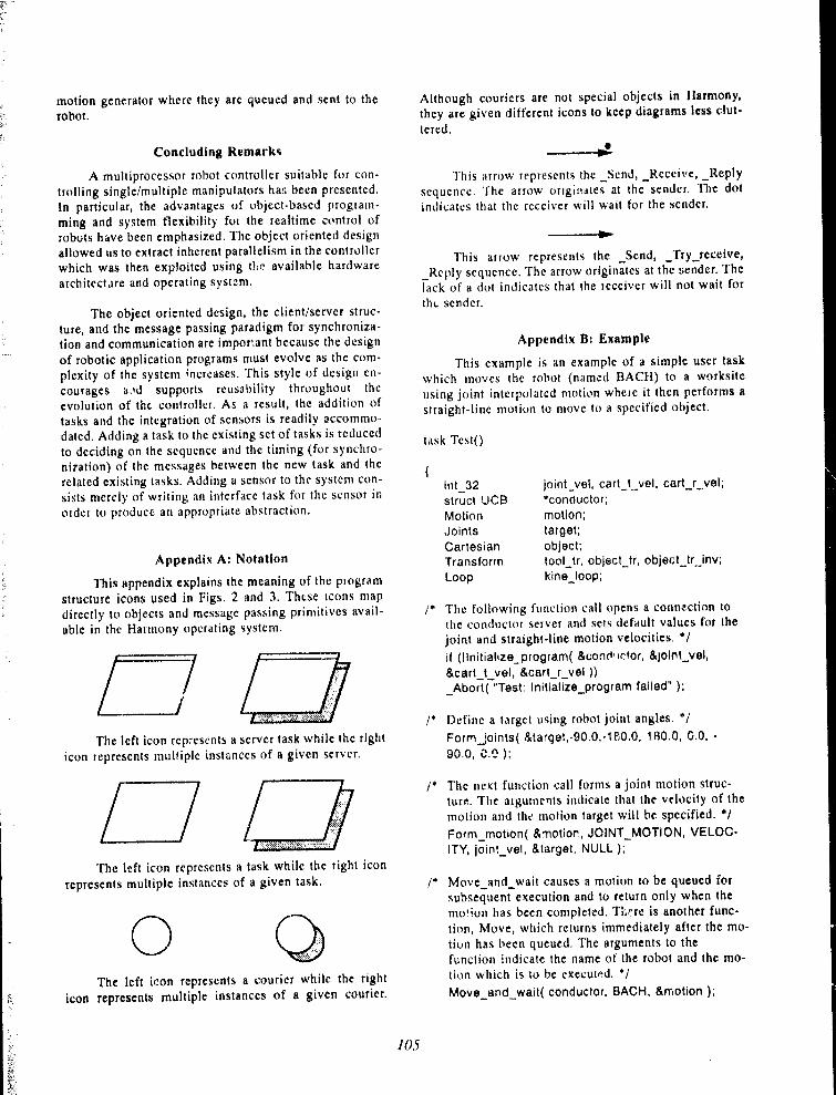
motion generator where they are queued and sent to the
robot .
Concluding Remark s
A multiprocessor robot controller suitable for con-trolling single/multiple manipulators has been presented .in particular, the advantages of object-based program-
ming and system flexibility for the realtime control ofrobots have been emphasized . The object oriented designallowed us to extract inherent parallelism in the controllerwhich was then exploited using thr~ available hardware
architecture and operating systzm .
The object oriented design, the client/server struc-ture, and the message passing paradigm for synchroniza-tion and communication are impor°,ant because the designof robotic application programs must evolve as the com-plexity of the system ;ncreases . This style of design en-courages a_ld supports reusability throughout theevolution of the controller. As a result, the addition oftasks and the integration of sensors is readily accommo-
dated . Adding a task to the existing set of tasks is reducedto deciding on the sequence and the timing (for synchro-nization) of the messages between the new task and therelated existing tasks . Adding a sensor to the systern con-sists merely of writing an interface task for the sensor inorder to produce an appropriate abstraction .
Appendix A : Notatio n
This appendix explains the meaning of the programstructure icons used in Figs . 2 and 3 . These icons mapdirectly to objects and message passing primitives avail-able in the Harmony operating system .
LThe left icon rcpresents a server task while the right
icon represents multiple instances of a given server .
OThe left icon represents a task while the right icon
represents multiple instances of a given task .
0The left icon represents a courier while the right
icon represents multiple instances of a given courier .
Although couriers are not special objects in Harmony,
they are given different icons to keep diagrams less clut-
tered .
~---a -
This arrow represents the Send, _Receive, _Repl y
sequcnce . The arrow originates at the sender . The dot
indicates that the receiver will wait for the sender.
-°------~
This arrow represents the _Send, Try_receive ,
_Rcply sequence . The arrow originates at the sender . The
lack of a dot indicates that the receiver will not wait for
thc. sender .
Appendix B : Exampl e
This example is an example of a simple user taskwhich moves the robot ( named BACH) to a worksite
using joint interpolated motion where it then performs a
straight-line motion to move to a specified object .
task Tcst O
{int 32 joint_vei, cart_t_vel, cart_r_vel ;
struct UCB *conductor ;
Motion motion ;Joints target;Cartesian object ;Transform tool_tr, object_tr, object_tr_inv ;
Loop kine_loop ;
/" The following function call opens a connection tothe conductor server and sets default values for the
joint and straight-line motion velocities . ' /
if (Ilnitialize_program( &cond -i rRor, &joint_vel,
&cart_t_vel, &cart r vel ) )_Abort( "Test : Initialize_program failed" ) ;
/* Define a target using robot joint angles . °/
Form_;oints( &target,-90 .0,-1Fi0 .0, 1 80 .0, 0 .0, -
90 .0, C .^ ) ;
/* The next function call forms a joint motion struc-
ture . The arguments indicate that the velocity of the
motion and the motion target will b e specified . "/
Form motion( &-notior, JOINT MOTION, VELOC-ITY, joint vel, &target, NULL ) ; ~
Move_and_wait causes a motion to be queued forsubsequent execution and to return only when themotion has been completed . Tl:^re is another func-tion, Move, which returns immediately after the mo-tion has been queued . The arguments to thefunction indicate the name of the robot and the mo-tion which is to be executed . ' /Move_and_wait( conductor, BACH, &motion ) ;
105

/* Form transformation vectors for kinematics loop inthe straight-line motion . * /
tc,,rl tr = Unit Transform ;Formvector( &tool_tr .VEC, 0 .0, 0 .0, 100 .0 ) ;Forrn_cartesian( &object, -587 .3, 346 .8, -601,5,21 .7, 179 .9, 49 .6) ;Cartesian_to Transform( &object, &object_tr ) ;
Invert_tran .sform( &object tr_inv, &object_tr ) ;
/* Form kinematics loop . The order of the argumentsindicates their placement in the loop . The two keywords MANIPULATOR and I)RIVE indicate the lo-cation of the robot and the drive transform in theloop, iespectively . Other transformations may havetransform bound tasks specified or NO TASK ifnone . I1ere the object transform is hound to thetask CONVEYOR which may modify the value ofthe transform during motion execution . There is adefault order of evaluation for the loop transforms .Here the order is CONVEYOR, Cartesian_tg (im-plicitly bouncl to DRIVE), and Manipulator_sg (im-plicitly bound to MAh'IPUI_ATOR) . * /
Form_toop MANIPULATOR,(&kine_loop, & tool_tr, NO_TASK,
DRIVE,&object_tr_inv, CONVEYOR,NULL ) ;
(* The Form_motion function is used again but thistime to form a straight-line motion . This motion
also specifies the motion velocity . * /
Form motion CARTESIAN_MOTION ,&motion, VELOCITY, cart_t vel, cart- .r vel,
&kine_loop, NULL ) ;
/* The straight-line motion is executed on 13ACH asin the case of the previous joint interpolated mo-tion . * /Move_and_wait( conductor, BACH, &rnotion ) ;
}
Acknowledgement
Varicus persons must be thanked for their contribu-tions and support, in particular David Green for his con-tributions in implementing the low level software and thehardware, Doug Taylor for his technical assistance, V.
Hayward and R . Kurtz of McGill University for their helpin understanding the control concepts implemented in
K ..li, Morven Gentlemen the author of Harmony, andStephen MacKay of the Warmony group .
[1 I
References
3layward, V., Paut, R . P ., " Robot manipulator con-
trot under Unix : RCCf., a robot control C library,"
International Journal of Robotic Research, 5(4),
1987 .
[21 Hayward, V., Daneshmend, L . K., and Fiayati, S .,
"An overview of Kaii : a system to program and
control cooperative manipulators," Fourth Interna-tional Conference on Advanced Robotics, Colum-
bus, Ohio, June 1989 .
[ 3 1 Gentleman, W .M., MacKay, S .A., Stewart, D,A .,
and Wcin, M., Using the Marmony Operating Sys-
tem : Release .? .D, National Research Council Reportf?RA-377, February 1989 .
[41 MacKay, S.A., Gentleman, W.M ., Stewart, D .A .,
and Wcin, M ., "Harmony as an Object-Oriented Op-
crating Systcm," YV'orksh on on Object-Based Con-
[5 )
/06
current Programming, ACM S1GPI,AN Notices,
Vol . 24, No . 4, April 1989 .
F,lgazzar,S ., Green,D ., and Gentlcman,W .M ., "Open
System Architecture of a Multiprocessor Robot
Controller," Seventh Canadian CAD/CAM and Ro-
botics Corrferrvrce, Toronto, Ontario, June 1988 .

Third Conference on Militvey Robotic Applications September 199 1
COC?RI)INATI:D CONTROL OF-MUI, l'IPLF: ROGO'l' MANI{'U1 ..%'l'U[t S
S . Kaiityt;tagiuThomson-C-SF tiystetrts18 Auriga Drive, NepeanOntario, K2E 7 I'9
U.S. Ncc..,,ulcsc uDept. of Mechanical I :ng .University of OttawaOttawa, Ontari o
Absirac t
The paper investigates the control aspects ofcoordinated multiple robot manipulators for possiblemilitary applications .
The coordination of multiple robots is achieved bythe control of each arm in a non-conflicting way as theycontrol the position of the object . The main objectives ofthis study are two fold : ( i) optimal load sharing, (ii) theapplication of optimal forces / torques to the payloadwhile maintaining accurate position control of the twoPUMA 560 robot manipulators .
An analysis of the load distribution problem forcoordinating robots handling a single payload is carriedout and an optimal load sharing algorithm is applied toa possible military strawman task . The t,tinimu .n r,n( rtn)joint torques and minimum contact forces are obtainedby the minimization of a quadratic function associatedwith the joint torques and the force victors of multiplerobot arms with the constraints of the robot systemequations . The applied algorithm is not computationallyintensive in comparisor with the existing algorithmsdescribed in the literature and therefore is very attractivefor real-time npplications .
The effectiveness of the control strategy tutcoordinated motion of the robots perti>rming differenttasks (i .e . lifting of an explosive) is checkect by a digitalcomputer simulation) . It is noted that the control strategyis very effective and the investigated control architecturehas a very important and desirable feature from acomputational point of view, since it is wel! suned lot- adistributed computer architecture .
I 11 troduct ioa
There is a great deal of interest in hedevelopment of coordinated multiple manipulatorsystems. Many impossible tasks for a single robotmanipulator can be performed by a multiple manipulatorsystem. For example, the Canada's contribution (theMobile Servicing System) to the Space Station Freedomwill ittcorporate it dual arm system (Special PurposeDexterous Manipulator) to carry out various complicatedand dexterous maintenance tasks in the space . Amongthe other areas of applications are nuclear industry,agriculture, mining, underwater and recently militaryprograms . Ilowever, many challenging technical tasksmust he resolved before an effective use of thesemanipulators .
Dual-arm robot motion control requires a higher!evel of controller complexity compared to the single-armrobot motion control because of the need to continuouslycoordinate the motion of the two arms [1], [2] .
Various combinations of position and/or forcecontrol of the two-arm motion have been reported in theliterature . Luh and 'Z.heng propose a leader/followercoordination strategy with no force feedback [3], [4] .Kinematics constraints for the closed kinematic cl, ;n areused for the determination of the follower motion giventhe leader motion in terms of positions, velocities andaccelerations . One rigid body and two urtictllated rigidbodies are used as loads . The dynamic dependence ofthe leader and follower input generalized forces are alsoderived. The major difficulty in using these results tocoordinate the motion comes from the lack ofcontact/force feedback . Consequently, such acoordination scheme would be successful only in the caseof no servoing and modelling crrors .
t)zguner et al develop an stpprciach fur cancellingthe cross coupling terms of the dual•arm dynamics whichreduces the control problem to controlling independen t
i t ticrvorttotors [5[, This is ;ichicved by a sliding moti•~ ,
107

discontinuous controller with gains obtained for a give :bound on the norm of cross-coupling interaction ." .
Simulations are performed for free and contact motionof the two arms with no load . No comments are madeconcerning the evaluation of the norm of cross-couplinginteractions and on the operation for varinus loads .
Swern and Tricamu p~ctpose ~a 1110dificattion of theposition cnntrcyllers of the two arms intended tocompensate the constraint forces applied by the .arms on
the load [61 . This is achieved by correcting the reference
positions based ►m the end-effector's measuredforces/torques and the load stiffness matrix . A fle.xihlerod and a beam are used as loads in simulations and arecursive identification scheme is used for the loadstiffness matrix . While this approach uses the actual loadstiffness matrix, Kazerooni ane : Tsay propose an artificialcompliance for a similar control scheme. [7] . The effectof joint flexibility on the steady-state error in the objectposition is analyzed by Ahmad and Guo for arms withposition/force controllers 1 8 1 .
Some dual-arm motion hybrid coordinationschemes are developed based on the wutkspace force,velocity and position vectors defined its symmetricfunctions on their joint-space counterparts for the two
arms . Uchiyama and Dauchez proposed a hybrid controlscheme for a chosen set of relative and absolute force
and velocity in the workspace [9] . Kopf and Yahutacompared, experimentally, the leader/follctwer stnd hybrid
control schemes 1101 . In the former control scho~.me, the
leader is position controlled and the follower is forcecontrolled while in the latter ccmtrol scheme, absoluteposition of the centre of the object and the relative(internal) force applied on floe object are controlled
symmetrically for the two arms . The leader/follower
scheme has performed poorly. Tho can he explained by
the lag in the reaction of the fn'.htwer . The hyhriu
scheme has had restricted u ;e because of the
requirement of the symmetric funct : ins mentioned above .
Suh and Shin generalized the leader /follower
schemc: by ►tllcrwing the follower grasping position tochange when reaching a configuration singularity, or forobstacle avoidance [11] .
In this paper, the coordination of multiple robotsis achieved by the control of each arm in a non-conflicting way as they control the position of the object .The main objectives of this study are two fold : (i) optimal
load sharing, (ii) the application of optimal forces /torques to the payload while maintaining accurate
position control for two PUMA 560 . The effectiveness of
the control strategy for coordinated motion of the robots
performing different tasks (i .e . a lifting task) is checked
by digital computer simulation). It is noted that thecontrol strategy is very effective and the investigatedcontrol architecture has a very important and desirablefeature from a computational point of view, since it iswell suited for it distributed computer architecture
A detailed description of the methodology which
minimizes the second norms of the contact force/momentand joint torques for multiple robots during acoordination task was provided by Kalaycioglu andI)aneshmend [121 to resolve the problem joi .tt
redundancy .
In the case of a dual PUMA 560, the following
robot dynamic equation is true for cac.tt arm :
D,ÿ+II,+G;=T,+J, Ti (1)
where y, is a 6x i vector descrihing joirit angles, T, is a 6xl
torque vector for each joints, J, is 6x6 manipulator
Jacobian matrix, p, is the force/moment vector exerted on
the payload, Cl is a 6x6 inertia matrix, H is the Coriolis
and centripetal force vector, and finally G is the force
vector due to gravity .
'['he dyn<unic equations for the translational and
the attitude motion of the payload can be written as :
MX+ MG =-Y.F
ING ► +c.txlNc.► - % N
(2)
(3 )
where M, IN are the mass and inertia matrix for thepayloail, respectively .
Ucfining the functicmal to be minimized as fnllnws :
0= 1/2 S"' WS+I " F.:
where S is a vector consisting of the contactforces/moments and joint torques, W is a positive definiteweighting matrix, L is the L<rgrangian multiplier, and E isthe system equations (two for the robots and one for thepayload). The optimality condition of the functionaldictates that the partial derivative of O with respect to Sand L vect-r niust be zero. This results in a linearsystem equation in terms of the vectors S and l, where Sis the optimal force/torque vector for a prescribedtrajectory . Figure 1 illustrates the uncontrolled processbetween the cartesian trajectory and the optimalforce/torques .
position Ctantrnl of . onrdinnt n o PU 56 0
with Ut►timaF fA►ttd .S harin_g
The main difference between the position controlof coordinating two arms and a single arm is that in theformer system additional natural constraints areintroduced due to the fact that two grippers must be
connected firmly to a rigid object . Thus, the arms can
exert forces/moments ►m each other . The arms must alsomnve in harmony to induce the desired motion to the
M .
I0cK

Figure 2 shows the dual-arm configuration holdin,,a rigid payload . The used control scheme is illustrated it,Figure 3 .
A lift operation is sitnulated from an initial to ~tfinal point with a dtsired trajectory of a rigid payloadcarried by two PUMA 560k . The mass of the payload is1 kg . The desired trajectory of the centre of mass of thepayload is shown if Figure 4 .
The obtained optimal contact forces exerted onthe payload by the two gripper of the PUMA 560s areplotted with time in Figure 5 . Figure 6 illustrates theoptimal joint torques for each robot during th- liftoperation .
Cc ► c ud irt g R>'msrks
In this paper, two important aspect of the two armload shari^g position controller were discussed : (a)optimal load sharing. (h ) the application of forces/torques while maintaining accurate position control . Theredundancy in the force /torque suhspace are resolved byan on-line minimization of a quadratic cost function ofthe desired constraint farce and joint torques .
Ackncwledgementi
I would like to thank Dr . F-:Igayzar of the Instituteof Information "I"echnoingy / National Research ('ctuncil,and Dr. Daneshmend of McRCFM fcr their fruitfnldiscussions and contributions .
~tefg-wcaces ,,
(1] Necsulescu, D .S., Jassemi-'Largrtni, R . and
Graham, W .B., Trajectory Generation forDual-Arm Robots Using ArtificialImpedance Approach, Can . Conf . on FLand Comp. Eng., Ottawa, Sept . 3 .6 , 1990,pp . 50 .1 .1-50 .1 .4 .
[2] Necsulescu, D.S ., "Artificial ImpedanceControl of the "l'rajeetriry Generation andCollision Avaidance for Single and Dual-Arm Robots," International Workshop inAdaptive and Nonlinear Conttcil : issue inrobotics", Grenoble, France, Novemher 21-23, 1990.
(3] Luh, J .Y. and Zheng, Y .F., ConstrainedRelations Between Two CoordinatedIndustrial Robots for Motion Control, Int .Journal of Robotics Research, 1987, No . 3,
pp . 60-70 .
[41 7.heng, Y .F., F..uh, J .Y . and Jia, P .F ., AReal-Time Distributed Computer Systemfor Coordinate Motion Control of TwoIndustrial Robots, IEF_,E Int . Conf . on
Robotics and Automation, 1987, pp . 1236-
1241 .
[5, Ozguner, U , Yurkovich, S . and Al-Abbass,
F., Decentralized Variable StructureControl of it Two-Arm Robotic System,IEEE Int . Conf. on Robotics andAutomation, 1987, pp . 1248-1254 .
[ 61 Swern, F .L . and "F'ricamo, S .J ., AnApproach to (`cyntrolling MaIti-ArmRobotic Manipulation of it Single Body,IEFF. Int. Conf. on Robotics andAutomation, 1498, pp . 51 6-521 .
[7 1
[ 8 1
[ 9 1
Kazerooni, H . and "F'sai, T .I ., ComplianceControl and Un-structured Modelling of(:'onperating Robots, IEEE Int . Cunf . on
Robotics and Automation, 1 988, pp . 510-
515 .
Ahmad, S . and Guo, H., f)ynnmicCoordination of Dual-Arm RoboticsSystems with Joint Flexibility, IF=EL' Int .Conf . on Robotics and Automation, 1988,
pp . 332- 1 37 .
Uchiyama, M. and D,tuchrz, P., ASymmetric llyhrid Position/ Force ControlScheme for the Coordination of TwoRobots, IFF:F Int . Conf. on Robotics andAutomation, 1988 , pp . 350-356 .
[lU] Kopf, C .D. and Ytthutst, T ., ExperimentalComparison of Master/ Slave and HybridTwo Arm Position/Force Control, IEEEInt . Conf. on Robotics and Automation,
19 88 , pp . 1631-I 637 .
[Il] Suh, I .F-I . and Shin, K .C; ., Coordination ofDual Robot Arms Using KinematicRedundancy, IF.'.EE Trans . on Rohtttics andAutomation, 1989 , No. 2, pp . 236-242.
(12( Kalaycioglu, B. and Daneshmend L.,"C'ontrol of Coordinated Multiple RobotManipulator", McGill University ResearchCentre for Intelligent Machines, Montreal,1988 .
(131 Elgazzar, S ., "Eff icient Inverse t'.inematics",IE:E::E .; "rransacttOns of Robotics andAutomation, 1985 .
109

INVf lW& rnYl Unl)t)YNAMH ; S
IIIAJ-->fOIIÇr_
_r. ._ ._ .._.,.--.,..._. . I [lesue~t (1olnl)
iNV1 11 .~f MAN11'lli A 1 C)N Pn~rnh~ec li)YNAMIC3 Tnr~lraa ._. ..
TIIAJ --> I 011CF/TC)IiOtll 0,
1 Deslre.l Oolol) Cool I I,ir, f,l
oI','IMI7'n ( ION:" (;IIC:ME_
Tid (C)e51rerl /M . rTxanllorrnlorques fr,'rEf ~ch finbe Q
ricl (C)eisre , l/
K 'IrxrMA ii ilorrn
Gorli•rc1F,>rGes )
DE:SIEIF D-I E1AJ1=:C1 OItY ---- > MINIMUM - NOEIM JOINT 1OIiQUEnS
(I)( SIHl C)) & CONTnCT FOEICE S
I .' Ib . I Ohtintizatiott Prl)ccs s
V ig. 2 Dual-arm Configuration
ll0

r ~ .! MA PUV{7GN rl I
If lR l
`7%.'•_ .iKP~ "_.. .
iGENERAUZEDI)ORQUE
~_ ..~..._r_ - ....~..~.~
I;
ION • LINE
OFTiMIZATIO N
Fig. 3 Ccmtrcrl Schemc.
0 .6
F
PAYIAAODYNAMIC S
G 0.4 -o
oa.b 0. :2E~
VI . . ._ . .••--
.. . . . . . . . . ..G . . . . .. . . . . . . . . . . . . . . . .
~ O .
iC~ ...._s____~_~..ax... ..... .... .. ....,-... ~._.,a .._ . ._ ~._.._._, ._. .-.`___,.
0 0."w 0 .4 O,fi 0.8 1 1 . :. l . -l l .(i
l'nnv (sec )
Fig. '7n variation ot- tll(. Position (il the
1 . 8
11!
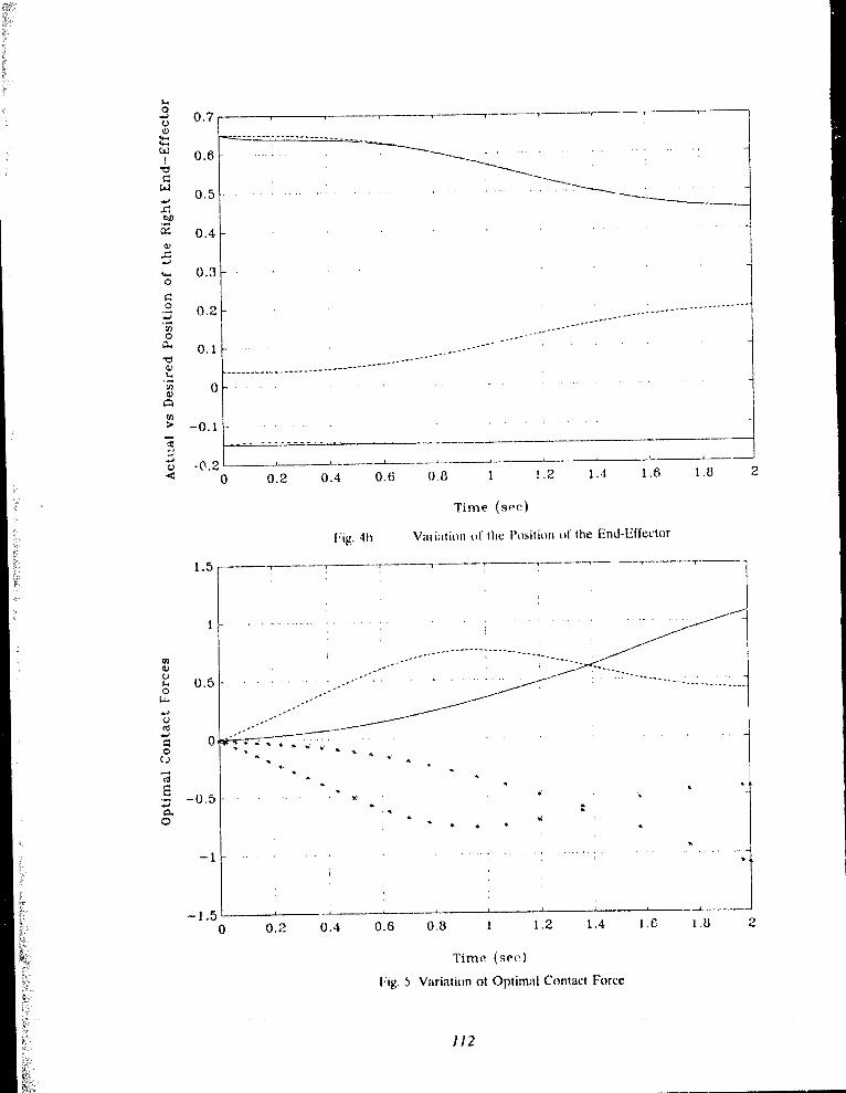
w - ------------ - -W nr _-, . ..
., 0. 5
-6
oa. 0 .1
------------
-----___°---------------------V) 0a)AEn> -0 . 1co --- -- ---
-0.2 -0 0.2 0.4 0.6 0 . 8
Fig . 41 )
1 .5
1
O
-1 5 t - - -- __.
0 0.2 0.4 0 .6 0.8 1 1.2 1 .4 1.6 1 .8 2
Time (sec )
Fig. 5 Variation ot Optimal Contact Forc e
~ r _ .• • • ° ~ • w
-
Y 1 1 .2 1 .4 1 .6 1.8 2
Time (sec )
Variation of the Position of the End-Effecto r
w
112

23
0' â1115
ww -10ti
-20
~wI
-30 .
° -40
__---50 °
ô --- ----- -- -: -- ; -- .--- - . - -
-600 0.2 0.4 0.6 0.f3 1 1 . 2
'rime (sec)
--------- 77 7 -
1 .4 1 .6
Fig. 6 Variation of Optimal Torques
1 .8 2
113

Third Conference on Military Robotic ApplicationsSeptember 199 1
Three Methods to Improve the Accuracy of a PUMA 560 Robo t
G.R. Hardy
Uefeuse Research Esltthlisluuent ParificFraO, Victoria, IIC, VOS- 111 0
ALIAW-A s
A prohlem with using it rohut to perl tin repeatable scans
on ;t CF-18 aircraft iti accuiacy . Altlrough currently the
"rttlibratitm" medwrl is ,Ircut ;uc enttu gh, it is ctmtplex to
iinplernent and teyuires a very fit." turnptuer to crnre<9 errots
in teal lime . Three simple tuethal : to impruve arcur ;tcy are
comparetl . One methoJ u .e, an utu ;tsonic pttsition ing
system to continuously correct position . 'Ihe second uses the
positioning system to conect unly the end points of the scan
lines . The thittl methotl, it nu difted c ;tlihration technique,
correct ,., (, ril the 24 pararnetci .. (lei ining the m ;tipul ;uor .
Both methttds using the ptwiunning systcm ietlure enots to
an acceptable level its long as ther e is it clev lutte r,f .i};In
between Ille tt ;utsmitter rn o untetl oit the arrn and tire
receiver:s . Ilowever, litige enors t,icut when it rtitect path is
blocked and the system tespunth to ;r tellectcd signal . 'I ire
thinl ruethotl is rot , nst and reli ;thle, bill mol ;t ; accuiate as the
uther tw0 .
lule-dAtlau
The surface areas of modern ;rircr ;rft, such as the ( T .IR,
cont ;titt an apl reriahle amtrunt o f crmtpttsite nt ;uerial . They
are usually inxpected for tlefects by xc ;tnning s u<pe :tel l ateas
ntanunll y with ultr ;tsrmir scnwis . This' technique iti timc
ccrosurning and dcpentlant an operaatr .r•kill, m ;tkutg srn ;tll
(lei aminations difficult to tletect It wrwltl be rlesirahle to
find (lei aminations I mm long and nwniter their i ;rowth .
The )efense. Research Lititahlishtuent I'acifrc (l)RL?p) plans
to rtse a PUMA 560 robot manipulatur to ttentonstrnte thatrobatü based scanners can prruiuce accurate repe ;tt ;thle
results and reduce tedious work . The fust hurdle is to
intprove the rohot's arcurcy .
k-Ctavulr_cnw! n s
It i5 iie~irahl~ to scan the I;rowth of defects every few
tnonths . 'l'Ite pt imary reyuitcment is to reu'ace the grid
p,rttcrn to witlrin 1 .3 rnnt . Arltlitionnlly, the sensor must 1
nutntnl to the sut lace within 5 tlegteeti to tnaintuin signai
strenkth .
tlihratit~n inetW it l
Several people (Lin i 11, Ilayatil21 and Kwohj ;j) ha, e had
succecx in irnptuvink tohttt acctuacy hy ttsinl the calihration
methorl In tliis ruethod, tue rohrrt is tk•fineJ ntarhemntic ;tlly
hv 24 par ;uneters . Fitch of tire six juint', have tou r
Iru ;tnteters : fini, lengih, Jititauce hetween axes, rtfiset angle
hctwecn jt ints, and joint angle 'l'he paratneters are
rletermiued usini; an extermtl tneaxurins,. device . l'iltel, Ille
crtru cati lie estitn -ted foi a given set of-ioint angles lie il
.pecitit• trrhrrt crtittrgtu,tlirml Iluwevet• a veiy fast
cerutputet is tcyuired to r.'ompute the en o-n's in teal ti :ne .
('taitçrrt .uf t~~ittrt
'l'Iris palier crunpares three less ct ntplex ways tu reducc
curus . 'Lu (fille, tmly position enrrrs have I+eeu ronsitletett
One tuethrtd (ctmUUUrws ionect1o11 methrr d ) u s c ,; art
ultr ;rstntii posititm rne ;rwrinl: systent tt, estiutare the p , sititm
etror ;tntl ;ippliex ctmtinur,us cotrectitms . A second melhod
(Cod point correction mctluo J) ca itects tmly the end-pt,ints of'
il Iuu• . 1-innllv, the fe ;tahiltty rtf uxing ;t tntxlttted r .tlihtation
technique (PO'L('AI, nrethotl) isrxaminetl hy uhservinH the
eftect et c .tlihtuting :mly r of (fi(, 2-3 paruneteis defitting the
rn ;tnilwl ;tkrr .
IS MA 56Uj rWiA rl!r
The Pl IMA 560 is it six axis raht,tir ;trm with it reach of I
m . It is itrutmlletl by ;tu I .Si I I cuntrt,ller and six 0800
based boards . It can be progianunetl in it BASIC likeianizuage and in ;tzsenthly IanEuage . 'fhete is also it
provision for nutntni ; it t ;rsk in the hackl;tt,und . '111 e
114

rnanufacturer claiuts a repeatahilrty of 0 . 1 mml4j, but its
accuracy is at least an order of r :iagnitutle worse . To
facilitate path correction it a)lows an extern .d device or an
internal background task to alter the path of the robot in the
fonn of an "alter-path" coiumauid .
MQdel of rQbo t
To ensure stability, a model for the robotic ami wlten
given ait "alter path" conunand, must be detennin~M . 'l'lie
PUMA ;,,0 robot cari lie modeled by the systeni shown in
figure 1 . 'I'lie sanrple and hold elernent models how normal
motion commands are broken into 28-tusec segment,, . An
integtator is included to rnodel the cumulative effects of the
alter-path comrnands . Ternis used in the figure are ,
T - sampler with a 28-rnsec perio d
(;Il - satnple and hold with a period of 28 rnsecP - plant representing the dyn .miic beliaviour of robo tGI
Fig . I . Model of robo t
G11(s) is aOth order hold with the truesfer function ,
I-elill(s)
s(I )
where G I l - tr,tnsfet function of 0 1 h order Itold
T - updute peti .xi - 28 msecs L.aplace-ttansfunn coinplex vat tabl e
P(s) i, the pl .utt represeuting the clynantic response of theann . It was yuauttified by fitti,tg the best first otder curve tosteu respouses drawn by the manipulatut . It is repre`ented by
% : I st order systetn ,
KP(s) _ `a+ swhere K = 49.7 /s
a = 50 /s
- integrato r
, PUbIA, .NO4I-- --------------
(Z)
'Ille nansfcr fuuctiun foi the integrator is,15 1
I
li1(Z) = Z- 1wltere z -!-Uansfotnt coniplex vat tabl e
(:utrtinuotts 4ttrrtion methud
(3 )
th ;s ntetl :od, file end-effector'v position error is
measured and it correction iu the font of an "alter-path"
contmaoul, from cit)ier an intetu ;tl task or an extetmtl
computer, is given to the moving atrm . Ilowever, whenever a
control loop is closed, stability must he ensute d
-V ltrawnic p~r ~s ticm in sy~tn . alke-0
The ultr:lsrmic positioning system is a commercial device
consistinK of four receivers used to measure the position of
up to eight tntnsntitters . Each transmitter uses a spark gap to
transmit att acoustic signal to each of the four receivers . Thelime delays represent distance and, with some computation,
the position of the transmitter can be deterrnined . The
distance measurement will be affected by local changes in
the speed of sound in air ,utd Doppler effects front air
ctut'ents . Ely nsing a reference nansrnitter to measure (lie
speed of sound, the measutemeut accuracy was improved
from 4 nun to Inrm Lit it sarnpling rate of 7 santples/sec . An
accuracy of 0 .2mm was achieved by ensuring calm air and
tmifonn temperutuie. . Ilowever, these cortditions will
unlikely to he achieved in it practical deruonstration . 'Ihis
sy5tetn will be relctted to as the sparker for the remainder of
this report .
Over_tli_tr :f1)sk't- fu ,;Iiun
Figure 2 shows how an external rneasuring device cati lie
used as feedback for motion in one of Ihree ttitections . The
tenus used in the figure aie ,
I'I - sunp)er with at 28-msec period
'1' 2 san,pl •r with a I•1 3 -mscc periotl
12(t) - continuou" tlesireJ position('(t) actual positio nE(t) • eno r
l'(U - cortec'tctl desiietl positionF*(t, s :rurple ..l couccted t)etiitetl po',itio n
115

r_P U .MA-B41L4T. ----------------
D a~
stlred F (t) AR~M•r 2!!
C(t)R(f) ~ >• ssa
1-_ rc~. ~ G H~--~ p~
1Commandr~ -r---J
Sa m pl~+s1. and Hol
d ~ intam grcatnr•
t_--- - -r.+ u-t-of iv-. ----------------Z uAltar eammond a
,,4T s
m 1 43 msa a
E (t)
,
Fig . 2 . Model of cltr, :eti tiycte m
In this case an ultrasonic positioning systent was used to
measure position . It gives a position about 21) rnsec after the
transmit pulse . In urder to a(curately measure error, the
spaticer must he triggeretl at the same time as the command
r(t) is sampled . As the command svnpling r :tte gives
positions about five times more often than the sensor,
different s.mtpling rates are involvecl, aclding to the
complexity of the prohlem . To simplify the analysi .ti, the
faster sampler ('l'1) was slowed to etfual that of thc sluwet
('F'2) on the assumption that it the xystem is stah ;e at it sluwer
sampling rate, it will he stable when Imtt of the sytitem is
sampled fastet .
In ttrJer to predict stability, the inathem :uical
represetitatimt of the closed sy'stem must he tletivctl . I•tom
Figure 2, F(s) and ('(s) (represenUr.g the lapl ;tcc ttantifum) of
the output) can he written as ,
F(s) = R*(s) (""r(s)O1(s) + It*(s)(il(ti) (4)
('(s) = F*(s) 611F(s) (5 )
Some of the signals : ►re. continuions while cahers are s,tml~le~l(idetrified by it supcrsctipt asterixk) . Samplin); etluaiiun 4and substitrtting into equation 5, and sampiing both sides
yields ,
C*(s) = R`(s)GIIP*(s) ('~(s)(il*(ti)Cilll'°(x) +
R*(s)(illF'"(ti) (0 )
Converting to z-domain and rewriting yields the overalltransfer function,
illl'(z) I +(il(z1C(z )I#(z) - ki-I) _--
1 + (ll(z)GIIP(z)
Aatua l
(7 )
'l'he tu :utsfet futtctittn of cadi clement in eyu :utun 7 is to
tx tietived . ' l'he s-dom,tin tr :uufer function of une of the
eletnents contes front equation I,uid 2 ,
I - e- s'1- k(i{I!'(x)=- s ti+a
Splitting into two teints yields ,
G1i1'(s)-(I S(s+a)
('un )" etling lo the z-tloni :tin yieltls,151
(8 )
(9 )
(3IIP(r)-k(I e il )
(10)u(z-e-:iT )
Suhstittttin); this and equation ; into equation 7 yields file
over :d! Ir :tnsfer function .
e :il) (z1(illl'(z) --
k ( 1 - - - I )(II )
a( 7 - e- :i1 )lz - I)+ kz( I- e-ut )
S(;t(iilitty
To ensure stability, the poles of the trantifer functiun mustbe within the unit c ircle . 'Ilte pole.s can he detennined bysetting the tienominator (equation 11) to zero ,
I)(z)=z2+ [ .eiti' e- :ii'Iz+e-ai =() (12)
116

The poles of this quadratic must have an absolute value lessthan one ,
Ipo le s, =4112 - 4AC
2A_--
.
wherc A = 1Ik k -
}~=t~_-tetil'_I_efJ
C= e-at
To detenuine the region of st,tl,ility . the eyuatiott was
intplemented on a spreatt shect . For t given set of satnpling
periods, the vat table k was incteased until the poles Ielt the
unit circle . The rewults, shown tn tigute 3, iptdicate that the
system will be stable for all santpl ;ng per iotis if file DC-gain
of the robot is less than 2 .
I
p row
C7
Nlcixrtntun çyrtn <>I ,un tF-1 -- -
F
-T
-
lA .,11 W. .iksV
I
"1he one-sampling-rate simplification was currohorated bya computer moilefing progteun ca!led "Simufali" from Math
Works Inc . . Modeting one sampler with it 2 8 nt .cec per ioe)
and the other at 141 rnsec, the system was stable for DC
gains less th.ut 2 .006 .
The mahifity titi the continuous collection method I%
assuretl because the i)(' gain of the ann is O . 995, well within
the limits in figute 3 .
lar4lw arsS~oufit ur~Ci t
-Ilte Owerall cunfiguriUiun uses it PUMA 5 0 0 u,hotic ;uniand lis coutrolier, the spatker, and it tetminal, confiE.weri as
shown in figure 4 . The sparker's four teceivets me at lite
corners of it squale on it pl :diotnt . 'fhere are two ultrasnnir
uanstuittets . One is tixeJ oit the hlatfrnm Itt act as itreference to meastne the S peeti of sound, and the otiter is
mounted neat tlte pen hultlcr .
~yftwat r
'Ille overall xuurtut :• uf communication willi Ille hardware
is best ciescrihed hy il ti .d ;t flow tiiagr ;tm (Figure 5) showinghow the suhroutines communicate- 'i'hick lines represent
either on/off corn roi or event fiagti . Other filles repleselit
discrete tialat package,-, Boxes altd pointers tepreventsuhroutines and h,udwar . devices re . hectively .'Ilte narruw
three sicieû boxes represent data store (filrs, global variables,
stack, etc) . 'i'he software mus in two ta .tik .-~ : "i'lhe foreground
lask tun` INI'l'IAI,i7.A'i'ION and MOVER Ii)litlIIeS . Ille
harkf;round task rtuts lire Al:l'i :R routine . Communication
hetween tasks lise a data s!ructure calied rentiezvousjbj so
irtnh tasks cari meet Io excl)iiiigc data .
1 ~.~ • .---_. _ .--_. . .--. . . . ... .-- .-__ ._ . ...--_ _ .,_.m---__ .-.~_-._0001 liplfl O Icn 1~F~~ I 0 1wR 1 Inllrw l
Stunplinf; Pet bd ut sitmpiers(sec )
Fig . 3 . Ref!irnt of stahllltv .ystem
Fig . 4 . 1 lardware configuration
1/7

A- I t .-T,
I
'/AItlfJ
rrr . ~fr1~,
rrr ,. rrl• .~,11
;rt•,` ,r
I
nt IL' 1,r,rr~rrll rrl ;rr .Y•r r
'•t .• rV. . r ~1r.tr r
rl~~r~t~~r •,Irt . 1
~,11•~rl~,
rri . r1 ,Ir r rrrr r ..t•.
Fig . 5 . L)ala flow tfial;nun for continuous Collection Inelhod
Lnitiali Lttiott . lite INfI'IALIZA"IlON routines use:; the
sparker to measure the translation front the .patker axis to
the robot axis, and ► o measute the dispfacenrent offset ftom
the spark gap transmitter to the end-effector .
M v .'1•he MOVER routines moves the end-effector
through exercises to test the syslern . One routine draws
concentric boxes on the platform to test for jitter, and the
other draws a line on the pfatfonn to test for accuiacy .
àhçS . 'llte ALTER routines impolis data frorn the.
sparker to measute the end-effecutr position, dcicimiiie flicerror, mui then corrects the p :uh evety 14 3 rneec .
Eri j-po ïtt! correcliu r o t
Intteacl of continuously correcting along the length of adrawn line, this ntethod corrects only the end-Itintz The
end-effeclor is moved to the end-Point, and the error is
measured using the positioning meaxuring system . The end-
ef7ectut is tl ;en ruoved hack to draw a line to file collected
en .!-point Rec-u :'se Ihe on!y firtlhnck is at the end points, no
jitter is expected .
59-ft Lk ;"
To imhlernent thi, ntethod, the saux ynotzraut, with some
rninor alterattons, is used . First, the alter t .'utines Jo not
alter the robot path, but metely teport the ernOr . Second,
every time a line is drawn, ;utother routine move~ thc entl-
effector to the end-point, records the cri-or reported ftom thealter routines, and then goes back and chaws a line to the
corrected end-point .
1!0'1' (,AL metlnul
The PO•l'C AL (poterltiometer calibration) method is
actually it subset of the calibration method . It effectively
correct s (i of the 24 paruueters which define the a nt by
~r-eroinh the measurement potentiorneters on each jo int . It is a
two hour procedure descnbed in the PUMA ntan e al 1 4 [
The PO•1•CAL procedure is executed before a run . The
arm is moved to a specific position and the angle. measuring
pote;ttionteters are adjusted to tead zeto . The proceJure
produces a new correction table (overlay) to he used by the
PUMA, the ncxt tim e it is use(] .
A line is t1taw•n and its length rneatiurecl to contpare the
;tt•cutacy of the rtrffi•rent nu°thotlti . I .ine . were drawn with
, ;itü•rcnt collection mcthoxk., in Jifferenl r .litections, with
uiffetent speeds, and with thlferent overl .rys in the l'Ol'l'AL
case . The mean length error for Iines tlr ;fwn trttder Ihese
conditions are surntnat i7etf :n table 1, .ur,tl Ihe taw data are
liated in Appendix A .
Mr1~;'I 17 ,~_.
~1r,iw~r,rr ly1, r
r . uvr c:~r~ .~•~~ .~, 1
118

Table IF?rrots in a line 100 mm lon g
Metiw(1 Slre((I nverage Grror
------ --- - -- ------1 ---011111/s) lines Ili lin
- ----
_-~ - 1l0~
-- - - O.25
--- - - - Lf~
IlOtle
COIltiriUOUi 1
was testecl, tiuh-millimeterumps coulcl he seen every 7 min
showing whenever corrections occune(I . Very infte .tently,
observations . Fir,t, when tne motion was relleaterl with the
one (If th( rerci" en was 1>urll(lsel y hlackecl a Jumll was
observed .
correCtiuti {O(
corr ection
'Hie cuntinuuur : collection m( thu(1 itnlnuve(I the ;tccutac y
but sottie pruhlem, where trhserved . Fable i shilwt~~ that the
P(Yf('AI, IUU
#
13ox druwi retiul~
Jitter was teste(I by druwing cnncentt ic boxes and
obser.•ing the motion . While the ,_rmtinuuus feeclhuck case
a 5 mm long julnp,.lcctntc(I in the vertical direction . 'Ihese
longjumps seeme~ .l to ha~c been c,us e•tl by the Ilen hlockiug
one of the ultras( signuls, This is curtohot .uecl by two
pen rernove(I, no vertiral j utnhs wete sec•n . Secuu(ily, whe n
T houkh th~t fee(Illack in the cutttittuuu . (orrectirnt metllocl
wu5 juntlly, !he two (/tller net lions wete ui/sctve(I to he
stnouth, as expected .
lliscussiur (
less su~ceptihle tu hl~lcked signais ,ute1 ptrxlured vety stnuuth
filles, I~ur [lie specific application of' rastct scannin~, il ttee(I
(_ lt tlli nt(!!uv L(litç~~ti~~(~
continutws feedback nletho(I itnpitlvc .l t!le accuracy to about
1 .5 111111 iront 4 .~ 111111, inJtcating th .~t the tlletht( is tel ;uively
incemitive I') pool cn•etlays and ro sIlccck ull to 000 ntrll/s .
tl(' ---
As sht wn iii table I . Inurlu( ing ,t new uvetlay ueutf. the
tec'clvc't ~---- ; ~.-
(nlnl)
I Ilu not u,tie had re(eivc•tx c tn't tlctect had teccive t
1 . 3.I S
0.15---0
.75
Iluwever, vetitcal jumps rrccurteO mien the iiiiiitsoliiL signal
was hlucked . "l'he jutups ve verlical heeautie the sensrlr is
near the plane of Ille oltratiunic teceiverti, .m(I any cleviatitm
in the rtange tü unc sen .ur, currespnn~ls t(1 u la+ge juntp in the
vertic•tl elite(`titlt . 'l'he hil~gest ptuhlem with usnt) ; (lie
sll .uker i•; that the hlc~.ked ultra<rluic signal canntrt he t~~tsily
(Ictecteri . In addition, Ille mois ('au lie lat ge . When
putptlscly lduckecl, 50 mm errur5 wete uhserve(I .
f :-n(I fl~>tht ~•uileçtit,il
'llte end-puiut collection methu(I hall a hener accuracy of
I 11,111, but il Iclok ilitee tunes longe, Io ( Itaw a fille . It was
nut t, l ke as long . Recause the cucl-point~ ale so close Il) each
rlthet, the moi (/ f ,t futtue etlrl-Ix,int cati lie etitimate(! fttlm
the meuwtcnlent of the lueviuu s ncaiby end point .
-11111m slliltn receivet s
V ,u iutium tu-a_v-ilül hlokrl i1hrasiinic signal
'l'Ite main Ilttrhlcul using Oie sltatker is the un(iet :e'tahlc
!llockecl signal . By taing file available srnl~lus teceiven and
transnlitters, the hlrlcked si)±nal nli};Itt be detected and
hyllussed . Table 1 shows van ions ways to do this and listsIltuhlc•ms with cadi metltuct In all ca~e, the blocked signal
caunut always be rlctecte(I .
to the teceiver plane . c ;ul't guarttltc e
I'Of('/~1 . Iltucecltne, inylttlverl the uccutaiy boni •l .}{ 111111 tu
1 .7 mm . Il was e .t~y tu imlllenu•ut ( ;dthr)u~h fiolecrrnsunting), Ilttxlucecl sn"wtL hiles, and silice il w :rsn t
tunning ( luting tr~ht,t t,l,et ;tti~ r ;, il flee•tl III) Ille hackpolind
t,t ..k .
'f„hle 2Ways ttr avoid a blocked ulttilsrmic sigitul-- _~-
---# uf ttans_ -- Sulutuln ~ l'tuhlc•nl
mittctx
Uetect bill] recetver by
11 9
gc•outeu"y
- tuttxt alt gtt tccc•ivets
Iletfec t ly _ __
h,tr(I to itltlrlcmcn t
impossible tu guttwntc• e
ITetfc•rtiy _ - ~
Use the ttansminet clusea c• ;tsy tu inthle•ment
I'ttrhlcm if two teccivctshltl~kec t
t•nct-Irt
ii)) =---~â~5 :â7
x- es in
elirectirln y-directio n
60O
100
0 .<!8

Reconuneradatio n
'Llf.nif!,PlsçS
Although the PUMA 5 6 0 tohotic ,rnn should be ie!eal forproducing repeatahle results for ('F-I8 aircraft insllection, itsaccuracy is ;eriously lacking . For example, whecc the robotwas contmanded to go 3 00 mm, it only moved to within 5mm of its destination . To he useful it has to be accurateenough to repeatedly locale adelaroiu .atiotr only I min long,and to niaintain the trltrasonic trantiduc{r normal to thesurface .
Prrfunn,urçe
'l7ris haper introduced tl .rce rnethods to inrprove the
PUMA's accuracy . Two onethods used aPositioning
measuring system based on an ultrasonic digitiz.er . The
continuous conection method was successful in reducing the
error from 4 8 mm to 1 .5 min . Ifow<:ver, it required that at
all times, three of the ultrasonic recetvers had to be in the
line-of-sight of the transmittei mounted on the end-effector .
A variation on this method corrected only the end-points of a
straight line . Although it is the only method accurate enough
to meet the specifications, it also requires that the receivers
are within sight of the transrnitter at the end-l7oints . The
thirel methocl zeroed the measurement potentiorneters on each
of the rObotic links . This metliod, culled PU'l'CAI . in the
PUMA m .utual, is done manually ,utJ takes about two hours,
,%lthough the accuracy imprrrvetuen' was not as great
(13mm), it wcnked iii any configuration .
Eu i4 t c .w_gj k
Metirocls using the uhrasonic positioning rneasuringsystem (sparker) reyuire more work in order to make them
Practical . First, either the uansmrtter must be mounted to
guarantee line-of-sight for all motions, or five tr :utsmiuets
could be mounted ou the robot so that the one that isn't
blocked could be used . Second, althoul!h the ulgorithrn
corrected the position, correcting orientation iequiies
po ;itional dara for at least two points iather thanjust one, and
as a result, more programming effort .
lite sirnplest tuethod is to run the POTCAL procedure,
but it dtd ivere d an accuracy of only 1 .7 mur . If more
accuracy is required it more complete calihration methocl
must be u : :cd . ' l7ee bras in each of the 24 link parameters
must firs t be computetl by exetcising the robot thrwrgh
various positions and nreasuring (lie end- 01 cctor position . If
the air is still and uniform in tern pe. rature, the spaiker can
achieve an accuracy of 0 .2 nirn, which should be accruate
enough to measure the end-effector position . A Kalrnan
filter may prove uuful in computing the hi .cses . Instead of
continuously measuring the end-effector position with the
sparker and cotnputing the error, it cati be computed d irectly
from six joint angles . Kwohl3l has demontiuuted a five fold
irnprovement in accnracy d own to I tnnr using this method .
Iluwever, because of the intensive matit involved, an external
computer is needed to compote the error cotrections in real
lime .
$efereoces
W . Lin, J .B . Ross, M .H . Z ; .gler, "SemiautomaticC'alibration of Robot Manipulator foi Visual
),Inspection Task", Journal of Robotic Systems, -3( 119-39, 1986 ,
121 S. Ilayati, M . Minnirani, "fwproving the Absolute
131
l'ositioning Accuracy of Robot Manipulaturs",Journal of Robotic Systems, 2(4), 39 7-413, 1 9 85 .
Y .S . Kwoh, J . Hou, E .A . Jonckheere, S . Hayati, "ARobot with hnproved Absolute Positioning Accuracyfor ("f' (.iuidetl Stereotactic Brain Surgery", IEEt_Transactions on Biomedical I ;ngineering, 1-5 (2), t53-
1 60 , 199 8141 "l Inim:rte PUMA Mark 11 Robot 500 Serie s
151
t ;tluipment Manual for VAt . Il and VAL. plus
OIrcratink Systcm", Unimation lncorporated,
I)anhury Connecticut, 1985 .
K . Ogata, "Modetn ('onttol fï,ngineering", PrenticeHall 1970 .
161 S .ft . l.c:ibson, "Ad ;► ", L :UN Magazine, 3A (Ib),pg 112,
1990 .
120

At Ij sndix A : Measured lengths of a nominaB 100 inin iine
length(mm) speed 1986 overlay 1989 overlaymethod (mm;:,) x y y
none 100 295 299 .5 298 299. 4296 299 .6 298 .7 299
295 .5 300 .5 298 .5 30()299. 7
continuous 1 W 299 3()0 .5 301 297 . 5correction 299 .6 297 .2 299 .8 29' a
i299 .5 299 . 5 3(X )
300 299 .7 299298 299. 5
600 300_
~ 298 . 8299 .7 297
end pt 100
:
299 . 5
I299 .5 3()0 .3 299
CorrectYon 300_ 299 301 299
121

Third Conference on Military Robotic Application s
Forse Control Techniques for Robot Manipulatorsand tttleir Military Application s
P. Wojcik and K. Chrystal l
Alberta Research Counci lAdvanced Computing and Engineering Department
6815 8th st . NE, Calgary, Alberta T2E 71i 7
Abstrac t
Many potential military applications of roboticsrequire the robot to directly contact and manipulateother objects . Examples of this are robotic handlingof ammunition for artillery and tanks or robotic mineclearance and ordnance disposal . In circumstancessuch as these, the ability to control, or at least limit,the range of contact forces when a robot manipulatortouches another object is essential . A variety ofapproches towards developing a gdneraimethodology of contact force control (usually referredto as compliant motion control) for robot manipulatorshave been investigated over the last 20 to 25 years .Solutions to specific instances of the contact forcecontrol problem have been implemented during thistime but a general solution, applicable to allsituations, has not been developed .
This paper presents an overview of existingtechniques for providing comn,iant motion control torobot manipulators, briefly discusses the theoreticalbackground, working principles, advantages anddrawbacks of each technique and gives examples ofpossible military application . The paper concludeswith a summary of techniques which are likely to bethe most useful in increasing the operationeftectiveness of the armed forces through applicationof robotic technology while reducing the risks toarmed forces personnel .
i . introductio n
Whether a robot manipulator makes a desirable oran unexpected contact with its environment whileperforming a task, compliant motion is necessary tocontrol the contact forces that will be generated .There are two primary methods for producingcompliant motion :
- a passive mechanical compliance built into themanipulator (for example compliant wrist) ,
- an active compliance implemented in thehardware/software control loop (i .e . force control) andachieved either automatically or guided by a humanoperator.
September 199 1
Achieving passive mechanical compliance isstraightforward ; however, the technique is dependenton the nature of the task being performed . This meansthat the type of passive compliance requir4d forinserting an artillery shell into a gun, for example, issignificantly different from the passive complianceneeded to follcw the surface contours of an aircraft fornondestructive testing purposes . Since passivecompliance is strictly a hardware feature, it thenbecomes very difficult to have effe ;:tive passivecompliance tor all possible tasks that can be executedby a general purpose manipulator.
Active compliance offers the advantage offlexibility in being able to provide the necessarycompliance to suit the task at hand . Various activecompliance systems for providing contact forcecontrol have been developed and two alternatemethods have emerged :
- logic branching feedback ,when contact forceis detected, position of the robot manipulator ismodified in a sequential fashion) ,
- the continuous feedback method, usedprimarily for edge foiiowing tasks, where desiredposition and force to be applied are determined andcontrolled concurrently .
Both these methods can be used either in manualcontrol mode, where human operator has continuouscontrol over forces exerted by a manipulator arm, or inautomatic control mode, where desired forces arepreprogrammed or set by a higher level intelligentcontroller .
In the manual mode of operation, called forcereflection technique or kinesthetic force feedback, ahuman operator has a direct control of a contact forcethrough a joystick. An operator's hand feelsresistance of a joystick proportional to the forceexerted by the manipulator arm . It is proven [1], thatthis type of force feedback provides a significantincrease in the performance of a remote manipulationsystem in comparison with using pure positioofeedback .
However, manual force feedback operation of aremote robot gives a satisfactory performance onlywhen a continuous two-way (without delays )
1 2?

communication between a manipulator and a humanoperator is provided . When this kind ofcommunication can not be guaranteed (for exampleat a battlefield), the only way to achieve force controlcapability is to give a certain degree of autonomy to aremote manipulator system . In this case the forcecontrol loop is closed within a remote robotic system,and data regarding preplanned position and forcetrajectories can be transmitted to a remote systemwhenever comn,unication is possible . A shortcommand to execute these trajectories can be send toa robotic system some time later .
Such remote manipulator systems, usually referedto as supervised autonomous robotic systems are ofgrowing import&nce in several industrial sectors andin military applications .
When analyzing and assessing performance ofcurrent technologies of force control in robotics, thepoint of view of particular applications has to becunsidered . Applications of contact force controltechniques during robotic manipulations can begrouped as follows :
- contour fc'lowing with a predetermined forcenormal to a surface ,
- handling of unexpected collisions,dexterous grasping .
- in3ertion tasks ,multiple arm/finger coordination .
2. ggguirementl of Force Con ltçl for Miiitarvobotics
Force control techniques will be necessary fo rmar.y military robot applications which rano. iradexterous interactions between robotic systems andother oojects . Robot handling of ordnance [2,4], forexample, requires dexterity and secure gripping inorder to be useful . Humans can handle a wide rangeof objects with dexterity and precision due, in part, toour sense of feel . Force control is an attempt to mimicthis human capacity in robotic devices .
Since many miiitary applications for robotics mustbe executed in the field (3,4], the technologiesemployed must be robust and capable of operating inless than ideal circum lances . Smoke, rain, fog, dustand snow can create many difficulties for anautomated device, especially for the sensing devicesthat may be used for measuring and evaluating therobot's environment . Non-contact sensors such ascameras and range finders are particularly sensitiveto atmospheric conditions . In order to maintainoperational effectiveness in the presence of elementslike smoke or snow it is prudent to augment non-contacting sensors with contact force sensors whichcan then be used to facilitate control of robot activities .This is analogous to the strategy adopted by humanbeings to compensate for lose of visuai acuity withtheir sense of touch .
Some military robot applications requireautomated handling of objects that are either : fragile,volatile, of unknown composition or were notspecifically designed to be handled by a robot device .Force control can help determine properties of
contacted objects such as surface stiffness, frictioncoefficient and object weight . This type of informationcan help determine it a robot's hold on an object issecure or is slipping and requires adjustment . Th swould be especially importdnt if the objects be ; .i ghandled were volatile or expios~le .
The need for force control techi,ntogy i!~ shared byother industrial sectors, such as manufacturing andaerospace industries . Force control techniques forapplication in industrial manipulator arms have beenunder investigation for many years . Much of thiswork, with additional c:evetopment, has potential tosatisfy many of the military needs for force cantrolcapabilities in the near future . The next section of thispaper gives a brief review ot the state of the art inforce control technologies that have some relevanceto military applications .
3. Review of Fxistina_Force Con tLp1ID-rOmilml
Active compliance of robot manipulators can beachieved by using either logic branching feedback orcontinuous feedback method, as mentioned insection 1 .
Logic branching feedback method of force controlcan be described as a sequential execution of a set ofdiscrete movements terminated by discrete events .This method is primarily scalar in nature and strings ofcommands in a computer control language may becomposed as follows :
move along y until contact is detected ,move along x until force exceeds Ft,,,r (force
threshold) ,- rotate about z until moment exceeds Mth, (torque
thre : hold) .Th,;c, this method is static, and deliberately forces
execution c! a sequence of events related to a taskgeometry regardess nf any dynamic consequencesof movements . Application of logic branchingfeedback is quite straightforward, and requiresdetailed task decomposition followed by extensiveprogramming .
A majority of research efforts regarding forcecontrol techniques has been directed towardscontinuous feedback methods, where the problemsare much more complex, but the potentialapplications are broader than with logic branchingmethod . As a result of these efforts, two broad classesof approaches to achieving compiiant motion withcontinuous feedback have emerged .
The first approach, called hybrid position/forcecontrol [Sj, is based on the observation that when therobot end-effector is in contact with the environmentthe Cartesian space of the end-effector coordinatesmay be decomposed into a position subspace andforce subspace . The position and force subspacesare orthogonal and correspond to the Cartesiandirections in which the end-effector is respectivelyfree to move and constrained by the environment . Thehybrid position/force control approach to compliantmotion is to track a position and orientation trajectory
123

in the position subspace and a force and momenttrajectory in the force subspacR .
The second approach to compliant motion controlof robotic arm is called impedance control [8], andproposes that the control objective should involve theregulation of the mechanical impedance of the robotend-effector. Thus, the objective of the impedancecontroller is to maintain a desired dynamicrelationship between the end-effector position and theend-effector / environment contact force .
3.1 . Hybrid Position / Force Contro l
The hybrid position/force control scheme,introducad by [9], combines force and torqueinformation with positional data to satisfysimultaneous position and force trajectory constraintsspecified in a conveniant task related coordinatesystem. Therefore, it can be stated that the hybridposition/force control method integrates explicit forcecontrol and pure position control concepts .
Fig.2. Pure position control
The hyb rid position/force control concept [9], isillustrated in FIg .3 . Both the force controlling loop andthe position controlling loop are present . The positioncontroller assumes that the arm is in a free space andis not responsible for compensating for any appliedforce . On the other hanc:, the force controller is notresponsible for causing any motion, it is onlyexpected to apply the desired force/moment at 11 .7end-effector. Fig .3 . shows that the measured force atthe end-effector is compared with desired force vectorand the error signal is formed. The selection matrix Seliminates the force errors in the non-force con ►rolieddirections.
AmalvOW-
FiQ. f . Explicit force contro l
The principle of operation of an explicit forcecontrol scheme is illustrated in Fig .1 . In this case adesired force input in the form of a force vector Fp iscompared with an actual force measured by anappropriate sensor located at the end of themanipuia2or arm . The desired force trajectory FD atthe input may be specified in world coordinates, andin this case the controller hns to transform the worldcoordinates into joint coordinates before any dynamicr.entrol actions are applied to robotic joints.
This type of control scheme is suitable to maintaina stable contact with the desired force between therobot end-effector and an object in the environment .However, in order to make an initial contact with anobjAct, a robot has to be position controlled .Therefore, for completing a task of contour following,a logic branching strategy [7] may be used. Thisscategy allows switching between pure positioncontrol and explicit force control when necessary .
A pure position control scheme, illustrated inFig .2 ., is commonly used in industrial robots, wheretasks do not require a continuous contact of a robotend-effector with an environment (for example pickand place tasks) . In this control mode a robot armfollows a desired position trajectory regardless of anyobjects located in its path . In the case of unpredictedcollision, the robotic arm as weu as the object may bedamaged .
1-ECOMTROLLER
AdiW Am*
FJg .3. Hybrid position / force R.ontrol
Let us consider, for example, an Insertion task(peg in the hole) . The task related reference frame ischoser, such that its z axis is aligned with the holeaxis, and x,y plane is perpendicular to the hole axis .Assume that the peg has already started itsmovement down the hole . To continue the insertion ofthe peg the robotic arm should be position controlledin the z direction and in the rotation around the z axis.There should be neither forces applied in the x and ydirections nor moments applied arou,id these axes .Thus, the force selection matrix S in the hole fram ewould be :
S __
1 0 0 0 0 00 1 0 0 0 00 0 0 0 0 00 0 0 1 0 00 0 0 0 1 00 0 0 0 0 0
where the force vector is
Fa[Fx,Fy.F:,M, My„M:)T ,
F - forces, M - moments .
124
AUIMPULl1TORARM
(1)

The position control half of the 3ystem computesthe Cartesian position error in the same coordinateframe. Again, the position selection matrix, which isthe identity matrix minus the force selection matrix, isused to eliminate errors in non-position controlleddirections. For our example the position selectionmatrix will be :
1 S -
0 0 0 0 0 00 0 0 0 0 00 0 1 0 0 0
0 0 0 0 0 00 0 0 0 0 00 0 0 0 0 1
(2 )
where the position vector i s
p = [x,y,z,ax,ay,aZ)T ,
x,y,z - displacements, a - rotations .These modified position and force errors are then
transformed , according to a control law, into positionrelated torques and force related torques respectively,which are added and sent to tho robot joints forexesution . As a result each joint of the manipulatorcontributes to both the force applied by the end-effector and the overall arm motion .
The hybrid position/force control algorithm doesnot specify what type of control law should be appliedto each of the error signals. The choice of control lawdepends on particular design specifications such asovershoot limits, response times and final errors .
3.2. Impedance Contro l
The objective of impedance control is to designand implement feedback control so that specificmechanical impedance is achieved at themanipulator end-effector [8] . Rather than controllingposition or force directly using hybrid control scherne,this methodology places a dynamic constraintbetween position and force. rts advantage inaccomplishing manipulation tasks is that interactionwith external objects is managed by low level servocon'lol . This greatly reduces the detailed knowledgeof task required at higher levels of control, andsimplifies the ph!.nning and decision making requiredto perform basic motion functions .
Ftp.4. Stiffness control
A simplified case of impedance control, activestiffness control method was introduced by (10j .Stiffness of the manipulator is defined as the rate atwhich forces and torques at end-effector increase as itis deflected from a nominal position . Thus, in stiffnesscontrol mode the force applied by the end-effector hasto be proportional to the position error . Fig .4. shows ageneral block diagram for stiffness control scheme,where PD is a desired position of a manipulator . Inorder to implement this type of manipulator control adesigner has to specify the matrix C (Fig .4 .) withdimensions of compliance (position/force) .Applicati .m of an appropriate dynar,0c controller [10)make the manipulatoi arm behave as it had stiffnesst-_Nccifitid by the matrix C .
CONTROLLER
P
MANIPULATORARM
AcUdv+bcMY
~AQVW w"
F/p.5. Damping contro f
The }econd simpiified case of impedance controlis damping control or accommodation [11], which isillustrated in Fig .5. This control scheme uses thedesired velocity pp of the end-effector as the inr,Sensea actual forces F give rise to velocitymodifications through specified earlier force feedbackmatrix A, which has dimensions of admittance(velocity/force) . In this case the equilibrium contactforce is directly related to the desired velocity
Foq = A- ' pp (3)
As a result, when pp .0 and the roboticmanipulator is pushed by an externat force (forexample a human arm), the r,'1anipulator will tnenbegin to move in the direction in which it is bdingpushed at the speed proportional to the exorted force .
Generalization of the active stiffness control anddamping control methods gives rise to impedancecontrol scheme [6,7,8) . The general bloc* diagram ofimpedance control of a robotic manipulator 'oillustrated in Fig .6 . Specification :: for this type ofcontrol are given in terms of a desired motiontrajectory and a desired dynamic relationshipbctween position (and orientation) errors andinteraction forces (and torques) . This dynamicrelaticrnçfsip (i ;npedance) is usually specified [5j in thefollo,/+ing form :
J (p-Pp)+B (P- Pu)+K (P-Po) = F (4 )
125

where F is a vector of forces and :)rque3 utiiis,y onthe manipulator tip due to contact with thegnvironment, and p, p, p represent tt,o linear andangular motions of the end-effector .
A key feature of impedance control is that thesame controller successfully deals with all parts oftask : the free motion, the constrained motion, and thetransitions between them .
g, ;acenarios of Force Control Applications
Force control technologies are potentially usefu lfor many military robot applications . Specificexamples are ordnance handling, vehicle refuelingand mine field clearing [2,4] . Each of these cases arebriefly discussed below .
Flg .6. Impedance con!ro .
Since F is identically zero if (p - pD) is identicallyzero, the trajectory pu is interpreted as the non-contact end-effector trajectory called also the virtualtrajectory . As the end-effector is perturbed by theexternal force F, equation (4) describes the dynamicsof the trajectory per ;urbaiion (p - PD) . The impedanceof the manipulator arm sf,er.iiied by equation (4) isgiven in the frequency domain by the matri x
Z= (F,/(pl-poi)] =K+Bs+Js? (5)
where K is the stiffness matrix, B is the dampingmatrix, and J is the inertia matrix . These parameterscan be selected to correspond to variousmanipulation task objectives . The parameters of theoverall system in Fig .6 . (matrices A, C, and controllerparameters) can be designed so that the end-effectorbehaves like ainass attached via a virtual spring-damper to the environment (with parameters K, B, J) .The ideal performance of the impedance controlledmanipulator is iliustrated in Fig .7 .
Y A
Virtual hajectory
Actual trajecto ry
!-x
x0
---~►time
Flg .7 . The Ideal performance of the Impedancecontrolle r
xp
4 .1 . Ordnance Handlin g
Handling of military ordnance by robot systemsriearly calls for force control tecnnologies . Insuringsecure grips, precise insertion and extraction ofordnance from cavities (ie . loading artillery) andminimizing the impact of unexpected collisions are alluseful features that force control could provide to thistype of application . Without force control technology itis unlikely that robotic handling of ordnance will befeasible .
Freeing a soldier's time to attend to more criticaldut ;ss is one of the main benefits in using a robot toha,idie ordnance . This is not the type of aF,)licationwhere teleoperation via manual controls would bepractical since this form of control requires a full timehuman operator . A practical implementation wouldrequire a robot capable of carrying out the bulk of itsduties in a relatively autonomous fashion requiringoccasional human supervision for direction andhandling any unexpected situations that may arise .
In order for an ordnance handling robot to workwith a degree of independence from a humansupervisor it is necessary to use an automatic forcecontroi methodology . The robot's environment islikely to be very dynamic and quick response timesa . i therefore essential . Continuous force feedback isthe most appropriate ch,^ice of methodology since it isinherently faster than logic branching feedback . Logicbranching, which controls robot position and forcesequentially, is slower than the concurrent force andposition control proti :ded by continuous forcefeedback .
4.2 . Refueling Vehicles
The advantages of automating vehicle refuelingare the reduction of military personnel required forthis task and removing military personnel from apotentially hazardous environment . An exanrple ofthis second point is a scenario of refueling a vehiclewhich has been contaminated with hazardousmaterials .
Vehicle refueling could be done by teleoperationwhere an operator manually controls the motions ofthe rohotic device doing the refueling . Force contr •in terms of force reflection to the operator's manuarcontrols is necessary to achieve maximumperformance . Visual feedback to tne operator, eithe r
126

by direct line of sight or by camera view points, iseasily impaired by dust, smoke or other atmosphericconditions. The placement of the vehicle with respectto the refueling robot is likely not precise enough topermit the operation to be done blird . Forcereflection gives the operator additional information tocompensate for loses in visual acuity pernitting theoperation to proceed .
If vehicle refueling is done automatically under thesupervision of a human operator then continuousforce feed back control is necessary to compensatefor variations in vehicle position and environmentaloegradation of non-contact sensor data such asvisual information . Without force control collisiorsbetwoen robot and vehicle are likely unless atreme,ndous amount of rare is taken to preciselyposition the vehicle so that refueling can be doneblind . The addition of force control makes automaticrefueling more robust and reliable in the event of non-optimal vehicle position and environmentalconditions . Either passive mechanical compliance oractive force control could provide the necessaryfunctionality depending on the details of the refuelingapplication .
4.3 . Mine Field Clearin g
RE.tmote clearing mine fields is another examplewher :3 either teleoperation or automatic techniquescould be used to control the contact forces exertedand encountered by a robot system Mechanicallyremoving mines, whether individually or by bulldozer,requires controlled contact with the ground toeffectivelv move soil . In a situation where mineclearing is done by teleoperation, force reflectingmanual controls give a human operator necessaryfeedback about the forces being exerted on ground .This mimics the direct feedback an operator of abui!dozer gets through the controls of his machine .Without force feedback of some nature it is virtuallyimpossible to control earth moving machinery withprecision or finesse . This is especially true if visualfeedback to the human operator is impaire yobstructions or a?mospherc contamination such asdust or fog .
A mining clearing robot system working underautomatic control also requires force controltechnology. Non-contacting sensors such ascameras do not provide sufficient information for arobot to move soil and/or handle mines reliably . Evendevices such as laser range finriers or :nfraredimagina, which can overcome some of the difficultiescaused by dust and other atmospheric conditions, cansti!I only determine surface profiles . Importantcharacteristics of the soil such as density and stiffnesscan only be determined by controlled contact .Handling individual mines for disposal also requiresforce control since this is an ordnance handlingapplication as discussed in section 4 .1 . Automatingthis procedure is very desiraole in order to removerniiitary personnel from a hazardous task .
Continuous force feedback control is moreappropriate to automatic mine clearing systems
because of faster response times as discuased insection 3 .2 . The robot system is dealing with P. largelyunknown situation and quick reaction times arecrucial for dealing with unexpected circumstances .
5-flecommended Areas of Research
, he Emtire spectrum of force control represents asignificant enabling technology for developing manymilitary robot applications . Force reflectingteleoperation and continuous force feedback are themost likely candidates for incorporation in militarysystems . Passive mechanical compliance as ameans of force control is also applicable in somemilitary applications, but the development of thistechnology is application specific and cannot begeneralized to a broad category of uses .
Force reflecting teleoperation has been underinvestigation since the beginning of indusidal robotdevelopment . Successful applications have beendeveloped for remote material handling applications,such as in the handling of radioactive materials,where the human operator has direct line of sight withthe robotic devices under his control . Currentinvestigations are developing force refiection forapplications vrhere the human operator does nothave direct line of sight with the robot system andmust rely entirely on visual, force and othc,r sensorfeedback, to carry out the tasks . Military applicationsof this technology generally fit into this category andtherefore this line of investigation would be promisingfor the military to pursue .
Continuous force feedback control has yet toreach practical application but it merits furtherinvestigation due to the potential it represents . Amajor difficulty has been the capacity of existingcomputing technologies to perform the large numberof calculations required in real iime, but newhardware and software architectures are reaching thepoint where this form of control can be realized .Studying the use of continuous force controltechnology in some specific military applicationscould lead to successful, very high utilityimplementations in the near future .
References
[11 Hannaford, B ., (1989), ";>tab lity and Periorrnance l'radeottsin Bi•Iateral ïelemanipulation", in Proceedings of TheIEEE International Conference on Robotics andAutomation, Scottsdale, Arizona, pp. 1764-1767 .
(2) Kyle, R .G ., Howard, A .J ., (1989), "Robotics : The Canadian
[31
Army Approach", Second Workshop on Military RoboticApplications, Augusi, 1989 .
Solem, E ., Sadler, HE ., ( 1989), "Robotics as a StrategicTechnology, A 1=uturec Perspective", SecondWorkshop on Military Robotic Applications, August,1989 .
(41 Woods, P .E ., (1989), "Defence Robotics in Canada",Second Workshop on Mi;itaty Robotic Applications,August, 1989 .
127

[5] Lawrence, D . A ., (1988), 'Impedance Control StabilityProperties in Common Imptemeniaions', inProceedings of The IEEE International Conference onFiobotics and Automation, Philadelphia, PA, pp . 11 B5-1190 .
[Fi Hopan, N., (1987), 'Stable Execution of Contact Tasks
[71
[81
Usirp Impedance ControP, in Proceedrrgs or The tEEEInternational Conference on Robotics and Automation,Raleiph, North Carolina, pp. 1047-1054 .
Whitney, D . E ., (1987), "Historical Perspective and State ofthe Art In Robot Force Control', The InternationalJoiimat of Robotics Research, Vol . 6(1), pp . 3-14 .
Hogan, N ., (1985), "Impedance Control : An Approach toManipulation : Part 1 - Theory, Part 11 - Implemantation,Part III - Applications", Journal of Dynamic Systems,Measurement, and Control, pp. 1-24 .
[g1 Raibert, M . H . and J. J . Craig, ( 1981), 'iyOrid PosRiorVFOrceControl of Manipulators", Journal of Dynamic SystWM.Measurement, and Control, Vol . 102, pp. 126-133 .
(10] Salisbury, J . K ., (1980), "Act'rve Stiffness Control of aManipulator in Cartesian Cooniinates', in Pnoceedinggof 19th Conference on Decision and Control, pp. 95-100 .
(11[ Whitney, D . E ., (1977), "Force Feedback Control ofManipulator Fine Motions', Journal of DynamicSystems, Measurement, and Control, pp . 91-97 .
128

Third Cor¢erence on Military Robotic Applications
An Inverse ! Kinematics Algorithm for the DREP/PhilipsReal-time Radiographic Manipulator System
K.K. Yeung
Detence Research Establishment PacificFMO, Victoria, B.C ., VOS 1B 0
Abfilus i
A gantry-type robotic manipulator was installed in theDREP real-time radiography rese.rrch facility to develop auto-mated radiographic inspection for large-area aircraft structures .The original position controller of the manipulator system is aset of three joysticks designed only for manual operations .Numerical control capability has been added to allow directcontrol of the scanning motion from an external computer . inorder to move the radiographic imaging end-effector to a givenlocation in the world coordinate system, an inverse algorithm isrequired to compute the joint variables for the desired end-effector location . This report describes a closed foem inversekinematics algorithm for the manipulator system. The algo-rithm was developed and tested using a cormnercially availablerobot modeling and simulation program .
5eptentb : r 1991
kinematics algorithrn in a C l anguage program . The combinedphysical and inverse kinematics model of the C-ann martippla-tor was then installed in the robot library of the siunpllt kinenvirwmnent . CUvfSTATION was used to simulate â radio-_graphic inspection performed on a disassembled leading edgeflapoftheCF-Ig . Usingthesirnulation, it was possible to verifythe inverse kinematics algorithm an d reveal the singul ar ityconditions that might occur in the inspection operation.
The definitions of the coordinate systems associatedwith the various components of the C-ann manipulator arepresented in the next section . These are followed by thederivation of the direct and inverse kinematics algoritluns of themanipulator, modeling of the C-arm m an ipulator using acommercially avail ahle robot sirnulation software package andthe simulation of a radiographic inspection on the CF-1$ wingflap are presented .
Introduction
The C-ann manipulator installed in the DREP real-timeradiography research facility is agannry-type manipulatorsystemmanufactured by Philips Electronic Instruments Company . TTtissystetn is used as a test bed to develop automated radiographicinspection for large-area aircraft structures . The position con-troller of the manipulator supplied by Philips is a set of threejoysticks designed only for manual operations and precisioncontrol of the manipulator motion is difficult to achieve . Inorder to improve the accuracy of the positioning system, nu-merical control (NC) capability has been added to the positiopcontroller of the C-arn . manipulator [ 1,21 . This new capabilityallows direct control of the scanning paths of C-arm tna,tipula-tor from an external computer .
Contputer-controlled positioning algorithms generallyfunction in the joint variable space of a manipulator system,while the locations (positions and orientations) of the workpiecesare generally specified with respect to a fixed world coordinateframe . In order to move the radiographic imaging end-effectorof the C-ann maniputator to a given location in the worldcoordinate system, an algorithm is required to compute the jointvariables for the desired location . This set of joint variables isknown as the inverse kinematics solution of the manipulator.An aigorithtn to compute the closed form inverse kinematicssolutions for the C-ann manipulator is presented . The inversekinematics algorithm was developed and tested usingCIMSTATION, a commercially available r,rbot modeling andsime :ation program .
The model of the C-arm manipulator was developed intwo stages, the formation of a computer model of the C-annmanipulatoi system and the implementation of the inverse
j~tiSenel ic Cun~euration of~ç I .arm..j~~r~uL
U ' ttd .JS2St.?t5
The DREP Gann manipulator is a six degree offreedom (DOF) gantry robot . It is comprise.,1 of an articulatedchain of six rigid links connected together by thT.e prismatic andthree revolute joints . The base of the manipulator is designatedas link 0 . Although the base is identified as litilc 0, it is thestationary base of the n;anipulator and, therefore, not consid-ored to be a part of the articulated chain . In this paper, thedesignatiou of the linkages and joints of the articulated chain ategiven in ascending order counting from the base to the outboardend of the chain ; i .e . I ink I i,,7 the first moveable link ad)acent tothe base and link 6 is the last link on the chain . Joint I is the pointof connection between the base, link 0, and link 1 . An X-rayimaging end-effector is attached to the end-point of the C-amtmanipulator . The link designations of the C-ann manipulatorare shown in Figure I .
The hase of the C-ann manipulator, I ink 0, consists ofa pair of ceiling mounted 1-beatn tracks providing the structuralsupport for the manipulator . As shown in Figure 1, the first threelinks are prismatic and the remaining ones are revolute . Theprismatic links provide the x, y and z translational movementsfor the X-ray tool . The yaw, pitch and roll manipulations arecontrolled by the last three revolute links . The three revolutelinks are designed to rotate about the vertical telescopic column,an axis 90 degrees to the vertical column ,md an axis centeredbetween the end-points of the C-shaped structure on link 6 . Tomaneuver the X-ray imaging :ool to an arbitrary location in thework space, a combined movement of all six links is required .
129

Link 0
X Hay Iniago Inlans,0er
1•if;ore I . Ille link clesit,uatic n~rf thc I)KIII'/l'hilipti ('- ann rn .tntpul .d o r sytitet n
Courilütille I_t,utiriti=u)il joint VilliallIc s
In uttler U ) tuc nitut Ihe nuweincnt ut tlie ('-cunrntanilnulator and its V raV int,+hing end elfc•ctol, a rrnrlin ;ue
tr .une i5 asstrriated with each link of the mallipulalof . 'I lit,spatial rel ;tlitttttihip of the tnanipulatur and the fixe+l cuotilinateliante of its wotkspaCe are cleriverl litait the locations of thesecoordinate frames . In this Imper, these ctrntt!inate fratnes areestahlishec! haseelun the Uenavit- I lvtenherg (I)-Il)Cutrventirm13 1 . As shown in Figure 2, the hase tetitence fiame of litenuutipulator is conveniently placeel at the center point along filemiddle of the two I-beam tracks . The z-axis is parallel to the I-heam tracks and pointing away front the c•cmtml room of thereal-time raditrgraphy facility, while the x-axis is in the vertical
direction . The coorc!inate trame of link i, where i= 1, . . . .6, isestablished based on the fttllowing, iules :
(1) The origin is located al the outhtrtrtl end of the link . i .e .al joint i+ 1 ;
(2) The z.-axis lies along the axis of motion of link i+I ;(3) Thex-axisisnorntaltolhez-axisofthecctiirdinatefrune
of i-1 and pointing in the direction away front link i ;(4) The y-axis is asstgnec.t using the right-h ;utd rule .
In the D-11 representatiun, the geometric relationshipbet•veen the coordinate frunes of two adjacent links, i-I and i,can be described by if 4x4 homogeneous transformation matrixexpressed in tenns of four genrnetric parvneters, the jointrotation angle Oi, joint translation distance ai, link length di ; andthe link twist angle (xi . 'lltese four parutteters are t!efincc1 asfollows :
Hi = the joint angle front the xi-1 axis Io the xi axis about tire
X Ray Imagin g
Und [Ilecto i
Ji ax15 ;
ai = Ille ,,h o itest rlietanre !tetween the zi-I ax : ancl 7 axis ;(fi = the di s tance Iront the urigin of Ih e i- I cuottlinate fiante
fil tire intersection of the ii . I nxis with the xi axiti ;t,ti - the o f ftiet angle fi-mil Ille zi-1 axis t o the z 4Ixiti about Ille
xi oxis ;
vhere xi, Yi and ri ate Ille x, y antl z axe'-, rrt the c uttirclintue franrtea.tisociatecl with link i, and xi . I, Yi-1 and Ti-I are the x, y and zaxes of the ctxrrdinate haine asso iatetl with link i- 1 . 'flichc nxrNenrouslramfc7rntatiorurrtttix,i-IIli whincdeticribetithe.relative location between flic iti' and flic i- I ;t coorelinate fi amesis given as :
where c8i=cos(Hi), and soi= sitt(Hi) .fil the ('-arm system, (Il, d2 and tl ; are the joint variables of theprism,dtc iinks, and H.a, H5 ancl6t~ are the juint variuhles of tlrerrxvolttte links . The joint vector of flic rn .utipulatctr is given as :
The values of the four geomeui,: pattuttetets forearh link of theC-,tnn manipulcuor are given in'l'ahle 1 .
130

~çj~~4ç~~uatinns +► f' the C-arn ►Mil!9lWl l il1lLr
f)irec._~ Kinu~_nr,ttis Ptchleti )
'l'lie location of the tuul flange relative ;o the hase
coorclintue fi allie of the C-arrn manipulator is detrnnined hy theChain product of the transfonn :uiot natrtcee atisociatecl with
eac Il link of Ille manipulator . 'fhe taol flange nr,utixO/1(~isgiven
as :
0 11 6 = 0111 1112 211 l ; 11 4 4115 51l f,
where rx, ry nnd rt are the unit ve c tors along the principle axesof the tool flraige coordin .rte fr;nne relative to the base referenceframe ; p is the displaa°nient vector of the tool fl ange coordinatefrarne ; rxx, rxy and rx2 are the components of rx ; ryx , ryy andryz ar e t!ie com p rm ents of ry, and rzx, rzy and rz,z are thecomponcnts of rz projected onto the hase reference frarne .Hence, the components of the tool fl :uige unit vectors are givenas follows :
rxx -_ -C5C6 (7)rxy = -C4S5C 6 -S4SG (8)rx Z = S4S5C'6-C4S6 (9)ryx = C5S6 (.10 )
( I I )ryy, - C4S5S6-S4C 6ryz = -S4S5S6- ('4C6 (1?)rzx= S5 (I;)rzy = 4,41 25 ( l4 ~r77 = S4C5 (15)Px =-aC5-d3 (Ih 1py = -a('4S5+(3S4+d2 (17)pz, = ccS4S5+I3C4+d l (18 )
where Ci = cos(8i) m id Si = sin(()i), lot i = I to 6 ;
a= 30 .5 cnt and 13 =-r)0 .(1 cnt .
For a givenjoint vecior H of the ('-arnt nt ;utipul :uor, the locationof the tool flange with respect to the base coordinate f raille canbe determined directly from I ;y . (7)-(18) .
Ir rr r~ p
O Q f) I
r „
r~, r„ r . , P,
r< t„ 4, l' :O 0 0 I
(4 )
(5 )
(6 )
Tgl'l'rutsft} +niation of the X:rixi
The X-ray inraging end-effector is compritied of .r X-
ray tul e mounted on one end of Ihe C-shape.cl m .utipulator and
a n ima'e intensifier system mounted on the opposite end . As
shown i .-~ o 'igure 3, the coorclin :ue liante of the X-ray tn'a} irgend-effertor is centered between the X-ray tube and the. . . . . . . C
iruetstfie- . The tool ttansforntation of the X-ray unit relative to
the tool M nge, the en ;lpoint of the C-a nn ntanipulatnr, is given
a : :
p (1 I 1 .75
0 I 0 --36.25
-1 0 0 O
0 O 0 1 j
l31
'l'lie romlr,atnd tuol Uantifonnation inattix pllt tel ;nive to thehase reterence haine i~ eyu ;tl to the ch :tin ptoduct fil the toolIl :tnge Itdnstotntatiun Off( ) and the tool n,tn~Ifrtm .uion ( J lt :
(Ill = 0 116 6llt (20)
I lence, the loralinn ut the tool cange of the ('-atm for a givenX-ray cri(]- ctfcctoi location rs given as :
(Il I fl =lllll hllt t
where (tNt-1 is the invetse of the toul transfounatiun mairix .
'l'lie Itiy_ç,t5c Kinei?rttiçti l'tttftlcit t
Manipuicuot Conti olal )!ot itlunsgenet .illy function inthe joint- vat ialilc space, while the locations of the worlcpiecesaie usully specified in a fixed teference coordinate frame.rrsociwed with the hase of the m a nip ulator . The inversekinematics solution of the ('-arm manipulator is the set of jointvariables of the nruri pul :uor corresponding to a given positionand orientation of the X-ray imaging end-effe ctor.
Ftom the given location of the X- tai, z : : d -effectur andits tool transformation, the location matrix ot the tool r-!artge canbe determinecl front Ey .(21) . Substitutirg the element ; of thetool flange matrix into F,y .(7)-(18), the components of the jointvector H are given as :
05 = sürt(r~x), or I8U°-siu-t(rzx) ( 22 )06 = sin-t(ryx/(75) (23)G,t = cos- t(-rzy/('5) (24)(I I pz - aS4S5 - PC.4 (25)c12 = py + aC4S5 - G3S4 (26)(1 ; _ -px - t.r.C'5 (27)
Il is evident that there exists tw o solutions for 0 .5retiulting in two sets of ' inverse kinentatUcs solutions for e a chgiven X-rtty end-effector location . One method to select the:enn :opriate set of solutions iti to Iimit the operation of the C-armIoeithcr X-t .ty tube Uf'or X-ray tulle DOWN configurations, asshown in I - il,ure. 4 . 'l'lie tunges of joint variable 0 5 in these Iwo
con(igutations are liaed in Fable 11 . In ntany UIZRP inspectionapplications, the ntanipulatur is reyuired Io operate in hothcontigutauiuns . Il is iinht,tctirtl Io restrict its operauion to justfine configuuuiun . llence, th e fol lowingtuvo ci iteria ai e utiecltocleterrrtine the clesitahle solution tiet . All tltejoint variables mustlie within the wnrkint! r ;tnl!e ot each hnk, and joint travels nrusilie rrtinitnirc•d with tespect to the I :t ,~t tuanihulator po s ition . Ifhanh solutions have exceedecl the joint Iünits, ujoint out of range
fl a g w i ll lie set to vignify that the de .~itefl goal is out of reach by
the ('-atnt manilntl :uot . 'l'lie valid t .rnge,e ot the joint vatiahlesare listed in'l'nl,le. tII .
Table H . The tangec of 85 for the C-arm cotti guru tou s
Astn Conftgutation . Rmnees crt H 5
X-ray Tube (Il' -n/2 < 0 5 < n/2
X-tay'l'uhr l)OWN -~ < 05 < - ic/2 , an d
tt/2 <~5< rt

. i
Figure 2 . The coordinate frames of the C artn tnauipulator systen i
Table 1 . The link paranreters lis t
Links Join tVariables
a ;(deg) a;(c~n) d ; (cm) 9 ; (deg)
1 di -90 0 dl 90
2 d2 -90 0 d2 90
3 d3 0 0 d3 -90
4 04 -90 0 0 180+04
5 95 -90 30 .5 -90 .0 -90+e 5
r 6 06 0 0 0~ 06
By substituting the parameter values from Table 1 into By . (1),
the transformation matrices i-lHi, for are listed asfollows :
! 0 0 0
0 0 1 0
0 -1 0 d,
l0 o () I
:H3=
4 H5 =
s5 0 c5 asS
--c5 0 s5 -ac5
0 -1 0 ,Q
0 o () 1
(3)
wherr,ci = cos(Oi) and si = sin(0i), for i•=1 to 6,a = +30 5 cm, an d() = -y0 .0 cm .
SH6 -
0 0 -l 0
1 0 0 0
0 -1 0 d2
0 0 0 1
- c4 0 s4 01
-s4 0 -c4 0
0 -I 0 0
o 0 0 1
132

Figure 3 . Tïie coo i dinate frame of the X-ray imaging end-effector
X-ray Tube UP X-ray Tube DOWN
Figure 4 . X-ray ünaging end-effector configuration : (i) X-rry Tube UP ; (ii) X-ray Tube Down .
133

Table 111 . 'I lie r ;tn~e~ of tlte (` :rat joint vasi<tMe s
Joint Vat tables Range s
(i t 225 cm h, -22 5 rn t
t12 8 7 cm to - 8 7 t n t
(1 -1 18 1 .8 ctn to 77 .8 c m
(7<i I 80"tu I 8 0"
Ij s 180' t o - 1 }8 0°
f)t, 3 0" to - I1 0 "
Snwll,u rçy,
Singularity is relateti to the tiegencrauun tif the linkntechwrtr,nt O f the to .rnipuianur . It uccuts when two links trlthenuutil,ulatur are in-line . As :t re .tiult, the freeelutu of the. nta-nipul,ttor system is retlucecl by one degree . In the C- .u"ntntarttpulatur systent, singularity conditions ocaur when jointvariable 0 .5 is equal to 90 or -9 0 degices ; i .e . the z-axes of link4 and link 6 are parallel or anti-parallel .
At a singularity point where 0 5 is ctlual to 90", (04 - Or,)becomes an independe•rt variable and is expressed as .
(64 - 8 (, )= cos- 1(-rxy) .
Sintilat •y, iC 05 is eyu .ti tu -`)O", (04 + (•)(,) is givert ai :
M4 4 06 ) ° COS- 1(rxy) .
(28 )
In the c .utrent intl7lementtmon, 06 is fixetl to the oint value Oflink 6 ttont [lie I ;te,t ntuvement of the (-'- :un prior to th esingul,trity . FJsing this joint value, 0,1 hectmtes,
04 = cc,s- I(-txy) + tFr(,, for 05 =')O "
0.{= cos- I(txy) - (1)( ) ,lor0 5 =-9)0° (31)
whete (1) 6 is the Joint value t,f Irnk 6 fittnt the last nurntlrtlatt,rntoventent tuiur tro the singul,u point . For examplc, if theclesiretl tuo i flange is lox•atetl at the coartlinates of i-IRO cnr,67 25 cnt, 271 .i cnt ~, anel the }'aw, pitch ,tncl rull t,rientat iuns ate271, -9C tuul -30 t(egrees, the inverse kinentatics sul!niuns of~ Itistttul flauge lucatiun :ue, J I= 273 .8cnt ; t12 = 64 .O ctn ; cl3 =) ROcnt ; 04 - H(, = 30" ; ancl 0 5 = t)O" . If (h6 Of the lo s t nwvetnent is
1 5°, then 04 is equal to 45° .
Mudeling and Simulatio n
CIMSTATION, a robot simulation lnogratn elevelupetlby Siltna, was usecl (tt f,tcilitate the developinent and Ille
vetificatiun of lite invetse kinentutics algt,tithnt for lite C'-art»
nt an ipulatur systenr . This simulation prugram is implenuntedon a UNIX-boted Intergraph i060 ('AD workstalion 'Ille
impletuentation of the inverse kinentatics ulguritltnt in tite robot
simulation ertvironutent invulved the fulluwing st : ges : (I)tlevelopment of the C'AI) ntutlel of lite C'-unu ntanipulatt,r and
ils X-ray intaging encl-c: f fe ctut ;(2) inipirmentalion (if the inverse
134
kinenuttics algtxithm in a C language 17rttNr m n ; and (3) simula-lion of :t tatliuf;t ;tphic i mpecuun perfi,nneel by the ('- arrunt,tnipul : tur .
tittV.gLa)_iwi of the l'hytiical tu td Inver se Kiu •~ics Mu i~ b
"I fie robot ntudel of the ('-antt ntantpulatorcttn4sts of twoc,otnpunetttti, th, physical ('Al) model and the inverse kinentat-ics tnoefel . The ('AI) model rlescriheti (lie physical dimensionsof the tnttnipul ;ttor tiyxtenr, while the inverse kinent :uie•r model
tlescrRies the spaucd reL•uinnshiphetween theJoini variables andthe end effet'tur location . The ('Al) nutdels of the C-amttnaniltulatur and titc X-ray intaging end-efféctor were cleveloued titi tlte Interf!tatph Engineering and Mocleltng xystent (I/FMS) hav:d un the specificatit,nti given on the engineeringtlt ;twings, incunjunctiurt4viththecliturn~ionanteasureclnttutu,tllyun the ntanipulatut . 11te ('Al) nrcxle.ls were then Ir,tsferretffront the Intetgraptt gralthtct sytitent ttt the tobol simulationenvironntent via the Initial (itaphics Fxcltange Specification(K,6S) fut7nat . After the. CAl) utoelelx were loaded into thesitnulatiom envitunntent, courdinate frantes were assigned in-te ractively to the links of tlte ntanipulator model in accordatcewitlt the D-11 convent ian tlesc ibecl prev ittusly . A ttwl coorclinatefrwne was also assigned to the X-ray irnaging end-effectormodel its specifietl in the pteviutts section .
The invetse kinenratics model of the C-arrn manipulatorwas implemented in a C language function . This functiot•computes the values of the joint variables from the givcn toolflange location, checks whether the inverse kirPwatics solu-tions are withiu Ilte prescrittecljoint limits, resolves sirtgularities,and selects the solution nearest to the last manipulator locationwhen multiple solutions exist . This inverse kineruatics functiunw ;ts l inked togeth,,-r with the (,'A f) model in the MYORP utilityto foin a new tohot module in the simulation environment .
Itn the simulation environnteru, the CAD model of the C-arrt can either be linked tu the utier-writtert inverse kinentaticsfunrtion w t o il :(, ituernal itercuive solver availahle in theMYURP utility . 'l'Ite MYORF' iterative solver analyses thelocations of the cotrtclinme fr :unes atistgnetl to t,te ('Al) modelantl utilizes a ruletl-ha :red tMhniyue fit tlc•acrntine the inversekint~ntatics st,lutiunt (4~ . Since the C' ltrogrant prtduces closedfont solutions, il is sutttit,tntially le-,s cotttptuationai intensivetltan the MYOIZI' iterative sulver, hence more suitahle fur teat-tinte conhol applications . In this study, the iterative soi verserved as a valuuhle debugging tuol . Il provided the refè rencesolutions tlurink the tlehugging prt,cess of the closed fouitinverse kinetnat icti ,tlgoritlutt .
S in!ulatiun Of it Radi of;),hic It~?!~stiun Wut~l l
In this section, it simulation to deittonstrate the use. ttf the('- i uut ntanipul :rttrr to perfotnr a rndit,grtphic inspection On atlitiatisenthletl leatling, r.~tlf;e flap of the CF - 18 mirerait is pre-seutetl . "l-te tletailed setup prucctlures of the cintulation envi-rtmntcnt were clescrilred in it previous publication oit athenntr€ralthic inspection systent 1 5 1 . A brief cuntntary of theSinwlatetl racliugraphic inspection w O tkcell folluw', .
The surface ntuclc•I of the CI-18 wing suucture wastrantifetrecl front the Interl;ri;plt ('Al) data hase to the robotsimulation envirtmntent usin},MIP.S ft,ntt,tt . The robot mo(meOf the C'-antt ntattipulatt,r Was installed into the simulationworf.celL 'llte ntuclel of the X-ray inlage nnit was ntctunted astut erui cff,ctor to th; ttutl t'angc of the C'- :+nn ntanipuiatt.r . Alayout of the racliographic inspection wrnkcell is sLown inI~igure5 . •Ilte"Autuplace"functitm in('IMS'l'A'1-ION w•as .tseel

Figute 5, A layotn of III,- rtdiogmphic inspection workcc•il .
to cletermine the optimal plac'etncnt of the tlisasseurhled leadingedge tlap in otcier to ptoviele the nutximum cuventgc of theinspection specitnen. The X r:1y end etfector was guidedmeuiuallytoapredefüredst ;ulittglointufthcinsl,ection ;ue ;t . Attrsk contrul ptogram tlteu to++k rwer the ,notiott c•untrol funt t ional Id simulated tlre recttline .u ratiter scan tnut inn for [lie inspectionupestuion ,
The resull of thiv clenum~ ;tat i„n i ;a all :uttnt ;u iou setluenreof the inspection operati ; . :+ Ix:ing contlucted by the (' :rrmtnanipulator . [3y ntonituring die nxction of the X-ray entl-effertor, it was possihle to exantitr~ .~Itelln~t atleyuate covetagewas proviclecl to . :Il the necessary inspection areus, to tliSrovct'any singulartty conditions :tlong the, scait pat h . and to detectcollision with other workpieces in the workcell .
ÇJnclusiuns
An inverse kinem :ttics algorithm for Ihe I)R[;1' L- :+nnmanipulator was developed and itnplentented in ;t C languagefunction . Ronottnodelinganclsimulationtechrtiyurswereu .tiedto facilitate the development and verify thc fuu, :tionalitv of titisC language progr .un . 11sing the CIMSTATION robot simula-tion software, it was possible to sinutlate the inspection operat ionperfomted by the C-ann tnanipulutor on a disassembled le . :dirrf±edge flap of the CF'- 18 aircratt .
1.J11llf:S.ASiCii
efferior and culcul ;ues the invertie kinenwticti solution :ascoci-ated v itlr each wutk point . 'fhe joint values of the t'-armmanilrul :uor at e ;trh w,rtk point aie n,tnittrted to file PC hasedposition contholiet via ;t w+ial KS-232(' communication 1-nk .'I lie hn .tiir itnpl .trtrnt,uiun of Ille ÉC s oI v ed motion r,;ctmtPlel .• and iti iuncntly ttndci evaluation .
~e~ .~%Î~U LCL111
1 W . k ;tnishottottt, " ltpgr:ale of Nunteric, il ( "ontrol foiflic 1)Rt?l'/l'IiII,IPS Radiogrt,hic robot ', 1)REP C'on-nactrn's Report, Contra(t # \'✓ 7718-0 11388J0l-XSA, toi+e puhlitihctl .
2 . W . R :rnt s huntmt, "Opet ;uot M,wual I'hilips/1)RC?I' NCReal finie X-ray Sytitem", I)RNp Contr ;tctor's Report,Coatrac( # W7708 0-0,388, to li e
1 . J . I)cn,tvit and R S . llartenhetg, "A Kiiieiliatic Notationfor Luwcr Pair Mechn :tni "; tn . Based on Matrices",Jtiurn,tl of Aut>l ied ht~(. htutic ., , `lol . 22, June 1955, pl),215-221 .
4 . J .1? . Slotitte :tnd 1)R . Yoeigei, " A RuIcd-hased InverseKittemalirs Algotithm t'lit Redondant
liil~.nt:tti~tnalluutnal of Itolrutics_~il~lu» :~ti~~r . Vol .2, No . 2, 1987, pp . 86- 89 .
5. K.K. Yeung and A .G . McCray, -Robot SimulationSoftware for the Design of a'tltennogtaphic InspectionSystetn liir the CF-18 Aircraft", Prgç~dineS of tireSecond WoikslrtrhunMIlitay Rubt)l ic s Applica t iotts ,August I9 8 9, pp . 398-405 .
Based on the inverse kinetmttics function develolx(S inthis study, a resolved motion cotrtrol algorithm for the C-urm
tn,utipulatr.,r is being implemented in a6RO30-hased Ileurikon
system . This control algorithm detennines the locations rf thework points along a prescril7ed scanning path for the X-rm end,
135

Third Conference on Militnry Robotic Applications
HATT-Xe A HIGH PBRlK*MANCH FLYING Ltii80[tATaRYFOR AllrOWOMOtJB [JIHU1l1NHD AIIiCRArT R&D
Alex B . Markov and Robert W. HerringDefence Research Establishment Suffield
Ralston, Alberta Canada
Abstrac t
Since the late 1970's, thë DefenceResearch Establishment Suffield (DREE:)has conducted RW into aerial targettechnologies required by the CanadianForces in meeting current and futurerequirements . As the capabilities of theair threats has improved, increasingpressure has been placed on the R&Dprogram to provide technologies thatfacilitate the development of systemsthat are representative of the threatwhile being simultaneously cost-effective . These R&D efforts haveincluded the development of experimentalflight vehicles that serve as flyingplatforms on which to invt-stigate anddemonstrate a variety of emergingtechnologies . One such platform Is theHigh-speed Aeronautical TechnologiesTestbed (HATT-X), a high subsonic speed,rocket-powered drone that has evolvedfrom the ROBOT-X aerial target drone .
HATT-X is a highly maneuverableflight platform capable of bothautonomous and semi-autonomous flight,and Is currently being utilized by DRESin investigating a number of dronetechnologies . Capabilities that arebeing pursued include highly agileevasive maneuvering, the ability to take"intelligent" actions to counterdefensive measures, and supersonicflight . Current capabilities of theflight vehicle and ongoing R&D aredescribed, planned enhancements that willfacilitate a number of advancedconfigurations, and R&D anticipated forthese platforms, are also reviewed .
BackSround
In the 1970's, scientists andtechnologists at the Defence ResearchEstablishment Suffield (DRES) recognizeda growing requirement within the CanadianForces (CF) for more sophisticated aerial
Septenrber 199 1
target technologies than were thenavailable . This awareness came as aresult of work that was being conductedwith the Canadian Navy in providingperformance monitoring technologies forevaluating the performance of the anti-airself-defence capability of the newlycommissioned DDH 2 80 class of destroyer,including the Sea Sparrow surface-to-airmissile and a five inch radar controlledgun system . The work with the DDH 280surface-to-air weapon suite was invaluablein providing the system-level knowledgeessential to effectively address theassociated aerial target technologyrequirements . This was particularly truein the sense of allowing DRES a long termview of upcoming requirements, so as toanticipate long-term technologyrequirements that would be essential tomeet 3erial target needs in future CFsurface-to-air weapon system procurement,such as the current Canadian PatrolFrigate (CPF) and the Low Level AirDefence (LLAD) proyects .
The initial aerial target techno'.ogyR&D work at DRES focused on galn'.ng abetter understanding of existing aerialtarget technologies, techniq+.ses andsystrems, and in providing relevantexperience and training to DW 3G personnelInvolved in this R&D . Str,,cting with agood background in weapos : system tech-nologies, this resultec, in a growingunderstanding of a ..~xverse group oftechnologies and d1..!ciplines includingflight dynamics, Pc:rodynamics, guidanceand control, r.~vigation, propulsion,flight test data acquisition, reductionand analysiF, and IR and radaraugmentation . During this initial perioda number of modest R&D efforts wereundertakc.s: that addressed several CFaerial target requirements and at the sametimer~rovided hands-on experience for DRBEsta'f .
These early efforts also made DRESstaff aware of the system problems
136

associated with providing aood aerialtarget technologies . Most }iotabl.y, theseproblems included those f.ssociated w :.thproviding accurate miss distancemeasurements and of providing sub-scaletargets that have rerd•esentative visual,radar and IR signatares . A requirementfor more sophisticAted data acquisitic.n,reduction and an .flysis capabilities wasalso identifi.ed .
The wor, on rocket boosted aerialtargets a1Fi had Its start in the lateseventies At that time a collaborative
effort v_ts initiated under the auspicesof th- j Aerial Targets and Drones
techn .cal panel (HTP-1) of The TechnicalCoo~-~,ratton Program (TTCP)' . This effortwa,, based on a US Army/DRES agreement totake a US Army rocket-boosted targetsystem referred to as BATS (BallisticHerial Target System), and modify it foruse with the Canadian-developed C14 (CRV-7) 70 mm rocket motor . This effortultimately led to an all CRV-7 poweredaerial target that became known as ROBOT-9 (ROcket BOosted Target) . The new namereflected both the fact that it wassubstantially a new system withcapabilities that BATS did not have andthat the design, prototyping and testinghad been clone in Canada . Working withthe Naval Engineering Unit Atlantic(NEUA), Maritime Command (MARCOM), andthe Directorate of Maritime CombatSystems (DMCS) in National. DefenceHeadquarters, a series of technical andoperational evaluations were conductedof the ROBOT-9 system in the early1980's . This led to the acceptance ofthe ROBOT-9 system by the Canadian Navyas an aerial target system suitable for
up to Mach 1 .3 presentations to the SeaSparrow surface-to-air missile system .
As is the normal practice within theDefence Research Establishments, in thecourse of this effort DRES transferredthe technology associated with the ROBOT-9 system to the Canadian Navy and toCanadian Industry . Boeing of Canada
1 . The TTCP provides a mechanism forAustralia, Canada New Zealand, the UnitedKingdom and the United States to developcooperative research programs in technicalareas of mutual interest. TTCP consists ofa series of subgroups which are concernedwith bx-)ad areas of research where there issufficiont interest among the membercountrie,; f,)r initiating cooperativeactivities. The goal of TTCP is toidentify areas of common interest and gapsin existing R&D programs and to providerecommendations for new R&D activities .
Winnipeg has been licensed by DND tosupply ROBOT-9 to the Canadian Forces andto any off-shore customers ttsat can beldent if led .
The technical success of the ROBOT-9system, in conjunction with its cost-effectiveness, suggested that amaneuver ..ng, rocket-boosted target flyingunder ground and/or autopt.lot controlwould provide a number of advantages overturbine-powered targets o f equivalent
performance . At the same time, some ofthe inhecent limitations and disadvantagesof the ROBOT-9 approacn (e .g ., inabilityto maneuver and ranges shorter than navalover-the-radar horizon Langes) wou'.d beeliminated .
DRES involvement with what eventuallybecame known as ROBOT-X (the 'X' is acommon aerospace acronym for experimental)commenced in 1 981 with a feasibility studyaddressing the number of CRV-7 rocketmotors that would be reqi.ired for 20 nmranges at subsonic velocities . Thisrequirement stemmed from the focalobiective of developing cost-effectivetechnologies that could be applied towardsthe development: of a naval point defencemissile system target . This target wouldsimulate a low flying subsonic invaderaircraft or a low-flying subsonlc antishipmissile coming from beyond the radarhorizon . Even In this conceptual stage,it was recognized that development ofthese technologies and any associatedflight vehicle would have a hich degree ofpotential in air-to-air and lo .a-level airdefence applications .
In parallel with this feasibilitystudy, consideration was given to otheraspects of the system that would have tobe addressed in order to provide a cost-effective, relatively high performancesystem .
It was quickly realized that thisemphasis on a cost-effective andoperationally-effective system did notimply a trivial R&D effort . Indeed, theconverse was the case - there was anextensive requirement for designing,prototyping and testing virtually allsubsystems from first principles in orderto achieve the desired mix of good per-formance with low cost . This realizationled to the ROBOT-X proof-of-concept (POC)pr.oiect .
The POC project has resulted in aflight vehicle and associated technologiesthat is uniquely Canadian, and hasdeveloped a Canadian base in cost-effective subscale aerial targettechnologies and unmanned vehicle guidancearid control technologies . The effortculminated In a seventeen flight PCX :
1 3 7

flight test program that was successfullycompleted in 1988 (Figure 1) .
In part due to the requirementsassociated with ROBOT-X POC flighttrials, DRES developed in the cou .4~, ifthis proJect an extensive cAnability ininstrumentation, video and ttlemetrywhich can support a variety of re-,earchfllght trials .
The DRES POC effort has led to aseven million dollar Advanced EngineeringDevelopment (AED) proiect managed fromNational Defence Headquarters, andcuntr,qcted with 'ncreing of CanadaWinnineg . This effort; is focusedspecifl,.ally on providing a fullyintegrated aerial target for Canadiannaval use . It has addressed a number ofdevelopment issues including fulltransfer of the technology base toCanadian '.ndustry, system valueengineering and development of maritimeoperational procedures for the aerialtarget configuration . Phase 2 of the AEDeffort was recently completed and hasincluded numerous land and maritimefirings, as well as presentation of thesystem during maritime and land missileexercises . Phase 3 work is now underwayto take the system into production as aCanadian aerial target .
HATT- X
A significant portion of the ROBOT-XPOC flight vehicle assets remained afterthe completion of the POC test flights .From the DRES research perspective, theseassets could be best utilized inadvancing the aerial target technologybase by converting them into advancedflying laboratories . (This approach isnot unique in aeronautics, and has beenutilized in the past to advance fliqhtvehicle technologies ; e .g ., as per theNASA H1MAT program (1] .) The f.lyinglaboratory version of ROBOT-X, referredto as a High-Speed Aeronautics TechnologyTestbed (HATT-X), is being transformedinto a number of configurations thatfacilitate its research mission . Thisevolution is intended to make HATT-X intoan agile, multi-mission flight vehiclethat will allow DRES to fully address anumber of research problems . The factthat a cost-effective flight platformexists provides the unique capability fornot only exploring emerging technologiesin simulation and in the laboratory, butalso in flight . As importantly, thisasset (and the associated range dataacquisition instrumentation) is availablefor use by other DND researchestablishments and by the CF in supportof ongoing R&D effortn .
Current DRES <<erial target researchintrrests include advanced guidance andconr~nl architectures and techniques, very
agi) .-?, f'.ight vehicles, emerging inertialsenso[ technologies and supersoric (Mach 2plus) aerial target technologies .
Although HATT-X cannot cover all of thespeed and agility envelopes that are ofin'terest, it provides a stepping stonetowards achieving these longer term goals .
A number of HATT-X configurations arecurrently in place or are expected to beavailable in the near future . These are
describea in the following .
HATT-X Rocket-Boost Configuratio n
This configuration utilizes up to 23CRV-7 rocket motors fired in stages, andis similar to the rocket-boosted aerialtarget configuration . There is anextensive flight test experience with thisconfiguration, obtained both during DRESPOC and flying laboratory trials andduring numerous AED flight trialscompleted by prime contractor Boeing ofCanada Winnipeg . This configuretion ofHATT-X (Figure 2) has been used in avariety of trials evaluating advancedflight control and attitude nd headingreferenca system (AHRS) ilgorlthms andtechnologies .
HATT-X is capable of maximum flightspeeds of Mach 0 .9 and flight maneuvers
exceeding 6 cj (the airframe is üesigned toan 8 g flight cnvelope) . It has aprogrammable flight control system thatmay be readily reconfigured for differenthardware and software configurations, andis capabable ot operating in bothaut onomor.s and command modes .
St ret ched Conf i 2urat ton
A fifty-centimetre fuselage plug hasbeen designed and prototyped by Boeing ofCanada Winnipeg undet contract to DRES .This stretch is intended to provideadditional payload volume for a variety ofresearch payloads and experiments (e .g .advanced Inertial sensor and navigationpackages and flare modules) . The fuselagestretch is being initially integrated intothe rocket boosted configuration of HATT-X, out will be readily adaptable to theother configurations that will bedescribed in the following subsections .It is noted that Boeing of Canada hasflown r ► vehicle with a 30 cm stretch aspart of the ROBOT-X AED program .
Turbine Confiouratio n
Steps have been take by DRES toconvert two of the rocket-boosted HATT-Xairframes into a turbine configurationpowered by the Teledyne-CAL Model 32 0 - 2
138

turboiet engine . The airframe andelactronic integration of this engine 1 .sraing completed by a design team composedof DRES, Boeing of Canada Winnipeg,t.*)=.ntis Aerospace Corporation andBa111atech Systems Incorporatedpersonnel, and is e , Dected to undergoground and ilight trials in 1992 .
The turbine HATT-X wI11 provide aconstant airspeed platform (up to Mach0 .75 in level flight) that will becapable of completing a variety of flightexperiments (particularly in guidance andcontrol aspects) for which the boost-glide configuration was not well-suited .In addition, the turbine configurationwill be capable of 30 minute flighttimes, in comparison with the 4 minutesavailable for the rocket-boostedconfiguration .
Air-Launched HATT- X
in 1989 DRES initiated work onobtaining a stores clearance for HATT-Xflight from a CF aircraft . An air-launched version would provide additionalflight time in all vehicleconfigurations, would allow permitprofiles at significantly higheraltitudes (greater than 9000 m [30000 ft)MSL) and ranges (75 km+) and would alsobe a unique opportunity to developCanadian wy-ertiae in tt:e clearance ofwinged, iiiteli.igent stores (currentexpertise tends to be focussed onfinned/symmetrical, uncontrolled ("dumb")stores) . Although some initial work wascompleted on the CF-18, the bulk of thiseffort has been focussed on the CF-5aircraft due to its greater availability .Progress hais been slow in obtaining astores clearnance, mainly dut. to thelimited resources that are currentlyavailable for completing the aerodyrpmiraspects of the stores clearance process .Further work on an air-launchedconfiguration is currently awaitingfunding; all ground tests, i.ncludingelecto-magnetic compatibility andfit/function tests have been completed atthe Aerospace Engineering TestEstablishment (AETE) at Canadian ForcesBase Cold Lake .
The work to date on the air-launchedconfiguration has been with a rocket-boosted configuration, although it isexpected that supplemental clearances fora turbine configuration and a stretchedconfiguration will be relativelystraightforward .
Miscellaneous Configuration s
A number of other configurationchanges are under consideration for HATT-X . These include re-designed wings and
canards that will give the rocket-boof,tedconfiguration a low supersof,lc capability(near Mach 1 .3), and will allowexploration of a number ol aerial tarettechnology problems asscciated with thetransonic and low supersonic regimes .This worx is :urrently at afeasibility/prel,minary design stage, andhas included wind tunnel testing at theTrisonic Slowdown facility of the NationalResearch Council .
Other configuration changes that areunder consideration include enhancedflight control features that will permithigher-g, all attitude maneuvering ofHATT-X .
Drone R&D Facilities
DND has invested significantresources into developing the dataacquisition capabilities on the DRESExperimental Proving Ground (EPG) . Thiseffort, to a stgnific.ant extent, has beenmotivated by the aerial targettechnologies R&D, and has providedsubstantial capability in telemetry,tracking radar and video data acquisition(Figure 3) . These capabilities areavailable on a range that is dedicated toa research (versus a development orevaluation) mission . This situation isideal for not only advancing aerial targettechnologies for meetirg the targetrequirements of the Canadian rorces forthe next generation of guided weapons, butis also an oppo•.cuni4:y W contribute morebroadly to th-:? mar.y scientific andengineering disciplines associated withhigh speed unmannea aircraft flight . Anumber of opportunities for collaborativeresearch with other government agenciesand with industry are currently undercons Ide rat ion .
The data acquisition capabilities arecomplemented with a variety of otherground and flight facilities that includea real-time processor-in-the-looplaboratory as well as a manned researchaircraft intended for providing a stable,controlled environment for initial flighttrials of unmanned aircraft avionics,instrumentation and software .
The_Future- Beyond HATT• X
As is the case for many technologyareas, it is not a trivial task toanticipate the longer term (10 to 15 year)requirements -for aerial targettechnologies . A review of the current andanticipated requirements, however,suggests that future missile threatsconfronting the CF will be faster, more
139

Intelligent and have significant evasivecapability .
The aerial targets R&D hasaccordingly become focus3ed on providingcost-effective technologies for fast(Mach 2+), highly maneuverable (12g+)flight platforms that have a significantdegree of onboard " intelligence" andflight autonomy . These interests haveresulted in R&D not only on the flightplatform itself, but on the feasibilityof utilizing a number of emergingtechnologies ( e .g ., neural networks)towards cost-effectively Improving theflight vehicle's "Intelligence" .
As a result, a number of effortshave been initiated for which thetechnology payoff may not come for sometime . These efforts 1nclude anassessment of the feasibility ofutilizing neural network technlqu(, forflight vehicle control and thefeasibility of a supersonic flyinglaboratory configuration (tiUPER-X, Figure4) .
The basel ine performancerequirements for SUPER-X include speeds
of Mach 2+ for 90 seconds and an"intelligent", fully autonomous flightcontrol architecture with a high-gmaneuver capability . Although It is notclear right now whether the resourceswill be available for the exploratorydevelopment of SUPER-X, the technologybenefits are potentially very high forboth DND and Canadian industry and theeffort is consistent with anticipated CFrequirements ; as well, it builds on theexperience and facilities alreadyavailable . Finally, it Is also notedthat it presents an opportunity forenhancing Canadian capabilities insupersonic flight vehicle technologieswithout having to deal with the verycostly aspects associated with mannedsupersonic flight .
Although the aerial caryettechnologies R&D at DRES has led to theestablishment of a technolory basesuitable for meeting a range of currentCanadian aerial target requirements, thelonger term research and technologybenefits have also been very significant .The latte ., have included progress in theareas of cost-effective aerial targetdrone flight control technologies, costeffective airframes and the use of theCRV-7 in a controlled, winged flightvehicle . The establishrc,ent of researchand range facilities at DRES suitable fora variety of future drone and rPvresearch and development progra-3 is also
proving to be of long term value . The
effort has resulted in a considerableCanadian Industrial partic.ipatlor at t'ieF~D level, and has resulted in dirscttechnology transfer to Boeing f CanadaWinnipeg, which is licensed for the ROPOT-X aerial target technology, and toAtlantis Aerospace Corporation, which islicensed for the MicroPilot guidance andcontrol technology . Both companies arepursuing off-shore markets for thesesystems and technologies . There has rreena significant off-shore market identifiedfor a ROBCT-X class of target, and Boeingof Canada Winnipeg has completed a seriesof test firings at White Sands MissileRange in which ROBUT-X was evaluated bythe US Army as a possible aerial target .
A Canadian aerial target technology baseand Industrial capability has beenestablished .
To maintain this capability as wellas to advance the technoloay base in a waythat meets longer term requirements, DRESis now addressing a number of researchproblems that will permit the developmentof faster, more intelligent, more cost-effective aerial targets . This researchbuilds on existing assets and c&pabilitiesand is complementary with the industrialcapabilities that have been established .Flying laboratories, including HATT-X,have played and continue to play a rnalorpart in this effort .
This effort will continue to beconducted in concert with Canadian univer-sities, industry and other researchagencies (e .g . the National ResearchCouncil and the Alberta Research Council)and will continue to provide the basenecessary to meet the long term unmannedaerial target technology requirements ofthe Canadian Forces . The work will alsoprovide essential technology and data tomaintain Canadian industrialcompetitiveness in ruture off-shcre targetmarkets .
Reference
1 . Jerry L . Lockenour and Garrison P .Layton, "Focus on H1MAT",Ast ronautics and Aeronautics , Vol .14, No . 4, Apri?. 1976 .
14l)

Fig . 1 . Proof-of-Concept ROBOT-XFlight 3 Launch - 29 August 1986
Fig . 2 . Rocket-Boosted Configuration HATT-X(23 CRV-7 Motors) Prior to Launch at DRESExperimental Proving Ground
141
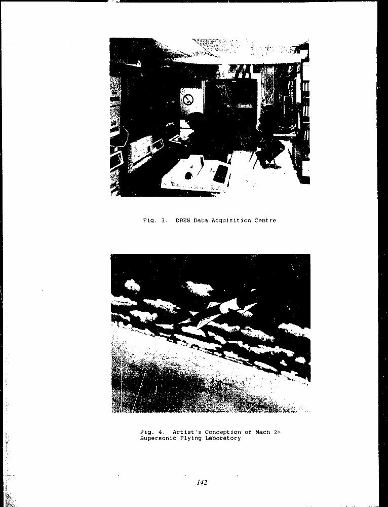
Fig . 3 . DRES Data Acquisition Centre
Fig . 4 . Artist's Conception of Mach 2+Supersonic Flying Laborator y
142

Third Coreerence on Military Ro`totic Applications Septenuher 199 1
Simulation of lightweight robots and their controller s
J .-C . Piedbcetrf and R. J . Ferguso n
11tochttnieal I?ugirtrrring* I)rf>arUne'ut, lit>J'+tl ;1lilittu'y' ('ull<'ge of ('au .ul ; . ,
Kingston, ( 'an ;tr,la {i71\ 5L 0
A bstrac t
1'his papt'r tlrsctih c :; the tlt'vt'lolttn<'ttt of a,inutl ;ttur
f(>r a rt rl e gr e< . of G>'r',lunl robot ><ith vla5lic juittt, and
flexible liuk, . We tlt'ri v t?l tht' tuu<I c l of tilt , t<>1wt witli
d ' rlltnthcrt' s f>rittci p l c ut<I we iuclu<I< '( I ho th ,tiff<~nitlt ;
and whtrl twntt'ntunt . Wt' also nllowt•<I fur i rlutit'<I kinc-
tn ;ttic iool, ht'twtrn ( ht' c 11 <11>uiut an<( tilt- wulking I>l a ut' .
\Vc tliscus m '<l ht irllti• tlterutttrul 1>ruhlrtu for Ilt'xilrlt' ruhuts
wht'rc tht' e'niif>uittt 411 t1 nut tlu' joint lut~ to 1><' cutttt o llyd .
To cuncludr, we tit'sc rih e ti Ille suilt' of ,>no gt' .>tns u=r<1 for
titis <lt•t<'lul>tnt'nt . It hus n lm lnit' ., for uto<! e I p,rnt'r,ttiun .
tnotlrl i irnnÏ ;tiiun un .J
Introductio n
Iniln,u i,tl iuhots ;iw~,t ilf t61 I : ntt~~i~'< linl:~ .+n<1 hulk
g"utuct t}' tu t'ttsurc ;a I>neciw I,u~it iuning uf t h<' <'nrl u dl'r< I t~t
ttsiug sintl>Ir' cuntUUl laws . Such ruhuts atr ,tow, u>:<, lart ;<,
acttlator :: .+nt! tnu"t Ill, nwdilit'<1 for cutuftli ;tnt tuutiun . "tl-
tt~rn ;tti~~rl~~, a robot with IigJttwc'ight links ~tn ;tllt't ,ic-
tuatut" will be f ;+stt'r .+ml li ;tw' mu t in,icall v ,'nttf>li ;tnt
bt'6aciotu' . Suclt ruhutti wotul<1 I>c ii 'cfti) to (,](,;u ntinrlicltl,
wht'r<' ht'a v v tubots all . u~t'lt'tiv .
l'ufur,tni ;lt<•1~', the 1le'ciLilit}ul Itt;lttttit'ight Itu6, tin
not be nrglt'ctctl tru<It'rittg nw<1<'ling tnJ cutittut nn" i<'
cumplt'x . :1 llt' N thlt' link is it tlistrihttit't,l 1> i ttautC tt'r, , \ .-
tctu, whi<It we rt'hrt~t~nt 1> v it "et of t,rditt ;uly ~iifGenntiltl
equatiuny nsing it Ifitz appru ;tc!t .
6ti'hile dewlof>ing tilt' ntudcl . we iuclu<I<A tlilfrrrnt rlfccts often neglcct<•d itl the litcrahtrt'.
1 . ' I'Itc• stiffcuiug cift'ct . Jlan1' tnurit'l5 uf II< x,hlr t'thut ;
atv valid only fur titnali .tngulat ~t'lu<i,it'~ (e .g . I1))
1>tcausE' the stifft'ttiug t'fft'tt is nwglc<ir'ck huwc't<'t .
<' wn at luw spt'c>I t(ii . r'ff<•rt is ituf,utt ;utt I,> i
with long links 121 .
2 . The whccl ntvntentunt . TO reduc<' tc>t<tl wcigitt, to
decrease Lite tnot.t>r velocitirs rtntl lit inctt'ast' t lit-tn
plic<I toryu<'>,, the n>- :urs are ctmnertc'â to thl, liiil,
:3
n~ing high ratio ;t'rlitrv r~ . "Iht'rt'fum tlir' :u1k ;ltL,r nt
,rnl~~ln ~~i Ill, n , .<lIU' to, tll<' fulul~ I, O ,+IIIIL' •
Itigh ' 1> v t'<1 i~ intl>ortattt .
('Iosrvl-kin<'tntntir luop . A robot rtaking contnct w'ti
it plant' f('1 Ill, it clutirtl ktnt'ut ;tti - loup . To sitnttl .tU'
tituh a sitnttiun we inclutlc tltr<ndpuint n>t .,ttaints
itt titi t•tlu .ttion .~ of motion u . ;iutr l, .+gt'rtn~<~'v untlti-
f>litrs . `üncc tliie nl m .hutl rryu~rt~s the .f ;tcuhi ;tn ;nttl
itw cl<'rivat iveti wr dt• v t'lul>t't! Ill 'nt fut it lira ihkc robo t
( :3!
Ih,' In<k of t;u-, ;l <uttttt>1 is th<' '>iggt'~t ul,wt<tcl<' to titt '
rn st• of lit;'tliwt-ight tnl~ots . I{aving it Ill (!(I in it !itst atep ;
y t't, lu exploit titis tnurl<') ;<u<1 to s i utltLt' tout roi f>ruh-
Irtn . w<' u e r<i a'ul>fti~ttt ;+t<•<I ,ïtn!tLttiutt progr .nn . Such it
t=tut;ratn ii~, ;tku tt,<'fttl tu <utnp.'tt<' , ulu<I< I c,itli tn r Xp rr-
Ilin9lt ;tl 5v',tt'lll ut tU iÎr•.Igil H Ilt'\ihlc luht,l .
1)ifft'rcnt gc n c t,tl t> ;ir p u." t' f>ruptant~ cxi5t fut ntulti
ho<1l~' s v st-nr- it,, t :'victci'tl I>~' tir!ii ;lhlt•u (IJ!lU) [ 1 ] . l't'w
of thr,<' f>togr .tttl " it .ui<Ilt' tl<'xihlc hutli<ti ttnti t' v t'n G'~+>'r
inclutlr thr :;till " : ~ .; rlft'<i . i3<'.i<6's tLu :,<' 1<rogr<ttn~ all,
tnon' cnicutc<1 tuv.,, ;<l <k'n ;itnics th ;ul towanl curttrAL Our
Itrugrtnt ha ,~ Ille turc ar the :,ut'twttt't' Ii010i1N1 clt,-
,i•lvltt' .I at tilt' I''Ittiir,l l,rlk'rr~it, of 11u .tich [ 5 ] . lit, .
llO13SI N I 1>rugr,tnt wa~ ~lt'signt~<I to si!tntlxtc thcit t'xI>cri-
tut'nt<tl ruhut anti nt'ctl c' l rt'}trogrunnting to lian(llo atltrr
tuLots We havr t,t•n<-t .tli /. t-tl IlOH51\I tu accrl>t .uty ruhut
withunt h ;tving to wtit<' ut'w nubtuttiu<~~ and rv<utul>ilt'
th r wltul<' f>i<,grant .
Mnde l
In this :4<'t tiun, wc <iovt'lul> tht'rtptetiun of lh<• t;t'uctel
t t{t>grrc of ft'cctlutn robot showu in Figure 1 . Flli :; robot
ha= tt,t, ri};irl Ih<xlit's nt <1 11 p, 1b' .\ ihlv hr>dio ;: . ~ : ttl>pose tht,
rtthut f>ussr's :cs n, jui'it~ with it, of thrm' jnittts hiikint .+,
Sunl<' clam icity . With each tkexibhc al Ill 1, WC IsSO(Iatc ?if,
gc'n<'r ;+lizrtl ruurtlinatr, . 'l'hcn, tIu• vrctur cf gt'nt'r ;tlixrvi
ct>ut<Itn ;ite's 9== (9 ! .4 ,, 1 , 4 1'j 1 dv~crihi's tlu' sy5lent c(nn-
~,I~ irly . Ihr tlitttrn,iun of' i ., tt == it, } n, + rt f w i t ,
143

tiliffeuitig, çlf<c t
1'here aie two tn c thuds I, , r takiug Itx , Stiffrni ;tK o ffect
into ac c uuttt . We eau use th<a x i a l clc•futntaticat of a flex-
ible liuk to ubtt,iu the runtinu ,tc, utode l as pa rtial clirfe,r .
cntial c yuatiun s [ i ] . The tnori el is tl•n aftt,ruxiutet e (1 by <tisc -t of c,nlinarv clüfc~t c ntial r q u<ctic,n s . Y<t, for ntorr th<>n
uue flexible liuk tlre partial difGe r v trti a l cc{uatiun :, Ixc curne
too c untlrlex and it is easier to inciudc• thi s effect tfrruugh
the kinrtnatirn 181 .
Sinc v we cuntiicl e r s ittaÎl d e furnt<+tions for th e elrt5tic
joint . and tlrc• flc•xihlc• ittk, we ticcvl th(' c•yut+tiuu , of' nw-
hguri' 1 : ,A o clct ; ; cr if freecluin rul,n ,
Nf "= r ," t ]If, . Note tll(It if li!~I,I I)U~11' ,l,H'ti not II,'~I I ,
Ittc\r it ci"gnr of ftc•ecfutn ; it car, be cntlly a tn7ss .
\1,•thc,c i
We wrir, . th( . nw,lrl rn~int.; i' ;AI,•u,l,ert'v tnincif,lo (fi ) :
,J ;r ., J,w, i w, x 1,w, - L lT ;
k
I~~-~Af .r) J
wh c rc• : O = rlO~dt, tf is u,+isti cruter ,c,c .lcrali„n, w i, the
angudal ,peecl, ! is the iuettia tenti<u', Tt" i~ Ilie f,o~ Iwn
w rt„r hct woou t Ite force ;urtl the nras . conter . .1 t ir, O w
Jncobian of trr+ttSlrctiun, J1{ is th('l .,col,ir,n of ruttitiut,,
lis the frutr'ntial Gtn<tic,tt furlite af,plic,l F " Is .,
non r„nsrn•ativc-• xl,l,lic .-) force, AI" is it nunr,-tnsvr\ .rtkc
al,hlic•d turyuc, II is il, c c~la~ti~ pn,teuti,,l tut tLw lic~~tl,l,
links LLtttcl F' f i ., .c fur(r nut inclucl,-+l iti I lu• t'lavtic' t,utcnt i .cl .
We rewrite the ;nudel (1) iu thc ti,lluwing cuntprc t
for nt :
A1(q)9 4 ,f(9 . (j ) = 13 T (t )
M E'k" .", f c'R" . B c: >?,, .,,, 7' ,,l?
., ,
witlt AI(q) lit(, nta .,s nrctrix, f(9•9) Ille nuniinei,r ccctur
of cctttrifut;al, Coriolis and gravity forc e ;, T(t) the % rctc,r
of control forces and B a selrrtiun nt.ctrix tcr al,l,ly flic
1 011 t 1,0 1 f>rce un tFhe juinl equntic,ns .
fit(' positions ; cncl vclucitics to the wrun,l urcl c t . If we tilt
uut ,l„ that the tuucl e l tni :;srs tit>tne tirai urcler tcunti and
is ttnstal,le for high tut .ttiuu til,recl .
'I ' h e sr c cmcl urcler tornr, rut,u , uult' ftcurn the flexible
link kiuematics, wlrich is ❑ ture cuntf,leN than tic, uur (If
it joitrt . Ileca„tme of the iutlx,rt.ance of these s e c„n d urcl"r
tcr,us we exl,lsin how tu St :crl the kiuvtn .rtic ntodc•1 of a
flexible link .
kinc•tratic nturlrl „f it tit{i,t robot is ahtaiur-d by
finrliug thc tcdatiun5 front une' joint to auc,thrr r v ritr~i~rl1 .
5irniLtrly w e w'rite fit(- kim•ntatic tuudel o f tltc, Itexihl<• link
s li„ %t°n in Fihunc '! Lç rrl,ttittK the ft,unv S, at thc link
CNttVntit v to III(, fraiu,, S,- t .,t tLv liuk rc,ut . We <t,,unue
thr+t cnci, tlc) :il,lc link „ntv>t,on,ln I-, it 13rrnuiJli t„c .,,u
itucl ~ee run~i,lr~r t c~~u fu~t f,c~ndic~ular hentiiut; di~f,lac~e~tnc~ttt~,
and I hc• torsion .
lrsing t he c utvaittms as cc,ut,linntes . tee ul,ts,iu ti :~-• tu
tati„n tnatrix fruin S, to S,-t and the vectot front the
orit ;in of $, ._, to lltr urigiu (If S, a, is, :{] :
1t ;S
,
1 t ~ l r ' ~ ` + ~ u'~) ! c,'r, " ,ly -u~' - j c, '
rtrr,,,r/ r 1-~(r~'~ +rt l ) -o - J t " rrr,d ,
rr' -f f crr c, t'°rr"A I- lfrr.,t n
u u
r- ~ jlr~'~+rr'')d~
-f f tr~"rt tll) r,~
( 3 )
u u !
u~,I ; i~"n drt d~ 1
w l e n , O' = rfO~cLr . 'File leaclint; sultersct'il,t i- I in ('t)
clen„tcti tlr;tt s (h-fineti in S, 1 . !t'ith the,e two
ectuations, we can contpute the contf>lete kit .errtatics recur-
sivrly starting from the roet of the robot . Note that, the
enf;ttlrcr velucity is directly related to the rotation tnrrtrix .
Ihc I n We c .,n icluply' (I ) to c>btain thcc cylatiolls of motion .
T lu~S e c•qnaliunti will n•fl ect th(- iuctr .c .m• itn stiffnv:<a Kit 11.iu ,g ular %*elocity .
144

The inclusion of the stiffening effect in the equation ofmotion gives nonlinear equations even for a single flexiblearm rotating in a plane . Some coupling terms also appearbetwersn the horizontal and the vertical beam deforma-tions .
Figure 2 : A flexible lia k
W r (!el rnornentu rn
Typically a flexible robot using harmonic drives as re-
ducers has reduction ratios between 1 :100 and 1 :200 . Thusthe angular momentum of the rnotor is important . even for
small inertia rotors . We need additional ternis to include
wheel rnomenturns in the equat'ons of motion .One might think that we only have to multiply the
rotor inertia by the square of the reduction ratio . Still
that is correct only for a planar robot . For robot with 31)
motion, additional out-diagor i al ternis , ppear in the massmatrix and other terrns also modify the nonlinear vector
f of (2) .A way to include the whee l snomenturn in a program
that does not have that capability is wi ~ at Chun et al
(1990) (9] call the brute force approach . It involves mod-
elirrg each wheel as a separate body and introducing the
appropriate constraints . Then for a robot with it, uro -
tors, one need to add it, fictitious bodies and as man,y
constraints .A better approach is to compute the additional ternis
required to include the w4:ee1 monrentum and add these
terms directly in the equations of motion . We suppose
that vie know the equations of motion for a reduction
ratio equal one . Then the ternis to add in (1) to include
the wheel momentwn of the motor a are :
iR .i [thj iCtq~ + X C,] +
S [rl?J,9. + r1,J~CT (JH.,9 + t~~ (q,4', t»~ (5)
S C `3i°,S J 0 if 1#'
(1)=l1 ifj= r
where ri, = il,., - I with Il,, the reduction ratio of motor i,
w, is the angular velocity of the nrotor i, c..w,(q, q , i) is Lhe
part of the angular accelerat :on of the motor i indepen-
Irul of q, e, is the rotn,tinn axis of the niotor r . J, = r',r1,c,
with l', the inettia tensor for the motor i and .1R,, is the
Jacobian of rotation for the motor : .
Constraint on t h e end poin t
A manipulator with a Lree-like structure and foires atthe gripper usually forms a kinematic closed loop, wlrichcan be expressed as a scleronornic constraint C(q) = 0 .
The problem of the inanipulator endpoint moving on a
plane surface (Fig . 3) is often met in industrial applica-
tions . For this case, we formulate the constraint conditio n
as :
nr(re -- `PY) = 0 mil =1 (6)
where n is the normal to the. plane on which the end .
point is moving, r, is the cartesian position of the robotendpoint, and rr, is the position of a point on the plane .The constraint (6) implies that the distance between therobot endpoint and the plane must be zero . To include
this constraint in the nonlinear model (2), we differenti-ate it twice with respect to tinte and we use 7„agrange's
nwltipliers to obtain :
145

W
I : .A lu!no t tnuvillg un il p I .ulr '
nl i qlïl t f(rj' .yl I \ ri ' J, (q) = 1; 'l'M
rt~ .l(q) ÿ i (9•4) 4=1 1
wllcrt' ,l't , is the .I .It ulli ;ln uf t rrul~l ;tt iou fur t llt' l'n'l
+ f f r ( t k )I . .A p ' t l l ' t , t l Gannul .l l i o II I( 'I t l l f . . l . t r J 6r1 u,lvti% a ti\ l'
fur dill' I I}~1i1 ot lll•XIIdc lulxtt 11 ;i', dI'lrlujrci! .,11 d II11 p 1[
'ont ro l
.A liw,ic as511niltt iom fui III,' t unt Iol „f ;I I ihid robot is
that if uuc i -III n,! . tII,' joinl . titi lu' kuon~ the c u,lll o lllt
1>u,itiun r ::art-ly' . T!I .It is brc .tuu• tll<'tc 1, n(, j'mnt c!,,~-
tililv It link 1lcXiLilit~fhiv in tlu• t(m l, it tllt • ~uc~~~S,~
of t Ihl• tucal 1Cr(lll,l(k(unt roi Mhl'rv• unlY !II(- jniut lru .it iuu
vltl it~' .tw G'(I l,,lrk .
Itv ( t~nU ;+~t, in it nohot with !)rsil)lt' link, or c ! ; : :.ti ,
"ints tflt' utlk' iulhUlt ;lllt 1-1111 i, tl- ~~,L„~ , •
"ftr ttu a joli we nlusi follow ngivl'tt ttajor~tur, ~ mtll t!u'
, !point : tllr l',int pu'itionti .ue tlun ittrle~ .lnt .
On-line
I-iKnrt' 1 : I ' lu' Innlti ..tag", (ntlttu l
witlt optimal gain I1] . titill, illcl . At the arc [lot
din'( t l)' ntr'rt"nr ;l{tlt ,~Nv nr r'<) an uit"t•t vrr and t bll'u the
014l''1 of the runtnolirr is higit . i ' ht' optimal n'gIll ;+tor is
With it 11cxil)lv I obo t . tc , ' ( ;III I1 ,1' ü, tuttin .~it lulnltll ;lnte'
to tut'a,ut'' tilt' G~t (v . l'fs ilfrr cl , I (l'Ntt)) [I I] ' I , nr
Sm n e ~tnllit'a au'l rxpt•litttvnt~ rm tlli, ' tl b jrtt . tiinri• t~llr
point ;ul it %n,rkinglll ;tut', tct'ran •autlv tlli, fnrwimuttu l
A ,tratt'gy' that i, wutking will oit III t"<pt'tinlt'lual
[()bol is th' . Ilullti .~tal;t' t'onrvI,t illll,ir .ltv~1 at F i~,nl c l
l) cclt tt ,t iutl _\q tu <onlltrn,ett' fut t llc' rl .ltit i, juiuts entl lmr
am l nti11711V~' I1,- tu!iul rildtiulllt dlutlll i l tlt c tlIulV'
An uitviou, suint i,m is to fr'e,l liartn lit- endl-i'It data .
IIoHVvvt r, the rrsultin}; systt'in tuas a nutl ruininunu l,ham .
tut ► ,t trp!Ill ;ltt,r with Ii t( ) purtik ,nal antl (1oriV .ItiVt' gaitta
( ► 'I)) gict'ti all unnt ;tlrlr sv,,tr•nl 1111] . I hl' tutr,t ► ,ultufAr
.II•ltrt, ;trll to tuntnol II!. .\iLli• tuliut_, iti Il(, a ;rtt' G'rilb,vl,
imltral tical fut t'slerinlc'ttiri', robots with nlurc than un<
juült
A lrronti'ing .Illpltl'atiutl with Nt•aih ► t' trl~nipulatut~ is
tlll I10rritl rutlUul . litai Is tlll' c"nttu ► of t{It' func anll
(I1 c ► I w iti" tl for tlll• l'illt! Ultlt . 1o titi t!I,tt l~ltll ;t tigill
Io!tut ~cv II~~~~• Io ad(I ,I iunlp!intli wtl,l it the "wllwillt .
ltl u} t,,nl ► n'rnlit , lit t utiuritlg 4un~t t~lint , Lt't wrt•u t llt' onti
[1 2 . 7t] . !ilt• Ill,t tllt• 11'l e I v il (c ttll i4t tiiil
41) iI~~Innitlg it I ip,i(l roh"t 'I'In' r, „u'l ,t Ilt ;e , i!( 111,11 c, t hr
tlc'si!Ilt' link, . 'I Iliti rt,rrrrtiun is tunlllu'c,I tln<t,i-~tiltira!It'
It}' kt~sInniug titi %t'lulitics ncrr xr(rk•rati<tns . This >tag('
lisl (1 in III(- Gnk' : . l'lu' tllirl! :;tar;'' nws tllt I(t•sin'(I joint
~alu~•~ g,~ to cuulpIltr III(- ti'~•tlfur~crit~l tulqnc, 7'n . Ou! t'
iht tif;itl nw'ieI is u5 t'~! tu do tll .lt . Ille ültit tllrt'c 't"t ;rs
ut• til<• nlu'.t tllu~' tu :l,ulniu~~• ,u1~1 .ui' ~'~~'clltr~l u!f i~n~' .
I IwoII Ililt' pdlt of two rcgU! .Itui~ : tllf ' )o1111 i'~~1 1
i l lIn l the ilrxt! lc luntlul . I lu' t~co IS' ;,11!~tt l~ .(,III
Iwll' ;att• fol t!Ir IcIn ;lininP, ~Iltl .ttion .n"lln .l tlu' U .Ij'•t 1,)l
`~Ilrlluk.l nntl ! ;uk!rtlLrrg I i'.tti!)) f 1 :{] ;tn'l Uc Lm .t .ul'l
~ïil'ilirtnu ( [1 11 e! 'u hrtw' studis•(i in tlt t ;tik tlla• II'~'~1
fvl~tnl~l ttuil tlw il .tjr4 tor)' (I)nttul 'I 'd ~in,+;lC liu! : flrNi!dt '
Fedd=forwardUsing Rigid Model
FlexibleCctntrol

`l'he_softwar e
Figlu't' ., sltutc, till• gt'ut'r,tl ~tlnrtille of tln• I,rut'•t•11u .
I'}u'suftovttit• i~ ,1 ~t't of t,lutlulilr h rlran .Inll (' I,n,gtnuu,
inthat worl. intll•I,otnlt'I,tty' and lolntnlulltntl' it st's II t !
tl'1 frlrr till'I . :Au alltiit i•,u„I .,,nuht t oit ,'sint, itou II A1 :A
(I. .\li
Modules of Flexible Robot Project Software
DataFile forModel
GeneralDataFile
foooeP ,Generàtion
Data Filefo r
SimulationI
- Z+Model
Simulation
Report Fi1e
1 File o fFiexibiiity
Data
r
MATLAB File(Linearized
Model)
Graphics ~fM~nu
Graphics"Output
~System
Analysis Scree n&N.
PostscriptPrinte r
11u' littfe t('nl nlullul .~~
\V<'t1ivitll'thcsoïlu'arl'itltkr 1111 ro, Ill .tin tnutlull', : Int„It•I
~ent'ration, Si n,l,l,ttiull :tn,l an,ll,r',i, . AV '1' ~cl,lti' 1111• lit .,t
two rnoclttlrs in i"urtra ❑ tvhill' tllt' tum ultllt• thinl Il ;orl
Itlt• is the ,,,tnutt'rci,+l aufmarv' t,alkak;t• \1,\'i L .\13 . I II,'
I,t'uf;rtnt " run un rAI,ullu i lnd Sun t~,nl:,tatiull,' .
M o d l' I r;l'tu '1 at i utt I'hr nt„Ilrl ~/ nl'rrlt i,m r•llt ulatl' , 111
tilt' pnratnt•tt•r~ nl'1111'ti tl, t ;,'nt•I,ttt' , 1 nu„I,'I II ;~ .,,'It ,~II I III
~It'scriPtll,n hl v ru l,.~• tllr n,l•r . I'lll' nt,llu ; ,alt of' tht' lo t
qrattl slrvts tu (;1'nt'I,+ir iht fll'~iltility ~l~lta . I II,' .1' 11,11 . 1
t'o [Isis i rnainlY of it sit uf i t t t e g t ' ; t l h u i t tirl',, runtl,l„rd
~I,,IrI• 11,'I w n d ,'nt funttlun< GnIln I{iti II~
rl'nlllt s of' t111' niwll'1 ~„cnl'Intil,n :ut' ttc,l 11 a It~ tllt' :, p I11, ; l
ny,ln t file.
\1,,,1eI_ Siililil . tt O,tl II1,' nnnuletl„n nl,,,lllll• f,l• ; II lit, n '
tlll,lll,l'IIIFÿ tli[' Illl,tlllll , I ; I lf• ;II I,tl,lll . I„ Ill, tllill lltl' I)Il ,
gtaun nuk-l ., tll,' inll u„nliul' .u t,l,linturv ,litlt'1,,lit l•11 rtlll<,
tiuns using vatial,lr,tl'I„izl',tlt.',<nitllnn . Slill tlll• luntiul
is runll,lrit'll ut ,1 ,,lln{Ilitl'„ ratr rllt,u'n I,~\tlit, 11,1•r . l'lll'
sitnulatiun is tllrn ntuel' rl <Ili'tic I11'rau>r it Irfor ullull .• tLr
t„ul,it'n,, 1•xi~tlnt; t,.'itll digital 4t,ntn,l . The u,rr I .ln ~t't
Ili(ir'rl'nt 11 .1y"; to tlrtitll' wllicll It,ntr„I will Lr altl,lil•,i . thr'
1vi,l' of 11 ajl'rt urv . II . htl't'rl't,' t 1 tl jl'rtl,ri,', toi'it II ,li1f,'11•11t
II 'ltrullt'rti l' ;nl c l,nllw,l' it ~inlltl,lti„n .
.\ ualv si< l'll,' Aul,lli, Inu,lnl,' II,1 " \1 :1I LA 11 lu I,rt
fut ln liuwau ~v~it'nl fin' 1111,111 ful A1 VI I . .Ali is
i t nl't of' Inurll'Iti Ilul' auülvl illulul,l tlil' tlllfl'll'Itt I,uiut, -oft}It' trajt•ctutv . AV'r It,r• tlli~ :nurlnll• to liglnr ('111 fit" St ; l
,t,iltll,l l /'tl l ( 11 l'\iillilill', \\l' flllll tlil' Fÿ,lll„ flll ,I I ' I ) 1 1 k'I I
Itltul Il,Sing \1 .A II, .Ali anll tlll•n tl' :,1 litait o•.Itll tllr 11111tuutlrl u~illg tllt' ..ilnlllntiun ululiull' .
I) ;Ita illl>tl t
'I Ilt• Iltil'r intt'r,tl ls with tlll'sufttc ;lrt at dut' It'vt' 1 , : !~,1
tnutl,'I };t•ul'rniiull, tut tiinnlLltiun .lntl f„1 e ;l .,llllil, . W Ilt' u
It t ulnl'Y to hllllf,lvillg 1171ta It, 17,nllnttl't I)t1, g rRlnt+ tlu'tl' i s
nu i111'a) sull,tital lot l'tl'r v <' ;1ti1' . Au uu,• lik-+ aultit :l'IinF ; a
long srrirs (of ynr~tiun, Inl',rlltl•tl unr nfter ,ull,tll' .'r . 'flli,
is lrlll'<i,lli~~ tlnl' \chl'n it Ini11,l{0, n ;t'an,, ,I , uling Ilu' ;,lu
icvlln'r o v t•t' again_ "Fill tlu' I,I,ulk" In,'I,u, or nlrull, ttiiill
hoirrs arc' iii lit, LIII 1111' N ,tllirÎ.l\' Lr,uln,' ir & on>, tclll'tu
he rl ;uuunt ui tlltt ., is I<tlgl' .
\1'hl'n ulan v data no-1•d to L c input fit,, trlll,til,n .l! lat,,
fill' is . t good >ulntio,l l'sll'I,t tliat nu,ll III(" ,ul' di(firll!t tuI,ri'lt,ln• tt'ithulll 1•tl„r aull t!iilitult to Irtlll . I~I,r thl•,Ilitl'uf I,1ut;l .lulti ill ! he flrxil,lr 1„Ilut I,lujr, l . ~ w rll ' w,r tu
It,r the uun,t .lu,lntll V,nll,ul IjO G' g Itlu ' ' \ .A11h:1 .151~ .
\1'itll t+.t'll Illllst'll v .uial,l - ' n .unr" , ~n int'~I,1ti,'nt~11 11,1'I, Illl nltr(lilY tlv' at,lntl,lnl tt'nll,l ;ltl' hlr t ., lut tlll' I,I"LII'tn
itl hslnll .
I ' IIt' ( ' X alnl,lr in Vip,lul• t o i, ,1 I,urllun uf thr illllut
Illr ~,Ilutving I wn A-\11I' ;IJtiT S : S I Ii(i .Al' ,In,l 11' IJ1('1I :Ali\11 vtllinh rill}; I,ut'idl• tl n .nnl'lla . tcllich ir, lir•litnitl•11
1, v M, is not 11' ;ld h,'r III- I,rugrutll . AV'l' u, ( ' tins til,Mrr tt)
,tritu sottie It,lulrn'r,t :, to tiui,ll' the 11 "1'1 ,n I,t,illt tl, hl•!t,1i11' ~
Data 0111pil t
W1' du tllr' ( i i lt a ulttl,nt 11>ing Itntllr~' lill'St'xtrllt for thl'
rhl,,,tt file" and lhr \1 .A'l'1, .11i fill' . I`III'sinntlxtl)r ual•s tllt'
(output iill's fltlnl tlu• n1u :11•I grnl'I ;ttiurn anll creatc ., pilotfilt'~ We tt'1•ilt illt•tit' I,111t filt', tvitl : nutttht'r I,rl,gltttn 11 ,
, . r,lrl,'Si,lll 1..',nllthil ., t,n Ilifft•r,'nt outputs . lutt' t If(- intt 1
147

Strain gauge characteristics
see '"/robot/include/strgau .inc'
for a descriptio n
$3TRGAU
STGCHA(0,1) s 1, STGCHA(1,1) = 1,
STGCHA(0,2) - 1, STGCHA(1,2) - 1 ,
STGPOS(1) = 0 .2, STGPOS(2) = 0 .2,
â
SIMULATION DATA
The vector of parameters CIPAR and CDPAR
are described in '-/robot/include/ctepar .inc '
SSIMCHA
DEGREE = 1, 1
XMO x 0 .0, 10 .0 XPMO = 0 .0, 0 . 0
TITLE _ 'Robot F2 simulation'
PL1'FIL(1) = 'simul .plt'
PLTFIL(2) _ 'endpt .plt '
CIPAR = 10000 CDPAR = 2 .
$
Figure 6 : Data input using NAMP;LIS'T s
faces exist for MA'I`LAf3, and for 1,0(,(-)S and GRAPH
shareware workstation softwares from University of Illi-nois and from ADUS (formerly Apollo 1)oinain Society) -
114c plan a 3 1) aniniation iuodulc .
Conclusio n
This paper presented software to simulate a n degree of
freedom robot with elastic joints and flexible links . The
models included the stiffening effect and the whe+, l mo-
mentum that are often neglected in the literature. The
program also handles closed kinematic loops using La-
grange's multipliers . To do that we developed a general
formulation for the Jacobian deriratives .We can test any kind of control with the program . One
promising strategy for real-time application is the multi-
stage concept . In this concept the feedforward torque ob-
tained from the rigid model is corrected to consider the
joint elasticities and the link flexibilities .
We divided the program in modules that co mi nuni ( ate
using files . A fi rst module generates the model while the
second realizes the simulation . A third module uses the
MATLAB commercial software to make Gnear analysis
and control design .
This program is being used at the Royal Military ('oflege of Canada on Apollo workstations and at the Ecole
Polytechnique de Montréal o n Suit workstations . We en
v i sage possible use in graduate co u rse. Plans for the pn ,
grain concern the addition of a 3D animatiou . We also
want to include different controllers to make extensivecomparison . We equally plan to connect the program with
a real-time application on experimental robots .
Refçrençes
(1] R . H. Cannon Jr . and E. Schrnitz, "Initial experi-ment on the endpoint control of a flexible one-link
robot," The International Journal of Ror,otics Re-
search, vol . 3, pp . 62--75, 1984 .
[2] J .-C . Piedboeuf and R. Hurteau, "Modeling and anal-ysis of a two degree of freedom robot with a flexible
forearm," . To be published in : Canadian Journal of
Electrical and Computer V.,ig in ce ring .
[3] J .-C . Piedboeuf, "'l'he jacobian and its derivatives fora flexible rnanipulator," . In preparation .
(41 W . Schiehlen, ed ., Multibody Systems Handbook.
Berlin ; Springer-Verlag, 1990 .
[5] K . Richter and F . Pfeiffer, "Software package RbI3-SIM for the dynamics and control of elastic manipu-
lator," Technical University of Munich, Sep . 1989 .
[61 F . Pfeiffer and H . Bremner, "Elastic multibody theor y
(71
applied to eiast,ic m :+nipulators," in IU'l'AM Sympo-
siur~a on : 1)ynantical Probir ;,ts of Rigrd•Rlastic Sys-
tcrns a nd Slr u ctur t s, Moscow, May 1990 .
J .-C . l'iedbtruf and R . Hurteau, "The use of Katie'sequations to write a continuous model of a flexibleiobot as a step toward a discrete nnodel," in Dy-
namics of flexible Structuns in Space, (C . L . Kirk
and J . 1 . lunkins, eds .), pp . 305 319, First Inter-
national Conference, Cranfie:ld, UK, ComputationalMechanics Publications, Southampton co-publishedwith Springer- Veilag, Berlin, May 1990 .
[$] It . !ohanni, "Aut.ornatisches Aufstellen der Y.e-
weg,angsgleichungen von baumstrakturierten Me:hr-
Urpersysternen mit elastischen Bauteilen," Tech .
Rep ., Institute B for Mechanics, "I''echnical Univer-sity of Munich, 1985 . Report 8501 .
[9] U . Chun, J . Turner, and II .P .Frisch, °Recursivemultibody formulations for robotics applications
with harnioni- drives ." . Presented to : Internntinyr,, ;
Conference on Dyna rn ic;• of flexible Structurts in
,ipace .
[10] J .-C . Piedboeuf, D . Dochain, R. Hurteau, and K . Eie-
nameur, "Optimal control of the tip of a flexible
arm," in C'anadran Conference on Electrical and
C'ompufcr Engineeri ng, Sep . 1991 .
148

(11J F . Pfeiffer, K . Richter, aiid H . Wapenhans, "Ela,-tic robot trajectory planning with force control," inIFIP International Syrnposium on Theory of Robots,Rome, Italy, 1990 .
[12] F . Pfeiffer and B . Gebler, "A multistage-approachto the dynamics and control of elastic robots," in1988 IEFF International Confe re nce on Robotics andAutomation, pp . 2-8, Philadelphia, PA, Apr . 1988 .
(13j A. Shchuka and A . Goldenberg, "Tip control of asingle-link flexible arm using a feedforward tech-nique," Mechanism and Machine Theory, vol . 24,pp . 439-455, 1989 .
1141 A . Be Luca and B . Siciliano, "Trajectory control of anon-linear one-link flexible arm," International Jour-nal of Control, vol . 50, no . 5, pp . 1699-1715, 1989 .
{15) MATLAB, MathWorks Inc ., 21 Eliot Street, SouthNatick, MA 01760 .
149

TL :rd Corrference on Military Robotic Applications
THE RESPONSE OF FLEXIBLE MANIPULATORS TO A NEW COMPUTED TORQUECONTROL STRATEGY : SIMULATION RESULTS
September 199 1
T . 1) . LookeElec & Comp Eng Dept, Royal Military College, Kingston, Ontario Canada K7K 5L 0
M .M . Uayoum iElec Eng Dept, Queen's University, Kingston, Ontario Canada K7L 3N6
M . FarooqElec & Comp E:ng Dept, Royal Military College, Kingston, Ontario Canada K7K 5L 0
Abstract
The need for faster and lighter autoncmou sand teleoperated robots, especially in militaryland, undersea, and space applications, requirescontrol algorithms which account for the elasticresponse of lightweight, flexible structures .The numerical analysis and testing of thesecontrol algorithms further requires accuratesimulation techniques . The finite elementsimulation method generally yields very accuratepredictions of the transient., dynamic response offlexible structures to applied loads, However,this method is usually used to simulatestructures subjected to known constant ortime-varving loads and not to simulate feedbackcontrol algorithms .
In this paper, it is shown that a standardfinite element simulation package may be used totest computed torque and adaptive feedbackcontro] aigorithms for multi - Iink flexiblemanipula tors The response of one and two linkflexible manipulators to computed torquealgorithms developed by the authors is alsopresented,
Introduction
The dynamir.s of flexible robots are governed bynon linear partial and ordinary ciiff'erentialequations for which no direct solution techniqueexists . Therefore, to validate (and/or analyze)the stability and PC: for malice of controlalgorithms developed for these systems, it isnecessary to either numerically simulate or buildthe robot structure in question .
The mosi common modeling approachea fornumerical simulation of flexible robots are themodal analysis and the finite element methods(1] . In the modal analysis approach, the shapeof a flexible robot link is assumed to be givenas a sum of weighted characteristic functions,each of which is defined over the entire link
domain. The link shape is then described in
terms of ordinary different.ial equationsgoverning the evolution of the magnitude of eachcharacteristic function weight . In the finiteelement approach, the link domain is discretizedand the link shape is given as a chain ofcharacteristic functions, each of which is
defined over some interval of the link domain .The ent+.re link is then represented in terms ofordinary differential equations governing theevolution of the characteristic functions overeach interval of the link domain .
The modal modeling of multi-link flexiblemanipulators for simulation puraoses has beenadd-essed thoroughly by severr.l authors [2), [3) .These methods yield fast and accurale, simulationalgorithms, and are especially useful if thecontrol objective is to compensate for theresponse of t.hc, elastic modes . However, thissimulation approach is relatively new, leavingindividuai researchers to dEvolop their ownsoftware inplementation and verificationstrategies .
The reliability, versatility, andportability of the finite element method is wellknown . This; simulation approach has beenstandardized since its inception in the 1940's(4), and numerous commercial packages areavailable for esimulatirg flexible structures . Inaddition, the finite element model very closelyresembles the physical construction of themulti-link flexible robots and yields localdisplacement and stress data which 1s requiredfor the computed torque algorithms developed bythe authors .
In this paper, computed torque controlalgorithms are presented for flexible robots .Then a simulation approach bascd on the finiteelement method is proposed and the response ofvarious fle,x'.ble robot configurations to thecomputed torque algorithms is given . The ANSYSfinite element program (5) vis used to build an,isolve the finite element model described in thispaper .
Flexible Manipulator Nodel ing and Contro l
The fult order, nonlinear', dynamics ofmulti-link, flexible manipulators with revolutejoints i13 given as follows :
D(q)q + C(q,q)q + g(q) = Sz (1)
where q is the infinite dimensional vector ofgenerali ._ed coordinates which includes thevariables describing joint, and rigid body motions(rectilinear and rotational) and the variablesdescribing link elasticity ( measured relative t o
150

the rigid body) for each link . The terms D(q)and C(q,q) are the inertia andcorlolli,./centrifugal effect matrices,respectively, and g(q) is the vector derived bytaking the partial derivative of the systempotential energy functional with respect to eachgeneralized coordinate . Rigid-link robots
generally have one controJ. input for each degreeof freedom, while flextble-link ribots, asmodeled here, have one control input for eachjoint/link pair, and thus the input matrix, 8,for flexible robots is of finite rank and
non°invertible .A detailed analysis of the dynamics of
flexible robots and the development of equation
(1) is given in [b] .
passive Feedback Control Objectiv e
It is well known that when ac:tuatorr .
(inputs) and sensors (outputs) are colocated Inan e, astlc strttcture, then stable feedbackcontrcllers are easy to design . It is one of the
goals of this study to develop a nonc.ol.c.cated
controiler design approach for flexible
manipul , ors . To this end, the following control
objective Is adopted :
The torque control objective is to ensurethat an error vector• representing colocated andnoncolocated parameters converges to zero, whilealso ensuring the boundedness of all other
®ignals .
Computed Torque Controller
it is shown in (61 that when all system
parameters are a s s :.!med to be known exactly, the
fo llowinF, computed torque control algorithm will
meet the control objective :
i= 93y llID(q)a t C(q,q)v + g(q) - Kv"i3yr) (2 )
where 1), C, and B are as given in equation (1),
$9 is the generalized inverse of n3, such that Cy
1($' and R = 06 ' 13 ) 1 (' is the adjoint
oper'ator), and r e 12w (infinite dimensional re .rl
vecrors) . The feedback vect.ors, a, v, and r a ;e
given as follows :
a at %3iCa - KR(s)(E) E3~) K(s)cj 1 .3)
r = ( l - v =(s + K(s) 1 e (4 )
where F is the vector of actual joint ani,les
(colocated parameters), © is the vector ofnoncolocated parameters (to be defined lat,rr),K8(s) eP"x"(s) is a full rank transfer ma'.rix
and e is the error vector', which can he defined
as follows :
e= (C - Cr) + KR(s)(o - or) (5)
With the controller as defined in equa ion s
(2)-(5), it Is shown in (b) that the foll)wing
convergence and boundedness properties (which
meet all of the control objectives) are obtained :
• 11 r 1[ ?(t) e L.
e E 1 ." n L." and e-> 0 as t -> aoz w
eE L" and e-~ U as t a w2
Flexible Robot. Finite Element s
The ANSbYS elastic beam and rotary jointclement models were used to simulation th,~,tnr,rlti••link, f lexible robots presented in trispaper . The following brie,f descriptiors aregiven concerning the characteristics . . theseelements . For more details, see [7) .
Elastic Beam Elemen t
The elastic beam element is a uniaxlal
element with tension, compression, torsion, and
bendirrg capabilities . The element has six
degrees of freedom at each node : translation In
the nodal x, y, ard z directions and rotation
about the nodal x, y, and z axes . The displaced
element shar,~ is given as first order polynomials
in the axia : displacement and torsional rotation
and as cubic polynomials in the two transverse
displacements . The following parameters d,.-fine
the elastic beam element for this study :
E : Ftateriai Elastic Modulusp : Material mass densit yA : Link cross-sectional are aI Cross-sectional area musent of inertia
about the element z--axis
I C.ross-sectional rrea moment of inerti ayy about the calement y-ar.i s
l'K : Element thickness along the elementz-axi s
1K : Element thickness alor,g the element
y y-axi s
Joint F.lemen t
The Joint elernent is a three-dimer:sional pinfor revolute) joint which may be used to connecttwo or more parts of a model at a common point .
The most useful capability of this element is thelarr,e defle,ct'on (pinned) response, in which alocal coorciinate system is fixed to and moves
with the joint . The two active nodes of thiselement are used to represent the rotor, andstator of the robot joint actuators . For thisstudy, the joint element is assumed to befrictionless . 'ftre following par=meters definethe joint element :
M ; .loicrt mass (evenly divided betweenrotor and stator )
I : Joint mass moment of inertia about thez-axis (evenly divided between rotorand stator )
Simulation Result. s
One-Link Robot Simu lation
Robot Structure .and Pararneters : The one-
joint, one-link man .ipulator with no end mass, as
shown in figure 1 was simulated . The link/joint
material properties are given in table 1 .
151

Figure 1 . One ,Joint, One link manipulator with noend mas s
Table 1 . One-Link Robot Table 2 . One-LinkLink/Joint Properties Controiler Parameters
Aluminum Alloy 6061-T6
Parameter Value
E 69 .0 GPap 2 .7 kg/m3
T 0 .1 m
TKÿ 0 .006 m
ZA 0 .0006 mi 1 .8x10 9 m {~~
-7
4I 5 .0xl0 myyM 2 .0 kg
J 1 .0 Yg-mZ
Parameter Value
r 0 .5 radd
r 0d
9 0.5 ra dd
0 0dd
ke(s) -0 . 5
k(s) 1 . 0
T 0 .01sec
Computed Torque Control Algorithm : The
computed torque control algorithm, as given inequation (2) may be expressed as follows for the
one-link robot :
T =2
3 + My(0) - rr(0) Vy(0) - kvr (6)
where 2 is the rotor inertia . My(0) and Vy(0) are
the link bending moment and shear force,respectively, measured at the joint attachment
point, and r1(0) is the radial moment arm from
the link attachment point to the joint center of
gravity. For this simulation, the joint elementis considered to be a point mass, and thus rr(0)
= 0 .The feedback control variables of equation
(6) are given as follows :
a - v dtl,d-k©(5)(0--ed)-k(s)e~ (7)
r _ r -lll v = ( s + k(s)le (8 )
where r and rd are the actual andJ deSired joint
angles (between the stator and the rotor), 0 and
6ddefine the actual and desired link rigid body
angles, and e is the error function which is
given as follows :
e = (r - rd) + ke(s)(e - Hd (9)
Simulation Results: An ANSYS finite element
simulation was conducted for the one-linkflexible manipulator with parameters given in
table 1 . The controller of equation (6) wasemployed with the parameters given in table 2 .
For this simulation, the kinematic angle, 8, was
choeen to represent the angular position (inradians) of the link tip as shown in figure 1 .
The flexible link simulation was conductedusing 100, one dimensional beam eleme .%ts. Eachof these elements had two active nodes, each ofwhich had six degrees of freedom (except for node1 of element i which was constrained to onedegree -if freedom : rotation about the z-axis) .Since tn>e hub torque represerrts a loadingsingularity, the ela.nents were chosen to be ofnonuniform ?engt2h, with the smallest element
being element 1(at the manipulator hub) and thelargest element being element 100 (at the linktip) [4) . The element lengths lncreaseduniformly from element 1!o element 100 (which
was 20 times the length of element 1) .CLased loop torque c(ntrol was simulatPd by
running the nonlinear, dynamic, finite elemeatsimulation with constant hub torque for a sho :t
time Interval, T (the sa,epling period) . Then,the nodal and element data was postprocessed toyield the new controller torque value, and thefinite element s1mulai.i-.z, ,ras restarted for thenext sampling period with the new torque value .The sampling period for this simulation was 0 .01seconds (as shown in table 2) .
In postprocessing the nodal and elementdata, It was necessary to compute the timederivative of certain variables . The followingdis:.rete algorithm was used to approxirpte thetime derivative of a varlable at the k sampleperiod :
where
y(kT) _ -br Illu(kT)-18u((k-1)i')
+19u((k-2)T)-2.u((k-3)"i)I (10 )
y(kT) s -â~u(t)t=kT
(1' )
Simulatior, data was stored after every tenthrun (every 0.1 seconds) . Figures 2-5 show theresponse of the one-link flexible robot to thetorque algorithm of equation (6) .
a !
ô,R
1 1 ~ I 9 ~x.W, i
Figure 7_ . Tip response o,- one-link manipulato r
152

0 .1
~ , s , 9 ...o .e . .
Figure 3 . Flub response Pf one-link manipulator
Figure 4 . Applied torque for one-linkmanipulator
L.~., ..r-----~ ~----------_.
Figure 5 . Beam shape after .1 second
Two-Link Planar Robot Simulation
Robot Structure and ParamFters : The
two-,Joint, two-link planar alanipulator with no
end mass, as shown In figure 6 was simulated .i'he link/,)oint material prcperties are given i ntable 3 .
~~~_-_
~ r, ~ i/ ~ _
i
Figurr. 6 . Two joint, Two link manipulator with no
end mass (planar)
CorpupA Torque Control Algorithm : The
computea torque control algorithm as given inequation (2) can be expressed as foiiow:; for the
two-link manipulator :
I7 1
112~ P. J ld
1
19212
(12)
Joint ! l- 1 stator (x = Li) attachment points ,
where g ar.d g are defined below .1 2
=g1 M yl (0) - r I (0) V y1 (0) (13)
g= M
y(01-r 2 (0)V y2 (0 )
z r+ M (L1)+r (l)V (L1) (14)v1 I yl
where Myi(x) and Vyi(x) (i -- 1, 2) are the l1n!• : I
bending moments and shear forces about theyi-axia measured at the Joint 1 rotor (x = 0) or
rt(0) and rt(t) are the radii of the joint i
rotor and stator, respectively (assumed to bezero for this simulation) .
The user defined, control parameters ofequation (12) are given as follows :
a = v dc(fd--KO(s)(0-9a)-K(s)e )
kOt1(s) k01 (s)II01 Odt
k (s) k (s) ~()2 -91 02.2 0 2 d2
k (s)k (s)11 12
k12
(s)k22(s)
= ( sI + K(s) ) e
s+k (s) k (s)11 1 1
k (s) s+k (s)11 tl
e
(15 )
(16)
For this simulation, the kinematic angle vector,
200, one dimensional beam elements . As in theone-link simulation, the elements were chosen t o
Simulation Results: A finite elempnt
simulation was conducted for the two-link, planarflexible manipulator with parameters given intable 3. The controller of equation (12) was
employed with the parameters given in table 4 .
9, was chosen to represent the angular positions
(in radians) of the link tips as snown in figure6 .
The two-link simulation was conducted using
be of nonuniform length, with the smallestelements placed closest to the joints and elementsizes unifor,nl.y Increased as a function ofdistance from nearest ,!oint . Therefore, thelargest element of 11n4: one wz~ the middleelement, while the largest element of link 2 wa,sthe last element (at the tip of link 2) . Closedloop torque control was simulated in the samemannsr as in the one-link simulation .
153

Table 3 . Two-L_ink, Planar Table 9, fwo-Link,Robot PropertLes Control Parameter s
Aluminum Alloy 6061-16
Parameter Value
69 .0 GPa
37 .7 kg/m0 .i m0 .00C f o
0 .0006 m -
1 .£ix10
S .Ox10 7 m 4
M1 ~ joint
J1 I
M . l joint1"l. J z
Paramet.e r
l' a
it
KO(ti )
K!<a )
1 .
Value
(t
() ~
0 .5
-0 .5
( J
~ p0 . `i 0 ~
0 -0 . 5
1 .U 0
Il 0 1 .0 1
Figures 7. 12 show the response of thetwo- link f lexible robot to the torque algorithmt,of equations (1?.) -(17) .
l'ipure 9 . 30,11t one fesPoIISII(tw,rlink planar manipulator )
o 1 4
-o ,
o I t
n • n
figure 1 0 . Joint two responsemanfnit sr„- 1(two-link r'l-ins+ r
Figure 7 . Tip response of linkFone(two-link planar manipulator )
e c
0 2
-a z
Figure 8 . Tip response of link two(two-link plana : manipulator )
` . .
Ï r.--r -,-TT- T5 1-. 6 1C , y
MC
,,. ~ I. 1 f P ~,. . .Ta
F:gure 11 . Joint one torque(two-link planar manipulator )
c .ie
o .i
o a s
oi
_..'^_-T T
~,I11 1
0 0 __~_r.-1 re T,-T ~- r
Figure 12 Joint two torqu e
(two-link planar manipulator )
154

Two-Link Ncn-Planar Robot Simulatio n
Robot Structure and Pzr remeter® : The two ..
joint, two-link non-planar manipu .ator with no
end mass, as chown in figure 13 Mas simulated .
The link/joint material properties are as give n
in table 5 .
F'lgure 13 Two joint, Two link manipulotor with
no e . rd mas s
S i rxn.rl atton Keeultn : A fintte elernf'ent
simulation was condu :`.ted for the two link,
non-planai fIexlblemanipulator Witt' palain0f-,fsgiv-n in table 5 . The controller of equation07) was employed with thc, parameters given In
table 6 . rot this simulation, the kiuem~rtlcangle vector, o, was chosen to rr :presvrrt, the
angular positions (in radians) of the llnk t.ips
as shown In figure 13 .The two-- link non piancrr simulation was
cunducted u ..1ng the same clernent distribution as
In U.e two-iink planai sirnulat)on .I'1 gure , 14-19 show the r,esponse of the
two-link, non-planar flexible robot to the torque
algorithms of r:"{u<rtions ( 12)-(17 )
Table S . Two-Link, Non- Tahle 6 . Two-LinY„I'lanar Robot Properties control parametersA luminum Alloy 6061-T6f'aramet.e r _ Va1ue f'aramtr --Value
1L both 6
9_0 GPa 3 ( 0 .5JI> I(
 link 0.0006 mam 0'5
71C 0.1 m 0 lTK
11 0.006 m f' JI
y' linkl 1 8x10⁻⁹ ma `t
0
0 .51zzt
1-0 .5I YY1 S .Ux10
7mt Oa jj
TK 0 .006 mTKL2 0.1 m 0
I Yz 1 1 nk25 . 0x10-r m4 ©a 0
zzz
IyY2 1 .8x10 9 ma K(s)
0 .5 0
M1 10.0 kg 0 0 0.5
Ji }Jointl 5.0 kg-mz 1 .0 0
M2 }joint2 4.0 kg 2 K(s) 1 0 1 . 0 1
J2 2.0 kg-m T 0 .01 --1--- is- 1 -r - 1 -- i '
Figure 17 . Joint two response(two-1in't non-planar manipulator )
Figure 14 . Tlp rr,spouye of link one(two-]irrk non pianar manlpulator' )
I
1 1- 1e ~e ~ . . . .
l'igur e 15 Tip res,hone,e of' t it!k two
(two-Ifnk nv7n-plana.r mantptilator )
Figure 16. Joint one iesponse(two-link non-planar manipulator )
155

tigre 18, Joint one torque(twoifnk non- planar mttnipul<ttor
n . t
o u
4 ] ,
e , e
C ~ s
1 7 .
➢ ,
Figute 1 9 . Jo'nt two torque(two--link notrplarnar mani{,ulalc>t )
Conclusion s
A very general computed torque algotithm formulti-link, revolute joint, flexible robots has
been presented along with a finite element
simulation approach. Simulation results of the
response of one and two-link, planar andnon-planar, flexible manipulators to the proposedcomputed torque algorithm were obtained using acommercially available finite elemont package .
These results clearly show the usefulness of this
new computed torque approach .As reported in 181, further simulations
osareed
currently being conducted to test pi p
adaptivecontrol algorithms for flexible
manipulators .
References_
[1) H . Kanoh, et al, Modelling artrJ Control o f
Flexible Robot Arms, in Proceedings of the
75th IEEE Conference on Deci sion and
Control, 1986 , pp . 1866"70 •W . J . Book, Recursive L.agrangiatt Dynamics of
Flexible Manipulator Arm.s . TheInternational Journal of Robotics Research,
vol 3, No . :3, pp . 87-101, Fall 1984 .
131 J O. King, V . G . tiourleiiank:rr, and 11 . E,
HSnk, L.. .rg rang ian Dynamic•s of F'fextble
Hart lpula tor .s Using A.r,ufat Veloclties
Lnstead of TrranSf o rmation .Mat t ic ~ s . IF;E£
Transactions on System s , Man, and
Gybernetirs, Vol . 17, No . 11, pp,
1059 68, Nov/Dec 1987 .
141 D . S . Dec nett, Finite Element Analyzi is .
Reading, Massachusetts : Add ison-Nesley
PublishSug Company, 1987 .
t51 The Ansya; è'inite Element Program, Suanson
Arralysis System .3, Inc : . , 1989 .
[61 T .D . Looke, Modeling and Corrtrnl of Flexible
Mani pulatura . Technica] Repott, Qucen's
[Jniversi ty, Y.togston, Ontarlo, Canada, 1991.
171 G .l . 1)eSalvo and H .W . Gr,ytmetn, Aneays U,ter'a
M .uxtal . Swan,,ort Analy,i+s Sy,;teme>, InC .
1989 .
(h1 l' .1) . I .ooke, M 11 . Ilayoumi, în'l M . I, a rooq,
5inr 4 yatiarn o f Computc'd Torque Cnntrollers
lot' Flc'xi b lcr Marlïpulators . Invited F' .~per,
34th Midwest Symposium on Circultta and
SyHt.ema, 1991 .
156

Third Conference on MiPitary Robotic RppCicarrorr<r
Sy?m.bcrXic,~~enera.tion of Dynamics :1!;quatirans for
Manipulators Ma,unted on Moving Base s
R.W. '1i`oogoocl, L. i.lP1 ;Uxyye, s
f)ept. of Mechanica', Fnt;ineerirrg
University of Alberta
DA, Mac:k:tity
1)efeuce Research Elst .ablishmentSuffiold, Albert a
AhfArm- A
A number of progrsams have becn devc•lot,uclfor Ille szutoniatic syn .bolic t;encr ;riion of c~ffi .~ir~rr
tcorrlputk~r codo for the lnri dir~,r-t <I~~nr~naic
anaal,ysis of serial rigid and f1vxib1r~ linkrnamipulsrttns. 'Chese gerrcraaUors allow the robotbase to bm w given an arbitravy linvar tlccel(,rat .ionrurct/or nn~~.alz~r velocity anct sv~crlc=rszt irm . 'l'lris t~npcrbriefly clesscrit,e~s th~~ s,yn~~bdic: grner.aion and
:;Jmptification tc~ch~iictur's . '!`he ariderf coinirutationalloacl du e u2 iucludint, thc~ base rut ion is slo)wn .
Sortie dynUmacs siniulat.ic .n results are presented fo rlink rit;~d m<uripulrctc,r rnourrtc~d on zrn oscilhrting
bnse, which trrtrphiCnlly illust,r>>tc~n the vffect of thebuse movernexit on the dynannicss ,
Zntr~rcluctlaF a
Dynan'ic ur:arlysis is an iniport .ant Rornponent
of robot simulation an i control . Consec{uerrtly, there
has been consideroi:re work done with the aim of
developing ef!icien,, dynamics algorithms . Early
efforts consiclered the manipulator to be composed of
rigid links . With the growing intc~rest in light
weight and high speed robots, the effects of link
flexibility have been included in several dynamic
analysis rnethods. Generally, the interest has been
directed at robots mount.c;d on a fixed base and
operating under the influence of gravity . A number
of cases come immediately to mind where this is not
the case :
o manipulators mounted on space vehicle so manipulators mounted on moving earth-bound
ve_h.icle so robots mounted on automatically guided
vehicles (AGV's)
o micromanipulators mounted on the end of alarger robot
For these cases, the motion and orientation of themanipulator basc can have a significant effect on the
September 199 1
dynarnicq of th,, manipulator and must, be, includedin ihw e'turrtions of rnotion .
The dynamics algoritluns are usualty
conrputationallv cona plex and th - prel,arat .ion of
n unnerically imt:le r iented cc~des h a s twodisad v€antages . First, tfre parint, code is labour
intensive and offers ample oI5f,ortunity for errors
both in th o formulai ion and in r~ntz~ri~~g the code .
:ircarully, ï n rhleni ent.ini, t;cvu+ric .~lt;or~ithr~~ ~ for the
~lyn :.~nric ana ly 8 ,s of specifi c', naanipnlaturs eloc:s not
ttike i rrlverntagc cf the raniy foi,
nirnplifir~ation of the conrputrciiorr f;~,rysr~yurntiy, in
t he tyast. few ye ;rrs, a ncunber of p,~ot~r<+n~h h :~vrr bec~n
develotx ' d for t.l ' e .rutunurtic synabolic gencru±ion of
c:ustc7niir.,c~<i conrput, e r code for rigicl and flexible lillk
tn :u~ipulntt,rs . These custornizecl coclus oftc•n contrairdr~rsluct ions in cc.~mt,ut :.i.ionai rertuir~mentn of sit le :rst
an ordor of magnitude ver the generic alkariihnrs
on which they are b a sed . Those have
heen n;~plied Co cases of r~rbots working frein fix<rdbases in a 1-g environment .
This paper will describe the irnplemeirtationof a nimber of progr xms for the symbolic generationof computer code for the inverse and direct d,ynanlicsanalysis of serial link robots mourrtnd on movingbases. Links can be rigid or flexible . The nextsection briefly describes the implemented dynamicsalgorithms. Section 3 will discuss the majorfeatures of the symbolic generation procedures . Thecomputational efficiency of the generated code forthe inverse and direct dynamics analysis problemsis discussed in section 4 . Some simulation resultsare presented, and discussed in section 5 . The lastsection will present some conclusions anddescriptions of further work .
157

; fjumf~ ~t caritl s
Numerous analytical approaches andelgorithms have been proposed for manipulatorswith rigid and/or flexible links W,,~ wilt not presc:nt.a comprehensive review of this literature, but ratherpoint, out those algorithms used in our current, workonly . For the rigid link case, efficient inversedynamics schemes have been developed using arr,cursivel .agrang•~atr formulation [I] and a Newton-
Y:uler fonnulatior 121 . An approach for solving thetlirrct dynanrice pt`ohlem was presentcxi in [ 3] hasedon tlae use of it routine, for computing, LhEe inversedynamics . 'l'hese f-wrnulatio,ks h ave been rnsed forthe analysis of rit;id link mnnipulators in tlaepresent w(Yrk
. I''or flckilrle lit~k ~nanipulat~7rs, thr~ algorithnl~,used in the presrnt v,!--A are it recursive I .agrangirtn
formulation [4] r .nd a Nt*wton-Euler-liko fortnulirt.iore[ir] . Rot h.algorithrns use assumed modes to nrodelthe link oscillations in bending and torsion . iWl:tjotrevisions were rn ;adr= o Book's alg .rriilun [91 by
Mackay [ 6 ,7) .
'1'lre key point which is explolted in thepresent wor]c is the frlct ihat, the algorithms perfornia recursive kinertt,atïc trnalysis stariin,f ; from t.lle
l,ave frame . In the Newtorr-I?ulctr formulation, litebase frame is nor .nsallyr given linctir and ringulitrvelocity anrl arceleration cotnponcntri as follows :
o
o
8
r ,
0
o
0lNotc, that the effect of t~r:evity is incti.tded by t ;ivingthe base tnttne an acreleration of I•g upwards . In
the prese.nt, work the linear anct angular velocity andaccelc=ration of the base fratrie can be se t as follows :
VO ` U vJ
a,l
ar I~'L
I , cr.
_
, J
(0
w t
which allows for arbitrary motion of the base fr :arne .
If a gravitation &I field is present, its components can
be inchaded in the base linear accelerat,ion vector,thus giving a provision for an arbitrary orientationof the robot base . Th~pse components must also becomputed if the base is undergoing an angularrotation . Note that the base linear velocity vector isunchanged because a constant velocity can have noeffect on the manipulator dynamics . With thesemodifications made to the base frame motion,numerically implemented algorithms tire unaffected-- they carry out the same number of operations asbefore . Iiowever, in the symbolic generation process
discussed in tlae next section, the presence of thesenon-zero t.ertns will increase the amount ofcomputation required in the final code .
fw►LrjA_IQM
Dynamic.s algorithms are cXuite complex andthe translation to computer code contains ampleopport,unity for crrors of both algebraic andtypographic nature . l Icncc, there has been Krowirrgintxrest in the lise. of automrtic symbolic gerrer}+tionfor th4, production of computer code [ 8, 24), Thc^sesymbolic gc'neratrirs perform the algehraicruw-iipulations inherc^nt in a givt~n d ✓ nat,nicsalgorithrn . :;orne requirc nnrn .ral pre-procossing ;several produce tomtriler-rekrdy cotriprttc>r code . Afundstnumt,tl benefit of s~>mlrolic gerieration is thatthis codr, cen be 'customized' taa trzke advantrtge ofthe kinernatic and dytuwric structure of tileManipul :rtc'r (e gn link lengtlus of zero, sharsc: incrtianaat.riees, etc .) to eliminatc~. trtuch ruir wces :;atrycon7l .rt,rr.ion .
For flexible nit+nipulatamost of the workd.ine in sym},olic lrrograoltning has been Izerforntedutilizing comrnercially <svailalrle symbolic!manipulation languaagea such as `+>G11', MACSYMAand Ith,l)!Jf~l ;. h.xrarnplrss of this are report4A in[Î :i `u :)] .
For the ptist sevorraf years, we have l;eertdeveloping symbolic genvratiurt proc.eclures for rigidand flexible link rutiniprtlator5 [6,7, :30- :37) . Ourr:ynrholic gon.-ration Sciconre has been divided intotwo 5tetis, hirst, gencrt3tion is tacrforrneri using oneof tue t)rogrnms listcd itt Tables I or II . Themïcrocomt~utcrr•bascd generation prot;rarrtsimplomwrrt . ;i }>nrt .icuLar dynanii( :s formulation anduse a library of symbolic manipulation routines .'I'hese are not genrral p»rrpoye trrogratns as, forexample, synabolic mathematical programs such asIII?UliCh,, MACSYMA, and MATHEMA'I'IC,A .Rather, each generator shown in Tables I in(] 11uses a driver program which details the sequence ofsyrnbolic operations to he performed for the chosendynamics forrnulation . The generators will output afile of s
,ymtactically correct FORTRAN statenients, in
the form of a subroutine . For the inverse dynamics,the subroutine will compute the joint torques for aninput set of joint l .ositions, velocities, andaccels.rations. For the direct dynarnics, thesubroutine computes the manipulator inertia matrixand bias vector (see 13j) . The second step is commonfor all the generators and involves simplification ofthe automaticz.lly genc+rated code using a post-processor.
158

Table I Symbolic generation programs fordynamic analysis of rigid manipulators
Pro gra m Formulat ion AlgoritFl m
Name ree . Newt r b HLag . Euh ver ma t(note (note
1) 2 )
DYNAM
:3XiAKEIt
IIM AKIi H
NEl)Y N
NL.Iâ lAS
~N1 :ti . O :l•C • •
NI:1lI 3M A T_
•--~-~.-.._ ......._ • •_
Notes! 1 . see reforence [3 ]2 . see refercnce [4 ]
Table It Symbolic generation programs for
dynarnïc analysis of flexible
marnpulatAr s
I}Y o!{7"alll (' orYYlllIt3L17[i i,IgoritÎ1J11
NHillo ro cLag .
(uot e3)
NEwk
li!!1 .
(noto
4)
T f ~
veC
1 [
mat
I~I .XI)Y ;y ` •
1~1 .EX • >
Lt. .làX1.3 •
FLE;X iI • •
Nute . : : 3. see referenres [21i, 26]4 . see referencz [24 ]
It.equired user input to the generators cosisiscsof a file of the link geometric (Denavit-Ilart.enberg)
parameters, link and joint mass and inertialparameters, and a specification of desired flexuralmodes (including torsion) t-) be included wheredesired . Linl ; twists are restricted to 0 and ±90
degrees. At the present time, only rev~lute jointsare supported in the flexible link oenerators . Theuser is given the choice of either specifying thegravity orientation, using r.rbitrary base linear
accelerations, or using totally arbitrary rootion of thebase (rotatione.l and translational velocity and
acct-',eration) . No additional programming by theuser is required . By efficient use of memory (eg .dynamic memory allocation), all the symbolicgenerators shown in Tables I and II can be run on
niicrocomputor$, unlike most other generationsystems reported in the literature . Also, programexecution time is on the order of seconds, ratherthan many minutos as reported for most othergeneration systems .
Further dc+tails on the design and operation ofthese symbolic generation programs can be found in[30 . .38] .
( .'çt r,nx,n Lf<tttcin}il 1';,i'fit1ençy
To domonwtrate the l,en p fits of the s,ymbolirgeneration and the arddell corsputat ioxral load due tothe moving ► arrse, the mrinipulntor shown in FigureI was exlaminerl. t,eometric and mass prot>i~rties oftitis rnanipulat,rir are giverr in Table ill . Code wnsgenerlltvd for botti rigicl and flexible link cases . Forthe flexible c,fsc, links 2 and 3 were given one modeof flexure in eacll of two orthogonal planes, fol 1itotal of 7 degrees of freedom . All links had alrniformly distributed mas s .
Figute 1 3 link revolut,_~ nranipulrrtor andhase mot ion param,eters
Table IV shows the computat .ional loadinvolved in the generated code for the inverse anddirect. dynamics compt' tion for the manipulatorassuming all rigid links . The table also shows thearnount of computation in the generic algorithm (theNewton-t:uler formulation of [2]) . The symbolic codewas generattd (using programs N1JI)YN andNFI-IBIVIAT) for a number of cases of base motion .The first was the 'norrnal' code for a fixed hase in a1-g gravitational field (G). The next three casesconsisted of including some or all of the base motion :linear acceleration only (L), linear acceleration plusangular velocity (W), or linear acceleration plusangular velocity and acceleration (A) . For theinverse dynamics, the reductions in computationalrequirements for this manipulator trrom the originalnumerical algorithm range from 83% to 890io .
159

Table III Geometric and mass parameters forthree link manipulator (Figure 1 )
Link
2 3
length ( m) 0 .0 6 00 5 .00
offset (m) ) .0 0.0 0 .0
twist (deg) 90 0 0
ri :a~e (kg) 40 .00 25 .541 21 .284
x-bar (in) 0 - 3 .(N) -2 .50
y-bar (m) -0 50 0 0
7.-bar (in) 0 0 0
13 .30 0 .017 0 .01 7
3(N).5 177- 4
T, (kg . m~) 13 .33 300 .5 177 . 4
X-aectif. narea (rn')
7 .851•' 3 1671i,-3 1 .57 IF- 3
I . . (m ' ) 0 0 0
t Gn" ).vdL~.s.__ ._-
~
4 1K1!t E 8. _~...
5 105C - 7.._ . .___ .. 6.10W- 7__. .__ .._ . .....
1„ (m`) 4909b tl 5 Ir)~1 .7 6 l0ïi}~)=7~~--
Table IV Gomputational requirenlents for
inverse and tliroct, tlynamics of a simple
31{ nlrrnipul(tt.or with rigid links using
sytzrbolic sally p, entra t ed code
Case Nuuitx ,r of Aritlnuetic Op.-ration s
inult . adda total 0",
red ~ct ïan
IN1'1S1t5i".UYNAM tcS :
nutuerical 4B6 558 1,01 4imptemntalion
G 71 47 118 89"k(gravity -Z )
11 78 54 132 87°,6
W s8 74 172 84%
A 102 77 179 83%
1)IRCC TDYNAMICS :
nume ri cal 1,458 1,674 3,13 2
implementation
G 9J 60 159 95 %(gravity -Z )
L 106 67 173 94%
W 124 92 216 93%
A 130 9Ei 229 93~~
Table V Computational requirements forinverse and direct dynamics of a simpl e311 manipulator with 2 flexible links
Case Number ol Arithmetic Qperotions
malts ridde total %redurtion
INVERS EDYNAM I CS :
nurnerica lixn yleznentat ion
1,07 6 1,1!50 2,226
G
(gra vity - Z)
K0
.
269 621)
...,.._._
7246
.. .
1 .
_~.
3£i4 27 5 6 39 71'A
W 382 233 07G 7CY%
A .#8 2S3 OE2 69°fi
DIl(1:C'I,I)YNAh1 1f'fi :
nnYT7eKirRt11T1(tlementatioil
8,468 9,11 6 1 % ,~.184~ _.rc
G
(gr avity 7,)
µ
571 408 979 94 %
678 414 :yj? 34V116
W 602 442 1,f144 ~J4°k
A 610 113 t,058 93 %
Specifying an arbit .rary base liete,t-i r a ce e-let- a tion
instead of n constant, gravit,y field involves only an
u dllitiontrl 7 11j ultiplicieti o 11~; t)lxl 7 additions .
Including constaa n t angular velocity requires an
cirldit.ian,3l 20 multiplies and 20 adds . Finally,
i ncludint, the zrst;ulstr acceleration t•e q uirt>s only '9
more muiti p lies and 3 more additions . Theseincreased t^om putational requirelnents areunchanged and therefore become less significant as
the total number of links increases . For the directdynamics, the reduction in computationalrequirements ranges from 93°jô to 95% . The addition
of base motion adds a similar number ofcomputations as in the inverse dynamics case .Again, theae additional computations become asmaller fraction of the total load as the number of
links increases.
Table V shows the computationalrequirements for the inverse and direct dynamicscode for the 31ink manipulator including the flexureof links 2 and 3 . Again, the code was generated fora number of types of base motion, using programsFI.EX and FLEXHB. Reductions in the inversedynamics code range from 72% for the simplest case(G) to 69% for arbitrary base motion. Theincremental cost of including the base motion issimilar to that shown for the rigid manipulator . For
160

the direct dynami cs, a reduction of 94% in totalcomput :ntional requirements from the originalnumerical algorithm is obtained. It can therefore beseen that the symbolic generation has allowed anincrease in execution speed of the dynamicsimulation by a factor of about 10. The penalty forincluding the motion of the base in the di rectdynamics is very small and, in fact, becomes lesssignificant as the number of degrees of freedornincreases either due to additional links or modes offlexure .
I:xrirnt~l~ M~trnulr~ti~:n_ ktest, lt s
Tho c>.ffcct of the niotion of the robot; base onthe inverse dytaan .ics for a rigid link nitrniptrl~ttur ispresented in (381 . Here, we will pr-eae.nt so,nerotuparisons of the direct d,ynsrrnic-e simulation whichshow the respon ." of the rigid link manipulator to ttmoving base when rt ;ing it corntrutvd•torctue controlscherne. 'I'lue direct rlynarnica simulation wasperfortncd according to the flow chart shown inFigure 2 . The computed joint, torque was ot,itainedeither by including the base notion or by ignoring it-!n eir,herca~; , thc~ solution of the rE:sulting e:ctuat.ionsof motion included the cffect.3 of the tnovin(; base .
INPUT ..ane!:~~é::~nua;r :.z~.rmaauv.auar. beaa rnat~~.i ~ee,rrr~rt~a ~• e~ivxii!ntSCki do'~w ste{~ cr~rJ icCa! tlnW
-__ .__ _. ..^_ ._A. .. ..~___ . ..... ._~-._~
!P!!!IA#fÏE' yo~m txrahxino, vN~:r,tlaa, wrr .+a4+.tkrir ~
L'----------
l_!- p- rr.r!:çz,ns o-fa+ nx~ti~v~ t t 1',
f ~1 unmppRs Qesked p4i1 poaltktn
, oortp,oe a..!na wmr,ert• oqa rwsb!nt twqwa IprxY'inp joint KrquN hv.k,dkq
mawn Of ow
I
N / t as ® motlon fn -~. Y~, . calcu!etlor, of_ . ~ °orq"` -~
;nrotlon a na►.
RunpsKuua •a,roa, apwtlons d motlon uW+qoo+,wutad WM+t t«quw
Figure 2 Flowchart of direct, dynamicssimulation using computed torques
The desi.red joint, traje+.te>ries were rarnput.~rdas follows :
where
and 2n B
which producet3 il Hint-tsoidt,l motion between 0,,,,,aand Ur,,,,,t, over a time interval of tr r t. The jointacceleraf ion and velocity are zero at the stsrrt andend of the trajectory . With identical for eachjoint, this is e furia of joint intertwlcrt.ed cont.rol .
I;ach comtaonent, of the base accelertrtior~, a, i=x,y, or z, wcrs npccified using a mean, M, tunplitucle,A„ and period, l'„ rts follows :
a,(t M, - A , sin 2n t
Tho angular motion of the base waei eoniputt~d in (liesanie manner :
t<,J t ) = M, + A, (2M)
W!(t) A, 2.rc cn.P,
sintueoe~ /
~ lit !
h'igure.s 3 and 4 show soute resuit.a for directttynairrics simulations for the 3 link rigidmanipulator. The base motion parameters tireyhown at the right, in each figure . 7ltc, fig,rres slrowthe desired input, trajectory, the trajectory whichresults if the base motion is ignored in the jointtorque calculation, and the trajectory obtained whenthe base motion is included . In Figure 3, only atime-varying linear acceleration of the base wasused, resulting from an oscillating base which moves± 5 cm in the base Y direction with a period of Isecond . In Figure 4, only a time-varying angularmotion of the base was used, resulting from I°amplitude oscillations about the base X and Y axeswith a period of 2 seconds . It is easily observedthat, even for these relatively slow base motions, thejoint trajectories are significantly affected . Ignoringthe base motion in the joint torque calculationcauses the trajectory to rleviate substantially fromthe desired path . The deviations from the desiredtrajectory are much larger if either constant baseacceleration or angular rotation are included . Theseresults have obvious implications in the developmentof control systems for robots mounted on movingbases .
/61

4nlrer~ trujrrtt.a'y~-'-" Mce nntlnn (xr1uM1 1~ t,.~yun ..1ru1 .41an
'' Mce iatlcw i.noe-M In torpa. r .It.,.1.t1uw
Jolna 2
NYIIG - r11rtY IIM.N45~wrlec r
tln . .taY • Y YYh.ut tiwn + 3 .911
,I,la . . .. .w«» ~Ytart rlnl .h
t N Y M1 ..t 6Y Y tt YJ -IéYY lA Y
Ys .n Ilatlnn - tlqM . r
It..Y ..e r. ,h. YYY . YY 1 Yry Y YY 1`n 1 Ya ~.YI Y .YY 1 e
M .e IMAinn -_
lare .-.n w .o rr r
Ya Y N Y YY 1 YZ YYY Y .ew , .W Y fW Y iYl i Y
Figure 3 Direct clynanaic ,imiil<rtïon of t.ln°celink tnmnipuLttor with rit;id linksand linear acccleration of bas e
C~en ,xxlG .~ylA I~ .,R .tM wlw r
lise tte Y ~In,.al l~a
G ' T_rt rlol .n
1 IA Y C1> Yt Ha Y TY Y
Jf J (fY Y W Y
I H.irn tt . - I lr+^+enr•« n r.,v rrr
.':' n Y lMf Y 9M t b
Y 6W Y YY t Y4 t.l Y Y8 t, Y
Mp r. :Ile Y tlb 4 1 ; L Y
f1#, YY9 Y :t tYi YY Y YY M YY I Y
Figure 4 Direct dynarnic simulation of threelink manipulator with rigid linr :sand angular motion of the bas e
Conclusions
The use of automatic symbolic generation ofcomputer code for the dynamic analysis andsimulation of rigid and flexible link manipulatorsmounted on moving bases has been presented . Inparticular, attention was focused on the effect ofincluding various degrees of freedom of base motionon the computational load . Symbolic generationallowed reductions in the direct dynamics
simulation, for the c ases presented, of approximat,ely
J3°tb for the rigid link rnanipUlators and 94% for the
flexible manipulator. 'Cbese reductions are typi.cal
for other cases not presented here ( see [36 . . .38)).Inc!uding the effect of the base motion adds aconst a nt number of operatiorrs to the codr,~ ,
independent of the number of ;oints or degrees offreedotn of flexure . For manipulators with higher
total numbers of degrees of fre edom, then, the addedcomputational load due to the moving base becomes
, could be furtherless significnnt. The cod ecustomire.d if certain of the base motion piu-nincterscould be nc>glvctei ( for exrrmtrle, if base motion
nccclertrtions or s+ngultn rul.:rt.ions were rest.rictcd to
ac sin g le direction) .
The direct+lynanricy simulation o f a Simple 3link rigid nrtrnipuiat,or has shown that smslll base
motions can cause significant chrrnge'~s in the
rc'sc .altillg joint nretions . (J."irlg rc compub'd-t„rrt,ta
schcme where the b a se motion is inclutled in the
ccrrntrutatiorr of the reryuïred joint torque results in
rnuch more sccurtat<l following of tilt! cle .,ired
t .rnjcctor-y . 'l'his bas imttlicntion :a for the simulation
rtnd design of cont.rol systoms for robots nlorrt,cA on
moving bases, such as on veiiicles or space-basect
s ystA ' ms. Ilowever•, the use of the symbolic
gener.rtion allows vc ry yuick and casy production of
corntrutcr code to trid irr thcse sinnalat.ion and design
functions .
Furlhcr wl,rk with th~nw syrnbolic t ;enerilt,orsis heintK dirt cU^d it continu '~ d inltJrovcirrents iir thesimplifications carried wAt by lhe post-processor .I'rclirnin ;iry work has indicutsd that alternativesirnplifietrtion procedures cati fttrther rc7drrce thecotnputtati,rnn9 load from the figures reportc'd }tere .°l'hese procedures, however, are currently effectiv€aonly for relatively simple dyn :wic mociol,s . Work istherefore being carried out on the development ofthese procedures to effectively t.reat, morecomplicated dynamic systems, including the effect,sof link flexibility. Also, direct, dynamic simulationsof flexible manipulators are being devr,loped for theinvestigation of suitable cont-l -c;Jemes which conaccount for the motion of the manipulator base .
Refere nces
[1] J.M. llollerbach, "A recursive formulation ofLagrangian manipulator dynamics and acomparative study of dynamics formulationcotnplexity," IEEE Trans . Systems, Man, andCybern,etics, 10(11) :730-736 (1980) .
[2] J.Y.S . Luh, M.W. Walker, and R.P.C. Paul,"On-line computational scheme for mechanicalmanipulators," Trans. ASME J. Dyn. Syst.hlea.surement C,ontr ., 102:69-76 (1980) .
162

[3] M .W . Waikr.r and D.E. Orin, •T',fficientdynamic computer simulation of roboticmechanisms," ASMfs J . I?ynamic !iystcrrns,141easurement, and Corctrol, Vol 104, pp205-211, September 1.982 .
[4J W.J. Book, "k&~cursive Lagrangian dynamic sof flexible manipulator arms," Internrclional,Journal of Robotics Research, 3(3) :87-1()1(1984) .J .O. King, "lipcursive models and controllersof flexible manipulators", Ph . 1). Thesis,I)c~pcartment of Jaect.rical Engineering,University of Alberta, 1988 .
[6] D.J. Mackay, "A simulator for robots with
(7 ]
18 ]
flexible linl:s,'• M.Sc. Tlacsis, llcpt . ofMechanicnl 1?nginc~cring, IJaaiv(nrsity ofAlberta (1988) .R .W. Toogood and 1) .J . MacKay, "1)yartunicsimulation of flexible nlanipulitfors: Part 1 :'l'ire 1)ynatuicr tligorithaaa,"I"c~c}rnical Report,Dept . of Mec,haiaicral Engineering, Universityof Alborta. (1990) .J .J . Murray oint C.P. Neunacua, "ARM : Ai tnlgeb .raic robot dyn}2mïc modrlling prot;ram,"Proc. Int'l . ('on/ : Robotics, Atlanta, Gcaorgia( wm ) .( .> .l' . Neuao ara and J .J . Murray,"Cornput<ation,rl rot,ot dynamics : Founclratinnsand applicatirmv," J. Ilobotic Sysl~~rras,2(4) :92 ,5 -252 (1985) .
[ 1 t1[ C.P . Neumar, and J .J . Murray, "Custonai~eclcompt .etat.ionral robot dyuamics," J. Robotic,,ystcros, 4( -1) . ,5O ;3-taÏEi (1 198 7) .
1111 C .P . Neun,+m .rnc'I tJ .J . ItTura`ray, "Syzz~t ulic'allyefficient, foa°nauiFrtions f+~r r,onYputrrt,ronal rol..otdynrtmica," J. Robotic SYstcrn,s, 4(6) :793-769(1987) .
[121 J .J . Murray and C .I' . Neuman, ".C)rganirîngcustornized robot. d-yn :rnlirs .rlgoritlarns forcfficient evaluation," IlsxsK Trais. flystcnts,Alun, and Cybernetics, 1H(l) :11[i-1 25 (1 988) .
113 1 L .. Vecchio, S . Nicosia, F. Nicola and 1) .Lentini, "Automatic gencrat.ion of dynamicalmodels of ananipulators," l'roc. IOu'International Symhostunr on InclustricrlRobotics, Milan, Italy, pp .293-301 (1980) .
[14] J .Y .S . Lulr and C . S . ],in, "Aut.omaticgeneration of dynamic equations formechanical manipulators," Proc. 1981 JointAutomatic Control Conference, Charlottesville,Virginia (1981) .
[15] H. Faessl 2r, "Computer assisted generation ofdynamical equations for rnultibody systems,"Int'l . Journal of Robotics Research,5(3) :129-141 (1986).
(161 P.E. Nielan and T.R. Kane, "Symbolicgeneration of efficient simulat.ion/cont .rolroutines for multibody systems," in 1.)ynam icsof b7ultibody Systerns, IUTAMj1IToMM
Symposium, Udine, Ital,y . (G . 13ianclli and W .ScbieLhlc•n, eds .) Springer-Wrlag, Berlin(1980) . cf. Toogood [431 .
1 171 M.A. tiussain and B. Noble, "Application ofsymbolic computation to the analysis ofnwchanical systÆ!ms, including robot arms,"Computer Aided Ana.lysis and rJptianization ofMeclurnical Systern I>yn.amics, NATO ASISeries, Vol . P) (E.J . I1aug, *d.), Springer-Verlag, I3e.rlin, pp 28 3 •306 (1984) .
118] M.A . Hussain and B . Noble, "Application ofMACSYMA to kia7enaaticri and mechanicalSyst.ems," in Prot,. of the 1984 MAC.`,Ya1fAUsers' ("orrferc>ncc, Schenectady, New York(l!)8,1) .
lltll W.O . ;ïchielalen, "Comaut.er generat .ion ofequations of motion," in Computer Ai(h-drlnalysis and Clptitraiaation of Meciuanic.al..Syslcrni 1)ynamics, NATO ASI Series, Vol . M)( H-J. I f,aiag, ed .), Springe:r-Verlaag, Berlin,pp .383-215 (1984) .
[')O] D.E . Itosenthal and M .A. Sherman, "Symbolicmultilwdy equations via laanc's rnethod,"AA . i/Al AA ilstrodyuctrnic;l wpcycialistConference, Paper 83- 8 6 3 , Lake Placid, NewYork (1983) .
[211 C.W. Wampler, "Comp,rtir methods inmanipulator kinemat.ics, dyn€atnic,3, andcontrol : A coamaarativc study," I'1aU ' .Claesis,Stanaford University (1 981) .
[22] M. Vulcol3r~rtovir. r+.ncl i~'" ICircanski, "A nac~thod
for coaaput.c,r-aided construction of amilytical
mortel', of robotic ananipuizttors", II s1.' (:'onf:
on Itobotics and i1ulonaation, pp . 519-528,(1984) .
[ 23] N. Kircanski, "I'r .rgram package : SYM",
priva te communication .
[29] W. IChralil and J . klcinfinger, "Mininaumoperations and mininuma pa.rameters of thedyuornic models of tree structure roboLs",II;E1;'r7. of IZobolics•andAuloniation, Vol . RA-3, No. G, pp. 517-526, (1987) .
[25] S. Cetinkunt and W.J. Book, "5ymholicmodolling and dynrunic analysis of flexiblemanipulators", IF,E'F. Int'l Conf. Systems,Alan, and Cybern<>tics, Atlanta, pp . 798-803,(1986) .
[26] S. Cetinkunt and W.J. Book, "Symbolicmodelling of flexible manipulators", IEEEConf on Robotics and Automation, pp . 2074-2080, (1987) .
[271 S . Cetinkunt and W.J. Book, "Symbolicmodelling and dynamic simulation of roboticmanipulators with compliant links andjoints", Robotics and Computer Aidedaianufacturing, 5(4) :301-310, (1989) .
[28] S. Nicosia, P. Tomei, and A . Tornarnbe,"Dynamic modelling of flexible robotmanipulators", IEEE Conff, on Robotics andAutomation, pp . 365-4 72, (1986) .
163

[291 P. 'Tomei ami A, 'I"orroimbe, "Apt,roxirxrYrtemocle l ;ing of robots having elastic links",IEEE l'rrxr:ws . on Systcrns, Mar{, arulCybernetics, 18(5):63 1-8,3 1), (I988) .
[301 R.W. Toogood, "Symbolic generation of robotdynamics equations ; Part 1 : Th eI)7!NAM/CLEAR systerrr,°" ACMIR TR £37-O4,D ept. of Mechanical Engineering, Universityof Alberta (1987) .
[311 R.W. Toogood, "Symbolic generation of r,:)hotdynamica c<,J.ratâons ; I'art. II : Case Studiosusing the llYNANI,JCLEAIt syst.am, ." ACMIRTR 87-05, I)ept . of Mechanical Engineering,University of Alberta (I987) .
[321 R.W. To,rgoocl, "HoboL direct dynamicsalgorithnis using symbolic t.>rnaration,"At7MI1t 'I'K 88-02, Dept . of Mech,rnicalI+',ngineering, University of Allwrta ,
1331 IZ.W . 'I'ovgoqcl, "Efficient: robot invr.rscrrndclirecL dynamics algorithms using rnicro-cornl>ut4-r bfr=,~.~1 syrnt,oiic generrrt.ion," 1/:Pr;Irtt'l Ct.rrrf. urr Eto botic.s ancl :4utn7nation,Sc :ottsdtrle, Arizona, 19£351, Vo1 .3, 1,Er .1827-1832
(341 D.J . Mackay, Ii .W.'I'oot;ool and L. VA-IZayyc's," :3yrmholrc t;enerrrtion of thc> equations ofmotion for flexible-link robot .rriw:," 2ndWorkshop on tllilitary Robot Appliefitiolls,Kingston, t)nt .rrio (19H'3) .
( ; ;,>) I, . VA-ltrryyFzs, .Syr7rholic genwrcrCoi# ofclynr,rnics equatiotas for rigid ami flexiblernkinipultrtr,rs," MNd' `I9wsis, [)rpt . ofWr.htrnical Errginecring, C'nivcrti,it .,y ofAlberta (1990) .
3, 61 R .W. Toot;<,orl r 1111 1 L. l'A-Itayyvs, "y4icr-ocomtyut --r Irfrsed symbolic generutiun of e•»t,otinverse and direct clyncurrres," (srilrnrittccl WJournal of Robotic SystF~rns )
[371 R .W . 'I'oo goocl, D.J . Mac1{ay, wnci L . I?1-I2uyyes, "I)ynam'x sinkolation (J flexiblernanipulators . Part lI : Symbolic gcneration",Technic:al Itcport, I)ept. of Mrrch. I;ng .,Univorsity of Alberta, (1990) .
13$J R.W. Toogc,rd, L . I;1-Hayyes, and D .J . Mackay,"Dynan:ics equations of robots mounted onmoving bases," ASME Computers inEngineering, Santa Clara, August, 1991 .
164

Third Gvrrjererrce on Militory Robotic Applications
Activities ia Machine Vision at Imago Manufacturing Ltd .
Mr. Roy Ball, Dr . Terry Fotinsbeu, Dr. Lionel Pelkowitz
Imago Manufacturing Lt d .3(X)-175 0 ("our1wocxi C'resuent, Ottawa, Ontario k2(' 2B5
61 3 -226-7890 Phone61 :3226774 .3 Fa x
,!1bctrilr1
This pater pre.~nts an overview irf,mmachine vision research and devclopmcntbehtg conductcd al Imago fïrr roboticcontrr,l, tart,et tr,acking, irnage stabrlimGun,and image rrgistration .
(7u ~ 111ethot ls arc° aim e tl at real wc7 :ldscer l arios whieh taresent the vision systrmwith varions combinaticros of low contrast,n .risy im,+ges, var iable illur't~inatiort, cluth:re<I
background and partial (f),wau .rtion of theobjtx.as of interest .
Fr3.rw) ILi trtl~fat turin}, I._STI._
Imagos rnain busincss is machinevision which incGrdcS file diwijilillc~. ofir,rage prtx,essinr, arlificial intelligence, andpattern recognition .
We work with application speci ;i1i .,,u,suc) as SAMUMUFRACTO for the calindustry, and VADt:K(3 for spacesystemsJlarge scale robots .
We are tackling a numbc- ofapplications which we will use to illustrateour overall approach .
'I7re ~l ve rv Iao o f~TcchnoloQ v
Table I gives a summary ofapplications and illustrates that there is asignificant overlap between the technologyneeded for each application . In particularthe items noted with ast.erisks are closelyrelated since they are all forms of featurematching .
September 19 9i
t he feature rnatching technology is at
the core (if our approach to these
applicatir.•rrs and is required by a larg e
number of crther machine vision problems .
ï~ç u t<~K,iy Asmabl y
('urrcnt robotic assembly ofantohrxües involves a massive dependenceon fixed jip;s . This is txc,+use the robots art-,blrnd and cati only otxrate if the parts theyassemble are clantfxd cxtremciy prR:.ci wiy .The fixcd jigs arc custom made for each carnjotTel . "lhe addition of an e(tecii-e visionsy=>tcm will result irr a flexible assembly linecapable of lrandlrr different mcxtels withoutrctttxrling .
?'At tt~.4_'?'t ~4k ï rt g
Current technology is effective fortracking high contrast targets such asinfrarcd hot spots against a reasonablyuncluttered background . Our approachyields effective tracking for a much broaderrange of scenarios .
trqagc Rçgistratio n
Ibis is required for a variety ofapplications including change detection andcomposite image :nosaicking. s."urrenttechnology depends on a high level ofoperator interaction . The basic operation isto select a set of features which are visiblein each image . Software uses these tiepoints to geometrically transform one imageso it may be overlaid on the other . Ourmethodology automatically selects. andmatches the tie points .
165

TAHLE 1
Overlap of Technal.ogy
APPLICATIONS
TECHNOLOGY AUTOBODY TARGET IMAGE POST EVENTF2EQUIRP.t) A :>SI,MI3LY TRACKING 12E'GI5'1"ÎtAT. 0 N STABILIZATIO N
tt E A[ . 'PIM ;: : YES YES SOMETIME•,'S N O
IN'T'ERACTIVE TRAINING YF'S SOMETIMES NO N 6
*Mtat)1_1, BASE) F EA'i'URt;'f3ETEC"G I ON YES SOMETIMES NO N O
*i•'1:A7'UHE TRACKING YES YI;S NO YkS
* FEW Î'r1kE MA'l'C1tIid GFIF,TWE:F.N "ti'W tJ VIF .WS S'CEit1.0 NO YES N O
I 1 li010 Gt2AMYA I.TR`r" Si1'S SOMETIMES SOMETIMES NO
SCAN rtirJNVE',R :-tION NO NO YES )i E S
I CONT12O1,- -- - - k6110'I~_ ÇA19P.RA NO ~~- VÇR~~~_
1 here arc many applications where avidco tape is obtauted of a target or object ofinterest . It can be drtJ`icult to analyse thetarget bcx'ausc- it juntps around in file l1lovillf,"irnap,ery die to tareet or camera mcrtion . Asingle frame c an be aualybut usually thertnal,e is severeiy dcI„rarlekt in free le tramemode . We track and gtabiluc the target inordor to circurnvcrtt theSC 1>r0bicnu .
f eLLtt~irG R961tt_itilty
ihis takes several ion7rti . Por
autoboxty assembly and other rndustrialassr.mbly and inspcclio,i applications theinitial match is between a tucxjel of the partsbeing manipulated and real tinie cameraimagerv . The saine approach can be usedfor the acquisition phase of sortie militarytarget tracking applications although in manycases the knowledge about the target is quite
limited or conjectural .
For the subsequent tracking phase ofboth robotic assembly and military trackingthe feature matching is between one imageframe and a subsequent frame . This is also
trie for post-event stabilization .
For image registration the probiem isto autow: tically locale features in 2 imagesof the saine scelle and search forcorreslxmdences tetween them .
!'rçï~ile.itl3 1?nkVU!t4~ri~È ~!L!_~',xï~ irtg1'ç ttutç. KILO, Tçc hr~" kt1~X
We '~v rll iltuitrate with a couple of'exanrl)les . lt.xistinf; military target trackerstyprc, ally rcly ulx>n image thresholding orothersif,mcntation methods . I his limrts
reliahle operation to high contrast targetsankVor simple backgrounds such as H1Rimagery rrf hutsx)ts for targets against a skyor water background . These methodsfrequentiy will not work tor complex IRbackgrounds or TV image applicationssince successful segmentation is diftïcult toachievc with such imagery .
For very simple industrialassembly>inspection tasks there are a aumberof systems that rely on segmentation .However the cornrnercially most successfulindustrial systems use grey scale correlationand an intelligent search mechanism . Theseonly work for extremely well structured,two dimensional applications such as circuitcard inspections . They are limited i n
166

performance due to their clcsed architecturcand fi xed algorithm approach .
~ ~ ~1~F1►t~ - ~&int~ boMl !~~+~
Imago solutions include proprietarytechnology for autornatically detecting,matching, and tracking features at highspeed . Our approach is based uponnormaliz,ed grey sic le correlation whichworks for :
(a) noisy images(b) Fxxx contra :s t(c) Variable i If unrin .uion(d ) partial (rhscuration( e) clr<ttered backgroun d
('orrcl,ation is computtllirnrallyco m plex but we combine pr+>prictary searrhrn e th i xis with affordahle proccssing Ix~~~ct toryield cust-effcr-ctuve, hi};h tilx•ed solution> .Our sysieua has a varietv ot intelligent se'arcirmechttnisuis, ~e :ation methods,lirepnxcti~ing tilters, rules, cic . that wrcombine and olytirnise for each application .
ih,:vf-lt>prnunt l'hïho.u7ph y
We. believe th ' u pr,tchc~rl but etti'ct,vc
software algorithrns tri> the key to swlvint,
most applications . Ovcr empha~i ~ on ketUng
rc:a! tirne performance Itom tcxJa
hardware is unjnstifir(1 given the long
developtneilt tunes fhr Spnk.' rlf ontapplications and the extremely r .rüid
trar(!ware advances in :
ta) sFx°.ed( b ) I nemory(c) complexity of operations(d) cost reduction s(e) ready to integrate board product s
Our emphasis is on finding a robustsolution in ne,rr real time for eachapplication . Once this has been achievedthen we engineer a marketable ceal t :nresolution based on current hardware .
We have built a powerful near realtime development system with the fbl!owingfeatures :
(a) Wide range of algorithms .(b) Software architecture for quickly
determining the best combinations ofalgorithms for a given application .
(c) Software that is easy to transporl toeither route powerful or lower costhardware platforms delending on theapplication requirements .
Our development system's initialhardware platform is selected to becompetitively priced and to support some ofout present applications in real time . it isbascd on a set of Matrox Image Seriesdisplay boards in a 8(><a86 host .
Sonie, of our software is pn( :a., tir,cdand available under licence or via turnkeysystrm sales .
h1 ;+lrux__I,çrta~ ~_S4riG.s . I ar~dArçrg.
This has the following ',catures :
(a) PC compatible(b) Hill 24 bit color(c) Up to l').SU r. 1024 resolution(d) 8 Mbyte display mctnory(e) F'loating point pio-cessor(f) Pipeline processor(g) Graphics •>ignal prt. c essa ) r(h) Real time (3 0 frames per sccond or
fastcr) op,:rahons inclucle :
(r) Ccnvolution
(ii) Inr,wgc I rame
intel'r~ttionlsuhiraCtio n
(iii) Histcrgranrrrti,tgIl V) lslorph olog y
ln! ;ef;~ Ik~vçl4iFmtirrt4 ~Y~Itrtt►__• `~<!~ .~~
I his is Imago prohiictarv or usedunrier licrtncc front third parties . It includes :
Intelligenr sczirch m ;tixxlsCorrelaticn rn ; tl,odsAttribute matchingSegmentationSystem trainin g'.'repnxessing filters and otherslandar~ image analysis functions>11orp!iolog yTracking filtersPhotogrammetryScan ConversionNeural network sRule hased algorithmsCamera/VCR/Robot contro l
/5 :

CQfldU1, Q
Imago are tackling a range ofmachine vision applications that overlap infeature matching and other technology areas .We have built a powerful softwaredevelopment tool hosted on a cost-effectivebut powerful hardware platform. Oursoftware is designed for easy migration tomore powerful and/or cost-effectiveplatforms as our work pregresses .
Parts of our software are availablenow either as integrated turnkey systems orvia licencing arra,,gements .
4As;kwwjWg4ryr~n? s
We thank the following agencies fortheir amtnbutions to this rescarch :
(a) industrial Research AssistanceProgra m
(b) Defence Industrial Research Progra m
(c) Strategic Technologies in Automationand R(,botics Program
(d) Dcfence Rese.arch l ;çt.iblishmentSuffiel d
(e) Dcfenoe Research El stablishmentValcartier
168

Third Conference on Military Robotic Applications
Variable-Resolution Stereo Matchin g
Antip (3ststt '
Uepartint nt cri Comlmiittg ScienceUniver . ;ity of Albert a
G1 5 , Getler ;rt Se rv i ce ; BuildingEdmonton, rllherta TG( : 211 1
Abstract
The humait visual systent e an be. chat ae te-rtic(l as a),ariahle-
re'solutio+.t system : F'ovcal inforntation is I,ror ese•,I at
very high spatial resoiutinn wherr;r.~ fx~riplteral informa
tion is proeesyed at low sp"ttal re'solutictn . Although the
yuantitattve aspect, of this variahle-reu,lution l,roce ' ss .
in p •+r e knuwn yuite l~ree i+e{~ . tt i~ une iear what eotnl,
utatu,nal ad%antages it hcs1111 tf„tnt resolutunt l>ro-
, es>ing . «'e•deinon :,trate herethatratiahl,n°sohtti-t vi-
sual {rru,s~iug can tnd,-ed lie n,eful in st-n, tnatchiug
and vergeure eontrol . It is ~hown that tilts al,l,toath
gent-rates it mat(hing function twtth efi~,parity as it free
variable) whith incrcases to a ttvnk correspondinK to the-
torrect trtatch and thrn deereases . The shape' of the
rnatching function help~ in olrtaining quickly and reli-
ably correct vergence with respect to it given objet t .
1 . Introductinn'1-here has been significant research on multi-resolution
vision in the rccent past [3], 1 10] . "I'he theories devel-
oped have clearly demonstrated that various advantagea
exist in such a visual system . However, one important
concept has been generally overlooked ; a variable reso-
lution, (henceforth referred to as VR), imaging system
such as the human eye can simplify n:any visual tasks .
This is the problem we address in this paper .
t'I'his work is supported in part by the Canadian Natu-ral Sciences and Engineering Rewarch Council ❑ nder Grant
OG 110105739 . The help of Walter Bischof in con-lucting this re-
search is gratefully acknowledged
Sep :ember 1 99 1
It i s, a wcÎl knua'n that the hittnan r,-tina is represented
tulwgrattltically in the vissai cortex . The projection of
re•tinal positions (n'~tu cortical positions is, however, not
unife,rtn . 'I Ill, cortieal area elevotecl to I,rocrtising the
e e-ntral arca o f the re tina is ""ch larger than th"'ortieal
~a devotr~l to l , rnce•~sing an area of saint, retinal sive lo
,et - i in it,, . ttetit,hrrti rctnta . hxtensicre-ntpirical work
lias h"C n 1 I "11" on qnantif~inh thc• seal , of cortieal pro
jecti, o t , auel se•vota! rl,l,r-:itnat umti to the, st-aLnt; f.u t<~r .
O W e Olt i( <tl IttaKnl`u M1011 LV'tor, have heen eierelnpe•r!
( - t; . [t ;• , , 8 13 .
"Ilie• svsternatir chany,e of the +ortv at maguihta0un far-
tor ow•r the retina is closely relateei to changes in ~ev
t•ral \ isua1 fw ; furtuanc c funrt ions . For ex :em{tle, acuity,
or spatial rr :,olution, elerr-ases continuonsly with ercen .
tric ;ty in the visual field . 'f`he mrrespondence between
cortical ntagnification aod visual performance holcis not
only on a qualitative level, but at a relatively f,recise
quantitative level . This has been shown, among others,
for the photopic contrzst sensir,ivity function ( [7, 12]),
the temporal contrast sensitivity function ([131), and
for tnotion perception ( [1, 11]) . This remarkable rela-
tionship allows the formulation of an invariance principlc
of cortical magnification ([G]) : Visual functions rema;u
constant. over !h , •, iqual field when expressed in corti-
c•al rather than rethnal coordinates . Thus, visual acuity
or resolution, remains more or less constant over differ-
169

(-fit amas of the visitai field w he'It c'xlire•ssc(I in curtira. l
elistani t•s .
Mh y e1i(1 a non nnifutin ri'tim, eortical t,rujc'ctiun rlr•vi'lulr
in thr hnlnan visua) st•sle•r117 Ftrst, give'n tllat rnll}' a te•I -
att\c•Iy tiln .tll r(,rtletl atv• ;i is eli W utc•ci to ViAuti, rn,tluni
furlnity I,e•ntuts Ille s y .te•tu to h ;t \ e' .i luge vi~u;il livlt l
hile . lu .,ult ;ul I ing hihll n'sol(ttiult ill at ie' .i , t ,i I,+rt
uf tlte' lii , Iil . Sr •e unel . tt In .i~ te iïe'e t .t fiul, t of ,il , I,e rinl
iiali„n of tlli' ti~,u,il stO,•nl• t% lth Ilu' Give• .tl r,•t;iun Ill-
Mg .I,e•c inlin•rl (e ,r hit;ll re',ulut lun t at it- vkiuu . it If l t Ile .
t,erit,he'ry lie•itlt; ~,I,rri .,li ;e•el for List tr .(,liltinn el~'n .intii
ei,iun, i .r . Inutte,n IoIrrl,tie,n Illitel, s.,tuc t,nneil,l-
i,f I,rire'l,tltni in,iint! (.in be el,'ri\e•e1 fteun I,te,l,e•itle•, of
ilN' te•l~llu turtl( ;tl Ili,il,l,ilig ( r . g. It 1s, hrnt~rtrl .
lulele• ;tr %% lutllcr niai iluiGolul ( of t If al m .tlln ~v . icitll ;it
te'nil ;ult will 11111 fe,nll re ~ dutü,n, w .t,k te, ,ttl y e uinq ,uta
tie,nal üelr,wt,ig, , (or t,rr,te•, .ulg % t ' u .tl inGonl .itte,li . II
tllis ~k e'le' ifiv• e,i ,e• tl w rl ~ a n .tl,le• ri- '. ,luti„li % i~iun nti,qltt
;tlsu he ;iei~nntnge„Itti for e ulululle'r % i .intl s t,te•lu, . lu
this m•i tU,m % ~ c ,hum luo ~+ % .trl o l d t• ri•",{(It le,n e atl siutl,hfj
str'tev rtl ah hit It; a If l N e - l ).~e•nre - r, . ntrul .
~1lPre'Itlltie~ is if Itlrtilurl fur eulill,ltttttg ? 'I,tll in amt• ;I :'
front tH~e, ilille -ie•nt ~ie•H~• }r,iVe it Its the• re•tlnal ilrtnge°s of
h(,lll e' y e'~, or by the' int ;ip;c•s ul,taine'el with tau eaturra5 .
I)e't,th re'cuvcr~ is a(hie'Nevl in thr(•v stops . Fir,t, f('ntitrr
points, such a-; e(Igc~ or linc• suginc'rtts, are icli'tui(it•el in
l,uth itrtagt A si•ce ) tl l l . retrn'sI,ottile•,tces h+ti.i' to I,e• i•.-
tal,li,he(I lu•tkrcn fe' .Itulc' I,i,iut, in hulh inlagrs . I hirrl,
elcpth is r'stilnate'rl front toux ilist,ari+ics, i .c . front rlif-
fcrrncrs in tilt, reIativr, positions of fcatune points . Ihc
major challenge for ntethc,ds of storeopsis is that a Sin-
gle frature in onc image can have a large set of lwwOlilc
matches in Iltr oth('r ilnagc' . lite sncc"s and Mlicicnr}-
of stereo tnc'thori5 clepcncls on thc- c'xtcttt to ichich the
se•t of possible rnatehcs ran he r e elu v rrl . In velge'-ha~cel
approarltcs, whrn' relgcs are ntatrlte(I hi•hw'r'rt itn ;igrs .
this can be at hie'crd in two ;% ay n . I•irst, niait Li• . c .in he•
et,nsll .tineü by nrighh(trhe,uel matches ! tsirtg i-onstrainte
slleh its ligilrtl runtitu(ity ((' 1 ) or sllrfare cuttiirtllity
(~ ;,~I . Sccemrl, the nunthc'r of Inatchcs rau he r('elurrii
171' lCUrl<111g at A(uor,e' Ici-el of re'~OlittlUil, N'llt're' edge
rli•usity is luw . 11u~ce~~e r . is re•s(,lutir,n eiecrra .e•s, mi
n t;te y of relge le,ralii ;ttitm titi re'a w s and, thrrofun', ac .
rnr,lcy of ek'lith cstinl ;ite~, al .c, il", Ie,+srv, 1•o in-crri,uti,
On- t,tnl,li'nl . Ili};h ;te t itnat y ytr•nv e urre ~I,ultrlrnr r (art
he i .ht,iit ;i rl It,,, ~c„4int; .,t tnultil,b' li'ct~l~ of rr.i,littiun
in ;, licr,trtti,l .tl sche'tnv, with mullrtiurt5 at ruar>e' lt'ce lv
, , , u . t r n i t l i r i t; t l u • nc t„f t, . . .al,l( tualrhr•s at filuer Ieti•rk .
('utl,ir .tnll I,tut„tg,ltiun rnl l fulluH' e'ithr'r a s lrict hi e r-
;ue llü al ,rhi•tne• (I1 . ?I), t r it (,fit he hielirr(t iutlni, as
pre,l,e„e•,I hy ('t)) in Ili , ee,nenrr "nt rttultifr' v e'I r e lnxtttiun
,rhruir .
('e,n,tr,tlut I,r„t,,ixntlt,tl ar ri,,, rlluliit,lc' lrc~•I~ of re'sr,let-
lluil i, li~,t te•ttillle'el loi !lie VI? 101911Ue1 tirut',,,,I'el 111 Il,('
, lit I,,tt,e•r . 1 he' Idr,t of thl~ rtlohi,el i, tltt• fo l1, 1
k',cuit.'. ~."unle that e,ln' e•~, 6,i111rrat 1, !ix ;llln,' at ; .
'I", III( point in .t m e u" . I .'.v u if tlir e,th ' -r cp ' i s not fix-
.illug ,a titi ~ ;tJiH• „r ;ie• truttit, tlt,ile 1H'' fr111 1N' e,l,taiitrt l
ut .ilnLlgnnil,l~ in t If(- I,e'nl,lle'r) . ~,in( c' re• ,ulut ion fit titi
a 1f97 4 tilt AuN' . luit iii ,U ;tr~e` ,',tliliPttt•?, of the et,rTe'i )
e„tn VI g,1°ner• antlnl,, ' l .t,tiu,•eï tut the• t,r'ril>ht•rv . If %e'r
gru ' is .i,ljn,tevl inti, tllc ~tin,tl} elirr, tiull thrn ulate!I(•s
in tlie' I,e'nl,li,•t y .in, n1", Iu , t . If te•rg, •liec i , .+,Iju .ter1 i n
llie' titi re'e t elirl'e t ion, lllnte'ht's are ;dm, Ul,tallli'tl in Are'd .,
rlrtu tlu~ G ne - ;i . Ihrre'Grt(' . stuting front an ir ;tia )
tli,ILirltl' `: .Illll•, A'Iy fae•IIt1• 11 ;Ieljit ~ te'tl mi as iU 711(r('a,ti( '
the' tntal uulnl,er of ntritnces I,e'twor'n Icfi and right ittt-
agrs . I he rli~lt ;tritt• value at whirh it lut'iil utaxi ;nnnt is
:uhievtvl, is the totrcrl ilitil,ality valut' . It is shuwn be-
ltm ih ;it, fuir V'It itnagr,, the vrtluvof the itlatc}t function
illrr(' ;imcs'.luwQ and tnonotcmically to a peak, and thr'tt
elcrre'ascs . I his facilitates finrling the peak (and th"s the
cr,rn'tl dNM rit y calue•) sincc an}' gra(lient "Cent Inedho(1
,,All l,r (tscel . The mat( h fluti t ion has a eliffe,rc'nt sltalue
for unifc~rtu nse,lutiun images : A' ;tlucs arc, high K'ithin -t
lïU

>rrtall neiRhhorirooel of thc• correct disparity, Lut drop to
chanrc• level outvirlc this neighhorhood .
In Il le n,•xl ~,ertion w v eiescribe huw VII images w,•r~• cn•-
atr l front unifonu rc,~ulution irna};r~ . tt'r sholilil point
out that V Ii images can hc qrn, .ratccl without ar,y Cori,
Inrtati,mal co5t 1 Y slrrcial l v ns e s and ,lit;itizcrs .
5,•, t ion :3 sliuw', wh~~ t In• rni,t, hiut; fun,'lion l, .+s t h e ni, r
I>rul>,•rti,•n irrlre,ilnee,i alrocv . l' .xtxrritn,•ntsarr~i~rri ~citli
r,• ;,l inrahes lit ~ v , lion t . and the lial,e• tif dit, obu~r\cd
ruatchinv, finit lion is " h„tic•n to I„• as , , xp,•ctr,l front tlic-
„rc•tical an lti'~is .
2 . Generating variable-lrf'S()Iiltlr)Il images
Ihe -nv at tw,, ,iitferrnt nl,lnoaeIi- to I,n„in, ing :~ari :+Llc
n•",lrttion iniago . Ïn the hrst al,l,nrn,ir . :,n input irn ; :g
,i, tiltrrrd tiwh avariant iiltor Na'h+,',• ~Imti~,l ,,,ri
tarrt varies %%~it ii ,,,,•ritricity : thf,n',•n) rc, p;iuu i . itltrr<-,1
citli , t ri an~, ;c fil t,•r Iia% iri, lit t,li , s , harm t i l s 1 r, ~ . at„1
as ti,t• ,`cn~ntncity inrr,• , ,•t .s tlf, - ,I,,vlt ;eI ,„n~tnlli o f tli,•
tilt,•r in, suif it fr .,s in, rcastugly' I,nc I,ie, . , I,,u,u
tfri,ttrr- In th,• second .,I,I>ro .,ch . tlir inl,nt i5 ntal,t",{
uonii,ieariti' iuto -, r,nli,' ;rl inr<,t!,e•, ehvn ,,I,e•rator, of ,on
"raut si/c can ir• al,l,licel to tLe° cortical irnakr . I he I ' ,ttcr
alrproarh is in cuneonlancr• witlr the inv.,rian„c I,rincil,!r
of corl ical magnificat ion rnentiurv,l varlier . Thr• iir,t i,p
ptoach has thc ar1vantagr lltat tnctricai pro4,a•rtice of thv
input image are preserved, but the cost of applying any
operator to the . input image are very large, since opera-
tors of very large size have to he lise,,] in the fovcal area .
For this reason we have opted for the second approach
in our rttctltoil for variable-resolution titereo rnate-hing .
l'sychophysical and ncurophysioloF icai studuc, show that
cortical rrmagnification car. he expresse•d, at ;i first ap-
proximation, as an inverse lincar function of rcc<•ntricity
in the visual field, i .e . A1 a f t where Al is cortical
nzagnification and f•; is rcccntricity in the visual field, (
[6, 7, 81 ) . This irnplic•s that the retino-cortical rnahpint ;
film titi is a r„tul,le~x lot;arithnt ([t{]) . Mort, spe•r•i{icaliy,
Ici :=- i r~xp(iO) d( flot, . tue polar coordinalvs of tlt,•
t,•tiur,l irtr .+rr. cottic.,l roe,r,linat,•s aue ;~ivcn ap
I,r„~iruai,~!~~ I,~% rc = log(z { a) . Vig . la .ehowti atr itnage•
,tuel an o-,l,l,r~~xirrrati,m of tlir• (urtiral projection usint;
tlt, (Vig Ih). .1s <an be• r,rrn,
tlir fo%eal r,•gi„ir i~, I,rnj"ctr•,I at ~rry' nrl~,h re'tiolntion and
r,••o :ntlofl rymliutlo,rnl\' lit Ille j)vriJ)hvr~ .
h
Fig . I . (a) Input image, ( b ) Schwartz approximation,
(r) our approximation .
171

In the approach presented here, a sirnpler ver .v ;,,n of
Vit iruagrs is Its e d . One prol,letn of applying .`'+chwartz'
rnethocl direcl.ly is that image continuity across the ve
rtical tcteridian is lost, and canr!ot be re,•ovcredeasily. We
use a!,implitic-,1 projurtion m"thod of tue foiÎowing fonn :
I vt ((;t,r7) donote the polar ccx,rdinales of the retinal im-
age . 'lhrn the cortical cuunlit!ates (/3',)I') are given by
fi" _ s log( I -}- ( rjf )
whe•re• s is a :in!plv scaliuK fa, tor, and n , un, rois t lie
atnount of clisturtiun over tlw wh„lr rc•t.inal inl .rl.;c• . I It, .
invcrsr mal,fling it gioen h .; ,i - ( t t(exp(!d~ ) -- I)mu,l
0 =(l' . Hic - image. tihr,wn in Iig. V t tihuw5 the <<,rt! I al
l,rc,jc•c lion i!nage using ti!i-+sitnplificd frrc,jcctiun tm•thn, ;
The disa,Ivat!t,,t,c• of thw sin!f,l!ficrl n!allpivg fnuc tiutl is
that it lrro+ln(c•s it ntru!!g anisutnq,it ,n,tvrti„n in Irr-
rit,hc-ral tcgiu!1,, and for l :erj,, talue•s of t'tl,• cli :•t,,; t i„u
luu,ctnrt,'r is .
3. Effe.lct of %arialfle resulutiun on stcrezo
lY' ^tC}l i Il g
In thi ,; so (I ion wc• dc .scriLe a tncthod for of,t i cinint; v cr
gence estitnal cs Iras e c1 on tu a tching edt,e i m ages . First .
we af,ply the 1 n 01l url to !!niforu!-rc -s ,rli!t ion images . I'llcil
we discnss flow th e nit litai i5 affv cte,l when a p l,lie,l t,
VI{ images .
Fdge images are obtait,c d by conn olving the input irnapy
with tlie Laplacian of a(iautisian Mid tlten locating the
zero-cros,ings ( Marr, 19 82 ), i .e ., by locating the set of
points {(r,J) I V ' ( ,' (o) * 1(r,1) = 0 S• V G ( a ) * 1(t,)) ~
0), with l :(a) denoting a Gaussian with standard de-
viation o, 1 denotirtg the input image, and * dencrting
convolution . The edge map is U(i, j) = 1 if there is it
zero crossing at (z,a), otherwise U(t,,j) = 0 .
We Oht.ain disparity estitnates by cross correlating re-
gions of the le'ft and right edge images . For a gio~en
vergence if, a pixel (r,)) in the left 'mage is consid-
erecl to have a match if 171(i, j) = I and U,( .r, j) = 1,
i j d- c / 2 < r< r-} d-f- c 1 2, where e denotes the
ntatching rangv, i e ., the range in which an edge match
is act~elltecl, and Ur, U, rvllrewents th- edgc• ;ntcps in tL• -
left and right itnage5 rc :til>c•ctivcly . A'ergcncc estin!ate.,
are rrl,tainc•d by ,u!rurlin(; edge nl .ctchc~ within an in x rr .
window it, (cnlercd at (t .)) iu the lift itn,tg", and at
(i + (f,)) in the right image, '1'l7,, c:crss curnvlation flutr .
t ic,n ( " (r,)) is expc ctrd to have iI local Illaxillillinfor the
curnv, t ,lisl,anty oaluc- ,f = I)-
\\f• w'!ll IICI~:' ~"~1n~IrÎr'r tI1~' 111'lla~'Ir>Ilr of tlll` tnat c ll!nt
ti„n from a~latisti(al point Of \~ic•ev . l .e-t pde'nute Hie'
i-olrll,ility of having an c,igr at a l, :rcl in it j;!v,'n win-
dc,w . l Itcn fur tl,c• <<,rrr -( t vil w• of thv,l!sparit~ 1h4-valnc•
,if t' (r . )) iv ~•~pc~ tc~,{ to I,c p, .11u,• th" ctlhes man h in
tlre 1,41 en-l right rvin,lnw . Il oo s co •r . ~.vhrn th!- ,li,l,.rrit
yi~. mot,i,le thr• a+,rptnn,r rringc . 4un- t,ixel, of lrngt!! c ,
Ill .]) i,, extrc•c titi t„ ILe• pl tilt' (, I „Lahilit .~' t hat I rcu c~c1i c~
I , uiut, in tl! (' lift and ri p,l!I tcin,l~,rc tnrttrh h,• c h,enre . In
11t1!l'r %5(Irll, ,
( ' ' ( t , ) -I
jr if1)--1<df)+
p1 cahr rwi me
If t,"olnt ion is inc r v a.m •r1 the :ure ptancc• tanf,V c de( reaties
cu!rc~•lrc,nclingly . H encr• if tite re solu!ion is incn•a'ed by
a f .l ( toi r witi! rrs l!i - , t to liuv unit of re s olution in ( 1
t l i cn :
p if l) ~~ <d<1)+ .~:
p, otherwise
l?qn<ition (2) rclates the ross-correlation futic•tion to the
rc•solitt ion in an image . r\ sketch of the matching ~unetion
(' d is show'n in figure 2a . As cari be seen, the matching
fnnction provides no chic about the location of D ontsidcy
the ntatcl!ing range (1) - I) +
172

E,_ d if 2~f~,t) :, /{
f i l p"(11 . if zi1~- I R,r~ -n
a
u ~n , 1) n,<n,
-- r._---
DcJ1R D U . cR R
vCrgPYlc t
l'i); . 2 . (a ) l'tufurnt rrsuintiun Inat+liing funltiun .
(L) \ (i nlatchinK funetirui .
('r,nsi,lvr now t lit- r ;v~e• uf variable n•solilt in an .i it, t-tfr( t
on thr tihatre• of thc mat ( hing foin t un . 1 " s 111 n 4 • that
ro .e,lutiun br-twr•e•n lll ,eud k,, :end for sintpli,it
furthcr i, .vunw that HI = t) and {dl ~ H 1„ find tlir ,
n,atr 111,,~, fut,rtiutt, 1'~~r . In I lii . r nne~ N% r itlf~-grnte 1I
nmat, Ii inK fun,tul( j ) r ear~uir•, itr tLw ran),e .
(o, lei . I hrlt i "
or .
1~.t(r•1) - (trl,/(d E (I)i-~ ))dr. { ~xlr~/(d Ff (Ilf ~ )),Ir
fu 2r o ?1
(11 c re, / d e•notrs the inllientor fnncliou . )
= f''t f 1 ;'z
Now,
lô P(/,. if g,-di > I?
J 0 '-'7 f }ill. If < ito ~iô-àj -
or,
J pR if z~l-dl > ft
pz~~~i_ if `_ it
b
1 7_3
'I liat is .
p~(H- if !f
I (r, ) ) --
l'eli-- ïj t i'`(ir ïï!i---i) f ïlfi_d~ <
I lins ,
r p/l f ~-~~ >
Or .
11
N, ,lo lliat t lir ' t d .ltv.en rf th ,- 11t nl ;,t ( hin); full ,
h, tt 111 s thr j,! .a,.lu 1,4 rr,tl~r~s flat rm i r . r'unlparnt thr
This is furth c r illustrntrd in the follo w ing at,ctiun .
l,/t if rl F. ( P f .
l'( l- l')! l r>-ri
I I , •L~ipr~ of th(- V ' 1 { l u , l t e b i n g fnneti o n k shown i n hg-
U,m I,t . Itlun,,i L Y tli, Ina \ itnutu t,-rJutl„n U . :1 I[
~h .lt„•~ ,f t I„ niatelliug fuw 1 i 4 ,n i I if,
! .r) a n d tlie - V'li tn .ei ( üin): lu n, tivn (FIR, 2L), - n o t,• all
itu p.,rt .,ut ,litf • r c n, c . 'l ho, nnif„nw t, s uliltiun fur , tiuu is
.i " t,`l ,fi llir t Iuli, nnd the ~ .11,1 c ~ . ) Vlt~l'1 c If :(" orle' ( t Irl .lli I I
inr; range l,ru v i+l " no cl w ,elrulti Ille lor .ittun of t61 - t,r :ek .
\lurcravvr, at !ii};hrr trtinlutiotl, iht• lu,+trllinK rnnt,r, lie
tU~lt~lif~ .t, .(lin-, 11(ftrUl4r'r . I I115 is [lot the f a Sr' for V P
i ' hr graelu .+i slul,c of Ihe V'It tnatrLing finlrti o rl nlle,w , it
nc lt+tiv e l y simple so arch technique for locating tlu , l,r• .+k .
4. Expc:ritne><ital result s
the center of he pattcrened cul) in front of t.he s ene .
We i)In :;trtrte the aclvanlagcs of VR tnatching u~ing the
sitnple scrute shown irr Fig . 3 . The right view i5 shown
in Fig . 3a, and left views for different vergence angles
are shown in Figs . 36-f . The view shown in Fig. 3d
corresponds to the optimal vergence angle for fixat'ag
'l'ilr corresponriing \''k v .ews are shown in Fig . 4 .
I) if 'I1s'ji > NI;'r =

U
,,
L
t't I lt trl~ .t',~~ In uluft,lnl t,~ .ttliltn,ii .
Fig. 4 . ('up inlagc, in variable resolution .
1.)
l'ht' V'It intagt~, w t•re' trlrt .+inrtl from t6r unife,rm re solo-
tllnt int .lgt, u,ing e'ttltatiun ( 1) with it - 0 .5 and s= 37 .5 .
IIt' ~,t-alinq tntr~unt'tt'r .v ~inujl>I}' t'++le•s the Vil itnage' i to
11l,rt,xinl+trl)' the •r,ntr tiiir a, Iln• unif,rrrrn-m s e,luti<,n
(AH itn ;,t.~•t'ti ~tuncn in Fit ;'; . 3 anti 't have a s,zr
of 3aUi I,ixt'l, ) Frtnn dit',, int,tyt•~, utiKe• images wcro,
t,Lt,,iur,l I,c t,mcuking tlir iuin};c, with p'( ;((7) Itsiut;
I i,iVk, r,ntl tlirn It,lltlnk all V t'ru t Itt',sint~, . l'elE, r
n,IttL,, «e'1,'t„tultnt,'d lot ,1 t,+up;t' uf tli'llaiaie'ti . `Ille
t',iqt• Ini,lt~,t' if tlit- rigltt 6t•,r is ~Ituwn ill Fig . 7,n . and
tlnt - tlrir,•rt•nt t'tlr;t' tl!titgt', of tht' It'ft 6t'a• ,trr shoN•n
11! I I,-,, ,It ' I . % tiltll ltj!, 'u tnlr-I,t,nt1111g In tllt' ltr5t
V,'IC,' `I1, fuf 11Anttll}; tiit't'tltt•r of tllt' I,Alit'It•nt'll
I Il p
tl„F.ioR at 11n' t~ti~?r Illt,t ll1 t' . in I 1}; . t,rllr 1 an -t't' (ilh )
tlitt~,ie,t' . Ir~ tllt I,t'ti{tLt~n' ,,rt' nt,t .tr,tue,l~ atft~t 1',I Lti
tr I~, fii r' I I I(~`~ •rt, 'h, \l lit'tt'~7 , 1'~l~l•ti in t ilt' i l'fIt!'r ,tlt '
>tt„nek~ tl I~ l r tilt' tt,rrt',t it'rçt'ritt' atlv,it' tlIV
"I )rtlht lll,tl+ilr, dtl't,1,t,illlt'iltttt'1 ( ilt'rlïlilt'illidl' ' ',Ite',t
ut " . fp,t'rit t' ,ttt{;Î- ill Olt' fIt'IKI11~1,(IIi,Utl t~l ilt,' t t,litv l
e,tnt t• ,,ue.lt', tige In,ltl h~ ~,It,~ ~,Lt~lint'ti )Ill) In O w
lwrii,lit•r% If tfit' t~ th,'ntt• ,,utlt' tl,'6,,tl', t'~t'ri furthrr
fttnll tLw ft n• l .tiut• . nl,ttllit' . :Ir,' It,,l In tiit• i't'I,t,ln'ry
t,_- . I hn~ ,lIit' e,In e•tl,t't t ;t gt,niilal tlrt Ira .v in thc' 1111111
Ite'1 if e'tit;t' tnatrlir, as ct'rt;e'utt'tlt•ciatt' . mort' and tuure•
ft•uu tht• tint' value . Vur Imifurln reyulntitm intatitw, <,u
tlit' trtht'r hami, tlw ItuntLe'r of t'eil;r nlxirlirs drul,s to
it tllhnee level, (p` in t'tluatiun 2), ontsirje^ tilc corrrrt
nt .tithint; iuL'r~al . This is further illu~trateid in Fig . fï,
wltitll ~hurt', the proportion of etiga• Inatrlrvti for unifurnt
n•snlutiun (a -- 0) aIle1 V'll ((T = 0 .5) images, for a range
of di~l,atity ~'altu's aronnel the true value' . The results
att' run~iste' ;lt with the apl,toxintations derived in the,
last st'etion and ltaw• t,e'em cuniirnxecl with othrr images .
'l'!u' results show that tite tnatching function tan devi-
atc• from I,erfrct num(Itc>I!icit .y outsidc Ille tnat.i•}ting in-
trrval tilt(' to a e~ride'ntal alignntenl of a large nunthcr of
celge points . Still, it is possible to locate ih(, peak of Iha •
174

a
nta If hirig fun<tiu!1 u,irt}; a fast ( u ;trtir linrr sr•ar, h if e•th,xi .
III ;„l,liti„tl, it nluni!,1 I„, i„tc,l tl,,,t fil, - e,1}r,e trl ;,trhiti},
if ,l,rli,in ,n"•,i in fhis , .,I„cr i, eatr,~tn,~ly simple, ;u ) ,l
t ! i a i III .,n Y .Ir, i'10,111 11 ; I l i y ; n i n , • r i t . I n ] I f , , , - litnin a t , ' l it,
n~, L~ t 1,•r tu,ti, liirlt; 'I t lit 1,1t' on nt hrr f, .tt it ,
,11~ II .n ,irI,•ill .,tluti tU d rrlt',,},I~,~IIr111 . A\,• Ii,U',• ~!, .
i i l „ • r . , t , • l V 111r,l a ' t n , l , l 0 - a l k , ~ n t l , n t i n „,11'r t„ ,li„fc t h , -
L ; I , If , t I , - I t II r,f f h,- VIt II ni .,t, Liu g .
C
I It "~ I ,i vc ~,nlhm , nt, ,rn .,r~,• .
In „in r\l„ tlnu'I,t . wr,rlll,ll .lt,,i \vrt;'tr,• tn„LV tu,'i t, I,ÿ
,itnl,lc 4iftirlp{ tli, \cit„l,nv, u"',I 1, If Ill, .! , 11111t ; iu „n,' „ I
I I I , - ini,t :,'~ I In, ,,I,I,t„ \ il!i,,1 If . i1 1„ ~, - IG,,•In,' IV i~ - , I ! ,ult,
'Allrl (l .it,• i,'„ I1 k 1•1V' I,, I"' ,lu 4, 1" 111 Itl,'AI %I( Illdlrll
it i t~ fGln, fit Ili \V :tl! ., t, .,n rtu', Il,lni,nl, ,l,•I,tlt ,lilf,•r<•u„' .
t %ctt h 1 " •In, t t„ l li,• t xr• ,Ilu,r ;t, t,rf uli j rv Is ,HI N lu, 11 «r
nl,, LU ,1 \ ,'rçirlC, . I II At ! g. r rl,fi li tnul,i Ildn iIn N 17a11 „f I,ar-
,,1l, I,t, , nuu r,,• . I lu , init,in ., that titi ;v' •unil,twri
,Sf ttl .,l, i t ."ir„Ill,ili V, 11 , .t , Iif I „ titi „ut , ,11, , th,' ., , t I lil '
i, uln,ll tour" ÎiE,, .lN t„ trif , itr I •\ I if rnlt,'fit ,
v.Itll a t, .lnftllt ,IrcI f
\\,' dl``+1 lli~l [III ~lil uf tIffn!I18 tli I ' I!',(,I,III„II d! l!1 t '
., «1,11, e~n, r,u!! tls,\ li i,u,,~t~, fr„rn th,~ ,Inlf„rtn-
rr",1nU„n .,In , \, il! tlu, \ 1i v.,tr,'r
tln, nt i, tl,,tl,•u- 1 .,rt r n-It , ,{1 rnrlt~.~~ I I it.~ ''1,? .
it q,'tlnrur \ !{ Itne ,
,afu"t! .
5 . ( 1J11(' I 11ti1(lI l
NCl
(y D iow) d
Fi>.; . L . Al~lirhinE~ finirtwn fur Cul> c ' ::p, -rirurnt .
175
\\,' !1 , ,1,' tr,`- ritrrl a Itl,'tllurl fur ,urltl„lllllg A' crl'
ill„ % ,nwilt I !rI ir I t!, It I .,ti,,hl,' t,„fIllili,n r,-l,re"entltioin o f
iL-, inl,nt I lit- titi 111,1 r,'ll,, un a"•r .N : .itnl,l,•
„li,•tn c t„t nl,,tchi nr;,'lit;c, of tht• lift an,l rikht N wi,~<,
i g nurinp, .!tiy run,tl,lint . that nlig!it L v n~c ,l fr,r clinti
nntin g fa l, e rrlge nlignnt,nt~ . It, power is ,lvrice,i :ulr•Iy
ftunl thl• c ;ui,,l,ir•-1,~u!Illiun ,tl,llrua rh . nrt d it ,v,ul,l III,
fnrt h c r rnli ;ln,~,',1 I'V' !wing hri t c r v,lgr ntatrhiuf; tiriucntcti .
'I lit , nuct!iotl ,IrSrril„vl is tnt,'t ii,rlill for tiolvinF, I,ruL-
Irr. i s in sterrr, vet'f,rnrc . ;Ilihutlgh it rl,ulr! be u 'c,{ f( )r
(l,-t cl ininine. (kl) ;u'it Y for ;lu}' „hj,•,t in it pair of i c ft and

right view images . The advantages of the variable r e so-
luliun scli e nx- are lost in Sc e lles contaitting srnall objects
with I .rr};r rlepth tltscc,utinnitir's . It, tihuulrl bc- l,uint e cl
out, huwev er, that it i s the se situations that also cr e at e
pruhlr - ru , for thc . Inunan visnal sytitettt . To(.op(. with
such situations, a r ;tultirt•soltttion sch e nt v tnay have to
I,t . n s r , cl .
Sitnpltfieri verhenee, untr„I is nuit the'rsnly Avantage Of s
%'arial,lr . 14 ulttt iun ~•i,ion . I{rr r•nt Iv, wv have shvwu that
th,- r r,tnplc-xity of r haracter thir,t :ing pruhhcms cau hv-
Krratly mrlurr•d hy using trmplntrs with a high rr•sulutiun
rt•ntc•r part ,und a fuw• -c~oluticrn f,eriph,rY . At tilt, .antv
tinu•, t ht, prrf,rrtunn, r c,f unr t liinuin( ; alg,mt lun ha, juin
t1,-ui,mstratcrl to he 1,etter cotnlr ;rrrtl to utnf„rnt n•su1n
ti,m tut-thr1, . In genrrel, ~~.triahlr ne,nlutum rhr•rncs
can wrlmr fit,- cuutl,lexttv of man} pt•rceptual ta .k< .
I It, . i< ar hi,•~v, i at lhw , n,t c4 n'Itrir tmv rir tn :Irrl % i
, irm tu n anall I,crt uf th, • ci .ual inp1tt . In orrl,~r tu utr
lain r•1,,1x,ratr and r1c•iaihed +l,- ript iris of t x h„Ir u rnr ,
tuulttl,lr-v,rriaLlr• tc•<olutirm in :age, h,rt~c• to 1re intr,Frntctl
.rcr,,a lixatt„rr' . anrl tlin, t,mttul of ht•n,1 arv,i r•tir tnuvc-
tnwnt, I,r•<utuwn .t , rnrt<tt pett r,f the Iertt•ptual prmrs-
RefereilCE'S
[ 1] flac id 11 . Iur.lrr . f . I hr,r,un, J . 1 ' . A1t IIwAi n, aud
\I . Iti,•,lrrnian "I h,xti,m . '1 he fin e grain muvenuent il-
In•i„u : A prvcr`ptnal probe of fit(, r-nrr,nai (onnwctivity
in thw Iwman visnal sN'stem . Vision Rc .v arrh, '11 :1123
1I24, 19 .k1 .
(2] W . E . L . ( :ritnsr,u . rt'nrrrt / rnagcs to Surforesr A('out-
pt,trttiornl Study of Chc llurnrrn F'nrty Visnol Systctn .
M .I .T . Press, (' anrbridg e , MA, 198I .
(3] A .D . Cross and A . Rosenfe ld . Multiresolution object
detection and delineation . Comput(r Vision, Gmphics
and Image Yrore.ssi!,y, 39 :102- 11 5 , 198 7 .
(4] David Marr and -l'omaso Pogg io . A computational the-
ory of huntan stomn vision . Proreerlinys of the Royal
Srx.irty l .undnn, 132((1 : :401 32M, 1979 .
(S] J . E . W . Mayhew and J . 1' . Vrisby . Psychopltysiral and
r un,putation .tl sturiir•m tr,wards a thckory of huntan store .
opsis . :trttJirtnf lntrttagcnrr, 17 : :349 IJ041 .
(f] Jonathan S . Pointer . The sortis al maRniErntirin factor
and photc,pic ckiun . /lrologicat Rr~rtcrrs of the ('arn-
'nridyc i'httasophtcnl S,,,'tt fy, 61 :97 119, 1986 .
(7] J . Ruvann, and V . Virsu . An c-r.timatinn and application
of the human cortical magnifrcation factor . Frprrirncn-
tat Nrrtnt /le st tin '1,, :17 :t4t .', !,Ill, 1979 .
[ x ] I : . L . Srhwartr . (',rtnput .+tiunal anatum}' and funrtinnal
arrhitr~rtur~~ of striatr• curt,,x : :1 spatial tnappinK ai)
pn,nr h t,r prr,rptua~ cir,lin~' . l'I~tun He Feun•h, 2ü :ti1 i
tr i (1, 1940 .
~!)j 1lunitrl I*e~r/„puul<,, . ~tultilr~ :,'1 c„tnput,tltnn .tl pr .,
fur tit,u,c1 surf :.,t . rt~,cm~lnutirrn . ('r~nip~iler 1r-
,i, m , riruph,r> rrnd /rrtaqr /'rYxr 'l96, l't4- t
Ïli)j I> 1r t/r,puuluu .~ . 11'lit tr,•.,,lrntt,rn c,nnput,tUr,nal prn
, r .slur ~ i,u,tl snrfn„• rot'„n•t ritr Uom . r-umpntr r lt .%ton,
(iruphn• , urut trr,uy< '1j - , 19K3 .
[ II ; \V . A % .+n il-, A . J . sari t)noun, .u,d j J . F:cren
d,riul i„n of r,rhrn•nt n~~,tir~ntcnt in penphcvall}~
~ir~wrd r .rnd,nn dot pnttvrns . ./nurunl of Ille (ipt,cnt So-
e'trly uf 4rntr4 r,t, i :3 .tt 7t tfix ;i, 19, 3 .
(12] V . A'irsu and J . 1tr,catnu . Vi'u .t1 mnolutiun, contrast
svnsiricits, and the cortical rna3;nific,{tion factor . Erlxr-
tmrntnl Nrutn Rrscnrrh, 37 :17 .', • 1 91, 1 9 79 .
(13] M . J . Wright and A. Johnston . Spatiotemporal cort-
trast scnsitivity and visual field locus . Vision Restarch,
2 :3 : 98 3 989, 1983 .
176

Third Confetence on Military Robotic Applications September 199 1
Motion and Structure From Planar Motion
In Noisy Monocular Image Sequences
V.C . AitketxI)efe•nrc• I{esearrh F.>tahiishrnrcnt Stdlield
Ifox 100 0 , Medicine Hat, Alberta, TI A tzK6on e•due atron leave a t
I)epartutent of Systerns and Computer Fneincering
Carleton l'niversity, Ottawa, Ontario, KIS •513ti
H .M . Schwart z1),•parttnent of tiyste•nt :+ and Computer Engin(4-ring
Carleton t'niw'r ;itv, Ottawa, Ontario, K1S 51t 6
Abst rat4
We propose linear rnotton and Aructural rrtoeLel, for a
rigid object which is con~tr,tine•ef to Iit~~n a known planar
surface, and a non-hne•ar rn~ .t, ure nte nt mocfe•l whieh de
scribes noisy monoular pe•r~pre trvr projection uhwe•rva
tions from an arbitrary position ahove the known Irlaw,
Abtiolute motion and structural paranu•ter . are reco v e•re•cl
with clisc rrte-tune, extendeel };alntan filtering in the pre• sente of feature point orclu,ion . ('ornparison of Monte
(-'arlo simulation n•,ttlts with :eppt,,xitnate ('rarncr
hounds dvtnon~trates alKonthrn l,erforr. ;anre .
Introduction
In a large mtrnber of rnotu,n au,ely~i, prohlents, pat ritularly in tnan_, robotrc, applicat o frjec is of inten-t
art, eomtratnt•d to he on a surfai t' which is known or can
be approti. ;ouated analytt(all)ln this paper, we pr. :puse
hnear rtotion and structural rnodelr- for a rigid object
which is constrained to lie, on a know it planar surfai e, and
a nonlinear measure•nrent mocle•1 whirh describes not,yntonoc•u!s perspective proit,ttion observations front ;in
arbitrary position above the known plane . Object nto-tion is both translational and rotational, w•hile of,jrct
structu:e refers to positions of feature points expressecl
with respect to an object-fixed reference frame .
F. discrete-time extended Kaltnau filter with local it-erations is employed to retine initial state estimates overan arbitrary number of image frantes . This approachwas motivated in part by the work of firoida, C'hellappa,Young, and their colleagues and by other motionanalysis research based on extended Kalman filtering, [7]-(11] for example. In recent work [12], we have applied thernetho~ of Broida et al . (2] for constant velocity motionand monocular imaging systems to simulated imagery forthe planar motion problem . Although their approach
yields satisfactory performance in the estimation of nor-malized translational motion and structural parameters,recovery of absolute parameters has not been addressed .
It is well-known that with a monocular perspectiveprojection image formation model object structure and3D translational kinematics can only he recovered upto a scale factor unless prior information about, objectstructure or translational motion is assumed . Object
rutational krnernaticti are not t uhject to this scale far .
tor . Hroiela et al [21, and Young and ('hellappa [fi] ref
rrene,' .tructure• and trauslatrunal motion parameterx to
the unage plane throuRh norrnali/ation by the unknown,thtnr' vnr)ing cic•pth (distant e nteasure4f perfwndreufar to
the image plasre•) of the origrn of an object fixed refer
enc v fr,umv . Ili thvir parann tR rirattun, the' origin of the
objet t-fixe•d fratnr lies at the tnter±e•e tion of a bitte and aplant .' the Itlte• is the d%14 of ulejrc t rcrtattun : tilt' plane is
,,ne, which thnmt{h an arbtlrarrly wIce-trd featurepoint on the ohje, t and is parallel to a cot)rdinatv plane
nf :e ~tr+ttnnar % , .rnter .tfixrtl frrerur . We u1~t~tftat berau_w•
this line, and plane have rswntrally arhttrary relative urierntatum . th" eerigin of t6f• okje•e t tixe• l I frarne• nerf l not lie
in or on the objet t,Ati rc r~•~,ult . " <<•n th+euxh the distant c•
of the ohjrct from the , ant,~r .e he• t-stirnate+l bt' an
extental soun <° (for erarnltlr, r,cdar, laser, or sonar sy4-
te•rn,), >uch rnr .rsurerne•nts will not, in grneral, prvvi<Irall estimate• of thr eli,t .utee frunr the catnera to the ori
gin of the ot,j , ~ct fixed frante, whi+h is required to obtain
ahsolute translational rnotÙon and structural parameters .
In our work the proposed mution, structure, and inea,surrntent ruodel, rxple,it a planar motion constraint, and
we assutne that the, height of one featurr point above theplane of ruot ion is knuwn or estirnatc~d . In this ca.w~, absolute motion and strue ture• pararneters are 04aincd (rom
a rnonocular intaging systrnt . fit addition, we irtvestigateeffects of feature occlusion on the recttrsive state est
imation process. F'eature occlusion was not addressed by
I3roida it al . (I, 2, 3, 5 1 , nor by Young and Chellappa [4[,
but has re :ently been c•onsidered by Young, Chellappa,and N'u [6] in conjunction with a batch estimation algo-
rithtn .
Geometry and Image Formation Model
Three reference frames, denoted Fr~ - i;arnera-tixed ,F<) - Object-fixed, and FF• - Earth-fixed, are used inthe following development . A reference frame, Fp, wherece represents either C, G, or E, is defined by a pointOtt, the origin of F. , and three orthonormal vectors i .„j,,, and k„ which lie along the x,„ y., and zo axis, re-spectively . A vector r which describes the position of afeature point with respect to O„ and is expressed in Fais denoted by ro . The components of ra are written as
177

r„ =[r'„ , r,, .t, r•,,+ j r A setc, :ul re'fe'renee frarnr, F,,, is r, . .late'd to l' ;, by it translatiun'1`,, , ~K,hirh t'serris it vert„rfrom U„ to 0,1 antl, wht'n r .Kl,res :.ecl tc'it It re :;l,,'c t to l' ;, .is written as 11,,i[, . and in c,rtlwt;t,nnl :( • 3 rnatrix . I ; .whrrh ,It'notev a translorntatinn frutn tiu' „ I,asi, it, tIl,'J hasts and rrl,re"'nt ., it rigid rotation of /it . With thisnotation, we writ,' [r„[,r = l ; ;r, and r,, = jr,],, +
t'igurt' I show, t h,' aasi :,r,rti gt'„nu't r)' for the t>r'rnt,er .tivt' I,toje'c-trun itn .,ge' G,rrn .+titrn niotiel . 'I ht' origin if /'r.•is takt'n at lht erntn'of ii .'. ion (of t6e' irn :,ging. It'n>Iht' xr axis of V, - is :,lit ;hr,l µitll tfie't,l,ti,, ;l aer, . „lult•
yc' is I,,trallt'I t„ it st an lin, .,nd t,,,,itiir t„ tlit' right inthe un++Re' . 'I If(' 2, • n\i, is 1,,,.'itn'r tl,m it III thr it' :r,r'lt'to (orrn it right h,,n,l,',l t„t,r,lin,,t,' .Ao,t,•rn . I It,, t,,, .itr„nof tht' fill ft'aturt' p„ittt . J)" in l C is tlt• .cnl,t•,I }~t r~ . . Afrt,t urr ,it p„nit p' i, l,r„jt , tt'rl „ntu tilt' inr .,r;t' I,Lur,' it(/ .u' .r'')in!'C .ti+~ht'rt'/ , tLr,'ff- tIll . f„tal l,'nt~t6ant E
r' .
rt , ~
I ,t,
. = toc a
titr,it tllrt' of ilH' ti};,tl ul,),' ( t Iv ,!rtlli,'tl 1,~ d~ i u(urltitetil \e, tors, .
,'; = Zr : , 1 i -.` I . .' . . . . A ; J . ( 2)
.nc f if .A , is tilt, nrt' 1„nt 11 . rv .t . !nvt'nt•rel . • A ., r, ., m,r. .i=, n• ., .Ir,r, l t t,e,t'r f , n 1 ,ti„nc,t trnn , .,.. w',k fG',,I nt' t,,at,t n„t nlr, -,,,1 % S .,rt '
,1, tltt , , .til 1- a,i,{t'+i tu ti(t' If 114 tilr~,l !Il,t,t,'I \ tar i v Kl,t'n time, f,,,,,<•c,~r . q ;Iti ., ;, C~: muas Ill,\i~il,l,' ,I11,' tt,,,t, I 1 I ' 1„!1 All f"' ,ttlr, '
1 1 it.;ilr, :! .li, ,,c, ., ttl , x .,ll,llt .l, .,l,rr .,tu .v,,•tr„~rlt ft,r th,'pln lot r nu,ttu ;r lot c,hlt'ni I Lt• , . Llt', t of nt t!i5 t . .1 , „ti % nfu'rt' is ,t I,I,,, L 1 . ,tr .t nl,r,1 L',' fit ii,' }- tut ., fill t~ A,.,tnlrle' the l,I„c l, , t,nn n . n /'~, . 1 h,' r,trrh t1 ,t tl rt -l, rt'n,t'tratn,' . FF . i .,ittinr•tlu,htir ,,ttht' rr )rr t"„rtiru .,t,•plant' Is tht' pl .,n,' uf n ;nta,tr I Ill' Zoo V,, „f 1u 1•Ali tttit',IIf,, I,t' l,Ar .lllt'I ( „ I ll1' I, k ,IIt'r,t nation in ,i 1 .4r ;1 t d"'tilt- ,, \ i , of rut .,ti„n is I,,tra!i, l to z, .I Ill . I,,, .1ti"rr 111,lori,'nt .,Uun of 1)• i, a- uru,,i I„ I„' kn,,,41i witi, rr .l,r, ftil Vr. .
,11,ç,tion and Stru c ture Model s
Vs in thc' wt,rk of lirur,i,, it ul . ['! ] , we f„t is i IlitiallY oui the ca,e of unf„rre,l nl„trutt for ~+hirh Ir .iri ,lational and n,tatiun :,l v,'6,crti,'.~ are c,nia .tnt . I 6,- pt„ition of thr origin of {')t rel,rtk~r to G i~ tel,rt'st'nt,',1 Lt'1 7 " ) , 4( 1 ) = [ ' ( t ) , 4( t), t)) f . 'f h(' „rient at ion of 1 ,) ) rrl .,t i% .,'to FF is descril,eel Ir, the v,iw :Inf;lt' r.'(1) whc,se ((-onstant )tinle de'rivativ,' it, tle(int's the' nd ;ttional vt'Ic,eity vector asw=[0,p, u+1F . The state vector for object motion is lhe'ngiven by
xmlt) ~ lr(t), .r, .U(t),tr,4'lt),IC II . (3)
The ot igin of Fo is def ned to lie at the intersection o fthe rotational axis and the plane of motion . We as'turt :ethat one feature point is observed whose height al)ovc'the plane of motion is known or estimated, and we fixthis point in the (vertical) x0-2o plane . }lence both the
Iif inr I : !'e nl,t't ltct I,rojv, t iun Itunt ;e' furn, .at n,n ht'„t u
Iiy;ui, '! : S .~,t,'ni r,;r'utnrtr}ft,r I,I :tur'r tr ;uti„n ,tnnl~Y i~ .
Z,>- dnrl y'i, ,',u,r,itildtr~ of llih ~I,e,'i .11 f,'ai or rt' I,Ufnt it, .
kno~tn ttu,i r,'nru,c'd fn,nr tlu t,ttnintiun pru,In „r,ler t,,,irnl,lifV nt,tntlt,n in th,' full„IA'ing,l ;~elutinlent, wc'iurtir.!1v r,'t;lr•ct t,cclu• .i„n aml fil,' n'rn nal of two t,,,,r+li-nate ; of „ne ft'ntnrc' I,nirlt nul t'rnpl„. v thr full :,trn,turr:rt ti .
Hic full ,,tilt(' ve', lot whi, It tit'•, riht' . „hjt't t rnc,titnrand strrrcture is Jchnr,l a ,
x(t) x„It) ~
,vht'rt'
x , ~ r. . . .,(rN°)r~~r . (,r)
A linear ciiscrete-tirnc' cliffc'r,'nc t' ett ;ration which d,'scribestirua' propagation of the slate , :(t) over a satnple period7 k (:an be written as
x(k 4 1) = 4)(d')x(k) + G(k)w(/c), (fï )
where
Alto ( k) ~s,ti(kt) 0Î~; vVr, ,
in which 0},••r rt'presents a I , x q block of zeros, 1p is th e
178

p x P idr•ntity tnatrix, an d
I'1 ~ l) ll t) 1)t) 1 I1 II 11 0
~(k) o tl 0 1 1`k U 0O u u t ru o
I) U (1 0 1/ tiII U 11 II II 1
lu Equatiott (li) . the' yaotn is 't-mile',I tu Lr (1 rivrnthrough the tnmtrix (:(A-) b}' ihe'rli,e trte• 6m4% /ci(, tne•,,n,
white (iau,siau noise trroee• ., w(k) with c(tvarianc,' m
atrix Q(kl Il;t;her or+ier tuutiun e,,u be ineerrl,err,etr,I into
thw ,}'stem tnrxtt•1 w•hich n'ntant, 11111,1f itt the• e•G•tttcnt,
of the Aide vo-ctor . Hic o%e•r .rl! .tate tran,itinn tn,rtnx
4~(k) in (7) is e•xtrr•ntrl} sp ;rrse• whie It Ieads to ie•r~ e'lii-
cient litne pru{>arKatiou in the di .cmte• time, I ;hV itnph'
tnentatiou .
Measurement _M ode l
~~hF" in!~tAntatlE'Ou9 1)USitiott am! orie•['taÙuti of 1•p rP l
ative to FE; are gio.'e•n b}' the translatan t
[Ta1l: It) _ (x(!),4(t),O~t. • (` ► )and rotation ntatrtx
COS t,' - sin t' Usin t' e (l,t• t) (Q)E0 o i
wi i ilt- the hnown pc, .ttt , ,n anel une•nt,eturn of Fr• rrl .+tt•.e'to
h'E- are eirtined by ' I` t• and I j • , rr,(ec(tt%e1y Ihe• I,,,.,tt'm
of the rth feature point with re,,lte•r t to t :c• is wrttte•n i s
I~lltru} ~TUjF tle~ F ~
It is we•ll 4.nown that IF, (-an lot, e'xpre's,e'rl as
[ k p .-]C~ ]r •
in whtch ca,r rt. e an he writtrn lit ec mnponcnt funn il ,
= iir•(t ~Irrre T ~I~1~t - ~~hi'~l ~ 'T r, (
hF:r~., _ ~: (t ~It:ru ~ l~ n]t Ir•ft J
r•~' .r = (k('], { Itrô +I~Z~j j p, - 1f1 CI '
%%'ith ,ti't, frntrtre• points of :iite•rc,t . anc : initiall
, vn I- -
glecting occlusion and the renroval of two coorelinat,'s of
oue feature point, the tne•asuretne'nt trtoci e l is gtven h Y
z(k)=h(x(k)[+v(k), (l~t )
withf h'(x(A•)]
W(x(k)]h[a(A)]
h'1°[x( k ))
(15 )
where the image plane position, h'[x(k)], of the ith fea-ture point is computed with the perspective projection
transfor :nation of (1),
r~', al,, [xt A' )] r•~-~
h'(x(k)) ~ h .(x(k)] - l. r,,r
r't J
anei 04 r ) nroeirls the• nte•a,ttn'nietit luise wltirlr is <r„utnrrd
ln it rlt,e re•tt' tilnt• , tero nU'att, whilt• Ghu s" ian I,ru ' , .nti
~~tth re,rari .+ner tuatnx R(k) .
~,tttgl e trun ge p t'u~ trlr, '! .1't , e•yuat ton, in li + ;I Vi, -'1.
uu k nm% u, inee' i ,nr f,trtnt - I ,r,int L,r., t«u Incnkn to
.14 liurtte' .j . i;arh ail) it ('11,11 fe'•tinr<• ( ,uint p r„ vides t cte
nwrr e•yn .ettuW, . L U t 1114 te',r,e•, thr dtnn•n,iun Of thrr statr
~e•et„r Ir% thrcr itn ~.w~ ,i% n, - iCrtli f, ,ur fe'nture potnt>, f , o r
ex .nul,l e . e'art, image I,ru,i d e•, t+ e•ynnt .unti in Ill uttknown
% ari,thlrs . in thi, ea sc , at le• .r,t twv inta p • frante•ç are re
e(nire•el to obt ;-, in nwre• re(uattou, t} , ,tn tnt k ttown, . 'lhree
of the se ~at t,et,le s( r, q, t,') art- lime tarving while a11 oth
t'r5 arl' [Ut,,~d! , t .
Reçursive Filter Structure
Itroi d ra t t ul ('?[ p ruf,os ,- all (te'rate•d F.xte•nde•ei KalneanVtitrr ! IF:KV) .a.s the re rur,ice nt<~chani+tn to ne finc i nttialr,,tintate•, uf ubje~<t tne,tion and Strui'ture over an arhit,-at~ nm inlrrr of t :na g r frarnes . We foliuw• <•tise'nttallv th , •satrn' apfrroa ( It and provide only it hrie•f n•view uf the hI-
tcrutg e -ynation, he•re' . .•\ detaileel t .watillelit of the II-A\
Is qi~e n b~' .iaiwtn,{ i[lfï] .g thr notation of [lt~j . x±;1jk) rie•nute• s thel il i„w in
or lilte'rrd tate• e•,ttniat<• just after the tlth
nrc,t.tiur,•rrtcnt np .latr, while icfA , i{d- ) denutrs the pre-dn te•d or extratrutat .•rt c,tttnate• just prwr to the {k -}
i),t tneatrtr<'tn e nt ,• % e•nt . I 'lie f• attn .Ytu,n e rrcr is eh°line'eip
its z( .i}1 - x : k ) - zt7jll, whi ( h 11 1.1 co V artanre• tnatnx
Plk~1) `-~ 2 ~z?kj~ ~kr(k17)}, whe~rt• .~{-) ele•note', e•x(,e'e .
;dt iott .
ifter A--- I ine• a tiurt•itit•nt e-crnt, . the ,tale- cert (j r an dcrrianre~ tnatrit arr rttraleol .et« A in time a ,
ztA- i k - I) = 41~ lA•- I)ztA, -- IjA-- 1), (1 7 )
1) (k. ; k -- I ) - 4) (A~ - I , 1'e,A - - I'A - - I 1$r k - I )
-t GrA , - 1 Q(l' - I ) C .r ( A' - I I
Ihc I ;K F ntra.,urctm'ni upeiate• cutnputed folluwing thekth tne•a.,ure•ment is give'n h~ ~
KlA-) = P(klk - i J1 "(k )
II(k)P(k(k -- i)ti "(k) + N(k)~ ( 18 )
ic(klA') = z(tt I k -- 1) -t• K(,t) {z(A') - h[z(k I k - I )]) ,
i3 ( kIA') = [I - K( k )H( k )] P( k I k - 1),
where• K(k) is the Kalman gain matrix, an d
H(k) = °h(X] I3x=z(k J1,-1)
(19 )
is the Jacobian of the mt'a.suremunt vector evalttated atthe most recent state estimate . Tite accent on P hasbet n used to entpha.sixe that the covariance estirnate i s
179

depc-ndent on the lil'et estitnale .In our work 1121 . thr e,i,cre•te• titne I° ;KF was founri
to vield satisfactory rcvltlts withottt loca ; iterations white
obje-(,t structure is knowrl, but rtrnlewvtrat es .otne'what
slower eouverKcne r in the ahse'ne e of ruer :•trurtut'aI information . ' I 'h e ll :lïV ge•ue•raC}' };ives ~iy;nificant ilntarove .
rtlt•nt< in the• rate oï eunve'rge•nce' whilr ,trueture is tle•-ing e-stlnlatevl . In pa-tieul .nr, it was nutr•d that whenan octlude'el fcaturr t,c>utt nn,lele•tlly r-al,tlrarrvl, tlu• filter
e'xe-cuteri lwn r,r 0!n*,-trl<litiun .tl itorat!e,n, G,r thr' nwtt
fe'N' IIIPaa,trerllt•t!l Ittlrlhtl', and sIlowr'll inlt)ruNrvl 1)„rfu r
InxnceuA er the t :rnel'ct',I l': K F iIII }II,•nlrrntatu,n . f1r'twe'rrl
olr!,e•rvati,nr the rtat - and cuc',ui,crn• e•,tttn .ctr- . 1- -j'agale at (urrl!ng to tln e'rtunttun, uf ( 17) . At cal 1 1tion c%cs!t, lice ,el IIr'r .tt!un, ,it, inttl,eli/rrl N1!tl! xlk j +<')u
z(k' I k -- I), fulluw'rri ht itr'r,rtir,n, on Ihe, nu,e,urr•Inrutupelato c qvntwnv :
H(k)„ _ ~-
(_'tt)liX
x x! k ,11 .,
it(<)u !'(x 14 -- IFfI(k) „
1fIÂ'i„l'(~' ~ - i firlk!„ 1 itlk),
ic(F ;d')„tl ktl' x' - I I t Klt.i ., {z~kt -- rt'icrk ;~'•, j
11!xL,~ :~K~,~ tt ?f .
Le,<al rterat!eno a :r, te•tnun,,tr d w i w u th, rv' i, u„ Ikn!ti
(,tilt , tl,tltt;e• ut <e,tr~e r!rt I %t- ttrr,tte , I I!rtt tltr• last !tr•t c , ,' .
z(1. 1 k) ; .a}', i , t,tl,,~tt G,r thl . c-t!al .;!r iik'd'j anrt il,r• r„
tari .tner tinettes i , er -sit t„ttr- , I h,uvrl uu tt ;e' linr•anr.nttou
about z ( A ;k) \
Il!e• lare,h, .tu 4 h X , v.lneh r, re•yu!rr'rl ttl the• l'hF
rraltiat!o ;t, i . Kltir'u 1,~ til c 2,1i, • E, t :1 % a nratrn x
11(k) --
rlh'r7x,,
1 iüh~!'
L r7x,,, J
Sorne of thc foile,w iuK e'ynat!c,n, rr .nt,ttn n!,tt rtk cn,,, l,n,rluc t e,t,rr .ttor,, wllie It ar,' rlt•tlne'ei n! te•rnt, 4 r,,tnl,onent ,
of it curre .pr,uelinK %ce tur ' „ iv;
0
Assunting that I1~' (0') and r t . ha- hcen eotnt,ntrel as
in (10) an (I (l :3), the- htoek cotuponent III alriec, 'z . E
R'~xe' and _'r'; C /t2` i in (22) can be representeel in co m
pact form, afte'r sorte alKrletaic manipulation, as follc,w ;.•. ;
8h'
wXm
{oco : o(~~i~ C11t j O%l '
ii 0c~y 0 ~~ 0
where, with It ° [rr~k] ,
,t he, ;,,
rI h ~
iIr
Mit
d i /
e%"
iNr 1
rl .e '
11r',
e)i/
! .r~ .rct21 -• rf,le~t t
rC' .1 t k 0 -- rC't o 1 tt -_._ .._..~.
(ri)r j r
rlr „
.1I1 r•ut rir' . of I f ,t ht•r t liai t hr,,,, ,I,ccthe'el :.br,t e' : e w re'n,In t he .thvcr retnnuntls• j f :.. 1 U- 1 . îl ! r , k/ _ ~() . ti, i'r,
an d jx andkÊ
i r~' the tu,,t rlx , ro. . l,re,rlu~ t ul,e't .tturvurime'ri with it, In d k i., re• , t,r,ti % e'Iv .
Feature Occlusio n
As the uhject rotate's and translates, feature pointsnaturallt hee onlretccluded w'hil be Illicite tu it measurevne'nt
tee tur z(k) of tin!-var
,vitlg elinuvu .lon, i .e ., z(k) E/i'^tkl
ttllcre ncnt' rn(k) =•' .A-ti(k) and .; ',(d') is the ntunher of\ i
,sihle G•ature points in the R't6 image . A nlea.urenlent
ntodel of variahle rlln!e'n,iotl is r',r .5i(y incorporateel intothe iilte•ring eyuattous, which is asigniticant adv3ntage of
the Kaltnan filtering approach . l"he structure titate vec-tor, x„ may contain unob ..rrvaf,le states during occlusionif funned from the• c-onlplete structure set S . If a feat tirepoint is o'-clueit•d civet a short trc'riod of tinie, only slightdegradation in performance should he c•xpectr>d . Ilow-ever, occlusion over it long time period should be treated
by filter decoupling to retnoveestimation of structure as-
sociated with this point . `I'his practice would result in a
reconstruction of the state vector and covariance rnatrixtrille each sarnpled image .
180

All states corresponding to object structure appear as
constants in the :!vnamic model of (7) . Otite a thresh-
old confidence level of any structural pararneter est itnateis attained, therefore, this pararneter may be retnoved
front the stnte veetor, but, if reyuired, could st III be ern-ployed as a known (approxintate) value in the e•stitnatiott
process . In this way, active selection of available Ge a-
turc• points may lead to iutpn.,vi•d tracking performance
and, in addition, etnpha.tiis could be nhifterl to structure
estimation of new feature points in order to construct
a more cornplete and n,eaninl ;ful rnodcl of the ohserved
objrct . For vitnplic'ity in the following in\rstilration ., thc
full stMe veetor is rrn),luyr,i rrg,rrrlless o f w•hte h point,
are occluelcd- No atternpt is made at tho prcsent tirmc
tc .ievise• an algorithnt to i'clapti\e1y builrl th' . 'tale- vcr-
tor and eovarianee n .,ttrir at va, it mva :-uren•nt f•,ent .
Althougtr future imf• ;;tig .rtion- ~heulel coit,icler thi, al-
ternative, a"he-st" appn,ach may be semtewhat appli
cation ~peeilic . :11e .nN ver, cotnt,h•te state e•ntir ;tation in
the presence of occlusion will ,i•tnunstr .ur the Ic-ol ofperformance deqradation aml re,iue ~cl accnrnulation ofinfonnatiun that ura.: he vxpecte•el ,lnring the occlusion
pro( ess .
Sintulation Ftesnlt s
In ex!cu,ice .in~ul,,tie~r :~ (I21, we found that the l F lh)
gives reliahle con\#•r};cwe to true• pmun :uet,•rv ,citii ,t yitn
Isle :.inKic-fratne' initialitetum of ofrje•r t t,,,,ition and ori-
er,t .ttion . anst wtth all <,th-t p,trarnucter, ,et to /i ro . In
this tiertUOn, howr :e•r, we Itn,tiMonte C'erlu ~irnuÎaÙon
rve,ult~ L .44ec1 on +.iU n,n> K~tth r .,ndont tiltrr ttutinltiatie,n
taken from n (iau .si,,n p,pulatton rentmel nLont lite trite
initial statr-, ie ., we- .rr ;utlate, the a\'atl,tiniity of an un!,i-
1Krd e~tin+ate,r of x(0) with at .eti,tx ~ x„ - \tx(Ut . Vr,) .
whure the e u•,arianr e tu .ttri ; F' , elefinwv the h~%e1 of pt ior
information in the initial cotrn,,ir x,, . h tite•r tnittali/att„n
tsthentalena xiU} I)=x„ .tnel=F'.. Ftlte•r
nrean error, ( M f?) anel r„ot tncRut ~c)uare crn,r,~ (I{\1tiE)
are totnpttteel in,eeliatelc fullu,tiin) ; c• .n It oh,er\atu,n e•~r~ :tt
ovrr-the GO simulation rkm, .
I he EKF is gc•nrrall~ ,+ twttlincar . tuhoptintai ~,tatv
estirnatiorn technryne . A l,owerful restrlt whieh provides
a performance' assesstnect of paratne'ter estimation teeh -niqnen is the Cramer-{tao ine•rtualit • (Iti] . The ('ranuer-
Rac, lower bound (('RL .I3) for the crror co%arianee n,atrix
S( .A') of an urrbtamd ectimator z( .A") of thc state x( .A ' ),
where the estitnate is based Ott the prior information in
x0 and the observations z(0), . . .,z(,Y), is given by
(2`~)where J(N) is Fisher's information rnatrix [19, pp . 91-
93] . The rnatrix inequality S> J-' is eyuivalent to stat-ing that (S -- J-' ) is positive semi-definite . In particu'.ar,since the diagonal elements of a positive serni-definite rna-trix are non-negative, the diagonal elentents of J-'(,V)provide the estimation error variance lower bounds forthe corresponding elements of z(N) .
Following methods outlined in the literature [ :'a, 1 ;3,14], [16]-[19], we obtain [12] Fisher's information ntatrixfor the deterministic systern (G( k ) = b) through recur-sive evalnation : the initialization accounts for informa-
tion in the initial estirnat,~ and that in !he first set of
nrerwu,rernetit s ,
J(0) = P" ' ~ ;- It ; (o)u '(t))tl,{o) . (29)
folluw,el hv mcnr s iun for k>O ,
J(><-+I) =. ( 'll '( k)j' J(k) ( 4, '( k )J +li ," ( k )It-'( .;) l It( k ) .( :3(31
l'he• s+tbtieript "I° on 1 11 is i :~e•d to ernphatiii.e that the
.iac ohian of the nrea=~,re~nu tit vector ' n ( 1 9 ) is evaluateel
along tfte, true traj -etun' x(k) r .tthe•r than along the, e•s-
tinrate•ri trajcciory z(k) as in the ri .u .,l I?li F rcalizatton .
f-,yuations ('?!t) and (aft) are, t;ivcn for dis( rr•te-titnc•,
Itnrar dcierntini~ti+ ,tul nunlinv ;rr nni~y (zevo-
nn• .,n, te•tn ;>urall}• white, C,,t i,,n) ntra .utr,nc ni models .
Fwtlternrorc, ihi~ re,nlt ,,s'utnes :rn unLiasc•d e .titnation
l,ru,r,lun• . ,1 more gr•nr•r,+l rc• .ult for an etitintator with
titate-ehcpe nde•rtt lilas is given by l3alakrishnan [1 7, ppI', 121 . howcver, the lias is generally not avaitaf'le irr att-
alyttcal fornr . t'nfottnn,cte•ly, a state depende'nt l,ias canre•sult in highcr or luwe,r bounels in ce,ntparinutt to J-' .
A ~ a rratlt . tnc,>t an :ely,iti [3]-[ ., j , []3], [11 ] , proct'ecl 1111 -e1e•r the a"untptie,n of itnbia~,vl e'titnatiou re•"niting in
,rl,pro .:itnate, ccA .erl,+uee boitrtrls .
I'he• };eunie•trv of Fik,ute 2 ,ti•,t, ,t- .rd tu generate tie .
elitewe•sof intap;r fe,tture points ~cith ucclnsion and corre-
.p„nJenre infurntatton . The cannera position and, oricn-
tatieni ttidefine•d l,y it rrantilatie,n [Tt]H; =[0, -30 . _3011"
,tml thr' ; ransfurtnati„tt V. forrned from h;uler anglc", vu -
I? (yaw or pan), Ut . _-15° (pit(h or tilt), and C>c~ = 0
(roll About c,t,ti(al axis) .
'I he ol'jrct is elr .e rihed by right corners uf it solid
rre ( .tngular hlu+-k 20 units wide and 11) nnils in height
,tim( ,•pth . I-our f+-ature points lahelled p', p', p5, and
p' dr•Îinc.~ th e strnelure of the t ;lock . We have found tl',at
('raener-ltau bonnels do not decrease significantly when
tnorr th~in four featnre points are considered . Points lot
.tnel p ' are diagonally opposite conrers on the hottotn face
of the block, and hcnce ar .~ ,ul,jc•cl to occlusion due to
uLject tnutinn l'otnt . p' and p' are diagonally oppositeeurners un the top ft+rr• of the block and are diagonally
opposite t„ pl or p`' on sïde faces . Poi,it p5 (sometimes
uc ( lud ,d) is ~elc( teri &~ the special feature point whieh
is knowtt to lie in thr• plane of motion and is further
asstnned to he on th e negative xc) axis . In this case,
the true• structur+• set, which definrs the structure state
%rctor x„ i s
tS - {rc;, r o
l, r o
5. rû (31 )
1L11~1 s
1
[ (i . -1 0,s 'l ~~'-11101~' IÜ
. ltil ~_8
.`~11J l '
use true trajectory is ch•fined by an ir,itial position
(r(0), h(0)) -(30, -25) units, orientation :(,(0) = 2 .l ra-
dians, constant transl .rtional velocity (à,y) _ (2 .5,5 .0)
units/s, and constant attgular velocity u, _-0 .5 radi-
ans/s . Initial estirnate uncertaiuty is defined by a diago-nal Po in which the square roc,ts of the diagonal entries
represent standard deviations of 5 units for position, 3
units/s for translatioual velocity, 0 .35 radians for angular
position, 1 .0 radians/s for angular velocity, and •5 unit s
!tY /

for each of the 10 structural pararnet e rs ( th e y- and zc oordinates of p ' are not e sti m at ecl) . Local iteratiuns ateach observation event are ernployed with a maximum of10 and ternrinalin g if the rnaxininrn e le nrent of the difference in successive iterates is less than 0 .01 . In most cases,only 5 to 7 iterations were reyuired during initial obser-vation ev ents, Lut as the filter accumulates information,only one or two iterations were necessary .
F igure :3 shows a sanrple noisy image wecluence of f- a-Lure point trajectories with additive m O asure tnent noiseof standard deviation o„ = 0 .02 nnits and unity focal
length . A 20 second lime interval is employcd with a
sarnple period of 7' = 0 .1 seconds, The niviksuivinent
noise Icvel of 0 .02 units roptrscnts quantities on the orclerof 5% to Itl`X of lh e ollject itrratre size when tJle object isclosest to the cannera, hut as the object me,ves away from
the camera n oise levrls are on t he ordcr of 1 l`h to2 :3`l, of
the ohject image s ize at the end of the trajector,y . A fea -
turc• point. occlusion mal) is shown in Figure 4 . Featurepoint pl is visible irt th e first 9 inrage samples or alrnostI second before hc•iug occluded for about :1 seconds . Thespecial feature point ps is crcclucle•d clurin g titue perio(3sfront 6 .5 to tf) secon d s and from about 19 seconds to theend of the trajectory .
I I,m„w~W Inu,`e t'oa,n-
O t
Figure 3 : Santple noisy featlne point trajcclori c
10 IS
F i g ur e 4 : Feature point occlusion mal) .
I
n
Figures 5 and 6 show the root-meau-squared error(IiMâ ::), Cramer-f3sur lower bouud (('RLL3), and meanerror (Mf~.) results for a 60 run Monte Carlo simulation .Figure 5 shows results for motion parameter estimation .Position and orientation estinlates tend to be hiased overthe first 1 0 seconds a4ti indicated by the ME tr .~ce . Afterp'' agaiu becomes visible at 10 seconds, the RMS E, for r-I,owition approaches and followv the C ".ftL .li . ItMS errorsfor y position and velocity are also initially hiased, butapproach and follow the CRLB when pl becomes visiblejust after 4 seconds. Angular position L7MSF remainsabove the CItL .R t .hroughont the trajectory and tencls toincrew;c slightly during the occlusion of p" but denlon-st,lates only snlall biati after IO seconds . (iooc3 perfor-
mance is shown in the estimation of an};uiar veloc ity and:r velocity.
Figure (i shows results for structure estimation of onepoint ., III, on the top of thc block (not subject to oc .chrsiorr), and bot.h points, pl and p'~, on the bottorn of
the block . Satisfactory ItMSF, performance is cierncrn-
strateed for p7 structure after 5 seconds with negligible
bia .s . Simulation resnlts for estimation of p' structure
(not shown) are almost identical to those shown for p' .
Rrrors iu estiulates of p' structure during occlusion maybe largely responsible for bias in other state estimates
over tk. initial portion of the trajectory. The prescnce
of p' in ii, :-,ges sampled after t= 4 seconds resnits ina ralv .f decrea.se in structure ItMS errors as estimation3~cr~c~r.naucc appromhes the I?stitn<ction of the
x()-coordiuate of p3 is also sonrewhat birrse(3 particularly
just after p' hecotnes visible and cluring th e time intcrval
(i < t< 10 seconds when p" itself is occludrd . ItMS er-
tors of all structural p:rranletcrs appr„ach 411111 follow th e
a
7
ta IS
Imm(3<1
>3, ._ ._ . .- Y 1~
Mwn _._r ,-
o
20I0 510~15- 211
I- (tiroc
to-._.._ ..15_~...,.-2n 0 S to Is 20
hmc Iticc1 1'- ISea )
0 S 10 15 20
T .- (s- )
0 5 10 IS 20
ri'm (s„ ,
Figure 5 : Motion paranreLer Monte Carlo simulation re-sults . All plots show ---- RNISE, C111,11, and
M El .
182

_- - V,)K,C,YWinw-, _.
~~ . . . . :. . . : :~.-~~
-V,,-c! .Kdmm4' .---
o 10 15 21)
Imre(ti:. )
0 S It) 15
Icttia)
2t_ -__1() S~-I(1~--~1 2f1
PI L<'~.rJuutc
I'• . . .,~ . , ,
20 0 .1 fo~~-I5~- 10
Lnr (tir, 1
l'"iqtne 6 : Strif turo I,;+r,ttnt, 1, or IN lunlr' ( 'ittlu tiitnul,llic,nIt',ttlts . Ail plt,t, show - - I(nt!il ;, - - -- ('111 1 3, a tltl. . . . . . NI V .
CH 1,11 tow•arcl5 Ihe end of til,' trajt'rtt,ry .Est irnlat iua of ol,jr'ct uric nt at iou, l' it! ;nlo fi, ;tpl,t'at n to
be slow to d-nit natrtcle ct,rtver};euce . I3,uilllt rt al . ['L] al, cl
Young and CI c'Itaj,l,a [4, ti) ntucit•I ;tt bit r ;rry ohjvt t ut i
entatitm rr'lai.ive to t .hr crunr'ra franc with yluttl'nlilmn .
1?stitnating it tlllateruitm involvr' ;, thc' rrcovery of ncsllecl
trigononte'tric functions of half tIu' angle tc'lal.iny; tIu' Iwo
reference franos . In their work as w e ll as in our itlventiK;l
tionv of their technique [12[ it was fouu<3 Ihrtt ctual ( 'ttliou
errors were oscillatory with it 'cre ;rsinK am3i'itnde, and
that the pc•riocl of oscillation wrt:; al,proxinuttely twice
the p••riod of object rotation . A utet+sure of convergence
of the estimated rotation mat.rix forntr•d fretin tir' statr'
estimate. IO(k), to )r 'rue rotati .xt ntatrix, I f ~(k), is
givt•n by a scaled 1 , > .'mue ttorrrt of the error trlatrix
j°°
1 o_Y~'
('(k) °-- 3 - ~'l'r{i~~(~')[rc [r (d')}~ ` , (32)Zf3
whe're- 'l'r{ .A} denotes thc' trace of A . The Frohenio,tti
norm ha..~ been employed in similar ansly`;iti [I")[ withoutthe normalizxt .ion factor . In 13te pro3u„er1 tvr hnirlne andin that of Broida r1 al . [2] (due to a quaternion nonualiz ;t-
( unr t'« . )
f•"iyltre 7 : ( 'untprt,riti,) of roi ;ttiul) ot,er,ttor cunvrrgencr'intlr'x HMSI? . l'It,1 shows (' . 33i11Sh for ISruidrl'S ;tl
g urithnt +rt,l,lic'd to clic t,lan,tr nlot ion I,roh1et11, •- -- w('-
Iill'1 S 1'; for I,ro3)ow•cl t,v huiyne.
lion vlr~t,) I,utl : the trrtl' antl r;;lirll a tl'tl 1„t ;ttiotl tu a tlitt s,trr' orthogonal . In tIli ., c ;tnc', thr' st .114' fat lor olrlllltryt•tl in( :32) itrll,lioti Ihal thr tuaxi,nutn v;lln e attained i,y ("(k)is 1 .
l' It;lnr 7 shows ofm t'llt•t• Itl,l,'x ( '( k ) ove-1 fi t) r1 :r14 lot the t7lutx,tit'r3 tilrthtH l
(Iltcatrtl tr ;t,t') urlrl fi)[ tilt, tc'chniltul' of lit ioda fi ,tl.
[2] a1,I,li e J Io Ille planai Inotic,n pl„h!,'In (S irlitl ( r à l,') .i4roitlit , t al . ;,ssltlnc' tic initial orir'ntatiltrl i s kn,)wn l'x~.n tl,y (('(0) z- I)), ,n,l wt• have ;uljnr,tc~,l the ;tl,c,vc iui
t11tl1%ittll) ❑ Ildi'ülll!'tCl". ;tlttJ ItHAI ttt'fattAlll lllreFhr .~~l t o:,cc,tlnll for t, ;tr.tnletr'r nornl :+lü, ;ttiuu . ftt'r,ults for tht'itluc'thcui nn' nlwwn withullt fl', 'ic point occlusion . filcuntrtttit, thr' Int,lru,l'tl trchuilll,r • tl)I :,its know ; lt{r tif
t Ilc' plauc of ntotiun, i, prtn•itlrtl wit`t only litlitr iu3urlnatiun abolit th e illi,i .tl ulicnt ;ttion, re . .~lliw ive wil„wt, foi-
fra tluc' occlusion, aoll lit(- tiystc'nl is ullt,i, .c~n<cl~lr' whw rtthe' s lu'cï ;tl fi' ;tture point j,'' îs ncclurlell tlltring tJu i period
fi C(< 10 si-couds . 'file It\1S1'; fur Ille pl ;nnar motionir'chnique Iloes not clrcrr'; ts e tiikrtilitrultly alter about (iUsantl)les (( i xecorttl ,~ ) ,tnt1 shows a final rtror of appru ;e-
int ;ttr'Iv (kcillaliunti itl thc' K N IS3? for l3roida'snlr'thotl rr'titlit frunl u~+ill ;+tury quaternion c'.timation errois which l;ivc ;t final fil roi . ;tftt'r 100 santpl~ ., (20 vec-
oncl ;;) on Che ortlc•r of •'I~~o .
Ç'Orll-çltlsiott s
Motion, strur'tttre and nteanurement tnodels have bc~c'ttpropoyed whïch Ile~c ri6e motion of a rigid object cc
wStraiued tu a known pl;in ;tr surface wit .ir tru>rtocular oh-Nervations front xhovc the knowtl pl ;we . Monte (,art(,simulation Itaoboltndw rlc~monstratr good I,r rforruanct in tue recoveryof abwolute motion ;tnd ,t.rutture throtrt;h iteratec3 ex-tended KaIman filtering tvhich parallels the approach ofIlroida r•1 ~Al. [2 1 . This lowstigation fiasfiltcr performance that tnight bc for constantt .ranslationai and rotationtl velocity motion wit3t featurecycclu ;~ion . -
/83

In the planar motion pmblem, all feature points lieat constant heights relative to the plane of motion . Oncean estirnate of any component of a fea~-re point reachesa predefined corn':dence level, it may be removed fromthe estimation process . A fundamental assumption ofthe proposed technique is that the height of one featurepoint from the plane is known or approximated . Anotherlimitation of the proposed technique and the methods ofBroida et al . [2] and Young it al. (fi) is that the systr•msas formulated are not observable for zero angular vekx•it,y . The absence of rotational motion rnuat be detectedduring initialitation, and an alternate parameterizationis required in which one feature point is selected as theorigin of the object-fixcd frsrnc• and anqular velocity isrernoved from the state vec ;,,r . We have found that. fil-ter performance can he seriously degraded as rc .tationalrates becomc very srnall .
Possible extensions for future work include higher or .
der object mot ion, motion constrained to a smooth knownsurface, adaptive construction of the state vector andcovariance ntatrix dr.rritrg occlusion, obje,ct motion and
structure e•:~tirnatictu in the presence of c8omotion, fe•ed-back of motion and structure estirnates and I,trrdictionorrors to feat.ure detectïon and correspondrnce probletns,and analysis of real image Weqncncrs with applications toeontrol of rotxotic systetns .
lteft=re nees
[1) T . liruid<'+, B . ('hr•Il .rlrtra, "l',stintatiun of object trto-
t.ion Irarautrtrrs from noi ;y images," 11'.T,Js 7'rurrsnc-
liou .s out l'otterrt AnnlySi .9 and Alachtnc, lrttrllrgcncc,
Vol, l' A MI 8, No . 1, J .,n . 1986, 1>p 9 0 9 9 .
(2) T . 13toida, S . Ch,+ncha;;hckh :u', R . ('Lt•Ilatrlra . "He
(,ursivc• ;1 I) teint Ion estitnaliou frotu a tlmnocular int-
age t;r•qur<nrr," 11.7 ;1 lian .tiochon en ,1rru .aporr und
h7rctronic Sy.S`tent .v, Vol . 26, No . 4, July 1 99 0, Ill)
634)-S'i6 .
(3] T .J . l3roida, "Nstintating the kinentalics and ~t rur -ture of a rnoving object front a sequem'r of intagcs,"l'h .l) . dissertation, University of Southern ('alifornia, Los Atige!es, 1987 .
[4) ( ; .J . Young, K . ('hrllappa, "31) motion etitintatiouusin ;t, a tic•que•nce of noisy stereo images : ntodels, r•s-tinratiou, and uniyueness results," IF;F;L' Tran .var-
timts on Pattern Anal,y.tiis ond Machine Intelligence,
Vol . l'AMI 12, No, 8, Aug . 1990, rrp 7 :35-759 .
(5] T . 13roida, H . Chellappa, "Performance bounds forestimating tivee dirnerrsional motion para retersfrom a sequence of noisy images," Journal of the Op-
tical Society of Arnerira, Vol . 6, No. 6, June 1 9 89,
pp 879-889 .
[6] G .J . Young, It . ('hellappa, 'l' .II . Wu, "Monocu3armotion estirnatic,a using a lonp, sequence of noisy
images," Proceeclings, 11:•h'1;' International (`onfer-
cnrc on Aconstrc .s, Speech, and Signal !'ror•c .vciny,Toronto, Ontario, May 14-17, 1991, pp 2437-2440 .
[7] G .R . Legters, T .Y . Young, "A mathernaCcal modelfor computer image tracking," IEEE Transactions
on Pattern Analysis and Machine Intelligr.nce, Vol .F'AMI-4, No . 6, Nov . 1982, pp 583-594 .
(ftl F .D . Dickmanns, B . Mysliwitz, T . Christians, "Anintegrated spatio-temporal approach to automaticguidance of autonomous vehicles," IEEE Tran4ac-
tion.r on Systems, A1an, and Cybrrnetics, Vol . 20,
No . 6, Nov ./l)ec- . 1990, pp 1273 1284 .
(9] N . Ayache, O. Fauqeras, "Maintaining representa-tions of the crtvironment of a mobile robot," IEEE7 rattsartrons on Itobotic.s and Automation Vol . `'i,No, 6, Dec, 1 989, pp 804 819 .
[10) L . Matthies, T . Kanadr•, cycle of uncertaintyand constraint in roba' perception," in Proceedingsof the hotn•th International .Syrrtposium nn IloboticsRrsearch, 1987, pl) :1 2 7-335 .
[I 1] 1 .1 . Wu, l3ink, T.M . C.u•Ili, V .G . ( ;ourishankar,"Recovery of the 3-U location and motion of a rigidohjcct throu};h iarnt•ra intat;r• (an extc•nch4d Kalmantiltr•r typprox(h)," International Journal of ('ont-putrr Vision, Vol . :3, 19 8 8, Ith :17 :1394 ,
[lû] V.C. Aitkcn, "Motion and structure estimation in
noisy rnunocular irnagc serlururrs : sper ialization to
planai tnot.iun," Master's '3'hcsis, Cath•tuu (tniver-
sity, Ottawa, Orttruio, 199 1 .
[13 ] J 1 1 . 'l'xylur, "The CranterI3aur estitttation errorlowrr bnrincl cuntlrutntion for dt•t+•rtnirtistic non-lincar systc•tus," 11,17111' on AutomaticCnntrol, Vol . A(' 24, Nu .2, Attril 1 9 7 9 , pp 3 4 3 344 .
(l,l) C . Cltnuy.,, J . 'l'.tbaciynski, "Application of state c•s-
titnaticnt to tarhr•t tr'nckint;," Il;'IiF; "li'ansactioits on
Arttomnfic ('orttrol, Vui . A(--29, No, 2, Feb . 1984, pp
98-109 .
[I5) I .Y . liar-ltzhack, Y . Osttntan, "Attitude dete•rntina-tion from vr(tor observations : quaternion estima-
tion," IG F' F: Transactions on Aerospace and W'lec .tronir .System .+, Vol . AI :S-21, No . 1, Jan 1985, pp
128-13''i .
(lf) A .li . .Iazwinski, Stochastic l'roc•esses and F'ilteringTheory, New York : Academic, 1970 .
[17) A .V . Ilalakrishnan, h"alrnarr Filtering Theory, Opti-mization Software Inc ., Publications Division, NcwYork, 1984 .
(18] C.R. Pao, Linear Statistical Inferr.nce and Its Appfi-rations, Second Edition, New York: John Wiley andSons, 1973 .
119] K .V. liury, Statistirvtl Modrl.s in Applied .SclenrP,New York : John Wih•y and Sons, 1975 .
184

Third Cot}jerence on Military Robotic Applications September 199 1
VïSion Guidance Systems for Off-Road Agricultural Operation s
It . C. Wood*, J . N. Wilson*, N. Brown**
*College of Engineering, University of Saskatchewan**AFa'l., Chalk River, Ontario
Abstrtsl
Guidance of off•road agricultural vchi c les for avariety of tasks often involves repetitive operations wh c rerelatively simple decisions have to be made by an operator .The operator's attention is usually required fur moreimportant contuol decisions, and the guidance task oftenbecomes a continual distraction . A variety of techniqueshave been proposed and te :;ted f'orreductng the butden Ofguidance from the operator, but succes~ful irnplcmenuuionsusually require extensive modifications to th e, land, such asburying guidance cables, or other elahorate equiprnent suchas navigation beacons . This p„per presenlti an an ;tlytiis of itsystem that emulates as closely its possible the pruceduresused by a htnnan operator for guidance, that is, vitiuafperception of tfl c hot,ndary bctwern twrr distinct wgion ti , forexample, till e d and ruuilled suil, or crin and titrent crop, a ndthe generation of guidance decisions b :tscd on ;r p~ortcttiealanalysis of the scene a :td the pc:rceived houn ;l ;tries. Act iraifield conditions were rccorded on video tape and u s ed to testnew and existing al1, o rithnts for bowldary t e lineatton,Clesults were compstred with the decisions it huruan operatormade from the same data, and showed that guidanceinformation accurate to a few centitneters in displacetnent,and approximately one degree in direction were readilyattained from the field data .
Introductio n
Sevcra! techniques have been developed in recentyears for the automatic guidance of agricultural rnachine.r•y inthe field . Good summaries of these techniques are presentedby Young (13J and by Jahns (9] . The principal put pose ofautomatic guidance has been the reduction of overlap, andthe prevention of misses in field operations . The reductionof lateral overlap, which may average as much as 1017o intypical field conditions, has been studied exrentiively byPalmer (101 at the University of Regina . The elimination ofthis overlap leads to direct reductions in the costs of inputssuch as fuel, seed, fertilizer, chemicals, and machine wear,and of course, Wour . It was estimated th•ti the eliminationof the 10% ovr,rlap would lead to a 5617,1 increase in totalL rly profits, assuming a typical Saskatchewan grai n
ming operation, using 1987 prices and profit levels .
Palmer (11] has also suggested that automaticguidance would result in substantial changes to farmingbeyond cost reduction due to the eiimination of overlap, withsuch benefits as row following, which could lead to
automatic weed extraction without the nr.ed for chemicals,instantaneous yield information and the capability ofapplying variable inputs, such as fe.rtilir.er, that wouldoptimize crop returns, smaller, less expensive tractors withless expensive tillage eyuiprncnt, less wind and watererosion, and better retention of water in the .oil due toreduced reliance on summerfallow . "]'here would also beless dependence on monocultures, sincc very large fieldswould not be necessary, and reducrd dependence onchemicals would permit (.,rcatcr v ;u-iety in the numher andtypes of crops that could be grown econornically . Theaddition of automatic guidance could tlrerefore result inseveral benef ïci ;tl changes to the ;ikriculturul induvury, and byextensiorl, ;tutomatie vehicle guirl ;utce could also introducesignificant changes to other systemti that reyuire intensivehuman input, such as hil ;hway driving , or drivinl; off roundvChicles .
The thrust of tecent ft,uidaunce research har ; hven todevelop systems capable of rccogniring the p :tth that theimplement is to follow, calh°d the guidance dùectrir„ bynteans of vision sentiors and sufficient zomputinr; hardwaleand software to process the sïKnalti prrxluccd by the scnwt5 .This npproach has been possible only for the la"l few yearsfollowing the rrtiniatnriralion and cost reduction ofcomputing eytripnuent . Vision-based techniques aiedesirable at this stage of development since the primarysense that humans use for guidance is vision, and most ofthe existing machine systems are desi};ncef for visualguidance . As well, vision is non-contacting and hassufficient fundamental resolution to accontrnoiate theguidance operations that are required in the field .
Iiarly opto-electronic gui dance systems wereprimarily furrow-following, since a furrow provided aclearly recognizable feature that was commonly used anywayfor guidance of subsequent passes i n a field . Harries andAmbler 181 developed a furrow-following sensor and aheadland turn control system . The sensor consisted of twophotodiode arrays focused through a lens on a projectedband of light 1 .5 m in front of th- tractor . Lateraldisplacement error was indicated by an uneven distributionof the band of light on the furrow wall . A microprocessorcalculated the displacement error and issued a signal to astee ri ng control motor . The headland turn control systemconsisted of an opto-electronic range meter and reflectingposts so that the position in the field could be determined andan automatic turn sequence initiated at the headland . 3"estingwas successful at speeds of 5 to 6 km per hour, thoughsome difficulties were experienced finding the furrow after aheadland tu rn .
185

Early expe ri ments with closed circuit television forguidance assistance were reported by GundWrson et al . 171who used a video camera attached to the end of a sprayerboom, and a cultivator . The video image was observeddirectly in the cab by the operator without any pre-processing of the images . The operator made any necessarystee ri ng corrections by aligning points on the field machinewith : alibration marks on the monitor scrcc11 . Cioodaccuracy was achicved in field tests, however consi(i, fableconcentration was req .tired of the operators, who had tocarefully observe the monitor, and as well had to check onthe outside conditions frequently . As well, some angles ofthe sun with respect to the field of view made observationson the monitor very difficult .
Researchers beXan to apply image processingtechniques to video signals ;- the mid 1980'ti (Gcnntih et A .(5, 61, Reid 1121, and Branunn et al . 12)) . The wurK of(3erri sh et al . led to the c :evelopment of asntuli vision guidedtractor system that was able to fc .llow rrrws of curn plan tti ata speed of approximately 4 km/hr (fThr and Getnwh, (41) .The work of Reid was also on row crupti allhoul,h theanalysis was not real lime, with virle.o image,, lierne, rccrrrrleclin the field for later ~,tudy in the I,rbor .ttory . I :,trm:,tcs oferrors between video tcchnic ;ueti and uprr,uur jurlgtnent otcorrect direction were apprilxim,nely U . I in ,uul 1,25 ricf!reesof angle . fhe wnrk of' Brandon ct al . was tu inrlrlrtnriu ;liealgorithms of Reid in it frcirl situation, again un inw crolr, .,however, rrsultti are not ye•t avail ;rble (,f he mucccss of thisattentç7t .
The objective of the current research is to developand test microcornputer-based image processing techniquesto determine guidance information front video images of twocommon prairie field conditions, namely, tilled versusuntilled soil, and cut versus standing crop . Thedemarcations will be used to calculate heading and offseterrors which could be used to steer the vehicle . The fieldconditions are unstructured, in that the dernarcaUons are notbe related to any rows that may previously exist in the field,or in the crops .
jbta Acquisition and Analysi s
A Panasonic WV3210 Vidicon ColorTV Camera anda Panasonic NV 8 410 VH3 VCR were used t o record imagesin a tilled•sarrtilled soil condition during June 19 88 , and in acut-standing crop <• ;,ndition during August 19 88 . Imageswere collected for a wide variety of ~ohtr elevation andazimuth angles, and for it nurnber of dernarcatienr ex,tmpleti,as described by Brown 131 . Several of the iniages wereselected fordi);itir.ation and analysiti in the laboratory wirlt anAT&T 63 00 microcomputer eyuippcd with an AT&TTrueVi,rion'"l'rucVision Advanced R ;nter Gr,tphicti Adapter"(TARCrA) Model M8 card . "l'he. T ARCiA was configured todigit 'rze one frame of the NTS(` video signal at aspatialresolution of 512 wide x 41Y,1 high pixels with 8 bits of i!reylevel resolution (256 levels) . Typt,al ~1re,itired rmages areshown in Figure I for ttlled-untiiled soil, and in 1=rgure 2 forcut-standing crop .
Figure 1 . A typical 512x400 tilled-untilled soil image (image Si),

Figure Z. A typical standing crop-stubble image (image C3) .
'11)e intuge pruc'essinl w ;tti lrrrti~rrnt~tl with ;ut A'f& i *6 :18 6( ;it 686 havedj nticrcx'urnpulcr c, tuilqrrrf t+,llit trn X f & 'f"l'rueViSiun ^'i'V15'6'A cw,t and the aourci,,tet1 "tit,rnri,uci
TrueVitiivn Acl,tpt,rl,lo r4,rlririrs Fnviruinnenl" (SI A t il .;)driver and (` I,tnl;uage functi .m hbr,iry I"rrrgr.um \tirrltcn in
Microsoft C Ver 5 .1 acceStied tht• S i'A t ;f : Irlrr,uy to f,er lïrr ;n
the software tasks .13efore atteutpting to fïnd denr ;u,, ;uitu in the rr~rt)~,rti,
different forrns of frre>processing ocre aphliccl to tit,nle .)tthe image`, primarily for the purpo,cv of ntrisc rctlucntrn orcontrast enhancernent . The Standard tccArnitluc ofconvorution s171oothinM was ttsecl for recfurtiun, ',vhrlehistogram equalization was u s eti ftrr .ontr;nt enh .rnrernrnt(see for example Ballard and Brown j 11) !lnw lhrrtechnique, that of image shrinking, by a Grctcr Of fu(u oneach side, was used to c.xaminz the fca,,ibrirty of usingreduced quantities of image data in the clrvcloprnent ofguidance algorithms . Five forms of the vidco iruvtgc•s werethen used for subsequent analysis, n ;iiely, t ;lw, convolutionsmoothed, histograrn equalized, shronken, ;rntl vhttntkenhistogram equalized .
Guidance Aleuritttrtn'
The app roach used to extrac t guidance infurnruionfrom the images was based on the hy!-rhesiti that intenvitydifferences between regi o ns could , . :,~qnrrtely reveal thedemarcations ; it is likely that human visual systems use atleast this information for similar tasks, although spectral andtextural information are also useful . The particular problembeing investigated here appeared to be quite dificrent frommost published work on image analysis, and many of thestandard techniques did not apply directly to the problem .
'fherefurc, some ;tlgotithtuti were tlrvelulrvtl frortr lutitprinciples to crrrnrruW the. }~uici .rnrc trmartrrtcrw 'llirtiealrurithrnti .lrc tvtcrn,_ti to is tlr(,- Ad,r1ruvv lier titi 1 t1gi .
Vin(lc'r (~11f{I ), the f31ox°k Ihttcrcncr NLrlri*, (ItI)ti9), rnd'f'ireshultling fitll;c'llacktng ('ff{1 ) . Ihv lotit Iwo rnc•thtxlt,
tend tr, supprus, noise in the rru ;rp;Gw, itnti tond drlterences
bc•hveen tegions of the imatoc, wliiie the tlrtrtt rnethodcnlr,tnees the ciifferenccti bctween regiunti by rcntuvrnf .;
constant vaines (rom regitmti Of tire rm,rke . The thirc) nrethtrei
is .uLrptcd etifreCi ;rlly trom Reid i 12i, while ti1e trrtit twoappear to he of if;rnal .
Faulr ttlf.*cttithm provttleti twtr p ;tranteterti for
guidance, the heading error and tne olttiet .°rror . I'he
hc;rding cnnr i5 the ;rngulur tfc•vi,uu.rn Of the irnplenrent's
patf7 front the di-sired path, and the utf,rt ('lot is the I ;urrr :
deviation of the itnplerttent froni the desired path .
Traditionally, only offset error h ;rti been produred inautomatic guidance systems, especially from contactingsensors, however, the addition ;tl provision of h v aclin g error
gives important look-ahead information to the f;uidltncesystem to irnp rove stability .
The field of view of th e camera wa s tiuffirientlysmall that for all ealcufations in this work, the de m arcationwas assumed to be a str,tight line in each of the irrtges . Inthe analysis, therefore, the end points of a strai g ht hile werefound in the image, and the screen coordinates of thesepoints were geometrically tran s furmed to field cooidinales .A fine connecting these points was conipured to a lineindependently estimated by a human observer in order toestimate heading and offset error . The details of theprocedures used to ertlculate the end points of thedemarcation line from the video images are described in thefollowing sections .
187

Ad~yt ive Itera(ive Ede e Fj1ld I
The AIEF algorithm identifies differcm-cs in theaverage intensities at various locations in the image .Initially, four equally spaced horizontal hands are idrntifrcdacross the image, one near the top. one near the bottorn, andtwo evenly spaced between the first two . This i,, a furtherarbitrary dat a reduction procedure u wd to accrlcrarc thecalculation of guidance parameters made possible by theassumption of a straight line detnrrr c atron . II' ,tgnitlc,ultcurvature of the line were to occur, such as at corners in thefield, then more bands across the imago : wuuld be necetiti,rry .Such conditions were riot included irr this an ;rly~ .iv .
The horizontal bands rr)ntiimed of either .90 vicieoscan rows in the raw images, or 10 rrlwv in the tihrunkenimages, and each band was tiubseyuently tiivicicr .ihorizontally into fo ur equally tiired blocks labelletl it, b, c,and d (see Figure 3) . Intensities for each rlf the frrur blockswere averaged, and a first elyder nnnrerical tliftcrcntiationwas performed on the retiultti . The tlerivutive ulleratorca!culated the simple differertcev be.tween adjacent blocks,(a-b), (b-c), and (c-d), and the largest ditfrreno, wasselected to indicate where in the hori,rrmtal hand the ttrc ;ttetitchange of intensity oc'curred . The twrl blocks tn whicll thcgreatest change ocetrrr••d were then tinhrliviricd into tourequal regions, averaged, and ilil'forcnced nt!uin 'f h,., Inlrccs',was repeated until a narrow block 16 pixcl,, wirle renl ;lineif .Further subdivision was not wari,ued (lite to the noiselevels in the zl .n,,t .
the successive division tcrlurirlue was Icluatrkl foreach of the other three horiaontal h ;rnriti, and f rn ;llly a linw,lrregression was applied trl the centct points rll the tourrernainirtl; blocks . 'fhc end pi,inl, of ihe hrtit fit !lite wctcthen tIctctmrned, artd coordinat ~ u ;intifwnl,tùlmti to the fieldrxwrdin,:tes performed to calcnlate the hculing, ;iuü offSeterYur~, . The re•tiults of the llIFF alti,olithnl lot t .nv andsfnunken nn,)f{es are lv,iven in Table I'I hic avelines crf theabso lute values of the he ;nGng and otiWt (titli-renrrs lor theraw image : are OA(1 elegrees and O .t)53 metcr`, te ~ llecrivel y
:ra t 512 . 4oort7r M0,too r
.
I
0
I
d
10 1342 .400 ütf11
1 0 ISrJw~00 /ON Ir 1 t1
.100 11rd,rON 1
16 tslr ► OOO)l'~~~ ~
---A ~~j 0 tlttf100 )
Figrxre 3 . 1?ltrartration of the operation of theA IEF and EtDM algorithms .
For the shrunken images, the values are 0 .75 degrees and0 .040 meters . The smoothing and histogranr techniques didnot improv e the results, and in fact, cuu,ed some reductirlnin accuracy, though it is not clear flow these cffect, cameabout . The computation time for un uncompressed imagewas 1 .55 seconds, while the time for ashrunken iniage was0 .13 seconds, indicating the potential for renl-rtrneprocessing . A soil image with the resultti of the AIG1=algoritl;rn superimposed is shown in Figure •1 .
$lock C7ifferctl4e Mup'i x
'l'Ite 13L)M algurithrrt also t'chr.,, on ,rvcrage rntrn>itydifferences between clifferent locations in the iiliiq ;cs Themcthod extends the AIL :I , technique by ev,+luating Mlpossible differenceti between the tour hlockti in it hun/uutalband . This is one way to include higher utiler rhflerencing
tenns into the algr,rithm. The culculated dtttcrenreti are
placed in it nmitrix, as shown in Figure 5, in such a % +,tv thatnrc:mbwrs of' if cnlurnn cclrrc`jtond lil thc Ihffrtrnre valuesprrrduced by snbtructinp, tac average nttentiity o f :t glverrblock frot'n the average inten~ity of each block to its It-ft .Thus, the entry in the firtit coltnrnn is prurlureci bysubtracting the averagc <If blrrrk b from each block rcl it, . Icft,in thi, case only block it Similvly, the two "illue" if) filesecond culurun arc tl.lrnletl by sublr .icUnt thc rntk-n,uy ofblock c fnrnr block it and then frtnn hluo, k 1), Vitkik-, [of filethird colurnn are protiurcll by strbu ;tcttng d from it, thcn
fmnl b, then lit mm c .Hie prcsenc'e of' a denltui,rtwn tht(our , h one of the
block, ,,, alTectti values in c,:u ;lin c•ulunlnti ulurc than in rltltercolunuts, for exantple, if the dernve'irnrm ,ccur, in hloïk e1,tho5e cntrics involving block (I will be ,tl :`ccwli k~ hile tliuwentrics moi involving block 11 will be un ;itlec'icd lu thi~catie, all tluc•r t•ntrieti in c'oluntn 2 are atlrcl e il, imol noneothrrs . ('ohunn avera ges can thereforc enh .urce tl w :nnpledifferenres used in the A llaF alf!urithrn . SonneMj,i1 lesscnh,rncciurnt is obtainecl if thc'rh'ni,nr,iUon urcür N In H ur:ktiit, b, of c•bnt titill surnc change ovni Ihl.• A II I c :ul lieDlitirip,ntrel wnh the Iil)ti1 Iechniyne . ltuth of th k •tie in c third tiare developrri frrmt th e otr,erv ;tlUUn Ih ;n the intensityavr•raL;es oser rhttc -lent ;ue ;is un one tiide or file dvilimciltiollare ~+r h tlc 4+vertges over aruts on uppütiue >ides c,t
the drrrrnrFrurln differ six,nificuntiy .The I31)",1 mcthrxl, using coltunn ,ivcr,l~c'S to üh•ntify
blocks through which th e t.lcntatcation Ir :rtiticti, is rrpr .nrrl Cl)successively divirleci blocks until it ► (, pirel rel;ion in c .rcirhorizontal ballot is ic1t•ntilied to contain the z1cnl ;trt,ItUtm . Thestrne fittinL, and transformation proccxlure it,, fur the A If : Fntethod is then used to identify the guidance pill-illilvicl I, ,
The result,; of the ItIJM algurithn ; for the nrw andtitlrunken images are also presented in "!'able 1 . Nluvtfavourable results were obt,rined from the raw images, withabsolute heading and offset drfference values ot 1 .10degrees fit(] 0 . 092 meters . Less aceurAe rcyu h ti wereobtained for the shrunken, and for the ftltered images .Simüar corr,puration times its lot, the MIT technique weretneasured .
11LS W1 r,o ? , • ..,),' rarckine .
This is u more contplcx and time con,umingproCeelure that uties signalx from thc entire nuage ratiner thanfrom narrow horizontal strips . The first step in thisalgorithrn c•onsists of grey level thresholding if raw orshrunken image tio that regions of ttlled or untillcd, or, cut orstanding crop are classified as eithrr black of- whiteaccording to their respective grey levelrt . Noise in the
188

Figure 4 . Pictorial result of the AIFf algorit'rim on image S3 .
Col umul 0 1 2
a-b a-c a-d
x b-c b-d
X s c-d
Figure 5 . The block difference matrix .
resulting images is reduced by application of a median filterusing a 5x5 group of neighboring pixels and wing as outputthe median grey level of the region . The third process, edgefinding, searches the top rows of the image for a blackto-wh'rtc or it white-to-black transition, indicating the positionof the demarcation between the two rgions . Following theinitial discovery of an edge, the trm .•t,tnfg, larocerttu-ti is br°f;unby searching in a 3x3 pixel window ahout the curtent edgepoint . When the appropriate adjacent pixel is identified,seatining begins in a row 2 pixels before this pixel, andanother transition is identified . `l'hi, procedure is repeateduntil a series of pixels from the top to the huuum of' heimage is identified to dcfïne the demarcation between theregions .
Table 1 . Alqorithm Performance Compariaon
Average Avera® etka*4 offset
Metce,oe tJifTmme Canputw mA) Iffstr !rn Size de n n
AUF 512 x 400 0 .4 0 .033 1 .5 .512111 x 100 0 .75 0 .040 0 .3 3
BOOM 512 x 400 I .10 0 .092 0.62128 x 100 3 .12 0.080 () 3 3
7lrreafntQArrg 312><400 0.153 0.093 9t14 .2 :-Etlr kTracking
128%100 0.90 0.337 59.24
Since the demarcation line thuti tlefined is usuallyjagged, and often contains dtscrete jumps, block titttng ofstraight lines followed by rejection of out-lying points isperformed, until only those points, remaining within !),1 ofthe line intercept standard deviation, unct 0 .25 of the lineslope standard deviation, are left . A final linear regression isperfomted on the renntining points to definc the drnrtrcntionline in the screen coordinates .
The average absolute heading en-or found by thismethod was 0 . 63 degrees, and the offset error was (1 .085meters (Table 1) . While several minutes of calculations wererequired, the results are not significantly differe,it from thoseof the earlier rnethcxls .
189

Lonciusions
Three diffe.rent image prucesvng technulue, wer eapplied to video image data acyuired under field cunchtirrnsincluding tilled and unuïted soil, and cul and .rlaneling crop .Generally favourable ~esulta Acre obtained, thoul,h theAdaptive Iterative Edge 1•rnder (AIFF) and Block I)tftcrenceMatrix (BDM) ntethodx dLvelopr,i in this wutk wc•rc hr .rthfaster and more accurate than a th-'e,hulding crlt~r trtrkinf~method proposed by others . The most favourable re,uh,,
0 .40 degrees of heading error and 0 .053 nteterti of ort',eterror, were obtained with the AlFî F :+Igurithnt on r ;trv irnakedata . Convolution Ymcrothinl; and hi,togt,rnt eyt~ .iltiatir,nhall no berteficiul e(fects, and even dc-cre :t,ecl titeeffertivenese of the algol l thms wh :,r t:rmwrning nture titnc .
Comprestiitt}, thr, images drd not nt,tterr .rfly reclurcthe accuracy, and did rig tificantly re ltuv e the tirtle retluirrUto compute the guidant c• information . ('ulc•uluuun truies of,approxintately one third tal' a second for a cJigiticecl tntal'r : trn
a tnicroc O mputer are coMpatihle With rt°al unrr teywrrnrennfor field operation, cti'heo : it is e,ti ;n ;uc•c1 :hm t w o or tluve, kit
a maxirnurn o f five, updates per ,rt-onrl ;nt: r c rlumo l for the
speeds and rates of Change of direction eniountrrerl Ill ,tr),t
agt'ii :ultural field operations . Since uvcrl ;rlr tri thc•,e
operation, is uwu : .lly tvlcrahle, Mule uti„utl r, not, ailoffset bias contpartbtc' to,tpptuxün,uely tlouhle th
e offsel error would he sutficienl,'I III,, w~nrlri rcsult in o It,cuof appruxirnatrly lll c•nt, suh,t .rntt :t)ly le"', than thr ItPS,
(typically > 1 nt) (unently oht,tincd roui tn ;rnu,tl guid,mrr .
It is tiugf;etitecl thm umrc impi A) vcinc'nt, imulrl h e
made to the exititing aystent to inrptttvc in Itt•itrnin .inrr . The
video images mil,ht he cnhanccd l,efute :tC .lui"itiun . thruu)'h
optical filterinlt, . Analy,is of th(, ,prrtral ofsoil and crrtlr ,ik,nalti wurrlrf he itt'Er.~,, ;uy tu r' lc'tntinc
whether tiltcrtnt; woulrl lie u,eful . 'Ili, . n r ( rl colur il,rlf
nray learl ut liciter pcrfmnnanie . When irnny,c .; aic ulrt,rinitd
ff omt ntovittt; eyuipntctlt, an d only ,inall ch,tnt~,c, hc twrcn
Successive itn,fgeti are cxpectcrl, ance (lie dciirur ;uir,n, c ;tn
be cxpected in approxint ;uc•ly (lie Saune i,v"iur,nti, rur ' ic
resnictive .,runrtirtg .rtay he Iru,tirhle, furthrr Nrluctnl; lie
calculaticrn tinte rc'rluirrrtx nt, . As wr :ll, +1Cdtc'ate d ')r),tt ;rl
signal processing hurclw ;tte and softcv ;ue is cxl~rrt~:d to
enhar, ;:e the time performance, mtd to r ;ne the
intplentt•n(ntion of field test unit, . As the procc,,nl; power
of the syst .,n i . .creases, the nuntber of hrni/onl,il ~, rulr -,
included in the calculations cati he incrvaticrl, le,tdtng tobetter Wstimations of the corrvct hcucling ;uwl off set
,)ararneters .
ArknwWlcdL'l [ne l(,,~
The authors wish to exprc, ., their th,rnk, In Mi . K .
Jeffrey and Mr. t . MacPhedran of lhe Unrv-t,tty ofSaskatchewan Computing, Service : for their assistance : .nd
advice throughout the project . Fincut i,tl support 1tornNSERC, though ci post-gr .,duate scholurtihil.t, and opetating
grant A2751, i : .tcknowledg(yd .The author, awknowledge rlte support of the Institute forRobotics -w l Intelligent Systerrix'IRIS) under the Networksof Centers c=1' li;x4ellence program, and the purti4ipalicn ofPRECARN Xlm .rOates Inc .
Referencss
1 . Ballard, R . H . and Brown, C . M ., 1 9 ki2 . Cc!rrrput tVision, Prentice Hall Inc ., Englewood Cliffs, NI .
2 . Brandon, 1 .R ., Searcy, S .W ., and Fi ..tbr~++tci, R,J .,
19 8 9 . "f)ititributed Control fr-r Vi,ion lia serf Irat•tor
Guidance", ASAIi papcr fr;9-7517, Arneri~ ;tn Society ofAgriculttua! Hngineerti, St . Jrr,rph, M I
3 . Brown, N .FF ., 199(1."hnage Analy,r, for Vision BasedAgricultural Vehicle Ciuid ;inie", M . Sc . thc5is,Deparunent of Mechanical I?ngincerinf;, l ;ni,-er,tty ofSaskatchewan .
4, Fehr, B .W . and (3errish, .1 B ., I`)O. "Vi~ion ( iuidedOff-Road Vehicle", ASAF pap,rr c;~~ 751tr, AntcricanSociety of Agricultural F?ngineerti, St . Joseph, MI .
5 . Genrish, J .14 . .Stuc'knta11 . ( ; (' ., M,inrr, I . ., vui I lu, Ci„
1997. "l' ..tthFinrlinb by Image Prui:,•x,tng in
Agricultur;ti f•reld Oper:ttionx" SAF piller Y,h' 155,
SAf°: 'I-rant, c'lion,, Vol 95, Secuon 5, Su :~ic•ty of
Autonurlive 1?ngïnec•t, hic,, Wam-nda1c, PA
6. C;ertish, 1 .14 . ,rnd Swhrcrok, 'l' .(', 198 1 . '11rrbile
Robot, in Agriculture", l'tocretlinf,, of the Ftrst
lntCrn ;nïon ; . : CorAcrrncc rm Roholw" and Intelligent
Machines in ,lgriculturr, A' ;nl` puhlrt' ;uurn -l 84 ,
Society rrf Alricultural 1•:nginrct,, tit . Ju,cl7ll,MI .
/ . ( auntlcr s r.m, f) .( i ., Kirk, "l' ( ; ., .+nrl Wilwn, J N, I982 ."Feastl,ility tiludy of C'lo,rd ('ircuüTV ;t•- a GuitnceAssist for I•u•Irl Fytttltrnent", AtiA1 : p ;rl)ci I\(-IZ 8 2
117, Arneric ;tn So.tc'ty of Af;ri(ultrii,t l
Jw,eph MI .
8 . 1larries, (i .U. and Arnblct, It , 10 l . "Autonraticl'lout;hing : A'l'rtctrn Uuidanee `iy,tem t',ing Ulrlrt .clectrortit• Itcntote Scn,ing 'frchniquc', ;utd a
Mtcroi,rocessor 13 :auc! C'unuc,ller", J . Agric . I :ngng .
ltcs ., 26(1) :33-53, Academic Nre<s, London ,
9 . Jahas, (7 ., 1983 . "Autout ;uic Gtidancc in Ap irulttut' : AKcview", ASAf? piller NCR }{3-104, Antcric,rn Societyr~l Abritttlttu';rl 1•:nginecrti, St . Jose mir, MI .
10 . Palmer, R J . and Mmheson, S .K ., 198X 'Imp.wt of
Anterican Society of Agticultur ;tl I :ngtaeerti, St . Juseph,
MI .
I t . Palmer, R .J ., 1991 . "The Adoption of /,n-. ~natic FieldOperations" . Proc . of ll'sGF' Wescane, ("onference IC:FE9FCH2927-2 on Computer, Power, andCommunications Systems in it Rural Envirorment,Regina, Sask .,May 29, p 80-83 .
12. Reid, JT., 1987 . "The E)evelopment of ComputerVision Algorithms for Agrictilt ur,tl Vehicle Guidance",F'hE) 1'Itesis, Texas A&M University, College Station,"E'X ,
13 . Young, it .E ., 197 6 . Aurornatii• Guidance oJ FurrnVehicles : A Monugrul.>/r, Auburn Univer,ityAgricultural Engineering Depnrtrtent Sertes No . I,.luburn 11 „
190

Third Corl/erence on Military Robotic Application s
THERMAL IMAGING FOR A MOBILE RODO T
Claude Caillas 1
Central and Technical Establishment for ArmarnentPerception Systern Laboratory
16 bis, rue de la côte d'or 94114 ARCUEIL, France .
Abstract
This paper describes a novel model that usesthermal imaging for identifying different types of ma
terials in outdoor scenes . First, we present the model
that we developed to calculate the temperature of
materials . By applying this model, we show that it
is possible to determine a physical characteristic of
the rnaterial : thermal inertia . Second, as an applica-
tion, we examine how an autonoruoun robot can usethis model to explore the planet Mars . In particular,we show how a legged robot can use thermal inertiaand so select where to place its foot next or which
111ate6al to eampiti~ .
I I l1tT'O d 11Cti/)I1
This li ;atrCr I ) rese nts thertaal intagi ril; tcdhnictues that
allow :r ut; to identify tuateriais in outcl,~or scenes . The
apt,lic. ;ction th ;tt we have in ntiwï, is an ext>lor ;ttory
rnirr :riun ou auothrvr pl ;tret t>osttil ly Mstt4 .
To ncyuire tnaterial information iii outdoor
scenws, we have develot .ed in : ; o ctïon 2, ;t uuvel tncniel
for c ;tlt;ulrtinl ; the tetnl,erttrurc of the surface of vl,-
j ects by consiclorint; heat excitant;es with the envi-
ronn7ent . By nt ;tking eeveral ;tsanmptic,ny about the
hrat exchanges and the shape of the Lotly, we o h-
tain an expression of the temperature ,,is a function
of two main pttratuetere : therrnal inc•rtin k f the o h -
je .t viewed, and time of d :ty at which the image is
taken . We can therefore calcul .tte the thermal inertia
of tan-lies by using the previous extrre.saion, a tht,r .
rn ;til c amera that gives tetnpcrttire information and
a watch that f;ive;r tirne . N'in ;rlly, by nsint, eutne t .t
bics of phc,nic,tl c<rttyi,antr+, we (' ;ut pracisely relate th e
.s reae .crch w ;x+, sponsored by NASA ioder (: ;r :wtt'!'lu ,
NA< :bV 1175 This w o rk w a s 1wrforilicd In 1989 :Mdtt)<)(I nt the 16,hotics Inytrtute, ti,u•nefçte Maall,rn tlhtvc•r•
stty, l'it .InhurgL, l'vnnsytvania 1C~213, USA The views :,nd
conclusions containecl in this ttociunent it those of the
.cuthor tcnd choit not be Intc•rpnrtrGt its irlsresenting theoffict,tl t ohcivs, vither expreereci -,r init livd, of NASA or
the US ( ;overninvnt
September 199 1
thermal inertia to the type of material at any time
of the day. Thus, knowing the thermal inertia allows
us, in some extent, to discriminate among different
constituents in the scene .
Section 3 p esents an applic.ation for therrual
Imaging : a planet .iry exploration by an autonomous
robot on the planet Mars 121 . The robot, designed
at Carnegir, Mellon University, is a six legged robot
called Ambler . N'irat, we analyze what must be the
basic iurlarovernents of infrared technology to perceive
infrared radiation on Mats . 'Chen, we show how the
thermal tnudel allows us to Joterrnina: the type of the
ruaterial such as sand by rem :)tely deterruining the
size of its grain . 'l'hile, the leggecl robot can 1190 the
grain size information to select wherc i,r place its fect
or which ntaterial to sample .
The I,aper conclurte :r in Section 4 by (liscus :+tt .i,
the limitations of the t>revioua rnethc"ls ttncl t,resent-
in{; future work .
2 T kiea•rllal lrr><aging Mocle l
1\'e show in this tccti~>n tIl ttt it is trussil,i~r (0 ; ;il( Ill . du
body tempt-rature as a funchon of two main I) , iraiti
etere : tinte (t) moi therntal inettia (/) . The basic
idea (if the inoclel is to clerive the t .herin ;tl inwrtia as a
fnnction of tentperaturo and titn,r . :iince the thermil
inertia is a charstcteristic of tnateriala, ite knowletif;e
:ahoulcl allow ue to detertnine the type of tn ;tterials .
2 .1 Mocl e liil g Ijtldy and I~I v .>,t Ex-
changes
We tuodel the bwdy as mu hontot;onec,u, sruli intinttvhody whuse surface is in hwrirc,ntttl plane . To de .
tnc~~le1termine the surface teruwerature, we neeci t o
th-2 heat conduction inside the body and between thesurface and the PnvIYClnlnent. .
Since the body is 'ulrfruserl to liv setni-intinite
with ;t fil ;ut ;tr stuf:cce, wo tn,iy c--n :cidrr that the flux
of heat is tnonculituensi,mal and flowtl in adirrc ti,>n
uotecl s;, which is perpell(lit-Illar t') the c . M''?-( .,
"ver, the axsuHI Pt .ion -J body hotnc19('neit7 will I-
low us to c~,nai ler that Ilte physit .al ch ;trac teristics o t
191

body niuh as conductivity k, density p,,, and specificheat ct, acd the same overywhere within the body .
Then, the variation of temperature is governed by anequat?on called heat conduction equation that can bewritteii as a differential equation of the second orderdepend'ng on time t and depth x in the material (8 ) .
k 8 2 T(x, t) (1)at pmto 8z'
This equation is not sufficient to determine the tem-
perature expression .We now need to model the heat exchanges at the
surface of the body (see Figure 1) . The sun is the
heat source emitting some radiation C. Indeed, G
in composed of two types of radiation, one is directlycommunicated by the sun to the body (G .), the other
is first absorbed by the atmr+pphere ant.i then diffused
in all directions (Co) . The body reflects one part E .
of the incident energy, transmits by conduction one
other part E,.d in the perpendicular direction Oa of
the surface of the body and absorbs the last part .
This absorbed energy is reemitted by radiation E,.j
and convection I+:r,, . The basic relation that bounds
G-GS•Ga
Figure 1 : Heat exchange s
p', ,t and f;c„ in the equatir>n of energy., „conservation :
( : = E , I F•,o~ t Ezd t- (2)
In order to express the temperature as a func tion of
time t and thernial inertia l(where I= ✓kp,,c~,), we
need to expo,und the ditierents terms of this equation
c7lled bound,+,y condition equxtion :
G* ~ U . i G .C4',-"pGr.,,,t -. t,mT`(o, t) (:})
7T x,t )Fxk
F',,, = h(T(0,t) .-T„ I
where p is the material reflectivity, E . is the surf«"
emissivity, a is the Stephan constant, T(0,t) is thesurface temperature, h in the convection coefficient
(that depends on wind speed) and T. is the atmo-
sphere temperature . If you want to know more about
System 3 refer to 141 . The emissivity c, of bodies was
set up to the value 0 .92 because 0A12 in a good ap-
proximation of rock emissivity such as sandstone andsand at ambient temperature (13, 18 1 . The reflectiv-
ity p of sand and rock was set up to the value 0 .24
(41 .
2 .2 Calculating Surface Tempera-
ture and Thermal Inertia
The variation of the Earth temperature has been dis-
cussed by many authors 13, 10, 15) . In solar radiatir-n
literature, we found some models for calculating the
body temperature but usually they can only be ap-
plied in very specific cases (equator, no convective
heat transfer with the atmosphere, . . .) . For inter-
preting outdoor scenes, other approaches that using
thernial inertia information have been investigated .
It was shown in (13( that the ratio between the con-
ducted and absorbed heat fluxes in the body are use-
ful features .To get the expression of the tcmperature 7' at
the anrfnr:e of the body, .vr, have to aolv e the ayetem
of the two etlu,rtio,ns : I^,<taati0,n I and Equation 2 .
I' is a),eriotiical functicin of time whose period in
2n /u) = 24h . 'l'lie reeç,hitio,>n of this systeui for x- 0
leads to the exl,reseion of 7', .rt the surface of the
body, as a function of tinne and thermal inertia :
„-_ 7
( :, sin(wt -- P) 1(,1"2 co :r(wt- 0)
I _, 2al, t 2a„'1I 2
(n) cos(nwt -- 0„) (4)
~1 f 2a0tt'/21 + 2a (, vnl '
where a, ) , ( '2 and G3(tt) depend on angu-
lar speed of the I!;arth w, solar radiation Gn, solar
declination b, latitude L, surface emissivity c„ atmc-
sphere ernissivity ca, refiectivity p, atmosphere trans-
rniesivity r, atmosphere temperature T. and wind
speed V. 14 1 .
Equation 4 zhovls that the a mplitude of T de-
creases with I . In order to illustrate Equation 4 and
to further analyze the in fl uence of the thermal inertia
on the temperature, we calculated the teniper:,tnre as
a function of tin,t• for :
• the conditions of the ex pv rinrenl described in
Section 2,3 ( i .e, r 0 .70 , ( = 0 .4)2, p== 0 .24,
t/„ = 1 .9m~s, T,, 2 9 4 :3 7 .5K, G=- 40°, $
1O")

• the two materiale used for the experiment,rock (I = 2300Wsr1'/m~K) and sand (! ~
b5UWei/2/rn2K )
The results are presented in Figure 2 .
324~
314 .~
In K
ti •
1>rTIfT5 8 14 16
s 1 =5M
r t=?9oo
tIn lt
Figure 2• Surface ten ► perature as a function of
Lim e
2 .3 Expr,rirx><entsWe have conducted an cxperirnent,rtion in all out-
door ®ceni, tb+► t consieted of rnennurinY trtnpwr, ►►.ure
of sand and rock . We bt,ilt a horizontal and flat
9m' sandbox, 0 .6m m depth in }`ittyburgh (1, = 40°,
L.o = 8 0°) to demonstrate our niodel . We placed a
big sandstone on this sandbox . Duriiig the course
of one day, we acquired thermal images of this wcene .
Two of the thermal images of the, scene a1ev,:ribing the
physical phenomenon, one taken duriut, the day andanother during the night, are presented in Figure 3
and Figure 4 . The thermal in ..rtia for Nar.d and rock
was evaluated by ueing physical tai&-~s of 4 mntit : .nt:+
1 1ti 1 .
11,xperirnent a l reaulte are prr:eent ri 1 in ViKurt! S .
The two curves repre 4 ent t h e tetuprr,itureq A eand
and rock as a function of time. For 11,01i of Oin-Av
materials, the figure shows three main dotn :kina .
• between Fipm and 7am (night prriud) the tetu-
perature der•.rearen about 12°( ` fer hoth nt ;rteri
ale .
• between 7um and 2prn (a"unN h in e ) thl• tvntprr
atur e inrrer.nen rapidly from H!°(' to "~t ► '~C" for
sand and from 12"t' to 3f,°(" f„i i~,( k .
• hetworn 2pm and 8pm (eun s hinr), the totnlrcr
at.ure decreahee (less rapidly thnr it inrreaacn)
from 5O°(` to 22°(' for s and an-1 ;36ï°t' to 25"l,'
for rock .
Figure 3 : Thermal image of the sandbox at night
(I(? :38pm )
Figure 4 : Thermal image of the sandbox during
s unsl► ir.F (2 :37prn )
V ► t ;urc 5 : h;sl>eri ► r ► r• ► tl,rtl lriur~,ck
w rature• of sand an d
193

We can explain the results by using the thermalrynndel. The comparison between theory and experi-ment can be done by doing a point by point compar-ison between the experimental curves and the theo-retical curvee . Comparison shows us some cliecrepan-ciee between theory and experiment . The theoretical
temperature for rock is always superior to the exper-imental one from 4 to 10°C. For sand, theory andexperinrent correctly agree during aunehiue since thedifference of temperature between both is not higherthan 4°C. During the night, agreement is not sogood and the error can reach 6°C . The different ae-eumptione made for obtaining the analytical expres-
sion of the temperature can explain the quantitativedifference between theoretical and experimental re-
sults . Since quantitative results of the model are notreliable enough, we need to answer the question : How
to use the modei to identify materials ?
2.4 How to Use the Model?
Although quantitative data of thermal inertia are notalways accurate enough to determine the nature ofthe material, the model can reliably classify the ma-terialn by increasing value of thermal inerti ;r . Indeed,
if we take for exattrple two materials whose thermalinertia are Ir and 13 such that Ir < 1 ;1 , then, the
model indicates as illustrated in Figure 2 that :
• T(li) < before sunrise and after eunrset
• 7'(ir) > 't'(lti), between sunrise and sunPe t
Experiment for rock and sand agrees with this
qualitative thermal behavior . Indeed, this is true forthe particular values of emissivity, reflectivity, lati-tude and wind speed of our experiment (see Figure 2) .
but, simulations in a broad class of conditions kdiffer-ent values of these parameters) have shown that thethermal behavior is still the same as the previous one
(41 . This resn!t is important because it means that
the thetmal behavior of matAriale described above isa constant beh : .vior . Then, on the qualitative point
of view, it can be ue,+ee± to eiiecriminat.e m ;eterinla o f
different thermal inertla .
3 Application: Planetary
ExplorationThe robot (see Figure (3) needs to know the geometryof the terrain in order to determine good p-the over
the very rutrgv<i terrain that can he enconntc~red o n
the surface o f other pLrnets such as M a rs i 1, !1 J . For
that purpose, the prototype of the rohe,t, iu equiplxcdwith a laser rwege finder that allows constrnctinE; a
geometric mal) of the terrain (81 . KnowinK th e geomi
etry of the terrain is however insufficient to certify
the safety of a traverse path . Information about ma-
terial nature Is also needed. We explore the field of
therm;d imaging .
Figure 6 : The Amble r
3 .1 Infrared T(Timology for Mars
The mean atmosphere tetnperature -, c Mare is about
200K which is about 100K colder than on Earth . On
Mars, the mean temperatur°. :, sorth polar re~gion9
can even reach less than 140K 1 1 fl . Viking primary
mietxionw showed the atmospheric temperature rangedfrom 130K to 290K .
In order to see the possible use of thermal imag-ing for the exploratioa of a planet such as Mars,we need to answer to the following question: Cantemperature this low be detrTted by current thermal
cameras ?So far, manufac.turer® have built thermal cam-
eras for terrestrial applications . Fnr that purpose,
two wavelength bands are used, the band 8-12pm fordetectinx cc.mmon t,erreNtri :il tempwratures (300K)
and the b .iwl 3 -- 5pni to preferentially detect high
tenrperntnre (600K) f o r industrial or miliSttiry appli-
cations . At 300K the maximum of the emitted en-
ergy curve is in the 8 -- 12firrr band and at 600K the
mr.ximunr is in the band 3- Eilern .Since out problem is the cletection of lower tem-
perltums, we nced to determine which bandwi,ith is
the best suited . At the temperature of 20 01C, bodi^s
conld Ywt be detected by cameras using the 3-- 5µm
since they d o n .+t . eniit. any enert;y in the 3 •a Sµm
band . 'l'h(, R-- 12Ee»r hmnel is also non adequate mince
the cuirvut les t r ;unpr,es ntiint, thï' . band only allow
to letect teinpreaturr ,is low as 223K . 'l'he ernit•
tcd eneit;y for trmperature below 223K is too low to
be detect~d in the band 8 -- 12Frrn. . Which techno-
194

logical improvements are needed to perceive martian
temperature?First, notice by applying the equation R = 01''
that the avai!able energy (in all the spectrum) onMare is only 91W ,/m' at 20GK while on Earth, itis 460W/mli at 300K . By using the technique prr-
sented in (1 6] (page 441), we find that the energy in
the band 8-- 12µm +R 115Wj m2 on Earth . Since only
91W/m' are available on ïviare ; detecting energy in
all the spectrum Is not sufficient for collecting the1166W/m' collected on the Ear+ ;► . To collect a large
amount of the available energy on Mare, we need touse a wider band than 8 - 12µm. In fact, there is a
tradeoff between the bandwidth and the energy col-
lected: collecting much energy requires the sensor to
be sensistive to a wide band ; howe-rer, the wider the
band is, the more difficult it is to build the sensor .
Fortunately, most of the energy Is concentrated in the
lower part of the spectrum . For example, we can ob-
tain a large amount of the energy available on Mare
(for instance 85%) by using the 8 -- 40µm wavelength
band? The energy gained by increasing the band-width would be minimal since the band H- 60µm can
only collect 896 more energy . By using the 8 - 40µm
band, we can collect about 77W /m 2 . Although this
energy is of the same order of magnitude as the en-
erry available on Mars, it Is still lower th4n the en-
ergy available In the 8 - 11µm on the Earth . There•
fore, we also need to develop sensors more sensitiveto thermal radiation than are currently available .
In summary, technological improvements insensing matter is required to see the 200K usually
encountered on the planet Mare . The two major i .n-
provementa are firstly, using wide wavelengths bandsuch as 8-- 40µm and second, increasing the sensor
sensitivity . Moreover, although the military needshave already created robust systems for tactical ap-
plications, the thermal camera like the overall robotmust work under the severe conditions of ten_pet ► •
ture . A special design for the electronics and the tne-chanice of the thermal device will certainly be needed .
3 .2 Det,ertni>rling Grain Si ze
In this section, we address the problem if deternrir-
ing grain size of martian materials by using thermal
imaging. Firstly, we demonstrate the relation hc-
tween thermal inertia and grain size for martian con-
ditions . Then, we show that the thermal model that
we have developed allows us to reliably classify gr . ► n-
ul :► r materials by increaqing ortler of grain size . Th e
thermal inertia ciepenclq on the conduct.ivity, the <i e n-
nity and the Kprqcih f hrat (see Section 2 .1) .
iletrrnnnatio) ,f this hand is performe'l by :'p-
f,tyinR be technlque prAwented in 1 lfi i pie 441
For materials such as rock or sand, the con-
ductivity can vary by several orders of magnitude
from one material to another while density and spe-cific heat change much lees . Conductivity for rockis about ten times sand•s value while density is only
one and half tintes and specific heat is aimost the
sanie . On the Earth, typical valuen for the density are1500kg/rn' for sand and 2500kg/wn' for rock 19, 121-
On Mars, sand and rock density are fairly similar tothat of Earth since it is between 1000 and 1600kç lm'
for sand and between 2 300 and 2900kg/m' for rock
1 9, 12) . For the specific heat, we corld also expect
values similar to those on Earth . In f.u.Z., the ieter•
minant factor for the thermal inertia in the cond .uc-
tivity .The conductivity itself depends on three main
parameters 114I : a.trnnospheric pressure, mois-
ture, and grain site of the material . Since the atnto-
spheric prea9ure is a constant for a given location of
the robot on the planet and there is almost no mois-
tu-^, we can conclude that the conductivity only de-
,,ends on grain size . Since the conductivity increaeeswith grain size, then the thermal inertia increaees
with grain size (I - Vk). We can notice that on
the Earth, this conclusion would be erroneous sincemoisture can be present in large quantity .
3 .3 Determining Footfallposition s
The robot will have to p!ace its six legs several mil-
l6ns of times on the martian landscape to cover the
one hundred kilometers run specified for a sannpling
miaeion on Mars . 17eterntining good footfall positions
therefore appears to be a major task for the Mars
12 .over . At every step, the robot must know where
to set its feet . f'lac ing a foot at the wrong place,
for example where the terrain is not stable, can be
dangerous sinc.e the robot could sink . Probe of the
terrain with the foot itself is certainly the beut way to
kw)w the compliance of the terrain and its mechani-
c .►1 cl ar :►cteriei .ics but it re(luires the robot tomove
the foot to the poqsihle position . tiit .ce enc .rgy mini
ntization is crucial for a cotnplete antononrous robot,
hre .relec•.tion by nying viaion grnsorq should :► Ilow the
robot to decre ;uae the energy uni time required for
walking .We have clevelolrcd qever-il methoda 151 that de-
termine fl .ct positions of the terrr+i ❑ from the gcomet-
rir inforur.ction ~,f the tetrain delivereil by the laser
r,uit;e tin ler . linf~-rtunali1y, : IIJlrnt;h Ilatnesa is nec .
ev;r ; ►ry ti, t*,rt, Goutfall it doeN not en-
sure that .r foothIl position is <"inpleti",• 4, ►fu . Ltfoi •
ui :rtit,n sct,"ut s-il trntni~, i4 n~~~'ded-
As Ini,sente<I in Sot t n,n 2 .2, the t.eutprratum in
formation a11ows its to (Iorivt• thorin ;cl inrrt .irc inf<,i -
195

mation . Although our model is not always accurateenough for determining true values of the thermal in-ertia, applying the model to experimental data (see
Section 2 .3) has shown, as expected, that sand has a
lower thermal inertia than rock at any time of the dayor the night, In the cane of a scene only composed of
sand and rock, we can therefore reliably discriminate
sand from rock . Since rnartian surface is mainly cov-
en.d with sand and rock, the discrimination between
both of thern is ensuied .The robot has therefore some information about
terrain harctnes :t (rock in hard and sand is soft) of the
soil that is helpful to select foot place.nlent .
3 .4 Determining Material Collec-
tion SiteThe principal mission for the robot will be to collect
samples of tnaterialt+ . Interesting samples of mate-
rial have typically a sise of the grain in the range of
0 .lmm for sand and a few centimetere In diameter
for pebbles . Range techniques are currently used to
achieve this goal ('i l . We can do much with these tech-
niques by dotecting features such as range jutnpe andsurface norntals that usually 'sndic,rta the presence
of objects . flowever, they fue®ent two major litnita-
tic,ns . hirst, to be seen by a range sensor a pe.hble
must f•resent some apparent geometric features that,ell,,w it to he discriminated from its eurrounding en-
vironuient . A pebble can not b c perceived by the
r<en9or if it is at the natne level as the niril . Secondly,
the range finder can not differentiate different typesof tine Kmined materials becauee the diameter of the
grain is too em;rll .In the first case thermal inragtng can dit#crinti-
nate a pehlde that is at the saine level as the tsand
f>ec ;tuse the discriruin,ttion is based oon tnnterïal char-
ac toristic and not e ,n geouietric featurett . Indeed,
the tetuper,titure of the pebble is not the same as
,and teneperature allowing the discrirnination be-
twoen both of them . In the second case where we
w ;tnt to dint'inMniRh between two kinds of fine grained
tn ;eteriuls, thermal iturcging can the(~retically see a aiK,
nilic ;%nt clifference of tentper ;iture hetween the two
nraterialH . Figure 7 represents the clifl'erence of tent-
fer .eture between some sand (Î =. .`i50Ws' / '/rn~K
'NlwsCt grain size in about Irnrn) like the one used for
the exf,eriiuont and nonte, very fine y,rained materials
Km h :es d net (I -_ 2001Y s'/2 /»ti2 K whose grain size is
al~~,ut v .inun) . The difference of temperature (the-
joi .rtic .kt v .clueA) between theye two materials daring
t.hw & ty i•, , f the order of 2 o 7r 4ft . This differenwe
sutli( or f~ sec two different kinds of ntaterialA r.ince
t.hj• , ;cmei,e een detect a difference "f a few tenth of
dvt;rres . For example in Figure 7, the difference of
t^nif,eratnre between rock ;uut c+aud is only 3 or 4K
WmpYr.'~ .I AIWr.r~ri M ~
r+lu
rmPm h
Figure 7 : Theoretical differencr of tetnperature
between sevaral ruaterial s
degrecq and is fairly well detected We intend to per-fornt sonie experimcnt to verify if the dilTerentiationbetwcon the two fine tlr .cina.l nintori ;tils is pos9ible .
4 1)igcuS'Sir►ty
We have 1>reyvnted new techniques b :csvd on thermal
in-, :ct;int; to discrimin ;ete ohjects in uutr1001 wcenea .
First, tho ruodel tlt .et we havc develof"ctf the:o,
retically allows to discrinein,ite matcti,tl:a by c ;ilcuLtt-
int{ their thermal inertia . oit the qualitative point
of view, we have ahuwn th ;ct, our wo(1el in partic.u-
tarly rohuat . The experituent showed, :eN preciicted
by the Inodel, the existence )f two pointe called con•
trast inversion points ci+rresl>ondinp; appri,xitnately
to snnrise and suneet . For those two points, tenrper-
atures of the two m .eteriala are the e :\Ine . ltock is
warruor titan eand dnriuE, the night while it is colder
during aunshine . We found th,ct the thermal inertia
value c ;ecuLetr<I by usink the tnuilel is, as expect.ed,
►owr•r at any t.iutr of the day f«r s ;uwd t.h ;tin for rock .
1"hiw allows us to relinbly iliNtinguiah rock frotu eand .
However, on the quantitative },oint, of vicw, cotupar-
ison of the+•ty ~'rith c~xperiment shows that at c urate
qn ;uttit ;tt ivP valnen of therin ;tl inerti ;e cnnnot reli .ehly
be ~,htaincil at any tinte of the day . This is dut, to the
difliculty to, procisely mr,del t.he ditlrrent par .inieterA
invr.lved in (,nr problo-in .
oc(,mf, we she,weel :in ;1pt>Iiz~,f -in' tuod-
cunt; f,,r thr exf,lorati(m of Mars by ,t k,Kgeel n,hot .
1)istint;ui~hin~ between ln9t., - :wnd ;,nd r"ck is ,t tna-
jor mIvrontaF;e for walkint; ~zinz c the l,n,rwle>due if the
typo' of nt ;elelial sho'ild ;1I1(,w tilt, r,~lwt. tr) Inter eer-
1 9 6

tain eoil features such as compliance, load-bearing
strength, and coefficient of friction . Recognizing rock
from sand is also interesting for aampling . More-over, distinguishing between varieties of sand (sandand dust for example) is theoretically possible andpromising srrtce the robot could select in advance
the type of sand to sample . We intend to evaluatewhether their practical pe-forrnance lives up to their
theoretical promises . Although promising, to be usedon Mare, thermal imaging would require technolog-ical iii) provetnents in sensing matter to see the lowtemperature (200K) of materials .
At the Central and Technical Establishment forArmament, we are currently developing a numericalmodel whose goal is to calculate more precise valuesof thermal inertil than our analytical model by taK-
ing into acc.ount nteasured values of solar radiation,wind speed and atmospheric temperature acquired
by a mete,orological station . We hope that our mod-
eling will lead to reltablu identification of materials inoutdoor scenes which iq particularly challenging formany robotic applications .
5 Ackriowlegrncant sI thank Takeo Kanatle who gave rue the opportunityto conduct this research in his la+>clratory . I espe-
cially thank i+:ric, Krotkov and Martial t{et>ert whoprovided helpful discussions, coruntents and encour-agenaenty during this work . 't'hanke to t1 e(7M11 itn-
age tlnderst ;tn(liuf; group who piovided helpful ratrp-
port,
lt .e. i'e Y• e nc.. es
1 11 R . E . Arvidson, A . li . llrntl o r, : ,. nd K . .1 Jones .
The ;;urf:tc o i f Mars . .4cirntiJic Amrriran,
238 :7t; rti+, M :rrc h 197 8 .
121 J . 33ares, M. Ilehert, T . Kanac.i e , E . Krotkov, T .
Mitchell, 11, Simmons, and W . Whittaker . An
Autoncnn o u ., l ; over for l'l :utetuy 14, xttho rat,ion .
l E N,'h: ('o vrputrr, 22 ;18 2 6 , June 1 08 ' .
1 31 1) . Ilrunt . Noyul A4eteoroloyrcnl Soriety, 5 8 :3 8t ),
1932 .
( 4 ( C. ( 'aill a s . Thermal Imagi .ny for llobotic Ap-
pliccttrona sit Outitoor Seenet . ' :echnical itr-
p o rt ( 'Mll Id 'l'R- 90 -08, The It o bo&cs Irtsti
tute, (' ,trney,ic` Mellon University, 1990 .
(Cr( ( ; . (', i ill :ts, M. ilehert, K . Kr .,tk o~, 1 . S . iCweon,
and T . Kar a rrl v . Methods for Irlr a trfying Foot-
fall l'o ::iiirn s for a LegKed In l'r, ,,~ , !F;Er:
International N"nr4 q hop on Intelligent / 7 o bot+
and tiy .atern< , pages 14 4 -^5t), ' l'sukuh :t, Jalran,
Septeml,er 109') .
lg l
17 1
18 1
191
H. S . Carslaw and J . C . Jaeger . Conduction
of Heat in Solids . Oxford Science Publications
, Second edition, 1959 .
T . Cboi, H . 1)elingette, M . Dclouis, Y . 11-lin,
M. Hebert, and K . Ikeuchi . A Percet,' ion and
Manipulation Systent for Collecting i(~xk Sain-
D. G . Yidek . One Mars Year : Vikiv Vide r
indic Naturr o f S-Iar luscriathon . F;rrryy ('o n
pies . ln Proc . of the Workahop on Sprtre Ohrrn-!'iubotira (SOAk 'Or~), .tunotionaAutomation and
1990 .
M. Efebert, C . Caillas, F . Krotkov, 1 . S . Kwe~~n ,
and T. Kande . Terrain Mapping for :c Itoviutç
Planetary Explorer . In Ih;E'l:' Robotira and Au-
tom a tion ("onference, Scottsdale, Atir,~~n,t, May
1989 .
K. L. Jones, R. E. Arvidson, E . A. ( ;uinnesn,
S . L . Bragg, S . 1) . Wall, 0 . E, (~ariston, and
Imaging (-)bse.rvationA . Scienre, 20 9 80G,
May 1979 .
(1 0 j A . K. Khatry, M . S . So(iha, and M . A . S . Malik,
Periodic Variat ;on of (1round 'I'eiuper :cturr with
I)epth . Solar F:neryy, 20c425 427, 1 9 7 8 .
(111 H . 11 . Kieffet, T . Z . Martin, A . li . l'rtxrfrvtutd,
It, M . Jakosky, E . 1) . Miner, and F . 1) . l'all ❑
coni . Thermal anil Albedo Maplriirg Irurinv the
Viking l'ritn ;rry Mission . (Jecrp/t y .+icul lletrnrch,
82(28), Septetnter 1977 .
jiLj F. J . Moore, B . E . Ilutton, it . I," . S c ,o t, C . It .
Spitzer' and It . W, Sh"rthill . Surface Materi,+l~q
of the Viking Luwliug Sites . Ceophysirui Kc-
aearch, N"L(Zi'), Septenrl,er 1 9 77 .
1 1 31 N . N:tndhakuntar and .I, K, At ;l;arw .il . Afnl
ti+en,+or h'u .+ion for Srrnr l'ereepthon - Irttr•
yrating Thermal and Visual Irnrtgrry . `fec.hni
cal 33eport 'I'li-R7-9-41, C'ontlrutvr and Vision
itesearch ('enter, The University of Texas at
Austin, Au};ust 141 8 7 .
(1 tJ 1, . A . S,tlomc,ne, W. 1) . 1{ovacd, and It . We, Ir-
aler . Thermal Rehuvior of Fine. -Cruirrrd S o tie .
ILS 1)ehartmrnt o f ('c,rnnrerce . N :ct.ion,,l Iturenu
of ÿt ;tn&urln, 1 982 .
(15( A . K . S . 'l'h ;ik.ur and 141 . Musa Moru,~h . "l'oru
petïtturr, Variation in ltpper F;arih C'rwA to
version Managrrnrnt, 131 1 :34, 1 9 82 .
(1 G I F . M . White . Hrat orr,l At w~ s Tiatofet Addison
Wealey, t!IHt( .
/97

7hird Cc,nference on Military Robotic Applicutiuw
Sonar StruSiug and Ul> :;taclc, I)e t oc-tio ► i
' 111(~ill I?r~r;ulll ( 'rnt(I till I lit ('lli};1'nl \I ;llllinr\Ir(~ill I'llwiI~U I' Ili w r ,it Y 51 .
1lrlntl('lll . ('an ;l(I,1 I H .A 2 .A 7
Ih•lul lurnl of t'rnlllnlt(-I SI r•nlr, l'lli v r'Itiit v uf Inrmtuluruulu . Canada 11"iti I .\ I .
Urll ;nIllll'llt of ( 'uillllut('I tirirlitt', Y(111 , ('nk rinil l
I ) um' n< \ i(• \V . t' A n . I . I
AbStréll't.
It,, lulnllin('ll I,rulllrlu ; Ili' mru~ul rltur In(r(Irllinp; aullIII,, r'>,Ill .nnlirrn of Ilnknuwrl ('m irulluu'nt', ;nr fnnll ;tllrill,ll a.till('I (v uf 111llulinlnull4 IUIkIIifN, We fulltiirlrl
tll('41' I/w11I1•Ins in tllr- rulltrxt of nlallllinr; all Ilnklllrl\ll
rll)hP(1 ('ilt~ilr1111lN'nt \cilll 8 tiulJilr hrl1s(rf .
I Il t`, 1(' .lllti I11 (111/'ll I`,hlll'ti it 11111f'l('llt II'\'l'I`i of, III-
SI I,u 1 ilrn : nn)111'llin); the rhar ;u trl itit i,, Id, thl' ;1'nsul .
(Irsllinu, with llr nn .l\rli(lahll' aulmnnlil'.v in th(' Il .tl,r (Jr
lniu('(l. .Inll rllr .lln(tïllg it luug torm 11'llr,>l'nl ;ltiun (11'Illr' (,n\'irunnlrnl . A11 inllluIl ;inl 1 ;1,,,1 of thk I,sllli
liutt'ilg of tlll' Ilrul)lrnl IN th ;ll it trik('s Is h )Ili local
(luanlitntive (I('~rl'ihtirmn I11 I .IrGI,t'-scalr :;ylnllulic une; .
Ihis I,,IpI'r III r's('nt, (llgoritlrlnti for rktr ;lrtilig ull .lrl-
rlr I rlnl() lu", lulu , uuslr (Illtn, th ;ll ,1cc(,IIUtv fril Ilu'Ili l,l'r11 in, Ill un,ll InnrlvIlrll in rlnl' Ilerviull, %crrl k . I Il k% \'ull, Iti II11'It I r 1 ;11141 Io 1CU11. 1111 1 11 4 ' I11!',II I('\l'I I11(lllit'I11
of r~ru~llfl(lill t; .1 I 11 . 1 1 1 uf tnl Illll , tl m\ it rll v iluullN'llt .
Onl tilt if' ~ull,ll Inllt;r ,('u " illw, IF rnllrlt n .n6 e,a -I ir .n ,I'( onnl• . Irr nlult 11111 I('ll(' I i(m, r)f titi' .r,n .u ~iu,u,l llu'hwY'il nnll 1('~(•I)ti'll : . I Ili~ F;I\r, nl(11( '
litillr 1(• .IIII` 111,111 pIr•viull', Iurldl l': l'lli, (vnll .lllr . l;Ir (Ii1L,I) lull IIH`I lill .llrlu :y\' (,rll be ti11I1>l'lltlr'l11ll' Iln('(1
Ir! ( tlllll(Ji~' 1('r Illlllt~l('~ IUI I I11' Ultr'l lll'l'ISII IUI1 (11 I llr' ;Il'~
Ilnill'(I rl .11 . 1
hrunl I Ilk 'urlllrl Ill s(lll,u sl'Ir,inr ittirlf, it III'w inr„II 1
lot ïnl'llilll ; (r,ll('Ir•Ill I .'II, I(111,t( "llltil( . is Ila'v(`lullrrI .
I(,1 .1'rl uu all .Ir~nnllltirm of (oln'Irnl annl,lil ,alnf .l(rsiu III,' I~r)rlll . I Ili', i' .1('ulullli'.Illvl In Il'itlç,lll "1'nr'1i; YIl~itir'rl Ininiuli : nf ion" lll•l;llrit Illu 11) rc(rl I nollnl In(Vlvlll4 '
I111'ul . illlll ,111' mn r(lll•,i,tl'ut w itll all to priuri wull(IilNnlr` i
I in,llh . \\r I)rirll,\ 111',r rl"s .1 11'l)I(',1'lll,ll [tin ful I,11fl'
,11+' ~I I II( I III(' . rI O w r'II\ lirlllllllill 111.11 Iti I),I'r'(i ulll\rlll
III' ItrllolutYl( .11 Illlr II('I+Itlrllt III'I1Crr~l1 III ;1(('5 ui tllI('ll't
,In(I 111(• Ir,ll It, ( uunrrl lup; I II('nl .
"I Introduction
,Septernber 1 99 1
I Ill' ('vlllllittm Of ;nltununlun~ rcllwlirs llrpr1111 rl'iti-
(,111}' lnl thv Illlilitt• tu nnvip",tl' in Iniknnwn /vl\irunInc•llts . This, is tlul' uut (,111l\' he(ims(' of th(' ilupr,c .
i( ;IlitY I11 uht ;linink Mid l'nlullinA ,ulliril'nll, v ;a(rnrnt('Inalla of In ;ln\ 1)1 ;14 vs of' intr'Ir,t, Ilu1 „I'u hl'l' ;111m' r't'l'n
ll «r11 Lnr,)t'u -ucilultul(vll . tllirn};•. .ur ii,llllr tll rll,ulel'rlv('I lime .
Ill III(, Il"luh it In,ll> (d In Ilu
I(Il(n1'n C11vilullllwIll, ;In ;IIII(,IJClilwllti 1(Ilull luu .l dlyU
I l,kr into n(c(,nnt I I11' I Il,ll .altl'I ixl irn uul I:iIlibillt icw litik .,ritsur' . lu Li,1'noral, Ihis ilulllir . h :1\ ill,y a m,tiun ufMl ;lt 6iu11 .; of rrlul . Ihr : ;rn,ul IS Ilrlrnr Irl ,1, %trll ;1s
Iluw to (II-;1) Icitll thl'In . "'I' Irmsi(lol nlrlll nlnNtrlirriunltiill,y sona l 11 ;1t11 . In rl(lint, nu, we (Ieal with tha' issrlr
,If, nlullrlline,' th(' .(•n,urs, illtl')grntiuu Inurliahll' I11('.+sit rlurlllv +nrl rrul~tinltinl; it nlulll'I G"r 11 I ;11'krtirall'l'Mïluulul•nl ,AIllluuyll weIlr ;ll \cltll aal,lr 10llhl' wl'nv•inp;, Ill' (rmlluWiull, .lurl 11141 'Ail ., wl' I111'w'nt lu,'.11)111 (illll(" IU ((tllt'1 I'111};IIIL; I('I Ililrrlag11's ,
I lil, I1,1111'l (II''( IIII .'\ 111 ill l'111 .It1' Ilirl I o Irlll(Illf II111 '
lu(rd .'I 1 .i1 ~oIl,n I .Ingr ,(•n',illt', lu .) Iltr .(•nl, .I11 A,l;uII Iliil lot 1111 6w ulr~l .ir I(' r rrlll(llli, lu ,UI II t1~11,1 . li'lr' •,('t
111(` ils 111 titi' 1 Ulllr'VI of I1111 II•1,11(v1 (r-,(' .III II (,II ~o11J 1
ul(I(iri'ini;,Inrl nl,lll I'Ililrlill,q I .,I I\\ .I I(',I ull . I 11 .1 . Illr
.11i'(llilllnl i, .'u(11's .fnl I .ut ;rl\' Ilrran.(' it Ir(rln'll, %\r-Il
flJl fil(' Ilr( Illi ;nilif'S (,f 5"11 .1t tAl117,1• nlr~l~.nt'rulrlll . 111A 1
rnn uul, v Ilr Itn(II'Is tl,l) I l tIli url);II (, uIdnl nulllrllillk; 14•rlnv Ilr\iI ( ;,, SI•r(rull, t lit . ,IIMuI 1111111 lot III, I IlrirlyrIn'Iwrl'u tlll' luw Ir'vrk(rnal rl®I .1 and unl Iligll il'w'I ('z11(lr .lt irln .Ilh(rril Illn .
\rrnls.lir ;lll}, I),L,rrl .tirl110 . , I1 .1\0 lu'l'll I11r(1 ill .1 1111111
luy (ll (Illli'll'llt IuI)(111 syIt'ltl•,12, III . \((lll,illL',I'll~lll>
nlr ;ltiulr [lit, tiltir r'f Ilï,qht flunl tLl• .r'u,rll It, nl .itl li lln I Ill, r'n v illrnnll'nt . I11r' t('rllnul(,p i , ' iulllll', iu+' \ I,1'ntihl', Mid vil I!\, ;11',Ill,lllir' . "' u11711 Illll};(' "('h',l'lr.
'o tl•r IIIJUIIrpii(ls I~`1 l'luii l iu~; sllullrl rip',Il,lls dnll ulr' .Lltl
ll}ÿ tlll' rll,llll(Ir'li',ti( ., of tll(' rrIlr, tll'l' I('tlit llv . flit'
r'ullllllullf`>t fnl ill of ?Iltlfu' I .InJ;r' ~rLl•illi: I hl' illlr w( •
will ,+Illllrs" h('rl' - is I/ ;1 .51'(1 (,n l'Inilttu} ; a sunel i);n .l l
19b'

,lIf l Inl ;rnuring III' tinu' 111'I :1}' Initil .Itl iuitl :+) c' ho i~ III•tr,lrll . I'lli,fit l,v'il!I~va lliutif nl .,llt,iln!,}l'nnlll'rlrnunl
il! Inl'tllltl! fit] Ili,ta lif l' nu' .I .nlt'nll'nt, Our rulnlrntuiY
I1 .1•11 ,unllul'lli,ll .v ., tl'In i . thl• lif t!aluill tilul•I,f Ilit ;htII,II kagl• . I Ili, tluit llti!üt•n tilt, ,,Inl, it'tllnitlugy 111,11 .,,1\,Illn!,II' in l'n!,uuill r,imrlrl .ti . I hr ulit ;1'nll'r titi tnIlhl't,unir !rul,l' Irlll 11'rur ; llr' 111'! I)' tll t!u' Irtl'I,tit,l l
nf, ttll l'1 Ilt, . ( il'.'1'll I he ' Itiv`II of Motlllll Iil illi I I11' Illhillttlt'
to (llr I .trgl•) ci tll I,1' l',lillt,til'll . I , ItI' IHlll,tll uf JI siII,L',ÎI'
sut 11 .1•I) , tlr I,t/,\illl' . iil Ilitl'll i lltllllll,ltil)tl ,iI)Ullt tIII' 1 u
illntnu'nt ; ,it t,lkiuç tlll t,ull,nt uf ,I•v'l'1 il! ,1'n,lllv itlilfl il nl If if ltiun" 1 111 ulil•tll .ltiuln lu Ii +irIl,tnlta '
r>tilitatl' if tIN' tiilrrltiutllilt)i; ,111J1 Illrl' 1a11 I,1' ul,tpiuY'll .
Of tht' va rif n ;< I,on, il,lt• "I'n,t,r .trrnllut'tnt•ut .,, tl,/'lull,l l'Iminnm is n ring 'h ;llx'll Ilm' . Fit( It Iutii i . firr,l
in 'uvlnl'n, r . and Ian!i,l! Ili,tiulrr~ it, :.rtrfm l', .u1• n'1 rn-l'I 1 'll, Th,- I,! ;ItltllIII luuiailliu)1, tIfl• .,IIltiutsl ;ln IH' IItltCrl I
Ilr -t ;; " l'It !111•nl•ntili il,ns, ;Intl i ht' kutncn Inllt iull of' t lu 'nl'll~tll 1 1 1,ltlullll dtlll tlll' hl,lldr rl', I,Itllm '9 411 1111!1•II'll t
Ilultif m , mr iutl'yr,ltl'll illtll it 1!1•,Irilttiun If thl• Iur
'ut I`c,ttiuu . Il', tut uutt Ilu' I,-hl,l 111'tvvv-rn •<rall, , t Inl!!.nt,\\'iltl; tLl' Ili,t,ulll' ,Irlll .lill'1 til,n of Irnttlun LI't\cr/'l l
it is ,nw}11,!r In intl'l)i'ltr 1111' nlr,1',Illrlnl•Iliti tut u
ldI''rlll,ti-ln of I . tut tlll'cm ilunnu'llt .tiul' If 11 " 1 .~ i . uf ;l II illr i llin'll , rv . I •,1I I,f inlinltl'I~ ihill
I,r .lnnlll ' lt 11't III lltlu'rlnl,lnll'l o tltrllt, .,lwt, Ill fnlr, III11',llitV' (hr lnitt• i - l',UU I III( klll' , ,, thl' II'lll'ti III( l• pi ,I,l'lll`C u! illl' I~Illt'I Il In'tllk; llld t111' 11t1,,,,11111 1
til• . 1tlutni!,!l' rl'!II•rtiun'• u l' iulltl,rt,uli is,uri, l'( It
l's,lnl!t6•, ,I,nllt ~rltnN \\'lul It ,ul' titi I11'II,1'nllil'lllv' tt,
. u 11!Ijl•, t nl ;l\ lit, It'!il'1 tl`d nvcn~' fnml 1!Ir til,n ;n Inlilnllll !1„l, ul~ II11'i IIL1A' IN' I,ulilll'141 Of t)tlll't l,fitl'1 I ; II I
tllrl'InillIII nlt'nt Ir',ulin,r; to iulllttl'lt Ili .tnntl• nu',I,tnrtutus ritl'vv•ilkl', IU!)It 4IrN1'In,a 149t) . lu ,ulllltiun, it i s
IUI) puh,llllt' to tUtlill!l'tl'IV' titi !Il l llr}Iirl .v ,I11'l 11 .1' 11t, '
Irn l i l , u I f a I it ,t . I-'1 :1 c\,tlIII llr . (',If 11 lilul• .1 tit iIJI,\f". tutu' i', ,I,Illr'•II!,I,~ly;l' 11rt1\rrll IIII' \rlll'l'I", .tll d
tin' ,ntl .lrl', As tlu'>r lur,l .lnl'Inl'nt . all, ,Inul,l,tlnl!rll
u\ 'l'1 it nIInILI't uf ,tl`!, ., 1111, 1 If"( t All tlli• . t'rrlrl i, ,'lunn
I,111Al', .A!tl'I •1 itlllll!II'I I,f 11t1' cl ul' .I"Ix'I .11oll VA'tt 1 1
t',ul, v nll',I,Iltrnll'ni, I,tn ho" ('1114, Iln,tlll Inll'r ,III I Ili, I,,1!tl'r . al' I,rt;iu I,, \~ I,lirrll,\' Irv'irvciny, uur Icl,ll;
titi wlnl,u Illllllrlliug . I~tllluvving tlli•., vv'l' tilt fit .Ilhll
litIII l IIItIt I11'It .1%v's \cl'll irt Illr' pic .1•ulr of 1111' I}'!Ir . of,
1' 1 l1,1 r'!I,It' . 11'tl`t i,t il~ Uf, t Illw ut !!I!',III ,u11 .11 Ilr\if 1~,, I' l
tl,llly, \cl' 111'~/ti!,1' Ilu• 11'i.lti,,u,llil' of 1111, work. if, ou trntl rt AcUrl: full Inttl,llill}; Uf lul!, :ti,Acll rllA•iltluiln•III'+ ,
2 Analysis of data acquisitiolit i
1 111'rr ru l' Set el ; t l lutul d rxitir s inv'ulvl'tl in 111 i In a l
y,i, of' sitnlll ( • ` .r ;ln g l` In/' ;I Int Irn nl . F il,,t, thr 11'
tuln tiilstl,ll Ilrirltlrl 1,)- tl le t•In tutlç Ilnv'r I„IluvvOff
1 !ltll frtlnl tlu• tl Mn~lnitll'r illvItlv'ill A tnllltillit' trllrr~
tiUll, . rf,tlu'r tllhll it tl•!Irl til,ll . 5t'llnlll . tlil' it ,
tint siltn,tl tn,lr !I,nr I,lip"in ;ttrd I,t!tlit ' ,titninp', I .i, if
ll :' Il,tn~nlittrl (,iull' I,u\cl't i, not Iwull'Ilil ttl'll 'Ill ;lu,t r.iugit' liul'I . I hitd . 11i111 ,lt tilln tn .l .% II!,t\ :t 11,11' lu IIII'
IIIUI/,lE, ;lt iun of I III' .,ulnlll /'nl 1 f,\ .
In 1,11!1•I to •.tul!\' of 111',Illllp, \rltll it, II .1'll~l,l 11
lot 'i, it its I,I1,At'tl AY'1 A 11,14111 tli 1 t,IJ,iint t fit ,II I III fit ,
Inlllll'I of tI11'<r lull,ll'a, :uli It',,IIIirs, W1' Iwi,ill t,\ 1111 I
1!t'• .1'lllllll,ll of ~III}`,!l'-~Ilr!'tl~l' ttltl'llu•tlull~ [91 d tltl <'I,II w
IMc it tu 1!l',11 \\Itll Iltlwt' utlu'I Lu lul, I lu' ~t\,lil,l!t1111\
of ,t Int,l!l'I vclul~ll w rul al l'Ivr"lltlul', tlll•"r tl' .Ittnl",l!
!111\'s w115 1J1 Illtt'hl a tlllil IIN'tll o lly ( t, I,1' 1 , 11111 .111•1! 111111!,I\
,11,11 N'it It data I tut 1 . 111 IH` )tl,l l ..l r 'l, it plu Of 11 hoill (III, ,
1•wrntiun to >,nulllrl . l'In' rl`Yn!t i'i it nu,l!rl Illat ~itnnllltt- . and nwlll'k tII/' I,1•h+l\il,l t,f Inllltil,ll' inl!i\illll,l l~tllldl' "I,IA'1i " , '),+III!,II' ,I}!Iw! INltll, u[' fllllltVCI'11 Ilull t
tlll' tlnu,n1it11'I, tlulm};h !Ilutulvs aulll Ililll,n liom . Il,u kto 111l' If't1•i\t'I .
I lift IIUH!l'I is Ittl'llll',IVI tHl ,l',Y'1 a1 ,I,,Ilillllt Il,lis A!,UIL
tlll• In`IlltA'll,r o f ,Itlltll nl4,11111, III Illliltlill titl'llll0 .llill', ,
I, il~, t vvl' n",nlnr I,ICVlunlin,lnl!t.,I,1'1nl,u II'lll•ttil,n II'
IIII',ull .ll nl),11~11 Ilulll,111t~1ir' . ~IIII! 111,11 II1,1,1, , III111r, i 1
inc•, Iul "111'!\ I,r ilnlnl'll dm, it, Ih,' I,+lyr ~lut,l~ 'I
III( lll''n"~ . FItI tlir' t, %'pil,ll a,n,u I11"Iln'nlil',, II'!I,,ln,n
111i111 lul,••t \v,lll ,ull~l~ 1". ~ul' I,liulnlil\ -.I,rl 111,11 1,, ,1- "
I l , l t l l t lot 1 , 1 1 1 (if I , I , I lit, ,I I 11111111°, ,III II ; I, Ilnul',, AAr I11 .1 A
II u I,In ivvIl llinlrlt"il-n,ll .Inlnl,ltll,n in, Ilitll'll'nl 11 .,,,
~.t`Ititlil, uf tlir' cm ill,tnnl'IIt tl, 11'll,\l'1 II'li,ll,ll• I,InI,, '
Ir ;uliul,~ . VIir l'\,Inll,!l' . tllr r,linnl,ltlIII Il .nlit Ilr Ilnt
Iln Ilnl' huü/Uilt711 ,Inll Ilnl' ui'tt tu ,t i ll,w,,,,rftillll hui t
,rrrtiu)!, Ilu' tllu•.IIII l l'I, in (\elt!~ i .v,llt IlIf if ll!tr ;llit, II u
,1'\l'1~11 II•11,1111'1 l'll",\ 111,11, 1!i tllt' l'It11111111111'tlt . \\l'
,I,•,tlJllf I l l ~ l t tlll',ItlJ, it tClll 11"I mlll, 11111t,~ tli ilf' (11- 1
o 1 .IItil'lllt' u! tlll' II'll'llfll .ll ul a 'IV,il-ll uAt'1 1111' tlill'-I I
11!1) ~I11'rli, tll, irl n)„i\l'rl Ili,tl \I••- ' . \% 1, ;I .,nnll' Ih,l l
Illr 1,1111 ;1•InllIf '1 illi . 1111,11 '11", d II , IlliI lllll('1 \\II1 .,~ I" ,li n
illl llin".11!v Icltll tnrn' 11, ,I~InI~`'n~,lt~• I-1 tlr'' ~II,
!,rl,illn of tlll' ~igunl illt" r ttlli, i, ,1kt , Ilnr,i'•Inta itll I lluuul,tll\ II~I'( l tl'1 Iul . d ., .:\ ), t ll I11'1 I,,Il,lnll'Irl, 1, 1
Illr' Inln!l'I Ill . IuJ," Itaultii!Illl•I Inll,ill'l' ir' .p1,11'`r lllll tllJ'
I .111„ lil IIII' .`"III'll}}III, - - I , I `li1'1 I11+111\ li'lll'111',I " Il',11 , 1 1
,IIII I it ,iIli!
~ilnnlt iln,`uu,l}I
1\ 11 u\\in p, If+l' in+lnll s l n',II„Il,r , Inll f Ill, \c,l\'( G,I III I 1
11,, '! ,II,+1 " ,Ili+l+ ,tll„1A, 11 , 1„ Ill 'I('1iI111H' tll+'
'.tl~'llqlll „! ,'e,II ,(~nlll 1,1~' 7,, Ii il .lA('I, Ilirn+ll;ll ,I,,,+,' .
„ I+nl~ fl+,u „( 111( II .+n~nli5~i„n ,In~,l,' .In,l ~-~+'I+II~,n
\'I, Iln . . \\r +,,u ,I+'t,•nuin,' Ilw' tinlr ,~I II+~'lll ut
I In' III ~I ~,m,~l 1 .1~ i ll,lt 1 . ,,Iltli+ i('llt I~ '.I I,+up, I„ +I II, 111+'
~ I(' l+' ( I i~+l ~ 1 1 I I 11 IA "
li,'I„\c I . ,In ,'~,~nll,l+ ; Inl (,!' (,ur ,inlnllll l+m (ul ,+ •ulll l,°
' iln~ll .ll+' , I 'II\ il,~lulr III 1111',lu+' I 1 I Ir(' nnl,l('I 1 ; 1, I, 0 •1•n
\,+li,l,+l+',I +I!,+in~t ,lull,l(` I,',I) `,(,nfu I,11,+ ~I"I~ .
3 Data integration
.An .vlu,,litluu f+,ll,lvv, tvIlirll I ;Ikrs ,un+unlr,l,nl, nl~ nl' ;
Il,+nl ,1 Ilnc, II„` (,,Il, vtwu 1,1 "lu .u vrl",PI , ,lu,l illl ,
)til,lt(•, II,' Ill,li, llll'nl, `Ilt, nA+•r a nllnll,rl tll I), nlI .,)n, il l
,(I,I+'I t,I Llul,l nI+ n I(+,lu ,I( „ I )t I) Il 1114 ` tvvu plin, i
I,Ir, IIlullA,+tIll,t; II11, ,11,1,1(al(ll rll+' tIl,' 11)4)1 II " 111,1,1 1
I,li 111111 iti IN' IA lIl- I„',I(',I l,'lilut ;UIII~1+1', ,111,1 i w
n ( n l , i . l , lit 1)111) III ,I pn i„11 \\+l l,l nnl,l+ I . lu - l I h(' ; 1,
nI1I11h1ti'm ,+' il l', +ttll,lti,o l lilllr . Ilir !11)'I nitllill
I + , 1 , L , r , I . , i u , u + '. I 1 4 4 1 1 1 t It,, I„II+'vcïnh Ir,lt Ill- j+l luin(I .
• ti+ll,u 1, 1,+,11'," ,'n„I u+ n i\\+ II In,+(I( II+',I L~ ,1
inil~lr r.lllt+ t~,lll„l,+n I~I,~,r~', . Ili I+,Ilii+lll,l i
^ 1 II+' ,'tl,'(~1 „I i IH' IIIIII(' I,111',+' VA I(It II ,111+1 ~1+1, '
I+,L, ,,+I I II~ .,+n,ll I,nl,,' \clll I( .ult n "~ lrlu
l i+ ( I I,i', ill 1,'I,+,11 ' Mill ,li l t,ln, r,. It
r\,,Illl,lr . I l ;i, 1\ ill 1',nll ill Î,II,r I, ,II„II„'
n+',11 In,i+ll, ~+1 Ilicll ,nl\~Illu+ ( ,' .p, . ,,,In+'i~) .
- I Ilrl,' i, n rl ll it ,11 lr i ,(,lo t
it I+ r III 1+',1111 ill I+,Ilti,ll lu I+111 ü,l . .+l 1'll+'r .
tl,lll ,1AA,n ( I(,nl 111+' ~(~II,11 Ilnit VAIlrll tll,' I)nl~( '
~ It „'l11 Ilril+,'n,ll+nl,ul+ tu ,1 +(' . lu
n,ln\' +,II +' Illr 1+' .I\\ill lu(,I I,r I " I . I,I I
1,1111,'1 ACIII IH' I('lll'+ 1(',I (,11 ~++Iil+' ulll+'1 vllll( •
ll,' I I I III(' Y'nV'il„nlllrlll ,1+1(I 111,'u 1 ,1, I, tu 1111
-11,11 lullt . 1c,1111 Ill,-, Ill ,1 (J I,+' Ir,l,(l', „ t
n+'(•C~+IIII,I~', ilit •IIiCI,' . I ,,,III,I s I~'I,i,llll\ Il l
n~ull,,l lllr(' i,lrill!, nl 1,( 11„11
Vc,+ll ,+I I I~,' ,li,l,+nr,• „Î ~ I~,' ul :'1 . II,•I l,rn,li
, nl,+l I~~ IIn~ 11,111'-~In~,'1 ,+ilnnll; iil , '( tn m
•I I~rl~• nl+l`~I I,• ~.,,II!(' Ili,(ll I - I "hop Ilill ."~I+I('I ~.,,Il,u 'n1 .,,1', tllr,'11,+1 in II11'I,(is i
I„l,tl~,ll ,~f (11(' 1(',I„+II``,' s 1+'I,IIIA+' lu III,' 4)111)1) 1
Il~,u ~~I Ilu' 1(~I+(+I vvill R,l„vv' .
• I 11~•I,• Inll*I Irt• ,UIIJ,' Illt `( Il,liIi .fll I„ t!,LJi,IY' t IH' 1(,'lu l
ill + r~l,l„I,1I1(m tn,,I, . i- i,',Illç Illr nu'(ll,lllisnl
.,11~511111 1+1 Itn+l' lllc' Ullrc'It,lifit ç t,1 II11' (1I I
1 4 n l l l t + • I I , I + ' t , l l i n i I ul,) l lbt I Illl' iIl tIle VI l\ i1,NllilIII ,
t,111v'I Ill .ul • .inll,IY (,Ill,+tcint .. ,1 I,Ir,+•t 11i I111 .
Ilu• t .\ ,r',,If r`rn,r . a„uc'llttrlI \l, 111 •I nIA I nu'at,lltl•
In,'n s itr' ru,l \\rll r,'lul wl'ntr(I I, \ n( - Inlnll ( li Irll,n!l'l I
l'I ;,,I I~n+tl(ql, . li~ltll'I 111+ +'LI„i, ,u+' ,\,t,•Il l
ti( ,,n(1 Iliyhlv,tulrtnl('+I . I,'(Ilni,im'~,u,ll ,,• tlttluy,
,ir .lia,hl 'in~', t(+ ill+' ~,~n•n ,I,11,+ n~inl` I(',,,t ~,In,u+ . ~~I
~~In(' ~in l,ll In,',I,ulr ,11(' lil,+'Ic t„ ,11,+~~ Ilt ,Il,+it;lll lin+',
t„ t1u' 1`l lul, . li~llli+`I I ll,+n ,,,u~l,l~y tn~ II ,ul ,Il+l~l,nn II .
IIII, I,lllu'1 I,!I+I„NI', In ll l l' ,1, 111(' +„Iliutil~ I„ d,'„ 111„ '
ln+tlu, In III(' l'll\il, . unlrnt . I I+, \ it ,~I Illr ,11
11111111 ,1(',1'lll,'+I f,+'I(+AC I~ (I,'1 l,I1+'~I t(~ „I,+'IJt+' 111 tll
,'I I \'itutlJ,`I+t 111,11 (,u~ lu• ( ! . ;Ilnlt,'I~~,rl ,ull -
I„III ,I Ili, i, 1, 1. )l l'llA~il+,+li` . . i• ,H Illl,ll
I11l111, UII ! tIUUI, ( ,II,'ti . II II',+', I('llt',Ilrd "'ll„+I b,,+ll, h )
Jl•IivrIllrl,u'~itiun+,1 ' s IIU+tIn,`v .,ul+lit 11 '+',tII,'1nr w ut
IIIIr11,1,'t,ll lull tu 4 I11A,' 1111` k,ll I+I+„~,'h, .
4 '.['hEa Algorithm
H I,' I(+Ir,rt illirldl l< VAiill il .ti ('nAiI+,IIIJI,'ill iiJ IVAu Vcll ~\ 'v .
I IIt' I„L,il ( ,111 tilt))))) ,1 '+,u,ll hr ;lll AAi1II Ii„(,Lllll IiiJI~,
nn(I 1,',,+I I II(• 1+ I+IIJ1,'+I P,1111,"+ 1~111J Ilf' , rI111 . Ollll it ( . 11 1
nu~vr ,1 t',iv+'n Jl~l,ulr,• in ,+ ~I1,'+illr,l lilrl liun ,Ill) j,vI
I+r Ilir I~~,",,•u„ ul ,ilij,•+I~ In It~ rliAii,~ul'Irnt . A, r,,(11
\~Ili~l ,ul !,I f+,+inl i, I+'tnlu,',I I) I, ilitr+~l,llt',I jnt„ Iln'
I„I1 ~rllnlIll,,l1 Aclù, h i, ,Ira W. I IN'iul A
II++' g",11 u, III",1I4ulül1111 i', I„ „I~t,,Jil ,1 ill'.,Iil,li+ . II
(,I ,+I,j,•, 1, ill tLl','IJi'jl(lulll,'llt t!iA1•n 1!u' 1+• ;IIII,,,I In+•Vi
l,u,'„n+,ll h(,Int: . Ilit('In .lll~ .tll+'I„I+,il VAilllrlll,',l'lll 11 ;
+'llAil,(u11P'IJI it,, at)III'i IiuIJ If rl . I . IU,IJ lltrlIll ll~
IVA(+,liln •n ' il+fl,ll 1)1)1)))))', n ill II g IIIr'
'2 . thll` +~I III,••,r t(~I11,++11~ . (,, . i', ,li'•IiI~C~It`•Iirvl ill il~,ll
it +(,Ill,+ill, I111 „I III(' Utll('I „+nt„111, tVll 11 . Ifl(1 I
111 u1111'1 I++Iliulll~ r~ ,111,1 l'I I) I~ IIuI 111+' (,+'++' Illnl ,,
,'+,III ;1111~ ~~1 IIII,'I,(, I~ ,'+ . ,A ; ,`n( I+ 11,'I,+i l, -I, ~,1 I Ii~' IIPu
lillllil, tlll I,1IN,I Kill lu„c(' . I+t'It„ '.111 1 '•„11,11 lu ,In
III+'U ilJU,ItI' Illr Il,t1 nl,•l+~nll'In,•111', IIJt„ c', IIIJIi,+ll
\l+ , 1.+'I (u IIi+ ,,,IlIulu lulllr+l I .A juiliill0, It lll '(
„I 'nr,l,lnt"ni'lllti l,+ta'fli+'I ill it I,,li,+l I,1'+lù,n l
I 11, nl ;ul it Illn ,+I"~ ,~I,lint +iu, .In r~tl'l ll .ll rurru.~ ~u l
I„tll+',I !l l Ii+'11 •~ul :,+l Il•,Inll`~+'~ ,Ilt' I(9„i,l('~I . ~~I 1AIII'll
,,,I1,11 1+• II„n'•r, ,11+• ~1) ;+',I . I Iü~ ru+'14,A 1II I,1~ r u l
Illtill~ tllr „~nl~nn, t~~ Ilu'•++u .+l I, .I~„II•+" . I(1,• 1•nl'lu, ~
,I+I ~,u ,• . 511)111,)) Ill+m i~ \ n' ,+I,'I~ . ~,I II+•_,•Ili ,
II~', til, r,.,,'I,t tli,~t Illrr,tllr irlur,r1 111„u,ll
,nlI,,1 In,~l, .ll,ill~lll I,'Inr•.+'lll,,li, ' il „t tlll' l u
if 1 + n , • i l l t I n ( ' n \ i l u l u l l r n l . \' Ilill' lu III, Ill„'i I In '
,'I+1'1~ ~ ,InLl+r i~ A n ,I,Illitiv, ;-,- 1 1 I ,111„vcin t ; I,,] tlll• 11,11
itv I(,'.1 Llr,lrt Inr\inll,l\ };i\('11 Illll+,nl .
\\ 'I 71 ~(+II i II' 1 1,111 I, 111 o 1+1+', tll,' l'ullut „I,IaIIt,
it Ilvl p ; ( It,l,ln(('ti ( ;In,l +iil,',Iiu11ti) Ill ,Ilurtlu(~, in 1111'
I`nv il„ulnrnt Il,lnl tllr :,,,IIaI 1111115, I Ili, l an y,ivl' ~, ,nl>
IIIIIt fur Ilu'l' x iytruf,'+II',uli+l II 111)1)11)' ilI 114)' 1111 hIll)
Inrrl nt a nlnnôrl „( +lili~'Irnl Ill ii, I" I\clu`II' tll,' •,mn t
20J

Fi}t,urr I . SilIII l'tt' ( l sult a r Irvllt,u I,c's
l'1l,Int''L : ('ont t,nr -~ Iop lrsl If liuJ ; I If 't'nvilt,llnlrnt .
inG'tic'tl tu IIII vt' Ilrv'n It'llc'rtrtl), as 1+'t'II IS tht• plrn,
c'utt~ t,f 11rt' ,I,Atv' (the ntr+tit;llt lint' fltml (ho rt,l,t,t to
the l'rlÎt'ttiuh l'It,iut) . H tt' robot inte'hralir!, Illr st' tlvu
I,ulc'uti,l) titlullr's (if ïnfullrl a tiun into tilt, tlrw-lilrtiou tlf
11" . "tilt,ulllrnt in two tcnt`F . V il4t, iIlt' -,Ill,l,ult for
Itllr' Ilntlnlt' in IIu' c'nA'ilun!llCflt iS inlt'ki111t'tI into Nfl
t'ut'll ;~ nlut'I lvllith i s It,rtl lu fol ytnutulc' in
the c' m - alut'llt . Vult's j rlt' "tttllult'tl" Ill the ( '11 4 y' g ~'
5111f'ritV' !(~) . Fat II IttT•il1Yt' It,I)UIIVI' 1'Ult'3 I,\' iltltlill,kL
t l, t lit, !oc', I rnc'rg1' Snl Glt c' nr,u .ri~ . I'In' l~lll~ul l i~
tntltlt'It'tl os
/( .i') lu( 1[l' rn 11 ` I I ) 1 ('))
fhr r+l) ~It,nl the rutlut tt, this Vote rrgitln is nl , l
n'rt,rttc',I ill tilt, rut't'o' :,nlGnr nca 1 rc'pit,ll l,f I,,t<itil'c '
It',Ilt,nsr . Îutliratint; Support for frrr .I, ;Itv' itlunh tlli "
tlil,'t) Itl!1 ( w l' (if;lilY' a) . AS l'n,I1 `,Otlllt Pt'hllull m ' is
it'tt,itlt',I, It '+ " 111 1 IVlit is ,I,Itlt'tl tt, tilt, l'tlty g l' ~.IllfFltt' .
.\Iltv ,1 ,III11Yir'I111\ I,11lf,t' Illlllll,rl t,f IJlfa`Illlt'lllt'nis I1,1, r
I,r,~n nl,ltlt', tilt- t'ut'Ip' ~Ilif,ltt' I,c'p>iln Itl ol,l,r .u qnitt '
!4 IIIIiI o I' tt, the ttt'.ti'rlltitUlV t,t Olt' Iu0111 . ,A,ItIItIUU,tI
Itu,lllillllull IIIIUt mal It,i1 (s Ilt'It ,1`• tllt' Itt•t' ~I,It,t' I It,l~tlt
Ilati I,Asnt'll tltl„I II;II (tl!ltlll{ tlle t'Cl,lt,ld11u11 tuf It< t'll\'I
luunlrnt ), of tilt- I,rc'mrutc td uh,tarlrn, (inllir,t'+'tl I,}'
ihr culli~itnl 'llr rul,l,l lvith s? titi tutu' in Illt' tnki
Ivntnt'nt ), lnn r .lsslY be inle'gintt'tl tutu Ilus r•hlv t,t' !,fit
fart' .As adtlitiunal !+unar ulrn,lnt'lut'nls ,tlr nl,ltlt', tht' \
.Irc'Itltlt'tl it, Ihlt'ilt'tgy tilllf'~-t' . OItIP'i 14,li(11 Ilt,'0„Iilt '
rn•nts . 1cllitIl otr tl .'rulvti tu ,r it,, I"ot!,rl Ilt,•.itft,n,tlll
, Itt111 o tt', rut I,t' 8111,IIJitt'tl l"lt, lit, ttit'1},l hllil,lt,' .
Note that llliti I1l't' ,t uq ,rr:lttun i s u~,t po ~. ,,ililo il tilt,M , Illrun ~ ' I, .,tt' is ïntt'lltlt'+t'tl in it pul,l,,ll,ill , llt In ;ln
nt'r . l'lu' Ir,t~it 1,1,1, t11,11 tilc' 1„I,t,l lnn'•itll'1, is nttllinp;
I Ill, rnt'I p >Ill lit t' in t!ttlrr 1o t,l,taill I :,uln and ul,jt•t
tlt'tit I Illl tttll s
I'lir m 'turltl wo 1 Ill 11'lli,ll Illr illluun,ltlt,ll i, inlc'
p,r ; ttt'tl il!1t, t hl' tit t'nt' tit•srl i p tiun i s t Ill ,tll p' h I lit' 11Y Ilul il
t'~i• li( ;, urll', Utltltt Ill,it'tl rt'g iun ft , llnt'tl fLV rt,ntl .* Ii,I C
Ihr III Ill nt'tl Suntll Inl'~1> .lurnlrnl> t,I,i,linr,l I,1 tilt- r,, l
t'ill "( ,111 . IIII`• it'!',It,ll I`• It,},I,111\ ,liiilt'tl Io IIH't'\I~IIIit•
lt't' po, r It'rrl„II(s) ,1, I,It'1111ho1 II\ Illt' •it I I\t• t'u111u11i •
tlt', t Ifl,t'tl I, t'It,lc ► , IIn' Ir,nltln}{ Irqltvl i, Ilpno nlk iu
Indr, of l,ntr,m~ t,lll tutus ,ultl ! Iw It I Il t• , t,lllt,lll n .O In t'
nt'll'd I Irlnt"t-nt,lllun is Ilicll I1,-,I I tt,nll,int' lis
IrF,i„tl 11'itll t'\i~,filit, nP',tvlllt Illt'lll . .
,\t Ill`'rtnlituu . tn ~•n .lht'~ tt" 1 t t~irlttllll) IUIIHI inrt I I
201

TYr!~!'.Il (
1) lytll7ll l
I fllil , llllttl•f (11,N nr I r
V ie,nlr a : V nt'ry,}' Illlrl i ttr' va lnt• 1, n fllur linn of rliwt .lnn• to on tlLstnt It ,
,Ini,ln Gn lit I illp; it rllnlrnu to III rnrrk v slu it r . 511i1kt' N
II,1vr lulnlll Illlllitntiuns ill /t'lu Iltlllint;, ulljt'rl U,IIk-
nlitlitn~lulinh, antl A wn,lkr' is all r'nr'11 ; v
t rl,ini ; "1111,11111c 1 unlllu , rrl ol ,In +Irvlt'It'll " 'rlnrnl t' Irl
Lur ts . 'fllr• total r•ut'I,t.', y of ,1 .IlAr' (ll ;nllnlt'it'lirrll II\'
!'( ' ) = (!is }.;iNrn I )Y111111
nlulll'I Ilt',r-lillt'rl t'allier . 111!' Ir'l ;iun .; tl,'ntifit'rl I1IN' thr'tinilkr' :: iut' llelkt'n tluwn into ,ilnlllt' lion i'llers-tin gI11111111ntJiflillp, frl;ilru`., t'\tt•Ilt fin Ihr' tllltl'illlrrrt rr-
gIo1l "nI his ,IlluAA' .s Olt' btlill"'Y ltl IÎf•I1111,A' Il~ttit,ll lt'h
.Ill \CI•II il~ (I11` t'\It'llitl' f)Illlltrl,ll\ of llt' 1 -111111t "s Irrr i t
lion, I Ilr' pIut'rsa tif t,liaill; tIN' ft'gI1111', I/lr'lltitlr'll II\' tllt '
'Il,lkr's and t'tlutink tllrln III tiilulllrr toit intr'I,r-ting,
nl,n I I III liniIII, II 'I' iunv i, iil runlllli,lu'll 11v I,Injrl t ing
Illr rll,.•rll wcllln ,~ rlr' .ctillrvl IIv Iln' •li,~la' . Ilntl, III i t
~ . nlrt Illrn I"rllot nliutt IlolulrInl~ I1111~,1ving Inl tllr '
II'>IIIIine, Ilillal\ inl,lt ;r' Il,itlv, 1 fllll, til,li Iil,li pri lot III,
likl' l' .Ilu'll'n luttlr' . \cllt . It i~ Ilt'm lillr'rl in I. vcllik h r'nl ulul,tl-< e\llrlurlv snl,lll lot al imn, 1v-ïl II v\ll• t
ldl I ,ui r v II('~If / 1' 1 u 411r' rlk l i IIYIr'l l
If is ,11',rl lll,ni!Ilt' 1o1 I llii, Illl,rr,5 it, nli'ti Ir,lt i,ll 11•
t ;jlm> 111,11 aur' ,lulll) Irlnt ict' to t llr ,tlurll Illll't' 'parinK
IrlhnlttsIl,l+inM. ftt'giutli vr)lirlllltlv'rnrl'uahr,Illut'ilirll
to Ihrnl but wllilll lul\'r' it Iligll lut'lli 1 :,,,,,1, \alr, titilu• r,lsilv illl'lltilirrl and >,nakr's itl't'Itr'rl in oIllr'r It . II I
u illt'lltlftllt'w It'gjun . ,1, tlm' tlL,jrtlv, Ihis i, nrlt
titrlulllr -rl in tllr I lllll'nl ilu(111'nlr111,11 iu
nl'llr' I,.Iiir1 l',\Illtllr'Y It'• r'n\ul,llnt~'ul Ir\ IIH,\ ille, tll
VC .II11~ 111-' "Il,livr' fll~lllt 11'llll It lia, 1)Ir' 1,11 VI'"~t 1,,,,,l,
;,I Ill . ~111I1 ,1 17rllllt 11 .1, r'Itlll'I Irl'r'II Iltlr'lllul'itr'll (prr,
,il,l\ "\ el au nlll'niul;l . 1,1 In ;ll II,1\r rr,'n III ,1\In ,111,11\
lit tu ll',Il,tlnl tlnr, \\ Ilr'll tlu' lullllt Intl\l', I - 1\\Ir- l' Illi .
\\111 (11 .1\cl '.ïnt ; ilnt)utt,ll tllr I~ulMn l'Inlil 1 ~Il,llu) lII
I ( Ilr'll IH911111t1`+ it tiullllP sI,111 . it II(lrl,lll'N 1 Il,' Illl,11 r'll!'1}I, A
,In f u r . I ht• ~.Ixunl ,I .In will nt•,11 t I1+' •u .l,rl t Inlirll
t'lillr'i )lit :: it nullll tillll .ttr• (1P111111 IIrllr•,I~r•Y Illr` l r
I('tn), of Il,l'st'~ illluuy,ll it (It',1viul, Ilrlliull ,1 IaI} ;r• p11sti\'r I/ ;Itll) %\'llil It \\'ill ntt/\t• Ihr• dn ikr^ ,1\ca\' I`luln Illr '
I o I1111 . O f Itltlt,t•, tllt' I,1\'rllli Ill tllr' ,utllll I11itlItt"~I1111
Illat tlll' lullul r,lUtlut 11,1\'igIltr' tlilt'r II\ luw,ntl* 1111 ,
'Il .llr'<t Irlrillt, Illit tlu• plot es" tll tt ;lvv'I~in,~ tluon},II aln
ulrlll,anrr };r ;l(Ih is oeil hnu\\'n titi nl,lll\' 'ulllliu ;l, 1• x
ist ifl tllt• lilt'I .ltlllt' l 1 :1 1 . Ill tllt• iILllrllt in1111eInC'ut,l!Itln .
( 3 )
rlll'Ir' /,,! IrInt-r•uts Illt' iulr'In,ll t'rlr'r, )' „I tIII, ,Illint'
rllll' Irl In'llllltl,t; .Illrl ~',,,,,t, it'llll"~1'llt~ Ilir Iill,lt!,t' lull ~' ~
ik~ lit, r vlllullls t1,' 11r' P' IIIÇ, Itlt• 1 lU,r'd Iiu ~Ilrv I a ) I11 o
rlTVtl1}; is I c tllllir'rl it t III, r'llrlti of tllr'tii1,tlU'6 . I'~Illo l\'lll};
ltiJ tllr' illtrin,ll s(lilllr• 4.11'll{y IAII it, Ulittr'i l
/ ',,,t = n(,)Ir',( .•,W t .f( . )1 r' .,(•` W ( I )
I II(' two Iii iii'. u1' f Ilt' iutr'ultll sillillr ; tIl'tg) rllltnrr 1111
('II-lit kitlrl, of sInrrullllir'sti Ilntu tllr rtllltlrllt, tli+tlulrt '
(l'llnill'llr•rl Ir~ o(,)) and t ur % ntulr ( ( rmt ;'ul{r•1111Y i( )) .
I .Itlll'1IV'llr' of ~III \ ,ltlllr'(ui hIIII)Itlullli'll- llllil o ll -
Illrl tllt' lot III ol II w ~u,lla• .
I lit' i,,, I ,y, WI III I, 11'l'll lu fit Illr' it llAr' Iolltulltlli
tllr' tirltl .ll pIrltlt, uli(,Iltll'll IIA tIU' Illllllt WI11'llr'Vr'l
.rili,ll Illt'n'+ulcl nt-ilt i,ILtlillrl1, tllr' l'Inl nll
rla r'rl Jr tl1'~111111'!1 ,11)Ir'1 . I I11' tlll)r'l't1r111 irl `Jl,li~t'~ ~+
Ilr' 11 wn Il .r' , I 1 s .t,utint; Ii rinl'< I( )I ou Illlll , llrtl ,Illjrr t
Inullr'I . I III, ~ 11 , 1 l'A - s r'rk lul ;ll Inlnitn,l in uldt'I trl nlinilui/t' 1111'il tlrt,ll t'nrll,v .
Illr'll is ml 1,,I .Iull it iI~ .nlnr th ;lt 1)It' Illinilu,l a•
Irt tell II\' t It,, tinakt'v will l,t' 1 uln'rllit'nt Iv it l tni ;t'rl sit
thilt Ill . Iau runtrnlr' inirl"t'!I, not in tllr nlillilnunl
srv'Liny Illlrlr .S hll,lr .lntrr'tt tll tlriv'r• intlivirlwi) .n,Ju',
tu Inlillnr ,.olutil>n'. . I'hlls tllt~ nlininla s r, lrclr'rI I,
vIIII, sn,lkrv Itlay \'julatr' Illr silnplr nrlll inirtwt thlll .
will ttrrnt ;utlillç, ,I•,~rlnllliiuu• Ilr'> .riLrtl l',ulirr . In ul~
del to Ir'lulnl tllr' "n,ll.t's Il,llk ttl the urlll jnll•1>rtljny,
202

tht' Irrlltl'rl' ( l tontuul, arf' Ilavi tc) it!f'ntif N Illr puitlftutv',tr I in wllirll tlu' luhl,t tihuulll ntuv ,.', an d t 1101 robot
untv1`v l Ih>II Ilin'tiloin nntlrl hlun,nl (*()ntll,L OIt1o;l,iu h
VPUIi( I'l'ILv it ltlitutna tt' Illl~ Iliutf'NS, I!II' 1•Xlt!ni+ltit,tl ,
sr,tn, mlll ~Ilakr ul>t!nt in .q Itlftt ('Si rttnt itmc~ mit il fit)pt,itlt t•xi,t ;, vcitil itn 1,, . ,. ,,,1, tl'lltl p,re'.Itl'r (!Inn a pariir-nl,ll if,tt'lantc' . At tlli~ ltl,lut Illt•t'n v inlnnu`Itt is sai111tth,l\ t' Itt'e'u f` x I,It,rt•tl .
As : ;final infor lnaliun inunly atlllt•d lu tII,'l'nf'r gy nurface Ilrc,ut;lt knc ;un unllr ,cati,, sonar data ran hr t'a,-iI} . rlt{rll I,Y If'nlf'tnltt'ritth illt• tx,sitiuns t,f ,can .v, andIllrll rrnu~viny, 11 lit, atlflitiv'r elfe(t uf ,1 w,tul frutn th+•l'lil'r,ç y s I l t fit e' . l'hr tin .t!crr tht'n ,+tl' nu lunf;f'r unllrrthe l'llrtt of tllt' lul'u~luruu'llt .\tlt! r a tl nlltve' i11.'lltltliu};I)' . I'IIk il,t; ; 11 g Itrult'tis ttlluwv fur uttlor, II' N ti arrnratf'un'Itsnre'ntrut .ti tu be furP ltitrn .
5 Sample Ru n
Figure I in tt partial d'tvrltltul ftf the' 7th fluor of the Ruashnilding at York I tttivrrsity. Note that tilt- flfrur retu ."istsof it uttlnlu•r of hallwr;ya with central rrgifms . Initiallythe• rokf>t was elruhp<'fl tle'nr tht'rk'v•ntr,rrs and al!ow<'dto rottnl the halls . Figure 5 shows tht' t'xp!urrd regiunafter 11), 20, :I(i, and .10 luoveg . Note that tlln•ittg thee'xit!ortttiolt the robot, succe,nfully itle'utilit's tlu' f-t'ntr :AlIt!uflc of tilt- llt•p,u'tmt'nt, antl that hy 1h1' tl)III lnuvrtilt- fluurplsu oit ajout hy the robot is f`s,entially theflourpl a n of tilt, Ltlilfliut, .
As fllf' rul'rtt rxltlurtw, support from tut` rtt'uftllrr
in f he' stem- Itrl~ulnrs att aurhftr fut fit(- at t nr rurttullrs .
As nr\t' re'xiuns tttr itle'ntifirtl, Ill-, ~I,nnr suait Inr,hr s tiltwunkrv ntu ttlll;uuwn mf•,ts, \vh ; ! .' thf• e'xi,littt ; InrltYutr,tlu'nts kf•et the' st ;tkrs f'otlnf'rtf'll tfr tltr ron!ity' ftf e'lu"lic'r
Ille 1 r1tillrPlltt'lithl .
6 Mal) Construction
Illr .1\ a il,ll,i 1 itv nf s t,tl,lt' 111' " ttilttiullti It 11111 II!nrl'alll,tt's n I;lulall 111 .11, intl'Ift,ttnrrliutr, tlu' ,r plates It,I w t t,tl - t I nt tl't! . I`hi s ilivll!v1', I,f•illt; nl,ll' to I 4 '1 up;tlirf'II k tI'l'ti fI1H11 t lH' tutu tV' 111,11 Ilrnf 111t1' s I IN'll I1u11111171111+
Allll l' '111 In' (7t'f'Uiltltll s !It'll IlSllil{ ulti` ul i .l•Vl'l!11 1 111 At'
rrtuhuitilnl ttlrt!wtl sj l2, I ; l . For rlt st,n s it 111 mat y is\\'rll ~Is I f,tultllt .lt iunal t'I!il irtu Y. hu\ct'vc'r, it i s iulllurinllt lu tI,tt ' lrult I a rt;r-e. c ,l!l' nt ;ll, , of 1 lullr , ly lt'\t'I .
Iit,llutil 1• x It!t>t,ltinll ntlll iunft Il :nf'tl 11 , 16ga tiltn It,i , t " Ititi 111',111 11'Al,lllllj{ 7ti tltftillllt if) Ilt'It111111l1411 It\l'l ! ;ttyl•
,I,tltl ;tl tilitlt'~ fV'ItItVUI II'fl'tl'i111' lit t' ,\ tl'rüil! tl'ililltl~ UI
tlrn' vctlt!yj, Ilnr 1,t Ili' tut lltuul,ltillu ul l'ttul in roltntIw~tlitm ~'n,l tnïrnlatll,u(IIt . a l
Ill f,lllvr %\i-rlt . vol' lime ; Im~ill~'It•1! I It,, I,1„I .It'lu Idf '\~ItllllinGç ,Inll ul,ll,l,irtt; a wI1111 \\'llirlt tnn LI' tll " 11i1,1•11
in Irrnla id, ,In rlnl,rtWiug uf all untlirr( tl•tl }r,l,lltll 1," W
l" b") w!IeIt' rrl c,},niz;thll' titi t•ti ale nwt!e'lll'el he I Ill, S1'tnf vf•ttilr, l' ;nid Itoll`ntitt! runtt', In`1vvrl'u tlu'tlt I,v tllf'
'cl , f l'tlt;l's /,,'[ i . ~ t J . We !ulvv' 1 l l 'ilt!l'ht`II I ll ;ll wit Ilttut
any Lnuw•It'tlt;r uf Ilitit,lnrl'n it t;ll,l,,ll 1I~Inllinntl' .w a,i u
tj,ll' I l t o l 9 1 1 , 1r' c il IU!i1'tl (ll`,It IIr,1rlhrll dti d"tll,lrlU 9
tir ,.hr ;lrl'n") iv sllfiit il•nl tl, lull}• Innl, Illt' f'Inirutlnu°nt .l llt` tu!hutir rxltlu ;,ltii>II l'Iof II'ttt 1!f•yt ri!x'll hrlr f arlrnt!
Ill . ~ulvfvl ninll,ly' IlsinK 1!t•I,Ih tir Itrral!th tir,t 1',trv II_
ll": itlf'rttity (if inllivitlllrll vt'rtirt' .ftf tllt'gtttl,ll l,lttnttt
I,r l',lablih hrü vitlwut firr,t 'Itlvillg fh<' nrtltltinfi I>rulr
It'nl . On, I . 1!Ir gIIl,lt has lbl't'n 1•xltlurrfl, it crtn thru
be ,IVUclll'tl l'lliril'utl\hy' :,Iautlarll tt'cllnillllr .v (alld file
nlp,llril!ull, in fart, tlurs titis wilhin tlu' Inottiutt uf tht'
krnlth thnt hit .• rtlrl'nlly' In'f'n nl,lllptvl uut) . Iiy' funsitt,'ring the .utnitl- sikrlrttlnt's of' sItt'c ifir Itxvttiuu . its place
Iltkl•n", it w,In!ll rtltltevu. th,tt 11 is 'tritightfuttviufl toruusttnft tnalt :; of .trltitriuv l'nrilutnnt•nls .
ity' shftvving tll ;lt tlIv nlap acetllitiilitnl IlrvtLlt'nt r,ul IiI'
su!v"fl with arfcl,tahle rulnl>lr'xity huntttl . Iltltlor the'se
f itcutnntanl~e,~, w<' fleInrmvtrate tltal vw'h ta .iks art . ,ulv• .
ltf,lr wit!lin at 11'ast thrse bouwl5 Ity more sol>hixticate'fl ,y'vlrtlts . Furtltrrluort', alttwugll mure` ,olthi .tit
ir»tc•fl pf'rne'Ittnnl tnreltartivins inc'lucling, for e':cl>,mplt',
global Itositionfll infortna'iun, may lot- av'ltil .tltlf', the•y
art' rt+re'IY Cunlpl,•tt'ly tle•peodtthle (nut unly' must III, ,
dCCUt111) ft,l' tit`115ur t'l'rltC+, bill if1" st`Iltit'tl tlAtB k alti"
Ilutu ;lin tlrltc'ntle'ttl ) . Ilf'Itl l', e'\ I'rl lultut, \\'i f ; ;tu\vl'r
titi tif'nvillg, ,y,tl•Itlv ma N, urc,fsiunltllv tintl thrlu' ;e`lvrti
rrilllf t'll lu llu' le'vrl of th(. ntuflrl llt's1 riltetl lu`It' .
7 T)asc11ssrQx 1
The I!hutitllln ittt'tie'ntrtl in this Ir,tl,rt is cltllaltll' uf n 'tll1't•Illlt,, s tltil' l'lllSt'fl l'fltllil tli'nl' 6 l>t1t11IR (Illl'llllllttA UI )
s l,t ( !f' .) u,int, stm ;lr tlittlt . I'hr .Ilqurithnl ut'ilirl•, ,Ictiv1•rttntltnrsf'r su,tkf', in of-del tl, tt'rl,vrl t!II' ll,unl 1!t'm lit)liltu' . 'l'hl' Ill(' Of ,n,ll,l' . ,111m\', Ihl' ;Ilt;/lrilluu tt, Iili\1•llll' 1`\I,!ul~,llitil loti l'sti, ,11111 (n I,r Ir•t', •,1`I1'1tt\l' tut \ n
It'luntit t'rttn, ill tlu' atll,n nn',I,rlll'Inf-nt I,IIn ;' ., . I lit,tnr Of mi Illllili\r rnrt};v ,InLllt' .Illu\c, Ilu' IuLtll tlt„fltt}:,rt" I,Illrl Im,tl nu' ;Itilurnlrnt, \\•Ilit ll will lot . `11~put I 11'Iqtl\'l' lu II11' tUIH1t" s 1u ullllil,itl' It'lll .
In tilt It, Inul" III!Ivl'~Itllllr I III, lilnit'tliurt~,lntl atlv'rtnt~lyl'v tut Illi~ altlnuorll . Illrr ,t!purithtn Inil :'I Ili- - e,n
,illt'It'll Ilnlit'r nltur n'iIli'lir ruu{litittu~ Itre'tit'ntrll in thi .I,,ll,rr . Hht' .I!p;ltlitlutl 11'4111ile's tl'~linp, untll'r nlt,tr tl'Ili fil 'iln11111tr1! ,Imal II,II .111 Ij, 11111 4wnlll Itt' tl' .tl•tlun 11 II',11 'Itn .ir dut luit itt Illis i~ ilu' ~rtl/j+'tl uf luitI;I,iut ; rramlll ,Inll all Imt;nlnt, t;rnut altltlil'llit,u \Illlnlltrl Itl In,llt!t'nl, ,Inl! luul/•s•,rs ~t :ll trllnnr Illt'ntlt,n l'\l'n In thr Inlrtlrll Ilulli~lin Il,n'il!l'I'A Ilrlr, I lit
,t!clttillln! -Il,r~ it tIll wntlv -ill,tlull lull It,Ll,til 1,1 1lt)1 (if 1III' l'\Itl~~lilt I1111 pi '.,t I II , ' 1 I1 . 11,1' 1 0W Il ' t' .I I1 1
itlrlltifv vvhrtl' llf' I+,I,1,1 ~litnllll 1`NItlu14' ul'\t, titi lut-
2f)3

Il ' er,nr rlr ci il irreu .. . ,S' n nkr ., e l r r rlrrurve fia close i! rrel lre,n .: . Iii rw,eenl Irnnfrmn nf tlrr r,eibe.f i, qmrn bel u rr e,r l l,lue . and Mt Le .,l place to rrplorr Iii II is !/m ( rr bq nvmrl l
. Ute l, Ill mo tY +
- -. ..__~..
._..~
l fr, r -'() i ,, m • ( .
I /I tr il) rl„eve .,
1] , I I r JO e,r ovr .,
F i g inr r : Nuuni iI"•.eii1o ir ' n ,
204

I
f'iullrl• •I : Inlrlll flo(n)'I .u :
itlilll ('Ulittlll IG 11,t•tl tu YIIU1'1• IIIt• It1111rt IlPîtr (hl, point . .A . l' .IIOs . l',tI1g rNtllllhlltl' Iill , ( I 11 Illllhill• lnll+ll l' l
wlnalll ui„tttll .•r r,in lit, tltiss(•tl Irv tilt, rtllluf (Iltriil}r itn rt•Irtillu,I ull nv ig,tli+m . llhl ('tlrnpr,ltr . Y'_'(tl)Ilr ."rr .
ex l,ll ) lntiun of IIu , r•uvirunuuctlt . A i''''' .ti is I(•yttit(•11to "iI(I11° ~nilkt•s tu local en- rl;A• Ilivl rilrttt ions w ilil h i tl( .luit a,,rlt jettcll with an r\i .tiling snako .
Ackriawlec'igernen#, s
I'lu• w ttlll,t s t.;ratt•'inll
, v
rni knl m. lt•tl gl• Ihl• liu .ln( inl s ul1port (If Nat Ili ll `+Iit•nl(•• and I;uyr,intv rin "' ; R( " r,ntll((Iltnl it . tlll• l'lu v inrc (If Onl,uilr In(ur mat jl,u I'1•1 hmll
op 1{r, c ,n(l , ( '1•nl c r, t he (iuvl ' ttlnlrnt t,f Ont i uiu ittt c l~
Illu v inri,tl tnll,lllurntirn p tuy;raln and tllr l'rllt•I,11 \(•t•\c o ll ; ,~ tll' ('cntt•r•, of' I \11 Il eul• .
Rf'iE?rE'Il('f' s
References
fl l
l 2 l
1) . liailarll .1a11 C . Iirtlwu . ('ntrrpulrr I'r.•nlitl•
I1 .111, i'n~lr~auull ('lift'!;, N . .I ., IIIxY .
J . ('r(1 w lot' . Naviw.ttil'n fui all intr•Ilit;re ut tntlhilr nlhllt .lF1:1' .holrr•rrnt if fur(! llrlr,tlrnlinrr, I( I) : :CI -11, AI,u(II I'YN'r .
Irnl•,,i I)nck, . lit prr r rr!inq Lord I,yuirrrli/ l,'+nqm!rhrr•1(nnrrltrhlr . l'ilnl,ul titi 11url;,+n { ;+lufnulnu l'uhll,h
411 .,, Inl„ Ltlnllun mid I its Ali,l., (' ,Ilillrni a , 19 S6 .
( ; . 1)uJl•L . 11 . .1vIlkiu, I ., Milil,,,, anll I) . AV'il6v~ . l' .,illt;;1 nlnrl.(•r tu ulap ,tu lulknu w n rn \ lruunlrrlt . l'rurrld-in(l .: rrf I'i>itrn /tilt rfnr, I9 .,01 . At,l .~
( ;rohllry Unll " M . \lirL au•I .Il -11 l,ln . l : .lntyrll , 1lilill .,, ,tn11
I)an6ll \V'ilkrs . 1(Illll,lir rxplllr,ttilltl .I ~ t;l .lllll Ilyll,tluc-
tion , l 'r (III .trrtinn,, nui ll+lblrfir , mid iufmm a !inr ) , i!11)I .
J lil ( itl g llr\' I111414 and .Illhn N . I,Ilt .li ; . 511,11,1• rrllrr .( ' n-
Ii II iu ❑ ~lull II•rllani!illu Ii11111 turI"ltllrl•, Ihv,rleding,, of
th( !tl!tl ('r :nfe rr lit-, nn ('nrapuh r t i.+vlrrr Irrld 1'nllr rn
llr .nrlrrrlrurr . .luul• I 91 11 .
.Innl• 1 98 9 .
\I . K .Ia . A . \\'it {,in . ltlll D . I'ornllllulllln . 5r1,16 v , :ti % r l'I m lllinr tlll 111 hl lut . ( 'I , uf, ( 'urrtpul , r 1 i-
pak(•, 1 Y ) '1ti,t . l')N ; .
['ll 1( I01l and NI . A\ . till'~;+'I l'!1"Il,lllyI1,1,~~d 'moll'it 1 . I t1111111 d ltlt illllll ,l ll - I1 ,111 I " 1 ' 1'll Illllflt rl,l\t p" illllll . l'O -
t(rrr I rrulrl,r . mid Ilnlluut bit, /lit, it, e-'!( h) : ;rit . ïl~ti,
I'4 .v7 .
Itl) II . huillor~ mid 'II,Ilhl• ,( nll~ .p~l/ l• .
I r% itl N,I i);,Ition and tu,lppinr, lit
1 1 1 1 1 1 r l n - ur, . 1,,1 1,I,, :1 I : i . St it i i
(I11 it . 1tu1,1 %"(, tivn-l lu,ilnl in Ieit,linl .t p,li,l•.Im Inllbil . ,lulllll . .I /,lltIII r_rur . Il,lgr, 11 1 ï 1 . !-Iulutnw l
.1 . Slhw,o/ and 11, tih,uil Illl-uilll,,lluln it Il m ll .lll tIII),( Ill . At uh jl•I i, in N ,(linlt,ll,iuu, I1% 111 .11, llin,y ~11uni~1' '/ll,tlartl-rl•tir (Itl~'1•,' . Rllblrtil, I{vw,ulll I 1(Ih, ('luumit In,tltlrie . Vr%a lurk I nit rr,itI, IN .ti", ,
1 :1] .1 . til lnv,lrti and (hl•r IwvI); l'a p . -1111nr o r• . itNublrtirs, I(rl . ! . ILtnrrllt Ili ir 4) 1101 (i(nlr ) ellil1+•prrt ,(If Nubrrtrr ' , I,,It~rrr rl' I ;tlllaunl . \,•ul i llr,, Ilill,ll .lll ,ti . .l ., I!6K7 ,
J I l )
I I-
1
205
It,l \ id \\'i161• ~ , l ;neg nr y I)ulll•I . \tllh,l " l ,Ir 11 6in . mid
l',~ .ult;rll„ \lilil" . llil• rulm,l ,ilnul,ltï om .11 ~omar
rnallpinF; Irulll rnllllipll• t i v\~ l .lliut,, l'Inlrl dhrli! , IIf
the lu!r rrtn!rnnn! h'twir III fol ( Jph m ! l' nynu 1 t,ru/ 'yrlrn-
Ika,irrrrl nrl ,Idru .ln ., m bill !lrqrrr! Hlrbnln . tiy ' lr li t
('t,r,f, n nr, u,l Iho nr!1 ll o Glr,l . I, N ,,, v tlll -1 l'l'I n
I),I\ ill \V'ilkl•, . ( ; w R m t I)nllll . . %11' 11'"'1 i~~nl,ul, nu"l
I\ .Int,rlu, \lillll•, . I Ill . .iululalnw 111 - u .u nl .lllllint•,
iu Ilunpl • \ I 'm illmrn v nt, u,int, nlallilllo I0111rli0,l ,lrr
I ' 111 -,, l'rnrlrriruq , uf Ii., irtrr bill rfnrt l't'11, Ilultl'l'll

7`irird C'onference nr Military Rot,catic Applications
Obstacle Detection for an Autonomous Vehicle
R . Neil lir'tiithWaltL and M . Y. T3eddoes
L)rllartulrnt of I';i , It lit il l 1?np;inerrint;, llllivt'Isity of Britis h ('"tutnhia
2') ;'(ï Nt .rin M .111, Vanrunvrr, It .(' ., ('an,ttl :r, V61, 1 .'Y 5
This paprr discu,xl+ the nloyt flrinritisr nlo.lnlc' in
a. navif;ational cuntrol systhitt of all autl,nonluux vehicle :
obstacle drtcw•tion . The task perfurlned by this Inoduh'
is the detection of rrroviug and stationary obstacles froill
a vehicle undergoing I>red<trninaut.Iy rec'tilinear tnotil,n .
Stereo cameras provide image flow (motion) and dispar-
ity (depth) ex;tiluatew frorrt which properties of the ob-
stacles and the vehicle are cxt.ractcd . Localized changes
in the diapartty Will irnaKe flow fic'h!, Itrl>villr infornla•
tion rc•garding the position anll vc'lr,city of the uhstlcicv
Global changes in the image flow fief ils providr thr traus-
laticrrral and rott+tiorlal vc•lrcit.y of the vehich' . 'l'hc' ve .
hiclr rotation is rectuircd to st.ahilize the stt'rt•u inrage
st,quencr so Chat nltst..vclr and vl•hicle• motion tau be esti-
rnatrd using pure translation lialnlan filt<'rs . Irnllurtant
obstacle parmucters, such an how close the vt'hiclo will
be a.M it passes the obstacle (point of ctllli,il,n) and how
long before it flttswc'~i Ihe' ohstaelr (titne to ( ulli .ïlrn), are
predicted uying tho rstiluittell ohKlnrh' and vehicle not
tiullv . The I„t.;.is of tlli's luothull is Iht' G I I hllr filtl'r whuvl'
flhanc' rt'sirun ;w is usl'll to t'xtr .irt nurni,tl inl .ll ;r vrlllrily
Isnlt rli .pi rity (tutu the titl'rtrt ilwlt;r srcfurncl• . Sillllllr
t'xpt•riln/, .ts illu'trett' the t/utt'uti .ll of this Illethcul III
eh'tertiuri ull ;,l .uh's .
jl,tltrq-lufit_için
Cinl' t•f nlany n'yuirt•ulrutti fol th(- >nfl' Iltlt'I,Ituln o f
all Al lrUrll)Illt)tlli V4 '11!( It, is t Il(' 7rhllit ) ' to th'tt't l 1111` .l .t
(-I( s . ('onsi<h•r it vt•ilittr Intlic'r};I,inh le'(lilinrnr luntio n
11) it elyrlltlrltl- t'il'11IUIIIIk`Elt . Tho, .IlVirlllllnl'lli I ont ,tII1 G
IYUtlly olljrcts nlllllloltl'lt by nglunllll flinlll' . `i~lulv of
tlu' .ir clhjt'cls irrr nluvink,, uthrls tee statiun .tly A Iullt•
lt(1I11tI autt(llllltll(/v w \'l'IcilIt' Illlltit 110 l't t tlll'>.{' Ilhll't Is .II11 Î
ch'te•rtninl' whil h( if atly) of the elhjrt Is will inlllt't1r f lit,
September 199 1
dl'sirt'd nrot .ïon of the vc•Ilicle . "I'hc'se• ilnpeding ohjects
are referred to as "Icthxtacles . ",I'o dc,terrninc if an ohject is an obstacle, it is necessary
to predict the future position of an object relative to thefuture position of the vehicli• . If at xorne, future time t
hoth the vehicle and an object occupy the san ie space,
a collision is pIr'dicted . An obstacle detection module inthe autouotnous vehicle should notify the pilot or obstacle
avoidance nro .lule that all rvasivc rnaneuver is required .
In order to rrpresent pesition and velocity of objects
ttutI the ve!ticlr, it is nrcc'ssauy to detina• sotne coordinate
frautrs . 'l'he c'vehiche coorltinate frante" defines the No•
:,<ition and veh>city of an object relative to the vrhicle .
The urigin of the vehicle coordinate frame rnoves with
the ve'hil le . 'l'hl' z,- axis is ele•finlyd as the vehicle heading,
the Y,-axis i4 clelint'cl along the, vehicle height, and the
.r,,-axis is defined alonK the vehicle width . The "world
ruonlinate franre" is tixc'd with respect. to the ground
plane . This coolllinlitr frt+ntr', whose axes are d<•uot .e-d
by .r,,,, z"„ is ewvl to rnc•a.wum the vehicle and oh-
jec t motion rrhltivc' to tht' ground . A tilird coordinate
frtrnu', the "observer ccwrdinatt' frame'," is used by the
st'nsors to re'pn'se'nt thrlr Ilitnrnauna) spmv, The axes
of the observer cuurllin .ttt' fralnl' are 16'nt>trel by J, y ,
a nt1 : . `ünre' the .rn .ur5 arc' attrrcltell to the vrhicle, the
otigin of the uhtirrw'r and vt'htclr can hl' nl .rclr to cuin-
ritlc, Thr two Illur/linate' frarnc' will only Ilifft'r hy fixrd
anKhuti o f rotation, In this ftnpc'r, III, ;rugul .tr tlllft'rrnce'
hc'ttvrl'n thr ullxt•rvrr arnll the vl'hirlr roultlinatt' fr8ntrti
is as,unie•ll to be s 111..11 ; dual is . lllr , it'tt•ing clirl'tliun of
th c rtlsorv (strrt'u tmnrlax) i5 nllllrllxiln .ttt•ly the sanie .
its tht' vt'hirlt' ht' :uhn); .
IIUsItl o ll of dll cilljrl'1 tNt'l' fllnt' with respect lit
the utltiorw'r loonllnntl' fr ;ltul' tirtinl•s it tr .ijrrtc,ry . Oh
ntarrlr lle'tt .ltiun can III, Irllu<c•tl 1111'"' Ir111 .rtinK hutv rlost•
ihe' tt A jrctur> will hr ,1 S Ihl' vchiclr pasSrv lhc' tthjc'ct .
The tie'hicle i :+ ju " l Inl .>Ink thr' t,hjrrt w1 11 ' 11 tht' ; pos t
206

Lion of the object equals zero . 'l'Fis instant of passing isalternatively described as the intersection of the objecttrajectory with the ,r-y f,l :r.nc . The point of intersectionwith the x-y plane is referred to as the "puint of col-lision," and is denoted by (rc„t,yr„t,(1) . The diiferencebetween the time instant when the vehicle passes the oh-,ject and the current time is referred to as the "time tocollision ." The time to collision is cienoteel by 1,,,t .
The time to collision and the point of collision areestimated using the following equation ., :
to+f
`a
x ,Jt = lu 4-
10 o+t~ ~
licol = yo + J >%(f) elt,tu
(1 )
( 2 )
to+ :a,J
eJ = zo + f z(!) dt, (3)~ u
where to is the current time, ( r,,, y ( ,, ~„) is the current
position of an object, and (r, y, z) is the ohject velocity
using the observer coordin : .te frame . If it is xssunu•d lhat
both the vehicle and objects are trati~lating at constant
velocitie9, the 8bove equations becotn e
T- t = so + ,'r lrr,t, (1 )
yM = ,40 + f% i,,,t,
Z orrJl - - - •
0 )
(G )
The remainder of the paper is as follows . The nextsection investigates how stercv, cicntcra . tait be u -J to e .-
titttate object and sensor ntot ion . It k fullowccl by a Lricfsection on using Cabor filters to estionatr uornta.I imagevelocii,,y and sterctit disparity . The expc•riutent .rl tcsults
section contai ris simple ex<<mplcs which test lhe ohjecland sensor motion modules oit real image sequenrrs . Afuture work section brietly etiplains ho"- the col6iun p,cranteters could be used to test possible obstac le ave l :cl i ince
maneuvers . The final section contaiv- the concludinK re-
marks .
Object and Sensor Motio n
In this paper, stereo camera ., are used a :; iniaging seu -sors for obstacle cletcrtion . 'Hie iuiagi,tg Keotnetry o f itpin hole camera is shown in figure 1 . The orityin of th(' oh-
server c,)ordhtate frante coincidrn with tl i e camcra I o ns .
The image plan(,, shown in ftout of th,- lens for cunve-nience, is displaced front the ortgin by the focal Irnt ;th
zl . The focal length and the size of the- irnage plane cle -
termiue the field of view of the c :uneta . Longer focal
lengths restrict the field of view .
A point F(t ..y, z) in the camera's field of view is I,ro-
jected outo the image plane at image coordinatesThese, image coordinates are given b y
i=- `1x . ( 0
207
Y
Lens
Figure 1 : Irnaging 0,ontetry of a Pin Hole Camer a
?1 = ~ y• (8)ZIf thc• position of the point rnoves (with respect to ob-
server coordinate frame) due to object and/or sensor mo-
tion, the brightness pattern corresponding to the image
projection of the point will n :o v e . The ntoti:m of the
various brightness patterns within an itnage sequence is
referred to as the "image velocity field" or the "optical
flow field ." The image velocity dut' to the motion of a
point l'(r, y, z) is gis Iii b y
where• 1 f and l'p are the image vel mcitieti in the .i , and jidireclions, rr l~eclivcl , and ,
:1 :.= x t`llJ f l . ( 10)f-i J
.i~
û
It is oftcn cliflicult to estintate both the magnitude
and clin•rl ion of t he image vrloctt Y . Sim e iut .+l;e velocit y
is nsualll' tn eatiuretl nsinp; local rrgilms, of Ow image . the
"aperture probletn" (l(l) will arisc . As it cunsrqueucr,
only the contpuneul (if Ihe innagc ve,ucily uortnni to an
intage contour can be nteavw~ecl . Titis "nurmal itnage
velocity," denoted by 1 ;,, is givcn b y
r ~ , (il)l :, = ttt I " L 1`
where n=[cos Q„ sin 1~ is the di :cction normal to thecontour The superscript 'I' iutlic:,ite, tr :t~posr .
The motion of points in the camera field of view isdue to object ancl sVn5or ntotion :
I ='The uonnal direction i s d' •scnh e d h) th" 'pt+tial grr+dirnt di-
rrerti w in the i 1ert se•rtiuu

where [xw ~w zw]a is the local translational velocity of
an object with respect to the, world coordinate îrante,
9=[Ty. Tt, 7; SZ= SéY S2=] ` is the translational (7') <,n(]
rotational ( SZ) velocities of the sensor with respect to t ;-,eworld coordinate frame, an d
-•1 0 0 0 - Z V
ET(z ) = 0-1 0z Y
(I : ;)
t) 0 -1 --y s 0
Object motion induces image velocity in local regions of
the image . In contrast., sensor motion induces image ve-
locity at every point in the image . For this reason, the
rotational velocities of the sensor should be consitlered
even if they are small in magnitude and transient, in titne .
Another reason for considering the rotational veloci-
tie s of the s-nsor is that the image velocity is v ,, ry sensi-
tive to rotations abou t the r- and y- .txes . For a statton-
ary object ( with respect to the world coordin,ttcv franle),
the normal image veloclty induced by sen ~z or nlotion i 5
1 ;(x y1 ° ./"© ( 1 4)
where JT = rt"A (z-t)l3(z) . It can he seen by calculating
J that for a small field of view, the contribution of S2r
and 521, to the image velocity field is approxinlalel y
6 ; ~ z)51" (1 5 )
Vy : z f i2_ (f(î)
"Chus, ri ncarly c .mst.a,nt, otfset is introdnced into the inl -
age vi•locity field . The estinlates of oi,lj'ect and sen 'or
translation will be corrupted if the sensor ' n,ltion rnoetel
does not account for the c•tfects of sensor rotation .
If the image points cocrespunllitl}; to stationary ob
jects are iclent.i fi cd, and the dcpth ~ is known at each of
these image points, the translational auel •utatie,nal ve-
lorities of Lice scnsor came be estiulatetl frl,ln thr s~t of
normal irtlage velocities using weighted least s (l u m- es :
0=Q t11, (I1)
wLerc and in, is a
weight .ing terni based ou the certainty of 1 ;,(i) . Unfortu-
nately, the de+lth z at cach image point is gcnw r+llly not
known . Note that (I 4 ) can be rewritten a s
where a and b are only fi ici et oies of the itnage coorclinates
( .'r, q) and the c•atuera focal length z,, ; 7" .", = [ T, T l', ] t
and _ [Slr Slt, S2,] 7' . If the motion or the sensor
is known, the depth of any stationary object s can be
estimated .
zNegahdaripour and 8urn 1 1 21 eso auttc• 4e'nsor Inntwn fno nl it
set of normal encage v elucitlrs without knowin g 111<, de- p th In-t e Yd ,
they assume that a single caillera Is vlewlnK n s tntuon :vy, plnnnr
surface .
In this paper, stereo cameras are used so that depthand sensor metion can be estimated sirnultaneously . If
the relative position and orientation of the two camerasare known, the normal cotnponent of stereo disparity (d„)
can be estintated 3 . For the case of parallel stereo cam
eras, separated along the r-axis by h, the depth is given
by
where d„ =<ir cos çh,, . Once z has been estintated, (17)
can he used to obtain the sensor motion .
In order 7,o us(.- (17) it is nec<'svary to cfeterrnine which
image point. : correspond to stationary objrcts . 'l'he "Ma-
halanc>bis distance" [141 can be used to test the hypoth-
esis that, a given normal image velocity tneasuremt•nt be-
longs to a stationary object . In this application, th.e Ma-
halanobis distance is given b y
d,nat, _ /.[e~]
(20 )
where e= V„-J" t3 and E[ ] denoter; expected value . "T'he
expected squared error contains two parts the expectedsquared error to measurement noise F,[( A V„)z) = m-t,
and the expected squared error dire to motion paraine-
ter uncertainly P'Q'tJ . A threshold is applied to thc
Mahalanobis distance to identify nle°asuretnents that areinconsistent with the estimated sensor motion 0 ail(] the
stationary object assunlption [15) .
Note that the lllnhalanobis distance requirc's Q 1 and
N . In order to ittsure tllta the inverse of Q exists and the
ciment estiutate of B is accurate, it is necessary to " S eed"
Q and p usiug tne.>ntiurentents corresponding to known
stationary objects . A coarse segmentation of the image
velocity field is requirecf . If previous segmentations are
front past intages, the known s,txtiunary pointscime be used in the sereling stage- Initial se,•dint ; can
be ,lidevi by grouping itnage points that. have ~:itnilar i .
( ;iven the stereo disparit.y, the velocity z. cau b e csti-
tnated lacally using tlle difrerencr in image velocity at
cortcsponeiinfi points ° in the rit ;ht and left stere•:1 images
[ ,' ; . If the speed of th(, ve'hi<k' is al :proxintate'ly known,
an image point, whose i is significantly ditferont than thenegalion of the vehicle tipr~'d can Lr e'xciudeel front the
initial sec•ding .The above text has discusse,f image veloc itics . Ilnagt'
velotitics a.aslunc• tlli,t the itnagr sequettce is continuous .
Ill a disc-rete image sequence, image velocit irs arc aflprox .
For the case of strreo images, disparity r•-plues nornial imagevelolity and the relative etitferenoc in camrra position and <,,Ien
ration repla<:es thr srlocor motion paramet,•rs in (00 . 5mce b is
valid for dilTc'rentis.l chttnges ut the rotation angles, (18) 4-an only
be uKed to estirnate deptll from at .ereo If the c<xarlLnntes frarnea of
the two cameras nre nearly pnralle I
't'orrestlonding puintr, are it pair of image points that corre-
spond to a Kiven c>h,leci fettturlt in successive or eteieo inuegrü .
208

imatcd by inter-frarne displacentents 5 . Equation (17) isused to estirrrate inter-frame translational and rotationaldisplacernents . The estimate of inter-frarne rotation isused to stabiliLe the image sequence, allowing the use ofa pure translation rnodel for sensor motion . A Kalmanfilter is used to intagrate sensor translation over tinte .
In ord,-r to use fully the inter-frame motion informa-tion in the Kalrnan filter, the effects of rotation must, be
decoupled ftom Q and p . The new decoupled rnatrices,containingonty inter-frame translational information, ar e
given byQ
7' =Q .
- QeQ-
t()
n,
Pr=P„-QbQ, tpe ,
where p = ( p„pe]"
, an d
Q .-ILf tYa (, 6 I ,
fw1D Q c
(21)
(22 )
(23 )
The decoupling process incorporates the uncertainty ofthe rotational pararneter5 into the estimate of the trans-
lat.ional parameters . The Kalman filter becomes e
Q(tt)=Q(tt 1 to)+ QT, (24 )
©(tt) = 0(tl/to) 4- Q '(t ) )[Pr - Q'1'0(11 /10)],
©(t,/t, ) = lm(1t) ) ,Q (t .itt) = ]fIQ-t (tt)Ilt ] t =' /IQ(tt)l>'" .
(25)
(26 )
(27 )
The notation (ft / to) indicates a},reJiction for lime ftbased on the estimate at t.itne lci . Note that fit(' s"condequality in (27) assumes that the o .tation ntalrix it is
orthonorinal . 'I'he rotation matrix It, using the sntaJlangle approximation, is given b y
I iy:,t
f>' = 52,~.1t 1 --Si, At , (2 8 )'-SV\f S.,At I
where At is the time between successive images ((2 - tt) .This matrix is not ort.honormal, but for small rotational
angles the error in tnaking such an assurnption is stual l
The tr:rnslaticmal velocit,y ot the objects cati be inte-
grat,ed over time using a sintihtr Kalrnan filter for each ob
ject . Ijy s .,btracting the estimated norrual image vc•loc itydue to sensor mot ion, the excess ne,rmal image ve~lucitycan be integrated . The translational vclocity estitnated
using the excess normal itnage velocity would be rclntive
to the world coordinate framc . The observer velocities,
i, ÿ, z, can be estimatc+d using the difference hetwcrnthe int.egratnl object motion and tlue iutrgratecl +e,rtsor
motion .
°lnter-frame displkcemcnt. is the imMae displ ;ccement berwrru
eucceaeive image s ,'The following equations are a nwctdied version of tilt, "alter-
native Kalnran filter" prcrwrotetl in (11] . Within the Kntmau filtrrequations, the 3x3 matrix Q and the 3xl vcctor A eontain only
translational informat.ion .
Normal Image Velocit +
'l'lie iechnirlues presente el in the previous section as-sutne that the normal image velocity is available . 'l'liegradient technique is often used to estimate image veloc-ity . 'l'lie gradient constraint equation is given b y
bi1r+6r3v+ bt `0
. (29)ÿ
where c is a candidate fi :nction measrtred front the im-
age (7] . In this paper, the candidate l'onction is file
phase response frotn a type of quadrature bandpass fil-
ters : namely, Gal>r filters [I] . 'l'lie spatial and temporal
phase derivatives are the local spatial freque•nc-ies w i , wv
and the local temporal frequency wr of the fiit~•red itnaf;r .
fiy cotnbi :'trg (1 1) and (29), flic, normal imagv velocity
is given by (fi]
where
w9 = P .4, + wJ]0.5 ( 33 )
The kernel of the G abor filter [ 3] is a two-dimeusionalelliptical Caussian window modulated ' at a specific spa-
tial frequency cw in a specific orientation rr3 . A set of Ga-
bor filters, with different frequencirs and oriontations, are
used to rnsure good drtection of inragc fraturcr., . ln this
paper, log-polar frequc~nry ; errirntation spacing is used 12] .
As a result, the bandwiclth ce•nter fre clue•ncy ratio of each
bandpass chuune•I is cotttitant . If the filtere•d images are
sub-s<unl>lecl according to the bandwidth of the filter, the
low fre•qucncy channrIS are represented using sparse sam
pling lattices whereas the higlt frequency cltanrtels are
represent .ed using dense satnpling hrttices . In this traper,
the lattice spacing along the orientation ~ is given by
'l'hus, file set . of fillcrrd irnag v s provitlesa nntlti-resolutiun
rcprc 'sc•ntation of the original ituage .
in tlir phase gradient technique for estimating normal
itnagc• velocity, the nraxitnurn temporal phase shift is rc.
strietev' ir . To lirev en t aliatiing (phase wt tparountl),
the ditiptac c tnt•ul of ( orn•sponrfing intage poil Is must be
limited t o
wherc J(1r is the temporal phase sh it . Il cau be sci • ❑
that t.he rnaximunt image displacont o nt is a fi nction of
" T lie t ;ahc:,r kt•rurl is modutalyd at it frrqneucy w= 't l- i } Wÿ)° 5
in an orientation uh = arctan "1lrr IucRl frrqurnty of he f'rltered
imag" wb is close to hut, in grncrrd, is not eq ral Io thr filter'.s crutrr
frrqurnry w .
209

the local spatial freqttrtxy of the- filtc•retl image . Sinrethe filter has a finite hatttlwitlth, the• luc .11 fretluoncy ofthe ► ilterewl intaf;e,huttltl be cluso to the modulation fre-yuruc-y of th(- Gabor kcinel " . 'Ihrtrfore, it cati Ili, ex-pected that the lower frequency rh,rnnels will Ili- aldr lutneasure larger image disftlaeeineuts than (h(- higlrer fm-yuency channels .
The sire of the displacetnent, cati be c-xteuded if the
two images are coarsely stlig ;trcf hefute rnvasruing Atlr ;-
The aligntnent inutit f,ut the ct,trc•sI,untlin, points withill
the "phase iueking rtnl;c,,• of 1-T . 'f'huti . the nlit;ntnetrt
process tntttit match points on 1 hc' satnl>hn); I ;tt t it r of tilt,
current image with latti(r point, ; ill thr , ;nl,,,e•tl trut iin
age . Assnntint{ that ,) ; ~zz ,(aI) sngt;e>t,; tl, ;et a(;t,tl
match shc,uld have it tctultnral f,ham• tliffrrrnct• of Iesti
than 0 .57r . The ntal;nitutle rrsixtttw of the Gabo r filtt•rr l
image can he used t_t a,vitit t he mal hitrt ; I,tu, ca 01 .
Matching lattice points ahuultl havt, sintilw lot al tn,tKni-
tudes . If is ea .iest to match lattice pointe w•h .,m• ntag-
nitttdes are rttuch larl;rr titan their sI,;ttinl ttvit;hl,ururn .
These clivtinctive points have it large relnl ivt• ut ;tt;nitntlr .
l .intiting the diffcrenco hvtw•trn I,h,ttit•, tn .ti;nitn,lt•, and
relative utagnit utle lintits tilt, nunthrr of twtrtit iai tnatchr .; .
Potential matches tait also be linrüocl uninl{ f,nctlittit,u :
the ctrrrenl e .1it rate t,( , usur/uhjt t motion c,,n I,r rtstvf
to predict itt,ttt;t• vvL,c'ity, and lowrt frrtlrtrncy rhttnnrls
cau he u,r,l to e.tintale stereu cfi~lrtrity ill hitht~r ftt•-
qceuty chattnels [41[ .
The local variance in tilt, f,htttii• r ;ett Ili, nset) to cs ti-
tuatc the uucc•rtainty in the lut al spatial frr,lncncy [13[ .
This tntcertainty can he used to rstintntr the tiulr .rclurnt
uncertainty it tihe ntunt .tl intay,e tcl„tity'
If phase variance is um'd, the .uit tiw nt tin, t•tt ;,iutt• in
V, is cundit iunxl tm the c„rtec~t tnatchint ; of I ;,t t i, r points
hetween inu,f;es . titis rntrrt,rinty will not arc„unt for
any gross errors causcd by pool ;tlihnntt•nt of itnaf;rs . 'Ihr
Mahaf .tnetLis distance will ielentify tn,tny of i he•se• large c r-
rctrs .
Ex4terimentnl Resul t s
l'wo si :nple exfterintents me prest•uttvl tu tlt°tucn~t rott•
the utility of this tnethutl . 'file first rxlrrrintvnt Itwk the
tiensor nwtiun estintati"u, HIC st°rutul Cxln•rinnCnt Ira,
the object motion segntentation and tilt' uhjtv lvt•lurity
estintation .
Two .)ave•lin CCD vanteras art, ti .vtf in the fulluw•ing
experiments . The nunrinal fol. 11 length is I .ü(lit Irtotluc-
ittg a narrow field of view (f) . i.1 radians, or vy6valently,
31 degrees) . Ili the firs( experitnent the strrrct cameras,
are setup st) that t .he of,tical ;+xes are paiallel and tilt,
haaelinc separation is 11 (-fit . In th(, second v-,,pcrimvnt
sit is only :, regions of ph4w tnatrebitit.y tluet tl,r k,-al fre-
ttuency is nigrnficanllv di(frrrnl than thr, tnudufxtUon frryut^nc~' (`S) .
Thrre regions will nia prudure arrnratc rvtin,ate,; of normal imsp•
vclncity .
Figure 2 : 'I , he Scent, for l';xf,eritnent I
the h,rsc,linr sef, ;trtt iun (If tilt' cameras is 111 (' tu . The of)-
tical axes of the vtc•reu rtnu•ra are snppu :.c to Ill' paradd,
hnwc•ver, calibration nueatinrc•nteuts show that the c•ettn-
vras are slightly divergent and exhibit a sntall clifferential
tilt . 'l'h,se angular uff~rt~ in tilt, arrtY> ntuutU, w•hich
are ratintatctl by cutnpsrrinl; the stereu cfivparily with tin•
k'nuwn tlef,th (If tliatinetivc• uhjects, protluee an iutap,
tiitiftarity offset (right image relative to the Irft intage) of•13 pixels and -1 0 pixels in the J . ancl If directions, re
"I,e•ctively . (!,inf; the al,ltruxint .,tiuus (Ir,) and (IG), the
estintatr(l anl;ul ;ct u!ftios at , S2i = -(1 .fll l(r ;ilfrt'onlittl
lilt) aucl 12u = (I .0 11 (clivt•r};t•tice) radians . l'! .e cliver
f; e nir and clifferc•ntial tilt are inrlutltvl in the' tlrl,th and
velP+'ill• t'stittlate+ of exlDerihtt•ttt 2 .
An image from the first exf,eritue•nt is shown ill figure
~ . 'file r,uttrt ;,s ale virwiuR it st ;rtiunttrv induur srrne
cunt ;tinitig st atketf boxes antl frtltcrs . l'hr ~lerc•u catner .tti
atn• nu,t•inl; tu•Xrrr,i . llue huxr~ at IU cnt/itnagr fratnr . The
inter frttne rc,tatiun is tr ;tn .irttt toit <nurll . 'l'ht• (lit e•ctiurnof cntuc•ra translntic,n i• .ef,prux ;tu,t l cly I,ar;tllel to theaxis .
The inter-franir >rnsur nrt,tit,t over it fout image se.
yttencr apfu• .trs iu table I . I'hr frrm itttc•r-fraune sen ;cur
motion contains a rotation of (I .011 rad ians/itnttge frame .
l'his siMtll rotation ftfudure, a 12 pixel offset in the s
ccmtptruent of the image velcu-ity. If the tu•.ttlel of itrter-
frame sensor tnutiutt dicf not accutntl for rotation, the x
translation, 7 ;, wuulcl he in error It %, ;LG cm/image frtune
(fol it point ill : _ •illl! ( 'rn) .
?10

Table 1 : Inter-fr-urne Sensor Motion foi, 1
l~r a nleclnjr
"l~ 'lÿ ~I'r
1~=Trad,r rS2r S2y !I x
Q- l -0 .4 :3 0 . 35 9 .56 3 .93 1 Z.1 1 . :3 a
1-2 0.09 5.16 -0 . :311 - 1 .8 :3 (1 .7 G
2-3 -Q .11 O.l)î 9 .53 l .'l'L 1 .7 :3 1 .7! I
Table 2 : Lito} r~~tr~l Sensor Mol ion fur I ;xl,~ riine~nt I
Pramecni/f r
7 ;. 7'yl're d
A7 'I.F rror cin/f rJ7 'y N 7'r
ÔÎ -0 .43 (1 . T) 9 . 56 ±ü. ;i s 1(l .'31) 10 . 2 :
02 -0 .13 0 .17 9 . 4 9 -10 .'' ;3 t 0 .2 2 {(l . l t
0-3 02 5 Q .13 9 . 5 0 1 0 .17 1 0 .17 fO .1 1
The integrated sensor translation and the predictederror appears in table 2 . The predicted error is obtainedfrom the decoupled error covariance matrix Q-"(I,) (seeequation (24)) . If the actuai s,.nsor motion is approx-
imated by (Tr,TT,) = (0,0, 10), the actual error isgreater than the predicted error . 'l'hc• me~~ .~urel trans-
lation is less than the actual translation over the entire
image sequence, suggesting that there might have beena setup arror . It is believed that the stereo canieras are
slightly divergent instead of parallel . If the final tra.nsla-tiona! velocity of the integrated sensor notion is used asan estimate of the actual velocity, the a.ctu,il errors areconsistent with the predicted errors .
Ali irnage frorn the second experiinent is shown in
figure 3 . Stationary sterevl canier4s an, viewing an inde,orscene with cluttered shelves in the background and twomoving stools in the foreground . (ln top of each stool is a
pop can . Comprting cola branelti atr used au that the t.wu
stools are distinct . The "T-cola" and "C-cola" stools art,moving at 20 cm/irnagc frame and 10 cin/image• fr,eine,
respectively . "l'he ('-ca!a stool is going to eulli(le into thecamera mount . The l'-cola stool will pass in front of thecamera mount ..
Sine the carlleras are station ..try, the inter-frairne amithe integratee3 sensor unit omis shwild be r.eni . The inter-
frante sensor motiuli over a fiwe intnl ;e sequenrO :eP(i(1ar .a
in table 3 . The integrated ser,sor translation and thepredicted error appears in table 4 . As exhected, hoth
sensor motions are approxiniately ucro .The integrated sensor notion air(] the uhje~t mot ion
are combined to estimate the l .irme to collision and the
r-coordinate of the point of collision . The collision I)aramet.ers and the expected errors for the l'-cula and tueC1-cola stools appear in tables, 5 and 6, tespectivriy . The
Figure 3 : The Scene for Experiment 2
Table 3 : Inter-frame Sensor Motion fo r Experiment 2
ci l : / fr }Ô --r rad / fr
Fragile il, il il si Q 9 10 - 1 0 .09 7 -0A,13 0 .001 -0 .11 .0 .25 -0 .1 31-2 -(1 .123 0 .078 0 .1 5 2 0 . 21 0 .33 0 . 532-3 0 . 0 1 - 0 ..77 0.135 - 0 .20 0 .01 0.093-4 - 0 .0 8 3 -0 .071 (l .l'l7 -0 .16 0 .21 - 0 .0 7
Table d : lotegr,itcd ti .~ntior Motion for Experituent 2
c 111/ fr I" .cd . I?rror c m / frl'1 l .r ~4 1, x/ . ..
J /. . . . .. .. ... .J I ,
-( 1 - 1 _----0 .097~_. .
_ 0 0 1 3- ~.-._.~_
O .(3(11 :3 O 1 5. .
_t ll . (I s_
:( W2 1
Q-2 0 .l) :3 1 ( 1 .OF58 0 .et 76 t_(l .(ISl ! (1 .0~1 .i.0.1r1O 3 - l) .01 i 0 .0 65 (1 .09"S, 3_( l .ll7 .f : 0 .131 { (3 .1'l
O_ l -0 .(Ci_3 U .OhG ~t3 .1-01 t(I_ (1G t11 .113fO .11 1
"/I

Table 5 : P-cola Collision ParameGers for Experiment 2
F'rarne
Units : a,ot crn, t,-oEstimatcz-t t, o t r
0 -i59.1) 16 .7 -80 1 5 t28 .1 f-4 . 21 -77 .2 13 .0 -80 14 ±24 .5 f3 . 42 -79.9 12 . 5
,3
ifranresActual Pred . Error
~ot 1-1 ~z~ot ~ <<~t
- 80 1 3 -k21 .1 ~2 . RFeature Tracki ng Los s
'l'ahle 6 : ('-cola Collision l'arantcters for I•;xpc,rintent '?
F rarne
tJnlts : T ;,,7 (' [il, } ;,J frames
E.stintate I Actual l'rcd . I;rro r
xn,r <<.,,t -r,-„t t ;,,t c~ .r .,•t t „ t_~
0 6 .2 14,.f -1 25 f.6 . ,'i'
__7 . 8
I 5 .6 23 .8 -I 2•1 i6 .1 3-6 . 9
2 2 .5 22 .9 - l 2:3 15 . 6 iTi, I
3 0 .7 21 .0 -1 !2 _t5 .t t1 . 3
actual collision pararneters are also incluchvl " . Mostof the etitintatecl collision Iratantct-r, are w•ithin the rx-Itected t.olerances .
The „fcature trackinp; loss" comment in tablc 5 re
quires art explannt iun . The foat ure tracking moclnle, whi, It
is the basis of the object motion estii,tator, srlrctc,l two
stereo features (a total of four featurr,;) hrl.rn g in}; to the
i' cola stool . Bot lt stereo `ralures wctc Irrujcrtions of the
left leg of the stcx>I . f)tuing the transition front flatill . :1to frarne 4, the Icft leg of the F'-c-ola stool tirade (ontact
with the back, right. Iet{ of the ('cola stcrol . 'l'hc local itn
age vclocit.y ntcasurement, ruuthinccl dw motion of the
two stools at thc,r<c fc•atures . As it rrsult, fit(, track ;til;
was lost . The ('-col .r stool ww; not atfccted becaune its
tracke~d features (projection,; of fit,, tolr of the stool and
pop can) were yuflicicnt ly far (gre•itter t lt„ , t J .+) frotni t lu -
1'-col :r tit.ool .
The result.s of thcsc• rxltt•rintrnts are Irtotnkirt; hc-cause the est.itnates are coo .+istcnt with the Irrc,lictr•derrors . The predicted enc,n ct-gins at the Gahor liltr•r
level as the variance in th•.• spatial ftc,tue•ncy . It is trartn-forntcd into nornial image vrloeity and ,lkl,arity rrrors,
t.hen finally transfonnecl into motion I,arainrtcr c•tiur, .
The ability to reltresent. ~:•rr:,~ .. r•xlrlicitly is an a(Ivaulahcobtained by using the phase gradient technique (for cti-tirnating normal image velocity) and thc Kalnian liltrr(for est.imating the integrated sensor motion) .
'The act,ual collision p ;cramrtcrs are h ;4cr,l on tIi • :4.,umpti„nthat the obetacle will c,,nUinje on a straight palh at ,e c„nsl+rut %r-
Icxtty wil.hout heierg ohhtructe•d fit this rxp •rim,•nt the two slo(d,
will colhde alter fratue uuin6er 4 .
The experimental results also dc:ntonstrates the im-
p ortance of rnodellinF, rotation in a stereo camera setup .
Unrnodellel rotation can cause errors in disparity (dueto angular offsets in the cariera rnount) and image veloc-ity (due to inter -fratr e rotation) . This prohlent is ntost
signi fi cant for ramera setup with a narruw field of view .
Future Wor k
Once an obstacle lias been detectcd, it is necessaryto avoid it . A set of sintple rnancuv ; rs, described by
the :,tcering angle and tar> :rraking (or prouulsion) of thevehiche, can be test.ocl to determinc fit(, maximum tilliehefore encountering an obstacle . A uonzcro stecring an-gle causes the vehirla• to travel in it circlc w•hose radius isdc•fined by the vchiclc wh(rl base and the Arering angle .'l'he future position of the vehicle on fit(- c•ircle is drfi,iedby fit(- current position, the vehic•le vpcecl, and any fu-ture changes in vc•hi(ie speed introclncod by l,raking . If a
model of vehicle dc*celeration due to braking is assumedand incorporate(1 with the above mentioned model of ve-hicle rotation dite to st.crring, the future vehicle velocityrelative to the world coordinate fram e can be predicted .Using the estinrate of the obstacle's world framc velocity,(1), (2), and ( :3) can predict if a given rnaneover will passthe obstacle without colliding . In a sïntilar ntanner, theseequations can be used to,letermine if the ntarreuver willcause the vehicle to encounter new obstacles .
Conclusio n
The task of obslaclo cletcction ('an be detinecl in ternis
simple collision p arantc•ter ., thr point of collision and
the time to rolliNi(>n . Ohject. position and velocity infor-
mation relative to the observer are nr•ccssarV to predict
thenr collision lrararncte•rs . It is possible to ohtain it Ic•ast
.qitarrs etitiniale (,f bot h t t•anvlat ionstl and rc,tatiunal r:rn-
sor motion using nurntal image vvlocity tneasurvmeuts
of points correslroncling to stationary objects at, known
,Icl,ths . The ileqrtlt cati he ext .racted using vtereo catu-
cras, and the stat,ionaty points call be i,lculiticcl nsittt;
the Mahalauwhis distance as it hypotlietiis lester . llsing
the e.tintatec) sensur rotation, the inragr sequence can be
stahilized allowint; the imlrlcr,u•ntation of a pure transla-
tion K,rlman filter . The lrrcliniinary rrsults supporlthe
t he„rct ic al prcclict ionh .
References
(I 1 D . (iahor, „l'h vcrry of communication," J . Insf .h,'!cr• . l;'rrg ., vol . 93, pp . 429-4 ,5 7, 194G .
( 2] R . N . Rraithwaite, use of the Gabor expan-sion in computer vision syst.ems," M ast.er thesis,1)elr . I ;ler- 1?ng ., llniv . of British Columbia, Van-conver, C auada, 19 89 .
212

[3] J . G . fiaugtnav, "I .Jn~,ertainty wlatic n for reohr-tion in space, spatial freyuency, and onentatic,n op-timized by two•dimensional vinual cortical filters,"J. Opt . Soc . Ain . A, vol . 2, no . 7, pp . 1160 -1169,198°i .
[41 T. D . Sanger, "Stereo disparity computation using
Gabor filters," Hio( . i'ybcrnclics, vol . 59, pp . 4 0.`i-418,1988 .
[5 1
[6 ]
(7 )
[8 1
[91
I) . J . Fleet, A . 1) . Jcpsou, and M . R . ,len4in,"l'ha .ee-based disparity measur e nrent .," CV( ;IP :Image (Inderstancling, vol . 5 3, no . 2, pp . 198 210,1991 .
1) . J . Heet and A . 1) . Jepson, "Computation ofeomponent Image velocity frorn IocaJ phase irrfor-rnation," Intern. J . Cornpul . l'i~ion, vol . ri, no . 1,
pli . 77-104, 1990
J . K . Aggarwa' and N . Nandhakrnnar, "Un thecomputation of motion front secluon rs of images -A review," 1'ror . vol . 76, no, 8, pp . 9 17- 9 .3 5 ,1988 .
M . K . Jenkin and A . l" . "Respouse profilesof trajectory detectors," l1-,'Et 7'tvrn .ti . .tiy.a . A1urt
15~9 .( 'yb ( rn ., vol . 19, no . 6 ,
A . [) . Jepson and M . K . Jenkin . "The f,,-;t rorn{ru-tation of disparity from hhaw clilfr•rence,," in yr•o-ceeviiny ., IL'I;h; ('L'l'll, Son I)ieyo (':t, I9N9, PP .34)8-4Q3 .
[10] H . K . llorn, Robot L`i~ i on . New York, NY : McGraw-liill, 1418 6 .
[11) It . G . Brown, Introduction to llandom .4ignal ;1nal-ysis and h'a(man 1•'tllcriny_ New York, NY ; JohuWiley and sons, 1983 .
[12] S . Negahdaripour and 13 . K . Horn, "Direct passivenavigation," !h'1?h' 7'r-an s . 1'nltc rn AnoL A1rrrMnr
liste-11 ., vol . 9, no . l, pp . 16N-17N, 1987 .
[1 3 ] R . F;agle-son, P ersonal communication .
[ 14] N. Ayache and O . 1) . Faut;c ras, ,.Maintainintç rclrresentations of the e!rvironnrcvt of ,i rnoLilc , robot,"
IF;h.'H' ÏrYtns . Hobotic•c Autornal ., vol . 5 , no . G, p 1, .
8114-H19, 195!1 .
j 15] 1) . J . Ileeger and ( ; . Iinger, "F, };ornotion and th estabilized world," in Irrcx•cutr :rq,, , ,ticccrnd Intc , rir .
Gonf. ( bmp . Vision, 7ampn l'1.., /yXti, l ) p . •} :3Ci-
440 .

Third Conference on Military Robotic 4ppiicatiuns
Elements of Supervisory Control for MilitaryRobotic Application s
A. Dagnino, P. Feighan, and K. Chrystall
Alberta Research Counci lAdvanced Computing and Engineering
6815 8th St . NECalgary, Alberta, T2E 7H 7
B==
Supervisory control for robots can be viewedas a spectrum ranging from teieoperated devices onone extreme to fully autonomous systems on theother. At any point along the spectrum betweenthese two extremes there is a shared résponsibility ofcontrol between the human operator and the roboticdevice . Several basic elements are necessary toattain a significant degree of :3upervisory controlbeyond teleoperation . These elements are sensorand actuator systems, workspace models, machinebased planning and the human/machine interfaces .A supervisory control architecture provides themeans of integrating these elem, :,nts into a coherentsystem .
This paper describes each of the elements ofsupervisory control, followed by a discussion ofsupervisory control system architectures . Theintention of this paper is to help clarity how the manydiverse technologies which are needed forsupervisory control relate to and depend on eachother . The paper concludes with recommendedareas of research to devc,lop supervisory controlsystems for military robot applications .
l111SLyduSfll11
Many Canadian irdustries and governmentagencies are considering the use of robottechnology . Broadly statad there are two reasonswhy robo( technology is attractive . First, robotics canincrease the operational effectiveness of many worktasks, and second it can reduce the occupationalrisks to personal safety that employees must face .The Canadian military is pursuing qpplications ofrobot technology for both these reasons (8,11 J .
Many of the robot applications that areenvisioned by the Canadian military require a robotto operate in circumstances where the workingenvironment is unstructured . An unstructuredworking environment means that the robot's
September 199 1
environment is not completely defined before worktasks are started . For a military robot application it isi nper ;ative that the robot system be capable ofcoping with the degree to which its environment isunstructured .
Supervisory control is a strategy which seeksio strike the optimum combination of human andmachine capabilities !or operation in unstructuredenvironments . This optimum combination isdependent upon many factors including the state ofexisting technology and the type of application beingconsidered. Supervisory control can be viewed as aspectrum of control techniques that ranges from pureteleoperation at the one extreme to fully autonomousrobotic systemW, at the other (61 Figure 1 i llustratesthis concept .
HUNA N
C.oNrnOL
TFLF-OPFHATFD AUTONO44"
sraTCN --
'--a-
•Y1RF 1
Fig . t Supervisory Control Spectrum
Teleoperated systems, where the humanoperator directly controls the motions of robotmanipulator arms or robot vehicles, is a wellestablished commercial technology . The humanoperator uses this form c-f control with one or morehand guided input devices, sometimes called'joysticks' . The operator typically has either a directline of sight to the working environment of the robotdevice or has real time video feedback from one ormore cameras mounted on or in the vicinity of th e
214

robot . This control technique is applicable to certainmilitary robot applications such as remote controlledtargets for training exercises .
Industrial robot manipulators canautonomously move between points in their workenvironment that are specified by a human operator .This is a small step in the direction of greatermachine capabilities and slightly less reliance on thehuman operator . However industrial robotmanipulator applications require highly structuredenvironments and are extremely fragile tounexpected circumstances There are relatively fewpotential military robot applications where this smallincrease in robot autonomy offers a real advantageover teleoperated systems .
Effective performance of military robotsystems, in situations where teleoperation is notpossible or justifiable, requires more autonomousrobot capabilities than current robot technologyprovides . This is true not only for the military roboticsbut for robot applications in other industries such asthe resource sector (eg . mining automation) and inspace applications . Current research in supervisorycontrol techniques is aimed at providing autonomousrobot capabiiities that will enable a broad spectrumof new robot applications .
Supervisory control research covers a broadrange of technologies . To be able to put individualresearch efforts into context it is important to have anunderstanding of the basic elements that make up asupervisory control system . This papur brieflydiscusses the basic elements of supervisory controland then outlines some of the essential concerns indefining system architectures to integrate theseelements . i his is followed by a discussion of howsupervisory control concepts can be applied tomilitary robot applications . The paper concludes witha set of recommendations on research areas f .,rdeveloping supervisory control c,-.pabilitie :, formilitary robots .
SunerviagCy ContrQL Efampnts
Supervisory control can be organized anddescribed in a number of different ways . For thepurposes of this discussion four basic elements aredefined based on functional considerations . Thesebasic functianal elements are : sensors and actuators ;workspace models ; machine based planning andhuman-machine interface . Each of !hese functionalelements are described below .
Sensors and Actuators
Sensor systems allow the robot',: operationalstatus and its working environment to be perceivedby both the human operator and the robot itself .Actuator systems allow the robot to move and bringabout changes in its environment . Sensor andactuator systems are made up of physical devicescoupled to computing hardware and software for
information processing and low level control . Takentogether the physical sen ;or and actuato ; devicesmake up the mechanism usually identified as 'therobot' .
There are many .~onsing devices that can beused for supervisory control . Video cameras,rangetinders, force and moment sensors, touch ortactile sensors and proximity sensors are allexamples of devices that can provide necessaryinformation on the environment in which a robotsystem is operating. Encoders, accelerometers,temperature and pressure sensors are examples ofdevices that provide information on the operatingstatus of the robot mechanism . The raw data fromthese devices is processed to extract information thatcan be used either autonomously by the robot or sentto the human operator . The techniques for initialinformation extraction are usually dependent of thesensing device and how it is being used . Somecurrent research efforts in sensor technology arefocusing on integrating the information provided bydiverse sensor devices to construct a more completeview of the items and events being sei+sed .
Physical actuator devices are typicallyelectromechanical or hydraulic/pneumatic units . Mostrobotic actuators are used to position tools orsensing devices at specific locations. Underteleoperation these locations are taker, directly fromoperator input to a manual hand control mechanism .Most industrial robot manipulators automaticallycontrol the position of actuators depending onnumeric input from a human operator . Robotactuator technology ha-, seen fittle change in the pastdecade .
yp(arh2 .Qrjce pOodels
The workspace model is a computerrepresentation of the robotic system and itsimmediate environment . A variety of information iscontained in the workspace model relating to syst+imstatus, telerobot configuration, object and obstaclelocations, and environment mapping . The primarypurpose of the workspace model is to provide theinformation required by the machine based planningelement to generate sequences of robot activities . Asecondary purpose is to provide meaningfulinformation to be displayed to the operator throughthe human-machine interface .
Workspace models are ofter, designed toinclude a blackboard type knowledge base whichcontains relevant information on all known objects orentities in the workspace . Geometrical modelingcapabilities are also necessary, the extent of whichdepends on the application . Geomeüical modelingallows objects, including the robot system, to berepresented as volume models . It supportscalculations of relative locations and kinematictransformations and can also support the generationof synthetid displays to provide visual intrmation totho operator .
Methodologies for constructing workspacemudels are currently being researched but only themost eiementary systems are being used in practica l
215

applications. The development of comprehensiveworkspace modeling systems is crucial to increasingthe level of robot autonomy .
Machine Based Plannin g
Kartam and Wilkins [7, p . 1] define planning as"generating sequences of actions that will achievethe given goals in the given world state" . A machinebased planning system uses as input a description ofthe world state (eg. the workspace model), adescription of the goals to achieve, and a descriptionof the possiblo actions that can be taken . With thisinformation, the system outputs a sequence ofactions that achieve the input goals .
Machine-based planning systems must beflexible, powerful and dynamic to accuratelygenerato a sequence of activities to be performed bya robotic system. Artificial Intelligence (Al) planningsystems provide this functionality . Hendler et al. [ 5,pp . 62-63] define an Al planning system as a systemthat generates a sequence of activities whichrepresent one possible solution to a specifiedproblem .
Several terms have been defined in the effortto develop effective machine basdd planning tools .A problem consists of an initia! state and a goalstate . An Initial state describes the way the worlais "right now" to the planning system . The goalstate describes the way the world is modified afterthe desired goals have been achieved . In somecases, the goal state can be sub-divided into sub-goals . The application domain refers to the worldor environment in which the planning activity takesplace . Strip operators describe actions to beexecuted in a plan in terms of precot,ditions that mustbe true before the action can occur and effects thatresult from the action taking place . A plan is anorganized collection of strip operators . "A plan issaid to be a solution to a given problem if the plan isapplicable in the problem's initial state, and if afterthe plan F;xecution, the goal is true" (5, p . 63j .
Hall and Benokraitis [4] identify four key areasto be considered when designing autonomousrobotic planning systems : (1) planning in a dynamicenvironment ; (2) reasoning with uncertainty; (3)explanation and user interfaces ; (4) knowledgerepresentation. These four areas are especiallycritical for autonomous robotic planning systRms formilitary applications .
1 . Planning in a Dynamic Environment . Theplanning system must be able to adapt to changes inthe environment after an initial plan has beengenerated . Military robotic systems will typicallyoperate in dynamic environments where flexible andadaptable plans must be generated continuously .Four approaches to planning have been developedto handle dynamic environments : (a) hierarchicalplanning ; (b) skeletal planning; (c) dynamichierarchical planning ; and (d) reactive planning .
Hierarchical planning allows reasoning atdifferent levels of abstraction . Skeletal planningmakes use of pre-stored, partially specified plans,where each plan stop can be anything from a very
abstract, high-level goal, to a very specific deviceaction . Dynamic hierarchical planning staits withinitial goals, possibly specified in terms of skeletalplans. The entire plan is decomposed to a pre-determined level of abstraction . Then, details aregenerated only for a few skeletal plans at a time,waiting for the results of execution of these stepsbefore adding details to subsequent skeletal plans .Reactive planning refers to plans that are generatedas a response to unforeseen situations in theenvironment . This approach facilitates planning indynamic environments by attempting to localize theimpact on the overall plan caused by an unexpectedevent . Radical changes and replanning efforts forfuture steps are undertaken only if absolutelynecessary .
2. Reasoning With Unce rtainty . Unce rtainty canarise from several sources. One source stems fromthe inaccuracy of sensor data . Another source arisesfrom not being able to anticipate all possibleconsequences of the system's actions . Theimprecision involved in machine based inferencealso contributes to the unce rtainty of the overallplanning system . Milita ry robotic systems generallywill operate in unce rtain environments . BayesianProbability Theory, Ce rtainty Factors, Dempster-Shafer Theo ry , Fuzzy Set iheo .ry , and the Theo ry ofEndorsements are techniques that have beendeveloped to deal with uncertainty . Thesetechniques have been incorporated in Al roboticplanning systems and can be very useful for milita ryapplications .
3. Fxplanation and User Inte rf aces . The ability ofa planning system to trace its line of reasoning isq ; i ite impo rtant for real world applications . Visualrep i ssentation of machine developed plans isdifficult to develop in a user inte rface, but it is acrucial pa rt of the machine based planning system .In military applications for example, the operator maywant to assess the current status of a plan at anypoint in time . Therefore, the user inte rface to theplanning system must provide this capability .
4 Knowledge Representation . Concise andunambiguous knowledge representation plays aninvaluable role in p roviding the flexibility andefficiency needed in planning systems for milita ryapplication . Production rules, object-oricntedrepresentation, and procedural nets are allpotentially useful tec hniques for efficient knowledgerepresentation .
Human-Machine Interfac e
The human-machine interface is a criticalelement in any supervisory control system as itdefines the human operator's ability to monitor andcontrol the activities of the robotic device. Theinterface also facilitates the operator's interactionwith the work space model and machine basedplanning elements . The human-machine interfaceprovides the operator with all pertinent information
216

regarding robot performance, Ideally in a fashion thatcan h9 readily interpreted and acted upon .
Supervisory control entails the presence oftwo decision making centres, the human operatorand the autonomous capabilities of the robot . Thehuman-machine interface supports this functionalityby allowing for traded or shared control betweenthese decision making centras . tNherever possible,the humGn-machine interface allows the operator tooverride the autonomous functions of the robot andtake direct manual control. The capability for someform of manual control will he necessary for theforsseeabte future due to the iïmited sophistication ofautunomous robot capabilities in dealing withunexpected situations or failures .
In situations where cnntinuous, real timecommunication betwoen human operator and robotsystem is possible, the operator interface can bedesigned to achieve telepresence whereby thehuman operator has the impression of being presentat the robot's worksite . The primary form of feedbackfrom the robot system in these circumstances isvisual, and several camera views may be requireddepending on the application . Visual enhancementssuch as synthetic graphics, projected reference linesand grid planes are often helpful in allowing theoperator to orient camera images . Information in theworkspace model, displayed to the operator usingsynthetic graphics, allows comparison of videoimages to computer data for verification .
~~.., ~ . ...
i
-I-__ _i_
F_ " ....
,c-
f/g. 2 NASAINBS Standard Reference Model for ïe/erobotControl System Architecture (NASREM) j1 1
In applications where continuous, real timecommunication is not possible Jirect manualoverride and control of robot actions may not befeasib!e . 'n this case the rot,ot's autonomouscapabilitie-, will need to be relied upon to a muchgreater extent . Synthetic graphics can providepred ;ctive simulations of p!anned robot activities andcan provide historical simulation of pist robot actionsif appropriate data records are available . The levelof control the operator provides and the degree ofautonomy the robot system mist possess aredependent on the nature and severity of the limits ondirect communication .
Svstem Ambh9cture
System architecture is the framewi3rk forinteg ;ating the capabilities of each supervisorycontrol el3ment . Architectures define how and wheninformation is exchanged between individualelements . Architecture also has a profound impacton the way the supervisory control system ispresented to, and interacts with, the human operator .
An example of an architecture for asupervisory control system is the NASA/NBSStandard Reference Model (NASREM) developed bythe U.S . National Institute of Standards andTechnology [1] . Figure 2 shows a schematicrepresentation of the NASREM architecture .
MI~;C(~Sn~G YJMIMG U[ .~~1~1,J„
I . :,..I -
J --
F_~-~ --~~_~ ~T~-r-. ..~.~[ 1--1
H .
T_ --~-~..~-
I
217

NASREM is configured into a hierarchical structurewhere supervisory control funcüoï ris are divided intoseveral discreet layers of detail . Moving from the toplevel of NASREM down to the bottom, each levelprovides control and monitoring functions for robotsystems with increasing detail and over shorter timeframes .
All of the basic elements of supervisory controlare present in the NASREM architecture . Sensorand actuator systems, wo :icspace modetinh, machinebased planning and human-machine interfacetechniques are tightly coupled in the vertical andhorizontal arrangement of NµSRE'M modules .Sensor systems and workspace modeling arepresent as the vertical columns of "SensoryProcessing" and "Wcrld Modeling" modulesrespectively . Machine based planning and actuat . . .systems are combined in the "Task Decompositionmodules . The human-machine interface, labeled°Operator Interface" in Figure 2, is simultaneouslyconnected to all levels of control allowing humanparticipation and intervention at any point . "GlobalMemory" in NASREM is a data storage mechanismthat permits any module access to the information itneeds .
The advantage of a hierarchical supervisorycontrol structure is that the required level of humansupervision can be clearly defined . A teleoperatedapplication is one where the human operator isproviding supervision at the most detailed, andconsequently lowest level of control . For a robotsystem with a high degree of autonomous capabilitythe human operator can provide supervision athigher levels of control but can still intervene at lowwrlevels should such circumstances arise . Thehierarchical approach also provides a path fortechnology development in autonomous robotcapabilities . As new technologies become availableto augment the autonomous capabilities of rc,otsystems, the human operator can more further up thehierarchy in terms of supervision provided and therobot system can undertake a broader range ofactivities independently .
The NASREM architecture is beingconsidered for application in a numoer of differentfields such as space robotics, mining automation andadvanced manufacturng [3,9 1 . NASREM provides aconceptual starting point of developing supervisorycontrol system architectures, but should not be takenas a definitive solution to this complex problem .More work is needed to develop comprehensivearchitectures that integrate the best capabilities ofhuman and robot in a manner that permits robottechnology to evolve towards greater autonomy inthe future .
snnllrntlnn to MIIItarY ROba 1M
This section discusses examples of how theindividual elements of supervisory control can beused in military applications . These examples have
been extracted from literature in the field of militaryrobotic systems .
A study conducted by the Flight DynamicsLaboratory at Wright-Patterson Air Force Base inOhio identified aircraft refueling as the bestcandidate for automation using robe, technology [2] .A design concept was then developed for anautomated aircrait refueling system. The projectconcept calls for a robotic system mounted on the 'topor the sides of a hangar . With the help of sensorsystems (namely a computer vision system), therobot can automatically locate the aircraft's refuelingreceptacle, compute the receptacle's nosition, deploythe actuator systems of the manipul.~tar arm to refuelthe aircraft and return tho manipulator to an origin or"home" position (2) .
A workspace model is essE',r?aal for this robotsystem to automatically refuel aircraft . A computerrepresentation of the entire hangar area is needed inordAr to determine the type of aircraft present, locatethe refueling receptacle and plan collision freetrajectories for the robot manipulator . Informationprovided by the vision system is used to update theworld model as individual aircraft are brought up forfuel . While the robotic manipulator is in motion, itsactual position is tracked and the workspace modelis updated accordingly [2] .
Military robotic vehicles for training orsurveillance activities will also require workspacemodeling to organize and maintain the results ofterrain mapping functions . A workspace model of theterrain allows the machine based planning elementto navigate obstacles and possibly adjust vehicleconfiguration to suit local conditions . Video feedbackto a human operator will likely not provide acomplete view of the robot vehicle and terrain at anygiven instant . The representation of the vehicle in theworkspace model may be used to generate a globalview of the vehicle through use of synthetic graphics .
In some military robotic applications, such asservicing weapon systems, there is enough structurein the workspace to allow detailed planning of robotactivities before task execution begins . The machinebased planning and workspace modeling functionscan be used together to provide a predictivesimulation of these preplanned activities to theoperator through the human-machine interfacE .When operating with predictive simulation, theworkspace model is used to predict the responses ofthe robotic system to a sequence of activitiesdeveloped jointly by the operator and the machinebased planning system. The predictive simulation isdisplayed to the operator using synthetic graphics,allowing him/her to preview and evaluate theplanned activities before execution . Such a scenariowould be beneficial for applications where activitysequences of considerable duration must beplanned in advance due to the limited availability ofthe operator or due to communication restrictionsbetween operator and robot system .
218

HmMMQ_U0. Aleas Q >` f;lese 11_rç$
Machine based planning is an importan ttechnology providing the autonomous capabilitiesneeded for many military robot applications . Thefield of Artificial Intelligence (Al) provides useful toolsto develop robot planning systems . Two types of Alplanning systems have been studied : (i) domainindependent ; and (b) dornain dependent [5] .Interesting results have been ohtained with domainindependent planning systems, especially with theSIPE system [10] . However, domain independentplanning systems need specific domain knowledgeto solve particular problems . Domain dependentsystems have been developed for specific purposesin certain fields of application, and solve narrow andwell defined problems . Future research is needed toamalgamate the results obtained in the generaldomain independent planning systems with specificdomain dependent systems .
The technologies needed for military robotapplications, such as machine based planning, arevery similar to technologies required by other robotapplications such as in the mining industry and inspace. Both space based and mining robotapplications must operate in unstructured, dynamicenvironments where continuous real timecommunication between operator and robot may notalways be possible or practical . This degra3e ofsimilarity suggests that a technological approach thatenables robot applications in one area shouldenable applications in the other areas . Jointdevelopment of technologies between groups suchas the Canadian military, Cünadian Space Agencyand the mining industry could therefore providegreater benefits to each participant thandevelopment efforts conducted independently .Specific areas for joint development could includesystem architectures, machine based planning,workspace modeling and human-machine interfacetechnologies .
Apart from joint research with other industri3s,the Canadian military should also developexperimental robotic systems using supervisorycontrol techniques . Experimental systems willprovide the Canadian military with insight intodetermining the requ!rements for specific robotapplications and evaluating the feasibility of thoseapplications in view of existing technology .Investigating the integration of individualtechnologies within experimental supervisory controlsysterns will help determine the approaches with thegreatest potential for military application .
fi]
Referert,çes
Albus, J .S . ; McCain, H .G . ; Lumia, R . ;"NASA/NBS Standard Reference Model forTelerobot Control System Architecture(NASREM)", U .S . National Institute ofS,tandards and jechnol.Q.qy Technical Note1M, April, 1989 .
[2] Chawla, M . D . and Hagins, S . E ., "AircraftGround Support and Robotics", PrUC .fi.Qqlr~.~Uof ihe ; econd Worksh~_QIlrqp"ati_o=. Kingston, Ontario, Canada ,
[3]
August 8 11, 1989, pp . 372-378 .
Chrystall,K . ; Dagoino,A . ; Feighan,P . ; (1990),"A Robotic Planning System" ,1bg_ Sixth_ _. Q4.II.f ffqtlçe on Astronautiçs,
Qanadi n Aerosoace an~ ;nace Institut4,November, 1990, Ottawa, Ontario .
[41 Hall, M . R. and 6enokraitis, V . J ., "A MissionPlanning Architecture for an AutonomousVehicle", E ~oceedings of the F i ulInternational ( nnference on Industtia : andEngineering (ç.3ti.o n s of Artiftgl.aEIn tQ11içence and Expert Systems ItŸALAlF_
[5]
1988, pp . 582-589 .
Hendler, J ., Tate, A., and Drummond, M ., "AlPlanning : Systems and Techniques, AA.A,►Magazine, pp . 61-77, Surnmer issue, 1990 .
[6] Jackson,E . ; Chrystall,K . ; Williams, O . ; (1990),"Autonomcus Robotics Phase 1 - Definition",Volume 1, Chapter 4 ., ;:ubmJ.tLf3~_i2_Ihl3C anadian Snacr,l,,, , Acency S 1 x ate giç
n Automation and BgboticsTShnoloaie~pLQgram : DSS _=W.31098-9-20021 ;
171
Sarial Nn . 31098-9-2021/01-SW .
Kartam, N. A. and Wilkins, D . E., "Towards aFoundation for Evaluating Al Planners", AlEDAM , vol . 4, no . 1, pp . 1-13, 1990 .
[8] Kyle, R.G . ; Howard, A .J . ; (1989), "Robotics :Thc Canadian Army Approach", S&mp d81U [19 L on M maKingston, Ontario,19R9 .
mou A" licatiorts ,Canada, August 8-11 ,
[9] Schnakonberg, G .h . ; Sammarco, J .J . ;(1991),"Overview of the U .S . Bureau of MinesComputer-Assisted Mininy ResearchProgram", PLocee itlqof the International5ym o s~.ium on Mitl~ Mechani~ion and4utomatitzn , Volume 2, June, 1991, Golden,Colorado .
[10] Wilkins, D . E ., °pJacticaLP 1a,tr7ina : Exte gdi_ns~the Q iasjçs31gj Plan n ing .Taradiarn" . MorganKaufmann Publishers, San Mateo California,1988 .
[11] Woods, P.E . ; (1989), "Defence Robotics inCanada", Secand YrLorkshon on _ Mii.i ts'i[)tRobotic At2t+[içi3tions , Kingston, Ontario,Canada, August, 1989 .
219

Third Conference on Military Robotic Applications
Aspects of the Operator Interface for Military RoboticApplications in Unstructured Environment s
P. Feighan, P. Wojcik and K. Chrystal l
Alberta Researc h Counci lAdvanced Computing and Engineering Department
6815 8th st . NE, Calgary, Alberta T2E 7H 7
Abatrbc t
Th:s paper add-essas :urne of the major issues indeveloping opP ;ato ► interface technologies for theremote c.r^dtion of robotic systems in a militaryenvironment .
First, the major challenges facing a designer of amilitary robotics operator interface are discussed .These challenges include operating in unstructuredenvironments, coping with restrictions incommunications between the operator and theremote robotic system, defining the level of autonomyof the robotic system, and monitoring system health .
Next, the naper briefly describes current operatorinterface technologies for remote robotic systems thathave been developed and tested in research orindustrial laboratories . This overview includesdiscussion of the level of autonomy of teleroboticsystems, and its impact on the operator interfacedesign, as well as description of the best ways ofdisplaying information from the remote sy :;tem and ofinputting necessary commands and controls fortelerobots .
Following this, concepts of military roboticsoperator interface are presented . These concepts arebased on two scenarios : one is simple teleoperaiion,and the second involves remote control of a semi•autonomous robotic system . Both scenarios usesynthetic graphics to help the operator understand thework environment . This technology has recently beenfound very useful and its importance in operatingremote robotic systems is expanding .
The paper concludes with proposedrecommendations regarding critical technology areaswhere further investigation and development areneeded .
1 . Introduction
The majority of potential military applications forrobotics involve operation within an unstructuredenvironment [22,25] . Such applications include
Septerr>}ier 199 1
unmanned vehicles for autonomous surveillance,mine c!earance, ordnance disposal, and the deliveryof weapon systems [14,25] . The primary advantage ofdeveloping these applications is to decrease humanpresence in dangerous eovironments . The state of theart in computing and artificial intelligencetechnologies is far from providing completelyautonomous capability of robots in unstructuredenv?ronments [22] . Human operators, therefore, willstill be required in the control loops of these roboticvehicles [25] . For many applications, particularlythose concerning weapon systems, maintaining thepresence of the human operator in the control loop isthe most desirable arrangement .
Since human operators will remain as crucialelements in the control of military robotic vehicles, theimportance of the operator interface mustcorrespondingly be emphasized . The operatorinterface must provide an effective means cfinteraction between man and machine . This paperpresents an overview of important operator interfacetechnologies for robotic systEms, and a discussion ofseveral aspects of operator i,iterface design,development, and implementation .
The paper describes sev3ral applications in whichsynthetic graphics may be useful . Synthetic graphicsare computer ger ► e ► ated images which may simulateohjects in the robot environment o* even the robotitself troe Figure 1) . These images may be used toaugment video images or to convey informatioi . that isnot provided by video or other sensor feedback .Synthetic graphics may be used to implementpredictive simulation which allows the operator toassess the response of a robotic system to inputcommands or pianned sequences of activities byviewing simulations prior to execution . Historicalsimulations which display to the operator the pastactions of the robot can be implemented usingsynthetic graphics . These capabilities would beespecially significant when continuous real timecommunications between the robot and tht~ h,,manoperator were undesirable because of the probabilityof detection in a hostile environment .
??i)

2. The Çhelfer. 2g ot Military FigboticsOperator Interface Desla,,,.n
Success!ul introduction of robot technology intothe Canadian Armed Forces is dependent on thedevelopment of effective interfaces between humanoperators and military robotic systems . A welldesigned operator interface can help realize theoptimum combination of human and machinecapabilities in performing a given task . A poorlydesigned interface can render an otherwise goodtechnology completely useless . Since militaryapplication of most technologies makes extremedemands on both operator and machine it is prudentto carefully consider how the operator interface torobotic systems will be structured .
plg.1. Synthetlc Graphics Imageof a Manipulator Arm
There are several, interrelated issues that must beaddressed in order to define the fi .inctionalrequirements of an operator interface . Some of theseissue~, are :
a) the environment in which the robotic systemand the human operator must work ,
b) communication restrictions between theuperator and the robotic system ,
c) the degree of supervision the operator mustprovide ,
d) the level of robotic system health monitoringand fault diagnosis the operator must provide .
The environment in which the robotic systemoperates and the degree to which the robot systemmust interact with this environment has a greatinfluence on operator interface design . A key conceptin this context is the degree of structure in theenvironment . A structured environment is one wherethe is very little chance for the unexpected or theunanticipated to occur . An unstructured environmentis one where very little information can be assumedand very few events can be anticipated . Most
potential military applications of robot technologypresent highly unstructured environments .
Functioning in an unstructured environmentrequires a great deal of sensor data cuJection andinterpreiation . Visual, proximity, contact, force, torque,position and orientation are examples of what types ofparameters may need to be sensed . For the humanoperator it is imperative that this data be collected andinterpreted appropriately so that he/she may takeaction on it as required. Provig the operator withtoo much or too little information, can dramaticallyreduce his effectiveness . Information must also bepresented to the operator in a way that can be easilyunderstood . For example humans typically can morereadily comprehend graphical information asopposed to lists of numbers . From the point of view ofpersonnel qualifications and training requirements, itis important to keep the display of information to theoperator as intuitive cnd clear as possible .
Reducing risks to the safety of militE .ry personnel isa key reason for developing military robotapplications [25] . Conscquently, remote operation isanother key aspect in the design of military robotsystems and in the design of the operator interface .The manner in which the operator must communicatewith remotely located robot systems defines asignifican( part of the function„lity that is required ofthe operator interface. The amount or real timeinformation that can be passed between operator andremote system can be limited by restrictedcommunications . Restrictions can occur for manyreasons . Coniinuous transmissions are unwise inbattlefield situations, because they can help anenemy locate the robot vehicie or the operator .Terrain obstacles, whether natural of man-made, canblock communication for periods of time . Additionalrestrictions can be imposed on an operator controllingmore than one remote system since his attention mustbe divided between different devices .
In any of these circumstances it is important for theoperator to remain in effective control of the remotesystem and the remote system must be capable ofeffective operation dwing iapses in directcommunication with the operator . For this reason it isvery important to define what actions the remote robotcan undertake on its own accord and what actionsmust be dsrected by the operator . This leads to a formof shared control between the robot's onboard systemand the human onerator . Shared control has anoverriding impact on the design of the operatorinterface .
The degree of supervision that a human operatormust provide, given the constraints that restrictedcommunication impose, creates a key considerationin designing the operator interface . The most commonpractise with existing robot systems is to have a'"joystick" device which gives the operator direct control ofthe motions of the robot device . This type of directcontrol is usually referred to as teleoperation . Thelevel of operator supervision is consequently verydetailed and requires continuous, real timecommunication between operator and robot .Industrial robots, which operate in highly structure d
221

environments, often have an interface which allowsthe human operator to program the robot's requiredmovements and the robot executes these movesautonomously . However, industrial robot applicationsare not very robust to unexpected events and thehuman operator needs local access to the robot'senvironment to manually solve any problems whichoccur . Typically the only autonomous strategy ofindustrial robot for dealing with unexpected events isto stop moving and then signal the operator forassistance .
For the majority of possible military robotapplications the human operator will not be able todirectly teleoparate the robot (due to communicationrestrictions) o~ manually intercede to solve problems(duo to the remote location of the robot) . The operatorinterface must be designed so that the operator canprovide supervision at a level which is appropriate tothe available access to, and communication with, therobot system . The remote robot must have sufficientautonomous capability to continue to act effectivelywhen the operator is inaccessible . The operator mustbe able to interact with the autonomous capabilitiesthe robot possesses to optimize overall performance .
Monitoring the internal status of military robotsystems is another important activity the operatorinterface must facilitate . The operator needs to bepromptly and concisely informed about actual orimpending component faults so that corrective stepscan be initiated . Automated fault diagnosis and faultanticipation are features which will be necessary formany military robot applications in order to minimizethe specialized training qualifications required fromthe operator . Monitoring systems will need to bedesigned into the operator interface so as to assist theoperator accomplish his objectives rather thanprovide a source of distraction .
The circumstances that the human operator will beworking under must also be considered . In a largenumber of potential applications the operator will beworking in less than ideal conditions . The tasks to bedone car, be dangerous, difficult and highly dynamicrequiring extreme :ÿ fast responses from both robotand operator. The operator, though remote from therobot, could still be at a high risk location, distractedby noise and other surrounding confusion . All the seconsiderations demand that the operator interface tothe robot system be as simple as possible, robust,and allow the operator to focus on the task at hand .
3 . Review of Ç~,t[Lent Technologv
Operator interface t9chnologies for direct manua lteleoporation of remote robotic systems (telerobots)have been under development for several decadesand continue to advance . Advanced telerobcticsystems with varying degrees of semi-autonomouscapability are being developed as experimentalmockups and conceptual designs . As these systemsevolve towards the goal of increased autonomy, newoperator interface technologies are being iden'iifiedand developed .
3 .1 . Control Strategie s
It is believed that remotely operating robots willhave limited intelligence for many yeais [10] .Automation will, therefore, be limited and manualcontrol will remain an important consideratïcn in thedevelopment of the operator interface for theforeseeable future . Manual control will also benecessary as a back up mode to cope withunpredictable events [1 6] . The capability for humanintervention or approval of certain dangerousactivities will always be a factor in the design of theoperator interface for military robots .
One means of increasing the autonomy oftelerobotic systems is the low level automation ofsubtasks (181 . Such automation can result in closedsensory lôop subroutines or more advanced adaptivesubroutines that make their own decisions on how tocarry out an operator's command [12] . Autonomousdecision making capabilities will require the use ofartificial intelligence tschnotogies .
The concept of supervisory control is discussed byseveral authors as a means to shift more autonomy tothe robot while offering the human operator high levelcontrol and intervention capabilities [10,18,19] . Undersupervisory control, task sequences are interactivelyplanned between the human operator and computercontroller . Once approved by the operator, tasksequences are executed under computer control . Thehuman operator monitors task execution and provideserror recovery assistance .
Preliminary experiments in supervisory controlhave led to improvements being made in assemblytasks performed by industrial robots [23] . However,there are still many issues to be addressed .Supervisory controi entails the presence of twodecision making centres, the human operator and thecontrol computer . Conflicts between these decisionmaking centres must be expected [23 ] . Traded controlis one possible type of supervisory control in whichthe operator can switch between manual operation ofthe remote robot system and autonomous operation .Unfortunately, the automatic detection of conditions inwhich control is traded between manual andautonomous operation has not yet reached anadvanced level [23 1 .
An alternative type of supervisory control is that ofshared control in which the human operator andcontrol computer share control of the telerobot [1) .Both the concepts of shared and traded controlrequire further development and refinement .
3.2. Presentation of Feedback
It is widely accepted that the most important formof feedback to a human operator is visual information[12,16,17] . If the telerobot has a manipulator arm,camera views should be provided for both the globalworksite (to enhance the operators notion ofmanipulator orientation) and for local, close-up viewsfrom the end-effector (for inspection and fine control)(2,5] . In addition, the coordinates of the camera vie w
222

displays should correspond to the principal axes ofthe control input (16] . In many applications, colordisplays of camera views provide a certain advantageover black and white ones [17,23] .
In degraded vision conditions, the use o f syntheticgraphics for displays of the telerobot environment canbe useful [8] . Synthetic graphics can besuperimposed on camera views cr can be displayedseparately . Separate displays allow a change in thepoint of view and zoom factor, independent of cameraviews. Experiments have shown that the best operatorperformance in manipulator control, in terms of leastrollisions, is obtained using both camera views andsynthetic graphics (8] . Other experimental resultsindicate that the superimposition of visualenhancements on the display of camora views toprovide 3D information grea ly improves operatorperformance [13] . These enhancements included areference line indicating the vertical height of a robothand above a datum, a stick figure model of the hand,and its projection on a horizontal grid plane .
In addition to camera views and syntheticgraphics, non visual information can be translatedinto visual form . Such information may includevisually perceivable forms of force-torque, touch, slip,and proximity data [3,5,8,9] .
Kinesthetic force feedback combined withteleoperated control is believed to be important forexacting tasks which are achieved primarily throughfeel as opposed to vision . Experiments have shownthat the use of force feedback enables operators toperform tasks with twice the performance as withoutforce feedback [20] . Force feedback can bemechanically difficult to implement due to possibleinstability . It has, however, been implemented throughhand controllers in a number of telerobotic systems[3,9] .
Other information feedback required by theoperator includes alarms, warnings, system status,which are components of the health monitoringsubsystem, as well as task scripts, menus, plans, andknowledge bases [1,2] . Much of this can be displayedvisually . Certain forms of information, particularlyalarms and warnings, can be communicated audiblyas tones [3] or computer synthesized language[10,24] . To alleviate the workload of the operator,displays should be event controlled . For example,proximity and force-torque data will not usually needto be displayed at the same time [3] .
3.3. Input Devices and System s
Manual controls, as a form of operator input,enable th3 operator to project his/her presence to theremote site of the telerobot . Ideally, these controlsshould provide spatial correspondence such thatmotions (positions and velocities) in the ,ontrol spaceare duplicated in the actuator space of the telerobot[12] .
Many different types of mar ual controlmechanisms have been developed for driving robotsystems . Most successful input devices are easily
backdriveable, have as large a displacement aspossible to enhance accuracy, and are capable ofproviding force feedback [21] . Input devices withproportional displacement have shown improvedperformance over devices that respond only to handpressure (16] .
Dual 3 axis joysticks have been selected forseveral systems [2,6] . Experiments have shown thatlearning is easier with joysticks but operators hadimproved control coordination using replicacontrollers [8] . Replica controllers are a type of'master-slave' input device where the motions of theoperator's hands are directly copied by themanipulator with the addition of a motion scalingfactor . The disadvantage of replica controllers is theirlarge operational volume and the :issociated increasein operator fatigue [21] . Also, fo ►cq feedback is moredifficu!t with a rEplica controller and c.7uld potentiallyresult in instabi!ity [15] . Several authors conclude thatgeneral purpose 6 degree of freedom handcontro!!ers are the most awactive option [16,?1] .
The operator interface must provide appropriatecontrols for the selection of coordinates, input scalingfactors, device control modes, degrees of freedom,manipula ;or speed, etc . Besides standard keyboardand mouse type input devices, voice recognition isrecommended for controlling selected secondaryfunctions [10, 16] . Experiments using voice activatedcontrol switches showed that the oi erators preferredsimple vocabutaries with buzzword-like ccmmands[3] . Additional experiments have shown that voicecontrol of camera positioning is effective andinterferes less with manipulation than conventionalcontrol [7] .
The design of the operator interface must alsoconsider the requirements of supervisory control . Thismode of control requires the development of tasklevel programming to express commands in terms ofeffects desired rather than in terms of the motion therobot must undertake [11] . The operator interfacemust effectively support task level programming forsupervisory control, providing mechanisms for theoperator to recall, modify, or create tasks [2] .
4. ConcgpI5 f o r NÇi litary gobotics. Qgeralor1t1lgl.WiPSc4t
4 .1 . Scenario #1 - Teleoperatio n
Military robotics applications such as mineclearance or ordnance disposal may be implementedunder direct teleoperation in circumstances wherecontinuous communication is possible . The operatorinterface for such applications should be designedtowards the creation of telepresence such that theoperator has the impression of actually being presentat the remote worksite . Ideally, telepresence requiressensory correspondence such that vision, forcereflection, and all of the environmental factors thathumans can sense are incorporated into the design ofthe operator interface (12) .
223

Visual information is the primary form of sensoryfeedback in teleoperation and is usually provided bymultiple cameras. Other non-visual information canbe represented in graphical form, such as vehicleattitude or proximity to objects . Synthetic graphics canprovide a visual display of the configuration of therobotic system. This is useful since a global view ofthe robot vehicle is often unavailable . Syntheticgraphics based on sensor information can also beused to help interpret the environment in situationswhere video images are obscured or are notavailable due to equipment failure .
Other forms of sensory feedback such as force andaudio are necessary in many military robotteleoperation applications .
A variety of input devices are necessary in theoperator interface for direct te!eopcration . Vehiclepositioning is primarily a two dimensional task and isusually accomplished by joystick or steeringmechanism control of direction and rate of travel .Manual motion control input to manipulator arms ismore complex, depending on the number of degreesof freedom possessed by the arms . As discussed inSection 3 .3, there are various options for the controldevice of a manipulator arm. Dexterous handling ofexplosive devices requires force reflection to thehurian operator .
,4 .2 . Scenarto #2 - Supervis?d Autonomy
Military robotics applications such as surveillanceand weapons delivery can be more effective!yimplemented under supervisory control using moreadvanced technologies than those of directteleoperation . In this scenario, the robotic systemsfunction under limited autonomy, with the capability tosense and model their environment and planactivities based on that modeling . The operatorinterface for such applications must be designed tosupport the operator in the roles of system monitoringand error recovery .
The level of system autonomy, and hence the levelof supervision required, will depend on the availableknowledge of the environment of the robot and on thedegree of struL,ure in the task the robot i5 to perform .In situations with structured tasks and well understoodenvironments, sequences of robot activities may beplanned in advance of their executior . The operatorinterface then uses synthetic graphics to generate apredictive simulation of the robot's response to thep!anned activities . The synthetic. graphics aredisplayed to the operator, allowing him/her to previewthe planned activities and approve t)em or edit thembefore the plan is actusAly directed tc, the remote robotfor execution .
As an examp!s of the above sitiation, consider arobotic vehicle given the task of ravigating from itspresent location to a target location in a well knownenvironment (eg . building, aircraft carrier) . If sensorsand/or prior koow!edge provide a complete mappingof the fenvironmei ;f to be traversed, a plan isgeneraied using psth planning and obstacleavoids,nce algorithms . This plan is displayed to the
operator using synthetic graphics which simulate thevehicle traversing the environment . This plan is thenapproved or altered before execution .
In situations where tasks are not highly structuredand there is limited knowledge of the environment, itwill not be possible to generate long sequences ofplanned activities to be approved for execu' :ion .Instead, the robot requires a high level of autonomy,with the capability to respond to information about theenvironment as it is detected by the robot's sensors .Such high level autonomy is necessary whencommunications between the operator and theremote robot are limited, as is the case with "burst"communications intended to reduce the probability ofdetection in a hostile environment . The operatorinterface must be designed to allow the operator tomonitor the status of the remote robot at times when itreports its status information and to be able to assumemanual control at any time . Synthetic graphics can beused, upon provision of sufficient data from theremote robot, to generate a historical simulation at I'ierobot's autonomous activities since the last point ofcommunication . This would be useful in determininghow the robot arrived at its present situation and fordiagnosing problems .
As an example of the above situation, consider arobotic vehicle given the task of traversing anunknown terrain . The robot requires considerableautonomy in continuous! ; scanning its environmentand computing trajectories in order to execute its task .If continuous communications are not permitted, ahistory of locations and terrain mapping can bemaintained on-board the robot and, whenappropriate, transmitted back to the operator . Theoperator can then use synthetic graphics to displayimages depicting what the robotic vehicle had done .
ecommended Argai-of Research
This paper has discussed several consideration sof operator interface design for military robotapplications that go beyond the limits of currenttechnology . Existing operator interface technologyconnects human operators to robot devices that havelittle to no on-board intelligence, and a humanprovides virtually all the intelligence needed by therobot system . The characteristics of most military robotapp!ications demand that robot systems have someminimum level of on-board intelligence. This requiredlevel of intelligence can be defined by the type o',work the rotiot system must accomplish and theenvironment the robot must work within . Newter.hniquas and technologies are needed to interfacehumar, operators to robot systems that may havesome autonomous capabilities such as sensorintgrpretation, task planning, error recovery or healthmcnitoring . Such systems will operate undersupervisory cuntrol such that the human operatorperforms only high level monitoring and interventionfunctions . The operator interface itself may requiresome intrinsi; intelligence to help the operator focuson what needs his attention .
224

Some operator interface issues that requireinvestigation are :
1 . The effect of control strategy on the operatorinterface and vice versa .
2 . How to develop shared control betwaen thehuman operator and the autonomouscapabilities of the robot system .
3 . Appropriate input devices for the humar,operator .
4 . How and when to display information to thehuman operator .
Supervisory control of remote robotic systems isbeing investigated through several projects under theStre.r~,gic Technologies in Automation and Robotics(STEAR) program of the Canadian Space Agency .These projects involve the development of controlcapabilities for a semi-autonomous robotic systemaboard Space Station Freedom . The operatorinterface issues from the above list are beingaddressed, to some extent, for this space basedapplication . Although the environment is clearly verydifferent from that of military robotics applications, therequired operator interface technologies forinteracting with a partially autonomous robotic systemare closaly relatr,d . The military robotics communitymay benefit from terrestrial spinoffs of thetechnologies developed through the STEAR program .
Research is being conducted in the area ofoperator interface technologies for real timesupervisory control systems through the IntelligentGraphic Interface (IGI) Research Project sponsored bythe PRECAFIN Associates research consortium (4) .The iGl Research Project is focused on processapplications such as petro-chemical and power psantoperations . This research is primarily addressina thefourth point from the l'st of operator interface issuesabove, with the goal of combining advancedcomputer graphics, expert systems, and humanfactors technologies to produce an "expert assistant"for operators of real t~me supervisory control systems .Development of operator interfaces for military robotsystems could derive some benefit from the results ofthis work .
Additional work, focused specifically on militaryrequirements, will also be necessary to successfullyImplement military robot applications . Militaryapplications impose a unique ret of constraints on thedesign of the operator interface . Hazardousenvironments, unstructured tasks, and communicationrestrictions will present a considerable challenge tothe designers of operator interfaces for remote roboticsystems .
References
(1) Albus, J . S ., Lumia, R ., McCain, H ., (1988), "HierarchicalControl of Intelligent Machines Applied to SpaceStation Telerobots", IEEE Transactions on Aerospaceand Electronic Systems, Vol . 24, No . 5, Sept . 1988, pp .
535•E;41 .
(2) Andre, G ., Blais, T ., ( 1988), 'Space Teteoperation and
[3)
Control Concept Experimental Evaluation for theHermes Robot Arm (HERA)", in Teleoperation andControl ; Proceedings of the International Symposium,C A . Mason (ed .), Bristol, England, pp . 365-380 .
Bejczy, A .K ., Hannaford, B ., (1988), "Mari-MachineInteraction in Space Telerobotics", in Teleoperation andControl; Proceedings of the International Symposium,C . A. Mason (ed.), Bristol, England, pp. 135-149 .
[4) Crawford, J ., (1991), "An Introduction to the Intelligent
151
Graphic Interface Research Prolect", MPR I'etech L .td .,May 15, 1991 .
Davies, B . F ., (1988), "Development of a Flexible Test-Bedfor Robotic .., Telemanipulation and ServicingResearch", in Teleoperation and Control; Proceedir.gsof the International Symposium, C .A . Mason (ed .),Bristol, England, pp . 67-76 .
[6 1 Delail, M ., (1988), "Hermes Robotics Arm Test Bed", inTeleoperatior. and Control ; Proceedings of theInternational Symposium, C .A . Mason (ed .), Bristol,England, pp . 77-83 .
[7 1 Draper, J . V ., (1988), "Manual, Voice and Automated
18 1
191
Control of a Teleoperator V i ewing Systern , inTeleoperation and Control; Proceedings of thetnternational Symposium, C .A . Mason ( ed .), Bristol,England, pp . 351-363 .
Fournier, R ., et al ., (1988), "Computer Aided Teleoperationof the Centuare Remote Controlled Mobile Robot", inTeteoperation and Control ; Proceedings of theInternational Symposium, C .A. Mason ( ed .), Bristol,England, pp. 97-105 .
Hayati, T ., of al ,(1991t, "A Unified TeleoperatedAutorwmous Dual-Arm Robotic System", IEE.E. ControlSysterns Magazine, Vol . 11, No .2 Feb .1991, pp . 3-8 .
[10 1 Hir-~inger, G ., Heindl, J ., Landzettel, K ., (1989) . "Predictiveand Knowledge•Based Teterobotic Control Concepts',in Proceedings of IEEE International Conference onRobotics and Automation, Scottsdale, Arizona, pp.1768-1777 .
[111 Jain, A., Donath, M ., (1989), "Knowledge RepresentationSystem for Robot-Based Automated Assnmbly",Transactions of the ASME, Journal of DynamicSystems, Measurements and Control, Vol . 111,September 1989, pp ~ 12-4E9 .
(121 Johnson, E .G ., Corliss, W .R ., (1971), Human FactorsApplications in Teleoperalor Design and Operation,WileyInterscience, New York, pp . 42, 75, 166 .
(131 Kim, W . S ., Stark, L .W ., (1989), "Cooperative Control ofVisual Displays for Telemanipulation", in Proceedings ofIEEE International Conference on Robotics andAutomation, Scottsdale, Arizona, pp . 1327-1332 .
(14J Kyle, R .G ., Howard, A .J ., (1989), "Robotics : The CanadianArmy Approach", Second Workshop on Military RoboticApplications, August, 1989 .
(15) Lumia, D . R ., (1989), "Space +iobotics : Automata InStructured Environments", in Proceedings of IEEEInternational Conference on Robotics and Automation,Scottsdale, Arizona, pp . 1467-1471 .
225

[16] McKinnon, M ., King, M ., (1986), "Manuat Control ofTelenianipulators", in Teleoperation and Control;Proceedings of the International Symposium, C . A .Mason ( ed .), Bri stol, England, pp . 263-276 .
[17] Miller, D .P ., McGovern, D .E ., (1988), "A Laboratory-Simu!ation Approach to the Evaluation of VisionSystems for Teleoperated Vehicles", in Teteoperationand Control ; Proceedings of the InternationalSymposium, C .A . Mason (ed .), Bristol, England, pp . 85-94 .
[1$] Parrish, J .C ., (1989), "Opportunities for Space StationAssembly Operations During Crew Absence", J .Spacecraft, Vol . 27 (3), pp . 338-345 .
[19] Schenker, P .S ., (1988), "NASA Research andDevelopment For Space lelerabotics", IEEETransactions on Aerospace and Electronic Systems,Vol . 24 (5), pp . 523-534 .
[20] Sharpe, J .E ., (1988), "Technicat and Human OperationalRequirements for Skill Transfer in Teteoperations", inTefeoperation and Control; Proceedings of theInternational Symposium, C .A . Mason (ed .), Bristol,England, pp . 175-187 .
[21] Siva, K . V ., et al ., (1988), "Development of a GeneralPurpose Hand Controller for Advanced Teteoperation",in Teteoperation and Control; Proceedings of theInternational Symposium, C .A . Mason (ed .), Bristol,England, pp . 277-290 .
(22) Solem, E ., Sadler, HE ., (1989), "Robotics as a StrategicTechnology, A Futures Perspective", SecondWorkshop on Military Robotic Applications, August,1989 .
[23] Vertut, J ., Coiffet, P ., (1985), Teteoperation and Roboticsvolume 3A : Evolution and Devefopmert, Kogan Page,London, p . 213 .
[24) Vertut, J ., Coiftet, P ., (1985), Teteoperation and RoboticsVolume 3B : Applications and Technotogy, KoganPage, London, pp . 34-37, 149 .
[25] Woods, P .E ., (1989), "Defence Robotics in Canada",Second Wortrshop on Military Robotic Applications,August, %99 .
226

Third Conference on Military Robotic Application s
Supervised Autonomous Control for Space StationSpecial Purpose Dextrous Manipulator (SPDM) Robo t
Guy ImmegaKinetic Sciences Inc .
#106-23°. 8 Engineering RoadVancouver, B.C . V6T 1Z4
Abstract :
Kinetic Sciences Inc . has commenced work onSTEAR (Space Station Strategic Technologiesin Automation and Robotics) PROGRAM RFP 3(Autonomous Robotics) Phase II contract fromthe Canadian Space Agency aimed at reducingthe work load on astronauts using the SPDM(Special Purpose Dex.trous Manipulator) robot .Instead of providing closer coupling of theoperator to the robot through telepresence,the robot control system will be upgradedwith the ability to function autonomouslyunder the supervision of the operator . Forsupervised autonomous operation of the SPDh1to be successful, new technologies must beintegrated into a system design toaccommodate the task requirements, theinherent limitations of the SPDMmanipulators, and the demands made upon thehuman operators . Innovative technologies arebeing developed in four parallel projectswhich cover : Supervised Autonomous SystemDesign, Database for Autonomous Operation,Real-Time Inverse Kinematics, High-LevelOperator Interface, and Vision System ObjectRecognition .
Introductio n
A novel design for a supervised autonomouscontrol of the SPDM is being built as part ofCanada's contribution to Space StationFreedom . A key priority in the design is toremove, as much as possible, the requirementthat individual joints of the SPDM must bemanually controlled in real-time . Theapproach that will bs taken will be toimplement a task orionted, window driven
September 199 1
interface which allows the operator to selecthigh level subtasks b i means of screen cursorcontrol . The opera,or will view the operationof the SPDM with << video link, be able toselect objects in the scene, ana use commandwindowr with pull down menus to access alibrary of preprogrammed, flexible subtasksto exercise control . Path planning and editingtools will also be implemented .
Under the supervision of Kinetic SciencesInc ., the work is being undertahen by aindustry/acadernic team consisting of Dr .Dale Cherchas of Endev Consulting Ltd . (UBCMech Mech Eng), Dr . Peter Lawrence (UBC ElecEng), Mr . Greg Grudic of (UBC Elec Eng), Dr .David Lowe (URC Computer Science) and RSIResearch of Sidney, B .C .
System Conceptual Design
The System Conceptual Design effort is aimedat providing "add-on" or "replacement"software and hardware to the SPDM IOC(Initial Operational Configuration) to allow i tto evolve from full teleoperation tosupervised and eventually to autonomousoperation . Figure 1 shows the SystemHierarchical Architecture Concep t
Inside the dashed line of Figure 1 is theSupervised Autonomous System (SAS) thathas been designed for the SPi)M; the existingIOC design is on the periphery of the diagram .This system conceptual design is asophisticated real time software systemoperating on computer hardware that can be"added-on" to the SPDM IOG computer,manipulator and sensor system. It is based
227

on the hierarchical NASREM model .
Task Pfannlrlg aExecutan Hierarchy
~:. . .~~'SUPERVISEC~
. . . . .. RUTO. . . . . . . . . . . . . . . . . . . . . . . . .
; NOW10Us S1rS~TEM (SAS) ;
work{Mace WorkpawModelling Motlalling It-
Aaslat Windo w. .~. ... .. .._. ._. ..ç~G^ Task
~S Grl~ u n
Senaora
faekw~naow
AS-1401 Task } Task PlanPlanning ,j Window
SuDlcak SubraakBaba a 4` ~ Se~ucvreachTsach WlnOOw
A 4181 O(lerae0n 1 O
Cparalbn ( Aealat F-
jWindow I
Svalam Datn[au
ATass Clar IContro l
workpaCe and
Conl,g r . onMooe i
Subu.sk IJb'ary
Rererenw Fies
pp.nator inWrauFo n
At Based ReasOnirp &Conalstancy Cnecks
UPOaie Workulaca 6GorRipuratlon Mode l
Road and FuseSenwr Data
Figure 1 . System Hierarchical Architecture Concept
The Supervised Autonomous Systom (SAS)
software modules are organized as shown inFigure 2 Supervised Autonomous SystemOrganization . The SAS is comprised of five
modules : Operator Interface, Task Planningana Execution, Database, World Modeller, anathe Vision System Processing .
Worltl Mode~~W~erarchr
Senaing cSya•.ama Hiararchy
Proaaelr p
VisionProtaeao ra :+NJ
Etige .flarqebqaG
Recognition& Location
4
22<

Opera2orInterfac e
_~..~Supervleed
AutonomousSystem
TaskPlanning an d
Executio n
Databases &SC3L f~DBM S
WorldModeiler
CommandInterpreter
WorkregionMode!ler _
j
SPDMConfiguratio n
Modelle r
ModelMatchin g
1 Processing
VisionSystem
NLP Imagerocessin q
Figure 2 .SPpM Supervised Autonomous Syste m
Operator Interfac e
The operator interface for Supervised-Autonomous robot operation represents anovel approach to man-machine interaction .It will speed up task execution, redlceoperator workload, make possible operationof mUltiple robots and generally redufine tasksharing between the robot and the operator .The Operator Interface design mests thefollowing general requirements :
a) Presentation of real-time video data ofthe workregion to the operator ,
b) Provision of range information tosystem and operator ;
c) Capability of object recognition andtracking in video image data ;
d) Presentation of window menus andstatus data to operator :
e) Database query capability by operator :
f) Camera command by operator ;
g) SPDM task and subtask commano hyoperator ;
h) Manipulator path planning in 3-spaze byoperator .
The Operator Interface has a cursor andkeyboard interface, disp!ay screen andcommand interpreter . The Operator Interfac eis contro!ied by a cursor and keyboardinterface and the display unit, which arestandard computer workstation units . Thecursor and keyboard interface will allowoperator input in the usual fashion. Thedisplay unit will present a 2-D image of theselected workregion to the operator ; rangeinformation in the video scene may beavailable, but will not normally be displayed .The display unit will also be able tosimultaneously present graphics diagramsand window text messages to the operator .The display unit will also transmit databasequery, command and control messages, andinformation used to update the world mode! .
iha Command Interpreter coordinates theoverall function of the operator interface . Adatabase interface interrogates the SPDMdatabase using SQL (Structured QueryLanguage) and redirects information tocontrol the display screen graphics and datawindows. An SPDM command generatoraccepts commands selected by the humanoperator and generates system, subtask orcontrol commands as well as providinginformation to the database .
Task Planning and Execution
The task planning and execution module is trielink between the astronaut and the operationof the SPDM . The inputs to the module aretask options commands and subtask optionscommands from the operator interfacemodule and data from the system databases .The module outputs teleoperation commandsand joint motion commands to the SPDM IOCcontrol computer .
One of !he main features of the desir;n is th e
229
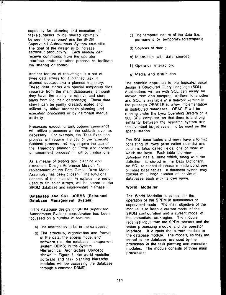
capability for planning and execution oftasks/subtasks to be shared optimallybetween the astronaut and the SPDMSupervised Autonomous System controller .The goal of the design is to increaseastronaut productivity . Each module canreceive commands from the operatorinterface and/or another process to facilitatethe sharing of contro l
Another feature of the design is a set ofthree data stores for a planned task, aplanned subtask and a planned trajectory .These data stores are special temporary filesseparate from the main database(s) althoughthey have the ability to retrieve and storeplans from the main database(s) . These datastores can be jointly created, edited andutilized by either automatic planning andexecution processes or by astronaut manualactivity .
Processes exccuting task options commandswill utilize processes at the subtask level asnecessary . For example, the 'Tas;c Execution'process will require the use of the 'ExecuteSubtask' process and may require the use ofthe 'Trajectory planner' or 'T-1op and operatorenhancement process' in difficult situations .
As a means of testing sask planning andexecution, Design Reference Mission 4,replacement of the Beta Gimbal Drive MotorAssembly, has been chosen . 'The fun(:tionalaspects of this mission, to replace the motorused to tilt solar arrûys, will be stored in theSPDM database and implerr9nted in Phase Ill .
Databases and SQL RDBMS (RelationalDatabase Management System )
In the database design for SPDM SupervisedAutonomous Systern, consid9ration has beenfocussed on a number of features :
a) The information to be in the database ;
b) The structure, organization and formatof the data, the access mode, andsoftware ( i .e . the database managementsystem DC3MS ; in the SystemHierarchical Architecture Conceptshown in Figure 1, the world modellersoftware and task planning hierarchymodules will be accessing the database,through a common DBMS) ;
c) The temporal nature of the data (i .e .permanent or temporary/scratchpad) ;
d) Sources of data ;
e) Interaction with data sources ;
f ) Operator intnraction ;
g) Media and distrOutio n
The specific approach to the logical/physicaldesign is Strucrured Query Language (SQL) .Applications written with SOL can easily bemoved frcm one computer platform to anotherand SQL is available in a netwoik version inthe package ORACLE to allow implementationin distributed databases . ORACLE will berunning unc'sr the Lynx Operating System on a386 CPU computer, so that there is a strongsimilarity between the research system andthe eventual tarnet system to be used on thespaceI station .
The SQL base tables and views have a formatconsisting of rows (also called records) andcolumns (also called fields) one or more ofwhich are keys. Each table and viewdefinition has a name which, along with thedafir.ition, is stored in the Data Dictionary .An SQL relational database is made up of oneor more base tables . A database system mayconsist of a large number of individualdatabases each with its own name .
World Modeller
The World Modeller is critical for theoperation of the SPDM in autonomous orsupervised mode . The main objective of themodule is to keep a current model of theSPDM configuration and a current model ofthe immediate workregion, The modulereceives input from the SPDM sensors and thevision processing module and the operatorinterface . It outputs the current models tothe database module . The models, as they arestored in the database, are used by theprocesses in the task planning and executionmodules . The module consists of three mainprocesses :
230

a) Astronaut and Al Modelling Assist
This process i ; to assist in the modelformulation and test processes byproviding Al based rules and inferenceprocedures and astronaut expertisewhen needed .
b) Workregion Modelle r
The Worktegion Modeller hassubprocesses to process and fusesensor data, formulate and test modelsusing nominal reference models andstore the workregion model in thedatabase .
The Sensor Intogration and Fusionmodule will efficiently fuse sensoryinformation from a number of sources .This will be done by representinguncertain geometry and manipulating,comparing and combining uncertaingeometric structures . it will usenominal, sensor and error models toperform the sensor information fusion .
The Workregion Model Matching modulecompares the workregion featuredescriptions derived from sensoryfusion with the nominal referencemodel to allow additional objectidentification and location to beperformed in the matching process .Operator assistance may be requested .
The Workregion Model Verificationmodule inputs the model, uses theworkregion model, and outputs theverification status. This module willsystematically perform a featurecomparison with the reference modeland report differences and missinginformation .
C) SPDM Configuration Modelle r
The Configuration Modeller process willbe ;f par!;cülar importance if some ofthe sensors on the SPDM aremalfunctioning yet a currentmanipulato ► model is required . Themodeller has subprocesses to fusesensor data, formulate and test modelsusing nominal reference models and
store the SPDM configuration model inthe database .
Vision System Processing
The vision system provides real-timeinformation about the location andorientation of objects within the field ofview. It can function with input from anyavailable cameras or range sensors . Thevision system is critical for semi-autonomous or autonomous operation, as itwill be the major source of informationregarding the position of objects relative tothe robot . Due to flexibility in the SPDM andSpace Station as well as object motion, it isimportant that the vision system trackmoving objects and update their locations inreal-time .
The major modules of the vision system areas follows :
a) Image Processin g
The image processing module willperform digital operations on videostreams of data to extract usefulfeatures for higher-level matching . Itruns on special-purpose signalprocessing hardware which is pipelinedto sustain the high rates of processingthat are necessary .
b) Feature Groupin g
The feature grouping module will takeedge points extracted from the originalimage and break them into straight linesegments or smoothed curve segmentsfor subsequent feature matching . itwill also detect instances of localparafleiism and connectivity betweenthese features to provido compoundfeatures for matching .
c) Model Matching
The module for model maUChinq is theheart of the vision system . it willperform an iterative process in whichthe best feature matches are selected,modti( parameters are adjusted, and newmatches are generated from thes e
2 .31

resutts . This results in a much morereliable system than if all matches areattempted simultaneously . The fullaccuracy of the data is exploited b ./keeping track of tha covariances o" allunknown parameters .
d) Camera Contr,)ile r
The vision system can receive inputfrom a number of cameras and rangesensors, each of which can have avariety of controls . The cameracontroller selects camera inputs sothat objects of intorest are always inview and clearly imagr;d Thu canierapan and tilts will be adjusted to centreobjects of interest, a zoom lens can beadjusted so that the object is acriuiredat the desired resolution for its currentdistance, and the focus control willmaintain focus on the features ofinterest . The brightness of the imagewill be adjusted through control of theiris and an electronic shutter . Theshutter can also be adjusted to provideclear frames during periods of rapidmotion .
CONCLUSION S
The Supervised Autonomous Systern for theSP DM is designed to increase the efficiencyof robotic operation in hazardou senvironments by reducing operator workloadand by speeding robot motion by providingdetailed information about work objects anatasks . The focus of the work has been thehighly structured space station environment .
The specific mission to verify theautonomous design r•,oncepts will areplication of Design Reference Mission 4 ,replacement of Beta Gimba! D~ivo MotorAssembly . During the current Phase II work,the goal to is implement in a parallel,independent fashion the essentialtechnologies needed for supervisedautonomous operation of the SPDMmanipulators . In Phase III the essentialtechnologies will be integrated to control arobot in a proof of feasibility demonstrationof linrited supbrvised autonomous operation .
Other applications of this technology in lessstructured environments will require moreoperator interaction and more flexible taskplanning . However, if 3-D laser scannerinformation is added to provide a threedimensional model of an unstructuredenvironment, then objects in a vision systemimage can be identified by the operator (usingthe screen cursor) and high level commandscan be given tu the robot to automaticallyperform such operations as grasping, etc . Asa library of motion routines is accumulated,serni-autonomous operation of robcts in lessstructured environments may be possible .
232

Third Conference on Military Robotic Applications
A Tesiibed for the Development of Ground-Based Controlof Space-Based Manipulators
E. Jackson, K. Buchan, D. Eddy, G. SpringleInternational Submarine Engineering, Ltd.
K. Chrystall, P. Feighan, A. DagninoThe Alberta Research Counci l
Abstract
The paper describe.s a project presently beingperformed for the Canadian Space Agency in thedevelopment of Ground-Based Control technologiesfor Space-Based Robots. Autonomy is described asbeing an important phase in the development ofautonomous control capabilities for robots on theSpace Station Freedom. Fundamentalrequirements for autonomous control are described .
A tesibed 4s described that is being built to developGround-14ased Control methodologies. Thebehaviour of the testhed robot is speciTed througha set of Task Verbs. The testbed consists of anOperator Interface, a Planning System, aManipulator Control Coordinator, u WorkspaceModelling Computer, u Low Level Control System,a Vision System, and a Testhed Munipulator. Eachof these items i7 described to its own section.
September 199 1
viewed as an evolutionary process during whichoperator supervision reouirements are graduallyreduced . The f,rst step toward autonomy forShace-Based Robots is to move the operators'worksite from the Space Station to the ground.
ISE has proposed that Ground-Based Control ofCanada's SPDM and SSRMS is a logical first steptowaru greater robot autonomy on the SpaceStation Freedom. Problems that arise incontroaling the robots from the ground includethe difficulty in analyzing the local task space andoperation over a time-delayed dr.ta link . Timedelays are anticipated to range anywhere between2 and 6 seconds for round-trin data . Thiscom raint places a logical lower limit on the timedomain level of autonomy to be provided on theSpace Station robots - they should be able tooperate for around 10 seconds withoutsupervision . This time constraint defines theminimum desired level of autonomy that we willdemonstrate in this project .
lïitc!>_da.tioa
ISE is presently performing a. project for theCanadian Space Ag,: ncy to develop Ground-Based Control capabilities for Space-BasedRobots . This is a critical step in the developmentof autonomous control capabilities for Space-Based Robots . The project focuses on thedevelopment of a testbed which emulates ground-based and space-ba.sed equipment, including ahardware emulation of a Space-Based Robot .
In earlier work, (JACKSON] ISE defined autonomyas a level of supervision . Greatei autonomy isachieved when a task can be performed with lesssupervision. Given that autonomy is a measureof supervision, we can define "levels" of autonomyby the amount of supervision that is required toperform a given task . Providing autonomouscontrol capabilities to a robotic system can be
ISE is using the NASREM (NASA StandardReference Model for Telerobotics) specificationas an overall functional specification forsupervisory control systems (At,trus] . NASREMis a time domain hierarchical control system inwhich slower high-level processes provide controlcommands to quicker low-level processes.Providing control at higher NASREM levelsmeans that supervision requirements are spreadout over longer time periods, i .e . a commandgiven by the operat :;r at a high NASREitii level(e .g . Change out module) will take longer for therobot to complete than a low level command (e .g .go to position XYZ) . Since the time domainhierarchy of NASREM is intimately related tothe notion of autonomy, we have adoptedNASREM as our model for specifying controlsystem functionality .
ISE is presently building a testbed for th e
233

development of Ground-Based Controlmethodo logies. Ground-Based Control will beinitially emulated based on scripts of elementalrobot movement ( E;-Move) commands which takeon the order of 5 to 10 seconds to complete .Work is also t.nderway on a higher level planningsystem that will decompose commands formanipulations on objects int o I ivtove commands .
FUPAILm ental-ft.qti_[gM.cnL2f anAutan~mou~i~ryl . Systcm
In reviewing app ;uaches to autonomy, a numberof fundamental requirerttents for autonomousrobot control systems were generated . 'l'heserequirements are described in the followingparagraphs .
bw"n_d__Quljt.=
The controller inputs consist of sensors and theoperator communication channel ; its outputs areactuators and the operator communicationchannel . The control system is required tointerface to all of the sensors and actuators of therobot and to provide an operator interface to alllevels of the control hierarchy .
The Operator must be able to define thebehaviour o t' the robot in an intuitive andsymbolic (as opposed to numerical) manner . Thecontrol system must support a lexicon of "taskvcrbti" which provide a framework for work taskandd robot behaviour specification by theOperator and the autonomous planning system .They are based on the robot's capabilities andoperational requirements of the work task .
Vlwn nine ' ilily ~_~~► l.~ç~kir~IS~h~v_ic_i~ r
The minimum level of "high level" commands thatis acceptable for Ground-I3ased Control isdefined by the time delay in the communicatio,islink between the operator and the spacecraft . Thetime taken for a command to be executed shouldbe at least of the same order of magnitude as thetime delay, i .e ., 5 to 10 seconds . Therefore, werequire planning facility to decompose these highlevel operator commands into manipulator jointcontrol commands .
The controller will support hierarchical levels ofgoal-seeking behaviour . Some goals will he validfor all time - others will be valid only for theduration of an activity . Some behaviours will betriggered by external and internal events, e .g .system "safing" behaviours ; others by thecompletion of previous nchaviours. The planning
capability is required so that the robot can planhow to achieve its goals .
Multiple independent goals may be valid at anytime . These goals may interact and conflict . Thecontrol system must therefore provide a means tocombine goal-seeking behav :ours and to resolvethem when they conflict . Two types of conflictresolution will he provided : cooperation andsubsumption . In cooperation, two conflictinggoals compromise their requirements. Insubsumption, one goal overrides another .
W rqks~l~lttiisl t '
Modelling of the robot and the environment mustbe supported . 1:)iscrepancies between the modeland the sensor readings must be recognized, andthe control system must be able to update itsmodel of the environment . The workspace of therobot must be modelled to some extent within thecontroller to allow reduction of informationtransfer between the ground-üased operator andthe Space-8ascd Robot, The level of complexityof the model will impact directly on the level ofautonomy achievable by the robot . Theworkspace model must support the decompositionof symbolic commands to numerical commandswith an adequate level of rc,solution . It must alsobe modifiable to accept updated numeric andsymbolic data .
l.rnlL~.s1~t ~t ~.tk._4.SZn1~
In order to provide predictable interactions withthe local environment, the controller must et:ablecontrol over the impedance of the robot toenvironmental disturbances . The control systemniust provide the capability for controlling theimpedance of the robot in workspace ormanipulator endpoint (tool) coordinates . Thecontrol system must be stable under all operatingconditions .
ISLw LCSittt, t~l'~li~t
As system designers, we must understand thetasks that the robot is expected to perform sothat we can reduce the uncertainties involved .We must perform hardware simulations of thev,ork tasks . A hardware simulation facility isrequi .ed that will allow testing of proposedrobotic work task scenarios.
LisaattLeè_$"m ►itgssriutigm
ISE is building a testbed system to developGround-Based Control capabilities . It wil l
234
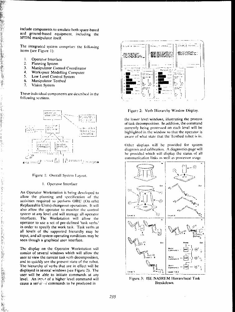
include components to emulate both space-basedand ground-based equipment, including theSPDM manipulator itself.
The integrated system comprises the followingitems (see Figure 1) :
1 . Operator Interface2 . Planning Syste m3 . Manipulator Control Coordinator4 . Workspace Modelling Computer5 . L.ow I,evel Control Syste m6. Manipulator Testbed7. Vision Syste m
These individual components are described in thefollowing sections .
nPr .,,,ru~~ lwu-et~.tn~ I
}I _ I
tOV tFk~GNlurlu F°~
1-`--._.1 ----.`1` 1
î? il_u lki Id! r__.
~lt~'ul(R
a
Figure 1 : Overall System Layout .
1 . Operator Interfac e
An Operator Workstation is being devclnped toallow the planning and tipecifirttion of theactivities required to perform ORU (On-orbitReplaceable Units) changeout operations . It willalso allow the operator to monitor the controlsystem at any level and will manage all operatorinterfaces . The Workstation will allow theoperator to use a set of pre-defined "task verbs"in order to specify the work task . Task verbs atall levels of the supported hierarchy may beinput, and all system operating conditions may beseen though a graphical user interface .
The display on the Operator Workstation willconsist of several windows which will allow theuser to view the current task verb decomposition,and to quickly see the present state of the robot .The hierarchy of verbs that are in effect will bedisplayed in severaE windows (see Figure 2) . Theuser will be able to initiate commands at anylevel . An inrot of a higher level command willcause a serLs - ri commands to he produced in
j
Figur,: 2: Verb llierarchy Window Display .
the lower level windows, iilustrating the processof task decomposition . In addition, the commandcurrently being processed on each level will hehighlighted in the window so that the operator isaware of what state that the "l'estbed robot is in .
t)ther disp!ays will be provided for systemdiagnosis and calibration . A diagnostics page willhe provided which will display the status of allcommunication links as well as processor usag e
Wr h 1
(I _ H_____0A,
ow
} 4t
0. 1
lr .si 3 F^~'Va~`C l,~.sl I i 7
Figure 3 : ISE NASREM Hierarchical TaskBreakdown .
t rvel 4
235

variables for each processor in the system .Another page will allow viewing of all statevariables and online calibration of the sensorsand control system parameters (e .g. loop gains) .
A lexicon of task verbs is being developed toallow specification of system behaviour at varioushierarchical levels . The hierarchy chosen is basedon the. NASREM (NASA Standard RefeienceModel for Telerobotics) specification. Thespecification can be thought of as describing aseries of task decorapositions (see Figure 3) . Thehighest level considered here decomposes worktasks i-ito various operations on objects, withoutspecific regard to the robotic equipment availableto perform the operations . The next level ofdecomposition maps individual operations onobjects into elemental motions (or ['s-Moves) byspecific robot hardware . The next leveltransforms the symbolic I -Moves (e .g. "Positionthe Peg in the Hole with the small manipulator"into numerical trajectories . The lowest levelstransform the trajectories into real-timecommands to the manipulator actuators . TaskVerbs represent the inputs and outputs of thesetransformations, i .e . a task decomposition processdecomposes one Task Verb (behaviour) into a setof lower level Task Verbs (behaviours) . Sampletask verbs are defined as follows :
Uh7 .<t Icvcl ( Ievc14) l"k \crb ,A( ()IIIR Pl'IA(lA'ITA( 11/0I IA( 111-XII(A("I/I?7tiI RIIV )11 )I(x•Alr:
Iywpment Icvcl (Ic- l i) la,k Vcrh ,manïpul ;uor . tnoh tientinitINGAUP/UISI NOA(11(iRAr'l'I i ./I TO 1 . A! \ 1POST llON IASnNi1~NIti IN IDrti'111`i
Pnmwve 1 cvrl ( I cvcl ?) I z,k Vcr Mmatmpulatoe nrulr tiemor,A('nVA'll ; llb1/ A("flVAl1/ 11N1)DI A('ITVA n1(?.1 UEAVIIVA11 POINIAPPR( )A(11/I )IPAR 1FIl)VI
2 . Planning Syste m
The Purpose of the Planning S~stent is toautomate the decomposition of task verbs . It willprovide planning capabilities for the generationof elementa ry rnoves (E-Moves) from Objectlevel commands and for the generation ofPrimitive level commands from the E-Moves . Th(.decomposition will be perforrned initially on aninput script of f.:-Move task verbs, then a set ipt ofObject level task verbs . Planning activities willbe based on the knowledge of the manipulatorsand their environment provided by theWorkspace Modelling Computer .
Initially, the Planning System is being developedto reside entirely in the representative groundcontrol station . One goal of future work will beto duplicate sections of the Planning System inthe representative on-orbit controtlet to providelow level planning activities onboard resulting ina greater ►evel of autonomy .
In the Planning System, Object Level ( l.evei 4)Task Verbs are decomposed into EquipmentLevel (Level 3) Task Verbs which are in tu r ndecomposed into Primitive Level (Level 2) TaskVerbs . The Primitive Level Task Verbs areoutput to the devices of the testbed . A Typicalbreakdown of a l.evel 4 verb to [ .evel 2 tasks forthe Level 4 verb AQUIRI can be represented asfollows :
(1 ere! 4I c'cl ±
I rvel 2 )
A('pIIIRI . (ce, OItll) I ROM (()RU NtonaFc)INS IOW (ntanipulaiur I )PCr5111ON (ntantpulator 11 Il) (grapplc uol cirungtoul )
APPNUA('I1 (numcncloceoon) BY (oftsct) l1SING (manipulalur 1)htOVI(mampul .nr 1) TO (numeric location )
I N(i4G1'. (grapple tool)1O (mampulator I)A('lIVAII{ '1('M (11 (mampulalot 1 )
PUSrnUN (mampulator 1) 10 (neuOkll grappln, location)bI.iPAkT BY (offsct) IiSINCi (manipulator a )APP ;tOACn (numeric I(xation) BY (nffsct) USING (manipulator 1)Mr')VIC (manipuletor 1) 11) (nurncric location )
GHAPPI F (neu ONU) tty1NG (p,rapplc t(x+l)AC IIVAIr (l:rapple tool)
4f
\
___~A p
.=igure 4 : APPtZC)AC'Il, DI :PAR"l', and MOVE
'l'ask Verbs .
Figure 4 . is a state transition diagram to clarifythe rneanings of the primitive level manipulatortask verbs APPROACH, 1)C PART, and MOVi: .The presence or absence of these task verbs inthe breakdown of the equipment level task verbPOSITION will depend on the necessity for themanipulator to depart the initia ; location or toapproach the goal location.
A : initial locationl3 : location at depart offset from AC: location at approach offset from 1)D : goal locatio n
The structure of the verb ACQUIRE is shown inTable 1 ,
236

ACQI.JIRE: To obtain an oEject front itslocation on another object
Syntax: ACQUIRE. (object a) FROM(object b )
Applicability : - object a : OR Uobject b : MSC storage ,ORU storage
Constraints - object has been detache dand - grapple tool availabl ePreconditions : - manipulator available
clear path availablegripper empty
Knowledge : - tool required for remova lof object alocation of'übject ageometry of object atool placement locationrelative to object atool changeout location sclear location s
Information : - status of manipulato r(free/in service )status of manipulato rend -effecto r(free/tool attached )sdatus of tool(free/attached )location of bothmanipulator s
~ .~-----~--- -~
Table 1 : Structure of the Task Vert)ACQUIRI : .
3 . Manipulator Control Coordinato r
The Manipulator Control Coordinator is desif ;ned
to be a space-hasecl function . It is responsible forcoordinating the low-level activities for themanipulator, both spatially and chronologically .It will have extensive, knowledge about themanipulator, including what tools are pres :ntlyon the manipulator, what object is currently beingheld, and the positions and status of themanipulator . The Control Coordinator will knownothing about the outside world other than theinformation required by the current task beingperformed. It will have limited memory of
previous tasks .
The Control Coordinator will receive l .evel 3
instructions for specifying manipulator endpointtrajectories, endpoint forces and toolconnect/release commands . These commands will
be translated into primitive level commands forthe Low Level Control system . The Control
Coordinator will produce path traje:ctories (either
pre-planned or derived) for the Low LAvel'. ;ontrol System at a maximum rate of tOHz . Avariable length time delay will also beimplemented in order to simulate the expectedturne delays in space.
Trajectories will he defined by means of "knotpoints" which will be interpolated through . Thetrajectory generator for the Control Coordinatorwill be provided knot points from the PlanningSystem or from the Operator Workstation . The
Control Coordinator will then produce worldspace commands for the Lc)w Level ControlSystem at a rate of 10Hz. The generation of thesepoints will he bound by the world space velocityand acceleration constraints for the Space-liasedRobot .
A function will be provided to enable the user toteach the robot paths which can be replayed .This function will he useful for performingrepetitive tasks . The paths stored on the ControlCoordinator will have the ability to be playedback at a variable speeds or in reverse . Inaddition, the playback feature will have af'AUSB/STOP feature which will enable theplayback path to be stopped or paused at anytime during the execution of a playback file .
A future requirement of the Manipulator ControlCoordinator is reactive obstacle avoidance . This
feature is intended to be implemented in a laterphase of the project .
4 . Workspace Modelling Compute r
The primary function of the WorkspaceModelling Computer is to support the taskdecomposition activities of the Planning Systemand the Manipulator Control Coordinator byproviding the knowledge of the environment onwhich plans will be based . A secondary functionis to support the operator interface through thegeneration of synthetic graphics of the workspace .
The Workspace Modelling Computer is beingdeveloped to reside entirely in the representative
ground contrcl station . The goal of subsequentwork will be to duplicate sections of theWorkspace Modelling Computer in therepresentative on-orbit controller to support lowlevel planning activities on board a moreautonomous robotic work system .
The Workspace Modelling Computer will includegeometrical models of the following :
F:(Iuipment : manipulators, tools, and sensors .
Objects : ORUs (on-orbit replaceable units) ,ORIJ fasteners, and storage areas .
237

The Workspace Modelling Computer will providethe Planning Systeni and the Manipolator ControlCoordinator with information on the environmentof the robot that is necessary t o the generation ofplans . This information will Fe represented in aknowledge base and through geometricalmodeling . The information in the workspacemodeliny, system will be kept current by updatesfront the sensors of the robot .
5 . 1A>w Level Control Syste m
The I .ow Level Control System provides theabstraction necessary for the robot to bec,,)ntrolled by the Manii:iulator C'orrtrolC'oorctinator in world space or tool spacccoordinates . The lAaw Level Corrtrol System willcause the 'l'esthed Manipulators to follow worldspace trajectories or apply wodd space or tool~pace forces/torque, without any manipulator-specific knowledge by the Con'roI Coordinator .'It will deal with the redundancy associated witha 7 UOh manipulator in order to achievetrajectory tracking and force control .
An Operator Interface will be provided to theLow Ixvel Controller for development purposes .The operator interface to the 1,r,v I .evel ControlSystem will primarily he text displays forindicating the present values of different systemvariables for debuggink and calibratin}; thesystern . The user will he able to view real timeplot, of certain predefined systern v :triables . Also,the user will be able to modify th .: control gainsof the manipulator controllet and otherc,~~libratior. parameters directly from the keyboardwhile the controller is running .
Position/force commands along with timinginformation will he received by the Low LevelControl System from the Manipul ;ttor ControlCoordinator at 1 0 Hz. The IArw I,evel ControlSystem will send diagnostic information to theManipulator Control Coordinatirr at a rate ofabout 2 IIz . Various status information regardingthe current control mode, joint configuration, toolselected and tool tip position will be sent by theLow L.evel Control System . It will also sendstatus information when tasks have beencompleted and when any failures have beenencountered .
The types of control that the Lrtw Level ControlSystem will support are : low level se rvo-loops forjoint position and velocity, resolved rate control,and force control . The low level servo-loops willcontrol the motion of each individual joint so thathigher levels of control need only generatedesired endpoint position, velocity, and forcecommands . The resolved rate control mode will
control the velocity of the manipulator endpointin world coordinates, and force control mode willcontrol the endpoint forces of the manipulator inworld or tool coordinates . Both the resolved rateand the resolved force controllers need to handlethe redundancy associated with the TestbedManipulator . In general, the reciundancy isresolved by enforcing one or more additionalconstraints on the system's behaviour .
A forward Jacobian method will be 4.sed for theforce controller . A desired world space force willbe calculated using the error between the desiredworld position and actual world position and thena forward Jacobian is used to determine thedesited torque to each joint . This methodhandles redundancy by allowing joints that havethe abAity to contribute toward endpoint motionperform the work .
A Jacohran pseudo-inverse with additional nullspace mapping will he used for the resolved ratecontroller . This matrix calculation will determinethe desired joint velocities from the specifiedworld space velocity . The joint velocities caneither be used as input to a high gain velocitycontrol loop or he used to generate a series ofjoint position commands .
In order to ensure control system stability, thetarget handwid,h of the control systcr-i should bean order of magnitude less than the lowestunrnodelled syst',,rn dynamics . Given the n,auralfrequencies of the Testhed Manipu'.ator actuators,either the actuator dynamics must be modelled orthe control response must he lower than theactuator natural frequencies. '7'he; control systernneeds to sample at 10 times the highest targetfreyuency . Modelting the actuator dynamics ofthe "I'esthed manipulator will re,luire a samplingrate of at least 25 0 IIz . An alternative is tomaintain the system response below the lowestactuator freyuencies, i .e . below S IN . Acompromise is to design the, coritioller forquicker response on the distal joints than on thebase joints . Another, more ctmiplicated,alternative is to change the frcyuency response ofthe controller as a function of the armconfiguration .
Besides performing the low level joint servocontrol and the forward and inverse kinernaticroutines necessary to control the manipulatorendpoint position or force, the Low Level ControlSystern will provide the fo',lowing functions :
compensation forgra.vitational forcesacting on the arm ;limiting joint ranges of motioninitialization alignment on startup ; an d
238

- manipulator freeze and limping .
The Controller will allow the gains for thevarious control loops to be modified by theor;,-ator while the controller is running .
6. Manipulator Testbed
The requirement fer the manipulator is toprovide a testbed to evaluate Ground-BasedControl strategies . It must therefore be areasonable emulation of actual Space-BasedRobots . It will he used for testing controlstrategies and, possibly, for operator training .
The design of the "l'esthed Manipulator is largelybased on information gathered on the currentconfiguration of the Canadian SPf)Mmanipulator . ISE has selected a geometricalconfiguration and pl: :rformance specifications foithe testhed that differ somewhat from the currentSPDM concepts for the following reasons :
i) the testhed ;s designed to work in a 1-C ;environment ;
ii) the available specifications for SP DM arevery prelimiriary and are still cvolving ; and
iii) a ground-based testhed need not move a sslowly as the actual space manipulator andtherefore may have somewhat higherperformance .
The Tet'hed Manipulator target capahilities art,sumtnarized as folows in Table 2 .
Sf'OM 1 " I HI ! )
1`a.l, qd I11 M1 :t Ih,l u, 1n~,~t al F.c end e!!nf ~N ,~- 114 1 , " l !h,l I 1,
la,5omc., ia n p~ . , (u!1 -ph, {,l,n~nipe vnrruiA f rrn ,nn nl I A, n a• , n
imrt (uIl gr- iv
_. ..__
. . . .___•
..__•__•__
wfl
. ._Cr .y,hj ^
~n. ; 1 : r,i „ h "0
R 1 ~
<,r,
. ...__ . .__, .~f~r . . , .ol, „rF ,a ~~
~~~
•
J. I~R ~ ~'
~ ._
~ (, • 1 ,. .uh
~t , S~„~t` R r f . n 1 . . 1._.....~. .__ ...~ . _- .__ _
.._--_`- -
. . . .._ .. , _ __ ~
. . ... _. ....
U .tnn,.
f~..!v'
modular link attachment5 . These will provide a
aCxirv~p•.a ~ . ,
Table 2 : Testbed Target Capabilities .
The Testbed Manipulator is designed with
simple means for incorporating structuralflexibility into the system .
Mass counterh~alancing is often use(] as aneffective mean. ;, by which to increase the paylo<tdof a manipula :or designed to operate within it
gravity field. However, counterbalancingincreases the moment of inertia and consequentlydecreases the manipulator bandwidth . There isno joint counterbalancing in the ISE design at
Figure. 5 : 'T'esthed Manipulator .
present .
Consequently, the required stopping distance o f
- ~ , . ..- w- + v . . - . , . 4 . „ . . . . .
capable ( . ; providing substantial torque in acompact (lightweight) package :~~',thle of
The motors selected are three-phase hrush ;ess d c
them it . . most desirable choice . The primarydrawbacks in using harnwnic drives is that they
modelled and compensated for . The primarybenefits of harmonic drives are that they are a n
The testhed manipulator will he equipped withbrakes on the first four joints . However, they willnot he designed for repeated dynarnic braking ;rather, they will he fail-safe brakes for use inemergency or Power Off situations .
the manipulator system will he a function of theloading configuration (including the direction ofmotion with respect to gravity) and the torquecapabilitie :, of the actuators .
(motor or gear output) .
'1 lie foremost motor requirement is that it he
adequate torque co . :iroL Other i :.si+c, .nclude :motor aspect ratio, rnaximurn zceeu, thermallimitations, torque ripple, shaft mertia, and cost .
motors .
23 9
Itarrnon'c Drives have been selected as the joir,ttransmis ion drives . Although harmcnti4 drives dohave son e inherent problems, their benefits make
are significantly more compliant (less stiff) thanother types of drives such as cycloidal gears andplanetary gears . "I'his joint °windup" can he
extremely compact means of transmitting largetorques . Furthernlore, as they are a single stagemechanism, they exhibit negligible backlash .
Joint fecdhack will he providecl through opticalencoders . The most important issues in encoderselection are resolution, encoder type(incremental or absolute), and sensor placement

The minimum angular displacement of themanipulator tip requires 15 bits of resolution. Itis prudent to exceed the minimum resolutionrequirements so that the system's accuracy is notlimited by the encoder selection . A resolution of16 bits has been chosen . An incremental encoderis recommended over an absolute encoder inconsideration of cost, probability of failure, andseverity of failure mode . The encoders are to bemounted at the joint output . The reason for thisis !o measure the actual position ofthe outputshaft, regardless of the compliance that isintroduced by the harmonic drives .
7 . Vision Syste m
A Vision Sy s( e.m will be integrated into thesystern for recognizinf, pre-defined objects,deterrnimn}; ohject po 5,itiorrs and orientationrelative v) the camera reference frame, anddetermining manipulator tip position andorientation relative to the camera referenceframe .
Object recognition will be performed by theVision System computer. Objects in theworkspace will be identified by specific targets onthem. The targets will be on each face of theobject that needs to be recognized so that thevision system will be able to find the object nomatter what orientatiç,n it is in . The targets willhave to be distinct enough that one object is notconfused for another, and the appropriate size sothat the Vision System will be able to recognizeit in a large range of distances from the object .
C"O-Oki 2t?s
ISC has a contract with the Canaclian SpaceAgency to develop Ground-Based Controltechnologies for Space-Based Robots . Thebaseline approach is for the ground-basedoperator to send robot elemental movement ( E -Move) commands to the. Space-Based Robot .These commands will be :,tored in a pre-defincdscript . The operator will monitor the progress ofthe robot and output new commands on the orderof once every 1 0 seconds .
The fundamental requirements for anautonomous contro! system were described . These.are :
1 . Inputs and Outputs - sensors, actuators,and operator interface ;
2 . Planning Capability / Goal SeekingBehaviour - task decomposition andresolution of conflicting goals .
3 . Workspace Modelling - geometricalmodelling of the robot and its workspace ;
4 . Impedance Control - control of interactionforces between the robot and itsenvironment ; and
5 . Understanding Work Tasks ThroughI-tardwaie Simulation - this will allow thedesigners to ensure that the task can beaccomplished with minimum supervision .
ISE is building a testbed system to developGround-Based Control methodologies for Space-Based Robots. The testbed includes thefollowing items :
1 . Operator Interface - the OperatorInterface provides the operator vis'hilityinto the task decomposition process andallows him to specify the behaviour of therobot at any level in the control hierarchy .
2 . Planning System - The Planning System isa ground-based component whichdecomposes Object leval Tas~. Verbs intoI:-Move commands and E-Moves intonumerical manipulator uajectories . It hasthe capability of resolving con;iictinggoals .
3 . Manipulator Control Coordinator - TheManipulator Control Coordinator isintended to be a space-based component .It coordinates the behaviour of theindividual robotic components in time andin space . It inputs symbolic or numeric E-Move commands and outputs numericalcontrol commands to individual low levelcontrollers . It also has the capability ofresolving conflicting goals .
4 . Workspace Modelling Computer - TheWorkspace Modelling Computer containsgeometrical knowledge about the robot,manipulated objects and the workspace,which is used by the Planning System andthe Manipulator Control Coordinator .
5 . Low Level Control System -'I'his is thelow level control syst°m for the TesthedManipulator . It performs all low levelservo functions .
6 . Testbed Manipulator - The TestbedManipulator is intended to emulate theCanadian SPDM manipulator which willhe located onboard the Space StationFreedom . The manipulator is full scale tothe SPDM and is electrically powered.
7 . Vision System -'Che purpose of theVision System is to recognize targets andto measure their p.,)sition and orientationrelative to the camera . It will be used toprovide updated information to theWorkspace Modelling Computer regardin g
240

the position and orientation of objects inthe environment .
The work described in this !)aper is tundet; by theCanadian Space Agency STEAR Program -STFAR RFP #5 - Autonomous Robotics, DSSContract Number 31 0 18-0-2328/01-SW.
ni jimul-lx
E.Jackson, O.Williams, K. .Buchan"Achieving Robot Autonomÿ", 3rdCanadian Military Robotics Conference,Medicine H at, Alberta, 199 1
2. J .Albus, H .McCain, R . Lumia,"NASA/NBS Standard Reference Modelfor Telerobot Control System Architecture(NASREM)", National Bureau ofStandards (NIST) Technical Note 1235,July 198 5
241

Third Con(erence on Military Robotic Application s
.Acâ:ieving Robot Autonom y
Eric Jackson, Owen Williams, Keir Bucha n
International Submarine Engineering, Ltd .
_A..(LSlraa
Autonomy is defined in this paper as a nteasure ofsupervision and is quantified in tenns ofcommunication bandwidth . The need for increasedautonomy is established and the driving and opposingfactors are identified. The closc relationship henveenincreased automarry and reduced bandwidth of arohot's control channel and its data channel isestablished. The command channel bandwidth can bereduced by decreasing the performance requirements inthe work task and by offloading the high frequency,high resolution, and high a<rgree-of freedom tasks tothe robot . Reduction of the data channel bandwidth
nury be achieved by adding the uppropriale dataproces.sing capabilities to the robot, by adding
urtuators or efjeciors to allow the robot to a( I on thee
chttu, by increasing III,, (.a
ouhility of the robot tohandle ccnplexity, and by reducing the risk o( therobot acting on the data . ]ncrea se.s in robot autonornyresults in increases in their respwr.ci6ility to inuerprot
their environment and act as desirod . ]l~ulehmonitoring and fault tolerance hecoine signiJicunt
issues. Finally, several reyuirernertts for «utonornrrsrobotic control .systerns are prisented .
MtinOmn__gf_Autonamy
The notion of autonomy in robotics is open tointerpretation . A paraphrased dictionary de4initionof autonomy is as follows :
a) a condition or quality of beingself-governing ;h) self-determination ; andc) independence .
Since robots are designed to work for humans, theyshould nF~er, by definition, be completelyautonomous . We are led then to the notion ofrelative autonomy in robotics, where greaterautonomy implies lower supervision requirements .
Septernber 1 99 1
Autonomy can then he thought of, and is hereindefined as, a measure of supervision .
The field of Supervisory Control can be viewvd as acontinuum which has fully supervised control at oneend (i .e . teleoperated) and fully autonomous controlon the other end. The amount ofautonomy/supervision can be directly related to theamount of humar. interaction teyuirecl for the robotto perform a given task . The amount of interaction
an be quantified by the bandwidth or informationtransfer, in bits per second, of the messages thatmust be sent between the operator and the robot .
In making it system more autonomous, we candecrease the amount of work required by humans .The level of autonomy of it system can he measuredby the level of supervision required to operate it :given two supervised sy5tems working inenvironments of equal complexity and performingtasks at the same speecl, the system that requiresless supervision (which can be measured inbandwidth) is more autonomous than the other .Therefore, by saying that a sy,,tent is arrtonomous,we do not mean that it is not controllable byhuntan~, but that it can operate with some knownlevel of capability in the absence of supervision forit defined period of time . It is still ,rverrideahle byhumans, and it is also reconfigurable by humans .
Urivin~~nd SZPRQ~i!?Q_~~-I~ri
Two fundamental reasons for making roboticsystems more autonomous are to assist humans inmanaging complexity and to achieve critical timeresponses in a changing environment . Automationof mission expertise is very desirable for assistinghumans in complex operations planning endntanagement areas as well as in health monitoring .f-lowever, in these situations the amount ofinformation processing required is proportional tothe task complexity and inversely proportional to th e
z4 7

time available to the process the data. There,fore,time response is always a major factor in increasingrobot autonomy .
Given that the issue of autonomy is intimatelylinked with time response, the level of supervisionachievable in a man/machine system is limited bythe communications system and by the timeresponse capability of the operator. Thecommunication syste :n places constraints onbandwidth, time delay, and availability . Thecommunications system therefore establishes anupper bound on the bandwidth with which theoperator can interact with the system and on thearnouut of time available for interaction . Theopcrator is limited in his physical and mentalreaction times . These reaction times place an upperhound on the amount of supervision that theoperator is ablc to provide. Our robotic systemmust he designed sud that it will operate with apredetermined level of capability within theconstraints of the communications systern and theoperator's response time .
Operator response time is relatively slow comparedto modern robot mechanisms ; therefore it isreasonable to design the system such that the robotshould implement low-level, fast responsesautonomously, while the operator supplies newsetpoints and parameter values at it lower speed .The operator therefore gives it "hif;her-lcvel"commands .
We can optimize our usage of our corrstrainedcommunications channel through the use ofcommunications system engi»eerinp, techniques . Wecan use modulation and data encociing techniques toachieve more efficient usage of the cornmunicatio,itichannel . However, assuming that we can minirn zc.the channel bandwidth usage, we can design .heoverall control system such that the informationtransmission requirements over the communicationschannel are reduced . in implementing tfesetechniques, we will he ptrtting more intelligence minthe remote system, thereby nnakinf; it moreautonomous .
As the required level of operational capability tor agiven robot is increased or the communicvtionscapability is decreased, the required level of robotautonomy is increased . Consequently our work asengir.eers is made more difficult . We can examinea specified operational capability of a system andattempt to quantify the time response requirements .We can then determine the le v el of autonomyrequired by the system over a ra^i ;e of availablecommunications channels .
The main factors that determine the time responserequirements are safrty concerns, mission concerns,and the magnitude and probability of disturbances .All of these factors will combine to establish arequired time response capability that must he meteither through autonomous control or operatorsupervision . If neither of these are practical, thenthe requirements must he relaxed .
Safety concerns are primarily due to faults, i .e . theirexpected criticality or potential of criticality, and toperceived danger to the robot and its environment .Faults may shorten the life of the robot or decreasethe capability of the robot . Therefore they must bedetected . diagnosed, and rJealt with quickly .Sintilarly, dangerous situations must be detected,diagnosed, and dealt with quickly .
Robot missions are concerrted with obtaining dataand/or performing sonic action on the environment(i .e . on an object) . Mission concerns that drive thetime response requirerrrent,, are the importance ofobtaining the data and/or porforining the action ina timely tnanner . The foIlowing questions must heasked :
When is the data/action needed ?When ;s the data/object available? Will thesan:c data/object he avsrilable, later ?flow important is the mission, i .e . what is anacceptable cost to obtain the data or performthe action on the object in a timely manner ?
As the iniportanee of the mission increases, thehrohahility of failure must be decreased . Todecreatie the probability of ftailure, onboard systemsmust he provided to detect, diagnose, and recoverfrom faults in the absence of operator supervision .
The third factor driving the time responserequirement is environmental disturbances. '1°hesewill vary grea'tly between application ctornaitts . Theycan include, for example :
currents and turbulence in air and water ;equipment shutdown in integrated industrialrobot applications ;::urfacc irregularities in dehurringapplications ;unmodelled robot self-dynamics ;hostile behaviour ; andequipment faults .
These disturbances should be analyzed as to theirtime response characteristics and the resultin€interaction responses with the robotic system .
243

S~t~lg[Façtors 'vi e AutQn_lZtU
While time resp-rise is tl .e prime driver forautonomy in robo;ic systems, other factors mayoppose it . The main f.ctors )pposing autonomy arethe various costs involved it, developing andinstalling processing capacity onFoard the rob~iticsystems . Also, a lack of faith in tire reliability andcapabilities of autonvmous svstems by usersunfamiliar with the technolol;v has ;, :~,toricafl,ycaused the delay of increased automation .Skepticism by observersJusers is anticipated indeveloping embedded s,sterns for higher levelcognitive aspects of problem handling inautonornous control .
~gtnm~niçtflitln~_I3~n~_.vid~h_ .It~gis ir~qaç~nl l
In a fully supe .-vised (er completely tclec .crated)system, the operator rnu,,t control each r%rvablefunction or degree o ; freedom of the robot in re,rltime. The requirnd hanclwidths for the cuntrulch,rnnel (i .e . the communication channzI from th .,operator to the robot) and the data channel (i .e .from the robot ro the oper~tor) are described in thissection .
The requircd handwidth of the - . .mtrol ch,7nel isequal to the surn of the prutluct~ of the reyuirccltracking frequency rtspunse of each r .lef;ree offreedom of the robot with its requireci resulutiun,mea.sured in bits . The tracking fre(Juency responseis the ratio of actual robot motion to amimanrieclrobot motion as a function uf freyuency of c<, ;mmandchanges. (The faster the motion corni-nands changethe less the robot will he able to keel) tip) . As wespecify more degrees of freecfunr, greater resolution,and faster operator commands to the robot, thereyuired command channel bandwidth increases .
The data channel bandwidth (fruni the robot to theoperator) is determined by two factors :data-gathering, tasks and the uncertainty of the robotand the envirunmcnt .
In data gathering tasks, bandwidths are ue'erntineclby the quantity of data gathered divided by theamount of time available to send it to the operatur .Therefore, as the quantity of data i5 increased, andthe time available to send it 's decreased, therequired channel bandwidth is increased . Thehighest bandwidth requirement is in real-time data-gathering, i .e . where data gathered by the robot isreyuired by the operator immediately . The requiredchannel bandwidth is lhen determined by thequantity of information and the speed in which it isgathered .
The uncertainty of the robot and the environmentcan be quantified by the products of theenvironmental entropy and frequency content, andby the mutual impedance between the robot andenvi .onment . Entropy is a direct measure ofuncertainty and is defined in statistics as thenegative expected value of the loga;ithm of thelikelihood of the observed system being in aparticular state [ScttARFJ . The frequency contentaetermines how fast the environment is likely tochange . For a given environmental entropy level,the faster the environment is changing, the moredifficult it is to make an accurate estimate of itsstate . The mutual impedances determine how therobot and environment interact and change eachother's stat e
Reductions in supervision requirements arequantified by the corresponding reductions inbandwidth requirements of the command and datachannels . "1°herefore, to increase autonamy, we canlook at methods of reducing bandwidthreyuirements .
Itcda ;ctitm of-ÇQmmt .rd ._(_hannel-B_andwidt h
Reduction of command channel bandwidth can beachieved by decreasing the performancerequirements of the task, i .e . degrees of freedom,tracking frequency response, and resolution, or byoff-loaifing the control of some uf these parametersto the robot . This thereby allows the operatoi tospecify behaviour at highcr levels . For a task of agiven complexity, we shoul+l therefore look at mettnsof alluwing the operator to specify tasks using lesstlef;reeti of freedom, lower frequency response, andless resolution than the. robot would see . In thelimit, we should be v hle to specify a completemission plan and not sencl any mure commands untilthe robot has either compictecf the mission or ha ;requested assistance .
The first n-icthnd of retittcing the command channelh,uitlwitlth is to reduce the performancereyuirerncnts of the task . If we comm make the tasksimpler by requiring less resolution, speed, andrlegrces of freedom, we will significantly reduce theamount of supervision required by the operator . Inorder to rnake tasks simple, we must first understandthem through a process of testing and verification .
In order for the operator to he able to specify : taskwith fewer degrees of freedom than the robot mustutilize in performing it, the robot must be able to!~,e cunstr,aints cither from its knowledge hase orfruni the environment to control it . unspecifiedcf,:grces of freedom. Some examples of robotknowledge in performing tasks are :
2-14

point the camera at the end of themanipulator ;maximisr.e the determinant of the mv.nipulatorJacobian matrix ;slide the endpoint of manipulator along thewall ; o ralign th- manipulator endpoint with thetarget .mate the robot's tool with the fastener beforeextractinf, it .
All of these constraints imply some knowledge orsensing information regarding the robot and/or itsenvironment . Clearly, some onhoard intelligencemust be added to the manipulator in order toreduce bandwidth in this mariner .
Similarly, we can allow the operator to specify a taskin such a way that the specification has a lowerfrequency content than what the manipulator willrequire to perform it . This implies that themanipulator must perform local sensing and mustadapt to the environment at the required rate . Thisrequirement is applicable in target tracking, forexample . The robot must sense the target and trackit as it moves, while the operator gives it higherlevel commands, e .g . approach the target, grasp thetarget, move behind the target . Again, robot sensingand knowledge is rcquired .
Resolution command reyuirements can be reducedby transmittir :g symbolic commands to the robot .This in 'urn requires that the robot has a model ofitsetf and the environment, ard that it can senwc: theenvironrnent .
If we wish to develop it controller that will < .Ilow usto specify missions at a sufficiently high level thatthe robot can perform without constantly rcyue,tingassistance, we must specify the mission in ternis ofits goals and consiraints . In the examp;e of anautonomous submersible, its goals might be to findan object in the water column and to return to itsbase before its energy is depleted . Its constraintsmight be the bottom depth and the amount ofstored energy . To allow the robot to resolveconflicting goals, e .g . completing the mission vs .returning before the energy is depleted, we mustalso define their relative importance and the methodto be ased in resolving them .
Two methods are available for resolving conflictinggoals : subsumption and cooperation . Subsumptionis where one goal overrides another goal, e .g . thebattery is almost depleted so abort the mission .Cooperation is where both goals are valid and apriority weighting scheme is use(] to combine theactivities that result from the conflicting goals . Anexample is obstacle avoidance, where a robot willcombine its desired course with an obstacle
avoidance maneuver to go a round an obstacle .
In high level control systems, the operator and therobot muct share some "knowledge" of the activüiesthat the robot can perform and of the °nvironment .New commands from the orerator to the robot willthen consist o f :
addition and deletio : : of goals ;modifications to the importance of goals ;modifications to the method of resolution ;modifications to constraints ; andmodificz-nns to the world model .
The minimum information necessary to transmitthese messages, assuming a noise-free channel,consists of a message type identifier, whosc lengthdepends on the number of message types, andparameters to express the new information .
Re~l~çli.p~gf .Ç]itIg Chanpg1 Bandwidt h
As describeci earlier, robot missions are concernedwith obtaining data and/or performing son>c actionon the environment . Data channel bandwidthrequirements are gencrated by the requirement fortimely data gathering and by the need formonitoring and verification of the robot 's mission .Data channel bandwidth reduction can thus heachievecl by reducing the bandwidth o f real, :imesensing tasks and by reducing the uncertainty in therobot and environment .
In any robotic system, if an operator needs datafr ;rrn the robot in real time, it is because the robotts :
not capable of processing the data ;not capable of performing the reyuiredactions on the environrnent based on thedata ;that the actions required are too complex forthe robot to perfnrrn autonomotttly ; o rthat the risk of the robot acting co the datais tuu hibh to allow autonrimousdccision-making and action .
Otherwise, it would be sufficient that the robotgather the dt+ta, perform appropriate actions, andinform the operator of the results . Bandwidthreduction for re ;tl-finie sensing tasks can thereforebe achieved by adding appropriate data processingcapabilities, by adding actuators or effectors to allowthe robot to act on the data, by increasing thecapahility of the robot to perform complex tasks, orby reducing the risk of the robot acting on the data .
Once we add data processing capabilities to therobot, the robot is generally able to transmi t
245

information back to the operator at a higher level ofabstraction than witn raw data . For example, therobot could send the operator the relative locationof a recognized object rather than sending acomplete video image. This capability therebyreduces the bandwidtlt cf the data to be transmitted .
"Co allow the robot to act on the data. the robotmust he supplied with the nee.es :ary effectors to acton the environment . The sensor data must beprocessed to extract the desired information for therobot to make planning decisions, then the robot'seffectors guided by the control system to achieve thedesired results .
l'ro, .idiug sensors and effectors to the robot is noten.ough to allow it to perform ~oniplc.x tasks . Thecn a +rol system must be able to perform sequences ofr,ctivitics hase,J on the dctection of specifiedeKtctnal r .nd internal evcnts . I t must also haveenough intelligence to recoüni : :e anomalouscircumstances and to decide upon appropriateresponses . It must be able to act toward thefulfihnlent of various goals (e .g. corul,lete mission,preserve health) and to resolve these goals whenthey conflict .
The risk emailed in the robot acting autonomouslyon the data that it gathers can be quantiC :cd as theprocluct of'some loss function with the uncertainty ofthe state of the robot and environment . T he lossfunction quantifies the danger of acting (or notactinp) on incorrect interpretation of the state of therobot and the envi :onment (e .g . the loss entailed innot i;rni .:ing a ccrtain event vs, the loss entailed inacting on a false alarm) . aisk can therefore bereduced by reducing the uncertainty of the state ofthe robot and its environnent . This uncertainty canbe quantified by the products of tht :- ~,ntropy andtheir frequency content and by thrir rnutualinlpedances . We cart thcrefore redueè urrccrtaiai,yby reducing entropy, by reducing the frequencycontent of the robot and its interaction with theeuvitor:ment, or by modifying the impedance of therobot . It is assunted that we cannot affect thefrequency content or impcdance of the enviromnient .
Likelihood is increased and entro;,ry thereforereduced by adding sensors to observe thc states, byincreasing sensor quality (accuracy, signal-to-noiseratio) to get better measures of the states, vnd byusing apriori information as to the probabilities ofstates and state transitions . On the other hand,entropy is increased through poor re'~iability. Wecan therefore decrease entropy by increasing thecost of the system through more ;tnri better sensors,through more extensive aprirni modelling, andthrough increased :cliability .
The frequency content of the robot determines howfast it is likely to change state due to operatorcor,trnands or its owr: volition . As designers, we canspecify this frequencv content . We can loweruncertainty by making the frequency contentarbitrarily slow at the cost of increased missiontimes. This invarir.bly dictates increased energycon:urnption . It is, however, unreasonable to lookat the frequency content of the robot without!ooking at the frequency content of the environment(which we cannot change) and the mutualimpedances of the robot and environment, Thesetwo factors determine how fast the robot is likely toch<rnge state iue to environmental disturbancesregardless of the frequency content of the commandsignals .
The mutual impedances of the robot andenvironment, usu .tlly specified as the robotimpedance and the environmental admittance,(IItx,F','1 detcrrnine how they interact . Theimpedance of the robot with respect to theenvironment specifies the dynamic response of therobot to environmental disturbances, and vice versa .The robot's impedance, therefore, is a measure of itsgoal-sceking behaviour in the presence oftlisturnamdes . As ~.tesigncrs, we can contiol (to acertain degree) the impedance of the robot . Firstly,we can implement goal-seeking behaviour in a robotthrough a myriad of techniques - for the example ofas-bmersible robot, we cari control its attitude byarran};inb the centre of mass relative to the centre ofhuoyaney ; we can cause it to hold a certain headingby mer~ .yurinp:; heading with a compass and byactuating thrusters or control planes as a function ofdeviations front a heading setpoint . Furthermore,we can enable it to avoid hitting an obstacle by, .rkling an obstacle detection sonar and commandingit to alter its path to go around the obstacle .'l'hrough application of control system designte(hniques, we can alter the frequency response ofthe robot to environmental disturbances . In geneml,we. can specify how much energy should beconsumed to offset the effect of environmentaldisttrrhances .
In the preceding discussion, the uncertainty of therobot and the environment is linked to the datachannel bandwidth in two ways : through the directbandwidth required for environmental dataacquisition purposes and through the process ofallowing the robot to take actions that wouldnormally be guided by the operator . The former isdriven by the operator's need to know the state ofthe ro!lot and mission and increascs the datacham,el bandwidth requirement . In the latter, weattempt to decrease the data channel bandwidth byallowing the robot to perform actions autonomously .As the robot is allowed to perform more functionsautonomously, the operator's need to know the state
246

of the robot rjecreases, in either case, we need toi .:duce the uncertainty of the states of the robot andenvisonment .
As the robot is allowed to perform more functionsautonomously, the operator's need to monitor thestate of the robot decreases. Since the robot isprogrammed in terms of goals and constraints, theoperator and the robot share some " knowledge" ofthe activit ;es which the robot can per:orm and of theenvironment. The operator and the robot most eachhave a model of the robot ( the operator's model ofthe robot may sinaply be his understanding of thedescription givtn in the instruction manual) and ofthe envirortme ;,t . All data channel messages ,antiter ..fore he generated purely irom dcv;atio :l sbetween sensor readings and the models . Forexample, the robot can send data to the c~peratorsuch as "voltage level n 101o low" or "obstacle v o , ifieciat position x,y,a." . In the !imi , , if no deviatiur,,, fromthe models occur, no messag~s need to be sent tothe operator.
QghàWiay-r_
Deviations from the robot , ncl environmentalmodels can occur due to unmodetled disturbancesand due to modelling errors . With a "thoroughlyte5ted" ro!-,ot, the only unmodelled disturbances inthe robot itself will correspond to device failures,which tmtsi he handled through reciundancy.t.tnmocleiled disturha :7ces in the environrnent,however, will also manifest theinselves in the robot(throuf;h the rohot's trnlteciat ;ec as describedprevi,rusly) . Modelling crrc,rrs can occur in both therobot and the environment .
Unmodelied er_v 'sron ;nental z.iiiturbances are hcreindefined as unmodelled motions or forces in theenvironment . They can consist of random andregular (or predictable) components . If thedisturbances incl :tcie regular hchaviour, the robotcan thectretically iearn thew regularities and addthem to, its environmental nnodel . Once they areincorporated in its, model, the robot can replan itsactions to achieve its goals in the presence of thedisturbances . If the unrnodelled disturhances arerandom, the robot has the option of modifying itsimpedance to the distuchances, thereby trading offpower consumption and sluggish behaviour for+'educed response to disturbances .
Modelling errors in the robot are herein defined asdifferences between the actual and expectedbehaviour of the robot v:ith respect to actuatorcommands . These errors should not occur in it"thoroughly tested" robot, except due to wear or todevice failure . Another cause of "apparent"
modelling error is due to the behaviour of the robotwhen in une ;:lrected centact with the environment,In this case, the interaction has modified ' he robot'sbehaviour and the error, if any, is due to themodelling of the environment .
Modelling errors in the robot can be managed intwo ways - by reducing performance such that theerror is outside the performance bounds or byadapting the model to correct the error . The formermethod is used commonly in control system design- the frequency response of the systr, .m is kept belowany unmodelled frequencies (e .g. bending modes) inthe system. The latter is a subject of adaptivecontrol methods.
Modelling errors in the environment can includeomissions as well as inaccaracies . Omissions includeregular unmodelled disturbances (motions t,ndforces) as well as unmodelled objects. Both types ofmodelling errors can be corrected by updating theworld model with the new data derived from sensorreadings . Both cases may generate the need forreplannirtg .
?:~tit»~nr al R ir m~n t~ Q r n? A.tllLrt~.mku5_909 t
From our summary of approachcs to reduction ofsupervision, we can draw the following conclusionsregarding control systents for autonomous robots :
a) The robotic sytitem inputs and outputsinclude :
an operator intrrfacc ; there is abidirectional conuntmications linkbetween the operator and the robot ;sensors a s inputs ; a n dactuators as out p ut s .
h) The (or.troller will support hierarchical levelsof goal-sceking hehaviour . It ntuu he able tore :,olve conflicting goals . Planning functionsare roquired so that, the roh ;-t con pian howto achieve its goals .
C) Modelling of the robot and of theenviron ment will he supported .Discrcpancies between the model and the(processed) sensor readings will berecognized .
d) The controller will allow control over theimpedance of the robot to environmentalfactors .
e) As designers we must understand the tasksthat the robot is expected to performautonomously . We must simulate the task ~
247

with robotic hardware and understand there~~rirernents .
çg~çlusion
Autonomy, having been defined as the. measure ofsupe rvision, can be quantified in terms ofcommunication bandwidth . Several factors drive theneed for inc r eased autonomy :
the reduction of humari management .the reduction of responsc: time in a changingenvironr^ent .i`)ounds on the communication bandwidth .
Communications channels have two components : thecontrol channel and the data channel . As roboticsy5tems Lecome more complex and we specify m oredegrees of freedom, greater resolution, and fasteroperator commanr:s to the robot, the requiredcommand channe', bandwidth increases . The datachannel bandwidth is determined by data gatheringrequirements and uncertainty in the robotsenvironment .
Reductiori in supervision requirements and hense,increase in autonomy, are q~rantified by thecnrresponding re iuction of the command and datachannels . The command channel Wmdwidth can hereduced by decre_sing the performancerecluirements in the work task and by offloading thehigh frequency, i, ► gh rrsolution, and higia degrec-of-freedc?m tasks to the robot . Rednction (A the datachannel bandwidth may be achieved by adding thea ►7propriate data processing capabilities to the robot,by adding actuators or eft'cctors to aCiow the robotto act on thee data, by ir.cre :csink the capc+i)i'ity ofthe robot to handle complexity, and by reducing therisk o f the robot acting on tl :c data .
As rohits are given more autonomy, they are givenmore responsihility to interpret their environmentand act as desired . Differences in robot andenvironmental models can occur due to unmodelleddisturbances and due to modelling errors .
Several requirements for autonomous roboticcontrol systems were described . These are :
The robotic system inputs and outputsinclude : a bidirectional communications linkfor operator interface ; sensors ; and actuators .The controller must be able to resolveconflicting goals and be able to plan toachieve its goals .Robot and cnvironmental modelling mustyield any significant discrepencies that exist .Impedance control is necessary if the robot isto interact with an uncertain envirenment .Designers must have an understanding of thetasks to be performed autonomously .
Djuo¢rcaahv
flogan, N., hnpedance Control : An Approach toManipulation, Journal of Dynamic Systems,Mcasurement and Control, Vol . 107, March1985, pp . 1-24 .
Scharf, Louis L, Statistical Signal Processing,Addison-Wesley, 1991 .
24 ~,~

Third Conference on Military Robotic Applications September 199 1
Improving the Execution Speed of Robot Control Computations :an Allocation Scheme for Heterogeneous Multiprocessors
M. McKay, M. Farooq and C. Wortley
Departntent of I?lectrical and Computer I'Jigineering,Royal IW9ilitary ('ollc~e of Canada, Kingston, Ontario, Canada, K7K 51 O .
R Vslr.ttç f.
As the ettvirountont in wltich a robot ctpcrrtes andflic autoaonry of its+rperation incretises in coruplt ;xity, fil(,curry7utt:rs u4et1 to contro) the rcr ;iui often ti~c :ome inade-yuate . If a nttritiproccssor is used as ix coniicrlivr, afford-able increa't-s in Itruce55ing powcr ran be nr .rclu vrte boarclat a finie . 'I tre resultinf hrtrrvgerienuc ntultilirocessor re-quires s}7c~cial task ~illocation routines te) ensu, .. optinttrtnutrliration and rntiuimunt real- tirnc dczlay .'l'his (taper pro-poses a n2ethocl for hd~tctof;encous rnultil>rtccsrur pre-runtinte task .tltocation wltich attempts lo uiirtitni-r.e the e;x-
ecution tune of an acyclic se+Irrence of tasks withprecedence consttaints on a given heter<tge~neotrs 1114Iti-prc,tces5rtt . T he rnultiproce~klcnis atisunrcc4 tcr he tightiycoupled "iith ;ir<rred mcm,ny . '1`he nrcthoal involves ahranch--and-bound hc nri5tic sear ch whidh finch ; a gooct ini-tial solution to the allocation problem and then fi ies il) inr-prove flic, solution throuf,h exhaustive search .
Iri tlY1CI l.t Ç t ï(!rr
'1 his f7aperis the result of effot is undertakett at theRoyal Müit,iry College of Canada (i2M(') to develop it ro-bot workr,tation capable of testing advanccd controlschemes . In all effort to cut costs, exititing cqtliplnciil, Pontother projects has been included with newly f, .rrchasedequipment to create a heterogeneous multiproces.sor(VIt4 . : chassis) with a mix uf different 08'0\0 Central Pro-cessing Units (('PU's) . The progranuning of this systemposes no obstacle if!Sje C:FfJ's run independently and com-tnunicate rarely . However, to improve the real-time per-formance of certain sections of the control system, it is nec-essary to decompose the control system into a number ofinterdependent computational tasks with precedence con-straints and aliocate these tasks to the mu!tiprocessor . Theresulting system can not be considered independent andthe allocation scheme becomes critically important in de,termining the minimum possible real-time response of the
system.
The initial design of the control system follows a de-composition of the control system into a hierarchical ar-rangement of interdependent activities or Itiera.chical lev-
els (HI's) . Fig. 1 . illustrates the decomposition of a robotcontrol system into HL:s . In a simple ,ystem, the divisionsof the hierarchy can be used to map the processing re-
.luired to dim ributedproces.sors, one or more I ll :slter pro-ces
' Sorj I ; . Since the I II X are indepeuricnt in olreration, a
rate monotonic M ltedulinf; alf ;orithrn can, for a single pro-cessor al it time, deter mine if all of the I l t :s will :neet their
Jt:adhncs . If de~idhucss can not he nret, either a fanter pro-ceSsor will be recluired or tire 111, car be ciecuml7ost;d intot .rnits of concurrent exc:cutiun1r11 and distributed ay well .'I Iris is t"rc is ihe root crf the problern, fur . unless the deci>n
t position can produce incfeltenclent urtits of concurrent cx-euution, the rescclting distr ibutcd prof;rarn will be highly in-tctdependent . In such a c :rse the uniprocessor schedulingalg;arithnts will be incftr.ctive and the teal-iinte perfoim-
ance of the <,ystcrn depc .itds upon the iWellil;errt allocationof tasks to pro ;:etisors .
For honutgetteous muttiproc:cs^us, ,ei'ucationscfretnes exist [4J which use knowledge of the executiontime of'csrch ta sk irt tfvterrrining fto""sibic atitl ofrtitual ,tllo-cations . Vor hetero};eneou5 multiproct,ssurs titis knowletll,e of exccutïctrt tir,7e is noi available sirrce the execr .rtioutïn~,~ is ti futtc:tion of witatever pruce=hsor tste lask is allo-Gatcd to . Ilet_ause of this vtrriahie executian finie, t,orru,.rlcritical path analysis techniques cari not he applietl to pre-dict the corrtpletion tinte of a partiall,y al(ocated secluet ;ceof ta~ks .'Fhe critical path, for cxantple, which is a tneat,ure .of the etnüest possible cornpletion finie on a homoge-neous rnultil rrocessor, varit-5 with the ailocation schc+!ne ona muitiproiessor . What is required is a method to accu-rately predict the cornpletion time of a partially allocatedsequence° of tasks regardless of homoZ;eneity of the multi-processor .
By modeling heterogeneous processors as similarprocessors with re ;ative speed differences, it is possible togeneralize task allocation schemes for homogeneons mul-tiprocessors to the include the heterogeneous case . Whilethis model is not correct in general, since different C'I'U'smay be optim :zc-d for certain types of progr~tms, it is ade-quate for the case of computational control system taskswhere only one type of program (computation) existsthroughout the system (input bound tasks are being ig-nored) . Using this model, the execution tune of any com-putational program on any processor is it's execution timeon the fastest processor times the relative speed of the pro-cessor in question . The rate at which the set of processorscan execute a program, relative to the rate of the fastest
249

t{igh Ieve1~nsvey
~rrtx'cssin
Intermedi:itelevet scnsurypri~cssin n --
I A)W Icvetscnx}ryfrrc,.csti+n y
r'drtCCnlndeU r,trus,ir
fc:edhx k
Iit;urc L A tylarcdi hrcraiairrat rotx ,t cuntru0 sy5tcm 131 .
prtxc•s.sor in the set, is given by the mol of the, rrl,ttive
speeds of all the l'>rrrces .tiors in the st t . A simple et,Unrçttirm
clf ihe est:e~rtiatt tirne itf a chrecteci grlplt crf unkics iz ttrv
surir of l lie irrrF . du,zl ;m ; .:'tivi ;y+..xecutirrn tintes in th e fastest
prt ;cesr;r.>r r.Sividetl by rlle. rate at which th<r ser. r,fpro .cs5crrs
ctua exc^cute a prvgrant Mort; cuntplex and at.curttte nteth-tx9s of estintating the "hrwer bcwnd" on exectrtirin tin,e ex-
isl for h<nno%errecrtrs prnces.titrr sets and thc=,e have been
extended to include heterrrl;eneuus processrxs as dis-
cu 'Sed below .
Fecdback
G.rnasandh~pu t
-j F'ven ; detection
'tiit4,cringtiven t
r __ -.airS ~---------- • =~-in r Ile,ton and Bi tn hi nI -
Output collection and Disitibutio n
ouse Kecpin~ ~
('cmputaticros
(21+Ltutls
F igurc 2 . A functional block diagram of one of the hierarchicallevels .
ii
t.,enc.r_tttion t;ritl AIttx ;ttivn rrt'thç Can14t:01 jS
'I his acUion of the. Imper t1 scribaz5 th e generationof a cuntrol sy :,tem and how it (an lie rlccurnpurec! intoti ;ont.urrrnt unit :, of wttucntiai co,itputittiftn . I he t;cnci,t
-titrn fnlhrws three stsps: ttec m np o :,ititrn, :,oft warc gen e r,r~ti<rn :rn d alluu titm. . The frirai step is of the most intcre " tto this p,rper.
I .r.çt'crmpmitic.ttt
U ig . 2 . shcrws a funw tiun a l block clia g ram r,f .i parte-ul,tr f tierare?ric ;,l Level (I IL) in a hiertrrc.hical control Sys-tem . 'f'he 111, beh ; ives like a cuntrol Icrop and perfornrs thefollowing functions :
l . event clct~~rtion .'Chis could include the arrivai ofinputs, the accept a nce ofoutputs or an intr,rr u ptfrom a timer or sensor :
2 . input collection, The inputs inciude the cun-,-inand input and the feeclbacB: signals :
3 . branching to the appropriate control algorithm .'i'here may be only one, or there, may be manyûepending upon the alaplication . In sonic cases,it is important to ensure that the switch is"bumplcss", i .e. does not induce a tiistur-banct;[5) ;
4 . carnputation .'T'he fundamental difficuity here isnot the complexity of the mathematics but thespeed with which the solution must be found ;
250

5 . uFatpw rol.`-°z lien and distribution to tht*, next III,in the hierarchy : wr d
b . house keeprnh . This may irrvolve cleanup catlc'u-iations perfr:arme .t after the output has beensent, such as saving vaiues required for the nextpass through the loup or re-armirtg of the eventdetector .
If the, sequentia! performance of the f 11 . is tuo slow,the speed can be inrprt»eu if it is possible to decomposethe computations ~uyrfEirrnetl by the 114 , into concurrentunits of secjucntia! computation or t,tsks .rntl exewte thenton a rnultiliroeesserr . 1 lie deconspositicfn can be h .tncllcclin three ways :
1 . by sonic oi,tiinir,tirm aIgnrithnt which seeks tontiriimiae some cost function, say the intettaskcoi rrrtIII nicatiui,[ti1 1
2 . by a t ulr rrf t},cttntr suc h a nr~tktrt} tltr~ aver,ikecomput .ttinna' ti .3ae several fultl larget than theavcrak;,: intet+at,k nnntnturir<rtton tine[4[ : o:
3 . by ex,,erinte!ttatitnt .
l'he testtlting t,ar<tüer algtrrit?titn can lie t,xt7re :setlatsirtt; t;iaphic .rt tnethtr-ts, concurrent al};onthmit'tlc:~crip-
tive t.tnguages or ptcr~ramnitig c<rw;tructs. t irahfricat;uethoc#s of sefiresenting c;mcutrent activities are itleaisince they are ettsy W tncit :t :»t,rnd and no relVrctri-e to th :soft.w,tre if; ntide, f ter f :, tires, irretltott :, eut be u .=.ert to vi-
sutt :?y 'iest,cibr: tilt : esmct.rrre.rtcy in the ,llgorithm long be .fcrrr~ the ;irftwirte has ht:en cle'signed .
f',,7ncitrtt :rt ttetivitws are typicalîy cti :.playe.tl ti.sirtl,
,t directr.d asyac{ie grupfi, or bubble chat t, where each nodt ;of the f;ra,rlt relresents a sequ;•nti,il ,rcivity and the arcstx°tsvcen the ttotfra t eprcscnt t1 . intert9 ,;~>endent ia,~. of the
autivities an slurwrr in fig . 3 . 't`itt~ rnaly5is of these gtahhscan yic:ItS iutl ortant ittfurtnation ,about the shortest lxrtsi-t.l e execution litree ( ca 1ie d the critical path length), henurnber (If Irrtrees.sots ri*quired to atciùeve the critical path
leny;th, üncl the level (longest path Uothe. exit natlt:, clenotccl
by l; for tFisk r') of each (ask in the system 141 .
tw(r)
proEra m
`Itztn&form (,{()error
Prugmrn
t'roa ~~;sing "t ïn. e
,,1.rxk t ta .
6: Eatruau TwakDummy tVod r
9 : Exit TatskDummy lvrx)e
C'riticai Par hPath t .cnrtt~ = 9 ► ui l
Pil;trrr 3 . All c(ampte of a lie ~ tcd ar:ycGt. gr.rph 14 1 .
Another benefrt of usine ciirccted graphs is that acuatrtrf all;tnrilhnt, t.xpres.4cd in a r .rrrssical block d-agrain,tiztn be e j.rsily mil pet] unru a directed graph .'!'he. btt .is
t G15resent asinl;le trartsfurrttsrtion of inputs tu nutputs .'l' ;)e
passage of itrfrxmatitrn between the i .lc3cksrlr4ines tlic: ztrts
of the f;raph . For exantple, (fie txrntrrrt aîf;trrithrn of fig . 4a resolved &,cch_tation cwntrol sy .Aern developed in 1 71
can be ttansfcrtnteti into the t"itectctl gralrh of fig. S . very
eitsi(y .
Wtthin the blocks of a c,,,ttrcrl diagratn, it is oftenpossible to turthct checmtpose the <tthtrrithnt, f~tys ibly camri lerin~ each rn~~the rnatre,il ül .eraiinn (floating p<rint nnal-til7ly, divide, addition or subtra(tirrrt) as an iucitviduat coucur rent ac tivity [4 )f he tna.ts ntatrix pr~rgrnrn, fr~r ~~x,trrple,
could be clk:eornfrtr5°d inttr a nunrlrt,r of ta°,ks which ex-ecl-h .+ Cirnt fit ic:ntly . The a,Ixtent towhieh an algol itlun is cie-curnl,osed Will cltrlrentl uf}crn the porft,rn? a nt,e of the cout-lrrtter hatczwar+.; and the sf>ec:d of ccautnrrnticZatitrn tJtïtweett
the ta :,ks. As ntentir>ntuci frre.viaur>iy, agt:nera1 tuief uf
tltuulb that has I-cri sh+"'wn to tic effective is to 1 :1 .► k e theaverage prrrcessirtfs limite several fcrlt.! lt>rr~,e. : than the ave!'_are cuunnwtication titite for re.asctattle herfutnianr"
gains or t1: .• trverlr.ad of e.vrrmunit :atiun nr:gates rite ar3-vantagtis of paralielismQ41 .
©~ `-~ tiit7Ut Y
- - tbrque/Force[-, Yrugram (
©
- I jManipul?t r
Figure 4 . Bock diagram of a reurlveJ-au.'eteration c<rntnd algo-
rithm 171 .
rë
251

typ,'det struct ta>k nfo struct {1;,k-rd "EA .K 10:
Q : t)urnany Input '! ;isk1 : tnvtrse Kinc ;natrrs2 : Mass Mlatrix Pnrgr,u n3 : 't}ansforn, IrrnrhuY+,t .trn4 : tJcnvative uf Mas . M,,Inx5 : Multiplication i1y ronMhnt6 : Matrix Surruatrtirnr7 : Multrplrc.+ttun by coou,r ittt : invcrtie,rf N'lass Malik "9 . Matrrx Slurnnttrrort r
1 0: 16ryuciturrc (' .rlcul ;rtio,rs111)urnmyOtrtput7hs k
t-tgurc 5. 'l'tictc~s~hcd 4cx;e'Icratn,n .rly,,,,rrhnrdr,rticiurtiarr,,~y,Jrer .lurxttd graph .
Ÿ(~ftwtire .( ;S•ru:r,tti,tn
Once 'lie cotliputations to be !,+.~tiiritrted l'y e :uh4rsk h<tve h(:crr deterrnined, the ta4k sirftwtrrc car he gcn,crated using a Skelc:ton airnilar to tirrtt tihowrt in (tg . 6 .l'hecomllutatitrw, Io lie perfrnrned t!raw tirer irrlrui'. frtrm a
g.l,rbr>.I data Irt>ol which i4 controilc :tl by a sit+}t,?( : tar,k (fliccr,rrrrrrlt :•r) . alti Store the outputs hack intts the thtr,t hoo! .Ille conr!rut ;rt~rrnai t,tsk Sc-n(!", a rtlcs5,rfr,r +nnccatinf; t'rttth cotnlrut<rtions i-tre colnp!c,tc to the conrs<,i[cr aat,dblocks . 't lie control!e°r wiil ic~ply tu t!ri-, rrtc~,4s,tgz~ .nrri ,in-block the con~put .ttier,rttl task otrly when il i s t ti41tnr .~( .t)nce unb!ocketl, thc~ c!rruptttationai t ;tt,k vdl! lerolr zt :rsl l,crfo r, nt titu coniputatiow, again .
'Che cemtrollc .r, fil conuuihng ,rccess tc, tire ftlrrt>a 'rdata pool, atVso conh ois the or(!er of ex~ :cution oC t!tu c crnputatirrn ;rl tasks .'1`hr; luc°ccdcnce information iiçI1)( ;iiilttlfront die zr!talysis of the t~t~k graph and is used Io initialir,c:an rrray whose eletne3its have the S-ucture shown in fig .7 . 'hhree interface f-,anctiops arc uscd to initialue andcreate th=~ computational tasks, trigger the entrante tasksand control the orrler of eKecutiort . Thus, thc c:oniputrtior,-
woid Cern,zu ;ati< ;~nal tdsk_,lO ~-V~~~^~~~~_ . YT
•• Initiahration and setup.
for(;/* evcr'l;) {t" .!-plr = (POOL._SIRtJ(T') reslx)nse.POOt ._PLR ,
Perform calculations hcrc .
if ( tiend((pointer)&request, ({xintcr)&reslxrnsc,controllcr_id)_Log_gossip("Comp task 1 : Ç'omp!etion t,>rled .");
}P End of the Contputational Task ' !
Figure 6 . Example of computat.ional task u,ftw;,rc
it _If, N1)M PLfEt)F( t S:i(3tL '.i:int ta r~ItiM_ Yt .'l~ ~fO ('tlM1iPl . :""t`t . ;inr_ Ih `lt.J '. kU('t'E.`iti()RS ;uit 16 ht.t('t T'. S S01: LIS tlh4ft}G_tVUhM1-tirit'Y'I :.S~"f)t15jt
I?\sl:_tNl•( ; ::1 1 l2U?'I ;
t-rY;urc 7. Wrc_,adcncr. infutmaUOn stru,aurc . ll;c : :urrtr,ller
ctrate ; 'Ili MI Ctatk, whrtt ,, ch eirinrnr hks rY u 6ract .n . trr.wn itc ri .
al ta-ks h<s ;~c no koowiedge of Ille suea:cc~ttiu~~ or pr e s t~irtg
t,tsks, greatly ~imt>!it ;ritr! ; t°rrir structure antÏ snat~al ;esn< .nt ,
l~urthernlore, ottif the e'f~~~rutirlY; Sy!,tClu kru,wn on
which prvrcessor :t Utsks i~ rustninf; .'i hi, ittforrnat ;rrn is hr'o
granuned into the con'tfautr. r ptc.- r+~ntitn~: ~s paEt of ltte i ;i~,t
stcp in the prrices.~ ; si!or;•rtiti,n .'fJic prrspcr :,llcr,.at itia {,f the
con7lrutatin~t,t1 task5 to processrrrti isr>Ss:ritrc<tl irttltott,urci.
with regaM tri nminimiring th(, execrrtion finie If (h,• aft1r*-
rithrt . .
A1toc ;tti(t t
'I 1w alhr,Kttir,n probh :m his long lwcil r(a~ ;t NI'- ( rrm ;r!t•tr , prribh•m . ltranch and h+runtl (131i} iv ,t
tntyaer. h,-vt• bevu u,c tS t " srrive it for both hc,rniree-nw cru•,(4 R! :tn d hr ( eroget,enus pruccs-w t ;,jl ) j .
Ihc= f3li work ., by partitinnint, th~~ !>r - ! dl errr intaarn,rt!er r,ired chttnks, t,acfr of Ntcse ~:t+talirsr htr~lsiF~n, .~ rel3-t<,a+ .art s if !ra ;-üa{ ,,,,iution of the conri ;iete: ptoülcrn . 'i lies rrt,tl!er I,toh! '" ru5 are ftr,th ;r p . ;rtiti .!uca , I nttl a cr,ni p h :tc:Sttlnu(ta is fcJun~! . iiY 1rnr :, ;litZg :t !)illtte iri, r itr2atN'h :'ft tri!t]tI solution can bt.' i o r w d tilnief:?y . 1-ir r t?tr hr>nto genc•ou scase~, tite rru ;rtbzr (rf po*sihlc: hr~1 nrht~s i~ f~ia an is ; ~ csntt}~i-n«Prrrial ftstrnul<t . F or thc: ireiert>getxa lu5 time nrt,nherof hrr': il~!t~ tx;rnctre :; is g ive n by ;r h ,, ttttritsstturr fca ttt,r!a, ;rmuch nutu ber,
"Ih _~ efïectiv : ! nc;s of tire hrartcit arr d L- trurnl algo-ritirm eic P ;:nd s u pr>n the tluta6ity (if th c i+aitt,ti tu€utiern andth o. sharly,•'rt's.s of ttîe low,cr be irn d cs±ir,~,tts s wit,ch :u e usedto deterttiine the incrit of ixttsuing a p articul .ar bïanch .lhe hewer bour; :i or (ate, cu il tf, ! c tion tari~' for a pacticufarf,attiaï aiieycil tion is cornf,arc.d with the h€ %,1 krt o, FVtt ::olu-tic>n . If this li: .vet bonn(+ is gr,, a te r t`rran the b cst known so-lution, the partial allocation is elirnir .rfi :.d fr om furthere:orrside:ration . Othtcrwise, the B}3 hroceed s with the nextpartial allocation as deterniinzd by selt~ctit ;n t ules such asimplicit ordering, iower bound sorting etc .
in the approach used byc:..hzn and Xltr 191 , the moû-el of a heterogeneous mu!tiproce ,,sor was cornplerely gen-eral . 1 his induced a complexity in their F313 algorithrnwhich Iimi :etJ its applicability to snral l stiecl prohlc:rns. `I hispaper proposes that the hetr:rog,eneous mttitiprocessor notbe modeled a s contpletely general but rather as similarC'PU's with differing relative speeds . Since the tasks'taderconsideration are all computational with minimal d:ffer-ences between them, it is assumed that if one task executesfaster on a particular processor, so wilt ev ery other tisk .This assuntpti on allows the methods used for, ho rno g e-neous multiprocessors to be extended easily .
252

By assiprninp the faktest prr,cessor the rcïative ~,pcedof ? .(! ; V z,! t,:xerution tirr!e, trq(i) , of ; rty task i on a pro ( t,-sor p is ;~,,iven by
trw(i) - r; ItSq ') . (i)where t, is th4 task's execution time on the ftrste,t proceti
sor and /i,S(1) ) represents the tipeecl of prrrcesssrp rel,ttiveto the far;ter I. processor . For convenience, the processutsare sorted in orcler of relative r .peed with the fastest pt ctces .,c,r first . Fv r hornobeneous pr..icess<,rs, all proccss,,ws havea relative "ilwed of 1 A
Th,; sturt of, the tel<+tivc spec•rls o f all the Ir',)( G~sS~rs,in the no Itihroccs,ror ~ivc•s a tneasuic of the atwhich tilt: njultiplocessor van ti ccomputation re!ative to the ttuz+l seu,urntirtl e x. cuti4m tistzeoti she fa, tcst processor. f'all this sutn tlw t o tal cosnputrngpvwa;r (T('P) of tite natitihrocrssrrr, or rnsrr,' precsciy ,
i n
wh,• i e,r is thc; uuotht:t off `l't l's in thw multi f,rrrs.cr_~:~r . 0 ofthe hwrnnkencoaa c,t'.c;, T('i' = in ,
'1 he v=tlu C R T uan he used in an srt :<ilrrgM :S %Mry tothe r,urrtht I of P I 'ti, nt, when c'alcrtlatitig the lowerhou!,t't,stinr,zt s . (,r`e.e 14 j for a s'otrtpleie description o f theBis uscrl hc ie .) In patticula" flic siml7l<.,r,t boulld possibleis given by
tdn(tra) ~tI~~ i~ l, t lt3 (-j )
irtw(ra) ts the luw~rl lataund, t, is the ex %~cui+an tinu:
o f t ;r~k r, 1(n„) rcpresentti all the ta•,kr, that h a ve not yet
fr CcAu a ;fo c, :t c d . .r 'ld tt is Or av timt. o f l:n". allocation .
SinJtiat ly, the ~.unt of prot,~ ;sc)rs can t•-C rt , p L u .etl by7 C'd' in l'c rn,tn :( ez 'b' eXrswr,iun ui I tus Lowcr hountl(4]
w W th is g,iver; by
1 .(.a'«i .` tHu(7ta) - t~ .(~a) ~t cj(7(~) (~ )
1 1 ~.f111r~~ °t tn~aX ~ tk
1r~ =• rx s~..(n<) ~a 1~t~1' o
where
ïj = t, ,07,0 --I1`to (7 )1, for t E (r; ,îi + tt)
5 -( - O, r,tnetwtse
(8 )
F(T.t) ~ ~. t). (9 )
; E t(nA )
In e~luations ( 4) and (5), high load &nsiti:s(botile-
necks) .are distected and the extra processing required to
perform this work is averaged over the available ('ftU's
and adde d to the critical path length .'M s gives a good esti-
mate of the completion time of a partial solution . (?ther
methods of calculating the same thing are availabie[8] .
Of critical importance to the accuracy of this lowe r
(5 )
t,,('Tv) - rnax !, + to (6)E.l( a a )
f(ï„t)
hirut+t.i is the tqt :nate of the level of a ta :.k
is rne a ti+.tred r0 ;tti % e t« ;I ;e f„r,ic~t p :ocl.5~,or, the av~^.ilabil-tty of the at the ti ;ttr of alFaeaiion is tnt-f, o rtantJ I 01 . '1 hiti c .tn be ,ttix<ronteci for by replacing to in
eyuation ((i) with equation ( 1 0 ) wh , c~lt calculates the ef,)ë c -ti v e edllieSt sYprt time as
( I(1 )
I-
whcri: (7'fl rr~~dt'(p) refers it, the i~~a~ly time ut a(` l'tll>,
,t'!li tc,t(!1 I" the PürltP.lt ftClrl 1(i!1P . 1,.,(1) is t"IvCn by
(I1)
tes(i) = n~t,x~ ntin ( (~l'(r_rr'd[!i' j kJ ) , noix I~iqi¢rV'~~) ,I,d.K>rt lEI 1 l 't, l
kvherc rra i~; the nunther ol ( t~tJ's, tl,,,,,r ;(t ) ib thc ctrmpletiun
titnc of t .t "k j and i^, thr set of I te~rnr_di ;~ttc s-.rccpsscrs
to tartk i .
I he ter 11) rl r(1~, t) rneaua es the availability Of f;i5tct
essors and is given by
( = 0, for t ~ . f'/'tl ra~~td}'(7~j o f/Ir~~.,,t)}I t ,.r t,tin(,C~]'(! resul4'(kJ) (12 )
Ik- r,
n!ht. :wis:+ :. .
I lie l'tuha~>r of ey ;rrt :ran ( 1-21) is to tlcteninnc th~ .
t~tnwwrrt of Narirk that coi he r_~ :rntl l lcta'cl on the :.~rittcal f~~:t!t
by Slowcr to ~ .,sa ;rti hefure the fstitcst proce5 :ztrr hec~.~nzt ' ~,frr.~~~~ . '1 itf~ tiu l ~t of the tinit~ o! exect~tt~in on the >,it~wtier itro-
û~es.se~t s n .ultilpi~t'tl by tlaar it tattvk• slaeeti s give~, a rncasurcof 111C wtr!k ca~r~u,lctc.<1 Suhtt< :ctsnf; this am ;~nnt ft~ )rn thest,ttt t ;ntc of the fGt5tf .7t l~toce=:~ot gives the efi4' ctive 4tarttimE^ of the critic=ti l~:ath.
(!si~r g the lowcr biïund equations 13J and 1 4J, it isi I)tiihlC to obtain (3tttppjl s tl( estltn itk s of tilk~- CI)n1171et1Jrttime nt thr lot a ltl i rohh tn g vs,tt a partial solution for a het-et~rgenec~us multiprocessor . ltisttng to quantify the per-forrnar~cc of thF. bounds is onlcrit~g but initial results Sug-gest that the bounds are equivalent tc~ the h :xtiogenec~uscas+„ that is, with i n approxinrttely 5% of the trt ;e c~ptit ~utr ,
allocation as found by exhaustive search[4j .
Iwo selection rules are being irtvc,stigated .'The firatis the Depth First / Implicit Y~leuristic Search (D1=~7I1-TS)which allocates the most critical task tu the first avaiiableprocessor as a first choice . This is fine for hornof;etteoussystems, but for heterogeneous cases, it may be better towait for if faster processor to become free rallier than allo-cate a task to a slower proc<~s,sor immediately .
To handle this, a f)epth Fitst / P .east Lower f3ound( f)k/LL .B) ut p rop~sed which is similar to a steepest gradi-ent tree search . The I)N/LLF3 picks the least lower boundof all the possible allocations at a particular point in timeas the next allocation to branch from.'i'ite sorting step adds
cPU, eny(t )
_ ~Vtn). ....
1.,,, ~ 1 )
'5 .3

cow,iclerak:riv to the exe.cutie>n tinit ..of tire ;xar4h but 0101,1111resui it; a better initial solution than the 1o,III1S . Initialrestrlt :, .huw, hriwever, that the optimal gr,schent search isconfounded by plateaus of equal lower bat7rJ estimates .
As it result, the I)F>I-i,I3 selection rule can not effectivelye•liminate or compare possible branc'7es. the r,e,nc:h timesare ntuch longer than the 1)lAl IS ancl the initial results of-ten much pcuer . M nre results are bein f; gathereel frtr hoththe I M •IIIIS and the f) F / 1 .1 13 methods to rluantify the:irhcrlr>rni anr_e .
Ille til3 alg<,rithrn ricscribcci ahrrve lias i,aeen itn-1>Icrnetutcci ;is rn allrtcatirrrt trro! loi the robmt cunlrrrl ntul-tiprncestiur . I he loir) is still in il :, tlcvclul'~nirnt ;,inre tiuehaspects as interlxot:es5ru t:omniunic,ttirrn rtnci Ilf) Irrqr-ce ;, ,,es have hecn contpletely igncue•cl . Still, the to,l cltx' sshow that nr .sr optimal allocation of inteidt:Iwirduri tto hetetrrE ;encous Irtrtcctisors is possilrlc .
t,'trncau s iurr
The me:thurl ui ïrnlilcntrntinf; ;r c omhut .tti ..tnally ïu ,teu1 ive ctmtrtrl 4ys tem oit :t tn k ritihrneetitiur i, ivuivV s t,rre Ct,te17 " : cleciriuluY .~ ,itton r7i the hr f rbtrrn intrr c,m c inrent unit',of tietinenti,rl cntrtlruttttton . th e rcliciation lot dit .an d tie allocation tif' the tru.ks to a tr w ticoi,Ar p rcrcc5titrr .The alirrctrtiuu of the taa,kr, tir pmcesst,rs is ( r1 c l iUcal ïm-p,rrtancctu the n•al timcre,larnaeoÈthe .,y .•tr,rn .i3yruorl-eling the heterol;encous p r i 7 ,~ c .,sr i~ a , sitrnlar hror "r :, "ntswith r.rx :eeul rlilfcrcnrc ti, it i ." possible iu c xt , 'nel exititint; hetcrof;en~~rru allrrc .rtiun thrrme~, :cr crtver the hrtinrakeurrruscase .
I hi~ ly :nc~ t teprc :,r~nts tf,e= irtiti,rl invcsttt ;,terun int~~lrrcr}>rammin;uf hcttrrr~~'rtc;our, irtultijrtuce~,tiors fcn ,tl>hü-t°alirrn tir rr)Ejotic, . Strrne of the c,tlrct aicx : .', crfintcrest in-clttde tiehtahaliul rnultihle ill "s that t 1 ,tve 1ree , i clrcrnn•posed into ntultirrrrrr.c~ ; .r7r 1111-0gtatlis, tt~inql thec<<tnlxut,itirin5 as reat -titrre math tt~t,~ti :rnsanei tht.re,tl tinie schctluiiitg prirblemr, ussuc•i,tteel t4'tth thesemulttltiri>cessur eJctnanr) pvoceSsrs .ti .
[1 I
Itef(•ret>ççs
R . Allard, I?ç ~ ign, I tii ; l rYntent .ttr4>n tttiP i rluittii .,rr!,tif fkic_I~Q~ic~t-4'crntnt f~ çr 10_St,tttt~tl (fL(J °) orta1)i$frit~(,t!cçi, _Prgcc.ysit~Nç~wgrk . 'Fhesis, [~i•part-ment of Electrical F ngtnerring, Queens University,Kingston, 014 ., May 1990 .
(2] S F;lgazlar, "A Multiprocessor Architecture fo r
[ 3 1
Real--tinte Robot C'untrol", l'roceedint,s of the ( a-naclian C.onference on Electrical and O m:pu ter Rngineering, Ottawa, Ont ., September 4-6, 1 99 0-
W'I: . Snyder, in(1p-;lrkal iloùoL,,,.: :omRt~çr !ntc~~ Pjq (J C,Qqqr1),t, Ert ;lewood Cliffs, New Jersey ;
Prctttrce-Hrall . 1985 .
(4j H . Kasahata . S . Nariata, "ParalFb! Pr o cessin g ofRobot-Arm Control Co mputation on a Multtmt-crap roce.ssor System", IEEE Journal of koboti csand .9utomcrtio t, Vol . RA- l, No . 2, jure 1985 .
[Si S . !3enne~tt, Kç•.ti f'inti° i'~~~t~i,ute [lF~cl~cturrt, Canrbrietge UK ; l're nti c e Hall Inte:rna-ticrnal ( t)K) !_td ., 1 988 .
161 V .-~,rkar . ►'drlin .c,gin,& ;jns~WAJU1i~ 1dy-tr>-
1 7 1
191
~t~rra~ Canrbrt ge ; Hie M I"F1'ress . 1989.
J .S .Y . I,uh, M .W. Walkcr, R .V. Paul, "Reaolveel-Ac-celeration Çbntrol of Mechanic:al MarriPui .rtsrrs" ,IIif: ' Trair.iac°ticros rn .Qutra>rratic (rrruna, Vol .A('-25, No . :3, June 148t1 .
M .A . AI Moult,tmerl, "Iirtver I3rrund on thr Nur i) -ber of f'rcrce .; ~rrs antJ for Schecluhn g l'rece-clenc.e ( ; 1 aphs with (' o rtununicEtti o n Cersts, . II~;I .'1 :7iu 0i eu~ im Software i .'nr~iltee ;lnh, `,r~rl . ?G. No .12 . I)cc . 1991) .
hr,tnch- antl- brrunci til gr,rithnt for module awsil ;n-nunt prui>lerrI4" frtfurntutirrn f'roce.txirtg 1_et w rs, v+rl .32, nu . 2, }rp .(i 1--71, l989 .
1101 N1,1- McK a y, 1Lfiultt~~r~3ç~ür 1'tirfntnttt)ing Mcth-txl,' An In " .'s tittcn rnto the Pr~tigr,tntin l tn), ifR~,t1 i~r.e Ç' utt(r(rl 5y;tt~tq4 . M .F,rr g Ihcnis tiub-mitted t o i X~ht . I ;le c an<f (' ,nnp Log, Royal Milit .uy(`ullcj;e KirrgSt,n't, Ontario, May I - 1 1 .
254

Third ('on ence on Military Robotic Applications
Motion Control of Mobile Robots
Dr . D .S . Ne. sul.escra, B . Kim
Dept . of Me chani.cal Engr .University of OttawaOttawa, Ont, KlN 6N i
Ï4ir.~it :T"ar : t
1•lobi le Robot5(Mft)Uulc3f'(i Veh ici r ;; (AG V )n ign i f ic .rnt: role:; in the
and Au t.omért i c,wa 11 ç)lay
noar Yr.atur-e fo r
mi lit ary applications to reduccyast;oc iated with 11 .rrardcau~>unstructurec] environments .
ri . ::ksrnic l
MR and AGV out ion ti:ontr-o1 lias beenextcn.,ively stuclied with very simplerobot and actuatrar dynamic: modcl~: .
irowcrv e r, for m ,.t of the irilit . .ary
applic a t:ions (i .e . doit linry wit.hunst.ructtrred ttlskr; i p an~;tz ir~,t .ured /uncei tain envirorlrnerila) , thu roi-.()tcontrol :crr z°c,quir u rs a suitiibie r('txotmodF 1 irr orclc>r to intcract with the
c~aviron~nent as w e ll ,r !7o", I ision ft'e.e motion
fS E, I l i,. , t_) ry infor ."KrL ionenvironment .
t .-.o porform ainc :ort,"Irat < r<qabout t hF.?
l .re paper maires u!,;u of the
artific,iaL impcdancr,t approrch f >r .develcpinq the high level controlicr of amobile robot . The linf.rnat.ir ,nc] +.lyn nuh, :modc:ls of a thre~ wheeled mobile robot.are first developed . The control of themobile, robot is formirlated in such a wayto have the robot behave like a linearva.rtur:rl M-B-K impedance 1in}.ing thecentre of mass of the mobile robot andthe destination point . Simulationresults for obstacle free work volume arepresented . The performance of theimpedance controller for obstacle
avoidance is also discussed .
Imtroduct_iS2n
Mobile robots and other autonomousvehicles are important new mean :s for
handling hazardous materials in littlekt;own task space, specific to manymilitary applications . Remote controland autonomous operation require thedevelopment of new control approachessuitable for such applications and
Dr . S . Kalaycloglu
Robotics and Automation Tech .Thomson-CSF Systems CanadaNepean, Ont, K2Fi "l'1' 9
irnpeclance c~ont.rol px' ov (1 s
att.ractive. : .oli .rtic)n .
Se/aternber 199 1
to hr.; a n
Mobile robots, beïny nonholeanomicsyt,tcros, requi,re moi tipi e reftrenc.e
frame = cho . ;c_n in .iuch a way to ftrc,il ittrte
the c3c:vcalohinent of the kî nemat i cr model,
dynami.c model and the control law . Twoinertixl_ and one movincl rote ronce frarneare chosen for t'rir> purnose (1°3J . A
movinq reference frarnc-x-y-z is attachedto ttno vehicle(x-axis alonq the vehicle,
y- .txi :a paral.lel tc> rear axle and theori(l i n i n the ve_h ï.cae''s c'ent.re of mass) .
With reyard to a ! ix< <i refr,.rence frzrrne T -
Q-S , the plane :; 'C - -t? and x-°y ace a sums !d,
p:arall 0 l for the :'a.11sly of p .ltinizr m0ti,0n,
ic . the urri.t vcsctor ., .rnd k a
L.a«aral lel ( f iq . ] 1 .
'X'hc: coorclinatc' tz<rnsformat5.on ctiverr,
tthe poesitlori(T,Q) in T-Q plarw of a point
(le t ir~ed by the posit.ion(x,y) in x•-y
plant~~(fig .1) .
c°os 0 - sin(t [ x1sin© cos~,o jl ~ y 1 ( 1 )
where Po,Q0 is the position of the origin
of x-y in T- -Q, and 0 is the orientation
angle of x-axis with regard to T-axis,defined counterclockwise .
in vectorial form, eq . (1) and its
derivatives are ,
Rto - RTA +r
RTO = r ( 2)
2 .5 5

where, f,q are unit vectox :; in '['-(2fixed reference frame, 1,1 are unitvectors in x-y moving reference fiame .and,
cnso sint)I
si ;tE) c:ost)(3 )
Figure 7 The Llx ed T-0 "id the '1),'Ith<tlignEticl X-Y in e rt .ittl refcr.rnce t rames
For developing fhe cfynerrhic mt;dof , it
is conveniant to d{•finr a multit .udf~ o f
inori : .inl fr .triLes X -Y--7. ; <:nt, for each point
nl<.anc3 the path of the vetlicle . At e.iw-h
instant of vehicle motion, the muvinrl
reference f rame of the veh icl e wi 1 1 b e
ds'liyned witli the inert-Jal trame at.t,ac :hed
to the particular point on path vis3ted
by the vehicl.e's centre of mass and thedyrnamic equations can be written withregard to that shecifi .c inert.3_al frame .
Of cout~:;e, to tranr,late the motion intothe fixed 'P--Q-S inertial trame, acoordinate transformation wi :i be
requ i rer3 . [ ] . •-3 ] .
Vehir lé_Kinén±Y.ics
Under rigid body assumption, theabsolute speed and the absoluteacceleration of an arbitrary point
i(xi,y i) on the f. rame of trie
vehicle(fi .g .2) with regard to the aligr,edinertial X-Y-'3 frame(i=7, j=J, k=}t) can
be obtained as follows[2] ,
p. -= V+ 01- x ri i=1,2,3 (4 )
and ,
}>: . = + H x r; + 6k x(8k x ri) (`'1i=1,2,3
where,
W--R-V +vyj is the absolute ssf>Eecï of
the centre of mass ofthe vehicle ;
A-R=-Axi+Aj is the abso? i teacceleration of thecentre of mass of theveh .icle ;
Vi--vxi i+vrt7 is the absolutevrlocity(i = 1,2,3) ;
A i -Ax ~ ;AY, j i, the ab .-;oluteacceleration (
is the position vect.ot measuredin the x-y movinq trame{r x i+y, j) ;
6-1) ÿ is the ak,r,olute an(3ularvelocity of the x-y movinqieforence frame (vehi cl le) ;
H-EIk is the aL7solut,e .3n(311lar,tcc-eleratïon o f the x-y movingreference frame .
t>},viottsly, (.lue to the literaileli ::m ofthe <+x~s z, Z and S, the vertical
comhonent of the <tn7uJar tz< .G~eler<,t.ic~n .i5
the surie in all rvyMem, of r.eNrence .
Figure 2 . Velocity diagramconditions .
From ficl .l,2, we obtain ,
r2=-ci+(t/2) j
r3=-ci-(1/?)j
for no S I
Let u s, define the anqular velociticswt, wz and W3 of the three wit2els whichhave radii rHt, rwt and ra3, rE•spectiVel .y .
In the case that no side:vay slipoccurs ,
256

VU = Vr.s ~ rJ
and,
r.w s
Vxt - L) 1 rwl cosb (10)
Vyl = Lrl rMl sinb (11)
Vx2 = b2 ru2 (12 )
VxS =
The i M
(13 )
era+.ions 1la are depenc:ent on bj ,
W , and b ,
Axl
AT1 rwl 0 1
Ax2-
rw2
co ;,,E - rWl Li1 (()+b) sinb (14)
sinqi + rwl 7a1 (f)+t~) ca b {15 )
(1~ )
Ar2 02 b2 O ( l'7 )
Ax1 i Hs AS ( 1 ~ )
NS NS id 3 t) (1,9)
In this case e.e,l . (4) can be written as ,
(-: c> ::,b -+- j ssinn) - ti+(tix)xrl ( :?t+ )
rw~ ï~ V+(fik) x rI i ~ 2,3 (2 1)
VU? 12 sc.a la+ croit ic7n°a (20) , (1,1 )and (5) de.,c:ribt> the kina„otics of thevehicle under on slip romlitions . Thet;ix. Pr{uaMionn (20) and (21) are not trll1 i nearly incie)reirknt . In fac.t theitn,lyinar-•y part of ec ; . (24) Lou W2 and i=3ejive iclFtinticr+l :,C~~lRtr ea+ ;ual.. .ionr,
U VY - co (2 2 )
The five .,cal .ar litrearly indet>encfentec;uath3ns (2C) and (23) have 7 variables,6 lr `•+~2r W', V,, UV and A . Two variableswi11 he conszdorod as independentvariables and the other five will bedepen3ent variables .
Equations (20) and (21) can he use dfor
(a) direct ki .wmatics . In thiscase, for given Lrl and bsolutions for the unknown
s i33, 8, V. and Vr will b eobtained,
(b) inverse kinematics . In thiscase, for given V. and V theunknowns 6 1, b2, t~ , f~ anc~will becbtained . 8is theresult of the only nonli .+ :eardependence
b -- tan l[ (V,/Vx) (b/c) J
The, integration of 8 for a qiveninit :al valve 4(0) permits the
ca lc:ulation of fJ(t) used i,n thetransformation (1) o f the vector ,. fromtt'+e x--y frame into the fixed T-Q fl:•a?ne .
Equations ( 14) to (1 9 ) and (5) give
ra1Ls1( .i<;osb+jst_ibj+r4i,,' ( ÉW ) (° i : :inbs jc°osn)
= Tt+t7xr1+(4)k)x({~kr.rlj (23)
ru~(7~~iata~(i) )
A+ 8 xi ;+(dk)x( O kxr+) 1 =2,3 (24)
The real parts of eq . ( 21) for 4, 2a nd i -3 qive
to2ru2 ex e)(112)
filrWS 'x Vx ~ 0 ( 1 /2 )
F3liminixtin'1 Vx, we can obtain
t<~21w2 = titsYA - 2 6 ( 1 /2 )
whi ch u sed in ed . (24) for i=2 .
6 2r-uzO = Ay - (112)62
Iives
( 0
or
rt)
" ld)0 -- Ar - (1/2.)02 a c! )
_: AY I (1/2)0 ? -- ca )
which is the real part of eq . (21) fo r
This prove>, that, only f ive of t hizrzix cr c(s . (23) , (24) are 1 inrNar7 y
indepc.ndent . ï.e ;~~ . (21) and (24) colat.:aisr12 tknknowns b 1 r tJ2 , b{, ~.~1 * a 2 1 63! 6, n •6, b, Ax and Ay . Fr,,1).oulncs the directkinematics or inversc* ki.n~rn,lricssolutions for the velocity,equat .ions, allvariables Pal, tr2, L+ , Ei and S <aredetermined . Using ti:ese variables asindependent variables together with the3iven values for T. and A, the f ivelinearly independentx equat.ions (23) and(24) c an be solved for the five depc-ndantvariables, the acceleratior+s 63 , 0and the speed 6 .
The_i.7ylr4lniçHodelf The Vehicl e
The dynamic model of the vehicle isobtained usi.ng free body diagrams for theriqid vehicle frame and for each of theth+.ee wheels . For planar motion, threeequations are obtained for each freebodies .
-2.5?

Figure 3 . F'rame frvc~ body qr.am .
The, foilowinrl eclilatioW, result :--for the vehicle frr,me(fi(.J .3 )
mAx ° F)( z 4 F ,,.3 + Fx i co:>E - FY l sinb (25)
mAY - FY2 4- ï'Y3 4 Fx j E,in4 4 FY j co :, ?i (26 )
]fcm0 s° C(XY2 -F fy0 '(1/û) ( 1~? ¢ rxi )-i (l)--c) (1'x'sin6 + FYicosd) (27)
-fcir the wheel #1(fiq .4a )
mwA x, - (t,x j -F,i j )cosb - (Uj-r'Yi)siiiR (2E,)
mN AYt =_ (Gx 1-l ' x j )s•tnf, -i (t,Y , °P`ri)co<,ti (29 )
I~ e) , .-Ti - G XI r~+ t
--for the whc:el i=2,3 (fiq-4b)
- "xi - e x i
mvAYi = G YS - F Y i
r=Xi "wi
(31 )
(32 )
(33 )
where,ai; I i m :> the ma s and the mumerit. ofineria with regard to thecentre of mass of the vehicle frau~ci .m,,, lM is the mass and the rioment ofiner'cla of each wheel wit hregard co their axis cf rotation .
These 12 equations contain 12
unknown forces F' ;, Fyi, -xi, Gy, (i=-1,2,3)and an input torque c l to the wheQl #1 .For given pooitions, specds andaccelerations and a qiven 4tate dependentcontrol law which commands the invuttorque, the dynamic mode'l has a uniquesolution at each instarit of time . Inorder to obtain a solution for z , , oneextra equation is ~zeeded . Assuming thatthe rear axle is elastic but with a very
high sti ff.aess, we can prove tha t
'Y1 13 (34~
4 ib )~.~
Fiqure 4 . Free bc,ciy l î :irat-am fox' frontwheel (a) and resar wheels i-- .2, 3(b) .
which permit!, to S olve the c,c(uatio~7:~ (2 q )to (34) . the solution foi, i, will be afunction of all accelerations and h :
c , = [ l (Ax, Ay, 0 , 61 , 6z, 63, h) (35)
U:°iny the kinemat.ic.s mnclesl , thesolutions for the acc:elcration (1, ï.i7, GiZ!F133 and for r% can be obtained for gtvvin Vand fi . In (his ca.sc>, eq . (35) Lrscom.c .• s
A,V) (36)
h.q . (3r>) yives the tc,z (pue command forgiven mot.iei of the centre of man, of thef,r.<rmcs foz eschievincl a(3ive,r, cor't :rseia rispeed t.' and acceiecvrt.ion in theinr'r t ia1 f rame X••Y-°7. .
Im} :zctl<tncje 4'ontfv 1
Im)ec3ance control imposes a clesireddynourics, itoz-mol1y the dynani( ::r. ~,f a M -
-13-K l i near :a7st-em between the current pointand the destination point. Xp, i .e .
(bis2 + Bs +- K) (x"(s)-ri,(s)? _ _ :r-1 (37)
wh+:=_re P~ ~ is the contact force . Inthe rase cfx free motion FQ~r=o, andequation (37) can be used to obtain thedesired motion of a repre,:--er.tative point:of the mobile robot, say the centre ofmass . Solving eq .(37) for r- (t) andr(t) , we can use these solutions as theinstantaneous desired motion to beïollowed by the mobile robot in the fixediner. tial framP m- .i?-- S
t'urther, r - (t~= (t.) t+ roq can betransformed into V =V :-+V j u~irig thetransformation qiven in eq.(3) . Usinc;the iesulting V and the similarlyobtained A, in c_q .(36), the mobile robotis forced to behave like a M-B-K linearsystem, i .e . virtual i-;rpradance described
258

by eq .(37 ) . The impedance matrices arenormally chosen diagonal and in such away to result in a critically dampedmotion toward the destination .
~jjD!~.l4UMRe-*RAg
in the case of a mobile robot, forwhich the dynamic mr.del, the parametersand the variables are all exactly known,
the motion resulting from an impedancecontroller described by r_sq .(37) isgener._atec9 by the linear virtual impedanceM- f3-•t( . The resulting trajectory in thecase of no obstacles is a strairyht:line(fi(J .5 )
Ylc! I
0 S
0 . 4
o 3
02
0 1
0r ozIml Q 6
0 5 0 6
N'icluse 'a . '1"r~~,l c_~tc_>ry gen+ zxt ic}I~ Lor amobile robot sub.jccct to an irnf,cdanc..cacontrot.ler .
Si .milarly to the Case Of a j J int0drobot aLm subject to a n i.roi7ed,aircec:•ont:ro .i lc>r, a carte<3iart t: ra jectory can begerierated for the case of a wo,.* vol.ume:containing obstacle s(f .ig .6) tay po..inq
repulsive virtual impei,r;ance ;, laet:ween themobile robot and the obsta<,1F--s[7) .
YRnI
0 6 --
0 .5 I
0 . l {
0, 3
0, 2
p I
0
0 .1 0.2 0.3XIm106 0 .5 0 6
Figure 6 . Obstacle avoidance for arobot u4rder impedance control .
Çvr1çag~,S21!ig
The kinematic and caynamic, model o f
the mobile robot can be formulatedfunction of vehicle centre of mass
position, orientation, speed andacceleration . This formulationfacilitates the .ievelopment of theimpedance controllar of the mobile robot
by imposing to behave like a virtualimpedance 1inki .yq the centre of mass to
the destination . rue impedancec.ontroller permit--s the qeni-!ration of thetra jectc5ry in hoth obstacle fiec andobstacle avoldance cases .
The major .aclvantttclc:. of the 1>rcii,ex, .cd
imped :anc.€ control, for the motion of amobile vehic,lcn is the fact thetraject .ary, rather than 1.>re>plannocl, is
goneraced and is correc,ted to avoicl
obFStaa ..! 14s in rea-t tim.e . hThilo the
dir3t .ince between the current position aii(Ithe destination is normally known in
.rcl ✓ inc;cs t o the unexpected obstao,;le.x i soiat,*ainect rrnd updated in real time fins
pr0ximity .erraors . This fac:t. divesfurthe.r advantages to the irarpe.>.cl<rnce
cont.rol in car.•t.esi,:an space to incorpora teand mor.li fy the >ervomotors torques inorder to air ive to tho t»atrlut and avoicl~zl> .~tsa~ ;les »
Tho i rnped»ance= c.ontrol approach can
he fur-ther de*.velohed for mobile robots inc7rcYFr to c.orztrol contact forcr ; whendackincX and clurinrl haalctling o}ajc=ct .> .
A l .sca, toi c3iac a~at ~rration and other mot ioncon,A r-aintr- can k> a itrcc>rpc~xateci .isa tLercent roi l C'r .
259

J24' f clT":11~.
1 1 1 1' . .t . Clraett.ingor, B . H . Krogh,"Evaluation and Time-Scalirsq ofTrstijector ies xoz. Wheeled MobilePobots", Tran ., ._ofAS ME;, vol . 111,pp . 2 22,2 3 1, June 1989 .
(2J D . K . Anand, P . F . Cunniff,ErlqùICr r !na _-Mtr.h, n_i ct,.. .!~y n <~ m i cv s,Allyn and ki acczn, 1984 .
[3J Z . Shiller, Y .R . t,wc, "[)ynrimicMot: j 00 F'ltuxnir,cJ of Aütczny ;nou,
Vchiclec>", ~ty_itok,c;>4, :7cr
ktxc#,_AuCc,m,~t:inrk, ncz .?, pp . 241, 749,
lt)Jl . .
[41 S .K . Saha, J . 71nc3eles, „Ki.nem~tic: .,
and [7y:z<zmics of a 7'kzre:e°w'r.cnlecl 2POP t'1CIV", 3k',k?I:lni:: . c;Ûrlfi. ._ ±l,p . 1572, 1 5 / 7 , 19 8 9 .
0 J fl .Fi . Kro<lki, + .k; . 'T'h 01 e, nintcaqrat,e43
F' .zt]i k'lanazinq and Dynamic ;;Cc2crincJ
Control for. Autono:ni,n~> Vc.hi.cles"[zp . 1664,
1 669,, 1986 .
(6 ) J . Elox-oneat.:c.ir, Y . Kore-n, "lie .11-'Pime
<?c>stc+c)le Avc,ldànc .es for F:,<at Ptrst>ila
ktok.aotsp1, kLL' : 'i't'arzs, ._ .;MÇ, no . 5,kal 1179, 11C7, 1989 .
[7) tl . S . ilxec :.,ulescu, F . .7 assarni.-
l .it"tk1lTkl., W . B . Crr.,lkliim, u .kiTlpCda tiCJ e
C:.ontr(J1 for Ftc~bc,t i~ s I•taz'>>.E)tzlat : i.on",
9F>,, 10 1 1ï i'} _'t?ç~1 _c>i! _2~1.•1 l F tit:~ k . ,k,ç~t.l w
1Sk~?llc ït.isilli, pp . H, li, RMC',Kinc3stoix, Ont, Aug, 19 8 9 .
260

Tt+ird Conference on Milrtctry Rohc>ti c Ap~htit'ntirrns
Terrain Previt~%Nil ;lng for an Active Suspension Systein
!) .lVl . l,lanna*, R ..t . Anderson", and J . E- 'i'ragensa**
*l44ence Research ►,stablishnrent tiuffirid (i)RES)
Meclicine flat, Albert a
**Oireeu's University, 1)ep,artnient of Mecir-.rnicul Fnginc*ri=rg
Kingston, Ontari o
!1, lhOrlt4 t
; e c rnt w, l- k has te4ultr'd in the develcpmeut of a
micicxumputer cuntrolled, hydraulically actu .rted, active
suspension for the this I/4 ton 4X4 iruck . The system has
been designed it, accon modale vat ions coutrol schemr's
thrurtf!h changes to software and with the addïtiun of
trEi.tiSduf.ers as rtect's5arv .
Thî .s frnlrr dcscrii~Cs the inrpicnjcntatit;n of a te,n,iïnlueviCw sy .viern on (lie Ilttti . 1•otlr,wing an c .ntctr,,i .e tevi .°wof' s e nsur teciutol~rgy, uitr,rsunic <A'nsur werc ~~i~.cterf filprovidr preview infotmation `fhr°se sen sors are ruf .;y,ed,.sufficiently t:ccurate, anil Cost r:tft,ctive fur this pu 1 }k :7u, .'Ille syst,-•ru ptovidc ;s u ,~eful infa,rrnatron up to veltitlespeeds (if anprucimately 10 kptr.
One previ+,w control ;a(f;orithm was impirmvrstedand in software . Results trorn prul .,ninary expetitl~enls a.represenreu which show that the pr, :view control atgntithrnperfortued significantly better than the passive suspensionand marginally better than another active suspensionalgorithm fer the discrete disturbance tested .
InLrOAK i n
Recent research conducted by Queens University
and the lXfertce Research Establishment Suffield (DRES)
has resulted in the development of a r.ricrsscomputercontrolled, hydraulically actv ated, active suspension for the1J4 ton, four wheel drive vehic'e called the litis (Figs . I
and 2) . The system has been designed to acc o rnntodatevarious control schemes throt,gh relatively straightforwar .i
changes to software and to tran :ducers which collect the
state variable data required for the specifsc algorithm .
Some aigo ri tttms have been test4d and the active
suspensic -) , both hardware and software, has been tho :vn to
be capable and rel?able .
septemher 199 1
A tovtew of the activt' suspcnsirnt literature shov sthat, fur a nunttx'r of yt•,tts, Vicie have, txxn thcurctic'a14tudies of' the putcntial hcneitts of having a tred-lorwrtrrlpath in the sy~!ern whcreby informaiiurr relating, turuadwa}' rüsturhancrts ahout to lie cncotnttercd by thcvehicle could tK: u'rrmud aird in tle corurni ;,chemc .
'fhere is uneral ar reement, f{ Fr exAntplc in the re c enr
works iay Shtup C Il and l'uag and (R ube.i 121 as we :) as in
rntirny otdcr paliers, that th-~ txnea .s of this 'preview
cuntrul' are tiuh4tantiai if such a cu~tuntlcr cari tw realrr.c.din hardvtMtre .
1?.ffurt at Quccn`s < m d 1-tftf'S has been ain7crl at
imhlctnerttlstlr a w ua'sn ptevr e w 4ystrrt on the Iltis .
V oll , +wir,g ;an exu'n ~ ive teview t,t stmor technology,
ultr,tstu5ic se nstirs were selecteil for use in Ft preview mode .
`Ihetie .,ensors are tugged, sulttcir'ntl,y accurate, and cost
clfective for this putpcrsr: .
the paper rivscrib.:3 the vehic'e, the activesuspension hardwate, the terrain preview systein, 'a simplecontrol algorithnr, and the resuits of tc .tits of the actively
sus,pended litis with preview control . Since the lltis isprimarily intendcd for otf-road operation, the main designgoal is to improve performance when the vehicleencounters discrete obstarles or traverses very rough
terrain . The behaviour of the systi:m under theseconditions is the primary focus of the palk.r .
?~~!'ç-~J~€_ '~âe~at ~~stent
The conventional iltis is a 1>'4 top, four-wheel-r1rivernilitary vehicle used by the. Canadian Armed Forces .Figcres 1 and 2 givc an overall impression of theunmodrtted -.chicle . The suspension st;i`fness is generatedby two transve-se leaf springs, one at the front and one atthe rear . Added stiffnets comes from rubber elementsbcmded to the shcxi, absorbers which connect a lowe r
MI

contrrrl arnt to the vehictc body at each whcel 4!atioat .
I it; . I . Ihttilicw s
htr+tlttic .tttrmr, havt' Lcen madc to ,t „nprlr Ibis4' c htclt' in urrlcr to c yrr,p it with an at t ;vt' su5pr„~isatt 'I ticvchicl e was Inst trltuJ wilh an hy d iaufi c st~ .~scin, va,iuuwtt{ rr " d iCir:,, and an rut hr3a r d r nnthutur . [tic sol lw,rrc was
clesi go c cl t o ii- .,i1 n ;r w duccr ~,, and und contrat , i g n,tlti b o twas pu 1110"C tulfy [l c xtht " in that :I did n, t rtrnwtrn a fi+ï C tiic nntrr,i :al g(1 rithni {i .:thcr, any connut tib3r_~nr<^ 4r+ o ld becasily .ntl,f,_ ;nent e d by inytalhnt; th, - re , lt.ur e d tr ;intiducc-rtiand coding th v trlgatithsu into the sulx•rvr,rtry prograro .
the hvdr ;tulir sumpen .si,rn su p p le m e nta the existingMis su~pcrt,ion by atidank tom fast responseu•r ,. rnactuut,rrs in place rrf the shock ahwrtets 'ï" : tc leafsprings rrtttairt A Ciel ; driven hydraulic pump produces 71M f'a at ti.h"i I/s ( 3tH1t! psi at 10 USGPM), Peak flowdemands are handled by accumulatrus located near eachv: hvel yt i-fion ,
tfvrrall crmttrtl of the su,pe n .ion IN h ;,nd led by an1 13 M crrmpat:hl e titttKC, mi c rucurnputer . This computerti;rmp!cs tra w,dur.'cr values, calvtilat e v the control forcewyuired in each ;tctu ;tt o r, ,rnc1 w ncls forci set points to eachnt our ; rrr„rrg scrvra-tuttpltfi o rs (Hg . .t' . "hheu- antrlogtr vic C v, rsn e p+.- r wt w cl ~tatton, am c',rp A) fe of nttl~lcntet~tindP!I) conur,l ti+:ith v tther k rrr,v or ~.fi pl,u~_~~~tcnt ( cr~dhack .thr• ncnti~- this is iypic,rlly tun w i th only pr opo rtrun ;tlcoutil and trrt k:e frt' dhac k, t tic i~s,r frt o l v`nntrui sr.h e mr*,bers the c umput o r t,r the cxtt°nt that c,rn v „t si gnais caneasily ht,, upklated <ut kf ,cm tn all Mhccl stations in less than5 rn .xkv .
T r .rnsdus•rrs tn,t,,E4K J sanipl o ,ii ~pfa cernertt andlr,tu . rn r<rrh .~~.ru,+tnr, vr ;nctly xctu5 " c ;rch actuator, and
Iii ari, d h rn1~~ w c•t•l c r,rtn,n . In tl?i~ c+rntr~uraüun, I S of the3v :nlahtc 1 2 ch .rnncf, of 4Lrr,1 ;x'tftri'.tttnn are uxc1 . '11tercnt,rin,,itir arc trcr to he for ,}iltur ttansauccrs re q utre dt,y candidat " a.untr,rl scirn3r~ _
Iht Iatr,t ,.h,rnlg r tn ;tih° t,r die rlcuv e tfti ; bas (kcnth e in "' t,rtfat v rn n! 'prwr~-w' c ;rhai,ilrty It is n o w ah)(' t o5 thc v V rtr .+f l+rnttl V rlteacf . rt ihc• Iront uft~:c°!s andw-'e this mturn„ 111 , 11 in the vunulrl algrarathm . The r+c.nsrrrsall, üftt,,~nn,G tn,i t,tr° ~:r=sitrirlE~d by c+ x°ç o nd R03K 6r,tt hutrrtl c o n : p u ;c s [~x ;u~run .nt~ are 3,tiv v rn g crsnduct vd,A rth t io this ,ut,i tiunt~ 7 e .uty rrwutt4 are prrve. ntcd inStxtto n 5 of ihi ,~ j , , Ef}cr .
7~tr ~ 3itt._l't'É_4ï(y~ ._s!,k .~~S~:t É
Fig . 2 . lïtis sus{x:nsior,
the rrevirw 5y •,tcnt wa,% dcssgner' in mu ; h flic sameway &, the aetivc s,yq em. Il w.r.s intOn,,ied tg) he adevclnpntcntrti vy.itrnr, ~:lnd as such, il tuas no tipv_•ficaft,,tnthnt for contrrri Kathc°r, rt .s Ilexrhl ~- nature Ktillitsiraplemc ;ttatirrn cil varirrus prr view ! rfirrrnaticm :.c'her,tes,'M'hc primary limitations arc dictated hy,ys{ent hardware .
'Ille previ ew syaent consiats r~f the followinghardware- ultrasucic transj u (--, °r :, sonar control nodules,a vontro l computer, an d ar, amhicnt tc.mperature scn:c) r .
Uftrasunic transducers are l ocated near the frontbumpc.r (if t::rr lltis as tntiicated in Fig . 4 . They aretriggered by sonar control modules located under the hoodaMo ve the left from w7Eel . A signal from the c o ntro!module causes the ultrasonic sensor to emit 1 6 cycles of a50 kfiz vluare wave . This vs followed by a blanking signalof 2 .5 m,lhsr: :c nci tluratir,n . The blanking signal is used toeliminate stray tefletait•n, front othe.r than the 9 tound
202

.iM~Ms I nONl !
51~W~ ë~ ~Mt1oo4 lnRoro l
' . . ._ . . -
CA1d10t I .-_ ~Md iWp~. ~0~7aRSt.
~~
Mo~NrrotlonAtdk Ra0. YOW Rota
----) Vrowrw. trR Troa k1ti ow lw. ràqM Truck
Fig . - 1 . Terrain lxevicw s y,te m
surface of interest. The transducer then switches to rec ;~ive
mode for 2 .5 milliseconds This cycle is then rrrcatcd
The control module counts urne hetwec7 the transmit and
re.ccive signals utilicing a precision counter timer . The
count that is r,.ad is scalt-d to a voltage hetween - . 5 . 0 vu!ts,
and +5 .(1 volts . In the mo .tit simple ni,i ;e oi trpetatinn, th e
voltage signal is wnt 6iret:tfy to the active su .sren-sitm
:omputer, ;++ith updcües every 5 miliisccund, .system ,
Additional capability is built into the systcm in tlta'form of a terrain preview computer. Althuuf;h it petformsa complete setup of the ut,r;,,o ;ic transducers upon system,
initiation, its main function is to make the sytitem act as a"smart° sensor . The preview computer may pass thevoltage directly to the active control computer as describedabove, or it may manipulate this value . Once the previewcomputer reads the displacemcnt (voltage) from the countertimer hold register, it may obtain other information to use
t o manipulate the basic displacement signal . For examplr,with a knowledge of instantaneous st : rinf angle, it can
chan~'C frum one u!tr ;lJUnIC u'tl %Ur to the other, or some
cutnhina .ion of the two, to account for alteted front wheel
path . It can also sample the ambient air temCrerr+ture
transducer and atr)ust the speed of sound to further
manip.,laie the ditirlacement prevnted to the active
suspension cm,iputcr .
The speculai rctleclUvity of the ultrasonic sensorsare, as expekted, sensitive to the surface being traversed .12eflectivitrc, o f ap,)mx,imate.ly 0 .90 front a plywoodsurface were ohscrv.-d in lah studies. While similarretie.ctivitie4 have also be,_~n noticed on paved surfaces aswell as the fabricated steri bump described in Section 5 . 0O f M : . repnrt, htrhaviOur o f the ultrasonic transducers in theoff- :oad environment (i .e ., dirt, Era.s, and brush) has yet it,he determined .
Based on :t 5 nisec update rate, (which is mhievahlewith control algorithinti such as that dt•ticrihed later in thispaper) . and based on it distance 40 .9 m hetwecn th e
203

sensor and the iront whcel, the maximum speed at whichpreview information can in obtained and processed is 70kph . This speed is sufficiently high for off-roadpc rformancc studies .
Y revitw_Can LO
Langlois 1 41 surveyed the available activesuspensi o n preview literature and fuund that, although thetheoretical development has advanced significantly, somedi fiicultics remain with respect to their in;plcmrntati om onit real vehicle . For uxantph', most of the control schemesstudied were based on 1/4 vehicle muciels duc tcr themathematical complexity tct full vciù .Ic mrrdc:ls. inaddition, all of the controllers investigated used stochasticroad profiles as in, ut for the models . This createsdifficulties when trying to respond to discrete hump inpl nti .
It was also ncccssary to find ,_ontrrl algorithms
which are rcali tahlt• g ivcn the constraint , of the Iltis as
currently ccrnftfturcd . In other wurds, givcn the vehic•h:
mrasurcmcr:ts availa N c from Iltis transducers and the
limitations on physical location and response time of the
ultrasonic sensors, Langlois uerded a ci111trt1l sc hrrnc
described in : .ul'ftcient dct<+il to allow implcrncntaürm on
the active flits .
Tw f , comtruilcrs initially fil Inc above ccmttrainv,
ihc>r were (irir!wk•d h} Tnmiiuka 15,61 and Thompson
1 7, 8 J . Roth were unually .uhicrtzd Io an array of tests
unrtrr cnntputcr simulation using the A'Gt :M muluhntfy
oynrrnirs ,}a4ka; c( 1 J . L!nf rtunatr!y, it was found that
Tcr ;nituka`ti control modcl rcqui~rd considerably more
suspension tr : vr l than w,r, avail .rhle with the llti, Al y I .
this ci ntrull,•r was rt- .pVed a.iapttv4, and tfau, w o uld
require rCculculation of gains at each tti+ri st-(r, ntaking it
unacceptable in trnns of rhr rryuirrd cnrnputati(ro tinic .
"I'hcrmpson's mcthr,d showed pnuni .c _n that it wass, cc d adarti%r e ver though it rcÿuircû ,tat,-+.(rn crnlrrrm .d :,fn which is not avai!ahtc from the thts . An arrayof cumpWt4rs simuiauuns with this controller provideG ahaNis for drveiopmcrt of a full vehicle controller.
Latt&l ;ris 191 proposed a conttol!cr whicL w o uld he
better at nLgotituirrg discrctr huitips with lcs~. attention
givcn to ~zllruatl profiles . it is based on a N i l vehtc•ic•
mttdcl but requires only !tmitcd state infurmatiu .r . The
primary gtutl o f this crmtn,l!er was to minunivc changes ir
force into the .'chicl e hody rc,uliind in small body
accc!eratiims arnJ thus vrry good ride performance . In
!srder to account for grades and cornets, the contrullcr must
ternpcirarily :,tiffen to creale changes in body attitude . This
adaptive stiffe:ninL is a, .comp!ishcd by measuring the
average excursion of the preview signai from a ncimiual
value over r spccificd It•ngtit of terrain . if the excursion
becomes large, the suspension .cütfens allowing the body w,
fi,llow grades . When the excursions are small, thr•
suspcnsion resumes r.cro force control for negotiation ofsmall discrete humps . The reru forcc control algorithm i s
r~ _ -s,w,~,~~,rA,+~•,(AI~,J+f~•z+i~~i-s, „)~A ; ~~ 1
where
Ai = suspension travel (compression positive),Ai = rate of change of suspension travel ,Asc! - actu .ytur inclination scaliw, factor ,
S= ntaximun : alno wahlL wtr_cl c :xcur siun, and
,.rs = undetermined paramctcrs .
Sr_ is a control Irmiting facto i which adjusts thecctnlrul to the wavelength of the disturbance . The control,cducticm is proportional to the rati - f of lrma„i to theequilibrium xn.sur measurement disaance h,,,,, . Theequation fnr .S,_ i s
The value of- S, _ varies tetwecn 0 and 1 . A value of" 0
prevents any transmitted force rt~duction . The same valu!of S, is used for the front and rear yuartcrs on both sides ,
irelim ir> O r,-ktc;su+s s
l hc• lull vehicle ptcvirw cuntnrller ptu(rtr~c~d " y
Langlois was rm!rlcmented on the litis in urdt :r to purit+rrn
pn•timinary t g • ,.ts Di the 'lrrrarn l'rt~~iew Systcnt . Fig . 5
tim'înar.•,~ vertical acirliranons t-iiea,,ured al the (:(-litre of
mass of the lit!, a. il iti utn•~at .d in thrcc ditfercnt contro l
t,vrr a ruundcd hurnP itt ntni higii und 176 mm !n
Ictagth . Tho t'incc curvcs aie unie dc:laye :3 frc'm ea
''h oxhtx
tur tl :arity . -The irrtit c .u:tr+'I mudu strttuiatrss the virc:cws
,hock ah~ .rnc~rx ot the cImtictuinnal ibis strtip c.nsion 1 hC
titicund is an -active ct,ntnri alt crritt;rtt whiçh .actcm~ts tu
maintarn cun:,tant hrad in the actuaUxs at al! trmca . Il
provides a nnticeahle retluctiun in [leak accrl .raucin value,
cx~encrn..cd' :y the vchüic entre crf, ma> .ti .
The third control mode is that of active -ontrolusing preview information as hrnpur ;:d above . A furthr:tintprcwcricnt in vehicle ,idc is cviclrnt with the previewc<,ntr!,lier . RMS acceleration vat_uc:, for the vis-cous, active,and Grcvicw 4urvc-; are t},2it5 go , O .IF2p, and 0,175g,n:spc :cüvcly . Ignoring any frequency weighting normallyJs .~oclatl.d with human r'du~ comtlirt, in this case previewcontrol prcividrd aftprctxirnate!y a 15% improvement in rideover the convcntiunal vehiclc a;id a d~l itnprov+`mcnt overthe active suspi isron configuration without prcvic•x .
~'~ti1~~lLs~►n~
A terrain pr•,vrcw .sy .strm hr been realriti:d on the.

TIME (s )
Fig . i . Vertical acceleration vs . time over 50 mm f, w np .
lltis active susF>en ;nm research vehicle which utilii.cs
tiltra,sernic sensez :s as the look-aheaci device . The system
f,rervide . new displacement tntorm ;inrm eve•ry 5
ntillt,e:comùs which corresponds well wit'a the active
contre,l computer, which alr,ci ha.ti a 5 milh~:ecOn,l upd,tte
rate . III additrun, this gives the systvm the captthiluy to
ptovtde uxful tnformatiam un to approximately 70 kph
which is in the range of intere,a for e,ff-rerad travel
SrnsitivitM of the ultrasonic settson, to various surfaces has
yet to he determined .
A simple zero-force' comtrullor was implc^-ientedand preliminary tcst results are prev'ntc :l III this fsziwr . Theresults are promising and show that the prevk-w cuntrulalgorithm perfrrrmed stgniticantly hetter than the passivesuspension and mareinally t0ter than anntL+~r activesuspension algorithrn for the discrete disturhance testcd .
3 . R .J . Andcrti,m, ' .A'Çrl : M - Auronn .ltrc f ;e'neraticrn „fGyuatieir~s-e,t h~ntt~~ii : Us--, '.w Manual", tluci^n', 1?irtversity .F).;partment of h1_ch,+.r :cai Eng;re'enr:j, f)ynamtcsl .abarran7ry, Report !)L-ttt-N.l> (r4vived I 09 ), 19 8 9 .
J . R .G . 1_anglur .,, . .Pre.viLVw i`aantroi Algurithms for the
A<-w., {;u ..lx'ntiiun uf an 011-Road Vehicle", M .Sc . 77ietirs,
l .h'(lafrml'nt eif Mechanical l :ngineertng, Queen's
UniveX~ity, l'ay1 .
5 . M'F',,mi Al ka, , t?lrtrr.u m f-anear Preview Control withAplilicat~om to Ve,l,icle Suspension -- Revisited", b-UMjjLj)f1`YLt~r=.ri~ . .~yti4s~tt~ ._1~7:s~u%'~?t!^:~s?r~1S!,itttrul, September,1976, pp . 309-3 15 .
b . M l'mnr,.ulca . -'7h,- clptamal finite pr+tvie :v prohle:n andrt.s application to man , rnachine sysücmi' . Ph .f). Thesis,M 5 s,, ,.hutiett .•; Institute erficchnrlugy, 1974 .
It appears that terrain previewing with an activesuspension systern promises improvements in perf,7rma.ni-e-Gffort must now he directed at developing and t ..-urrgcontrol algorithms for the preview system .
Refer"igs
1 . R . Snarçt, "Preview Control of Vehicle Ride -- OptimaiConirol Theory Background", CCG cours .: not-, July,
1990 .
2 . Q . Foag and G . Grubei, "Nàulta•C'rite•tia Contcol Designfor Preview Vehicle-Susl>Ln .;i,m cystems", Automa ç!j,,
p p . 1 R'i l'3 .
7 . A .G . 'fha>reip, .e ;n, R .R . Davis, and C' .E .M Pearce, "AnOptimal ; .inear Active Suspension with Finite RoadPreview", Society of Autpmutive i.ngineers, TechnicalPapcr 8 0052 0 , F'ebruary, 1 9 r;0 .
S . A .(r . ',-h+>m p s.m, "An Active Suspension with Optimall .lnear State Fc4eéha::t'°, :Y4h~J,~YSItL[I_[)yg am,cs 5, 1976,ItP .187-203 .
9 . 12 .G . Langlois, D .M . wianna, and P.J . Anderson,"Fmp ;cnu_:n
"ng Preview t_'ontrol on Pn Off-,oar; Vehicle
v.-ith Active Suspensi o n", Pr~c11nES, IJth (~n~çr~n~etçht ntçn ; iu>?A! . A,~'±i)1`t?lOi_ . W '4 ti4ie :lt?Dyp,ân1iç,, . ~ . erf;ust, 1991 .
2F`

Third Conference on Military Robotic Applications
A MullLipieaced Two-way Solid Communications Linkfor Teleoperated Pobot s
J. J. Grodski and D. Statnpe
f :kfenc-e and Civil Institute of t :nviroruxrenü.c' MedicineP.O, Box 2(XX), North York, Ont . M30 33 9
Abstrac t
The Canadian Forces (C F ) make use of teleoperatel
rat».rts for explasivc ordnance disposal tasks . The current
operational system uses the kemote Mobile lnvesfigiwn(RMI) robots in thi, function . The RMI rtrtxrt : encomp s
a remote unit and a control staUcm . In the onizinal versionof the rotxrt, the control tittWrm and the remute unit arelirked by an eighty metres krns;, heavy (17 conductor)
electrical cable spooled at the cunUul station . The cableprcrvidev the cemtrol, video, and audio c.onnnunicatiunx hnk
between the two unrt4 . This paper tievcnbeti a newmultuplexerldemuluplerer sy :tem whrch was developed toreduce the sue of the cable, extend the range Of thecommunications link, and mtntmrie the cost cit- the link .
'I lie link u .,s a single 75 ohm co axial catrle which car iresrnuluplexed audio and Lontrol tiif;nalti to the remote unit,
and video and autha h-rck ur the cuntrul station . ('rrtrc'al
design fi~titures and cha ;,aterrsiics of the yy s teru are
described . Picltmin ;rry test> of the tiyl(ent ineticate that itsperformance is very g cxl- The hnk v.rll be proposed tru
implementation in the ft411 or other explosive ordnancedisposal sy5terns in
0 ,reauuing a .zrlici eunt in Lin icatiun~
link . The link can be also readily adapted to othcr
teleoperated systems with similar coniniunicationsn:yuirements .
lntt•od uction
The Remote Mobile Investif;atur ;r2411), PcdscotMtx!cl RMI-3Z, is a teleoFn.rated nrobile robot used by theCanadian Forces (CF) in explosive ordnance dispu-~al(FOU) operations . The robot's design is mechanicallysimple, consisting of it sirrrple manipulator arm with 2degrees of freedom and a claw gripper. Separatelycontrtt,`ra wheeis on each side of the kMi allow turningand fo :w;trd,reverY;e motion, tmder control of the e>pcralttr'sjoystick . Other tunetit7ns, including arm motions, arecontrolled by switches on the control box .
September 199 1
The remo;e robot unit is operated from a ccmtrolstation which includes a vi+leo monitor, a two-way audiosystcnr . and a hand-held cuntrol box . A pictorialrepresentation or the tiytitem with labelled components is~huwn in hrE,u ;c l . The control station is prcsenrly linkedto the tcrncne robot with an tiO m long, -TV h-ye" cable,cngineered for remote control, monitor and, cue line
sppltcatiuns . This heavv ccintrn ;inicatiun :, Itnlc limits the
operational range Of the remute unit and (,ften makesriperai ion of the k%11 drfticult Therefore, an alternativetype (if <rperatur-tu~tubrit cnnrmrunicatiun is dctiirahle utaihow f.reaier ease and 1lexibtht . of' operation and gre .tter
operating range for kM1 rrrtxrtti .
One irbvwus 4ulumon trr the prublent is tu u se a
w'rre'eNti radio control sy~tem . lirtv<ever . RI- c<<ntrcrllect
nohrrt5 are susceptible to rntrrferrncc, xil,ual "~harl~rvtintr,uxl rrnay trigger it hcrmb ~cith the signal front their
TV
fecrlback transmuter. Aoother option ftururnote control is ainccf-uptrc cahL° link . Iltrwe~er, hh,,:r-optr+` control isrcl,ruvely r-xpenstve, reyutrrnf, digital rnulttplexing andc ;hf ;nf± of control and audio talkh : -:k vignalti, and a tiepar,rtefilin r for vidccr and audur uperator ft^ectbaik . liber opticcatle is also relartvely fragile and expensive, and is difficulttrr,,ldtee if damaftect . C'ust of the R!sII control link must bekc ;ri lrrw, as thc cost of the Nti11 itself is only about
$151)W .
'I lie sc.hcnt ; che,sen for the prescrit tmplennent;itirr,z has
the advantage of being inexpensive and robust, and isshtrwn in Figure 2 . An inexpentiive'l'V coaxial cable (RCi-5 9 ) is used to carr., in tilt iplexec; analog control and auc!io
,,ign .rls to the renvtrie unit, and TV Mid Midi,) l1lonilOTsignals b,tck :c> the oper ;ttur, ntexlulateei uni "l'V ch ; nnel 3
(66 Mllt) . This may he pick :d up by a battery-qperated
portable TV or V''ft . pr ojeited cost of the svstc!m,
inclu ding 100 mc,tcrs of cahte, would be under $' 00CrO,crmnresur,tte with the low cost of the RMI itself .
266

~:~4L.... Ss A i.IOLN
111KEUIiBII_ICAL
CONTROL Cf3E3E EBOX , CAMERA a-MUM -UN-1 T
BRrt' RR it
SFE:RKE:R/li 1 CROPHQIt E
Figure 1, Original F3entCte f:,tobHNa Irtvvr>ttgatior (RMI) SyFmert ,
S:szul~LLin~ . ~iss~:i.t s;tusttl s
' I fie or?gin,d k11I- 37. control link cott s i ,,t, of a ITwire ca bie, 13e1dcn 48 4 82 . 'lwaoot the,e wtrvs have coaxialshield i ng with 750 and 5t1S2 ratut r s .. two are Iti ~ ;tugeconductors and the rernainde r are 22 gau ge con;luitur ,; .The signals canicd by t+,is cable are :
8 switch signal ltnws (-t-12V or -12V, 1)V == of,,,-) :I . ilack Ai in : uph, , At, n2 . Fro nt Arm : up/dov n3 . Claw : open/cime4 . TV ch .1 /cL .25 . Ltght: on/off
f'an : ieft/rrbht6 . Za,t -rn: in/out7 . Disrupter I or 28. Gun or disrupter selec t
bl 4 analog motor control lines (2 differetnial currentpair.s) ;
e) power for the control box (-+24V and Glr'i?) ;d) video signal on a shielded video cable ; ande) two-way audio signals on a shielded audio caüle .
!n the new link shown in Figure 3, all signals arecarried by a single coaxial cable . The switch and motorcontrol lines a re time-multiplexed much a~, described ir. apreceding pubhcation2 . The audio link to the RMI is alsomultiplexed with the control signals, requiring a samplingrate of at least 8 000 samples per second for the audiosignal . Video and audio feedback from the RMI is sentback to the operator's station on the same cable as thecon trol signals by modulating these signals ontc an RFcarrier in standard TV format . Care must be taken to
separue RF front control signals at each %: nr,i o"t the Itnk,l'oucr for die :~ ,}ntrol t>.rx and '1 V r,•Wctver ts now, 4cri•,, uifrom a h- .t1 12V a~, it cannat Ex trrrn ; tl>iRN1I
StttciY i, .r primats c~,n .aii+rr .tttoi) in the link rfe~~ign .S'n"c the 3:'Atl carr~es a lo .rdt .tl shi,t~~,tn ,t ti ,i/or,i dss+u v t,_- rgun, acctttr•ntal trih);ertnf dtt<, to Itnk t,atlun. of toise couldhe lctlral It me RMI ntutc,r contrr ;l faits calt,ing t~tanaw~~;,r C r?il+si :rn c ould te " ult In ïiatnaf,e to itscli or fytit ;tr°tiers .
'I hcrefore aOuttlown circuit with several faifurr Jr•IWtrrsk Muüt ;nt o the ren,ute hni, receive r
;y f lu tin?exin Ly uitrut _~,jzja ah
'I-hvre are 8 swttch control signals, 4 trnroiorr ctrrntn>llimes (2 dtf41•tenual pairs ; and an :tudio charn_1 to he:nultipiexect . The audio rrtic,i be sampled at ;c i!r, : ,It(k)unies per second to prevent aliasing 1istortic> .t, sclliug theminit,iurn "frame" rate . By using two equal'i,v tipax•t:d %,udiosamples per frame, the rate may he lowered to 41X)() fra?tPsper second . lti sample interv :.ls -.on,titute one fi•arr,e, wittcthe sannples a4signcd its illttstrsted in 1 :gure 4 .
Two special sample intervals should be notei~ . Thefirst is the re fere nce s.vnple, used to correct for any voltageoffset in the link . This offset may res i tlt from current loopsor drift in the transmitter's grount' reference . The groundreference for the l:nk is not carried on the coaxi al link cableshield, a s the -12V output of the RMI's power supply isconnected to its body. The link shield must also beconnected to this voltage to pre vent possible short circuits.
267

i].UN i teSGL.k I COAXIAL (ABLE
TRLKBF^CKSPERQR
CONTROL BO X
rRLKSRCt,
MICROPHONE
-✓~-- -4f
RECEIUtRl u
Figure 2 . Mndtfit:td Coin mur;irateons Link HMI ';ystem
The first sample in each frame is a synchnt,n z attonpulse . The sync pulse is defin°d by its voltage (-!SV , audis unique from ill other link signals The u se of a v,yL cttcdefined sync pulse preventv recurrent fra wing errc n vt tchc<zn occur with the stophtrl,,t.art bit nteüud uuedl in : ;previous desig0 . The sync pultie is also used to Jetccttr,utsmitter or hnk failure and to shut clown the RNt1 .
All switch control signal,, arc+ converted fr o m theirori ;;inal values of (+12V,OV, • )2V) to (+3V.(rV,-3V) byresistcrr ciivide:rs , prevcnting confusion with the avnc signaiby the receiver . The receiver must then restore the voltagelevels of the ' 11 thet . oJginal range t o operateIN- Rhii's r_ .tays fvfc .tor c.otitrol E.~ -rtents frunr the juystickare r :.mve,ted to a differential voltage .ignal between +3Vand -3V tczr transrni*sion . The diffcienr :al motor signalsare itnmurte to link offset errors .
Enccoding of the conirol signai is performed in thetransmitrc:r by a simple analog multiplexer, crystalcontrallrAl for stability. Each santple is 16ltsec ion,t, and aframe requirrs 256 psec . The output is low-pass tïltered toremove spikes arid higher harmonics that might interfeicwith the RF TV signal, and buffered to match th~ 7552impeciance, of the coaxial link .
The high frame (-te of the fink allows inexpensivesample-hold circuits to, ue used . A sample unit is analyzedin Figure 5 . Each sample-hold circuit consists of theswitch internal to the analog de,oultiplexc•r itself, a O .IµFcapacitor, and an op-annp buffér. Total leakage currentsfrom the analog demultiplexer and the buffer arv less than
Iytf1, rc%~rlung rit levs Ihart 2 .SntV droop per 256ftert ;'ftarne . The rnaximur't on ~tate re .t_,tenre caf` th :c!ct;ruiui>lcxcr Swttche+ is ?YU, and, v+tth the t' if tunewin,iuv, tune nf Hpsec, te-,u!, :. ;ri an i.f!ecuve io~vpa,tifreylicncy of 15 0 Il/ fur the ,ai7tple h~>!d cucu-t. 'I hts tsqwie acceptable Fur the .kowly varying uuritntl >tl ;nals .
The control tiwnal butfer % are al•c+ cuntigarr.d assubuactrrs to remove the link otV" :.et voaarie detccteeJ on thert•ference .amp!e . A gain factor of 4 . 0 h ;Krtits the i3Vcontrit : stC,nals to the i12V ievei, required by the RMI'trelays . Current drive is supplied by unbiased clatis-Btransistor ampltfiers, protected from inductive spt k es frontthe relays by protection r'i,xle 5
The motor signals frc>rn the sample-üold buffersrequire no offset cotn.pensa!ton, as they are sent ascitfferenti .tl voltage pairs The gain and balancc of th,,nutor drivers are set by trirnmrr resistors which performvoltane-to-cutrent conversion .
Syrtchrcnti, rtixn between the transmitter and receiveris achieveci through the. -8V sync pulse, . This pulsesynchronii,es the recr,iver circuitry on bmrth ctr .rrse and finescales . The counter that ce!ects which :oritrol signaisample/hold is to be activated is reset by the sync pulse .The fine timing of the 8ltsec samp!ing window is alsolocked to occur in the middle of each 16µsec sampleinterval . All digital timings are derived from a cryr'aloscillator, so the timing will not drift appreciably e,, .n ifsync is missing for several frames . Of course, if ync ismissing, the contiol signal samples are also like'y to bedamaged, o the RMI must be shut down to preve t erraticbehaviour.
2 t5f3

TV RF (Vider, and Aurtio Feedback )
Avdio Microphone
Multiplexed.,nakx,tcontrolsignerls
F i{jüre 3
Ill ttntr,~c;fO r
UGmurlpiexer
~I~na~trlay Cantro l
Bidirectional Mtatliplex:r;d NMI l ..!n k
Since the RMI is an arrn(d, 1?owered vehtcie,runaways causrd t)y cnntroi m,aifuncuon cnulcl hec6uusrioph ;c: . "Theref ;ne, a number of fatlure nxxlcti arcde.tectabie by the link receiver. A ll must fotce temporaryshutdown of the 1tM1, by rerrroving ntotor and relay control,ignals . Control is (ersroved for a rnintniurn of 15M, tmccalter good link ope.ratton is rc>tr~rcd, allcrwing ;nntrolsignais to -rabli :+e . The delay also gives positivefeedback to ti,c, cperttor that urrnething is amis s
A nurnber of common cause :, for runawrty have beenidentified and detectois have been inclucled for thern in thelink receiver :
a) l .oss of iink signal due to breakage or power loss at !hecontrol box ;
b) Voltage offsets in the link due tcr current loops or powersup p ly problernr .
C) Unbalanced RMI barcry voltages or broken powersupply wires ;
d) False syrnc pulse detection due to noie or excessivecontrol voltages .
Lin .'.< signal loss is easily detected by r;rissing syncpulses . If no sync appears for % consecutive frames, theRMt will be shut down until at least ) 5(X) msec . of goodsync has been re-ceivrrl . False sync can Fie detected by syncpulses clo, -'r ittrgether than 1/2 fiante (128 µsec) .
Link volt .-i r;c oit set wtli iy: ccrmprttr.;rteci for by thereference sign a l if thc} are in the rrnf,e crf tl .+V. Iltk?, erotf -,et indicates serrot» problerns and wilt rt:sult initnrttec7c .ite shutJow:n till voltages s.t .c ;rclize a gain l'rrk .,supply p rnbiems from the R NtI are :: . o ally a ,J~unequally charged + i"_> and - i 2V h:ttterrea or hre- tk .i g , tif .ipower supply connel,tu,n . C, orrtparlson 0 the s uln (if t;.,-po s itive a :tc1 negatrve power suppltC~ " tth the çrcundrcfcrcnce is .a gtxxt indtcator of this hrol~'rna .
It i s impo ss ible to ttetcct all possible fati i tre i of thel i nk or FZ!vll that can result lit rrrnaway, but at least theoperator can shut down the 91,41 by retnoving po wer fromthe control Vx rx A s more ( ailure rncxle s txcortre apparent,the shutd o wn circuits may OC enh,tnced vo handlr, s.h :•nt_
~~lkbaek Audio i'roc.~~f}„
'lite PMI talkback auch ) signal is multiplexed with tl :ccontrol signals at -cn rfe ;:tive rate of }il?(X) sarnptes/scç .Since this recults in it J`dyquist frequency of 4(1(Y,)Fiz, low-pass filtering is requireri at the transmitter to remove higherfrequencies, and at the recciver to remove harmonics of4(X)() 11 z .
At the tran,nrittf-r, a microphone preamilliherprovides two-pulc low-p ;as liltering (Fi; ,= 33001-[z) as welias iimiti o g the voltage swing to t,`/ pe, prevent faL,e syn c
269

t>ï 5 K H zf, k,HZ .1b) - .~_TU Ll-~~..TU1.-1~ , ..CL; V1__rI ~1~1( U l_~?..~Z J1_J~l~ 'L_S%DAf'L E 2 3 : 4 C,2 3 4 5618 91 t , 9 : 1Nt)MB E R g
FuNCl IO N
LiNKVOL rnrf_
-8V-+-
o:M S ' A 5S :SS H~S nS4 y U w w w w ' w t' w u w
N L) fs 6 7 7 4 F 2 Q 3C I t
(
~ c)
1~~--
~
3±
SYM1 ' Ht=t Fi;F .NC,f:
1, t2 ~ 13 1 ; 1 : J : 1 tA 5
S : M ,?,A : M : N ; S AW 1 2 3 4 Y : i)
t t! t7C
Figure 4 . Multiplexed I..ink Control Sulnal s
-4 -,- up .a^ .p
U °'^ +3V
ttrf;ger rnp! . A high pin ,unl~hlicr utth jiuxlc !inuten in thetretlh .tc'4, !rxrlr pro--ides I .t!riti odt h•nt!ttrtZ . :1t4 rutput ofthe l ' re, .rnhlrt!er t ' fcci r1u-ctk to, ihe au,tlt ,g nt~htr,l~tcrti .nce trie t1tulteples cr look, hi. : :r; tnu•rrnmrnt lr,,,Lt tu theptC~, ;t~t',iiltcr dur, trr a~u~ht'cl ,-. .,l+ .tc!tur cltc•it,, t re,s .tt, r-T^ p- eap.lintrr retuirr k on the hre .tnrl,(ther uuil~ut mu .t'x use dit, reclucc tt, Ai~ tr, ;,t .tn;t' .tn d eluntn .t,e Nutl,it :119 nt,l,r•t'tleCt ,
ti,n :`~I !
'ty~ âi ~rs~w~ .~si!',xltf :f-~~57.~•'_'v(_~l~fi.ilill.~;i .
C)ri ;4 or Sa g. VI !tv' :a k <tt
( '
Effective F rcquency Ruspctn ;e
2nK,,~ 1t :at i .yl i
Aud19_rhar=:TonFipS 1on==8µSToff = 120 ftS TO = 248 pSRs==330 w Rs=33US2C = 0.01 µF C=0.1 tt F
V'd=1 .2mV Vd_2.5mVFc~- 3300 Hz Fc= 151 H 7
Figure F . Si mplified Sample-rlnld Circui t
4051rrx
l;u1 : aGOnr1 tU,a ; °r.eJnA L?lt? A
---s+- .:~--
lei te : lCCe1FPt . ( h . t,41~~141tJI1~C Ili tile ,ltil?,tl tdr111li Clmlrl i, rcûut .ed ttr tLtNt?}11~ t,r tctm,i,t' r I , I o NI'.,t ., curl,c'rI ;rtl ;ti n". tri t~t+(t l i : rï!tcr i ;uttrrtnfL in .~ 1clr ;ttrn,tl !uscFr .t . . tttter t1,-l~lk!!l~! rrr; ;rt~e'~. rrt : : .e ,.n,.i ,NU .htrtl;hstntir.tt~ ., ,Z S+Jt,' la,~.,er ,imhlttt~°r ( i 1J ~~'(NI :'? tlr:~ ., thciz111 .j,rr rr tirt~r t, lu,' rn„ut~h that no rrtuunE; INr,au~rrtt ~cf~;rn Fh t,+lk t~, .c} tttitnt ~hunc t, ,uuchc .l :!tf .
Ort c of dve corn«:r,tr,rtt. ., ttt titis nt~w and tnt•cpctt :.i `i r=dc :,ig ;t t :, he use of a~t ; tidarti TV tntx .iul,neti fort>ertt ;ur f e cûbaA , ta;rretl o~~r th,, saine v a o L . a~ thece,ntrc ) ? st~~~als . u~,in~ tt!c tti~ttttt ei ,ttags;tn :rne l in Ftgute 6 .This design t15a1a^s u`l- of irte~lxn .tv :- nn!pc>nc°nfs andall ows the use of' corL ;irrtt ;ü 1'l'R :> and tc. .eivir , andsupports v :deo erhant'ementti such at tïelef- s witchec!~tereuxtpie viewiny, sy s trnt % ! .
The TV t aoctulattrt prudt~~e~, a goxxi yu ;,ttiy signai on1'V channel .4 , at atwn .tt 4r6 i!1 A 1r . T hi , Es far entitt g h abovethe hi bhest reyuirut hamx>n!cs of the , inalof, control signalsthat sirttp!c î.C.'R tr,w- and hil:h ppa ;>; ;ilt :~rs eau be used turisoiatiort of die TV and anal og ~it;aals . Sr :~cra' stages oflowpass it fiitt- rs at the output of the transmit> .r reslut . econtr o l si g n . .l h ; ;rnictitics by )ver t><k+li, retiulting in clearrece f>t , on of :lu° TV signal . A highpass tilter must also bettscd to rerru,avc ~- rty +,.w-frc•.,;uency contro! si g cal .e from theii,put to the TV w ccivrr's tunv ~r, whü n ti•au ;e saturationof the Cr st RF stt,gc tord hlank lin°s tr . ,tvtare .
A prtiblem cari be cause d, b y ü iKr, .*;:<luenry n,ri - >r,fiYtm the rük;it ;;t transmitter , n,l receiv v citruit ., howev°. r.C'ar°f% l shief i ttf and isolation of circuit modules i s
2 7'l'

TVC H . 3 1 Audio Microphone Inpu t
Modulato t
~ Isolating tiPF~ t _, ~iow Fre querlcy Lortlra! ii'F
-W»-RF F-eedbark
Figure 6 l .tnk RF DL:plex :ng and Isolatio n
rc+)tt+tc.°+! t+l J~fç%UIiI fil Illetr,al,nltttcr At :hi, end of thc hnf,, flic Ri " ik:nel lut, f+c'e r.altrnu .ttc~ ,urttcc4h ;tt hv the c(1°tït,tl hnk, . .tb!c, anJ t, nu,rr,utiïc,ml'r,ic t(, nol "r . iuturr m,tilï!ti ~ ,i t!I u,(' a nttK!ttl .,rur, c ;th `-a g hcr ,,u :put tu rcclu~~ï iii, !,rt+t,!c•n ,
`.',lfi(r i,,rt :er .t 'ttt}~rtt, ttt .tv < k rcïtlti c!rl+.r the RI
tt :t>'}I :latrr .:ut!tn tn! , ltt tient .i ln!ïr: .(lhl'nr nec,1, tcl he
prraalp!+ile d a!icl !nuttc'ci hitnrc hctng t :(ri,hrd tu the
ttuxu!ntctr . Outl'ul flta!! III c!c' ' trrt r.ltï .t,(ihunc clcntcnl .
t,: .ttt~tt+:ali~ ik,l! .ttcc! In in :h(- rïcet~r : c li l,, urr, is
°urpÎttirtt an d Ilntlte d tc+ b V il p SCc,iu~ it} has !utlNe.l to
he rll,,rc th,ut .tcl .t!t!,ttc° !or r[t(+nunrt wi, the R\11',
Lrt~l!Of1111r1t t
"At>+talator alut(lut IN (rtnp!eJ it the Int .k tahlc thtt ;t,ghan d .( ' isu!atmy, iil!er .`.t the (>ttt .r,tu+r'ti end, u1 the I :nf`, aui,(°R hiEhl+es> ncitc(nl, ïuui>!c" thc RI- mI;nal t+> thc.° Itx',tl' I V rc' .'ctc('r ('are ncc',i~ t(t he t'.tketl !ntcttta!Iv andexttrnal!y to ttl .• tran .nt!tter t(1 kcc!1 the I:F c,t!1!c to th(, T V
tiï!/wr ; :c litait ï(rrlhul and !1.+vt_r stippiy !r ;ut> of the I+nktra ;tsmitt :•r, which nt ;ty radiate some I& nuise '1 lielti(1!at(+r is carefu!ly Nhtclt!c(! . with the IN R! : octt(nti ja(!,c,:j-saciU` cl+., i•,nl :tt .(! !i(lt .t the ri' s t of t!!c° ïtrïtt!l for (lcni,cr
titt,np!y ant!nlltse rr,t~(ma .
& ~ty attd_(btrcEusiurL}
!'rr!imirtary tests of the link sy~t(:m show th,lt m isindistingttishab!P from the direct svirc contrnl systert, inhct .^.ulir,g, t"or,trol is positive urt(1 itnm(:ri,rte, with no sign
of noise or instabilttv . Audio ta!khack is ï•lear, and monit(traudto is clean . "l'he~link functions prupcrly with variationsin tram,,lrli!t+.r supply voltage, and shuts dowrl positively inextremp situations . 'r'h .•, !ightcr, timallïr c ;tb!e results inbe .ter handling and iets the +tperator conr.entrate onnavigating the fZ,tilf
' ► he % i,!e o lnnntwl tt°c•clhaci. IN t .ttriy gtw>ii . ahu .A in gnniy at,,, i. trt re ' ltluutm and ,it?{frïi rtriy(' It 1 5er!+ .ïtCC! tkt .it un!lrtl % r m tnt°, in ctln,ttuituln nid .htelû,+tt;.trxl trrtprr+ % cd nu %. (t!,ttur uut!,att'.c .i1 cl!ntt+t,ttr !h+: rt,n N e .
! t. 1 1 crr munntc!lt .tl tr,nn g ) : . t , lit) : tx:(n+ .etr„ t tut . . Nx, t)trtc ; :rr r :(t e~! c~~ ;,,Ii~ ritrr :lra!i -. cuitai c ltï,ltt,
in l!,t' Cle~~~!+1, no !lrt,h!Cr!t, ai,,- .•+. ;%tCfï' d
hie ItaR at!1 he ffrnllo,et!'.tlt tmp!~:n :cnt .ttttl ❑ III theK '% 1! or ( ,tttcr v rpill5t~r u;c)axt(: c k !t,!°u .", Iin ( Tte+(cnrr,g .t ,u11(! +.(,l+lnlunn muon , !t ; :ic 'HIE° Lnk (.,ta he .t!,(1rc' .tt ;tly tt1 .t!ltcci t(1 athrr tr!rtl! 1m°r,lts.'(t ,~~ .,ctn1 v.tth ; r., t1 .tr, (1ntIt111t11ti,;Ui,n1 rC(jVlrCfrlCnt, ~
H Lj.S:u !t
M !'rci~.r~tr ;('tt!l .tcial L!tl 5'I ik .t!tr. ;ty A cc ., Sc ;trh :lr(++! g h,Ont , s ; l bl 3'15) M . f î i+4) _'0 9-7 ! 1 5
121 J .) (irn(I>F.t, I) . Stuu :p e , :+n(! l' . ! lwctt .
1? 1
27!
Uc°nturrsïr A i(ln of an Analut C'utrtniunica?iu!t5t .ink for. an I:xpl(tsi~s f ► rc'nance !)ispr,alRobot, 1X'IHM Report (in (lresr: )
P. tiiilpant, I) . I)rasic and J .J . Gru(J .,ki,Stcrco:,copic F'ide(r and SupdrïrnpusedCo rtt pu ier St crco}(r aplcics: A pi . IScat ion ir"!'elcatperatierrr, f'tr ;c . Sec(tt!tl Wcrh;sh(tp un 'M0ttaryi;tlhotic Applications , Applications, Rh1(', Kint,st(tn, Aug . 19}?9 .pp . 20-25

Third Cc :nJi*rence on M ilitary Roholic Applications
Ground Vehicle Automation
The Cloeinq Cc,mpol7yIntense and ;;p . we ,r m • p
Aer aspace . ,r.<9 E1c: '-•tr 0 t :icsSc.,ttl-, washlnrtar :
Abatpmlc t
;he tioernvi Mar•Emny is vehiL:r tewtrr vision and altt<;l :r :;tn,i con-
tro i systesms, Is E,otent ia l S m 11 1 lt_'t?h~
tiarder.e:d Mobile L.lunche:r loa<9uct ir.-
prcve.ments . Iha>w .levmlo{ments me v ;:-
tett5iot : := 0 1 e .1rl iet ieve1C>ynn£'rtt of lutu-
matecy transit sysE- ;,s . Our vtpErroah:h Is
to devel op 1+.sS Imphisyt tcntc=i & M T s
first, .tnci t<.) thcati t . :Iil<i rncrtr .) ;itil ;}'
more cumy;lic.ite t•c,wrc,l modus en la, .er
oI =.ler suc' .(: .zc,r .,, , to t .-c•
I I u 111-i ,'s r t>r_r,,t c` v I s i~ ) It .°,y'`;t ,~• ,
trrîc - ona~r .,t.Son ,n;a t?;e ._t .zlt c,I .tt I o-mi9t 1C~ " tedciT" , 1n i-rel'4ldt-'0 cï?nfiI o 1
Tutort :nt:ior. 1)F,velopnie*r?t Progrk m
I nAl,err.itMt.the Fxor~ t rq CorE,rr"}° t eyAn i n
F?2r;e .1r01 and lrc, :.elt~i>nwnt (itt5[7) },to,,n t
an 1'✓,31, to fj r~~~ ; .i
:e htcie .1t ;Co;^, . . . ot ; . h c• (0) ert.iv ,>s ~tc•
tr,r in ;r - e .r, ;e.~ th~• urvrf il :ty
;t^. I l 1 ; E i t R " ;~i lùrSc t a;~t ;" }iA r mue i t• :ci t l e
l,I ::nc,te r' (litilL) Iy .+Inst it ruclear ,tt i :r
and to redise the co.,t oz cpmr, tt m3 the
tystcm . Ausder°, to .he . . e conc.mrn . :•cr .
"sottqht :
o How woul~_i .adi, ,it zviny t,c ro s t r act " ,t
by u:in,,i rehtote vision ?
o Which recrute visic,n IF t,-st acc•t,htoad
by dI : .vers and ;il .lt are ito I imit-
ations ?
il How large must tilt field of view Defor drivin•J '
o Can vehicle automation be used to re-cover tiMl,s from. nuclear fallcuta~e ;;s ?
o Can vehicle automation be applieci to
driver tra i.ring on public roacis ?
o Can oultoination reduCe the cc•st. Of
c~,.,ners-,nip?
Th i s HMT. i mprove:ne nt : R& 11) di ew upon
ilüe inr, eaper~tcnct~ itl building the .ruto-
mnt e c.l lorsonal Kapid Tr<tnssit system ,i tWest vlrgrnia University (b:orsantvdn) inthe ea"y 1970s, and the Clone ofM<>rgan,town at the Znternaticnalc)cre.arroyral~~hic FxI>n..ition on Gkinawa in
the rdd-1910s . Hoth of `hese were un°manneci, computer controlle_l, r:e -
chanically steereci I;ystems that t.rov :W.1
,pw~.'e to 3U nsl.h anJ . ehiclr> a+er j inrJ
with th'~ol.lyit tr :rffic with .t :~ littl e ,+s
13 seCOll J . ae„i .«ay .
(•ar :ç qpr0 3" h to {i ovelol :incl a .,taa.stlon
for ;{MI .S i5i tt~ build rslcj l le : OL ' ler 0, .- '. Q -
matlrn on i aw er otde r suc.cesssfu . .iutom .ttioli. For c•x,l^F,1€, t.eleol:eration r=;
built on tt t e : 'c~ m <ote vision drivir;~i mrI ±eLy I ':qplacinti the unkcs :,.l h .ra .✓ i r, C.
co7 n mnl lir.kss to the m ic r<>piacess;or i~'it h
rM radio -)rd the r;O,xi<ti t .Ibl.e IrOm tarr
v is;Ian !"qnsr.rs to the d ;sE.,lad~ rri:n -1 I-<.tc}•.:ll Vc t r .lnGtCi t tc•r and receiver . luis
i pp ro .:c:li i s i 11 u o t r<et e •.i by t icJul e 1 . Au-tom a tio n modes are li<:teâ alc,ng the left
:i de, with cn •.Inu a l op e•rri tz o n At th e tc~E,and an intelligent veh icl e a t the but -
tom . AJonri the t op are the pic•ceb ofhardware a nd software recluirerl to acc: o m-17' rsh the variour, automation In odes . Tho
"k:s" .i .ientify the l,ie :.~es reguirF>ci foreach autf,r v •t.iar: mode and the shaded ar°ea s h :.rlh1 ij „t our proe;rts s . Another .,p-proac h criterion is to use c ommerciallyav~i ilable components• .
Hrtrciewr}p~rà,_Mobi .le C'he FiMÛ ; shownin Figure 2, is a?0t?0 HP, 120 ton,tractor-•tr.ailer, crewed by two pCrsons,that carries and launches a 37,000 lb .single warhead ICBM . It travels at 50 4mph on hard roads and up to 20 mph offroad . It can negvti.ate a 3--foot deepditch and the mud of the spring thaw .Its furtction is to survive a nearnuclear detonation and to be a viable

C ontro: Oo v qfopm entH ._--.. - .- .__. .~c~--7
I
----- •- --
-
~_~ _
d° ~N ~ _a t, dA
; ~x4
{` , T _â~C
•a~=
'f~V
E NÔ Û V
"O .1
P N,' t?
E
C
~~
ï
~ç+y
2~
(
d O
Kn
f, T Â'7 c i
`
C U E 6
-
~ t `~L' U 6' V J a± V
fl N
!1'
' N
L,r ~
;! R V ~J O ~, t.
C
n
:.?
O
~OE
C
~FEp
f~'
N I~E~{
3
UÔ
t~ •
L Cû a
' N
~S4~ .
t„ v
O r~i.
r ÿN c4 M
Cl Oû Né r+
~1â
Jrt'rorcon ;r,l--ttt.u_
ttcrn :al vlsl~r.~ _ _ _u -
- 1_ ,
Dr ;eOrCornlO'-~: ~ }, i5o° Gr :•) ~
advrrsa s ;n~
_ .- . _
IiqmOtq cOnlrO{-- 1 ,c ,C i?95 1 7i p
- ~ -- -- -° - -- -° . .__ ------------ -- -_.i ._. . .... . ._._ . f_ -- -IRarnatocon,rot -
tn".!!rtvi! o
TqiooPCrxlcn
x „l ; :)
1488 O L D
I
-- -ua t
lsr•~a q t icln ira :r, .n ;
s~rnu!3 :crA ~ .< ~ .{ t ~ X ~
t967 an )IS9~ 6;S D
_
_A 11c1cbst cla
_.` .._ _
I
_.- x `(
A
~.qt Ct S .1 1 3 .4
~ ~ - _ _ _~ ~. .._- .. -_.__. . _.-.~ _ . -.~.. - _ ... .. _ -.._.. .. .__.,._... ....._.._ .- . .
;1 .f9c1:
~
~
~
~_ .~~.~J,ra~• ;e~. :Eto~..___. .
- ---^-
_- . ~. _ ._
F.ig u ro 2 , Hacden,ù Mobile Launcher
2 T3
1.
a .__.-~ _ .°......_1....._,-...
', 70hicl+ , Autum,iCion De ✓ ~Iv~~n+enL Matrix

retal .iatory weapon . Survival is achievedby a combination of hardness and mobil-ity . hardnear; is provided by the struc--tural shape of the launcher and diqgin!3it's bottor-+ seal plates into the ground .These enable the launcher to survivesri thout disabl ir;q damage, being roi.le3or Leing turned . IiML mobility enablesthem to invalidate attacker targetingand to increase dispersion . Two HML bas-
ing modes are planned . One is intermit-
t~~nt rarrdoin movement on military prop--erty in the southwest United States . Theother is to be housed at Minuteman silo
sites in tJ; northern tier -states . In ni-ther mode the HMLs are disl;ers>ed . Whenwarning of an attack is received th~HMLs dash to enlarye the <iispersal are . .
Dashing negates prior targotin, and 12n-
Iarges the dispersal area forcing theattacker.• into an area wide barrage . .a
su^c:essfil l att 7-. . ..k that avoids ret,al ia-
t .icn is proi,ab).y beyonr? the G7ttacker'seconc,nic ability .
A,.atomat_j9p __:'c st Vi'hirIF--'9nç? ._. ._. E q.ulpme.nC .
Our test v,hicle is a 1985 For . .l
T.., C.onovan, shown in Figure 3 . it is
equipped w ith st e ering, t.hrcttle a n a
hrake servoactuators t hat a re ùontrolle. .l
by a Motoro la 68 01 0 microproccesesor and
firm.:ar , . A t.c:st d river .3 eat and c O n-
trols, in Figure 4 , are iustali -. d
in the - r<.rn's ~ .: .arrJo space . PM an_i Cri ; : i -
dio tr o n_Sceivers, r+ic .o -,~`<lV .°
tr .1 n<<mttL V r, t h rec . vi t -yon surso r s3iS-
pl .rys and r ~, ; :csrder s an extrn~i,7bie r^ .r~;t
with 'I p an-tilt mr~clfan d a e 3ata te-
co rd inq sy_:tz7r arc, other primary 1n -
st , Ilied. equi p ^ c nt .
Figure 'I , Automation Test Vehicl e
A t:eleop.:.ratiun controller, shown inFigure 5, is mounted in another van for
transport to test sites . The controllor
is equipped with a joystick, a Motorol,i
E8010 microprocessor, FM and Cf3 radiotransceivers, a microwave receiver andantenna and a single video display unit,
Figure 4, Test Driver Position
l'iyu :~e _, Teleop«~,ration Cootrolier
:~u*.omatxo~ .~~ve3s~,~sent._Psoc~res s
nr_iverVision Tests . Driver vision testswere perr:.,rr, :ed to evaluate driver per-formance when using remote vision and tooptimize the remote vision system . 7'ype.~;of vision sensors, sensor locations,minimum required field of view as wellas driver performance and comfort wereassessed . The purpose for this wor
k to develop a system that would enat>l oHMI_s to continue dash after losing
274

direct vision to either environmentalprGbiems or because the crew had tocover the windows to avoid nuc±car flashar,d thermal pulse .
tests were performec. in the landing
a.plroach area of Seattle-'I .-cc-o, .i1 iriter'n,.j-
tional 7li.rport or, a natwork of ro, icist1hat remain from a J :'.splacQd re~:idt.ntial
neighborhood . A safc-ty driver wi :: always
at the veh icl2 controls to take ovcr i ta driving error o4curred . A :jro ..p ot
milit3ry age oersons dreve the vehi .c:lefrom the rear test driver location u~;inq
video disp?-,y vision ard microproc.e-sorcontrolled r-'ceering, throttle and braF:o .
Test drivers we.re instructed to : '-' vc•
c_hi c'eu :se at the hiah(-st comfcrt,~ble
speed . At the end of each •..est. sc+r ies
each driver ccmplet.e.d 1questionnaire on
their perceptions and preference,,, .
Jr.r•veli .n Electronic:s MOS 500 i x 3 t)o V U S'1 .
vid0 o, Hitachx CCD 3 3 GH x 350V colo
2vic]eo,Hughes prototype Driver Ther: -i .31
Vzr .rer I.a sensor, Ste .rc, ograC>hics Coil ' .t3iW sr:ereographi c vi deo and Sperry co-
herent fiber optic systems were ::o^pare .i
for remot.e v ision . All tests„ e>.,.•E°pt tt,e
Sperry system, were :trivin , y*,east.s . Install a c-ion l ;ro~D le,ss c aus e>~3 c .z ! :-c o llation of the S perry svste- t
l±itii, 0 i,3 Of the Se:6S O T C o'; F,~ : :L'1 :.>v ., ..
i n c ;ude ;
c t16W or co1Gr v .i . ;eo an.l the TR :~rnr.c.r
provide ade,s .r ;.ite v ts i.on tv rit i v(.r t? :e
,«:•_:t cour-se at normal site c:rivir:)
sF`E`ec1 :s .
0 Drivers prt2i ~• "- VI-le'.)
:espite iessE>r rea~olL,tion .
o Cvlor video grves a sen_-. e r.t rlel,tl~
of field .
o Neither viileo is sat 3 sfactory ;or
night d rivir,g with only hea-91 i<ahts .
o IR sensor v ision is sat ; s f act ,) ry,
except towards morninq when tempc•r-
ature r.ontrar>ts d imir.ish . ( we had
the opportunity to test in a snow
stc•im where visibility was, about
feet ; but with the IR sensor t he
entire airport was visibl e . )
o it is possible to bide from an IR
sensor by placing a reflector in
front of the oâject being hid<'sen .
o Fixed mount stereopticor; syster.is
provide i n-focu i.; images at only one
location forward of the sensors .
Milliniet.er wave iniag i.ng wa ;.~ studied but
not tested because equipment providing
adequate resolution was r,ot: available .
Figure 6 i1luWtrates the variety of sen-
sor locations that were tried . All test
driver., prefer the sensors located imMe-
diately above the windshield, i .c. . as
ne~sr the normal driving vision local ion
as Possible .
Vision field of view testir : .y was per-
tormed using several differant lens and
by maskir,g the video displays . The wi .ié
est horizontal field of view '.vas 13' )
using three vi.ciea cameras and d'lsplay :-
A single video camera wi~h a 7 .5mm wide
angle lens provided a 54 FiFc?v . Gri -✓ ing
rt n-~ar J~rect vision speeds is fear,iblp
with a 54 IiF(:)V (which Compares to a 30
HF•Ol: when night (irivi,nq kith
he .:adlights) . H .)wever, similar to nighk
driving, a nar~,.+w 111'0V re quires slowing
down and pick.in.3 reference points when
n .2 :lot.iating curves . Narrower `zslas of
view require c) :-eater caution . 30 is the
least tried . An tx ::imuth panning camE>r,c
r ..ucnt W a~- tested . However, without a
f l xl°C1 L'é'fE:r~~Ct~'E', such 13 a f lxE.•d cuï sC)r ,
the driver G soon bec.§*,E_ disorienteti .
Vertical field of view testinq was :i:n-
:tec3 due to time 1 n3 corly driver sati,;-
tactron with an al iyn^t-nt: that put tt,c'l, c,ttom ut the pi ::ture at 15 feet <ihe•+ .i
of tue test vehicle . Other VF 0'1 tE :;tc* i
were s)LUtuLe bottcros: at 50 and :00 feet
shc .e A of the vehicl~2 .
:<° :c„ l-k r,rt~ort t~_v_4~ •f ; erlt ..ci .itti^n c! i
tIa e,F cc~r,~m<in_i iirtk ~n'! i mi ', :o
tron_;-,tter to the test vohlcle .rnci , :i~-
vc-loc:e,c~nt of a remote controller en .zi'1-5
'-h<_ ;EhLC :e to be tE• :ooF:eratee.i .
Hic , r`i RF transceiver~ are 9601î Lao i
~r•,+~!.ç ~~(t'i'rStii~~ At (!2 .4f,25 ~YnC7 3 G 7 . 4 b .,~'~
pji7~: . CI,Rtrol c'omm .iil,lti .1 1 e tr_ansfiï :ttc°1
trom the controller to the tcst vehrc Io,
rna spE~cs .i fee ;:iuack is re ::eivecl tro;- t h E•
\.ehr 1e via this data I ink . ;i,c> sys:tEtm
h+s the c•Ipacity for ~,d32tion,rt c .7nm .rr : .i
.,n-:.i fee~jtac:k tr<:f t ic . .
v E:nate vision for the teleoperator L S;
provi .ieci by a single color video c'.im c2 r-,~
mounteci on the test vehicle abovc-thE•windshield . The camera is fitted with 87 .5mm auto iris len, th .at. providcys a 54
1110V and is vertically al.i,7ned to put
the bottom of the display i ; 1ge at 15
feet forwarct of the test veni-le . 7he
video picture is sent to the controllc , r
bv the microwave transmitter, ope. ratincl
at 24 5 5 .5 Mil'L . The transmitter is a
single channel unit, and the controllerreceiver is a 2 GHZ frequency agile por-
table unit . Both are co,amercial televi-
sion remote un:ts . First operation ofthe microwave system showed a serious
multipathing problem . The problem was
aggravated when operated on a large
paved area . Attempts to alleviate th e
275

t GYi - SiUE MJUNT LOA .- FC)RW .IRï) Nlc}N - rOFAAfi ; )
Pia"1i ;1~.) 41UU"+1~
HiGN - AV-,
."ddSf MUUrt rVAH .G :LFf, yYiL7E ANGLE - lELE54CF E
Fiouro. G., Vision r ;on_:oI: T"°;t lAic•it ions
multip:rthinq by loc-xting the receiver .st
areater di~.r.anc.e or at hiqhec L:lE>va*_i-^r;s
+.rece unsucc-essful . . k:owcver, the, ÿtip-,ji ior, Broeclcast Microwave S^rvic :c-, Ir :c:,
ds.ve log,ed an antenna tho t sicl. p re
m-o ltipathing to tan a .,r. .sl,r .ihi ~ is'V <.' I .
"ic.rvy f falidye inte rrupts uct '~" roW- V-/
tt*ansQiss'.on tJh<+n the test . 0 tti~: .
passes behind it . Pco%.eVer, un th4, aLr -port test course the ir,terrupticn is ;,c,
t<t iEi that the teier,per ..,ted ve:t icie c.o n -
tinues vithout hesitat ion .
gcn~ rat. d tiTeleolseration commands arethe controller joyst.ick . The ~csysti>'~as chosen for the controlier to provr1z,
a c..ompar. ison with the .xutc mcLive type,control5 installed for t'emo*_e A rivinc3
Crom the vehicle caryo area ; Yri_i, be-
caur:e o f possible futur L, repackaginc;
into a man-portable unit . Asi c.~urrently
programmed, left and right joystick mo-
tion ger-r,?es --teerincl ïomman :is, for -
vdrt7 Woti.on comn:~%nds throttle inire Ise,rearward motion incre-- ; brake applica-
tion . Cente.red (hands off ) , steErirkl is
centered, throttle is at idle and 5 0 %
brakes are applied . Currently, joy•: . ick
commands are linear ; i .e ., steered ant3i qis proportional to joystick lateral dis-placement,and throttle and brake p<_•da ïdisplacements are proportional to for-ward or aft joystick position .
Zeleoperation -demonstrat ions are con-ducted on the road network in the air-craft approach area at Sea-Tac airport .
The road system provide> some challengesin tight turns, sections of narrow ro :Id
with 8-foot shoul&.r drop-offs, fairlylong straight sections, where speed can
276
be in~re .i<sed, and optionc.a for vary I. nq,
the course, The controll.er tr :anspc>rt van
i5 lia kr.d on a hill, .?c*_'os5 a freeway,at
.zbot-t ' ;!R rai :r from the clüsast 4ec:tion
of the test cc .,rs e . The con* rol. ï er oa .
.ïaar ?ine--af-sirlht_, rxce-l.t for
to the entire test co u rse, Witt) very
little i,ract. ;- -s F+!ri;on can be che4r,ec!
out to auccissfu'.ly t .e.lroperate tt-3c, sys'-
teat . -ipprox :ritel•i 30 persona %:re
ciwock.ed out for s•yratem s:elea~rerati~cn .
z' e leoperation Aeve.lopanents and demon-
srr,wtcc,bti*a provide the followins) in-
* iq lit s .
o With a f'ew minutes' practi<:c, mostpersons can remotr,ty onerat.3 hevehicle with eitter automtAive orjcystick control .
o I,ac:k of audio cliies does not han.6 :caNteleopcrators .
o operatots have little sF.nse of speed
from the video d"r.play, and atapecdLeedback is desirable .
o Hicrowav,- :nul.tipathiny can be stàp-pressc-d .
t: :ltit.v7deG picture is logt when the
vehi.cle is more than 40 from the
renteriine of the microwave. receive
anterna . Upyrading co a tracking
antenna is c?.e.sirable .
o Unrestricted driviâg is ganerallyfeas+.be.e with a 51 Itl' OV if cautionis pxercised througb sharp turns . Apanning mount with <t stable fixed

cursor reference or an automaticreturn to conter feature would im-prove travel through turns .
o As currently programmed, the steeringis too responsive near center . A pro .-gram where steering near center isless responsive than near steeringangle limits is desirable .
o Our microprocessor has significantlymore capacity than we are using .
Teleoperation can enhance the HML inseveral ways . It can replace the secondcrew person by providing a means to tak eover vehicle control if the driver irz'incapacitated . Taking one crew personout of cab the can reduce the number ofrequired personnel by 250 0 during thelife of the system . In current money,thi s could be a savings of 112 billionUS dollars . Teleoperation can ctluer beused to recover surviving ttMI,s fromnuclear fallout areas . in this case, thedispersion area of 5 0 0 southwest U&based FfMCrs may be as large as 8000 s(l .miles ; and, a surviving FiMI, may be dis-tant from a safe region . For thi8roat,on, an well as normal dash op .-c*r a t.iona, tnthorind lIMLs with a fik.lr ., roptic umbilictal is not practiccil . Ourconcept, sshc>wn In Figure 7, is to micru-wl7vcr vision s irlna ln to the z,;ontrollerusi nq RPV mounted relay :> . We iravr: c.ori-sicle rrci, but not, I7ur•rsuect,non -) inea-•of -caiélht esrenca c l,rnirr v r;t;rscl {ïPtrfanymius tun . üther telR7oprnrat.ion con-crpt€r irucludr_ unmanned cc>nvuy or- ser,.u-
rAty vetricte ., fur <lira{reer>u.ci IIMr .n
Au~gmatic yet►icle y_=),ÿX„gj,.~ An automaticteach-and-repeat control mode, shown inFigure 8, is being developed . This modemakes use of the RAM capacity of thevehicle's microprocessor . The vehiclecontrols are instrumented and a distancetraveled counter added . The vehicle ismanually driven along a route and allcontrol commands and the distance fromstart stored in RAM . From the samestarting location the vehicle can be au-tomatically controlled along the sameroute by the microprocessor . Severald,ifterent routes and starting locationscan be stored simultaneously . This capa-bility will enable mobility without di-rect or remote vision or without a crew .r)bvir-rnly this mode can be adapted toretrotraverse .
The goals of this automatic. ;ontrol workare to learn how far the vehicle cantravel undrrr microproce.rsor guidance be-fore the guidance orror is exccakssivc,whether rate gyros, accelc,rc,rnotern,and/or, incl inorncrtern are required to re-duce guidanc.o error to an acceptableamount and what are the trrrcioe of accu-
r211 .y and cost .
A spin-offfrom automation ctevetlopment is t.hc>
potl°Inti71 for rrninq a rsmall le ss c,ostly
vehicle akr r I driver trrriner t'or° larqoless agile vehieiclcs . This in acc.cnn-
tal i e ;had by (:ha nçi i riq t h~ f i rmcrarrcr in ttr ornicroprocnlnesor that c•vmrni+nlttr vcrh i ,l eCc,ntrol eirrvlT<rctutIt urra ncr that thO ve •-
hiclce wi l l renc:t to driver Input In tho
6Am0 satiner as the largo vvhil.Av . l'o r
NI,rüMllr . NI .I .M1r• VlYlin
.nl .nn . ♦ .• . . . . .. _ ~.~ 11 .~-IM .1111r~i• .,.,~ . . .I n,.~Y TaI
+ .,.s .rr .
.Illr
.,r .r ~l 81. .r . d
., ._.v 4R 4 ~.n1e11r .i J ..>I II
,1 .., .~.. . ~..-,.. . : .
n;Er i aa ~. now n
Pigure. 7, 9'o1eoparation I1MC, R*-!trieva l
277
( ► lue . .lsr
~ l .1r ~ Iull J
JJ.
rnpln •
¢Ilre I f 91 .n1- tlPr•dl_}~Fel u_~,.- Yler I ~i 1„IC~ ~ ~I~ dli .rllen ~
lll AAA LLL~ Wlr .lll`! . ♦ ~ . .,_,_ .
~1.[Ilenl .ir l
g1:,111 , N, .II H
~~rl~<1•

l11~i .MCy ' Ibri1~/•I1~IIN4 Vl i.::. ....-..~ ~~71.-.~ ..~... .
.pIi1N1CyMff+lbl
Base systen)
1 ' i i lur ( , r, , Altt <rtn,.t t
ox .tmplct, two tut nu cat the ntecrin'l wi .c~c•l
Woaulof r-e E; crlt` le a 40 foot' turli r,,rcliu : :
int :;tnad o t the not mlrl 20 foot r .ulirt ;), or
the vc2hinlcr .r< :celirrat.ecz to i0 rnph in ia
uoc;oircl4 In :,touc-t ot 11 tacrnclia .
We can drmonnt rM o 11MI+ tract c.tr- ssimuia .
I ion . The Y12C,)M . . I t , the tv~3t Votir .~Ao t n f -
c , r c a l ; , 1:1 * c~tazao r° have 1>eort to i Io r, of +e :4{ 11 (J
11M11 Iru±t- f crrrnctttc'e data mciat :) r ed clurittci hc,
l'1f19 Nc17'thot n 'i+it+r tt!c;l-n at M;r ;E;trc,7n
At'i), Grc : .rt Vit ilts, M'1+ . The t+1 .~t V ."hii . .
I ctact ra w i t It t ho eaamct pc+r't (trm .tnr :r an t 114+
IIMI, tr .:rcte,r jc) r,it.acrrînq, .Wc:01sr .it inn
and 1>rakincl . For this Wrmcmrstr«rt icqn, tlir
rc:tlfot.e vision tuoclit wit .it III'? tc+ : .t 1riVer
,t t- the crarqo rtrc,a cotttroln in c.t,src-1 t,r-
C .tiu . :e thc,±tr <'orctroln c:omm.tnd the Ici c•ra--
Itroc c s-csc>r and tuc)rtt nearly r°vpl icate t
t.rainer situation . Ncyrtirearn Tir :r t"E,t
drivc+rt> have driven our r .imu0,ttion rtna
c;c>nrur with its c?mulettion of 1iML twrtor-
manc;e .
Appl Od t (,) a HMI . driver trrrine r, Cutncrr-
in<1 prtirforma nr. o Of the troc tcrr -trai ,it
c;omltln a t_ion murat be r epliioMod . A con .-
Mpt of a tr:tctor-t.ra i)ar t rai nc:r i :»
sh own in F igure 9 . The t rai Or i s c•c rr-•
trollatt in steering and braking by II, lit,
microprocessor to off- trrtck turns on the
s rt ;m e course an a MML launcher . As rthown,
the simulator t ra :ler ha s a manually ex-
trrnd a ►ale tongue to imlaravcr the geometry
of trar.:king through turnr. . The rea r;cyn
for s horte ning the tornqtte, in to i rtc:rv rtr .r,
the et as e of travel to trctinirul Men .
Not al l features of a large vehicle con
s imul a t e c3 Pconomically, and ssomc± tull
s e.at7.«+ training will be reeluireri . tiow-
ever', this concept, if implcm e nt.ed , wi l 1
rnmult in rrignific~ a nt tr' i+ining sav'cnypi
over providing training in dcauic, a t p ct
tiMGrs . Furthe r, the mobile driver tra inv t
c• Vf,h i c• l e Cont.t c7l
Mobile systO m
c.arn pr'uvi+ict tact .ua1 ctxt $( ari once in driving
tr1>tent ial clash t out.ws wititout ciamayo to
the rcraci :t or di sturhartr,e to, the c'c')tnmu-
nity .
479nCj u sl Qttl3
Tl thl Iltf,It Irt'cr je c :t clr~muw,tr,wt c z) rczmlltc-
vir ; ï c~n c11 tv i ny and rsr!vrt .r i car'uim+l ve -
hic•Ic .1 nutc)n'i ,it cd cuntrc)i nicxf, th.tt c^.cn
he alllili "d to cltuWth till'ItM t M l .<y t o itn
1 0 rnvr* t III- lr {~tc.tt'+tt,ilit .y c)1 r.utvi Va i , t ()
17tcrvi (ki it way of rot.t ic-vinvl V o iiit°ict,
t rom .r c-nnt .rm i n,tt c+cl env i rcmrrwnt w i t huttt
r i!sk i ttq perrc,mtc?I , .tnd t o of 1 or ra irl•.
ntt ic :EMt rc;ducai o nr: in tho . uoç?t co own-,
or!;hip . It alun anawr>rs clutwt.ionn o f vi-
nicrn rccju 't rementr;, nOrrr1101, p c .rt tcttroccn c c.
+tn f f c :ontrcal l,rrr<f+~rrnc vc . Whi II thiri wo r - P.
r,ulllxort u i1ML improvcWcant .., i t in not
1 imitttcl to üMl, and can Irci 7pl>1iml tocathc+r vehiclclSn or rtyatà~tns . :~i crmcr o1enor+rl
uonr,itinir7nt: 1r 01" this, work hrn :
a licat.h c:caror viclvu and Ift vi .)lürt
dorsir .+hlc* . ('()101- vid(,,o In theromott~> vision for ciriviny, and lk
zri lowrs niyht o r vision in bail c 'l-v i ronmont dt' iv i ncl rond i t i ctn :3 .
o A micrupr°ac~a+3e>or crantrcallcacA vnhicJc~ca n be givert any Performanc ertr,ttc Ose re :n+l,ionnive than its normalpertormarrce by ttti lorinq the t i rm-
ware.,/ :aoftwarr+ .
o Rc,motr vision ciriviny, tc~lcc,l~r~r :rtinnand vehiulo rmulatirtn ccantrol modt~ncati be a~sa~mkale~d largely firüm trvail-.j l, l r+ (icrmmr) rr. i a l compon<+nt s .
o Thin tc•>chntrlo-gy is c)c:nc°iric . Lt 1 : 41 n
lw npoic*cf to HMt, amt.l othmr unm.nnnwl
vc_rhiclr.±t; .
278

Salilrv ~
lyW
whaalIni
Brak•padal r~
Tralnoa
tnrolui•~ pa<L I
Slrorlnpwtud
Llnoar htoI11U [npin•RClU ilL!! }~ '"logo ~i P00 ". ..____-- { p r
Hutary ~ ( Coldtul 14, Trd4 ro ~,rra;4,~ VâIV. ~ ~rak . a: - 1
~ llnaar °^~- -°~-^^^~ 'rralfor~ . ~rluat4r ~ ~~~ ~nrlr ~ . ~ alperhlr
lrallu brrk
~ lovor M ~,
prnka(4 .M~radel
l'irpura 9, tthttI ) r( vr~r 'l'r,riliïny Uinit xl,itc> c
Slaarlnp
279

Third Conference on Military Robotic Applications September 1991
Simulating Shock and Vibration Qualification of Unmanned GroundVehicles negotiating Off-Road Terrains
. «.S . sankatr A . Dhi r
•1'rofes s or and Director
••
Graduate StudentCONCAVE Research Centro,
f7ept .at Mrach . Eng . , Concord ta llniv .Montreal, Quebec, 11 :IG 1M8
. . .V. S. Shankhta
. . .Senior pefc:nce Sctentts t
De.fence Technologie% Division
Defence ite ; :earch t° ;r;tt~bllt;hmerSt 5ufflr :l d
f2t~latan, Alberrt.a, Tü .l 7.Nl i
Atn•trac t
A nonllne ..rr, 1n-plane dynrrmi c :i t mu la tl ml
modo I of an Unmanned l :r ound Vv1r V t. l e (tIGV 1
ne:Notlating unrsiructtued rough Ic•rralnu In
de>voloptrd to ralmulate tts totrnin- induted
vibration and rhurk envlronment . The l)(,V 1s
connidereri In be a multt-wheelocl ttackcxi vcrhicle
traverntrrgl an arbittary terr7lrr at a roruit .iut
nl,errd . The mode1 lnclu<Iern lrtrr,k dynarnic lo .rdrt,
rrrml and hull whnr,laJttack-letraln lntr°ractluna,
anJ Indr,porvleni euv .ponl;lsan r_llit rnr.trrl!ttlcn . 7 b r
tihuck and vibrntfon ]r.vcItr at it :pot Illocf
locaUun olthrzt wlt III n .o on the vrhlrle body atc
,=lrtlmal4d by :;1mul .rtinr{ the UGV to travvl ovrr ir
rarndom courre artrl ;r dlssctete h,rlf round olrt .laclv
at diffrtent ttl,uM :+ . 10 r,hrrrk, , :nW vlhratiun
W aaala atr- evttluated In toi mu of pm uk
o(rotr,ratlon (k) and ,rcxe+trrr,ttlun I i owrr t.l,ttilrtrl
det"oltfnt: ft;2/Hil . Mtlftury t ;tnnWard t trvlr"nrn4n°
tal Spr_t .lflc,:atton : :, M WS lb tilt,)f:, ate uWod as
pr+tiorma uceti r r lt cr 1a In or de r tc rraca; the sho<k
un , 1 vlbr .rlfun leve l,, Ici thr l sdk i, nf tilts
: ;truty, the vehlclr par-unrtot , curtr5.p 011rlin}; to ,r
convent lon.rl Ill molrrn l l per st,11111vl cal t tel
(M11 .1A1 A1'(7 ), :ur used for e; imulif t i()n tun : ; . 7hr•
+almulation roodt>l 1 s valldatod ttrrouNh dltvt't
runrpar lson of slmulatrd and f irld nro,t+ .ur("d
,rct.:t°i<tratlt)n lt•v ❑ ls; sa :asot_tzrlorf wlth dtlvor'rt r,eat
boirnre: and hul l pi tub of MI 13A1 AI'C t r,rver r;inK
(>--1n . and fl In . tECr)f-round oht,taclez3 .
Introductio n
'The u:ie of M111tary Hobotlr° Vsahir•lean of
UrrmanrrEd (,round Vehicle*w (U( ;V'n) In roles of
var 1our3 types In kfut. emerMing and hr.aRa grctat
potentla) In area!r that would lie to d.rngerous
for humanra . These.~ roi t'a are likely to lne.tucie :
reconnrrie,± ;ttm.e>, urban war far o, avttl -armour
srttack, mine ftr'ld cloarance, exploit Ive ordlntmr-e
diapo sal, amrnunition trsupply, sentry duty, e.te,
11erpPndlng upon the type of MA complex and
r;enerltSve elcect .rorrlc modules such an owboard
data acrlultrttion system, c-1e ::tric drtvca--ttr+ln,
camera-wintlo'i, m)c,ro-proce,.riot, etc„ ale used
(or navlqatton, ccmtrr,l, and ta^rratri nrKotlatltrn .
Durr to the unintprovedlunpropered te r rat titi
(ofl-ro.rd) whtrar am moo like,ly to be
c:nrounterrd by UCV's 111 its appllcation
envitonme;nt, the sensltlvity of eir'ctronrc
equipment and fnr;t rumvntat loti to the
te•rt ;tirr -induced ..bock uni vthratlon lewesl, impose
it tyr.vcre. Ilmitrrtlrrn to the vehic'!rt mohill.ty
performancc . 'ltre s3hock and vlbt7tIon
e nv 1 r onrnrnta1 ra f cc t S have been t ound t o cause
(11 : wire chat 1rrg„ loosu*nlrrtr of far;tf'n e r ;ï,
int nrml ttent rlectrlr:rf rontatts, touchtnH and
r ;hortink; of rzloulrlr°al parts, .c: .el drtotmrrtlon,
compranent fatlguP, O l,tlc:al mlt,alt g rrm ent, cracking
and I ul,tut In}, exc :eaaa,lve . altrct.r ical nrrlsa, etc .
tbnse(lnently, thvtr .rte two Impottant
requtrernrntu t-r.l+tti•d to Ur ;V'H that nec<I to b(,-
Invor ;tigatttrl : (1) abiltly lot rapfd trr,rss-•cc7urttry
ttuvr•I, and (Il) attonu¢rtlon of tertatn lnrfut-ed
uluwk and vilrtatlun, no that the prtformsnoe of'
hfghly far•nlrltlve e1r•utrunic unttr3 srn<1 c :omp'rnr-1013
Is nut comprorntrtr l d .In rniIltary rsl,pilcationsj, the Konrrsrl
procnfurc to evalunte and errce{,t oui-board
ateetronic, cony+ou .-nts and lmâtrtrme•nts su1,Jerted
to +hock uni vtbt .rl loir onvitonmrr,t Is ba :;erl on
the Nuldr!llnr :, :,peclllVd by Military St3 ndtatd
EnvlruumenUal Test Mr~~tholl .r, MIi .•-`Iill-8it)E (i I
( I) e xultation ot the t es t Ifem ( r:q uJ pmt•nt
crpt -rat irrk) rtttached t o a vltrrat fcrn table
arr :•uniïru{ to rendaan vfIn ert irrn tr'st
rrpr c llfrnf lcrns, itrid (11) application (If an
etrprcr(rrfstr^ lest f,r°crcetdure tu slrmrlatr+ the shook
c•nvirurtmcnt of file wyutpmertt In ft,s lunctfona l
nxor,te . Thre.e trtat prorerduree~n arrrrtst to determine
If the* lndivldu.,1 edt!,t,mcnt cft component I8
reantrttuckcd to wlth :,tsrnd expertefd dynamtcstresses and to raraurr that naifunc:tton will not
be produced by the sppplicattort onvironr-ent . . Fig .
I llluratrateg t.yplcal representative spectralr>trapen of irack^d vrhic.,!e random vibration
envlronment . In this particular c"e, the da ta
exitihlt.ed c:orrnt»f, :,r"!,`> to nr+r rowband r'andoro-
an-r .+rnlom vlIII ation raw, tta! r,haperi for Ine>talledHqulpmant on the dock of M113 APt, . An it can be
seen, the eenvlronment cont :rlnrz a low level of
hrrradhand random upon wftl ch Is superimpoaednrrrrowhand rtrndom discrete trerluency bands . The
1:rroadtrrnri rtendom base ia from the basic movementof tho vchlcle, susponsion syr,tenr and ronddlvcontlnultle :a, whereas the rurrrowband randomexcitation Ill atstaociated with the track-laying
2A()

aa
0.1
v«New~
1111 Alft
a r 10 a0 rooFrequency (Hz )
Fig. 1 : Narrowband iandom-on-random vibrationspectral rrhapes for installed equiprnant on the
tr,r~,ked v,?hic12 (numerical values ar e or in:rtal-
led r.quipmc+nt on the deck of an Mil3 A('C) (11 ,
Time
Fig, 2 : A representative shock time historyshowing effective transient duration T r lI
lpattern and road surface 111. Fig . 2. iflustrat.NSaa representative shock input time history, where
effective transient. duratFon, TE, correspond" to
the minimum length of time which contains alldata magnitudes exceeaing 1/3 of the peakmagnitude aRsociat.ed with the shock event M .
An ae.celer'at.lon peak value of 40 g'a and '(' r._ - 6-•9
ms are used for the functlonal shock teatprocedure performed for ground equipment .
Although an i.ndividual component may
successfully pass the environmental test, it may
not be certain whether the same compunent when
assembled as a part of an equlpm(Inr. and rat ried
on-board an tFGV will be able to withstand the
expected shock and vibration environment at, the
equipment location either within or on the
vehicle . It is known that the actual shcck and
vibration environment at equipment location
depends on the dynamical vehicle-terrainInteractions, vehicle speed, severity of terrain,
and the equipment location. Since it is not
practical to conduct repeated testing of every
individual vehicle (UGV's) In order to measure
the acceleration levels at each equipment
location so as to assess their resistance to
shock and vibration environment, it Is e4sential
to proposr, a more practical, cost effective, and
reliable method . One possible method would be to
develop a comprehensive mathematical model of a
typical Ut.V and to adopt a computer simulation
approach to evaluate shock and vibration
crnvironrn+'nt at var'icut, cacluipment locations . In
this methodology, a Lypical ULŸV is simulatedtraverhing trn arbitrary but speciffed
undeformahle terrain at a constant Speed . The
acceleration level^; at va ri oris equipment
locations are estabFt :,hed and compared agairrst
the MIL-5T11-810E r>pec:iflcations . If the
actceler'at.io*r le,vel s are below the re+levcrnt
specittcatlon s , thcn the vehic.l'- is crtrt4fted to
have pas;d :ed the shock and Vibration qual If ieaLlon
for the selec,ted v ehicle speed in the e;lmutat.ton .
Foi the cas,!, when the acceleration levelr. from
file s imulation fa il to sat .isfy the• M11 .
npeclf7cation,, then slmul .rtion Is repeatedwith
rt-riuced vcrhicie speed untl l the, limiting vuhicle
speed fcrr whlch rt('reclflcation~. are satitsf .>clcrrfly
mot . 13y this procecfurr3, It is pua;tilrlc to
er,tlmato vcahf " le ope ratlonal spec>i,; cm:>urlny
,;afeFuard of the crluip :nent . Ilowvvur, If orle
wtt,hos to maintalu file ol,+" r .rt.l 0mal spced at a
cor tain ctontr ed level, Ihe cor rrspr,rrdln A
ac,celrrattnn rspvcfr,r ers ;tlm<rtc•d fhlougl, simulation
car) be used to mod(fy Mll , slteclf 1t ;it 1cros, whF c h
are, then, to be followed t o, ecluipmont trvr;tirrg .
In t.lils p .rper, a computer simulation apploachIS presented for the shock ard vi bratton
yuerllfication of an Unmanne,d Grournl Jehiclca (l1t ;V)
nep,otl<eting un= :tructuted routzh terrains . tiInce
t racked vehicles are prnfv rred over whn,et ;-d
vehiclea due to apparent advantaJ,,es In t.ravwrsing
off-road ter'r'ains, the UGV Is crns!.dr•rctd to be a
multi -whec- led t.racked ve:hicle lraversing an
arbttrary but . ~;peclf'ied undef'ormakb'~e terrain at a
constant speed . A comprehesnslvc si mu luit ionsoftware, TANKDYN, developed by CON( IF' ResearchCentre at Concordia University Sn ct,laborationwith Defence Research l:wtabl!!ahtnent 5uffleld isused In this study . The vehicle model tncludes
track dynamic loads, rond •.rrrd hu ;1 wheels!track-terrain Interactions, and independent
suspension characteristics . The dynamlc trackloads are modeled in vi ew of track beltstretching and Initial track tension, whereas anequivalent damper and c:ontlnuous radial springformulation It, employed to model the road andhull wheels/track-terrain ioteractions .
The s(.ock and vtbrat .tcn levels at a specifiedlocation within/on the huil body are estimated byrrtmulating the vehicl : to travel over acros:v-country terrain (random course) arid adlscrete half-round obstacle at different vehiclespeedv . The shock and vibration levels ar e
28 1

evaluated In terms of peak acceleration responses
(g) and acceleration power spectral clenslties
(ga/Nz), and are assessed with respect to
MIL. -'3Tp -810E spectfications . For the purpose of
this study, the vehicle parameters of a
conventional armoured personnel carrier (M113A1
APC), are used for simulation runs . The
simulation model is validated through direct
comparison of simulated and field measured
acceleration levels associated with driver's seat
bounce and hull pitch of M113A1 APC traversing
6-in . and 8-ln . half'-round obstacles .
Literature Survey
Tracked vehicles are elthor low speed
vehicles (uttaas~{~crtd+tri e%0ri .c1k.4) to produce high
tractive efforts or milltary vehtcle> (atrny iendcd
Oehixlea) capable of far htdherspeeds 1 21 .
Tracked vehiclet, In mtlttary applications arvgnnerally fitted With passive <;usp(nnion system
base© on torsion bais rrnd slrock st,sorhers inordcrr to ,tttcwnuate vllrr-itinntr origirrafing lromdynamical vehlcle.-tcarrafn int.ertrctlorrt; . WI th a
continual demand for im.reaseri powet-to-wrlghtratio and moblLlty of mliftarv trarkerf vc,hir-Ies,there have been rrigril flcs+nt clfof ls In thedevelopment of effective runntng gear for cuch
vehicler, . A brict' literatr :rcj survey of previous
lnvc'&i.1l,attont ; fs pretsvntr.d in the fo llc:wing
par il N,r aphs, .1'revious siudtczs develupe,f nonlfneirr, twu,
cilmcrnsiona l ma lhem.ttIca l modo lrr va ryiny, fram
,Smhicr two fr~}çr c~e! ; ~of f r cc<n (d . o . f .) to
comprehent.ive multl d .o .f . rcprc*s.entatlorxr ("r-91 .
l'pptngc:r vl al . 131 dcavelopod it two c1 .n .f .
(t'nuncry and pitch mutlont, of sprung rnat;tt) modrol
of a nwltt°wheeled tracked ve.htcle, wtseta thc
track was modeled ,.rs a arisa lias elastic band,
t.etasern and Marphy I41 formulrrted it m:rthomalical
model of the multl -wheeled t rarked vrlrtcle
tric.tuding the houn, .e and pitch motions of -spiung
mass (hull), and bounce motion of eiich road wheel
assembly . (aynamic t rack tension was modeled by
vertical sprfngs interconnecting each adjacent
wheel pair . the ro-rd wheels were modeled as
groups of radial springs .
Wheeler (51 develnped a tracked vehicle ride
model considering PI tell arrd bounce
d .o .f . associated with vehicle sprung mass and an
additional rotational d .o.f . for each road wheel
and axle assembly . The wheel-grcunci Inter,:rctlc,rr
was modeled through vertical force and overall
track tension was accounted for track dynamic
loads . Garnich and Grimm (6) developed a similar
model as in (5) except the road wheels were
represented by radial springs and dampers, and
track dynamic loads were acco nnted for by local
and global track tensions . McC'ullough and Haug
(7) utilized the concept of superelement
representation to model a typical high mobility
tracked vehicle Incorporating the track tension
approximation via catenary equations . Bennett et
al . 181 developed a tracked vehicle ride model
incorporating threc d .o.f .(pitch, bounce and
longitud! ;tai) for he hull, and one d .o .f . for
each ro4d wheel . The track was considered as a
light string with an exponential elastic
characteristics measured from an Initial tracktension . Cra.ighead et al . 19) analyzed the ridedynamics of a multi-wheeled tracked vehicle with
both point contact as well as radial contact
patch formulations of wheel-ground interaction .
These studies have demonstrated the importance of
comprehensive representations of track dynamicloads and wheel/track-terrair . interactions in the
analytical tracked vehicle model, and validation
of' analytical predictions against field
measurements .
Mathetaatical Model of a Typical Tracked UGV
In view of dynamic modeling, a typicaltracked vvhicle can be divided Into track andnuspenerion components, and hull componcints . Theformer group includes the track, hull wheel+,(drive sprocket, idler, and roller supports),roarf wheel asswmblfes, and suspension components,
whereas the hull represents collectively all
rr:mrrintng comporrentts• of the vehlcle . For tne
pur pcise of titis study, a dyrr .unlc model of atyplcal tracked vehicle travarrsinfg an arbitrary
but sirecif led terrain at constant speed isfnrmulat,•d as a "3+N" dc>grees-of-freedc~m
rlyn,rmical r;ytptem, where N Is the specified numhcr
of' toad whaelr; on one ! ;Ide of the vehiclo .As illusttated In F1g . 3, the model ir;
two-dimenr,tonal with symmetry a5su1jleci about aplane del ined by a ver (]cal axis and thevehic.le' s longitudinal ax1s, Incorporat int, twocicgrcct=, ot frccdom (pitch and bounc(;) <as5Oclated
with vchir)e hull o .g . .rrul an optlonal vertical
clcgr ce of'--Iroe<lum C or the equtpmont .vssembly .
Larh ro,ul whcael ❑ rnt ax :e .r,t .embly If ; represe.ntc:d
by :r lurnpecl unsi'rrunfç mass ii lth vcrf,icaldogree-•of -irecdom . 1hc; vvhlclc> tiuspr*nt,lc~n u;tlts.arV mode lcd Lis ing tndr:+pcnunnt rtusprn :.i,,n
conftguration whose t,pring and cl .amping
chari~ctoriwtlc;, can be elther linear ornorrlinear . Yach road-wheel ret,tlng or' Lite trackpad Is reprewentc;d by a contlnuous tadlal sprint„
and an equlvalent damper model . 'File sprocket and
1dlrat arc also treated r,;imllar'1y, when they come
in contact with the terrain . The mass of tracksegment resting on the sprocket and tdler, lIslumped with the vehicle sprung mass . The trackIs assumed to be a massless, contlnuous belt .The overall track tension, given as a sum ofinitial track tension and tension caused by thestretching of the track belt., is considered toaccount. for dynamic track loadn . The terrain
prufile, whlc,h the vehicle negotiates during thecourse of a given run, Is assumed to benon-deformablc and is described by linearsegments adjoining the horizontal and verticalcoordinates of sruccess ;ve points on the profile .
luquatlons of Mot ion
The dynamic equations governing the bounce
(yr) and pitch (0 n) motion, of the hull, the
bounce motion of the lch road wheel ausembly
(y ), and fore-aft and bounce motions of thew l
equipment assembly N0 and yo) are expressed
282

(refer to Figs . 3 and 4) from the vehlcle's freeor zero-force position, given as :
Bounce motion of Hull :
ÿ - ln~ E (F' +F' )--(F' +F )+F +F I -g (1 )n m wt dl .o do hfy hry J
t . I
PJich Motion of Hull :
An.
-lh( Î(({"ttt+Fdt)a1G0-FVoit hwt> -(FFa o+Fdo) .1GC 0
tg l
+ b ( F hr%C0 "' Fhfy5
0 j+a lit (F hrx5 0 +F' hry C; 0 ]
:-;0+ b
hr(F
hrxc
0-F'
hry4;
01 +a
hrF
nrx~ + F In yC;
l3]l ("1_)
Bounce Motion of Road Wheel Assembly :
Ys Y-m I3 wy ()`pr+F~l I l ~ K ( ;3 )
Fore-aft and l3ounrr Notion of Sirspended Fqu(pmrnt
Assembly :
Xo
' ° ( b0
+b 0 no riC 0 - Oh50 j ( 4a
)
Ut l'
yo in eo du0
(A)
For r ttrldly conuwAed equtpmcnt a : : ::omblY, ihefoto••t+ft and bounc~e ro„pon~aer~ at the c;clu3pmernt .•-hulI Interfa ce 7r0 obtainod by ki Item a t icconnstraint equations ,
x a --b [Ci C - 0 So o h 0 h 0
Fig . 3 : Schematic repreuentation of a typical
multi-wheeled tracked vehicle .
(5a)
Y
L\
.2Y. = yh + ao[OnCH - ühSH] (9b )
where, C. - cos Ah and S . w sin 0n. mh and Ih
are the mass and pitch mass moment of inertia
corresponding to half of the vehicle sprung body .
mwt and mo correspond to unsprung mass of the Ieh
road wheel assembly (on one side of the vehicle),and suspended mass of the equipment assembly .
F'IIr and Fdr are the spring and damping forces,
respectively, corresponding to the Ith primary
suspension unit . The spring and damping forcesare computed from the relative displacement andvelocity across the suspension, respectively .Similarly, F'
roand F
doare the spring and damping
forces of the Isolator mounts of the equlpment,re.pectively .
F't am FI are the net horizontal andw% wy
vertical forces acting on the Ith road wheelcenter due to interaction with terrain, and tracktension, as Illustrated In Figure 5a, areexpres"d a=3 :
F1 m Fr sin7wa wn t
Ft m FI ceis Y+wy wn 1
1 .1 1(cos c/ +cos CZ) (6a )
( 54in ct•l+sln ct) (6b)I T.
where, rr•l and r;r c'orresponcf to the hot Lontal1 2
!nt„lluat Ion of the trduk on the loft and t ight
s)des of the irr' rual whr:el, rc .pect .ively . }'1wn
1>t tno net footpi Int foi(e ropresented by aradlai ly dlstr tbuta.d sfir Int;, and an equl'caNntdamper taking Into ac,count the stlfflieets andcJampinp, ch :rtacter3st 1c-s ui the rti,ad wheel andtrack I',ad, In ordcr to c:omute the net footprirrtforce, the wheel- terraln contact patc:h 3sdetermined . Acting at an 11118h . W, with respec t
283 -

F'tg . 4 : Forces rt:,ulttngterrain Interaction .
to vertical axis, F' 1, oat .ttned as :W n
Ft m2Kt it [slrtcx a cosa ]+F'r (7 )Wn rW Wi Wt Wt Wr d w
whrre Kr Is the radial t.>prlrtg constant, aWt is
half of the wheel-terrain contact patch angle,r W
and RWr Is the urtdcrflec:ted roucf Nltr-el radlu5 . V'td w
1 : ; the domplnFç force comlrutecl from the rvlat(vevelocit.y racro,rr . : . wheel urrit, y,lven as :
1Nt W Vxiln 4 - yWrCJi Yt (8 )
where V !s the forward veloc:ity of the vehlcle1x
1he dynamic, track tenrrr In, rtr 3s given a, :
_•1 -tr
K( L. - l, tr )+ To rtr tr tr tr
ro
where T andtr
>lo
t r
1 . S 1. 0tr tr tc
(9 )
represents th,r t.rack dynaml c
load, and total track length at any Instant, an d
tr
from cJyn<rmical vehicle w
their Initial values at timx, t- 0 are T0 andt r
( .° K Ir, the longttudital ealff"nesstr lr
coefficient of the track . The total track
length, which varies wlth the ter`aln and overallkeometry of the vehicte, is (om ;)uteci at cacti
intefrrsttton step by r,ummtng up the var loussegments which ctonsat ltute .s toe ent(re
circumferontlal :ength of the track (ttqura 4) .
The net horixc,ntat and vertical forceb acting
at the c•enterE of the front tond rear hu11 wheelare f{iven as (1'1gs . 5 1) and Sc) :
Front Mill Wheel,
+ T ccs n ( lt),~ )Ihrx ! Fhfnsin 1 lr f
F . F - T sin 17 (lob)hly hfn
cos~ f tr f
R e ar MON1 111 lrlt) :
Fhrx _
- Fhrns1n
ar
-'Ttr
Cos rlr
(11a )
F - F' cosI -T sin phry hrn r tr r
(a ) ith Road Wheel (b) liear Hull Whee l
Fig. 5 : Resultant horizontal and vertical forces .
(c) Front Flull W:reel
(llb )
284

where Fhfn
and Fhrn
represent the net normal
ground reactions on the front and rear hullwheels, respectively, represented by a radiallydistributed continuous spring, and an equivalentdamper taking Into account the stiffness anddamping characteristics of track pad .
Computati onal Procedure
In the initial computational phase, thestatic equilibrium of the given vehicle is
established, and the corre sponding Initial
displacements associated with hull c .g . and road
wheel centers are computed . The terrain
negotiation phase, then begins with the vehicle
positioned on a flat ground and in its zero-force
configuration . The vehicle resporrse variables
are approprlately lnitialized . As a re.;ult of
terrain Interactions and overall track tension,the net horizontal and vertical forces at each
road wheel center, and sprocket and tdler cent+Ns
are computed . The equations of motion are, thei,
integrated using fourth-order Runge°Kutta
technique to determine response variables for
each d .o .f . All key coordinates on the vehicleare updated usirrg the corresponding
dlsplacements . 'rhis process Continues lint.11 the
pro-assigned simulation time or horizontal
vehicle travel distance Is reached . The recul te
are obtained as a table of time histories of eachvariable . An 1tT analysl5 of the time history
correnpording to the cieslred reqpcrose variable Iscarried out to produce infcrrMat iun In t .he
frequcncy domain .
Hanoi ta a nd lriscuo-rnto 1 1
Computer Model Validation
It Is essential to valldate the simulationmodel agatnst field measurements as thorouYhly aspossible in order to establishment confidence inthe predicted results . The field tests of M113AIAPC were carried out using nominally flat terrMnwith man made half-round obstacle of radii 6-in .
and 8-in . placed in the path of the veht .,le
Accelerometers were appropriately attached at the
hull and driver's seat to measure accelerationlevels associated with hull bounce and pitch, and
seat bounce motions . An optical encoder was usedto record rpm of the drive shaft, which was
necessary to compute the vehicle speed. A
128-channel MegaDAC placed inside the vehicle on
a cushioned platform was used to record the data
or. accelerations and vehicle speed. The
acceleration signals beyond 30 Hz were filtered
using a low-pass filter .
Computer simulations of the field-tested
vehicl3 are performed and the result.s have been
superimposed on the meaoured traces. The vehicle
speed used for each simulation Is computed as the
rms value of corresponding recorded vehicle speed
trace . Fig. 6 shows the mea 3 ur-ed and predicted
acceleration traces corresponding to the driver's
seat vertical and pitch motion,, as the vehicle
crosses over 6-in . half-rourol obstacle with an
initial track tension of approximately 10 M .
_-The computed and measured result.s show generall y
good agreement, although it is noted that thereare phase shifts between the measured andsimulated peak responses . This discrepancy can
be attributed to the fact the vehicle speed wasnot maintained constant during obstacle crossing,whereas the simulation was carried out at aconstant speed of 14 .3 km/h (rms value of test
speed trace) . Other discrepancies in thecorrelation may be caused due to the idealizedrepresentation of trailing arm suspension and theuse of estimated vehicle parameters in
simulation . Similarly, Fig. 7 shows the
corrc!lation between measured and simulatedacceleration time histories for the vehicletraversing 8-in half round obstacle at
approximately 7 .8 km/h. The measured and
predic:ted hull pitch acceleration exhibit adownward sharp peak as shown in Fig . 7b, Thishappc,n5 due to impact of idler with the obstacle .
Shock and Vibration Qualification
The shock and vtbration levels at the dec :k of
M11 3 A1 APC (directly below the drivicer's seat .) areestimated by simulating the vehi~le to travelover a typical random course (rms roughnetir, m 3 .5
Ill . ), and a dlscrete lraii-roind obstacle of
12-in . radius at vehlcle spctcd> of 1 5 km/h awi 20
km/h . The simulatlori results are assessed withrespect to eorreapondlnl; M11. - 51T) - 81 0 1:
spoctlications . F1y . R slow, the deck
lonKltudinai and vertical acceleration spectr a
rleid T~w 4
- r
'ca 301 2. .ao o. r .
I
1 . .1 ;, 1,01 1 „
g,
Î II
g I I I (
Ti.. 1b i
Fig. 6 : Acceleration time history of M113A1 APCcrossing 6" half-round obstacle (Track Pre-
Tension = 10 kN ; Speed (rms) g 14 .3 km/h) .
285

r ' r
;~--Ir,
~ ~~
--;~- ~--;I Elrut.tten I ~
-
I tdt .t' tcueruf Bunp l
J-TI (
~
!(
T7-77~ ~ L~
ï-Mfi .4 ( . ,
fol M113A1 At'(' travrr<:1np, the- r .rndom cour se at. 7.(1
MIL specifications are satisfactorily met . Fig . 9Illustrates the de~* acceleration sper.tra for
operational speed at a certain deslred level, the
specifications . Prior to the vibration testing
Fig . 7 : Are,eleratlon tir'e history of M))3A1 At'(,
cru;sing 8" ha)f roen"d obstacle (l ' t :rck Pre
Tenston - 10 kN ; SIrod ( .ms) - 7 . 8 k_m/h) ,
km/Ir . Ar; lt it he seau, the ar.celeratlnn
eapecLr a i:xcaed the III o ;edtrrnd r a.rndum bdt~e by a
slgnlflcant amount, especitrlly, in the iowor
froquenc.y range (1°2 .5 il/), which cotre!iponds, to
,ehicle bounce and pl tc;h resonanc es . Al tlwut;h
MIL spcr.ificat.ions are provicfad Irom S-I(t
c,r1w}ards,;, one should takr' Into account vlbratton
levels in the f requcncy band,, below S ilz, because
off,°road vehicles, In general, haver natural
freque•7cfert (aswoz.fated with horrncee, and i d fch)
below S-f1z .
The simulation can be repealed with rcrducedspeei, until the limltinp, vehicle speed for whfch
M113A1 APC traversing the random course at 15km/h . In comparison with Fig . g, there Is analmost 100% reduction in the acceleration
spectra . Consequently, by this procedure, it 15feasible to establish the vehicle operational
speed enscring safeguard of' the equipment .However, if one wishes to maintain the
correspondtng acceleration spectra estimatedthrough simulation can be used to modify MI1 ..
of the equipment, following modificatlons to MII ..
spec . are recommended : (I) shift upwards thebroadband random base in the frequency rangebelow )0-Hz, upto the predicted vibrationmagnitude at 5-Hz, and (il) lrrrlude anothernarrowband random cxcitatlon in the lower
o .r r1) S0 100
t,eyue x y iHa)r(pP . O
Fig . R : Ae•ce>lerrrt(on power ra,rctral deanstttes at
approximately 4 times higher than the
equipment tested ae,c:ording to the functional test
Installation . However, if the maximum peak value
the deck of M111A1 AN' tt .rveretlrg the r,,ndomcou ria' at 1E) km/h .
t t r,lueancy t ange cor r ersponding to thr" vuhicler r,tsonan "o ( c . g . for MI 13A1 APC : 1- 2 . 5 liz ) .7hi ;J I,roccelure, thurt, would provld O an adcquatemethod for t.estlnF; equlpment to be ltrstailer.ton board high mobility ground vehicles .
Ftgs . )tf<a and 10b shows the superimposed shocktlrne histories in the longitudinal and vertIc&Iaxes, for vehicle :apecrds of 15 km/h and 20 km/h,respcect.ively . As it i ;y observe.l from thefigures, the Peak 'crrtical shock tevelsr are
r:orresponding longitudinal ones . However, in
comparison with MIL spr_, .tf'1ed pejrk level of40 g's, the "timated maximum peak acceleration(12 g's at 20 km/h) is gignlficantly low .Consequently, in the case of M1 13A1 APC, the
procedure, would be satisfactory for
exceeds 40 g's for certain speed, the functionaltest procedure can, then, be conducted using thepredicted peak value .
Conclusions
A comprehensive computer simulation model o f
a tracked multi-whetled tlnmanned Ground Vehicle(t1GV ) negotiating an arbitrary terrains at aconstant speed is developed to simulate its
terrain- induced shock and vibration environment .
The model includes trac,k dynamic loads, road andhull wheels/track-terrain interactions, and
286

__ Mn.-rn'D-Ylor:_ . .-. .I
U100
.,~.P
S pe ed = 20 km/h
. - Vertti~l Act"~-- lon# _
Irudinal Ac c( . `~ _._.__ . . _ _._ .__ __ .. ...
__ ' _.~D,A.._.._ . - ~' ~ . , ._ .-,_ .i,0 .-.«_ , .,..._1 ~_' -_ .
.r 0rt .e ( u )
nrrt<et *,ë_ jM11 S10 Rtor_
„ ,t . r 1 , .! ,I 0 Stl 10(3
~ ( R~u+nry I lir )
Ffg . 9 : A(,ccrlerat)t)n power spcc .tlal clettsitles atthe deck of M11JAI Al'C traver'r:inP tM~ r .)nclomcourue at 15 km/1 , .
In(ic)pendeenk su4pnn .ion chnra(-tel 15t icr3 . ll)v:,irail latIon rr,odcl lZ~ v ;llid,lt .crd af; .ylIf r" t fluldmeasured data III order to Fstahlfeh cont ldcrnc~a inthe predieted r'ee,ult5 . A cc'>nventlonal ,(rmc,u)edpersonnel carrier- (M113A1 APC) has t,ecn employedfor this study . 7he shock and vibrallon
environment at the deck of M113A1 AI1C: Isestimated by simulating the vehi( le to trtwrlover a typical rr.ndom cauls>e and a dl Soi atehalf-round obstacle al dtffer-ont vehlcie r,l:>ce(]s, .
Mi)Stary Standard Environmental Speclficrtttons,MIL-STD-81 0E:, are used as performance criterla In,) rder to assess the shock and vibration levels .ibis study has demonstrated ttle po tell tt«rlus:f ~O ness of the pror,ose:d model in irr.•etst)gatingthe shock and vibratton qualltlratIon of atypical UGV roc given operating conditions - anecessary criteria to ensure the safeguard af thesensitive equipment .
Acknowledgeme„t c
This work has been supported by the fundsprovided by DRES (Defence Research E:st.ahllnhmentSuffleld, Alberta) and CONCAVE Research Centre(Dept . of Mech . Eng ., Concordia Unir ., Montreal) .The authors also wish to acknowledge LE:TE ((_andEngineering Testing Establishment, tJtta*4a) forcarrying out the field testing .
Referencee
(1 ) Annn.," Military Standards : MIL-STD-810E
FIg . 10 : Ac-ceietatloti lime ;Il, the deckof M11 :3A1 AIT traversing 12" half-rourld ot?stacleat 15 km/h and 2.f1 km/h .
(21 Cr'oila, D .A ., 1 9 i11, " Off ttoad Vc~htcl e (lynarn-Vc ' tl . 5iys . Uyn., Nn, 1 0, pp . 25 :3-LGb .
1 il f~lyl>inger , R Il ., KIng, A . I . :In(l tee, tt .A .,19Y1, "I:xpertmc~nt .ll and Math(~rnntf(rai : >imul~et~tcm of a MultlVethlcle Wlt}t and Wlthuut an F:lastic 7rac.k," f'roc . of the l 21 d frit .Conf . on Vch . Me~ch . , Par 1,, pp . 275 Lz`36 .
(4) l .es:,em, AS . and Mcuphy Jr . , °N .R., 1972,Studle:s of' the Uynamics offracked Vchlcl<a,WES Technic .ll Repor't `72-1 .
( 5 ) Whee1er, P ., 1977, "' l ' rar :ked Vehicle Ridel)ynam)c;s t : o mputer, l'rogram," SAF. Prlper No .770048 .
161 Gc+rnich, M.R . and Grimm, T .R ., 1984, "Modell-
ng and Simulation of a Tracked Veh)cle," ASMEiProc . of the lnt . Comp. in E':ng . G'onf . F Exh .on Adv . Automat ., Vol . 2, Las Vegas, Nevada,Aug. 12-15, pp . 591-600 .
(71 McCullogh, M,K, and Haug, E: .J „ 1985, "Dynam-ics of' Nigh Mobility Track Vehicles, ASMEPaper No . 85-DET-95 .
l?1 Rc:nl,c!t 1., M . D, and Penny, P . H .G . , 1985, "The,.-cr.ssme(t of Tracked Vehlcle Suspension
Using Computer Simulation Techniques," IMech
Conf . Pub) . 1985-5, C112/85, pp .103-117 ,
(91 Craig h ead, I .A ., 1.00, Y.W ., Storey, A .,Nlslop, J . and Mar tin, R ., 1986, "Val Idat tonTests on Computer Simulation f'rogramsModeling Off--Road Vehicles," J . of Terramech .
,Vol . 23, No . 1, pp 1 3-22 .
287

Third C..c>rt/'erence on Mi(itary Robotic Apptic.arons
Design Summary and Potential Applicationsof a N ava l Target Cmtrol System
John Funk. Gilbert Gillis
13<>eing Canada 'Cechnolubry Ltd., Targets Engineering15 0 1 r';ershnw Dr S.W., Medicine Hat, All, TIA 7V 1
Xd1if5~tI~S~Û1
ANI .L+t.4.!
This paper outlines it Naval TarKet Control Systemdesigned by Boeing of Canada under cemaact toDepartment of National Defc*nsr: (DNI)), ti> Irruvicte,remerte control ovei it sea surface target(BARRACUDA) and an aerial earlret (VINDICATOR) .This paper will focus primarily on the contfol aspectsand rrilitrery applications of the BARRACUDA laigo .
f°he BARRACUDA target is based on it 24 ft .,riKiet-intlnuihle-boat (RIB) in commun use by hothCanadian and U .S . Navies, which is modified to allowremote as well as manned operation . A digital radiofrequency (RF) command link is led to an crnher®rdmicroprocessor interface which irnplemr•nts the remotevehiclelprryleuael commands . Vehicle hnrrrmctrrsincluding position inferrmr+tron from it I,iwrnn C ut CiPSreceiver are also monitor J, by the interface andreturned to the eerntrerl st ; ~'on by it second RF link .Tele-operetti<m is provided t a ferrwsrrri-leiukint ; emhumd
camera and RF'video link .
The control statiem, which is etr .ignrel lot shihherudinstallation, incorpurttc•s display h:rretwatc/seritw,rre tosü7rphty targct profile cuntrrrl . Inde.licnelc•nt tar gv ttr'r►ckmg is accomplished by dislilirying the tcleinetr•rcetBARRACUDA position on an r.Jectrontc chFrrt nlemf ;with the position If the control station (as determined bythe control station Ioran C or C.îPS recuive-r). Awindowing environment is used to nrescnt otherpertinent tHrgct data on tire mvigatiun display .
System performance, waylrerim or rnetemurnerusnavigation, and uvetr-the-horizon communications, will hediscussed . An crvetview erf future develuhmrnt ns well itsadditional military roles for it BARRACUDA typeplatform will conclude the psrper .
,Septernher 199 1
IToe:ing Canada Technolergy I-td, has been tnvcrlvedwith the Department of National T :)efence ([)ND) andDefe.nce Research Establishment Suffield (1)ftF;5) intarget support and development since the early I980's .
In the full of 19 88 , it contract was awarded to Boeing bythe Navy to co-develop (with I)RP.S), it sea surfacetargct to meet the requirements of the C'Ph (CanadianPatrol Frigate) and the 'fRUMP (Tribal Update andMuderniz;rtiun Project) programs. Both programsreyuired it re :elistic surface target to validate theIrvrferrmartce of surface to surfrrce weapons ( 5 7 & 7h mmguns, ITttrpnurn missile) and radar sensors . This contractwas cc7mpleted in 1989 ; [ 1 ] with the succr.ssful
demonstration of the I3ARRAC't ► DA sea target using aprerrrf-44-e•erncept remote control system . A folhow-oncrmtrwcr ; (2) was awarded to Boeing in mid 199Q tocomplete the development of n dual role Naval TargetC'emtrrrl Station which could be utilized for targetr7l7rratiuns of both BARRACUDA and VINDICATOR,it Boeing nrriael ntrget, '1'his paper summsrizes the workto date on the RARRAC'l.JI)A target and Naval Target('emnetil S ► ntiern providing technical descriptions andpertu(mztnce evaluations, cn : Iuding with comments anmeus of future development and the potential foraut .litiemrel uturuenne d militnry rule,s .
),?4~i~t1 ~z!!ltt11)ttly ,
I ) n,RRX%J) VA . )'3! rw-1
The BARRACUDA sert surface txrget (Figure 1 .) ishzised on si rigid intlo-.rtnhle boat (RIB) produced byl,ueti ;rc/1lurriczene Rescur ('raft . The configuration waschuicrt fur its sjiecci, mancuvernhility and st,rhility as wellas iv, certnmermtlity with the C'l'F werrkhuttt allowingshclrheurrrl t :+rget deployment utilizing standard deckcr nlles and davet httrrlwatre . A 2114) h .p, Volvo marinek'irsel tnerunte.d amidships powers it single inhtr.rrel/uuthrinrd le g equipped witit two counter-rotatingIII upellors .
2r4 8

[3MRACXJUA 'I'AItC;h'i' HC)A'i'F'ig," 1 .
ANAInG NI`Uli,
MAILLA Ii UNIRt)1
1
IN~21~1111 %112AN` .Mi ~'~IUN1 ON INM 11 4
_ M
MARIN IA0101~~
.- 1o1 110> (-Al l
I (,1a ,121)l I I H
. ..
[ ._. ._1r'aU) UkAUI I!
~'Owtl : 1i1 :11
_ _
l~l~liiFrwl
Nti013
Ii I I M1 IHr 1 1
I ~ .,.._.. . )IoMMA'10 ft k
43A1tR A( .'tI[)A (OfV'i ït()1 . ;i(II!:MA"IICFi gur e Z
289

To prcwide unmanned operation, the BARRACUDAis fitted with an electronic control system as described inFig . 2 . which provides remtrte uper :+trtr control of:
thrtyttlctransmission(fnrwnrei, neutral, reverse)headin gcontrol gainrudder positio nengine start, kill and preglow .paykr ;td eyuipmrnt ( on/ufi)3 channels
The onlnrard cuntrul system also mertsureti and
t•eturns the following target stutuy, information :
command link quality: nKinc pa.+rrtme•tcr s(rpm, temp, cul, pressure, Ixro!;t)power supply voltages (12 & 28 VI W)position (latituelc & Ictngituctr )
veltx ityheatlingcetntroi sttttu s
The cure of, the ::untntl systrm is the micm-prt~res,ur
based Onhetsrrel frlemetiy Interface "ystrm-
f3AftfiA('l1L)A (UTlti-fi) which is led the digital
camnrrtoeï 5trrnm from the command link radio rrccivrr .
The commands tire t~rrur checked lot vah.lity and then
implenrented by the (yTlti13 . Tnrttttlr and transmiss ;on
control are nct•ac.vrrl by sentlinh uk'tmtrttl signal to in
actuation subsystem wiuch pruvrdrs closed loup cttnuttl
of both thruttle and transmission push-pull cables
Target heading is ctmtrtallyd by OTIS 13 thruugh if
hi-#,iirecttunarl serial communication link with it rns+rine
atttapilat . The ATIS-H commands the autopilot mode(heading cïemnnd, rueidrr angle demand, str+nclhy),heading or rudtfer ungic, control gain and rcnds th
rauterpilut slntus and tarrgrt heading. The niai ne
autopilot operates as it suhsyste•m, lyrtrvidrnl{ closed loop
contint nI the t ueldct, ;rensing mugnetie: heading,
implementing heading elenuurti and udulativr elenethnncicontrol to minimtxe "nvcr rtrntratl" in hetrm srati . 'Ihr
on/off control tondions of the f)'l'lti-E3 aie irnfrlrmrntrd
by relays .
The O'l`Iti-fi film) fcntures "ignn) cttnelitit,ne•d inpnt4
whic h .:licrw ertgine and irwc,r sultiirly hurannctcr . to he
measure.tl . Target {xrsititrn tu W vrhrcity are rra+d trunr :ut
antxrnrd G1ls 0t I A rt'rsn C receiver (Itrrrm (" useel as in
interirn syatem) . All inlxtt duca is thrn chrek .rummcrl
and furruntrrt for transmission ;u the control station .
As the boat can he structurnlly orverstrrssctt in highscat stntes, a fotw,rrd looking vi ;.lcet camera is used toprvrwiele the remoic^ eiperutcu with boat handling and sen
star- information allowing maximum relit<hk . target
frerformwrce as well as providing fall-of-shut i nformation
cluring i ;vc firing exercises.
A number of fuüsFtfes are pruvideei On thef3ARRA(`l!t)A to frrevent run•Iiw'fly in case of target
darnnge and equipment failure . Ia>ss Of e :onrm,utd link
for more than 15 seconds wi" cause the (7T1S-E3 tocommand engine idle and neutral transmission, A"watchdcrg" circuit monitors the operation of the OTiS-Rand will command engine kill if a failure is detected . If
target power is lost, the engine is stopped rising a
norrnttlly cluscd fuel shut-off solenoid .
Ilnmtrnned f1ARR.ô("l1Df : operations have been
ru7efcrntken in at large range of weather and senconditions and radar tracking has demonstrated excellent
straight line tr .+ck and maneuverability. At speeds of upto 15 knots in sea state 3, maximum cross-truck error
usinl; it constant heading was less t .unt "Tthn and turns of
Irss than 200111 radius were completed .
Vat ions puylnsrdq have been added to theIfAftRA('UI)A to increase its utihty during firingcxrtciscs . Passive radar atigmentotion and activetracking hca+cuns have bee n ntcrunteef to etrtr ;+nce its low
basic radasr cross-section . Visurrl augmentation has been
atr.'hi':ved with a trame synchronized strnhe light for usewith shill ~in(] helicopter ht+srd photo trinn guhteiun
xcouing systerns . A rachat doppler Miss Distance
In d tcsttar (MI)1) which teïrmeters scuring i t rfrrrmrtticrn
lot wcnpcmw evatluntian has been fitted . A prototype 360
degree ir,tnur :+mic cirrc caunrr+t systeni has beenevnluntrd furhtrtentiat in tlrtcrmining full-of•shctt . '1n
ttnlor the tHrge, t signature tom improved threat simulation,
nadititmr+l 1vylerttds such as active radar augmentation,t?Ir,u'nnic Wrtrfare (i?W) threat simulation as well a s
coufile tnretrsure:r such as chFrtf, flores etc are also being
ntnsietcrcrt . Payloads are presently controlled from theNovstl 'l'urget ('antr+tl Station (NI"('S) using the three
ltuyfu :l trnlut't chunrtt ► % .
N.t► v4i1_..I~ttrfâK:.t ..~`~tutrc>I 5t ;rtic.;1]
'I tir Naval 't'trrl{rt ('nnttni Stutittn consiste of three
nu . lctr t'umptrnrnts, tire ehsplary nurdule (Fig ure :► .), the
smtrnna module, and the nntcnntr array . The nntertnn
modo le and array comprise all the R F Iunctiuns of the
cemUttl station and only data and video Connections arerc•yuirrel with the tlitiplay nuululc . This configuration
nlluws large tirit :+tntiuns ( ul ) to I (>t)m) between the
stntennn and contrul station corn ironcnt5, its i4 ttften
rctiuirrtl lot s hiith oartl ittst,tlh+ti o n, withttut incurring I7f '
lusses . Marehtlur construction is used to rxprtiiite
pntteLihty and to allrtw quick installation o n the
c'untrttllinK ship, A schrmntic the control strtturn is
shnwn in ligote 4 .
:.>9()

MN"l'ftC)t . STATION 1)ISPIAY MC)[)UI EFigurc 3.
MN'ï"ltUi . til'A°l'lUN St'1!1?M A 'l'ICFigure 4 .
I
291

A xcrial data loop is used for communicationhetwcen th e display and atntenrta rnrxiulc:s . The disp laymexlule contains the c< ►t . ► puter used Io gerieritte tirecr ► ntr ► il dis p l}ry nncl a control paliel duittr.rnstiitrs user inputs irtto serial data . The ciisplnycurnputer tüar ► sntitti cltrtse Il) Ille cmntml pt+nr,l, whichmergrs r ►prratar inputs and passes the (tata to thetentenn ►► module c ►► ntruller . This cc ►ntrrrller, clesiµnateciOTIS-A, is identical to ()T I S -13 rxti.ept for s► iitwar z; andminor jumpered configuration changes . The OTIS-Astrips ils command information (tritrisniittel-slentrn«Ir rotation etc .) passing the tcmtiining t,rrgetcommand data tcr the cunimancl trrrnsmlttCr, 1-Ikc- vise,the (.)`l'IS-A inputs terrgrt trlr,m c t ry datit front thetelr.met ry re4eiver, ttctds its own statut infatimition, andtransf•.'rs the result tu the c!rstrlxy Corriptitri, This damk,e7p technique rrlfuws communication henaee ,► ait thre.edevicrs using rirrly one hr drrectiu'nnl s e rial fscut in crectr .
The primrt ry f i ' iction of the t.lrs plrry sr+ftwurc: usecl isto present t :rrge t unrl cantrtll .r-tatinn position data in sr
Plan Position Indretrtur ( WPI) ft ►rmtrt , ttcNh trrrgrt and
ccintmi station positions ar t clisphryrcl cm krn rlectrntric
chs ► rt Mtckgte► unet altrn r, with the plfurnicl tnrt ;ct (nufïlc,
fa ► ünly tut g rt truck, vrctur tlislilay of' tur 8 rt and tarit toi
stntiiin ve•Iix- ity and hrrrctiut;,us wr Il tty ► r stntns winclrrw .
I tI 11J
ti+ '',IAIU ;I
u[tN 1 'u "W!2 ~) 1 W
nt t 10 llhn~i :
I i?NI1,'ll l
I A I l', 14 ;01 ONl . •t? 1 0 ; A W
IIIIG ?'üAN I i I11 Ir( I, ;
101(, hl, I O V RI11 AII AH M ',I'Iti , l(IW IIAIII All '
M!tN VO lx I1i1 1Wrl'1 ItVIt ", IWDI u,,S t INh I N1,1 W'1 wl`t I tt'I t)A11 VA .'M VRI,
l Itnu ,MiIt I I ,?
•° `.,llVltt.riNr
f t`Nrklil I itli .'I11r'
IAIIt .I Il'HUt tt i.
11?I,I :MPl'I2Y ANt) NAVI(iA`t'IUN 1)ISI'1AlfFignrr, 5 .
The status window contains operational target andcontrol a.tritiein information which is continrtusly,mnnitcireci by the computer and irightightecl to alcrt theul rratt ► r it out-of-limit conditions are detected . This
display cari he P lsrcr ►1 anywhere on the scrre it of
cnrnhletrly sulrpre4seel . It s o f ► pressed, any new
twt~rif•tinut r► intiitirrrts will cuu+r the display to pop ula to
warn the r ► txrsitrtir . ('ursor select functions provided on
the display allow the erperattlr ;+r implement antenna
module commands using ►+ cor sole mounted track hall .
A diagrtim of the display is st'own in Figure 5 .
The ele".mumc chlrrt is (ire-cligit,xeci as it fannatted
clrnwing arld stcrrcd on the :.vslr.m hard drive .
1»tueimassr.s and imfrc►rt'tnt h, ►unchtries (rwngr,boundaries, safety templatrs) are dtyplnyed' ver the areawhrret,rry,et crteratiuns or Irl ►rnm d. °r'u maximize the
resolution of the chrtrt ctiolilley, the t .tay select the
entint chart or any portion for full 5 , . . en display during
tlrrgrt raftrrtrtiuns .
D ur ing n►unt :+I ulter rrtitm, thc ccunl-utcr auttt'tatlca{tygenrrutes puinting cc►mrrunds lot the steerarblr, antenna
r ► rnry using the relutive treatring ► tf tire trrrgz•t os
elrtrrrninrcl frum the Irusltiuns of the t ►etgrt ttncl thecuntnll station, ns w+ell as thr hrlydint; rrfthe r ontrnl ship .
AUIUI'rsIN I
292

A ma:gnetameter and Loran C or GPS receiver in thettintenna module provide the OTIS-A with control stationposition and tuaattirtg inftmnatitin . If no trlrmrtry isavttilahie frotn the tar get, u eliirl mi the crmtrrrl conatrlris prcwitlrr.l for manus► I untcnntr pointing.
Surfttcc tu sntf .rcr RI• rurnntunicati om rrukc• is vcrydrpen► lrnt on antrnn a height . 'l'he ► ncticstl ro-tnbr fut thecommand and telemetry links w ! th fiAfiï2A('UUA isuvrt "C)nnt (video RF range nhout 8nrn) with an aturnnuarray height of 1 5 m . Tests with an trntrnnst ,rrray heightof 30n dernunstrsttrcl excellent command, trlrntc•tty, anrlvideo RF links to lUum . Solid t+rcliu links to ISimi havealso been established with it SI ►;trrt cuntrul stationclrvtrtiun .
K&LV).I)k .ICCir tiQ p
The f3AkFtA('llf)A is prcxrntly uprtutrtf in tnnuunlrutl .lrr control or heading cic•ntstncl modes . III maiwalnirtdr, the riKht joystick tlùrctly t'untrills tilt, ruthicrposition trn the BAI2itAt't1I')A . 'l'hsw stlluws t o tkrttclr-ttftersttir ► n u,',ing the htrwnrci lutrkiuj; vidcu tlispi,ry .'i'tti!r tnrrllr is uxrful for rruurruvcring lite HARRACk IDAcluting urmutnncd dtsrking : ► nci rrcuvc•ry prucrchuc+. Inheading tlrintnrtt m ► lc, the ulrrt :rtttr cuntmtrnsh tturtarget heading uwing t-trntrul console kryllacl ioptils . Thismode is used for normal targc:t operation as wrll its lottransit to and from the oprrsrtiunstl rustµc . In cithcrmtxir, thrrtttir ctmtrrrl is mnnual using the left juystick .
An uvrr-rulr switch clnt>aatcf Ille 11ARRACUDAelhrwi► full ntnrruttl csmtrttl (il u11 thisU functittns .
SLYU:11tc._:ilU iw.tl ~.), lxwi r u
7`hr, orge range of modern ~atfsur~xurfacr ntir,hilrsrrrcluirc extensive xafrty tr,rnlrlsttrs which ftrrrlurlrmnnnrcJ cr7ntrttl xtt,tint .s wrthin `>fh 11Di1 fini of the titigel .As titr xurfracr xu ; fstcr,, hoc rit-night (LOS) RU, ctmtrtrlifnkv prrxrntly usrcr es+nnrtt (aruvuir t'untrnun :ca,üunv tt~thc ;tr rartgr .r, rnrth.xis of t»rt thr-hurütttr (t)'I~If)cltntrul ntuwt lx, clevch ►Isrct . !ievrrul fwt~ihlc^ vrrhuiunrarc dr :rrrihrJ and r.valuntrcl .
&t,ltLOC .f~11ll41)s~ft!~!S?tt• An ►► hviaus sululi ► rn whichextends trlcn e try rsutgr by inrrrnsinf; the titre of sit;htand avoiding low grstr.ing angle rrflrt°titm ht;rsr:a . Theprr^arnt ccrntrot station cttulcf he easily aun fi gurr- tl lotairctsrft installation ( Ilrirnar,y changes involve it rrrlu, ( üruin monitor sire and tinte itou rr•rtmfig unrtitrn) . As III tuyranges ttlrrndy rnsnntnin it iodai ryuilrprtl survcill . . & •rairrrnft to confirm clrrrr fiting ares, ntldititrnsrl ~- tr..tvwould not be incurrcd .
A variant of the surhttrnc cttntrtrl
station, this technique involves placement of an faFrrhryto receive and retransmit RF signrrls to increase controlrrurl!e . This technique minintir.cs the :unt ► unt of stirhrirne
h ;irtlwurr hut rrcfuirrs twice thc RF bandwidth and rtdulrquilmicnt thnn is rrrluirctt fut ntrttnul ol>rrrttitrtty ,
`iuttllftç,' lteltty . Srvrrul satellite nrtwotks available(Imnsrrtiat, (,)usrlrumnt, (n•nsutr) cs+n provide Ittw ctist,how hautl tittr, thrtst rtmrntrtnirtrtions wtth c•xtretnrly Luge(III suntr ruscs, global) rtrvrrstt{e . S mo-rll, hlw crrrtIwttsrhlr trsrnscriver/~rntennst tiystcmti hsrvr bern tle4ignccltor thrmr ttctw ► trkv and .tir t'uttunt5nly used to hritvïttc
h ► csUiunlnsrss :rging services lot lart,r trut•kinf; and
IF srnslxutution crrmltunirS . lltilizauiun of satellite relaysfur t)'I'I I BARRACUDA ultrrntiuns have beeninvrrtigrttcd and Show ctmsiclrt ;thlr pruntixr, with prexrnt,rhorU•untings in clatu tlchry uncrrutinty, htw data title%rrnd nrrtt-gluhsll ctivrtaftr . 'thesr arncrsn+ xhnuld fit-alh•visttrtl In the nrxt t -w yrars (lire to trctnrnthrttsk;rowth in E;Iuhtrl satellite cu~rttttwric~+tiunr with new,yxtrm+ such its MtHnrtiltt's I . itliurn %ystrnt hrinkt om ► nti .siomrcl .
()~?ç ► ;t1it..tri ;~1 M tik1C 131tlr,ttlcstt.letIts
tkttihiplc•„,fïttBG't+ . As Ihrrstt sccuutio's r ' hr ;r invtrlvc
tn ► tn• th,tn I lr, ► tticilrautt, the ability to wintultocrouslyt•rt,tUtil tnultilrlr t :rrgr.tr is vrry tfrvirtrhlr, To ptovi•te it
rn ► ,re, tuyt rifct•ttvr and lar,tcttr<tl solution than sirni7lytuultihlying ctmtrr•1 stations arul r ► lntrt,l freyurncirF, ttn
ntltftrssr ►1, tinrr ntultiplrxrtl command and Controlf,r ► rtnc++l is rnvisaptrti, Multiple turgrt ctrmmt► rttlw aretu1-11cssrrf snitl Sent to all nrtptx using it single RFcstrtirt, l -~ach tnrgrt resltontiw trrtly tu rnnrmsutdx
n►Ittrrssrrl to it, 'a'hia technique can alr+tr be rxtrndrd tothe th,t+ ► c'hannrl rnstintaincd from the target to thecttntrt• ; station uaing the command link to appr ► t ;trittte`lystsrKp,r the identified rr5ptmxr ;t of rnch target . Bothc► rntnrstnd and srsNus tlutrt links can he furttter combinedtrrHct it single carrier with the tt%r of RP trnnxceivrrx .
The rrnnnsrontf link is ngarin used hr i r toütac~wyt,thrtmiz,r all ► •rrninnmicsati ►in . While thistrrhttiyne trlluwa rrtrrltiplr firrlrr.t runtrul oil 41 singlefrrclttenr•y, each latk:rt xuf(rt>i cununrrntl and stsrtusIrnru .lwithl, rrduc ;itm its it functiun of thc nunrftrr ofcutttrullrrJ ta rgets . To tnuittUtin it suffie•ient levrl ofcttntrttl with less cu ► nm;+nti informtU'nn often rrtluirrv agtcutc•r tlrgrcr of nutrint ►tny its will be tiiscussrd in 'Itrftllhowrnf; Sr( tttrn5 .
WttypoitttNitviptit,tj-h (hic wily of grr,uly rrthtringctmtrul hrntlwirl[h rrtluirrntrnts with un increstir innutt'rumty is to irt7prntrnt wuylxtint Illivigiltioll, Thistrchmiilur- of Itf'V n :rvigartitrn will hrrcune vcty ctrtnu~ m-Irlitcr nuw that (ïI'ti is stv,tih ► hle and is prrzrntly itfrtïutity ulrpsrtlc (of the Ii*Ah1ZA('Uf)A With u(iVSsc•nstrt nlrcutly integrntrtt intti t ;,r syxtern and ulh7wt ► nccamAtdc furwsryptrut lums(ci in file communicatio n
293

protocol, only w,ry frrrint control and managementsoftware need to he added to the (iT1S-R t°i implementthe waypoint navigation rtt<xle .
The tirst version of waryfroirrt nnvit,±srtirrn in the13A1tf2A('lll)A will prtrbnhly allow the crfrcrator torrtuitt rcarl tirnc• (III utth~-tr ;tnsnti„iun a,nnUol hur rrtvit;.rtrthe 1.3 .1RF2A('IJJA t,tiirtf; n cursor selrctrtl "to" waypointfrrrrn the elcctncnit: t•ftarrt . '1`ltrr "hoir" wayfurirrt 4tnlldeither lie the Irrst warylruint achieved Of thel3ARRAC'lll)A's position at the time of "ttr" waypointselectturr . ('ttursr tontrrrl between w,aypuints will hebased on tninirnir.tnh cnrvs rrttck cri or . A set les ofwtryhuints to rtrrrtpritir at "rnissiun" could he sent to thetarget as a c<rmplr!c waypoint table . Extewling thewaypoint table with command itttut'maitinn such its slrcc•tland payload tw ivntic>n (rithrr between waypoints or atit wnyfrint) ulktws tr frrc-I,rtr grarnnnrd mode r i t'nutrrntrnrcnrs operation ,
5unir of the nuliutry applicationsrlrscrihrtf hrter trriuirr a ctntirrn•krrping rnotfr, whcrcthe unt ' rrtnnrtf vrha•ir tmtintarin a fixed relative positionwith the connut ship . This runtr')l mode w,» tlrl tyflictrllyI V im(7i~ .~tttrntc' f by the ainhtrnrcf ctmltul Station Ira s tiin .gappropriate ct )III nt,tnrh to the untnnnnrct h o,tt, h,t ...'rtl rrnlrrrsrnt and hrutrctrcl cnutrcrl ship lr~itiun, . Ar th,-frrrsrnt Ctrntttrl station cunttf;uratu<m inrludrN it Iru :+ilitmsensor, tt tixrtf offset between rnnttrrlltntç and rrrntUtrllctlvrssrls ctruld be rnsily intlrlrt~tcntrcl ,
I"xtyl~r3tt~ i~lt~~~ ~ :trnltu) . 'I tic final level or zrutonutnyIs achicwtl when navigation rutmu ;rntl s rrrr lattvi,trti hytnrhoatd (y3tylurrclw . 'I hrse httylnuck wiruld lie ttuSsiMnslrrriftc and r(uiplreaf with srnsrrtx tlrsqnrtl to supl,lyinformation rrrcetisarry for deriKiarn-nnrking and missionctrntplcnun . The BARRACUDA cunttol +ystrm(esherïrtlly with waypoint navigation) is Inc s rrtily at itshtlr whrrc• it ctrulcf easily he utihrc•d lot pluttutntrnnttul by su c h n"stnattt" pstylt,.rtt ttlhrwinl; a numhrt (itrruhtsrty applications its will ïlr turthrr d r w nhrd .
M tll!itty _AJ?l,ltiitlit)tt %
Whilr nnt frtarctically iritsihlr• withontt the tcrrnttlrvrlopmrnts III rnntputrts turcl rlrrirtrnit,%, untn ' utnrclrclutlirrtrnt has always hcrn it goal for miht,uy designers,While the jurlElrmrnt and ittgc'nuny tit the Irunranopen alun will tic tiifficult to replace, hasir hunt~ut Irhy.iratlrrtfuitrnrrtus (steel', irutf, ihrl ►rr rtc .) place Intgrrunstrnints on the design trnrl ttlrrrrrtirrn of nrilit,ttysystems . Applications invtrlving simple or repciflivoterks, long frrrurcts trf inn(tivtty ta rxtrrnu' rnwnrntrnrntalrontliÙutts would uncltruhtccily frrvtrur unm;tnnrct sr %trm % .Most inrlutnntly . climirrtUtar or trrn0tr Irltrccnrrnt of,the hnrnan rrpt'ratut rrtutrvcs the rthiutl or IroltUcitlrrntitlIca tiuns wttich nftrct t .rctirttl rlrrisiuns invnlvinfr Inf;hrisk tnilitrrry ntivsitrns . lhus fnr, unnrnnnect militari loirs
have been restricted to airborne systems such as missilesand reconnaissance Rl'V's . Only It few of these systems(cruise missile, lisrrpotrn, HARM etc .) are trulyunrn ;rnnrd, while the rranurrcter rely tm hunten input fortrrntinul control or target ce5igrr;ttitrn, rtlbeit remotelysitu,ttrtl . Major arttvsrncrs in 1~rucess'ing power andsensor trchutdufr,y promise large sartclcs in systemtrutnnomv for the fututr .
Naval rntlitttry upcratiuns nlsr> invuive mantyalrplictrtiun~ foi unmarnnccl sur face vuhicles (f .JSV) .Srvr-ral Iwtrnti+tl uscs foi surh systrmv will irc hrieflytfrscrilrrtl in tire lirlhrwing tirrtian~ .
'1'hr, advnnc'rrnent r;f wealXynssystc'nr, fins plrrrccf increasing signature ttuilctrin{trequitrrnrnts un iartgrt systrnts . An effective target ftrrtire nr.w f;rnrrfrtiun of " .Smart" wralrtrtts must rrarlisticnllyrrfnrsrnt tir(' Irnssivc radar trturns ars H'NIM ns theclc•ctrtrrnc,rml actrustic rntissiuns rit the dirent . Tailoringtttis targui srs il "fticntlly" vessel thrn allows direct use rrsu t.trc'oy . 'l'trr decoy mny rirnply sc•rvr trs il diversion orultinurtrly Io tltnw lire tu expose cnrmy ptrsiti .rns oftlivrrt nrissilrs intc nclcti for tnurh more rxpcnsivc . rr :csets .An r+clcn~intt ut Ille drt'try concept invidvrs a IJSVryuilrfx tl witlt the ralwhihty rit elc•ctrtrrtirully .irntthrtirrgtir(- natal rrtutn+ of' ,t ~rtr-~kintmin}; missile . *Mistrcltnnlu};y is arwuhrhle hut trrluires thrtt the tJSV Ctcluc'trtrtl ttt the !rrrurtit point ut` tlrccptian, which placesstr ;thh trtfuirrtnc'niti on tire ll!iV il) ;tverid eirtrctitm artdrxlrrratuc, A tJtiV ncrtl ns at ttc•cuy rryuires tctrhsticsprrrl ~r, wrla tr% n rrl<ttivrly high tlegrre of srat•krepingtu rnnhlr utthrrnnut in must conditions Smtrll sir,c' is tintrsrt ns il nllowi stcn,tf;r and ticlrlaytncttt front thetuut :rrr ,r•hip nul rrtlucra clrte(,tuhility .
A l1SV cttultl also ovale ,t prnrtic'nl mobileIrlntturnt for utatnrfrrll ttrrl :u putnnring or rrtnutr srnsingelrc•ttuni :s (RF, ttctrnstic) u,rrl toi rrc'r7nn:rissttncr andr ;ltly w ; trntn g .
As rnuRt FW packages ;ttv tc I ;~twc ly sinali, ri filial trottuthkc the HAftftM 'lll)A roulcl prtwitlr flic nr,•rssrrryluqloutii cafratctty and lit ttrr catw of rc'nrutr xrttrinK orntt,silr simulation, Irtnvitlr thr rryuirrtl ~tr,ulthrhuta+trttstics Io rrilurc tlctcctnrn Irrctharhthtir~ .
'l'hr applications for rrn rxprn.inhleIItiV tut trtint• c~IcirrinK nlrr•tntiurts irrt• nhviuu4 . Fornaval ntutrs, Ihr IISV ctruhl incctrlxrratr an acousticsignal g rnrt,attrr t o Irtgfçrr " tnutt" mines alnng with thestuntlitrtl ;uttinK luttes Iii hrnrg suhntrr~ctf ntirres to Illeswf,tt'r . tiurltrcc• ntinr% rutrlcf tir cJrtrttctl with tmhrnirdvtclro ~c'n~urs .
Itr%itkrs c Ir•,ninl; ntutc•., ;-n unnutnnrt.l boat ,'uultl alsohe u<clul ut ntunr I,lnrrrurni, r%l1eci,rll,y in nrrna tntdr rcnrnry rutvctllnnrr whc^rr uw dctc. c ttthility and
?9d

expendability a re an asset .
Use of a l1SV as itwe;t(xons Hunch platform, csltr.rially in rt tutstl!yautunrtmtrus nttodr, will rcquire extcrusive htootlnv oftttrgetinK software and high Icve.ls of ecluipmcrrt rcli ;thilitytit rc°duc•e tthvirrus risk,s . Applications for nn unmartnrilhturtch plettfurtn for short r,utgc• anti-radiation missiles,hstrassrnent or rr'•runrtFti ~sancc cJrtines he-cume. notcimmediate, howrver, wh, .,n urni-,tutcmttrnc,us ope rationsare considered, wherr. TttrgrtinEg, and Ittunctt cntnmanckare grnrratcd by it tentotr nlx•riuur . l'ire c•ffct'tive r,tnf;eof these dromes ruulcl be ctitrncfcrl by lOll•SINI ntn withthis technique, with 4ittle chance of luttnch plttttitrmdetection or expr.ndrttue .
S:i~.iWfti LA pP.~i~"si<~it,t»
lis(. uf all utuuttnnecl nttvttl xuttarr vchidr is notrestricted tu military encic•avtrrs . 5r,trrh ;tnrl rrsrurtrprrsttitmti are tyfiii,tlly cunclurterl in vr ry hnr.urrlirusConditions and <tltcn lil~tcc the liYrs o f thc tcsrucrs incunxicfCrnrhlir jeopardy. In sttntc^ situations, an tillillimiledcrtttl cuukf he used to htinf ; cntrtf;c°ncy sulifilic•ti(nrrtficttt, sutviv,tl f;c a r ) ttr krti•utiuni inaccessible byutitnnc'c1 boat or celicrrpicr due to u.•vrtr wr ;uhcrc'00tfittutta ,
Ottter applications invulving king Irrut rntrnitrrttnEy, turnfutrc intc•tnauitrn,tl 1i41rirtg zones ui tnuuittrr illicttsrnu gg ltn g upc•rtititntti iuc ;thtr rnvisitf;t•tl .
(.,altil..1t14ft11t S
'I' he I1AfZ1tA('lJl)A ftussrtixc'z iii(l%t of filetraits (gacx .f se ;tk crl ) iu g, luw cost, vrnull Nïrr, + 11 r .)rryuirccl ttf ait unmurtt .rd uutunnmtrus srtt xutGtrrve hiclr . 'I ' hea Nasal Iurf!c•t ('nntnrl Syvtrnt fias liruvrn trtlie il inielfacc and 11 ;1% triexcellent cuptrhility lot ttccuitur v<•Iticlr• Iosttitminl; andrtmtr+rl, titrth Ille OI1S irai NT( `i me snll~tinir' hirrr'clullnwinl; loi flrxthlc it itrnhftur,ttir,n ainri cu " tlyitYtlal~ntrntc~rl ruhanccunr .its. l'hr h;t~clinc % yat' utilisrusxrcl in titis Iralrc'r Irtnvitlu•N tt .uhtl Itrunrl,rtitrtt ftrrrnhttnctu~ tht,~rtt xtnutlntintts ,nu1 Ji .rcuvt•r inf; rliversr ttutimore stuturwnxtur uxes lot utttnrtttnrrl autfurc vc•hidr s
12r1i't ellrc',~
III J, Funk, "1)cvcluprnrnt of ;t Itrntutrlv ('ntutnllc~lScit Surface 'i'utfrt" . 11otktity, l'c1rltnir~tl - Itcf>rrllN('WA'it 89-320, July l989.
1'j .1 . I'unk, G . G tlhs, A lrvrlofrmcrnt l'I .rn tt)t it Navall'nrgrt ('t,utrtrl tiy .rtrnr", 11tJrilty;,It'41nÛ4'311, ~trlt~~tl13('W-'l'ft'ltt,3 .1b, Junc l99(t.
295

Third ("nnference on Military Robotic Applications
Ai.JV Fiber Optic Cable Laying -F rum Concept To Reality
l'hll llartley and Bruce Butle r
ISE Research l .td .1734 Broadway St ., Port ('o yuitlant, 13 .C". Canarda
Ahmtlt;t
The ctcv ~lopment of autonomous untletwv.rie r vehicles(AtJVs) has been progressing in recent years to a pointwere some specific applications o f the technology can
now be applied . It has been widely accepted that AtJV.r
will perfo rnm an important role in file future in aleas
such as deep uccun surveying and milita ry applications .
This paper will aclclress an emerkinf; application, fiber
optic ctthl e hryirtK .
IS F Research Ltd, has completed a series of cirntract .tifor t)efertse, Research Establishment Pacific, a('an .aclianDepartment of National t)efence research institute,which cletnrmstrated the ability of in AIN toaut0n0m0utily ;ay fiher optic cahle, At the completiunof the sea trials, over 3 0 kihrme.terti of cable had beenlaid, the longest single cable being 12 kilurneterti .
This Ira er will address the pruhlem of AI.IV cahlelaying from conceptnal design throuKh to cable layingsea trials . Fitlluw-un work to ttevelnp in AUV capableof p4rfunni ig long range cable ( .ryinh will be cleticrihecl .
1nlfysiucti.u A
As rontiercial, irce<tulçraphic and militauy workcontinues unclerwater, there is a need for high speecl,
high quality and secure dat ., links between remote
senwr sites and data recording or pruressinf; locations .Fiber uptic cables are. one of the best suitecltransmission mccliums for this application, howcverinstallation costs can be very high . 'l'hene high costs callbe cumpoxunded when installation is recluirecl in areaswith extreme water depths or where environmentalconditions make normal laying techrûciues difficult .
One approach at reduc'inf; the cotitl assuci .uect with acable link is to use a very small, low cwtit fiher rilHic
cable . While the cost of the cable itself can be reduced
Septem.ber 199 1
by using a small, simple design, other installationprzihlems can be introduced . Some of these problemsinclude : cable strain caused by vessel motion duringlaying ; excessive cable in the water column in deepwater locations ; and the inability to lay the cable overthe huttorn when operating in areas with unknownbot toril tnprigr,rphy .
One technique to nünirnir.e these pruhlcrns is to lay thecable frum all underwater vehicle . A cost effectiveapproach would lie to use an AIïV to lay c ;thle close tothe huttuur regardless of the surface conditions and withminimal s,rttprtrt cre.w .
1)efense Research l .;stahlitihntent Pacific in U. squimatt,British Columbia, cuntructeil ISC ; Research to conducta feasibility study to determine if the ARCS AUV,owned by the Canadian government, could he used tolay fiber optic cable . The results o f the study werepositive . Additional corrtracts were then awarded toallow IS1; Research to begin the development of acomplete cable laying system .
'I he cable laying system development contract lookplace over a I year period front January tu t)ecember1990 . Work carried out included :
a) the design and fabrication o f a ;5(1" long hullpayload section to houxe the dispensing sytitem ;
b) cahle tlephryment and hnoyancy compensationequipment ;
c) selection and acquisition of fiber trptie cable ; and(1) the subsequent sca trials and laying of
apprnxirnately 30knt of cah!e .
The cable laying contract focused or the requirementsassociated with fihet optic cable layirig, relying on thepreviously etitahlishet' abilities of the ARCS to carry outthe normal autonomous vehicle tasks such as controland navigation .
2 96

With the assistance of it's teaming partner Eiockwe!'.International, ISE? Research compiled a requirementslist necessary for mission success . Most of therequirements are directly or indirectly related to thephysical parameters of the fiber optic cable .
Cable size, weight and strength are the most importantconsideration . Cable diameter determines the arnountof cable the vehicle can carry, placing an upper limit onmission range. It is desirable to provide the longestrange possible to provide cost effective layingoperaticns, thus a very small diameter cable wasrequired . Unfortunately, small cables tend to have lessstrength . The desire for the smallest size of cable wascarefully weighed against reduced strength . The cablemust be strong enough to support it's own weight whensuspended in the water column and he able to withstandnormal handling, but must also have a specific gravitylow enough not to cause vehicle buoyancy problems .The cable must also be heavy enough to allow it to sinkto the bcntom quickly, to avoid excessive lengths ofcable from being suspended in the water colurmn .
A design goal for the development system was a cablelength of 15 kilometers . A buoyancy compensationsystem was required to ensure that the ARCS would notbecome too buoyant as the cable was dispense(] . Aliexcessively buoyant vehicle would result in in increasein drag as the hydroplanes attempt to maintain vehiclepitch and depth .
The cable must also be resistant to "hockling", or theformation of loops after being dispensed . If a hockle ispresent and the cable is tensioned, the glass fiber willlikely he broken. For a cable to be hockle resistant, itmust have very low residual torque . This places a verystringent requirement on both it's design andmanufacture .
('able pay-out tensions must also he carefully dcfincd .The tension must be high enough to prevent the cablefrom self dispensing when susE.endcd over the txittnnt,but not high enough that the vehicle's maneuverabilityis impaired .
f f IFIVJII S hA11! hlf G i 11 f ( 1RtIM (
! .Iln, L' d ;,,,
As shown below, the ARCS is configured around asingle 27" diameter cylindrical pressure hull . A freeflooding section is located aft for housing the propulsionmotor and control surfaces, A 50" long free-floodingfiberglass hull section was built to provide space for thecable dispensingand but>yancycompensation equipment .The payload section was inserted between the aftpressure hull bulkhead and the free-flooding motorcompartment . A ►lischarge tube was designed andinstalled to direct the fiber optic cable from the payloadarea to aft of the propeller.
~ IPf R lll~ll t
rnm i
A survey was conducted to identify candidate fiber optic~~ahle designs suitable for this application . 'The,cablerequirements included :
a) low loss, < 0.25 (114/km ;h) good abrasion resistance ;C) high break strength ;(1 ) low specific gravity, down to approximately 1 .5 ;e) low torque, < 0 .20 in/lb ; an df) low rotation, < 0 .25 deg/f t
Of the cables .;tudied, the two most promisingcandidates were selected and various lengths ►► f eachourchased . The cables chosen were : E3•glass with ahytrel jacket, and a steel-tubed liber with FRP and ahytrel jacket . Specifications of the cables purchased areas follows :
L-~~m !Aârsl-lubs.si
break strength 2()<) His 250 Hisworking strength 7() lbs 75 lbsspecific gravity 1 .54 2.2weight in water 6.2 lb,r•/km 8 .7 lbs/kmdiameter 0.067" 0.075"
The cable lengths were wound into cylindrical spwls 21"cliameter and 12" long, using an orthonormal wind withan internal peel . 'E'his winding arrangement provided avery high volumetric efficiency (90%) and would allowthe joining of multiple cable spools in future vehicleswhen longer cable lengths are required .
P In, ~'11 „
C>atltk, -Ss14s.fin
W ► ; ; 4101 ) 11 a
ARCS - Cable Laying Configuration
I
297
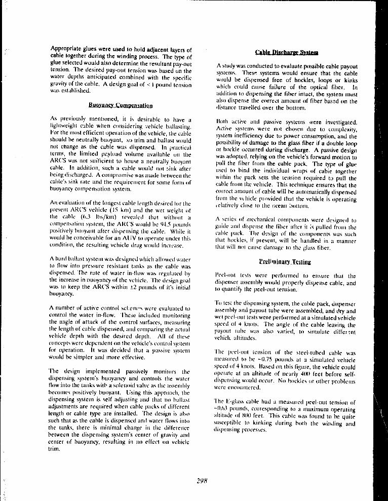
Appropriate glues were used to hold adjacent layers ofcable together during the winding process, The type ofglue selected would also determine the resultant pay-outtension . The desired pay-out tension was based on thewater depths anticipated combined with the specificgravity of the cahle . A design goal of < I Pound tensionwas established.
~t!~111i1CJt ~ttII!{t~it~ltt~Qpl
As previously mentioned, it is desirable to have alightweight cable when considering vehicle ballasting .For the most efficient operation of the vehicle, the cableshould be neutrally hurryant, sa trim and ballast wouldnot change as the cable was ciispensecl . In practicalterim, the limited pt,.ylutrd volume available on theARCS was not sufficient to house a neutrally buoyantcable . In addition, such a cable would not :,ink afterbeing discharged . A compromise was rnade between thecable's sink rate and the reyuirernent for some form ofbuoyancy compensation system .
An evalturtion of the hrngc:st cable I e nhth desirecl fo r thepresent ARCS vehicle ( 1S km) and the wet weight ofthe cable (6 .3 Iht/krn) revealed that without acompensation systenr, tire ARCS would be 94 .5 puun ►Ispositively buoyant after dispensing the cahle . While itwould he conceivable for an AUV to oper a te under thiscondition, the resulting vehicle drag would incr e ase .
A hard ballast system was detiigne d which allowed waterto flow into pressure resistant tanks as the cable wasdispensed . The rate of water in-flow was regulated bythe increase in o uoyr► ncy of the vehicle . The design g o alwas to keep the ARCS within ± 2 pounds of it's initialbuoyancy.
A number of active control ticl :em°h were evaluatecl tocontrol the water in-flow . `l'he .e included monitoringthe angle of attack of the control surfaces, measuringthe length of cable dispensed, and crrmparinly the actualvehicle depth with the desired depth . All of theseconcepts were dependent on the vehicle's control systemfor operation . It was decided that a passive systemwould be simpler and more effective .
The design implemented passively monitors thedispensing system's buoyancy and controls the waternow into the tanks with a solenoid valve as the ascemblybecomes positively buoyant . Using this ;rpprrraclr, thcdispensing system is self adjusting and that no ballastadjustments are required when cable packs of differentlength or cable type are installed . The design is alsosuch that as the cable is dispensed and water fluws- intothe tanks, there is minimal change in the differencebetween the di .pen5ing system's center of gravity andcenter of buoyancy, resulting in no effect on vehicletrim .
Cable [lischarrxe Sy st em
A study was conducted to evaluate possible cable payoutsystems . These systems would ensure that the cablewould he dispensed free of hockles, lcx>ps or kinkswhich could cause failure of the optical f•iber . Inaddition to dispensing the fiber intact, the system mustalso dispense the correct amount of fiber bas-,d on thedistance travelled over the hottom .
Both active and passive systerns were investigated .Active systems were no t chosen due to complcxity,system inefficiency due to power consumption, and thepossihility of damage to the glass fiber if a double loopor hockle occurred during discharge . A passive designwas adopted, relying on the vehicle's forward motion topull the fiber from the cable pack . The type of glur,used to hind the individual wraps of cahie togetherwithin the pack sets the tension requireal to pull thecable from the vehicle . 'Yhis technique ensures that thecorrect arnuunt of cable will he automatically dispensedfrom the vchicle provided that the vehicle is operatingielatively close to the ocean *,)ottom .
A relies of inechanical components were designed toguide and dispense the fiber after it is pulled from thecable pack. The design of the. components was suchthat huckles, if present, will be handled in a mannerthat will not cause damage to the glass fiber ,
Prs.Nminuty_,'Szaliu¢
pcc.l-Out tests were performed to ensure that thedispenser assembly would properly dispense cable, andto quantify the peel-out tension .
TO tcst the dispensieg system, the cable pack, dispenserassembly and payout tube were assembled, and d ry andwet peel-out tests were performed at a simulated vehic.lespeed of 4 knots . The angle of the cable leaving thepayrrrrt tube was also varied, to simulate ctiffer,~ ntvchiclc altitudes .
'1`hc pcel-out tension of the steel-tuhed cable wasnrcawretl to he -- 0 .75 potrntls at a simuhtted vehiclespeed of 4 knots. I3ased on this fi ;,ure, the vehiclc couldoperate at an altitude of nearly 4tH1 feet before self-disl,icnsing would occur . No hr ►ckles or other problemswere encrrunterecl .
'l't► e f?.-g,lass cable had a measured peel - out tension of-0,63 puunùs, correspondi ng to a rnaxitnum o peratingaltitude of 8 t10 feet . This cable was fuund to he quitesusceptible to kinking during hoth the win.fing anddi s pensing processes .
298

Cable Laying Sea Trials
During the fall of 1990, sea trials were undertaken to :
a) determine the effect of cable dispensing onvehicle dynanu o' ;
b) evaluate the cable dispensing system duringdifferent marwuvers ;
C) evaluate the buoyancy compensation systernduring cable iaispensint, ; an d
d) quantify the :haracteristics of dispensed cable .
17ynamic,; of the Aftr_S vehicle have been measured onst:veral previous occa:ions . During cable laying trials,vehicle attitude and c,mtrul surface positions werelogged by an onhoard dWt.t recorder while the vehicleexecuted a series of two and three dimensioraalmaneuvers . No effect! on vehicle dynamics weredetected, primarily due to the low cahle tension .
TO evaluate the cable dispensing systent, video camerasand recorder,., were installed in the vehicle to recordcable dispensinf;. one camera was mounted to view theinterior of the cable pack, and another nttrunteriexternally to Observe the cable as it exited the ve h icle .Post'missiun analysis of the video provided it means oftlete.rrnining if and Mitre hocklinT; and/or kinkingoccurred, as well as the angle of the di! ;pcmerl cablerelative to the vehicle during maneuverr .
To determine the effects of the dispertsing process rrnthe cables used, an (lptieal "I'ime Domain Itellectunteterwas used . At the heg ;rnting of each dive, the ARCS waslowered into the water near shorc., the cable end pulledfrom the ARCS and delivered to the OTC)R operatoron shore . The operator prepared the cable end andmeasured both attenuatiun and total length . [)uring thedive, these properties were monitored in near real-time,At the end of the mission, the cable was cut at thevehicle, and final CYT"f)IZ measurernents were niatle .Neit)ter type of cable showed any significant change in.utenuatiun due to the dispensing process .
A total of 22 cable laying missions, with both types ofliber optic cables, were perfurnu^d over a 3-monthperiod . ('able lengths laid varied from 2(N) meters to 1 2kilometers . The [;-glass cable perforrnwA po,irly overall,as it was fragile and kinked during botrt handling anddispensing . The steel-tuhed cable perfmntetl very well .A kinking prohlem with the steel-tubed cable early inthe program was traced to it solvent used in the glue,The solvent, methyl-ethyl ketone (Mf~K) temporarilybroke down the epoxy matrix in the cahle . Switching toa different glue resolved the problem .
Future Ulrections
There currently exists a need for a larger, long rangeAUV capable of laying fiber optic cable over hundredsof kilometcrs . Such missio :ts pose unique problems inhydrodynamics, navigation, obstacle detection andavoidance, control, fault tolerance, and energy storage .IS F Research is presently working on a number ofcontracts for 1)f2[.;P which are directed at thedevelopment of a long range cable laying Al'V . Thegoal is to design and build a system with a range of3(Xlkm while laying cables up to 130km . Thecompletion of this system is scheduled for early 1994 .
C'onstrained and free-swimming trials are beingperformed with the ARCS to generate enough data toaccurately model vehicle dynamics, the goal being thedesign of a larger vehicle hull, A preliminary vehicledesign is underway .
'I he prohlems associated with lunk-term autonomousuperations are hceing tah)ressctl . A navigation systemwhich will opcrate anywhere in the worhl with it rangeof 300km is heing developed, using it Ifoneywell InertialNavigation Unit and it dhoppler sonar its primary sensurs,l'resein day obstacle tletectitrn/avuirlance systems are1101 tiufllciently develupecl for autonomotrs operationenvisiunet) for this prograrn . ISf?. Research is beingfun d cd to aid i~t the development of a system suitahlefor uw in an At IV .
A new At)V computer control sys tern is currently un derrleveaopntent . Software design uses Object C')rie°ntedl'ru g ranrming (()O l') techniques, and it real timc pre-ernptivt sche d uler developed at ISE. The hardwareplatform will he based on the G E SI'AC" (i-9 6 bus, andwill use tl e Motorola M C 680a0 as the main piocessior .l',tult tulerance will be designed into the control systernto ensure ucce.stiful mititiions . This system is scheduledfor- completion by the end of 19111 ,
The existing ARCS vehiclc uses either one or two banksof rechatf;eahle NiC"ad batteries, each of which allowsoperations for 5 ho ;rrs al 4 knots . [ :nergy systems withsignificantly greater capacity are being investigated,includïn}, silver cathode batteries and fuel cells .
A phased approach has been taken with the presentdevc.hrpme.nt contracts, intending to demonstrate theARCS vehicle with it's new conit-A and navigationsystems in early 1 992-3 . Following the tc,,ting of thesesuh~ystems, they will be transfe.rred to the new vehiclefor cumpletion and testing in early 1994 .
299

In addition to the intended cable laying use, thetechnology developed c.i ; ;ring this project has otherinteresting applications . The concept of an underwatervehicle carrying and dispensing it small liber optic cahleis of significant importance when considering real timecuntrol of systems in extreme water depths . By utiiizingthe techniques demonstrated during this project, vehiclescan he conceived which will offer real-tirne control tofull ocean depths without the necessity of a large surfacewinch .
In less than 12 months, ISE Research, with a ssistancefrom R ockwell International, designed, fab ricated,installed, and field trialed a fiber optic cable layingsysvm for the ARCS Al1V. Sea trials demonstratedthat .:n Al .1V could auton o , ;iously lay differcnt types of
fiber optic cable without compromising cable integrity .[)uring the final mission, nearly 12 kilometers of cablewas laid in less than three hours .
IS[; Research is presently working on the design of acahle laying A11V with a range of 3KK1 kn-. . 'I 'ttecompletion of this system is scheduled for 1994 .
Applications of this technology will be of great use insystems intended for extreme water depths.
A9 lst1 srWkd9tmctZt;:
The ar .thors would like to acknowledge UREN for theircuntinued support of this program . We would also liketa thank Stanley Stone of Rockwell International for hisassistance and perseverance during sea trials, often inless than ideal weather conditions.
300

Third Conference on Military Rohotic Applications September 199 1
Unmanned Vehicle Mobility: L imits of Autonomous Navigatio n
A .W. McC'ormac, I),Ct1 . Hanna, and J . itiRcE'e e
I)efence Research f?slnhlish file, t Suffield
C'onsideraLle re!;e<u.h is being devoted to the
developmeut of unmanned vehicics for military andcivilian applications, particulariy in hostile environments .Such vehicles could work with toxic chemical or biologicalcontaminants with no risk, and could manipulate explosivematerial with fin,rncial risk only and no threat to human fileor limb,
it is desirahle to proNce a vehicle which can selectits (),Am route, not requiring remote navigadon, but it must
then be able to "sc.e" its surroundings . Though imagingsystems and modern computers make this possible, thee.xtreme data processing demands usually make itimpractical . In general, that is under the assumption that aclear, flat path must he found for the vehicie to progressthrough .
The au ;hors suggest an inverse relationship existsbetween vehicle mobility and the complexity of thea.ttonomous navigation system requirecl, A heavy vehiclewith little power, small wheels and no suspension systemmust avoid everything in its path, and would therefore haveto completely segment and identify the terrain around it, Avehicle with large power to weight ratio and excellentclearance, approach angle and traction can traverse manyobstacles, and if it is highly agile, it may also navigatearound larger obstacles at relativet%, ~ :~h speeds . It would
not have to evaluate the terrain ahead in great detail : it need
only iden :~~, obstacles large enough to impede it .
This paper presents an overview of vehiclenavigation, and the degree to which it is affected byincreasing the inherent mobility of the vehicle .Simplifying the navigational computatic ns means thevehicle p4th selection and speed and steering adjustmentsmay be made more quickly, resulting in higher vehiclcspeeds whenever possible . Cornhined with reduceddeviation from the intended path, this represents signifiwantincreases in the speed-made••good from point A to point B .
17J)lro(JMSl!S?t!
In the militai y . a vehicle is not rated in terms of
aesthetic values of shape and color or flow pleasant the
driving expcrience is . It is ratcd on a hiytily quantitativebasis, in terms of its lite cycle cost and its potential to
complete intended missions. The first factor takes into
account the costs of acquisition and of maintenance, thesecond factor includes rtssessrnent of the deployahility and
the mobility of the vehicle . The concept of unmanned
military vehick!s expands the scope of both .
'i"hcrc are many mission profiles in which anunmanned vehicle has a priceless advantage. No one hasyet been able to establish a price for a soldier's life .C'hemical and biological weapons are readily available tosuperpowers and terrorist elernentx alike . Even nuclearweapons are far too acces .eible, as evidenced by recent
world rtrws . When these weapons are deployed, anddefence forces are tasked with stopping their deployers,any measures that reduce the number of soldiers in directcontact with the hazard is extremely valuable .
llowever, with ever-tightening hudgetc . e+rJ
increased scrutiny of defence spt:nd 'tng, dcfence staff arevery careful how they spend their altrtmc:nt of the
taxpaycr's dollar. if an unmanned vehicte costssignificantly more than a manned ve.hicle, it must have aproportional performanze or mission advantage . Certainlyin the next decade, unmanned vehicles will cost no-irebecause they utilixe expensive equipment . Despite theirpotemial to reduce human casualties, unmanned vehiclesmust still have mobility equal to or in excess of cur :entvehicles in oider to receive consideration by the mihtalÿ .
yt;it(sLe."Oil3.S.y
Land vehicles are constructed in many differentshapcs and sizes, usually slecific to their intended purp)5e .The components used determine wherr, the vehicle will be
30/

capable o!' going, what it will he able to carry, and how fastit can go. In military circles, the usefulness of a vehicle islargely determined by its mo6ilirv, which is defincd as thespeed-made-good from on :: location to another on a knownterraia transect under a known set of ►uading andenvironmental conditions ,
Matn ~ ltr .y c~licle ntobili~
Researchers who study traction mechanics andvehicle sy-aent dynamics have historically ide,itifiedseveral p : .rameters which may prove to be ihc speedlimiting factor, as itemiz.ed in the NATO RefewnceMobility Model (M2MM) and listed below I 11 :
I . Total tractive effort availahle lo overcome the conihinedresistances of internal friction, soil drag, gradient, obstacleand vegetation overric?e, and drawhar pull exerted .
2 . Necessary tnamctrvering to avoid tnoes and any rHherobstacles too large to override .
3 . Acceleration and deceleration between disu-ihutodobstacles if they are small enough to he overriden .
4 . 'I'hreat of damage to tires or other running gear due toterrain surface hazards or excessive applied forces .
5 . Driver reluclance to proceed tastcr than the speed atwhich he wottld he able to ston in the visible region ahcatl,as limited by hraking, . power or by visibility .
(ï . Driver ride Corn lori (tir diuumfou) over nrutth tcrtainand urlcrance to impacts on veg,vlalion or rrtht•r r~h .~laclcs .
Nt'om this list, the ttrst four tlcfine thc inhercntnurhility of the ve.tiicle, as they tehcntl rin dcsign . "1-heyhave in the past been consttained by imntaturc ntatetialstechnology and the lack of adequate vehiclr crmtrolsystents . Many ut'' today's emer}ting technologies show1xoterttial to enhance veLicle ntohility .
The fitst ilem . althrrttgh it ohviuusty rC hrs onproper running gear, is largely determined by the power it)weight ratio of the vehicle . If a vehicle has a la-getwwernlant relative to its that will Iessen theprohahility ot tractive effort limitint ; mobility . ;t will havethe power to traverse. many otherwise impassable ohstaclcs .Modern nuwertrains are capable of' generatin ;; more powerout of nutch snt,tller packages than thosu: of twenty ycarsago . Traction ctmtrol systems are now heing used toimprove he efticic :, .y of power delivery to aulomohile
wheels .
The second item is denewlent on vehicle asttlity ; if avehicle has a low center of gr ; vity, small turning radius,ùnd broad power curve it is .hle to turn and weave quicklyaround and between large obstacles in a stable manner,Thus while it travels Guther to get where it is headed, it
does not waste time on the way . The design of statittizersand research in steer-by-wire and four wheel steeringsystems is improving, the agility of modern automobiles .
The third item depends once again on power curve
and also on braking efficiency . Linear features (which
cannot be avoided) cause a vehicle to brake to a speed safefor navigating them, and a sluggish vehicle takes muchfarther to slow down and much more time in the process .Sintilarily, when it has crossed a linear feature and has verylittle forward momentum it takes considerable space andtime to accelerate hack to top speed. Anti-lot,k brakesystems are cummon today on civilian and i :rdustrialvehicles to imptuve suopptng power and safety . Close ratiotransmissions, and the use of the relatively noveltechnolo};y of continuously variable transmissions tcllt/Ts)are all improving power delivery performance in vehiclesfor transport and recr,!atiunal use .
The fourth item relies primarily on robustness Ofcumponents, but also on the performance of the vehiclesuspension system . If forces transmitted thmu};h the
suspension (and generated in the running gear) can becontrolled by making the snsnensic, . : sufficiently compliantto disturbances, the survivahility of running gear will behclter and handlinft characteristics may also he improved .Active and semi-acttve suspensions are the ohject ofconsiderable research, and both are now emerging on somenas,,wnger cars.
It is important to nnQ1. rh,u the 1 : : :,i two ncme in thislist of limiting, factors aie limits imposed by it humanrtnetatur in the vehicle, not vehicle :omnonents . In the
cunsitlrratir,n of unntanned vehich-,, human operators mayhe invitlved, drnetnlint; on the tte.pree ot' vehirle tuttunomy .Te!r-oItettnion uses it huntan driver watching a remotesrreen, but a trulY autononunts vehicle will c011(luct its rrwn
navigation . In cithur case, visibility will still impose amuhility limit . The fully auwnrrmrrus vehicle would not he
lintited by "reluctance", of course, but would he ahle to<omhutr exactly flow fast it could travel and still t%, able lostop in the tange Of sight . It rnay theref+tte have uSneed
advantage over it human operator, who would tend to
overestitnate süt(tning, time for safety .
Whether the unmanned vehit'le is tele-operated orautnncxttous, it contains no humans by definition . The lastof the speed limiting items will definitely not ahnly . :n theNRMM, a su+ntf-alone preprocessor called VNFIC)YN 11121, employs two subroutines to analyz.e the human factor .
One limits the xated human driver to 2 .5 g vertical
acc.eleration for single exposure, and the other limits theamount of acceleration power ahwrhed over time to sixwatts . Authors' experience with the. NRMM indicates thatfor many conventional military vehicles on generallyunstructured terrain, the ride quality and instantaneousacceleration limits quite frequently are the most significant .
302

I2Ltm, v ' itzk.l11Q-Nh1.Y
Regardles,s of' spectfïcs, any mission profile for anunmanned military vehicle wili include :
a) ttavel from po int deployed to a remtild location,h) pe rfctrming a functi o n at that location ,c) travel to a secondary location, if specifiect,d) pe rf .unting a funciion at that !t><ation ,c) rep e atin g steps c and d for remainder of ntissirm,f) returning to point delrhryed or uthcr terminus ,
The Vehicle Concepts Group (VCG) considersmilitary vehicles in general to be. a powered platform withquantifiable mtrhility, which may or may not be equippedwith an application package ttf Ixrinheral hardware specificto the mission prctfile . Within that definititm, anyenhancement tu the vehicle mohility will increase theusefulness of the vehicle and the rrrrhahility of missionsuccess . Removing the human occuranl(s) will improvemobility .
One of the authors took part in a hrevicurs NRMMsimulation study which showed that if the humansoccupying two rnilitary vehicles were remrwed, mnrrilrtywould he enhanced on altnr,st any discrete or conlinuou~terrain disturbance ;; 131 . The vehicles were a BombardierIltit 44 quarter ton utility truck and it Leopard CI mainbattle tank, the former wheeled and the latter trac,ke d
Simulation runs were petfurmrd to clu ;tntity tiu•eff.rct o f "urtm,inninf," the vchicle over dtsc'relc• hall-nowtdobstacles, which inv .rriahly impose a%pevd limitation kiticto shock . The heuristic ntannt•d ltntit in thr N1ZMM is 2 .5g of vertical shock imposed on the wmed body of anaverage suldier, For an unnt,tnnwd vehicle, Ihr• lintit wastaken as lf) V of vertical shock ur the payload, which is theexposure lirnit for strnte computer eyuiprr ; nt . It was Iountlthat the u,tmanned f!tis cttuld traverse an obstacle inaverage 4 .4 .7 timex as fast as wilh it cli iver, 'l'he u 1 tn 1 ,tnnrcl
Leopard rrntld traverse the saune obstacle an avc•r .il;t' of 1 .5tintes as fast as wilh a tlriver .
Further runs were hetfutmecl ttr yuantify themobility advantage of* lemnvinl; the titan over seyu e ncc•s ofeven :y spaced half-round huntps, vaiying the hunilr :teig.lrtand spatial frequency to obtain it h ;uad rutt;e of rrrughnessvalues, mensured as rrtut rnc an-suuarcd cleviatirm from th•ground level . The NRMM uses it heuristic limit of 6 watts
of acceleraticn power absorbed by the se,ttcl hudy of anaverage soldier durirg the crtrssing of a given terraintransect .
As payloads and equipment are gener :;lly nit as
flexible as a human body they do not ,thsurn vihtatinnulenergy in the same way . Huwever, they may still suffermechanical ftttigue, su in the study a steady start, vibrationlimit of 4 g(relx.ated) was im f+cxk.d trn the unntunned
vehicles . it was determined that the unmanned lltis had it
mobility intprovement of 1 .6 tùncs its minned counterpartand the unmanned I.et•nard had an irttpruvernrrtt of' 1 .4tintes the rnannrd .
Fig ure 1 shows the mobility intpro v e mcnt availableto those conventional milit . t ry vehicle s by removing thehuman contents . The improvement is de fined as the ratioof uttntanneu to ntann vd specd-nt ;tde- eucid mittus unity,expressed as a pe rv:entstg !+ . It h.wcontes u' , ions thatunntanned vehicles may he capable of' m• .n greaterm o htlity and thc'reftnc rnissitm capeh il ity nte, . :y by hcirtgunnt,inncd . If file physical ntake-up (if the vchiel ec o ~nstitutes a hi g h power to wei g ht ratio, low center ' ifyravity . hrecise stcerin g crttttrtrl, hruad power curve, andhi g hly ctmtpli ;wt suspension or control of llooting forcesand trac•tiun, then the only slYrntlCant limit to its mobility isvisi!~ility . It will t><• able to go almost «mywhen•, as long ivsit can "sec" where. it is g rrirtg . It is at this point that thc• re a lh e art of th4. P ruhl ( nt I ezumes evid4nt . How does antinntannrcf vehicle "ud"'
i'ercent Mobility Increase w/o Occ .ultanrys )
300
250
200
150
10 1)
50
S' titi s
■ S - loopard
l l fa • ttlis
9111R- tt~apt,n d
S r Single Ohrwk, It . ttopeated Shrwks '
F i g . I Mrrhilily iinhr o vrmrnt lor un :nartnrd vrhivlc ~
Accurnte tnlerhretation rtt file >eiii,nriiiittilig,%m :rkinf suunrl navte ;ttitrnnl rteci~,iuna is a ditttrutt ta .kcritic ;tt Io flic ctc• ;ttiirn t+l un :nnirnnntnuti vchicle. Tocun .ituc'1 algotithmv tha enahlr a vcfncle tu navir ;cuc•withuut huntan intettctiun, ii i~, Itrst rtrcessaty tu researchh o •,v il n :tvigatvs rrirh humait iutrtacûrrn . The decisir Ilsutade he ;ln auUmtrntrrus navty ;urrr tnust f o :rs rltc•rliwt• as
mlote t'lli•cti- :c` Ihan those of a limitait ultc•taun in urdcrur r) ntaximüc the ulility itnd ntnhilny tif the unntanncdvchicle .
Mtrhility of it vehic le may defitte the e lfectiveuc•ssnt it given driver de c isno n . A hutnan driver seeing ith o ïh o lc in front o f' his car, will intm e diately brake or steerto ttvntd it, If the same (tetsnn were drivirtk ;t tank, theywuuld rr)rre c tly assume the Ixtthrtle would have little eflbctand drive ttvt.r it . 'l'h e driver's perception ttt' the ntttbilit,y ufthe vehich^ deterrnitt e s which alternative fie :wlcc!s .
303

To study the efL,.i of pcrreived mobility on driverdecisit)ns, field trials were carried out un the D lZESlîrnerirtuntal l'n)ving (iruunds (T:N(i) . A sot of threevehicles, each with a chmactcrimic niohility, was driven bya set of' Four drivers, over a small patch of the L?l'( .ï . Eachdriver was inururted to uavel front a start point to it turn-around point 200 rneters away and return to the start ineach vehicle . They wt•re told they would he tinted for eachrun and thertrttrre it wuuld be important to ~hnok the mosteEEicicnt rath . Each run was video-utpetl front it tower atthe turn-art)und point .
The, vehic!es uuv d w v re all 4x4 . but one ha(i largedilierrnrev in power to weight ratios and dimensions . Axumnnuy nf, the vehit:lex and thrir ct)mparetl rhtue .teristivsis given hcre :
:ps.sui!iut!iun_.____C!'c W_Sttb__~att :~~_Yitt?
Puwe.r (kW) 130 11 9 2 8 . ;
Mass (tnnn e) 2.9 3 2.97 0.254
Power/Mass 44.4 40.2 111 . 6
Wheelbase (cm) 426 '134 126Clearance (cm) 24.0 17 . 8 21 .2Track width (crn) 190 I(iH 1 I 1Turn radius (cm) 952 70 0 226
Figure 2 denicts the speod-made-gutiil (SM( .~~) byeach driver, plotted against each vehicle driven . Average,SM(i in the Crew Cab was Itrwest at 9 .1 knt/h . In the
('art;n Van it was l; .Ec'x hlgher at 9 . 9 km/h, and on the A'l'Vit was 47 . 11Yv higher at 13 .4 km/h . ( ► rdy driver A had a5M(i on the ATV lower than in cither ttuck, II!tuninterviewing, the driverS, it was dist•twrrett that only (rivelA had no prior experience driving an A'l'V and therrturchad no prior perception of the mobility of the vchic!c .
Specd Mllde ( axt lkntAt )
ra 0150
100
60
00
tIijU11t:1tLlI 1C~wCab Ùryolnn A1 V
I I IkMr A IN DiMr8_~.. w (Wvr C m . .~~ tl lkNMt 1)
T:iE; .2 Mobility mcttsured in driver decision trial s
Driver order was chronological, with A driving tr11three vehicles, then B, C, and D . All drivers had an
opportunity to view the terrain hcfarehand, to avoid Icwfirst run SMG tlue to lack of familiarity with the terra~n,
A NI V Crew ('ab Cargo VailIt ('rew Cab Cargo Van AT V
C Cargo Van Crew Cab ATV1) Crew C'ah ATV Cargo Va n
Figure 3 indicates that perhaps the drivers did gaincunfidenc,~ with each successive run since, with the
exception ut the second ran o f driver 17, the S .v1G was
always luwcr than on the following nm. It should also benoted that the exception was driver D's run on the ATVwhich denuutstrated rnuch high :.r mobility than either ofthe trucks on average - an advantage. that driver U wascugni/ant of . This observation relates to our hypothesisthat the driver's perception of' the mobility of the vehiclewould influence his s;x+cd made good . Driver A had nopriur cxpcct .,ticm for the mobility of the ATV and thus ithecame his lowest spced trial . 'T'he other three driversexpertrd superior mobility from the ATV and thus turnedin their Eastest runs by far on that vehicle .
SMG Change, by Driver (km/h) ~
200
16 .0
10 .0
6 0
00 11 1p ~1 ~~ ÎÏ iA C
( 1 i st Run ! 2nd Run ■ ard RunI
I ih .1 Individu ;tl driver mobi!ity on successive run s
The source of the ad d itinnul speed O htaineti by
driver, it, l'.:' and l7 on th e, ATV became evident when thevideo lapes were rr-iewcd . The trial zone had bee n
sc!roed hixause it cuntained I+ierex of terrain withditft'rrnt rhararteristicti, as indicated on fi g ure 4 .
L■~re~rt
~ l;reAnd'qTwvel rn1Th~rk vew~etrt~~•nR,aA pileStgntrtcant rtdg s
Fig .4 Sketch of trial zoneAlso to avoid skewing due to driver kn o wledge increasing
on each lun, the vehicle order was changed for each :
304
•
St .rt

On the figure, the dominant paths chosen aresulx,rimposed . Some divergence from these paths didoccur of coursc, and only the most significant terrainfeatures are indicated . The arrow heads indicate that onlythe center path was ever bidirectiemally selected . No driverever approacned the tower using the southern path orreturned usint, the northern path . The most reasonableexplanation any of the drivers or observers offer for this isthat habitually, front driving North American vehicles withleft hand drive, drivers prefer to keep the obstacles on theirleft for better visibility .
Points where small divergences f'ront the thrcedominant paths rxxurred were examined in greater detailafter the trials in order to identify li,atures lit,elyrespon :;ihfe for the driver's decision, and thcsc ohst :rvationswere mw.1e :
1 . Drivers in trucks were careful to apt,roach lincar feaumes(ruts, roads and ridges) at or close to perpendicular toavoid tipping, while on the ATV they would approachthem up to 45 degrees from perpendicular, if it was it moredirect line to the destination .
2 . When travelling between major obstacles, drivers intrucks tended to crowd those on the Ieft, probably due toreduced visibility on the right side, while on the A'I'V theytended to travel midway between .
3 . When driving the ATV, all drivers Uwk a"connect the-dots" approach, travelling in approximately straight linesegments front :rne obstacle to the next, while in hothtrucks and the long wheelha.k. Ciew Cab in particular, theytravelled in sweeping curves to ",set up" their nextavoidance man oeuv e r and avoid the need for sharp ► urns .
The third observation relates directly to the agilityof the ATV corrpared to that of' the trucks . If a givenvehicle can make very tight and ytrick manoetrvers, thedriver can adhcre mor, closely to the intended path andwill only deviate to avoia one onstacle at a time, withoutplanning his approach through all other oh,tach•s in hisrange of visibility . The A°i'V also exhibited tnuch morerapid acceleration and braking along the line segmwnts ittravelled, due Iargely to the use ot' the C'VI' and also due toit.c low inertial mass, strong hyd,aulic brakes and thesuperior traction of edf-rriad tires .
A few cenclusions can be drawn from this sinipletrial ; the principal one is that driver decisiuns areinfluenced by perception of the mobility of the vehicie .The operative word here is "perception", because the drivermust he familiar with the vehicle capabilities or lie will notuse them to advantage, as in the case of driver A on theATV. It may also he deduced that if a driver has highconfidence in the agility of it vehicle, he does not have towatch the terrain far ahead hecivrse lie is able to tackle eachobstacle encountered without pre-arranging the angle ofattuck .
Another conclusion of importance to unmannedvehicle development is that on nnstructured terrain, it isvirtually impossible to avoid all obstacles, so a driver will
first glance over the surroundings for major obstacles andplan his route on a macroscopic level . As he approachesless significant obstacles on that route which lie has
decided to override, he scans them in detail and decideshow fast and from what angle to attack, based on hisknowledge of how the vehicle will txhave . Most of hisconcentration and time is devoted to path selection at thismicroscopic level . If the vehicle has high mobilitycharacteristics, their the driver will not feel the need to beas cautirnis and is thus less likely to deviate front thechou.•n path . F'rom the perspective of the unmannedvehicle this means that the image, the driver sees-is not
processed to the same level ot' tletaail if the driver knows thevehicle can traverse difficult obstacles and withstandobstacle impact and terrain-induced vibration .
Imace 'rocMing
The most general definition of image processingidentifies it as the extraction of measurements, data orinfr,rniatinn frurn an image . Some other names it goes byinclude scene analysis, photointerpretation, imagedescription, and image understanding . The science ofimage processing as it relates to vehicle navigationinvolves usiag one or more imaging systems to view thearea being entered and then segmenting the image(s) intoobjects and feruures recof;mtahle by pattern analysisall;oritltms and soi sit' form of vehicle navigator andcontr,rller .
'I he complexity of the image, attained depends inpart on the hardware used to canture it, but even more onthe degrce, to wltich it must he processed . The capture ofimages is virtually instantaneous but the processing takessome finite time, acd in current research the greates'bottleneck in antonrxnous vehicle navigation is thetxnh ;tgation delay in the sutlw;.tre or Iirmvrare whichanalyres the image contents .
QYS:fylS.~ 111...LC.t'.t?1it1Lft
An imaging sysIem consists of one or more digitalcamrtas interfaced to it pnk•essing romlruter . Th errsolurion of the imaging system, which is defined as howmany hicture elentents (pixels) are used to corn rose oneimage, has it direct correspondence to the si/x• ol objectsand the detail that may he extracted .
The field of viPN' (if' it canter, is the portion of thereal world which is in the image, It can he de .wrrtK.d as atetrahedron with the apex at the camera lens, the apex angledecided by the camera focal length f', and the. ha.k: at thelimit of visibility front the camera lens, as shown in figure
305

S . Of course lho limit of visibility is rather vague, so itmay he defined more precisely as a threshold of resolutiun- a point at which one pixel repnvu:nts a real world area ofone uluare centimeter or dccimeter, for exantple . If' it isassumed that the pixel resolution of' a xyxtem is constant,then focal length selection becomes a lrade-off betweenalv.x angle and the distance to a particular threshold ofresolution .
Fig .5 Camera field rit vic w
It is tthvictus that durinf; hn,crssing, the int :tgr tnutitnot he allowed Io changr . A video ntcmury hank on [lie,hr't>4cxxinF board(r) "captures° one individual scelle andholds the information xtatic white i l iris procCs,;Cd . The finiebetween the capture of successive images iti callyd thejrumirt,s; inlervr,l . While Ille canieta viewing thccnvircantn.nt is a cuntinwous ftruc e ss, Ille vvahlatioll ofimages i :: a dtscretc (rmrc~~, and Ihus fil(- hrcrcrNsin ;o, (il cmcimage does not Ittcrvide ÎttlcrrnrNiun abolit flic mcrtitin ulthe cnn :cra relative lu Ihe wurht lit motion o i ohjccts in tireimage . Alstt, a raw image is two dinirnsiunal in nature andthcrefurt• a single camera citnncrt dtrtrrtnint, Ille distanco fil,an identified tthject, except th :( il is hclwrrn the I . Ils andthc thresholtl tir resc+httitin .
most imaginf; xy .tet ;ts sultltly images to an ;utaly .ixItrc,gr.tnt alter Itotfnrmrny; sunte han)iv,n . cnh ;tnrrinrntfuncticmx . Mntlyhutug'i-ai prc,re•~in4 may be porto trrtctl infront end hardware of Iitruware . as fillc•tinr of viclrcc nnne .This is direct binary prucessing cit it raw image in orner toaccentuate of, tUlenuate tmage featnres . •l'htee l,tiniipalntrn; huhtgical cthcrations arc funtlantcntal to t ;tw im,tftt,filtering 1 5 1 :
1 . I)ilurirrn or fattenirt g , in which surfaces an, cnh ;tncetl by
utting pixels to the same state its th ir ncii.hho rs, s o the
object unifitrmly grows in two .1 mitre ris itmitl are,t .
2 . ISrrccinn or thinnin g , in which surG ces are enhanced bysettin g pixels to the background stale unless they nrrsurrounded by similar neif;hhtturx, so the object unifctrntlyshrinks in area .
3 . Skefeu,nizatiun, similar to erusicm except that surfacesare not allowed to disconnect, su after many iteranons theimage will he a".slick diagram" of the original .
AI't-r such luw level pritcessinK is Ixxfurme.d, themodified image is passed to some form of image analyzer .The authctrs define image analysis as a suhwt of imageprocessing, to be differentiated by the fact that the outputof analysis is rtumertcal, rather than teing a modifiedpicture .
Irl1wvx__iin ;tl_yyi~
ln ternis of vehicle navigation, the doired output ofimage an:rlytiis is a matrix of ;hree dimensional vectorsdescrihing (lie location of' potential obstacles in thesurrrnntdings . Having that matrix, the vehicle controller isable to cuntpute the s ;tlcst and most efficient path to take,and outputs cuntrcd commands to direct the vchicle alongit . Ohjrctx of interest may be identified in a single image,fircrviding u two dimensional map of' the surruundings .t)htaining the third tlimensinn, which is the distance to thecrhject, is dttne in a couple of ways depending on whetherthe systrm uses a sinF;le caniera or multiple cameras .
In ;t single caillera or systelli . flic:nt,tlysis ;df;nrithm ntust kevlt a record of the position tifcach ohject in view fruit Ihc' firVt trame fil a uqurnce .Whrrt successive trames art :tvail ;thho, the saine nhjects areIc,catect in thc„e images . Changes iu the orientation ctf anuf~jrct, calloci crprirul fl n c , tue vv ; .tlu .ttt-cf hy any (if anumhcr (il point (il, rtl~t~ Itackinf; atgcuithrns, fruit whichthe intfncenclent uitnslatinn and tutatitm (il' the objecttrlnttvr tc, Ille cantrra can he cumfluted . Il file precisiemotion and six deg rrr ut Irectlnm trrir~ntalicm lit thevchiclr, called pose, is known, thcn flic coinjNoilent (iltrptical Ilctw atttihutable nt carlic ta mcHic,n ntay hedetruninccf as a fonction c i l distance front Ille caillent leils1 S 1 . 'l'hi• olrtical tlttw vect+trs ut an nhject then alfuwcuntlttualinn rit it s
tln .• prc,hlctn witlt thi s mrlhucl c,cctn s in Ih V
uturuiun, alhT il t :uc, when n .yrnmctt - cal crhtcct ires ahead
clirrctly our the •txis o f locus, No motion will he
tictrtminrcl fur that O hject . Iho wevcr, file tiollilidiled
iu• :reust' (of ctccrt•a se ) in .i /c htuvitlrti some infcntnt,niurt on
tht• clusin ,t velocity of the 0 hjcct 10%V0 10 thc canter .i .
Ntctnrt .eccrfrir xyxtcmx can tluitr accuratrly tr :tck s tatiurtarycthj c cts in a ntuving field of virw, and converselV nntvin g
uhjrct S in a Etatnmar'y field of view . t tnfo ritm;ttely, whenindc hrnclrnlly ntnving cihject s :uc viewed by a nno vin};camc•ra, it is cxtr'emely ditfi t ult t o di s tinguish the o pti c alflow vcct o rs attrihutahi e to each nrtit,n .
In ctrdor to determine the range to the object in itmultiple c :tmrra sy`tetn, ralh•tf .rrr•rro .crnpie•, the {torallaxfretwccn th e vanlage points may he emphtyed . Figure (rdepicts httw all object :tppears to two eamerax aimcd at itcttmnturt perspective point at distance 1, and separated b y
306

distance I . When the left and right images are analyied andthe object is located in c:ach, the sum of the lateraldisplacements of the object from th ., image centers, dl anddr, is the buse of a similar triangle, atisuming small fucusangle A . Distance to the object D is easily calculated as :
~V ~---~ R _~_ ►
I dr r--- ~ .
I.elt d i
1)= 1 .x(I-(dl+-dr)/1)
-)
f'ig .6 Ohject range in stereoscopic vision
(I )
The greatest advantage of stcrcrlvcvlpic over
mrrnr7sccipic systems comcs in the detrrminatiun of this
third dimension 101 . If each c .nr'rn is comnoctrrl to ;t
d e dtcatcrl pmccssur, then the two-dtmrnsir,nal mapping rit'
le ft and right images can occur sirritiltancously, in the saint,
am,tunt of time it takes to tnap the tirxt image in ;t
1m0110scnl7ic systetn . The distance to each potential
obstacle in the stCrcoscnpic scrnr is calculated by r(lu ;uion
(1), whilt' the nlOnrlsclltlic AVstCrll must ptrlcP s V at ICn .~t one
more cunthlctr trame belote any range intram ;uion is
dc.n'nnined at all .
Once the s y .~lcm has auainrtl lange infollcialioll lof
all objects of intc'rrst in the ,urrnundinft" . the clusing
velocity to each ttt ;ry be calculatc•rl its the c han);c ill langefront one framc to the next divided hy th e ttaming Interwil .
For vchiclc navigation, the trivial case ni.-cuis when thc
closing vc'Iricity is positive, ic . the object i,, gcttir g tnthrraway . !t' the clusing vt•lurity Is ttrg,nivi' thrtc t . antmpcnding cul!iskrn hetwGen the vehicle and tht° uhjrct,whether one, the other or both atc acnmlly mllving . It isimportant to note that the closing velocity tnay he th e
velocity of Oct. object toward a autirm;try iamct ;t, the
velocity of it c ;tntr•ra-cquihprtl u lift) :mned vrhiclr tmvatd it
stationary object, or the sort rlt hnth .
~ll,iliLll.lltS~Y .£11.L4 .~~ .~1.3)Xlgt1S~Q11
Two principal avenues of approach are available to
implement navigation systems for unmannrd vehicles, Thernan-in,the.-loup aPppruach simply rrfmtwcs the humancontents to another location and the vehicle is driven underremote control, The Ir-~s explored antl more complexapproach is Io implcmcnt a computcrised auttlntunuus
navigator on the vehicle .
_ D
Rest , archcrs involved in autonomous navigation
syae.ms for land vehicles or o ttiar machine vision
applications nrnntally identify three Ic.vuls of' data
complexity a s listed here 171 .
1 . S; nsury - lowest Icve1, raw image reprvuntrnl; intensity .
cuhlr, and rell e ctivity, possibly tiltr•rcd by hardware .
2 . Sylnhulic - nialr p ing of edges, surfaces, and vcrtices,
rrnge de terni inat ion, and the analysis of' opGcal flow
(motion) .
i . K.tuw:ICrIL&-'-bau'd • highest I0vc1, recognition 'il* ObjectS .matchinf; sccnrry tu wrlrld mndcls, Iehllviural prcdictitrn .
Currrnl imay;ing hardwnre cari prrldur,c quite
accliratc tirnsnry inlottmatirm, and m ;tny high slccdlilit,tin}; ;ma nwrphtlhl);ical processing ctrmpunents are
available . As ;t result . nxrdificd Images can lie maleavaitahlc Io analysis algorithnis almost ina;unanruu .dy .On the t'thcr end ut the scale, expert systcros and artificiaiintcllig+'nce research has made available sortie veryefficient knuwlydge-hased pattern recognition, trajectrn'ytn ;tht•tnf; and global path planning, alg,orithms . The
hl,tt!r'nrck bas hi`trlrically ficela the translation nf scnwryintmntutiom intu tiymbrlhr 10aturr5 .
Art unrnanncd vrlticlr Must be ohlc to rrcrmnin
obstacles in the sutnlunilingx and t-'mvidc accur ;ur Of) , Itar.lc
intiolmatinn lu sonne toi ni of rxrrrt tt .+vil;;unr .
In the case of tclc nl7rrnlccl vclticir ., thrro tasks arc
lu'rtoumr'd hy [lie rrlnuh' ohi'rdU r, wh o also !tapfx•tts to ha
the o rhrrt navi~~atrlr . Ihlwevrr, t•vcn witlt vrty good video
s)'~t1'n1 .C, Ille rt'I1111tC 1/(1Crntijr wdtchCs a less minage
within a n ;nruwcr lit-iii of virw thcln lie wtluld ur il tir
Ni'rr on th e vehi :h• . With pouf ccrtplx`ral vt .suln, flic,
upcr:urlr clmmri u'c a movitt); rrhject on an intCrcclu cuitrre,
prrh ;lhs, (il lut nltrtnatr route th;lt m ;ty ht' much ra .~ict Io
n ;lvif;,ur but i .~, just outside lits field of view .
In urttcr tn hruaden the field of, vicw and Imo vidc
mrac prlinhk'ral vision, it widc angle kits must be
rrnlrl„ y rd . ltnfunun;nrly, tttc rr'Nulting decrease in focalh'ngth results in a larl;cr field apex ;utglc, tcrallirtg ligure
5, and tltu s shtntens the distance to th ncccsr;uy thrrshrrld
of wsulutirlt, . Potential obstacles will th,n hcctlrt)c more,difficult to discrrn until the cannera gels close to them, so
the vchiclc must move quite slowly in ordcl to givt• theuhcrator tinlc to rc,a•t and take action to avoid or prcltnre tooverride thr•rn .
one way around the peripheral vision and thresholdof testrlutilun trruhlems is to in :rrlduce tefe-/rreseru•e . In a
simple systcnt, tClr .preK'ncc putts the cannera on it pan and
tilt hi'ad . It the retnutr operator nuises his head to on e
307

sidc^, sensors attached to hirn measure the motion and sendcontrol signals to the camera on lhc vehicle nr turn to thatside a corresponding amount . This allows the use of Inn~(-rfrxal length su the nfx:ratrrr cari sesc (tetail farthcr away andthus move the vehicle more rapidly . Unfurtunatc•ly, thisonly provides peripheral vision when the operator choosesto use it . It also adds cnnsidcrahlc crrmplcxity to thecuntrul prublcm and to the transnriti.siur, riyuirrrnc•ntstxetwccn the vehicle and its crnu(il station .
Another shortfall of hnth of thcu: sy .titcros is the tactthat the vehicle still has a mission to prrfr(rm, and if thatinvolves direction by it rcmutc hurnan uhsr•rvrr/e(mtr( th•rand is to he dune while in motion, it pruhahly rcyuirrsan+rthcr human at another crnurul station, as (lie driver willbe tuu busy navibating to carry out (Hhrr turrctiuns . ltwould be advanlagrcrus to have u vchiclc capable of f'ullyautonomous r ;,rvigaliun, so only mission functions wouldrequire interaction with a rcmntc (rpCxatur . An auurnum(ru .xchassis would be able to accommodate almost any missiun-specific package t o he c arricd to rcmutc sites .
UnUutS1S2tlill .ST yaftw
The dcsirrcf way to rcm(wc the hunr .in navif; :itorfront the vehicle is crrtainty tu replace him with an cyuallycapable computcri!ed version . t?nfurtumuety, images ofunstructured terrain are not likely to vomain a hnundud air(]cfefinitivc set of patterns like th(ise cncmuntt•rcd in m,rnyplant and industrial machine vision sy+tcrw~ . Tho", thranalysis of those images will not he restrictc(f n) theClassification of sct•nt• rt•f;ions to a frxc•d numht•r (ifcategories ; ohjcct variety tt',ay be vast and lu((uly d4incd .This will further rornphaur the uernslatirrn of modifiedimage data into symholic rchrcu ntati(ms, and serve to 'Slowtluwn what is alrcady the ratt dctrrniininZ;-atr(r toautonomous navigation .
C'atuguriz,ing and identifying every object in a scrncrcyuirus operations being drroo, on all of' tilt, inf(rrruationcontained in an image . Rrrrntly, s(rtm• rrsr,uchr ;s h ;rvcadoptt.d a h•ss gt•ncral appioach fit image processing lotnavigational applications . If the navig;u(rr must idrntifyonly one or a small set of prrdrfïncd categmics of obit-cl,either to avoid or track thrnt, Ix•rhaps there is to need urprocess the entirc urrrr .
As an cxan(plts, Brown et ul desired all algurithrnfor locating a field demarcation line, to be used as adin,ctiorral aid for farrn equipment to monitor andntinimi i,r, iimplement overlap jtij . t!sing a video cameraand a personal computer with a CCD interface, theyimplemented it conventional edge tracking algorithm whichIocatcO the borders between tille.d and untillcd soil andbetween standing crop and stubble to an acceptableaccuracy, proc.ev.srng all of a 512x4ix1 image, I Ising imagecomp ression they reduced the raw image by a factor of 4 inboth directions to 128x1O(l, and were able to identify theline in the co m pios c d image t o an equivalent acc.uracy .
71he full image processing required computation
limes nl about 16 minutes pe r IYaite., while the compressedimage, with one sixtcrnth the numtCr 01' Pixels, took aboutone mintrtc, still trio long for real time processing .
At that point they hyp(rrhesited that real timeprocessing at field speeds may h -- pcissible it the number ofpixels nn be processed could he further rcelucrd . As thedcmariali(m line is always appruximalcly straight andtrave•Is frnm it point on the top edge of the iniage to a pointon the h(rtaam edge, they dc•velnhcd two novel alg(rr'tthmswhich analyiett four hniis.(rntal rnws on the irnay,u . Thet ows wcrr each 411 pixels wide f( ,T full illiages and 10pixels wide for o(mfmesud images, and were eyuallyspacc•(I from the top u• hutlum edge of the rnrngc . Thus thecftcctive site to he processed was I6t)x4Ol) for t ;tw imagesand only 40x1(h) for r,•(rmprr.ssed The four pixel handspnocc,,.rcl by the Adaptive Iterative !?.tlge Finder (AIE3F)and the Block f)ifferrncc Matrix (B[)M) algurithmsproviclccl four points on .he dertiarc;atiun, and computing atcf;re .si(rn linc front Ihr~se points f+ruvided the thresholdctirrctrnn with more a :•curacy than the conventional edgetrackrr .
'U1c computation tim e s for the Aff:F wcrc 1 .55seconds foi full and (t .11 seconds l'or complessed images,and flic 13f)M timrs wcrc 0 .62 x~c(mds for full und U . :l :lseconds l'or ctImpts.sc(l ,
'I ho ccmrl,rsinn n) be gleaned from th tt work is thatit you nvcrl orly icle•ntify rrhjc•e•ts of particular sue or shapc,thcn )'Ou crin c(mstruct image analysis algorithmti tof ic•rfrnm Ifrr- icit•ntiftratiun functinn with equivalentnccur .(cy in tilt Jrtis time ,
t"nlikr ttr(rwn's ohjcctive of line tracking, theObjective ut an autonuruuus navigator is to avoid obstacles ..I'hus ttic basic image prucc•ssinf• functi(rn involvesextracting objects which are large cmut,_Ht to impede thepath of the vehicle .
%l,Nltl'tl!.;Itjs'S !.~f . ~ .tslJtlt«.tltat~?11
The pnoccss of dissecting a r :(w or tttodificcf irnagCïntn dixc•crnihlc uh,lcrls is callccl ar,~mentririr,rr . Thesimhlrst u•gnte•ntatiun rncthuds invulvc using a I ocalIntensity Mran (1 .1r`t) in a window of' fiKerf site, toexamine the image in smaller set-!ions ustav pixc :nik•r ;ttinns, When a L,Ifti1 is fauncf to contain significantly6ighcr or lower mean intensity within the image, thcc theimage tx,ordin ;ues of that LIM are used i :~ rlag a(rutcntize,object . When all (yh,jrc'ts are located, the acttnnnmc„snavigator has a mail of bcith where nhjccts are, or arehclicvrtl to be, r-w d by exclusion where they arrn't ,
f'sarh individual method of segmentation requires adrl'initc span of time to prex•css. As an example, let usconsider pyramidal I ..IM segmentation, which is considere d
308

to be computationally efficient relative to o ther methods .In this method the image amtlyzer successively averagesgeometrically doubling LIMs within the image, hence the'pyramid' designation . The nom ber of tipe ratiuns requiredfor each successive level of examinatiun dect ca .us due tothe data reduction effect of previous levels .
The incremental time rceluircd to process one imagcat each LIM window sin is aplrruxinrctwly constant,directly proportional to the area of the entire image andinversely proportional to the area of the designated LIM .More simply put, it takes more time to process largerimages and less time if you use are starching for largerobjects, as one would naturally expect . Indeed, theserelations hold true for virtually any u :gn:cntatittn schcme,although the constants of proportionality change . One r fthe authors ascertained in a previous detivatiun (e)j that thenumher of operatiems reeluired to segment an image ofNxN pixels using a square LIM window of MxM pixels isas shown in figure 7 .
~~.A B
C, . ._ .p
~ - -~
Row Imago (NkN)
. . . . . . . . . .
. tIM o AaQ~-~!A- a A'I
Av e ropinp rodutr o f 3 op *ratlon tpar 1 .2 pnrad, (dlvl eton optlona!)
1 imago '
Imoça'(~ ■ 1 ) (Y-Y )
Fig .7 Pyramid segmentation by Local Intensity Mea n
In this paper, we tnake ttic very rra.stm :,hleassumption that trees, boulders, buildings and otherinsurrnuuntahle structures may be di :.tinp,ui .hed fromsurroundings by cetntrast. In the case of very largefeatures, it is of course possible that no other ' .urrnun ;iing:will be visthle . Thu s , we also assume that an unntaunedvehicle will have supplied to it it knowledge hase (if neathyfeatures on the scale of canyons or lakes .
Referring to the figure, take an image of 1024 by1024 pixels as an examplc . If that rehresent .s a field ofview of 60 degrees apex angle horir.orttally and vettic,tlly,and the threshold of resulution is one centimeter Ivr pixel,then the distance to that threshold is almost nine meters .
Suppose pyramid segmentation is emhhryed to uanthe image for objects with dimensions of 1 6 cm on aside .Typically, differentiation is based on a four to onesampling, so the mean intensity of a 16x 16 ohjcct would hefound when compared to that of a fi4x64 window . Usingthe incremental number of operations for each pyramidlevel from figure 7, the number of operations neqnired toevaluate the local intensity rnea~x within the 6404window is :
6
? kk-1
At typical off-road speeds with human drivers onvehicles such as the ATV used in trials, course and speedcorrection :: to direct the vehicle at any point within thefield of view may easily be monde well within nïne meters.If the iniage analyie:r used above hall comtiutati mal poweron the order of ten million operations per ~econ11, which isachievahle but qui te exrcnsive, it woutd take it tenth of' itsecond to find one object in the field of view, Thenavigational algorithm requires it map tiI all nhjrcts, aswell as some additional time to generate cuntntl outputs .('l c auty, this unmanned vvlricle will travel n"iuch mores!owly than its ntanned equivalent .
()n almost any off-road vehicltr, an obstacle srnallerthan 1 6 cm high may be straddled or overridden with littleeffort, regardless of its width . It is not necessary to processanything in the image shorter than that . If that is the case,then niany trnnecessttry operatieius are heinb done in theexantp e above .
The reliability of LIM xel;meln.+tion relies on the.ir.e of the comparisun window relative to the ohject, andnot on the number of pixels occupied by the ohject . Frontthe example, retaining the nine meter Ï for corrective action,we could reduce, the, necessary real wllrld resolution to 8cm r.uher than one . "l'hen any ohje,ct not uccupying it 2x2pixel block would be ignored as noise. "i'he imagererolutinn cuuld he reduced by it factor of' 8 in eachdimension to a 128x128 . Still using foutfelld sampling,local rneru» wnuld be calcuhnwd for Hxft windowe . Thentumher of ope rations reyuircd would he wiluccd frontmore than rme million to 10 ,12 8 which is it 9 8.5 %reduction .
!.'.Ufld0)~,►.1 1
Simulation and cnnunon senst hoth indicate thatrernoving the rel ;rtivr'ly fragile huntan occupants fromntilitary land vehiclr•s could f.~,reatly enhance their mohility .The most k riotts factor limiting overland speed wouldhecunte the rerutitm lime it the control systern . "I-hnlsystent may be it tuuuan oherator tu a rentote controlconsole, or in the future if may he a computer emuhttinKthat t>pe.rator, placed on the vehicle . 13oth have limitedreat'tion titnel.
The reaction time of it human operator in thevehicle is it functi(m of confidence, mental mate, andphysiological reClc.xes . Some variability exists betweenpeople, but no new versions are being made with reactiontïme, reduced by orden of magnitude . In general, themind processes the scene of the surroundings and makespath decisions very quickly, but it strong instinct for self-
3(t074) `1, 0 4 8 , 3 2 0 o.y .~rnr lon~
.i'09

preservation often slows the reflexes in the off-roadenvironment .
When the sanie person is Gae-operating the vehicle,caution does not lintit speed as much . hlnfortunately, theabsence of sensury feedback tends to he confusing to themind, and thus slows the decision making process . SimplyPut, human drivers react fi!ster when driving by feel thanby pure Sight . Attempts to provide the missing sensoryfeedback have had limtted success, as this adds muchctnplexity, and a resulting delay, to he control loop .
Current research pruiects into auttrnrmtuusnavigation Ireyuetttly cunccrttrate un cnmpietcunderstanding o f an irnage, because human nature is todesire the 'big P,cture' - we always wish trt see everything .lhrwever, your car is blind and it drres not stiffen when yousec a pothole ytw are 'about to hit . If the car drove itselt; itwoulci not stiflOn either . Unfortunately, if it drove rtsclf itmight run into a tree or a building and hi-cak .
The autuntimr7usly navigated vehicle must be ableto locate nhjects which may impede it, select a path aroundsuch nhstacles if they exist, and effect any conlrois on the,vehiclc that p4tth selection calls fou . If it is to lime itntrrhrlity advantagv over manneel vehicles, it must (In ctll trtthese thirtgs faster than it man could . C'Imtinner hardwareis cr,ntinually F;eaing faster as well as loss exrensive andnr.' ;r reliable, but currently no autonomous n :tvigatrrr hasheec f+ruven supcritir or faster than ntan .
\Vc havr' p trt futwarrl Ille hypothesis (bat il' Illeinhrrent nuohility of a vchicle is ~peatly elillanced . Illescrnc Ixu~'i's~Nirtg reclurri'm nl~ arr f!rratly rrdur •il, andhigh tihcc~i aulunurnuu~ navigation tnigltt hc'cuntere :tlilahle . Wi' further propose that V('(i wili research anddr~i~~n a verv hivh nuobihty Itlatfo nn trr sulmrrrt ( hr URI :Sand I)NI) cffrirts intu autuntmurus navigation, willi IllehtrPe that this hyrrnhrsis nt ;ty hu validated .
1 . Peter W . Haley, M . Peter Jurkat, and Peter M . Brady Jr.,n'AMRç[_'ercne rrhilitv -H(r&)y E (j j ti }n I . U & r~ t'lçl/olurn e 1, Report 12503, US Army Tank-AutomotiveResearch and [)evelopment Command, Warren Michigan,October 1979, pp. 21-29
2 . Daniel C . Creighton, j2_ç,_v_j~~~d'ti'l' ~ylr rsltticsf~1Q-dil IeUSltit'rr1Qti ~ ' fg 1 _'nm )uçç r ft g~yr;fr~t V I~;NL7lN il,Waterways Fxherirnenl St i +ti o n, Vicksburg, Missis~inpi,May 19ti 6
3 . Doug NI . tianrta and Ting F . Stupich, " MuhilityC'umparium of Robotic and Cunventi o nal Vehiclcs",1)rfrnce Research f:stuhlishmcttt Suffield, DREP/RMC'Mihtary Kuhutic Applications Workshop, Aqgust 198 7
4 . William K . Pratt, f_.)i i 11 1mL,, LPrmziti+ 2nd Edition,John Wiley and Sorts, 1991, pp . 449-49 0
5 . Eclward M Riuv mar, and Allen R . Hans on, " DynamicImage Intcrpretatitm for Autonomous Vehicle Navigation,Final Report", AD-A213 172, University of MassachusettsComputer and Information Science rkpartment, Amherst,Mass ., August 198 9
t, . P . Mile'.ram ut al, "Stercrrsct7~rc Video and Su, crirnpu,tiedComputer StcrcograPhics : Applications in Tclcnhertiirrrt",I)(`II?11-9t1-P-113, D rfcnc e and Civil Institute M'tinvirnrunental Mrdicine, f7~rwnsvirw Urttari .i, Canaà
7. ('h :ulrs ( , Wcems, "Architectural 12eyuirentents oflm:to-e tlndr'ttitantlrng with Respect to Parallel I'tr,crs g "l'rurertlings uf Ihe 161 .t', Volume 7 1), No . 4, Ahril 1 99 1
K . N .II . Brown, J .N . Wilson, 1I_C. Wood, "Imay Analysislog Vision-R :tsrrl Agrirultural Vrhi& (iuidtutce" ASAEPaher 90 1623, Wintrr Mceting, Chical"'o, Illinois,1) e cemb e r 1 9 9 0
9, J . Mcl,re, K . Russell, M . Itr+, "l)rtrctrnn of Surl;tu'-laidMrnrfietels usirtg a llier ;trchical Inla,',r l'rrtct ; :~in~~Algcrrithnt", Sl'lti l'nr.•eerling,, V ..rlumc 1567, SPIE('tmferencc o il Applications of Digital Image PnocessingXIV, July 199 1
310

Third Conference on Military Robotic Application s
Heat Driven Power Systems for Small AutonomousUnderwater Vehicles
G. T. Reader*, I . J . I'otter*,J . G. Iiiawle}y
* University of Calgary, Calgary, Alberta, T2N 1 N4 CanadaRoyal Naval Engineering College Manadon, Plymouth, PI -5 3AQ l,ngland
Abstrac t
The military potential of autonomous underwatervehicles has long been recognised but until recently theassociated technology has not been sufficiently mature forsuch devices to be fully developed . The advent of highcapacity microprocessors and advanced C', navigation androbotic systems is now enabling the development ofintelligent unmanned underwater vehicles to go beyond theconcept phase . However, to make full use of the capabilitiesof the increasingly sophisticated electronic and manipulatorsystems sut'ficient power and energy has to be provided todrive them and the other systems which enable the vehicleto remain submerged for long periods of time . Therefore, acrucial element of an AUV is the power system .
Present in-ser6ce vessels invariably use batterydriven motor systems which while they can provide sufficentpower cannot normally support extended endurance activitiesbecause their energy storage capacity is inadequate . Thusalternative systems have been sought, based on such devicesas the fuel cell and the radioisotope but these are still toreach technical maturity . However, heat driven devices areavailable which could fill the current energy gap until thenew systems become available and the use of such deviccSis discussed in this paper .
roductïo n
The military has been the almost exclusive user ofthe undersea environment since the turn of this century .However, over the last thirty years the commercial, andscientific communities have also started to exploit andexplore the deep oceans . The main impetus behind thesenon-miliary interests has largely been the offshore oil andgas industry . In the future other strategic materials such asmetallic ores will also need to be recovered or extractedfrom the ocean floor as land based resources become scarce .Thus the commercial and scientific use of underwatervehicles will most certainly increase in the future but the useof military AUVs will show an even more dramaticincrease .
Whatever use is made of an underwater vehicle, i f it
September 199 1
is to be autonomous it will, of course, require an onboardpower system. In this instance autotu,mous means a vehiclewhich can operate independently of a suppo rt vessel, i .e .,untethered . Manned submarines using either nuclear ordiesel-elec tr ic power systems have the capability ofautonomy . However, autonomy does not neccssari ly implythat the vessel can stay submerged for long periods of time .The underwater endurance and range of present diesel-electric submarines, for example, is very limited .
Thus, unta relatively recently an autonomousunderwater vehicle was a manned vessel and longsubmerged missions could only be contemplated if nuclearpower systems were used . However, the co .i t of suchsystems and the lack of general access to the appropri atetechnology have been two of the main reasons whyalternative power systems have been sought over the lasttwenty years .
Non-nucle.ar free swimming vessels invariably use.conventional secondary batteries as the energy source fortheir power system's prime movers when submerged . Thecommonly used batteries, lead-acid ; silver-zinc and nickel-cadmium, have p oor energy storage capacities and requirefrequent recharging in the space lir A ted conditions inherentof underwater vessels . [3etter batte ries are being dewd opedbut those available at the moment are either technicallyimmature or very expensive . Other power systems usingelectrochemical devices such as the fuel cell are also beingdeveloped and expe ri mental have already been fitted withfuel cel ' s but it will probably be another 5 to 10 years suchsyste m s are accepted into operational service . To fill the gapbetween the present nuclear systems and the futunoelectrochemical systems, a number of different underwaterheat engine systems have been proposed (lj .
Initially, non-nuclear air-independent heat enginesystems were developed with two applications in mind, theman ned submarine and the torpedo . In t. te latter ro tary andturbine engine have u sed successfully for a number of years .However, these particular underwater vessels have sho rtendurances (minutes) and operat e just below the surface .Until recently th e use of anaerobic heat engines in mannedvessels has not been successful although efforts to developsuch systems date back over eighty years ( 21 . However, the
3//

Uwa O.yp•n ruw .l r strwq p•,w.ra
U1aN çuwNa J Stap• 661t9ry
Figu re 1 Hybrid Power System Concep t
concept of the F1'y8rid power system, figure 1, developed inthe 1970s, in which an underwater heat engine is used as abattery charger, has enabled the non-nuclear poweredsubmarine to achieve far greater submerged endurances [3) .
An underwater power system must drive not only thepropulsion plant but also meets the demands of the so-calledhotel load, i .e ., the energy required by the sensor, weapon,tools, and life support system . The latter consumes a greatdeal of the generated onboard power especially during longendurance missions and also takes up a significant amountof internal space which in an underwater vehicle is usuallyat a premium . If the vehicle could operate unmanned thenthe equivaient manned mission could be carried out with alower consumption of energy or a longer submerged missioncould be undertaken and in far more hazardousenvironments .
Although the removal of the crew members eases theburden on the power systems is also eliminates the vehicle'sintelligence . Thus unmanned vessels can be largely dumb .However, the micro-electronics revolution and the advent ofVLSI circuitry hai enabled small but powerful processingsystems to be built such that it has been possible to seriouslycontemplate the development of unmanned intelligent, i .r ; .,smart, underwater vessels . This development has enabled ~armore ambitious missions to be considered for unmannedvehicles but these require superior power systems to thosecurrently available . Not surprisingly since anaerobic heatengines have been used successfully in torpedoes andmanned submarines they have also been investi,,ated foi usein unmanned vessels.
In this paper some of the current work taking placeon the use of underwater air-independent heat enginesespecially for AUV applications is described .
Air aud Depth lndelmtdcnsv
The term air-independency is often misundcrstacxi ormisused when describing the operab.on of certain undr.rwaterheat engines. If a reciprocating internal combustion engineis to be used in this role then most certainly it will requirean oxygen supply . When such an engine is operated on landit has access to natural atmospheric air which contains thenecessary oxygen . Underwater, except at 'snort' depth, theengine must be provided with an alternative source ofoxygen, in esser. ;.e an artificial or synthetic atmosphere . Insuch instances the engine does not operate independent of
312
air but independent of atmospheric air - perhaps a pedanticpoint - but nevertheless important .
Some heat engines can operate with energy sourceswhich do not require the combustion of a fossil fuel andhence do not need an oxygen or 'air' supply . In these casesthe system is truly air-independent . We shall consider bothtype of heat engines in this paper .
Another important aspect of underwater heat engineoperation is that of deprh-independenc-y . It doe:, not followthat because a power systems is air-independent that it canoperate at any depth although the impression can be gainedfrom some of the literature that such is the case . In heatergine based power systems where combustion is involvedthere will usually be a need to remove some or all of theproducts of combustion from the vehicle . These exhaustgases must be ejected into the sea against an ambient backpressure . As the depth increases the power required tocompress or liquify these gases to a sufficient level forsuccessful ejection increases . This parasitic loss can becometoo high and eventually impose a limit on the operatingdepth of the vessel .
Over the years air-independent underwater powersyste :ns using Diesels, Spark Ignition, Stirling and rotary
o
r
v
M•
o s te sa ~a a qs
Tank Volume - Cubic MetresDtle •upNw A •/ M~14A Qq. C .
Figu re 2 LOX Tank Storage Capabilitie s
engines have been devi .lopcd with varying degrees ofsuccess. However, over the last decade and a half it is thehydrocarbon fuelled Diesel and Stirling which have attractedthe most significant development effort . These engines canutilise such fuels underwater provided that an oxygen supplyis available . Dissolved oxygen is present in sufficientconcentrations in most of the underwater environments thatare encountered but for a number of reasons extractiontechniques, although rapidly improving, are still inadequatefor use with underwater heat engines . Consequently, anonboard supply of oxygen has to be provided . To keep thestowage space to a minimum the oxygen is usually stored inthe form of a liquid (LOX) in well insulated cryogenic

tanks . However, although this method is efficient formanned submarines in the case of small diameter AUVs theadv antages are reduced . This is because, as shown in figure2, the ratio of the oxygen volume to tank volume de creasesthe smaller the storage unit .
Stirling
The Stirling engine is a mechanical device which operateson a closed regenerative thermodynamic cycle with cycliccompression and expansion of the en,d~pr~ed working fluid(usually a light molecular mass gas) taking place at differenttemperatures, figure 3 . It is an inherently quiet engine
Figure 4 Ideal Stirling System Performanc e
emw..o""M ws
p.r.a .~~..rwK~re~~~ Z=
the Upholder uses an externally pressu ►ised combustionchamber (20-30Mi1a) so that the exhaust gases can beejected at depths down to 200-300 metres without the needfor an auxiliary compressor . Oxygen is stored in the formof LOX and combustion gas recirculation is used to ensurethat the chamber temperature does not exceed themetallurgical limit of the construction materials . Thecomplete system is shown in figure 5 .
The systems just discussed use engine units withindividual pov cr outputs of about 70kW using helium g .as
F[gure 3 Ideal Stirling Cycl e
because of the lack of internal explosions and the absence ofthe need for flow regulating valves . The idealthermodynamic cycle upon which the operation is basedembodies the same cycle efficiency as that of the Carnotcycle between the same temperature excursions but has ahigher specific work output . Furthermor-, Stirling enginesusing crank disciplined pistons can have, in theory, thehighest mechanical efficiency possible from anyreciprocating heat engine . The ideal system elficiencies fora well designed Stirling engine operating at (a) maximumefficiency and (b) maximum power, are shown in figure 4[4) . In practise, this utopian promise is still to be realisedand the maximum system efficiencies so far obtained inpractice are closer to those of the lower curve .
Following earlier work done by General Moto--s inthe USA, the Swedish company, United Stirling (nowKockums), developed an underwater Stirling engine using ahydrocarbon fuel - initially diesel - for use in a hybridpower system in a Nacken class manned patrol classsubmarine [3] . This system is now fitted in operationalsubmarines . Studies in the UK demonstrated that a similarsystem fitted into an Upholder class submarine of 2400tonnes displacement could increase the vesseis submergedendurance by a factor of between 5 and 7 over it's batterypowered performance [5j .
The system fitted in the Nacken and investigated for
Figure S Hydrocarbon Stirling System
pressurised to 7MPa as the internal working fluid . The
.3 l .ÿ

presently envisaged AUV missions require peak powers inthe 10-20kW region . The power output of a Stirling isdirectly proportional to the cylinder pressure and this can bereadil ;+ adjusted . However, in situations where space is at apremium it is more judicious to maintain the pressuru levelwhilst reducing the swept volumes.
Kockums [6] have developed a small Stirling unitwhich ÿould be fitted into an AUV of the DARPA type,figures 6 and 7 . Using a light fuel oil and oxygen mixtureit is claimed that this particular Stirling based power syste m
Figu re 6 Kockum's Stirling AU V
can provide twice the energy density of a comparable silver-zinc battery system, sufficient to kee;, 'whe vehicle submergedfor 2.5 days. The DARPA specification calls for a
Figu re 7 DARPA Vehicle
underwater mission of 14 days .
A Synthetic Atmosphere Diesel (SAD) engine systemcar be configured in three basic forms, recycle, closed-cycleand ;rni ;-closed cycle . The basic principle is the same forall variants, i .e ., a synthetic air mixture is produced bycombining oxygen with recirculated exhaust gas, figure 8 .This latter gas may be supplemented by the addition of aninert gas such as argon or helium to improve thethermodynamic and heat transfer characteristics of thesynthetic atmosphere .
The performance of present SAD systems in termsof specific fuel and oxygen consumption, 0 .25 kg/kWh and0.9 kg/kWh respectively, is Jmost identical to that of
Figure a SAD Syste m
similar Stirling systems . However, ther' is an extra problemwith SAD systems because of the need to ejrxt outboard atleast some of the carbon dioxide produced in the combustionprocess . The compressor power required to achieve thisejection becomes an unacceptable as the operating depthapproaches 200 metres . To alleviate this difficulty it ispossible to 'scrub' the exhaust of carbon dioxide usingphysical or chemical means M .
Although chemical systems using regenerativecompounds amines are viable for large power systems ofhundreds of kilowatts, for small systems - such as thosebeing used by Bruker Meerestechnik in their 50 tonnesubmarine Seahorse 11 - non-regenerative hydroxidecompounds have to be used . This means that not only issnace take up by the scrubbing system but that extraconsumables have also to be carried . However, a novelseawater scrubbing invented by the British companyCosworth appears to have overcome the packaging problemand promises to allow SAD operation at depths well below1000 metres .
However, the water system is not as efficient atremoving carbon dioxide as the chemical systems and thusthe synthetic atmosphere will contain a high percentage ofthe gas which usually results in performance degradation .Unconfirmed reports also suggest that the system may havea high level of noise emissions which when combined withthe inherent noise of diesel engine systems may preclude theuse of such systems in stealth missions .
Originally invented in 1907 [2], the SAD couldprovide a simple and cheap solution to the problem ofincreasing the submerged endurance of manned navalunderwater vessels and some commercial vehicles .However, at the moment it's use for miliary AUVs appearsto be questionable. A m*r problem with the SAD is thatwhile it has been the subject of a great of 'development' ithas not enjoyed a similar degree of attention fromresearchcrs . Thus, there is a dearth of freely availableempirical data and a lack of understanding of the processe s
314

involved in synthetic atmospher ;, operation . Thrse issues arenow being addressed on both sides of the Atlantic at anumber of universities and research institutions ; NATO, forexample, are funding a joint research programme betweenthe University of Calgary and the British Navy's RoyalNaval Engineering College, in this area .
Qther Eneïnes
Synthetic atmosphere spark ignition engines bothreciprocating and rotary have been developed for underwaterapplications but concems over the volatility of their fuelsremain . The only recorded fatality in this gener-al area ofresearch was during the testing of such an engine . However,this form of power system is now attracting attention againin the UK and the technology n:garding rotary engines fortorpedoes is well established .
Although, both gas and steam turbines could be usedunderwater with hydrocarbon fuels at low power levelssystems using these heat engines do not exhibit anyadvantage over the Stirling and the SAD systems . Moreoverin the underwater vehicular application their packaging ismore involved and the overall system more complex thantheir reciprocating contemporaries . Nevertheless, a closedcycle gas turbine system capable of using diesel fuel hasbeen devetoped[8] .
Oxidant Manaecment
Whatever heat engine is used one of the main systemproblems encountered when using a hydrocarbon fuel willbe that of oxidant management . Although, as previouslymentioned, a number of new and novel ways of providingoxygen are being investigated at the moment the, choice isrestricted as to the method of storage . The most compacttechnique is to use highly concentrated hydrogen peroxide,HaO2, which can be catalytically decomposed to yieldoxygen . Such systems have been used in experimentalunderwater vehicles and are currently in-service in Swedishtorpedoes but the difficulties of safe handling and enginedamage caused by debris carryover from the catalyticconve► tars have precluded it's more general use .
The two more favoured methods of storage are asGOX - high pressure gas (30-40MPa), or as a liquid, LOX .The amount of oxygen used in the combustion process willbe at least 3-4 times that of the fuel consumption on a massbasis and up to 8 times vo!umetrically . Thus the enduranceof any underwater vessel which makes use of hydrocarbonfuelled systems is primarily governed by the quantity ofoxygen which can be stored onboard and because of theLOX tankage problems already discussed the use ofhydrocarbon fuelled systems for AUVs is limited to short tomedium range missions .
Metal Combustio n
The problems associated with the use of hydrocarbonfuel can be largely overcome by using non-oxygencombustion process as the energy source for the heat engine .
Figure 9 Metal Combustion Reaction Data
In the 1960s and 1970s work by General Motors-Phillips [9]and Garrett division of Allied Signals [8] demonstrated thatmetal combustion systems could yield power and energydensities far in excess of those available with all othersystems other than those using nuclear reactors and,perhaps, advanced fuel cells . Althougy there are a numberof metal combustion reactions which could be used, figure9, the process which attracted particular atten tion is thelithium-sulphur hexafluoride reaction .
Stirling systems using the heat from such reactionswere built in the 1960s and 1970s but hardware
or% w ,%nx cw wsn»ronU na W tAM I eae nw W
Figure 10 Gas Turbine(CBC) powered AUV .
development is not currently taking place . However, themetal combustion closed cycle gas turbine is presentlyavailable from Allied Signals . The gravimetric energydensities available from such systems are about 5 times thatof a silver-zinc battery system . The main problems withmetal combustion systems are the control of the reaction andthe transfer of hea• energy between the source and theconvertor . Nevertheless they have the greatest potential ofall the non-nuclcar heat driven systems and have beensuccessfully used in torpedoes with a steam turbineconvertors and improved heat pipe and reflux boiler designshave significantly ameliorated the latter difficulty . A
.315

conceptual mine delivery AUV using a metal combustion-closed cycle gas turbine power system is shown in figure10, [8] .
One of the secondary virtues of such systems is thatthere is no gravimetric or volumetric change during the-action . The design of the vessel's stability and buoyancysystems is therefore less complicated than with thehydrocarbon systems. Furthermore there is no need to ejectany exhaust gases .
Thermal Storaee
It is possible to construct rcchargeable thermalenergy storage units which have operating tertilxraturessuitable for use with the Stirling engine or closed cycleturbines . These units are usually based on the use of thelatent heat of molten lithium salts . General Motors-Phillipsinvestigated the concept in the over twenty years ago usingStirling engines . In recent years, hardware development hastaken place in France and Sweden whilst detailed analyticala1tudrtrQ on AUV applications are presently underway inCanada and the UK [10] . As far as it is known not work iscurrently taking place on the turbine variant of the thermalstorage power system .
The concept is very rimilar to the metal combustionsystem and similar problems with regard to the transfer ofheat energy from source to convertor are encountered . It isalso important to control the rate of heat transfer io preventpremature solidification of the molten salt . Although directcontact heat transfer is possible the use is usually made ofheat pipes in the same way as the mctal combustionsystems .
Thermal energy storage systems are superior tohydrocarbon fuelled systems but inferior to those usingmetal combustion . However, a major adva..ttage is that theunits can be electrically recharged . Thus a 'mother'submarine could use AUVs with this type of power systernsas forward scouts or some form of force multiplier .
It;adiolsotoces
The use of nuclear isotope heat sources with the :engines described above has attracted attention since the1960s . An isotope powered Stirling engine built in the 1970soperated for 110,000 hours before being taken out of service[Il] . However, the relatively low system efficiencies,control problems and low power output of such systemshave precluded their more genr:ral use . However, significantadvances are now being made in the technology area as partof a number of space power programmes . The LawrenceLivermore Laboratory is also investigating the use ofThulium radioisotope underwater power systems in therange 5-50kW. Their work has indicated that such a systemwill provide an energy density higher by a factor of one totwo hundred times in one half-life than a silver-zinc batteryon one charge .
* Syatem Type
The uses to which AUVs and underwater robotscould be put in the miliary environment are welldocumented[12] . In many instances the identified tasks couldbe carried out by divers and ROVs but in certain hazardoussituations, e .g ., under-ice operations, autonomous vehicleshave many advantages . Furthermore they can operateregardless of the weather conditions . In many situations theywill need to exhibit a very low indiscretion ratio . Thisrequirement would appear .o preclude the use of SADpower systems .
If missions requiring diving depths of 600 metres ormore are envisaged then it is unlikely that hydrocarbonfuelled systems could be used efficiently . If depthindependency is paramount then metal combustion, thermalstorage or radioisotope energy sources will have to be used .In which case the choice of convertor will be between theStirling and the closed cycle gas turbine . The final selectionwill be made on the grounds of power density and noisecharacteristics . For the type of power densities required bythe presently forecast AUVs missions the Stirling wouldseem to be preferable . However, the closed cycle gasturbine may eventually prove to be a quieter convertorespecially at the lower frequencies . Furthermore metalcombustion systems are currently available for gas turbinesbut not for Stirling engrr+.es .
The relative merit of the various systems currentlybeing considered for the DARPA AU V application is
Pow
l F TCL
L t-e..rue.
MHa1-A,ay"
M4t4t-911,IMe
HC-efYlln)
Aptu P .61 Cal
DiN~u,ss[gp
121 -"""a ft*
Idad Ratio - I
30601,wh Capadly
e a to it ItRatio
Figure i l -- ARPA AUV Power systems
illuctrted it, figure 11 . It can be seen that heat drivensystr.rns have much to offer but that the greatest potentialappears to be with fuel cell systems . However, far moredetailed analyses are required before any definiteconclusions can be drawn with regard to the 'best'underwater power system . It would appear that Stirling andgas turbine systems could be used effectively for militarytype missions whereas the SAD could provide a cheap andquick alternative to the present battery systems in situation s
316

where stealth is not overly important .
Aclrnowledeemçib
Research on air-independent power systems at theUnive .sity of Calgary if funded by research grants from theNational Science and Reseku .,1i t-ow„c :, of Canada andNATO. At the Royal Naval Engineering Colkge the workis sponsored by the Ministry of Defence and NATO .
H £ffl'S11S.tï;k
[1] G. T. Reader, J. G, Hawley, G. Walker,"Powerplant Development for IJn&rwatcr NavalVehicles up to 3000 tonnes displac:ement",T=sjMalE, vol . 102, pp . 345-362, 1990 .
[2] E. Rossler, 3jjç_U-boat : ..A . technical historv , Armsand Armour Press, London, 1989 .
[3] O. B. Pearson, "The KMAB Stirling AirIndependent Power System", a,pp5jhjuE , vol . 102,pp . 137-140, 1990 .
[4] G. T. Reader, "Performance Criteria for StirlingEngines at Maximum Power Output", in ErQc&QdjWof jh5;, 5• Internatioaal $tirling Engine Confe re nce,Yugoslavia, 1991, paper 91069, pp . 353-361 .
[5] R. A. Sylvestre et al, "Enhanced UnderwaterEndurance using Stirling Engines", in Prot eeciin¢s nfthe 4' IntçmjtioTa,aL_jticlim_ Encin€~s~nf~t~nss0M)w1 , Japan, 1988, paper 45, 7p . 219-227 .
[6] C. Bratt . "The 4-95 Stirling Engine for UnderwaterApplicat,ons", in procecdjpp,s„At((,_ltt .g ._?j!_ .IECt:.C.,Reno, 1990, vol . 5, pp . 530-5323 .
[7] A. Fowlec, "Closed Cycle Diesel Engine PropulsionSystems", rt,;n~,v(", pp . 25-32, March 1990 .
i8] S. W. Trimble, "Closed Brayton Engines ForUndersea Applications", in EwmWings of The 20ffiCE,ç, Boston, 1991, vol . 5, pp. 527-532 .
[9] G. T. Reader and C. Hooper, E.F. & N. Spon, London, 1983 .
[10] J . G. Hawley et al, "Thermal Power Sources forTube Launched Unmanned Underwater Vehicles", in~Jines of the 266 IECEC , Boston, 1991, vol .5, pp . 545-550 .
[11] B . A. Ross and J . E . Dudenhoefer, "StirlingMachine Operating Experience", in Proceedin"l126* IECF.C , Boston, 1991, vol . 5, pp . 278-283 .
317

Third Conference on Military Robotic Applications
Electrochemical Power Source (i✓'PSj Selection
for Energetically Independent Robots (EIR) :
A Systematic Approar. h
P.R . Roberge and K .A. Sosi n
Royal Military College of Canada, Kingston, Ontario. K7K SI .I)
Department ,if Chemistry and t'hc :nical f :ngir :eerin(;
f;lectri, .,hemical power source sclectior. for
energetically inciehendent robots constitute.ti a se ri ous
engineering challenge . The selection process is acompromise between various and , :untraciictury
requirements . 'I'his paper introduces it structured
approach to the selection process . Mission duration and
environment, total energ~j demand, power prof; :e,
acceptable weight and size its well as reliability are
considered key selection factors . A critical analy,is of
existing I?PS with respect to these cunsider,rtiuns i5
presented ancf reveals the applicability of fuel cells foi a
wide r ;+nge of 1~.112 .
inirstsi .uc.tio n
Nstmettslatstr s
The term energetically independent robots
(F.IR) is used for iohuts that can perform it mission
while depending only on energy stored and carried by
themselves . In the case of longer missions, periodical
refuellinp .~,!rechargirtg is admissible ,
5WRV
Potential military applications of variuustypes of reybotic machines incltrde the following J I] :
• reconnaissance,• urban warfare ,• anti-armour attack,• minefield clearance ,• cieception by means of decctys,• NBC wa rn in g and monitoring,• Iogistics ,• ammunition resupply,• ~,entry duty,• explosive-ordnance disposai .
September 199 1
in all these applicenuns, eeergy independence i, either
indispensable or strongly recommended .
Robots may be classified with respect to
scve, al factors such as area of use, land, underwater or
air . Some of them may be statiorary, other mobile .
Mobile robots may use different locomotion
techniques, power syr~teme, etc . Land telcoperated
robots of strictly military applications range from
'ieIc:uperated Mobile All--purpase Platforms (TMAPs)
weighing around 350 kg and having top speed of 15
km/h, thtrrugh 4i:teoperated Vehicles ( TC.Vs) basr:d on
a nurcfifiecl Iliy,h Mobility hlulti-purpose Wheelru
Vehide (I iMM WV) M 99 8 weighing 29 00 kg and hav ng
maximunn spaed of 91) km/h, to the ROBAI' (Rohotr .
t)hstac!e--Iircaching Assault 'lùnk), based on an M61
tank equipped with a minefield--clearing 10 t rcjlltr .
Cunently, there are at least 114 manufacturers of land
-abotic units (including military) and the number of
different unitti avai! rblc reaches 228 121 .
Underwatcr nrhutic units that can conduct
survcilLtnce, rece,nn,.aissancr., inspection and
maintenance missions, ROVs, are manufactured by 19
companies . The total number of units available
amounts to 3 8. Some of them are miniature enough to
perform missions in 15 0 mm diameter piping systems,
but they ranf„e to vehicles which , like the DO1 .PH1)`I,
are more than 7 in long, have a diameter of I m and
carry a 15(1 hp turSo-charged diesel power plant on
board J, 3 ] .
The Unmanned Acrial Vehicles (UAVs) mayhave ranges reaching 700 km and endurances up to 100hrs. [4J .
318

f;lectrnchemical power source selection for
such a variety of tasks and machines poses a seriousengineering challenge [5j . This paper attempts todevelop and investigate a structured approach to theproble :n by employing knowledge engineering
techniques elaborated in the field of ArtificialIntelligence (Al), It is as.tiumed that, in order to beapplied effectively, data regarding robots and their
missions as well as the relevant engineering knowledgeand expertise ne«;d to be structured in a way that
guarantees their productive functioning .
~CLtkZYMt~ *}.e ~~LYstIlGGàll 411
In onler to select an electrochemical power
source .suitable for an application, numerous
characteristics have to be specified .'I'he.se are (equisitefor establishing a set of chttice criteria consequently
applied to a list of availahl~ power sourc«_~s [ 6 1 , 'l'hus,
two knowledge sub-domains can be dislinguished :Application and Electrochemical Power Sources, The
Application domain contains facts and reasoning rules
regardinl, the particular robot and its planned mission .Also, it includes engineering knowtr.dge necessary to
combine and reason upon them . It p ► ovide5 means todeduce a specification of in F.PS desired for theapplical io ► a .
Reswctivcly, the FPS knowledge domain wtclutiesfacts, d .it ;a and re,►~onin6 rules relating to available
power sources . It may enclose databases, mathematicalmodels, etc . The two area .r are linked to each other b y
Reasoning rules
EIeett achemiCtt<l
>Ebwrr Sourre
peslt`ed
'l'he Application knowledge sub-domain
means of a set of rules "mapping" the desired power
source characteristics into the set of available power
sources . Thesr rules are used to select a power sourcesuitable for the application . This structure is illustratedin fig . 1 .
lbs : _ADolication knowledee sub-d umpjn
76 make the approach general, thesub-domain has been constructed so that it can adopt a
wide range of robots and miss.'ons. It contains the
following knowledge elements :• Robot,• Mission ,• Reasoning rules
• EPS desired .
Defining a set of I:I tt`s prope.rties relevant tothe EPS selection is complex. since not all properties arepertinent to all types of robots . In order to achievegenerality, a class structure may be utilized . "Theknowledge element Robot can be built of one class
(F IR), two first-level sub--classes (Land FIR and WaterFIR), four s .:cnnd--Ievel sub-classes (1 .ar ► d--Mobilehïlft, Wat,~r-Mohile FIR, Land-Stationary FIR andWater-Stationary EIR) and, respectively, eight
third-level sub-classes: (Land-•Mobile EIR
w/electroche.mic.al primary energy storage .Iand•-Mobile FIR w/hybrid primary energy storage,etc .) . (In fact, the structure contains much more
subclasses, not listed here for the sake of simplicity) .
Properties that are contmon to all robots aredeclared at the Llaks level and are inherited by al l
Da1.TAKAS >rr.~.+
41Y
Fig . I . The knowledge organi7ation
.i~Iectrochernicftl
.1 000
Reasonin g
ttywer Source . :
MatJtemat#crD
'ntadth
Sclected , ;. ` /., ,
The E1'S knowledge sub-domai n
3 19

sub-classes . The process of specifying a robot involvesgoingdtrwn through the structure and makingselectionsor tiupnlying values for all slots . An object F;CR Relevantthen becomes cumPleteiy defined fur the puipose of the
electruche.niical power source sel .,ctiafn . The elementRobot is illustrated in fig . 2 .
EM ^ry~
~--_---. '. °
.and Water ~
~' Mobïle ~ Statianary~~ ... . .,..,,,~. .,, . .._,.~ ..,-~.~,. ...t l--
~`'E~ Mecunchemic ~ Hybrïd'`~,. .... . _~ ~_.. .._-_.~
t=ig . 2'l'he frrme grou p Robo t
The following properties (curnmun to all
robots) are declared at the I: ►R class level :
• Operating environment (land, r .,atcr) ;* Tÿpe (stationary, mobile) ;• Primary energy storage (electruchernical,
chemical, neclear) ;
• Physical pararneti•rs (weight, si/r) ;
• Cost ;
+ Power demand for sleeping'• Power demand for idlingl ;
• Operational power demand ;• t,nergy conversion efficienoy ;
° The term "sleeping" denotes a state when robot
remains all quiet with only its CPU being active .
2"I:Jling" means that robot does not muve, althuugh its
CPU, sensing and communication equipment are
active .
The Water sub-clas .s contrins the following property :
• Submersible/semi--submersible .
7 lie Mobile sub-class contains the following
properties :• Iocomotion type (Tracked, wheeled,
legged, hybrid, other) ;• Maximum velocity ;• Maximunt acceleration .
The Hybrid sub-class introduces thefollowing properties :
• 7ÿpe of the prirnary energy source ,• Power of the primary energy source ;
• Energy capacity of the primary energy6(lurce .
Statta~aairy`Mittsia* ,
I ig .3 The frame group Mission
The knowledge element Mission contains
one clatis, FIR Mission, and two sub-classes, MobileMission and Stationary Mission (fig, 3), The following
propetries are declared at the EIR Mission class level :• Ti>tal duration ;
• Sleeping time ( . ,'O of the total missionduration) ;
• it)iirig time (/(, of the total missiond uration) ;
• 161 al operational time ('4) of the total
mission duration) ;
• P<i s si N lity of recharging/refuelh n g;• Importance ( high, medium, low) ;• Operating environment (difficult, medium,
light : contaminants, other peculiaritie.r) ;• I .,e vel of heat dispersion allowed .
•'I'he following properties are declared atthe Mission mobile sub--aass level :
320

• Cruising velocity:• Number of emergency manoeuvres;• F',rnergency acceleration ;
• Emergency escape velocity ;• Emergemy escape distance .
There is no need for declaring propertiesspecific to the Mission Statir;nary sub-class . It willinherit all necessary properties directly from the 1?IRMission class level . Similarly, an object Missionrelevant is to become completely defined by makingselections and assigning values to the structures'pnoperties .
The object I ;PS desired contains properties which
valk, es are to be deduced from the FIIR relevant andMission relevant characteristics . It is defined asaccurately as possible but in general ternis only . EPS
desired is a prototype of an appropriate power source .
EPS desired contains following properties [7] :• Rechargeability (yes, no) ,• Average power ;• Peak normal power;• Maximum power,
• Energy capacity ; '
• Efficiency under pulse load,, ;• Resistance to civerluading ;
• Uurability ;
• Reliability;
• Operating environment ;• Heat dispersion level allowed (low,
rnedium, high) .
"Th~ .~l~~usza~t~emis•~L.Es~~r~s~.urs~ ~t~sisrmatin
Great variety of available power uourc,ss ca nhe effectively dealt with if it tree knowledge structure isused . A section of the EPS knowledge sub--domainorganization i s illustrated in fig . 4 . Data regardingproperties of ir+dividual power sources c:ant be stored indatabases linked to appropriate levels of the structure .A list of apropos information is given in `15ble 1[6] .
FE'S selection has to take into account a largenumber of factors invulved in an EIR powermanagement . 'l'hetie include multi- dimensionalinformation on the. t:PS po%kr etficiency under variousconditions, energy capacity, vnrbient temperatureeffect .,, etc . Substantial progress has been made recentlyin mathematical modelling of EPS, and a number n ;models is already available [8 - 14] . These models canbe computerized and includeJ in the knowledgesub- domair t
L1SC t Mnhemisetl~r~Yxe ~urss scls~tiQn .tsrYJR
The selectiuli process consists of two st-sges : ( 1) defininga power source desired for the application (EPS
Fig . 4 . The F?lectrochemical Power Sources km>wledy ;e sub--domai n
.~2/

7âble I . Battery systems characteristic s
Size and weight limitations Electrical characteristics Intermittent time condi -
C)uter height Open-circuit voltage tion s
Outer diameter* Continuous current drain* Operating timeOuter width and lenl;th Intermittent current drain Non--operating tim eWeight Shut-off voltag eBattery life cltaracteristicS Use and storaRe conditions Terminal s
• "l'<rtal duratiun time • 'Ièmperature range , "làb, "Ibb_pia or Pi n•'lirtal use perio d• Storage period
• I lurnidity rang e• Atm. pressure range
• Lead wires lenKt h• I .ea d
Mechanical conditions C'unnectors typ e(vibrations, shocks)
* if applicable .
desired) and (2) selecting the appropriate t?PS from
those obtainable . As an illustration, the following
exarttple is provided :
A:L'1~1,t~, f,a itnilaC, .tsz...tt1~_':1~7 c~sls..~ .s.t.ilzs.si in~. i 5aJ!
a) FIR relevant dcfiniUu nOperating environment : land ;'We : mobile ;
Primary energy strx :~f;e : clechuchentical ;l .tx^urnutirin type : wheeled, 4 wheels . 0 .55 in diameter,
024 rn width ;
C'ost : high ;
Physical Irar :rnreteir . weit;ht ca . 350 kg;• length 2 rYr ;• Width 0. 8 m :• height 0 .8 ot ;
Power demand for sleeping: less than I W;
Power dernand for idling : 5 ( ) W ;
Operational power demand (to be established) ;
Energy conversion efficiency: t'J"ln ;
Maximum vekocity : 15 km/h :Maximum acceleration : 2 rn/s2 ;
b) Mission relevant detinitian'Rrtal duratsun : 5 }irs :Importance : high ;
Sleeping lime : 15°!n ;
Idling time : 20°l0 ;
'Total operational time : 65'7c,Operating environment : difficult, contaminated ;
L.evel of heat dispersion allowed : low ;
Ambient temperature : 2tNr ;
Cruising velocity: 6 km/h :
Number of emergency manoeuvres : 1 ;
Emergency acceleration : 2 m/s2;
Emergency escape velocity : 15 krn/h :
Emergency escape distance : 500 in .
The above characteristics are a base for thedefinition of an object LI PS desited . It means that the
object properties' values have to be found . The pnxess
of establishing values may sometimes be very simple(for instance, rechargeability property takes its value
directly from the LIR Mission); in other cases, however,
engineering knowledge and expertise have to beemployed and calculations have to be perfcrmed to find
the nee ded values .
Ûv1Lru~ittutiua.ts~i_Ilx~ ~~~~_.tls ilts s~_
1) Recharf;eability : no ;2) Average power :
In the case of this off-road vehicle, wl~ylesistanceconies mainly from compacting resistance of theground . This can be determined by formula 1[ 16 1 :
R - -t4"
-( 5. 7 • , •t,•v )
where : Rc - compacting resistance (N),
W - vehicle's weight (N) :
c - experimental terrain characteristic (l'a),b - tire width (nt) ,
1) - tire diameter (in) .
&,tiuming c= 1(1 kPa one get s
R, = I . 6 * Ifl i N .
(1 )
3) Ilili-climbing resistance : Assuming maximum slope
3 011 , the hill-climbing resistance is 1 171 :
ft,t= 1 .7 * 103N •
4) Acceleration resistance . I .inear component :
Rac,1tl = rnassh * acceleration = 7 00 N .
322

Without knowing particulars of the robot's drive systern
one can as -~ume the rotational acceleration resistancecomponent at the level of 10'lr, of Ra,l(l) 1161 :
kucc(roq = 7f) N .
The overall acceleration resistance, therefore, is
R„«. = 770 N .
5) Ac rodynarnic resistance 1 151: less than 2 N
(negligible) .
6) Power demand for sleeping : les .ti than 1 W7) Power demand for idling : 51) W.f{) Power demand for ctuising at 6 km/h :
f'cruism ;; = 2 .7 kW.
9) Power demand for hill--climbing: (slopes up to 3 00 ,
speed v= 3 kni/h = l) .R m/s)
P,1 = 1 .4 kW,
10) Power demand for (constant power) acceleration :(a%,suming that the TMAP should be able to developacceleration of 2 m/s2 while making 10 km/h = 2 .8 m/s)
1'n, =2.ikW.
11) Power demand at the, emergency escape velocity 15km/h = 4 .2 m!s :
l ,, = 6 .7 kW.
12) Average power deman dThe average power demand is asunl rrf all the
compen:entti listed abovr., takerl with al.lpropriate
(mission-dept.,ule.nt) weights and takinl; into account
the robot's enerf.ry conversion efficïency .The following
weights are appNed :
• for sleeping - 1,• for idling - 1 ,
• for cruising -- 0 . 85 ,
• for accelerating - 0 .1,
• for hill climbing - 0 .3 .
Thus, the average power demand is
Pav[kW] =
(1*1*10--3-t- 1*5 0 m 10-3 + 11 .R5*2 .7 + U.l*2 .2 .i-t1 .3* ) .7 f
/0 .8=3 .R kW.
13) Peak normal power demandThe peak normal power demand is a sum of all powercomponents accounted for the robot's energy
conversion efficiency :
PprA = 8 .3 kW.
14) Maximum power demand
The maximum power demand is a , sum of all the above
components except that the power demand for cruising
is substituted with the power demand for emer8ency
escape velocity:
l'max = 13.2 kW.
15) Energy capacity :The energy capacity is a sum of the energy necessary forperforming normal operations and the energy neededfor emergency manoeuvres . both should be taken with
appropriate safety factors ,
1%normal =
Pd, * Mission duration * 1 .5 (safety factor) = 28 .5 kWh
L ~mcrx - (esc .clistance/ecs .velucity) ' l'„r~ 1 .1 = 0 .5
kWh .
16) Efficiency under pulse loads : high. The mission
dertrands frequent power "boosts" for acceleration .
climbing hills and possible escape .
17) Physical parameters : both size and weight of the
power source should be minimized ; weight, however, is
critical .
18) Reliability : high (because of the high cost of therobot and high mission importance) .19) Uurabolity: high (rough terrain, exposure to shocks
and vibrations) ,
20) Operating environment : may be contarninated .'l'he
power source should be resistant tct environmental
CUnt11111id1mUUn5 .
21) tlcat dispersion level allowed : low .
:r1lft:ti~a,,.. .t~f_;stt_l :k'.5_~uitltb.lc_lttt 1.L~~►p!?lis~atiutl
Il .c HIS ciesile.rl calls for a power source of rather high
energy cattacity (28 .5 kWh) and capable of delivering
moderate power :1 .8 kW under normal conditions and,
at the same time, having a reserve for emergency
conditions . The reserve comes in the form of a rather
moderate eneigy 0.5 kWh quickly mobilized andsupplieri in a high power rate of 12 .4 kW. These
demands arc c,nlt .radictory and there is no single power
source type that could satisfy them . However, the
reyuiretr.ents may 1.>> met by a hybrid electrochemical
power source 151 . in such a source, composed of two
different power sources, one component is intended to
and optimized with respect to delivering high energy
capacity at low power rate, and the other element hasopposite characteristics . The high-energy capacity
components of contemporary hybrid power sources are
usually aluminum-air batteries or fuel cells . l,ead acidand nickel-cadmium batteries, being extremely
resistant to overloading and relatively cost-effective,
are utilized as high-power, low-energy capacitysegments (5j .
A fuel cell of the following (single cell) characterititichas been tested ecently :
323

• volume - 9' 10--4m3,• cell mass -• l . 11 kg,• max. power output - 0 .25 kW,• theoret . C'F13(.)H c o nsumption (at 1004t,
efTicien;y) - 0 .4 kg/kWh ,• tlteoret . Oz consumption (at 1(10°l0
ef4'iciency) - 0 .4 kg/kWh .
Efficicncy ffl f)utput Power (kW ]
()
) .2 5
l1 .2t 1
0 .1 5
0 .11 1
0 .0 5
25 50 75 100maximum current densit y
Fig . 5 . F;.ffici+;ncy and power versus current densityfor the Ballard Mark VAC) fuel cel l
'F'lic fuel cell demonstrates a contradictory
relationship of output power and efficiency versus
current density . Maximum output power coincides withminimum cell efficiency (fig . 5) . Thus, to meet givencoutput requirements, either a small number of cells can
be operated at the highest possible current density,using a laa-ge volume of reactants, or a larger fuel cell
stack can be operated at a lower current density, using
less amount of rcactants . 'f'he optimum point has to be
selected with respect to the particular applicationre,quirements. For instance, a power source for asubmarine should be optimized so the total volume of
the. fuel cells stack and reactants be minimum ; for the
1"MAP application, however, the overall weight of both
fuel cell stack and reactants is the most importantconsideration . fnble 2 surnmavizes results ofcalculations performed in order to optimize the size ofthe fuel cells stack .
Table 2 indicates that for the relevant missionthe total weight of the fuel cell stack and reactants is
controlled mainly by the weight of fuel cells and
relatively small number of cells (18) is preferred, This,obviously, would change if longer missions were
considered .
Optimization of the second ct)mponent of
the hybrid system is based on the importance of highpower rates while the energy c:apacity being a seconda ryfactor . As it has been mentioned before, lead acidrechargeable batteries feature resistance to
overloading while being relatively irre x pensive . The sizeof the battery should be optimized with respect to itsweight so that the necewsa ry power (and energy) can bedelivered . Fig . 6 illustrates the relationship between
power and energy densities for various batte ry systems(Ragone plots) . The dependence is contradicto ry , i .e . .
.~ tooo
w
.Y
tO
Ni Cdl .i/t'e~
I1(K) 1(X)0
Specific energy (Wh/kg]
Fig . 6 . Battery systems performance characterisics
Table 2 . "el cell stack optirnizstiu n
No. of fuel Weight of the Efficiency Weight of Total weigh tcells stack reactants [kg] [kg ]
16 17 . 8
~
0.40 57 .Q 74 . 8
18 20 .0 0 .42 543 74 . 3
22 2 4 . 5 0 .43 5 3 . 0 77 . 5
32 35 .5 4 3,(1 78 . 5
324

high energy densities and high power densities can notbe achieved simultaneously. It can be seen, however,that a Ni-Cd battery can, for a short time, deliver asmuch as 500 W/kg . Since the TT-1AP power demand foremergency manoeuvres amoums to 13 .2 kW, and thestack of 18 fuel cells can provide 4 .5 kW, the additionalNi-Cd battery should be capable of supplying 8 .7 kW.At the power density of 501; W/kg, such a battery wouldweigh about 18 kg .
Summaiy
A hybrid electrochemical system consistingof a stack of :8 fuel cells and a Ni-Cd battery could beused as an exclusive power source for a'l'MAP militaryrobot . The weight of the system itself would be around40 kg, and the weight including reactants for a 5 hrsmission would not exceed 95 kg . Such a performance iscomparable, if not better, than most contemporarygasoline and diesel engines 1181 .
Discussion
The example presented illustrates thatdevelopments in electrochemical power sourcestechnology have come a long way towards making themviable alternatives for military robotic applications.Hybrid :systems, featuring a combsnatiorr of a long-termhigh energy capacity and a short- terrn high powercapability, should be considered as particularlypromising They oft'er extreme tlexibilitv, allowing fortheir optimization with sespect to either weight orvolume, depending on the type and profile of 4 mis :ion .They are quiet, have low Infra Red (IR, signature and, atthe same time, their power and enLrgy effectivenes.s iscomparable to gusoiine or diesel engine,~.
Demonstrating such capabilities, hybridsystems may open completely new areas of militaryrobotic applications like portable stationary sentinels,portable how;tzer loaders, etc., thus redu ., :ng risk andphysical effoti of humans.
L~►nclusinns
Electrochemical power source selectioii forenergetically independent robots is a complex taskinvolving interdisciplinary engineering knowledge andexpe rt ise . A systematic approach to the selectionprocess is possible by utilizing knowledge engineeringtechniques elaborated in the field of ArtificialIntelligence . Contemporary fuel cell technology offerslightweight electrochemica l power sources capable ofdelivering large amounts of energy at relatively high
power rates . Those sources can be combined withothers, demonstrating high resistance to overloading,
thus creating hybrid power plants potentially betterthan ciassic internal combustion engines . Greatadvantages of those sources are quietness and low heatemission .
References
(1] M . Hewish and G. Türbe, "b;urope and USpursue battlefield robotics", jplernatjonal f)eft:n=Bcyj .e.yr, Vol . 24, pp 12 19, 46, January 199 1
12J It . MLieran, "Mobile robots continue to march(and crawl, roll, walk, slither, climb and swim) intoaction", l`I„~jÿ~r Bn~ineetine l~„ Vol . 36, No . 439,January 1991, pp . 26-.28 .
[3] W.J. Hamilton, "The DOLPHIN semi -submersible : an Unmanned, Untethered Vehicle forMir.e Countermeasures", prA= çlineof ( hc__S cçc,n dWorksh oTon Mililsy Robc<<jcs Ap Rjications , DCIEMSpecial Reporr, 90-1, RMC Proceedinps 90-1, pp .289-294 .
(4) M.A. Libbey III and PA Putignano, See Deep,Shoot Deep. UAVs on the Future Battlefield, MWj,,qjyReview, February 1991, pp. 38-49 .
[5) P.R . Roberge -id A.V. Anantaraman,"Power sources for Thctical Robotics", plst~j~y5~thc~,Stis~tzttsl__ . Wtlik_~n. trn MiliWsy _. ...Aizt'!s7tii~Awltutim, DCII:M Special Report 90-1,RMC Proceedings 90-1, pp . 199-205 .
(6] K.A. Sosin, E . Marois and P.R .Roberge, "('AFCCBA -- a Knowledge-based (Expert)System for Battery Selection in Avionics'", pmc .:!ctLSymR,QSb,ltzlLL)Mukslu; .) jo1L EQert Svs.em inUND, Kingston, 2-3 May 1991, pp. 102-118 .
171 G. Ptalpert, S . Subb-srao and J .J . Rowlette,:ihe.-i`ASB_ .Ac [t1Sp.ace B' Lte y Handbook , NASA,Jet Propulsion Laboratory, Pasadena, California,1986, pp . .S -5 .
[8] D.P. Hafen, "Battery Model for ElectricalPower Syst,; m Energy Balance", 1982 _QmjdardS2am Qs .14,e1_ Batterv :jt♦!orkshup, pp . 117-124 .
(9] J.P. Gabano, M . Brousssely, Y .Jumel andE Potiron, "Performance Characteristics and
Storage Capabilities of Some Solid Cathode LithiumBattery Systems", froc . S,y.m ns~um _ on lithiym1jaUgjjr,s, California, Oct . 19-24, 1986, pp . 41-52 .
(10] D.P. Hafen, "Nickel-cadmiumvoltage/1,1e prediction equation", Proc. Inte tatx._ •i~1.ll~tgjt._S~ullY~t .i191LEtlgineering Conf. , Poliscataway,NJ, pp .359--361 .
325

fil] D. Mayer and S . Biscaglia, "M odellinyand Analysis of Lead Acid Batte ry Operation",PLOS. .11ttt 1lti L1st~s._m ,Cu17f.-LNIL1.,:LC. .:S9, pp . 1--6 .
[ 12] J. Boscher, P. Marrot and K . B ouridah,"Mathematical Modelling and Expert Systemfor Battery Management", P~~,.~~y~~y~ace Powert:Dilf., Madrid, 1989, pp . 179-185 .
(13] M. Maja and P. Spinelli, " A Simplified Model ofthe Lead/Acid Batte ry ", I .PUWer . k S2uCSt5 . Vol . 30,(1990), pp. 201-207 ,
(14] W.R . Dunbar and R .A. Ga [..';gioli, „Comput e rSimulation o f solid Electrolyte Fuel Cells", Uays,ASME . .F.nere . Resources Techn . . Vol . 112, No . 2, pp .114-123 .
(15] J .A. Wei .", 'TMAP -- A Versatile MobileR,~bot" . ]?Log, Second ,_~l/t~LJsshs~~ s~i~ iylili.(~ly. ~yr~T oticsQpRliolim, DCIEM Special Repcrt 90-I,1tM(' Proc .90 -1, pp .23 0-233 .
(16] J.Y. Wong, ~t~y . S2l _LtIS1U11~_.~11i51t S . J .Willey & Sons, New York, 1978 .
(17] L.F. Urmewehr, i:l~~tL►i~_YSllt~ls~_IS5h1L~ lsr~y .J .Willey & Som,, New York, 198 2 .
(18] P. Maltais, ":Stear. Objectives, Over~iew &
Program Status", Pcsti,~~,s ts~t~t! .y4'!ttJS~klst~ _t?.u_MililïttXX3s2i~i~~lS~Lipp11G~►Itit[I~, f)('IFM Special Report 0 -1,1tMC Proc . 9U-1, pp . 172-182 .
(19) M. Takano, "Speed-up of Robot Motion", Bull,
~àj2dt), Suc. uf ~4ç, L'nee . , Vol . 21, No . 2, (June 1987),pp . 91-94 .
326

Third Conference on Military Robotic Application s
Doing B usiness with Government
moderated by
Sultan M. AkhtarCommerce Offis•er
Industry Science and Technology CanadaOttawa, Ontari o
An ISTC sponsore d session, ()oing Business withCovernrrtenr, was held on the afternoon of the last day of theconfe re nce . The moderator for the session was Sultan M .Akhtar, Commerce Officer, ISTC Ottawa . The scheduledspeakers were :
Lt. Col . Patricia Palmer,R&D Contracting F)irectorate,Wright Laboratory, Dayton, Ohio,
Mr. Archie Campbell,Canadian Trade CommissionerWright-Patterson AFB, Dayton, Ohio ,
Mr . Eric Fresque ,Supply and Services Canada,Flull, Quebec.
Unfottunately, Mr. Fresque was unable to attend becatu;e oftrave! difficultie,, The following is a summary of thesession .
l.t . Col . Patricia Palme r
Lt. Col . Palmer presented slides and talked aboutdoing business with the USAF, specifically engaging in R.&F)projects . She gave an overview of Canada / US DefencePrograms including :
1 . U .S . / Canada Defence Development SharingProgram (DDSP) ,
2 . Unsolicited Proposals Program ,3 . Prograrn R&D Announcements (PRDAs) and
Broad Agency Announcements (BAAs) ,4 . Requests for Proposals (RFPs), and5 . Proposal Content .
The following points were emphasized . First, there arenumerous business opportunities available . Second, one of
September 192 1
the best sources of information on U .S . governmrntprocurement of products and services is a d!.tily publicationcalled the Commerce Business 1.)aily . Subscription requestsfor the Commerce Business Daily can be made through theSuperintendent of Documents, Government Printing Office,Washington, DC 20402 (Telephone : (202) 7 8 3 3238) . Andthird, it is imperative to follow all synol . sis ! RFPinstructions carefully to avoid disqualificatior, from thebidding process .
Additional refe re nce materials identified by Lt . Col .Palmer included Selling to the Military, E)epartment ofDefence, Washington, DC' 203 01 and Selling to the UnitedStates Air Force, AFP 80X) 41, Office of Sm v ll andF)isadvantagecl Business UtiGi,ttion, FFeadquaners USAF,Washington, FX' .
Mr. Archie Campbel l
The annual United States Department of Defense(DoD) acquisition budget is in excess of $2(X) billion . Somelarge contracts span a number of years and others arerestricted to U .S . firms for U .S . national securi ty reasonsleaving a marke t of between $20 - $1(X) billion annually inwhich Canadian companies can compete for business .
Canadian companies can pursue defence business oneither a prime or subcontract basis. Prime contracts are thosemade dirc.ctly to a U.S . military procurement agency, forproducts or services . Cor. .racts with Canadian sources aregoverned by the Dol) supplement to the Federal AcquisitionRegulation, in particular Subpart 225-71 - CanadianPurchases . An excellent guide to the regulations andprocedures involved is contained in the booklet CanadianIndustry and the United States Defence Market, availablcfrom External Affairs and International Trade Canada(EAITC), Aerospace and Defence Programs Division (TAG) .['here are also useful American publications, such as Sellingto the Military available from the Superintendent o f
;2 7

Documents, U .S . Gove rnment Printing Office, Washington,D.C. 20402 .
Smaller Canadian companies, particularly those thatcannot, on their own, make a complete response to a Requestfor Proposal (RFP), should consider teaming arrangementswith larger manufacturers for subcontracts, assuming theirteaming partner is successful in winning the competition forRFP re„yuirements . This technique is valuable to specializedfirms, such as robotics designers and manufacturers, whoseexpertise lie in a small, but important aspect of the overallrequirement .
For exanrple, the Aeronautical Systems Division(ASD) located at Wtight-Patterson Air Force Base, Ohio,manages annual acquisition funds in exi: : ,s of $5 billion forresearch, development, test, and evaluation, plus $8 billionfor procurement of aircraft, missiles and other ptzxiucts .Over 60% of ASD procurements are made on a competitivebasis . r.s a guide for potential subcontractors, a list ofASD's top 20 contractors for FY90 is shown in Table 1 .These 20 contractors won over 90% of ASD's total contractobligation .
Earlier this year, the Air Force Systems Command(AFSC) announced the reorganization of their laboratorystructure to form S up er•lahs from the fou rteen that existedpre viously . The Superlabs and their technology areare sponsibilities are :
• Wright Laboratoryaeropropulsionair vehiclesavionicsmaterialsconventional armament ,
• Philips Laboratory- advanced weapons
geophysicsspace and missiles ,
• Rome Laboratory- C'I and computational sciences ,
• Armstrong Laboratory- human systems,
• Engineering Services Center- civil and environmental engineering, and
• Off-ice of Scientific Research- re search sciences .
Canadian companies with advanced technology expertiseshould become aware of the interests of U .S . militarylaboratories, as R&D contracts are valuable first steps tosuccessful competition for future product requirements . Of
Wright Laboratory's $922 million budget for FY91, 76% isfor contracts with industry and academia ; the remainder is forsupport of in-house R&D activities .
The interests of the U .S . Air Force in mbotics andteleoperation are varied . These include basic human sensoryfeedback research, which is undertaken by a component ofArmstrong Laboratory located at Wright-Patterson AFB .Automation of various aircraft operational requirements, suchas autonomous refuelling, rearming, cargo loading, andunloading, is being pursued by an office in the FlightDynamics Directorate at Wright Laboratory .
The Air Force is also start ing to use automation formaintenance processes on ai rc raft . During the last few yearsa program was implemented to develop robotic paintstripping technology and a facility now exists for paintstripping of fighter aircraft at Ogden AFï3 . Larger aircraft(such as the C5 transport) and the increasing use ofcomposites in aircraft structures have posed newtechnological problems for robotic paint st ripping and acontract for development of large area robot'.c paint stripping(LARPS) was awarded a couple of months ago to addressthese re quirements .
Robotics i, .lso being used for other tasks whichformerly requirec' humans to work in unpleasant, if not toxic,environments . One example is robotir fuselage fuel tankdesealing for the F1 l t aircraft, which otherwise requiressmall penons o work in very confined areas . Roboticprocesses have also been applied to an engine manifoldcleaning ptxess, which not only reduces the exposure ofhumans to hazaninns fumes, but has resulted in substantialcost savings by reducing waste of cleaning materials . Somerepair and manufac•turing processes can also utilize robotictechnology, such as integrated welding of various parts.
This presentation has provided an overview ofopportunities and procedun°s for doing business with U .S .military organizations, including some examples of the useby the USAF of robotics and teleoperation technology . Foradditional information, contact the EAITC Aerospace andDefence Programs Bureau in Ottawa, (613) 596-3437,International Trade Centres at ISTC offices in majorCanadian cities, or Canadian government TradeCommissioners at their consulates in the United States inwhose territories are located the U .S . military facilities ofinterest to you . You should also contact the CanadianCommercial Corporation (CCC) in Ottawa to learn how toregister with them and be placed on the bidders mailing listsof the U .S . military procurement agencies of interest to you .
Last, but by no means least, a new, expeditedprocedure for direct;y arranged visits to U .S . militaryfacilities and U .S . defence contractors' plants is beingintroduced. This is applicable only to Canadian or U .S .representatives of companies who hold valid certificates frontthe United States - Canada Joint Certification Office (JCO) .A JCO certificate is also required to obtain unclassified,

Rank Contractor
I McDonnell Douglas Corp.
2 Ger.cral Dynamics Corp .
3 United Technologies Corp.
4 General Electric Company
5 Lockheed Corp .
6 Hughes Aircraft Co .
7 Northrop Corp .
8 Martin Majiettz Corp .
9 Rockwell International Corp .
10 Raythcon Compan y
11 Westinghouse Electric Corp .
12 CFM lntcrnational
13 International Business Machine Corp .
14 Boeine Co .
15 Loral Corp .
16 Ford Aerospace and Communications Corp .
17 Eaton Corp.
18 CAE-Link Corp .
19 Chrysler Technologies
20 Teledyne Inc .
$ Obligated % -)f Total(Millions)
3219 .6
1761 .1
1230 .4
1107 .8
896 .3
790 .7
4t)1 .3
481 .1
415 .1
364 .2
339 .8
318 .1
283 .1
279 .1
21 •: .1
111 .6
111 . 3
84 .0 0,6
80.7 0.5
73.6 0.5
Table 1 ; ASD's Top 20 Contracto rs for FY90
military critical technology and data, or to attend manymeetings sponsored by U .S . military agencies at which suchsubjects are discussed. For information on eligibilityrequirements and application procedures, contact theCanadian representative at the JCO in Battle Cxek, MI,Mr. J .C.L. (Pete) Chenier at (616) 961-7431 .
Mr. Eric Fresque
Mr. Fresque provided a transcript of his speakingnotes which was made available to the audience. It dealswith the government of Canada acquisition procedures forproducts and services . Mr. Fresque also provided a list ofpublications available from the Department of ExternalAffairs, Defence Programs and Advanced Technology Bureauin Ottawa :
• United States / Canada Defence Sharing Program• United States / Canada Defence Production
Sharing Program• Selling to the U,S . Military (a DoD publication)
• CCC - Your Prime Contractor for U .S . DefencePurchases in Canada (a CCC publication) .
Upon completion of the presentations, there werequestions from the floor seeking further clarification andinformation . One subject raised was that of the SmallBusiness Set Aside and it was suggested that potentialCanadian contractors align themselves as subcontractors toU .S . small businesses rather than attempting to qua li fy andcompete with thern . Some so-called U .S . small businessfirms have $20 million in annual sales .
329

Third Conference on Military Robotic Applications September 199 1
List of Attendees
Aitken, Mr. VictorDRESPO. Box 4q00MEDICINE HAT, AltwrtaTIA 8K 6(403) 5~:4-4726
544-3388 (FAX )
Akhtar, Mr. SultanISTCMarine & Land Defence Development Division235 Queen StreetOTTAWA, OntarioKIA 0H 5(613) 957-2866
957-8912 (FAX)
Bartels, Mr. Klaus J .Manager, Program I.nveloptnent Remote Handling SystemsSpar Aerospac° LimitedAdvanced Technology Systems G roup1 7(X) Ormont Dri veWEST'")N . OntarioM9L 2W7(416) 856-4573
S56-4624 (FAX )
Barton, Dr . SimonDRE SP.O. Box 4(XX)MEDICINE VAT, Alberta'I'l A 81< 6(403) 544-4760
544-3388 (FAX )AnderSon, Mr. DaleDRESP.O. Box 4000MEDICINE HAT, AlbertaTIA 8K 6(4()3) 544-4834
544-3388 (FAX )
Arderson, Dr. Ronald J .Dept. of Mechanical EngineeringQueens Universit yKINGSTON, Ontari o
Bakelaar, Mr . Ed45 - 3rd Street NWMEDICINE HAT, AlbertaTIA 6K4
Bull, Mr. RoyImago Manufacturing Ltd .300, 1750 Courtwocxi Cre :centOTTAWA, OntarioK2C 211 5(6) 3) 226-7890
226-7743 (FAX )
Bannister, Mr. NeilDRESP.O . Box 4000MEDICINE HAT, AlbertaTIA 8K6(403) 544-4620
544-3388 (FAX)
Basu, Dr . AnupDepanm e nt of Computing Science615 General Serv ices BldgUniversity of Albe , ta1 :1)MON'I`ON, Alberta'l'fiG 211 1(403) 492-5198
492-1071 (FAX )
Beare, Major Stuar tDirectorate of Land RequirementsNational M fence HeadquartersMGen George R Pearkes Bldg .101 Colonel By DriveOTTAWA, Ontariof : '. A OK2(613) 996-211 5
Beaulieu, Mr . Alain41 Limeridge Dr .KINGSTON, OntarioK7K 6M 1
Bedard, Mr . Roger J . Jr.Jet Propulsion LaboratoryMS 180-6034800 Oak Grove DrivePASADENA, Califo rn ia 91109U .S .A .(818) 354-4238
354-7298 (FAX)(FTS) 792-423 8
330
Benson, Mr . f;oug N .DRESP.O. Box 4000MEDICINE HAT, AlbertaTIA 8K6(403) 544-4757
544-3388 (FAX )
Bergeron, Mr . DenisDRESP.O. Box 4000MEDICINE HAT, Albe rt aTIA 8K6(403) 544-4756
544-3388 (FAX )
Boechler, Mr. DarrellDRE SP.O . Box 400()MEDICINE HAT, AlbertaTIA 8K6(403) 544-4851
544-3388 (FAX )
Bogner, Mr . StephenDRESP.O. Box 4()00MEDICINE HAT, AlbertaTIA 8K 6(403) 544-4786
544-3388 (FAX )
Braithwaite, Dr . R. NeilDepanment of Electrical F nginveringUniversity of British Columbi a2536 Main MailVANCOUVER, B .C .V6T 1W 5(6()4) 822-2872
822-594 9
br;sinsky, Mr. ChrisDRESY.O. Box 4(X)0MEDICINE HAT, AlbertaTIA 8K 6(403) 544-4763
544-3388 (FAX )
Brydon, Michael J .Royai Military CollegeEngineering Management Dept .KINGSTON, Ontari oK7K .iL.O
Burton, Mr. StanDRESP .O. Box 4000MEDICINF?. HAT, Alberta'i'lA 8K 6(403) 544-4737
544-3388 (FAX )
Caillas, M . ClaudeCentral and Technical Establishment for ArmamentPerception System Laboratory16 bis, rue de la côte d'or94114 ARCUEII .France33 1 42-31-99-0 133 1 42-31-99-55 (FAX )
Caligiani, GiancarloRobotics Systems OfficeOTO MELARAVia Valdilocchi 15191(Xl LA SpeziaItal y39 187 58294 339 187 53000 (FAX )
Campbell, Mr. Archic F .MC1..DE)P, Rin 148, Bldg . 11A, Area 13Wright-Patterson AF11Ohio, 45433-650 :3U .S .A .(513) 255-4537
255-1821 (FAX )
Carruthers, Major AII)RF? SP .O . Box 40(X)MEDICINE ElA'F', Alerta'I'l A 8K 6(403') 544-4727
544-3388 (FAX )
Castelli, Dr. Stephanne(,IA'I' Industrie sCentre de SatoryE3BTyDL:D/ESI/PS7802 .2 Versailles CedexFrance33 1 39-49-37-1 533 1 39-49-33-46 (FAX )
Chesney, Mr . RobertDRE SP.O Box 4(XX)~1F:IDICENE HAT, AlbertaTIA 8K6(403) 544-4764
544-3388 (FAX)

Chrystall, Mr . Keith -Alberta Research Counci lAdvanced Computing and Engineering3rd Floor6815 - 8th Street NECALGARY, AlbertaT2E 71-1 7(403) 297-2600
275-3003 (FAX )
Coffey, Mr. C.layttinDRESP .O . Box 4000MF:DICINE FIAT, A1hK ;rlaTIA 8K 6(403) 544-4755
544-3389 (FAX )
Das, Dr. YogaDRE SP.O . Box 4(XK)MEDtCINE HAT, AlbertaT1A 8KO(403) 544 4'i38
544-3388 (FAX )
Dawes, Mr . William R .Canadair G rou pDivision of Bombardier Inc .P.O. Box 0082, Stu "A"MONTREAL, Quebec113C 3A 7(514) 744-1511 ext 4271
744-9819 (FAX )
Dawson, Mr. T .The Boeing CompanyDefense and Space CroupAerospace & Electronics DivisionP .O. BOX 3999, MS 3C-JKSEATTLE, Washington 98124-2499(206) 657-062 5
657-11,987 (FAX )
Det;rooi, M r . Joh nJohn DeGroot Associates Inc .Box 241, Station "A"SCARBOROUGH, OntarioMIK 5C1
dela Cruz, Ms. LoryDRESP .O. Box 4000MEDICINE FIAT, AlbertaT1A 8K6(403) 544-4742
544-3388 (FAX)
Do ubleday, Mr . RogerAustrak Technologies Corp .4250 - 80th Avenue S .E .CALGARY, AlbertaT2C 3A 2(403) 236-4200
236-9172 (FAX )
Ehmae, Mr . Dave ,Supe rvisor, Electronics Enginee ri ngBct ing Canada Tech . Ltd .99 Murray Park RoadWINNIPEt;, ManitobaR3J 3M 6
Eirich, Mr . RonDRE Sl'.O . Box 4(x)0MEDICINE HAT, AlbertaTIA 8K 6(403) 544-4745
544-3388 (FAX )
El ;,atxr,ar, Dr . ShadiaNational Research Council of Canadalnstitu t e of Information TechnologyAutonoinous Systems LabOTTAWA, Ontari oK I A OR 6(613) 993-6628
952-715i (FAX )
E.flin e,son, Mr . RobDRE SP .O . Box 4000ME.E)IC INE FIAT, AltertaTIA 8K6(403) 544-4736
544-3389 (FAX )
Fairhrother, Mr. Blainec/o DRESP .O . Box 40()0MEDK.1Nli? HAT, AlbertaTIA 8K6(403) 544-4852
544•3388 (FAX )
Farooq, Dr. M .Dept. of Electrical and Computer Engineeri ngRoyal Military Colleg eKINGSTON, OntarioK7K 5L .0(613) 541-6366, 723-7((X)
723-5600 (FAX )
332

Feighan, Mr. PatrickAlberta Research Counci lAdvanced Computing and Engineeri n g Dept .3rd F7oor6815 - 8th Street NECALGARY, AlbertaT2E 711 7(403) 297-26( ()
275-3003 (FAX )
Ferguson, Mr. JamesISE Research1734 Broadway StreetM?RT t'Y)QLJTT[,.AM, B .C.V2W 2M 8
F iakelstein, Mr . RobertRobotic Technology Inc .1 0001 Crestleigh LanePOTOMAC, Maryland 20854U.S .A .(301) 762-1622
762-0716 (FAX )
Flamman, Mir . TimAccutra k10t~ 1915 27th AveCA:t .GARY, AlbertaT2E 7E4
Folinsbee, Mr. TerryImago Manufacturing Ltd .300, 1750 CourtwcKd Cres .OTTAWA, Ontari oK2C 211 5(613) 226-7890
226-7743 (FAX)
Foster, Dr . KenNDHQ/CRAD/DRDL305 Rideaj StreetOTTAWA, OntarioK1A OK 2(613) 996-2608
996-6038 (FAX )
Frea7erli ck9, i4.. Ha lDevelopment, Promotion and 'l'ourismCity of Medicine Hat580 First Street SEMEDICINE HAT, AlbertaTIA 8E6(403) 529-8353
526-1239 (FAX)
Funk, Mr. JohnBoeing Canada Ltd .1501 Gershaw Dr .MEDICINE HAT, AlbertaT1A 7V 1(403) 525-035 3
Gillis, Mr. GilbertBoeing Canada Ltd .1501 Gershaw Dr .MEDICINE HAT, AlbertaTIA 7V 1(403) 525-035 3
Grodslci, Dr. J .DCIEMRobotics and impact Biosciences Division1133 Sheppard Ave WestP O. Box 2000NORTH YORK, OntarioM3M 3119(416) 635-2085
635-2104 (FAX )
Gund:y, Mr . John231 6uena Vista Rd .OTTAWA, OntarioKIM OV9
Hardy, Mr. GordonBl gig . 199, DREPFM0 VICTORIA, B .C .V05 1 B(1(604) 363-285 0
I!lartley, Mr. Phil23684 108 LoopMAPLE RIDGE, B .C.V2W 1I32(604) 942-5223
942-7577 (FAX )
H,anna, Mr . DougDRE SP .O . Box 4000MEDICINE HAT, AlbertaTIA 8K 6(403) 544-4833
544-3388 (FAX )
Henders, Mr . Michael G .Combustion Dynamics Ltd.#203, 132 - 4th Avenue SEMEDICINE HAT, AlbertaTIA 813 5(403) 529-2162
529-2516 (FAX )
333

Hennebeck, Major (USMC) Lawrence M .Unmanned Ground Vehicle Joint Project OfficeU .S . Army Missle CommandAMC-PM-U6 Bldg 541 0REDSTONE ARSPNAL, Alabama 35898-306()U .S .A .(205) 842-0945
842-()947 (FAX )
Hickey, Mr . Mikec/o DRESP .O . Box 400OMEDICINE HAT, AlbertaT1A 8K6(403) 544-4850
544-3388 (FAX)
Hodges, Ms. JoanneDRESP.O. Box 4000MEDICINE HAT, AlbertaTIA 8K 6(403) 544-4115
544-3389 (FAX )
Ilodges, Mr. W.S.Godfrey Aerosapce Inc480 Montreal-Toronto BlvdI ..ACI I I N I~;, Quebec1185 113 8
tludema, Mr. HenryDRE SP .O . Box 4(XX)MEDICINE HAT, AlbertaTIA 8K6(403) 544-4744
544-33843 (FAX )
Hughes, Mr . MichaelCanadair1215 Jefferson Davis fiwy 9t)1ARLINGTON, Virginia, 22202U .S .A .
ImmeRa, Mr. Guyc/o Kinetic Sciences Inc .#106, 2358 Engineering RdVANCOUVER, B .C .V67' 1?A(604) 822-579 2
Irwin, Dr. ;eraldDR E SP.O . Box 40()()MEDICINE HAT, AlbcrtaTIA 8K6(40,3) 544-4827
544-3388 (FAX)
Jackson, Mr . EricInternational Submarine Engineeri ng Liu .1734 Broadway Stree tPORT COQUITLAM, B .C .V2W 2C 8(604) 942-5223
942-7577 (FAX )
Jones, Mr. BillBoeing Canada Ltd.15 0 1 Gersiraw Dr .MEDICINE HAT, AlbertaT1A 7V 1(403) 525-035 3
Kalaycioglu, Dr . Serda rHead of Robotics and Automation TechnologiesThomson-C5F Systems Canad a18 Auriga DriveNEPEAN, OntarioK2F: 7T9(613) 723-70(X)
723-5((x) (FAX )
Katynski, [,tCol . StanNDIiQ/CRAD/DRDI,305 Rideau Street0T`I'AWA, OntarioKIAQK2(613) 995-2177
996-(X)38 (FAX )
Klassen, Mr. NeilControl Cingin<.eringUniversity of SaskatchewanSASKATOON, SaskatchewanS7N ()W 0
Kramer, Mr . Alanc/o URE SP.O. Box 40OOMFDICINE IIAT, AlbertaTIA SK(i(403) 544-4747
544-33$8 (FAX )
Larorcc, Mr. ClémentDRESP.O . Box 4(XX)MEDI~; INC HAT, AlbertaTIA fK6(403) 544-4733
544-3388 (FAX)

Lindsay, LCoI . J . GrahamDLAEEM 4National De fence HeadquartersMGen George R Pearkes Bldg .OTTAWA, Ontari oKIA OK2(613) 997-9741
994-8710 (FAX)
Ludberg, Ms. Jankeilirectorate of Scientific Information Se rv icesResearch & Development Branc hNational Defence 1 leadyuarn,rsMGen George R Pearkes Bldg .OTTAWA, Ontari oKIA OK 2(613) 992-2257
996-0392 (FAX )
l.yngP, Ka iEconomic Development & TradeSmall Business and Industry10th F loor, Sterling Place9940-106 St .EDMONTON, AlbertaT5K 2P6(403) 427-2205
427-5924 (FAX )
Mackay, Mr. Da v id1)RE SP.O . Box 4(XX)MEDICINE HAT, AlbertaTIA 8K 6(403) 544•4732
544-3388 (FAX )
Markov, Dr . Alex B .DRESP .O. Box 4000MEDICINE HAT, AlbertaTIA 8K 6(403) 544-4759
544-3388 (FAX )
MrCormac, Mr . AlanDRE SP.O . Box 4000MEDICINE HAT, AlbertaT1A 8K6(403) 544-4832
544-3388 (FAX)
Division
McFee, Dr . JohnDRESP.O. Box 400()MEI)ICINi : HAT, AlbertaTIA 8K 6(403) 544-47s9
544 3388 (FAX)
McLennan, Mr . IonBoeing Canada Ltd .1501 Gershaw Dr .MEDICINE HAT, Alberta'I'lA 7V 1(403) 525 035 1
McE,eod, Mr . DavidBaIlan:! Power Systems107 First Street WestN. VANCOUVER, R .C.V7P 3N 4
McMath, Dr . William S.Canadian Space AgencyP .O. Box 114%, Station IiOTTAWA, Ontari oK211 8S 2(613) 998-2558
993-4207 (FAX )
Meidinger, Mr . TerryI)RF'.SP .Q. Box 4(XX)MF?.t)ICINh: FIA'l', Alberta111 1A 8K(r(403) 544-4744
544-3388 (FAX )
Mellsen, I)r. Starley B.DRF: SP.O. Box 4000MF3I)ICINFi. H,1'I', AlbertaTIA 81{ 6(403) 544-4661
544-3388 (FAX )
Mialkowski, Col . J .(,.Associate I)irector General R&D OperationsResearch & Development Branc hNE7I-IQOTTAWA, OntarioK I A OK 2
Miller, Mr . 7'erry L .467 Phelps AvenueVICI:7RIA, B .C .V9I3 3Fi 8(6(}4) 363-2839
363-2856 (FAX )
335

Milinusic, Mr . PomislavAxion Spatial Imaging Ltti .Suite 301, 10240 - 124th StreetEDMONTON, Alt,ert aT5N 3W6
Mishio, Mr . Marvin G .Manager Manufacturing Technologie sAlberta Technology, Re,tarch & Telecommunications10909 Jasper Avenu eEDMONTON, AlbertaT5. 13L9(403) 422-0561
4222O03 (FAX )
Moen, Dr. Ingar1)S l'o lNl)HQOTTAWA, OntarioKIA OK2(613) 992-7665
996-(X)38 (FAX )
Monckton, Mr. Simon2003 Saddleback Rd .EDMONTON, Alberta'l'SJ 4'l' 4
Montrniny, M . t3enoitDRFVP.O. Box 88(X)COURCt ;l,lï'1"TI's, QuelecG( ► A 1 R O(418) 8444tr02
844-,4511 (FAX )
Moretti, RichardCïcyse :r Robotic s1(x) Boul . Roland 'lherrienLONGUEUIL, Quebec1411 3V 8
Nelson, Mr . TerryAPRO Applied RoboticsP .O . Box 831SASKATCX)N, SaskatchewanS7K 31,7(306) 343-5928
242-2776 (FAX )
Noble, Mr. D. WilliamND1.IQ/DRDA 5305 Rideau StreetOl'I'AWA, OntarioK I A OK 2(613) 992-8795
996-0038 (FAX)
Oliphant, Mr . Dave798 - 16-th Street NEMEDICINE HAT, AlbertaT1A 5X 3(403) 526-46(X)
529-O6G2 (FAX )
Oliver, Mr. Lindsay ThomasUniversal Robotics Corp .627 Dudley AvenueWINNIPEG, ManitobaR3M 1P 5
Olivier, [) r . MarcMPB Technologies Inc .15i Hymus Blvd .POINTE CLAIRE, Quebec1lyR lE9(514) 694-8751
695-7492 (FAX)
Ollevier, Mr . Thcrnas E .I)RE SP .O . Box 40()UMI3DICINE HAT, AlbertaTI A 8K6(403) 544-4758
544-3388 (FAX )
Olson, Mr . Maynard R .307 Whiteshore PlaceSASKA'IYX)N, Saskat , :tcwanS7J 4G 2(3(10) 314-231 2
Palmer, it . Col . Patrici aDeputy Director R&D Corrtracting C)irectorate
Wright LaboratoryWright-f'atterson AFl3(513) 255-481 3
Petriu, C)r. Emill.)ep3rtment of Electrical EngineeringUniversity of Ottaw aOTTAWA, OntarioKIN 6N 5(613) 564-2497
564-6882 (FAX )
Piedboeuf, Dr . Jean-ClaudeKoyal Military College of CarjadaMcchanical Engineering DeptartmentKINGSTON, Ontario
K7K 51,0(613) 541-6309
542-8612 (FAX )
336
©

Potter, Mr . Ian J .Mechanical Engineering Dept .University of Calgary2500 University Drive NWCALGARY, Albert aT2N I N 4(403) 220-5779
282-8406 (FAX )
Rea, Captain TerryDCMEM 3National Defence HeadquartersOTTAWA, Ontari oKIA (3K 2(819) 9,9 4-9885
994-9619 (FAX )
Reader, Dr. G . T .Mechanical Engineering Dept .University of Calgary25 00 University Drive NWCALGARY, AlbertaT2N 1N4(403) 220-5770
282-84()6 (FAX )
Riddell, Mr . JohnThe Riddell Grou p#600, 744 - 4th Avenue SWCALGARY, Albert aT2P 3T4
Ru. -I, Mr . KevinDRt':iP .O . ►iox 40x)Mh'DICINE tlA7', AlbertaTIA 8K 6(403) 544-4736
544-3388 (FAX )
Saint, Mr. DaveIliRE SP .O. Box 4000MEDICINE HAT, AlbertaT1A 8K 6(403) 544-4746
544-3388 (FAX )
Sankar, Dr. SeshadriDirector, CONCAVI~ Research CentreDepartment of Mechanical EngineeringConcordia University1455 Maisonneuve Blvd . WMON7REAL, QuebecH3G 1M8(514) 848-3148
848-8635 (FAX)
Saunderrc, Mr. Wayn eCanadair (Surveillance Systems Division)P.O. Box 6087, Stn "A "MONTREAL, Quebec113C 3G 9
Schaldemose, Mr. I)aveUniversal Robotics Corp .627 Dudley AvenueWINNIPEG, ManitobaR3M 1P 5
Schmaltz, Mr . Davec/o DRE SP.O. Box 400MF:DICINE HAT, AlbertaTIA 8K 6(403) 544-4838
544-3388 (FAX )
Scott, Mr . GordonRCM PI3NI"B12(K) Vanier ParkwayO"I"I'AWA, OntarioK I A ()t2 2(613) 837-177 2
834 0 812 (FAX )
Shankhla, Dr. VikramDRi?SP .O . Box 40OOMk?DIC'I ;:` HAT, Altx.itaTIA 8K6(403) 544-4823
544-3388 (FA7 : )
Sidor, Mr. LyleDRE SP.O . Box 4(XX)MEDICINI: HAT, AlbertaTIA 8K6(403) 544•1742
544-3388 (FAX )
Simard, Mr. Jean-RobertDRESP O. Box 4(X)()MEDICINE HAT, AlbertaTIA 8K 6(403) 5444730
544-3388 (FAX)

Sodero, Mr. Jame:;DRESP.O. Box 400()MEDICINE HAT, AlbertaT IA 8K 6(403) 544-4730
544-3388 (FAX )
Solem, Dr . ErikORAEDept. of National Defence6CBS, 101 Colonel By DriveOTTAWA, Ontario.)KIA OK2(613) 992-4541
992-3342 (FAX )
Sosin, Mr. K.A .Royal Military CollegeKINGSTON, OntarioK7K 5L0
Stones, Capt . Ron C.DLAEEM 4-2- 2National IJefence HeadquartersMGen George R l'earkes Bldg .OTTAWA, Ontari oKIA OK2
Suart, Dr. BobDRE SP.O . Box 4(X)OMEDICINE HAT, AlbertaTIA 8K6(403) 544-4722
544-3388 (FAX )
Swiuson, Major (US Army) Mar kUnmanned Ground Vehicle Joint Projects OfficeU .S . Army Misslc Comman dAMC PM-L16 Bldg 541 0REDSTONE ARSENAL, Alabama 35898-3,0(()U .S .A .(205) 842-0945
842-0947 (FAX )
Teklernariam, Dr . ï' ilrnaResearch Manager, Research DivisionAlberta AgricultureEDMONTON, Alberta
Thïbauit, Dr. PaulCombastion Dynamics Ltd .#203, 132 - 4th Avenue SEMEDICINE FIAI, AlbertaTIA 8B 5(403) 529-2162
529-2516 (PAX)
Toews, Mr . JackDRE SP .O. Box 4000MEDICINE HAT, AlbertaTIA 8K6(403) 544-4730
544-3388 (FAX )
Toogood, Dr . RogerDepartment of Mechanical EngineeringUniversity of AlbertaEDMONTON, AlbertaT6t; 2G 8(403) 492-4712
492-220() (FAX )
Tregenca, Mr. JimAlupower Canada407 Counter StreetUnit 20P .O . Box 8500KINGS'I'ON, OntarioK7I. 5N7
7'rudel, Mr . Cameron P.Spar Aerospace Limited17(X) Ormont DriveWESTON, Ontari oF.191, 2W7
Vassa le, MarcoOTO MFLARAVia Valdilocchi 1519100 LA SPEZIAItaly
Vessca, Mr. Joseph J .c/ü Technical Spc;cialties513 - 14th Street NEME)JICINI? HAT, AlbertaTIA 5W 1
Visram, Mr. Ami nDept . of Western Economic Diversification1500, 97(10 Jasper AvenueEDMONTON, AlbertaTSJ 411 7(403) 495-6425
495-4557 (FAX )
Wake6eld, Mr. DougNDHQ/CRAD/DRi7i.305 Rideau SuretO'ITAWA, Ontari oK 1 A OK2(613) 992-7860
996-W38 (FAX)
338

Walker, Dr. GrahamIndustry, Science and Technology Canada540 Canada Place9700 Jasper AvenueEDMONTON, AlbertaT5J 4C3
Webber, Dr. Robert E.Dept. of Computer ScienceUniversity of Western OntarioLONDON, Ontari oN6A SB 7
Weickert, Dr . ChrisDRE SP .O . Box 4000MEDICINE HAT, AlbertaT1A SK6(403) 544-4724
544-3388 (FAX )
Weiler, Mr. David R .Combustion Dynam'ics Ltd .0203, 132 - 4th Avenue SEMEDICINE HAT, AlbertaTIA 813 5(403) 529-2162
529-2516 (FAX )
Wilkes, Mr . Bo bAlberta Technology, Research and Telecommunications10909 Jasper AvenueEDMONTON, AlbertaT5J 3L9
Wilkes, Mr. Davi dDept. of Computer ScienceUniversity of TorontoTORONTO, Ontari oMSS IA4E-Mail : [email protected] u
Wilkinson, Mr. JackAlberta Research Council
3rd Floor6815-BSt.NECALGARY, AlbertaT2E 7H7
Williams, Mr. Owe nInternational Submarine Engineering Ltd .1734, Broadway StreetPORT COQUITLAM, B .C .V3C 2M8(034) 942-5223
942-7577 (FAX)
Winfield, Mr. JimR&D Engine.wrAtlantis Aerospac•P Corp .i Kenview Blvd.BRAMPTON, OntarioL6T 5E6
Wojcik, Dr . PiotrAlberta Research CouncilAdvanced Computing and Enginee ring Dept .3rd Floor6815 - 8th Street NECA1..GARY, Alberta`i'2F : '711 7(403) 297-7569
275-3003 (FAX )
6Vortley, Mr. ColinDept. of Elect :ical and Computer EngineeringRoyal Military CollegeKINGSTON, OntarioK7K 5L0(613) 541-6493
542-8612 (FAX )
Yeung, Mr . KeithDRE PFMO VICTORIA, B .C .VOS 113 0(6,14) 363 '872
363-2856 (FAX )
Zhan ;, Dr . YuefengDept. of Computer ScienceUniversity of Weste n . OntarioLONDON, Ont .'. ioN6A 5B7(519) 679-211 1
339

Author Index
Anderson, K . J .Aitken, V . C .
Ball, R .Haner;ec, V . K .I3asu, A .I3ayoumi, M . M .Bedard, R . J . Jr.I3eaie, S .Beddtx,s, M. P .Bieseman, T .Braithwaite, R . N .Brown, N .Buch vn, K .I3utlcr, B .I3yt,,c, R . 11 .
Caillas, ( ' ' .Castongu ;ty, A .Chcsnc,y, R . Il .Cb~ystall, K .
Dt+l ;nimo, A .I L w ."on, J . T .Dhir, A .1) itlek, G .
1?arl, C . S .
I:ddy, 1) .
Ehman, 1) .
Eirich, R .
1 :1-Rayycs, L.
l :lgarzar, S .
Fartxiy, M .Feighan, l'.Ferguson, R J .Finkelstein, R .Fcdinsbrc, T .Funk, J .
G i'.lis, G .Green, 1) .C`JrrKitiki, J .
Ilanna, D . M .Iiardy, G .Ilartley, P .Ilawley, J . Cr .Ilenders, M . G .Ilennebeck, L M .
Immega, G .
Jackson, lï .Jenkin, M .
Kalaycioglu, S .Kim, B .Klarer, P . R .Korba, L .
26117 7
1659 3
1691506126
20686
20618 5
233, 2,1'2296
2 8
1 9 199/4
122, 'Z14, 220, 23 3
214, 2332722Ntl198
9 323 37468
157
99
93, 1 ,50, 249214, 220, 23 3
1434
165
288
28s47
26 6
261, 301114
29b
31 1
741 2
227
42, 233, 24219 8
107, 25525 5
2847
Kramer, A .
Lang . S .
l .avery,1) .
Lescoe, P .
Liscano, R .
Looke, T. 1) .
Mackay, i~. J .Mani, A .Markov, A . B .McCtrrmac, A . W .McFec, J .McKay, M . J .MeMath, W . SMialkowski, C . J .Milios, li .Montminy, B .
Necsulescu, 1) . S .
Ollevier, T . 1 ; .
l'elkowitr., L .Pctriu, F.Niet.lbox,uf, J .- C.Potter, 1 . J .Powell, K .
Readei, G. T .Robcrgc, P . R .Rucb, K .
Sankar, S .Solcan . I? .Schwartz, 11 . M .Shankla, V . S .Sosin, K . A .
Springle, (" .Stampe, 1) .Swinson, M . L .
'l'homhson, B .'I'oa.tgtxxl, R . W .]'ragcnza, J . E .'l'rrif, N .
Webber, R . E .Weiler, D . R .Wilkes, 1) .Williams, O . R .Wilson, J . N .Wojcik, P .Wood, 11 . C .Wartley, C .
Yeung, K . K .Yeung, S . K .
'l.hanl;, Y .
68
4761614 7
93, 150
15747136
301301
249
80
19837
107, 25 5
8 1
16586143
31 14 2
311
;1E42
28019
177
280318
233266
1 2
4215726 1
5474
19 842, 242
185122, 22 0
185249
12986
54
34f)