3D reconstruction of geological surfaces by the equivalent dip-domain method: An example from field...
13
3D reconstruction of geological surfaces by the equivalent dip-domain method: An example from field data of the Cerro Bayo Anticline (Cordillera Oriental, NW Argentine Andes) Nu ´ ria Carrera * , Josep Anton Mun ˜oz, Eduard Roca Departament de Geodina `mica i Geofı ´sica, Universitat de Barcelona, Martı ´ i Franque `s s/n, 08028 Barcelona, Spain article info Article history: Received 4 March 2009 Received in revised form 16 July 2009 Accepted 9 August 2009 Available online 14 August 2009 Keywords: 3D reconstruction Cylindrical domain Equivalent dip-domain Andes Cordillera Oriental abstract This paper presents a new method for the 3D reconstruction of geological structures: the equivalent dip domain method. It improves existing and currently used methods of structural reconstruction by taking advantage of the absolute position of dip data and by imposing geological constraints derived from the structural analysis of data. It deals with the definition of the simplest 3D geometry that honours most of the data; in the case presented here this geometry has been simplified to multiple cylindrical domains. The geometric framework derived from these cylindrical domains (fold axis and different planes) enables the interpolation and extrapolation of dip data along the structure to fill gaps of information. Thus, this method is useful to reconstruct the 3D geometry of structures in which available data are scarce and/or sparse. This method has been developed to reconstruct the 3D geometry of structures in remote areas where data acquisition is not always possible. It has been applied to the reconstruction of the Cerro Bayo Anticline, a thrust-related fold of the Cordillera Oriental in the north-western Argentine Andes. There, the analysis of aerial and satellite images and its combination with field data add further constraints in the definition of the geometrical framework. Ó 2009 Elsevier Ltd. All rights reserved. 1. Introduction Characterization of geological structures and 3D reconstruction of their geometries constitutes a major challenge for structural geologists. 2D cross-sections and maps have been the most frequent way to interpret and represent them. However, techno- logical progress in recent years has provided scientists with new tools to visualize the 3D geometry of structures and the possibility of processing large quantities of data in reasonable amounts of time. This has resulted in new representation tools and methodo- logical approaches (structural workflows) that are being progres- sively incorporated to best reconstruct and visualize the 3D geometry of geological reality. Most of the currently used methods for the 3D reconstruction of geological structures (linear interpolation, Discrete Smooth Interpolation, DSI (Mallet, 1989), or spline interpolation, among others) are useful in areas where available data with X, Y, and Z coordinates are abundant. Where data are scarce, these methods are of limited use because they do not use all the information given by the available data which is needed to better constrain the geometry of the structure. The spline interpolation do not take into account the dip information of data and the DSI inter- polation can be modified to take this into account, but only to provide a local control (limited to the location of the data point) on the construction of the individual surface on which the data point lies. On the other hand, geological cross-sections or seismic sections make use of this dip information but 3D models con- structed by the linear interpolation of these 2D sections do not use the dip data to constrain the interpolation process. In these cases, the absolute position of data is normally lost and not taken into account once the data has been projected onto the section. Moreover, the linear interpolation between 2D cross-sections may introduce geometric errors in the 3D model, some derived from the procedure of the cross-section construction and some from the interpolation process between sections. The incorrect projection of data onto the section plane is an important error introduced during the first stages of cross-section construction when projection vectors are not properly defined to reproduce the 3D geometry of the structure (Fig. 1). These resulting errors may be amplified and extended laterally during subsequent interpolation between cross-sections which * Corresponding author. Tel.: þ34 93 402 13 73; fax: þ34 93 4021340. E-mail addresses: [email protected], [email protected] (N. Carrera), [email protected] (J.A. Mun ˜ oz), [email protected] (E. Roca). Contents lists available at ScienceDirect Journal of Structural Geology journal homepage: www.elsevier.com/locate/jsg 0191-8141/$ – see front matter Ó 2009 Elsevier Ltd. All rights reserved. doi:10.1016/j.jsg.2009.08.006 Journal of Structural Geology 31 (2009) 1573–1585
Transcript of 3D reconstruction of geological surfaces by the equivalent dip-domain method: An example from field...

lable at ScienceDirect
Journal of Structural Geology 31 (2009) 1573–1585
Contents lists avai
Journal of Structural Geology
journal homepage: www.elsevier .com/locate/ jsg
3D reconstruction of geological surfaces by the equivalent dip-domain method:An example from field data of the Cerro Bayo Anticline (Cordillera Oriental, NWArgentine Andes)
Nuria Carrera*, Josep Anton Munoz, Eduard RocaDepartament de Geodinamica i Geofısica, Universitat de Barcelona, Martı i Franques s/n, 08028 Barcelona, Spain
a r t i c l e i n f o
Article history:Received 4 March 2009Received in revised form16 July 2009Accepted 9 August 2009Available online 14 August 2009
Keywords:3D reconstructionCylindrical domainEquivalent dip-domainAndesCordillera Oriental
* Corresponding author. Tel.: þ34 93 402 13 73; faxE-mail addresses: [email protected], nurialur
[email protected] (J.A. Munoz), [email protected] (E
0191-8141/$ – see front matter � 2009 Elsevier Ltd. Adoi:10.1016/j.jsg.2009.08.006
a b s t r a c t
This paper presents a new method for the 3D reconstruction of geological structures: the equivalent dipdomain method. It improves existing and currently used methods of structural reconstruction by takingadvantage of the absolute position of dip data and by imposing geological constraints derived from thestructural analysis of data. It deals with the definition of the simplest 3D geometry that honours most ofthe data; in the case presented here this geometry has been simplified to multiple cylindrical domains.The geometric framework derived from these cylindrical domains (fold axis and different planes) enablesthe interpolation and extrapolation of dip data along the structure to fill gaps of information. Thus, thismethod is useful to reconstruct the 3D geometry of structures in which available data are scarce and/orsparse.
This method has been developed to reconstruct the 3D geometry of structures in remote areas wheredata acquisition is not always possible. It has been applied to the reconstruction of the Cerro BayoAnticline, a thrust-related fold of the Cordillera Oriental in the north-western Argentine Andes. There,the analysis of aerial and satellite images and its combination with field data add further constraints inthe definition of the geometrical framework.
� 2009 Elsevier Ltd. All rights reserved.
1. Introduction
Characterization of geological structures and 3D reconstructionof their geometries constitutes a major challenge for structuralgeologists. 2D cross-sections and maps have been the mostfrequent way to interpret and represent them. However, techno-logical progress in recent years has provided scientists with newtools to visualize the 3D geometry of structures and the possibilityof processing large quantities of data in reasonable amounts oftime. This has resulted in new representation tools and methodo-logical approaches (structural workflows) that are being progres-sively incorporated to best reconstruct and visualize the 3Dgeometry of geological reality.
Most of the currently used methods for the 3D reconstructionof geological structures (linear interpolation, Discrete SmoothInterpolation, DSI (Mallet, 1989), or spline interpolation, amongothers) are useful in areas where available data with X, Y, and Zcoordinates are abundant. Where data are scarce, these methods
: þ34 93 [email protected] (N. Carrera),. Roca).
ll rights reserved.
are of limited use because they do not use all the informationgiven by the available data which is needed to better constrainthe geometry of the structure. The spline interpolation do nottake into account the dip information of data and the DSI inter-polation can be modified to take this into account, but only toprovide a local control (limited to the location of the data point)on the construction of the individual surface on which the datapoint lies. On the other hand, geological cross-sections or seismicsections make use of this dip information but 3D models con-structed by the linear interpolation of these 2D sections do notuse the dip data to constrain the interpolation process. In thesecases, the absolute position of data is normally lost and not takeninto account once the data has been projected onto the section.Moreover, the linear interpolation between 2D cross-sections mayintroduce geometric errors in the 3D model, some derived fromthe procedure of the cross-section construction and some fromthe interpolation process between sections. The incorrectprojection of data onto the section plane is an important errorintroduced during the first stages of cross-section constructionwhen projection vectors are not properly defined to reproducethe 3D geometry of the structure (Fig. 1).
These resulting errors may be amplified and extended laterallyduring subsequent interpolation between cross-sections which

Fig. 1. Errors in the projection of data onto a cross-section. Data away from the section plane can only be projected onto it if an average 3D geometry of a folded surface that honoursmost of the data is defined. Projection vectors should be consistent with the geometry of the folded surface to project data onto the right position and construct the proper cross-section (b) that will be equivalent to the real cross-section resulting from sectioning the geological structure (a). Moreover, properly defining boundaries where projection vectorschange will be important to avoid the construction of erroneous cross-sections (c).
N. Carrera et al. / Journal of Structural Geology 31 (2009) 1573–15851574
should ideally be done following the vector field used for projectionof data onto the section planes in order to avoid additional errors inthe 3D model. Another source of error may derive from differencesbetween apparent and real thicknesses of stratigraphic units rep-resented on contiguous cross-sections along structures with vari-able plunge (Fernandez et al., 2003a). Finally, linear interpolationbetween cross-sections frequently results in excessive longitudinalprolongation of structures (Fig. 2).
The aim of this paper is to show a new methodology for the 3Dreconstruction of structures based on the basic concepts forgeological cross-section construction but taking into account all theavailable data and their absolute position. It avoids the errorsmentioned above by defining an average 3D vector field from thestructural analysis of data (Langenberg et al., 1987; Groshong,2006). The reconstruction of the 3D geometry is obtained by usingthe calculated vector field, avoiding unnecessary steps of sectionconstruction and preventing the introduction of additional errorsduring the interpolation between sections. This method can dealwith any sort of data such as horizons interpreted on 2D seismiclines, wells and associated data, geological map data and fieldobservations (i.e. attitudes of planes and lines).
To illustrate this new methodology this paper focuses on the 3Dreconstruction of the Cerro Bayo Anticline. This fold is located in theCordillera Oriental in the north-western Argentine Andes wherethere are no seismic or well data available. Therefore the 3Dreconstruction is based on geological mapping, bedding attitudescollected in the field, aerial photographs and satellite images.
Fig. 2. Interpolation between two cross-sections may result in a wide range of possiblestructures depending on the available data. a) Cross-sections A and B with their cor-responding vectors used for the projection of data onto the cross-section planes. b) 3Dreconstruction by linear interpolation between the two sections (A and B) ignoring theprojection vectors used for their construction. The white arrow represents the fold axisof the constructed structure. c) 3D reconstruction of a single anticline taking intoaccount only the projection vectors used for the cross-sections. d) 3D reconstruction oftwo distinct anticlines taking into account the projection vectors of the cross-sectionsand including other vectors not used for projection onto the cross-sections.
2. Methodology
2.1. Introduction
To characterize geological structures, structural geologists oftenreduce or approximate the complex 3D geometry of structures tosimple geometric shapes. This is particularly true when data arescarce. The shapes (from now on ‘‘average geometries’’) that areused most frequently are cylinders, cones and planes. Planes can beused to define areas of constant dip (also known as dip-domains:Coates, 1945; Gill, 1953; Suppe, 1985; Groshong, 2006). Cylinders
and cones, on the other hand, can be used to describe fold geom-etries. Both these geometries are used in their broadest sense andfolds are identified as cylindrical where surfaces can be defined bymoving a line (the fold axis) parallel to itself along the surface.Conical folds are those in which the folded surface can be definedby rotating a line (the generatrix) around a fixed point (apex).
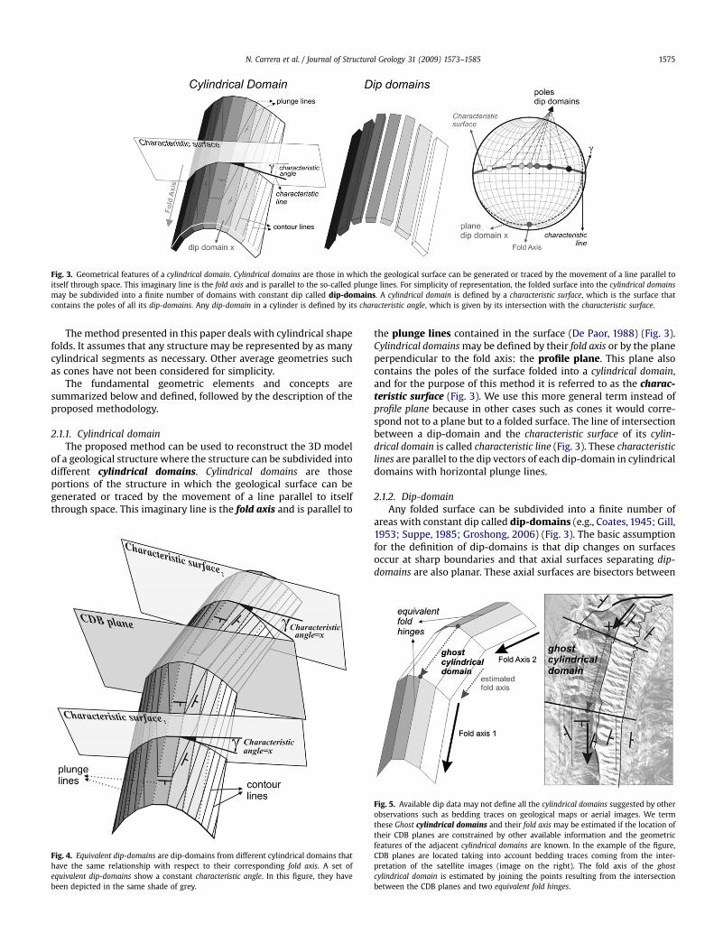
Fig. 3. Geometrical features of a cylindrical domain. Cylindrical domains are those in which the geological surface can be generated or traced by the movement of a line parallel toitself through space. This imaginary line is the fold axis and is parallel to the so-called plunge lines. For simplicity of representation, the folded surface into the cylindrical domainsmay be subdivided into a finite number of domains with constant dip called dip-domains. A cylindrical domain is defined by a characteristic surface, which is the surface thatcontains the poles of all its dip-domains. Any dip-domain in a cylinder is defined by its characteristic angle, which is given by its intersection with the characteristic surface.
N. Carrera et al. / Journal of Structural Geology 31 (2009) 1573–1585 1575
The method presented in this paper deals with cylindrical shapefolds. It assumes that any structure may be represented by as manycylindrical segments as necessary. Other average geometries suchas cones have not been considered for simplicity.
The fundamental geometric elements and concepts aresummarized below and defined, followed by the description of theproposed methodology.
2.1.1. Cylindrical domainThe proposed method can be used to reconstruct the 3D model
of a geological structure where the structure can be subdivided intodifferent cylindrical domains. Cylindrical domains are thoseportions of the structure in which the geological surface can begenerated or traced by the movement of a line parallel to itselfthrough space. This imaginary line is the fold axis and is parallel to
Fig. 4. Equivalent dip-domains are dip-domains from different cylindrical domains thathave the same relationship with respect to their corresponding fold axis. A set ofequivalent dip-domains show a constant characteristic angle. In this figure, they havebeen depicted in the same shade of grey.
the plunge lines contained in the surface (De Paor, 1988) (Fig. 3).Cylindrical domains may be defined by their fold axis or by the planeperpendicular to the fold axis: the profile plane. This plane alsocontains the poles of the surface folded into a cylindrical domain,and for the purpose of this method it is referred to as the charac-teristic surface (Fig. 3). We use this more general term instead ofprofile plane because in other cases such as cones it would corre-spond not to a plane but to a folded surface. The line of intersectionbetween a dip-domain and the characteristic surface of its cylin-drical domain is called characteristic line (Fig. 3). These characteristiclines are parallel to the dip vectors of each dip-domain in cylindricaldomains with horizontal plunge lines.
2.1.2. Dip-domainAny folded surface can be subdivided into a finite number of
areas with constant dip called dip-domains (e.g., Coates, 1945; Gill,1953; Suppe, 1985; Groshong, 2006) (Fig. 3). The basic assumptionfor the definition of dip-domains is that dip changes on surfacesoccur at sharp boundaries and that axial surfaces separating dip-domains are also planar. These axial surfaces are bisectors between
Fig. 5. Available dip data may not define all the cylindrical domains suggested by otherobservations such as bedding traces on geological maps or aerial images. We termthese Ghost cylindrical domains and their fold axis may be estimated if the location oftheir CDB planes are constrained by other available information and the geometricfeatures of the adjacent cylindrical domains are known. In the example of the figure,CDB planes are located taking into account bedding traces coming from the inter-pretation of the satellite images (image on the right). The fold axis of the ghostcylindrical domain is estimated by joining the points resulting from the intersectionbetween the CDB planes and two equivalent fold hinges.

Fig. 6. Framework of axial planes between dip-domains in a cylindrical domain. Axial planes are bisectors because a constant bed thickness has been assumed (a). Note location ofaxial planes is constrained by dip data at different stratigraphic levels (a) and from dip data extrapolated from equivalent dip-domains (b). Hinge lines are parallel to the plunge lines.
N. Carrera et al. / Journal of Structural Geology 31 (2009) 1573–15851576
two contiguous dip-domains if beds are of constant thickness,whereas in settings with thickness variations the angle betweenbedding and axial surfaces must be adjusted (Marshak and Mitra,1988; Groshong, 2006). The quantity and criteria for defining dip-domains will depend on the available data, the geometry to bereproduced and the required resolution.
2.1.3. Fold axis vector field (multiple cylindrical domains)Several cylindrical domains are normally necessary to define the
geometric model of any complete structure in 3D such as fault-related fold. Under these circumstances, data projected ontocross-sections may be restricted across a limited portion of the foldrepresenting only one cylindrical domain to avoid projectioncomplexities and errors (Figs. 1 and 2). Alternatively, a vector fieldcomprising all the fold axes of the cylindrical domains may bedefined to extrapolate any data along the fold. Few sections are donefrom data projected from multiple cylindrical domains because it istedious and time consuming (see Langenberg, et al., 1987; De Paor,1988).
However, when dealing with scarce data we are often obliged toproject data into the section plane from different cylindricaldomains in order to constrain the geometry of the cross-section. Wepropose to take advantage of the definition of this projection vectorfield to construct the geometry of the structure directly in 3D,avoiding the step of the construction of a set of serial cross-sectionsand honoring the absolute position of data.
2.2. Equivalent dip-domain method
The method proposed herein – termed equivalent dip-domainmethod – takes advantage of the multiple cylindrical domainprocedure for cross-section construction to directly reconstruct the3D geometry of folded surfaces. It consists of the definition of a 3Dframework of planes, lines and vectors, which relate any dip data ofthe studied structure with an average geometry and allows us toextrapolate data along the structure to fill gaps of information inareas with scarce data.
2.2.1. New geometric elements of the equivalent dip-domainmethod
The basis of this method is that each dip-domain in a cylindricaldomain has its counterpart in the adjacent cylindrical domains. These
are called equivalent dip-domains and have the same geometricrelationship with respect to their own fold axis as their characteristiclines have the same angle of pitch on the characteristic surface.
The pitch angle is herein termed characteristic angle and isconstant for a set of equivalent dip-domains (Figs. 3 and 4). Thecharacteristic angle is an excellent parameter to easily discriminateand manage dip-domain data in a 3D environment and to quantifyother features related with the 3D reconstruction of structures asfor example error and uncertainty calculations.
The intersection of any two dip-domains in a cylindrical domainis a line that is parallel to the fold axis of the cylindrical domain.This intersection line is the plunge line for the cylindrical domain,and all plunge lines within a same cylindrical domain are parallelto each other. The intersection lines between adjacent dip-domains are local fold hinges and the intersection lines of equiv-alent dip-domains in different cylindrical domains are equivalentfold hinges.
Once the multiple cylindrical domains that best fit the data sethave been defined, the orientation of the plunge lines and thelocation of the boundaries between adjacent cylindrical domains aredetermined. These boundaries are assumed to be planar surfacesfor simplicity and are named CDB planes (Cylindrical DomainBoundary planes). CDB planes bisect the characteristic surfaces ofadjacent cylindrical domains if bed thickness is constant (Fig. 4).Their location is constrained by the position of dip data, seismicdata and the geometry observed in geological maps and/or in aerialand satellite images.
Available dip data may not define all the cylindrical domainssuggested by other observations such as bedding traces ongeological maps or aerial images. We term these Ghost cylindricaldomains and their fold axis may be estimated if the location of theirCDB planes are constrained by the position of neighboring cylin-drical domains and geometric features (dip-domains, fold crest) ofthe adjacent cylindrical domains are known (Fig. 5).
Extrapolation of dip data in each cylindrical domain is accom-plished by the definition of the axial planes bounding the dip-domains as defined by the respective characteristic angles. Theposition and orientation of these axial planes are strongly con-strained not only by all the dip data initially contained in any onecylindrical domain but also by the location of data in equivalent dip-domains in other cylindrical domains and by taking into accountdata from all stratigraphic positions (Fig. 6).

Fig. 7. Obtaining dip orientation for a dip-domain from their equivalent dip-domains. a) Knowing the orientation of a dip-domain and the fold axis of its own cylindrical domain itscharacteristic angle can be easily found graphically which is the pitch angle of the characteristic line (intersection between the characteristic surface and the dip-domain) measuredon the characteristic surface. b) The orientation of an undefined dip-domain may be obtained if the characteristic angle of its own set of equivalent dip-domains is known. Graphically,there are two possible solutions because in any cylindrical domain two different oriented dip-domains may have the same characteristic angle but have characteristic lines plunging inopposite directions. To discriminate between them, two possible scenarios have to be taken into account. c) For a structure with cylindrical domains that plunge in the samedirection, equivalent dip-domains have characteristic lines that plunge in the same direction when looking down the fold axis. d) If the structure has a structural low or high betweenboth cylindrical domains (i.e. a saddle or dome), the equivalent dip-domains have characteristic lines plunging in opposite directions when looking down the fold axis.
N. Carrera et al. / Journal of Structural Geology 31 (2009) 1573–1585 1577
2.2.2. Obtaining dip orientation for a dip-domain from itsequivalent dip-domains
Once the framework of cylindrical domains and relatedgeometric features (dip-domains, plunge lines) has been
established, the amount of dip-domains that need to be honored ineach cylindrical domain can be defined from the number of differentcharacteristic angles calculated for the complete dip data set.Densification of data to constrain the 3D geometry of the folded
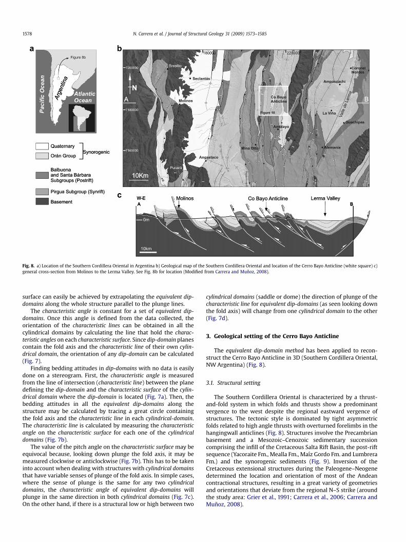
Fig. 8. a) Location of the Southern Cordillera Oriental in Argentina b) Geological map of the Southern Cordillera Oriental and location of the Cerro Bayo Anticline (white square) c)general cross-section from Molinos to the Lerma Valley. See Fig. 8b for location (Modified from Carrera and Munoz, 2008).
N. Carrera et al. / Journal of Structural Geology 31 (2009) 1573–15851578
surface can easily be achieved by extrapolating the equivalent dip-domains along the whole structure parallel to the plunge lines.
The characteristic angle is constant for a set of equivalent dip-domains. Once this angle is defined from the data collected, theorientation of the characteristic lines can be obtained in all thecylindrical domains by calculating the line that hold the charac-teristic angles on each characteristic surface. Since dip-domain planescontain the fold axis and the characteristic line of their own cylin-drical domain, the orientation of any dip-domain can be calculated(Fig. 7).
Finding bedding attitudes in dip-domains with no data is easilydone on a stereogram. First, the characteristic angle is measuredfrom the line of intersection (characteristic line) between the planedefining the dip-domain and the characteristic surface of the cylin-drical domain where the dip-domain is located (Fig. 7a). Then, thebedding attitudes in all the equivalent dip-domains along thestructure may be calculated by tracing a great circle containingthe fold axis and the characteristic line in each cylindrical-domain.The characteristic line is calculated by measuring the characteristicangle on the characteristic surface for each one of the cylindricaldomains (Fig. 7b).
The value of the pitch angle on the characteristic surface may beequivocal because, looking down plunge the fold axis, it may bemeasured clockwise or anticlockwise (Fig. 7b). This has to be takeninto account when dealing with structures with cylindrical domainsthat have variable senses of plunge of the fold axis. In simple cases,where the sense of plunge is the same for any two cylindricaldomains, the characteristic angle of equivalent dip-domains willplunge in the same direction in both cylindrical domains (Fig. 7c).On the other hand, if there is a structural low or high between two
cylindrical domains (saddle or dome) the direction of plunge of thecharacteristic line for equivalent dip-domains (as seen looking downthe fold axis) will change from one cylindrical domain to the other(Fig. 7d).
3. Geological setting of the Cerro Bayo Anticline
The equivalent dip-domain method has been applied to recon-struct the Cerro Bayo Anticline in 3D (Southern Cordillera Oriental,NW Argentina) (Fig. 8).
3.1. Structural setting
The Southern Cordillera Oriental is characterized by a thrust-and-fold system in which folds and thrusts show a predominantvergence to the west despite the regional eastward vergence ofstructures. The tectonic style is dominated by tight asymmetricfolds related to high angle thrusts with overturned forelimbs in thehangingwall anticlines (Fig. 8). Structures involve the Precambrianbasement and a Mesozoic–Cenozoic sedimentary successioncomprising the infill of the Cretaceous Salta Rift Basin, the post-riftsequence (Yacoraite Fm., Mealla Fm., Maız Gordo Fm. and LumbreraFm.) and the synorogenic sediments (Fig. 9). Inversion of theCretaceous extensional structures during the Paleogene–Neogenedetermined the location and orientation of most of the Andeancontractional structures, resulting in a great variety of geometriesand orientations that deviate from the regional N–S strike (aroundthe study area: Grier et al., 1991; Carrera et al., 2006; Carrera andMunoz, 2008).

Fig. 9. Chronostratigraphic diagram showing the main tectonostratigraphic unitsinvolved in the Andean structure of the southern Cordillera Oriental as well as themain tectonic events that controlled their deposition. The main formations outcrop-ping in the area have been represented. The major unconformities bounding the mainunits are indicated by a wavy line, whereas minor internal unconformities are repre-sented by dash-dotted lines (Modified from Carrera et al., 2006).
N. Carrera et al. / Journal of Structural Geology 31 (2009) 1573–1585 1579
3.2. The Cerro Bayo Anticline
The Cerro Bayo Anticline is a N–S trending basement-involvedfold (Figs. 8 and 10). It is a tight west-vergent asymmetric anticlinewith a nearly vertical forelimb (70� dip) and a moderately dippingback-limb (with almost constant 30� dip). It is cored at surface bysynrift sediments of the Pirgua Subgroup and it is bounded west-wards by a N–S trending thrust that places its forelimb on top of theCenozoic synorogenic sediments (Figs. 10 and 11).
In map view the Cerro Bayo Anticline shows an arcuate shapeconcave towards the E. Its central portion is N–S trending, parallelto the thrust to which it is related (Fig. 10) and the southern andnorthern segments trend NW–SE and NE–SW respectively. Thesouthern NW–SE trending segment plunges to the SE and is parallel
to a syncline also located in the hangingwall of the thrust. Thenorthern NE–SW trending segment plunges to the NE and is cut byan E–W trending extensional fault, interpreted as a tear faultparallel to the thrust transport direction. North of this north-dipping fault, the Cerro Bayo Anticline splits into two anticlineswith a smaller wavelength (Fig. 10).
The geometry of the Cerro Bayo Anticline is nicely depicted inthe field and in satellite images by the post-rift sequence, speciallyby the light-grey carbonatic beds of the Yacoraite Formation(Fig. 11). Thickness of the post-rift formations may be assumed asconstant at kilometric scale. Together with the relative simplicity ofthe fold geometry and the changes of the fold trend and plunge, theCerro Bayo Anticline makes a perfect example to attempt a wellconstrained 3D reconstruction.
4. 3D reconstruction of the Cerro Bayo Anticline
The reconstruction of the geometry of this anticline has beenlimited to the southern side of the E–W tear fault that cuts thenorthern end of the Cerro Bayo Anticline. North of this fault, the 3Dreconstruction has not been attempted due to the scarcity ofavailable data with respect to the wavelength of the structures(Fig. 10).
The selected horizons for the reconstruction of the Cerro BayoAnticline belong to the post-rift sequences. Their constant thick-ness facilitates the application of the equivalent dip-domain meth-odology as CDB and axial planes can be considered bisectorsbetween characteristic surfaces and dip-domains respectively.
Following the proposed methodology, the description of thegeometry of bedding in these sequences has been performedfollowing the steps described below.
4.1. Structural analysis
The structural analysis of the available field dip data of the CerroBayo Anticline defined five cylindrical domains whose fold axes arefrom north to south: 04/208, 07/180, 09/171, 04/158, 17/166(Fig. 12). The longitudinal extent of the cylindrical domains and thelocation of their boundaries (CDB planes) along the structure areconstrained by satellite and aerial images. These images were usedto define changes in strike of the steeply dipping forelimb and inthe axial plane (Figs. 12 and 13). Using these orientation changesa ghost cylindrical domain was defined (Fig. 13). As bedding tracesshow continuity across the boundaries of this ghost cylindricaldomain its fold axis may be calculated (Fig. 5). Based on the strike ofthe steeply dipping beds of the forelimb, the location of CDB planesand the location of the fold crests of the adjacent cylindricaldomains this fold axis is oriented 11/144 (Fig. 12).
4.2. Geometric framework
The next step involves the construction of the geometricframework of CDB and axial planes which will bound the dip-domain volumes. For the construction of this geometric frameworkwe consider the real position of field dip data irrespective of itsstratigraphic position. Moreover, equivalent dip-domains of thewhole structure will be considered to better constrain dip-domainvolumes (Fig. 6).
In each cylindrical domain, folded surfaces are subdivided intoseveral planar dip-domains. In the backlimb of the Cerro BayoAnticline, characterized by moderate dips, a threshold of 20� for thecharacteristic angle has been used to define the dip-domains. Therounded hinge observed in the field is accurately reproduced byusing a threshold of 10�. In the steep forelimb collected dip datamainly fit into three equivalent dip-domains, which averaged

Fig. 10. Geological map of the Cerro Bayo Anticline and general cross-section showing the main geometry of this fold. Note the Cerro Bayo Anticline involves the basement togetherwith the cover succession and shows an arcuate shape in map view.
N. Carrera et al. / Journal of Structural Geology 31 (2009) 1573–15851580
characteristic angles are 70�, 40� and 30�. These have been thoseused to represent the frontal limb of the Cerro Bayo Anticline(Fig. 13).
4.3. Applying the equivalent dip-domain method to fill gaps ofinformation
Extrapolating dip-domains well constrained by dip data tocylindrical domains in which there is not enough data enabled us to
Fig. 11. Panoramic view from the W of the Cerro Bayo Anticline to the E. The carbon
accurately define the 3D structure of the fold (see Section 2 andFig. 13).
4.4. Structure contour map
The resulting geometric framework has been better constrainedby the reconstruction of the base of the Maız Gordo Fm whichconstitutes the horizon with the largest amount of available data(Fig. 10). Its 3D geometry has been reconstructed using structurecontour maps by joining points of equal elevation across the CDB
atic beds of the Yacoraite Fm nicely depict the geometry of the fold in the field.

Fig. 12. a) Satellite image of the Cerro Bayo Anticline with field dip data. b) Structural analysis. From the structural analysis, field data have been grouped into five cylindricaldomains. Orientations of their fold axes are given. In a part of the SW sector, field dip data are absent and the geometry cannot be defined by structural analysis (ghost cylindricaldomain). In this case, the study of satellite images and Digital Terrain Models allowed us to define an extra cylindrical domain in this area. c) The orientation of the fold axis of theghost cylindrical domain has been calculated based on the strike of the steeply dipping beds of the forelimb and the location of the fold crest of the anticline in the adjacentcylindrical domains.
N. Carrera et al. / Journal of Structural Geology 31 (2009) 1573–1585 1581
and axial planes, similar to the geometric construction suggestedby Groshong (2006).
Contouring started where dip data on the Maız Gordo horizon isavailable (control points). Contours are parallel to the bed strikeand their spacing is determined by the dip of the surface. The trendof contours changes where the dip-domain boundaries (CDB andaxial planes) become parallel to the bed strike in the adjacent dip-domains (Fig. 13d). The position of CDB planes and axial surfaces hasbeen adjusted iteratively to reconstruct a continuous surfacehonoring all control points and average bedding orientations. Inthis iterative process, compatibility between the data and the
deduced geometric framework strongly reduces the number ofpossible solutions. Structural contours were constructed by usingsoftware developed in-house in a Microstation environment(Bentley Systems Inc�) (Fernandez, 2004; Fernandez et al., 2004).With these tools, contours are constructed once the geometricframework has been already defined.
4.5. Construction of the 3D model
The surface of the base of the Maız Gordo Fm has been repre-sented by a Triangulated Irregular Network (TIN) which is derived

Fig. 13. 3D reconstruction of the Cerro Bayo Anticline. a) Location of the available dip data georeferenced in 3D. b) Location of the CDB planes between the different cylindricaldomains defined by structural analysis. Their position depends on the location of the available dip data and on the geometry observed in aerial images. Plunge lines are representedby grey arrows (their orientations are given). c) Extrapolation of dip-domains along the structure using the equivalent dip-domain method in order to fill gaps of field information.Dip-domains have been grouped into equivalent dip-domains. The equivalent dip-domains have been depicted in the same shade of grey. The characteristic angles of the equivalentdip-domains selected to reconstruct the Cerro Bayo Anticline are also given (Note: negative values are used to discriminate between the front and back limbs of the structure) d)Contour map of the reference level: the base of the Maız Gordo Fm. Be aware when comparing the position of dip data with the contour map. Dip data are from differentstratigraphic positions whereas the contouring represents a specific stratigraphic level (Maız Gordo Formation Bottom).
N. Carrera et al. / Journal of Structural Geology 31 (2009) 1573–15851582
from the structure contours. This has been done using the DSIinterpolation algorithm (Discrete Smooth Interpolation) imple-mented in gOcad (Earth Decision�) (Mallet, 1989) which helps tosmooth the angular surfaces constructed from dip-domains.
Construction of other folded stratigraphic surfaces can be per-formed knowing the vector field defining the stratigraphic sepa-ration from the reference surface. In our case, the four surfacesbounding the post-rift formations involved in the Cerro Bayo

Fig. 14. a) 3D Model of the Cerro Bayo Anticline representing the fault and the base of the main stratigraphic units as well as the location of cross-sections. b) Cross-sections acrossthe 3D structural model of the Cerro Bayo Anticline. It is interesting to emphasize the fold is more asymmetric in the north than in the south, along with an increase in the dip ofboth forelimb and backlimb. Note the variations in apparent thickness resulting from generating vertical cross-sections of the 3D model across cylindrical domains with varyingplunge of the fold axes.
N. Carrera et al. / Journal of Structural Geology 31 (2009) 1573–1585 1583
Anticline have been easily reconstructed by applying an algorithmimplemented in 3DMove for the construction of constant thicknessfolded beds (Midland Valley Exploration�) (Fernandez et al., 2009)(Fig. 14a).
5. Results
The 3D model of the Cerro Bayo Anticline shows a westwardvergence with increasing dip of its axial plane southwards and itsbacklimb shows two main planar domains with different dip. Thesteeper one only crops out to the north. In the same direction theforelimb shows a steeper dip. Consequently, the fold becomestighter from S to N.
Fig. 15. a) Cross-section c-c0 of the 3D model constructed by the equivalent dip-domain methnear the trace of the section. c) Comparison between these two coinciding cross-sections: nsection is located in an area where the forelimb is mostly eroded implying the 2D cross-sectfrom other cylindrical domains providing a better constrained forelimb geometry.
Cross-sections in any position and orientation can be easilyobtained from the complete 3D model of the fold. Serial cross-sections of the fold reveal longitudinal variations of its geometry, asexplained above. The apparent thickness variations observedbetween vertical cross-sections across the Cerro Bayo Anticlineresult from changes in the plunge of the fold axis (Fig. 14b).
It should be noted that the fold reconstruction is only partial andthat the construction of a more complete 3D model of the CerroBayo Anticline would require: a) the extrapolation of the outcropdata beyond the boundaries of the reconstructed folded surfaces, b)the interpretation of the structure at depth and c) the definition ofthe thickness of the Pirgua Subgroup which is not constant in thestudied area because of its synrift character. This can be achieved by
od. See Fig. 14 for location. b) Cross-section c-c0 constructed with data located along orote that most differences between both cross-sections occur in the forelimb. The cross-ion is particularly poorly constrained in this area, whereas the 3D model includes data

N. Carrera et al. / Journal of Structural Geology 31 (2009) 1573–15851584
taking into account the geometries observed in adjacent structureswith different exposed structural depths (Fig. 8)
Moreover, to constrain the structural interpretation and there-fore the deep fold geometry, the geometrical relationships betweenthe fold and its related thrust need to be explored. The geometry ofthe thrust that limits the Cerro Bayo Anticline to the west has beenreconstructed on the basis of the trace of the fault and the geometryof adjacent deeply eroded structures. It has also been consideredthat, following the simplest models of fault-related folds, the dip ofthe thrust at depth should be equal or higher than the steeper dip-domain of the back limb (Figs. 10 and 14). Despite all the abovementioned constraints, the lack of fault plane data prevents anaccurate reconstruction of thrust geometry and, therefore, theresolution of the most appropriate kinematic model for the CerroBayo Anticline.
The quality of the 3D model of the Cerro Bayo Anticline has beentested by comparing a vertical section across its central partresulting from sectioning the model with a cross-section con-structed (with standard techniques) from data located along andnear a coincident trace (Fig. 15). The main differences are in theforelimb as a result of the restricted amount of data projected ontothe 2D section plane. Moreover, both forelimb and backlimbdifferences derive from the position of the axial planes betweendip-domains which in the 3D model are better constrained becausedata of equivalent dip-domains are taken into account. Thesedifferences increase in the exhumed structurally higher areas(Fig. 15).
6. Discussion
6.1. General considerations
Geologists generally believe that the construction of a 3Dgeological model requires a high density and high quality data setand that in areas with scarce or sparsely distributed data 3Dreconstructions should be approached through the interpolation ofserial cross-sections. We are convinced that the methodologypresented in this paper and the example given show that recon-structing structures directly in 3D is possible from scant data.Furthermore, the amount of time consumed in building a 3D modelis similar (if not less) to the time that would be required toconstruct valid and accurate serial cross-sections. Constructing 3Dmodels directly provides better value because 3D constructiontechniques honor the original position of data as well as their 3Dcharacter which cannot be captured in 2D sections.
The construction of a 3D model similar to the Cerro Bayo Anti-cline from cross-sections would require a minimum of six cross-sections (one for each cylindrical domain) and the interpolationbetween them along plunge lines. However, if cross-sections wereto be interpolated linearly, sections would need to be properlylocated close to the CDB planes and would have to account fordifferent projection vectors for data from different cylindricaldomains. Furthermore, construction of vertical sections acrossplunging folds has to deal with apparent thickness and axial planesnot bisecting the planar domains (Fernandez et al., 2003a). Alter-natively, profiles with an orientation perpendicular to the fold axiswould need to be constructed for each cylindrical domain. If per-formed properly, this procedure would be time costly and in factcomes close to the idea of directly building a 3D model. Moreover,any error during the construction of cross-sections will be trans-ferred and accumulated into a 3D model derived from the linearinterpolation of sections.
The equivalent dip-domain method introduces vector informa-tion (projection vectors or plunge lines) for the interpolation andextrapolation of data along the structure. It improves the currently
used methods for 3D reconstruction of surfaces which are based onthe interpolation of point data or data with linear attributes such asdip and dip directions (De Kemp, 1999; Fernandez et al., 2004) inthat it requires a significantly smaller amount of data.
The definition of the projection vector field optimizes theavailable data and imposes the strongest geological constraintgiven that these vectors have structural significance derived fromstructural analysis. Once the vector field has been defined, data canbe projected following the vector field over long distances to betterreconstruct the geometry of the fold and fill gaps in any part of thestructure where data are absent or scarce. Most importantly, oncethe geometric framework has been defined 3D reconstruction ofthe folded surfaces honours all the dip data by preserving theirabsolute position.
6.2. Application to conical structures and folded unconformities
This method has been applied to cylindrical folds with simplelayer cake stratigraphy. However, the same concepts can be adaptedto deal with more complex geometries, such as conical folds orfolded strata with variable thickness or containing unconformities.
In a conical fold, extrapolation of data would follow generatricesconverging on the cone apex, each dip-domain having a distinctlyoriented generatrix (Fernandez et al., 2003b). In this case, charac-teristic surfaces and CDB planes would not correspond to planes butto cones or surfaces that are more complex.
In the case of folds involving layers with different thicknesses orconcerning unconformities the definition of the changes of orien-tation of CDB planes and axial surfaces would be required. Alter-natively each package with similar initial orientation and thicknessrelationships should be reconstructed independently following theproposed methodology.
6.3. Limitations
This methodology has a shortcoming in that folds are averagedto perfect cylindrical domains. Consequently, the 3D geometry canbe simplified in excess by smoothing local irregularities. We thinkthat the best approach to overcome this problem is first to deal withthis average geometry and then introduce the modifications toaccount for all the available data, including data departing fromsuch average geometry. For example, in the Cerro Bayo Anticline,some of the equivalent dip-domains have been tapered, so as todisappear in the southern part of the fold in order to preserveconsistency with field data that precludes the existence of certaindip-domains near the fold termination. As a result, some of theintersections between dip-domains are not strictly parallel to theestimated fold axis as they are expected to be in a cylindrical foldgeometry (Fig. 13).
7. Conclusions
The equivalent dip-domain method is a simple and effectivemethod to reconstruct folded surfaces in fault-related folds wherethe structures can be subdivided into cylindrical domains. Theequivalent dip-domain method has enabled us to reconstruct thegeometry of the folded surfaces of the Cerro Bayo Anticline takingadvantage of all the available data. It has been proved to be a validmethodology to precisely define the 3D geometry of folded surfacesin areas with scarce data.
3D reconstruction of a fault-related fold from the construction ofthe geometry of the folded surfaces directly in a 3D environmentfollowing the equivalent dip-domain method has been turned out tobe more reliable and efficient in the case of the Cerro Bayo Anticlinethan it would have been by serial cross-section construction. We can

N. Carrera et al. / Journal of Structural Geology 31 (2009) 1573–1585 1585
conclude that the proposed methodology is a valid procedure toreconstruct 3D geometries in regions with scarce and sparse data.
The proposed methodology is a powerful technique if applied tofold structures that have a good expression in satellite or aerialimages as they make it easier to constrain the required geometricframework. However, this method has also been applied success-fully to sub-surface structures with no outcrop expression. Themethod was initially developed to reconstruct the 3D geometry ofthe El Porton Anticline (Neuquen Basin) based only on dipmeterdata from wells and seismic data, as it has not surface expression(e.g., Carrera et al., 2003). In these contexts, reliable 3D recon-struction are of primary importance for volumetric estimates andto understand detailed geometry and structural evolution. This isencouraging because of the increasing availability of 3D kinematicand geomechanical modelling tools that enable us to predict notonly the structural evolution but also strain history.
Acknowledgements
This work was funded by project MODES4D CGL2007-66431-C02-02/BTE and was developed in the Grup de Geodinamica iAnalisi de Conques, 2005 SGR 000397, of the Comissionat d’Uni-versitats i Recerca de la Generalitat de Catalunya and in the Geo-models Research Centre. Geomodels is a research centre sponsoredby the Generalitat de Catalunya (DURSI) and Instituto Geologico yMinero de Espana (IGME). The authors would like to thank FrancescSabat, Ricardo Mon and Ana Vega-Cano for their assistance in thefield, and Oscar Fernandez and Rick Groshong for their enrichingcomments.
References
Carrera, N., Roca, E., Munoz, J.A., Zapata, T., Fernandez, O., Selva, G., Ansa, A., Zamora,G., Falivene, O., 2003. 3D structure of the El Porton Oil Field at the Andes thrust
front (Neuquen Basin, Argentina). In: American Association of PetroleumGeologists International Meeting, Barcelona, abstracts with programs.
Carrera, N., Munoz, J.A., Sabat, F., Roca, E., Mon, R., 2006. The role of inversiontectonics in the structure of the Cordillera Oriental (Argentinean Andes).Journal of Structural Geology 28, 1921–1932.
Carrera, N., Munoz, J.A., 2008. Thrusting evolution in the southern CordilleraOriental (northern Argentine Andes): constraints from growth strata. Tecto-nophysics 459 (1/4), 107–122.
Coates, J., 1945. The construction of geological sections. Quarterly Journal GeologicalMining Metallurgical Society (India) 1 (7), 1–11.
De Kemp, E., 1999. Three-dimensional projection of curvilinear geological featuresthrough direction cosine interpolation of structural field observations.Computer and Geosciences 24 (3), 269–284.
De Paor, D.G., 1988. Balanced section in thrust belts. Part I: construction. AmericanAssociation of Petroleum Geologists Bulletin 72, 73–90.
Fernandez, O., Munoz, J.A., Arbues, P., 2003a. Quantifying and correcting errorsderived from apparent dip in the construction of dip-domain cross-sections.Journal of Structural Geology 25 (1), 35–42.
Fernandez, O., Roca, E., Munoz, J.A., 2003b. Projection of dip data in conical foldsonto a cross-section plane. Journal of Structural Geology 25, 1875–1882.
Fernandez, O., 2004. Reconstruction of Geological Structures in 3D: an Examplefrom the Southern Pyrenees. Ph.D. thesis. Universitat de Barcelona.
Fernandez, O., Munoz, J.A., Arbues, P., Falivene, O., Marzo, M., 2004. Three-dimen-sional reconstruction of geological surfaces: an example of growth strata andturbidite systems from the Ainsa basin (Pyrenees, Spain). American Associationof Petroleum Geologists Bulletin 88, 1049–1068.
Fernandez, O., Jones, S., Armstrong, N., Johnson, G., Ravaglia, A., Munoz, J.A., 2009.Automated tools within workflows for 3D structural construction from surfaceand subsurface data. Geoinformatica. doi:10.1007/s10707-008-0059-y.
Gill, W.D., 1953. Construction of geological cross-sections of folds with steep-limbattenuation. American AssociationofPetroleum GeologistsBulletin.37, 2389–2406.
Grier, M.E., Salfity, J.A., Allmendinger, R.W., 1991. Andean reactivation of theCretaceous Salta rift, north-western Argentina. Journal of South American EarthSciences 4 (4), 351–372.
Groshong, R.H., 2006. 3D Structural Geology: A Practical Guide to QuantitativeSurface and Subsurface Map Interpretation. Springer-Verlag, Berlin,Heidelberg.
Langenberg, W., Charlesworth, H., La Riviere, A., 1987. Computer-constructedcross-sections of the Morcles nappe. Eclogae Geologicae Helvetiae 80 (3), 655–667.
Mallet, J.L.,1989. Discrete smooth interpolation. Transactions on Graphics 8,121–144.Marshak, S., Mitra, G., 1988. Basic Methods of Structural Geology. Prentice-Hall,
Englewood Cliffs, New Jersey.Suppe, J., 1985. Principles of Structural Geology. Prentice-Hall, Englewood Cliffs, NJ.