
3D Reality Modelling: Photo-Realistic 3D Models of Real World Scenes
8
3D Reality Modelling: Photo-Realistic 3D Models of Real World Scenes Vtor Sequeira, Joªo G.M. Gonalves European Commission, Joint Research Centre, TP 270, I-21020 Ispra, Italy E-mail: {vitor.sequeira,joao.goncalves}@jrc.it Abstract This paper presents a 3D reality modelling system, applying lasers and digital photography to create super- accurate photo-realistic three-dimensional worlds. A key feature of the 3D reality system is its flexibility. It can be used with all common long-range scanners and digital or video cameras, without the need of any pre-calibration or static arrangement between the different sensors. The system can be used for a wide range of applications in industry and science, as well as for environmental modelling and virtual reality presentations. The 3D models are sufficiently lifelike to be used in sectors such as real estate, culture heritage and construction. Results can be exported to all major 3D software and CAD packages or viewed via a web browser. 1. Introduction In general, there are two techniques for 3D reconstruction of real objects and scenes that are commonly used. One is based on active range data (e.g. structured light, laser range finders), and the other is based on video images normally referred as image-based modelling. Traditionally, active range sensing was mainly associated with the reconstruction of high-quality models of small objects (e.g. museum artefacts) using high- resolution range cameras based on structured light [1,2]. Recently, there have been attempts to use this technology for the reconstruction of large objects and buildings [3,4,5,6,7,8]. Passive range techniques based on video images give good results in extracting a minimum structure from the scene (e.g. a wall made of four points) with video images to enhance 3D appearance. Examples of such reconstruction can be found in [9,10,11]. Normally, the full geometry of the scene is not available. A building is represented from a collection of planes for the walls and roof and an indoor environment is represented as a video panorama wrapped to significant features on the environment. This technique has difficulties with an indoor environment exhibiting some complexities (e.g. monuments), where a detailed reconstruction is required and when the full geometry is needed (e.g. reverse CAD engineer or verification of plant designs). The system presented in this paper uses a scanning laser to capture the 3D structure and a video or digital camera to add textures and colours. The subject is scanned from a number of positions, which allows the finished image to be viewed realistically from any angle. Any new position is linked to the previous by processing the acquired spatial data (un-registered sequence of range scans and 2D un-calibrated photographs). Embedded software performs several automatic functions, including triangulation of the range data, range to video registration, registration and integration of data acquired from different capture points, and planning the next optimal capture position in an initially unknown large-scale scene (indoor or outdoor). 2. Paradigm for 3D Reality Modelling Our 3D reconstruction paradigm (see Figure 1) begins with a data acquisition session using a laser scanner and a digital camera (see Figure 2), followed by the creation of a geometric model of the scene. The model is then analysed to detect occlusions. The best capture point for the next data acquisition is thus computed and instructions given to move the sensor head. A second data acquisition session takes place. Raw data from this view is registered to that of previous acquisition sessions. The geometric model for the new view is extracted and merged with the existing one. If new or unresolved occlusions are detected, further acquisition sessions are required. When this process is completed, the geometric model is triangulated, and each triangle textured with data from the video camera. 3. Geometric Modelling For each viewpoint, the laser scanner provides a set of two perfectly registered images: a range and a reflectance image (see Figure 3). It is desirable that the reconstructed surface description is as simple as possible while preserving its detail and accuracy. The final representation should not depend on how the different views were taken and a single model for the whole scene should be built irrespectively of the number and sequence of the range images. Proceedings of the First International Symposium on 3D Data Processing Visualization and Transmission (3DPVT02) 0-7695-1521-5/02 $17.00 ' 2002 IEEE
-
Upload
independent -
Category
Documents
-
view
0 -
download
0
Transcript of 3D Reality Modelling: Photo-Realistic 3D Models of Real World Scenes
3D Reality Modelling: Photo-Realistic 3D Models of Real World Scenes
Vítor Sequeira, João G.M. Gonçalves
European Commission, Joint Research Centre, TP 270, I-21020 Ispra, Italy E-mail: {vitor.sequeira,joao.goncalves}@jrc.it
Abstract
This paper presents a 3D reality modelling system, applying lasers and digital photography to create super-accurate photo-realistic three-dimensional worlds. A key feature of the 3D reality system is its flexibility. It can be used with all common long-range scanners and digital or video cameras, without the need of any pre-calibration or static arrangement between the different sensors. The system can be used for a wide range of applications in industry and science, as well as for environmental modelling and virtual reality presentations. The 3D models are sufficiently lifelike to be used in sectors such as real estate, culture heritage and construction. Results can be exported to all major 3D software and CAD packages or viewed via a web browser. 1. Introduction
In general, there are two techniques for 3D reconstruction of real objects and scenes that are commonly used. One is based on active range data (e.g. structured light, laser range finders), and the other is based on video images normally referred as image-based modelling. Traditionally, active range sensing was mainly associated with the reconstruction of high-quality models of small objects (e.g. museum artefacts) using high-resolution range cameras based on structured light [1,2]. Recently, there have been attempts to use this technology for the reconstruction of large objects and buildings [3,4,5,6,7,8].
Passive range techniques based on video images give good results in extracting a minimum structure from the scene (e.g. a wall made of four points) with video images to enhance 3D appearance. Examples of such reconstruction can be found in [9,10,11]. Normally, the full geometry of the scene is not available. A building is represented from a collection of planes for the walls and roof and an indoor environment is represented as a video panorama wrapped to significant features on the environment. This technique has difficulties with an indoor environment exhibiting some complexities (e.g. monuments), where a detailed reconstruction is required and when the full geometry is needed (e.g. reverse CAD engineer or verification of plant designs).
The system presented in this paper uses a scanning laser to capture the 3D structure and a video or digital camera to add textures and colours. The subject is scanned from a number of positions, which allows the finished image to be viewed realistically from any angle. Any new position is linked to the previous by processing the acquired spatial data (un-registered sequence of range scans and 2D un-calibrated photographs). Embedded software performs several automatic functions, including triangulation of the range data, range to video registration, registration and integration of data acquired from different capture points, and planning the next optimal capture position in an initially unknown large-scale scene (indoor or outdoor).
2. Paradigm for 3D Reality Modelling
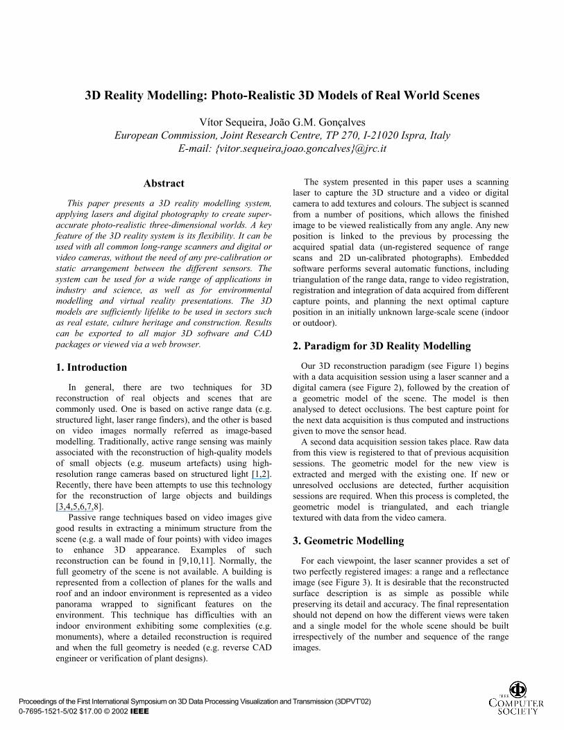
Our 3D reconstruction paradigm (see Figure 1) begins with a data acquisition session using a laser scanner and a digital camera (see Figure 2), followed by the creation of a geometric model of the scene. The model is then analysed to detect occlusions. The best capture point for the next data acquisition is thus computed and instructions given to move the sensor head.
A second data acquisition session takes place. Raw data from this view is registered to that of previous acquisition sessions. The geometric model for the new view is extracted and merged with the existing one. If new or unresolved occlusions are detected, further acquisition sessions are required. When this process is completed, the geometric model is triangulated, and each triangle textured with data from the video camera.
3. Geometric Modelling
For each viewpoint, the laser scanner provides a set of two perfectly registered images: a range and a reflectance image (see Figure 3). It is desirable that the reconstructed surface description is as simple as possible while preserving its detail and accuracy. The final representation should not depend on how the different views were taken and a single model for the whole scene should be built irrespectively of the number and sequence of the range images.
Proceedings of the First International Symposium on 3D Data Processing Visualization and Transmission (3DPVT�02) 0-7695-1521-5/02 $17.00 © 2002 IEEE
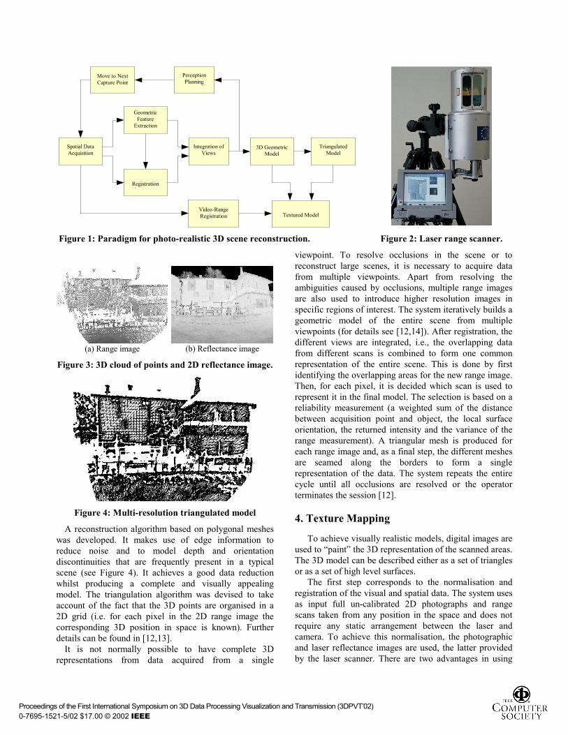
Figure 1: Paradigm for photo-realistic 3D scene reconstruction. Figure 2: Laser range scanner.
(a) Range image (b) Reflectance image
Figure 3: 3D cloud of points and 2D reflectance image.
Figure 4: Multi-resolution triangulated model
A reconstruction algorithm based on polygonal meshes was developed. It makes use of edge information to reduce noise and to model depth and orientation discontinuities that are frequently present in a typical scene (see Figure 4). It achieves a good data reduction whilst producing a complete and visually appealing model. The triangulation algorithm was devised to take account of the fact that the 3D points are organised in a 2D grid (i.e. for each pixel in the 2D range image the corresponding 3D position in space is known). Further details can be found in [12,13].
It is not normally possible to have complete 3D representations from data acquired from a single
viewpoint. To resolve occlusions in the scene or to reconstruct large scenes, it is necessary to acquire data from multiple viewpoints. Apart from resolving the ambiguities caused by occlusions, multiple range images are also used to introduce higher resolution images in specific regions of interest. The system iteratively builds a geometric model of the entire scene from multiple viewpoints (for details see [12,14]). After registration, the different views are integrated, i.e., the overlapping data from different scans is combined to form one common representation of the entire scene. This is done by first identifying the overlapping areas for the new range image. Then, for each pixel, it is decided which scan is used to represent it in the final model. The selection is based on a reliability measurement (a weighted sum of the distance between acquisition point and object, the local surface orientation, the returned intensity and the variance of the range measurement). A triangular mesh is produced for each range image and, as a final step, the different meshes are seamed along the borders to form a single representation of the data. The system repeats the entire cycle until all occlusions are resolved or the operator terminates the session [12].
4. Texture Mapping
To achieve visually realistic models, digital images are used to �paint� the 3D representation of the scanned areas. The 3D model can be described either as a set of triangles or as a set of high level surfaces.
The first step corresponds to the normalisation and registration of the visual and spatial data. The system uses as input full un-calibrated 2D photographs and range scans taken from any position in the space and does not require any static arrangement between the laser and camera. To achieve this normalisation, the photographic and laser reflectance images are used, the latter provided by the laser scanner. There are two advantages in using
Spatial Data Acquisition
Geometric Feature
Extraction
Registration
Integration of Views
3D Geometric Model
Triangulated Model
Textured Model
Perception Planning
Move to Next Capture Point
Video-Range Registration
Proceedings of the First International Symposium on 3D Data Processing Visualization and Transmission (3DPVT�02) 0-7695-1521-5/02 $17.00 © 2002 IEEE
Reflectance image and reprojected Video (in dark)
Resized image
Video Image Reflectance image
User extraction of a sub-image Edge detection
Distance
Iterative algorithm
Edge detection
False
True
Translation
Rescalling
Rotation
it<Val
Tsai Calibration
Start cycle
End cycle
With: D: Mean distance between edges Dant: Distance in previous iterationVal: Maximum number of iterations It: Iteration D<Dant
laser reflectance for the normalisation procedure, including registration and calibration: • Reflectance and range data are fully registered,
considering they both originate with the same echoed laser pulse. The spatial resolution of both reflectance and range images are exactly the same.
• A reflectance image is itself an image of the scene (normally in the infrared band) and can be matched to any other image such as photographic images.
4.1. Matching laser reflectance with intensity images
The matching algorithm is divided in two main steps: rescaling and matching. Rescaling resizes the video image to match the dimensions of the reflectance image. Matching is used to locate corresponding features.
Traditional matching techniques used in photogrammetry or stereo vision use images obtained from the same sensors, i.e. same size and same resolution. In our specific case, an intermediate step is required to rescale the two images before using any matching procedure.
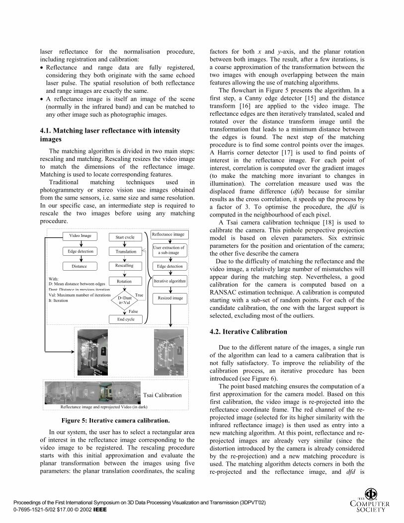
Figure 5: Iterative camera calibration.
In our system, the user has to select a rectangular area of interest in the reflectance image corresponding to the video image to be registered. The rescaling procedure starts with this initial approximation and evaluate the planar transformation between the images using five parameters: the planar translation coordinates, the scaling
factors for both x and y-axis, and the planar rotation between both images. The result, after a few iterations, is a coarse approximation of the transformation between the two images with enough overlapping between the main features allowing the use of matching algorithms.
The flowchart in Figure 5 presents the algorithm. In a first step, a Canny edge detector [15] and the distance transform [16] are applied to the video image. The reflectance edges are then iteratively translated, scaled and rotated over the distance transform image until the transformation that leads to a minimum distance between the edges is found. The next step of the matching procedure is to find some control points over the images. A Harris corner detector [17] is used to find points of interest in the reflectance image. For each point of interest, correlation is computed over the gradient images (to make the matching more invariant to changes in illumination). The correlation measure used was the displaced frame difference (dfd) because for similar results as the cross correlation, it speeds up the process by a factor of 3. To optimise the procedure, the dfd is computed in the neighbourhood of each pixel.
A Tsai camera calibration technique [18] is used to calibrate the camera. This pinhole perspective projection model is based on eleven parameters. Six extrinsic parameters for the position and orientation of the camera; the other five describe the camera
Due to the difficulty of matching the reflectance and the video image, a relatively large number of mismatches will appear during the matching step. Nevertheless, a good calibration for the camera is computed based on a RANSAC estimation technique. A calibration is computed starting with a sub-set of random points. For each of the candidate calibration, the one with the largest support is selected, excluding most of the outliers. 4.2. Iterative Calibration
Due to the different nature of the images, a single run of the algorithm can lead to a camera calibration that is not fully satisfactory. To improve the reliability of the calibration process, an iterative procedure has been introduced (see Figure 6).
The point based matching ensures the computation of a first approximation for the camera model. Based on this first calibration, the video image is re-projected into the reflectance coordinate frame. The red channel of the re-projected image (selected for its higher similarity with the infrared reflectance image) is then used as entry into a new matching algorithm. At this point, reflectance and re-projected images are already very similar (since the distortion introduced by the camera is already considered by the re-projection) and a new matching procedure is used. The matching algorithm detects corners in both the re-projected and the reflectance image, and dfd is
Proceedings of the First International Symposium on 3D Data Processing Visualization and Transmission (3DPVT�02) 0-7695-1521-5/02 $17.00 © 2002 IEEE
computed between neighbour corners. The neighbour corner with the higher correlation is then selected as the new matching point and based on these correspondences a new calibration is computed.
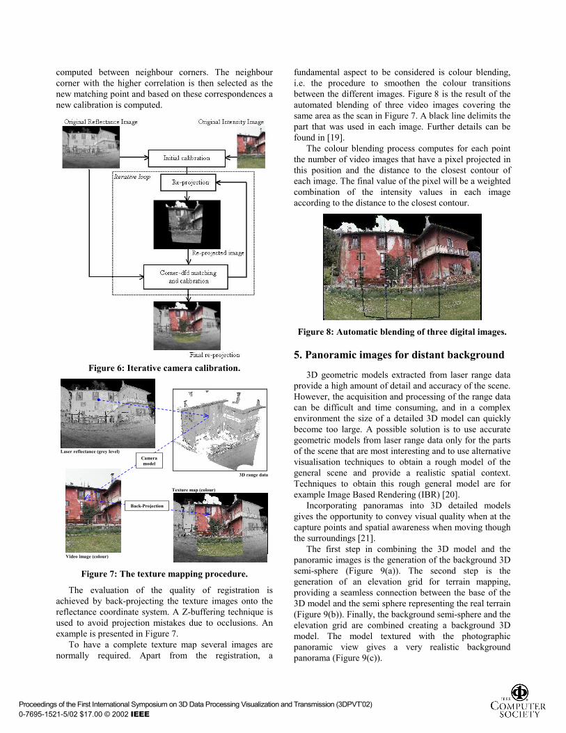
Figure 6: Iterative camera calibration.
Video image (colour)
Texture map (colour)
Laser reflectance (grey level)
Back-Projection
3D range data
Camera model
Figure 7: The texture mapping procedure.
The evaluation of the quality of registration is achieved by back-projecting the texture images onto the reflectance coordinate system. A Z-buffering technique is used to avoid projection mistakes due to occlusions. An example is presented in Figure 7.
To have a complete texture map several images are normally required. Apart from the registration, a
fundamental aspect to be considered is colour blending, i.e. the procedure to smoothen the colour transitions between the different images. Figure 8 is the result of the automated blending of three video images covering the same area as the scan in Figure 7. A black line delimits the part that was used in each image. Further details can be found in [19].
The colour blending process computes for each point the number of video images that have a pixel projected in this position and the distance to the closest contour of each image. The final value of the pixel will be a weighted combination of the intensity values in each image according to the distance to the closest contour.
Figure 8: Automatic blending of three digital images.
5. Panoramic images for distant background
3D geometric models extracted from laser range data provide a high amount of detail and accuracy of the scene. However, the acquisition and processing of the range data can be difficult and time consuming, and in a complex environment the size of a detailed 3D model can quickly become too large. A possible solution is to use accurate geometric models from laser range data only for the parts of the scene that are most interesting and to use alternative visualisation techniques to obtain a rough model of the general scene and provide a realistic spatial context. Techniques to obtain this rough general model are for example Image Based Rendering (IBR) [20].
Incorporating panoramas into 3D detailed models gives the opportunity to convey visual quality when at the capture points and spatial awareness when moving though the surroundings [21].
The first step in combining the 3D model and the panoramic images is the generation of the background 3D semi-sphere (Figure 9(a)). The second step is the generation of an elevation grid for terrain mapping, providing a seamless connection between the base of the 3D model and the semi sphere representing the real terrain (Figure 9(b)). Finally, the background semi-sphere and the elevation grid are combined creating a background 3D model. The model textured with the photographic panoramic view gives a very realistic background panorama (Figure 9(c)).
Proceedings of the First International Symposium on 3D Data Processing Visualization and Transmission (3DPVT�02) 0-7695-1521-5/02 $17.00 © 2002 IEEE
(a) (b) (c)
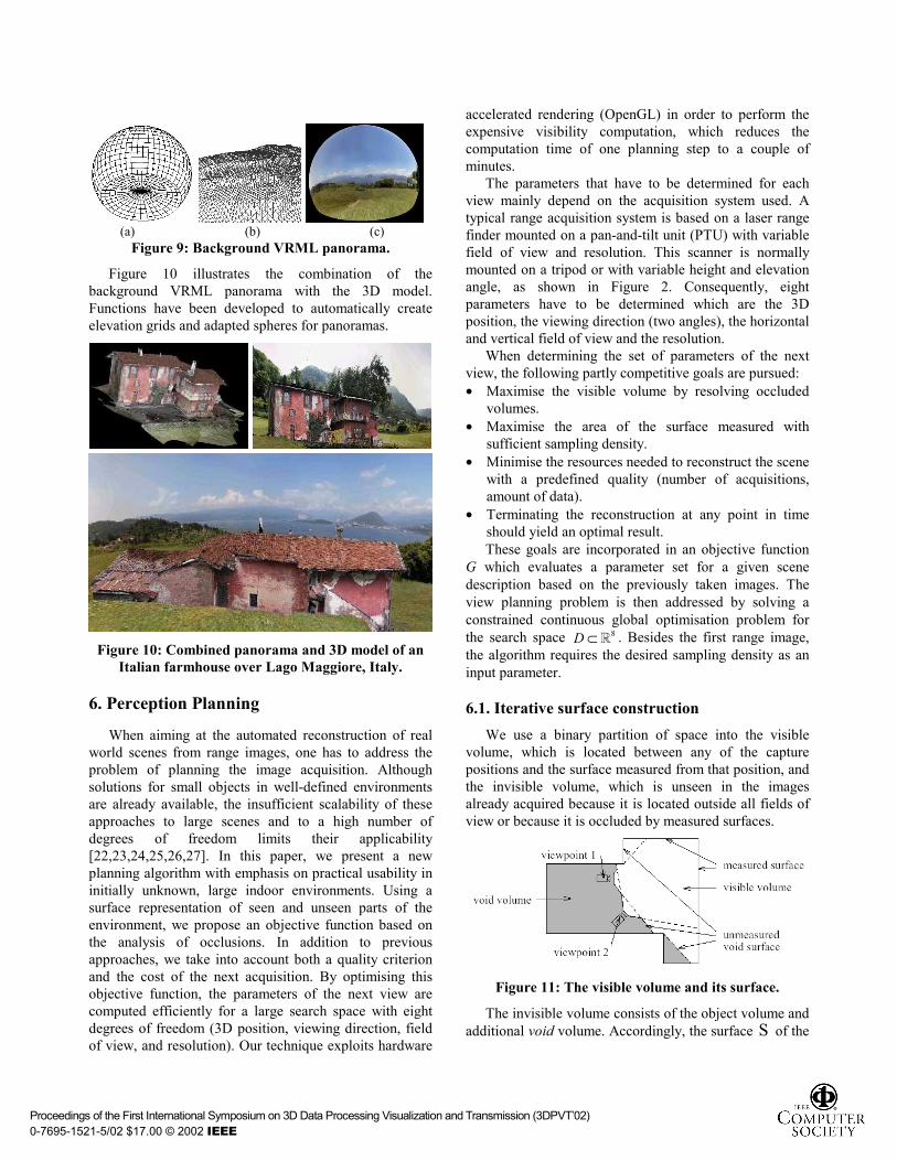
Figure 9: Background VRML panorama.
Figure 10 illustrates the combination of the background VRML panorama with the 3D model. Functions have been developed to automatically create elevation grids and adapted spheres for panoramas.
Figure 10: Combined panorama and 3D model of an
Italian farmhouse over Lago Maggiore, Italy.
6. Perception Planning
When aiming at the automated reconstruction of real world scenes from range images, one has to address the problem of planning the image acquisition. Although solutions for small objects in well-defined environments are already available, the insufficient scalability of these approaches to large scenes and to a high number of degrees of freedom limits their applicability [22,23,24,25,26,27]. In this paper, we present a new planning algorithm with emphasis on practical usability in initially unknown, large indoor environments. Using a surface representation of seen and unseen parts of the environment, we propose an objective function based on the analysis of occlusions. In addition to previous approaches, we take into account both a quality criterion and the cost of the next acquisition. By optimising this objective function, the parameters of the next view are computed efficiently for a large search space with eight degrees of freedom (3D position, viewing direction, field of view, and resolution). Our technique exploits hardware
accelerated rendering (OpenGL) in order to perform the expensive visibility computation, which reduces the computation time of one planning step to a couple of minutes.
The parameters that have to be determined for each view mainly depend on the acquisition system used. A typical range acquisition system is based on a laser range finder mounted on a pan-and-tilt unit (PTU) with variable field of view and resolution. This scanner is normally mounted on a tripod or with variable height and elevation angle, as shown in Figure 2. Consequently, eight parameters have to be determined which are the 3D position, the viewing direction (two angles), the horizontal and vertical field of view and the resolution.
When determining the set of parameters of the next view, the following partly competitive goals are pursued: • Maximise the visible volume by resolving occluded
volumes. • Maximise the area of the surface measured with
sufficient sampling density. • Minimise the resources needed to reconstruct the scene
with a predefined quality (number of acquisitions, amount of data).
• Terminating the reconstruction at any point in time should yield an optimal result. These goals are incorporated in an objective function
G which evaluates a parameter set for a given scene description based on the previously taken images. The view planning problem is then addressed by solving a constrained continuous global optimisation problem for the search space 8D ⊂ � . Besides the first range image, the algorithm requires the desired sampling density as an input parameter. 6.1. Iterative surface construction
We use a binary partition of space into the visible volume, which is located between any of the capture positions and the surface measured from that position, and the invisible volume, which is unseen in the images already acquired because it is located outside all fields of view or because it is occluded by measured surfaces.
Figure 11: The visible volume and its surface.
The invisible volume consists of the object volume and additional void volume. Accordingly, the surface S of the
Proceedings of the First International Symposium on 3D Data Processing Visualization and Transmission (3DPVT�02) 0-7695-1521-5/02 $17.00 © 2002 IEEE

visible volume is partitioned into a measured part and the unmeasured void surface (Figure 11).
6.2. Objective function
For the incorporation of a quality criterion we define a function : Sβ → � which yields the sampling density for a given point on the surface S . Points on void surfaces yield a function value of 0. Additionally, we associate each point p on S with a desired sampling quality βmax (p). Accordingly, we define a function
8: S F × →� � , which expresses the expected sampling density yielded at a point on the surface S when viewed with the evaluated set of parameters. With the solid angle Apatch covered by one pixel at the position in the image grid in standard resolution1 onto which the point p S∈ is projected, the function F is formulated by
patchvhea Ad
nmmF⋅
−⋅= 3
)(:),,,,,,( xpxp�
ϑϑϕϕ (1)
where n� is the normal of the surface S in point p and p - xd = is the distance between the capture point x
and p . In order to avoid a high number of small images or a high number of data points the costs of an image acquisition with the evaluated set of parameters have to be taken into account as well. To meet these demands, we express the objective function as a cost-benefit ratio which has to be minimised, thereby taking the number of pixels N and the costs ca of each acquisition into account. The benefit depends on the parts of the scene actually seen from point x and is thus integrated over the visible area of the surface S . Summarising the geometric parameter vector by ( , , , , ) :a e h vϕ ϕ ϑ ϑ τ=x the cost-benefit ratio can now be expressed by
∫∫∈
⋅+⋅
=
)(
),,(),(:),(
Sp
Spp dmBwcNmmG
v
A
τττ (2)
with{ } { }max max
( , , ) :min ( ), ( , , ) min ( ), ( )B m
F mτβ τ β β
=−
pp p p p
(3)
where the value of cA has to be chosen empirically and is in the order of magnitude of the number of pixels in a typical image. Considering the predefined desired quality βmax (p) ensures that redundant measurements do not increase the computed benefit for a given capture point.
When acquiring images from a real world scene, e.g. using range finders, the visible surface determination is addressed inherently. The dual process for geometry models is the computer graphic rendering step, where the visible surface determination is addressed e.g. by ray-casting or the z buffer algorithm. When speed is a major concern, usually a hardware implementation of the z buffer algorithm is used. Besides the fast computation, the
perspective view of the partly reconstructed scene enables the use of the rendered image as a lookup table for all functions of the surface points and the evaluated capture position. This lookup table can then be used for the fast approximation of the integral in Eq. 2 (for details see [28]). As the complete plenoptic function [29] has to be stored, the perspective geometry leads to a set of six planar projections in the form of a cube (see Figure 12).
Figure 12: View-cube with surface area covered by
one pixel.
When evaluating the results of the planning technique, two main criteria can be distinguished, of which the first is the percentage of the scene volume reconstructed at a given iteration. The second criterion is the amount of surface area represented at a given resolution at a given iteration. We evaluate the percentage of the surface area represented with the desired sampling density as well as the percentage represented with lower densities (75%, 50%, 25% of the desired resolution, and the percentage visible at all). By analysing both criteria as functions of the iteration number the quality of the reconstruction in each iteration can be estimated.
Figure 13: Reconstruction results after 10 automatically planned data acquisitions.
Figure 13 presents a real world complex scene to demonstrate the practical usability of the method. The scene is a typical complex laboratory environment 10m×6m×4.3m, which serves as a complicated real world scene. Figure 14 shows the evaluation data from 10 views. While some occlusions have not been resolved, the algorithm yields a sufficient density in more than 70% of the reconstructed surface area. This demonstrates the efficiency of the method with limited resources. Failures in the registration due to an insufficient overlap did not
Proceedings of the First International Symposium on 3D Data Processing Visualization and Transmission (3DPVT�02) 0-7695-1521-5/02 $17.00 © 2002 IEEE
occur in our experiment. The real world scene was reconstructed using a PIII 550 based computer with a hardware accelerated OpenGL implementation where the view planning takes less than 4 minutes per view, while the total time for the reconstruction was dominated by moving the system.
Figure 14: Percentage of reconstructed volume (left) and
percentage of surface area represented with given sampling densities (right) for each iteration.
7. Discussion and Conclusions
The paper illustrated a new automated technique for the creation of photo-realistic 3D models of real world scenes (see some examples in Figures 10, 14 and 15). The main advantage is that it takes reality as the base of modelling.
A notable aspect of the overall system is its integrated approach, producing automatic modelling procedures, including detection of non-modelled parts and computation of the next best view, to progress from range and visual data acquisition to final high quality texture models of interiors and exteriors. The system can be used with all common range scanners and digital or video cameras, without the need of any pre-calibration or static arrangement between the different sensors.
A main aspect of this technique is that a single acquisition session can produce all sorts of models each one targeted to different applications. Indeed, it is possible to have the high-quality master model, including fine spatial and visual detail (and normally of large dimension), for high quality documentation or scholar applications, and low-size, lower quality model targeted for Internet applications where download times are important. Intermediate quality models are easily derived from the initial one.
It is believed that 3D reconstruction is of particular use in cultural heritage both for indoor and outdoor applications. A few examples were presented. The same technique together with the design of clever Java scripts/applets can be used in archaeology or architectural studies, whenever there is the need to quantify distances and orientations between relevant features. 3D models in archaeology can be most beneficial for documenting the findings in different strata, as well as to provide 3D time (and depth) continuity to the objects found. Animations and other forms of data presentation can be easily built. 3D models can also help assembling objects from individual parts.
Our current work concentrates in three aspects: i) increase the visual and dimensional quality of the models by using more than one registered image and photogrammetry techniques in order to get 3D information directly from the intensity images. In this case, it will be possible to combine the 3D information coming from the intensity and range data, in order to improve the 3D models� geometry and accuracy; ii) extend the perception planning technique to simultaneous solve for best range and video capture positions iii) extract structural representations for seismic analysis of heritage buildings and monuments. A further area of development is the seamless combination of the 3D models with real-time, on-line data originated from the real world. This association of modelled (and yet realistic) data with on-line data helps building powerful Human-Computer Interfaces. As an example, it is thus possible to visit the ruins of a medieval castle and see in 3D how the castle looked like in ancient times. 8. Acknowledgments
The technologies described were all developed at the JRC. Their progress was possible thanks to the participation in the following European projects: RESOLV, InfoBoy, CAMERA. The authors thank E. Wolfart, K. Klein, P. Dias, M. Ruggeri, E. Biotti and E. Bovisio for their contributions for the work described in the paper.
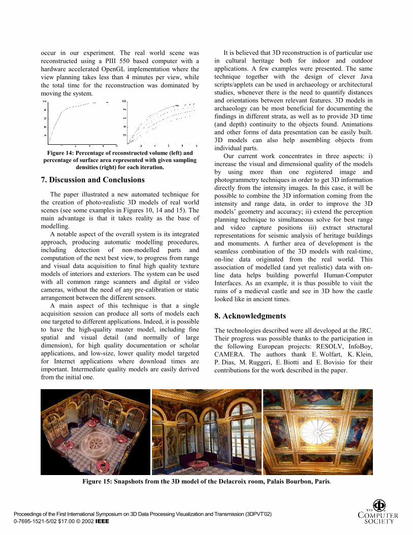
Figure 15: Snapshots from the 3D model of the Delacroix room, Palais Bourbon, Paris.
Proceedings of the First International Symposium on 3D Data Processing Visualization and Transmission (3DPVT�02) 0-7695-1521-5/02 $17.00 © 2002 IEEE
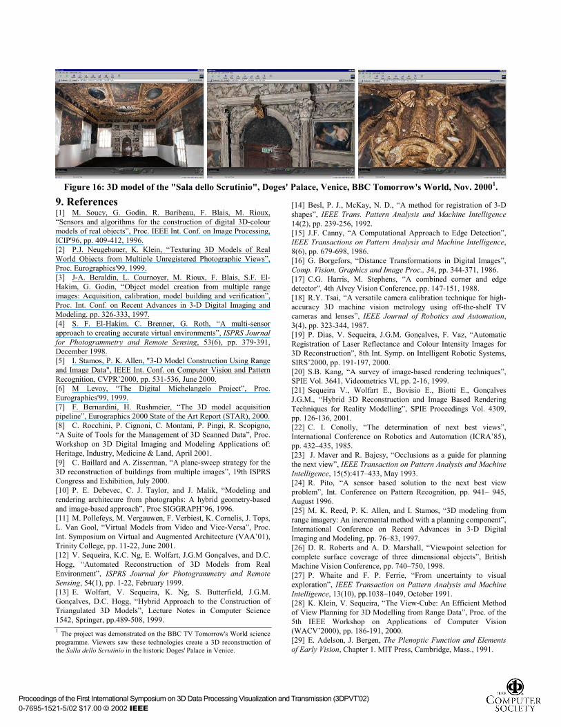
Figure 16: 3D model of the "Sala dello Scrutinio", Doges' Palace, Venice, BBC Tomorrow's World, Nov. 20001.
9. References [1] M. Soucy, G. Godin, R. Baribeau, F. Blais, M. Rioux, �Sensors and algorithms for the construction of digital 3D-colour models of real objects�, Proc. IEEE Int. Conf. on Image Processing, ICIP'96, pp. 409-412, 1996. [2] P.J. Neugebauer, K. Klein, �Texturing 3D Models of Real World Objects from Multiple Unregistered Photographic Views�, Proc. Eurographics'99, 1999. [3] J-A. Beraldin, L. Cournoyer, M. Rioux, F. Blais, S.F. El-Hakim, G. Godin, �Object model creation from multiple range images: Acquisition, calibration, model building and verification�, Proc. Int. Conf. on Recent Advances in 3-D Digital Imaging and Modeling. pp. 326-333, 1997. [4] S. F. El-Hakim, C. Brenner, G. Roth, �A multi-sensor approach to creating accurate virtual environments�, ISPRS Journal for Photogrammetry and Remote Sensing, 53(6), pp. 379-391, December 1998. [5] I. Stamos, P. K. Allen, "3-D Model Construction Using Range and Image Data", IEEE Int. Conf. on Computer Vision and Pattern Recognition, CVPR�2000, pp. 531-536, June 2000. [6] M Levoy, �The Digital Michelangelo Project�, Proc. Eurographics'99, 1999. [7] F. Bernardini, H. Rushmeier, �The 3D model acquisition pipeline�, Eurographics 2000 State of the Art Report (STAR), 2000. [8] C. Rocchini, P. Cignoni, C. Montani, P. Pingi, R. Scopigno, �A Suite of Tools for the Management of 3D Scanned Data�, Proc. Workshop on 3D Digital Imaging and Modeling Applications of: Heritage, Industry, Medicine & Land, April 2001. [9] C. Baillard and A. Zisserman, �A plane-sweep strategy for the 3D reconstruction of buildings from multiple images�, 19th ISPRS Congress and Exhibition, July 2000. [10] P. E. Debevec, C. J. Taylor, and J. Malik, �Modeling and rendering architecure from photographs: A hybrid geometry-based and image-based approach�, Proc SIGGRAPH�96, 1996. [11] M. Pollefeys, M. Vergauwen, F. Verbiest, K. Cornelis, J. Tops, L. Van Gool, �Virtual Models from Video and Vice-Versa�, Proc. Int. Symposium on Virtual and Augmented Architecture (VAA�01), Trinity College, pp. 11-22, June 2001. [12] V. Sequeira, K.C. Ng, E. Wolfart, J.G.M Gonçalves, and D.C. Hogg, �Automated Reconstruction of 3D Models from Real Environment�, ISPRS Journal for Photogrammetry and Remote Sensing, 54(1), pp. 1-22, February 1999. [13] E. Wolfart, V. Sequeira, K. Ng, S. Butterfield, J.G.M. Gonçalves, D.C. Hogg, �Hybrid Approach to the Construction of Triangulated 3D Models�, Lecture Notes in Computer Science 1542, Springer, pp.489-508, 1999. 1 The project was demonstrated on the BBC TV Tomorrow's World science programme. Viewers saw these technologies create a 3D reconstruction of the Salla dello Scrutinio in the historic Doges' Palace in Venice.
[14] Besl, P. J., McKay, N. D., �A method for registration of 3-D shapes�, IEEE Trans. Pattern Analysis and Machine Intelligence 14(2), pp. 239-256, 1992. [15] J.F. Canny, �A Computational Approach to Edge Detection�, IEEE Transactions on Pattern Analysis and Machine Intelligence, 8(6), pp. 679-698, 1986. [16] G. Borgefors, �Distance Transformations in Digital Images�, Comp. Vision, Graphics and Image Proc., 34, pp. 344-371, 1986. [17] C.G. Harris, M. Stephens, �A combined corner and edge detector�, 4th Alvey Vision Conference, pp. 147-151, 1988. [18] R.Y. Tsai, �A versatile camera calibration technique for high-accuracy 3D machine vision metrology using off-the-shelf TV cameras and lenses�, IEEE Journal of Robotics and Automation, 3(4), pp. 323-344, 1987. [19] P. Dias, V. Sequeira, J.G.M. Gonçalves, F. Vaz, �Automatic Registration of Laser Reflectance and Colour Intensity Images for 3D Reconstruction�, 8th Int. Symp. on Intelligent Robotic Systems, SIRS�2000, pp. 191-197, 2000. [20] S.B. Kang, �A survey of image-based rendering techniques�, SPIE Vol. 3641, Videometrics VI, pp. 2-16, 1999. [21] Sequeira V., Wolfart E., Bovisio E., Biotti E., Gonçalves J.G.M., �Hybrid 3D Reconstruction and Image Based Rendering Techniques for Reality Modelling�, SPIE Proceedings Vol. 4309, pp. 126-136, 2001. [22] C. I. Conolly, �The determination of next best views�, International Conference on Robotics and Automation (ICRA�85), pp. 432�435, 1985. [23] J. Maver and R. Bajcsy, �Occlusions as a guide for planning the next view�, IEEE Transaction on Pattern Analysis and Machine Intelligence, 15(5):417�433, May 1993. [24] R. Pito, �A sensor based solution to the next best view problem�, Int. Conference on Pattern Recognition, pp. 941� 945, August 1996. [25] M. K. Reed, P. K. Allen, and I. Stamos, �3D modeling from range imagery: An incremental method with a planning component�, International Conference on Recent Advances in 3-D Digital Imaging and Modeling, pp. 76�83, 1997. [26] D. R. Roberts and A. D. Marshall, �Viewpoint selection for complete surface coverage of three dimensional objects�, British Machine Vision Conference, pp. 740�750, 1998. [27] P. Whaite and F. P. Ferrie, �From uncertainty to visual exploration�, IEEE Transaction on Pattern Analysis and Machine Intelligence, 13(10), pp.1038�1049, October 1991. [28] K. Klein, V. Sequeira, �The View-Cube: An Efficient Method of View Planning for 3D Modelling from Range Data�, Proc. of the 5th IEEE Workshop on Applications of Computer Vision (WACV�2000), pp. 186-191, 2000. [29] E. Adelson, J. Bergen, The Plenoptic Function and Elements of Early Vision, Chapter 1. MIT Press, Cambridge, Mass., 1991.
Proceedings of the First International Symposium on 3D Data Processing Visualization and Transmission (3DPVT�02) 0-7695-1521-5/02 $17.00 © 2002 IEEE