3D Modeling Method of Whole Structure for Turbo-generator ...
7
3D Modeling Method of Whole Structure for Turbo-generator Based on PROE-ANSOFT Information Interaction Yu-Ling He 1 , Qing-Fa Meng 1 , Ping Wang 2 , Wen-Qiang Tao 1 1. School of energy, power and mechanical engineering, North China Electric Power University, Baoding, China, 071003. 2. Department of Electrical Engineering, Harbin University of Science and Technology Rongcheng Campus, Rongcheng, China, 264300. E-mail: [email protected]. Abstract: In this paper, a new method based on PROE-ANSOFT Information Interaction for building 3D model of turbo-generator structure is proposed, which can solve those problems such as low efficiency of surface modeling, the lack of physical connection relation for the automatic turbo-generator integral structure, the occurrence of insufficient memory and even crashes for imported PROE model. Taking the stator winding coil of a turbo-generator as an example, the establishment process of 3D solid model is given. On this basis, the overall structure of turbo-generator in the ANSOFT working platform is completed. And the advantages and disadvantages of five kinds of simulation models in ANSOFT working platform are compared and analyzed. The results show that the 3D simulation model drawn by this method can be no longer limited to the special solution environment of electromagnetic field symmetry. Meanwhile, this model can simulate the real physical connection relationship, and complete the division of the simulation model, which will be helpful for the further simulation analysis of the finite element software. Keywords: Turbo-generator; Whole structure; 3D modeling method; PROE-ANSOFT; Information interaction 1. Introduction Turbo-generator is one of the key equipments for the large-capacity generator sets. The health status of its components will directly affect the safe and stable operation of generator sets. Therefore, it is of great academic significance and engineering practical value to construct accurate generator models and perform simulation analysis. The finite element software ANSOFT is the typical software to solve and analyze the mechanical properties of stator windings, stator and rotor. However, ANSOFT work platform is less efficient in surface modeling. And automatically generated model does not have a real physical connection relationship. Meanwhile the imported PROE model has difficulty in the process of splitting. Therefore, it is important to realize the construction of the precise model of generator and the finite element simulation analysis, especially the simulation of the key parts of the generator. The structures of the stator windings are very complex, especially the end of the winding. Therefore, Stator winding is the most difficult in 3D modeling of generator. The end coil of the winding is a space curve on a conical surface. After being expanded, a space involute can be obtained. This design ensures that the end coil is lifted, the pitch, and the equal distance between two adjacent coils. And it can ensure that the current intensity is equal and ventilation cooling conditions are reliable [2]. By building 3D model of stator end windings can reduce duplication of effort, improve efficiency, and facilitate further simulation and calculations [3]. In the past, the description of the involute of the stator winding ends was usually determined by the approximate drawing method or the planar involute curve calculation method. However, the approximate involute accuracy obtained was very low, and the calculation procedure was complicated [4, 5]. In addition, the 2D model is only a flat surface in the ANSOFT work platform [6]. The automatically generated 3D model also only establishes an equivalent magnetic field and does not have a real physical connection. At the same time, the externally imported physical model has problems about splitting [7-9]. Some scholars have already finished the construction of 3D model within the ANSOFT work platform. However, this model is limited to the special solving environment of air gap and electromagnetic field symmetry. When the appearance of eccentric or field winding inter-turn short-circuit, the model will no longer be applicable [10]. Based on the series of problems in the modeling process in ANSOFT, this paper proposes a new 3D modeling method based on PROE-ANSOFT information interaction for establishing whole structure of turbo-generator. Journal of Modeling and Optimization 47 10:1 (2018)
-
Upload
khangminh22 -
Category
Documents
-
view
4 -
download
0
Transcript of 3D Modeling Method of Whole Structure for Turbo-generator ...
3D Modeling Method of Whole Structure for Turbo-generator Based on
PROE-ANSOFT Information Interaction
Yu-Ling He1, Qing-Fa Meng1
, Ping Wang2, Wen-Qiang Tao1
1. School of energy, power and mechanical engineering, North China Electric Power
University, Baoding, China, 071003.
2. Department of Electrical Engineering, Harbin University of Science and Technology
Rongcheng Campus, Rongcheng, China, 264300.
E-mail: [email protected].
Abstract: In this paper, a new method based on PROE-ANSOFT Information Interaction for building 3D model
of turbo-generator structure is proposed, which can solve those problems such as low efficiency of surface
modeling, the lack of physical connection relation for the automatic turbo-generator integral structure, the
occurrence of insufficient memory and even crashes for imported PROE model. Taking the stator winding coil of
a turbo-generator as an example, the establishment process of 3D solid model is given. On this basis, the overall
structure of turbo-generator in the ANSOFT working platform is completed. And the advantages and
disadvantages of five kinds of simulation models in ANSOFT working platform are compared and analyzed. The
results show that the 3D simulation model drawn by this method can be no longer limited to the special solution
environment of electromagnetic field symmetry. Meanwhile, this model can simulate the real physical
connection relationship, and complete the division of the simulation model, which will be helpful for the further
simulation analysis of the finite element software.
Keywords: Turbo-generator; Whole structure; 3D modeling method; PROE-ANSOFT; Information interaction
1. Introduction
Turbo-generator is one of the key equipments for the large-capacity generator sets. The health status of its
components will directly affect the safe and stable operation of generator sets. Therefore, it is of great academic
significance and engineering practical value to construct accurate generator models and perform simulation
analysis.
The finite element software ANSOFT is the typical software to solve and analyze the mechanical properties
of stator windings, stator and rotor. However, ANSOFT work platform is less efficient in surface modeling. And
automatically generated model does not have a real physical connection relationship. Meanwhile the imported
PROE model has difficulty in the process of splitting. Therefore, it is important to realize the construction of the
precise model of generator and the finite element simulation analysis, especially the simulation of the key parts
of the generator.
The structures of the stator windings are very complex, especially the end of the winding. Therefore, Stator
winding is the most difficult in 3D modeling of generator. The end coil of the winding is a space curve on a
conical surface. After being expanded, a space involute can be obtained. This design ensures that the end coil is
lifted, the pitch, and the equal distance between two adjacent coils. And it can ensure that the current intensity is
equal and ventilation cooling conditions are reliable [2]. By building 3D model of stator end windings can
reduce duplication of effort, improve efficiency, and facilitate further simulation and calculations [3]. In the past,
the description of the involute of the stator winding ends was usually determined by the approximate drawing
method or the planar involute curve calculation method. However, the approximate involute accuracy obtained
was very low, and the calculation procedure was complicated [4, 5]. In addition, the 2D model is only a flat
surface in the ANSOFT work platform [6]. The automatically generated 3D model also only establishes an
equivalent magnetic field and does not have a real physical connection. At the same time, the externally
imported physical model has problems about splitting [7-9]. Some scholars have already finished the
construction of 3D model within the ANSOFT work platform. However, this model is limited to the special
solving environment of air gap and electromagnetic field symmetry. When the appearance of eccentric or field
winding inter-turn short-circuit, the model will no longer be applicable [10].
Based on the series of problems in the modeling process in ANSOFT, this paper proposes a new 3D modeling
method based on PROE-ANSOFT information interaction for establishing whole structure of turbo-generator.
Journal of Modeling and Optimization
47
10:1 (2018)
And comparing and analyzing the advantages and disadvantages of the five kinds of simulation models in
ANSOFT, this 3D modeling method will contribute to the further solution and analysis.
2. Structures of Stator Windings
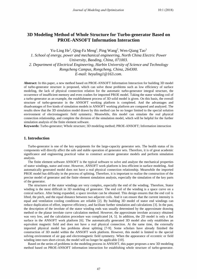
Turbo-generator, including stator and rotor, stator windings and rotor windings, is indispensable in the
production of electricity. The structures of stator winding are more complicated, especially the end of the stator
winding. It is composed of two layers of windings. The coil is a space curve on a conical surface. After the
expansion, a space involute is obtained. After the two cones of the coil are respectively unfolded, they are
projected from the side to obtain the projection. β is cone's semi-cone angle, points A and B are respectively the
starting point and the ending point of the involute. Each layer of the coil is composed of L1 (the length of the line
segment outside the core), L2 (the length of the line segment intersected with the involute), L3 (The length of the
nose-top end connection) and L5 (the length of the segment involute) and r1, r2, r3(the corresponding transition
arc), as shown in Fig 1(a).
定
子
铁
芯
转轴
L1
L2
L3
L5
A
B
β
r1 r2
R1/R2R1'/R2'
r3
Fig.1 Stator end winding structure simplified schematic and real picture
Tab.1 Stator end winding parameters
Upper and lower Upper Lower
Number of slots/Z 42 42
Half cone angle/(o) 20 20
Radius of base circle 1085 1085
Radius of starting 2400 2800
L1/mm 240 /
L2/mm 86 /
L3/mm 90 /
a/mm 95.6 95.6
b/mm 40.3 40.3
h/mm 125 /
Where: a and b are respectively the width and height of the coil cross-section, h is the distance between two
layers of the coil.
3. Modeling of Stator Windings
3D modeling method of stator winding structure based on PROE-ANSOFT information exchange can be
divided into three main steps: 1 Drawing a 3D model of stator winding based on PROE, extracting and sharing
point sets according to established scanning lead of stator winding bar. 2 Using the forming principle of point,
line, surface, body to establish a 3D model of stator winding. 3 Assembling the components to get the 3D model
of the whole turbo-generator.
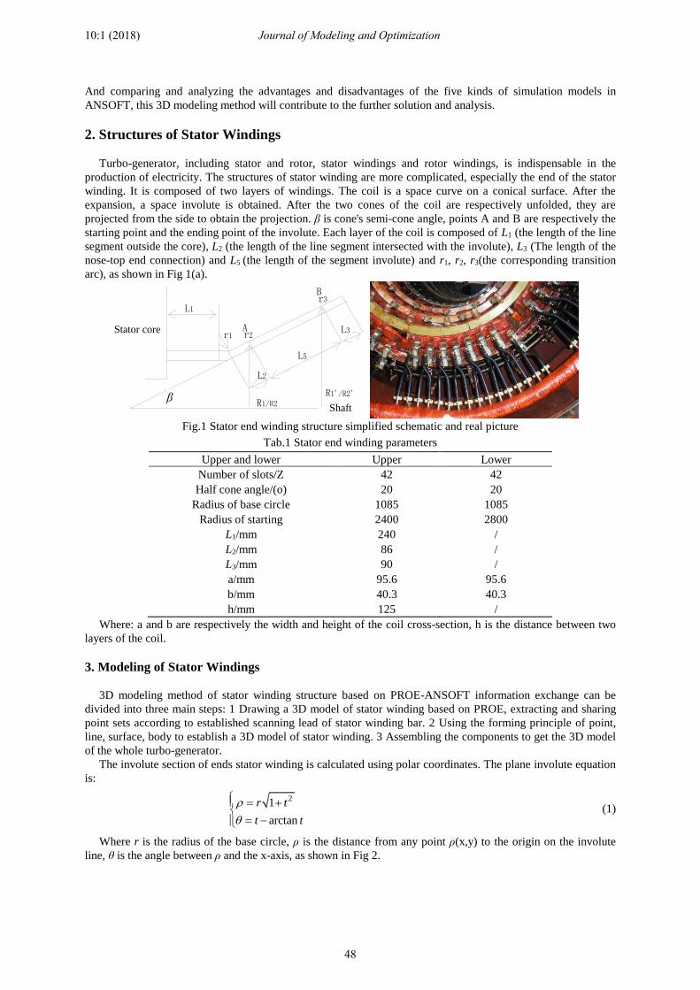
The involute section of ends stator winding is calculated using polar coordinates. The plane involute equation
is:
21
arctan
r t
t t
(1)
Where r is the radius of the base circle, ρ is the distance from any point ρ(x,y) to the origin on the involute
line, θ is the angle between ρ and the x-axis, as shown in Fig 2.
β Shaft
Stator core
Journal of Modeling and Optimization
48
10:1 (2018)
First plotting the conical surface with an elevation angle of β, and then project the involute curve to obtain the
parametric equation for the involute of the end winding [2]:
sin cos sin
sin sin sin
cos
x
y
z
(2)
The space involute curve described by Eq. (2) is shown in Fig. 3, where the involute directions of the upper
and lower windings are exactly the opposite.
As indicated in Eq. (1) and Eq. (2), the radius of the base circle of the involute of the end winding can be
obtained according to the diagram of the stator winding structure [8].
2r ZH N (3)
Where Z is the number of stator slots, H is the distance between the centers of two adjacent involutes, N is the
number of conductors on the same involute, and N is 1. The specific calculation process can refer to the
literature [5] and the literature [8], which will not be repeated here.
(a) Plane involute parameters (b) Stator winding end structure (c) Stator winding whole structure
Fig.2 Plane involute parameters and stator winding structure
With reference to [5] and [8], 3D models are completed in PROE.
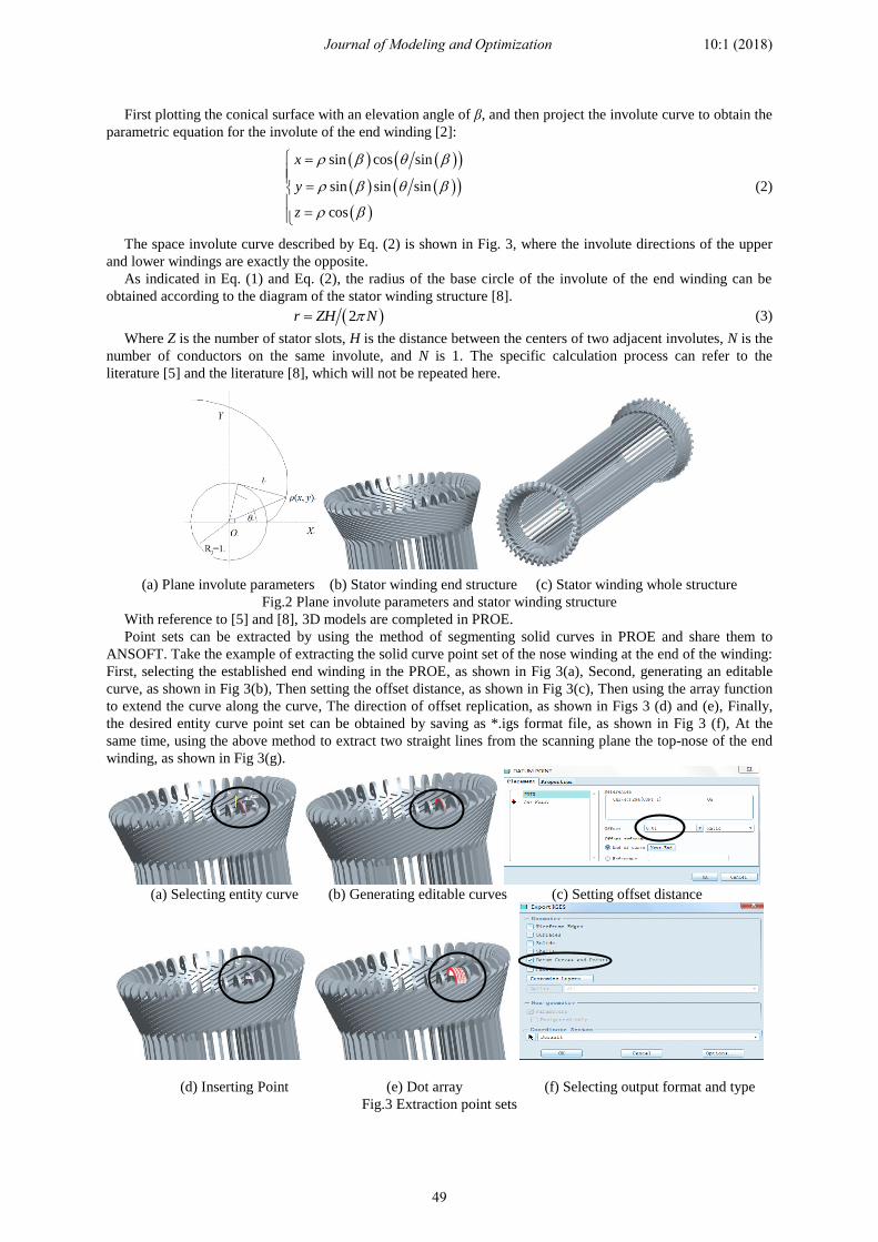
Point sets can be extracted by using the method of segmenting solid curves in PROE and share them to
ANSOFT. Take the example of extracting the solid curve point set of the nose winding at the end of the winding:
First, selecting the established end winding in the PROE, as shown in Fig 3(a), Second, generating an editable
curve, as shown in Fig 3(b), Then setting the offset distance, as shown in Fig 3(c), Then using the array function
to extend the curve along the curve, The direction of offset replication, as shown in Figs 3 (d) and (e), Finally,
the desired entity curve point set can be obtained by saving as *.igs format file, as shown in Fig 3 (f), At the
same time, using the above method to extract two straight lines from the scanning plane the top-nose of the end
winding, as shown in Fig 3(g).
(a) Selecting entity curve (b) Generating editable curves (c) Setting offset distance
(d) Inserting Point (e) Dot array (f) Selecting output format and type
Fig.3 Extraction point sets
Journal of Modeling and Optimization
49
10:1 (2018)
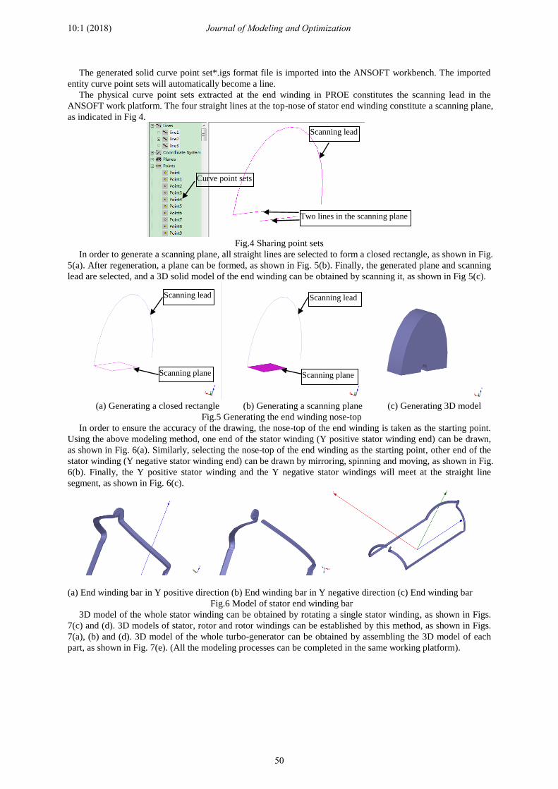
The generated solid curve point set*.igs format file is imported into the ANSOFT workbench. The imported
entity curve point sets will automatically become a line.
The physical curve point sets extracted at the end winding in PROE constitutes the scanning lead in the
ANSOFT work platform. The four straight lines at the top-nose of stator end winding constitute a scanning plane,
as indicated in Fig 4.
Fig.4 Sharing point sets
In order to generate a scanning plane, all straight lines are selected to form a closed rectangle, as shown in Fig.
5(a). After regeneration, a plane can be formed, as shown in Fig. 5(b). Finally, the generated plane and scanning
lead are selected, and a 3D solid model of the end winding can be obtained by scanning it, as shown in Fig 5(c).
(a) Generating a closed rectangle (b) Generating a scanning plane (c) Generating 3D model
Fig.5 Generating the end winding nose-top
In order to ensure the accuracy of the drawing, the nose-top of the end winding is taken as the starting point.
Using the above modeling method, one end of the stator winding (Y positive stator winding end) can be drawn,
as shown in Fig. 6(a). Similarly, selecting the nose-top of the end winding as the starting point, other end of the
stator winding (Y negative stator winding end) can be drawn by mirroring, spinning and moving, as shown in Fig.
6(b). Finally, the Y positive stator winding and the Y negative stator windings will meet at the straight line
segment, as shown in Fig. 6(c).
(a) End winding bar in Y positive direction (b) End winding bar in Y negative direction (c) End winding bar
Fig.6 Model of stator end winding bar
3D model of the whole stator winding can be obtained by rotating a single stator winding, as shown in Figs.
7(c) and (d). 3D models of stator, rotor and rotor windings can be established by this method, as shown in Figs.
7(a), (b) and (d). 3D model of the whole turbo-generator can be obtained by assembling the 3D model of each
part, as shown in Fig. 7(e). (All the modeling processes can be completed in the same working platform).
Scanning lead
Scanning plane
Scanning lead
Scanning plane
Curve point sets
Two lines in the scanning plane
Scanning lead
Journal of Modeling and Optimization
50
10:1 (2018)
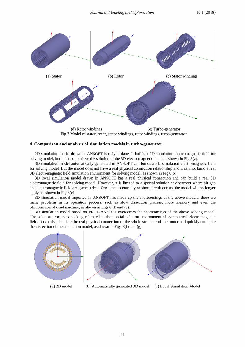
(a) Stator (b) Rotor (c) Stator windings
(d) Rotor windings (e) Turbo-generator
Fig.7 Model of stator, rotor, stator windings, rotor windings, turbo-generator
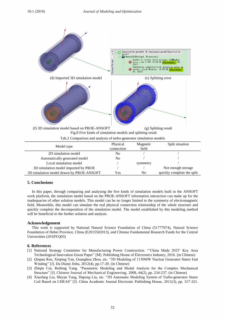
4. Comparison and analysis of simulation models in turbo-generator
2D simulation model drawn in ANSOFT is only a plane. It builds a 2D simulation electromagnetic field for
solving model, but it cannot achieve the solution of the 3D electromagnetic field, as shown in Fig 8(a).
3D simulation model automatically generated in ANSOFT can builds a 3D simulation electromagnetic field
for solving model. But the model does not have a real physical connection relationship and it can not build a real
3D electromagnetic field simulation environment for solving model, as shown in Fig 8(b).
3D local simulation model drawn in ANSOFT has a real physical connection and can build a real 3D
electromagnetic field for solving model. However, it is limited to a special solution environment where air gap
and electromagnetic field are symmetrical. Once the eccentricity or short circuit occurs, the model will no longer
apply, as shown in Fig 8(c).
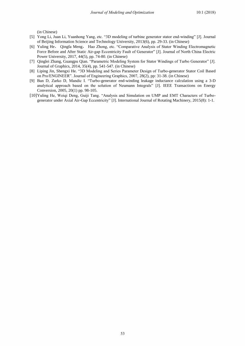
3D simulation model imported in ANSOFT has made up the shortcomings of the above models, there are
many problems in its operation process, such as slow dissection process, more memory and even the
phenomenon of dead machine, as shown in Figs 8(d) and (e).
3D simulation model based on PROE-ANSOFT overcomes the shortcomings of the above solving model.
The solution process is no longer limited to the special solution environment of symmetrical electromagnetic
field. It can also simulate the real physical connection of the whole structure of the motor and quickly complete
the dissection of the simulation model, as shown in Figs 8(f) and (g).
(a) 2D model (b) Automatically generated 3D model (c) Local Simulation Model
Journal of Modeling and Optimization
51
10:1 (2018)
(d) Imported 3D simulation model (e) Splitting error
(f) 3D simulation model based on PROE-ANSOFT (g) Splitting result
Fig.8 Five kinds of simulation models and splitting result
Tab.2 Comparison and analysis of turbo-generator simulation models
Model type Physical
connection
Magnetic
field
Split situation
2D simulation model No / /
Automatically generated model No / /
Local simulation model / symmetry /
3D simulation model imported by PROE / / Not enough storage
3D simulation model drawn by PROE-ANSOFT Yes No quickly complete the split
5. Conclusions
In this paper, through comparing and analyzing the five kinds of simulation models built in the ANSOFT
work platform, the simulation model based on the PROE-ANSOFT information interaction can make up for the
inadequacies of other solution models. This model can be no longer limited to the symmetry of electromagnetic
field. Meanwhile, this model can simulate the real physical connection relationship of the whole structure and
quickly complete the decomposition of the simulation model. The model established by this modeling method
will be beneficial to the further solution and analysis.
Acknowledgement This work is supported by National Natural Science Foundation of China (51777074), Natural Science
Foundation of Hebei Province, China (E2015502013), and Chinese Fundamental Research Funds for the Central
Universities (2018YQ03)
6. References [1] National Strategy Committee for Manufacturing Power Construction. “’China Made 2025’ Key Area
Technological Innovation Green Paper” [M]. Publishing House of Electronics Industry, 2016. (in Chinese)
[2] Qiupan Ren, Xinping Yan, Guanghou Zhou, etc. “3D Modeling of 1150MW Nuclear Generator Stator End
Winding” [J]. Da Dianji Jishu, 2012(4), pp.17-20. (in Chinese)
[3] Zhiqin Cui, Ruifeng Yang. “Parametric Modeling and Modal Analysis for the Complex Mechanical
Structure” [J]. Chinese Journal of Mechanical Engineering, 2008, 44(2), pp. 234-237. (in Chinese)
[4] Xiaofang Liu, Shiyan Yang, Dapeng Liu, etc. “3D Automatic Modeling System of Turbo-generator Stator
Coil Based on I-DEAS” [J]. China Academic Journal Electronic Publishing House, 2011(3), pp. 317-321.
December,
December,
Journal of Modeling and Optimization
52
10:1 (2018)
(in Chinese)
[5] Yong Li, Juan Li, Yuanhong Yang, etc. “3D modeling of turbine generator stator end-winding” [J]. Journal
of Beijing Information Science and Technology University, 2013(6), pp. 29-33. (in Chinese)
[6] Yuling He, Qingfa Meng, Hao Zhong, etc. “Comparative Analysis of Stator Winding Electromagnetic
Force Before and After Static Air-gap Eccentricity Fault of Generator” [J]. Journal of North China Electric
Power University, 2017, 44(5), pp. 74-80. (in Chinese)
[7] Qinglei Zhang, Guangpu Qian. “Parametric Modeling System for Stator Windings of Turbo Generator” [J].
Journal of Graphics, 2014, 35(4), pp. 541-547. (in Chinese)
[8] Liping Jin, Shengxi He. “3D Modeling and Series Parameter Design of Turbo-generator Stator Coil Based
on Pro/ENGINEER”. Journal of Engineering Graphics, 2007, 28(2), pp: 31-38. (in Chinese)
[9] Ban D, Zarko D, Mandic I. “Turbo-generator end-winding leakage inductance calculation using a 3-D
analytical approach based on the solution of Neumann Integrals” [J]. IEEE Transactions on Energy
Conversion, 2005, 20(1) pp. 98-105.
[10] Yuling He, Weiqi Deng, Guiji Tang. “Analysis and Simulation on UMP and EMT Characters of Turbo-
generator under Axial Air-Gap Eccentricity” [J]. International Journal of Rotating Machinery, 2015(8): 1-1.
Journal of Modeling and Optimization
53
10:1 (2018)