3D image-based female pelvis anatomy by ultrasound
132
IAEA 3D image-based female pelvis anatomy by ultrasound
-
Upload
khangminh22 -
Category
Documents
-
view
1 -
download
0
Transcript of 3D image-based female pelvis anatomy by ultrasound
IAEA
3D image-based female pelvis anatomy by ultrasound
IAEA
Aims
To present an overview of the role of ultrasound in gynaecological brachytherapy
• Prior knowledge of female anatomy presumed• Prior knowledge of ultrasound presumed• Information presented is intended only as a basic introduction to female pelvic
anatomy, the use of ultrasound to image the female pelvis, and the use of ultrasound in gynaecological brachytherapy and is no way a substitute for formal education and training.
Where possible clinically obtained images are used to illustrate concepts.
IAEA
Specific Learning Objectives
• To present an introduction to ultrasound (terminology, concepts, techniques)
• To present an overview of female pelvic anatomy as seen on ultrasound
• To present an introduction to ultrasound use in gynaecological brachytherapy
IAEA
Contents
• Overview of ultrasound• Normal female pelvic anatomy• Sonographic techniques - image orientation• Normal sonographic anatomy• Anatomical variations• Anatomical anomalies• Common pathologies• Accuracy of ultrasound - comparing modalities and techniques• Using ultrasound in brachytherapy - assess response to EBRT
- identifying applicators- bladder filling- intra-operative technique- intrafraction / interfraction movement- applicator and volume verification- planning with ultrasound
• Future - 3D ultrasound
IAEA
3D image-based female pelvis anatomy by Ultrasound (US)
• Overview of ultrasound• Normal female pelvic anatomy• Sonographic techniques - image orientation• Normal sonographic anatomy• Anatomical variations• Common pathologies• Using ultrasound in brachytherapy• Future - 3D ultrasound
IAEA
Ultrasound
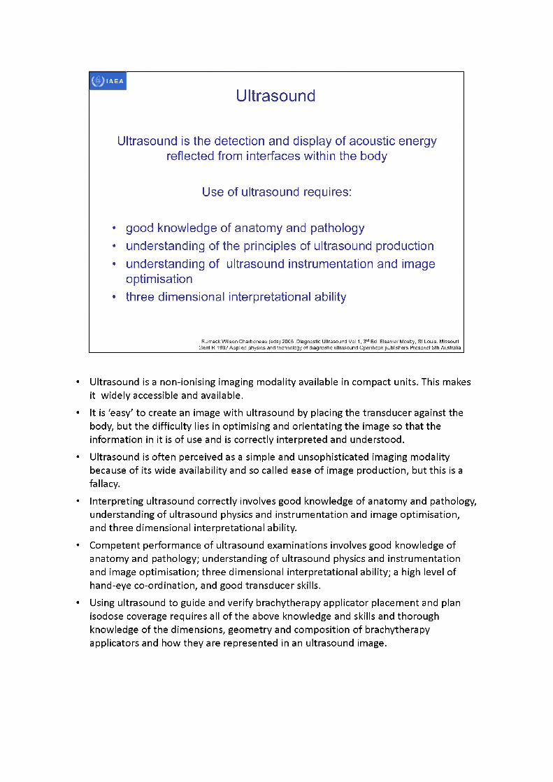
Ultrasound is the detection and display of acoustic energy reflected from interfaces within the body
Use of ultrasound requires:
• good knowledge of anatomy and pathology• understanding of the principles of ultrasound production• understanding of ultrasound instrumentation and image
optimisation• three dimensional interpretational ability
Rumack Wilson Charboneau (eds) 2005 Diagnostic Ultrasound Vol 1,3rd Ed, Elsevier Mosby, St Louis, Missouri Gent R 1997 Applied physics and technology of diagnostic ultrasound Openbook publishers Prospect Sth Australia
• Ultrasound is a non-ionising imaging modality available in compact units. This makes it widely accessible and available.
• It is ‘easy' to create an image with ultrasound by placing the transducer against the body, but the difficulty lies in optimising and orientating the image so that the information in it is of use and is correctly interpreted and understood.
• Ultrasound is often perceived as a simple and unsophisticated imaging modality because of its wide availability and so called ease of image production, but this is a fallacy.
• Interpreting ultrasound correctly involves good knowledge of anatomy and pathology, understanding of ultrasound physics and instrumentation and image optimisation, and three dimensional interpretational ability.
• Competent performance of ultrasound examinations involves good knowledge of anatomy and pathology; understanding of ultrasound physics and instrumentation and image optimisation; three dimensional interpretational ability; a high level of hand-eye co-ordination, and good transducer skills.
• Using ultrasound to guide and verify brachytherapy applicator placement and plan isodose coverage requires all of the above knowledge and skills and thorough knowledge of the dimensions, geometry and composition of brachytherapy applicators and how they are represented in an ultrasound image.
IAEA
Understanding the ultrasound image
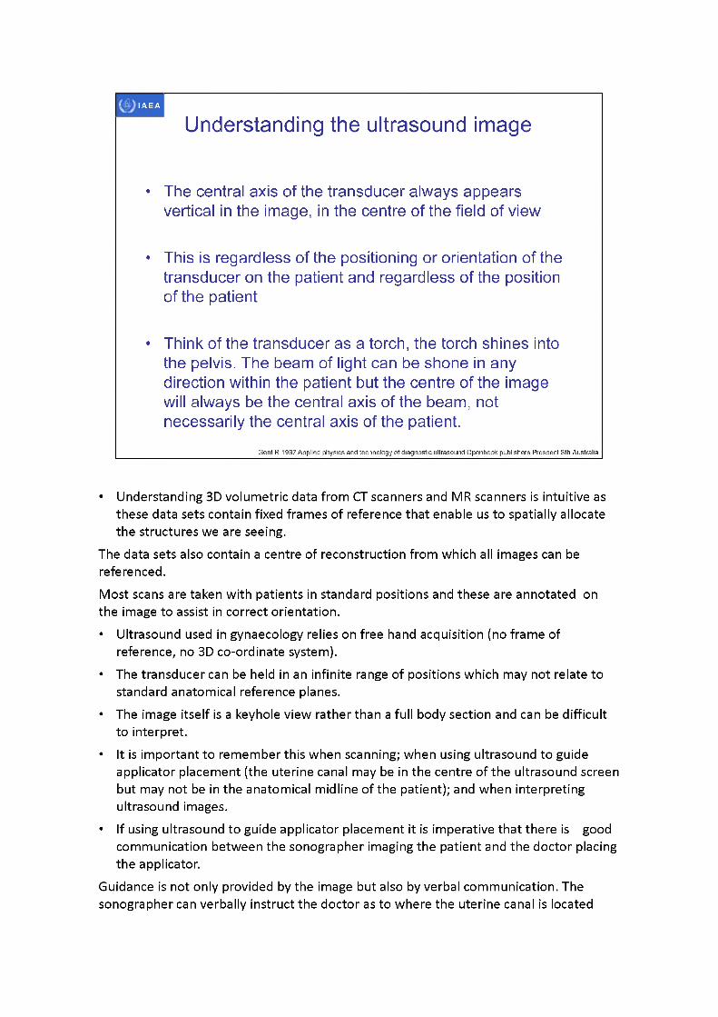
• The central axis of the transducer always appears vertical in the image, in the centre of the field of view
• This is regardless of the positioning or orientation of the transducer on the patient and regardless of the position of the patient
• Think of the transducer as a torch, the torch shines into the pelvis. The beam of light can be shone in any direction within the patient but the centre of the image will always be the central axis of the beam, not necessarily the central axis of the patient.
Gent R 1997 Applied physics and technology of diagnostic ultrasound Openbook publishers Prospect Sth Australia
• Understanding 3D volumetric data from CT scanners and MR scanners is intuitive as these data sets contain fixed frames of reference that enable us to spatially allocate the structures we are seeing.
The data sets also contain a centre of reconstruction from which all images can be referenced.Most scans are taken with patients in standard positions and these are annotated on the image to assist in correct orientation.• Ultrasound used in gynaecology relies on free hand acquisition (no frame of
reference, no 3D co-ordinate system).• The transducer can be held in an infinite range of positions which may not relate to
standard anatomical reference planes.• The image itself is a keyhole view rather than a full body section and can be difficult
to interpret.• It is important to remember this when scanning; when using ultrasound to guide
applicator placement (the uterine canal may be in the centre of the ultrasound screen but may not be in the anatomical midline of the patient); and when interpreting ultrasound images.
• If using ultrasound to guide applicator placement it is imperative that there is good communication between the sonographer imaging the patient and the doctor placing the applicator.
Guidance is not only provided by the image but also by verbal communication. The sonographer can verbally instruct the doctor as to where the uterine canal is located

based on where the sonographer is scanning.
IAEA
B-mode ultrasound
• B mode - so called because it came after A-mode (widely referred to as brightness mode)
• Real time B-mode is the most familiar format
• Reflectors in image are depicted as dots with a brightness corresponding to the amplitude of the returning echo
• An image produced by B-mode is a two dimensional representation of a volume of tissue, not a true two dimensional plane
Gent R 1997 Applied physics and technology of diagnostic ultrasound Openbook publishers Prospect Sth Australia
IAEA
Real time vs static
• Limits of human visual perception cause the appearance of structural boundaries on real time images
• Same boundaries disappear on static freeze frame images
• Ultrasound is an INTERACTIVE MODALITY - need to keep watching the screen
Gent R 1997 Applied physics and technology of diagnostic ultrasound Openbook publishers Prospect Sth Australia
• Taking images with ultrasound is quite different to taking images with other imaging modalities.
• Protocols are set on CT and MRI and there is little interaction from the operator.• When using ultrasound the operator has a range of controls and settings available to
them to optimise the ultrasound image. It is imperative that the operator stay focussed on the ultrasound image to improve the image as much as possible.
• A good sonographer asks the following questions: can I identify all the structures displayedcan I improve the imagehave I scanned the entire area of interesthave I documented the relevant findings
• Taking images with ultrasound is a dynamic process.Gent R 1997 Applied physics and technology of diagnostic ultrasound Openbook publishers Prospect Sth Australia• Being able to see in real-time is one of the most powerful aspects of ultrasound.• It is possible to adjust settings and probe position during image acquisition to obtain
the best quality image and the most appropriate view of the area under investigation.• It is necessary to ‘volume scan' the region of interest to ensure that the correct
planes have been identified. Volume scanning means using and moving the transducer across the region to examine not only the organ of interest but the

surrounding anatomy. This will result in identifying the most optimal view of the region of interest and may also alert us to other unexpected findings.
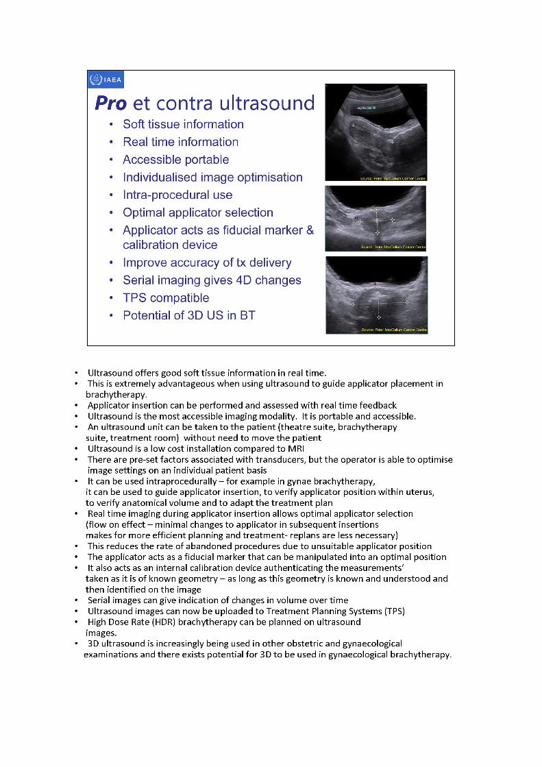
• Ultrasound offers good soft tissue information in real time.• This is extremely advantageous when using ultrasound to guide applicator placement in
brachytherapy.• Applicator insertion can be performed and assessed with real time feedback• Ultrasound is the most accessible imaging modality. It is portable and accessible.• An ultrasound unit can be taken to the patient (theatre suite, brachytherapy
suite, treatment room) without need to move the patient• Ultrasound is a low cost installation compared to MRI• There are pre- set factors associated with transducers, but the operator is able to optimise
image settings on an individual patient basis• It can be used intraprocedurally - for example in gynae brachytherapy,
it can be used to guide applicator insertion, to verify applicator position within uterus,to verify anatomical volume and to adapt the treatment plan
• Real time imaging during applicator insertion allows optimal applicator selection (flow on effect -minimal changes to applicator in subsequent insertions makes for more efficient planning and treatment- replans are less necessary)
• This reduces the rate of abandoned procedures due to unsuitable applicator position• The applicator acts as a fiducial marker that can be manipulated into an optimal position• It also acts as an internal calibration device authenticating the measurements'
taken as it is of known geometry -aslong as this geometry is known and understood and then identified on the image
• Serial images can give indication of changes in volume over time• Ultrasound imagescan now be uploaded to Treatment Planning Systems (TPS)• High Dose Rate (HDR) brachytherapy can be planned on ultrasound
images.• 3D ultrasound is increasingly being used in other obstetric and gynaecological
examinations and there exists potential for 3D to be used in gynaecological brachytherapy.
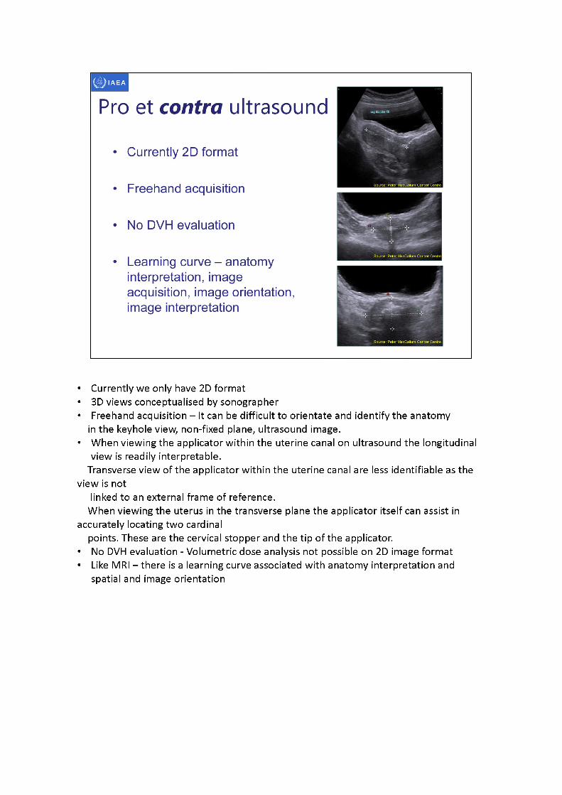
• Currently we only have 2D format• 3D views conceptualised by sonographer• Freehand acquisition - It can be difficult to orientate and identify the anatomy
in the keyhole view, non-fixed plane, ultrasound image.• When viewing the applicator within the uterine canal on ultrasound the longitudinal
view is readily interpretable.Transverse view of the applicator within the uterine canal are less identifiable as the
view is notlinked to an external frame of reference.
When viewing the uterus in the transverse plane the applicator itself can assist in accurately locating two cardinal
points. These are the cervical stopper and the tip of the applicator.• No DVH evaluation - Volumetric dose analysis not possible on 2D image format• Like MRI -thereis a learning curve associated with anatomy interpretation and
spatial and image orientation
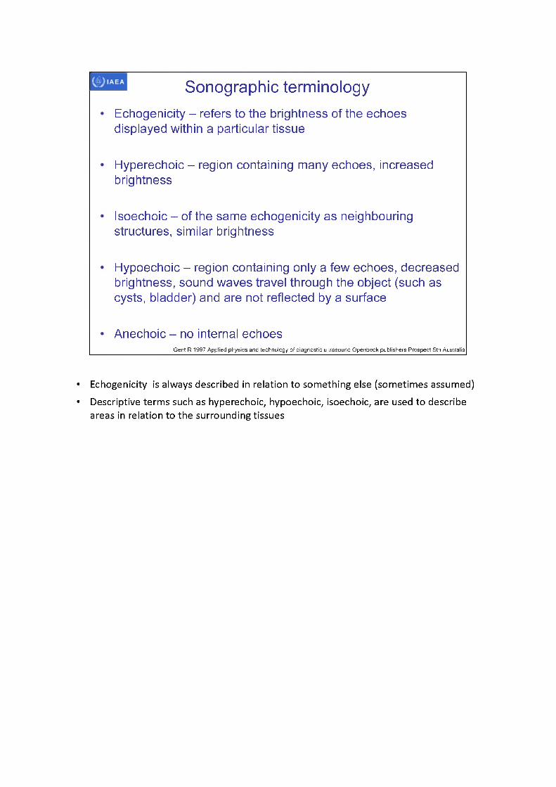
Sonographic terminologyEchogenicity - refers to the brightness of the echoes displayed within a particular tissue
Hyperechoic - region containing many echoes, increased brightness
Isoechoic - of the same echogenicity as neighbouring structures, similar brightness
Hypoechoic- region containing only a few echoes, decreased brightness, sound waves travel through the object (such as cysts, bladder) and are not reflected by a surface
Anechoic - no internal echoesGent R 1997 Applied physics and technology of diagnostic ultrasound Openbook publishers Prospect Sth Australia
• Echogenicity is always described in relation to something else (sometimes assumed)• Descriptive terms such as hyperechoic, hypoechoic, isoechoic, are used to describe
areas in relation to the surrounding tissues
IAEA
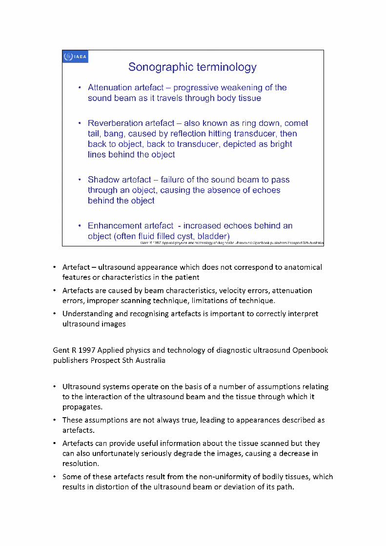
Sonographic terminology
• Attenuation artefact - progressive weakening of the sound beam as it travels through body tissue
• Reverberation artefact - also known as ring down, comet tail, bang, caused by reflection hitting transducer, then back to object, back to transducer, depicted as bright lines behind the object
• Shadow artefact - failure of the sound beam to pass through an object, causing the absence of echoes behind the object
• Enhancement artefact - increased echoes behind an object (often fluid filled cyst, bladder)
Gent R 1997 Applied physics and technology of diagnostic ultrasound Openbook publishers Prospect Sth Australia
• Artefact - ultrasound appearance which does not correspond to anatomical features or characteristics in the patient
• Artefacts are caused by beam characteristics, velocity errors, attenuation errors, improper scanning technique, limitations of technique.
• Understanding and recognising artefacts is important to correctly interpret ultrasound images
Gent R 1997 Applied physics and technology of diagnostic ultraosund Openbook publishers Prospect Sth Australia
• Ultrasound systems operate on the basis of a number of assumptions relating to the interaction of the ultrasound beam and the tissue through which it propagates.
• These assumptions are not always true, leading to appearances described as artefacts.
• Artefacts can provide useful information about the tissue scanned but they can also unfortunately seriously degrade the images, causing a decrease in resolution.
• Some of these artefacts result from the non-uniformity of bodily tissues, which results in distortion of the ultrasound beam or deviation of its path.

• Some artefacts also relate to the fact that ultrasound beams have finite dimensions
• Artefacts, while often misleading and confusing can also help identify structures (anatomical, pathological, foreign e.g. applicators)
• Air scatters and disperses sound waves so that no echoes or random echoes return to the machine. Air or gas (bowel) essentially hides any images below it. It is best to avoid air.
IAEA
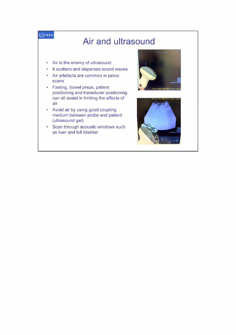
Air and ultrasound
• Air is the enemy of ultrasound• It scatters and disperses sound waves• Air artefacts are common in pelvic
scans• Fasting, bowel preps, patient
positioning and transducer positioning can all assist in limiting the effects of air
• Avoid air by using good coupling medium between probe and patient (ultrasound gel)
• Scan through acoustic windows such as liver and full bladder
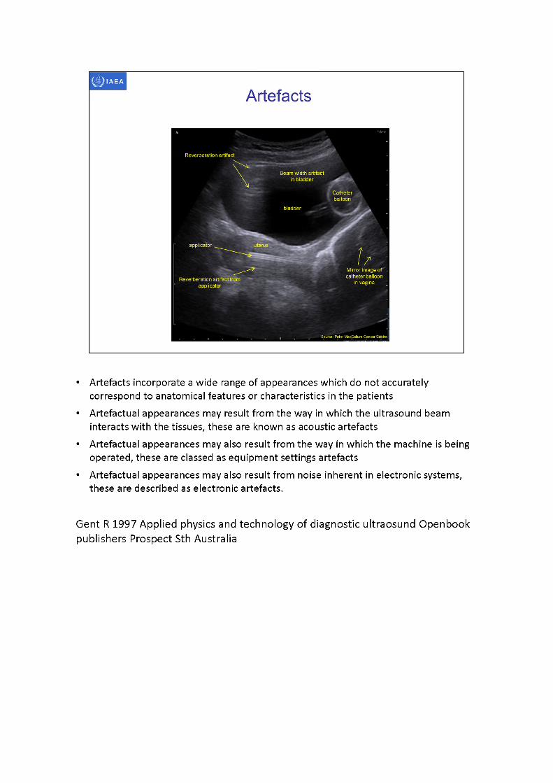
Catheterballoon
bladder
applicator uterus
Artefacts
Reverberation artifact
Beam width artifact in bladder
Reverberation artifact from applicator
Mirror image of catheter balloon
in vagina
Source: Peter MacCallum Cancer Centre
• Artefacts incorporate a wide range of appearances which do not accurately correspond to anatomical features or characteristics in the patients
• Artefactualappearances may result from the way in which the ultrasound beam interacts with the tissues, these are known as acoustic artefacts
• Artefactualappearances may also result from the way in which the machine is being operated, these are classed as equipment settings artefacts
• Artefactualappearances may also result from noise inherent in electronic systems, these are described as electronic artefacts.
Gent R 1997 Applied physics and technology of diagnostic ultraosund Openbook publishers Prospect Sth Australia
IAEA
Artefacts
-0.8 cmBeam width artifact .
in bladder
bladder
X Catheter balloon
T -
artifact from retractor ■retractorjL, -
mirror artifact Mirror artifact ofcatherter balloon
Source: Peter MacCallupi Cancer Centre , . . . . . .15-3 cm-
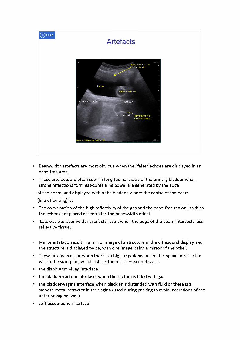
• Beamwidth artefacts are most obvious when the “false” echoes are displayed in an echo-free area.
• These artefacts are often seen in longitudinal views of the urinary bladder when strong reflections form gas-containing bowel are generated by the edge
of the beam, and displayed within the bladder, where the centre of the beam (line of writing) is.
• The combination of the high reflectivity of the gas and the echo-free region in which the echoes are placed accentuates the beamwidth effect.
• Less obvious beamwidth artefacts result when the edge of the beam intersects less reflective tissue.
• Mirror artefacts result in a mirror image of a structure in the ultrasound display. i.e. the structure is displayed twice, with one image being a mirror of the other.
• These artefacts occur when there is a high impedance mismatch specular reflector within the scan plan, which acts as the mirror -examplesare:
• the diaphragm -lung interface• the bladder-rectum interface, when the rectum is filled with gas• the bladder-vagina interface when bladder is distended with fluid or there is a
smooth metal retractor in the vagina (used during packing to avoid lacerations of the anterior vaginal wall)
• soft tissue-bone interface

Gent R 1997 Applied physics and technology of diagnostic ultrasound Openbook publishers Prospect Sth Australia
IAEA
i '■ ‘
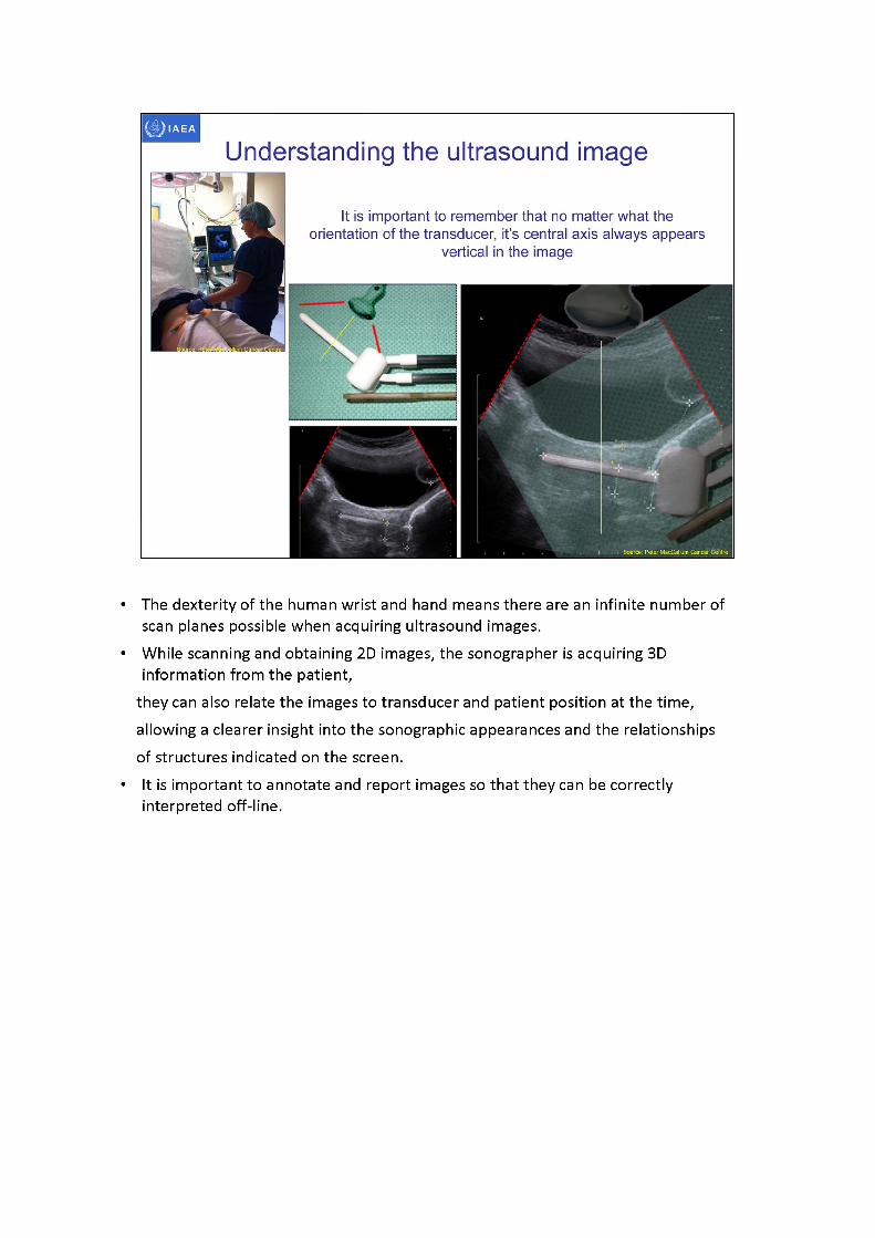
Understanding the ultrasound image
It is important to remember that no matter what theorientation of the transducer, its central axis always appears
vertical in the image
• The dexterity of the human wrist and hand means there are an infinite number of scan planes possible when acquiring ultrasound images.
• While scanning and obtaining 2D images, the sonographer is acquiring 3D information from the patient,
they can also relate the images to transducer and patient position at the time, allowing a clearer insight into the sonographic appearances and the relationships of structures indicated on the screen.
• It is important to annotate and report images so that they can be correctly interpreted off-line.
axial tip tandem
bladder fill
Source: Peter MacCallum Cancer Centre Source: Peter MacCallum Cancer Centre
IAEA
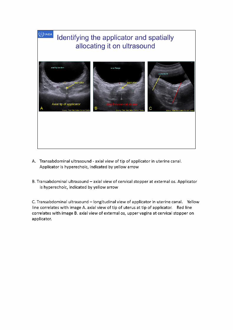
Identifying the applicator and spatially allocating it on ultrasound
Axial tip of applicator
A. Transabdominal ultrasound - axial view of tip of applicator in uterine canal. Applicator is hyperechoic, indicated by yellow arrow
B. Transabdominal ultrasound -axialview of cervical stopper at external os. Applicatoris hyperechoic, indicated by yellow arrow
C. Transabdominal ultrasound -longitudinal view of applicator in uterine canal. Yellow line correlates with image A. axial view of tip of uterus at tip of applicator. Red line correlates with image B. axial view of external os, upper vagina at cervical stopper on applicator.
IAEA
3D image-based female pelvis anatomy by Ultrasound (US)
• Overview of ultrasound• Normal female pelvic anatomy• Sonographic techniques - image orientation• Normal sonographic anatomy• Anatomical variations• Common pathologies• Using ultrasound in brachytherapy• Future - 3D ultrasound
Normal female pelvic anatomy uterus cervix parametria vagina
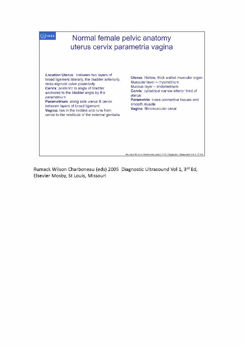
Location Uterus:: between two layers of broad ligament laterally, the bladder anteriorly, recto-sigmoid colon posteriorlyCervix: posterior to angle of bladder anchored to the bladder angle by the parametriumParametrium: along side uterus & cervix between layers of broad ligament Vagina: lies in the midline and runs from cervix to the vestibule of the external genitalia
Uterus: Hollow, thick walled muscular organMuscular layer - myometriumMucous layer - endometriumCervix: cylindrical narrow inferior third ofuterus:Parametria: loose connective tissues andsmooth muscleVagina: fibromuscular canal
Rumack Wilson Charboneau (eds) 2005 Diagnostic Ultrasound Vol 1, 3rd Ed
Rumack Wilson Charboneau (eds) 2005 Diagnostic Ultrasound Vol 1, 3rd Ed, Elsevier Mosby, St Louis, Missouri
IAEA
Dimopolous et al IJROBP 64 (2006) 1388-1388 Dimopolous et al Radiother Oncol 91 (2009) 166-'
Normal female pelvic anatomy parametria
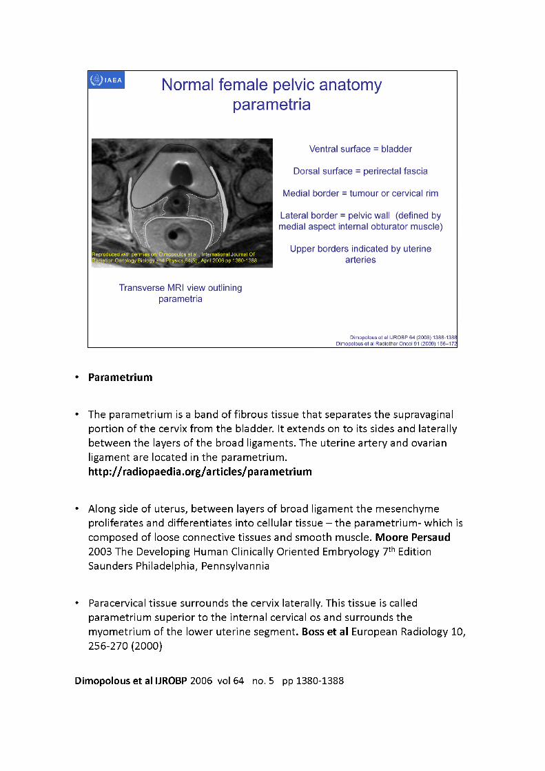
Ventral surface = bladder
Dorsal surface = perirectal fascia
Medial border = tumour or cervical rim
Transverse MRI view outlining parametria
Lateral border = pelvic wall (defined by medial aspect internal obturator muscle)
Upper borders indicated by uterine arteries
Reproduced with permissionrDimopoulos etal, International Journal Of tion Oncology Biology and Physics,64(5), April 2006 pp 1380-1388
• Parametrium
• The parametrium is a band of fibrous tissue that separates the supravaginal portion of the cervix from the bladder. It extends on to its sides and laterally between the layers of the broad ligaments. The uterine artery and ovarianligament are located in the parametrium.http://radiopaedia.org/articles/parametrium
• Along side of uterus, between layers of broad ligament the mesenchymeproliferates and differentiates into cellular tissue - the parametrium- which is composed of loose connective tissues and smooth muscle. Moore Persaud 2003 The Developing Human Clinically Oriented Embryology 7th Edition Saunders Philadelphia, Pennsylvannia
• Paracervical tissue surrounds the cervix laterally. This tissue is called parametrium superior to the internal cervical os and surrounds the myometrium of the lower uterine segment. Boss et al European Radiology 10, 256-270 (2000)
Dimopolous et al IJROBP 2006 vol 64 no. 5 pp 1380-1388

Definition of parametria according to visible and reproducible radiologic criteria at its borders: ventral bladder, dorsal perirectal fascia, medial tumour/cervical rim, lateral pelvic wall (PW).
FischerovaUltrasound scanning of the pelvis and abdomen for staging of gynecological tumours: a review vol 38 pp 246-266 Ultrasound Obstet Gynecol 2011• Currently, we are advised to use the international anatomical nomenclature, although
this is not always what happens in the surgical literature and in daily use.• In international anatomical nomenclature, ‘parametrium' refers to tissues that
surround the uterine artery between the uterine corpus and pelvic sidewall cranial to the ureter and superficial uterine pedicle.
• The dorsolateral attachment of the cervix is named the ‘paracervix', and this term should replace others such as cardinal ligaments, ligaments of Mackenrodt, lateral cervical ligaments and parametrium. Moreover, cervical cancer can spread in any direction, ventrally affecting the vesicouterine and vesicovaginal ligament (otherwise referred to as ventral parametrium) and/or dorsally affecting the uterosacral and sacrovaginal ligament (otherwise referred to as dorsal parametrium).
• Although the consensus of new anatomical terminology was reached more than 10 years ago, surgeons are reluctant to abandon the unofficial but traditional terminology (ventral, lateral and dorsal parametrium).
IAEA
3D image-based female pelvis anatomy by Ultrasound (US)
• Overview of ultrasound• Normal female pelvic anatomy• Sonographic techniques - image orientation• Normal sonographic anatomy• Anatomical variations• Common pathologies• Using ultrasound in brachytherapy• Future - 3D ultrasound
IAEA
Sonographic techniques
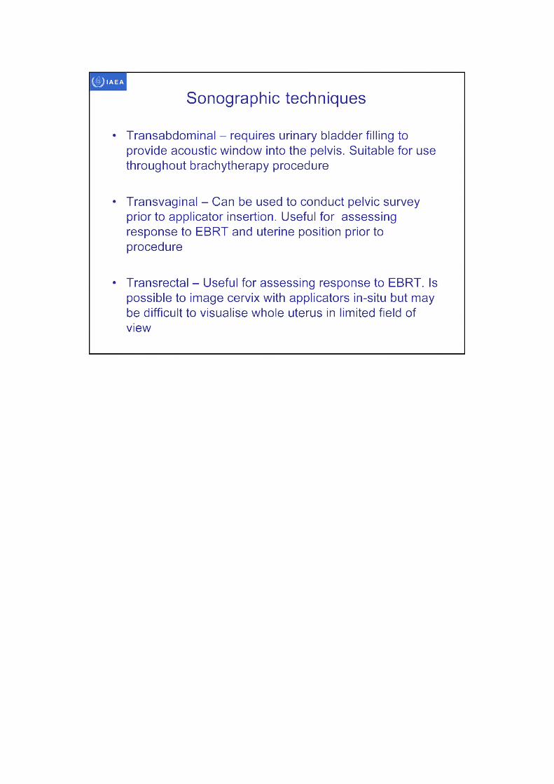
• Transabdominal - requires urinary bladder filling to provide acoustic window into the pelvis. Suitable for use throughout brachytherapy procedure
• Transvaginal - Can be used to conduct pelvic survey prior to applicator insertion. Useful for assessing response to EBRT and uterine position prior to procedure
• Transrectal - Useful for assessing response to EBRT. Is possible to image cervix with applicators in-situ but may be difficult to visualise whole uterus in limited field of view
IAEA
not possible to display on ultrasound
unit
Transvaginal ultrasound orientation
Intuitiveorientation-
cephalad
Transducer
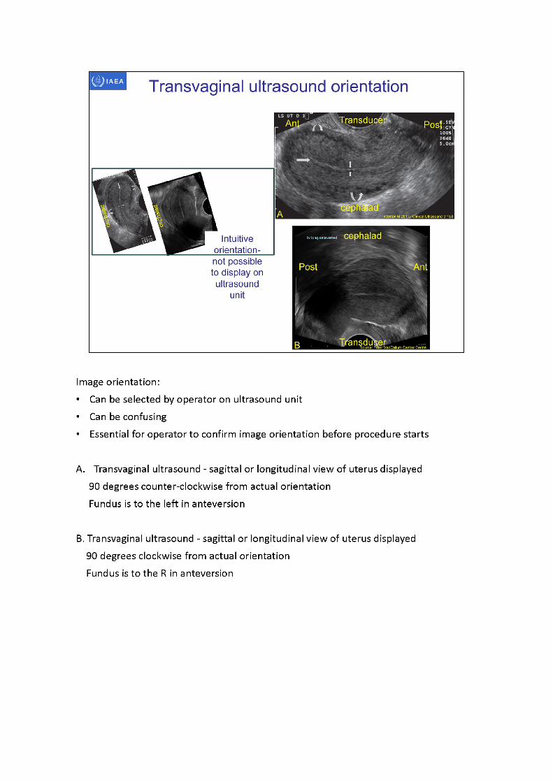
Image orientation:• Can be selected by operator on ultrasound unit• Can be confusing• Essential for operator to confirm image orientation before procedure starts
A. Transvaginal ultrasound - sagittal or longitudinal view of uterus displayed 90 degrees counter-clockwise from actual orientation Fundus is to the left in anteversion
B. Transvaginal ultrasound - sagittal or longitudinal view of uterus displayed 90 degrees clockwise from actual orientation Fundus is to the R in anteversion
Source: Peter MacCallum Cancer CentreTransducer
Source: Peter MacCallum Cancer Centre
•Transducer
Transvaginal ultrasound orientation
Transducer
Images A and B Hughes T 2011 in Clinical Ultrasound 3,d Ed
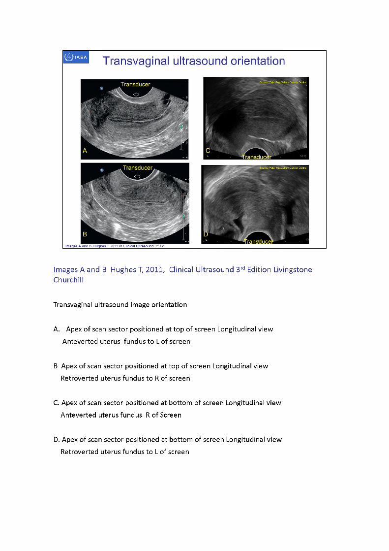
Images A and B Hughes T, 2011, Clinical Ultrasound 3rd Edition Livingstone Churchill
Transvaginal ultrasound image orientation
A. Apex of scan sector positioned at top of screen Longitudinal view Anteverted uterus fundus to L of screen
B Apex of scan sector positioned at top of screen Longitudinal view Retroverted uterus fundus to R of screen
C. Apex of scan sector positioned at bottom of screen Longitudinal view Anteverted uterus fundus R of Screen
D. Apex of scan sector positioned at bottom of screen Longitudinal view Retroverted uterus fundus to L of screen
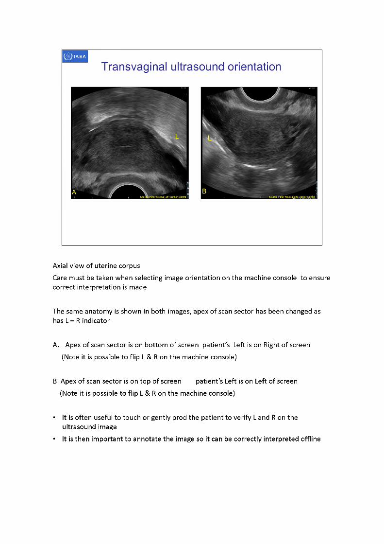
Axial view of uterine corpusCare must be taken when selecting image orientation on the machine console to ensure correct interpretation is made
The same anatomy is shown in both images, apex of scan sector has been changed as has L -R indicator
A. Apex of scan sector is on bottom of screen patient's Left is on Right of screen (Note it is possible to flip L & R on the machine console)
B. Apex of scan sector is on top of screen patient's Left is on Left of screen (Note it is possible to flip L & R on the machine console)
• It is often useful to touch or gently prod the patient to verify L and R on the ultrasound image
• It is then important to annotate the image so it can be correctly interpreted offline
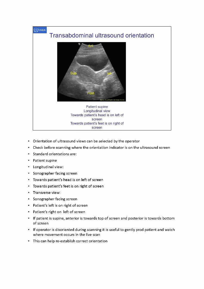
• Orientation ofultrasound views can be selected by the operator• Check before scanning where the orientation indicator is on the ultrasound screen• Standard orientations are:• Patient supine• Longitudinal view:• Sonographer facing screen• Towards patient's head is on left of screen• Towards patient's feet is on right of screen• Transverse view:• Sonographer facing screen• Patient's left is on right of screen• Patient's right on left of screen• If patient is supine, anterior is towards top of screen and posterior is towards bottom
of screen• If operator is disoriented during scanning it is useful to gently prod patient and watch
where movement occurs in the live scan• This can help re-establish correct orientation
IAEA
3D image-based female pelvis anatomy by Ultrasound (US)
• Overview of ultrasound• Normal female pelvic anatomy• Sonographic techniques - image orientation• Normal sonographic anatomy• Anatomical variations• Common pathologies• Using ultrasound in brachytherapy• Future - 3D ultrasound
Normal sonographic anatomy uterus and cervix
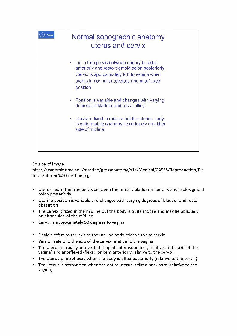
• Lie in true pelvis between urinary bladder anteriorly and recto-sigmoid colon posteriorly Cervix is approximately 90° to vagina when uterus in normal anteverted and anteflexed position
• Position is variable and changes with varying degrees of bladder and rectal filling
• Cervix is fixed in midline but the uterine body is quite mobile and may lie obliquely on either side of midline
Source of Imagehttp://academic.amc.edu/martino/grossanatomy/site/Medical/CASES/Reproduction/Pictures/uterine%20position.jpg
• Uterus lies in the true pelvis between the urinary bladder anteriorly and rectosigmoid colon posteriorly
• Uterine position is variable and changes with varying degrees of bladder and rectal distention
• The cervix is fixed in the midline but the body is quite mobile and may lie obliquely on either side of the midline
• Cervix is approximately 90 degrees to vagina
• Flexion refers to the axis of the uterine body relative to the cervix• Version refers to the axis of the cervix relative to the vagina• The uterus is usually anteverted (tipped anterosuperiorly relative to the axis of the
vagina) and anteflexed (flexed or bent anteriorly relative to the cervix)• The uterus is retroflexed when the body is tilted posteriorly (relative to the cervix)• The uterus is retroverted when the entire uterus is tilted backward (relative to the
vagina)
Normal sonographic anatomy uterus and cervix
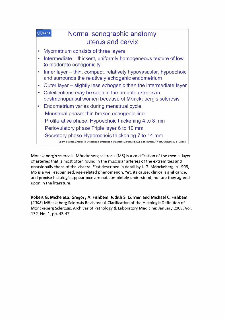
• Myometrium consists of three layers• Intermediate - thickest, uniformly homogeneous texture of low
to moderate echogenicity• Inner layer - thin, compact, relatively hypovascular, hypoechoic
and surrounds the relatively echogenic endometrium• Outer layer - slightly less echogenic than the intermediate layer• Calcifications may be seen in the arcuate arteries in
postmenopausal women because of Monckeberg’s sclerosis• Endometrium varies during menstrual cycle.
Menstrual phase: thin broken echogenic line Proliferative phase: Hypoechoic thickening 4 to 8 mm Periovulatory phase Triple layer 6 to 10 mm Secretory phase Hyperechoic thickening 7 to 14 mm
Salem & Wilson Chapter 15 Gynecologic ultrasound in Diagnostic Ultrasound 2005 Eds: Rumack, Wilson, Chaboneau 3rd Edition
Monckeberg's sclerosis: Monckeberg sclerosis (MS) is a calcification of the medial layer of arteries that is most often found in the muscular arteries of the extremities and occasionally those of the viscera. First described in detail by J. G. Monckeberg in 1903, MS is a well-recognized, age-related phenomenon. Yet, its cause, clinical significance, and precise histologic appearance are not completely understood, nor are they agreed upon in the literature.
Robert G. Micheletti, Gregory A. Fishbein, Judith S. Currier, and Michael C. Fishbein(2008) Monckeberg Sclerosis Revisited: A Clarification of the Histologic Definition of Monckeberg Sclerosis. Archives of Pathology & Laboratory Medicine: January 2008, Vol.132, No. 1, pp. 43-47.
Normal sonographic anatomy uterus and cervix
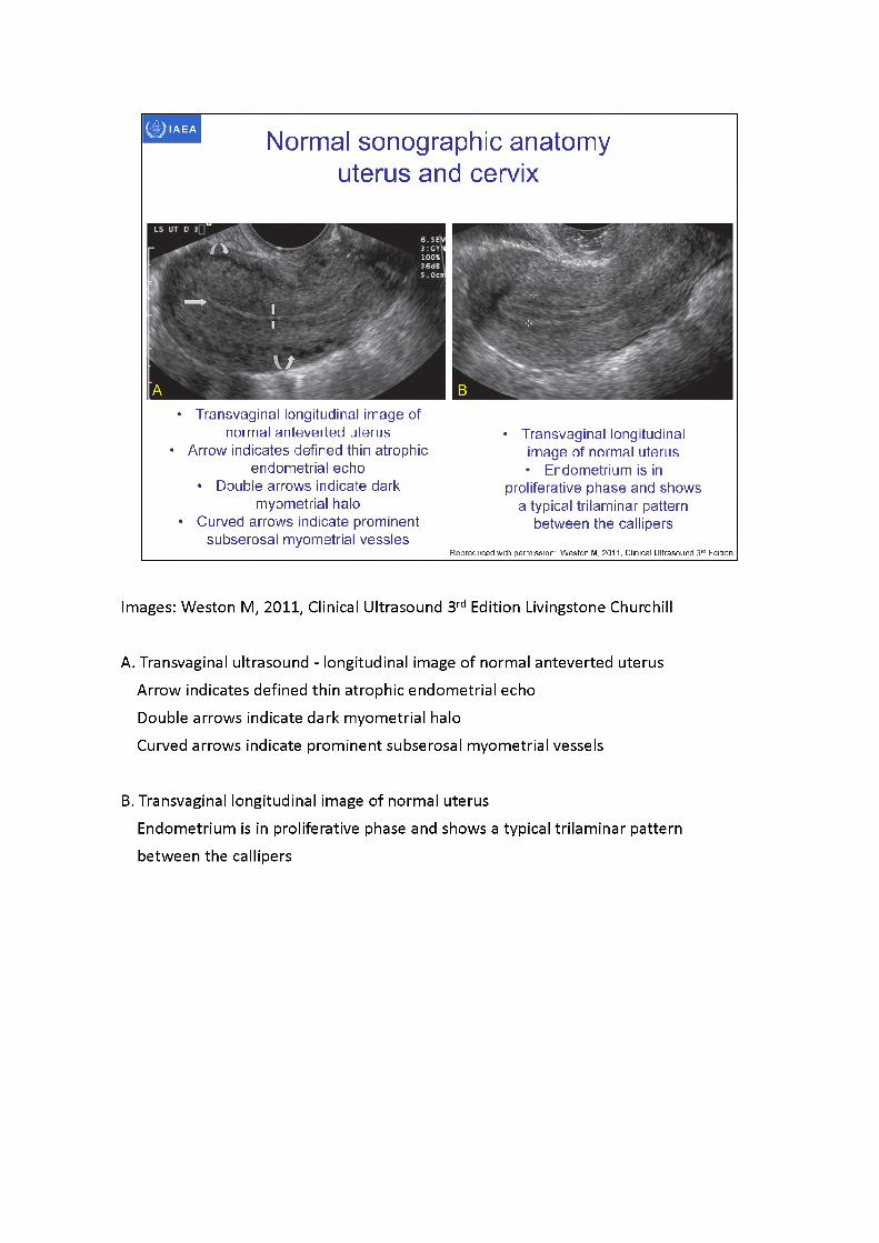
• Transvaginal longitudinal image ofnormal anteverted uterus
• Arrow indicates defined thin atrophicendometrial echo
• Double arrows indicate darkmyometrial halo
• Curved arrows indicate prominentsubserosal myometrial vessles
• Transvaginal longitudinal image of normal uterus • Endometrium is in
proliferative phase and shows a typical trilaminar pattern
between the callipers
Reproduced with permission: Weston M, 2011, Clinical Ultrasound 3rd Edition
Images: Weston M, 2011, Clinical Ultrasound 3rd Edition Livingstone Churchill
A. Transvaginal ultrasound - longitudinal image of normal anteverted uterus Arrow indicates defined thin atrophic endometrial echo Double arrows indicate dark myometrial halo Curved arrows indicate prominent subserosal myometrial vessels
B. Transvaginal longitudinal image of normal uterus Endometrium is in proliferative phase and shows a typical trilaminar pattern between the callipers
bladderuterus
cervix uterus
packingcervixbladdervagina.
SauMefafaeter MacCallum Carreer Cenfre Source: Peter MacCallum Cancer Centre
Normal sonographic anatomy uterus and cervix
,^<Vagii O' Wjt|x. Ant
applicator
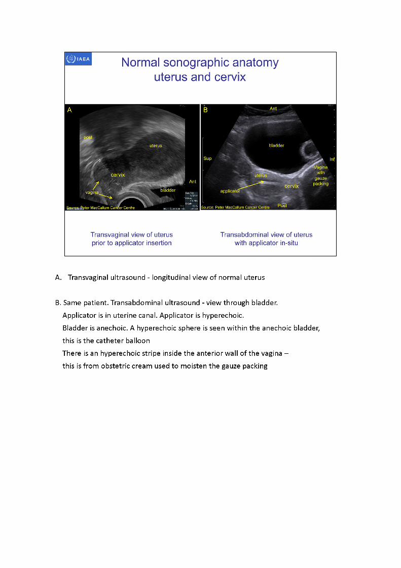
Transvaginal view of uterus prior to applicator insertion
Transabdominal view of uterus with applicator in-situ
A. Transvaginal ultrasound - longitudinal view of normal uterus
B. Same patient. Transabdominal ultrasound - view through bladder.Applicator is in uterine canal. Applicator is hyperechoic.Bladder is anechoic. A hyperechoic sphere is seen within the anechoic bladder, this is the catheter balloonThere is an hyperechoic stripe inside the anterior wall of the vagina - this is from obstetric cream used to moisten the gauze packing
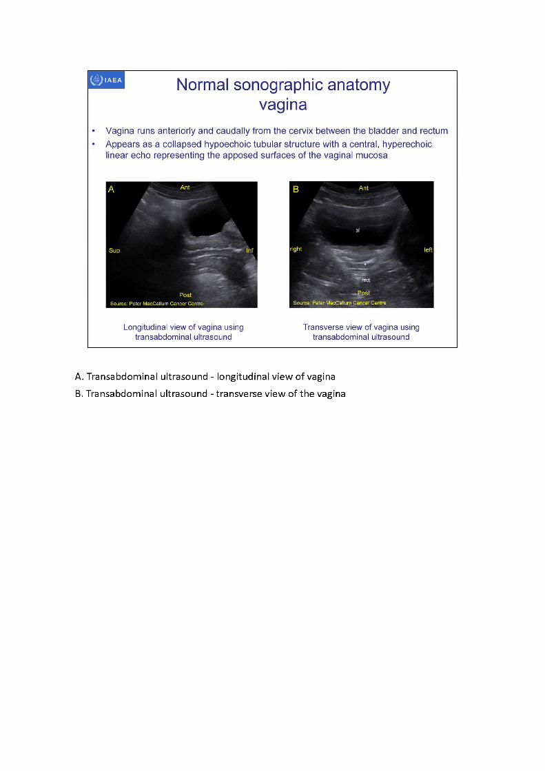
A. Transabdominal ultrasound - longitudinal view of vaginaB. Transabdominal ultrasound - transverse view of the vagina
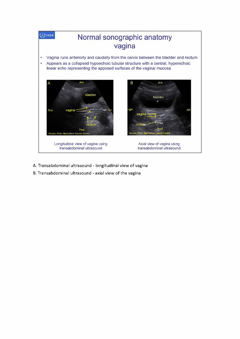
A. Transabdominal ultrasound - longitudinal view of vaginaB. Transabdominal ultrasound - axial view of the vagina
■applicator
vagina
Normal sonographic anatomyviewing the parametria
All images: Peter MacCallum Cancer Centre
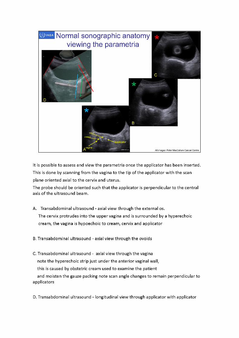
It is possible to assess and view the parametria once the applicator has been inserted. This is done by scanning from the vagina to the tip of the applicator with the scan plane oriented axial to the cervix and uterus.The probe should be oriented such that the applicator is perpendicular to the central axis of the ultrasound beam.
A. Transabdominal ultrasound - axial view through the external os.The cervix protrudes into the upper vagina and is surrounded by a hyperechoic cream, the vagina is hypoechoic to cream, cervix and applicator
B. Transabdominal ultrasound - axial view through the ovoids
C. Transabdominal ultrasound - axial view through the vagina note the hyperechoic strip just under the anterior vaginal wall, this is caused by obstetric cream used to examine the patientand moisten the gauze packing note scan angle changes to remain perpendicular to
applicators
D. Transabdominal ultrasound - longitudinal view through applicator with applicator

(tandem, ovoids and spatula superimposed) with scan planes(This image used to illustrate scan planes -sagittalimage is not the same patient as
transverse images)
All images: Peter MacCallum Cancer Centre
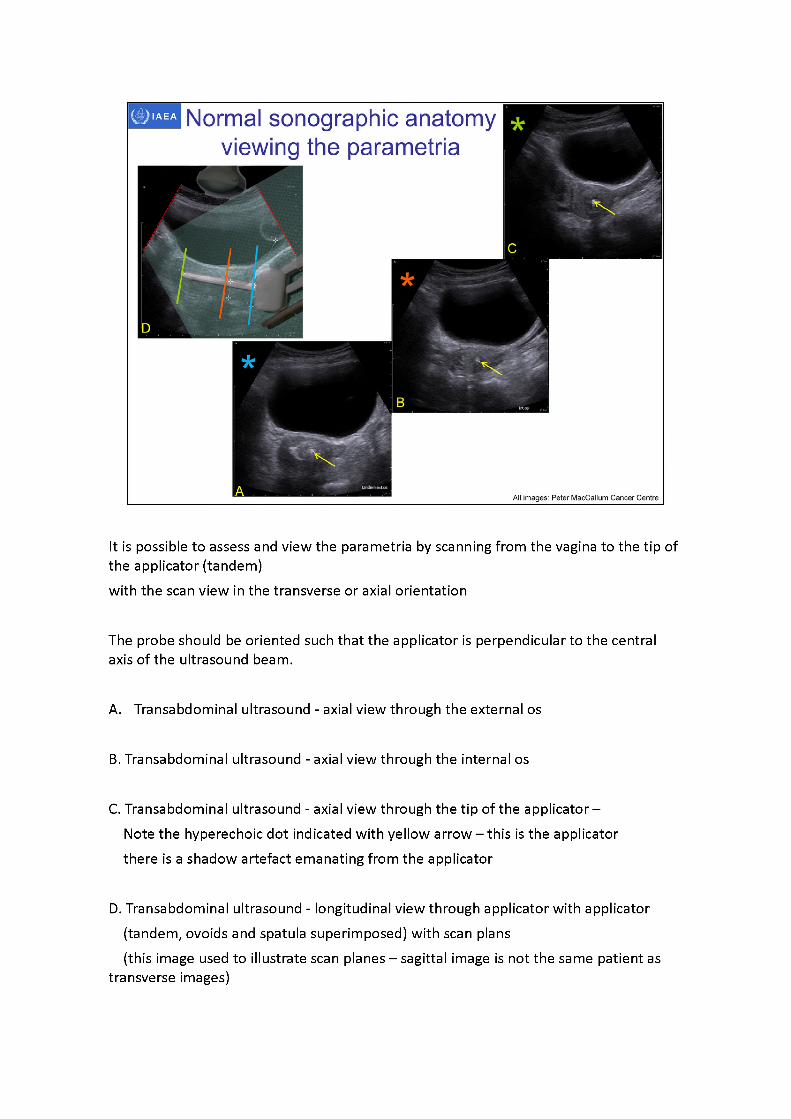
Normal sonographic anatomy viewing the parametria
It is possible to assess and view the parametria by scanning from the vagina to the tip of the applicator (tandem)with the scan view in the transverse or axial orientation
The probe should be oriented such that the applicator is perpendicular to the central axis of the ultrasound beam.
A. Transabdominal ultrasound - axial view through the external os
B. Transabdominal ultrasound - axial view through the internal os
C. Transabdominal ultrasound - axial view through the tip of the applicator - Note the hyperechoic dot indicated with yellow arrow -thisis the applicator there is a shadow artefact emanating from the applicator
D. Transabdominal ultrasound - longitudinal view through applicator with applicator (tandem, ovoids and spatula superimposed) with scan plans(this image used to illustrate scan planes -sagittalimage is not the same patient as
transverse images)
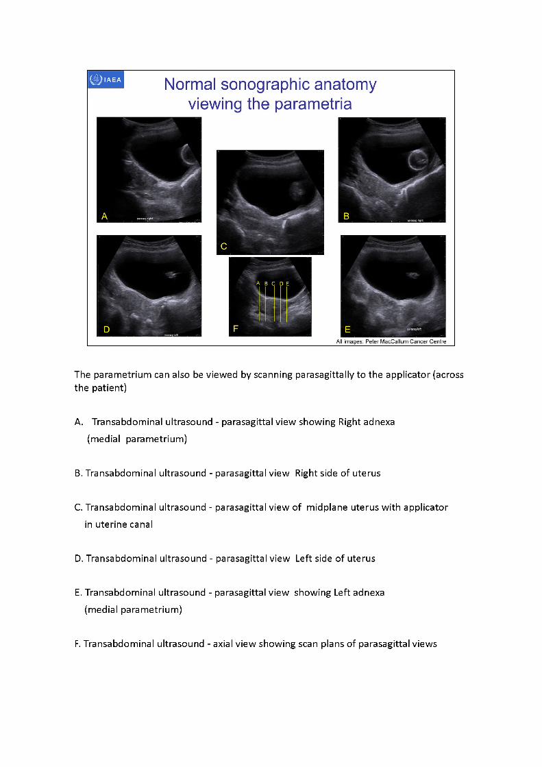
IAEA Normal sonographic anatomy viewing the parametria
All images: Peter MacCallum Cancer Centre
Apiaujrghl
The parametrium can also be viewed by scanning parasagittallyto the applicator (across the patient)
A. Transabdominal ultrasound - parasagittal view showing Right adnexa (medial parametrium)
B. Transabdominal ultrasound - parasagittal view Right side of uterus
C. Transabdominal ultrasound - parasagittal view of midplane uterus with applicator in uterine canal
D. Transabdominal ultrasound - parasagittal view Left side of uterus
E. Transabdominal ultrasound - parasagittal view showing Left adnexa (medial parametrium)
F. Transabdominal ultrasound - axial view showing scan plans of parasagittal views
IAEA
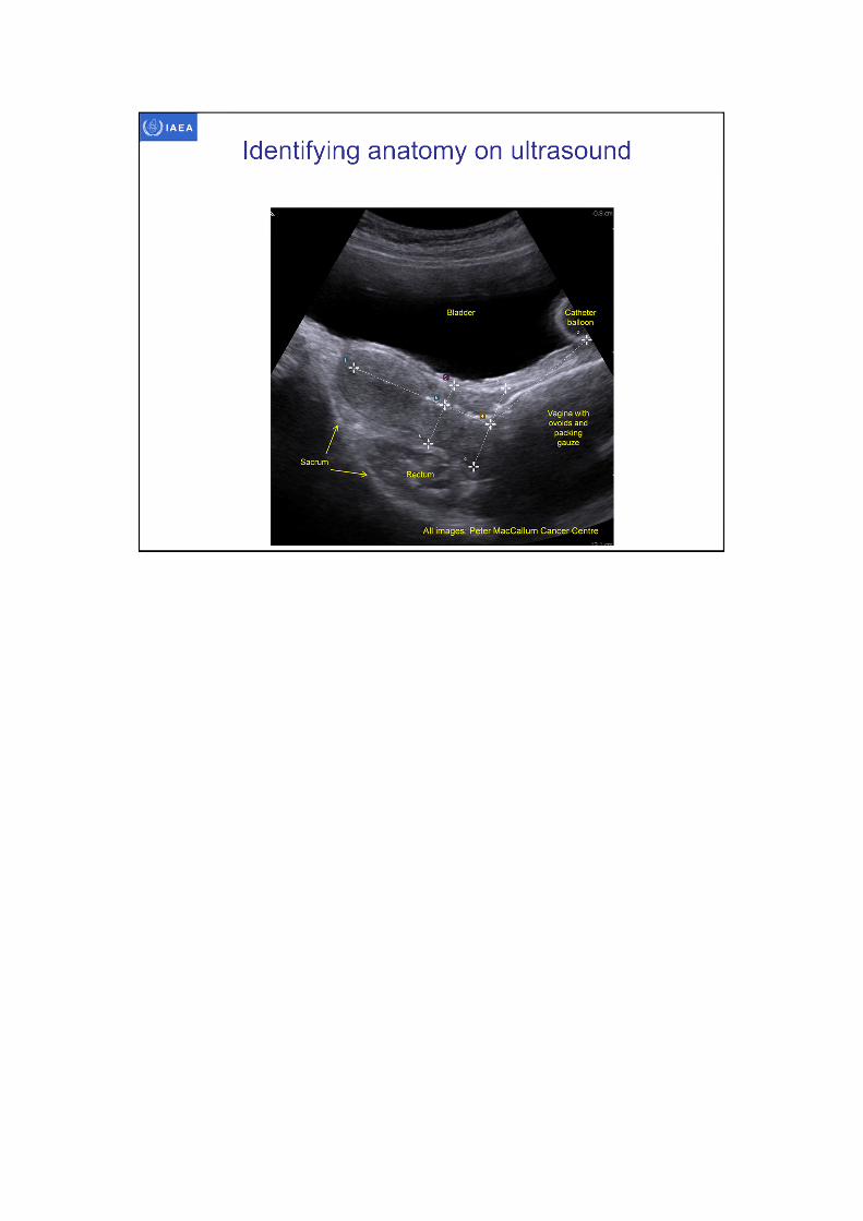
Identifying anatomy on ultrasound

IAEA
3D image-based female pelvis anatomy by Ultrasound (US)
• Overview of ultrasound• Normal female pelvic anatomy• Sonographic techniques - image orientation• Normal sonographic anatomy• Anatomical variations• Common pathologies• Using ultrasound in brachytherapy• Future - 3D ultrasound
* bowel
Vallum Cancer CentreSource: Pete)
Source: Peter MacCallum Cancer Centre
IAEA
CT sagittal view showing anteverted uterus with tandem perforating posterior cervix
Davidson et al Brachytherapy 7 (2008) 248-53
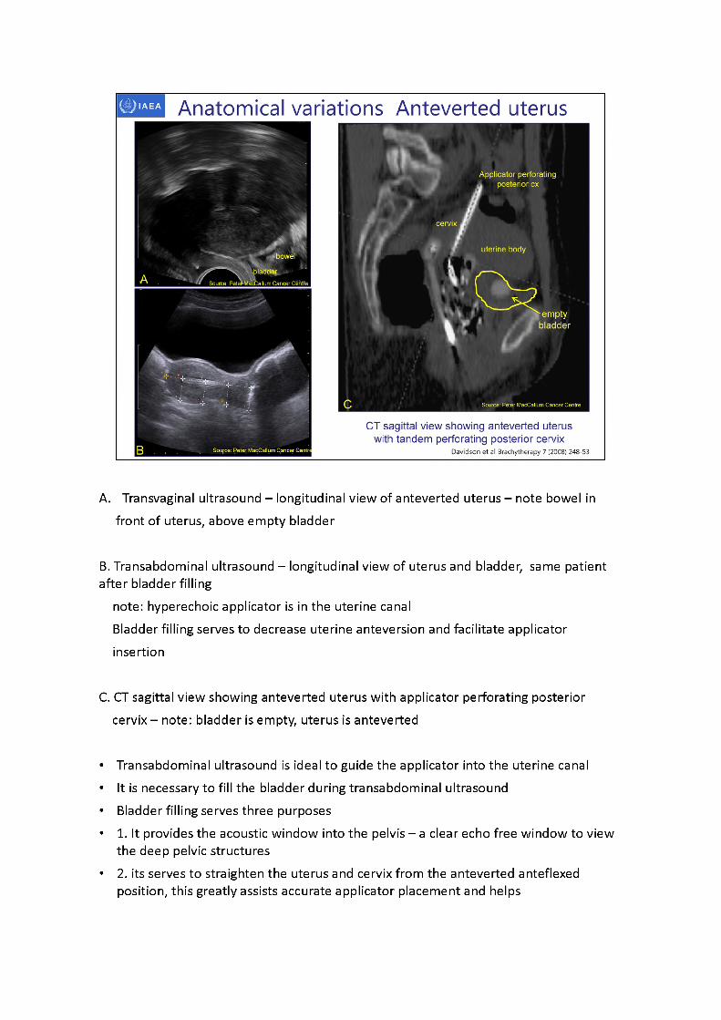
Anatomical variations Anteverted uterus
ft,'Applicator perforating . posterior ex
uterine body
» em ptyk F ' . bladder
A. Transvaginal ultrasound - longitudinal view of anteverted uterus - note bowel in front of uterus, above empty bladder
B. Transabdominal ultrasound - longitudinal view of uterus and bladder, same patient after bladder filling
note: hyperechoicapplicator is in the uterine canalBladder filling serves to decrease uterine anteversion and facilitate applicator insertion
C. CT sagittal view showing anteverted uterus with applicator perforating posterior cervix -note:bladder is empty, uterus is anteverted
• Transabdominal ultrasound is ideal to guide the applicator into the uterine canal• It is necessary to fill the bladder during transabdominal ultrasound• Bladder filling serves three purposes• 1. It provides the acoustic window into the pelvis -aclear echo free window to view
the deep pelvic structures• 2. its serves to straighten the uterus and cervix from the anteverted anteflexed
position, this greatly assists accurate applicator placement and helps

prevent perforation3. it displaces bowel away from the uterus and cervix
Bladder filling can also move the cervix and uterus into a less acute retroverted retroflexed position, again assisting accurate applicator placement
• 2013 Park et al Technique to displace bowel loops in MRI guided high intensity focused ultrasound ablation of fibroids in the anteverted or anteflexed uterus Vascular and Interventional Radiology
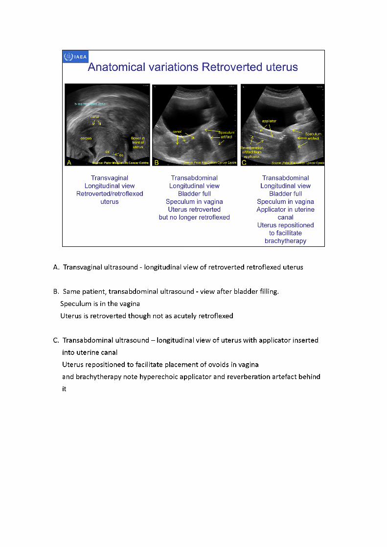
A. Transvaginal ultrasound - longitudinal view of retroverted retroflexed uterus
B. Same patient, transabdominal ultrasound - view after bladder filling.Speculum is in the vaginaUterus is retroverted though not as acutely retroflexed
C. Transabdominal ultrasound -longitudinal view of uterus with applicator inserted into uterine canalUterus repositioned to facilitate placement of ovoids in vaginaand brachytherapy note hyperechoic applicator and reverberation artefact behindit
rource: Peter RacCmlum Cancer Centn "Cancer Centre I
Anatomical variations Retroverted uterus
TransabdominalLongitudinal view
Bladder full Speculum in vaginaUterus retroverted
Transabdominal Longitudinal view
Bladder full Speculum in vagina Applicator in uterine
canalUterus repositioned
to facilitate brachytherapy
r Peter MaaSwttoni Cancer Centre
Transvaginal Longitudinal view
Retroverted/retroflexeduterus
Ant
bowel
Ant
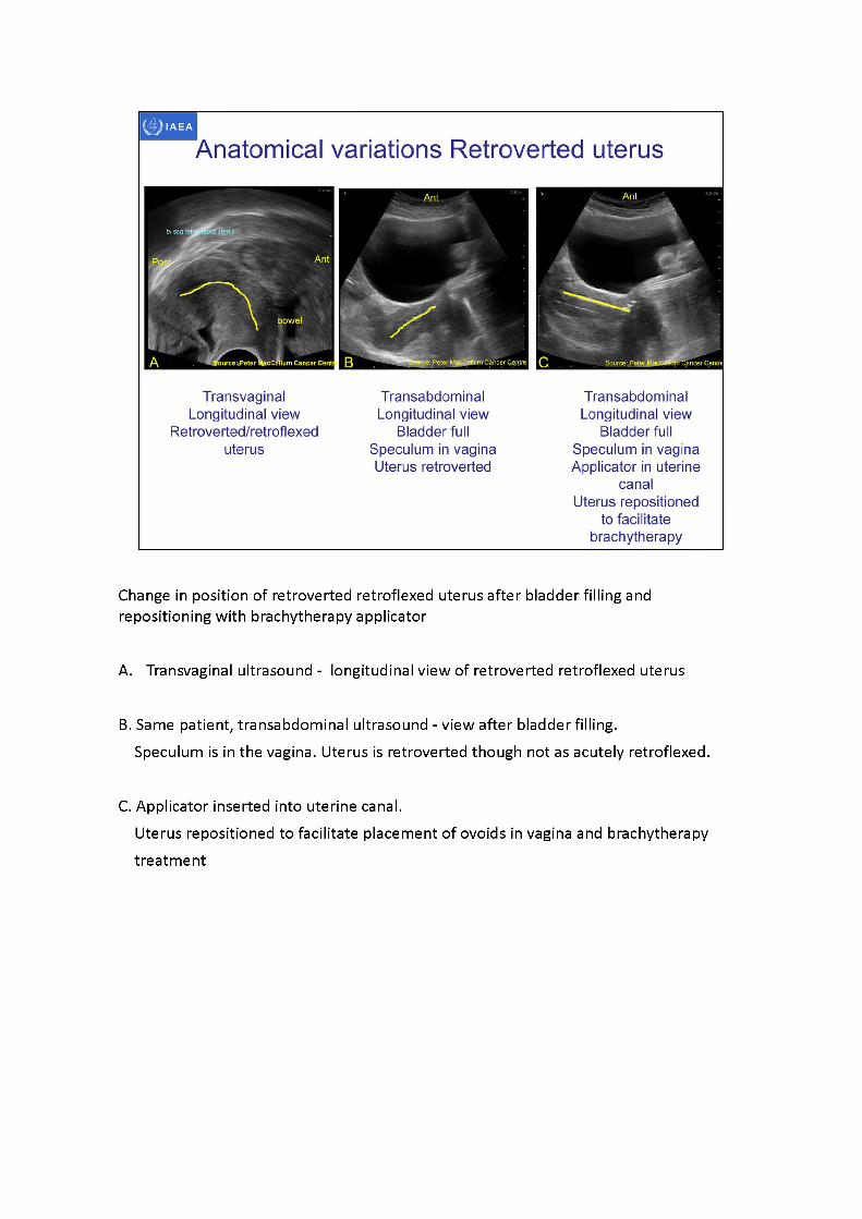
Change in position of retroverted retroflexed uterus after bladder filling and repositioning with brachytherapy applicator
A. Transvaginal ultrasound - longitudinal view of retroverted retroflexed uterus
B. Same patient, transabdominal ultrasound - view after bladder filling.Speculum is in the vagina. Uterus is retroverted though not as acutely retroflexed.
C. Applicator inserted into uterine canal.Uterus repositioned to facilitate placement of ovoids in vagina and brachytherapy treatment
Bladder BladderBladder
^Source Peter MacCallum Cancer Centre
Anatomical variations Retroverted uterus
Transabdominal Longitudinal view
Retroverted uterus with small amount of
fluid in canal
Transabdominal Longitudinal view
Retroverted uterus With applicator in
uterine canal It was not possible to alter uterine position
•mall hydrometra
Acousticenhancement
Source: Peter MacCallum Cancer Centre Source: Peter MacCa um Cancer Centre
Confirmation sagittalMRI
Retroverted uterus withapplicator in canal
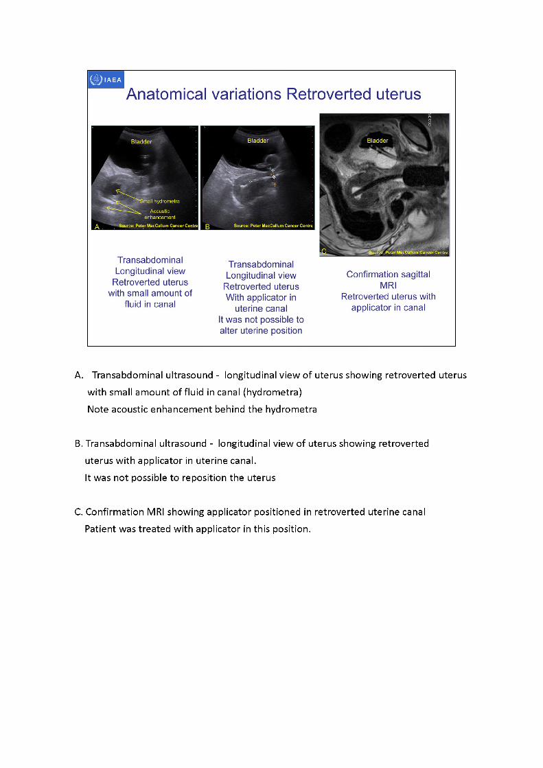
A. Transabdominal ultrasound - longitudinal view of uterus showing retroverted uterus with small amount of fluid in canal (hydrometra)Note acoustic enhancement behind the hydrometra
B. Transabdominal ultrasound - longitudinal view of uterus showing retroverted uterus with applicator in uterine canal.It was not possible to reposition the uterus
C. Confirmation MRI showing applicator positioned in retroverted uterine canal Patient was treated with applicator in this position.
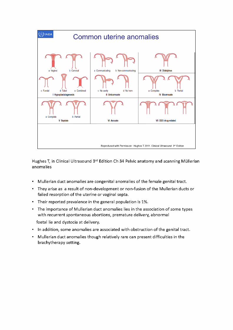
Hughes T, in Clinical Ultrasound 3rd Edition Ch 34 Pelvic anatomy and scanning Mullerian anomalies
• Mullerian duct anomalies are congenital anomalies of the female genital tract.• They arise as a result of non-development or non-fusion of the Mullerian ducts or
failed resorption of the uterine or vaginal septa.• Their reported prevalence in the general population is 1%.• The importance of Mullerian duct anomalies lies in the association of some types
with recurrent spontaneous abortions, premature delivery, abnormalfoetal lie and dystocia at delivery.
• In addition, some anomalies are associated with obstruction of the genital tract.• Mullerian duct anomalies though relatively rare can present difficulties in the
brachytherapy setting.
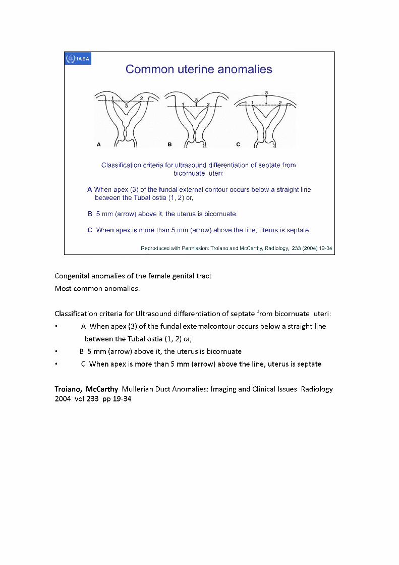
Classification criteria for ultrasound differentiation of septate from bicornuate uteri:
A When apex (3) of the fundal external contour occurs below a straight line between the Tubal ostia (1,2) or,
B 5 mm (arrow) above it, the uterus is bicornuate.
C When apex is more than 5 mm (arrow) above the line, uterus is septate.
Reproduced with Permission: Troianoand McCarthy, Radiology, 233 (2004) 19-34
Congenital anomalies of the female genital tractMost common anomalies.
Classification criteria for Ultrasound differentiation of septate from bicornuate uteri: • AWhen apex (3) of the fundal externalcontour occurs below a straight line
between the Tubal ostia (1, 2) or,• B5 mm (arrow) above it, the uterus is bicornuate• CWhen apex is more than 5 mm (arrow) above the line, uterus is septate
Troiano, McCarthy Mullerian Duct Anomalies: Imaging and Clinical Issues Radiology2004 vol233 pp 19-34
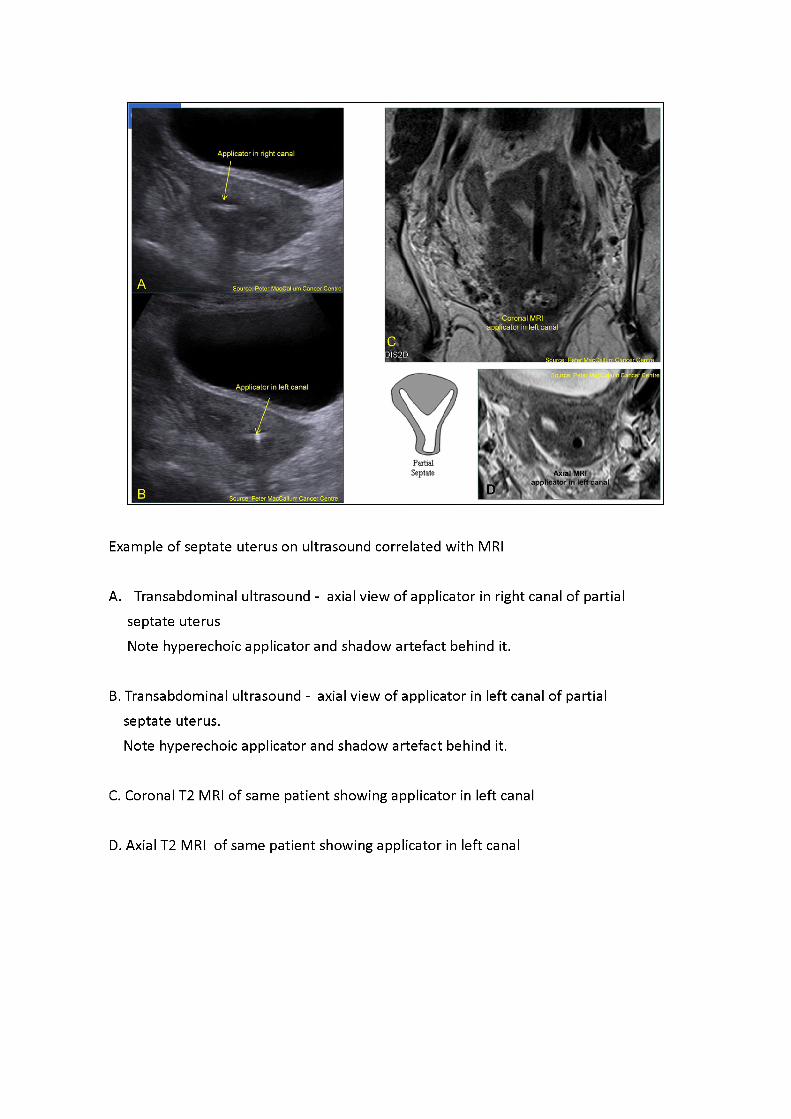
Example of septate uterus on ultrasound correlated with MRI
A. Transabdominal ultrasound - axial view of applicator in right canal of partial septate uterusNote hyperechoic applicator and shadow artefact behind it.
B. Transabdominal ultrasound - axial view of applicator in left canal of partial septate uterus.Note hyperechoic applicator and shadow artefact behind it.
C. Coronal T2 MRI of same patient showing applicator in left canal
D. Axial T2 MRI of same patient showing applicator in left canal
IAEA
3D image-based female pelvis anatomy by Ultrasound (US)
• Overview of ultrasound• Normal female pelvic anatomy• Sonographic techniques - image orientation• Normal sonographic anatomy• Anatomical variations• Common pathologies• Using ultrasound in brachytherapy• Future - 3D ultrasound
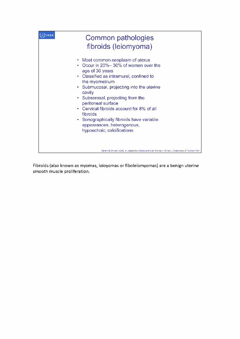
Common pathologies fibroids (leiomyoma)
Most common neoplasm of uterus Occur in 20%- 30% of women over the age of 30 yearsClassified as intramural, confined to the myometriumSubmucosal, projecting into the uterine cavitySubserosal, projecting from the peritoneal surfaceCervical fibroids account for 8% of all fibroidsSonographically fibroids have variable appearances, heterogenous, hypoechoic, calcifications
Salem & Wilson 2005, in Diagnostic Ultrasound Eds: Rumack, Wilson, Chaboneau 3rd Edition Vol 1
Fibroids (also known as myomas, leioyomas or fiboleiomyomas) are a benign uterine smooth muscle proliferation.
IAEA
Weston M 2011, Clinical Ultrasound 3rd Ed
Common pathologies fibroids (leiomyoma)
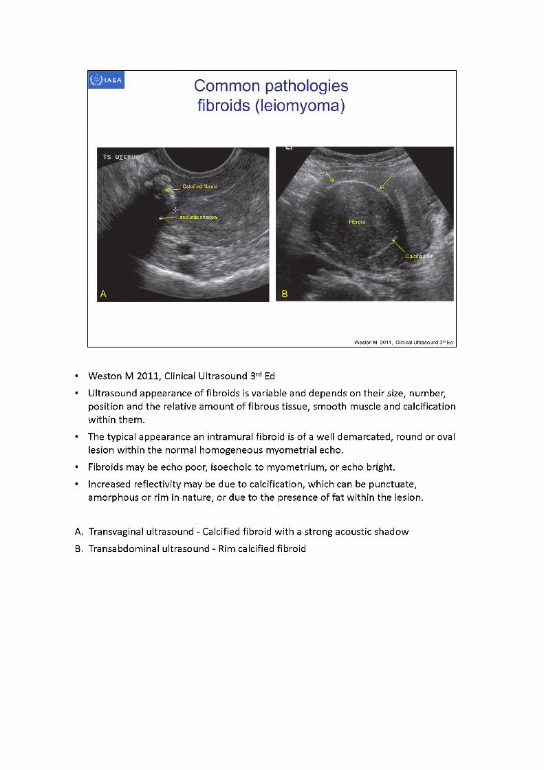
• Weston M 2011, Clinical Ultrasound 3rd Ed• Ultrasound appearance of fibroids is variable and depends on their size, number,
position and the relative amount of fibrous tissue, smooth muscle and calcification within them.
• The typical appearance an intramural fibroid is of a well demarcated, round or oval lesion within the normal homogeneous myometrial echo.
• Fibroids may be echo poor, isoechoic to myometrium, or echo bright.• Increased reflectivity may be due to calcification, which can be punctuate,
amorphous or rim in nature, or due to the presence of fat within the lesion.
A. Transvaginal ultrasound - Calcified fibroid with a strong acoustic shadowB. Transabdominal ultrasound - Rim calcified fibroid
Common pathologies fibroids (leiomyoma)
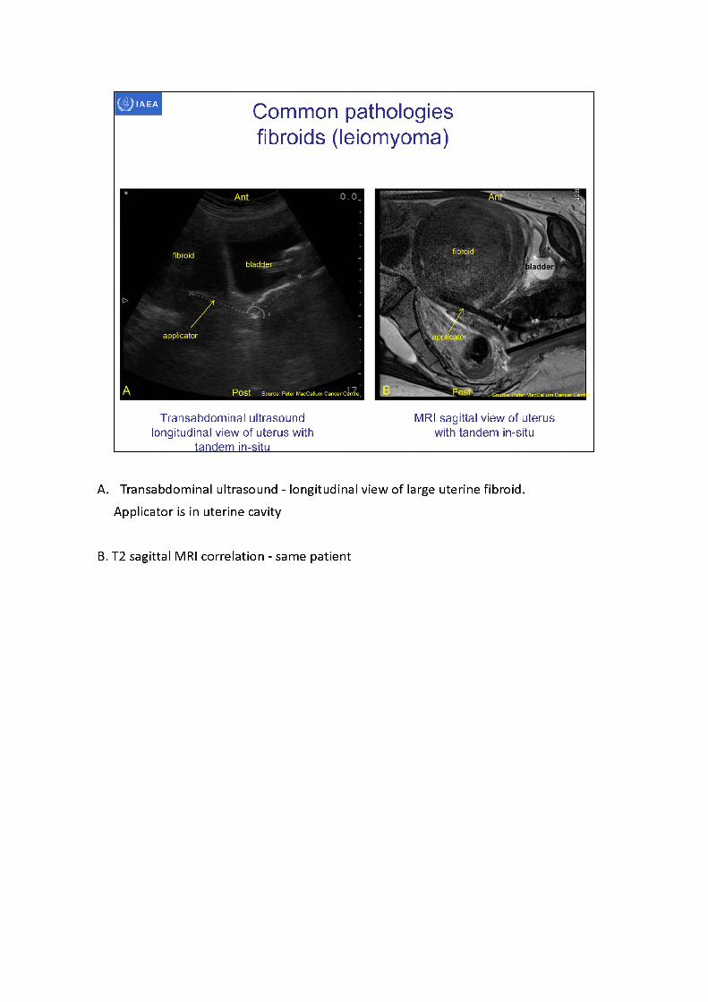
Transabdominal ultrasound longitudinal view of uterus with
tandem in-situ
MRI sagittal view of uterus with tandem in-situ
A. Transabdominal ultrasound - longitudinal view of large uterine fibroid. Applicator is in uterine cavity
B. T2 sagittal MRI correlation - same patient
Common pathologies fibroids (leiomyoma)
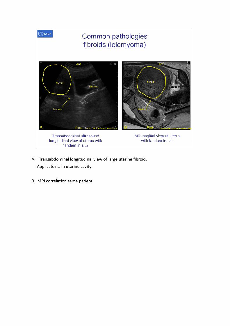
Transabdominal ultrasound longitudinal view of uterus with
tandem in-situ
MRI sagittal view of uterus with tandem in-situ
A. Transabdominal longitudinal view of large uterine fibroid. Applicator is in uterine cavity
B. MRI correlation same patient
Common pathologiesfibroids (leiomyoma)
Submucosal fibroid
Source: Peter MacCallum Cancer Centre
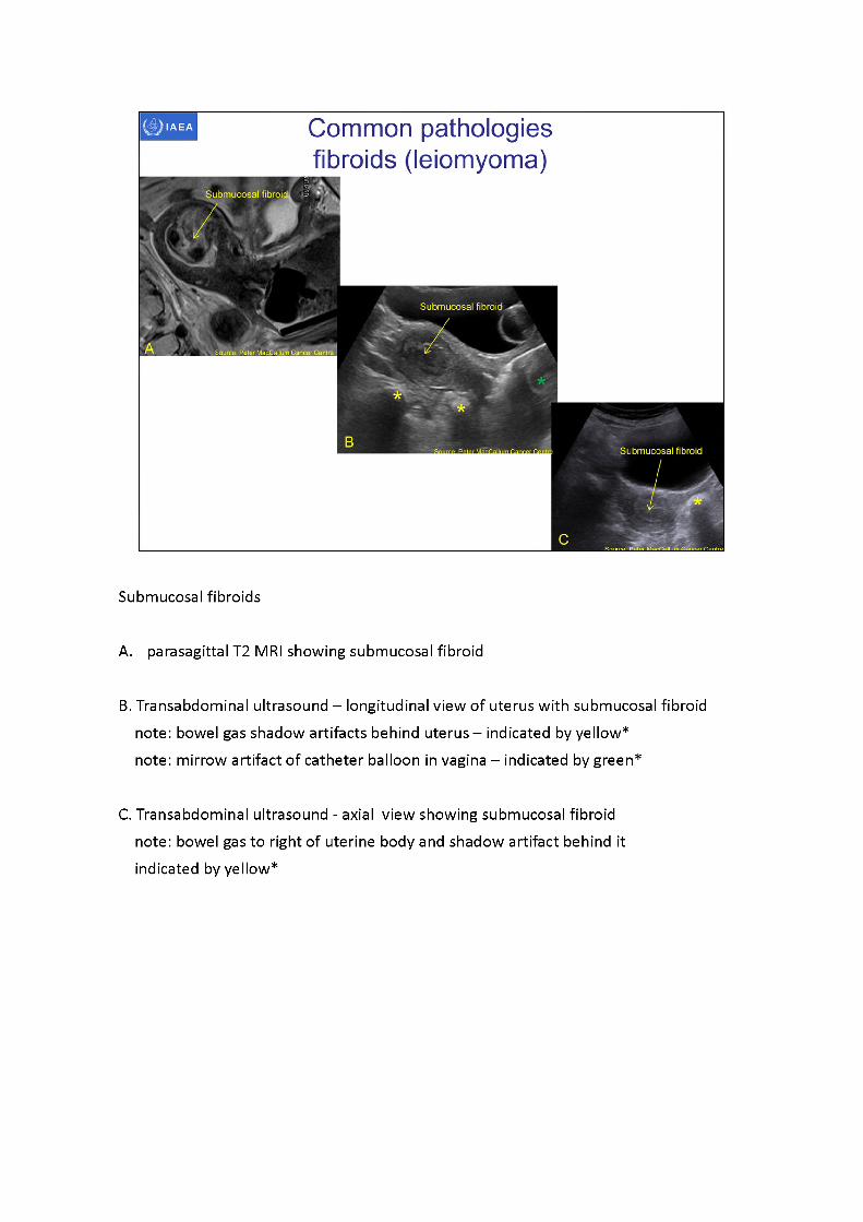
Submucosal fibroids
A. parasagittal T2 MRI showing submucosal fibroid
B. Transabdominal ultrasound - longitudinal view of uterus with submucosal fibroid note: bowel gas shadow artifacts behind uterus - indicated by yellow*note: mirrow artifact of catheter balloon in vagina -indicated by green*
C. Transabdominal ultrasound - axial view showing submucosal fibroid note: bowel gas to right of uterine body and shadow artifact behind it indicated by yellow*
IAEA Common pathologies fibroids (leiomyoma)
Subserosalfibroid
Applicator
--------- shadow
-
aritifact
A , Source: Peter MacCallum Cancer Centre
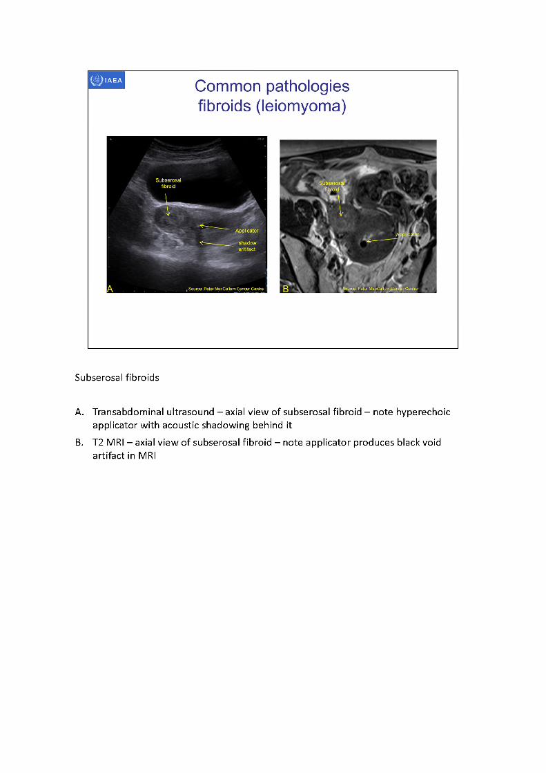
Subserosal fibroids
A. Transabdominal ultrasound - axial view of subserosal fibroid - note hyperechoic applicator with acoustic shadowing behind it
B. T2 MRI -axialview of subserosal fibroid -noteapplicator produces black void artifact in MRI
Bladder
External
cervix
sacrum
Source: Peter MacCallum Cancer Centre
Common pathologies Nabothian cysts
Nabothisy^cyst ii
Air in rectum causing shadow artifact
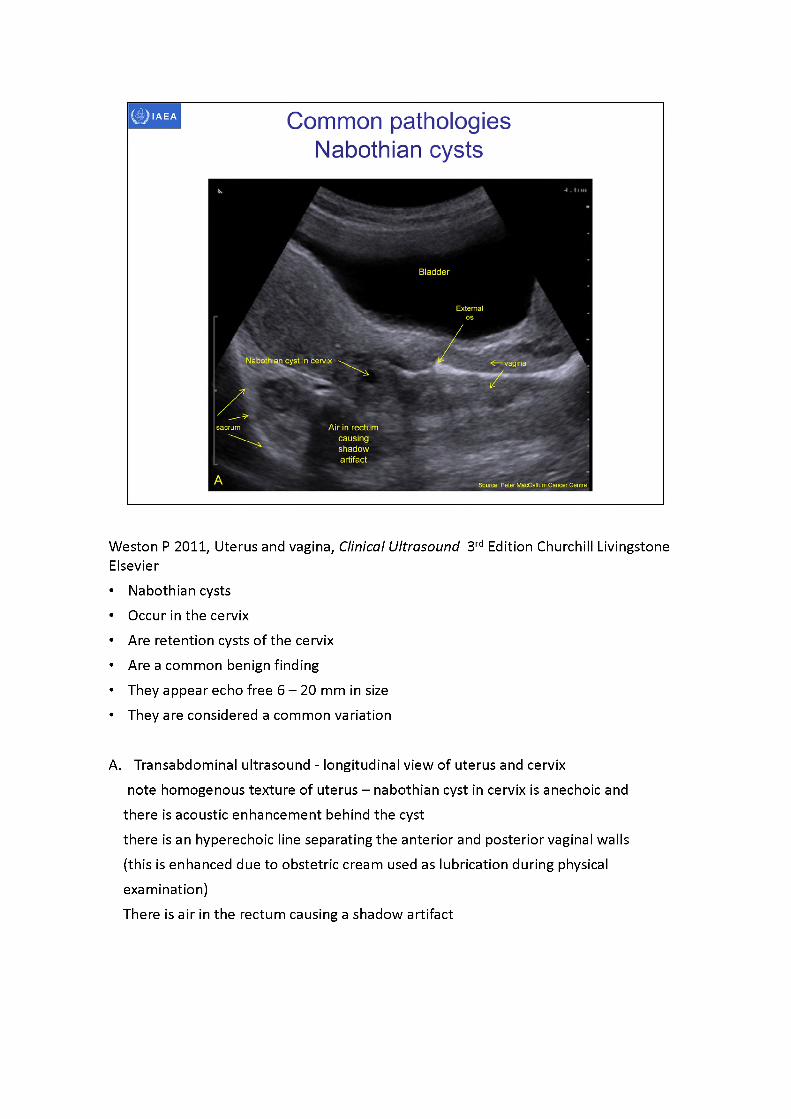
Weston P 2011, Uterus and vagina, Clinical Ultrasound 3rd Edition Churchill Livingstone Elsevier• Nabothian cysts• Occur in the cervix• Are retention cysts of the cervix• Are a common benign finding• They appear echo free 6 -20 mm in size• They are considered a common variation
A. Transabdominal ultrasound - longitudinal view of uterus and cervixnote homogenous texture of uterus -nabothian cyst in cervix is anechoic and
there is acoustic enhancement behind the cystthere is an hyperechoic line separating the anterior and posterior vaginal walls (this is enhanced due to obstetric cream used as lubrication during physical examination)There is air in the rectum causing a shadow artifact
O.O.
Note acousticenhancement behindthe low attenuating
Acoustic enhancement
Source: Peter MacCailum Cancer C<
Source: Peter Mac€alturwCan<# Centre
Acoustic shadowing behind applicator
NABOTH IAN CYST
NABOTHIAN CYST!
Nabothiancyst
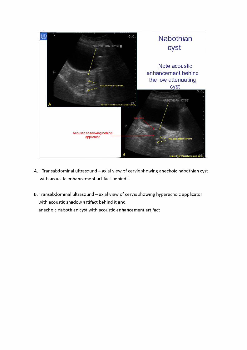
A. Transabdominal ultrasound - axial view of cervix showing anechoic nabothian cyst with acoustic enhancement artifact behind it
B. Transabdominal ultrasound -axialview of cervix showing hyperechoic applicator with acoustic shadow artifact behind it and anechoic nabothian cyst with acoustic enhancement artifact
M ulti-septated o\
Full bladder
Uterus
Source: Peter MacCallum Cancer Centra
IAEA
Ovarian cysts
Acoustic enhancement behind fluid filled cyst
TRANS L OVARIAN CYST
Mutti-septated ovarian cyst
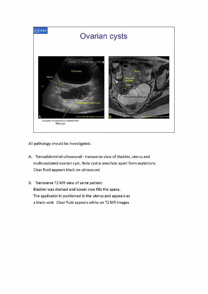
All pathology should be investigated.
A. Transabdominal ultrasound - transverse view of bladder, uterus and multi-septated ovarian cyst. Note cyst is anechoic apart from septations. Clear fluid appears black on ultrasound
B. Transverse T2 MR view of same patient.Bladder was drained and bowel now fills the space.The applicator in positioned in the uterus and appears as a black void. Clear fluid appears white on T2 MR images
hydrometra
Source; Peter MacCallum Cancer Centre
IAEA
FIGO IIIB PET node -ve
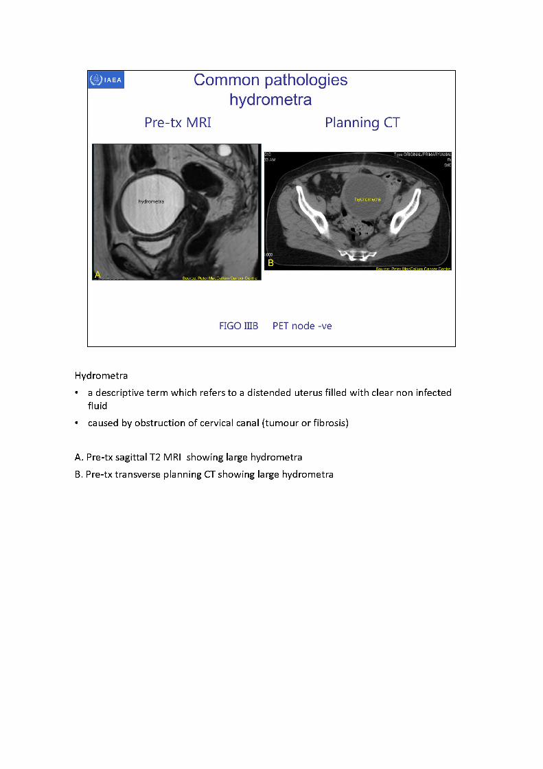
Common pathologies hydrometra
Pre-tx MRI Planning CT
Hydrometra• a descriptive term which refers to a distended uterus filled with clear non infected
fluid• caused by obstruction of cervical canal (tumour or fibrosis)
A. Pre-tx sagittal T2 MRI showing large hydrometraB. Pre-tx transverse planning CT showing large hydrometra
hydrometra
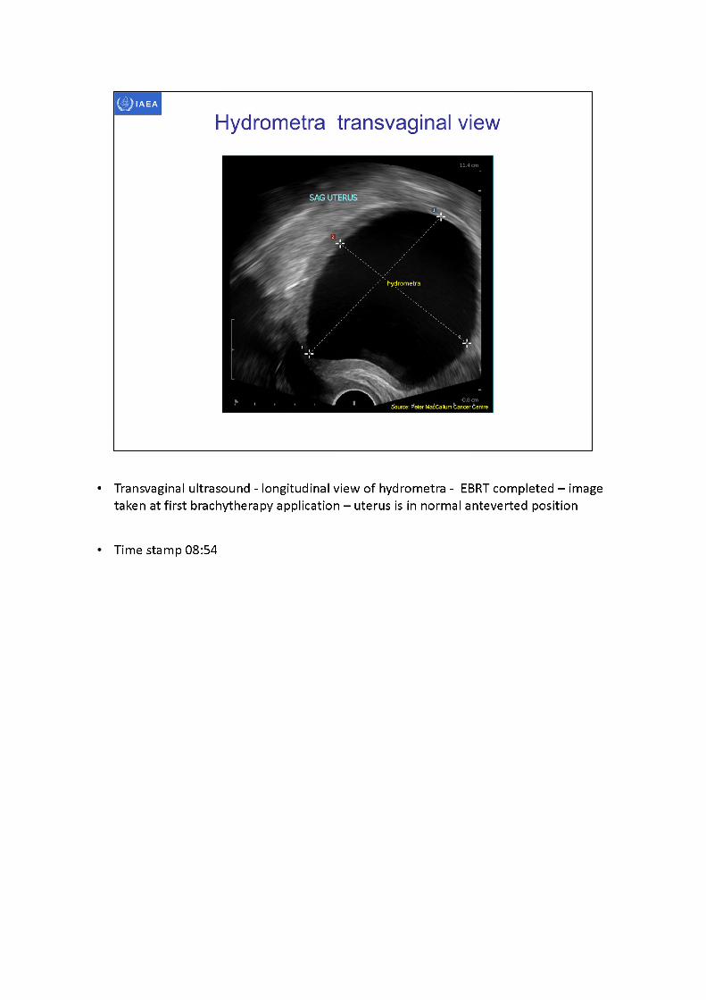
Hydrometra transvaginal view
SAG UTERUS
-0.8 cmSource: F*eter MacCallum bancer Centre
• Transvaginal ultrasound - longitudinal view of hydrometra - EBRT completed -image taken at first brachytherapy application -uterusis in normal anteverted position
Time stamp 08:54
hydrometra bladder
vagina
sacrum
14.6 cmSource: Peter MacCallum Cancer Centre
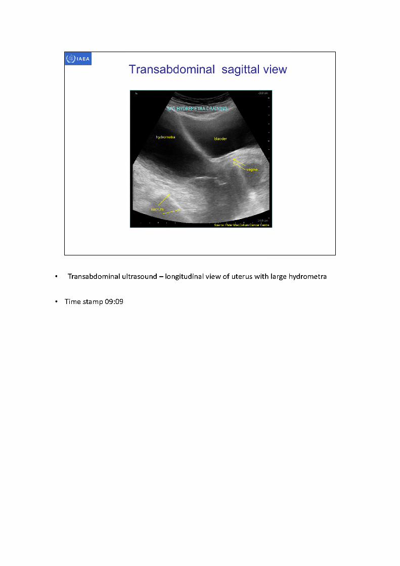
Transabdominal sagittal view
SA^HYDREMETRA DRAINING
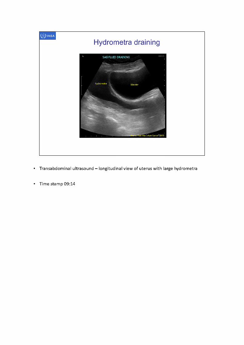
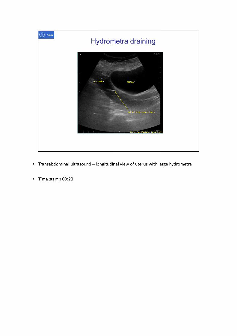
• Transabdominal ultrasound - longitudinal view of uterus with large hydrometra
Time stamp 09:09
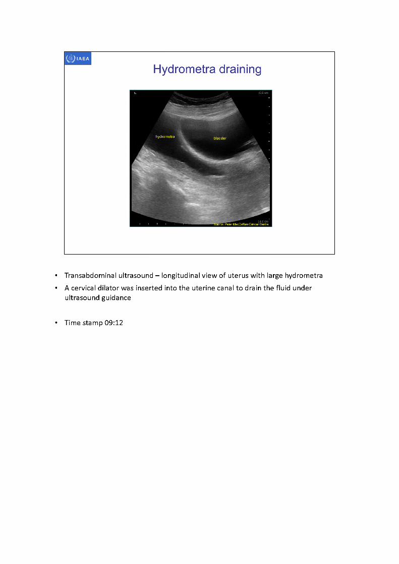
• Transabdominal ultrasound -longitudinal view of uterus with large hydrometra• A cervical dilator was inserted into the uterine canal to drain the fluid under
ultrasound guidance
Time stamp 09:12
• Transabdominal ultrasound - longitudinal view of uterus with large hydrometra
Time stamp 09:14
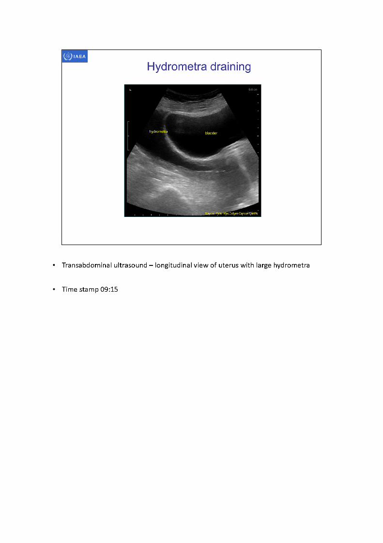
• Transabdominal ultrasound - longitudinal view of uterus with large hydrometra
Time stamp 09:15
hydrometra bladder
Source: Peter MecCallum Cancer
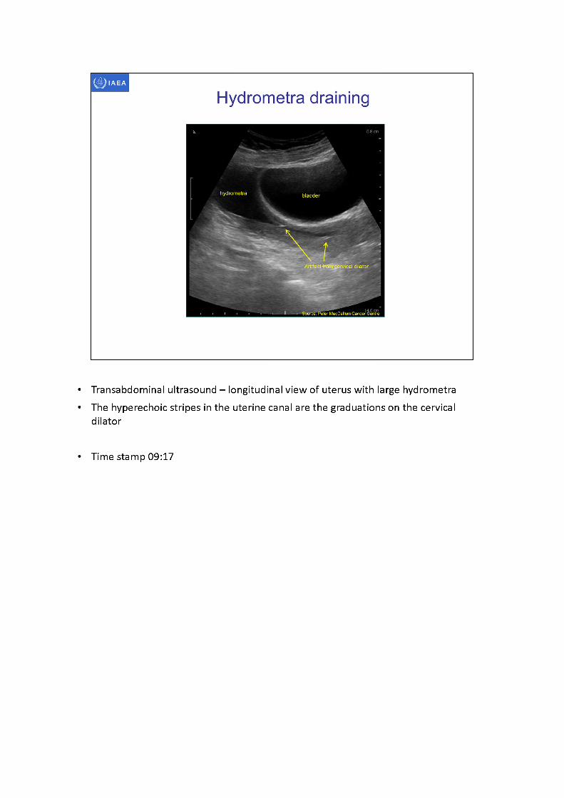
Hydrometra draining
Artifact-frdmjervical dilator
• Transabdominal ultrasound -longitudinal view of uterus with large hydrometra• The hyperechoic stripes in the uterine canal are the graduations on the cervical
dilator
Time stamp 09:17
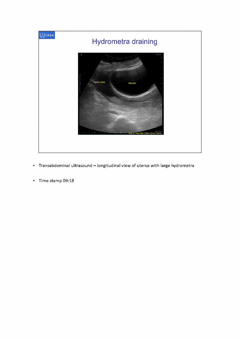
• Transabdominal ultrasound - longitudinal view of uterus with large hydrometra
Time stamp 09:18
hydrometra bladder
Artifact from cervical dilator
14-6 E™'Source: Peter MacCallum Cancer Centre
Hydrometra draining
• Transabdominal ultrasound - longitudinal view of uterus with large hydrometra
Time stamp 09:20
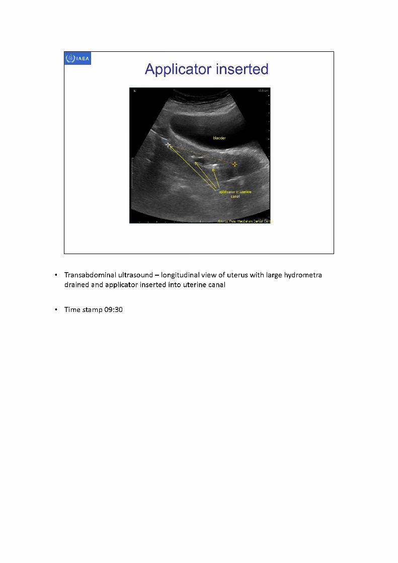
bladder
applicator in uterine canal
rSource: Peter MacCallwnCarW? Ce'ntl
Applicator inserted
• Transabdominal ultrasound -longitudinal view of uterus with large hydrometra drained and applicator inserted into uterine canal
Time stamp 09:30
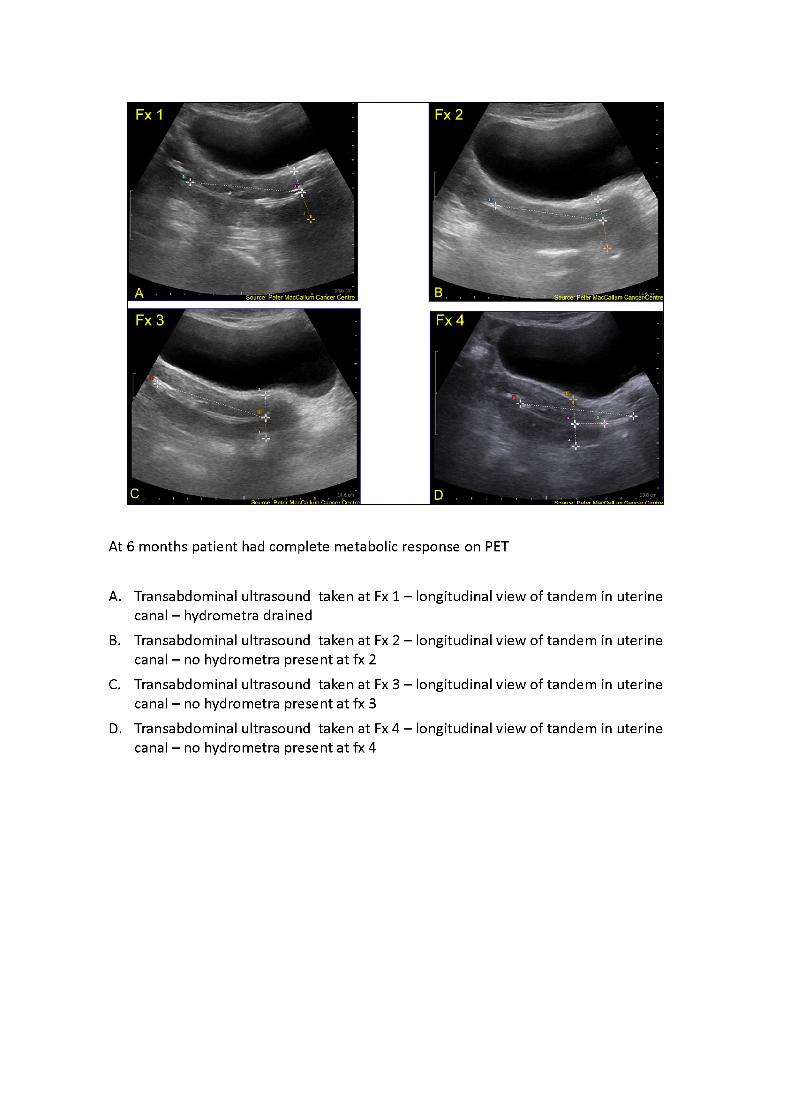
At 6 months patient had complete metabolic response on PET
A. Transabdominal ultrasound taken at Fx1 -longitudinal view of tandem in uterine canal -hydrometra drained
B. Transabdominal ultrasound taken at Fx2 -longitudinal view of tandem in uterine canal -nohydrometra present at fx2
C. Transabdominal ultrasound taken at Fx3 -longitudinal view of tandem in uterine canal -nohydrometra present at fx3
D. Transabdominal ultrasound taken at Fx4 -longitudinal view of tandem in uterine canal -nohydrometra present at fx4
IAEA
3D image-based female pelvis anatomy by Ultrasound (US)
• Overview of ultrasound• Normal female pelvic anatomy• Sonographic techniques - image orientation• Normal sonographic anatomy• Anatomical variations• Common pathologies• Using ultrasound in brachytherapy• Future - 3D ultrasound
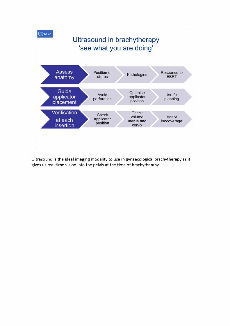
Ultrasound is the ideal imaging modality to use in gynaecological brachytherapy as it gives us real time vision into the pelvis at the time of brachytherapy.
hydrometra
acousticwindow
Source: feeler MacCallum Cancer Centre Peter MacCallulancer Centre
IAEA
Pre-tx MRI
FIGO 3B 8.0 cm tumour Node negative
Heterogeneous mass Exophytic and infiltrative
Invasion into posterior wall and bladder base
vaginal wall invasion
Response EBRTto
Ultrasound 45 Gy MRI 45 Gypost post
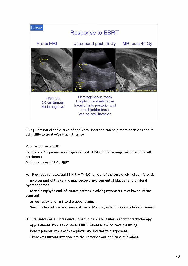
Using ultrasound at the time of applicator insertion can help make decisions about suitability to treat with brachytherapy
Poor response to EBRTFebruary 2012 patient was diagnosed with FIGO IIIB node negative squamous cell carcinomaPatient received 45 Gy EBRT
A. Pre-treatment sagittal T2 MRI -T4 N0 tumour of the cervix, with circumferentialinvolvement of the cervix, macroscopic involvement of bladder and bilateral
hydronephrosis.Mixed exophytic and infiltrative pattern involving myometrium of lower uterine
segmentas well as extending into the upper vagina.Small hydrometra in endometrial cavity. MRI suggests mucinous adenocarcinoma.
B. Transabdominal ultrasound - longitudinal view of uterus at first brachytherapy appointment. Poor response to EBRT. Patient noted to have persisting heterogeneous mass with exophytic and infiltrative component.There was tumour invasion into the posterior wall and base of bladder.
70
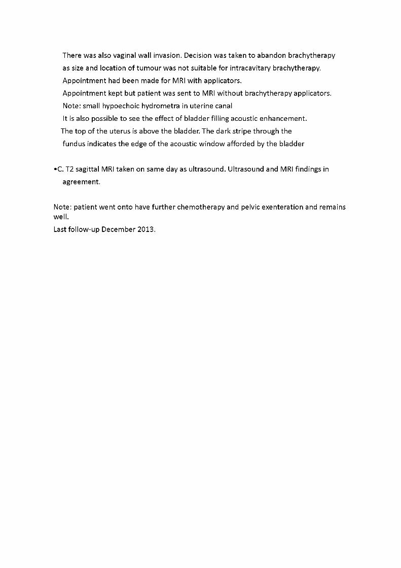
There was also vaginal wall invasion. Decision was taken to abandon brachytherapy as size and location of tumour was not suitable for intracavitary brachytherapy. Appointment had been made for MRI with applicators.Appointment kept but patient was sent to MRI without brachytherapy applicators.Note: small hypoechoic hydrometra in uterine canalIt is also possible to see the effect of bladder filling acoustic enhancement.
The top of the uterus is above the bladder. The dark stripe through the fundus indicates the edge of the acoustic window afforded by the bladder
•C. T2 sagittal MRI taken on same day as ultrasound. Ultrasound and MRI findings in agreement.
Note: patient went onto have further chemotherapy and pelvic exenteration and remains well.Last follow-up December 2013.
tumour
d^B^eter MacCallum Cancer Centre Souifce: /eter MacCaHjjm Cancer Centre
bladder
Source: PeterMacCallum Cancer Centre SdliSfetPeter MacCallum Cancer Centre!
Response to EBRT
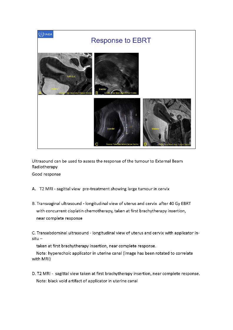
Ultrasound can be used to assess the response of the tumour to External BeamRadiotherapyGood response
A. T2 MRI - sagittal view pre-treatment showing large tumour in cervix
B. Transvaginal ultrasound - longitudinal view of uterus and cervix after 40 Gy EBRT with concurrent cisplatin chemotherapy, taken at first brachytherapy insertion, near complete response
C. Transabdominal ultrasound - longitudinal view of uterus and cervix with applicator in- situ -
taken at first brachytherapy insertion, near complete response.Note: hyperechoic applicator in uterine canal (image has been rotated to correlate
with MRI)
D. T2 MRI - sagittal view taken at first brachytherapy insertion, near complete response. Note: black void artifact of applicator in uterine canal
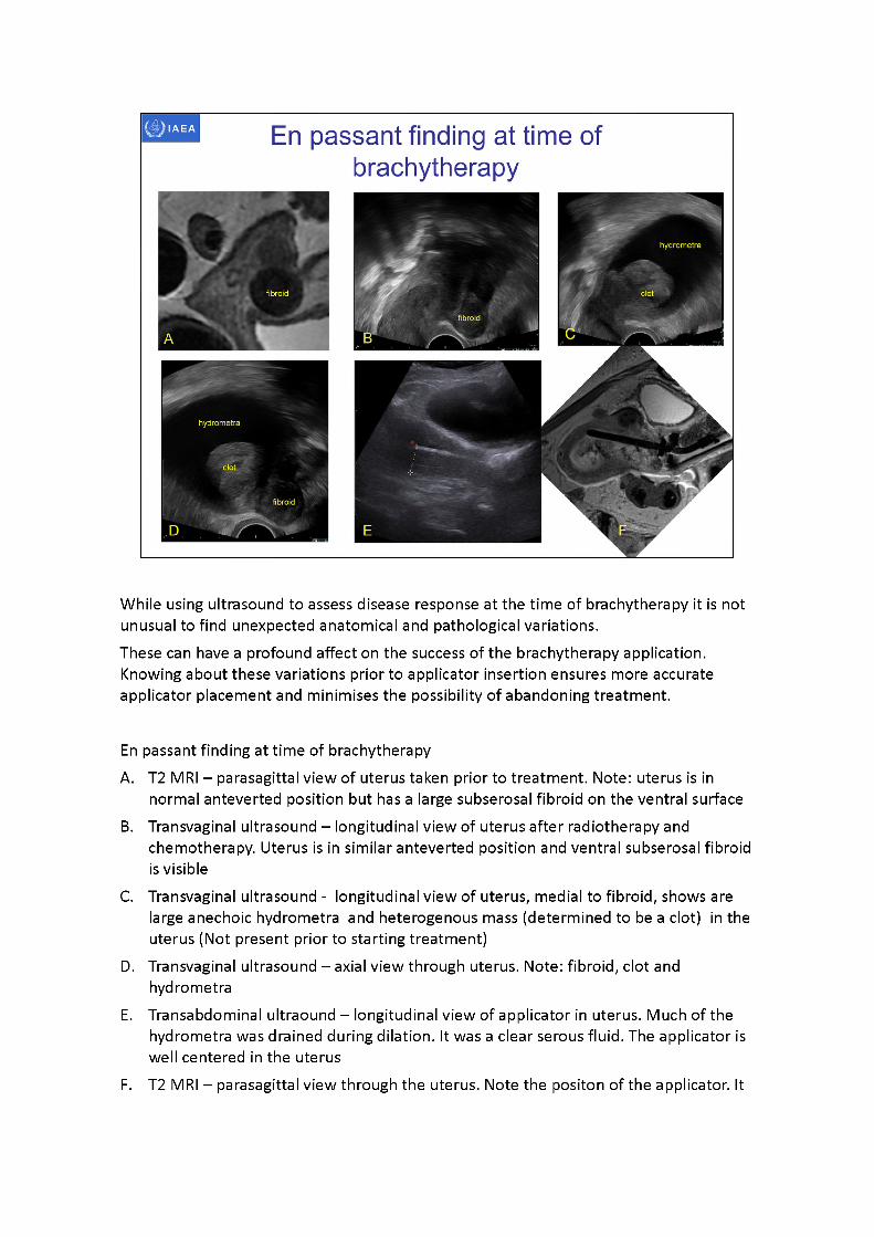
While using ultrasound to assess disease response at the time of brachytherapy it is not unusual to find unexpected anatomical and pathological variations.These can have a profound affect on the success of the brachytherapy application. Knowing about these variations prior to applicator insertion ensures more accurate applicator placement and minimises the possibility of abandoning treatment.
En passant finding at time of brachytherapyA. T2 MRI - parasagittal view of uterus taken prior to treatment. Note: uterus is in
normal anteverted position but has a large subserosal fibroid on the ventral surfaceB. Transvaginal ultrasound -longitudinal view of uterus after radiotherapy and
chemotherapy. Uterus is in similar antevertedposition and ventral subserosal fibroid is visible
C. Transvaginal ultrasound - longitudinal view of uterus, medial to fibroid, shows are large anechoic hydrometra and heterogenous mass (determined to be a clot) in the uterus (Not present prior to starting treatment)
D. Transvaginal ultrasound -axialview through uterus. Note: fibroid, clot and hydrometra
E. Transabdominal ultraound- longitudinal view of applicator in uterus. Much of the hydrometra was drained during dilation. It was a clear serous fluid. The applicator is well centeredin the uterus
F. T2 MRI -parasagittal view through the uterus. Note the positon of the applicator. It

moved during transfer to the MRI scanner. While the applicator position is different the dimensions of the uterus are similar to that measured on transadominal ultrasound.
Bladder Bladder
IAEA
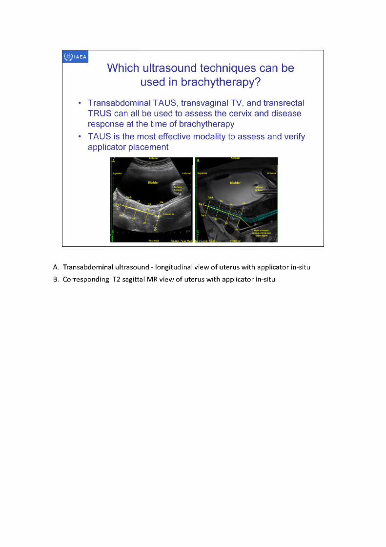
• Transabdominal TAUS, transvaginal TV, and transrectal TRUS can all be used to assess the cervix and disease response at the time of brachytherapy
• TAUS is the most effective modality to assess and verify applicator placement
Which ultrasound techniques can be used in brachytherapy?
A. Transabdominal ultrasound - longitudinal view of uterus with applicator in-situB. Corresponding T2 sagittal MR view of uterus with applicator in-situ
tip tandem
Source: Peter MacCallum Cancer Centre Source; Peter MacCallum Cancer CentreSource: Peter MacCallum Cancer Centre
Source: Peter MacCallum Cancer Centre!
IAEA
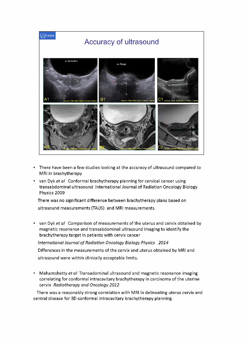
Accuracy of ultrasound
• There have been a few studies looking at the accuracy of ultrasound compared to MRI in brachytherapy
• van Dyk et al Conformal brachytherapy planning for cervical cancer using transabdominal ultrasound International Journal of Radiation Oncology Biology Physics 2009
There was no significant difference between brachytherapy plans based on ultrasound measurements (TAUS) and MRI measurements.
• van Dyk et al Comparison of measurements of the uterus and cervix obtained by magnetic resonance and transabdominal ultrasound imaging to identify the brachytherapy target in patients with cervix cancer
International Journal of Radiation Oncology Biology Physics 2014Differences in the measurements of the cervix and uterus obtained by MRI and ultrasound were within clinically acceptable limits.
• Mahantshetty et al Transadominal ultrasound and magnetic resonance imaging correlating for conformal intracavitary brachytherapy in carcinoma of the uterinecervix Radiotherapy and Oncology 2012
There was a reasonably strong correlation with MRI in delineating uterus cervix and central disease for 3D conformal intracavitary brachytherapy planning.
• Schmidet al Feasibility of transrectal ultrasonography for assessment of cervical cancer Strahlentherapy Onkology 2012
The feasibility of TRUS for the assessment of local target extension could be demonstrated.
Comparison of the target width and thickness showed a high correlation between TRUS and MRI, indicating the potential of TRUS for target definition in image guided adaptive brachytherapy.
• A1. Transabdominal ultrasound - axial view of tip of applicator in uterine canal• A2. T2 MRI - axial view of tip of applicator in uterine canal• B1. Transabdominal ultrasound - axial view of applicator at external os• B2. T2 MRI - axial view of applicator at external os• C1. Transabdominal ultrasound - longitudinal view of applicator in uterine canal• C2. T2 MRI longitudinal view of applicator in uterine canal
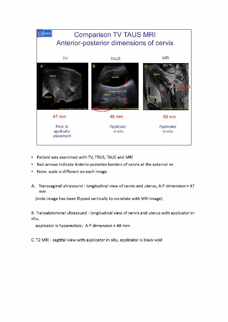
Comparison TV TAUS MRI Anterior-posterior dimensions of cervix
TV TAUS MRI
47 mm 48 mm 50 mm
Prior to applicator placement
Applicatorin-situ
Applicatorin-situ
• Patient was examined with TV, TRUS, TAUS and MRI• Red arrows indicate Anterio-posterior borders of cervix at the external os• Note: scale is different on each image
A. Transvaginal ultrasound - longitudinal view of cervix and uterus, A-P dimension = 47 mm
(note image has been flipped vertically to correlate with MRI image)
B. Transabdominal ultrasound - longitudinal view of cervix and uterus with applicator in- situ,
applicator is hyperechoic, A-P dimension = 48 mm
C. T2 MRI - sagittal view with applicator in-situ, applicator is black void
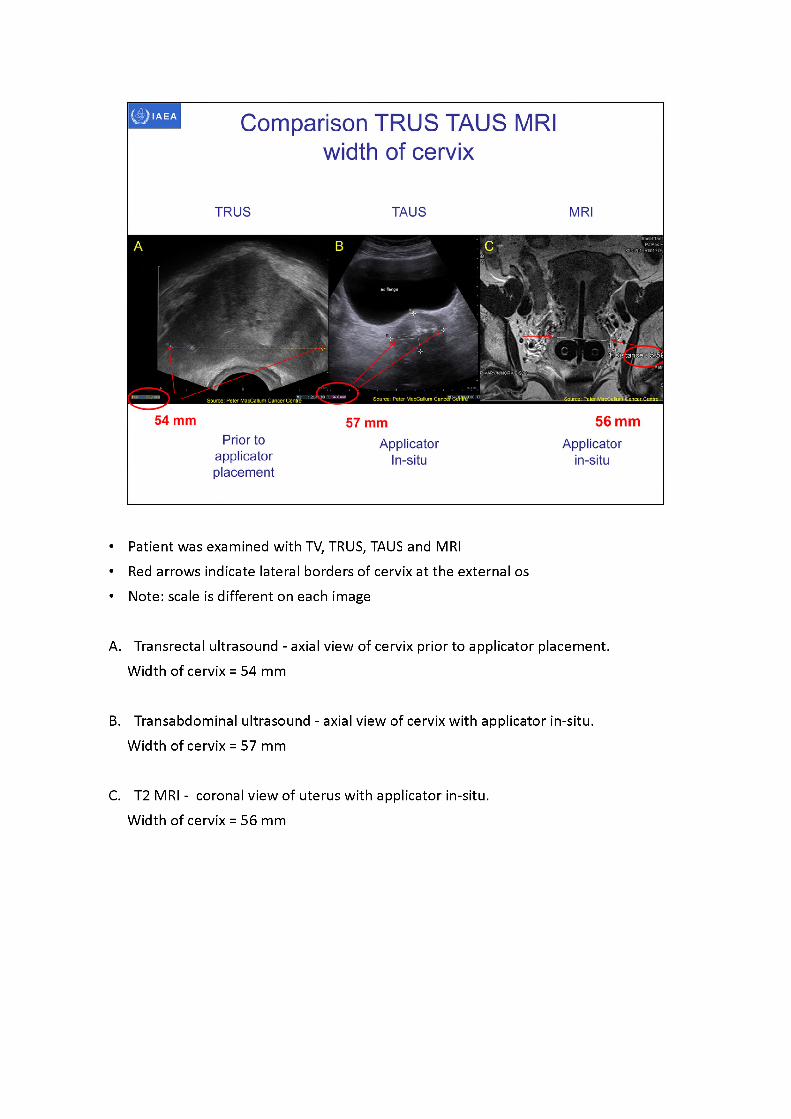
Comparison TRUS TAUS MRIwidth of cervix
TRUS TAUS MRI
54 mm 56 mm57 mmPrior to Applicator Applicator
applicator In-situ in-situplacement
• Patient was examined with TV, TRUS, TAUS and MRI• Red arrows indicate lateral borders of cervix at the external os • Note: scale is different on each image
A. Transrectal ultrasound - axial view of cervix prior to applicator placement. Width of cervix = 54 mm
B. Transabdominal ultrasound - axial view of cervix with applicator in-situ. Width of cervix = 57 mm
C. T2 MRI - coronal view of uterus with applicator in-situ.Width of cervix = 56 mm
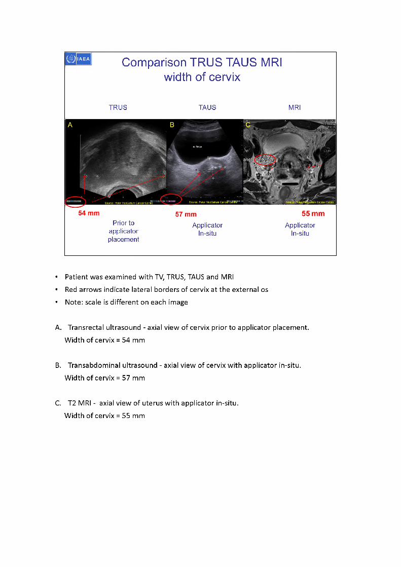
Comparison TRUS TAUS MRI width of cervix
TRUS TAUS MRI
4ORMTDIS2CT
Source: Peter MacCallum Canc^J'Ce'bW ialfum Cancer CentreSource: Peter MacCallum Cancer Centre
Prior to applicator placement
ApplicatorIn-situ
ApplicatorIn-situ
• Patient was examined with TV, TRUS, TAUS and MRI• Red arrows indicate lateral borders of cervix at the external os • Note: scale is different on each image
A. Transrectal ultrasound - axial view of cervix prior to applicator placement. Width of cervix = 54 mm
B. Transabdominal ultrasound - axial view of cervix with applicator in-situ. Width of cervix = 57 mm
C. T2 MRI - axial view of uterus with applicator in-situ.Width of cervix = 55 mm
CylindersegmentHyperechoic applicator Hyperechoic applicator
Revereration artifactShadowartifact
Sourre^PeterMacCallurnCi
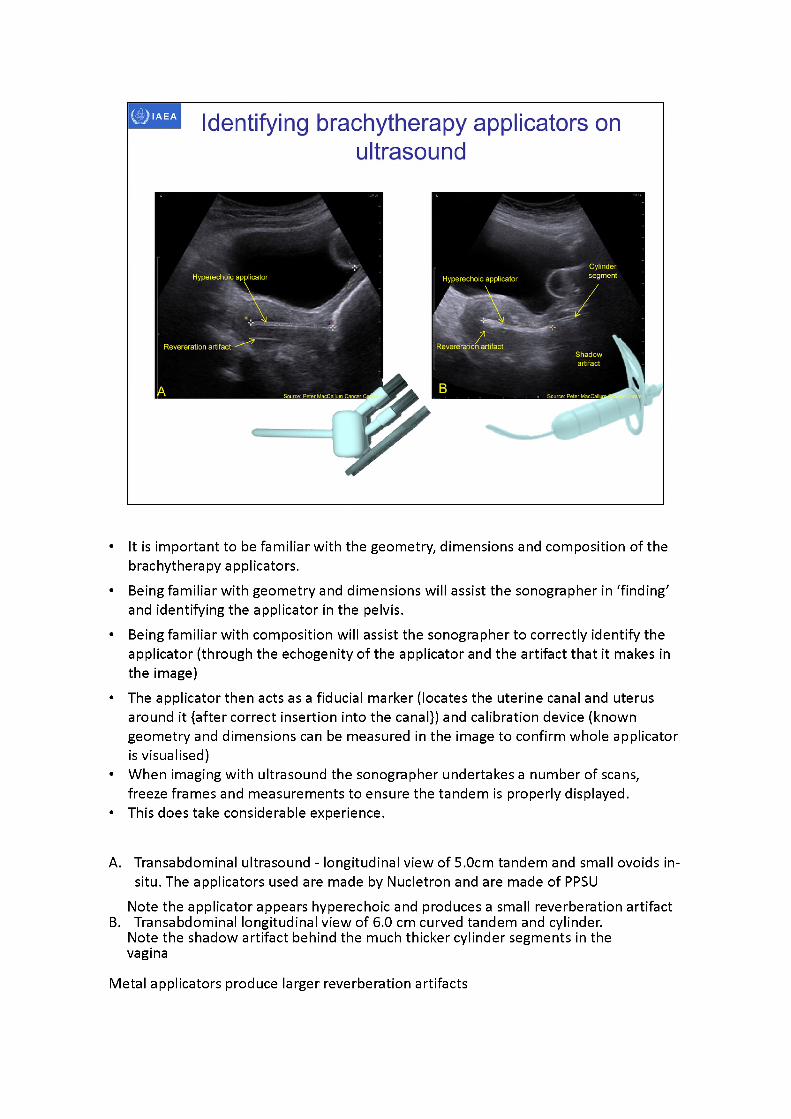
IAEA Identifying brachytherapy applicators on ultrasound
Revereration artifact -
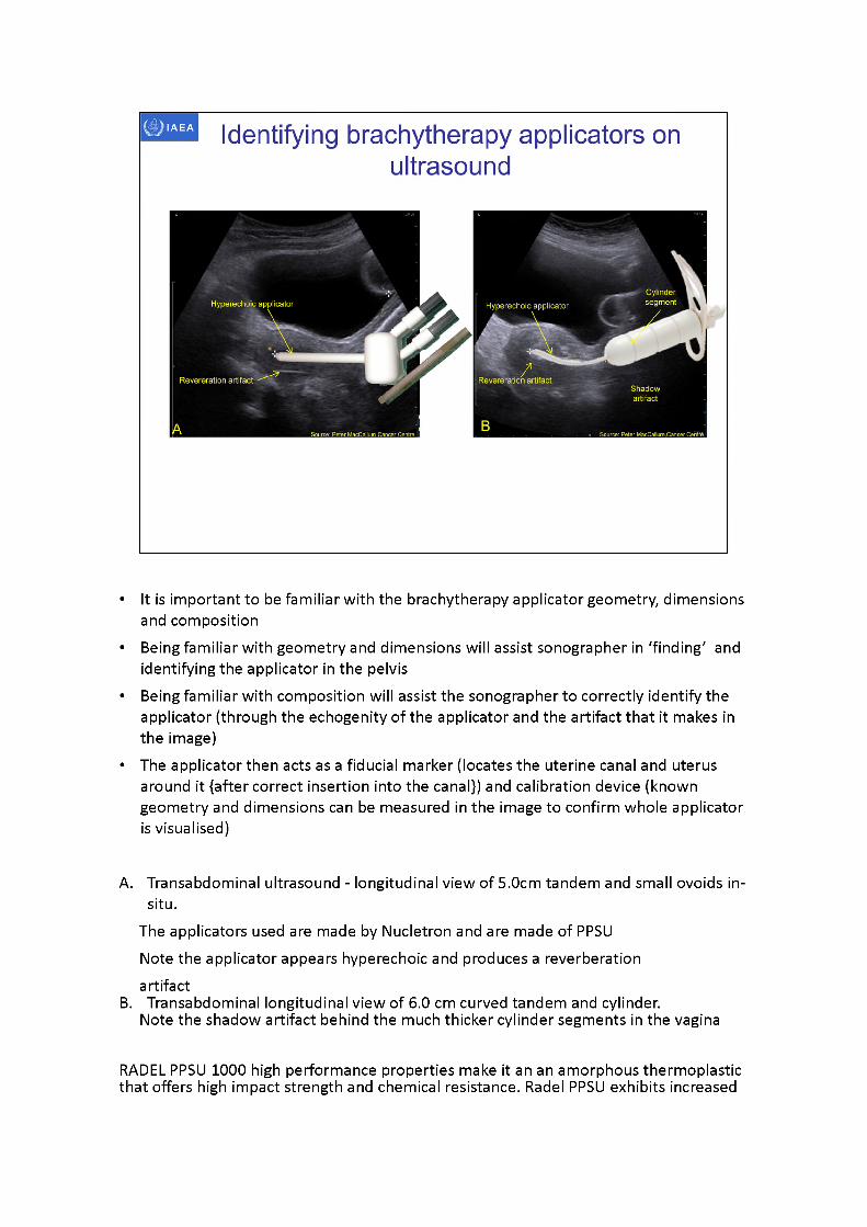
• It is important to be familiar with the geometry, dimensions and composition of the brachytherapy applicators.
• Being familiar with geometry and dimensions will assist the sonographer in ‘finding' and identifying the applicator in the pelvis.
• Being familiar with composition will assist the sonographer to correctly identify the applicator (through the echogenityof the applicator and the artifact that it makes in the image)
• The applicator then acts as a fiducial marker (locates the uterine canal and uterus around it {after correct insertion into the canal}) and calibration device (known geometry and dimensions can be measured in the image to confirm whole applicator is visualised)
• When imaging with ultrasound the sonographer undertakes a number of scans, freeze frames and measurements to ensure the tandem is properly displayed.
• This does take considerable experience.
A. Transabdominal ultrasound - longitudinal view of 5.0cm tandem and small ovoids in- situ. The applicators used are made by Nucletron and are made of PPSU
Note the applicator appears hyperechoic and produces a small reverberation artifactB. Transabdominal longitudinal view of 6.0 cm curved tandem and cylinder.
Note the shadow artifact behind the much thicker cylinder segments in the vagina
Metal applicators produce larger reverberation artifacts
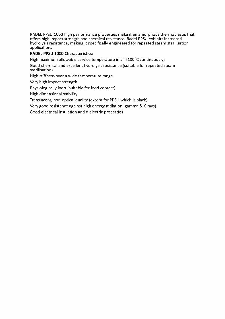
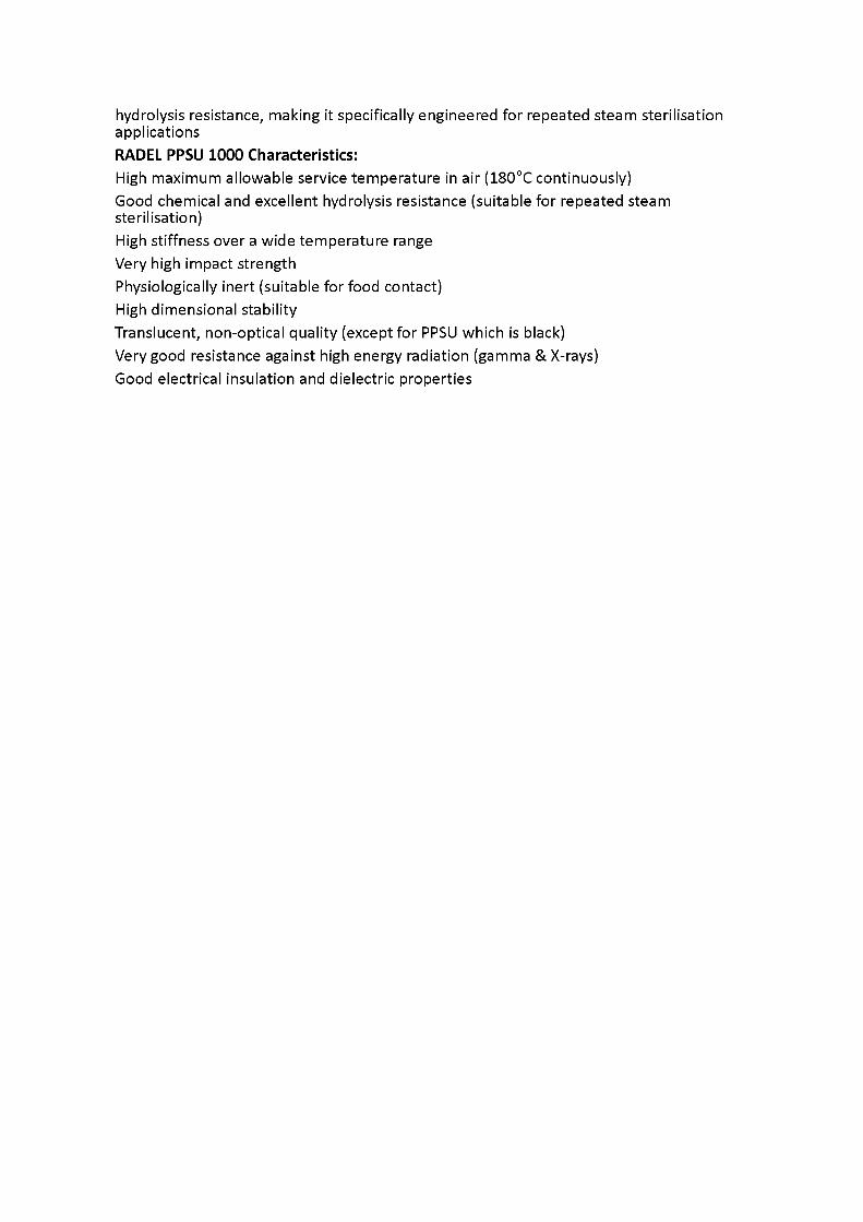
RADEL PPSU 1000 high performance properties make it an amorphous thermoplastic that offers high impact strength and chemical resistance. Radel PPSU exhibits increased hydrolysis resistance, making it specifically engineered for repeated steam sterilisation applicationsRADEL PPSU 1000 Characteristics:High maximum allowable service temperature in air (180°C continuously)Good chemical and excellent hydrolysis resistance (suitable for repeated steam sterilisation)High stiffness over a wide temperature rangeVery high impact strengthPhysiologically inert (suitable for food contact)High dimensional stabilityTranslucent, non-optical quality (except for PPSU which is black)Very good resistance against high energy radiation (gamma & X-rays)Good electrical insulation and dielectric properties
CylindersegmentHyperechoic applicator Hyperechoic applicator
Shadowartifact
Source: Peter MacCallum C; Source: Peter MacCallum.Cancer Centra.
Identifying brachytherapy applicators on ultrasound
Revereration artifact/
Revereration artifact
• It is important to be familiar with the brachytherapy applicator geometry, dimensions and composition
• Being familiar with geometry and dimensions will assist sonographer in ‘finding' and identifying the applicator in the pelvis
• Being familiar with composition will assist the sonographer to correctly identify the applicator (through the echogenityof the applicator and the artifact that it makes in the image)
• The applicator then acts as a fiducial marker (locates the uterine canal and uterus around it {after correct insertion into the canal}) and calibration device (known geometry and dimensions can be measured in the image to confirm whole applicator is visualised)
A. Transabdominal ultrasound - longitudinal view of 5.0cm tandem and small ovoids in- situ.
The applicators used are made by Nucletron and are made of PPSU Note the applicator appears hyperechoic and produces a reverberation artifact
B. Transabdominal longitudinal view of 6.0 cm curved tandem and cylinder.Note the shadow artifact behind the much thicker cylinder segments in the vagina
RADEL PPSU 1000 high performance properties make it an an amorphous thermoplastic that offers high impact strength and chemical resistance. Radel PPSU exhibits increased
hydrolysis resistance, making it specifically engineered for repeated steam sterilisation applicationsRADEL PPSU 1000 Characteristics:High maximum allowable service temperature in air (180°C continuously)Good chemical and excellent hydrolysis resistance (suitable for repeated steam sterilisation)High stiffness over a wide temperature rangeVery high impact strengthPhysiologically inert (suitable for food contact)High dimensional stabilityTranslucent, non-optical quality (except for PPSU which is black)Very good resistance against high energy radiation (gamma & X-rays)Good electrical insulation and dielectric properties
40mm27mm28mm
Source: Peter MacCallum Cancer Centre
Source: Peter MacCallum Cancer Centre
B-KMt:
IAEA
Identifying brachytherapy applicators on
ultrasound
Fx 34.5 cm straight stainless steel tandem
Note reverberation artifact
tiro.g • FR-40 G= 38z Prs = 2
Acoustic shadowing
Fx 24.0 cm curved PPSU tandem
Jj: 50* k ■■ 130*
FR39 G: 56z Prs 2
X+o
X 45mm12mm14mm
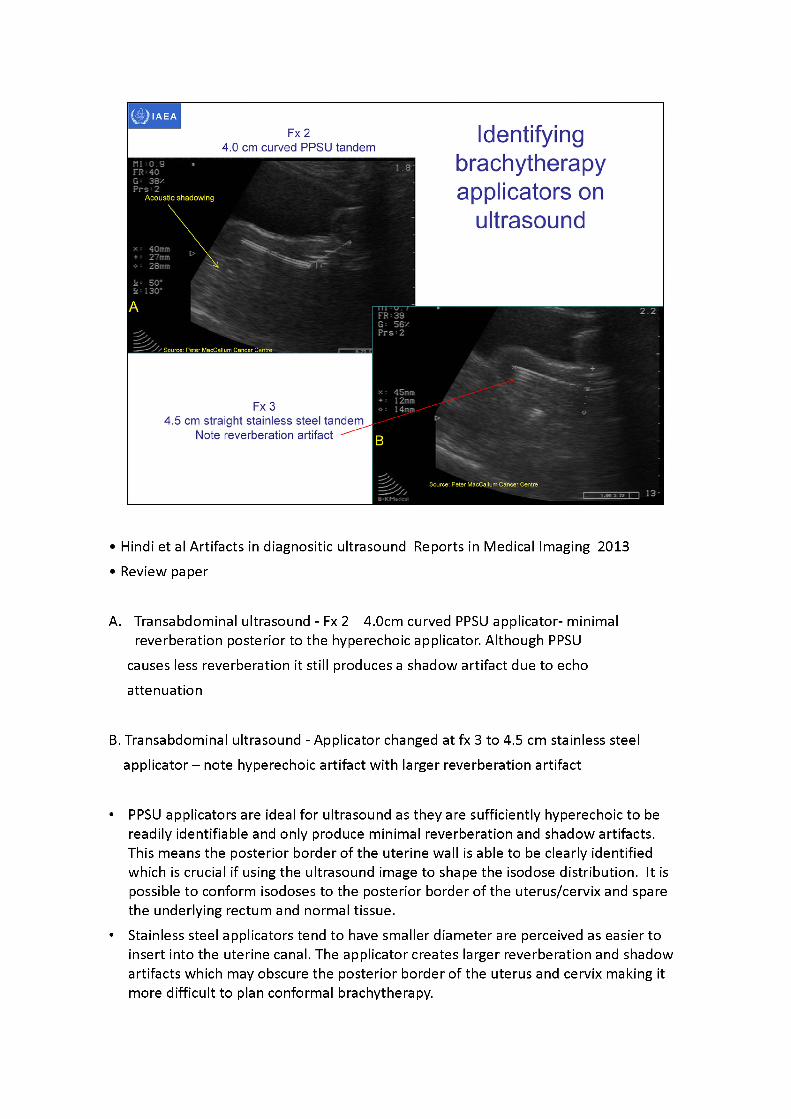
• Hindi et al Artifacts in diagnositic ultrasound Reports in Medical Imaging 2013 •Reviewpaper
A. Transabdominal ultrasound - Fx 2 4.0cm curved PPSU applicator- minimal reverberation posterior to the hyperechoic applicator. Although PPSU
causes less reverberation it still produces a shadow artifact due to echo attenuation
B. Transabdominal ultrasound - Applicator changed at fx 3 to 4.5 cm stainless steel applicator -note hyperechoic artifact with larger reverberation artifact
• PPSU applicators are ideal for ultrasound as they are sufficiently hyperechoic to be readily identifiable and only produce minimal reverberation and shadow artifacts. This means the posterior border of the uterine wall is able to be clearly identified which is crucial if using the ultrasound image to shape the isodose distribution. It is possible to conform isodoses to the posterior border of the uterus/cervix and spare the underlying rectum and normal tissue.
• Stainless steel applicators tend to have smaller diameter are perceived as easier to insert into the uterine canal. The applicator creates larger reverberation and shadow artifacts which may obscure the posterior border of the uterus and cervix making it more difficult to plan conformal brachytherapy.
Source: Peler MacCallum Cancer Centre
fc.
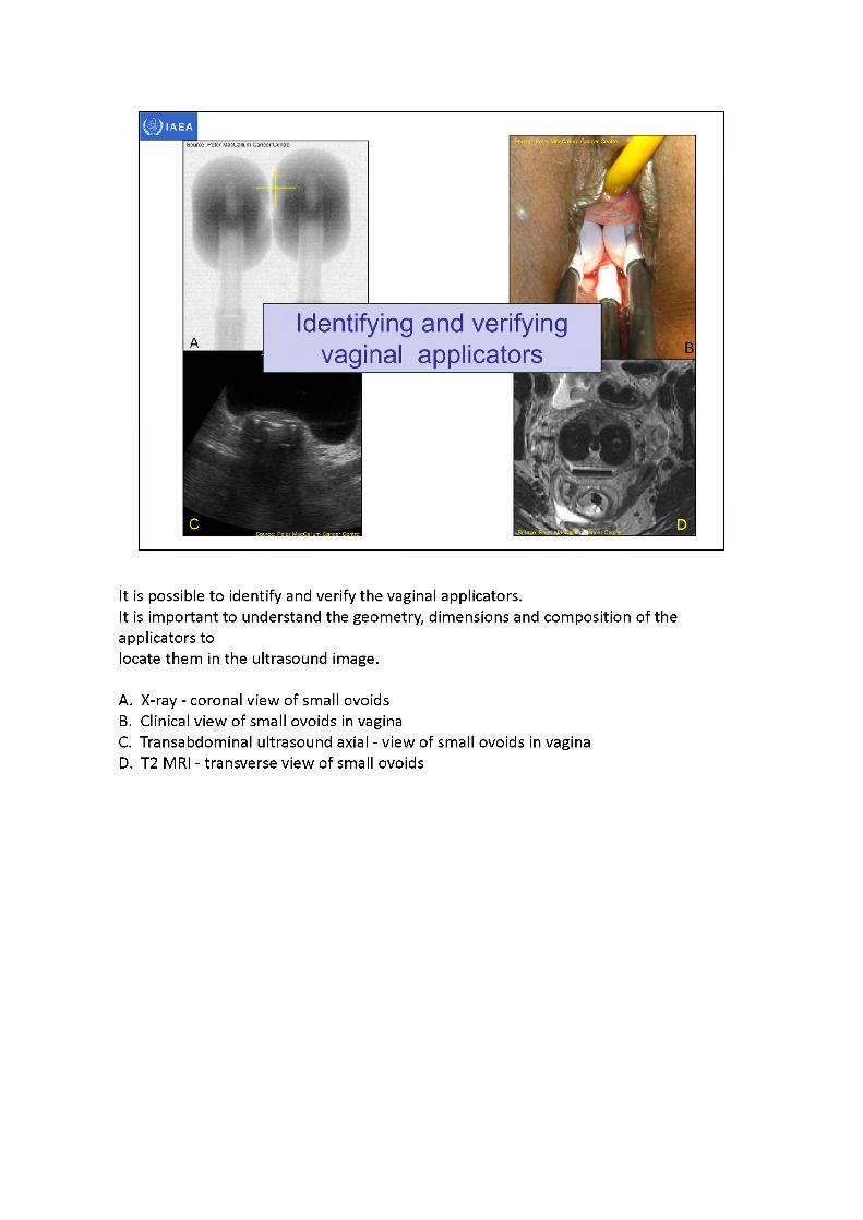
Identifying and verifyingvaginal applicators
It is possible to identify and verify the vaginal applicators.It is important to understand the geometry, dimensions and composition of the applicators tolocate them in the ultrasound image.
A. X-ray - coronal view of small ovoidsB. Clinical view of small ovoids in vaginaC. Transabdominal ultrasound axial - view of small ovoids in vaginaD. T2 MRI - transverse view of small ovoids
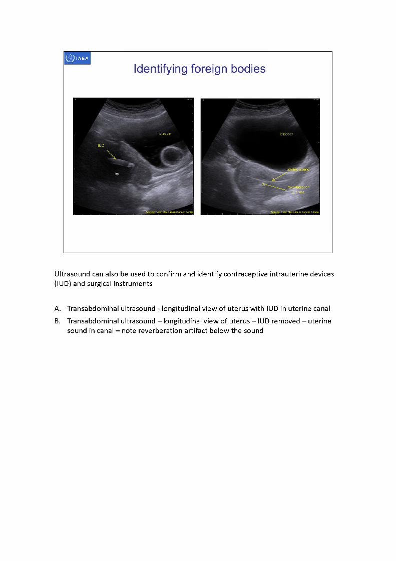
Ultrasound can also be used to confirm and identify contraceptive intrauterine devices (IUD) and surgical instruments
A. Transabdominal ultrasound - longitudinal view of uterus with IUD in uterine canalB. Transabdominal ultrasound - longitudinal view of uterus -IUD removed - uterine
sound in canal - note reverberation artifact below the sound
bladder bladder
'Speculum in vaginauterus uterus
reverberation and' shadow artifact
vagina sacrum
Source: Peter MacCallum Cancer Centre Source: Peter MacC^llum Cancer Centre,
Source: PeterMacCallurrr
Identifying foreign bodies
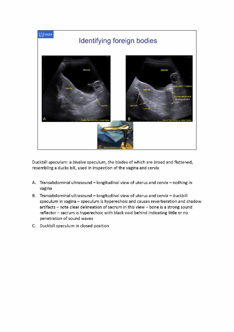
Duckbill speculum: a bivalve speculum, the blades of which are broad and flattened, resembling a ducks bill, used in inspection of the vagina and cervix
A. Transabdominal ultrasound - longitudinal view of uterus and cervix - nothing in vagina
B. Transabdominal ultrasound -longitudinal view of uterus and cervix -duckbill speculum in vagina -speculumis hyperechoic and causes reverberation and shadow artifacts - note clear delineation of sacrum in this view -boneis a strong sound reflector -sacrumis hyperechoic with black void behind indicating little or no penetration of sound waves
C. Duckbill speculum in closed position
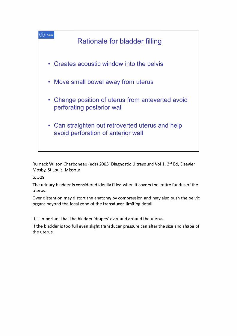
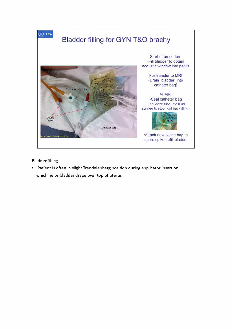
RumackWilson Charboneau (eds) 2005 Diagnostic Ultrasound Vol 1, 3rd Ed, Elsevier Mosby, St Louis, Missourip. 529The urinary bladder is considered ideally filled when it covers the entire fundus of the uterus.Over distention may distort the anatomy by compression and may also push the pelvic organs beyond the focal zone of the transducer, limiting detail.
It is important that the bladder ‘drapes' over and around the uterus.If the bladder is too full even slight transducer pressure can alter the size and shape of the uterus.
IAEA
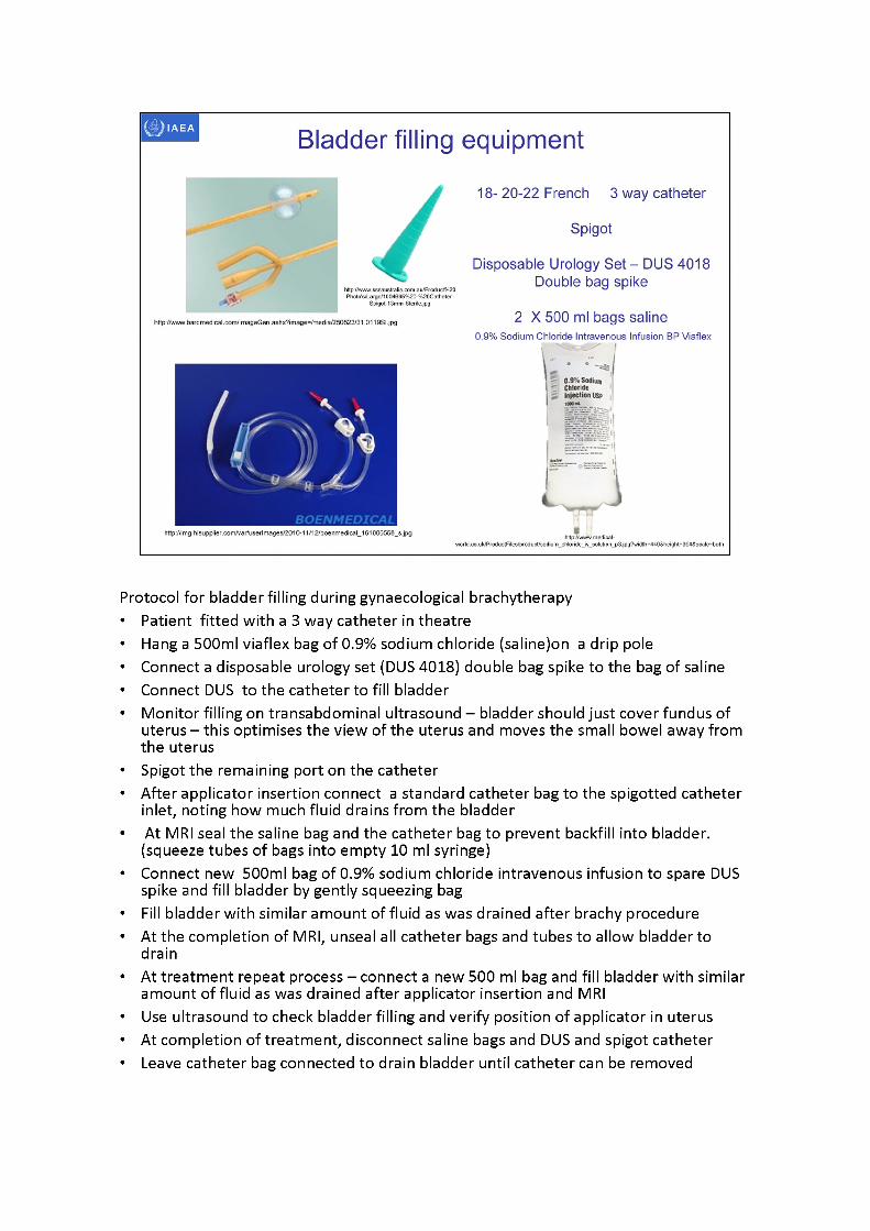
Bladder filling equipment
http://img.hisupplier.com/var/userlmages/20l0-11/12/boenmedical_161006568_s.jpg ■ 'http://www. medica I-
world.co.uk/ProductFites/product/sodium_chloride_iv_solution_p3.jpg?widlh=440Sheight=394S sea le= both
18- 20-22 French 3 way catheter
Spigot
Disposable Urology Set - DUS 4018 Double bag spike
2 X 500 ml bags saline0.9% Sodium Chloride Intravenous Infusion BP Viaflex
0.9% SodiumChlorideInjection
http;//www.bardmedical.com/lmageGen.ashx?image=/media/250523/31.0119Sl.jpg
http://wwwsssauslr.alia. com. au/Prod ucl%20 Photo's/Large/1004695%20-%20Catheter-
Spigot-13mm-Sterile.jpg
BOENMEDICAL
Protocol for bladder filling during gynaecological brachytherapy• Patient fitted with a 3 way catheter in theatre• Hang a 500ml viaflex bag of 0.9% sodium chloride (saline)on a drip pole• Connect a disposable urology set (DUS 4018) double bag spike to the bag of saline • Connect DUS to the catheter to fill bladder• Monitor filling on transabdominal ultrasound - bladder should just cover fundus of
uterus - this optimises the view of the uterus and moves the small bowel away from the uterus
• Spigot the remaining port on the catheter• After applicator insertion connect a standard catheter bag to the spigotted catheter
inlet, noting how much fluid drains from the bladder• At MRI seal the saline bag and the catheter bag to prevent backfill into bladder.
(squeeze tubes of bags into empty 10 ml syringe)• Connect new 500ml bag of 0.9% sodium chloride intravenous infusion to spare DUS
spike and fill bladder by gently squeezing bag• Fill bladder with similar amount of fluid as was drained after brachyprocedure• At the completion of MRI, unseal all catheter bags and tubes to allow bladder to
drain• At treatment repeat process - connect a new 500 ml bag and fill bladder with similar
amount of fluid as was drained after applicator insertion and MRI• Use ultrasound to check bladder filling and verify position of applicator in uterus• At completion of treatment, disconnect saline bags and DUS and spigot catheter• Leave catheter bag connected to drain bladder until catheter can be removed
IAEA
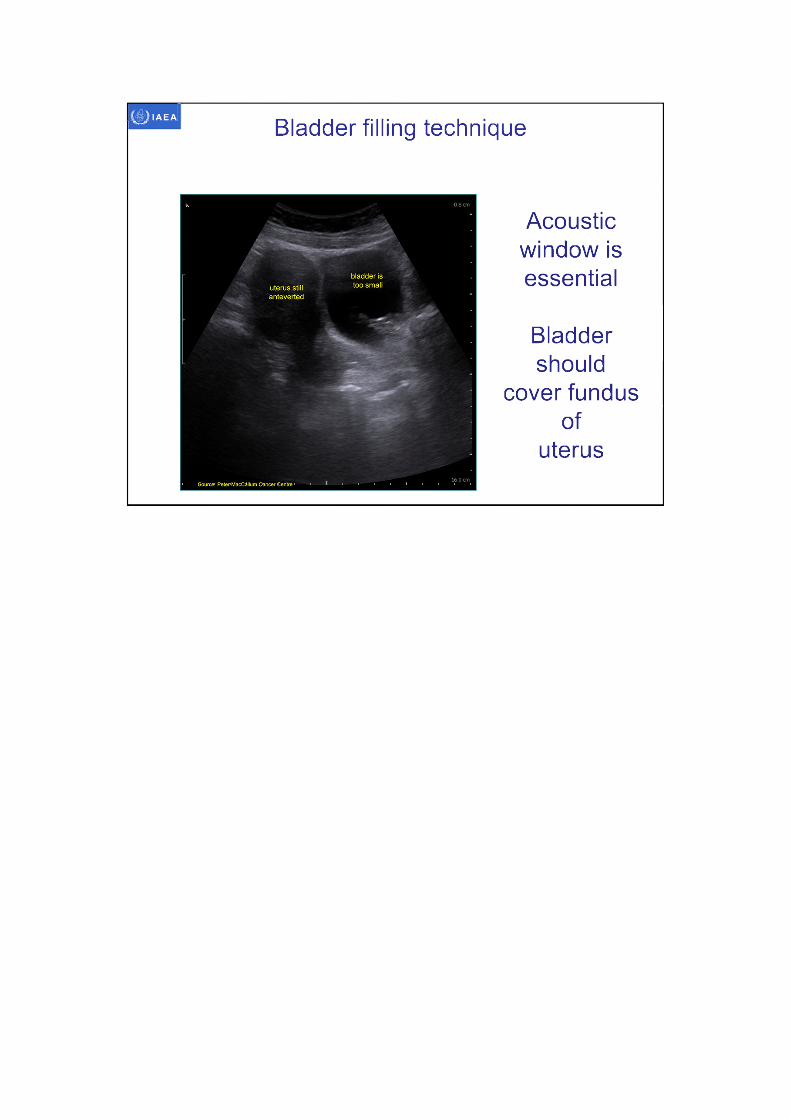
Bladder filling technique
Acoustic window is essential
Bladder should
cover fundus of
uterus
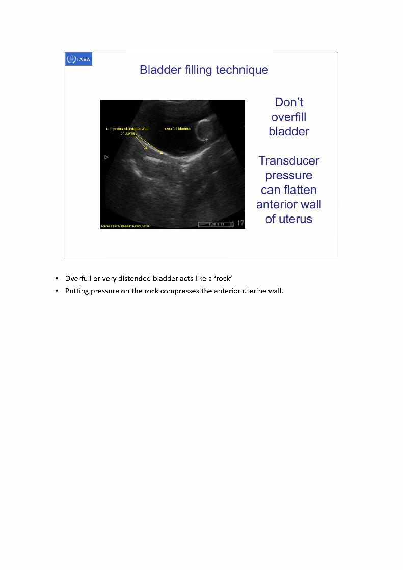
• Overfull or very distended bladder acts like a 'rock'• Putting pressure on the rock compresses the anterior uterine wall.
I Source: Peter MacCalluiTi Cancer'Cenlre
IAEA
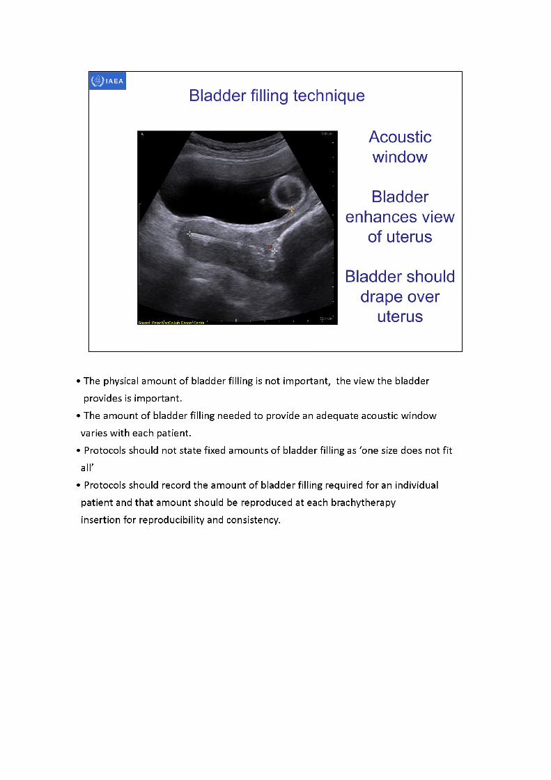
Acousticwindow
Bladder enhances view
of uterus
Bladder should drape over
uterus
Bladder filling technique
•Thephysical amount of bladder filling is not important, the view the bladder provides is important.
•Theamount of bladder filling needed to provide an adequate acoustic window varies with each patient.
•Protocolsshould not state fixed amounts of bladder filling as 'one size does not fit all'
•Protocolsshould record the amount of bladder filling required for an individual patient and that amount should be reproduced at each brachytherapy insertion for reproducibility and consistency.
Double
Peter MacCallum Cancer Centre
IAEA
Bladder filling for GYN T&O brachy
Start of procedure •Fill bladder to obtain
acoustic window into pelvis
For transfer to MRI •Drain bladder (into
catheter bag)
At MRI•Seal catheter bag
( squeeze tube intolOml syringe to stop fluid backfilling)
•Attach new saline bag to ‘spare spike’ refill bladder
Catheter tube
spike
Catheter
• i Tubes in : 10 ml
syringe
Bladder filling• Patient is often in slight Trendelenberg position during applicator insertion
which helps bladder drape over top of uterus
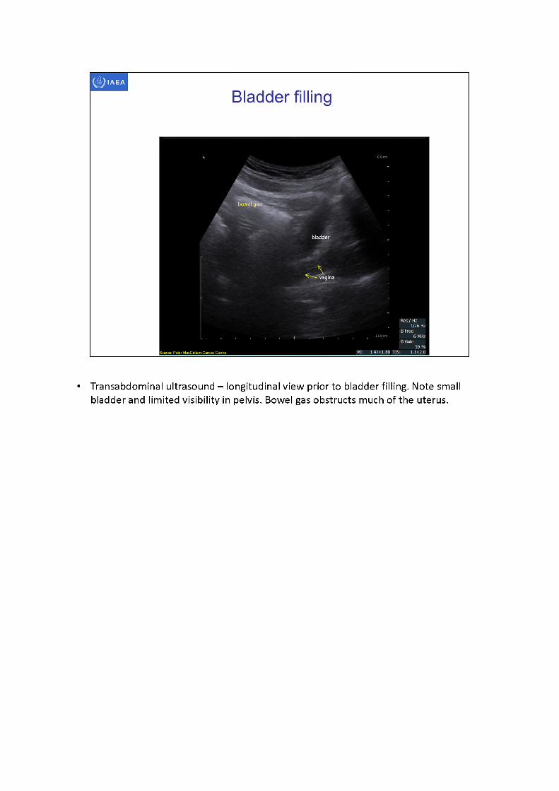
• Transabdominal ultrasound - longitudinal view prior to bladder filling. Note small bladder and limited visibility in pelvis. Bowel gas obstructs much of the uterus.
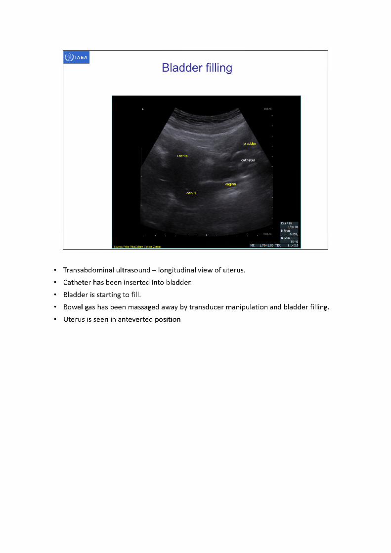
• Transabdominal ultrasound -longitudinal view of uterus.• Catheter has been inserted into bladder.• Bladder is starting to fill.• Bowel gas has been massaged away by transducer manipulation and bladder filling.• Uterus is seen in anteverted position
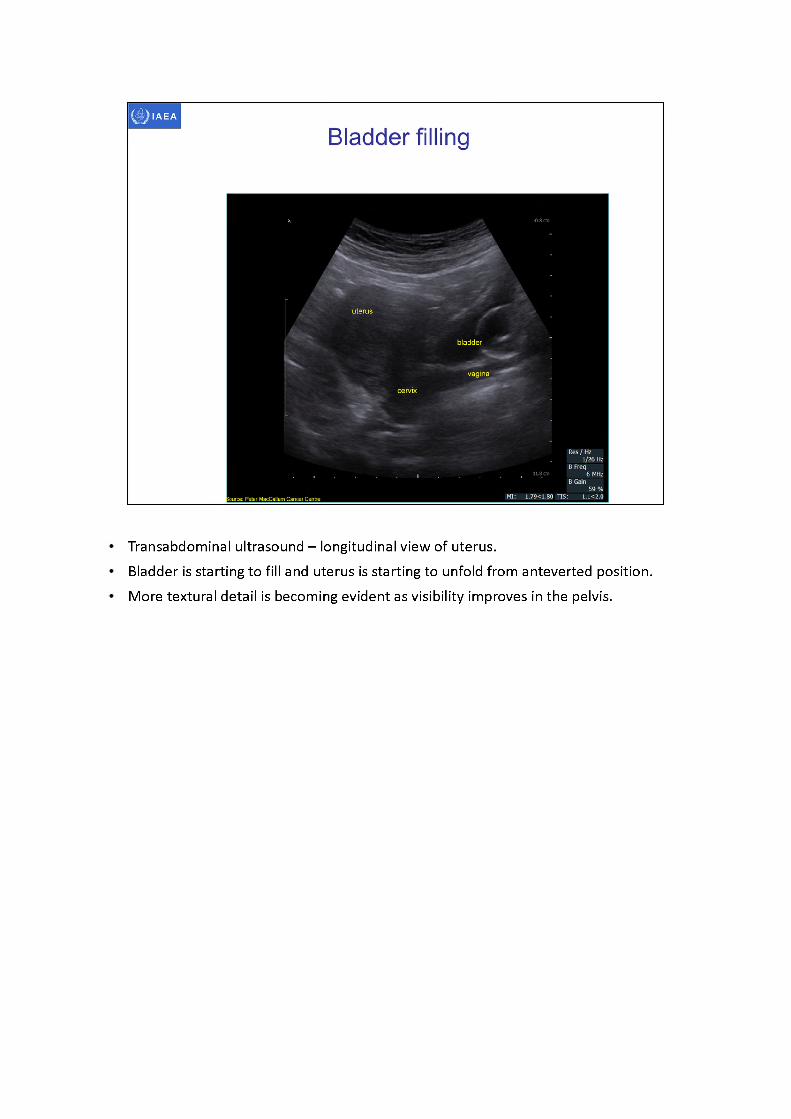
Transabdominal ultrasound -longitudinal view of uterus.Bladder is starting to fill and uterus is starting to unfold from anteverted position. More textural detail is becoming evident as visibility improves in the pelvis.
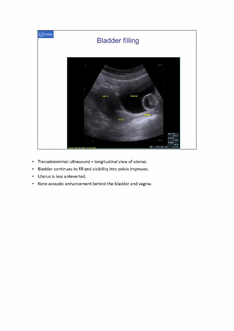
• Transabdominal ultrasound -longitudinal view of uterus.• Bladder continues to fill and visibility into pelvis improves.• Uterus is less anteverted.• Note acoustic enhancement behind the bladder and vagina.
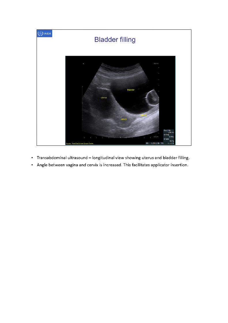
Transabdominal ultrasound - longitudinal view showing uterus and bladder filling. Angle between vagina and cervix is increased. This facilitates applicator insertion.
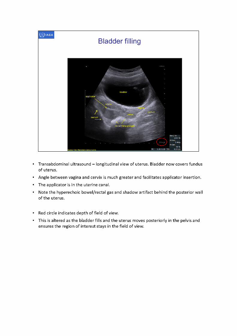
• Transabdominal ultrasound -longitudinal view of uterus. Bladder now covers fundus of uterus.
• Angle between vagina and cervix is much greater and facilitates applicator insertion.• The applicator is in the uterine canal.• Note the hyperechoic bowel/rectal gas and shadow artifact behind the posterior wall
of the uterus.
Red circle indicates depth of field of view.This is altered as the bladder fills and the uterus moves posteriorly in the pelvis and ensures the region of interest stays in the field of view.

Bladder filling not only provides an acoustic window into the pelvis through which to view the cervix and uterus, it also pushes the bowel away from the uterus.Maintaining bladder filling during treatment can limit the radiation dose received by the bowel.
A. Transabdominal ultrasound -longitudinal view of uterus. Note small amount of bladder filling. The top of the uterus is obstructed by bowel
B. Transabdominal ultrasound -longitudinal view of uterus. Bladder filling increasing, fundus of uterus is now visible, there is far less bowel visible
C. Transabdominal ultrasound -longitudinal view of uterus. Bladder filling is sufficient to clearly view whole uterus.
D. Transabdominal ultraosund - longitudinal view of uterus. Optimal bladder filling giving clear line of site to uterus with applicator in-situ
Note how uterus moves deeper into the field of view as the bladder is filled.
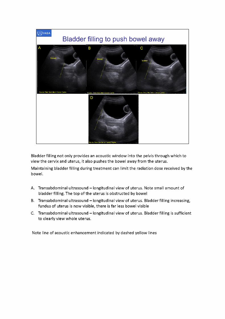
Bladder filling not only provides an acoustic window into the pelvis through which to view the cervix and uterus, it also pushes the bowel away from the uterus.Maintaining bladder filling during treatment can limit the radiation dose received by the bowel.
A. Transabdominal ultrasound -longitudinal view of uterus. Note small amount of bladder filling. The top of the uterus is obstructed by bowel
B. Transabdominal ultrasound -longitudinal view of uterus. Bladder filling increasing, fundus of uterus is now visible, there is far less bowel visible
C. Transabdominal ultrasound -longitudinal view of uterus. Bladder filling is sufficient to clearly view whole uterus.
Note line of acoustic enhancement indicated by dashed yellow lines
IAEA
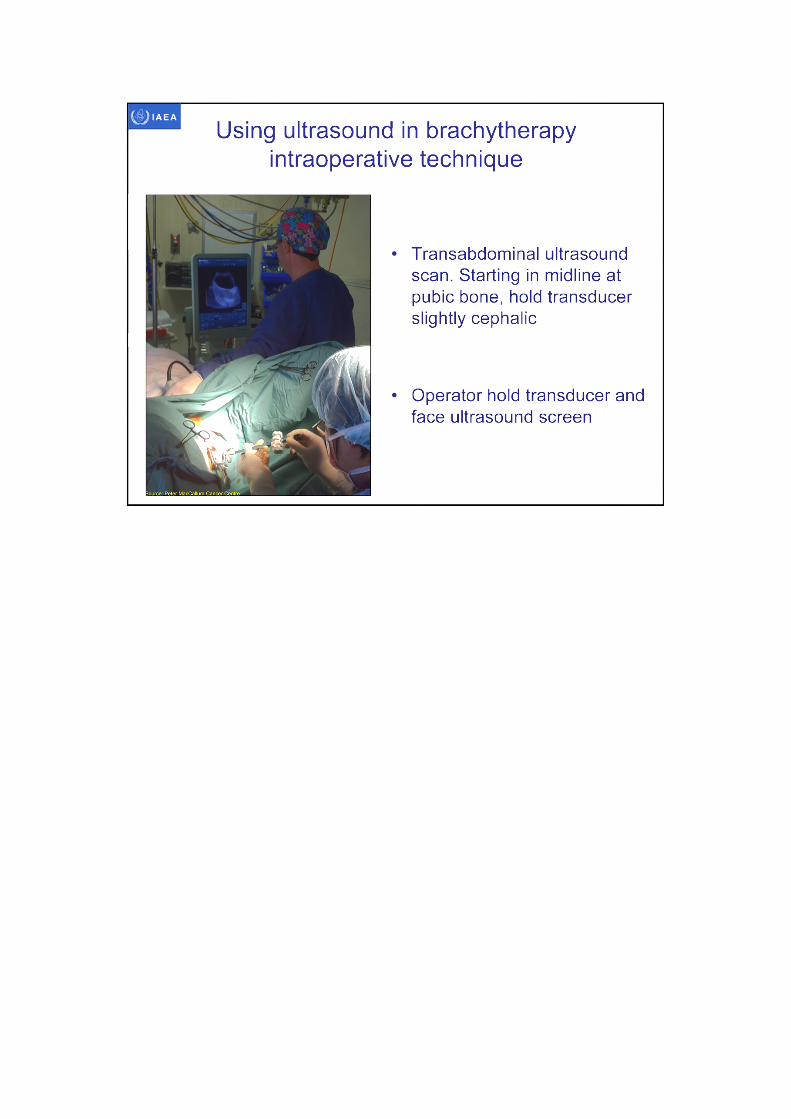
Using ultrasound in brachytherapy intraoperative technique
Transabdominal ultrasound scan. Starting in midline at pubic bone, hold transducer slightly cephalic
Operator hold transducer and face ultrasound screen

Transabdominal ultrasound orientationwith applicators in-situ
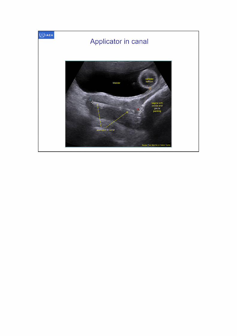
Longitudinal view of applicator in uterine canal.The whole applicator must be identified to ensure the correctplane is being viewed. Calipers can be used to confirm the
whole applicator is identified.
• Uterus may not be in true anatomical sagittal plane• Sonographer must find the uterine canal to guide the applicator into place• Once the applicator position is confirmed the sonographer can use the applicator as a
fiducial marker and obtain longitudinal views of the applicator within the uterus
bladder
bowel
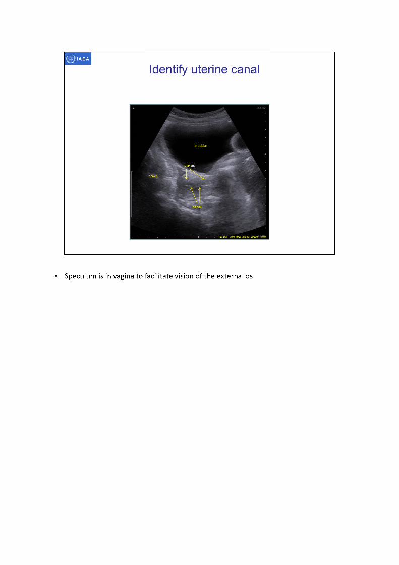
Identify uterine canal
uterus
, Source: Peter M^Calluqi CancfrCeritre
• Speculum is in vagina to facilitate vision of the external os
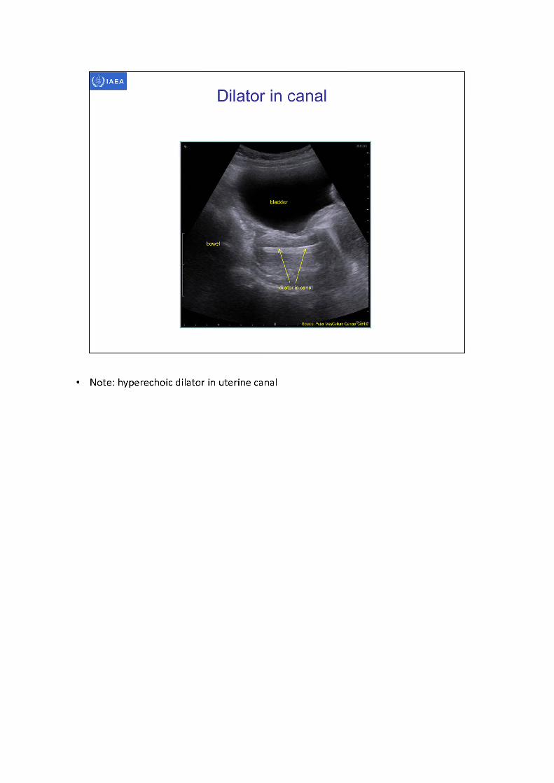
• Note: hyperechoic dilator in uterine canal
IAEA
Applicator in canal
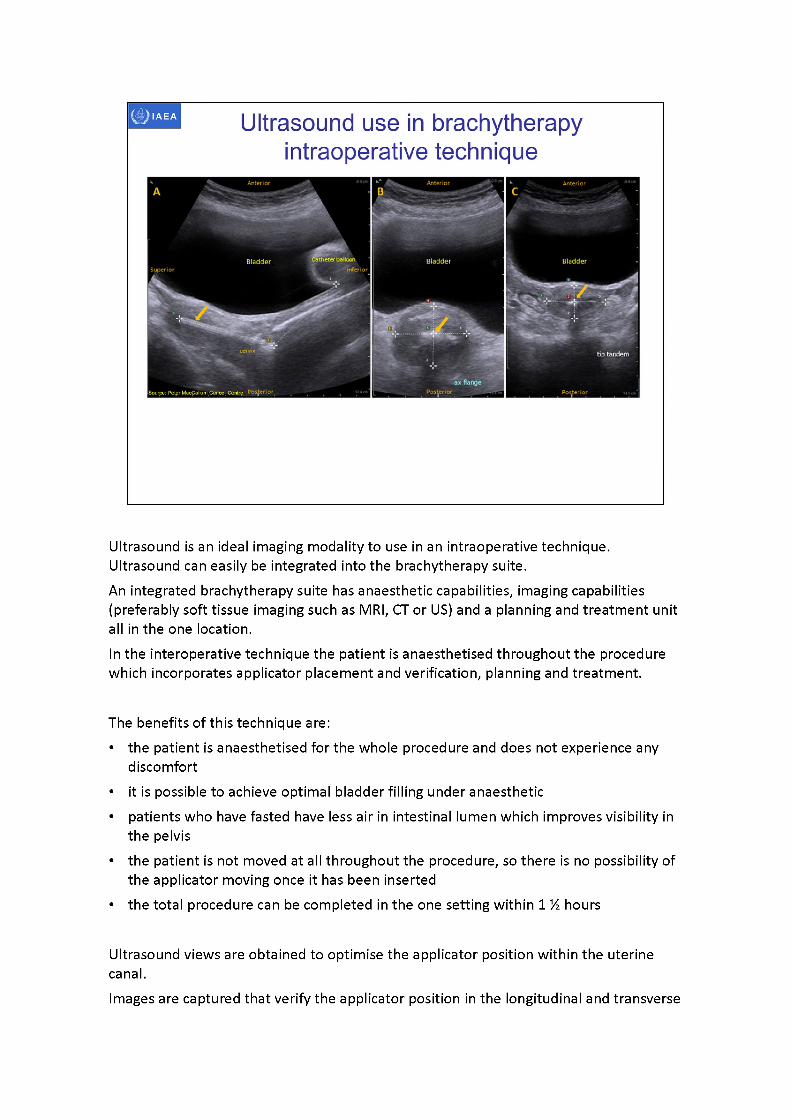
Anterior Anterior Anterior
Bladder BladderBladder■'inferior
cenzix tip tandem
Ultrasound use in brachytherapy intraoperative technique
Ultrasound is an ideal imaging modality to use in an intraoperative technique. Ultrasound can easily be integrated into the brachytherapy suite.An integrated brachytherapy suite has anaesthetic capabilities, imaging capabilities (preferably soft tissue imaging such as MRI, CT or US) and a planning and treatment unit all in the one location.In the interoperative technique the patient is anaesthetised throughout the procedure which incorporates applicator placement and verification, planning and treatment.
The benefits of this technique are:• the patient is anaesthetised for the whole procedure and does not experience any
discomfort• it is possible to achieve optimal bladder filling under anaesthetic• patients who have fasted have less air in intestinal lumen which improves visibility in
the pelvis• the patient is not moved at all throughout the procedure, so there is no possibility of
the applicator moving once it has been inserted• the total procedure can be completed in the one setting within 1 % hours
Ultrasound views are obtained to optimise the applicator position within the uterine canal.Images are captured that verify the applicator position in the longitudinal and transverse

planes of the uterus.Yellow arrow indicates applicator
A. Transabdominal ultrasound -longitudinal view of applicator in uterine canal.B. Transabdominal ultrasound -axialview of external os/upper vagina at cervical
stopper. Note shadow artifact behind hyperechoic applicator.C. Transabdominal ultrasound -axialview of uterus at tip of applicator
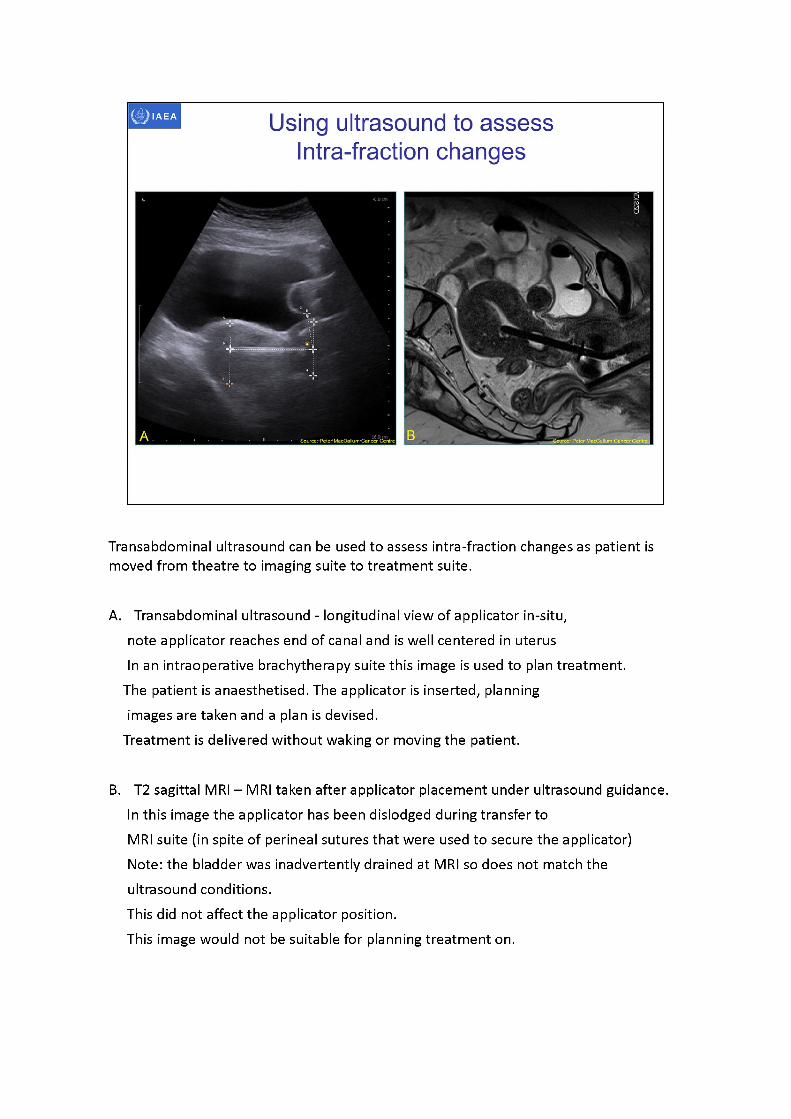
Transabdominal ultrasound can be used to assess intra-fraction changes as patient is moved from theatre to imaging suite to treatment suite.
A. Transabdominal ultrasound - longitudinal view of applicator in-situ, note applicator reaches end of canal and is well centered in uterusIn an intraoperative brachytherapy suite this image is used to plan treatment.
The patient is anaesthetised. The applicator is inserted, planning images are taken and a plan is devised.
Treatment is delivered without waking or moving the patient.
B. T2 sagittal MRI - MRI taken after applicator placement under ultrasound guidance.In this image the applicator has been dislodged during transfer toMRI suite (in spite of perineal sutures that were used to secure the applicator) Note: the bladder was inadvertently drained at MRI so does not match the ultrasound conditions.This did not affect the applicator position.This image would not be suitable for planning treatment on.
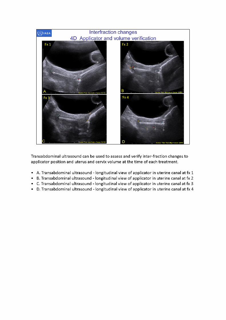
Transabdominal ultrasound can be used to assess and verify inter-fraction changes to applicator position and uterus and cervix volume at the time of each treatment.
•A. Transabdominal ultrasound - longitudinal view of applicator in uterine canal at fx1 •B. Transabdominal ultrasound - longitudinal view of applicator in uterine canal at fx2 •C. Transabdominal ultrasound - longitudinal view of applicator in uterine canal at fx 3 •D. Transabdominal ultrasound - longitudinal view of applicator in uterine canal at fx 4
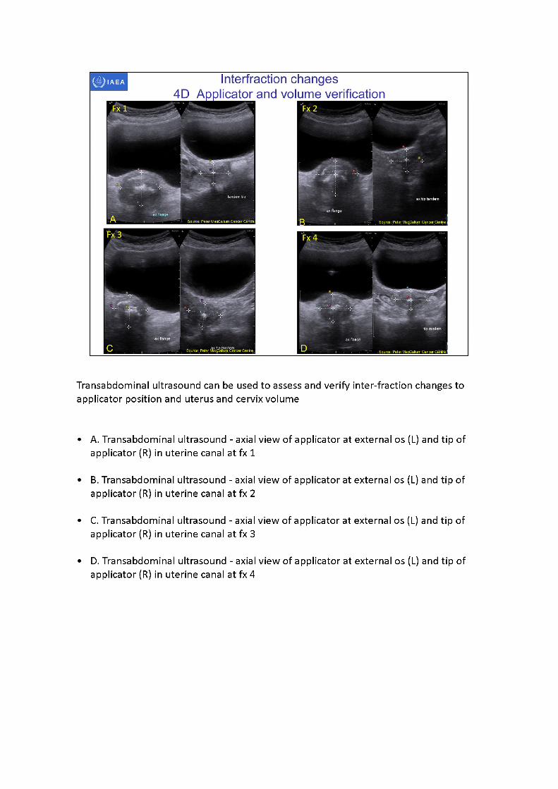
Transabdominal ultrasound can be used to assess and verify inter-fraction changes to applicator position and uterus and cervix volume
•A. Transabdominal ultrasound - axial view of applicator at external os (L) and tip of applicator (R) in uterine canal at fx1
•B. Transabdominal ultrasound - axial view of applicator at external os (L) and tip of applicator (R) in uterine canal at fx2
•C. Transabdominal ultrasound - axial view of applicator at external os (L) and tip of applicator (R) in uterine canal at fx3
•D. Transabdominal ultrasound - axial view of applicator at external os (L) and tip of applicator (R) in uterine canal at fx4
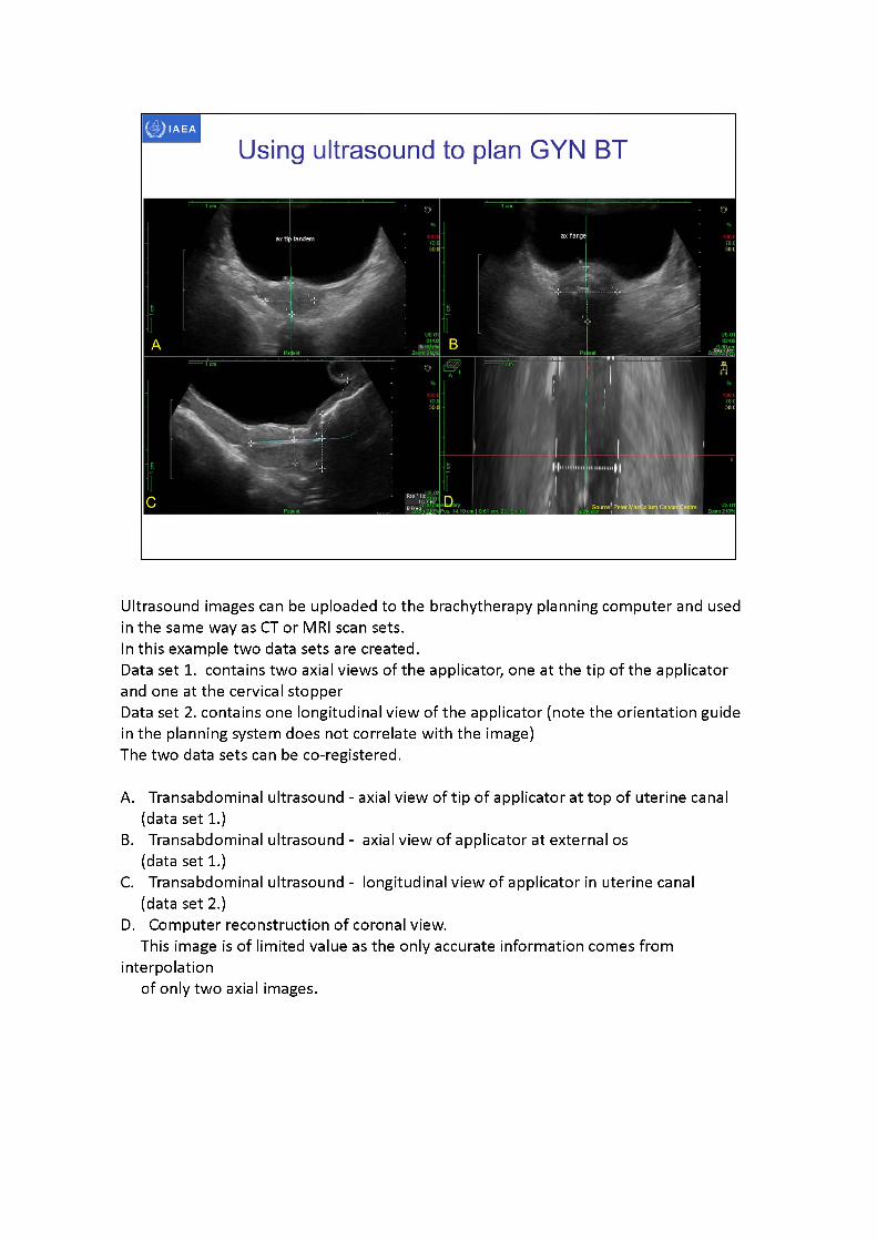
Ultrasound images can be uploaded to the brachytherapy planning computer and used in the same way as CT or MRI scan sets.In this example two data sets are created.Data set 1. contains two axial views of the applicator, one at the tip of the applicator and one at the cervical stopperData set 2. contains one longitudinal view of the applicator (note the orientation guidein the planning system does not correlate with the image)The two data sets can be co-registered.
A. Transabdominal ultrasound - axial view of tip of applicator at top of uterine canal (data set 1.)
B. Transabdominal ultrasound - axial view of applicator at external os (data set 1.)
C. Transabdominal ultrasound - longitudinal view of applicator in uterine canal (data set 2.)
D. Computer reconstruction of coronal view.This image is of limited value as the only accurate information comes from
interpolationof only two axial images.
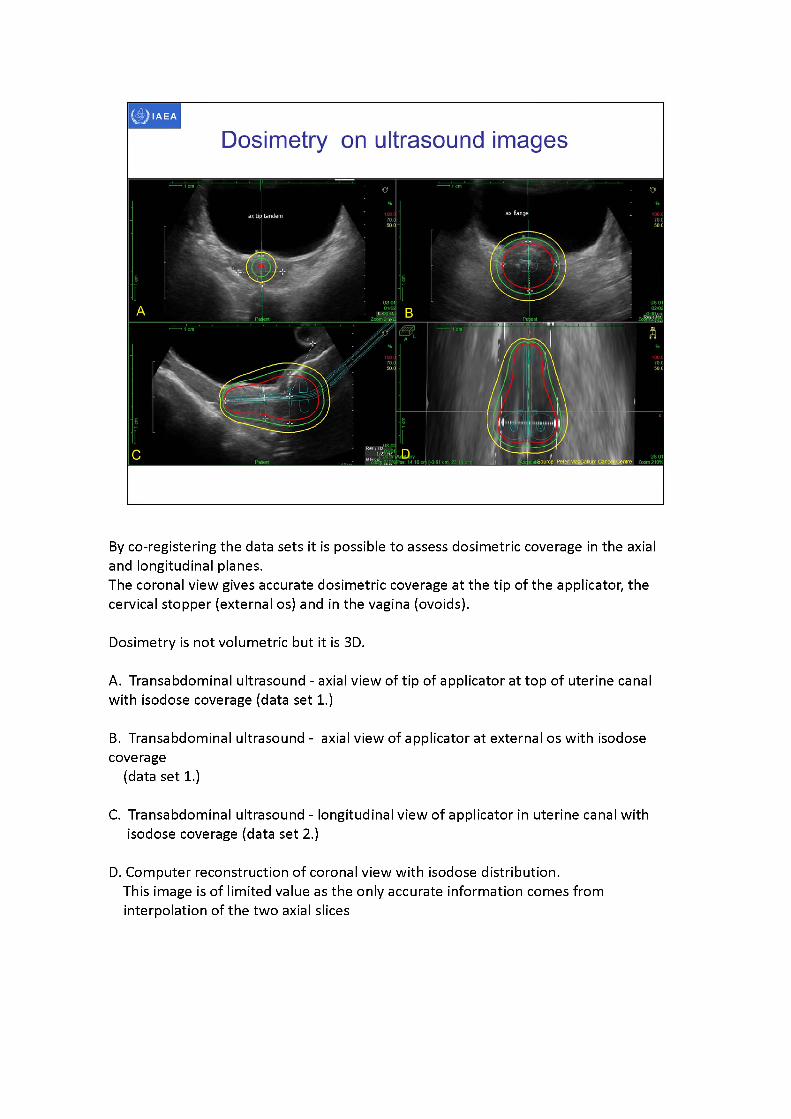
By co-registering the data sets it is possible to assess dosimetric coverage in the axial and longitudinal planes.The coronal view gives accurate dosimetric coverage at the tip of the applicator, the cervical stopper (external os) and in the vagina (ovoids).
Dosimetry is not volumetric but it is 3D.
A. Transabdominal ultrasound - axial view of tip of applicator at top of uterine canal with isodose coverage (data set 1.)
B. Transabdominal ultrasound - axial view of applicator at external os with isodose coverage
(data set 1.)
C. Transabdominal ultrasound - longitudinal view of applicator in uterine canal with isodose coverage (data set 2.)
D. Computer reconstruction of coronal view with isodose distribution.This image is of limited value as the only accurate information comes from interpolation of the two axial slices
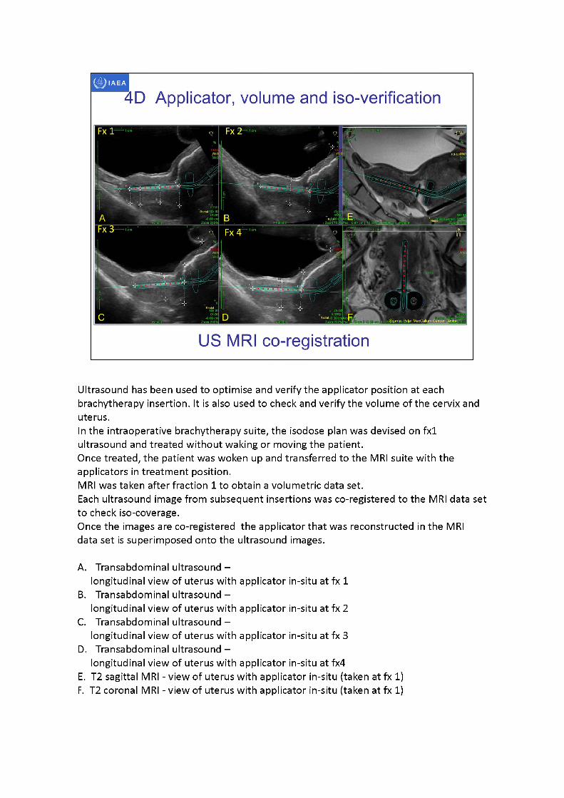
Ultrasound has been used to optimise and verify the applicator position at each brachytherapy insertion. It is also used to check and verify the volume of the cervix and uterus.In the intraoperative brachytherapy suite, the isodose plan was devised on fx1 ultrasound and treated without waking or moving the patient.Once treated, the patient was woken up and transferred to the MRI suite with the applicators in treatment position.MRI was taken after fraction 1 to obtain a volumetric data set.Each ultrasound image from subsequent insertions was co-registered to the MRI data set to check iso-coverage.Once the images are co-registered the applicator that was reconstructed in the MRI data set is superimposed onto the ultrasound images.
A. Transabdominal ultrasound -longitudinal view of uterus with applicator in-situ at fx 1
B. Transabdominal ultrasound -longitudinal view of uterus with applicator in-situ at fx 2
C. Transabdominal ultrasound -longitudinal view of uterus with applicator in-situ at fx 3
D. Transabdominal ultrasound -longitudinal view of uterus with applicator in-situ at fx4
E. T2 sagittal MRI - view of uterus with applicator in-situ (taken at fx1)F. T2 coronal MRI - view of uterus with applicator in-situ (taken at fx1)
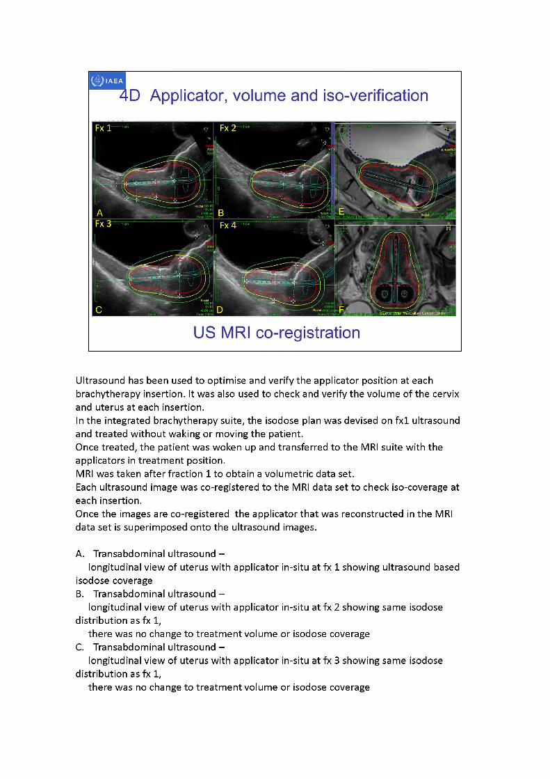
ICItU3i8.'pl
4D Applicator, volume and iso-verification
US MRI co-registration
Ultrasound has been used to optimise and verify the applicator position at each brachytherapy insertion. It was also used to check and verify the volume of the cervix and uterus at each insertion.In the integrated brachytherapy suite, the isodose plan was devised on fx1 ultrasound and treated without waking or moving the patient.Once treated, the patient was woken up and transferred to the MRI suite with the applicators in treatment position.MRI was taken after fraction 1 to obtain a volumetric data set.Each ultrasound image was co-registered to the MRI data set to check iso-coverage at each insertion.Once the images are co-registered the applicator that was reconstructed in the MRI data set is superimposed onto the ultrasound images.
A. Transabdominal ultrasound -longitudinal view of uterus with applicator in-situ at fx 1 showing ultrasound based
isodose coverageB. Transabdominal ultrasound -
longitudinal view of uterus with applicator in-situ at fx 2 showing same isodose distribution as fx1,
there was no change to treatment volume or isodose coverageC. Transabdominal ultrasound -
longitudinal view of uterus with applicator in-situ at fx 3 showing same isodose distribution as fx1,
there was no change to treatment volume or isodose coverage
D. Transabdominal ultrasound -longitudinal view of uterus with applicator in-situ at fx4 showing same isodose
distribution as fx 1,there was no change to treatment volume or isodose coverage
E. T2 sagittal MRI - view of uterus with applicator (taken at fx 1)Isodose coverage was devised on ultrasound and back projected onto MRI after treatment had been delivered
F. T2 coronal MRI - view of uterus with applicator (taken at fx 1)Isodose coverage was devised on ultrasound and back projected onto MRI after treatment had been delivered.Even though it is not possible to take a coronal view with 2D ultrasound a reasonable
assessment can be made of theuterus and cervix width and the parametrium at the time of scanning.This assessment is intuitively considered when planning treatment.
IAEA
3D image-based female pelvis anatomy by Ultrasound (US)
• Overview of ultrasound• Normal female pelvic anatomy• Sonographic techniques - image orientation• Normal sonographic anatomy• Anatomical variations• Common pathologies• Using ultrasound in brachytherapy• Future - 3D ultrasound
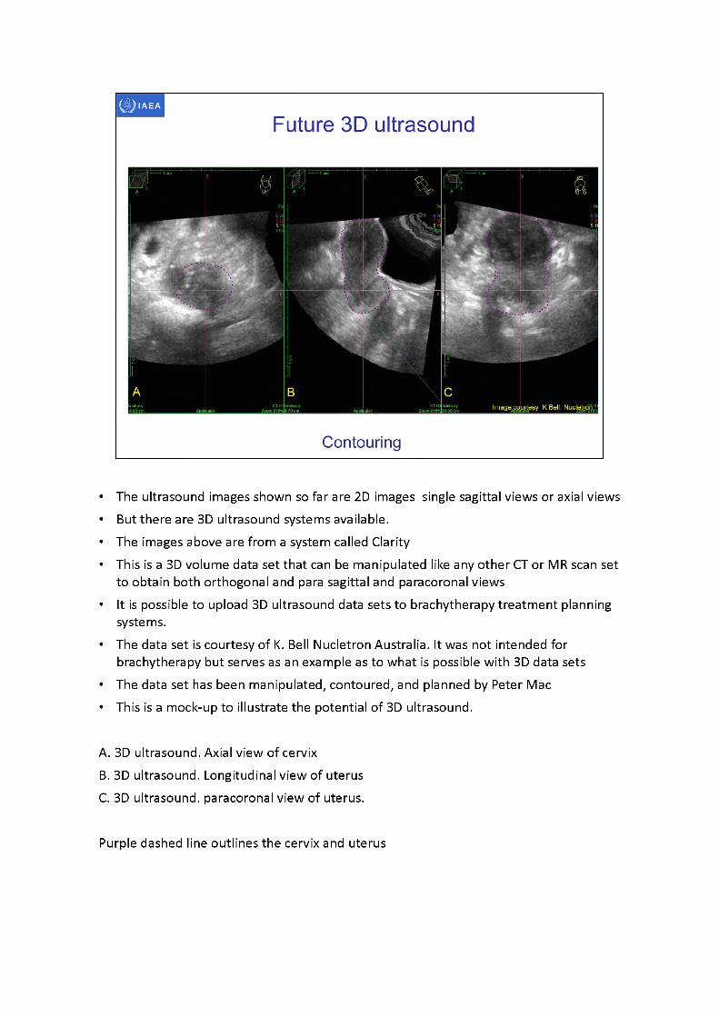
• The ultrasound images shown so far are 2D images single sagittal views or axial views• But there are 3D ultrasound systems available.• The images above are from a system called Clarity• This is a 3D volume data set that can be manipulated like any other CT or MR scan set
to obtain both orthogonal and para sagittal and paracoronal views• It is possible to upload 3D ultrasound data sets to brachytherapy treatment planning
systems.• The data set is courtesy of K. Bell Nucletron Australia. It was not intended for
brachytherapy but serves as an example as to what is possible with 3D data sets• The data set has been manipulated, contoured, and planned by Peter Mac• This is a mock-up to illustrate the potential of 3D ultrasound.
A. 3D ultrasound. Axial view of cervixB. 3D ultrasound. Longitudinal view of uterusC. 3D ultrasound. paracoronal view of uterus.
Purple dashed line outlines the cervix and uterus
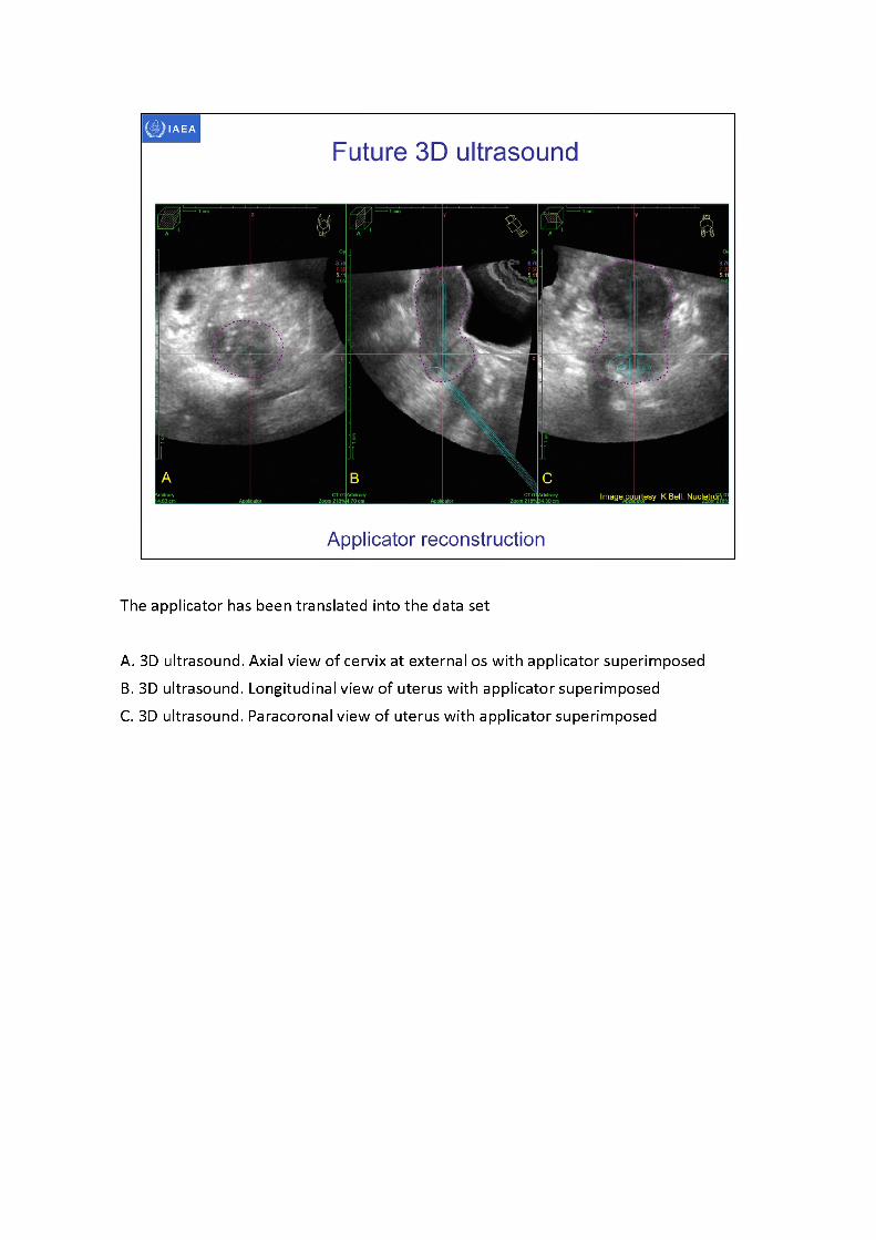
The applicator has been translated into the data set
A. 3D ultrasound. Axial view of cervix at external os with applicator superimposedB. 3D ultrasound. Longitudinal view of uterus with applicator superimposedC. 3D ultrasound. Paracoronal view of uterus with applicator superimposed
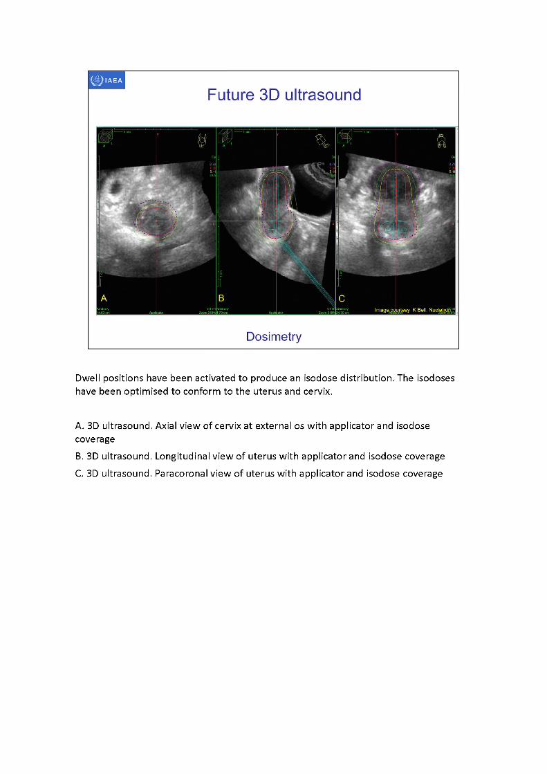
Dwell positions have been activated to produce an isodose distribution. The isodoses have been optimised to conform to the uterus and cervix.
A. 3D ultrasound. Axial view of cervix at external os with applicator and isodose coverageB. 3D ultrasound. Longitudinal view of uterus with applicator and isodose coverageC. 3D ultrasound. Paracoronal view of uterus with applicator and isodose coverage
IAEA
Bibliography
• ABU-ZIDAN, F.M., HEFNY, A.F., CORR, P., Clinical ultrasound physics, J Emerg. Trauma Shock 4 (2011)501-503.
• ALLAN, P., BAXTER, G., WESTON, M., Clinical Ultrasound, Third Edition, Churchill Livingstone Elsevier, Edinburgh (2011).
• BALTAROWICH, O.H., KURTZ, A.B., PENNELL, R.G., NEEDLEMAN, L„ VILARO, M.M., and GOLDBERG, B.B., Pitfalls in the sonographic diagnosis of uterine fibroids, Am. J. Roentgenol. 151 (1988) 725-728.
• BENACERRAF, B.R., SHIPP, T.D., BROMLEY, B., Which Patients Benefit from a 3D Reconstructed Coronal View of the Uterus Added to Standard Routine 2D Pelvic Sonography? Am. J. Roentgenol. 190 (2008) 626-629.
• BOSS, E. A., BARENTSZ, J. 0., MASSUGER, L. F„ BOONSTRA, H„ The role of MR imaging in invasive cervical carcinoma, Eur. Radiol. 10 (2000) 256-270.
• BRODY, J.M., KOELLIKER, S.L., FRISHMAN, G.N., Unicornuate uterus: imaging appearance, associated anomalies, and clinical implications, Am. J. Roentgenol. 171 (1998) 1341-1347.
• CAOILI, E.M., HERTZBERG, B.S., KLIEWER, M.A., DELONG, D„ BOWIE, J.D., Refractory shadowing from pelvic masses on sonography: a useful diagnostic sign for uterine leiomyomas, Am. J.Roentgenol. 174 (2000) 97-101.
• CIBULA, D„ ABU-RUSTUM, N.R., BENEDETTI-PANICI, P„ KAHLER, C„ RASPAGLIESI, F„ QUERLEU, D., and MORROW, C.P. (2011). New classification system of radical hysterectomy: Emphasis on a three-dimensional anatomic template for parametrial resection. Gynecologic Oncology 122, 264-268.

IAEA
Bibliography
• DAVIDSON, M.T., et al., Optimization of high-dose-rate cervix brachytherapy applicator placement: the benefits of intraoperative ultrasound guidance, Brachytherapy 7 (2008) 248-53.
• DIMOPOULOS, J. C., et al., Systematic evaluation of MRI findings in different stages of treatment of cervical cancer: potential of MRI on delineation of target, pathoanatomic structures, and organs at risk, Int. J. Radiat. Oncol. Biol. Phys. 64 (2006) 1380-1388.
• DIMOPOULOS, J. C., et al., Inter-observer comparison of target delineation for MRI-assisted cervical cancer brachytherapy: application of the GYN GEC-ESTRO recommendations, Radiother. Oncol. 91 (2009) 166-172.
• FISCHEROVA, D., et al., Use of transrectal ultrasound and magnetic resonance imaging in the staging of early-stage cervical cancer, Ceska. Gynekol. 74 (2009) 323-329.
• FISCHEROVA, D. Ultrasound scanning of the pelvis and abdomen for staging of gynecological tumors: a review. Ultrasound Obstet. Gynecol. 38 (2011)246-266.
• GENT, R., Applied Physics and Technology of Diagnostic Ultrasound, Milner Publishing, Prospect, South Australia (1997).
• HANGIANDREOU, N.J., AAPM/RSNA physics tutorial for residents. Topics in US: B-mode US: basic concepts and new technology, Radiographics 23 (2003) 1019-1033.
• HINDI, A., PETERSON, C., BARR, R., Artifacts in diagnostic ultrasound, Reports in Medical Imaging 6 (2013) 29-48.
• IHNATSENKA, B., BOEZAART, A.P., Ultrasound: Basic understanding and learning the language, Int. J Shoulder Surg. 4 (2010) 55-62.
• LEIBMAN, A.J., KRUSE, B., MCSWEENEY, M.B., Transvaginal sonography: comparison with transabdominal sonography in the diagnosis of pelvic masses, Am. J. Roentgenol. 151 (1988) 89-92.
IAEA
Bibliography
MAHANTSHETTY, U., et al., Trans-abdominal ultrasound (US) and magnetic resonance imaging (MRI) correlation for conformal intracavitary brachytherapy in carcinoma of the uterine cervix, Radiother. Oncol. 102 (2012)130-134.MICHELETTI, R. G„ FISHBEIN, G. A., CURRIER, J. S., FISHBEIN, M. C„ Monckeberg sclerosis revisited: a clarification of the histologic definition of Monckeberg sclerosis, Arch. Pathol. Lab. Med. 132 (2008) 43-47.MOORE, K. L., PERSAUD, T. V. N., TORCHIA, M. G., The developing human: clinically oriented embryology (9th ed.), Saunders, Philadelphia (2011).NARAYAN, K„ VAN DYK, S„ BERNSHAW, D„ RAJASOORIYAR, C„ KONDALSAMY-CHENNAKESAVAN, S., Comparative study of LDR (Manchester system) and HDR image-guided conformal brachytherapy of cervical cancer: patterns of failure, late complications, and survival, Int. J. Radiat. Oncol. Biol. Phys. 74 (2009) 1529-1535.PARK, M.J., KIM, Y.S., RHIM, H., LIM, H.K., Technique to displace bowel loops in MRI-guided high- intensity focused ultrasound ablation of fibroids in the anteverted or anteflexed uterus, Am. J. Roentgenol. 201 (2013) W761-W764.PINKAVOVA, I., et al., Transrectal ultrasound and magnetic resonance imaging in the evaluation of tumor size following neoadjuvant chemotherapy for locally advanced cervical cancer, Ultrasound Obstet. Gynecol. 42 (2013) 705-712.RUMACK, C„ WILSON, S„ CHARBONEAU, J. (eds), Diagnostic Ultrasound, Third Edition, Elsevier Mosby, St Louis (2005).SITES, B.D., et al., Artifacts and pitfall errors associated with ultrasound-guided regional anesthesia. Part I: understanding the basic principles of ultrasound physics and machine operations, Reg Anesth. Pain Med. 32 (2007)412-418.
IAEA
Bibliography
• SITES, B.D., et al., Artifacts and pitfall errors associated with ultrasound-guided regional anesthesia: Part ILA pictorial approach to understanding and avoidance, Reg Anesth. Pain Med. 35 (2010) S81- S92.
• TROIANO, R.N., MCCARTHY, S., Mullerian duct anomalies: Imaging and clinical issues. Radiology 233 (2004)19-34.
• VAN DYK, S., BERNSHAW, D., Ultrasound-based conformal planning for gynaecological brachytherapy, J. Med. Imaging Radiat. Oncol. 52 (2008) 77-84.
• VAN DYK, S„ NARAYAN, K„ FISHER, R„ BERNSHAW, D„ Conformal brachytherapy planning for cervical cancer using transabdominal ultrasound, Int. J Radiat. Oncol. Biol. Phys. 75 (2009) 64-70.
• VAN DYK, S„ KONDALSAMY-CHENNAKESAVAN, S., SCHNEIDER, M., BERNSHAW, D.,NARAYAN, K., Comparison of measurements of the uterus and cervix obtained by magnetic resonance and transabdominal ultrasound imaging to identify the brachytherapy target in patients with cervix cancer, Int. J. Radiat. Oncol. Biol. Phys. 88 (2014) 860-865.
• WAGNER, B.J., WOODWARD, P.J., Magnetic resonance evaluation of congenital uterine anomalies, Semin. Ultrasound CT MR 15 (1994)4-17.
• WATKINS, J.M., KEARNEY, P.L., OPFERMANN, K.J., ACKERMAN, S.J., JENRETTE, J.M., KOHLER, M.F., Ultrasound-guided tandem placement for low-dose-rate brachytherapy in advanced cervical cancer minimizes risk of intraoperative uterine perforation. Ultrasound Obstet. Gynecol. 37 (2011) 241- 244.
• ZALUD, I., ROCHA, F., Artifacts, pitfalls and normal variants, Donald School Journal of Ultrasound in Obstetrics and Gynecology 6 (2012) 1-8.