
3D Digitizing Strategy Planning Approach Based on a CAD Model
10
William Derigent e-mail: [email protected] Emilie Chapotot Gabriel Ris CRAN, Research Center for Automatic Control of Nancy, CNRS UMR 7039, Université Henri Poincaré, Nancy I, Faculté des Sciences, BP 239, 54506 Vandoeuvre-lès-Nancy Cedex, France Sébastien Remy ICD, Charles Delaunay Institute, Université de Technologie de Troyes, 12, rue Marie Curie, BP 2060, 10010 Troyes Cedex, France Alain Bernard IRCCyN, Communication and Cybernetic Research Institute of Nantes, CNRS UMR 6597, Centrale Nantes, 1 rue de la Noë, BP 92101, 44321 Nantes Cedex 3, France 3D Digitizing Strategy Planning Approach Based on a CAD Model The objective of this paper is to describe a new method to determine the three- dimensional (3D) digitizing strategy for a computer aided design (CAD) known mechani- cal part by using a plane laser sensor. The Research Centre for Automatic control in Nancy, France has initiated a project to create an automatic 3D digitizing system. Pre- vious papers focused on the visibility determinations using spherical geometry in a three axis environment. Here, the latest developments are presented. They enable one to im- prove this approach by taking into account a five axis environment. Using a new ap- proach based on the Minkovsky operations to calculate the visibility of the different face of the B-Rep model of the part, the minimum set of directions required to entirely digitize the part is computed. DOI: 10.1115/1.2410023 Keywords: automatic digitizing, visibility calculation, scanning strategy 1 Introduction Nowadays, three-dimensional 3D digitizing cells appear in many factories as useful tools in domains like geometric and di- mensional inspections and reverse engineering. This tool is gen- erally used to obtain a numerical view of a given physical part. However, the digitization process involves repetitive human tasks, which are time consuming and prone to inaccuracy. In the geo- metric and dimensional inspections domain, the computer aided design CAD model of the part is usually available. This CAD model can be a base to the determination of the digitizing strategy, as an analogy to the machining strategy in CAM. The Research Centre for Automatic control in Nancy CRAN, France has initi- ated a project to propose an automatic 3D digitizing system for the geometric inspection of mechanical parts defined by their CAD model. Some previous papers 1–3 focused on determining the digi- tizing strategy for a part defined by a meshed surface, like a ste- reolithography STL model, for example. References 1,2 present different algorithms based on the visibility theory 4, adapted to the 3D digitizing domain. This digitizing environment was composed of a plane laser sensor integrated on a coordinate measuring machine allowing 3 degrees of freedom DOF, the three translations along the X, Y , and Z axis of the CMM. The result of this previous approach was the set of digitizing directions needed to completely digitize the part by taking into account the visibility of all the points of the surface. The main drawback of this approach is the high number of calculations due to the high number of triangles of the meshed model. In order to fix this problem, Ref. 3 presents a new way of computing the visibility of the different surfaces of a part. Instead of a triangle meshed surface, the part is represented by a B-Rep model composed of planar faces. This approximation can be applied. The visibility of every face is calculated using a new visibility approach where the cone of visibility is computed using Boolean operations. In this paper, this new visibility algorithm is implemented and used to determine the digitizing strategy. The objective of the present paper is to describe an improve- ment of the previous approach. Section 2 contains a review of related works. The advantages and drawbacks of each of these works are discussed. The global approach is then described in Sec. 3 and the new visibility calculation method and the determination of the digitizing strategy are presented in Secs. 4 and 5, respec- tively. Then, a discussion and a conclusion deal with the advan- tages and the drawbacks of this approach and present some future works. 2 Review of the Related Works As 3D digitizing is becoming important in the industrial world, this resource needs to be automated. Researchers deal with differ- ent cases. In the first one, the part that has to be digitized is known, by a CAD model for example, and the difficulty consists in determination of the digitizing strategy. In the second case, the part is unknown, e.g., a prototype or an old part, because no CAD Contributed by the Computer-Aided Product Development CAPD Committee of ASME for publication in the JOURNAL OF COMPUTING AND INFORMATION SCIENCE IN ENGINEERING. Manuscript received September 14, 2005; final manuscript received July 28, 2006. Guest Editor A. Fischer, R. Levi, D. Dutta, and E. Cohen 10 / Vol. 7, MARCH 2007 Copyright © 2007 by ASME Transactions of the ASME Downloaded 15 Sep 2011 to 193.49.161.206. Redistribution subject to ASME license or copyright; see http://www.asme.org/terms/Terms_Use.cfm
-
Upload
univ-lorraine -
Category
Documents
-
view
2 -
download
0
Transcript of 3D Digitizing Strategy Planning Approach Based on a CAD Model

William Derigente-mail: [email protected]
Emilie Chapotot
Gabriel Ris
CRAN,Research Center for Automatic Control of Nancy,
CNRS UMR 7039,Université Henri Poincaré,
Nancy I, Faculté des Sciences,BP 239,
54506 Vandoeuvre-lès-Nancy Cedex, France
Sébastien RemyICD,
Charles Delaunay Institute,Université de Technologie de Troyes,
12, rue Marie Curie,BP 2060,
10010 Troyes Cedex, France
Alain BernardIRCCyN,
Communication and Cybernetic ResearchInstitute of Nantes,CNRS UMR 6597,
Centrale Nantes,1 rue de la Noë,
BP 92101,44321 Nantes Cedex 3, France
3D Digitizing Strategy PlanningApproach Based on a CAD ModelThe objective of this paper is to describe a new method to determine the three-dimensional (3D) digitizing strategy for a computer aided design (CAD) known mechani-cal part by using a plane laser sensor. The Research Centre for Automatic control inNancy, France has initiated a project to create an automatic 3D digitizing system. Pre-vious papers focused on the visibility determinations using spherical geometry in a threeaxis environment. Here, the latest developments are presented. They enable one to im-prove this approach by taking into account a five axis environment. Using a new ap-proach based on the Minkovsky operations to calculate the visibility of the different faceof the B-Rep model of the part, the minimum set of directions required to entirely digitizethe part is computed. !DOI: 10.1115/1.2410023"
Keywords: automatic digitizing, visibility calculation, scanning strategy
1 IntroductionNowadays, three-dimensional #3D$ digitizing cells appear in
many factories as useful tools in domains like geometric and di-mensional inspections and reverse engineering. This tool is gen-erally used to obtain a numerical view of a given physical part.However, the digitization process involves repetitive human tasks,which are time consuming and prone to inaccuracy. In the geo-metric and dimensional inspections domain, the computer aideddesign #CAD$ model of the part is usually available. This CADmodel can be a base to the determination of the digitizing strategy,as an analogy to the machining strategy in CAM. The ResearchCentre for Automatic control in Nancy #CRAN, France$ has initi-ated a project to propose an automatic 3D digitizing system forthe geometric inspection of mechanical parts defined by theirCAD model.
Some previous papers !1–3" focused on determining the digi-tizing strategy for a part defined by a meshed surface, like a ste-reolithography #STL$ model, for example. References !1,2"present different algorithms based on the visibility theory !4",adapted to the 3D digitizing domain. This digitizing environmentwas composed of a plane laser sensor integrated on a coordinatemeasuring machine allowing 3 degrees of freedom #DOF$, thethree translations along the X, Y, and Z axis of the CMM. Theresult of this previous approach was the set of digitizing directions
needed to completely digitize the part by taking into account thevisibility of all the points of the surface. The main drawback ofthis approach is the high number of calculations due to the highnumber of triangles of the meshed model. In order to fix thisproblem, Ref. !3" presents a new way of computing the visibilityof the different surfaces of a part. Instead of a triangle meshedsurface, the part is represented by a B-Rep model composed ofplanar faces. This approximation can be applied. The visibility ofevery face is calculated using a new visibility approach where thecone of visibility is computed using Boolean operations. In thispaper, this new visibility algorithm is implemented and used todetermine the digitizing strategy.
The objective of the present paper is to describe an improve-ment of the previous approach. Section 2 contains a review ofrelated works. The advantages and drawbacks of each of theseworks are discussed. The global approach is then described in Sec.3 and the new visibility calculation method and the determinationof the digitizing strategy are presented in Secs. 4 and 5, respec-tively. Then, a discussion and a conclusion deal with the advan-tages and the drawbacks of this approach and present some futureworks.
2 Review of the Related WorksAs 3D digitizing is becoming important in the industrial world,
this resource needs to be automated. Researchers deal with differ-ent cases. In the first one, the part that has to be digitized isknown, by a CAD model for example, and the difficulty consistsin determination of the digitizing strategy. In the second case, thepart is unknown, e.g., a prototype or an old part, because no CAD
Contributed by the Computer-Aided Product Development #CAPD$ Committee ofASME for publication in the JOURNAL OF COMPUTING AND INFORMATION SCIENCE IN
ENGINEERING. Manuscript received September 14, 2005; final manuscript receivedJuly 28, 2006. Guest Editor A. Fischer, R. Levi, D. Dutta, and E. Cohen
10 / Vol. 7, MARCH 2007 Copyright © 2007 by ASME Transactions of the ASME
Downloaded 15 Sep 2011 to 193.49.161.206. Redistribution subject to ASME license or copyright; see http://www.asme.org/terms/Terms_Use.cfm

model is available. An automatic digitizing system must discoverthe part using some intelligent path planning module to discoverthe part step by step. This section focuses only on the first casebecause of the domain of this paper: dimensional and geometricinspection. When a CAD model is available, 3D digitizing is to beused to obtain a 3D point cloud from a given part. This one is thencompared to the CAD model of the part to perform the inspection.In the following, the related works concern only experiencesof global automatic 3D digitizing environments based on lasersensors.
2.1 Works in 3D Scanning With a Touch Probe. Numerouspapers !5–14" based on visibility calculation exist for several do-mains like CMM inspection with touch probe and NC machining.These different approaches have been discussed and used in pre-vious papers !1,2" and are not discussed here. Actually, it shouldbe noticed that the different approaches used in these papers arealso based on visibility. In CMM inspection using a touch probe,the visibility of one point is calculated, because of the nature ofthe contact between the part and the touch probe #a point$ and thescanning strategy generally used #point by point$. In the case pre-sented here, a laser sensor is used #no contact and continuousscanning along a trajectory$. This technology brings many con-straints that do not exist in touch probe based inspection. Theseconstraints will be presented in the following section, but as anexample, the fact that a point must be seen in two directions #onefor the laser and another one for the camera$ could be cited. How-ever the different methodologies described in Refs. !5–14" arevery interesting because they propose the mathematical bases ofmany approaches. In the following sections, different papers thatfocus on 3D digitizing using laser sensors are presented, based onadaptation of point visibility or on new approaches. Within thedifferent approaches presented in the next sections, these math-
ematical theories are not used. New approaches are used based onthe cinematic capabilities of the machine in terms of degrees offreedom !15", or on computer graphics algorithms #ray tracing!16" and Z buffer !17"$.
2.2 Systems Using Laser Sensors. In the following, we firstfocus on experiences of global automatic 3D digitizing environ-ments based on laser sensors. Xi and Suh !15" propose a methodusing a plan laser sensor. The first step of the method consists ofcutting the CAD model of the part into a set of bands. The widthof these bands corresponds to the width of the sensor field ofview. In the second step, a trajectory is created to digitize eachband. All the trajectories enable the complete digitization of thepart. According to the authors, many areas of the part could re-main undigitized with this method because of the 3 DOF of theirCMM. However, this approach is interesting because it is basedon the width of the field of view of the sensor. It could be im-proved by using visibility calculation.
Prieto et al. !16" experiment on a method to find all the view-points needed to digitize the complete part. The computer aideddesign #CAD$ model is decomposed into NURBS surfaces. A pro-jected viewpoint on each of these surfaces is defined. Then, thereal viewpoint is found by a kind of ray-tracing method: from theprojected viewpoint, a ray is traced to find a corresponding view-point which is not obscured by the rest of the CAD model. Thismethod uses an environment with more than the 3 degrees offreedom but the digitization itself is provided by doing a rotationaloperation that allows one to sweep the surface as the sensor re-mains in the same #X,Y,Z$ viewpoint A. The method cannot beapplied in most of the case where a translation is needed in orderto sweep the surface from point A to point B.
Trucco et al. !17" present the general automatic sensor planning#GASP$ system. GASP needs the CAD model of the object andthat of the sensor as input. It simulates a finite number of view-points corresponding to the face of a spherical grid defined aroundthe object. For each viewpoint, the system provides an efficiencyindicator. Here, the machine must go to all the chosen viewpoints,which is possible if the machine has at least 5 DOF. However,there is the same problem existing for Prieto. A viewpoint basedmethodology is possible if the digitization itself is provided by
Fig. 1 The Zephyr sensor
Fig. 2 Local visibility cone of a planar face „2D view…
Fig. 3 The obtained visibility cones
Journal of Computing and Information Science in Engineering MARCH 2007, Vol. 7 / 11
Downloaded 15 Sep 2011 to 193.49.161.206. Redistribution subject to ASME license or copyright; see http://www.asme.org/terms/Terms_Use.cfm
doing a rotational operation that allows one to sweep the surfaceas the sensor remains in the same #X,Y,Z$ viewpoint A. A methodavoiding this concept of viewpoint has to be developed.
According to the previous sections, several methods are used toautomate the 3D digitizing process. It is clear that a system musthave at least 5 DOF to entirely digitize a given part. In othercases, certain parts of the piece will never be digitized. A possiblesolution would be to determine the best orientations of the pieceso that these nondigitized parts are minimized. This solution isused for NC machining !4,18" and was implemented in Refs.!1,2,19,20". This paper proposes to deal with a 5 degrees of free-dom system, avoiding the use of the viewpoint concept by im-proving the approach of Ref. !15" with visibility calculation basedon a Minkowski approach !5". This one is improved to take into
account the two directions of visibility that enable the digitaliza-tion. In this case, the 5 DOF belongs to the laser sensor, so that thepart does not have to be moved.
3 Our Approach
3.1 Problem Definition. In order to make the geometric in-spection of a mechanical part, several tools are available in thelaboratory. A gantry type coordinate measuring machine #CMM$by DEA as well as a Zephyr sensor by Kreon Technologies pro-vide an efficient 3D digitizing environment. The sensor is a laserplane sensor, small enough to be integrated on the CMM using aPH10 motorized head by Renishaw. This head allows two types ofrotation to enable one to orient the sensor around the Y #called theA axis$ and Z #called the B axis$ axes of the CMM #Fig. 1$. Therotation about the A axis is between 0 deg and 105 deg and therotation about the B axis is between 0 deg and 360 deg. The sen-sor can be oriented according these two rotations every 7.5 deg,which gives us 720 available positions. In the previous works!1–3", the orientation of the sensor was fixed and the resulting 3DOF digitizing system needed the design and manufacture of fix-tures used in the inspection process to hold the part in the requiredposition. Such a fixture allows a correct orientation of the part tobe scanned. However, designing and manufacturing these fixturescould be difficult and costly in many cases !20". The works pre-sented here take the benefits of the two rotations of the PH10 headto provide an approach where the part does not move, eliminatingthe need for complex manufactured fixtures. Instead of that, in thisnew approach, the possibility of changing the orientation of thesensor is used. Even if the best solutionstrategy is to find an op-timization by moving both sensor and part, this limitation is usedin a lot of papers such as Ref. !10".
3.2 The 3D Digitizing Process. Classically, the visibilitytheory is used to determine the directions of visibility of a given
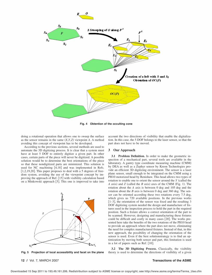
Fig. 4 Obtention of the occulting cone
Fig. 5 Projection of local accessibility and facet on the plane
12 / Vol. 7, MARCH 2007 Transactions of the ASME
Downloaded 15 Sep 2011 to 193.49.161.206. Redistribution subject to ASME license or copyright; see http://www.asme.org/terms/Terms_Use.cfm

geometric element. In fact, a direction d is said to be visible for apoint p of a part S if a ray originating from p in a viewing direc-tion d does not intersect S. The aggregate of all directions ofvisibility is defined as the visibility cone of p.
DEFINITION 1. Visibility Cone of A Point: A point p of the set Sis said to be visible in viewing direction d if #p!!d$!S=" , !!#0. The visibility cone #VC$ of p, denoted as VC #p, S$ can bedefined as
VC#p,S$ = !d:#p ! !d$ ! S = ", ! ! # 0" #1$To understand the concept of VC #p ,S$, we can imagine that
there is a point light source on the point p, and trace the imaginaryrays of light from the point p to the infinite. If a ray of light doesnot intersect any other points of the set when it travels to theinfinite, we say that the point is visible in the direction of the lightray. All the directions in which the point can be visible will forma cone and it is defined mathematically by the above definition.
DEFINITION 2. Visibility cone of a face: A face F of the set S issaid to be visible in viewing direction d if #p!!d$!S=" , !!#0, ! p!F. The visibility cone #VC$ of F, denoted as VC#p ,F$can be defined as
VC#F$ = ! VC#p,S$, ! p ! F, ! ! # 0 #2$
1. The local visibility cone #VC$ of F is denoted LVC#F ,S$,which corresponds to the visibility cone of F when !!0. Inlaser scanning, for a planar face F of a set S, whose normalis n", the local visibility cone LVC#F ,S$ is the set of directiond so that
LVC#F,S$ = !d":n" • d" $ cos#%$" #3$where % is the maximum angle of incidence of the laser#Fig. 2$.
2. The global visibility cone of p is denoted GVC#p ,S$, which
corresponds to the visibility cone of p when !!&. if wedefine the occulting cone of F of a set S !noted OC#F ,S$" asthe set of directions d so that #p!!d$!S!" , !!#0, ! p!F, then, the global visibility cone can be expressed as
GVC#F,S$ = LVC#F,S$ ! OC#F,S$ #4$
As explained in Sec. 3.3.1, this boolean relation is one of thebasics of our algorithm.
During the digitizing process, the sensor orientation is fixed sothat only one direction can be used during each digitization row.We pointed out two different approaches to optimize the digitizingstrategy: the first one, which we called microscopic, and the mostused approach, processes in this way: it discretizes all the faces ofthe part into tiny elements #triangles, points,…$, and works withthe visibility cone of every point and then determines the optimumorientations. Methods using this approach are subject to a dramati-cal computation time increase when the discretization accuracy isincreased. Our first visibility evaluation system !20", based on atriangular meshed representation of the part, presented this defect.Because of an algorithm of O#n2$ complexity, an important num-ber of triangles implied a great number of computations.
On the other hand, the second approach, called macroscopic,tries to avoid this discretization of the part by directly evaluatingthe visbility of high-level geometric elements #in our case, planarfaces$. Reference !21" presents a macroscopic visibility computa-tion algorithm which evaluates the exact global visibility of aplanar face thanks to boolean operations and Minkowski sums.This algorithm, used as a starting point in this paper, is shortlydescribed in the next section. The resulting visibility cones givenby this algorithm are expressed as portions of the Gaussian sphereS2 !6" #Fig. 3$. It should be noted that algorithms based onMinkowski sums have been introduced by Ref. !5" and developedin Refs. !9,11,22". However, no really robust exact analytical
Fig. 6 Circular visibility map
Journal of Computing and Information Science in Engineering MARCH 2007, Vol. 7 / 13
Downloaded 15 Sep 2011 to 193.49.161.206. Redistribution subject to ASME license or copyright; see http://www.asme.org/terms/Terms_Use.cfm

implementation is provided in these references. As a result, wecould consider Ref. !21" as a relatively new implementation ofRef. !5", for planar faces.
This paper thus proposes a methodology based on these visibil-ity cones to determine the different possible indexes to be used bythe sensor in order proceed to the digitization. It takes into ac-count a B-Rep model of the part to digitize. It is divided into threedifferent steps: the calculation of the global visibility of each faceof the B-Rep models, the determination of the set of all the pos-sible orientations to use, and the selection of a minimal set ofdirections needed for digitization.
3.3 Our Methodology
3.3.1 Computation of Global Visibility. A previous paper hasalready focused on the visibility calculation method !21". Given aface F and an obstacle O, our algorithm first computes LVC#F ,S$,then OC#F ,S$ to obtain, with a boolean substraction, GVC#F ,S$.If LVC#F ,S$ is easy to construct, OC#F ,S$ needs special opera-tions, involving Minkowski sums, to be computed. Figure 4 givesan overview of the process.
Representing the global visibility cone as a volume is a goodtool to visualize it. However, this representation could not be veryuseful for the following calculation. In the next subsection, weconsider the use of a 2D visibility map based on these cones, toproceed to orientations selection.
Fig. 7 2D map computation
Fig. 8 Common orientations for F1 and F2
14 / Vol. 7, MARCH 2007 Transactions of the ASME
Downloaded 15 Sep 2011 to 193.49.161.206. Redistribution subject to ASME license or copyright; see http://www.asme.org/terms/Terms_Use.cfm

3.3.2 Construction of the 2D Map. This concept of a 2D vis-ibility map was developed in Ref. !23". In fact, given a face, itsmaximum GVC can be expressed as a hemisphere of the Gaussiansphere S2, centered on the normal of the plane. Every direction ofthe cone can be defined by its Cartesian coordinates #X ,Y ,Z$ orby its polar coordinates #% ,'$. % is the angle between the vectorand the X axis of the part of the reference frame and ' is the anglebetween the vector and the Z axis of the part of the referenceframe. Using these two angles, it is possible to obtain a 2D rep-resentation of the global visibility cone #Fig. 5$. As a limit, such amap is mostly adapted to represent simple and classic cones butnot useful when the cone of visibility is complex like the onepresented in the figure.
Another 2D representation is explained in Ref. !10". A STL orVRML part, composed of triangular facets, is taken as a startingpoint of this approach. Then each facet is sampled in a certainnumber of points in order to determine the GVC of each point. To
do so, for each point P, the local point visibility cone LVC#p ,S$and each occulting facet F are projected into a 2D local coordinatesystem #XL ,YL ,ZL$ on the XLYL plane, tangent plane at point P.The difference between the transferred local visibility domain andthe union of the projected facets is the point global accessibilitycone domain in 2D. The local coordinate system on the tangentplane is defined arbitrarily so long as the Zl axis in the localcoordinates system is along the surface normal direction at pointP #Fig. 5$. A similar map is shown by using Ref. !12", which takesinto account the length and the volume of the probe.
In order to automate fixturing design for CAPP, Ref. !24" intro-duces the concept of a 2D circular visibility map. Only defining ittheoritically, this paper does not provide any implementation. Inconclusion, there is no existing 2D representation method thattakes into account the exact global visibility cones of faces. So, a
Fig. 9 An example with hollow box
Fig. 10 Shadow and occultation phenomena
Fig. 11 Directions of the laser and the camera and their associated meridian
Fig. 12 Directions of the camera for a given direction of thelaser on the map
Journal of Computing and Information Science in Engineering MARCH 2007, Vol. 7 / 15
Downloaded 15 Sep 2011 to 193.49.161.206. Redistribution subject to ASME license or copyright; see http://www.asme.org/terms/Terms_Use.cfm

new method was needed and developed based on a circular mapintroduced by Ref. !24" #Fig. 6$. In this map, a given direction dwith its polar coordinate #% ,'$ is defined by a point P such as
OP" = cos#%$ . cos#'$ . i" + cos#%$ . sin#'$ . j" #5$Here, the distance between the point p and the origin O is equal
to cos#%$ and the angle between the X axis and the vector is equalto '. The set of directions that have the same angle % is repre-sented by a circle with O as the center and cos#%$ as the radius.The set of directions that have the same angle ' is represented bya complete radius. In Fig. 6, the point N is on the intersectionbetween the circle with O as the center and cos#45 deg$ as theradius and the radius that has an angle of !90 deg with the X axis.The point N defines the direction #45 deg, !90 deg$.
On this map, all the possible orientations of the sensor arerepresented. Each of these orientations is characterized by a valuefor A=% and B=' #Fig. 1$. As shown in Fig. 6, a set of concentriccircles represents the different values of A, every 7.5 deg. Forexample, the third circle from the origin O represents a value of Aequal to 3(7.5 deg=22.5 deg. The radius are also every 7.5 degand represent the different possible values for B. On this 2D vis-ibility map, the possible orientations of the sensor are on the dif-ferent intersections between the concentric circles and the radius.As a limitation to this representation, the angle A represented on asingle map must be between 0 deg and 90 deg #which corre-sponds$. The angle A between 90 deg and 105 deg are not takeninto account.
The representation on this map of the cone of visibility is ob-tained by projection. Each point M#x ,y ,z$ belonging to the coneof visibility #which is a section of a sphere$ can be associated to apoint N#x ,y$ that is the projection of the point M on the plane XY.The set of the projected points represents the image of the cone ofvisibility on the 2D visibility map. An application has been devel-oped on SolidWorks to compute this 2D visibility map. Figure 7summarizes the different steps for three faces of a given B-Repmodel. Considering the image on the 2D visibility map of globalvisibility of F1, it is possible to identify the different orientationsof the sensor that enable one to reach F1. These are the orienta-
tions that are within the boundary of the global visibility of F1 onthe 2D visibility map. By the way, the common orientations thatallow one to reach simultaneously the faces F1 and F2 are easy toidentify using the map. Figure 8 shows these common orienta-tions. But, due to the digitizing technology, all these orientationscould not be used. Actually, to be digitized, a face F must be seenin two different directions: one along the laser beam and the sec-ond corresponding to the camera. The 2D visibility map must beimproved to take into account that fact. This improvement is pre-sented in the following section.
Figure 9 presents another example. The part is an hollow box,with holes in its sides, and an island on its bottom. The top face ofthe island is studied to evaluate its accessibility.
3.3.3 From Global Visibility to Digitizing Orientation. As pre-viously mentioned, to be digitized, a face has to be reached by thelaser beam and to be seen by the camera. The principle of trian-gulation allows the appearance of two phenomena: shadow andoccultation !20". The shadow phenomenon appears when the facesubmitted to the digitization is seen by the camera but not reachedby the laser beam. The occultation phenomenon appears when theface is seen by the laser beam but not by the camera #Fig. 10$.
Assuming that the directions presented on the 2D visibility mapare the laser directions, the directions of the camera have to beadded. For each laser direction, the corresponding camera direc-tions are projected on the 2D visibility map. As previously stated,a laser direction is represented by a point, intersection between acircle, and a radius. As shown in Fig. 11, it can be also representedby a point on a sphere, as part of the visibility cone. Consideringa meridian ML of this sphere to which this point belongs, thereexist a set of associated camera directions on a meridian MC ofthis sphere that is orthogonal to ML #Fig. 11$. The directions ofthe camera are represented by an angular section of MC. Thisangular section is given by )max and )min, respectively, the maxi-mum and minimum angles between the direction of the laser andthe directions of the camera #Fig. 11$.
The angular section of MC that represents the directions of thecamera is projected on the plane of the 2D visibility map. Theprojection of MC on this plane is an ellipse and the directions of
Fig. 13 Test of the laser directions
16 / Vol. 7, MARCH 2007 Transactions of the ASME
Downloaded 15 Sep 2011 to 193.49.161.206. Redistribution subject to ASME license or copyright; see http://www.asme.org/terms/Terms_Use.cfm

the camera are represented by a section of this ellipse #Fig. 12$.With this new tool, the transition from global visibility to digi-
tizing orientation is possible. As shown in Fig. 12 each directionof global visibility is tested. In the example presented in the fig-ure, the global visibility directions that allow each to reach simul-taneously the faces F1 and F2 are already known. Figure 13 showshow all these global visibility directions are tested. Let us con-sider a given laser direction L. If the associated directions of thecamera are also inside the boundary of the global visibility area,the direction L becomes a digitizing orientation or else the direc-tion L is removed.
3.3.4 Choice of a Set of Orientations. At this point of theapproach, the set of possible digitizing orientations is known forevery of the part #by the way of its CAD model$. These data aresummarized in a binary table like the one presented on Fig. 14. Inthe real table, the 624 lines represent the possible orientations ofthe sensors #624 orientations obtained with 13 different values forangle A and 48 different values for angle B$. The n columnsrepresent the n faces that compose the CAD model of the part.Considering an orientation, 1 is used for each face that is acces-sible 0 for the other surfaces. Using this table, the minimal set ofdigitizing orientations needed to entirely digitize a given part can
Fig. 14 Determination of the minimum set of digitizing orientations „MSD…
Fig. 15 The CAD model „left… in divided into two sub-CADmodels „right…
Journal of Computing and Information Science in Engineering MARCH 2007, Vol. 7 / 17
Downloaded 15 Sep 2011 to 193.49.161.206. Redistribution subject to ASME license or copyright; see http://www.asme.org/terms/Terms_Use.cfm

be computed. An algorithm based on a heuristic has been devel-oped in order to provide this set of orientations. This algorithm iscomposed of a loop of two steps. It can be described as follows:
1. Determine the digitizing orientation that allows one to digi-tize the maximum of faces #if this maximum is reachable by mdigitizing orientations, then the digitizing orientation with thesmallest index is chosen$. The set of faces digitized using eachdigitizing orientation Di is called TDi. If the maximum is null,then stop the algorithm. Otherwise, add Di to the minimal set ofdirections #MSD$.
2. For each of the other digitizing orientations Dj #j from 0 to n,j! i$, remove from TDj all the faces common to TDi. Go to step1.
Figure 14 shows an example of determination of the MSD. Inthis example, an imaginary part composed by four faces has to bedigitized by a sensor that is able to reach four differentorientations.
Assuming that there are n digitizing directions in the MSD fora given part, the next step of the proposed approach is the creationof n sub-CAD models, one for each of the digitizing orientationbelonging to MSD. Each of these new sub-CAD models is com-posed by the surfaces that will be digitized in using the corre-sponding digitizing orientation and will help to compute the digi-tizing paths. For more information, the reader is referred to Ref.!20". Considering the example presented in Fig. 14, as the MSD iscomposed of two digitizing orientations, two sub-CAD models arecreated a CAD model is composed by surfaces 1, 2, and 3 whichcorresponds to the digitizing orientation 3 and a CAD model com-posed of surface 4 that corresponds to the digitizing orientation 1.Considering now a real example #Fig. 15$, two digitizing orienta-tions are needed to entirely digitize the part and two CAD modelsare created.
4 DiscussionThis approach has been developed to improve the automation
of the 3D scanning task. Previous works !1–3" have already dem-onstrated the feasibility of this automation. From a given CADmodel, in fact a meshed model, those works enable one to deter-mine the scanning strategy and the scanning trajectories. As adrawback, this meshed model approach is very time consumingbecause of the very large number of triangles in the model.
This new approach proposes to fix this problem by using thefaces of a B-Rep model instead of the triangles. But, as the num-ber of calculations are reduced, some new problems have ap-peared. When applied in the small triangles of a meshed model,the visibility theory states that the visibility of every point on thesurface of a given triangle is a constant. On a bigger surface likethe face of a B-Rep model, this property is not true. To solve thisproblem, a new approach has been developed to determine thevisibility of a face. This one is based on the Minkowski opera-tions. It is efficient in terms of calculation time but for big faces,the global visibility cone that is calculated is not the best one. Forexample, a face could be considered invisible if its boundaries areinvisible even if the majority of the other parts of the face arevisible. To tackle this problem, a subdvision phase has to be in-troduced in the system. Indeed, every nonvisible face could besubdivided and the visibility of the resulting subfaces analyzed topoint out which part of the face is not feasible. This step could berecursive and applied on evey nonvisible face, until the subfaceshave a certain given limit area.
The heuristic developed for determining the scanning strategyis simple from an algorithmic point of view and easy to imple-ment. In Ref. !20", for example, this heuristic is to another ap-proach. The main drawback of this heuristic is the MSD #mini-mum set of directions$. The MSD proposes the minimum set ofdirections needed to entirely digitize the part but there is no proofthat this minimum set of directions is the best set of directions interms of digitizing time, for example.
5 ConclusionThe 3D digitizing technologies contribute to optimizing the de-
velopment of new products by accelerating the control phase pro-cess. The Research Centre for Automatic Control in Nancy hasinitiated several works to create an integrated environment for theinspection of complex parts. This application of the visibilitytheories in a field such as 3D scanning is an approach that has notbeen studied in depth until now. In fact, there are several researchstudies in this area that use many methods from a projected view-point to the creation of intelligent modules of path planning. Eachof them has its advantages and its drawbacks. The proposedmethod attempts to solve the problem inherent to the kinematicsstructure of a digitizing environment composed of a laser sensorand a CMM: 5 DOF but the digitalization itself performed by atranslation only. This type of trajectory #translation only$ can de-velop some problems during the point acquisition. However, it isa constraint of the environment but the calculation of the visibilitycould improve the results.
References!1" Bernard, A., Sidot, B., and Remy, S., 2000, “Visibility Theory Applied to the
Automatic Generation of Laser Scanning Process,” Proceedings CIRP DesignSeminar, Haifa, Israel.
!2" Bernard, A., and Veron, M., 2000, “Visibility Theory Applied to AutomaticControl of 3D Complex Parts Using Plane Laser Sensors,” CIRP Ann., 49, pp.113–118.
!3" Derigent, W., Remy, S., and Ris, G., 2003, “Method of Automatic Digitaliza-tion: A New Approach of the Visibility Calculation of an Object,” ProceedingsInternational Conference on Advanced Research in Virtual and Rapid Proto-typing Leiria, Portugal, October.
!4" Risacher, P., Hascoët, J., and Bennis, F., 1997, “Visibility, Workpiece Setupand Machine-tool Choice in Milling,” Proceedings International Conferenceon Industrial Engineering and Production Management, Lyon, France.
!5" Spyridi, A. J., and Requicha, A. A. G., 1990, “Accessibility Analysis for theAutomatic Inspection of Mechanical Parts by Coordinate Measuring Ma-chines,” Proceedings of IEEE International Conference on Robotics and Au-tomation, Cincinnati, OH, May 1990, pp. 1284–1289.
!6" Woo, T.-C., and Turkovich, B. V., 1990, “Visibility Maps and its Application toNumerical Control,” CIRP Ann., 39, pp. 451–454.
!7" Ziemian, C., and Medeiros, D., 1996, “Automating Probe Selection and PartSetup Planning for Inspection on a Coordinate Measuring Machine,” IMEWorking Paper, Department of Mechanical Engineering, Bucknell University,Lewisburg, Technical Report.
!8" Elber, G., and Zussman, E., 1998, “Cone Visibility Decomposition of Free-form Surfaces,” Comput.-Aided Des., 30, pp. 315–320.
!9" Spitz, S. N., Spyridi, A. J., and Requicha, A. A. G., 1999, “AccessibilityAnalysis for Planning of Dimensional Inspection with Coordinate MeasuringMachines,” IEEE Trans. Rob. Autom., 15#4$, pp. 714–727.
!10" Vafaeesefat, A., and Elmaraghy, H. A., 2000, “Automated Accessibility Analy-sis and Measurement Clustering for CMMs,” Int. J. Prod. Res., 38#10$, pp.2215–2232.
!11" Spitz, S. N., and Requicha, A. A. G., 2000, “Accessibility Analysis UsingComputer Graphics Hardware,” IEEE Trans. Vis. Comput. Graph., 6#3$, pp.208–219.
!12" Wu, Y., Liu, S., and Zhang, G., 2004, “Improvement of Coordinate MeasuringMachine Probing Accessibility,” Precis. Eng., 28#1$, pp. 89–94.
!13" Limaiem, A., and ElMaraghy, H., 2000, “Integrated Accessibility Analysis andMeasurement Operations Sequencing for CMMs,” J. Manuf. Syst., 19#2$, pp.83–93.
!14" Jackman, J., and Park, D., 1998, “Probe Orientation For Coordinate MeasuringMachine Systems Using Design Models,” Rob. Comput.-Integr. Manufact.,14#3$, pp. 229–236.
!15" Xi, F., and Shu, C., 1999, “Cad Based Path Planning for 3D Line Laser Scan-ning,” CAD, 31, pp. 473–479.
!16" Prieto, F., Redarce, T., Boulanger, P., and Lepage, R., 1999, “Cad-BasedRange Sensor Placement for Optimum 3D Data Acquisition,” Proceedings3DIM’99 Conference, Ottawa, Canada.
!17" Trucco, E., Umasuthan, M., Wallace, J., and Roberto, V., 1997, “Model-Based Planning of Optimal Sensor Placements for Inspection,”
18 / Vol. 7, MARCH 2007 Transactions of the ASME
Downloaded 15 Sep 2011 to 193.49.161.206. Redistribution subject to ASME license or copyright; see http://www.asme.org/terms/Terms_Use.cfm

IEEE Trans. Rob. Autom., 13#2$, pp. 182–194.!18" Balasubramaniam, M., Laxmiprasad, P., Sarma, S., and Shaikh, Z., 2000,
“Generating 5-axis NC Roughing Paths Directly from a Tessellated Represen-tation,” Comput.-Aided Des., 32, pp. 261–277.
!19" Remy, S., Bernard, A., and Ris, G., 2002, “Visibility Analysis as an Aid forDetermining Scanning Strategy,” Proceedings Tools and Methods for Com-petitive Engineering, Wuhan, China.
!20" Remy, S., Derigent, W., Bernard, A., Ris, G., and Véron, M., 2004, “Auto-matic 3D Digitizing: A Visibility Based Approach,” Proceedings CIRP DesignSeminar, Cairo, Egypt.
!21" Derigent, W., Ramy, H., and Ris, G., 2005, “Détermination Des Directions de
Visibilités par Opérations Volumiques,” Proceedings Colloque National AIPPriméca, La Plagne, France, April 5–8.
!22" Spitz, S., Spyridi, A., and Requicha, A., 1998, “Accessibility Analysis forPlanning of Dimensional Inspection with Coordinate Measuring Machines,”IEEE Trans. Robotics and Automation.
!23" Lim, C. M. C. P., 1994, “CMM Feature Accessibility and Path Generation,”Int. J. Prod. Res., 32, pp. 597–618.
!24" Capponi, V., Villeneuve, F., and Paris, H., 2004, “Handling of AlternativeProcesses for Machining of Aeronautical Parts in a CAPP System,” Proceed-ings IFAC-MiM 2004, Athens, Greece.
Journal of Computing and Information Science in Engineering MARCH 2007, Vol. 7 / 19
Downloaded 15 Sep 2011 to 193.49.161.206. Redistribution subject to ASME license or copyright; see http://www.asme.org/terms/Terms_Use.cfm