Digitalização 3D utilizando Kinect e sistemas CAD e CAM para confecção de órtese de membro inferior
Upload
khangminh22Category
view
0download
0
®
FlashCut CAD/CAM and
CNC Control Software
Version 6 User's Guide

Page ii FlashCut CAD/CAM and CNC Control Software
Notices
Revised July 1, 2016
Version 6.0.5.22
© 1997-2016 WPI, Inc., all rights reserved
FlashCut® CNC is a registered trademark of WPI, Inc.
Stingray® is a registered trademark of WPI, Inc.
PowerMax® is a registered trademark of Hypertherm, Inc.
AutoCAD® is a registered trademark of Autodesk, Inc.
Other trademarks are the property of their respective holders.
About this document
Because new features may be added to the software in the future, this manual applies only to the version for
which it was released.
There may be differences between the information presented here and the features found in either older or newer
versions of the software.
Screen captures used in this document are edited for clarity, and may differ in minor ways from the actual
FlashCut application.

FlashCut CAD/CAM and CNC Control Software Page iii
Disclaimer
FlashCut CNC and its affiliates are not responsible for the safe installation and use of this product. You and only
you are responsible for the safety of yourself and others during the operation of your CNC machine tool. FlashCut
CNC supplies this product but has no control over how it is installed or used. Always be careful!
FlashCut CNC is not responsible for damage to any equipment or workpiece resulting from use of this product.
If you do not understand and agree with all of the above, please do not use this product.
Safety and usage guidelines
Automated machining is potentially dangerous. Please take the time to completely read through this manual to
understand operation of the software before running the system.
A working knowledge of the PC and the Windows operating system is required in order to install, use, and
troubleshoot the software.
Since FlashCut is a real time control program, it must have full control of the operating system while running. It is
very important that you do the following before running FlashCut:
Disable all screen savers and power management programs.
Make sure there are no background programs running, such as back-up software and calendar reminders.
Make sure no other programs are open.
Safety is of the utmost importance. To use FlashCut CNC to control your automated machine tool in a safe and
proper fashion, the following safety guidelines must be followed:
Never let the machine tool run unattended.
Require any person in the same room as a running machine tool to wear safety goggles, and to stay a safe
distance from the machine.
Allow only trained operators to run the machine tool. Any operator must have:
Knowledge of machine tool operation
Knowledge of personal computer operation
Knowledge of Microsoft Windows
Good common sense
Place safety guards around the machine to prevent injury from flying objects. It is highly recommended
that you build a safety shield around the entire tool envelope.
Never place any part of your body within the tool envelope while the machine has power, since
unexpected machine movement can occur at any time.
Always keep the tool envelope tidy and free of any loose objects.
Be on alert for computer crashes at all times.

Page iv FlashCut CAD/CAM and CNC Control Software
Technical support
Expert technical support is provided for all of our products. Many resources are available to help you resolve your
problems quickly. We recommend that you use these resources in the following order:
Website
http://www.flashcutcnc.com/
Our website has product specifications, documentation, support videos, and other information.
Dealer support
If you purchased FlashCut CNC from a dealer or other machine tool manufacturer (OEM), please contact them
first. They will have the best knowledge of your complete system.
Email is the most organized way to communicate an issues to our support staff. In your e-mail, please state your
problem completely. The email should include this information:
FlashCut version
Computer processor and speed
Windows version
Signal generator serial number.
In addition, please attach the following files:
Setup and Tooling files (usually found in a folder named c:\Flashcut Data)
G-code file with which you are having problems (when appropriate)
CADCAM file with which you are having problems (when appropriate)
Alternatively, you can attach a single FlashCut support file. The support file is in ZIP format and contains all
relevant files needed by technical support to resolve your issue. To generate the file:
Select the Help button in the upper right of the main window
Click the Build Support File button
Name and save the file using the Windows dialog box.
Note The Support file will only include a G-Code file that has been saved and it will not include a
CADCAM file. If you are having a CADCAM issue, please e-mail the CADCAM file separately.
Please see Getting Help for more details.

FlashCut CAD/CAM and CNC Control Software Page v
Phone/fax support
If email is unavailable to you, please call our telephone support number. We will normally respond to your call
within 24 hours.
Phone: (847) 940-9305 (9:00 AM-5:00 PM, US Central Time, M-F)
Fax: (847) 940-9315

Page vi FlashCut CAD/CAM and CNC Control Software
Contents
Notices........................................................................................................................ ii
Introducing FlashCut® CNC ......................................................................................... 1 System requirements .................................................................................................................... 1 Program packages and features ................................................................................................... 1
Version 6 standard features .....................................................................................................................1 Additional Version 6 CNC features ........................................................................................................3 Other Version 6 a la carte features ..........................................................................................................3 Version comparison ................................................................................................................................3 Version 6.0 Feature Summary ................................................................................................................4
Installing the FlashCut CNC software ............................................................................................ 5 Preparing to install the software .............................................................................................................5 Installing the software .............................................................................................................................5 Updating the setup file ............................................................................................................................8
Installing the USB driver ................................................................................................................ 9 Windows 7 ..............................................................................................................................................9 Windows 8 and 10 ................................................................................................................................13
Getting started with FlashCut CNC .......................................................................... 14 Launching the software ............................................................................................................... 14
Running in evaluation mode .................................................................................................................14 Activating a license ..................................................................................................................... 14 Configuring the software ............................................................................................................. 14 Getting help ................................................................................................................................. 15 Understanding common interface elements ................................................................................ 15
Configuration, License, and Help buttons ............................................................................................15 Tabs .......................................................................................................................................................15 Accept / Cancel .....................................................................................................................................16 Menu bar ...............................................................................................................................................16 Documents menu ..................................................................................................................................21 Parameters area .....................................................................................................................................21 Status bar ...............................................................................................................................................21
FlashCut CAD ............................................................................................................ 22 Ribbon ........................................................................................................................................ 23
File tools ...............................................................................................................................................23 Import tools ...........................................................................................................................................24 Create tools ...........................................................................................................................................31 Shape tool .............................................................................................................................................43 Modify tools ..........................................................................................................................................44 Group ....................................................................................................................................................52 Ungroup ................................................................................................................................................53 Ungroup All ..........................................................................................................................................53 Transform tools .....................................................................................................................................53
Pan and zoom tools .................................................................................................................... 63 Pan ........................................................................................................................................................63 Zoom Extent .........................................................................................................................................63 Zoom .....................................................................................................................................................63

FlashCut CAD/CAM and CNC Control Software Page vii
Zoom to Fit ...........................................................................................................................................63 Snap tools ................................................................................................................................... 64
FlashCut CAM ........................................................................................................... 68 Ribbon ........................................................................................................................................ 69
File tools ...............................................................................................................................................69 Feature Type .........................................................................................................................................69 Selection ................................................................................................................................................70 CAM Actions ........................................................................................................................................72 G-code ...................................................................................................................................................83
Import .......................................................................................................................................... 83 DXF/DWG ............................................................................................................................................83 CADCAM .............................................................................................................................................83
Pan and zoom tools .................................................................................................................... 84 Pan ........................................................................................................................................................84 Zoom Workpiece Extents .....................................................................................................................84 Zoom .....................................................................................................................................................84 Zoom Toolpath Extents.........................................................................................................................84 Zoom Window ......................................................................................................................................84
Display options tools ................................................................................................................... 84 Cutting directions ..................................................................................................................................85 Kerf .......................................................................................................................................................85 Material .................................................................................................................................................85 Parts ......................................................................................................................................................85 Rapid moves .........................................................................................................................................85 Tool paths .............................................................................................................................................85
Drawing workspace ..................................................................................................................... 85 Feature manipulation ............................................................................................................................86 Lead in/out settings ...............................................................................................................................86 Program zero .........................................................................................................................................88
FlashCut CNC ............................................................................................................ 89 System Status and Connect ........................................................................................................ 90
System Status ........................................................................................................................................90 Connect .................................................................................................................................................90
Fab head settings........................................................................................................................ 91 Plasma torch settings.............................................................................................................................91 Oxyfuel settings ....................................................................................................................................92 Waterjet settings ...................................................................................................................................93 Marker control ......................................................................................................................................93 Laser pointer control .............................................................................................................................93
Program coordinates panel ......................................................................................................... 94 Machine coordinates panel ......................................................................................................... 94 Jog and point control panel ......................................................................................................... 95
Move to point ........................................................................................................................................95 Jogging ..................................................................................................................................................96 G-code window .....................................................................................................................................97 Pan and zoom tools .............................................................................................................................100
Drawing workspace ................................................................................................................... 101
Configuring FlashCut .............................................................................................. 102 Setup file (*.setup extension) .................................................................................................... 103

Page viii FlashCut CAD/CAM and CNC Control Software
Configuration workspace ........................................................................................................... 103 Configuration Menu ................................................................................................................... 104 System ...................................................................................................................................... 105
General ................................................................................................................................................105 Controller ............................................................................................................................................105
Preferences ............................................................................................................................... 109 Language .............................................................................................................................................109 Jogging ................................................................................................................................................110 Display ................................................................................................................................................111 Pendant ................................................................................................................................................112 USB Interface Board ...........................................................................................................................112
Machine .................................................................................................................................... 113 Fabrication Heads ...............................................................................................................................113 Axes ....................................................................................................................................................120 Drive Parameters .................................................................................................................................125 Rotary Axes ........................................................................................................................................129 Reference Points .................................................................................................................................131 Homing ...............................................................................................................................................133 Dynamic Ventilation ...........................................................................................................................134
Programming ............................................................................................................................ 134 M-Code Definitions ............................................................................................................................135 M-Code Execution ..............................................................................................................................136
I/O ............................................................................................................................................. 138 Input Lines ..........................................................................................................................................138
CAD .......................................................................................................................................... 140 General ................................................................................................................................................140 Features ...............................................................................................................................................141
CAM .......................................................................................................................................... 141 General ................................................................................................................................................141 Features ...............................................................................................................................................142 Breaks .................................................................................................................................................142 Post Processor .....................................................................................................................................146 Toolpath Adjustments .........................................................................................................................148
Licensing FlashCut ................................................................................................. 150 License Management Window .................................................................................................. 151
Import License File .............................................................................................................................151 Activate PC License ............................................................................................................................151 Deactivate PC License ........................................................................................................................152 Licensed Features List ........................................................................................................................152
Getting Help ............................................................................................................ 153 Help .......................................................................................................................................... 153
Version ................................................................................................................................................153 Firmware Version ...............................................................................................................................153 Graphics Drivers .................................................................................................................................153 User’s Guide .......................................................................................................................................153 Programming Reference .....................................................................................................................154 Build Support File ...............................................................................................................................154
System Status ........................................................................................................................... 154

FlashCut CAD/CAM and CNC Control Software Page 1
Introducing FlashCut®
CNC
Thank you for purchasing FlashCut® CNC, the most innovative, powerful CNC control system for Windows 7, 8,
and 10. No control system is easier to set up and use. With intuitive controls and real time graphics, FlashCut
CNC lets you design and make parts quickly and accurately on your machine tool.
FlashCut Version 6 has three main portions – FlashCut CAD, FlashCut CAM and FlashCut CNC. All three are
completely integrated for seamless operation from drawing a part to creating a toolpath to cutting the part.
FlashCut CAD – A unique CAD program for precision and artistic design.
FlashCut CAM – A unique CAM program for creating and editing toolpaths and G-code. It can be set
up to instantly create toolpaths complete with kerf compensation, lead ins and lead outs. FlashCut CAM
together with FlashCut CAD (FlashCut CAD/CAM) is sold as a combined product separate from
FlashCut CNC but all three together create one seamless program.
FlashCut CNC – The latest version of our control software which can be configured to operate almost
any type of automated machine tool. It receives its motion commands from G-code programs. G-code can
be created in FlashCut CAD/CAM or from an external CAM program, or it can import a DXF CAD
drawing. FlashCut CNC is sold separately from FlashCut CAD/CAM but all three together create one
seamless program.
We are committed to the excellence and ongoing enhancement of FlashCut CNC. Feel free to contact us with any
comments or questions.
System requirements
Windows Version 7, 8, or 10 (32 or 64 Bit)
Intel I3 processor or equivalent or better
At least 4GB of RAM
A separate graphics card is preferred for processing larger files
Program packages and features
FlashCut CNC is available in different configurations depending on your needs. The standard package contains
the features needed by most customers to design and cut 2-D parts. Other features add advanced functionality, and
offer enhanced machine control during production. These advanced features can be purchased a la carte; a pro
package that includes the most popular a la carte features is also available.
Version 6 standard features
Simple, powerful 2-D CAD
Integrated CAM with true shape nesting
Automatic kerf compensation

FlashCut CAD/CAM and CNC Control Software Page 2
Automatic generation of lead ins and lead outs
Automatic cut settings based on material
Simple import of pictures and drawings
Easy CNC program flow control including “Jump to Line”, forward and reverse processing
Integrated Plasma Torch Height Control (THC)
Industry renowned CNC control
Additional Version 6 CAD features
Standard Package
Improved DXF/DWG Import
Measuring tool lets you determine any part dimension or distance on a drawing
Pro Package
Integrated shape library
DXF export
Bring TT fonts directly into CAM without exploding
“Fix Tool” finds and corrects CAD mistakes instantly
Ability to bridge internal cutouts instantly, such as the center of an “O”
Additional Version 6 CAM features
Standard Package
Improved nesting performance
Editable plasma and oxy-fuel cut charts for Hypertherm and Thermodynamics
Support for multiple fabrication heads including plasma, water jet, oxy fuel, spindle
Smart feedrate and THC handling of small holes
Pro Package
Enhanced nesting interface of multiple parts and external files
Enhance production nesting features – fill sheet, multi sheet, partial sheet
Corner looping

FlashCut CAD/CAM and CNC Control Software Page 3
Additional Version 6 CNC features
Standard Package
Marker support
Advanced security to prohibit unwanted changes to configuration
Support for simultaneous multiple fabrication heads including plasma, water jet, oxy fuel, spindle
Feedhold on loss of Arc Transfer Signal
Pro Package
Lead in automatically added when starting in the middle of a G-Code, minimizing blemishes on
part
Ability to turn THC on and off in the middle of a cut
Other Version 6 a la carte features
Laser pointer support, including finding zero and previewing the toolpath directly on the sheet
Enhanced communication with Hypertherm® Powermax® plasma cutters to set amperage, pressure and
reporting status
Bar code input and automatic file loading for streamlined production
Advanced input configuration including joystick jogging
Dynamic control of ventilation zones
Version comparison
The table below lists the different features included in the standard and professional packages, and those available
a la carte. Please contact FlashCut for more information when ordering.

FlashCut CAD/CAM and CNC Control Software Page 4
Version 6.0 Feature Summary
Standard Package
Pro Package
Available A la carte
Simple, powerful 2-D CAD with improved DXF/DWG import x x
Measuring tool displays any part dimension or distance x x
Integrated CAM with true shape nesting with improved performance x x
Editable plasma and oxy-fuel cut charts for Hypertherm® and Thermal Dynamics®
x x
Support for multiple fabrication heads including plasma, water jet, oxy-fuel, and spindle
x x
Smart feed rate and Torch Height Control (THC) processing for small holes
x x
Automatic kerf compensation x x
Automatic generation of lead ins and lead outs x x
Automatic cut settings based on material x x
Simple import of pictures and drawings x x
Easy CNC program flow control including jump to line, forward, and reverse processing
x x
Integrated shape library x x
DXF export x x
Ability to bring True-Type fonts directly into CAM without exploding x x
Dynamically curve text around any shape including arcs, lines, ellipses and splines
x x
Fix tool finds and corrects CAD mistakes instantly x x
Ability to bridge internal cutouts instantly (e.g., alphabet shapes) x x
One click to weld or subtract intersecting shapes x x
Enhanced nesting interface of multiple parts and external files x x
Enhance production nesting features - fill sheet, multi sheet, partial sheet
x x
Corner looping x x
Ability to turn THC on and off while cutting x x
Automatic lead in on restart x x
Advanced file management including bar code scanning support and automatic file loading
x
Laser pointer and laser pointer software support * x
Laser pointer software support only x
Dynamic ventilation zones x
Programmable I/O interface board* x
Joystick with Programmable I/O Interface Board * x
Integrated THC with Mini I/O Expansion Board, Voltage Isolation Box, Ohmic and Torch Interface Cables *
x
RS-485 communications with Hypertherm® Powermax® plasmas for real-time current and pressure control *
x
* Includes hardware

FlashCut CAD/CAM and CNC Control Software Page 5
Installing the FlashCut CNC software
Preparing to install the software
Important: Install FlashCut CNC before connecting to a signal generator
The software should be installed before you connect a signal generator to the PC. If you connect the electronic
hardware before installing the software, you may have to manually install the USB driver. Instructions for
Installing the USB Driver are provided below.
When the hardware is connected to the computer with the USB cable and then powered on, Windows will try and
find a driver for the device. If the correct driver is not already installed, Windows may attempt to use a driver for
a different device. If the software is installed first, the proper driver will be selected.
Installing the software
Please follow these instructions to install FlashCut CNC.
1. Open the FlashCut CNC installer downloaded from the internet, or mount the installation CD.
2. When prompted to run the installer, select Run to open the InstallAware wizard.
3. The wizard checks for previous installations of FlashCut CNC version 5 or 6, and prompts you to
uninstall them.
Note You may also uninstall a version of FlashCut CNC 6 manually by selecting Uninstall FlashCut
CNC 6 from the Windows Start menu.

FlashCut CAD/CAM and CNC Control Software Page 6
4. After dealing with the pre-installation requirements, the wizard prompts you to install the latest release.
Click Next >.
5. Select a destination folder for program files. By default, FlashCut creates a new folder, as shown here.
Click Change… to set a new location for the file.
Click Next >.
FlashCut CAD/CAM and CNC Control Software Page 7
6. The wizard is now ready to perform the installation and configuration.
Click Next > to finalize the configuration and begin the installation.
7. During the installation process, Windows may display this message asking for permission to install the
USB Signal Generator 501A driver.
Click Install to install the driver software.

FlashCut CAD/CAM and CNC Control Software Page 8
8. When complete, the wizard will inform you that the installation was successful.
Click Finish to close the wizard.
Note The wizard may give you the option to restart your computer by checking the Restart now box. The
option to restart your computer is typically only offered if FlashCut software has never been installed on
this computer before.
Updating the setup file
If an older version of the setup file is present, FlashCut will save a copy and update the file when you launch the
updated version.

FlashCut CAD/CAM and CNC Control Software Page 9
Installing the USB driver
The software needs to be installed before you connect a signal generator to the PC. If you connect the electronic
hardware before installing the software then there is a high likelihood that you will have to manually install the
USB driver. The USB driver will be automatically installed as long as the FlashCut CNC software has been
successfully installed prior connecting the controller with the USB cable and powering it on.
If you need to manually install the FlashCut USB driver so the software can communicate with the signal
generator, follow these instructions.
1. Make sure the FlashCut software is installed.
2. Connect the signal generator to the PC using an A-B USB cable.
3. Turn on the signal generator or CNC controller.
To finish the driver installation, follow the steps for your version of Windows.
Windows 7
Windows will automatically find and install the driver for the USB signal generator. If Windows is unable to
locate and install the drivers, proceed with the following steps in order to properly install the driver.
1. Click Start►Control Panel. Windows displays the Control Panel screen.

FlashCut CAD/CAM and CNC Control Software Page 10
2. At the top right corner of the screen, click View By and select Large Icons. Windows display the
available Control Panel icons.
3. Click Device Manager. Windows displays the Device Manager screen.
4. Expand the Universal Serial Bus Controllers listing.

FlashCut CAD/CAM and CNC Control Software Page 11
5. Right click on USB Signal Generator 501A and select Update Driver Software.
Windows displays this dialog box.
Click Browse my computer for driver software.
FlashCut CAD/CAM and CNC Control Software Page 12
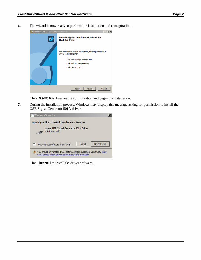
6. Windows displays the following dialog box.
7. Click Browse and navigate to the following folder:
32-bit Windows 7
C:\Program Files\FlashCut CNC 6\Drivers\USB
64-bit Windows 7
C:\Program Files (x86)\FlashCut CNC 6\Drivers\USB
When you’ve navigated to the appropriate folder, Click Next >.

FlashCut CAD/CAM and CNC Control Software Page 13
8. Windows installs the driver then displays this message to tell you that driver installation is complete.
Click Close.
Windows 8 and 10
Later Windows versions automatically find and install the driver for the USB signal generator.

FlashCut CAD/CAM and CNC Control Software Page 14
Getting started with FlashCut CNC
Launching the software
When you start the program, you will see the drawing workspace. From here you can either open an existing file,
or simply begin drawing.
Running in evaluation mode
After you install the program, FlashCut CNC will run in evaluation mode until you activate a license. In
evaluation mode, you can try out many features of the program. Some features will be disabled, while others will
be limited. For example, you cannot communicate with the CNC controller, you will not be able to save files, and
only 25 lines of G-code will be generated when you send a CAM toolpath to the CNC workspace.
Activating a license
To enable the full functionality of the program, you must activate a PC license. Select the License
button in any workspace. For more information, see Licensing FlashCut.
Configuring the software
When you first launch the program you will be prompted for the location of the setup file. The default
location is C:\FlashCut Data\FlashCut CNC 6\Setup\FlashCutPlasma.setup.

FlashCut CAD/CAM and CNC Control Software Page 15
To examine or change settings saved in this file, select the Configuration button in any workspace. For more
information, see Configuring FlashCut.
Getting help
To view the program version, firmware, graphics driver status, select the Help button in any workspace.
From the Help window, you may also view this user’s guide, or the programming reference.
In addition, you can build a Support File to assist in troubleshooting problems. For more information, see
Getting Help.
Understanding common interface elements
Configuration, License, and Help buttons
The Configuration, License, and Help buttons are the same in FlashCut CAD,
CAM, and CNC.
The Configuration interface modifies program settings stored in the setup file. See Configuring
FlashCut for more information.
The License interface is used to install license files, and activate or deactivate program licenses. See
Licensing FlashCut for more information.
The Help interface is used to access the manual and the programming reference, and to generate a
support file for use during troubleshooting. See Getting Help for more information.
Tabs
Use the tabs at the top of the screen to navigate between the CAD, CAM, and CNC windows.
Use the Double Arrow tabs to send the drawing you are working on to the next stage: from CAD to CAM to
create the toolpath, or from CAM to CNC to generate the G-Code and cut the parts.
FlashCut CAD arrows send to CAM and
create toolpath
FlashCut CAM arrows send toolpath to CNC
and generate G-code
FlashCut CNC
FlashCut CAD/CAM and CNC Control Software Page 16
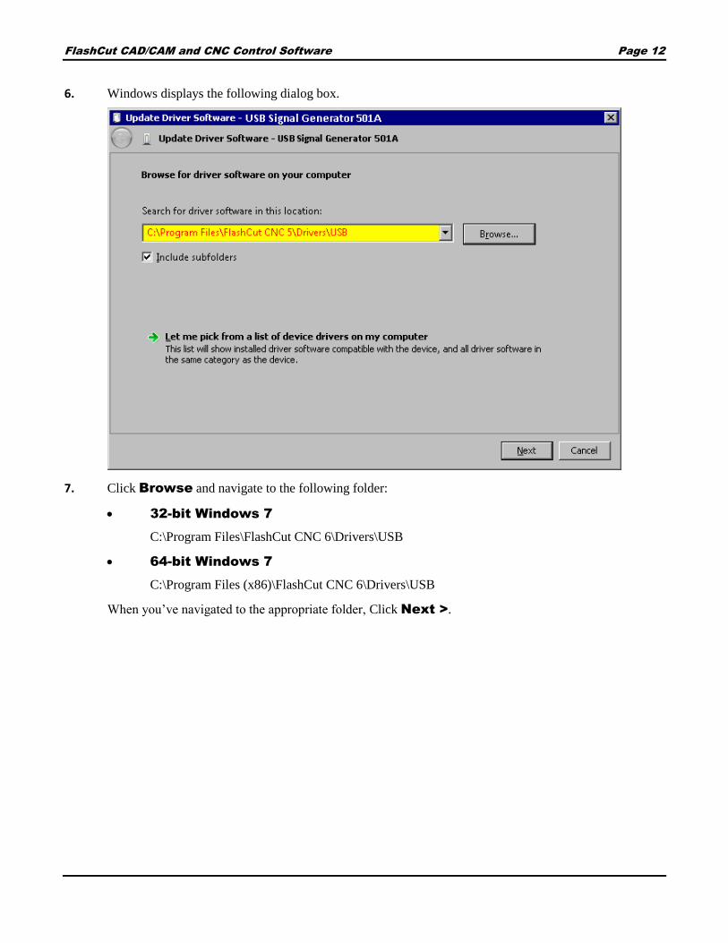
Accept / Cancel
The Accept and Cancel buttons are located in the bottom right of the window in FlashCut CAD and
FlashCut CAM.
The green check is used to Accept an action or operation, and the red X is used to Cancel
an action or operation. The Parameters area often displays detailed information about
what you can Accept or Cancel.
Menu bar
The menu bar is the same in both FlashCut CAD and FlashCut CAM. The menu bar contains menu items
for system commands. Hotkey commands are listed next to their respective functions. Accelerator keys are
displayed when you press the {Alt} key.
File menu
Edit menu
Documents menu
File menu
The File menu presents the following commands:
New (Ctrl+N)
Open (Ctrl+O)
Close
Save (Ctrl+S)
Save as
Save all
Export
Exit
New (Ctrl+N)
Creates a new CAD/CAM drawing in a new FlashCut CAD window. It does not close the current
drawing. Note that you can view any open drawing by selecting it from the Documents menu.
Open (Ctrl+O)
Opens an existing CAD/CAM file for editing in a new FlashCut CAD window. It does not close the
current drawing. FlashCut version 5.0 or later CAD/CAM files (file extension .cadcam) can be opened.
However, Version 6.0 or later CAD/CAM files cannot be opened in an earlier version such as 5.0.

FlashCut CAD/CAM and CNC Control Software Page 17
Close
Closes the current CAD/CAM drawing from the CAD editor. If the drawing is unsaved, the software
prompts you to save the file before closing.
Save (Ctrl+S)
Saves the current CAD/CAM drawing using the existing file name and location. It will not save any other
CAD/CAM drawing that is open. FlashCut will prompt you to create a file name and destination.
FlashCut saves drawings to the CAD/CAM (file extension .cadcam) format. These files are readable by
FlashCut version 6 or later. The Save command is unavailable when no recent changes have been made.
Save as
Saves the current drawing to a new file name or destination. It will not save any other CAD/CAM
drawing that is open. FlashCut prompts you to create a file name and destination. Saved files use the
extension .cadcam. These files are readable by FlashCut version 6 or later.
Save all
Saves all open drawings, including those in other windows. This command is unavailable when no recent
changes have been made.
Export
Export DXF
Saves a copy of the current drawing to a new
file in the AutoCAD® Drawing Interchange
Format (DXF).
After setting the parameters for the file, you
may either Accept or Cancel the changes.
Choose DXF file
Create a new file or replace an existing one.
Browse opens the Windows dialog box.
DXF Export Format
Choose from DXF 2000 or DXF R12
Export Curves as Polylines
When selected, curves will be saved as polylines in the DXF file. When not selected, arcs and
circles will be maintained, but ellipses and splines will be saved as polylines. Polylines are
drawing objects composed of multiple separate line segments.
Export Text as Polylines

FlashCut CAD/CAM and CNC Control Software Page 18
When selected, text shapes will be saved as polylines in the DXF file. Polylines are drawing
objects composed of multiple separate line segments. When not selected, text will be saved as a
font.
Export Units
Choose from either inches or millimeters
Exit
Closes the entire FlashCut application. If any drawings are unsaved, FlashCut prompts you to save these
files or discard changes before closing.
Edit menu
The Edit menu has the following commands:
Undo (Ctrl+Z)
Redo (Ctrl+Y)
Settings…
Cut (Ctrl+X)
Copy (Ctrl+C)
Paste (Ctrl+V)
Select All (Ctrl+A)
Undo (Ctrl+Z)
Reverses the previous drawing action. Up to 20 actions can be reversed.
Redo (Ctrl+Y)
Repeats the previous drawing action, or reverses the Undo stack.
FlashCut CAD/CAM and CNC Control Software Page 19
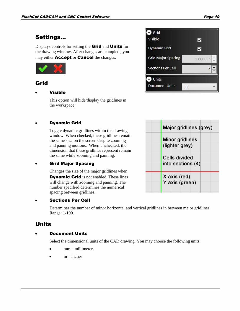
Settings…
Displays controls for setting the Grid and Units for
the drawing window. After changes are complete, you
may either Accept or Cancel the changes.
Grid
Visible
This option will hide/display the gridlines in
the workspace.
Dynamic Grid
Toggle dynamic gridlines within the drawing
window. When checked, these gridlines remain
the same size on the screen despite zooming
and panning motions. When unchecked, the
dimension that these gridlines represent remain
the same while zooming and panning.
Grid Major Spacing
Changes the size of the major gridlines when
Dynamic Grid is not enabled. These lines
will change with zooming and panning. The
number specified determines the numerical
spacing between gridlines.
Sections Per Cell
Determines the number of minor horizontal and vertical gridlines in between major gridlines.
Range: 1-100.
Units
Document Units
Select the dimensional units of the CAD drawing. You may choose the following units:
mm – millimeters
in – inches

FlashCut CAD/CAM and CNC Control Software Page 20
FlashCut gives you the option to
convert any existing parts (drawing
objects) in the workspace. Selecting
Yes rescales the existing values into
new units (i.e., a 1 inch circle is a
25.4mm circle). Selecting No
reinterprets the values into new units
(i.e., a 1 inch circle becomes a 1mm
circle).
Note that changing the units for a
drawing will clear all CAM data.
Cut (Ctrl+X)
Removes selected features and places them on the clipboard to be pasted.
Note that objects are selected by clicking on them with the selection arrow (which becomes
available by pressing the Esc key). To select all segments of a feature (chain select), hold
down the Alt key.
You can include other objects by holding down the Ctrl key while you select the objects that you want.
You may also select multiple objects by creating a selection box with the selection arrow. Creating a
selection box that goes from left to right will select all objects that it touches and a selection box that goes
from right to left will select all objects that it completely envelopes. You may also select all items in the
workspace with the Select All (Ctrl+A) command.
Copy (Ctrl+C)
Copies the selected features and places them on the clipboard to be pasted.
Paste (Ctrl+V)
Pastes copied or cut features from the clipboard. The features will be centered at the cursor
point and you will be able to maneuver them to a desired location. Clicking the mouse will
paste the features permanently into the drawing.
Select All (Ctrl+A)
Use the Select All command to select all geometry in the workspace.

FlashCut CAD/CAM and CNC Control Software Page 21
Documents menu
The Documents menu allows you to toggle between all open drawings in both FlashCut CAD and
FlashCut CAM.
The checked document is visible and available for editing.
Note You may copy features from one drawing and paste them into another drawing.
Parameters area
Parameters for selected tools or objects are shown in this area in both FlashCut CAD and FlashCut CAM.
Parameters displayed in this area will be described in the sections of this document where the tools or objects are
discussed.
Status bar
Reports the real time position of the cursor. In the CAD window, provides instructions to the user for the
expected input of the currently selected tool.

FlashCut CAD/CAM and CNC Control Software Page 22
FlashCut CAD
FlashCut CAD features a two-dimensional CAD (Computer-Aided Design) editor for creating quick and detailed
drawings. The FlashCut CAD should be used to draw the part only. The toolpath with kerf compensation, lead
ins, lead outs and nesting are generated in FlashCut CAM.
The FlashCut CAD main screen is shown here.
An explanation of each area of the screen is provided in these topics.
Tabs
Snap tools
Menu bar
Drawing workspace
Configuration, License, and Help buttons
Parameters area
Ribbon
Status bar
Pan and zoom tools
Accept / Cancel
Several interface elements are the same in both CAD and CAM, and are explained above: see Understanding
common interface elements.
1 6
2 7
3 8
4 9
5 10
3
4
5 6
12
7
8
109

FlashCut CAD/CAM and CNC Control Software Page 23
Ribbon
The ribbon features an assortment of command icons to create, modify, and transform elements such as points,
curves and shapes in the drawing window. Pressing the Esc key enables you to exit out of any particular tool.
There are six different types of tools; each is explained below.
File tools
Import tools
Create tools
Shape tool
Modify tools
Transform tools
File tools
There are three file tools on the ribbon:
New (Ctrl+N)
Open (Ctrl+O)
Save (Ctrl+S)
New (Ctrl+N)
Creates a new editable document in CAD.
Open (Ctrl+O)
Opens an existing CAD/CAM drawing for editing in a new FlashCut CAD window. It does not close
the current drawing.
Save (Ctrl+S)
Saves the current CAD/CAM drawing using the existing file name and location. It will not save any
other CAD/CAM drawing that is open. FlashCut will prompt you to create a file name and destination.
FlashCut saves drawings to the CAD/CAM (*.cadcam) format. These files represent CAD drawings
readable by FlashCut CAD version 6 or later. This command is unavailable when no recent changes
have been made.

FlashCut CAD/CAM and CNC Control Software Page 24
Import tools
The import tools are used for adding images or DXF CAD drawings from an external file to the drawing.
FlashCut accepts numerous image file types:
*.bmp
*.dib
*.jpg
*.jpeg
*.jpe
*.png
*.pbm
*.pgm
*.ppm
*.sr
*.ras
*.tiff
*.tif
There are three ways to import a drawing:
Import silhouette image creates an outline of the silhouette of an image
Import DXF/DWG image imports lines and arcs from a DXF CAD drawing
Import centerline image creates an outline of the centerline of features in an image
Understanding silhouette and centerline images
Below are three images: the original line drawing (left), the drawing imported as a silhouette (center), and the
same drawing imported as a centerline image (right). When creating a silhouette, FlashCut attempts to identify the
drawing by its contrast against the background. Note how both sides of the plane’s outline have been reproduced.
In the centerline image, FlashCut has translated the shape into a single line.

FlashCut CAD/CAM and CNC Control Software Page 25
Import silhouette image
This tool takes an imported image and renders it as a series of closed
line segments, forming a silhouette. Higher resolution images
generally result in a cleaner drawing that requires fewer revisions.
After changes are complete, you may either Accept or Cancel
the changes.
Choose image
Click Browse… to select an image file from the computer.
Select Open to call up the desired image. A list of file
formats that can be imported appears on page 24.
Scale
Select how large or small the image will appear in the
drawing relative to its original size. Scaling can be done as
an absolute dimension or as a percentage of the original
image size.
Position X
Enter the value for the X coordinate of the lower left corner
of the imported image.
Position Y
Enter the value for the Y coordinate of the lower left corner
of the imported image.

FlashCut CAD/CAM and CNC Control Software Page 26
Select All
When checked, the entire silhouette is selected for movement or reshaping after parameters are
confirmed. When not checked, nothing will be selected.
Create Group
The Create Group checkbox allows the user to import the image as a Group instead of importing the
image as individual elements.
Progress
Indicates the rendering progress after changes are made to the drawing. Making edits during rendering
consumes more system resources. It is advised to wait for rendering to finish between edits.
Create Silhouette from Photo
Finds the boundary between the background color of the image and any other color. This is beneficial for
importing the profile of a part/item, when the part/item is taken in front of a solid color backdrop.
When you enable Create Silhouette from Photo, FlashCut presents these options:
Background color –Select which corner of the image that is to be used to sample the
background color. The color sampled from the specified corner will be set as the background
color. When importing a photo, the edges of the object are determined by the color contrast
between an object and the selected background color. The Color Tolerance setting is used to
adjust the level of contrast.
Grid size – Is the background search resolution. The smaller the grid size the more thorough
the analysis of the image, however this requires more computational power and time. Range: 0-
10000

FlashCut CAD/CAM and CNC Control Software Page 27
Color Tolerance – This tolerance is used to determine the contrast between the background
and the silhouette. Range: 0-100.
Intensity threshold
Select how much detail FlashCut CAD transfers from the image to the final drawing. When increased, the
program increases the number of features. Range: 1-255.
Segmentation quality
FlashCut CAD automatically breaks curves in the drawing into small, separate line segments. Select how
finely the program will divide curves. When increased, the program divides curves into smaller segments,
preserving more detail. This also increases the size of the drawing file, and the program’s memory usage.
Range: 0.0001-100.
Optimization tolerance
Select the degree of accuracy of the lines in the silhouette to the original image. A larger tolerance level
allows for more variation from the original drawing, while a smaller tolerance replicates the image very
closely. Range: 0.0001-100.
Despeckling
Reduces the number of small dots that appear in the image. It also can reduce the overall detail of the
image being imported. The larger the number, the lower the dot tolerance, causing fewer dots to appear in
the imported silhouette. Range: 0-100.
Corner threshold
Select the tendency of FlashCut CAD to generate rounded corners at line vertices. Increasing this
parameter will make the corners less jagged, but sharper features will become rounded. Range: 0.0001-
100.
Smoothing Factor
Reduces the magnitude of small jagged features on an entity. It also can reduce the overall detail of the
image being imported. The larger the factor, the smoother the result. The examples below show the
effects of the minimum and maximum amount on the original (left). Range: 0-5%.

FlashCut CAD/CAM and CNC Control Software Page 28
Inverted
When checked, this option reverses the shapes enclosed by the curves of the silhouette.
For example, both objects below were imported as silhouettes from a photo. The right hand object is an
inverted version of the left. The left hand object is a part; the right hand image is a cutout.
Import DXF/DWG image
This tool imports a two dimensional DXF or DWG file into the
drawing. After changes are complete, you may either Accept or
Cancel the changes.
Choose image
Click Browse… to select a DXF file from the computer.
Click Open to call up the desired image.
Scale
Select how large or small the image will appear in the drawing
relative to its original size. X and Y values will be scaled
equally.
FlashCut CAD/CAM and CNC Control Software Page 29
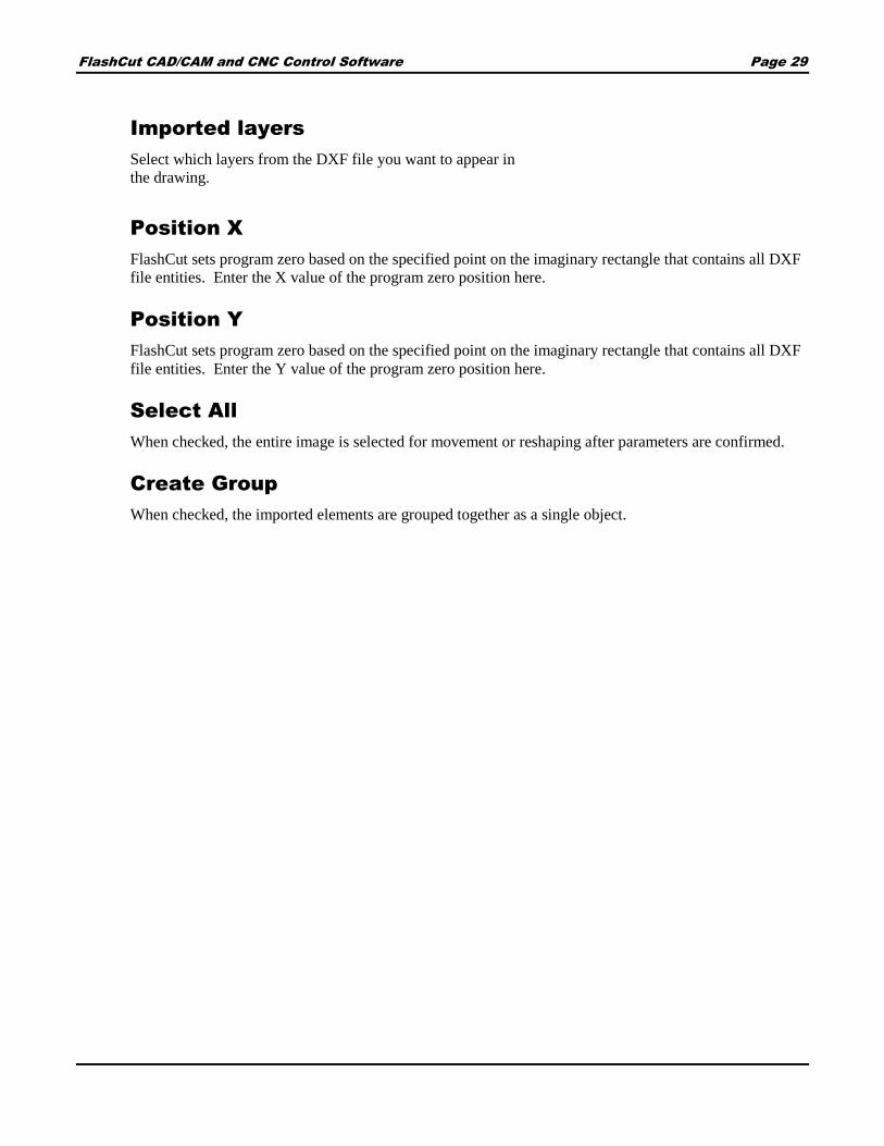
Imported layers
Select which layers from the DXF file you want to appear in
the drawing.
Position X
FlashCut sets program zero based on the specified point on the imaginary rectangle that contains all DXF
file entities. Enter the X value of the program zero position here.
Position Y
FlashCut sets program zero based on the specified point on the imaginary rectangle that contains all DXF
file entities. Enter the Y value of the program zero position here.
Select All
When checked, the entire image is selected for movement or reshaping after parameters are confirmed.
Create Group
When checked, the imported elements are grouped together as a single object.

FlashCut CAD/CAM and CNC Control Software Page 30
Import centerline image
This tool imports a bitmap image and renders each feature as a single
toolpath line down the center of the feature. Images with defined lines
generally result in a cleaner drawing that requires fewer revisions.
After changes are complete, you may either Accept or Cancel the
changes.
Choose image
Click Browse… to select an image file from the computer.
Click Open to call up the desired image. A list of file formats
that can be imported appears on page 24.
Scale
Select how large or small the image appears in the drawing
relative to its original size.
Position X
Enter the value for the X coordinate of the lower left corner of
the imported image.
Position Y
Enter the value for the Y coordinate of the lower left corner of the imported image.
Segmentation quality
FlashCut CAD automatically breaks curves in the drawing into small, separate line segments. Select how
finely the program will divide curves. When increased, the program divides curves into smaller segments,
preserving more detail. This also increases the size of the drawing file, and the program’s memory usage.
Range: 0.0001-100.
Inverted
When checked, this option reverses the shapes enclosed by the curves of the image. The relationship is
the same as that between a part and a cutout: if inverted, the object created from the imported image will
behave like a cutout (below, right).

FlashCut CAD/CAM and CNC Control Software Page 31
Select all
When checked, the entire image is selected for movement or reshaping after parameters are confirmed.
When not checked, nothing will be selected.
Create Group
When checked, the imported drawing objects will be grouped together.
Progress
Indicates the rendering progress after changes are made to the drawing. Making edits during rendering
consumes more system resources. It is advised to wait for rendering to finish between edits.
Create tools
These tools add new elements
to the drawing.
After selecting a tool, move
the cursor into the drawing
window in order to begin
constructing the element.
You may use the mouse to place and size each element or you can edit parameters for the element, such as
dimensions and location, in the parameter window after creating the element. Click the shape or features and then
edit the desired parameters.
After changes are complete, you may either Accept or Cancel the changes.

FlashCut CAD/CAM and CNC Control Software Page 32
Each tool (with the exception of Point) lets you define the Treatment parameter to determine whether the
element is cut or only marked.
Select Cut Element to use the default cutting fab head. This is the pre-selected option. These
elements appear in the CAD window as solid black lines.
Select Mark Element to use the default marking fab head. Marked elements appear in the CAD
window as purple solid lines. If the drawing contains a marked element that is not contained within a
part, FlashCut will notify you when you send the drawing to CAM.
In addition, you may select the For Construction option to indicate that the feature is a construction line, and
should not be cut or marked. Construction lines appear in the CAD window as blue dashed lines, and are not used
by FlashCut CAM and CNC.
The drawings below contain a marked ellipse inside a cut rectangle (left), and an orthographic projection using
construction lines (right) to indicate the relationships between the three views.
Different creation modes exist for each tool and each mode requires different information about the element being
created. When creating an element graphically, or with the mouse, the information is required in a specific
sequence. The Status bar provides step by step instructions on how to use the selected tool in a particular
creation mode.
Note that the behavior of all of the Create tools is influenced strongly by the active Snap tools. See the Snap
tools section of the manual for details.

FlashCut CAD/CAM and CNC Control Software Page 33
These are the tools that are available on the Create portion of the ribbon:
Line
Rectangle
Arc
Circle
Text
Point
Polygon
Elliptic Arc
Ellipse
Spline
Line
Lines may be created either as Continuous Lines by adding segments and vertices with each
mouse click, or as a simple Two Point Line.
When creating a Two Point Line, the properties may be adjusted manually in the parameters window. Any single
line segment (e.g., any segment that is part of a polygon or a multi-segment line) may be selected and its
properties displayed.
Creation mode
Select the type of line to create.
Continuous Line
Two Point Line
Examples of each type are shown below.
Position, offset, angle and length
Define or display the attributes of a specific line segment.
For Construction
Select to make the line a construction line.
Treatment
Select whether the element should be cut or marked.

FlashCut CAD/CAM and CNC Control Software Page 34
Rectangle
FlashCut CNC offers several different options for constructing rectangles, including selecting two
corner points; selecting a center and corner points; selecting three corner points; selecting a center
and two outer points; and selecting three points to generate a parallelogram.
Select which method will be used, and then click the rectangle points in the drawing window. You can manually
enter point coordinates as well.
Creation mode
Select the type of rectangle to create.
Corner Rectangle
Drag from a single corner point.
Center Rectangle
Drag from a center point.
3 Point Corner Rectangle
The first two points clicked describe one
side. Drag to set the length of the
remaining sides.
3 Point Center Rectangle
The first two points clicked set the
length of the center line. Drag to set the
distance from the center line to the lines
parallel to it.
Parallelogram
The first two points set the length of one
side. Drag to set the position of the line
parallel to the first.
Position, offset, midpoint,
corner
Define or display the attributes of a specific
point.
Treatment
Select whether the element should be cut or marked.
FlashCut CAD/CAM and CNC Control Software Page 35
For Construction
Select to make the rectangle a construction line.
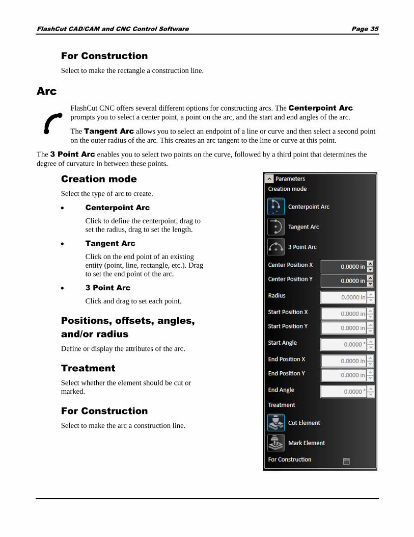
Arc
FlashCut CNC offers several different options for constructing arcs. The Centerpoint Arc
prompts you to select a center point, a point on the arc, and the start and end angles of the arc.
The Tangent Arc allows you to select an endpoint of a line or curve and then select a second point
on the outer radius of the arc. This creates an arc tangent to the line or curve at this point.
The 3 Point Arc enables you to select two points on the curve, followed by a third point that determines the
degree of curvature in between these points.
Creation mode
Select the type of arc to create.
Centerpoint Arc
Click to define the centerpoint, drag to
set the radius, drag to set the length.
Tangent Arc
Click on the end point of an existing
entity (point, line, rectangle, etc.). Drag
to set the end point of the arc.
3 Point Arc
Click and drag to set each point.
Positions, offsets, angles,
and/or radius
Define or display the attributes of the arc.
Treatment
Select whether the element should be cut or
marked.
For Construction
Select to make the arc a construction line.
FlashCut CAD/CAM and CNC Control Software Page 36
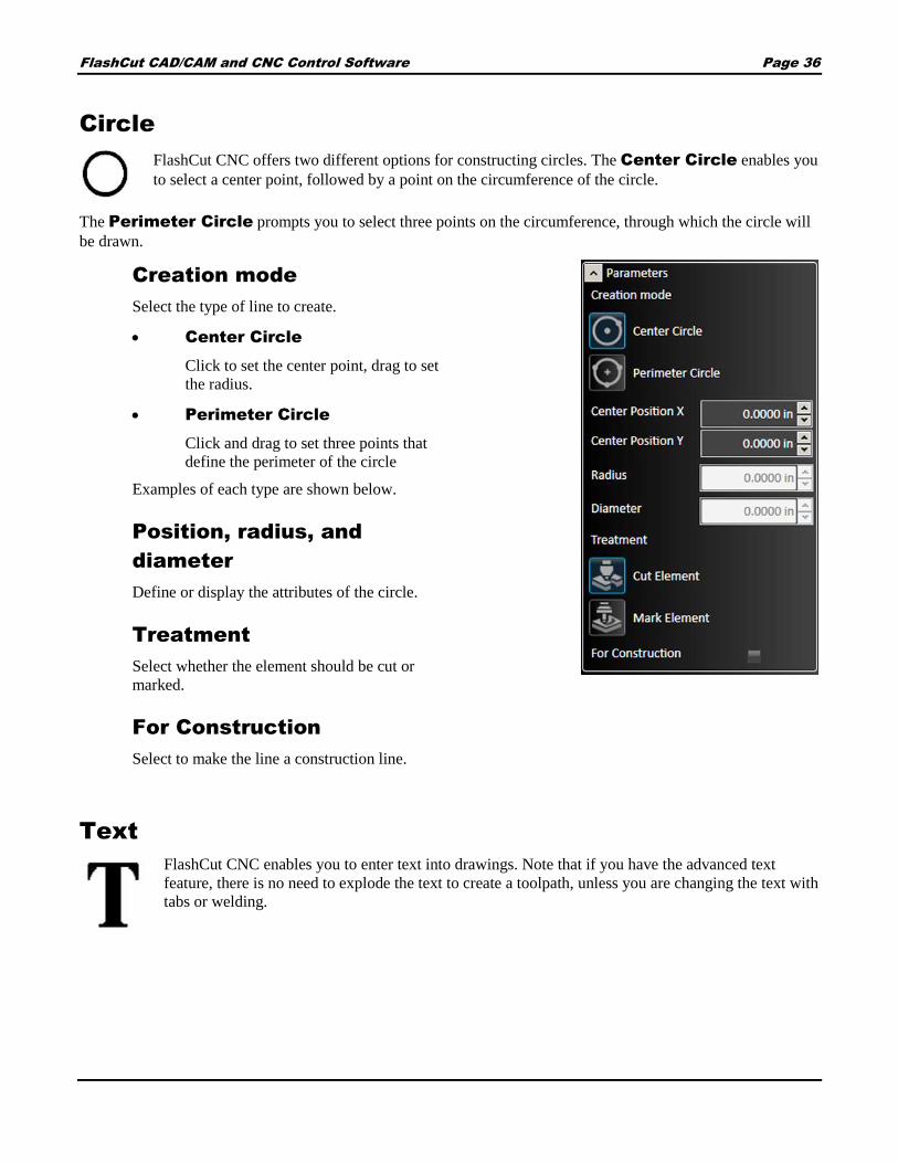
Circle
FlashCut CNC offers two different options for constructing circles. The Center Circle enables you
to select a center point, followed by a point on the circumference of the circle.
The Perimeter Circle prompts you to select three points on the circumference, through which the circle will
be drawn.
Creation mode
Select the type of line to create.
Center Circle
Click to set the center point, drag to set
the radius.
Perimeter Circle
Click and drag to set three points that
define the perimeter of the circle
Examples of each type are shown below.
Position, radius, and
diameter
Define or display the attributes of the circle.
Treatment
Select whether the element should be cut or
marked.
For Construction
Select to make the line a construction line.
Text
FlashCut CNC enables you to enter text into drawings. Note that if you have the advanced text
feature, there is no need to explode the text to create a toolpath, unless you are changing the text with
tabs or welding.

FlashCut CAD/CAM and CNC Control Software Page 37
Position X and Y
Position of the anchor point relative to the
origin.
Text
Type the desired message in the text field. Can
contain multiple lines.
Font Name
Any installed TrueType font can be selected.
Alignment
Alignment of the text relative to the anchor
point. Options include left, right, and center.
Size
Text objects are scalable. The size is shown in
system units.
Kerning Offset
Spacing between letters.
Angle
Angle relative to the anchor point. 360 degree rotation in either direction permitted.
Bold and Italic
Check box to apply style.
Treatment
Select whether the element should be cut or marked.
For Construction
Select to make the text object a construction line. You may also select options for bold and italic here. In
the drawing field, click the desired point for the text. This point varies with the alignment setting of the
text.
Once the text is correctly configured choose the green check mark or press Enter.

FlashCut CAD/CAM and CNC Control Software Page 38
Point
Click on the drawing to create a new point at that location. You
may edit coordinates in the parameter window.
Polygon
FlashCut CNC enables you to select the number of vertices setting, and whether the shape will be
inscribed or circumscribed within a construction circle.
Creation mode
Select the type of polygon to create.
Inscribed Circle
Circumscribed Circle
Click in the drawing window to select the center
point of the polygon. Drag out to the point that
will be the first vertex of the polygon.
Examples of each type are shown below.
Sides Count
Defines the type of polygon. Minimum number
of sides is three.
Position, radius, diameter
and side length
Define or display the attributes of the polygon.
Leave Construction Circle
Causes the circle to remain in the drawing after
the polygon has been completed.

FlashCut CAD/CAM and CNC Control Software Page 39
For Construction option
Select to make the polygon a construction line.
Treatment
Select whether the element should be cut or
marked.
Elliptic Arc
Creates an arc that is a section of an ellipse.
Drawing the arc
Click in the drawing window to select a center
point and the first radius of the ellipse that will
remain fixed.
Move the cursor to determine the second radius
of the ellipse, and click for the desired bend.
Finally, select a start point and then an end point
to the arc.
Center Position X and Y
Coordinates of the center point
Radius 1 and 2
In the example below, Radius 1 is the radius of a
circle defined by the center point and the X axis,
while Radius 2 is the radius of a circle defined
by the center point and the Y axis.
Major Axis Angle
Changing this value allows the arc to be rotated around its centerpoint.

FlashCut CAD/CAM and CNC Control Software Page 40
Start and End Angle
Define the beginning and end points of the arc relative to the center point.
Treatment
Select whether the element should be cut or marked.
For Construction option
Select to make the line a construction line.
Ellipse
Creates an ellipse.
Drawing the ellipse
Click in the drawing window to select a center
point and the first radius of the ellipse that will
remain fixed.
Move the cursor to determine the second radius
of the ellipse, and click for the desired bend.
Center Position X and Y
Coordinates of the center point
Radius 1 and 2
Values defined by the center point and the
furthest extent of the ellipse along each axis.
Angle
Changing this value allows the ellipse to be rotated around its center point.
Treatment
Select whether the element should be cut or marked.
For Construction
Select to make the ellipse a construction line.
FlashCut CAD/CAM and CNC Control Software Page 41
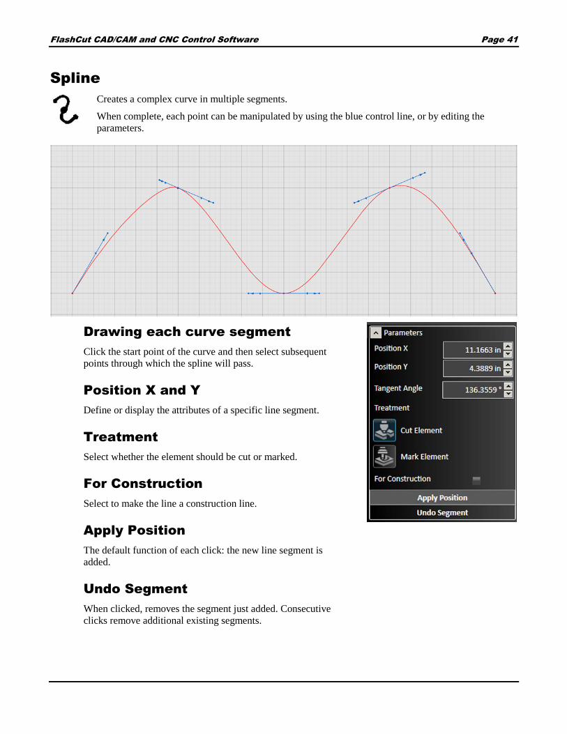
Spline
Creates a complex curve in multiple segments.
When complete, each point can be manipulated by using the blue control line, or by editing the
parameters.
Drawing each curve segment
Click the start point of the curve and then select subsequent
points through which the spline will pass.
Position X and Y
Define or display the attributes of a specific line segment.
Treatment
Select whether the element should be cut or marked.
For Construction
Select to make the line a construction line.
Apply Position
The default function of each click: the new line segment is
added.
Undo Segment
When clicked, removes the segment just added. Consecutive
clicks remove additional existing segments.

FlashCut CAD/CAM and CNC Control Software Page 42
Adjusting a curve segment
The example below shows a single vertex. The blue control line
can be rotated and either end extended to change the shape of the
curve at the vertex.
Current Vertex
Selects the particular vertex on the spline.
Position X and Y
Coordinates of the vertex.
First and Second Magnitude
Shows the length of each control arrow. In the example above, the arrow representing the first magnitude
points to the upper left.
Angle
Describes the angle of the blue control line tangent to the curve at the vertex.
Treatment
Select whether the element should be cut or marked.
For Construction
Select to make the line a construction line.

FlashCut CAD/CAM and CNC Control Software Page 43
Shape tool
FlashCut CNC offers a library of shapes for both simple and complex parts. This library is part of the
pro package, and is also offered as an a la carte feature. Select the shape tool from the ribbon to load
the library in the parameters area.
To choose a specific shape, select it from the list.
Example: Two circles connected by
tangents
Shape parameters
When the shape is imported into the drawing window, its
specific parameters appear. For example, for the shape above,
any of the following attributes can be manually adjusted: R1
and R2 (the radii of the two circles), D1 and D2 (the diameters
of the two through holes), or W (the distance between the
center points of the two circles).
Insertion parameters
The position of the shape on the page and the location of its
pivot point can be selected. In addition, the shape can also be
flipped horizontally or vertically.
After changes are complete, you may either Accept or
Cancel the changes.

FlashCut CAD/CAM and CNC Control Software Page 44
Modify tools
The Modify tools on the ribbon affect a shape that is already in the drawing. First, select the features to be
modified, and then click the tool to modify the feature. You may edit parameters for the modification in the
parameter window.
After modifications are complete, click the green check mark to accept changes or the red X mark to cancel
changes. These are the tools that are available on the Modify portion of the ribbon:
Apply Chamfer
Apply Fillet
Extend Tool
Trim Tool
Scale Entities
Apply Offset
Fix Drawing
Curve Text
Cut Tool
Explode Entities
Group
Ungroup
Ungroup All
Apply Chamfer
Select two intersecting lines or their intersection point, and then click this tool to add a sloped chamfer
to this edge. You can scale the size of the chamfer by dragging the mouse towards or away from the
chamfer, or in the parameter window, type the distances from the intersection in both directions and
the slope angle.
Choosing the Lock Angle option causes both distances to change when one of them is edited, holding the
angle measurement constant. Once the chamfer is correctly configured choose the green check mark or press
Enter.

FlashCut CAD/CAM and CNC Control Software Page 45
Apply Fillet
Select two intersecting lines or their intersection point, and then click this tool to add a rounded fillet
to this edge. You can scale the size of the fillet by dragging the mouse towards or away from the fillet,
or in the parameter window, type in the radius of the fillet. Once the fillet is correctly configured
choose the green check mark or press Enter.
Extend Tool
The extend tool enables you to continue a line or a curve until it intersects with another object in the
drawing. Click the extend tool, and then hover the selection cursor over the endpoint of the line or
curve to be extended. A preview of the extension should appear (in blue, below). Click the mouse to
finalize the extension.
Trim Tool
The trim tool enables you to trim a line or a curve at its intersection with another object in the drawing.
Click the trim tool, and then hover the selection cursor over the line or curve to be trimmed. A preview
of the cut should appear (in red, below). Click the mouse to finalize the trim.

FlashCut CAD/CAM and CNC Control Software Page 46
Scale Entities
Select a feature or group of features to be scaled. FlashCut CNC offers you two options for scaling.
The 3 Points scale prompts you to select a center point and a point close to the feature. Drag the mouse
to increase or decrease the size of the features about the center point and click to apply the
modification. The Point and Factor scale enables you to select a center point and type in a factor by
which the features will be scaled.
FlashCut CAD/CAM and CNC Control Software Page 47
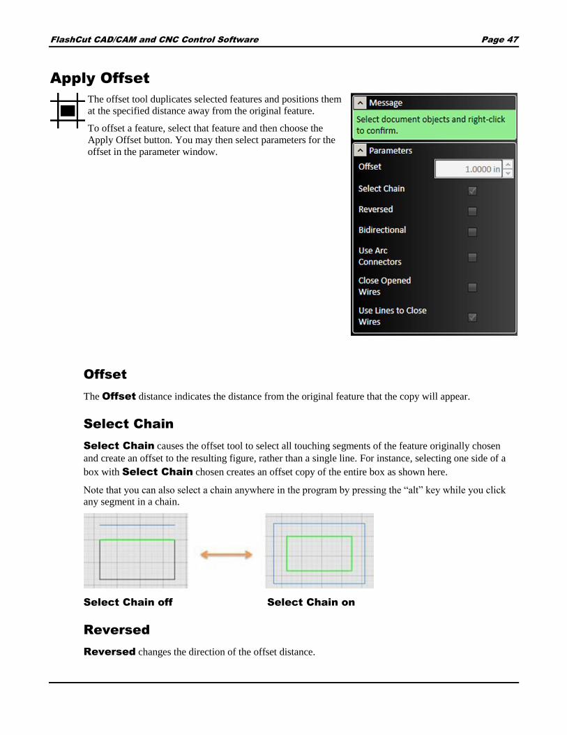
Apply Offset
The offset tool duplicates selected features and positions them
at the specified distance away from the original feature.
To offset a feature, select that feature and then choose the
Apply Offset button. You may then select parameters for the
offset in the parameter window.
Offset
The Offset distance indicates the distance from the original feature that the copy will appear.
Select Chain
Select Chain causes the offset tool to select all touching segments of the feature originally chosen
and create an offset to the resulting figure, rather than a single line. For instance, selecting one side of a
box with Select Chain chosen creates an offset copy of the entire box as shown here.
Note that you can also select a chain anywhere in the program by pressing the “alt” key while you click
any segment in a chain.
Select Chain off Select Chain on
Reversed
Reversed changes the direction of the offset distance.

FlashCut CAD/CAM and CNC Control Software Page 48
Bidirectional
Bidirectional creates a second copy, opposite the first. When the Bidirectional option is chosen,
the Close Opened Wires option appears.
Close Opened Wires
Close Opened Wires option closes the gaps created by the offset ends when chosen.
Use Arc Connectors
Use Arc Connectors rounds out the corners of the offset by transforming them into arcs. An
example appears below.
Use Lines to Close Wires
Use Lines to Close Wires changes the rounded edges to flat, straight lines.
Fix Drawing
The Fix Drawing tool is used to correct mistakes in the drawing that could prevent accurate
toolpaths from being created, such as line segments that do not touch.
To identify issues and fix the drawing, select the icon, and choose a Join Tolerance larger than any of the
errors in the drawing.

FlashCut CAD/CAM and CNC Control Software Page 49
Use the Search Issues button to identify issues with the drawing that could lead to mistakes in fabrication.
Issues noted with a green circle can be fixed automatically by selecting Fix All. Issues noted with a red circle
must be addressed manually.
Curve Text
The Curve Text tool modifies an existing text object to follow a curved shape. Start by creating
both the text object and the curved shape you want to use.
Select the Curve Text tool and follow the instructions in the Parameters
window: select the curve, and then right click on the text object. The
position of the text object can be adjusted with the cursor, and modified
by changing the parameters.
In the example below, note that the Extra Vertical Offset and Kerning
Offset have both been adjusted to make the curved text even and
legible.

FlashCut CAD/CAM and CNC Control Software Page 50
The resulting CAM toolpath for the sample drawing appears below. Note that it is not necessary to explode letter
shapes to create toolpaths.

FlashCut CAD/CAM and CNC Control Software Page 51
Text Start Parameter
Indicates the position on the curve where the text begins. This can be set by adjusting the value in the
parameters window, or by dragging the control handle in the drawing window.
Remove Curve(s)
Separates the text object from the curve.
Set New Curve(s)
Select a different curved object to combine with the text object.
Flip Curve(s)
Changes the side of the curve that the text object follows.
Alignment
Describes the relationship between the start of the line of text and the control point. Options include:
Left
Right
Center
Vertical Alignment
Above Curve – Text is always above the line.
On Curve – Text follows the curve, but portions of the font may
dip below the line.
Below Curve – Text is always below the curve.
Curve Center – The line passes through the center of the text.

FlashCut CAD/CAM and CNC Control Software Page 52
Extra Vertical Offset
Controls the relationship between the text object and the curve.
Line Spacing
Affects the spacing of multiple lines of text.
Kerning Offset
Adjusts the spacing between letters.
Cut Tool
The cut tool divides a segment into separate segment. Click the mouse on the part of the segment to be
split. The segment will separate at that point. You can verify this by hovering the cursor over the
feature. Only a part of it will highlight if the cut worked properly.
Select position on entity to cut into two entities.
Explode Entities
Transforms a feature that is solid and not composed of lines (such as a font) into individual line
segments. This is necessary for toolpath generation of any feature that is solid. Select a solid feature
then choose Explode Entities. See the example below.
Group
The Group command combines selected objects so that they can be modified or transformed as a
single unit. If you choose this command with no objects selected, you will be prompted to select the
objects to be grouped, and to confirm the action by right-clicking.

FlashCut CAD/CAM and CNC Control Software Page 53
Ungroup
The Ungroup command separates the selected grouped objects. If you choose this command without
a group selected, you will be prompted to select the objects to be grouped, and to confirm the action by
right-clicking. See
Ungroup All
The Ungroup All command can separate multiple sets of grouped objects in one operation. If you
choose this command without a group selected, you will be prompted to select the objects to be
grouped, and to confirm the action by right-clicking.
The example below shows the highlighting and message for all grouping operations.
Ungroup vs. Ungroup All
The difference in behavior between Ungroup and Ungroup All is shown below. Each object in the group (left) is
itself a group of multiple objects. Ungroup (center) will separate the group but leave each subgroup intact,
while Ungroup All (right) will break each object into its component lines. Note how the selections (green)
indicate the level of grouping: all, some, none.
Transform tools
These tools do not change the physical properties of the drawing features. Instead, they modify the size, scale, and
number of features in the drawing.

FlashCut CAD/CAM and CNC Control Software Page 54
First, select the features to be modified, then select the transform tool that will be used. You may edit parameters
for the transformation in the parameter window. After transformations are complete, click the green check mark to
accept changes or the red X mark to cancel changes.
These are the tools that are available on the Transform portion of the ribbon:
Copy entities
Delete selected objects
Move entities
Rotate entities
Measure entities with ruler
Bridge entities
Perform boolean operation on entities
Weld selected entities
Mirror entities
Linear pattern tool
Circular pattern tool
Copy entities
Select the features to be copied in the drawing window, choose the Copy entities button and then
click a reference point about which the new features will be copied. Position the cursor at the paste
location and click to paste the copied features. You may paste multiple features until you exit from the
tool.
Delete selected objects
Select the features to be deleted, and then click the Delete selected objects tool. The features
will be removed.
Move entities
Select the features to be moved, and then click the Move Entities tool. Click a reference point about
which the features will be moved, and then select the new location for the features.

FlashCut CAD/CAM and CNC Control Software Page 55
Rotate entities
FlashCut CNC offers two modes for rotating features. The 3
Points rotation prompts you to select a center point, a point
near the feature, and a final point to which the feature will
rotate. The Point and Angle rotation requires you to select a
central rotation point, and then enter a rotation amount in
degrees. After changes are complete, click the green check
mark or press Enter to accept changes or the red X mark to
cancel changes.
Measure entities with ruler
Measurements can be made in one of three modes: as a ruler between points or entities, or as a
protractor between points on an arc. Allows for measurement between any two points and displays
offset in X and in Y directions.

FlashCut CAD/CAM and CNC Control Software Page 56

FlashCut CAD/CAM and CNC Control Software Page 57
Note Protractor will not measure an arc or angle if it is grouped with other lines or shapes; must ungroup the
arc for protractor tool to become available to measure.
Bridge entities
Connects two or more objects with a bridge that spans the gap between them. Can also be used to
divide a single object into separate objects. The width of each bridge can be set individually.
To create a bridge, select the tool, draw a line with the cursor, modify the width of the bridge if
desired, and select the green checkmark to accept the change.
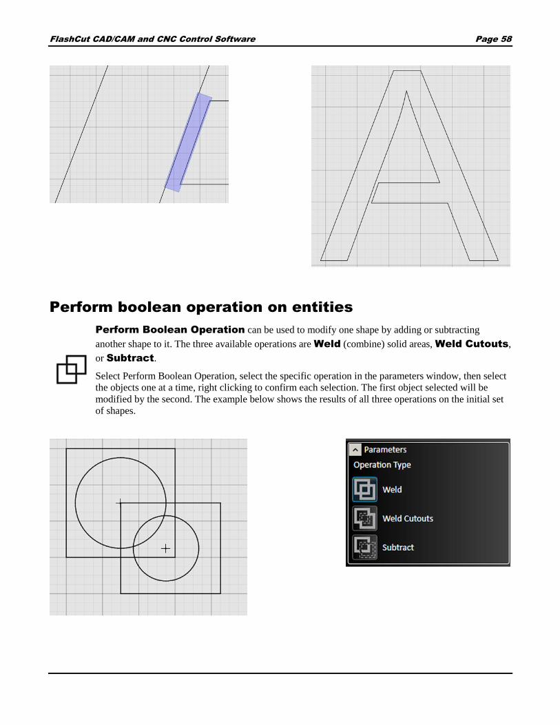
FlashCut CAD/CAM and CNC Control Software Page 58
Perform boolean operation on entities
Perform Boolean Operation can be used to modify one shape by adding or subtracting
another shape to it. The three available operations are Weld (combine) solid areas, Weld Cutouts,
or Subtract.
Select Perform Boolean Operation, select the specific operation in the parameters window, then select
the objects one at a time, right clicking to confirm each selection. The first object selected will be
modified by the second. The example below shows the results of all three operations on the initial set
of shapes.

FlashCut CAD/CAM and CNC Control Software Page 59
Shapes highlighted to indicate which object is first
(gold) and second (red). The results of a Weld operation.
The results of a Weld Cutouts operasion The results of a Subtract operation.
Weld selected entities
To quickly combine multiple shapes into a single shape,
first create the desired overlapping objects.
Select the Weld Selected Entities tool, select the
objects, and right-click to confirm the operation.
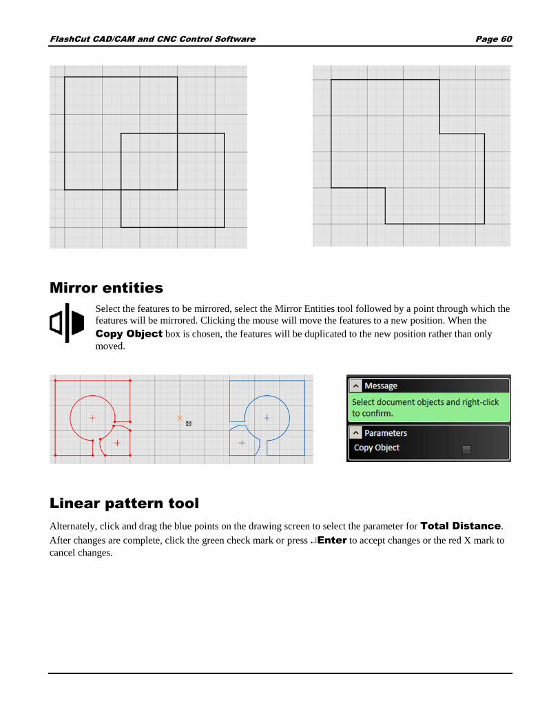
FlashCut CAD/CAM and CNC Control Software Page 60
Mirror entities
Select the features to be mirrored, select the Mirror Entities tool followed by a point through which the
features will be mirrored. Clicking the mouse will move the features to a new position. When the
Copy Object box is chosen, the features will be duplicated to the new position rather than only
moved.
Linear pattern tool
Alternately, click and drag the blue points on the drawing screen to select the parameter for Total Distance.
After changes are complete, click the green check mark or press Enter to accept changes or the red X mark to
cancel changes.

FlashCut CAD/CAM and CNC Control Software Page 61
The linear pattern tool duplicates selected features in a
grid fashion. Select the feature to be duplicated, select
the Linear pattern tool then specify parameters.
Direction 1 represents the horizontal
direction.
Direction 2 represents the vertical direction.
Spacing sets the distance between copies.
Total Distance represents the overall
distance from the original to the final copy.
Count indicates the number of copies to
generate in each row and column.
Angle specifies the angular offset from the
horizontal and vertical directions.

FlashCut CAD/CAM and CNC Control Software Page 62
Circular pattern tool
The circular pattern tool duplicates selected features in a
circular fashion about a specified point. Select the feature
to be duplicated, select the Circular pattern tool and
then specify parameters.
The Center X and Center Y options specify
the point about which the feature will be rotated.
Alternately, click and drag the blue center point of
the rotation.
Checking the Spacing Mode box changes the Angle parameter to represent the degree angular
spacing between each copy, rather than from the original to the final copy.
The Angle parameter indicates the angular position of the final copy from the original
The Count option determines the number of copies that will be created.

FlashCut CAD/CAM and CNC Control Software Page 63
Pan and zoom tools
The pan and zoom tools are located at the top left of the workspace and are used for
moving and magnifying the drawing in the drawing workspace. Click a tool to change
the cursor’s function.
Pan
The pan tool allows you to click and drag
anywhere in the drawing window to move the
drawing around. Right clicking and dragging
in the window also allows you to pan without
the use of the pan tool.
Zoom Extent
Click and drag a box in which to zoom in.
This tool allows to user to focus in on a
specific section of the diagram.
Zoom
Click and drag anywhere to zoom in and out
on the drawing. You can also use the scroll
wheel to zoom; scroll up to zoom in and scroll
down to move out.
Zoom to Fit
Click this button to adjust zoom automatically
to best fit the drawing.

FlashCut CAD/CAM and CNC Control Software Page 64
Snap tools
The snap tools affect how drawing tools interact with the background grid or features already created. Clicking a
snap tool toggles it on or off. Snap tools cause a feature or segment to lock on to the closest active snap location
when the cursor is dragged nearby. Note that more than one type of snap can be active at one time.
These are the tools that are available on the Snap tools toolbar at the top right of the workspace:
Center snap
Endpoint snap
Grid snap
Horizontal/vertical snap
Intersection snap
Midpoint snap
Nearest snap
Parallel snap
Perpendicular snap
Quadrant snap
Tangent snap
Center snap
Features connect to the center of elements like circles.
Endpoint snap
Features connect to the endpoints of elements like lines.

FlashCut CAD/CAM and CNC Control Software Page 65
Grid snap
Features connect to points located along the background
gridlines.
Horizontal/vertical snap
Features align vertically and horizontally when pulled into
either direction.
Intersection snap
Features connect to the intersection points of
elements in the drawing.

FlashCut CAD/CAM and CNC Control Software Page 66
Midpoint snap
Features connect to the midpoint of elements like
lines.
Nearest snap
Features connect with the element closest to the
cursor.
Parallel snap
Features align parallel with elements of the
drawing like lines. A blue dashed line indicates
that the feature is parallel to the red highlighted
element in the drawing.

FlashCut CAD/CAM and CNC Control Software Page 67
Perpendicular snap
Features align perpendicular with elements of the
drawling like lines. A blue dashed line indicates
that the feature is perpendicular to the red
highlighted element in the drawing.
Quadrant snap
Features connect to the topmost, bottommost,
leftmost, and rightmost points of elements like
circles.
Tangent snap
Features connect tangentially to elements in the
drawing like circles.

FlashCut CAD/CAM and CNC Control Software Page 68
FlashCut CAM
FlashCut CAM (Computer-Aided Manufacturing) generates an accurate toolpath from a CAD drawing. This
toolpath is used to create the G-code that will be used in FlashCut CNC.
The FlashCut CAM main screen is shown here. An explanation of each area of the screen follows.
An explanation of each area of the screen is provided in these topics:
Tabs
Display options tools
Menu bar
Drawing workspace
Configuration, License, and Help buttons
Parameters area
Ribbon
Status bar
Pan and zoom tools
Accept / Cancel
1 6
2 7
3 8
4 9
5 10
3
4
5 6
7
12
8
9 10

FlashCut CAD/CAM and CNC Control Software Page 69
Ribbon
The FlashCut CAM ribbon has seven types of command icons:
File tools
Feature Type
Selection
CAM Actions
G-code
Import
File tools
There are two file tools on the ribbon:
Open (Ctrl+O)
Save (Ctrl+S)
Open (Ctrl+O)
Opens an existing CAD/CAM drawing for editing in a new FlashCut CAD window. It does not close
the current drawing.
Save (Ctrl+S)
Saves the current CAD/CAM drawing using the existing file name and location. It will not save any
other CAD/CAM drawing that is open. FlashCut will prompt you to create a file name and destination.
FlashCut saves drawings to the CAD/CAM (*.cadcam) format. These files represent CAD drawings
readable by FlashCut CAD version 5 or later. This command is unavailable when no recent changes
have been made.
Feature Type
This pair of settings controls whether the top level of the drawing, indicated by the outermost line, is considered a
part or a cut out. This setting will change which sections of the drawing are considered scrap, and which the part
to be saved. The placement of kerf lines, lead ins, and corners is determined by this setting. For example, when
making a circular cut in the workpiece, is the intention to make a disc, or to make a circular hole? The former is a
part; the latter is a cutout. The behavior of nested closed shapes is also determined by this setting
Changing from one to the other will reset the history of the Undo command.
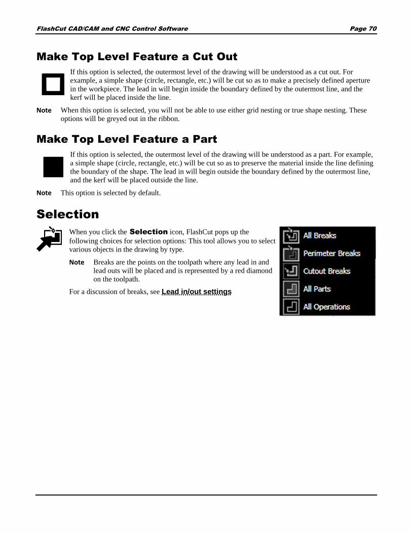
FlashCut CAD/CAM and CNC Control Software Page 70
Make Top Level Feature a Cut Out
If this option is selected, the outermost level of the drawing will be understood as a cut out. For
example, a simple shape (circle, rectangle, etc.) will be cut so as to make a precisely defined aperture
in the workpiece. The lead in will begin inside the boundary defined by the outermost line, and the
kerf will be placed inside the line.
Note When this option is selected, you will not be able to use either grid nesting or true shape nesting. These
options will be greyed out in the ribbon.
Make Top Level Feature a Part
If this option is selected, the outermost level of the drawing will be understood as a part. For example,
a simple shape (circle, rectangle, etc.) will be cut so as to preserve the material inside the line defining
the boundary of the shape. The lead in will begin outside the boundary defined by the outermost line,
and the kerf will be placed outside the line.
Note This option is selected by default.
Selection
When you click the Selection icon, FlashCut pops up the
following choices for selection options: This tool allows you to select
various objects in the drawing by type.
Note Breaks are the points on the toolpath where any lead in and
lead outs will be placed and is represented by a red diamond
on the toolpath.
For a discussion of breaks, see Lead in/out settings

FlashCut CAD/CAM and CNC Control Software Page 71
All Breaks
Selects all available breaks in the document, including perimeter
breaks and cutout breaks.
Perimeter Breaks
Select this option to select all breaks that are on the outside of the
part. When the toolpath is offset to the outside of the part the break
on this toolpath is defined as a perimeter break.
Cutout Breaks
Select this option to select all breaks that are on the inside of a cutout.
When the toolpath is offset to the inside of a feature or a cutout, the
break is called a cutout break.
In this example (below), the break for each circular cutout is
highlighted, while the perimeter break for the surrounding part is not.
All Parts
Choose this option to select all of the parts in the viewport. This allows the user to drag and drop all parts to
another position on the workpiece.
All Operations
Choose this option to select all of the operations used to fabricate the part.

FlashCut CAD/CAM and CNC Control Software Page 72
CAM Actions
The CAM actions bar enables you to replicate and nest various
features in the CAM drawing, as well as select various settings
for lead in and lead out lines and the plasma torch. Clicking each
option brings up numerous settings in the parameter window.
These are the tools that are available on the CAM Actions
portion of the ribbon:
Project Settings
Plasma Settings
Oxyfuel Settings
Waterjet Settings
Marker Settings
Grid Nesting
TrueShape Nesting
Sequence tool
CAM Reset
If a fab head has been configured, its icon will
appear on the CAM ribbon. For more
information, see Configuring FlashCut.
Project Settings
Configures options applied to the current CAM project.
Click the Project Settings icon to bring up the
following options in the Parameters window.
General
Default Cutting Fabhead
Selects the default cutting fabhead. Multiple fabheads can be
defined in the Configuration interface.
Default Marking Fabhead
Selects the default marking fabhead.
Workpiece
Width
Specify the width of the sheet being cut. This will change the
size of the material in the drawing window as well as any
nesting settings.
FlashCut CAD/CAM and CNC Control Software Page 73
Height
Specify the height of the sheet being cut. This will change the size of the material in the drawing window
as well as any nesting settings.
Recent Sheet Sizes
Select from a list of recently selected material types.
Material
Material Type
Select your material type. The parameters will automatically adjust to match your selection.
Thickness
Select the thickness of your material. The parameters will automatically adjust to match your selection.
Recent Materials
A drop-down list containing recently selected materials.
Plasma Settings
If a plasma fab head has been configured, its settings can be adjusted here.
FlashCut offers a number of different options for calibrating the CAM editor to match the
specifications of various plasma torches. Click the icon to bring up options in the parameters window.
You can override any of the recommended settings by simply typing in the respective field. After specifications
are complete, you may either Accept or Cancel the changes.
The values in the parameters are derived from the settings in the *.setup file. Changes made here will apply to the
specific drawing, but will not change the values set in the configuration window. The configured values for the
fab head are in turn populated from the cut charts. See Configuring FlashCut for more details.

FlashCut CAD/CAM and CNC Control Software Page 74
Nozzle
Select your plasma torch nozzle. The parameters will
automatically adjust to match your selection.
Note that each of the following parameters will be
automatically adjusted when the nozzle is specified. However,
they can also be input manually.
Quality Level
Toggle whether the toolpath will be optimized for best quality
or fastest cutting.
Feedrate
Specify the default feedrate at which the machine will move
while cutting.
Kerf Width
Input the width of the kerf of the plasma torch. This will
determine the thickness of the cut, and the toolpath will change
to reflect the new size. The toolpath is automatically offset
outside by ½ the kerf width for parts, and automatically offset
inside by ½ the kerf width for cutouts.
Corners
Toggle whether the corners on the toolpath will be sharp or rounded. Different types of corners will result
in more precise cuts depending on the qualities of the fab head and the material.
Changes to the corner settings may take a short time to render the toolpath.
Sharp corners
The toolpath follows the same angle as the part, maintaining a
consistent distance from the edge.
Rounded corners
The toolpath describes an arc at the corner of the part, maintaining
a consistent distance from the edge.

FlashCut CAD/CAM and CNC Control Software Page 75
Rounded loops
The toolpath proceeds past the corner and describes a loop to
reorient the fab head in the desired direction to cut the next section
of the part. May result in a more precise cut at the corner.
Triangular loops
The toolpath proceeds past the corner and describes a triangle to
reorient the fab head in the desired direction to cut the next section
of the part. May result in a more precise cut at the corner.
Pierce Height
Specify the height at which the torch will initially pierce before cutting along the toolpath. If your
machine is set to do a touch off at the beginning of each cut, then the pierce height is relative to the last
touch off location.
Cut Height
Specify the height at which the torch will cut the part along its toolpath. If your machine is set to do a
touch off at the beginning of each cut, then the pierce height is relative to the last touch off location.
Pierce Delay
Specify the time between the command for the torch to fire and the motion of the machine. The delay
allows the torch time to pierce completely through the material prior to any other machine motion.
Safe Z Height
Input the height to which the torch will return after each cut. It is a safe plane on which the torch can
move, and indicates the lowest height at which the torch will make rapid moves between cutting features
or parts. This is relative to the Program Zero, and is independent of the last touch off position.
Voltage
This is the target voltage for the THC system in order to maintain a specified cut height. The set point
value is determined by the cut chart for each plasma torch, and can also be found in the operator’s manual
of the plasma torch. It and is dependent on the material type, thickness, torch settings, and other
parameters.
When sampling is enabled, the system will automatically detect this voltage and track it throughout the
cut. The higher the voltage the higher the torch will cut, lower the set point to bring the torch closer to the
material during cut moves.
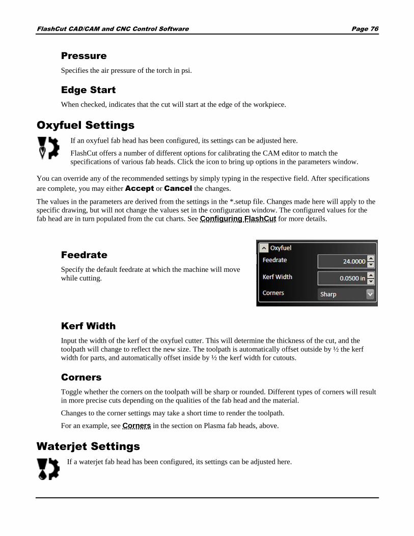
FlashCut CAD/CAM and CNC Control Software Page 76
Pressure
Specifies the air pressure of the torch in psi.
Edge Start
When checked, indicates that the cut will start at the edge of the workpiece.
Oxyfuel Settings
If an oxyfuel fab head has been configured, its settings can be adjusted here.
FlashCut offers a number of different options for calibrating the CAM editor to match the
specifications of various fab heads. Click the icon to bring up options in the parameters window.
You can override any of the recommended settings by simply typing in the respective field. After specifications
are complete, you may either Accept or Cancel the changes.
The values in the parameters are derived from the settings in the *.setup file. Changes made here will apply to the
specific drawing, but will not change the values set in the configuration window. The configured values for the
fab head are in turn populated from the cut charts. See Configuring FlashCut for more details.
Feedrate
Specify the default feedrate at which the machine will move
while cutting.
Kerf Width
Input the width of the kerf of the oxyfuel cutter. This will determine the thickness of the cut, and the
toolpath will change to reflect the new size. The toolpath is automatically offset outside by ½ the kerf
width for parts, and automatically offset inside by ½ the kerf width for cutouts.
Corners
Toggle whether the corners on the toolpath will be sharp or rounded. Different types of corners will result
in more precise cuts depending on the qualities of the fab head and the material.
Changes to the corner settings may take a short time to render the toolpath.
For an example, see Corners in the section on Plasma fab heads, above.
Waterjet Settings
If a waterjet fab head has been configured, its settings can be adjusted here.

FlashCut CAD/CAM and CNC Control Software Page 77
FlashCut offers a number of different options for calibrating the CAM editor to match the specifications of
various fab heads. Click the icon to bring up options in the parameters window.
You can override any of the recommended settings by simply typing in the respective field. After specifications
are complete, you may either Accept or Cancel the changes.
The values in the parameters are derived from the settings in the *.setup file. Changes made here will apply to the
specific drawing, but will not change the values set in the configuration window. The configured values for the
fab head are in turn populated from the cut charts. See Configuring FlashCut for more details.
Machinability
This parameter is specific to the material to be cut, and is
populated from the cut charts for the fab head.
Nozzle Diameter
Nozzle diameter for the cutting head.
Pressure (ksi)
Cutting head pressure, thousands of pounds (kilopounds) per
square inch.
Abrasive Flow
Flow rate for the abrasive compound.
Quality
Low, fair, average, good, or excellent.
Kerf Width
Input the width of the kerf of the waterjet. This will determine the thickness of the cut, and the toolpath
will change to reflect the new size. The toolpath is automatically offset outside by ½ the kerf width for
parts, and automatically offset inside by ½ the kerf width for cutouts.
Feedrate
Specify the default feedrate at which the machine will move while cutting.
Corners
Toggle whether the corners on the toolpath will be sharp or rounded. Different types of corners will result
in more precise cuts depending on the qualities of the fab head and the material.
Changes to the corner settings may take a short time to render the toolpath.
For an example, see Corners in the section on Plasma fab heads, above.

FlashCut CAD/CAM and CNC Control Software Page 78
Marker Settings
If a marker has been configured, the Feedrate
can be adjusted here.
See Configuring FlashCut for more details.
Grid Nesting
The grid nesting function duplicates a part in a grid pattern. In the parameter window, type in the
count of parts that you want to cut along with the X and Y spacing of parts in the grid. The number of
rows and columns is determined by the sheet size.
Copies fill rows left to right, and when the edge of the material is reached, they will advance up a row. Grid
nesting does not change the orientation of any of the parts being nested as illustrated in the screen below where 5
triangles are grid nested. The parameters for grid nesting are described below.

FlashCut CAD/CAM and CNC Control Software Page 79
Count
Determines the total number of parts that will be nested,
inclusive of the original.
Automatically add workpieces
Adds a new sheet to the drawing containing a new workpiece if
the number of shapes to be cut exceeds the capacity of the
current workpiece.
Nest from corner
Selects the starting point of the nesting operation.
Nesting direction
Selects the direction from the starting point in which new nested
parts will be added.
Spacing X
Sets the horizontal spacing between parts.
Spacing Y
Sets the vertical spacing between parts.
Start Nesting
Starts the nesting operation
Progress
Shows the progress of the nesting operation. Complex nesting operations can take significantly longer.

FlashCut CAD/CAM and CNC Control Software Page 80
TrueShape Nesting
The TrueShape nesting function will duplicate, rotate and translate each part to create a nest that
minimizes the amount of material used in a sheet. 12 triangles are nested below using TrueShape
Nesting. Notice the material usage is much lower for TrueShape nesting as it is for the same number of
triangles using Grid nesting. The parameters for TrueShape Nesting are described below.
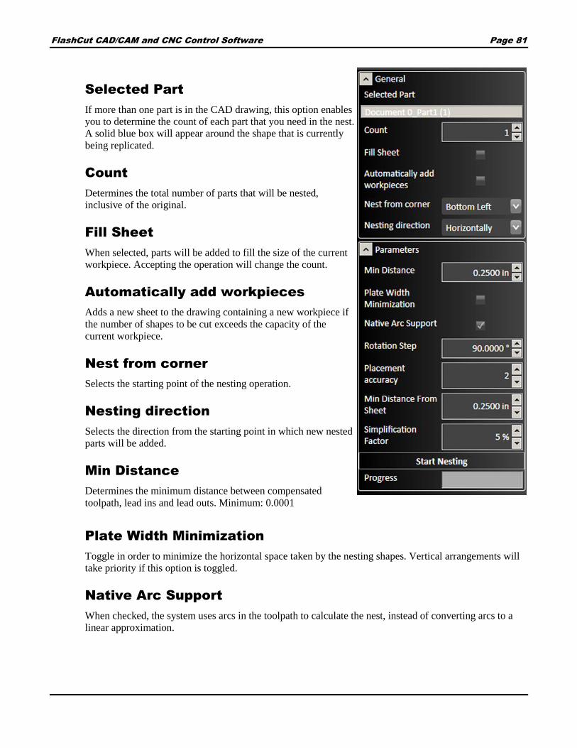
FlashCut CAD/CAM and CNC Control Software Page 81
Selected Part
If more than one part is in the CAD drawing, this option enables
you to determine the count of each part that you need in the nest.
A solid blue box will appear around the shape that is currently
being replicated.
Count
Determines the total number of parts that will be nested,
inclusive of the original.
Fill Sheet
When selected, parts will be added to fill the size of the current
workpiece. Accepting the operation will change the count.
Automatically add workpieces
Adds a new sheet to the drawing containing a new workpiece if
the number of shapes to be cut exceeds the capacity of the
current workpiece.
Nest from corner
Selects the starting point of the nesting operation.
Nesting direction
Selects the direction from the starting point in which new nested
parts will be added.
Min Distance
Determines the minimum distance between compensated
toolpath, lead ins and lead outs. Minimum: 0.0001
Plate Width Minimization
Toggle in order to minimize the horizontal space taken by the nesting shapes. Vertical arrangements will
take priority if this option is toggled.
Native Arc Support
When checked, the system uses arcs in the toolpath to calculate the nest, instead of converting arcs to a
linear approximation.

FlashCut CAD/CAM and CNC Control Software Page 82
Rotation Step
Specify the minimum angle by which FlashCut will attempt to rotate a part when calculating the nest. By
default, this setting will be 90 degrees. The smaller this step, the longer it will take for the nesting to
render. Range: 0-360 degrees.
Placement accuracy
Specify the minimum step distance by which FlashCut will attempt to position a feature when calculating
the nest. By default, this setting will be 0.2000 inches. The smaller the step, the longer it will take for the
nesting to render. Range: 1-10.
Min Distance from Sheet
Determines the minimum distance from the edge of the sheet to any feature on any part including kerf
compensation, lead ins and lead outs. A value of zero corresponds to the edge of the material.
Simplification factor
Speeds up nesting when nesting complex shapes. Complex shapes can take a long time to nest.
Simplification modifies the variables sent to the nesting algorithm to balance faster nesting against
perfection of spacing. A higher value will make the nesting algorithm finish faster at the cost of some
precision of spacing. Range: 0-100%.
Sequence tool
When selected, the sequence tool will display the order in which parts will be cut by displaying
arrows. To change the order, click the edge of a feature and then drag a blue arrow to the edge of the
next feature you want cut. When finished, select the green check mark to finalize changes.
CAM Reset
Resets CAM page and clears all drawings as well as clearing the tool path.

FlashCut CAD/CAM and CNC Control Software Page 83
G-code
The G-code tools on the ribbon allow you to create or edit a G-code program for the CAM
process for the current workpiece. These are the tools that are available on the G-code
portion of the ribbon:
Create G-code file
Open editor
Create G-code file
Click the Create G-code file icon to create a G-code program for the CAM process for the current
workpiece.
Open editor
Click the Open editor icon to open the FlashCut CAM G-code editor with the G-code program for the
CAM process for the current workpiece.
Import
Files can be imported into the CAM drawing workspace. If other objects are added, new toolpaths will be
generated.
Note Objects imported as files will not appear in the CAD drawing space.
DXF/DWG
Imports DXF/DWG file to the CAM drawing workspace. The file selection dialog, and other options
are shown in the Parameters window.
CADCAM
Imports a CADCAM file to the CAM workspace. The file selection dialog and a progress bar are
shown in the Parameters window.

FlashCut CAD/CAM and CNC Control Software Page 84
Pan and zoom tools
The pan and zoom tools are on the top left of the workspace and are used for
moving and magnifying the drawing in the drawing workspace. Click a tool to
change the cursor’s function.
Pan
The pan tool allows you to click and drag
anywhere in the drawing window to move the
drawing around. Right clicking and dragging in
the window also allows you to pan without the
use of the pan tool.
Zoom Workpiece
Extents
Click this button to zoom the drawing to
fill the workspace with the workpiece.
Zoom
Click and drag anywhere to zoom in and out on
the drawing. You can also use the scroll wheel to
zoom; scroll up to zoom in and scroll down to
move out.
Zoom Toolpath
Extents
Click this button to zoom the drawing to
fill the workspace with the toolpaths.
Zoom Window
Click and drag a box in which to zoom in. This
tool allows you to focus in on a specific section
of the diagram.
Display options tools
The display options tools are shown at the top of the drawing workspace
and allow to you to decide what appears in the drawing window. Click
the buttons to toggle each option on and off. You may toggle any
number of options at one time.
The following display options are available:
Cutting directions
Kerf
Material
Parts
Rapid moves
Tool paths

FlashCut CAD/CAM and CNC Control Software Page 85
Cutting directions
When toggled, the direction of motion of the cutting tool is shown in the drawing as a series of small
arrows.
Kerf
The kerf indicates the width of the cut created by the plasma torch or other cutting tool. When toggled,
a blue highlight will appear over the cut outline which indicates exactly how the feature will be cut.
You can modify the kerf width in Plasma Settings.
Material
When toggled, a red box is displayed in the drawing window to indicate the actual sheet dimensions.
Double clicking this box enables you to edit its dimensions in the parameter window. You can also
click on the perimeter of the sheet to bring up the parameter window.
Parts
When toggled, each feature to be cut is outlined in black on the CAM drawing.
Rapid moves
When toggled, rapid moves of the cutting tool are displayed on the drawing as dotted red lines. In
order for rapid moves to be displayed, Tool paths must also be toggled.
Tool paths
When toggled, the path of the cutting tool is outlined in red on the CAM drawing.
Drawing workspace
This section discusses the following topics:
Feature manipulation
Lead in/out settings
Program zero

FlashCut CAD/CAM and CNC Control Software Page 86
Feature manipulation
You can maneuver parts in the drawing window into a
desired rotation or position. Move the cursor over the
part so that it highlights green and select it so it turns
red.
From here, you may click and drag the part to a specific
location. You can also rotate parts by clicking and
dragging one of the arrows in the corners. Moving a
feature also adjusts automatically generated features,
including lead in, lead out lines and rapid move paths.
Lead in/out settings
Lead in and lead out lines are used to provide a way for
the torch to ease into a shape. Usually, they are oriented in the
same direction as the toolpath in order to ensure a clean cut of
the final piece. The lengths of these lines are initially
calculated from the thickness of the workpiece.
The initial locations of these lines are automatically
generated by an internal algorithm using basic rules. FlashCut
CAM enables you to override these initial settings for each
individual feature.
To adjust the lead in and lead out settings, select the red
diamond icon on the desired feature. This brings up the
parameters window.
If you want to change the location of the lead in and lead out,
then you can simply drag the red diamond along the toolpath
to the desired location.
In the examples to the right, the top drawing shows a closed
break with an overburn. The cut begins with an arc-shaped
lead in, and finishes with an arc-shaped lead out. The
parameters for this break are shown below.
The bottom drawing shows a tab break, no lead in or lead out.

FlashCut CAD/CAM and CNC Control Software Page 87
Break Type
Closed
When selected, the lead point and the end of the cut
will overlap, closing the break between the beginning
and end of the cut.
Overburn
To ensure a clean cut, you may set the torch to
continue through a cut along the same toolpath. This
feature allows you to determine how far this overburn
will go. Lead out lines appear after the overburn.
Tab
When selected, there will be a gap between the lead
point and end of the cut, creating a tab break between
the beginning and end of the cut.
Width
The distance of the tab can be set here.
LeadIn/LeadOut Type
Select the type of leading line to be used for the lead in and
lead out lines.
No Lead removes the respective line.
Line results in a straight line. If you choose Line, the
Line Length and Line Angle options below are
displayed.
Arc creates an arc tangent to the feature. If you
choose Arc, the Arc Radius and Arc Angle
options are displayed.
Line Length
Select the length of the leading line.
Line Angle
Select the angle that the leading line makes with the toolpath. The angle is measured clockwise.

FlashCut CAD/CAM and CNC Control Software Page 88
Arc Radius
Select the radius of the circular arc.
Arc Angle
Select the angle that the arc travels through, measured from the edge of the toolpath.
Program zero
The blue set of axes in the drawing window represents the origin of the program
coordinates. You may move these axes around by clicking and dragging the blue lines,
or by entering coordinates manually in the parameter window. For more information
on program coordinates, see Program coordinates panel.

FlashCut CAD/CAM and CNC Control Software Page 89
FlashCut CNC
FlashCut CNC (Computer Numerical Control) control is the final step in the cutting process, and may be accessed
at any point from the other two steps, or independently if you already have a file to import. The panel is used to
program and control each axis on your machine via the FlashCut CNC Controller. For comprehensive information
on programming and G-code, see the FlashCut CNC Programming Reference manual.
The main screen is shown below. An explanation of each area of the screen follows.
An explanation of each area of the screen is provided in these topics:
Tabs
Machine coordinates panel
Configuration, License, and Help buttons
Jog and point control panel
System Status Connect
G-code window
Fab head settings
Pan and zoom tools
Program coordinates panel
Drawing workspace
1 6
2 7
3 8
4 9
5 10
1 2
3
7
8
4
5
6
9
10

FlashCut CAD/CAM and CNC Control Software Page 90
System Status and Connect
System Status
Click the magnifying glass icon to view the live status of the input and output lines.
Input Lines
If a numerical control (NC) input line is normal, it
will be in the closed state and the blue LED will
not be illuminated. If the machine is connected,
these icons are live when a switch changes its state.
If an NC switch is tripped then it will be in the
open state and the blue LED will be illuminated.
Normally, only input lines that have been defined are
displayed. However, if the show all checkbox is
selected, the status of all input lines will be displayed.
Output Lines
The output line status icons are either white for off,
or blue for on. You can also control the state of
these switches by clicking on them here.
Controller
The serial number and USB speed of the controller
are also shown.
Connect
Clicking this icon connects or disconnects the signal generator. When connected, the
icon is illuminated and the two halves are in contact.
Ensure that the signal generator (CNC controller) is securely connected via USB cable
to your PC, and that the USB driver is installed (see Installing the USB Driver for
instructions).
Click the Connect icon. FlashCut begins communication with the signal generator. If there is a problem with
the connection, a dialog box appears.
When properly connected, the Connect icons will join and turn blue. Press Disconnect prior to unplugging
the signal generator.

FlashCut CAD/CAM and CNC Control Software Page 91
When the signal generator is connected, all moves are performed by the machine tool.
Before the unit connects, a safety reminder screen appears. It is imperative that you and anyone else near the
machine understand, agree with and adhere to all of the safety guidelines. If the safety guidelines are not
accepted, the software will not connect.
Fab head settings
Each fab head that has been configured and saved will be displayed here. See Configuring FlashCut for more
information.
Plasma torch settings
Parameters are populated from Settings set in the CAM window. If an editable parameter is changed here, the
settings in CAM will not be affected.
Torch On/Off Click to turn the torch on or off.
Before turning on the torch, FlashCut CNC will
display a warning dialog asking if it is safe to proceed.
Torch Height Control Click to turn THC on
or off.
Use Sampling Click to turn sampling on or off.
Voltage Click up or down arrows to raise or
lower the voltage.
Dry Run When selected, machine will execute the
operations, but the torch will not be lit, and cuts will
not be made.
Material and Thickness These properties are
visible here, but are configured in the CAM window
under Project Settings.

FlashCut CAD/CAM and CNC Control Software Page 92
Touch Off The torch will touch the material in
order to establish a zero point on the machine
coordinates. Toggling Touch Off on will cause the
torch to touch down to reestablish the zero point
between rapid and feedrate moves.
Nozzle This is a torch consumable, providing this
information allows the software to properly generate
the toolpath.
Quality Level Torch manufactures often provide
different cut parameter profiles, specify the best
quality or the fastest cut.
Cut Height The cut height is the distance
between the torch tip and the stock material
throughout a cutting move. Maintaining a precise cut
height is vital to maintaining good cut quality. The cut
height also provides the torch height control, if
applicable, with a sampling height.
Pierce Height The pierce height is the distance
between the torch tip and the stock material at the time
when the torch is commanded to fire. The torch will
maintain this height until the pierce delay, if any,
expires.
Safe Z Height Also commonly referred to as the clearance plane, the safe Z height should be
defined such that the torch will retract above any parts, stock, fixtures, or other obstructions that may exist
in the machine envelope. The safe height is not included in the G-Code program directly but is called
automatically before any rapid, or G00, command.
Pierce Delay This is a delay intended to allow the torch time to pierce completely through the stock
material. The delay begins when the torch is commanded to fire and there is no motion in any direction
until the delay expires.
Voltage The operating voltage of the torch.
Amperage The operating amperage of the torch.
Pressure The air pressure of the torch in psi.
Kerf The width of the kerf of the torch.
Oxyfuel settings
Parameters are populated from Settings set in the CAM window. If an editable parameter is changed here, the
settings in CAM will not be affected.

FlashCut CAD/CAM and CNC Control Software Page 93
Use Automatic Preheat Delay – Select
to turn on this feature.
Preheat Delay – Time to preheat the material
before cutting.
Pierce Delay – Time to delay before
completing a pierce operation.
Purge Delay – Time to delay before purging
the cutter.
Kerf – The width of the kerf of the cutter.
Waterjet settings
Parameters are populated from Settings set in the CAM window. If an editable parameter is changed here, the
settings in CAM will not be affected.
Abrasive On Delay – Delay before flow of
abrasive starts after the cutter is activated.
Abrasive Off Delay – Delay before the
flow of abrasive ends when the cutter is
deactivated.
End of Cut Delay – Delay at the end of the
cut to make sure it is complete.
Kerf – The width of the kerf of the cutter.
Marker control
If a marker is configured, it can be turned on and off by clicking the icon.
Laser pointer control
If a laser pointer is configured, it can be turned on and off by clicking the icon. The pointer can also be locked in
the on position.
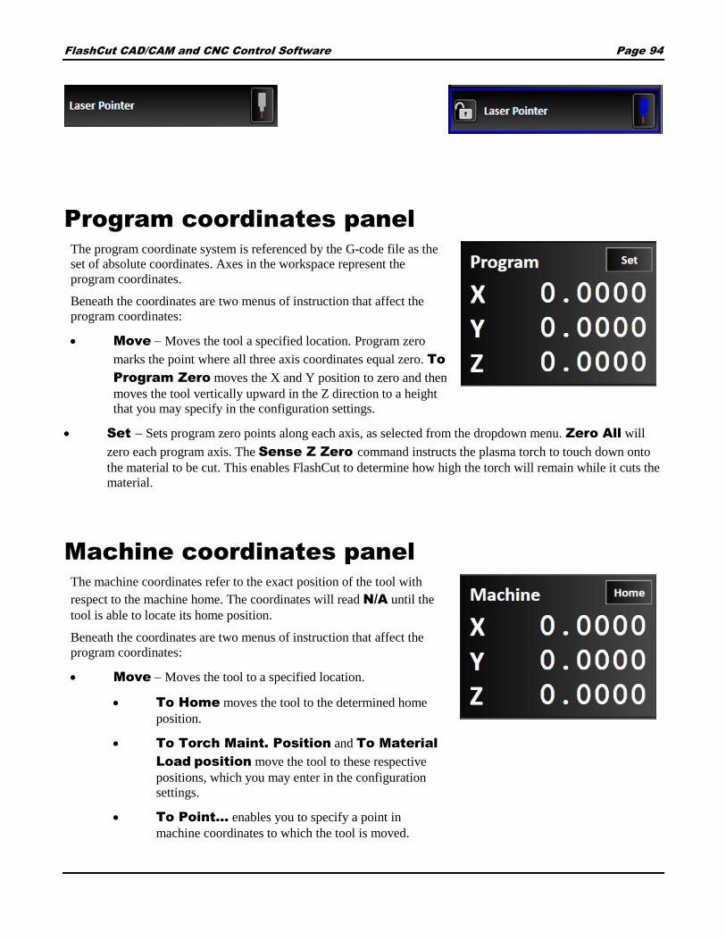
FlashCut CAD/CAM and CNC Control Software Page 94
Program coordinates panel
The program coordinate system is referenced by the G-code file as the
set of absolute coordinates. Axes in the workspace represent the
program coordinates.
Beneath the coordinates are two menus of instruction that affect the
program coordinates:
Move Moves the tool a specified location. Program zero
marks the point where all three axis coordinates equal zero. To
Program Zero moves the X and Y position to zero and then
moves the tool vertically upward in the Z direction to a height
that you may specify in the configuration settings.
Set Sets program zero points along each axis, as selected from the dropdown menu. Zero All will
zero each program axis. The Sense Z Zero command instructs the plasma torch to touch down onto
the material to be cut. This enables FlashCut to determine how high the torch will remain while it cuts the
material.
Machine coordinates panel
The machine coordinates refer to the exact position of the tool with
respect to the machine home. The coordinates will read N/A until the
tool is able to locate its home position.
Beneath the coordinates are two menus of instruction that affect the
program coordinates:
Move Moves the tool to a specified location.
To Home moves the tool to the determined home
position.
To Torch Maint. Position and To Material
Load position move the tool to these respective
positions, which you may enter in the configuration
settings.
To Point… enables you to specify a point in
machine coordinates to which the tool is moved.

FlashCut CAD/CAM and CNC Control Software Page 95
Home After connecting the signal generator to FlashCut, it is necessary to seek out and set the home
point, or Machine Zero, of the tool. You may home axes individually or all at once by using the Home
All command and pressure switches at the ends of each axis. To save time, it is recommended that each
axis is jogged first near the home switch before homing. Once machine zero is set, the machine tool
envelope is redefined in the workspace.
When multiple motors are used to drive an axis, FlashCut simultaneously homes each motor
independently. For example, if two motors are driving a single axis, FlashCut starts the homing process
by moving both motors towards the homing limit switches. Once one motor reaches its limit switch, it
stops and waits until the other motor reaches its limit switch. Once that occurs, all motors retract
simultaneously from the limit switches. This process corrects any skewing that may have occurred
between the two actuators.
It is necessary to home the axes normally first. The Zero command sets the current point as the origin of
the machine coordinates. Clear closes the machine coordinate system. This displays N/A on each axis
and requires you to reestablish a machine zero point.
Jog and point control panel
The jog control panel allows you to move your tool location in two ways.
Move to point
Jogging
This icon in the top left corner of the jog control panel is a button that toggles between them.
Move to point
Move-to-point allows you to move (jog)
your tool to a specified exact point. You
may specify the feed rate to be used for
these moves by editing the value in the
Feedrate field. If you prefer the
move to be made at the maximum
allowable speed, check the Rapid
Move box.
Click the Program Zero
button to move the tool to the
program zero point shown on
the Program coordinates panel.
Click the Machine Zero
button to move the tool to the
machine zero point shown on
the Machine coordinates panel.

FlashCut CAD/CAM and CNC Control Software Page 96
You may also use the controls on the right side of the jog-to–point panel to modify the destination based on your
selection with the dropdown. The choice you make with the dropdown specifies which point the move will be
made with respect to. You may choose from:
Program – When you choose Program, the tool can be moved with respect to the program zero point
shown on the Program coordinates panel.
Machine – When you choose Machine, the tool can be moved with respect to the program zero point
shown on the Machine coordinates panel.
Incremental – When you choose Incremental, the tool can be moved with respect to its current
location.
Check the box next to the axis you want the move to be made in. You may make the move in one, two, or all three
axes. Enter a positive or negative numeric value in the appropriate field to instruct FlashCut to move that distance
from the specified location. You may click the 0 button next to a field to automatically populate that field with
0.0000. When you’ve specified the distances you want the tool to move, click the green arrow control to start
the desired motion.
Jogging
The jog control panel provides these
controls for manually positioning all
axes.
Axis jog buttons
Pressing and holding an axis jog button
(+X, +Y, +Z, -X, -Y, -Z) moves the
machine tool exclusively on the
selected axis. Ramping is used in cases
where the jog rate is faster than the
stop/start feedrate.
Diagonal jog
buttons
Pressing and holding a diagonal jog
button (unlabeled) moves the machine
tool evenly along two axes. Ramping is
used in cases where the jog rate is faster
than the stop/start feedrate.
Jog mode
Determines the function of the jog buttons. Continuous jogging moves the tool at the assigned jog rate buttons
are held down. Discreet distances moves the tool incrementally the specified distance. Step jogging
advances the motor exactly one motor step.
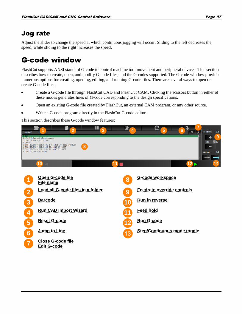
FlashCut CAD/CAM and CNC Control Software Page 97
Jog rate
Adjust the slider to change the speed at which continuous jogging will occur. Sliding to the left decreases the
speed, while sliding to the right increases the speed.
G-code window
FlashCut supports ANSI standard G-code to control machine tool movement and peripheral devices. This section
describes how to create, open, and modify G-code files, and the G-codes supported. The G-code window provides
numerous options for creating, opening, editing, and running G-code files. There are several ways to open or
create G-code files:
Create a G-code file through FlashCut CAD and FlashCut CAM. Clicking the scissors button in either of
these modes generates lines of G-code corresponding to the design specifications.
Open an existing G-code file created by FlashCut, an external CAM program, or any other source.
Write a G-code program directly in the FlashCut G-code editor.
This section describes these G-code window features:
Open G-code file File name
G-code workspace
Load all G-code files in a folder
Feedrate override controls
Barcode
Run in reverse
Run CAD Import Wizard
Feed hold
Reset G-code
Run G-code
Jump to Line
Step/Continuous mode toggle
Close G-code file Edit G-code
1 8
2 9
3 10
4 11
5 12
6
7
1 57
8
642
1211
9
3
10

FlashCut CAD/CAM and CNC Control Software Page 98
Open G-code file
When a CAD or CAM design is sent to be manufactured in FlashCut CNC, it appears in the G-code
workspace. However, to open an existing program manually, click the Open G-code file button to browse
to a G-code file and open it in the G-code workspace. A visual preview of the code will appear in the
workspace. The name of the G-code file is displayed in the G-code workspace.
This workspace displays the currently loaded G-Code file. While the program is running the current line of code
is highlighted in real time, this way the user can track their progress throughout the operation.
File name
FlashCut CNC displays the file name of the currently displayed G-code file here.
Load all G-code files in a folder
Prompts the user to select a folder. All G-code files in the folder will be loaded into FlashCut CNC.
Barcode
Allows the user to input a barcode representing a list of files to be cut.
Run CAD Import Wizard
Allows the user to open DXF files directly into FlashCut CNC. Imported files will not be visible in the CAD and
CAM windows.
Reset G-code
Click the Reset G-code file button to reload the current G-code file. This will not change the position of the
tool.
Jump to Line
This button allows the user to jump or skip ahead to a specific line in the program.
Close G-code file
Click the Close G-code file button to close the current G-code file. You may replace it by loading a G-code
file, creating a part with FlashCut CAD or FlashCut CAM, or by writing a new G-code manually with the G-code
editor.
Edit G-code
Click the Edit G-code button to edit the currently displayed G-code file with the G-code editor.

FlashCut CAD/CAM and CNC Control Software Page 99
G-code workspace
This workspace displays the currently loaded G-Code file. While the program is running the current line of code
is highlighted in real time, this way the user can track their progress throughout the operation.
Feedrate override controls
Increases or decreases the defined feed rate by the given percent in the box. One hundred percent override
corresponds to zero change in feed rate. This function does not affect rapid move speeds, where feed rate is
undefined.
Run in reverse
This button is not enabled yet, but will allow the user to run the program in reverse. This is beneficial when
troubleshooting a program in simulation mode or dry run mode, not typically used while actually cutting.
Feed hold
Click the Feed hold button to pause execution of the G-code file. The machine tool stops, ramping down if
necessary. The slower the ramping rate, the longer it takes from the time the Feed hold button is clicked to the
time the tool comes to a complete stop. This button pauses any motion including automatic tool changing, tool
length sensing and so on.
Run G-code
Click the Run G-code button to begin execution of the current line of the G-code file. When in step mode,
execution stops automatically at the end of the current line, or when the Feed Hold button is clicked. When in
continuous mode, execution continues until the end of the program, or until you click the Feed hold button. If
the program has been stopped in the middle of a G-code line, clicking the Run G-code button begins execution
exactly where the program stopped.
Step/Continuous mode toggle
Select whether the G-code will be executed continuously as a single set of moves or step-by-step by executing
each move line-by-line. The blue option is the one that is selected.
Step mode Continuous mode

FlashCut CAD/CAM and CNC Control Software Page 100
Pan and zoom tools
The pan and zoom tools are used for moving and magnifying the drawing in the
drawing workspace. Click a tool to change the cursor’s function.
Pan
The pan tool allows you to click and drag
anywhere in the drawing window to move
the drawing around. Right clicking and
dragging in the window also allows you to
pan without the use of the pan tool.
Zoom Extent
Click and drag a box in which to zoom in.
This tool allows to user to focus in on a
specific section of the diagram.
Zoom
Click and drag anywhere to zoom in and
out on the drawing. You can also use the
scroll wheel to zoom in and out.
Zoom to Fit
Click this button to adjust zoom
automatically to best fit the drawing.

FlashCut CAD/CAM and CNC Control Software Page 101
Drawing workspace
The workspace displays different
views of the tool path described by
the current G-code file. By default,
FlashCut CNC displays a two-
dimensional XY view. You may
manipulate the two-dimensional
view using the zoom and pan tools,
as well as by using the Display
options on the Preferences screen.
The workspace pictorially displays
the G-code as it is written in the
program editor.
Pan and zoom tools
The current tool position is shown by a yellow dot.
Solid red lines show the
toolpath
Dotted red lines represent rapid moves
The maximum dimensions which a tool may not exceed are represented by a thick blue box. The box
will appear after the machine has been homed.
To avoid improper machining, ensure that the entirety of the toolpath remains within this machine tool
envelope. If the feature dimensions exceed this size, return to FlashCut CAD or FlashCut CAM in
order to make revisions.
1 4
2 5
3
1
2
3
4 5

FlashCut CAD/CAM and CNC Control Software Page 102
Configuring FlashCut
This section describes how to configure FlashCut for use with your machine tool. It is very important that the
software and hardware are configured properly. Incorrect configuration may cause the machine tool to behave in a
potentially dangerous manner. Please read through this section carefully to gain a thorough understanding of how
FlashCut controls your machine.
Note If an Administrator password has been set, you must enter it before you can make changes to the
configuration. See Security for more information.
The Configuration icon is available in all three windows: CAD/CAM/CNC.
Click the icon to examine or modify FlashCut settings.
An explanation of each area of the screen is provided in these topics:
Setup file (*.setup extension)
Configuration workspace
Configuration Menu
1
2
3
1
2
3

FlashCut CAD/CAM and CNC Control Software Page 103
Setup file (*.setup extension)
When FlashCut is first loaded, it prompts you to select a setup file. Setup files have the extension *.setup; legacy
files with the older extension *.STP can be loaded and updated. If you don’t have a setup file to load, click
Cancel to tell the program to load a default configuration, which you may edit and save under a different file
name. Each setting is described by category, along with a list of sub-categories. Clicking the plus-minus icon next
to each subcategory enables you to toggle whether or not the list is displayed.
The panel at the top of the configuration window enables you to save a certain configuration in the .setup file
format.
The New button allows you to duplicate a previously-created setup file. Select the file to be copied then click
OK. Note that this is a temporary copy of the file that must be saved in order to solidify any changes; it will not
affect the original file.
The Load button prompts you to save the current configuration setup, and then loads a previously-created STP
file.
Click Save to save the current configuration state. By default, FlashCut stores setup files in the C:\Program
Files\FlashCut CNC 6\Application Data\Configuration folder but you may not have sufficient
privilege to store your setup files there. Choose an alternative location.
If a file has not been created yet, the Save As… button enables you to create a new .setup file and destination.
Configuration workspace
Detailed configuration options for each menu item are displayed in the configuration workspace.

FlashCut CAD/CAM and CNC Control Software Page 104
Configuration Menu
System
General
Controller
Security
Preferences
Language
Jogging
Display
Pendant
USB Interface Board
Machine
Fabrication Heads
Axes
Drive Parameters
Rotary Axes
Homing
Dynamic Ventilation
Programming
M-Code Definitions
M-Code Execution
I/O
Input Lines
CAD
General
Features
CAM
General
Features
Breaks
Post Processor
Toolpath Adjustments
1
2
3
4
5
6
7
1
2
3
4
5
6
7

FlashCut CAD/CAM and CNC Control Software Page 105
System
General
Controller
Security
General
System Units
Use the System Units drop-down to choose which units of
measurement to use. You may choose:
English
Metric
Controller
Controller
Motor Signals
Signal State Preferences
Security
Controller
The Controller settings section presents the
following controls:
Controller Type
USB Speed
Jog Buffer (sec)
General Buffer (sec)
Connect at Startup
Controller Type
Specifies the type of signal generator (controller) you are using:
501A (USB connection)

FlashCut CAD/CAM and CNC Control Software Page 106
USB Speed
USB Speed allows you to specify the speed of USB communications with the signal generator. If your
machine is exposed to excessive electrical noise, setting the USB speed to Full Speed helps to prevent
communication problems.
Jog Buffer (sec)
The jog generator buffer prevents system events (such as screen updates) from affecting motor movement
on the machine tool. The larger the buffer, the less effect system events have on motor movement. The
smaller the buffer, the more responsive the machine tool is to mouse clicks and keyboard commands. In
most cases, the lag-time between the PC and the motor movement is imperceptible. The value can range
from 0.01 to 1.0 seconds. Slower computers may require a higher value.
The jog buffer setting sets the buffer size on the signal generator for jogging in continuous mode.
Typically this value is lower than the general value, to make the jog buttons more responsive.
General Buffer (sec)
General Buffer (sec) sets the buffer size on the signal generator for all operations except jogging in
continuous mode.
Connect at Startup
When this option is selected, FlashCut will attempt to connect to the default machine controller when the
program launches.
Motor Signals
Driver Model
Driver Type
Step Pulse Polarity
Step Pulse Activation
Step Pulse Width (µsec)
Min Time Between Steps (µsec)
Direction-Step Setup (µsec)
Min Step Direction Lag (µsec)
Enable Signal Polarity
Dynamic Enable Line
Driver Model
Sets the model of your motor driver or combination controller/driver box.

FlashCut CAD/CAM and CNC Control Software Page 107
If you are using a FlashCut driver or combination controller/driver box, the model number is printed on a
sticker located on the back or bottom of the box. When you select your driver model, FlashCut enters the
correct values for all other signal settings (Step Pulse Polarity through Dynamic Enable
Line). The fields are disabled and cannot be changed. If you need to change the values, choose Other
(generally not necessary).
If you are using non-FlashCut drivers, choose Other. This enables all fields, allowing you to enter the
proper settings based on your motor driver requirements. Note that some signal fields do not apply to all
signal generator models, and may be disabled based on your controller settings (signal generator model
and chip).
Driver Type
Indicates your motor driver type: stepper or servo.
Step Pulse Polarity
Sets the polarity of the step signal to High or Low as shown in this diagram.

FlashCut CAD/CAM and CNC Control Software Page 108
Step Pulse Activation
(Model 401A signal generator only) Indicates how the signal generator creates step pulses as follows:
Normal – The signal generator times the duration of each step pulse.
Inverted – The signal generator times the delay between step pulses, while guaranteeing the step pulse
duration is at least the step pulse width entered. When the motor driver requires a long step pulse, this
mode yields higher step rates.
Optimize – FlashCut automatically selects the best activation mode.
Step Pulse Width (µsec)
Sets the duration of the step pulse (in microseconds). See the diagram above.
Min Time Between Steps (µsec)
Sets the minimum time between step pulses (in microseconds). See the diagram above.
Direction-Step Setup (µsec)
Sets the time between a direction change and the leading edge of the subsequent step pulse (in
microseconds). See the diagram above.
Min Step Direction Lag (µsec)
Sets the minimum time from the leading edge of a step pulse to a subsequent direction change (in
microseconds). See the diagram above.
Enable Signal Polarity
Sets the polarity of the enable signal. Choose High if the motor driver is enabled by a high signal, or
Low if the motor driver is enabled by a low signal.
Dynamic Enable Line
Sets the behavior of the enable line. When checked, the enable line turns on when any axis is in motion,
and turns off when all axes are idle. Generally this box should be unchecked.
Signal State Preferences
Enable Motors On Power Up
Enable Motors After Disconnect From Sig. Gen.
Enable Motors After Limit/Safety
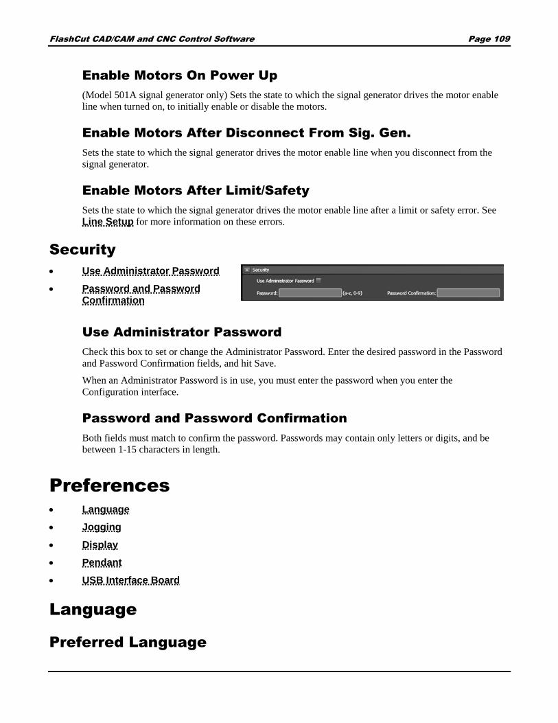
FlashCut CAD/CAM and CNC Control Software Page 109
Enable Motors On Power Up
(Model 501A signal generator only) Sets the state to which the signal generator drives the motor enable
line when turned on, to initially enable or disable the motors.
Enable Motors After Disconnect From Sig. Gen.
Sets the state to which the signal generator drives the motor enable line when you disconnect from the
signal generator.
Enable Motors After Limit/Safety
Sets the state to which the signal generator drives the motor enable line after a limit or safety error. See
Line Setup for more information on these errors.
Security
Use Administrator Password
Password and Password Confirmation
Use Administrator Password
Check this box to set or change the Administrator Password. Enter the desired password in the Password
and Password Confirmation fields, and hit Save.
When an Administrator Password is in use, you must enter the password when you enter the
Configuration interface.
Password and Password Confirmation
Both fields must match to confirm the password. Passwords may contain only letters or digits, and be
between 1-15 characters in length.
Preferences
Language
Jogging
Display
Pendant
USB Interface Board
Language
Preferred Language

FlashCut CAD/CAM and CNC Control Software Page 110
Use the Languages configuration option to choose the language FlashCut uses for its user interface. You may
choose from:
English (United States)
Spanish (Spain)
Italian (Italy)
French (France)
Portuguese (Portugal)
Jogging
The Jogging configuration option displays the following controls:
Jog Rates
Jog Distances
Runtime Jog
General
Jog Rates
Use the Jog Rates controls to set the default jog rates for
each axis.
Slow, Fast
These columns correspond to the jog rate option
buttons on the Error! Reference source not ound.. FlashCut executes all jog moves using the
rates you enter in these fields.

FlashCut CAD/CAM and CNC Control Software Page 111
Jog Distances
Distance #
The distance number identifies which button on the main
screen the displayed distance refers to.
Displayed Distance
This is the value of the incremental move that is commanded
each time the user clicks a directional jog button on the CNC
panel.
Runtime Jog
Allow Runtime Jog
Select this box to allow runtime jog operations. The runtime
jog buttons allow you to jog the axis while a G-Code file is
running. The axis moves at the Slow Jog Rate.
Note that THC conflicts with this feature.
General
Jog Ramp Up Reduction
Set the percentage of the speed at which the rate increases
during jog operations. The default is 100%.
Display
Axis Display
Check the appropriate check box for
the desired axis settings. The icon
displayed will change depending on the
settings selected:

FlashCut CAD/CAM and CNC Control Software Page 112
Current Position
Select the desired icon to mark the current position.
Pendant
The Flex Pendant is a versatile accessory that you can customize to your particular application. You can assign
functions to each button to create your own custom layout.
General
Use Flex Pendant
Enables control of the machine from
the pendant.
Pendant Buttons
Two sets of 20 buttons (green and red)
can be configured. Click the button
you wish to configure, and then assign
its function.
Use Standard Layout
Selecting this button will load the pre-
defined settings. All current custom
function settings will be overwritten.
Functions
Layer (green or red)
Button (1-20)
Function (select from
dropdown menu)
USB Interface Board
A USB Interface Board is available from FlashCut for some machines. The board allows direct control of the
machine by assigning functions to different switches. The functions of the board can be programmed here.

FlashCut CAD/CAM and CNC Control Software Page 113
General
Use USB Interface Board
Enables control of the machine from the board.
Number of Jog Rates
Sets the number of jog rates (2-12) that can be defined.
Functions
Use the Add Function and Delete Function buttons to
define or remove the functions assigned to different
Each function has four attributes:
Layer (green or red)
Wiring Row (1-8)
Wiring Column (1-12)
Function (select from dropdown menu)
Machine
Fabrication Heads
Axes
Drive Parameters
Rotary Axes
Homing
Dynamic Ventilation
Fabrication Heads
This section explains in detail how to configure each of the different types of Fab Heads used by FlashCut
Cut Charts
Fabrication Heads
Cut Charts
Cut charts are tables of information for configuring the properties of different manufacturer’s fab heads. The
information is stored in *.csv files in the FlashCut program files folder.

FlashCut CAD/CAM and CNC Control Software Page 114
When configuring fab heads, the initial values for a particular head are populated from the relevant standard cut
chart.
An example is shown below:
Use Standard Cut Charts
Use the pre-loaded cut charts with
recommended settings such as feedrate, pierce
height, cut height and THC set point.
Use Custom Cut Charts
If you choose the Custom Cut Chart option, then a *.csv file copy of the standard cut charts will be stored
into the specified location when you hit the Copy Standard Charts To Folder button.
Any value in these cut charts can be edited using a spreadsheet program like Excel.
Fabrication Heads
Fabrication heads are the actual cutting heads on your
machine. You can have more than one installed on
your machine. Types include:
Plasma
Oxyfuel
Waterjet
Laser Pointer

FlashCut CAD/CAM and CNC Control Software Page 115
Marker
Each type of Fabrication Head (or Fab Head) has its unique settings. In this section, you can edit an existing
Fab Head by selecting it from the list or you can delete or create new one.
To edit a Fab Head, select it from the list and the Fab Head parameters will appear.
The parameters for the various types of Fab Heads are outlined below:
Plasma
When defining a new plasma head, select the Type, Subtype, and Model from the drop down lists.
ID and Name – These values will be
automatically populated, but you can
edit them.
Offset – Enter an X and Y offset if
you have more than one fab head.
Communication – Select RS-
232/RS-485 and a Comm port if you
have direct communication with the
plasma for setting Current and Pressure
on the fly.
Legacy Tool Number – Enter
number here.
Lead Length – Length of the
plasma table.
Torch Control – Fill in the proper
M-Codes for turning the torch on and
off. Typically, there are 50 and 51,
respectively. Note that the M codes
must be defined in the M-Code
Definitions.
Automatic Execution Mode -
Enter the Automatic M-Codes or
Macros for turning the torch and THC
on for cuts and off for rapid
movements. Note that the Macros and
M-Codes must be defined in the M-
Code Definitions and Execution
Screens
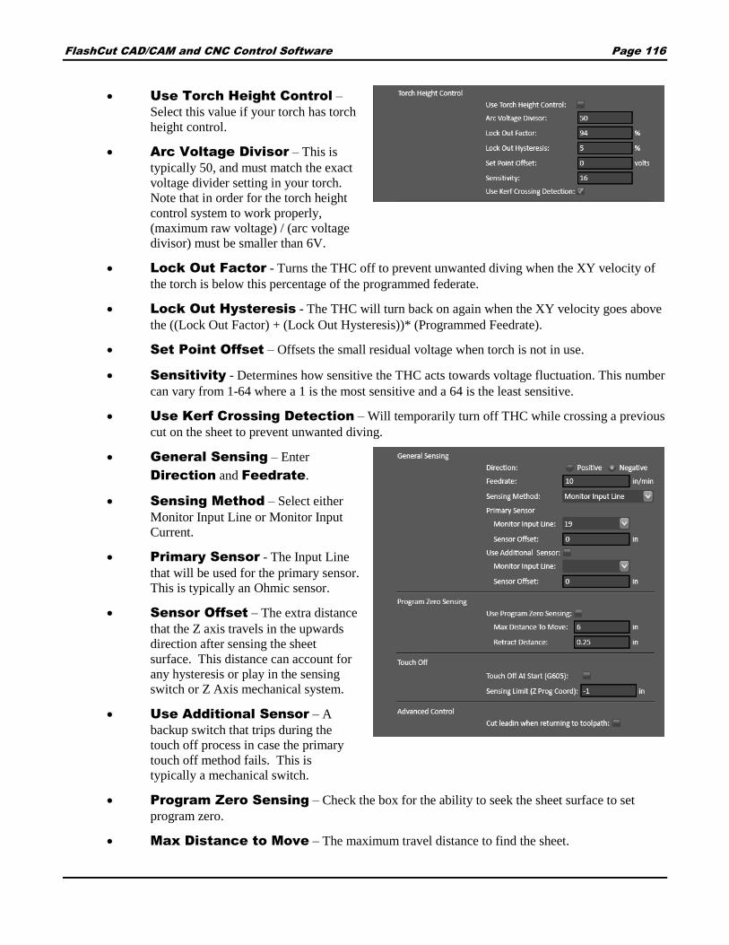
FlashCut CAD/CAM and CNC Control Software Page 116
Use Torch Height Control –
Select this value if your torch has torch
height control.
Arc Voltage Divisor – This is
typically 50, and must match the exact
voltage divider setting in your torch.
Note that in order for the torch height
control system to work properly,
(maximum raw voltage) / (arc voltage
divisor) must be smaller than 6V.
Lock Out Factor - Turns the THC off to prevent unwanted diving when the XY velocity of
the torch is below this percentage of the programmed federate.
Lock Out Hysteresis - The THC will turn back on again when the XY velocity goes above
the ((Lock Out Factor) + (Lock Out Hysteresis))* (Programmed Feedrate).
Set Point Offset – Offsets the small residual voltage when torch is not in use.
Sensitivity - Determines how sensitive the THC acts towards voltage fluctuation. This number
can vary from 1-64 where a 1 is the most sensitive and a 64 is the least sensitive.
Use Kerf Crossing Detection – Will temporarily turn off THC while crossing a previous
cut on the sheet to prevent unwanted diving.
General Sensing – Enter
Direction and Feedrate.
Sensing Method – Select either
Monitor Input Line or Monitor Input
Current.
Primary Sensor - The Input Line
that will be used for the primary sensor.
This is typically an Ohmic sensor.
Sensor Offset – The extra distance
that the Z axis travels in the upwards
direction after sensing the sheet
surface. This distance can account for
any hysteresis or play in the sensing
switch or Z Axis mechanical system.
Use Additional Sensor – A
backup switch that trips during the
touch off process in case the primary
touch off method fails. This is
typically a mechanical switch.
Program Zero Sensing – Check the box for the ability to seek the sheet surface to set
program zero.
Max Distance to Move – The maximum travel distance to find the sheet.

FlashCut CAD/CAM and CNC Control Software Page 117
Retract Distance – The amount that the Fabhead will move up after sensing the sheet.
Touch Off at Start (G605) –Senses the sheet at the start of each cut.
Sensing Limit – The lowest coordinate that the Z axis will sense to.
Advanced Control – Cut lead in when returning to toolpath. When checked, allows recovery
from a lost torch.
Oxyfuel
When defining a new Oxyfuel head, select the Type from the drop down lists.
ID and Name – These values will be
automatically populated, but you can
edit them.
Offset – Enter an X and Y offset if
you have more than one fab head.
Legacy Tool Number – Enter
number here.
Oxyfuel Control – Fill in the
proper M-Codes for turning the cutter
on and off. Typically, these are 60 and
61, respectively. Note that the M codes
must be defined in the M-Code
Definitions.
Automatic Execution Mode - Enter the Automatic M-Codes or Macros for turning the
torch and THC on for cuts and off for rapid movements. Note that the Macros and M-Codes must
be defined in the M-Code Definitions and Execution Screens.
Advanced Control – Cut lead in when returning to toolpath. When checked, allows recovery
from a lost torch.
Waterjet
When defining a new Waterjet head, select the Type from the drop down lists.
ID and Name – These values will be
automatically populated, but you can
edit them.
Offset – Enter an X and Y offset if
you have more than one fab head.
Legacy Tool Number – Enter
number here.

FlashCut CAD/CAM and CNC Control Software Page 118
Waterjet Control – Enter the
proper M-Codes for turning the
waterjet on and off. Typically, these are
40 and 41, respectively. Note that the
M-codes must be defined in the M-
Code Definitions.
Support Low Pressure Mode
– When checked, enter the proper M-
Codes for turning the low pressure
mode on and off. Note that the M-code
must be defined in the M-Code
Definitions.
Support Use of Abrasive – When checked, enter the proper M-Codes for turning flow of
abrasive compound on and off. Note that the M-code must be defined in the M-Code Definitions.
Automatic Execution Mode - Enter the Automatic M-Codes or Macros for turning the
cutter on for cuts and off for rapid movements. Note that the Macros and M-Codes must be
defined in the M-Code Definitions and Execution Screens.
General Sensing – Enter
Direction and Feedrate.
Sensing Method – Select either
Monitor Input Line or Monitor Input
Current.
Primary Sensor - The Input Line
that will be used for the primary sensor.
This is typically an Ohmic sensor.
Sensor Offset – The extra distance
that the Z axis travels in the upwards
direction after sensing the sheet
surface. This distance can account for
any hysteresis or play in the sensing
switch or Z Axis mechanical system.
Use Additional Sensor – A
backup switch that trips during the
touch off process in case the primary
touch off method fails. This is
typically a mechanical switch.
Marker
When defining a new Marker head, select the Type from the drop down lists.

FlashCut CAD/CAM and CNC Control Software Page 119
ID and Name – These values will be
automatically populated, but you can
edit them.
Offset – Enter an X and Y offset if
you have more than one fab head.
Marker Control – Fill in the proper
M-Codes for turning the marker on and
off. Note that the M codes must be
defined in the M-Code Definitions.
Automatic Execution Mode -
Enter the Automatic M-Codes or
Macros for turning the cutter on for
cuts and off for rapid movements. Note
that the Macros and M-Codes must be
defined in the M-Code Definitions and
Execution Screens.
Mill Spindle
When defining a new Mill Spindle head, select the Type from the drop down lists.
ID and Name – These values will be
automatically populated, but you can
edit them.
Offset – Enter the X and Y distance
from the center of the laser pointer to
the center of the Plasma Cutter.
Mill Control – Fill in the proper M
codes for turning the Laser Pointer on
and off. Note that all M codes must be
defined in the M-Code Definitions.
Automatic Execution Mode –
Since a laser pointer is a simple device,
there is probably no need for a macro.
Laser Pointer
When defining a new Laser Pointer, select the Type from the drop down lists.

FlashCut CAD/CAM and CNC Control Software Page 120
ID and Name – These values will be
automatically populated, but you can
edit them.
Offset – Enter the X and Y distance
from the center of the laser pointer to
the center of the Plasma Cutter.
Laser Control – Fill in the proper
M codes for turning the Laser Pointer
on and off. Typically these are 10 and
11 respectively. Note that all M codes
must be defined in the M-Code
Definitions.
Automatic Execution Mode –
Since a laser pointer is a simple device,
there is probably no need for a macro.
Enter the same values used for Laser
Control.
Axes
Motor Line/Axis Mapping
Axis Settings
Feedrates and Ramping
Drive Parameters
Motor Line/Axis Mapping

FlashCut CAD/CAM and CNC Control Software Page 121
FlashCut provides three signals for motor drivers: step, direction, and enable. Different driver manufacturers have
varying requirements for the polarity and timing of these signals. FlashCut provides the flexibility to tailor the
motor signals to run any driver. Motor lines are the physical lines on the signal generator used for driving motors.
Each column is described below:
Line #
This number corresponds to the axis number on the back of the CNC controller. Each signal generator
can command up to five independent signals simultaneously.
Axis Letter
Assigns a logical axis letter (X, Y, Z, A, B, C) to a physical signal generator motor line (1, 2, 3, 4, 5). If
you have more than one motor driving an axis on your machine, you may assign the same axis letter to
more than one motor line.
Sub Axis
Index number that allows the rest of the FlashCut system to distinguish between multiple motors used on
the same axis. This is important for homing, when FlashCut handles each motor independently.
Direction
Sets the direction of rotation for the motor connected to each signal generator axis. Depending on how a
motor is wired, the same signal from the motor driver can turn it clockwise or counter clockwise. Use the
jog buttons to make sure that a positive move in each axis on the screen corresponds to a positive move in
each axis on the machine tool. Note that the direction of movement is defined as the direction of the tool
relative to the workpiece. For example, on a typical milling machine, a positive X move (tool movement
to the right) requires table movement to the left. If any direction is incorrect, change the Motor Direction
from Positive to Negative (or vice-versa) to reverse the correspondence between the software and
machine tool.
Axis Settings

FlashCut CAD/CAM and CNC Control Software Page 122
Enables you to define whether or not an axis is being used and if there are physical limits to each the axes in use.
Axis
These are the six possible axis identifiers that are expected to be found in a G-Code program. If the G-
Code program calls any of these axis letters, the axis must be selected with the Use Axis checkbox. There
are additional parameters that are specific to each axis.
Use Axis
Indicates whether or not the axis is used on your machine tool.
Limited Travel
Indicates whether or not the axis travel is limited. Many rotary axes do not have limited travel.
Length (Inches)
Sets the length of travel in inches of each axis of your machine tool. You may want to define the axis
length slightly smaller than the values published by the machine tool manufacturer. This will leave some
room for error.
Feedrates and Ramping
For your system to run accurately, it’s important to tune the values on this panel correctly for your specific
combination of drivers, motors and machine tool. All parameters must be set conservatively to prevent the system
from losing position (losing steps).
An axis can lose a step when the motor gets the signal to move a step, but isn’t physically able to perform the
move. The usual cause is insufficient torque at a given motor RPM. Since most stepper motors are open loop
systems, there is no way of telling when a step is lost without physically measuring the movement of the axis and
comparing that to the amount it should have moved. However, when stepper motors are not over torqued they are
very reliable and accurate.
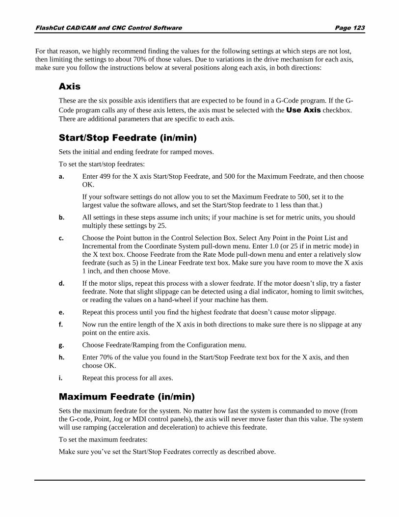
FlashCut CAD/CAM and CNC Control Software Page 123
For that reason, we highly recommend finding the values for the following settings at which steps are not lost,
then limiting the settings to about 70% of those values. Due to variations in the drive mechanism for each axis,
make sure you follow the instructions below at several positions along each axis, in both directions:
Axis
These are the six possible axis identifiers that are expected to be found in a G-Code program. If the G-
Code program calls any of these axis letters, the axis must be selected with the Use Axis checkbox.
There are additional parameters that are specific to each axis.
Start/Stop Feedrate (in/min)
Sets the initial and ending feedrate for ramped moves.
To set the start/stop feedrates:
a. Enter 499 for the X axis Start/Stop Feedrate, and 500 for the Maximum Feedrate, and then choose
OK.
If your software settings do not allow you to set the Maximum Feedrate to 500, set it to the
largest value the software allows, and set the Start/Stop feedrate to 1 less than that.)
b. All settings in these steps assume inch units; if your machine is set for metric units, you should
multiply these settings by 25.
c. Choose the Point button in the Control Selection Box. Select Any Point in the Point List and
Incremental from the Coordinate System pull-down menu. Enter 1.0 (or 25 if in metric mode) in
the X text box. Choose Feedrate from the Rate Mode pull-down menu and enter a relatively slow
feedrate (such as 5) in the Linear Feedrate text box. Make sure you have room to move the X axis
1 inch, and then choose Move.
d. If the motor slips, repeat this process with a slower feedrate. If the motor doesn’t slip, try a faster
feedrate. Note that slight slippage can be detected using a dial indicator, homing to limit switches,
or reading the values on a hand-wheel if your machine has them.
e. Repeat this process until you find the highest feedrate that doesn’t cause motor slippage.
f. Now run the entire length of the X axis in both directions to make sure there is no slippage at any
point on the entire axis.
g. Choose Feedrate/Ramping from the Configuration menu.
h. Enter 70% of the value you found in the Start/Stop Feedrate text box for the X axis, and then
choose OK.
i. Repeat this process for all axes.
Maximum Feedrate (in/min)
Sets the maximum feedrate for the system. No matter how fast the system is commanded to move (from
the G-code, Point, Jog or MDI control panels), the axis will never move faster than this value. The system
will use ramping (acceleration and deceleration) to achieve this feedrate.
To set the maximum feedrates:
Make sure you’ve set the Start/Stop Feedrates correctly as described above.

FlashCut CAD/CAM and CNC Control Software Page 124
a. Enter 1 in/sec2 in the General Ramping Rate text box for the X axis. (This is a conservative
ramping rate.)
b. Set the Maximum Feedrate to 500 in/min (or the highest value your settings allow), and then
choose OK.
c. Choose the Point button on the Control Selection Box. Select Any Point in the Point List and
Incremental from the Coordinate System pull-down menu. Enter 1.0 (or 25 if in metric mode) in
the X text box. Choose Feedrate from the Rate Mode pull-down menu and enter a feedrate that is
double the Start/Stop Feedrate for the X axis. Make sure you have room to move the X axis 1
inch, and then choose Move.
d. If the motor slips, repeat this process with a slower feedrate. If the motor doesn’t slip, try a faster
feedrate. Note that slight slippage can be detected using a dial indicator, homing to limit switches,
or reading the values on a hand-wheel if your machine has them.
e. Repeat this process until you find the highest feedrate that doesn’t cause motor slippage.
f. Now run the entire length of the X axis in both directions to make sure there is no slippage at any
point on the entire axis.
g. Choose Feedrate/Ramping from the Configuration menu.
h. Enter 70% of the highest no-slip feedrate you found in the X axis Maximum Feedrate text box.
i. Repeat this process for all axes.
General Ramp Rate (in/sec/sec)
Sets the rate of acceleration and deceleration for rapid moves and jogging.
Ramping Rates typically range from 1 to 10 in/sec2. Slower ramping rates require more time to ramp up
to the maximum feedrate and to ramp down to a stop. This may become a potentially dangerous situation
when using the Feed Hold button or jogging since the machine will take longer to come to a complete
stop. The goal is to choose a fast ramping rate that will start and stop the tool responsively without losing
steps. Fast ramping rates can also allow acceleration past resonant speeds of a stepper motor.
Make sure you’ve set the Start/Stop and Maximum Feedrates correctly as described above.
a. Enter 1 in/sec2 in the General Ramping Rate text box for the X axis. (This is a conservative
ramping rate.)
b. Choose OK.
c. Choose the Point button on the Control Selection Box. Select Any Point in the Point List and
Incremental from the Coordinate System pull-down menu. Enter 1.0 (or 25 if in metric mode) in
the X text box. Choose Rapid from the Rate Mode pull-down menu. Make sure you have room to
move the X axis 1 inch, and then choose Move. If the table doesn’t reach a continuous speed
before ramping down to a stop, there isn’t enough room to fully ramp up and down, and you
should increase the length of the move.
d. If the motor slips, repeat this process with a lower ramping rate. If the motor doesn’t slip, try a
higher ramping rate. Note that slight slippage can be detected using a dial indicator, homing to
limit switches, or reading the values on a hand-wheel if your machine has them.
e. Repeat the above steps until you determine an optimal General Ramping Rate for the X axis.
f. Choose Feedrate/Ramping from the Configuration menu.

FlashCut CAD/CAM and CNC Control Software Page 125
g. Enter 70% of the highest no-slip ramping rate you found in the X axis General Ramping Rate text
box.
h. Copy the General Ramping Rate to the Feedrate Move Ramping Rate text box. If you determine
that your system would benefit from a lower ramping rate for feedrate (cutting) moves, enter a
lower Feedrate Move Ramping Rate.
i. Repeat this process for all axes.
Note that once the optimal ramping rate is determined for each axis, you may want to re-test the
Maximum Feedrates to see if they can be set any higher.
Feedrate Move Ramp Rate (in/sec/sec)
Sets the rate of acceleration and deceleration for feedrate moves.
Continuous Contouring Feedrate (in/sec)
Continuous contouring (also called Look-ahead) is a high performance feature that lets FlashCut run
G-code files smoother and faster. The advantages of using continuous contouring are:
Smooth transitions from one G-code line to the next if the two moves are in line with one another.
There is no ramp-down period and subsequent ramp up period. This minimizes witness marks,
burning, melting and other quality problems sometimes encountered in machining. It also
provides smooth, high speed motion for any other control application that requires it. A
continuous smooth motion may span hundreds or thousands of G-code lines.
High speed machining of point-to-point type G-code files (composed of many short moves) used
in complex 2D profiling and 3D surfacing. These G-codes files can be executed much faster with
continuous contouring.
To determine if two moves are lined up enough to allow a smooth transition without ramping, FlashCut
calculates the change in speed of each motor through the transition, and compares that to the setting for
continuous contouring feedrate tolerance. If the change in speed for each motor is less than the tolerance,
FlashCut executes the two moves as part of the same smooth motion. Otherwise, FlashCut ramps down to
end one motion and ramps up to begin another.
Any command that breaks the continuity of motion causes the machine tool to ramp down to a stop (such
as any M code to control an auxiliary device, a G04 command for dwell, and so on).
A typical default setting for the continuous contouring feedrate tolerance is the Start/Stop Feedrate (in/min) value. The higher you set the tolerance, the smoother a G-code file will be executed (i.e., more
moves will be linked together into smooth motions). If the values are set too high, loss of steps (stepper
motor drivers) or servo errors (digital servo drivers) can occur. The best way to find an optimal setting is
through trial and error. Incrementally raise the values and run demanding test files, checking for lost steps
or servo errors.
Continuous contouring is always turned on. If you prefer that all moves ramp up and down, set the Continuous
Contouring Feedrate Tolerance to zero for all axes.
Drive Parameters
Axis Drive Parameters

FlashCut CAD/CAM and CNC Control Software Page 126
The axis drive parameters window displays the following information:
For each axis:
The current Control Parameters and Drive Mechanism are displayed.
The Tool Positioning Resolution is displayed. This is the length of axis movement per Signal
Generator pulse, automatically calculated from the control and drive mechanism settings.
This value represents the smallest linear increment that the machine can move on each particular axis.
More specifically it is the exact linear distance traveled by the machine when the motor rotates by the
smallest possible increment, also known as a step.
A drop-down menu displays the following options (X Axis shown):
Set Same as
Sets all control/drive mechanism settings the same as another axis.
Edit Control Parameters…
Opens the Control Parameters dialog box. Select Stepper or Servo from the Driver Type pull-down
menu.
Stepper

FlashCut CAD/CAM and CNC Control Software Page 127
Step Mode – The number of micro steps between each full motor step. Enter “1” for full-
stepping, “2” for half-stepping, “4” for quarter-stepping, and so on.
Motor Resolution – The number of full motor steps for one revolution of the motor. For
example, a 1.8° stepper motor has 200 full steps per revolution; a 0.9° stepper motor has 400 full
steps per revolution.
Servo
Encoder Divisor – The number of encoder pulses that correspond to one pulse from the
Signal Generator.
Encoder Resolution – The number of encoder pulses per revolution, not including any
adjustment for running in quadrature mode. When calculating the Tool Positioning Resolution,
FlashCut assumes the encoder is running in quadrature mode.
Edit Drive Mechanism…
Opens the Drive Mechanism dialog box. Select a drive mechanism from the Drive Mechanism pull-down
menu. Note that Rotary is an option only for axes A, B and C.
Lead Screw
Gear Reduction – Enter the parameters for any gearing between the motor and lead screw.
A decimal gear ratio of 1.0 indicates no gearing.
Lead Screw Specification – Enter the parameters for the lead screw.
Correction Factor – Use this value to fine tune the axis, so the distance it moves exactly
matches the commanded distance.
Rack and Pinion

FlashCut CAD/CAM and CNC Control Software Page 128
Gear Reduction – Enter the parameters for any gearing between the motor and pinion. A
decimal gear ratio of 1.0 indicates no gearing.
Rack Specification – Enter the parameters for the rack.
Pinion Tooth Count – The number of teeth on the pinion.
Correction Factor – Use this value to fine tune the axis, so the distance it moves exactly
matches the commanded distance.
Belt
Gear Reduction – Enter the parameters for any gearing between the motor and drive pulley.
A decimal gear ratio of 1.0 indicates no gearing.
Belt Specification – Enter the parameters for the belt.
Pulley Tooth Count – The number of teeth on each pulley.
Correction Factor – Use this value to fine tune the axis, so the distance it moves exactly
matches the commanded distance.
General Linear
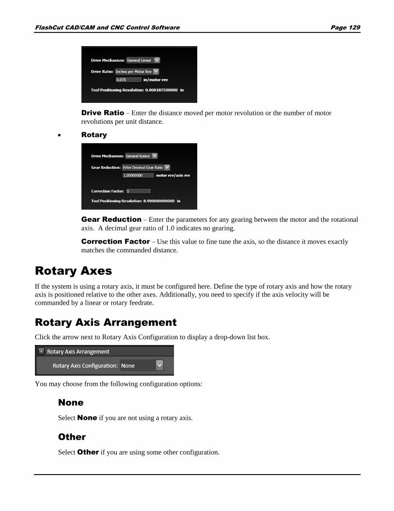
FlashCut CAD/CAM and CNC Control Software Page 129
Drive Ratio – Enter the distance moved per motor revolution or the number of motor
revolutions per unit distance.
Rotary
Gear Reduction – Enter the parameters for any gearing between the motor and the rotational
axis. A decimal gear ratio of 1.0 indicates no gearing.
Correction Factor – Use this value to fine tune the axis, so the distance it moves exactly
matches the commanded distance.
Rotary Axes
If the system is using a rotary axis, it must be configured here. Define the type of rotary axis and how the rotary
axis is positioned relative to the other axes. Additionally, you need to specify if the axis velocity will be
commanded by a linear or rotary feedrate.
Rotary Axis Arrangement
Click the arrow next to Rotary Axis Configuration to display a drop-down list box.
You may choose from the following configuration options:
None
Select None if you are not using a rotary axis.
Other
Select Other if you are using some other configuration.

FlashCut CAD/CAM and CNC Control Software Page 130
Rotary Table (Four Axes)
Select Rotary Table if you have only one rotary axis. Right handed indicates whether or not the
rotary axis obeys the right hand rule. If you curl your hand closed in the direction the rotary axis revolves
and your thumb points in the positive direction of the axis of rotation (Parallel Axis setting), the axis is
right-handed.
Dual Rotary Table (Five Axes)
Select Dual Rotary Table if you are using two rotary axes built into a single table. You must define a
Rotary Axis for each.
Rotary Knife
Select Rotary Knife if you are running a CNC knife cutting machine. You must also select a Knife Axis
(A, B, or C).
General
These options are part of the rotary table configuration screens.
Use offset for rotary zero
If checked, define the offset below.
Offset for Rotary Zero Position
Indicates the fixture offset for the rotary zero position.
4-Axis machining
Rotary zero is anywhere along the axis of rotation of the rotary axis. The parallel axis in the
fixture offset is ignored.
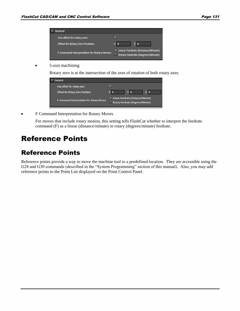
FlashCut CAD/CAM and CNC Control Software Page 131
5-axis machining
Rotary zero is at the intersection of the axes of rotation of both rotary axes.
F Command Interpretation for Rotary Moves
For moves that include rotary motion, this setting tells FlashCut whether to interpret the feedrate
command (F) as a linear (distance/minute) or rotary (degrees/minute) feedrate.
Reference Points
Reference Points
Reference points provide a way to move the machine tool to a predefined location. They are accessible using the
G28 and G30 commands (described in the “System Programming” section of this manual). Also, you may add
reference points to the Point List displayed on the Point Control Panel.

FlashCut CAD/CAM and CNC Control Software Page 132
G-Code
This field identifies the command in a G-Code file that moves the machine to the point (not editable).
Description
Enter a description for the point. For G28, the standard description is “Tool Change”.
Coord System
Choose between machine and program coordinates.
X, Y, Z, A, B, C Coordinates
Enter the coordinate for each axis.

FlashCut CAD/CAM and CNC Control Software Page 133
Homing
For each axis, the following settings are available:
Home Axis
Select to configure homing for the axis.
Home End
The end of the axis at Machine Zero (Home).
Home Order
The axis order for the homing operation. For safety, set the order so the initial homing move retracts the
cutting tool away from the workpiece.
Home Switch Offset
The distance each axis backs away from the home switch after the switch is tripped during homing.
Homing Rate
The feedrate at which the machine tool will move when locating home switches.
Homing Tolerance
The distance allowed from the original Machine Zero location to the new Machine Zero location found
during homing.
Execute M-Codes Before / After
You may specify M-Codes to execute before and after each axis homes. For more information on
defining M-Codes see M-Code Definitions.

FlashCut CAD/CAM and CNC Control Software Page 134
Home Position Machine Coordinate
If the home switch is positioned at the travel limit, the machine coordinate of the home switch is zero. If
the home switch is positioned somewhere within the machine envelope, set this value to the machine
coordinate of the home switch location (nonzero value).
Dynamic Ventilation
Dynamic ventilation systems sense the location of the cutting head, and only activate the ventilation system in the
specific zone(s) where it is needed. If your machine is equipped with a dynamic ventilation system, its behavior
can be controlled through these settings.
General
Use Dynamic Ventilation
Turn dynamic ventilation on or off.
Controlling Axis
Sets the axis along which the ventilation zones
are defined.
Number of Zones
Sets the number of zones.
Zone Length
Sets the width of each zone.
Overlap Length
Sets the amount of overlap between zones. Overlapping zones ensure that the dampers controlling the
airflow have sufficient time to open and close.
First M-Code
Enter the first M-code here. The first M-code is the code that opens the damper in zone one. Note that
codes are consecutive: the second M-code will close the damper for zone one, and so on.
Programming
M-Code Definitions
M-Code Execution

FlashCut CAD/CAM and CNC Control Software Page 135
M-Code Definitions
The M-code definition option presents these M-code definition configuration types:
Output Line M-Codes
Macro M-Codes
Output Line M-Codes
FlashCut controls output lines to activate
external devices such as a plasma torch or plate
marking device, the M-codes below are tied to
output lines.
M-Code
The number for the M-code that you
want to define.
Description
A brief description of the action taken when this M-code is executed.
Execute Before Move
Indicates the sequence of actions when there is a machine tool move command on the same program line
as the M-Code. Check this box to execute the M-Code before the machine moves as commanded.
Execute Delay First
Check this box to implement the specified delay before the M-code. If the box remains unchecked the
delay will occur immediately after the M-code.
Delay (sec)
The duration of the delay that will occur when this M-Code is executed. For example, if the spindle motor
takes about 3 seconds to reach full speed, this value should be at least 3.
Output Lines
Each output that is controlled by the M-code is listed here with the desired state of the output.
Add M-Code Button
Adds a new line to define an M-code.
Delete M-Code Button
Deletes the highlighted M-code definition.

FlashCut CAD/CAM and CNC Control Software Page 136
Macro M-Codes
FlashCut can also use M-codes to call a macro.
M-Code
The number for the M-code that you
want to define.
Description
A brief description of the action taken when this M-code is executed.
Macro
Click the Edit button to bring up the G-Code editor. Enter any number of G-Code lines. Whenever
FlashCut encounters the M-Code in a G-Code program, these commands will be executed.
Execute Before Move
Indicates the sequence of actions when there is a machine tool move command on the same program line
as the M-Code. Check this box to execute the M-Code before the machine moves as commanded.
Add M-Code button
Deletes the highlighted M-code definition.
Delete M-Code button
Deletes the highlighted M-code definition.
M-Code Execution
The M-code execution option presents these M-code execution configuration types:
Automatic Execution Mode
Execute After Motion Errors
Execute at Start/End of Motion
Execute During Ramping
Execute While Connecting/Disconnecting
Any M-code entered with these configuration types must be defined on the M-code Definitions panel.
Automatic Execution Mode

FlashCut CAD/CAM and CNC Control Software Page 137
Enter an M-code in the field(s) associated with the
selected radio button.
None FlashCut doesn’t execute any M-codes
automatically.
Basic This mode is intended for applications
where it’s convenient to automatically turn off
spindle, vacuum and other devices whenever the
machine is stopped.
Start (After Hold) FlashCut can execute an M-code whenever Start is clicked after a feed
hold has occurred (but not when initially starting the file).
Feed Hold FlashCut can execute an M-code whenever Feed Hold is clicked, or an error
occurs.
Note You don’t need to fill in both M-code fields. For example, you can specify a Feed Hold M-code, and
leave the Start (After Hold) field blank.
Full This mode is intended for applications where the signal generator must turn output lines on during
feedrate moves and off during rapid moves. Applications include plasma cutting, laser cutting, waterjet
cutting and liquid dispensing.
Feedrate Move FlashCut executes the Feedrate Move M-code before any feedrate
move (G01, G02, G03), and before restarting a feedrate move after a Feed Hold.
All Other Times FlashCut executes the All Other Times M-code:
Before any rapid move (G00)
Whenever Feed Hold is hit during a feedrate move
At the end of the program if the program ends with a feedrate move
When an error occurs
Execute After Motion Errors
After Limit/Safety/Spindle Error
FlashCut executes the M-code after an error
occurs. This is useful in applications where it’s
safest to automatically turn off the spindle,
vacuum and other devices whenever the signal
generator detects an error.
Errors include limit switch tripped, safety switch tripped, or spindle stopped during thread cutting (lathe only).
When running a lathe, and especially when cutting threads, this mode is highly recommended. If an error occurs
(e.g. a limit switch gets tripped), FlashCut immediately stops moving the tool. The spindle must then be stopped,
or else there will be interference between the stationary tool and the spinning workpiece. The automatic M-code
should be configured to stop the spindle.

FlashCut CAD/CAM and CNC Control Software Page 138
Execute at Start/End of Motion
A typical use for this feature is to turn on a warning light whenever the
machine tool is moving.
Start of Motion FlashCut executes this M-code
immediately before any motion begins (including starting a G-
code program, jogging, and so on).
End of Motion FlashCut executes this M-code immediately after motion stops.
Note Motion includes actual machine moves as well as dwells.
Execute During Ramping
A typical use for this feature is to turn on/off an external
device when the machine tool is accelerating or decelerating.
FlashCut turns the device on/off only while running a G-code
file.
Beginning of Ramp Up FlashCut executes
this M-code when ramping up begins.
End of Ramp Up FlashCut executes this M-code when ramping up ends.
Beginning of Ramp Down FlashCut executes this M-code when ramping down begins.
End of Ramp Down FlashCut executes this M-code when ramping down ends.
Execute While Connecting/Disconnecting
A typical use of this feature is to turn on and off a warning
light indicating the machine tool is active.
Connecting FlashCut executes this M-code
whenever the software is connecting to the signal
generator.
Disconnecting FlashCut executes this M-code whenever the software is disconnecting from the
signal generator.
I/O
Input Lines
Input Lines

FlashCut CAD/CAM and CNC Control Software Page 139
The Input Line Setup configuration area allows you to configure each of the 32 available input lines.
General
Sets the duration in sections of the debounce for operations M100 and
M101. This is the time a switch must be continuously tripped for
FlashCut to recognize it as tripped.
Line Setup
You may set the following options for each input line.
In addition, you may click one of the two buttons to set each input line as normally open or normally closed.
Line
Description
Function
Axis
Sub-axis
Position
Sensing Debounce
Wiring
Line
Identifies the line number on the Signal Generator’s Input connector.
Description
A brief explanation of the input line, used by FlashCut in various system messages.
Function
The function of the switch as follows:
Home/Limit – The switch will be used for homing and limiting travel.
Home – The switch will be used for homing only.
Limit – The switch will be used for limiting travel only.
Safety – The switch will stop motion immediately (e.g. a servo error line.) The switch behaves
the same as a Limit switch, but does not have a Location associated with it.
Control – The switch will be used for general control purposes (e.g. for tool length sensing or
program zero sensing).

FlashCut CAD/CAM and CNC Control Software Page 140
Feed Hold – The switch will cause a feed hold to occur, just as if the Feed Hold button were
clicked.
Start – FlashCut will start running the current G-Code file, just as if the Start button were
clicked.
Run File - FlashCut will load the specified G-code file and start running it.
Load File – FlashCut will load the specified G-Code file.
Unused – The input line is not used and will be ignored by the system.
Axis
Identifies the location (by axis) for all limit and home switches.
Sub-axis
If your machine uses two motors to drive an axis (defined on the Machine>Axes panel), FlashCut will
include two sub-axes in the list of choices.
Position
Identifies the direction, for a given axis, for all limit and home switches.
Sensing Debounce
For a switch to successfully reach a desired state, it must hold that state continuously for the debounce
duration (in seconds).
Wiring
Indicates whether the switch is wired normally open or normally closed. Use the Normally Open or
Normally Closed button to set the wiring type for all input lines at once.
CAD
General
Features
General
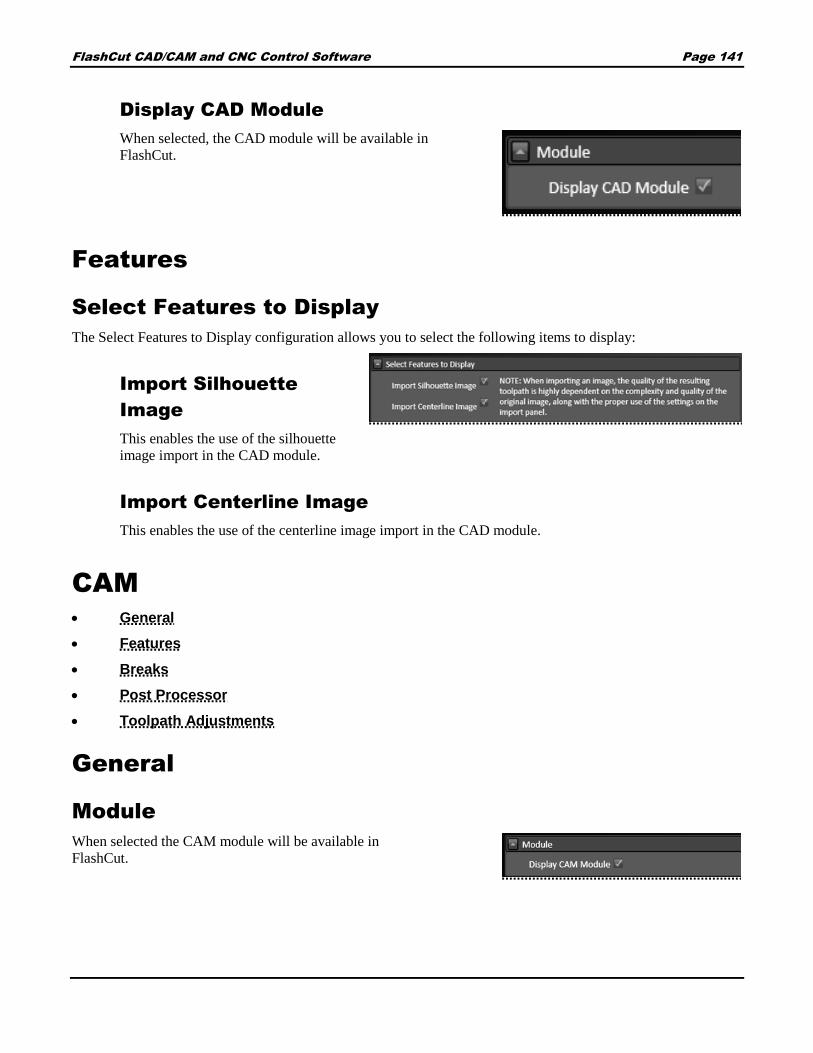
FlashCut CAD/CAM and CNC Control Software Page 141
Display CAD Module
When selected, the CAD module will be available in
FlashCut.
Features
Select Features to Display
The Select Features to Display configuration allows you to select the following items to display:
Import Silhouette
Image
This enables the use of the silhouette
image import in the CAD module.
Import Centerline Image
This enables the use of the centerline image import in the CAD module.
CAM
General
Features
Breaks
Post Processor
Toolpath Adjustments
General
Module
When selected the CAM module will be available in
FlashCut.

FlashCut CAD/CAM and CNC Control Software Page 142
Geometry Processing
Join tolerance
Defines tolerance in system units
Chord error
Defines amount that will trigger an error in
system units.
Toolpath Adjustments
Return to program zero
When selected, this feature is enabled.
Features
The Features configuration option presents the following configuration items:
Select Features to Display
The Select Features to Display configuration allows you to select the following items to display:
Grid Nesting
This enables the use of grid nesting in the CAM module.
Breaks
Breaks on Parts
This section defines the default values for the break placements and lead definitions for parts. The parameters
are identical to the section below titled Breaks on Cutouts, so it is important to distinguish between the two.
A "part" is a closed geometric shape that requires the toolpath to be offset to the outside. There is a lead in and
lead out definition for two break placement approaches. The break can be placed at a corner or not at a corner.

FlashCut CAD/CAM and CNC Control Software Page 143
Enable starting at corners
This range of angles will specify whether or not
a break will be placed at a corner or not. If the
software finds an angle within the range, it will
place the break at the vertex of that angle. If no
angles exist that fall in this range then the break
is placed at the midpoint of the longest line
segment. If no acceptable angles exist and no
line segments exist, the break will be placed on
an arc nearest the origin.
Minimum corner angle
Maximum corner angle
Starting at corner
If an acceptable angle is found, a break will be
placed at the vertex of the angle. The break will
then use the defined lead in and lead out values
below.
Overburn
To ensure a clean cut, you may set the
torch to continue through a cut along the
same toolpath. This feature allows you
to determine how far this overburn will
go. Lead out lines appear after the
overburn.
Lead in
You may choose from:
None
Line
Arc
Lead out
You may choose from:
None
Line
Arc

FlashCut CAD/CAM and CNC Control Software Page 144
Not starting at corner
When no acceptable angle is found, the break will not be placed at a corner. It will instead be placed at
the midpoint of the longest line. If no lines exist the break will be placed on the arc nearest the origin.
Once the break is placed on the toolpath, the lead in and lead out will be created based on the definitions
below.
Overburn
To ensure a clean cut, you may set the torch to continue through a cut along the same toolpath.
This feature allows you to determine how far this overburn will go. Lead out lines appear after the
overburn.
Lead in
You may choose from:
None
Line
Arc
Lead out
You may choose from:
None
Line
Arc
Breaks on Cutouts
This section defines the default values for the break placements and lead definitions for cutouts. This is
identical to the Breaks on Parts section above, so it is important to distinguish between the two. A "cutout" is
any geometric shape inside a part. Cutouts require the toolpath to be offset to the inside. There is a lead in and
lead out definition for two break placement approaches. The break can be placed at a corner or not at a corner.

FlashCut CAD/CAM and CNC Control Software Page 145
Enable starting at corners
This range of angles will specify whether or not
a break will be placed at a corner or not. If the
software finds an angle within the range, it will
place the break at the vertex of that angle. If no
angles exist that fall in this range then the break
is placed at the midpoint of the longest line
segment. If no acceptable angles exist and no
line segments exist, the break will be placed on
an arc nearest the origin.
Minimum corner angle
Maximum corner angle
Starting at corner
If an acceptable angle is found, a break will be
placed at the vertex of the angle. The break will
then use the defined lead in and lead out values
below.
Overburn
To ensure a clean cut, you may set the
torch to continue through a cut along the
same toolpath. This feature allows you
to determine how far this overburn will
go. Lead out lines appear after the
overburn.
Lead in
You may choose from:
None
Line
Arc
Lead out
You may choose from:
None
Line
Arc

FlashCut CAD/CAM and CNC Control Software Page 146
Not starting at corner
When no acceptable angle is found, the break will not be placed at a corner. It will instead be placed at
the midpoint of the longest line. If no lines exist the break will be placed on the arc nearest the origin.
Once the break is placed on the toolpath, the lead in and lead out will be created based on the definitions
below.
Overburn
To ensure a clean cut, you may set the torch to continue through a cut along the same toolpath.
This feature allows you to determine how far this overburn will go. Lead out lines appear after the
overburn.
Lead in
You may choose from:
None
Line
Arc
Lead out
You may choose from:
None
Line
Arc
Post Processor
Post Processor Settings
Include line numbers
Check this box if you want to number all of the
G-Code lines in the program that’s being
created.
Include units command
Check this box if you want to include the
G20/G21 commands for Inch/Metric units
respectively. The G-Code command will
correspond with the units defined in the
CAD/CAM settings menu.

FlashCut CAD/CAM and CNC Control Software Page 147
Include feedrate commands
Keep this box enabled: disabling this box is intended for internal use only. The feedrate command will no
longer be included in the program if this box is disabled.
Any G-code command entered here will be added before all rapid moves (G00).
Include feedrate for rapid moves
This will enable the use of the F feedrate command for a rapid move. Select the checkbox and enter the
feedrate value to be used in the input field labeled feedrate.
Include fabrication head commands
If selected, the M-106 command will be included in the G-code file. M-106 is the fab head change
command: for example, changing from plasma fab head to the marker fab head.
Include THC commands
For plasma fabrication heads only. Commands to enable and disable torch height control will be included
in the G-code file.
Decimal places for coordinates
Enter the number of decimal places to be used for coordinates.
Decimal places for feedrates
Enter the number of decimal places to be used for feedrates.
Positioning mode
Select either absolute or incremental.
Add to the beginning of the G-code file
Any G-code command entered here will be added at the beginning of all G-Code programs generated
from the CAM module.
Add to the end of the G-code file
Any G-code command entered here will be added at the end of all G-Code programs generated from the
CAM module.
Add before each rapid move
Any G-code command entered here will be added before all rapid moves (G00).

FlashCut CAD/CAM and CNC Control Software Page 148
Add after each rapid move
Any G-code command entered here will be added after all rapid moves (G00).
Add after each cut
Any G-code command entered here will be added after each cut.
Save G-Code to FTP Server
Use Save G-Code to FTP Server to instruct FlashCut to upload your G-code file to an FTP server each time the
file is saved.
Activate
Enable the Activate checkbox to
upload your G-code file to an FTP
server each time each time the user
clicks the cut button.
Server Address and Path
Enter the URI for the server including the sub-folder paths.
Username
Enter the username for the FTP account in the Username field.
Password
Enter the password for the FTP account in the Password field. FTP account passwords are typically case-
sensitive.
Use FTP upload panel
If Use FTP upload panel is checked: An FTP upload panel appears in the parameters pane with
various control options.
If Use FTP upload panel is unchecked: the file is uploaded with a default filename (e.g.,
gcode.nc).
Toolpath Adjustments
Holes

FlashCut CAD/CAM and CNC Control Software Page 149
Reduce federate for holes
When checked, federate will be reduced for
holes of the listed diameter multiplied by the
thickness of the material, at the listed percentage
of the program federate.
Turn off THC for holes
When checked, torch height control will be turned off for holes of the listed diameter x the thickness
multiplied by the thickness of the material.

FlashCut CAD/CAM and CNC Control Software Page 150
Licensing FlashCut
Click the License tab to display the FlashCut license management window.
There are two forms of licensing in FlashCut: a license file for the controller, and a license key for the
computer connected to the controller. Both licenses can be managed through FlashCut. A list of features
enabled by the currently installed license can also be reviewed in this window.
Import License File
Activate PC License
Deactivate PC License
Licensed Features List
1
2
3
4
1 2 3
4

FlashCut CAD/CAM and CNC Control Software Page 151
License Management Window
Import License File
If you’ve received a license file, you may import the file into this software to license it. Follow these steps to
import your license into your software.
1. When you receive a license file, copy it to an appropriate location on your computer.
2. Click the Import License File… button.
3. FlashCut displays an Open dialog box.
4. Browse to the location of the file, select it, and click OK.
5. FlashCut installs the license and displays this notice to confirm that the license has been activated.
6. Click OK. The license will be loaded into your controller the next time you connect to it.
Activate PC License
If you’ve received a license key in an email message, you may license your software by typing or pasting the
license key into a dialog box. Follow these steps to license your software with a license key from an email
message.
1. Click the Activate PC License… button.
2. FlashCut displays a License Your Software dialog box.
3. If you’ve copied the license key from the email you received, click the Paste From Clipboard
button. FlashCut pastes the license key in the License Key field. Otherwise, you may type the license
key in the field yourself.
4. Click the License Software button.
5. FlashCut installs the license and displays a notice to confirm that the license has been activated. The
license will be loaded into your controller the next time you connect to it.
6. The license will be loaded into your controller the next time you connect to it.

FlashCut CAD/CAM and CNC Control Software Page 152
Deactivate PC License
You may deactivate the license on your computer so it can be used on a different computer. Follow these steps to
deactivate the license on your computer.
1. Click the Deactivate PC License… button.
2. FlashCut displays a confirmation dialog box.
3. Click OK to deactivate the license.
Licensed Features List
This list shows which advanced or a la carte features of FlashCut are enabled by the installed license key. For an
overview of FlashCut features, see Program packages and features.

FlashCut CAD/CAM and CNC Control Software Page 153
Getting Help
Help
System Status
Help
Selecting the Help icon from any window brings up the following Help screen.
This screen provides information that can help you learn or troubleshoot the software, and that can help
FlashCut technical support assist you in on a support call.
Version
Firmware Version
Graphics Drivers
User’s Guide
Programming Reference
Build Support File
Version
The software revision identification number that is currently installed on the PC.
Firmware Version
The firmware revision identification number that is currently loaded on the signal generator.
Graphics Drivers
The status of the PC’s graphics drivers is displayed.
User’s Guide
Displays this User’s Guide in PDF format.

FlashCut CAD/CAM and CNC Control Software Page 154
Note Requires a PDF viewer, such as Adobe® Acrobat®
Programming Reference
Displays the FlashCut Programming Reference in PDF format.
Note Requires a PDF viewer, such as Adobe® Acrobat®
Build Support File
Builds a compressed ZIP file that contains all current information about your system, including copies of current
setup, configuration, and log files. This information can help FlashCut technical support answer a question or
diagnose a problem.
The loaded G-Code file will be included only if it has been saved. The support file will not include any
CADCAM files. If you are having a CADCAM issue, please e-mail the CADCAM file separately.
FlashCut displays the file Save As dialog so you can save the support file in a convenient location for attachment
to an email message. The default location for the saved file is C:\FlashCut Data\Support.
System Status
Selecting the System Status button in the FlashCut CNC window will display live information
from the input and output lines. The serial number and USB speed of the controller are also shown.
If a numerical control (NC) input line is normal,
it will be in the closed state and the blue LED
will not be illuminated. If the machine is
connected, these icons are live when a switch
changes its state.
If an NC switch is tripped then it will be in the
open state and the blue LED will be illuminated.
Normally, only input lines that have been defined
are displayed. However, if the show all
checkbox is selected, the status of all input lines
will be displayed.
The output line status icons are either white for
off, or blue for on. You can also control the
state of these switches by clicking on them here.
Copyright © 2022 FDOKUMEN