Creating by Imagining: Use of Natural and Intuitive BCI in 3D CAD Modeling
9
Proceedings of the ASME 2013 International Design Engineering Technical Conferences & Computers and Information in Engineering Conference IDETC/CIE 2013 August 4-7, 2013, Portland, OR, USA DETC2013-12276 (DRAFT) CREATING BY IMAGINING: USE OF NATURAL AND INTUITIVE BCI IN 3D CAD MODELING Sree Shankar S DART Lab University at Buffalo - SUNY, NY Email: [email protected] Anoop Verma DART Lab University at Buffalo - SUNY, NY Email: [email protected] Rahul Rai * DART Lab University at Buffalo - SUNY, NY Email: [email protected] ABSTRACT From its inception, computer aided 3D modeling has pri- marily relied on the Windows, Icons, Menus, Pointer (WIMP) user interface. WIMP has rarely been able to tap into the nat- ural intuitiveness and imagination of the user which accompa- nies any design process. Brain-computer interface (BCI) is a novel modality that uses brain signals of a user to enable natural and intuitive interaction with an external device. BCI’s poten- tial to become an important modality of natural interaction for 3D modeling is almost limitless and unexplored. In theory, using BCI one can create any 3D model by just thinking about it. This paper presents a basic framework for using BCI as an interface for computer aided 3D modeling. This framework involves the task of recording and recognizing electroencephalogram (EEG) brain wave patterns and electromyogram (EMG) signals corre- sponding to facial movements. The recognized EEG/EMG brain signals and associated keystrokes are used to activate/control dif- ferent commands of a CAD package. Eight sample CAD models created using the Emotiv EEG head set based BCI interface and Google SketchUp are presented to demonstrate the efficacy of the developed system based on the framework. To further exhibit BCI’s usability, human factor studies have been carried out on subjects from different backgrounds. Based on preliminary re- sults, it is concluded that EEG/EMG based BCI is suitable for computer aided 3D modeling purposes. Issues in signal acquisi- tion, system flexibility, integration with other modalities and data collection are also discussed. * Address all correspondence to this author. 1. INTRODUCTION Computer Aided Design (CAD) systems form the basic foundation of design and innovation processes. Modern day CAD systems rely heavily on the conventional windows, icons, menus, pointer (WIMP), user interfaces (UIs). The WIMP UIs restrict the degree of natural interaction between the user and CAD applications [1]. Lack of natural interaction in WIMP UIs inhibits the creativity of the designer in the design process and this in turn hampers the quality of design solutions. There is a need for intuitive and natural interfaces that can synergistically utilize the thought process of the designer during conceptual de- sign exploration and 3D modeling. Natural and intuitive interfaces capable of using designer in- tent as part of the design exploration process needs to be devel- oped. Such natural interfaces should allow designers to interact with computers in the same way they interact with people [1]. In other words, human computer interaction (HCI) should encapsu- late the characteristics of human human interaction (HHI). Brain computer interface (BCI) is a novel technology that imbibes HHI specific characteristics. BCIs’ potential to become an important modality of natural interaction for 3D modeling is almost limitless and unexplored. In theory, if developed to its full potential, BCI could be used to create entire CAD assemblies by just thinking about them. The research presented in this paper lays out a preliminary foundation to achieve the aforementioned theoretical potential. The main aim of this paper is to furnish a novel BCI based user interface for conceptual 3D modeling tool that is natural, intuitive, and easy to use for novice design- ers/users. 1 Copyright c 2013 by ASME
-
Upload
independent -
Category
Documents
-
view
4 -
download
0
Transcript of Creating by Imagining: Use of Natural and Intuitive BCI in 3D CAD Modeling

Proceedings of the ASME 2013 International Design Engineering Technical Conferences &Computers and Information in Engineering Conference
IDETC/CIE 2013August 4-7, 2013, Portland, OR, USA
DETC2013-12276 (DRAFT)
CREATING BY IMAGINING: USE OF NATURAL AND INTUITIVE BCI IN 3D CADMODELING
Sree Shankar SDART Lab
University at Buffalo - SUNY, NYEmail: [email protected]
Anoop VermaDART Lab
University at Buffalo - SUNY, NYEmail: [email protected]
Rahul Rai ∗
DART LabUniversity at Buffalo - SUNY, NY
Email: [email protected]
ABSTRACTFrom its inception, computer aided 3D modeling has pri-
marily relied on the Windows, Icons, Menus, Pointer (WIMP)user interface. WIMP has rarely been able to tap into the nat-ural intuitiveness and imagination of the user which accompa-nies any design process. Brain-computer interface (BCI) is anovel modality that uses brain signals of a user to enable naturaland intuitive interaction with an external device. BCI’s poten-tial to become an important modality of natural interaction for3D modeling is almost limitless and unexplored. In theory, usingBCI one can create any 3D model by just thinking about it. Thispaper presents a basic framework for using BCI as an interfacefor computer aided 3D modeling. This framework involves thetask of recording and recognizing electroencephalogram (EEG)brain wave patterns and electromyogram (EMG) signals corre-sponding to facial movements. The recognized EEG/EMG brainsignals and associated keystrokes are used to activate/control dif-ferent commands of a CAD package. Eight sample CAD modelscreated using the Emotiv EEG head set based BCI interface andGoogle SketchUp are presented to demonstrate the efficacy ofthe developed system based on the framework. To further exhibitBCI’s usability, human factor studies have been carried out onsubjects from different backgrounds. Based on preliminary re-sults, it is concluded that EEG/EMG based BCI is suitable forcomputer aided 3D modeling purposes. Issues in signal acquisi-tion, system flexibility, integration with other modalities and datacollection are also discussed.
∗Address all correspondence to this author.
1. INTRODUCTIONComputer Aided Design (CAD) systems form the basic
foundation of design and innovation processes. Modern dayCAD systems rely heavily on the conventional windows, icons,menus, pointer (WIMP), user interfaces (UIs). The WIMP UIsrestrict the degree of natural interaction between the user andCAD applications [1]. Lack of natural interaction in WIMP UIsinhibits the creativity of the designer in the design process andthis in turn hampers the quality of design solutions. There is aneed for intuitive and natural interfaces that can synergisticallyutilize the thought process of the designer during conceptual de-sign exploration and 3D modeling.
Natural and intuitive interfaces capable of using designer in-tent as part of the design exploration process needs to be devel-oped. Such natural interfaces should allow designers to interactwith computers in the same way they interact with people [1]. Inother words, human computer interaction (HCI) should encapsu-late the characteristics of human human interaction (HHI).
Brain computer interface (BCI) is a novel technology thatimbibes HHI specific characteristics. BCIs’ potential to becomean important modality of natural interaction for 3D modeling isalmost limitless and unexplored. In theory, if developed to its fullpotential, BCI could be used to create entire CAD assemblies byjust thinking about them. The research presented in this paperlays out a preliminary foundation to achieve the aforementionedtheoretical potential. The main aim of this paper is to furnisha novel BCI based user interface for conceptual 3D modelingtool that is natural, intuitive, and easy to use for novice design-ers/users.
1 Copyright c© 2013 by ASME

In the research outlined in this paper, BCI system is used todetect and relate patterns in brain signals to the users thoughtsand intentions. Specifically, the presented approach recognizeselectroencephalogram (EEG) brain wave patterns that corre-spond to performing certain allocated tasks. These detected userintentions are converted to user intended commands which isthen used to create 3D CAD models. Additionally, EMG sig-nals are also used to support the proposed interface to carry outcertain tasks in the 3D modeling process.
The present work forms the basic foundation of BCI in CADmodeling applications by allowing users to: (1) create geometri-cal shapes, (2) edit shapes by resizing or by geometric operationssuch as booleans, sweeps and extrusions, and (3) move shapesby rotations and translations [2]. The approach developed in thepresent paper is novel and has lot of fruitful extensions.
As every individual has a unique thought pattern when itcomes to performing the same task, human factors study havebeen carried out to assess the reliability and intuitiveness of BCIbased system developed in this research. A preliminary humanfactor study on five subjects was carried out. The preliminaryhuman factors study demonstrates that the developed system haspotential to have lower learning curve and high usability.
The paper is organized as follows. In Section 2, the rele-vant work carried out in the field of BCI and CAD applicationsis discussed. Section 3 outlines the basic hardware and overallsystem developed in the study. The 3D models created using thedeveloped system and results of the human factors user study ispresented in Section 4. Finally, the outcome of the study is sum-marized in Section 5. Issues related to signal acquisition, systemflexibility, integration with other modalities, and data collectionare also discussed in Section 5.
2. RELATED WORKIn this section, the related literature in key research areas is
discussed.
2.1 Classification and Selection of Part GeometriesIn CAD systems, an important aspect is user comprehension
of geometrical features that he/she intends to create [3–5]. Theuser must also be able to distinguish between different geometri-cal features [2, 6, 7]. In this regard, Esfahani and Sundarajan [2]carried out experiments to explore the potential of BCI in distin-guishing primitive shapes. In another recent work by Esfahaniand Sundarajan [8], the authors report the use of BCI on the se-lection of geometrical surfaces in a 3D CAD model.
2.2 Deploying Brain SignalsBrain activity associated with any thinking process has to be
quantified and converted to tangible intentions and commands.The very first advancements in this respect were made in the
virtual reality domain. Pfurtscheller et al. [9] demonstrated forthe first time that it is possible to move through a virtual streetwithout muscular activity when the participant only imaginesfeet movements. Leeb et al. [10] also carried out similar stud-ies where the user was able to navigate in a virtual environmentby using his/her EEG brain signals. Fabiani et al. [11] and Trejoet al. [12] took this one step further with their work on cursormovement using BCI. These studies show that the BCI can beused in many applications and domains [13]. This makes BCI anideal candidate for developing a natural interface for conceptual3D CAD modeling. Similar advancements have also been madein the world of virtual gaming [14] where brain signals are usedto control the user’s avatar.
2.3 Natural and Intuitive CAD Interfaces
For BCI to be an effective tool in CAD applications it needsto be user friendly. This in turn necessitates inclusion of human-human interaction (HHI) aspects in the interface [1]. HHI re-lies on concurrent use and perception of behavioral signals (cues)such as speaking, moving, gazing, and gesturing, which conveyvarious messages (communicative intentions). For example, todescribe an object, one can talk about it and at the same timemove one’s hands to explain different features of the object suchas its size or shape. MozArt, a Multimodal Interface (speech andtouch) for conceptual 3D modeling is an ideal example in thisregard [15, 16]. MozArt prototype interface explores how multi-modal input coupled with appropriate hardware may be appliedto simplify the conceptual 3D modeling for novice CAD users.
2.4 Development of Non-invasive BCI
BCI’s advancement can largely be attributed to its non-invasive nature [17]. In addition, factors such as reduced costsand portability have also helped increasing its popularity amongresearchers [18,19]. In BCI, field work carried out by companiessuch as Emotiv and Neurosky have led to development of head-sets that give users a lot of freedom. Reduction in the cost of thehardware has also enabled this upcoming technology to competewith traditional WIMP based interfaces. If developed to a greaterextent BCI based UIs has the potential to replace existing WIMPbased CAD interfaces.
In summary, BCI interfaces are being used in a wide varietyof applications ranging from its traditional use for recording EEGsignals to video gaming. However, BCI’s potential to be used as anatural and intuitive interface for conceptual 3D CAD modelingremains largely unexplored and this forms the foundation of thework presented here. The next section details the configurationand functioning of the system components.
2 Copyright c© 2013 by ASME

3. SYSTEM COMPONENTS AND METHODSIn the present research, electrical signals based on user’s
brain activity, i.e. electroencephalography (EEG), and facialmuscles, i.e. electromyography (EMG) were considered for de-veloping an interface to interact with a CAD system. Thesesignals were recorded and analyzed using Emotiv headset (Fig-ure 1). The recorded signals were used to train the interface tounderstand the user’s thought patterns and intent. Emotiv APIis used to link the user and CAD application. For present re-search, Google SketchUp is used as test CAD platform. GoogleSketchUp is chosen because of its simplicity and ease of use [15].Once trained, users can conceptualize, create, and manipulate 3Dmodels in the CAD environment.
FIGURE 1: Basic framework of the developed system
3.1 The Emotiv EEG InterfaceThe Emotiv EEG is a low cost Human-Computer Interface
(HCI) that is comprised of: (1) a neuroheadset hardware deviceto acquire EEG and EMG signals, and (2) the software devel-opment kit (SDK) to process and interpret these signals. Fig-ure 2a depicts the overall sensor placement scheme on the scalp.The actual Emotiv headset is shown in Figure 2b. The names ofchannels are based on the international 10-20 convention. Theneuroheadset acquires brain signals using 14 sensors placed onthe user scalp. It also includes 2 internal gyroscopes to provideinformation about user’s head position. The BCI headset com-municates with the computer system wirelessly by means of aUSB dongle.
The Emotiv headset can capture and process brainwaves inthe Delta (0.54 Hz), Theta (48 Hz), Alpha (814 Hz) and Beta
(1426 Hz) bands [20]. User’s expressive actions, affective emo-tions, and cognitive actions can be detected using these signals.The expressive actions correspond to user’s face movements andare typically detected quickly (10 ms), making them suitable forfast paced applications like 3D CAD modeling.
The Emotiv EEG can enable 13 different movements, i.e.the push, pull, left, right, up and down directional movements,the clockwise, counter-clockwise, left, right, forward and back-ward rotations and a special action that makes an object disap-pear in the user mind representing the user’s cognitive actions.Additionally, the angular velocity of one’s head can be measuredin the yaw and pitch (but not roll) directions using the inbuiltgyros.
(a) (b)
FIGURE 2: BCI Headset (a) Location of sensors on the headset(b) The Emotiv headset
3.2 EEG Data Acquisition and Feature ExtractionFigure 3 describes the basic flow of EEG signal acquisition,
preprocessing, and classification. EEG is recorded by electrodesplaced on the scalp and digitized by an Analog to Digital Con-verter (ADC). Computer processing extracts features most suit-able for identifying the user’s intensions such as extruding cer-tain geometry. When an intension is classified, a certain com-mand is sent to an external device e.g., a display. The visualfeedback from the screen provides the user with the results ofhis/her actions, thus allowing them to alter the system behav-ior [21].
EEG signals are recorded from 14 locations at sampling rateof 2048 Hz. The neuroheadset applies a series of high-pass andlow pass filters to preprocess the incoming signal. Two notchfilters at 50 Hz and 60 Hz are then applied to the preprocessedsignal to remove the main artifacts which maybe caused due tophysical movement. The signals are then down-sampled furtherto 128 Hz. The recorded EEG signals are assumed to be a linearcombination of n (14 in the present case) statistically indepen-dent input signals from the scalp. In other words, X=WS where
3 Copyright c© 2013 by ASME

FIGURE 3: General scheme of EEG based BCI
X is the brain signal, W is a weighting matrix and S correspondsto statistically independent sources in the user’s brain.
In the preprocessing step, Independent Component Analysis(ICA) decomposition is used to find the independent components(ICx) of the recorded data, defined as:
ICx =W−1X (1)
where independent components (ICx) represent synchronous ac-tivity in the underlying cerebral and noncerebral sources (e.g.,potentials induced by eye or muscle movement). To implementICA decomposition, logistic infomax ICA algorithm is used withnatural gradient and extended ICA extensions implemented inEEGLAB [22].
The independent components obtained are further used toextract the relevant features. In the literature, several techniqueshave been used for classifying EEG data in BCI for differentmental tasks. It includes band powers (BP) [23], power spec-tral analysis (PSA) values, autoregressive (AR), adaptive autore-gressive (AAR) parameters, time frequency analysis, and inversemodel-based analysis. In PSA for example, the different brainwaves that have been captured can be represented as follows (seeequations 2-4)
Delta =∑
4k=0.5 k2P[k]
∑4k=0.5 P[k]
(2)
T heta =∑
7k=4 k2P[k]
∑7k=4 P[k]
(3)
Al pha =∑
12k=8 k2P[k]
∑12k=8 P[k]
(4)
Beta =∑
30k=13 k2P[k]
∑30k=13 P[k]
(5)
Where P[k] is the phase-excluded power spectrum and k corre-sponds to the frequency of the brain waves [24]. The final steputilizes an EEG pattern classifier, which identifies patterns cor-responding to the various mental states of the users. Classifiersbased on two-class common spatial patterns (TCSP) and multipleclass common spatial patterns (MCSP) are widely used [21].
Quite similar to EEG, Electromyography (EMG) is a tech-nique for evaluating and recording the electrical activity pro-duced by skeletal muscles. The expressive suite of the muscles isused to calibrate inputs of this form. Signal processing in EMG isdone sequentially using full-wave rectification, filtering, averag-ing and smoothing. A quantitative measure of the EMG activityis typically obtained by determining the area under smoothenedsignal envelope [25]. The quick response of EMG to a givenstimulus, and adaptability to the users makes it ideal for a CADinterface. In the presented research, EMG is also used along withEEG in the developed CAD interface.
3.3 Software UsedThe Emotiv toolkit includes the a C++ API, which allows (1)
communication with the Emotiv headset, (2) reception of prepro-cessed EEG/EMG and gyroscope data, (3) management of user-specific or application-specific settings, (4) post-processing, and(5) translation of the detected results into an easy-to-use structure(also called as EmoState) [18]. Figure 4 describes the integrationof Emotiv API and EmoEngine. EmoEngine is the logical ab-straction of the Emotiv API that performs all the processing ofthe data from the Emotiv headset. The Emotiv EEG, by meansof the Emotiv API, provides external applications informationabout the event type that emanates from the user’s brain and re-ports the event power, which represents the certainty of the eventoccurence. Alternatively, a neutral event is reported when no ac-tions are detected [20].
3.4 CAD Graphical User Interface PlatformThe testing platform of proposed CAD modeling interface
is based on Google SketchUp software [26]. Google SketchUpprovides an easy to use 3D modeling environment that has alarge online repository of model assemblies for efficient analy-sis. Google SketchUp is used in the developed system as a 3Dmodeling environment for creating and visualizing 3D models.The graphical user interface (GUI) of Google SketchUp is usedas platform to display the current state of 3D models. Based onvisual feedback from the current state of 3D models the user gen-erates a new set of input brain signals. The new brain signals arerecorded and processed by the Emotiv headset and sent to GoogleSketchUp for altering the state of the 3D models.
4 Copyright c© 2013 by ASME

FIGURE 4: Integration of EmoEngine and Emotiv API with an application
FIGURE 5: Emotiv expressive suite acquiring EMG signals
3.5 System SetupIn this section, the overall configuration of the developed
system, and its integration with the chosen CAD application(Google SketchUp) is discussed. Following inbuilt function ofthe Emotiv API are used in the implemented system.
1. Emotiv Control panel2. Emotiv Key3. Emotiv Test bench
The Emotiv Control panel serves as the training platform fornovice users. It has three suites namely the expressive, affective,and cognitive suites of which the expressive and cognitive suitesare used in the developed system. The expressive suite is used for
the EMG component of the user input i.e. signals that are gen-erated from movement of facial muscles. The EMG componentconsists of 11 recognizable inputs, all of which can be calibratedto best suit the user. Figure 5 shows the expressive suite and thesignals being recorded for different facial features.
The cognitive suite is an API used for acquiring brain signals(EEG) that are generated by thoughts. The EmoEngine is trainedto interpret the users’ intent using this module. The cognitivesuite accommodates for 12 of movements including 6 directions(left, right, up, down, forward, and “zoom”) and 6 rotations (anti-clockwise rotation, turn left and right, and sway backward andforward) plus 1 other visualization (“disappear”) in the virtualenvironment.
5 Copyright c© 2013 by ASME

The Emotiv Key is used to link the EmoEngine and theCAD application (Google SketchUp). Specifically, the EmoKeyis used to assign the EMG/EEG signals of the user to specifickeystrokes that can be understood by the CAD application. Theassignment of EMG/EEG signals is accompanied with condi-tions such as ‘greater than’ ‘equal to’ ‘lesser than’ and ‘occurs’.These conditions have to be fulfilled in order to execute a givencommand. The EmoKey can thus be used as a controller to sim-ulate surface selection and manipulation tasks of 3D CAD mod-eling.
The Emotiv test bench is used to acquire the EEG signal as-sociated with tasks that the user is performing. During the cog-nitive training, the user has to imagine manipulating a cube inthe virtual environment. This training action includes imaginingabout pushing, pulling, rotating, lifting and dropping the cubein the virtual environment. Figure 6 shows the sample variation
FIGURE 6: (a) Baseline when user is not engaged (left) (b) Whenuser is under cognitive load (right).
in the brain waves of the user during rest (neutral) and trainingphase (cognitive push and pull).
4 RESULTSIn this section, 3D CAD models generated from the devel-
oped system are presented. In addition, observations from a pre-liminary human factors study are also outlined.
4.1 CAD ModelingTo demonstrate the use of the developed BCI based system,
a set of simple 3D CAD models were created. The user was freeto choose a mapping that he preferred. Modeling begins withcreating a 2D sketch using the line or arc tool. The position ofthe cursor is governed by head movements. The 2D sketch isthen extruded to produce the final 3D part. Table 1 shows themapping that was used for the construction of the 3D CAD mod-els. The magnitudes for the conditions that have been shownin the table are based on trial and error and depend on the fa-cial features and thought processes of the user. These values areunique to each user and are generally determined during train-ing. Once the Emotiv Key links the CAD application with theneuroheadset, the user is able to interact with the CAD tool. TheBCI interface is used to simulate the selection of the CAD toolsmenu to construct 3D models. The tools for drawing circles andextrusion were associated with thoughts ‘push’ and ‘pull’ (EEG)while other functions relied on facial expressions (EMG ).
Figure 7 shows sample 3D CAD models created using thedeveloped BCI based CAD system. These 3D models were cre-ated by different users. Depending on the part geometry, the 3DCAD models took an average of 1-3 minutes to generate. To geta more objective view of the performance of the system, humanfactor studies were carried out. The details of the human factorsstudy is presented next.
4.2 Human Factors Study on BCI CAD ApplicationsIn order to validate the performance of presented BCI inter-
face, a human factors study consisting of novice CAD users wasperformed. The aim of the study was to:
1. assess individual differences/similarities of the participantswhile creating the 3D models
2. assess the learning curve of the users
A total of five young male participants were selected for thestudy. All the participants were aged between 24-28 years withno known mental disorders. The task required the participants tocreate 3D parts (in Google SketchUp) using the developed BCIsystem. The proposed study started with a training session whereparticipants thought patterns were tuned to the desired actionssuch as push, pull, and eye blink etc. (see Table 1). The calibra-
6 Copyright c© 2013 by ASME

Name Action Trigger Value Key(s)
Left Click Blink Occurs - Mouse left click
Right Click Furrow Brow Is greater than 0.8 Mouse right click
Hold Left Raise Brow Is greater than 0.3 Hold left mouse
Circle Push Is greater than 0.2 C
Arc Look left Occurs - A
Line Look Right Occurs - L
Extrude Pull Is greater than 0.4 P
Clear Smirk Right Is greater than 0.3 Ctrl+Z
TABLE 1: Sample mapping of keystrokes using Emotiv Key
FIGURE 7: 3D CAD models created by different users using the developed BCI based CAD system
tion process took about 30-35 minutes, after which the partici-pants had to perform four tasks of increasing difficulty.
Figure 8 displays the processing steps of the tasks that theparticipants had to perform. The information related to partici-pants activities along with the time taken to finish the tasks wererecorded. Figure 9 displays the distribution of participants com-pletion time with varying task difficulty level. As anticipated,the completion time of the tasks was proportional to the task dif-ficulty level. There was a steep increase in the completion time
of task 3 compared to tasks 1 and 2. This was largely due to theinvolvement of two thought processes (push and pull) in tasks3 and 4. Even though no additional information was providedto participants during the execution of task 4, participants tooklesser time to complete the task. It should be noted that task 4was of the same difficulty level as task 3 and this indicates thatthe participants were able to adapt to the interface once they fin-ished the first three tasks.
7 Copyright c© 2013 by ASME
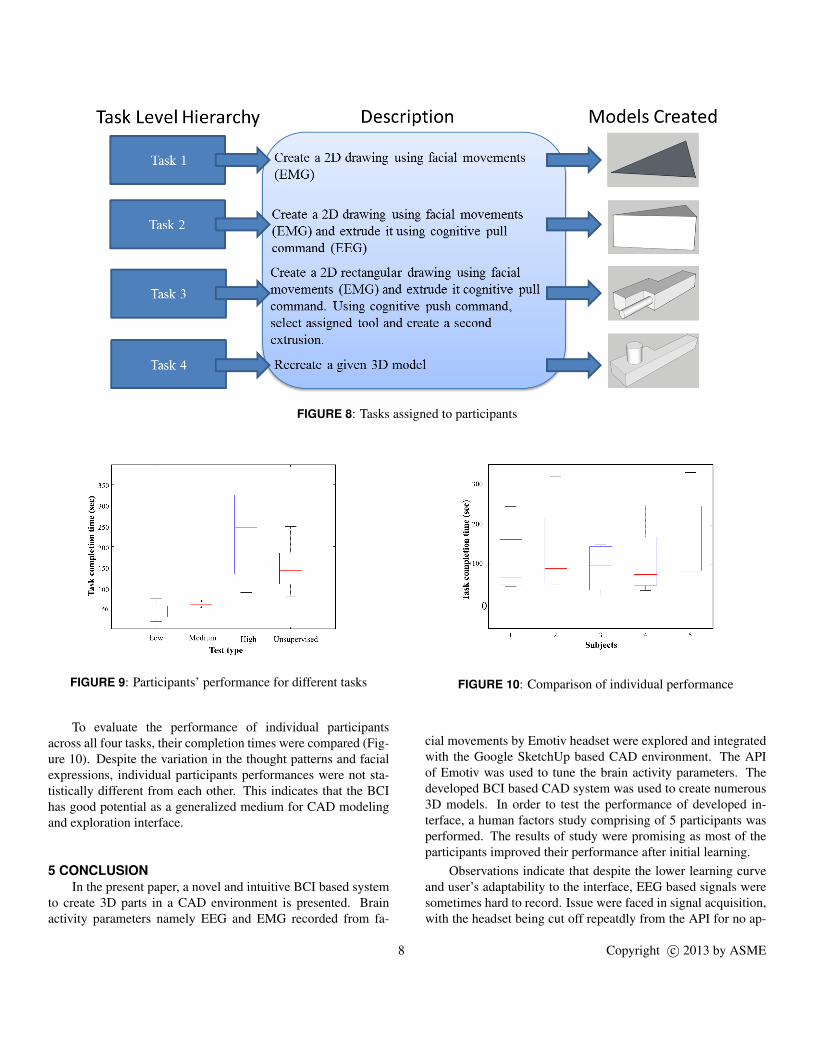
FIGURE 8: Tasks assigned to participants
FIGURE 9: Participants’ performance for different tasks
To evaluate the performance of individual participantsacross all four tasks, their completion times were compared (Fig-ure 10). Despite the variation in the thought patterns and facialexpressions, individual participants performances were not sta-tistically different from each other. This indicates that the BCIhas good potential as a generalized medium for CAD modelingand exploration interface.
5 CONCLUSIONIn the present paper, a novel and intuitive BCI based system
to create 3D parts in a CAD environment is presented. Brainactivity parameters namely EEG and EMG recorded from fa-
FIGURE 10: Comparison of individual performance
cial movements by Emotiv headset were explored and integratedwith the Google SketchUp based CAD environment. The APIof Emotiv was used to tune the brain activity parameters. Thedeveloped BCI based CAD system was used to create numerous3D models. In order to test the performance of developed in-terface, a human factors study comprising of 5 participants wasperformed. The results of study were promising as most of theparticipants improved their performance after initial learning.
Observations indicate that despite the lower learning curveand user’s adaptability to the interface, EEG based signals weresometimes hard to record. Issue were faced in signal acquisition,with the headset being cut off repeatdly from the API for no ap-
8 Copyright c© 2013 by ASME

parent reason. The participants experienced fatigue that couldbe ascribed to the headset configuration and design. The usabil-ity study results presented in the paper were based on a smallgroup of users. In future, a more extensive user study will bedone to get better understanding of the interface usability. An-other future research direction will be to improve the usabilityof presented interface by integrating BCI with other modalitiessuch as speech and gestures.
REFERENCES[1] Gurkok, H., and Nijholt, A., 2012. “Brain–computer in-
terfaces for multimodal interaction: A survey and princi-ples”. International Journal of Human-Computer Interac-tion, 28(5), pp. 292–307.
[2] Esfahani, E., and Sundararajan, V., 2011. “Classifica-tion of primitive shapes using brain–computer interfaces”.Computer-Aided Design.
[3] Kosslyn, S., and Osherson, D., 1995. An Invitation to Cog-nitive Science, -Vol. 2: Visual Cognition, Vol. 2. Mit Press.
[4] Moulton, S., and Kosslyn, S., 2009. “Imagining predic-tions: mental imagery as mental emulation”. PhilosophicalTransactions of the Royal Society B: Biological Sciences,364(1521), pp. 1273–1280.
[5] Farah, M., Hammond, K., Levine, D., and Calvanio, R.,1988. “Visual and spatial mental imagery: Dissociablesystems of representation”. Cognitive psychology, 20(4),pp. 439–462.
[6] Kosslyn, S., 1996. Image and brain: The resolution of theimagery debate. MIT press.
[7] Alexiou, K., Zamenopoulos, T., Johnson, J., and Gilbert, S.,2009. “Exploring the neurological basis of design cognitionusing brain imaging: some preliminary results”. DesignStudies, 30(6), pp. 623–647.
[8] Esfahani, E., and Sundararajan, V., 2011. “Using braincomputer interfaces for geometry selection in cad systems:P300 detection approach”. ASME.
[9] Pfurtscheller, G., Leeb, R., Keinrath, C., Friedman, D., Ne-uper, C., Guger, C., and Slater, M., 2006. “Walking fromthought”. Brain Research, 1071(1), pp. 145–152.
[10] Leeb, R., Scherer, R., Lee, F., Bischof, H., andPfurtscheller, G., 2004. “Navigation in virtual environ-ments through motor imagery”. In 9th Computer VisionWinter Workshop, CVWW, Vol. 4, pp. 99–108.
[11] Fabiani, G., McFarland, D., Wolpaw, J., and Pfurtscheller,G., 2004. “Conversion of eeg activity into cursor movementby a brain-computer interface (bci)”. Neural Systems andRehabilitation Engineering, IEEE Transactions on, 12(3),pp. 331–338.
[12] Trejo, L., Rosipal, R., and Matthews, B., 2006. “Brain-computer interfaces for 1-d and 2-d cursor control: designsusing volitional control of the eeg spectrum or steady-state
visual evoked potentials”. Neural Systems and Rehabilita-tion Engineering, IEEE Transactions on, 14(2), pp. 225–229.
[13] Kubler, A., Kotchoubey, B., Kaiser, J., Wolpaw, J., and Bir-baumer, N., 2001. “Brain–computer communication: Un-locking the locked in.”. Psychological bulletin, 127(3),p. 358.
[14] Lecuyer, A., Lotte, F., Reilly, R., Leeb, R., Hirose, M., andSlater, M., 2008. “Brain-computer interfaces, virtual real-ity, and videogames”. Computer, 41(10), pp. 66–72.
[15] Sharma, A., Madhvanath, S., Shekhawat, A., andBillinghurst, M., 2011. “Mozart: a multimodal interfacefor conceptual 3d modeling”. In Proceedings of the 13thinternational conference on multimodal interfaces, ACM,pp. 307–310.
[16] Hondrou, C., and Caridakis, G., 2012. “Affective, naturalinteraction using eeg: sensors, application and future direc-tions”. Artificial Intelligence: Theories and Applications,pp. 331–338.
[17] Muller, K., and Blankertz, B., 2006. “Toward non-invasivebrain-computer interfaces”.
[18] http://www.emotiv.com/.[19] http://www.neurosky.com/.[20] Gomez-Gil, J., San-Jose-Gonzalez, I., Nicolas-Alonso, L.,
and Alonso-Garcia, S., 2011. “Steering a tractor by meansof an emg-based human-machine interface”. Sensors,11(7), pp. 7110–7126.
[21] Bobrov, P., Frolov, A., Cantor, C., Fedulova, I., Bakhnyan,M., and Zhavoronkov, A., 2011. “Brain-computer interfacebased on generation of visual images”. PloS one, 6(6),p. e20674.
[22] Delorme, A., and Makeig, S., 2004. “Eeglab: an opensource toolbox for analysis of single-trial eeg dynamics in-cluding independent component analysis”. Journal of neu-roscience methods, 134(1), pp. 9–21.
[23] Pfurtscheller, G., Neuper, C., Flotzinger, D., and Pregenzer,M., 1997. “Eeg-based discrimination between imaginationof right and left hand movement”. Electroencephalographyand clinical Neurophysiology, 103(6), pp. 642–651.
[24] Khushaba, R., Greenacre, L., Kodagoda, S., Louviere, J.,Burke, S., and Dissanayake, G., 2012. “Choice modelingand the brain: A study on the electroencephalogram (eeg)of preferences”. Expert Systems with Applications.
[25] Soderberg, G., and Cook, T., 1984. “Electromyography inbiomechanics”. Physical Therapy, 64(12), pp. 1813–1820.
[26] http://sitescontent.google.com/google-sketchup-for-educators/home.
9 Copyright c© 2013 by ASME