xBCI: A Generic Platform for Development of an Online BCI System
7
IEEJ TRANSACTIONS ON ELECTRICAL AND ELECTRONIC ENGINEERING IEEJ Trans 2010; 5: 467–473 Published online in Wiley InterScience (www.interscience.wiley.com). DOI:10.1002/tee.20560 Paper xBCI: A Generic Platform for Development of an Online BCI System I Putu Susila ∗ , Non-member Shin’ichiro Kanoh ∗a , Non-member Ko-ichiro Miyamoto ∗ , Non-member Tatsuo Yoshinobu ∗,∗∗ , Member A generic platform for realizing an online brain–computer interface (BCI) named xBCI was developed. The platform consists of several functional modules (components), such as data acquisition, storage, mathematical operations, signal pro- cessing, network communication, data visualization, experiment control, and real-time feedback presentation. Users can easily build their own BCI systems by combining the components on a graphical-user-interface (GUI) based diagram editor. They can also extend the platform by adding components as plug-ins or by creating components using a scripting language. The platform works on multiple operating systems and supports parallel (multi-threaded) data processing and data transfer to other PCs through a network transmission control protocol/internet protocol or user datagram protocol (TCP/IP or UDP). A BCI system based on motor imagery and a steady-state visual evoked potential (SSVEP) based BCI system were constructed and tested on the platform. The results show that the platform is able to process multichannel brain signals in real time. The platform provides users with an easy-to-use system development tool and reduces the time needed to develop a BCI system. 2010 Institute of Electrical Engineers of Japan. Published by John Wiley & Sons, Inc. Keywords: brain–computer interface (BCI), generic platform, electroencephalography (EEG) Received 27 March 2009; Revised 5 December 2009 1. Introduction 1.1. Brain–computer interface (BCI) A Brain– computer interface (BCI) system is a communication system that does not depend on the brain’s normal output pathways of periph- eral nerves and muscles [1]. BCI technology can be applied to a communication system for patients with severe motor disabilities (e.g., late-stage amyotrophic lateral sclerosis, spinal cord injury, stroke), a brain-state monitoring system during rehabilitation, or a new human–computer interface in the entertainment field. In a BCI system, brain activity is recorded through invasive or noninvasive techniques such as electroencephalography (EEG), near-infrared spectroscopy (NIRS), or functional magnetic res- onance imaging (fMRI), and is then processed and translated into commands for controlling external devices (see Refs 2–4 for reviews). Previous studies have demonstrated the capabilities of BCI systems for controlling a computer cursor, selecting letters or words, playing computer games, controlling avatar in a virtual reality environment, or controlling external devices such as a robot arm, a functional electrical stimulation device, or a wheelchair [5–9]. 1.2. A generic platform for BCI research A BCI system consists of modules for acquisition of brain signals, com- mand detection, interface with external devices, and feedback pre- sentation (see Fig. 1). Processing brain signals to detect commands involves various algorithms such as preprocessing, feature extrac- tion, and pattern classification. Depending on the algorithm to be a Correspondence to: Shin’ichiro Kanoh. E-mail: [email protected] ∗ Graduate School of Engineering, Tohoku University, Aobayama 6-6-05, Sendai 980-8579, Japan ∗∗ Graduate School of Biomedical Engineering, Tohoku University, Aobayama 6-6-05, Sendai 980-8579, Japan used and the number of channels for measurement, large compu- tational power may be required for processing. A system that can process the signals in parallel (e.g., a multi-threaded system on a single computer or a distributed system using several PCs con- nected through a network) is needed, especially when the signals should be processed online. In BCI research, there is a need to implement artifact detection and removal, command detection, application control, an online feedback system for training subjects, etc. In addition to satisfy- ing the above-mentioned requirements, a BCI system should be flexible since researchers often change parts of the system during development. When the system is developed from scratch, it is time consuming and requires knowledge of hardware and software. Currently, there are several available platforms that can be used to build an online BCI system, such as BCI200 [10], Open-ViBE [11], rtsBCI [12], and BCI system provided by Guger Technologies (g.tec), Austria [13]. The BCI2000 platform that is implemented using Borland C++ programming language is a module-based BCI platform working on Windows. The platform consists of four types of modules (operator, source, signal pro- cessing, and application) which can be combined to realize a BCI system. The modules are implemented as stand-alone applications which exchange data with each other through a network protocol based on transmission control protocol/internet protocol (TCP/IP) even though they work on the same PC. Open-ViBE is a BCI framework which consists of many modules and can be applied to neuro-feedback and virtual reality. Modules can be added to the framework as plug-ins. The framework needs a data acquisi- tion server for measuring brain signal and send the signal using TCP/IP. The rtsBCI platform is a toolbox of MATLAB with a real- time environment working on Microsoft Windows. This system consists of MATLAB/SIMULINK modules such as data acquisi- tion, classifier, and feedback presentation. The commercial system provided by g.tec can be used to realize several types of BCI systems. 2010 Institute of Electrical Engineers of Japan. Published by John Wiley & Sons, Inc.
Transcript of xBCI: A Generic Platform for Development of an Online BCI System
IEEJ TRANSACTIONS ON ELECTRICAL AND ELECTRONIC ENGINEERINGIEEJ Trans 2010; 5: 467–473Published online in Wiley InterScience (www.interscience.wiley.com). DOI:10.1002/tee.20560
Paper
xBCI: A Generic Platform for Development of an Online BCI System
I Putu Susila∗, Non-member
Shin’ichiro Kanoh∗a, Non-member
Ko-ichiro Miyamoto∗, Non-member
Tatsuo Yoshinobu∗,∗∗, Member
A generic platform for realizing an online brain–computer interface (BCI) named xBCI was developed. The platformconsists of several functional modules (components), such as data acquisition, storage, mathematical operations, signal pro-cessing, network communication, data visualization, experiment control, and real-time feedback presentation. Users can easilybuild their own BCI systems by combining the components on a graphical-user-interface (GUI) based diagram editor. Theycan also extend the platform by adding components as plug-ins or by creating components using a scripting language. Theplatform works on multiple operating systems and supports parallel (multi-threaded) data processing and data transfer toother PCs through a network transmission control protocol/internet protocol or user datagram protocol (TCP/IP or UDP). ABCI system based on motor imagery and a steady-state visual evoked potential (SSVEP) based BCI system were constructedand tested on the platform. The results show that the platform is able to process multichannel brain signals in real time. Theplatform provides users with an easy-to-use system development tool and reduces the time needed to develop a BCI system. 2010 Institute of Electrical Engineers of Japan. Published by John Wiley & Sons, Inc.
Keywords: brain–computer interface (BCI), generic platform, electroencephalography (EEG)
Received 27 March 2009; Revised 5 December 2009
1. Introduction
1.1. Brain–computer interface (BCI) A Brain–computer interface (BCI) system is a communication system thatdoes not depend on the brain’s normal output pathways of periph-eral nerves and muscles [1]. BCI technology can be applied to acommunication system for patients with severe motor disabilities(e.g., late-stage amyotrophic lateral sclerosis, spinal cord injury,stroke), a brain-state monitoring system during rehabilitation, or anew human–computer interface in the entertainment field.
In a BCI system, brain activity is recorded through invasiveor noninvasive techniques such as electroencephalography (EEG),near-infrared spectroscopy (NIRS), or functional magnetic res-onance imaging (fMRI), and is then processed and translatedinto commands for controlling external devices (see Refs 2–4 forreviews). Previous studies have demonstrated the capabilities ofBCI systems for controlling a computer cursor, selecting lettersor words, playing computer games, controlling avatar in a virtualreality environment, or controlling external devices such as a robotarm, a functional electrical stimulation device, or a wheelchair[5–9].
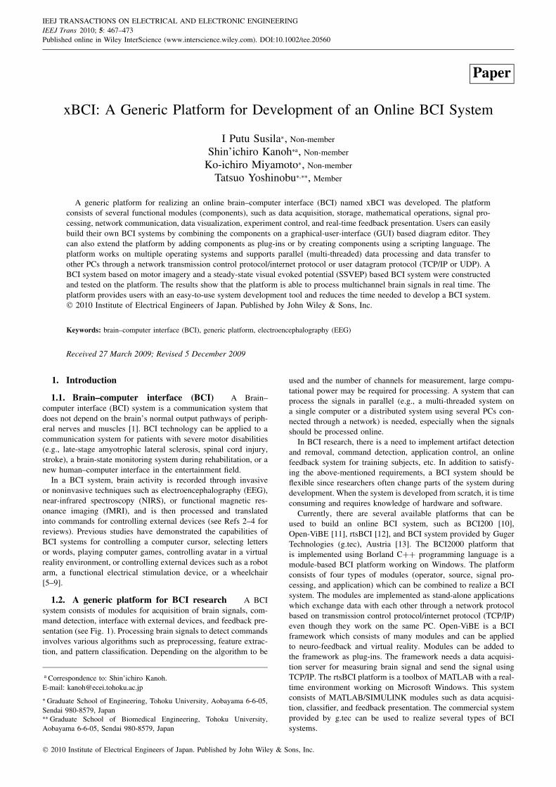
1.2. A generic platform for BCI research A BCIsystem consists of modules for acquisition of brain signals, com-mand detection, interface with external devices, and feedback pre-sentation (see Fig. 1). Processing brain signals to detect commandsinvolves various algorithms such as preprocessing, feature extrac-tion, and pattern classification. Depending on the algorithm to be
a Correspondence to: Shin’ichiro Kanoh.E-mail: [email protected]
∗ Graduate School of Engineering, Tohoku University, Aobayama 6-6-05,Sendai 980-8579, Japan∗∗ Graduate School of Biomedical Engineering, Tohoku University,Aobayama 6-6-05, Sendai 980-8579, Japan
used and the number of channels for measurement, large compu-tational power may be required for processing. A system that canprocess the signals in parallel (e.g., a multi-threaded system ona single computer or a distributed system using several PCs con-nected through a network) is needed, especially when the signalsshould be processed online.
In BCI research, there is a need to implement artifact detectionand removal, command detection, application control, an onlinefeedback system for training subjects, etc. In addition to satisfy-ing the above-mentioned requirements, a BCI system should beflexible since researchers often change parts of the system duringdevelopment. When the system is developed from scratch, it is timeconsuming and requires knowledge of hardware and software.
Currently, there are several available platforms that can beused to build an online BCI system, such as BCI200 [10],Open-ViBE [11], rtsBCI [12], and BCI system provided by GugerTechnologies (g.tec), Austria [13]. The BCI2000 platform thatis implemented using Borland C++ programming language is amodule-based BCI platform working on Windows. The platformconsists of four types of modules (operator, source, signal pro-cessing, and application) which can be combined to realize a BCIsystem. The modules are implemented as stand-alone applicationswhich exchange data with each other through a network protocolbased on transmission control protocol/internet protocol (TCP/IP)even though they work on the same PC. Open-ViBE is a BCIframework which consists of many modules and can be appliedto neuro-feedback and virtual reality. Modules can be added tothe framework as plug-ins. The framework needs a data acquisi-tion server for measuring brain signal and send the signal usingTCP/IP. The rtsBCI platform is a toolbox of MATLAB with a real-time environment working on Microsoft Windows. This systemconsists of MATLAB/SIMULINK modules such as data acquisi-tion, classifier, and feedback presentation. The commercial systemprovided by g.tec can be used to realize several types of BCIsystems.
2010 Institute of Electrical Engineers of Japan. Published by John Wiley & Sons, Inc.
I. P. SUSILA ET AL.
Fig. 1. Diagram of a typical BCI system. Modules surroundedby gray can be realized on the proposed platform
We developed a new generic platform for building an online BCIanalysis and experiment system. The platform is module-basedand do not rely on commercial systems or libraries. Functionalmodules (components) can be added to the platform as plug-insand using scripting language. Data exchange between componentsworking on the same PC is done through memory to minimizeoverheads. And more than one application of this platform work-ing on individual PCs can be linked by transforming data throughEthernet connection. This platform supports multiple operatingsystems (OSs) and is freely available under GNU public license.
2. Platform Design
2.1. Features The platform was designed to realize thefollowing features:
1. Extendable module-based system designThe platform consists of many components that can be used torealize the desired BCI systems. Users can design and buildvarious types of BCI systems by combining these compo-nents. Users can also add a custom component to extend thefunctionality of the platform. A custom component can beadded to the platform by creating a plug-in or by writing thecomponent using scripting language.
2. Graphical-user-interface (GUI)-based system realizationA BCI system to be realized is expressed as an editable dia-gram (hereinafter, system diagram), which consists of severalcomponents. A GUI-based diagram editor for building andediting the system is provided. Using the editor, even inexpe-rienced users can easily build their own systems. Parameterssuch as sampling frequency, name of file for storing EEGdata, and cut-off frequency of the digital filter, can also bedefined and edited through a GUI-based property editor.
3. Multi-threaded parallel processingEach component is executed on its own thread and startsprocessing in parallel as soon as any data incoming to thecomponent becomes available. On the platform, a user canbuild a multi-threaded system without any detailed knowledgeof the OS or thread programming.
4. High-speed data processingA BCI system that acquires and processes brain signals(recorded through multichannels at a high sampling rate)within a short period (i.e., on the order of milliseconds) canbe easily built on the platform. This feature enables online(real-time) data classification and feedback presentation.
5. Multi-OS supportThe platform supports multiple OSs, including Microsoft Win-dows and GNU Linux.
For realizing various types of BCI systems using EEG, whosefrequency range is up to about 100 Hz, this platform was designedto realize systems that are able to acquire and process at least 16channel analog input sampled at 1000 Hz.
2.2. Design concept Figure 2 shows the outline of theplatform. The platform consists of a GUI-based diagram editor forrealizing the desired BCI system. On the editor, a BCI system
is expressed as a system diagram. The system diagram consistsof several components that are connected to each other throughconnection lines. The diagram editor is used to edit and executethe system diagram. During execution of the system, each com-ponent performs a task assigned to it. Data are processed andthen transferred to other components as a packet. In the following,the components, the data transfer between components, and theexecution of the system are described in detail.
2.2.1. Components A component is defined as a func-tional module that can be connected to other components to builda complete system. It consists of common application program-ming interfaces (APIs) for processing data, checking any errors,executing tasks, editing parameters, etc. It has input and/or outputport(s) for receiving and sending data from/to other components.An output port can be connected to one or more input ports, butan input port cannot be connected to more than one output port.Every input port has a queue for storing incoming data. The useof the queue guarantees that no data will be lost even if it arriveswhile the component is processing previous data.
On the platform, there are three types of principal components:
1. Source componentsA source component provides data that will be processed byother components. This component has only output port forsending data to downstream components. A component foracquiring data from hardware, a component that generates datafor simulation, and a component that receives data through thenetwork are examples of source components. Common param-eters such as sampling frequency, data unit, and the numberof measurement channels are defined in the source componentand are shared with other components in the system.
2. Processing componentsA processing component receives data from upstream com-ponents, manipulates it, and then sends results to downstreamcomponents. This type of component has both input port(s)for receiving data and output port(s) for sending data.
3. Sink componentsA sink component enables a user to review, store, or senddata through the network without manipulating them. The sinkcomponent has only input port(s) for receiving data.
2.2.2. Data transfer Data are transferred between com-ponents by means of a packet. A packet consists of a packetheader and the data to be processed (hereinafter, packet data).System parameters that will be shared among components, suchas sampling frequency and number of channels for measurement,are defined in the packet header.
Packet data is arranged in a two-dimensional (2D) array, whichaccommodates multichannel brain signals of a specified timelength (referred to as block length). For the best performance,the block length can be optimized.
2.2.3. Execution of a system After a system diagram iscreated, it can be executed from the diagram editor. For executionof the system, there are three available modes: continuous, timer,and counter modes. In the continuous mode, the system runs untilthe user aborts the execution manually. In the timer mode, thesystem runs for a certain period of time specified by the user, andfinally in the counter mode, the system runs for a certain numberof repetitions.
A pseudocode of execution of a system is shown in Fig. 3.Before execution, the connections between components and theparameters set by the user are verified, and then shared parametersare transferred from the source component to other components inthe system. The parameters must be propagated in a proper orderfrom source to processing and finally to sink components. Inter-nally, the components in the system are stored as a list. Each time
468 IEEJ Trans 5: 467–473 (2010)

xBCI: A GENERIC BCI PLATFORM
Fig. 2. Outline of the platform. A BCI system is realized by combining several components in the diagram editor (top left). Screen captureof data visualization components is shown on the right side of the figure. An outline of tasks that are performed during the execution of
the system is shown at the bottom
Fig. 3. Pseudocode for executing the system, executing a taskon each thread, and aborting the execution
the user adds a new component, it will be appended to the list. Toguarantee that the components in the list are stored in the properorder, each time the system is executed, they are sorted accord-ing to their distance from the source. Then, the verification andpropagation of the parameters can be done sequentially.
After all components have been verified to be free of error, athread associated with each component is started, and then thisthread executes the task assigned to the component. The task isexecuted repeatedly until aborted by the user, until a defined periodof time elapses, or until an error occurs.
3. Implementation
3.1. Library and development tools The platformwas implemented using C/C++ programming language and wascompiled with a GNU C/C++ compiler set (MinGW on Win-dows). The following open source libraries were used to implement
components and the platform itself: Qt GUI toolkit, QLed, andQProg classes which support GUI implementation on multipleOSs; COMEDI (device drivers for data acquisition under Linux);FFTW [14] (calculation of fast Fourier transform); qwt and qwt-plot3d (2D and 3D data plotting libraries); muParser (parsingmathematical expression), WinIo (parallel port input/output onWindows); and BioSig for C/C++ toolbox (saving and loadingEEG data). A Code::Blocks integrated development environment(IDE) was used to develop the platform.
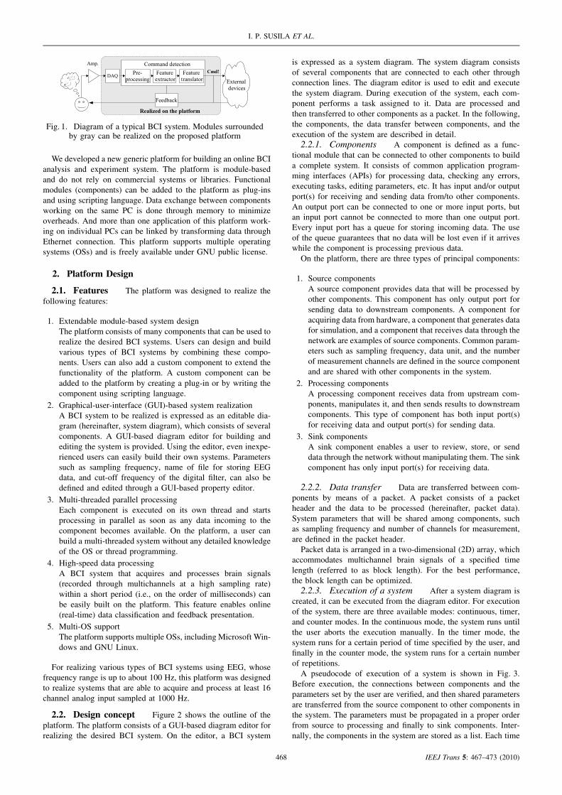
3.2. Implementation of a component Figure 4 showsthe libraries required by the platform and several common APIswhich are defined for each component. Qt and third-party librariesare provided by other vendors, while the others are libraries wehave developed. There are two types of libraries: a user interfacelibrary and a core library, which are required when implementinga component as a plug-in. Several main APIs that typically need tobe implemented in each component are listed in the figure. To adda custom component, the user needs to create a C++ class whichinherits the class shown in the figure and then implements relatedAPIs.
Another way of adding a custom component is to write the com-ponent in scripting language (QtScript). The APIs that need to beimplemented in the script are similar to those in C++ class. Supportof scripting language provides a convenient way to add a customcomponent without the need for any development environment.
3.3. Ready-to-use components The components in-cluded in the current version of the platform were implementedas plug-ins. Using plug-ins, components can be added withoutrecompiling the whole platform and can then be distributed sepa-rately from the platform. The use of plug-ins makes the platformhighly extendable. The components that were implemented arelisted below.
(1) Basic mathematical operationLogical operation, arithmetic operation of scalar values andmatrices, and basic mathematical function such as trigono-metric, logarithmic, etc.
469 IEEJ Trans 5: 467–473 (2010)
I. P. SUSILA ET AL.
Fig. 4. Libraries in the platform and common APIs which are defined for each component
(2) Data processingFinite impulse response (FIR) and infinite impulse response(IIR) digital filter, discrete Fourier transform (DFT), smooth-ing by moving average, and averaging over channels.
(3) ClassifiersA threshold-based classifier and a classifier based on template-matching are provided.
(4) Data acquisition (DAQ)The interface between xBCI and DAQ boards is provided bythis component. On Linux, data acquisition is implementedwith COMEDI, which supports many acquisition boards. OnWindows, data acquisition through DAQ boards of NationalInstruments Corp. (Austin, Texas, USA) and Interface Corp.(Hiroshima, Japan) are supported.
(5) Digital input/outputA digital signal (e.g., event markers) can be written/readthrough a parallel port or a digital I/O board of NationalInstruments Corp.
(6) Network communicationData transfer between PCs can be done using the userdatagram protocol (UDP) or a TCP/IP server and a clientcomponent. The components allow the user to easily buildan experimental system with several PCs connected by thenetwork.
(7) Evaluation of a mathematical expressionA component for evaluating a mathematical expression(n-inputs, 1-output) is provided. Calculation of a slightlycomplicated expression with arithmetic and logical operators,basic mathematical function, and conditional expression (if ...then ... else ...) can be achieved using the component.
(8) Script componentA script component can be used to implement custom com-ponents, online feedback, or experiment controls. The com-ponent using QtScript is based on the ECMAScript scriptinglanguage, as defined in standard ECMA-262 (with the samesyntax as in JavaScript). The user is provided with a windowwhich can be programmed from script to display text, line,shapes, or images. A method for playing sound and timercontrol are also provided.
(9) Data visualizationA multichannel real-time scope, a power spectrum, multipledata plots, a ti–frequency plot, and a 3D plot are providedfor displaying and monitoring the measured or processeddata.
(10) Visual feedback presentationA gauge bar and a lamp for expressing on/off states are pro-vided. The length of the gauge bar can be controlled usingany values such as amplitude or power spectrum of recordedEEG (cf [16,17]). The lamp, which is linked to a gauge bar,mimics a light-emitting diode (LED) on the computer screen.It will turn on when the value of the input data exceeds apredefined threshold value.
4. Evaluation and Discussion
Several examples of BCI systems were built on the platform toevaluate the performance, timing accuracy, and online capabilitiesof the platform. Experiments involving humans on this evaluationwere reviewed and approved by the Ethics Committee on ClinicalInvestigation, Graduate School of Engineering, Tohoku University.
4.1. Performance and timing In order to evaluate thecapability of the platform, an online system for acquiring data andfor calculating band power of input signal was built and tested.Such system is widely used for EEG-based BCI to detect motorimagery [15,16].
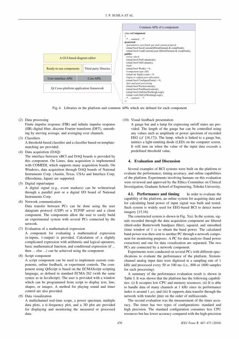
The constructed system is shown in Fig. 5(a). In the system, sig-nals recorded through the data acquisition component are filtered(third-order Butterworth bandpass filter), squared, and smoothed(time window of 1 s) to obtain the band power. The calculatedband power was then sent to another PC through a network compo-nent for monitoring purposes. A PC for data analysis (band powerextraction) and one for data visualization are separated. The twoPCs are connected by a network component.
Experiments were conducted on several PCs with different spec-ifications to evaluate the performance of the platform. Sixteen-channel analog input data were digitized at a sampling rate of 1kHz and processed every 50 or 100 ms (i.e., 800 or 1600 samplesfor each processing).
A summary of the performance evaluation result is shown inTable I. It was shown that the platform has the following capabili-ties: (i) It occupies low CPU and memory resources; (ii) It is ableto handle data of many channels at 1 kHz since its performanceindex is around 1 µs; and (iii) It supports data transfer through thenetwork with transfer jitter on the order of milliseconds.
The second evaluation was the measurement of the timer accu-racy. The timer has two types of configurations: standard andhigh precision. The standard configuration consumes less CPUresources but has lower accuracy compared with the high-precision
470 IEEJ Trans 5: 467–473 (2010)
xBCI: A GENERIC BCI PLATFORM
(a)
(b)
Fig. 5. System diagrams for performance and timing evalua-tion. (a) Band power extraction system, (b) experiment controlsystem with a time chart of each event (in seconds) during a
trial
Table I. Result of performance evaluation
TCP/IPBlock Processing Performance jitterlength PC CPU&MEM time [ms] index [µs] [ms]
50 NB 6% (20 MB) 0.70 ± 1.35 0.88 1.46PC1 5% (19 MB) 1.06 ± 0.66 1.33 2.90PC2 8% (20 MB) 1.13 ± 1.16 1.41 3.83
100 NB 6% (20 MB) 1.07 ± 0.42 0.67 2.88PC1 5% (19 MB) 1.61 ± 1.17 1.01 1.99PC2 8% (20 MB) 1.62 ± 2.40 1.01 1.33
Notebook computer (WindowsXP Professional SP2, Celeron 1.6 GHz, Memory 512MB) with 16-channel PCMCIA DAQ card (CBI-360116: Interface Corp.), PC1: desk-top computer (WindowsXP Professional SP2, Pentium 4, 2.4 GHz, Memory 1.25 GB)which is equipped with 16-channel DAQ boards (PCI-6251 & PCI-MIO-16E-4) fromNational Instruments Corp., and PC2: desktop computer: (WindowsXP ProfessionalSP2, Celeron 2.4 GHz, Memory 512 MB). Performance index is equal to processingtime divided by the number of processed samples, while jitter is defined as a deviationof network transfer delay between data packet.
configuration. In the evaluation, first, a periodic pulse, whoseperiod was controlled by the timer, was generated in the platformand then was written to the parallel port of the PC. The pulse wassampled with a DAQ board installed in another PC at a samplingrate of 50 kHz. The periods of the pulse were varied from 10 to 100ms. On every measurement, 500 pulses were recorded. The experi-ment was conducted on a desktop PC (Windows 2000 SP4, P4 2.0GHz, memory 512 MB). Results show that the resolution (stan-dard deviation of the recorded pulses) of the timer with standard
configuration was around 10 ms, while that of the high-precisiontimer was less than 1 ms.
Next, in order to evaluate the influence of other tasks on timeraccuracy, we realized a system for experiment control, shown inFig. 5(b). The system consists of a timer for controlling the tim-ing of beep, cue, and cross shown in time chart of the figure. Thescript component produced a beep sound, drew a cue or cross,and sent a trigger signal of an event through the parallel port.The experiment was conducted on PC1 and Linux PC (Ubuntu8.04.1, kernel version 2.6.24, Celeron 1.8 GHz, memory 1 GB).The accuracy was defined as the average of the difference betweenactual onset and requested onset of an event. For example, if therequested onset for the ‘beep event’ was 7000 ms, and the actualbeep was presented at 7002 ms, then the difference was 2 ms. Theresult showed that the timer accuracy on the Windows PC was0.76 ± 0.65 ms and that it was 0.32 ± 0.06 ms on Linux PC. Theaccuracy was maintained in the order of milliseconds even whenseveral tasks are added to the system.
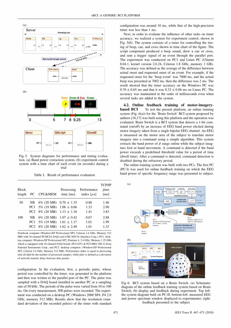
4.2. Online feedback training of motor-imagery-based BCI To test the present platform, an online trainingsystem (Fig. 6(a)) for the ’Brain Switch’ BCI system proposed byauthors [16,17] was built using this platform and the operation wasevaluated. Brain Switch is a BCI system that detects a 1-bit com-mand (on/off) by an increase of EEG band power elicited duringmotor imagery taken from a single bipolar EEG channel. An EEGis measured on the motor area of the subject to translate motorimagery into a command using a simple algorithm. This systemextracts the band power of β range online while the subject imag-ines foot or hand movement. A command is detected if the bandpower exceeds a predefined threshold value for a period of time(dwell time). After a command is detected, command detection isdisabled during the refractory period.
The online training system was built with two PCs. The first PC(PC-I) was used for online feedback training on which the EEGband power of specific frequency range was presented to subject.
(a)
(b)
Fig. 6. BCI system based on a Brain Switch. (a) Schematicdiagram of the online feedback training system based on BrainSwitch, (b) display and feedback during experiment. Top left:the system diagram built on PC-II; bottom-left: measured EEGand power spectrum window displayed to experimenter; right:
feedback presented to the subject
471 IEEJ Trans 5: 467–473 (2010)

I. P. SUSILA ET AL.
Extraction of the band power is done by applying a digital fil-ter (third-order Butterworth bandpass filter) to the acquired data,squaring the filtered data, and smoothing the squared data by 1-smoving average. A white bar, the length of which is proportional tothe band power, is presented to the subject as feedback through theLCD monitor connected to PC-I. The second PC (PC-II) receivesdata from PC-I through UDP. The power spectrum is calculatedand displayed together, with the measured EEG for data reviewby the experimenter.
An experiment with a healthy subject was conducted to evaluatethe system. A single-channel bipolar EEG was recorded from thescalp around the motor cortex (International 10-20 System: Cz-CPz). The measured EEG was amplified using a Nihon Kohdenamplifier (16-channel amplifier, AB-611J) and then was digitizedat a sampling rate of 1 kHz.
The EEG signal was processed as described above to extract theband power, and a white bar was presented to the subject online.The subject was instructed to execute or imagine foot movement.Figure 6(b) shows the display of the PC-II during experiment,the EEG, and its power spectrum observed by the experimenter.Observation of the measured EEG, power spectrum, and whitebar indicated that this system calculated and presented feedbackinformation correctly.
4.3. Steady-state visual evoked potential (SSVEP)based BCI Next, the SSVEP-based BCI system [18,19] thatdetects the frequency components in the measured EEG was imple-mented on the present platform. SSVEP is elicited when the subjectgazes on an object flickering at a certain frequency. Many studieshave demonstrated that an EEG measured from the scalp aroundthe visual cortex contains a frequency component at the frequencyof the stimulus. In these studies, a DFT or a lock-in amplifier sys-tem has been commonly used to extract the frequency componentat the frequency of the stimulus and its harmonics.
The implemented system for system evaluation is shown inFig. 7(a). With this system, a six-channel monopolar EEG (Inter-national 10-20 System: Oz, POz, O1, PO3, O2, PO4) was recordedand then differentiated into a three-channel bipolar EEG. The EEGwas divided into blocks, and DFT with a time window of 1 s wasapplied. This method is known as the short-time Fourier transform(STFT).
The experiment was conducted with a healthy subject. The stim-ulation was presented by a stimulation unit which contained threeLEDs with flickering frequencies of 6, 13, and 15 Hz. The sub-ject was instructed to gaze at each LED for 1 min, followed by1 min of rest (no gazing at any LED). The intention of the sub-ject was detected using threshold-based classification. If the powerspectrum of the target frequency (e.g., 6 Hz) exceeded the prede-fined threshold, a command was detected. The command and theassociated power spectrum were displayed by three lamps andgauge bars on the computer screen. The power spectrum that wasobserved when the subject was gazing at the 6-Hz LED is shownin Fig. 7(b). It is clearly observed that the EEG power spectrumincreased at 6 Hz and its harmonics (12, 18 Hz), not at otherfrequencies. At the same time, the gauge bar level increased andexceeded the threshold value, causing the lamp displayed on thescreen to turn on.
5. Conclusion
A generic platform (xBCI) for building an online BCI systemwas developed. The development of xBCI is intended to helpresearchers to build an online experiment and analysis system. Theplatform is highly extendable and flexible, easy to use, supportsmulti-threaded parallel processing, and can be executed on multipleOSs such as Microsoft Windows and GNU Linux.
(a)
(b)
Fig. 7. BCI system based on steady-state visual evokedpotential (SSVEP). (a) Schematic diagram of SSVEP-basedBCI system, (b) display during experiment. Top: averagedpower spectrum and bottom: feedback window with lamps
and gauge bars
The platform consists of many ready-to-use components, whichcan be divided into source, processing, and sink components. Userscan easily build online systems by combining the available compo-nents. Every component is completely independent, and changesto a part of the system (e.g., data acquisition, classifier) do notrequire rebuilding of the system from scratch. A custom compo-nent can be easily added as a plug-in or a component written inscripting language, without any influence on the platform and othercomponents.
Experiments with a band power extraction system demonstratedthe performance of the platform. It is possible to process manyEEG channels online using a notebook PC with relatively lowcomputation power. The accuracy of the timer was also evalu-ated with a system for experiment control. The result showed thattiming control on the order of milliseconds can be achieved onthe platform. Experiments on a Brain-Switch-based online train-ing system and an SSVEP-based system proved that BCI systemswith different modalities and processing algorithms can be easilyimplemented on the platform.
The current version of the platform only supports data acquisi-tion from generic DAQ boards. However, by adding a custom dataacquisition component that acquires EEG from a commercial EEGamplifier and measurement system and the acquisition of brainsignals other than EEG (e.g., NIRS), various brain signals can berecorded and processed in the platform. Extending the platform byadding a custom component such as a feature extractor, classifiers,
472 IEEJ Trans 5: 467–473 (2010)

xBCI: A GENERIC BCI PLATFORM
interfaces with external devices, etc., will improve the capabilityof the platform. Improvement of the GUI-based diagram editorand support for other scripting languages such as Python or Rubywill be considered in the future.
The platform along with documentation and example designscan be obtained at http://xbci.sourceforge.net/ and is freely avail-able under GNU public license.
Acknowledgements
Part of this work was supported by grants from Tohoku Uni-versity Electro-Related Departments Global COE Program. SKacknowledges the support by Grant-in-Aid for Scientific Research,Ministry of Education, Culture, Sports, Science and Technology,Japan (No. 19560414), and Central Research Laboratory, Hitachi,Ltd., Japan.
References
(1) Wolpaw JR, Birbaumer N, Heetderks WJ, McFarland DJ, PeckhamPH, Schalk G, Donchin E, Quantrano LA, Robinson CJ, VaughanTM. Brain-computer interface technology: a review of thefirst international meeting. IEEE Transactions on RehabilitationEngineering 2000; 8:164–173.
(2) Weiskopf N, Mathiak K, Bock SW, Scharnowski F, Veit R,Grodd W, Goebel R, Birbaumer N. Principles of a brain-computerinterface (BCI) based on real-time functional magnetic resonanceimaging (fMRI). IEEE Transactions on Biomedical Engineering 2004;51:966–970.
(3) Sitaram R, Zhang H, Guan C, Thulasidas M, Hoshi Y, Ishikawa A,Shimizu K, Birbaumer N. Temporal classification of multichannelnear-infrared spectroscopy signals of motor imagery for developinga brain-computer interface. NeuroImage 2007; 34:1416–1427.
(4) Birbaumer N. Breaking the silence: brain-computer interfaces (BCI)for communication and motor control. Psychophysiology 2006;43:517–532.
(5) Wolpaw JR, Birbaumer N, McFarland DJ, Pfurtscheller G, VaughanTM. Brain-computer interfaces for communication and control.Clinical Neurophysiology 2002; 113:767–791.
(6) Krepki R, Blankertz B, Curio G, Muller KR. The Berlin brain-computer interface (BBCI): towards a new communication channelfor online control in gaming applications. Multimedia Tools andApplication 2007; 33:73–90.
(7) Birbaumer N, Kubler A, Ghanayim N, Hinterberger T, Perelmouter J,Kaiser J, Iversen I, Kotchoubey B, Neumann N, Flor H. The toughttranslation device (TTD) for completely paralyzed patients. IEEETransactions on Rehabilitation Engineering 2000; 8:190–193.
(8) Pfurtscheller G, Guger C, Muller G, Krausz G, Neuper C. Brainoscillations control hand orthosis in a tetraplegic. NeuroscienceLetters 2000; 292:211–214.
(9) Galan F, Nuttin M, Lew E, Ferrez PW, Vanacker G, Philips J,Millan JdelR. A brain-actuated wheelchair: asynchronous and non-invasive brain-computer interfaces for continuous control of robots.Clinical Neurophysiology 2008; 119:2159–2169.
(10) Schalk G, McFarland DJ, Hinterberger T, Birbaumer N, Wolpaw JR.BCI2000: a general-purpose brain-computer interface (BCI) system.IEEE Transactions on Biomedical Engineering 2000; 51:1034–1043.
(11) Arrouet C, Congedo M, Marvie J-E, Lamarche F, Lecuyer A, ArnaldiB. Open-ViBE: a 3D Platform for Real-Time Neuroscience. Journalof Neurotherapy 2005; 9(1):3–25.
(12) Scherer R, Schlogl A, uller-Putz GR, Pfurtscheller G. Inside the Graz-BCI: rtsBCI. Proceedings of the 2nd International Brain-ComputerInterface Workshop and Training Course, 2004, 81–82.
(13) g.tec—Guger Technologies. Austria. http://www.gtec.at/.
(14) Frigo M, Johnson SG. The design and implementation of FFTW3.Proceedings of the IEEE 2005; 93:216–231.
(15) Pfurtscheller G, uller-Putz GR, Pfurtscheller J, Rupp R. EEG-basedasynchronous BCI controls functional electrical stimulation in a
tetraplegic patient. EURASIP Journal on Applied Signal Processing2005; 19:3152–3155.
(16) Kanoh S, Scherer R, Yoshinobu T, Hoshimiya N, Pfurtscheller G.Brain Switch BCI system based on EEG during foot movementimagery. Proceedings of the 3rd International BCI Workshop andTraining Course, 2006; 64–65.
(17) Kanoh S, Scherer R, Yoshinobu T, Hoshimiya N, Pfurtscheller G.Effect of feedback training on EEG-based brain-computer interface(BCI) to detect motor imagery. Proceedings of the 4th InternationalBCI Workshop and Training Course, 2008, 150–155.
(18) Cheng M, Gao X, Gao S, Xu D. Design and implementation of abrain-computer interface with high transfer rates. IEEE Transactionson Biomedical Engineering 2002; 49:1181–1186.
(19) Muller-Putz GR, Scherer R, Brauneis C, Pfurtscheller G. Steady-state visual evoked potential (SSVEP)-based communication: impactof harmonic frequency components. Journal of Neural Engineering2005; 2:123–130.
I Putu Susila (Non-member) was born in Bali, Indonesia, in1978. He received the B.E. and M.E. degreesfrom Tokyo Institute of Technology, Tokyo,in 2002 and 2004, respectively. He is cur-rently a Ph.D. student in the Department ofElectronic Engineering, Tohoku University.His research interest includes brain–computerinterfaces (BCI), signal processing, and soft-
ware development.
Shin’ichiro Kanoh (Non-member) was born in Kanagawa,Japan, in 1968. He received the B.E., M.E.,and Ph.D. degrees in electric and telecommu-nication engineering from Tohoku Universityin 1991, 1993, and 1996, respectively. Since1996, he has been an Assistant Professor ofElectronic Engineering at the Tohoku Uni-versity, Sendai, Japan. His research subjects
concern measurement and analysis of brain activities, biosignalmeasurement in general, and development of brain–computerinterface.
Ko-ichiro Miyamoto (Non-member) was born in Yamaguchi,Japan, in 1979. He received the B.E., M.E.,and Ph.D. degrees from Tohoku Universityin 2002, 2004, and 2006, respectively. HisPh.D. thesis deals with the study on biomolec-ular sensing using infrared absorption spec-troscopy. Since 2006, he has been an Assis-tant Professor in the Department of Electronic
Engineering, Tohoku University. His interest is on the applica-tion of silicon-based chemical sensors for biomolecular sensing.
Tatsuo Yoshinobu (Member) was born in Kyoto, Japan, in1964. He received the B.E., M.E., and Ph.D.degrees in electrical engineering from KyotoUniversity in 1987, 1989, and 1992, respec-tively, for his study on gas source molecularbeam epitaxy of silicon carbide. In 1992, hejoined the Institute of Scientific and IndustrialResearch, Osaka University, where he started
the development of silicon-based chemical sensors. From 1999to 2000, he was a Guest Scientist at the Research Centre, Julich,Germany. Since 2005, he has been a Professor for ElectronicEngineering at Tohoku University, Sendai, Japan. Since 2008,he has also been a Professor at the Graduate School of Biomed-ical Engineering, Tohoku University.
473 IEEJ Trans 5: 467–473 (2010)