
3D conjugate heat transfer with thermal radiation in a hollow cube exposed to external flow
13
This article appeared in a journal published by Elsevier. The attached copy is furnished to the author for internal non-commercial research and education use, including for instruction at the authors institution and sharing with colleagues. Other uses, including reproduction and distribution, or selling or licensing copies, or posting to personal, institutional or third party websites are prohibited. In most cases authors are permitted to post their version of the article (e.g. in Word or Tex form) to their personal website or institutional repository. Authors requiring further information regarding Elsevier’s archiving and manuscript policies are encouraged to visit: http://www.elsevier.com/copyright
Transcript of 3D conjugate heat transfer with thermal radiation in a hollow cube exposed to external flow

This article appeared in a journal published by Elsevier. The attachedcopy is furnished to the author for internal non-commercial researchand education use, including for instruction at the authors institution
and sharing with colleagues.
Other uses, including reproduction and distribution, or selling orlicensing copies, or posting to personal, institutional or third party
websites are prohibited.
In most cases authors are permitted to post their version of thearticle (e.g. in Word or Tex form) to their personal website orinstitutional repository. Authors requiring further information
regarding Elsevier’s archiving and manuscript policies areencouraged to visit:
http://www.elsevier.com/copyright

Author's personal copy
3D conjugate heat transfer with thermal radiation in a hollowcube exposed to external flow
C. Albanakis, D. Bouris *
Department of Engineering and Management of Energy Resources, University of Western Macedonia, Bakola and Sialvera, 50100 Kozani, Greece
a r t i c l e i n f o
Article history:Received 23 July 2007Available online 24 May 2008
Keywords:3D RANSConjugate heat transferThermal radiationCube envelope
a b s t r a c t
The interaction of an asymmetrically heated cube envelope exposed to turbulent external flow is numer-ically studied using a three dimensional computational fluid dynamics control volume approach withconjugate heat transfer, including thermal radiation effects. An analytical approach is used for thermalradiation modelling with an implicit boundary condition for convective and radiative heat transfer atsolid–fluid interfaces. For external flow Reynolds numbers of 2 � 105–106 and heat flux values ofq = 20, 40 W m�2, a weak but turbulent (Ra = 1.5–5 � 109) buoyant flow is induced inside the cube. Thetemperature distribution of the inner surfaces is significantly affected by heat flux orientation withregard to external flow as well as the relative influence of convective and thermal radiation heat transfer.
� 2008 Elsevier Ltd. All rights reserved.
1. Introduction
Natural convection is found in a number of applications such aselectronics, aeronautics, building engineering, solar energy collec-tors, aerospace systems, etc, where forced convection and thermalradiation might also be present. Buoyant flows in indoor spaceshave been receiving much attention recently and understandingthe mechanisms that link them with external wind flow is valuableinformation for natural or hybrid ventilation applications [1]. Aninteresting situation arises when a building is subject to externalairflow while simultaneously exposed to solar radiation since itcombines a number of heat transfer modes: natural and forcedconvection, thermal radiation and conduction through the enve-lope. The purpose of the present study is to present a numericalmethodology that is being developed to study the fundamental3D configuration, for all involved heat transfer modes.
Turbulent flow and heat transfer past a surface mounted cubehas been the subject of both experimental and numerical studies.Meinders et al. [2] and Nakamura et al. [3] performed experimen-tal measurements of the local and mean Nusselt number distribu-tion on the surfaces of a heated cube exposed to turbulentexternal flow and the latter developed correlations for the exter-nal surface heat transfer as a function of Reynolds number. The in-side of the cube was solid and at steady heating conditions.Meinders and Hanjalic [4] extended these studies to heat transferfrom two surface mounted cubes, finding that the distribution ofthe heat transfer coefficient depends on the vortex shedding ofthe upstream cube but that the average value remains indepen-
dent of the relative placement of the two cubes. Turbulent flowpast a surface mounted cube has been a challenging problem fornumerical studies due to the complex flow pattern that includesrecirculation regions, stagnation points and unsteady vortex shed-ding. Cheng et al. [5] compared large eddy simulations to standardReynolds averaged modelling using the k–e model and Tsuchiyaet al. [6] investigated the applicability of modifications to thestandard k–e model for bluff body flows where excessive turbu-lence energy production is usually predicted in the stagnation re-gions. Iaccarino et al. [7] and Rodi [8] attribute the superiorpredictions of LES for this type of flow to correct modelling ofboth turbulence energy production and vortex shedding. Unfortu-nately, since the computational cost of this type of simulation ishigh and even unsteady RANS are overwhelming for parametricstudies [7], some of the inaccuracies of RANS models must stillbe tolerated [8] although knowledge of the shortcomings isimportant for extracting dependable conclusions.
In a differentially heated cubic enclosure, natural convectiondominates and this has also been a subject of interest for manyyears. Markatos et al. [9] numerically studied the buoyant flow ofsmoke in a square enclosure and the numerical modelling of thebuoyancy forces in gases is still being refined [10]. A common con-figuration for natural convection in enclosures is when one side ofthe enclosure (usually a cube) is heated and the opposite side iscooled. The laminar flow experiment by Bajorek and Lloyd [11],which involved a 2D enclosure with obstacles (baffles) extendingfrom the top and bottom walls, has been used as a validation testcase for both enclosure natural convection and conjugate heattransfer [12]. Tian and Karayiannis [13] experimentally studied a2D enclosure with differentially heated side walls, but for a moder-ately turbulent flow (Ra � 109), without obstacles. Dol and Hanjalic
0017-9310/$ - see front matter � 2008 Elsevier Ltd. All rights reserved.doi:10.1016/j.ijheatmasstransfer.2008.01.038
* Corresponding author. Tel.: +30 24610 56675.E-mail address: [email protected] (D. Bouris).
International Journal of Heat and Mass Transfer 51 (2008) 6157–6168
Contents lists available at ScienceDirect
International Journal of Heat and Mass Transfer
journal homepage: www.elsevier .com/locate/ i jhmt

Author's personal copy
[14] performed numerical studies of turbulent natural convectionin a side-heated enclosure with a number of turbulence modelsand found that the low-Reynolds number k–e model variants failto represent details of the flow but are capable of providing quali-tative information. Radiation effects in these configurations can be-come important for large temperature differences, or whenconvection is not prominent and Kasemi and Naraghi [15] per-formed 2D numerical studies of the laminar flow in a differentiallyside heated square enclosure at low values of gravitational acceler-ation. The effects of radiation were modelled using the discrete ex-change factor method and became more important as convectionwas reduced at low-g. Mezrhab et al. [16] used the radiosity ap-proach to include radiation effects in their study of 2D laminar nat-ural convection in a cavity with a square body at its center andmore recently Dharma Rao et al. [17] used an ADI solver to performa detailed conjugate heat transfer analysis of 2D conduction, natu-ral convection and radiative heat transfer in a horizontal fin arrayconsidered as a two-fin enclosure. Sharma et al. [18] studied turbu-lent flow in a differentially heated square enclosure with thinwalls, for which conjugate heat transfer of convection and conduc-tion was considered at the interface but the walls themselves weremodelled as one dimensional fins. The presence of three dimen-sional solid objects was considered by Consalvi et al. [19] who pre-sented a methodology for solving turbulent flow and heat transferin enclosures under conditions of fire. Sharma et al. [18] and Cons-alvi et al. [19], used the k–e model for turbulence effects, the radi-osity method for radiation and the harmonic mean of the solid andfluid thermal conductivities was used at the interface. However,Chen and Han [20], who focused on modelling conjugate heattransfer with SIMPLE based algorithms, found that the applicationof the harmonic mean across the interface might lead to erroneoussolutions.
There are a number of complex physical phenomena present inboth the flow past a surface mounted cube and in the buoyant flowinside a differentially heated cubic enclosure that have been ad-dressed separately in the past, as shown in the preceding discus-sion, but the combined configuration has not received much
attention. Bouris [21] and Petridou and Bouris [22] have previouslyperformed studies of the flow and heat transfer past a hollow sur-face mounted cube, examining both the effects of turbulence mod-elling assumptions as well as the variation of the thermal fieldsthrough the cube envelope. However, radiation effects were not in-cluded in the study and thermal sources were uniformly distributedinside the cube. In the present study, a numerical methodology ispresented that allows for the simultaneous solution of forced andbuoyant turbulent flow with conjugate convective, conductiveand radiative heat transfer through solid–fluid interfaces. Specialattention is placed on the thermal boundary condition at the so-lid–fluid interface so that it is implicitly included in the solutionrather than through a separate iterative procedure.
2. Numerical methodology
2.1. Flow field
The numerical method is based on the Reynolds averaged Na-vier–Stokes equations (RANS) with the mass, momentum (veloci-ties: u1, u2, u3, pressure: P) and enthalpy (Cp: specific heat, T:temperature) equations written in Cartesian notation (i = 1, 2, 3correspond to x, y, z directions, respectively):
o
oxiðquiÞ ¼ 0 ð1Þ
o
oxjðqujuiÞ ¼ �
oPoxiþ o
oxjleff
oui
oxjþ ouj
oxi
� �� �þ qbgiðT � ToÞ ð2Þ
o
oxjðqujCPTÞ ¼ o
oxjkt þ
ltCP
rT
� �oToxj
� �þ ST ð3Þ
where kt is the thermal conductivity, q the density, l the dynamicviscosity, b the thermal expansion coefficient and gi is the accelera-tion of gravity (g1 = g3 = 0, g2 = 9.81 m s�2) with To the referencetemperature for buoyancy force calculation. This system of equa-tions applies to the whole domain whether fluid or solid (velocitiesbecome zero), dominated by natural or forced convection (the
Nomenclature
A surface area, m2
Cp specific heat, J kg�1 K�1
Cl, C1, C2, C3 k–e model constantsd, L, H geometric dimensions of configurations, mdn normal distance from solid surface, me emissivityFt interpolation coefficientFij view factor between surface i and jg acceleration of gravity, m s�2
Gr Grasshoff number, bgH3(Th � Tc)/m2
h convective heat transfer coefficient, W m�2 K�1
hri,j linearised radiative heat transfer coefficient for surfacesi and j, W m�2 K�1
kt thermal conductivity, W m�1 K�1
k turbulence kinetic energy, m2 s�2
Nu convective Nusselt number, hL/kt
P pressure, PaPk, Gk turbulence kinetic energy production terms, kg m�1 s�3
q heat flux, W m�2
qj,i radiative heat flux between surfaces i and j, W m�2
qr radiative heat flux term, W m�2
Ra Rayleigh number, gb(Th � Tc)H3/maRe Reynolds number, U0H/mST source term in energy equation, W m�3
T temperature, K
To reference temperature for buoyancy force calculation, Ku velocity, m s�1
x, y, z Cartesian directions
Greek symbolsa thermal diffusivity, m2 s�1
b thermal expansion coefficient, K�1
e turbulence energy dissipation rate, m2 s�3
DT temperature difference, Kg, n secondary Cartesian directions in Fig. 1l, lt, leff dynamic, turbulent and effective viscosity, kg m�1 s�1
m kinematic viscosity, m2 s�1
q density, kg m�3
r Stefan–Boltzmann constant (5.67 � 10�8 W m�2 K�4)rT turbulent Prandtl number
Subscriptsi = 1, 2, 3 Cartesian notation corresponding to x, y, z directions,
respectivelysf solid–fluid interfaces solidf fluidc cold wallh hot wallo upstream flow
6158 C. Albanakis, D. Bouris / International Journal of Heat and Mass Transfer 51 (2008) 6157–6168

Author's personal copy
buoyancy term becomes negligible in areas of no temperature dif-ference) and it is solved on a Cartesian grid with a collocated vari-able arrangement using the SIMPLE pressure correlation algorithm[23] with corrections for the cell face velocities [24]. For calculationof the turbulent viscosity (lt):
leff ¼ lþ lt ¼ lþ Clk2
eð4Þ
the transport equations for turbulent kinetic energy (k) and turbu-lent energy dissipation (e) are:
o
oxjðqujkÞ ¼
o
oxjleff
okoxj
� �þ Pk þ Gk � qe ð5Þ
o
oxjðqujeÞ ¼
o
oxjleff
oeoxj
� �þ C1ðPk þ C3GkÞ � C2e½ � e
kð6Þ
Pk ¼ ltoui
oxjþ ouj
oxi
� �oui
oxj; Gk ¼ �
lt
rTgib
oToxi
ð7Þ
The constants in (3)–(7) are Cl = 0.09, C1 = 1.44, C2 = 1.92, rT = 1.0,rk = 1.0, re = 1.3. Test calculations using C3 ¼ tanhðu2=ðu2
1 þ u23Þ
0:5Þ,as used by Sharma et al. [18], did not show any significant differ-ences compared to the suggestion of Markatos et al. [9] that it isacceptable to take the buoyancy constant C3 to be zero for enclo-sures – possibly because of the low (only moderately turbulent)Rayleigh number of the flows considered. The k–e turbulence modelwas used [25–27] but it is important to mention that although thebest results for turbulent heat transfer with the k–e model are ob-tained with its low-Reynolds number variants [28], these are verydemanding in terms of grid density near the walls and convergencestability so the standard wall function approach has been used here.Buoyancy forces were calculated based on density differences aris-ing from temperature variations with respect to a reference temper-ature-density value. This is based on the commonly usedBoussinesq approximation that has recently been re-examined bySparrow and Abraham [10], who concluded that, as long as the fluidproperties and reference density are considered at the mean sur-rounding temperature, it is acceptably accurate compared to thecomputationally expensive alternative of directly inserting thebuoyancy term. All terms are discretised using second order differ-ences while second order upwind differencing of the convectiveterms was implemented using the fully bounded second orderBSOU scheme [29].
2.2. Radiative heat transfer
The last term in (3) is a heat source term that can be added tothe temperature equation to represent the effects of heat sources,such as thermal radiation. First, a finite number of surfaces (N)are chosen as a radiative heat transfer system. In the present study,these are the solid surface control volume cell faces that surroundthe enclosure and are determined by the grid resolution. Calcula-tion of the net radiative heat fluxes between these surfaces couldbe calculated using the commonly applied radiosity approach,which however requires a matrix inversion that may becomeexcessively demanding for a large number of surfaces. Here, ther-mal radiation between solid surfaces separated by a non-partici-pating medium (air) is modelled according to an analyticalapproach proposed by Clarke [30] that involves simpler calcula-tions. The emissive power (qi) from any surface of area (Ai), emis-sivity (ei) and temperature (Ti) is
qi ¼ ei � r � Ai � T4i ð8Þ
with (r) the Stefan–Boltzman constant. This will be distributedamong all other surfaces in an enclosure, depending on the viewfactor between surface pairs (Fij), and will be absorbed or reflectedby them, possibly returning to the original surface or escaping
through openings in the enclosure. The reflected radiation dependson the emissivity of the surfaces but for the most common sur-faces found in building enclosures the emissivity is high (>0.8),leading to a limited number of reflections. Based on this observa-tion, an analytic solution can be derived, that considers reflectedradiation between surface pairs, including reflections from a thirdparticipating surface i.e. direct and indirect radiation resultingfrom one intermediate reflection. The heat flux being absorbedat surface 2 that originates at surface 1 or results from infinitereflections between the two surfaces or any other single interme-diate surface (n) is given as a geometrical progression:
qðnÞ1!2 ¼ e2ð1� enÞe1rA1T41F1!nFn!2 þ e2ð1� e1Þð1� e2Þ
� ð1� enÞ2e1rA1T41F2
1!nF2n!2F2!1 þ � � �1
¼ e2ð1� enÞe1rA1T41F1!nFn!2
1� ð1� e1Þð1� e2Þð1� enÞF1!nFn!2F2!1ð9Þ
so the flux arriving at 2 from 1, through any other surface, would becalculated as the sum of (9) for all surfaces n = 1, N (except 1 and 2).The total radiation exchange between surface (i = 1) and surface(j = 2) can be linearised in the form
qj;i ¼ q2;1 ¼ hr2;1 � A1 � ðT2 � T1Þ ð10Þ
where hr2,1 is the linearised radiative heat transfer coefficient thatcan be calculated from the infinite geometrical progression ofthree-surface interactions (9) and is [30]:
hr2;1 ¼ ðT22 þ T2
1Þ � ðT2 þ T1Þ
� e1 � e2 � F1!2
1� ð1� e1Þ � ð1� e2Þ � F21!2A1=A2
h iþ e1 � e2 � r � A2
8<:�XN
i¼3
ð1� e1Þ � F1!iF2!i
Ai � 1� ð1� e1Þ � ð1� e2Þ � ð1� eiÞ � F1!iFi!2F2!1½ �
)
ð11ÞIn (11), the view factor reciprocity relation F2?1 = F1?2A1/A2 hasbeen taken into account and summation refers to all of the remain-ing surfaces (other than the surface pair being considered) involvedin radiation exchange. Net radiation for any surface (i) is calculatedfrom the sum
Pj¼1;N�1qj;i
� �where q1,2 = �q2,1 and hr1,2 = hr2,1A1/A2,
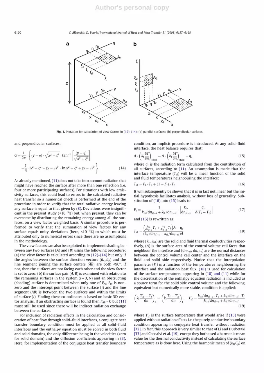
so that for all surface pairs being considered, only half of the heattransfer rates (q) need to be calculated. The term in brackets in(11) involves computationally expensive summation for all surfacesbut, since it is only geometric and hence temperature independent,it can be calculated once at the beginning of the calculation proce-dure and then the expression for hrj,i is easily updated depending onthe local surface temperatures before being inserted in the sourceterms in (3). Calculation of the view factors (Fij) in (11) is facilitatedby the use of the Cartesian grid and can be based on the analyticalexpressions given by Howell [31] (see Fig. 1 for notation):
F1�2 ¼1
ðx2 � x1Þ � ðy2 � y1ÞX2
l¼1
X2
k¼1
X2
j¼1
X2
i¼1
ð�1ÞðiþjþkþlÞGðxi; yj; gk; nlÞ
ð12Þ
where G is given for parallel surfaces
G ¼ 12p� ðy� gÞ �
ffiffiffiffiffiffiffiffiffiffiffiffiffiffiffiffiffiffiffiffiffiffiffiffiffiffiffiðx� nÞ2 þ z2
q� tan�1 y� gffiffiffiffiffiffiffiffiffiffiffiffiffiffiffiffiffiffiffiffiffiffiffiffiffiffiffi
ðy� gÞ2 þ z2q264
375
8><>:
þðx� nÞ �ffiffiffiffiffiffiffiffiffiffiffiffiffiffiffiffiffiffiffiffiffiffiffiffiffiffiffiðy� gÞ2 þ z2
q� tan�1 x� nffiffiffiffiffiffiffiffiffiffiffiffiffiffiffiffiffiffiffiffiffiffiffiffiffiffiffi
ðy� gÞ2 þ z2q264
375
� z2
2� ln½ðx� nÞ2 þ ðy� gÞ2 þ z2�
9>=>; ð13Þ
C. Albanakis, D. Bouris / International Journal of Heat and Mass Transfer 51 (2008) 6157–6168 6159
Author's personal copy
and perpendicular surfaces:
G ¼ 12p� ðy� gÞ �
ffiffiffiffiffiffiffiffiffiffiffiffiffiffiffix2 þ n2
q� tan�1 ðy� gÞffiffiffiffiffiffiffiffiffiffiffiffiffiffiffi
x2 þ n2p" #(
�14� ½x2 þ n2 � ðy� gÞ2� � ln½x2 þ n2 þ ðy� gÞ2�
)ð14Þ
As already mentioned, (11) does not take into account radiation thatmight have reached the surface after more than one reflection (i.e.four or more participating surfaces). For situations with low emis-sivity surfaces, this could lead to errors in the calculated radiativeheat transfer so a numerical check is performed at the end of theprocedure in order to verify that the total radiative energy leavingany surface is equal to that given by (8). Deviations were insignifi-cant in the present study (<10�5%) but, when present, they can beovercome by distributing the remaining energy among all the sur-faces, on a view factor weighted basis. A similar procedure is per-formed to verify that the summation of view factors for anysurface equals unity, deviations (here, <10�7%) to which must beattributed only to numerical errors since there are no assumptionsin the methodology.
The view factors can also be exploited to implement shading be-tween any two surfaces (A) and (B) using the following procedure:(a) the view factor is calculated according to (12)–(14) but only ifthe angles between the surface direction vectors ð~nA;~nBÞ and theline segment joining the surface centers ðABÞ are both <90�. Ifnot, then the surfaces are not facing each other and the view factoris set to zero; (b) the surface pair (A, B) is examined with relation tothe remaining surfaces in the system (i = 3, N) and an obstructing(shading) surface is determined when only one of FAi, FBi is non-zero and the intercept point between the surface (i) and the linesegment ðABÞ is between the two surfaces and within the limitsof surface (i). Finding these co-ordinates is based on basic 3D vec-tor analysis. If an obstructing surface is found then FAB = 0 but (11)must still be used since there will be indirect radiation exchangebetween the surfaces.
For inclusion of radiation effects in the calculation and consid-eration of heat flow through solid–fluid interfaces, a conjugate heattransfer boundary condition must be applied at all solid–fluidinterfaces and the enthalpy equation must be solved in both fluidand solid domains, the only difference being in the velocities (zerofor solid domain) and the diffusion coefficients appearing in (3).Here, for implementation of the conjugate heat transfer boundary
condition, an implicit procedure is introduced. At any solid–fluidinterface, the heat balance requires that:
A � ktoTon
� �solid¼ A � kt
oTon
� �fluidþ qr ð15Þ
where qr is the radiation term calculated from the contribution ofall surfaces, according to (11). An assumption is made that theinterface temperature (Tsf) will be a linear function of the solidand fluid temperatures neighbouring the interface:
Tsf ¼ Ft � Ts þ ð1� FtÞ � T f ð16Þ
It will subsequently be shown that it is in fact not linear but the ini-tial hypothesis facilitates analysis, without loss of generality. Sub-stitution of (16) into (15) leads to
Ft ¼1
kts=dnsf—s þ ktf=dnf—sf� kts
dnsf—s� qr
AðTs � T fÞ
� �ð17Þ
and (16) is rewritten as:
Tsf ¼kts
dnsf—sTs þ ktf
dnf—sfT f
� �A� qr
kts=dnsf—s þ ktf=dnf—sfð ÞA ð18Þ
where (kts, ktf) are the solid and fluid thermal conductivities respec-tively, (A) is the surface area of the control volume cell faces thatneighbour the interface and (dnf–sf, dnsf–s) are the normal distancesbetween the control volume cell center and the interface on thefluid and solid side respectively. Notice that the interpolationparameter (Ft) is a function of the temperatures neighbouring theinterface and the radiation heat flux. (18) is used for calculationof the surface temperatures appearing in (10) and (11) while forthe discretisation of the enthalpy equation radiation is included asa source term for the solid side control volume and the following,equivalent but numerically more stable, condition is applied:
ktT 0sf � Ts
dn
� �s¼ kt
T f � T 0sf
dn
� �f; T 0sf ¼
kts=dnsf—s � Ts þ ktf=dnf—sf � T f
kts=dnsf—s þ ktf=dnf—sf
ð19Þ
where T 0sf is the surface temperature that would arise if (15) wereapplied without radiation effects i.e. the purely conductive boundarycondition appearing in conjugate heat transfer without radiation[32]. In fact, this approach is very similar to that of Li and Durbetaki[33] and Consalvi et al. [19], except they both used a harmonic meanvalue for the thermal conductivity instead of calculating the surfacetemperature as is done here. Using the harmonic mean of (kt/Cp) on
a b
Fig. 1. Notation for calculation of view factors in (12)–(14): (a) parallel surfaces; (b) perpendicular surfaces.
6160 C. Albanakis, D. Bouris / International Journal of Heat and Mass Transfer 51 (2008) 6157–6168

Author's personal copy
the fluid and solid side is a potential source of error in many steadystate applications according to Chen and Han [20] and the presentmethodology avoids this problem.
The procedure of including conjugate heat transfer with radia-tion effects can be summarised as:
(a) calculation of the radiation term (qr) depending on the wallsurface (not cell center) temperatures that appear in (10).These are calculated through (18) based on values fromthe previous iteration.
(b) (qr) is inserted as an energy equation source term (ST) in (3)for the control volume on the solid side of the interface.
(c) implementation of (19) is achieved by using (T 0sf ) for calculat-ing the normal diffusion terms of both solid and fluid controlvolumes neighbouring the interface. Wall functions for tur-bulent boundary layers can be included in the usual manner,as presented for non-radiative conjugate heat transfer in [32].
Updating of the radiation heat fluxes is performed at every iter-ation of the SIMPLE solution procedure and interface temperaturesare updated accordingly. The implementation has proven to be ro-bust although some underrelaxation for the enthalpy equation wasfound beneficial. In the present approach, a single grid spans fluidand solid domains and the conjugate heat transfer boundary condi-tion, including radiative effects, is implicitly applied in the solutionof the system of equations. This is facilitated by the assumption of(16) and only the temperatures and heat flux required for the (Ft)coefficients are lagged in the iterative process.
3. Results
The numerical procedure was first validated through the simu-lation of relevant configurations in the published literature andthen applied to parametrically study the situation of a hollow cubeexposed to external fluid flow and a constant heat flux on one of itsexternal surfaces.
For the flow inside the enclosure, validation was first per-formed for low-Rayleigh number flows in side heated enclosures,with and without radiation and internal obstacles, and then for amoderately high Rayleigh number flow. For the effect of the exter-nal flow on the cube envelope, the most common approach is toset a constant heat transfer coefficient on the external walls (e.g.[18]). Here, the turbulent flow past a surface mounted cube is cal-culated leading to local values of convective heat transfer on theexternal walls. For calculation of turbulent flow past a surfacemounted cube, eddy viscosity models, such as the k–e model ap-plied here, admittedly lead to inaccuracies that are difficult toovercome but although variants to the model have been suggestedtheir effectiveness is still questionable [8,5,22]. Large eddy simula-tions and even unsteady RANS have proven to yield the best re-sults when compared to experiments but the computational costis much higher. To the authors’ knowledge, similar analysis ofthe heat transfer from a surface mounted cube has not been pub-lished but a previous attempt to examine it [22] indicated thatsimilar conclusions should be drawn. Since the purpose here isto provide a more accurate estimation of the external wall heattransfer rather than applying a uniform constant value, and dueto the excessive computational requirements for a better ap-proach, the standard k–e model was used but the accuracy of thecalculation will be kept in mind and its effect on the results andconclusions will be discussed.
3.1. Isolated cubical enclosure
Bajorek and Lloyd [11] measured the flow and temperature fieldin a two dimensional square enclosure (L � L) with two baffles
(d/L = 0.1, H/L = 0.25) protruding from the middle of the top andbottom walls. The side walls were maintained at a constant tem-perature difference of �15.5 K, leading to a Rayleigh number ofRa = 3.5 � 105. Zimmerman and Acharya [12] studied this configu-ration numerically and found an important influence of the per-fectly conducting wall boundary condition, as opposed to themore commonly used adiabatic one. In the present study, theconfiguration was extended by 3L in the third direction and discre-tised with a 50 � 58 � 21 Cartesian grid. As expected, no 3D effectswere observed. There were three grid cells defining the 0.1L thicktop and bottom walls, which were assumed to have the thermalconductivity of the experimentally used plexiglass (kt = 0.665W m�1 K�1). The same material was considered for the two bafflesof the enclosure. The calculated flow and temperature field is pre-sented in Fig. 2 with conjugate heat transfer considered for the baf-fles and the top and bottom walls. The favourable comparison withthe experimental measurements of Bajorek and Lloyd [11] and thenumerical predictions of Zimmerman and Acharya [12] is evidentin Fig. 3. Inclusion of radiation effects (not shown) did not leadto any discernible differences, also in agreement with the findingsof Zimmerman and Acharya [12], most probably because of therelatively small temperature differences and the constant tem-perature walls.
Radiation effects were examined by comparison with thenumerical calculations of Kasemi and Naraghi [15] who used thediscrete exchange factor method to calculate radiative heat transferin a square (H � H) enclosure for normal and low levels of gravita-tional acceleration. The advantage of this type of validation is thatradiation effects and natural convection effects can be consideredseparately. A 22 � 28 � 15 cartesian grid was used, with the depthdirection exhibiting no 3D effects. As before, the top and bottomwalls were discretised using three grid cells but assuming negligi-ble thermal conductivity in order to simulate adiabatic boundaryconditions. Results are presented in Fig. 4 for H = 0.021 m, a Grass-hoff number of Gr = 700, and cold–hot wall temperature ratio ofTc/Th = 0.5. Radiation effects are initially omitted, leading to analmost conductive, linear, behavior, where the weak natural con-vection plays a negligible role. With radiation present, natural con-vection remains at low levels but the temperature distributionalong the hot and cold walls is significantly altered. Agreement
Fig. 2. Flow field vectors (m/s) and temperature field contours (K) for buoyant flowin an enclosure with two baffles (Ra = 3.5 � 105).
C. Albanakis, D. Bouris / International Journal of Heat and Mass Transfer 51 (2008) 6157–6168 6161

Author's personal copy
with the results of Kasemi and Naraghi [15] is considered accept-able since differences are below �5% of (Th � Tc).
Turbulent flow in a square (L � L) enclosure with hot (Th) andcold (Tc) opposite vertical walls has been examined by comparisonwith the results of Tian and Karayiannis [13]. The dimensions oftheir experimental configuration have been retained in all direc-tions (2L in the third direction) and the calculated flow field is pre-sented in Fig. 5. This is a moderately turbulent Rayleigh numberflow (Ra = 1.58 � 109), turbulence onset being at roughly 108, butstill poses a challenging numerical exercise. Results with a 323 grid,clustered near the walls, are presented in Figs. 6 and 7 for temper-ature and velocity fields, respectively. Agreement is generallyacceptable and calculations with a 623 grid did not show signifi-cant improvements. According to Tian and Karayiannis [13], themean Nusselt number along the wall should be Nu = 64 and thepresent calculations gave a 15% difference for both the 323 and
623 grids so the representation of the general features of the flowis considered acceptable for the purpose of the study. Sharmaet al. [18] reached similar conclusions for grids ranging from42 � 42 to 82 � 82 for higher Rayleigh numbers (Ra � 1010) eventhough they did not apply any type of wall boundary approxima-tion such as wall functions or a low-Reynolds number variant ofthe k–e model.
3.2. Hollow cube subject to external heating and flow
The chosen configuration is that of a hollow cube exposed to anexternal flow of cool air and simultaneously subjected to a heatflux on one of its external sides. The enclosure dimensions are3 � 3 � 3 m with 0.2 m thick walls and kt = 0.14 W m�1 K�1,q = 2300 kg m�3, Cp = 650 J kg�1 K�1, e = 0.9. This gives emissivityand a thermal permeability factor (0.7 W m�2 K�1) correspondingto characteristic building materials. The computational domain ex-tends 4H above the cube, 6H in the spanwise direction and 12H inthe flow direction with the cube 3.5H from the inlet boundary. Theupstream flow velocity was uniform and the temperature constant
-0.5
-0.4
-0.3
-0.2
-0.1
0.0
0.1
0.2
0.3
0.4
0.5
0.0 0.2 0.4 0.6 0.8 1.0X/L
T*
-250
-200
-150
-100
-50
0
50
100
150
200
250
V/ (
v/L
)
Present Numerical: T*Bajorek&Lloyd (1982): T*Zimmerman & Acharya (1991): V/(v/L)Present Numerical: V/(v/L)
0.0
0.1
0.2
0.3
0.4
0.5
0.6
0.7
0.8
0.9
1.0
-150 -100 -50 50 100 150U/ (v/L)
Y/L
Zimmerman & Acharya (1991)
Present Numerical
0
a b
Fig. 3. Comparison with experimental and numerical results: (a) for the non-dimensional form T* = [T � (Th + Tc)/2]/(Th � Tc) and V/(m/L) along the centreline between the hotand cold wall; (b) U/(m/L) vertically, midway between the hot and cold wall.
0.5
0.6
0.7
0.8
0.9
1.0
0.0 0.2 0.4 0.6 0.8 1.0X/H
T/T
h
Present, Rad, TopKasemi&Naraghi (1993), Rad,TopPresent, Rad, BottomKasemi&Naraghi (1993), Rad,BottomPresent, No Rad,TopKasemi&Naraghi (1993), No Rad, TopPresent, No Rad, BottomKasemi&Naraghi (1993), No Rad, Bottom
Fig. 4. Temperature distribution between hot and cold walls along top and bottomwalls, with and without radiation effects.
Fig. 5. Flow field vectors (m s�1) and temperature field contours (K) for buoyantflow in an enclosure (Ra = 1.58 � 109).
6162 C. Albanakis, D. Bouris / International Journal of Heat and Mass Transfer 51 (2008) 6157–6168

Author's personal copy
at To = 293 K, with the ground at the same constant temperature.Symmetry boundary conditions were applied in the spanwiseand vertical direction and fully developed flow at the outlet. Forthe cube’s solid walls, conjugate heat transfer boundary conditionsare applied and the standard wall function approach is used for themomentum equations next to all solid boundaries.
Calculation of the flow past the hollow cube has been performedfor three different external flow Reynolds numbers (Re = U0H/m =2 � 105, 5 � 105 and 1 � 106), two different heat flux values(q = 20 and 40 W m�2) and four different outer face heat flux orien-tations (top, upstream, downstream and one of the side faces). Theexternal heat flux values are rather low to correspond to solar heatgains, but the present calculation is performed at steady state soactual values would lead to unrealistic inner temperatures. TheReynolds numbers correspond to common wind velocity values ofU0 = 1, 2.5 and 5 m s�1, respectively. The effect of the externalReynolds number and heat flux value is examined for the upstreamand downstream heat flux orientations and the full effect of heatflux orientation as well as the relative influence of convective andradiative heat transfer is examined at Re = 2 � 105 and q =20 W m�2. During calculations, it was found beneficial for conver-gence to calculate external flow while maintaining internal cubetemperature constant and to subsequently introduce internalnatural convection flow and then radiation effects. The grid size
was the same for all calculations: 62 � 50 � 76, with 30 points onthe cube edges but calculations were also performed with an82 � 60 � 91 grid and 39 points on the cube edges for the down-stream and top heat flux directions. Variations in the internal andexternal face mean temperatures were between 3% and 12% ofthe maximum temperature difference.
The Nusselt number is defined:
Nu ¼ q � Hkt � ðTsf � ToÞ
¼ ðdT=dnÞ � HðTsf � ToÞ
ð20Þ
where (dT/dn) is the temperature gradient normal to the surface, Tsf
is the surface temperature and To is the upstream temperature. Forthe cube mean Nusselt number, the mean value of the five exposedfaces is calculated. Surface cooling of a heated cube exposed toexternal flow has been studied in the past and external surfaceand cube mean Nusselt number correlations all agree to the formNu = c � Ren with n < 1 (see e.g. [2,3]).
Calculations were performed for a q = 20 W m�2 heat flux, ini-tially on the upstream cube face and then on the downstreamone, for Reynolds numbers in the range of Re = 2 � 105–1 � 106
and the cube mean Nusselt number and air temperature are pre-sented in Fig. 8. With increasing Reynolds number, the Nusseltnumber increases according to an n = 0.60 exponent (close to then = 0.68 value found by Nakamura et al. [3]) and thus leads to an
5
10
15
20
25
30
35
40
45
50
0 0.2 0.4 0.6 0.8
X*=1-x/L
T (°
C)
Present, y/L=0.2Tian&Karayiannis (2000): y/L=0.2Present, y/L=0.4Tian&Karayiannis (2000): y/L=0.4Present, y/L=0.6Tian&Karayiannis (2000): y/L=0.6Present, y/L=0.8Tian&Karayiannis (2000): y/L=0.8
0.0
0.2
0.4
0.6
0.8
1.0
0.00 0.05 0.10 0.15X*=dwall/L
(T-T
c)/(
Th-T
c)
Present, hotwall
Present, coldwall
Tian&Karayiannis (2000), hotwall
Tian&Karayiannis (2000), coldwall
1
a b
Fig. 6. (a) Temperature profiles between hot and cold walls at various heights of the enclosure. (b) Temperature boundary layer near the hot and cold wall at y/L = 0.5.
-250
250
750
1250
1750
2250
0 0.2 0.4 0.6 0.8X*=1-x/L
v* (
m/s
)
Present, y/L=0.9, v*=(v+2)*1000
Tian&Karayiannis (2000): y/L=0.9
Present, y/L=0.7, v*=(v+1.5)*1000
Tian&Karayiannis (2000): y/L=0.7
Present, y/L=0.5, v*=(v+1)*1000
Tian&Karayiannis (2000): y/L=0.5
Present, y/L=0.3, v*=(v+0.5)*1000
Tian&Karayiannis (2000): y/L=0.3
Present, y/L=0.1, v*=(v+0)*1000
Tian&Karayiannis (2000): y/L=0.1
1
Fig. 7. Vertical velocity profiles between the hot and cold walls at various heights of the enclosure.
C. Albanakis, D. Bouris / International Journal of Heat and Mass Transfer 51 (2008) 6157–6168 6163

Author's personal copy
asymptotic decrease in cube mean temperature. The oppositeeffect can be observed if, for comparison purposes, the heat fluxis doubled to q = 40 W m�2 at an external Reynolds number ofRe = 2 � 105. The resulting distribution of internal cube face tem-peratures is shown in Fig. 9 for the two cases of upstream anddownstream orientation of external heat flux. Results for the lower
heat flux value (q = 20 W m�2) at the same Reynolds number aswell as a higher Reynolds number (Re = 1 � 106) are also shown.The higher heat flux value leads to higher inner temperaturesand the higher Reynolds number induces a stronger cooling effectbut the relative spatial temperature distribution remains the same:when the upstream cube face is heated, the inner surface temper-atures and the cube mean temperature are higher. The tempera-ture difference between the hottest and coldest face is between0.6 and 2 K for the cases presented in Fig. 9 but all Rayleigh numbervalues are in the range Ra = 1.5–5 � 109 i.e. above the turbulentthreshold (Ra > 108).
The relative ‘‘asymmetry” between upstream and downstreamheating is further demonstrated through Figs. 10 and 11. Fig. 10ashows the temperature distribution on the external surfaces ofthe cube when the upstream face is heated with a heat flux ofq = 20 W m�2 and the external flow Reynolds number is Re =2 � 105. Streaklines indicate the presence of the upstream stagna-tion zone and horseshoe vortex, as well as the recirculation zoneson the top, side and downstream faces. The ‘‘hot spot” at the frontstagnation region is prominent, as are the cooler edges, but the hotfluid captured within the top and side recirculation zones, com-bined with conduction through the envelope, leads to a tempera-ture increase on the rest of the surfaces as well. Fig. 10b showsthe corresponding buoyancy induced inner flow: the warmer up-stream face causes a recirculation zone of air that rises, followsthe ceiling and declines along the back but turns upward againmidway along the bottom face. This is explained by the radiativelyheated area near the front of the bottom face which lifts the flowbefore it reaches the upstream face. A radiatively heated regionis also evident on the outer surface of the downstream face, whichdoes not appear when radiation effects are not included. At thesame Reynolds number (Re = 2 � 105) but at double the heat fluxvalue (q = 40 W m�2) the surface temperatures and the tempera-ture differences become larger leading to a doubling of Rayleighnumber (Ra = 4.5 � 109) and the recirculation zone is now pushedtowards the top and downstream face (Fig. 11a). The asymmetry ofthe inner and outer flow and heat transfer for upstream and down-stream heating is clear in Fig. 11 for the higher heat flux value. Thecube’s inner surface temperature range is roughly the same whenupstream (Fig. 11a) and downstream faces (Fig. 11b) are heatedbut the variation in temperature difference induces a different in-ner flow, possibly due to the slightly higher inner surface temper-ature differences for downstream heating (see also Fig. 9):Ra = 5 � 109 as opposed to Ra = 4.5 � 109 for upstream heating.On the outer surfaces of the cube envelope, an iso-temperature
293
294
295
0 2 50000 500000 750000 1000000
ExternalFlow Reynolds Number(Re)
Mea
n C
ub
e A
ir T
emp
erat
ure
(K
)
200
400
600
800
1000
1200
Mea
n C
ub
e N
uss
elt
Nu
mb
er (
Nu
)
Temperature (upstream heat source)Temperature (downstream heat source)Nusselt (upstream heat source)Nusselt (downstream heat source)
Fig. 8. Effect of flow Reynolds number on mean cube air temperature and meancube Nusselt number.
293
294
295
296
297
298Side
Top
UpstreamBottom
Downstream
Re=2E5, Q=20 W/m2, Upstream
Re=2E5, Q=20 W/m2, Downstream
Re=1E6, Q=20 W/m2, UpstreamRe=1E6, Q=20 W/m2, Downstream
Re=2E5, Q=40 W/m2, Upstream
Re=2E5, Q=40 W/m2, Downstream
Top
Upstream
Downstream
Bottom
Side
2
2
2
2
2
Fig. 9. Inner cube face temperatures for heat flux on upstream and downstreamorientated external faces.
Fig. 10. Temperature and flow field (a) around and (b) inside cube envelope when heat flux is on upstream side (Re = 2 � 105, q = 20 W m�2).
6164 C. Albanakis, D. Bouris / International Journal of Heat and Mass Transfer 51 (2008) 6157–6168

Author's personal copy
surface has been plotted at the value of T = 293.1 K. These zones areindicative of the heat dissipated by the flow and the extensivewarm air zones in Fig. 11b show the heat leaving the cube. InFig. 11a, these regions are thinner, implying that more heat is beingtransferred to the other cube faces, leading to higher surfacetemperatures.
The relative variation of mean temperature values and Nusseltnumbers on the cube’s external faces are presented in Table 1and Table 2 for all possible heat flux orientations for Re =2 � 105 and q = 20 W m�2. The temperatures of the cube facesshow a minimal variation of DT = (Tface � To) while the heated faceis 3–4 K hotter than the unheated faces for all cases. One wouldhave expected a stronger dependence on orientation but this isactually more evident in the convective Nusselt numbers (Table2). Comparison with the experimental correlation of Nakamuraet al. [3] is also shown and should be compared with the heatedface for each situation. Upstream and downstream values are inrelatively good agreement with the correlations and, althoughthe top and side values are appropriately predicted higher thanthe upstream and downstream ones, they are underestimated byabout 30%, due to the turbulence modelling difficulties already dis-
cussed. On the other hand, this introduces a uniformity in the heattransfer among the cube surfaces that actually makes the presentdiscussion conservative in its points and conclusions.
Calculation of the inner flow, induced by the non-uniform cool-ing of the envelope, has already been shown for upstream anddownstream cooling. The situation with the heat flux on the topface is presented in Fig. 12 where the effects of convective andradiative heat transfer on the inside of the cube are evident.Fig. 12a shows the inner temperature distribution when the air isconsidered stagnant (i.e. only conductive heat transfer) while inFig. 12b air motion induces convective effects and leads to a coolerceiling but hotter side walls. The full effect of conduction, convec-tion and radiation is presented in Fig. 12c where the induced flow(Vmax = 0.03 m s�1) and the higher temperatures on the floor andsidewalls are evident. The differences in the sidewall temperaturesthat are induced by the effect of the outer flow lead to a slightasymmetry with the center of the recirculation zone being pushedtowards the downstream face.
The relative influence of convection and radiation on the innertemperature field is further demonstrated in Fig. 13 where the ra-dial graphs have been plotted for the four different heating orien-tations and results are shown for stagnant air, pure convection andconvection–radiation. Temperature differences of over 4 K arisewhen convection and radiation are taken into account instead ofstagnant air, especially on the heated face. Even more interestingis the fact that thermal radiation leads to a more uniform internaltemperature distribution among the surfaces whereas pure con-vection is not as effective in this regard. The heated surface re-mains at a much higher temperature without radiation effects,which tend to cool it and simultaneously heat the others, leadingto the uniformity in temperature. This effect is a direct conse-quence of keeping the heat flux constant and letting conduction,convection and radiation determine the wall’s temperature. In
Fig. 11. Temperature and flow field in and around the cube envelope when heat flux is on (a) upstream and (b) downstream side. Streaklines have been projected onto thecenter-plane and the outer temperature iso-surface value is T = 293.1 K (Re = 2 � 105, q = 40 W m�2).
Table 1Mean temperatures on the outer faces of the cube, depending on the direction of theheat flux (Re = 2 � 105, q = 20 W m�2)
Temperatures (K) External heat source direction
Upstream Downstream Top Side
Side 293.48 293.46 293.39 296.85Top 293.44 293.43 296.73 293.40Upstream 296.64 293.33 293.41 293.42Downstream 293.35 297.03 293.43 293.41
Table 2Mean Nusselt numbers on the outer faces of the cube, depending on the direction of the heat flux (Re = 2 � 105, q = 20 W m�2)
Nu External heat source direction Correlations from [3]
Upstream Downstream Top Side
Side 368.41 331.35 358.24 390.44 Nus ¼ 0:12Re0:70 ¼ 598Top 373.50 355.69 411.90 355.41 Nut ¼ 0:071Re0:74 ¼ 575Upstream 380.61 377.40 380.02 379.74 Nuf ¼ 0:71Re0:52 ¼ 396Downstream 309.58 332.46 296.13 309.19 Nur ¼ 0:11Re0:67 ¼ 380
C. Albanakis, D. Bouris / International Journal of Heat and Mass Transfer 51 (2008) 6157–6168 6165

Author's personal copy
situations where studies focus on constant temperature walls, suchan effect cannot be observed.
The interaction of the outer flow and the orientation of theheated surface and their effect on the inner flow and temperaturedistributions can be seen more clearly in Fig. 14. For each of thefour heat source orientations that were studied, the five surfaces’mean temperatures are plotted on the corresponding axis. Themean cube air temperature is also plotted on the axis that corre-sponds to the surface being heated. Here it can be seen that the in-ner temperature differences are not negligible (over 0.5 K) and thatthere is also a significant difference in the mean cube temperature,
depending on the heat source orientation with regard to the exter-nal flow direction. The relative effects of upstream and down-stream heating have already been discussed with regard toFig. 11 and similar conclusions are drawn here, for the lower heatflux value. The highest temperatures, both the mean cube air andthe inner surfaces, arise when the heat source is on the upstreamside while heating on the top leads to the lowest inner tempera-tures. When the upstream face is heated, although the surface Nus-selt number is low (see Table 2), the dissipated heat is transferredto the downstream surfaces, leading to their higher surface tem-peratures when compared to the other heating orientations (Table
Fig. 12. Temperature distribution inside the cubicle considering (a) stagnant air without radiation effects, (b) natural convection without radiation effects, (c) naturalconvection including radiation effects (Re = 2 � 105, q = 20 W m�2).
Downstream heat source
293
295
297
299
301Side
Top
UpstreamBottom
Downstream
No internal flow
Convective internal flow
Convective_Radiative internal flow
Upstream Heat Source
293
295
297
299
301Side
Top
UpstreamBottom
Downstream
No internal flow
Convective internal flow
Convective_Radiative internal flow
Side Heat Source
293
295
297
299
301Side
Top
UpstreamBottom
Downstream
No internal flow
Convective internal flow
Convective_Radiative internal flow
Top Heat Source
293
295
297
299
301Side
Top
UpstreamBottom
Downstream
No internal flow
Convective internal flow
Convective_Radiative internal flow
Fig. 13. Variation of the mean temperatures of the inner surfaces of the cube, depending on the effects of convection and radiation for: (a) downstream heat source;(b) upstream heat source; (c) side heat source; (d) top heat source (Re = 2 � 105, q = 20 W m�2).
6166 C. Albanakis, D. Bouris / International Journal of Heat and Mass Transfer 51 (2008) 6157–6168

Author's personal copy
1). On the other hand, the higher Nusselt numbers on the heatedtop and side surfaces, which are already underpredicted (see Table2), explain the lower temperatures inside the cube, especially sincethe heat is carried away by the flow. The large recirculation zonebehind the cube leads to a low Nusselt number on the downstreamheated face and the higher temperatures on the outer surface (Ta-ble 1) and the cube inner air temperature.
4. Conclusions
A study of combined fluid flow and heat transfer includingforced and natural convection, thermal radiation and conductionthrough solid–fluid interfaces has been performed for the heattransfer through a cubic envelope subjected to external flow. Thenumerical methodology that has been implemented includes allheat transfer modes in an implicit solution procedure through anovel boundary condition at the solid–fluid interface for convec-tion and thermal radiation effects.
The methodology was first validated by comparison to experi-mental and numerical results from the literature for laminar andturbulent natural convection in enclosures, with and without radi-ation and conjugate heat transfer effects. There are some simplifi-cations applied, especially with regard to the turbulence modellingof the moderately turbulent (Ra � 109) buoyant flow in the cavityand the heat transfer on the outer cube surfaces. However, valida-tion calculations show that the methodology can be used to derivequalitative conclusions with regard to a configuration that, to theauthors’ knowledge, has not been previously studied.
It has been shown that radiation effects between the inner sur-faces of a cubic enclosure can play a significant role in determiningthe temperature distribution when a constant heat flux is the heatsource. An increase in the Reynolds number of the external flow af-fects the cube Nusselt number and leads to an asymptoticallydecreasing mean cube temperature. Different heat flux values sim-ilarly increase the mean temperatures although both cooling dueto higher Nusselt numbers and heating due to higher heat flux val-ues seem to retain the inner surfaces’ relative temperature distri-bution. The orientation of the heat source with regard to theexternal flow is also important. Due to the outer flow and buoy-ancy forces, a heat flux applied from different orientations will leadto different inner flow and temperature patterns. Heating on theupstream surface causes much of the heat to remain within the
cube and leads to higher inner temperatures than for other heatsource orientations.
Acknowledgements
The research is co-funded by the European Union – EuropeanSocial Fund & Natural Resources – EPEAEK II and the Greek Minis-try of Education and Religious Affairs under the Pithagoras IIprogram.
References
[1] P. Linden, The fluid mechanics of natural ventilation, Annu. Rev. Fluid Mech. 31(1999) 201–238.
[2] E. Meinders, K. Hanjalic, R. Martinuzzi, Experimental study of the localconvective heat transfer from a wall mounted cube in turbulent channel flow,J. Heat Transfer 121 (1999) 564–573.
[3] H. Nakamura, T. Igarashi, T. Tsutsui, Local heat transfer around a wall-mountedcube in the turbulent boundary layer, Int. J. Heat Mass Transfer 44 (2001)3385–3395.
[4] E. Meinders, K. Hanjalic, Experimental study of the convective heat transferfrom in-line and staggered configurations of two wall-mounted cubes, Int. J.Heat Mass Transfer 45 (2002) 465–482.
[5] Y. Cheng, F.S. Lien, E. Yee, R. Sinclair, A comparison of large Eddy simulationswith a standard k–e Reynolds-averaged Navier–Stokes model for theprediction of a fully developed turbulent flow over a matrix of cubes, J.Wind Eng. Ind. Aerodynam. 91 (2003) 1301–1328.
[6] M. Tsuchiya, S. Murakami, A. Mochida, K. Kondo, Y. Ishida, Development of anew k–e model for flow and pressure fields around bluff body, J. Wind Eng. Ind.Aerodynam. 67 and 68 (1997) 169–182.
[7] G. Iaccarino, A. Ooi, P.A. Durbin, M. Behnia, Reynolds averaged simulation ofunsteady separated flow, Int. J. Heat Fluid Flow 24 (2003) 147–156.
[8] W. Rodi, Comparison of LES and RANS calculations of the flow around bluffbodies, J. Wind Eng. Ind. Aerodynam. 69–71 (1997) 55–75.
[9] N.C. Markatos, M.R. Malin, G. Cox, Mathematical modelling of buoyancy-induced smoke flow in enclosures, Int. J. Heat Mass Transfer 25 (1) (1982) 63–75.
[10] E.M. Sparrow, J.P. Abraham, A new buoyancy model replacing the standardpseudo-density difference for internal natural convection in gases, Int. J. HeatMass Transfer 46 (2003) 3583–3591.
[11] S. Bajorek, J. Lloyd, Experimental investigation of natural convection inpartitioned enclosures, J. Heat Transfer 104 (1982) 527–532.
[12] E. Zimmerman, S. Acharya, Free convection heat transfer in a partially dividedvertical enclosure with conducting end walls, Int. J. Heat Mass Transfer 30 (2)(1987) 319–331.
[13] Y. Tian, T. Karayiannis, Low turbulence natural convection in an air filledsquare cavity. Part I: the thermal and fluid flow fields, Int. J. Heat Mass Transfer43 (2000) 849–866.
[14] H.S. Dol, K. Hanjalic, Computational study of turbulent natural convection in aside heated near cubic enclosure at a high Rayleigh number, Int. J. Heat MassTransfer 44 (2001) 2323–2344.
[15] M. Kasemi, M. Naraghi, Analysis of radiation–natural convection interactionsin 1-g and low-g environments using the discrete exchange factor method, IntJ. Heat Mass Transfer 36 (17) (1993) 4141–4149.
[16] A. Mezrhab, H. Bouali, H. Amaoui, M. Bouzidi, Computation of combinednatural-convection and radiation heat-transfer in a cavity having a squarebody at its center, Appl. Energ. 83 (2006) 1004–1023.
[17] V. Dharma Rao, S.V. Naidu, B. Govinda Rao, K.V. Sharma, Heat transfer from ahorizontal fin array by natural convection and radiation – a conjugate analysis,Int. J. Heat Mass Transfer 49 (2006) 3379–3391.
[18] A.K. Sharma, K. Velusamy, C. Balaji, S.P. Venkateshan, Conjugate turbulentnatural convection with surface radiation in air filled rectangular enclosures,Int J. Heat Mass Transfer 50 (2007) 625–639.
[19] J.L. Consalvi, B. Porterie, J.C. Loraud, Method for computing the interaction offire environment and internal solid regions, Numer. Heat Transfer, Part A 43(2003) 777–805.
[20] X. Chen, P. Han, A note on the solution of conjugate heat transfer problemsusing SIMPLE-like algorithms, Int. J. Heat Fluid Flow 21 (2000) 463–467.
[21] D. Bouris, A 3D calculation of the flow and heat transfer in and around a hollowcubicle exposed to external flow, in: 1st International Conference ‘‘FromScientific Computing to Computational Engineering”, 1st IC-SCCE, Athens,8–10 September, 2004.
[22] M. Petridou, D. Bouris, Experimental and numerical study of the effect ofopenings on the surface pressure distribution of a hollow cube, WSEAS Trans.Fluid Mech., 1790-5087 1 (6) (2006) 655.
[23] S. Patankar, D. Spalding, A calculation procedure for heat mass and momentumtransfer in three dimensional parabolic flows, Int. J. Heat Mass Transfer 15(1972) 1787.
[24] C. Rhie, W. Chow, Numerical study of the turbulent flow past an airfoil withtrailing edge separation, AIAA J. 21 (1983) 1525–1532.
[25] B.E. Launder, D.B. Spalding, The numerical computation of turbulent flows,Comput. Methods Appl. Mech. Eng. 3 (1974) 537.
293.0
293.5
294.0
294.5
295.0
295.5Side
Top
UpstreamBottom
Downstream
Top heat source
Upstream heat source
Down stream heat sourceSide heat source
Cube mean air temperature
Top
Upstream
Downstream
Bottom
Side
Fig. 14. Mean temperatures of the inner surfaces and the cube for the different heatsource directions that were examined. The mean cube temperature for each heatingorientation is placed on the radial axis that corresponds to the heated surface(Re = 2 � 105, q = 20 W m�2).
C. Albanakis, D. Bouris / International Journal of Heat and Mass Transfer 51 (2008) 6157–6168 6167

Author's personal copy
[26] D.B. Spalding, Contribution to the theory of heat transfer across aturbulent boundary layer, Int. J. Heat Mass Transfer 7 (3) (1964) 743–761.
[27] C.L.V. Jayatilaka, The influence of Prandtl number and surface roughness on theresistance of laminar sublayers to momentum and heat transfer, Prog. HeatMass Transfer 1 (1969) 193–329.
[28] H.B. Awbi, Calculation of convective heat transfer coefficients of room surfacesfor natural convection, Energ. Build. 28 (1998) 219–227.
[29] G. Papadakis, G. Bergeles, A locally modified second order upwind scheme forconvection terms discretisation, Int. J. Numer. Methods Heat Fluid Flow 5(1995) 49–62.
[30] J.A. Clarke, Energy Simulation in Building Design, second ed., Butterworth,Heinemann, 2001.
[31] J.R. Howell, A Catalog of Radiation Heat Transfer Configuration Factors,University of Texas, Austin second ed., 2001, Available online at: <http://www.me.utexas.edu/>.
[32] D. Bouris, G. Bergeles, Numerical calculation of the effect of deposit formationon heat exchanger efficiency, Int. J. Heat Mass Transfer 40 (17) (1997) 4073–4084.
[33] X. Li, P. Durbetaki, The conjugate formulation of a radiation induced transientnatural convection boundary layer, Int. J. Numer. Methods Eng. 35 (1992) 853–870.
6168 C. Albanakis, D. Bouris / International Journal of Heat and Mass Transfer 51 (2008) 6157–6168