3A0293J, Manual, Air Controls, Instructions-Parts, English
14
3A0293J EN Instructions-Parts Air Controls Air controls for light and heavy duty Xtreme ® Sprayer carts. For professional use only. 24E025, 24Y396 Air Controls for Light Duty Xtreme Package Carts 24E013, 24Y101 Air Controls for Heavy Duty Xtreme Package Carts 17N621, 25D529, 25D649 Air controls for King Sprayer (XL6500/XL3400) 125 psi (0.86 MPa, 8.6 bar) Maximum Air Working Pressure depending on relief valve selected. Important Safety Instructions Read all warnings and instructions in this manual and the Xtreme Packages manual. Save these instructions. 24Y101 r_24e013_3A0293_1a 24W593, 24W040 Air Controls for Xtreme XL Cart or Wall Mount Packages 244841 Accessory lubricator kit for Xtreme or Xtreme XL Packages 17U994, 25D532, 25D650 Air controls for King Sprayer (XL10,000)
-
Upload
khangminh22 -
Category
Documents
-
view
0 -
download
0
Transcript of 3A0293J, Manual, Air Controls, Instructions-Parts, English

3A0293JEN
Instructions-Parts
Air ControlsAir controls for light and heavy duty Xtreme® Sprayer carts. For professional use only.
24E025, 24Y396Air Controls for Light Duty Xtreme Package Carts
24E013, 24Y101Air Controls for Heavy Duty Xtreme Package Carts
17N621, 25D529, 25D649Air controls for King Sprayer (XL6500/XL3400)
125 psi (0.86 MPa, 8.6 bar) Maximum Air Working Pressure depending on relief valve selected.
Important Safety InstructionsRead all warnings and instructions in this manual and the Xtreme Packages manual. Save these instructions.
24Y101
r_24e013_3A0293_1a
24W593, 24W040Air Controls for Xtreme XL Cart or Wall Mount Packages
244841Accessory lubricator kit for Xtreme or Xtreme XL Packages
17U994, 25D532, 25D650Air controls for King Sprayer (XL10,000)

Contents
2 3A0293J
ContentsContents . . . . . . . . . . . . . . . . . . . . . . . . . . . . . . . . . . 2Installation . . . . . . . . . . . . . . . . . . . . . . . . . . . . . . . . 2
Prepare the Site . . . . . . . . . . . . . . . . . . . . . . . . . 2Kit Components (page 7) . . . . . . . . . . . . . . . . . . 2Using the Pipe Port Inserts . . . . . . . . . . . . . . . . . 2Adding a Lubricator (Accessory) . . . . . . . . . . . . . 3
Operation . . . . . . . . . . . . . . . . . . . . . . . . . . . . . . . . . 4Pressure Relief Procedure . . . . . . . . . . . . . . . . . 4Adjusting the Air Regulator . . . . . . . . . . . . . . . . . 4
Repair . . . . . . . . . . . . . . . . . . . . . . . . . . . . . . . . . . . . 5Air Regulator . . . . . . . . . . . . . . . . . . . . . . . . . . . . 5Lubricator Service (Accessory) . . . . . . . . . . . . . . 5
Repair Kits . . . . . . . . . . . . . . . . . . . . . . . . . . . . . . . . 6116521, 17C498
Air Filter/Regulator . . . . . . . . . . . . . . . . . . . . 6C11034 Lubricator . . . . . . . . . . . . . . . . . . . . . . . 6
Parts . . . . . . . . . . . . . . . . . . . . . . . . . . . . . . . . . . . . . 7Technical Specifications . . . . . . . . . . . . . . . . . . . . 13Graco Standard Warranty . . . . . . . . . . . . . . . . . . . 14Graco Information . . . . . . . . . . . . . . . . . . . . . . . . . 14
Installation
Prepare the SiteNOTE: Always use Genuine Graco Parts and Accessories, available from your Graco distributor. If you supply your own accessories, be sure they are adequately sized and pressure rated for your system.
Bring a compressed air supply line from the air compressor to the pump location. Be sure all air hoses are properly sized and pressure-rated for your system. Use only electrically conductive hoses. The air hose should have a 3/4 npsm(m) thread. Before installing any air line components, blow out the air lines to remove scale and other debris. Use pipe compound or tape sparingly and only on male threads.
Install a bleed-type shutoff valve in the air line upstream from all other air line components, to isolate them for servicing.
Kit Components (page 7)
Bleed-Type Master Air Valve (3)
Relieve air trapped between it and the air motor when the valve is closed. Be sure the bleed valve is easily accessible from the pump, and is located downstream from the air filter/regulator (1).
Air Filter/Regulator (1)
Controls pump speed and outlet pressure by adjusting the air pressure to the pump. It also removes harmful dirt and moisture from the compressed air supply. Locate the regulator as close as possible to the equipment it serves, but upstream from the bleed-type master air valve (3). Install the regulator in the air line so the air flow is in the direction of the arrow stamped on the body.
Using the Pipe Port InsertsTo open the pipe port insert (A), remove the insert pin (S) and pull insert up in direction away from pin hole. Install new insert and reinsert pin.
Use the bleed-type master air valve (3) to relieve air trapped between it and the pump when the valve is closed. This helps reduce the risk of serious injury, including fluid injection and splashing of fluid in the eyes or on the skin, and injury from moving parts if you are adjusting or repairing the pump.
ti1249a
A
S

Installation
3A0293J 3
Adding a Lubricator (Accessory)
To add an accessory air line lubricator to the kit, you must order Part No. 244841 Lubricator Accessory Kit.
1. Remove filter/regulator from mount bracket.
2. Remove the pin (B) from the outlet of the filter/regulator.
3. Remove regulator cover.
4. Slide the threaded end insert (13) off with outlet fittings still attached.
5. Install the modular connector (2a) (with o-rings and grease provided) between the filter/regulator and the lubricator (L).
6. Install the threaded end insert (13) onto the outlet of the lubricator (L) with o-ring and grease.
7. Install the three retaining pins (B).
NOTE: On some configurations install the 3/4 in. npt fxf elbow with the 3/4 in. npt fxm elbow supplied with kit 244841, refer to instructions (form 406512) included with kit.
The lubricator meters oil into the moving air stream to automatically lubricate air-operated motors. A manual adjustment in the housing (F), Fig. 2, sets the oil drip rate into the air stream, which can be monitored through a sight glass. One to two drops of oil per minute is common. Use an oil rated at 50 to 200 SUS (ISO grade 7 to 46) at 100°F (38°C), such as Graco motor oil, Part No. 202659.
Refill Lubricator
1. Unscrew the fill plug. Land pour in the oil. The lubricator’s capacity is 7 oz. (0.2 liter).
2. Check the oil level with the side sight glass. The lubricator can be refilled with the system pressurized. However, always relieve the system pressure before removing the bowl for any reason.
BB
2a
1
4
13
r_24e025_3A0293_4a

Operation
4 3A0293J
Operation
Pressure Relief Procedure
1. Lock the gun trigger safety.
2. Close all bleed-type master air valves, including the bleed-type master air valve (3), supplied in your system.
3. Turn the regulator T-handle all the way counterclockwise if you are removing the air filter/regulator (1) bowl, or servicing the air filter/regulator.
4. Open any fluid shutoff valves.
5. Unlock the gun trigger safety.
6. Hold a metal part of the gun firmly to the side of a grounded metal pail, and trigger the gun to relieve pressure.
7. Lock the gun trigger safety.
8. Open any fluid drain valves (required in your system), having a container ready to catch the drainage.
9. Leave the drain valve(s) open until you are ready to spray again.
If you suspect that the spray tip or hose is completely clogged, or that pressure has not been fully relieved after following the steps above, very slowly loosen the tip guard retaining nut or hose end coupling and relieve pressure gradually, then loosen completely. Now clear the tip or hose.
Adjusting the Air Regulator
1. To increase the regulated air pressure, turn the T-handle clockwise.
2. To decrease the regulated air pressure, turn the T-handle counterclockwise.
3. To lock the regulator setting, tighten the jam nut.
4. Slowly open the air filter/regulator (1). Use the filter/regulator to control pump speed and fluid pressure. Always use the lowest air pressure necessary to get the desired results. Higher pressures cause premature tip and pump wear.
Use the bleed-type master air valve (3) to relieve air trapped between it and the pump when the valve is closed. This helps reduce the risk of serious injury, including fluid injection and splashing of fluid in the eyes or on the skin, and injury from moving parts if you are adjusting or repairing the pump.

Repair
3A0293J 5
Repair
Air RegulatorRepair Kits are available. Refer to page 6.
Every day, drain contaminants from the bowl before reaching the baffle level by opening the drain (D) at the bottom of the bowl (B). See FIG. 1.
Clean the air filter regularly to maximize filtering efficiency and to avoid excessive pressure drop. Fully relieve pressure to remove the bowl (B).
Clean the filter element and bowl using detergent and water or denatured alcohol. Use compressed air to blow out the filter body. Blow the filter element out from the inside.
Service the regulator if the regulator fails to operate, operates roughly, or vibrates. Inspect all parts for wear or damage. Replace damaged parts. Refer to page 7.
Lubricate the bearing area, all o-rings, adjusting screw threads, and spring ends with no. 2 lithium-base grease. See. FIG. 1. Reassemble the regulator.
Lubricator Service (Accessory)An accessory Lubricator Kit is available. Order Part No. 244841. Repair Kits are available (refer to page 7) for an accessory lubricator.
Clean the lubricator regularly to maximize efficiency. Fully relieve pressure and remove the lubricator from the air line.
Disassemble the lubricator.
Clean the parts with detergent and water or denatured alcohol. Wipe dry with a clean, soft cloth.
Use compressed air to blow dirt and contaminants out of the lubricator body. Inspect all parts for wear or damage. Replace damaged parts.
Clean the sight glass (S) thoroughly. See Fig. 4. Do not leave solvent residue in the sight glass as it may attack or weaken the glass. If the sight glass appears damaged, replace it immediately.
Reassemble the lubricator.

Repair Kits
6 3A0293J
Repair Kits
116521, 17C498Air Filter/Regulator
C11034 Lubricator
FIG. 1: 116521, 17C498 Repair Kits
1
Lubricate with no. 2 lithium-base grease.
1
1
1
1
D
B
40 Micron Filter Element Kit 116635
Bowl Replacement Kit 116672
Regulator Repair Kit 116634
TI1251A
FIG. 2: C11034 Repair Kits
Sight Dome Repair Kit 116670
Bowl Repair Kit 116672
TI1252A
Parts
3A0293J 7
Parts
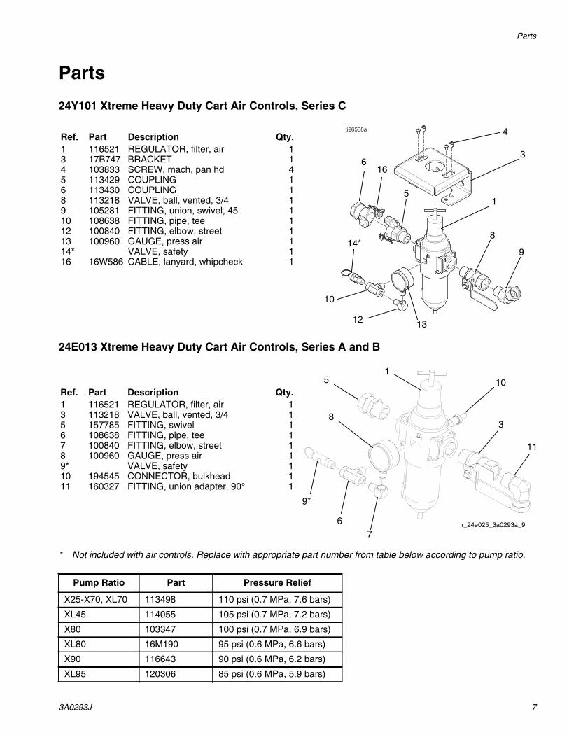
24Y101 Xtreme Heavy Duty Cart Air Controls, Series C
24E013 Xtreme Heavy Duty Cart Air Controls, Series A and B
* Not included with air controls. Replace with appropriate part number from table below according to pump ratio.
Ref. Part Description Qty.1 116521 REGULATOR, filter, air 13 17B747 BRACKET 14 103833 SCREW, mach, pan hd 45 113429 COUPLING 16 113430 COUPLING 18 113218 VALVE, ball, vented, 3/4 19 105281 FITTING, union, swivel, 45 110 108638 FITTING, pipe, tee 112 100840 FITTING, elbow, street 113 100960 GAUGE, press air 114* VALVE, safety 116 16W586 CABLE, lanyard, whipcheck 1
1
3
4
616
10
12 13
9
814*
5
1
3
11
76
8
5
9*
10Ref. Part Description Qty.1 116521 REGULATOR, filter, air 13 113218 VALVE, ball, vented, 3/4 15 157785 FITTING, swivel 16 108638 FITTING, pipe, tee 17 100840 FITTING, elbow, street 18 100960 GAUGE, press air 19* VALVE, safety 110 194545 CONNECTOR, bulkhead 111 160327 FITTING, union adapter, 90° 1
r_24e025_3a0293a_9
Pump Ratio Part Pressure Relief
X25-X70, XL70 113498 110 psi (0.7 MPa, 7.6 bars)
XL45 114055 105 psi (0.7 MPa, 7.2 bars)
X80 103347 100 psi (0.7 MPa, 6.9 bars)
XL80 16M190 95 psi (0.6 MPa, 6.6 bars)
X90 116643 90 psi (0.6 MPa, 6.2 bars)
XL95 120306 85 psi (0.6 MPa, 5.9 bars)

Parts
8 3A0293J
24E025 Xtreme Lightweight Cart Air Controls, Series A and B
24Y396 Xtreme Lightweight Cart Air Controls, Series C
* Not included with air controls. Replace with appropriate part number from table below according to pump ratio.
1 2
3
4
5
7
6
8
5
9*
Ref. Part Description Qty.1 116521 REGULATOR, filter, air 12 160032 FITTING, nipple 13 113218 VALVE, ball, vented, 3/4 14 122327 ELBOW, street, pipe, 90° 15 157785 FITTING, swivel 26 108638 FITTING, pipe, tee 17 100840 FITTING, elbow, street 18 100960 GAUGE, press air 19* VALVE, safety 1
r_24e025_3a0293a_8
Ref. Part Description Qty.1 116521 REGULATOR, filter, air 13 17G536 BRACKET 14 103833 SCREW, mach, pan hd 45 113429 COUPLING 16 113430 COUPLING 18 113218 VALVE, ball, vented, 3/4 19 105281 FITTING, union, swivel, 45 110 108638 FITTING, pipe, tee 112 100840 FITTING, elbow, street 113 100960 GAUGE, press air 114* VALVE, safety 116 16W586 CABLE, lanyard, whipcheck 1
6
14*10
12 1
4
3
8
16
5
913
Pump Ratio Part Pressure Relief
X25-X70, XL70 113498 110 psi (0.7 MPa, 7.6 bars)
XL45 114055 105 psi (0.7 MPa, 7.2 bars)
X80 103347 100 psi (0.7 MPa, 6.9 bars)
XL80 16M190 95 psi (0.6 MPa, 6.6 bars)
X90 116643 90 psi (0.6 MPa, 6.2 bars)
XL95 120306 85 psi (0.6 MPa, 5.9 bars)

Parts
3A0293J 9
24W593 and 24W040, For Xtreme XL Heavy Duty Cart or Wall Mount Packages
* Not included in 24W040. Install couplings (5) and (6) directly into regulator (1).
** Not included with air controls. Replace with appropriate part number from table below according to pump ratio.
244841 Lubricator Conversion Kit
Ref. Part Description Qty.1 17C498 REGULATOR, filter, air, 1 in. npt 12* 100467 ELBOW, street, pipe; wall mount only 13 17B747 BRACKET 14 103833 SCREW, mach, pan hd 45 127784 COUPLING, universal, 1 in. npt(m) 16 127785 COUPLING, universal, 1 in. npt(f) 17 158585 NIPPLE 18 113163 VALVE, ball, vented 19 127945 FITTING, swivel, 45°, 1 npt x 1 npsm 110 108638 FITTING, pipe, tee 112 100840 FITTING, elbow, street 113 100960 GAUGE, pressure, air 114** VALVE, safety 116 16W586 CABLE, lanyard, whipcheck 1
8
9
7
2*
5
6
16
1
4
3
13
1210
14**
Pump Ratio Part Pressure Relief
X25-S70, XL70 113498 110 psi (0.7 MPa, 7.6 bars)
XL45 114055 105 psi (0.7 MPa, 7.2 bars)
X80 103347 100 psi (0.7 MPa, 6.9 bars)
XL80 16M190 95 psi (0.6 MPa, 6.6 bars)
X90 116643 90 psi (0.6 MPa, 6.2 bars)
XL95 120306 85 psi (0.6 MPa, 5.9 bars)
1
2c
* Elbow not used in all configurations.
Ref. Part Description Qty.1 C11034 LUBRICATOR, air 12 116522 AIR CONTROL, conversion kit
(includes 2a-2c)1
2a ADAPTER 12b PINS, retaining 22c O-RING 24* 100549 ELBOW, street, 90°, 3/4 npt (m x f) 1
r_24e025_3A0293_4a
2c
2b
4*
2a

Parts
10 3A0293J
17N621 Air Control Module, 3/4 in. NPTFor King Sprayer (XL6500/XL3400)
25D529 Air Lubricator Module, 3/4 in. For King Sprayer (XL6500/XL3400)
* Not included with air controls. Replace with appropriate part numbers according to pump ratio.
Ref. Part Description Qty.1 17U995 BRACKET, air controls, painted 12 116521 REGULATOR, filter, air 13 103833 SCREW, mach, crbh 44 113429 COUPLING, universal 15 113430 COUPLING, universal 16 16W586 CABLE, lanyard, whipcheck 17 113218 VALVE, ball, vented, 0.750 18 101689 GAUGE, press, air 19* SAFETY VALVE 1
113498 110 psi, K30-K70 models116643 90 psi, K90 model
1
Ref. Part Description Qty.1 17U995 BRACKET, air controls, painted 12 116521 REGULATOR, filter, air 13 103833 SCREW, mach, crbh 44 113429 COUPLING, universal 15 113430 COUPLING, universal 16 16W586 CABLE, lanyard, whipcheck 17 116522 KIT, conversion, air control 18 C11034 LUBRICATOR, air 19 113218 VALVE, ball, vented, 0.750 110 101689 GAUGE, press, air 111* SAFETY VALVE 1
113498 110 psi, K30-K70 models116643 90 psi, K90 model

Parts
3A0293J 11
25D649 Wall Mount Air ModuleFor King Sprayer (XL6500/XL3400)
17U994 Air Control Module, 1 in.For King Sprayer (XL10,000)
* Not included with air controls. Replace with appropriate part numbers according to pump ratio.
Ref. Part Description Qty.1 17U995 BRACKET, air controls, painted 12 116521 REGULATOR, filter, air 13 103833 SCREW, mach, crbh 44 113429 COUPLING, universal 15 113430 COUPLING, universal 16 16W586 CABLE, lanyard, whipcheck 17 113218 VALVE, ball, vented, .750 18 101689 GAUGE, press, air 19 115813 FITTING, street elbow, 3/4 npt 110* SAFETY VALVE 1
113498 110 psi, K30-K70 models116643 90 psi, K90 model
Ref. Part Description Qty.1 17U995 BRACKET, air controls, painted 12 17C498 REGULATOR, filter, air, 1 in. npt 13 103833 SCREW, mach, crbh 44 127784 COUPLING, universal, 1 in. nptm 15 127785 COUPLING, universal, 1 in. nptf 16 16W586 CABLE, lanyard, whipcheck 17 158585 FITTING, nipple 18 113163 VALVE, ball, vented 110* 101689 GAUGE, press, air 1
SAFETY VALVE 1113498 110 psi, K71 model16M190 95 psi, K47 and K82 models
Parts
12 3A0293J
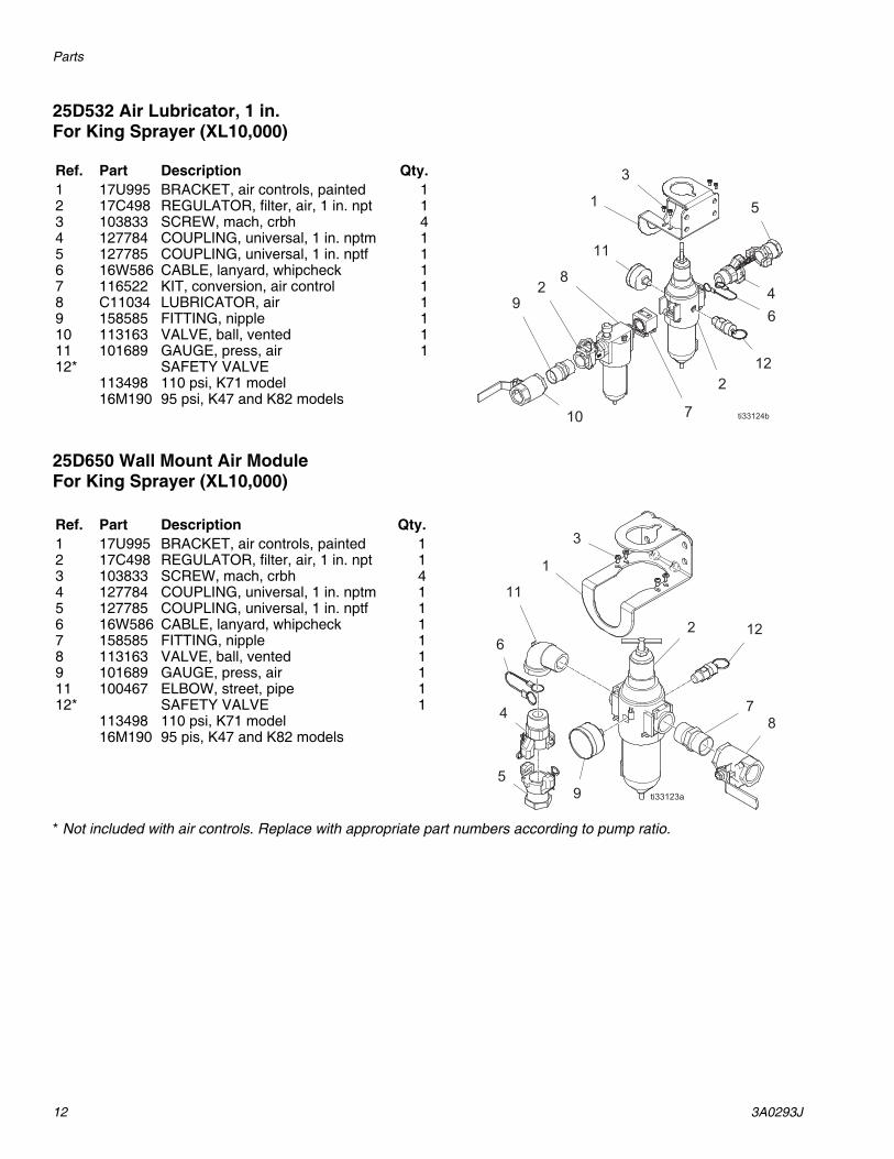
25D532 Air Lubricator, 1 in.For King Sprayer (XL10,000)
25D650 Wall Mount Air Module For King Sprayer (XL10,000)
* Not included with air controls. Replace with appropriate part numbers according to pump ratio.
Ref. Part Description Qty.1 17U995 BRACKET, air controls, painted 12 17C498 REGULATOR, filter, air, 1 in. npt 13 103833 SCREW, mach, crbh 44 127784 COUPLING, universal, 1 in. nptm 15 127785 COUPLING, universal, 1 in. nptf 16 16W586 CABLE, lanyard, whipcheck 17 116522 KIT, conversion, air control 18 C11034 LUBRICATOR, air 19 158585 FITTING, nipple 110 113163 VALVE, ball, vented 111 101689 GAUGE, press, air 112* SAFETY VALVE
113498 110 psi, K71 model16M190 95 psi, K47 and K82 models
Ref. Part Description Qty.1 17U995 BRACKET, air controls, painted 12 17C498 REGULATOR, filter, air, 1 in. npt 13 103833 SCREW, mach, crbh 44 127784 COUPLING, universal, 1 in. nptm 15 127785 COUPLING, universal, 1 in. nptf 16 16W586 CABLE, lanyard, whipcheck 17 158585 FITTING, nipple 18 113163 VALVE, ball, vented 19 101689 GAUGE, press, air 111 100467 ELBOW, street, pipe 112* SAFETY VALVE 1
113498 110 psi, K71 model16M190 95 pis, K47 and K82 models

Technical Specifications
3A0293J 13
Technical Specifications
NOTE: 17C498 is the same regulator as 116521 except with 1 in. npt end fittings instead of 3/4 npt.
California Proposition 65
Air ControlsUS Metric
Maximum air input pressure 250 psi 1.7 MPa, 17.2 barGauge Port Size (Air Regulator) 1/4 npt(f)Air Filter Element 40 micron polypropylene screenMaximum operating temperature 122°F 50°C
Air Inlet SizeXtreme, King (XL6500/XL3400) 3/4 npsm(f)Xtreme XL, King (XL10,000) 1 in. npt(f)Air Outlet SizeXtreme, King (XL6500/XL3400) 3/4 npt(f)Xtreme XL, King (XL10,000) 1 in. npsm(f)
MODEL 116521 AIR REGULATOR FLOW CURVE
OU
TP
UT
PR
ES
SU
RE
(M
Pa,
bar
)
AIR FLOW AT INLET PRESSURE OF 100 PSI (0.7 MPa, BAR), 3/4 in. port,
and 40 micron element
50(1.120)
60
80(0.55, 5.5)
(0.41, 4.1)
40 (0.28, 2.8)
20 (0.14, 1.4)
100(2.240)
150(3.360)
200(4.480)
250(5.600)
CALIFORNIA RESIDENTS
WARNING: Cancer and reproductive harm – www.P65warnings.ca.gov.

All written and visual data contained in this document reflects the latest product information available at the time of publication. Graco reserves the right to make changes at any time without notice.
For patent information, see www.graco.com/patents.
Original instructions. This manual contains English. MM 3A0293
Graco Headquarters: MinneapolisInternational Offices: Belgium, China, Japan, Korea
GRACO INC. AND SUBSIDIARIES • P.O. BOX 1441 • MINNEAPOLIS MN 55440-1441 • USACopyright 2020, Graco Inc. All Graco manufacturing locations are registered to ISO 9001.
www.graco.comRevision J, November 2020
Graco Standard WarrantyGraco warrants all equipment referenced in this document which is manufactured by Graco and bearing its name to be free from defects in material and workmanship on the date of sale to the original purchaser for use. With the exception of any special, extended, or limited warranty published by Graco, Graco will, for a period of twelve months from the date of sale, repair or replace any part of the equipment determined by Graco to be defective. This warranty applies only when the equipment is installed, operated and maintained in accordance with Graco’s written recommendations.
This warranty does not cover, and Graco shall not be liable for general wear and tear, or any malfunction, damage or wear caused by faulty installation, misapplication, abrasion, corrosion, inadequate or improper maintenance, negligence, accident, tampering, or substitution of non-Graco component parts. Nor shall Graco be liable for malfunction, damage or wear caused by the incompatibility of Graco equipment with structures, accessories, equipment or materials not supplied by Graco, or the improper design, manufacture, installation, operation or maintenance of structures, accessories, equipment or materials not supplied by Graco.
This warranty is conditioned upon the prepaid return of the equipment claimed to be defective to an authorized Graco distributor for verification of the claimed defect. If the claimed defect is verified, Graco will repair or replace free of charge any defective parts. The equipment will be returned to the original purchaser transportation prepaid. If inspection of the equipment does not disclose any defect in material or workmanship, repairs will be made at a reasonable charge, which charges may include the costs of parts, labor, and transportation.
THIS WARRANTY IS EXCLUSIVE, AND IS IN LIEU OF ANY OTHER WARRANTIES, EXPRESS OR IMPLIED, INCLUDING BUT NOT LIMITED TO WARRANTY OF MERCHANTABILITY OR WARRANTY OF FITNESS FOR A PARTICULAR PURPOSE.
Graco’s sole obligation and buyer’s sole remedy for any breach of warranty shall be as set forth above. The buyer agrees that no other remedy (including, but not limited to, incidental or consequential damages for lost profits, lost sales, injury to person or property, or any other incidental or consequential loss) shall be available. Any action for breach of warranty must be brought within two (2) years of the date of sale.
GRACO MAKES NO WARRANTY, AND DISCLAIMS ALL IMPLIED WARRANTIES OF MERCHANTABILITY AND FITNESS FOR A PARTICULAR PURPOSE, IN CONNECTION WITH ACCESSORIES, EQUIPMENT, MATERIALS OR COMPONENTS SOLD BUT NOT MANUFACTURED BY GRACO. These items sold, but not manufactured by Graco (such as electric motors, switches, hose, etc.), are subject to the warranty, if any, of their manufacturer. Graco will provide purchaser with reasonable assistance in making any claim for breach of these warranties.
In no event will Graco be liable for indirect, incidental, special or consequential damages resulting from Graco supplying equipment hereunder, or the furnishing, performance, or use of any products or other goods sold hereto, whether due to a breach of contract, breach of warranty, the negligence of Graco, or otherwise.
FOR GRACO CANADA CUSTOMERSThe Parties acknowledge that they have required that the present document, as well as all documents, notices and legal proceedings entered into, given or instituted pursuant hereto or relating directly or indirectly hereto, be drawn up in English. Les parties reconnaissent avoir convenu que la rédaction du présente document sera en Anglais, ainsi que tous documents, avis et procédures judiciaires exécutés, donnés ou intentés, à la suite de ou en rapport, directement ou indirectement, avec les procédures concernées.
Graco Information
For the latest information about Graco products, visit www.graco.com.
For patent information, see www.graco.com/patents.
TO PLACE AN ORDER, contact your Graco distributor or call to identify the nearest distributor.Phone: 612-623-6921 or Toll Free: 1-800-328-0211 Fax: 612-378-3505