3445600497282.pdf - Oak Ridge National Laboratory
170
-
Upload
khangminh22 -
Category
Documents
-
view
0 -
download
0
Transcript of 3445600497282.pdf - Oak Ridge National Laboratory


Contract No. W-7405-eng-26
CH EMlCAL TECHNOLOGY ~ i V l S l ~ ~
A ~ ~ ~ A ~ PROGRESS REPORT
for Period Endiarg Nay 31, 1961
F. L. Culler D. E. Ferguson - Chemical Development
R. E. Blanco - Chemical Development
K. 5. Brown - Chemical Development
M. E. Whatley - Unit Operations Section Chief ti. E. Goeller - Process Design Section Chief J. C. Bresee - Pilot Plant Section Chief
- Division Director
Section A Chief
Section B Chief
Section C Chief
DATE ISSUED
OAK RlDCE NATIONAL LABORATORY Oak Ridqe . Tennessee
operated by -
UNION CARBIDE CORPORATION for t h e
U. S. ATOMIC ENERGY COMMISSION
1 3 4 4 5 6 0 0 4 9 7 2 8 2


1. POWER R E A C T O R FUEL PROCESSING
Chemical Processes for Sta inless Steel-Containing Fuels
Cold laboratory and engineering-scale develop- ment of the Darex process for stainless steel- containing reactor fuels was completed except for f inal refinement of the room-temperature EIQ, sparging method of chloride removal from Darex solut ions and possibly addit ional studies of off- gas composition. In decladding tests w i th stain- less steel-clad ThO,-UO, fuel samples irradiated to 25,000 Mwd/ton the uranium l o s s increased w i th burnup, t o -3%; the thorium loss was 0.1% a t a l l burnups. These resul ts show that Darex cannot be used ,as a decladding method for Tho,-UO, fuels.
Uranium losses to i n i t i a l decladding solutions result ing from Co6O gamma radiat ion were tw ice the oxidat ion losses, 0.30 vs. 0.1576, but in f inal Dnrex solut ions oxidation was control l ing, 0.90 vs. 0.25% for 3 hr exposure.
Removal of chlor ide from Darex solut ions by NO, sparging a t “-25OC produced solutions con- ta in ing ppm chloride when 2000% excess NO, WQS used; better contacting methods are being studied t o decrease the amount of NO, required.
Co ld laboratory and engineering-scale develop- ment of the Sulfex process was a lso completed. In Sulfex decladding of UQ,-ThO, samples irradiated t o 20,000 Mwd/ton, uranium and thorium losses were less fhan 0.4 and 0.2%, respectively. l o s s e s were independent of burnup. In i n i t ia l solution, uranium losses were increased 5-fold by Cod’ gamma irradiat ion and 17-fold by oxidation, t o 0,86 and 0.29%, respectively; losses i n f inal solut ion were not material ly affected by either oxidation or rad ia t i on.
Dissolut ion studies w i th high-density UQ,-6% ThQ, pel lets in Thorex dissolvent showed that 35 h r i s required for a cyc l i c dissolut ion process operated w i th 5% oxide heel.
Modified Zirf lex Process for Zirconium-Containing Fuels
The modif ied Z i r f l ex process, in which uranium- zirconium a l loy fuel i s dissolved in 6 ,+I NH,F- 1 NH,NO,-t-{,Q,, was demonstrated w i th unir- radiated fuel, on a small engineering scale. The optimum H,Q, concentration was 0.01 kls con- t inuous addi t ion being required to prevent uranium precipitat ion. A dissolut ion flowsheet for the TRIGA fuel (8% U-91% Zr-1% H) w a s demon- strated, 11 hr being required for core dissolut ion w i th an i n i t i a l d issolut ion rate of 30 mg c m m 2 rnin-’. The off-gas contained 10% H, and 88% NH,. The dissolut ian of the PWR Seed 3, 34% ~ 0 , - 6 5 % ZrO,, was unsntisfactory, 0.04 mg cm-’
rnin-’ in 12 NH,F-1 h1 H,O,. She rate i n
boi l ing 12 M H F was 3.3 mg cmW2 min- ’ .
Anhydrous Hydrochlorination Processes A Zi rcex f lowsheet for processing the TRIGA
fuel (8% U-91% Zr- l% H ) was developed. The aluminum cladding i s reacted w i th HCI-N, a t 3OO0C t o produce vo la t i le AICI,, and the U-Zr-H i s re- acted w i th HCl a t 600°C and then w i th CCl,-N, at 550’C. The uranium chloride residue can be either dissolved i n 13 hi HNQ, t o produce 0.1 A,! uranium solut ion or f luorinated a t 200°C t o UFg. The graphite e n d plugs are burned in oxygen a t 750°C
An oxyhydrochlorination process developed for the U-lQ% hAo fuel of the CPPD Core 1 provides for mechanical decladding and washing free the Na bond. Ninety percent of the molybdenum is re- moved by 15% HCI-air a t 400°C, another 3 to 6% i s removed by pure HCI at 400°C, and chloride i s removed by converting the uranium to U,O, wi th 0.6% H,O in air a t 100 t o 400OC. The U,Q, i s dissolved in n i t r i c ac id to produce a 1 M uranium solut ion containing 175 ppm of chloride.
Processes dsr Craphire-Based and Uranium Carbide Fuels
In tests an the 90% HNO, disintegration-leach process for graphite-uranium fuels w i th fuel con- ta in ing 3 t o 12% wroniurn, 0.001% burnup, 44, 30,
... I l l

and 20% of the Ce144, 2r95, and Ru106, respec- t ively, wete not leached from the graphite in two
4-hr digestions. The Q ~ I I ~ W I E . of C S ' , ~ rctoined varied from 7 t o 81%. The uranium loss at boi l ing f o i 12% uranium fue l was 0.03% and for 3% irrnrsium fuel was 0.7%, the same a s for unirradiated fuel. Losses a t 25OC were about twice these volues.
1 he EIICSII part ic le s i z e of the residue WTS 200 to 400 pE wi th -0.257; <10 + after 1 day's contact and * 1% <10 p after 4 days' contact. In f i l t rat ion studies the f i l t rat ion rate, wi th > 6 in. Hg vacuum, was 60 gal f t - 2 h r - ' wi th a 1-ft-deep gruphite cake.
Combustion of 0.001% burned up graphite-uranium fuel in oxygen 0 5 !?OO°C volat i l ized mGSt of the Ru106; however, that which did not plate out in cool po;;s of the equipment w o s quanti tat ively absorbed in Na0M solution, No 2rv5 , CS',~, or
W Q S volat i l ized. The YO% HNO, process i s not appl icable t o graphite fuel containing Al,o,- coated 110, particles; <1% of the uranium was
leachable. Combustion sf th i s fus l resulted in a uranium recovery of only 1056 when the ash w a s treated 8 hr in boi l ing 10 !t! HNO,. Combustion of fuel w i t h coated Si-Sic was more satisfactory; losses varied from 0.35 to 2% as the cocrtfng th ick- ness WQS varied from 3 to 30 mi ls -
I he off-gas from dissolut ion of uranium iiiono- carbide i n 4 ,\f MNO, \*1"s pr incipal ly NO and CO, and no H, ar hydrocarboirs were produced. Disso- lu i ion of uianium carbide in water and HC1 produced -85% methane and 10% ki,.
-
-
P i Q C e S S Studies Q91 s&&CtrPCPd h41iXed Oxide arad Merd F u a l s
Hoste! loy X, which s a y be used u s a cladding inaterial foi the GCRE and MGCR fuels, dissolved at i4 rate of 28 mg sin-* m i r i - ' i n 2 A! HN03-4 !\I
MCi. Boi l ing 6 t o 13 HNO, dissolved 99.8% of the U 6 , orad 50% of the Be0 from 30% 8e0-70% UO, G C R E f u e l pellets in 6 to 7 hr; however, SO hr was required t o dissolve a l l the Reo . In 6 XI MNO,-3 to 7 AI H,SO,, 80% of the Be0 dissolved in 6 t o 7 hr. With the MGCR fuel, 61% UO,-39% BeO, 24 hr leaching in 8 ,\f MNO, W Q S required t o recover the uranium quarifitaiively. The U 0 2 - B e 0 fuels containing <lo% UO, dissolved 11111ch more slowly, the highest ra:e being 1.7 m g ~ r n - ~ m i n - ' w i th boi l ing 5.8 A! NH,HF,.
The uranium leaching rate from sinteied U0,- AI,O, pellets by n i t r i c acid was feasible for
high-u02-corrten.i fuel but too low for low-uO,- content fuel. The uranium loss for UO,-d% Al,g, was 0.002%, but 58% for a fuel containing 61Y4 A1203. were q w a l l y ineffect ive for high A.l,O, contents.
Beryl l ium metn! dissolved in I~oi l ing 4 f.I,SO,, 6 AI NaOH, and 5 ,\.I HNO,-O.l NaF ab rates w r y i n g from 2 t o 63 my c m - 2 min,^'. Niobium metal reacted w i t h anhydrous chlorine a t 360°C o t 3 rate of 28 mg cnr-^* in in- ' and with 9 M HF-.3 h!
ENO, a t o rate of 35 rng crn,-2 min- ' ; rates in other reagents geneial ly were low.
I-iydrafluoric ac id and 5 ,$I k!NO,---5 M
Final corrosion t e s t s indict i fed that t i tanium i s satisfactory for dissolut ion of thorium fuels but cannot be used in the condensef for continuous refluxing. Under modified Z i r f l e x conditions, LCNA w53 corroded c t an ovei.-al! rate of 1.15 rni lsjmonth and w i s superior to I-lastelloy I-- and types 301.L and 309 SNb stainless steel.
In Z i rcex tes:s iil which specimens of Hoyrses 2.5, Inor-8, Nichrome V, and Pyrocercm were exposed t o 15% WCI-85% air at 400°C, and to HCi at 3.S0°C., a l l the nbove a l loys :*iere sotisfactsry.
P c s ; ~ to detc?rrnine the best moter iu l for handling Darrx, Zir f lex, tho re^, ond Purex solutions at roan temperature, such as might be required for a universal centrifugz, indicated that Plastelloy F wi th a maximum rote of 0.7 iiiiI/inanth i n Purcx service was superior t~ Titanium-dSA., HasteI!oy C, L.CNA, and Carpenter 20 SNb.
In corrosion tests on glass Rasshig i ings, for possible iisc in c r i t i ca l i t y control during storage of uranium and plutonium solutions, 4% boron glass samples exposed PO 2 and 5 \-!NO, at 23 and 65OC were satisfactory but 5.8% boron glass ond t i tania- coated 5.8% boron gloss wc.;e unsuitable.
Ss!ren: E Iriicaction Studies
In a lnrge numbc: 3f 2-in.-dia pulsed COliJilici i'uns t o determine optiinum opemting conditions for the ac id Ti lorex flowsheet, w i th both sieve and nozzle plates and w i t h both n top and a bot;oim inteiface, losses, HETS data, and flooding values YVCW ob- tained for extraction, partitioning, orid stripping. A uranium product concentrotion of 20 g,'Iiter wns achieved hy ref luxing uranium in the str ipping column and top of the partitiorring eolumn. -%e uranium loss t o the thorium product i v 3 5 O.Q_54%, cnd the thorium l o s s wni6 0.03%. It was found that
i v

plant capacity can be increased wi th no sacri f ice in f i ss ion product decontamination by increasing the thorium feed concentration from 260 t o 325 g/l iter and increasing either the T E P volume or concentrat ion.
The optimum point for addit ion of 14 ?/i HNO, for salt ing was found to be four stages below the feed addit ion point. Addi t ion at th is point rather than a t the feed point gave a 10-fold increase i n ruthe- nium, zirconium, and niobium decontamination and an 8-fold decrease i n thorium loss,
The use of dibasic aluminum nitrate for part i- t ion ing the uranium from the thorium was demon- strated. Th is innovation simpli f ies the subsequent thorium second cyc le feed adjustment and results i n a more concentrated uranium product.
Irradiat ion of the feed i n a Co60 gamma f ie ld t o 5 whr/l iter decreased the over-al l decontamination factor by <2, and irradiat ion t o 65 whr/l iter in- creased decontamination by “4.
Both boron and cadium, which are being con- sidered as soluble poisons for c r i t i ca l i t y control, were sat is factor i ly removed by solvent extraction. The boron and cadmium contents of the extraction product were <7.8 and <0.4 ppm, respectively.
The f i rs t cyc le raff inate was satisfactori ly con- centrated to 6% of i t s original volume by evapora- t ion t o 1.3% for HNO, recovery and d i lu t ion wi th water back to 6%. Th is i s equivalent t o 0.2 l i ter per kilogram of thorium processed and i s a 10-fold improvement over the aluminum-salted Thorex f l o w s heet.
Tests w i th the second uranium solvent extract ion cyc le demonstrated that, due t o increase in solvent siltura ti on, decontamination from f iss ion products does not decrease between 2.5 and 15% TBP when n i t r i c ac id i s the salt ing agent. About 99@6 of t h e thorium in the concentrated IJ233 product was re- moved on Dowex 50W resin.
In h igh-act iv i ty tests, 0.1% of the CETR fuel a c t i v i t y (25,000 Mwd/t), decontamination factors for ruthenium, zirconium-niobium, and rare earths were lo4 , 5 x lo3, and 2 x IO5 , respectively.
I n studies on the chemistry of zirconium and niobium extraction, it was found that a t least two species of zirconium are present i n 2 ,U HNU, and that the d is t r ibut ion coeff icient of 0.12 for the T ~ Q E extractable form in 30% TBP in dodecane i s constant for contact t imes of 5 t o 60 min. More than 90% of the niobium was adsorbed on Vycor
glass powder from zirconium solutions containing zirconium-niobi urn tracer.
M ec h a n i ca I P r o c e s s i t-, 9
The mechanical dejacketing fac i l i t y for the SRE Core 1 fuel was completed and tested w i t h unir- radiated fuel, and operation w i th irradiated fuel was started. The fue l was removed from the stain- less steel jackets at a rate of 2 to 3 kg/hr, washed free of NaK, and recanned i n aluminum for shipment o f f -s i te for subsequent processing. The interiar surfaces of the empty jackets were scraped free of NaK wi th a p last ic rabbit, flattened, ro l led into coils, and removed to the burial ground. The proc- essing rate attained thus far i s about 30% of that expected.
The 25O-ton fuel shear was insta l led w i th the leacher and aux i l iary equipment in 61dg. 3019, and test ing w i t h nonirradiated material was started. In a large number of laboratory countercurrent dis- solving experiments w i t h UO, pel lets to simulate leaching, 3 t o 4 stages were required t o at ta in steady-state operation. At steady state the pro- duct solution uranium concentration varied From 300 to 500 g/l i ter and the ac id i ty from 1.2 t o 3.2 M H+, composite values being 410 g/l iter and 2.3 M.
Engineering Studies
A cr i t i ca l l y safe shipping cask for U233 was designed nnd constructed which permits shipment of up to about 30 kg of u2J3 at a uranium concen- t ra t ion of 225 g/liter. A neutron mult ipl icat ion tes t performed during f i l l i n g gave a maximum source mul t ip l icat ion of 4 t o 5, which indicates an effec- t i v e mul t ip l icat ion constant of t0.8. A conven- t i ona I tank conta in ing boron-g las s Raschig r ings i s being insta l led which permits storage of 60 kg of u~~~ at a uranium concentration up t o 200 g/l iter.
2. F L U O R l D E V O L A T I L I T Y PROCESS
Processing of Uranium-Zirconium Alloy F u e l
Seven complete batch flowsheet runs, including d isso lut ion of zirconium-uranium alloy, 400 t o 600 g of uranium per batch, i n molten NaF-LiF-ZrF, w i t h HF, and f luorination t o UF,, were made in the F luor ide Vo la t i l i t y P i l o t Plant. Dissolut ion rates were >3.5 kg/hr wi th an HF f low rate of 150 g/min. Nonrecoverable uranium losses averaged less than 0.8 g per run, and to ta l cation impurit ies i n the UF, product were less than 320 ppm. Corrosion in
V

the dissolver i n 14 runs was -20 mi ls overall. N a F sorption bcd studies indicated that the f i lm
atid so l id phase diffusions of UF, and the heat transfer rates betweer? the so l id and the gas stieoin are sorption rate-coritrolling processes. The mass transfer f i l m coeff icient for UF, has n value of -0.05 rrn/sec and tho sol id phase di f fusiv i ty of UF, i s cm.-2 set."'. Average zirconium dissolut ion rates in the Inor-X prototype dissolver were corre!otcd snt isfactor i ly by the equation T = kv-'I3 In (w/0.40) w h e r e v i s the kinematic v iscosi ty and ')I' the HF f low rate.
Laboratory studies on dissolut ion of stainless steel and of various oxides i n fused fluorides and oil volat i l izat ion of PuF, CIS we! \ O S of UF, fioiil such melts indicated thc feasibi l i ty of fluoride- vo la t i l i t y processing of a wide variety of reactor fuels.
LJranium recoveries of -98% were obtained from NaF-ZrF,-IJF, sal ts containing 1 and 0.2 wt % uianium by f luorination i n a one stoge Inborutory- scalc steady-state fluorinatnr. The carrier salt (63-37 mole 5% LiF-Bet'',) dissolved in s t i r r ed , bo i l ing 90% HF--lO% UO, a t an in i t ia l rate of l 5 0 m i l s / h r , but the rate decrmsed to <10 itiils/hr as a laycr of undissolved Beb-, was lef t on the surface.
So!vcnfs of SbF, in HF w e r e investigated for blanket solt decontamination. With L iF the corn- pound LiSbF, was formed, w i th a solubi l i ty of 0.23 molz p i Jitr; of IjF. Rare earths forimed a corriplex wi th SbF, that was soluble t o the extent of 200 t o 300 g of rare earths per l i ter of HF, but ThF, WCIS
insoluble.
4. H O M O G E N E O U S R E A C r O R F U E L . P R O C E S S I N G
hdvlticlone System $*iudies
Development work on aqueous homogeneous re- actor fuel processing was concluded with twrnina- t ion of the Womogeneous RFactoi Praiect.
Hydroclone performance studies, i n both out-ob- p i le tests and a t thp H R T Chemical Plant, dernon- strated that mult ip le hydroclone units could not be operated sat isfactor i ly w i th induced underflow. A signi f icant lowering of the e f f i c i m c y of fset al l gains. When the fuel w a s processed through hydro- clones on a 10-min cycle, sol ids col lect ion rates were o s high as production rates from corrosion, but w i th large reactors such short cycles neces- sitate n large and complex processing syste.n. Periodic, infrcqdent descaling of hcat exchanger surfaces may be D more at t iact ive processing schcme than rapid, continuous hydroclone pro- cessing. For eithe: method, nucleat poisons are control led n t very low levels by solubi l i ty effects and mechanisms which depasit sol ids on pipe wal ls outside the rcactor core.
Fuei Processir~g by Uranyl Peroxide Pr eripitation
Rapid p r o c ~ 5 s i n g of reactor fuel to l im i t thc accumulation of nickel by batch prer ip i tat ion of IJienyl pcroxide wc5 tested in the laboratory a n d demonstrated in ful l-scale, 4-kg engineering tests. I he d-4, batches of natural uranium v:c:e processed i n geometrical ly safe equipmcnt w i th uranium losscs of 3% and decsntaminntion factors of 100. The process mny be carried out in an ordinprry fuel-U,O system w i t h o u t addit ion of potential contaminants. The engineering system was on the scale required for lsrge power stations.
Relatad Sys tem
T h e charcoal off-gas absorber beds were sat is- factor i ly operated with the systerrl below atmos- phcric pressure to decrease the potential hazard of a leak i n the Qff-gaS system.
5. W A S T E 1 R E k T & F N T A N D DISPOSAL.
bB i &-Activity W w sts f reatmerit
Synthetic nonradioactive Purex, Dmm, and TSP-25 wastes were successful ly evaporated and calcined i n bofh bench-scale (18- by .I-in.-dia) and vngineering scale (82- by 8-in.-dia) pots. Sulfatc vo la t i l i t y from Puiex waste W Q S only 0.2 to 0.7% when 10% E X C ~ ? . ~ sodium, magnesium, or calcium WCIS added to form thermally stable sulfate salts. .fhe nitrat- content of the calcined sol id varied from 60 to 500 ppm. Control of a 25-l i ter con. tit-ruous cvapora'os w i th direct feeding of the pot
v i

calciner was sat isfactor i ly demonstrated i n two runs. In the bench-scale equipment, ruthenium vo la t i l i t y from Purex waste was decreased t o back- ground counting levels, 0.03%, b y making t h e waste 1.5 M i n phosphite.
Glasses were prepared from Purex waste by adding borate and phosphate a s f luxing agents in addi t ion to sodium and magnesium or calcium to prevent sulfate vo la t i l i t y . The best product can- ta ined 22.2, 30, 5, and 8.9 wt %# respectively, of SO,, P,O,, B,O,, and hlgO and had a density of 2.7 g/cc. About 5.5 gal of th is glass would con- ta in the waste oxide from 1 ton of uranium. The in i t i a l leach rate in water was less than IO-$ g cm-2 dayi1 after 1 week i n spite of the high s u l - fate content. The phosphate can be formed by adding phosphite t o the nitrate waste, thus achiev- ing control of ruthenium vo la t i l i t y a t the same time.
Conceptual design of a pot calc inat ion p i l o t plant indicates an i n i t i a l cost of $1,000,000 for purchase and instal lat ion of equipment in exist ing ce l l s at Idaho. A cost of $1,500,000 was estimated for construction of a new bui ld ing for instal lgt ion of th is equipment a t CIRNL.
Low-Ac t i v i t y Waste Treatment
Bench-scale tests of a scavenging-ion exchange process using phenolic resins showed that CRNL low-ac t iv i t y wastes can be decontaminated t o the maximum permissible concentration recommended for populations in the neighborhood of atomic energy instal lat ions. More than 99.9% of the cesium and strontium were removed from 1500 resin bed volumes of waste by sorption on either sulfonic- phenolic or carboxyl ic-phenolic ion exchange resins; these resins were regenerated w i th 10 resin bed volumes of 5 ,?I HCI or 0.5 (b! HNO,, respectively. A small test unit (60 l i te rs lh r ) wa5 started up t o determine the ef f ic iency of the system on actual waste. A p i l o t plant (10 gal/min) i s scheduled for startup i n August.
A study of interim waste storage costs for tanks showed that for storage times of 0.5 to 30 years, costs ranged from 2 x IO- , to 9.3 x IOe3 mil/kwhe for ac id ic wastes, and from 1.5 x t o 4.7 x mil l /kwhe far neutral ized wastes.
6 . P I L O T PLANT DECONTAMINATION
The ac t i v i t y level i n t h e Radiochemical Pro- cessing P i l o t Plant, fo l lowing an explosion in
November 1959, was decreased to an average level of from 80 t o 20,000 d/m/100 cm2 prior to bonding the ac t i v i t y wi th paint. A total of 1.5 kg of plu- tonium was f lushed from the processing equipment, of which 1.1 kg was recovered.
7. G C R C O O L A N T B U R l F l C A T l O N STUDIES
Oxidation by 0, or CvO Kinet ic studies of the oxidation of contaminants
in a simulated hel ium coolant stream resulted i n design data for either a catalyt ic oxidizer or a copper oxide oxidizer. Data from the catalyt ic studies were empir ical ly correlated to g ive reactor design equations, and the copper oxide oxidizer data were f i t ted t o a theoretical model wh ich can be used in reactor bed design. The theoretical model for the heterogeneous reaction w i th copper oxide was postulated to be a combination of gos f i lm and molecular di f fusion in the porous solid.
Design of Helliom f9urification System A pur i f icat ion system was designed for the pro-
posed Pebble Bed Reactor Experiment coolant gas, consist ing of a delay t rap for f i ss ion product gases, an oxidizer for chemical contaminants, on adsorber for the oxidation products, and an absolute f i l ter for part iculate removal.
8. E Q U I PM ENT DECONTAMINATION
Several improvements in stabi l i ty and efdective- ness were made in the oxalate-peroxide solut ion recommended as a general decontaminant and UO, solvent for the GCR charge and service machines. Peroxide, 0.1 hi, was shown t o be a corrosion in- h ib i tor for stainless steel i n fluoride, sulfate, oxa- late, and ci t rate solutions. Homogeneous reactor scale was dissolved from a rupture disk of the HRT b y inhibi ted phosphoric acid, and further decan- taminated t o i t s Co6' background radiat ion by oxal ic acid-hydrogen peroxide.
9. HRP THORIA BLANKET D E V E L O P M E N T
Preparation of TRO, Pellets
Strains leading to cracking in rounded thoria pel lets, fabricated by automatic pressing and cal- c inat ion of Tho, powder, were decreased by pre- f i r ing the powders t o 1200°C prior to granulation, minimizing the curvature of the punch face, and holding the pressed pel lets a t 1200 to 1300'C for
v i i

1.5 to 2 hr before f ina l f i r ing a t 17.50"C. Weight losses i n a t t r i t ion tests on thoria part icles prepared by the sol-gel process were due to grinding off of edges and sharp points. Slight, but consistent increases in density were observed i n Tho, gels f i red i n hydrogen over those f ired in air. Fi r ing at 1150 to 1200°C increased the Tho, density s l igh t ly more than a t 1200 t o 1250°C.
Development ef Gas RecombinetiQas CoSSllyst
The catalyt ic ac t i v i t y of the sol-prepared pal la- dium catalyst i s more than suff icient t o recombine the radiolyt ic gas (at 100 psi D, part ial pressure) piOdlJCed in n thoria-wrania blanket slurry at the lO-kw/l i ter power level expected i n a breeder blanket. Out-of-pi le tests wi th a slurry (782 g Th/kg D,O, 1460 ppm $d/Th) proposed foran in- p i l e slurry corrosion experiment a t 26 watts/ml power level indicate a catalyt ic ac t i v i t y suf f ic ient t o maintain the radiolyt ic D, gas prassure a t <lo0 ps i a t 280°C. Gas recombinntioil data obtained wi th palladium-containing slurries a t oxygen part ial pressures greater than 200 ps i agreed w i th a k inet ic expression showing a first-order dependence on hydrogen and a 0.5 order dependence on the oxygen part ial pressure. At lower oxygen part ial pressures or H,/O, rat ios >1 the kinet ic expression d id not hold and catalyt ic ac t i v i t y was enhanced.
Cal ibrat ion of the gas inject ion apparatus used i n the gas recombination catalyst development studies showed unsuspected gas holdup in the capi l lary tubing connecting the gas charging system to the reaction autoclave. Re-evaluation of previous rata data obtained En th is system prior to cal ibra- t i on w i th slurr ies containing the sol-prepared pal ladium catalyst showed l i t t l e or no deactivation of the catalyst by excess oxygen and complete reaction of deuterium (or hydrogen) and oxygen in the presence of the slurry-catalyst.
Thosi urn 6 x i de l i ra& ation fr
Examination of a sett led bed of 50 thoria pel lets irradiated 2900 hr i n D,B in the L.1TR a t 250°C and a thermal f lux of - 2 x n cm-, sec- ' showed 20 of the pel lets broken into fragments and fines. The remainder had essent ia l ly the same bulk density as the original tnatericil but showed some damage from chipping out of s t d a c e fraginents and breaking of f of spherical segments. All sur- faces were porous, and a black, carbonaceous, vitreous-appearing substance, about 1 wf % of the
recovered solids, was found i n the upper half of the irradiat ion autoclave. Th is was probably a carbon residue from i he polyvinyl alcohol binder used i n the pel let fabrication.
235
oxide irradiated i n a sett led condit ion a t 280°C in the L I Y R t o a total nvt of 5 x 10¹⁹ n/cm2 showed pronounced part ic le damage. Twelve percent of
the irradiated material ( in i t ia l l y 2.1 p ovwage s ize and 0.5% <I p ) was recovered as a dispersed suspension w i th an average part ic le s ize of 2500 A. A portion of the material (26%) that had sett led t o the bottom of the outoclave and bean resuspended by st irr ing hod an average size of 1.6 p but very steep size distr ibut ion curve, indicating that nearly a l l the original material had suffered part ic le do mag e .
A D,O slurr-y of c lass i f ied thoriu1~1--0,4'% U
A review of the part ic le s ize information obtained in 18 s luny irradiat ions over the past several yews suggests pronounced part icle damage in some cases; some oxide preparations h w e greater r a d i a - t ion damage resistance than others.
10. FUEL C Y C L E D E V E L O P M E N T
b l - G e l [fgsocess for ThQ,-ldB, nnd Tho,
Thoria-uranin part icles containing 4.4 wt '% of 93% enriched trrunium prepared by the sol-gel pro- cess had c1 part ic le density of 9.93 g/cc compared to the theoretical 10.G35 g/cc and wore compacted i n tubes by air vibrat ion t o bulk densit ies of 8.7 g/cc. The tubes were sealed and placed in the NKX reactor i n March. A method for preparing sols from oxides derived by steam denitrnt ion of thorium ni t rate gave high-density thoria-urania particles. Thoria part icles were prepared similarly.
hjaterial sui table for dispersion to a sol was pre- pared on on engineering scale in an agitated-trough steam stripper. he density of the f ina l part icles increased as the W T h mole ra t io of the denitrnt ion product increosed from 0.05 to 0.10.
-
Modified S I - G e l Psoceos for UQ, f e n grains of dense (10.6 g/cc) urania gel par-
t i c l es was prepared by evaporation and calc inat ion of a hydrous uranous oxide piecipitate from uranous formate solution.
v i i i

11. TRANSURANIUM E L E M E N T S T U D I E S
Isotope Production Cdculations
Irradiat ion calculat ions for production of ~ f ~ 5 ~ have shown that the High F lux Isotope Reactor (HFIR)-Transuranium F a c i l i t y (TrU) complex w i l l produce % 1.3 g of cf2S2 per year a t steady state. Mi l l ig ram amounts w i l l be produced by December 1965,
Basis for Shielding Design
The bulk shielding requirements for the TrU F a c i l i t y have been revised because of a more con- servative estimate of the production of Cf254, which has a 55 day-half- l i fe for spontaneous f ission. The shielding, carrier, and chemical operations are now designed for processing 1 g of Cf252 irradiated 30 days a t 5 x 10’’ n cm-* sec- ’ and decayed for 1 day.
Chemical Process Development
Two feasible chemical separatian methods, one based on solvent extract ion w i th a tert iary amine, and the other on anion exchange were developed a t tracer levels for most of the required steps i n the Transuranium Program. In batch countercurrent tests w i th synthetic teed containing americium and cerium, americium was selectively extracted into 30% Alamine from 11 M L iCI containing <0.1 M HCI wi th >99.99% recovery and a decontamination factor f rom rare earths o f > lo4. Tests of the anion ex- change process w i th synthetic solutions traced w i t h americium and cerium on a column 2.5 cm dia and 60 cm high gave >99.99% americium recovery and a decontamination factor from rare earths of > 106.
The proposed flowsheet for High F l u x Isotope Reactor target processing includes d isso lut ion in hydrochloric ac id and selective extraction of act inides into tert iary amine from 11 it! L iC l fol- I awed by berkel ium-ca l ifornium extraction from 1.5 41 HCI into 1 !M mono-2-ethylhexyl phenyl- phosphonic acid. In a miniature batch counter- current extraction, californium recovery was 99 2 I%, and the decontamination factor from curium was io3 . Prel iminary measurement of einsteinium distr ibution coeff icients indicate that neither tert iary amine nor phenylphosphonic ac id extraction can be used t o separate californium and einsteinium. The only method avai lable i s chromatographic
e lu t ion from a cation exchange column w i t h CI-
h ydroxy-i sobutyrate. Berkel i um-cal ifornium separa- t ion factors of IO5 per stage were obtained by extracting Bk(IV) in to 1 At di-2-ethylhexyl phos- phoric ac id from 10 M HNO,-O.l :M KBrO,.
H F l R Target Fabrication Development and Design Features of the TRU F a c i l i t y
The design of The Transuranium F a c i l i t y i s in progress. Cold development work, as a joint program wi th the Metallurgy Division, on target fab- r icat ion has started and design and instal lat ion have started for a sealed manipulator-served box located in a 4.5-ft-concrete-shielded cel I for higher ac t i v i t y tests of process chemistry. Two ce l l s have been added, along w i th four addit ional cold laboratories, t o do special separations for isotopes such as Bk249 mi lk ing for Cf249, ;Sk255 decay to Cm25* fol lowed by separation, E s and F m separations, and others. Construction i s scheduled for com- p le t ion in Apr i l 1964 and fu l l -sca le operation by June 1365.
12. P R O D U C T I O N OF U R 4 N I U M - 2 3 2
Pure U232 i s to be prepared for nuclear cross- section measurements. Calculat ions showed that 10 mg of u~~~ containing <IOO ppm of u~~~ can be prepared by irradiat ing 50 cj of Pa23 ’ for 5 hr at a f lux of 1 x n cm-2 sec-’ and processing after 20 to 120 hr decay. Irradiation for 200 hr and proc- essing after 65 to > 140 hr decay y i e l d s 1 g of u~~~ containing < I % u ~ ~ ~ . In preliminary tests on a chemical f lowsheet for recovering uranium and protactinium from irradiated Pa,Q,-AI by anion exchange <0.3% of the protactinium and ~ 3 % of the uranium, the l im i ts of detection, were lost. The protactinium product contained < 10% of the uranium and the uranium product 0.04% of the protactinium.
13. URANIUM PROCESSING
A solvent extract ion process for puri fying uranium concentrates, which uses a phosphonate as ex- tractant and ammonium carbonate a s stripping agent, was demonstrated successful ly i n continuous equipment. The use of a phosphonate al lows ex- tract ion w i th low-nitrate salt ing in the aqueous phase, and the product from the ammonium car- bonate str ipping c i rcu i t i s converted t o UO, more eas i ly than i s uranyl nitrate from the conventional t r ibuty l phosphate circuit .
i x

A method was developed for recovering n i t r i c acid from ref inery waste streams by extraction wi th a secondary oitiine.
l d , FISSION P R O D U C T R E C O V E R Y
sssvent Extsaetiora
In a continuous run of the Ji(2-eihylhexyl) phos- phoric acid ( D2EHPA) extraction process for recovering strontium f r o m Purer wastes i n minia- turc mixei-sett lers w i th nonradioactive feed, both chemical and physical pe;furniance .7~si:c satis- factory. In Iaboratoky experiments cesium W O S
pxtmctsd from Purex waste, i idjusted to pH 5 . by sodium tetrilpherryl boson arid stripped w i th d i lu tc ac id . Howevw, such a process w i l l be cconomicul ly at t ract ive only i f the extiactant can be obtained at a price considerably below currcr;t quotations. Zirconium and niobium were extracted f r o m acidic Pusex waste w i th 0.3 21 D2CHPA in hydrocarbon di luent and stripped w i th 1 M oxalic acid.
P rec i p i ta t ion
Strontium was recwered from a Purex waste con- centrate by precipitat ion >vith NH,, Na,CO,, NaOtl, and Na,CO,, in sequence; iron, lead, and calcium impurit ies in the f inal product were <3 wt 76 of the strontt urn.
Ion Exchange
In laboratory studies on pre-ion exchange treat- ment of Purex Waste, >as% of the sulfate ion present was precipitated by addit ion of excess ferr ic ion and d i lu t ion w i t h fuming ni t r ic acid to 50-55% HNO,.
15. TI- lORIUM R E C O V E R Y F R O M G R A N I T E
Sample Cdlect ion
Study of thorium reserves and recovery casts from various largc-tonnage sources W Q S continued with the principal effort centered on granit ic rock. Of -200 rock samples collecte?, Conway granite from New Hampshire showed the highest overagc thorium content, 47 ppm, and t h i s fatmotion incry represent an imporiant thorium reservr.
Acid Lcach-So%vea+ Exxfractisn Method
Thorium recoverie5 in acid leaehing of granite were similr l i wi th sulfuric, nitr ic, and hydrochloric acids and were not improved by grinding smullei
than -48 mesh. Thorium was extracted fruit1 S U I - fate liquors with primary amines.
Cast Studies
Piclirrririirry estimates of mining and granii'e- treating cos ts were $3.51 t o 5.30 per ton. Estirnatcd costs for recovery of 1 Ib of thorium p l u s uranium ranged from $31 to $510 for the 14 samplzz, stirdied.
16 S O L V E N T E X T R A C T I O N TECHNOLOGY
Fino! Cycle Plutonium Recovery by Anisre Extraction
A chemical flowsheet was developed for f inal- cycle plutonium purif icat ion by tertkr); amine cx- tract ion und reductive nr complzxing st r ipping. A Purex part i t ioning-cycle plutonium-product stream can bc used as feed w i th no adjustment other thasa reoxidation of plutonium to Pu(Iv). Sulfate can be tolerated a t the levels expccfed from ferrous sui- famate reductive str ipping in the Purex cycle. S ~ V W G B amine-diluent cambinations a t 0.3 M con- centrat ion showed stable plutonium loading to above 1.5 g/liter, suf f ic ient to concenttate plutonium from 0.5-2 g/lite; i n the feed to 20-60 g/l i ter in the product
M e d S~~.trote Extroctian by Amines
Con;inued studies on amine extraction of fissiora product and corros ion-product metal nitrates showed extraction coeff icients, wi th -0.3 M amine from 2-8 .M HNO,, of (0.01 for zirconium, t0.02 for
Ce(ll l), < l o - , for Crll l l), Fe(l l l ) , Ni(ll), @0(11) . Extraclion coeff icients foi zirconium for excess n i t r i c ac id decreosed s l igh t ly regularly w i th increasing temperature, -20 <15%, respectively betveen 25 and 53OC.
and and but nn d
the ter t iary amine single-cycle process for recovery and separation of technetium, neptunium, and uranium from f luor inat ion plant residues. E l im i - nation of nitrate fsom the technetium can be included i n the single-cycle process, in contrast t o the typical need for a separate cycle, because of the high separation factor for technetium tram ni t rate together wi th 0 control tes t developed t o monitor 98 k 8 % hydrolysis of the amine salt. EstirnaTes indicate essent ia l ly complete el imination of nitrate i n perhaps only 12 ideal stages.
X

Extraction Performance and Cleanup o f Degraded Process Extractants
Infrared measurements as wel l as several different extract ion tests have shown nitrohydrocarbons (RNO,) to be the most l i ke ly di luent degradation products formed during radiochemical processing o f nitrate solutions. The chemical properties of these compounds are such that they can react in com- bination wi th TSP t o g ive strong, synergist ical ly enhanced, extract ion of f ission-product zirconium- niobium. The only ef fect ive method found for removing the nitrohydrocarbons from the solvent has been their sorption on activated sol ids such as alumina or manganese dioxide. The amounts of so l id required, however, are impractical for process use. In view of this, attention has turned t o new di luents which are less susceptible t o nitration. Encouraging results have been obtained w i t h mono- alkylbenzenes such as butylbenzene. In addit ion t o greater resistance t o degradation these aromatic di luents a lso have other advantages, a5 compared t o al iphatic di luents. They impart greater radiat ion s tab i l i ty t o the extractant such as TBP, provide better separation of uranium and f iss ion products, and permit greater organic phase so lub i l i t y of ex- tracted metal-complex salts.
Suppression of Zr-Nb and Ru Extraction b y TBP-Amsco from Feeds Pretreated
w i th Keto-Oximes
A n improvement i n decontamination of uranium from zirconiwm-niobium and ruthenium has been noted when aqueous nitrate feed solutions were treated w i t h nitrous ac id and acetone before solvent extract ion w i th phosphates or phosphonates. A plaus ib le explanation has been based on the fact that acetone (as we l l as certain other ketones) can react w i t h nitrous ac id t o form keto-oximes which are potential complexing agents for metal. D iacety l monoxime, a commercially avai lable keto-oxime, decreased Zr-Nb and R u extraction by severely degraded TBP-Amsco extractants. A keto-dioxime a l s o suppressed Zr-Nb extraction. The bifunction- a l i t y of these keto-oximes has been shown t o be essential t o suppression of Zr-Nb and Ru extraction.
A lka l ine Eo& Extraction by Di(2-ethyl hexyl) PRo sphate
The equil ibr ia betweet3 aqueous hydrogen ion i n 4 ,+I NaNQ, and 0.1 M di-2-ethylhexyl phosphoric
ac id plus sodium di-2-ethylhexyl phosphate mix- tures i n benzene were established over the range l o - ' 2 [H'],, 2 The extractant became 1% Na a t [Hi]aq = 1.3 x and 99% Na at [H'],, =
3.0 x lo-,. Strontium extraction coeff icients varied w i t h the aqueous ac id i ty according to the expected inverse square relat ion i n some cases and w i t h continuously varying power dependences in others. The f i rs t power dependence on the organophosphate concentration suggests extraction by dimeric D2EHPA.
Uranyl Sulfate Di f fus ion in Solvent Extraetion
A preliminary study of the dif fusion of uranium i n ac id ic aqueous sulfate solutions indicated that the d i f fus iv i t y of the uranyl ion i s about 10 times that of either the monosulfate complex or the disul- fate complex, in reasonable agreement w i th the factor of 6 derived from measurements of the ex- tract ion k inet ics w i th similar aqueous systems.
Solvent Extraction System Act iv i t y Coef f ic ients
The vapor pressures of a series of water-saturated solutions of tri-n-octylamine i n benzene indicated that th i s system obeys Raoult's law up t o about 0.2 !\I, i n confirmation of the hypothesis used pre- v ious ly i n deriving equil ibr ium constants for the system TDA-C, H, :H ,O-H,SB,.
17. MECHANISMS O F SEPARATIONS PROCESSES
In studies on the distr ibution of n i t r ic nc id be- tween aqueous and 5 t o 100% TBP i n Amsco 125-82, the concentrat i on-act i v i t y q irot ient for ex- tract ion was found to be a simple function of the n i t r i c ac id concentration in the organic phase when the aqueous ac id i ty was <5 M.
The G(-HNO,) value i n the rad io lys is of TBP- Amsco 125-82-H2Q-HN0, was found t o be 4 to 11 molecules/lOQ ev at a dose of 45 whr/l iter CIS she organic phase ac id i ty increased from 6.1 t o 0.7 M. Corresponding values 4 ~ r dibutyl phosphoric ac id formation, G(HDBP), were 1.2 t o 3 mo!ecwles/100 ev. Both G(-HNO,) and G(HDBP) decreased as the irradiat ion increased to 405 whr/l iter.
A model of the foam separation process combining the Gibbs and Langmuir equations accurately surri- marired and correlated measurements of surface tensions and surface radioactivi t ies of solutions of surface-active agents and w i t h the separation attained in a total-recycle single-stage foam column.
x i

In tes ts on solubi l i t ies, c r i t i ca l micel le concen- trations, foarnabilities, and separation of cesium, strontium, and cerium a t pH 1, 7, or 12 w i th a hundred commercial surfactants, at least one sur- factant was found that gave good separation for each element.
18. R A D I A T I O N E F F E C T S ON C A T A L Y S T S
Cmvarsiesm of Cydahexanol to CycSohexene
Irradiat ion of the MgSO4-Na2SO4 catalyst in the conversion of cyclohexanol t o cyclohexene at rates of 13 rad/min did not effect the ac t iv i t y of the cato lyst.
Behydmgsnation of ~ ~ ~ ~ ~ ~ 1 ~ ~ ~ 1 ~ ~ ~ ~ ~ ~ ~ om P romated Chromi n-Al wmina Catalysts
Incorporation of up t o 51 mc of ~m~~~ per gram of chromia-alumina catalyst had no measurable effect or1 h e cato l y i i c dehydrogenation of methyl- cyc I ohexane to t o I uene.
19. I O N E X C H A N G E T E C H N O L O G Y
Irradiat ion of Dowex SOW X-8 (20-50 mesh) resin, in a c i rculat ing system of demineralized water, in o 10,000-curie Co60 source to 0.85 x lo9 r decreased the resin specif ic capacity 30%' the volume 20%, and the moisture content from i t s original 42.7% to 38,6%. A dose of 3.4 x lo9 r decreased the specif ic capacity 60% and the volume 8S0A, but increased the moisture content to 55.1%.
Uranium, sulfate, and chloride self-dif fusion rates and uranyl sulfate loading and elut ion rates measured w i th various s ize fractions of Dowex 21K confirmed a mathematical model that was based on the assumption that only one signi f icant uronium species exists w i th in the resin. The model accu- rately predicted uranyl sulfate loading rates on sulfate-equilibrated resin when the uranium species was considered t o be UO,(SO,),.
About 99% of the thorium and only 2.5% of the U233 were sorbed by Dowex 5QW resin from a 0.1 M HNO, solerbion containing 100 and 1 g per l i ter, respectively, of uranium and thorium.
Plutonium w a s recovered from spent decontami- nating solut ions w i th <1% loss by sorption on Permutit SK resin and elutiori with ni t r ic acid.
20. C H F M I C A L E N G I N E E R I N G R E S E A R C H
Bcsfrtosn l n t e r k x e Carstrsl fplr PuSsed Column
A bottom interface control based on dif ferential levels i n water-purged head pots was sat isfactor i ly demonstrated on o 2d-ft-high nozzle-plate pulsed column. It can be operated remotely.
Interfacie91 Vi scosisneter
An interfacial vi scosiineter, essential ly a modi- f ied two-dimensional Brookfield viscosimeter, was
designed for use i n measuring transport of mole- cules across an interface, the rate of which i s a functioi-i of interfacial viscosity.
Stacked-Clone Cantactor
A stacked-clone solvcnt extract ion contactor larger than tho Mark I was designed. The capacity of Mark I1 for both phases was quintupled to 6 l i ters per minute compared t o 1.2 l i ters per minute for Mark I, whi le the actual clone stage volume ex- clusive of recycle pumps and lines W Q S only dou- bled. The total volume of a t yp ica l stage including pumps and l ines was only 10% greuter than that of
bfiark I. While the tested stage ef f ic iencies of Mark 1 1 range up t o 5606 compared t o 90% for Mark I , con- tact times s t i l l compared favorably because of tho high throughput to stoge volume rat io. Mark I 1 cx- hibi ted c-s m u c h more sharply delineated atgnnic-rich vortex region and much cleaner pump streams. The favorable oprrut ing characterist ics of Mat k I of short half-t ime to steady state of about ien seconds per stage, stable control of inventory and through- pijt, 5 imple start-up and shutdown, and trovhlr- f ree oper~ t i o i -~ over 300 h r have becn maintained in Mark II.
Thermal di f fusion studies of uranyl sulfate solu- t ions showed very s m a l l Soret coefficients, w i th no or very sma l l concentration a t the cold wnll., Large Soref coeff icients measured for zirconyl and hafnyl nitrrstes may be due to spurious thermal osmotic effects i n the experiments.
I ntarmedi ate- Scwl e Mi xea-Settler P etfomance
The intermediute-scale mixer sett ler performed sat isfactor i ly in extensive tests.
2 1. I N 5 T R Ula E Bs -i A T ION
A method based on x-ray determinations of the posit ion of the liquid-vapor interface in a cal ibrated
x i i

25, ASSISTANCE PROGRAMS pressure vessel was devised for measuring l iqu id densi t ies a t measured high temperatures and pressures.
22. HIGH-TEMPERATURE C H E M l S T R Y
A hi gh-temperature high-pressure spectrophoto- meter system sui table for use w i th solutions con- ta in ing a emitters a t temperatures wp to 330°C and pressures up t o 3000 ps i was designed. The sy- stem includes a d ig i t a l output of wavelength and absorbency information on IBM computer punch cards.
23. CHEMICAL APPLICATIONS O F NUCLEAR EXPLOSIONS (CANE)
Calcium and magnesium sulfates were reduced b y hydrogen a t 800 t o 900*C t o a sol id containing about 15% Caa and 85% Cas, and pure MgO, re- spectively. The instantaneous reduction rate for CaSO, a t 700°C was 2.43 x mole m-2 min-’, and the apparent act ivat ion energy was 39 kcal/mole. Tr i t ium exchange from HTO t o H, over CaSO, was slow a t 400 to 700”C, the highest value being 25% at 6Q0°C for a f lowing mixture of 6.5 x mole H2 min- ’ , 4.5 x low4 mole H,O min-’, and 4.1 x lo -” mole HTQ min- ’ and a gas-sol id contact t ime of 45 sec. The apparent act ivat ion energy for the exchange was 8.8 kcal mole-’. .4 sequenced sampler for the Project Gnome
detonation was designed, and a hypervelocity jet sampler was developed in co-operation w i th Frank- ford Arsenal.
24. REACTOR EVALUATION STUDIES
Heat Transfer from Spent Fuels during Shipping
Experimental measurements of the temperature r i s e in simulated spent fuel elements and shipping carr iers were started to evaluate the l imi tat ions that heat transfer considerations w i l l place on shipping carrier design and economics. In i t ia l resul ts indicated that >=3S% of the heat transfer w i l l he by radiat ion.
Shielding Design Calculation Code
A code was wri t ten far the IBM 7090 which w i l l perform 290% of the basic shielding calculat ions for fuel-hand I ing fac i I i t ies.
Eurochemic Assistance
ORNL coordinated the Eurochemic assistance program, w i th review and exchange of information on radiochemical processing of irradiated f u e l . The Eurochemic preproject study has been completed.
Q” Pi lot Plant
Design of the 017 Separations P i l o t Plant was completed. The fac i l i t y includes small-scale d is t i l l a t ion equipment for preliminary separation of oxygen isotopes and two thermal di f fusion cascades for f inal enrichment of the 017 isotope product.
yZ33 Metallurgical Development Laboratory
Design cr i ter ia and cs preliminary cost est imate for a laboratory for fabricating u233 were started. The design includes three ce l l s shielded by 4 f t of normal concrete, Master-slave and rect i l inear operators w i l l be provided.
High Radiation Level Analytical Laboratory
Design cr i ter ia were provided for the HRLAL, which w i l l have two storage ce l l s of 4-f t - th ick barytes concrete plus laboratories and supporting areas.
BuiBding 4507 Alsditian
An addit ion t o Bldg. 4507 was designed w i th work ce l l s for demonstrating radiochemical pro- cesses on a small but fu l l -act iv i ty- level scale.
Containment Modi ficetion s
Containment changes made in the Vo la t i l i t y P i l o t P lan t included seal ing of the ce l l s and instal lat ion of f i l te rs and backflow preventers on the a i r inlets, of a scrubber on the ce l l off-gas system t o remove HF and F,, and of appropriate vent i lat ion and radiat ion instruments and controls. Similar changes were made in Bldg. 4507, and the area above the ce l l s was provided w i th secondary containment by construction of an 18-ft-high roof-cover. Bui ld ing 3026 was also s imi la r ly contained.
Piant Aqueous Waste System
Prel iminary design was made for a new waste system for Melton Volley. Design o f a new 600- gal/min intermediate-activi ty- level waste evapo- rator and of two new high-activi ty- level waste tanks w o s completed.
... X l l l


CONTENTS
SUMMARY ..............................................................................................................................................................
1 . POWER REACTOR FUEL PROCESSING .. ............................................................................. 1.1 Chemical Processes for Stainless Steel-Containing Fuels ............ ..................................... 1.2 Abdified Zirflex Process for Zirconium-Containing Fuel ............................................................ 1.3 Anhydrous Hydrochlorination Processes ................................................... ................................. 1.4 Processes for Graphite-Based and Uranium Carbide Fuels ........................................................ 1.5 Process Studies on Advanced Mixed Oxide and Metal Fuels ...................................................... 1.6 Corrosion Studies .............................................................................................................................. 1.7 Solvent Extraction Studies ................................................................................................................ 1.8 Mechanical Processing ...................................................................................................... 1.9 Engineering Studies ............................... ........................................
2.1 Processing of Uranium-Zirconium Alloy Fue 1 ................. ......................................................... 2.2 Application to Stainless Steel-Containing Fuels ........................................................................ 2.3 Application of Fused Salt Systems to Pu Recovery ......................................................................
3 . MOLTEN SALT REACTOR FUEL PROCESSING .................................................................................. 3 . 1 Fluorination ........................................................................................................................................ 3.2 Carrier Salt Recovery ..........................................................................................................
................................. 2 . FLUORIDE VOLATILITY PROCESSING ................................................... .................................
...
4 . HOMOGENEOUS REACTOR FUEL PROCESSING .................................................................................. 4 . 1 Mwlticlone System Studies ................................................................................................................ 4.2 Fuel Processing by Uranyl Peraxide Precipitation . ... 4.3 Re1 ated Systems ................................................................................................................................
5.1 High-Activity Waste Treatment ..................................... ..............................................................
..................................................
5 . WASTE, TREATMENT AND DlSPOSAL ......................................................... ....................................
5.2 Low-Activity Waste Treatment ........................................................................................................
6 . PILOT PLANT DECONTAMINATION ......................................................................................................
7 . GCR COOLANT PURIFICATION STUDIES .. ........................................ ........................................ 7.1 Oxidation by 0, .................................................................................................................................. 7.2 Oxidation by CuO .................................... ..................................................................................... 7.3 Design of Helium Purification Systems ................ .....................................................................
8 . EQUl PMENT DECONTAMlNAT ION ..................................................................................................
... I l l
1 1 5 8
10 13 15 19 25 28
30 30 34 35
37 37 37
38 38 39 40
40 40 49
52
57 57 59
40
61
xv

9 .
10 .
1 1 .
12 .
13 . 14 .
15 .
16 .
17 .
xvi
I-lRP PHORIA BLANKET DEVELOPMENT .............. ............................................................. 9 . 1 Prepaxat ion of ThO Pel lets .......................................................... ............................................ 9.2 Development of Gus Recombincstivri ca ta l ys t ................................................................................ 9.3 Thorium Oxide Irradiations ........................................................ .................................................
2 -
FUEL CYCLE DEVELOPMENT ................................................................................................................ 10 . 1 SoI-Gel Process for ThO,-UO, and ThO, ............................ 10.2 Modified Sol-Gel Process for UO, ..................................................................................................
TRANSURANIUM ELEMENT STUDIES .................................. ................................................. 1 1 . 1 Isotope Productian Calculations for the HFlR .............................................................................. 1 1.2 Basis for Shielding Design .............................................................................................................. 11.3 Chemical Process Development .............................................
11.5 Design Feakures of the TRU Fac i l i t y ................................ ............................................
PRODUCTION OF UF?AN1191k\-232 ............................................................. ......................................... 12 . 1 Cnlculations of Pa231 Irradiatibn .................................................................................................... 12.2 Process Development ........................................................................................................................
..................................... 11.4 HFlR Target Fabrication Developnient ..........................................................................................
- URANl IJM PROLESSI NG ............................................................................................................................
FISSION PRODUC'I" KECOVEXY .............................................................................................................. 14. 1 Solvent Extraction .......................................... ............................................................................. 14.2 Precipi tat ion ...................................................................................................................................... 14.3 Ion Exchange ...... ...........................................................................................................
THORIUM RECOVERY FROM GRANITE ................................................................................................ IS . 1 Sample Col lect ion .............................................................................................................................. 15.2 Acid Leach-Solvent Extraction Methods .......................... .................................................... 15.3 Cost Studies ...... .............................................................................................................................
SOL- V E N I E X T R ACT J ON T ECHNBL OGY ............... ......................................................................... 16.1 16.2 16.3 16.4 16.5
16.6 16.7 16.8
Final Cycle Plutonium Recovery by Amine Extraction ..... Metal Ni t rate Extraction by An' 8 ines ................................................................................................ '~echnetiurn-Neptuniurn-uuuniurn P\ecovery ...................................................................................... Extraction Performarice Clenraiq of Degraded Extractants .................................................. Suppression of Zr-Nb and Ru Extraction by TBP-Amsco from Feeds
T-'~@trented wi th Keto-Oxi mes ............................................................ Alknl ine Earth Extraction by Di(2-ethylhexyl) Phosphates ........................................................ Uranyl Sulfate Di f fusion in Solvent Extraction
Sol vent Extraction System Act iv i ty Coeff i cienfs ..........................................................................
..........
.......................
MECt-lANl SMS OF SEPARAT iONS F ROCESSES ...................................................................................... 17 . 1 Distr ibut ion of N i t r i c Acid Between Aqueous and TBP-Amsco 125-82 ......................................
62 62 53 66
70 70 73
74 76 81 82 91 91
94 94 95
97
99
99 101 102
102 102 103 104
104 105 107 188 109
112 113 114 115
116 116

17.2 Radiotion Damage to Tributyl Phosphate-Amsco 125-82 Systems ..................................... 17.3 Foam Separation ................................................................................................................................
18 . RADIATION EFFECTS ON CATALYSTS .......................... ................................................................. 18.1 Conversion of Cyclohexanol to Cyclohexene with MgS04-Na,S0, a s Catalyst ...................... 18.2 Dehydrogenation of Methylcyclohexane on Promoted Chromia-Alumina Catalysts ..................
19 . ION EXCHANGE TECHNOLOGY .............................................................................................................. 19 . 1 19.2 Kinetics of Uranyl Sulfate Anion Exchange .............................. .............................................
Radiation Damage to Ion Exchange Resins ....................................................................................
19.3 Fission Product Recovery ................................................................................................................ 19.4 Plutonium Recovery ..........................................................................................................................
20 . CHEMICAL ENGINEERING RESEARCH .................................................................................................. 20 . 1 Sottom Interface Control for Pulsed Column .................................................................................. 20.2 Interfacial Viscosimeter .................................................................... ........................................... 20.3 Stacked Clone Contactor .......................................... ................................................................... 20.4 Thermal Diffusion .............................................................................................................................. 20.5 Intermediate-Scale Mixer-Settler Performance ................................................................................
2 1 . INSTRUMENTATION ..................................................................................................................................
22 . HI GH-TEMPERATURE CHEMISTRY ..........................................................................................
23 . CHEMICAL APPLICATION OF NUCLEAR EXPLOSIONS (CANE) ............................ 23 . 1 Chemical Studies ........................................................................................................ 23.2 Engineering Studies ................................................................................ ...................................
24 . REACTOR EVALUATION STUD1 E$ ........................................................................................................ 24 . 1 Heat Transfer f rom Spent Fuels During Shipping .......................................................................... 24.2 Shielding Design Calculation Code ................................................................................................
25 . ASSISTANCE PROGRAMS .......................................................................................................................... 25 . 1 Eurochemic Assistance .................................................................................................................... 25.2 0’ Pi lot PI ant .................................................................................................................................. 25.3 U233 Metallurgical Development Laboratory .................................................................................. 25.4 High Radiation Level Analytical Laboratory ................................................................................ 25.5 Building 4507 Addition ...................................................................................................................... 25.6 Containment Modifications .......................................................................................... 25.7 Plant Aqueous Waste System ............................................................................................................
26 . APPENDIX . LIST OF PUBLlCATlONS AND SPEECHES .................................................................... ORGANlZATlON CHART .......................................................................................... ............................
117 119
121 121 122
122 122 123 124 124
125 125 125 125 128 128
129
130
130 130 131
132 132 133
134 134 135 135 135 135 136 137
138
147
xvi i


1. POWER REACTOR FUEL PROCESSING
__ Laboratory- and engineering-scale development
work i s being done on processes for recovering i f iss ionable and fer t i le material from irradiated
fuel elements. Dissolut ion and feed-preparation methods for power reactor fuels containing stain- less steel and zirconium are being investigated. Processing by new chemical and mechanical methods i s being studied for the power reactor fuels of current importance; chemical and co ld engineering studies for advanced reactor fuels such as graphite loaded wi th uranium and/or thorium oxide or carbide and beryl l ia-U0, are i n progress.
I
1.1 CHEMICAL PROCESSES FOR
1 STAINLESS STEEL-CONTAiNING FUELS
Two processes being developed for recovering uranium and thorium from stainless steel-contain- ing fuels are Darex and Sulfex. The chief effort has been applied to the Consolidated Edison (CETR) fuel, stainless steel-clad Tho,-UO,, which appears to be the most d i f f i cu l t to handle in either process. Development of the Darex and Sulfex dissolut ion processes i s now com- plete except for radioactive ver i f icat ion tests wi th a high level of radioact iv i ty and certain engineering-scale tests on chloride removal from Oarex solutions by NO, sparging.
In the Darex process stainless steel and uranium (or UO,) are to ta l ly dissolved i n bo i l ing 5 AI HNO,-2 !M HCI i n titanium equipment. Chloride ion i s quant i tat ively d is t i l l ed from the dissolver solution, which has been ac id i f ied to 10 to 12 ,M HNO,, and the chloride-free solution i s ad- justed to correct metal and n i t r i c ac id concen- trations for Purex or TBP-25 solvent extraction. For highly irradiated Tho,-UO, fuels a two-step procedure i s required. First, stainless steel cladding i s dissolved in 5 iM HN03-2,w HCI, which a lso dissolves 2 to 3% of the uranium from the mixed oxide core. Chloride ion i s d is t i l l ed from the decladding solution, acidi f ied to -12 M HNO,, and the Tho,-UO, core i s dissolved i n the de- cladding solution t o which 0.4 M NaF and 0.1
1
M AI3 ' have been added. The core solution, con- ta in ing stainless steel, thorium, and uranium, would then be evaporated and steam stripped to 0.1 M acid deficiency for ac id Thorex solvent extraction.
In the Sulfex process the stainless steel clad- ding i s d issolved i n boi l ing 4 to 6 M H,SO,, and the solution i s discarded. Undissolved UO, cores are washed free of residual sulfuric acid and then dissolved in 8 to 12 ht HPIO,; washed Tho,-UO, cores must be dissolved in Thorex dissolvent, 13 AI HN0,-0.04 ,\I NaF-0 to 0.1 M AI(NO,),.
- -
Darex Process
Decladding. - Uranium losses to boi l ing 5 M HNO,-2 hf HCI were too high for the Darex proc- ess to be applicable as a decladding method.' In a series of tests on prototype CETR fuel p ins under flowsheet conditions,2 uranium losses i n 1 hr increased wi th irradiation, from 0.04 to 3% as the burnup increased from 0 to 25,000 Mwd per ton of fuel (Table 1,la). Losses varied inversely wi th the density of the fuel pel lets and d i rect ly wi th the exposed surface area of the oxide. With high-density unshattered fuel pellets, thorium lasses were usual ly <0.1%, even at very high burnup. However, many pel lets i n irradiated test p ins wi th burnup >500 Mwd/ton were severely shattered, a condition which probably i s represent- at ive of the spent fuel elements from an actual power reactor.
uranium loss from 6% U0,-Tho, pel lets in contact for 3 hr wi th a f ina l Darex decladding solution (5 M H+, 47 g of stainless steel per l i ter) was 0.25% i n the absence of air. Irradiation of a similar sample i n a 1-watt/liter Co60 gamma f ie ld
The
'Work done by Battelle Memorial Inst i tute under subcontract 1381.
'L. M. Ferr is and A. H. Kibbey, Sullex-Thorex and Darex-Thorex Processes for Dissolution of Consoli- dated Bdison Power Reactor Fuel: Luborutory De- velopment, ORNL-2934 (Oct. 26, 1960).
1

CHEMICAL TEC%%bdOLOGY DlYlSlOM P R O G R E S S R E P O R T
Table 1.1. Uranium and Thorium LOSSES in Deciodding of Irradiated Prototype CETR Fuel P ins* .._...-. I . . . . . .-... . . . ._
P e l l e t Compos it ion L o s s e s (%I
IJ Th -.... "
P i n UO O/IJ Density Burnup (Mwd/ton Decladding Nos (X) Rat io ( d c c ) of core) T ime (hr)
1
2 3* *
4
5
6**
7**
8*'
9
10
11
12**
13
14**
15**
16**
17**
18**
4.5
4.5
5.0
5.0
9.1
9.1
4.2
4.2
4.5
4.5
4.5
5.0
9.1
9.1
9.1
6.5
4 , s
4.2
2.7
2.7
2.7
2.7
2.0
2.0
2.0
2.0
2.7
2.7
2.7
2.7
2.0
2.0
2.0
2.0
2.0
2.0
(a) Darex Dscladding (5 hl HN03-2 .M HCI)
8.0-8.5
8.0 -8.5
8.0-8.5
0
0
190
8.0-8.5 275
9.5 0
9.5 875
9.5 21,800
9.5 -25,000
(b) Sulfex Decladding (4-6 ,M H p S 0 4 )
8.0-8.5 0
8.0-8.5 0
8.0 -8.5 0
8.0-8,5 200
9.5 0
9.5 620
9.5 740
9.1 6,000
9.1 -128000
9.5 19,600
2
1
1 4
1 4
1 16
1 8
1 3
1.5 3
3
4
6
3 6
3 16
1 8
1 5
3
3
3
0.63
0.23
2.1 3.7
0.06 0.15
0.04 0.17
0.32 0.90
2,l 3.2
3.0 4 6
0.3 1
0.35
0.39
0.26 1.6
0.008 0.008
0.04 0.07
0.07 0.26
0.03
0.30
0.09
0.09
0.10
1.1 2.6
0.03 0.06
0.01 0.02
0.16 0.40
0.07 0.09
0.07 0.12
0.05
0.03
0.04
0.12 0.70
0.004
0.01
0.04 0.04
0.1 1 0.18
0.03
0.29
0.02
* Specimens comprised of sintered ThO2-UO2 pel lets encased in type 304 stainless steel.
Fwel pel lets severely shattered. **
2

P E R I O D E N D I N G M A Y 31, 1967
did not increase the ~ o s ~ . ~ However, wi th air present, the loss increased to 0.90%. Lasses were higher with fragmented irradiated pellets than predicted from tests on unisradiated powdered
Chloride Removal, - Chloride ion can be re- moved adequately from dissolver solutions by dist i l lat ion from strong ni t r ic acid. In tests on an attractive al terna t ive ch lor ide remova f method, sporging with NO,, the chloride concentration of adivsted Darex dissolver product was decreased f rom 0.75 :a to 40 ppm in 3 h r (Fig. 1.1). However,
3T. A. Gens, Consolidated Edison Fue l Losse . s on Exposure to lrradiatrd and Arratcd Sulfeh and Darex Derladiiing Solut iony, ORNL-3023 (Apr. 18, 1961).
IJ N CL A S S I F I E i) CRNL-LR-DWG60252
N O 2 I N T R O D U C E D (% OF THEORETICAL)
355 264
- i 4 2 -
L 71 u 57 43
0 50 100 150 200 250 SPARGING TIME (min)
Fig. 1.1. Removal of Chloride fram Adiustsd Darer Dissolution Product by Sparging with NO, (0.077
ma!e/min) at 60%: Effect an Chloride Concentration of Time and Amount of NO2 U s e d . Solution composi-
tion: 8.5 M HN03-Q.75 M CI', 30 g of stainless steel per lites.
the amount of NO, used was 20 chiometric requirement for the reaction 2NO, + CI- -*HOC1 + NO,, and better contacting methods are being sought to decrease the quantity of NO, required.
Sulfew Pmcess
In contrast to prototype CETR fuel losses to Darex decladding solutions, losses to Sulfex de- cladding solutions, 4 to 6 M H,SO,, were not greatly affected by reactor burnup aver the range studied, 0 to 20,000 Mwd per ton of fuel.' In general, uranium losses were less than 0,4% i n 6 hr decladding time with pellets containing 5 to 10% 140, and with densities greater than 9 g/cc (Table 1.1b)" Losses were higher from low-density pellets with O/U > 2.3. Thorium losses were generally less than 0.2%.
Cobalt-60 irradiation incrensed the loss of uranium from 6% U0,-Tho, pellets in contact with final Sulfex decladding solution (2.8 M H,SO,, 56 g of stainless steel per E X -
posure of pellets i n the clad solution for 1 hr to a l-watt/ l i ter Co6' gamma f ie ld in the absence of air resulted in a uranium loss of about 0.1%, which, while not significant, was 1.5 times higher than losses without irradiation.
Stainless steel exposed to high-temperature reactor cooling water develops an oxide f i l 1 ~ 1 ~ 8 ~ that i s resistant to attack by sulfuric acid i n the concentration range 6 to 8 M. The passive f i l m can be broken by contact with a l e s s noble metal, as i s done in the KAPL-developed SIR process.' Chemical methods for breaking this f i l m have been investigated,' and the reaction potentials find dissolution rates of passivated stainless steel i n sulfuric acid were studied. At temperatures of 73 to 11ooC, the protective f i l m was attacked rapidly by 6 M H,SO,, particularly at the higher temperatures. At ai I temperatures tested above 73"C, the passivated stainless steel was less
,T. A, Gens, Investigation o/ Depassivation of 304 Stainless Steel in 6 M H2SO4 by EMF iMrusuzprnents, ORNL-CF-60-1-22 (Jan, 14, 1960).
'Chenz Tech. Diu. Ann. Prog. Rep. Aug. 3 1 , 1960, 0 RNL- 2993.
'M" E. Brennon et at., P U P [ Recovery Process for t h ~ SIR Mark. A, KAPL-933 (Ju ly 17, 1953) (c lassif ied) .
'T. A. Gens, Sul/ei Pfocess: Depassivation of S t a i d e s 9 S t p e l , ORNL-2785 (Idov. 6, 19591,
3

C H E M I C A L T E C H N O L O G Y DSVISIQN PROGRESS R E P O R T
noble than platinum (Fig. 1.2). When the oxide filin was completely penetrated, act ive dissolut ion of the stainless steel started, wi th hydrogen evolution, and the potential rose sharply. The logarithm of the depassivation t ime was a linear function of reciprocal temperature (Fig. 1.3), in- dicating that the reaction i s zero ordero The uctivation energy determined f rom the slope of the Arrhenius plot was 37 kcal/mole.
UO,-ThO, Pel le t Dissolution
Unirradiated UO,-ThO, dissolut ion rates, both in i t ia l and at various stages of dissolut ion of individual pellets, were determined for use i n design of c1 processing plant, Most of the tests were made w i th 4.4% IJO, pellets that were -95% of theoretical density. The dissolvents contained 8 to 18 ,hf HNQ,, 0.04 AI NaF, 0.1 M AI(NQ,),, and 0.02 t o 1.0 M Th, and the U/Th rat io was 0.05.
The empirical correlation obtained,
\ 3 "HNO
- 0.12 (*) <hfTh
(R = reaction rate, tng CJ-' rnin-.', ,$ IHNo3 and
!\lTh = molarities of n i t r i c acid and thorium in dissolvent) w a s reported p r e ~ i o u s l y . ~ The average deviation between predicted (C) and experimental (E) in i t ia l dissolut ion rates,
i =n Z:
i z 1 c, - E, = -0.0036 rng g- ' min-'
showed very nearly equal plus and minus varia- t ians from the correlation values. The average mean square deviution,
UNCLASSIFIED ORNL-LR-DWG 6025
I-
TIME (rnin)
Fig. 1.2. EMF Differences Between passivated
Type 304 Stainless Steel and a plat inum Wire i n 6.0 M
HzSOg. Passivat ion produced by refluxing 1 hr i n
15.8 ,\I HN03-Q.Q25 M Cr(ll1).
UNCLASSIFIED O R N L - L R - D W G 60254
2.6 2.7 2.8
showed that, altliaugh there i s scattering of the data, any experimental value should fa l l in the interval C -t 0.5C with >95% certainity.
Fig. 1.3. Effect of Temperature on Depassivation
Time of Type 304 Stainless Steel in 6.0 rM H2SQ4- Passivat ion treatment: 1 hr in refluxing 115.8 M
HNO,-0,025 M Cr(lll).
4

A s pellets dissolve, roughness and porosity increase with on attendant increase in bath the surface/weight ratio and dissolution rate. In more than 308 rneasurenients of instantaneous dissolu- tion rates of pellets that had been U to 87% dis- solved, an intermediate maximum rate was ob- served when 19 to 15% tiad dissolved. This may be due to the release of small particles of U0,- ThQ, from the pellet surface, resulting in an apparent weight loss without di ssolution having actually occurred.
The variabil ity of dissolution rates increased us the percentage dissolution increased (Fig. IA]+ Rates of fresh pellets in modified Thorex dis- solvent, 12 WNO,-0,04 M F-0.10 Al(NO,),- 0.2 M Th-O.01 ,W U varied from 0.28 to 0.37 rrag g-l rnin-l and for 50% dissolved pellets from
UNCLASSIFIED 0XNI.- L R - D W G 8 0 2 5 5
~9 L . ~ .... ~ ~ ........ 1 .........
__ ............ ..~
RRNGE 4T 070 DlSSOLlJTlON
20 $0 50 80 I
AMOIJNT DISSOLVED Pa)
1.4. Dissolution Rate of Single U Q 2 - T h ~ 2 Pellets in 12 iM HNO3-Q.4 M NaF-0.02 M Th-0.1 M
Al(NO,),, TR/U 2OS as Function of Fructlon Diz - solved. Pellets: 95.6% Th02*U82a Q/U = 2.0; density 9.5 g/cc, wt 5.0 to 5.5 g, dio 0,264 inD, length 0.60 to
0.65 in.
0,54 PO 1.17 nig g-l min" ' . The mean rates and standard deviations fm the two sets of pellets were 0,325 and 0.022 mg g- ' min" far fresh and 8.772 and 0.164 rng g" rnin-' for 50% dissolved pellets, respectively. Norma! distributions were approximated in both cases,
time for cyclic operation with a 5% T110,-1J0, heel was determined, In two runs with 6600-9 charges of LKJ,-Tk0, the steady-state dissolution time was -3.5 hr w i th 5% OB less i n i t i a l heel (Table 1.2). In the first run no in i t ia l heel was involved, and less t ime was required PO dissolve the oxide
than i n the second curs w i t h CI 4,576 heel. If the number of pellets for subsequent runs were the same, the heel buildup for a dissolution t i m e o f -, 35 tit- should not exceed 5%.
Because total dissolunirrn required r48 hr, the
Chorge-. 125-130U02-ShQ2 pellets(Universnl Match Co.) Dissolut ion tempsroture: 120-20 C:
D ~ s s ~ l v e n t : 15.8 M [email protected] ?1I NaF-Osl M AI(NOj)3' r sc i rcu lut sd; 3.30 l iters per tun
R I J ~ 1 Run 2
1102-Th02 charged (y) 6.59. i 661.1
Totul IJO2-ThOZ. in dissolves (9) 559,1 660.6
Rccycl ing t ime (hu) 31.5 40.0
Final dissolvent vu1 ( l i b e r a ) 3.20 3,18
Final Th dissolvsnt looding (g/'liter) 164,8 173.3
UO2-TRo2 heel (9) 29.5 12,d
U 0 2 - T h 0 2 heel (% of chorge) 4.5 1.9
Effect af Jxrodiarican on Care After either Dasex or Sulfex declndding of irra- diated fuel, ' the residual ThC),-IJO, core (8 to
20 mesh) w a s dissolved in 200% excess boil ing
rate of dissolution was essentially the same as ttiat of unisradinted material2 of approximately the same particle size; cores were completely dis- solved after two 5 - h ~ digestions with fresh reagent,
8,--0.04 M NaF-0.1 M AI(
The Zirflex process, an aqueous head-end proc- ess for decladding zirconium-clad UO, fuel with

NH,F-NH,NO, solutions, ~ ~ a s modified and ex- tended to the complete dissolut ion of zirconium- clad U-Zr and IJ-Zr-Nb al loy fuels by addition of
H 2 0 2 during dissolution.
A modified 7 i r f lex flowsheet (Fig. 1.5)8*9 W Q S
developed for TRIGA fuel, which i s aluminum- clad 4% 11-91% Zr-176 H al loy containing graphite end plugs and AI-Sm neutron poison wafers. The aluminwni i s removed with 2 $i blaO!i-l.8 M NaNO,, the grcsphite i s disintegratcd in 19 ,$f HNQ, -2
........ ~ . . . _ _ _ _ _ _
i. A. Gens, Zircex and Modif ied Zirf lex P r o c e s s e s f o r 8% U--9I% %r---l% I { TRIGA Kenctor Fuel . C)RNL- 3065 ( i n press) .
9T. A. Gens, Nuclear Sci. Eng. 9, 488 (1961).
OFF-GAS 0.5 mole NH3
i-iz 0 WASH
3 . 2 l i ters
2 M NaOH 1.78 M NaNO3 3.2 l i ters
1 DECLADDING
$1 H,SO,, and the al loy core i s f inal ly dissolved in 5 . A ($1 NW,F-0.3 ,nii NtE,NB,. Decladding and grophite disintegration require 3 hr and core dis- solut ion requires 11 hr. The in i t ia l core dis- solut ion rate is 30 m g cine, rnin-'. The average composition of the gas evolved during core dis- solut ion i s 10% H,, 2% N,, 0.5% O,, and 87,576 NH,. The dissolver solution i s adjusted to 1.6 21 HNQ, and 1.4 ,+I AI(NO,), for solvent extrac- tion, After the HN0,-AI(NO,), addit ion the sol- vent extrucfion feed contains 0.0085 M %
Uranium-zirconium al loys containing up to 10% uranium were successfully dissolved i n 5 ,hi NW,F-1 XI NH,NQ, by continuous addition of H2Q2 t o the dissolvent to oxidize U(IV) to the m o r e
OFF-GAS 14Omoles NH3 0 . 8 mole 0 2
16 moles H Z 2.5 moles N2
i i zO WASi i
3 .5 l i t e rs
\ M i-1202 8 3 l i te rs
3 5 l i ters 34 8 l i t e r s
G RA P i i IT E 1 CORE DI SI NTEGRAT ION DI SSOI.UTION
U N C L A S S I F I E D O R N L - L R - D W G 60256
f .6 M HNO3 L4 M .41(N03), 54 8 l i t e r s
8 70 U, 31 % Zr , 1 To H (-0 .I kg A I
0 3 5 kg GRAPHITF)
00085 M U C 2 5 M Z r 0 8 8 M AI
GRAPHITE WAS I E 0 5 M NoAIO, O 3 5 k g GR4PHITE 0 5 M NaOLi 6 3 M H Y 0 3 0 3 M NaNO3 0 7 M HzSO, 2 1 M F
AI W A S T F
6 3 l i ters 10 5 liters 1 0 M H N 0 3 0 6 6 M NHq
8 9 6 l i ters
TO SOLVENT EXTRACTION
6

P E R I O D E N B l N G M A Y 31, 7 9 6 1
solub4e U(VI). In four runs i n engineering-scale butch equipment, uraniuna-zirconium-tin multiplate assemblies (1.24 to 2.73% uranium and 0 to '1.6% t i n ) were dissolved in 6.65 r\f NH,F. An H,!, addition rate of -0.5 x mole cme2 min 1 prevented UF-, precipitation, and excess H 2 0 2 had l i t t l e effect on the stabil ity of the adiusted solvent extraction feed. With a dissolvent boilup rate at lQOaC of 0.07 ml min-1 the Zircaloy dissolution rate was acceptable. Foaming pre- sented no problem and no solids remained on the walls of the dissolver. The product solution had to be maintained at -90°C unt i l HNQ,-AI(NQ,), solution was added to form solvent extraction feed in order i o prevent fluororirconate precipi- tation, Hydrogen was a major component of the off-gas after HNO, scrubbing, but the amount de- creased to <0,1 mole per male of zirconium dis- solved when the ammonium nitxate concentration in the dissolvent was increased to 0.57 A!. The ammonia evolution rate was 4.7 L 0,16 moles per mole of zirconium disolved,
The PWR Seed-3 contains wafers of 40-mil-thick 3434% UQ,-66% ZrQ2 ceramic clad in Zircaloy-A Ammonium ilucside solutions, which dissolved the Zircaloy cladding, attacked the wafers only slowly, the penetration rate in 12 h1 NH,F being only 0.03 mg cmW2 rnin"' and in 9 hf Nt4,F-I M H202 only 0.04 mg cin-' min-' . This dis- solution rate in refluxing hydrofluoric acid in- creased from 0.3 to 3.3 mg crn12 min" as the hydrofluoric acid concentration was increased faom 3 to 12 M.
Loboratory tests to determine the mechanism of
H,O, decomposition, for use in optimizing the H,O, concentration and addition rate, showed three decomposition mechanisms in boiling 5.4 rCa NH,F, 0.1 M NaOH, and 1 M HNO,: (1) o very fast reaction, which probably occurred before the hydrogen peroxide became well mixed with the solution; (2) o slightly slower reaction which continued unt i l the peroxide concentration reached about Q.01 M ; and (3) a relot.ively slow decomposi- tion of the remaining peroxide, The second reac- tion was decidely faster i n 1 r\t NaOH and i n modified Zir f lex solution containing dissolved Zircaloy-2 than in 1 M HNO In fresh modified Zirfllex solution this reaction occurred at on intermediate rate, and was not affected by the
3.'
presence of ammonium nitrate (Fig. l"6). Data an decomposition of 5 M n20, in boiling 1 .W HNO, (Fig, 1.7) indicated that the intermediate reaction i s not f i rst order, but that the subsequent slow reaction, which starts when the hydrogen peroxide concentration goes below 0.0% M, is. The specific rate constant measured for the !after reaction was 0.033 hr"'.
ORNL U N C L A S S l F l C O ILH D,VG r ,w5r
6 ?O 0 1 2 3 4 5 TIME ( h r )
Fig. 1.6. Decomposition of Hydrogen Peroxide in
Various Boil ing Solutions Ini t ia l ly 1 M in H2Q2.
U IUCL. & S S I F<EO .......... ORNL-LR-DWG ........ 60258
I 1 I ...- -
100
5
lo-' .- - $ 5
N 0
T.
io-2
5
2
Flg. 1,7, Decomposition of Hydrogen Peroxide in Boiling 1 M HN03-5 M H2Q2.
7

CHEMICAL T E C H N O L O G Y D I V I S I O N P R O G R E S S R E P O R T
...- l_l ..... ... . ... . . .
1.3 A N H Y D RO U 5 M Y D R 0 C H L 0 R f N A F 10 N P R O C E S S E S
The Z i rcex process i s G hydrochlorination proc- ess f o r zirconium-clod UO, and uranium-zirconium alloy, including U-Zr-H, fuels. In a siriii lor proc- ess for uraiiium-ino(ybdenuiii fuels, the fuel i s reacted with i-ICI, HCI-air, CI,, or CCI,-N, gas at 400 to 600°C to produce a mixture of metal chlorides, which are water- or n i t r i c acid-soluble and con l e processed further by standard tech- niques. Zirconium, niobium, molybdenum, and perhaps other fuel di luents can be part ia l ly or total ly separated as volat i le chlorides from the l e s s vo la t i le uranium chlorides.
Ziacex Process for E4-Ea Fueis A Zircex proczss (Fig. 1.8) w a s developed for
the TRIGA fuel,* which i s 8% 1J-91% Zr--1% H al loy c lad with aluminum and contains graphite
end plugs and AI-Sm neutrori poison wafers. The aluminum cladding i s removed as vo la t i le AICI, by HCI-N gas at 3OO0C, a t a rate o f 1 1 mg cm-2 rnin-1. h e core is then reacted wit11 HCI a t ~ O O ~ C , at u rote of 20 mg cm-' m i n - ' , and the residue i s contacted wi th CCI,-N, a t 5.50°@, In bath the two latter steps uranium chloride i s select ively conden;ed and i s subsequently dis- solved in 13 HNQ,. The chloride i s removed CIS i n the Dorax process, and the solution i s further processed by solvent extraction. The f inal uranium concentration iri the solvent extract ion feed, affei chloride removal, i s 0.1 ,$I. The graph- i te end plugs are burned i n 0, at 75Q°C or could be removed rnechonicnl ly. AI tesnativel y, the uranium chloride product can be fluorinated"
''Pa A. Gens and R. I..- Jolley, New Laboratory De- velopnienfs in the Zircer Process, O R N L - 2 9 2 2 (P.pr. 10, 1961).
U N C L A S S I F I E D 3 R N L- C R-- CVv G 6 0 2 5 9
O F F - G n S EO2 24 moles
OFF - S A 5 :.I2 56 ,noles N2 18 moles t
E X C E S S ! i C I 'IO Y n o l e s
HCI 90.3 r o l e s T R I G 4 F U E L
U 0 1 8 4 9 Z r 2 05 kg H 0 O 2 k g
AI 0 I kg c '0.35 Kg
1 Uc iA 'd lUV 333oc ~-
H N a 3 13M-4 C H L O R DE D I S S O L U T I O N 7 6 l i t e r s 0 5 h r , 6 0 ° C
HC ' , CClq
Z r A N D 3,l C O N D E N S A [ION
RCOM T E M P E R A T U R E
u c.1 M
Z r 0 i M C I 3 8 M
H 1344 7 E b l e r s
Na3 13
1 TO C H L O P I C E R E M O V A L A N D F E E D A D J U S T M E N T
W A S T E Z r C l q 5 1 kg A I C l j 0 5 kg < a + % OF U > 97% O F Zf - 100% OF AI
-
FEg. 1.8. Zircex Proccss for Recoveslng Uranium from TWBG.4 (8% 81-917, Zr-1% H) Fuel.
8

P E W l O D E N D I N G A A Y 31, 1961
at 200°C to produce UF,, which could be proc- essed further by the Fluoride Volati l i ty process
The aqueous dissolution rates of 34% U0,-66% ZrO, wafers (PWR Seed-3) in either 9 to 12 NH,F or 3 to 12 h! HF were unsuitably slow (Sect. 1.2), but the reaction rate with CCI, vapor was 0.4 to 0.6 mg min- l a t 300 to 550"C and 3 mg cm-, min-' at 595'~.
(ChQp 2).
Oxyhydrochlorination Process for U-Mo Fuels An oxyhydrochlorination process (Fig. 1.9) was
developed on Q laboratory scale for 90% U-10% Mo alloy from the CPPD Core 1 fuel." It was assumed that the fuel would f i rst be mechanically declad to remove the stainless steel cladding and residual No bonding agent and that the uranium- molybdenum alloy rods would be recanned in
H? 425 moles
I I
aluminum. The chemical processing then consists in removing the aluminum cans by hydrochlorina- tion at 300OC and reaction of the core with 15% HCI in air at 40Q'C to remove 00% of the molyb- denum and with pure HCI to remove another 5%. The residual uranium oxide i s reacted with 0.6% H,O in air at 100 to 40OoC to str ip the ehloride. The residual U,O, i s dissolved in 4 M WNO, to produce a salvent extraction feed 1 ,1.i in ura- nium, containing only 175 pprn chloride. Reaction rates of 90% U--lO% Mo with 15% HCI in air were >5 rng cm-, min-' above 400°C (Fig. 1.10a), and up to 90% of the molybdenum volati l ized (Fig. 1.10b).
1. A. Gens, An Oxyhydrochlorination Process for Preparing Uranium-Molybdenum Reactor Fuels /or Solvent Extract ion: Laboratory Development2 OHNi - - 3019 (May 8, 1961).
UNCL.ASSIFIEU om.-t R-DWG 5 3 2 4 ~ 0
OFF-GbS
5000 l i t e r s i i 2 100,000 liter; AIR t N2 ---.-
.- ...........
0.59 M N*JrMo0q 1.21 AI NoAlOp 1.2 M N o C l 2.1 !b' NoIL'Oj 0.3 Id NoOH o 01 % u 1.05s
NO t NO2 230 moles
Mo02C12 40.1 kq 117 moles
AIzCls 4 1 . 4 kg H 2 0 21% moles HCI 62mo les I b1002C12 1.2 k3
H C I 277 1 1 i o I ~ s
i- HCI ' ..... 1 ~~ I
CCPD-1 FUEL CORE OXIDIZATION ivlo " 'Ozkg CAN RtPJOVAL VOLATILIZATION
MG 22 .4hg AI 2.24kg 4CO"C I r3:z: 1 13hr
hlo CLEANUP 400°C
2 h r
I CI CLEANUP AND
300"C, 3 hr CO0L.IYG ! U 3 0 8 DlSSOLlJl lON
GO- 80°C 400-I00"C. 1 hr ~ I hr
I L I .......... I I I
t t t Soi.vEidT FEED ) * T P A c m N 15 9- HCI --AIR H C l 0.690 IH20-AIR 4 hr iiNo3 104,500 I i i d w 6G50 l i t e r s R O O 9 Il t t?fS 350 l i ters I M iJ
t 60% HCI-NZ 13,300 l i ters
0.017M Mo 0.003 M AI
I75 p p m CI 1.7 M HPJ0j
850 litprs
Fig. 1.9. Oxyhydrochlorinotlon Process for Removing the Aluminum Can and Processing the CPPD Core, 90% W-10% MO Alloy.
9

CHEMICAL. T E C H N O L O G Y D I V I S I O N P R O G R E S S R E P O R T
UNCLASSIFIED O R N L - L R - DWG 60260
I - i ._ E { O r
~ ,
Fig. 1.1 0. Oxyhydroclalorincrtion Kotes and Molyt- denum Volati l ization from 90% U - l O % Ma a s a Fuliction
o f ( a ) Percentage HCI in air a: 50OoC; ( h ) Temperature
wi th 15% HCI i n ciir.
1.4 P R O C E S S E S F O R G R A P H I T E - B A S F D A N D URAN!LJM C A R B I D E FUELS
Development of processes for uranium-graphite fuels included invcstigetion of 90% nit r ic acid to disintegrate and leach the fuel and of burning the fuel and leaching the ururliuin-bearing ash. Studies on processing of uranium carbide fiaells included wcrk on the stoichiometry of dissolut ion i n water and various acids.
Graphite-Bcsrd Fuel
The 98% HNO, tieat.ment12 consists of two successive 4-hr leaches o f the fuel wi th 90% HNO, at either 25’C or the boi l ing point. Each leach i s fallowed by thorough water-washing of the graphite residue. Under flowsheet conditions wi th fuell specimcns irradiated to abaut 0.001% burnup and containing either 3 Q’F 12% uranium, a signif icant fraction of the Iong-Aive’Oj f iss ion products remained in the graphite residue even when uranium recovery was essential ly quantita- t i ve (Table 1.3). Minimums of 44% of the Ce144f 30% of the Zrg5, and 20% of the R L ~ ’ ’ ~ w e ~ e re- tained by the graphite residue; the aiiiount of
12M. J. Uiadley and L. M. Ferris, Ind. Eng. Chem. 5 3 279 (1961)
C S ’ ~ ~ retained varied ftcjm 7 to 81%. A Iarger fraction of the f iss ion products was solubi l ized in two 24-hr leaches dlaii i n tho stondoid 4-hr treatment. Uranium losses were esseatia! l y those expected from cxpeai117~nts with un irradiatcd samples,’ being about 0.7 and O.03%, respec- tively, from specimens rontaiv ing 3 and 12% uranium with hai l ing acid and about twice as high with acid at 25°C. Inert graphite accessorips w i l l require special consideration. Exposure of 2.25-in. cubes of AGOT graphite to 90% t1N0, for 48 hr at 93’C plus 48 hr at 25’C reduced the moterial to only 15% <20 m e s h .
Part ic le size analyses of the graphite rcsidiaes from the levching of the irradiated samples were best correlated by assuming a log-normal distr i - bution, The geometric mean part icle size varied with both leaching tenrpcrature and time. After two 4-hr le i lc l ie~ of specimens containing either 3 or 12% uranium, the qrometric mean part ic le sizes of the residue w r e 300 to 400 and 300 to 300 ,u when leaching v m s conducted a t 25 and 93OC, respectively. Two 24-hr l e ~ c h e s with boi l ing acid decreased the geometric mean part ic le size of the rrs idup to 180-190 pe
Ora an engineering scille, wi th kilogram qvari- t i t ies of 3% iJran;um-graphite, swel l ing and dis- integration of i - in . - th ick slabs i n 90% HNO, were complete i n 30 to 60 min. Less than 0.2.5% of the graphite part icles i n material leached 24 hr was <10 p ; 4-day lenching fol lowed by wotcr washing produced - 1.0% < 10-1~ particles. Mate- r ia l leachcd either 24 hr at 58’C or 4 days at 75°C contained 560 to 570 ppm undissolved uran- ium. The amount of undissolved uranium was not strongly dependant on part ic le s ize for a single batch leaching, Neutron activation analysis of samples taken by the Andreasen pipet method for part icle size distr ibution indicated undissolved uranium contents of 600 and 200 ppm for part icles less than 175 and 15 p , respectively. A sett led bedk 6 in. diu x 5 in. deep, of 24-hr leashed mote- r ia l w a s readi ly tronsferrcd through a P4-in.-dia tube by vacuum.
The permeability o f disintegrated graphite to the f low of water was 1ow, with a f i l t rat ion rote of -60 gal f t - * h r - ’ for n 1-ft-thick cake a t 21 in. Hg dif ferential pressure, Water flow rates through the cake were piact ical l y constant over the range 6 to 21 in. Hg vacuum i n a 2-in.-dia
10

P E R I O D E N D I N G M A Y 31, 1961
Tnble 1.3. Disintegration and Leaching o f 51ightly I rradiated Uranium-Graphite Fuel
Fuel burnup: "-0.001% Leach ing procedure: tw5 successive leaches wi th 90% HNOp each followed b y water-washing of residue
Amount i n Graphite Residue
Leach ing Conditions (% of original) Nominal
U i n Fue l (35) Temperature ('C) Time (ha) U zr9j Rw"' csl 37 Ca144
3 25 4 1.1 38.2 46.3 80.7 75.7
93* 4 0.62 40,o 36.0 31.4 62,1
12
25
93*
4 1.3 81.9 41.2 a. 1 69.1
4 0.66 54.2 43.6 22.4 553
93* 24 0.15 20.5 22.7 13.0 26.8
25
93"
93*
25
4 0.11 46.2 63.2 28.0 74.4
4 0.03 59.5 36.7 21.1 61.3
4 0-02 29.7 19.2 7.1 43.6
4 0.17 79.6 57.5 35.0 75.9
* Approximate boi l ing point of 90% HN03*
glass column containing a &in. bed of Ottawa sand.
Attempts to detonate a 100-cc mixture of dis- integrated graphite and fresh 90% nit r ic acid, primed by a No. 6 cap and a 5-g PETN booster, were unsuccessful.
Cambustion of sl ightly irradiated fuel samples in a flowing stream of oxygen at 900OC volati l ized significant amounts of Ru1O6. The specimens, in porcelain boats, were burned in a furnace- heated 1-in.-dia quartz tube connected to four scrubbers i n series containing 5 1V NaQH. A Ca(QH), bubbler at the end of the train showed that no CO, passed through the scrubbers, From specimens containing 3, 3, and 10.9% uranium, respectively, 60, 94, and 40% of the R u l o 6 was volatilized, most of it being condensed on the cool exi t end of the reaction tube but some going as far as the fourth caustic scrubber. All the Zr95, Cs13?, and Ce144 in the specimens re- mained with the ash. Combustion was complete i n 3 to 4 hr.
Coated Fuels. - In in i t ia l experiments with un- irradiated fuel of 125-p lJ02 particles coated with 17-mil-thick A120, and dispersed in graphite, the uranium loss to the residue after two leaches with 90% HNO, was 99.2%. Combustion of the
fuel i n oxygen at 700 to Y00OC and digestion of
the ash with boil ing 10 iM HNO, for about I) hr recovered only 9.9% of the uranium. Uranium losses from unirradiated samples of the Pebble Bed Reactor fuel, which had been coated with Si-Sic, on burning i n oxygen at 700 to 900°C and digestion of the ash with boil ing 10 M HNO, for b to 8 hr, were 0.35 and 2%, respectively, with coatings 3 and 30 mils thick. The U/Si weight ratios i n the respective samples were 4.5 and 0.33.
Uranium Carbide Fuel Uranium carbides react with most aqueous rea-
gents and a number of gases, and processes se- lected w i l l depend on the type of cladding and bonding used in specific fuel elements, safety, and reaction rates. The advisabil ity of using 90% HNQ, to disintegrate uranium carbide-graphite fuel, such as that of the HTGR, i s partially de- pendent on establishing that the carbide-nitric acid reaction does not produce potentially ex- plosive gas mixtures or solutions. Since the chemistry of the uranium carbides is virtually unknown, the stoichiometries and rates of reac- tions of uranium carbides with water, nitric acid,
1 1

CHEMlCA h. T E C H N O L Q G Y U l V l S l O N P R O G R E S S R E P Q R T
....._II ..?__I_ ~ - , _._.
common aqueous decladdiny solutions such as aqua regia, sulfuric acid, and sodium hydroxide, and such g a s e s a s oxygen and chlorine arc being stuC!;E?ol,
High-puri:y uranium monocarhide reocted with water at 80°C i n a helium atmosphere to produce a f inely divided brown urani~rn( lV) compound and 93 ml (SPP) of gas pea gram of uranium carbide hydralyzed.13 The gas ronsisted pr incipal ly of 86.7 vol 70 methane and 1 0 J vol 7; hydioyen, bu t also contained 8.8% ethane, 0.69% propane, 0.27% butane, 0.009% i sopentnne, 0.050% n-pentane,
0.045% branched hexane i sorners, 0.01070 n-hexme, and <0,001% n-heptane. At least three and proti- ably all four branched-chain hexane isomers were present. No eihylene or other unsaturated hydro- carbons were detected. Euch gram of uranium carbide theoretically contained 4,OO miiioles each of carbon a id uranium; e::pesimentally 3.99 mmoles o f uranium and 3.95 m m o l e s of carbon were found, By comparison, a total of 3.91 rnrncles of carbon and 16.1 rnrnoles of hydrogen were found in the gas phase. A t 9OoC the reaction rate WGS higher than ot 8OoC, but the products were essential ly the same. The off-gas results do iwt agree with those of Litz,14 ~6ho rsported that the hydrogen coneentratiun increased from 12 to 22% and :he
-. _I__ ._ ...........
3!,i. J. Bradley and L. M. Fenis, Processing o/ Uranium Cmbide Reactor Fuel s . I. R ~ a c t i o n m t h 1f20 and fjci, ORNL-3101 ( in press).
iiiethane decreased From 81 to 72% as the hyd7ol- ys is temperature was raised from 83 to 9 P C .
The brown uranium precipitate was an urliorphous sol id readi ly oxidized by air. After dissolut ion in chlorine-free 6 M HCI, 99% of the uranium W Q S
in the tetrawllent state. The uranows chloride solut ion contained (0.05 mmole of carbon per grain of uranium earbide. Reaction of high-purity u r ~ n i ~ m monocarS;des wi th 5.6 ,$I HCI ot 8OoC was slower dlon with w0ter, but the gaseous prod- ucts were essential ly the same, the uraniuin dissolved as uranous chloride,
In prel i r n innry water-h ydro I ys i s ewper i r-ilerrts wi th uranium caibide, CIS the C/U inole rat io in- creased from 1 to 1.6, the hydrogen concentration i n the off-gas increasrd horn 10 to 23%, while the methone concentration drcaeased from 87 to 14% (Table 1.4). The total volume o f gas evolved decreased froirr 93 ta 32 ml/g. The s ~ m p l e s wi th C/U rat ios > 1 a lso yielded on unidenti f ied browi. wax: which was insoluble in w o t e ~ but soluble i n nonpolar organic solvents. The infrared spectrum of a CCI, solution of this wax indicated thot it mi g h i contoin ol iphatic and ararciutic double bonds, carbonyl (ester, aldehyde, and/or ketone), e h r , and ester groups.
.- .... -.
14L. M. Lit i , Uranium Carbides; Their Preparation, Structure, and f l ydmlys i s , Ph.D. Thesis, Ohio State Universi ty, NP-1453 (1948).
Table 1.4 Reaction of Uranium Carbides with Woter at t%O'oC
(He1 ium atmosphere)
Analysis by gas chromatography
Total
Volat i le Carbon
(mmoles/g)
Total
(mrnoledg) Gas VOl, S TP
(ml/g)
Carbide Composition
Avg, Gas Composition (vol X) _. ...........- -_ ........ Comhi ned H2 Ct j4 C2IH6 3 to 8 C c/u
Mole 11 Rat io
c - -. . ... - .......... ....... ____I.
0.99 3.99 3.95 93.0 3.91 10.4 86.7 1.8 1.07
1.06 3.99 4.22 85,3 3.62** 12.5 81.1 5.4
1.20 3.93 4.71 76.6 3.4.0** 13.8 75.2 8.2
1.63* 3.81 6.22* 31.7 3.1 23 14 38 22
**
* *
.......... -... . .- ....... il -..._-II *
Assuming thot fiee carbon le f t after hydrolysis was unreacted i n original specimen.
Analytical procedure not very sensit ive for higher hydrocarbons. * i
12

P E R I O D ENDING M A Y 31, 1 8 6 1
In scouting studies on the reaction of uranium monocarbide with 4.38 iZf HNO,, NO and CO, were the principal gaseous products. A small amount of other nitrogen oxides and <0.01 mmole of CO per gram of carbide were also found. No hydrogen or hydrocarbons were evolved. The uranyl nitrate solution was dark red and contained 40 to 50% of the original carbon. Ion exchange appeared promising as a method for separating uranium from the dark red species, which i s sorbed by anion- but not by cation-exchange resins.
1.5 P R O C E S S STUDIES O N A a V A N C E D M l X E D O X l D E A N D M E T A L FUELS
Process development studies were started on the more advanced fuels, e.9. BeO-UO, and AI,O,- UO, mixed oxide and Nb-U metallic sinters, and methods of dissolving beryllium metal and Hastel- Ioy-X, a newly developed cladding material, were studied.
Processes for Fuels Containing Beryllium Oxide and Aluminum Oxide
Materials such as Be0 and AI,O, are being considered as matrix materials for gas-cooled reactor fuel elements, The 5eO-containing fuels are in two main categories: (1) those containing more than 60 wt % UO,, e.g. those planned for the GCRE and MGCR, and (2) those containing less than 10 wt % UO,. The ceramic material generally i s i n the form of small pellets and i s clad i n metal, currently Hastelloy-X, which has the approximate composition 46.0% Ni, 22.5% Cr, 17.2% Fe, and 9.3% Mo.
In preliminary experiments the Hastelloy-X cladding of the GCRE fuel dissolved in boil ing 1 to 3 M HNO,-~ M HCI at a rate of -25 rng crn-2 rnin"' (Table 1.5). Solutions stable at room tem-
perature which contained 50 g of alloy per liter were prepared. The reaction may be represented as 0.484 Ni -t 0.25 Cr + 0.195 Fe + 0.061 Mo + HC! + 4 Htd0,-0.494 Ni(NO,), + 0.25 Cr(NO,), + 0.195 Fe(NO,), + 0.061 Mo(NQ,)~ + NOCl t- 2,5 H,O + 0.156 NO + 0.156 NO,. Standard Darex (5 ,.M HN0,-2 M HCI) and Sulfex (4-5 hi H,SO,) dissolvents were unsati sfactory for the dissolution of Hastelloy-X, with in i t ia l dissolution rates of 0.2 and 0.1 my ~ r n - ~ min-', respectively.
Virtually a l l the uranium was leached from prototype GCRE fuel pellets containing 70% U0,- 30% BeO, 0.44 cm dia by Q.52 cm long, in about
Table 1.5. lnitial Rates of Dissolution of Hastellor-X* in Boiling Dilute Aqua Regia Solutions
Dissolution time: 10 min
N i t r i c Acid Hydrochloric Acid Rate (mg cm-, min-'1
Conc. ( A I ) Conc. (MI
0 3 0.05 1 3 7.7 3 3 0.6
5 3 0.4
0 4 0.05 1 4 26 3 4 26 5 4 5.9
0 5 0.05 1 5 27 3 5 28 5 5 13
* 46% Ni, 22.5% Cr, 17.2% Fe, and 9.3% Mo,
4 hr i n a typical decladding solution containing 25 g of Hastelloy-X per liter, 4.1 M hydrogen ion, and 3.4 M chloride ion. The final solution con- tained about 4 g of uranium per liter. Most of the Be0 matrix remained as an undissolved res- idue.
Leaching, with uranium losses to the 9 e 0 res- idue of <0.2%, required about 4.5 h r i n boil ing 6 to 13 ,M HNQ,, but much longer times were necessary for complete leaching with boiling 4 M HNO,. HNO, about 50% of the Be0 frorrl the matrix was dis- solved (Table 1.6); about 50 hr w a s required to
solubilize the last traces of 5e8.
In 6 to 7 hr leaching with 8
Uranium was completely leached in 6 to '15 hr from GCRE fuel pellets with nitric acid-sulfuric acid mixtures with HN03/H,SQ, mole ratios of Y5, 5, "/,# and q3, the rate being higher with the higher ni t r ic acid concentrations, The pellets dissolved completely i n 24 hr to yield solutions containing about 5 y of uranium per liter. The sulfuric acid had l i t t l e effect on the rate of 110, dissolution, but almost doubled the rate of dis- solution of #he Be0 matrix. For example, i n solutions containing 3 to 7 M H,SO,, 80% of the Be0 dissolved in 6 to 7 h r compared to only 50% in solutions containing no sulfuric id.
13

Table 1.6, Uranium Recavesics in Leaching af
GCRF Fuel Peslefs (70% UO2-30% WCO) with Boiling Nii;ic Acid
. . . . ... _ _ _ _ _ I ~ _ _ _ _I-... --
Amount in HNO, Conc. Leoch i t l y Time BeO Residue
IC__.- (hi) Uroni rrm Beryl1 i urn
(MI
4 4.0 22.7 39.8
6 6.77 0.13 66.2
8 6.78 0.059 59.3
10 6.73 0.094 43.2
10 6.78 0.12 50.3
13 6.18 0.12 48.8 - __I .__. __ _____.
When GCRE ~ J P ! p-llats WEBC heated in air, spal l ing and physical disintegration occurred. The resultant powder dissolved completely i n ’I Iir in boi l ing 3 4l Hld0,--3 hl H2S04. W i t h MGCR fuel pellets, wh ich contoin 61% 110,-39% 5cO and are 1.05 cm $;a by 1.12 e n long, about 26 hr \sas required to completely leach the uranium with bai l ing 8 M HNG3.
The UO,-BeO fuels containing less thaii 10% UO, did not dissolve rapidly in common aqucsus rcagents (Table 1.7). Rates were highcst i n acidic fluoride S O ~ I J ~ ~ G ~ S , with sintered Be0 arid Be0-8% UO, dissolving in i t ia l l y at rates of about 1.7 mg ~ r n - ~ inin-’ i n boi l ing 5.8 ,+I NE,HT
Ceramic UO,-AI,U, i s being cons,dered as an alternative fuel for the MGCR; the fuel pel!ets would be clad in stainless steel or Hastellay-X. i ww types of high-density unirrndinted pel‘”ts, homogeneous” and “hetwogencous, containing
4 to 7.% AB20, were used in processing studies.
groins of UO, dispersed in an AI 0 matrix; the UO, parf icles in the: “heterogeneous riiatrix ‘#ere about 150 p. Uranium losses were affccted by hoth ttie type of pellet and the A1,0, content. In 4 hr leaching w i th boi l ing 10 V HNO, the l a s s from “homogeneous pelllcts containing 4% A120, was about 0.002% whil-. that from pel lets con- ta in ing 61% AI,O, was 88%. In gene*nl, losses Groin “heterogeneous” pel lets WCE about Iicslf those From the “homogeneous, other conditions being the 5arne. In o l I cases, <1% of the AB20, dissolved. Extended leaching for 72 hr or addit ion
2:
t l I 1
1 ) The “homogeneous p t ? l l e t ~ consisted of 10-p
,,3
1 1
9 1
of hydrofluoric oc id to the ni t r ic acid did not appreciably increase urisnium recovery. Boi1iP.g 5 M HNO,-5 ,$f IiCB \vas also ineffect ive in leach- ing either uranium or a l u m i n u m from the pel8ets.
N i obi Y CJ and Bevy I I i u m B i s SO I uti o FI
The use of niobiurr~ and niobium pentoxid- EYS
fuel cladding, cermet, or ceramic material i s very probable 5ecairs- of favorable physical, chemical, and nuclear propprties. l5 The insolubi l i ty of niobium pentnwide16 in acids in the absence of I C W C J ~ amounts of highly corrosive fluoride, sulfate, or chloride coinplexing pract ical ly ex-
cludcz conventional acid $E ssolution methods, and tlrs precipitat ion of Nb 8 i n t d w e s with dis- solut ion mid f i l tmtion.
The reaction icites of niobium with anhydrous chiorina, hydrogen chloride, and hydrogen f luoride and wi+h ~ ~ ~ U ~ Q L J S solutions of concentrated caustic and sulfuric acid rind boi l ing hydrofluoric-ci ir ic acid were studied. 7 h e use of anhydrous chlorine at 300°C appeared to offer the best processing method, unless a suitable itioterinl of construction cnn be found for hydrofluoric-nitric acid. Anhy- drous fluorine also reacts r-adi ly wi th niobium.
aveicp? dissolut ion rates of niobium in 30-min tests in boi l ing sulfuric acid ?vere 2 ing cm-’ m i n - l cit 2320C 111 16 M M,SO,, 5 mg c n m 2
rnin-’ at 230’C in 18 !AI H,SO,, and 7 mg c m m 2 rriin-’ at 14Q°C i n 19.3 +I t12S04. In tests with boi l ing mixed HN0,-MF solutions, dissolut ion rates in 5 4 n tcsfs were as high us 35 mg crii-*?
min- ’ W i t I i 3 M H F - ~ IM HNO,; thc rute i n 5 M HF- 1 M HNC, wn5 5 rrig z m - , m i n - ’ . In 10 h! KOH solution containing 5 and 10 ,bt KF, th-. dissolut ion rates i i? 10-min tests werc about 0.1
17
20 -
~ I-I_ ~~
15J. A. CeMastry ond K. f. Dickerson, Nucleonics
16G. L. Hi~ inphrey , /. Am Chern, Soc. 75p 978 (1954). 17’l-. A. Gens and F. C,. Bsird, Modif ied Zirf lex Pro-
cess for Dissolution o f Zirconium- and Niobirrm-hearing Nucleav Fuels in Aqueous Fl?torz’de Solrtiions: I>abo?’~- topy Development , ORNL-2713 (Dcc. 8, 1959).
”Yu. A. Ruslow and N. S. Nikoloev, Russ. 1. Inosg. C h e m (English translation) 4, 210 (1953).
19J. W. Knnzal i iwyor, J, Ryon, and H. Fieund, J. A m Chem SOC. 78* 3020 (1956).
”L. Trevorrow, Studies on the Behavior of Niobirm Pentafluoride in the F u s e d Talt Processing of Zirconinm- Urmziwn Fuel Alloys, ANL-5789 (December 1957).
18, 87 (1960)
14

P E R l O D E N D I N G M A Y 31, 1961
Table 1.7. Init ial Rates of Dissolution of F u e l s Containing < 10% B e 0 __
Materia 1 Rea 9e nt Init ial Dissolution Rate (mg c m - 2 min-’)
Be0 4 M HN03 0.003
BeO-8% U02 4 M I iNOg 0.02
B e 0 4 hl W2SO4 0.05
Be0 15.8 M HN03-0.2 ,+I N a F 0.03
B e 0 8 M H2SD4 0.26
5e0-8% U 0 2 8 M H 2 S 0 4 0.05
BeO-8% U 0 2 5 1‘4 NH4F 0
B e 0 5.8 M NH,HF, 1.7
BeO-8% UCI, 5.8 M NH4HF2 1.5
Be0 5 M NHqHF2-2 AI NH4N03 1.9
mg cm-2 min-’; the rate i n 30 M KOH at 325‘C was 6 mg min-’.
In tests with anhydrous CI,, HCI, and HF at
elevated temperatures, reaction with CI, gave the best rates. Niobium was attacked by CI, at a rate of 12 mg min-’ at 30QOC and at 28 tng cm-, min- l at 36OOC. The reaction rate with HCI was 8.1 rng ~ r n - ~ min-’ at 4500C and 3 mg cm-‘ min-’ at 600°C. With HF, rates were 0.1, 1.8, and 6 mg ern-* min-’ ot 500, 600, and 55OoC, re spec ti ve I y.
Reryllium metal, which i s frequently mentioned as a cladding material for uranium oxide fuel elements for gas-cooled reactors, dissolved read- i l y i n boil ing 4 rM H2S0,, 6 h! NaOH, and dilute ni t r ic acid containing 0.05 to 0.1 hf NaF, Ini t ia l dissolution rates varied from 2 to 63 nig min- (Table 1.8).
1.6 CQKROSION STUDlES’’
The corrosion evaluation program includes work on materials of construction for the Thorex, Modified Zirflex, Sulfex, and Zircex process dissolvers and for a centrifuge to clarify various types of fuel solutions, and on possible materials for fluoride-containing solvent extraction equip- ment and for a mixture of fuming ni t r ic and sul- furic acids.
21WorR done by m e m b e r s of the Reactor Chemistry Division.
Table 1.8. lnitial Rates of Dissolution of Sintered Beryllium Metal in Various Boil ing Reagents
Initio1 Dissolution Rate Reagent (mg c m - 2 mi”-’)
6 df NaOH 2
4 1Z.I H 2 S 0 4 63
4 ilf HN03 0.02
15.8 M HN03 0.04
4 iM HN03-0,05 ,+I NaF 8
4 M HNO,-O,Ol N a F 11
Thorex Process
In the Thorex process ThO,-UO, pellets are dissolved in boil ing 13 M HNO3--0.04 fluoride with or without aluminum or borate. Continuation of earlier t e s t s 5 confirmed the suitabil ity of titanium for batch feed adjustment boildowns, but localized attack by condensate above refluxing solutions of constant compositions, such as would be obtained in a continuous process, was severe. The presence of 0.2 .VI borate in the solution for cr i t ical i ty control did not affect the localized attack. The maximum overall corrosion rate at a total exposure time of 316 hr was 0.05 rnil/month for 100 batch boildowns. Overall rates in csntin- uous reflux tests were between 1.8 and 2.5 m i l d month for 2016 hr exposure. The solutions used
15

i n these tests had an in i t ia l composition of 9.5 ;If
UO,(NO,),, 0.8 ,\I Th(NO,),, 0.0025 21 I-iCI, and 0.004 M Fe(N03),. The same solution containing 0.2 $1 borate showed no appreciable difference in corros inn behavior.
In 96 hr exposure of LCNA2, to in i t ia l Thorrx dissolve: solution, 13 HNO,-O.O4 ,$I NaF-0.05
Na,B,O,, attack was uniform, wi th a maximum value of 11.5 miIs/month i n the vapor phase, When 0.1 AI(NO,I,, 0,1 TR(NO,),, and both 0.1 AI(NO,), and 0.1 ,$f Th(NO,), were present i n the dissolvent, maxiniuin rates were 3.2, 10.0, ucd ?,6 mils/month, respectively. These rates W E l i t t le, i f any, bette; than those of Ni-o-ml, but local ized intergranular attack, which i s ob- served in the heat-affected zone of welded Ni- 0 - 7 3 ~ ! , ~ # ~ ' was not observed with LCN4,
IINO,, 0.04 ,M F", 0.04 v AI(NO,),, 0.06 M
SulBex P70EC55
In the S u i h process, stainless steel cladding i s removed from UO, or UO,-ThO, fuel by dis- solution i n 3.5 to 6 h! H,SO,. LCNA orid twc i Iayrrrs experimental alloys, EBA358 and EBS459, exposed to boi l i f is 6 21 H,SO, and to 6 tl ki,SO, containing 10 g of stainless stecl pr: l iter, showed maximurn corrosion rates of 3.3, 2.9, and 2.4 mils/month, r rspect ively in '120 hr exposure to 5 M H,so,.'~ ~n the solution contoinifig IO g of stainless steel pe* liter, maximum 120-hr rates of the three alloys were 1.7, 0.47, and 0.52 mils/ month, respectively. I. CNA showed o rnuxiinum rut-a in the vapor phase, but both l laynes cllloys W ~ T F corroded more rapidly i n the ssluf ion phase, and a l l showed some random pi t t ing in the solu- t iom
M a d i f i d Zirtlex Process
In the modified Zirflex process studies, welded specimens of Hastelloy F, LCNA, and types 304C ond 309SNb stainless steel *mre exposed -500 hr to boi l ing 5.4 M N'rl,F-0.33 h! Nt-E,NO, to wbich hydroger! peroxide was added continuously to innintain it betweejl 0.0028 and 0.0037 ,M. LCNA
nvcrall rate of 1.15 mils/msntli und some sl ight grain boundary attack. tlastel!oy F, 304LI and
perforlned the most satisfactoiily, wi th max;rnur*r
309SNb stainless steels a l l showed extensive weld decay with overal l maximurn rates of 3.1, 13.4, and 2-3 rnils/nonth, respectively.
In a boi l ing solution prepared by dissolving 61 g of Zircaloy-2 i n 1 l i ter of 5.4 M NH,F-0,33 ,M
NH,NQ,-O,OO3 hf M,O,, specimens of 304L and 309SNb stainless steel were corroded at rates which accelerated as the exposure time was in- creased from 24 to 48 Iw. For 3041.. the 24- arc4 48-hr maximum rates were 14.3 and 23-9 mils / month, respectively, aa;d for 309SNb, 3.7 ai72
40 rnils/month. The 304L suffered edge corrca- sioii and pit t ing attack.
A tentai ive flowsheet was devrloped for dis- solution of the 8% U---92% ZrH eslloy of the Tf?$GA fuel, which i n one step uses a dissolvent of 30 vo! 7% 21 M HN03-1Qvol % 20 21 H,SO,. The tam- pernturo would be controlled ot 50°C to decrease eoirosion. LCNA, type 309SNb, and INOR-8 were investigated us potential mnterials of coq- srtuction for the dissolve;. INOR-8 pasformed the most satisfactorily, w i th an ovew l l maxiinurn rate of 0.17 rnil/month for 335 hr exposure. No local- izod af tark was observed and t he corrosion rates of the solut ion and vapor phase specimens were almost identical. Both 1. CNA and 309SNb suffered extensive weld decuy and intergranular attack ii?
thr vapor phase even though avercl l rnoximum rates were only 6,9 and 2.9 mils/month, respectively. Fjushing tho ~ a p o i space with dry air Inwered the nmxiaurn rate for Ni-0-ne1 $0 0.3 rnil/rnon?h and decreased taut did not completely el iminate local- ized attuck+
w . I itaniurn far NowDarex Applications
Since titanium has shown23 superior resistance to a l l the commonly used aqueows processing dis- solvents except sulfuric acid and fluor ide-con, tainiag solutions, tests were made BO evaluate i t s resistance to the HN0,-Fe(NO,), solutions used for dissolut ion of uroni l~m-l0% molybdenum fuel allay. Welded specimens of Titnnium-45h were exposed tn 3.5 and 8 ,\I FINO,, 0.5 !lil in FelNO,), and containing 0,Q 11 UO,(NO,), and 0.02 b! MOO, to approximate spent dissolver solutions, The 24- to 72-hr behavior of titanium in these boi l ing solut;ons W Q S somewhat erratic, varying, without
"A special low-carbon alloy di f fer ing i n composition from Ni-o-ne1 on ly i n i ts lower carbon contsnt.
23W. E. Clark and T. A. Gmns, A Study of Dissolution o/ Reactor Fuels Containing Z ixon ium in a 'l'itanirim Vesse l , ORNI..-3'118 (in praporation).
16

P E R I O D E N D I N G M A Y 37, 1961
~~
apparent pattern, from sl ight weight gains to cor- rosion rates as high as 0.24 mil/month. A t longer exposure times, rates became steady and slowly decreased. When the tests were terminated after 1000 hr exposure, the maximum rate was about 0.06 mil/month wi th no apparent local ized attack.
Studies,, to determine the feasibi l i ty of in- h ib i t ing titanium by chromate in processes that use f luoride for zirconium-containing fuel showed that when the F/Zr rat io was 6 4 (Fig. 1.11) the corrosion rote of Titanium 65A was < 3 mils/month, but at F/Zr rat ios > 5 corrosion rates were very high, A continuous process was postulated in which a dissolvent, 16 ftI HN0,-0.58 ($1 Cr--1.9 h! F, i s continuously added to a dissolver in which the equil ibr ium concentrations are 16 ,%t HNO,- 0.58 (2.2 Cr-1.9 ,M F-0.5 fv Zr, and an equal volume o f product i s continuously withdrawn. With th is flowsheet it was determined that the Zircaloy-2 dissolut ion rate would be 2 mg cm-, min- ' (Fig. 1.12).
In tests in which titanium was exposed to boil- ing 0.5 M HBF,-0.3 ($1 (NH,),Cr,O, and i n which the HNO, was made 3, 9, 12, and 15 M, the corrosion rates were 50, 150, 295, ond 270 mils/month, respectively, i n the absence of zir- conium and 19, 140, 110, and 190 mi ldmon th in the presence of dissolving zirconium.
Zircex Process
In the Zircex process zirconium and molybdenum fuels, and possibly certain ceramic and graphite- containing fuels, are contacted w i th hot CI,, HCI, HCI-air and CCi,-N, gas to convert them part ia l ly or wholly to vo la t i le chlorides, Speci- mens o f Haynes 25, Inor-8, Nichrome V, and Pyroceram exposed for 48 hr to f lowing 15% HCI- 8576 air a t 400°C showed maximum corrosion rates o f 0.06, 0.03, 0.06, and 0 mil/month, respectively. Specimens exposed 360 hr to f lowing anhydrous HCI at 350OC showed maximum rates of 0.25, 0.03, 0.16, and <0.01, respectively.
Multipurpose Material of Construction Several candidate materials were exposed a t
35OC to spent decfadding or dissolver solutions produced by the Darex, Zirflex, Sulfex, Thorex,
2 4 ~ o n s i r u c t i o n Materinls for Various fieaci-fynci Processes for the Aqueous R e p r o c e s s i n g of S p e n t Fuel E lement s , BMI- 1375 (Aug. 28, 1959).
UNCLASSIFIED O R N L - L R - O W G 53256A
L - E 100 50 20 10 5 2 1
F/Zr RATIO
Fig. 1.11. Corrosion Rates of Titanium 65-A In RQ- fluxing 16 ic1 HN03-Zlrconium Solution.
and UO, core dissolut ion processes in order to determi ne whether a satisfactory common material o f construction could be found and thus el iminate dupl ication of expensive equipment. Hastel loy F appeared to have the best general resistance to attack o f the materials studied (Table 1.9). The addit ion of 0.05 iz1 AI(NO,), t o the UO, core solut ion decreased the corrosion rates for titanium
17

CH
EM
BC
AL T
EC
HN
OL
OG
Y B
IVC
SlON
P
RO
GR
ES
S REPOR b
~. . . . . .
.- I_._I-_
nr X 0
3
v)
c
- +
C
0
0
VI V
I
- .- 0
0
3
b x 0
0 I
t- L
5 x 0
- + L .- N
x 0
0
L
n
0:
;> IY
Z
E ./
D 3
L
;T
a. &
w
u
-.
0:
G-
2
E ....
f :z * -..
JJ x
n
rg
0
9
cy h
W
N
lo'
Io
m
m
m
d
m
N
h
W
- 8 N
h
rg
0
-3
h
W
U x
0
0
y1 El
- - c
r
N
a
9
cy h
W
m
-? 0
c
T?
W
m
0
9
cy h
rg
c') 0
9
0
v)
- 2 0
0
v)
a
5 0 cy
0
C
0
L
c
!? u"
m
0
z E
F
v)
I
T:
.
cy
u. .
+[
I
oz

P E R I O D E N D I N G M A Y 31, 1961
UNCCASSlFlED ORNL-LR-UWG 53257A
6 5 4 3 PVEllAGE F/Zr mole ratio
Fig. 1.12. Dissolution Rate of Zircaloy-2 in 16 IM HN Q3-H F -(NH 4)2Cr20,.
and Hastelloy F to 3.42 and 0.09 mils/month, respectively, for 528 hr exposure but caused heavy pitt ing of the titanium.
Solvent Extraction Feed In the Modified Zir f lex Process, i n which
zirconium-uranium alloy fuels are dissolved in 6 121. NH,F-1 M NH,NO,-H,O,, the spent dis- solver solution i s prepared for solvent extraction by addition of HNO, and Al(NO,),. The com- position of the feed solution w i l l be dictated partly by container corrosion. The corrosion rate of LCNA in 288 hr exposure to 1 M Al3'-0.4 !b! Zr4+-2.7 !%f F--l M H+-4.2 NO, was 0.08 mil/month.
Borosilicate Glass Rings as Nuclear PoEsons
The storage of highly Concentrated (> 200 g/litea) aqueous solutions of uranium and plutonium in conventional tanks i s feasible i f heterogeneous nuclear poisoning i s used for cr i t ical i ty control, e.g. high-boron (5.8%) borosilicate glass Raschig rings. The results of tests on high-boron glass and titania-coated (1-p-thick coat) high-boron glass rings, with normal (4% boron) rings as a control, indicated that normal borosilicate glass i s satis- factorily chemically resistant under process con- ditions; the high-boron glass rings were judged unsuitable.
The uncoated rings were fire polished and annealed. A l l were exposed for 650 hr to 2 and 6 '$1 HNO, at 23 and 35°C for eight combinations of variables. The normal borosilicate rings showed only -4.4 to -0-6 rng weight change per ring, but the bare high-boron rings lost weight under a l l conditions, with temperature having a greater effect than acid concentration. The weight loss occurred by both solubilization af boron and sodium and flaking off of silica. Crazing of the inner surface of the high-boron sings and consider- able chipping and internal cracking were noted, and a fine glass powder was produced at 65OC. Solwtion samples indicated that both boron and sodium were leached at a steadily decreasing rate. Weight losses of the coated rings were only very slightly less than for uncoated rings, but most or a l l of the weight change may represent loss of coating. These rings showed no evidence of chipping or cracking of the glass at W C , but the titania coating had spa1 led and/or separated from the glass i n extensive areas. Failure of the titania coating was confined to the inner surface of the rings; the coating on the outer surface was ful ly intact on a l l rings.
1.7 SOLVENT E X T R A C T l O N STUDIES
Acid Thorex Flowsheet
In the acid Thorex process6 ni t r ic acid rather than aluminum nitrate is used for salting, the chief advantage being that the waste can be concen- trated about 15-fold vs. 1.5-fold with aluminum nitrate present. The uranium and thorium are co- extracted from acid-deficient feed with 30% TBP in Amsco, with nitric acid salting below the feed point. After being scrubbed with ni t r ic acid and water, the loaded solvent i s fed to the midpoint of the partitioning column, where thorium is stripped with 0.01 ($1 HNO, and uranium i s scrubbed from the aqueous stream with fresh solvent. Finally, uranium i s stripped from the solvent with 0.01 M HNO,. The flowsheet was demon- strated in three 2-in.-dia pulsed colunins wi th 12-ft sections for extraction, scrubbing, parti- tioning (thorium stripping and uranium scrubbing), and uranium stripping. The total losses (Table 1.10) of both thorium and uranium were less than 0.1% with one exception where the uranium loss in the stripped solvent was 0.39% because the flow ratio was set too close to the pinch point.
19

CH
EM
ICA
L T
EC
HN
Oh
6G
Y D
IVISfO
N P
ao
GR
Es
s REPORT
... .. .. . .
h
C
0
U
.- c c
X
!5 5 C
-- 0 V
4
3
Q n
6
3
ra
co
rn
-
--
X
G&
cv
e
c!. a
+!-
+
Q6
6
1p
&
t- m
m
N
20

P E R I O D E N D I N G M A Y 31, 1961
Otherwise, most o f the losses were due to in- complete separation of thorium and uranium in the part i t ioning column, where good f low control i s required and addit ional column length would decrease the losses.25
Revision of the flowsheet used in the above runs so that part of the aqueous stream from the uranium stripping column was returned as a strip- p ing agent for thorium to the part i t ioning column and the remainder withdrawn as uranium product built up the uranium concentration to Q maximum in the upper section of the part i t ioning column where the thorium concentration i s low. Further down the column thorium sal t ing caused extraction o f the uranium, preventing loss out the bottom. By proper choice of f low ratios, uranium was com- pletely stripped, resul t ing i n increased concen- trat ion a t the bottom o f the column. In a 12-hr
25A. D. Ryon, McCabe-TkieIe Graphical Solution of Uranium- Thorium Partitioning /rom 30% Tf?P-Am.sco Solvent, QRNL-3045 (Jan. 17, 1961).
demonstration run with a 24-ft sieve-plate staip- ping Column at CI feed/scrub/recycle/product f low rat io of 1.0/0.15/0.48/0,15, the uranium concen- trat ion increased to 20 g/liter, more than tw ice that without reflux. Uranium loss was 0.054% to the thorium product and <0.02% to the stripped solvent; thorium loss was 0.03%.
The f low capacity and eff iciency of both sieve and nozzle plate columns used for extraction ond stripping i n the Thorex flowsheet (Table 1.11) were in general agreement wi th those previously reported for the standard Pusex flowsheet.6 Typi- cally, wi th a I-in. pulse and 50 cpm frequency the capacity was about 1000 gal f tm2 h r - l and the HETS was 2 to 3 ft for extraction of thorium in either a sieve-plate column operated w i th a top interface or a nozzle-plate column with a bottom interface,
Laboratory experiments showed that the capacity of a plant may be increased without loss i n decon- tamination by increasing the thorium in the feed
Table 1.11. Flooding Capacity and HETS for Pulsed Columns Operating on Acid Thorex Flowsheet
Pulse amplitude: 1 in. -I
WETS (ft) Flooding Capacity, total flow (gal f t -2 h r - I )
Pulse Frequency
(cpm) Top Interface Bottom Interface
Column Top Interface Bottom Interface
Sieve Plate, 0 .125ina-d ia holes, 23% free area
Extraction 50 1030 1690 T h 2.1 4.0
Partitioning 30 950
50 7 50
Stripping 35 1290 1290 T h 6.1
u 4.2
Nozzle Plate, 0.125-in.-dia holes, 23% free area
Extraction 30 1400
50
70
1250
50 0
6.1
4.6
T h 2.5
Nozzle Plate , 0.188-in.-dia holes, 23% free area
Extrac ti an 50 T h 4.0
Stripping 35 2080 2280 T h 6.1 T h 6.2
u 4.4 U 5.0
21

CHEMICAL T E C H N O L O G Y D I V I S I O N PROGRESS R E P O R T .__I-
ftsm 240 to 325 g/lites and c:orFespordii?dly in- creasing either the concentration or volumn of the solveiit.
Point of Acid Addition
Changing the point of addit ion of the acid to differeEi extraction stages modified the thorium and acid prof i les of the column atid thereby af- fected both the decontamination facfors and thorium loss, When acid was added at the feed plate decontaiaii i-wti on factors fro117 ruthenium htnd zirconium-niobium were 1000 and 3000, respec- tively, csnd the thoriiim ~ O S S was 0.3%. Wheri the acid was added to the fourth extraction stage, the corresponding values were 600 and 10,800, and 0.6%. When the nc;d W Q S added ejit the lust stage the loss was 2%. A second organic phase was formed when the acid was added at the feed plate bui not when it was added to ony othe; stage.
Effect of Equil ibrat ion T i m ~
Equil ibrat ion of solot ions under feed plate conditions at 55OC for 1 hr decreased decontarni- nation from ruthenium and zircoi-iium-niobii~n? by factors of 2 and 4, respectively, compared with a standard 5-min contact. I he contact time in a pulsed column i s only about 8 min.
I
Thsrirrrn Stsippin3 with Dibasic Alum;nrrm Nitrota - [he use of dibasic aluminum nitrate to selec-
t i ve ly str ip thorium from the 30% TB? thorium- uranium extract gave an acid-deficient thorium product solution. This could be direct ly concen- trated by evaporation to prepare aii acid-deficient feed for the second thorium cycle solvent ex- traction wi h u t the hi gh-tcniperaturz feed cld i u s t - nent required wi th dilute nitric acid stripping. The urunium product was also more concentrated due to the decrease in acid i n the organic phase to the stripping column. Flowsheet conditions were: r reed:
Strip: Scrub: Stages: 5 strip, 5 scrub
42.3 g/liter Th, 2 6 9 g/liter U, 0.05 ,+I HNO,, 30% TBP in Amsco, 7 volumes
0.05 .M AI(OH),NO,, 4 2 volumes 30% TBP in Amsco, 1.4 volumes
The thorivni contained 0.06% of the uran;um and W Q S 0.04 N acid deficient. The uranium product stream contained 0.08% of the thoriiim and \NUS
l ess than 0,Ql M i n HNO,.
Effect O B &If-irradiation
The s n l v m t extraction teed for the acid 'Ihorex p r o c r s s i q of CETR fuel will generote c lbov~ 15 w a t t d i t e r , which amount of self-irrodicrtiort grcatl y decreossd decontclmi nation From f iss ion products wi th the aluminum-salted Thore:< Blow- sheet, and the bist i l f i te treofment WQS developed to sounteract t h i s Irradiation of syn- thetic CFTR feed solutions to -5 whr/liter in a Co60 source decreased dcconfamination by a factor of not more :hon 2, but irradiation to about 65 whr/l iter increased decontamination by a factor of A whan the bisul f i te treatment wa$ used.
H O W X ~ W Q U ~ Cr i t i ca l i t y Poisons
Laboratory experiments have demonst~citei j the chemical compatibi l i ty wi th process solutions of cadmium or boion, which have been proposed as homogeneous c r i t i ca l i t y poisons i n the dissolut ion and feed adiustment of rcactor fuel.27 In svbse. quent countercurrent batch extt action experiments wi th the acid Thorex process, the concentrations of these neufran ubsorbess wer? decrsased from
of thorium in the feed to less than 7.8 ppm o f baron and (3.4 ppm of cadmidm in the thoriiim prod- uct in a single solvent extraction cycle,
0.084 9 of boron and Q,01 Q of Cc3dmiUll7 pi?i
wasie CoPcenPralEaw
Colicentratiori of a synthetic acid Thorex f i rs t cycle aqueous waste solut;on to 6% of i t s original volume resulted irr only a s l ight amount of pre- c i p i tata. The so I ut i on, si mu I oti ng aqueou s waste from the processing of CETR fuel by the ar id miorex process, in i t ia l l y contained 0.043 M AI(NO,),, 0.043 ht H3B03, 0.043 hf NaS1S03; 0.17 .\I NaF, 0.0043 'M H,PO,, 0,0043 (h4
Fe(NH,SO,),, and 2.6 hi tliV0, bbt no f ission products. It was concentrated to about 1.3% of i t s original VOIUIIIP to remove most of the nittic acid and then di luted to 6% of i t s original volume with wcrtar, This volume of concentrated aqueous waste f r o m the acid Thorex process i s equivalent
26R. H. Rainey, A. B. Meservay and R. G. Mansfield, L a b o r a t o ~ y Development oj the Thoren Process . PPogress Report, Der. 1. 1955 to Jan" 1, 1958. ORNL-2591.
27J. G. Moore and R. ti. Rainey, Chemical Feas i - b i l i t y o/ Ilomogeneou F Neutron Poisons /or Crit ical i ty Controls in Consolidated Edison FiLel Processing Solat ions, ORNL-2854 (Mar. 25, 1960).
22

PER100 E N D l N G M A Y 31, 1961
to 0.2 l i ter per kilogram of thorium processed, a Factor of 10 less than that from the aluminum n i trate -sa I fed scheme.
cycle, capacities were higher and decontamination factors were equivalent to those found with 25, 5, or 10% TBP (Table 1.12). With a feed of 6.3 gAiter U, 1 g/liter Th, and 3 M HNO,, a scrub of 2 M HNO,, and 4 scrub and 4 extraction stages, the percentage saturation of solvent was highest with the highest TBP a on cent ration.^^
Second Cycle Uranium Flowsheet In laboratory experiments with 15% T5P and
acid rather than aluminum for the second uranium
Table 1.12 Effect of Varying TBP Concentration in Final Uranium Purification Cycle
4 scrub, 6 extraction stages
- 2.5% 5% 10% 1 §% TBP TBP TBP T BP
Feed 6.27 6.49 6.3 6.28 U (g/litsr)
T h (g/liter) 1.00 0.98 0.99 0.96 Ht (iv) 3.35 2.98 3.0 3.03 Voiurne ratio 1 1 1 1
Scrub
H + ( N ) 2.0 Volume ratio 0.50
2.0 0.112
2.0 0.05
2.0 0.03
Solvent vol ratio 3.3 0.86 0.35 0.21
Organic Product
U (g/liter)
ti+ (N)
Aqueous Waste
H + ( N )
Vol
1.95 0.03
2.92 1.5
Column* uranium 130 capacity (g/hr)
7.61 0.07
2.76 1.112
18.0 0.08
2.88 1.05
30.7 0.11
2.88 1.03
3 20 450 50 8
Gross y D. F. 1.58 x l o 3 1.2 lo4 1.2 lo4 1.3 x 10⁴
Ru y D.F. 2.22 i o 4 >4.2 i o 4 2.4 104 1.8 i o 4
Zr-Nby 0.F. 3.92 i o 3 3.4 io4 3 . 2 ~ lo4 3.9 i o 4 TRE ,fl D.F. > 1.2 105 9.1 x i o 4 8 . 5 ~ i o 4
D.F. from T h 76 25 47 140
u loss (%) 0.60 1.0 0.83 2.4
U material
balance (%]
U Saturation a t
feed point (%)
103 102 101 105
25 38 43 47
* Assuming a column capacity of 109 liters/hr and feed of 6.3 g/liter.
23

C H E h i i t A l . T E C H N O L O G Y DjVlSION P R O G R E S S R E P O R T
_____._- .-- I___...... ._-____... ___...... ___ ..... .-
The use of ni t r ic acid instead of alurriinum nitrate in the srcond uranium cycle extraction with 5% TBP in Amsco WCCIS studied in a Zin.-din pulsed column. T h e extraction flooding rate was >lo00 gal f t-2 h r - I and thz H E T 5 was t2 f t at n pulse Frequency of 50 to 70 cpim (Table 1.13). H E T S vnlues for stripping were 2 to 3 f t at 51) cpm. Typical feed/scrub/solvent f low rotios were 6/1/7. Ihe feed consisted of 3 iz! HNU, containing 10 g UAitea; thc scru!, WCIS 2 M HNO,.
Erprr inen+s with High-aciivity Feed In o series of acid Thorex dzrootamination
e x p e ; iriien t s in 111 ini-mi XBF sol vent extrsc t ion equipment with feed solutions containins 5 to 25 times the act iv i ty used in laboratory studies, dscontamination factors weic l o 4 , 5 x I O 3 , and 2 x lo5 Froni ruthenium, zirconium-Elobiurn, and rare enrths, respectively, Due to the l i m i t e d
-
nuinbe: o f stagc; in the equipi i imt the 5hor;rlin loss was 5 to 20%. I he l imi t ing ac t iv i t y in cnth product w a s i-;rconiurn-niobium, Ruthenium and iars cn;ths wcrc i imoved to the l imi ts of analyt ical idctect;on. The act iv i ty i n thzse ttucer runs was from 1 to 5 x lo8 y c rnin-' m l ' * ' but was only ahout 0.1% of the act iv i ty expected i n the C E l H fuel-
-
Solvent Extraction C h e m i s t r y of Zirconium n r d Hiobiaim
Leached borosi l icate glnss has been shown to adsorb zirconium and niobium from low-%oncen- trwtion nit r ic acid solutions2' and glass wool to remove O h 9 d m g h t e r s by selective adsorptton
28c, S, Low- and H. W. McVey, Ruve Earth-Actznzdp Sepnratron b y Adsorpiion, U.S.P. 2,903,333 (Sept, 8, 1959).
'fable 1.13. Flooding nad KETS for Second Uranium Cycle, 556 TBP F ~ O W S ~ E B ~
Pulse amplitude: 1 in.
Column dia: 2 in. ..... _~ _I_y_ .... _IxI______- ..... ___I___ ....... __II_--__I .......
Interface Interface . . .." ......................................... _l___l_l .....
S t r i pp ing
Extraction- Scrub
Sieve Plates, 0.125-in.-dia Holes, 23% Frcc Area
Extraction-Srwb 50 1 A80
70 9 i 5
90 550
30 775
50 47 5
70 275
Nozzle Plates, 0.125in.-dia Holes, 10% Free Are0
50 1790
70 820
90 380
S t r i p p i ng 30 37 5 9 50
50 260 550
70 140 325
2.2
1.2
1.0
3.1
1.5
1.5
3.2 1.9
24

P E R I O D E N D i N G M A Y 31, 1961
29 from solutions of high nitrate concentration. Zirconium solutions i n which 95% of the activity was Zr95 were prepared by passing solutions con- taining 20 g/Iiter Zr, 10 ,AI HNO,, c min-’ ml” ’ Zr95-Nb95, and 25 g of 100-mesh unfired borosilicate glass per l i ter through two 13-mm-long by 10-mm-dia columns containing 1 g of >lo0 mesh unfired Vycor. The zirconium adsorption decreased with increasing acidity, from 2 to 16 M , but niobium adsorption was maximum from 10 hi. Unfired borosilicate glass had a higher capacity for adsorption of zirconium and niobium and probably a greater potential for separating the two elements. In laboratory tests the distribution coefficients for zirconium between 30% TBP in dodecane and an aqueous solution 0.01 M i n zirconium and 2 111 in HNO, indicated the presence of a t least two species of zirconium, the most extractable having a distribution coefficient of about 0.12. With 4 ih! HNO, solutions the coef- f icient was 0.42 and did not vary for contact times ranging from 5 to 60 min; with 6 HNO, it was 1.6.
I n preliminary experiments on the extraction of Nb9’ from 4 M HNO, with 30% TBP i n dodecane containing 10 vol % chemically degraded TBP in Amsco, the distribution coefficient for the ex- tractable niobium species was 0.90; -20% of the niobium was in an unextractable form. The dis- tribution coefficient from organic containing Nb9’ to fresh aqueous solution ranged from 0.4 to 2.0.
1.8 MECHANICAL PROCESSING
The faci l i ty for mechanical deiacketing of stain- less steel-clad NaK-bonded uranium fuel from Care 1 of the SRE was completed, tested with unirradiated fuel, and used to declad SRE Core 1 assemblies with an average burnup of 675 Mwd per ton of uranium. A 250-ton fuel shear, bui l t by the Birdsboro Corporation to a joint ORNL- Birdsboro design, was installed in the chop- leach faci l i ty along with a rotary-screw conveyor- feeder and an inclined rotary-screw leacher. Testing of the faci l i ty with unirradiated fuel was started.
29V. M. Vdovensko, L. N. Lazarev, and Ya. S. Khvorosten, Radiokhimiya 1, 364 (1959).
Dejacketing of SRE Fuel SRE Core 1 fuel burned to -675 Mwd/ton and
decayed - 2 years is being deiacketed at a rate of 2 to 3 kg/hr. Tests with unirradiated proto- type fuel supplied by Atomics lnternational had indicated a rate of 10 to 20 kg/hr, and the lower rate with spent fuel i s attributed to embrittlement of the 10-mil-thick tubular stainless steel jackets so that they are not appreciably expanded by an internal hydraulic pressure of up to 1700 psig. The uranium fuel slugs were slightly bent and swollen 10 to 30 m i l s dia and could not always be hydraulically removed from the tubular jackets as expected. In processing a typical irradiated cluster (70 kg) consisting of seven fuel rods, the slugs from one rod were removed hydraulically, and one rod was cut into slug lengths (6 in.) and deiacketed separately in the auxiliary dejacketer which spl i t the jackets by roiler cutters, the jackets then being pried from the slug surfaces. Five rods required the use of a jackscrew ramrod to physically dislodge the slugs from the open- end tubular iackets.
The deiacketed slugs were steam cleaned free of NoK, canned in aluminum cons, and stored i n a shielded faci l i ty to await off-site shipment to a chemical processing plant. The emptied jackets were cleaned free of NaK, roiled and flattened into a coil, and disposed of by ground burial along with the spacer wires, end caps, and the metallic spiders sawed from each end of a fuel cluster.
The fuel clusters appeared to be relatively un- damaged by a temperature excursion which melted some fuel rods and stopped reactor operation. The surfaces of the stainless steel tubes were severely discolored by a black tu dark brown powdery deposit, indicating carbon embrittlement by organic coolant which leaked into the reactor. The spent fuel slugs were severely pitted (orange peel appearance) in some instances but were typically gold in color and smooth textured.
The dejacketing equipment complex, consisting of a traversing-receiving table, multipurpose disassembly saw, hydraulic wire cutter, hydrau- l i c deiacketer, slug steam cleaner, canning de- vice, auxiliary dejacketer and NaK disposal system, performed mechanically as expected. Operational bottlenecks were: transfer of canned fuel to a storage cell, insertion of a cannister containing a spent cluster from the carrier t o the segmenting cell, transfer of the NaK to a
25

CHEhdl f A L 7 % CFlNOL Q G Y DIV / S / O N B W OGR ESS R E P O R T
niefaririg pot +hen the NaK i s in an oxidized, *-wiy form, a i d rernovnl of lockets from highly pi t ted slugs after Ihe locket has been cut CY^
era 1 t ime5, Prior to the rons wi th fuel rods, the nrlaquacy of
the fac i l i t y ana' of thc equipmerit cornpo;le;i:s of :he rnnchanical deiacketing complex wa+ demon- strated by varisirs tc-,'s an tha automatic f i re f ighting equipment, the venti lat ion system, the shielding of the fac i l i t y and shipping mitier, the doconinmination systern, the NaK disposal ~ y s t e m , the auxi l iary deiockete:, the multipurpose disussenibly saw, emorgeiacy ret, ievul devices, and S O ~ E me*cr'bsls to solvc lubi icat ion problems on4 rc latcd troubles. Sac~ndary a t i t u i i-iinent baiiiess for compliance with thc 3RNL pol icy for thc csntainment and control of radionctive par- t icotatas and gases we:? completed.
The processing of NaK-bondd fuel pr, ascn ts a f i r t arid explosion hazard not usually encountered in fuel processing. Iherefore the SRE fuel i s deiasketed a d the uranium slugs arc discharged uridcr ail oi l (Bayol-D) blanket. She NoK bond, about 100 PC per fuel rad, i s simultaneciirzly dis- cl1arqed '?to the oi l ond transferred by a nittoyen- pliigccl vacuum system to c1 vessel rvhcre it i s safely reactex! wi th ste~rn. 1 he hydroxide formed i s further di lutad with wcter and tsnn~fertcd ts the W Q S + ~ b: aim 0perot;onal tests demonstruted t h i s disposal method to be satisfactory w:th a Bayol-D o i l blanket. Bayol-D i s a deodorized, highly r e f i n d kemseiw consist ing of highly branched saturated hydrocarbons containing Q small clritwunt
point of 185OF, density of 0.77 g/cc, and 35,s SUS viscosi ty at 1OO"i .
Thc nuxi l io-y dejacke+er ro l l cutters *$re re- dcs'gned and tested. Cutters 0 5 Carpenter K. '8. Steel, 60-42 Rockwall C hardness, wi th a 15-mil- dccp cutt ing edge a t a 40' i n c l ~ d a d ariy(e, were nat dulled after mnk;ng 12 cons ut ive sl i ts , 6 in. long, through SRE Eackets con ning ste-1 slugs of 7 mils cambzr. The test was condi.rstcd by pushing +he &in.-long jacketed slugs through the ro l l cutters by cs Sin.-dia cross sectioq air cyl- izbcr. l h a cutters opewted at Q minimum of 20 psig air pressure (140 Ib force). The maximum nperafing presswrc available wo,ild produce -670 Ib Corce, i f needed.
Two materials, Tef lon and nylon, sho\aed ex- cel lent resistance to NrsK whi le subnicrged in
a+ed hydrocarbons, ~ i i h u f lash
NaK u.itb a E3apI-D blanket at 1 0 6 O C ' for two wcckss, The matra:als were tested far use 0s l iners i n stainless steel plug valves siiice thr Bayol-D dissolves most lubricants and csllows the stainless steel valves to goll, A Prtloil- l ined plug valve vdas instal led :;I +he NaK reacts: diain liw,
Sbcnwmckbeash Praccss Development
Shearing of tcrbrJIor fucl a'ements into 1-in.-long section3 and leachinn the 110, or UO,-Tho, coif ncmtsriol permits recoveby 3f f i ss i l e and fert i le material from spent powiior reactor fuel eletiicnts hy the conventional P u r a or Thorex pincess without dissolut ion o f tho metal l ic jock-ting materia' and ecd ~ d ~ p t e r ~ . These i m r t inateyials can be s'iored dircct!y as o minimum-volume sol id waste. A shea:"and-leach faci l i ty, consist ing of a shear, convcyar (feeder), G lcclshei (Fig. 1.13), was in- stalled and 33 K a n i ~ e n k z e d prototype fuze
ts, each consist ing of 38 5tninRass steel tubes, were purchased. 1 lul f the asscmhl i cs wcnz f i l lEd 4 t h UO, and the other half with IlO,-'ThC), or TRO, alovp S w h run in th- cc ld sher?*-ond- Icoch comp5-x w i l l require about 69 kg of fuel pellets ( two assemblies).
Fubricetion and ilsse!nbly of thz 2 5 0 - t ~ ~ shea; by Bir d s b r o Corporet iw for shear;rsg m u l t ~ t t h e stainless stcel fue! assrmb? ies into 1-in. le!lgtlas wcre ronpletcd, &?C" tests 0 3 Stoody 1, 420F, and 416 stainless steel, se lw ted from previous elimirmt;an tests without lubricnt;nn, wi th W S ~ E : as a lubricant, and -ith ~ c t m containing khS, in- dicated Stnady alloy to b r t h ~ !:est r l l o y for gibs iind liiacrs. Desp;te SOIW incsnsistsneies i n meas- urerriri.t, th r re w o ~ ample w i d - n c r that ;i water suspension of MoS, great!y decreilse? the wear rate of the test liners aver that of dry opcration and mad2 less a i t i c a l the choice of l iner anate.- rials. Th is lubricant ult imat- ly cakes on n o w rubbing surfaces aiid c a u s r ~ a hais? crust, which may camp!icats sesvicioq, bra in orientation of the wear specimas;~ had no c p p r m + e f f x t on the results of the tcsts. Tests on +lie '/4 scale w a o d ~ ~ shsnr mudel and tc41c to simulate 110, fines indi- cated that 23 spray no771es with a total capacity ot -9.5 ypm 1st 40 psi should be adequa:e to
wash and dscontaminabr thc intc-rior of the shear, I he stainle55 steel spirrll-drum conveyor has
14 f l ights oil %I &in, pitch. Thi: conveyor w i l l receive the chopped actiol lis of spsnf fuel from
-
-
26
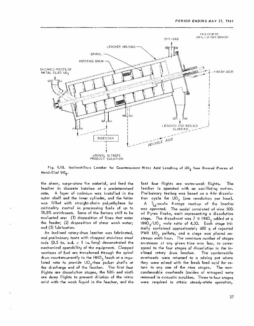
P E R I O D E N D I N G M A Y 31, 1967
UNCL ASSlill-ID O R N L - L R - D W G 38945R
OFF-GAS A
LEACHER HOUSING
ROT4TING DRl i
SHEARED PIECES OF METAL CLAD UO2
/ _- .-
I 7
URANYL N l l -RATE PRODUCT SOLUTION
Fig. 1.13. Inclined-Drum Leacher for Countercurrent Nitric Acid Leaching of U02 from Sheared Pieces o f
Metal-Clad U02,
the shear, surge-store the material, and feed the leacher in discrete batches at a predetermined rate. A layer of cadmium was installed i n the outer shell and the inner cylinder, and the latter was f i l led with straight-chain polyethylene for cr i t ical i ty control i n processing fuels of up to 10.8% enrichment. Some of the factors s t i l l to Le evaluated are: (1) disposition of fines that enter the feeder; (2) disposition of shear wash water; and (3) lubrication.
An inclined rotary-drum leacher was fabricated, and preliminary tests with chopped stainless steel rods (0,s in, 0.d. x 1 in. long) demonstrated the mechanical operabi l ity of the equipment. Chopped sections of fuel are transferred through the spiral drum countercurrently t o the HNQ, leach at a regu- lated rate to provide UQ,-free jacket shells at the discharge end of the leacher. The f i rst four fl ights are dissolution stages, the fifth and sixth are dump fl ights to prevent dilution of the ni t r ic acid with the wash l iquid in the leacher, and the
last four fl ights are water-wash flights. The leacher i s operated with an oscil lating motion. Preliminary testing was based on a 4-hr dissolu- t ion cycle for UQ, (one revolution per hour).
1/16-~cule 4stage niockup of the leacher was operated. The model consisted of nine 500- ml Pyrex flasks, each representing a dissolution stage. The dissolvent was 7 ,VI HNO, added at a HNO,/UO, mote ratio of 4.33. Each stage ini- t ia l ly contained approximately 100 g of rejected PWR UQ, pellets, and a stage was placed on- stream each hour. The maximum number of stages on-stream at any given time was bur, t o corre- spond to the four stages of dissolution in the in-
rotary drum leacher. The condensable overheads were returned to a mixing pot where they were mixed with the fresh feed acid for re- turn to any one of the nine stages. The non- condensable overheads (oxides of nitrogen) were removed in acoustic scrubber. Three to four stages were required to attain steady-state operation,
A
27

C H E M I C A L T E C H N O L O G Y D i Y l S l O N P R O G R E S S R E P O R T
-.I._.-. ~ ............. ___ . . _. . . . . . .
&en the uranium concantration varied from 500 to 300 g/liter m d the acidi ty from 3,3 to 1.2 11. The carnposi;c product uranium concenttation and acidi ty were 419 g/liter and 2.3 '$1, respectively.
TR- :nstantaneous dissolut ion rates of the UO, pel!sts in the g lass model i n boi l ing 2 to 8 \I HNO,-O M uranium, and 0.5 to 2.5 M lENO,-2 M
urailiuin (Fig. 1.14) WCPC correlcstod by i l ~ equa- t ion
where R i s ii-i m i l l i g r a n ~ s pcr square centimeter pcr m i w t r 2 based on the supe'ficial surface area of the cyl indr ical pellcts. The data apply only to thew specific pcllcts. These rneasuramcnts extcx-4 the rate data into the rsgion of high UTC-
nium-low c c i d concentration, a coi idit ion inipor- tant for stage coui i terwrrent di s s o l ~ f i o n such as +- #nut in the :nclii-ied ~ o t ~ ~ > - d ~ ~ ~ l e c ~ ~ l a ~ i ,
UNCLASSIFIED O R N L - L R - D W G 6 0 2 5 1
0 2 4 6 8
HNO, CONCEN i r ? A l ION ( M )
t l g . 1.14, Instantancous Flsso1a:ion Rates ob !JQq
PeBEcts in Boiling Aqueous N i t r ic Ac!d-U-onyl Nitrate Solutions. P e \ \ & r 0.37 in. long. 0,37 in . 410, 10.1 q/cc d e n s i t y . E q u n t i o n of curves: log R = [-0.276 + 0.183 (M U)] -t L0.184 + 0.0625 [iW Ul21 (M H').
Lng i iez+ i ng efforts warp devoted to cr i t i ca l i t y studies and to modification of the I i i ~ r f i i Fue i l i t y i n ce l l 1 of Blds. 4507 for anioii exchange proc- essing of plutonium-aluminum alloy Fuel. Bc- cause of rccer t 4EC decisions that future p i lo t plan:ing of fuel recovery pros.-sses w i l l bp done a t the ICPP under a co-sprnt:ce ,-fiort taetwecn ORNk and Phi l l ips Petroleum Company, select ion of processes to be p i l o t -p lnn td circ being em-
Crib.i t a I i t y Srudi 5 5
s ider5-l i ~ ~ i n t I y.
Annula: vessels that w i l l use f i vcd poiarans far nisclcnr s&-iy control weie upproved and are being fabricated fur p i l o t plcant use. A:: annular conta;ne: for shipping (J233 solutions wos ap- proved, fabricated, tesfed, and placed i i i service. A tank pacLwl with Pyre; glass Raschig rings for storege o f (J2,, solut ion WQS approved and i s beil ly insrallcd.
O ~ U I C V U233 shipping c l ~ n ~ u i r a e r can be used to tser ;sv~~t up to 125 l i ters of u~~~ s o ~ p t ion at ci uranium concentration $ 1 ~ to 225 g/liter. It i s shielded with 8 in. of concrete os protection C E G ~ p n n a radiation from the d r jgh te i s of thc u232 present. I h e vrsisel i s fcjbiicntc3.d of 1.9- in.-thick stainless steel, and the 175-lite: c y l i n -
dr-ical void i s f i l l ed Xvith pa~&ii i , The outer surfaces are covered tvith (P 30-mil-thick she-' of cadmium, which C O L ~ S C S the ~ e s s e l to simulate the necrtam mult ipl icat ion pso;erties of a slab tliut i s only nominally ref lected cnd cannot sustain a nucl,-or icazt ion because o f large neutron Icak- age. :e rnbwiwrv has B very high cross section for thermal ne~irc.::s and a low C i i ) L S section fcir fast neutm.is, it prohibits the return o f fast nc .~- trons born in t h e !issi!e solution, which escape the vessel and me mndemted in either the outer conc:ste shield or the paiaffin careo A neutron mult ipl icat ion test performed whi le the conteiner v m s bcing f i l l ed with 125 l i ters of U 2 3 3 solut isn containing 225 g oC ( J 2 3 3 per l i ter sho;.;-d a mmxi- mum source mnerltiplicrition of no mewe than 5, which indicetes that the sffect ive mult ipl icat iori constant was no rime than -0.8.
A glass-Roschig-ring-iackeJ tank i s being in- stal led i n cel! 3 of Rldg. 3019 for storage a/ up to 6Q kg of U233 as a solution af 100 to 200 3 of L J 2 3 3 per liter. The storage tank i s a 3-ft-dia 260-gal tank packed with 1.5-in, Pyrex Raschig
The
-.
28

P E R I O D E N D I N G M A Y 3 1 , 1961
rings to a glass volume of -20%. The problems of glass corrosion, precipitation of U233, radiation damage, radiolytic hydrogen generation, breaking and settling of rings, leaks, external radiation, and mixing were considered in the design of the tank. A neutron multiplication measurement with U233 solution w i l l be made in the tank before it i s placed in service.
Plutonium-Aluminum Al loy Fuel Processing
The recovery of highly irradiated plutonium from plutonium-aluminum alloy for use in plutonium cross-section studies i s planned in cel l 1, Uldg.
4507, starting in July 1961. The dissolver and process equipment originally installed for the i ntermedi ate-scal e head-end solvent extraction faci l i ty w i l l be used. Two cycles of anion ex- change with Permutit SK resin have been added for the actual separation of the plutonium i n order to achieve a greater decontamination and higher product cancentration than with the single solvent extraction cycle. Additional instrumentation, a product-loading glove box, sample-handling facil- ities, and a shielded dissolver slug chute pedestal have also been added, and a special 10-ton fuel- rod shipping cask has been fabricated.
29

C H E M I C A L T E C H N O L O G Y D I Y I S r " 0 N P R O G R E S S R E P O R T __ I- ........ ...I__
2.1 P R O C E S S I N G OF URANIUM-Z IRCONIUM A L L Q Y F U E L
Modif icat ions' fa the Vo la t i l i t y P i l o t Plant re- quired for processing uronium-zirconium al loy fuel elements were completed. Modif icat ions now i n progress to m e e t containment requirements consist of bui lding changes to permit the required air f l o w and pressure controls, and instal lat ion o f a MOH scrubbing system for a l l off-gas. The Gionnini data logging system was instal led for continuous
'
-*
'Chern. Tech. Ann. P r o p . Rept. Aug. 31. 1960, O R N L - ~ W ~ , p 68.
FLUOR1 N A T O R
U N C L A S S I F I E D O R N L - L R - 2 W G 552360
monitoring of 95 electr ical and 24 pneumat;c process signals. Paper tape o u t p u t w i l l be proc- essed routinely by the Oracle for c a n ~ e r s i o n of the signals to "engineering unitsi" print-up and curve platt ing of the data, and storage of duto an magnetic tape for subsequent calculations. ./.
The basic fluoride vo la t i l i t y Flowsheet (Fig. 2.1) involves dissolut ion of fuel elements in molten NcrF-Li F-ZrF, (37.5-37.5-25,O mole X) by HF, f luorination of IJF, to UF, w i t h F,, further puri f icat ion by absorption on and desorption from an NoF bed, and reeovery o f UF, in a cold trap. Processing condit ions tentat ively f ixed C I S CI r e s u l t
Fig. 2.1. Schernatlc Diagram of Volatillty PiPot Piant.
30

P E R I Q O E N D I N G M A Y 31, 7961
of experimental runs are: (a) dissolution tempero- ture -50°C above the salt melting point ( in mosf cases temperature in i t ia l ly 650°C and gradually decreased to 500°C as dissolution proceeds), (b) HF flow rate of 150 g/min, (c) the use of a movable-bed absorber rather than the fixed-bed absorbers, which w i l l be available for emergency use, and (d) the use of a small product receiver to recover for sampling the UF, from each in- dividual run followed by transfer of product from several runs to the larger shipping cylinder. The fluorine flow rate i s s t i l l being studied.
The f i rst seven development runs (T-1 to 7, Table 2.1) were partial flowsheet runs i n which dummy Zircaloy-2 fuel elements were dissolved to determine the operability of the dissolution system. A major operating di f f icul ty was plugging of the dissolver off-gas valves by 0.01- to 2-p particles formed in the dissolver during dissolu- tion. The particles appeared to be 25 to 40% salt, the remainder being metallics, principally iron, tin, chromium, nickel, and molybdenum. The
average concentration i n the off-gas during a dissolution was about 1 9/m3. Fi l t rat ion with copper mesh, which provided a large amount of impingement surface, was the mast successful method tried for removing the particles; it was 85 to 92% efficient as the dust loading increased from 0 to 18.0 Ib/ft3. Filtration by porous metal and separation by a 2.5-in.-ID cyclone were even less satisfactory. A system for continuous washing of the off-gas l ine w i t h l iquid HF i s being designed.
The first seven of a series of complete flow- sheet demonstration runs (TU-1 to TU-7) with non- irradiated fully enriched zirconium-uranium alloy fuel elements were completed. A total of 3579 g of uranium was processed, 2849 g of which was sent to Y-12 Product Processing. Approximately 531 g of uranium was retained in recoverable form (samples, absorbed on NaF, cylinder heels). System holdup was determined to be 200 i: 100 g. Fuel dissolution rates were >3.5 kg/hr with an
Table 2.1. Summary o f Dissolut ion Runs
Euns T-1 through T-7: dummy Zircaloy-2 fuel, "30 k g per element
Runs TU-1 through TU-7: nonirradiated fu l ly enriched zirconiumuranium al loy fuel, "1% U, "40 k g of fuel per run
Molten salt: 37.5-37.5-25.0 m o l e % NaF-L iF-ZrF4
Salt Temp. Salt Recovery Avg. Dissolut ion ~ i ~ ~ * Avg. HF Avg. HF
(%I F l a w Rate Ut i l izat ion' (hr) Run No. (" C) Rate'
Max. Min. (ks/hr) (g/min) (
T- 1 560 520 0.84 32.1 104 13.5 105.5 T- 2 530 525 0.69 34.6 40 28.9 97.0
T-4 630 495 1.45 18.5 90 26.9 101.8
T-6 650 50 0 1.20 22.0 150 13.4 99.0
T-3 625 550 1.46 20.2 90 27.0 102.6
T-5 625 5 30 1.21 22.5 90 22.4 100.1
T-7** 655 523 2.77 19.0 135 34.4 100.0
TU- l * * 670 490 2.46 18.2 92 44.5 100.5 TU-2** 650 500 2.82 15.5 125 37.3 102.4 T U - 3 * * 655 495 3.22 12.3 150 35.8 98.0 TU-4** 650 555 3.34 7.6 1 50 33.4 100.1 TU-5 650 500 2.50 15.7 150 24.5 98.1 T I.!- 6 650 500 1.89 18.8 121 22.8 92.8 TU-7 650 500 3.68 10.8 150 35.7 106.7
___I
*Based on 90% completion of dissolution. * *Two- el ement d i sso I u tion s.
31

....._I______ ...... _____ .... __ ....... ......
LSZ ? l> Z 9 01 > OZZ l> 2 8 l> i '9-ni
ESZ ? l> P P 01 > 12 l> 9 OlZ 1 v-n L
P8 ? l> l> P 01 > 19 l> l? P l> s-n 1
8CL > l> P PZ 009 Ll 2> S PL l> E31
569 > l> 1 L? 009 69 Z> I> Ll l> Z-Cll
LZPL > l? 2 E OOEL 001 t> Z 01 l> i -n1
z "PZ 1 'V 09 '09 91 '9 Z'P LOZ'Z L-nl 90'0 L66'0 98
PO'O L.61'0 9s
SO'O 9EZ'O E9
91'0 900'1 66 Z'LL 6 '8 rr09 'SL ++ZL 'V 9's 811's P-nl
E'LL n -s SZ '09 91 '9 6'0 ~99'2 9-1-11
V'91 1 '9 DE 'G9 91 'P 0-1 SR'L S-nL
l&'O SE6.1 SL Z'LL 6'8 SOL 6 1.6 EOOT E-ni
8Z'O LZZ'l SI; 9'8 L'll os 1 9 8'E OPO'Z Z-n1
LO'O S.LE.0 LL 9'0Z 6 'P os 1 El Z'L OF8'Z 1-i'l. .... __ ..... ...... ~_-_I_.____I.__ ~I____.--------...--
..... . ...... __... . .- ..... __ .... __ .._........_I _I ......
.___ I-

,
P E R l O D ENDING M A Y 31, 1961
Engineering-scale studies on sorption of UF, from a flowing UF -N stream by Q deep fixed
rate i s controlled by the diffusion of UF, through the solid phase and through the film, and by the rate of heat transfer between the solid and the gas stream. The importance of each process depended on flow rate, gas concentration, and in i t ia l solid temperature. Calculated f i l m coeffi- cients for mass transfer of UF, are q.0.05 cm/sec and for solid phase diffusivities, ,-,, IO-’ cm2/sec. A monitoring system for continuously determining the UF, concentration i n the range 100 ppm to 20 inole % in a UF,-N, mixture, which uses a Thermistor cel l to sense effects due to the change in density of sample gas w i th change in UF, concentration, showed a response time of r: 10 sec. One of the fission product fluorides that is volati l ized at fluorinator temperatures i s MoF,; the reactions of MoF, w i t h the NaF absorber were studied to determine i ts effectiveness in removing MoF, from the UF, stream. Laboratory-scale measurements of the dissociation pressure of the MoF,.xNaF complex ind icated that molybdenum contamination in the product UF, can be minimized by proper choice of UF, absorption temperature and fluorine flow rate. As w i t h the UF,-3NaF complex, the classical relation between dissocia- tion pressure and temperature exists over a wide range in the NaF/MoF6 ratio:
bed of granular NQF 6 ? indicated that the removal
log p , , Hg 7 10.21 - 3630/T°K
The MoF6.xNaF complex i s colorless in contrast to the yellow UF,-NaF complex; they are alike i n being stable to 0, and N, but not to H,O, which causes hydrolysis of the molybdenum corn- plex. Complex dissociation pressures determined by a static bomb method over approximately a 10O*C temperature range were reproducible gen- erally to 55% (Fig. 2.2), observed variations being attributed to temperature variations and the impurities WF, and HF. Dissociation pressure apparently did not depend on the complex compo- sition (Table 2.4). The only low values, obtained at a NaF/MoF, mole ratio of 248/1, are attributed to the use of only 0.002 mole % MoF, i n a total volume of about 60 nil .
Corrosion rates i n the Inor-8 dissolver were somewhat encouraging. During the 14 nonradio- active dissolution runs (Table 2.1) with total sa l t and HF exposure times of 765 and 404 hr,
Fig. 2.2. Dependence of MoF6-NaF Dissociatlon
Comparison with Dissocia- Pressure on Temperature: tion Pressure of UF6.3NaF Complex.
Table 2.4, Dissociation Pressures at Various NaF/MoF6 Ratios
- Pressure (rnm Hg at 25OC)
--.- N aF/Mo F , Mole Rat io At At A t At
135OC 172OC 197°C 22OoC --_ 5.40 20.2 114 317 725
5.52 110
8.21 23.0 111 313 717
16.3 19.6 119 3 25 729
18.2 115 311 69 1 31.6
248 12.2 73
33

CNEMJCAb T E C H N O L O G Y D I V I S I O N PROGRESS R E P O R T _-._ ._.__I_ ... ..---I.
respectively, the nwximiim decrease i n metal thickness based on ultrasonic measurements w a s 25 mils, for n rate loss of 0.06 mi l per hour of HF exposure oi 24 m i l s per month of snlt-MF residence time. Ultrasonic ineosurements showed only bulk metal losses as opposed to intergranular corrosion or small pits. Howeverp complete gamma radiography and s a m e repl icat ion with dental wax indicated no signi f icant pitting.
Fluorinator corrosion rates were higher than those experienced in the dissolver. Fluor ine exposure during preliminary tests and the seven runs with nonirradiated uranium i n the melt (Table 2.2) W Q S 20.3 hr wi th 694 hr exposure to salt. Ultrasonic thickness measurements indicated - 1 mil/hr corrosion based on F, exposure and 20 to 25 rnils/month based on exposure to salt-F, conditions. However, a l i f e of h, 115 runs i s predicted for both vessels since the f luorination runs require only -1.5 hr exposure to F, as com- pared to -18 hr of HF exposure per run i n the dissolver.
Data from 20 engineering-scale dissolut ions of Zircaloy-2 in HF and fused sal t were correlated by
T - k(V/l.0)-1’3 In (1.1’/0.40)
where
T - dissolut ion rate, Ib hr- ’ f t -2
k = rate constant, Ib hr-’ f tm2
V - kinematic viscosity, f t /hr 2
v/l.O = dimensionless kinematic viscosity, which includes temperature and ZrF, concentration dependences
u’ = HF flow rate, Ib/hr
M’/0.40 = dimensionless HF rate
The value of k was 0.04345 for salt with a Na/h..i rat io of 43/57 and ZrF, concentration f r o m 0 to 43 mole %, w i t h temperature from 535 t o 810°C and WF rates from 1 to 5.8 Ib/hr. The term W/0.40 represents the HF rote corrected for a speci f ic geometrical arrangement of vessel and fuel ele- ment.
2.2 A P P L I C A T I O N T O STAINLESS S T E E L - CONTAINING FUELS
Dissolut ion of stainless steel-clad fuels w i t h HF i n fused fluoride salts fol lowed by volat i l izo- t ion of UF, i s feasible as a means of processing stainless steel-clad fuels. A process flowsheet
based on InbOrQtOiy data has been suggested for use in the Vo la t i l i t y P i l o t Plant w i th the EBR-I Core 2 rrieltdown fuel, 88% U--2% Zr-1076 type 347 stainless steel p lus iron container material. This flowsheet uses the high dissolut ion rate i n 37- 52-1 1 mole % I..iF-NaF-ZrF4 with subsequent nddi- tirrn of ZrF, to briny: the composition t o 26-37-34-3 mole % LiF-NaF-ZrF,-U~-~,, a cornposition favor- able for f luorination a t 500°C and with an adequate so lub i l i t y for the stainless steel fluorides. Small- scale tests of th is flowsheet were completely successful, including good wranium recovery. The corrosion rute for Inor-8 (the material of construc- t i on currently favored for the dissolut ion vessel) ranged fiom 0.084 mil/hr for the in i t ia l compnsi- t ion to 0.005 mil/hr for the latter.
The dissolut ion rate of type 317 stainless steel coupons was -0.5 mg C I I I - ’ ~ inin-’ at 650°C in 60-40 mole % NaF-ZrF,, i n which the solubi l i t ies of NiF, and FeF, are high. In 25-37-37 inole 70 LiF-NaF-ZrF,, a sal t from which uranium can he removed by f luorination a t 500°C, the rate of d issolut ion was 0.24 mg cm-2 min- l . T h i s composition of sa l t for inany reasons i s the hest for pI‘OCe55 use Q f a l l compositions tested (Tabie 2.5). The solubi l i t ies of stainless steel f luorides i n 26-37-37 male 7% LiF-NaF-ZrF, were observed to be suitable (Table 2.6). F l inak sa l t (LiF- NaF-KF) has a comparable solubi l i ty for stainless steel f luorides but ZrF, must be added to 30 mole % to al low recovery of the uranium by Qluori- nation.
Table 2.5. Dissolution Rates of T y p e 347 Stainless
Steel i n Fused FJu0pids.s by Hydrcfluorinmtian -____ __
Salt Composi rion Tcrnp. Dissolut ion R o t e
(mole %) ( “c) (mg cm mine ’ ) - 2 .. . . . . .- .....___I_-
60 NaF-40 ZrF, 600 0.38 6 50 0.55 706 1.1
37 LiF-52 NaF-’I1 ZrF, 650 1.7-2.1
26 LiF-37 NaF-37 ZrF4 500 0.24 60 0 0.67
50 KF-50 ZrF4 6 50 2.0-2.2
60 KF-40 ZrFq 650 0.89- 1.0
46 LiF-11.5 NaF-42 K F 550 9.7 600 8.5 650 5.5
-._-
34

P E R I O D E N D I N G M A Y 31, 7961
Data for dissolution of various oxides, such as those contained in stainless steel-clad oxide fuels, in fused salt (Table 2.7) together w i t h previously pu bl i shed metal I i c dissolution results indicate that the fused salt volat i l i ty process i s generally applicable to heterogeneous fuel, The possibil i ty of recovering uranium from oxide fuels prompted corrosion studies of fused salt-HF- oxides (and water vapor) systems. Results of one laboratory test at BM12 i n which Be0 was hydro- fluorinated i n 45.6-54.4 mole % ZrF,-NaF indi- cated that at 570°C corrosion i s no worse than
2F. W. Fink, BMI, let ter to R. P. Milford, April 19, I96 1.
during the hydrafluorination of zirconium in 43-57 mole % NaF-LiF at 708°C. Corrosion rates i n the B e 0 case ranged from 0.1 rniI/month in the l iquid phase away from the HF sparge tube to 5 mi ls / month at the vapor-liquid interface.
2.3 A P P L I C A T I O N OF F U S E D S A L T SYSTEMS T O Pu R E C O V E R Y
The in i t ia l plutonium work was conducted at the low level of 2 ppni plutonium to explore the effect of temperature, salt composition, and F, flow rate before proceeding to a higher concentra- tion. The results indicate that PuF6 volati l ization i s a first-order reaction under the conditions used
Table 2.6. Solubi l i t ies of Mixed Fluorides of FeF2, N iF r and CrF2 i n 26-37-37 mole 76 LiF-NaF*ZrF4
FeF2, NiF2 , and CrF added successively in the proportions found in stuinless steel 347, 2 and samples of f i l tered s a l t taken after each addition
Concentration (wt %) Sampling Tenip.
-._I_ Cr ~
Fe N i (O C)
Addition
Cnlc. Obs. Cal c. Obs. Calc. Obs. x_
1 600 3.8 3.5 0.37 0.48 0.63 0.59
2 600 5.6 3.9 0.54 0.46 0.86 0.73
3 600 7.4 4.6 0.71 0.45 1.09 0.84
500 7.4 3.0 0.71 0.49 1.09 1.05
Table 2.7. Dissolut ion of Oxides by Hydrofluorination in F u s e d Salt
Material * Salt (mole %) Temp. Dissolut ion Rates
(mg cm -2 min-') (O C ) - - __ - - - -
ZrOl 31 L iF -24 NuF-45 ZrF4 650 1.1, 1.4
36% U02-64% Zr02 31 L i F - 2 4 Nof-45 ZrF4 650 1.0, 1.2
"02 31 L iF -24 NaF-45 ZrF4 650 11.5
Be0 49 NaF-40 L i F - 1 1 BeF2 60 0 0.60, 0.56, 0.62
Tho2 4 (Apparently much faster in 31 L iF -24 NaF-45 ZrF
4; than in any o f above due to metathesis wi th ZrF speci f ic ra tes d i f f icu l t to determine)
*A l l materials high-fired.
35

I
62.1 0 98'0
€bo x
09
OB
00 I

P E R I O D E N W l N G M A Y 31, 1 9 6 1
3. MOLTEN SALT REACTOR FUEL
* Uranium i s recovered from the Molten Salt r Reactor fuel and blanket sal ts by the fluoride
vo la t i l i t y process (Chap. 2), the UF, being fluo- r inated to UF, which volat i l izes and is collected. The fuel carrier salt, Li7F-BeF,, i s decontami- nated by dissolut ion i n 90% HF-10% water.
3.1 FLLdORlNATlON
\- In four runs in a laboratory-scale steady-state
fluorinator uranium was 97 t o 98% recovered from synthetic MSR fuel by 40 min f luorination at 650°C. Corrosion of the nickel container was severe. The fluorinator, which contained about 70 nil o f salt, was a 1-in.-dia n icke l tube; sal t overflowed thraugh a k- in.-dia tube into a jackleg from which samples were taken.
Two signif icant experimental runs were made with LiF-NaF-ZrF, (26-37-37 mole %) containing 1 wt % UF, i n one case and 0.2 wt % in the other. In the f i rst case f luorination near 7GOOC with ex- cess f luorine and an average sal t residence t ime in the fluorinator of about 40 min lef t 100 to 200 ppm of uranium in the spent salt, 1 t o 2% of the original concentration. In the other experiment, w i th a temperature of 600 to 65OoC, the uranium content of the overflow sal t was 25 to 50 ppm, also 1 to 2% of the feed concentration. Preferred condit ions would include a lower temperature, about 55OoC or less, and a shorter sal t residence t i m e . Corrosion rates based on nickel concentra- t ions were of the order o f 1 mi l /hr a t 700OC and 8.1 to 0.2 mil/hr a t 600°C.
3.2 C A R R I E R SALT R E C O V E R Y
Dissolut ion rates of re lat ively large pieces of sol id i f ied 63-37 mole % LiF-BeF, in stirred, boi l ing 90% HF-10% H,O were suff ic ient ly rapid t o el iminate the necessity of preliminary atorni- zation of fused sal t t o produce sol ids of high
'A. F. Clifford and S. Kongpricha, J. Inorg. C Nuclear Chem. 5, 76 (1957).
surface area, In two experiments the rate was -50 mils/hr in the f i rst 10 min, decreasing to <IO mils,% after 1 hr because of a layer of soft solids, probably BeF,, lef t on the surface. When the salt specimen wa5 vigorously agitated w i th a magnetic stirrer it dissolved very rapidly, -200 mils/hr, as the weakly adherent surface layer was mechani- ca l l y removed. The sal t samples dissolved were capsule shaped, 270 to 290 mils dia by about 7 mi ls long, prepared by casting i n a spl i t graphite mold.
The solvent SbF,-HF for carrier sal t wos inves- t igated on the basis of data showing that rare earth fluorides are soluble in these solutions, SbF, being the strongest ac id in the hydrogen fluoride solvent system i f an acid i s defined as a substance that increases the concentration o f the solvated cation of the solvent (H,F+ in th is case).' In i n i t i a l tests HF containing about 20% SbF, re- acted with both L iF and rare earth fluorides, as indicated by heat evolution. The compound formed w i th L iF was not very soluble, but that formed w i th rare earth fluorides w 0 s very soluble. There was no apparent interaction or solubi l i ty with ThF,.
The sol id formed by adding l iquid SbF, to an HF solut ion of k i F was not stoichiometric, the Li/Sb mole rat io typ ica l l y being around 1.4, but was re- crystal l ized from anhydrous MF to y ie ld the 1:l LiF-SbF, with a chemical analysis of 50.4% Sb, 2.67% Li, and 46.5% F and a Li/Sb mole rat io of 0.93 and F/(Li + 5Sb) rat io o f 0.99. The compound gave a good x-ray dif fract ion pattern, showing monoclinic symmetry, w i th the cel l dimensions
a = 5.42 A b = 5.18 A
c = 7,5O A fi = 93.6'
Systematic ext inct ion indicated the space group Cs3-lm. The pattern persisted as the hygroscopic sol id absorbed water unt i l it was almost com- pletely in solution. The compound was somewhat soluble in HF, 0.23 mole (1.6 CJ) o f l i thium per
37

CHEMICAL T E C H N O L O G Y D I V I S I O N P R O G R E S S R E P O R T ____... --. ... -,.
l i ter a t the boi l ing point and l e s s a t lower tem- peratures, but was quite soluble in wnter. Struc- tures for the analogous TI, Ni-C,, Rb, and CS compounds2 and for NaSbF, and NoSb(QH)6(ref 3) have bean published, but soiiie of these may have contained water. The corresponding KF-SbF', compound was prepared to complete the a lka l i rrtetal series, nnd the AgF-SbF, compound was prepared. Crystal structures of t h e s ~ new com- pounds are being determined.
The LiSbF, compound decomposed on being heated from 400 to 650°& i n an inerf atmosphere i n nickel or copper containers, as indicated by the appearance Q f a whi te smoke when the vapor con- tacted moist air. The vo la t i le material was SbF,, indicating a reaction of LiSbF, w i th the container to form SbF, and NiF, or CUE,. Decomposition occurred a t lower temperatures in copper than i n
2N. Schrewe l ius , A r k i v Kemi, Mineral. Geol . 168,
,N. S c h r e w e l i u s , 2. anorg. 11. allgem. Chern. 238, 241 No. T (1943).
( 1 9 38).
nickel, that in nickel being incomplete at tempera- turcs as high o s 700OC.
Attempts to prepare the I-iF.ShF, compound by reaction of sol id L i F w i th SbF, vapor were un- successful. The SbF, was carried by argon gas that bubbled through l iqu id SbF, at temperntures between 2.5 and 60°C to the I-iF powder spread i n an lnconel or n ickel boat in a tube held at or above 10OOC. The metal surfaces became coated with a viscous l iqu id layer.
compound could nat be purif ied by recrystal l izat ion since i t was very soluble, 200 to 300 g of r w e earth per liter. The sol id obtained by evaporation or cooling of the saturated solut ion was a very-f ine-part icle material associated w i th a quanti ty of the solution.
Since SbF,-HF solutions dissolve rare earth fluorides but not ThF,, the possibi l i ty that th is reagent could decontaminate ThF, from MSDR blanket s a l t was investigated. T h e LiF was leclched from a sal t spiked w i th Cs, Ce, and Pm act iv i t ies w i th 95% HF-5?5 water, r insed w i th HF, and then l rached twice w i th 5 vol 5% SbF, i n HF. The ThF, was not s igni f icant ly decontaminated from rare enr th5 .
The rare earth fluoride-SbF5
_I___ ..... ___._______ .... -
T h c program for development of processing systems for aqueous homogeneous reactor fuel was terminated when operation of the IiRT was sus- pendcd May 1. Evaluation of thc performance of hydroclone systems throughout the fuel processing program' indicates that a rnulticlone unit operating a t undcdlow rates >!E should remove circulat ing sol id corrosion products from the H R T as rapidly as they are formed. The niulticlones with several t imes a s many paral lel hydroclones needed for large renctors presumably could kc? operated w i th high eff iciencies. However, an underflow stream
' D e t a i l s a r e reported i n M R ? p r o g r e s s reports, e.g. for M e y 31, 1961, ORNL-3167.
of many gal lons per minute would have t o be pro- cessed, which might require individual hydroclones and underflow receivers. The disndvantages of such a complex system rnight outweigh the advnn- tages, Since circulat ing solids, and th2rebie neutron poisons, remain low in any case as a re- sult of deposition on reactor surfaces, descalifiy of heat Zxchangess on a very infrequent schedu!e might be more economical than c o n t i n ~ ~ o u s high- rate hydroclone processing.
4 . 1 M U L T R C L O N E sysrEM STUDIES
With a tnulticlone system of th;i:een 0.6- in.dia units on a 1 0 - m i n cycle in the H R T , sol ids viere removed a t a rate of 1 g/hr i n u 1000-hr run, but
38

PERIOD ENDING M A Y 37, 7961
change in the rat io when one or more ports in the uni t become plugged. This was necessitated by plugging o f the feed ports in the original 13-unit mult iclone after about 1000 Rr operation, which drast ical ly lowered the ef f ic iency but was not detected unt i l after removal o f the uni t from the cel l .
4.2 F U E L P R O C E S S I N G B Y URANYL P E R O X l D E P R E C I P I T A T I O N
a t normal corrosion rates of 0.5 mpy for stainless steel surfaces and 10 mpy for the Zircaloy core tank, sol ids are produced at a rate of 1.5 g/hr (ref 2). In a new system with eighteen 0.4-in.-dia units and the fu l l head (90 ft) of the reactor circu- lat ing pump used across the system instead of only 42 ft as i n the first, the sol ids col lect ion rate was improved. Removal rates in the f i rs t 50 hr o f individual reactor runs were about 1.5 g h r . How- ever, in an attempt to further improve the efficiency, the system had been instal led for induced-underflow operation, and th is resulted i n the rates dropping after a few hundred hours to an apparent equilibrium value of 0.3 g h r . In a total of 2100 hr operation (reactor runs 22 through 24) removal rates averaged less than 0.5 g h r , and general performance was comparable to that wi th a single hydroclone. The overal l ef f ic iency o f 4% for the 1-p part icles in the reactor i s consistent w i th ef f ic iencies measured in cold water tests wi th Tho, slurr ies of 1.1 to 1.6 p mean part ic le s i re. These ranged from an expected 65% at 10% underflow, not induced, down to only 10% at 20% induced underflow. Results w i th other paral lel units were similar. The ap- parent induced underflow rate for the HRT unit was 3.5%, compared w i th an expected value of 1.3% for Q single hydroclone, and for other units the underflow rate varied from 2.5 t o 5 times the value for single hydroclones of the same dimen- sions. In previous work a t h igh underflow rates, hydro-
clone eff iciency was not impaired by operation of several in paral lel on a single underflow receiver, provided the individual hydroclones were matched, und a t high underflow rates, the ef f ic iency of the larger paral lel units was identical t o that of a single hydroclone. However, although the 18 in- d iv idual hydroclones had been fabricated with port tolerances of +0.0005 in. to ensure proper matching, the eff iciencies dropped drast ical ly as underflow rates were decreased.
A method of monitoring the performance o f a mult iple hydroclone for changes in operating char- acter ist ics was devised, based on the constancy of the rat io o f the difference between feed and underflow pressures to feed and overflow pressures over wide ranges of f low rates and the signif icant
2Chern. Tecb. ORNL-2993,
Ann. Progr. Rept . Aug. 1960,
The nickel concentration in reactor fuel solu- t ions must be l imi ted to about 500 ppm t o ensure fuel chemical stabi l i ty, which for Q large power station, wi th several kilograms o f uranium in the fuel, would necessitate dai ly processing. Of several possible methods of removing nickel, peroxide precipitat ion o f the uranium appears most promising because no foreign materials other than peroxide are added. Uranyl peroxide i s soluble to the extent o f 3 g of uranium per l i te r a t 10 to 25°C. Laboratory and ful l -scale tests w i th nonirradiated fuel solutions indicated that it should be possible to process 4 kg of uranium on a 1- or 2-day sched- u le w i th uranium losses as low CIS 2% and a decon- tamination factor from soluble components of at least 100.
In laboratory studies wi th simulated WRT fuel containing normal concentrations of uranium, cop- per, nickel, sulfate and excess acid, the optimum technique was slow addit ion of 4-fold excess hydrogen peroxide to the top of the solution, wi th agitation. Decontamination factors were >10 with l i t t l e or no washing, and uranium recoveries were consistently 95% or better. The peroxide preci- p i tate was held sat isfactor i ly on a gloss f i l te r of 10 t o 15 p nominal pore size, but not on nominal 3-p sintered stainless steel except when 10 g o f diatomaceous earth per l i ter of solut ion was in- cluded. With a solut ion uranium concentration of 75 g/liter the f i l t rat ion characterist ics of the pre- c ip i tate were considerably better than with 150 g/l iter.
I n three engineering-scale runs in a h-in.-dia 20-ft-high precipitator column wi th 4-kg batches of simulated HRT fuel, uranium losses were 6% without r insing the precipitate and 3% with rinsing. Recycl ing the i n i t i a l port ion of the filtrate, which always contained high uranium concentrations, would decrease the losses s t i l l further, Decon- tamination factors were 8 without washing and 100
39

GHEMBCAL T E C H N O L O G Y D / V I S / O N P R O G R E S S R E P O R T
-
with three r inses. Heprecipitat ion of the decon- tarriinated uranium from one run w i th two r inses of the precipitate gave a further decontamination of only 2. L o s s e s were only 0.4%, probably because excess acid had been removed in the in i t ia l pre- c ip i tat ion and the uranyl peroxide was therefore less soluble.
The precipitator colurnii used i n the experiments was equipped w i th external cool ing and heating co i l s and two sintered stoin!ess steel f i l ters. A Z-in.-dia by 3-ft-long cy l indr ica l f i l ter extended up from the column bottom, and contained a 5-in.- dia f la t f i l ter disk, which was used for the f inal 10 t o 20 l i ters.
4.3 R E L A T E D SYSTEMS
C R ~ c w l Off-Chs Adasrber Beds
In order to decrease the potential hazard from a leak i n the off-gas system, which i s located under- ground but uneontained except for the primary piping, the system was operated belaw atmospheric
pressure the past yeas. A vacuum pump controlled the charcoal bed exit pressure at 11 psia, whereas previously it was discharged into the stack a t atmospheric pressure. Because of thp lower pres- sure, which decreased the holdup time for f iss ion gases, three beds were operated i n parallel, in- stead of the normal two w i th one in standby. No d i f f i cu l t ies were noted. Samples of the off-gas
from each bed jridicnted that the signif icant dif- ferences i n holdup t ime for the three beds noted in early tests s t i l l existed, but with no apparent gross changes. L e s s than 0.5 cvrie/dny of Kr85 and Xe133 xwos released.
Off-Gar SampleT
A system for sampling the reactor off-gas vp- stream of the C~CWCQQI beds was devised and used i n the f inal reactor run. Approximately 100 l i ters of off-gas W Q S routed to the vapor space above the chemical plant decay tanks and removed subse- quently via bubbler l ines on the tank level instru- ments. Samples were removed without d i f f i cu l ty after 3 days' decay.
__I_.. ......
5. WASTE TREATMENT AND DESP0SAL
._ I he objective of th is program i s to develop and
demonstrate an integrated process for safe treat- ment and permanent disposal of both low- and h i g h -r a d i o a c t i v i t y - I eve I w a s te s . For I ow -a c f i Y i t y
waste, 2.g. very di lute salt solutions such as cool ing and canal water, treatmen; by a scavenging- ion exchange process to remove radioactive con- st i tuents i s proposed, with discharge of the eff luent to the environment. The retained waste sol ids or slurr ies ccin be combined with high- ac t i v i t y wastes produced i n fuel proces,' 'Ing oper-
' ations, evaporated t o ds-yness, and colc incd to oxide. The feasibi l i ty of adding f luxing materials to the wastes t~ f i x the f iss ion products in a low- solubi l i ty g loss i s nn alternative to calcination. i h e calcined or f ixed sol ids, contained i n the stainless steel cyl inder (pot) i n which they were
'. calcined, could be shipped to an ult imate storage si te such as a mine i n salt or limestone for
-
permanent disposal. Ult imate disposal poss ibi I i t ies are being evclluuted along with storage and shipping
' parameters as part of a genera1 engineering, i economic, and hazards evoluotion of the ~ o i i ~ p l e t e ' waste complex. i-
5.1 M I G H - A C T ! V I T Y WASTE T R E A T M E N T
Pot calcination of synthetic Purex, U G ~ ~ X , and TFSP-25 wastes containing mi l l i cu r ie amounts o f rutheniuril i s being developed on both a laboratory and engineering scale to provide design information for the construction of a p i lo t plant. In the proposed process (Fig. 5.1) the waste is fed to an evaporator together wi th n i t r i c acid or water to maintain the acid concentration i n the evaporator below 6 it!, which minimizes ruthenium vo la t i l i - zation. Evaporation muy be either batch or con- tinuous; a catch tank i s used between the evaporator

P E R i O D ENDING M A Y 31, 1961
U N C L ASS I FI ED 0 R N L- L R - D W C 6 026 5
.
PUR EX W A S I ' E ....... .
40 go1
0.i i?A CORROSION PRODUCTS 0.5 M FISSION PRODUCTS 7500 curies ga l - '
R t i i hr-1 gal- '
GM H N O j
INERT GASES
i M HNO3, 224 go1 -
0 8 M I iNO3, 184 ga l - -
PRODIIC: r (1 2 M H N 0 3 , 2 0 go1
NITROGEN OXIDES
5.EM HN03, 4090 CONDENSER SOLVENT F x rRACTlON
6 M HN03, 40 g a l
sol IDS __ -___
1 5 kg CORROSION PRODIJCT OXIDES (5 kg FISSION PRODUCT OXIDES 304,000 cur ies 2 4 0 0 Btu/hr
I t
TO PERMANENT STORAGE
Fig. 5.1. Converrlon of High-Activity Wastes to Sdids by Pot ta lc lnat ion. Basis: Purex process waste con- taining 1 ton of spent uranium, irradiated to 10,000 Mwd/ton and decayed 3 years.
and calciner in batch operations. Th is continuous flowsheet dif fers from that shown previously' in the recycl ing o f calciner off-gases, containing nitrogen oxides, through the evaporator and con- tinuous addition of d i lute n i t r i c acid to the evaporator. The evaporator concentrates go to an electr ical ly heated pot at essent ia l ly their in i t ia l concentrations, where they are evaporated to dryness and calcined to 900OC. Chemical additives, such as calcium or magnesium salts, and phosphorus
' C h e m . Tech. Ann. Progr. R e p t . Aug. 31, 1960,
2J. J. Perona and M. E . Whatley, Calculution of T~mpera iure R i se in Deeply Buried Rudioartioe Cylinders , ORNL-2812 (Feb. 3, 1960).
ORNL-2993, pp 93-95.
acids may be added prior to calcination i o decrease sulfate and f ission product vo la t i l i t y or t o produce a melt i n the pot after calcination. After being f i l l ed wi th calcined solids, the stainless steel pot w i l l be sealed and used as both the shipping and permanent storage vessel. Abaut 90% of the nitrogen oxides in the calciner off-gas can be absorbed during condensation of water vapor in the evaporator condenser and the remainder i n the rect i f ier ref lux condenser. About 1 ft3 of non- condensable gas per gallon of feed i s anticipated i n relat ively leaktight process equipment; only a small f inal absolute f i l ter and gas cleanup system w i l l be required. Calcination and heat dissipation rates in f inal storage media are satisfactory.'C2
41

CIiEMICAL T E C H N O L O G Y DIV1SlON P R 6 G W E S S R E P O R T
~~~~~g~~~~~~~~~ c i nation
In Inbowtory experiments, synthetic Purex waste (Table k l ) , 40 gal per ton of uranium processed, was evapnrated and calcined to a V O ~ L J ~ ~ of 5.7 gal/ton. The product had a bulk density of 1.32 g/ml, wi th a calculated porosity of 58%- The addit ion of 10% stoichiometric excess sodium and magnesium (1.2 moles of NaOH and 0.2 mole of MgO per l i ter) decreased the sulfate vo la t i l i t y during evaporation t o 0.28-0.776, os cornpored w i th 70% in the absence o f additives. The use o f calcium instead of magnesium was unsatisfactory because of precipitat ion of calcium sulfate i n the feed. N i t r i c oxide gas W G S introduced into the pot during calcination at a rate suff icient to keep the system at atmospheric pressure. The experi- ments were performed in an 18- x cl-in.-dica stainless steel pot in a 9-kw furnace equipped w i th a down- draft condenser, packed absorber column, poly- ethylene expansion bag (to measure net non- condensable gas volume), and gas recirculat ion pump.3 The in i t i a l boi l-off rate i n evaporation was
31bid., Fig. 6.2.
180 ml/min and calcination was to u temperature of 900OC. In three similar experiments wi th in i t ia l boi l-off rates of 125 ml/min, the volume was decreased to 4.0, 4.5, and 4.2 gal per ton o f uranium, respectively, the lower f inal volvnies being at t i ibutsd to the higher boi l-off rate. The NO consumption was 0.39, 0.36, and 0.43 mole per l i ter o f waste. 4 s i n previous experiments w i th NO added t o the system during evaporation- Calcination, the net off-gas production was n i l . Stable ruthenium in the condensate wus 31.8 to 45.8% of that i n die feed in the f i rs t two runs and 19.5 and 17.6% in the last two, the higher values being obtained when NO was introduced into the vapor space of the calciner, and the lower when i t was introduced into the l iquid feed l ine to the calciner. Sulfate in the condensate varied from 0.28 to 0.70% of the original i n the feed and appeased to be caused mainly by entrainment,
The results of eight engineering-scale evapo- rat ion-calcination runs (Table 5.2), i n %in.-dio pots, showed that Purex (with calcium addit ive), Darcx, and TBP-25 wastes can be calcined successful ly at acceptable rates to produce o
product suitable for ult imate storage. Sulfate
Table 5.1. Laboratory-Scale Continuous Evaporation and Pot Calcinot ion of Synqhetic Purex Waste to 9OO0C
In i t ia l waste composition (equivalent to 40 gal per ton of uranium processed): 6.1 M NO3-, 5.6 M H', 1.0 M SO4--, 0.6 M Na', 0.5 M Fez+, 0.1 M AI3+, 0.01 M Cr", 0.01 Ni", 0.002 M R u
Additives:
Calciner pot:
1.2 moles of N a O H and 0.2 mole of MgO per l i ter
1 in. dia 18 in. high ~ ~~ ~~ ~.
Amount (% of or iginal) ...... In i t ia l NO Residue - In Condensate
NO3 in ~ - 1
Residue F ina l Vol Boiloff Rate Sweep Rate Erpt .
No. -- ( g / c c ) Residue SO4 RU (rnl/rnin) (rnoles/liter) (gal/+on "1
...... ............ ................ _ I ~
1 100 0.40 5.7 1.32 Hard brown 0.18 0.28 31.8* solid, calcd. porosity 58%
2 125 0.39 4.0 1.86 Ward, brown 0.18 0.51 4 . 8 * solid, colcd. porosity 41%
3 125 0.36 4.5 1.66 Hard, brown 0.21 0.70 19.5** solid, calcd. porosity 47%
a 125 0.43 4.2 1.78 Hard, brown 0.25 0.56 17.6** solid, calcd. porosity 43%
....... ............ ......... . ___ ~
*NO introduced into vapor space of calciner pot.
**NO introduced into l iquid feed entering calciner pot.
42

P E R I O D ENDlNG M A Y 3 1 , 1961
Table 5.2. Engineering-Scale Evaporation and Pot Calcination of Waste to 90OoC
Initial waste composition (equivalent to 40 gul per ton of uranium processed): 6.1 M NOg-, 5.6 AI Ht, ++ -- 1.0 121 SO4 , 0.6 M Na', 0.5 M Fe , 0.1 M AI3', 0.01 rL1 Cr", 0.01 Nit'
-- -I -
Solid Feed Sulfate in Nitrate in Catciner
R u n Waste Feed Size, in. Bulk Stoichiometric
No. Type Rate - Density Additive Condensate Cake Ratio - .,- Ca++ (70 of feed) ( P P d
s04 ( I /hr) Dia Height (g/cc)
30
31
32
33
37
36
34
35
Purex 16
P wrex 22
Purex 24
Purex 21
Purex 20
Purex 20
Darex 24
TBP-25 30
6 84 1.5
8 a4 1.2
8 a4 2.5
a a4 2.5
8 9 0 1.3
8 90 1.2
a 90 1.1
8 90 0.83
0.6 M NaOH 0.6 M CaO
0.6 M NaOH 0.62 M CaO
1.0 '41 Na2S04 0.5 M NaOH
1.0 M Na2S04 0.5 iM NoOH
1.2 iM NaOH 0.2 M MgO
None
None
None
1.15* 5.0 (0.05 M )
1.15** 12.0 (0.12 Eil)
1.29 3.0 (0.03 M)
1.29 3.0 (0.03 M )
0.9 1 0.2 (0.002 M)
3.34 Not analyzed
300
60
5000
500
Not analyzed
Not onolyzed
30 0
60
-- *1.1 M SO in feed.
**1.5 M SO4 in feed. 4-
vo la t i l i t y was only 0.2% when the stoichiometric rat io of SO,-- to Ca + Na was less than 1, but was 3 to 12% with higher ratios. The cake ni t rate content was acceptably low, 50 to 5000 ppm, and bulk densit ies ranged from 1.1 to 1.3 g/cc. In two runs (32 and 33) 1.0 M Na25O4 was added to the feed to give a denser, more uniform, and more thermally conductive cake. The calcined product melted a t 850 to 9OO0C, producing a sol id with a high thermal conductivity, 0.6 Btu l ire ' f t - ' "F-' compared to the usual 0.2 Btu hr- ' f t - ' O F - ' , and a density of 3.0 g/cc. However, sodium sulfate addit ion i s not recommended because in one run a large amount of gas was suddenly evolved during the late stages of the test, causing the molten contents of the pot to splash up into the off-gas system. This may have been caused by NaWSO, decomposition or by part ly calcined sol ids wi th large residual contents o f nitrate and water fa l l ing into the melt and releasing their vojat i le con- stituents suddenly. In runs 36 and 37 the calciner
contents part ia l ly melted, producing a dense cake a t the bottom separated by a void space from the sintered upper layer. In run 37, containing sodium and magnesium additives, the cake melted and corrosion in the calciner was severe. Th is resul t wi th sodium and magnesium addit ives i s contrary to the results in laboratory runs (Table 5.1) where melt ing did not occur and corrosion was negligible. A thermocouple fai lure followed by excessively high temperatures makes interpretation di f f icul t , however. The dense cake a t the bottom of the pot was found to have a melt ing point near 700OC. The appearance of th is low-melting mixture was not expected from laboratory studies and may be due to segregation in the long pots. Further studies of magnesium addit ive are indicated.
In runs 30 and 37, a continuous 25-liter evapo- rator direct ly coupled to the calciner pot (Fig. 5.2) was successful ly used to supply -440 l i ters of synthetic Purex waste to the pot. Except for a
43

PP
r-- I I I 1 I I II I I I I
83A3 l32U 3 1VS N 3 a [\I 03
lOHLNO3 -13A31
h 1
S 9 2 0 9 3 MO -- U 1 --I N H 0 u31~1SSvl3Nn
7 0 tl IN 03) AllSN30
H3 1.VM 3 13A33 tl
.-
I
I I I I I I I I I I I I -4
-.----A
1
amssaid 101DJOdDAa

P E R I O D E N D I N G M A Y 31, 1951
- ___. -~ __ ~
or iginal 18-in.-high x 4-in.-dia stainless steel pot, varied almost l inearly from 0.19 at 400'C to 0.66 Btu hr-' f t - ' O F - ' ' a t 1600'F (Fig. 5.3). Sodium and magnesium had been added to the waste to prevent sulfate vo la t i l i t y (Table 5.1, Expt. 1). The l inearity wi th temperature for the calcined sol ids i s typical of a granular, gas phase con- tinuous, rather than a cel lular, sol id phase con- tinuous, material although the pot-calcined sol id had the physical appearance o f a cel lular material. lhe variat ion of k with temperature for a true granular material, sand, i s shown in Fig. 5.3 for comparison.
UNCLPSSIFIED O R N L - LE-DWG 60267
E +
I t- w '5, 0 . 3
0 . 2 400 800 1200 I600
IEMPEIIUTURE ( " F )
Fig. 5.3, Variation o f Thermal Conductivity with Temperature. ( a ) Calcined synthetic Purex wc15te con-
taining sadiumand magnesium, p .-- 1,32 g/ml; ( b ) Ottovra sand, 20 t a 30 mesh, p = 1,72 g/rnl. Theoretical corn-
position of P u t e x coke, w t %: 21.0 FcZOg, 0.4 NiO, D,4 Cr203, 2.7 AI2O3, 67.1 Na2SQ4, 5,3 MgS04, 2,1 MgO.
utheniurn Volatility. - The addit ion of 1.5 h~ phosphite to Purex waste prior to evuporation- calcination decreased the ruthenium in the con- densate to 0.03% of the total present (Table 5.3, Fig. 5.4); with 0.5 M phosphite the amount volat i l ized was greater by a factor of > l a , Ruthenium vo ja t i l i t y was not increased by in- creasing the ruthenium concentration froin 0.002 to 0.2 M . The ruthenium i s probably volat i l ized after the phosphite has been oxidized by the nitrate. A disadvantage of phosphite addit ion i s the increased production of noncondensable gases, e.9. N, and N 2 0 , although the magnitude of th is problem remains to be established.
An ideal end product nf high-activi ty waste treatment i s a sol id refractory material, representing maximum volume reduction, which is mechanically strong and has a high fhermal conductivi ty and low solubi l i ty in natural environmental water. Fixat ion o f the ac t iv i t y in an insoluble gloss i s not essential since wastes are to be stored i n a dry environmenb, but the above advantages plus the additional safety in shipping to the ultimate disposal s i t e m a y warrant the extra cost,
To el iminate void spaces, which weaken a gloss, decrease i t s thermal conductivity, and increase its leachabil i ty by increasing the avai lable leaching surface, f luxing agents are added is the melt. With borate and phosphate as f luxing agents, plus sodium and magnesium or calcium to retain the sulfate, sol ids were produced which fu l f i l l the cri teria to a reasonable degree (Table 5.4). Densit ies were i n the range 2.6 to 2.5 g/cc , and 1 gal of f inal sol id represented between 5.2 and 6.9 tons of processed uranium. Solid leach
U N C L A S l j l I ~ I I ~ l J 0RNL.- I. R . UWG 555530
10
e T B P - 2 5
4
3.1
Fig. 5.4. Effect af Phosphite ~ r p Ruthenium Vola- t i l i ty in Pat Calcination of Purex Waste.
45

CgdEMlCAL T E C H N O L O G Y D I V I S I O N PROGRESS R E P O R T
T a b l e 5,3, R u t h e n i u m Volatil ity in Botch Evoporation-Cn$cinotion of Synthetic Wastes --
Purex (molos/liter): 6.1 NO3-, 5.6 H', 1.0 SO4
0.1 AI3', 0.01 Cr", 0.01 Ni", 0.01 p c Ru106
7.19 NO3-, 2.00 Ht, 1.21 Fe3', 0.38 Cr", 0.17 Ni",
0.04 MntS, 0.001 CI-, 0.1 p Ru106
, 0.6 Na', 0.5 Fe3',
Darex ( m o l e d l i t e r ) :
-- THP-25 (moles/l i ter): 5.35 NO3-, 0.5 H', 0,026 SO4 , 0,002 Fe3', 1.6 AI3',
0.01 Hg", 0.07 NH4', 0.1 p R u ' 0 6
~ u " ~ (X of total) _......._......1___...1........_I......._...I.-___-I_ ...... . l_l Moterial Balance Expt. Add i t i ve s
( %) In Equipment
Wash In Condensate In Bubblers No. (moles/l i ter waste) In Residue
Pvrex
1 0.60 H3P03 94.98 2.51 1.79 0.10 99.38 0.80 Ca(OM)2
2 1.52 H3F03 100.24 0.47 0.04 0.00 100.75 0.80 Ca(OH)p
3* 1.52 HgP03 98.83 0.58 0.03 0.00 99.44 0.80 Ca(OH),
DCNt?X
4 0.46 t13P03 98.57 0.65 1.47 0.00 100.69
5 0.91 H3P03 99.02 0.56 0.18 0.02 99.98
6 1.52 H3P03 99.10 0.55 0.22 0.00 99.87
7 1.82 W3P03 100.00 0.16 0.D3 0.00 100.18
8 None
TWP-25
64.58 3.20 32.90 0.22 100.90
9 0.38 H3P03 97.50 0.35 0.30 0.00 98.15
10 0.75 H3P03 100.20 0.82 0.80 0.00 101.82 _____.________ ...__....-...._s-__. . . ................................ .............................
*Stable Ru concentration increased 100-fold to 0.2 M.
(dissolut ion) rates i n ci 14-day period in d is t i l l ed water, as shown by cesiuin t imer , wwi: g/cm2 the f i rs t day, but dropped rapidly to the Iirnit of drtec*abi l i iy, l o p 5 g ~ r n - ~ day-' by the seventli Jay. One of the m o r e satisfactory sol id products contained 22,2, 30.0, 5.0, and 8.9 wt %, respectivcly, of SO,, P,O,, R 2 0 3 , and MgO (Fig. 5 3 .
equipment in the calciner plant (evaporators, condensers, tanks) m d i n the calciner pot both during the eainporcrfisa-calcination and storage.
Both 304L and 347 stainless steels in Darex- Purex orid i n Dorcx-Thocex wastes showad g ia in boundary nttack after several hundred hour5' exposure at tciiiperotures above 50°C. The onset of v is ib le grain boundary corrosion was delayed by d-creasing the free nitric acid concefitiation from
Corrosion by high-activi ty wastcs occurs i n the 5 to 2 141 and the temperature froiil 80 to 5OoC,, nnd waste tanks during interim storagr ir! the pcmanent by t h e presecrcd of polyethylene i n the system.
46

P E R I O D E N D I N G M A Y 3 1 , 1961
Table 5.4. Results of Precipitation-Clarification-Ion Exchange Treatment of Low-Activi ty Waste*
Amount of F P ’ s Removed in FP’s Removed by Typical Overall
(% of original) (% of remaining) D. F.
cs 1-10 > 99.9 1000
Sr - 50 >99.9 1000
Ce and other R.E.’s 90 -99 10 100
co 70-95 10 10-40
Ru 70-90 10 10
Fiss ion Product Precipi tat ion-Fi l t rat ion Ion Exchange Process
I
Zr-Nb 50 Not determined Not determined
*Volume reduction from original waste to resin i s a t l east 1500.
1.52 moles H3P03 0.80 mole MgO 0.172 mole Na28407-10 H20 I .67 moles NaOH
( p e r liter)
IJ N CL A S S I F IE 0 PHOTO 33680
EVAPORATE AND
HEAT TO 850°C
PUREX WASTE 40 gal / ton bl
ALL SOLIDS IN SOLUTION AT - 35°C Metabora te-Metaphosphate
Glass 2.70 g /ml Density 39.1 wt % Waste Oxides 5.5 gal /ton U
Flg. 5.5. Mstaborats-Metaphosphate Glass Farmed from Synthetic Purex Waste.
47

CNErWlCAL T E C H N O L O G Y D I V I S I O N ! 'ROGRES5 R E P O R T
Overal l rates varied from a few hundredths to 0.1 -0.2 mil/mo when the temperature was varied from 50 to 80°C. Tests w i th and without chloride indicated that the grain boundary attack is due to the effects of h igh concentrations of i ron (-67 g/liter) and possibly chromium ( % 19 g/liter) rather than to the presence of up to 100 ppm of chloride.
Under the condit ions in the evaporator con- denser, Hastel loy F, LCNA, type 347 stainless steel, and Titanium-45A were corroded a t rates of 3.2, 0.82, 3.4, and 1.4 mils/mo, respectively, i n boi l ing 6 M HNO,--0.05 /\I H,SO,, the average composition of Purex condensate. Exposure times varied from 300 t o 1000 hr. Al l materials except t i tanium suffered aggressive grain boundary attack, part icularly i n the vapor phase. LCNA and Hastel loy F were subject to th is type of attack in the absence of sulfate. Ni-omel containing 0.2070 Pt was corroded a t a rate 6 to 7 times as rapidly as LCNA.
In the calcination step the n i t r i c acid concen- tration i s about 15 M but the sulfuric acid varies from essential ly zero in rl-in.-dia pot tests to an average of 1.0 M i n 8-in.-dio pat tests, Titanium was corroded a t a maximum rate of 2.01 miIs/mo i n 1145 hr exposure to boi l ing 15 M HN0,-1.0 fl,SO, ( f inal condensate composition) wi th only s l ight local ized attack i n the heat-affected zone near we Ids.
Pot corrosion by a sulfate-bearing synthetic Purex waste solution, 5.6 h! H', 6.1 111 NO,-, 1.0 M SO4--, 0.6 !b1 Na', 0.5 ,\I Fe3', 0.1 M AI3', 0.01 iZ.1 Cr3', 0.01 M Nit', and 0.002 izI RuCI,, was investigated under evaporator and calciner con- ditions. Evaporation of thc solut ion to sol id fol lowed by heating to 9OOOC for 24 hr to simulate a calc inat ion cycle resulted in a total penetration of 0.22 m i l (-7.4mi\s/mo) i n 3041 stainless steel. About 1.4 rnils/rno con be expected from air oxi- dation on the outer surface o f the pot a t 9OOOC. When a specimen was held a t 90OOC for 168 hr, the internal total corrosion rate, including that during evaporation and calcination, was 3.6 mils/mo.
Long-term internal and external corrosion tests have not yet been run on the pot storage vessel.
Design of POP Calcination Pilot Plant A. preliminary design study, which resulted in o
proposal for the construction of a waste colc inat ion
p i lo t plant a t ORNL or ICPP, was preparec~.~ Included were a design summary and cost estimate for a p i lo t plant bui lding at OHNL. and the subse- quent instal lat ion of an ORNL pot calcination un i t and a BNL rotary calciner along with the necessary common feed, off-gas treatment, and mechanical equipment in th is bui ld ing or i n three of the f ive ce l l s i n the ICPP hot p i l o t plant. The cost of the new bui ld ing a t ORNL was estimated to be $1,500,000, and the cost of procurement and in- stal lat ion of the equipment a t either s i te was estimated a t an addit ional $1,000,000. The fac i l i t y w i l l permit storage of the calcination pots or rotary calciner powder receivers for one year to permit observation of temperature, pressure, and vessel integri ty prior to f inal disposal.
The p i l o t plant i s designed to demonstrate Calcination of Purex, Thorex, Darex, or TBP-25 wastes a t average batch rates of 5 gal/tit, to a f inal calc inat ion temperature of 900°C. Evapo- rat ion could be either batch or continuous i f certain safety considerations are satisfied. The equipment could ult imately be used to demonstrate the f ixat ion o f wastes in phosphate glasses w i th either the pot or rotary calciners.
I h e BNL rotary calciner contoins a 10-in.-dia by 4-ft-high lnconel rotat ing vessel heated to 700°C, 20% f i l led w i th %-in.-dia stainless steel balls. Waste solut ion i s fed to the calciner through a central feed tube and drips out the rotat ing bed of bal ls. Vapor from the solut ion leaves the calciner through a vapor l ine while the sol ids formed are pulverized and f low by gravity to a p o w d e ~ receiver. Since the pot and rotary calciners can be operated with common auxi l iary process and mechanical handling equipment, both w i l l be tested Q t a large saving in both time and cost over that which would be required for separate instal lat ions. Prcl iminary design of the p i l o t plant i s scheduled to start January 1962 and equipment instal lat ion a t the ICPP by January 1963.
-
Engineering, Economic, and Hazards Evaluation
A comprehensive study has been undertaken on t h e economics and hazards associated w i th methods for ult imate disposal of highly radioactive l iqu id and sol id wastes. A 6-tenIday plant i s assumed, processing 1500 tons per year o f uranium-converter
,J. M. Holmes, Was& Calcinrzr Pi lo t Plant Proposal , GRNL CF-60-12-121 (Dec. 14, 1960),
48

P E R I O D E N D I N G M A Y 31, 1961
-
fuel at a burnup of 10,000 Mwd/ton and 270 tons/year of thorium converter fuel a t a burnup of 20,000 Mwd/ton. Th is hypothetical plant could process a l l the fuel from a 15,000-Mwe nuclear economy, which may be i n existence by 1970.
Preliminary operations to be evaluated are: interim l iquid storage, conversion to sol ids by pot calcination, interim storage of sol id waste in pots, and shipment as l iquids or calcined solids. Ult imate disposal methods to be evaluated are: pot-calcined sol ids in sal t deposits, in vaults, and in vert ical shafts and l iquids in sal t deposits, i n deep wells, by hydrofracture, and in tanks. A cost estimate of each preliminary step as a function o f t ime since reactor discharge and of each ult imate disposal method as a function of decay time prior to storage w i l l be mode for acid and neutralized Purex and Thorex wastes. From the graphs obtained, the disposal cost of any of the four types by any of the disposal methods can be calculated for any sol id and l iquid interim storage period. The hazards evaluation w i l l be made separately from the economic since i t w i l l be more quali tat ive,
The economic evaluation of interim l iquid storage was completed. A conceptual design of a tank farm was made in which water f lowing through tank cool ing co i l s passes through heat exchangers served by a secondary cool ing loop, including a cool ing tower. Heat exchangers, pumps, and cool ing towers were sized and cost estimated for storage times of 0.5 to 30 years. Tanks of Savannah River design were used, wi th stainless steel construction for acid wastes. Ce l ls and a steel bui lding were included for shielding and secondary containment, An interest rate o f 4% was assumed and used with the present value method of financing future capital outlays. With interim storage defined u s f i l l i ng time plus ful l time, tank costs were minimum when ful l t ime was roughly three-quarters of the interim storage time. For waste storage times of 0.5 to 30 years, costs ranged from 2.0 x to 9.3 x mi l l / kwhe for acidic wastes and from 1.5 x to 4.7 x l o m 3 rnill/kwhe for neutralized wastes (Fig. 5.6).
5.2 LOW-ACTIV ITY WASTE T R E A T M E N T
A scavenging-ion exchange process5 (Fig. 5.7) i s being developed, on both a laboratory and p i lo t plant scale, for decontaminating the large volunies of s l ight ly contaminated water produced in nuclear
40-2
- r
z 5 > ::
- E
b-
.J * c 0
,0-3 L-.-LL..II...- ' ... LJ .... 1 u 0.4 , 2 5 10 20 40
IN IEl?lM LIQUID STORAGE 1-IME (jiearsl
'.8 I - i I l l ! 1'- ( d l NEUTRAI. PUREX - NEUTRAI. THOREX I
Fig. 5.6. Cost o f Interim Liquid Waste Storage OS a
Function of Storage Time.
installations. The process uses phenolic resins, which ore much more selective for cesium in the presence of sodium than ihe polystyrene resins used in earl ier technology. The Cs/Na separation factor i s 160 for CS-100 resin v s 1-5 for Dowex 50; other cations, e.g. strontium and rare earths, are sorbed. The solut ion must be clar i f ied prior to ion exchange since ion exchange media do not
remove co I I oida I materia I s ef f i c ien tl y . Development Program
In the scavenging ion exchange process, the water i s made 0.01 iM i n NaOH (pH *, 12) and 5 ppm in iron to form a floc, which settles and removes a l l suspended material, carrying 50 to 99% of the rare earths, cobalt, ruthenium, and zirconium for which the ion exchange step i s less effect ive (Table 5.4). After set t l ing and f i l t rat ion the water i s passed through a CS-100 ion exchange resin column where >99.9% of the cesium and strontium are sorbed during the passage of 2000 resin bed volumes of water. At p H 12, a large fraction o f the phenolic groups on the CS-100 resin (phenolic- carboxyl ic type) are ionized and free to sorb cations. As a result of the two steps, the radio- act iv i ty content of ORNL low-activi ty waste would be approximately the maximum permissible concen- trat ion for discharge to the uncontrolled environ- ment. The ac t iv i t y i s eluted from the resin wi th di lute n i t r i c acid and the acid recovered by evapo- ration. The combined dry volume o f evaporator
' 5 . T. Roberts and R. R. Holcomb, A Phenolic Resin Ion-Exchange Process for Decontaminating L.owKudio- activity-level Process Water Ii'ustes, presented at the American Chemical Society Meeting, New York, Sept. 11-16, 1960 (ORNL CF.60-8-103); also presented i n QRNL-3036 (Mar. 17, 1961).
49

CHEMBCAL T E C H N O L O G Y D l V l S l O N PROGRESS REPQR T __.
U N C L A S S I F I E D O R N L - L R - D ~ ~ C 5 5 5 6 5 4
P R C C E S S WATER WASTE
P E R 3 5-7 d a y C Y C L E 1500-2030 RESIN BED VOLUMES -.--
vu, R I N S E FiECYCLE-----.-. 130 vu8 X I D ...... REG E h E R AN T WSST E ,NOj !II E V A P O R A T O R
W A S T E 0 01 M -.
0.5 7 YOI SGLT
---CONC TECH. HNOj
---WATER
EFFLUENT
NoOH TO M A K E
- 0 4 vu1 ‘3RY C A * E
t S T O R A G E
Fig. 5.7. Process Water beontaminnt ion ~ l t h
sa l t residue and f locculat ion cake i s about 0.6 vol, i.e., about 0.03 vol 76 of the treated water, The flowsheet in Fig. 5.7 represents an iinprove- ment over earl ier ones in that wi th CS-100 resin n i t r i c acid rather than hydrochloric i s the regen- want, and only 0.1 as many equivalents of acid are r e q u i r e d for elut ion (Fig. 5.8).
The scavenging precipitat ion step (flash mixing, flocculation, settling, and f i l t rat ion) was studied extensively in 15-liter/hr equipinent wi th tap water. Slnw mixing with large blades was important in floc formation, the in le t stream to the sett ler had to be ot the bottom to take advantage of the sett l ing action o f the f loc blanket, and ci screen was needed on the out let to retain small amounts of suspended flocs. The step i s now being studied on actual ORNL low-activi ty waste on a 6Q-liter/hr basis (Fig. 5.9). In in i t ia l runs the gross beta ac t iv i t y of the water was decreased from 28 to 1.1 c min- ’ ni l- ’ , a decontamination factor o f 25.
In studies w i th other exchange media >99.9% (DF = 1000) of the cesium and strontium were removed from 6900 bed volumes of ORNL low- ac t iv i t y waste w i t h 19.2 ml of c l inopt i lo l i te, a natural ly occurring zeol i te mineral. The column
WAT E R PINS E I L - ___
I 4 “01
Carboxylic-Phenol IC Ion-Exchango Resin.
UNCLASSIFIED
0 2 4 6 8 io 12 EFFLUENT VOLUME (bed volurn~s)
Fig. 5.8. Elution Characteristics of Phenolic ion-
Exehange iaerins.
50

P E R I O D ENDING M A Y 31, 1961
diameter was 0.5 in. and the f low rate 20 gal hr- ’ ft-2. Th is represented a breakthrough level o f 1% o f the feed ac t iv i t y concentration; 8700 vol had passed through a t the 50% breakthrough level. The breakthrough was attributed entirely to cesium since strontium could not be detected in any of the eff luent samples.
Design of Low-Activity Waste Treatment Pilot Plant
A p i lo t plant for treatment of ORNL low-activi ty waste was designed a t an estimated total cost o f $65,000. Startup i s scheduled for August 1961. The design capacity i s 10 gal/min wi th water from the ORNL sett l ing basin. Obiectives are to de- termine the type o f equipment required to achieve results comparable to laboratory data, i.e., removal o f 99.9% of the cesium and strontium from 1500 ion-exchange bed volumes. A further objective
may be the demonstration o f processes using natural mineral zeolites, such as c l inopt i lo l i te, as the ion-exchange medium. This information w i l l be used i n the design o f a full-scale plant t o treat 750,000 gal lday.
The major equipment pieces include (in f low sequence) a f lash mixer, flocculator, clari f ier, pol ishing fi Iter, and ion-exchange columns. Ac id regeneration equipment and chemical feeders for the required reagents are provided. The process i s designed for di lute n i t r i c acid regeneration. If an HCI flowsheet is used for regeneration o f the ion exchanger resins, space w i l l be provided for the evaporation equipment. However, the acid tanks, ion exchange columns, and piping w i l l be compatible for either HCI or HNO, solutions.
The f lash mixer, flocculator, and clar i f ier combi- nation are designed to remove a t least 90% of the in i t ia l feed turbidity plus the sol ids precipitated
FEEC PUM” ANE CONTR
I O N -EXCHANGE C O L U M ~
Flg. 5.9. Semi-Pllot Plant for Demonstratlon of Ion-Exchange Treatment of Low-Activity Process Woste Water.
51

C H E M I C A L T E C H N O L O G Y D l V l S l O N PROGRESS R E P O R T
by the addit ion of NaOH and coagulant to the feed (pH 11.7). The pol ishing f i l ter w i l l decrease the level of undissolved sol ids to less than 0.2 ppm and w i l l demonstrate f i l t rat ion of the c lar i f ier sludge during shutdown. Two ion exchange beds (vs0 of plant scale volume) w i l l be tested sepa- rately. The 10-in.-dia x 8-ft-high bed i s scaled down at constant l iquid velocity from the proposed plant bed. The 18-in.-dia by 32-in.-high bed has the same height to diameter rat io as that in the
proposed plant and w i l l determine i f the data ob- tained from the 8-ft bed must be corrected for a lower rat io when scal ing up to plant size. About 72 hr should be required to exhaust one of the beds. The ion exchangers w i l l be regenerated by feeding acid upflow to the beds fol lowed by a water and caustic wash to convert the resin to the sodium form. Ac t iv i t y removed by the beds w i l l be returned to the sett l ing basin or sent to the concrete waste tanks.
/ 6. PILOT PLANT DECONTAMINATION
I>- Since Nov. 20, 1959 a ful l -scale decontamination
program' has been i n progress in the Radio- chemical Processing P i l o t Plant fo l lowing an evaporator explosion caused by deflagration o f nitrated organic compounds. The area beneath the sampling gallery was enclosed to serve as a containment wal l and an air f low plenum chamber which routed a l l the air from the penthouse area through the cells.' Since th is time, 521,000 l i ters o f various decontaminants has been used to de-
' crease the alpha ac t iv i t y level by a factor of 1000 from an original lo8 d/m/100 cm'. Trans- ferable activi ty, in a few spots, of the order o f lo5 d/m/IOO cm2 that could not be cleaned by exhaustive f lushing and hand scrubbing (Table 6.1) was sealed to the wal l and cei l ing surfaces with three or more coats o f color-coded paint (red, gray, and white). After being painted, sur- faces that had probed > 105 d/m/100 cm2 were
i outl ined with a magneto stripe and g standard I warning sign was affixed.y Process vessels in L._ ___CI_-----------
'Chem Tech. Diu. Ann. f rog . R e p . Aug. 31, 1960, 0 RNL -2993.
'J. R. Parrott, Decontamination of Ce l l s 6 and 7, Buildin 3019, Following Plutonium Release Incident. ORNL-$100 ( i n press).
some areas (cel ls 6 and 7) were painted with water-soluble polyvinyl acetate paint to permit possible future decontamination. Stainless steel floors are s t i l l being cleaned w i th small rotary buff ing machines fol lowed by total immersion in 1 M HNO, and 0.1 M NaF at 90- 100OC.
The in i t ia l phase of the cleanup program con- s isted in f lushing residual plutonium from process vessels wi th a solut ion o f 2 M HNO,-0.02 M fluoride-0.04 M boron. A total of 1.5 kg of plu- tonium was flushed from process equipment3 but only 3% of th is was found in equipment that was not a part of the ruptured evaporator (Table 6.2).
The ce l l walls, ceilings, and cubicles, which were contaminated t o a transferable u act iv i t y level o f IO8 d/m/100 cm', were flushed with various decontaminating solutions. From a tem- porary cubicle, fabricated from Luc i te and ply- wood and placed a t the entrance ta ce l l 6 (Fig. 6.1), a total of 21,900 l i ters o f laundry compound detergent was sprayed onto wal ls and debris, removing 57 g of plutonium.
Concrete shielding blocks and debris were then removed to decrease the radiation background in
'L. J. King, W. T. McCarley, Plutonium Release In- cident of November 20, 1959, ORNL-2989, Feb. 1, 1961.
52

. P E R I O D E N D i N G M A Y 37, 1961
Table 6.1. Activity Level of Processing Cel ls Prior to Painting
Fixed Activity 0, y Activity (d/m/ 100 cm2) Transferable Activity
(d/m/100 cm2) (mr/h r ) Cell No. of
No. Smears No. of Avg. Max. Probes Avg. Max. Background Max.
3 73 79 488 91 < amo* 4.5 x lo4 <2 10
4 132 273 1276 142 5465 8.0 x lo4 15 10,000**
6, 7 21 1 1.8 x lo4 5.0 x 10⁵ 212 2.5 x i o 5 >7.0 x i o 5 20 3,000
5 150 2 16 258 4 85 9974 1.8 x 10⁵ 30 5,000
*38 probe readings were <SO00 d/m/100 cm2. **lnacces s i ble area.
Table 6.2. Plutonium Removal from C e l l Equipment I
Flushes plutonium R e m o v e d Equipment
Total No. Volume (liters) ( 9) (X of total)
Feed preparation 1 1,510 2.03 0.1
Solvent extraction 17 12,250 45.77 3.0
Evaporators P-65 7 3,865 2 1 3 4 1.4
Body 40 15,879 804.26 51.9 Catch tank 7 2,105 492.58 31.7 E xbe r i or 91 252,610 ia4.90 11.9
P-15*
Total 163 288,200 1,55 1.08 iao.00 -I___
*Ruptured evaporator.
the cell and e l imina te the s o u r c e of s a n d a n d grit, which were detrimental to t h e steam j e t s used for solut ion t ransfer . The b l o c k s were f i r s t packaged in m i l d steel drums with clamp-on lids, a n d debr i s w a s e n c l o s e d in p l a s t i c bogs within drums a n d t h e drums e n c a s e d in another p l a s t i c bag to prevent leakage of &contaminated par t ic les into noncontaminated ureas . The ruptured evapo- rator and a s s o c i a t e d components were Q ~ S O re- moved, t h e largest component being the steam str ipper which w a s packaged in a plywood box wrapped with p las t ic , A portable te lescoping e leva tor was used in the cells for handling the material at higher e leva t ions .
With t h e radiation cell background d e c r e a s e d from 1000 to 2000 to 50 mr/hr, cell f lushing w a s resumed. A total of 430,600 l i ters w a s sprayed in t h e cell by Chempurnps supplying a liand- operated spray wand or a Se l le rs high-pressure jet cleaner . Turco 4501 solution w a s recirculated through a hea t exchanger to i n c r e a s e the tempera- ture. Of the total of 141 g of plutonium removed from the sur faces , 50% was found in t h e f i r s t 32,000 l i te rs and 99% in t h e f i r s t 240,000 l i ters (Fig. 6 .2 ) .
The hazard a s s o c i a t e d with the long-lived CL
a i r ac t iv i ty n e c e s s i t a t e d close surve i l lance of
53

C H E M I C A L T E C H N O L O G Y D I V I S I O N PROGRESS R E P O R T
Fig. 6.1. View of Temporary Cubicle from Plenum Chamber.
54

P E R I O D E N D I N G M A Y 31, 7961
160
140
120
.... Ln ;; 100
i5
W > 0
80 a
a W 5
F - a _I 60
H 3
3
V V a
40
20
0
VOLUME OF FLUSH SOLUTION ( l i t e r s )
Fig. 6.2. Plutonium Removal vs Volume of Flush Solution.
working areas. From air-contamination data (Fig. 6.3) and the results of thorough surface contami- nation surveys “resuspension factors” were cal- culated and used to estimate the air-borne con- tamination when the plutonium surface contamination i s known (Table 6.3). These factors overlap a resuspension factor obtained from the literature4 of 4 x IO-* (wc/cc air + pc/cm2 surface) by a factor of 5 to 10.
4E. J. Leahy ond A. L. Smith, Contamination Control Procedures f o r Special Weapons Accidents , USN RDL- TR-283, Dec. 22, 1958.
’L- J. King, Process ing of Air Monitoring Data in the Radiochemical Process ing Pi lo t Plant ( in preparation).
The long-lived a activity data accumulated daily from 20 air sampling stations were reduced to final results in a variety of forms by three programs written for the IBM 7090, labeled AIRCOUNT, DAILY TAPE, AND AIRPLOT.5 These programs may be applied, without modifi- cation, to processing of air-sampling data col- lected elsewhere.
Of the total 1.5 * 0.2 kg of plutonium flushed from process equipment, 1.1 kg was in solution in concentration sufficient to justify processing. These solutions were evaporated, and the plu- tonium recovered was by anion exchange (Sect. 19.4).
55


P E R I O D E N D I N G M A Y 31, 1961
Table 6.3. Plutonium Resuspension Factors
_I. -- -.I
Weighted Average of A i r Ac t i v i t y Resuspension Factor
Operation in Cell Transferable Surface i n Ce l l ,uc/cc air + ,uc/cm2 Cel I No.
Dote
Ac t i v i t y (ILC cm-,) (~,rc/cc air) surface
-.. -
8.33 X low2 1.1 x 10-’0 1.32 x 1/11/61 6, 7 Removal of damaged
equ ipment
2/13/61 6, 7 Cleanup in progress 5.28 x 1.54 X 1.89 X
2/21/61 6, 7 Cleanup in progress 8.25 x 3.38 x 1 0 - l ~ 7.88 X
3/30/61 6, 7 Floor being cleaned 4.82 x 1.18 x lo-’, 2.45 x 10⁻⁷
4/3/6 1 5 Cleaned, unpainted 4.49 x 10⁻⁵ 7.65 x 10-l3 1.70 x lom8
4/14/61 5 Cleaned, unpainted 9.73 x 4.39 x 1 0 - l ~ 4.51 X
2/2/15 1 3 Contaminated wi th U 3.24 x 10⁻⁵ 1.50 x 10⁻¹³ 4.62 x 10⁻⁷ 233
-_ I
7. GCR COOLANT PURlFtCATlON STUDlES
The anticipated nonradioactive gaseous contami- nants that w i l l have to be removed from helium coolunts of gas-cooled reactors are H,, CO, CO,, H20, and trace amounts of hydrocarbons. These contaminants may be maintained at low levels i n the coolant by continuous pur i f icat ion of a small portion of the total coolant stream. The method proposed for removing the contaminants i s oxida- t ion of all oxidizable contaminants (H,, CO, and
hydrocarbons) to H,O and @02 followed by co-
sorption of H,O and CO,.
7.1 O X I D A T I O N B Y O 2
Kinet ic tests were made with oxidation of the individual contaminants (Table 7.1) and with s i - multaneous oxidation of H, and CO, H, and CM,, ond H,, CO, and CH,. The tests wi th simulta- neous oxidation of two or more contaminants
Table 7.1. Condit ions of Cata ly t ic Oxidat ion o f Indiv idual Contaminants _- l_-l
No. of Tests Catalyzed Reaction Gas F low Rates
(g moles cmv2 min-1) Ini ti al Contominont
Conc. (vol %)
24 H2 -i 0.5 0, t i20 -0.067 0.219
H 2 = 0.35-2.08
15 CO + 0.5 O2 = CO, 0.067 CO = 0.425-1.94 0.115 0.216
0.067 0.114 0.218
CH4 = 0.22-0.63 17 CH4 + 2 0, = COP t 2 H20
-I .-I_-.._.
57

Cf-!EMi(lCAL T E C H N O L O G Y D I V I S I O N P R O G R E S S R E P O R T
showed that the preference of oxidation was hydrogen first, carbon monoxide second, and methane last.
Although these effects were not quantitative, for a conservative reactor design it should be assumed
that the f i rs t portion of the oxidizer w i l l oxidize hydrogen, the next port ion CO, and f inal ly, CH,. Thus,
the necessary reactor volumes are addit ive for each contaminant and the oxygen mole fraction to be used
in each zone i s the total unused oxygen i n the gas stream. A typical design for the EGCR purif icat ion
system was a catalyt ic oxidizer wi th 3.77 f t3 of catalyst.
Gases i n a f lowing stream of hel ium were passed through a f ixed ked of t - i n . Girdler 6-43 platinum'
in a 2-in.-dia oxidiz ing vessel (Fig. 7.1) at 300 psia, 500 k 25OC. The contaminated hel ium stream
and the oxidizer off-gas were analyzed for H,, CO, CH,, and 0, by a gas-adsorption chromatograph with
lower l im i t of detection * 10 ppm for H2 and 5 ppm for 02, CO, and CH,. Empirical correlation o f the data gave the fol lowing' reactor design equations for use in design o f
catalyt ic oxidizers for gas-cooled-reactor helium pur i f icat ion systems:
For hydrogen,
For carbon monoxide, where oxygen i s less than
1.052 F V Z x In
(,1.5~0.982 J r c o - 2yoo
stoichiometric,
For corbon monoxide when oxygen i s greater than stoichiometric,
2.10 F v = 1- (,r 1 .5G0.982
0 0
For methane,
2.2 F YCHlyO, I I1 ... -
v c H ,2G0.859
'C. D. Scott, Kinet ics of the Cata lyzed Oxidat ion of Hydrogen, Carbon Monoxide, and Methane by Oxygen in a Flowing Streum of ! fe l iuni , ORNL-3043 (Feb. 7 , 1961).
58

P E R l O D E N D I N G M A Y 31, 1961
where
V,, V c , V , , = volume of platinum catalyst nec- essary for the oxidation, cc
F = gas feed rate, g moles/min
n= total pressure, atm
G = mass flow rate, g moles cm- 2
rnin-]
y H O , y c o l y C H O l y o o = in i t ia l mole fraction of
- final mole fraction of H,, H2, CO, CH,, and 0,
Y H 'C,' y C H f f f f CO, CH,, and 0,
UNCLASSIFIED ORNL-LR-DWG 48486A
MgO INSULATING FIREBRICK --
'/e-in. THERMOCOI
SCHECULE-80
SUPPORT RODS/
SS SCREEN-
PLAT1 NUM CATALYST BED
GASENTRANCE 2-in. SS TUBING
JPLE
Fig. 7.1. 2-in.-dia Oxidizer in Helium Purlficntion Test Facil i ty.
7.2 O X I D A T I O N B Y CUO
In i t ia l results of a kinetic study on the oxidation of H,, CO, and CH, from a f lowing stream o f helium by a f ixed bed of k-in.-dia CuO pel lets indicated that mass transfer o f the H, and CO from the bulk gas stream to the CuO reaction s i te i s the rate-control l ing rnechoni sm. The rate-con- t ro l l ing mechanism for CH, oxidation i s not yet known.
Such an oxidation would operate i n 0 cycle in which the CuO would be reduced to copper metal and regenerated to CuO by air. Operating con- dit ions tested were 400 to 600"C, 10 to 30 atm pressure, gas f low rates of 0.086 to 0.257 g mole
rnin-', and contaminant levels of 0.01 to 1.0 vol %. The 2-in.-dia oxidizer (Fig, 7.1) was used.
A theoretical model has been postulated for the heterogeneous reaction H2 + CuO --f Cu + H 2 0 i n which external d i f fusion (gas f i lm dif fusion) and internal dif fusion (molecular dif fusion in the pores of the porous solid) of H, are the rate-controlling steps (Fig. 7.2). Th is model appears to describe
UNCLASSIFIED CRNL-LR-DWG 5G330R
GRS bILM REPRESENTING GAS PHASE RESl5lANLt TO H2 DIFFUSICN
H iDFiOGEN COlvCFNTRAllON
C C' c*- ~
c,=o
OUTSIDE OFCu-CuO
Co-CuO RFPCTION
Fig. 7.2. Section of Spherical Model Used to De-
scribe Rapid, Irreversible Reaction of H2 and CuO
with Reaction Rata Controllad b y External and In- ternal Diffusian of H2.
the experimental results of both dif ferential beds of CuO and deep beds of CuO in a f lowing stream o f helium contaminated with hydrogen. Based on th is model, two dif ferential equations describing the hydrogen concentration i n the bulk gas stream
59

CHEMICAL T E C H N O L O G Y D l V l S l O N P R O G R E S S R E P O R T
as a function of t ime and posit ion i n the CuO bed can be derived:
where C = hydrogen concentration i n bulk gas phase, g moles/cc
t = time of reaction, sec
V - linear veloci ty of the gas through the interst ices between CuO pel1 ets, cm/sec
z = height in CuO bed measured from the botrom of the bed, cm
k = mass transfer coeff icient through the
a : specif ic external surface area of CuO
g external gas film, cm/sec
pe I I et s , cm 2/cm
P = external porosity of CuO bed
T = number of CuO pellets per uni t volume of bed, pellets/cc
R - radius of hypothetical CuO sphere wi th volume equal to volume of average CuO pellet, cm
r o = radius of reaction interface (Cu-CuO)
a = effect ive internal porosity of the CuO
b : CuO molar density wi th in CuO pellet,
within the sphere, cm
pel let
g moles/cc
These two dif ferential equations can be solved by a f in i te difference method on a high-speed digi ta l computer and then used as design aqua- t ions for a fixed-bed CuO oxidizer for H, i r i a f lowing stream of helium. The CQ and CH, oxida- t ions w i l l be treated similarly.
7.3 DESIGN O F HELIUM P U R I F I C A T I O N SYSTEMS
A helium coolant side-stream purif icat ion system consist ing of paral lel sections for radioactive and nonradioactive decontornination was designed for the pebble bed reactor experiment. Primary equip- ment components are two gas coolers, gas heater, charcoal trap, CuO oxidizer, Molecular Sieve ad- sorber, and fu l l flow filters. The charcoal trap i s sized to provide a holdup of 30 inin for krypton isotopes, 6 hr holdup for xenon isotopes, and 99.9% retention of iodine isotopes, result ing in
decontamination factors” varying from 1 for Kra5 to 5.56 for Nonradioactive decontamina- t ion w i l l result i n a steady-state Concentration of CO, in the coolant of 20.8 ppm or less. The total estimated cost of the system, excluding auxi l iary equipment and containment, i s estimated to be $26,690.
A helium coolant puri f icat ion system for the proposed 800-Mwt Pebble Bed Reactor was de- signed to operate on a coolant side stream o f l % of the total coolant flow. There are provisions for radioactive and nonradioactive Contamination removal. Primary equipment components are dual oxidizers, an economizer heat exchanger, a gas cooler, dual adsorbers, a f iss ion product gas trap, and dual filters. The f ission product trap i s sized to provide a holdup of 30 rnin for krypton and 6 hr for xenon and for 99.9% retention of iodine. Nonradioactive decoritarnination i s suff i- c ient t o maintain oxygen-beari ng contamination at <30 ppm in the coolant. The total cost of the system, excluding auxi l iary equipment and con- tainment, was estimated to be $176,360.
I t
60

P E R I Q D E N D I N G M A Y 31, 7 9 6 1
..I _I
A solut ion of 0.3 A1 sodium oxalate-1.0 M hy- drogen peroxide-0.056 M oxal ic acid at pH 5 and 950 was recommended for spray decontamination of the mi ld steel EGCK charge and service machines, but the pH had to be adjusted f re - quently because of peroxide instabi l i ty, occel- ernted by a r i se in pti . The solut ion was im- proved by replacing tl-ie sodium sa l t wi th the more soluble ammonium oxalate, which i s a better derontaminant, i s easi ly decomposed and volat i l ized from waste solutions without residues, and increases solut ion stabi l i ty by its improved buffering effect. Solution stabi l i ty wos increased to 5 hr at 9S0C without pH adiustrnent, even in the presence o f 100 ppm F e 3 + and large surface5 o f iron, by lowering the H,O, concentration to 0.3 ,$! and the pH to 4.0 and adding 0.1 hl ammo- nium citrate to complex iron and as extra buffer.' Several peroxide stabi l izat ion reagents normally used in industry had l i t t l e effect. The solut ion i s V ~ P Y corrosive to copper, and i s rapidly dc- composed by it. Without peroxide, the solut ion i s too corrosive for use on cirrbori steels.
Peroxide acted CIS a corrosion inhibitor for both carbon and stainless steels. Corrosion rates at 95OC and pH 4.0 were > 1.6 vs 0.010 mi l /h r for high-corhon ba l l bearings and 0.32 vs 0.M1 rni l /hr for type 44OC stainless bal l bearings, without vs wi th 0.3 hf H,O,. Aluminum corroded a t 0.12 t o 0.24 mil/lnr in oxalate-peroxide SOIW t ions a t 95°C. Several commercial corrosion in- h ib i tors were without effect on mi ld steel i n peroxide mixtures.
L iqu id spray decontamination i n the EGCR charge and service machines was simulated by the use o f a modif ied household dishwasherel Fif ty-four coupons of carbon steel, type 347 stainless steel, and aluminum were contaminated w i th eight pure f iss ion products and wi th mixed f ission products by a drying and baking technique, washed with hot water, gamma-counted, and then
b C R Quart Progr. Rep?. MCZF. 31, 1961 ( in press). 1 - 1
exposed for 90 miri i n the washer at 75 to 980C with 0.3 M (NH,),C 0, + 0.28 to 0.36 121 H,O,, and to the same sofut ion with 0.1 citrate, at pH 4.1 to 4.4. Nearly all test coupons were de- contaminated by factors of I O 3 to lo5.
Stenm sprays containing oxal ic or n i t r i c ac id with added H,O, decontaminated samples of stainless steel gas loop piping exposed to UQ in the L lTR and contaminated with R U ' ~ { and ce14' . Decontamination factors were: gross, 65; ruthenium, 100 to 180; iodine, 75 to 130; and cerium, 120 to 140n2
Homogeneous reactor scale was dissolved from a rupture disk of the i l R i by Deoxidine 170, a proprietary inhibited phosphoric acid metal cleaner. Ruthenium and niobium were then removed by alkaline KMnO, and oxol ic acid-H,O, solutions. The total decontamination factor was 330, from an in i t ia l ac t i v i t y level of 200 r h r ut 1 ft. The remaining activi ty, as judged from a gamma- spectrometer scan, was due to Co6" from neutron activation of the steel.
A mixture of 1% (6.3 N ) H,SO, and 1% (0.3 I$f)
H,O was a good decantaminant for 347 stainless steef? and the addit ion o f 0.1 M NaF greatly en- hanced the effect., The peroxide essentirdlly prevented corrosion in either case (0.001 and 0.902 miIAir). Comparisons between these and many other decontaminating solutions showed mixtures of oxalates and oxal ic acid to he gen- eral ly superior. Fluoride (0.2. M ) i n the QXalC!k- peroxide mixture at pi-i 4.0 was extremely cor- rosive t Q mi ld steel, however (136 mi ls/hr at
A I i two ture review on equipment decontamina- 95OC). ' t ion WQS cornple~ed.3
,A. B. Messrvcy, Decontaminution of E C C R Com-
3A. B. Meserrcy, Procedures and Pract ices for the Decontamination of Plant and Equip7?2cni, QRNL CF- 60-12-71 (Jan. 17, 1967) (to be chapter in Progress i n ivuclear Energy Series IV , Pergornon).
ponents, ORNL CF-60-12-37 (DCG 9, 1960).
61

CHEMICAL T E C H N O L O G Y D I V I S I O N P R O G R E S S R E P O R T
_I
9. HRB THQRlA BLANKET DEVELOP
9.1 P R E P A R A T I O N O F Tho2 P E L L E T S surface area determined by nitrogen adsorption
Study of methods for preparing thoria pel lets for was lower than the l im i t of detection for a 10-9 sample. use as a stationary water-cooled blanket for on
aqueous homogeneous reactar was continued. Ten samples o f Tho, fragments containing 5 wt X Rounded pel lets of good integri ty could not be uranium and four Pure ThQ, gel fragments repre-
consistently prepared by pressing and sintering, senting four s ize fractions, c4, -4 +IO, -10 +12, primarily because of strains produced by the and -12 U.S. sieve mesh, and f ive variations in
a++rition-resistont were only Chemistry D iv is ion for evaluation, mainly for re- SUcceSsfUi. M~~~ o# the effort sistance to attr i t ion. Since there had been no effort
pressing operation. Efforts to coat pel lets wit}, sol preparations ~ e ~ e submitted to the Reactor
zxaended on adapting the sol-gel process (Chap. 10) to produce dense, rounded, attr i t ion-resistant pel lets for aqueous homogeneous reactor use.
j Preparation of Pellets by Pressing and Siritwing 4
In preliminary tests the tendency of Tho, t o crack was considerably lessened by increasing the pour density of the original powder by either pre- calcination or prepressing and regranulation (Table 9.1). In some cases annealing the pel lets at 1200 to 1300OC before the f inal sintering at 175OOC decieased cracks in the f inal pellets. A consider- able improvement was a l so made Lay minimizing the curvature of the punch feces to provide o more even pressing pressure across the pellet.
Since the thoria-uranin gel fragments prepared in the Fuel Cycle studies (Chap. 10) were of new ly theoretical density and appeared to be very hard and strong, 10 tragments, containing nominally 5 wt % uranium and having approximately the shape and size desired were subjected to s ix successive 1-hr spouted-bed at t r i t ion tests. Losses for suc- cessive hours were 2.13, 0.88, 0.68, 0.96, 1.13, and 0.28 wt %. Microscopic examination showed no degradation by cracking; weight losses were due to grinding o f f of edges and sharp points. T h e
'Deta i ls are reported in HRP progress reports, e.9. for May 31, 1961, ORNL-3167.
2s. D. Clinton et nl. , Prepamtion of High-Densi ty O x i d e s and Vibratory Compaction in Fuel 'Tubes, ORNL-2965 (Jan. 27, 1961).
t o round these fragments in the so l stage of prepa- ration, some of the fragments ware very irregular, and many had cracks, sharp edges, and points. The in i t ia l unsized preparations were ground i n a v io lent ly agitated spouted bed BO round them and t o break cracked part icles down to an ultimate uncracked size,
Several attempts to prepare rounded, f ired thoria gel part icles by forming in n thickened sol stage were unsuccessful because of the strains induced by the large (3 to 8) shrinkage factor sustained from the forming to the f inal calcination stcp. In one approach so ls were evaporated t o a thixotropic paste and cast into a graphite mold or extruded. The formed gels were evaporated in air at 70°C, in vacuum at 25 and at 40"C, and i n steram. ,411 specimens cracked into a t least four pieces.
Loading of so ls wi th Tho, derived from oxalate precipitat ion and calcination at various tempera- tures or with nitrate-dispersed and evaporated Tho, gels in order to decrease shrinkage on evape oration rand f i r ing also fa i led to produce a large percentage o f integral particles. Most of these preparations cracked in the evaporation step.
Fir ing of thoria gels i n hydrogen unexpectedly p r ~ d ~ c e d a consistent small increase in density over f i r ing i n air i n the temperature range 825 to
1255°C. F i r ing of thoria or thoria-urania gels i n hydrogen or air at 1150 to 120OOC gave a consistent small increase in density over f ir ing at 1200 to 1250OC.
62

P E H 1 0 R E N D l N C M A Y 31, 1 9 6 1
T a b l e 9.1. Effects o f Variat ions in Fabrication Procedure on Density,
Cracking, and Attrition Resistance of ThoZ P e l l e t s
Final calcination temperature: 1750OC for 4 hr
Pour Density o f Pel le ts Heated Avg Fired Density Samples with Attrition
Powder Grains 1.5 to 2 h r a t o f Pellets Visual Cracks Rate
(g/cc) 1200 to 1300°C ( d c c ) ( W ) (%/hr)
2.14 No Y e s
8.84 8.74
67 33
1.02 0.86
2.42 NO
Yes
8.50 8.89
67 0
1.12 0.9 1
2.48 NO Yes
8.82 8.80
67 0
1.41 0.90
2.50 No Yes
8.73 8.74
67 0
0.34 0.30
2.65 No Y e s
9.03 9.15
67 0
0.46 0.36
2.77 NO 9.29 0 0.27 Y e s 9.34 16 0.55
____ ...__._..
the gas-inject ion apparatus and further studies wi th slurr ies containing the sol-prepared palladium catalyst.
Coating of VhO, Pellets with M e t ~ l l s and
The feasibi l i ty of coating Tho, pel lets w i th nickel, chromium, AI$,, Ta,O,, ZrQ,, or TiO, by the plasma jet apparatus was studied. Powders of -325 mesh, f lu id ized by argon or argon-hydrogen mixtures, were passed through the arc and deposited on the pel lets held in the jet stream 3 to 5 in. from the hot exit , The arc was struck in argon or argon- hydrogen at 25 vol ts and 325 or 700 amp. At the higher power settings, pel lets were successful ly coated.
Only the nickel-coated pellets, which had been post-annealed at 120OOC in hydrogen, showed greater resistance to at t r i t ion i n the spouting bed test than did the original thoria pel let. In the f i rs t two of s ix successive 1-hr tests the nickel-coated pel lets showed weight losses of 0.07 and 0.04% per hour. After the th i rd hour, the coat came off the pellet, evidently sheared a t sharp edges.
9.2 D E V E L O P M E N T OF G A S R E C O M B I N A T I O N C A T A L Y S T
Work on the development of a catalyst for use i n aqueous oxide slurries t o recombine radiolyt ic gas continued w i th a re-evaluation and recal ibrat ion of
Gas-lnjectiaw Apparatus
Experiments in the gas-ir i ject ion apparatus indi- cate that sol-prepared palladium catalyst in thorium-usunia slurries i s an acceptable recom- bination catalyst for radiolyt ic gas produced in a
lO-kw/Iiter power density blanket far o thermal breeder.
Recalibrat ion of the gas-inject ion equipment showed a signif icant holdup of gas in the capi l lary tubing connecting the gas-charging system to the reaction autoclave, which led to several erroneous conclusions as to the ac t iv i t y and properties of the palladiuin catalyst being used in the gas re- combination work. The holdup volume between the pressurizable gas burette and the reaction auto- c lave had been estimated o t 0.92 mi, 0.36 m l in the capi l lary tubing between the gas burette and the charging valves, and 0.56 ml i n the capi l lary be- tween the charging valve and the reaction auto- clave. The data suggest that the holdup volume i s probably closer to 1.1 nil. Re-evaluation of the gas
63

CHEMICAL. T E C H N O L O G Y D I V I S I O N P R O G R E S S R E P O R T ..-
recombination data as a resul t of the recal ibrat ion indicates that there i s l i t t l e or no deactivation of the catalyst under excess oxygen, reaction i s ob- tained even at very low hydrogen part ial pressures, combination of the oxygen and hydrogen in the reaction vessel i s complete, and the solubi l i t ies of both oxygen and hydrogen in the slurry catalyst system are consistent w i th those predicted from the Henry law constants obtained at both BM13 and ORNC.4 The enhanced catalyt ic act iv i ty in the presence of excess hydrogen may indicate a di f - ferent k inet ic process than that which applies on the oxygen-rich side*
Palladium Catalysis
Further work on the sol-prepared palladiuin cata- lyst indicated a catalyt ic ac t i v i t y more than suf- f ic ient t o recombine the radiolyt ic gas (at 100 psi D, part ial pressure) produced in 17 blanket slurry at the IO-kw/liter power level expected in o breeder blanket. The rate dependence on the deuterium (hydrogen) part ial pressure was f i rst order and on the oxygen part ial pressure was 0,5 order in sys- tems containing excess oxygen. The work, which was done in support of the in-pi le slurry corrosion studies being made by the Reactor Chemistry Division, was carried out on samples of pumped Th-0.4% U235 oxide slurry from preoperational test ing of the in-pi le slurry loop (L2-265-6-4)' and o f slurries containing the Th-12.4% oxide projected for the next in-pi le autoclave slurry- corrosion experiment.
TLQ,~% u ~ ~ ' oxide ~ ~ u r r y . - ~ h e slurry f rom t h e in-pi le loop contained 483 g Th/kg D,O, 0.4% ura- nium oxide, and 640 ppm Pd/Th of the palladium catalyst. It had been pumped several hundred hours under oxygen and subjected to debterium-oxygen reaction tests at 28OOC during the loop operations. In two series of experiments w i th this slurry i n which the in i t ia l oxygen part ial pressure was held constant a t 215 and 353 psi, an excess of oxygen, the in i t ia l reaction rate showed first-ordcr depend- ence on the deuterium part ial pressures up to
3H. A, Bray, C. E. Schweicker:, and 5. A, Minnich, l a d Eng. Chem. 44, 1146 (19.52); also BMI-T-25, May 15, 1960.
4H. F. Soord, Solubi l i ty of Oxygen and Hydrogen in Thorium Oxide Slurries, ORNL CF-60-3-153 (Mar, 25, 1960).
5E, L. Compere e t a]. , 1 f R P Quart. Progr. Rept . A ~ Y . 30, 1960, ORNL-2947, p 107.
D2/02 rat ios of about 1 (Fig. 9.11). In a third series of experiments at 28OoC the in i t ia l deuterium par- t i a l pressure was held wi th in a narrow range, 35 to 100 psi, and the in i t ia l reaction rate showed a probable 0.5-order dependence on the oxygen part ial pressure between 113 and 765 psi (Fig" 9.2). Tlie rate data plotted as in i t ia l reaction rate divided by the in i t ia l hydrogen part ia l pressure vs the 0.5 power of the oxygen pressure was a fa i r ly good linear fit. These experiments were carried out prior to the cal ibrat ion experiments and corrections were made for the calculated uiriounts of the gases held up in the tubing. The apparent decrease in rate wi th increasing oxygen pressure (Fig. 9.1) and the fact that the rate data obtained at a con- stant oxygen part ial pressure of 215 psi do not extrapolate to zero a t zero deuterium part ial pres- sure probably result from inaccuracies introduced by the calculated corrections.
Th-l2.4% u235 Oxide Slurry.-Data obtained w i th the slurry to be used for in-pi le corrosion studies in autoclaves indicuta that the catalyst wil l maintain the part ial pressure of D, at s1OO psi a t 280°C. The slurry contains 782 g ' r i dkg B,O of the Th-=12.4% U235 oxide and 1460 ppm Pd/Th of the sol-prepared palladium catalyst. The power density i n the LITR w i l l be about 26 watts/ml. In two series of experiments wi th th is slurry the i n i t ia l reaction rates were correlated by a kinetic expression involving a first-power de- pendence of rote on the deuterium partial pressure and a 0.5-povmr dependence on oxygen partial pressure. In one series the slurry contained 68 g Th/kg D,O of the Th-12.4% lJ235 oxide and 154 ppm Pd/Th, and in the other, 86.3 g Th/kg B,O of the oxide plus 1460 ppni Pd/Th catalyst. Prior t o use in the recombination studies, the f i rst slurry was heated in 0, (600 psi above steam) at -280°C for 68 hr and the second for 3 weeks.
A l imited number of experiments were made with the f i rst slurry at 700 psi 0, and 62 t o 108 psi D, in i t ia l pressure, The reaction rate con- stant was obtained from the slope of the plot of (dF'/dt)/p:5 VF p D 2 (Fig. 9.3). The average CPI (catalyst performance index) a t 280°C of 1.2 wotts/ml for the di lute slurry indicates a CPI >IO0 wat tdm1 for the in-pi le slurry, assuming linear dependencc of catalyt ic ac t i v i t y on catalyst con- centration. The CPI i s the specif ic power genera- t ion rate, i n watts per mi l l i l i te r j that w i l l produce
2
64

P E R I O D ENDING M A Y 31, 1961
CI steady-state D, part ial pressure of 100 psi at the stated temperature and 0, part ial pressure. It i s obtained by div id ing the combinotion rote pro- duced by the catalyst at 100 psi of D, by the rate of D, formation a t CI power density of 1 watt/nI.
200 400 600 0
INITIAL D2 PRESSURE (psi above steam a t 2 8 0 ° C )
Fig. 9.1. Initial Reaction Rates of D2-02 Mixtures in Aqueous Tho2-0.5% U Oxide Slurries for Constant Initial Oxygen Pressures at 2 8 0 ~ ~ .
Fig. 9.2. Reaction Rates of D2-Q2 Mixtures In
Aqueous Th02-0.5% U Slurry Containing Pailodium Catalyst at 280°C. P = 161 to 765 psi above steam;
O2 35-100 ps i above steam.
pD2
For the second slurry the i n i t i a l reaction rate a t 280°C was studied as a function of the initirsl 0, part ial pressure from 200 to 800 ps i and a constant D, part ial pressure of about 110 psi. The plot o f
vs p t m 5 (Fig. 9.4) was l inear and the
CPI at 280'C and 700 psi 0, was 6.8 watts/mI, indicating a CPI >60 watts/mI for the in-pi le ex- periment. When the reaction rate was measured at only 200 psi 0, and 280°C, the f i rst reactiors pro- ceeded at a measurable rate, but i n the next two
2 (dP/dt)/P D2
UNCI ASSIFIED ORNL-LR-DWG 60509
68 0 g Th/kg D20
280°C
A 154 ppm Pd /Th 5 r- g - a - - - - -
6
II _1
4 2 -
z
80 90 j 00 110 0 -_
60 70 INITIAL DEUTERIUM PRESSU'lt (psi 1
Fig. 9.3. Effect of Deuterium Partial Pressure on Recombination Rates in Thor[um-12.4% Uranium Oxide Slurry.
25 I
UNCLASSIFIED ORVI. L R-DWG 60510
r-- - 1 - 1 e6 3 g Th/kg D 2 0 1460ppm Pd/Th 1
r C L W 280°C
J (01 - ' ( INITIAL o2 D R E S S U R K ) ~ ~ ips,)%
20 25 30 10 15
Fig. 9.4. Effect of Oxygen Portia1 Pressure an Re- combination Rate in Thorium-12.4% Uranium oxide Slurry.
6.5

CHEMlCAL T E C H N O L O G Y D i V l S R l N P R O G R E S R E P O R T
experiments the D, reacted as rapidly as it was charged. The series was repeated w i th the same results. Th i s may indicate that the catalyt ic ac- t i v i t y i s enhanced at low 0, part ial pressures or low Q2/D, ratios. Th is enhancement of catalyt ic ac t i v i t y a t low 0, part ial pressures i s also seen i n the data of Fig. 9.2.
9.3 T H O R I U M O X I D E I R R A D I A T I O N S
Thoria Pellet Irradiation
A 2900-hr irradiat ion i n the LlTR a t 25OOC and a thermal f lux of -2 x 10¹³ n cm-2 sec-'of a sett led bed of 50 thoria pel lets in D20 (Exp. &-43-2) was completed. The pel lets were prepared by treating 1400'C-fired Davison Chemical Company pel lets wi th dibasic aluminum ni t rate and ref i r ing ati 1750OC. When the irradiat ion autoclave was opened, 20 of the pel lets were found6 to have broken into fragments and fines. The remainder had essent ia l ly the same bulk and pycnometric densit ies as the original material (Table 9.2) but showed damage from surface chipping and breaking o f f of spherical segments (Fig. 9.5a). A l l surfaces were porous. h carbonaceous, black, apparently vitreous, substance, about 1 wt % of the recovered solids, was found in the upper ha l f of the irradiat ion autoclave (Fig. 9.5b). Pel lets removed from ~l
paral lel laboratory control experiment showed no apparent damage and no evidence of the black
R. E. McDonald, Post- I r radiat ion Examination Group, Metal lurgy Division, ORNL,
vitreous muterial. These pel lets are inferior to those now being manufactured, and the radiat ion effect, whi le real, may not necessari ly be so severe for the best thoria pel lets now available.
UNCLA PIE
Flg. 9.5. (a) lrradlcltad Thorfa Pel le ts and ( b ) Car-
bonaceous Materia! Found in Thor ia Pellets I r radiated
Wet.
Tablo 9.2. Thoria Pe l le t Irradiatton Data
Pe l le ts irradiated 2900 hr in D20 a t 250'C and 2 x 10¹³ n/crn2-sec . ...... ... . .... ..
Thorium Aluminum Bulk Pycnometr ic Surface Pe l le ts A vg Avg Content Content Density Densi ty Area
(%I (XI ( d c c ) ( d c c ) (rn2/g) w t (9) Vol (cc)
~~ __
Un i rradiated 0.43 0.060 86.4 0.54 7.2 <o. 1
Control 0.43 0.059 87.1 0.54 7 .3 9.2a <o. 1
Irradiated 0.38 0.056 5.8 8.Sb _... ._...__
'Measured pycnornetrically in water after drying at 1 10'C. A pycnometric densi ty measurement on the control pe l le ts before drying showed a densi ty o f 9.7 g/cc, ind ica t ing that heating a t 250'C had resul ted in f i l l i n g w i th water pores not ordinar i ly f i l l e d during the usual density measurements made a t rooiii temperature.
bBy weighing in a i r and then i n water to constant weight,
66

Analysis of the black vitreous deposit indicated >76% volat i le matter; it was identi f ied spectro- graphical ly as carbonaceous and had a density of 1.18 g/cc. It contained 0.23% thorium, 0.07% iron, 0.07% uranium, and some f ission product oct iv i ty. The source of the material was probably a carbon residue from the polyvinyl alcohol binder used in the pel let fabrication and not removed by the 1930°C firing, b u t repeated analyses of the unirra- diated pel lets did not show suff icient carbon to account for the amount of material found in the irradiation autoclave.
SI w a y I wadi ation B
A D,O slurry af c lass i f ied thorium-0.4% U235 oxide (DT-22) was irradiated 5 weeks a t 280°C in the LlTR t o a total nvt o f 5 x 10¹⁹ n/cm2 to deter- mine the effect of reactor irradiat ion on part icle
8
6
4
- 3 2 n w c w 2
0 2
Y 1 2 m 0.8 a
$ 0.6 w J
4 z
c
a
0.4 W
0 .2
0.1
integrity. Twelve percent o f the irradiated material ( in i t ia l l y 2.1 p in average size and 0.5% <I p) was recovered as a dispersed suspension with an average part icle s ize of 2500 A (Fig. 3.6). A por- t ion of the material (26%) that had sett led to the bottom of the autoclave and been resuspended by st irr ing had an average size of 1.6 p but a very steep size distr ibution curve. The bulk of the irra- diated material sett led on the bottom of the uuto- clave and was not readi ly resuspended by stirring. A laboratory control experiment in which part o f the same slurry batch was subjected t o iden- t i ca l temperature, pressure, and agitation yielded a slurry of an average part icle size of 1.8 p, wi;h 10% <l p (Fig. 9.7). Apparently the control slurry was also degraded by high-temperature water, possibly releasing f ines held on the classi f ied sol ids which w e r e not dislodged by the dispersing
UNCLASSIFIED ORNL-LR-DWG 60150
80 90 95 98 99 99.5 99.9 40 60 0.f 0.2 0.5 1 2 5 10 20
PERCENTAGE LESS THAN INDICATED PARTICLE SIZE
Fig. 9.6. Partlcla Size Data on Irradiated ThOrlQ-ulanla Slur~y. .Th-0.4% U235 Oxide (DT-22); total n v t = 5 x n/cn12,
67

C H E M I C A L T E C H N O L O G Y D I V I S I O N PROGRESS R E P O R T
UNCLASSIFIED ORNL-LR-OWG 80151
80 90 95 98 99 99.5 99.9 0.3
0.1 0.2 0.5 1 2 5 10 20 40 60
PERCENTAGE LESS THAN INDICATED PARTICLE SIZE
Fig. 9.7. Classification of Thoria-Uronio Powder far Reactor Irradlatlon Damage Experiments.
agent (0.081 AI Na4P,0,) used in the part icle s ize ana lysis.
The irradiat ion was carried out in a stainless steel autoclave with the slurry (1 9 of sol id per 7 ml of D,O) i n a sett led condition. An overpressure of 100 ps i of 0, and 700 psi of hel ium was added a t room temperature. No radiolyt ic gas pressure was observed during the experiment.
The mixed oxide used in the experiments was a portion of the oxide used in the in-pi le slurry loop e ~ p e r i m e n t . ~ It had been careful ly c lassi f ied to remove part icles less than 1 p by elutr iat ion wi th oxal ic ac id a t p t i 2.6 and then w i th ammonium hydroxide a t pH 10.5, the sol id being washed w i th water i n between and on completion of the c lassi f i - cation. The classi f ied oxide was f i red a t 65OoC to remove adsorbed materials. The c lass i f ied sol ids contained 87.0% thorium and had a U/Th rat io of 0.0044 and a speci f ic surface area, meas- ured by nitrogen adsorption, of 2.1 m2/g. Before c lassi f icat ion the surface area was 2.5 n2/g.
7 ~ . L. Compere, ti. C. Savage, et a[., H R P progr. Rept . Aug. 1 fo N O U . 30, 1960, OKNL-3061, p 89.
ed, by. J. A. Lane , H. G. and F. Maslan, Addison-Wesley, Reading,
Fuel R e a c f o r s , MacPherson, Moss., 1958, p 180.
Par t i c le Damage by Reack+r Irradiation
Data obtained in 55 slurry irradiations and a few dry thoria powder irradiat ions in the L lTR over the las t several years are being assembled in prepn- rat ion of a progress report on these studies. A re- view of the part ic le s ize information (Table 9.3) suggests not only pronounced part ic le damage i n some cases but also greater resistonce of some oxide preparations t o radiat ion damage than others. The damage observed i n the wet irradiations as opposed to the apparent s tab i l i t y demonstrated by the dry oxide i n tests carried out here and else- where suggests a radiat ion-water-sol id interaction, but def in i t ive comparisons between wet and dry tests have not yet been made.
The slurry irradiat ions were carried out primari ly t o determine whether or not there was gross dete- r iorat ion of slurry behavior under reactor irradiat ion rather than to assess part ic le damage as such. The particular slurry investigated in each case was selected as the best avai lable a t the time of the irradiat ion experiment. All slurry irradiations were made i n a dash-pot st irred stainless steel auta-
clave a t 280°C;8 the principal information obtained was whether or not the slurry could be stirred whi le under irradiation. Although the stirrer degraded
68

Table 9.3. Particle Size Effects in Reactor-lrradioted Slurries
Temperature: 28OoC
Flux: '"2 x d3 n/cm2. s e c
Fract iona I Increase In Percent Less Than 0.7 Micron, Refs.d
irradiated/Un;rradioied
Exp. slurry cone, Irradiation Stirring" Solidsb Average Par t ic le Size, M ~ c r o n s % L e s s Than 0.7 Micron No. Slurry Solids (9 Th/kg H,O) Time Time Recovered U n i r r o d i o d ' irradiated Unirradiated' Irradia?ed
Ihr) Ihr) (a) Solids Soiids Soiids
64 6.1 4, 5 530 258 i 20 (57) 2.0 ~ 0 . 7 11
5CO 175 12 (79) (7.1; 0.9 (32) 37 > .2 5 9OO'C-ii:ec' Tho, d C
500 165 165 2.0 1.7 11
9 1600'C-fired pumped Tho, 500 200 200 (73) 0.8 0.6 43
17 900°C-fired Th-0.591 i l-235 Oxide 1000 92 9 28 2.0 1.0 1 1
3 650T- i i r eC ThO,
3! 2.9 5, 6
53 1.3 5, 6
34 3. I 7, 8
8 650'C-iired ThO,
168 52 (0.9) 1.9 (17) 31 1.6 8, 10
19s 33 0.8 0.9 $0 47 1.2 9, 10
344 21 (i.0) 5.4 (15) 24 1.6 9, 10
320 121) (1.3) 1.3 (16) 16 1.0 1 1
62 (50) (0.8) 0.6 (44) 60 1.4 12, 13
322 55 (:.7) : .5 13'11 23 <:.0 13
2': 900°C-fired Th-0.4% !.I-235 oxide 753 168
26 90PC-f i red Tho, 75c I98
27 80G°C-iirec ThO, 750 344
33 ;60D0C-fired pumped Tho, 500 336
38 100C'C-fired Th-0.4% Nut U Dxide 750 332
40 1300'C-iired Th-0.4% U-235 Oxide 500 322
76 1.1 0.8 10 40 4.0 13, 71 114 1000°C-fired Th-4% Nat U Oxide 753 49 49
47 1000°C-fired Th-4% Kat V Oxide 25C 254 354 07 1.1 1 .o 10 34 3.4 15, 14 46 l00O0C-iirec' Th-4% Not U Oxide 503 36 1 361
65 1.1 i . i 10 32 3.2 13, 14
(14) 'i , 1 0.4 9 73 8.1 i 4 , 1s 48 1000'C-fired Th-4% hlat G Oxide 250 310 3111
1.1 3.0 9 34 3.8 14, 15
74 1.3 2.0 18 4.5 16, 17
A? 1000'C-fired T L 4 % Not IJ Oxjde 250 350 350
54 1050'C-f.red Th-8% Nor U Oxide 250 335 335 5
4 28 1 .3 0.6 56 11 17 5.5 i350'C-fired Th-9% Not U Oxide 500 370 370
'Ender irradiation bValues in parenthesesestimated from settled voiumes of recovered sol ids assuming constant seit led density for a l l irradiated solids; others are based on 'Th analyses. 'Values in parentheses are those obtained on the sol ids from a conirol experiment; oihers are from the originai so!ids.
dReierences: 4. ORNL-1943 6. ORNL-2057 8. ORNL-2148 10. ORNL-2272 12. ORNL.2403 14. ORNL-2651 16. ORNL-274:: 5. GZNL-2004 7. 3RNL-20Y6 9. ORNL-2222 11. ORNL-2'432 13. ORNL-2561 i5 . ORNi-2696 17. ORNL-2879

C H E M l C A L T E C H N O L O G Y D I V I S I O N P R O G R E S S R E P O R T
particles, part icularly those larger than 1 1-1, making part icle s ize data d i f f i cu l t t o interpret quantita- t ively, some experiments i n which material recovery was good and part icle s ize analyses of the irra- diated material reasonably self-consistent can be qual i tat ively interpreted. They indicate that thorium oxide f ired at 650 to 800OC i s less resist- ant t o part icle dariiayc by reactor irradiation than that fired a t 900 t o 16OO0C, and that 200 and 330 hr irradiation of 1600°C-fired oxide causes l i t t l e damage. Mixed thorium-uranium oxides containing 0.5% u235 did not appear to be degraded much more than those containing 0.5% natural uranium, and a
130O06-fired Th-0.5% U 2 3 5 oxide suffered l i t t l e or no part icle damage in 320 hr irradiation. Mixed thorium-uranium oxides containing S t o 8% natural uranium showed pronounced damage, but comparison w i th that occurring in thorium oxide or thorium- 0.5% U235 oxide slurries indicates that the damage may be an effect of the preparation method.
Apparent discrepancies i n which large increases i n the fractions of material l ess than 0.7 p are accompanied by l i t t l e or no change, and sometimes by an increase i n average sizes, resulted from agglomeration of some of the sol ids when part ic le damage was pronounced.
Because o f the radioactivi ty associated with thorium and U233 recycled from power reactors, i t i s highly desirable to develop fuel fabrication procedures that are simple and easi ly adaptable to remote opeiution behind shielding for reasons o f economy. Vibratory compaction o f thorium
i ' oxide fuel into preassenibled tube bundles appears
; to be such a technic. This method requires oxide ' part ic les of high density and controlled part ic le ' size. The sol-gel process for making oxide par- i t i c les and vibratory compaction into fuel tubes
are being investigated as a jo int program of the , Chemical Technology and Metallurgy Divisions.
The sol-gel piocess, which i s based on the fact that drying and calcination of a thoria hydrosol produces large, near theoretical density, part icles of Tho,, consists o f four major steps: preparation of Tho, from thorium nitrate, dispersion of the oxide to a hydrosol, drying of the sol to produce a gel, and calcination of the gel to the oxide.
' denitrat ion of thorium nitrate - flowsheet dcvelop- ment was concentrated on hydrothermal denitration of thorium nitrate which appeared to offer the best compromise of process simplicity, low cost, and desirable product properties. I n th is method (Fig. 10.1) thorium nitrate i s hydrolyzed in f lowing steam at about 39OOC and 1 atm pressure to give a thoria powder containing 4 to 5% residual volat i le mattes and a N/Th mole rat io of 0.13 t a 0.15. The powder i s dispersed in water to form a stable sol 2 M i n thorium. The sol i s aged at least 14 hr under ref lux boiling, and uranium i s then added a s ammonium diuranate, hydrated uranium trioxide, or uranyl nitrate. The sol formed i s evaporated to dryness a t 7O"C, y ie ld ing gel fragments of milli ineter size which are precalcined on a 100OC per hour r is ing temperature schedule to 500°C. Final calcination i s i n air at 1200°C for 4 hr, and in hydrogen also at JZOO°C for 4 hr i f the oxide contains uranium.
Two kilograms o f thoria-urania part icles (Fig. 10.20) containing 4-4 wt % enriched uranium pre- pared by th is process. had a part ic le density of
10.1 S O L - G E L PROCESS F O R ThOZ-UOZ A N D Tho2
Of various methods considered for preparing the precursor oxide - calcination of thorium axa-
c ip i tat ion of thorium peroxide-nitrate, or thermal
'Detai ls reported in Fuel C y c l e Deve lopment progress late, precipitation Of hydrous thoria, peroxide prc- DRNL CF-60-11-56 for Sept. 30, 1960; C J R N L - ~ ? ~ for March 31, 1961.
y :
70

. P E R I O D E N D l N G M A Y 31, 1961
UNCLdSSl Fl E O ORML-LR- DWG 50270
DEN ITRATION H N 0 3 -4 k T L R : $ C L E
STEAM
Th(N031q
OXIDE N/Th mole RAT10 0 13-0.15
DISPERSION I N H20.-2M
AGING 14 hr AT B O I L I N G
SOL
EVAPORATION TO DRYNESS AT 7 0 ° C R A I S E TO 5 0 0 ° C
OVER 4 hr
OXIDE PARTICL ES
1 r 1
CALCINATION AT -1200°C 4 h r l i d A I R , T H E N
r l h r I N H20
I PRODWCl
Fig. 10.1. Schematlc Flawsheet for Mixed Oxide Preparation by t h e Sol-Gal Process.
9.93 g/cc compared to the maximum theoretical of 10.035 g/cc. It wos vibratori ly compacted by the Metallurgy Div is ion to beds o f 8.7 g/cc bulk density i n eight t- in.-dia by 11-in.-long tubes and placed i n the NRX reactor i n March. They are scheduled for removal i n August. The maximum part ic le density attained with similar arc-dused oxides i s 8.9 g/cc.
Thoria part icles (Fig, 10.2h) were prepared similarly.
On an engineering scale the compositions of products prepared by steam str ipping of Th(NO,), i n an agitated trough were the same as those o f laboratory products when steam rates were high, steam pressures were s l ight ly above atmospheric t o avoid air inleakage, and the temperature was careful ly controlled. About 9 kg o f th is product
was easi ly dispersed as a sol and a sample was dried, calcined, and vibrated to 8.4 g/cc in a tube. Products that had been overstripped were dispersed as sols by addit ion of nit r ic acid. yo re than 99% of the nitrate released from the Th(NO,), was col lected i n the spray condenser water. About one-third of the thorium was entrained in the off-gas as incompletely stripped moterial, and a scaled-up rotary calciner i s being designed to minimize th is and other operating problems.
Six runs under identical condit ions were made i n the agitated trough denitrator to prepare product o f N/Th mole rat io of 0.05 to 0.10 for sol dis- persion-drying-clacining studies. The N/Th rat io alone does not consistently determine whether dispersion into a so1 w i l l occur or what the sol properties w i l l be, but the density o f the f inal product part ic les seemed to increase as the sol N/Th mole rat io decreased. Products of 9.72 t o 9.88 g/cc as measured by toluene immersion were compacted to 8.4 or 8.5 g/cc i n $6-in.-dia tubes i n tests conducted by the Metallurgy Division.
Properties of Calcined Fragments, - The gel property having the most effect on oxide part ic le s ize and density i s the residual nitrogen content. Increasing the nitrogen content decreased the f inal oxide part ic le size, and decreasing it below a c r i t i ca l level, characteristic of the kind of thoria being dispersed, resulted i n part ic le inhomogeneity and a decrease in part icle density. Secondary influences, in approximate order of importance, were sol aging, in i t ia l thoria c rys ta l l i te size, uranium content i f below IO%, sol drying rate, and drying dish geometry.
Part ic le s ize and density depended markedly on the calcination procedure. It i s preferable, how- ever, to exercise size and density control i n earl ier steps because the effects of calc inat ion are inherently irreversible. The precalcination procedure removes volat i le matter that would shatter a gel placed direct ly in the 1200°C fur- nace. If the gel i s placed on o continuous schedule to 1200°C instead of being abruptly shif ted from 600 to 12QOoC, part ic le density i s lowered, typ ica l l y about 5%. The removal of
excess oxygen above UO,,,,, i n mixed thoria- urania samples appears to be consistent w i th the assumption of oxygen di f fusion being the rate- l imi t ing step with about 27 kcal/mole activation
71

r) z m E
r r) b
-4 m r) z z 0
0 Q < b <
0 z -0 a 0 0 a
rn
r
- - Y
2 a m D 0 a -I
UNCLA5SlFIEO U N ~ L ~ ~ ~ ~ ' E o M-2754
UNCLASSIFIED M-2864
c
-1 ' P
Fig. 10.2. Oxide Part ic les Produced by Calcination of Gels Formed from Nitrate Sols. (a) Thorium-5 m o l e % uranium oxide and ( b ) thorium oxide pro- duced from gels formed from nitrate sols; (c) U02 produced from hydrous urania precipitated from uranous formate.
*

P E R I O D E N D I N G M A Y 31, 1961
energy, which agrees with the value of the activa- t ion energy for di f fusion of oxygen in urania.2
Par t i c le s ize distr ibution wi th respect t o weight was measured by sieving. The largest modal s ize reported i s 4 mm (Table lO.l), but fragments o f the order o f 1 cm dia were made in >25% yield. Part ic les smaller than 0.2 mm average size were made but not examined in detail. Densit ies measured pycnometrical l y i n toluene, agitated to remove superf icial air but not vacuum outgassed, give a reasonable estimate of ef fect ive part ic le density for packing purposes. X-ray data showed that the oxide fragments are polycrystal l ine rather than true amorphous glasses despite their vitreous appearance and conchoidal fracture. It i s thought that the wide scatter o f x-ray crystal s ize data i s related to strain-broadening o f the dif fract ion pattern since fine-grinding of samples caused apparent increases in x-ray crystal size.
10.2 M O D I F I E D S O L - G E L PROCESS F O R U O 2
A few small samples of urania (Fig. 10.2~) made by a modif icat ion of the sol-gel process for
2J. Bel le and 0. Lustman, Properties of UOz, W A P D 184, 1957, p 51.
thoria and thoria-urania had part ic le densit ies of 10.6 g/cc compared to 10.97 g/cc theoretical maximum and an average part ic le s ize of 0.8 mm compared to 1.2-2.0 mm required for the coarse- fract ion part icles in v i bratory compaction. The modi f icat ion consisted i n precipitat ing hydrous urania from uranous formate with a 50-50 volume mixture of concentrated aqueous ammonia and 85% aqueous hydrazine. The precipitate was centrifuged, washed with deoxygenated water, and dried at 25 to 45°C under 20 t o 25 in. vacuum. The dried gel was f ired i n a hydrogen atmosphere on a uniformly r i s ing temperature schedule to 45OOC i n 5 hr, and then placed i n an argon-flushed furnace preheated to 1100°C and calcined for 2 hr in a current of hydrogen. The dried gel and the prefired oxide were intensely black and had a high vitreous sheen, but the 1100°C fired fragments had a graphite-like sheen and were dark brown. Coarse, closed voids appear to have been blown into the fragments by the vacuum drying step, result ing i n toluene densit ies o f 10.5 g/cc without outgassing and 10.6 g/cc wi th vacuum outgassing compared to the theoretical maximum density of 10.97 g/cc. The modal part ic le s ize o f the sample was 1.2 mm, the average part ic le s ize was 0.8 mm, and 85 wt 5% exceeded 0.25 mm.
Table 10.1. Properties of Thoria and Thorium-Uranium Oxides from Gels
F i n ol Cal c i nation Crystal Modal
Si ze Temp Time Pres Size ( d c c ) ( A) ("C) (hr) (aim) (mm)
~ Particle Density* Condition s Oxide Composition
o/ u U T h Source
(mole X) Mole Ratio
Hydrous thoria 0
Thermally denitrated 0 Th(NO3I4
Calcined Th(C204)2 0
1200 1 Air 500 0.2 9.8
1240 1.5 Air 1400 0.5 9.9
1200 4 Air 1300 > 1.2 9.9
Hydrothermally denitrated 4.6 2.008 1260 4 H2 1300 > 1.2 9.9 Th(NO3I4
Hydrothermal1 y denitrated 4.6 2.375 1300 5 Air 1300 > 1.2 9.8 Th(NO J4
Th(N0314 Hydrothermally denitrated 5.2 1250 4 Air 4.0 10.0
Calcined Th(C204)2 10.3 2.039 1250 4 H2 1400 1.0 9.7
*Toluene not outgassed.
73

C HEMlCA L T ECHNOLO G Y D l V l S l O N PRO CR ESS R EPO R T
..- I
I
1
1
The uranium trioxide-uranyl nitrate system does not form gels analogous to those of the thorium oxide-nitrate ~ y s t e m , ~ and uranous nitrate solu- t ion4 requires a holding reductant and cannot be heated. The uranous ion in general, and hydrous urania i n particular, i s very subject to air oxida- tion. Practical l imitat ions of the avai lable equip- ment w i th respect to exclusion o f air led to the
investigation of chemical precipitat ion o f the gels i n preference to formation by sol evaporation. In i n i t i a l experiments chloride ion dispersion of UO, made by low-temperature calcination of uranous oxalate5 and d is t i l l a t ion of formic acid from uranous formate did not produce suitable frag- ments, probably because of excessive carbon present in the f i rs t case and air oxidation in both cases.
3S. D. Clinton e t al., Preparation of High-Density O x i d e s and Vibratory Compaction in Fuel T u b e s . ORNL-2965 (Jan. 27, 1961).
Uranium(lV) by Oxygen and Nitrous Acid, DP-554 (Fe b ruary 1961).
'C. C. Furnas, The Relat ions Between Spec i f ic Volume. Voids , and Size Composi t ions of Broken Sol ids of Mixed Sizes, U.S. aur. Mines Rept. of In- vestigations No. 2894 (October 1929).
4A. L. Slode, Oxidat ion o
11. TRANSURANIUM ELEMENT STUDIES
Gram quantities of heavy-element isotopes up to Cf252 and smaller quantities of elements above cal i fornium are to be produced by a series o f neutron irradiations starting wi th Pu239 (Fig. 11.1). Because of the large amount of heat re- leased by f ission of p~~~~ during the early stages o f th is irradiation, the in i t ia l irradiation i s best accomplished a t a moderate f lux unt i l most o f the f issionable plutonium (Pu239 and Pu241) i s con- sumed. The Pu242, Am243, and Cm244 formed i n the in i t ia l irradiation i n a large reactor w i l l be separated from f ission products and refabricated into targets for irradiation in the ORNL High Flux Isotope Reactor (HFIR) a t -3 x 10¹⁵ n sec'l. After irradiat ion the targets w i l l be proc- essed for recovery o f curium, berkelium, cal i - fornium, and small quantities o f einsteinium and fermium. The curium w i l l be recycled to the reactor for further irradi ation.
-\
The Chemical Technology Division, together wi th the Metallurgy Div is ion i n the work on HFIR target fabrication, i s responsible for the separation process development, equipment design and speci- fications, fac i l i t y design, construction, and opera- t ion o f the fol lowing portions o f the Transuranium Program:
(1) Isolat ion o f Am243 and Cm244 from a rough rare earth-actinide cut made on the raff inate from the separation of fPu242 produced in the irradiat ion of the f i rst batch o f Pu239. (The in i t ia l irradiation o f Pu239 and the subsequent separation of Pu242 from the aluminum and f ission products, as well as the rough separa- t ion o f a concentrated americi urn-curium-rare earth fraction, w i l l be done in a large reactor and chemical plant.)
(2) Dissolution, Pu242 separation and recovery, and Am243 and Cm244 recovery from possible subsequent batches o f irradiated Pu239.
(3) Fabrication o f HFlR targets from the Pu242 and Am243-Crn244.
(4) Processing of HFIR-irradiated Pu242 and Am243-Cm244 targets for the recovery o f curium, berkelium, and californium and the refabrication of curium isotopes into target rods for re-irradiation i n the HFIR.
(5) Processing of recycle targets from the HFIR to recover californium, berkelium, and heavier elements and to recycle residual curium to the HFIR.
(6) Separation, purification, and isolat ion o f elements higher than cal i forni um from re- cycled curium irradiations, Signif icant
74

PE
R18D
EN
DIN
G A4AY 3
1,
19
61
.-
--I;-81
I-
7 -#
1
I I
I
I
75

GHEMSCAL. TECHNOLOGY D I V I S J O N P R O G R E S S R E P O R T
L.
quantities o f elements heavier than cal i - fornium w i l l be produced. Attempts w i l l be made to routinely recover (480 days). Preparation of 100-mg to 1-g califnrniuni targets for re-irradiation in the HFIR. Processing (for recovery of heavier, short- l i ved elements) af californium irradiated at 5 x l o i 5 n cmo2 sec- ’ for -30 days and decayed a very short time. Preparation, for research use, o f individual isotopes of californium, curium, ond berke- l ium by specif ic milking and irradiat ion procedures. Preparation o f stnull auantities o f other heavy-element isotopes for research use. Preparation o f puri f ied isotopes i n quantities t l iut require heavy shielding.
Work directed toward meeting these obiectives has included development of chemical processes, HFlR target fabrication techniques, process equip- ment, and fac i l i t y concepts. The Transuranium Processing Fac i l i t y (TRU) that w i l l house these operations i s being designed, The overoll sched- u le for the transuranium program i s set by the schedule for design and construction of the HFIR. The current schedule for the HFIR-Transuranium cornpl ex i s :
TRU Facility HFiR
Design completion June 1963 Sept. 1961
Start construction Nov. 1962 July 1961
Complete Nov. 1964 June 1963 construction (wi hiaut
equipment)
Start routine Nov. 1965 Jan. 1964 operation
The Transuranium Fac i l i t y wi II be operated with irradiated targets prior to July 1965 to test the chemical separations and torget fabrication methuds with the actual materials to be recovered, which can be processed only i n the completed TRU Faci l i ty. To start the HFIR, -350 g of Pu242 w i l l be required by January 1963 as target rods; an additional 300 g w i l l be required in July 1963. The HFlR w i l l operate wi th these targets until July 1965, a t which time Am243-Cn~244 tar- gets w i l l be produced in h ie TWU Fac i l i t y and the H F l R recycle initiated. From in i t ia l HFlR
target processing, i t i s hoped that the f i rs t m i l l i - gram quantities of californium can be isolated by December 1965.
A glove box l i ne w i l l be instal led i n an exist ing alpha laboratory i n Bldg. 3508 to produce the P u 2 4 2 targets for a t least the f i rst two loadings for the HFIR.
11.1 I S O T O P E PRODUCTION C A L C U L A T I O N S F O R THE H f l R
The overal l production of heavy elements by the HFI R-Transuranium Fac i l i t y has been optimized for maximum production o f Cf252. The CRUNCH code for heavy element production was used in making the calculations. The isotopes studied and their physical properties are surninarized in Fig, 11.2 and Table 11.1. The cross sections given for the transuranium buildup chain are a self-consistent set o f cross sections for p i l e neutrons. In many cases the values for individual isotopes have not been measured.
For design use cross sections that gave a con- servative estimate of shielding and heoting prob- lems were used. This i s part iculorly important for the capture cross section of Cf2’3, for which the hest previous estimate, obtained a t n cm-2 sec-’, was 15 i 1.5 barns. The cross sec-
t ion of 60 barns used as a design basis gives a safe upper l im i t for the y ie ld o f Cf254, whose spontaneous f ission rate (55-d half- l i fe) and neu- tron y ie ld (3.9 n/fission) are control l ing i n shield- ing, heating, act ivat ion of cel I components, and radiation damage. Very recent measurements at Argonne and Berkeley gave a preliminary value of 2 barns for the capture cross section of Cf253. Recalculation of radiation levels are now i n pro- gress, and a special measurement of the thermal and epithermal capture and f ission cross sections o f @f253 w i l l be made i n the ORR a t -5 x 10¹⁴ n c m W 2 sec-’; data should be available i n October 1961. The f inal design w i l l be based on these results,
The CRUNCH code was used to optimize the production rate of Cf252, starting with a 310-9 loading of P u 2 4 2 . Optimum irradiation times were found to be about 1, 0.6, 0.4, 0.4, 0.36 year for the f i rs t to f i f th cycles, respectively, The isotopic composition a t the ends o f these cycles is given i n Table 11.2. These vdues were obtained with
96

P E R I O D ENDING M A Y 37, 1967 i \ I
UNCLASSIFIED ORN L- LR-DWG 555M-Rl
Fm-252
36 h o 7 04
S F d y
Fm-750 Fm-251
30 n i i 5 h
~ ~~ -~~ I Er-248 Er-249 Er-250 €5-2M Er-241 Er-251
7.3 m 1 25 rn 2 h 8 h
IK) (I 7.35
K (99+) a 6 87 (+ 2)
K 1991) 0 6 76 ( 4 . 2 )
Cf-246 Cf-247 1 Cf-248 CC?M 1 Cf-245
25 m 4 4 m 35.7 h 2.4 h 1 250 d
K K 166) CI 6 753 (78) K 1 P 6 2 6
r ,285 s F 7 w o y a 7 17 a 7.1 I (34) 0 6.711 122)
I I ,044 Others .4?
S.F.21W y I I
!?; ;1. ..* . .
31.147
I . 9 d , 7 K Q y
31-245 j ' B k - 2 M 81;-243 Bk-244
: 0 5.67 (301
~ , .I45 j 5 50 (So) Others , 5 30 (10)
4.5 h 4 4 h 5 d
K {99+) K ;99+) I K (994 : K 0 6 7 2 (-.15) 6 . ~ 16~10-5) 7 . I 5 I .sa
0 6.37 (-.I)
I .oas Other$
Others O t h m
~
Cm-241
35 d
K (PPI) o 5 90 (.96) 7 ,472
~
Am-240
50 h K 7 1.02 Other$
u Umnium N p Neptunium P" Plulonium
Am Americium Cm Curium Bk Berkelium C l Coliforn,urn E$ i inrteinium Frn Fermium
M v Mendelevium
Syrnbbolr -me (1s on G. E. chart Nunben in parentheses ofier decoy are percentager Decoy schemes in pxenthesrr are vnce,toin
~
The C ~ I I section & t i gsven for the tmnivronium bu8ldup c h i n ~n fhls c h r i ore 0 self consistent e t of pile neutron c ~ D % I - ~ ~ ~ ~ ~ ~ ~
c m e n for the TRU derlgn bar ,r . Mony of the Ind,vfduol cross i e c f l o n i haie "of been Other physical cQnjmntJ Ole
from the "Tiilineor Chart o i Nuc l ickd 'ond "Review of Modern Phyrl i . "
'Recent mewrement i 0 , Argonne ond Berkeley indicate the oc for Cf-253 :s about 2 barns lor piie rneutrons (MTR).
2.10 d
P 1.26(55)0.26(451 y 0.044
OliW? oi I 6x10³
? 33 <I
3 .329(52).44(31) 7 .I05 Others J ( 3 d 35/25 SIF. 7 5 ~ 1 0 ' ~ ~
Others ' Others I
U-238
4.51x10⁹y
0 4.18 d .045
~~
U-239
23 5 m
3 1 2 1 I ,075 Y I5 <{ 22
U-235
26.3 m I 7 15r108y
IT , o 4 40
U-236
2 3 9 ~ : 1 3 ~ ~
CI 4.499 7.050 " 9 5;. 2x10¹⁶y
U-237
6.75 d
P ,248 r 203 189)
U-240
14 I h
P .36 175) 1 ' 0 W 2 j r 18
: Others
~ 0. 106 j U f 577
C H P R T OF T H t T R A N S U R A N I U M E L E M E N T S
O A K R I D G E N A T I O N A L L A B O R A T O R Y
Fig. 11.2. Chart of +he Transuranium Elements .
77

C H E M l C A L T E C H N O LO G Y B l V l S l O N PRO G R ESS R €PO RT
Table 11.2 Isotopes Produced from O n e H F l R Lauding of 310 g of Pu 242
Isotope
Pu-238
239
240
24 1
24 2
243
244
~
-~
Am-241
24 2
Table 11.1. Properties of Transuranium Isotopes
neuts/sec-cj -___ SF Holf Life, Alpha or Beta Radiation
~ ~~
Type Hoif Life me*/dir curies/g Yr AI o-n SF ~-
0 89.6 y 5.49 16.2 4.9 x 10 3.36 x lo5 2853
0 2.44 x 10 y 5.15 0.061 3 5.5 d5 1.22 x 10 0.3294
;0
4
a 0.226 1.3 x 10 4.51 x 10 935 6.6 x 10 y 5.16
3 13.2 y 0.020 113
a 3.8 lo5 4.90 0.00389 7.2 x 10” 77.8 1670
R 4.98 hr 0.57 2.59 x IO6
11 3
3 0 7 1 0 ~ ~ 4.8 2.09 2.5 x 10 0.41 8 5.2 x l+- 10
13 0 462 y 5.48 3.21 1.4 x 10 6.42 x I O 9.42
5 R I 6 hr 0.625 8.1 x 10
K 152 y 0.049 14.8
Body Burdens/g Specific Heat, x 10-6 wa tw’g
4 20
I .53
5.65
1 26
0.078
2.6 x 10 6
-4 ~~ 5.23 x lo
32.1
8.1 x lo5 14.8
0.546
0.OOi 88
0.00693
0.0044t
1.13 x I O
291 0
-4
*x 10:
0,105
1 0 0 G
0.0014
24 5 a e x 1 0 ~ ~ 5.27 0.184 3.68 x 10 3.68 0.0058 3
5 0.98 XL 7 244 D 26 m I .5 3.3 lo7 3.3 x IO
24 3 0 35 Y 5.78 4 2 1 8.41 105 46.7 1.45
246 0 6.6 x 10 y 5.37 0.22 1.2 :07 4.4 x 10 4.4 0.0070
7
Cm-242 a 1 6 2 5 d 6.1 1 3320 7.2 x 10 1.98 x IO’ 66,500 120 6.65 x 10’ 6
a 1.09 ~ - 1 % 796 2.74 244 18.4 y 5.80 Z L 4 1.4 lo7 1.59 x IO 245 a 8 x 1 0 y 5.36 0.1 82 3.65 x lo3 4.55 0.0058
3
7 - _-
3
7 1.39 x 10 3
a 4.6 x 24 7 1 o7 5.37 0.000145 2.9 0.0029
24 8 a 4.2 x 10 y 5.05 0.00343 4.2 x 10 08.5 4.32 x 10 0.069 1.03 x 10
24 9 3 6 4 m 0.86 1.175 x IO 1.175 x :07 60,OCC
-4 7 6 5
7
nK-249 3 290 d 0.10 1610 6 x 10’ 3.1 105 2590 0.356
250 8 3.22 L1 0.73 3.89 x lo6 - ~~ ~ 3.89 x 10⁶ 16,800_
Cf-249 0 360 y 5.82 3.98 1.5 x I O 99.5 0.138 5 1.28 x 10 4
8.0 x 10 9
4 250 0 10 Y 6.02 143 1.5 x 10 2.86 x 10 1.31 x I O l o 3580 5.21
25 1 0 700 y 6.02(3) 2.04 4.08 x Id’ 51 0.073
252 0 2.2 y 6.1 1 645 66 1.29 x IO 3.03 x 0” 39,900 r9.0
En-253 0 20 c 6.63 25,800 7 to5 5.15 x 10 2.91 x , O 6.5 x IO’ 1 0 1 4
0 470 d 6.44 1092 1.5 105 41.7
253 R 18 d ’.3(31 28,730 1.5 x 10 50,500 56.4 1.31 x , o 254 100 y 6.1(3) 14.1
9 5
0 5 5 c - 2.82 x lo5 1.35 x 10 l5 9.3 x 10 11,2mp 6
~-
8
9
9 254 R 37 h 1.04 333,000 1.5 x 10 4.7 lo5 683 1.35 x 10
1.35 x 10
5
4
4 2.73 x 10
2.44 x 10 7
7 2.2 x 10
33.6 - - 255 G 30 d 1.0(7) 17,100
Fm-254 0 3.38 h 7.22 3.65 x IO 0.60 7.3 x 10 3.52 x 10 l4 8.9 x 10 159,000 6
255 a 21.5 7 7.05 572,000 60 1.14 x 10 l o 3.50 x IO .43 ,07 24,OW
256 a I O d (9) 7.:,3) 51,000 3.1 hr 1.03 x lo9 5.91 x IO 4,710,000 4.0 x 10
12
17 9
I s o tope C y c l e 1 C y c l e 2 C y c l e 3 C y c l e 5
0.36 yea; 1 year 0.6 year 0.4 year
Pu’42, y
Am243, g
Cm2d4, g
cIT1245, g
Crn’46, g
~ m ’ ~ ~ , g
cm 248 , g
2.28
1.36
59.0
0.8
13.9
0.5
5.6
13.4
0.2
8.9
0.3
9.9
5.27
0.07
5.8
0.22
11.2
0.92
0.01
2.30
0.09
11.7
Tota l Cm, g
BkZd9, mg
~ f ’ ” , m g
Cf’51, mg
~ f ’ ~ ~ , mg
~ f ~ ~ ~ , mg
cfZs4, mg
80
9.6
6.9
’1.7
87
4.8
3.4
33
17.2
12.4
3.1
20 E
12.0
10.2
23
19.3
14.0
3.5
21 1
12.1
8.2
15
20.2
14.7
3.7
220
12.5
8.2
Total Cf, mg 104 245 250 260
the design cross sections and with 2 barns #or the capture cross section of CmZ4’.
The HFiR target irradiation schedule can be programmed to vary isotope prodwetion rates as desired. For instance, a maximum quantity of CfZ5* can be produced during an irradiation by loading a large number of recycle curium rods at one time. However, i f the object ive i s to pro- duce the maximum amount of cal i fornium per year, the reactor w i l l always be loaded with both fresh feed material, PuZ4’ or Am243-Crn2 d4, and with curium isotopes avai lable from previous irradia- tions. If th is is done commensurate wi th the heat removal capabil i ty o f the target region, the target loading approaches that given in Table 11.3. The amount of actinides loaded per rod i s determined by the iesidual f issionable isotopes, primari ly CmZ4’. For the f i rs t cyc le the permissible amount of Pu242 per rod, 10 g, i s determined by the heat production rate of Cr7-1’~~ which reaches a maximum o f 24.2 k w per rod at about 140 days, In subse- quent cycles the curium isotopes can be contained i n a decreasing number of rods, as shown in the
- table. Extrapolation of th is tabie to an inf in i te number of recycles gives a Cfa5’ production rate o f about 1.3 g/’year, corresponding to an inventory of about 4 g o f CfZs2.
Production of Isotopes by Irradiation of 1 g of Californium
When suff icient californium has been produced (i.e,, fourth-cycie HFlR farget, Table 17.21, a target loading o f californium wi I1 be prepared for Q special HFlR irradiation to produce large quanti t ies of einsteinium, fermium, and possibly heavier elements. The target rods w i l l contain 100 to 200 mg of californium as the oxide, w i l l be irradiated i n the f lux trap at 5 x l o i 5 n c m “ ’ sec- ’ for 30 days, and processed 3s soon after discharge as possible.
The isotopes avai lable from such an irradiat ion of 1 g of californium are given in Table 11.4. Th is material w i l l be processed within 1 or 2 days after discharge to isolate fractions of the very short hal f - l ived isotopes of einsteinium, fermium, and possibly mendelevium.
78

P E R l O D E N D i N C M A Y 31, 1 9 6 1
Table 11.3. idea l i zed Equi l ibr ium Op4a t ion of HFlR for Maximum Cf252 Product ion
Assuinptions: Maximum heat dissipat ion in f lux trap: 24.2 kw/sod Toto1 number of target rods/charge:
Crn248 capture cross section: 2 barns (conservative)*
Cf253 capture cross section: 60 barns (probably 2 to 6 )
Cf253 f i ss ion cross section:
31 - 2 - 1 f l u x : 3 x n cm sec
300 barns
Cycle 1 Cyc le 2 Cyc le 3 Cyc le 4 Cyc le 5
.I_.. .. ^
T ime in reactor, yr 1 .o 0.6 0.4 0.4 0.36
Average inventory, rods in 23.1 6.02 1.11 0.505 0.23 H F l R
I n i t i a l wt actinides, g/rod 10.4 6.3 9.6 14.7 25.4
Final wt actinides, g/rod 2.72 2.67 6.70 11.48 21.8
Cf252 at discharge, my/rod 3.0 16.9 64.5 150 305
Rods/yr 23.1 10.1 2.78 1.26 0.64
~ f ~ ~ ~ , my/yr 69 169 179 189 195
Estimated ~ f ~ ~ ~ , % o f ~f~~~ 3.9 4.9 3‘ 9 3.8 3.7
801 rng/yr 252 Tota l average yearly Cf production rate for f i r s t
5 cyc les**
*The C I ~ ~ ~ ~ CJ may be os h i g h a s 6 barns, depending on resonance contributions.
** The re-irrodi:tion o f t h e curium isotopes remaining af ter f i ve cyc les w i l l ra ise t h e total year ly Cf252 production
rate t o about 1.3 g, and an inventory of about 4 g of Cfz52 w i l l result.
Very signif icant amounts of (480 days) P L J ~ ~ ~ can be studied i f pure P u 2 4 3 can Le iso- w i l l be made i n th i s special irradiation, 1.3 x 10” lated and irradiated to obtain f ission y ie ld data. atoms or 55 pg. The same amount of w i l l An important area o f interest i s i n power he produced during the irradiations which produced reactor cycles, where at 20,000 Mwd/ton ir- the californium init ial ly. It i s therefore important radiat ion o f fuel, in i t ia l l y 2% enriched with U235, to attenlpt tQ isolate einsteinium during routine about h a l f the total fissions are fa on^ plutonium and processing of recycled WFIR targets. 10 bo 20% are produced by the f issioning of P u ~ ~ ’ .
Fission Product Fractions
From the irradiation o f f i rst- and second-cycle H F l R targets, large quantities of the f iss ion pro- ducts o f C m 2 4 5 can be obtained, Again, infor-
~ i ~ ~ i ~ , ~ products resulting from the complete m t i o n on f ission product yields and cross sec- burinup of Pu239 in the preparation cyc le for P u 2 4 2 tions can be w i l l be isolated and stored for possible research There appears to be Some just i f icat ion for Q
or other use. Many kilograms of rare earth f ission shielded calutron for separation o f hsuvy elements products will be avai lable wi th concentrotions o f and f ission product isotopes. Many f ission pro- the heavier rare earths enriched by several suc- ducts and hecavy elements wil l be avai lable in cessive neutron captures during the extended quanti t ies suff icient to perform cross section irradiation. The f ission yields and capture cross measurements with controlled-energy neutron sections of the f iss ion products o f Pu239 and sources.
79

CN
EM
lCA
L T
EC
HN
OL
OG
Y D
IVIS
ION
PRO
CH
ESS R
EP
QR
T
,-. >. 0
U
0
'V
In x
0
-u u)
v)
0
0
U 3
TI c
Y.
.a- c
h 0
U
x
- Y 5 3
0 c
v) 0
(3
al Y
0
0
0
c
... "I
L
c
I_
0
0,
.- .- L
n
\.
""
""
""
""
""
2"
"
""
"2
""
""
Z"
"
80

PERIOD ENDlNG M A Y 31, 1961
11.2 BASIS F O R SHIELDING DESIGN
Shielding design for the Transuranium Fac i l i t y involves new problems for chemical and metal- lurgical ce l l s because of the high fast-neutron flux, the large quantities o f alpha emitters which must be to ta l l y contained, and the penetrating gammas from f ission products and spontaneous fission. The control l ing penetration radiation i n determination o f shield thickness i s the fast- neutron contribution from the spontaneous f ission o f C fZs2 and Cf254. The latter isotope, with a 55-day spontaneous-fission half-life, has been assumed to be controlling. fhe most intense fast-neutron source w i l l be 1 g of cal i fornium irradiated 30 days a t 5 x lo i5 n ~ r n - ~ sec-’. shielding for th is source w i l l exceed the require- ments for cal i fornium in recycled HFIR targets, qamma-emi t t ing f iss ion products from the com- plete burnup of P u ’ ~ ~ and in recycle rods, and spontaneous f ission gammas.
The fast-neutron source strength assumed for handling of 1 g of californium that has been ir- radiated 30 days at 5 x 10¹⁵ n cm-2 sec-I and decayed 1 day, 2.4 x I O l 4 n g - ’ sec-’, is prob- ably a very high estimate inasmuch as it i s based on a Cf254 concentration of 20%. Th is value con- tains a safety factor o f “-4 over the value based on the most probable neutron capture cross section value.
The maximurn californium content for a fifth- recycle HFIR target rod i s -30 mg (Table 11.3). This rod’ w i l l have been irradiated a t +-3 x 10’’ n cm-’ sec- ’ for 0.36 year and will contain 3.7% Cf2541 based on the maximum probable values. Applying a safety factor o f 4 to th is value, the fast-neutron source strength for design i s 6 x 10¹³ n/sec per rod, less than the maximum design source strength.
There are two sources of gamma rays: f iss ion products and spontaneous fission. For design purposes the maximum quantity of f iss ion products was assumed to be provided by rare earth f iss ion products from the f iss ion of 10 kg of Pu239 (90% burnup for the peak rare earth quantity). These f iss ion products w i l l report with the Am243-Cm244.
The distr ibution o f these f ission products, by gamma photon energies, after 90 days’ decay i s
500,000 curies 1.0-Mev y
80,000 curies 1.7-Mev y
2,500 curies 2.6-Mev y (from P r 1 4 3 and
The 2.6-Mev maximum fraction controls the re- quired gamma shield. These assumed values are high because Pu239 w i l l be irradiated to >99.9% burnup rather h a n the f iss ion product peak producing 90%.
The spontaneous f ission gammas from 1 g of californium with a f iss ion rate o f 6.25 x fissions/sec give the fol lowing control l ing photons in the energy range 4.75 to 6.5 Mev (90% of total spontaneous f ission gamma dose), assuming f ission y ie lds similar to u ~ ~ ~ :
Mev Number of photons
4.75 2.7 x lo1’ 5.5 1.1 x 10¹²
6.0 4.4 x 10¹¹
6.5 2.5 x 10l1
The required shielding thicknesses, assuming a concrete shield wi th magnetite ore aggregate con- ta in ing 1.67 g of iron and 0.196 CJ o f water per cubic centimeter, are shown in Table 11.5.
The bulk shield w i l l be 6 f t of magnetite con- crete w i th a 0.196 g/cc minimum water retention. This thickness w i l l reduce the radiat ion intensi ty o f neutrons at the outer surface of the bulk shield to 0.15 mrh r , h e r e heavy occupancy i s antici- pated. For surfaces facing the limited-access areas, the outer surface of this shield w i l l provide a radiat ion f ie ld of no more than 2.5 mr/hr. Care- ful attention to water retention i s necessaryl but there i s a safety factor o f a t least 2 in the source strength calculations, which should be suff icient for a very low water content.
Speci a! shi elding-wi ndow design i s required, using layers of glass interspersed with hydro- geneous (perhaps borated) material. The window design, not yet established pending experimental work in the Bulk Shielding Faci l i ty , wi l l be -6 ft thick, with non-browning cel I-side lamination, The surface of the window exposed to alpha con- tamination w i l l be removable from inside the sealed cel I *
81

CHEMICAL T ECIf NO LO @ Y P l V l S l O N P R Q GRESS R EPQ R T
T a h l e 11.5. M a g n e t i t e Concrete Shielding Requi rements fop TRU f a c i l i t y for 0.25 rnr/hr a t Outer Cell F a c e
Strength Shie ld Th ickness
(n/sec) (in.) Source
_...._._.I ... ._...._._._ _.
Neutrons, 1 g * of Cf, 20% Cf254
5% Cf254
1% Cf254
72
68
62
305 m y Cf (maximum rod ) 6,O x l d 3 68
Gaminas, rare oor t l i f i ss ion products
from ou239 f iss ion
Spontaneous* f iss ion o f
1 g of Cf252, 20% cf254
(see tex t ) 50
(see tex t ) 56
*Con tro I I in g.
Gaif1I11a heating i n the shield has been calculated, that from the rare earth f iss ion products result ing from Pu239 burnup being controlling. Calculat ions based on a source strength o f 500,000 curies (conservative) of 1-Mev gammas as a 75-crn disk, 30 cm from the shield, indicate a possible 13°C temperature rise i n the shield, which i s riot suf- f ic ient to create damaging stresszs i n the shield.
11.3 CHEM3CAL PROCESS D E V E L O P M E N T
Various chemical separutions have been explored i n the laboratory with trace quanti t ies of the trunsclranic elements. r e s t fabrication of target elements, with equipment similar to that for the Trnnsuraniurn FaciI i ty, i s planned by the Meial- luryy Division; and test specimens o f target pel lets were made by the oxide-aluminum ceriliet technique.
Quantities of rare earth f iss ion products and o f ainericiurn-curium for transuranium process test ing were isolated by TRT? solvent extmct ion in Bui ld- ing 3019 from highly irradiated plutonium-aluminum MTR sleiiients. Separation o i berkelium and ca l i f - ornium at a tracer level by solvent extraction was excellent. In a single test on the solvent extiac- t inn separation of culifornium and einsreinium, made with the assistance of n research group at UCRR, there was essential ly no difference in distr ibut ion coeff ic ients for the Cf and Es; only cation exchange separation may be feasible,
Problems of radiot ion damage to ion exchange resins and to organic solvents were studied suf- f ic ient ly to give confidence that these materials,
wi th appropriately di lu ted feed, can h r used for the required seporutions; work w i l l continue on radiaSion damage to organics u n d e r actual flow- sheet conditions.
Corrosion studies for the nlrcesrrasy nitrate- chloride systems were started, and suff ic ient data were obtained that the materials o f con- struct ion can be tentoi ively specified, although the very necessary detai led corrosion information i s being collected.
Many separate chernicol Feparation steps, as we l l as target and P ~ S C O T C I I sample preparations, are required i n the Transuraniuin Program; to sunirnarrize the best avai lable process information, th2 current proce+ses of choice and alternatives are l i s ted in Table 11.6.
Americium -Curi urn -Rare Earth Recovery f r c m Pes ERtracPion Raffinates
Recovery of americium, curium, and rare earths by T8P extraction ftom neutral r i i t rote solutions was investigated, but vmrk was discoiltinwed becousr present plans no longer call for processing the irradiated P u Z z 9 in the Bldg, 3019 p i l o t plant, In m;ni-mixer-settlers wi th 9 extraction stages and 7 scrub stages, cxtract ion of cerium arid europium was essential ly complete i n 5 stages with 2 M AI(NO,), feeds containing either 0-05 or 0.4 M
HNO,. Solvent/feed/scrub f low rat ios were 3/3/1. The scrub was 1 '$1 AI(NO,),, and the solvent was 30% TBP i n Amsco. At both ac id concentsations 13% of the zirconium and 30% of the ruthenium were Pxtracted.
a2

T a b l e 11.6. Deve lopmen t of C h e m i c a l P r o c e s s e s for M e t a l l u r g i c a l T a r g e t s for Transuranium Prog ram
Status of Tests Alternative Method Status of Tests Responsi bi i i ty Separation !dethod of Choice
1. Pu242 from AI, FP’s Am, and Cm (from large preparation
. cycle targets)
2. Am243, Cm244 and RE from other FP’s and AI
Anion exchange, Dowex 1-10X
Checked at ful l activity level on engineering scole
Solvent extraction, dilute T3P
Checked ot iuli activi?y level, pi lot plant scale, Bidg. 3019
Large plant other than ORNL; Pu- AI allay wi l l be processed (-2 kg ini t ial Pu239) in Bldg. d507 in FY 1962 os part of development
Large plant other than ORNL; raffiriates i rom obove Pu separation wi l l be processed for Am-Cm recovery by anion exchonge in Bldg. 4507 during FY 1962
Transuranium Faciiity (C cells, Fig. 11.8)
Precipitation of R E sulfates, con- version of sulfates to hydroxides, ship- ment o f slurries
Solvent extractim,* tertiary amine from chloride system
Lab scale, tracer level experiments
*Solvent extraction, TEP from neutral nitrate solution; *onion exchange
Checked ot full octivity level on pilot plant scale, Bldg. 3019
3. Separation o f Am243- c m 2 4 4 from RE FP’S
Laboratory scale with tracer activity
*Anion exchange, Dowex I - lOX, from ti NO,-AI (NOj) 3; product in L iCl solutions
Same as 1,2,3 above
Laboratory scale with tracer activity
4. Dissolution of targets and separation of Pu242 from AI, Am, Cm, FP’s (from m a i l pre- paration cycle targets)
targets of Pu~~’, Am- Cm recycles
5. Dissolution and HFiR
Same as Items 1, 2, 3 Laboratory scale with tracer activity
Laboratory scale with tracer activity
Large plant other than ORNL, or, i f necessary, Tronsuronium Foci l i ty (C cells, Fig. 11.8)
See Item 3
See Item 3
See Item 3
Dissolve in KI;* separation by solvent extraction tertiary amine
Solvent extraction* mono-2-ethyl hexyl phenyl phosphonic acid
Laboratory scale, cold for dissolution, lob scale trace for separation
Labramry scale, tracer level
*Anion exchange (see Item 3)
Anion exchange, Dowex- 1
Transuranium Faci i i ty (C cell, Fig. 11.8)
6. Separation of Am-Cm isotopes from Bk-Ci- Es, isotopes (routine recycle)
Cf i Es (routine recycle)
7. Seporotion of 81: and
8. Separation Cf and Es (and Fm?) (routine recyclej
Solvent extraction,* di-2-ethyl hexyl phosphoric oci d
Cation exchange, Dowex 50-1 2X
Laboratory, tracer levels
Anion exchange, Dowex- 1
Based on work at UCRL; some l a b oratory tracer a t ORNL
&sed on work at UCRL; some lab- oratory tracer ot OKNL
None
None 9. Sepcration of Es, Fm, Mo, others from Cf (special 1 g m irradiation)
Cation exciionge, Dowex 50-12X

m P
Table 11.6 (continued)
Separation Method of Choice Status a4 Tests AI ternative Method Status of Test Responsibil i ty
Transuranium F a c i l i v ( S ceils, See Item 7 10. Milking of Bk249 Solvent extraction,* See Item 7 See item 7 for ~f~~~ [I2EH?A Fig. 11.8)
l i . Milking of 3kZJ9 Soivent extraction, * See item 7 See I:em 7 See item 7 (after short 0-2EHPA irradiation for ~ f ~ ~ ~ , ~m~~~ (7)
12. Separation of Cation exchange, Es, Fm, Mv, others from each other after speciai i rradiaf ion
Oowex 50-12X
13. Target fabrication, *AI-actinide oxide cermet ;n a l l classes
a. ~u~~~ AI can b. Am-Cm, Cf
14. Special source preparations for
research
Based on work ai UCRL
Cold tests only wi th stand-in cerium oxide
None
None
Transuranium Fac i i i t y (S cells, Fig. 11.8)
Transuranium Fac i l i t y (C and S cells, Pig. 11.8)
Bldg. 3508, 1 s t fwo HF!R loadings, Transuranium Fac i l i t y ( T F and 1 cells, Fig. 11.8)
Transuranium Fac i l i t y ( S cells, Fig. 11.8j, and proposed Heavy Element Researcll Lab
*Process development reviewed in th is report.

P E R l O D E N D I N G M A Y 31, 1967
Distr ibution coeff icients for cerium and europium between 30% TBP-Arnsco and aqueous phases increased with increasing AI (NQ,), conceiitration and decreased with incseosing HNO, concentration. Distr ibution caeff icients for rutherium increased as the Al(NQ,j, concentration increased but were independent of a r i d concentration over the range 0 to 0.6 M HNQ,. Zirconium distr ibution cocf- f ic ients increased with both increasing HNO, and AI(NO,), concentrations.
It i s possible that the americium-curium-rare earth fraction w i l l be removed from the aluminum ni t rate plutonium extraction raff inates by precipi- tat ion of the sulfates. The sulfates w i l l be re- covered and converted to hydroxides by meta- thesis wi th sodium hydroxide solut ion or by re-solution in HNQ, followed by precipitat ion of the hydroxides to form acceptable feed for the separation of americium-curium from rare earths.
Seporation of A ~ e ~ ~ c ~ u ~ ” C ~ r ~ w ~ from Rare Earths by Sslvent Extraction Flowsheets
A solvent extraction process (Fig. 11.3a) for separating americium and curium from rare earths was developed in which the aniericium and curium are extracted into a tertiary amine organic phase from a concentrated LiCI solution. Americium and curium are readi ly extracted into 30% Alan ine 336-DEB from feeds containing as much as 10 p’ l i ter o f americium-curium and 50 g/liter rare earths whi le the rare earths remain i n the aqueous raffinate. The scrub i s 11 N LiCI, and the scrub/ feed/solvent f low rat ios are 1/1/3. A minimum of 5 extraction and 5 scrub stages is necessary. The americium and curium are stripped from the solvent wi th 1 M HCI, with a minimum o f 5 stages and a strip/solvent flow rat io o f 0.5’3. In laboratory countercurrent demonstrations with 7 scrub and 7 extraction stages, americium recoveries were >99.99% with a decontamination factor from rare earths o f > lo4.
Since the presence of n i t rate greatly increases lanthanide extraction, n i t rate i s removed from the feed by evaporating the feed and then adding HCI to 5 M and extracting the nitrate wi th a tertiary amine. In 10 stages, the nitrate concentration i s reduced to trace levels by extraction into 30% Alamine 335-diethylbenzene (DEB) with a feed/ solvent f low rat io of 1/2. The nitrate-free product in 5 M HCI i s converted to a concentrated LiCl
solut ion containing <0.05 M free ac id by ndding LiCI, evaporating to 13 N LiCI, and then di lut ing to 11 N LicI.
In an alternative flowsheet (Fig. 11.3h) the actinides are extracted into a tertiary online from an 8 N LiCI-2 N AICI, feed solut ion and stripped with di lute hydrochloric acid. In batch counter- current experiments with f ive stages, wi th feed/ scrub/organic volume rat ios of l / l / l , >98% o f the was extracted and separated from >99.7% o f the Eu152. The solvent was 1 M tr i - isooctylamirie i n diisopropyl benzene, and the aq- ueous phase was 8 N LiCI-2 N AlCl,. The feed i s prepared by extracting the actinides and lantha- nides from neutral nitrate solutions with TRP, scrubbing ni t rate from the TBP with 12 N liC1, and str ipping the actinides and lanthanides with s l igh t ly acidi f ied 8 N LiCI. To this, 12 N LiCI and 8 N AICI, are added to adjust the sui t solution to feed conditions.
Variables. - The extraction o f act inides and lanthanides by tertiary amine chlorides varied wi th amine composition and concentration, di luent composition, acidity, and the aqueous phase chloride concentration. Extraction was increased by decreasing the carbon chain lengths and thus the molecular weight o f the amines (Table 11.7). Extraction also varied with the nature of the di Iuent. With a l i photic hydrocarbons il modifier, such as tr idecyl alcohol (TDA), was added to prevent formation of a second organic phase. However, as the TDA concentration increased from 5 to 10’36, the extraction coeff icients de- creased by a factor of 4.
Act in ide and lanthanide distr ibution coeff icients were strongly dependent on LiCl Concentration, the dependence being approximately the 17th power o f the LiCl concentration. In 1 1 N LicI, the lanthanide extractabi l i ty increased from cerium to europium and then decreased PO lutecium (Fig. 11.4). The actinide extractabi l i ty was Cf 2 Frn 2 En > Bk > Am _> Cm. The minimumgroup separa- tion, l im i ted by curium and europiumr was -100.
- - __
Distr ibution coeff icients (O/A) were inversely proportional to the square of the hydrogen ion concentration and direct ly proportional t o the square of the amine concentration. The amines formed salts with acids, the strength o f sa l t pt formation being C i 9 i > NO, > CI- > HSO, > F- , ~
85

UNCLASSIFIED ORNL- L R - D W G 6 1 0 8 2
11 N LiCl 1 hi‘,HCI
0 WASTE ‘----a- SOLVENT
RE’S 50 g/lNtCf LICI I1 N HCI 0.05 M
EXTRACTION
30“I,ALAMINE 336 IN DEB
WASTE SOLVENT WITH NO;
( 0 )
I M H N 0 3 5 M HCI
8 N LiCI 2NAIC13
12 N LiCl t
‘-.-I STRIPF
8 N L l C l I N HCI
WASTE FEED SOLVENT
0 TRAYS Pu’s RE'^ ~ . . . . . ~ . .
PRODUCT TRANS Pu’s
WASTE IN HCI RE’S
0.8 M R 3 N HCI IN DlBP ( e . ¶ . 30”7, ALAMINE 336)
L bi
Fig. 11.3. Flcwoheets: of Tertiary Amine Extraction Processes for Separnting Amsr ic lun and Curturn from Rare Earths. Circled numbers are f low ratios.
86

P E R l O D E N D I N G M A Y 31, 1961
Table 11.7. Extract ion Rependence on Amine and Ci luent Type
Extract ion by 0.5 M amine in d i luen t from 8 iZ.1 L iC I -2 N AICIJ
Separoti on Extract ion Coeff ic ient Amine D i luent
Am EU Factor
Tr i lauryl Solvesso-100 Alamine 336 (octy l Solve sso- 100
and decyl) Tri i soocty l So I ve s s 0- 100 Tr i isoheptyl So I ve s so- 100 n-Butyldi lauryl Solvesso- 100 n- Buty l di dodecen y l Solvesso-100
0, SO 0.004 0.64 0.007
1.02 0.008 130 1.35 1 .o 1.0
Tri isooctylamine Benzene 0.27 0.0022 130 Toluene 0.45 0.0040 110 Xylene 0.65 0.0052 125 sec- Buty l benzene 0.83 sec- Butyl benzene + 5% TUA* 0.19 0.0020 95
Diethyl benzene Di isopropyl benzene Tr ieth y I benzene Cyclohexane Te t ra I i n
Decal in Norione + 5% TDA* Hexodecane + 10% TDA* Amsco G Amsco 123-15 i- 5% TDA”
1.35 0.011 120 1.8 0.015 120 1.2 1.8 0.025 70 0.07
3.5 0.029 1 20 0.79 0.74 0.13 0.49
Arnsco 125-82 + 5% TDA* 2.5 0.03 Amsco 125-82 + 10% TDA* 0.6
1.0 Arnsco 125-82 + 5% nonylphenol
Varsol t 10% TDA* 0.45 Shell E-2342 + 5% TDA* 5.7 0.29
80
20
Dibutyl carbi to l Acetophenone Osophorone Pentach loroethane Di isobutylcarbinol
0.06 0.2 0.3
<0.001 50.002 -
I_ I
* T D A = t r idecy l alcohol.
(ref 1). With a solut ion containing HCI and HNO, the n i t r i c ac id amine sal t was formed in preference to the hydrochloric acid amine salt, and actinides and lanthanides were not extracted. When ex- tract ing from neutral s a l t s the presence o f 0.2 M Di f f i cu l t ies in obtaining reproducible results
were encountered when extracting from neutral LiCl into the tertiary amines. This could be overcome by addit ion of AICI, to the aqueous
ni t rate greatly increased the lanthanide extraction and thus decreased the actinide/lanthanide sepa- rat ion factor from 100 to a b u t 10.
’F. L. Moore, “L iqu id -L iqu id Extract ion with H igh Molecular Weight Amines,” O R N L CF-61- 1-77.
87

CHEMPCAL TECNNQLOGY B l V l S l O N PROGRESS REPORT
phase to prevent hydrolysis or by careful cow- dit ioning o f ths organic phase prior to use. The amine was converted to the HCI sa l t with 6 M
MCI followed by th is treatment, from 11 N Licl M ! IC ! .
L
3 0 1 - - m r 0 05 E
rn i n
two passes o f 2 N LiCI. After extractions were satisfactory
solution containing 0.01 to 0.05
UNCLASSIFIED ORNL-LR-DWG 61083 _ _ _ ~
NlDES
b.- ---
La Ce Pr Nd Pm Sn- iu Gd Tb Uy Ho Er Trn Y b Lu
Fig. 11.A Er t rac tab i l l ty of Actinides and Lantha-
nides into 30% 41arnine-336 in Xylenz 4rom 11 ,fd
LICI-0.02 M Ha.
In further tests with TBP as the extruciant for ameri c i urn from conccnt;ated ch I o:i de so I utions, a single-stage separation factor of about 4 was measured between americium and Puropium, with smal ler separations betwcen americium and the hcnvi er lanthanides prorlucccl by long irradiation o f the primary f iss ion products. Recent batch countercurrent tests of extraction by 1 it! TBP in Amsco 12.5-82 from 8 N LiCI-2 N hlCI, solutions confirmed the aniecici urn-europium separation. A 13-stage test gave the expected overall separation factor of * 1 PS
Separation of Am an$ f m fiom Rare Ehs~ths by Anion Exchange
In th<c m i o n exchange process being considered for separating arncririirm and curium from rare earths (F iy . 11.5), the rare earths, americium, and curium are sorbed ftorn 6 M LiNO,-0.8 M AI(NO,), on a rnlurnn of Dowex 1-1OX (100 to 150 mesh)
resin at 85°C. To Iood the column with 7.5 g of rare earths per l i t c r of resin, 3 column dis- plocernent volumes are pumped through a i a f low rate of 4 ml ciii - 2 iiiiii-I. Washing at 85°C with 2 coluivin volumcrr of 6 it! LiNO,-0.8 M P.I(NO,), and 4 column volumes of 8 b! I !NO, a i 4 mI cm-* m i n - I removes iron, nickel, a n d chromium. The rare eardis are eluted 85OC iii 10 column v o l ~ ~ i i i e s of 10 21 1121 a t a flolv rate of 1.5 ml cm-* min-I , and the americium orid curium are completely eluted at 85°C in 2 colurni~ voliames of 1 M LiCi a t a f low rote of 1.5 liiR ~ i i i - ~ min-' .
In laboratory demonstration i n a glass column 2.5 cm dia by 60 cm high with fecd con ta i - i i q 0,5 g iron and 5 g of mixed rare earth3 per lite: and tracer ameri ciusn, the rare -x2rths were completely rwmved ii-i 9 column volumes o f 10 A I Lic1 with no detectable aaiiericiuiii ~n ihc f i rst 1 1 column VOIUMCS~ More than 99% of the iron was eluted i n the wash . P.me.r;cium recovery w a s >99.99%, wncl the decontairiinotion factor fiom rare earths
Process conditions were dr5igncd to minimize physical handling prohlcins associated w i t h column operation &iAc 5;:Il obtaining good detontamina- t io i i froin rare enrths, iron, and other impurities. The presence o f aluminum i i i t rute in die feed and in thc wcsh i s necessary to prevent lion prccipi- tation. N t h I I U alumiiwln i n the fcsd, up to 70% of of the iron precipitated in the column, causing exccssivc pressure drop and poor iron drccntami- iiation. Afte, iron r e m w a l from the column i s complete, o l i i m i n o ~ m nitrate i s waslied from ihc column witli 8 iZ.1 LiNO, to prevrn: the excpssive gas formation wh'rl? occiir5 whsn 10 41 LiCl solu- t ion immed;ately fol lows AI(NO,), solution. lii- creasing the rezi:: part icle s ize to decrease t h e pressure drop spread the rare c o r h e!uf isn peak nncl gave p o x rare earth decontaiiiiilation fnctors.
wa5 > 106.
HE!!-? Targo: Pmeessirig
A flowsheet for proreszing iriadiatecl HblR targets W Q S part ial ly developed (Fig. 11.6). Tar- gets are dibsolved in 4 M ilCI, and ilmcricidin, curium, be;kel ium: cal iforniuril, einstei2ium, and fermium are extracted Fiom concentluted I. iCI- AICi, solution into 30% .4!nniine 336-DLB and stripped into HCI, \~dliich S ~ ~ W C S G S feed for a mom-2-ethylhexyl phenylphosphonic ac id (2-EH (dP)A) extraction of ths barkal iuni-eul iforniuiii
88

P E R I O D E N D I N G M A Y 31, 1961
UNCLASSIFIED O R N L - L R - D W G 61084
* I
I _I
I d I I I I
I I
i DOWEX 1, 1OX ! I 100-150 MESH I
65OC ! I I I I I !
I I
WASH R.E. ELUANT Am-Cm ELUANT FEED 6 M L i N 0 3 - 0 . 8 M A I ( N 0 3 ) 3 ( a ) 6 M L i N 0 3 - 0 . 8 M A l ( N O 3 ) 3 i0 M L iC l 1 M L i C l
R.E. 5 a / l i t e r 2 COLUMN VOL 10 COLUMN VOI.. 2 COLUMN VOL
min- '
WASTE WASTE WASTE LiPJO3 LiNO,-4I(NO3), L i C l A m - C m
R.E. IN L i C l A l ( N 0 3 ) 3 Fe, Ni, Cr SOLUTION
Fig. 11.5. Flowsheet of the Anion Exchange Process for Separating Americium and Curium from R a r e Earths.
UNCLASSI FIE0 ORNL-LR-DWG 6tCiOS
11 M L.ICI 1.5 /M HCl
l S1 F<IPPING
1.iCI T t I Am,Cm, 9k, Cf, Es. Fm VJASTE
LiCl 1.5 M HCI FP's I
I M 2 IN
Fig. 11.6. Flowsheat for Processing HFlR Targets. Circled numbers are f low ratios.
89

product. I f einsteinium nnd fermium are prcseenj they will also be extracted. The americium-curium remaining in the aqueous raff inate wi II be recycled for target filbricntion and further irradiation.
After the aluminum-actinide? oxide targets ore
dissolved i n d i lu te HCI, the solution can be ad= justed to 11 !Vl I-iCI-0.05 M HCI and extracted unde: the same condit ions o s those given for separufing americium-curium from rare earths (Fig. 11.3). All the tr ivalent act inides are extracted intn the tert iary urnine ~ n d stripped from ii with 1.5 M HCI. The berkelium, californium, einsteinium, and fermium are extracted from the 1.5 HCI solution by 1 iM rnono-?-ethylhcxyl phenylphosphonic acid i n diethyl benzene w i th feed/scrub/solvent f low rat ios o f 1 / 1 / 3 Thc nmoricium-curium fraction i s recovered from the raffinate; the berke! iesm, californium, einsteinium, and ferrniurip are stripped from the solvent with 6 M HNO, i n G minimum of 5 stages and a/o f low rat io of 0.5/3.
Laboratory-scale demonstration o f the phos- phonic acid extraction has been I imi ted by berke- I i urn-cal i forn i um but fens i b i I i ty o f the system was demnstroted with a counter- current extraction of feed cotiteinirig 1 x 10, d/m Ct 2 5 2 and 1 x l o 8 d/m C m 2 4 2 iil 1.1 it1 HCI. The scrub was 1.7 hi HCI and the s o l v e ~ t 1.0 M 17icsno-2-etliyl1~cxb.A phenylphosphonic ac id in xylene with 3 scrub and 3 extraction stages and scrub/ feed/solvent f low rat ios of 1/1/3. Califoiniurn recovery was 39 + 1% and the dscontarnination factor f rom curium was io3.
Distr ibution coeff icients between 1.0 ,%I 2- EH(+P)A i n xylene and 2,O it1 HCI show a sepo- rat ion factor betweer curium and californiuni of a b u t 100 and a berkelium-curium separation factor of the order of 25 (Fig. 11.7). In 2 M HCi vs. 1 M ZEH(+,T')A, the americiumj curium, bsrkeliuni, cot ifornium, eifisteiniurn, and fermium distr ibutioi i coeff icients were 0.008, 0.01, 0.25, 1, 1.3, 3.2, respectively. Distr ibution coeff icients were inversely th i rd power dependent on the hy- droger; ion concentration ani: directly dependent on the th i rd power of the organic concen8:ation. Under the above conditions, zirconium w i l l he cxtrac tsd quantitatively, but r u than i urn d i str i - bution coeff icients are l e s s thcsn 0.01.
A solvent extraction process to separate trans- cal i forniui i i e1eimen:s i s not available, as i s
evidenced by the distr ibution coeff icients o f
avai I a bi I i ty,
UNCLASSIFIED O R N L - L R - D W G 6j386
C n Bk ~ ....
C f ES F71
11.7. Extroet.oh!Bity of hctlnldcs. into 1 M
califomiurn, einsteinium, and fermium in thz amine- Li Ci system and the 2-EH( +P)A-HCl system (Figs. 11.4 and 11.7). If G sotisfoctory solvent system cannot be found, chromatographic elut ion wi th i-trnrilonik~m alphci hydioxy-iso-butyratc horn cation exchangc resin can be used to sepoaate Cf, Es, nnd Frii (reds 2?3),
Berkelium and californium were s e p ~ i o t ~ ! by solvent extraction aftes oxio ' i i ihg the berkelium to Bk(lV) with 0.1 M KBrO, i n 10 h.1 MNO, and extracting $v. tti di-2-ethyl hexyl phosphoric ac id (D-ZEHPA). Distr ibution cocff ic ients for Bk(1V) and Cf(ll1) in the system 10 M HNO,-O.1 M KBrO, vs 1.0 M D-2-EIIPA i n n-heptane were 100 and 0.001, respectively. A single stagc scporation factor of "'lo5 was obtained.
.... . . . ~ 1 _ 1 . _ _ . . 2G. R. Chappiil, 6. G. Harvey, ond 5. @. Thompson,
3 ~ - ~ . Louise Smith and Dasleone C, tioffman, 1. 1not.g. 1. Inorg. Nucl. Cbem., 2 5 5 (1956).
Nucl. Cbcm., 3 243 (1956).
90

P E R I O D E N D I N G M A Y 37, 1961
11.4 HFIR T A R G E T F A B R I C A T I O N D E V E L O P M E N T
The purpose o f the target array i s to introduce heavy isotopes of plutonium, americium, and curium into the flux-trap region o f the HFIR in such a way that f iss ion heat i s dissipated and f ission products are retained in the targets. The array w i l l be a cluster of 31 rods, each measuring
in. o.d., wi th an actinide oxide-aluminum cermet core 20 in. long. Calculat ions o f the target heat-transfer requirements showed that a metal lurgical bond w i l l not be required between the core and the aluminum cladding. Therefore the target fabrication sequence may be as follows: blending actinide oxides and aluminum powder, pressing pel lets about & in. dia by Y , in. long, loading the pel lets into an aluminum tube, seal welding an aluminum end plug, and col lapsing the jacket onto the pel lets to improve heat transfer. Development o f HFIR target fabrication methods i s the joint responsibi l i ty o f the Chemical Tech- nology and Metallurgy division^.^
Scouting experiments showed that act inide oxides can be prepared by either hydroxide pre- c ip i tat ion wi th urea followed by calcination at 400°C or oxalate precipitat ion fol lowed by calc i - nation at 600 to 700°C. The dimensional stabi l i ty o f aluminum-cermet pel lets was demonstrated with cerium oxide, and the dimensional stabi l i ty o f AI-PuO, pel lets containing 10 vol % PuO, was confirmed by holding at temperatures as high as 60OOC for 100 hr.
The quantity o f the heavy-element isotopes in each target w i l l vary wi th the composition (Tables 11.2 and 11.4), as l imi ted by a total heat genera- t ion rate (due to f iss ion o f Pu239, P u ~ ~ ’ , Cm245, Cf252, and Cf254) of 24.2 kw per rod, and by a maximum spontaneous f ission rate o f the ca l i - fornium isotopes to produce no more than 300 watts per rod i f stored i n air or 600 watts per rod i f stored in water.
11.5 DESIGN F E A T U R E S O F THE TRU F A C I L I T Y
At the present time the Transuranium Fac i l i t y design includes twelve shielded cells, a shielded transfer area, and a space for off-gas equipment
4E. S. Bornar and T. D. Watts, “Fabrication of HFIR Targets,” Mei. Div. Ann. Progr, Rept . May 31, 1961, ORNL-3160.
and f i l ters (Fig. 11.8a and b). Each ce l l w i l l contain, at viewing window level, an alpha-tight box or cubic le sized to u t i l i ze the maximum reach o f Model 8 manipulators. Behind th is cubicle and separated by a l igh t inner shielding wall, there w i l l be a deeper ce l l space (Fig. 11.8~) for the tanks and process vessels that are not expected to require excessive maintenance; a l l valves, pumps, samplers, operating equipment, and process l ine disconnects w i l l be enclosed in the cubicles. Maintenance within the cubicles w i l l be done with Model 8 master-slaves; large pieces of equipment w i l l be removed from inside the cubicle v ia a sealed, shielded caisson in such CI way that the inside o f the cubicle w i l l not be opened to any space other than the inside o f the caisson. Small pieces of equipment, samples, supplies, etc. can be introduced through either o f two conveyor systems, which w i l l move material in and out o f the cubicles without breaking the alpha seals, v ia a sealed can, to be opened only after a second seal i s made to the bottom o f the cubicle,
Process tanks, storage vessels, and other equipment for which l i t t l e maintenance i s antici- pated w i l l be located in a p i t behind the cubic le but s t i l l wi th in the main shield. The process equipment in the cubic le w i l l be connected with special gasketless remote disconnects to the tanks; a l l connections, both process and service lines, will be made by remote disconnects. The tank p i t w i l l be part ia l ly shielded from the cubicle by a removable 2-ft-thick wal l o f magnetite con- crete to make i t possible to do maintenance on either the cubic le (with the caisson) or the tanks. The tank p i t w i l l be flooded with water for under- water maintenance, and direct manipulation w i l l be through the ce l l roof plugs. In the space be- hind the cubic le and over the tank pits, a General M i l l s manipulator can be inserted through a roof plug i f needed. This manipulator w i l l be remov- able and will be moved from ce l l to ce l l by the bui lding crane in Q sealed caisson.
The ce l l block i s div ided into 12 te l l s , each separated from the others by 2 ft o f shielding to reduce the penetrating radiat ion contribution from one operation ce l l tQ the next, so that maintenance can be accomplished without decontamination of a l l cel ls. The sealed cubicles wi th in each ce l l prevent the spread o f contamination.
91

C H E M l C A L T E C H N O L O G Y D I V I S I O N P R O G R E S S R E P O R T
._.
MECHANIC41
MOCKIJP
OPFRA1 IliG AREA
1.IMITED ACCESS A R E A
I I I I
L A B R E A G E N T 1 L A B I 1 UCCHANICAI r i L A B
ANALYTIC4L ANALYTICAL GLOVE STANDBY L A B 1 L A B 1
~.
L I M I T F D ACCESS AREA
92
f i g . 11.8. TRLJ Fnci l j ty Plan. ( a ) F i r s t floor, ( b ) second floor,


at lowest vacuum. The l imi ted accsss area has a separate venti lat ion system, operated at a lower than atmospheric pressure. The bui lding i s sealed and meets the requirements for secondary containment established at ORNL. TWO cells, labeled A i n Fig. 11.8a, ilre for analyt ical use. Two cells, labeled S , are for special separations. Four cells, labeled C, are provided for chemical process use, Target fabrication wi I I be performed
i n three cells, labeled I F ; targets, free Qf ex- ternal containiriation, wi II be inspected and non- destructively tested in one cell, labeled I. F ive nonshislded analyt ical laboratories are provided, plus a counting room; two cold labs, supporting four alphu labs for lower act iv i ty chemical work, and possibly for P L ~ ~ ~ ~ target rod fabrication, are included.
TWQ pure samples of 1-1232 are to be prepared for nuclear cross-section measurements a s part of CI
joint program of the USAEC and the UKAEA. Ap- proximately 50 g of P a 2 3 1 w i l l be irradiated in t h e ORR to provide the u232; one sample will contain approximately 20 mg of U237 with i 100 pprn of U233, and the other w i l l contain approximately 1 g of U232 with <1% U 2 3 3 . The UKAEA has loaned 50 g of Pa231, which w i l l be decontatni- noted and converted to oxide upon completion of the U232 program.
The protactinium irradiation targets wi I ! be pre- pared as Po,O,-AI cermet c lad in aluminum, and the f i ve capsules w i l l be irrudiated at 1 x 10¹⁴ n
sac- l . Chemical processing by ion ex-
change to recover and purify both the protactiniuin and uraniurii w i l l be carried out in a sealed, heavi ly shielded ce l l in Bldg. 4509. Uranium-232 cross-section targets w i l I be prepared as UO,-P.I cermets.
12.1 CALCULATIONS O F P a z 3 ’ I R W A D l A T l O N
Maim reactions occurring during neutron ir- radiat ian of Paz3 are:
“233 “ - 7 , c ”232 -% , 300 b 70 b
F P F P
Both U232 production and the U233/U232 rat io ore functions of dlux, irrodintion time, and decay time. Calculat ions for irradiation at CI f lux o f 1 x n cmm2 sec-l are shown in Fig. 12.1. An i rradiat ion t ime of 7 hr at 1 x I O t 4 n cme2 sec-’ and a decay time of 20 to 50 hr can be used to produce 20 mg of uZ3’ containing < 180 ppm of (J233 . An irradiation t ime of 200 hr at 1 x 10¹⁴ n a n s 2 sec-l and o decay time o f 65 to > 140 Irr can be used to produce 1 g of U232 containing < 1% ~ ~ 3 3 .
U N r l ASSIFIED ORhL I R-DIVG GO513
1 i
10
0 9
1100 ~~
\
IRRADIATICN TIM: 200 hr
_/I--
30
IRRADIATION TIME 7 hr
- 0 0 20 40 60 80 100 120 140
~~
DECAY TIME (hr)
Fig. 12.1. Ilranluni-232 Production and U233 Con- 231
0-1 Y -
tainlnntion 62erulting from Irradiatton of 50 g of P a at a F I U ~ of 1 x 1d4 n cmm2 5ec-l .
94

P E R I O D E N D l N G M A Y 31, 7969
- 12.2 P R O C E S S D E V E L O P M E N T
Uranium and protactiriiutn w i l l be recovered and separated from f ission products by anion exchange (Fig. 12.2). The aluminum jackets and matrix w i l l be selectively dissolved in hydrochloric
1 acid, leaving most of the Pa205, uranium, and f ission products undissolved. Trace amounts of protactinium and uranium that are dissolved w i l l
Both protactinium and uranium form anion complexes with excess chloride ions, which are r;trongly sorbed on Dowex-l resin. The protactinium can be preferential ly eluted from Dowex-1 resin by 8 hf HCI containing 0.4 ,\I HF. The f luoride
1, greatly decreases the sorption of protactinium \ without elut ing the uranium.
The Pa205, along with the remaining uranium and f ission products, w i l l be dissolved in hydro- chloric acid containing hydrofluoric acid. Th is solut ion w i l l be passed through the same Dowex-1 res in bed and the eff luent saved for protactinium recovery. The uranium w i l l be sorbed on the column and eluted with di lute n i t r i c acid. The
, 1
\ be loaded on the anion exchange resin.
/ ?
I
1RRADIS:IED ?0205-AI TARCkTS
iBOq AI
basis of this procedure was developed by Kraus and Moore.'
The flowsheet has been checked in the l a b - ratory through th is stage. An unirrodiated target, containing 100 mg o f Pa,Q, and 8 mg af U;"CI, mixed with aluminum powder, was dissolved, loaded onto 01 Dowex-l column, and eluted. The waste solution, the uranium product solution, and the protactinium product solut ion were analyzed by alpha pulse analysis. The uranium product contained 0.04% of the protactinium, the prot- actinium product contained < 1076 of the uranium ( l im i t of detection), and the waste solut ion con- tained <0.3% of the protactinium and <3% of the uranium ( l imi ts of detection).
The eff luent from the resin column, containing the protactinium and some f ission products, w i l l be purif ied by a second ion exchange step. Suf- f i c ien t aluminum ions w i l l be added to the solut ion to break the fluoride-protactinium complex, and
'K. A. Kraus and G. E. Moore, f. Am. Chem SOC. 73, 2900 (1951).
IJNCLASSIF IED QitNL -LR - DWG (50541-1
PO
Fig. 12.2. Recovery of Protactinium cmd U232 from lrradlated Pa2O5.
95

CHEMICAL T E C H N O L O G Y D I V I S I O N P R O G R E S S R E P O R T
the protactinium w i l l be loaded onto another Dowex-1 resin column. Most of the f iss ion products and other impurities w i l l pass into the effluent. After elut ion of the protactiniuiii with a liydroch lor i c acid -hydrof I uor i c acid mixture, the protactinium wi II be precipitated as Po(BK),, filtered, washed, dried, and calcined, by the procedure used to prepare the original Pa205.2
The uranium product solut ion w i l l be purified and concentrated by a TBP solvent extract ion cycle, wi th aluminum nitrate a salt ing agent. After being stripped, the uranium w i l l be pre- cipitated as the peroxide and ignited to the oxide.
Laboratory studies indicate that the priniary separation of the uranium and protactinium could be accomplished by TBP extraction from o chloride system i f the protactinium i s complexed w i th fluoride ions. However, the solvent ex-
--...
purilication of p ~ 2 * ~ ~ , A E R E - R - 3 3 1 1 (April 1960).
tract ion procedure requires large volumes of solu- t ions (Fig. 12.3) compared with the anion exchange procedure deseri bed above.
2N. Jackson, F. J. G. Rogers, and J. F. Short,
UNCLASSIFIFD ORNI LQ-DWGGO515
50 r-
20
10
5
2
I 0 .. 0 1
0.5
0.2
0.1
0.05
0.02
0.01 0 2 3 4 5 6
F/AI RATIO
Fig. 12.3. Extroctian Coefficients of Uronlum and
Protoctlnluni Into 3Q% T B P from 8.0 M MCI-0.5 M
AlCl, as a Function of Fluorlde Concentratlon.
96

P E R l O D E N D I N G M A Y 31, 1 9 6 1
113. URANIUM PROCESSING
A solvent extraction process (Fig. 13.1) for pur i fy ing uranium concentrates, alternative to the t r ibuty l phosphate (TBP) extraction process, showed promise i n preliminary mixer-settler tests. Uranium was extracted with a phosphonate (diamyl- amyl or dibutylbutyl) and was precipitated from
the solvent as ammonium uranyl tricarbonate (AUT) by contact wi th NH,NO,-(NH,),CO, solut ion sat- urated with uranium. The AUT product sett led and f i l tered rapidly and was readi ly converted to UQ, by calcination ut 40OoC. The higher extrac- tion power of the phosphonate compared to TBP
U N CL A S S I F I ED 0 Ft N I.-- LR - D W G 6 0 2 7 i
......... ~
2.2 /VI NOS, 0.2 M s o p SLURRY METAL I~vlPURITIES
IJO, P R O D I J CT
F i g . 13,1. Flowsheet for Puri f icat lon of Uranium Concentrates. Orgumic: 1 (M diamylamyl phosphonate in Amsco 123-15 dilvent. Flow ratios: organic/fced liquor/scrub/recycle solution/bleed = 1/0.55/0.2/2/0.17.
97

C H E M I C A L T E C H N O L O G Y D l V J S l O M P R O G R ESS R E P O R T
permits extraction a t re lat ively low nitrate sal t ing (-0.5 ,%f excess nitrate), and handling of the pro- duct appears simpler than evaporation and cal- c inat ion of uranyl nitrate solution, which i s the present product of TBP processes. A possible disadvantage of the process i s the low tap density (- 1.7 g/cc) of the calcined AUT.
A solvent extract ion method was developed for recovering nitrate (as ni t r ic acid) from waste
streams. Such a process i s applicable t o uraniuin ref ineries and other plants, offering, as Q second- ary objective, a inenns of decreasing nitrate pol- lut ion of rivers. The process (Fig. 13.2) involves extraction of nitrate wi th a secondary amine, str ipping w i th n l ime slurry t o produce calcium nitrate, and reaction of the latter wi th sulfuric acid to form ni t r ic acid and waste calcium sulfate.
U N C L A S S I F l E D ORNL-LR-DWG 60272
ORGANIC RECYCLE
.
ST R I PPI NG
..__ ....... CONTAIN I NG
N I T R A T E
PRECIPITATIO A N D FILTRA7.ION W4STE CaS04
H2S04
W A S H H20 ( 2 S T A G E S )
Fig. 13.2. Recovery of Pdltric Acid from Waste Liquors. Organic: 0.3 M Ambeilite LA-1 in Amsco 123-15- trideconol dilucnt.
98

P E R I O D E N D I N G MAS" 31, 9961
14. FISSION PRODUCT RECOVERY
The objective of th is program i s the development o f processes for recovering rnegacurie quanti t ies of f i ss ion products from reactor-fuel processing wastes. There i s evidence that large quanti t ies of these elements w i l l be required for various industria I appl icat ions. Relat ively s mal I amounts have been recovered in the past, pr incipal ly by butch precipitat ion techniques, and the newer technologies, such as solvent extract ion and ion exchange, may offer better methods for commercial applications. Since solvent extract ion shows promise of greater versuti l i ty, in i t ia l emphasis i s being placed on t h i s technique. Pr ior i ty has been placed on Sr90, for which there is already a large demand, and secondary attention i s being given to rare earths, ces ium, and zircanium-niobium. \ r
14.1 SOLVENT E X T R A C T I O N
Strontium and Rare Earths
A s a resul t of further studies the four-cycle f lowsheet' for recovering strontium and rare earths from adjusted Purex wastes by extraction w i th di-(2-ethylhexyl) phosphoric acid (D2EHPA) was revised t o a three-cycle flowsheet (Fig. 14.1). In batch tests and in one continuous run w i th non- radioactive solutions in miniature mixer-settler equipment, the chemical and physical operabi l i ty of the new flowsheet was excellent, w i th no emulsions or precipitates being formed in any cycle.
I n the f i rs t cycle of the continuous run the strontium and rare earths were extracted and sepa- rated from iron. After 17 hr operation, 4.8% of the iron in the feed was being extractedbutonly 0.02% was being stripped into the f i rst-cycle product, g iv ing an iron separation factor of 4.4 x lo3. This i s better than the factor of 1.4 x lo3 predicted from batch tests. The iron i n the solvent was easi ly removed w i th sodium carbonate-sodium tartrate solution.
'Chem. Tech. Ann. Progr. Rept. Aug. 31, 1960, OKNL-2993, Fig. 14.1.
In the rare earth-strontium part i t ioning and the rare earth-stripping steps, which comprise the second cycle, 98.2% of the rare earths was re- covered a s product, 1.8% being lost t o the used organic stream. Separation factors were: rare earths from sodium, 9 x IO3; rare earths from iron, 1.3 x 10'. Strontium in the rare earth product was below the level of analyt ical detection. The rare earths were concentrated by a factor of 30.
In the third cyc le essent ia l ly 100% of the stron- t ium was recovered and concentrated by a factor of 30. The strontium-iron separation factor WQS
100 and the strontium-sodium, 130. The miniature mixer-settler equipment was in-
stal led in a hot ce l l in Bldg. 4507. Runs on actual Purex waste are scheduled a s soon a s containment changes in the bui lding have been completed.
Ces ium Cesium can be extracted from adjusted Purex
waste solutions by a solvent comprised of sodium tetraphenyl boron in hexone.' The cesium i s stripped from the organic phase with di lute acid, but contact w i th acid converts the Na(C,H,),B t o a form that does not extract cesium, and the solvent therefore cannot be recycled.
Without extractant recycle, a satisfactory pro- cess might be devised i f the organic phase could be loaded to about 1 g o f cesium per l i ter of 0.3 Na(C,H,),B in hexone and i f the Na(C,H,)4B could be obtained commercially a t about $5 per pound. In studies thus far the organic solubi l i ty of the cesium has been l imited to 0.3 g per l i ter of 0.3 A4 Na(C,H,),8 in hexone and tentat ive pr ice quotations for Na(C,H,),B, currently a spe- c ia l i t y chemical, range from $50 to $180 per pound. Other vendors are being contacted for Na(C6H5)4B, and other di luents and di luent addi- t i ves are being studied for the possibi l i ty of in- creasing the solubi l i ty of the cesium complex in the organic phase. Search i s also continuing for Q
'Ibid., p 146.
99

CHEMlCAL T E C H N O L O G Y D l V l S l O N PWQGRESS R E P O R T
P
U Y C L A S S I F I E D C ? f \ L - l R - D W G 5 tCBZP
V O T E : ER'3KE'J LIFJES C F W T E ORSANIC STREAMS: E X T R A C T A N T C O N i E N T R A T l O h SAME F O 2 ALL CYC-ES 14 q 1 i t e r N o '
2 8 g i l i t e . FC 0 1 iil A I + + + C 01 d.4 Cr, NI. tl, P O r - - I M so,-- 0 2 M SI 047 g / l l t e r ie 06 g / l ter L r -ND ( p p t l
0 29 3 :I l ler 2 u
3.83 g i I t e r R E + + +
1'' CYCLE : STRONTIUM APID RARE-EARTH CO-DECONTAMINATION
0 37 Qil8te' cs
TA l iTRATE
ib- C Y L L E F E E C -~
60-65 g i l ter N a - 3 5 G i l l t e r Fe 0 3 3 A4 TAR r q 4 - E 0 3 3 M 50,-
005: g / l l t e , Sr 044 G i l i t e r Z E E
lOTriER CGNSTI'LENTS, WASTE CON:/ 3
( S A V E COR ALL C T L E S ) 0 3 U G 2 E i P L 10 21 M DZEHPA, 0.09 M N o 3 Z E H P i 0 15 *!! T B D 114
@ --A 3 r d CYCLE. STRONTIUM RECOVERY
XIOH ro PH 5 5 ? 0.5; c 035 ;P TARTRATE Z r 3 C Y C L E CEEU
... .. . . _ _ C' I g / l i t e r S r TRACE R A R E E A R T H S 0 . 0 0 3 - 0 0 1 g i l i t e r Fe 3 304 TLRTRATE
I / 4 S T A G E S
Flg. 14.1. Racovery of Strontium and Rare Enrths numbers are volunle f low ratios.)
27 q / i t e r X R . E . - 0 3; g/liter Vat i 2 5 ,h' H N 0 3 SEP'N FACTORS R E j S r - 2 5 Y IO4
from Burex Wastes by Extrcrcfion with D2EHPA. ( C i r c l e d
100

P E R I O D E N D I N G M A Y 31, 7967
str ipping method that w i l l not destroy the cesium extraction abi l i ty of the Na(C,H,),B.
Zi r a m i u m N iobi urn
In preliminary tests zirconium and niobium were extracted f r o m acidic (4 rt2 Hs') simulated Purex waste by 0.3 M D2EHPA in Amsco 125-82, a hy- drocarbon diluent. Since the extraction was slow (65 to 75% extraction in 1 ta 2 hr contact w i th on equal volume of solvent), a batch process i s sug- gested. The extracted zirconium W Q S stripped from the solvent wi th 1 M oxal ic ac id solution,
14.2 P R E C l P l T A T l Q N
Saro ra t i u m
In the f i ss ion product production program at t-lanford, strontium is recovered from Purex waste
by a series of precipitation-redissolution steps, which ult imately y ie ld a solut ion containing stron- t ium along w i th appreciable amounts of calcium, iron, and lead. Since the presence of lead i s somewhat troublesome, the possibi l i ty af further pur i f icat ion of strontium by addit ional precipita- t ions W Q S br ief ly examined.
The lead was separated by a single precipitat ion w i th ammonia, and 80% of the strontiwm was re- covered by sequential precipitat ion w i th NH,, Na,CO,, NaOH, and Na,CO, (Fig. 14.2). Over-all separation factors were: Sr from Ca -225, Sr from Fe -28 x lo3, and Sr fr0m Pb -360 to y ie ld a pro- duct in which the iron, lead, and calcium impurities were t3 wt % of the strontium.
U N C L A S S I F I E D O R N l -1.R-DWG 6 0 2 7 3
PURE X CONCENTRATE
I -1
1 I... I
I WASTE SUPERNATANT E X C E S S Ni i40H; No'
WASTE PRECIPITATE FE, P b
...........
PRECl P I T A T E S r , Ca, T R A C E Fe . P b
PRECl PI TATE Sr ; . rRACE Ca, Fe, P b
1 HN03
No2C03
.......... II-.. __
WASTE S U P E R N ATANT
W A S T E SUP E R N A i A N T Ca; T R A C E S r , Fe, Pb
......
P R E C I P I T A T E Sr PRODUCT
T R A C E C o , Fe. Pb
Fig. 14.2. Recovery of Sr9' from Purew Waste Concentrate by sequential Precipitation.
101
_..._...I... .....................

C H E M I C A L T E C H N O L Q G Y DIVISION P R O G R E S S R E P O R T _.-
I.. -_.
14.3 ION E X C H A N G E
A previously reported cation exchange scheme3 for recovering strontium from Purex waste4 did not appear competit ive because the resin capacity for strontium W Q S a t least 100-fold less thnn for other cations i n the waste. Direct precipitat ion of stron- t ium fol lowed by redissolution, prior to iari ex- change, is interfered w i th by the 1 A! sulfate ion in P u r a waste.
In laboratory studies, >85% of the sulfate in Purex wuste was precipitated by adding excess ferr ic ion and then suff icient fuming n i t r i c acid to g ive a f ina l n i t r ic acid concentration of 50 to 55%.
Data2 on the solubi l i t ies (Fig. 14.3) of the nitrates of strantiurn and of the chief cat ionic im- pur i t ies i n Purex waste, AI3+ and F e 3 ' , indicated that >90% of the strontium could be precipitated in 80% II-INO, with <20% of the aluminum and <1% of the iron, but th is step has not yet been investi- gated. The strontium precipitate thus formed would be dissolved in n i t r i c acid and the strontium recovered from the solut ion by ion exchange.
31bid., Sec 14.2. 4Synthetic Purex w a s t e composition: 6.1 M NO, 1.0
,$f SO,, 4.6 M $, 0.6 M No+, 0.5 M Fe3+, 0 .1 M
0.01 M Cr3+, 0.01 ,M Niff , 0.01 ,\I [lo;+ plus stable elements equivalent to 3.75 g o f g r o s s fission products
5A. Sieverts and W. Petzold, L. anorg. u, a l lge tn .
'L. H. Milligan, I . Am. Chem. Soc. 44, 567 (1922).
per liter.
Chem. 214, 27-32 (1933).
500
2 0 0
100 0 5 50 0 ; 2 0 ?
10 0
9 5 LT
a 111 2 U
1 z
0 5 G
y) 0.2
U
E : 0.1
0.05
0.02
0.0 '
UI ICLASSIFIEO O R N C - L R - D W G 58086 _ _ _ _ ~ . I -__
\ ao'
I
11933). 25°C 0 YEE 119611, 24°C
\ A MlLLlGAN (19221. 20°C A11N0313{A YEE (196!), 24°C
4 CAMFRON 8 ROBINSON l!909l,
1. YEE 11961). 24'C _ _ _ _ _ -______
HN03 i w l % )
Flg. 14.3. Solubil i ty of S P ( N O ~ ) ~ , AI(N03)3, unrl
F e ( N 0 3 ) 3 a s a Funetion of N i t r ic Ac id Concentratton. Conditions: 100 mi of solution with excess sa l t equi-
l ibrated 24 and 48 hr; samples of solution analyzed at
each time interyal. (See references 5-9.)
7F. K. Cmnercn and 'A'. 0. Robinson, J . Phys. Chem.
*G. Malquori, Atti accad Lincei (6) 9 , 324 (1929). 9 1 . P . Kir i l lov and Z. A. Ustinova, Trudy Ivanovsk.
Khim.-Techol . lnrt . 1956, No. 5, 59.
13, 251 (1909).
' I n the long-range future, nuclear fuel supplies 15.1 SAMPLE C O L L E C T I O N for power production w i l l inevitably depend on low-grade sources, s ince high-grade reserves of ,4pproximately 209 grani te samples, for determi- uranium and +horium are limited. ,,,for- nation of thorium and uranium content and for
mation 011 the extent and probable treatment casts of low-grade thorium sources i s being obtained,
l iminary studies on granite rock were reported by Brown and Silver. J
- 'H.
' Drown and L. T. Silver, The p o s s i b i l i t i e s o/ ' with the i n i t i a l effort centered on granite. Pre- Securing Long-Range Supplies of Uranium, Thorium,
and Other Substances from lgnpous Rocks, P/850, ' proc. Intern. Conf. on Peaceful u s e s o f Atomic Energy, Geneva (1955), Vol. 8, p 129.
102

-
process studies, were collected2 from major granit ic bodies jn the western United States and New England. Many o f the samples alreody ana- lyzed contain thoriutii at a concentration 2 t o 7 t imes the 12 ppm value ci ted for "average grade'@ granite. Although sampling is sparse, the Conway granite of New Hampshire may represent a n im- portant reserve of thorium (and uranium). Fi f teen samples of th is granite ranged from 13 to 76 ppni thorium (average 47) and 2 to 16 ppm uranium (average 10). A more extensive survey of the Conway formation i s planned w i th a portable transistorized gamma-ray spectrometer. Granite samples from other orens, some representing ex- tremely large batholiths, e.g., Pikes Peak, were .Neil above "average" i n thorium content. La t - er i t ic soils and extrusive (volcanic) rocks are also being examined as potential low-grade
'BY Rice Universi ty under swbcontract to ORNL.
sources o f thorium, although relat ively few samples have been collected. A sample of Arkansas bauxige analyzed 70 ppm thorium, and several volcanic rock samples f rom Nevada and New Mexico contained 13 to 40 ppnl'.
15.2 A C I D L E A C H - S O L V E N T E X F R A C Y l Q N METHODS
Because of large variations in mineralization, granite from different sites responded very dif- ferently to treatment. Initial laboratory studies were concentrated on an ac id leach-solvent ex- tract ion flowsheet. T h o r i u m recoveries (Table 15.1) in sulfuric ac id Beaching ranged from 3 to 35% for 16 samples, poor recoveries in some cases k i n g attributed to the presence of part of the thorium in minerals (zircon, monazite) that are impervious to a dilute acid Beach. Usual ly CI
re lat ively high acidi ty (pH <O.7) wos needed for
Tuble 15-1. Estimated Total Costs for Recovering Thorium and Uranium (porn Gronits
Head Recovery in Estiaioted Recovery
Th i U Acid Consumption Cast** per Ib
Conc'n. Leaching*
( Ib H2SQ4 per ton ora) ( P P 4 (%I Th u Th U
Granite Sample
Silver plume, Colo.
Canway, N.H.
Boulder Creek, Colo.
Colorado
Boulder batholith, Cola,
P ikes Peak, Colo.
Cathedral Peak, Calif.
D i l l a n Tunnel, Cola.
Enchanted Rock, Tex.
Washington
Phil lipsburg batholith
Minnesota
95 3.5 31 26 92 3.5 37 29
72 14 85 65 71 16 a5 73
71 5 5s 6 2
40 4.5 29 14
33 6 50 25 20 4.5 49 31 8 1.5 61 24
24 4 71 33
23 10 46 567
22 8 41 50
21 4 66 13
16 3.5 60 45
12 3 32 43
12 4 s 35 20
91 104
78 91
75
97
52 82
101
113
99
97
120
89
94
131
75 70
31 32
50
190
110 200 450
135
150
180
180
2-10
4.50
510
*6-24 hr leaching with 2.0 N H2S04 at 60% pulp density.
**Assume $0,6$ direct mining costs per ton of granite in each case.
103

CHEMICAL. T E C H N O L O G Y DIV!S10M P R O G R E S S R E P O R T
rapid and ef f ic ient dissolut ion of the soluble thorium fraction, and ac id crinsumption W Q S high. Recoveries were similar w i th sulfuric, nitr ic, a n d hydrochloric ncids and were not improved by grinding smaller than -48 mesh.
A double leach with sodium crdmnate-sodium bicarbonatc solutions at 95°C dissolved -70% of the thorium from Conway granite. Under h e same conditions, recoveries from Pikes Penk and Boulder samples were < 15%.
Both sulfuric acid and sodiuin curbonate-sodium bicai boiiate solutions were c o m p l c t ~ l y ineffect ive i n dissolving thorium from ci pumice sample (58 pprn thorium) from Lipori , I taly. Two samples of bauxite showed better response t o acid leaching, althou& recoveries were still poot (26.-45%) and acid consumption WQS extremely high. Recoveries by carbonate Icaching o f bauxites were < 10%.
Thorium was extracted (E: > 1000) from granite sulfate leach liquors with primary amines; phose separation wa5 rapid,
15.3 COST STUDlES
A preliminary cost estimate’ (Tab!, 15.2) for treating granite by an acid leach-solvent e x -
tract ion flowsheet showed costs ranging f rom $3.61 to $5.36 per ton o f granite, variation wi th in th is range depending primari ly on differences i n acid consumption and assumed ore/waste rat ios
’Made i n cooperation with A. W. Ross and Associates of Toronto, Conadn,
T’ablc 15.2. EstBmatsd Costs For Treat ing Granite
Assumptions: ’rreatriient of 100,000 tons of granite per day
10 years’ amortization
14% annual return on investment
Processing Costs
per ton granite
Mining $0.45-0.90
Mi l l ing
Crushing to pregnant reonvsry 0.57 0.1 1
0.10
Pregnant treotment to product
Sulfuric ac id plus lime
Other charni ea I s 0.64- 1.88
Tota l direct operating costs $1.87-3.56
Overhead 0.24 Contingency 0.27 Amortization+ 0.51 Raturn on investment* 0.32
Total $3.6 1-5.30 .......................................... ..................... II __................I.- -.
*Based on capital costs of $ 4 0 , ~ ~ ~ , ~ ~ ~ for mining and $145,000,000 for mill ing.
for different granite forrnotinns. Costs for re- covery of thorium from the 16 granite samples
studied thus far were estimated at $31 to $Si0 pea pound of thorium plus uranium recovered (Table lS* l ) . The lowest cost ‘vas for a sample of Conway granite m d the highest For a granite of qpproxirnate!y “average grade,”
Solvent extraction i s a uni t operation of con- no‘hs used commercially for axtrnctinSl uroniu,il and siderable importance arid ut i l i ty , part icularly i n other metals f r o m acid O T C leo& liquors. Sorrae remota-control operations, but only a few sol- of these solvents extract by cation or anion ex- vents, appl icable to a nariow rGnge of aqueous change, offering a separations technology haf compositions, have so far found extensive use. uses the paiiiciples of inn exchange on a l iquid- In the former ORNL raw materials program a l iquid basis - i th the inherent engineering iid- number of new solvents were developed thcst are vantages nf l iquid-l iquid systems.

P E R I O D E N D I N G M A Y 31, 1961
16.1 FINAL C Y C L E PLUTONlUM R E C O V E R Y B Y AMINE E X T R A C T I O N
To compete with h-ibutyl phosphate extraction- anion exchange cycles olready designed, amine extraction of plutonium after typical Purex ex- traction and partitioning from uranium must provide high decontamination and reasonably high con- centration in a single cycle as well as being simpler and consuming less ni t r ic acid. Work'-4
'Ra S. Winchester, "Aqueous Decontaminafion of Plutonium from Fiss ion Product Elements," LA-2170 (May 15, 1958).
2J. C. Sheppard, "The Extraction of Neptunium (IV) and Plutonium ( IV) from Ni t r ic Ac id Solution wi th Tri- n-octylumina," HW-51958 (Aug. 22, 1957); A. 5. Wilson,
Tertiary Amine Extraction of Plutonium from N i t r i c Ac id Solutions,'* Proc . In& Con/. Peaceful rises o/ Atomic Energy. Geneva, 11958, P/544, vel 17, p 348, U.N., New York; W. E. Keder, J. C. Sheppard, and A. S. Wiison, "The Extraction of Actinide E l e m e n t s f r o m Nitr ic Ac id Solutians b y Tri-n-octylamine," J. Inorg. N71cl. Chem, 12, 237 (1960).
3A. S. Wilson, Hanford Atomic Products Operation, persona! communication, Qct. 5, 1960.
4A. Chesne, P. Fawgeras, C.E.A., Fontenoy-aux- Roses, and A. C. Zanetto, Centre de Marcoulel France, personal commwnication, Sept. 20, 1960.
#I
at higher concentrations than those so far in- vestigated at OKNL was used as a guide. The currently visualized flowsheet (Fig. 16.1) w i l l toke as feed a Purex partitioning-cycle plutonium- product stream in the range 1 to 2 ,%! HNO,, carrying some sulfate from the ferrous sulfomate plutonium reductant. The expected ni t r ic ac id concentrations are about those most favorable for pl wtonium extraction with tertiary amine^,^'^ and the only feed adjustment expected i s reoxidation of the reduced plutonium to Pu(IV) with nitrite. An organic scrub to decrease T 8 P carryover may be desiroble.
W i t h expected feed plutonium concentrations of 0.5 to 2 g/liter (-0.082 to 0.01 M plutonium), the desired product concentrations of 20 to 60 g/liter should be obtainable with an amine concentration of 0.3 M. The required plutonium concentration i n
5B. Weaver and D, E. Morner, "Distribution Behavior of Neptunium a n d Plutonium Between Acid Solutions and Some Organic Extractants," J. Chem Eng. DdLu.
6D. E. Horner and C. F. Coleman, "Plutonium Ex- t ract ion from Nitrate and Sulfate Solutions by Amines and Organophosphorus Carnpounds,a* ORNL-3051 (Feb. 23, 1961).
5, 260 ( 1960).
UNCLASSIFIED O R M L - L R - D W G 50798
FEED (TRP) SCRUB STRIP 0.5-2 g Pu/ l i ter > > 2 M OR 2 - 4 CI-i,COOH f
1.25 - 2 M HN03 << 2 M HNO3 0.4 M MNO3 OR
R E DUCTANT 0.02-0 06 M SO4 0.5 M HNO3 -4-
BASE
SOLVENT T R EATME N T
I
-- ---I E X T R A C T I O N L
1 R3N
RECYCLE
WASTE Pu PRODUCT 4-2.5 M HNO, 2 0 - 6 0 g Pu/l i ter
Fig. 86.1. Amlne Extrastlon Cycle f e r Fino! Plutonium Recovery.
105

CHEMICAL. T E C n N O L O C Y D I V I S I O N P R O G R E S S REPORT
...I_-- . . .. ._.
the organic, 15 g/liter, was obtained i n stable solut ions with 0.3 1M tr i laurylumine i n Solvesso 100 or in diethylbenzcne and w i th 0.3 it! Alaminc 336 i n the same di luents modified with 10% trideconol. Extraction a t A/O f low rat ios of 4/1 should thus be feasible w i th up to 0.015 It1 plu- tonium i n the feed and of 10/1 a t lower plutonium con cent rat ions .
‘The extraction isotherms up to 15 g/liter were uscful ly we
P E R l O D E N D I N G M A Y 37, 1 9 6 1
also effect ive - hydroquinone, resorcinol, and ascorbic acid - as wel l as sulfate4 complexing, but these leave residues i n the product solution.
Solvent degradation, as shown by formation of detectable amounts o f an as yet unidenti f ied compound or compounds that are strong zirconium extrnctants resulted from long contact o f amine with moderate t o high concentrations of n i t r i c acid, Scrubbing with basic chromate decreased the extraction of zirconium in a subsequent contact (see also Sec. 16.4).
16.2 M E T A L N I T R A T E E X T R A C T I O N B Y AMINES7
Study of the amine extraction characterist ics of f ission- and corrosion-product metals o f interest in ni t rate solut ions included work on extraction o f zirconium, cerium, and stainless steel metals by a straight-chain quaternary (Al iquat 336),a straight- chain tert iary (trilauryl), a highly branched sec- ondary [Amine S-24, bis (l-isobutyI-3,5-dimethyl- hexyl)], a s l igh t ly branched secondary (ditridecyl), and a highly branched primary amine (Prirnene JM-T).
In preliminary tests zirconium extraction was fair ly we l l f i t ted by the empirical equation
7Work done by the Department of Nuclear Engineering, MIT, under subcontract.
with n = b : c 2 (i\fNO includes MHNO her e)
More detai led analyses showed best f i t wi th non-
integral values o f the exponents, and with notice- able differences between amines, especial ly i n the response to acidi ty (Table 16.2).9 Extraction coeff icients were highest wi th the quaternary am- monium compound at the highest acidities, but were s t i l l low, e.g., 0.035 with 0.24 M Al iquat 336 i n 8 izI HNO,.
Extraction coeff icients for Ce( l l l ) from n i t r i c acid solutions w i th up to 0.4 izf trilaurylamine were a l l <0,02.9 With Amsco-decanol CIS
diluent they were 0.01, and w i th toluene as diluent, 0.005. They increased ot low acidi ty i n the presence of sodium nitrate, 0.025 in 1.3 HNO,-6 A1 NaNO,, but passed through maximums between 2 and 4 M HNO, without salt. Cerium(lV) was extracted strongly, E: 2 10, from 2 iM HNO, - 6 it1 NaNO, with 0.3 iM tr i laurylamine in toulene, but it i s not stable i n the amine solut ion and i s not expected to be encountered i n process solu- tions.
3 3
Extraction coeff icients for the stainless steel metals chromium, iron, nickel, and cobalt were
8Chem Tech. Ann. Proyr. Kept. Aug. 3 1 , 1960, ORNL-2993, p 157.
9V. C. A. Vaughen and E. A. Mason, MIT, "E-qui- librium Extraction Characteristics of Alkyl A m l n e s and Nuclear Fuel Metals in Nitrate Systems," Surrrtnnry Report. J U ~ Y 1, 1958 to J u l y 1, 1960, Subcontract 1327.
Table 16.2. Zirconium Extraction by Amlnes from Actd Nitrote Solutlons at Room Temperature
Amine ( in toluene) E:(Zr)*
Qua tern or y
Aliquat 336
Tertiary
T r i laurylomine
Secondary Ditridecylamine or Amine 5-24 (6 lo-') (Mamine) l.5 (MHNo )* (MNo I2
3 3
Pr imary Prirnene JM-T (5 x 10-61 (%mine)
1.5 (M H N 03)
HNO,' *M includes M O3
107

C WE a1 t f d, L 1' E CH N 0 L 0 G Y D I V IS 10 N P R 0 G R E SS 9 E P 6 R T
- I able 16.3. Exfmctlon ob Stainless Steel Metals by Amines !iom 6 !M HN03 o t Room 7cmperatwe
............... ..................... ............................... . Aiiii ne E ;
I - .... ....................... -.
C i ( l l l ) Fe ( l l l ) Co(lll) N i ( l l ) (0.3 M, i n toluene)
. ........ .................... ______---_I ..........._I__ .............. . .........
'Tri louty iuinine a x i o - 7 2 x 10⁻⁵ 1 x < 10-5
Diiridecylarnine 5 x 10⁻⁷ 1 x 10⁻⁵ 8 x 10⁻⁶ < 10-5
Amine 5-24 4 x IO".' 1 x 10⁻⁵ 1 x < 10-5
Primerie J/+ I' 2 x 10⁻⁵ 7 x 10⁻⁶ 2 x 10'4 1 x 10⁻⁴ -
a l l below IO-, with 0.3 hf ani ims in to1uene.l0 Extractions were highesf, w i lh i~ few exceptions,
Equil ibrat ions at higher tanipercatures showed zirconiuiri extract ion coeff icients w i th t r i lauryl- amine and Amine S-24 in toluene and in Rmsco- decnnol about 20% lower at 55 than a t 25OC. Ex:raction coeff ic ients for exczss n i t r i c ac id were less affected, dropping < 15% over the snwc iunge. l 1 'The amines were noticeably dis- colored at 55"C, but s t i l l gave class t o tho previous results when used agoiit a t 25OC.
from 5 M HNO, (Table 10.3).
16.3 T E C 1-:N E T 3 W M-b! E- P 'i II N l UM *U R A N IU M R E C O V E R Y
I. aboratory development W Q S comploted of the tertiary a m ; m single-cycle p r o c ~ s s for coext iur- t ion nf uranium, neptilnrum, oiid t d m E t i v m from fluorinsitian pCar\t residues and separation by con- szcutive stripping. 111 a continuous counteicvrient demonsti-atton of thc chemical flowshre: in Icrbo- ratnsy-bcnls cquipnnent (withsut :lie close control dcrzr ihad below), wi th n commercial a m i m and octuol plant feed solution, recoveries we-2 good and m&ml srpcration o f thc produc:~ Y Q S high (Table 16.4),12 A i l unusual fent j re of t h i s f low- shcct i s that the tcchnetrurn-ni:ratr separation rat? be included in the single cycle ( r i g . 16.4). T h i s is possible taecousc t h e separatiorr factor
''E. A. Mason and R. E. Skovdahl, i b i d , JGZ. I to Sept . 30, 1960, TID-? 1196.
"K. T o m o i (Atomic Fuel Corporation, Tokyo, Japan), k f tec t of Temperature on the Extract ion of Zirconium
froin Ni t ro te Solutions by Alkyl Amines," report t o E. A s Mason, Ml'l", Sept. 1, 1960.
, I - e
- I abl: 16.4. Uron;um, Nepi.unium, and Technetium
Products from Continuous Coiintercwrent Test 12 v i t h P lan t Fer$
Decontamination Foetor
I J - 100 oc 20
Np 93 125 160
T c 97 200 > 105
for pertechnctnte from nitrate is so high (>200) that the preynap: organic stream can enter the same stage f rom which the discard aqueous i-si- trots stream i s removed. I o appi-ooeh completa elitmiriation of nitrate frnni the techi-ietium requires nearly cornplztr? hydiolysis of :he amine salt wi*h close control, c.g., 98 t_ 1%. A control test w i t h pH indicator s ~ l u t i o n ' ~ was developcrl to dis- ti ngu i s h betweep < 37, 97-99, and > 99% hydra- lys is . With this, estirncrtss ii?dici?tc h o t il nitrate- removal section of perhaps only 13 ideal stages would produce an amnrronium potschnetote con- ccntm+e essen:ially free from nitrate.
-
l2C. F. Co lemm, F. A. Kappelmonn, and 8. Weaver, "SoIvent Extruct ion Recovery of Technetium, Neptu- nium, ond Uranium f r o m Fluor inat ion P lan t Residues," Nucl . Sei. :'ng.. 8, 507 (1960).
samplc of the amine so lu t ion wi'h f i rs* 1 ml and then 2 ml mora of 0.015 N standard base cantaining thyinol blu-., bromcresol green, and bromthymol blue at -5 nl of standard 0,04% oqueous so lu t ion of enrh per l iter: color less nt <SPY%: co lw less and then blue at 97-9976, immediately blue at >99% hydrolysis.
13Equi l ibrate a 5-in1
108

PERlCaD E N D I N G M A Y 31, 1961
IJN CL A S S I r I F: fl ORNL-LR-DWG 6 0 R 0 1
U PRODUCT
t WASTE
NP RIPPI
ST R I PP E D SO LY E N T TO R E C Y C L E ---+
NIT R A T E DISCARD
"NH40H INPUT ADJUSTED AT 1EITERVAI.S TO MAINTAIN 98 t 1% HYDROLYSIS OF THE AMINE SALT A T
bEITHER CONTII.IUOUS METERED FLGW OR EQUIVALENT INTERMITTENT BATCtI TAKEOFF. T H E HYDROLYSIS CONTROL S A W L E POINT.
Fig. 16.4. Chemical Flewsheet of Tc-Np-U Recovery Process. Circled numbers represent relat ive flaws,
16.4 E X T R A C T I O N P E R F O R M A N C E A N D C L E A N U P O F D E G R A D E D E X T R A C T A N T S
Many of the diff iculties encountered in cleaning up used TBP-Amsco 125-82 solvent stem from de- gradation products of the Amsco 125-82 diluent,l* which have been shownlfi to be nitragen-con- taining compounds, in addition to the acid de- gradation products af TBP. In recent studies nitro-paraffins (RNO,) gave the same infrared spectrum as and performed in extraction tests similarly to a nitrogen-bearing companent that had been separated from degraded diluent and to ni t r ic acid-degraded diluent. Tests were devised to measure both solvent degradation and cleanup, and new diluents have been investigated.
Tests of Sclvent Degradation
The test for measuring the degree to which TBP- Amsco solvent ha5 been degraded, by measuring its extraction power for Zr95-Nb95, was modified
14Chern. Tech. Ann. P T Q ~ Y . R e p t . Aug. 31, 1960, QRNL-2993. "G. L. Richardson, "Purex Solvent Washing wi th
Basic Patassiurn Permanganate," HW-50379 (May 29, 1957).
to toke advantage of the tautometry of the de- gradation products of the diluent:
ACID (ENOL)
/ o
SALT
The tautomeric shift from the neutral to the acid or enol form is slow, but from the neutral t o the salt form, in the presence of certain alkaline compounds, can be more rapid. For example, a large portion o f the neutral nitro-paraffins in a degraded solvent can be converted fairly rapidly to the salt form by contacting with solid calcium hydroxide. The salt form in turn i s converted im- mediately to the acid form upon contact with acid such as is experienced in extraction tests with acidic liquors. Both the neutral and acid forms of the nitra-paraffins in themselves are weak ex- tractants for Zr-Nb. However the combination o f the acid form with TBP provides a relatively strong extractant.
109

CHEMI CB L T ECHN 0 L O G Y 0 IV lS l0 N P 17 OG R E .TS R E P O i? T
-......... ~ ...... _. . . . . ...-
In view o f these properties of the di luent de- gradation products, the modif ied extraction test has been establ ished as fol lows:
(1) Make the degraded solvent 1 it! in TBP and scrub tw ice wi th an equal volume of 0.2 M aqueous Na,CO, t o remove lowmolecular- weight acids, primari ly DBP atid MBP (10 ni in each contact).
(2) Contact 30 min with sol id calcium hydroxide, -200 g sol id/ l i ter of organic phase, and separate from sol id.
(3) Contact wi th Zr95-Nb95 tracer solut ion i n n i t r i c ac id and measure the extraction. An equcal volume o f tracer solution containing 104 c sec- ' mI- ' i n 2 M HNO, i s customarily
i'igure 16.5 shows the results of such test ing on a 1 !,! T8P solut ion in Amsco 125-82 w h i c h hod been irradiated w i th Co6' y rays while being int imately mixed with 2 AI n i t r i c acid. Extraction of Zr-Nb by the degraded solvent decreased markedly with carbonate scrubbing (CWVE? 2 in Fig. 16.5) and subsequent acid scrubbing d i d not alter th is low level. Subsequent contacting wi th so l id calcium hydroxide increased the ex- tract ion SO that at 50 whr/liter i t was equal to that of the irradiated sample prior to carbonate
used.
UNCL4SSIFlED ORILL- L R - D W G 6 0 8 0 2
0 20 40 60 8C 100 RADIATION EXPOSURE (w l l r / l i te r )
Fig. 16.5. Ext iac t lon Porformnnce. o f YBP. ( a ) 1 >,4
TBP in Arnsco 125-82 degraded by irradiation whi le i n
contact w i th aqueous nitr ic acid; (6) degraded solvent
scrubbed wi th aqueous sodium carbonate; ( c ) degrcsded
and s c r v h b d solvent treated wi th sol id calcium hy-
droxide. Extract ion from 2 M HN03, containing ini-
t io l ly Zr95-Nb95 nt lo4 c sec-' inl-'.
scrubbing. A t 90 whr/liter ihe extraction by carbonate plus calcium hydroxide scrubbed ma- ter ia l was nearly 4 times that of the material scrubbed only wi th sodium carbonate. The t ~ s t method described fibova has also been used to determine tha t many o f the degradation product; originate in the higher boi l ing fractions of the Amsco 125-82, where i h c x are more complex molecules wi th ~ O F C sites act ive toward nitro- tion.
Tests of Sdven? Cieanup
Currant practice in TBP extraction plants for
removing degradation products From used solvents i s treatment w i th alkal ine permanganate soilition15 to form so l id MnO, which sorbs the degrodution products. Efforts to dcvalop I iquid scrubbing methods, which would be more convenient than Q
solids-handling method, have been unsuccessful. I he best method investigated was a combination
of a lkal ine scrubbing with sorption of the de- grcsdation products an AI,O,, but for performance equivalent t o that of the alkal ine perwanganats method, 20 times more A!,O, than MnO, was needed, With both the permanganate and alvrninr; treatment impurities causing 50 to 60% of the Zr-Nb extraction were easi ly sorbed. Removal o f another fract ion causing 20 to 25% of the Zr-Nb extraction required fr9rther relat ively large addi- t ions of solid, but CWFI at the highest sol ids levels used the solvent re:ained 20 to 25% of i t s Zr-Nb extraction power, No practical WOY has yet been found t o remove h e l as t traces of com- plexed Zr-Nb from used degraded solvent.
In obtaining the above results the two rriethods were compared on a 1 ,$I 'I-BP-Amsco 12.5-82 solu- t ion that had been exposed i n the pteejense of n i t r i c ac id to 45 whr/Iitcr in a ~ 0 6 0 source. For the alkal ine scrubbing-A1,03 tssbs, degraded solvent WQS treated with an equal VOIuinc of 0.2 ~ZCI Nr;,CO, at room tempra fure and 0 to 200 g of so l id AI,O, W Q S added per l i ter o f organic phase. Samples o f the centrifuged, treated so1venb.s were analyzed for theit. ab i l i t y to extract Zr-Nb. The part ic le s i z e of the alumina and predrying of it hod no effect on the results. The alkal ine permanganate treatment was similar, varying concentrations o f No,CO, and KMnO, being tried, and treatment was at raoni tempera- ture and 50%.
-
110

P E R I Q D ENDlMG M A Y 31, 1961
New piluents
Since no very e f fec t ive liquid scrubbing method has been found for removing di luent degradation products from the a l ipha t ic di luents now used, invest igat ions were s tar ted to find less easily de- graded di Icsents. Aromatic di luents impart greater radiat ion s tab i l i ty t o extract ing reagents such a s TBP and also permit higher organic solubi l i ty of the extractant metal salts.14 An advantage of the u s e of t h e aromatie Solvesso-100 os di lueat for TBP w a s shown to be t h e higher decontamination factors for Purex-type feeds:
Zepa rat i ora Factors, U D.C./%.P. D.C*
Gross a G r w s y TBP (M) Diluent
0.7 Solvesso 100 7670 7750 0.7 Amsco 125-82 11560 1715
1.4 Solvesso 10Q 1740 1770 1.4 Amsco 125-82 775 735
However, Solvesso h a s highly branched side chains and the So Ivesso-diluted extractant w a s severe ly degraded chemically. A 1 ,$f TRP solu- tion in t h i s diluent degraded by 4 h r treatmertt with 2 M HN8, at 107OC completely extracted t racer Tr-Nb from a synthet ic feed, as shown by calcium hydroxide tests (Table 86.5).
Compounds with b u t one side chain af the s i m - p l e s t configuration oi7 the benzene rings gave encouraging results as d i luents in t h e calcium hydroxide treatment test. The best ones t es ted , t h e butylbenzene series, have flash points of about 3300F (c losed cup) which should be su i tab le for some plants. Longer chain subs t i tuents are yet to be t e s t e d . The higher extrnction by di- isopropyl than by the isopropyl derivat ive can be a consequence of enhanced suscept ibi l i ty of the di-subst i tuted compound toward oxidation of its side chains . Nitration of t h e benzene ring i t se l f w a s shown not to increase Zr-Nb extract ion abi l i ty , which is cons is ten t with t h e inability of tertiary nitroparaffins to enol ize as shown above.
Table 16.5. Performance of Degraded Di ltnenbs
Extraction by 1 M TBP in diliient after chemical degradation with 2 iM HN0, for 4 k r rat 1OpC (tnfnl r e f j u x ) and
Tracer solutian init ial ly 1 x lo4 c sec- ’ ml”’ ~ r ~ ~ * ~ b ~ ~ y in 2 ‘$1 iHPd0, Extraction a t equal phase ra t ios
rernova I of low-rno l ecu J ar-we 1 yh t a c i d s by c arba nat e scrubbing
Extracted in Calcium Wydrmide Test Flash Foiiat (OF)
Diluent I_.....-
C l o s e d Cup c u p (c soc-’ m l - ’ )
A m s m 125-82
Solvessa 1100
Shell E-2342
Diethylbenzene
I sopropy I benzene
Di i sopropy lben z e n e
n-Butyl benzene
tmt-Buty lbenzene
lsobutylbanzenc
sec-Bwty lbenzene
123
118
> 140 138
102
179
160
140
126 145
4,000
l0,OQO (100%)
5,000
9,51PO
5,600
8,500
40
SO
400
3,000
“Tested by modified calcium hydroxide test described in t h i s section.
1 1 1

CHEMlCAb T E C H N O L O G Y D I V I S I O N PROGRESS R E P O R T
16.5 SUPPRESSION OF Z r - N b AND R u E X T R A C T I Q N B Y TBF‘-A,lrlSCQ F R O M FEEDS
P R E T w E AT E D WE YH K E T 0-0 x I ME 5
Improved decontamination o f uranium from zir- couiutn-niobium and ruthenium was noted pre- v iously ’6 when aqueous nitrate feed solut ions were treated with nitrous ac id and ocetone before solvent extract ion wi th phosphates or phos- plvzncrtes, Further tests showed the importance of both acetone and nitrous ac id in the suppression of Zr-Nb and R u extraction by TBP. A plausible explanation for these effects i s the rmx t ion o f the ketone with nit tous ac id to form a keto-oxime, o potential complexing agent for metal ions:
T r s t s on ci number of compounds of th is general structure in TBP extraction systems indicated that the addit ion of a keto-oxime conipoiind wi II imptove decontaniinntion factors from ruthenium and zirconi~m-niobium in Purex and Thorax type processes by an order of magnitude.
Di acetyl mano* i me, CH ,CO@NOHCH,, decreased the Zr-Nb and Ru extraction by fresh and de- graded TBP-Amsco cxtractor~ts, whi le not altei ing s igni f icant ly the extraction of uranium and tho- rium. I h e T B P - d i l u e n t phases were degraded by n i t r i c acid treetrrierit -it11 on$ without Co60 y irradiation. Thr dcyrcrded solvents ore strong 7r-Nb and Ru extractants, stronger thnil the fresh inotarials; therefore the decrease irr extraction indicates the formation of very strong aqueous- phase tOmpl€3XeS.
-
Nearly a l l the cxtractions were niade after tteirtrrient of the aqueous phos? with diacetyl- mcsrwxiimc at 8PC; since preliminary test ing showed enhancmien: of aqueous phase complex formation a t elevated temperatures. Assuming ci
tendency toward s low equil ibr ium in these sys- ternJ sirnilat to that i n the reort io i i o f nitro- paraffins, the ternpeooturc dependence seems rea- 5 on a b I <-*
In a typical expcrinienit (F ig 16.6) extraction of Zr-Nb by 1 M TRP-Amsco 125-83; irradicted to 44 whr/liter y ) in the presence of n i t r i c
‘*Chcm. Tech. Ann. Progr. Rept . Aug. 31, 1963. OKNL-2993.
112
UNCLASSIFIED O R N L - L R - D W G 60603
,000 __ I I
rn I I ” 0 0.05 0.1
D I A C E T Y L MONOXIME I N AQUEOUS PHASE IM)
Fig. 16.6, Suppression of Zr95-Zb95 Extraction by
Treated wi th Biaco’yl kmaxirna. I he dashed l ine
represents the ac t iv i ty remaining in thc organic extract
af ter three successive scrub stages wi th 2 M HNOg. Organic: 1 M T9P-0.25 M HNOg-Ahrm~co 125-92, ir-
radiated (Co60) to 44 whr/liter; aqueous: 2 M H N 0 3 , in i t ia l ly 1 x 1Q4 c scr-’ ,181-’ ZrP5-Nb9’ y. Extroction
e q a l - v o l u m e aqrmou-, vs organic phases, room tem-
pztature; 10-rnin contact after pretreatment of aqueous
with d iacety l monoxime for 2 hr a t 80°C (steam bath), Scrubbing. act iv i ty renaoii-ting in organic extract aftus three successive scrubs sv’th eqwal V O I U Q ~ S S of 2 hf
HN03 for 10 min eo&.
T B F - A w s ~ o 125-82 S o l ~ t I o n s f:01:7 A ~ U P ~ I J S Foe$
acid, dccraased rapidly wi th the f i rst smal l oddi- t ions of diac-ty-! monoxirne to the n i t r i c m i d tracer solution. At 0.05 and 0.1 ,V oxime the Zr-Nb extraction coeff icient was d e c r e ~ s e d by factors of 10 and 25, respectively. Diacetyl rnonoxirne (0.1 ,+I) decreased the ruthenium ex- t r a c t h i coeff ic iznt of fresh TBP-Amsco by a factor o f 17 when the solut ion was warmed during the treatment but did not change the cxiract ion when t h e soltitinn was treotcd a t room ternpeawtu:s. Changes in the uranium and thcrium extraction co- ef f ic ients wi th oxime-trcated cqut70uj solution by TBP-hrnsco, both fresh and degraded, w e r e smal I and temperature had I-IO effect.
In hatch countercwrrent tests of both the ac id and acid-dedicient Thorcx process solutions, Zr-Nb and Ru extraction cos f f i c ie r~ ts were de- creased and Pa extractiun ii-icreased by tho addit ion of 0.02 AI diacetyl monoxime to 1 M TBP in Anisi-o !25-82. There was no chnnge i n i’ciir

P E R I O D E N D I N G M A Y 31, 1961
Table 16.6. Pa, TRE, Zr-blb and Ru Extraction in Thoretx Process: Effect of Aqueous Complexlng by Diacetyl Monoxima
Acidic feed: 242 g Th/litcr, 13,s g U/Iiter, 1,83 hi HEd03, 1.26 x lo5 P a c/m/ml, 1.22 X I O 7 ? R E t/m/ml,
Acid deficient feed: 261 g Th/liter, 14,8 g U/Iiter, 0.1 ?d HNO -deficient, 1.35 x lo5 ?n c/ni/ml,
Aqueous scrub: 2 M HN03 Organic extractont:
F/S/O ratio: 1/1/7 Feed adiusted to 0.02 iU diacetyl monoxime and then heated 2 hr at about 90°C
2.75 X lo6 Zr-Nb c/m/m!, 7.7 X lo5 R u c/m/ml
1.33 X IO7 TRE c/m/mI, 2,86 x lo6 Zr-Nb c/m/mI, 8.09 x 10 53 R u c/rn/ml
1.1 rM TB? in Amsco 125-82
Acidic Feed Acid-Def i cient Feed ..-.__ _..__..__. __ E Control
E : Control E : Treated Treated E: Treated E Control
E Treated E Treated -I-
...__ -_ .- - Pa 0.007 0.015 0.5
SRE 0.012 0,012 1 0.012 0,011 1
Zr-Nb 0.007 0.005 1.4 0.00s 0,0016 3.1
R U 0.093 0.014 6-6 0.055 0.0045 12.2
earth extraction (Table 16.6) and no important change in thorium extraction.
A keto-dioxime, 5-methyl-1,2,3-cyclohexane- trione-1,3-diorimef also suppressed zirconium- niobium extraction, Similar reagents having the oxime groups but not t h e keto groups were not effect ive.
16.6 A L K A L I N E E A R T H E X T R A C T I O N B Y D 1 / 2 - E I H Y L k l E X Y L) PHBSPH A T E S
In a detai led study of strontium extraction from sodium ni t rate solutions by mixtures of sodium di(2-ethylhexyl) phosphate (NoD2EHP) plus di(2- ethylhexyl) phosphoric acid (D2EHPA) in benzene, sodium-hydrogen and strontium distr ibution data were establ ished ovei the acidi ty range lo- ' 2 (M 'laq 2 10- '3 . Strontium extraction coeff icients varied direct ly wi th the oryanophosphote concen- trotion, and inversely wi th the square of the hy- drogen ion concentration i n some cases but wi th continuously varying power dependences in others.
The so lub i l i t y of bJaD2EHP in benzene de- creased sharply w i th decreasing ionic strength af equi l ibr ium aqueous phase. Consequently, 4 iM
NaNO, aqueous phases have been used in studying alkal ine earth extraction into t h i s OF-
yonic system, Accurote relat ions between pH meter readings and hydrogen ion molari ty were established i n large volumes of 4 ,ti NaNQ, under
inert atmospheres and pure benzene layers. Simi- larly, pH readings were made an such aqueous phases equil ibrated w i th benzene solutions of various mixtures o f D2EHPA and NaD2EHP. Frcam the two sets of data the fraction of the D2EHPA- NoD2EHP mixture in the sodium form was obtained as a function of (H+) at a given total extractant concentration in the benzene. At Z(F?)or = 0.1, for example, 1% NaD2EHP corresponds to &it),, = 1,O x and 99% NaD2EHP to (H'),, = 2.0 x lWS. Within th i s range, which i s precisely the concentration range of greatest interest for t he alkal ine earth extraction studies, the organic phase i s an excel lent buffer, since a given D2EHPA-NaD2EHP mixture equilibrated with pure 4 :tf NaNQ, will establ ish o f i t s own accord the exact aqueous acidi ty required w i th only neg- l ig ib le change in i t s own sodium-hydrogen content.
In curves of tracer strontium extraction as a function of the aqueous hydrogen ion concentra- t ion (Fig. 16.7), a large number of the data ab- tained a t 0.5 M total extractant showed the expected inverse square dependence of the ex- tract ion coeff icient on I H ~ ) he slope of the curve at C(R),,, = 0.1 shows a continuous change from -2-1 to ?2-4 as the decreases. In both eases the maximum i s at the point where the ex- tractant i s about one-quarter sodium salt; simi- lorly, both turves level off at about 99% NaD2EHP and remain level from t hen on.
a 4'
aq'
113

CHEMBCAL T E C H N O L O G Y D l V l S l O M P R O G R E S S REPOW 'I
UNCLASSIF IED ORNL-LR-DWG 60501 1cl7-- ~ ~ ~ ~ ~
- 1
loo
I lo-' L
m I
, 6 3 I
I 7 1. .. . .....
I-
l l , I
I lo-' '3 IO 1 0 - l ~
[ H+Inq
Fig. 16.5. Coefficient of Strontium Ex t ioc tbm by D2EHPA-NaDZEWP In Bcnrcna Dl luent as a Funca lm
of Aaeioools Hydrogen loa Concentration. (a) Reagent
concentrotion 0.48 M, total stiointium 5 X l o a 8 M. (6) ~ e o g e n t concentration 0.1 M , to ta l strontii,m I x 10-5 M .
U N C L A S S I F I E D ORNL-LR-DWG 60805 . . . . . . . . . . .
I 10-2
I
10-2 2 5 13-1 2 5 100 TOT4L R E A G E N T C O N C E N T 9 A T I O N ( M I
Fig. 16.8, Coef i l c len t of Stroatlum Ex::acflon by D2EHPA-NaD2EHP in Baiinrane Dilueaat as a FursElwn of Total Reagsnt Concciitratlon. ( a ) 2% of reagent in
sodium form, [ b ) 40% of reagent in sodium form.
The strontium extraction coeff icient i s $e- pendcnt on the extractant concentration (Fig, 16.8). With 2"o of the extractant in the s ~ d i u r n
form the coeff icient iricieases somewhat inwe rapidly than with 40% in the sodium foim. While it i s conceivable that these dependences are due to the extraction of SrOH' by a rnonoineric re- agent, it seems more like!y that Sr++ i s being extracted by the usi~ol dimeric form of the D2EHPA.
16.7 U R n N Y l . S U L F A T E DBFFUSlOb: IN SO L '4 6 N T E X T R A C T I O N
Studies of the k inet ics o f the solvent extraction of urclnyl sulfate f r o m aqueous phases of varying sulfate iori concentration have indicated that the uranyl ion i s about s i x times as effect ive as ei ther the ~ O T ~ Q - ~i the disul fate complex in transferring urcnniurn to the organic phase.17 Thcsc results also suggest that the rete-con- t ro l l ing process occurs entirely on the aqueous side of the intooface. Accordingly, d i f fusion of uranyl sulfate in the aqueous phases alone W Q S
studied. Average dif fusion rate constants determined as
u function of sulfate ion cnncentrntiun (Fig. 16.9) were close to those computed from formation
assuming that the uranyl ion i s transporting 10 times as much uronium as either thc mono- or the disul fate ccmplex.
constants for :hr uicrnyl sulfate complexes, 18
17K. A. Allen, "I%e Relat ive Effects of the 'Jronyl Sulfate Complcxcs on the Rate of Extraction of Uranium from Ac id ic Sulfate A ~ ~ J ~ O U S Solutions," J. P h y s . Chein., 64 567 (1960).
"K, A. Al len, **The t l r v n y ~ sul fate Complexes from i-ri-n-oc:ylomins Sulfate Extract ion Equilibria,' ' I . A m Chem SOC., 80 4133 (1958).
ORNL U N C L A S S l r l C D LR-OWG 60306
"0 0:
--------. ~ .-A
0 e
~ ~I ~ ~~
0 AQUEOUS 0 2 SULFATE 0 4 CONCENTRATION 0 6 0 8 (MI 10
Etg. 16.9. D l t f u s t s n Rats Constants as a Funct ion
of Aq~aeeus Sulfate ,polarity. Points are euperirncntal
data; the so l id l ine was computed with the vssurnption
that Uo2" transports 10 t imcs as much uranium per un i t t i inc as ei thcr U O ~ S O , or uo,(sa,), . ._ *
114

P E R 1 0 W E N W l N C M A Y 31, 1967
The apparatus consisted of two glass cells separated by a vertical fritted glass disk and connected at the bottom by a long capillary U tube. An aqueous solution of a given sulfate ion concentration was introduced into both cells, and to one side sufficient uranyl sulfate solution, of the same total sulfate ion molarity, was added to produce an in i t ia l concentration of 0.01 M
UO,SO,. 50th were sampled at timed intervals.
16.8 SOLVENT E X T R A C T I O N SYSTEM A C T I V I T Y C O E F F I C I E N T S
Measurements of vapor pressures, for use in de- termining act iv i ty coefficients, for the system tri-n-actylamine-benzene vs benzene (both H,O
saturated) agreed within a few microns with V Q ~ U ~ S
computed from Raoult’s law up to on umine molarity greater than 0-2 M (Table 16.7). The ideal behavior of t h i s amine-solvent system in th i s concentration range confirms the hypothesis used19 in deriving equilibrium constants for the system TOA-C6H,:H2S0,-H,0, The apparatus and technique used were described p r e ~ i o u s l y . ~ ’
19K. A. Allen, “The Equi l ibr ia Between Tri-n- octylamine and Sulfuric Acid,’’ J . Phys . Cham., 60 239 (1960).
,‘A. L. Myers, “Summer Work on Vapor Pressure Apparatus and Technique Development#” ORNL CF- 60-1-18 (Jan. 12, 9960).
Table 16.7. Vapor Pressure R e s u l t s : TOA In C6H6 (H20 sat.)*
A p Observed AP Calculated** [ T O A ~ (mm Hs) (mm Hs) n2IP2 1
_- - I-
0.Q0729 0.082 0.543 0.539
0.01214 0.136 0.873 0.894
0.0 1487 0.167 1,080 1.091
0.02055 0,230 1.498 1.501
0.02737 0,307 2.057 1,984
0.03504 0,394 2.287 2,522 - -
2
*The calculated values in the last column were computed from the Raoult’s law expression: , j p = p * x , + n 1 / n 2 ,
where p o i s the vapor pressure of the pure solvent, x , is the mole fraction of the benzene in the solvent f lask (from
thesolub i l i tyof water in benzene) and n , and n are the numbers of moles of benzene and amine in the solution flask,
respectively.
**Based on po(C6H6, 20’6) = 74.84 mm Hg.
2
115

CHEWBCAL TECWMOkOC; Y 191V1SI86d P R O G R E S S R E P O R T
____._ _.. I- -
17.1 D ISTRIBUTION O F N l T R I C ACRD B E T W E E N A Q U E O U S AND T B P - A M S C Q 125-82
An ernpirical equation for calculat ing the dis- tr ibution of 8 to 4 ,V HNO, bztween an aqueous phase and 5 to 100 vol % T8P in Amsco 125-82 was formulated from dutu obtained in single- stage equilibrations, For the equilibrium relat ion
-1 H:q +- NOT a q + TBP,,, \- TBPo HNQ,
the equil ibr ium constant ~ f , in molar units, i s defined by
where brackets refer t o act ivi t ies; parentheses to concentrutions; y i to the act iv i ty coeff icient o f any species i; y , and cs to the stoichiometric ac t i v i t y coeff ic ient ' and concenkation of n i t r i c acid in the aqueous phase, respectively; and the subscripts aq and org to the aqueous and organic phases. Fol lowing McKay et al , , (TBP. ?lNO,)org i s equated to the analyt ical ly determined concen- trat ion of CiNQ, in the organic phase and (TDP) to the quantity (Total TBP),, - (HN03)org, where (Totnl T5P)Olg i s defined os qT5PS),,,.
The acidi t ies of organic and aqueous phases that had been equilibrated (0.01 to 8 hl HNO,) vs 5 to 100 vo l % TBP in Amsco 125-82 and then separated, the water contents o f the organic phases, and nitrate contents o f some of the organic phases w e r e measured and substituted i n the equation
'The act iv i ty coefficients of F. Hortmann and P. Rosenfeld, Z . phys ik . Chem. 164, 377 (1933), webe used in t h i s work.
2t-1. A. C. McKay et al., Trans. paraday SOC. 52 and 54, 1956 and 1958.
(TRP tlNQ3)o,.g (2) ... . . . . .- . - . .
[ H q a q [NC);Iaq [TRPI,,,
The logarithm of the values of the f i rs t term vs the rat io (WN03)o,g/(TB~s)org were straight l ines in a l l cases (Fig. 17.1):
("'3) or g = A + H
k ' h 3 P log { YTBP hF-103] U B P J o r g
= log
From Eq. (3) and the experimentally determined values of constants A and 3 (Table 17.1), the distr ibution of 0 to 4 M HNO, can be calculated.
Table 17.1. Equation (3) @nrrzlatinn Conatants for Distribution of HN03 Clotween Aqueous and
~ $ P - A r n § c o 125-82 phases at 25 LfC.
TEIP Cone. Correlation Constants
in Diluent ....... .I_.
B ( m o l e s TBP/mole WN03)
- A Nominal
vol % M a
5 0.172,, -0.5747 -0,3974
10 0.3518 -0.4442 -0,5084
15 0.5210 -0.2617 4 ,6723
30 1.095 -0,1486 .I 1 e Q 389
65 2.334 +QB0223 -1.3466
100 3.6515 +Q, 17% -1,6344
'The molar i ty of TEP in the diluent i s based on the dry a t id-free sol ut i on.
116

P E R l O D E N D I N G M A Y 31, 7961
UNCl ASSlFlED OQNL-LR -DWG 60654
RFf; 3, 30% T B P IN AMSCO ( 2 3 - 15 OR GULF DT
I REF. 4, 100%TBP A 2EF. 5 , 100% TRP
0 0.2 0.4 0.6 0.8 t .O
CONC RATIO IPJ ORGAPJIC PHASE, (H1?103),,g/(TRP, ) orSl
Fig, 17,l. Correlatlon of Daka in Extraction of Activity coefficient Nitr l c Acid by 30 ond 100% T8P.
quoi ient =
Kci‘YfBP org (HN03)org
Fina l mathematical analyses of the distr ibution data have not been completed, but preliminary analyses show that both the constants ‘4 and B are nearly l inear functions of the quantity
where Y d i , and YTBps are mole fractions of
Amsco 125-82 and TBP, respectively, in the or- ganic phose.
In the correlations shown in Fig. 17.1 the or- ganic phase n i t r i c ac id concentration i s the in- dependent variable. Th is leads t o simpler func- tions, which can be interpreted in terms of standard solut ion theories, than the aqueous phase concentrations used in earl ier ’ work. P lo ts (Fig. 17.1) of some o f the l i terature data5-8 from Eq. (3), after the value of (TBP,) had been cor- rected for an increase in v o K k e due to the transfer o f HNO, in the organic phase (1 l i te r of TBP,, i s 1.04 l i ters of TBP containing 1 mole o f HkO,), were in a l l cases straight l ines very c lose to the straight l ines obtained in th i s work.
17.2 R A D I A T I O N D A M A G E T O T R l B U T Y L P H O S P H A T E - A M S C O 125.82 S Y S T E M S ~
Data on the radiolyt ic decomposition of n i t r i c acid and I B P are signif icant in radioactive fuel processing since they can be used to calculate the extent of gas formation, the possibi l i ty of
precipitate formation when solubi l i t ies of dibutyl and monobutyl phosphates are known, and, even- tually, the extent o f changes in distr ibution co- ef f ic ients o f uranium and plutonium. Such effects are addit ive wi th those due to thermal reaction of IBP and ni t r ic acid. A radiation density of 1 whr/liter corresponds to 3,7 x I O m 4 rnole,/liter. Thus, for Thorex processing of short-decayed fueI ’Q w i th energy densities of 0.1 whr l i ter- ’ pass- ’ and for two nitrogen atoms per gas molecule’’ (N2, N,O), the calculated radiolyt ic gas generation rote due to ni t r ic m i d decomposi- t ion i s i n the range 10 cc o f gas per pass per l i te r o f solution, and dibutyl phosphoric ac id production from1 TBP decomposition i s i n the range 4 x io-5 to IO x 10-5 mole per pass per l i ter of solution. The latter could cause pre- c ip i tat ion of uranyl or zirconium dibutyl phos- phates in the aqueous phase12 their retention in the organic phase in a single pass a t such high radiat ion levels and would cause similar d i f f i cu l t ies a t lower radiation levels i f these
3J. W. Codding, W. 0. Haas, Jr., and F. K. Heumann,
4T. V. Healy and P. E. Brown, AERE C/R 1970
5D. R, Olander, L. Donadieu, and M. Benedict,
6T. V. Healy and P. E. Brown, AERE C/R 1970
’N. R. Geary, UKAEA-8142 (August 1955). *A. T. Gresky et al., ORNL-1367 (Dec. 17, 1952). 9Work performed partly at QRNL and portly a t Stanford
’OW. Davis. Jr.. Radiation Ilensilies and T B P Radio-
Indo Eng. Chem 50, 145 (1958).
(June 5 , 1956).
A.I.Ch.E. J. 7, 152(1961).
(June 6, 11956).
Research Institute.
. - l y s i s During Thbrex Short Decay Runs, QRNL-2764 (Aug. 6, 1959).
”A. H. Samuel, R. S. Farrand, and W. E. Wilson, Radiation Stability of Or,yanic Liquids, Stanford Re- search Institute Semiannual Rep. No. 1, Proiect Agree- ment No. 25, Contract AT(04-3)-115, January 31, 1961; ibid., No. 2, June 1961.
12W. Davis, Jr., Sdub i f i t i e s of Uranyl and iron(l1l) Dibulyl and h1onobiityl Phosphates in TDP Solvent Ex- tract ion Solutions, ORNL-3084 (Apr. 19, 1961).
117

LPO'O LO'O EL'O SZ'O LL"0 ZL'O 6E'O 90'0 PZ'O
60'0 LO'O
9ZO'O 8F0'0 8PO'O 01'0 ZL'0
108'0 ZP'L 98' 1 EL'Z 9L'l S 6'Z k 8'Z L 6'Z SL'E CE'9
ZS't
LE'Z
86'0 F6S'O 908'0 19L'O
LC'l 91'1
P'OL O'PL S'OI
6S'L
EZ'L 68'L 00'8 86'6 S8'L
ES'OL 14'0 I ZC'Z 1 98'9
SZT 98's
SS'E Of 'E CLUE P6'E 00"P Z8V
0'06 66'1 C'LS PO'Z Z'9P 60'2.
0 PZ'Z muwag 03 Aq IJO!+D!~W~;
09
SOP 1 zz SE 1 sc 1 SE 1 SP SP SP SP
6'11
SP SP
SE 1 SE 1 SE 1 SEl SP SP
S'S91 E'8L 1 Z'OZZ Z'OZZ E'8L 1 L'LPE 1"LW E'OZZ Z'OZZ E'8Ll
E'8f 1 E'8Ll
Z'OZZ S'S91 S'S91 S'S91 Z'OZC Z'OZZ
062'0 EZE'O SEE'O 1 OP'O
1 EP'O 81 L'O
ZE9'0 81 9'0 PEL'O 60L '0 169'0 PS9'0 66 9'0 90L'O
LPP'O ZSP'O
LLl'O
6Z90'0
SP90'0 0890'0
91 1'0 ~11'0
EL'L P8'1 S8'1 S6'1
8Z'P 8E'P S8'E P8'E 9P'V EL'P EL'P CZ'P SL'P 1 Z*P
PP'Z ZP'Z
PLY0 Vf 8'0 L98'0 5'98'0 m-0 ZLL'O

The results o f a few experiments made a t ORNL with Cobo gamma irradiation agreed closely wi th those at Stanford. The value G(-HNQ,) W Q S be- tween 10 and 14 molecules/100 ev at dose rates of 2 w/liter, a dose rate lower by Q factor of about 100 than that used at Stanford.
17.3 FOAM S E P A R A T l Q N
As a method for separating radioactive elements, foam separation has been seriously studied only during the l as t few years.14 Separation occurs because surface act ive solutes ex is t in higher concentrations a t a gas-l iquid interface than in the bulk solution. In practice, the surface i s generated in the form o f bubbles, or foam.
Separation Model Separation of cationic f iss ion products from an
aqueous solut ion requires that the cation become part of a surface act ive molecule. W i t h strontium, for example, the sodium form of a surfactant, such as an a lky l or aryl sodium sultonate, i s added to ths solut ion and strontium becomes part of the SUt'fQCtant:
2 RSO; -I- Sr+' (RSO,J,Sr . The model that best describes the excess con- centration of CI surfactant at a gas-l iquid interface of a solut ion containing several surfactants i s based on the Langmvir equation, which defines conditions for manolayer adsorption:
where
a. i s a constant for surfactant species i,
i s the bulk phase act iv i ty o f species i ,
'cm3/,01e
mo le/cm3 (li
I4E. Schonfeld, R. Sanford, G. Mazzclla, D. Gosh, and S. Mook, T h e Removal of Strontium and Cesium from Nuclear Waste Solutions by Foam Separalion, Ra- diat ion Applications, Inc., J u l y 29, 1960 (NYO-9577).
c i i s the bulk phase concentration o f species i,
7 i s the thickness o f the surface phase, crn
[ I t ! i s the concentration o f surfactant species i
or F m i f only one surfactant i s present, is the concentration of surfactant species i in a (saturated) monolayer o f species i , mo I e s/c m
c i ' ~ i s the concentration o f species i that would be expected a t the surface i f it were notsur- face active, moIes/cm2
ri is, by Eq. (4)* the increase in concentration of species i a t the surface due to i t s surface ac t iv i t y over the concentration it would show i f it were not surface active, moIes/cm'
ri -e c i ' ~ 2; ri since ri i s several orders of magnitude greater than ci'r for surfactants of interest in foam separation
Combining of Eq. (4) with the Gibbs equation,
m~ wcm3
in the surface phase, moles/cm2
and assuming that values of r , i are essential ly constant gives a Gibbs-Langrnuir equation
yo - y 7 rrn liT In (1 + a1 a i I- a2a2 + . . * t. ana,) . (6)
Thus, i f values of ai for a solution are known, the degree to which surfactants can be separated from solut ion or from each other can be colculated from surface tension measurements, y and y o of solut ion and pure water, respectively.
The Gibbs-Langmuir model was veri f ied by cam- paring measured surface tensions of solutions of several surfactants wi th values calculated from at's of :he pure individual surfactants, and by comparing the separations calculated from surface tension and surface radioactivi ty wi th experi- mental values obtained in a .iota! recycle foam column w i th t h e same chemical systems (Table 17.3). Agreement of values of 1', or r'/r ob- tained from the different experimental methods i s wry good. Similarly, agreement was good between measured and calculated surface ten- sions, in the range 35 to ?Q dynes/cm, af solu- t ions containing three or four of the alcohols n-pentanol, n-hexanol, n-heptanol, and rr-octanol.
119

CHEibBffGAL 7"ECPlNOLOGY DIVISION P R O G R E S S R E P O R T
Table 17.3. Evaluat ion of thc Gibbs-Langmulr Model for Surface Act ive Agents
10'0 x r,, rnoles/cn,2 io3 x rlc, cm -_s__.. ..... ..... .... 1111 .............
Calculated from Observed in Calculated from Observed in
Surface Tension Foam Column Surface Radioact ivi ty Foam Coiurnn
Measurements Experiments Measurements ExperIirients
So I ut ion
.... ........ II ~. .... lll__ll.. ......... ..-_ KWA-100 in H 2 0 2.4-3.1 2.5-2,Sr
RWA-100 in 0.1 M N a N 0 3 3.0 2.8-3,2
+ e RWA-100 in H20 + Ca 2,5-3*0 2.5-3.6)
Calculated surface tensions of the multicomponent solutions were based on values of a and r, of the individual alcohols in water.
Kinetic Effects
With aged solutions of HWA-100 (a butyl phenyl phenol sodium sulfonate) in water or 0.1 M NaNO,, values of I', calculated from surface tension measurements and values of P/c calculated from surface radioactivi ty measurements agreed with values determined faoni foam column expcriments, Surfnce tensions decreased as much us 10% as
the age of the surface prior to rneasurenient in- creased horn 0 to 24 hr, but beyond this time were essential ly constant. These comparisons o f rm indicate that the foam in the column attained at least 90% of the surface monolayer concentration, even though the bubbles o f gas are in contact wi th solut ion only a few secoiids.
Screening of Foaming Agents
Standard tests were sstaSI ished to measure the solubi l i t ies, c r i t i ca l micel la concentrations, foarn- abi l i t ies, and the separation of cesium, strontiuni, and cer i i~m from aqueous solutions at pH 1, 7, OF
12. Included in the approximately 100 surfactants tested were sulfonates, sulfates, amino acids, and phosphntes, most o f which were anionic, but a few of which were nonionic or amphoteric. With a few exceptions, solubi l i t ies exceeded 0.5 g/liter; in some cases solubi l i t ies exceeded 100 g/litcr. Most of these surfactants gave stable foams under one or more of the pH test condi- tions. Cr i t i ca l micel le concentrations, whish O ~ S O
are approximately equal to concentrations of mnxi- mum foam stabi l i ty, were primarily in the range 0.1-IO g/Iiter, or - 2 x 101.Q to - 2 x M
at pH 7.
The best results of separations tests, in terms of the distr ibution coefficient, I'/c, were: (a) ( I ' / C ) ~ ~ = 1.5 x till with lgepon T43 at pH 7; (b) ( ' / c ) ~ ~ = 3 x crri with RWA-100 at pH 7; (c) ( 1 7 / ~ ) C e = 1.8 x cm with RWA-100 at pH 2. lgepon T43 i s a sodium N-Methyl-)-J oleoyl taurata.
0 Ct43
II I
IGEFON -1.43
R W A - 200
The screening tests suggest that sulfonates be used for strontium in the pH range 7 to 11, for rare earths a: pH "2, and for cesium at pH -7. Sulfates may be usefiul in strontium removal at pH 7 to 11. Amino ncids should be useful in strontium removal a t pH 7 to 11. Amino acids should be useful in strontium and rare earth removal at p t i > 4 even in the presence o f large amounts of sodium, 1 to 5 M. In the presence of a large concentration of sodium, cesium i s best separated hy the s u r f a c ~ ~ ~ n t sodium tetraphenyl baron.
120

P E R I O D E N D l N G M A Y 31, 1961
Foam-Froth Decontamination of ORNL Low-Act i v it y Wa 5te
5efore being drained into White Oak Creek, O R N l low-act iv i ty waste i s held up in a basin for sett l ing of solids, which contain most of the Cs137 of the waste stream. The possible u t i l i t y of foam-froth decontamination wus tested by adding -200 mesh Illite clay to low-activi ty
waste, adjusting the pH to * 12 with sodium hy- droxide, and then adding sodium lauryl sulfate. Within 20 sec of starting a foaming operation wi th nitrogen gas, the S Q l U t i O n was free of a l l v is ib le quantities of solid. Analyses after 2 min o f foaming showed 97 to 99% cesium removal and q~50% strontium removal. The average distr i - bution coefficient, K D , of Cs137 between the I l l i t e clay and solut ion was IO5 ml of solution per gram of I l l i te .
18. RADlATlQN EFFECTS ON CATALYSTS
18.1 CONVERSION O F C Y C L O H E X A N O L T O CY CLOH EX E N E W I T H MgSO4-Na25O4
A S C A T A L Y S T
The catalyt ic ac t i v i t y of MgSO,-Na,SO, in con- vert ing cyclohexanol to cyclohexene a t 400'C i s increased twofold by incorporating 25.9 mc of 535 per gram of catalyst in the sulfate radicals and aging the catalyst several hours.'.' In further studies the percentage conversion was not affected by exposing the aged catalyst bed to -118 rad/min o f either 180- or 300-kv x rays during the reaction (Fig. 18.1). Th is dose rate i s equivalent to in- corporation of 67 rnc of S3$ per gram of catalyst. In these experiments the unused nonradioactive catalysts were characterized by BET surface area measurements (wi th nitrogen and argon), cxystal- l i t e size, pore s ize distribution, and toluene, helium, and tap densities, which was not done in earl ier ~ o r k . ~ . ~
In the past, re l iable surface areas on aged cota- lysts could not be obtained since exposure to the
.- I
'A. A. Balandine et a!., Doklady Nauk S S S R 121, 495 (1958).
2A. A. Balandine et al., Paper No. 68, Second Inter- nafional Conference on Catmlysis, Pari s, July 1960.
3Chrm. Tech. Ann. Progr. Reilt. A I I ~ 31, 1960, QRNL-2993, chap 17.
atmosphere during transfer of the material from the reaction tube to the surface area sample hosders (BET bulbs) i s suff icient to make the subsequently determined area a function of out-gassing treatment. Results were reproducible w i th freshly prepared material when the 6ET bulbs were loaded in an evacuated system wi th no exposure t o air sub- sequent to f inal drying o f the catalyst. A sys tem i s now under development to permit surface area nieasurements of used catalysts without removing them from the reaction tube.
UNCLASSIFlrD ORNL-LR-DWG GO275
10
c. e 5
r 3 ,,J c ri
> z 0
y 2 1 8 0 - k v X RAY, 15mo z
1) 0 2 cl
1
0 4 1.44 1.48 \5i? 156 .1 60 164 168
' G V T ( " K )
Fig. 18.1. Conversion of Cycloheranol to Cyclo- (a) 50 mg of Mg504; ( h ) 100 rng of MgSQ4-4% hexene.
EdaSQ4.
121

% C A L TECPfNOLOGY D l V l S l O N P R O G R E S S R E P O R T
18.2 D E H Y D R O G E N A T I O N OF catalysts, addit ion of up t o 51 m c of Pmld7 per M E T W Y L C Y C L O H E X A N E ON P R O M O T E D gram o f catalyst had l i t t l e i f any effect on the
catalyt ic ac t i v i t y and did not change the activation energy. The reaction was tenfat ively established as zero order under the experirnentol conditions,
C H R 0 Mi A- A L IJ M I N A 5: A T A L V ST S
ln further work on the effect of incorporatiny p,147 in the ps lFv~ous~y described chro,mia-alumina
The Ion Exchange Technology Program included work on the radiat ion stabi l i ty of a cation ex- change r e s i n and on the k inet ics of uranyl sulfate anion exchange.
18.1 R A D I A T I O N D A M A G E T C ION EXCHANGE RESINS
Considerable work has been done on radiation degradation of resins, but most of it has been in stat ic systems, in which degradation products accumulate. In a system in which demineralized
water was circulated through Dowex 50W resin being exposed in a Co6' source, 0.85 x lo9 r (2.3 whr per grain of dry resin) decreased d ie specif ic resin capacity 30%, the resin volume 2076, and the moisture content from i ts original 42.7% to 38.6% (Table 19.1). A dose o f 3.9 x lo9 r (10.6 whr per gram) decreased the specific ca- pacity 60% and volume 85% and increased the moisture content to 55.1%. These latter values do not agree with analyt ical ly determined values'
'Chem Tech. Ann. Progr. Rcpt , Aug. 31, 1960. ORNL-2993, chap. 18.
T a b l e 19.1. Summary of Data an Irradiated Dowex 50W X-8 (20-50 mesh) Resin*
_._... __ .....-I ....... ~ ......_
Radiat ion dose, r Watt-hr/g dry resin
Res in density, g dry resin/ml wet res in
Weight loss (dry basis), 76
Moisture content, wt X Sulfur content, WP %
Capacity, rneq/g dry resin By t i t rat ion
By sulfur analysis
Res in volume lost, vol % Sulfur recovered as SO;- from union
Sulfur recovery, % r e s i n , meq
After After One Week One Month
lrrad iirtion Irradiation
Original
Res in
_I . . . .
0.85 x i o 9 3.9 x lo9 2.3 10,6
0.386 0.418 0.25 12 95.7
42.7 38.6 55.1 15,7 12.9 7.0
4.96 2.89 4.90 4.03
20 4.9
1.89 2.18 85 17.8
80 64
*Radiut ion density 0.014 watt/g dry resin.
122

I INCL ASS I F l t U O R N L - I R - IOVJG 60655
for Dowex 56W X-12 (100 to 200 mesh), which,. wi th a calculated dose of 12 to 13 w h / g irra- diation, lost no capacity and increased in moisture content from 40% to 70%.
Ira each experiment, a bed of Dowex SOW X-$ (20-SO mesh) resin in the hydrogen foam was placed i r i o stainless steel container and inserted itit0 Q IQ,QOo-curie cob* source. Dernineral ized water, of speci i ie resistonce > I O rnegohm/ctn, was circulated through the container a t ca rate ob 5 t o 10 ml/min, The effluent stream was passed through a sintered glass disk to filter out part icula~e matter and then into a column of dyed anion exchange resin in the hydroxide form to sorb snluble degradation prcducts (Fig. 19,1). Quali tat ive analysis of the eff luent stream prior to entering the anion resin colunm indicated the presence of sulfate and polybasic organic acids.
19-2 K I N E T I C S OF U R A N Y L SULFATE AN18N EXCHANGE
Values of uranium, sulfate, and chloride 5 d f - diffusion coefficients (Table ?9,2), obtained with the svbinerged-pump contactor,Z were used to make calculations for evaluating a mathematienl model describing uranyl sulfate caninn exchange rates. The consistent ability of these calel~la- t i ~ n s $0 predict the loading rate adds considerable weight to this iiiodel.
Earlier information’ obtained by determining t h e rate of uranyl sulfate loading on an individual bead of s u ~ ~ a ~ e ~ e ~ u ~ ~ i b r ~ ~ e ~ Uuwex 21K showed that the rate i s very neorjy independent of t h e uranium and sulfate concentrutians, although the experimental conditions caused iarge changes in the concentrations of the various uranyl sulfate complexes. This observation impl ied that the dis- tribution of uranium between the wrious uranyl sulfate comp9exes d i d not change within the r e s i n ,
It seemed most likely that essentially a l l t he uranium formed the complex of hnghes* SO,-/U ratio, since the resin con be pictured cis a eon- centsated sulfate sa Iu8iot~ If i f cnssu~ned that ali the uranium e x i s t s only CIS D single ion, it should be possible to predict the I ~ ~ d i n g rales
three ions isavoived - a uranyl suifata complex, sulfate, and in same cases chloride ions.
by cnlculafiny the rate of courmtdrdifiusion a i *he
323

CHEMBCAL T E C H N O L O G Y D l V l S l Q N P R O G R E S S REPORT
_ _ ~ ~ ~ - ~ 1 <
0
uO/--: 2 O B 1
I 3
& 0 6 J
"0 , (so,);-
L 02 a cr L L
~~ 01 - _ - - - _ ; 0 4 /
- [ h e dif fusion o f an ion, j , at point i, can be
by the Nernst-Plonsk f lux e q ~ a t i o n : ~ described
_.. . 1 ( F / K T ) grad
"7 D , Ci, 1
These equations were piogrammed for the IBM- 7690 to calculate the radinl dif fusion rates o f up to three ions into or out of a splieriseI bead of ion exchange resin. Numerical solut ions to these equations have been ieported i n the literature3 for only two ions uncl for a l imi ted rangc of dif- fusion coeff ic ient tat ios.
where
D i c- sel f dif fusion coeff icient of ion j
C . . = concentration of ion j at i 1.1
I Z . = valence of ion j
bi -- e lectr ic potential a t i
Q. . -I f lux of ion j at i. 1 9 1
The f i rst term of Eq. 1 i s the same as the one obtained from Fiek 's law diffusion, and the second term represents the effect o f e lectr ic f ie lds on the ions.
The rates of uranyl sulfate loading on sulfate- equi l ibratcd Dowex 21K were calculated from the model by considering uranyl sulfate ions to be dif fusing into cn sphere occupied by relat ively mobile sulfate ions ( D =/Du r= 41) to 80). Re-
so4 sul ts for a l l three s ize fract ions of Dowex 21K avai lable agreed wel l w i th experimental loading curves (e.g., Fig. 19.2) when the uranium was assumed to ex is t as U(3,(S04);-. Rates cal- culated or) the assumption that the uranium was in the UO,(SO,)i- state were higher than those observed.
,F. Halfferick and M. S. Plesset, J. Chem, Phys , , 28 (1958) 418,
19.3 FISSION P R O D U C T R E C O V E R Y
A previously reported cation exchange scheine3 for recovering strontium from Purex waste did not appear to be competit ive because the resin capacity for strontiuni was at least 100-fold less than that for other cations in the waste. A direct head-end precipiPation-redissolution step to ob- ta in n inore concentrated strontium solutior; suit- able for ion exchange processing was considered possible froin solubi l i ty studies of the nitrates of strontium and the chief Purex cationic im- purities, AI3 ' and Fe3-tt i n 50 to 80% IiNO,. These data indicated that >90% of the strontium could be precipitated in 80% HNO, with <20%of the aluminum and < 1% of the iron. However, i t was found that the presence of 1 M sulfate i n Purex interfered with the above predicted quam tat ive recovery of strontium. On a laboratory scale, >85% of th is sulfate was precipitated by adding excess ferr ic ion to Purex waste and di lut ing with fuming n i t r i c ac id to 50 to 55% HNO,. The extent of strontium recovery from this nearly sulfate-free f i l t ra te wi I1 be determined by how closely the solut ion opprnaches ni t rate system conditions at. 80 to 55% HNO,. These f ie lds may be created by the mot ions of the ions that they affect. If the motion of several ions is considered and it i s required that the net charge at each point i n the r c s i n (taking in to account h e resin capacity) and the nc t f lux of charge a t a l l points i s zero, the electr ic potential term can be evaluated:
124

P E R I O D E N D I N G M A Y 37, 1961
>O.O] g/liter were adjusted to 0.1 ii-l aluminum to complex fluoride and evaporated to 33% of the original volume. The ni t r ic acid was adjusted to 7.0 hf and the plutonium was reduced to Pu(lll) with ferrous sulfamate and then reoxidired with sodium ni t r i te at elevated temperature. In a 5-in.- dia by S-ft-high ion column containing 23 l i ters of Permutit SK resin, the maximum loading was
34 g of plutonium per l iter of resin. The plutonium on the bed was scrubbed with 7.2 ic! HNO,- 0.005 M HF at 6U'C to remove fission product activity and ionic contaminants, and eluted with 0.6 M HNO, at 60°C. The overal! decontamination factor from fission products was 5200, which was sufficient to reduce the gamma act iv i ty of the product to 3.5 x lo3 c mrin-l mg-'.
20. CHEMICAL ENGINEERING RESEARCH
20.1 B O T T O M t N T E R F A C E C O N T R O L F O R PULSED COLUMN
A bottom interface control device based on differentia! levels in water-purged head pots was satisfactorily demonstrated on a 24-ft-high nozzle- plate pulsed column. This type of controller i s suitable for a direct maintenance radioactive fa- c i l i t y because there are no parts in contact with radioactive solutions which r equ i r e maintenance. The most cr i t ical design feature of the device is the necessity of providing surge capacity i n the horizontal portion of the transmission lines so that an increase in column pressure does not force either organic or aqueous salt solutions into the vertical runs of pipe, thereby adversely affecting the differential level in the head pots. The lag i n indicated interface was less than 0.5 in. and recovery time was about 5 inin after a linear in- crease or decrease of interface level of 4 in./min.
20.2 1 N T E R F A CI AL VI SC OS I M E T E R
Previous studies on the water-uranyl nitrate- tributyl phosphate system indicate that i n solvent extraction contactors the rote-limiting process for the extraction of uranyl nitrate i s diffusive and convective transport of the molecular species con- cerned to and from the interface. The presence of surface-active agents increases interfacial viscosity, and an interfacial viscosimeter w05 de- signed (Fig. 20.1) t o measure this property. It
i s essentially a modified two-dimensional Brook- f ield viscosimeter, A stationary ring, s t ~ s p e n d e d __ ~ .......
'MK I w a s described in ORNL-2993.
i n the interface by a fine wire of known torsional spring constant is surrounded by another ring, with a known clearance, which i s rotated at constant velocity. Frorri the torque produced in the stationary ring by the shear in the interface, the interfacial viscosity can be calculated. Mo- mentum transfer from the rotating to the stationary ring i s minimized by appropriate baffles, and can be separately measured and corrections applied.
20.3 STACKED CLONE CONTACTOR
A larger model, MK I I , of the stacked clone contactor' was constructed and partly tested (Fig. 20.2) on the system Amsco-0.08 i\l WN03-berlzoic acid. The MK I I contactor, compared to MK I, has hydroclone stages twice the diameter (1.5 vs 0.75 in*), half the length (2 vs 4 in*), and larger overflow and underflow ports. Throughputs of both phases ore 6 Iiters/min compared to 1.2 Itters/min for MK I, and the holdup of both phases per stage i s 203 mi compared to 192 mi.
Tested stage efficiencies for MK I I range from 10 t o 30% compared to 30 to 90% for MK 1. These lowet efiiciencies for MK I! are attributed to backmixing of one or both phases. L i th ium &lo- ride tracer injection studies, in which L iCl so- lution is injected info a stage arid the concenira- t ion profi le through the contoetos i s measured, show aqueous backmixing of 50 to 150% of the aqueous throughput under various conditions, Studies are in progress of the effect of variations of appropriate equipment dimensions, and af the effect of stage pump recycle f l o w un the back- mixing ratio and on the stage efficiency,
125

CHEMICAL T E C H N O L O G Y WdVlSlON PROGRESS R E P O R T -.
UNCLASSIF IED O R N L - L R - D W G 6 0 6 5 7
f
Fig. 20.1. Interfacial Viscosimeter.
126

P E R I O D E N D f N G M A Y 31, 1961
Fig. 20.2. MK I I Contoctor in Operation.
127

CHEMICAL T E C H N O L O G Y D l V l S l O N P R O G R E S S R E P Q R T
20.4 THERMAL D l F F U S l O N
Thermal di f fusion of electrolytes i s being studied t o advance the basic understanding of th is rela- t i ve ly new chemical engineering uni t operation. Soret coeff ic ient measurements on three samples o f aqueous solutions o f LiNO, showed no measur- able isotopic enrichment by thermal diffusion. Soret coeff ic ient measurements on a uranyl sul- fate-water solut ion with composition essential ly that o f the aqueous Homogeneous Reactor fuel (10 g/liter of U, 25% excess sulfate as H2S04) were not reproducible (Table 20.1), but no high- temperature inversion (concentration of sal t in the hot region) was indicated. The lack of reproduci- b i l i t y i s caused primari ly by the small concentra- t ion changes produced by thermal diffusion. Since the concentration rat ios between hot and cold sides are close to 1, small analyt ical uncertainties can lead to large errors in the logarithm of the rat ios used in calculat ing the Soret coefficients.
Negative Soret coeff icients obtained for the ZrO(NO3),-H,Q and HfO(N03),-H,0 systems in- dicated that both sal ts concentrate at the hot wa l l of the ce l l (inversion) (Table 20.1). However, preliminary calculat ions indicate that th is ob- served effect may be almost entirely due to a thermo-osmotic transfer of water across the rnem- brane rather than to thermal diffusion. The solu- b i l i t i es o f both salts were found to be quite small. Both sal ts ore bel ieved to be only part ia l ly ionized in solution, and to show col lo idal be- havior.
Theoretical studies o f the thermal di f fusion of electrolytes were started but results are s t i l l very preliminary. The results w i l l be tested largely in the Ni(NO,),-Co(NO,),-H,O system due to i t s convenience for spectrophotometric analysis,
20.5 1NY ERMEDIATE=SCALE MIXER-SETTLER P E R F O R M A N C E
The intermediate-scale mixer-settler solvent ex- traction contactors to be instal led i n the lMMl Fac i l i t y i n Bui ld ing 4507 were extensively tested w i th the standard Purex flowsheet. Three banks of mixer-settlers are racked vert ical ly to provide gravity f low of the solvent effluent froin bank A, the extraction-scrub bank, t o B, the part i t ioning bank, and f ina l l y to C, the stripping bank. A and B banks each contain 17 stages; C bank has 11. With proper control of the interfaces, aqueous holdup in the mixing and adjacent set t l ing chamher i s 20 and 120 ml, respectively; the corresponding organic holdup i s 20 and 80 ml. The C bank i s oversized by Q volumetric factor o f 2.25, compared to banks A and B. Aqueous flow through the tanks i s control led by the motor-driven pump-mix impellers which pul l aqueous into the bottom of each mixing chamber and discharge the srganic- aqueous emulsions through the mixed-phase dis- charge ports into each sett l ing chamber. The organic stream moves countercurrently from the sett l ing to the mixing chamber v ia overflow ports.
I n the test runs the extraction-scrub and par- t i t ioning bank total throughputs were each 280 ml/min at an impeller speed of 1200 rpm; the stage ef f ic iency for uranium extraction was 95%, at 85% of flooding. In the str ipping bank total flow a t 95% of f looding was 578 ml/min at an impeller speed of 950 rpm. The uranium stripping stage ef f ic iency was 93%. Actually, the str ipping bank, where uranium i s stripped froin the solvent, was l im i t ing to aqueous throughput which i s near maximum at 350 mI/min. A t 375 m!/min, sporadic f looding occurred by aqueous backing up and eventual ly f lowing out the solvent outlet from
Table 20.1. Soret Coefficients for Salt Systems
Mean Cell Temperature Mean Soret
System Temperature Difference Coeffici ant
(" C ) (O C) ( T ' ) -_
1.9 k 0 . 4 ~ 32 55
27 44 1.1 k0 .3
21 33 -0.5 $0.8 x I O m 3
32 55 -2.65 x
32 55 -203 x
uo2so 4- H*0
10 g/liter o f U
25% e x c e s s H2S04
ZrO( NO3) 2- H20
H fO( NO 3) 2- H20
128

P E R 1 0 D E N D I N G M A Y 31, 1961
the bank, but at the stable operating total f l o w rates o f 578 rnl/rnin, the Purex flowsheet could be operated at an aqueous throughput of 75 l i ters o f aqueous feed per day, corresponding t o a uranium throughput of 24 kg/day.
A s the aqueous throughput was increased, the impeller speed was necessari ly increased to pro- vide greater pumping action wi th attendant im- provement in stage rnixirag efficiency. Maximum
stage ef f ic iencies for uranium extraction and str ipping were a t 85 to 95% of flooding capacity.
I n the A and B banks, where the aqueous f low i s small re lat ive to the organic, stainless steel d isks were attached to the bottom of the impellers to restr ict the aqueous pumping from stage to stage. In the C bank, where the aqueous f l o w i s re lat ively large, the d i s k s were omitted to real ize maximum aqueous pumping.
A method was devised for measuring thedensi t ies composition i s determined in an autoclave of su i t - o f aqueous solutions a t measured temperatures able material, and an x-ray photograph i s made to and pressures up to the solution cr i t i ca l points. show the posit ion of the vapor-liquid interface in The liquid volume of Q weighed solut ion of known a cal ibrated section of the autoclave (Fig. 211.1).
(J N C L A S S I FI E 0 0 R N L- L R - D W G 5 4 3 0 ? A
TO RECORDEFi
t 1 H E R MO COU P L E

CHEM,ZICAL T E C H N O L O C 1-' D I V I S I O N P R O G R E S S R E P O R T
The density is determined from the weight of solu- t ion and the location of the interface. The feasi- b i l i t y of the method was establ ished' by the close
for a very similar solut ion over the temperature range 20 to 300°C.
__.____.
agreement of experimentally determined densit ies o f a uranyl sulfate solutian wi th those reporte$
'N. A. Krohn ~ n d R. 6. Wymer, A Method/or.bIeasuring I.iquid Dens i t ies at High Temperatwrcs and P r e s s u f e s , ORNL CF-61-1-47, (Jan. 11, 1961).
22. HlGH-TEMP ERATURE CMEM3 STRY
Design o f ci high-temperature high-pressure spectrophotometer system w a s completed. ' The spectrophotometer systeni, based on the Cary Model 14 PM spectrophotometer, i s designed for use w i th highly radioactive aqueous solutions a t temperatures up to 33OOC and a t pressures up to 3000 psi.
. . . . . . . . .
'By Appl ied P h y s i c s Corporat ion under contract.
An auxi l iary system was developed by the ORNL Instrumentation and Controls D iv is ion to produce a d ig i ta l output from the wavelength and obsor- bency information provided by the spectrophoto- meter system. The digi t ized information i s fed to G standurd BBM 26 print ing card punch, which i s programmed to produce cards suitable for computer proce s s i ng .
The Chemical Technology D iv is ion efforts i n the CANE program are a small part of other in-
vestigntions, centered primori l y at Livermore, to
explore the feasibi l i ty of producing desirable isotopes or chemical reactions wi th the affects of contained thermonuclear explosions. Rock sal t i s considered Q good containment medium, the maior impurit ies i n which are calcium ond magne- sium sulfates. Exploratory chemical studies at high temperature have been made to define the nature of the reactions of hydrogen and t r i t ium wi th minerals in the containment medium; a sequential sampler for the gas phase detonation products from the Gnome event i s being designed.
23.1 CHEMICAL %TUDIES
The stoichiometry and kinet ics of the reactions of hydrogen with CuSO, and MgSO, at tempcra- tures up to 90VC and isotopic exchange of
fritiirin between molecular hydrogen and water catalyzed by sulfafes at 400 to 700°C were studied.
Redwction o f Sulfates by Hydrogen
Calcium sulfate was reduced by hydrogen in the 800 to 900°C temperature range according t o the
130

P E R I O D E N D I N G M A Y 31, 1967
reaction CaSO, + 4H2 * (1 - x)CaS -t x C a 0 .I- xH2S + (4 - r ) H 2 0
where x = mole fraction of CaSO, reacting to form H,S or COO. Direct measurement of the H,S formed after complete reduction of the CaSQ, showed 12 to 18 mole % reduced to CaQ and the remainder to Cas. The CaQ and H S were formed by hydrolysis of Cas. The redjcuction rate of CaSQ, was independent of H pressure above 200 mm Hg under static conditions. The in- stantaneous reduction rate at 700°C was 2.43 x
mole m-2 min-’ and the apparent activation energy was 39 kcal mole-’.
Magnesium sulfate was reduced completely to MgO with the formation of H,O, H,S, and S i n the 700 to 8006C temperature range. The mecho- nism of free sulfur formation i s not known. At 800°C CaSO, was reduced about 5-fold more rap id ly than Mg SO,.
Trit ium Exchange
The exchange rate was investigated for the re- action
HTQ + H, H,O + HT
catalyzed by pure CaSO, and by impure anhydrite. Conditions were chosen so that the exchange would be l imited by diffusion, a condition which probably is typical of the reaction conditions fol- lowing a nuclear detonation. The net exchange was measured after a gaseous mixture o f H,- H,Q-HTO had been passed over layers of CaSO, at in i t ia l flow rates, in moles per minute, of 6.5 Y for H,, 4-5 x lo‘, for H,Q, and 4.1 x IO-’’ for HTO. The exchange rate ap- parently depended most strongly on the tempera- ture and the residence time of the gases at tem- perature; there was l i t t l e noted effect of CaSO, and surface area even with finely divided powders. The maximum tritium exchange at 60OOC under steady-state conditions was 25.8% for a residence time of 45 sec when the g a s stream was in con- tact with 12.0 g of CaSO, (10.0 m2/g). Anhydrite samples obtained from the Gnome dr i l l hole in bedded salt were only 25% as effective as pure CaSO, for catalyzing the exchange, and pure NaCl was only 1% as effective. Decreasing the total gas f low rate by a factor of 2 increased the exchange by a factor of 1.5. Further decrease in f low rate did not increase the exchange, which indicated that the exchange was adsorption- or
mass-transfer-control led. The net exchange was never more then 25% of the calculated equilibrium value. Arrhenius plots gave an apparent activa- t ion energy 8.8 2 0.08 kcal far the exchange.
Since only 1% tritium exchange was observed in gas samples from the Tamalpais nuclear explosion in tufted rock, these laboratory results strongly suggest that tritium from the detonation either did not contact any H,0 or any reducibleoxygen bearer at elevated temperatures, or the contact was for a very short time,
23.2 ENGINEERING S T U D I E S
Equipment was designed’ for taking seven samples in a predetermined time sequence o f the gaseous product of the proposed Project Gnome event during the expansion of the cavity and for taking samples on a continuing basis after completion of expansion (Fig. 23.1). The design provides for taking samples at millisecond intervals; valves wi I I operate in approximately 50 psec. Samples of the expanding gas streams moving at velocities of possibly 90 km/sec w i l l be taken.
In co-operation with Frankford Arsenal a hy- pervelocity jet sampler i s being studied for possible use in removing irradiation targets from the damage zone of a contained nuclear detonation prior to the onset of damage. Its purpose i s to irradiate and then to instantly and quantitatively recover a target material before the shock wave produced by the explosion destroys the target and exi t tubes. Specimen cones for use with shaped charges of conventional explosives were sub- mitted to Lawrence Radiation Laboratory and Frankford Arsenal for experiments with th is type of sampler.
Considerable study was devoted to sampling the chamber developed by the nuclear device for long periods after the explosion. This requires that a hole from the shot zone to the ground sur- face be kept open. The best system S O far con- ceived proposes the use of a very heavy-walled steel pipe, wi th an outer diameter-to-inner di- ameter ratio of $, partially f i l led wi th water and protected from ground shock by a gas blanket produced by a conventional explosive.
’J. W. Landry, “CANE Sequenced Sampler for Project Design Proposal,” ORNL CF-61-3-101 (Mar. Gnome:
15, 1961).
131

CHEMfCAL. T E C H N O L O G Y D I V I S I O N P R O G R E S S R E Q O R T
Honeycomb sl*c
ORNL Sequenced Sample r
UNCLASSIFIED ORNL-LR-DWG 59628
Steel Frame /
. I
Crib
1 ft
Integrated Somple Tank
Honeycomb
SteeJ Crib
Reinforced J Concrete Reinforced
Concrete
Honeycornb
f i g . 23.1. ORNL Sequenced Sampler, Design Prnpoaol: Assembly, Schemetic.
24,1 K E A ' T T R A N S F E R F R O M SPENT F U E L S
The dissipation of rodionc;ive decay heat ftom spent fuel elenlenf3 inside shielded carriers i s n major problem in the shipping of fuels from ths reactor to the processor. i n order to avoid malt ing or othsr damage that could resul t in release of radioactive materials, the carriers must be de- signed to maintain temperatures w i th in safe limits. under any conditions. Since the rate o f heat removal niuy l im i t the carrier capacity, oc-
D U R I N G SWIPPBNG curate iiiethods o f predict ing temperature r ises are needed br safe and economical carrier de- sign.
In i t ia l measurements of tcm-nperature r i s e were mads in stainless steel tubes internal ly h e t ? e d w i t h Nich~o ine resistance wire assembled in to mock f u e l bundles inside a 12-in.-i.d. stainless steel cyl indcr w i th transite flanges for a i r - f i l l ed cairiers and heat generation rates expccted with reactor fuels. They indicated that 10% or more o f the heat transfer w i l l be by radiation. Since
132

P E R I O D ENBlMG M A Y 31, 7 9 6 1
this type of transfer can be analyzed rnathemat- ~CQI IY with relatively few data, in i t ia l analytical effort has been in this direction. In a simple ex- periment wi th two concentric tubes of different diameters separated by a near vacuum, the emis- sivity of the stainless steel tube was found t~ be approximately 0.55. Calculated confi guration factors for radiation are shown in Fig. 24.1, to adjacent tubes in curve a and to diagonal tubas in curve b, as a function of the tube spacing to radius ratio, S. Because of the tight spacing of power reactor fuel elements, each tube can see no more than four adjacent tubes, fou r diagonal tubes, and eight other tubes adjacent to the diagonals. Factors for the diagonal tubes need be calculated for values of S up to only 2 J z since for greater spacings there i s no shadowing of the radiant f lux by the adjacent tube. Under these conditions, configuration factors for agonal tubes and s > 2fi-rnay be obtained from Fig. 24.10 since the tubes appear as adiacents with spacing SO The configuration factor for other tubes adjacent to the diagonal may be ob- tained by noting that the factor for rwdiation from one surface to a l l enclosing surfaces i s 1. Then the factor for this case i s - ’/2 ( F ~ ~ ~ + F ~ ~ ~ ~ ) .
0.2c
0.16
G 0.12
0.00
0.04
S 0 22 24 2 6
24.2 SHlELDlNG DESIGN CALCULATION C O D E ’
A code for the IBM 7090 was written to perform at least 90% of the basic shielding calculations required for fuel-handling facilities.2 The time saving i s indicated by the completion in 2 min of a problem that required 2 to 8 hr by hand col- culation. The code w i l l handle the fQ!lOwing ma- terials as options for the structure of the shielding, cladding material, and the material constituting a volume source: (1) water, (2) aluminum, (3) iron, (4) lead, (5) uranium, (5) ordinary concrete, (7) barytes concrete, (8) magnatite concrete, (9) ferrophos concrete, (10) window glass, (11) 3.2 g/cc density glass, and (12) 6.3 g/cc density glass. Space has also been allotted for f ive optional materials which may be added. Three different calculations involving laminated shields can be performed.
’ In co-oporation with Betty F. Maskewitz, Central Data Processing, K-25,
2E. D, Arnold and Betty F. Maskewitz, SDC: A Shielding Design Calculation Code * ire1 Hdndling Facilities,” ORNL-3041 (to be publiskd;
UFJCLASSI FIED ORNL-LR-DWG 60658
2 8 3 0 3 2
1 1- I
Fig. 24.1. Conflguratlon Factors for Adjacent Tubes and Diagonal Tuber.
133

C H E M ! C A L T E C H N O L O G Y DIVISION PROGRESX REPORT -.. -... . ~ . cI
The code calculoter shield requirements as de- termined by the basic equations for the various geometries given by Etherington.' The geometry source options covered are: (1) point, (2) line, (3) disk, (4) plane, (5) slab, (6) cylinder w i th shield at side, (7) cyl inder wi th shield at. end, (8) sphere, (9) ring, (10) rod cluster, (11) skew line, (12) annular cyl inder wi th shield a t side, (13) cmiular cylinder with shield at end, (14) l ine with cosine source distribution, (15) cyl inder wi th shield a? s ide and cosine sowrce distribution, (16) rod cl ustes wi th cosine source distribution. Equations for geometry options (10) and (12) through (16) were written by the authors.
The code supplies many calculat ional features as bii i l t- in data. I hese include E and F functions as subroutines: self-absorption coeff icients for large distances from source (both cyl inders and spheres) were evaluated f rom the data i n the Nu-
-
. . . . . . . . . . ._I_
'H. Etheiingtnn, Nuclear Engineerimg / fandhnoh. McGrow-Hi l l , New York, 1958.
clear Engineering Handbook and f i t ted to a poly- nominal by the method of least squares, and co- ef f ic ients for small distances from the source were obtained from the curves i n the Nuclear Engineering Handbook. These values W ~ W tabu- lated and Q double interpolation subroutine war written t o evaluate intermediate values of the self-ahsorption coefficient: total linear attcnu- afion coeff icients were take:: f r o m the Nuclear Engineering Handbook and other s n u r c e ~ for the l is ted marerial options (linear interpolation i s used to f ind intermediate values from these tables), and build-up factors were obtained either direct ly or extrapolated from other datu in the literature, Again, double interpolation i s used to obtain intermediate values. A method i s in- corporated to obtain a flux-averaged build-up factor for 0 1 1 penetrations that are not perprn- dicular to the shield surfacc.
The code has been used successful ly to eval- uate shield thickness and/or dose rates for several design iobs,
25. ASSISTANCE PRBCR
25-1 EUROCHEMIC ASSIS'TANCE
ORNL's contribution to the Eurochemic assist- ance program consisted i n coordination of the program and review and exchange of pert inent tecliniccj! information on radiochemical processing of irradiated fuels. About 210 USAFC-originated documents and 40 rriiscelloneous items were sen? to Eurocheniic, 11 Eurochemic documents were reproduced and distributed, and an additional 25 Eurochemic documents were received and are now being processed for distribution.
Thc preproject study (scope) by St. Gobain f a r the Eurochemic cherriical processing plant has been essential ly completed and contracts h a w been signed with eight spccial architect-engineer- ifig firms for various phases of the plant and supporting fnci l ities, Proiect e f f a t has started an the l owac t i v i t y waste l ines fo: t h e plant and research laboratory, on the research laboratory,
and on the fuel reception and storage canal, Sits layout ha5 been FroBen, and the admini stratisn building and tfia connecting canal bridge have becn completed, The main process bui lding ccrr- rently envisioned i s about 26Q f t long, 90 ft wide,
and 90 f t high, Two dissolver systems are in- cluded, one for fuels up to 1.6% enrichment and one far remaining due!^ of <5% enrichment. C o n - sideration i s being given to processing of inter- medi ate-mr i chrnent nnd fu I I y cnri ched wran ium. Disso!ution procedures include the Sulfex proczss for stainless steel -clad fuels, the Z i r f lex process for Zircaloy-clad fuels, caustic or di lute s u l f w r i c acid for alumin~m.clad fue ls , dilute sulfuric acid for magnesium-clad fuels, and ni t r ic acid for uranium, UQ,, and uranium-molybdenum al loy fuels, Other processes inzlwdes f w d preparation and storage faci l i t ies, a solvent-extraction par- tit ion iiig cyc I ep o sol vent-cxtracti on second cycle, an trnspecified ( ion exchange a i TLA extraction)

P E R I O D E N D I N G M A Y 31, 1961
I
second plutonium cycle, a si l ica gel system, two solvent recovery systems, waste evaporation and acid recovery facilities, and rework facilities.
25.2 017 P I L O T P L A N T
A pi lo t plant was designed for the Reactor Chemistry Division to separate 50% pure 0l7 by water disti l lation and thermal diffusion of oxygen gas. The water disti l lation cascade i s rated at a product rate of 1.5 g/day, the product containing -\.3,6% 0’’. This water w i l l be elec- trolyzed and gaseous oxygen separated as 50% 017 i n two 35-mg/day streams, one rich i n and the other i n 0l8.
The p i lo t plant was fabricated and installed i n the high bay area of Bldg. 4501. Installation i s complete and shakedown tests are being made.
25.3 U233 M E T A L L U R G I C A L D E V E L O P M E N T L A B O R A T O R Y
Design criteria and a preliminary cost estimate are being prepared for a shielded faci l i ty to be used by the Metallurgy Division for developing economic systems for fabrication of U233 into power reactor fuel elements. Because u~~~ i s formed i n small amounts along with U233 by neu- tran irradiation of thorium, U233 i s accompanied by penetrating radiation, the most energetic being the 2.6 Mev gamma of Th2”. Rapid refabrication after purification can minimize but cannot elim- inate the need for shielding. The in i t ia l effort i n the proposed U233 faci l i ty will be to develop a remotely operable technique for production and vibratory compaction of very dense thorium-uranium oxide particles into tubular fuel rods; the faci l i ty design w i l l be such that these techniques can be tried.
The physical plant w i l l consist of three cel ls shielded by 4 ft of normal concrete and required supporting areas. The largest cel l (20 x 48 x 18 ft high) w i l l be used for oxide preparation and experimental fuel element fabrication on a small scale. A second cel l (9 x 16 ft) i s to be used for decontamination and remote repair of equip- ment. These two cel ls w i l l be joined by a shield- ing, sealing door; both cel ls w i l l be completely sealed to prevent the escape of alpha active materials. A third cel l (9 x 16 ft) is to be pro- vided for inspection of the finished fuel elements but w i l l not have to be leaktight because a l l radioactive material w i l l be contained in sealed
metal tubes. Viewing w i l l be through zinc bromide windows, by periscopes, and by television. Manipulation w i l l be by sealed master-slaves and by rectilinear manipulators. A powered hoist w i l l be provided for transport sf heavy obiects.
25.4 H I G H R A D I A T I O N L E V E L A N A L Y T I C A L L A B O R A T O R Y
Design criteria were provided for the Analytical Chemistry Division’s High Radiation Level Ana- lyt ical Laboratory. The HRLAL w i l l be located across the street from and west of Bldg. 3019 on the site of the old physics building and w i l l be‘ approximately 130 x 85 ft with a second story 110 x 73 ft. It w i l l contain one storage ce l l 8 x 12 x 8 ft high, one unloading ce l l 6 x 8 x 11 ft high, s ix work cells 5 x 6 x 11 f t high, an operating area, a radioactive servicing area, a decontamination area, three 24- x 24-ft standard laboratories, and supporting change room, offices, and loading facil i t ies, The storage cel ls w i l l be bui l t from 4 ft of barytes concrete and w i l l be equipped with standard-duty model 8 manipulators and cerium glass windows; the work cells w i l l be bui l t with 4 ft of standard concrete and w i l l be equipped with standard model 8 manipulators, zinc bromide windows, and roll-out shield doors. The unloading cel l w i l l be bui l t w i th 4 f t of
standard concrete and w i l l be equipped with zinc bromide windows on front and rear faces, stand- ard- and heavy-duty manipulators, and a double- door carrier entrance system. This faci l i ty w i l l be used both as a service faci l i ty for the Labora- tory’s high-activity-level analytical requirements and for research and development on analytical techniques and equipment in high radiation fields.
25.5 BUILDING 4507 A D D l T l O N
An addition to Bldg. 4507 to be located imme- diately west of the existing 4507 building and immediately south of Bldg. 4505 was designed, It w i l l be 93 x 56 ft and w i l l include four work cel ls 8 f t 6 in. x 8 ft x 11 ft high, a storage and an unloading cel l each 8 f t 6 in. x 6 f t x 12 f t high, a nonradioactive operating area, and a cell- servicing area on the ground floor. A makeup area w i l l be at the second level over the servicing area and an air-tight crane bay w i l l be installed over the top of the cells. Barytes concrete shield- ing w i l l be used on the fronts o f a l l cells and the backs of the storage and unloading cell; normal
135

concrete w i l l be used on the backs of the work ce l l s and on the roofs of o l l cells. Each ce!I w i l l be equipped w i th a cerium glass window, a Model 8 manipulator, a ro l l out back door, and fu l l opening roofs slabs. The unloading cell wi l l be used for receiving and unloading carriers a i d doing simple operations on preparat;on of samples for storage and for use in the work cells. The storoye cell w i l l be used to store radioactive motariols prior to use in the work and for storing radionctive ro f i d wastes prior to disposal to the burial ground. The w w k cel ls w i l l be used to demonstrate various radiochemical processes and operations on a small, ful l-act ivi ty- level scale.
25,d C o N I46 W M E B.r T M 0 I[)$ F IC A 3” I O N 5
1-oborcrtory standards require that all fac i l i t i es handling 21000 curies of 0 - y act iv i ty and/or 1 g of plutonium be fu l l y contained. There w i l l be CI
primary containment znnc i n which the radioactivn matcrial i s hcndled and a sccondory containment zone surrounding the pFiji7aFy. The flow of air w i l l be always Cram the general environment to the secoridnry zone to the primauy, with special prccautions to minimize backf lov in the event o f fire, explosion, or other catastiophe. Air leaving the primary urea w i l l be cleamcd prior to release through the plant stacks. Similar provisions are also applied to the discharge of l iquid and w l i d wclste from the pr’inary zones.
A thorough review of the contaiiiment require- ments for the PRFP complex in Eldgs. 3019 and 3 B § led to the conclusion tho6 Eldg. 3019 should be fu l ly contained but that Bldg. 3505 c m l d be eliminated from fuel processing use by moving the plutonium piocessing function to Rldg. 3019. The cost of modifying Bldg. 3019 for bath con- tainment and processing improvements and addi- tions w a s estimated to be $1,000,000. As a re- sul t o f the AEC decision to p i l o t plant the PRFP processes at ICPP, thc program far upyrading the Bldg. 3013 process equipment W Q S abandoned and the containment changes were l imited to t h o s ~ necessary for safe operation of the Vo la t i l i t y P i l o t plant in cells 1 and 2. A f i l ter and ion exchange system were. to be instal led on the Metal Rccevety Canal as soon os possihle; haw- ever, these plans were abandoned in Cuvar of instal l ing a temporary f i l ter since $be c a m ! wil l
he drained, cleaned, and abandoned CIS soon ais the 30 tons of BNL slugs has been removed and shipped to SRP.
Contoiiiment changes at Bldg, 3019 included instal lat ion of an off-gas scrubber for ce l l s 1 and 2 to remove a l l F, or HE i n the w e n t a f a leak i n any of the process equipment. The IIF or F, would be scrubbed with KOH to prcvmt their entering the main bui lding duct and possibly des,troying the absoluts f i l ters at the 3039 stack, resul t ing in rPseclso of col lected activity. All holes i n ce l l s 1 and 2 were sen!ed with duct seal or equivalent, vestibules were instal led to the operating and sornp!ii-sg csre~s, bulkhead doors a t the c c l l cn:ries, and absolute f i l ters and backflow pravcnters on :he ce l l air inlets. Al l holes and windovrs i n the v a n e bay area over t he ce l l s were sealed, Automatic instiurnentation was iiistallsd to reset airf low patterns diir’nng an smorcjcncy, and neutron, y , and air monitors were instal led as needed to provide radiat ion doto foi parsonne! protection.
N e w equipment i s being ii-istallcd i n ee!l 3 of Bldg. 3019 for stoiage of U 2 3 3 , whirh i s now stored in three inf in i te ly safe tanks i n the pipe tunnri. The new storage tank w i l l be cu 22-5-90! canventional tank f i l l ed wi th boron glass raschig r ings for c r i t i ca l i t y control ( S c . 1.9). Th is tank and i t s assaciated piping - i l l be uni t shiclded in cel l 3.
R o o m 21 1 i n Bldg. 3019, which formerly contained the ion exchange equipmmt for U 2 3 3 isalat ion and concentration, i s being re-equipped us a plutonium process developinent laboiutory. The o!d equip- rirent was removed and the room stripped of i t s conventional laboratory furniture. A vestibule was instal led for radiat ion c o n t r ~ I , and a new stainless steel floor WCI; put down to simpli fy future decontam;notion, New or decontaminated used laboratory furniture and four glove Sroxes
w i l l be instal led to complete the renovation.
At Bldg. 4507 an air t ight strlrctute v m s bui l t over the cel l roof and Gantry crane, including afi airt ight telescoping door at ~ I I E west end of the new structure. Vestihu l a s were constructed a t both exist ing cnttances, a l l ce‘l holes w e r ~ sealed, especial ly the 6- Y 6-ft hack door oprnings and roof plugs, the Argoilile Made! 8 manipulators wcre double-booted, and f i l ters and backflow prevcnters were instcil led on o l l ce l l air in lz is and
136

P E R i O D ENDING M A Y 31, 1 9 6 1
individual f i l ters on a l l cal l off-gas outlets, In- strumentation similar t o that a t Bldg. 3019 was provided for personnel protection.
Containment modifications similar to those for Blldg. 4507 were also made at Bldg. 3026. In addition, the area above the cel ls was enclosed by a concrete block housing and equipped for use as a GM manipulator and general maintenance area. Because NaK i s to be handled in ce l l A during the SRE fuel mechanical processing pro- gram, special fire protection systems were pro- vided i n the cell, including bags of graphite pow- der to be used for smothering of small fires and a rate-of-ri se instrumented CO, extinguisher system for larger fires. Both systems were thoroughly checked out.
New off-gas fi l ter houses were installed to handle the low-activity-level exi t air from the laboratory and analytical radioactive cel l area of Bldg. 3019 and the combined ce l l exhausts from Bldgs, 45Q1, 4505, and 4507. The former i s located north of Bldg. 3019 and west of the 3039 sfack. The latter i s about 100 yards east of the main plant stack,
25.7 P L A N T A Q U E O U S WASTE SYSTEM
Modifications to existing ORNL l iquid waste system needed to decrease radioactive discharges at the Laboratory to 10.1 mpcw were studied. The proposed modifications emphasize contain- ment of act iv i ty through storage of high-activity wastes i n new stainless steel tanks, evaporation of i ntermed i ate-act i v i ty wastes, and decontam i - nation of low-activity wastes by either ion ex- change or lime-soda softening and vermiculite sorption, Conceptual designs were completed for a storage tank and evaporator faci l i ty and for a system for collecting and pumping wastes pro-
duced in Melton Valley to the Main Laboratory waste system in Bethel Valley.
Two high-level waste storage tanks of 50,000 gal capacity each, with approximate dimensions 10 f t dia by 85 ft long, w i l l be equipped with cooling coi ls on their outer surfaces for removal of a maximum of 30,000 B t u h of decoy heat and w i l l be supported inside a concrete vault for containment. The evaporator and a feed tank w i l l be installed inside a cel l shielded with 5 ft of concrete and w i l l process mainly intermediate- activity waste supernatant from the concrete waste tanks, but will be able to evaporate high- act iv i ty waste O S well. Two additional cells for the condenser and other off-gas equipment w i l l be housed with the evaporator cel l i n a building with an operating area and sampling gallery.
The proposed new waste collection and transfer system in Melton Valley w i l l provide for collec- t ion of intermediate-activity waste from each faci l i ty i n that valley in a central station com- posed of two 15,000-gal stainless steel tanks. These tanks would be evacuated through a 2-in.- dia underground cast iron l ine to the concrete tank farm in Bethel Valley. The low-activity wastes requiring decontamination before discharge would be pumped from retention basins at the various faci l i t ies through 6-in.-dia cast-iron lines to the equalization basin i n Bethel Valley. As an alternative, either waste stream may, i n an emergency, be routed to the existing 3,000,000- gal impoundment basin or to the seepage trenches in lower Melton Valley.
The decision as to how to best modify the low- act iv i ty waste treatment faci l i t ies to afford de- contamination factors as great as lo3 on 750,000 ga!/day of waste w i l l await results of p i lo t plant studies being carried out with ion exchange using synthetic phenolic resins and with vermiculite and natural zeolites.
137

C H E M K A k T E C H N O L O G Y D l V l S l O N PROGRESS REP OR T
._.... ...., - _..__ . .._I.I
POWER R E A C T O R FUEL PROCESSES
Bradley, M. J., and L. M. Ferris, “Recovery of Uraniuin and Thorium from Graphite Fue l Ele- ments. I . Grind-Leach Process,” Nuc. Sci. Eng. 8, 432 (1960).
Bradley, M. J., and L. M. Ferris, “Recovering UranEIJm from Graphite Fue l Elements,” ~ n d Eng.
Ferris, L. M., “Amriionium Fluoride-IJranyl Fluoride-Water System,” I . Chem. Eng. n a t a 5, 241
Ferr is, L. M., and A. H. Kibbey, “Sulfex-Thorex and Dorex-Thorex Processes for the Dissolut ion Laboratory Developmmt,” ORNL-2934 (Oct.
(Ihem. 53, 279 (1361).
(1960).
of Consolidated Edison Power Reactor Fuel : 26, 1960).
(Oct. 26, 1960). Ferris, L. M., “Zir f lex Process for PWR Blanket Fuel. 1 1 . Revised Flowsheet,” ORNL-2940
Ferris, L. M., J. W. Ullrricinn, A. H. Kibbey and J. F. Land, “Three-Minute irradiation a t Variable Power Densi ty of Prototype CETM Fuel Pellets,” ORNL-2999 (Sept. 28, 1960).
Ferris, L.. M., “Aqueous Processes for Dissolut ion of Uranium-Molybdenum A l loy Reactor Fue l
Finney, 5. C., and B. A. Hannaford, “Sulfex Process: Engineering-Scale Semicontinuous De-
Elements,” ORNL-3068 ( in press).
cladding of LJnirradiated Stainless Steel-Clad UO, and IJB,-ThO,,” ORNL-3072 (Mar, 21, 1969).
Gens, T. A., nnd H. L. Jol ley, “New Laboratory r)evrlopmerits i n the Zircex Process,” ORNL- 2?92 (Apr. 10, 1961).
Gens, T. A., “New Developments in Ilranium-Zirconium A l l o y Fuel Reprocessing,’’ ~ u c . ~ c i ,
Gens, T. A., “An Oxyhydrochlorination Process for Prepoiing Uranium-Molybdenum Rcai::or
Gens, T. ,4., “Measurement of Hazardous Components of Darex Process Off-Gas,” ORb.11.-3022
Gens, T. A., “Consolidated Edison f-‘uel Losses on Exposure t o Irradiated and Aerated Sulfex
Cng. 9 , 488 (1961).
Fuels for Solvent Extraction: Laboratory Developme~~i,” ORNL-301’3 (May 8, 1961).
(Apr. 17, 4961).
and Darex Decladding Solutions,” OWNL.-3023 (Apr. 18, 1961). Goodc, J. H., and J. R. Flonory, “Laboratory Development of a Tributyl Phosphate Solvent
Extraction Process for Processing 20% Enriched Uranium A l loy Fuel,” ORNl..-2855 (May 16, 1961).
Guthrie, @, E., “Radiochemical Reprocessing Costs in an Expanding Nuclear Economy,” Nuclear
McDuffee, ‘A’. T,, Engineering. [’art V I I I , Vol. 55, No. 28, p 30, 1960.
i t Power Reactor Fuel Processing P i l o t Plant: Rronkhaven Fuel Program,”
Messing, A. F., and 0. C. Dean, IieiiiovaI of S i l i ca from Darex Dissolver Solutions,”
ORNL-3013 ( D ~ c . 1, 1960). I (
ORNL.-3000 (Dee. 27, 19601, Rniney, R. Id., and J. G. Moore, “Laboratory Development of the A c i d l‘horsx Process for Re-
covery of Thorium Reactor Fuel,’’ Nuc. Sci. Fng. ( in press).
138

P E R I O D ENDlNG M A Y 37, 7967
Rainey, R. H., and J. G. Moore, “Laboratory Development of the Acid Thorex Process for the Recovery of Consolidated Edison Thorium Reactor Fuel,” ORNL-3155 (in press).
Warren, K. S., “Survey of Potential Vapor-Phase Explosions in Darex and Sulfex Processes,” ORNL-2937 (Dec. 27, 1960).
Watson, C. D., G. A. West, W. F. Schaffer, 6. 3. Klima, and J. B. Adams, “Mechanical De- -iacketing of SRE Fuel,” TID-7599, Book 2, 8th Hot Laboratory and Engineering Conference, San Francisco, Dec. 13-15, 1960, p 337.
F USED S A L T - F L LJOR ID E V Q L AT I LIT Y PROCESS
Cam, W. H., “Volati l i ty Processing of the ARE Fuel,” Nuclear Pngineering. /-’art VIII, Vol. 56,
Groves, F. R., Jr., “Measurement of Dissociation Pressure of Molybdenum Fluoride-Sodium
Milford, R. P., S. Munn, J. 5. Ruch, and W. H. Carr, Jr., “Recovering Uranium Submarine Reactor
No. 28, 57 (1960).
Fluoride Complex,” ORNL-3088 (Mar. 28, 1961).
Fuels,” Ind. Eng. Chem. 53, 357 (1961).
HOMQGENEOUS R E A C T O R FUEL PROCESSING
Chilton, J. M., and R. E. Leuze, “Development of Processing Methods for the Uranyl Sulfate Part VIII, Val. 56, Blanket Solution of a Homogeneous Reactor,” Nuclear Engineering.
No. 28, 62 (1960).
WASTE T R E A T M E N T AND DISPOSAL
Hancher, C. W., H. W. Godbee, J. T. Roberts, and J. J. Perona, ‘5ol id i f icat ion of Radioactive Liquid Waste by Pot Calcination,” TlD-7599,8th Hot Laboratory and Engineering Conference, Son Francisco, Dec. 13-15, 1960.
Roberts, J. T., and H. W. Godbee, “Laboratory Development of a Pot Calcination Process for
Roberts, J. T., and R. R. Holcomb, “A Phenolic Resin Ion Exchange Process for Decontami- Converting Liquid Wastes to Solids,” ORNL-2986 (in press).
noting Low-Radioactivity-Level Process Water Wastes,” ORNL-3036 (Mar. 17, 1961).
F U E L C Y C L E D E V E L O P M E N T
Dean, 0. C., W. S . Ernst, D. E. Ferguson, P. A. Haas, and K. H. McCorkle, “Preparation of High-Density Oxides and Vibratory Compaction in Fuel Tubes,” ORNL-2965 (Jan. 27, 1961).
Fuel Cycle Development: Semiannual Progress Report for Period Mar. 31, 1961,” ORNL-3142 (in press).
I 1
S O L V E N T E X T R A C T I O N T E C H N O L O G Y
Arnold, W. D,, and D. J. Crouse, “Further Evaluation of Amines as Extractants for Uranium from Sulfate Liquors,’’ ORNL-3030 (Dec. 28, 1960).
Coleman, C. F., F. A. Kappelmann, and B. Weaver, “Solvent Extraction Recovery of Technetium, Neptunium, and Uranium from Fluorination Plant Residues,” Nuc. Sci. Eng. 8, 507 (December 1960).
Davis, W., Jr., “Solubilities of Uranyl and Iron(ll1) Dibutyl and Monobutyl Phosphates i n TBP Solvent Extraction Studies,” ORNL-3084 (Mar. 1, 1961).
Horner, 0. E., and C. F. Coleman, “Plutonium Extraction from Nitrate and Sulfate Solutions by
Hurst, F. J., and D. J. Crouse, “Recovery of Uranium from Amine Extractants with Ammonium Amines and Organophosphorus Compounds,” ORNL-3051 (Feb. 23, 1961).
Carbonate,” ORNL-3064 (Feb. 15, 1961).
139

11 McDoweII, W. J., and K. A. Allen, “Thorium Extraction by Di-n-decyiamine Sulfate in Benzene,
Peterson, S., The React ion Between I henoyltrifluoroacetone and i t s Uranyl Complex in
/. P h y ~ . Chem. 65 (1961). (To be published in August). ‘ I
I S Benzene, I. Inorg. N u r l . Chem, 14, 126 (11160).
Ryon, A. D., “McCabe-‘Bhiele Graphical Solution of Uraniuiii-Thoriuim Partitioning f r o m 30% TRP-Amsro Solvent,’’ ORNL-3045 (Jail. 17, 1951).
Seeley, F. G., and 0. J. Crouse, d ‘ R e ~ ~ ~ ~ ~ y of Uraniuiii from Amines hy the High Nitrate-Wcrter
Weaver, D., and D. E. Horner, “DistribiJtion Behavior of NeptunitJm and Plutofiium Between Acid Stripping Method,” ORNI..-3071 (May 25, 1961).
Solutions and Some Orgonic Extractants,” I . Chenz. Ilng. n a t a 5, 260 (1960).
C H E M I C A L EN61NEERING 2 E S E A R C H
Bresee, J. C., F. S. Patton, Jr., M. W. Rosenthal, a i d M. E. Whatley, “Chemical Engineering 11,” Am. Inst. of Chemical Engineers, New York, 1360. Interfacial Area Measurement in Liquid-l._iquid Systems by
Problems: Nuclear Engineering. ‘ I Chester, C. V., and J. S. Newriian,
Rdioisotopes. 1 1 . The Use of a L iquid Scintillator,” ORNL-3018 (Jan. 19, 1961). Chester, C. V., “An Investigation of t!7e Transfer of Uranyl Nitrate Across the Water-Tributyl
Phosphate Interface Using the Method of Photographic Photometry, I’ ORNL-3109 (MQY 25, 1961).
I NST R UM E NP A 1- 10 N -
Mnckey, I . S., “ ln l ine Densimeter for Pulsed Colunrn Liquid Density, Pulse Amplitude, and Pulse Frequency Measurements,” ORNI..-3129 (in press).
,It B sc E L L Ah! E 8 u s “Chemical 1-echnology Division Annual Progress Report far Period Ending Aug. 31, 1960,’’
Baybarz, R. D., “Recovery of Np237 by an Oxidation-Reduction Fluoride Prccipitntioa Method,” ORNL-2993 (Sept. 23, 1960).
ORNL-305.5 (Mar. 21, 1951).
Baybaiz, R. D., “Preparation of Americium Dioxide by Thermal Decomposition of Amer ic ium
Bresce, J. C., review of the book by the Fr-anklin Inst i tute and the American Nuclear Society, Gas-Cooled Reactors, J. F r a n k l i n Inst. Philadelphia, 1960, reviewed for j . Nucl. Enevgy,
Pergamon Press, L.ondon.
Oxalate in Air,” ORNL-3003 (Dec. 5, 1960).
Bresee, J., C., “Redox Dissolver Incident: Comprehensive Report (Hanford),” to be published in Nuclear Safety.
Carr, W. H., “Decsntariiination Hazards , l1 Nuclear Safety 2, No. 2, 48 (1950). Davis, W., Jr., W. H. Baldwin, and A. B, Mescivey, “Chemistry of ?he Intercycle Evaporator
Incident of November 20, 1959,” ORNL-2979 (Nov. 5, 1360). Beoil, 0. C., “Production of Uranium M e t ~ l from UF, by Direct Reduction with Lithium or Sodium
Ferris, L- M., “Lead Nitrate-Nitric Acid-Water System,
King, L. J., orid W. ‘T. MeCarley, “Plutonium Release Incident of Novembe; 20, 1953,”
Scott, C. D., J. 8. Adams, and J, (3. Bresce, “Fliioiox Pioeess:
Amalgam,” ORNL-2770 (Apr. 18, 1961). ’ I I. C h e m Fng. Da ta 5, 242 (1960).
ORNL-2989 (Feb. 1, 1961).
Production of UF, in a Fluidized Bed Reactor,” ORNL-2797 (Oct. 13, 1966).
140

P E R I O D E N D l N G M A Y 37, 1961
Scott, C. Do, “Direct Reduction of Uranium Hexafluoride to Uranium Metal by Sodium (Druhin
Scott, C. D., “Kinetics of the Catalyzed Oxidation of Hydrogen, Carbon Monoxide, and Methane Process),” ORNL-3012 (May 10, 1941),
by Oxygen in a Flowing Stream of ORNL-3043 (Jan. 7, 1961).
MQNTHLYPFZQGRESSREPQRTS
Chemical Technology Divisian Chemical ~ e v e ~ o ~ ~ ~ ~ t Section B Monthly Progress Reports:
For August 1960, ORNL-CF-60-9-10s For September 1960, ORNL-CF-60-10-91 For October 1960, ORNL-CF-60-11-87 For November 1960, ORNL-CF-60-12-99
For December 1960, ORNL-CF-60-12-100 For January 1961, ORNL-CF-61-2-61 For February 1961, ORNL-CF-61-3-50 For March 1941, ORNL-CF-61-4-108
Chemical Technology Division Chemical Development Section C Monthly Progress
For August-September 1960,
For October-November 1960,
For December 1960-January 1961,
For February-March 1961,
ORNL-CF-60-9-119 OR NL-C F-6 1 - 1 - 106
ORNL-CF-60-11-126 0 RNL-C F-6 1 -3- 14 1
Chemical Technology Division PrQcess Design Status Reports:
For
For For
For
For
For For
For
August 1960, ORNL-CF-60-9-92 September 1960, ORNL-CF-60- ? 0- 12 1 October 1960, ORNL-CF-60-11-116 November 1960, ORNL-CF-60-I 2-95
For December 1950, ORNL-CF-61-1-80 For January 1961, ORNL-CF-61-3-54 Far February 1961, 0RNL-CF-61-4-92! For March 1961, ORNL-CF-61-5-20
Chemical Technology Division Unit Operations Section Monthly Reports:
A u gu s t 1 960, 0 R N L-C F -60-8-86 Sep tem ber 1960, ORN L-C F-60-9-43 October 1 960, 0 RN L -C F-40- 1 0-49 November 1960, ORNL-CF-60-11-38
For December 1960, ORNL-CF-60-12-28 For January 1961, ORNL-CF-61-1-27 ?or February 1961, ORNL-CF-61-2-65
S P E E C H E S
IAEA Conference, Vienna, Austria, Sept. 5-9, 1960 Ullmann, J. W., “Some Major Fuel Cycle Problems” (ORNL-CF-60-7-75).
ACS Meeting, New York, New York, Sept. 11-16, 1960 Allen, K. A., and W. J. McOoweII, “The Thorium Sulfate Complexes from Di-n-decylnmine Sulfate
Blake, C. A,, A. T. Gresky, and J. M. Sclimitt, “New Studies of Chemical and Radiation Effects Extraction Equ i I i bria,” (ORNL-CF-60-5-46).
on Recovery o f TBP Process Solvents” (ORNL-CF-60-5-37).
Hydrogen ’ I (0 RN L -C F-60-5-6 1).
integration and Leaching with 90% Nitr ic Acid” (ORNL-CF-60-3-65).
Bond, W. D., “Thermogrovimetric Study of the Kinetics of the Reduction of Cupric Oxide by
Bradley, M. J., and L. M. Ferris, “Recovery of Uranium from Graphite Fuel Elements. 1 1 1 . Dis-
141

CHEMICAL T E C H N O L O G Y D l V l S l O N P R O G R E S S REPORT
Holcornh, R. I?., and J. T. Roberts, “A Phenolic Resin Ion Irzxcliange Process for Decoiitami- nating Low-Radioactivity-Level Piocess Water Wastes” (ORI.rl..-UF-e;0~~0103).
McDoweII, W. J., and K. A. Allen, ”Thoriuin Extraction by Di-n”decylamine Sulfute in Benzene” (ORN L-C 1‘-60-5-42).
Milford, R. P., S. Monn, J. B. Ruch, and Y!. H. Cam, Jr., “Modifications to t h e Oak Ridge Fluoride Voloti l i ty Pi lot Plant for Recovering Uranium from Irradiated Submarine Reactor Fuel Ele- me n t s ’ ’ (0 R N L -C F -60- 5-8 1 )I
Wischow, R. P., and D. E. Horner, “Recovery of Strontium and Rare kurth.5 from Purex Wastes by Solvent Extract i on w it h D? E t l PA” (0 RNL -CF-60-5-36).
AlChE Meeting, $ept, 25-28, 1960, Tulsa, Bklahorno
Culler, Vaughn (Corning Glass Works), C. D, Watson, and G. A. West (ORNL), “Gamma Radiation Effects on Corning Code 7740 and Code 9900 Glasses” (ORNL-CF-60-3-112).
Reco i l Cffects on L irconiuin Oxidation” (ORNL-CF-61-3-45). k. E. Stansbury (Univ. of Tennessee), W. C. Yee, and G. H. Jenks (ORNL), “Fission Fragment
Second AEC Working Meeting, Fixot ian of Kcrdiiaactive Wastes i n S+abBe, Solid Media, Idaho Fails, Idaho, Sept. 29-29, 1960
Blomeke, J. (I-, “Conversion of Waste to Solids by P o t Calcination” (ORNL-CF-60-941). Clark, W . E., “Corrosion Problems in Vat Calcination of tliyh-l..evel Radioactive Wastes,”
(ORNL-C F-60-9-38). Perona, J. J., “Parti culate Attenuation in a Packed D is t i l lot ion Tower,” (OHNL-CF-60-9-33). Perona, J. J., and M. E. Whatley, “Calculation of Temperature Rise in Deeply Buried Radio-
act ive Cylindcrs’’ (ORNL-CF-60-9-39). Roberts, J. T., “Off-Gas Probleiiis in Pot Calcination” (ORNL-CF-60-9-45).
Mathematical AaanRyses of Atomic Energy Qperntians, Meeting Meld i n Germorn~awaa, Maryland, Doc. 2, 196Q
Whatley, M. E., and L, E. McNeese, “Use of Electronic Computers in Nuclear Chemical Engineering Problems” (ORNL-CF-60-11-100).
ABGhE Syrnpasim on Nuclear Chemical Plant Safety, Washington, D.C., December 4-7, 1960
Blomeke, J. O., and L. E3. Shoppert, “Radiochemical Processing: Off-Site Transportation and U I t i mate Storage Pioblems” (ORN I-CF-60-7-95).
ANS Meeting, Son Francisco, California, Bec, 12-15, 1960
Uresee, J. C., and I. J. King, “Plutonium Reieosa Incident at Onk Ridge Notional I..aboratory” (ORNL-C F-60-9-57).
Dean, 0. C., and A. F. Messing (Argonne National Lab), “Herinex Process: The Solubilities of Selected Metals in Mercury” (ORNL-CF-60-8-707).
Gens, T. A., and R. E. Blnnco, “Modified Zir f lex Process for Dissolution of 1--10% U-Zr Alloy Fuels in Aqueous NH,F-NI i,NO,-H,O,” (O~NI.--CF-50-8-112).
Honcher, C. W., H. W. Godbec, 4. T. Roberts, J. J. Perona, and J. 0. Biorneke, “Solidification of Radioactive Liquid Waste by Pot Calcination” (ORNL-CF-60-8-89).
142

P E R I O D E N D l N G M A Y 37, 1961
McCorkle, I(. H., 0. C. Dean, and C. E. Schilling, “Preparation of Dense Thorium and Thorium- Uranium Oxide Particles for Vibratory Compaction Loading of Fuel Elements” (ORNL-CF-
Moore, J. G,, and R. H. Rainey, “Chemical Feasibil i ty of Nuclear Poisons in (Jraniurn-Thorium 60-8-1 11).
Fuel Processing Systems” (ORNL-CF-60-8-115). Rainey, R. ti., and J. G. Moore, “Extraction of Thorium and Uranium from Spent Reactor Fuel
Solutions by Tributyl Phosphate-Amsco Using Nitr ic Acid as the Salt ing Agent” (ORNL-CF-
Watson, C. D., G. A. West, W. F. Schaffer, R. B. Klima, and J. 6. Adams, “Mechanical De- 60-8-1 10).
jacketing of SRE Fuel” (ORNL-CF-60-5-56).
ACS Meeting, St. Louis, Mo., Mar. 28, 1941
Allen, K. A., and A. L. Myers, “A Vapor Pressure Apparatus for Organic Solutions1’ (ORNL-CF- 60-1 1-33).
10th Annual AEC Corrosion Symposium, San Diego, California, May 8-11, 1961
Clark, W. E., “Materials of Construction for Multi-Purpose Aqueous Fuel Reprocessing Plants” (ORN L-C F -6 1-4-64).
6th Nuclear Congress: Symposium on Thorium Fuel Cycle, Rome, Italy, June 13-15, 1961
Blanco, R. E., L. M. Ferris, and D. E. Ferguson, “Aqueous Processing of Thorium Fuels”
Ferguson, D. E., E. D. Arnold, and W. S. Ernst, Jr., “Preparation and Fabrication of Tho, (0 R N L-C F-6 1 -6- 1 4).
Fuel 5’’ (ORNL-CF-61-6-114)
SEMINARS
1960
Sept. 6 Qct. 11
Oct. 18
Oct. 25
Nov. 1 Nov. 8
Nov. 15
Dec. 6
Dec. 13
Effects of Radiation on Catalysts Problems in the Transuranium Program
Computer Simulation of Solvent Extraction
Clean-up of the H lLAC Incident Columns
Report on Vienna Conference Digital Computer Simulation of Thorium Dioxide
Conversion of Enriched UF, to Metal Pe I let D i s so I ut ion
Methods for Evoluating Radiochemical Fac i l i ty Hazards
High-Temperature Corrosion of Some Metals and Ceramics in Fluorinating Atmospheres
N. A. Krohn, R. G. Wymer
R. D. Baybarz, M. H.
T. J. Walsh, Lloyd
Case Inst. Tech. J. E. Rainey, IJ. Calif.,
J. W. Ullmann M. E. Whatley
Berkeley
F. M. Tench, Y-12 Tech. Div.
J. P. Nichols
C. F. Hale, ORGDP Tech. Div.
143

C H E M I C A L T E C H N O L O G Y D l Y l S l O N P R O G R E S S R E P O R T .__--.
Dac. x)
Dec. 27
1951
The Role of X0,"- Inhibitors i n Passivation
A!ky l Amines a s Extractnnts in Nitrate Systems
G. Ha Cartledge, Chem. Div.
V. C, Vaughen
Jan. 10 Jan. 17
Jan. 24
Jan. 31
Feb. 7
Feb, 14
Feb, 21
Feb. 28
Mar. 7
Mar. 1.4 Mor. 21
Mar. 28
Apr. 11
Apr. 18
Api. 25
144
Shielding Design Calculat ion Code
Speculations on Nature's l o w s and the Universal Constants
Transuranium Laboratory: General Introduction
Bldg. 4507 Process Uevelaprnent Cubic le
Prel iminary Design Description
017 Pi lo t Plant: General Introduction
De 5 i g n
Recovery o f Unirradiated Scrap
Power Piants for Ion Propulsion of Spcace Vehicles
Direct Energy Conversion
Potable Water Prorlucfion from Salina Water
Stotus of the Vo la t i l i t y Pi lot Plant: Introduction
Process and Equipment Performance
Analysis of Data
Genetic Effects of Radiation ail Plants
F ina l Cycle Plutonium Extraction by Amines
I ransuranium Program: Operating Philosophies
Mechanical Design ProgFc7iil
Equipment Development Program
I-ransuranium Process Developmefit: I - lF IR
-
Target Deve I aprnent
h i a n Exchange
Solvent Exf.rnction
Low-Level Waste Treatment by Scnwng ing-Ion
Design of P i l o t Plant
Preparation of Thorium and Thorium-llraniurri
Fxchange
Oxides
Laboratory Compaction Status Report
Fixat ion of Eigh-Level Wastes i n Ssl id Media: Ruthenium by Phosphite Addit ion
E. D, Arnold
A. T. Gresky
W. E. Unger
B. B. Kl ima
5. F. Bottenfield
J. S, Drury, Cham. Div.
H. 0. Weeren
J. R. Barkman, J. S. Reece, Y-13 Chem. Operations
A. P. Froas, Reactor Projzcts
R. G. Wyrns:
W. K. Eister
R. B. Lindoue:
W. H. Carr, Jr. F. C. Moncrief
M. J. Constaiitiri, U.T. 49. Farm
C. F. Coleman
E. J. Frederick
F. L. Hmnon
G. K. E l l i s E. s. Bamai,
Metallurgy
M. H. L loyd
R. D. Baybarz
I=?. R. Holconib
J. M. Holmes
0. (1. Dean
'N. S. Ernst, Jr.
w. E. Clark

P E R l O D ENDING M A Y 37, 7967
Optimization of Solid Product
NeLw Solvent Studies and Extraction Performance May 2 of Degraded Process Extractants
actor Slurries: Introduction and Status May 16 Gas Recombination Catalysis in Aaueous Re-
Experi menta I Method
Reaction Kinet ics
Foam Separation Process
Modif ied Z i r f l cx Process for Dissolut ion of Zircon ium-Uranium AI loy Fuels
May 23
May 29
H. W. Godbee
C. A. Blake
J. P. Mc5ride
W. L. Patt ison
L. E. Morse
W. Davis, Jr.
5. A. Gens,
E. Schonfcld
F. G. K i t t s
145


7-
I .........
~
-- ?--
---.


ORNt-3153 Chemical Separations Processes for
Plutonium and Uranium TIP-4500 (16th ed., Rev.)
INTERNAL Dl STRl BUT10 N
1. C. E. Center 2. Biology Library
3-5. Central Research Library 6. Reactor D iv is ion Library
7- 126. Laboratory Records Department 127. Laboratory Records, ORNL R.C. 128. A. M. Weinberg 129. J. P. Murray (K-25) 130. R. G. Jordan (Y-12) 131. J. A. Swartoert 132. E. D. Shipley
133-134. F. L. Cul ler 135. W. H. Jordan 136. A. H. Snell 137. A. Hollaender 138. K. Z. Morgan 139. T. A. L inco ln 140. C. S. Har r i l l 141. C. E. Winters 142. H. E. Seogren 143. F. R. Bruce 144. M. E. Whatley 145. R. S. L iv ingston 146. C. D. Susano
147. 148. 149. 150. 151. 152. 153. 154. 155. 156. 157. 158. 159. 160. 161. 162. 163. 164. 165. 166. 167.
168-169.
H. E. Goeller R. N. Lyon R. B. Briggs C. W. Hancher R. E. Blanco W. E. Unger D. E. Ferguson A. T. Gresky G. E. Boyd J. L. Gabbard M. J. Skinner J. S. Drury E. D. Arnold C. E. Guthrie J. W. Ullmann K. B. Brown J. C. Bresee T. H. Pigford (consultant) D. L. Katz (consultant) H. Worthing ton (cons u I tan t) C. E. Larson (consultant) ORNL - Y-12 Technical Library, Document Reference Section
EXTERNAL DISTRIBUTION
170. Sylvania Electr ic Products, Inc. 171. D iv is ion of Research and Development, AEC, OR0
172-681. Given distr ibution as shown in TID-4500 (16th ed., Rev.) under Chemical Separations Processes for Plutonium and Uranium category (75 copies - OTS)
149
Reports previously issued i n th io series ore as fs l lnws:
OR N L - 268 ORNL-467 ORNL-530 OR NL - 663 OR N L - 763
OBNL-845 ORNL -936 0 RNL- 1000 0 KNL - 106 1 ORNL-1141 QRNL-1311 ORN L- 1328 ORNL-1385 BRNk-1448 ORNL- 14P4 ORNL- 1561 OKNL-1708 ORNL- 1800 ORNL-1881 OR UP -2000 OR NL-2079 ORNL-2189 ORNk -2392 ORNL-2576 ORNL -2788 ORNL-2993
Period Fnding May 31, 1949 Period Ending h g u s t 31, 1949 Period Ending November 30, 1949 Period Ending Februory 28, 1950 Period Ending May 31, 1950 Period Ending August 31, 1950 Period Ending November 20, 1950 Period Ending February 20, 1951 Period Ending Mop. 20, 1351 Period Ending August 20, i951 Period Ending February 10, 1952 Period Fiiding May 20, 19.52 Period Ending August 20, 1952 Period Ending November 20, 1952 Period Ending Fehrvary 20, 1953 Perisd Ending September 30, 1953 Pesiod Ending March 31, 1954 Period Ending Septembcr 30, i954 Period Ending March 31, 1955 Period Ending September 30, 1355 Period Ending March 31, 1956 Per iod Ending August 31, 1956 Period Ending August 31, 1957 Period Lndirng August 31, 1958 PerioJ Ending August 31, 1959
Period Ending August 31, 1960
150