Fracture Analysis of Vessels – Oak Ridge FAVOR, v04.1 ...
127
NUREG/CR-6855 ORNL/TM-2004/245 Fracture Analysis of Vessels – Oak Ridge FAVOR, v04.1, Computer Code: User’s Guide Prepared by T. L. Dickson, P. T. Williams, and S. Yin Oak Ridge National Laboratory Prepared for U.S. Nuclear Regulatory Commission
-
Upload
khangminh22 -
Category
Documents
-
view
1 -
download
0
Transcript of Fracture Analysis of Vessels – Oak Ridge FAVOR, v04.1 ...

NUREG/CR-6855 ORNL/TM-2004/245
Fracture Analysis of Vessels – Oak Ridge
FAVOR, v04.1, Computer Code: User’s Guide
Prepared by T. L. Dickson, P. T. Williams, and S. Yin Oak Ridge National Laboratory Prepared for U.S. Nuclear Regulatory Commission

CAUTION This document has not been given final patent clearance and is for internal use only. If this document is to be given public release, it must be cleared through the site Technical Information Office, which will see that the proper patent and technical information reviews are completed in accordance with the policies of Oak Ridge National Laboratory and UT-Battelle, LLC.
This report was prepared as an account of work sponsored by an agency of the United States government. Neither the United States government nor any agency thereof, nor any of their employees, makes any warranty, express or implied, or assumes any legal liability or responsibility for the accuracy, completeness, or usefulness of any information, apparatus, product, or process disclosed, or represents that its use would not infringe privately owned rights. Reference herein to any specific commercial product, process, or service by trade name, trademark, manufacturer, or otherwise, does not necessarily constitute or imply its endorsement, recommendation, or favoring by the United States government or any agency thereof. The views and opinions of authors expressed herein do not necessarily state or reflect those of the United States government or any agency thereof.

NUREG/CR-6855 ORNL/TM-2004/245
Fracture Analysis of Vessels – Oak Ridge
FAVOR, v04.1: Computer Code:
User’s Guide
Manuscript Completed: October 2004 Date Published: September 2004
Prepared by T. L. Dickson, P. T. Williams, and S. Yin
Oak Ridge National Laboratory Managed by UT-Battelle, LLC Oak Ridge National Laboratory Oak Ridge, TN 37831-6085
Prepared for Division of Engineering Technology Office of Nuclear Regulatory Research U.S. Nuclear Regulatory Commission Washington, DC 20555-0001 NRC Job Code Y6533


ii
FOREWORD
During plant operation, the walls of reactor pressure vessels (RPV) are exposed to neutron radiation, resulting in a localized embrittlement of the vessel steel and weld materials in the core area. If an embrittled RPV had an existing flaw of critical size and certain severe system transients were to occur, this flaw could very rapidly propagate through the vessel, resulting in a through-wall crack and challenging the integrity of the RPV. The severe transients of concern, known as pressurized thermal shock (PTS), are characterized by a rapid cooling (i.e., thermal shock) of the internal reactor pressure vessel surface in combination with re-pressurization of the RPV. The coincident occurrence of critical size flaws, embrittled vessel steel and weld material, and a severe PTS transient is a very low probability event. In fact, only a few of the currently operating pressurized water reactors are projected to closely approach the current statutory limit on embrittlement level during their planned operational life.
Advancements in our understanding and knowledge of materials behavior, our ability to realistically model plant systems and operational characteristics, and our ability to better evaluate PTS transients to estimate loads on vessel walls led to the realization that the earlier analysis, conducted as part of development of the PTS rule in the 1980s, contained significant conservatisms in several aspects. Consistent with the NRC's Strategic Plan and the strategy to use realistically conservative, safety-focused research programs to resolve safety-related issues, the NRC Office of Nuclear Regulatory Research undertook a project in 1999 to develop a technical basis to support a risk-informed revision of current PTS Rule. Two central features of the research approach were a focus on the use of realistic input values and models and an explicit treatment of uncertainties (using currently available uncertainty analysis tools and techniques). This approach improved significantly upon that employed to establish the 10CFR50.61 embrittlement limits, wherein intentional and unquantified conservatisms were included in many aspects of the analysis and uncertainties were treated implicitly by incorporating them into the models. The work reported herein combined the probabilities of through-wall cracking and the frequency with which the PTS transient can occur. This combination established an estimate of the yearly frequency of through-wall cracking that can be expected due to PTS-significant events.
The through-wall cracking calculations demonstrate that, even through the period of license extension, the likelihood of vessel failure due to PTS is extremely low (»10-8/year). These results provide evidence that the statutory limit established in 10CFR50.61 on embrittlement can be modified significantly to reduce unnecessary conservatism without affecting safety because the operating reactor fleet has little probability of exceeding the limits on the frequency of reactor vessel failure established consistent with NRC guidelines on core damage frequency and on large early release frequency during either the currently licensed lifetime or during the period of license extension.
This report and other supporting reports documenting the details of the analyses and the results have been forwarded to the Office of Nuclear Reactor Regulation for its consideration for a potential revision of 10CFR50.61.
_______________________________
Carl J. Paperiello, Director Office of Nuclear Regulatory Research

iii
Fracture Analysis of Vessels – Oak Ridge
FAVOR, v04.1, Computer Code: USER’S GUIDE
T. L. Dickson, P. T. Williams, and S. Yin
ABSTRACT
The current regulations to insure that nuclear reactor pressure vessels (RPVs) maintain structural integrity when subjected to transients such as pressurized thermal shock (PTS) events were derived from computational models developed in the early-to-mid 1980s. Since that time, advancements and refinements in relevant technologies that impact RPV integrity assessment have led to an effort by the NRC to re-evaluate its PTS regulations. Updated computational methodologies have evolved through interactions between experts in the relevant disciplines of thermal hydraulics, probabilistic risk assessment, materials embrittlement, fracture mechanics, and inspection (flaw characterization). Contributors to the development of these methodologies include the NRC staff, their contractors, and representatives from the nuclear industry. These updated methodologies have been integrated into the Fracture Analysis of Vessels – Oak Ridge (FAVOR, v04.1) computer code developed for the NRC by the Heavy Section Steel Technology (HSST) program at Oak Ridge National Laboratory (ORNL). The FAVOR, v04.1, code represents the baseline NRC-selected applications tool for re-assessing the current PTS regulations. Intended as a user’s guide to the computer system requirements, installation, input data-deck preparation, and execution of the FAVOR, v04.1, deterministic and probabilistic fracture mechanics code, this report is one of a series of software quality assurance documentation deliverables being prepared according to the guidance provided in IEEE Std. 730.1-1995, IEEE Guide for Software Quality Assurance Planning and IEEE Std. 1063-1987, IEEE Standard for Software User Documentation. Additional documents in this series include (1) FAVOR, v01.1, Computer Code: Software Requirements Specification, (2) FAVOR, v01.1, Computer Code: Software Design Description, and (3) FAVOR, v04.1, Computer Code: Theory and Implementation of Algorithms, Methods, and Correlations.

iv
CONTENTS
Page
Foreword .............................................................................................................................................................. ii
Abstract ............................................................................................................................................................... iii
Acronyms.............................................................................................................................................................. v
LIST OF TABLES.............................................................................................................................................. vi
LIST OF FIGURES........................................................................................................................................... vii
Acknowledgments............................................................................................................................................. viii
1 . Introduction ............................................................................................................................................ 1 1.1 Background......................................................................................................................................... 1 1.2 PTS Re-Evaluation Project ............................................................................................................... 5 1.3 Overview – Structure and Organization of the FAVOR Code....................................................... 7 1.4 Hardware Requirements ................................................................................................................. 12 1.5 Installation ........................................................................................................................................ 13 1.6 Execution........................................................................................................................................... 15 1.7 Distribution CD – What’s on the CD.............................................................................................. 22
2 . FAVOR Input Requirements....................................................................................................................... 29 2.1 FAVOR Load Module – FAVLoad................................................................................................. 30 2.2 FAVOR PFM Module – FAVPFM ................................................................................................. 41 2.3 FAVOR Post-Processing Module – FAVPost ................................................................................ 58 2.4 Content and Format for Flaw Distribution Databases ................................................................. 60
2.4.1 Method of Quantifying Uncertainty in Flaw Characterization ............................................... 60 2.4.2 Flaw-Characterization File Names and Sizes ............................................................................ 61 2.4.3 Inner-surface Breaking Flaws (Flaw Category 1)..................................................................... 61 2.4.4 Embedded flaw Characterization for Welds (Categories 2 and 3 flaws) ................................ 64 2.4.5 Embedded-Flaw Characterization for Plates ............................................................................ 67 2.4.6 Total Number of Flaws................................................................................................................ 68
2.5 FAVOR Load Module – FAVLoad Output ................................................................................... 70 2.6 FAVOR PFM Module – FAVPFM Output.................................................................................... 72 2.7 FAVOR Post-Processing Module – FAVPost Output ................................................................... 90
3 . Example Case................................................................................................................................................ 97
4 . Summary and Conclusions ........................................................................................................................ 109
5 . References ................................................................................................................................................... 110
6 . Appendix A – Summary of RVID2 Data for Use in FAVOR Calculations.......................................... 112
7 . Appendix B – FAVOR Error Codes ........................................................................................................ 115

v
Acronyms BNL Brookhaven National Laboratory EFPY effective full-power years EOL end-of-licensing IPTS Integrated Pressurized Thermal Shock Program LEFM linear-elastic fracture mechanics LOCA loss-of-coolant accident ORNL Oak Ridge National Laboratory NRC United States Nuclear Regulatory Commission PFM probabilistic fracture mechanics PNNL Pacific Northwest National Laboratory PRA Probabilistic Risk Assessment PTS pressurized thermal shock PWR pressurized water reactor RPV reactor pressure vessel T-E thermo-elastic T-H thermal-hydraulic

vi
LIST OF TABLES
Table Page
1. Record Keywords and Parameter Fields for FAVLoad Input File ..................................... 30 2. Record Keywords and Parameter Fields for FAVPFM Input File ..................................... 43 3. Record Keywords and Parameters for FAVPost Input File ................................................ 58

vii
LIST OF FIGURES
Figure Page
1. The beltline region of the reactor pressure vessel wall. ..........................................................2 2. Depiction of the development history of the FAVOR PFM code ...........................................4 3. The PTS Re-Evaluation Project. ...............................................................................................5 4. FAVOR data streams.................................................................................................................7 5. The global modeling approach in FAVOR ..............................................................................8 6. Flaw models available in FAVOR.............................................................................................9 7. The FAVOR load generator module FAVLoad.....................................................................11 8. The FAVPFM module..............................................................................................................11 9. The FAVOR post-processor FAVPost....................................................................................12 10. Execution of the FAVLOAD module ....................................................................................16 11. FAVLOAD calculates thermal, stress, and applied KI loading ..........................................17 12. Type FAVPFM at the MS-DOS prompt to begin execution of the FAVPFM module.....17 13. (a) FAVPFM prompts for input filenames...........................................................................18 13. (b) For a restart case, FAVPFM will also prompt for the binary restart file ...................18 14. FAVPFM continually writes out progress reports ..............................................................19 15. Type in FAVPost at the MS DOS Prompt to execute the FAVPost module. ....................21 16. FAVPost prompts for input filenames..................................................................................21 17. Weld fusion area.....................................................................................................................55 17. (continued) (c) Plate subregion element. ..............................................................................56 18. Example case – rollout of beltline region of vessel showing layout of plates and welds.105 19. Time histories of coolant temperature for four PTS transients. ......................................106 20. Time histories of convection heat transfer coefficient four PTS transients. ...................106 21. Time histories for internal pressure for four PTS transients. ..........................................107 22. Initiation event frequency distribution for PTS Transients .............................................107

viii
Acknowledgments
The development of the new methodologies and models incorporated into FAVOR, 04.1, has been the result of a long and fruitful collaboration with many colleagues. The contributions of the NRC staff including Dr. L. Abramson, D. Bessette, Dr. N. Chokshi, Dr. E. Hackett, D. Jackson, W. Jones, D. Kalinousky, Dr. M. Kirk, Dr. S. Malik, M. Mayfield, T. Santos, Dr. N. Siu, and R. Woods are gratefully acknowledged. The new approaches to conditional probability of initiation and failure and the treatment of multiple flaws were developed in collaboration with Professors M. Modarres, A. Mosleh, and Dr. F. Li of the University of Maryland Center for Technology Risk Studies. The new flaw-characterization distributions were developed by D. Jackson of the NRC and Drs. F. Simonen, S. Doctor, and G. Schuster at Pacific Northwest National Laboratory, and the new detailed fluence maps were developed by W. Jones and T. Santos of the NRC and Dr. J. Carew of Brookhaven National Laboratory. Dr. K. Bowman of the Computer Science and Mathematics Division at Oak Ridge National Laboratory (ORNL) developed the statistical procedures that were applied in the development of the Weibull fracture-toughness model for FAVOR. Drs. M. Sokolov and S. K. Iskander of the Metals and Ceramics Division at ORNL carried out the survey of fracture-toughness data that produced the ORNL 99/27 extended fracture-toughness database. Dr. B. R. Bass, head of the Heavy Section Steel Technology Program at ORNL, provided the survey of fracture-arrest data from the Large-Specimen experiments carried out in the 1980s. Drs. E. Eason and J. Wright of Modeling and Computing Services, Boulder, Colorado, and Prof. G. R. Odette of the University of California at Santa Barbara developed the new irradiation-shift model implemented in FAVOR, 04.1. In addition to developing the ductile-tearing model implemented in this version of FAVOR, Dr. M. Kirk of the NRC lead a Working Group in the development of the new fracture-toughness models in FAVOR. Other members of this Working Group included, in addition to the authors, Dr. R. K. Nanstad and J. G. Merkle of the Metals and Ceramics Division at ORNL, Professor Modarres and Dr. F. Li of the University of Maryland Center for Technology Risk Studies, Dr. M. Natishan of PEAI, and Dr. B. R. Bass. J. G. Merkle with Dr. Nanstad developed the lower-bounding reference temperature approach that was adopted in the uncertainty analysis of the reference-nil-ductility transition temperature. Several conversations with Prof. R. Dodds of the University of Illinois, Prof. K. Wallin of VTT, Finland, and Dr. C. Faidy of Electricté de France were most helpful in the course of this effort. There were also contributions from many members of the nuclear industry.

1
1. Introduction
1.1 Background
The Fracture Analysis of Vessels – Oak Ridge (FAVOR, v04.1) computer program has been developed to perform a risk-informed probabilistic analysis of the structural integrity of a nuclear reactor pressure vessel (RPV) when subjected to an overcooling event. The focus of this analysis is the beltline region of the RPV wall as shown in Fig. 1. Overcooling events, where the temperature of the coolant in contact with the inner surface of the RPV wall rapidly decreases with time, produce temporally-dependent temperature gradients that induce biaxial stress states varying in magnitude through the vessel wall. Near the inner surface and through most of the wall thickness, the stresses are tensile thus generating Mode I opening driving forces that can act on possible surface-breaking or embedded flaws. If the internal pressure of the coolant is sufficiently high, then the combined thermal plus mechanical loading results in a transient condition known as a pressurized-thermal shock (PTS) event.
In 1999, Dickson et al. [1] illustrated that the application of fracture-related technology developed since the derivation of the current PTS regulations (established in the early-mid 1980s) had the potential for providing a technical basis for a re-evaluation of these regulations. Based on these results, the U.S. Nuclear Regulatory Commission (NRC) began the PTS Re-Evaluation Project to establish a technical basis rule within the framework established by modern probabilistic risk assessment techniques and advances in the technologies associated with the physics of PTS events. An updated computational methodology has evolved through interactions between experts in the relevant disciplines of thermal-hydraulics, probabilistic risk assessment (PRA), materials embrittle-ment, probabilistic fracture mechanics (PFM), and inspection (flaw characterization). This updated methodology has been implemented into the Fracture Analysis of Vessels – Oak Ridge (FAVOR, v04.1) computer code developed for the NRC by the Heavy Section Steel Technology (HSST) program at Oak Ridge National Laboratory (ORNL). The FAVOR, v04.1, code represents the baseline NRC-selected applications tool for re-assessing the current PTS regulations. This report is intended as a user’s guide to the computer system requirements, installation, and execution of the FAVOR, v04.1, deterministic and probabilistic fracture mechanics code. Detailed instructions on input data deck preparation are presented along with a description of all output files. Example input and output cases are included. A detailed review of these advancements as implemented into the current release of FAVOR is presented in the companion report FAVOR (v04.1): Theory and Implementation of Algorithms, Methods, and Correlations [2].

2
Fig. 1. The beltline region of the reactor pressure vessel wall extends from approximately one foot above the active reactor core to one foot below the core (adapted from [3]) for a pressurized water reactor (PWR).
3
Concern with PTS results from the combined effects of (1) simultaneous pressure and thermal-shock loadings, (2) embrittlement of the vessel due to cumulative irradiation exposure over the operating life of the vessel, and (3) the possible existence of crack-like defects at the inner surface of or embedded within the RPV heavy-section wall. The decrease in vessel temperature associated with a thermal shock also reduces the fracture toughness of the vessel and introduces the possibility of flaw propagation. Inner surface-breaking flaws and embedded flaws near the inner surface are particularly vulnerable, because at the inner surface the temperature is at its minimum and the stress and radiation-induced embrittlement are at their maximum.
The PTS issue has been under investigation for many years. Most of the early PTS analyses were of a deterministic nature. In an effort to establish more realistic limiting values of vessel embrittlement, the United States Nuclear Regulatory Commission (NRC) funded during the 1980s the Integrated Pressurized Thermal Shock (IPTS) Program [4-6] which developed a comprehensive probabilistic approach to risk assessment. Current regulatory requirements are based on the resulting risk-informed probabilistic methodology. In the early 1980s, extensive analyses were performed by the NRC and others to estimate the likelihood of vessel failure due to PTS events in PWRs. Though a large number of parameters governing vessel failure were identified, the single most significant parameter was a correlative index of the material that also serves as a measure of embrittlement. This material index is the reference nil-ductility transition temperature, RTNDT. The NRC staff and others performed analyses of PTS risks on a conservative and generic basis to bound the risk of vessel failure for any PWR reactor. These analyses led to the establishment of the PTS rule [7], promulgated in Title 10 of the Code of Federal Regulations, Chapter I, Part 50, Section 50.61 (10CFR50.61), and the issuance of the NRC Regulatory Guide 1.154 (RG1.154) [8].
The PTS rule specifies screening criteria in the form of limiting irradiated values of RTNDT (desig-nated by the rule as RTPTS) of 270 F° for axially-oriented welds, plates, and forgings and 300 F° for circumferentially-oriented welds. The PTS rule also prescribes a method to estimate RTPTS for materials in an RPV in Regulatory Guide 1.99, Revision 2 [9]. For nuclear power plants to operate beyond the time that they exceed the screening criteria, the licensees must submit a plant-specific safety analysis to the NRC three years before the screening limit is anticipated to be reached. Regulatory Guide 1.154 recommends the content and format for these plant-specific integrated PTS analyses with the objective of calculating an estimate for the frequency of vessel failure caused by pressurized thermal-shock events. Regulatory Guide 1.154 also presents the primary PTS acceptance criterion for acceptable failure risk to be a mean frequency of less than 65 10−× vessel failures per reactor-operating year.

4
An important element of the PTS plant-specific analysis is the calculation of the conditional probability of failure of the vessel by performing probabilistic fracture mechanics (PFM) analyses. The term conditional refers here to the assumption that the specific PTS event under study has in fact occurred and that the postulated flaw(s) do exist. Combined with an estimate of the frequency of occurrence for the event, a predicted frequency of vessel failure can then be calculated. OCA-P [10] and VISA-II [11] are PTS PFM computer programs, independently developed at Oak Ridge National Laboratory (ORNL) and Pacific Northwest National Laboratory (PNNL), respectively, in the 1980s with NRC funding that are currently referenced in Regulatory Guide 1.154 as acceptable codes for performing plant-specific analyses. There have also been other proprietary PTS PFM codes independently developed in the US and internationally by reactor vendors and laboratories. These codes perform PFM analyses, using Monte Carlo techniques, to estimate the increase in failure probability as the vessel accumulates radiation damage over its operating life. The results of such analyses, when compared with the limit of acceptable failure probability, provide an estimate of the residual life of a reactor pressure vessel. Also results of such analyses can be used to evaluate the potential benefits of plant-specific mitigating actions designed to reduce the probability of reactor vessel failure, thus potentially extending the operating life of the vessel [12].
Previous efforts at obtaining the same probabilistic solutions to a specified PTS problem using different PFM codes have met with varying degrees of success [13-15]. Experience with the application of OCA-P and VISA-II as well as advancements in the science of probabilistic risk assessment (PRA) over the past 15 years have provided insights into areas where the PTS PFM methodology could be improved. The FAVOR (Fracture Analysis of Vessels – Oak Ridge) computer code was initially developed in the early 1990s [16] (see Fig. 2) in an effort to combine the best attributes of OCA-P and VISA-II. In the ensuing years, the NRC-funded FAVOR code has continued its advancement with the goal of providing a computational platform for incorporating additional capabilities and new developments in the fields of thermal hydraulics (as an input source to FAVOR), deterministic and probabilistic fracture mechanics, and probabilistic risk assessment (PRA).
Fig. 2. Depiction of the development history of the FAVOR PFM code
5
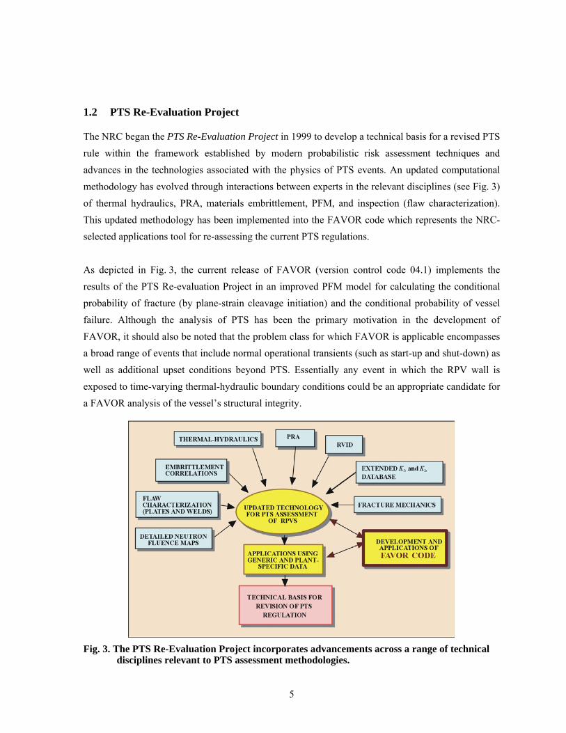
1.2 PTS Re-Evaluation Project
The NRC began the PTS Re-Evaluation Project in 1999 to develop a technical basis for a revised PTS rule within the framework established by modern probabilistic risk assessment techniques and advances in the technologies associated with the physics of PTS events. An updated computational methodology has evolved through interactions between experts in the relevant disciplines (see Fig. 3) of thermal hydraulics, PRA, materials embrittlement, PFM, and inspection (flaw characterization). This updated methodology has been implemented into the FAVOR code which represents the NRC-selected applications tool for re-assessing the current PTS regulations.
As depicted in Fig. 3, the current release of FAVOR (version control code 04.1) implements the results of the PTS Re-evaluation Project in an improved PFM model for calculating the conditional probability of fracture (by plane-strain cleavage initiation) and the conditional probability of vessel failure. Although the analysis of PTS has been the primary motivation in the development of FAVOR, it should also be noted that the problem class for which FAVOR is applicable encompasses a broad range of events that include normal operational transients (such as start-up and shut-down) as well as additional upset conditions beyond PTS. Essentially any event in which the RPV wall is exposed to time-varying thermal-hydraulic boundary conditions could be an appropriate candidate for a FAVOR analysis of the vessel’s structural integrity.
Fig. 3. The PTS Re-Evaluation Project incorporates advancements across a range of technical
disciplines relevant to PTS assessment methodologies.

6
In support of the PTS Re-Evaluation Project, the following advanced technologies have been incorporated into the current release of FAVOR, 04.1:
• the ability to incorporate new detailed flaw-characterization distributions from NRC research (with Pacific Northwest National Laboratory, PNNL),
• the ability to incorporate detailed neutron fluence regions – detailed fluence maps from Brookhaven National Laboratory, BNL,
• the ability to incorporate warm-prestressing effects into the analysis, • the ability to include temperature-dependencies in the thermo-elastic properties of base and
cladding, • the ability to include crack-face pressure loading for surface-breaking flaws, • a new ductile-fracture model simulating stable and unstable ductile tearing, • a new embrittlement correlation, • the ability to include multiple transients in one execution of FAVOR, • input from the Reactor Vessel Integrity Database, Revision 2, (RVID2) of relevant RPV
material properties, • fracture-toughness models based on extended databases and improved statistical
distributions, • a variable failure criterion, i.e., how far must a flaw propagate into the RPV wall for the
vessel simulation to be considered as “failed” ? • semi-elliptic surface-breaking and embedded-flaw models, • through-wall weld residual stresses, and an • improved PFM methodology that incorporates modern PRA procedures for the
classification and propagation of input uncertainties and the characterization of output uncertainties as statistical distributions.

7
1.3 Overview – Structure and Organization of the FAVOR Code
As shown in Fig. 4, FAVOR is composed of three computational modules: (1) a deterministic load generator (FAVLoad), (2) a Monte Carlo PFM module (FAVPFM), and (3) a post-processor (FAVPost). Figure 4 also indicates the nature of the data streams that flow through these modules.
Fig. 4. FAVOR data streams flow through three modules: (1) FAVLoad, (2) FAVPFM, and (3)
FAVPost.
The PFM model in FAVOR is based on the application of Monte Carlo techniques in which deterministic fracture analyses are performed on a large number of stochastically-generated RPV

8
trials or realizations. Each vessel realization, containing a specified number of flaws, is analyzed to determine the conditional probability of initiation (CPI) and the conditional probability of failure (CPF) for an RPV challenged by a postulated thermal-hydraulic transient at a selected time in the vessel’s operating history. The fracture-initiation mechanism is stress-controlled cleavage (in the lower transition-temperature region of the vessel material) modeled under the assumptions of linear-elastic fracture mechanics (LEFM), and the associated failure modes are sufficient flaw growth either to produce a net-section plastic collapse of the remaining ligament or to advance the crack tip to a user-specified fractional distance of the wall thickness. The potential for plane-strain crack arrest is also simulated. The time-dependent load path is assumed to be quasi-static.
A new ductile-fracture capability has been implemented into the Initiation-Growth-Arrest (IGA) submodel to allow the simulation of flaw growth by stable ductile tearing in combination with cleavage propagation. When this user-selected option is turned on, an additional failure mode of unstable ductile tearing is included in the determination of CPF.
The Monte Carlo method involves sampling from appropriate probability distributions to simulate many possible combinations of flaw geometry and RPV material embrittlement, all exposed to the same transient loading conditions. The PFM analysis is performed for the beltline of the RPV, usually assumed to extend from one foot below the active length of the reactor core to one foot above the core. As shown in Fig. 5, the RPV beltline can be divided into major regions such as axial welds, circumferential welds, and plates or forgings that may have their own embrittlement-sensitive chemistries. These major regions may be further divided into subregions to accommodate detailed mappings of azimuthal and axial variations in fast-neutron fluence.
Fig. 5. The global modeling approach in FAVOR allows the entire beltline to be simulated in
one model definition.
9
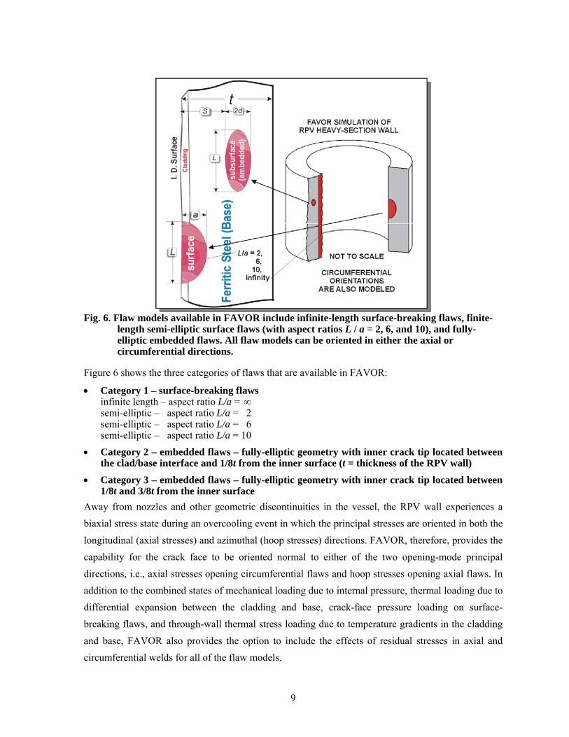
Fig. 6. Flaw models available in FAVOR include infinite-length surface-breaking flaws, finite-
length semi-elliptic surface flaws (with aspect ratios L / a = 2, 6, and 10), and fully-elliptic embedded flaws. All flaw models can be oriented in either the axial or circumferential directions.
Figure 6 shows the three categories of flaws that are available in FAVOR:
• Category 1 – surface-breaking flaws infinite length – aspect ratio L/a = ∞ semi-elliptic – aspect ratio L/a = 2 semi-elliptic – aspect ratio L/a = 6 semi-elliptic – aspect ratio L/a = 10
• Category 2 – embedded flaws – fully-elliptic geometry with inner crack tip located between the clad/base interface and 1/8t from the inner surface (t = thickness of the RPV wall)
• Category 3 – embedded flaws – fully-elliptic geometry with inner crack tip located between 1/8t and 3/8t from the inner surface
Away from nozzles and other geometric discontinuities in the vessel, the RPV wall experiences a biaxial stress state during an overcooling event in which the principal stresses are oriented in both the longitudinal (axial stresses) and azimuthal (hoop stresses) directions. FAVOR, therefore, provides the capability for the crack face to be oriented normal to either of the two opening-mode principal directions, i.e., axial stresses opening circumferential flaws and hoop stresses opening axial flaws. In addition to the combined states of mechanical loading due to internal pressure, thermal loading due to differential expansion between the cladding and base, crack-face pressure loading on surface-breaking flaws, and through-wall thermal stress loading due to temperature gradients in the cladding and base, FAVOR also provides the option to include the effects of residual stresses in axial and circumferential welds for all of the flaw models.

10
The format of the required user-input data files will be discussed in detail in the following sections. In summary, the input files along with the resulting output files for the three modules are:
• FAVLoad Data Stream (see Fig. 7) 1) Input file that includes: vessel geometry, thermo-mechanical material properties for the
cladding and base (either constant or temperature dependent), user-selected loading options, and thermal-hydraulic definitions of all transients to be analyzed
2) Output file that provides an echo of the user input 3) Output file that is used as a load-definition input file for FAVPFM
• FAVPFM Data Stream (see Fig. 8)
4) Input file that provides user-selected case options, major region and subregion definitions with weld/plate embrittlement data, and the number of RPV realizations/trials to be simulated
5) Input file from the FAVLoad module [data stream file 3)] that contains load-definition data for each thermal-hydraulic transient
6) Input file that provides characterization data for surface-breaking flaws in plates, forgings, and welds
7) Input file that provides characterization data for flaws embedded in welds
8) Input file that provides characterization data for flaws embedded in plates and forgings
9) Input file for restart cases (required only if the current execution is a restart from a previous run)
10) Output file that provides an echo of the user input
11) Output/Input binary restart file, created at user-selected checkpoints during the FAVPFM run
12) Output file that contains summary reports of the PFM analysis
13) Output files that can be used for Quality Assurance checks of PFM calculations
14) Output file with the conditional probability of crack initiation matrix for input to FAVPost
15) Output file with the conditional probability of through-wall cracking matrix for input to FAVPost

11
Fig. 7. The FAVOR load generator module FAVLoad performs deterministic analyses for a
range of thermal-hydraulic transients.
Fig. 8. The FAVPFM module takes output from FAVLoad and user-supplied data on flaw
distributions and embrittlement of the RPV beltline and generates PFMI (INITIATE.DAT) and PFMF (FAILURE.DAT) arrays.

12
Fig. 9. The FAVOR post-processor FAVPost combines the distributions of conditional
probability of initiation and failure calculated by FAVPFM with initiating frequency distributions for all of the transients under study to create distributions of frequencies of RPV fracture and failure.
• FAVPost Data Stream (see Fig. 9) 16) Input file that provides initiating frequency distributions for each transient defined in 1)
above. 17) Input file from FAVPFM containing the conditional probability of initiation matrix 18) Input file from FAVPFM containing the conditional probability of failure matrix 19) Output file that, in addition to an echo of the user input, contains histograms describing the
distributions for the frequency of crack initiation and frequency of failure (also known as the through-wall crack frequency) with the units of cracked vessels per reactor operating year and failed vessels per reactor operating year, respectively.
1.4 Hardware Requirements
The three FAVOR modules have been successfully compiled and executed on the following computers, operating systems, and compilers:
• Pentium II and III with Windows NT 4.0 (SP6) – Lahey/Fujitsu Fortran 95 compiler
• Pentium II and III with Windows NT 4.0 (SP6) – Compaq 6.1 Fortran 95 compiler
• 80486DX with Windows 98 (DOS 7.1) – Compaq 6.1 Fortran 95 compiler
• Power Macintosh 9600/200MP with OS 8.6 – Absoft Pro Fortran 90 compiler
• Compaq XP1000 with TRU64 UNIX 4.0F – Compaq Fortran 90 v5.3-1120 compiler

13
• Dell Precision™ Workstation 330 Pentium IV with Windows 2000 Professional – Compaq 6.1 Fortran 95 compiler
• Dell Precision™ Workstation 330 Pentium IV with Windows 2000 Professional – Lahey/Fujitsu Fortran 95 compiler
• Dell Precision™ Workstation 340 Pentium IV with Windows XP Professional – Compaq 6.1 Fortran 95 compiler
• Dell Precision™ Workstation 340 Pentium IV with Windows XP Professional – Lahey/Fujitsu Fortran 95 compiler
The recommended computer for execution of FAVOR, v04.1, is a Pentium III or IV (or equivalent) with the Windows XP Professional operating system and 2 Gbytes of RAM. The installation requires approximately 165 Mbytes of free disk space for executables, documentation, source code, and example input files.
All three FAVOR modules make use of dynamic memory management where the required internal memory is calculated based on the size of the problem and then allocated from the global heap1 at run time; therefore, the only limitation on the number of thermal hydraulic transients, the number of RPV trials, the number of simulated flaws, or the number of subregions (employed in defining the model of the RPV beltline) is the memory capacity of the computer being used. For all of the models tested by the developers to date, 2 Gbytes of RAM was sufficient to run FAVOR; however, be advised that larger models in the future may require more memory. In addition, some problems have been encountered when running large cases (e.g., 60,000 subregions with 30 transients) on a PC with Windows 2000 Professional and 512 Mbytes of RAM. Windows XP (with the latest Service Pack installed) is the recommended operating system.
1.5 Installation
Copy all of the files on the distribution CD (with the exception of the setup subfolder) to the user’s hard drive. These files may be copied manually by using Windows Explorer or by running the “SETUP.EXE” application created by InstallShield® and available in the .\FAVOR4.1\setup subfolder. If the “autorun” feature on the user’s computer is enabled, then the InstallShield® installation application will automatically run when the FAVOR distribution CD is loaded into the drive. The InstallShield® installer will prompt the user for the target installation folder. The User’s Guide and Theory Manual files are in Adobe Acrobat PDF format. The installer for the free Adobe
1 The heap is an internal memory pool, controlled by the computer’s operating system, and available for dynamic allocation during run time.

14
Acrobat Reader 6.01 is included on the distribution CD. Execute “AdbeRdr60_enu_full.exe” from the CD to install the Acrobat Reader on the user’s computer, if it is not already installed.
Installation on Windows 2000\NT\98 Operating Systems – If the contents of “FAVOR 04.1” folder and its subfolders were manually copied from the distribution CD to the user’s hard-drive, it will be necessary to remove the “Read Only” attribute on the data files in the “.\FAVOR 04.1\Flaw Data\”, “.\FAVOR 04.1\Examples\”, and “.\FAVOR 04.1\Examples\Installation Examples\” folders. The “Read Only” attribute is set automatically by the Windows 2000\NT\ME\98 operating systems for files copied from a CD2. One way to change the attributes for a file or collection of files is through the Windows Explorer utility. Here is the procedure:
1. Bring up Windows Explorer (e.g., right-click3 on the “Start” button at the lower left-hand corner of the main window and select4 “Explore”)
2. Navigate to the “.\FAVOR 04.1\Examples” folder
3. On the Explorer menu bar at the top of the window, select View>Details
4. Click4 on the “Type” bar at the top of the file window to sort the files by their file extension, if not already sorted this way.
5. Select the file “FAVLoad.in” by left-clicking once on the filename.
6. Hold down the <Shift> key and select the data file at the bottom of the list. This procedure will select all of the data files at one time. It is not necessary to change the attributes of the application files: FAVLoad.exe, FAVPFM.exe, and FAVPost.exe.
7. Continue holding down the <Shift> key and with the cursor positioned over the selected files right-click to bring up a pop-up menu.
8. Select “Properties” at the bottom of the pop-up menu.
9. Deselect the “Read-only” attribute by left-clicking on its check box, if it is checked.
10. Select the “OK” button, and release the <Shift> key.
All of the data files in this folder should now be ready for execution with FAVOR. Repeat Steps 3 through 10 for all of the data files in the “.\FAVOR 04.1\Flaw Data\” and “.\FAVOR 04.1\Examples\ Installation Examples\” folders.
2 The “Read Only” attribute is not assigned automatically when running under the Windows XP operating system, or if the InstallShield® SETUP.EXE application is used to carry out the transfer of files from the CD. 3 “right-click” click once with the right mouse button 4 “select” “left-click” click once with the left mouse button
15
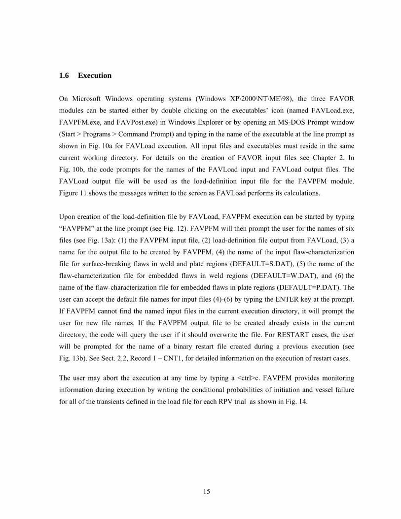
1.6 Execution
On Microsoft Windows operating systems (Windows XP\2000\NT\ME\98), the three FAVOR modules can be started either by double clicking on the executables’ icon (named FAVLoad.exe, FAVPFM.exe, and FAVPost.exe) in Windows Explorer or by opening an MS-DOS Prompt window (Start > Programs > Command Prompt) and typing in the name of the executable at the line prompt as shown in Fig. 10a for FAVLoad execution. All input files and executables must reside in the same current working directory. For details on the creation of FAVOR input files see Chapter 2. In Fig. 10b, the code prompts for the names of the FAVLoad input and FAVLoad output files. The FAVLoad output file will be used as the load-definition input file for the FAVPFM module. Figure 11 shows the messages written to the screen as FAVLoad performs its calculations.
Upon creation of the load-definition file by FAVLoad, FAVPFM execution can be started by typing “FAVPFM” at the line prompt (see Fig. 12). FAVPFM will then prompt the user for the names of six files (see Fig. 13a): (1) the FAVPFM input file, (2) load-definition file output from FAVLoad, (3) a name for the output file to be created by FAVPFM, (4) the name of the input flaw-characterization file for surface-breaking flaws in weld and plate regions (DEFAULT=S.DAT), (5) the name of the flaw-characterization file for embedded flaws in weld regions (DEFAULT=W.DAT), and (6) the name of the flaw-characterization file for embedded flaws in plate regions (DEFAULT=P.DAT). The user can accept the default file names for input files (4)-(6) by typing the ENTER key at the prompt. If FAVPFM cannot find the named input files in the current execution directory, it will prompt the user for new file names. If the FAVPFM output file to be created already exists in the current directory, the code will query the user if it should overwrite the file. For RESTART cases, the user will be prompted for the name of a binary restart file created during a previous execution (see Fig. 13b). See Sect. 2.2, Record 1 – CNT1, for detailed information on the execution of restart cases.
The user may abort the execution at any time by typing a <ctrl>c. FAVPFM provides monitoring information during execution by writing the conditional probabilities of initiation and vessel failure for all of the transients defined in the load file for each RPV trial as shown in Fig. 14.

16
(a)
(b) Fig. 10. Execution of the FAVLOAD module: (a) type in FAVLOAD at the line prompt and
(b) respond to prompts for the input and output file names.

17
Fig. 11. FAVLOAD calculates thermal, stress, and applied KI loading for all of the transients
defined in the input file.
Fig. 12. Type FAVPFM at the MS-DOS prompt to begin execution of the FAVPFM module.

18
Fig. 13. (a) FAVPFM prompts for the names of the (1) FAVPFM input file, (2) FAVLoad-
generated load-definition file, (3) FAVPFM output file, (4) flaw-characterization file for surface-breaking flaws in welds and plates, (5) flaw-characterization file for embedded flaws in welds, and (6) flaw-characterization file for embedded flaws in plates.
Fig. 13. (b) For a restart case, FAVPFM will also prompt for the binary restart file created in a
previous execution (see Record 1 – CNT 1 for details regarding restart cases).

19
Fig. 14. FAVPFM continually writes out progress reports as the code proceeds through the
required number of RPV trials.

20
FAVPost Execution – The FAVPost module may be run while FAVPFM is still executing. This feature is particularly helpful when FAVPFM is executing a run that could take hours or possibly days. Here is the procedure:
1. While FAVPFM is running in one DOS Prompt Window, bring up a second DOS Window and navigate to a directory that is not the FAVOR working directory.
2. Copy the FAVPost.exe executable and the current files INITIATE.DAT, FAILURE.DAT, and NSIM.DAT from the current FAVOR working directory to the directory selected in Step 1.
3. Start the copied FAVPost executable in the directory selected in Step 1 by typing FAVPost and then <Enter> at the prompt.
4. Respond to the prompt for the FAVPost input filename.
5. Take the defaults for the INITIATE.DAT and FAILURE.DAT file names by hitting the <Enter> key twice.
6. Respond to the prompt for the FAVPost output file name.
7. Respond to the prompt for the number of RPV trials to be processed.
8. FAVPost will interrogate the INITIATE.DAT file to determine the current number of completed RPV trials.
9. FAVPost reports the number of RPV trials completed and asks how many trials the user wishes to process.
10. Respond to the query with either a number (less than the total completed) or take the default “ALL” by hitting the <Enter> key.
The above capability is also convenient for calculating convergence statistics as a function of RPV trials, even when the FAVPFM run has completed. For example, the analyst might wish to calculate the 99th percentile of the failure frequency vs RPV trials as a check for convergence. Just run FAVPost several times asking for 1000, 2000, 3000, …NSIM RPV trials, and then plot the relevant statistics.
In Fig. 15, FAVOR’s post-processing module is executed by typing FAVPost at the line prompt. The code will then prompt the user for the names of four files (see Fig. 16): (1) a FAVPost input file, (2) the file created by the FAVPFM execution that contains the conditional probability of initiation matrix (DEFAULT=INITIATE.DAT), (3) the file created by the FAVPFM execution that contains the conditional probability of failure matrix (DEFAULT=FAILURE.DAT), and (4) the name of the output file to be created by FAVPost that will have the histograms for vessel fracture and failure frequencies. Again, for files (2) and (3), the user may accept the defaults by typing the RETURN/ENTER key.

21
Fig. 15. Type in FAVPost at the MS DOS Prompt to execute the FAVPost module.
Fig. 16. FAVPost prompts for the (1) FAVPost input file, (2) CPI matrix file generated by
FAVPFM, (3) CPF matrix file generated by FAVPFM, and (4) the FAVPost output file.

22
1.7 Distribution CD – What’s on the CD
The distribution CD contains the following folders and files:
Main Folder: .\FAVOR04.1
The main folder .\FAVOR04.1 contains six subfolders. The file “AdbeRdr60_enu_full.exe” is the Adobe Acrobat Reader 6.01 installer application. If the free Acrobat Reader does not exist on the user’s PC, just double-click on the installer, and Acrobat Reader will be installed and the “.pdf” extension will be associated with the Reader application. The installer may require the user to restart the PC to complete the installation. After installation, the FAVOR, 04.1, documentation may viewed by double-clicking on the individual “.pdf” files.

23
Subfolder: .\FAVOR04.1\bin
.\FAVOR04.1\bin contains the executables for a PC running under the Microsoft Windows operating system.
Subfolder: .\FAVOR04.1\doc
.\FAVOR04.1\doc contains draft copies of the Theory and User’s Guides in Adobe Acrobat PDF format. The free Adobe Acrobat Reader 6 installation file is included in the root directory. The draft documents have not undergone a final NRC review and are supplied for information purposes only.

24
Subfolder: .\FAVOR04.1\Examples
These are the input and output files for the example case discussed in Chapter 3 of this User’s Guide. Several of the files, e.g., ARREST.OUT, created automatically by FAVOR have been renamed to save them for comparison checks by the user.

25
Subfolder: .\FAVOR04.1\Examples\Installation Examples
The files in this subfolder exercise the deterministic capabilities of FAVOR. The file “bflaws.in” is a FAVLoad input file for all of the “EmbedA?.in, EmbedB?.in, and EmbedC?.in” input files that calculate time-histories for embedded flaws using the case matrix developed for the Embedded Flaw Verification Study. The “FAVLoad.in, FAVPFM.in, and FAVPost.in” file are input files for the same example case in Chapter 3, except that the number of RPV simulations have been reduced to 1000.

26
Subfolder: FAVOR04.1\Flaw Data
The three flaw-characterization files developed for the PTS Re-Evaluation Project are included in this subfolder for each of four nuclear power plants. The files “Palisades.exe”, “Oconee.exe”, “CalvertCliffs.exe”, and “BeaverValley.exe” are self-extracting WINZIP archives containing the three plant-specific flaw-characterization files. Just execute the self-extracting archive file on the PC, and the user will be prompted for the files’ current FAVOR working directory. The files “W.dat”, “S.dat”, and “P.dat” are the files used in calculating the installation examples.

27
Subfolder: FAVOR04.1\setup
An automated procedure for installing FAVOR on the user’s computer is provided in the .\FAVOR04.1\setup subfolder. The user may execute the “SETUP.EXE” application in this folder, and the necessary files will be copied to a user-selected installation folder on the user’s hard drive. If the “autorun” feature on the user’s computer is enabled, then the InstallShield® installation application will automatically run when the FAVOR distribution CD is loaded into the CD drive. The InstallShield® installer will prompt the user for the target installation folder.
28
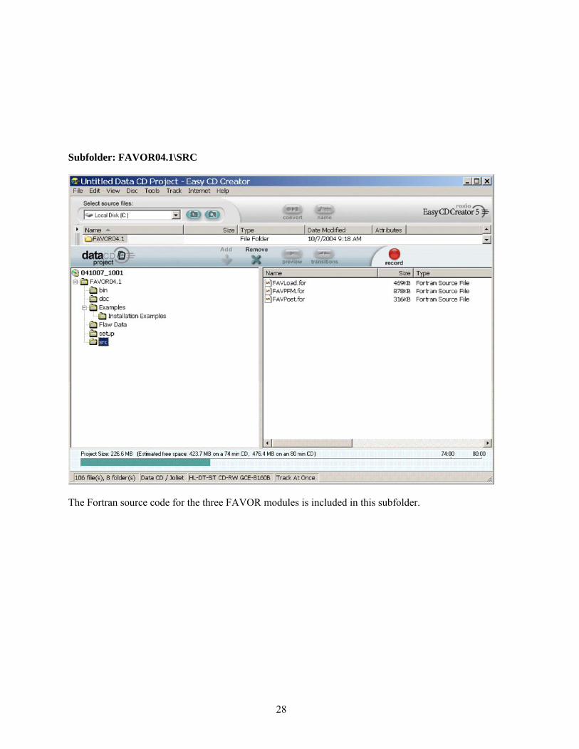
Subfolder: FAVOR04.1\SRC
The Fortran source code for the three FAVOR modules is included in this subfolder.

29
2. FAVOR Input Requirements
FAVOR employs ASCII files either created by the user or created by previous executions of the FAVOR modules. User-created input files are organized by a sequence of keyword records with free-field format for the placement of parameter data located on the same line record as the keyword or on data lines following the keyword record. The data must be input exactly in the sequence and order prescribed in the sections below. Omission of data fields is not allowed. The 4-letter keywords always begin in column 1.
Comment lines are designated by an asterisk, “*”, in column 1. The user is encouraged to take full advantage of including comments in the input files as a method for internal documentation of the model. It has proven beneficial by the developers of FAVOR to use the input files (included in the example cases on the distribution CD) as templates for the creation of new input datasets.
In developing input datasets, the user should pay careful attention to the required units for each data record. FAVOR carries out conversions internally to insure a consistent set of units for all analyses; however, the input data must be entered in the units specified in the sections below.

30
2.1 FAVOR Load Module – FAVLoad
A total of 12 data records, listed in Table 1, are required in the FAVLoad input file, where each record may involve more than one line of data. A detailed description of each data record is given below.
Table 1. Record Keywords and Parameter Fields for FAVLoad Input File
Record Keyword Field 1 Field 2 Field 3 Field 4 Field 5 Field 6 Field 71 GEOM IRAD=[in] W=[in] CLTH=[in]2 BASE K=[Btu/hr-ft-°F] C=[Btu/lbm-°F] RHO=[lbm/ft3] E=[ksi] ALPHA=[°F -1] NU=[-] NTE=[0|1]2a NBK NK=[-] if NTE=1
input NK data lines with {T, K(T) } [°F, Btu/h-ft-°F] pairs - one pair per line2b NBC NC=[-] if NTE=1
input NC data lines with {T, C(T) } [°F, Btu/lbm-°F] pairs - one pair per line2c NBE NE=[-] if NTE=1
input NE data lines with {T, E(T) } [°F, ksi] pairs - one pair per line2d NALF NA=[-] if NTE=1
input NA data lines with {T, ALPHA(T) } [°F, °F -1] pairs - one pair per line2e NNU NU=[-] if NTE=1
input NU data lines with {T, NU(T) } [°F, - ] pairs - one pair per line3 CLAD K=[Btu/hr-ft-°F] C=[Btu/lbm-°F] RHO=[lbm/ft3] E=[ksi] ALPHA=[°F-1] NU=[-] NTE=[0|1]3a NCK NK=[-] if NTE=1
input NK data lines with {T, K(T) } [°F, Btu/h-ft-°F] pairs - one pair per line3b NCC NC=[-] if NTE=1
input NC data lines with {T, C(T) } [°F, Btu/lbm-°F] pairs - one pair per line3c NCE NE=[-] if NTE=1
input NE data lines with {T, E(T) } [°F, ksi] pairs - one pair per line3d NALF NA=[-] if NTE=1
input NA data lines with {T, ALPHA(T) } [°F, °F -1] pairs - one pair per line3e NNU NU=[-] if NTE=1
input NU data lines with {T, NU(T) } [°F, - ] pairs - one pair per line4 SFRE T=[°F] CFP=[0|1]5 RESA NRAX=[-]6 RESC NRCR=[-]7 TIME TOTAL=[min] DT=[min]8 NPRA NTRAN=[-]
Repeat data records 9 through 12 for each NTRAN transients9 TRAN ITRAN=[-] ISEQ=[-]10 NHTH NC=[-]
input NC data lines with { t , h (t ) } [min, Btu/hr-ft2-°F] pairs - one pair per line11 NTTH NT=[-]
input NT data lines with ( t , T (t ) ) [min, °F] pairs - one pair per lineor
11 NTTH NT=101STYL TINIT=[°F] TFINAL=[°F] BETA=[min-1]
12 NPTH NP=[-]input NP data lines with ( t , P (t ) ) [min, ksi] pairs - one pair per line

31
Record 1 – GEOM
Record No. 1 inputs vessel geometry data, specifically the internal radius, IRAD, in inches, the wall thickness (inclusive of cladding), W, in inches, and the cladding thickness, CLTH, in inches. The thickness of the base metal is, therefore, W – CLTH.
EXAMPLE
******************************************************************************** * ==================== * * Record GEOM * * ==================== * *------------------------------------------------------------------------------* * IRAD = INTERNAL RADIUS OF PRESSURE VESSEL [IN] * * W = THICKNESS OF PRESSURE VESSEL WALL (INCLUDING CLADDING) [IN] * * CLTH = CLADDING THICKNESS [IN] * *------------------------------------------------------------------------------* ******************************************************************************** GEOM IRAD=78.5 W=8.031 CLTH=0.156 ********************************************************************************
Records 2 and 3– BASE and CLAD
Records 2 and 3 input thermo-elastic property data for the base (typically a ferritic steel) and cladding (typically an austenitic stainless steel), respectively: thermal conductivity, K, in Btu/hr-ft-°F, C, mass-specific heat capacity in Btu/lbm-°F, mass density, RHO, in lbm/ft3, Young’s modulus of elasticity, E, in ksi, coefficient of thermal expansion, ALPHA, in °F-1, and Poisson’s ratio, NU. All property data are assumed to be independent of temperature if NTE = 0.
EXAMPLE
******************************************************************************** * =========================== * * Records BASE and CLAD * * =========================== * * THERMO-ELASTIC MATERIAL PROPERTIES FOR BASE AND CLADDING * *------------------------------------------------------------------------------* * K = THERMAL CONDUCTIVITY [BTU/HR-FT-F] * * C = SPECIFIC HEAT [BTU/LBM-F] * * RHO = DENSITY [LBM/FT**3] * * E = YOUNG'S ELASTIC MODULUS [KSI] * * ALPHA = THERMAL EXPANSION COEFFICIENT [F**-1] * * NU = POISSON'S RATIO [-] * * NTE = TEMPERATURE DEPENDANCY FLAG * * NTE = 0 ==> PROPERTIES ARE TEMPERATURE INDEPENDENT (CONSTANT) * * NTE = 1 ==> PROPERTIES ARE TEMPERATURE DEPENDENT * * IF NTE EQUAL TO 1, THEN ADDITIONAL DATA RECORDS ARE REQUIRED * *------------------------------------------------------------------------------* ******************************************************************************** BASE K=24.0 C=0.120 RHO=489.00 E=28000 ALPHA=.00000777 NU=0.3 NTE=0 CLAD K=10.0 C=0.120 RHO=489.00 E=22800 ALPHA=.00000945 NU=0.3 NTE=0 ********************************************************************************

32
If NTE = 1 on Records 2 or 3, then tables of temperature-dependent properties will be input.
EXAMPLE
******************************************************************************** * =========================== * * Records BASE and CLAD * * =========================== * * THERMO-ELASTIC MATERIAL PROPERTIES FOR BASE AND CLADDING * *------------------------------------------------------------------------------* * K = THERMAL CONDUCTIVITY [BTU/HR-FT-F] * * C = SPECIFIC HEAT [BTU/LBM-F] * * RHO = DENSITY [LBM/FT**3] * * E = YOUNG'S ELASTIC MODULUS [KSI] * * ALPHA = THERMAL EXPANSION COEFFICIENT [F**-1] * * NU = POISSON'S RATIO [-] * * NTE = TEMPERATURE DEPENDANCY FLAG * * NTE = 0 ==> PROPERTIES ARE TEMPERATURE INDEPENDENT (CONSTANT) * * NTE = 1 ==> PROPERTIES ARE TEMPERATURE DEPENDENT * * IF NTE EQUAL TO 1, THEN ADDITIONAL DATA RECORDS ARE REQUIRED * *------------------------------------------------------------------------------* ******************************************************************************** BASE K=24.0 C=0.120 RHO=489.00 E=28000 ALPHA=.00000777 NU=0.3 NTE=1 ******************************************************************************** *--------------------------- * THERMAL CONDUCTIVITY TABLE *--------------------------- NBK NK=16 *--------------------------- 70 24.8 100 25.0 150 25.1 200 25.2 250 25.2 300 25.1 350 25.0 400 25.1 450 24.6 500 24.3 550 24.0 600 23.7 650 23.4 700 23.0 750 22.6 800 22.2 *--------------------------- * SPECIFIC HEAT TABLE *--------------------------- NBC NC=16 *---------------- 70 0.1052 100 0.1072 150 0.1101 200 0.1135 250 0.1166 300 0.1194 350 0.1223 400 0.1267 450 0.1277 500 0.1304 550 0.1326 600 0.1350 650 0.1375 700 0.1404 750 0.1435 800 0.1474 *--------------------------- * YOUNG'S MODULUS TABLE *--------------------------- NBE NE=8 *---------------- 70 29200

33
200 28500 300 28000 400 27400 500 27000 600 26400 700 25300 800 23900 *---------------------------- * COEFF. OF THERMAL EXPANSION *---------------------------- NALF NA=16 *---------------- 70 0.00000702 100 0.00000713 150 0.00000729 200 0.00000745 250 0.00000760 300 0.00000774 350 0.00000788 400 0.00000801 450 0.00000813 500 0.00000825 550 0.00000836 600 0.00000846 650 0.00000855 700 0.00000863 750 0.00000871 800 0.00000878 *---------------------------- * POISSON'S RATIO *---------------------------- NBNU NU=2 *---------------- 0. 0.3 1000. 0.3 ******************************************************************************** CLAD K=10.0 C=0.120 RHO=489.00 E=22800 ALPHA=.00000945 NU=0.3 NTE=1 ******************************************************************************** *--------------------------- * THERMAL CONDUCTIVITY TABLE *--------------------------- NK N=16 *---------------- 70 8.1 100 8.4 150 8.6 200 8.8 250 9.1 300 9.4 350 9.6 400 9.9 450 10.1 500 10.4 550 10.6 600 10.9 650 11.1 700 11.4 750 11.6 800 11.9 *--------------------------- * SPECIFIC HEAT TABLE *--------------------------- NC N=16 *---------------- 70 0.1158 100 0.1185 150 0.1196 200 0.1208 250 0.1232 300 0.1256 350 0.1258 400 0.1281 450 0.1291 500 0.1305 550 0.1306 600 0.1327 650 0.1335 700 0.1348 750 0.1356 800 0.1367 *---------------------------

34
* YOUNG'S MODULUS TABLE *--------------------------- NE N=3 *--------------------------- 68 22045.7 302 20160.2 482 18419.8 *---------------------------- * COEFF. OF THERMAL EXPANSION *---------------------------- NALF N=16 *---------------- 70 0.00000846 100 0.00000863 150 0.00000887 200 0.00000908 250 0.00000927 300 0.00000946 350 0.00000964 400 0.00000980 450 0.00000995 500 0.00001010 550 0.00001025 600 0.00001038 650 0.00001050 700 0.00001060 750 0.00001070 800 0.00001079 *---------------------------- * POISSON'S RATIO *---------------------------- NNU N=2 *---------------- 0. 0.3 1000. 0.3
The following sources were consulted to develop the temperature-dependent tables shown above:
Base Steel ASME Boiler and Pressure Vessel Code – Sect. II., Part D: Properties (1998) [17] thermal conductivity – Table TCD – Material Group A – p. 592 thermal diffusivity – Table TCD – Material Group A – p. 592 Young’s Modulus of Elasticity – Table TM-1 – Material Group A – p. 606 Coefficient of Expansion – Table TE-1 – Material Group D – p. 580-581 Density = 489 lbm/ft3
Cladding ASME Boiler and Pressure Vessel Code – Sect. II., Part D: Properties (1998) [17] thermal conductivity – Table TCD – High Alloy Steels – p. 598 thermal diffusivity – Table TCD – High Alloy Steels – p. 598
Young’s Modulus of Elasticity – NESC II Project – Final Report – p. 35 [18] Coefficient of Expansion – Table TE-1 – High Chrome Steels – p. 582-583 Density = 489 lbm/ft3
FAVLoad constructs monotone piecewise cubic-Hermite interpolants [19,20] for interpolation within the temperature-dependant property look-up tables.

35
Record 4 – SFRE
Record 4 inputs the thermal stress-free temperature for both the base and cladding in °F. In addition, crack-face pressure loading on surface-breaking flaws can be applied with CFP = 1. If CFP = 0, then no crack-face pressure loading will be applied. The recommended value of 468 °F was derived in reference [21].
EXAMPLE
******************************************************************************** ******************************************************************************** * ==================== * * Record SFRE * * ==================== * * T = BASE AND CLADDING STRESS-FREE TEMPERATURE [F] * * CFP = crack-face pressure loading flag * * CFP = 0 ==> no crack-face pressure loading * * CFP = 1 ==> crack-face pressure loading applied * ******************************************************************************** SFRE T=468 CFP=1 ********************************************************************************
Records 5 and 6 – RESA and RESC
Records 5 and 6 set weld residual stress flags, NRAX and NRCR, for axial and circumferential welds, respectively. If NRAX or NRCR are set to a value of 101, then weld residual stresses will be included in the FAVLoad output file. If NRAX or NRCR are set to a value of 0, then weld residual stresses will not be included in the FAVLoad output file.
EXAMPLE
******************************************************************************** * ========================= * * Records RESA AND RESC * * ========================= * * SET FLAGS FOR RESIDUAL STRESSES IN WELDS * *------------------------------------------------------------------------------* * NRAX = 0 AXIAL WELD RESIDUAL STRESSES OFF * * NRAX = 101 AXIAL WELD RESIDUAL STRESSES ON * * NRCR = 0 CIRCUMFERENTIAL WELD RESIDUAL STRESSES OFF * * NRCR = 101 CIRCUMFERENTIAL WELD RESIDUAL STRESSES ON * *------------------------------------------------------------------------------* ******************************************************************************** RESA NRAX=101 RESC NRCR=101 ********************************************************************************

36
Record 7 – TIME
Record 7 inputs the total elapsed time, TIME, in minutes for which the transient analysis is to be performed and the time increment, DT, also in minutes, to be used in the time integration in FAVPFM. Internally, the FAVLoad module uses a constant time step of 1.0 second to perform finite-element through-wall heat-conduction analyses (1D axisymmetric).
EXAMPLE
******************************************************************************** * ========================= * * Record TIME * * ========================= * *------------------------------------------------------------------------------* * TOTAL = TIME PERIOD FOR WHICH TRANSIENT ANALYSIS IS TO BE PERFORMED [MIN]* * DT = TIME INCREMENT [MIN]* *------------------------------------------------------------------------------* ******************************************************************************** TIME TOTAL=80.0 DT=0.5 ********************************************************************************
DT is the time-step size for which load results (temperatures, stresses, etc.) are saved during execution of the FAVLoad module; therefore, DT is the time-step size that will be used for all fracture analyses in subsequent FAVPFM executions. Some testing with different values of DT is typically necessary to insure that a sufficiently small value is used that will capture the critical characteristics of the transients under study. Note that there is no internal limit to the size of the time step; however, the computational time required to perform a PFM analysis is inversely proportional to DT.
Record 8 – NPRA
Record 8 inputs the number of thermal-hydraulic transients, NTRAN, to be defined for this case. The following Records 9 through 12 should be repeated for each of the NTRAN transients to be defined.
EXAMPLE
******************************************************************************** * =============== * * Record NPRA * * =============== * * NTRAN = NUMBER OF TRANSIENTS TO BE INPUT [-] * ******************************************************************************** NPRA NTRAN=4 ********************************************************************************
Record 9 – TRAN
Record 9 provides a mechanism for cross-indexing the internal FAVOR transient numbering system with the initiating-event sequence numbering system used in the thermal-hydraulic analyses that were performed to develop input to FAVOR. The internal FAVOR transient number, ITRAN, is linked

37
with the thermal-hydraulic initiating-event sequence number, ISEQ, with this record. Whereas, the value of ITRAN will depend upon the arbitrary ordering of transients in the FAVLoad transient input stack, the value of ISEQ is a unique identifier for each transient. ITRAN begins with 1 and is incremented by 1 up to NTRAN transients.
EXAMPLE
******************************************************************************** * ========================= * * Record TRAN * * ========================= * *------------------------------------------------------------------------------* * ITRAN = PFM TRANSIENT NUMBER * * ISEQ = THERMAL-HYDRAULIC SEQUENCE NUMBER * *------------------------------------------------------------------------------* ******************************************************************************** TRAN ITRAN= 1 ISEQ=7
M TRAN ITRAN= 2 ISEQ=9
M TRAN ITRAN= 3 ISEQ=56
M TRAN ITRAN= 4 ISEQ=97
M ************************************************************************
Record 10 – NHTH
Record 10 inputs the time history table for the convective film coefficient boundary conditions. There are NC data pairs of time, t, in minutes and film coefficient, h, in Btu/hr-ft2-°F entered following the NHTH keyword record line. The number of data pairs is limited only by the memory capacity of the computer. The film coefficient is used in imposing a Robin boundary condition at the inner vessel wall, Ri, defined by, [ ]( , ) ( ) ( ) ( , ) for , 0wall iq R t h t T t T R t R R t∞= − = ≥
where q (R,t) is the heat flux in Btu/hr-ft2, ( )T t∞ is the coolant temperature near the RPV wall in °F, and ( ),wallT R t is the wall temperature in °F.
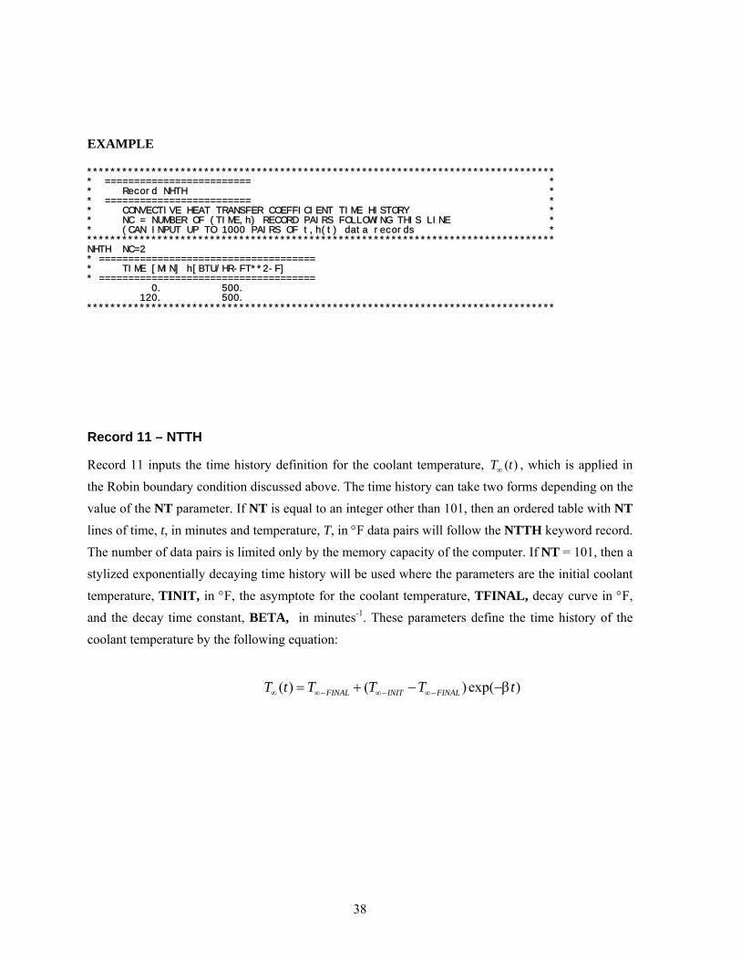
38
EXAMPLE
******************************************************************************** * ========================= * * Record NHTH * * ========================= * * CONVECTIVE HEAT TRANSFER COEFFICIENT TIME HISTORY * * NC = NUMBER OF (TIME,h) RECORD PAIRS FOLLOWING THIS LINE * * (CAN INPUT UP TO 1000 PAIRS OF t,h(t) data records * ******************************************************************************** NHTH NC=2 * ===================================== * TIME [MIN] h[BTU/HR-FT**2-F] * ===================================== 0. 500. 120. 500. ********************************************************************************
Record 11 – NTTH
Record 11 inputs the time history definition for the coolant temperature, ( )T t∞ , which is applied in the Robin boundary condition discussed above. The time history can take two forms depending on the value of the NT parameter. If NT is equal to an integer other than 101, then an ordered table with NT lines of time, t, in minutes and temperature, T, in °F data pairs will follow the NTTH keyword record. The number of data pairs is limited only by the memory capacity of the computer. If NT = 101, then a stylized exponentially decaying time history will be used where the parameters are the initial coolant temperature, TINIT, in °F, the asymptote for the coolant temperature, TFINAL, decay curve in °F, and the decay time constant, BETA, in minutes-1. These parameters define the time history of the coolant temperature by the following equation:
( ) ( ) exp( )FINAL INIT FINALT t T T T t∞ ∞− ∞− ∞−= + − −β

39
EXAMPLES
******************************************************************************** * ========================= * * Record NTTH * * ========================= * * THERMAL TRANSIENT: COOLANT TEMPERATURE TIME HISTORY * * NT = NUMBER OF (TIME,TEMPERATURE) DATA PAIRS *
* (CAN INPUT UP TO 1000 PAIRS OF t,T ∞ (t) data records *
******************************************************************************** NTTH NT=12 * =============================
* TIME[MIN] T ∞ (t)[F]
* ============================= 0.0 550.0 2.0 469.0 5.0 412.0 7.0 361.0 11.0 331.0 16.0 300.0 29.0 260.0 45.0 235.0 63.0 217.0 87.0 205.0 109.0 199.0 120.0 190.0 ********************************************************************************
or
******************************************************************************** * ========================= * * Record NTTH * * ========================= * * THERMAL TRANSIENT: COOLANT TEMPERATURE TIME HISTORY * * NT = 101 ==> STYLIZED EXPONENTIAL DECAYING COOLANT TEMPERATURE * * * * TINIT = INITIAL COOLANT TEMPERATURE (at time=0) (F) * * TFINAL = LOWEST TEMPERATURE IN TRANSIENT (F) * * BETA = DECAY CONSTANT (MIN**-1) * * * * FAVLoad CALCULATES AND STORES THE COOLANT TEMPERATURE AT * * 100 EQUALLY-SPACED TIME STEPS ACCORDING TO THE RELATION * * *
* T ∞ (t) = T ∞ -FINAL + (T ∞ INIT - T ∞ FINAL) * EXP( -BETA*TIME(min) *
******************************************************************************** NTTH NT=101 STYL TINIT=550 TFINAL=190 BETA=0.15 ********************************************************************************

40
Record 12 – NPTH
Record 12 inputs the time history table for the internal coolant pressure boundary condition. There are NP data pairs of time, t, in minutes and internal coolant pressure, p, in kilo-pounds force per square inch (ksi) entered following the NPTH keyword record line. The number of data pairs is limited only by the memory capacity of the computer.
EXAMPLE
******************************************************************************** * ========================= * * Record NPTH * * ========================= * * PRESSURE TRANSIENT: PRESSURE vs TIME HISTORY * * NP = NUMBER OF (TIME,PRESSURE) DATA PAIRS * * (CAN INPUT UP TO 1000 PAIRS OF t,P(t) data records * ******************************************************************************** NPTH NP=2 * ============================== * TIME[MIN] P(t)[ksi] * ============================== 0.0 1.0 120.0 1.0 ********************************************************************************

41
2.2 FAVOR PFM Module – FAVPFM
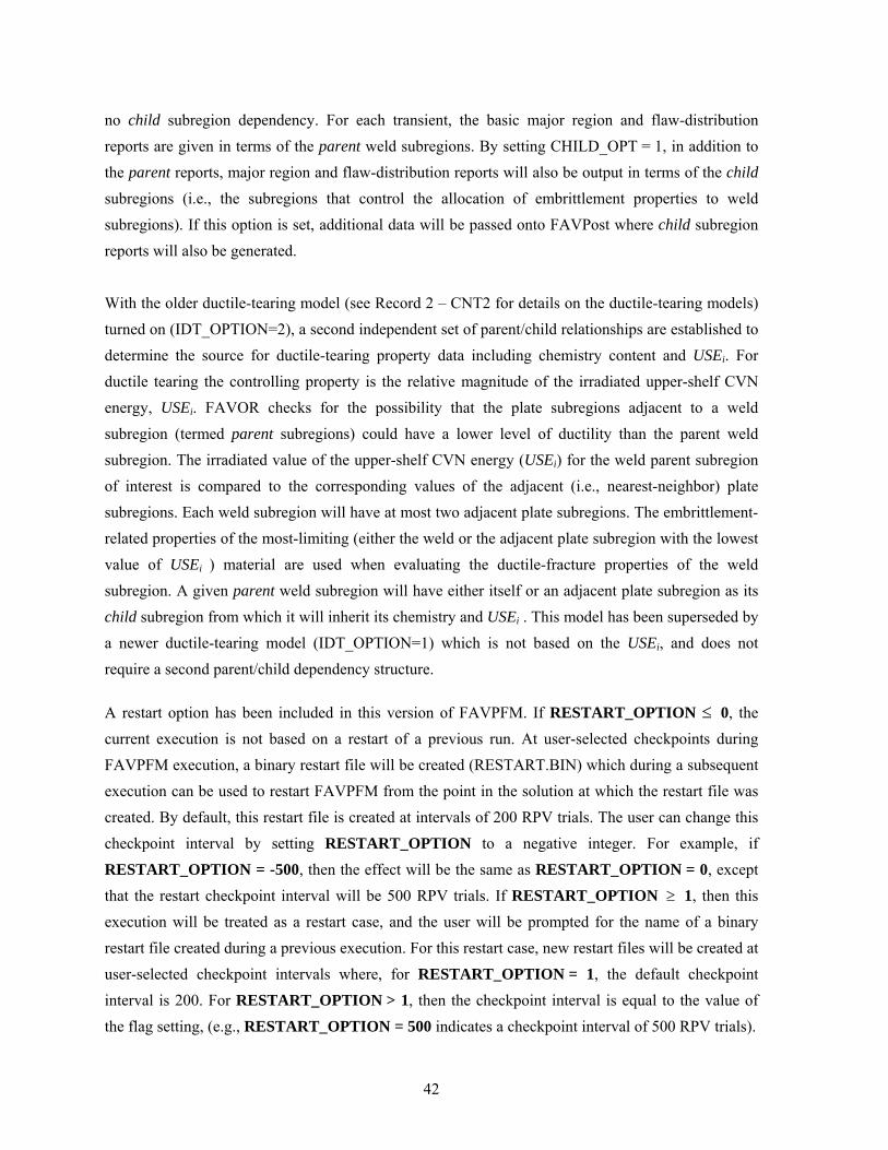
A total of 11 + NT + NWSUB + NPSUB data records (the value of NT is defined in Record 9, NWSUB is defined in Record 10 + NT, and NPSUB is defined in Record 11 + NT), listed in Table 2, are required in the FAVPFM input file, where each record may involve more than one line of data. A detailed description of each data record is given below.
Record 1 – CNT1
Record No. 1 inputs the number of simulations, NSIM, for the plant-specific analysis of this RPV, the number of trials, IGATR (where IGATR is bounded from 100 to 1000, i.e., 100 ≤ IGATR≤ 1000.), applied per flaw in the Initiation-Growth-Arrest (IGA) model, and sets the warm-prestressing option (WPS_OPT=1) on or off (WPS_OPT=0).
The PC3_OPT flag sets the Category 3-flaws-in-plate-material option (PC3_OPT = 0 don’t perform or = 1 do perform analysis). In a typical PFM analysis, a substantial fraction of the total flaws are Category 3 flaws in plate regions. Based on experience and some deterministic fracture analyses, these flaws rarely contribute to the CPI or CPF with the plate flaw size distributions typically used. Therefore, setting PC3_OPT = 0 can result in significantly shorter execution times without affecting the solution, unless there are unusual circumstances such as using a new flaw-size distribution for plate flaws. In either case, the Category 3 plate flaws are included in the bookkeeping reports.
The CHILD_OPT flag sets the child reports option (CHILD_OPT = 0 don’t include child subregion reports or = 1 include child subregion reports in the FAVPFM output file). The discretization and organization of major regions and subregions in the beltline includes a special treatment of weld-fusion lines. These fusion lines can be visualized as approximate boundaries between the weld subregion and its neighboring plate or forging subregions. FAVOR checks for the possibility that the plate subregions adjacent to a weld subregion (termed parent subregions) could have a higher degree of radiation-induced embrittlement than the weld. The irradiated value of RTNDT for the weld parent subregion of interest is compared to the corresponding values of the adjacent (i.e., nearest-neighbor) plate subregions. Each parent weld subregion will have at most two adjacent child plate subregions. The embrittlement-related properties of the most-limiting (either the weld or the adjacent plate subregion with the highest value of irradiated RTNDT) material are used when evaluating the fracture toughness of the weld subregion. A given parent weld subregion will have either itself or an adjacent plate subregion as its child subregion from which it will draw its chemistry. The flaw orientation, location, size, fast-neutron fluence, and category are not linked. A parent plate subregion always has
42
no child subregion dependency. For each transient, the basic major region and flaw-distribution reports are given in terms of the parent weld subregions. By setting CHILD_OPT = 1, in addition to the parent reports, major region and flaw-distribution reports will also be output in terms of the child subregions (i.e., the subregions that control the allocation of embrittlement properties to weld subregions). If this option is set, additional data will be passed onto FAVPost where child subregion reports will also be generated.
With the older ductile-tearing model (see Record 2 – CNT2 for details on the ductile-tearing models) turned on (IDT_OPTION=2), a second independent set of parent/child relationships are established to determine the source for ductile-tearing property data including chemistry content and USEi. For ductile tearing the controlling property is the relative magnitude of the irradiated upper-shelf CVN energy, USEi. FAVOR checks for the possibility that the plate subregions adjacent to a weld subregion (termed parent subregions) could have a lower level of ductility than the parent weld subregion. The irradiated value of the upper-shelf CVN energy (USEi) for the weld parent subregion of interest is compared to the corresponding values of the adjacent (i.e., nearest-neighbor) plate subregions. Each weld subregion will have at most two adjacent plate subregions. The embrittlement-related properties of the most-limiting (either the weld or the adjacent plate subregion with the lowest value of USEi ) material are used when evaluating the ductile-fracture properties of the weld subregion. A given parent weld subregion will have either itself or an adjacent plate subregion as its child subregion from which it will inherit its chemistry and USEi . This model has been superseded by a newer ductile-tearing model (IDT_OPTION=1) which is not based on the USEi, and does not require a second parent/child dependency structure.
A restart option has been included in this version of FAVPFM. If RESTART_OPTION ≤ 0, the current execution is not based on a restart of a previous run. At user-selected checkpoints during FAVPFM execution, a binary restart file will be created (RESTART.BIN) which during a subsequent execution can be used to restart FAVPFM from the point in the solution at which the restart file was created. By default, this restart file is created at intervals of 200 RPV trials. The user can change this checkpoint interval by setting RESTART_OPTION to a negative integer. For example, if RESTART_OPTION = -500, then the effect will be the same as RESTART_OPTION = 0, except that the restart checkpoint interval will be 500 RPV trials. If RESTART_OPTION ≥ 1, then this execution will be treated as a restart case, and the user will be prompted for the name of a binary restart file created during a previous execution. For this restart case, new restart files will be created at user-selected checkpoint intervals where, for RESTART_OPTION = 1, the default checkpoint interval is 200. For RESTART_OPTION > 1, then the checkpoint interval is equal to the value of the flag setting, (e.g., RESTART_OPTION = 500 indicates a checkpoint interval of 500 RPV trials).
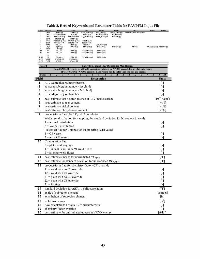
43
Table 2. Record Keywords and Parameter Fields for FAVPFM Input File Record Keyword Field 1 Field 2 Field 3 Field 4 Field 5 Field 6 Field 7 Field 8
1 CNT1 NSIM=[-] IGATR=[-] WPS_OPT=[0|1] PC3_OPT=[0|1] CHILD_OPT=[0|1] RESTART_OPTION=[≤0|≥1]2 CNT2 IRTNDT=[992|993] TC=[°F] EFPY=[yr] IDT_OPT=[0|1|2] IDT_INI=[0|1]3 CNT3 FLWSTR=[ksi] USKIA=[ksi√in] KIa_Model=[1|2] LAYER_OPT=[0|1] FAILCR=[-] 4 GENR SIGFGL=[-] SIGFLC=[-]5 SIGW WSIGCU=[wt%] WSIGNI=[wt%] WSIGP=[wt%]6 SIGP PSIGCU=[wt%] PSIGNI=[wt%] PSIGP=[wt%]7 TRAC ITRAN=[-] IRPV=[-] KFLAW=[-] LOG_OPT=[0|1]8 LDQA IQA=[0|1] IOPT=[1|2] IFLOR=[1|2] IWELD=0|1] IKIND=[1|2] XIN=[in] XVAR=[in|min] ASPECT=[-]9 DTRF NT=[-]10 ISQ ITRAN=[-] ISEQ=[-] TSTART=[min] TEND=[min]11 ISQ ITRAN=[-] ISEQ=[-] TSTART=[min] TEND=[min]
…9+NT ISQ ITRAN=[-] ISEQ=[-] TSTART=[min] TEND=[min]10+NT WELD NWSUB=[-] NWMAJ=[-]11+NT PLAT NPSUB=[-] NPMAJ=[-]
Record
Fields 1 2 3 4 5 6 7 8 9 10 11 12 13 14 15 16 17 18 19 20
Embrittlement and Flaw-Distribution Map Records
11+NT+NWSUB+NPSUB records: Each record has 20 fields with one line per recordInput NWSUB records for all weld subregions followed by NPSUB records for all plate subregions
Field Units
1 RPV Subregion Number (parent) [-]2 adjacent subregion number (1st child) [-]3 adjacent subregion number (2nd child) [-]4 RPV Major Region Number [-]5 best-estimate fast-neutron fluence at RPV inside surface [1019 n/cm2]6 heat-estimate copper content [wt%]7 heat-estimate nickel content [wt%]8 heat-estimate phosphorous content [wt%]9 product-form flags for ∆T 30 shift correlation
Welds: set distribution for sampling for standard deviation for Ni content in welds1 = normal distribution [-]2 = Weibull distribution [-]Plates: set flag for Combustion Engineering (CE) vessel1 = CE vessel [-]2 = not a CE vessel [-]
10 Cu saturation flag0 = plates and forgings [-]1 = Linde 80 and Linde 91 weld fluxes [-]2 = all other weld fluxes [-]
11 best-estimate (mean) for unirradiated RT NDT0 [°F]12 best-estimate for standard deviation for unirradiated RT NDT 0 [°F]13 product-form flag for chemistry-factor (CF) override
11 = weld with no CF override [-]12 = weld with CF override [-]21 = plate with no CF override [-]22 = plate with CF override [-]31 = forging [-]
14 standard deviation for ∆RT NDT shift correlation [°F]15 angle of subregion element [degrees]16 axial height of subregion element [in]17 weld fusion area [in2]18 flaw orientation: 1 = axial; 2 = circumferential [-]19 chemistry-factor override [-]20 best-estimate for unirradiated upper-shelf CVN energy [ft-lbf]
Description

44
EXAMPLE ********************************************************************************************************** * ==================== * * Control Record CNT1 * * ==================== * *--------------------------------------------------------------------------------------------------------* * NSIM = NUMBER OF RPV SIMULATIONS [-] * *--------------------------------------------------------------------------------------------------------* * IGATR = NUMBER OF INITIATION-GROWTH-ARREST (IGA) TRIALS PER FLAW [-] * *--------------------------------------------------------------------------------------------------------* * WPS_OPTION = 0 DO NOT INCLUDE WARM-PRESTRESSING IN ANALYSIS [-] * * WPS_OPTION = 1 INCLUDE WARM-PRESTRESSING IN ANALYSIS [-] * *--------------------------------------------------------------------------------------------------------* * PC3_OPTION = 0 DO NOT PERFORM FRACTURE ANALYSIS OF CATEGORY 3 FLAWS IN PLATES [-] * * PC3_OPTION = 1 PERFORM FRACTURE ANALYSIS OF CATEGORY 3 FLAWS IN PLATES [-] * *--------------------------------------------------------------------------------------------------------* * CHILD_OPTION = 0 DO NOT INCLUDE CHILD SUBREGION REPORTS [-] * * CHILD_OPTION = 1 INCLUDE CHILD SUBREGION REPORTS [-] * *--------------------------------------------------------------------------------------------------------* * RESTART_OPTION = 0 THIS IS NOT A RESTART CASE [-] * * RESTART_OPTION = 1 THIS IS A RESTART CASE [-] * *--------------------------------------------------------------------------------------------------------* * ============================= * * Notes for Control Record CNT1 * * ============================= * * IN A TYPICAL PFM ANALYSIS, A SUBSTANTIAL FRACTION OF THE TOTAL FLAWS ARE CATEGORY 3 FLAWS IN * * PLATE REGIONS. BASED ON EXPERIENCE AND SOME DETERMINISTIC FRACTURE ANALYSES, THESE FLAWS VERY * * RARELY CONTRIBUTE TO THE CPI OR CPF WITH THE PLATE FLAW SIZE DISTRIBUTIONS TYPICALLY USED. * * THEREFORE, INVOKING IP3OPT = 0 CAN RESULT IN A SIGNIFICANT REDUCTION IN EXECUTION TIME WITHOUT * * AFFECTING THE SOLUTION, UNLESS THERE ARE UNUSUAL CIRCUMSTANCES SUCH AS A NEW FLAW-SIZE * * DISTRIBUTION FOR PLATE FLAWS. IN EITHER CASE, CATEGORY 3 PLATE FLAWS ARE INCLUDED IN ALL REPORTS. * * * * Notes on Restart Option: * * * * The restart option flag can also be used to control the frequency with which restart files are * * created. If RESTART_OPTION is given a value other than 0 or 1, then the absolute value of this flag * * sets the checkpoint interval at which the restart file will be created during the run. For example, * * * * 1.RESTART_OPTION = -200 ==> This is not a restart case; restart files will be created every 200 trials * * 2.RESTART_OPTION = 0 ==> Same as example No. 1. * * 3.RESTART_OPTION = 200 ==> This is a restart case; restart files will be created every 200 trials.* * 4.RESTART_OPTION = 1 ==> Same as example No. 3. * * 5.RESTART_OPTION = -50 ==? This is not a restart case; restart files will be created every 50 trials. * * * *--------------------------------------------------------------------------------------------------------* ********************************************************************************************************** CNT1 NSIM=10000 IGATR=100 WPS_OPTION=1 PC3_OPTION=0 CHILD_OPTION=1 RESTART_OPTION=-50 **********************************************************************************************************
Record 2 – CNT2 Record No. 2 inputs a flag, IRTNDT, that designates the correlation to be used for irradiation shift calculations, where IRTNDT = 992 use Regulatory Guide 1.99, Rev. 2, for irradiation shift in RTNDT
IRTNDT = 993 use the E900 correlation for irradiation shift in RTNDT
the normal operating coolant temperature, TC, in °F, the plant operating time, EFPY, to be assumed for this case in effective full-power years, and a flag IDT_OPTION to turn on (IDT_OPTION≥ 1) or off (IDT_OPTION=0) the ductile-tearing model in the IGA submodel. If IDT_OPTION=2, the ductile-tearing model introduced in v03.1 can be activated; however, this model is no longer supported and is maintained in v04.1 for backward compatibility with v03.1 executions only. The newer ductile-tearing model (IDT_OPTION=1) is recommended when investigating the effects of ductile tearing. The flag IDT_INI provides additional reporting concerning flaw initiation due to

45
ductile tearing. Currently, there is no model in FAVOR to determine the probability of flaw initiation by ductile tearing. The ductile-tearing model simulates reinitiation by tearing only after a flaw has arrested. The additional reporting when IDT_INI=1 provides a log of the number of potential ductile-tearing flaw initiations (when applied IcJ J> ) that occurred during the analysis. It should be noted that setting IDT_INI=1 has the potential of significantly increasing the computational time for a given run. When IDT_INI=0, the checks for ductile-tearing initiation are not carried out. When the ductile-tearing option is activated, however, checks for ductile-tearing reinitiation of an arrested flaw will always be performed.
EXAMPLE ********************************************************************************************************** * ==================== * * Control Record CNT2 * * ==================== * *--------------------------------------------------------------------------------------------------------* * IRTNDT = 992 ==> USE RG 1.99, REV 2, FOR ESTIMATING RADIATION-INDUCED SHIFT IN RTNDT * * IRTNDT = 993 ==> USE E900 CORRELATION FOR ESTIMATING RADIATION-INDUCED SHIFT IN RTNDT * *--------------------------------------------------------------------------------------------------------* * TC = INITIAL RPV COOLANT TEMPERATURE (applicable only when IRTNDT=993) [F] * *--------------------------------------------------------------------------------------------------------* * EFPY = EFFECTIVE FULL-POWER YEARS OF OPERATION [YEARS] * *--------------------------------------------------------------------------------------------------------* * IDT_OPTION = 0 DO NOT INCLUDE DUCTILE TEARING AS A POTENTIAL FRACTURE MODE [-] * * IDT_OPTION = 1 INCLUDE DUCTILE TEARING AS A POTENTIAL FRACTURE MODE (recommended) [-] * * IDT_OPTION = 2 INCLUDE DUCTILE TEARING AS A POTENTIAL FRACTURE MODE (v03.1 model) [-] * *--------------------------------------------------------------------------------------------------------* * IDT_INI = 0 DO NOT CREATE A LOG OF POTENTIAL DUCTILE TEARING INITIATIONS [-] * * IDT_INI = 1 CREATE A LOG OF POTENTIAL DUCTILE TEARING INITIATIONS [-] * *--------------------------------------------------------------------------------------------------------* ********************************************************************************************************** CNT2 IRTNDT=993 TC=550 EFPY=32 IDT_OPTION=1 IDT_INI=1
Record 3 – CNT3 Record No. 3 inputs values for the flow stress, FLWSTR, in ksi to be used in the failure model of plastic collapse (ligament instability), the upper bound for KIc and KIa , USKIA, in ksi in. , a flag KIa_Model to designate which arrest model (1 or 2) to use in checking for stable arrest, the weld layer resampling option, LAYER_OPT, (on or off), and the fraction of the total wall thickness, FAILCR, used in the vessel failure criterion. If a flaw, propagating from the inner surface of the vessel, grows to this depth into the wall (relative to the inner surface), then the event will be designated as a vessel failure, where 0.25 FAILCR 0.95≤ ≤ .

46
EXAMPLE ********************************************************************************************************** * ==================== * * Control Record CNT3 * * ==================== * *--------------------------------------------------------------------------------------------------------* * FLWSTR = UNIRRADIATED FLOW STRESS USED IN PREDICTING FAILURE BY REMAINING LIGAMENT INSTABILITY [ksi] * *--------------------------------------------------------------------------------------------------------* * USKIA = MAXIMUM VALUE ALLOWED FOR KIc or KIa [ksi-in^1/2] * *--------------------------------------------------------------------------------------------------------* * KIa_Model = 1 Use high-constraint KIa model based on CCA specimens [-] * * KIa_Model = 2 Use KIa model based on CCA + large specimen data [-] * *--------------------------------------------------------------------------------------------------------* * LAYER_OPTION = 0 DONOT RESAMPLE PF WHEN ADVANCING INTO NEW WELD LAYER [-] * * LAYER_OPTION = 1 RESAMPLE PF WHEN ADVANCING INTO NEW WELD LAYER [-] * *--------------------------------------------------------------------------------------------------------* * FAILCR = FRACTION OF WALL THICKNESS FOR VESSEL FAILURE BY THROUGH-WALL CRACK PROPAGATION [-] * *--------------------------------------------------------------------------------------------------------* * ============================= * * Notes for Control Record CNT3 * * ============================= * * If ductile tearing model is included, then the values for USKIA and KIa_Model are ignored. * * They are automatically set internally to KIa_Model=2 and there is no upper limit on USKIa. * * If ductile tearing is not included in the analysis (IDT_OPTION = 0 on CNT1), both the KIa_Model * * and USKIA are user-specified on CNT3. * * * ********************************************************************************************************** CNT3 FLWSTR=80. USKIA=200. KIa_Model=1 LAYER_OPTION=1 FAILCR=0.9 **********************************************************************************************************
Record 4 – GENR Record No. 4 inputs the value of two multipliers, SIGFGL and SIGFLC, used to obtain the standard deviations of a global and local normal distribution for fluence sampling, where the fluence at the inner surface, (0)f 5, is sampled from two normal distributions such that
)
)
)
( , )
(0) ( , )
global subregion
subregion global
local
local
SIGFGL fluence
f N fluence
SIGFLC f
f N f
σ
σ
σ
σ
= ×
←
= ×
←
where subregionfluence is the best-estimate for the subregion neutron fluence as input in the embrittlement map (to be described below).
5 A curved overbar indicates a sampled random variate, e.g.,
)( , )f N µ σ← means the random variate f has been
sampled from a normal distribution with mean µ and standard deviation σ .

47
EXAMPLE
********************************************************************************************************** * ==================== * * Record GENR * * ==================== * *--------------------------------------------------------------------------------------------------------* * SIGFGL = A MULTIPLIER ON THE BEST ESTIMATE OF FLUENCE FOR A GIVEN SUBREGION [-] * * PRODUCES THE STANDARD DEVIATION FOR THE NORMAL DISTRIBUTION USED TO SAMPLE THE MEAN * * OF THE LOCAL FLUENCE DISTRIBUTION. * *--------------------------------------------------------------------------------------------------------* * SIGFLC = A MULTIPLIER ON THE SAMPLED MEAN OF THE LOCAL FLUENCE FOR A GIVEN SUBREGION [-] * * PRODUCES THE STANDARD DEVIATION FOR THE NORMAL DISTRIBUTION USED TO SAMPLE THE LOCAL FLUENCE* *--------------------------------------------------------------------------------------------------------* * ====================== * * Notes for Record GENR * * ====================== * * Let "flue" be the best estimate for the subregion neutron fluence at inside surface of the RPV wall. * * flue_STDEV_global = SIGFGL*flue * * flue_MEAN_local << Normal(flue,flue_STDEV_global) * * flue_STDEV_local = SIGFLC*flue_MEAN_local * * flue_local << Normal(flue_MEAN_local,flue_STDEV_local) * * * ********************************************************************************************************** GENR SIGFGL=0.056 SIGFLC=0.118 **********************************************************************************************************
Records 5 and 6 – SIGW AND SIGP Records No. 5 and 6 input the values of the standard deviations of the initial normal sampling distributions for the weld and plate chemistries, respectively. On Record 5, the three data fields include the standard deviations for the weight % of copper, Cu, WSIGCU, nickel, Ni, WSIGNI, and phosphorous, P, WSIGP in welds. On Record 6, the three data fields include the standard deviations for the weight % of Cu, PSIGCU, Ni, PSIGNI, and P, PSIGP in plates and forgings. The heat estimates for Cu, Ni, and P given in the embrittlement map described below are used as the means of the normal sampling distributions for the weld and plate chemistries. The weld chemistries are sampled using the following protocols:
*
*
For Ni-addition welds Heats 34B009 &W5214
( , )min(0.0718 ,0.0185); 0.162
( , ) For other heats( , ) (0.029,0.0165)
(
Heat
HeatCu Heat
Cu Cu
Heat CuNi
Cu Cu WSIGCUNi N Ni WSIGNICuWSIGNI
N Cu
Cu N Cu N
Ni N
σ
σ σ
σ σ
= ×←
= ×=
←
← ←
←
); ( , )
, )
Heat
Heat Ni
P N P WSIGP
Ni σ
←
The plate chemistries are sampled using the following protocols:
)
( , ) ; ( , ) ; ( , )Heat Heat HeatCu N Cu PSIGCU Ni N Ni PSIGNI P N P PSIGP← ← ←

48
EXAMPLE
********************************************************************************************************** * ==================== * * Record SIGW * * ==================== * * STANDARD DEVIATIONS (STDEV) OF NORMAL DISTRIBUTIONS FOR WELD CHEMISTRY SAMPLING: * * WSIGCU = STANDARD DEVIATION FOR COPPER CHEMISTRY SAMPLING IN WELDS [wt%] * * WSIGNI = STANDARD DEVIATION FOR NICKEL CHEMISTRY SAMPLING IN WELDS [wt%] * * WSIGP = STANDARD DEVIATION FOR PHOSPHOROUS CHEMISTRY SAMPLING IN WELDS [wt%] * *--------------------------------------------------------------------------------------------------------* * ====================== * * Notes for Record SIGW * * ====================== * * FOR NICKEL IN WELDS THERE ARE TWO POSSIBILITIES. * * (1) FOR HEATS 34B009 AND W5214 (Ni - addition welds) * * WSIGNI = 0.162 wt% using a normal distribution. * * (2) For other heats, the standard deviation (WSIGNI) shall be sampled from a normal distribution * * with mean equal to 0.029 wt% and standard deviation = 0.0165 wt% * ********************************************************************************************************** SIGW WSIGCU=0.167 WSIGNI=0.162 WSIGP=0.0013 ********************************************************************************************************** * ==================== * * Record SIGP * * ==================== * * STANDARD DEVIATIONS (STDEV) OF NORMAL DISTRIBUTIONS FOR PLATE CHEMISTRY SAMPLING: * * PSIGCU = STANDARD DEVIATION FOR COPPER CHEMISTRY SAMPLING IN PLATES [wt%] * * PSIGNI = STANDARD DEVIATION FOR NICKEL CHEMISTRY SAMPLING IN PLATES [wt%] * * PSIGP = STANDARD DEVIATION FOR PHOSPHOROUS CHEMISTRY SAMPLING IN PLATES [wt%] * *--------------------------------------------------------------------------------------------------------* * ====================== * * Notes for Record SIGP * * ====================== * * RECOMMENDED VALUES ARE: 0.0073, 0.0244, 0.0013 for Cu, Ni, and P, respectively. * ********************************************************************************************************** SIGP PSIGCU=0.0073 PSIGNI=0.0244 PSIGP=0.0013 ********************************************************************************************************** * =============================== * * Notes for RecordS SIGW and SIGP * * =============================== * * THE ABOVE DISTRIBUTIONS ARE FOR THE 1ST FLAW POSITIONED IN A PARTICULAR SUBREGION. * * IF THE CURRENT FLAW IS THE 2ND OR MORE FLAW FOR THIS SUBREGION, THEN FAVPFM WILL USE * * THE LOCAL VARIABILITY SAMPLING PROTOCOLS PRESENTED IN THE THEORY MANUAL. * **********************************************************************************************************
Record 7 – TRAC Record No. 7 provides a mechanism for the user to put a trace on a particular flaw, KFLAW, in a specific simulation, IRPV, and for a specific transient, ITRAN. This facility provides a Quality Assurance tool to verify the computational models(s) used to calculate values of CPI and CPF. Data describing the initiation, crack growth, and arrest check calculations are written to the files TRACE.OUT and ARREST.OUT. The variable ITRACK=1 creates flaw-tracking log tables to help identify values for (ITRAN, IRPV, KFLAW) to specify in later executions. These tables can be found in the file TRACE.OUT. An additional file is created called FLAW_TRACK.LOG which provides data for the first 10,000 flaws sampled during the execution.

49
EXAMPLE
********************************************************************************************************** * ==================== * * Record TRAC * * ==================== * * ITRAN = TRANSIENT NUMBER [-] * * RPV = RPV SIMULATION [-] * * KFLAW = FLAW NUMBER [-] * * FLAW_LOG_OPTION = 0 DO NOT CREATE FLAW LOG TABLES [-] * * FLAW_LOG_OPTION = 1 DO CREATE FLAW LOG TABLES [-] * *--------------------------------------------------------------------------------------------------------* * =============================== * * Notes for Record TRAC * * =============================== * * THE ABOVE FLAGS IDENTIFY A SPECIFIC TRANSIENT, RPV SIMULATION, AND FLAW NUMBER WHOSE COMPLETE * * HISTORY WILL BE GIVEN IN THE FILES: "TRACE.OUT" AND "ARREST.OUT" * * SEE THE USER'S GUIDE FOR DETAILS ON THE CONTENTS OF THESE FILES * * * ********************************************************************************************************** TRAC ITRAN=3 IRPV=12 KFLAW=270 FLAW_LOG_OPTION=1 **********************************************************************************************************
Record 8 – LDQA Record No. 8 provides a mechanism for the user to carry out, as a Quality Assurance (QA) or diagnostic exercise, deterministic calculations for the transients received from the FAVLoad module. This utility allows the user to tailor output reports containing (1) time histories of load-related variables at a specific location in the RPV wall or (2) through-wall profiles of load-related variables at a specific transient time. There are eight parameters associated with this record appearing on a single data line.
(1) IQA = 1 activates the QA analysis module; no PFM analysis will be performed IQA = 0 ignore the rest of the data on this data line and proceed with a PFM analysis
(2) IOPT = 1 generate time history results at a specific location in the RPV wall IOPT = 2 generate through-wall profiles of stress and applied KI at a specific time
(3) IFLOR = 1 flaw orientation is axial IFLOR = 2 flaw orientation is circumferential
(4) IWELD = 0 do not include weld residual stresses IWELD = 1 include weld residual stresses
(5) IKIND = 1 inner surface-breaking flaw IKIND = 2 embedded flaw
(6) XIN – only used if IKIND = 2 (otherwise ignored) if IOPT = 1; XIN = location of inner crack tip from inner surface (in.) if IOPT = 2; XIN = 2d = flaw depth (see Fig. 6)
(7) XVAR – meaning depends on the value of IOPT if IOPT = 1; XVAR = flaw depth (in.) (a for IKIND = 1; 2d for IKIND = 2 in Fig. 6) if IOPT = 2; XVAR = elapsed time in minutes
(8) ASPECT aspect ratio = L / a for IKIND = 1; aspect ratio = L / 2d for IKIND = 2 if IKIND = 1; ASPECT = 2, 6, 10, or 999 if IKIND = 2; ASPECT > 0.0

50
EXAMPLE
********************************************************************************************************** * ==================== * * Record LDQA * * ==================== * * THE LDQA RECORD PROVIDES THE OPPORTUNITY TO CHECK LOAD-RELATED SOLUTIONS * * SUCH AS TEMPERATURE, STRESSES, AND KI. * * * * IQA = 0 ==> THIS EXECUTION IS NOT FOR LOAD QA [-] * * IQA = 1 ==> THIS EXECUTION IS FOR LOAD QA [-] * *--------------------------------------------------------------------------------------------------------* * IOPT = 1 ==> GENERATE TIME HISTORY AT SPECIFIC THROUGH WALL LOCATION [-] * * IOPT = 2 ==> GENERATE THROUGH WALL DISTRIBUTION AT SPECIFIC TIME [-] * *--------------------------------------------------------------------------------------------------------* * IFLOR = 1 ==> FLAW ORIENTATION IS AXIAL [-] * * IFLOR = 2 ==> FLAW ORIENTATION IS CIRCUMFERENTIAL [-] * *--------------------------------------------------------------------------------------------------------* * IWELD = 0 ==> DOES NOT INCLUDE THRU-WALL WELD RESIDUAL STRESS [-] * * IWELD = 1 ==> DOES INCLUDE THRU-WALL WELD RESIDUAL STRESS [-] * *--------------------------------------------------------------------------------------------------------* * IKIND = 1 ==> INNER-SURFACE BREAKING FLAW [-] * * IKIND = 2 ==> EMBEDDED FLAW [-] * *--------------------------------------------------------------------------------------------------------* * XIN IS ONLY USED IF IKIND=2 (EMBEDDED FLAWS) * * XIN = IF IOPT=1; LOCATION OF INNER CRACK TIP FROM INNER SURF. [IN] * * XIN = IF IOPT=2; FLAW DEPTH [IN] * *--------------------------------------------------------------------------------------------------------* * XVAR: IF IOPT=1; XVAR=FLAW DEPTH [IN] * * IF IOPT=2; XVAR=TIME [MIN] * *--------------------------------------------------------------------------------------------------------* * ASPECT = ASPECT RATIO; FOR SURFACE BREAKING FLAWS: 2,6,10,999 (infin) [-] * * FOR EMBEDDED FLAWS: ANY VALUE > 0 * *--------------------------------------------------------------------------------------------------------* * =============================== * * Notes for Record LDQA * * =============================== * * IQA = 0 NO VALIDATION REPORTS WILL BE GENERATED, PFM ANALYSIS WILL BE PERFORMED * * IQA = 1 LOAD PARAMETERS WILL BE GENERATED FOR VERIFICATION PURPOSES, PFM ANALYSIS WILL NOT BE PERFORMED* ********************************************************************************************************** LDQA IQA=0 IOPT=2 IFLOR=2 IWELD=0 IKIND=1 XIN=0.53 XVAR=70 ASPECT=99 **********************************************************************************************************
Record 9 – DTRF
In some cases, the PFM solution(s) can be sensitive to the time-step size (specified as DT on Record 7 in FAVLoad input as discussed in Sect. 2.1) used in the analysis. Some preliminary analysis is useful in determining a suitable DT that provides a converged PFM solution, i.e., converged in the sense that a decrease in DT does not result in a significant change in the solution. Decreasing DT resolves the load and fracture toughness variables better; however, smaller values of DT increase the number of discrete time steps to cover the transient, thus increasing the amount of computational effort required to perform the PFM analysis. Ideally, one would like to use a relatively small time step in the PFM analysis for better accuracy, yet to perform the PFM analysis for only the time period during which all of the crack initiations and failures are predicted to occur.
Record 9 provides a mechanism to specify the starting and ending times for specific transients supplied in the FAVLoad output file. The variable NT sets the number of ISQ records that follow the DTRF record. The following NT records contain values for ITRAN (= the transient number in the transient stack supplied in the FAVLoad output file), ISEQ (= the corresponding identifying thermal-

51
hydraulic sequence number), TSTART (= starting time in minutes), and TEND (= ending time in minutes). Only those transients in the FAVLoad transient stack for which the user wishes to set special values of TSTART and TEND need be identified by the DTRF records. All other transients in the stack, not explicitly specified in the DTRF records, will use the global transient start (always = 0.0) and ending times set by the execution of the FAVLoad module.
During preliminary analyses to determine a suitable DT that provides a converged solution, one may also determine for each transient the time period during which postulated cracks are predicted to initiate and propagate through-the-wall since this information is reported for each transient in the Transient Time Distribution Report (See example FAVPFM output in Sect. 2.6). Limiting the time period during which the PFM analysis is performed for each transient will reduce the computational effort.
EXAMPLE No. 1
********************************************************************************************************** * ==================== * * Record DTRF * * ==================== * *--------------------------------------------------------------------------------------------------------* * NT = number of ISQ records that follow [-] * * NT = 0 no ISQ records follow * *--------------------------------------------------------------------------------------------------------* * FOLLOWING THE DTRF RECORD, THERE SHOULD BE "NT" SUBRECORDS * *--------------------------------------------------------------------------------------------------------* * ISQ ITRAN= ISEQ= TSTART= TEND= * *--------------------------------------------------------------------------------------------------------* * ITRAN = sequential number in FAVLoad transient stack [-] * * ISEQ = Thermal Hydraulic trasient sequence number [-] * * TSTART = starting time for FAVPFM analysis [MIN] * * TEND = ending time for FAVPFM analysis [MIN] * ********************************************************************************************************** DTRF NT=4 *--------------------------------------------------------------------------------------------------------* ISQ ITRAN=1 ISEQ=7 TSTART=2 TEND=35 ISQ ITRAN=2 ISEQ=9 TSTART=1 TEND=29 ISQ ITRAN=3 ISEQ=56 TSTART=9 TEND=56 ISQ ITRAN=4 ISEQ=97 TSTART=11 TEND=85 **********************************************************************************************************
To use the global starting and ending times for all transients, set in FAVLoad Input Record 7, input the following:
EXAMPLE No. 2
********************************************************************************************************** * ==================== * * Record DTRF * * ==================== * *--------------------------------------------------------------------------------------------------------* * NT = number of ISQ records that follow [-] * * NT = 0 no ISQ records follow * *--------------------------------------------------------------------------------------------------------* * FOLLOWING THE DTRF RECORD, THERE SHOULD BE "NT" SUBRECORDS * *--------------------------------------------------------------------------------------------------------* * ISQ ITRAN= ISEQ= TSTART= TEND= * *--------------------------------------------------------------------------------------------------------* * ITRAN = sequential number in FAVLoad transient stack [-] * * ISEQ = Thermal Hydraulic trasient sequence number [-] * * TSTART = starting time for FAVPFM analysis [MIN] * * TEND = ending time for FAVPFM analysis [MIN] * ********************************************************************************************************** DTRF NT=0 **********************************************************************************************************

52
Records 10+NT and 11+NT
Records 10+NT and 11+NT give the number of major regions and subregions for welds and plates, respectively. The sum of the number of weld subregions, NWSUB, and the number of plate subregions, NPSUB, gives the total number of embrittlement map records to follow this keyword line. NWMAJ is the number of major weld regions, and NPMAJ is the number of major plate regions.
EXAMPLE
********************************************************************************************************** * ==================== * * Record WELD * * ==================== * * NWSUB = NUMBER OF WELD SUBREGIONS [-] * * NWMAJ = NUMBER OF WELD MAJOR REGIONS [-] * ********************************************************************************************************** WELD NWSUB=838 NWMAJ=5 ********************************************************************************************************** * ==================== * * Record PLAT * * ==================== * * NPSUB = NUMBER OF PLATE SUBREGIONS [-] * * NPMAJ = NUMBER OF PLATE MAJOR REGIONS [-] * ********************************************************************************************************** PLAT NPSUB=14442 NPMAJ=4 **********************************************************************************************************
Records 12+NT through 11+NT+NWSUB+NPSUB
Following Record 11+NT, there will be NWSUB + NPSUB data lines (one record per subregion and one data line per record) that contain the embrittlement map for all of the weld and plate subregions. Note that the data records for the weld subregions must precede the data records for the plate subregions. There are 20 fields in each record.
(1) subregion number – subregion numbers should start with 1 and then increment by 1 for the complete embrittlement map.
Flaws in welds have been observed to reside along the fusion line between the weld and adjacent plate; therefore, it is possible that the adjacent plate(s) could have a higher degree of embrittlement and/or less ductility than the weld. The embrittlement/ductility-related properties of the most limiting (of the weld or the adjacent plate) material shall be used when evaluating flaw advancement by cleavage propagation or ductile tearing. If this subregion is a weld region, FAVOR will determine if one of the adjacent plate(s), located in adjacent-plate subregions, is more limiting, i.e., has a higher RTNDT for cleavage propagation and a lower value of USEi for flaw advancement by ductile tearing (IDT_OPTION=2 only). If so, FAVOR will use the embrittlement/ductility properties of the more limiting subregion, where separate sets of parent/child relationships are determined for cleavage

53
propagation and ductile tearing. The next two fields are valid only if the subregion designated in field 1 is a weld subregion. From a roll-out map of the RPV beltline, select the plate subregions that are adjacent to the weld subregion in field 1. If field 1 refers to a plate subregion, just repeat the subregion number from field 1 in fields 2 and 3.
(2) left-adjacent plate subregion number
(3) right-adjacent plate subregion
(4) major region number
(5) best estimate for fast-neutron fluence at inside surface of RPV wall ( 1019 neutrons/cm2)
(6) heat estimate for copper content (wt%), HeatCu
(7) heat estimate for nickel content (wt%), HeatNi
(8) heat estimate for phosphorous content (wt%), HeatP
(9) if field 1 is a weld subregion select the method for determining the standard deviation for the normal distribution used to simulate the Ni content
= 1 use the constant value given in the WSIGNI field on Record 5. (These are Ni-addition welds from heats 34B009 and W5214 in the RVID2 database.)
= 2 sample from a normal distribution with (0.029,0.0165)Ni Nσ ← (all other heats)
(9) if field 1 is a plate subregion with IRTNDT=993 on Record 2 (ignored if IRTNDT=992)
= 1 Combustion Engineering (CE) plate
= 2 all other plates and forgings
(10) copper saturation flag when IRTNDT = 993 on Record 2 (ignored if IRTNDT=992)
= 0 for plates and forgings
= 1 for Linde 80 and Linde 91 weld fluxes
= 2 for all other weld fluxes
(11) RVID2 heat estimate for unirradiated value of RTNDT (RTNDT0) (°F) (see Appendix A)
(12) standard deviation for RTNDT0 (°F) (used in RTPTS calculation). If the RTNDT(u) Method in Appendix A is either MTEB 5-2 or ASME NB-2331, enter a 0.0. If the RTNDT(u) Method in Appendix A is Generic, enter a best-estimate for the standard deviation.

54
(13) Irradiation-shift-correlation flag when IRTNDT=993 on Record 2
= 11 weld major region
= 21 plate major region
= 31 forging major region
(13) Irradiation-shift-correlation flag when IRTNDT = 992 on Record 2
= 11 weld major region; no chemistry-factor override
= 12 weld major region; with chemistry-factor override
= 21 plate major region; no chemistry-factor override
= 22 plate major region; with chemistry-factor override
= 31 forging major region
(14) Standard deviation for irradiation shift (°F) (used in RTPTS calculation)
(15) Angle of subregion element, dθ (degrees) (see Fig. 17 on the following page )
(16) Axial height of subregion element, dz (inches) (see Fig. 17 on the following page)
(17) Weld fusion area (=0.0 for plate subregions) (in2) (see Figs. 17a and b)
(18) Weld orientation; =1 axial; =2 circumferential (ignored if Plate subregion)
(19) Chemistry-factor override; (if IRTNDT=992 on Record 2 and irradiation shift correlation flag (field 13) = 12 or 22)
(20) Unirradiated upper-shelf CVN energy (USE0) in [ft-lbf] from RVID2, (used only if IDT_OPTION=2

55
(a)
(b) Fig. 17. Weld fusion area definitions for (a) axial-weld subregion elements and
(b) circumferential-weld subregion elements.

56
Fig. 17. (continued) (c) Plate subregion element.
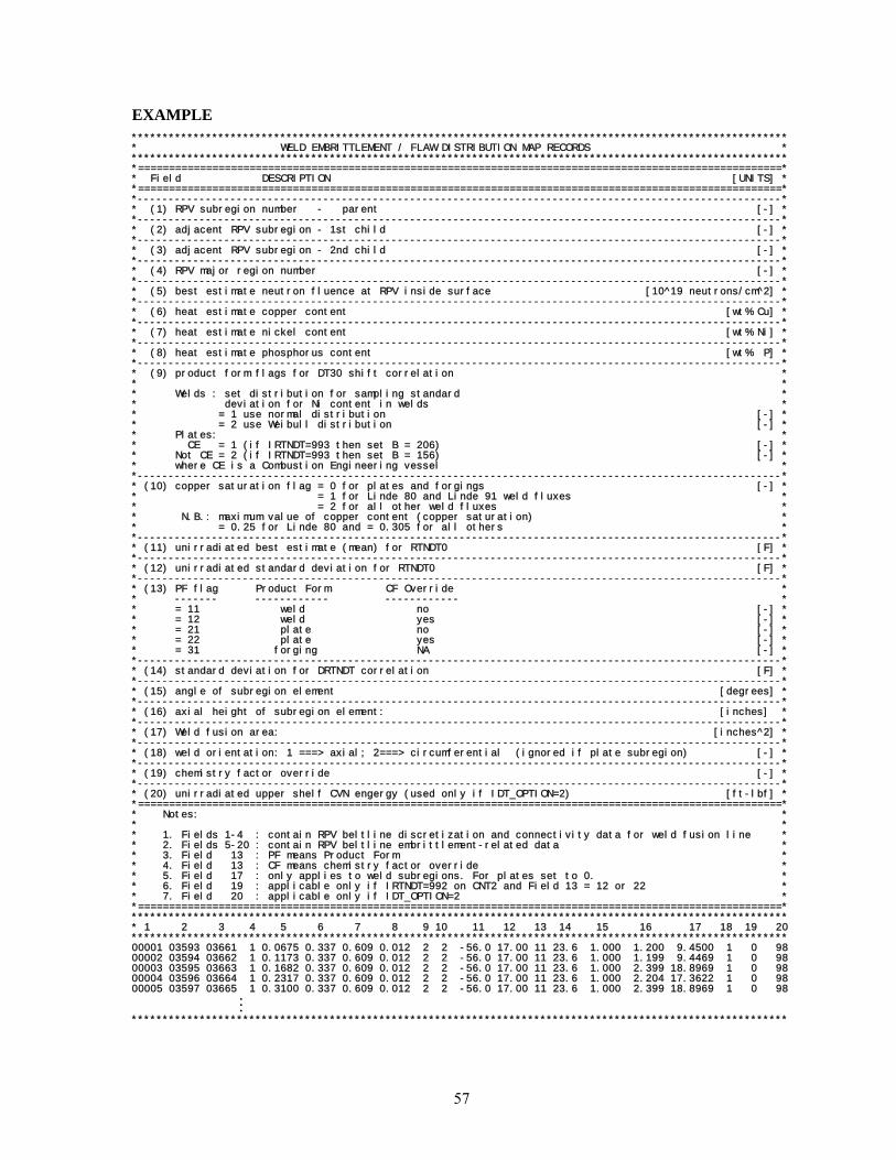
57
EXAMPLE ********************************************************************************************************** * WELD EMBRITTLEMENT / FLAW DISTRIBUTION MAP RECORDS * ********************************************************************************************************** *========================================================================================================* * Field DESCRIPTION [UNITS] * *========================================================================================================* *--------------------------------------------------------------------------------------------------------* * (1) RPV subregion number - parent [-] * *--------------------------------------------------------------------------------------------------------* * (2) adjacent RPV subregion - 1st child [-] * *--------------------------------------------------------------------------------------------------------* * (3) adjacent RPV subregion - 2nd child [-] * *--------------------------------------------------------------------------------------------------------* * (4) RPV major region number [-] * *--------------------------------------------------------------------------------------------------------* * (5) best estimate neutron fluence at RPV inside surface [10^19 neutrons/cm^2] * *--------------------------------------------------------------------------------------------------------* * (6) heat estimate copper content [wt% Cu] * *--------------------------------------------------------------------------------------------------------* * (7) heat estimate nickel content [wt% Ni] * *--------------------------------------------------------------------------------------------------------* * (8) heat estimate phosphorus content [wt% P] * *--------------------------------------------------------------------------------------------------------* * (9) product form flags for DT30 shift correlation * * * * Welds : set distribution for sampling standard * * deviation for Ni content in welds * * = 1 use normal distribution [-] * * = 2 use Weibull distribution [-] * * Plates: * * CE = 1 (if IRTNDT=993 then set B = 206) [-] * * Not CE = 2 (if IRTNDT=993 then set B = 156) [-] * * where CE is a Combustion Engineering vessel * *--------------------------------------------------------------------------------------------------------* * (10) copper saturation flag = 0 for plates and forgings [-] * * = 1 for Linde 80 and Linde 91 weld fluxes * * = 2 for all other weld fluxes * * N.B.: maximum value of copper content (copper saturation) * * = 0.25 for Linde 80 and = 0.305 for all others * *--------------------------------------------------------------------------------------------------------* * (11) unirradiated best estimate (mean) for RTNDT0 [F] * *--------------------------------------------------------------------------------------------------------* * (12) unirradiated standard deviation for RTNDT0 [F] * *--------------------------------------------------------------------------------------------------------* * (13) PF flag Product Form CF Override * * ------- ------------ ------------ * * = 11 weld no [-] * * = 12 weld yes [-] * * = 21 plate no [-] * * = 22 plate yes [-] * * = 31 forging NA [-] * *--------------------------------------------------------------------------------------------------------* * (14) standard deviation for DRTNDT correlation [F] * *--------------------------------------------------------------------------------------------------------* * (15) angle of subregion element [degrees] * *--------------------------------------------------------------------------------------------------------* * (16) axial height of subregion element: [inches] * *--------------------------------------------------------------------------------------------------------* * (17) Weld fusion area: [inches^2] * *--------------------------------------------------------------------------------------------------------* * (18) weld orientation: 1 ===> axial; 2===> circumferential (ignored if plate subregion) [-] * *--------------------------------------------------------------------------------------------------------* * (19) chemistry factor override [-] * *--------------------------------------------------------------------------------------------------------* * (20) unirradiated upper shelf CVN engergy (used only if IDT_OPTION=2) [ft-lbf] * *========================================================================================================* * Notes: * * * * 1. Fields 1-4 : contain RPV beltline discretization and connectivity data for weld fusion line * * 2. Fields 5-20 : contain RPV beltline embrittlement-related data * * 3. Field 13 : PF means Product Form * * 4. Field 13 : CF means chemistry factor override * * 5. Field 17 : only applies to weld subregions. For plates set to 0. * * 6. Field 19 : applicable only if IRTNDT=992 on CNT2 and Field 13 = 12 or 22 * * 7. Field 20 : applicable only if IDT_OPTION=2 * *========================================================================================================* ********************************************************************************************************** * 1 2 3 4 5 6 7 8 9 10 11 12 13 14 15 16 17 18 19 20 ********************************************************************************************************** 00001 03593 03661 1 0.0675 0.337 0.609 0.012 2 2 -56.0 17.00 11 23.6 1.000 1.200 9.4500 1 0 98 00002 03594 03662 1 0.1173 0.337 0.609 0.012 2 2 -56.0 17.00 11 23.6 1.000 1.199 9.4469 1 0 98 00003 03595 03663 1 0.1682 0.337 0.609 0.012 2 2 -56.0 17.00 11 23.6 1.000 2.399 18.8969 1 0 98 00004 03596 03664 1 0.2317 0.337 0.609 0.012 2 2 -56.0 17.00 11 23.6 1.000 2.204 17.3622 1 0 98 00005 03597 03665 1 0.3100 0.337 0.609 0.012 2 2 -56.0 17.00 11 23.6 1.000 2.399 18.8969 1 0 98
M **********************************************************************************************************

58
2.3 FAVOR Post-Processing Module – FAVPost
(2 × NTRAN) + 1 data records, listed in Table 3, are required in the FAVPost input file, where each record may involve more than one line of data. A detailed description of each data record is given below.
Table 3. Record Keywords and Parameters for FAVPost Input File
Record Keyword Field 1 Field 2 Field 31 CNTL NTRAN=[-]
Repeat data records 2 through 3 for each of the NTRAN transients2 ITRN ITRAN=[-] NHIST=[-] ISEQ=[-]3 input NHIST data lines with ( initiating frequency , probability density )
data pairs – one pair per linef init Density
[events/yr] [% ]
Record 1 – CNTL Record No. 1 inputs the number of transients, NTRAN, for which initiating frequency probability density distributions (histograms) are being input.
Records 2 and 3 are repeated for each of the NTRAN transients.
Record 2 – ITRN
Record 2 inputs the FAVOR transient number, ITRAN, the number of lines, NHIST, in Record 3 which contains the initiating frequency histogram (in terms of relative frequency), and the initiating- sequence event number, ISEQ, from the thermal-hydraulic studies that supplied the transient for input to FAVOR.
Record 3 – Initiating Event Sequence Probability Density Functions (Histograms)
Input NHIST lines containing one histogram data pair per line, where the first field is the value of the transient initiating frequency in events per reactor-operating year and the second field is the probability density (as a relative frequency in percent).
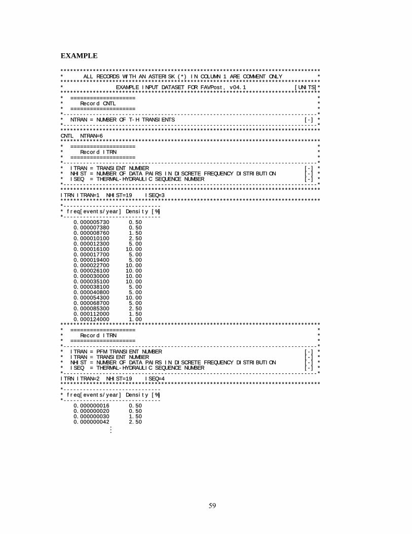
59
EXAMPLE
******************************************************************************** * ALL RECORDS WITH AN ASTERISK (*) IN COLUMN 1 ARE COMMENT ONLY * ******************************************************************************** * EXAMPLE INPUT DATASET FOR FAVPost, v04.1 [UNITS]* ******************************************************************************** * ==================== * * Record CNTL * * ==================== * *------------------------------------------------------------------------------* * NTRAN = NUMBER OF T-H TRANSIENTS [-] * *------------------------------------------------------------------------------* ******************************************************************************** CNTL NTRAN=6 ******************************************************************************** * ==================== * * Record ITRN * * ==================== * *------------------------------------------------------------------------------* * ITRAN = TRANSIENT NUMBER [-] * * NHIST = NUMBER OF DATA PAIRS IN DISCRETE FREQUENCY DISTRIBUTION [-] * * ISEQ = THERMAL-HYDRAULIC SEQUENCE NUMBER [-] * *------------------------------------------------------------------------------* ******************************************************************************** ITRN ITRAN=1 NHIST=19 ISEQ=3 ******************************************************************************** *------------------------------ * freq[events/year] Density [%] *------------------------------ 0.000005730 0.50 0.000007380 0.50 0.000008760 1.50 0.000010100 2.50 0.000012300 5.00 0.000016100 10.00 0.000017700 5.00 0.000019400 5.00 0.000022700 10.00 0.000026100 10.00 0.000030000 10.00 0.000035100 10.00 0.000038100 5.00 0.000040800 5.00 0.000054300 10.00 0.000068700 5.00 0.000085300 2.50 0.000112000 1.50 0.000124000 1.00 ******************************************************************************** * ==================== * * Record ITRN * * ==================== * *------------------------------------------------------------------------------* * ITRAN = PFM TRANSIENT NUMBER [-] * * ITRAN = TRANSIENT NUMBER [-] * * NHIST = NUMBER OF DATA PAIRS IN DISCRETE FREQUENCY DISTRIBUTION [-] * * ISEQ = THERMAL-HYDRAULIC SEQUENCE NUMBER [-] * *------------------------------------------------------------------------------* ITRN ITRAN=2 NHIST=19 ISEQ=4 ******************************************************************************** *------------------------------ * freq[events/year] Density [%] *------------------------------ 0.000000016 0.50 0.000000020 0.50 0.000000030 1.50 0.000000042 2.50
M

60
2.4 Content and Format for Flaw Distribution Databases
By convention, flaws have been defined as Categories 1, 2, or 3 using the following designations:
(1) Category 1 – inner-surface breaking flaws
(2) Category 2 – embedded flaws in which the inner tip of the flaw is located between the clad-base interface and t/8 where t is the RPV wall thickness
(3) Category 3 – embedded flaws in which the inner tip of the flaw is located between t/8 and 3t/8.
When executing the FAVPFM module, the user is prompted for three flaw-characterization files as follows: (1) inner surface-breaking flaws (2) embedded flaws in welds, and (3) embedded flaws in plates or forgings. The flaw-characterization file for inner-surface breaking flaws is applicable to both welds and plates/forgings.
The format is the following:
Each of the flaw-characterization files consists of 1000 file records, where each file record has 100 rows and several columns. The first and second columns in each row are: Column (1) – the integer row number
Column (2) – the flaw density corresponding to a flaw depth equal to (row number/100) * vessel wall thickness.
For example, the flaw density in the 1st row corresponds to flaw depths of 1/100th of the RPV wall thickness, the flaw density in the 19th row corresponds to flaw depths of (0.19)(wall thickness), etc.
The remaining columns are a probability distribution function (histogram) of aspect ratios (ratio of flaw length to flaw depth); i.e., each flaw depth has its own probability distribution of flaw length as will be discussed in more detail below.
2.4.1 Method of Quantifying Uncertainty in Flaw Characterization
The method used to quantify the uncertainty in the flaw characterization is to include 1000 flaw-characterization file records for each of the three flaw data files (surface-breaking, weld embedded, and plate embedded) discussed above. Each of these file records contains separate flaw-density, flaw-size, and aspect-ratio distributions with the format as discussed above. The format for the three characterization files is discussed in more detail below.
During the Monte Carlo PFM analysis, the RPV flaw-characterization data for the 1st stochastically-generated RPV trial are taken from the 1st group of file records, i.e., the first inner-surface breaking

61
file record, the first embedded-flaw weld material file record, and the first embedded-flaw plate material file record. The RPV flaw characterization for the 2nd stochastically generated RPV trial is determined from the 2nd group of file records, etc. The RPV trials cycle through the flaw-characterization file records sequentially up to 1000, and then restarts at the first file record.
2.4.2 Flaw-Characterization File Names and Sizes
The flaw-characterization file for inner-surface-breaking flaws is 100,000 rows with 5 columns. The name of the example ASCII text file on the distribution CD is “S.DAT” with a size of 7.0 MBytes. The flaw-characterization file for embedded flaws in welded regions is 100,000 rows with 13 columns. The name of this ASCII text file on the distribution disk is “W.DAT” with a size of 15.2 MBytes. The flaw-characterization file for embedded flaws in plate regions is 100,000 rows with 13 columns. The name of this ASCII text file on the distribution disk is ”P.DAT”, and its size is 15.2 MBytes. The distribution CD also includes flaw-characterization files that are specific to the four plants under study in the PTS Re-evaluation Program, specifically BVsurf.DAT, BVweld.DAT, and BVplate.DAT for Beaver Valley, S_CC.DAT, W_CC.DAT, and P_CC.DAT for Calvert Cliffs, OCsurf.DAT, OCweld.DAT, and OCplate.DAT for Oconee, and PLsurf.DAT, PLweld.DAT, and PLplate.DAT for Palisades.
2.4.3 Inner-surface Breaking Flaws (Flaw Category 1)
A more detailed explanation of the format of the inner-surface breaking flaw data is given by way of example:
Histogram of Aspect ratio (AR) (%) AR=2 AR=6 AR=10 AR=infinite 1 density of flaw depths 1/100 RPV thickness 35.0 30.0 20.0 15.0 2 density of flaw depths 2/100 RPV thickness 40.0 30.0 25.0 5.0 3 density of flaw depths 3/100 RPV thickness : : : : : : density of flaw depths = RPV thickness : 1 density of flaw depths 1/100 RPV thickness : 2 density of flaw depths 2/100 RPV thickness : 3 density of flaw depths 3/100 RPV thickness : : : : : 100 density of flaw depths = RPV thickness : : : : through the 1000th file : : : : :
As illustrated above, for each flaw depth, there is a histogram for the aspect ratio (flaw depth / length) where the bins are aspect ratios of 2, 6, 10, and infinity. The reason for these specific aspect ratios is

62
that they correspond to the flaw geometries for which stress intensity factor influence coefficients were generated and implemented into the FAVLoad module. The histograms will be sampled during the PFM analysis to stochastically determine the aspect ratio for the corresponding sampled flaw depth.
The FORTRAN subroutine in the FAVPFM module that reads the file containing flaw characteri-zation data for inner-surface breaking flaws is:
SUBROUTINE RDSURF(ISMAX) C+++++++++++++++++++++++++++++++++++++++++++++++++++++++++++++++++++++++ IMPLICIT REAL*8 (A-H,O-Z) C*********************************************************************** C*** *** C*** Revisions: *** C*** *** C*** Date | Modification *** C*** ============|==================================================*** C*** *** C*** *** C*** *** C*********************************************************************** C*********************************************************************** C SUBROUTINE RDSURF READS DATA FROM THE FILE THAT CHARACTERIZES * C SURFACE-BREAKING FLAWS (CATEGORY 1 FLAWS) AND IS APPLICABLE TO * C BOTH WELD AND PLATE REGIONS. * C * C THE UNITS OF THE CATEGORY 1 SURFACE-BREAKING FLAWS ARE FLAWS PER * C SQUARE FOOT OF AREA ON THE INNER SURFACE OF THE RPV. * C * C THE (I,J) ENTRY READ INTO ARRAY WDEPTH(100,1,IFILE) IS THE FLAW * C DENSITY OF INNER-SURFACE BREAKING FLAWS (CATEGORY 1 FLAWS) THAT * C HAVE A DEPTH OF (i/100)*WALL THICKNESS. * C * C SINCE THE DATA IS ALSO APPLICABLE TO PLATE MATERIAL, THE SAME DATA * C IS READ INTO PDEPTH(100,1,IFILE) * C*********************************************************************** INTEGER :: IVER, IERR C======================================================================= COMMON /PROG/WDEPTH (100, 3,1000),WELDCAT(3,1000),PLATCAT(3,1000), & WCATCDF(100, 3,1000),WSUM(3,1000), PSUM (3,1000), & WCATPDF(100, 3,1000),PDEPTH (100, 3,1000), & PCATCDF(100, 3,1000),PCATPDF (100, 3,1000), & WFLASPT(100,12,1000),PFLASPT (100,12,1000), & WASPCDF(100,12,1000),PASPCDF (100,12,1000), & SFLASPT(100, 4,1000),SASPCDF (100, 4,1000) C====================================================================== REAL*8, PARAMETER :: ZERO=0. C====================================================================== WRITE (*,1004) WRITE (*,8769) 1004 FORMAT (' ' ) 8769 FORMAT (11X,' READING AND PROCESSING SURFACE-BREAKING', & ' FLAW DATABASE') C*********************************************************************** C READ THE SURFACE-BREAKING FLAW CHARACTERIZATION FILE. THE FORMAT OF * C THIS FILE IS: * C * C K, FLAW DENSITY, FOLLOWED BY 4 NUMBERS THAT ARE A HISTOGRAM OF * C ASPECT RATIOS FOR FLAWS OF THIS DEPTH WHERE THE HISTOGRAM IS * C EXPRESSED IN PERCENT. A CDF WILL BE CONSTRUCTED FOR EACH OF THE * C HISTOGRAMS THAT CAN BE SAMPLED DURING THE PFM ANALYSIS TO * C APPROPRIATELY POSTULATE ASPECT RATIO FOR SURFACE BREAKING * C (CATEGORY 1) FLAWS. * C * C THE CORRESPONCE BETWEEN THE POSITION (OUT OF THE 4 BINS) AND THE * C ASPECT RATIO IS AS FOLLOWS: * C * C BIN NUMBER ASPECT ARRAY * C RATIO LOCATION * C * C 1 2 SFLASPT(J,1,IFILE) *

63
C 2 6 SFLASPT(J,2,IFILE) * C 3 10 SFLASPT(J,3,IFILE) * C 4 INFINITE SFLASPT(J,4,IFILE) * C * C J VARIES FROM 1==>100 TO COVER THE ENTIRE RANGE OF POSSIBLE FLAW * C DEPTHS * C * C IFILE VARIES FROM 1==> 1000 TO COVER THE ENTIRE RANGE OF WELD * C SURFACE BREAKING FLAW CHARACTERIZATION FILES USED TO INCLUDE THE * C QUANTIFICATION OF UNCERTAINTY. * * C*********************************************************************** READ (48,*) IVER if (IVER .NE. 41) then call xermsg ('FAVPFM','RDSURF', & 'SURFACE-BREAKING FLAW FILE NOT VERSION 04.1',17,1) call xerdmp call xerabt('xerror -- invalid input',23) endif ISMAX = 0 DO 10 IFILE=1,1000 DO 20 J=1,100 READ (48,*,IOSTAT=IERR) K,WDEPTH(J,1,IFILE), & SFLASPT(J,1,IFILE),SFLASPT(J,2,IFILE), & SFLASPT(J,3,IFILE),SFLASPT(J,4,IFILE) IF (IERR .NE. 0) GOTO 998 PDEPTH(J,1,IFILE) = WDEPTH(J,1,IFILE) IF (WDEPTH(J,1,IFILE) .GT. ZERO) THEN IF (J.GT.ISMAX) ISMAX = J ENDIF 20 CONTINUE 10 CONTINUE GOTO 999 C======================================================================= 998 CONTINUE write(*,1000) IFILE, J, IFILE*J, IERR 1000 FORMAT(/'IFILE=',I4,' K=',I4,' LINE NUMBER=',I5,' IERR=',I4/) call xermsg ('FAVPFM','RDSURF', & 'ERROR READING SURFACE-BREAKING FLAW DATA',18,1) call xerdmp call xerabt('xerror -- invalid input',23) C======================================================================= 999 CONTINUE C RETURN END
where WDEPTH (1:100, 1:3, 1:1000) is an array in FAVPFM in which the (J,1,IFILE) address contains flaw densities of Category 1 (inner-surface breaking flaws) for welds and PDEPTH (1:100,1:3,1:1000) is a three-dimensional array in which the (J,1,IFILE) address contains flaw densities of Category 1 (inner-surface breaking flaws) for plates/forgings.
SFLASPT (1:100,1:4,1:1000) is an array in FAVPFM in which the (J,1,IFILE) address contains the percentage of flaws with an aspect ratio of 2, the (J,2,IFILE) address contains the percentage of flaws with an aspect ratio of 6, the (J,3,IFILE) address contains the percentage of flaws with an aspect ratio of 10, and the (J,4,IFILE) address contains the percentage of flaws with an aspect ratio of infinity.
Inner-surface breaking flaws with a depth less than the clad thickness are not considered as candidates for cleavage initiation since the austenitic stainless steel cladding plane-strain cleavage fracture toughness is considerably more ductile than the ferritic base metal. Also, all inner-surface breaking flaws are assumed to be circumferentially oriented (even if the flaw is located in an axially oriented

64
weld or plate) since all inner-surface breaking flaws are assumed to be a result of the process in which the cladding was applied.
2.4.4 Embedded flaw Characterization for Welds (Categories 2 and 3 flaws)
As with Category 1 inner-surface breaking flaws, the first and second columns in each row are (1) the integer row number and (2) the flaw density corresponding to a flaw depth equal to (row number/100) * vessel wall thickness, and the remaining columns are a probability distribution function (histogram) of aspect ratios (ratio of flaw length to flaw depth). Again, a more detailed explanation of the format of the inner-surface breaking flaw data is given by way of example as follows:
Histogram of Aspect ratio (AR) (11 bins) (%) 1 density of flaw depths t/100 2 density of flaw depths 2t/100 RPV thickness 3 density of flaw depths 3t/100 RPV thickness : : : : : density of flaw depths = RPV thickness : 1 density of flaw depths t/100 RPV thickness : 2 density of flaw depths 2t/100 RPV thickness : density of flaw depths 3t/100 RPV thickness : density of flaw depths = RPV thickness : : : through 1000th file :
The FORTRAN subroutine in the FAVPFM module that reads the file containing flaw characteri-zation data for embedded flaws in welds is as follows:
C+++++++++++++++++++++++++++++++++++++++++++++++++++++++++++++++++++++++ SUBROUTINE RDWELD(IWMAX) C+++++++++++++++++++++++++++++++++++++++++++++++++++++++++++++++++++++++ IMPLICIT REAL*8 (A-H,O-Z) C*********************************************************************** C*** *** C*** Revisions: *** C*** *** C*** Date | Modification *** C*** ============|==================================================*** C*** *** C*** *** C*** *** C*********************************************************************** C*********************************************************************** C SUBROUTINE RDWELD READS DATA FROM THE FILE THAT CHARACTERIZES * C EMBEDDED FLAWS POSTULATED TO RESIDE IN WELD REGIONS. * C * C THIS SUBROUTINE READS THE FLAW CHARACTERIZATION FLAW DATA FOR * C EMBEDDED FLAWS IN WELD MATERIAL INTO ARRAYS THAT WILL BE SAMPLED * C DURING THE PFM ANALYSIS TO STOCHASTICALLY POSTULATE FLAWS * C IN THE RPV A MANNER CONSISTENT WITH THE FLAW CHARACTERIZATION. * C * C THE (I,J) ENTRY READ INTO ARRAY WDEPTH(100,1,IFILE) IS THE FLAW * C DENSITY OF INNER-SURFACE BREAKING FLAWS (CATEGORY 1 FLAWS) THAT * C HAVE A DEPTH OF (i/100)*WALL THICKNESS. THIS READ IS PERFORMED IN * C SUBROUTINE RDSURF. THE UNITS OF THIS FLAW DENSITY ARE FLAWS PER * C SQUARE FOOT OF AREA ON THE INNER SURFACE OF THE RPV. * C * C THE (I,J) ENTRY READ INTO ARRAY WDEPTH(100,2,IFILE) IS THE FLAW * C DENSITY OF CATEGORY 2 EMBEDDED FLAWS (EMBEDDED FLAWS SUCH THAT *
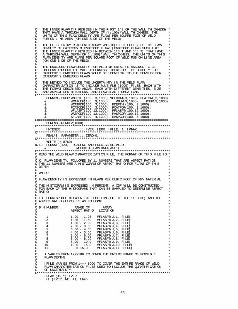
65
C THE INNER FLAW TIP RESIDES IN THE FIRST 1/8 OF THE WALL THICKNESS) * C THAT HAVE A THROUGH-WALL DEPTH OF (i/100)*WALL THICKNESS. THE * C UNITS OF THIS FLAW DENSITY ARE FLAWS PER SQUARE FOOT OF WELD * C FUSION LINE AREA (ON ONE SIDE OF THE WELD). * C * C THE (I,J) ENTRY READ INTO ARRAY WDEPTH(100,3,IFILE) IS THE FLAW * C DENSITY OF CATEGORY 3 EMBEDDED FLAWS (EMBEDDED FLAWS SUCH THAT * C THE INNER FLAW TIP RESIDES IN BETWEEN 1/8 T AND 3/8 T) THAT HAVE * C A THROUGH-WALL DEPTH OF (i/100)*WALL THICKNESS. THE UNITS OF THIS * C FLAW DENSITY ARE FLAWS PER SQUARE FOOT OF WELD FUSION LINE AREA * C (ON ONE SIDE OF THE WELD). * C * C THE EMDEDDED FLAW DENSITY FOR WELD MATERIAL IS ASSUMED TO BE * C UNIFORM THROUGH THE WALL THICKNESS; THEREFORE THE DENSITY FOR * C CATEGORY 3 EMBEDDED FLAWS WOULD BE IDENTICAL TO THE DENSITY FOR * C CATEGORY 2 EMBEDDED FLAWS. * C * C THE METHOD TO INCLUDE THE UNCERTAINTY IN THE WELD FLAW * C CHARACTERIZATION IS TO INCLUDE MULTIPLE (1000) FILES, EACH WITH * C THE FORMAT DESCRIBED ABOVE, EACH WITH DIFFERENT DENSITIES, SIZE * C AND ASPECT DISTRIBUTIONS, AND FLAW SIZE TRUNCATIONS. * C*********************************************************************** COMMON /PROG/WDEPTH (100, 3,1000),WELDCAT(3,1000),PLATCAT(3,1000), & WCATCDF(100, 3,1000), WSUM(3,1000), PSUM(3,1000), & WCATPDF(100, 3,1000), PDEPTH (100, 3,1000), & PCATCDF(100, 3,1000), PCATPDF(100, 3,1000), & WFLASPT(100,12,1000), PFLASPT(100,12,1000), & WASPCDF(100,12,1000), PASPCDF(100,12,1000), & SFLASPT(100, 4,1000), SASPCDF(100, 4,1000) C====================================================================== DIMENSION NDIV(1000) C*********************************************************************** INTEGER :: IVER, IERR, IFILE, J, IWMAX C*********************************************************************** REAL*8, PARAMETER :: ZERO=0. C*********************************************************************** WRITE (*,8769) 8769 FORMAT (12X,' READING AND PROCESSING WELD', & ' EMBEDDED-FLAW DATABASE') C*********************************************************************** C READ THE WELD FLAW CHARACTERIZATION FILE, THE FORMAT OF THIS FILE IS:* C * C K, FLAW DENSITY, FOLLOWED BY 11 NUMBERS THAT ARE ASPECT RATIOS * C THE 11 NUMBERS ARE A HISTOGRAM OF ASPECT RATIO FOR FLAWS OF THIS * C DEPTH * C * C WHERE: * C * C FLAW DENSITY IS EXPRESSED IN FLAWS PER CUBIC FOOT OF RPV MATERIAL * C * C THE HISTOGRAM IS EXPRESSED IN PERCENT. A CDF WILL BE CONSTRUCTED * C FOR EACH OF THE HISTOGRAMS THAT CAN BE SAMPLED TO DETERMINE ASPECT * C RATIO. * C * C THE CORRESPONCE BETWEEN THE POSITION (OUT OF THE 11 BINS) AND THE * C ASPECT RATIO (l/2a) IS AS FOLLOWS: * C * C BIN NUMBER RANGE OF ARRAY * C ASPECT RATIO LOCATION * C * C 1 1.00 - 1.25 WFLASPT(J,1,IFILE) * C 2 1.25 - 1.50 WFLASPT(J,2,IFILE) * C 3 1.50 - 2.00 WFLASPT(J,3,IFILE) * C 4 2.00 - 3.00 WFLASPT(J,4,IFILE) * C 5 3.00 - 4.00 WFLASPT(J,5,IFILE) * C 6 4.00 - 5.00 WFLASPT(J,6,IFILE) * C 7 5.00 - 6.00 WFLASPT(J,7,IFILE) * C 8 6.00 - 8.00 WFLASPT(J,8,IFILE) * C 9 8.00 - 10.0 WFLASPT(J,9,IFILE) * C 10 10.0 - 15.0 WFLASPT(J,10,IFILE) * C 11 > 15.0 WFLASPT(J,11,IFILE) * C * C J VARIES FROM 1==>100 TO COVER THE ENTIRE RANGE OF POSSIBLE * C FLAW DEPTHS * C * C IFILE VARIES FROM 1==> 1000 TO COVER THE ENTIRE RANGE OF WELD * C FLAW CHARACTERIZATION FILES USED TO INCLUDE THE QUANTIFICATION * C OF UNCERTAINTY. * C*********************************************************************** READ (49,*) IVER if (IVER .NE. 41) then

66
call xermsg ('FAVPFM','RDWELD', & 'EMBEDDED-FLAW WELD FILE NOT VERSION 04.1',19,1) call xerdmp call xerabt('xerror -- invalid input',23) endif IWMAX = 0 DO 210 IFILE=1,1000 DO 220 J=1,100 READ (49,*,IOSTAT=IERR) K, & WDEPTH (J, 2,IFILE),WFLASPT(J, 1,IFILE), & WFLASPT(J, 2,IFILE),WFLASPT(J, 3,IFILE), & WFLASPT(J, 4,IFILE),WFLASPT(J, 5,IFILE), & WFLASPT(J, 6,IFILE),WFLASPT(J, 7,IFILE), & WFLASPT(J, 8,IFILE),WFLASPT(J, 9,IFILE), & WFLASPT(J,10,IFILE),WFLASPT(J,11,IFILE) IF (IERR .NE. 0) GOTO 998 WDEPTH(J,3,IFILE) = WDEPTH(J,2,IFILE) IF (WDEPTH (J,2,IFILE) .GT. ZERO) THEN IF (J.GT.IWMAX) IWMAX = J ENDIF 220 CONTINUE 210 CONTINUE GOTO 999 998 CONTINUE write(*,1000) IFILE, J, IFILE*J, IERR call xermsg ('FAVPFM','RDWELD', & 'ERROR READING WELD EMB. FLAW DATA',20,1) call xerdmp call xerabt('xerror -- invalid input',23) C 999 CONTINUE RETURN 1000 FORMAT(/'IFILE=',I4,' K=',I4,' LINE NUMBER=',I5,' IERR=',I4/) END
where WDEPTH (1:100,1:3,1:1000) is an array in FAVPFM in which the (J,2,IFILE) and the (J,3,IFILE) addresses contain flaw densities for Category 2 and Category 3 flaws, respectively, for welds.
WFLASPT(1:100,1:11,1:1000) is an array in FAVPFM in which the (J,1,IFILE) address contains the percentage of flaws with an aspect ratio between 1.00 and 1.25, and the (J,2,IFILE) address contains the percentage of flaws with an aspect ratio between 1.25 and 1.50. The range of aspect ratios corresponding to each of the 11 bins used to develop the histogram that will be sampled for each flaw depth is given in the following table.
Bin
Number
Range of flaw aspect ratio
1 1.00 – 1.25 2 1.25 - 1.50 3 1.50 – 2.00 4 2.00 – 3.00 5 3.00 – 4.00 6 4.00 – 5.00 7 5.00 – 6.00 8 6.00 – 8.00 9 8.00 – 10.0
10 10.0 – 15.0 11 > 15

67
2.4.5 Embedded-Flaw Characterization for Plates
The data format for embedded flaws in plates/forgings is identical to that described above for embedded flaws in welds. The following subroutine reads in the characterization file for embedded flaws in plates.
C+++++++++++++++++++++++++++++++++++++++++++++++++++++++++++++++++++++++ SUBROUTINE RDPLAT(THICK,IPMAX,RO,RI) C+++++++++++++++++++++++++++++++++++++++++++++++++++++++++++++++++++++++ IMPLICIT REAL*8 (A-H,O-Z) C*********************************************************************** C*** *** C*** Revisions: *** C*** *** C*** Date | Modification *** C*** ============|==================================================*** C*** *** C*** *** C*** *** C*********************************************************************** C*********************************************************************** C DEFINITION OF ARRAYS: * C * C PDEPTH(100,3,1000) - HOLDS DATA AS READ FROM EXTERNAL FILE * C CONTAINING FLAW DATA FOR PLATE C * C PLATCAT(3,1000) -CDF FROM WHICH FLAW CATEGORY IS SAMPLED FOR FLAW * C LOCATED IN PLATE MATERIAL * C * C PCATPDF(100,3) HISTOGRAM EXPRESSING RELATIVE FREQUENCY OF PLATE * C FLAW DENSITIES FOR EACH FLAW CATEGORY * C * C PCATCDF(100,3) CDF FOR EACH OF THE 3 FLAW CATEGORIES FOR PLATE * C EACH COLUMN IS OBTAINED BY INTEGRATING PCATPDF * C*********************************************************************** COMMON /PROG/WDEPTH (100, 3,1000),WELDCAT(3,1000),PLATCAT(3,1000), & WCATCDF(100, 3,1000), WSUM(3,1000), PSUM(3,1000), & WCATPDF(100, 3,1000), PDEPTH (100, 3,1000), & PCATCDF(100, 3,1000), PCATPDF(100, 3,1000), & WFLASPT(100,12,1000), PFLASPT(100,12,1000), & WASPCDF(100,12,1000), PASPCDF(100,12,1000), & SFLASPT(100, 4,1000), SASPCDF(100, 4,1000) C*********************************************************************** INTEGER :: IVER, IERR C*********************************************************************** REAL*8, PARAMETER :: ZERO=0. C*********************************************************************** WRITE (*,9835) 9835 FORMAT (12X,' READING AND PROCESSING PLATE EMBEDDED-FLAW', & ' DATABASE') C*********************************************************************** C READ THE PLATE FLAW CHARACTERIZATION FILE * C*********************************************************************** C*********************************************************************** C THE DATA PROVIDED BY PNL ASSUME THAT THE DENSITY OF PLATE EMBEDDED * C FLAWS ARE UNIFORM THROUGH THE WALL; THEREFORE, THE FLAW DENSITY * C FOR CATEGORY 3 FLAWS IS IDENTICAL TO THAT FOR CATEGORY 2 FLAWS. * C*********************************************************************** READ (39,*) IVER if (IVER .NE. 41) then call xermsg ('FAVPFM','RDPLAT', & 'EMBEDDED-FLAW PLATE FILE NOT VERSION 04.1',21,1) call xerdmp call xerabt('xerror -- invalid input',23) endif IPMAX = 0 DO 110 IFILE=1,1000 DO 120 J=1,100 READ (39,*,IOSTAT=IERR) K, & PDEPTH (J, 2,IFILE),PFLASPT(J, 1,IFILE), & PFLASPT(J, 2,IFILE),PFLASPT(J, 3,IFILE), & PFLASPT(J, 4,IFILE),PFLASPT(J, 5,IFILE), & PFLASPT(J, 6,IFILE),PFLASPT(J, 7,IFILE), & PFLASPT(J, 8,IFILE),PFLASPT(J, 9,IFILE), & PFLASPT(J,10,IFILE),PFLASPT(J,11,IFILE)

68
PDEPTH(J,3,IFILE) = PDEPTH(J,2,IFILE) IF (IERR .NE. 0) GOTO 998 IF (PDEPTH (J,2,IFILE) .GT. ZERO ) THEN IF (J.GT.IPMAX) IPMAX=J ENDIF 120 CONTINUE 110 CONTINUE GOTO 999 998 CONTINUE write(*,1000) IFILE, J, IFILE*J, IERR 1000 FORMAT(/'IFILE=',I4,' K=',I4,' LINE NUMBER=',I5,' IERR=',I4/) call xermsg ('FAVPFM','RDPLAT', & 'ERROR READING PLATE EMB. FLAW DATA',22,1) call xerdmp call xerabt('xerror -- invalid input',23) 999 CONTINUE C*********************************************************************** C DETERMINE THE TOTAL FLAW DENSITY FOR EACH OF THE 3 FLAW CATEGORIES: * C * C PSUM(1,IFILE) = TOTAL FLAW DENSITY FOR CATEGORY 1 FLAWS IN PLATES * C PSUM(2,IFILE) = TOTAL FLAW DENSITY FOR CATEGORY 2 FLAWS IN PLATES * C PSUM(3,IFILE) = TOTAL FLAW DENSITY FOR CATEGORY 3 FLAWS IN PLATES * C*********************************************************************** DO 15 IFILE=1,1000 DO 20 J=1,100 PSUM(1,IFILE) = PSUM(1,IFILE) + PDEPTH(J,1,IFILE) PSUM(2,IFILE) = PSUM(2,IFILE) + PDEPTH(J,2,IFILE) PSUM(3,IFILE) = PSUM(3,IFILE) + PDEPTH(J,3,IFILE) 20 CONTINUE 15 CONTINUE C*********************************************************************** C GENERATE PROBABILITY DISTRIBUTION FUNCTION (PCATCDF), IN THIS CASE * C A RELATIVE FREQUENCY HISTOGRAM OF PLATE FLAW DENSITIES FOR EACH * C OF THE 3 FLAW CATEGORIES. * C * C COLUMN 1 OF ARRAY PCATPDF IS A RELATIVE FREQ HIST FOR CAT 1 FLAWS * C COLUMN 2 OF ARRAY PCATPDF IS A RELATIVE FREQ HIST FOR CAT 2 FLAWS * C COLUMN 3 OF ARRAY PCATPDF IS A RELATIVE FREQ HIST FOR CAT 3 FLAWS * C*********************************************************************** DO 80 K=1,3 DO 91 IFILE=1,1000 DO 90 J=1,100 IF (PSUM(K,IFILE).NE.ZERO) THEN PCATPDF(J,K,IFILE) = PDEPTH(J,K,IFILE)/PSUM(K,IFILE) ENDIF 90 CONTINUE 91 CONTINUE C*********************************************************************** C GENERATE CUMULATIVE DISTRIBUTION FUNCTION (PCATCDF)FOR EACH OF * C THE 3 FLAW CATEGORIES BY INTEGRATING THE PROBABILITY DISTRIBUTION * C FUNCTION (PCATPDF).EACH OF THESE CDFs CAN BE SAMPLED TO DETERMINE * C THE FLAW SIZE OF A FLAW IN ITS RESPECTIVE CATEGORY * C * C COLUMN 1 OF ARRAY PCATCDF CONTAINS THE CDF FOR CATEGORY 1 FLAWS * C COLUMN 2 OF ARRAY PCATCDF CONTAINS THE CDF FOR CATEGORY 2 FLAWS * C COLUMN 3 OF ARRAY PCATCDF CONTAINS THE CDF FOR CATEGORY 3 FLAWS * C*********************************************************************** DO 95 IFILE=1,1000 PCATCDF(1,K,IFILE) = PCATPDF(1,K,IFILE) DO 97 J=2,100 PCATCDF(J,K,IFILE) = PCATCDF(J-1,K,IFILE) + & PCATPDF(J,K,IFILE) 97 CONTINUE 95 CONTINUE 80 CONTINUE RETURN END
2.4.6 Total Number of Flaws
Inner-surface breaking flaw density data are expressed in flaws per unit RPV-inner-surface area and weld subregion embedded flaws are flaws per unit area on the fusion line between the weld and adjacent plate subregions. These conventions are consistent with the physical model utilized by

69
Pacific Northwest National Laboratory to derive the flaw characterization data input to FAVOR. Embedded flaws in plate regions are expressed on a volumetric basis.
Figure 17a and 17b illustrate axial and circumferential weld subregion elements, respectively. The number of flaws in each of these weld elements is calculated (internally by FAVOR) as the sum of the number of inner- surface breaking flaws and the number of embedded flaws as follows:
2
Number of Flaws 2 32in Weld Subregions 360 8
inner-surface breaking flaw density (per unit surface area - flaws/in )
weld embbed-flaw density (per un
SB i EW
SB
EW
R dz d dAπρ θ ρ
ρ
ρ
⎛ ⎞ ⎡ ⎤ ⎡ ⎤⎛ ⎞ ⎛ ⎞= +⎜ ⎟ ⎜ ⎟ ⎜ ⎟⎢ ⎥ ⎢ ⎥⎝ ⎠ ⎝ ⎠⎣ ⎦ ⎣ ⎦⎝ ⎠=
= 2
2
it weld-fusion area - flaws/in )
user-input weld-fusion area (for one side of weld) (in - input by user) inner radius of RPV (in. - input by user) height of subregion element (in. - input b
i
dARdz
=== y user)
subtended angle of subregion element ( degrees - input by user)dθ =
(1)
where SBρ and EWρ are summed over all flaw depths.
For axial welds, the fusion lines are on the sides of the weld, whereas for circumferential welds, the fusion lines are on the top and bottom of the welds (see Figs. 17a and 17b). In the term {2 (3/8) dA }, the factor of 2 accounts for the fact that the user input data is the area on one side of the fusion line whereas flaws reside in fusion lines on both sides of the welds. The (3/8) accounts for the fact that embedded flaws that reside beyond the first 3/8 of the base metal are not included in a PTS analysis. All flaw densities are assumed to be uniform through the RPV wall thickness.
Figure 17c illustrates a plate subregion element. The number of flaws in each of these plate elements is calculated (internally by FAVOR) as the sum of the number of inner-surface-breaking flaws and the number of embedded flaws as follows:

70
( )( )22
2
Number of Flaws 2 3in Plate Subregions 360 8 360
inner-surface breaking flaw density (per unit surface area - flaws/in ) plate em
SB i EP o i
SB
EP
dR dz d R R CLTH dzπ θρ θ ρ π
ρρ
⎛ ⎞ ⎡ ⎤ ⎡ ⎤⎛ ⎞ ⎛ ⎞ ⎛ ⎞= + − −⎜ ⎟ ⎜ ⎟ ⎜ ⎟ ⎜ ⎟⎢ ⎥ ⎢ ⎥⎝ ⎠ ⎝ ⎠ ⎝ ⎠⎣ ⎦ ⎣ ⎦⎝ ⎠==
3
bbed-flaw density summed over all flaw depths
(flaws per unit volume - flaws/in ) outer radius of RPV wall (in - input by user) inner radius of RPV wall (in. - input by user) cladding t
o
i
RR
CLTH
==
= hickness (in. - input by user) height of subregion element (in. - input by user) subtended angle of subregion element
( degrees - input by user)
dzdθ
==
(2)
where SBρ and EPρ are summed over all flaw depths.
2.5 FAVOR Load Module – FAVLoad Output
FAVLoad creates two output files – (1) the load definition file (user-defined filename at time of execution) that will be input to FAVPFM (*.out) and (2) *.echo which provides a date and time stamp of the execution and an echo of the FAVLoad input file. The following page gives a partial listing of a typical FAVLOAD *.echo file. The name of the FAVLOAD *.echo is constructed from the root of the FAVLOAD output file with .echo extension added, e.g., LOAD4.out ⇒LOAD4.echo.

71
LOAD4.echo
************************************************ * * * WELCOME TO FAVOR * * * * FRACTURE ANALYSIS OF VESSELS: OAK RIDGE * * VERSION 04.1 * * * * FAVLOAD MODULE: LOAD GENERATOR * * PROBLEMS OR QUESTIONS REGARDING FAVOR * * SHOULD BE DIRECTED TO * * * * TERRY DICKSON * * OAK RIDGE NATIONAL LABORATORY * * * * e-mail: [email protected] * * * ************************************************ *********************************************************** * This computer program was prepared as an account of * * work sponsored by the United States Government * * Neither the United States, nor the United States * * Department of Energy, nor the United States Nuclear * * Regulatory Commission, nor any of their employees, * * nor any of their contractors, subcontractors, or their * * employees, makes any warranty, expressed or implied, or * * assumes any legal liability or responsibility for the * * accuracy, completeness, or usefulness of any * * information, apparatus, product, or process disclosed, * * or represents that its use would not infringe * * privately-owned rights. * * * *********************************************************** DATE: 27-Sep-2004 TIME: 07:40:48 FAVLOAD INPUT DATASET NAME = favload.in FAVLOAD OUTPUT DATASET NAME = load4.out FAVLOAD ECHO INPUT FILE NAME = load4.echo ************************************************* * ECHO OF FAVLOAD INPUT FILE * ************************************************* ******************************************************************************** * ALL RECORDS WITH AN ASTERISK (*) IN COLUMN 1 ARE COMMENT ONLY * ******************************************************************************** * EXAMPLE INPUT DATASET FOR FAVLoad, v03.1 [UNITS]* ******************************************************************************** * ==================== * * Record GEOM * * ==================== * *------------------------------------------------------------------------------* * IRAD = INTERNAL RADIUS OF PRESSURE VESSEL [IN] * * W = THICKNESS OF PRESSURE VESSEL WALL (INCLUDING CLADDING) [IN] * * CLTH = CLADDING THICKNESS [IN] * *------------------------------------------------------------------------------* ******************************************************************************** GEOM IRAD=78.5 W=8.036 CLTH=0.156 ******************************************************************************** * =========================== * * Records BASE and CLAD * * =========================== * * THERMO-ELASTIC MATERIAL PROPERTIES FOR BASE AND CLADDING * *------------------------------------------------------------------------------* * K = THERMAL CONDUCTIVITY [BTU/HR-FT-F] * * C = SPECIFIC HEAT [BTU/LBM-F] * * RHO = DENSITY [LBM/FT**3] * * E = YOUNG'S ELASTIC MODULUS [KSI] * * ALPHA = THERMAL EXPANSION COEFFICIENT [F**-1] * * NU = POISSON'S RATIO [-] * * NTE = TEMPERATURE DEPENDANCY FLAG * * NTE = 0 ==> PROPERTIES ARE TEMPERATURE INDEPENDENT (CONSTANT) * * NTE = 1 ==> PROPERTIES ARE TEMPERATURE DEPENDENT * * IF NTE EQUAL TO 1, THEN ADDITIONAL DATA RECORDS ARE REQUIRED * *------------------------------------------------------------------------------* ******************************************************************************** BASE K=24.0 C=0.120 RHO=489.00 E=28000 ALPHA=.00000777 NU=0.3 NTE=1 ******************************************************************************** *--------------------------- * THERMAL CONDUCTIVITY TABLE *--------------------------- NK N=16 *--------------------------- 70 24 8

72
2.6 FAVOR PFM Module – FAVPFM Output
FAVPFM produces the following ten files:
General Output Files
(1) Filename defined by user at execution (e.g., FAVPFM.OUT)
(2) Echo of input file with filename defined by user at execution (e.g., FAVPFM.echo)
(3) Binary restart file – restart.bin
Input files for FAVPost
(4) FAILURE.DAT
(5) INITIATE.DAT
QA Verification Files
(6) ARREST.OUT
(7) FLAWNO.OUT
(8) FLAWSIZE.OUT
(9) TRACE.OUT
(10) FLAW_TRACK.LOG
The following pages present partial listings of example files: (1) FAVPFM.OUT, (2) FAVPFM.echo, (6) ARREST.OUT, (7) FLAWNO.OUT, (8) FLAWSIZE.OUT, (9) TRACE.OUT, and (10) FLAW_TRACK.LOG
FAVPFM.echo includes two sections:
(1) Echo of all input data from FAVPFM.IN file. (2) Summary of structure of Major Regions and Subregions
FAVPFM.out includes results for all transients in this case definition including:
Mean value of conditional probability of initiation (CPI) Mean value of conditional probability of failure (CPF) Mean value of RTNDT at crack tip Flaw distribution report by material and category Weld Flaw-Size Distribution Report Plate Flaw-Size Distribution Report Transient Time Distribution Report Multiple Flaw Statistics

73
FAVPFM.echo
************************************************ * * * WELCOME TO FAVOR * * * * FRACTURE ANALYSIS OF VESSELS: OAK RIDGE * * VERSION 04.1 * * * * FAVPFM MODULE: PERFORMS PROBABILISTIC * * FRACTURE MECHANICS ANALYSES * * * * PROBLEMS OR QUESTIONS REGARDING FAVOR * * SHOULD BE DIRECTED TO * * * * TERRY DICKSON * * HEAVY SECTION STEEL TECHNOLOGY * * OAK RIDGE NATIONAL LABORATORY * * * * e-mail: [email protected] * * * ************************************************ *********************************************************** * This computer program was prepared as an account of * * work sponsored by the United States Government * * Neither the United States, nor the United States * * Department of Energy, nor the United States Nuclear * * Regulatory Commission, nor any of their employees, * * nor any of their contractors, subcontractors, or their * * employees, makes any warranty, expressed or implied, or * * assumes any legal liability or responsibility for the * * accuracy, completeness, or usefulness of any * * information, apparatus, product, or process disclosed, * * or represents that its use would not infringe * * privately-owned rights. * * * *********************************************************** DATE: 05-Oct-2004 TIME: 07:18:43 FAVPFM INPUT FILE NAME = FAVPFM.IN FAVLOAD OUTPUT FILE NAME = LOAD4.OUT FAVPFM OUTPUT FILE NAME = FAVPFM_10K.OUT FAVPFM INPUT ECHO FILE NAME = FAVPFM_10K.echo Begin echo of FAVPFM input data deck 07:18:43 30-Sep-2004 no./col. 1.......10........20........30........40........50........60........70........80........90.......100.......110.......120.... 1 ********************************************************************************************************** 2 * ALL RECORDS WITH AN ASTERISK(*) IN COLUMN 1 ARE COMMENT ONLY * 3 ********************************************************************************************************** 4 * EXAMPLE INPUT DATASET FOR FAVPFM, v04.1 [UNITS]* 5 ********************************************************************************************************** 6 * ==================== * 7 * Control Record CNT1 * 8 * ==================== * 9 *--------------------------------------------------------------------------------------------------------* 10 * NSIM = NUMBER OF RPV SIMULATIONS [-] * 11 *--------------------------------------------------------------------------------------------------------* 12 * IGATR = NUMBER OF INITIATION-GROWTH-ARREST (IGA) TRIALS PER FLAW [-] * 13 *--------------------------------------------------------------------------------------------------------* 14 * WPS_OPTION = 0 DO NOT INCLUDE WARM-PRESTRESSING IN ANALYSIS [-] * 15 * WPS_OPTION = 1 INCLUDE WARM-PRESTRESSING IN ANALYSIS [-] * 16 *--------------------------------------------------------------------------------------------------------* 17 * PC3_OPTION = 0 DO NOT PERFORM FRACTURE ANALYSIS OF CATEGORY 3 FLAWS IN PLATES [-] * 18 * PC3_OPTION = 1 PERFORM FRACTURE ANALYSIS OF CATEGORY 3 FLAWS IN PLATES [-] * 19 *--------------------------------------------------------------------------------------------------------* 20 * CHILD_OPTION = 0 DO NOT INCLUDE CHILD SUBREGION REPORTS [-] * 21 * CHILD_OPTION = 1 INCLUDE CHILD SUBREGION REPORTS [-] * 22 *--------------------------------------------------------------------------------------------------------* 23 * RESTART_OPTION = 0 THIS IS NOT A RESTART CASE [-] * 24 * RESTART_OPTION = 1 THIS IS A RESTART CASE [-] * 25 *--------------------------------------------------------------------------------------------------------* 26 * ============================= * 27 * Notes for Control Record CNT1 * 28 * ============================= * 29 * IN A TYPICAL PFM ANALYSIS, A SUBSTANTIAL FRACTION OF THE TOTAL FLAWS ARE CATEGORY 3 FLAWS IN * 30 * PLATE REGIONS. BASED ON EXPERIENCE AND SOME DETERMINISTIC FRACTURE ANALYSES, THESE FLAWS VERY * 31 * RARELY CONTRIBUTE TO THE CPI OR CPF WITH THE PLATE FLAW SIZE DISTRIBUTIONS TYPICALLY USED. * 32 * THEREFORE, INVOKING IP3OPT = 0 CAN RESULT IN A SIGNIFICANT REDUCTION IN EXECUTION TIME WITHOUT * 33 * AFFECTING THE SOLUTION, UNLESS THERE ARE UNUSUAL CIRCUMSTANCES SUCH AS A NEW FLAW-SIZE * 34 * DISTRIBUTION FOR PLATE FLAWS. IN EITHER CASE, CATEGORY 3 PLATE FLAWS ARE INCLUDED IN ALL REPORTS. * 35 * * 36 * Notes on Restart Option: * 37 * * 38 * The restart option flag can also be used to control the frequency with which restart files are * 39 * created. If RESTART_OPTION is given a value other than 0 or 1, then the absolute value of this flag * 40 * sets the checkpoint interval at which the restart file will be created during the run. For example, * 41 * * 42 * 1.RESTART_OPTION = -200 ==> This is not a restart case; restart files will be created every 200 trials * 43 * 2.RESTART_OPTION = 0 ==> Same as example No. 1. * 44 * 3.RESTART_OPTION = 200 ==> This is a restart case; restart files will be created every 200 trials.* 45 * 4.RESTART_OPTION = 1 ==> Same as example No. 3. * 46 * 5.RESTART_OPTION = -50 ==? This is not a restart case; restart files will be created every 50 trials. * 47 * * 48 * * 49 *--------------------------------------------------------------------------------------------------------* 50 ********************************************************************************************************** 51 CNT1 NSIM=10000 IGATR=100 WPS_OPTION=0 PC3_OPTION=0 CHILD_OPTION=1 RESTART_OPTION=0 52 **********************************************************************************************************

74
FAVPFM.out
************************************************ * * * WELCOME TO FAVOR * * * * FRACTURE ANALYSIS OF VESSELS: OAK RIDGE * * VERSION 04.1 * * * * FAVPFM MODULE: PERFORMS PROBABILISTIC * * FRACTURE MECHANICS ANALYSES * * * * PROBLEMS OR QUESTIONS REGARDING FAVOR * * SHOULD BE DIRECTED TO * * * * TERRY DICKSON * * HEAVY SECTION STEEL TECHNOLOGY * * OAK RIDGE NATIONAL LABORATORY * * * * e-mail: [email protected] * * * ************************************************ *********************************************************** * This computer program was prepared as an account of * * work sponsored by the United States Government * * Neither the United States, nor the United States * * Department of Energy, nor the United States Nuclear * * Regulatory Commission, nor any of their employees, * * nor any of their contractors, subcontractors, or their * * employees, makes any warranty, expressed or implied, or * * assumes any legal liability or responsibility for the * * accuracy, completeness, or usefulness of any * * information, apparatus, product, or process disclosed, * * or represents that its use would not infringe * * privately-owned rights. * * * *********************************************************** DATE: 05-Oct-2004 TIME: 07:18:43 FAVPFM INPUT FILE NAME = FAVPFM.IN FAVLOAD OUTPUT FILE NAME = LOAD4.OUT FAVPFM OUTPUT FILE NAME = FAVPFM_10K.OUT FAVPFM INPUT ECHO FILE NAME = FAVPFM_10K.echo Begin echo of first 200 lines of FAVPFM input data deck 07:18:43 30-Sep-2004 no./col. 1.......10........20........30........40........50........60........70........80........90.......100.......110.......120...... 1 ********************************************************************************************************** 2 * ALL RECORDS WITH AN ASTERISK(*) IN COLUMN 1 ARE COMMENT ONLY * 3 ********************************************************************************************************** 4 * EXAMPLE INPUT DATASET FOR FAVPFM, v04.1 [UNITS]* 5 ********************************************************************************************************** 6 * ==================== * 7 * Control Record CNT1 * 8 * ==================== * 9 *--------------------------------------------------------------------------------------------------------* 10 * NSIM = NUMBER OF RPV SIMULATIONS [-] * 11 *--------------------------------------------------------------------------------------------------------* 12 * IGATR = NUMBER OF INITIATION-GROWTH-ARREST (IGA) TRIALS PER FLAW [-] * 13 *--------------------------------------------------------------------------------------------------------* 14 * WPS_OPTION = 0 DO NOT INCLUDE WARM-PRESTRESSING IN ANALYSIS [-] * 15 * WPS_OPTION = 1 INCLUDE WARM-PRESTRESSING IN ANALYSIS [-] * 16 *--------------------------------------------------------------------------------------------------------* 17 * PC3_OPTION = 0 DO NOT PERFORM FRACTURE ANALYSIS OF CATEGORY 3 FLAWS IN PLATES [-] * 18 * PC3_OPTION = 1 PERFORM FRACTURE ANALYSIS OF CATEGORY 3 FLAWS IN PLATES [-] * 19 *--------------------------------------------------------------------------------------------------------* 20 * CHILD_OPTION = 0 DO NOT INCLUDE CHILD SUBREGION REPORTS [-] * 21 * CHILD_OPTION = 1 INCLUDE CHILD SUBREGION REPORTS [-] * 22 *--------------------------------------------------------------------------------------------------------* 23 * RESTART_OPTION = 0 THIS IS NOT A RESTART CASE [-] * 24 * RESTART_OPTION = 1 THIS IS A RESTART CASE [-] * 25 *--------------------------------------------------------------------------------------------------------* 26 * ============================= * 27 * Notes for Control Record CNT1 * 28 * ============================= * 29 * IN A TYPICAL PFM ANALYSIS, A SUBSTANTIAL FRACTION OF THE TOTAL FLAWS ARE CATEGORY 3 FLAWS IN * 30 * PLATE REGIONS. BASED ON EXPERIENCE AND SOME DETERMINISTIC FRACTURE ANALYSES, THESE FLAWS VERY * 31 * RARELY CONTRIBUTE TO THE CPI OR CPF WITH THE PLATE FLAW SIZE DISTRIBUTIONS TYPICALLY USED. * 32 * THEREFORE, INVOKING IP3OPT = 0 CAN RESULT IN A SIGNIFICANT REDUCTION IN EXECUTION TIME WITHOUT * 33 * AFFECTING THE SOLUTION, UNLESS THERE ARE UNUSUAL CIRCUMSTANCES SUCH AS A NEW FLAW-SIZE * 34 * DISTRIBUTION FOR PLATE FLAWS. IN EITHER CASE, CATEGORY 3 PLATE FLAWS ARE INCLUDED IN ALL REPORTS. * 35 * * 36 * Notes on Restart Option: * 37 * * 38 * The restart option flag can also be used to control the frequency with which restart files are * 39 * created. If RESTART_OPTION is given a value other than 0 or 1, then the absolute value of this flag * 40 * sets the checkpoint interval at which the restart file will be created during the run. For example, * 41 * * 42 * 1.RESTART_OPTION = -200 ==> This is not a restart case; restart files will be created every 200 trials * 43 * 2.RESTART_OPTION = 0 ==> Same as example No. 1. * 44 * 3.RESTART_OPTION = 200 ==> This is a restart case; restart files will be created every 200 trials.* 45 * 4.RESTART_OPTION = 1 ==> Same as example No. 3. * 46 * 5.RESTART_OPTION = -50 ==? This is not a restart case; restart files will be created every 50 trials. * 47 * * 48 * * 49 * *
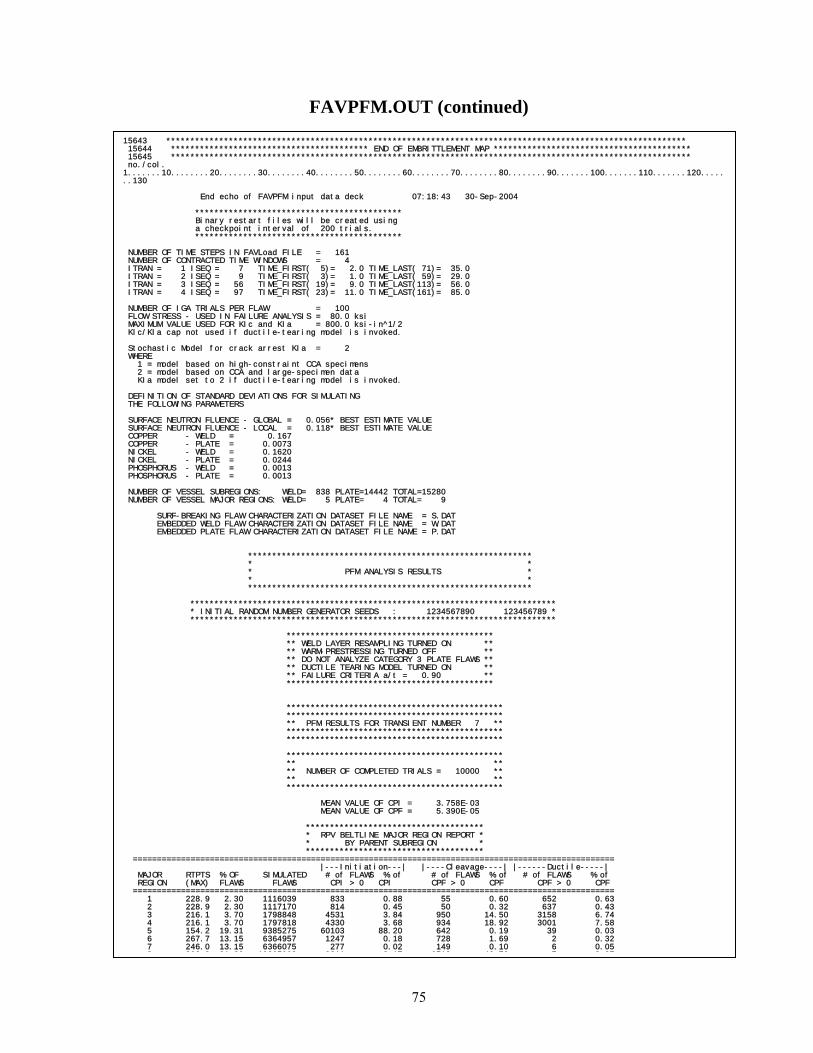
75
FAVPFM.OUT (continued) 15643 ************************************************************************************************************
15644 ***************************************** END OF EMBRITTLEMENT MAP ***************************************** 15645 ************************************************************************************************************ no./col. 1.......10........20........30........40........50........60........70........80........90.......100.......110.......120.......130 End echo of FAVPFM input data deck 07:18:43 30-Sep-2004 ******************************************* Binary restart files will be created using a checkpoint interval of 200 trials. ******************************************* NUMBER OF TIME STEPS IN FAVLoad FILE = 161 NUMBER OF CONTRACTED TIME WINDOWS = 4 ITRAN = 1 ISEQ = 7 TIME_FIRST( 5)= 2.0 TIME_LAST( 71)= 35.0 ITRAN = 2 ISEQ = 9 TIME_FIRST( 3)= 1.0 TIME_LAST( 59)= 29.0 ITRAN = 3 ISEQ = 56 TIME_FIRST( 19)= 9.0 TIME_LAST(113)= 56.0 ITRAN = 4 ISEQ = 97 TIME_FIRST( 23)= 11.0 TIME_LAST(161)= 85.0 NUMBER OF IGA TRIALS PER FLAW = 100 FLOW STRESS - USED IN FAILURE ANALYSIS = 80.0 ksi MAXIMUM VALUE USED FOR KIc and KIa = 800.0 ksi-in^1/2 KIc/KIa cap not used if ductile-tearing model is invoked. Stochastic Model for crack arrest KIa = 2 WHERE 1 = model based on high-constraint CCA specimens 2 = model based on CCA and large-specimen data KIa model set to 2 if ductile-tearing model is invoked. DEFINITION OF STANDARD DEVIATIONS FOR SIMULATING THE FOLLOWING PARAMETERS SURFACE NEUTRON FLUENCE - GLOBAL = 0.056* BEST ESTIMATE VALUE SURFACE NEUTRON FLUENCE - LOCAL = 0.118* BEST ESTIMATE VALUE COPPER - WELD = 0.167 COPPER - PLATE = 0.0073 NICKEL - WELD = 0.1620 NICKEL - PLATE = 0.0244 PHOSPHORUS - WELD = 0.0013 PHOSPHORUS - PLATE = 0.0013 NUMBER OF VESSEL SUBREGIONS: WELD= 838 PLATE=14442 TOTAL=15280 NUMBER OF VESSEL MAJOR REGIONS: WELD= 5 PLATE= 4 TOTAL= 9 SURF-BREAKING FLAW CHARACTERIZATION DATASET FILE NAME = S.DAT EMBEDDED WELD FLAW CHARACTERIZATION DATASET FILE NAME = W.DAT EMBEDDED PLATE FLAW CHARACTERIZATION DATASET FILE NAME = P.DAT *********************************************************** * * * PFM ANALYSIS RESULTS * * * *********************************************************** **************************************************************************** * INITIAL RANDOM NUMBER GENERATOR SEEDS : 1234567890 123456789 * **************************************************************************** ******************************************* ** WELD LAYER RESAMPLING TURNED ON ** ** WARM-PRESTRESSING TURNED OFF ** ** DO NOT ANALYZE CATEGORY 3 PLATE FLAWS ** ** DUCTILE TEARING MODEL TURNED ON ** ** FAILURE CRITERIA a/t = 0.90 ** ******************************************* ********************************************* ********************************************* ** PFM RESULTS FOR TRANSIENT NUMBER 7 ** ********************************************* ********************************************* ********************************************* ** ** ** NUMBER OF COMPLETED TRIALS = 10000 ** ** ** ********************************************* MEAN VALUE OF CPI = 3.758E-03 MEAN VALUE OF CPF = 5.390E-05 ************************************* * RPV BELTLINE MAJOR REGION REPORT * * BY PARENT SUBREGION * ************************************* ==================================================================================================== |---Initiation---| |----Cleavage----| |------Ductile-----| MAJOR RTPTS % OF SIMULATED # of FLAWS % of # of FLAWS % of # of FLAWS % of REGION (MAX) FLAWS FLAWS CPI > 0 CPI CPF > 0 CPF CPF > 0 CPF ==================================================================================================== 1 228.9 2.30 1116039 833 0.88 55 0.60 652 0.63 2 228.9 2.30 1117170 814 0.45 50 0.32 637 0.43 3 216.1 3.70 1798848 4531 3.84 950 14.50 3158 6.74 4 216.1 3.70 1797818 4330 3.68 934 18.92 3001 7.58 5 154.2 19.31 9385275 60103 88.20 642 0.19 39 0.03 6 267.7 13.15 6364957 1247 0.18 728 1.69 2 0.32 7 246.0 13.15 6366075 277 0.02 149 0.10 6 0.05 8 302 9 21 20 10265068 9811 2 17 6513 40 70 7 3 27

76
FAVPFM.OUT (continued) *********************************************
** PFM RESULTS FOR TRANSIENT NUMBER 7 ** ********************************************* ********************************************* ********************************************* ** ** ** NUMBER OF COMPLETED TRIALS = 10000 ** ** ** ********************************************* MEAN VALUE OF CPI = 3.758E-03 MEAN VALUE OF CPF = 5.390E-05 ************************************* * RPV BELTLINE MAJOR REGION REPORT * * BY PARENT SUBREGION * ************************************* ==================================================================================================== |---Initiation---| |----Cleavage----| |------Ductile-----| MAJOR RTPTS % OF SIMULATED # of FLAWS % of # of FLAWS % of # of FLAWS % of REGION (MAX) FLAWS FLAWS CPI > 0 CPI CPF > 0 CPF CPF > 0 CPF ==================================================================================================== 1 228.9 2.30 1116039 833 0.88 55 0.60 652 0.63 2 228.9 2.30 1117170 814 0.45 50 0.32 637 0.43 3 216.1 3.70 1798848 4531 3.84 950 14.50 3158 6.74 4 216.1 3.70 1797818 4330 3.68 934 18.92 3001 7.58 5 154.2 19.31 9385275 60103 88.20 642 0.19 39 0.03 6 267.7 13.15 6364957 1247 0.18 728 1.69 2 0.32 7 246.0 13.15 6366075 277 0.02 149 0.10 6 0.05 8 302.9 21.20 10265068 9811 2.17 6513 40.70 7 3.27 9 272.9 21.20 10264470 2381 0.58 1334 3.30 11 0.64 ==================================================================================================== TOTALS 100.00 48475720 84327 100.00 11355 80.32 7513 19.68 ==================================================================================================== NOTE: MEAN VALUE OF RTNDT AT CRACK TIP= 125.44 ************************************* * RPV BELTLINE MAJOR REGION REPORT * * BY CHILD SUBREGION * ************************************* ==================================================================================================== |---Initiation---| |----Cleavage----| |------Ductile-----| MAJOR RTPTS % OF SIMULATED # of FLAWS % of # of FLAWS % of # of FLAWS % of REGION (MAX) FLAWS FLAWS CPI > 0 CPI CPF > 0 CPF CPF > 0 CPF ==================================================================================================== 1 228.9 2.30 0 0 0.00 0 0.00 652 0.63 2 228.9 2.30 0 0 0.00 0 0.00 637 0.43 3 216.1 3.70 0 0 0.00 0 0.00 3158 6.74 4 216.1 3.70 0 0 0.00 0 0.00 3001 7.58 5 154.2 19.31 0 0 0.00 0 0.00 39 0.03 6 267.7 13.15 10342413 6752 4.80 833 2.61 2 0.32 7 246.0 13.15 6366075 277 0.02 149 0.10 6 0.05 8 302.9 21.20 18541771 61643 78.71 9028 74.30 7 3.27 9 272.9 21.20 13225461 15655 16.46 1345 3.31 11 0.64 ==================================================================================================== TOTALS 100.00 48475720 84327 100.00 11355 80.32 7513 19.68 ==================================================================================================== ******************************************************* ** DUCTILE TEARING MODEL TURNED ON ** ******************************************************* ** NUMBER OF NUMBER OF CL INITIATIONS 1821728 ** ** NUMBER OF NUMBER OF CL/DT INITIATIONS 0 ** ** NUMBER OF NUMBER OF DT INITIATIONS 0 ** *******************************************************

77
FAVPFM.OUT (continued)
********************************************** * FLAW DISTRIBUTION BY MATERIAL AND CATEGORY * * BY PARENT SUBREGION * ********************************************** ================================================== WELD MATERIAL ================================================== number of number % of number % of simulated with total with total flaws CPI>0 CPI CPF>0 CPF ================================================== FLAW CATEGORY 1 0 0 0.00 0 0.00 FLAW CATEGORY 2 5074031 70594 97.05 10118 49.93 FLAW CATEGORY 3 10141119 17 0.00 0 0.00 ================================================== TOTALS 15215150 70611 97.05 10118 49.93 ================================================== ================================================== PLATE MATERIAL ================================================== number of number % of number % of simulated with total with total flaws CPI>0 CPI CPF>0 CPF ================================================== FLAW CATEGORY 1 0 0 0.00 0 0.00 FLAW CATEGORY 2 11090542 13716 2.95 8750 50.07 FLAW CATEGORY 3 22170028 0 0.00 0 0.00 ================================================== TOTALS 33260570 13716 2.95 8750 50.07 ================================================== ********************************************** * FLAW DISTRIBUTION BY MATERIAL AND CATEGORY * * BY CHILD SUBREGION * ********************************************** ================================================== WELD MATERIAL ================================================== number of number % of number % of simulated with total with total flaws CPI>0 CPI CPF>0 CPF ================================================== FLAW CATEGORY 1 0 0 0.00 0 0.00 FLAW CATEGORY 2 0 0 0.00 0 0.00 FLAW CATEGORY 3 0 0 0.00 0 0.00 ================================================== TOTALS 0 0 0.00 0 0.00 ================================================== ================================================== PLATE MATERIAL ================================================== number of number % of number % of simulated with total with total flaws CPI>0 CPI CPF>0 CPF ================================================== FLAW CATEGORY 1 0 0 0.00 0 0.00 FLAW CATEGORY 2 16164573 84310 100.00 18868 100.00 FLAW CATEGORY 3 32311147 17 0.00 0 0.00 ================================================== TOTALS 48475720 84327 100.00 18868 100.00 ================================================== CHILD SUBREGION REPORTS SHOW LOCATIONS OF CONTROLLING RTNDTO AND CHEMISTRY CONTENT FOR WELD FUSION LINES

78
FAVPFM.OUT (continued)
********************************************************** * FLAW DISTRIBUTION BY MATERIAL, CATEGORY, & ORIENTATION * * BY PARENT SUBREGION * ********************************************************** ================================================== WELD MATERIAL ================================================== number of number % of number % of simulated with total with total flaws CPI>0 CPI CPF>0 CPF ================================================== AXIAL FLAW CATEGORY 1 0 0 0.00 0 0.00 AXIAL FLAW CATEGORY 2 1943713 35205 46.20 5026 19.77 AXIAL FLAW CATEGORY 3 3886162 8 0.00 0 0.00 ================================================== AXIAL SUBTOTALS 5829875 35213 46.20 5026 19.77 ================================================== CIRC. FLAW CATEGORY 1 0 0 0.00 0 0.00 CIRC. FLAW CATEGORY 2 3130318 35389 50.84 5092 30.16 CIRC. FLAW CATEGORY 3 6254957 9 0.00 0 0.00 ================================================== CIRC. SUBTOTALS 9385275 35398 50.84 5092 30.16 ================================================== WELD TOTALS 15215150 70611 97.05 10118 49.93 ================================================== ================================================== PLATE MATERIAL ================================================== number of number % of number % of simulated with total with total flaws CPI>0 CPI CPF>0 CPF ================================================== AXIAL FLAW CATEGORY 1 0 0 0.00 0 0.00 AXIAL FLAW CATEGORY 2 5547422 7098 1.41 7082 49.56 AXIAL FLAW CATEGORY 3 11082187 0 0.00 0 0.00 ================================================== AXIAL SUBTOTALS 16629609 7098 1.41 7082 49.56 ================================================== CIRC. FLAW CATEGORY 1 0 0 0.00 0 0.00 CIRC. FLAW CATEGORY 2 5543120 6618 1.54 1668 0.51 CIRC. FLAW CATEGORY 3 11087841 0 0.00 0 0.00 ================================================== CIRC. SUBTOTALS 16630961 6618 1.54 1668 0.51 ================================================== PLATE TOTALS 33260570 13716 2.95 8750 50.07 ================================================== ================================================== ********************************************************** * FLAW DISTRIBUTION BY MATERIAL, CATEGORY, & ORIENTATION * * BY CHILD SUBREGION * ********************************************************** ================================================== WELD MATERIAL ================================================== number of number % of number % of simulated with total with total flaws CPI>0 CPI CPF>0 CPF ================================================== AXIAL FLAW CATEGORY 1 0 0 0.00 0 0.00 AXIAL FLAW CATEGORY 2 0 0 0.00 0 0.00 AXIAL FLAW CATEGORY 3 0 0 0.00 0 0.00 ================================================== AXIAL SUBTOTALS 0 0 0.00 0 0.00 ================================================== CIRC. FLAW CATEGORY 1 0 0 0.00 0 0.00 CIRC. FLAW CATEGORY 2 0 0 0.00 0 0.00 CIRC. FLAW CATEGORY 3 0 0 0.00 0 0.00 ================================================== CIRC. SUBTOTALS 0 0 0.00 0 0.00 ================================================== WELD TOTALS 0 0 0.00 0 0.00 ================================================== PLATE MATERIAL ================================================== number of number % of number % of simulated with total with total flaws CPI>0 CPI CPF>0 CPF ================================================== AXIAL FLAW CATEGORY 1 0 0 0.00 0 0.00 AXIAL FLAW CATEGORY 2 8085565 42303 47.61 12108 69.32 AXIAL FLAW CATEGORY 3 16152295 8 0.00 0 0.00 ==================================================
2 23 860 2311 61 12108 69 32

79
FAVPFM.OUT (continued)
********************************************* * WELD FLAW-SIZE DISTRIBUTION REPORT * * FOR CONDITIONAL PROBABILITY OF INITIATION * ********************************************* ========================================================================= flaw simulated # % of simulated # % of simulated # % of depth catgy 1 with total catgy 2 with total catgy 3 with total (in) flaws CPI>0 CPI flaws CPI>0 CPI flaws CPI>0 CPI ========================================================================= 0.080 0 0 0.00 4046602 21631 1.07 8090278 0 0.00 0.161 0 0 0.00 914005 38888 37.11 1824929 0 0.00 0.241 0 0 0.00 82153 6316 20.40 164160 0 0.00 0.321 0 0 0.00 18340 1793 8.31 35828 2 0.00 0.402 0 0 0.00 7145 948 8.56 14196 1 0.00 0.482 0 0 0.00 2830 440 7.75 5908 4 0.00 0.563 0 0 0.00 1400 253 4.96 2649 7 0.00 0.643 0 0 0.00 626 126 2.04 1286 1 0.00 0.723 0 0 0.00 342 58 1.50 731 0 0.00 0.804 0 0 0.00 194 52 2.60 394 0 0.00 0.884 0 0 0.00 124 32 0.59 250 2 0.00 0.964 0 0 0.00 79 13 1.34 138 0 0.00 1.045 0 0 0.00 51 13 0.06 97 0 0.00 1.125 0 0 0.00 49 6 0.36 62 0 0.00 1.205 0 0 0.00 22 7 0.10 68 0 0.00 1.286 0 0 0.00 13 3 0.01 46 0 0.00 1.366 0 0 0.00 8 1 0.00 24 0 0.00 1.446 0 0 0.00 18 3 0.00 21 0 0.00 1.527 0 0 0.00 11 3 0.01 18 0 0.00 1.607 0 0 0.00 4 1 0.01 13 0 0.00 1.688 0 0 0.00 4 3 0.24 10 0 0.00 1.768 0 0 0.00 4 2 0.02 8 0 0.00 1.848 0 0 0.00 4 0 0.00 4 0 0.00 1.929 0 0 0.00 3 2 0.00 1 0 0.00 ========================================================================= TOTALS 0 0 0.00 5074031 70594 97.05 10141119 17 0.00 ========================================================================= ********************************************* * PLATE FLAW-SIZE DISTRIBUTION REPORT * * FOR CONDITIONAL PROBABILITY OF INITIATION * ********************************************* ========================================================================= flaw simulated # % of simulated # % of simulated # % of depth catgy 1 with total catgy 2 with total catgy 3 with total (in) flaws CPI>0 CPI flaws CPI>0 CPI flaws CPI>0 CPI ========================================================================= 0.080 0 0 0.00 6635935 819 0.01 13266638 0 0.00 0.161 0 0 0.00 3750783 5610 0.51 7496006 0 0.00 0.241 0 0 0.00 640815 5645 0.73 1282085 0 0.00 0.321 0 0 0.00 56087 1306 0.96 111289 0 0.00 0.402 0 0 0.00 6922 336 0.75 14010 0 0.00 ========================================================================= TOTALS 0 0 0.00 11090542 13716 2.95 22170028 0 0.00 ========================================================================= ********************************************* * WELD FLAW-SIZE DISTRIBUTION REPORT * * FOR CONDITIONAL PROBABILITY OF FAILURE * ********************************************* ========================================================================= flaw simulated # % of simulated # % of simulated # % of depth catgy 1 with total catgy 2 with total catgy 3 with total (in) flaws CPF>0 CPF flaws CPF>0 CPF flaws CPF>0 CPF ========================================================================= 0.080 0 0 0.00 4046602 2333 0.42 8090278 0 0.00 0.161 0 0 0.00 914005 6031 21.73 1824929 0 0.00 0.241 0 0 0.00 82153 1038 13.81 164160 0 0.00 0.321 0 0 0.00 18340 341 6.64 35828 0 0.00 0.402 0 0 0.00 7145 180 2.30 14196 0 0.00 0.482 0 0 0.00 2830 81 2.51 5908 0 0.00 0.563 0 0 0.00 1400 48 0.76 2649 0 0.00 0.643 0 0 0.00 626 27 0.06 1286 0 0.00 0.723 0 0 0.00 342 13 1.27 731 0 0.00 0.804 0 0 0.00 194 9 0.17 394 0 0.00 0.884 0 0 0.00 124 6 0.01 250 0 0.00 0.964 0 0 0.00 79 4 0.24 138 0 0.00 1.045 0 0 0.00 51 3 0.00 97 0 0.00 1.125 0 0 0.00 49 0 0.00 62 0 0.00 1.205 0 0 0.00 22 0 0.00 68 0 0.00 1.286 0 0 0.00 13 2 0.01 46 0 0.00 1.366 0 0 0.00 8 0 0.00 24 0 0.00 1.446 0 0 0.00 18 1 0.00 21 0 0.00 1.527 0 0 0.00 11 1 0.00 18 0 0.00 1.607 0 0 0.00 4 0 0.00 13 0 0.00 1.688 0 0 0.00 4 0 0.00 10 0 0.00 1 768 0 0 0 00 4 0 0 00 8 0 0 00

80
FAVPFM.OUT (continued) *********************************************
* PLATE FLAW-SIZE DISTRIBUTION REPORT * * FOR CONDITIONAL PROBABILITY OF FAILURE * ********************************************* ========================================================================= flaw simulated # % of simulated # % of simulated # % of depth catgy 1 with total catgy 2 with total catgy 3 with total (in) flaws CPF>0 CPF flaws CPF>0 CPF flaws CPF>0 CPF ========================================================================= 0.080 0 0 0.00 6635935 638 0.35 13266638 0 0.00 0.161 0 0 0.00 3750783 3796 9.66 7496006 0 0.00 0.241 0 0 0.00 640815 3371 16.31 1282085 0 0.00 0.321 0 0 0.00 56087 756 13.40 111289 0 0.00 0.402 0 0 0.00 6922 189 10.36 14010 0 0.00 ========================================================================= TOTALS 0 0 0.00 11090542 8750 50.07 22170028 0 0.00 ========================================================================= =============================================== ************************************** * TRANSIENT TIME DISTRIBUTION REPORT * * for transient sequence 7 * ************************************** =============================================== TIME TIME % of CDF of % of CDF of STEP (min) total total total total CDCPI CDCPI CDCPF CDCPF =============================================== 12 5.5 0.0000 0.0000 0.0000 0.0000 13 6.0 0.0000 0.0000 0.0000 0.0000 14 6.5 0.0068 0.0068 0.0000 0.0000 15 7.0 0.0753 0.0821 0.0043 0.0043 16 7.5 0.0331 0.1152 0.0038 0.0081 17 8.0 0.2083 0.3235 0.0418 0.0499 18 8.5 0.5269 0.8504 0.1909 0.2408 19 9.0 0.5013 1.3517 0.2520 0.4928 20 9.5 1.3981 2.7498 0.9138 1.4066 21 10.0 2.2171 4.9669 1.7602 3.1668 22 10.5 4.4224 9.3893 4.3142 7.4810 23 11.0 8.0936 17.4829 9.4143 16.8953 24 11.5 12.0053 29.4883 15.6543 32.5496 25 12.0 10.7455 40.2337 14.1914 46.7410 26 12.5 8.1557 48.3894 9.4983 56.2392 27 13.0 10.9918 59.3813 10.9220 67.1612 28 13.5 5.0497 64.4309 2.4783 69.6395 29 14.0 0.8203 65.2512 0.1395 69.7789 30 14.5 2.9830 68.2342 0.5974 70.3764 31 15.0 3.9104 72.1446 0.9472 71.3236 32 15.5 2.2161 74.3607 0.6303 71.9538 33 16.0 3.0666 77.4273 1.1969 73.1507 34 16.5 1.0547 78.4820 0.3598 73.5105 35 17.0 0.0481 78.5302 0.0172 73.5277 36 17.5 0.4713 79.0014 0.1582 73.6859 37 18.0 0.1826 79.1840 0.0915 73.7774 38 18.5 16.8098 95.9938 22.6801 96.4575 39 19.0 0.0206 96.0144 0.0030 96.4605 40 19.5 3.9290 99.9434 3.5049 99.9654 41 20.0 0.0488 99.9922 0.0317 99.9971 50 24.5 0.0014 99.9937 0.0001 99.9972 51 25.0 0.0051 99.9987 0.0024 99.9996 54 26.5 0.0000 99.9987 0.0000 99.9996 55 27.0 0.0000 99.9987 0.0000 99.9996 57 28.0 0.0000 99.9988 0.0000 99.9996 58 28.5 0.0000 99.9988 0.0000 99.9997 59 29.0 0.0011 99.9999 0.0001 99.9998 60 29.5 0.0001 100.0000 0.0002 100.0000 *********************************************************** * PROBABILITY DISTRIBUTION FUNCTION (HISTOGRAM) * * FOR THE INITIATING DRIVING FORCES * *********************************************************** =============================================== RELATIVE CUMULATIVE KI(ksi-in^1/2) DENSITY DISTRIBUTION (bin midpoint) (%) (%) =============================================== 21.00 0.6923 0.6923 23.00 17.9783 18.6706 25.00 22.8953 41.5659 27.00 16.4086 57.9745 29.00 13.4995 71.4740 31.00 11.8383 83.3124 33.00 8.7915 92.1038 35.00 3.6904 95.7942 37 00 1 5650 97 3592

81
FAVPFM.OUT (continued)
*********************************************************** * PROBABILITY DISTRIBUTION FUNCTION (HISTOGRAM) * * FOR THE INITIATING DRIVING FORCES * *********************************************************** =============================================== RELATIVE CUMULATIVE KI(ksi-in^1/2) DENSITY DISTRIBUTION (bin midpoint) (%) (%) =============================================== 21.00 0.6923 0.6923 23.00 17.9783 18.6706 25.00 22.8953 41.5659 27.00 16.4086 57.9745 29.00 13.4995 71.4740 31.00 11.8383 83.3124 33.00 8.7915 92.1038 35.00 3.6904 95.7942 37.00 1.5650 97.3592 39.00 1.1696 98.5288 41.00 0.6507 99.1795 43.00 0.3087 99.4882 45.00 0.2114 99.6996 47.00 0.1187 99.8183 49.00 0.0534 99.8718 51.00 0.0475 99.9193 53.00 0.0332 99.9525 55.00 0.0226 99.9751 57.00 0.0095 99.9846 59.00 0.0083 99.9929 61.00 0.0036 99.9964 63.00 0.0012 99.9976 65.00 0.0012 99.9988 67.00 0.0012 100.0000 ====================================================================================== FAILURE MECHANISM REPORT FOR TRANSIENT SEQUENCE 7 ===================================================================================== NUMBER OF % OF TOTAL FAILURE FAILURE TRIALS TRIALS UNSTABLE DUCTILE TEARING 175882 10.56 STABLE DUCTILE TEAR TO PLASTIC INSTABILITY 0 0.00 CLEAVAGE PROPAGATION TO PLASTIC INSTABILITY 0 0.00 STABLE DUCTILE TEAR EXCEEDS WALL DEPTH FAILURE CRITERIA 0 0.00 CLEAVAGE PROPAGATION EXCEEDS WALL DEPTH FAILURE CRITERIA 1490103 89.44

82
TRACE.OUT file
====================================================================================== ITRAN = 3 IRPV = 4 FLAW = 4478 ====================================================================================== PARENT SUBREGION = 673 CHILD SUBREGION - CLEAVAGE = 10829 CHILD SUBREGION - DUCTILE = 10829 IPASS PARENT SUBREGION = 1 SIMULATED CHEMISTRY FOR CLEAVAGE FRACTURE: SIMULATED COPPER = 0.136 SIMULATED NICKEL = 0.617 SIMULATED PHOSPHORUS = 0.017 SIMULATED FLUENCE @ RPV ID = 9.080 SIMULATED CHEMISTRY FOR DUCTILE FRACTURE: SIMULATED COPPER = 0.136 SIMULATED NICKEL = 0.617 SIMULATED PHOSPHORUS = 0.017 ====================================================================================== The variables DT30, SDRTNDT, and RTNDT are evaluated at XINNER in the RPV wall. ====================================================================================== RTNDTO = 73.00 DRTEPI = -13.10 DT30 = 195.15 SDRTNDT = 214.66 RTNDT=300.76 USE0 = 84.56 USEi = 64.93 FLAW CAT= 2 DEPTH = 0.161 XINNER= 0.181 ASPECT = 5.63 ====================================================================================== The variables KI and TEMP are evaluated at the position XINNER in the RPV wall. ====================================================================================== I TIME KI TEMP cpi cdcpi FAIL CL FAIL DT cdcpf CPFTOT ====================================================================================== 27 13.0 34.1 319.6 0.5842E-06 0.5842E-06 1. 0. 0.5842E-08 0.5842E-08 28 13.5 34.5 311.4 0.1846E-04 0.1788E-04 0. 0. 0.0000E+00 0.5842E-08 29 14.0 34.9 303.2 0.1064E-03 0.8798E-04 1. 0. 0.8798E-06 0.8856E-06 30 14.5 35.6 294.1 0.4206E-03 0.3142E-03 0. 0. 0.0000E+00 0.8856E-06 86 42.5 20.5 174.4 0.1547E-06 0.0000E+00 0. 0. 0.0000E+00 0.6431E-05 87 43.0 20.2 173.4 0.2522E-07 0.0000E+00 0. 0. 0.0000E+00 0.6431E-05 88 43.5 20.0 172.6 0.7304E-09 0.0000E+00 0. 0. 0.0000E+00 0.6431E-05 ==================================================================================================================| Flaws that Produce Vessel Failures | ==================================================================================================================| Parent Flaw | Category 1 | Category 2 | Category 3 | Orientation | itran irpv kflaw parent child| itran irpv kflaw parent child| itran irpv kflaw parent child| ============|=================================|=================================|=================================| axial weld | | 4 1 751 124 6485| 0 0 0 0 0| circ. weld | 0 0 0 0 0| 3 1 1744 180 10564| 0 0 0 0 0| circ. plate | 0 0 0 0 0| 3 1 814 9921 9921| 0 0 0 0 0| axial plate | | 1 2 415 10860 10860| 0 0 0 0 0| ============|=================================|=================================|=================================| ==================================================================================================================| Flaws that Experience Stable Arrests | ==================================================================================================================| Parent Flaw | Category 1 | Category 2 | Category 3 | Orientation | itran irpv kflaw parent child| itran irpv kflaw parent child| itran irpv kflaw parent child| ============|=================================|=================================|=================================| axial weld | | 1 1 751 124 6485| 0 0 0 0 0| circ. weld | 0 0 0 0 0| 2 1 588 511 15016| 0 0 0 0 0| circ. plate | 0 0 0 0 0| 1 1 814 9921 9921| 0 0 0 0 0| axial plate | | 1 2 415 10860 10860| 0 0 0 0 0| ============|=================================|=================================|=================================| ==================================================================================================================| Flaws that Reinitiate | ==================================================================================================================| Parent Flaw | Category 1 | Category 2 | Category 3 | Orientation | itran irpv kflaw parent child| itran irpv kflaw parent child| itran irpv kflaw parent child| ============|=================================|=================================|=================================| axial weld | | 1 1 751 124 6485| 0 0 0 0 0| circ. weld | 0 0 0 0 0| 2 1 588 511 15016| 0 0 0 0 0| circ. plate | 0 0 0 0 0| 1 1 814 9921 9921| 0 0 0 0 0| axial plate | | 1 2 415 10860 10860| 0 0 0 0 0| ============|=================================|=================================|=================================| ==================================================================================================================| Flaws that Experience Stable Ductile Tearing | ==================================================================================================================| Parent Flaw | Category 1 | Category 2 | Category 3 | Orientation | itran irpv kflaw parent child| itran irpv kflaw parent child| itran irpv kflaw parent child| ============|=================================|=================================|=================================| axial weld | | 1 1 751 124 6485| 0 0 0 0 0| circ. weld | 0 0 0 0 0| 2 1 588 511 15016| 0 0 0 0 0| circ. plate | 0 0 0 0 0| 1 1 814 9921 9921| 0 0 0 0 0| axial plate | | 1 2 415 10860 10860| 0 0 0 0 0| ============|=================================|=================================|=================================| ==================================================================================================================| Flaws that Experience Unstable Ductile Tearing | ==================================================================================================================| Parent Flaw | Category 1 | Category 2 | Category 3 | Orientation | itran irpv kflaw parent child| itran irpv kflaw parent child| itran irpv kflaw parent child| ============|=================================|=================================|=================================| axial weld | | 1 1 751 124 6485| 0 0 0 0 0| circ. weld | 0 0 0 0 0| 0 0 0 0 0| 0 0 0 0 0| circ. plate | 0 0 0 0 0| 0 0 0 0 0| 0 0 0 0 0| axial plate | | 1 2 415 10860 10860| 0 0 0 0 0|
| | | |

83
The flaw log tables are created only when ITRACK=1 on the TRAC record. These logged flaws are the first flaws sampled that meet the different criteria in the tables. ITRAN = transient number IRPV = RPV simulation FLAW = flaw number SUBREGION = subregion number SCU = sampled Cu content wt% SNI = sampled Ni content wt% SPHOS = sampled
)P content wt%
SFID = sampled/attenuated fluence 0 ( )f r 19 210 neutrons/cm× at the crack tip
RTNDTO = sampled unirradiated 0NDTRT [ F]°
DRTEPI = sampled [ F]epistemicRT∆ ° epistemic uncertainty term in 0NDTRT
DRTNDT = sampled 30 [ F]T∆ ° CVN shift term from Eason and Wright model
SDRTNDT = sampled irradiation shift [ F]NDTRT∆ °
RTNDT = sampled irradiated [ F]NDTRT ° at crack tip
FLAW CAT = flaw category DEPTH = flaw depth, a [inches] XINNER = inner crack tip position for embedded flaws [inches] ASPECT = flaw aspect ratio I = time increment counter TIME = elapsed time in transient [minutes] KI = applied [ksi in.]IK TEMP = temperature at crack tip [ F]° CPI = current conditional probability of initiation CDCPI = current cpi∆ FAIL = number of trials failing the vessel at this time increment CDCPF = current cpf∆ at this time station CPFTOT = CPF— conditional probability of failure

84
FLAW_TRACK.LOG file The file “FLAW_TRACK.LOG” is created only when ITRACK=1 on TRAC record.
STABLE ARREST :parent circ. weld category 2 flaw: itran= 2 irpv= 2 kflaw= 1074 parent subr= 672 child subr= 10829 STABLE ARREST :parent circ. weld category 2 flaw: itran= 2 irpv= 5 kflaw= 4511 parent subr= 831 child subr= 10458 STABLE ARREST :parent circ. weld category 2 flaw: itran= 2 irpv= 6 kflaw= 1309 parent subr= 669 child subr= 10670 VESSEL FAILURE:parent axial plate category 2 flaw: itran= 2 irpv= 6 kflaw= 2914 parent subr= 10708 child subr= 10708 VESSEL FAILURE:parent axial plate category 2 flaw: itran= 2 irpv= 11 kflaw= 2508 parent subr= 10702 child subr= 10702 STABLE ARREST :parent circ. weld category 2 flaw: itran= 2 irpv= 12 kflaw= 1943 parent subr= 833 child subr= 10564 VESSEL FAILURE:parent axial plate category 2 flaw: itran= 1 irpv= 15 kflaw= 3600 parent subr= 10701 child subr= 10701 VESSEL FAILURE:parent axial plate category 2 flaw: itran= 2 irpv= 16 kflaw= 887 parent subr= 10689 child subr= 10689 VESSEL FAILURE:parent axial plate category 2 flaw: itran= 2 irpv= 16 kflaw= 2385 parent subr= 10527 child subr= 10527 VESSEL FAILURE:parent axial plate category 2 flaw: itran= 2 irpv= 16 kflaw= 4847 parent subr= 10625 child subr= 10625 VESSEL FAILURE:parent axial plate category 2 flaw: itran= 2 irpv= 20 kflaw= 2479 parent subr= 10544 child subr= 10544 STABLE ARREST :parent circ. weld category 2 flaw: itran= 2 irpv= 23 kflaw= 4174 parent subr= 674 child subr= 10776 VESSEL FAILURE:parent axial plate category 2 flaw: itran= 2 irpv= 24 kflaw= 971 parent subr= 10841 child subr= 10841 VESSEL FAILURE:parent axial plate category 2 flaw: itran= 2 irpv= 25 kflaw= 222 parent subr= 10842 child subr= 10842 STABLE ARREST :parent circ. weld category 2 flaw: itran= 2 irpv= 26 kflaw= 3002 parent subr= 677 child subr= 10617 VESSEL FAILURE:parent axial plate category 2 flaw: itran= 2 irpv= 29 kflaw= 4373 parent subr= 10785 child subr= 10785 VESSEL FAILURE:parent axial plate category 2 flaw: itran= 2 irpv= 30 kflaw= 1756 parent subr= 9311 child subr= 9311 VESSEL FAILURE:parent axial plate category 2 flaw: itran= 2 irpv= 32 kflaw= 1840 parent subr= 15235 child subr= 15235 STABLE ARREST :parent circ. weld category 2 flaw: itran= 2 irpv= 32 kflaw= 2637 parent subr= 838 child subr= 10829 STABLE ARREST :parent circ. weld category 2 flaw: itran= 2 irpv= 35 kflaw= 4539 parent subr= 672 child subr= 10829 STABLE ARREST :parent circ. weld category 2 flaw: itran= 2 irpv= 37 kflaw= 1821 parent subr= 344 child subr= 15069 STABLE ARREST :parent circ. weld category 2 flaw: itran= 2 irpv= 39 kflaw= 4611 parent subr= 183 child subr= 10405 VESSEL FAILURE:parent axial plate category 2 flaw: itran= 2 irpv= 41 kflaw= 588 parent subr= 10640 child subr= 10640 VESSEL FAILURE:parent axial plate category 2 flaw: itran= 2 irpv= 41 kflaw= 2600 parent subr= 10675 child subr= 10675 STABLE ARREST :parent circ. weld category 2 flaw: itran= 1 irpv= 42 kflaw= 1728 parent subr= 665 child subr= 10458 VESSEL FAILURE:parent axial plate category 2 flaw: itran= 2 irpv= 42 kflaw= 3641 parent subr= 10840 child subr= 10840 VESSEL FAILURE:parent axial plate category 2 flaw: itran= 2 irpv= 45 kflaw= 1893 parent subr= 10688 child subr= 10688 STABLE ARREST :parent circ. weld category 2 flaw: itran= 2 irpv= 45 kflaw= 2121 parent subr= 838 child subr= 10829 VESSEL FAILURE:parent axial plate category 2 flaw: itran= 2 irpv= 46 kflaw= 4356 parent subr= 10866 child subr= 10866 STABLE ARREST :parent circ. plate category 2 flaw: itran= 2 irpv= 49 kflaw= 1348 parent subr= 10486 child subr= 10486 STABLE ARREST :parent circ. weld category 2 flaw: itran= 2 irpv= 50 kflaw= 3572 parent subr= 678 child subr= 10564 VESSEL FAILURE:parent axial plate category 2 flaw: itran= 2 irpv= 51 kflaw= 2111 parent subr= 10670 child subr= 10670 STABLE ARREST :parent circ. weld category 2 flaw: itran= 2 irpv= 52 kflaw= 2935 parent subr= 512 child subr= 14963 STABLE ARREST :parent circ. weld category 2 flaw: itran= 1 irpv= 53 kflaw= 4300 parent subr= 672 child subr= 10829 STABLE ARREST :parent circ. weld category 2 flaw: itran= 2 irpv= 54 kflaw= 3955 parent subr= 668 child subr= 10617 VESSEL FAILURE:parent axial plate category 2 flaw: itran= 2 irpv= 56 kflaw= 4396 parent subr= 10682 child subr= 10682 STABLE ARREST :parent circ. weld category 2 flaw: itran= 2 irpv= 59 kflaw= 3010 parent subr= 184 child subr= 10352 VESSEL FAILURE:parent axial plate category 2 flaw: itran= 2 irpv= 59 kflaw= 4956 parent subr= 10843 child subr= 10843 VESSEL FAILURE:parent axial plate category 2 flaw: itran= 2 irpv= 60 kflaw= 1543 parent subr= 937 child subr= 937 STABLE ARREST :parent circ. weld category 2 flaw: itran= 2 irpv= 60 kflaw= 3371 parent subr= 344 child subr= 15069 VESSEL FAILURE:parent axial plate category 2 flaw: itran= 2 irpv= 61 kflaw= 3025 parent subr= 10625 child subr= 10625 VESSEL FAILURE:parent axial plate category 2 flaw: itran= 2 irpv= 62 kflaw= 3003 parent subr= 10776 child subr= 10776 VESSEL FAILURE:parent axial plate category 2 flaw: itran= 2 irpv= 63 kflaw= 1381 parent subr= 10518 child subr= 10518 VESSEL FAILURE:parent axial plate category 2 flaw: itran= 2 irpv= 67 kflaw= 1794 parent subr= 10458 child subr= 10458 STABLE ARREST :parent circ. weld category 2 flaw: itran= 2 irpv= 70 kflaw= 3215 parent subr= 179 child subr= 10617 STABLE ARREST :parent circ. weld category 2 flaw: itran= 2 irpv= 72 kflaw= 2725 parent subr= 457 child subr= 12631 STABLE ARREST :parent circ. weld category 2 flaw: itran= 2 irpv= 72 kflaw= 4250 parent subr= 831 child subr= 10458 VESSEL FAILURE:parent axial plate category 2 flaw: itran= 2 irpv= 77 kflaw= 1090 parent subr= 10837 child subr= 10837 VESSEL FAILURE:parent axial plate category 2 flaw: itran= 2 irpv= 77 kflaw= 3532 parent subr= 14990 child subr= 14990 STABLE ARREST :parent circ. weld category 2 flaw: itran= 1 irpv= 77 kflaw= 4333 parent subr= 833 child subr= 10564 STABLE ARREST :parent circ. weld category 2 flaw: itran= 1 irpv= 78 kflaw= 1112 parent subr= 834 child subr= 10617 STABLE ARREST :parent circ. weld category 2 flaw: itran= 2 irpv= 80 kflaw= 4064 parent subr= 678 child subr= 10564 STABLE ARREST :parent circ. weld category 2 flaw: itran= 2 irpv= 83 kflaw= 911 parent subr= 668 child subr= 10617 STABLE ARREST :parent circ. weld category 2 flaw: itran= 2 irpv= 86 kflaw= 2364 parent subr= 182 child subr= 10458 STABLE ARREST :parent circ. weld category 2 flaw: itran= 2 irpv= 88 kflaw= 4108 parent subr= 664 child subr= 10405 VESSEL FAILURE:parent axial plate category 2 flaw: itran= 2 irpv= 88 kflaw= 4629 parent subr= 10584 child subr= 10584 VESSEL FAILURE:parent axial plate category 2 flaw: itran= 1 irpv= 90 kflaw= 3888 parent subr= 10634 child subr= 10634 STABLE ARREST :parent circ. weld category 2 flaw: itran= 2 irpv= 91 kflaw= 2088 parent subr= 672 child subr= 10829 VESSEL FAILURE:parent axial plate category 2 flaw: itran= 2 irpv= 91 kflaw= 4679 parent subr= 9247 child subr= 9247 STABLE ARREST :parent circ. weld category 2 flaw: itran= 1 irpv= 92 kflaw= 1558 parent subr= 838 child subr= 10829 VESSEL FAILURE:parent axial plate category 2 flaw: itran= 2 irpv= 100 kflaw= 2479 parent subr= 15235 child subr= 15235 STABLE ARREST :parent circ. weld category 2 flaw: itran= 2 irpv= 101 kflaw= 2078 parent subr= 343 child subr= 15122 VESSEL FAILURE:parent axial plate category 2 flaw: itran= 2 irpv= 102 kflaw= 497 parent subr= 10569 child subr= 10569 VESSEL FAILURE:parent axial plate category 2 flaw: itran= 1 irpv= 102 kflaw= 1011 parent subr= 10841 child subr= 10841 STABLE ARREST :parent circ. weld category 2 flaw: itran= 2 irpv= 103 kflaw= 3851 parent subr= 341 child subr= 15228 VESSEL FAILURE:parent axial plate category 2 flaw: itran= 2 irpv= 106 kflaw= 3410 parent subr= 10674 child subr= 10674 REINITIATION :parent circ. plate category 2 flaw: itran= 2 irpv= 107 kflaw= 514 parent subr= 922 child subr= 922 VESSEL FAILURE:parent axial plate category 2 flaw: itran= 2 irpv= 110 kflaw= 2452 parent subr= 1006 child subr= 1006 STABLE ARREST :parent circ. weld category 2 flaw: itran= 2 irpv= 110 kflaw= 4849 parent subr= 680 child subr= 10458 STABLE ARREST :parent circ. weld category 2 flaw: itran= 2 irpv= 116 kflaw= 2896 parent subr= 703 child subr= 9239 STABLE ARREST :parent circ. plate category 2 flaw: itran= 2 irpv= 116 kflaw= 4243 parent subr= 10810 child subr= 10810 STABLE ARREST :parent circ. weld category 2 flaw: itran= 2 irpv= 117 kflaw= 2675 parent subr= 669 child subr= 10670 STABLE ARREST :parent circ. weld category 2 flaw: itran= 1 irpv= 118 kflaw= 4393 parent subr= 671 child subr= 10776 STABLE ARREST :parent circ. weld category 2 flaw: itran= 2 irpv= 118 kflaw= 4468 parent subr= 333 child subr= 14857 STABLE ARREST :parent circ. weld category 2 flaw: itran= 2 irpv= 120 kflaw= 3685 parent subr= 672 child subr= 10829 VESSEL FAILURE:parent axial plate category 2 flaw: itran= 1 irpv= 124 kflaw= 882 parent subr= 10830 child subr= 10830 VESSEL FAILURE:parent axial plate category 2 flaw: itran= 2 irpv= 125 kflaw= 4451 parent subr= 10723 child subr= 10723 STABLE ARREST :parent circ. weld category 2 flaw: itran= 1 irpv= 129 kflaw= 3920 parent subr= 177 child subr= 10723

85
ARREST.OUT file (warm-prestress option turned off)
NTEST = trial number in IGA model PF = Pf value for this trial PROPA = the flaw is propagating by cleavage fracture STEAR= the flaw is extending by stable ductile tearing UTEAR= the flaw has experienced an unstable ductile tearing event REINI= the flaw has re-initiated by cleavage TREINI= the flaw has re-initiated by ductile tearing ARRES = the flaw is arrested STABLE= the flaw has arrested or stopped tearing and is stable for this time step RECHM = resample weld chemistry content; the flaw had advanced into the next weld layer SCU = sampled Cu content wt% SNI = sampled Ni content wt% SPHOS = sampled P content wt% NFLAW = flaw number TIME = elapsed time in transient [minutes] L = node number in IGA model mesh ZSURF = position of crack tip relative to inner surface [inches] TEMP = temperature at crack tip [ F° ] P = scaled quantile in KIa statistical model
============================================================================================================================================= ARREST TRIAL = 13 PF = 0.33472 PARENT = 162 CHILD = 6523 XDEPTH = 0.1607 XINNER = 0.1692 IFLCAT = 2 ASPECT = 7.36 ============================================================================================================================================= N.B. The variables DT30, DRTNDX, RTNDTA, RTNDT, TADJA, TADJI, KI, KIc, KIA, AND KJIc are evaluated at position ZSURF in the RPV wall. ============================================================================================================================================= NFLAW TIME L ZSURF TEMP P DT30 RTNDTO -DTEPA DTARR DRTNDX RTNDTA RTNDT TADJA TADJI KI KIC KIA KJIc KJR* ============================================================================================================================================= INITIA 3003 17.0 4 0.321 272.94 126.35 73.00 221.81 73.18 ============================================================================================================================================= PROPA 3003 17.0 6 0.482 279.44 1.6E-01 125.43 73.00 24.23 51.53 137.97 286.72 220.80 -7.28 58.65 86.67 62.93 PROPA 3003 17.0 8 0.643 289.73 1.6E-01 124.50 73.00 24.23 51.53 136.95 285.71 219.78 4.02 69.95 97.78 67.69 PROPA 3003 17.0 10 0.804 303.25 1.6E-01 123.58 73.00 24.23 51.53 135.94 284.70 218.77 18.55 84.48 106.45 74.57 PROPA 3003 17.0 12 0.964 315.94 1.6E-01 122.66 73.00 24.23 51.53 134.93 283.68 217.76 32.26 98.19 114.03 81.95 PROPA 3003 17.0 14 1.125 327.22 1.6E-01 121.74 73.00 24.23 51.53 133.91 282.67 216.74 44.55 110.47 120.88 89.37 PROPA 3003 17.0 16 1.286 337.43 1.6E-01 120.82 73.00 24.23 51.53 132.90 281.65 215.73 55.77 121.70 127.07 96.92 PROPA 3003 17.0 18 1.446 346.95 1.6E-01 119.89 73.00 24.23 51.53 131.88 280.64 214.71 66.31 132.24 132.65 104.72 PROPA 3003 17.0 20 1.607 356.15 1.6E-01 118.97 73.00 24.23 51.53 130.87 279.62 213.70 76.53 142.45 137.70 113.03 PROPA 3003 17.0 22 1.768 365.32 1.6E-01 118.05 73.00 24.23 51.53 129.85 278.61 212.68 86.71 152.64 142.27 122.11 PROPA 3003 17.0 24 1.929 374.43 1.6E-01 117.12 73.00 24.23 51.53 128.83 277.59 211.66 96.85 162.77 146.51 132.00 ********************************************************************************************************************************************* RECHM SCU = 0.136 SNI = 0.632 SPHOS= 0.015 RESAMPLE NEXT WELD LAYER CHEMISTRY ********************************************************************************************************************************************* ARRES 3003 17.0 26 2.259 392.59 8.1E-01 108.46 73.00 24.23 82.65 119.31 299.19 202.14 93.40 190.45 154.75 244.59 ********************************************************************************************************************************************* TREINI 3003 17.5 27 2.509 399.48 8.1E-01 107.00 73.00 24.23 82.65 117.70 297.58 200.53 101.89 190.45 155.93 819.07 100.95 157.64 ********************************************************************************************************************************************* STEAR 3003 17.5 29 3.009 422.50 8.1E-01 104.09 73.00 24.23 82.65 114.49 294.37 197.32 128.12 225.17 177.07 819.07 321.40 101.24 182.31 ARRES 3003 17.5 29 3.009 422.50 8.1E-01 104.09 73.00 24.23 82.65 114.49 294.37 197.32 128.12 225.17 177.07 321.40 STABLE 3003 18.0 29 3.009 416.95 8.1E-01 104.09 73.00 24.23 82.65 114.49 294.37 197.32 122.57 122.57 175.93 1545.38 101.91 182.31 STABLE 3003 18.5 29 3.009 411.48 8.1E-01 104.09 73.00 24.23 82.65 114.49 294.37 197.32 117.11 117.11 174.79 1394.73 101.89 182.31 STABLE 3003 19.0 29 3.009 406.23 8.1E-01 104.09 73.00 24.23 82.65 114.49 294.37 197.32 111.85 111.85 172.96 1265.43 101.88 182.31
M STABLE 3003 70.5 29 3.009 196.82 8.1E-01 104.09 73.00 24.23 82.65 114.49 294.37 197.32 -97.56 -97.56 47.44 102.28 107.27 182.31 STABLE 3003 71.0 29 3.009 196.06 8.1E-01 104.09 73.00 24.23 82.65 114.49 294.37 197.32 -98.32 -98.32 47.01 101.80 107.27 182.31 STABLE 3003 71.5 29 3.009 195.30 8.1E-01 104.09 73.00 24.23 82.65 114.49 294.37 197.32 -99.08 -99.08 46.36 101.32 107.27 182.31 STABLE 3003 72.0 29 3.009 194.53 8.1E-01 104.09 73.00 24.23 82.65 114.49 294.37 197.32 -99.85 -99.85 45.97 100.84 107.27 182.31 STABLE 3003 72.5 29 3.009 193.76 8.1E-01 104.09 73.00 24.23 82.65 114.49 294.37 197.32 -100.62-100.62 45.53 100.36 107.27 182.31 STABLE 3003 73.0 29 3.009 193.00 8.1E-01 104.09 73.00 24.23 82.65 114.49 294.37 197.32 -101.37-101.37 45.02 99.89 107.27 182.31 STABLE 3003 73.5 29 3.009 192.28 8.1E-01 104.09 73.00 24.23 82.65 114.49 294.37 197.32 -102.10-102.10 44.54 99.45 107.27 182.31 STABLE 3003 74.0 29 3.009 191.57 8.1E-01 104.09 73.00 24.23 82.65 114.49 294.37 197.32 -102.81-102.81 44.17 99.02 107.27 182.31 STABLE 3003 74.5 29 3.009 190.87 8.1E-01 104.09 73.00 24.23 82.65 114.49 294.37 197.32 -103.51-103.51 43.71 98.60 107.27 182.31 STABLE 3003 75.0 29 3.009 190.17 8.1E-01 104.09 73.00 24.23 82.65 114.49 294.37 197.32 -104.20-104.20 43.40 98.19 107.27 182.31 STABLE 3003 75.5 29 3.009 189.47 8.1E-01 104.09 73.00 24.23 82.65 114.49 294.37 197.32 -104.90-104.90 43.13 97.78 107.27 182.31 STABLE 3003 76.0 29 3.009 188.77 8.1E-01 104.09 73.00 24.23 82.65 114.49 294.37 197.32 -105.60-105.60 42.76 97.37 107.27 182.31 STABLE 3003 76.5 29 3.009 188.07 8.1E-01 104.09 73.00 24.23 82.65 114.49 294.37 197.32 -106.31-106.31 42.50 96.96 107.27 182.31 STABLE 3003 77.0 29 3.009 187.36 8.1E-01 104.09 73.00 24.23 82.65 114.49 294.37 197.32 -107.02-107.02 42.18 96.55 107.27 182.31 STABLE 3003 77.5 29 3.009 186.66 8.1E-01 104.09 73.00 24.23 82.65 114.49 294.37 197.32 -107.72-107.72 41.92 96.15 107.27 182.31 STABLE 3003 78.0 29 3.009 185.96 8.1E-01 104.09 73.00 24.23 82.65 114.49 294.37 197.32 -108.42-108.42 41.61 95.76 107.27 182.31 STABLE 3003 78.5 29 3.009 185.27 8.1E-01 104.09 73.00 24.23 82.65 114.49 294.37 197.32 -109.11-109.11 41.29 95.37 107.27 182.31 STABLE 3003 79.0 29 3.009 184.58 8.1E-01 104.09 73.00 24.23 82.65 114.49 294.37 197.32 -109.79-109.79 40.94 94.99 107.27 182.31 STABLE 3003 79.5 29 3.009 183.91 8.1E-01 104.09 73.00 24.23 82.65 114.49 294.37 197.32 -110.46-110.46 40.60 94.62 107.27 182.31 STABLE 3003 80.0 29 3.009 183.26 8.1E-01 104.09 73.00 24.23 82.65 114.49 294.37 197.32 -111.12-111.12 40.34 94.26 107.27 182.31 STABLE ARREST

86
DT30= sampled 30T∆ shift due to irradiation [ F° ] RTNDTO = sampled unirradiated value of RTNDT0 [ F° ] -DTEPA = sampled [ F]epistemic arrestRT −−∆ ° epistemic uncertainty term in ArrestRT
DTARR = sampled [ F]ArrestRT∆ ° DRTNDX = [ F]NDTRT∆ ° irradiation shift RTNDTA = [ F]ArrestRT ° arrest reference temperature used in KIa lognormal model RTNDT = [ F]NDTRT ° irradiated reference temperature used in KIc Weibull model TADJA = [ F]RELATIVET∆ ° temperature used in KIa lognormal model TADJ = [ F]RELATIVET∆ ° temperature used in KIc Weibull model KI = applied KI [ksi in.] driving force for crack KIC = current value of KIc [ksi in.] KIA = current value of KIa [ksi in.] KJIc= current value of JIc converted to KJIc [ksi in.] KJR*= current value of *
RJ converted to KJR* [ksi in.] USEI= current value of irradiated upper-shelf CVN energy [ft-lbf] C_DT= coefficient for sampled JR curve where ( )DTm
R DTJ C a= ∆ [in-kips/in2]
m_DT= exponent for sampled JR curve where ( )DTmR DTJ C a= ∆ [-]
da0= accumulated flaw advancement under stable ductile tearing [in]
P_T0= cumulative probability used in sampling for T0 (IDT_OPTION=1)
P_JIc= cumulative probability used in sampling for JIc (IDT_OPTION=1)
P_m= cumulative probability used in sampling for m_DT (IDT_OPTION=1)
sflow= sampled flow stress [ksi]

87
ARREST.OUT file (continued) ***************************************************
*************************************************** * STABLE ARREST STATISTICS * *************************************************** *************************************************** NUMBER OF OCCASIONS WHEN SIMULATED RPV HAD X STABLE No. of CRACK ARRESTS RPVs 1 5763 2 831 3 101 4 15 5 2 Note: One Occasion is 1 simulated RPV subjected to 1 transient ***************************************************** * HISTOGRAM OF CRACK DEPTHS AT WHICH STABLE ARRESTS * * PREDICTED TO OCCUR FOR EACH TRANSIENT * ***************************************************** TRANSIENT NUMBER = 1 TRANSIENT SEQUENCE NUMBER= 102 DEPTH % OF STABLE ARRESTS 0.402 0.00 0.562 0.00 0.642 0.00 0.723 0.00 0.803 0.00 0.883 0.00 1.044 0.00 1.205 0.00 1.285 0.00 1.365 0.00 1.446 0.02 1.526 0.04 1.606 0.11 1.687 0.20 1.767 0.33 1.847 0.64 1.927 0.99 2.008 19.48 2.258 28.95 2.508 6.87 2.758 7.61 3.008 5.84 3.258 5.45 3.508 4.19 3.758 3.50 4.008 2.78 4.258 5.40 4.508 4.42 4.758 0.25 5.008 0.01 5.508 0.08 5.758 0.55 6.008 1.30 6.258 0.99 TOTAL 100.00 TRANSIENT NUMBER = 2 TRANSIENT SEQUENCE NUMBER= 103 DEPTH % OF STABLE ARRESTS 0.402 0.01 0.482 0.01 0.562 0.01 0.642 0.00 0.723 0.00 0.803 0.00 0.883 0.00 0.964 0.00 1.044 0.00 1 124 0 01

88
FLAWNO.OUT
FAVPFM INPUT FILE NAME = FAVPFM.IN FAVLOAD OUTPUT FILE NAME = LOAD4.OUT SURF-BREAKING FLAW CHARACTERIZATION DATASET FILE NAME = S.DAT EMBEDDED WELD FLAW CHARACTERIZATION DATASET FILE NAME = W.DAT EMBEDDED PLATE FLAW CHARACTERIZATION DATASET FILE NAME = P.DAT FAVPFM OUTPUT FILE NAME = FAVPFM_10K.OUT REPORTING FROM SUBROUTINE GEOMQA: *************************************************** REPORT CLAD SURFACE AREA WHICH IS USED IN THE DETERMINATION OF THE NUMBER OF SURFACE BREAKING CATEGORY 1 FLAWS *************************************************** MAJOR AREA ON RPV REGION INSIDE SURFACE (SQUARE FEET) 1 0.587 2 0.587 3 0.946 4 0.946 5 4.282 6 105.038 7 105.038 8 169.372 9 169.372 *************************************************** REPORT WELD FUSION LINE AREA WHICH IS USED IN THE DETERMINATION OF THE NUMBER OF EMBEDDED FLAWS IN WELDED REGIONS *************************************************** USER-INPUT CAT 2 FLAW CAT3 FLAW MAJOR WELD FUSION WELD FUSION WELD FUSION REGION LINE AREA LINE AREA LINE AREA (SQUARE FEET) (SQUARE FEET) (SQUARE FEET) 1 3.373 0.843 1.686 2 3.373 0.843 1.686 3 5.439 1.360 2.719 4 5.439 1.360 2.719 5 28.380 7.095 14.190 NOTES: (1) USER-INPUT FUSION LINE AREA IS FOR ONE SIDE OF WELD (2) CATEGORY 2 FUSION LINE AREA IS IN THE FIRST 1/8th OF RPV WALL - ACCOUNTS FOR BOTH SIDES OF WELD (3) CATEGORY 3 FUSION LINE AREA IS BETWEEN 1/8 AND 3/8 OF RPV WALL - ACCOUNTS FOR BOTH SIDES OF WELD THIS IS CONSISTENT WITH DEFINITIONS OF CATEGORIES 2 AND 3 EMBEDDED FLAWS *************************************************** REPORT PLATE VOLUME WHICH IS USED IN THE DETERMINATION OF THE NUMBER OF EMBEDDED FLAWS IN PLATE REGIONS *************************************************** MAJOR PLATE REGION VOLUME (CUBIC FEET) 6 72.526 7 72.526 8 116.946 9 116.946 REPORTING FROM SUBROUTINE FLWDIS: ***************************************************

89
FLAWSIZE.OUT
FAVPFM INPUT FILE NAME = FAVPFM.IN FAVLOAD OUTPUT FILE NAME = LOAD4.OUT SURF-BREAKING FLAW CHARACTERIZATION DATASET FILE NAME = S.DAT EMBEDDED WELD FLAW CHARACTERIZATION DATASET FILE NAME = W.DAT EMBEDDED PLATE FLAW CHARACTERIZATION DATASET FILE NAME = P.DAT FAVPFM OUTPUT FILE NAME = FAVPFM_10K.OUT FLAW SIZE-DISTRIBUTION HISTOGRAMS FOR CATEGORIES 1-3 FOR FLAW FILE 1 DERIVED FROM INPUT FLAW CHARACTERIZATION FILES CATEGORY 1 CATEGORY 2 CATEGORY 3 DEPTH WELD PLATE WELD PLATE WELD PLATE % % % % % % 0.0803 0.0000 0.0000 91.0573 67.9584 91.0573 67.9584 0.1606 0.0000 0.0000 7.8899 29.5897 7.8899 29.5897 0.2409 0.0000 0.0000 0.6566 2.2366 0.6566 2.2366 0.3212 0.0000 0.0000 0.2461 0.1512 0.2461 0.1512 0.4016 0.0000 0.0000 0.0722 0.0640 0.0722 0.0640 0.4819 0.0000 0.0000 0.0290 0.0000 0.0290 0.0000 0.5622 0.0000 0.0000 0.0157 0.0000 0.0157 0.0000 0.6425 0.0000 0.0000 0.0101 0.0000 0.0101 0.0000 0.7228 0.0000 0.0000 0.0069 0.0000 0.0069 0.0000 0.8031 0.0000 0.0000 0.0048 0.0000 0.0048 0.0000 0.8834 0.0000 0.0000 0.0034 0.0000 0.0034 0.0000 0.9637 0.0000 0.0000 0.0024 0.0000 0.0024 0.0000 1.0440 0.0000 0.0000 0.0017 0.0000 0.0017 0.0000 1.1243 0.0000 0.0000 0.0012 0.0000 0.0012 0.0000 1.2047 0.0000 0.0000 0.0008 0.0000 0.0008 0.0000 1.2850 0.0000 0.0000 0.0006 0.0000 0.0006 0.0000 1.3653 0.0000 0.0000 0.0004 0.0000 0.0004 0.0000 1.4456 0.0000 0.0000 0.0003 0.0000 0.0003 0.0000 1.5259 0.0000 0.0000 0.0002 0.0000 0.0002 0.0000 1.6062 0.0000 0.0000 0.0001 0.0000 0.0001 0.0000 1.6865 0.0000 0.0000 0.0001 0.0000 0.0001 0.0000 1.7668 0.0000 0.0000 0.0001 0.0000 0.0001 0.0000 1.8471 0.0000 0.0000 0.0001 0.0000 0.0001 0.0000 1.9274 0.0000 0.0000 0.0000 0.0000 0.0000 0.0000 2.0078 0.0000 0.0000 0.0000 0.0000 0.0000 0.0000 2.0881 0.0000 0.0000 0.0000 0.0000 0.0000 0.0000 2.1684 0.0000 0.0000 0.0000 0.0000 0.0000 0.0000 2.2487 0.0000 0.0000 0.0000 0.0000 0.0000 0.0000 2.3290 0.0000 0.0000 0.0000 0.0000 0.0000 0.0000 2.4093 0.0000 0.0000 0.0000 0.0000 0.0000 0.0000 2.4896 0.0000 0.0000 0.0000 0.0000 0.0000 0.0000 2.5699 0.0000 0.0000 0.0000 0.0000 0.0000 0.0000 2.6502 0.0000 0.0000 0.0000 0.0000 0.0000 0.0000 2.7305 0.0000 0.0000 0.0000 0.0000 0.0000 0.0000 2.8109 0.0000 0.0000 0.0000 0.0000 0.0000 0.0000 2.8912 0.0000 0.0000 0.0000 0.0000 0.0000 0.0000 2.9715 0.0000 0.0000 0.0000 0.0000 0.0000 0.0000 3.0518 0.0000 0.0000 0.0000 0.0000 0.0000 0.0000 3.1321 0.0000 0.0000 0.0000 0.0000 0.0000 0.0000 3.2124 0.0000 0.0000 0.0000 0.0000 0.0000 0.0000 3.2927 0.0000 0.0000 0.0000 0.0000 0.0000 0.0000 3.3730 0.0000 0.0000 0.0000 0.0000 0.0000 0.0000 3.4533 0.0000 0.0000 0.0000 0.0000 0.0000 0.0000 3.5336 0.0000 0.0000 0.0000 0.0000 0.0000 0.0000 3.6140 0.0000 0.0000 0.0000 0.0000 0.0000 0.0000 3.6943 0.0000 0.0000 0.0000 0.0000 0.0000 0.0000 3.7746 0.0000 0.0000 0.0000 0.0000 0.0000 0.0000 3.8549 0.0000 0.0000 0.0000 0.0000 0.0000 0.0000 3.9352 0.0000 0.0000 0.0000 0.0000 0.0000 0.0000 4.0155 0.0000 0.0000 0.0000 0.0000 0.0000 0.0000 4.0958 0.0000 0.0000 0.0000 0.0000 0.0000 0.0000 4.1761 0.0000 0.0000 0.0000 0.0000 0.0000 0.0000 4.2564 0.0000 0.0000 0.0000 0.0000 0.0000 0.0000 4.3367 0.0000 0.0000 0.0000 0.0000 0.0000 0.0000 4.4171 0.0000 0.0000 0.0000 0.0000 0.0000 0.0000 4.4974 0.0000 0.0000 0.0000 0.0000 0.0000 0.0000 4.5777 0.0000 0.0000 0.0000 0.0000 0.0000 0.0000 4.6580 0.0000 0.0000 0.0000 0.0000 0.0000 0.0000 4.7383 0.0000 0.0000 0.0000 0.0000 0.0000 0.0000 4.8186 0.0000 0.0000 0.0000 0.0000 0.0000 0.0000 4.8989 0.0000 0.0000 0.0000 0.0000 0.0000 0.0000 4.9792 0.0000 0.0000 0.0000 0.0000 0.0000 0.0000 5.0595 0.0000 0.0000 0.0000 0.0000 0.0000 0.0000 5.1398 0.0000 0.0000 0.0000 0.0000 0.0000 0.0000
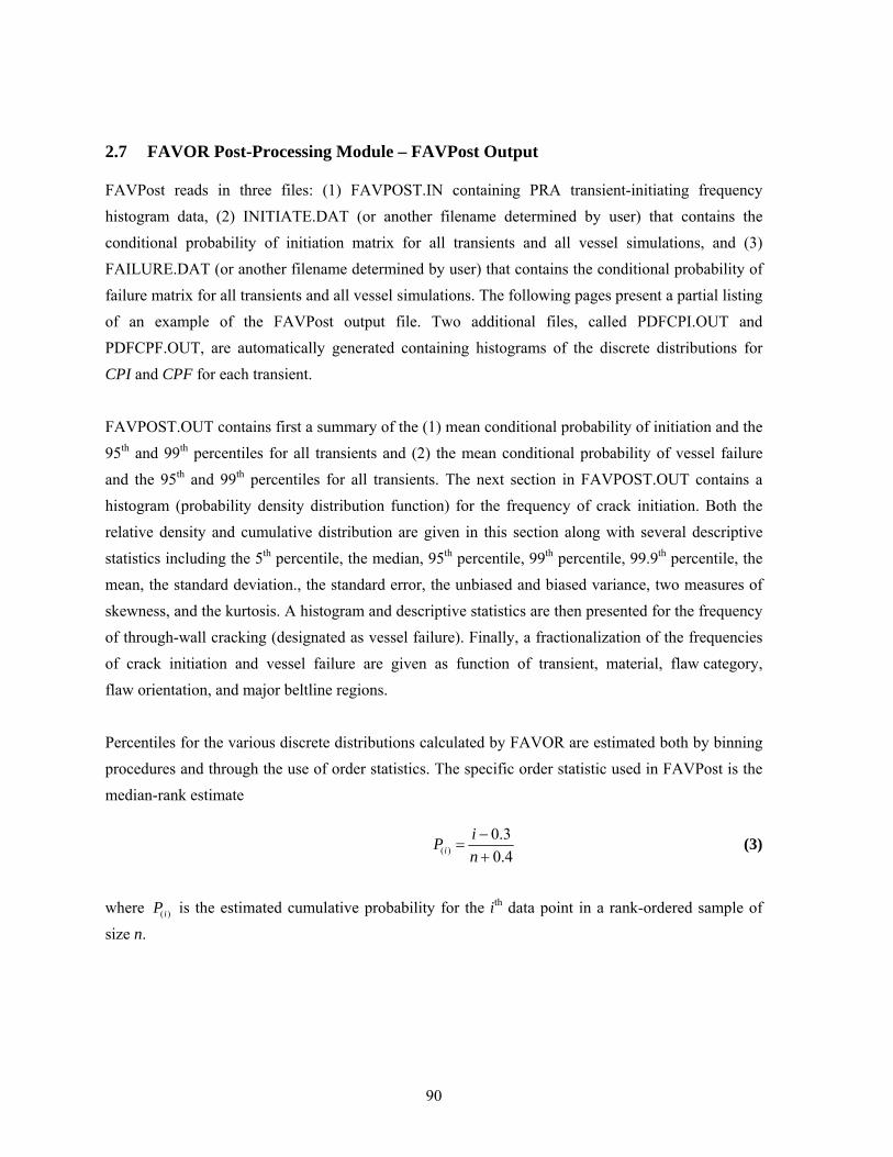
90
2.7 FAVOR Post-Processing Module – FAVPost Output
FAVPost reads in three files: (1) FAVPOST.IN containing PRA transient-initiating frequency histogram data, (2) INITIATE.DAT (or another filename determined by user) that contains the conditional probability of initiation matrix for all transients and all vessel simulations, and (3) FAILURE.DAT (or another filename determined by user) that contains the conditional probability of failure matrix for all transients and all vessel simulations. The following pages present a partial listing of an example of the FAVPost output file. Two additional files, called PDFCPI.OUT and PDFCPF.OUT, are automatically generated containing histograms of the discrete distributions for CPI and CPF for each transient.
FAVPOST.OUT contains first a summary of the (1) mean conditional probability of initiation and the 95th and 99th percentiles for all transients and (2) the mean conditional probability of vessel failure and the 95th and 99th percentiles for all transients. The next section in FAVPOST.OUT contains a histogram (probability density distribution function) for the frequency of crack initiation. Both the relative density and cumulative distribution are given in this section along with several descriptive statistics including the 5th percentile, the median, 95th percentile, 99th percentile, 99.9th percentile, the mean, the standard deviation., the standard error, the unbiased and biased variance, two measures of skewness, and the kurtosis. A histogram and descriptive statistics are then presented for the frequency of through-wall cracking (designated as vessel failure). Finally, a fractionalization of the frequencies of crack initiation and vessel failure are given as function of transient, material, flaw category, flaw orientation, and major beltline regions.
Percentiles for the various discrete distributions calculated by FAVOR are estimated both by binning procedures and through the use of order statistics. The specific order statistic used in FAVPost is the median-rank estimate
( )0.30.4i
iPn−
=+
(3)
where ( )iP is the estimated cumulative probability for the ith data point in a rank-ordered sample of size n.

91
The following descriptive statistics are calculated and reported in the FAVPost output:
m1 – 1st crude moment of the sample (sample mean) = 1
n
ii
xx
n==∑
unbiased variance ( )2
2 1
1
n
ii
x xs
n=
−=
−
∑
biased variance = ( )2
1
n
ii
x x
n=
−∑
standard deviation, ( )2
1
1
n
ii
x xs
n=
−=
−
∑
standard error = ( )
( )
2
1
1
n
ii
x x
n n=
−
−
∑
moment coefficient of skewness, ( )
( ) ( )2 33
1 2 331 1
2
; ; n n
i i
i i
x x x xm m mn nm
β= =
− −= = =∑ ∑
Pearson’s second coefficient of skewness = 3 x medians
−⎛ ⎞⎜ ⎟⎝ ⎠
moment coefficient of kurtosis, ( ) ( )2 44
2 2 421 12
; ; ( )
n ni i
i i
x x x xm m mm n n
β= =
− −= = =∑ ∑

92
FAVPOST.OUT
************************************************ * * * WELCOME TO FAVOR * * * * FRACTURE ANALYSIS OF VESSELS: OAK RIDGE * * VERSION 04.1 * * * * FAVPOST MODULE: POSTPROCESSOR MODULE * * COMBINES TRANSIENT INITIAITING FREQUENCIES * * WITH RESULTS OF PFM ANALYSIS * * * * PROBLEMS OR QUESTIONS REGARDING FAVOR * * SHOULD BE DIRECTED TO * * * * TERRY DICKSON * * OAK RIDGE NATIONAL LABORATORY * * * * e-mail: [email protected] * * * ************************************************ *********************************************************** * This computer program was prepared as an account of * * work sponsored by the United States Government * * Neither the United States, nor the United States * * Department of Energy, nor the United States Nuclear * * Regulatory Commission, nor any of their employees, * * nor any of their contractors, subcontractors, or their * * employees, makes any warranty, expressed or implied, or * * assumes any legal liability or responsibility for the * * accuracy, completeness, or usefulness of any * * information, apparatus, product, or process disclosed, * * or represents that its use would not infringe * * privately-owned rights. * * * *********************************************************** DATE: 05-Oct-2004 TIME: 08:23:12 Begin echo of FAVPost input data deck 06:23:12 04-Oct-2004 no./col. 1.......10........20........30........40........50........60........70........80 1 ******************************************************************************** 2 * ALL RECORDS WITH AN ASTERISK (*) IN COLUMN 1 ARE COMMENT ONLY * 3 ******************************************************************************** 4 * EXAMPLE INPUT DATASET FOR FAVPost, v03.1 * 5 ******************************************************************************** 6 * ==================== * 7 * Record CNTL * 8 * ==================== * 9 *------------------------------------------------------------------------------* 10 * NTRAN = NUMBER OF T-H TRANSIENTS * 11 *------------------------------------------------------------------------------* 12 ******************************************************************************** 13 CNTL NTRAN=4 14 ******************************************************************************** 15 * ==================== * 16 * Record ITRN * 17 * ==================== * 18 *------------------------------------------------------------------------------* 19 * ITRAN = PFM TRANSIENT NUMBER * 20 * ITRAN = TRANSIENT NUMBER * 21 * NHIST = NUMBER OF DATA PAIRS IN DISCRETE FREQUENCY DISTRIBUTION * 22 * ISEQ = THERMAL-HYDRAULIC SEQUENCE NUMBER * 23 *------------------------------------------------------------------------------* 24 ******************************************************************************** 25 ITRN ITRAN=1 NHIST=20 ISEQ=7 26 ******************************************************************************** 27 *------------------------------ 28 * freq[events/year] Density [%] 29 *------------------------------ 30 2.11E-07 0.50 31 3.01E-07 0.50 32 5.19E-07 1.50 33 7.92E-07 2.50 34 1.32E-06 5.00 35 2.43E-06 10.00 36 3.08E-06 5.00 37 3.79E-06 5.00 38 5.55E-06 10.00 39 7.90E-06 10.00 40 1.12E-05 10.00 41 1.64E-05 10.00 42 2.03E-05 5.00 43 2.57E-05 5.00 44 4.74E-05 10.00

93
FAVPOST.OUT (continued) 150 1.96E-05 2.50 151 2.90E-05 1.50 152 3.56E-05 0.50 153 8.62E-05 0.50 no./col. 1.......10........20........30........40........50........60........70........80 End echo of FAVPost input data deck 06:23:12 04-Oct-2004 FAVPOST INPUT FILE NAME = FAVPost.in FAVPFM OUTPUT FILE CONTAINING PFMI ARRAY = INITIATE_10K.DAT FAVPFM OUTPUT FILE CONTAINING PFMF ARRAY = FAILURE_10K.DAT FAVPOST OUTPUT FILE NAME = FAVPost_10K.out ********************************** * NUMBER OF SIMULATIONS = 10000 * ********************************** ___________________________________________________________________________________________________ CONDITIONAL PROBABILITY CONDITIONAL PROBABILITY OF INITIATION CPI=P(I|E) OF FAILURE CPF=P(F|E) TRANSIENT MEAN 95th % 99th % MEAN 95th % 99th % RATIO NUMBER CPI CPI CPI CPF CPF CPF CPFmn/CPImn |--------------------------------------| |--------------------------------------| 7 3.7584E-03 7.2820E-03 3.6865E-02 5.3901E-05 8.9334E-05 8.7207E-04 0.0143 9 5.8876E-03 2.3043E-02 6.6791E-02 1.0514E-04 1.9096E-04 1.8005E-03 0.0179 56 2.2043E-03 4.6862E-03 2.6764E-02 6.3464E-05 1.0063E-04 1.0982E-03 0.0288 97 1.8385E-04 2.7432E-04 3.4783E-03 1.6248E-04 2.4377E-04 3.1176E-03 0.8838 ___________________________________________________________________________________________________ NOTES: CPI IS CONDITIONAL PROBABILITY OF CRACK INITIATION, P(I|E) CPF IS CONDITIONAL PROBABILITY OF RPV FAILURE, P(F|E) *********************************************************** * PROBABILITY DISTRIBUTION FUNCTION (HISTOGRAM) * * FOR THE FREQUENCY OF CRACK INITIATION * *********************************************************** FREQUENCY OF RELATIVE CUMULATIVE CRACK INITIATION DENSITY DISTRIBUTION (CRACKED VESSELS PER YEAR) ( %) (%) 0.0000E+00 0.0000 0.0000 2.0506E-07 80.0800 80.0800 6.1517E-07 8.4900 88.5700 1.0253E-06 3.3100 91.8800 1.4354E-06 2.1300 94.0100 1.8455E-06 1.2100 95.2200 2.2556E-06 1.0800 96.3000 2.6657E-06 0.6300 96.9300 3.0758E-06 0.6200 97.5500 3.4859E-06 0.3900 97.9400 3.8961E-06 0.2100 98.1500 3.5065E-05 0.0100 99.9700 3.9576E-05 0.0100 99.9800 4.0396E-05 0.0100 99.9900 ============================================= == Summary Descriptive Statistics == ============================================= Minimum = 1.3916E-15 Maximum = 4.0601E-05 Range = 4.0601E-05 Number of Simulations = 10000 5th Percentile = 7.5760E-10 Median = 6.5353E-08 95.0th Percentile = 1.9505E-06 99.0th Percentile = 6.4638E-06 99.9th Percentile = 2.1697E-05 Mean = 4.5678E-07 Standard Deviation = 1.6431E-06 Standard Error = 1.6431E-08 Variance (unbiased) = 2.6997E-12 Variance (biased) = 2.6994E-12 Moment Coeff. of Skewness = 1.0872E+01 Pearson's 2nd Coeff. of Skewness = 1.6702E-02 Kurtosis = 1.7097E+02

94
FAVPOST.OUT (continued)
*********************************************************** * PROBABILITY DISTRIBUTION FUNCTION (HISTOGRAM) * * FOR THE FREQUENCY OF VESSEL FAILURE * *********************************************************** FREQUENCY OF RELATIVE CUMULATIVE VESSEL FAILURES DENSITY DISTRIBUTION (FAILED VESSELS PER YEAR) ( %) (%) 0.0000E+00 2.9500 2.9500 1.7676E-08 92.0500 95.0000 5.3027E-08 2.0200 97.0200 8.8379E-08 0.9100 97.9300 1.2373E-07 0.4900 98.4200 1.5908E-07 0.2800 98.7000 1.9443E-07 0.2100 98.9100 2.2979E-07 0.2000 99.1100 2.6514E-07 0.1000 99.2100 3.0049E-07 0.1200 99.3300 3.3584E-07 0.0800 99.4100 3.7119E-07 0.0300 99.4400 4.0654E-07 0.1000 99.5400 4.4190E-07 0.0600 99.6000 4.7725E-07 0.0500 99.6500 5.1260E-07 0.0400 99.6900 5.4795E-07 0.0200 99.7100 5.8330E-07 0.0200 99.7300 6.1865E-07 0.0300 99.7600 6.8936E-07 0.0200 99.7800 7.9541E-07 0.0100 99.7900 8.3076E-07 0.0200 99.8100 8.6611E-07 0.0100 99.8200 9.0147E-07 0.0100 99.8300 9.3682E-07 0.0200 99.8500 9.7217E-07 0.0100 99.8600 1.0075E-06 0.0200 99.8800 1.1489E-06 0.0200 99.9000 1.1843E-06 0.0200 99.9200 1.2196E-06 0.0100 99.9300 1.2550E-06 0.0100 99.9400 1.3257E-06 0.0200 99.9600 2.1741E-06 0.0100 99.9700 2.4569E-06 0.0100 99.9800 2.4923E-06 0.0100 99.9900 3.7649E-06 0.0100 100.0000 ============================================= == Summary Descriptive Statistics == ============================================= Minimum = 0.0000E+00 Maximum = 3.7512E-06 Range = 3.7512E-06 Number of Simulations = 10000 5th Percentile = 3.3240E-15 Median = 1.7411E-10 95.0th Percentile = 1.7676E-08 99.0th Percentile = 2.1034E-07 99.9th Percentile = 1.1489E-06 Mean = 1.1376E-08 Standard Deviation = 8.1581E-08 Standard Error = 8.1581E-10 Variance (unbiased) = 6.6554E-15 Variance (biased) = 6.6547E-15 Moment Coeff. of Skewness = 2.2133E+01 Pearson's 2nd Coeff. of Skewness =-1.9849E+00 Kurtosis = 7.2233E+02

95
FAVPOST.OUT (continued)
*********************************************************** * FRACTIONALIZATION OF FREQUENCY OF CRACK INITIATIONON * * AND FREQUENCY OF RPV FAILURE BY * * TRANSIENT * * WEIGHTED BY TRANSIENT INITIATING FREQUENCIES * *********************************************************** % of total % of total frequency of frequency of crack initiation of RPV failure 7 23.05 10.44 9 11.85 10.02 56 64.93 73.76 97 0.17 5.78 TOTALS 100.00 100.00 *********************************************************** * FRACTIONALIZATION OF FREQUENCY OF CRACK INITIATION * * AND FREQUENCY OF RPV FAILURE BY * * RPV BELTLINE MAJOR REGION * * BY PARENT SUBREGION * * * * WEIGHTED BY % CONTRIBUTION OF EACH TRANSIENT * * TO FREQUENCY OF CRACK INITIATION AND * * FREQUENCY OF RPV FAILURE * *********************************************************** % of total % of % of total through-wall crack MAJOR RTPTS total frequency of frequency REGION (MAX) flaws crack initiation cleavage ductile total 1 228.85 2.30 0.69 1.95 0.17 2.12 2 228.85 2.30 0.30 1.04 0.11 1.15 3 216.12 3.70 3.09 21.88 2.11 23.99 4 216.12 3.70 3.03 25.75 2.55 28.30 5 154.20 19.31 89.73 3.32 0.04 3.36 6 267.73 13.15 0.14 1.01 0.07 1.08 7 246.02 13.15 0.01 0.05 0.01 0.05 8 302.85 21.20 2.47 35.01 2.04 37.04 9 272.85 21.20 0.53 2.70 0.21 2.92 TOTALS 100.01 100.00 92.69 7.31 100.00 *********************************************************** * FRACTIONALIZATION OF FREQUENCY OF CRACK INITIATION * * AND FREQUENCY OF RPV FAILURE BY * * RPV BELTLINE MAJOR REGION * * BY CHILD SUBREGION * * * * WEIGHTED BY % CONTRIBUTION OF EACH TRANSIENT * * TO FREQUENCY OF CRACK INITIATION AND * * FREQUENCY OF RPV FAILURE * *********************************************************** % of total % of % of total through-wall crack MAJOR RTPTS total frequency of frequency REGION (MAX) flaws crack initiation cleavage ductile total 1 228.85 2.30 0.00 0.00 0.17 0.17 2 228.85 2.30 0.00 0.00 0.11 0.11 3 216.12 3.70 0.00 0.00 2.11 2.11 4 216.12 3.70 0.00 0.00 2.55 2.55 5 154.20 19.31 0.00 0.00 0.04 0.04 6 267.73 13.15 3.68 4.03 0.07 4.10 7 246.02 13.15 0.01 0.05 0.01 0.05 8 302.85 21.20 81.10 85.60 2.04 87.64 9 272.85 21.20 15.21 3.01 0.21 3.23 TOTALS 100.01 100.00 92.69 7.31 100.00
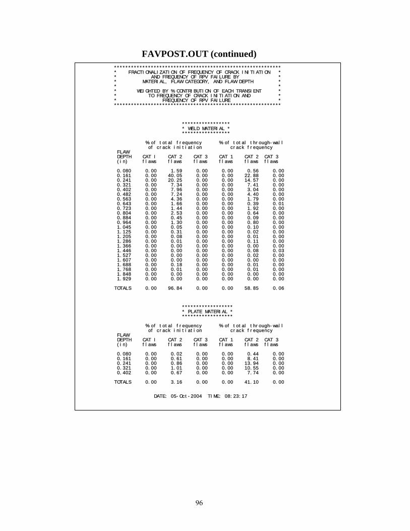
96
FAVPOST.OUT (continued)
*********************************************************** * FRACTIONALIZATION OF FREQUENCY OF CRACK INITIATION * * AND FREQUENCY OF RPV FAILURE BY * * MATERIAL, FLAW CATEGORY, AND FLAW DEPTH * * * * WEIGHTED BY % CONTRIBUTION OF EACH TRANSIENT * * TO FREQUENCY OF CRACK INITIATION AND * * FREQUENCY OF RPV FAILURE * *********************************************************** ***************** * WELD MATERIAL * ***************** % of total frequency % of total through-wall of crack initiation crack frequency FLAW DEPTH CAT I CAT 2 CAT 3 CAT 1 CAT 2 CAT 3 (in) flaws flaws flaws flaws flaws flaws 0.080 0.00 1.59 0.00 0.00 0.56 0.00 0.161 0.00 40.05 0.00 0.00 22.88 0.00 0.241 0.00 20.25 0.00 0.00 14.57 0.00 0.321 0.00 7.34 0.00 0.00 7.41 0.00 0.402 0.00 7.96 0.00 0.00 3.04 0.00 0.482 0.00 7.24 0.00 0.00 4.40 0.00 0.563 0.00 4.36 0.00 0.00 1.79 0.00 0.643 0.00 1.66 0.00 0.00 0.39 0.01 0.723 0.00 1.44 0.00 0.00 1.92 0.00 0.804 0.00 2.53 0.00 0.00 0.64 0.00 0.884 0.00 0.45 0.00 0.00 0.09 0.00 0.964 0.00 1.30 0.00 0.00 0.80 0.00 1.045 0.00 0.05 0.00 0.00 0.10 0.00 1.125 0.00 0.31 0.00 0.00 0.02 0.00 1.205 0.00 0.08 0.00 0.00 0.01 0.00 1.286 0.00 0.01 0.00 0.00 0.11 0.00 1.366 0.00 0.00 0.00 0.00 0.00 0.00 1.446 0.00 0.00 0.00 0.00 0.08 0.03 1.527 0.00 0.00 0.00 0.00 0.02 0.00 1.607 0.00 0.00 0.00 0.00 0.00 0.00 1.688 0.00 0.18 0.00 0.00 0.01 0.00 1.768 0.00 0.01 0.00 0.00 0.01 0.00 1.848 0.00 0.00 0.00 0.00 0.00 0.00 1.929 0.00 0.00 0.00 0.00 0.00 0.00 TOTALS 0.00 96.84 0.00 0.00 58.85 0.06 ****************** * PLATE MATERIAL * ****************** % of total frequency % of total through-wall of crack initiation crack frequency FLAW DEPTH CAT I CAT 2 CAT 3 CAT 1 CAT 2 CAT 3 (in) flaws flaws flaws flaws flaws flaws 0.080 0.00 0.02 0.00 0.00 0.44 0.00 0.161 0.00 0.61 0.00 0.00 8.41 0.00 0.241 0.00 0.86 0.00 0.00 13.94 0.00 0.321 0.00 1.01 0.00 0.00 10.55 0.00 0.402 0.00 0.67 0.00 0.00 7.74 0.00 TOTALS 0.00 3.16 0.00 0.00 41.10 0.00 DATE: 05-Oct-2004 TIME: 08:23:17

97
3. Example Case
The example case included on the distribution CD was developed for the RPV beltline description shown in Fig. 18. Partial input listings for the three FAVOR modules are given on the following pages. The complete output listings are included on the distribution CD.
Example Case FAVLoad input file (partial listing)
******************************************************************************** * ALL RECORDS WITH AN ASTERISK (*) IN COLUMN 1 ARE COMMENT ONLY * ******************************************************************************** * EXAMPLE INPUT DATASET FOR FAVLoad, v04.1 [UNITS]* ******************************************************************************** * ==================== * * Record GEOM * * ==================== * *------------------------------------------------------------------------------* * IRAD = INTERNAL RADIUS OF PRESSURE VESSEL [IN] * * W = THICKNESS OF PRESSURE VESSEL WALL (INCLUDING CLADDING) [IN] * * CLTH = CLADDING THICKNESS [IN] * *------------------------------------------------------------------------------* ******************************************************************************** GEOM IRAD=78.5 W=8.036 CLTH=0.156 ******************************************************************************** * =========================== * * Records BASE and CLAD * * =========================== * * THERMO-ELASTIC MATERIAL PROPERTIES FOR BASE AND CLADDING * *------------------------------------------------------------------------------* * K = THERMAL CONDUCTIVITY [BTU/HR-FT-F] * * C = SPECIFIC HEAT [BTU/LBM-F] * * RHO = DENSITY [LBM/FT**3] * * E = YOUNG'S ELASTIC MODULUS [KSI] * * ALPHA = THERMAL EXPANSION COEFFICIENT [F**-1] * * NU = POISSON'S RATIO [-] * * NTE = TEMPERATURE DEPENDANCY FLAG * * NTE = 0 ==> PROPERTIES ARE TEMPERATURE INDEPENDENT (CONSTANT) * * NTE = 1 ==> PROPERTIES ARE TEMPERATURE DEPENDENT * * IF NTE EQUAL TO 1, THEN ADDITIONAL DATA RECORDS ARE REQUIRED * *------------------------------------------------------------------------------* ******************************************************************************** BASE K=24.0 C=0.120 RHO=489.00 E=28000 ALPHA=.00000777 NU=0.3 NTE=1 ******************************************************************************** *--------------------------- * THERMAL CONDUCTIVITY TABLE *--------------------------- NBK NK=16 *--------------------------- 70 24.8 100 25.0 150 25.1 200 25.2 250 25.2 300 25.1 350 25.0 400 25.1 450 24.6 500 24.3 550 24.0 600 23.7 650 23.4 700 23.0 750 22.6 800 22.2 *--------------------------- * SPECIFIC HEAT TABLE *--------------------------- NBC NC=16 *---------------- 70 0.1052 100 0.1072 150 0 1101

98
Example Case FAVLoad input file (partial listing) (continued)
******************************************************************************** * ==================== * * Record SFRE * * ==================== * * T = BASE AND CLADDING STRESS-FREE TEMPERATURE [F] * * CFP = crack-face pressure loading flag * * CFP = 0 ==> no crack-face pressure loading * * CFP = 1 ==> crack-face pressure loading applied * ******************************************************************************** SFRE T=468 CFP=1 ******************************************************************************** * ========================= * * Records RESA AND RESC * * ========================= * * SET FLAGS FOR RESIDUAL STRESSES IN WELDS * *------------------------------------------------------------------------------* * NRAX = 0 AXIAL WELD RESIDUAL STRESSES OFF * * NRAX = 101 AXIAL WELD RESIDUAL STRESSES ON * * NRCR = 0 CIRCUMFERENTIAL WELD RESIDUAL STRESSES OFF * * NRCR = 101 CIRCUMFERENTIAL WELD RESIDUAL STRESSES ON * *------------------------------------------------------------------------------* ******************************************************************************** RESA NRAX=101 RESC NRCR=101 ******************************************************************************** * ========================= * * Record TIME * * ========================= * *------------------------------------------------------------------------------* * TOTAL = TIME PERIOD FOR WHICH TRANSIENT ANALYSIS IS TO BE PERFORMED [MIN]* * DT = TIME INCREMENT [MIN]* *------------------------------------------------------------------------------* ******************************************************************************** TIME TOTAL=80.0 DT=0.5 ******************************************************************************** * =============== * * Record NPRA * * =============== * * NTRAN = NUMBER OF TRANSIENTS TO BE INPUT [-] * ******************************************************************************** NPRA NTRAN=4 ******************************************************************************** * ========================= * * Record TRAN * * ========================= * *------------------------------------------------------------------------------* * ITRAN = PFM TRANSIENT NUMBER * * ISEQ = THERMAL-HYDRAULIC SEQUENCE NUMBER * *------------------------------------------------------------------------------* ******************************************************************************** TRAN ITRAN=1 ISEQ=7 ******************************************************************************** * ========================= * * Record NHTH * * ========================= * * CONVECTIVE HEAT TRANSFER COEFFICIENT TIME HISTORY * * NC = NUMBER OF (TIME,h) RECORD PAIRS FOLLOWING THIS LINE * ******************************************************************************** NHTH NC=500 * ===================================== * TIME [MIN] h[BTU/HR-FT**2-F] * ===================================== 0.00 4216.86 0.50 2063.75 1.00 748.74 1.50 552.12 2.00 582.22 2.50 907.80 3.00 1365.43 3.50 1297.57 4.00 665.04 4.50 601.89 5.00 630.19 5.50 533.59 6.00 443.70 6.50 493.02 7.00 369.04 7.50 327.64 8.00 392.38 8.50 370.52

99
Example Case FAVPFM input file (partial listing)
********************************************************************************************************** * ALL RECORDS WITH AN ASTERISK(*) IN COLUMN 1 ARE COMMENT ONLY * ********************************************************************************************************** * EXAMPLE INPUT DATASET FOR FAVPFM, v04.1 [UNITS]* ********************************************************************************************************** * ==================== * * Control Record CNT1 * * ==================== * *--------------------------------------------------------------------------------------------------------* * NSIM = NUMBER OF RPV SIMULATIONS [-] * *--------------------------------------------------------------------------------------------------------* * IGATR = NUMBER OF INITIATION-GROWTH-ARREST (IGA) TRIALS PER FLAW [-] * *--------------------------------------------------------------------------------------------------------* * WPS_OPTION = 0 DO NOT INCLUDE WARM-PRESTRESSING IN ANALYSIS [-] * * WPS_OPTION = 1 INCLUDE WARM-PRESTRESSING IN ANALYSIS [-] * *--------------------------------------------------------------------------------------------------------* * PC3_OPTION = 0 DO NOT PERFORM FRACTURE ANALYSIS OF CATEGORY 3 FLAWS IN PLATES [-] * * PC3_OPTION = 1 PERFORM FRACTURE ANALYSIS OF CATEGORY 3 FLAWS IN PLATES [-] * *--------------------------------------------------------------------------------------------------------* * CHILD_OPTION = 0 DO NOT INCLUDE CHILD SUBREGION REPORTS [-] * * CHILD_OPTION = 1 INCLUDE CHILD SUBREGION REPORTS [-] * *--------------------------------------------------------------------------------------------------------* * RESTART_OPTION = 0 THIS IS NOT A RESTART CASE [-] * * RESTART_OPTION = 1 THIS IS A RESTART CASE [-] * *--------------------------------------------------------------------------------------------------------* * ============================= * * Notes for Control Record CNT1 * * ============================= * * IN A TYPICAL PFM ANALYSIS, A SUBSTANTIAL FRACTION OF THE TOTAL FLAWS ARE CATEGORY 3 FLAWS IN * * PLATE REGIONS. BASED ON EXPERIENCE AND SOME DETERMINISTIC FRACTURE ANALYSES, THESE FLAWS VERY * * RARELY CONTRIBUTE TO THE CPI OR CPF WITH THE PLATE FLAW SIZE DISTRIBUTIONS TYPICALLY USED. * * THEREFORE, INVOKING IP3OPT = 0 CAN RESULT IN A SIGNIFICANT REDUCTION IN EXECUTION TIME WITHOUT * * AFFECTING THE SOLUTION, UNLESS THERE ARE UNUSUAL CIRCUMSTANCES SUCH AS A NEW FLAW-SIZE * * DISTRIBUTION FOR PLATE FLAWS. IN EITHER CASE, CATEGORY 3 PLATE FLAWS ARE INCLUDED IN ALL REPORTS. * * * * Notes on Restart Option: * * * * The restart option flag can also be used to control the frequency with which restart files are * * created. If RESTART_OPTION is given a value other than 0 or 1, then the absolute value of this flag * * sets the checkpoint interval at which the restart file will be created during the run. For example, * * * * 1.RESTART_OPTION = -200 ==> This is not a restart case; restart files will be created every 200 trials * * 2.RESTART_OPTION = 0 ==> Same as example No. 1. * * 3.RESTART_OPTION = 200 ==> This is a restart case; restart files will be created every 200 trials.* * 4.RESTART_OPTION = 1 ==> Same as example No. 3. * * 5.RESTART_OPTION = -50 ==? This is not a restart case; restart files will be created every 50 trials. * * * * * *--------------------------------------------------------------------------------------------------------* ********************************************************************************************************** CNT1 NSIM=10000 IGATR=100 WPS_OPTION=0 PC3_OPTION=0 CHILD_OPTION=1 RESTART_OPTION=0 ********************************************************************************************************** * ==================== * * Control Record CNT2 * * ==================== * *--------------------------------------------------------------------------------------------------------* * IRTNDT = 992 ==> USE RG 1.99, REV 2, FOR ESTIMATING RADIATION-INDUCED SHIFT IN RTNDT * * IRTNDT = 993 ==> USE E900 CORRELATION FOR ESTIMATING RADIATION-INDUCED SHIFT IN RTNDT * *--------------------------------------------------------------------------------------------------------* * TC = INITIAL RPV COOLANT TEMPERATURE (applicable only when IRTNDT=993) [F] * *--------------------------------------------------------------------------------------------------------* * EFPY = EFFECTIVE FULL-POWER YEARS OF OPERATION [YEARS] * *--------------------------------------------------------------------------------------------------------* * IDT_OPTION = 0 DO NOT INCLUDE DUCTILE TEARING AS A POTENTIAL FRACTURE MODE [-] * * IDT_OPTION = 1 INCLUDE DUCTILE TEARING AS A POTENTIAL FRACTURE MODE [-] * *--------------------------------------------------------------------------------------------------------* * IDT_INI = 0 DO NOT CREATE A LOG OF POTENTIAL DUCTILE TEARING INITIATIONS [-] * * IDT_INI = 1 CREATE A LOG OF POTENTIAL DUCTILE TEARING INITIATIONS [-] * *--------------------------------------------------------------------------------------------------------* ********************************************************************************************************** CNT2 IRTNDT=993 TC=550 EFPY=32 IDT_OPTION=1 IDT_INI=1 ********************************************************************************************************** * ==================== * * Control Record CNT3 * * ==================== * *--------------------------------------------------------------------------------------------------------* * FLWSTR = UNIRRADIATED FLOW STRESS USED IN PREDICTING FAILURE BY REMAINING LIGAMENT INSTABILITY [ksi] * *--------------------------------------------------------------------------------------------------------* * USKIA = MAXIMUM VALUE ALLOWED FOR KIc or KIa [ksi-in^1/2] * *--------------------------------------------------------------------------------------------------------* * KIa_Model = 1 Use high-constraint KIa model based on CCA specimens [-] * * KIa_Model = 2 Use KIa model based on CCA + large specimen data [-] * *--------------------------------------------------------------------------------------------------------* * LAYER_OPTION = 0 DONOT RESAMPLE PF WHEN ADVANCING INTO NEW WELD LAYER [-] * * LAYER_OPTION = 1 RESAMPLE PF WHEN ADVANCING INTO NEW WELD LAYER [-] * *--------------------------------------------------------------------------------------------------------* * FAILCR = FRACTION OF WALL THICKNESS FOR VESSEL FAILURE BY THROUGH-WALL CRACK PROPAGATION [-] * *--------------------------------------------------------------------------------------------------------* * ============================= * * Notes for Control Record CNT3 * * ============================= * * If ductile tearing model is included, then the values for USKIA and KIa_Model are ignored. * * They are automatically set internally to KIa_Model=2 and there is no upper limit on USKIa. * * If ductile tearing is not included in the analysis (IDT_OPTION = 0 on CNT1), both the KIa_Model * * and USKIA are user-specified on CNT3. * * * ********************************************************************************************************** CNT3 FLWSTR=80. USKIA=800. KIa_Model=2 LAYER_OPTION=1 FAILCR=0.9 ********************************************************************************************************** * *

100
Example Case FAVPFM input file (continued)
********************************************************************************************************** * ==================== * * Record GENR * * ==================== * *--------------------------------------------------------------------------------------------------------* * SIGFGL = A MULTIPLIER ON THE BEST ESTIMATE OF FLUENCE FOR A GIVEN SUBREGION [-] * * PRODUCES THE STANDARD DEVIATION FOR THE NORMAL DISTRIBUTION USED TO SAMPLE THE MEAN * * OF THE LOCAL FLUENCE DISTRIBUTION. * *--------------------------------------------------------------------------------------------------------* * SIGFLC = A MULTIPLIER ON THE SAMPLED MEAN OF THE LOCAL FLUENCE FOR A GIVEN SUBREGION [-] * * PRODUCES THE STANDARD DEVIATION FOR THE NORMAL DISTRIBUTION USED TO SAMPLE THE LOCAL FLUENCE* *--------------------------------------------------------------------------------------------------------* * ====================== * * Notes for Record GENR * * ====================== * * Let "flue" be the best estimate for the subregion neutron fluence at inside surface of the RPV wall. * * flue_STDEV_global = SIGFGL*flue * * flue_MEAN_local << Normal(flue,flue_STDEV_global) * * flue_STDEV_local = SIGFLC*flue_MEAN_local * * flue_local << Normal(flue_MEAN_local,flue_STDEV_local) * * * ********************************************************************************************************** GENR SIGFGL=0.056 SIGFLC=0.118 ********************************************************************************************************** * ==================== * * Record SIGW * * ==================== * * STANDARD DEVIATIONS (STDEV) OF NORMAL DISTRIBUTIONS FOR WELD CHEMISTRY SAMPLING: * * WSIGCU = STANDARD DEVIATION FOR COPPER CHEMISTRY SAMPLING IN WELDS [wt%] * * WSIGNI = STANDARD DEVIATION FOR NICKEL CHEMISTRY SAMPLING IN WELDS [wt%] * * WSIGP = STANDARD DEVIATION FOR PHOSPHOROUS CHEMISTRY SAMPLING IN WELDS [wt%] * *--------------------------------------------------------------------------------------------------------* * ====================== * * Notes for Record SIGW * * ====================== * * FOR NICKEL IN WELDS THERE ARE TWO POSSIBILITIES. * * (1) FOR HEATS 34B009 AND W5214 (Ni - addition welds) * * WSIGNI = 0.162 wt% using a normal distribution. * * (2) For other heats, the standard deviation (WSIGNI) shall be sampled from a normal distribution * * with mean equal to 0.029 wt% and standard deviation = 0.0165 wt% * ********************************************************************************************************** SIGW WSIGCU=0.167 WSIGNI=0.162 WSIGP=0.0013 ********************************************************************************************************** * ==================== * * Record SIGP * * ==================== * * STANDARD DEVIATIONS (STDEV) OF NORMAL DISTRIBUTIONS FOR PLATE CHEMISTRY SAMPLING: * * PSIGCU = STANDARD DEVIATION FOR COPPER CHEMISTRY SAMPLING IN PLATES [wt%] * * PSIGNI = STANDARD DEVIATION FOR NICKEL CHEMISTRY SAMPLING IN PLATES [wt%] * * PSIGP = STANDARD DEVIATION FOR PHOSPHOROUS CHEMISTRY SAMPLING IN PLATES [wt%] * *--------------------------------------------------------------------------------------------------------* * ====================== * * Notes for Record SIGP * * ====================== * * RECOMMENDED VALUES ARE: 0.0073, 0.0244, 0.0013 for Cu, Ni, and P, respectively. * ********************************************************************************************************** SIGP PSIGCU=0.0073 PSIGNI=0.0244 PSIGP=0.0013 ********************************************************************************************************** * =============================== * * Notes for RecordS SIGW and SIGP * * =============================== * * THE ABOVE DISTRIBUTIONS ARE FOR THE 1ST FLAW POSITIONED IN A PARTICULAR SUBREGION. * * IF THE CURRENT FLAW IS THE 2ND OR MORE FLAW FOR THIS SUBREGION, THEN FAVPFM WILL USE * * THE LOCAL VARIABILITY SAMPLING PROTOCOLS PRESENTED IN THE THEORY MANUAL. * ********************************************************************************************************** * ==================== * * Record TRAC * * ==================== * * ITRAN = TRANSIENT NUMBER [-] * * RPV = RPV SIMULATION [-] * * KFLAW = FLAW NUMBER [-] * * FLAW_LOG_OPTION = 0 DO NOT CREATE FLAW LOG TABLES [-] * * FLAW_LOG_OPTION = 1 DO CREATE FLAW LOG TABLES [-] * *--------------------------------------------------------------------------------------------------------* * =============================== * * Notes for Record TRAC * * =============================== * * THE ABOVE FLAGS IDENTIFY A SPECIFIC TRANSIENT, RPV SIMULATION, AND FLAW NUMBER WHOSE COMPLETE * * HISTORY WILL BE GIVEN IN THE FILES: "TRACE.OUT" AND "ARREST.OUT" * * SEE THE USER'S GUIDE FOR DETAILS ON THE CONTENTS OF THESE FILES * * * ********************************************************************************************************** TRAC ITRAN=3 IRPV=4 KFLAW=3003 FLAW_LOG_OPTION=1 ********************************************************************************************************** * ==================== * * Record LDQA * * ==================== * * THE LDQA RECORD PROVIDES THE OPPORTUNITY TO CHECK LOAD-RELATED SOLUTIONS * * SUCH AS TEMPERATURE, STRESSES, AND KI. * * * * IQA = 0 ==> THIS EXECUTION IS NOT FOR LOAD QA [-] * * IQA = 1 ==> THIS EXECUTION IS FOR LOAD QA [-] * *--------------------------------------------------------------------------------------------------------* * IOPT = 1 ==> GENERATE TIME HISTORY AT SPECIFIC THROUGH WALL LOCATION [-] * * IOPT = 2 ==> GENERATE THROUGH WALL DISTRIBUTION AT SPECIFIC TIME [-] * *--------------------------------------------------------------------------------------------------------* * IFLOR = 1 ==> FLAW ORIENTATION IS AXIAL [-] * * IFLOR = 2 ==> FLAW ORIENTATION IS CIRCUMFERENTIAL [-] * *--------------------------------------------------------------------------------------------------------* * 0 O S O C S S SS [ ] *

101
Example Case FAVPFM input file (partial listing) (continued)
************************************************************************************************************ * ==================== * * Record DTRF * * ==================== * *----------------------------------------------------------------------------------------------------------* * NT = number of ISQ records that follow [-] * * NT = 0 no ISQ records follow * *----------------------------------------------------------------------------------------------------------* * FOLLOWING THE DTRF RECORD, THERE SHOULD BE "NT" SUBRECORDS * *----------------------------------------------------------------------------------------------------------* * ISQ ITRAN= ISEQ= TSTART= TEND= * *----------------------------------------------------------------------------------------------------------* * ITRAN = sequential number in FAVLoad transient stack [-] * * ISEQ = Thermal Hydraulic trasient sequence number [-] * * TSTART = starting time for FAVPFM analysis [MIN] * * TEND = ending time for FAVPFM analysis [MIN] * ************************************************************************************************************ DTRF NT=4 ISQ ITRAN=1 ISEQ=7 TSTART=2 TEND=35 ISQ ITRAN=2 ISEQ=9 TSTART=1 TEND=29 ISQ ITRAN=3 ISEQ=56 TSTART=9 TEND=56 ISQ ITRAN=4 ISEQ=97 TSTART=11 TEND=85 ************************************************************************************************************ * ==================== * * Record WELD * * ==================== * * NWSUB = NUMBER OF WELD SUBREGIONS [-] * * NWMAJ = NUMBER OF WELD MAJOR REGIONS [-] * ************************************************************************************************************ WELD NWSUB=838 NWMAJ=5 ************************************************************************************************************ * ==================== * * Record PLAT * * ==================== * * NPSUB = NUMBER OF PLATE SUBREGIONS [-] * * NPMAJ = NUMBER OF PLATE MAJOR REGIONS [-] * ************************************************************************************************************ PLAT NPSUB=14442 NPMAJ=4 ************************************************************************************************************ * WELD EMBRITTLEMENT / FLAW DISTRIBUTION MAP RECORDS * ************************************************************************************************************ *==========================================================================================================* * Field DESCRIPTION [UNITS] * *==========================================================================================================* *----------------------------------------------------------------------------------------------------------* * (1) RPV subregion number - parent [-] * *----------------------------------------------------------------------------------------------------------* * (2) adjacent RPV subregion - 1st child [-] * *----------------------------------------------------------------------------------------------------------* * (3) adjacent RPV subregion - 2nd child [-] * *----------------------------------------------------------------------------------------------------------* * (4) RPV major region number [-] * *----------------------------------------------------------------------------------------------------------* * (5) best estimate neutron fluence at RPV inside surface [10^19 neutrons/cm^2] * *----------------------------------------------------------------------------------------------------------* * (6) heat estimate copper content [wt% Cu] * *----------------------------------------------------------------------------------------------------------* * (7) heat estimate nickel content [wt% Ni] * *----------------------------------------------------------------------------------------------------------* * (8) heat estimate phosphorus content [wt% P] * *----------------------------------------------------------------------------------------------------------* * (9) product form flags for DT30 shift correlation * * * * Welds : set distribution for sampling standard * * deviation for Ni content in welds * * = 1 use normal distribution [-] * * = 2 use Weibull distribution [-] * * Plates: * * CE = 1 (if IRTNDT=993 then set B = 206) [-] * * Not CE = 2 (if IRTNDT=993 then set B = 156) [-] * * where CE is a Combustion Engineering vessel * *----------------------------------------------------------------------------------------------------------* * (10) copper saturation flag = 0 for plates and forgings [-] * * = 1 for Linde 80 and Linde 91 weld fluxes * * = 2 for all other weld fluxes * * N.B.: maximum value of copper content (copper saturation) * * = 0.25 for Linde 80 and = 0.305 for all others * *----------------------------------------------------------------------------------------------------------* * (11) unirradiated best estimate (mean) for RTNDT0 [F] * *----------------------------------------------------------------------------------------------------------* * (12) unirradiated standard deviation for RTNDT0 [F] * *----------------------------------------------------------------------------------------------------------* * (13) PF flag Product Form CF Override * * ------- ------------ ------------ * * = 11 weld no [-] * * = 12 weld yes [-] * * = 21 plate no [-] * * = 22 plate yes [-] * * = 31 forging NA [-] * *----------------------------------------------------------------------------------------------------------* * (14) standard deviation for DRTNDT correlation [F] * *----------------------------------------------------------------------------------------------------------* * (15) angle of subregion element [degrees] * *----------------------------------------------------------------------------------------------------------* * (16) axial height of subregion element: [inches] * *----------------------------------------------------------------------------------------------------------* * (17) weld fusion area: [inches^2] * *----------------------------------------------------------------------------------------------------------* * (18) weld orientation: 1 ===> axial; 2===> circumferential [-] * *----------------------------------------------------------------------------------------------------------* * (19) chemistry factor override [-] * *----------------------------------------------------------------------------------------------------------* * (20) unirradiated upper shelf CVN engergy [ft-lbf] * *==========================================================================================================* * *

102
Example Case FAVPFM input file (partial listing) (continued) *==========================================================================================================* * Notes: * * * * 1. Fields 1-4 : contain RPV beltline discretization and connectivity data for weld fusion line * * 2. Fields 5-20 : contain RPV beltline embrittlement-related data * * 3. Field 13 : PF means Product Form * * 4. Field 13 : CF means chemistry factor override * * 5. Field 17 : only applies to weld subregions. For plates set to 0. * * 6. Field 19 : applicable only if IRTNDT=992 on CNT2 and Field 13 = 12 or 22 * * * *==========================================================================================================* ************************************************************************************************************ * 1 2 3 4 5 6 7 8 9 10 11 12 13 14 15 16 17 18 19 20 ************************************************************************************************************ 00001 03593 03661 1 0.0675 0.337 0.609 0.012 2 2 -56.0 17.00 11 23.6 1.0000 1.2000 9.4500 1 0 98 00002 03594 03662 1 0.1173 0.337 0.609 0.012 2 2 -56.0 17.00 11 23.6 1.0000 1.1996 9.4469 1 0 98 00003 03595 03663 1 0.1682 0.337 0.609 0.012 2 2 -56.0 17.00 11 23.6 1.0000 2.3996 18.8969 1 0 98 00004 03596 03664 1 0.2317 0.337 0.609 0.012 2 2 -56.0 17.00 11 23.6 1.0000 2.2047 17.3622 1 0 98 00005 03597 03665 1 0.3100 0.337 0.609 0.012 2 2 -56.0 17.00 11 23.6 1.0000 2.3996 18.8969 1 0 98 00006 03598 03666 1 0.4193 0.337 0.609 0.012 2 2 -56.0 17.00 11 23.6 1.0000 2.3760 18.7109 1 0 98 00007 03599 03667 1 0.5191 0.337 0.609 0.012 2 2 -56.0 17.00 11 23.6 1.0000 1.6043 12.6341 1 0 98 00008 03600 03668 1 0.6065 0.337 0.609 0.012 2 2 -56.0 17.00 11 23.6 1.0000 1.2500 9.8438 1 0 98 00009 03601 03669 1 0.7145 0.337 0.609 0.012 2 2 -56.0 17.00 11 23.6 1.0000 1.5728 12.3861 1 0 98 00010 03602 03670 1 0.8412 0.337 0.609 0.012 2 2 -56.0 17.00 11 23.6 1.0000 1.8720 14.7424 1 0 98 00011 03603 03671 1 0.9584 0.337 0.609 0.012 2 2 -56.0 17.00 11 23.6 1.0000 1.8504 14.5719 1 0 98 00012 03604 03672 1 1.0646 0.337 0.609 0.012 2 2 -56.0 17.00 11 23.6 1.0000 1.8504 14.5719 1 0 98 00013 03605 03673 1 1.1577 0.337 0.609 0.012 2 2 -56.0 17.00 11 23.6 1.0000 1.8504 14.5719 1 0 98 00014 03606 03674 1 1.2384 0.337 0.609 0.012 2 2 -56.0 17.00 11 23.6 1.0000 1.8504 14.5719 1 0 98 00015 03607 03675 1 1.3065 0.337 0.609 0.012 2 2 -56.0 17.00 11 23.6 1.0000 1.8504 14.5719 1 0 98 00016 03608 03676 1 1.3636 0.337 0.609 0.012 2 2 -56.0 17.00 11 23.6 1.0000 1.8504 14.5719 1 0 98 00017 03609 03677 1 1.4095 0.337 0.609 0.012 2 2 -56.0 17.00 11 23.6 1.0000 1.8504 14.5719 1 0 98 00018 03610 03678 1 1.4452 0.337 0.609 0.012 2 2 -56.0 17.00 11 23.6 1.0000 1.8504 14.5719 1 0 98 00019 03611 03679 1 1.4712 0.337 0.609 0.012 2 2 -56.0 17.00 11 23.6 1.0000 1.8504 14.5719 1 0 98 00020 03612 03680 1 1.4879 0.337 0.609 0.012 2 2 -56.0 17.00 11 23.6 1.0000 1.8504 14.5719 1 0 98 00021 03613 03681 1 1.4961 0.337 0.609 0.012 2 2 -56.0 17.00 11 23.6 1.0000 1.8504 14.5719 1 0 98 00022 03614 03682 1 1.4961 0.337 0.609 0.012 2 2 -56.0 17.00 11 23.6 1.0000 1.8504 14.5719 1 0 98 00023 03615 03683 1 1.4895 0.337 0.609 0.012 2 2 -56.0 17.00 11 23.6 1.0000 1.8504 14.5719 1 0 98 00024 03616 03684 1 1.4790 0.337 0.609 0.012 2 2 -56.0 17.00 11 23.6 1.0000 1.8504 14.5719 1 0 98 00025 03617 03685 1 1.4718 0.337 0.609 0.012 2 2 -56.0 17.00 11 23.6 1.0000 1.8504 14.5719 1 0 98 00026 03618 03686 1 1.4803 0.337 0.609 0.012 2 2 -56.0 17.00 11 23.6 1.0000 1.3012 10.2468 1 0 98 00027 03619 03687 1 1.4840 0.337 0.609 0.012 2 2 -56.0 17.00 11 23.6 1.0000 0.7500 5.9062 1 0 98 00028 03620 03688 1 1.4861 0.337 0.609 0.012 2 2 -56.0 17.00 11 23.6 1.0000 1.2067 9.5027 1 0 98 00029 03621 03689 1 1.5108 0.337 0.609 0.012 2 2 -56.0 17.00 11 23.6 1.0000 2.2264 17.5327 1 0 98 00030 03622 03690 1 1.5398 0.337 0.609 0.012 2 2 -56.0 17.00 11 23.6 1.0000 2.5059 19.7340 1 0 98 00031 03623 03691 1 1.5611 0.337 0.609 0.012 2 2 -56.0 17.00 11 23.6 1.0000 2.2244 17.5172 1 0 98 00032 03624 03692 1 1.5718 0.337 0.609 0.012 2 2 -56.0 17.00 11 23.6 1.0000 2.2244 17.5172 1 0 98 00033 03625 03693 1 1.5738 0.337 0.609 0.012 2 2 -56.0 17.00 11 23.6 1.0000 2.2244 17.5172 1 0 98 00034 03626 03694 1 1.5640 0.337 0.609 0.012 2 2 -56.0 17.00 11 23.6 1.0000 1.1770 9.2686 1 0 98 ************************************************************************************************************ * 1 2 3 4 5 6 7 8 9 10 11 12 13 14 15 16 17 18 19 20 ************************************************************************************************************ 00035 03661 03593 2 0.0675 0.337 0.609 0.012 2 2 -56.0 17.00 11 23.6 1.0000 1.2000 9.4500 1 0 98 00036 03662 03594 2 0.1173 0.337 0.609 0.012 2 2 -56.0 17.00 11 23.6 1.0000 1.1996 9.4469 1 0 98 00037 03663 03595 2 0.1682 0.337 0.609 0.012 2 2 -56.0 17.00 11 23.6 1.0000 2.3996 18.8969 1 0 98 00038 03664 03596 2 0.2317 0.337 0.609 0.012 2 2 -56.0 17.00 11 23.6 1.0000 2.2047 17.3622 1 0 98 00039 03665 03597 2 0.3100 0.337 0.609 0.012 2 2 -56.0 17.00 11 23.6 1.0000 2.3996 18.8969 1 0 98 00040 03666 03598 2 0.4193 0.337 0.609 0.012 2 2 -56.0 17.00 11 23.6 1.0000 2.3760 18.7109 1 0 98 00041 03667 03599 2 0.5191 0.337 0.609 0.012 2 2 -56.0 17.00 11 23.6 1.0000 1.6043 12.6341 1 0 98 00042 03668 03600 2 0.6065 0.337 0.609 0.012 2 2 -56.0 17.00 11 23.6 1.0000 1.2500 9.8438 1 0 98 00043 03669 03601 2 0.7145 0.337 0.609 0.012 2 2 -56.0 17.00 11 23.6 1.0000 1.5728 12.3861 1 0 98 00044 03670 03602 2 0.8412 0.337 0.609 0.012 2 2 -56.0 17.00 11 23.6 1.0000 1.8720 14.7424 1 0 98 00045 03671 03603 2 0.9584 0.337 0.609 0.012 2 2 -56.0 17.00 11 23.6 1.0000 1.8504 14.5719 1 0 98 00046 03672 03604 2 1.0646 0.337 0.609 0.012 2 2 -56.0 17.00 11 23.6 1.0000 1.8504 14.5719 1 0 98 00047 03673 03605 2 1.1577 0.337 0.609 0.012 2 2 -56.0 17.00 11 23.6 1.0000 1.8504 14.5719 1 0 98 00048 03674 03606 2 1.2384 0.337 0.609 0.012 2 2 -56.0 17.00 11 23.6 1.0000 1.8504 14.5719 1 0 98 00049 03675 03607 2 1.3065 0.337 0.609 0.012 2 2 -56.0 17.00 11 23.6 1.0000 1.8504 14.5719 1 0 98 00050 03676 03608 2 1.3636 0.337 0.609 0.012 2 2 -56.0 17.00 11 23.6 1.0000 1.8504 14.5719 1 0 98 00051 03677 03609 2 1.4095 0.337 0.609 0.012 2 2 -56.0 17.00 11 23.6 1.0000 1.8504 14.5719 1 0 98 00052 03678 03610 2 1.4452 0.337 0.609 0.012 2 2 -56.0 17.00 11 23.6 1.0000 1.8504 14.5719 1 0 98 00053 03679 03611 2 1.4712 0.337 0.609 0.012 2 2 -56.0 17.00 11 23.6 1.0000 1.8504 14.5719 1 0 98 00054 03680 03612 2 1.4879 0.337 0.609 0.012 2 2 -56.0 17.00 11 23.6 1.0000 1.8504 14.5719 1 0 98 00055 03681 03613 2 1.4961 0.337 0.609 0.012 2 2 -56.0 17.00 11 23.6 1.0000 1.8504 14.5719 1 0 98 00056 03682 03614 2 1.4961 0.337 0.609 0.012 2 2 -56.0 17.00 11 23.6 1.0000 1.8504 14.5719 1 0 98 00057 03683 03615 2 1.4895 0.337 0.609 0.012 2 2 -56.0 17.00 11 23.6 1.0000 1.8504 14.5719 1 0 98 00058 03684 03616 2 1.4790 0.337 0.609 0.012 2 2 -56.0 17.00 11 23.6 1.0000 1.8504 14.5719 1 0 98 00059 03685 03617 2 1.4718 0.337 0.609 0.012 2 2 -56.0 17.00 11 23.6 1.0000 1.8504 14.5719 1 0 98 00060 03686 03618 2 1.4803 0.337 0.609 0.012 2 2 -56.0 17.00 11 23.6 1.0000 1.3012 10.2468 1 0 98 00061 03687 03619 2 1.4840 0.337 0.609 0.012 2 2 -56.0 17.00 11 23.6 1.0000 0.7500 5.9062 1 0 98 00062 03688 03620 2 1.4861 0.337 0.609 0.012 2 2 -56.0 17.00 11 23.6 1.0000 1.2067 9.5027 1 0 98 00063 03689 03621 2 1.5108 0.337 0.609 0.012 2 2 -56.0 17.00 11 23.6 1.0000 2.2264 17.5327 1 0 98 00064 03690 03622 2 1.5398 0.337 0.609 0.012 2 2 -56.0 17.00 11 23.6 1.0000 2.5059 19.7340 1 0 98 00065 03691 03623 2 1.5611 0.337 0.609 0.012 2 2 -56.0 17.00 11 23.6 1.0000 2.2244 17.5172 1 0 98 00066 03692 03624 2 1.5718 0.337 0.609 0.012 2 2 -56.0 17.00 11 23.6 1.0000 2.2244 17.5172 1 0 98 00067 03693 03625 2 1.5738 0.337 0.609 0.012 2 2 -56.0 17.00 11 23.6 1.0000 2.2244 17.5172 1 0 98 00068 03694 03626 2 1.5640 0.337 0.609 0.012 2 2 -56.0 17.00 11 23.6 1.0000 1.1770 9.2686 1 0 98 ************************************************************************************************************ * 1 2 3 4 5 6 7 8 9 10 11 12 13 14 15 16 17 18 19 20 ************************************************************************************************************ 00069 06483 10882 3 1.5204 0.273 0.629 0.013 2 2 -56.0 17.00 11 23.6 1.0000 4.6144 36.3382 1 0 112 00070 06484 10883 3 1.5009 0.273 0.629 0.013 2 2 -56.0 17.00 11 23.6 1.0000 2.2244 17.5172 1 0 112 00071 06485 10884 3 1.5023 0.273 0.629 0.013 2 2 -56.0 17.00 11 23.6 1.0000 1.1201 8.8206 1 0 112 00072 06486 10885 3 1.5012 0.273 0.629 0.013 2 2 -56.0 17.00 11 23.6 1.0000 0.7500 5.9063 1 0 112 00073 06487 10886 3 1.4961 0.273 0.629 0.013 2 2 -56.0 17.00 11 23.6 1.0000 1.1437 9.0066 1 0 112 00074 06488 10887 3 1.5079 0.273 0.629 0.013 2 2 -56.0 17.00 11 23.6 1.0000 1.9252 15.1609 1 0 112 00075 06489 10888 3 1.5254 0.273 0.629 0.013 2 2 -56.0 17.00 11 23.6 1.0000 2.1181 16.6801 1 0 112 00076 06490 10889 3 1.5379 0.273 0.629 0.013 2 2 -56.0 17.00 11 23.6 1.0000 1.9252 15.1609 1 0 112 00077 06491 10890 3 1.5439 0.273 0.629 0.013 2 2 -56.0 17.00 11 23.6 1.0000 1.9173 15.0989 1 0 112 00078 06492 10891 3 1.5424 0.273 0.629 0.013 2 2 -56.0 17.00 11 23.6 1.0000 2.1358 16.8196 1 0 112 00079 06493 10892 3 1.5294 0.273 0.629 0.013 2 2 -56.0 17.00 11 23.6 1.0000 1.9331 15.2229 1 0 112 00080 06494 10893 3 1.5145 0.273 0.629 0.013 2 2 -56.0 17.00 11 23.6 1.0000 1.7146 13.5022 1 0 112 00081 06495 10894 3 1.4915 0.273 0.629 0.013 2 2 -56.0 17.00 11 23.6 1.0000 2.1024 16.5561 1 0 112 00082 06496 10895 3 1.4738 0.273 0.629 0.013 2 2 -56.0 17.00 11 23.6 1.0000 1.9252 15.1609 1 0 112 00083 06497 10896 3 1.4740 0.273 0.629 0.013 2 2 -56.0 17.00 11 23.6 1.0000 1.1614 9.1462 1 0 112 00084 06498 10897 3 1.4718 0.273 0.629 0.013 2 2 -56.0 17.00 11 23.6 1.0000 0.7500 5.9063 1 0 112 00085 06499 10898 3 1 4657 0 273 0 629 0 013 2 2 56 0 17 00 11 23 6 1 0000 1 2008 9 4562 1 0 112

103
Example Case FAVPost input file
******************************************************************************** * ALL RECORDS WITH AN ASTERISK (*) IN COLUMN 1 ARE COMMENT ONLY * ******************************************************************************** * EXAMPLE INPUT DATASET FOR FAVPost, v04.1 * ******************************************************************************** * ==================== * * Record CNTL * * ==================== * *------------------------------------------------------------------------------* * NTRAN = NUMBER OF T-H TRANSIENTS * *------------------------------------------------------------------------------* ******************************************************************************** CNTL NTRAN=4 ******************************************************************************** * ==================== * * Record ITRN * * ==================== * *------------------------------------------------------------------------------* * ITRAN = PFM TRANSIENT NUMBER * * ITRAN = TRANSIENT NUMBER * * NHIST = NUMBER OF DATA PAIRS IN DISCRETE FREQUENCY DISTRIBUTION * * ISEQ = THERMAL-HYDRAULIC SEQUENCE NUMBER * *------------------------------------------------------------------------------* ******************************************************************************** ITRN ITRAN=1 NHIST=20 ISEQ=7 ******************************************************************************** *------------------------------ * freq[events/year] Density [%] *------------------------------ 2.11E-07 0.50 3.01E-07 0.50 5.19E-07 1.50 7.92E-07 2.50 1.32E-06 5.00 2.43E-06 10.00 3.08E-06 5.00 3.79E-06 5.00 5.55E-06 10.00 7.90E-06 10.00 1.12E-05 10.00 1.64E-05 10.00 2.03E-05 5.00 2.57E-05 5.00 4.74E-05 10.00 7.82E-05 5.00 1.24E-04 2.50 2.12E-04 1.50 3.09E-04 0.50 1.02E-03 0.50 ******************************************************************************** * ==================== * * Record ITRN * * ==================== * *------------------------------------------------------------------------------* * ITRAN = TRANSIENT NUMBER * * NHIST = NUMBER OF DATA PAIRS IN DISCRETE FREQUENCY DISTRIBUTION * * ISEQ = THERMAL-HYDRAULIC SEQUENCE NUMBER * *------------------------------------------------------------------------------* ITRN ITRAN=2 NHIST=20 ISEQ=9 ******************************************************************************** *------------------------------ * freq[events/year] Density [%] *------------------------------ 6.48E-08 0.50 1.01E-07 0.50 1.71E-07 1.50 2.64E-07 2.50 4.40E-07 5.00 8.10E-07 10.00 1.02E-06 5.00 1.26E-06 5.00 1.85E-06 10.00 2.63E-06 10.00 3.76E-06 10.00 5.46E-06 10.00 6.78E-06 5.00 8.54E-06 5.00 1.57E-05 10.00 2.60E-05 5.00 4.12E-05 2.50

104
Example Case FAVPost input file (continued)
******************************************************************************** * ==================== * * Record ITRN * * ==================== * *------------------------------------------------------------------------------* * ITRAN = TRANSIENT NUMBER * * NHIST = NUMBER OF DATA PAIRS IN DISCRETE FREQUENCY DISTRIBUTION * * ISEQ = THERMAL-HYDRAULIC SEQUENCE NUMBER * *------------------------------------------------------------------------------* ******************************************************************************** ITRN ITRAN=3 NHIST=20 ISEQ=56 ******************************************************************************** *------------------------------ * freq[events/year] Density [%] *------------------------------ 1.70E-05 0.50 1.96E-05 0.50 2.68E-05 1.50 3.29E-05 2.50 4.24E-05 5.00 5.58E-05 10.00 6.17E-05 5.00 6.89E-05 5.00 8.35E-05 10.00 9.89E-05 10.00 1.17E-04 10.00 1.41E-04 10.00 1.54E-04 5.00 1.72E-04 5.00 2.33E-04 10.00 2.97E-04 5.00 3.56E-04 2.50 4.55E-04 1.50 6.00E-04 0.50 1.21E-03 0.50 ******************************************************************************** * ==================== * * Record ITRN * * ==================== * *------------------------------------------------------------------------------* * ITRAN = TRANSIENT NUMBER * * NHIST = NUMBER OF DATA PAIRS IN DISCRETE FREQUENCY DISTRIBUTION * * ISEQ = THERMAL-HYDRAULIC SEQUENCE NUMBER * *------------------------------------------------------------------------------* ******************************************************************************** ITRN ITRAN=4 NHIST=20 ISEQ=97 ******************************************************************************** *------------------------------ * freq[events/year] Density [%] *------------------------------ 3.97E-08 0.50 8.40E-08 0.50 1.33E-07 1.50 1.92E-07 2.50 3.10E-07 5.00 5.57E-07 10.00 7.38E-07 5.00 9.21E-07 5.00 1.36E-06 10.00 1.81E-06 10.00 2.49E-06 10.00 3.55E-06 10.00 4.26E-06 5.00 5.30E-06 5.00 8.53E-06 10.00 1.29E-05 5.00 1.96E-05 2.50 2.90E-05 1.50 3.56E-05 0.50 8.62E-05 0.50
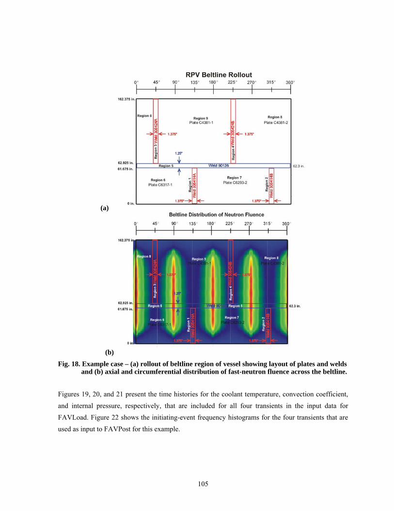
105
(a)
(b) Fig. 18. Example case – (a) rollout of beltline region of vessel showing layout of plates and welds
and (b) axial and circumferential distribution of fast-neutron fluence across the beltline.
Figures 19, 20, and 21 present the time histories for the coolant temperature, convection coefficient, and internal pressure, respectively, that are included for all four transients in the input data for FAVLoad. Figure 22 shows the initiating-event frequency histograms for the four transients that are used as input to FAVPost for this example.

106
Fig. 19. Time histories of coolant temperature for four PTS transients.
Fig. 20.Time histories of convection heat transfer coefficient four PTS transients.

107
Fig. 21. Time histories for internal pressure for four PTS transients.
Fig. 22. Initiation event frequency distribution for PTS Transients 7, 9, 56, and 97.

108
The output files for this case are listed in Section 3 of this report as examples of output files and are included on the distribution CD. The 10,000-vessel simulation example case on the distribution CD required 48,475,720 flaws to be analyzed and took approximately 26.2 hours on a FAVOR-dedicated Pentium IV computer (Windows XP Professional operating system) with 2048 MB of memory and a clock speed of 1.5 GHz.

109
4. Summary and Conclusions
The FAVOR, v04.1, computer code has been developed under NRC funding to perform probabilistic fracture mechanics analyses of nuclear reactor pressure vessels subjected to pressurized thermal shock and other pressure-thermal events. In support of the PTS Re-Evaluation Project, the following advanced technologies and new capabilities have been incorporated into FAVOR, v04.1:
• the ability to incorporate new detailed flaw-characterization distributions from NRC research (with Pacific Northwest National Laboratory, PNNL),
• the ability to incorporate detailed neutron fluence regions – detailed fluence maps from Brookhaven National Laboratory, BNL,
• the ability to incorporate warm-prestressing effects into the analysis, • the ability to include temperature-dependencies in the thermo-elastic properties of base and
cladding, • the ability to include crack-face pressure loading for surface-breaking flaws, • a new embrittlement correlation, • a new ductile-tearing model simulating stable and unstable ductile fracture, • the ability to handle multiple transients in one execution of FAVOR, • RVID2 database of relevant material properties, • fracture-toughness models based on extended databases and improved statistical
distributions, • a variable failure criterion, i.e., how far must a flaw propagate into the RPV wall for the
vessel simulation to be considered as “failed” ? • semi-elliptic surface-breaking and embedded-flaw models, • through-wall weld residual stresses, and an • improved PFM methodology that incorporates modern PRA procedures for the
classification and propagation of input uncertainties and the characterization of output uncertainties as statistical distributions.
This report has provided a detailed description of the computer system requirements, installation, and execution of the FAVOR, v04.1, deterministic and probabilistic fracture mechanics code. Detailed instructions on input data deck preparation have been presented along with descriptions of all output files. Example input and output cases were included. The companion report Fracture Analysis of Vessels – Oak Ridge, FAVOR, v04.1 Computer Code: Theory and Implementation of Algorithms, Methods, and Correlations [2] gives a detailed review of the computational methodologies implemented into this version of FAVOR, v04.1.

110
5. References 1. T. L. Dickson, S. N. M. Malik, J. W. Bryson, and F. A. Simonen, “Revisiting the Integrated
Pressurized Thermal Shock Studies of an Aging Pressurized Water Reactor,” ASME PVP-Volume 388, Fracture, Design Analysis of Pressure Vessels, Heat Exchangers, Piping Components, and Fitness for Service, ASME Pressure Vessels and Piping Conference, August, 1999.
2. P. T. Williams, T. L. Dickson, and S. Yin, Fracture Analysis of Vessels – FAVOR (v04.1) Computer Code: Theory and Implementation of Algorithms, Methods, and Correlations, NUREG/CR-6854 (ORNL/TM-2004/244), Oak Ridge National Laboratory, Oak Ridge, TN, 2004.
3. A. R. Foster and R. L. Wright, Jr., Basic Nuclear Engineering, 2nd ed., Allyn and Bacon, Inc., Boston, 1973.
4. D. L. Selby, et al., Pressurized Thermal Shock Evaluation of the Calvert Cliffs Unit 1 Nuclear Power Plant, NUREG/CR-4022 (ORNL/TM-9408), Oak Ridge National Laboratory, Oak Ridge, TN, September 1985.
5 . D. L. Selby, et al., Pressurized Thermal Shock Evaluation of the H.B. Robinson Nuclear Power Plant, NUREG/CR-4183 (ORNL/TM-9567), September 1985.
6 . T. J. Burns, et al., Preliminary Development of an Integrated Approach to the Evaluation of Pressurized Thermal Shock as Applied to the Oconee Unit 1 Nuclear Power Plant, NUREG/CR-3770 (ORNL/TM-9176), May 1986.
7. U.S. Code of Federal Regulations, Title 10, Part 50, Section 50.61 and Appendix G.
8. U.S. Nuclear Regulatory Commission, Regulatory Guide 1.154 (1987), Format and Content of Plant-Specific Pressurized Thermal Shock Safety Analysis Reports for Pressurized Water Reactors.
9. U. S. Nuclear Regulatory Commission, Regulatory Guide 1.99, Revision 2 (1988), Radiation Embrittlement of Reactor Vessel Materials.
10. R. D. Cheverton and D. G. Ball, OCA-P, A Deterministic and Probabilistic Fracture Mechanics Code for Application to Pressure Vessels, NUREG/CR-3618 (ORNL-5991), Oak Ridge National Laboratory, Oak Ridge, TN, May 1984.
11. F. A. Simonen, et al., VISA-II – A Computer Code for Predicting the Probability of Reactor Pressure Vessel Failure, NUREG/CR-4486 (PNL-5775), Pacific Northwest Laboratory, Richland, Washington, March 1986.
12. T. L. Dickson and F. A. Simonen, “The Application of Probabilistic Fracture Analysis to Residual Life Evaluation of Embrittled Reactor Vessels,” AD-Vol. 28, Reliability Technology, American Society of Mechanical Engineers, (1992) 43-55.

111
13. B. A. Bishop, T. L. Dickson, and F. A. Simonen, Benchmarking of Probabilistic Fracture
Mechanics Analyses of Reactor Vessels Subjected to Pressurized Thermal Shock (PTS) Loading, Research Project 2975-5, Final Report, February 1993.
14. T. L. Dickson and R. D. Cheverton, Review of Reactor Pressure Vessel Evaluation Report for Yankee Rowe Nuclear Power Station (YAEC No. 1735), Appendix D, NUREG/CR-5799 (ORNL/TM-11982), Oak Ridge National Laboratory, Oak Ridge, TN, March 1992.
15. B. R. Bass, et al., International Comparative Assessment Study of Pressurized Thermal Shock in Reactor Pressure Vessels, NUREG/CR-6651 (ORNL/TM-1999/231), Oak Ridge National Laboratory, Oak Ridge, TN, December 1999.
16. T. L. Dickson, FAVOR: A Fracture Analysis Code for Nuclear Reactor Pressure Vessels, Release 9401, ORNL/NRC/LTR/94/1, Oak Ridge National Laboratory, Oak Ridge, TN, 1994.
17. American Society of Mechanical Engineers Boiler and Pressure Vessel Code – Sect. II, Part D: Properties, 1998.
18. L. Stumpfrock, et al., “Brittle Crack Initiation, Propagation and Arrest of Shallow Cracks in a Clad Vessel Under PTS Loading,” NESC II Final Report, NESCDOC Man (02) 07, EUR 20696 EN, European Commission DG-JRC/IE, Petten, The Netherlands, March 2003.
19. F. N. Fritsch and R. E. Carlson, “Monotone Piecewise Cubic Interpolation,” SIAM J. Numer. Anal. 17(2), (1980) 238-246.
20. F. N. Fritsch and J. Butland, “A Method for Constructing Local Monotone Piecewise Cubic Interpolants,” SIAM J. Sci. Stat. Comput. 5(2), (1984) 300-304.
21. T. L. Dickson, W. J. McAfee, W. E. Pennell, and P. T. Williams, “Evaluation of Margins in the ASME Rules for Defining the P-T Curve for an RPV,” Proceedings of the Twenty-Sixth Water Reactor Safety Meeting, Vol. 1, NUREG/CR-0166, Oak Ridge National Laboratory, (1999) 47-72.

112
6. Appendix A – Summary of RVID2 Data for Use in FAVOR Calculations

113
RTNDT(u) [oF] Composition(2)
Product Form Heat Beltline
σflow(u) [ksi] RTNDT(u) Method RTNDT(u)
Value σ(u)
Value Cu Ni P USE0 (ft-lbf)
Beaver Valley 1, (Designer: Westinghouse, Manufacturer: CE) Coolant Temperature = 547°F, Vessel Thickness = 7-7/8 in.
C4381-1 INTERMEDIATE SHELL B6607-1 83.8 MTEB 5-2 43 0 0.14 0.62 0.015 90 C4381-2 INTERMEDIATE SHELL B6607-2 84.3 MTEB 5-2 73 0 0.14 0.62 0.015 84 C6293-2 LOWER SHELL B7203-2 78.8 MTEB 5-2 20 0 0.14 0.57 0.015 84
PLATE
C6317-1 LOWER SHELL B6903-1 72.7 MTEB 5-2 27 0 0.2 0.54 0.01 80 305414 LOWER SHELL AXIAL WELD 20-714 75.3 Generic -56 17 0.337 0.609 0.012 98 LINDE 1092 WELD 305424 INTER SHELL AXIAL WELD 19-714 79.9 Generic -56 17 0.273 0.629 0.013 112
LINDE 0091 WELD 90136 CIRC WELD 11-714 76.1 Generic -56 17 0.269 0.07 0.013 144 Calvert Cliffs 1, (Designer and Manufacturer: CE) Coolant Temperature = 545°F, Vessel Thickness = 8 5/8-in.
B-8489-1 LOWER SHELL D-7207-3 78.8 MTEB 5-2 -20 0 0.11 0.53 0.008 81 B-8489-2 LOWER SHELL D-7207-2 80.3 MTEB 5-2 -10 0 0.11 0.56 0.009 90 C-4351-2 INTERMEDIATE SHELL D-7206-1 74.7 MTEB 5-2 20 0 0.11 0.55 0.011 90 C-4420-1 LOWER SHELL D-7207-1 78.0 MTEB 5-2 10 0 0.13 0.54 0.01 77 C-4441-1 INTERMEDIATE SHELL D-7206-3 78.5 ASME NB-2331 10 0 0.12 0.64 0.011 112
PLATE
C-4441-2 INTERMEDIATE SHELL D-7206-2 82.6 ASME NB-2331 -30 0 0.12 0.64 0.011 81 20291/12008 INTERMEDIATE SHELL AXIAL WELD 2-203 78.8 ASME NB-2331 -50 0 0.22 0.83 0.01 110 LINDE 1092 WELD 21935 LOWER SHELL AXIAL WELD 3-203A/C 78.6 Generic -56 17 0.18 0.72 0.015 109
LINDE 0091 WELD 33A277 INT. TO LOWER SHELL CIRC. WELD 9-203 78.6 ASME NB-2331 -80 0 0.24 0.16 0.014 160 Oconee 1, (Designer and Manufacturer: B&W) Coolant Temperature = 556°F, Vessel Thickness = 8.44-in.
FORGING AHR54 (ZV2861) LOWER NOZZLE BELT (4) B&W Generic 3 31 0.16 0.65 0.006 109
C2197-2 INTERMEDIATE SHELL (4) B&W Generic 1 26.9 0.15 0.5 0.008 81 C2800-1 LOWER SHELL (4) B&W Generic 1 26.9 0.11 0.63 0.012 81 C2800-2 LOWER SHELL 69.9 B&W Generic 1 26.9 0.11 0.63 0.012 119 C3265-1 UPPER SHELL 75.8 B&W Generic 1 26.9 0.1 0.5 0.015 108
PLATE
C3278-1 UPPER SHELL (4) B&W Generic 1 26.9 0.12 0.6 0.01 81 1P0962 INTERMEDIATE SHELL AXIAL WELDS SA-1073 79.4 B&W Generic -5 19.7 0.21 0.64 0.025 70 299L44 INT./UPPER SHL CIRC WELD (OUTSIDE 39%) WF-25 (4) B&W Generic -7 20.6 0.34 0.68 (3) 81 61782 NOZZLE BELT/INT. SHELL CIRC WELD SA-1135 (4) B&W Generic -5 19.7 0.23 0.52 0.011 80 71249 INT./UPPER SHL CIRC WELD (INSIDE 61%) SA-1229 76.4 ASME NB-2331 10 0 0.23 0.59 0.021 67 72445 UPPER/LOWER SHELL CIRC WELD SA-1585 (4) B&W Generic -5 19.7 0.22 0.54 0.016 65 8T1762 LOWER SHELL AXIAL WELDS SA-1430 75.5 B&W Generic -5 19.7 0.19 0.57 0.017 70
LINDE 80 WELD
8T1762 UPPER SHELL AXIAL WELDS SA-1493 (4) B&W Generic -5 19.7 0.19 0.57 0.017 70

114
RTNDT(u) [oF] Composition(2)
Product Form Heat Beltline
σflow(u) [ksi] RTNDT(u) Method RTNDT(u)
Value σ(u)
Value Cu Ni P USE0 (ft-lbf)
8T1762 LOWER SHELL AXIAL WELDS SA-1426 75.5 B&W Generic -5 19.7 0.19 0.57 0.017 70 Palisades, (Designer and Manufacturer: CE) Coolant Temperature = 532°F, Vessel Thickness = 8½ in.
A-0313 D-3803-2 (4) MTEB 5-2 -30 0 0.24 0.52 0.01 87 B-5294 D-3804-3 (4) MTEB 5-2 -25 0 0.12 0.55 0.01 73 C-1279 D-3803-3 (4) ASME NB-2331 -5 0 0.24 0.5 0.011 102 C-1279 D-3803-1 74.7 ASME NB-2331 -5 0 0.24 0.51 0.009 102 C-1308A D-3804-1 (4) ASME NB-2331 0 0 0.19 0.48 0.016 72
PLATE
C-1308B D-3804-2 (4) MTEB 5-2 -30 0 0.19 0.5 0.015 76 LINDE 0124 WELD 27204 CIRC. WELD 9-112 76.9 Generic -56 17 0.203 1.018 0.013 98
34B009 LOWER SHELL AXIAL WELD 3-112A/C 76.1 Generic -56 17 0.192 0.98 (3) 111 W5214 LOWER SHELL AXIAL WELDS 3-112A/C 72.9 Generic -56 17 0.213 1.01 0.019 118 LINDE 1092 WELD W5214 INTERMEDIATE SHELL AXIAL WELDS 2-112 A/C 72.9 Generic -56 17 0.213 1.01 0.019 118
Notes:
1. Information taken directly from the July 2000 release of the NRCs Reactor Vessel Integrity (RVID2) database. 2. These composition values are as reported in RVID2. In FAVOR calculations these values should be treated as the central tendency of
the Cu, Ni, and P distributions. 3. No values of phosphorus are recorded in RVID2 for these heats. A generic value of 0.012 should be used, which is the mean of 826
phosphorus values taken from the surveillance database used by Eason et al. to calibrate the embrittlement trend curve. 4. No values strength measurements are available in PREP4 for these heats [PREP]. A value of 77 ksi should be used, which is the mean
of other flow strength values reported in this Appendix. 5. No values for the unirradiated upper-shelf CVN energy, USE0, are recorded in RVID2 for these heats.

115
7. Appendix B – FAVOR Error Codes Error Code Description Subroutine User's Guide Section
FAVLOAD Error Codes1 Error in data Record 1 - Keyword GEOM: Data required IRAD= W= CLTH= RD79 2.12 Error in data Record 2 - Keyword BASE: Data required K= C= RHO= E= ALPHA= V= RD79 2.13 Error in data Record 3 - Keyword CLAD: Data required K= C= RHO= E= ALPHA= V= RD79 2.14 Error in data Record 4 - Keyword SFRE: Data required T= RD79 2.15 Error in data Record 5 - Keyword RESA: Data required NRAX= RD79 2.16 Error in data Record 6 - Keyword RESC: Data required NRCR= RD79 2.17 Error in data Record 7 - Keyword TIME: TOTAL= DT= RD79 2.18 Error in data Record 7 - Input Time step too small RD79 2.19 Error in data Record 8 - Keyword NPRA: Data required NTRAN= RD79 2.1
10 Error in data Record 9 - Keyword TRAN: Data required ITRAN= ISEQ= RD79 2.111 Error in data Record 9 - ITRAN numbers must be in ascending order with no ommissions RD79 2.1
101 Memory allocation error - insufficient memory available for this execution CHECK_ALLOC (-)102 Singular matrix found in axial stress calculation SYMSL3 (-)103 Elliptical angle out of bounds during linear interpolation of surface-breaking flaw SIFICs ANGINTBS2 (-)104 Elliptical angle out of bounds during linear interpolation of surface-breaking flaw SIFICs ANGINTBS6 (-)105 Elliptical angle out of bounds during linear interpolation of surface-breaking flaw SIFICs ANGINTBS10 (-)106 Elliptical angle out of bounds during linear interpolation of surface-breaking flaw SIFICs ANGINTCL1562 (-)107 Elliptical angle out of bounds during linear interpolation of surface-breaking flaw SIFICs ANGINTCL1566 (-)
FAVPFM Error Codes1 Error in data Record 1 - Keyword CNT1: Data required NSIM= IGATR= WPS_OPT= RD17 2.22 Error in data Record 2 - Keyword CNT2: Data required IRTNDT= TC= EFPY= RD17 2.23 Error in data Record 3 - Keyword CNT3: Data required FLWSTR= USKIA= ILAYER_OPT= FAILCR= RD17 2.24 Error in data Record 4 - Keyword GENR: Data required SIGFGL= SIGFLC= RD17 2.25 Error in data Record 5 - Keyword SIGW: Data required WSIGCU= WSIGNI= WSIGP= RD17 2.26 Error in data Record 6 - Keyword SIGP: Data required PSIGCU= PSIGNI= PSIGP= RD17 2.27 Error in data Record 7 - Keyword TRAC: ITRAN= IRPV= IFLAW= RD17 2.28 Error in data Record 8 - Keyword LDQA: Data required IQA= IOPT= IWELD= IKIND= XIN= XVAR= ASPE RD17 2.29 Error in data Record 9 - Keyword WELD: Data required NWSUB= NWMAJ= RD17 2.2
10 Error in data Record 10 - Keyword PLAT: Data required NPSUB= NPMAJ= RD17 2.211 Error in data Record 8 - Keyword LDQA: IQA must be = 0 or 1 RD17 2.212 Load file not generated by FAVLoad 02.3: Rerun load module RDDET (-)13 INVALID FLAW ORIENTATION PROP (-)14 ISQ? CARD NEEDS FOUR VARS - SEE USER GUIDE RD17 2.215 DTRF Record: ITRAN ISEQ mismatch RD17 2.216 DTRF Record: ITRAN greater than MTRAN RD17 2.217 SURFACE-BREAKING FLAW FILE NOT VERSION 04.1 RDSURF (-)18 ERROR READING SURFACE-BREAKING FLAW DATA RDSURF (-)19 EMBEDDED-FLAW WELD FILE NOT VERSION 04.1 RDWELD (-)20 ERROR READING WELD EMB. FLAW DATA RDWELD (-)21 EMBEDDED-FLAW PLATE FILE NOT VERSION 04.1 RDPLAT (-)22 ERROR READING PLATE EMB. FLAW DATA RDPLAT (-)23 INVALID ICORR(NSBR) EWO1998 (-)24 ERROR IN WELD SUBREGION DEFINITIONS RD17 2.225 ERROR IN PLATE SUBREGION DEFINITIONS:NSUBR(I,1)/=NSUBR(I,2) RD17 2.2
101 Memory allocation error - insufficient memory available for this execution CHECK_ALLOC (-)
FAVPost Error Codes1 PFM input files not generated by version 02.3: Rerun with FAVPFM 02.3 Main (-)2 Inconsistent input data. Incorrect number of transients specified Main (-)3 Inconsistent input data. Transient sequence numbers do not match. Main (-)4 Inconsistent input data. Incorrect number of transients specified PRA (-)5 Error in construction of Histogram PRA (-)6 Inconsistent input data. Transient sequence numbers do not match. PRA (-)
101 Memory allocation error - insufficient memory available for this execution CHECK_ALLOC (-)

116
3. DATE REPORT PUBLISHED MONTH YEAR
October 2004 4. FIN OR GRANT NUMBER
Y6533 6. TYPE OF REPORT
Final, technical
7. PERIOD COVERED (Inclusive Dates)
15. NUMBER OF PAGES
16. PRICE
Fracture Analysis of Vessels – Oak Ridge (FAVOR, v04.1): User’s Guide
P. T. Williams, T. L. Dickson, and S. Yin
Heavy Section Steel Technology Program Oak Ridge National Laboratory P. O. Box 2008, Mail Stop 6085 Oak Ridge, TN 37831-6085
Division of Engineering Technology Office of Nuclear Regulatory Research U. S. Nuclear Regulatory Commission Washington, DC 2055-0001
The current regulations to insure that nuclear reactor pressure vessels (RPVs) maintain their structural integrity when subjected to transients such as pressurized thermal shock (PTS) events were derived from computational models developed in the early-to-mid 1980s. Since that time, advancements and refinements in relevant technologies that impact RPV integrity assessment have led to an effort by the NRC to re-evaluate its PTS regulations. Updated computational methodologies have been developed through interactions between experts in the relevant disciplines of thermal hydraulics, probabilistic risk assessment, materials embrittlement, fracture mechanics, and inspection (flaw characterization). Contributors to the development of these methodologies include the NRC staff, their contractors, and representatives from the nuclear industry. These updated methodologies have been integrated into the Fracture Analysis of Vessels – Oak Ridge (FAVOR, v04.1) computer code developed for the NRC by the Heavy Section Steel Technology (HSST) program at Oak Ridge National Laboratory (ORNL). The FAVOR, v04.1, code represents the baseline NRC-selected applications tool for re-assessing the current PTS regulations. This report provides a user’s guide to the computer system requirements, installation, input data-deck preparation, and execution of the FAVOR, v04.1, deterministic and probabilistic fracture mechanics computer code.
pressurized thermal shock, probabilistic fracture mechanics, reactor pressure vessels
NRC FORM 335 U.S. NUCLEAR REGULATORY COMMISSION 1. REPORT NUMBER(2-89) NRCM 1102, BIBLIOGRAPHIC DATA SHEET
(See instructions on the reverse)
(Assigned by NRC, Add Vol., Supp., Rev., and Addendum Numbers, if anv.1
NUREG/CR-6855 ORNL/TM-2004/245
3201,3202
2. TITLE AND SUBTITLE
5. AUTHOR(S)
8. PERFORMING ORGANIZATION - NAME AND ADDRESS (If NRC, provide Division, Office or Region, U.S. Nuclear Regulatory Commission, and mailing address; if contractor, provide name and mailing address.)
9. SPONSORING ORGANIZATION - NAME AND ADDRESS (If NRC, type "Same as above"; if contractor, provide NRC Division, Office or Region, U.S. Nuclear Regulatory Commission, and mailing address.)
10. SUPPLEMENTARY NOTES
1 1. ABSTRACT (200 words or less)
12. KEY WORDS/DESCRIPTORS (List words or phrases that will assist researchers in locating the report.) 13. AVAILABILITY STATEMENT
unlimited14. SECURITY CLASSIFICATION
(This Page)
unclassified(This Report)
unclassified
NRC FORM 335 (2-89)