332 NEWBURY ST. - DataCAD
56
MARK 'UDltRA "ADURA STUDIOS 332 NEWBURY ST . 2ND fLOOR · BOSTON MA 02115 USA Bulk Rate U.s . Postage PAID Pe rmit No. 4 Spokane. WA
-
Upload
khangminh22 -
Category
Documents
-
view
7 -
download
0
Transcript of 332 NEWBURY ST. - DataCAD

MARK 'UDltRA "ADURA STUDIOS 332 NEWBURY ST . 2ND fLOOR
· BOSTON MA 02115 USA
Bulk Rate U.s. Postage
P A I D Permit No. 4 Spokane. WA

,
Easy Does It. Introducing the Kurta XLP": . .
Another Kurta Original Draw on the best name for quality and reliability with Kurta's new XLP graphics "fi r IBM" PCs and c les Th Y-mt ~~~~XlJ~lml1es S . ketch® compati virtually all softwar; sophis ed CAD. The price is compatible roo .. . just $395 for the entire package, including:
• 12 "x12" high-accuracy tablet • 2-switch pen and program
mable 4-button cursor • An integrated mouse/ADI'"
driver with auto-toggle between mouse and ADI modes and a Windows® driver in absolute mode
• Test, Set -mode and Reset utilities • Since the XLP draws its power from
the serial port, no power supply is needed
• Unlimited free technical support • Lifetime Warranty!
Get a total perfonnance package, with the award-winning qualities you've come to expect in reliable Kurta products . .. from the value-leading XLP to the high-end, feature-rich IS/ONE® and large format XLC~ It's_ the easy way to better graphics for greater productivity.
®
s. 1-800-44-KURfA J.lURTR® 3007 East Chambers Phoenix, Arizona 85040 (602) 27&5533 Kurtl., color swJ:Sh lI1d XI.P:ue regisrered tl'"Adermrks of Kurt.! Corp. W~ is :l ~ tr.Kkmark of M.icro6oft Corp. ADI is a regi';tered tr.Klem:u1c of AUlOOesk Inc. IBM is a rtgislen:d tr.Khnark of Imem;;llicml Dusine:ss ~hchines. Summagr.phics S~I=h;" regisIered<r.ldemlrl<of~Corp.

LET'S FACE IT! If you use CADI<EY and need a
CAM program to machine surfaces at a price you can
afford, you need ALL the facts and CUITING EDGE SURFACES!
CUTTING EDGE SURFACES has: • all the geometry of CADKEY • surface modeling of FASTSURF • complete tool path editing • a library of over: 1 00 pou..processors
No other CAM package has: • 1 00% CAOKEY data base compatibility • 1 00% CAOKEY human interface • a complete COE & CADL environment • g neral NURBS surface machining • CADKEY IGES capabilities
CUTIING EDGE SURFACES can be used as a stand alone CAM system for 3-axis milling, drilling, boring, reaming, slotting, pocketing, tapping and contouring. Immediate verification of the tool path before cutting reduces material waste.
CUTIING EDGE SURFACES is fully integrated into Cad key's desktop engineering tools. Now you can manufacture your designs directly from CADKEY part files with I 00% failure-free data transfer. NO TRANSLATION needed! You can also transfer other CAD files using IGES, DXF, and CADL.
CUTIING EDGE SURFACES offers ease of use unparalleled in the CAD/CAM world, an outstanding customization environment, general surface machining, and the ability to bring surfaces from any CAD system that supports IGES.
If you don't have a blue print or a CAD design, we can help with that too. Ask about the reverse engineering ability of CADDlnspector.
Call your CUTTING EDGE dealer or Cutting Edge Technologies, Inc. c:J.
4 Griffin Road North Windsor, CT 06095 • (203) 298-6433 Fax: (203) 298-6490
24 Hour Automatic Fax Info 1-800-n9-0202 Code 124407

Value Engineering Associates
Cost Reduction Specialists
•
. .......................................
Find out how Value
•
Engineering Associates
can help your company
save money!
IVE~ •
Value Engineering Associates E. 9415 Trent Avenue Spokane,VVA 99206 (509) 928-5169 Fax (509) 928-4937
• •••••••••••••••••••••••
About Value Engineering Value Engineering is a technique used to achieve maximum product value while cutting costs. It is not simply a search for new materials and processes. It is a well-informed, creative study of every item of cost in every part or material used. It focuses Engineering, Manufacturing, and Purchasing on one objective: equivalent performance at lowest cost.
AboutVEA We at Value Engineering Associates are interested in helping your organization realize the benefits that lowered product costs contribute to the health and well-being of an enterprise .
At a time when competitive pressures demand not just low cost but superior quality as well, and at a time when in many cases there are fewer people available to respond to those pressures, we believe the value engineering approach ensures not just competing but winning!
VEA Services • Value Analysis
• Product Design
• Tool Design • Manufacturing Analysis
• Factory/Product Automation
• Domestic & International Sourcing
The Savings Achieved Through A Rigorous VE Effort Can Be
Dramatic!
•••••••••••••••••••••••
•

CHARTING A COURSE Cadkey's President and CEO revisits 1993 and by Malcolm Davies 11 FOR THE 90'S shares plans and visions for the future
CONCURRENT Agile Manufacturing for 2000 and Beyond by Peter L. Grieco, Jr. 22 A vision of manufacturing in the 21st century
ENGINEERING Introduction to CAD / CAM Data Transfer by Dana Seero 32 SOLUTIONS Tips on using 2D and 3D CAD KEY data for CAM
CAE Technology Implementation by Robert Shaefer 38 Concepts , problems and solutions and Frank Lucatelli
CADK-EY ANTHROPOS and CADKEY by Frank Simpson 28
AT W 0 R K A software tool for designing ergonomical ly for real people
A Model Concurrent Eng ineering Company by Frank Simpson 30 How an electronics company uses networks, teamwork , and integration for concurrent engineering
PRODUCT What About Menu Tablets by Claudia Martin 16
F 0 C U S Should you use a menu tablet and digitizer with CADKEY?
Dig itizer Roundup 20 Features and capabilities of seven 12 x 12 digitizers
REVIEWPORT 42 Hardware and Software Productivity Tools
Timberline 486 / 66. a unique Personallnformalion Manager. JR 670 C-size inkiel
HANDS-ON Enhancing CAD KEY With Meritbar Utilities by Chavdar Popov 36
CADKEY A set of new util ities for rotating views, offsetting contours. chang ing lines I arcs to splines and more
MACROS, CADL, CDE'S by Cra ig Storms 46 A shareware compiler for CDE's and Usman Rashid
COLUMNS KeyTalk 7
AND KeyNotes 8
DEPARTMENTS Cad key Forum 10
New Products 12
CADL Toolbox 44
CADKEY Corner 50
Solution Mart 51 Advertiser Index 54
Digitizer Roundup - see page 20

SOME OF OUR CONTRIBUTORS
Peter L. Grieco, Jr. is President and CEO ofProfessionals for Technology Associates, Inc., an international consulting and education firm specializing in Automation and Systems Implementation, Just-InTime, and Total Quality Control. With more than twenty-five years as a practitioner and educator in manufacturing, Mr. Grieco has co-authored numerous textbooks including World Class: Measuring Its Achievements; Supplier Certification; and The World of Negotiations: Never Being A Loser.
Frank Lucatelli formed Software Ventures, Inc. in 1983 for the design and implementation of custom and commercial engineering software. Mr. Lucatelli's consulting business, Performance Patterns, integrates principles of team work with the creative use of technology. His models for team work came from twenty-five years in Human Educational Alternatives Research, Inc. (HEAR), which he founded in 1969.
Bob Shaefer is the founder ofPTI Corporation, which offers implementation consulting comprised of training in CAE technology and Personal Styles Technology for companies that use plastic materials. Formerly, he was general manager of the North American operations of Mold flow Pty. Ltd. With over twenty-five years in the plastics industry, Mr. Shaefer is a frequent contributor to industry publications, including Modern Plastics, Plastic Technology and Computer Aided Engineering.
On the Cover:
Model of a human programming an industrial robot in a work cell . For more on ANTHROPOS and CADKEY, see the story inside. Photos courtesy of 1ST GmbH, GrossRohrheim, Germany.
6 • KEY Solutions ' January 1994
KEn-l,) (I) i (I) ~ ~1 Concurrent Engineering for the 90's
P .O. Box 11978, Spokane, WA 99211·1978 Ph: 5091928·5169 Fax: 5091928-4937
EDITORIAL Editor-in-Chief Claudia Martin
Technical Editor Dr. Robert Martin
Senior Editor Jack Bilderback, CPIM
CONTRIBUTING EDITORS Chavdar Popov, Usman Rashid,
Dana Seero, Frank Simpson, Craig Storms, Martin van der Roest
DESIGN Art Director
Melissa Clark
PRODUCTION Production Manager
Gayle Simpson
ADMINISTRATION Business Manager/CEO
Steve Radford
Administrative Assistant Cathy Bilderback
ADVERTISING SALES WESTERN REGION - Jamie Bohn
Ph: 415/572-9011 Fx: 415/572-9969
EASTERNIMIDWEST REGION - Jo Schmidt Ph: 509/928-5169 Fx: 509/928-4937
CANADAlINT'L REGION - Frank Simpson Ph/Fx: 413/736-8312
EDITORIAL POLICY: KEYSoWflONS is an independent publication without obligation to any software or hardware dealer, vendor or distributor, except as indicated. Articles noted as news or features are written without knowledgeable bias. Articles noted 88 editorial represent the opinion of the author. Technical articles represent the opinion of the author and are selected by virtue of their educational value.
SUBSCRIPTION CORRESPONDENCE: (orders, change of address, etc.) should be directed to KEy SoUJTIONS, P.O. Box 11978, Spokane, WA99211·1978. Allow six weeks for processing.
EDITORIAL CORRESPONDENCE should be di· rected to Editor-in·Chief, lu :ySoLUTIONs, P.O. Box 11978, Spokane, WA 99211-1978. K>;ySoWrlONS en· courages readers to submit articles, letters, questions and technical tips.
K>;ySoLlITIONS, Copyright © 1993, (ISSN 1064-2145) is published bi-monthly by Value Engineering Associ· ates. Microsoft and Windows are registered trademarks of Microsoft Corporation. mM is the registered trademark of the international Business Machines Corporation. CADKEY is the registered trademark of Cadkey, Inc. AutoCAD and DXF are regis· tered trademarks of Autodesk, Inc.

KEVTALK As an avid magazine reader, I have plenty of personal opinions about
magazines in general-- not just KEySOLUnoNs. As a reader and consumer,
I like the stories, but I think that even the display ads (maybe especially the ads) are informative and useful. They keep me in touch with new
products and technologies. Even though I don't necessarily believe everything I read in the ads without checking, I find they give me ideas and help me gather data for purchases.
What's the scenario if you see an ad that sparks your interest? You have several choices of varying quality: you can call the company directly -- if it's a weekday and if you remember their time zone and if you want to take the time to ramble around an electronic answering system or talk to a real
person; you can contact a store or dealer -- if you're close to one or want to take the time; or you can putlittle circles around those oh-so-tiny numbers
on the "bingo card" and then hope you remember to mail it. If you opt for the "bingo card" and if you're real, real lucky, you'll eventually (as much
as 6-8 weeks later) get some material in the mail or a phone call.
If you're a "right-now" type person like me, "bingo cards" just don't cut it. I don't want to wait that long. I want to know now! So after many conversations with readers and advertisers and some in-depth analysis, we came to the not-so-amazing conclusion that Reader Service Numbers
are archaic in this age of computers and fax machines.
So, as 1994 begins, KEySOLUTIONS is launching a new high-tech system
to help readers and advertisers communicate. We have, in fact, replaced the Reader Service Numbers and ''hingo" cards with an advanced fax
service that will let you get fax and audio information on products -instantly -- 24 hours a day.
Here's how it works. On some of the ads in this issue you'll notice an 800
phone number followed by a 6-digit code. You simply dial the toll-free number (day or night, even weekends and holidays) and enter the code when asked. Then select the information you want, enter your fax number, and leave your name, address, and fax number. Information on the product will be faxed to you -- immediately. What could be easier and more convenient?
This new fax system is optional for advertisers and so there may not be
a code on every ad. You will continue to contact these companies directly.
We think this is a great way to do business for both you and companies
you want to contact. Let us know your reactions and if you run into any problems.
Last, but not least! All of us at KEySOLUTIONS wish you and your company
in all your endeavors an incredibly prosperous, healthy and happy New Year.
Robert Martin Technical Editor
, S.f).S. The S.O.S. Save Our Schools
program at Selkirk High School has really given morale a boost. The kids are extremely excited about learning and technical education -- CAD, machining, etc. In fact, we have a waiting list for some classes.
School budgets being what they are, there is no way we could have set up the computer/CAD lab this year without the help of KEVSOLUTIONS and the wonderful companies who have contributed materials.
I want to express the most heartfelt thanks from the students, the staff, and the community to all who helped get the S.O.s. program started. A very special thanks to -Cadkey, Inc. - for software for our fledgling CAD lab
Intel Corp. - without whose math coprocessors we could not run CADKEY Glencoe P ublishing Co. - for a set of "Mastering CADKEY" textbooks
HLB, Inc. - for CADKEY drafting productivity software and t emplates
ACECAD, Inc. - for five 12" X 12" digitizer tablets
Paradesign - for software Interactive - for Electronics Workbench Software Crary & Clark Attorneys, Spokane, W A - for setting up all the legal stuff
We'll let you know how the program is going through 1994.
Robert Fromm, Superintendent S elkirk School District Metaline Falls, WA
c~ Y~M-H4' The support S.O.S. has received
so far has been extremely satisfying, but the needs at Selkirk are still great and we have been contacted by other schools that would like to become involved.
So, please, please donate any old computers (386s), old NC or CNC equipment, books, software, and even cold hard cash. Money goes into a special trust account as part of a non-profit corporation. II)
Bob Martin - KEySOLUTIONS
January 1994 • KEY Solutions· 7

CADKEY In the News
AdYanced Modeler SIIIps Advanced Modeler, the latest addition to
the Cadkey product line, is now shipping.
This Integrated surface and solid modeling
package utilizes state-of-the-art NURBS
based technology. It offers a wide variet¥ of
surface and solid modeling capabilities,
solid primitive construction, extensive
editing features, and an advanced IGES bi
directional translator. "Every review
indicates that this is an outstanding
product. #I stated Malcolm Davies, President
and CEO of Cadkey. For the name of a
Cadkey dealer nearyou, call 203/298-8888.
New BusIness Hours- at CacIkeJ Switchboard 8:00-5:00 (Ext 0)
Customer Service 8:00-6:00 (Ext 8030)
Sales 8:00-6:00 (Ext 646n Tech Support 8:30-6:00 (Ext 8(60)
*Eastem Standard TItTle
DetaCAD Cadkey's three new product packages
related to DataCAD were offered through
an intensive direct mail campaign in
November and December. The packages
are DataCAD Starter ($49.95), DataCAD
Plus ($99.95), and DataCAD Professional
($149.95). After this promotion, DataCAD
Professional retumsto its regular prfceof S49S.
CadIt., and WIndows Apre-releaseversion of the CADKEY OBJECT
Developer is available for those interested
in building applications on top of it. For
more information, fax a request to Christine
Sweeney at 203/298-6484.
Development is continuing on a version of
(Continued on next page)
8· KEY Solutions· January 1994
Industry News Digest Reported in Computer World . ..
· .. Microsoft Corp. will give its Windows NT Advanced Server client software to first-time corporate buyers - probably in an attempt to entice them to choose NT over Novell, Inc.'s Netware as their primary client/server platform. Less clear, however, is whether bargain-basement prices will help Advanced Server carve a significant slice out of Novell's 68% to 70% share ofthe overall network operating system installed base.
· .. Intel Corp. is staring straight at a pincer-like move that could force it to lower its prices and shift its Pentium strategy in 1994. Surrounding Intel are the PowerPC initiative from IBM, Apple Computer, Inc. and Motorola, Inc. and Cyrix Corp.'s coming M1 chip design. The PowerPC systems began shipping in September. Like the Pentium, the M1 features a superscalar design. But unlike the Pentium, it does not require 486 code to be recompiled to top performance. Cyrix claims that the 66MHz chip based on the M1 design will run most 486 code 30% to 50% faster than today's 66MHz Pentium. Reported in CAE (Computer Aided Engineering) ...
· . . Control Data, Arden Hills, MN, is remarketing Sun Microsystems Computer Corp.'s complete line of workstations, servers, and software worldwide. It will integrate Sun systems with other products and services and add value with a full range of integration services, consulting and application solutions.
IDEAL Wins Part NA VFAC CAD 2 IDEAL Scanners & Systems, Inc. has been selected by Cordant Inc.
of Reston, VA to support Cordant's participation in the Naval Facilities Engineering Command Computer Aided Design Second Acquisition Program (NA VF AC CAD 2). IDEAL will provide the large format drawing scanners and software to capture existing engineering drawings for this major CAD program. NA VF AC CAD 2 is the largest Architectural Engineering and Geographic Information Systems CAD effort ever undertaken. Both Department of Defense and civilian agencies can order the contract's products and services. Cordant and Intergraph Corporation were each awarded twelve year contracts under this $550 million procurement.
Faster Than A Speeding Modem You will soon be able to transfer scanned or vectorized drawings and
documents, black-and-white or color, at speeds in excess ofthose available via modem to anywhere in the United States, and eventually the world. Subscribers to Scan-Net, a service from Ideal Scanners and Systems, Inc. (Rockville, MD) will have their own Personal Earth Station and terminal equipment. Direct access is acquired by customers, suppliers, and vendors through interconnected LANs, which allow the transfers to take place electronically, eliminating paper waste. Unlicensed correspondents can gain access via licensed reprographic service bureaus.
Technical Paper on Mold Industry Wins Award A technical paper written by Colin Austin, Managing Director of
Moldflow, Inc. was selected as the best technical paper at Antec 93. The title of Austin's paper is "Industrial Metamorphis." It explains how companies who design and manufacture plastics components using injection molding process are changing from a craft-based "over the wall engineering" approach to an approach using teamwork based on scientific understanding of plastics via CAE plastics flow analysis technology.

DOS 7 and/or Windows 4.0 Microsoft will provide alternatives to consumers in its next releases.
Chicago or Windows 4.0 will combine DOS and Windows functions , and a character-based version of DOS 7.0 will also be available. Chicago, a 32-bit multitasking, multithreaded version of Windows that will not require DOS to run, is expected to ship in mid-1994. According to Steve Ballmer, vice president of Microsoft's sales and support group, "There will be a DOS 7.0 that can be surgically removed (from Chicago) and sold separately for those who want to only run character-based applications." But he added, "I don't think it will be as popular."
Some analysts and users predict that a character-based DOS 7.0 may be more popular among users than Ballmer is willing to admit. Sales of character-based DOS 6.0, released last April, have already exceeded 4 million copies, making it one ofthe company's best-selling products despite mixed reviews. "There is a lot of industry focus on Windows because that is where the action is. But there is a sizablebased business with DOS. I have to believe that DOS is still a very important business to Microsoft," said Ed Iacobussi, chairman ofCitrix Systems, Inc. in Coral Springs, FL.
Autodesk Acquires Hoop Autodesk, Inc. has acquired Ithica Software and its Hoops graphics
system. Ithica Software will become a wholly owned subsidiary of Autodesk, Sausalito, CA. Ithica will retain its name and continue to operate from its Alameda, CA headquarters. Hoops is said to be one of the only systems capable of producing advanced graphics applications across the entire spectrum of workstations and PCs.
Wireless Communications Ahead for Mobile Computing Traveling Software, Inc. of Bothell, WA and National Semiconductor
Corp. of Santa Clara, CA have agreed to jointly develop and market integrated hardware and sofware products using wireless technology. The first product, expec;ted in the first quarter of 1994, will use communications software from Traveling Software and integrated communication hardware from National Semiconductor. This solution answers the need for fast, convenient and low-cost ways to coordinate information between desktop, portable, and handheld computers in the home and workplace. It's compatible with current portable platforms and adaptable to future computing standards.
New Technical Center in Michigan Desktop Engineering's new technical center in Southfield, MI will
be the focal point in actively marketing their wide range of engineering services, including computer-aided software development, computeraided engineering analysis, engineering testing programs and structural/mechanical engineering consulting. The technical center will also be the hub for servicing the many users of the company's packaged software products, including the DE/CAASE computerized engineering handbook.
Desktop Engineering pioneered the computerized engineering handbook which puts information that was once buried in books at engineers fingertips . Desktop Engineering is associated with Columbia University's testing laboratory. This 25,000 square foot lab provides nearly unmatched structural and materials testing capabilities, including universal testing machines, fatigue testing and strain gauge facilities, data acquisition systems, machine shop equipment, vibration and acoustics laboratory and photoelasticity capabilities.
CADKEY In the News CADKEY under Windows and Windows NT.
Its probable release date is planned for
sometime in 1994.
CADL/CDE Training KIt Update The CADLlCDE Training kit mentioned in
the August/September issue of
KEYSOLUTIONS will not be available until
winter 1994 due to new additions to the
product.
New Technical Support Policy Cadkey is restructuring their Technical
Support department. Under the new support
policies, Cadkey no longer provides free,
unlimited Customer Technical Support by
telephone to non-maintenance customers.
The elimination of free technical support is
becoming standard practice in the software
industry.
Unlimited Free Support will continue to be
available via Compuserve and the Bulletin
Board. All new customers, however, will
receive 30 days free phone support. After the
initial 3O-day period, phone support will be
available only through the purchase of
support contracts.
The two new Technical Support Contracts
available to customers are: 1) One Month
Contract for $75 and 2) Three Month
Contract for $150. This is telephone/fax
support only. These support contracts do
not provide product upgrades. Customers
are still encouraged to obtain local support
servicesfrorn their authorized CADKEY dealer.
Dealer Support Kim Gamer and Ronna Goslin are now
responsible for the North American CADKEY
and DataCAD dealer channel. They have
been the Dealer Managers for the Western
and Mid-west regions respectively. Tony
Mazzagatti, Director of North American Sales,
will assist in Dealer support.
January 1994 • KEY Solutions' 9

.'tiY;.Mc."JPG\tIe&. :Prallldelnt CI'ld CEO - Codkey. Inc.
I would lIk. tOteCOgtIIze thevolUable role played by our moat Important business partners: AuthorlzedCadkeyDeoJers. Unfortunately. we at Codkey sometimes toke our Dealers for gronted. We suspect many customers do also. Cadkey could notexlstwHhout Its Authorized Dealers; they are our local representatives. supplying excellent service and support. combined with local knowledge and experience.
Here's a partial list of reasons why you should build and maintain a good working relationship with your local Cadkey Dealer. and not simply think of the Dealer as a source of Cadkey software:
• Local Knowledge: Your Authorized Dealer knows you. and your business. systems and configuration.
• Needs Analysis: Authorized Dealers are able to assist customers in analyzing their needs and in recommending solutions.
• Demonstrations: Authorized Dealers are qualified to demonstrate and benchmark Cadkey software on-site where appropriate.
• Systems Integration: Authorized Dealers are experts in integrating and optimizing hardware. software and networking.
• Technical Support: Authorized Dealers are experts on Cad key software and are best able to help with technical questions through annual support contracts.
• On-Site Consulting and Customization: Many Dealers are able to visit customers and provide personalized consulting services including the development of special drivers and software.
• Training: Authorized Dealers are able to offer customized training on Cadkey products to enhance customer productivity.
• Scanning, Plotting and Printing
10 • KEY Solutions· January 1994
Support: Many Dealers offer special services to handle customers peakloads or special requirements.
• Users Groups: Many Cad key Dealers support Users Groups where you can meet fellow Cadkey customers and share information and ideas.
Some of the services will be free, others will be subject to a reasonable charge. Remember, many Cadkey Dealerships are family businesses. They are small because their owners want to provide personal attention to every customer and to build long-term relationships based on quality of service and trust.
The purchase of Cad key software is just the beginning of your Cadkey investment. Equally important is careful implementation of a training strategy and a data management strategy to maximize your return on investment.
Please use your Dealer as your business partner, not just as a supplier of Cadkey software. Your Authorized Cadkey Dealer has a vested interest in your success and growth.
Major Account Program
Cadkey's Major Accounts Program, launched during the summer of 1993, offers qualified end users discounts on Cadkey products ranging from 15% to 45%. "Companies such as AT&T, Eaton, EG&G, General Instruments, Honeywell, ITT, Siemens, Stanley and Zenith are a few who have joined the program within the last six months ," said Andy Hidalgo, Director of the Major Accounts Program. Cadkey invites any user of its products who wants to explore whether their company can qualify for the Major Accounts Program to contact Andy Hidalgo at 800/394-2231.
DWGlDXF Translator Update
The DXFIDWG translators for CADKEYandCADKEYDRAFTER have been updated. They are available on the BBS (203/683-1379). The file name is DWGDXFDREXE and is dated 11/9/93.
New Users Group in Pennsylvania
A new Cadkey User Group has been started in Pennsylvania. For more information contact John Ewell at Prism Engineering, Inc. Horsham, PA at 215/674-9696.
N~xt CADKEY Resource Guide Due in March
The CADKEY Resource Guide, recently published by Value Engineering Associates and KEVSOLUTIONS was mailed with the OctINov issue of KEVSOLUTIONS. It is also being distributed in new packages of CADKEY software. This handy reference guide contains comprehensive listings ofthird-party software packages, hardware and peripherals that support CADKEY and DataCAD. The CADKEY Resource Guide will be published twice a year with the next edition slated for March 1994. [lJ

Chart he
C'HAA/GFS' C'HAkkFA/GFS ' SOAkS by Malcolm Davies
Cadkey's President
and CEO revisits 1993
Cadkey launched a series of innovative product and business initiatives during 1993 that will forever change the face of the PCbased CAD industry.
and shares the Cadkey was first to institute commodity pricing with the release ofthe full featured Drafter
company's plans and program (fully compatible with all our products) for $995. This
visions for 1994. started a trend, putting an end to the artificial premium pricing in
PC CAD. In the AEC arena, architects and engineers now have a choice of three new versions of Data CAD 5 (formerly priced at $1,995) at prices ranging from $49 to $149. This creates price points for robust software that are more than 10 times less the cost of competitive offerings. The first sign that we were serious about reducing prices was our CAD tradeup offer at the start of 1993 when we packaged CADKEY 5 and a host of add-ins and add-ons together for $495. List price at the time was $3,495. At the low end, Cadkey broke new ground by offering CADKEY Light Version 5 (with 2D, 3D and drafting features) for $99 -- down from $395.
The introduction of CADKEY 6 in 1993 was another step forward for this award winning 3D package. A major ~ new feature is innovative shape recog-nition and shading technology called CADKEY Picture It. This intelligent PC-based visualization tool lets users work quickly on wireframe models interactively. CADKEY 6 is also the foundation for the ADVANCED MODELER, a NURBS based product that combines wireframe, surfaces and solids on the PC platform -- another pioneering achievement. ADVANCED MODELER is sold in a standalone version for $995, and features a Windows-like interface.
Cadkey's MEC and AEC product strategy for 1994 and beyond capitalizes on the acceptance of Windows and Windows NT. Over the past three years, we have reengineered our technology upon an object oriented programming foundation. NT is ideally suited for this approach, which also allows third party developers to easily integrate engineering and personal productivity tools into enterprise solutions.
Our first offering is the CADKEY OBJECT Developer, which will ship on CD-ROM in February. This full object-oriented, scalable, modular package, lets users create applications entirely oftheir own design and database structure. OBJECT Developer's release will mark the first time an advanced graphics development environment has been combined with a powerful objectoriented database in one consistent user interface.
This array of new products and trend setting pricing policies can't be accomplished without changes in the way Cadkey does business. This model for the 90's is already paying dividends. For the fiscal year ending October 31, 1993, Cadkey total revenues were 20% greater than 1992.
Our sales strategy in the face of these changes is to employ mass marketing techniques. At the same time, we are initiating
a major accounts program and continuing to sell CADKEY 6 and ADVANCED MODELER, our flagship products, through the V AR channel. As the prices for all CAD software continue to fall, the V ARis adapting by packaging their expertise, selling service and support to an increased customer base now able to cost effectively add new seats. Cadkey's major account restructuring is being done in conjunction with meeting V AR needs.
Changing the face of CAD also means reinventing a new Cadkey organization. We have opened an office in Asia and created Cadkey Europe through a $1 million investment from Rudolph Kunzli, who put Autodesk on
the map in Europe. Rudolph also provided an additional $1 million for domestic marketing and sales investment. After employing a series of internal streamlining measures, we have outsourced a number ofthese functions so Cadkey can completely focus its efforts on the two basic objectives of doing business in the 90's -- Product Development and Demand Creation.
Winners in the CAD arena of the 90's will be the companies who bring new technologies to market fast, offer mainstream pricing and provide seamless suites of quality software tailored for a variety of solutions. Cadkey's goal is to become the preeminent producer of low cost, high quality MEC and AEC software products. We intend to stan~ in the winner's circle!
m
January 1994· KEY Solutions ·1 1

SOFTWARE
Machineable Fonts Arcdraft America is shipping MACHINEABLE FONTS, a companion product to PRECISION FONTS FOR CADKEY. These full curvilinear implementations of industry standard typefaces can be output to NC postprocessing software. MACHINEABLE FONTS are extrudable and visible in all views, and are available in seven styles, precisely emulating HL V Light, HLV Medium, HLV Bold, UNV Heavy, Machine FUT2 and OPT. Each set of high resolution patterns includes all upper case, numeric and 20 punctuation characters.
Contact Arcdraft America at 8001447-4165 (U.S. 1 Canada) or 9041389-4899 (overseas).
Menu Driven DigitizinglMeasuring GEOCOMP, LTD. has released a menu driven digitizing and measuring program, Easydij 8.1, for the IBMlPC and the PS/2 , and any digitizer tablet. The program operates under DOS 2.0 or greater, Windows 3.1 and OS2. New features include: latitude/longitude or rectangular coordinates with azimuths between points; digitizes coordinates directly into a DXF or DBF file; and automatic conversion of degreesminutes-seconds to decimal degrees in Locate menu. The user can define digitizer cursor buttons within the program, so that Easydij can plot points or draw lines in graphic form. Program licenses list for $390 each; program updates are $80 each. Contact GEOCOMP, LTD. at 3031233-1250.
SURFCAM 4.0 Released SurfWare, Inc. has announced SURFCAM 4.0 for DOS and Windows. The system includes new time-saving capabilities such as 3-axis multisurfacing machining with end mill and bull nose cutters, additional CAD translators and new geometry construction techniques. SURFCAM 4.0 offers shaded surface modeling with an unlimited number of colors and userdefined light sources. Enhanced wireframe geometry construction offers new commands such as chamfer, two
12 • KEY Solutions· January 1994
point, tangent to three arc and circle construction, ellipse, helix, spiral, tapered spiral helix, and grid of rectangular and circular points. The IGES translator has been enhanced to allow customization ofIGES files to specific CADICAM systems, versions and company parameters.
Contact Surfware, Inc. at 8001488-3615, 818/361-5605 or Fax 8181361-1919.
Surfware's SURFCAM 4.0 for DOS and Windows
3D Images and Motion Sequences Visual Software announced Visual Reality, a family group of products for the creation of photorealistic images and motion sequences. The package ($595) runs on PCs under Microsoft Windows. Features include modeling (Visual ModeWisual Fonts), rendering (Renderize for Windows), camera animation (Renderize Live), image composition (Visual Image) and a library of 3D models (Visual 3D Clip Art CD). All editing is done with the mouse and imported models and objects can be texture, bump, transparency and reflection mapped. Renderize features unlimited camera angles and light sources. Visual Model has high-end modeling functions such as splines, cut, extrusion, and surface of revolution. Registered Renderize and Renderize Live owners can upgrade for $290 and $195 respectively. Contact Visual Software at 818 1883-7900 or Fax 8181593-3750.
Draftsman Upgrade Arbor Image Corporation has upgraded Draftsman, their raster to vector conversion program. Version 7.3 is now available for both DOS and Windows 3.1. Draftsman 7.3's new
features include the ability to set separate parameters for small entities and have these entities automatically placed on a second layer in a color different from the long lines and arcs. Draftsman's ability to convert drawings in segments has been improved and the segments are now seamlessly patched together. In addition to Draftsman's vector file support (DXF, IGES, CGM and others), Draftsman 7.3 produces HPGL and EPS formats. Contact Arbor Image at 3131741-8700.
DMS PRO 2.0 The van der Roest Group, Inc. has released DMS Pro 2.0, a document management system for engineering and manufacturing environments. Designed to maximize productivity by cutting engineering change control cycle times and the cost of document distribution and fulfillment, DMS Pro supports simultaneous DOS and Windows operations on all major networks and client/server environments. Document formats can range from CAD drawings, text files and imaging file formats including CALS. DMS Pro is fully customizable with an optional tool kit which includes menus and screen builders, reporting options such as QBE, natural language and SQL, and hooks into programming languages like BASIC and C. DMS Pro has three primary modules: a required base system, one optional change control, and document distribution and fulfillment modules. The system is licensed on a concurrent users basis in increments offive. Site licensing is available. Contact The van der Roest Group at 714/542-2201 or Fax 714/543-4931.
Coupler Curve Catalogue Saltire Software announced the Atlas of Linkage Design and Analysis, a comprehensive software and book catalogue of coupler curves for mechanical engineers. Over 500 pages of diagrams describe the motion offour broad familes oflinkage: the crankrocker, crank-crank, crank-slider and inverted crank-slider. Over 3000 coupler curves are shown. An introduction by Eugene Fichter, Ph.D.,P.E. of Oregon State University covers the use ofthe Atlas in designing four bar linkages and the application of four bar linkages in

the design of more complex mechanisms. The accompanying Windowsbased software allows any model from the Atlas to be loaded and analyzed for coupler location, velocity and acceleration throughout the motion of the linkage. The Atlas is fully
3D Digitizer Product Series Science Accessories Corp. introduced the GP-12, a 3D digitizer which operates indoors, outdoors and under any lighting conditions. 3D data can be acquired from any solid object, inert or
compatible with Sal tire's Analytix mechanism design and analysis software ($895). The Atlas of Linkage Design and Analysis is priced at $199.
Contact Saltire Software at 503/622-4055 or Fax 503/ 622-4537.
INPUT
Flexible Digitizer CalComp's Digitizer Division has released the E-size (36- x 48-in.) version of EstiMat, a flexible digitizer designed for estimating in construction and related industries. It is fully compatible with CalComp's DrawingBoard III family of digitizers. The EstiMat can perform "takeoff' analyses, automatically translating printed plans into area, length or item count calculations. The flexible digitizer can be rolled up for easy storage and transport and can be used with the controller housing at the left or at the right edge of the tablet. EstiMat works with popular CAD applications, mouse-driven programs, and Windows. EstiMat connects to a standard RS-232 serial port. The E-size EstiMat is $2395 and the D-size $1995, including the digitizer, choice of one cordless pen or cursor, power supply, 110 cable, plan hold-down clips, software drivers and a twoyear warranty.
Contact the Digitizer Division ofCalComp, Inc. at 602/948-6540.
See ITts Faster, Fewer Errors l1li Bigger Profits with New \frtuaI Gibbs. Get ready for a brand new vision of PC CAM in your NC machine shop. Gibbs has unleashed Virtual Gibbs, and now you can see it before you machine it! The Onty PCBued CAM Pacbge with Integrated R..u·tJme Rendering V'nIulI Gibbs integJates a full·featured CAM system with a verification system that shOl" a solid model of the part as the tool takes each cut It ~ literally lI>u pmverful manufacturing software systems in one! Striking graphics give you a view of exactly how the machine will cut your part. Blue represents uncut surfaces and red flags tool interference. Th~ seamless integtation enables you to program parts and verify machine code at the computer, saving machine time and reducing scrap.
~Daignedto IIandIe Change Coping with change is the most challenging aspect of NC programming. A changed print a changed schedule, a changed mind. Most CAM systems discrurage instead of encourage)OO to make changes in a program. Virtual Gibbs gi\'e5 you the freedom to work interacti\.1y with your programming system, to by different scenarios, to make changes without penalty, to create optimized programs quickly.
Virtual Gibbs gives you the pmver to see NC machining in a whole new way. Call us today for a demonstration, demo disk, or more information at ~,orinSouthemCA
at 80H23-0004.
_l7bahlB'I'''_t;,.,.;_
See it before you machine if
in motion, regardless of its material content, or any object in motion within a 3.25 x 3.25 x 3.25 or 8 x 8 x 8 foot cubic volume. Standard systems have individual data point acquisition rates of 100 points per second and all
January 1994' KEY Solutions. 13

systems incorporate automatic continuous calibration. The GP-12 offers user-selectable resolution and formats that output X, Y, Z Cartesian coordinates to operate with the most popular CADICAM packages. The system includes: data collection array, hand held probe, interface controller with power supply, cabling, interface software and operation manual. Contact Science Accessories Corporation at 2031386-9978 or Fax 2031381-9270.
HARDWARE
Cyrix 486DX Chips Released Cyrix Corp. released 33, 40 and 50 MHz Cx486DX and Cx486DX2 CPUs. An alternate source for 486DX CPUs, Cyrix chips have an original design and independently developed microcode. They include an integrated math coprocessor, 8k write-back cache, clock doubling, and unique performance and power management features for lowpower notebook and "green PC" applications. Prices range from $289 to $349.
Contact Cyrix Corp. at 2141994-8491.
ViewSonic Lowers Prices ViewSonic has reduced the price of its flat-square View Sonic 15 monitor to $549. This 15 in. monitor has been upgraded to include power saving management capabilities , 2.27mm dot pitch, maximum NI resolution of 1280x1024, a double dynamic focus gun and ARAG coating for reduced glare. ViewSonic has also upgraded its warranty program to a three-year limited warranty on its New Generation line of monitors (ViewSonic 15, 17, 20,21).
Contact ViewSonic at 9091869-7976, 8001888-8583 or Fax 9091869-7958.
New MultiSync Monitors NEC Technologies, Inc. announced the latest members of the MultiSync family of color monitors: the MultiSync 5FGp (17 in. ), 6FGp (21 in.) and 3V (15 in.). The monitors feature NEC's OptiClear:j: surface and IPM:j:, NEC's implementation of power management. NEC's Advanced Digital Control System automatically sizes and centers each screen image as graphics modes are changed. The MultiSync 5FGp and 6FGp support resolutions up to 1280x1024 at 74 Hz on PC's and
14· KEY Solutions· January 1994
1152x870 on Macintosh® computers. The MultiSync 3V supports 1024x768NI on PC and Macintosh computers. Prices range from $550 (MultiSync 3V 15in.) to $2535 (MultiSync 6FGp 2lin.) with threeyear limited warranties. Contact NEC at 800/388-8888 or Fax 8001366-0476.
Product Catalog CAD ONE, Inc. has a comprehensive 172-page catalog of discounted computer graphics products, featuring a full line of the most current products from OEM's such as CalComp, XES, Koh-T-Noor, Rexham Graphics/GTI, K&E Imaging and CAD ONE Brand supplies and equipment. It specializes in inkjet, electrostatic, xerographic, pen plotter, thermal and diazo technologies, and proposes user tip & tricks and answers to commonly asked product questions. Same day shipping and a staff of sales and technical reps are available.
Contact CAD ONE, Inc. at 8001232-3335 ext. 345.
OUTPUT
Mutoh Plotter BBS Mutoh America, Inc. announced a 24-hour Bulletin Board Service (BBS) for its plotter users. The BBS is accessed through a modem and supports PCs, Macs and Unix workstations. The BBS is intended to provide technical information to plotter users. Users can download a diagnostic program to help identify problem areas when plotting or users can input questions about Mutoh plotters and a Mutoh America technical support person will respond by phone or by leaving a solution on the recipient's computer. The BBS number is 708/952-8907 .
Contact MutohAmerica at 7081952-
8880.
HP Inkjet Plotter Hewlett-Packard announced a largeformat monochrome inkjet plotter, the HP DesignJet 200, which plots up to five times faster than pen plotters. It is available in E-size for $4695 or D-size for $3695. The base model can be set up on a table or an optional floor stand
($450 for E-size and $395 for D-size). The DesignJet 200 prints with a resolution of 300 dpi. An E-size plot can be completed in seven minutes and a Dsize plot can be completed in four minutes. The DesignJet 200 plotter comes with CentronicslBi-tronics and RS-232 serial ports for PCs, It may be connected to a LAN through an HP JetDirect EX external connection. It switches automatically between HP
GL, HP-GU2 and HP RTL, and supports virtually all CAD software.
Contact Hewlett-Packard at 800/851-
1170.
HP DesignJet 200 Plotter
High Speed Graphics Controller BGL Technology Corp. announced the HSGC-4, their latest laser printer/ plotter controller which is offered as a controller solution to print engine distributors and as an integrated part of all BGL LaserLeader printers (consisting of 15, 20, 26, and 32 pagel min. printers). Standard features include resolutions from 300 x 300 dpi to 480 x 480 dpi, 20 to 32 MB of RAM, 105 resident fonts, floppy and hard disk drives, a dual RS-232 interface and choice of either a Centronics or Dataproducts parallel, or a Versatec
interface standard. Standard emulations are BGLlPDL, CCITT Group 1111

IV TIFF/CALS, HPGL, HPGU2 , HP
PCL-4, LN03 Plus, Tektronix 4010/
4014, Versatec V-BO, CalComp 906/
907, QMS Magnum Code V and
BGL's "Z" emulation. The HSGC-4 is
priced at $5995.
Contact BGL Technology at 805/987-
7305 or Fax 805/987-7346.
GRAPHICS
Genoa VideoBlitz
Genoa Systems released the
VideoBlitz VESA Local Bus graphics
accelerator. The VideoBlitz is based
on the Weitek P9000 GUI accelerator
chip and uses its standard 2MB
VRAM to deliver high speed with rich
color at non-interlaced resolutions up
to 1600x1200. Video Blitz can also
deliver True Color (16.8 million
colors) at 800 x 600 resolution.
Genoa's FlickerFree technology
provides refresh rates of up to 75Hz
at 12BOx1024. Their Safescan utility
allows users with overscanning
monitors to eliminate the black
border around the application work
space. The VideoBlitz has drivers for
Windows 3.1, OS/2 2. 1, Ventura 3.0,
Lotus 1-2-3, Microsoft Word and
WordPerfect. VideoBlitz lists at $549.
Contact Genoa Systems Corp. at 408/
432-9090, 800/934-3662 or Fax 408/
434-0997
Router Interfaces
Router Solutions, Inc. released
Version 2 of the COOPER&CHYAN
CCT SPECCTRA router interfaces.
These interfaces are installed in
multiple service bureaus which are
specialized in routing services and
are currently in use at over 5000
installations worldwide.
Contact Router Solutions at 714/721-
1017.
GET the POWER OF lWousTABTM NOW BRING THE POWER OF A TABLET TO YOUR GRAPHICS SCREEN II
MousTAB, with CAD KEY's macro and cadi format, allows the user to glide thru the menus as much as 5 times faster using pop up dialog boxes and icon pictures of each function !! MousTAB has Also special HOT-KEYS for commonly used a DRAFT-PAKTM functions! !
CREATE TO: DELETE aln DRAFT-PAKTII
overlay that opens DRAFT-PAK CDE files and executes
lllf /f{ /rnnE
/(j'B~ ~0\~1~1\;\j 1\ 1. a~~0t"1~~ISl ll' 1-'IcI' (i) r- JlIII ® l' ~ S 811d" ~~. Jl ~~8(i)1li' - .p~~4t8nUTIl~r-,riRl
-~ IEOVB.E!O DIIENSIIWTIL IlllY DRAFT-PAK 3:, ~~ -~ lj! ~ r ;J~l~ functions up to !i IJc r- V' i±lhoun ~JE;.~' 100% faste r.
1 H f. ~ I I~ .II'£ 1r\~ 1 2d" + L~F10~ c., ~ 1.f1'llf
~~I,\l\\~ • ~l:I lILf~.
~ ~ 1 ~.;:'I"'~ Ig,
q 2 ~ .c:~ .m.~ gl~ Ull' ':
MousTAB Sells for $225.00 U.S.
r;;:=-:g;::,'lJ Z z Zl Z TIRED of waiting for your PLOTTER? ~ bZZZl2Z~2Z~ Add up to 40% more design time
mJ r, _" .J with : KEYPLOTTM
10" 1 "'""II _'_ ______ =:.. Ask about:
PATHDAT - directory organizer that KEYPLOT allows you to manage part, pattern and cadi
s2~1~6°~ S files ,changing them with in CADKEY . . . PATHDAT sells for $175.00 u.s
Call: CADTech Systems DISKSAVE - utility that compresses part 29 Arlington Street and pattern files up 80%. New Britain, CT. 06053 DISKSAVE sells for $200.00 U.S.
PHONE (203) 226-4066 FAX (203) 226-4128
More choices. More answers. Now, graphic digitizers with more specialized features.
Add our unique value to your CAD, GIS, and medical applications.
GridMaster™ Roll-Up Digitizing Mat Desktop performance to go. Just 1/32 in. thin, 12 oz light. Accuracy, +1- 0.01 0 in . Resolution, up t05,OOO Ipi . Self-diagnostics. Operates all graphics
software. 4 or 16 button cursor, or 2 button stylus . 3 sizes.
GraphicMaster IITM Digitizing Tablet Looks familiar. But It's d ifferent. Tilt top varies tablet angle . Changes field of vision. Accuracy, +1- 0 .0 lOin. Up to 5,000 Ipi resolution -industry's highest. Compatible with CAD/CA1v1/CH. . 6 soft keys. 2 button stylus, and 4 button cursor or 16 button cursor. 2 sizes.
AccuGrid™ Digitizing Tablet Opaque, translucent, or backlighted models. Excellent for CAD professionals; optical light panels ideal for GIS, mapping, and medical applications. Accuracy, +1- 0.010 in. or +1- 0.005 in . Resolution, 2,000 Ipi. Opaque, 4 sizes. Translucent/backlighted, I~~~~~~~~~" 6 sizes each. o NUMONICS
800-247-4117 101 COMMERCE DRIVE' PO BOX 1005' MONTGOMERYVILLE, PA 18936
January 1994' KEY Solutions' 15

What About Menu Tablets?
... A study that compared
CAD data input efficiency of a
template/tablet and a mouse
found that the template/tablet
offered up to 54 percent greater
efficiency. The study compared
the number of "clicks" requi red
to complete a series of
sequences for each type of
device and concluded that the
template/ tablet cou ld reduce
the design process t im e
significantly. The study,
conducted in 1992, was funded
by Summagraphics Corp . and
performed by Stephan LaKose,
CAD manager for Farrell
Industries, a Connecticut-based
p lastics manufacturer.
Design Technologies -October 1992
l1e function keys and immediate mode commands make CADKEY extremely functional and easy to use. In
fact, for folks who are "keyboardoriented" in their approach to computing, these tools offer a superior interface. The only other thing needed is a little "mousing around" for cursor placement and some menu picks. The functionality of this interface has meant that CADKEYhas not traditionally been a "tablet" or "digitizer" type program. Command entry in some CAD programs, AutoCAD for example, is so convoluted that a digitizer menu tablet is actually a necessity for maximum productivity.
16 • KEY Solutions' January 1994
by Claudia Martin
Still, manyCADKEY operations are several layers deep in the menu hierarchy and require multiple mouse picks or keyboard strokes. If you also use CADUCDE routines or symbol libraries, command entry can get pretty complicated. Amenu tablet, properly programmed (do it yourself or buy a third party program), can significantly speed up entry of commands and other data. Operations requiring multiple menu selections or keystrokes can be performed with one click. Macros and symbols are built-in and you can often add your own. In fact, several excellent add -on, third party productivity software packages for CADKEY come with digitizer templates. They are well worth the investment.
The small menu tablets -while technically digitizers -are not really practical for "heavy-duty" digitizing. First, the maximum active digitizing area is only 12" x 12" or 18". If a menu template is loaded, the area available for digitizing shrinks to about 3.75" x 3.25." While satisfactory for small parts or simple images, this small area is totally inadequate for inputting large complex drawings. In addition, the resolution of these tablets, while OK for simple work, does not match the resolution of large high-performance digitizers .
For all their pluses, menu tablets may not be for everyone. Their footprint is large and bulky compared to mice . They cost more -although not much compared
to really high-end mice. In general, their design has focused around function (successfully), but not around ergonomics, which increases the risks of RSI (repetitive stress injury in the wrist, elbow or neck) .
Menu tablets also involve a learning curve, as you must get accustomed to the locations of the commands and operations on the tablet. Most people find they often take their eyes off the screen to look at the digitizer. Still, once learned, productivity tends to increase dramatically. Technicalities
Common tablet digitizers consist of a tablet to hold the drawing, a pointing device called a transducer, stylus or cursor (the slang is "puck") to specify the coordinates on the drawing, and some form of electronics for determining the location of the cursor/stylus on the tablet's surface. In most tablets, two sets of parallel wires run perpendicular to each other inside the tablet. One set corresponds to the X measurement, the other to the Y. The cursor transmits an electric or magnetic field from the cursor point. The accuracy of the wire location on the tablet and the accuracy of the inter-wire interpolation determine the maximum resolution achieved by this technology. For high accuracy, most manufacturers use printed circuits (similar to those used on modern
Productivity Programs for CADKEY With Tablet Menus
DRAFT-PAK® Professional Tablet Overlay Fifteen color-coded menu groupings with 376 command functions for CADKEY and DRAFT-PAK Productivity Software. (PC) $195 Baystate Technologies, Inc. - 508/ 229-2020
CADjet M aster Templates Over 300 CADKEY commands for CADKEY 3.1 , 3.5, 4.X, 5.X & 6.X and CADjet Drafting. $75-125. Both 12x18 and 12x12 templates available. HLB Technology - 703/ 977-6520
M ENU-COMMANDER Over 250 color-grouped CADKEY commands, 30 immediate mode commands & user definable boxes. Text based tablet overlay without confusing proprietary icons. $78.95 and up. Innovative Design Consultants 215/ 38-9613

CADKEYand UNITEC Now the secret is really out!
Over 90% of all software purchased is over the phone or through mail orders. Call UNITEC and find out why. We have over 15 years of experience in this business!!!
CAD KEY 6.0 Cadkey Drafter Cadkey Advanced Modeler Cadkey Annual Maintenance Cad key Phone Support Draftpak 4.0 Draftpak Overlay
----------UNITEC Unitec, Inc. 52 Pond Side Road Rocky Hill, CT 06067 Voice:(203) 529-2443 Fax: (203)529- 2114
CADKEY 6.0 / 486-66 Bundle
ONLY
Cad key 6.0 486DX2-66mhz VESA Local Bus Graphics 14" SVGA Monitor
1024x768, .26DP, NI VESA Local Bus IDE 212MB Hard Disk 1.44MB & 1.2MB Floopy Disks 8MB RAM Keyboard Serial Mouse Pre-Installed Software
DOS, Windows 3.1, Cadkey 6
$4,995
call Draftpak BOM $635 call Cadview ($195 each additional copy) $495 call (cut & paste native Cad key part files Into Windows)
call 17" Color Monitor (1024 x 768,.26DP, NI) call call 20" Color Monitor (1280 x 1024,.31DP, NI) call
$635 Complete turnkey network solutions call $155 On-Site Installation/Consulting call
800-365-9595 Call abollt Ollr money back policy!!!

electronic cards) to create the wires on the tablet. Today's technology is so reliable that most tablets have lifetime warranties.
The cursors on the other hand have moving parts and eventually wear out. Their life can often be prolonged by protecting them with a dust cover when not in use, especially in dirty environments.
Digitizer manufacturers have worked hard at "keeping up with the Joneses." The result is that the resolution, accuracy and other "tech specs" of today's tablets are nearly identical. Larger digitizers have superior accuracy, resolution and technical capabilities, but if you only use a tablet for selecting commands, these are not the most important issues.
The most important considerations are what we call "hands-on" issues - things like size, weight, shape, type of cursor, how it operates with the software, how it feels, and how flexible it is. Feel - Relative vs Absolute
A mouse is a relative pointing device; a digitizer is an absolute device. This means the position of the digitizer's screen cursor is directly related to the position of the device on the tablet. The position of the mouse's screen cursor is relative only to its last position. The one-to-one correspondence of the screen cursor to the digitizer cursor position gives a tablet a very positive feel. You always know where you are and after a while can find your place without looking. It is also more accurate. Size / Weight
Graphic tablets with a 12" x 12" active area measure about 16" x 16" and weigh from 2.5 to 8 pounds. If you have lots of desk space and a large monitor they can be placed directly in front of the display with the keyboard at the side. Many people place the digitizer to one side. Some of the newer units are so light they could even be held comfortably on the lap. Cursors
Several configurations are available. Choosing the right one for you is a matter of function, personal taste and work styles. If you can, ask friends or co-workers if you can try different ones out. Most CAD users use the four-button "puck" which is used much like a mouse. Most companies also have 16-button versions which can be programmed
18. KEY Solutions· January 1994
DIGITIZER TERMINOLOGY for additional one-button command input and can also function as a numeric keypad for data entry. This version is often preferred by power users. A stylus (like a hand-held pen) is another option. Useful for free hand drawing and sketching, a stylus is usually preferred for graphic art applications. Some are inking. Cordless cursors and styli are available from some
REPORT RATE - the speed at which coordinate and other data (i.e., cursor button pressed) is transmitted to the computer; often called pps (points per second).
TRANSMISSION MODE - the method by which reports are sent to the computer. Point: one report for each press of the cursor key. Stream: a continuous series of reports that don't stop until the cursor moves outside the tablet's active limit. Switch/ Stream: continuous reports that stop when you lift your finger from the cursor key.
RESOLUTION - the smallest distance or movement a digitizer can distinguish. Often this is 0.005 inches. The units of resolution are Lines Per Inch (LPI)
manufacturers. Flexibility
It used to be that if you used a graphics tablet for CAD, you also had to have a mouse for other applications which created competition for scarce I/O ports. Most digitizers now have a Microsoft Mouse mode which lets you use the
ACCURACY - the measure of how closely the coordinate data transmitted compares to its actual location. Most manufacturers specify accuracy of plus or minus 1 / 1 00 of an inch -- sufficient for most purposes.
REPEATABILITY - If the same point is digitized twice, ideally each transmission will be mathematically identical. When a difference exists, the difference is called jitter or lack of repeatability .
PROXIMITY - the distance at which the digitizer can sense the cursor. Proximity is usually at least 1/2 inch, which lets you digitize through a thin book.
digitizer cursor in relative mouse mode with two buttons for mouseapplications that do not support a digitizer. Windows also makes the scene a little more complicated, but the new WINTAB digitizer interface standard simplifies the problem of working in different modes. Make sure any digi tizer you buy is WINTAB compatible.
Technologically and physically the tablets we looked at were very similar. They all had accuracy and resolution good enough for simple digitizing and more than enough for command and menu selection. The real differences - where the "tire meets the road" - were software, drivers, flexibility or ease of changing from digitizer to mouse mode, and the shape and functioning of the cursor. We looked especially closely at ergonomics. Long hours at the computer can increase the risk of repetitive stress injuries. The primary issues here were adjustable tilt of the board and the shape and handling features of the cursor or puck. Selecting a Digitizer
The major consi<;lerations in selecting a digitizer are function, price and reliability. The most common cause of any equipment failure is wearing of mechanical parts. Tablet and acoustic digitizers have almost no moving parts. The part most susceptible to failure in
tablet digitizers is the easily replaceable (and inexpensive) stylus or cursor. Most people select a 12" x 12" tablet digitizer beca~se of this reliability and their relatively low cost. You may also want your digitizer to have some ofthe following special features.
Reset and On/Off Buttons -Digitizers with a reset button are easier to set up and use. For example, if you change the dip switches on a digitizer without a reset button you must turn the power off and on again to enable the changes. Digitizers that don't have a reset button usually also lack an off/on switch which means you must pull the plug to turn power off. An extension cord with an off/on switch included will solve this problem, but it's clearly easier to have a reset button.
Feature Selection - On some digitizers, modes or features are preset and remain constant. On others you can select features and change modes. The big question is how these changes are made. The different ways available include dip switch selection, entering commands from the computer, selecting them with the cursor from a menu located on the digitizer, or removing or setting a jumper on the digitizer. If you make lots of changes, be sure your digitizer has a convenient method for you.

Digitizer Features Chart
ACECAD CalCamp KURTA GTCO Genius ~ DrillMng Slit! lli l!l1!mtlill I!ISk~!ch 1212
Equipment Pointing Devices 4-button cursor & Cordless 4-button 4-button & 2- 16-button cursor 16- or 4-button Included 2-button stylus cursor button stylus 2-button stylus cursor or 2-button
stylus
Additional Devices 3 button inking pen, 16-button cursor, No 4-button cursor & Same as above Available 16-button cursor cordless stylus 2-button stylus
Tilt Angles 3.5' & 6.5' 1.5' 8' Yes·2 Yes-2
Power Source Power Adapter Power Adapter Serial Port Serial Port Power Adapter Tablet Warranty 3 years lifetime Lifetime Lifetime (USA) 3 years Accessory Warranty 1 year Lifetime 2 years 2 years (USA) 3 years
Specifications Size 15.6'x16' 16"xI 7.25" 14.86"xI5.35" 15"xI5" 16.2"xI6.2" Active Area 12'x12' 12"x12' 12' x12" 12"x12' 12'x12' Weight 3.861bs 2.531bs 3.5lbs 2.81bs n/a Max. Resolution·· 10611pi 1270lpi 10161pi l000lpi 1000lpi Max. Accuracy +/-0.01 ' +/-0.01' +/-0.025 =/-0.01' =/-0.01 ' Output Rate To 150pps 200pps IS0pps 125pps 5-90pps
Other Features Drivers"· MS Mouse, Wintab MS Mouse, Wintab MS Mouse, Wintab MS Mouse, MS Mouse, Wintab
Windows Software/Hardware Stores up to 5 user Extremely thin, Template builder Oiagnositics, Windows Pen Features configurations; user lightwieght, software for custom clear-vue cursor Extensions
selectable output fast Dos &- Windows rate; Dust Cover Templates
Toll free Support No Yes Yes Yes No Bulletin Board Yes Yes Yes No No
The Bottom Une $129 $195 $195 $199 S449 (List Price) ACECAD CalComp KU RTA GTCO KYE International
Monterey, CA Scottsdale, A2 Phoenix, A2 Columbia, MD Ontario, CA 800/676-4223 800/932-1212 800/445-7823 BOO/344-4723 Boo/456-7593
'Applies to Numonics format only; 1 OOO/pi in Summasketch MM formot "Unes per inch "u All digitizers above also have ADI drivers
LOOK AT WHAT'S NEW
-Pa-r-amet~ics for CADKEY®S
Parametric Solution (PS) stretches Cad key's abilities in mechanical design a step further. It allows you to mold Cadkey to fit your individual needs. Cadkey contains a powerful programming language called CADl. Unfortunately, developing programs in CADL takes time and experience. PS changes this by converting dimensioned drawings into easy to use parametric programs. Using PS, anyone who can draw and dimension in Cad key can make their own parametric programs. Once a parametric program has been developed, it can used over and over to generate any variation of...
• Proposal Drawings • Job Drawings • Specification Sheets • Family of Parts
COMPUTER AIDED 3100 Dundee Rd Suite 202 Northbrook, IL 60062
Phone 708.498.9600 Fax 708.498. 9725 8.8.S. 708.498.9726
Call, write, or fax your order today!
Numonlcs Summagraphics !:irilRhicMaslerll Summillk~l~h III
4-button cursor & 4-button cursor & 2-button stylus 2-button stylus
16-button cursor 16-button cursor
2' , II ', & 16.5' Yes-2
Serial Port Power Adapter L~etime Lifetime 1 year 2 years
15"xI5' 16.25"xI6.25" 12'x12' 12ftx12 ft
2.81bs 5.Slbs 50oolpi' 2540lpi =/-0.01 ' =/-0.01' 160pps 114pps
MS Mouse, Wintab MS Mouse, Wintab
One-touch keys on Recessed area holds tablet for changing artwork securely emulations; on tab· let setup menu
Yes Yes Yes No
S595 S599 Numocics Corp. Summagraphics Montgomeryville, PA Seymour, CT 215/362-2766 800/729-7866
January 1994' KEY Solut ions - 19

DIGITIZER ROUND-UP
ACECAD D-Series
ACECAD D-Series The ACECAD has a full set of
features, but is still the most economical. Ergonomically, it has adjustable feet to change the angle; the LEDs are on top and the switches on the side; and the 4-button cursor has a rounded base which fits in the palm better than those with square corners. The cursor has large, well-spaced buttons with easy to read numbers. The reticle could be a problem for some users. The circular clear area is surrounded by a thick (1/4" high and 1/8" wide) plastic border that sometimes interferes visually. The reticle lines also are thicker than most, making it difficult to place accu-rately. This is not optimum for detailed, accurate digitizing, but adequate for menu selection. A real minus is the shiny, highly reflective overlay. A real conven-ience was the two transducer ports. This lets you plug in both a stylus and a cursor so you can switch between the two without disconnecting or powering down. A dust cover is provided to protect the moving parts in the cursor.
CalComp DrawingSlate The new DrawingSlate is the
thinnest, lightest digitizer we looked at. CalComp designed the ASIC (application-specific integrated circuit) to achieve the nearly flat (about 1/8" thinness) profile. With this
20 • KEY Solutions· January 1994
near-zero build, it requires no dedicated deskspace. You can put papers or files on top easily, or you can even work comfortably with it in your lap.
Still, it's a full-featured tablet with all the performance and reliability of its larger competitors. All the pointing devices are available in corded or cordless configurations. The 4- and 16-button cursors feature a unique design for the primary buttons. Buttons that perform the functions of the buttons on a 2-
button mouse are quite large and Lshaped. This gives a really positive feel; you never lose your place or click the wrong button by mistake.
The tablet's surface menu includes 18-user recordable macro blocks plus up to 16 additional userrecordable macro buttons from the cursor or pen.
Ca/Comp DrawingS/ate
Genius - HISKETCH 1212 The Genius HISKETCH 1212 is
ergonomically sound. Snap-out feet allow the angle of the digitizer to be set in two positions. The unique reticle on the 4-button cursor can be swiveled to the right or left up to 45 degrees. This effectively clears the field of vision for right or left hand use. The edges are clear for good visibility. In addition, the buttons are large and well spaced. The plastic overlay that protects templates has a matte non-glare surface that does not
reflect room lights, a problem with monitors as well as tablets. Velcro tabs hold it firmly in place. Without a recessed area or a positive locking system like this one, templates can sometimes slip. The power and reset switches are inconveniently located
Genius H/SKETCH 1212
on the back, but the LED on the top surface shows power, sense and status. A 16-button cursor is not available.
GTCO Ultima 1212 The UltraVu™ 4- and 16-
button cursors are great. GTCO eliminated the coil so it's totally clear and thin (no lines or edges to block your vision). Cursor buttons are color- coded, shaped and positioned like the Summagraphics cursor. The slight indentations on the button tops are helpful. On the down side, this
GTeG Ultima 1212

cursor is boxy and large with really square corners. It didn't seem quite as comfortable as some ofthe others.
A nifty built-in pencil tray at the bottom edge is handy for holding the stylus or writing
KURTAXLP
instruments. The angle of the board can be changed with a snapout bar. Unfortunately, this bar seems a little flimsy, but if you don't switch it back and forth very often, it should probably last.
KURTAXLP The XLP is powered via the
serial port and the tablet itself is light and slim. At the top of the tablet, a Logo Menu Strip has tablet and mouse emulation icons. Emulations are easily changed with a click of any button on either of the pointing devices. The four-button cursor has color coded buttons arranged in a circular pattern. The tops of the cursor buttons can be removed and legends inserted to label the buttons. The possibilities are endless - numbers, elaborate icons, or software-related
mnemonic references. The reticle is thick with a visual bulls-eye and thick cross hairs - adequate for menu/icon selection , but less so for accurate detailed digitizing. The tablet angle does not adjust, but is set at the ergonomically-
correct 8 degrees. The KURTA documentation was superior (easily the best); easy to read and follow even for a neophyte.
NUMONICS GraphicsMaster II
The GraphicsMaster II has a slim profile and is lightweight. The four button cursor is small with rounded ends and easy to handle. The reticle is clear at the edges with fine cross hairs for visual accuracy. We found the
buttons small, but the unique tsh aped pattern made them easy to use. Detachable (ergo, losable) risers
Numonics GraphicsMaster II
allow you to adjust the tablet to three angles. The Numonics tablet draws its power from the serial port, or a power adapter kit is available. Six
Summagraphics SummaSketch '"
on-tablet Softkeys on the edge of the tablet's active area let you place the cursor on the icon to enter setup mode, switch between four applications or return to the default. These softkeys are programmable to suit your needs. SummaSketch III
Summagraphics developed and maintains the MM output format which has become the de facto industry standard. SummaSketch III is the fifth generation of digitizers under the SummaSketch name. Ergonomic and user interface enhancements were specifically designed for CAD users. The recessed area and overlay fit all standard CAD templates. The nonglare matte overlay reduces eye strain. The 4-button cursor is wider and easy to hold. The slight depressions in the color-coded buttons help you locate them easily. The reticle is thin with no borders for good visibility and the cross hairs are very fine which aids accurate placement. Instead of having a physical reset button, the Summagraphic's tablet is reset using the Summagraphic software utilities.
A Mini Digitizer I Mouse Alternative - the ACECAT II
Sometimes a 12" x 12" graphics tablet is just too big. Obviously, a fullsize tablet is neither practical nor convenient if you travel with a notebook or laptop. More commonly, however, your work area may be quite small or filled with other equipment.
The new ACECAT II :I: 5" x 5" digitizer fills the gap. It uses less space than a mouse pad and weighs only 1.2 Ibs (0.55 kg), which means it can be easily held and used in the palm of the
hand or lap, or on a crowded desktop. For standing, sitting or reclining an optional wrist strap (with holder) is ideal for using the tablet off the desktop -- in the field or as a presentation control tool (with the PC attached to an opaque projector) for drawing or writing.
Small size does not equal decreased functionality. It has all the technical features and capabilities of its larger cousins including 2000 LPI resolution, advanced shielding for cursor stability in
high RF environments (classrooms or offices where multiple devices are used nearby), new MM1201 emulation, and ad-vanced Windows drivers. It comes with a programmable 2-button stylus.
Its size, absolute positioning, and price also make it a great mouse replacement.
For more information contact ACECAD
800/676-4ACE Fax 408/655-1919
January 1994· KEY Solutions· 21

Agile Manufacturing for
by Peter L .
Grieco . .Jr . .
President and
CEO of
Professionals for
Technology
Associates. Inc.
S ometimes it seems that there is something new to learn about world class methodologies every day of the week. But the one lesson I have learned from my experience with clients in North America and in Europe is that a proactive stance is a necessity that everybody needs in today's business world. Companies must begin considering the implications of manufacturing in the 21st century. On the horizon is a vision of manufacturing in the next century known as Agile Manufacturing. What we shall soon be experiencing is a paradigm shift from the lean and flexible styles exemplified by Just-InTime and Total Quality Control to a more inclusive and synchronous style which emphasizes the operations of the entire company and not just the factory floor.
Many of you may have already heard of agile manufacturing from stories about Japan's quest for the three-day car. The production of a car in three days is an example of their version of agile manufacturing as developed by that country's Japanese Manufacturing 21 Project. There are examples closer to home as exemplified by General Motor's Saturn, Benetton and Wal-Mart. Some of the agile ideas they are pursuing are described below:
AGILE IDEAS Saturn - In planning production,
Saturn "images" or creates stock orders for its dealers. The retailer then has the opportunity to change the order in real-time according to the desires of its customers. The new
22 • KEY Solutions · January 1994
and Beyond
specifications are directly reported to production scheduling at the Saturn plant.
Benetton - Instead of dying yarn and then knitting the sweaters, Benetton produces finished sweaters in neutral colors and then dyes them to meet the market demand for colors.
Wal-Mart - Wal-Mart lets individual stores order directly from suppliers. Using this method, WalMart maintains high service standards with 25 percent of the inventory. The company has also been able to cut restocking time from 6 weeks to 36 hours.
At Pro-Tech, we have seen from our clients that agile manufacturing can truly be said to begin with the design phase. It has been estimated by many engineering experts that 85-90% of the total cost of a product is designed in. In our opinion, that leaves a lot of room for improvement. And the cost of not focusing on the design phase can be very high, as the data below demonstrates:
Cost of N onconformance
If a defect is found by: It will cost:
The Customer $100,000
Manufacturing $10,000
Planning $1,000
Design $100
Companies intent on implementing agile methodologies will need an accounting and finance system which assigns costs more accurately to products and services and which provides management
with the cost information needed to make strategic decisions. Activity Based Costing will be the system to meet these needs. In the future, there will be an even greater need to establish time-based metrics to monitor progress. For example, design engineering will need to measure themselves in at least the following areas in order to make agile manufacturing possible:
• Total design cycle time
• Number of engineering changes
• Material costs
• Labor costs (direct and indirect)
• Production cycle time
• Test cycle time
• Components per product
• Component standardization
• First pass drawing accuracy
• Number of preproduction and prototype units required.
Movement will also need to be made toward lowering costs by integrating information systems and designing equipment so that set-up time simply involves reprogramming the machine. There should be no physical removal of tools or dies, for example. The machine would reconfigure itself to the new job according to the instructions it receives from the company's integrated data base. This costcutting would also be reflected in the design of modular production facilities and products. Some futurists see the possibility of buying one car in your lifetime. As parts wear out or get improved, they would

The llltirnare Wmdows® Pointing Device Ten Times Better than a Mouse!
Introducing the All New $129.00 ACECAT Ir Advanced Cursor Control Including: • Superior Absolute Positioning Technology • Easier Pointing & Clicking • Better Ergonomics • Powerful Tracing and Mapping In Capability • Natural Freehand Sketffiing in Graphics • Precision Digitizing for CAD • More Customization Choices • Faster Drag And Drop • Convenient Signing of your Paperless Faxes • Ready for Pen-Based Computing Today!
You've tried a mouse, now check out a CA'fl Precision pointing and clicking. The fastest, easiest way to complete your tasks in record time! And with our powerful new WINTAB multi·pointer driver you can even keep your mouse installed along side your CAT until the superior performance of the CAT chases your rodent right out of the room! Simple to install and use, the CAT provides superior ''Absolute Positioning" and a wealth of customization options. Moving the cursor around is a breeze. You can quickly and easily customize the active region on the tablet to any size (up to 5/1 X 5/1) making pointing and selecting as easy
FINALIST
as a slight wrist movement, a boon to those suffering from the tedious rolling strain of relative rodents! Use the included Tablet Control Panel to customize the button options in any combination of functions, left click, right click, left double click, left-drag, etc. Unlike mice or trackballs, you can use the CAT on your desk, off your desk, standing making a presentation or comfortably reclining in your chair. Work the way
"We think the pen is the best pointing device. It' s direc~ it's more natural than even the mouse. It's familiar, unobtrusive, small and very precise.
William H. Gates III Chai'rman / CEO Microsoft Corp.
Computer Paper, May '92
"A mouse is wonderful for selecting a pulldown menu item, but when you need precise control, .. you should give up rodents and check out a cat - an ACECAT graphics tablet from ACECAD."
Paul Bonner Senior Editor / PC Computing
The ACECAT II's ergonomic, lightweight (1.02 lb.) and compact design make it perfect
for freehand sketching, drawing, CAD and even works with the latest Pen-Based Computing Applications! (Over 3000 Windows applications are already Pen Aware!) ACECAT II is your COMPLETE pointing tool!
ACECAT II is the next generation of the critically acclaimed ACECAT Graphics Tablet New features include 2000 LPI Oines per inch) resolution, superior cursor stability, a custom template overlay, replaceable pen tips, cable channel for left handed friendliness, and all new custom drivers and utilities making switching between Windows and DOS a breeze. Consuming less desk space than a mouse pad, and as intuitive as the implement you first used to draw and write with, the ACECAT II is your ultimate pointing tool. See the ACECAT II in action at top Computer Retailers everywhere. For more information on the new ACECAT II and the complete ACECAD family of computing solutions, call us today at: (408) 655-1900.
1-800-676-4ACE
ACECADJ Making Digitizers That Make Sense
Acecad is a registered trademark of ACECAD. Inc. All other trademarks are property of thei r respecti ve owners. you prefer, with ease and spontaneity.
See the ACECAT II in Action At EGGHEAD SOFTWARE Stores Nationwide!

be replaced at "service centers." Even style changes would be done by outfitting your vehicle with new body panels.
CONCURRENCY The philosophy described above is,
of course, concurrency. Concurrency focuses attention on the concept and design stages where the impact of a change is least costly and least likely to adversely affect reaching the market on time. Quality is designed into the product and the process at the same time, thus guaranteeing that the product is producible and conforms to customer requirements. There are a number of principles and techniques which are gathered under the "concurrent" umbrella. A book would be needed to do them all justice, but I will describe a few of the more important ideas here.
• Design Standardization Use existing components whenever possible. Use similar designs as basis for new components.
• Simulation Techniques Evaluate product and process characteristics concurrently to determine the optimum product and process designs.
• Value Engineering Use to increase performance to required form, fit, and function specifications at the lowest total cost.
• Synchronous Manufacturing Use to maximize the acceleration of materials through the production process while minimizing resource utilization to minimize costs.
Be forewarned, however. Concurrency is most effective when a combination of upstream and downstream functions work together in a team environment during the concept and design stages. The team should seek to isolate product and process problems and to eliminate them using problem solving skills which will help them create better product and process designs.
PARADIGM SHIFT All these developments on the
horizon will lead to a radical change in manufacturing which will require companies to adopt a service business strategy. This new business style will place an emphasis on zero inventory, zero waste and, perhaps most
24. KEY Solutions· January 1994
TABLE I· PARADIGM SHIFT
LeanIFlexible • Eliminate inventory
• Eliminate waste
• Flexibility in scheduling
• Shortened lead times
• Six Sigma quality in products and services
• Low unit cost via large volumes of similar products
• Focus is on factory floor enhancement of through-put
• Task-oriented training of employees
• Equipment/technology as primary asset
• Effective use of resources to contain costs
• Clearly defined roles - Customers - Competitors - Suppliers - Manufacturers/providers - Stakeholders
• Broad-based market view: economies of scale
• Fra!Jile to the impact of change: optimized for one purpose - Focused factory
• Product designs are rigid and frozen only after numerous changes and enhancements - Value-added approach
• Products are designed for internal integration
• Operationally focused : - Short-term financial - Extend status quo as long as possible to
amortize costs
importantly, a fast response time and short production cycle. Table I summarizes what these shifts will be.
As you can see, the emphasis in the recent past has been on Total Quality Management (TQM), a worthwhile but somewhat limited goal in today's marketplace. TQM, as it is applied today, focuses on the manufacturing and quality assurance areas in an organization. For it to be truly total in the agile environment, it will need to embrace all functions and to adhere to the principle of driving out all non valueadded activities. Cycle Time
Agile • Zero inventory
• Zero waste
• Build to sales - daily
• Minimum lead times
• Quality & reliability measured in terms of total life cycle costs
• Low cost units from: - Modular production facilities - Easily programmable equipment - Enterprise-integrated information systems - Virtual products for each customer
• Focus is on total enterprise cycle time
• Enterprise-based training of employees for maximum capability and creativity
• Employees as primary asset
• Social responsibility - Products designed for recyclability and
reconfigurabirtty - Design-focused product changeover capabili
• Constantly changing roles as defined by the requirements of the virtual enterprise
• Economies of scope: focus on servicing ever smaller niches
• Change optimized - Equipment - People - Information systems - Supply base - Admin. systems & structures - Technologies
• Products are designed for: - Producibilitr. - Maintainability - Disassembly - Reconfigurability - Upgradability - Recyclability
• Products designed for maximum cycle time effectiveness
• Strategically focused : - Long-term performance - Diffused authority - Dynamic corporate structure
Management has become a key tool in achieving significant results in that regard.
THE BASIC TOOLS Cycle Time Management (CTM)
manages information and time in much the same way that JIT methodologies have managed inventories. CTM promotes reducing the number of ways information is channeled through an organization by reducing the number oflayers of management involvement. In other words, decisions are forced down to the lowest possible level within the organization. CTM says that all administrative and operational

IN T ROD U C IN G
activities must be analyzed to ensure that they flow seamlessly from upstream suppliers to downstream customers in the shortest possible time. One technique found to be particularly effective in creating this seamless flow is Process or Organizational Mapping.
In Process Mapping, each activity within an organization is mapped to determine its functional involvement, process flow characteristics, time consumption, bottlenecks and disconnects, and batch nodes. The mapping of the current state is referred to as the "as is" map, or the baseline. Once this baseline is established, we recommend forming a cross-functional team to re-engineer the process so as to eliminate all unnecessary time consumption . The new process becomes the "should be" map. We have seen impressive results using this technique: 50-90% reductions in an activity's cycle time are possible. And, since upstream and downstream processors are involved on the team, none of the enacted changes is detrimental to the organization as a whole.
I have always tried to make it the
9.~~hleprint 3D
24 Hour Automatic Fax Info 1-800-779-0202 Code 018601
philosophy of Pro-Tech that you can become a lean organization by yourself, but that it takes partners to become agile. Agility requires key alliances with supplier/partners to ensure a continuous flow of quality materials, in the required quantities, at the right time. To achieve this level of support, world class organizations have implemented the supply base management technique of Supplier Certification.
Certification programs are used throughout the business world today, but with widely varying degrees of success. The reason why many are less than successful is because they are treated as one-shot programs with a definite beginning and end. Once process capability and process controls are verified, certification is awarded and receiving inspection is discontinued. That is not Supplier Certification. To be effective, certification must be seen as a process methodology. Once process capability and process controls are verified, the next step is the monitoring of ongoing performance to ensure that the supplier is dedicated to customer requirements. Only after
a statistically based number of 100% conforming shipments are received is certification awarded. Thereafter, performance, cont rol and capability are monitored randomly to ensure compliance. Certification requires consistent performance or it will be suspended or revoked. Or, as I like to say, "In God we trust. All others must bring data."
CONCLUSION The American economy is based on
manufacturing and related support industries. Global competition becomes more and more keen with every passing month. If we are to stay competitive, drastic changes must be made immediately. The plan I have sketched in this article shows our best path to the future. Nothing which I have described is outside our ability. It is not easy. It requires an investment in time, money and resources. But, there is a return on that investment for those who are committed to long-term competitiveness. In fact, for some, the return may be the continued survival and vitality of their enterprise. m
January 1994 • KEY Solutions·

THIS IS NOT A GIMMICK OR A DEMO VERSION
*A S500 Value You get: • Geometric Talerancing
• ANSI Drafting Symbols • Welding Symbols • Nuts, Bolts, & Washers . quikview • SET/CHANGE Attributes • On-Screen MENU TOOLBAR + AND MORE!
Terms & Conditions for FREE DRAFTING Package: Available for CADKEY5 & 6 Only. Only one FREE DRAFTING PACKAGE per user per Version. Menu TOOL BAR available for CADKEY6 only. We reserve the right to reject or deny any application for this offer.
If you already have our FREE DRAFTING PACKAGE then let us UPGRADE IT with the following programs FOR ONLY S 149
~PIPING SYMBOLS ~SEARCH & REPLACE ~ 30·20 COMPRESSION ~CIRCLE IT! ~ AUTOLAYOUT ~Ez FONT • HELVETTE
~520 EZ FONTS
• Ez Fonts for CADKEY®. Works with CADKEY®v3.5,4.X,5.X, 6.X, Cadkey Drafter®,386®, DOS, UNIX, and Light® • ................................ Ea.·$49.95 . AII 17 Fonts(FONTPAC) ....... $299
17 DIFFERENT STYLES TO CHOOSE. Call for Catalog • Additional FONTPACs 1/2 Price. $149 • CIRCLE IT! Text Utility IDraws any CADKEY text on an ARC or CIRCLEI'IIII1$69
BLACKLINE ~,~ uCBrnm Drafter @l bill ypr o ~ D ~ TRL - ~\ I r k B I 0 C k ~ -~jl l~l~ Get a FREE CirclelT!
with each FONTPAK order. I' • k era w If @ !J r 0 ~ ® H E L VET T J_ j!t It JII YC 7l i I Slant Pa r ag on
CADKEY is a reg. trademark of CADKEY, Inc.
We take VISA, Me, AMEX, POs' All prices US$.
All PRICES & Terms and Conditions of FREE DRAFTING PACKAGE SUBJECT TO CHANGE WITHOUT NOTICE.

TEMPLATE/DIGITIIER SPECIAL! Yes, we want to take you to a higher level of productivity with your CADKEY! A recent study comparing the efficiency of a TEMPLATE/DIGITIZER compared to a MOUSE found that the TEMPLATE/DIGITIZER offered up to 54% GREATER efficiency. If
you've ever hunted up and down CADKEY's hierarchical menus looking for a particular command you know how time consuming and unproductive this could be! Especially if you're a new CADKEY user, with CADJET MASTER TEMPLATES you'll find that you don't have to memorize all those hundreds of different COMMANDS and HOT KEYS. SO SAVE YOUR TIME AND YOUR FINGERS! Let CADJET Master Template and ACECAD® DIGITIZERS take all the pain of finger hopping around the keyboard and the memorizing of countless commands away from you. SO, CONVERT FROM YOUR OLD, UNPRODUCTIVE MOUSE AND TRY THE
COMBINATION OF OUR TEMPLATE AND ACECAD® DIGITIZER FBEE FOB 30 DllYS UNCONDITIONALLY
GUARANTEED TRYOUT AND SEE FOR YOURSELF HOW EASY AND FAST CADKEY CAN REALLY BE! OR, IF YOU ALREADY HAVE A DIGITIZER, TRY OUR CADJET MASTER TEMPLATE ALONE.
"CADJ ET is well laid out. It groups commands in an order that makes sense to CADKEY users. The bright background colors and logical icons make it visually appeaflng. It is easy to see that CADJET will add to the productivity of any CADKEY user. With all of the CADKEY commands at the user's fingertips, less time will be required to learn the system." Paul Resatarits, Co-Author - USING CADKEY
, .
ACECAD ••••
"I've been teaching CADKEY to users for several years and I'm convi nced that CADJET w ill result in significant productivity improvements for both the new and experienced CADKEY users, Very user-friendly .... Excellent product ... .. A real winner! "
Tom Gray, CAD KEY Dealer
"CADJET saved our . company time and
money. Now, we have instant access to CADKEY's commands right at our fi ngertips. Detailed drafting and design is easier and much improved in quality. I highly recommend CADJET to any CADKEY user."
Mike Decker, CAD KEY User
"The CADJET Template made our part-time designers into CAD experts in a very short period of time. My two previously CAD-shy toolmakers literally fought over who was going to use the CADKEY system first. CADJET is undoubtedly one of the best products to come along In a long time. It speeded up training and increased productivity considerably. As long as I'm in charge, we'll never worK without it. It makes CAD KEY fun to use."
121x12" Digitizer wi Template - $499US
"As I have been using CAD KEY for several years, I was amazed at how fast and easy CADJET makes CAD KEY to use. CADJET really works. Thanks for a great product."
CADJET llxll Template Only .... $195US
181x12" Digitizer wi Template - $799US Henry Dieken, CADKEY User
Brian Gross, CAD Manager Welre SO sure CADJET TEMPLATES and
ACECAD DIGITIZERS will make Templates available for CADKEY Versions 3.1X, 3.5X, 4.x, S.x, 6.x
and CAD KEY Drafter®. Available in 2 sizes: ll "xll " for most standard Digitizers and 17"xll " for
larger Digitizer Tablets.
We Make CADKEY Even Better!
CADKEY easier, faster and more efficient, weill let you try it
Comes FULLY ASSEMBLED with Template
Mounted on Digitizer
CAD KEY and ACECAD are reg. trademarks of their respective companies. for 30 days
FREE. We accept VISA, MC, AMEX, Company POs'.
FAX: 703/977 -6531
CALL 703/977-6520

ANTHROPOS~CADKEY A (DE Tool for Ergonomic Design
Ergonomics, or human engineering, critically influences the efficiency and productivity of workers in their workplace and, frequently, the usefulness of products manufactured for end-user customers. Designing products and workplaces so that people can interact with them efficiently and safely has reached a new level with a software package that works right inside CADKEY®. Recently released ANTHROPOS® Version 3.1 is a human body-type CAD software developed to promote the design of products and workplaces that real people can use effectively and safely. The package was developed by 1ST GmbH of Gross-Rohrheim, Germany. ANTHROPOS (Greek for human being or man) is written in C, and once loaded, integrates seamlessly with CADKEY Version 6 as a CADKEY® Dynamic Extension™ (CDE). ANTHROPOS features the same type of dialog-box user interface as CADKEY. The human models created in ANTHROPOS conform to data in the German Industrial Standard: DIN #33-402 that measures the physical capabilities of men, women and children. The ANTHROPOS models also incorporate the anthropometric data published in the Handbook of Ergonomics (1982), Bodyspace by Stephen Pheasant (1988), the Anthropological Atlas (1989), and other published research.
28' KEY Solutions' January 1994
Body Types and Environments ANTHROPOS has a library of
body types, a library of ambiances or environments, and a model editor which lets you adapt any body type to the individual circumstances of a particular person. The body-type models include choices for gender, age and physical proportion. Because there are so many body types whose physical characteristics cannot be adequately represented by general models, such as, endomorphic (slender), ectomorphic (abdominal), mesomorphic (muscular), etc. , ANTHROPOS allows a user to specify nine levels of physical characteristics, together with nine
by Frank Simpson
levels of plasticity in the body for each level of physical characteristics. You can specify these 81 characteristics in the 1st, 5th, 50th, 95th, and 99th percentiles , at ten-year time intervals. Combining all these variable elements, ANTHROPOS currently has 1.1 million body-type models for each decade.
However, shaping a workplace for one or more handicapped persons

requires special considerations. The model editor allows you to adapt any one of the 1.1 million body-type models to fit the unique requirements of a specific individual.
Genetic and geographical conditions in different parts of the world influence some of the physical characteristics of the human body. Therefore, ANTHROPOS provides models for some peoples of Europe (France, Germany, Great Britain, Italy, Poland, Russia and Switzerland), Asia (Hong Kong, Japan and Russia because it extends across Northern Asia), and North America (United States).
Every model in ANTHROPOS consists of 90 body parts (including the spinal column and all fingers and toes) and 90 joints. Users can choose the type of graphical display they want for their human CAD model: as a skeletal model (with or without the spinal column), as a wireframe model composed of polylines, as a solid model composed of 5,000 polygons, or as a shaded model.
Animating the Models ANTHROPOS models can be
animated within the CAD working environment, emphasizing the
model's ability to reach things in its ambiance with open hands, closed hands, or even just a finger pointing toward an object. The outermost points that the human model can reach defines the model's work envelope. The curve of this envelope gets defined as a polygon net. The human model moves within its CAD ambiance according to the normal law of gravity, with automatic pelvic adjustment for standing, sitting, etc., and with the
arm-shoulder interdependence characteristic of human movement.
ANTHROPOS performs some biomechanical routines automatically (auto-animation). Auto-animation is especially helpful to a user who is a novice in the field of ergonomics, or who has a tight work schedule, for avoiding mistakes and faulty execution. Auto-animation always searches for the ideal way of performing a task in a single movement.
The ANTHROPOS model's animation includes the model's field of vision using both eyes as is normal or using only one eye. Objects which block or hinder the human model's sight and shadows which these objects project can also be displayed in ANTHROPOS. For example, the steering wheel of an automobile can interfere with a driver's ability to see parts of th e dashboard. Or, as a car is moving down a street, the buildings along the sides of the street can cast shadows into the street or onto the car which the driver sees through the car's windshield.
The human model can move loads, and ANTHROPOS can determine approximately the degree of danger for a real person, whose
body type, weight, physical condition and frequency of lifting correspond to the human model, in attempting to move such a load. ANTHROPOS also calculates the force that the individual must exert to perform the maneuver taking into consideration the model's position (lying down, seated, standing), pressure being exerted by the load on the subject, and the frequency of relaxation periods during the maneuver.
At the same time, in the background, ANTHROPOS displays data about the angles of motion of the human model's articulated joints and the forces and torques being exerted on these joints. ANTHROPOS also differentiates between the forces exerted on a part of the body (e.g., an arm) supporting itself extended in space or resting on a supporting surface. All data relevant to an ergonomic analysis can be displayed on the screen or output in hard copy by a printer.
ANTHROPOSas aCDE Because ANTHROPOS works as
a CDE inside CADKEY, the user profits from the full range of CADKEY functions. Any time a user leaves ANTHROPOS or turns off the computer, ANTHROPOS automatically saves the data content of the screen (model and specifications for actions).
ANTHROPOS also works with CATIA® and will soon work with AutoCAD®. English and German versions are available.
For more information, contact Susanne Krugmann, International Sales, 1ST (Industrial design, Somatographic CAD, Training) GmbH, Waldstrasse 13, D-6845 Gross-Rohrheim, Germany. Telephone (from outside of Germany): 49-6245-1795, Fax: 49-6245-6431. III
Editor's Note: English translations of the Handbook of Ergonomics (Handbuch der Ergonomie) and the Anthropological Atlas (Anthropologischer Atlas) do not yet exist.
January 1994· KEY Solutions· 29

a mod e
CONCURRENT ENGINEERING
ComPlete Integration A&J Electronics Corporation of
Brookfield, CT manufactures turnkey electronic assemblies , components , and machinery used for varied applications in computers, and other electronic products requiring very tight tolerances. Their methods and practices are models of how concurrent engineering should work.
Although focused on electronics, A&J Electronics is, in reality, a company of six divisions integrated into one location: engineering, CNC manufacturing, insert molding, stamping, electronic assembly, and design and manufacture of custommade machinery for other manufacturers .
Jackie Marsilio, President of A&J Electronics, manages the administration of the company. Arthur Marsilio, Vice President, and Bob Anderson, Engineering Manager, direct engineering and manufacturing. Ginger Rettemeier, Network Manager, handles the information system.
30 • KEY Solutions' January 1994
com pany
Automatic Assembly Machine
The Network's the Glue A&J Electronics has integrated
its three CADKEY® systems and two Mastercam® systems into a modified star-configuration network of personal computers, linking engineering design, CNC manufacturing and business administration.
"The network has three hubs, one active and two passive, and all hard drives in any computer on the network are accessible (for both reading and writing) from any other computer on the network. The network is virtually invisible. For our network system to collapse, all seven computers in the network would have to fail simultaneously," Art Marsilio stated. "By continuously upgrading PCs, we can stay abreast of technology."
"On the manufacturing end of our network we have 3-axis wire EDM equipment capable of holding tolerances of two ten-thousandths (0.0002) of an inch," Mr. Marsilio added.
by Frank Simpson
In addition to creativity in engineering and manufacturing, A&J Electronics has designed their own cost-per-hour analysis that keeps them on top of their business weekly. Connecting with the Outside World
A&J Electronics maintains contact with customers and suppliers via a 145,000-baud modem. "Now, customers are frequently bringing or sending their design in digital format," stated Bob Anderson. "We prefer to do less plotting of drawings internally and more digital transfer of information because it is one less step subject to human error." Data Integrity
Every part file in the network is available to anyone, so anyone can do anything to it except save it by the same filename. However, only the first person to access the file can save it using the file's original name. The last opportunity that design data in a part file has to be incorrect is in the engineering office. If the 3D model in CADKEY is correct, when the model goes through Mastercam and the numerical control equipment in the shop makes the part, that part is accurate to the degree of accuracy of the NC equipment.
The NC equipment includes machining centers, wire and graphite-electrode electric-discharge machines (EDM), stamping presses that can handle jobs requiring up to

Automatic Equipment Program mer
386-20-4 31 MB HD
DYNA CNC I
Dri ve
K
386-40-16 85 MB HD MASTERCAM
Fiber Optic Link ; lD PLOTTER I
(Passive Hubs) ~r 1 T . T
Dri ve
I
32 tons of shear force, and insert mold-making machines that can handle up to 30 tons of clamp force _ Rapid Response to Customer Needs
The flexibility of accessing design data from any computer in the network and of downloading it to any NC machine in the shop has given A&J Electronics the ability to respond to customers' needs very rapidly_ "When a customer presents us with a need, we can frequently deliver a solution within 24 hours ," Marsilio said_ "It is not unusual for us to receive an order at 7:00 a_m_ and to have the parts ready by 4:00 p_m_ the same day. To do this, however, requires extensive lowerlevel, in-house capabilities, such as
ACIERA CNC2
ELESTA
Dri ve
M
386-40-20 245 MB HD 150 MB tape streamer MASTERCAM
Dri ve
J
386-20 -8 42 MB HD
HP 75000 Data Acquisition
System
I IA PRINTER
286 42 MB HD
MITSUBISHI WIRE EDM
386-25 -8
Dri ve Dri ve
G N
A&) Electronics Computer Netw ork LANET
heat treating, welding, glass beading, engraving, etc.
"When a customer proposes a new type of contact design, for example, we make prototypes, and even limited production runs, by blanking on our wire EDM machine," added Marsilio. "Rather frequently we produce a strip of contacts 12 inches long that appears to have come from a progressive die, before the die is built_ This way we get parts to the customer so that they can make sure that the parts are going to do what they need to do before they incur the cost of manufacturing molds or dies_ We often go through this process several times before a customer finalizes their design. This allows the customer to make changes in the
81 MB HD
Drive
- F Accounting
I I B PR INTER I
product at very low cost." Mter the design is finalized, A&J
then gets into the design and manufacture of dies or molds for massproduction manufacturing_ In the design of dies for stamping, molds for insert molding or overmold cable assemblies, or electronic equipment, A&J Electronics builds the tooling necessary to meet the customer's requirements. ''You have to be continually concerned about your customers' needs," Marsilio said, "to produce the equipment and tooling that they need, to do what they want on the date they want to do it."
The design and manufacturing philosophy of A&J Electronics is "A problem is a solution in disguise!" III
~WANTEDI ~ CADKEY Productivity Tools ~ European CADKEY Dis- pean CADKEY customers tributor is interested to and dealer network). For provide US CADKEY 3rd more information send party applications (CADL short description and and CDE Utilities to Euro- price.
advanced graphics software gmbh
Software Dist ribution and Service
MollenbachstraBe 37 71229 Leonberg
Germany Tel. (49) 0 71 52/ 42081 Fax (49) 071 52/ 74166 BBS (49) 0 7152/ 977141
January 1994· KEY Solutions' 31

M~nufMturers toa~y f~ce m~ny
difficulties. Glob~1 competition m~~es proauct
aifferenti~tion essenti~1 (but more aifficult);
consumers aem~na extr~orain~ry qu~lity ~s ~
matter of course; ana proauct aevelopment
cycles are compressea: up to ~O% of lifecycle
profits can be forfeited when a proauct is nine
months late to market. He first two fMtors
aemana proaucts with increasea aesign
content, wnile tne latter aictates less time to
accomplish this more aifficult task!
fortunately, gooa integration of CAD/CAM aata
can help accomplish this.
This article expl~ i ns methoas for making
the transfer of aata between CAD ana CAM
maximally efficient.
(AD DATA fOR MANUFACTURING Although CAD and CAM software
is designed to help implement concurrent engineering methods, I often find that CAD data is not used to maximum advantage when integrating manufacturing. This may be due to concerns about security and accuracy, or lack offamiliarity with the techniques.
True, companies often work with a mix of CAD geometry, from 2D layouts through surface and solid models. However, all this geometry can be used for manufacturing integration. The examples I show here refer to geometry from CADKEY 6 and ADVANCED MODELER sent to SURF CAM for milling, turning, and wire EDM applications, but the techniques apply equally well to other CAD/CAM systems.
Manufacturers use CAD systems in different ways, depending on tools available, operator training, type of geometry, and organizational inertia. Product definition encompasses the following:
32 • KEY Solutions' January 1994
INTRODUCTI ON To (AD/(AM DATA TRANSFER
BY DANA 5ffRO
[XAHPL~ O~ CAOKrf SPLlN~ HUll.
1D W,RfFRAHf 3D and solid models are much
more valuable when integrating manufacturing. The additional time spent for product definition is more than made up for in decreased timeto-market. Still, 2D drawings can be used to good advantage for a wide variety of product geometry. For products manufactured using two and two and a half axis milling, wire EDM, waterjet, drilling, and routing, this two dimensional information allows programming directly from the data. SURFCAM can readily create complex contours, pockets, and sweeps from two dimensional information.
According to Jay Jacobs, Advanced Technologies Manager at Apple Pattern, "We definitely want the database because we can use the 2D views to locate features. We save 10-20% of the lead time required to make a model with a two dimensional database." SURF CAM allows Apple Pattern to create bosses and
pockets with draft from the two dimensional profile, or with tapered cutting tools .
Detailed view projections of a product usually include crosssections and detail views to insure an unambiguous description. What can make 2D drawings difficult to use in CAM software is the fact that most CAM packages do not support text or dimension entities: only geometry is transferred. Therefore, the following cautions apply:
- Make sure all geometry is 1:1 scale. Without dimensions, the CNC programmer must use the geometry to determine minimum tool radii. And, because he won't have text notes, he won't be able to determine scale. - If you have a series of cross-sections, reference the locations with geometry instead of tabular data - remember, there won't be text notes!
3D W,RfFRAHf Three dimensional wireframe
geometry can be used readily by the programmer to generate tool paths.
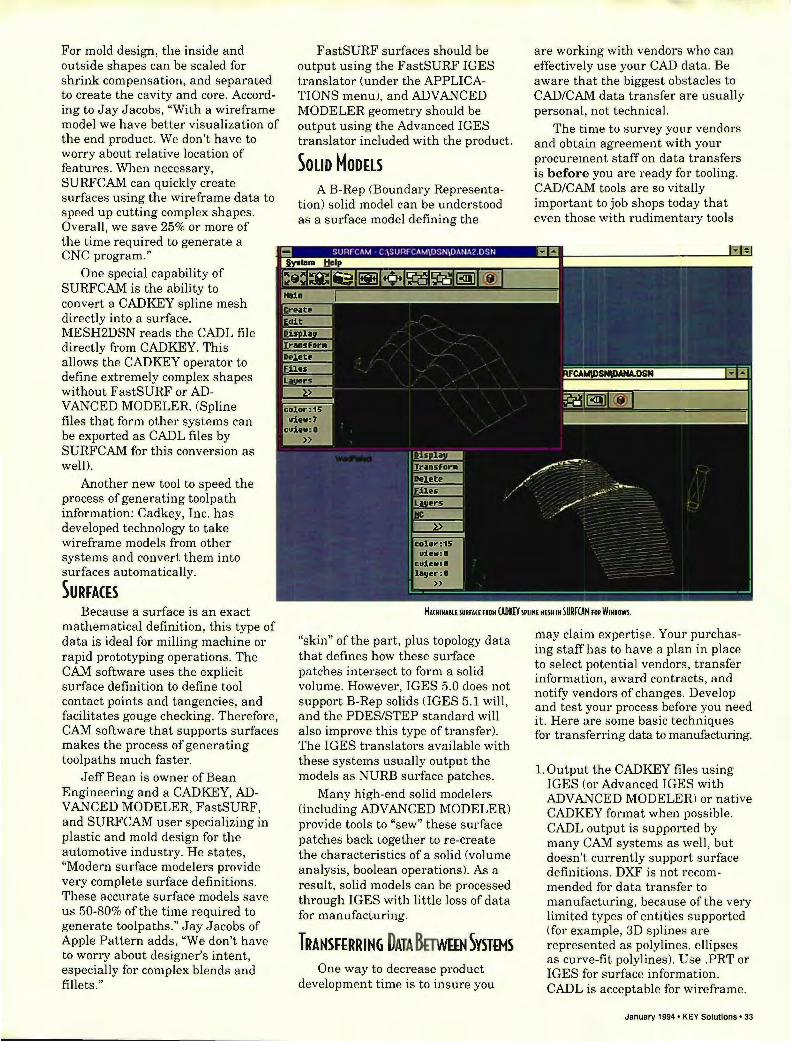
For mold design, the inside and outside shapes can be scaled for shrink compensation, and separated to create the cavity and core. According to Jay Jacobs, "With a wireframe model we have better visualization of the end product. We don't have to worry about relative location of features . When necessary, SURF CAM can quickly create surfaces using the wireframe data to speed up cutting complex shapes. Overall, we save 25% or more of the time required to generate a CNC program."
One special capability of SURFCAM is the ability to convert a CADKEY spline mesh directly into a surface. MESH2DSN reads the CADL file directly from CADKEY. This allows the CADKEY operator to define extremely complex shapes without FastSURF or AD-V ANCED MODELER. (Spline files that form other systems can be exported as CADL files by SURF CAM for this conversion as well).
Another new tool to speed the process of generating toolpath information: Cadkey, Inc. has developed technology to take wireframe models from other systems and convert them into surfaces automatically.
SURFACES Because a surface is an exact
mathematical definition, this type of data is ideal for milling machine or rapid prototyping operations. The CAM software uses the explicit surface definition to define tool contact points and tangencies, and facilitates gouge checking. Therefore, CAM software that supports surfaces makes the process of generating toolpaths much faster.
Jeff Bean is owner of Bean Engineering and a CADKEY, ADV ANCED MODELER, FastSURF, and SURFCAM user specializing in plastic and mold design for the automotive industry. He states, "Modern surface modelers provide very complete surface definitions. These accurate surface models save us 50-80% of the time required to generate toolpaths ." Jay Jacobs of Apple Pattern adds, ''We don't have to worry about designer' intent, especially for complex blends and fillets."
FastSURF surfaces should be output using the FastSURF IGES translator (under the APPLICATIONS menu), and ADVANCED MODELER geometry should be output using the Advanced IGES translator included with the product.
SOLID MODELS A B-Rep (Boundary Representa
tion) solid model can be understood as a surface model defining the
are working with vendors who can effectively use your CAD data. Be aware that the biggest obstacles to CAD/CAM data transfer are usually personal, not technical.
The time to survey your vendors and obtain agreement with your procurement staff on data transfers is before you are ready for tooling. CAD/CAM tools are so vit ally important to job shops today that even those with rudiment ary tools
MA(HIHA8l£ IURfAH fROM (ADK£Y IPUH£ M£\H IH SURFCAM fOR WIHOOWI.
"skin" of the part, plus topology data that defines how these surface patches intersect to form a solid volume. However, IGES 5.0 does not support B-Rep solids (lGES 5.1 will, and the PDES/STEP standard will also improve this type of transfer). The IGES translators available with these systems usually output the models as NURB surface patches.
Many high-end solid modelers (including ADVANCED MODELER) provide tools to "sew" these surface patches back together to re-create the characteristics of a solid (volume analysis, boolean operations). As a result, solid models can be processed through IGES with little loss of data for manufacturing.
TRANSFERRING DATA BmvEEN SVSTEMS One way to decrease product
development time is to insure you
may claim expertise. Your purchasing staff has to have a plan in place to select potential vendors, transfer information, award contracts, and notify vendors of changes. Develop and test your process before you need it. Here are some basic techniques for transferring data to manufacturing.
1. Output the CADKEY files using IGES (or Advanced IGES with ADVANCED MODELER) or native CADKEY format when possible. CADL output is supported by many CAM systems as well, but doesn't currently support surface definitions. DXF is not recommended for data transfer to manufacturing, because ofthe very limited types of entities supported (for example, 3D splines are represented as polylines, ellipses as curve-fit polylines). Use .PRT or IGES for surface information. CADL is acceptable for wireframe.
January 1994' KEY Solutions' 33

INTRODUCTION To (AD/(AM DATA TRANSHR
2.Ifyou need to add information about the part (such as material, tolerances, etc.) create a text file with the same name. For example, if you are outputting IGESTEST.IGS, manufacturing notes should be contained in IGESTEST.TXT. If you have a project nearing completion, send out test files before the actual part files are ready to check the process. According to Mark Boudreau, (master moldmaker at Mark Technical Mold, a CADIillY, ADVANCED MODELER, and SURFCAM user), "It is helpful to mail or fax a hard-copy of the original geometry, so that we can check completeness of transfer. We like the inside and outside to be on different layers, and features to be separated as well. The wireframe representation should be contained in the file, also on separate, named layers."
3. Because IGES, CADL, and DXF files are in ASCII format, they are very large when extracted from the binary database. A useful shareware utility program, PKZIP ($47. PKWARE, 414-354-8699), allows you to compress these files so that they will fit on a single floppy disk, or transfer faster and more reliably via modem. Compressed files are only about 20% as large as the originals.
If you are transferring to a UNIX workstation, insure they have the UNIX version of PKZIP. As an alternative, you can use a text editor to split very large IGES files into pieces that will fit onto a series of disks.
4. The most common transfer medium is a 3.5" high-density floppy disk, because they can be read by PC's, Macintosh, and most engineering workstations . However, transfer by modem or bulletin board is increasingly common. (Your CADKEY dealer will often allow you to use his BBS as a
34 • KEY Solutions' January 1994
transfer point). Large capacity streaming tape drives are common on workstations, but are usually incompatible with other hardware brands.
5. Insure that a procedure is in place so that vendors are notified of changes to the CAD model, and a new version transmitted. It is helpful to create a manual procedure to insure that the database is current, and create a sign-off process before final toolpaths are released for production.
(ONCLUSION Working to maximize CAD/CAM
data transfer with outside vendors requires a new approach to procurement. Because the CAD database represents a complete definition of your new product, purchasing managers must work with a small group of carefully selected vendors, with the ability and willingness to work from CAD data rather than prints. The benefits in lead time and quality more than make up for the smaller pool of potential vendors.
My company, Computer-Aided Products, conducted a study of molded parts requiring custom injection molds for manufacture. While CAD/CAM integrated and nonCAD/CAM integrated vendors provided similar quotes for price and delivery, actual performance was a different matter. Projects where mold shops worked directly from CAD data averaged 3-5 week shorter deliveries (out of 16-20 weeks), and 10-20% lower costs. Non-CAD/CAM integrated shops suffered from frequent delays and cost overruns .
True concurrent engineering with outside vendors is only starting to occur. According to Dick White of Mark Technical Mold, ''While CAD/ CAM transfer of data is common, we're only involved at the tail end of the development cycle. If a customer worked with us from product inception, we could complete the mold
(OHPAHI£S H£tmOH£D 114 THIS OTl(I.(:
APPLmmRN 106 Pratt's Junction Road Sterling, MA 01564
(508) 422-8223
BUH (HGIHHRIHG 27 Front Street Sanford, ME 04073
(207) 490-2326
COHPUUR-AIDfD PRODUCTS,INC 2 Catherine Lane Marblehead, MA 01945
(617) 631-9662
JAW,IHC P.O. Box 569
Bellingham, MA 02019
(508) 966-2141
HARK THHHICAL HOLD 113 Tolman Ave. Leominster, MA 01453
(508) 537-8051
design (three weeks) and build a custom mold base (four to six weeks), before the product was completely released. We would only need about four additional weeks to complete the mold, versus the 16 weeks it takes with the current, serial approach."
But progress is occurring. Jaco Manufacturing, a sheet metal fabrication firm (CADKEY, PROFOLD, METALSOFT) in Bellingham, MA often works with customers to complete the detail design for sheet metal manufacture. According to John Sarnofsky, Engineering Manager, "Now, about 80% of our customers are sending us CAD data, mostly via modem. We often send back CADKEY files of a redesign for their review. Cost reductions of 10-20% are the norm." III
Dana Seero, president and founder of Computer-Aided Products in MarbleHead, MA writes regularly for KEVSOLUTIONS.

ABC-Part Manager for CADKEY' 5.02 thru 6.01 100S onl , I
USE THIS FREE FOR 30 DA YS (T7~'t~~~~R)
Alton Boring Co . (313) 522 -9595 JO.9.)OA I .\UISTI<LIL I/IJ FAX (313) 522 - 1655 1.I 1"0.\"11 , III 1I11:iO
THIS IS NOT A "DEMO" IT'S THE COMPLETE PROGRAM
REARRANGE YOUR PART FILES AND SA VE THEM! ~ .. ---.
your entities on by color and subject
matter, WITHOUT HAVING TO REMEMBER LEVEL NUMBERS!
Rearrange levels
LEVELGRID The LEVEL GRID is the large grid in the wer right-hand corner of
the menu It is divided into THREE SECTIONS: 7 columns of primary colors, 7 of secondary colors and 2 for Notes and Dimensions. The entities can be automatically sorted into the appropriate columns. Each of the 15 rows has 16 levels and can be NAMED and used for related subject matter . The Levelgrid updates Cadkey ' s levels.
ISCREEN . BUTTONSl ~:reeD The SCREEN button toggles between the LEVELGRID and the PART so
you can see the entities before you process.
fLOAD ABC·PMI When ABC-PM is loaded, it scans the current part and marks each
level that has entities with a colored SQUARE, BLACK: LEVEL OFF and
BLUE: LEVEL ON. .. . SELECTING LEVELS ii -The user may select one of two ACTIONS: MOVE (default ) or DELETE . Only levels with entities can be selected. The levels can be individually selected, they toggle on and off. There are ALL ON and ALL OFF buttons (for ALL levels ) and ON and OFF buttons for each ROWand each COLUMN. These buttons have FEEDBACK lights that indicate if the ROW or COLUMN is empty, has entities that are not
selected, partially selected or all selected. They are always available s£ you can select while the PART is on the screen.
~ AND PARTIAL SELECTION BUTTONS I The MASK buttons mask to specific entity type, colors, ect.
PARTIAL SELECTION buttons let the user select entities manually.
~ MOVE -TO BUTTONS The MOVE· TO buttons control where levels selected for MOVE are
sent. There are MOVE· TO buttons for each ROWand each COLUMN. Only one ROWand/or COLUMN button may be picked at a time.
If aMOVE-TO ROW button is picked the entities will move to that row, otherwise entities will stay in the rows they are in. If a MOVE-TO COLUMN button is picked the entities will move to that column and change to that color , otherwise entities will sort to their appropriate columns .
No entities are processed until <Enter> is pressed, so that menu buttons may be picked in any order .
* Cadkey 5.02 or later * 256 Screen colors
* MS·DOS or PC· DOS 3.0 or later * Minimum BOOx600 Screen Resolution
- .. - 311> PARTY ~ DEVELOPER WE HOPE YOU LIKE IT AND BUY IT! $195 . 00

Enhancing CADKEY with MERITBAR Utilities by Chavdar Popov
As versatile as the CADKEY interface is, many users still prefer the mouse-picking (left hand in pocket) method of selecting CADKEY functions. To save time and tablet money, we at Merit Systems have developed a new add-on utility that we call the Meritbar.
The Meritbar functions as an intelligent on-screen tablet. This gives you the option to short-cut the CADKEY functions by pushing the icon buttons displayed at the top of the drafting window. For those who like working with Windows, sliders have been added to help you pan the screen horizontally or vertically.
In addition to this enhanced interface, the Meritbar offers a set of drafting and advanced modeling utilities. These utilities incorporate sophisticated math routines which boost CADKEY's 3D power even higher. The following briefly describes the features of the Meritbar CADKEYutilities. ROT AX - rotates the view about a 3D axis
Finding the best CADKEY view to inspect the details of a complex 3D wireframe can be a frustrating experience. The natural way to rotate the view of a part without losing your orientation is to have one axis fixed. With ROTAX you can actually see the axis of view rotations and push the part around it with the mouse until you are satisfied. The axis can be set anywhere on the part; it may be attached to a major feature (hole, bearing, etc.) about which the component will rotate or swing in its real-life application.
36 • KEY Solutions' January 1994
If you work in 3D on a regular basis, you will appreciate the advantage ROTAX gives by letting you decide where the part goes when the view is changed. SECTION - crea tes crosshatchable plane section s of 3D polygon models
The ability to create sections which can be handled separately from the 3D model has always been on the CADKEY users' wish list. The Meritbar will create single or multiple sections of a complex polygon model and automatically direct them to the CADKEY crosshatching dialog box. The section is an entity of its own. It can be moved away from the part, dimensioned or edited as any other CADKEYentity. BALLOON - ;u crea tes and ed its balloons
Meritbar balloons can be edited extremely easily - just pick and stretch them with the mouse.
The program not only creates balloons, but also looks after them once placed in the drawing. It will automatically recognize which part of the balloon has been picked and stretch it while preserving the other end's position. SPL2ARC-converts splines to a smooth sequence of arcs
The SPL2ARC utility will allow you to replace the CADKEY splines with a sequence of arcs prior to outputting them to your CAM system or
machine tool. This dramatically reduces the size of the CNC program! tape while maintaining the quality of the machine curve. The composite curve created by Meritbar represents a precise copy of the spline geometry; it's always smooth and passes through the spline nodes and inflection points. Given the same number of segments, this method produces a much smoother curve compared with line segmentation. The spline-to-arc conversion is also helpful for exporting smooth curve data to a package that does not accept cubic splines.
Cross-hatching a section

SPLINE-FIT- converts 3D line/arc contours to splines
The SPLINE-FIT utility replaces a chain of 3D lines and arcs with a single CADKEY spline entity. The new one-entity contour may be used to create surface meshes having boundaries defined by more than one entity. The program also allows for the creation of composite curves that incorporate sharp corners. This way, a square-to-round surface mesh may be constructed. With this utility you can create splines that follow the
Creating offset contours
shape of an arc or circle. The algorithm employed calculates the appropriate end conditions so these splines seldom need to have any intermediate nodes. EQOFFSET- creates line and contours
Offsetting contours is a problem that has been addressed with varying success by several third party developers and CADKEY itself. Performing a real offsetting operation is not a straightforward operation. The problem is that consecut ive entities that are not tangent at their connection points need to be trimmed to each other when offset. Some entities disappear completely and new entit ies have to be introduced to round sharp corners. The Meritbar OFFSET utility automatically offsets and trims the new entities to produce a continuous contour or even multiple contours with a different offset. It also handles or warns of most irregularities that may occur in the process.
Meritbar is in its first release. It is designed to be continuously enriched with new functions. We are very anxious to get user feedback so we can enhance it even further. Please give us your suggestions.
Merit Computer Solutions, Ltd. United Kingdom Ph: 0495350503 III
SERVERTM POiskette Based Interactive Plot Server
Don't Tie Up Your PC For Plotting!
pSERVER drives your plotter from plot files on diskette, so you keep full use of your PC while plotting. Use it stand alone, or connected between your PC and plotter for optional direct plotting too. The LCD front panel displays disk directory for file selection, plot status and pen change requests.
pSERVER keeps you in control of both your PC and plotter. Works with HI, HP, Calcomp and other CAD supponed plotters.
• Offline Plotting • Plotter Sharing • Interactive File Selection • Multiple File Diskettes
s~ FAR MOUNTAIN
CORPORATION
1420 NW Gilman Blvd. Suite 2163 Issaquah, WA 98027 (206) 392,6541
it just doesn't get any easier than this
MACHINEABLE F 0 N T S CADKEY
Ready-to-use patterns of the world's most popular typefaces based on the original PRECISION FONTS FOR CADKEY from Arcdraft America. Produce perfect results every time. Call for your free catalog today. (Outside the US call 904-389-4899)
1·800·447 ·4165 January 1994 • KEY Solutions' 37

CHNOLOGY IMPLEMENTATION
Compu ter Aided Engineering (CAE) technology has been hailed as the most significant development in the design of injection molded products in the past twenty years. Using CAE, engineers and designers can perform tests on new products before cutting any steel, without costly prototyping or
manufacturing trials. The manufacturing process can be simulated to avoid pitfalls and improve process capability. It is even possible to predict the shrinkage and subsequent warping of molded plastic parts prior to committing to sizes for cavities in a mold.
Most plastic material suppliers have one or more CAE software programs installed and have completed extensive evaluations. It is difficult to find injection molding companies that have not heard of CAE software and most have had some experience with its use. Still, experts in the field put the number of active, installed CAE sites under 1000 in North America. Plastics Technology magazine reported that respondents to a survey in 1992 used CAE on about 10% of molds. Assuming there are nearly 10,000 molding shops in North America, the number of molds benefiting from CAE is around 1%. The figure might be slightly higher because of the number of consultants making CAE available to shops that do not own copies of software, but the fact remains that CAE technology is used on only a small fraction of new molds built in North America.
What stands in the way of the spread of CAE technology? Is there some fatal flaw in the software that reduces its effectiveness in the real world of injection molding product design? The answer to this question may reside in the system used to implement CAE at most companies. Since CAE is an engineering tool, it is normally used within the engineering or research group. Analysis work is usually done by a small group or even one person who has been trained to run the CAE
38 • KEY Solutions' January 1994
by Robert Shaefer and Frank Lucatelli
software. It is almost always used to avoid problems on "difficult" molds or to solve problems after they occur. As a result, the return on investment for this expensive tool is often limited to savings generated on very few molds. Economic justification is often replaced by viewing CAE as "correcting mistakes" or an expensive way to make up for shoddy work or inexperienced personnel. As a result, managers often use CAE only when it is unavoidable rather than seeing it as an investment in better quality and higher profitability. Optimization with CAE
There are many direct benefits from the use of CAE such as reduced material usage, improved cycle times, lower scrap rates and less runner regrind. However, the largest possible savings from the use of CAE accrue when it is used as part of the design process to eliminate unnecessary material or to cut processing cycle times by using the unique properties of the plastic to provide required strength. The process has been described by Colin Austin, Chairman of Moldflow Pty. Ltd., as changing from "Metal-think" to "Plastic-think".
Many parts are made with constant wall thickness because the metal part was stamped from sheet metal and conventional wisdom says that will be easier to cool. Many structural components are designed to look like their metal forerunners. CAE can be used to overcome these deficiencies by finding areas of low stress and removing material. Innovative designers can often replace thick sections with ribs and structural shapes to save material and reduce cycle times needed for the thick sections.
Lastly, molding simulation can be used to design cooling systems that deal with the varying wall thickness and to optimize cycle times. The result can be a part that performs better, weighs less and can be processed faster. In a recent example cited by Mr. Austin, CAE was used to cut the cycle time in half and use one third less material. The final part was stiffer in resisting defection because the material was concentrated where it served that purpose without adding undue weight to the part. Optimization Requires Training and Teamwork
This process, called optimization, can only be successful if it is applied early in the product development process. It requires teamwork from a group with diverse skills. Optimization must be done early because it is a creative process and
•

Pentium for CAD: Xi P60 NTower™!
UNBEATABLE PRICES FOR AWARD WINNING CONFIGURATIONS • Intel 64 Bit Pentium 60MHz or 32 Bit 486DX2 66MHz • 17" Flat Square Tube Monitor 1280 x 1024 N I .26 dp • 256KB Write Back Cache up to 2MB with Pentium • 32 Bit VESA L-BUS 2MB Video RAM 1280 x 1024 NI • Intel Pentium Overdrive Socket P24T on 486 • Drivers for Windows NT, ACAD, Microstation, CADkey • 3 Slots 32 Bit VESA L-BUS Mboard w/ PCI-EISA option • 3.5" & 5.25" H.D., Floppy Drives, 2S / 1 P ports • 16MB 60ns RAM 64 Bit on Pentium / 32 Bit on 486 • 101 Key High Tactile Quality Keyboard • 32 Bit VESA L-BUS SCSI-2 Cache HD Controller • Microsoft-DOS 6.2, Windows 3.1, 3 Button Mouse • 345MB 12ms Cache Hard Disk Drive • Xi Tower Case, Double Fan , Heat Sink CPU
MULTIMEDIA KIT MONITOR UPGRADES HARD DRIVE UPGRADE SB PRO 16, CD-ROM Drive MPC & Multispeed , Spkrs, Mike, 2 CD Titles
$499
Microprocessor control , low radiation 1600 x 1280NI .28/.26 dp
20": $999 21 ": $1,268
1.23GB 11 ms FAST SCSI-2 256KB CACHE
$739
Xi Certified to run AutoCAD 12, Microstation 5.0, Windows NT, Novell, Lantastic. Call for a custom quote.
CAll TOll FREE 1 800 432 0486 USA & CANADA - - -IN CA: (71.4) .498·0858 FAX: (71.4) .492-6571
~ II ® Saudi Arabia +966-2661-0089 Warranty: Xi On-Site: one year parts, labor and free
Sweden: +46-660-55 900 replacement parts shipping. 30 day money back
II Switzerland: +41-91-56 15 78 guarantee. Life time toll-free technical support. Italy: +39-381 -42 401 Same day express shipping service from stock. ~i;:~
Computer Corporation ~~~g~~~~n~~~~~92673 • As reviewed in CADalyst, May 1992, May 1993, Autocad A11 /A12 indexes. All prices and specifications subject to change without notice. Prices do not include shipping. For more information on Xi produC1s & services call or write to Xi Computer. Xi is nol responsible for photographical & typographical errors. Xi, the Xi Logo, Workstationer, NTower and Netserver are trademarks & reg. trademarks of Xi Computer Corp. Xi450 & Xi466 Workstationers correspond to Xi PIN: Xi48S/SOW & Xi486/33W. Xi Netserver & NTower systems are FCC class A intended for professional use only. Intel, i486, Pentium and the Intel Inside Logo are registered trademarks of tntel Corporation. All other trademarks of their respective companies. Copyright © 1993 Xi Computer Corporation. All rights reserved.
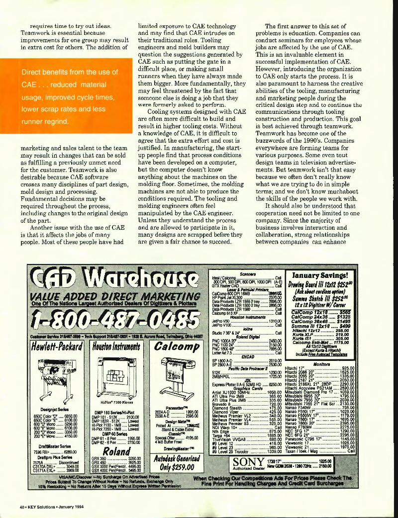
requires time to tryout ideas. Teamwork is essential because improvements for one group may result in extra cost for others. The addition of
Direct benefits from the use of
CAE ... reduced material
usage, improved cycle times,
lower scrap rates and less
runner regrind.
marketing and sales talent to the team may result in changes that can be sold as fulfilling a previously unmet need for the customer. Teamwork is also desirable because CAE software crosses many disciplines of part design, mold design and processing. Fundamental decisions may be required throughout the process, including changes to the original design of the part.
Another issue with the use of CAE is that it affects the jobs of many people. Most of these people have had
mill [
l1li
~ Hililot- 7100 Plotter
Designjet Series DMP 160 SerieslHl-Plol
limited exposure to CAE technology and may find that CAE intrudes on their traditional roles. Tooling engineers and mold builders may question the suggestions generated by CAE such as putting the gate in a difficult place, or making small runners when they have always made them bigger. More fundamentally, they may feel threatened by the fact that someone else is doing a job that they were formerly asked to perform.
Cooling systems designed with CAE are often more difficult to build and result in higher tooling costs. Without a knowledge of CAE, it is difficult to agree that the extra effort and cost is justified. In manufacturing, the startup people find that process conditions have been developed on a computer, but the computer doesn't know anything about the machines on the molding floor. Sometimes, the molding machines are not able to produce the conditions required. The tooling and molding engineers often feel manipulated by the CAE engineer. Unless they understand the process and are allowed to participate in it, many designs are scrapped before they are given a fair chance to succeed.
The first answer to this set of problems is education. Companies can conduct seminars for employees whose jobs are affected by the use of CAE. This is an invaluable element in successful implementation of CAE. However, introducing the organization to CAE only starts the process. It is also paramount to harness the creative abilities of the tooling, manufacturing and marketing people during the critical design step and to continue the communications through tooling construction and production. This goal is best achieved through teamwork. Teamwork has become one ofthe buzzwords of the 1990's. Companies everywhere are forming teams for various purposes. Some even tout design teams in television advertisements. But teamwork isn't that easy because we often don't really know what we are trying to do in simple terms; and we don't know muchabout the skills of the people we work with.
It should also be understood that cooperation need not be limited to one company. Since the majority of business involves interaction and collaberation, strong relationships between companies can enhance
IdeaI~aloom!> .... ~~~ ... ................ Call January Savlnts! G~ ~~~~:.~.~I: .. 1 .~.~ ... (~~ D"wi'f B",' III tZXtZ 1ZSf'D caJComp~--o~ ~.~~~ 'Aik'Htfel'''I#~~ HP Paint Jet Xl300 .. .. ..................... 2370.00 $/1/1/1, $kll,' 11/ tOO Data Produds LZR 1555 2 tray ........ 2895.00 D' UJ W It Data Products LZR 1560 2 tray ........ 2895.00 It x It '1,,111( WJ "''''' Data Products LZR 1580 ....................... Call Caloomp613XF .................................... Call Ca/Comp 12x111 ....... $585
Houlton In,/rumen" CalComp 24x36 ..... $1325 JetPro V50 ...................................... 1310.00 CalComp 36x," ..... $1495 JetProV1OO ............ iiiiiiN ...... · .............. · Call Summa III 12x18 ..... $499 SllJdio 7 36' & 24' ........ .. .. .. ... ................ Call ~ltachI12x12 ............ 295.00
Roland DIgItal K~: fir::::::::::::::::: ~~ug PNC 1000A 20' .. .. .. .. ....................... 2450.00 Ca/comp Estl-M.t ... 1175.00 PNC 110024' ..... .. ............ .. ............. 3150.00 A1112x12D1!1/11ZetS PNC 1800 48· .... .. ... .. ...... .. ........ .. .... 7895.00 (Except KurD I Hitachi) Letter Art 7.5 · .. ...... iiicAO .. · .... · ............ Call L_.:,nc:':UdI:::frIt:A:!!Ipqd:==li:;:Imp/I1Is==...JU SP 1800 A·D ................................... 2019.00 SP 2800 A·E ............. .. ..................... ~.OO Monitors
PKIfIc Dela ~ II Hitachi 17' ..... ... .. .. ............... .. .. ... 925.00 512K ............... ....................... .......... 1~.00 Hitachi 2088 20' ....................... 1625.00 2MB/HPGL ...................................... 1725.00
JDL Hitachi 2095 20' .............. ......... 1335.00 Hitachi 2187 21· ...................... . 2050.00
Express Ptotter II A·E 52MB HD ...... 8250.00 GlJlphlcs Cards
Artist XJ1000 50MHz ............... 1050.00
Hitachi 2188XL 21' .28DP ...... 2290.00 Hitachi Accuview PS21AM ...... 2590.00 Mitsubishi Diamond Pro 17 ..... 1059.00
ATI Ultra Pro 2MB .... .......... .. ...... 365.00 Mitsubishi 6955 20· ................. 1795.00 ATI U~ra Plus 2MB .. .................. 335.00 Mitsubishi 7955 20· ................. 2039.00 Bravado 8 ............. .............. ........ 720.00 Mijsubishi 7165 21· Flat Scr ... 2130.00 Diamond Steatth .... .................... 175.00 Diamond Viper ........................... 425.00
Nanao F340W ............................ 705.00 Nanao F550i 17· ................... ... 1029.00
PIICII8ttefI"'l 2024 A·D .............. t 995.00
Metheus Premier VLZ ................ 340.00 Metheus Premier VL4 .... ............ 555.00
Nanao F550iW 17' ................... 1179.00 Nanao T560i 17' ...................... 1695.00
2036 A·E .............. 2595.00 650C Color '0' ..... 6850.00 650C Color 'E' ... .. 8100.00
DMP 161 • 512K ....... 2100.00
600 '0' Mono ..... .. 5250.00 600 ·E· Mono ........ 6100.00 200 .0' Mono ....... 3350.00 2OO·E·Mono .. ...... 4150.00
DMP 162R· 512K ...... Lowest HI·Plot 7100 ·1MB ..... Lowest HI·PIot 7200· 1 MB ..... Lowest
OMP 60 Series DMP 61 ·8 Pen ......... 1995.00 DMP 62 • 8 Pen ......... 2750.00
DraftMaster Series 7596 RX+ ............. 6289.00
Oraftpro Plus Series 7575A ........... ... Discontinued C3170A DXL+ ......... 3049.00 C3171A EXL+ ......... 3969.00
40. KEY Solutions· January 1994
Deslgnllltll"'l Priced At.. .......... .. 1J&Ii;tIl
Stand & Cabie ExtraI Ctlllld"'
Special Offer ... .. .. .. 4195.00 4 MB Buffer Freel
DI'IWIngMaster (l1li
Metheus Permier 53 .................. 325.00 NDI Warp 10+ .. ........ .. .... .... ............ Call Nth Edge ............... ..................... 875.00 Targa +04 ...... ........ .. ......... : ....... 1695.00 TrueVision WGA8 .... ................. 890.00
Nanao T660i 20· ......... ............. 2395.00 Nanao F760iW ......................... 2275.00 NEC 5FG 17' ......................... .. NEC 6FG 21· ........... ......... ............. ~~.~~ . :~ Panasonic C795 17' .. ............. .
119 Level 12 ...................... .......... 418.00 119 Level 23 ........ ........................ 965.00 119 Level 29 Trucolor ................ 1339.00
VJewsonic 17 ........................... . Viewsonic 21 ...................... .. Taxan I ldek I

business even when the entire product development process is not controlled by a single company. Training and Team Building Approaches
For this process to work, two efforts must proceed hand in hand. Current technology usage must beunderstood while an inventory of human skills of the existing team is taken. An assessment of current technology is best done with a workshop for decision makers in engineering, manufacturing, sales and marketing. The workshop provides a forum for discussion of implementation issues within the organization. Introductory workshops can be tailored to adress specific issues of interest to decision makers. A combination of presentation and discussion are used to form objectives and to develop a model for implementation.
Technical training for CAE users and for those affected by its use within the enterprise is aimed at removing the "mystery" from CAE. Any technology, when understood for what it can do and what it cannot do, is less threatening. The aim is to eliminate the feeling that CAE technology can replace the experience of skilled
workers. Indeed, CAE is most effective when all of the team members participate freely, answering questions about design and processing before the product reaches the floor . CAE can be a great learning tool when dealing with new or unfamiliar materials or new designs. It can even be used to calculate difficult process parameters like injection velocity and packing pressure profiles. These types of processes are normally never optimized since experimentation on the molding machine is time consuming and expensive.
Follow-through consulting is the process of monitoring the system developed to be sure that it stays on track. Requirements are likely to be high at first but should wind down as experience is gained. Continuing involvement is also advisable to recognize the need for refresher training or to introduce new people to the concepts ofteam building and CAE use. It is also important to maintain an ongoing record of accomplishments, expressed in financial terms, so that the value of the effort is recognized. Like any other investment, the return should be recorded and reviewed periodically.
Ergo PowerBrick 66 The Lean, Mean CADKEY Machine
• 66MHz Intel 486DX2 • 1280 x 1024 Ext VGA • Local Bus Graphics • 4-32MB RAM Ergo's PowerBrick 66 is the latest in a long line of powerful CAD KEY systems. With a 66MHz 486DX2, up to 32MB RAM, a 200MB or 340MB HD, and local bus accelerated graphics, the PowerBrick outperforms most desktop PCs. Use it as your main Cadkey machine with a big screen monitor at 1024 x 768
COMPUTING
• TFT Color or Mono LCD • 2 PCMCIA Slots and FAX • I 20-340MB Hard Disk • 6.2Ibs., 2"x 8.5"x I 1" resolution with 256 colors. Or use it on-the-go with its easy to read TFT active color or dual scan passive color 10" LCD and 3hr battery. Discover how handy CADKEY is when you don't have to leave it behind. Call our automatic FAX Line for complete information, pricing & photos. Dealer Inquires Welcomed.
SALES, M-F, 9-6 EST 1-800-633-1925 24 Hr. Automatic FAX Info
1-800-723-0778 code 1552
One Intercontinental Way, Peabody, f\N\ 0 J 960 (508) 535-7510 FAX (508) 535-75 J 2
The goal of implementation consulting is to provide a team that is skilled in the use of CAE technology and able to determine when and how much it should be used. Most companies now use CAE only on difficult projects. This has the effect of creating emergency use, often delaying the development of critical projects.
CAE can be a great learning tool
when dealing with new or unfamiliar
materials or new deSigns.
More general use of CAE has the effect of improving the skill level, making CAE an efficient tool on all projects, reducing the overall cost. CAE, when used effectively, can have a beneficial effect on all projects, and have significant benefit for difficult projects. Wise investment in engineering technology will return higher quality products and higher profitability. m
January 1994 • KEY Solutions' 41

Timberline TrueCAD and TrueGraphics True to Name
by Robert Martin
These days a lot of folks are putting together 486 PCs and calling them CAD workstations. From a price/performance perspective some are great - others only OK. A relative newcomer to the arena, Timberline of Meridian, Idaho is not as well known as some of the big guys, but this small company is producing a very good product.
Timberline sells and services a complete line of 486DX2 66s that range in price from $3995 to $8585, depending on the options you select. For example, the high speed hard drives range from 520M to 2.1G and RAM ranges from 8 MB to 64 MB.
Timberline has worked hard to make their machines high performers. In fact, PC Magazine tested 74 486DX2/66 computers in Jan. 1993. As part of this benchmark,
ZD Labs measured seven indicators of performance and speed: disk, Graphics Winmarks, DOSMark, processor, memory, Disk Winmarks and video.
Timberline completed the testing to compare their machines to the competition. Timberline would have placed in the top three on six ofthe seven tests. They were first in DOSMark, processor and Graphics Winmarks; second place in Disk, and third place in memory and Disk Winmark.
A strong point ofthe TrueCAD machines is their expandability and flexibility. Each incorporates a Pentium upgrade able motherboard, seven 32-bit EISA slots and one 32-bit Local Bus slot. The three 32-bit CPU design even lets you obtain parallel processing in certain cases.
A Hot C-Size Bubble Jet for Plotting
by Robert Martin
Recently several printer vendors have released desktop bubble-jet printers capable of C-size output and touted them as printer/plotters. You probably noticed that they all looked alike and wondered. These devices look nearly identical because their basic print engine and case come from the same manufacturer. However, that's where the similarities end because each vendor adds functions and capabilities with software, emulations, controllers, and paper handling.
I've tried them all and they work fine. I felt a little blase' when the JRL version arrived for a test, but I quickly discovered that this one's different. The JR 670 is more functional as a plotter than any other that I have used.
First, the JR 670 has superior paper handling for plotting. A fullsize automatic C-sheet feeder is available that holds 100 sheets. (Others make you feed C-size media
42 • KEY Solutions· January 1994
one at time through the manual feeder. ) Its paper parking capability lets you alternate easily between cut sheet and tractor media. It handles almost any media, including plain paper, vellum, envelopes, and transparencies.
The JR 670 supports ADI, HP-GL, CalComp 906/907, Epson LQ1050, and Postscript output. The JR 670 also handles CCITT Groups 3 and 4 compressed raster data in a superior and unique way. You can send this type of compressed raster file directly to the plotter without decompression (even through a network); the JR 670 decompresses and prints the file automatically. The others don't do this. The printer even recognizes the data format of the files you send and changes to the correct emulation automatically. Other features on the plus side
The EISA SCSI caching controller comes standard with 32-bit drivers for DOS, Unix, and Xenix. This allows the use of multiple operating systems on a single platform and protects your software investment.
Good engineering shows and the small touches tell the tale. For instance, the power supply in the full size tower has its own "SMARTF AN" which constantly measures the interior temperature and automatically adjusts the rotation speed to the exhaust fan accordingly. II!
For more information call Timberline at 208/887-0969.
include super-fast processing times and 360 dpi resolution. Much of this power and flexibility is the result of JRL's proprietary integrated intelligent controller.
The Postscript model comes with 8 megs of RAM and costs $2495; the printer without the Postscript option has 2 megs and costs $1995. II!
For more information contact: JRL at 512/288-6750; Fax 512/ 288-7676.

IN HIS TIME Makes My Day
by Steve Radford
A former devotee of black, bound To-Do-List for the daily appointment books, I now use a day, appointments, computerized system that is light years beyond myoid manual method.
The Windows program is called In
His Time, and can best be described as "the Christian Information and Resource Organizer" - CIROTM.
CIRO's easy-to-use, well-organized features include tracking for appointments (either one time or
repeating), things-to-do, and events
to remember. These entries can be accessed by displaying a calendar for the year, month or week. Alarms can be set as a reminder. Additional features include a Daily Journal
which can be linked to the Windows Notepad or your word processor, an
address book, and printing ofthree
popular sizes of day planners for
when you must leave your computer
and hit the road.
I have my system set-up to start
each day with "Joyful Noise -- Comic
Relief," a cartoon that should appeal
to any Christian. I also print a daily summary report each morning when
I arrive at my office. It includes my
events to remember, the daily Bible
reading, and a prayer listing. A passage from Scripture appears both on the report and screen each day. I find this a great way to start the
day and like the
inspirational message. Scripture Topics is a listing of subjects (i.e., Adultery, Alcohol, Ambition, Anger, etc.) with a listing of Scripture references. There is a Daily Prayer Journal that lets you track prayer
requests and answers.
Sunda,.
16 J 1fH
GodisID ........
In His Time is as powerful a personal resource manager as you can find anywhere. I personally like it's Christian elements, but if this is not your persuasion, you can turn them off and lose none of the software's power or features. For
me, it helps integrate some spiritual
elements into a sometimes sterile
business environment. IIJ
For more information contact,
Colannade Technologies, 206/822-
2977.
TECH TIP You can reorganize commands in CAD KEY Status menu. Use a text editor to move the lines in the STATUS. TXT file so that frequently used commands are at the top. This trick works with DRAFTER and LIGHT as well.
Computer-Aided Products believes the best CAD/CAM software makes your company the most money. That's why we offer New England deSigners and manufacturers a full range of classroom and on-site training, consulting, and video training programs. We have special expertise in plastic product and sheet metal design and manufacturing, and support a full range of 3rd party productivity tools.
~--------------------------------------------------------------------~ WANT TO USE YOUR CADKEY SYSTEM MORE PRODUCTIVELY?
ASK FOR OUR NEWSLETIER WITH OTHER TECH TIPS, TRAINING, AND USER GROUP SCHEDULE.
Computer-Aided Products, Inc. 2 Catherine Lane - Marblehead, MA 01945 - (617) 631-9662 -In New Hampshire (603) 424-8486 - In Maine (207) 761-1200 - Compuserve 71344,1753
CADI(EY / ADVANCED MODElER / DRAFTER / DMS PRO / DRAFTPAI( / FASTSURF / LIGHT / PARADESIGN / PROFOLD / aSheet / SURFCAM
January 1994' KEY Solutions' 43

CAD L TOOLBOX ISODIM.cdl
CADKEY dimensions are entities attached to a particular plane of definition. Once created, dimensions may be seen from any view by pressing Ctrl-N. However, unlike other view-dependent entities (arcs, conics, 2D splines), dimensions must be created in their definition views. Because the 3D geometry is often superimposed, it's sometimes difficult to control the depth at which a dimension will be placed.
The ISODIM program allows creation of linear dimensions in 3D without the limitation of having to change the view in order to work in a particular plane. This way, a wireframe 3D model may be dimensioned from the view in which it will be presented. By changing the construction plane, the user can control the position and orientation of the dimensions. The dimension text is oriented in accordance with the construction view axes.
Horizontal dimensions are measured along the X-cview axis, vertical dimensions, along the Y-cview axis. In depth, each dimension is attached to its first reference position. This allows for the creation of dimensions at different depth levels in the same construction view. To help with the 3D orientation, temporary dotted witness lines are displayed prior to indicating the text position. The two reference positions are projected onto a plane which is parallel to the construction plane and passes through the first reference position. The dimension is measured in this plane. If the construction view is perpendicular to the display view, the cursor movement cannot be traced on the screen. To prevent this, the program projects the normal of the construction view onto the plane of the display view and examines its length. As with CADKEY itself, zero length dimensions cannot be created. For faster operation, compile the program into a cdx file and don't forget to press Ctrl-N before you start dimensioning. A comprehensive dimensioning utility, capable of creating also circular, radial and angular dimensions in 3D, will be included in the Meritbar Set of Utilities, featured in this issue.
by Chavdar Popov Merit Computer Solutions Ltd. . United Kingdom, tel: all (44) 495 301303, fax: 011 (44) 495 350504
44 • KEY Solutions' January 1994
RIDI JSODIII.4xIl. fftIltee dimeusions in 3D iaometric views .. .... dimeDliona are measured and created parallel to the construction plane "Preu Ctrl·N to allow dimension display in 3D
clear
int ENTATl'[O]
array REFLNt2)[4] array ENTATl'[9]
uIac .. (Ounita)? 1:1J26.4 big ... l0000*ufac vwaDltol- c:oe(80.001)
opt .8 form ... 1 idl-id2 .·1
mode draw
drawantidl drawentid2
ptmeDu "ISODIM: Choose option (HORIZTL)'", \ "HORIZTL", \ "VERTICL·, \ "PARALEL· ... ""I,I
form ... (Aey > 0) ? Gkey.form on (ekey + 8) goto end,aDd,
REM Check aDgle between view and cp1ane call dotprod,fitriewmat(2],09iewmat(6],Oriewmat[8], \
Ocviewmat[2],ttmewmat[6],@c:viewmat(8), \ vwang
if{abI(vwang) > vwangtol) goto first
pause 'This view is perpendicular to the cplane <RET>" pause "Select a dift'erent view to dimension in this plane <RET>" gotoeelopt
ptpos "Indicate 1st poeition" ,opt opt • (@key >- I) ? (ikey:opt on (@key+3) goto ae1opt,aelopt,firat,
aetdepth,Z
xl=Oxcview yl =@ycview Z =@zcview
view 1, Oeviewmat[O),@c:viewmat[ll,@cviewmat[2], \ @cviewmat[S],@c:viewmat(4),@cviewmat[5], \ @cviewmat(6),@cviewmat[7],@cviewmat[8]
if(form-I) VLINE xl,yl.big,z,xl,yl+big,Z,1,14,,2
if(form-2) VLINE xl·big,yl,z,xl+big,yl,Z,l,14,,2

:second
:pttzt
:end
getpos "Indicate 2nd position",opt opt = (@key >= 1) ? @key:opt on (@key + 3) goto selopt,firat,aecond,
x2=@xcview y2=@ycview z2=@zcview
REM check if distance is long enough diat = hypot(y2-yl,z2-xl) if(diat < O.OI*ufae)
goto second
if (form = 1) VLINE x2,y2-big,Z, x2,y2+big,z,I,14,,2
if (form = 2) VLINE x2-big,y2,z, x2+big,y2,z,I,14,.2
if(form=3) VLINE xl,yl,z,x2,y2,z,1,14,,3
REFLN[O)[O] ,. xl REFLN[O)[I] '" yl REFLNIO]l2J = x2 REFLN[O][3] = y2
getcur "Indicate dimension text poaiticm",I,O on (@key + 3) goto eelopt,second,gettxt,
xt=@zcview yt=@ycview
aDg = (form III:: 3) ? atan2(y2-yl,z2-xl) : 0.0
ENTATl'[O] = 1 ENTATl'[3J = @pen ENTATl'14J = @level ENTATl'[5] = @ltype ENTATl'16] = @lwfdtb ENTA1TI7J = ENTA1T18] = 0
REM Display temporary dimension ENTA1Tll] = ENTA1T[2] = 15 lindim xt,yt,Z, ,REFLN,aDg,form.",,ENTA1T ENTATl'II] = ENTA1Tl2] = 0
getmenu -Aeeept dimension ? (YES)","NO","YES" lindim xt,yt,z, ,REFLN,aDg,form,,,,,ENTA1T on (@key + 3) goto selopt,sec:ond",gettxt,
REM Create dimension entity mode normal
ENTA1T(I] = ENTA1T[2] ,. @COlor LlNDIM xt,yt,Z, ,REFLN,ang,fonn",,,ENTA1T
mode draw
gotoselopt
redraw exit
BOOKS, PUB Tips on Designing with Sheet Metal
Champion Manufacturing has produced a quick and easy reference for design and manufacturing engineers involved with sheet metal fabrications. Tips on Designing with Sheet Metal was created to take the mystery out of how to get the most from sheet metal design in terms of materials, finish, quality and innovation. The company's experience includes over 30 years of solving complex metal working problems. Capabilities include in-house design, and advanced laser cutting and fabricating equipment. A free copy is available by calling 203/ 526-4951 or by writing to: Champion Mfg. Inc., Corner of Main & Winter Aves, P.O. Box 36, Deep River, CT 06417.
Automated Fabrication Automated Fabrication-Improving
Productivity in Manufacturing, by Marshall Burns, is a guide to automated fabrication that explores its applications and the future of autofab technology. It highlights commercially available automated fabrication products and the most recent developments in the technology. Call Prentice-Hall at 515/284-6751 or fax 515/284-2607.
CAD/CAM Planning Strategies Penton Publishing has a 66-page
source of information for executives, engineers, managers and students. Offered by the publishers of ComputerAided Engineering, Machine Design and Industry Week , this instructive "handson" guide to CAD/CAM includes articles on Breaking Down Barriers to Integration; Technology for World-Class Engineering; Gaining the Competitive Edge; Building an Engineering Team; Communicating Globally; Exploiting Advanced Software; Putting Integration to Work; and many more. Call 800/321-7003 (Ohio 216/696-7000 x4220) or fax 216/696-4369.
Dataquest CAD/CAM Survey Dataquest recently completed a 400-
site survey of U.S. and European end users. The resulting reports evaluate the current work environment, technology penetration levels, buying history and plans, and importance and satisfaction ratings for strategic business issues, software, and point solutions.
The survey indicates that structural analysis and conceptual design are the two fastest growing applications areas. Additionally, improving product quality is more important than time market.
Reports are available in most industry sectors for $250 each. For more information contact Michael Seely, Dataquest, San Jose, CA; 408/437-8316 or fax 408/437-0292. II!
January 1994· KEY Solutions· 45

1i-11tNV v compiler (OCC) is a product of tile Free 'Boftware Foundation (FSF) of Cambridge, Massachusetts. It is part of the GNU project started by Richard Stallman in 1983 for producing a UNIX-compatible operating system. The purpose behind FSF is to give the users ..... freedom to study, share, change and improve the software they use." For this reason, all software from FSF includes the source code along with the applications. Users can make changes to the source to suit their needs.
Using the source for the GNU compiler, D. J. Dolorie of Rochester, New Hampshire ported the compiler for 386 MSDOS computers. The DOS package contains a C/C++ compiler with utilities, a DOS extender, and a symbolic debugger. The compiler generates 32-bit code, which is why it can be used for creating CDEs. In the following sections we will show you how to build CDE modules using the GNU compiler.
Requirements To create a CDE module with the GNU compiler, you need the following: 1. The GNU version of the CADKEY SDK. This SDK
46 • KEY Solutions· January 1994
executables, header files and CDEs with the GNU compiler.
is a CDE module that loads
de1~$4:>prnerlt system follow these
the compiler and copy that directory. For example, at the
<Enter> executing GCCMIN with the '-d'
. This option re-creates the compiler structure.
C:\> CD GCC <Enter> C:\GCC> GCCMIN -d <Enter>
3. Make a directory for the CADKEY SDK and copy GCCSDK.EXE into that directory:
C:\> MD \GCCSDK <Enter> 4. Extract the files by executing GCCSDK with the '-d'
option: C:\> CD GCCSDK <Enter> C: \ GCCSDK> GCCSDK -d <Enter>
5. Set the environment variables required to run the GNU compiler. The file SETUP.BAT in the compiler directory shows all these variables and their values. It assumes the compiler is installed in the \ GCC directory. If you name your directory something else, make changes accordingly.


A Shareware Compiler for CDEs
You can set the environment by running SETUP.BAT before you begin compiling. You can also move the contents of SETUP.BAT into AUTOEXEC.BAT. This way, your environment will be set as soon as you turn on your computer. You must also add \GCC\BIN to your path statement in AUTOEXEC.BAT.
Building a GNU CDE Module The process for building GNU CDE modules is very
similar to that of building a CDE module. The differences are in the command line for compiling and the use of GCC.CDE.
Header Files Depending on the CDE functions you use, you need to
include one or more of the following SDK linkage header files in your source files:
CK_CDL.H For CADL Library Functions CK_DLG.H For Dialog Box Functions CK_LAY.H For Layout Functions CK_MTH.H For Math Library Functions CK_REF.H For Reference Entity Functions CK_SYS.H For System Library Functions These files are located in the \GCCSDK\INCLUDE
directory. There are additional header files supplied with the SDK which are necessary for creating GNU CDE modules. All the SDK header files must be present in the Include directory or you will not be able to successfully build GNU CDE modules.
Listing 1 shows the source file HELLO.C. 1t includes the header "CK_CDL.H" since it calls ck_pause, a CADL Library function.
------ Listing 1 ------1*++ Name: Hello Summary: Prints a greeting *-*/ void hello 0;
Definition Files Every CDE module requires a definition file. The
definition file provides information about the CDE module so that CADKEY can load it. As a minimum, it must contain the names of the functions in the CDE module that need to be accessible from inside CADKEY.
The definition file for the "Hello, world!" application, HWORLD.DEF, is shown in listing 2.
------ Listing 2 -----#include 'ck3dl.h" void hello O;{ck_pause(Hello,World!");}
Running CDEGEN To include the definition file into the CDE module, it
must be processed through the CDEGEN utility. CDEGEN reads the information in the definition file and creates a C file . This C file contains data structures that encapsulate the information about functions. When CADKEY loads a CDE module, it deciphers the functions in the CDE with these data structures. The definition
48' KEY Solutions' January 1994
file is processed through CDEGEN the first time it is created and then every time it is modified.
To process HWORLD.DEF, use: cdegen hworld.def. This produces the file HWORLD.C.
Caution: Choose the name of your definition file carefully. Do not use the name of any of your source files. Otherwise, the C file produced by CDEGEN will overwrite it.
Compiling The next step is to compile all the source files (the C
file output by CDEGEN can be treated as one of the source files) to produce object files. Use the '-c' (compileonly) flag on the compiler command line so that it does not try to link it into an executable:
gcc -c -I1gccsdklinclude hello.c hworld.c The above command line assumes that the path for
the SDK Include files is "\GCCSDK\INCLUDE". This step will yield the object files HELLO.O and HWORLD.O.
Object Files The last step is to combine the source object files with
the SDK object files into CDE module. The LD utility is used for this step. The SDK object files follow the same naming convention as the linkage headers. These files are located in \GCCSDK\OBJ\G87:
CK_CDL.O For CADL Library Functions CK_DLG.O For Dialog Box Functions CK_LAY.O For Layout Functions CK_MTH.O For Math Library Functions CK_SYS.O For System Library Functions CK_REF.O For Reference Entity Functions You only need the object files for the functions you
call. HELLO.C calls ck_pause from the CADL Library, so it needs CK_CDL.O. The command line for building the CDE module is:
ld -r -0 hello.cde hello.o hworld.o ck_cdl.o To keep the command line short, you can copy
CK_CDL.O from the SDK object directory into the project directory. Executing this command line will create the CDE module HELLO.CDE. This module is ready to be loaded into CAD KEY.
Loading the GNU CDE Module To load the GNU CDE module, copy GCC.CDE (the
GNU loader) and HELLO.CDE into CADKEY's default CDE directory. Start up CADKEY and go to FILES menu. Choose the CDE option from menu. First load GCC.CDE and then HELLO.CDE with OPEN or LST/OPEN option. You can execute the hello function using the EXECUTE or LSTIEXE options. This will display "Hello, world!" on the prompt line.
Once you have a CDE properly loading and executing, you can load the CDEs automatically by using option 5 of CADKEY's config program. Be sure to list GCC first so that the GNU-compiled CDEs load properly.
Conclusion The GNU compiler is a freeware compiler that you can
use to create CDEs. It provides a low cost alternative to the standard CDE development system you can use to test-drive the CDE mechanism. III

The JR670 HighRes™ BubbleJet Plotter
WIDEST
SMARTEST
ABSOLUTELY
THE BEST.
FASTEST. The JR 670 is the fastest BubbleJet Plotter available. How fast? As much as 40% faster than Houston Instruments and 60% faster than Pacific Data Products. The difference is JRL's controller technology which rapidly rasterizes the data on-board the JR-670. You can measure the difference in productivity.
WIDEST. The JR 670 gives you a full 15.6" of print width. That' s .6" wider than Pacific Data Products and .3" wider than Houston Instruments. While that may not seem like a lot, it can make large plots fi t easier in the C fonnat.
SMARTEST. Here' s where you separate the printers from the plotters. The JR 670 is driven by the smartest, most sophisticated and fulJy featured controller in the world. This intelligent controller enables the 670 to take 8 different page input fonnats in their native languages including AutoCAD, PostScript and compressed raster data. The 670 can even scale your plots to fit , or rotate them and overlay data and images in different fonnats on the same page.
THE BEST. If you want to work smarter in A, B and C fonnats, the JR 670 HighRes BubbleJet Plotter is your best choice. Pacific Data Products and Houston Instruments can ' t give you all of the JR 670 's features at any price. But even if they could, the JR 670 would still be the best deal... absolutely.
$1995.00· Call 1-800 PLOT NOW
and take advantage of our 24 hour delivery and 30 day money back guarantee to see what faster, wider, and
smarter plotting can do for you.
JR~ SYS T E M S, INC .
8305 Highway 71 West· Austin, Texas 78735 (512) 288-6750' Fax (512) 288-7676
· JR 670 with Hp·GL, CalComp 9061907, AutoCAD ,and Epson LQ 1050 input for· mats and 2MB memory. PostScript, compressed raster, and raw raster fo rmats optional.
HighRes is a trademark of JRL Systems, Inc. BubbleJel ;s a registered trademark a/Canon, lnc. AUloCAD is a trademark 0/ Aucodesk. PostScript is a registered trademark 0/ Adobe Systems. Inc. CalCamp is a trademark o/Lockheed. HP·GL is a "gistered trademark 0/ H.wlttt Packard. 11:>1993 JRL Systems. Inc.

by Jack W. Allen
Drawing Layout Hidden Line Removal Methodology Using CADKEY 6.0
The purpose ofthis methodology is to enable designers to perform HLR (Hidden Line Removal) on their Drawing Layout Orthographic views using the "Picture It" CDE program.
1. Create a blank part with the following modals pre-set. A. Name Layers 191 to 199 as
follows: L191 TOP VIEW HLR L192 FRT VIEW HLR L193 BCK VIEW HLR L194 BTM VIEW HLR L195 RHT VIEW HLR L196 LFT VIEW HLR L197 ISO VIEW HLR L198 AXO VIEW HLR L199 AUX VIEW HLR
AND ANY ADDITIONAL VIEWS AS REQUIRED UP TO L255. * DO NOT USE L256 FOR STORING ANY GEOMETRY.
B. Name any layers that you might reserve for type specific entities. L090 DIMENSIONS L091 SECTION LETTERS
AND ARROWS L092 BALLOONS AND
BOM
L096 DRAWING SURROUND
50 • KEY Solutions· January 1994
2. Save this part as STARTUP.PRT and call this part whenever you start a new file. Save this as <filename>.prt where <filename> is the name of your job.
3. Upon completion of modelling, prepare the required orthographic views and name them accordingly.
4. Change to your first orthographic view: TOP and execute "PICTURE IT" HIDDEN LINE then save the result to the designated layer: L191. Continue this process for each of the required views and save the results to their corresponding layers. You could even do a POLYGON FILL ISO view and save this to its layer.
5. GOTO Drawing Layout mode and create the required instances. Then modify the layers of each instance so that all layers are OFF and only the HLR layer is ON in addition to any annotation layers that you need.
The end result is separate drawing layout geometry without modelizing and the ability to display rendered views. Your 3D model will remain intact.
Jack W. Allen is founder of Imagineering CADD Services (416 1 771-9236) and has done aircraft tool design and CADL programming since 1986. ill

Licensed ~-. to CJ!l Export I:} :'l, ~e..t- .
• CALL FOR STOCK.
SAVE - 30% - 50% - 70% - & MORE J g ZETA ~ l'l) ~!~';:.!ri 1A1rE16RAPHICS ~ M l.J1'O H
~~~ ......... . In .... ruln.n ... ~
y~~ ONUMONICS
!!!/iQ.t~ ,.(;.4§d5!*iii3*
.New Release creates c'bores, c'sinks, circular bosses, slots, ribs , etc, with draft, fillets/rounds simply by filling out the parameters in a CADKEV® Dialog Box.
.Offset paths, arcs, splines, ellipses by Draft/Depth w/move, copy~oin options.
.Fillet along a path , file search, and file path changing commands included.
• Free Demo Disk for CADKEV® 5.0 or 6.0. Call your CADKEV/Paradesign Dealer or. ..
Paradesign at (619) 484-8386 FAXNoice
"'~
¢-~ ..," ~~
cP
". ¢-'"
",,.'"
• CALL for remarketed HP 9000 CAD stations
1-800-422-4872
·24OD/E • 7596A • 7595A • 7576A • 757SA
• 7570A
• 7SSOA • 7475A • 7470A ·7440A
_ T£laIlCALaIClEIIT1fICArPlICmo ...... 2040 West Sam Houston Partway North Houslon. Texas n043 FAX 713-935-1555
Pop-Up '**tor .... CJDIII
Tired of typing math functions on a prompt line? We have a solution for you!
The GUI c:aIcuIator saves the bother of typJng math func:tIoDI by IettInC the user pick func:dons wldl the IDOUIIe.lt supports 20 most-used math operations Jnduding triBonometrlc functions and logarithms. Calculation results can be passed to CADOY.
Compu-80ludons 169 DuadII St..II. p.o. Bal4I118, ............
om.do, IM4GI, c-da (905)5664910· Fa (905) 277·9241
Connand of CADKEY with "MENU COMMANDER"
and Fee I the Powe r! Increase Product i v i ty
• by as nuch as 200 I. • Works with your standard d i 9 i t i zer. • User Oef i nab I e MACRO area .
Over 200 Pre-wr i tten MACROs • and 9 Inned i ate Mode Connands . • Macros are Co I or Grouped for faster
recogn i t i on and or i ent at i on . Innovative Desi,n Consultants
3S4 E. Brood St ., P.O. Box 878 Trunbouersvi lie, Po. 18970
(215) Sll-9613
CAD KEY INSTRUCTIONAL MATERIALS
Become a CADKEY ' Power User' in a minimum amount of time.
"Beginning CADKEY 6" provides a project oriented introduction to this high-level member of the CADKEY software line. You will learn how to use the advanced features of CADKEY6 (such as "Layout Mode" and "Picture It") as early as possible. The drawing projects presented move from the simple to the complex as you build your CADKEY skills and knowledge.
"Beginning CADKEY Light" provides a comprehensive introduction to the 20 and 3D capabilities of CADKEY Light. Educational and corporate users alike have been delighted by the practical, project oriented, hands-on approach.
The "The CADKEY 6 Videos", and "The CADKEY Light Videos" are closely correlated with the contents of the related books to provide you with a visual presentation of the fundamental CADKEY concepts and operations. State-of-the-art video equipment has been used to provide real-time on-screen drawing of projects found in the Beginning CADKEY books. Tips and techniques are presented to help you become a true CADKEY "Power User" .
Books and videos for DataCAD and "Tech Prep" programs are also available.
Microcomputer Education Systems Inc. 4900 Blazer Parkway, Dublin, Ohio 43017 phone: 614-793-3069 fax:614-766-3605
Interface
Improve quality of mcc:hODi .... deoi",. with moly.is OD
your PC, Kinematic, fon:e, dynamic ODd tolennce anaJys .. with animation COD Ihow the beot direction for your desian. Bi-directional interface to CADKEY enlUrei Ule of geometry plu. uoembly information.
~~~31~r!~ER2!~~~~~. ~1 ~~~

TRANSFERIGES FILES
Transfer ICES files to or from over 5000 computer systems Includin, 9 track tape. _. 4MM. 3480 & 114 inch cartrid, ... Call:
(800) CONVERT PIVAR . ®
COMPUTING SERVICES. mc. 165 AItIn&foll ... Rd. a.tf. en-. I. 80089
(7081 459-6010
Fast Conversion! Paper to CAD.
A Thru J Size Document Scanning Document Archival & Retrieval Over 30 Industry Standard File Formats Supported
CADKEY Compatible Part Files CAD Perfect 20 & 30 Drafting 2 Full Shifts for Quick Turnaround 24 Hr. Bulletin Board Service (BBS)
All services performed in U.S.A.
Milwaukee, Wisconsin
1-800-646-SCAN Local: 414-797-9189 Fax: 414-797-8280 BBS: 414-797-8984
qUNFOLD LITE NEW - SIMPLE - INEXPENSIVE
- Runs interactively from within CAD KEY - Part geometry determined automatically - Bend allowance computed or direct entry - Compensated flat part from folded part - Bend table displays radius, angle, allowance - Folded part with thickness from flat part - Design error detection - Online help explains all of the options - Demo diskette available
PSI's software is desi~ed to fit your convnerdm and mailary needs, for analysis of electronic, eledricm, ar mechlllicm equipment of Illy complexity.
PSI's entre produd tile is padced wi1h powerful features such as us. -friendly interface, visible rul.ntured assenmly Iree, p.-dooM! IIId pop-up .ndows and sup';. report outputs.
R&M Software Family Reliability Prediction * MIL·HDBK·217E/El/Fl
FMECA * MlL·STD·1629A * MIL·HDBK·2165 * AMC·P 75D·2 System Reliability * MIL·STD·756B * MIL·HDBK·338
Industrial Reliability * Belkor. TR ·NWT·OOO332 Io\e(hanical Reliability * DTRC·90/010
Maintainability Prediction * MlL·HDBK-472
DESIGN AND TEST ENGINEERING CONSULTANT
No Job is too SmallWITH CAD KEY
Design and Analysis for Hydraulic and Pneumatic Systems
Ducting • Check Valves. V-Flange Joints Quick Disconnect Couplings · Bellows Joints
Special Fittings and Adapters Pneumatic Low Pressure Hoses
Hydraulic Hose Assemblies and Fittings
• Design and Analysis • Reliabi lity Engineering • Technical Data Items • Test Engineering • Drafting Services Available
For Your Engineering Needs and I or More Information Contact: James Moschenross
Fax or Phone (818) 845-2126

TASC TECHNICAL SERVICES
o d ivision of
TASC SERVICE CORPORATION INTERNATIONAL
COMPUTER AIDED DESIGN
COMPUTER AIDED ENGINEERING
GRAPHICS AND INDUSTRIAL DESIGN
TECHNICAL PERSONNEL SERVICES
Our organization provides design and engineering support services that assist clients in meeting the timely
challenges of todays competitive market. We offer full CAD/CAE, graphics and product
rendering services. We also provide technical personnel in all areas of
engineering and manufacturing support. Workstations are available with CADICAE. personnel.
603/ 382-1 I 14
TASC TECH L SERVICES
TEN ELM STREET PLAISTOW. NEW HAMPSHIRE 03865
USA
A Great Way to Reach CADKEY Users!
Affordable and Cost Effective
Advertise your products and/or services in --
The Spring/Summer 1994 CAD KEY Resource Guide
FPLOT turns your printer into an HP pen plo tter. Lets you get fast, high resolution printing. Eliminates jagged l ines. V ary line width and color. Screen preview with zoom a nd pan . Works with most CAD and graph ics programs. Supports most printer, including color. Requires DOS 2.1 or higher. $119 + $3 S&H.
FPLOT Corporation 24-16 Steinway St. , Sui te 605
Astoria, NY 11 103
I VISA. I 718-545-3505 Irll l
3-D Solid Modeling Rendering
Stereo Lithography Design & Drafting
Let us help you meet your next deadline under budget and
ahead of schedule
24 Hr. Automatic FAX Info
1-800-779-0202 Code 014501
&1)[OJ~([&[)[) CroD EnGinEERInG 6 DRIlFTInG
.. ' .
-Diiect Marketing
- Technical Documentation .
· -Marketifig & Sales Lite;ature
. -CustomerNews/etters . . .
- Assistance· withc/ients Who speak
t/ .hench v German
. t/$p{Jni~h
Il.~ ~ .~ ..... .. ~ •.. \,;~~. Simpson Marketing Services
663 Dickinso"n Street #31 . Springfield, MA 01 108 USA · Vo1ce & Fax: 413-736-8312

COMPANY PROOUCT/SERVICE PG#
AI:;cess Technologies, Inc. Paper to CAD conversion 52
ACCU-CADD CADD Engineering & Drafting 53
ACECAD, Inc. ACECAT II Graphics Tablet 23
AGSGmbH European CADKEY dealer 31
AJton BorIng Co" Inc. ABC-Part Manager 35
Arcdraft America Machineable Fonts for CADKEY 37
CADTech Systems MouseTAB, KEYPLOT 15
CAD Wcret"o.re Hardware, peripherals 40
CalComp DrawingMaster plotter 55/IBC
Computer-Aided Products. Inc. CAD Training. support seNices 43
Computer Aided Technology, Inc. Parametric programming tool 19
Compu-SoIutions Pop-Up Calculator 51
Consulting Services International Sheet metal software 52
CuttIng Edge Technologies CAM software with surfaces 3
DIgItal Resources. Inc. Scanners, Plotters 51
Ergo Computing. Inc. PowerBrick M 41
Mountain Corporation pSERVER Interactive Plot Server 37
Surfacing software 47
FPLOTCorp. Pen plotter emulator software 53
Gbbs & Associates VIfIual Gibbs CAM system 13
lhe Good ~ Group GP Bk.Jeprint 3D software 25
HI.B Technology, Inc. Draftingt~ 26
HI.B Technology, Inc. Template/Digitizer 27
innovative Desigl Consuttant MENU COMMANDER 51
JRl Systems. Inc. JR 670 HighRes BubbleJet Plotter 49
KURTA XlP graphics tablet for IBM PCs 2/IFC
MechTech Solutions. Inc. MICROMECH (mechanism design) 51
MIcrocomputer Education Systems CADKEY Instructional materials 51
Moochenross Con<;Uting Design/Test Engineering Consultant 52
Numonics Digitizer tablets 15
Pcradesign Power Tools Bundle Rei 2.5 51
PIvar Computing Services IGS file transfer 52
Powertronic Systems. Inc. Integrated R&M software 52
Smpson MClkeflng Services Marketing/Sales services 53
Surfware, Inc. SURFCAM &:J/BC
TA'lC Technical Services Design. engineering support seNices 53
Technical & Scientific Application. Inc. HP Plotters 51
Technollsel XYZTabies 52
Unltec, Inc. CAD systems 17
Vak.le Engineering Arociates Engineering Consultants. Publisher 4
XI Computer Corp. CAD workstations 39
54 ' KEY Solutions ' January 1994

Qnecalcomp DrawingMaster plotter can handle the output of an entire
network by itself. You get final quality plots in as little as 71 seconds: Inkjets don 't even come close to the speed and convenience of direct imaging.
DrawingMaster.® Final plots in about a minute. And there are no pens, cartridges or toners to mess with. Just load a roll of media for crisp, high resolution plots in one or two colors. All our advanced direct imaging media provide exceptional durability, reproduction, and archivability. They're recyclable, as well.
You've waited long enough. See the plotter that will eliminate those bottlenecks forever at your participating "Value Add Vantage" reseller. Or call 800-932-1212, ext. 456 for the CalComp reseller nearest you.
\\edrawon your imagination:"
~calComp A Lockheed Company
'Based on average O-size monochrome plot. Average E-size plot takes less than 2 minutes. Special offer expires 12123/93. Amounts in U.S. Dollars. Drawing Master and We draw on your imagination are trademarks or registered trademarks of CalComp Inc. Plot courtesy of AutoDesk, Inc. © 1993 CalComp Inc. All rights res,rv,d.

,
YOU DESIGN IT, SURF CUTS IT.
If you're creating a design with CADKEY, SURFCAM will cut it. Because SURFCAM's bidirectional translators move designs to manufacturing with 100% data integrity.
Similar menus and construction concepts make it easy to move between systems.
Plus you can work with SURFCAM's true surface models to generate optimized tool paths with automatic gouge avoidance.
And create or import trimmed NURBS surfaces for one-step, gouge-free surface cutting. Contain tool paths within cutter boundary splines to guarantee gouge-free cutting up to adjacent surfaces.
Powerful 2, 3, 4 and 5 axis systems for CNC mills , lathes: 'wire EDMs, lasers, waterjets, routers, digitizers
and CMMs, including support for simultaneous 4 and 5 axis machining. All SURFCAM systems ship with both DOS and 32 bit windows versions.
Call us today. Demo disk is $15 on VISAIMC.
800/488-3615
SURFWARE INCORPORATED 421 Park Avenue San Fernando, CA 91340 818/361-5605 Fax 818/361-1919
© 1993 SURFWARE INCORPORATED. All rights reserved. SURFCAM is a registered trademark of Surfware Incorporated. All other product names are trademarks or registered trademarks of their respective companies.
24 Hour Automatic Fax Info 1-800-779-0202 Code 013701