
2N OMEGA Lite - Installation manual LŠ 1338v.1.3
46
2N ® - OMEGA Lite Installation manual INSTALLATION MANUAL Installation manual version 1.3
-
Upload
khangminh22 -
Category
Documents
-
view
0 -
download
0
Transcript of 2N OMEGA Lite - Installation manual LŠ 1338v.1.3
2N ® - OMEGA Lite Installation manual
INSTALLATION MANUAL Installation manual version 1.3

2N ® - OMEGA Lite Installation manual
Installation manual 2 www.2n.cz
Dear customer,
Congratulations on the purchase of the product 2N OMEGA Lite. This new product was developed and manufactured with an emphasis on maximum user value, quality and reliability. It is our desire that the 2N OMEGA Lite should give you complete and long satisfaction.
2N ® - OMEGA Lite Installation manual
Installation manual 3 www.2n.cz
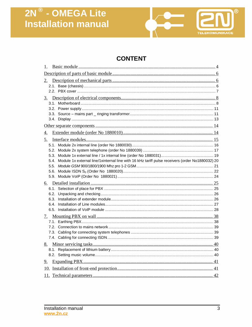
CONTENT
1. Basic module ................................................................................................................. 4 Description of parts of basic module ..................................................................................... 6 2. Description of mechanical parts ..................................................................................... 6
2.1. Base (chassis) ...................................................................................................................... 6 2.2. PBX cover ............................................................................................................................ 7
3. Description of electrical components.............................................................................. 8 3.1. Motherboard ......................................................................................................................... 8 3.2. Power supply ...................................................................................................................... 11 3.3. Source – mains part _ ringing transformer........................................................................... 11 3.4. Display ............................................................................................................................... 13
Other separate components ................................................................................................. 14 4. Extender module (order No 1880010) .......................................................................... 14 5. Interface modules......................................................................................................... 15
5.1. Module 2x internal line (order No 1880030)......................................................................... 16 5.2. Module 2x system telephone (order No 1880039) ............................................................... 17 5.3. Module 1x external line / 1x internal line (order No 1880031)............................................... 19 5.4. Module 1x external line/1xinternal line with 16 kHz tariff pulse receivers (order No1880032) 20 5.5. Module GSM 900/1800/1900 Mhz pro 1-2 GSM..................................................................... 21 5.6. Module ISDN S0 (Order No 1880020)................................................................................. 22 5.9. Module VoIP (Order No 1880021) ...................................................................................... 24
6. Detailed installation ..................................................................................................... 25 6.1. Selection of place for PBX .................................................................................................. 25 6.2. Unpacking and checking..................................................................................................... 26 6.3. Installation of extender module............................................................................................ 26 6.4. Installation of Line modules................................................................................................. 27 6.5. Installation of VoIP module ................................................................................................. 28
7. Mounting PBX on wall ................................................................................................ 38 7.1. Earthing PBX...................................................................................................................... 38 7.2. Connection to mains network .............................................................................................. 39 7.3. Cabling for connecting system telephones .......................................................................... 39 7.4. Cabling for connecting ISDN............................................................................................... 39
8. Minor servicing tasks ................................................................................................... 40 8.1. Replacement of lithium battery............................................................................................ 40 8.2. Setting music volume.......................................................................................................... 40
9. Expanding PBX ........................................................................................................... 41 10. Installation of front-end protection............................................................................... 41 11. Technical parameters ................................................................................................... 42

2N ® - OMEGA Lite Installation manual
Installation manual 4 www.2n.cz
1. Basic module
Types of basic modules 1880000 - basic module without modem for RemoteSupervision up to 24 lines 1880001 - basic module with modem for RemoteSupervision up to 24 lines
2N ® - OMEGA Lite Installation manual
Installation manual 5 www.2n.cz
In its assembled state, each basic module contains these parts: • chassis (metal part of mechanism) with power source • display • plastic cover • motherboard with or without modem for remote supervision (RS) • 1x platelet for power cable • 2x blanking platelets The following components are included: • Wall-mounting element (part of basic module) • Rawlplugs and screws for wall mounting • Power cable • Screws for fixing serial or blanking platelets It also contains this equipment: • CD with complete documentation and necessary SW • Serial cable with RJ-12 terminal and one gender changer for DB-9 connector
2N ® - OMEGA Lite Installation manual
Installation manual 6 www.2n.cz
Description of parts of basic module 2. Description of mechanical parts
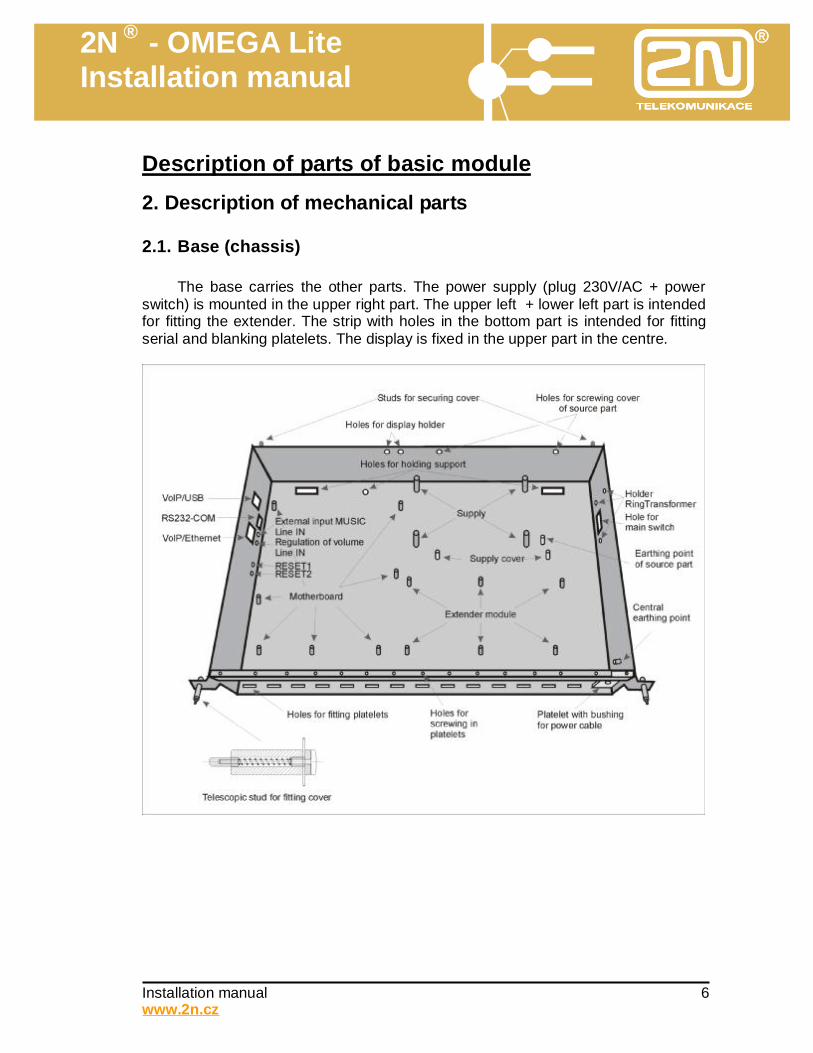
2.1. Base (chassis)
The base carries the other parts. The power supply (plug 230V/AC + power switch) is mounted in the upper right part. The upper left + lower left part is intended for fitting the extender. The strip with holes in the bottom part is intended for fitting serial and blanking platelets. The display is fixed in the upper part in the centre.

2N ® - OMEGA Lite Installation manual
Installation manual 7 www.2n.cz
2.2. PBX cover
The plastic cover bears a sticker with a transparent window for the display. The cover is fitted on the chassis by fitting into two holes in the upper part of
the plastic and is secured by two extendable “pegs” into the lower part of the plastic. When dismantling the cover, first press (using an appropriate tool) both
extendable “pegs”, whereby you free the cover and then remove the cover.
2N ® - OMEGA Lite Installation manual
Installation manual 8 www.2n.cz
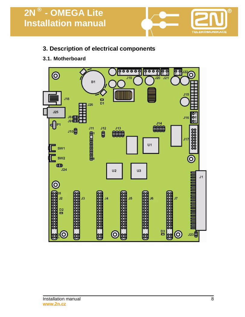
3. Description of electrical components 3.1. Motherboard
2N ® - OMEGA Lite Installation manual
Installation manual 9 www.2n.cz
B1 - Lithium battery holder. We recommend replacement when the voltage is lower than 2.5 V, or at least once every three years. We recommend the batteries be replaced with the PBX off. Before replacement we recommend saving the program of the PBX and the accounting data in a PC. After replacement check the date, time and program of the PBX and, if not correct, make the correct adjustment. Never change the batteries when the PBX is on. WARNING! Use only a tool made from insulating material for replacement!!!
J1 - connector for connecting extender J2 – J7 - connectors for connecting line modules (description of modules – see Chapter 5) J8 – J9 - shorting jumpers (connected – RS232-COM is connected to the J18 connector,
disconnected – RS232-COM is connected to the module VoIP) J10 - company’s servicing reanimation connector (1 Hz) J11 - connector for connecting additional memory for announcements (180 s) J12 - shorting jumper – always fitted (activation WATCH DOG) J13 - company’s servicing reanimation connector (SW for ALTERA) J14 - company’s servicing reanimation connector (SW for CPU) J15 - connector for connecting VoIP module J16 -.connector for connecting LED signalling J17 - connector for display J18 - connector RJ12 with galvanic isolation for PC connection (RS232-COM). J19 - input voltage connector – (1. +5V, 2.,4. GND, 3. +24V, 5. -24V, 6. RINGV). J20 - voltage connector – (1. RINGV, 2. -24V, 3. GND, 4. +24V) ). J21 - output voltage connector – (+24V DC). J22 - input voltage connector – (+24V DC). J23 - shorting jumper – always disconnected (only for testing purposes – connection
GND and PGND), J24 - servicing connector (locking of FLASH memory). J25 - line input (CINCH – AUX IN) for connecting external music source (for example
CD, radio). SW1 - Auxiliary RESET1 button (pressing results in reset). SW2 - Auxiliary RESET2 button (1. –setting company values (press button + switch on
PBX + confirm by pressing again after display of message “Clear config? - push again/wait“, 2. entry to “service mode” (hold button down during test of RAM memory).
P1 - regulating volume of line input. U1 - governing processor U2-3 - connecting cross-point array. D1 - signalling +5V D2 - signalling -12V D3 - signalling +12V
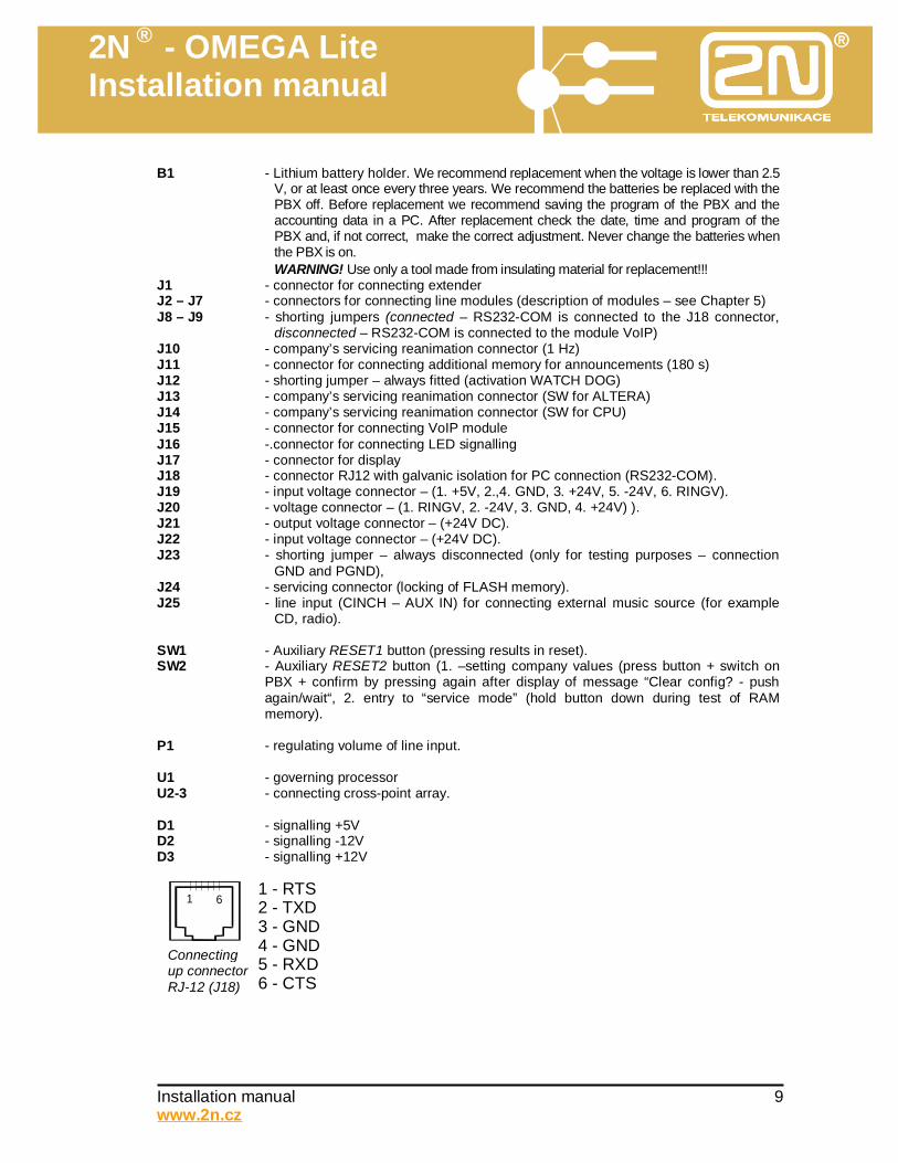
1 61 - RTS2 - TXD3 - GND4 - GND5 - RXD6 - CTS
Connecting up connector RJ-12 (J18)
2N ® - OMEGA Lite Installation manual
Installation manual 10 www.2n.cz
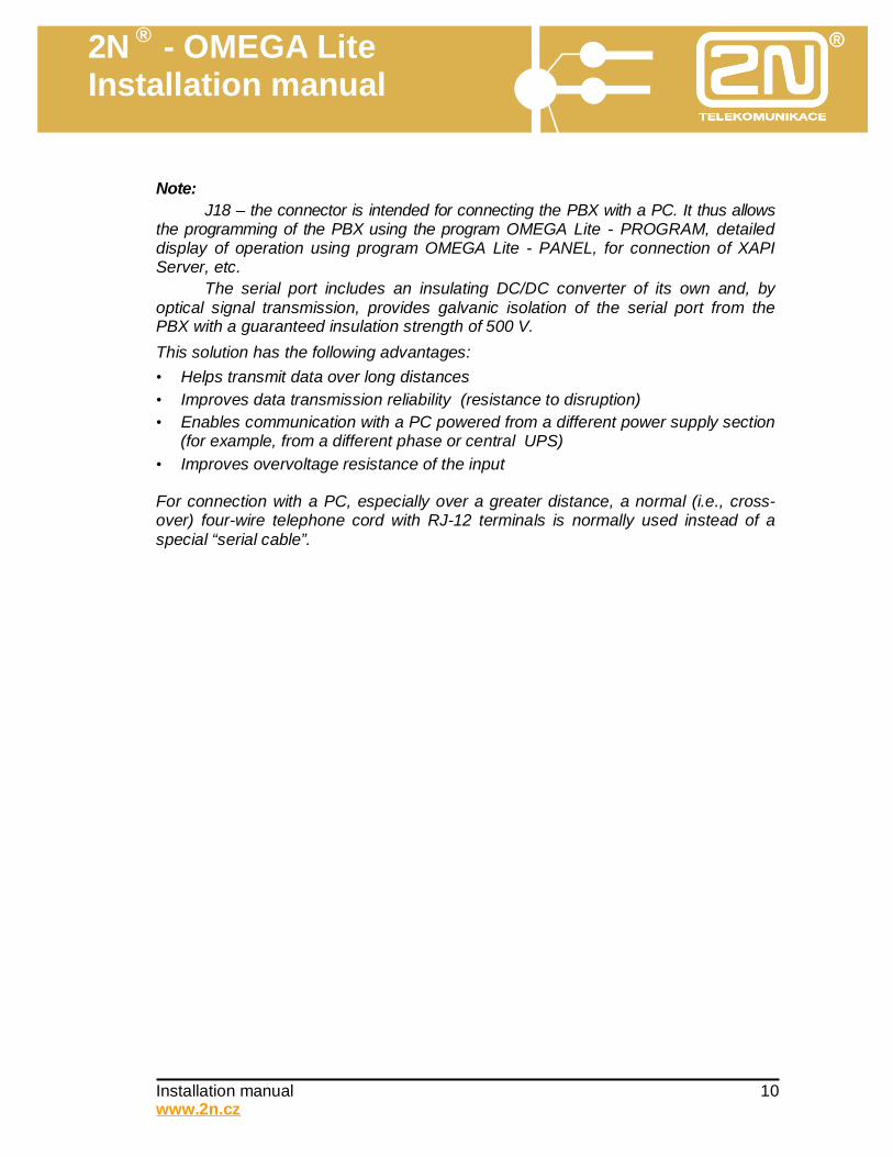
Note:
J18 – the connector is intended for connecting the PBX with a PC. It thus allows the programming of the PBX using the program OMEGA Lite - PROGRAM, detailed display of operation using program OMEGA Lite - PANEL, for connection of XAPI Server, etc.
The serial port includes an insulating DC/DC converter of its own and, by optical signal transmission, provides galvanic isolation of the serial port from the PBX with a guaranteed insulation strength of 500 V. This solution has the following advantages: • Helps transmit data over long distances • Improves data transmission reliability (resistance to disruption) • Enables communication with a PC powered from a different power supply section
(for example, from a different phase or central UPS) • Improves overvoltage resistance of the input For connection with a PC, especially over a greater distance, a normal (i.e., cross-over) four-wire telephone cord with RJ-12 terminals is normally used instead of a special “serial cable”.
2N ® - OMEGA Lite Installation manual
Installation manual 11 www.2n.cz
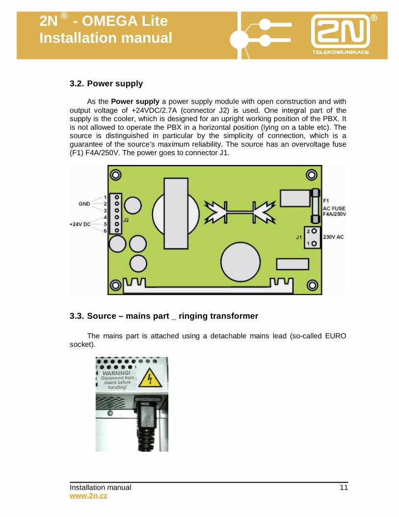
3.2. Power supply
As the Power supply a power supply module with open construction and with output voltage of +24VDC/2.7A (connector J2) is used. One integral part of the supply is the cooler, which is designed for an upright working position of the PBX. It is not allowed to operate the PBX in a horizontal position (lying on a table etc). The source is distinguished in particular by the simplicity of connection, which is a guarantee of the source’s maximum reliability. The source has an overvoltage fuse (F1) F4A/250V. The power goes to connector J1.
3.3. Source – mains part _ ringing transformer
The mains part is attached using a detachable mains lead (so-called EURO socket).
2N ® - OMEGA Lite Installation manual
Installation manual 12 www.2n.cz
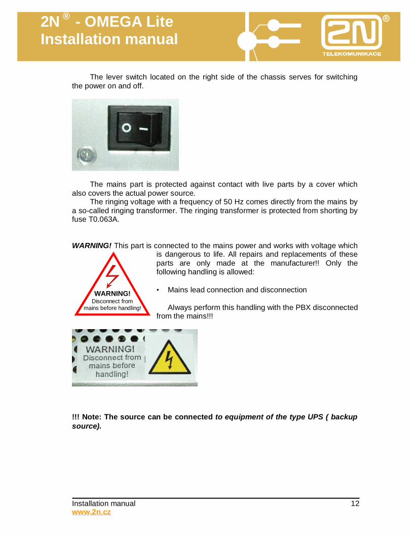
The lever switch located on the right side of the chassis serves for switching the power on and off.
The mains part is protected against contact with live parts by a cover which also covers the actual power source.
The ringing voltage with a frequency of 50 Hz comes directly from the mains by a so-called ringing transformer. The ringing transformer is protected from shorting by fuse T0.063A. WARNING! This part is connected to the mains power and works with voltage which
is dangerous to life. All repairs and replacements of these parts are only made at the manufacturer!! Only the following handling is allowed: • Mains lead connection and disconnection
Always perform this handling with the PBX disconnected from the mains!!!
!!! Note: The source can be connected to equipment of the type UPS ( backup source).
Disconnect from mains before handling!
WARNING!
2N ® - OMEGA Lite Installation manual
Installation manual 13 www.2n.cz
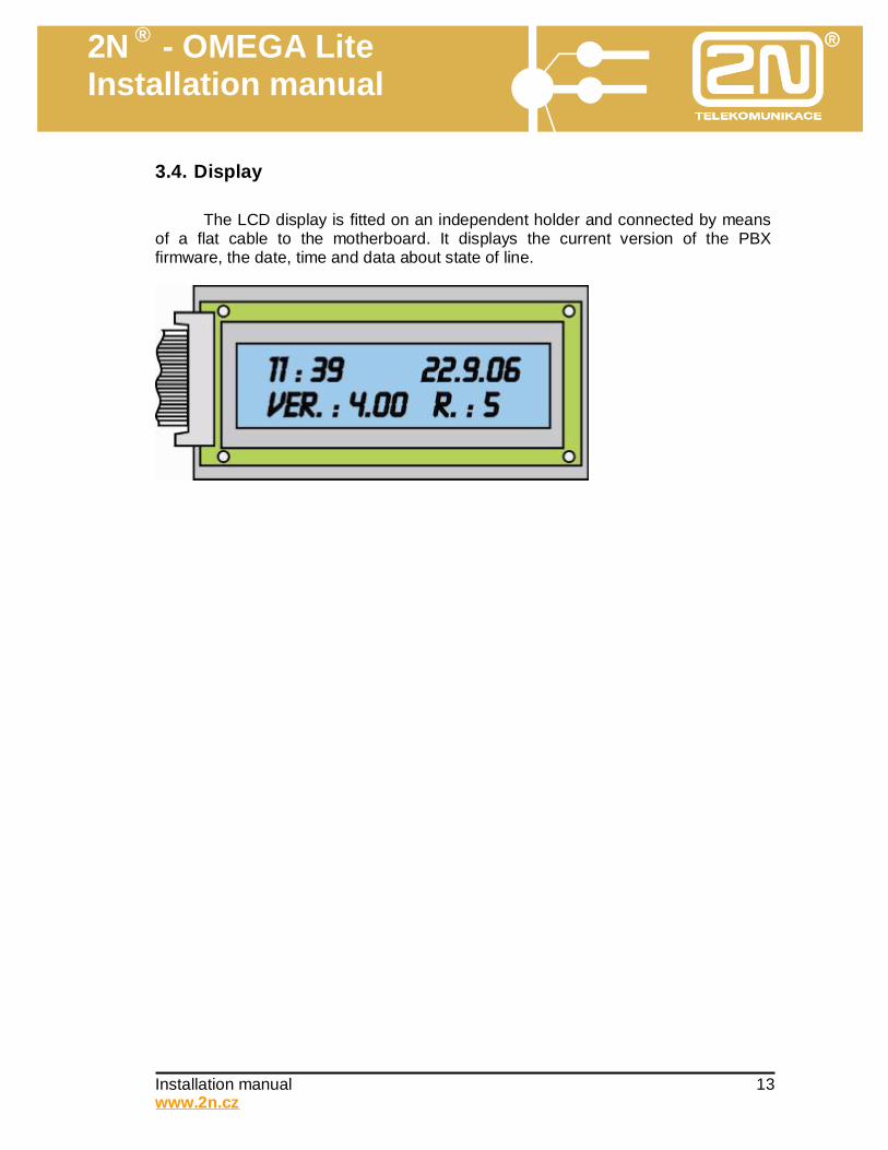
3.4. Display
The LCD display is fitted on an independent holder and connected by means of a flat cable to the motherboard. It displays the current version of the PBX firmware, the date, time and data about state of line.
2N ® - OMEGA Lite Installation manual
Installation manual 14 www.2n.cz
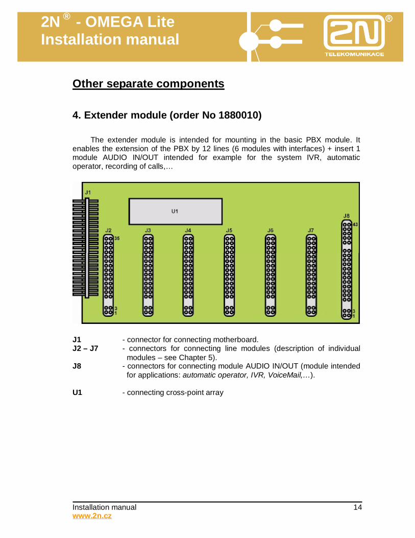
Other separate components 4. Extender module (order No 1880010)
The extender module is intended for mounting in the basic PBX module. It enables the extension of the PBX by 12 lines (6 modules with interfaces) + insert 1 module AUDIO IN/OUT intended for example for the system IVR, automatic operator, recording of calls,…
J1 - connector for connecting motherboard. J2 – J7 - connectors for connecting line modules (description of individual
modules – see Chapter 5). J8 - connectors for connecting module AUDIO IN/OUT (module intended
for applications: automatic operator, IVR, VoiceMail,…). U1 - connecting cross-point array
2N ® - OMEGA Lite Installation manual
Installation manual 15 www.2n.cz
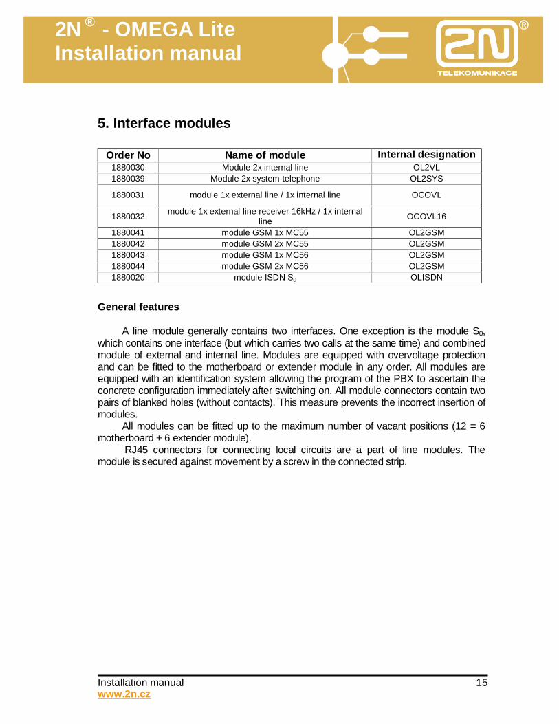
5. Interface modules
Order No Name of module Internal designation 2N 1880030 Module 2x internal line OL2VL
1880039 Module 2x system telephone OL2SYS
1880031 module 1x external line / 1x internal line OCOVL
1880032 module 1x external line receiver 16kHz / 1x internal line OCOVL16
1880041 module GSM 1x MC55 OL2GSM 1880042 module GSM 2x MC55 OL2GSM 1880043 module GSM 1x MC56 OL2GSM 1880044 module GSM 2x MC56 OL2GSM 1880020 module ISDN S0 OLISDN
General features
A line module generally contains two interfaces. One exception is the module S0, which contains one interface (but which carries two calls at the same time) and combined module of external and internal line. Modules are equipped with overvoltage protection and can be fitted to the motherboard or extender module in any order. All modules are equipped with an identification system allowing the program of the PBX to ascertain the concrete configuration immediately after switching on. All module connectors contain two pairs of blanked holes (without contacts). This measure prevents the incorrect insertion of modules.
All modules can be fitted up to the maximum number of vacant positions (12 = 6 motherboard + 6 extender module).
RJ45 connectors for connecting local circuits are a part of line modules. The module is secured against movement by a screw in the connected strip.
2N ® - OMEGA Lite Installation manual
Installation manual 16 www.2n.cz
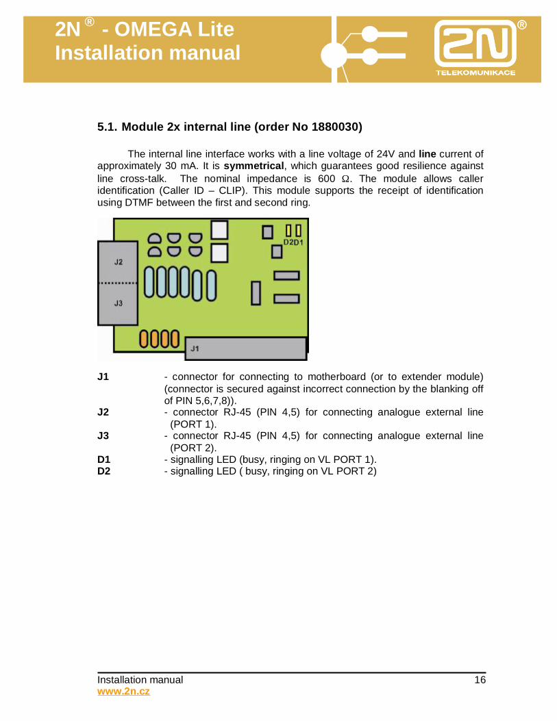
5.1. Module 2x internal line (order No 1880030)
The internal line interface works with a line voltage of 24V and line current of approximately 30 mA. It is symmetrical, which guarantees good resilience against line cross-talk. The nominal impedance is 600 Ω. The module allows caller identification (Caller ID – CLIP). This module supports the receipt of identification using DTMF between the first and second ring.
J1 - connector for connecting to motherboard (or to extender module)
(connector is secured against incorrect connection by the blanking off of PIN 5,6,7,8)).
J2 - connector RJ-45 (PIN 4,5) for connecting analogue external line (PORT 1).
J3 - connector RJ-45 (PIN 4,5) for connecting analogue external line (PORT 2).
D1 - signalling LED (busy, ringing on VL PORT 1). D2 - signalling LED ( busy, ringing on VL PORT 2)
2N ® - OMEGA Lite Installation manual
Installation manual 17 www.2n.cz
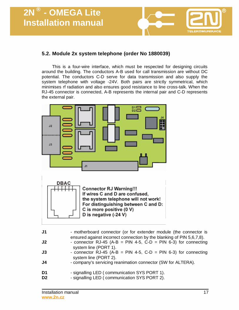
5.2. Module 2x system telephone (order No 1880039)
This is a four-wire interface, which must be respected for designing circuits around the building. The conductors A-B used for call transmission are without DC potential. The conductors C-D serve for data transmission and also supply the system telephone with voltage -24V. Both pairs are strictly symmetrical, which minimises rf radiation and also ensures good resistance to line cross-talk. When the RJ-45 connector is connected, A-B represents the internal pair and C-D represents the external pair.
J1 - motherboard connector (or for extender module (the connector is
ensured against incorrect connection by the blanking of PIN 5,6,7,8). J2 - connector RJ-45 (A-B = PIN 4-5, C-D = PIN 6-3) for connecting
system line (PORT 1). J3 - connector RJ-45 (A-B = PIN 4-5, C-D = PIN 6-3) for connecting
system line (PORT 2). J4 - company’s servicing reanimation connector (SW for ALTERA). D1 - signalling LED ( communication SYS PORT 1). D2 - signalling LED ( communication SYS PORT 2).
2N ® - OMEGA Lite Installation manual
Installation manual 18 www.2n.cz
Notes: • In no case may system telephones be connected in parallel. • LEDs (D1,D2) on the module signal by flashing ongoing communication between the
PBX and system telephone. • If the C and D connectors are confused in the system cabling, the system telephone will
not work but will not be damaged. • The module is provided with its “own intelligence” – a processor that time balances the
data flow between the main PBX processor and both system telephones. This single-chip microcomputer is mounted in a socket and can be replaced if necessary.
2N ® - OMEGA Lite Installation manual
Installation manual 19 www.2n.cz
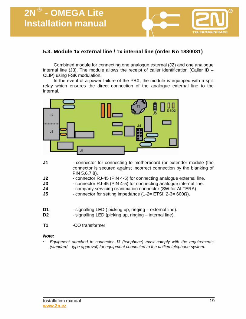
5.3. Module 1x external line / 1x internal line (order No 1880031)
Combined module for connecting one analogue external (J2) and one analogue internal line (J3). The module allows the receipt of caller identification (Caller ID – CLIP) using FSK modulation.
In the event of a power failure of the PBX, the module is equipped with a spill relay which ensures the direct connection of the analogue external line to the internal.
J1 - connector for connecting to motherboard (or extender module (the
connector is secured against incorrect connection by the blanking of PIN 5,6,7,8).
J2 - connector RJ-45 (PIN 4-5) for connecting analogue external line. J3 - connector RJ-45 (PIN 4-5) for connecting analogue internal line. J4 - company servicing reanimation connector (SW for ALTERA). J5 - connector for setting impedance (1-2= ETSI, 2-3= 600Ω). D1 - signalling LED ( picking up, ringing – external line). D2 - signalling LED (picking up, ringing – internal line). T1 -CO transformer Note: • Equipment attached to connector J3 (telephone) must comply with the requirements
(standard – type approval) for equipment connected to the unified telephone system.
2N ® - OMEGA Lite Installation manual
Installation manual 20 www.2n.cz
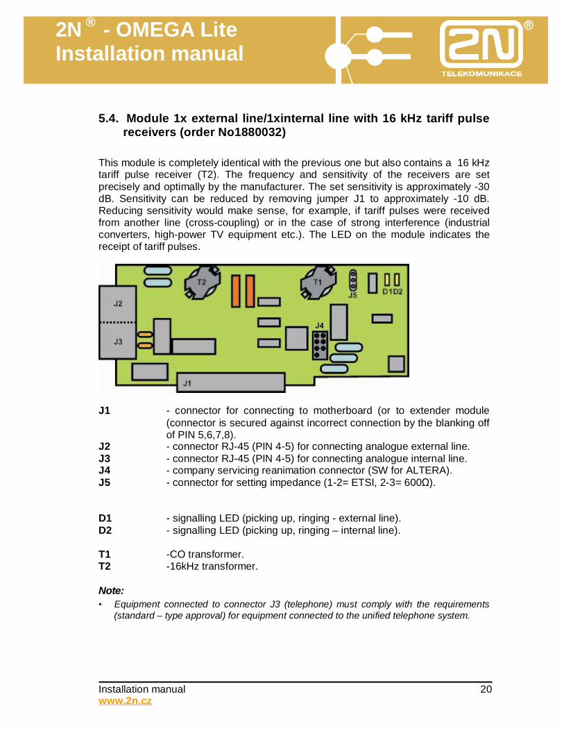
5.4. Module 1x external line/1xinternal line with 16 kHz tariff pulse
receivers (order No1880032) This module is completely identical with the previous one but also contains a 16 kHz tariff pulse receiver (T2). The frequency and sensitivity of the receivers are set precisely and optimally by the manufacturer. The set sensitivity is approximately -30 dB. Sensitivity can be reduced by removing jumper J1 to approximately -10 dB. Reducing sensitivity would make sense, for example, if tariff pulses were received from another line (cross-coupling) or in the case of strong interference (industrial converters, high-power TV equipment etc.). The LED on the module indicates the receipt of tariff pulses.
J1 - connector for connecting to motherboard (or to extender module
(connector is secured against incorrect connection by the blanking off of PIN 5,6,7,8).
J2 - connector RJ-45 (PIN 4-5) for connecting analogue external line. J3 - connector RJ-45 (PIN 4-5) for connecting analogue internal line. J4 - company servicing reanimation connector (SW for ALTERA). J5 - connector for setting impedance (1-2= ETSI, 2-3= 600Ω). D1 - signalling LED (picking up, ringing - external line). D2 - signalling LED (picking up, ringing – internal line). T1 -CO transformer. T2 -16kHz transformer. Note: • Equipment connected to connector J3 (telephone) must comply with the requirements
(standard – type approval) for equipment connected to the unified telephone system.
2N ® - OMEGA Lite Installation manual
Installation manual 21 www.2n.cz
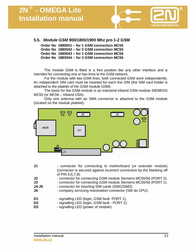
5.5. Module GSM 900/1800/1900 Mhz pro 1-2 GSM Order No 1880041 – for 1 GSM connection MC55 Order No 1880042 – for 2 GSM connection MC55 Order No 1880043 – for 1 GSM connection MC56 Order No 1880044 – for 2 GSM connection MC56
The module GSM is fitted in a free position like any other interface and is intended for connecting one or two lines to the GSM network.
For the module with two GSM lines, both connected GSM work independently. An independent SIM card must be inserted for each line SIM (the SIM card holder is attached to the platelet of the GSM module GSM).
The basis for the GSM module is an industrial triband GSM module SIEMENS MC55 (or MC56 – triband USA).
Only one antenna with an SMA connector is attached to the GSM module (located on the module platelet).
J1 - connector for connecting to motherboard (or extender module)
(connector is secured against incorrect connection by the blanking off of PIN 5,6,7,8).
J2 - connector for connecting GSM module Siemens MC55/56 (PORT 2). J3 - connector for connecting GSM module Siemens MC55/56 (PORT 1). J4-J5 - connector for inserting SIM cards (SIM1/SIM2) J6 - company servicing reanimation connector (SW do CPU). D1 - signalling LED (login, GSM fault- PORT 1). D2 - signalling LED (login, GSM fault - PORT 2). D3 - signalling LED (power of module).
2N ® - OMEGA Lite Installation manual
Installation manual 22 www.2n.cz
The GSM module makes it possible to: • automatically make calls to the GSM network and thus significant reduction in
telephone bill of your firm. • receive incoming calls and, in connection with the DISA code distribute them to the
branches (analogue internal lines, system lines). • When calls are made to the GSM network, to utilise all the services of the PBX
(reconnecting call, conference, rerouting, CLIP-called number display and its entry on record).
In the current form the module does not make it possible to: • convert a fax GSM connection to an analogue fax connected to the PBX, • convert a data GSM connection to an analogue modem connected to the PBX.
5.6. Module ISDN S0 (Order No 1880020)
The module contains two four-wire interfaces BRI or 2B+D (1x ISDN input, 1x ISDN BUS), and so two calls can pass through it simultaneously. It is intended for connecting to the public ISDN network and supports connection in the regime PTP and PTMP. • In the regime PTP (Point to Point) the code DDI is supported (i.e., as many
sequential numbers as the user requests of the ISDN provider). It is not possible to attach any further ISDN equipment to the line. The advantage is the possibility of merging capacity – when several ISDN modules are fitted they can all have the same code.
• In the regime PTMP (Point to MultiPoint) MSN is supported (i.e., upon request it is possible to allocate up to eight numbers, but it need not be a continuous series of numbers). It is possible to connect further ISDN equipment to the line (for example, ISDN card in computer – one number, on the module up to seven numbers will remain).
We recommend that overvoltage protection be installed to prevent destruction of the ISDN module by overvoltage. The control program of the module is stored in a FLASH memory which enables
the updating of the program directly in the PBX. One of the input RJ45 connectors can be used for simpler creation of an ISDN
bus and thus for the connection of further ISDN equipment (ISDN telephone, fax, modem).
2N ® - OMEGA Lite Installation manual
Installation manual 23 www.2n.cz
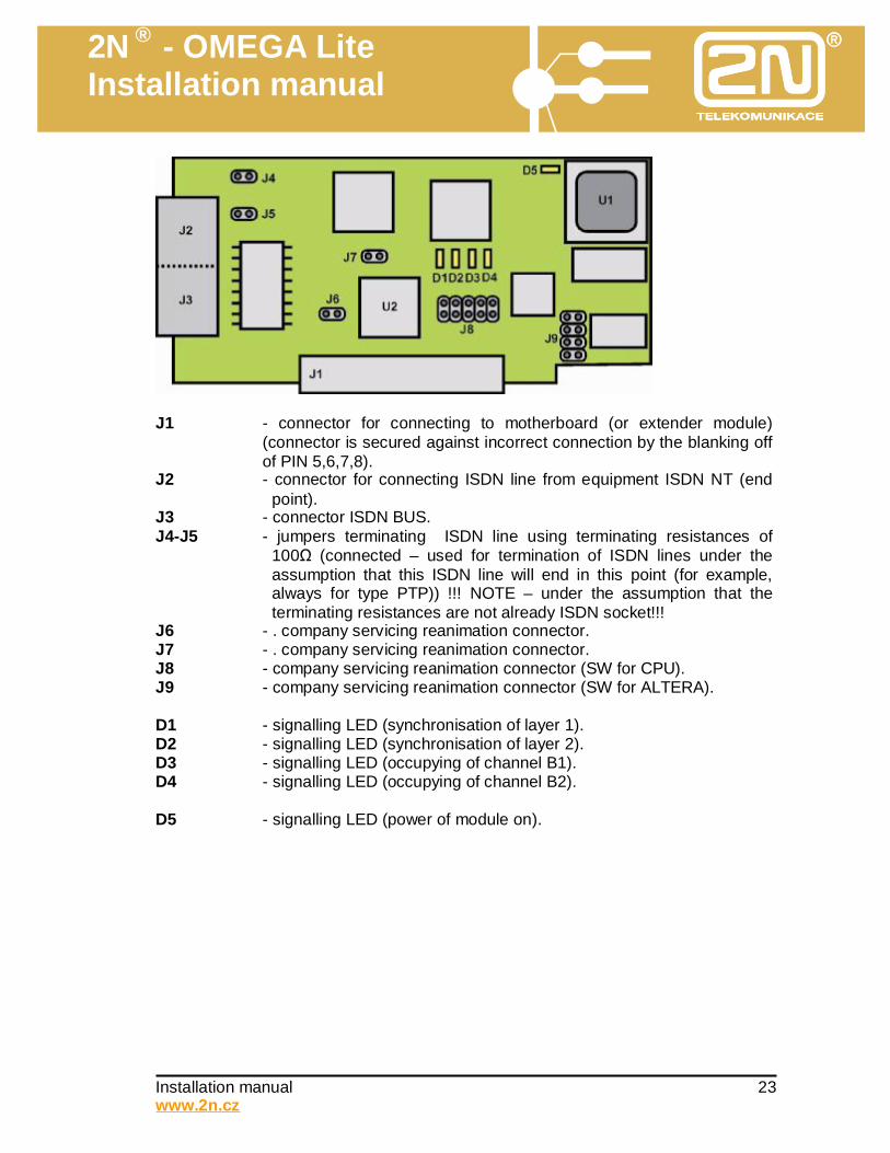
J1 - connector for connecting to motherboard (or extender module)
(connector is secured against incorrect connection by the blanking off of PIN 5,6,7,8).
J2 - connector for connecting ISDN line from equipment ISDN NT (end point).
J3 - connector ISDN BUS. J4-J5 - jumpers terminating ISDN line using terminating resistances of
100Ω (connected – used for termination of ISDN lines under the assumption that this ISDN line will end in this point (for example, always for type PTP)) !!! NOTE – under the assumption that the terminating resistances are not already ISDN socket!!!
J6 - . company servicing reanimation connector. J7 - . company servicing reanimation connector. J8 - company servicing reanimation connector (SW for CPU). J9 - company servicing reanimation connector (SW for ALTERA). D1 - signalling LED (synchronisation of layer 1). D2 - signalling LED (synchronisation of layer 2). D3 - signalling LED (occupying of channel B1). D4 - signalling LED (occupying of channel B2). D5 - signalling LED (power of module on).
2N ® - OMEGA Lite Installation manual
Installation manual 24 www.2n.cz
5.7.
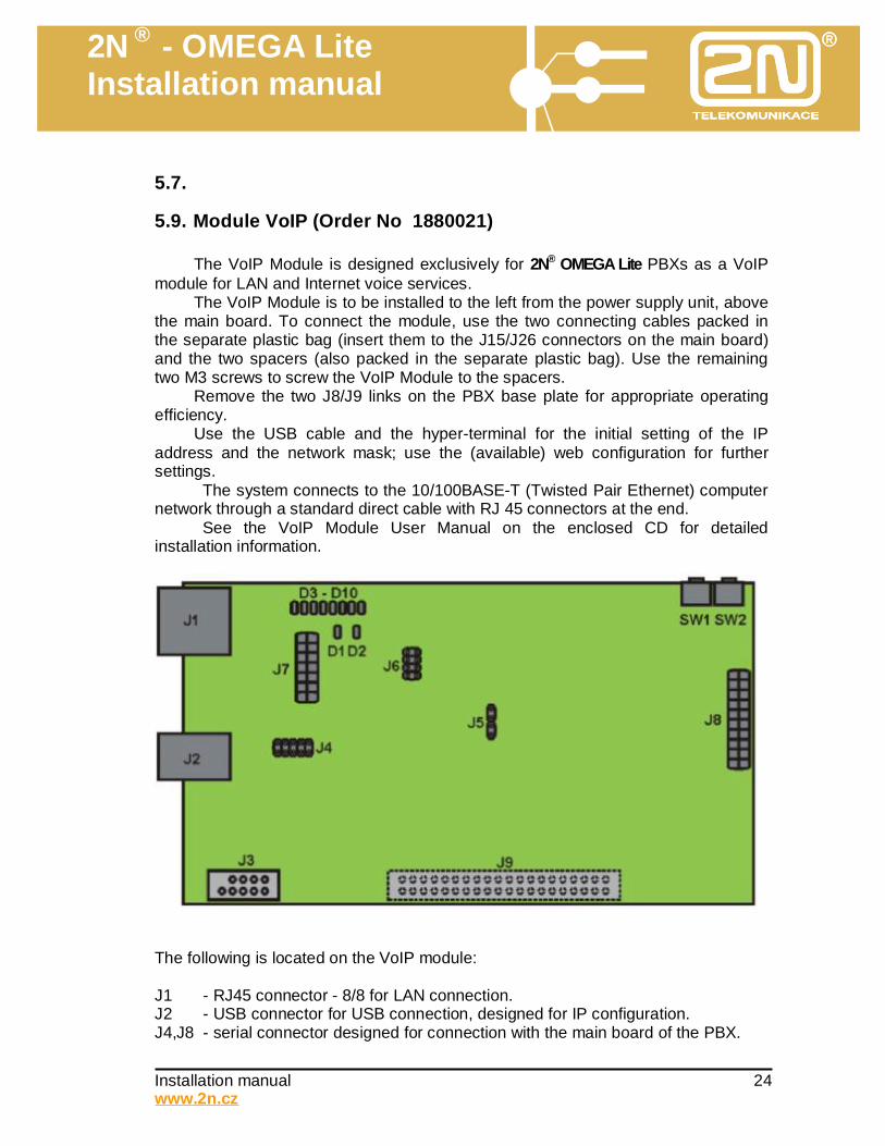
5.9. Module VoIP (Order No 1880021)
The VoIP Module is designed exclusively for 2N® OMEGA Lite PBXs as a VoIP module for LAN and Internet voice services.
The VoIP Module is to be installed to the left from the power supply unit, above the main board. To connect the module, use the two connecting cables packed in the separate plastic bag (insert them to the J15/J26 connectors on the main board) and the two spacers (also packed in the separate plastic bag). Use the remaining two M3 screws to screw the VoIP Module to the spacers.
Remove the two J8/J9 links on the PBX base plate for appropriate operating efficiency.
Use the USB cable and the hyper-terminal for the initial setting of the IP address and the network mask; use the (available) web configuration for further settings.
The system connects to the 10/100BASE-T (Twisted Pair Ethernet) computer network through a standard direct cable with RJ 45 connectors at the end.
See the VoIP Module User Manual on the enclosed CD for detailed installation information.
The following is located on the VoIP module: J1 - RJ45 connector - 8/8 for LAN connection. J2 - USB connector for USB connection, designed for IP configuration. J4,J8 - serial connector designed for connection with the main board of the PBX.
2N ® - OMEGA Lite Installation manual
Installation manual 25 www.2n.cz
J3 - connector for the connection of adapter for an external USB device (USB FLASH disk)*. J5-J7 - connector for maintenance use J9 - connector for connection of a functional floor* SW1 - RESET button. Pressing this button will RESET the CPU board. SW2 - RESET button. Pressing this button will reset default values (after switching on the PBX hold the button pressed for approximately 20s until LINUX starts). D1 - green LED – operation status indication (VoIP module ready for operation, approximately 20s after light-up). D2 - red LED – operation status indication (VoIP module inactive). D3-D10 - yellow LED – call channels busy signal. * In preparation Detailed installation
6.1. Selection of place for PBX Aspects which must be taken into consideration when selecting a place for the PBX: • Good visibility and accessibility (the exact time and other data about operation is
shown in the display of the PBX in operation). • Protection from damp and extreme temperatures: the PBX must definitely
not be located near heat sources (above heaters) or in a place where direct sunlight may fall. Also avoid damp places (bathroom, cellar), places where the temperature changes rapidly (near doors, windows, air-conditioning), dusty places (workshops etc) or places with aggressive gases (battery rooms, boiler rooms) and places with high vibrations and shocks (compressors, heavy industrial operations). The PBX has an upright operating position.
• Installing circuits in building: by choosing a suitable location for the PBX (centre of building or administrative centre) it is possible to reduce the costs for the building of the circuits. If there are already circuits in the building, the location of the PBX is generally already determined thereby and it cannot be changed.
• Possibility of direct connection using modules with connectors RJ-45. • Quality of GSM signal: if one part of your configuration is (or later will be) a GSM
module, it is necessary to take into account the fact that the cable from the PBX to the GSM cable is usually about 3 metres long (maximum 10m). It is therefore necessary to make sure that in the specified circuit around the selected place for the PBX there is a place with a good level of GSM signal suitable for locating the GSM antenna. *)
• Ensuring against theft: when selecting a position, it is recommended that the conditions of the insurance company be respected.
• Opening cover: there should be at least 10 cm of free space right and left of the PBX.
2N ® - OMEGA Lite Installation manual
Installation manual 26 www.2n.cz
Note: In places with a poor level of GSM signal it is possible to use an independent (external) GSM gateway which can be installed at a distance of up to 500 m from the PBX (!) in a place with a good GSM signal (on high building, hill etc.) and ensure both cheap access to the GSM network and reliable function in places where there is very poor coverage (borderline areas).
6.2. Unpacking and checking
If you haven’t yet done so, check that the delivery is complete. The packaging of the basic module is usually used for the transport of other independently purchased items of the PBX (modules etc.). You can usually check them using the delivery note and order numbers which are on all parts. The remaining components in the upper part of the box are the accessories of the basic module. Remove the separate basic module from the upper part. Open it and check everything against the packing sheet, which is a separate annex to the documentation. Check whether there was any mechanical damage to the parts during shipping. On the top of the box there is a printed reinforcing piece which serves as a drilling template for the mounting of the PBX. Keep the packaging (especially from the extender modules).
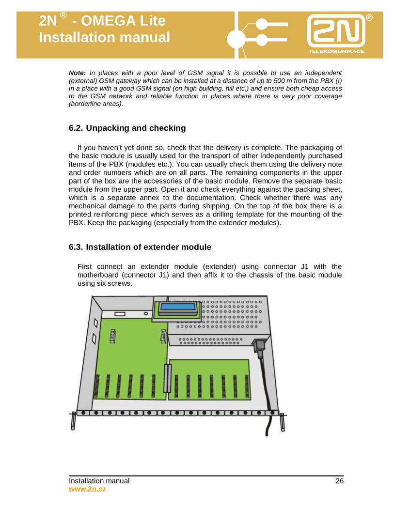
6.3. Installation of extender module
First connect an extender module (extender) using connector J1 with the motherboard (connector J1) and then affix it to the chassis of the basic module using six screws.
2N ® - OMEGA Lite Installation manual
Installation manual 27 www.2n.cz
6.4. Installation of Line modules Note: All modules can be fitted separately even after the PBX is mounted on the wall, but it is more comfortable to fit them on a table. Line modules can be fitted in any position on the motherboard (connectors J2-J7) or extender module (connectors J2-J7).
2N ® - OMEGA Lite Installation manual
Installation manual 28 www.2n.cz
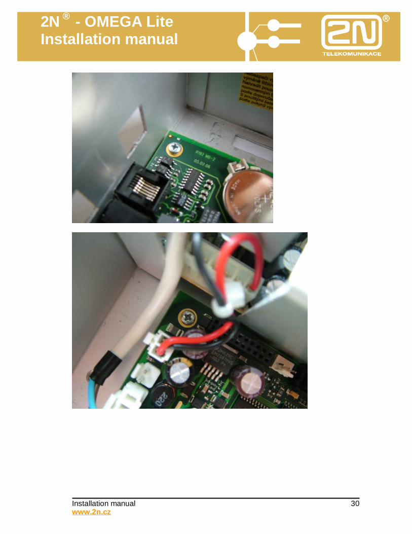
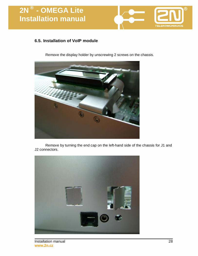
6.5. Installation of VoIP module Remove the display holder by unscrewing 2 screws on the chassis.
Remove by turning the end cap on the left-hand side of the chassis for J1 and J2 connectors.
2N ® - OMEGA Lite Installation manual
Installation manual 29 www.2n.cz
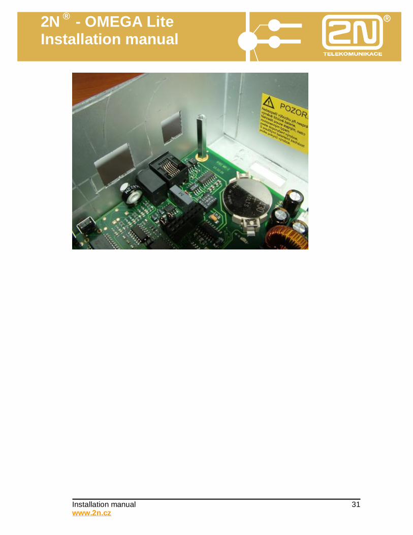
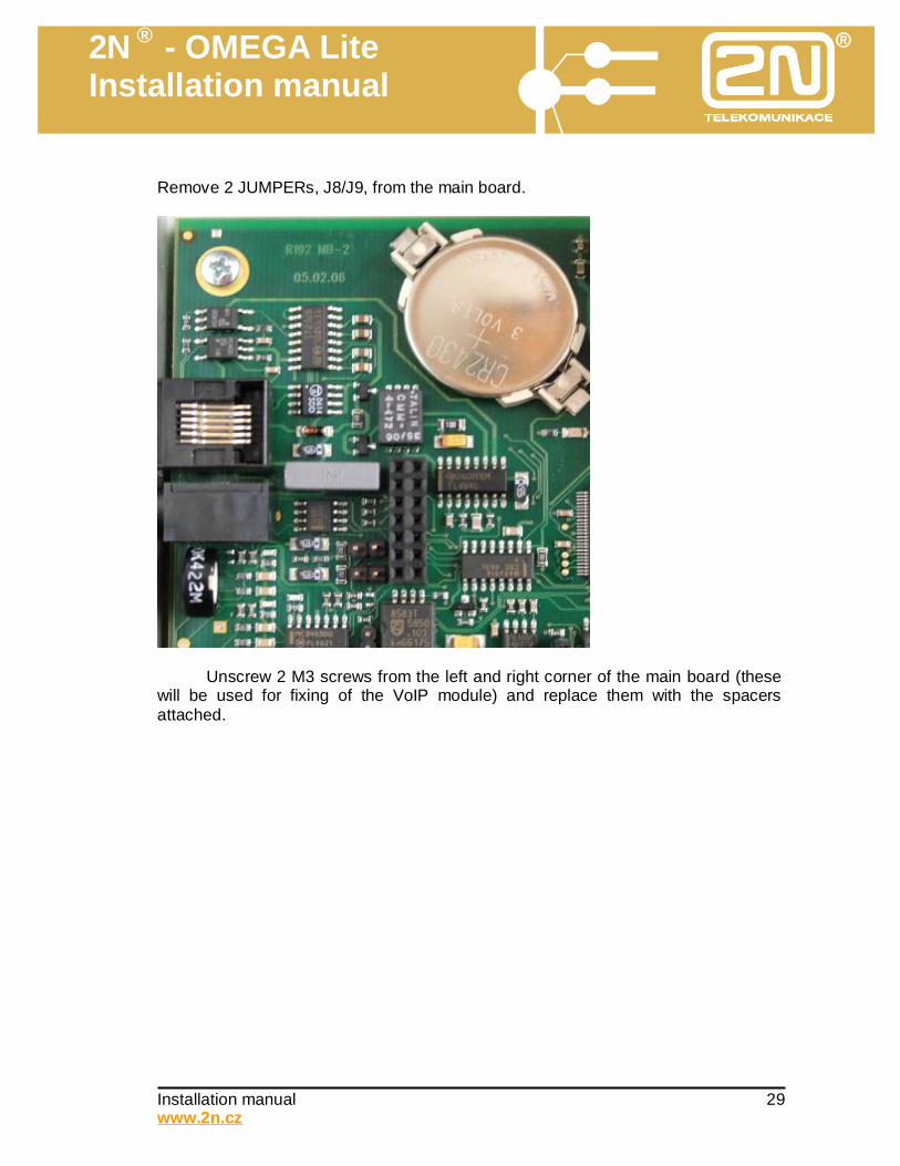
Remove 2 JUMPERs, J8/J9, from the main board.
Unscrew 2 M3 screws from the left and right corner of the main board (these will be used for fixing of the VoIP module) and replace them with the spacers attached.
2N ® - OMEGA Lite Installation manual
Installation manual 32 www.2n.cz
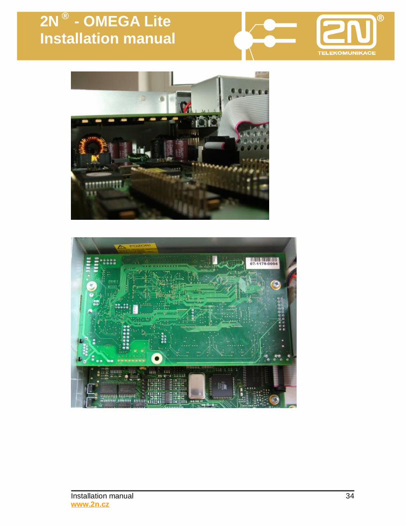
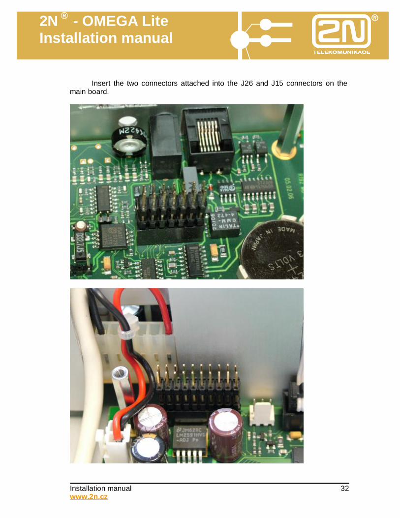
Insert the two connectors attached into the J26 and J15 connectors on the main board.
2N ® - OMEGA Lite Installation manual
Installation manual 33 www.2n.cz
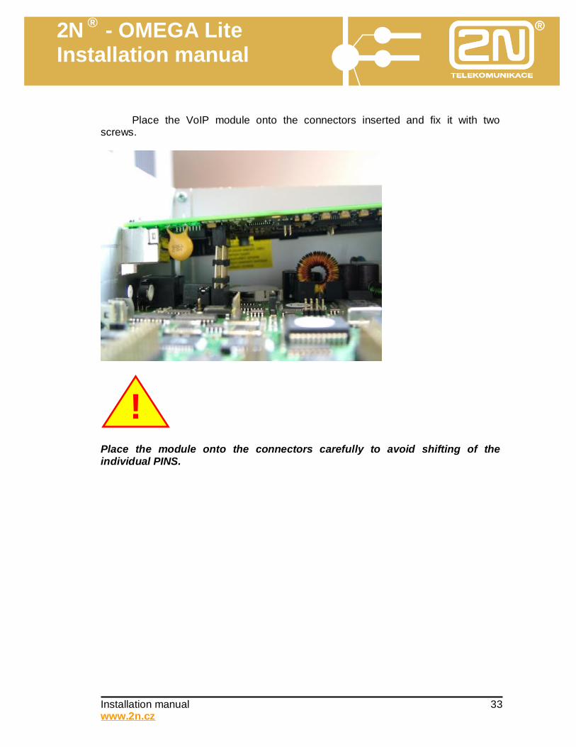
Place the VoIP module onto the connectors inserted and fix it with two screws.
Place the module onto the connectors carefully to avoid shifting of the individual PINS.
!
2N ® - OMEGA Lite Installation manual
Installation manual 36 www.2n.cz
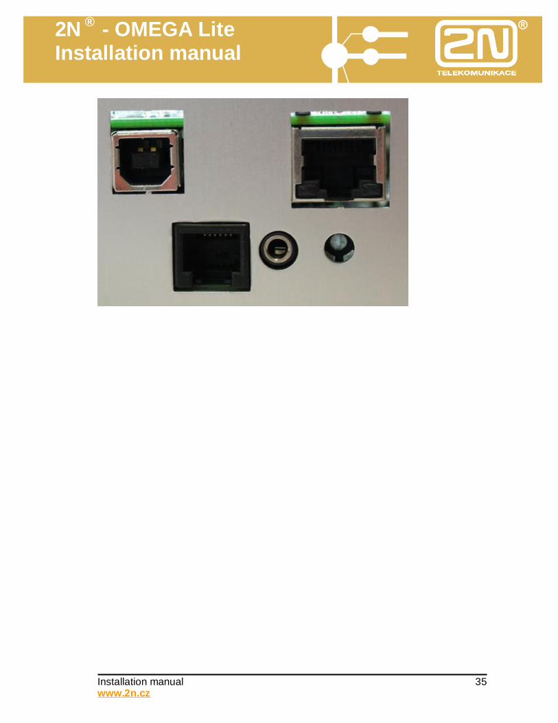
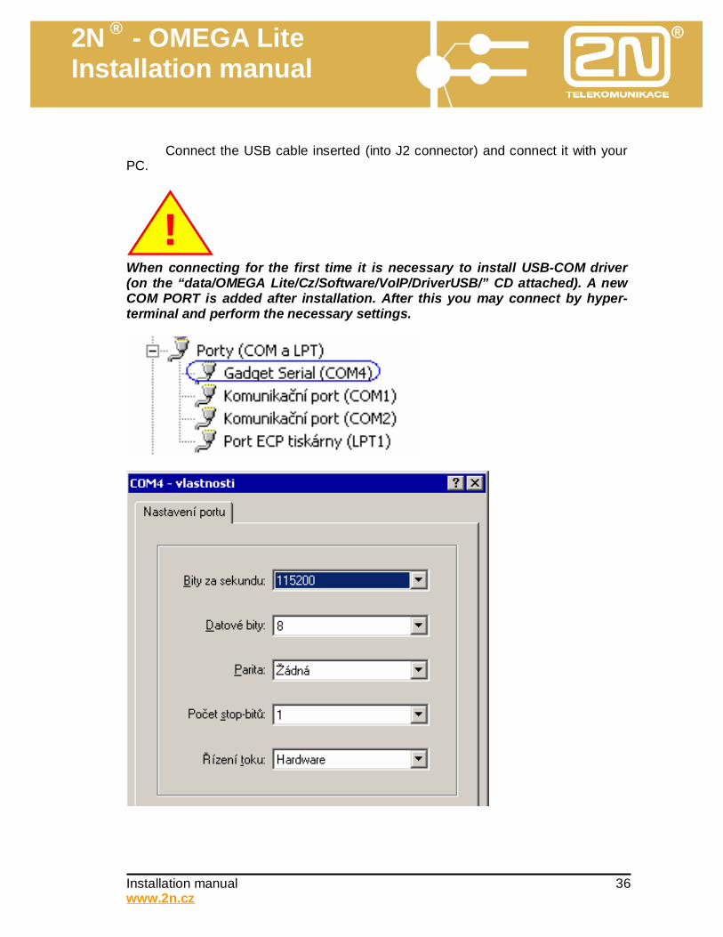
Connect the USB cable inserted (into J2 connector) and connect it with your
PC.
When connecting for the first time it is necessary to install USB-COM driver (on the “data/OMEGA Lite/Cz/Software/VoIP/DriverUSB/” CD attached). A new COM PORT is added after installation. After this you may connect by hyper-terminal and perform the necessary settings.
!
2N ® - OMEGA Lite Installation manual
Installation manual 37 www.2n.cz
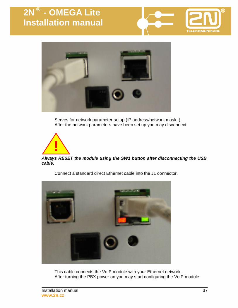
Serves for network parameter setup (IP address/network mask,.). After the network parameters have been set up you may disconnect.
Always RESET the module using the SW1 button after disconnecting the USB cable. Connect a standard direct Ethernet cable into the J1 connector.
This cable connects the VoIP module with your Ethernet network. After turning the PBX power on you may start configuring the VoIP module.
!

2N ® - OMEGA Lite Installation manual
Installation manual 38 www.2n.cz
7. Mounting PBX on wall
Using the drilling template (on scale 1:1), mark two holes on the wall (for requirements for location see above, paragraph Selection of location for PBX). Using an 8 mm masonry bit, drill holes and put rawlplugs in them. Screw the hanging element of the PBX into the upper holes using two screws (it is fixed to the chassis on delivery). Hang the PBX and secure it against being knocked off by screwing the (screw M3) chassis to the hanging element. Finally add the cover.
7.1. Earthing PBX
As has already been stated, good earthing of the PBX chassis is very important for the good functioning of the overvoltage protectors on the line modules. The PBX is naturally also earthed through the mains network (as a result of the earth wire – if it is connected to the plug). But this is not enough – for one thing in view of the danger that the PBX could be easily disconnected from the mains (the overvoltage from any line would then easily spread toe the chassis of the PBX and from there to all other lines!), and the principle applies that earthing should be as good as possible. The ideal solution is thus a yellow-green copper wire with a cross section of at least 4 mm2, leading for example from an earthing strip in the main switchbox. In an emergency it is necessary to at least earth it using such a wire (i.e., not
2N ® - OMEGA Lite Installation manual
Installation manual 39 www.2n.cz
disconnectable) from the nearest power socket (and check that it is correctly connected). Attach the wire to the chassis on the earth clamp on the right side of the chassis (marked with the earth symbol) and tighten well. We recommend that the earth always be connected before other cabling!!!
7.2. Connection to mains network
The detachable EURO-lead serves for connection to a regular socket. This makes it possible, if necessary, to rather elegantly make the lead longer with an extension EURO lead (used, for example, for connecting a PC and monitor). This extension also fits into the installation strip, for example 4x4 cm with other cables. The power lead can be run from the PBX through the hole in the power platelet with a hole and leads to the socket freely or through the strip.
7.3. Cabling for connecting system telephones
Every system telephone is connected to the PBX by a four-wire cable. The wires are marked A, B (call) and C, D (power + data both ways). For a system telephone to work, it is necessary not to swap the individual wires! If correct telephone cable is used (four-wire cross cable), this condition is met.
(you can tell if a cable is crossed by putting both transparent terminals next to each other pointing in the same direction, the coloured wire in both terminals are in the opposite order) If this connection does not work, the connectors probably do not have identical connection of terminals.
7.4. Cabling for connecting ISDN
According to the standard, the subscriber termination of line ISDN (NT1, NTBA (Network Termination Basic Access) is fitted with a connector RJ-45 with eight contacts. The module ISDN in the PBX is also equipped with the connector RJ-45, which can be used if the distance is not greater than 3 m. In this case it is necessary to use four-wire non-crossed cable with terminals RJ-45.
(you can tell if a cable is not crossed by putting both transparent terminals next to each other pointing in the same direction, the coloured wire in both terminals are in the same order)
If this connection does not work, the connectors probably do not have identical connection of terminals.
2N ® - OMEGA Lite Installation manual
Installation manual 40 www.2n.cz
8. Minor servicing tasks
8.1. Replacement of lithium battery
The battery must be replaced if its voltage drops below 2.5 V. But we recommend that the battery be replaced at least once every three years, even if its voltage is correct. We recommend that the battery be replaced with the PBX switched off. Before changing the battery, we recommend saving the program of the PBX and the accounting data to a PC. After changing the battery, check the date, time and programme of the PBX, and if this data is not correct, perform a correction of the setting. In this case we recommend that this task be performed only when no one is using the telephone.
WARNING! Use only a tool made from insulating material for replacement!
WARNING! Danger of explosion in case of incorrect battery replacement. It is only possible to replace a battery using one of the same or equivalent type
according to the manufacturers recommendation. Always handle used batteries according to the manufacturer’s instructions.
8.2. Setting music volume
On the motherboard there is a regulator for the volume of the external music source (connector J25). This task can be performed with the PBX switched on. In view of the miniature dimensions of the components, it is necessary to use a suitable tool (for example, precision screwdriver) and the appropriately light force.
2N ® - OMEGA Lite Installation manual
Installation manual 41 www.2n.cz
9. Expanding PBX
The PBX can be expanded as desired by buying further modules up to the maximum configuration (24 lines). But it is necessary to be aware that every expansion constitutes intervention in the installation, and if done inexpertly it could threaten the functioning of the whole. In other words, the same level of knowledge as for the complete installation is required for this activity.
There exist two possible methods: 1. Complete reinstallation of PBX – the advantage is the clarity of the procedure
and optimum result, the disadvantage is the amount of work involved. 2. Addition of new modules without intervention in original part. The result is not
always optimal, but there is less work. It is once again necessary to proceed according to the same rules which apply for the installation of a new PBX.
When expanding the PBX by either of the above methods, it is necessary to adhere to this procedure:
1. Before starting work, make backup copies of the PBX programming and
accounting data. 2. Before starting work, check that all lines work. 3. Respect the warranty conditions. 4. Use only new or tested modules. 5. First of all decide on the location of modules on paper. 6. Mount all modules. 7. Add cabling. 8. After the actual installation, retest the function of all lines – new and original. 9. It is always necessary to programme the new configuration again. 10. Test all functions which you have programmed. 11. Make another backup copy of the PBX programming. 12. Document all changes made.
10. Installation of front-end protection
If you have decided to install front-end overvoltage protection, we recommend that: • You carefully consider which lines you will protect (air lines, external lines or all
lines). • You use protection which has signficantly better properties, for example.:
- 2N® SAFE 3+,– shorting resilience with circuit 30V, - 2N ® ANTIBLESK II module A+,- leak current 2 x 20 kA
• Locate front-end protection at the entry of the wiring to the building. You will thus gain the greatest effectiveness and you will also limit the possibility of induction overvoltage in other circuits in the building.
• Under extreme conditions use protection which can be replaced easily (range 2N
® SAFE).

2N ® - OMEGA Lite Installation manual
Installation manual 42 www.2n.cz
11. Technical parameters Nominal mains voltage 230 V Tolerance of mains voltage +/- 10 % Nominal frequency 50 Hz Input max. 90 VA Fuse F4A/250V
Climatic conditions Temperature range +15…+45 °C. Relative air humidity Max. 85 % (40 °C) Classification of environment – basic characteristics
Normal premises Operating position Upright
Dimensions of PBX 384 X 270 X 117 mm Weight Max. 3,4 kg
Internal line parameters Impedance of analogue input 600 Ω +/- 20 % Ringing voltage 45 V ~ / 50 Hz Line supply voltage 24 V Line current Approx. 25 MA Number of connecting wires 2 Type of connector RJ-45 (PIN 4,5)
Parameters of wiring for internal telephones Single wire resistance max. 800 Ω A,B conductor capacitance max. 0,5 µF Leakage current between conductors min. 20 kΩ
2N ® - OMEGA Lite Installation manual
Installation manual 43 www.2n.cz
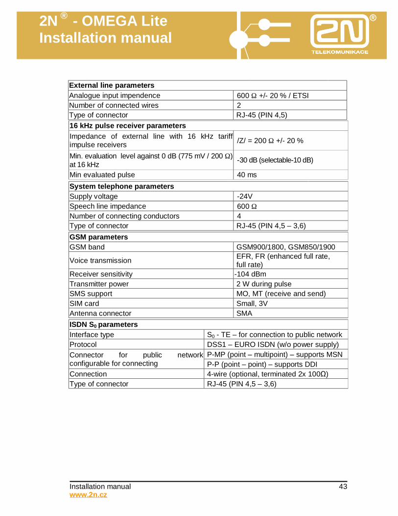
External line parameters
Analogue input impendence 600 Ω +/- 20 % / ETSI Number of connected wires 2 Type of connector RJ-45 (PIN 4,5)
16 kHz pulse receiver parameters Impedance of external line with 16 kHz tariff impulse receivers /Z/ = 200 Ω +/- 20 %
Min. evaluation level against 0 dB (775 mV / 200 Ω) at 16 kHz -30 dB (selectable-10 dB)
Min evaluated pulse 40 ms System telephone parameters Supply voltage -24V Speech line impedance 600 Ω Number of connecting conductors 4 Type of connector RJ-45 (PIN 4,5 – 3,6)
GSM parameters GSM band GSM900/1800, GSM850/1900
Voice transmission EFR, FR (enhanced full rate, full rate)
Receiver sensitivity -104 dBm Transmitter power 2 W during pulse SMS support MO, MT (receive and send) SIM card Small, 3V Antenna connector SMA
ISDN S0 parameters Interface type S0 - TE – for connection to public network Protocol DSS1 – EURO ISDN (w/o power supply)
P-MP (point – multipoint) – supports MSN Connector for public network configurable for connecting P-P (point – point) – supports DDI Connection 4-wire (optional, terminated 2x 100Ω) Type of connector RJ-45 (PIN 4,5 – 3,6)
2N ® - OMEGA Lite Installation manual
Installation manual 44 www.2n.cz
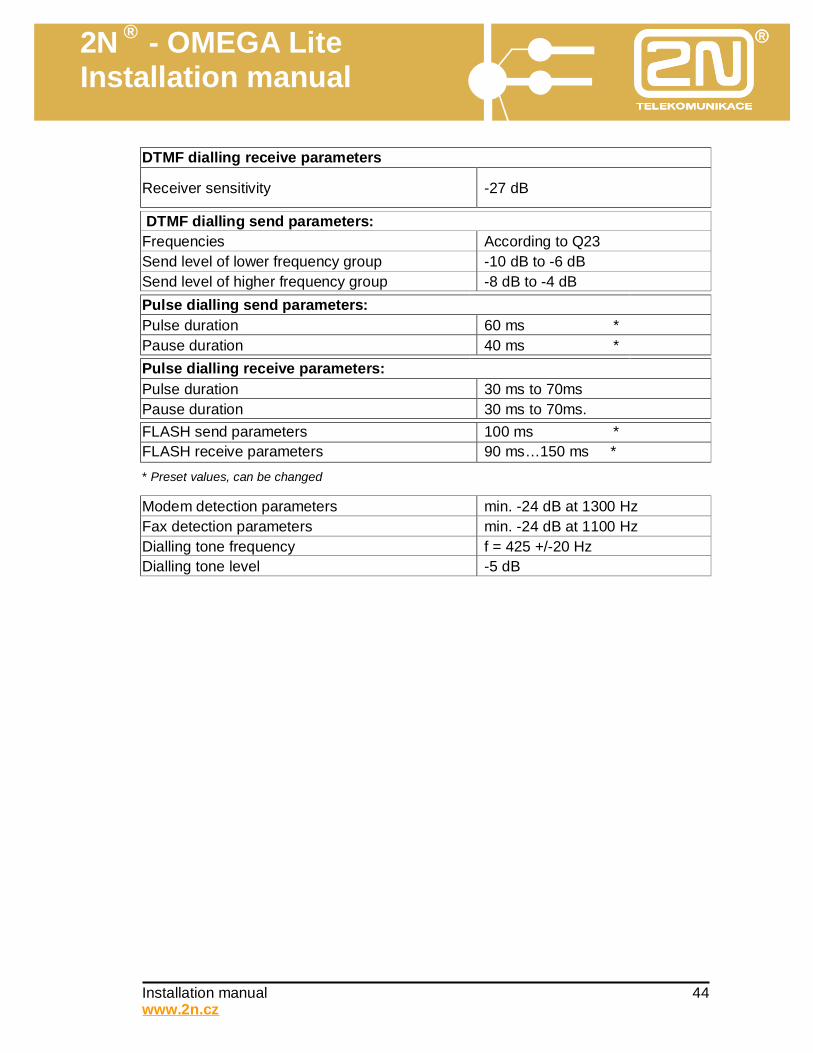
DTMF dialling receive parameters
Receiver sensitivity -27 dB
DTMF dialling send parameters: Frequencies According to Q23 Send level of lower frequency group -10 dB to -6 dB Send level of higher frequency group -8 dB to -4 dB
Pulse dialling send parameters: Pulse duration 60 ms * Pause duration 40 ms *
Pulse dialling receive parameters: Pulse duration 30 ms to 70ms Pause duration 30 ms to 70ms.
FLASH send parameters 100 ms * FLASH receive parameters 90 ms…150 ms *
* Preset values, can be changed
Modem detection parameters min. -24 dB at 1300 Hz Fax detection parameters min. -24 dB at 1100 Hz Dialling tone frequency f = 425 +/-20 Hz Dialling tone level -5 dB
2N ® - OMEGA Lite Installation manual
Installation manual 45 www.2n.cz
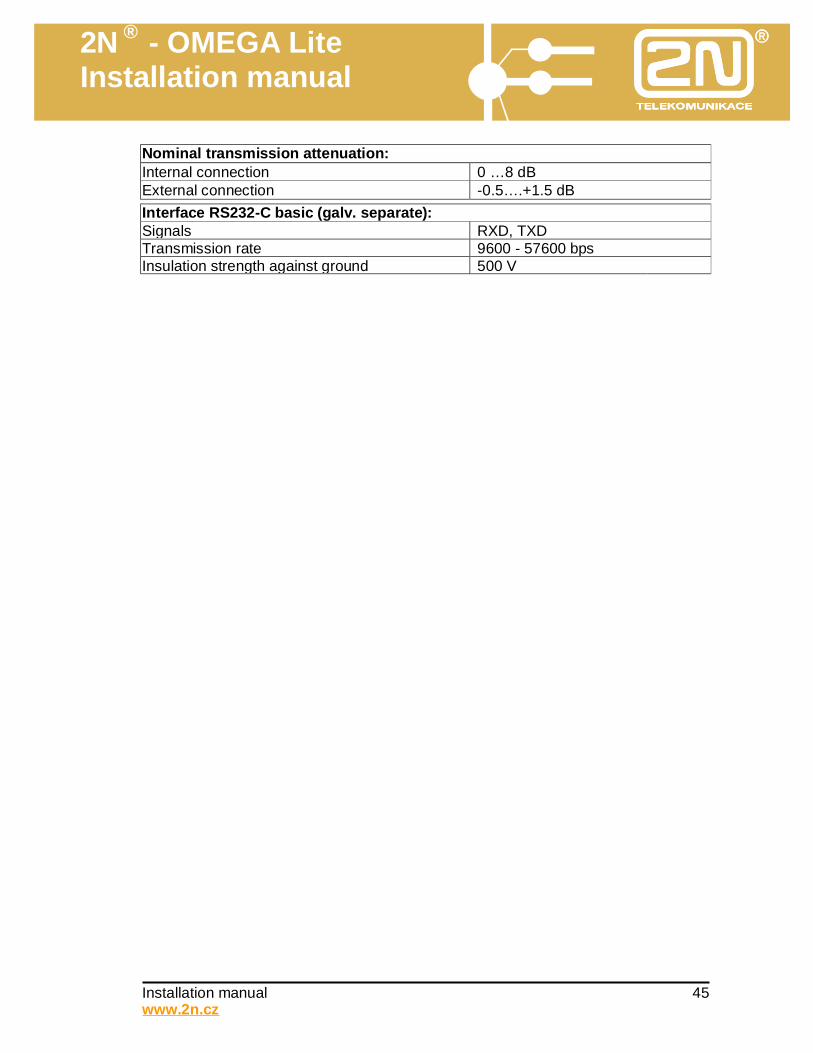
Nominal transmission attenuation: Internal connection 0 …8 dB External connection -0.5….+1.5 dB
Interface RS232-C basic (galv. separate): Signals RXD, TXD Transmission rate 9600 - 57600 bps Insulation strength against ground 500 V

2N ® - OMEGA Lite Installation manual
Installation manual 46 www.2n.cz
Notes: Notes:


![Elevator Catalog [1.3 MB] - Wirerope Works](https://static.fdokumen.com/doc/165x107/6327034c6d480576770d1104/elevator-catalog-13-mb-wirerope-works.jpg)


![Torq-Lite Digital Brochure [1].pdf - TKH](https://static.fdokumen.com/doc/165x107/631b1791c51d6b41aa051771/torq-lite-digital-brochure-1pdf-tkh.jpg)


