ibaPDA-SD-TDC Lite - Iba AG
53
Configuration Guide ibaPDA-SD-TDC Lite Manual Issue 2.2
-
Upload
khangminh22 -
Category
Documents
-
view
0 -
download
0
Transcript of ibaPDA-SD-TDC Lite - Iba AG
Configuration Guide
ibaPDA-SD-TDC Lite
Manual Issue 2.2
Manufacturer
iba AG
Koenigswarterstr. 44
90762 Fuerth
Germany
Contacts
Main office: +49 911 97282-0
Fax: +49 911 97282-33
Support: +49 911 97282-14
Engineering: +49 911 97282-13
E-mail: [email protected]
Web: www.iba-ag.com
This manual must not be circulated or copied, or its contents utilized and disseminated,
without our express written permission. Any breach or infringement of this provision will re-
sult in liability for damages.
©iba AG 2014, All Rights Reserved
The content of this publication has been checked for compliance with the described hard-
ware and software. Nevertheless, deviations cannot be excluded completely so that the full
compliance is not guaranteed. However, the information in this publication is updated regu-
larly. Required corrections are contained in the following regulations or can be downloaded
on the Internet.
The current version is available for download on our web site http://www.iba-ag.com.
Protection note
Windows® is a label and registered trademark of the Microsoft Corporation. Other product
and company names mentioned in this manual can be labels or registered trademarks of
the corresponding owners.
Certification
The device is certified according to the European standards and directives. This device
corresponds to the general safety and health requirements. Further international custom-
ary standards and directives have been observed.

ibaPDA-SD-TDC Lite Handbuch
Issue 2.2 3
Table of contents
1 About this manual ............................................................................................. 5
1.1 Target group .................................................................................................... 5
1.2 Basic knowledge .............................................................................................. 5
1.3 Designations .................................................................................................... 5
1.4 Used symbols .................................................................................................. 6
2 System requirements ........................................................................................ 7
2.1 iba Hardware ................................................................................................... 7
2.2 iba Software ..................................................................................................... 7
2.3 Siemens Hardware .......................................................................................... 7
2.4 Siemens Software ............................................................................................ 7
3 General information .......................................................................................... 8
3.1 Overview ......................................................................................................... 8
3.2 Foundations ..................................................................................................... 9
3.3 Functional principle ........................................................................................ 10
3.4 Characteristics of the SD-TDC Lite interface .................................................. 10
4 Configuration on SIMADYN D / SIMATIC TDC .............................................. 12
4.1 Transmission channels .................................................................................. 12
4.2 Reception channels ....................................................................................... 14
4.3 Technostring (TS) .......................................................................................... 17
4.4 Time synchronization ..................................................................................... 19
5 Configuration in ibaPDA-V6 ........................................................................... 20
5.1 ibaPDA standard settings ............................................................................... 20
5.2 Hardware interfaces ibaFOB-SD/ibaFOB-TDC .............................................. 20
5.2.1 Schematic depiction of the iba cards ............................................................. 21
5.2.2 Link level ....................................................................................................... 23
5.3 SD-/TDC Lite Module ..................................................................................... 23
5.3.1 "General" tab ................................................................................................. 24
5.3.2 "Analog" and "Digital" signal tables tab .......................................................... 25
5.4 Time synchronization ..................................................................................... 25
5.4.1 Synchronization with DCF77 signal (for CFC programs) ................................ 25
5.4.2 IEC time signal (for STRUC programs) .......................................................... 26
5.5 Diagnostics ibaFOB-SD/-TDC ........................................................................ 27
5.5.1 "Link Info“ tab ................................................................................................. 27
5.5.2 "Processor Info“ tab ....................................................................................... 29
5.5.3 "Report control" tab ........................................................................................ 30
5.5.4 "Data control" tab ........................................................................................... 31
5.5.5 "Configuration" tab ......................................................................................... 32
Handbuch ibaPDA-SD-TDC Lite
4 Issue 2.2
5.5.6 "Channels" tab ............................................................................................... 33
5.5.7 "Timing" tab ................................................................................................... 34
5.5.8 "Memory view" tab ......................................................................................... 35
5.6 Diagnostics ibaFOB-SDexp/-TDCexp ............................................................ 36
5.6.1 "Configuration " tab ........................................................................................ 36
5.6.2 "System info" tab ........................................................................................... 37
5.6.3 "Timing" tab ................................................................................................... 38
5.6.4 "Active data channels" tab ............................................................................. 40
5.6.5 "Channels in system" tab ............................................................................... 40
5.6.6 "Memory view" tab ......................................................................................... 41
6 Configuration in ibaLogic .............................................................................. 42
6.1 I/O configurator.............................................................................................. 42
6.1.1 "Hardware configuration" tab ......................................................................... 42
6.1.2 "Assign signals" tab ....................................................................................... 44
6.2 ibaLogic – diagnostics ................................................................................... 44
7 Appendix ......................................................................................................... 45
7.1 Error of sequence control .............................................................................. 45
7.1.1 Analyzing the error counters .......................................................................... 45
7.1.2 Errors with diagnostic functions ..................................................................... 45
7.1.3 Timeout error in ibaPDA ................................................................................ 46
7.1.4 Timeout errors of sequence control ............................................................... 47
7.2 Errors of the TDC driver ................................................................................ 48
7.2.1 Error classes ................................................................................................. 48
7.2.2 Errors with ibaPDA log-in in the computer coupling ....................................... 49
7.2.3 Errors with channel log-in .............................................................................. 50
7.2.4 Errors with data transfer ................................................................................ 51
7.3 Abbreviations ................................................................................................ 52
8 Support and contact ....................................................................................... 53

ibaPDA-SD-TDC Lite Handbuch
Issue 2.2 5
1 About this manual
This manual describes the use of the software ibaPDA-SD-TDC Lite.
1.1 Target group
This manual addresses in particular those qualified professionals who are familiar with
handling electrical and electronic modules as well as communication and measurement
technology. A person is regarded as professional if he/she is capable of assessing safety
and recognizing possible consequences and risks on the basis of his/her specialist train-
ing, knowledge and experience and knowledge of the standard regulations.
1.2 Basic knowledge
The following basic knowledge is required for operating the software:
Basic knowledge of the Windows operating system
Basic knowledge of dealing with ibaPDA
Basic knowledge of dealing with SIMADYN D, SIMATIC TDC, CFC and D7-SYS
1.3 Designations
The following designations are used in this manual:
Action Designations
Menu command Menu "Logic diagram
Call of menu command “Step 1 – Step 2 – Step 3 – Step x”
Example:
Select menu "Logic diagram - Add - New logic
diagram"
Keys <Key name>
Example:
<Alt>; <F1>
Press keys simultaneously <Key name> + <Key name>
Example:
<Alt> + <Strg>
Buttons <Button name>
Example:
<OK>; <Cancel>
File names, Paths „File name,“ "Path"
„Test.doc“
Handbuch ibaPDA-SD-TDC Lite
6 Issue 2.2
1.4 Used symbols
If safety instructions or other notes are used in this manual, they mean:
The non-observance of this safety information may result in an imminent risk of death or
severe injury:
From electric shock!
Due to the improper handling of software products which are coupled to input and
output procedures with control function!
The non-observance of this safety information may result in a potential risk of death or se-
vere injury!
The non-observance of this safety information may result in a potential risk of injury or ma-
terial damage!
Note
A note specifies special requirements or actions to be observed.
Important note
Note if some special features must be observed, for example exceptions from the rule.
Tip
Tip or example as a helpful note or insider tip to make the work a little bit easier.
Other documentation
Reference to additional documentation or further reading.
ibaPDA-SD-TDC Lite Handbuch
Issue 2.2 7
2 System requirements
2.1 iba Hardware
PCI card ibaFOB-TDC or ibaFOB-SD or
PCI express card ibaFOB-TDCexp or ibaFOB-SDexp
2.2 iba Software
ibaPDA basic license starting with V6.7.0 or ibaPDA V6.32.0
Additional license ibaPDA-SD-TDC Lite
For time synchronization in CFC:
iba function block library FBAPDA
2.3 Siemens Hardware
Interface for ibaFOB-SD/-SDexp:
1 free port on SIMADYN D – component CS12, CS13 or CS14
1 free port on SIMATIC TDC – component CP53
Interface for ibaFOB-TDC/TDCexp:
1 free port on the interface component CP51IO in the Global Data Memory
2.4 Siemens Software
STRUC starting with V4.2.1
or
CFC beginning with V6.0 with
D7-SYS beginning with V6.0
Handbuch ibaPDA-SD-TDC Lite
8 Issue 2.2
3 General information
3.1 Overview
iba AG offers the following solutions for access to Siemens SIMADYN D and SIMATIC
TDC:
Target sys-tem Interface Transmission iba Interface Manual
License
SIMADYN D
CS12/13/14
FO
ibaFOB-SD ibaFOB-SDexp
TDC-/SD- Request
TDC-/SD- Request
TDC-SD- Lite
TDC-SD- Lite
ibaLink- SM64-SD
FO ibaFOB-D SM64-SD16 -
CS7/SS52 Profibus DPMS / L2B - -
SIMATIC TDC
CP53
FO
ibaFOB-SD
TDC-/SD- Request
TDC-/SD- Request
TDC-SD- Lite
TDC-SD- Lite
GDM ibaFOB-TDC
ibaFOB-TDCexp
TDC-/SD- Request
TDC-/SD- Request
TDC-SD- Lite
TDC-SD- Lite
CP50 Profibus DPMS / L2B
FM/TDC- Profibus- Request
FM/TDC-Profibus Request
- -
CP51 Ethernet - Interface
TCPIP- UDP
Interface TCPIP-
TDC
In this manual, the issues marked in green are dealt with.
Other documentaion
The request interfaces with a blue background are described in the "ibaPDA-Request-SD-
TDC" manual. The request interface with a yellow background provides access to old
SIMADYN D systems starting with STRUC V2.2. For this, see the "ibaLink-SM-64-SD16"
description.
Other than the special iba interfaces, standard interfaces are available via Profibus and
TCIP/IP or UDP. For this, see the corresponding manuals.
Note
In this document, all statements made about ibaFOB-SD- or ibaFOB-TDC-cards also apply
to the PCI-express cards ibaFOB-SDexp and ibaFOB-TDCexp. Exceptions are mentioned
explicitly.
ibaPDA-SD-TDC Lite Handbuch
Issue 2.2 9
3.2 Foundations
You can connect ibaPDA directly to SIMADYN D and SIMATIC TDC systems with the
ibaFOB-SD and ibaFOB-TDC cards.
Communication protocols are implemented on these cards that facilitate direct connection
to the Siemens rack links. From the perspective of a Siemens control, the ibaPDA comput-
er acts like a connected Siemens rack.
In this document, all coupling components are designated as rack links that also facilitate
connection of ibaFOB-SD or ibaFOB-TDC cards. They are:
SIMADYN D: CS12, CS13 and CS14
SIMATIC TDC: CP53 and GDM (Interface card CP52IO)
All CPUs of all frames that are connected by a rack link component can communicate with
one another. If the ibaFOB-SD or ibaFOB-TDC is likewise connected to this rack link, then
all these CPUs can in principle also communicate with ibaPDA or ibaLogic.
In practice the number of possible CPUs is limited by:
Max. number of channels per FOB-SD/-TDC card and rack link component
Limited data rate of ibaFOB-SD/-TDC cards
Capability of the fiber optic connection
On an ibaPDA-PC 4 cards of every type can be operated (also mixed).
The cards differ as follows:
ibaFOB-SD/-SDexp ibaFOB-TDC/-TDCexp
FO Interface ST technology SC technology
Baud rate 96 Mbit/s 640 Mbit/s
Possible coupling
partners
SIMADYN D:
CS12 / CS13 / CS14
SIMATIC TDC:
CP53
SIMATIC TDC:
CP52IO (GDM)
ibaFOB-SD/-TDC ibaFOB-SDexp/-TDCexp
PC Interface PCI PCI express
Memory access via CPU DMS
Other documentation
For this, see the manuals of the ibaFOB-SD and ibaFOB-TDC components in the down-
load area of our website www.iba-ag.com.

Handbuch ibaPDA-SD-TDC Lite
10 Issue 2.2
Special features of the CP53 component (available in SIMATIC TDC starting with D7-
SYS V7.1):
The component can be configured as master or slave. In the master mode, one port can
be used for connection of ibaPDA (ibaFOB-SD card) and the other for connection of a
slave rack. The slave rack is either SIMADYN D with the CS22 component or SIMATIC
TDC with the CP53 component (slave mode). In the slave mode, the 2nd port cannot be
used.
For connection with SD under STRUC, the component has to be initialized in the STRUC
mode. Then no ibaPDA access to the CFC-CPUs is possible.
Special features of the CS12/13/14 components (SIMADYN D):
The components differ only in the number of optical fiber connections (1, 4 or 8). When
CS14 is mentioned in what follows, the information also applies to CS12 and CS13. Any
free port can be occupied on one of these components.
Special features of the Global Data Memory (GDM) (in SIMATIC TDC) :
The GDM is a complete frame in which there are only the CP52M0 memory component
and max. 11 interface components (CP52IO). Each interface component makes four
ports available. All ports have equal access.
3.3 Functional principle
In the measuring operation, numerical and digital signals are measured, i.e., variables are
read out of the computer system and recorded. In defining the variables to be measured,
two procedures are differentiated:
SD-TDC Lite
All values that you want to measure with ibaPDA have first to be projected in
process data telegrams.
To change the measurement scenario, you have to change the projection.
Symbolic Request:
You do not define the variables to be measured in the control, but rather in ibaPDA.
The iba cards and ibaPDA both support both procedures, but on one card you can only
configure one mode. If there are more cards and both licenses available, both procedures
can be used at the same time in ibaPDA .
For one card, the following applies:
If at least 1 Lite channel is defined, a Request channel cannot be assigned to this card.
If a Request channel is assigned to this card, a Lite channel cannot be added.
Other documentation
You find a description of the "Symbolic Request“ mode in the "ibaPDA-SD-TDC Request"
manual.
3.4 Characteristics of the SD-TDC Lite interface
No random access to the connectors in the control is possible with SD-TDC Lite. All
data to be recorded must be projected on the control.
On the Siemens side, max. 16 TDC-Lite transmission channels and 8 reception
channels can be projected per rack link and per connection.
ibaPDA-SD-TDC Lite Handbuch
Issue 2.2 11
Exactly 32 analog values (data type Real or NF) and 32 bits (a value of the data
type DW or DI or V4 or I4) are to be projected in each channel.
The data are transmitted in process data telegrams, as with a standard rack link.
The names of the channels are established by iba.
REFRESH is to be set as channel mode. Starting with ibaFOB-SD/TDC firmware
version B3, MULTIPLE channel mode is also possible for the transmission chan-
nels.
If you have set the MULTIPLE channel mode, then the transmission channels can
be received in parallel by different receivers, e.g., by several ibaPDA systems or
ibaPDA and ibaLogic.
Projection of the SER04A and SER04B service function blocks and import of the
address books into ibaPDA are not necessary.
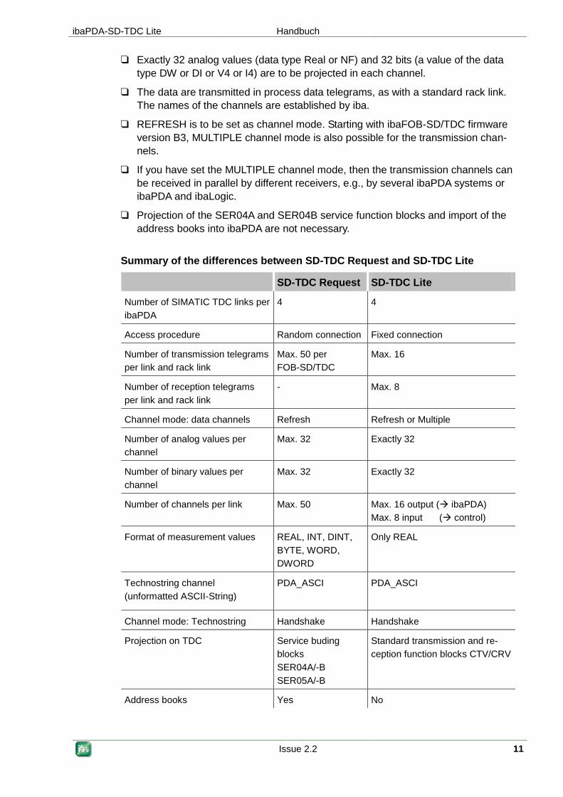
Summary of the differences between SD-TDC Request and SD-TDC Lite
SD-TDC Request SD-TDC Lite
Number of SIMATIC TDC links per
ibaPDA
4 4
Access procedure Random connection Fixed connection
Number of transmission telegrams
per link and rack link
Max. 50 per
FOB-SD/TDC
Max. 16
Number of reception telegrams
per link and rack link
- Max. 8
Channel mode: data channels Refresh Refresh or Multiple
Number of analog values per
channel
Max. 32 Exactly 32
Number of binary values per
channel
Max. 32 Exactly 32
Number of channels per link Max. 50 Max. 16 output ( ibaPDA)
Max. 8 input ( control)
Format of measurement values REAL, INT, DINT,
BYTE, WORD,
DWORD
Only REAL
Technostring channel
(unformatted ASCII-String)
PDA_ASCI PDA_ASCI
Channel mode: Technostring Handshake Handshake
Projection on TDC Service buding
blocks
SER04A/-B
SER05A/-B
Standard transmission and re-
ception function blocks CTV/CRV
Address books Yes No

Handbuch ibaPDA-SD-TDC Lite
12 Issue 2.2
4 Configuration on SIMADYN D / SIMATIC TDC
4.1 Transmission channels
When projecting the transmission channels, the following is to be observed:
The names of the channels are established and should not be used elsewhere.
The names of the max. 16 transmission channels (from the perspective of the con-
trol) are as follows:
Channel 1: M0PDADAT
Channel 2: M1PDADAT
: :
Channel 9: M8PDADAT
Channel 10: M9PDADAT
Channel 11: MAPDADAT
: :
Channel 16: MFPDADAT
The data structure of the telegrams is established and cannot be changed
(32 analog values and 32 binary values).
The channels are to be projected as process data channels in the REFRESH or
MULTIPLE channel mode.
The channels can be on different processors. The CTS connectors of the transmis-
sion function blocks must indicate the rack link component to which
ibaPDA/ibaLogic is also connected.
The channels can be projected in different time slices.
The "CTV" or "CTV_P" function blocks are to be used for transmission.
Note
When using the CTV function block, you have to apply all telegram data to the virtual con-
nection (see example below).
When using the CTV_P function block, you only have to enter the telegram length
132 bytes at the LEN connector.

ibaPDA-SD-TDC Lite Handbuch
Issue 2.2 13
Example transmission channel with CTV (CFC)
1. Generation of telegram data:
32 analog values (data type: Real) and 32 bits (data type: DW), telegram name:
!M0PDA

Handbuch ibaPDA-SD-TDC Lite
14 Issue 2.2
2. CTV transmission function block:
Description of the CTV connectors:
Connector Value Description
CTS D0600B Component name of CP52A0, connection to
GDM
CRT !M0PDA Telegram name (virtual connection)
AT M0PDADAT Name of the transmission channel
MOD R REFRESH channel mode
EN 1 Transmits the cycle of the time slice
4.2 Reception channels
Note
Reception channels only make sense for ibaLogic applications.
When projecting the transmission channels, the following is to be noted:
The names of the channels are established and should not be used elsewhere.
The names of the max. 8 reception channels (from the perspective of the control)
are as follows:
Channel 1: PDAM0DAT
Channel 2: PDAM1DAT
: :
Channel 8: PDAM7DAT
The data structure of the telegrams is established and cannot be changed (32 ana-
log values and 32 binary values).
The channels are to be projected as process data channels in the REFRESH chan-
nel mode.
The channels can be on different processors. The CTS connectors of the CRV re-
ception function blocks must indicate the rack link component to which
ibaPDA/ibaLogic is also connected.
The channels can be projected in different time slices.
The "CTV" or "CTV_P" function blocks are to be used for reception.
ibaPDA-SD-TDC Lite Handbuch
Issue 2.2 15
Note
When using the CTV function block, you have to apply all telegram data to the virtual con-
nection (see example below).
When using the CTV_P function block, you only have to enter the telegram length 132
bytes at the LEN connector.
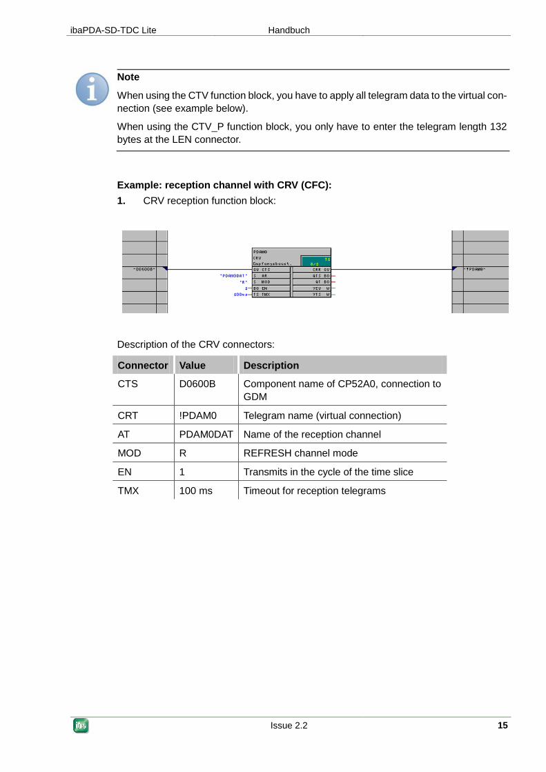
Example: reception channel with CRV (CFC):
1. CRV reception function block:
Description of the CRV connectors:
Connector Value Description
CTS D0600B Component name of CP52A0, connection to
GDM
CRT !PDAM0 Telegram name (virtual connection)
AT PDAM0DAT Name of the reception channel
MOD R REFRESH channel mode
EN 1 Transmits in the cycle of the time slice
TMX 100 ms Timeout for reception telegrams

Handbuch ibaPDA-SD-TDC Lite
16 Issue 2.2
Application of the reception data:
32 analog values (data type Real) and 32 Bits ('Data type DW);
telegram name: PDAM0.
ibaPDA-SD-TDC Lite Handbuch
Issue 2.2 17
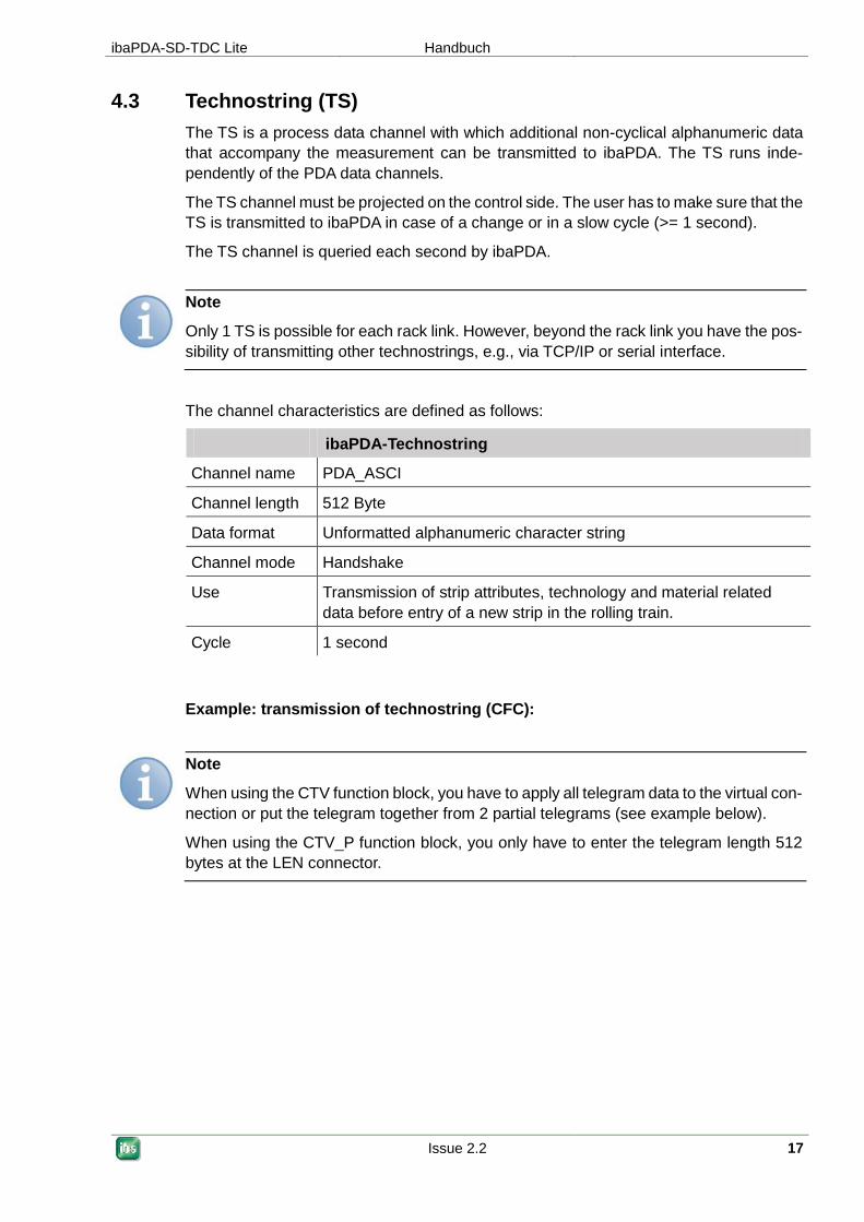
4.3 Technostring (TS)
The TS is a process data channel with which additional non-cyclical alphanumeric data
that accompany the measurement can be transmitted to ibaPDA. The TS runs inde-
pendently of the PDA data channels.
The TS channel must be projected on the control side. The user has to make sure that the
TS is transmitted to ibaPDA in case of a change or in a slow cycle (>= 1 second).
The TS channel is queried each second by ibaPDA.
Note
Only 1 TS is possible for each rack link. However, beyond the rack link you have the pos-
sibility of transmitting other technostrings, e.g., via TCP/IP or serial interface.
The channel characteristics are defined as follows:
ibaPDA-Technostring
Channel name PDA_ASCI
Channel length 512 Byte
Data format Unformatted alphanumeric character string
Channel mode Handshake
Use Transmission of strip attributes, technology and material related
data before entry of a new strip in the rolling train.
Cycle 1 second
Example: transmission of technostring (CFC):
Note
When using the CTV function block, you have to apply all telegram data to the virtual con-
nection or put the telegram together from 2 partial telegrams (see example below).
When using the CTV_P function block, you only have to enter the telegram length 512
bytes at the LEN connector.
Handbuch ibaPDA-SD-TDC Lite
18 Issue 2.2
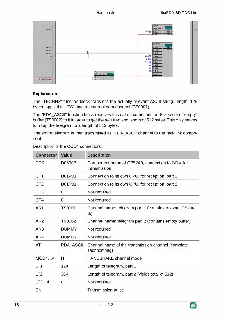
Explanation
The "TECHN2" function block transmits the actually relevant ASCII string, length: 128
bytes, applied in "!TS", into an internal data channel (TS0001).
The "PDA_ASCII" function block receives this data channel and adds a second "empty"
buffer (TS0002) to it in order to get the required end length of 512 bytes. This only serves
to fill up the telegram to a length of 512 bytes.
The entire telegram is then transmitted as "PDA_ASCI" channel to the rack link compo-
nent.
Description of the CCC4 connectors:
Connector Value Description
CTS D0600B Component name of CP52A0, connection to GDM for
transmission
CT1 D01P01 Connection to its own CPU, for reception: part 1
CT2 D01P01 Connection to its own CPU, for reception: part 2
CT3 0 Not required
CT4 0 Not required
AR1 TS0001 Channel name: telegram part 1 (contains relevant TS da-
ta)
AR2 TS0002 Channel name: telegram part 2 (contains empty buffer)
AR3 DUMMY Not required
AR4 DUMMY Not required
AT PDA_ASCII Channel name of the transmission channel (complete
Technostring)
MOD1…4 H HANDSHAKE channel mode
LT1 128 Length of telegram, part 1
LT2 384 Length of telegram, part 2 (yields total of 512)
LT3…4 0 Not required
EN Transmission pulse
ibaPDA-SD-TDC Lite Handbuch
Issue 2.2 19
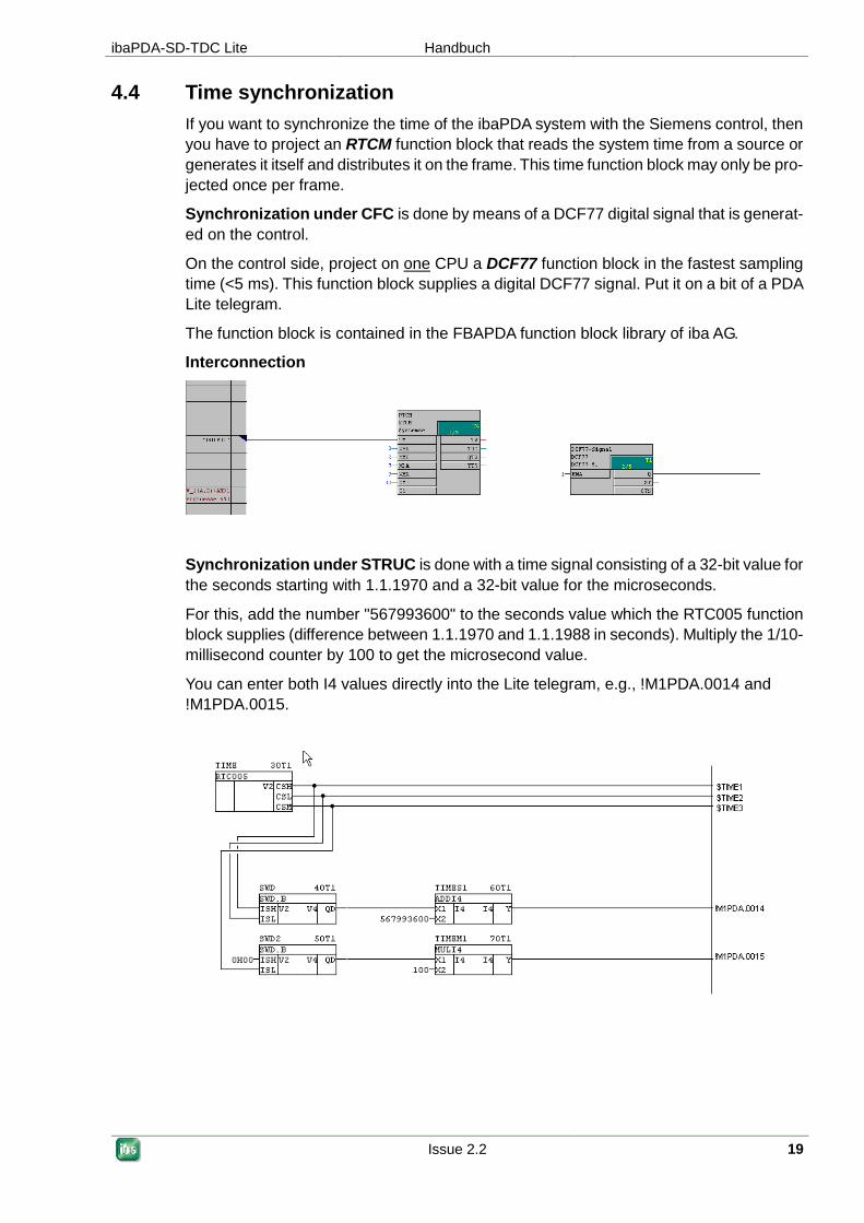
4.4 Time synchronization
If you want to synchronize the time of the ibaPDA system with the Siemens control, then
you have to project an RTCM function block that reads the system time from a source or
generates it itself and distributes it on the frame. This time function block may only be pro-
jected once per frame.
Synchronization under CFC is done by means of a DCF77 digital signal that is generat-
ed on the control.
On the control side, project on one CPU a DCF77 function block in the fastest sampling
time (<5 ms). This function block supplies a digital DCF77 signal. Put it on a bit of a PDA
Lite telegram.
The function block is contained in the FBAPDA function block library of iba AG.
Interconnection
Synchronization under STRUC is done with a time signal consisting of a 32-bit value for
the seconds starting with 1.1.1970 and a 32-bit value for the microseconds.
For this, add the number "567993600" to the seconds value which the RTC005 function
block supplies (difference between 1.1.1970 and 1.1.1988 in seconds). Multiply the 1/10-
millisecond counter by 100 to get the microsecond value.
You can enter both I4 values directly into the Lite telegram, e.g., !M1PDA.0014 and
!M1PDA.0015.
Handbuch ibaPDA-SD-TDC Lite
20 Issue 2.2
5 Configuration in ibaPDA-V6
For configuration, we recommend adhering to the following sequence:
ibaPDA – standard settings
Apply data modules
Mark the signals
5.1 ibaPDA standard settings
Other documentation
For settings of time basis, interrupt, etc. see ibaPDA-V6 manual.
5.2 Hardware interfaces ibaFOB-SD/ibaFOB-TDC
1. In the ibaPDA client, open the I/O manager and click on the "New configuration" icon.
ibaPDA detects the installed components and the licensed data interfaces and
represents them in the tree structure.
The iba components are schematically depicted in the dialog window if they are marked in
the hardware tree.
Since the ibaFOB-SD and ibaFOB-TDC are not functionally different, only the ibaFOB-
TDC card is described in the following. This description also applies to the ibaFOB-SD
card, unless something else is explicitly mentioned.

ibaPDA-SD-TDC Lite Handbuch
Issue 2.2 21
5.2.1 Schematic depiction of the iba cards
ibaFOB-TDC card:
ibaFOB-TDCexp card:
Handbuch ibaPDA-SD-TDC Lite
22 Issue 2.2
You get the following information in the dialog window:
Interface settings
Set the interrupt mode and activate the "In use" check box.
Important note
Set the ibaFOB-SD or ibaFOB-TDC as interrupt master if you use aside from these only
ibaFOB-ii-S or ibaComL2B-i/8.
PCI info
You can find information about the PCI interface in the PCI info area of the dialog.
It is of interest only to developers.
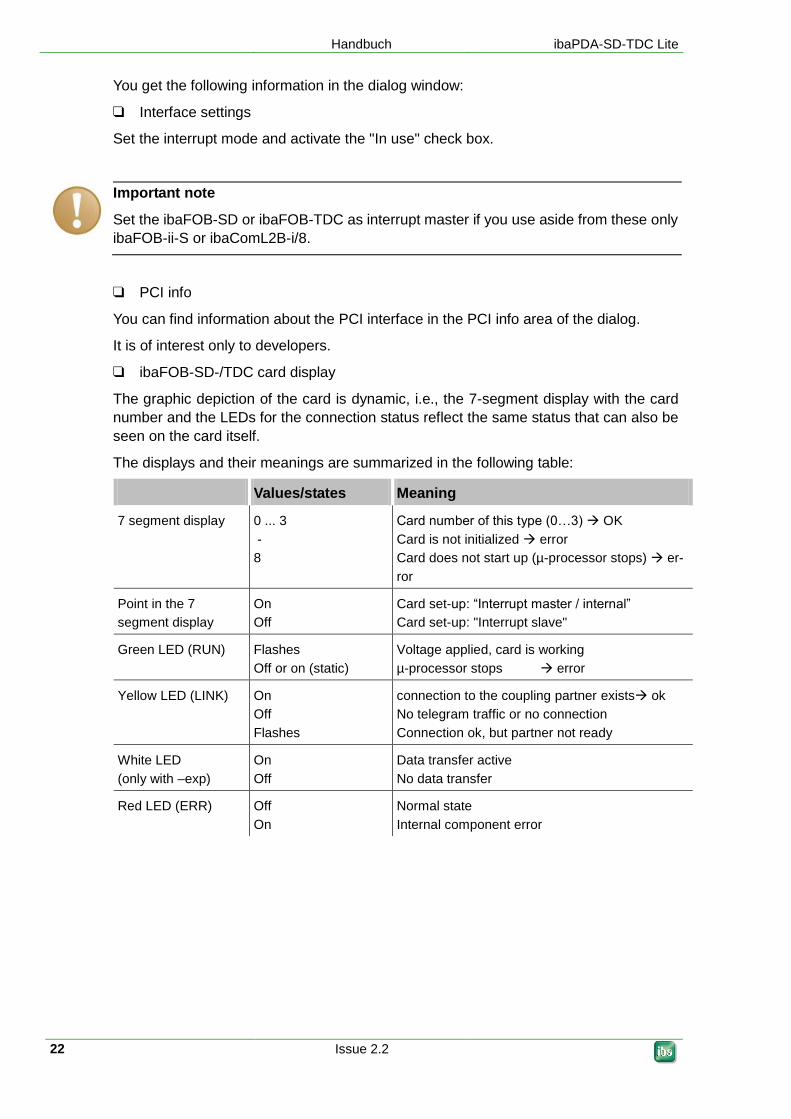
ibaFOB-SD-/TDC card display
The graphic depiction of the card is dynamic, i.e., the 7-segment display with the card
number and the LEDs for the connection status reflect the same status that can also be
seen on the card itself.
The displays and their meanings are summarized in the following table:
Values/states Meaning
7 segment display 0 ... 3
-
8
Card number of this type (0…3) OK
Card is not initialized error
Card does not start up (µ-processor stops) er-
ror
Point in the 7
segment display
On
Off
Card set-up: “Interrupt master / internal”
Card set-up: "Interrupt slave"
Green LED (RUN) Flashes
Off or on (static)
Voltage applied, card is working
µ-processor stops error
Yellow LED (LINK) On
Off
Flashes
connection to the coupling partner exists ok
No telegram traffic or no connection
Connection ok, but partner not ready
White LED
(only with –exp)
On
Off
Data transfer active
No data transfer
Red LED (ERR) Off
On
Normal state
Internal component error
ibaPDA-SD-TDC Lite Handbuch
Issue 2.2 23
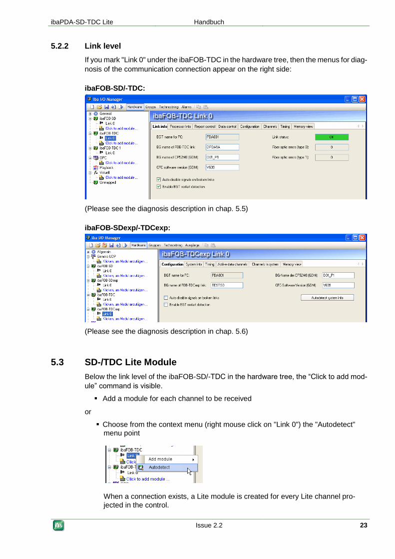
5.2.2 Link level
If you mark "Link 0" under the ibaFOB-TDC in the hardware tree, then the menus for diag-
nosis of the communication connection appear on the right side:
ibaFOB-SD/-TDC:
(Please see the diagnosis description in chap. 5.5)
ibaFOB-SDexp/-TDCexp:
(Please see the diagnosis description in chap. 5.6)
5.3 SD-/TDC Lite Module
Below the link level of the ibaFOB-SD/-TDC in the hardware tree, the “Click to add mod-
ule” command is visible.
Add a module for each channel to be received
or
Choose from the context menu (right mouse click on "Link 0") the "Autodetect"
menu point
When a connection exists, a Lite module is created for every Lite channel pro-
jected in the control.
Handbuch ibaPDA-SD-TDC Lite
24 Issue 2.2
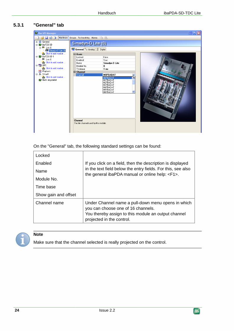
5.3.1 "General" tab
On the "General" tab, the following standard settings can be found:
Locked
Enabled
Name
Module No.
Time base
Show gain and offset
If you click on a field, then the description is displayed
in the text field below the entry fields. For this, see also
the general ibaPDA manual or online help: <F1>.
Channel name Under Channel name a pull-down menu opens in which
you can choose one of 16 channels.
You thereby assign to this module an output channel
projected in the control.
Note
Make sure that the channel selected is really projected on the control.
ibaPDA-SD-TDC Lite Handbuch
Issue 2.2 25
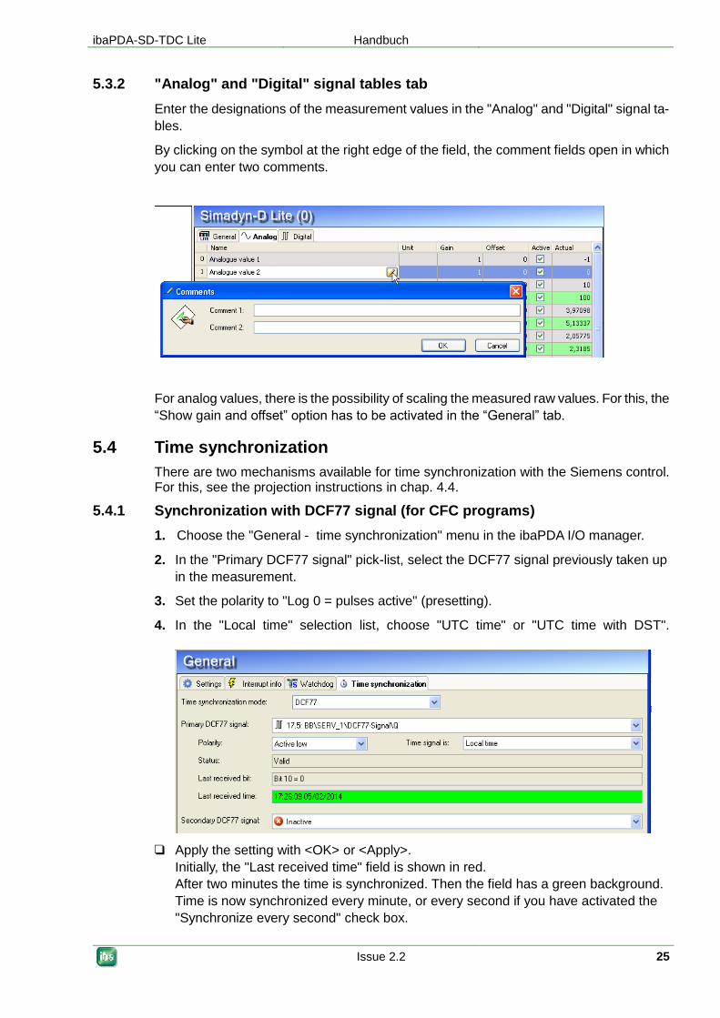
5.3.2 "Analog" and "Digital" signal tables tab
Enter the designations of the measurement values in the "Analog" and "Digital" signal ta-
bles.
By clicking on the symbol at the right edge of the field, the comment fields open in which
you can enter two comments.
For analog values, there is the possibility of scaling the measured raw values. For this, the
“Show gain and offset” option has to be activated in the “General” tab.
5.4 Time synchronization
There are two mechanisms available for time synchronization with the Siemens control. For this, see the projection instructions in chap. 4.4.
5.4.1 Synchronization with DCF77 signal (for CFC programs)
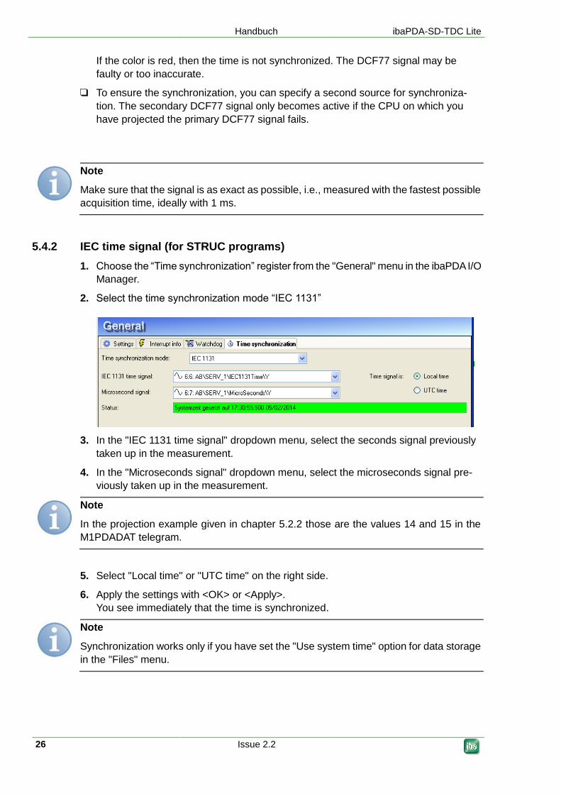
1. Choose the "General - time synchronization" menu in the ibaPDA I/O manager.
2. In the "Primary DCF77 signal" pick-list, select the DCF77 signal previously taken up
in the measurement.
3. Set the polarity to "Log 0 = pulses active" (presetting).
4. In the "Local time" selection list, choose "UTC time" or "UTC time with DST".
Apply the setting with <OK> or <Apply>.
Initially, the "Last received time" field is shown in red.
After two minutes the time is synchronized. Then the field has a green background.
Time is now synchronized every minute, or every second if you have activated the
"Synchronize every second" check box.
Handbuch ibaPDA-SD-TDC Lite
26 Issue 2.2
If the color is red, then the time is not synchronized. The DCF77 signal may be
faulty or too inaccurate.
To ensure the synchronization, you can specify a second source for synchroniza-
tion. The secondary DCF77 signal only becomes active if the CPU on which you
have projected the primary DCF77 signal fails.
Note
Make sure that the signal is as exact as possible, i.e., measured with the fastest possible
acquisition time, ideally with 1 ms.
5.4.2 IEC time signal (for STRUC programs)
1. Choose the “Time synchronization” register from the "General" menu in the ibaPDA I/O
Manager.
2. Select the time synchronization mode “IEC 1131”
3. In the "IEC 1131 time signal" dropdown menu, select the seconds signal previously
taken up in the measurement.
4. In the "Microseconds signal" dropdown menu, select the microseconds signal pre-
viously taken up in the measurement.
Note
In the projection example given in chapter 5.2.2 those are the values 14 and 15 in the
M1PDADAT telegram.
5. Select "Local time" or "UTC time" on the right side.
6. Apply the settings with <OK> or <Apply>.
You see immediately that the time is synchronized.
Note
Synchronization works only if you have set the "Use system time" option for data storage
in the "Files" menu.
ibaPDA-SD-TDC Lite Handbuch
Issue 2.2 27
5.5 Diagnostics ibaFOB-SD/-TDC
On the link level in the tree structure, a number of diagnostic information items are dis-
played that refer to communication and the processors of the component.
Tab:
Link info:
Set connection parameters and status
Processor info:
Information about the DPR assignment interface, hardware and firmware version
Log-in:
Information about the log-in in the PC coupling
Data:
Information about the telegram traffic of the PDA Lite channels
Configuration:
Information about the area in the rack link where all connected racks are registered
Channels:
Information about all communication channels set up in the rack link
Timing:
Information about utilization of the ibaFOB-TDC and access statistics
Memory view:
Content of the DPR memory in ibaFOB-TDC
5.5.1 "Link Info“ tab
Settings
BGT name for PC:
With this name, ibaPDA logs in as BGT in the administration area of the PC cou-
pling component.
Default setting: "PDA001" (from Registry)
BG name of the FOB-xx-connection:
With this name, the ibaFOB-SD/-TDC logs in in the computer coupling.
Handbuch ibaPDA-SD-TDC Lite
28 Issue 2.2
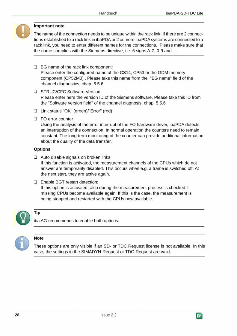
Important note
The name of the connection needs to be unique within the rack link. If there are 2 connec-
tions established to a rack link in ibaPDA or 2 or more ibaPDA systems are connected to a
rack link, you need to enter different names for the connections. Please make sure that
the name complies with the Siemens directive, i.e. 6 signs A-Z, 0-9 and _.
BG name of the rack link component:
Please enter the configured name of the CS14, CP53 or the GDM memory
component (CP52M0) . Please take this name from the "BG name" field of the
channel diagnostics, chap. 5.5.6
STRUC/CFC Software Version:
Please enter here the version ID of the Siemens software. Please take this ID from
the "Software version field" of the channel diagnosis, chap. 5.5.6
Link status "OK" (green)/"Error" (red)
FO error counter
Using the analysis of the error interrupt of the FO hardware driver, ibaPDA detects
an interruption of the connection. In normal operation the counters need to remain
constant. The long-term monitoring of the counter can provide additional information
about the quality of the data transfer.
Options
Auto disable signals on broken links:
If this function is activated, the measurement channels of the CPUs which do not
answer are temporarily disabled. This occurs when e.g. a frame is switched off. At
the next start, they are active again.
Enable BGT restart detection:
If this option is activated, also during the measurement process is checked if
missing CPUs become available again. If this is the case, the measurement is
being stopped and restarted with the CPUs now available.
Tip
iba AG recommends to enable both options.
Note
These options are only visible if an SD- or TDC Request license is not available. In this
case, the settings in the SIMADYN-Request or TDC-Request are valid.
ibaPDA-SD-TDC Lite Handbuch
Issue 2.2 29
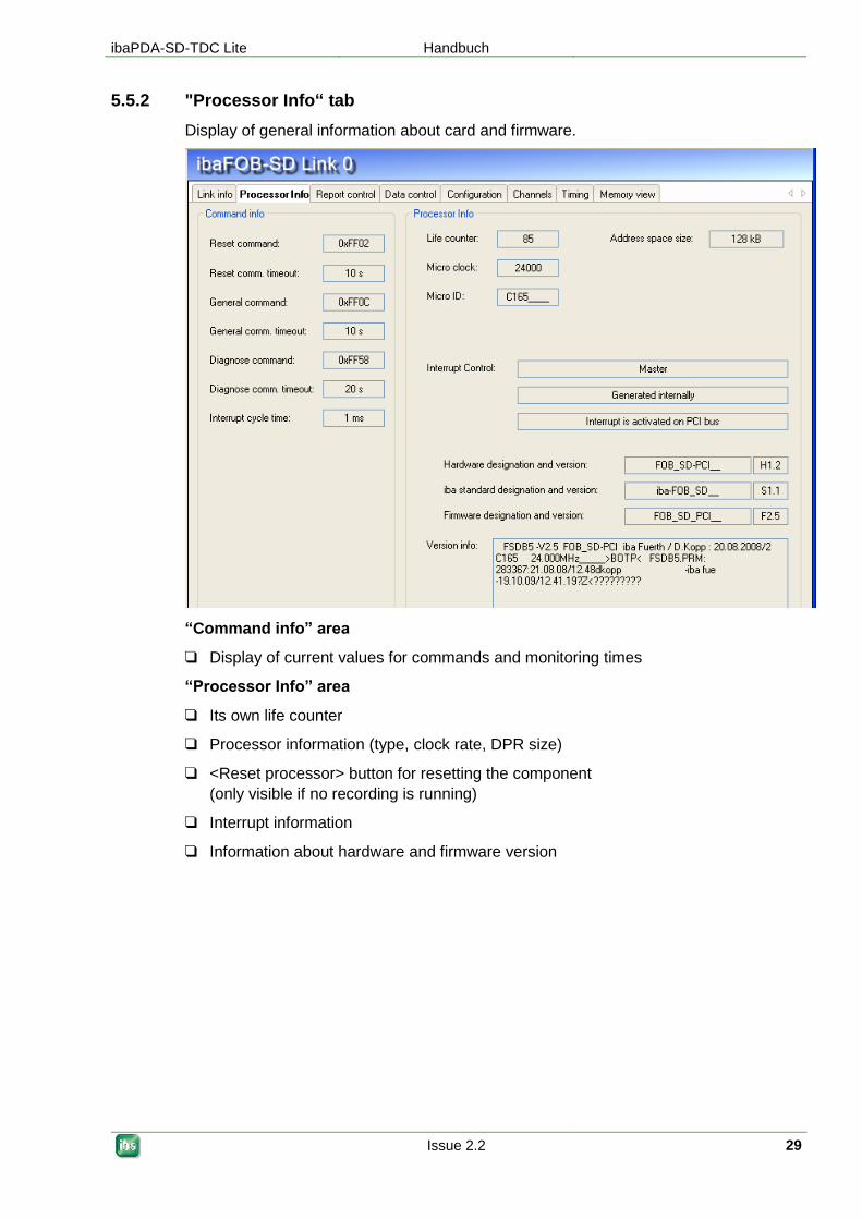
5.5.2 "Processor Info“ tab
Display of general information about card and firmware.
“Command info” area
Display of current values for commands and monitoring times
“Processor Info” area
Its own life counter
Processor information (type, clock rate, DPR size)
<Reset processor> button for resetting the component
(only visible if no recording is running)
Interrupt information
Information about hardware and firmware version
Handbuch ibaPDA-SD-TDC Lite
30 Issue 2.2
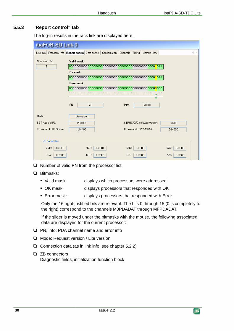
5.5.3 "Report control" tab
The log-in results in the rack link are displayed here.
Number of valid PN from the processor list
Bitmasks:
Valid mask: displays which processors were addressed
OK mask: displays processors that responded with OK
Error mask: displays processors that responded with Error
Only the 16 right-justified bits are relevant. The bits 0 through 15 (0 is completely to
the right) correspond to the channels M0PDADAT through MFPDADAT.
If the slider is moved under the bitmasks with the mouse, the following associated
data are displayed for the current processor:
PN, info: PDA channel name and error info
Mode: Request version / Lite version
Connection data (as in link info, see chapter 5.2.2)
ZB connectors
Diagnostic fields, initialization function block

ibaPDA-SD-TDC Lite Handbuch
Issue 2.2 31
5.5.4 "Data control" tab
The results of the measurement data transmission are displayed here:
Bitmasks: see chapter 5.5.3
If the slider is moved under the bitmasks with the mouse, the following associated
data are displayed for the current processor:
PN, info: PDA channel name and error info
Access counter
Access counter: number since the start of the measurement
(overrun at 65535)
Time base: access cycle (set acquisition time base)
Data transfer rate: percentage since the last reset
Handbuch ibaPDA-SD-TDC Lite
32 Issue 2.2
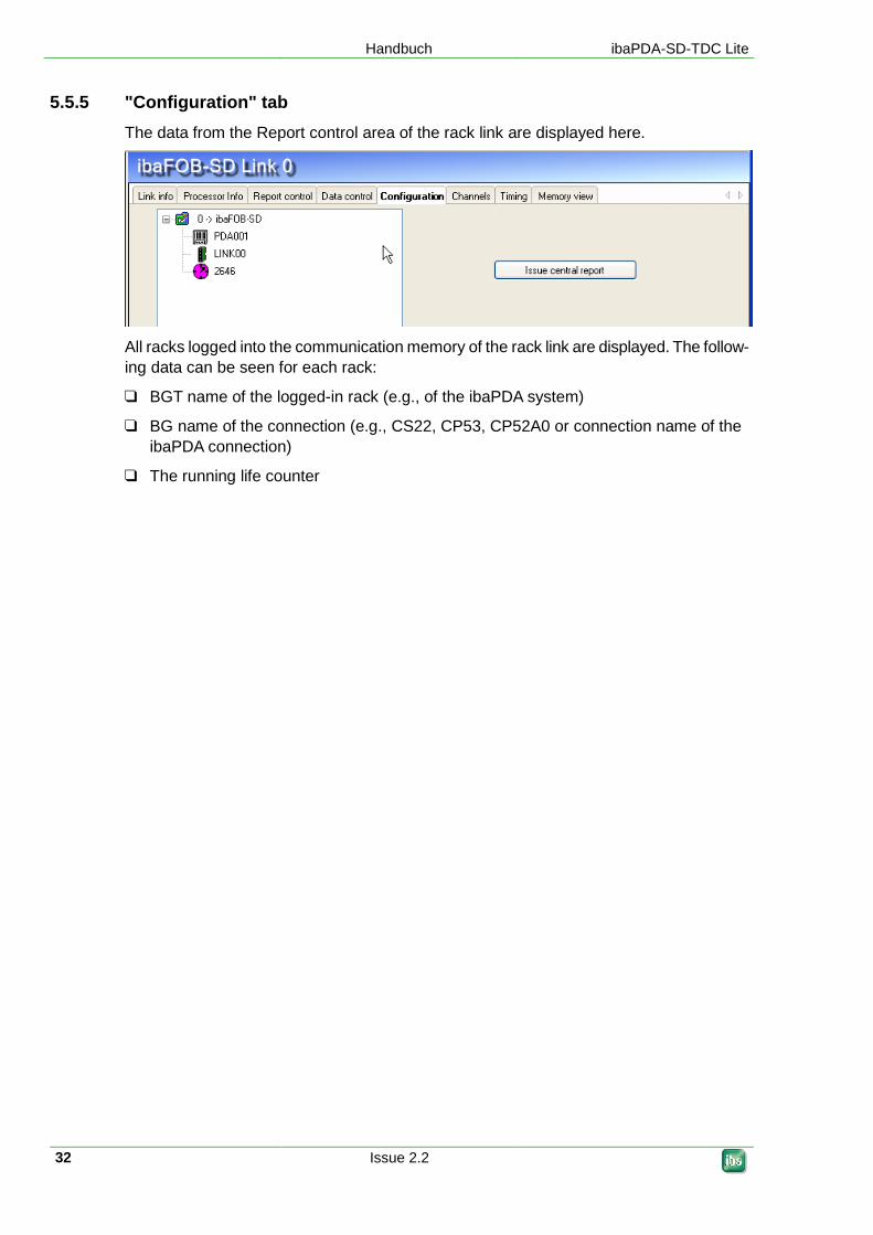
5.5.5 "Configuration" tab
The data from the Report control area of the rack link are displayed here.
All racks logged into the communication memory of the rack link are displayed. The follow-
ing data can be seen for each rack:
BGT name of the logged-in rack (e.g., of the ibaPDA system)
BG name of the connection (e.g., CS22, CP53, CP52A0 or connection name of the
ibaPDA connection)
The running life counter

ibaPDA-SD-TDC Lite Handbuch
Issue 2.2 33
5.5.6 "Channels" tab
Information from the data area of the computer coupling is displayed here:
By clicking on the <Search> button and entry field for the search term (with “?” wild
card), the rack link is searched for telegrams that correspond to the search term;
e.g.,
with "M?PDADAT" you find all transmission telegrams ( ibaPDA),
with "PDAM?DAT" you find all reception telegrams ( Siemens)
BGT diagnostics:
Log-in data read from the log-in area of the rack link:
Error code: error number in the case of access error, see chapter 7.1.2
List of channels found. For each channel, the following is displayed:
Channel name: telegram name
BGT name: empty
PN name: empty
Length: channel user data length in bytes: 132
Mode: (Refresh or Multiple)
Buffer state (initialized, buffer full, buffer empty)
The status is only a snapshot and is not dynamic
The table can be sorted in ascending/descending order by clicking on a column heading.
Handbuch ibaPDA-SD-TDC Lite
34 Issue 2.2
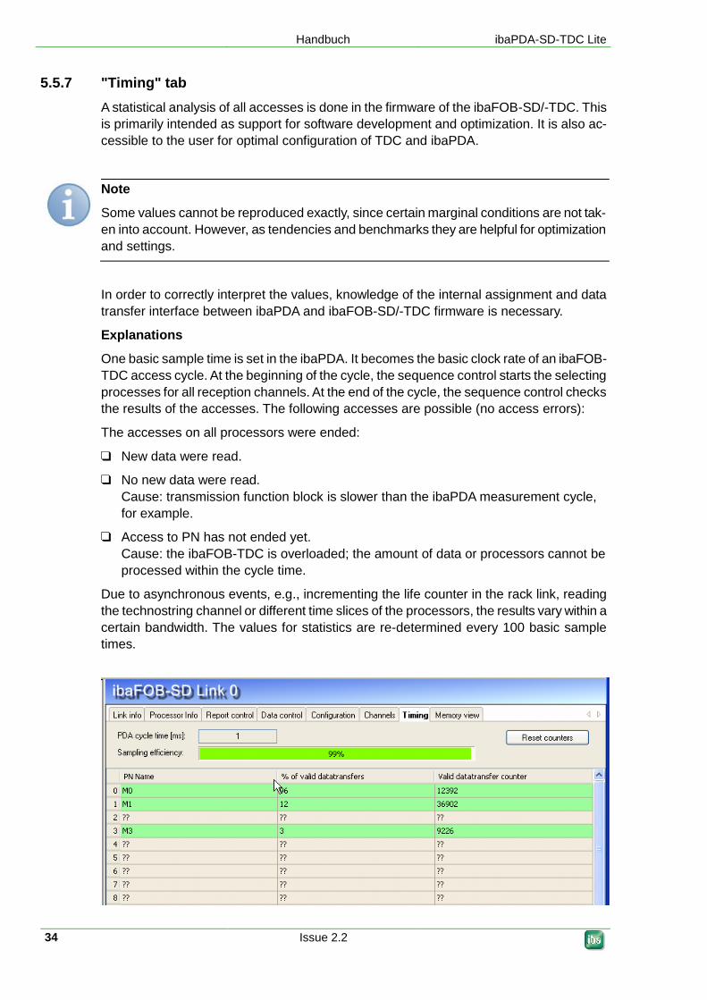
5.5.7 "Timing" tab
A statistical analysis of all accesses is done in the firmware of the ibaFOB-SD/-TDC. This
is primarily intended as support for software development and optimization. It is also ac-
cessible to the user for optimal configuration of TDC and ibaPDA.
Note
Some values cannot be reproduced exactly, since certain marginal conditions are not tak-
en into account. However, as tendencies and benchmarks they are helpful for optimization
and settings.
In order to correctly interpret the values, knowledge of the internal assignment and data
transfer interface between ibaPDA and ibaFOB-SD/-TDC firmware is necessary.
Explanations
One basic sample time is set in the ibaPDA. It becomes the basic clock rate of an ibaFOB-
TDC access cycle. At the beginning of the cycle, the sequence control starts the selecting
processes for all reception channels. At the end of the cycle, the sequence control checks
the results of the accesses. The following accesses are possible (no access errors):
The accesses on all processors were ended:
New data were read.
No new data were read.
Cause: transmission function block is slower than the ibaPDA measurement cycle,
for example.
Access to PN has not ended yet.
Cause: the ibaFOB-TDC is overloaded; the amount of data or processors cannot be
processed within the cycle time.
Due to asynchronous events, e.g., incrementing the life counter in the rack link, reading
the technostring channel or different time slices of the processors, the results vary within a
certain bandwidth. The values for statistics are re-determined every 100 basic sample
times.
ibaPDA-SD-TDC Lite Handbuch
Issue 2.2 35
The information in the “Timing” tab:
PDA cycle time:
currently set ibaPDA basic cycle time.
Sampling efficiency (load of FOB-SD/-TDC card):
portion of cycles that were completely processed, regardless of whether data were
received in this cycle or not.
If a cycle was not fully concluded, it does not mean that no data was received in this
cycle; instead, it only means that processing of at least one channel was not con-
cluded.
Example:
The indication of 80% with 10 projected data channels states that:
at least 2% of the data are lost if one channel was not completely processed in the
cycles not concluded, and max. 20% of the data are lost if no channel was com-
pletely processed.
For an effective measurement, a value between 75% and 100% is to be strived for.
PN name: channel ID in ascending order (only 16 lines are relevant)
% of valid data transfers
Portion of data accesses to this channel that actually supplied new data.
It is the ratio of ibaPDA sample time to channel cycle time, taking into account the
cycles not concluded (due to overload).
Valid data transfer counter
Number of successful data transfers since the last reset.
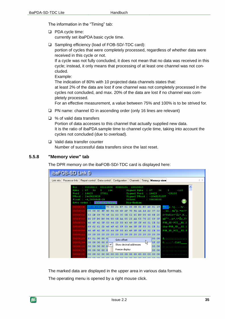
5.5.8 "Memory view" tab
The DPR memory on the ibaFOB-SD/-TDC card is displayed here:
The marked data are displayed in the upper area in various data formats.
The operating menu is opened by a right mouse click.
Handbuch ibaPDA-SD-TDC Lite
36 Issue 2.2
5.6 Diagnostics ibaFOB-SDexp/-TDCexp
On the link level in the tree structure, a number of diagnostic information items are
displayed that refer to communication and the processors of the component.
Tabs:
Configuration: Configured connection parameters
System info: Information about the link status, system information of the coupling
partner, log-in area in the rack link
Timing: Information about the load of the ibaFOB-TDC and access statistics
Active data channels: Overview of PDA channels, their time classes and access
times
Channels in system: Information about all communication channels configured in
the rack link
Memory view: Content of the DPR memory of the ibaFOB-TDC
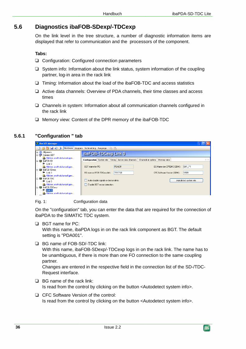
5.6.1 "Configuration " tab
Fig. 1: Configuration data
On the "configuration" tab, you can enter the data that are required for the connection of
ibaPDA to the SIMATIC TDC system.
BGT name for PC:
With this name, ibaPDA logs in on the rack link component as BGT. The default
setting is "PDA001".
BG name of FOB-SD/-TDC link:
With this name, ibaFOB-SDexp/-TDCexp logs in on the rack link. The name has to
be unambiguous, if there is more than one FO connection to the same coupling
partner.
Changes are entered in the respective field in the connection list of the SD-/TDC-
Request interface.
BG name of the rack link:
Is read from the control by clicking on the button <Autodetect system info>.
CFC Software Version of the control:
Is read from the control by clicking on the button <Autodetect system info>.
ibaPDA-SD-TDC Lite Handbuch
Issue 2.2 37
Options
Auto disable signals on broken links:
If this function is activated, the measurement channels of the CPUs which do not
answer are temporarily disabled. This occurs when e.g. a frame is switched off. At
the next start, they are active again.
Enable BGT restart detection:
If this option is activated, also during the measuring process is checked if missing
CPUs become available again. If this is the case, the measurement is being
stopped and restarted with the CPUs now available.
Tip
iba AG recommends to enable both options.
Note
The options are only visible if SD or TDC license is not available. In this case, the configu-
rations on the SIMADYN or TDC request mask are valid.
5.6.2 "System info" tab
Fig. 2: System information
On the "System info" tab, you see information about the connection of ibaPDA and the
SIMATIC TDC system.
Link diagnostics
Link status "OK" or "Error".
Error bytes:
In normal operation, the counters need to remain constant. The long-term moni-
toring of the counters may provide information about the quality of the data
transmission.
Last access time / Max. access time
Duration of the last access or the longest access since resetting.
Button <Reset counters>:
Resets the error counter and the max. access time.
Handbuch ibaPDA-SD-TDC Lite
38 Issue 2.2
System diagnostics
BGT name, BG name, Software version of the coupling partner
Cycle time: time of monitoring the communication (task of the initialization mod-
ule)
System free memory/ whole memory in the GDM / CP53 / CS13
No. of channels: number of configured channels in the communication memory
Central report area
All racks logged in in the rack link incl. ibaPDA are displayed. For every rack, the
following data are displayed.
BGT name of the rack logged in (e.g. of the ibaPDA system)
BG name of the connection, e.g. CS22 or name of the ibaPDA connection
Running life counter of the connection
Central report status (OK or error number)
Button <Issue central report>:
Log in of the ibaFOB-TDCexp in the coupling partner (Not necessary, as this is
done automatically at the first start of the the acquisition by ibaPDA).
5.6.3 "Timing" tab
Fig 3: Timing
On the "Timing" tab, information about the accesses of the card to the SIMATIC TDC
CPUs and the accesses of the card to the data memory (DMA) are displayed.
ibaPDA-SD-TDC Lite Handbuch
Issue 2.2 39
Note
The SD-/TDC-Lite modules are generally read in the T1 time class. All information about
the T2… T5 time classes only apply to the SD/-TDC-Request mode and are not relevant.
Timing
Manually set read cycle times:
Possibility of selecting manually the access times of the single time classes.
Actual read cycle time:
Currently selected or automatically calculated access times.
% valid transfers:
Proportion of the values that can be acquired within the "Actual read cycle time".
Current transfer duration:
Current duration of the data transfer for a sample. By means of the ratio of "Cur-
rent transfer duration" and the lowest "Actual read cycle time", you can see the
capacity utilization of the ibaFOB-TDCexp.
Max. transfer duration:
max. duration of a data transfer since the last <Reset counters>
Dropped transfers:
Number of lost samples. Whenever the "Current transfer duration" is higher than
the "Actual read cycle time", this counter is incremented.
Automatic channel initializations:
Diagnostics counter for automatic actions.
Capacity utilization
You can see the current capacity utilization by having a look at the fields "Current trans-
fer duration", "Max. transfer duration" and "Dropped transfers":
As long as the "Max. transfer duration" is lower than the lowest cycle time, all
samples are transferred without any losses.
If the "Max. transfer duration" is higher, but the "Current transfer duration" lower,
samples get sporadically lost. These samples are counted in "Dropped transfers".
If the "Current transfer duration" lies near the cycle time or above, the card is
overloaded.
You can see the percentage of the lost samples in "% valid transfers".
Image generation
Diagnostic data for the DMA accesses to the ibaPDA data memory.
Reset counters
Using this button, all counters are reset and the calculation of "% valid transfers" and
"Max. transfer duration" are restarted.

Handbuch ibaPDA-SD-TDC Lite
40 Issue 2.2
5.6.4 "Active data channels" tab
Fig. 4: Active data channels
On this tab, all data channels are displayed in a table providing information about the con-
figured time class, the cycle time and the data volume.
By double-clicking on a line with an entry, the memory view of this data channel will be
opened (chap. 5.6.6).
5.6.5 "Channels in system" tab
Fig. 5: Channels
On this tab, you find information about the coupling memory and the communication chan-
nels configured in this memory. In the search string, you can enter '?' as wildcard.
For example, you can display all SD-/TDC-Lite sending channels
The following data are displayed:
Channel name: all communication channels in the memory
Length: Length of all user data
Mode: Channel mode: Refresh, Handshake, Select or Multiple
Status: Receiver / Sender initialized, Channel in operation, Buffer emp-
ty/full
(Caution: the display is not dynamically, but only a snapshot at
the time of access)
ibaPDA-SD-TDC Lite Handbuch
Issue 2.2 41
Note
BGT name and PN are empty for SD-/TDC-Lite modules.
They are only used in the SD-TDC-Request mode for the right assignment of the pro-
cessors.
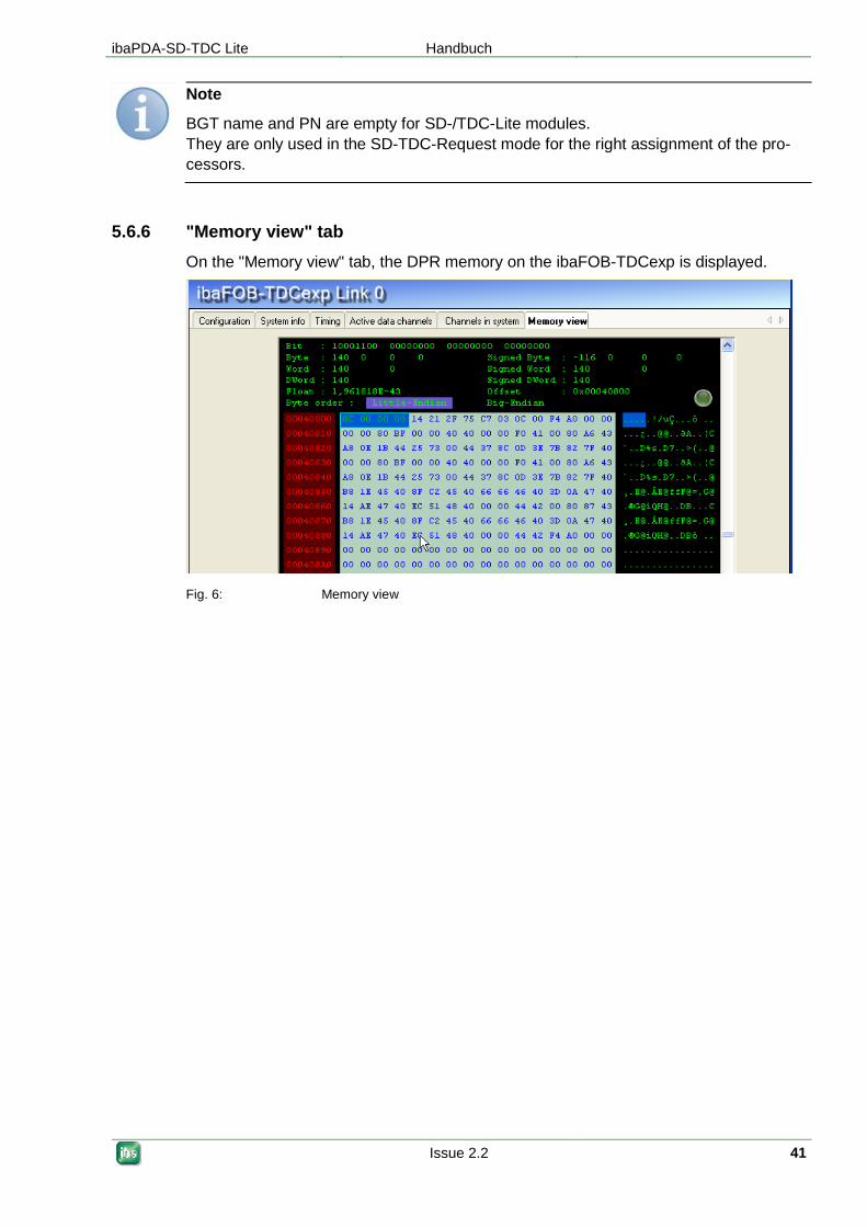
5.6.6 "Memory view" tab
On the "Memory view" tab, the DPR memory on the ibaFOB-TDCexp is displayed.
Fig. 6: Memory view
Handbuch ibaPDA-SD-TDC Lite
42 Issue 2.2
6 Configuration in ibaLogic
Note
The PCI express cards ibaFOB-TDCexp and ibaFOB-SDexp are not being supported by
ibaLogic, yet.
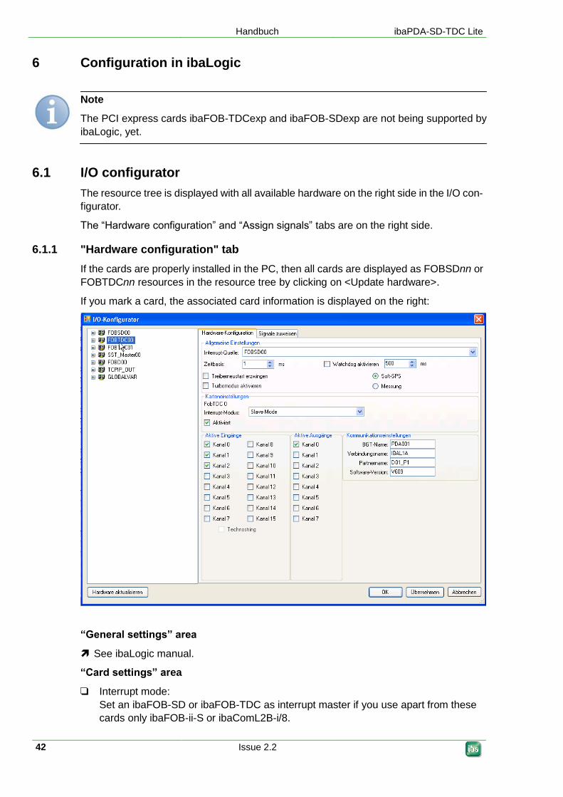
6.1 I/O configurator
The resource tree is displayed with all available hardware on the right side in the I/O con-
figurator.
The “Hardware configuration” and “Assign signals” tabs are on the right side.
6.1.1 "Hardware configuration" tab
If the cards are properly installed in the PC, then all cards are displayed as FOBSDnn or
FOBTDCnn resources in the resource tree by clicking on <Update hardware>.
If you mark a card, the associated card information is displayed on the right:
“General settings” area
See ibaLogic manual.
“Card settings” area
Interrupt mode:
Set an ibaFOB-SD or ibaFOB-TDC as interrupt master if you use apart from these
cards only ibaFOB-ii-S or ibaComL2B-i/8.

ibaPDA-SD-TDC Lite Handbuch
Issue 2.2 43
Note
Make sure that only one interrupt master is set. ibaLogic does not check this setting.
Activated:
The card is automatically activated if you activate at least one input or output chan-
nel in the lower area.
“Communication settings” area
Enter the data required for log-in here:
BGT name of the PC:
with this name, ibaPDA logs into the administration area of the rack link.
Default setting is "PDA001".
Connection name:
with this name, ibaPDA logs into the administration area of the rack link.
Default setting is "IBAL1A".
Important note
The connection name must be unambiguous within the rack link. If you have two connec-
tions to a rack link in an ibaLogic, or two or more ibaLogic systems are connected to a
rack link, then you have to enter different connection names. Make sure that the name is
in accordance with the Siemens guideline, i.e., 6 characters A-Z, 0-9 and _.
Partner name:
Enter the projected name of the CS14, CP53 or GDM memory component
(CP52M0) here.
Software version:
Enter the version identifier of the Siemens software here:
For STRUC: "V42x"
For CFC: "V6xx"
Active inputs and outputs area
The listed input channels 0 through 15 are firmly assigned to the telegrams
M0PDADAT through MFPDADAT.
The output channels 0 through 7 are firmly assigned to the telegrams PDAM0DAT
through PDAM7DAT.
Activate the input and output channels according to the projection on the SIMADYN D
or SIMATIC TDC side.
The technostring channel is not yet implemented.
Handbuch ibaPDA-SD-TDC Lite
44 Issue 2.2
6.1.2 "Assign signals" tab
Important noe
Please do not forget to apply the hardware configuration using the button <OK> or <Ap-
ply> before assigning signals.
For this, see the description in the ibaLogic manual.
Tip
When assigning signals in the case of channels that only have an input or output side, se-
lect "Inputs only" or "Outputs only" in the group characteristics. You can thus avoid the fol-
lowing errors when using the signals.
6.2 ibaLogic – diagnostics
Currently ibaLogic does not include a diagnostic function.
Use the “ibaDiag” diagnostic tool to detect any errors in the configuration.
Important note
Make sure that ibaDiag does not overwrite the current version of the ibaWdmDriver install-
er when starting. Confirm the message box that opens up with “No”
With ibaDiag, you can call up the diagnostic functions that are described in chap. 5.5.
In the “Channels” register you can find:
The data projected on the Siemens side which are necessary for log-in:
"Partner name" and "Software version"
The input channels projected by “Search” with the "M?PDADAT" search mask
The output channels projected by “Search” with the "PDAM?DAT"
search mask
You can find error messages for the configured channels in the "Report" and "Data" reg-
isters.

ibaPDA-SD-TDC Lite Handbuch
Issue 2.2 45
7 Appendix
7.1 Error of sequence control
7.1.1 Analyzing the error counters
The two "Optical fiber_error_0" and "Optical fiber_error_1" cells in the "Link info" register of
the hardware interface include the states of two counters that monitor optical fiber commu-
nication on the lowest level. Some errors are always registered in the start-up phase. Af-
terwards the values have to remain stable.
With separation of optical fiber lines, one or both counters increment permanently.
With systems in continuous operation, long-term observation of the counters can provide
additional information about the quality of transmission.
7.1.2 Errors with diagnostic functions
When accessing the rack link memory, it is checked whether the data are plausible. Im-
plausible data indicate connection errors, poor or damaged cables or errors in the rack
link.
Error Meaning Explanation
0 No error -
0x5000 Time-out with access -
0x5010 Component name of rack link is
faulty
No connection to rack link; malfunc-
tion of optical fiber
0x5011 BGT (rack) name faulty "
0x5012 Version ID faulty "
0x5013 Sampling time faulty "
0x5014 Channel name faulty "
0x5015 Number of channels faulty "
0x5016 Number of racks faulty "
Handbuch ibaPDA-SD-TDC Lite
46 Issue 2.2
7.1.3 Timeout error in ibaPDA
The firmware on the ibaFOB-SD/-TDC card is state-controlled. The ibaPDA commands are
only processed in certain states. If a command is not processed by the firmware due to a
coordination error, then ibaPDA generates a timeout error message with the command
code as error number.
Error correction
Restart ibaPDA acquisition and while doing so activate the "Restart driver" option
(in the I/O Manager – “General” register).
Check whether ibaFOB-SD/-TDC is running (green LED must flash).
Check whether connection is OK (yellow LED must shine).
Error Meaning Explanation
0x04 Timeout with channel log-in -
0x08 Data request with assignment -
0x0C Data reading with assignment -
0x1C Technostring reading with as-
signment
-
ibaPDA-SD-TDC Lite Handbuch
Issue 2.2 47
7.1.4 Timeout errors of sequence control
The interface within the firmware between the sequence control and the driver for access
to the communication memory in the rack link is similar.
The sequence control generates an error message here if the driver is not ready to accept
new transmission/reception assignments.
Error correction
Restart ibaPDA acquisition and while doing so activate the "Restart driver" option
(in the I/O manager – “General” register).
Check whether connection is OK (yellow LED must shine).
Check whether the optical fiber error counters are constant (see chap. 5.2.2)
Error Meaning Explanation
0x7000 No connection -
0x7001 TO with ZB log-in No RS after ZB log-in (step 5)
0x7002 TO with channel log-in No RS after channel log-in (step 7)
0x7003 TO with assignment telegram No RS after assignment telegram (step
11)
0x7004 TO with acknowledgement
telegram
No acknowledgement telegram (step 11)
0x7005 TO with data telegram Driver not ready for assignment: read data
(step 13)
0x7006 TO with data telegram No RS after start: read data (step 14)
0x7008 TO with data telegram No RS with cyclical reading (interrupt rou-
tine)
0x700A TO with assignment telegram No RS with assignment: address book re-
quest
0x700B TO with address book tele-
gram
No RS with reading address book tele-
gram
TO = Time out
RS = Return signal

Handbuch ibaPDA-SD-TDC Lite
48 Issue 2.2
7.2 Errors of the TDC driver
7.2.1 Error classes
Depending on the cause of the error or the necessary reaction on the ibaPDA-/ibaLogic
side, the error messages of the SD-/TDC driver can be divided into various classes:
Temporary status messages, no error;
if error permanently present, then error of class 2 or 3 has occured
Programming error in the ibaFOB-SD/-TDC firmware; please notify iba AG
Error due to inconsistent data, access error via optical fiber to the rack link
Projection error on Siemens side
Projection on Siemens side does not match iba projection
Projection or programming error on ibaPDA side or error in SER04 function blocks
Important note
The error codes 0x6000...0x6FFF listed in the following sections correspond to those in
the SIMADYN D / SIMATIC TDC manual "Diagnostics" section.
More precise descriptions and causes can be found there.

ibaPDA-SD-TDC Lite Handbuch
Issue 2.2 49
7.2.2 Errors with ibaPDA log-in in the computer coupling
Note
The most frequently occurring projection errors are “bolded.”
Error Cl. Meaning Explanation Remedy
0 Not an error, log-in OK; the connectors have the following states: CDM = 0x00FF: coupling OK CDA = 0x0000: coupling released NCP = 0x0001...n no. of connected CP52A0 (incl. ibaPDA) QTS = 0x00FF: coupling initialized BZS = 0x0008: life counter monitoring released ENO = 0x0000: no error
-
#0 Log-in termination with error; the connectors have the following states: - CDM = 0x0000: coupling disrupted - CDA = 0x00FF: coupling blocked - NCP = 0x0000: no. of connected TDC racks (incl. ibaPDA) - QTS = 0x0000: coupling not initialized - BZS = 0x0000: function block switched off - ENO = 0xnnnn: error number, see table
-
0x6AA0 6 Multiple projection The connection name is al-ready entered in the com-puter coupling log-in area. Several connected ibaPDA systems have the same link name.
Change the component name of the connection in the "Link info" menu (chap. 5.2.2)
0x6AA1 2 CIP name known, but CIP not ad-dressable
- -
0x6AA2 5 CIP name unknown Names of the rack link compo-nents in the Siemens projec-tion and the ibaPDA projection do not match.
Check the component name of the rack link component (Chapter 5.2.2)
0x6AA3 2 Impermissible function value of the zbak_cip_suche [search] function (*)
The connector EZU contains the unknown value
-
0x6AA5 3 Too many racks logged in With CS14: 8 slave racks With GDM: 44 TDC racks
-
0x6AA6 Component name of the rack link component is unknown
Names of the rack link com-ponent in the Siemens pro-jection and the ibaPDA pro-jection do not match.
Check the component name of the rack link component (Chapter 5.2.2)
0x6AA7 2 Impermissible function value of the _CS2_anmeldung [log-in] function
The connector EZU contains the unknown value
-
0x6AA8 2 Unknown operating state (*) The connector EZU contains the unknown value
-
0x6AA9 2 SAVE memory too small -
0x6AAA 2 SAVE area unknown -
0x6AAB 2 FOB-SD/-TDC in impermissible sam-pling time (larger than 2 * @CS1 sam-pling time)
Since it is fixedly set in the FOB firmware at 64 ms, the er-ror cannot occur with @CS1 sampling time >32 ms.
Check projection with cen-tral function block @CS1 or @SRACK
0x6AAC 2 No exception memory present - -
0x6AAD 2 No reorganisation memory present - -
0x6AAE 2 Impermissible function value of the zp_fb_init function (*)
The connector EZU contains the unknown value
-
0x6AAF 2 Faulty call of the bsspvw_korrekturwert [correction value] function
- -
0x6AB0 2 Faulty call of the ampi_asop function - -
0x6AB1 2 Wrong coupling type
0x6AB2 2 3 CS21 already present
Handbuch ibaPDA-SD-TDC Lite
50 Issue 2.2
0x6AB3 5 Software version incompatible Version of the Siemens software does not match the version of the connect-ed racks.
Change the SW version in the "Link info" menu (see Chap 5.2.2).
0x6AB4 4 Memory sizes do not match FOB-TDC expects CP52M0 with 2MBytes
Check TDC projection
7.2.3 Errors with channel log-in
Error Cl. Meaning Explanation Remedy
0 No error, log-in OK - -
0x0031 2 Log-in previously not possible - -
0x0032 2 Error with provision of memory - -
0x0033 2 Wrong transmission/reception identifi-cation
- -
0x0034 2 Too much partial information - -
0x0035 2 Target information not identifiable - -
0x0036 2 Target information faulty - -
0x0037 2 Channel name too long - -
0x0038 2 Address level 1 too long - -
0x0039 2 Address level 2 too long - -
0x003A 2 Wrong address string - -
0x003B 2 @Ziel [target] rack name too long - -
0x003C 2 Length of target component name wrong
- -
0x003D 2 Length of target interface wrong - -
0x003E 2 Target interface information wrong - -
0x6031 1 CIP entry found No connection Check optical fiber con-nection
0x6032 1 Coupling for initialization released No connection Check optical fiber con-nection
0x6033 3 Coupling release missing CP52M0 memory is currently being reorganized or is blocked due to access error
New ibaPDA log-in
0x6034 1 DEXDO3 released
0x6035 3 DEXDO3 release missing CP52M0 memory is blocked due to access error
New ibaPDA login; check optical fiber con-nection
0x6036 1 Coupling free, initialization running - -
0x6037 1 Semaphore was blocked - -
0x6038 1 Semaphore already blocked - -
0x6039 1 Channel name known - -
0x603A 1 Search not yet concluded - -
0x603B 3 Channel name unknown Subsequent error -
0x603F 1 Channel initialization concluded in faulty manner
- -
0x6040 3 Data inconsistent Access error Check optical fiber con-nection
0x6050 3 Buffer status invalid - Check optical fiber con-nection
0x6051 3 Channel status invalid - Check optical fiber con-nection
0x6052 3 Buffer semaphore already blocked - Check optical fiber con-nection
0x6053 1 No more space in ZCVWL list Internal list is full, since with each channel log-in list spaces are occupied but are no longer released.
(CIP3 concept!)
Activate ibaPDA "Driver restart" and restart ac-quisition
0x6054 2 No more memory space in ZCDAT area - -
ibaPDA-SD-TDC Lite Handbuch
Issue 2.2 51
Error Cl. Meaning Explanation Remedy
0x6055 2 CIP name known, but CIP not ad-dressable
- -
0x6056 5 CIP name unknown Component name of the rack link component in the Sie-mens configuration does not match the ibaPDA configura-tion.
Check TDC configuration and ibaPDA configuration
0x6057 2 Unknown zbak_cip_suche [search] function value
- -
0x6058 2 ZINI bus identification invalid - -
0x6059 4 Too little memory space Channel no longer fits in memory
Check TDC configuration
0x605A 2 Wrong channel mode Channel mode is fixedly set in firmware and service function blocks
-
0x605B 2
Wrong user data structure Fixedly set in firmware and service function blocks
-
0x605C 4 User data length too short Possibly after switching STRUC <-> CFC
Activate ibaPDA "Driver restart" and restart ac-quisition
0x605D 4 6
Wrong service type With TDC Lite: PROCESS DATA With TDC symbolic request: SERVICE
Check TDC configuration
7.2.4 Errors with data transfer
Error Cl. Meaning Explanation Remedy
0x6000 No error, data transfer OK - -
0x6001 5 Transmitter not ready to start No transmission channel projected with this name
Check SD/TDC configu-ration
0x6002 5 Receiver not ready to start No reception channel pro-jected with this name
Check SD/TDC configu-ration
0x6003 5 No assignment, i.e., buffer empty Transmitter is too slow or not released
Check SD/TDC configu-ration (sampling time)
0x6004 5 Buffer full (with transmitter, hand-shake)
Receiver is too slow or not released
Check SD/TDC configu-ration (sampling time)
0x6005 3 DEXDO3 release missing Initialization function block @CS1 / @SRACK missing
Check SD/TDC configu-ration
0x6006 1 Coupling free, initialization running - -
0x6007 1 Semaphore was blocked - -
0x6FF0 2 Buffer pointer = 0 - -
0x6FF1 2 Data length = 0 with writing - -

Handbuch ibaPDA-SD-TDC Lite
52 Issue 2.2
7.3 Abbreviations
BG board, component
BGT rack
CFC continuous flow chart, graphic programming language
CIP communication interface for SD and TDC
CP52M0 GDM memory component
CP52IO GDM interface component
CP52A0 TDC interface component for GDM
CP53 TDC/SD rack link can be configured as master and slave
CS14 SIMADYN D rack link master
CS22 SIMADYN D rack link slave
DPR dual port RAM, interface ibaPDA <--> FOB TDC
FOB fiber optical board, optical fiber interface component
GDM global data memory,
central communication memory in the TDC system
OF optical fiber
PDA process data acquisition
PN SIMATIC TDC processor component, CPU
RK rack link, component CS12, CS13, CS14, CP53, GDM
SD SIMADYN D
STRUC graphic programming language for SIMADYN D
TDC SIMATIC TDC
TS Technostring
ZB central function block, initialization function block for communication
ibaPDA-SD-TDC Lite Handbuch
Issue 2.2 53
8 Support and contact
Support
Phone: +49 911 97282-14
Fax: +49 911 97282-33
E-mail: [email protected]
Note
If you require support, specify the serial number (iba-S/N) of the product.
Contact
Headquarters
iba AG
Koenigswarterstr. 44
90762 Fuerth
Germany
Phone: +49 911 97282-0
Fax: +49 911 97282-33
E-mail: [email protected]
Contact: Mr. Harald Opel
Regional and Worldwide
For contact data of your regional iba office or representative please refer to our web site
www.iba-ag.com.


![Torq-Lite Digital Brochure [1].pdf - TKH](https://static.fdokumen.com/doc/165x107/631b1791c51d6b41aa051771/torq-lite-digital-brochure-1pdf-tkh.jpg)