24111
18
Journal of Engineering Volume 14 September 2008 Number 3 2786 LAMINAR NATURAL CONVECTION HEAT TRANSFER BETWEEN DUCTED PARALLEL PLATES Dr. Yasin K. Salman Eng. Hazim S.Hamad Nuclear Department Mechanical Department ABSTRACT Laminar natural convection heat transfer to air flow in a ducted two parallel plates subjected to same constant heat flux has been studied experimentally. In this study a test rig has been designed and constructed to allow studying the effect of plate spacing and plates angle of inclination on the heat transfer process. The study covers three plate spacing 15 mm, 35mm and 60 mm that makes plate aspect ratio (AR) 24, 10.285 and 6, The heat flux implemented in all test runs varies between 55 W/m 2 – 340 W/m 2 that makes the modified Rayleigh number (Ra) varies from 10 5 -10 8 . Experimental results presented as plate temperature distribution, variation of local heat transfer coefficient and the relation between Nu and Ra, reveal for the range of parameters mentioned above, an improvement in heat transfer process as the AR values change from 6 to 24 and the improvement rates is higher for the lower heat flux test (lower Ra). A correlation of the results were made in the form of Nuvr (Gr/AR) in which the effect of duct aspect ratio (AR) has been introduced. اﻟﺨﻼﺻﺔﻮازﯾﯿﻦ ﻣﺘﻮﺣﯿﻦ ﺑﻠﺮى ﻣﺠﻲ ﻓﻮاء اﻟﮭﺎن ﻟﺠﺮﯾﺎﻗﻲ اﻟﻄﺒﻲ اﻟﻄﺒﯿﻌﻞ ﺑﺎﻟﺤﻤﺮارة اﻟﺤﺎل ﻻﻧﺘﻘﺔ وﻧﻈﺮﯾﺔ ﻋﻤﻠﯿﺔ دراﺳﺚ اﻟﺒﺤﺬا ھﻲ ﻓﻢ ﺗ ﺛﺎﺑﺖ ﺣﺮاري وﺑﻔﯿﺾ ﻣﺘﻤﺎﺛﻞ ﺑﺸﻜﻞﺨﻨﯿﻦﺴ ﻣ. ﺎﻓﺔﺴ اﻟﻤﺛﯿﺮﺄ ﺗ دراﺳﺔ ﻣﻦﻤﻜﻦُ ﯾ ﻣﺨﺘﺒﺮي ﺟﮭﺎز وﺑﻨﺎءﻤﯿﻢﺼ ﺗﻰ ﻋﻠﺷﻤﻞ أ اﻟﻌﻤﻠﻲﺐ اﻟﺠﺎﻧ وزﺨﻨﯿﻦﺴ اﻟﻤ اﻟﻠﻮﺣﯿﻦ ﺑﯿﻦ اﻟﺤﺮارةﻧﺘﻘﺎل أ ﻋﻤﻠﯿﺔﻰ ﻋﻠ اﻟﻠﻮﺣﯿﻦ ﻣﯿﻼن اوﯾﺔ. ﻲ وھﺎﻓﺎتﺴ ﻣﻼث ﺛﺖﻄ ﻏﺔراﺳﺪ اﻟ15 mm و35 mm و60 mm ﺔ اﻟﺒﺎﻋﯿﺒﺔﺴ ﻟﻠﻨﯿﻢ ﻗﻲ ﺗﻌﻄﻲ واﻟﺘ(AR = L/D) ٢٤ ، ١٠.٢٨٥ ، ٦ ﻮاﻟﻲ اﻟﺘﻰ ﻋﻠ. ﺰ اﻟﻤﺠﮭﺮاري اﻟﺤﯿﺾ اﻟﻔىﺪ ﻣﺎن ﻛﻊ وﻟﺠﻤﯿ ﻟﻠﻮﺣﯿﻦ اﻻﺧﺘﺒﺎرات ﺑﯿﻦح ﯾﺘﺮاو340 W/m 2 – 55 W/m 2 ا ﯾﺠﻌﻞ وھﺬاﻮر اﻟﻤﻄﻲ راﯾﻠﻢ رﻗﯿﻢ ﺑﻘﺮﯿﻐ ﻟﺘ(Ra) ﯿﻦ ﺑحﺮاو ﺗﺘ١٠ ٨ – ١٠ ٥ . ﻮﻗﻌﻲ اﻟﻤﺮارة اﻟﺤﺎلﻧﺘﻘ أﻞ ﻣﻌﺎﻣﺮﯿﻐ وﺗحﻮ اﻟﻠﻰ ﻋﻠﺮارة اﻟﺤﺎت درﺟﻊ ﺗﻮزﯾﻜﻞ ﺑﺸﺖﺿ ﻋﺮﻲ واﻟﺘﺔ اﻟﻌﻤﻠﯿﺋﺞﺎ اﻟﻨﺘﻠﺖﺴ ﻧ رﻗﻢ ﺑﯿﻦ واﻟﻌﻼﻗﺔ(Nu) راﯾﻠﻲ رﻗﻢﻊ ﻣ(Ra) اﻟﺤﺎلﻧﺘﻘ أﺔ ﻋﻤﻠﯿﻲ ﻓﻦﺴ ﺗﺤهﻼﻋ أﻮرةﻛﺬ اﻟﻤ اﻟﻤﻘﺎدﯾﺮىﺪ وﻟﻤﺸﻔﺖ ﻛﺮﯿﻐ ﻟﺘ ﺮارة ﻗﯿﻢAr ﻦ ﻣ٦ ﻰﻟ إ٢٤ ﻨﺨﻔﺾ اﻟﻤﺮاري اﻟﺤﯿﺾ اﻟﻔﯿﻢ ﻟﻘﻰﻋﻠ أﻦﺴ اﻟﺘﺤ وﯾﻜﻮن) ﯿﻢ ﻟﻘRa ﻨﺨﻔﺾ اﻟﻤ.( ﻰﻟ إﺎ ﺗﺤﻮﯾﻠﮭﻢ ﺗﺔ اﻟﻌﻤﻠﯿﺋﺞﺎ اﻟﻨﺘﺮى ﻟﻠﻤﺠﺔ اﻟﺒﺎﻋﯿﺒﺔﺴ اﻟﻨﻰﻟ إ اﻟﻤﻄﻮر راﯾﻠﻲﺒﺔﺴ وﻧﻠﺖﺴ ﻧ رﻗﻢ ﺑﯿﻦرﺗﺒﺎطﯿﺔ أ ﻋﻼﻗﺎت(Gr/Ar) ﻲ ﻓﺔ اﻟﺒﺎﻋﯿﺒﺔﺴ اﻟﻨﺛﯿﺮﺄ ﺗﺮ ﺗﻈﮭﻲ واﻟﺘ اﻧﺘﻘﺎل أ ﻋﻤﻠﯿﺔ ﻟﺤﺮارة. INTRODUCTION The heat transfer characteristics of laminar natural convection flow of air between vertical parallel plates receiving renewed interest in the heat research community. This comes primarily in response to the problem of thermal control of microelectronic equipment. Passive (natural convective) cooling of communication and other microelectronic equipment continues to play a prominent role in thermal management of such systems because of its characteristically low operating noise level, low cost, ease of maintenance, and simplicity. How ever basic understanding of the fundamental mechanisms for natural convective heat transfer is lacking. (Incropera,1986) reported an experimental study focusing on local heat transfer phenomena in an asymmetrically heated, vertical parallel plate channel with laminar air flow in the high Rayleigh number regime. Natural convective heat transfer along vertical plates has been studied previously by several investigators. The pioneering experimental work of (Elenbaas 1942) laid the foundation for study of natural convection in isothermal parallel plate channels. A subsequent analytical study by Bodoia
Transcript of 24111

Journal of Engineering Volume 14 September 2008 Number 3
2786
LAMINAR NATURAL CONVECTION HEAT TRANSFER BETWEEN DUCTED PARALLEL PLATES
Dr. Yasin K. Salman Eng. Hazim S.Hamad Nuclear Department Mechanical Department
ABSTRACT
Laminar natural convection heat transfer to air flow in a ducted two parallel plates subjected to same constant heat flux has been studied experimentally. In this study a test rig has been designed and constructed to allow studying the effect of plate spacing and plates angle of inclination on the heat transfer process. The study covers three plate spacing 15 mm, 35mm and 60 mm that makes plate aspect ratio (AR) 24, 10.285 and 6, The heat flux implemented in all test runs varies between 55 W/m2 – 340 W/m2 that makes the modified Rayleigh number (Ra) varies from 105 -108 . Experimental results presented as plate temperature distribution, variation of local heat transfer coefficient and the relation between Nu and Ra, reveal for the range of parameters mentioned above, an improvement in heat transfer process as the AR values change from 6 to 24 and the improvement rates is higher for the lower heat flux test (lower Ra). A correlation of the results were made in the form of Nuvr (Gr/AR) in which the effect of duct aspect ratio (AR) has been introduced.
الخالصةت م ف ي ھ ذا البح ث دراس ة عملی ة ونظری ة النتق ال الح رارة بالحم ل الطبیع ي الطب اقي لجری ان الھ واء ف ي مج رى بل وحین مت وازیین
الجانب العملي أشمل على تصمیم وبناء جھاز مختبري یُمكن من دراسة تأثیر المس افة . مسخنین بشكل متماثل وبفیض حراري ثابت mm 35و mm 15الدراس ة غط ت ث الث مس افات وھ ي . اویة میالن اللوحین على عملیة أنتقال الحرارةبین اللوحین المسخنین وز
ك ان م دى الف یض الح راري المجھ ز . عل ى الت والي ٦، ١٠.٢٨٥، ٢٤ (AR = L/D)والت ي تعط ي ق یم للنس بة الباعی ة mm 60وتت راوح ب ین (Ra)لتغی ر بق یم رق م رایل ي المط ور وھذا یجعل ا W/m2 – 55 W/m2 340یتراوح بین االختباراتللوحین ولجمیع
النت ائج العملی ة والت ي عرض ت بش كل توزی ع درج ات الح رارة عل ى الل وح وتغی ر معام ل أنتق ال الح رارة الم وقعي .١٠٥ – ١٠٨رارة لتغی ر كشفت ولمدى المقادیر الم ذكورة أع اله تحس ن ف ي عملی ة أنتق ال الح (Ra)مع رقم رایلي (Nu)والعالقة بین رقم نسلت
النت ائج العملی ة ت م تحویلھ ا إل ى ). الم نخفض Raلق یم (ویكون التحسن أعلى لق یم الف یض الح راري الم نخفض ٢٤إلى ٦من Arقیم والت ي تظھ ر ت أثیر النس بة الباعی ة ف ي (Gr/Ar)عالقات أرتباطیة بین رقم نسلت ونسبة رایلي المطور إل ى النس بة الباعی ة للمج رى
.لحرارةعملیة أنتقال ا
INTRODUCTION The heat transfer characteristics of laminar natural convection flow of air between vertical
parallel plates receiving renewed interest in the heat research community. This comes primarily in response to the problem of thermal control of microelectronic equipment. Passive (natural convective) cooling of communication and other microelectronic equipment continues to play a prominent role in thermal management of such systems because of its characteristically low operating noise level, low cost, ease of maintenance, and simplicity. How ever basic understanding of the fundamental mechanisms for natural convective heat transfer is lacking. (Incropera,1986) reported an experimental study focusing on local heat transfer phenomena in an asymmetrically heated, vertical parallel plate channel with laminar air flow in the high Rayleigh number regime.
Natural convective heat transfer along vertical plates has been studied previously by several investigators. The pioneering experimental work of (Elenbaas 1942) laid the foundation for study of natural convection in isothermal parallel plate channels. A subsequent analytical study by Bodoia

Y. K. Salman Laminar Natural Convection Heat Transfer H. S.Hamad Between Ducted Parallel Plates
2787
and (Osterle 1962) served to confirm Elenbaas’ experiments. More recently, (Sparrow and
Bahrami 1980) studied experimentally the analogous isothermal plate boundary using the naphthalene sublimation technique, examining the effect of open edges at the plate lateral extremities.Investigations of heat transfer in vertical. Plates with the uniform heat flux thermal boundary condition are fewer in number. ( Sparrow and Gregg 1956) developed a similarity solution for natural convection along an isolated vertical, uniform heat flux surface. The governing equations have been solved for parallel plate geometry in developing flow region (Aung et al., 1972) and the fully developed limit (Aung, 1972) for both symmetrically and asymmetrically heated isothermal and isoflux plates. Limits bounding three possible flow regimes (fully developed, developing and single plate) were proposed as a function solely of the modified Grashof number, defined by
( )12
4
Lb
KvgBqbGr =
Note that the modified Grashof number as defined for use in the study of heat transfer in vertical parallel plate channels includes the channel aspect ratio b/H. (Raithby and Holland 1975) developed a simplified analysis for the prediction of the local heat transfer coefficient in a vertical parallel plate channel with arbitrary wall temperature distribution. Their results compared favorable with the experiments and analytical work of previous investigators. (Miyatake et al. 1973) performed both analysis and experiments for natural convection between vertical parallel plates with the some thermal boundary conditions as this study. Experiments were performed with water as the working fluid, and results were compared to the theoretical predictions with good agreement.
Experimental data on natural convection flow of air between vertical parallel plates with uniform heat flux are nearly nonexistent. (Wirtz and Stutzman 1982) reported measurements of local heat transfer in a symmetrically heated channel. correlations were developed for the local heat transfer along the channel and the maximum wall temperature as a function of relevant problem parameters. Their experiments spanned the range of modified Rayleigh number from 17.7 to 2414. More recently, an investigation of the optimum spacing of vertical parallel plates with a variety of thermal boundary conditions was undertaken by (Bar-Cohen and Roshsenow 1984). Their paper reviews thoroughly the available data and describes the recommended correlations.
The present paper reports laboratory experiments designed to determine local heat transfer characteristics for natural convective flow in a vertical parallel plate channel, each wall heated with uniform heat flux. In many practical applications the imposed heat flux at the boundary and characteristic of the system dictate moderate to high Rayleigh number natural convection, while still in the laminar regime. Additionally, the symmetric heating boundary condition studied is a limiting case prototypical of the arrays of heat-dissipating devices used in the electronic industry. The experiments reported here were designed to characterize the local and average heat transfer of such system. To this end the heating rates and channel wall spacing were selected such that the Rayleigh numbers were in the range 503 ≤ Ra* ≤ 1.75 × 10⁷. EXPERIMENTAL APPARATUS
The experimental apparatus was designed and conducted to cover all the ranges of the parameters which affect natural convection heat transfer process from a ducted two parallel plates. The parameters include the plate heat flux, the parallel plates orientation and plate height to the plates spacing ratio. A schematic diagram and photograph of the experimental setup of the apparatus are shown in Fig.1 and plate (1) respectively. The apparatus consists essentially of an open air circuit mounted on a wood board (D) which can be rotated around a horizontal spindle (S). The inclination angle of the open air circuit to the horizontal can then be adjusted as required with

Journal of Engineering Volume 14 September 2008 Number 3
2788
help a protractor fixed on the wooden board side. The open air circuit consists of light wooden shield (A) with a dimension of (500*500*500 mm). The shield opened (200*200 mm) at bottom side to form an inlet opening (B) through which the air move freely without restriction to the ducted parallel plates via the wooden shield in the same time the wooden shield is used to avoid the effect of air currents outside the shield to interfere with free convection created by heated parallel plates at parallel plates entrance. The open air circuit finished with test section (C).
The test section details are shown in Fig.2 which consists of rectangular passage of 360 mm
length, 150 mm width and (b) height (represent the parallel plates spacing)(15, 35 and 60 mm).The rectangular passage created by two identical heated upper and lower flat plates (A) and (B), respectively (for the vertical and inclined orientation).
Each plate has a length equal to 360 mm, width of 150 mm and height of 60 mm . The lower plate (B) of Fig.2 was fixed firmly to the wooded board with four bolts (C) while the upper plate left to adjust its position related to the lower plate with the help of 4 bolts (R) and the two vertical sides of the passage (V) which work as a spacer between plates. The vertical shorter sides of the passage (V) were a three set of two identical glass strips have a length of (400 mm), a width (b) and 10 mm thick. The glass strips work as a spacer between the two heated parallel plates with the width (b) takes three values 15 mm, 35 mm and 60 mm that generate a passage length to spacing ratio (L/b) which represent the aspect ratio (AR) values (24, 10.286 and 6) respectively.
The upper and lower heated plates of the test section were designed and manufactured to be the duct side heated with a constant heat flux (CHF) so the situations of either upper side heated and lower side heated only, lower side heated only and both side heated can be a achieved by powering the duct side required. The details of these plates are shown in plate (1). The heated surface was constructed from three layers glued together to form a composite heater.
The composite heating element, shown in figure (2) and plate (2) consisted of heating element as a Nickrom tape 4 mm wide and 0.01 mm thick wounded uniformly flat on a 2 mm mica sheet (H) (see plate (2) the heating element then covered from both sides by 2mm mica sheet (K) and (J). The heating element with covers fixed on 0.5 mm thick stainless steel plate (N). All thermocouples penetrate through the mica layers and mounted to the stainless steel plate. Thermocouples locations are depicted in plate (9). The heated plate with thermocouples which has been shown in plate (3), was attached permanently on 6mm thick, 150 mm wide and 360 mm long Teflon plate (L) then on a layer of 25 mm thick ceramic fiber (M) and finally all previous layers wholly fixed firmly in 20 mm thick a wooden cover (P). The wooden cover has been cut from piece of wood of a thickness equal to 40 mm and it was shaped nicely in frontal part to create with other plate a bell mouth at the test section entrance and to form with the two glass strips a smooth entrance to the air passage.
The heat loss through the heated plate lagging been accounted by inserting a thermocouple in the ceramic fiber layer. Then knowing the temperature gradient in the lagging and its thermal conductivity therefore the heat loss by conduction can be evaluated, the losses were found to vary between 2% to 3% of the total plate input power.
The inlet air temperature was measured by a thermocouple (W) located at the wooden box while the air exit temperature was measured by three thermocouple (V) located at the passage exit after extended the passage by 100 mm by a wooden duct (U) and The average of these three thermocouples represents the air exit bulk temperature. The local air temperature variation along the passage was calculated by fitting straight line interpolation between the measured inlet and outlet bulk air temperature.

Y. K. Salman Laminar Natural Convection Heat Transfer H. S.Hamad Between Ducted Parallel Plates
2789
DATA ANALYSIS
Power calculations The total input power supplied can calculate: Qt = V.I ( 2)
The convection and radiation heat transferred from each plate surfaces:
QC+r = Qt – Qcond ( 3)
Where:
Qcond = is the conduction heat losses (in the composite insulation).
QC+r = convection and radiation heat losses. (4)
Where:
I = AC – current measured by clamp-meter.
V = AC– voltage measured by digital Avo - meter.
Qcond = k Ac ΔT/ΔX
ΔT: Temperature different inside the insulation.
ΔX = the length of insulation.
Ac = cross sectional area (b * L)
Where:
b = the space between two plate
L = length of the plate.
The convective and radiation heat flux can be represented by:
= +
+ 2s
rcrc m
WA
Qq (5)
Where:
L*WAs=
=W width of the plate.
and the radiation heat flux can be represented by:
( )244 )(.
mWTTFq Wsxr −= σ (6)
Where:
:σ Stephen – Boltzman constant 248
.10*669.5
mkW−=
:F shape factor = )111(21
−ε
+ε

Journal of Engineering Volume 14 September 2008 Number 3
2790
:, 21 δδ surface emmisivity value (for inner face of the two plates).
:Tsx Local surface temperature.
:Tw Average wall temperature.
The convection heat flux can be represented by:
qc = qc+r – qr (7)
The convection heat flux, which is used to calculate the local and average heat transfer coefficient as follows:
hx =qc/ (Tsx– Tbx) (8)
Where Tbx: Local bulk air temperature.
All the properties were evaluated at the mean film temperature.
2)TT(T bxsx
fx+
= (9)
Where:
Tbx = Local bulk air temperature.
Tfx = Local mean film temperature.
The local Nusselt number based on hydraulic diameter (Nub) can be determine as: fxb KbhNu /.= (10)
The local Nusselt number based on length in the direction of flow (Nux) can be calculated as: fxx KXhNu /.= (11)
The average value of Nusselt number ( )xNu can be calculated based on the calculated average heat transfer coefficient as the following:
∫=
=
=Lx
0xx dx.h
L1h (12)
Also, we can calculated the average Nusselt number based on the calculated average surface temperature and average bulk air temperature as follows:
∫=
=
=Lx
xsxs dxT
LT
.0
.1 (13)
2TT
T 2b1bb
+= (14)
2TT
T bsf
+= (15)
The average value of parameter can be calculated as the follows:
( )bsf
c
TTkbq
Nu−
=.
. (16)

Y. K. Salman Laminar Natural Convection Heat Transfer H. S.Hamad Between Ducted Parallel Plates
2791
Fig.1 Schematic Diagram of the Test Rig
(A) wooden shield (B) inlet opening (C ) test section (D) wood board (S) spindle (W) thermocouple at inlet (V) thermocouple at Exit (M) protractor (U) Wooden duct at exit

Journal of Engineering Volume 14 September 2008 Number 3
2792
Fig.2 Parallel Plate and Composite Heater Details

Y. K. Salman Laminar Natural Convection Heat Transfer H. S.Hamad Between Ducted Parallel Plates
2793
RESULTS AND DISCUSSION Surface Temperature
The variation of surface temperature a long both upper and lower plates are shown in Figs.3 and 4 the variation of surface temperature for different plate heat flux and for three aspect ratios (AR) (24, 10.285 & 6) is presented in Figs. 3(a), Fig.3(b) and Fig.3(c) respectively. In general variation are smooth with little scatter. As expected, the wall temperatures are higher for higher heating rates; the convective driving potential must increase in order to dissipate the ohmic generation. Local temperature are relatively low near the channel entrance where the thermal boundary layer is thin. Then wall temperature climb quickly as the boundary layer thickness increases. There was no indication of transition to turbulent flow in any of the experiments. One also notice a slight decrease in the wall temperature near X/L=1 this reduction can be attribute to end losses. The variation of surface temperature for different duct aspect ratio and for four surface heat flux (55.6 W/m2, 114.24, 220 and 340 W/m2) are shown in Figs.4(a), Fig.4(b), Fig.4(c) and Fig.4(d) respectively. The figure reveals the high aspect ratio exhibits a reeducation in surface temperature at low heat flux in comparison with lower aspect ratio and can be attribute to a low natural flow created and expected to be a fully developed earlier. Local Heat Transfer Coefficient
Variation of the local heat transfer coefficient variation along the plate for different heat flux and for three plates spacing ratio (24,10.285 and 6) are shown in Fig 5 (a), Fig 5(b), Fig 5(c). As expected the heat transfer coefficient are higher for higher heat flux as the convective driving potential must increase in order to dissipate the ohmic generation via. Increasing local heat transfer coefficient. Local heat transfer coefficient is higher near the channel entrance since the boundary layer thickness is very small and temperature difference between surface and bulk air temperature is very small. As boundary layer thickness increase temperature difference increases that makes (hx) decreases downstream. The variation of local heat transfer coefficient along the plate for different aspect ratio and for four plates heat flux (55.6 W/m2, 114.24, 220 and 340 W/m2) are shown in Fig.6(a), Fig.6(b), Fig.6(c) and Fig.6(d) respectively. Figure depicted that the local heat transfer coefficient increases especially at low heat flux. The following simplified steps were used to analyze the heat transfer process for the air flow in the channel was subjected to uniform wall heat flux boundary condition. Correlation of Nusselt Number as a Function of Grashof Number
The correlation equation for the average Nusselt number in terms of the channel Rayleigh Number Ra b/L are proposed.
195.0)/(277.0 ARRaNu = ( 17)

Journal of Engineering Volume 14 September 2008 Number 3
2794
Plate (3) shows wood frame & bell mouth
Fig. 7 shows the correlation between average Nusselt number and modify Rayleigh number in which the effect of duct aspect ratio was accounted. The above equation correlation for whole duct ( ) 1LX = .
Plate (1) Experimental Apparatus
Plate (2) shows the heater
Plate (4) shows selector switch

Y. K. Salman Laminar Natural Convection Heat Transfer H. S.Hamad Between Ducted Parallel Plates
2795
Plate (5) shows variac (voltage regulator)
Plate (6) shows stabilizer Plate (7) shows digital thermometer reader
Plate (9) shows thermocouple location Plate (8) shows digital clap meter

Journal of Engineering Volume 14 September 2008 Number 3
2796
0 0.1 0.2 0.3 0.4x-Axis
20
30
40
50
60
70
80
T(x)
q=55.6 W/m2q=114.24W/m2q=220W/m2q=340W/m2
(a)
0 0.1 0.2 0.3 0.4x-Axis (m)
20
30
40
50
60
70
80
T(x)
q=55.6 W/m2q=114.24W/m2q=220W/m2q=340W/m2
(b)
0 0.1 0.2 0.3 0.4x-Axis (m)
20
30
40
50
60
70
80
T(x)
q=55.6 W/m2q=114.24W/m2q=220W/m2q=340W/m2
(c)
Fig.3 Variation of the heated wall temperature with height for different heat flux at three aspect ratio: (a) AR = 24 (b) AR = 10.285 (c) AR = 6
Y. K. Salman Laminar Natural Convection Heat Transfer H. S.Hamad Between Ducted Parallel Plates
2797
0 0.1 0.2 0.3 0.4x-Axis (m)
15
20
25
30
35
40
45
50
55
60
65
70
75
80T(
x)C
AR=24AR=10.285AR=6
(a)
0 0.1 0.2 0.3 0.4x-Axis (m)
15
20
25
30
35
40
45
50
55
60
65
70
75
80
T(x)
C
AR=24AR=10.285AR=6
(b)
0 0.1 0.2 0.3 0.4x-Axis (m)
15
20
25
30
35
40
45
50
55
60
65
70
75
80
T(x)
C
AR=24AR=10.285AR=6
(c)
0 0.1 0.2 0.3 0.4x-Axis (m)
15
20
25
30
35
40
45
50
55
60
65
70
75
80T(
x)C
AR=24AR=10.285AR=6
(d)
Fig.4 Variation of plate surface temperature with height for different aspect ratio and for four heat flux: (a) 6.55q = W/m2 (b) 24.114q = W/m2 (c) 220q = W/m2 (d) 340q = W/m2

Journal of Engineering Volume 14 September 2008 Number 3
2798
0 0.1 0.2 0.3 0.4x-Axis (m)
0
1
2
3
4
5
6
7
8
9
10
11
12
13
14
15
h(x)
q=55.6 W/m2q=114.24 W/m2q=120 W/m2q=340 W/m2
(c)
0 0.1 0.2 0.3 0.4x-Axis (m)
0
1
2
3
4
5
6
7
8
9
10
11
12
13
14
15
h(x)
q=55.6 W/m2q=114.24 W/m2q=120 W/m2q=340 W/m2
(b)
0 0.1 0.2 0.3 0.4x-Axis (m)
0
1
2
3
4
5
6
7
8
9
10
11
12
13
14
15
h(x)
q=55.6 W/m2q=114.24 W/m2q=120 W/m2q=340 W/m2
(a)
Fig.5 Variation of the local heat transfer coefficients along height for different heat flux at for three aspect ratio:
(a) Ar = 24 (b) Ar = 10.285 (c) Ar = 6

Y. K. Salman Laminar Natural Convection Heat Transfer H. S.Hamad Between Ducted Parallel Plates
2799
0 0.1 0.2 0.3 0.4x-Axis (m)
0
1
2
3
4
5
6
7
8
9
10
11
12
13
14
15h(
x)
AR= 24AR = 10.285AR= 6
(d)
0 0.1 0.2 0.3 0.4x-Axis (m)
0
1
2
3
4
5
6
7
8
9
10
11
12
13
14
15h(
x)AR= 24AR= 10.285AR = 6
(a)
0 0.1 0.2 0.3 0.4x-Axis (m)
0
1
2
3
4
5
6
7
8
9
10
11
12
13
14
15
h(x)
AR= 24AR= 10.285AR = 6
(b)
0 0.1 0.2 0.3 0.4x-Axis (m)
0
1
2
3
4
5
6
7
8
9
10
11
12
13
14
15
h(x)
AR= 24AR= 10.285AR = 6
(c)
Fig.6 Variation of the local heat transfer coefficients along plate height for different for four heat flux: (a) q = 55.6 W/m2 (b) q = 114.24 W/m2 (c) q = 220 W/m2(d) q = 340 W/m2

Journal of Engineering Volume 14 September 2008 Number 3
2800
104 105 106 107 108
Gr/AR
2
4
6
810
Nu
Nu = 0.24 (Gr/AR) at x/L = 0.9
Nu = 0.258(Gr/AR) at x/L= 0.97
Nu = 0.277(Gr/AR) at x/L = 1
0.2
0.197
0.195
Fig.7 Variation of the average Nusselt number near the top of the heated surface as a function of modified Grashof number

Y. K. Salman Laminar Natural Convection Heat Transfer H. S.Hamad Between Ducted Parallel Plates
2801
CONCLUSIONS
From experimental result and for the heat flux range 22 m/W350qm/W50 ≤≤ the following concluding points can be deduced.
1. The variation of the surface temperature a long the test section is affected by many factors
summarized in the following points: a. The surface temperature increases as the heat flux increases for the same aspect ratio and
same angle of inclination. b. The surface temperature increases as the Aspect ratio ( )bLAR= decreases for same heat
flux. The variation of (hx) a long test section for all cases is affected many Factors
summarized as the follows:- a. The local heat transfer coefficient (hx) increases as the heat flux increases for the same aspect
ratio and same angle of inclination. b. The local heat transfer coefficient increases as the aspect ratio increases for the same heat
flux. The average Nusselt number was affected by the factors as follows.
The average Nusselt number was increases as the aspect ratio increases at the same heat flux until the optimum spacing (maximum Nusselt number) after the optimum The average Nusselt number decreases.

Journal of Engineering Volume 14 September 2008 Number 3
2802
REFERENCES Aung. W., 1972, "Fully Developed Laminar Free Convection Between Vertical Plates Heated Asymmetrically", International Journal of Heat and Mass Transfer, vol. 15, pp. 1577-1580.
Aung, W., Fletcher, L. S., and Sernas, V., 1972, "Developing Laminar Free convection Between Vertical Plates With Asymmetric Heatign", International Journal of Heat and Mass Transfer, Vol. 116, pp. 2293-2308.
Bar-Cohen, A., and Rohsenow, W. M., 1984, "Thermally Optimum Spacing of Vertical, Natural Convection Cooled, Parallel Plates", ASME Journal of Heat Transfer, Vol. 106, pp. 116-123.
Bodoia, J. R., and Osterie, J. F., 1962, "The Development of Free Convection Between Heated Vertical Plates", ASME Journal of Heat Transfer, Vol. 84, pp. 40-44.
Elenbass, W., 1942, "Heat Dissipation of Parallel Plates by Free Convection", Physica, Vol. 9, pp. 1-23.
Incropera, f. P., ed., 1968, "Research Needs in Electronic Cooling", Proceedings of a workship sponsored by the National Science Foundation and Purdue University, Andover, MA.
Miyatake, O., Fukii, T., Fujii, M., and Tanaka, H., 1973. "Natural Convective Heat Transfer Between Vertical Parallel Plates-One Plate With a Uniform Heat Flux and the Other Thermally Insulated", Heat Transfer-Japanese Research, Vol. 4, pp. 25-33.
Raithby, G. D., and Hollands, K. G. T., 1975, "A General Method of Obtaining Approximate Solutions to Laminar and Turbulent Free Convection Problems, "in: Advances in Heat Transfer, T. F. Irvne, Jr. and J. P. Hartnett, eds., Vol. 11, pp. 265-315.
Sparrow, E. M., and Bahrami, P. A., 1980, "Experiments on Natural Convection From Vertical Parallel Plates With Either Open or Closed Edges", ASME Journal of Heat Transfer, Vol. 102, pp. 221-227.
Sparrow, E. M., and Gregg, J. L., 1956, "Laminar Free convection From a Vertical Plate With Uniform Surface Heat Flux," Trans. ASME, Vol. 78, pp. 435-440.
Wirtz, R. A., and Stutzman, R. J., 1982, "Experiments on Free Convection between Vertical Plates with Symmetric Heating," ASME Journal of Heat Transfer, Vol. 104, pp. 501-507.
Y. K. Salman Laminar Natural Convection Heat Transfer H. S.Hamad Between Ducted Parallel Plates
2803
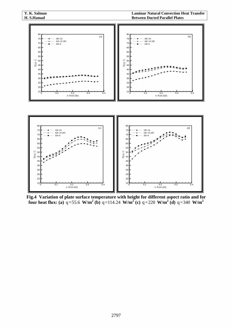
NOMENCLATURE AR = L/b NuH = Nusselt number at the top
of the heated q = spatial average of heat flux
corrected for radiation and conduction losses
b = channel wall spacing bNu = average Nusselt number, Ra = Raleigh number = GrPr Grb = Grashof number
based on channel wall spacing = gBqb4/Kυ2
Pr = fluid prandtl number = υ/α Ra* = Raylegh number=(b/ Ra) = Ra/AR
GrH = Grashof number based on channel height, gBqH4/Kv2
Q = heat flux T0 = channel inlet air temperature
Gr* = modified Grashof of number, equation (1)
qcond = conduction loss through the insulating substrate
Ts,x = local heated surface temperature
Grx = local Grashof number gBqH4/Kv2
qconv = local convective heat flux = qohm – qrad - qcond
T2,x = local insulated wall temperature
hx = local heat transfer coefficient
qohm = Ohmic dissipation in the heated foil
bT = estimate of the average bulk temperature in the channel
h = average heat transfer coefficient
qrad = radiation loss from the heated foil
X = coordinate direction along axis of channel
L = channel height m = correlation exponent, Nux = local Nusselt number
= hxx/k