2.3 psychrometric chart and air conditioning processes.docx
26
2.3 PSYCHROMETRIC CHART AND AIR CONDITIONING PROCESSES 1. Psychrometrics Psychrometrics is the science of involving thermodynamic properties of moist air and the effect of atmospheric moisture on materials and human comfort. 2. Psychrometric Chart Psychrometric chart provide a graphical representation of the thermodynamic properties of moist air, various air conditioning processes, and air conditioning cycles. The charts are very helpful during the calculation, analysis, and solution of the complicated problems encountered in air conditioning processes and cycles, Figure 1. Figure 1. Skeleton of Psychrometric Chart. ASHRAE developed five such psychrometric charts. Chart 1,2, and 3 are for sea level pressure. Chart 4 is for 5000 ft altitude (24.89 in Hg), and Chart 5 is for 7500 ft altitude (22.65 in Hg). The dry- bulb temperature ranges covered by the charts are Chart 1,4,5 Normal Temperature 32 to 120 F Chart 2 Low Temperature -40 to 50 F 1
-
Upload
independent -
Category
Documents
-
view
2 -
download
0
Transcript of 2.3 psychrometric chart and air conditioning processes.docx
2.3 PSYCHROMETRIC CHART AND AIR CONDITIONING PROCESSES
1. PsychrometricsPsychrometrics is the science of involving thermodynamic propertiesof moist air and the effect of atmospheric moisture on materials andhuman comfort.
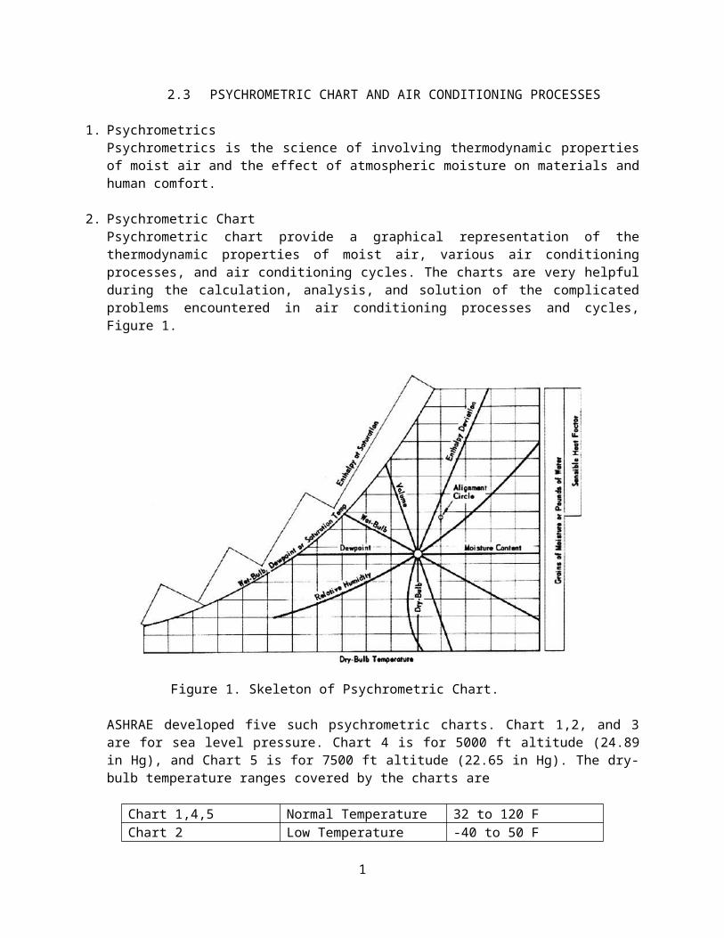
2. Psychrometric ChartPsychrometric chart provide a graphical representation of thethermodynamic properties of moist air, various air conditioningprocesses, and air conditioning cycles. The charts are very helpfulduring the calculation, analysis, and solution of the complicatedproblems encountered in air conditioning processes and cycles,Figure 1.
Figure 1. Skeleton of Psychrometric Chart.
ASHRAE developed five such psychrometric charts. Chart 1,2, and 3are for sea level pressure. Chart 4 is for 5000 ft altitude (24.89in Hg), and Chart 5 is for 7500 ft altitude (22.65 in Hg). The dry-bulb temperature ranges covered by the charts are
Chart 1,4,5 Normal Temperature 32 to 120 FChart 2 Low Temperature -40 to 50 F
1
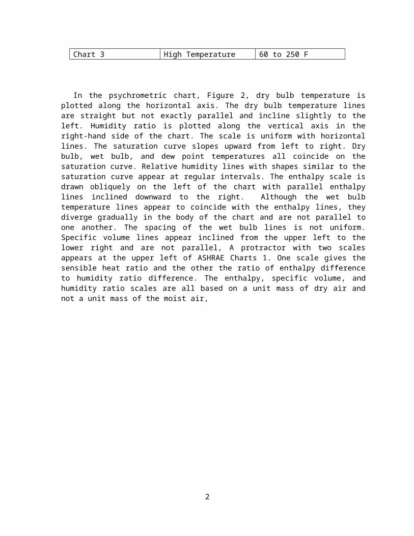
Chart 3 High Temperature 60 to 250 F
In the psychrometric chart, Figure 2, dry bulb temperature isplotted along the horizontal axis. The dry bulb temperature linesare straight but not exactly parallel and incline slightly to theleft. Humidity ratio is plotted along the vertical axis in theright-hand side of the chart. The scale is uniform with horizontallines. The saturation curve slopes upward from left to right. Drybulb, wet bulb, and dew point temperatures all coincide on thesaturation curve. Relative humidity lines with shapes similar to thesaturation curve appear at regular intervals. The enthalpy scale isdrawn obliquely on the left of the chart with parallel enthalpylines inclined downward to the right. Although the wet bulbtemperature lines appear to coincide with the enthalpy lines, theydiverge gradually in the body of the chart and are not parallel toone another. The spacing of the wet bulb lines is not uniform.Specific volume lines appear inclined from the upper left to thelower right and are not parallel, A protractor with two scalesappears at the upper left of ASHRAE Charts 1. One scale gives thesensible heat ratio and the other the ratio of enthalpy differenceto humidity ratio difference. The enthalpy, specific volume, andhumidity ratio scales are all based on a unit mass of dry air andnot a unit mass of the moist air,
2
Figure 2. ASHRAE Psychrometric Chart 1.
Example No. 1Read the properties of moist air at 75 F db, 60 F wb, and standardsea level pressure from ASHRAE Pyschrometric Chart 1.Given:Dry bulb = 75 F dbWet bulb = 60 F dbRequired: Read the properties of moist air.Solution:The intersection of the 75 F db and 60 F wb lines defines the givenstate. This point on the chart is the reference from which all theother properties are determined.
Humidity Ratio, W . Move horizontally to the right and readW=0.0077 lbmv/lbma on the vertical scale.
3
Relative Humidity, φ . Interpolate between the 40 and 50 percentrelative humidity lines and read φ=41 percent .Enthalpy, h . Follow a line of constant enthalpy upward to the leftand read h=26.4 Btu /lbma on the oblique scale.Specific Volume, v . Interpolate between the 13.5 and 14.0 specificvolume lines and read v=13.65 ft3/lbma .Dew Point,
td . Move horizontally to the left from the reference point and read td=50 F on the saturation curve.
3. Air Conditioning Processes
3.1 Heating or Cooling of Moist AirWhen air is heated or cooled without the loss or gain of
moisture, the process yields a straight horizontal line on thepsychrometric chart, because the humidity ratio is constant. Suchprocesses may occur when moist air flows through a heatexchanger. In cooling, however, if part of the surface of theheat exchanger is below the dew point of the air, condensationand the subsequent dehumidification will occur. Figure 3 shows aschematic of a device used to heat or cool air. Under steady-flow-steady-state conditions the energy balance becomes
mah1+q=mah2q=ma (h2−h1)Orq=macp (t2−t1)cp=0.245 Btu/(lbma−F )=1.02 kJ/ (kga−C )
4

Figure 3. Schematic of Device for Heating Moist Air
Example No. 2Moist air, saturated at 2 C, enters a heating coil at a rate of 10m3/s. Air leaves the coil at 40 C. Find the required rate of heataddition.Given: Point 1, moist air, saturated at 2 CPoint 2, t2 = 40 C dry bulbRate = 10 m3/s
Required: q = rate of heat addition.
Solution:
5
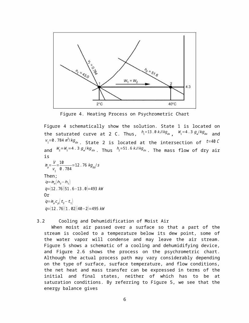
Figure 4. Heating Process on Psychrometric Chart
Figure 4 schematically show the solution. State 1 is located onthe saturated curve at 2 C. Thus, h1=13.0 kJ /kgda , W1=4.3 gw /kgda andv1=0.784 m
3/kgda . State 2 is located at the intersection of t=40 Cand W2=W1=4.3 gw /kgda . Thus h2=51.6 kJ /kgda . The mass flow of dry airisma=
Vv1
=100.784
=12.76 kgda/s
Then;q=ma (h2−h1)q=(12.76 ) (51.6−13.0 )=493 kWOrq=macp (t2−t1)q=(12.76 ) (1.02) (40−2)=495 kW
3.2 Cooling and Dehumidification of Moist AirWhen moist air passed over a surface so that a part of the
stream is cooled to a temperature below its dew point, some ofthe water vapor will condense and may leave the air stream.Figure 5 shows a schematic of a cooling and dehumidifying device,and Figure 2.6 shows the process on the psychrometric chart.Although the actual process path may vary considerably dependingon the type of surface, surface temperature, and flow conditions,the net heat and mass transfer can be expressed in terms of theinitial and final states, neither of which has to be atsaturation conditions. By referring to Figure 5, we see that theenergy balance gives
6
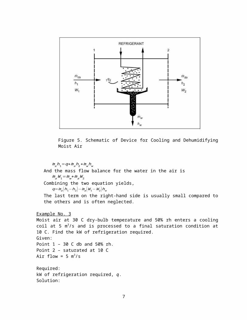
Figure 5. Schematic of Device for Cooling and DehumidifyingMoist Air
mah1=q+mah2+mwhwAnd the mass flow balance for the water in the air is
maW1=mw+maW2Combining the two equation yields,
q=ma (h1−h2)−ma (W1−W2)hwThe last term on the right-hand side is usually small compared tothe others and is often neglected.
Example No. 3Moist air at 30 C dry-bulb temperature and 50% rh enters a coolingcoil at 5 m3/s and is processed to a final saturation condition at10 C. Find the kW of refrigeration required.Given:Point 1 – 30 C db and 50% rh.Point 2 – saturated at 10 CAir flow = 5 m3/s
Required:kW of refrigeration required, q.Solution:
7
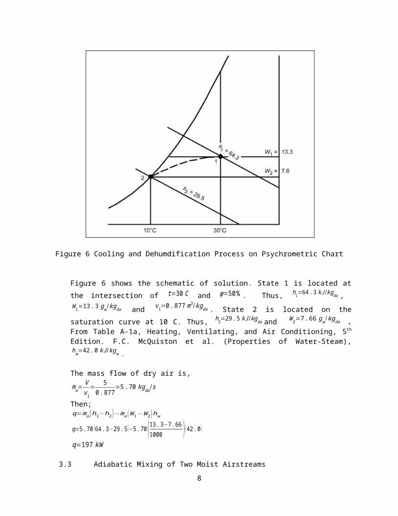
Figure 6 Cooling and Dehumdification Process on Psychrometric Chart
Figure 6 shows the schematic of solution. State 1 is located atthe intersection of t=30 C and φ=50% . Thus, h1=64.3 kJ /kgda , W1=13.3 gw /kgda and v1=0.877 m
3/kgda . State 2 is located on thesaturation curve at 10 C. Thus, h2=29.5 kJ /kgda and W2=7.66 gw /kgda .From Table A-1a, Heating, Ventilating, and Air Conditioning, 5th
Edition. F.C. McQuiston et al. (Properties of Water-Steam),hw=42.0 kJ/kgw .
The mass flow of dry air is,ma=
Vv1
=5
0.877=5.70 kgda /s
Then;q=ma (h1−h2)−ma (W1−W2)hw
q=5.70 (64.3−29.5)−5.70 (13.3−7.661000 )(42.0)
q=197 kW
3.3 Adiabatic Mixing of Two Moist Airstreams8
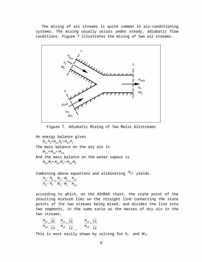
The mixing of air streams is quite common in air-conditioningsystems. The mixing usually occurs under steady, adiabatic flowconditions. Figure 7 illustrates the mixing of two air streams.
Figure 7. Adiabatic Mixing of Two Moist Airstreams
An energy balance givesma1h1+ma2h2=ma3h3
The mass balance on the dry air isma1+ma2=ma3
And the mass balance on the water vapour isma1W1+ ma2W2=ma3W3
Combining above equations and eliminating ma3 yieldsh2−h3h3−h1
=W2−W3W3−W1
=ma1ma2
according to which, on the ASHRAE chart, the state point of theresulting mixture lies on the straight line connecting the statepoints of the two streams being mixed, and divides the line intotwo segments, in the same ratio as the masses of dry air in thetwo streams.
ma1ma2
=32___
13___
,
ma1ma3
=32___
12___
,
ma2ma3
=13___
12___
This is most easily shown by solving for h3 and W3;
9
h3=
ma1ma2
h1+h2
1+ma1ma2
W3=
ma1ma2
W1+W2
1+ma1ma2
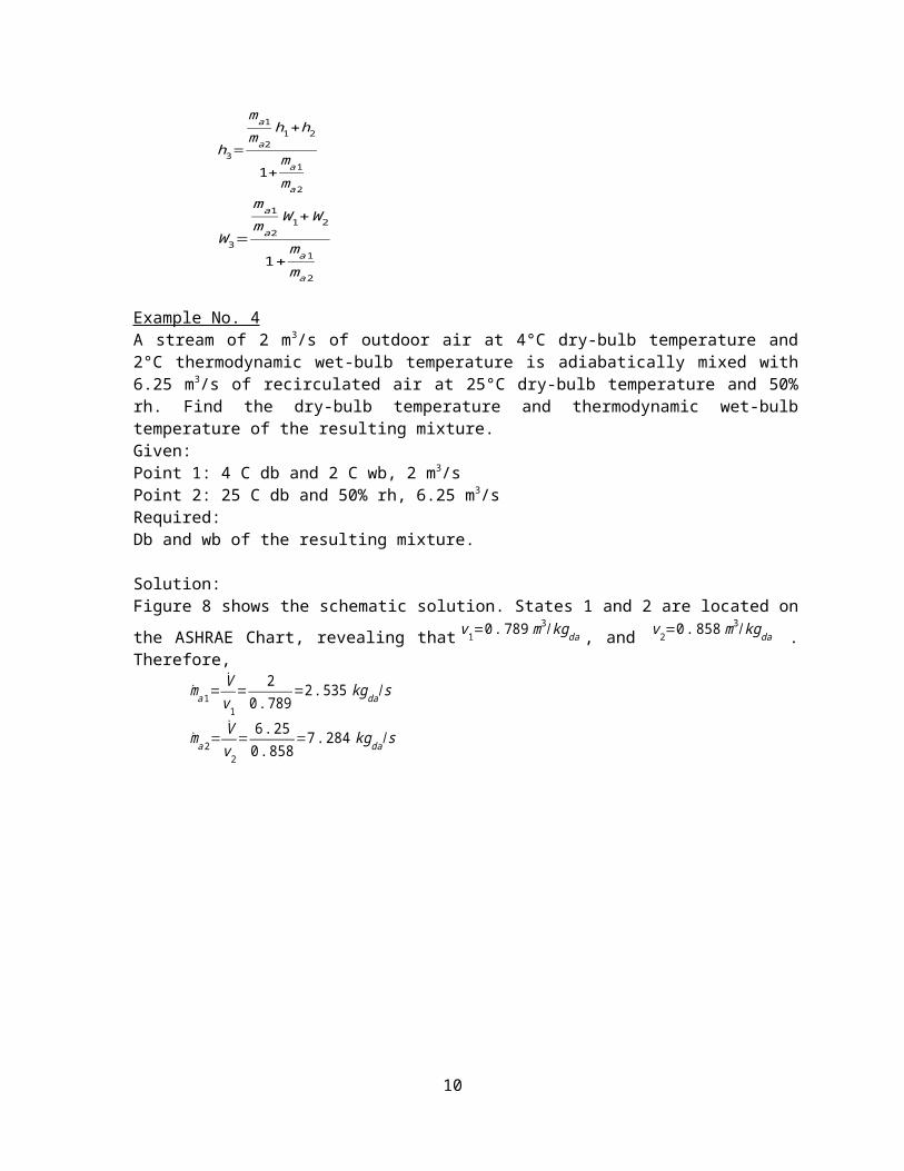
Example No. 4A stream of 2 m3/s of outdoor air at 4°C dry-bulb temperature and2°C thermodynamic wet-bulb temperature is adiabatically mixed with6.25 m3/s of recirculated air at 25°C dry-bulb temperature and 50%rh. Find the dry-bulb temperature and thermodynamic wet-bulbtemperature of the resulting mixture.Given:Point 1: 4 C db and 2 C wb, 2 m3/sPoint 2: 25 C db and 50% rh, 6.25 m3/sRequired:Db and wb of the resulting mixture.
Solution:Figure 8 shows the schematic solution. States 1 and 2 are located onthe ASHRAE Chart, revealing that v1=0.789 m
3/kgda , and v2=0.858 m3/kgda .
Therefore,ma1=
Vv1
=2
0.789=2.535 kgda/s
ma2=Vv2
=6.250.858
=7.284 kgda/s
10
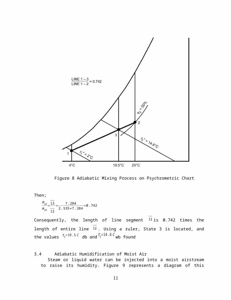
Figure 8 Adiabatic Mixing Process on Psychrometric Chart
Then;ma2ma3
=13___
12___ =
7.2842.535+7.284
=0.742
Consequently, the length of line segment 13___
is 0.742 times the
length of entire line 12___
. Using a ruler, State 3 is located, andthe values t3=19.5 C db and t3
¿ =14.6 C wb found
3.4 Adiabatic Humidification of Moist AirSteam or liquid water can be injected into a moist airstream
to raise its humidity. Figure 9 represents a diagram of this
11

common air conditioning process. If the mixing is adiabatic, thefollowing equations apply:
Figure 9. Schematic of a Humidifying Device.
mah1+mwhw=mah2maW1+mw=maW2
Therefore,h2−h1W2−W1
=ΔhΔW=hw
according to which, on the ASHRAE chart, the final state point ofthe moist air lies on a straight line whose direction is fixed bythe specific enthalpy of the injected water, drawn through theinitial state point of the moist air.
Example No. 5Moist air at 20°C dry-bulb and 8°C thermodynamic wet-bulbtemperature is to be processed to a final dew-point temperature of13°C by adiabatic injection of saturated steam at 110°C. The rate ofdry airflow is 2 kg/s (dry air). Find the final dry-bulb temperatureof the moist air and the rate ofsteam flow.Given:Point 1: 20 C db, 8 C wbPoint 2: 13 C dp, 110 C sat. steam.Mass flow rate = 2 kgs
12

Required:Final dry-bulb temp. of moist air (t2) and rate of steam flow (mw).
Solution:Figure 10 shows the schematic solution. By Table A-1a, Heating,Ventilating, and Air Conditioning, 5th Edition. F.C. McQuiston et al.(Properties of Water-Steam), the enthalpy of the steam ishg=2691 kJ/kgw . Therefore, according to the above equation, thecondition line on the ASHRAE chart connecting state 1 and 2 musthave a direction:
h2−h1W2−W1
=ΔhΔW=hw
ΔhΔW
=2.691 kJ/gw
Figure 10. Adiabatic Humdification Process onPsychrometric Chart
13
The condition line can be drawn with the Δh /ΔW protractor. First,establish the reference line on the protractor by connecting theorigin with the value Δh /ΔW=2.691 kJ /gw . Draw a second line parallelto the reference line and through the initial state point of themoist air. This second line is the condition line. State 2 isestablished at the intersection of the condition line with thehorizontal line extended from the saturation curve at 13 C ( td2=13 C
).Thus, t2=21 C .
Values of W2 and W1 can be read from the chart. The required steamflow is,
maW1+mw=maW2mw=ma(W2−W1)mw=2 (0.0093−0.0018)mw=0.015 kg/s (steam).
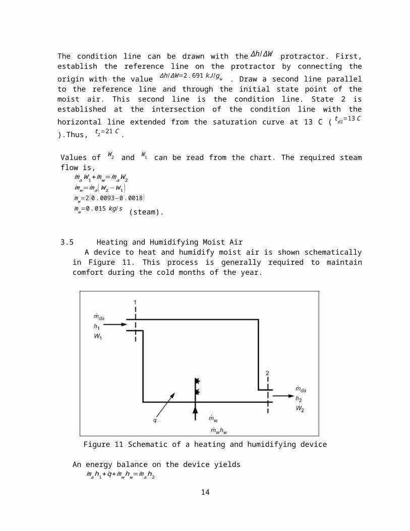
3.5 Heating and Humidifying Moist AirA device to heat and humidify moist air is shown schematically
in Figure 11. This process is generally required to maintaincomfort during the cold months of the year.
Figure 11 Schematic of a heating and humidifying device
An energy balance on the device yields mah1+q+mwhw=mah2
14
and a mass balance on the water givesmaW1+mw=maW2
Combine equations above to obtainh2−h1W2−W1
=q
ma(W2−W1)+hw
Orh2−h1W2−W1
=qmw
+hw
The last equation above describes a straight line thatconnects the initial and final states on the psychrometric chart.Figure 12 shows a combined heating and humidifying process,states 1-2.
A graphical procedure makes use of the semicircular scale onCharts 1 to locate the process line. The ratio of the change inthe enthalpy to the change in humidity ratio isΔhΔW=
h2−h1W2−W1
=qmw
+hw
Figure 12 shows the procedure where a straight line is laid outparallel to the line on the protractor through state 1.
15
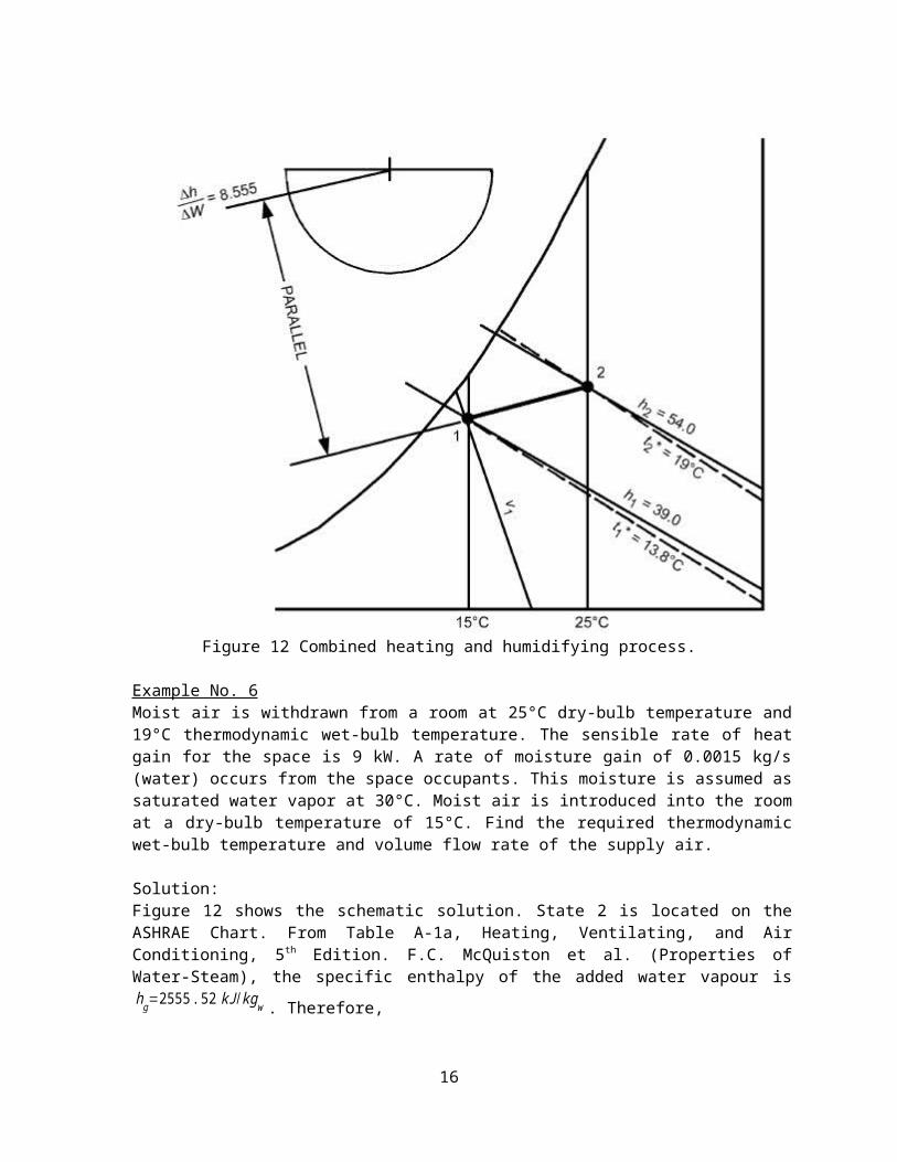
Figure 12 Combined heating and humidifying process.
Example No. 6Moist air is withdrawn from a room at 25°C dry-bulb temperature and19°C thermodynamic wet-bulb temperature. The sensible rate of heatgain for the space is 9 kW. A rate of moisture gain of 0.0015 kg/s(water) occurs from the space occupants. This moisture is assumed assaturated water vapor at 30°C. Moist air is introduced into the roomat a dry-bulb temperature of 15°C. Find the required thermodynamicwet-bulb temperature and volume flow rate of the supply air.
Solution:Figure 12 shows the schematic solution. State 2 is located on theASHRAE Chart. From Table A-1a, Heating, Ventilating, and AirConditioning, 5th Edition. F.C. McQuiston et al. (Properties ofWater-Steam), the specific enthalpy of the added water vapour ishg=2555.52 kJ/kgw . Therefore,
16
ΔhΔW
= 90.0015
+2555.52=8555 kJ/kgw=8.555 kJ/gw
With the Δh /ΔW protractor, establish a reference line of directionΔh /ΔW=8.555 kJ /gw . Parallel to this reference line, draw a straightline on the chart through state 2. The intersection of this linewith the 15 C dry-bulb temperature line is state 1. Thus,
t1
¿ =13.8 C .
The flow of dry air can be calculated from ma=
q+mwhwh2−h1
ma=9+(0.0015) (2555.52 )54.0−39.0
=0.856 kgda/s
At state 1, v1=0.859 m3/kgda
Therefore, supply volume = mav1=(0.856) (0.859 )=0.735 m3/s
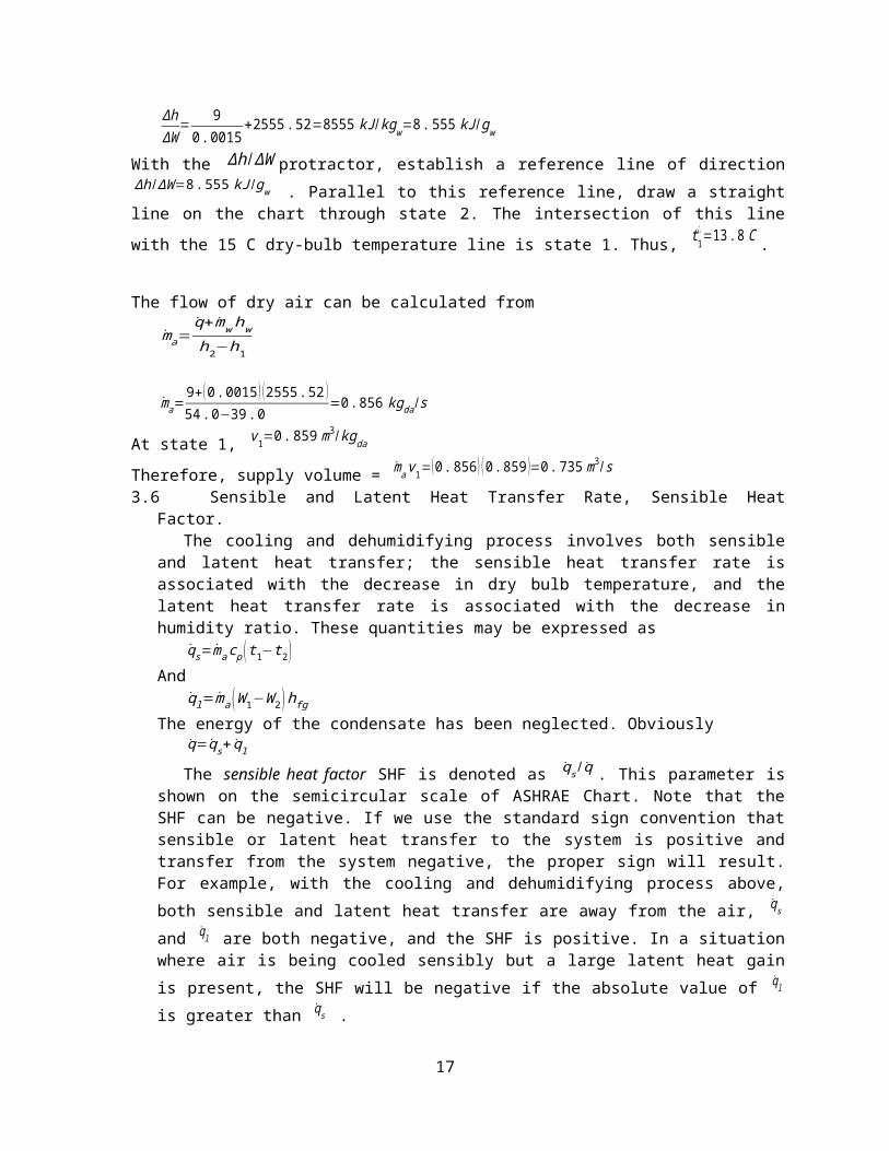
3.6 Sensible and Latent Heat Transfer Rate, Sensible HeatFactor.
The cooling and dehumidifying process involves both sensibleand latent heat transfer; the sensible heat transfer rate isassociated with the decrease in dry bulb temperature, and thelatent heat transfer rate is associated with the decrease inhumidity ratio. These quantities may be expressed as
qs=macp (t1−t2)And
ql=ma (W1−W2)hfgThe energy of the condensate has been neglected. Obviously
q=qs+ qlThe sensible heat factor SHF is denoted as qs / q . This parameter is
shown on the semicircular scale of ASHRAE Chart. Note that theSHF can be negative. If we use the standard sign convention thatsensible or latent heat transfer to the system is positive andtransfer from the system negative, the proper sign will result.For example, with the cooling and dehumidifying process above,both sensible and latent heat transfer are away from the air, qs
and ql are both negative, and the SHF is positive. In a situationwhere air is being cooled sensibly but a large latent heat gainis present, the SHF will be negative if the absolute value of ql
is greater than qs .
17
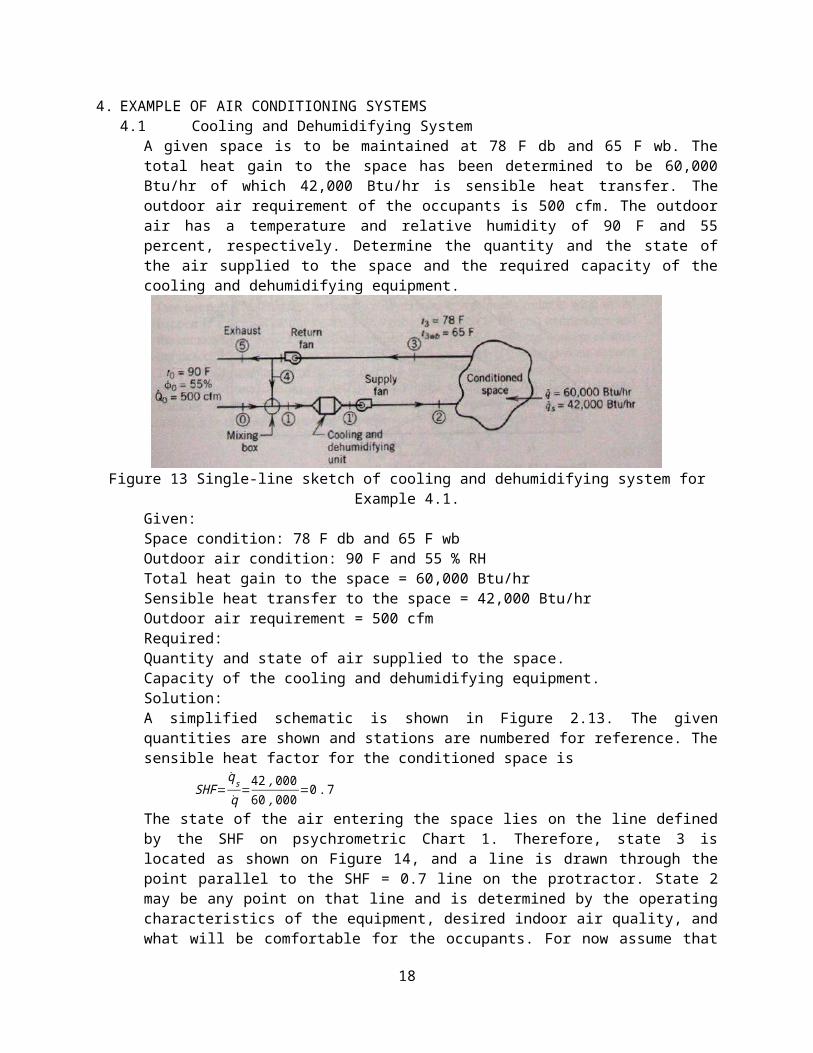
4. EXAMPLE OF AIR CONDITIONING SYSTEMS4.1 Cooling and Dehumidifying System
A given space is to be maintained at 78 F db and 65 F wb. Thetotal heat gain to the space has been determined to be 60,000Btu/hr of which 42,000 Btu/hr is sensible heat transfer. Theoutdoor air requirement of the occupants is 500 cfm. The outdoorair has a temperature and relative humidity of 90 F and 55percent, respectively. Determine the quantity and the state ofthe air supplied to the space and the required capacity of thecooling and dehumidifying equipment.
Figure 13 Single-line sketch of cooling and dehumidifying system forExample 4.1.
Given:Space condition: 78 F db and 65 F wbOutdoor air condition: 90 F and 55 % RHTotal heat gain to the space = 60,000 Btu/hrSensible heat transfer to the space = 42,000 Btu/hrOutdoor air requirement = 500 cfmRequired:Quantity and state of air supplied to the space.Capacity of the cooling and dehumidifying equipment.Solution:A simplified schematic is shown in Figure 2.13. The givenquantities are shown and stations are numbered for reference. Thesensible heat factor for the conditioned space is
SHF=qsq =
42,00060,000=0.7
The state of the air entering the space lies on the line definedby the SHF on psychrometric Chart 1. Therefore, state 3 islocated as shown on Figure 14, and a line is drawn through thepoint parallel to the SHF = 0.7 line on the protractor. State 2may be any point on that line and is determined by the operatingcharacteristics of the equipment, desired indoor air quality, andwhat will be comfortable for the occupants. For now assume that
18
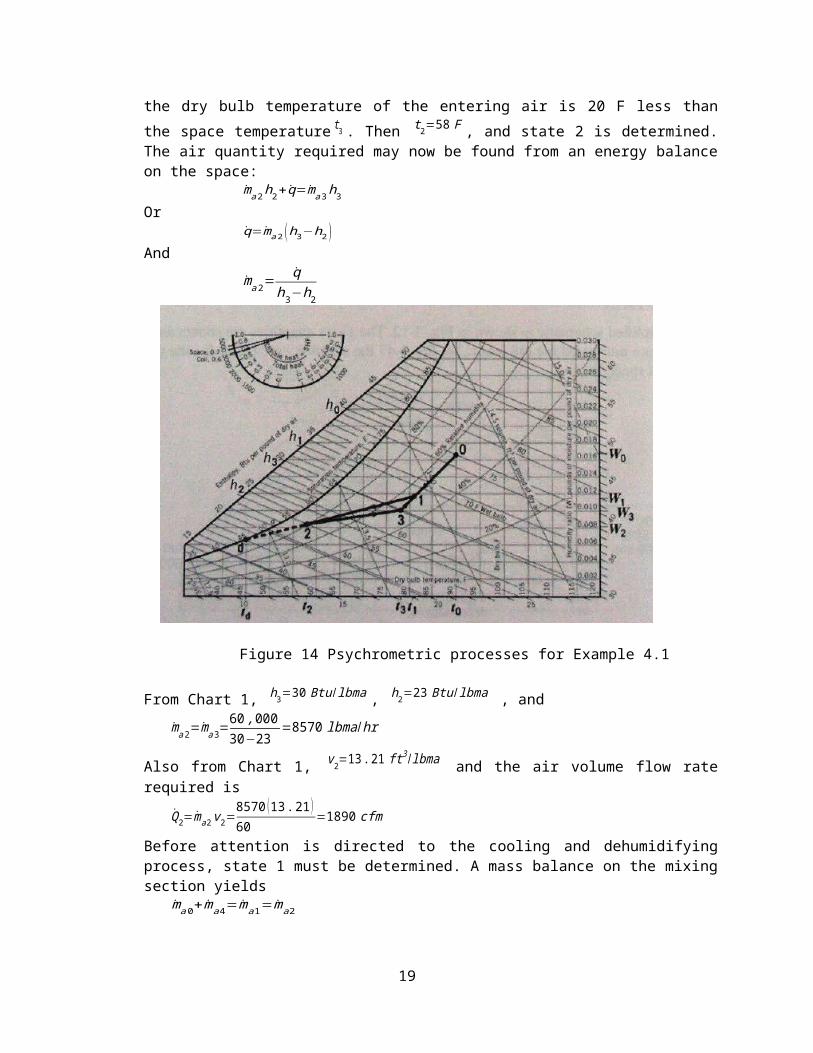
the dry bulb temperature of the entering air is 20 F less thanthe space temperature t3 . Then t2=58 F , and state 2 is determined.The air quantity required may now be found from an energy balanceon the space:
ma2h2+q=ma3h3 Or
q=ma2 (h3−h2 )And
ma2=q
h3−h2
Figure 14 Psychrometric processes for Example 4.1
From Chart 1, h3=30 Btu /lbma , h2=23 Btu /lbma , andma2=ma3=
60,00030−23
=8570 lbma/hr
Also from Chart 1, v2=13.21 ft3 /lbma and the air volume flow raterequired is
Q2=ma2v2=8570 (13.21)60
=1890 cfm
Before attention is directed to the cooling and dehumidifyingprocess, state 1 must be determined. A mass balance on the mixingsection yields
ma0+ma4=ma1=ma2
19
ma0=Q0v0
v0=14.23 ft3 /lbma
ma0=500×6014.23
=2110 lbma /hr
Then the recirculated air isma4=ma2− ma0=8570−2110=6460 lbma/hr
By using the graphical technique and referring to Figure 2.14, wesee that
31___
30___ =
ma0ma1
=21108570
=0.246
31___
=0.246 (30)___
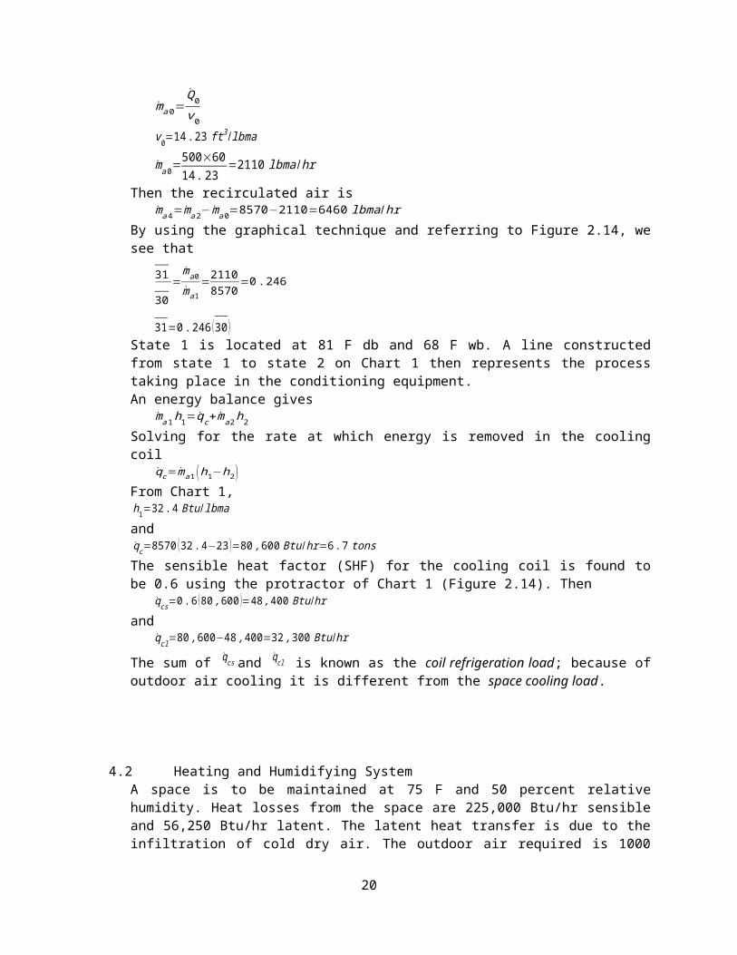
State 1 is located at 81 F db and 68 F wb. A line constructedfrom state 1 to state 2 on Chart 1 then represents the processtaking place in the conditioning equipment.An energy balance gives
ma1h1=qc+ma2h2Solving for the rate at which energy is removed in the coolingcoil
qc=ma1 (h1−h2)From Chart 1, h1=32.4 Btu /lbmaandqc=8570 (32.4−23)=80,600 Btu /hr=6.7 tonsThe sensible heat factor (SHF) for the cooling coil is found tobe 0.6 using the protractor of Chart 1 (Figure 2.14). Then
qcs=0.6 (80,600 )=48,400 Btu/hrand
qcl=80,600−48,400=32,300 Btu/hr
The sum of qcs and qcl is known as the coil refrigeration load; because ofoutdoor air cooling it is different from the space cooling load.
4.2 Heating and Humidifying SystemA space is to be maintained at 75 F and 50 percent relativehumidity. Heat losses from the space are 225,000 Btu/hr sensibleand 56,250 Btu/hr latent. The latent heat transfer is due to theinfiltration of cold dry air. The outdoor air required is 1000
20
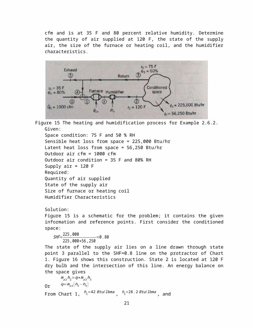
cfm and is at 35 F and 80 percent relative humidity. Determinethe quantity of air supplied at 120 F, the state of the supplyair, the size of the furnace or heating coil, and the humidifiercharacteristics.
Figure 15 The heating and humidification process for Example 2.6.2.Given:Space condition: 75 F and 50 % RHSensible heat loss from space = 225,000 Btu/hrLatent heat loss from space = 56,250 Btu/hrOutdoor air cfm = 1000 cfmOutdoor air condition = 35 F and 80% RHSupply air = 120 FRequired: Quantity of air suppliedState of the supply airSize of furnace or heating coilHumidifier Characteristics
Solution:Figure 15 is a schematic for the problem; it contains the giveninformation and reference points. First consider the conditionedspace:
SHF=225,000225,000+56,250
=0.80
The state of the supply air lies on a line drawn through statepoint 3 parallel to the SHF=0.8 line on the protractor of Chart1. Figure 16 shows this construction. State 2 is located at 120 Fdry bulb and the intersection of this line. An energy balance onthe space gives
ma2h2=q+ma3h3Or q=ma2 (h2−h3 )
From Chart 1, h2=42 Btu/lbma , h3=28.2 Btu /lbma , and21
ma2=q
h2−h3=281,25042−28.2
=20,400 lbma /hr
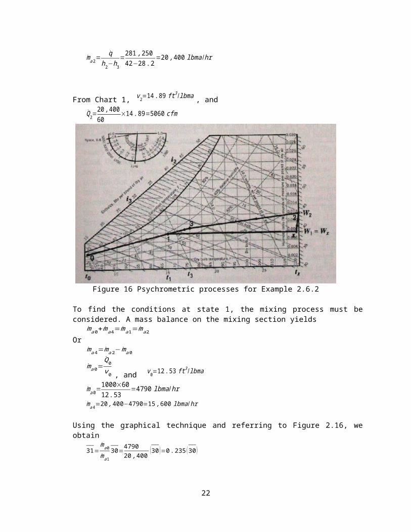
From Chart 1, v2=14.89 ft3 /lbma , andQ2=
20,40060
×14.89=5060 cfm
Figure 16 Psychrometric processes for Example 2.6.2
To find the conditions at state 1, the mixing process must beconsidered. A mass balance on the mixing section yields
ma0+ma4=ma1=ma2Or
ma4=ma2−ma0
ma0=Q0v0 , and v0=12.53 ft
3 /lbma
ma0=1000×6012.53
=4790 lbma/hr
ma4=20,400−4790=15,600 lbma/hr
Using the graphical technique and referring to Figure 2.16, weobtain
31___
=ma0ma1
30___
=479020,400 (30 )
___
=0.235 (30)___
22
State 1 is then located at 66 F db and 57 F wb. The line 12___
constructed on Chart 1, Figure 16, represents the combinationheating and humidifying process that must take place in theheating and humidifying unit. However, in practice the processesmust be carried out separately. Assume that saturated vapor at200 F is used in the humidifier. Then hw=1145.8 Btu/lbm from Table A-1a, Heating, Ventilating, and Air Conditioning, 5th Edition. F.C.McQuiston et al. (Properties of Water-Steam). The requiredsensible heating is
q1a=qs=macp (tX−t1)qs=(20,400 ) (0.245) (119−66)=264,900 Btu/hr
The amount of water vapor supplied to the humidifier is given bymv=ma (W2−W1 )
Where W2=0.012 lbmv/lbma and W1=0.008 lbmv/lbma from Chart 1, so thatmv=20,400 (0.012−0.008 )=82 lbmv/hr
5. EXERCISE PROBLEMS
5.1 A chilled water cooling coil receives 2.5 m3/s of air at 25C db, 20 C wb. It is necessary for the air to leave the coil at13 C db, 12 C wb. Assume sea level pressure.(a) Determine the SHF and the apparatus dew point.(b) Compute the total and sensible heat transfer rates from the
air.Answer: (a) 0.528, 6.45, (b) 67.22, 35.5.
5.2 Air at 100 F db and 65 F wb is humidified adiabatically withsteam. The steam supplied contains 20 percent moisture (qualityof 0.80) at 14.7 psia. If the air is humidified to 60 percentrelative humidity, what is the dry bulb temperature of thehumidified air? Assume sea level pressure.Answer: 91.6 F
5.3 Air at 38 C db and 18 C wb is humidified adiabatically withsteam. The steam supplied contains 20 percent moisture (qualityof 0.80) at 101.3 kPa. If the air is humidified to 60 percentrelative humidity, what is the dry bulb temperature of thehumidified air? Assume sea level pressure.Answer: 33.1 C
5.4 Air at 84 F db and 60 F wb is humidified with the dry bulbtemperature remaining constant. Wet steam is supplied forhumidification at 20 psia. What quality must the steam have toprovide saturated air? Assume sea level pressure.
23
Answer: 93.95%5.5 Air at 29 C db and 16 C wb is humidified with the dry bulb
temperature remaining constant. Wet steam is supplied forhumidification at 138 kPa. What quality must the steam have toprovide saturated air? Assume sea level pressure.Answer: 93.9%
5.6 Air at 38 C db and 20 C wb and 101.325 kPa is humidifiedadiabatically with liquid water supplied at 60 C, in suchproportions that the mixture has a relative humidity of 80percent. Find the dry bulb temperature of the mixture.Answer: 22.86
5.7 It is desired to heat and humidify 2000 cfm of air from aninitial state defined by a temperature of 60 F dry bulb andrelative humidity of 30 percent to a final state of 110 F drybulb and 30 percent relative humidity. The air will first beheated by a hot water coil, followed by adiabatic humidificationusing saturated vapour at 5 psig. Using the psychrometric chart,find the heat transfer rate for the heating coil and the massflow rate of the water vapour, and sketch the properties on askeleton chart showing pertinent data. Assume sea level pressure.Answer: 104,412 ; 122.5
5.8 It is desired to heat and humidify 1.0 m3/s of air from aninitial state defined by a temperature of 16 C dry bulb andrelative humidity of 30 percent to a final state of 43 C dry bulband 30 percent relative humidity. The air will first be heated bya hot water coil, followed by adiabatic humidification usingsaturated vapour at 34.5 kPa. Using the psychrometric chart, findthe heat transfer rate for the heating coil and the mass flowrate of the water vapour, and sketch the properties on a skeletonchart showing pertinent data. Assume sea level pressure.Answer: 31.6 ; 0.01576
5.9 Air at 40 F db and 35 F wb is mixed with warm air at 100 Fdb and 77 F wb in the ratio of 2 lbm cool air to 1 lbm of warmair. Compute the humidity ratio and enthalpy of the mixed air.Answer: 0.00702, 21.88
5.10Air at 5 C db and 2 C wb is mixed with warm air at 38 C db and 25C wb in the ratio of 2 kga cool air to 1 kga of warm air. Computethe humidity ratio and enthalpy of the mixed air.Answer: 0.00698, 33.90
5.11Air at 10 C db and 5 C wb is mixed with air at 25 C db and 18 Cwb in a steady-flow process at standard atmospheric pressure. Thevolume flow rates are 10 m3/s and 6 m3/s, respectively. Computethe mixture conditions.
24
Answer: 15.4, 10.4 .5.12A meeting hall is to be maintained at 25 C db and 18 C wb. The
barometric pressure is 101.325 kPa. The space has a load of 58.6kW sensible load and 58.6 kW latent. The temperature of thesupply air cannot be lower than 18 C db. (a) How many kilogramsper second of air must be supplied? (b) What is the required wetbulb temperature of the supply air? (c) What is the sensible heatratio?Answer: (a) 8.2073 ; (b) 12.92 ; (c) 0.50 .
5.13Outdoor air is at 95 F and 79 F wb and at a barometric pressureof 29.92 in. Hg is cooled and dehumidified under steadyconditions until it becomes saturated at 60 F. (a) Find the massof water condensed per pound of dry air. (b) If the condensate isremoved at 60 F, what quantity of heat is removed per pound ofdry air?Answer: (a) 0.0067 ; (b) 15.79 .
5.14Outdoor air is at 35 C and 26 C wb and at a barometric pressureof 101 kPa is cooled and dehumidified under steady conditionsuntil it becomes saturated at 16 C. (a) Find the mass of watercondensed per kg of dry air. (b) If the condensate is removed at16 C, what quantity of heat is removed per kilogram of dry air?Answer: (a) 0.0061 ; (b) 34.94 .
5.15Moist air enters a refrigeration coil at 89 F db and 75 F wb at arate of 1400 cfm. The apparatus dewpoint temperature of the coilis 55 F. If 3.5 tons of refrigeration is available, find the drybulb temperature of the air leaving the coil. Assume sea levelpressure.Answer: 73.18 .
5.16Saturated steam at a pressure of 25 psia is sprayed into a streamof moist air. The initial condition of air is 55 F db and 45 F wbtemperature. The mass rate of air flow is 2000 lbma/min.Barometric pressure is 14.696 psia. Determine (a) how much steam(in lbm/min) must be added to produce a saturated air conditionand (b) the resulting temperature of the saturated air.Answer: (a) 12 ; (b) 57.2 .
5.17Saturated water vapor at 100 C is used to humidify a stream ofmoist air. The air enters the humidifier at 13 C db and 2 C wb ata flow rate of 2.5 m3/s. The pressure is 101.35 kPa. Determine(a) the mass flow rate of the steam required to saturate the airand (b) the temperature of saturated air.Answer: (a) 0.0318 ; (b) 14.47 .
- End -
25

26