202B-(MICRO-PROCESSOR).pdf - Levelstate
69
M Q S REGISTERED FIRM Certificate No : GB1619 Levelstate Systems Ltd. ISO 9001 Solution at all levels INSTALLATION, OPERATION & MAINTENANCE MANUAL FOR ELECTRONIC DRUM LEVEL INDICATOR TYPE 202B ISSUE I : MARCH 2009 © 2009 Levelstate Systems Ltd. All rights reserved With technical progress the company reserves the right to change specifications without notice Little Kitfield, Gradwell Lane, Four Marks, Hampshire, GU34 5AS, U.K. Tel: +44 (0) 1962 773829 Fax: +44 (0) 1962 772849 E-mail: [email protected] Web: www.levelstate.com
-
Upload
khangminh22 -
Category
Documents
-
view
1 -
download
0
Transcript of 202B-(MICRO-PROCESSOR).pdf - Levelstate

MQS
REGISTERED FIRMCertificate No : GB1619
Levelstate Systems Ltd.
ISO 9001
SSoolluuttiioonn aatt aallll lleevveellss
INSTALLATION, OPERATION & MAINTENANCE
MANUAL FOR
ELECTRONIC DRUM LEVEL INDICATOR
TYPE 202B
ISSUE I : MARCH 2009
© 2009 Levelstate Systems Ltd. All rights reserved With technical progress the companyreserves the right to change specificationswithout notice
Little Kitfield, Gradwell Lane, Four Marks, Hampshire, GU34 5AS, U.K. Tel: +44 (0) 1962 773829 Fax: +44 (0) 1962 772849
E-mail: [email protected] Web: www.levelstate.com

1
CONTENTS Section Page
Boiler Codes or Standards - Summary of requirements 3
1.0 Operating Principle 4
2.0 Electronic Unit Description 6
2.1 Input Board 6
2.2 Power Supply 10
2.3 Discriminator Board 14
2.4 Local & Remote Display Board 18
2.5 Relay & Analogue Output Board 22
2.6 Input Board Probe Connection 26
2.7 Remote Display Connection 30
3.0 General Configuration 31
3.1 Probe Details 36
4.0 Installation General 37
4.1 Water Column 38
4.2 System Cabling 41
4.3 Electronic Unit Enclosure 46
4.4 Remote Display Unit (IP20) 50
4.5 Remote Display Unit (IP65) 54
5.0 Commissioning 58
5.1 Probe Installation 58
6.0 Maintenance and Fault Identifications 60
6.1 Pressure Parts 60
6.2 Electronic Unit Faults & Correction Action 63
7.0 202B EDLI Parts List 66
8.0 202B Electronic Unit Specification 67

2
Figs Page 1.1 Sensing Element 4
1.2 Water Level Monitoring 4
1.3 Typical Water Conductivities 5
1.4 Switching Hysteresis 5
2.1a Input Board Details 202B-8 7
2.1b Input Board Details 202B-16 8
2.1c Input Board Details 202B-32 9
2.2a Input Board & Power Supply Details 202B-8 11
2.2b Input Board & Power Supply Details 202B-16 12
2.2c Input Board & Power Supply Details 202B-32 13
2.3a Discriminator Board & Input Board Details 202B-8 15
2.3b Discriminator Board & Input Board Details 202B-16 16
2.3c Discriminator Board & Input Board Details 202B-32 17
2.4a Display & Discriminator Board Connection 202B-8 19
2.4b Display & Discriminator Board Connection 202B-16 20
2.4c Display & Discriminator Board Connection 202B-32 21
2.5a Relay & Input Board Schematic 202B-8 23
2.5b Relay & Input Board Schematic 202B-16 24
2.5c Relay & Input Board Schematic 202B-32 25
3.0 Side arm Water Column 32
3.0a Water Column Type- 501 33
3.0b Water Column Type- 502 34
3.0c Water Column Type- 503 35
3.1 Probe Type 801, 803 and 802 36
4.1a Water Column Installation 39
4.1b Water Column Support Structure 40
4.2a System Cabling 202B-8 42
4.2b System Cabling 202B-16 43
4.2c System Cabling 202B-32 44
4.2d Probe Cable Routing on Water Column 45
4.3a Electronic Unit Enclosure for 202B-8 47
4.3b Electronic Unit Enclosure for 202B-16 48
4.3c Electronic Unit Enclosure for 202B-32 49
4.4a Remote Display Unit 202B-8 (IP20) 51
4.4b Remote Display Unit 202B-16 (IP20) 52
4.4c Remote Display Unit 202B-32 (IP20) 53
4.5a Remote Display Unit 202B-8 (IP65) 55
4.5b Remote Display Unit 202B-16 (IP65) 56
4.5c Remote Display Unit 202B-32 (IP65) 57

3
Boiler Codes or Standards - Summary of requirements
ASME Boiler Code
Boilers must have one gauge glass. Above 400psi operation two gauge glasses shall be provided. For boilers
with safety valves set at or above 900psi two independent remote level indicators may replace one of the two
gauge glasses. If both remote indicators are in reliable operation the remaining gauge glass may be valved off
but must be maintained in serviceable condition. If gauge glasses are not visible to the operator two
dependable Indirect Indicators shall be provided. The lowest visible level of the gauge shall be at least 2”
above the lowest permissible water level where there is no danger of overheating any part of the boiler. Each
water gauge glass shall be equipped with a top and bottom shutoff valve of through flow construction to
prevent stoppage by deposits of sediment. Straight run globe valves shall not be used. Connections from the
boiler to the remote level indicator shall be at least 0.75" pipe size including isolation valves. For gage glasses
connected to the boiler the steam and water connections shall not be less than I" pipe size. There shall be no
sag or offset in the steam pipe and no part of the water connection shall be above the point of connection to
the gauge.
It is recommended that each boiler have two independent low water cut-offs. The permanent installation of cut-
out devices for low water cut-offs should not be provided; temporary devices can be installed for testing.
British Standard BS759. Part 1. 1984
Boilers shall have two independent gauge glasses each capable of being isolated from the boiler. One water
level gauge is permitted for boilers of less than 145kg/h evaporative capacity. For boilers with safety valves set
at or above 60bar in two independent manometric remote level indicators may replace one of the gauge
glasses. One gauge glass with its isolating valves shall be connected directly to the boiler. Remote level
Indicators which have been approved by an “Inspection Authority” may replace gauge glasses. The lowest visible level of the gauge shall be at least 50mm above the lowest permissible water level where
there is no danger of overheating any part of the boiler. Steam and water isolating valves if straight pattern
globe type shall be mounted with the spindle horizontal.
The bore of steam and water connections shall be not less than 25mm, local to fittings not less than 20mm.
The level gauges shall be mounted as close as is practical to the boiler shell or drum.
Automatic controls shall effectively shut off the fuel supply in the event of low water level.
There is a reasonable degree of commonality between the above requirements and this is generally reflected
in other National Regulations. Accepted or recognised standards must be used for the design, material
selection, welding and inspection of pressure containing components.

4
1.0 Operating Principle
The Levelstate 202B System is an electronic alternative to the gauge glass providing a significant
improvement in accuracy, visibility, reliability and safety, enabling transmission of the water level condition to a
remote display and the application of alarm and control functions. It includes connections for two separate
Mains Supply inputs to achieve the ultimate security and reliability for the indication and control functions.
The discrimination between water and steam is based on the significant difference in resistivity between the
two states over the saturation range. The sensing element is a Probe with an insulated tip inserted in a side-
arm water column Fig 1.1. If a voltage is applied to the tip, conduction occurs between the tip and the inside
wall of the column. The dimensions are selected to provide a resistance typically less than 0.1 Mega-ohms
when the Probe is immersed in water, which results in a resistance greater than 5.0 Mega-ohms for the steam
condition. An electronic discrimination circuit is arranged to sense whether the Probe resistance is less than
0.1 Mega-ohms representing water or greater than 0.1 Mega-ohms representing steam.
While any of the probe wires develops Short Circuit Fault (i.e. Short Circuit to Ground), this condition also
declares Water state. In general, Boiler Plant water conductivity does not go above 50µS/Cm. The probe cell
dimensions are so selected the corresponding resistance value at above max. water conductivity stands about
6KΩ. A Short Circuit fault detection circuit is so designed, the short circuit fault is declared when the resistance
value goes down below 3.3K which is well below the resistance value corresponding conductivity to max.
water conductivity. Thus this enables proper discrimination between short circuit fault condition and water state
condition.
Probes spaced vertically in a side-arm vessel attached to the boiler Fig 1.2 and with each Probe connected to
its own sensing and water/steam indication circuit a vertical display of Green/Red indicators provides sufficient
resolution for the water level indication. The spacing between Probes is chosen to cover the required Sight-
Range. 202B system supports upto 32 port. However, it can be configured to any number of probes from 6-32
as per system requirement.
Fig 1.1 Fig 1.2

5
Typical water conductivities are shown in Fig 1.3. The definition of the various categories is indicated at the
top.
Fig 1.3
Fig 1.4 below shows the relationship between boiler water resistivity (the inverse of conductivity) and boiler
drum pressure. The side-arm column purposely stimulates condensate flow and this flushing effect results in
the column water being purer than the water in the drum. As the pressure increases the water resistivity
increases and it is essential that the water/steam switching threshold lies above the side-arm water resistivity
for the maximum boiler pressure encountered. On the other hand it is advisable to use as low a resistivity
switching threshold as possible to render the system less susceptible to switching over due to moisture and
water droplets.
Fig 1.4
202B THRESHOLD & HYSTERESIS

6
2.0 Electronic Unit Description
2.1 Input Board (202B2502) :- In 202B system contain one input board mount on the left side of the chassis
plate in the enclosure. The input board provides redundancy of power supplies, connector for electrodes (two
wire system), connector for discriminator/processor PCB. There are 3 types of Input boards
• 8 channel board is used for 1 to 8 channels – 202B2502-8.
• 16 channel board is used for 9 to 16 channels – 202B2502-16.
• 32 channel board is used for 17 to 32 channels – 202B2502-32.

7
Fig. 2.1a Input Board Details for 8 Channel

8
Fig. 2.1b Input Board Details for 16 Channel

9
Fig. 2.1c Input Board Details for 32 Channel

10
Connection details: - TB3- For ODD numbered electrodes starting from Channel 1 at ODD Probe Input Board for 202B-8.
TB4- For EVEN numbered electrodes starting from Channel 2 at EVEN Probe Input Board for 202B-8.
TB9- For ODD numbered electrodes starting from Channel 1 at ODD Probe Input Board for 202B-16.
TB10- For EVEN numbered electrodes starting from Channel 2 at EVEN Probe Input Board for 202B-16.
TB9 & TB11 - For ODD numbered electrodes starting from Channel 1 at ODD Probe Input Board for 202B-32.
TB10 & TB12 - For EVEN numbered electrodes starting from Channel 2 at EVEN Probe Input Board for 202B-
32.
TB1- For Power Supply 1 Input ODD Probe Input Board.
TB2- For Power Supply 2 Input at EVEN Probe Input Board.
TB5, TB7 & TB9 – Relay/RDU connection for ODD probes at ODD Probe Input Board for 8 channel.
TB6, TB8 & TB10 – Relay/RDU connection for EVEN probes EVEN Probe Input Board for 8 channel.
TB3, TB5 & TB7 – Relay/RDU connection for ODD probes at ODD Probe Input Board for 16 & 32 channel.
TB4, TB6 & TB8 – Relay/RDU connection for EVEN probes EVEN Probe Input Board for 16 & 32 channel.
PL1- ODD input PCB to ODD discriminator PCB at ODD Probe Input Board.
PL1- EVEN input PCB to EVEN discriminator PCB EVEN Probe Input Board.
NOTE:-
Enough attention should be given for connection of the probe in ODD & EVEN channel in sequence to
avoid any malfunction of the system.
2.2 Power Supply (202B2505) In 202B two power supply units, PS1 & PS2 are used for redundant power supply to the system.
Specification: - Input 85-264V AC, 120-370V DC
Frequency - 47-63 Hz.
Protection Type: Hiccup mode, recovers automatically after fault condition is removed.

11
Fig 2.2a Input Board & Power Supply Details for 8 Channel

12
Fig 2.2b Input Board & Power Supply Details for 16 Channel

13
Fig 2.2c Input Board & Power Supply Details for 32 Channel CN1 & CN3 are two connector block on the chassis plate for AC input to the system. A shielded armoured
mains cable should be used for connection to power supply CN1 & CN3. 3 core braided shield cable 18 SWG
(24 X 0.2mm, 0.7 mm²) to be used with suitable gland at the bottom of the box. The 202B unit must be
installed with a circuit breaker with a maximum rating of 2A mounted adjacent to the unit for ease of
operation/maintenance and safety.

14
2.3 Discriminator Board (202B2501):- Two separate discriminator/processor boards are used for ODD & EVEN electrodes. The boards are identical
and operate independently for better reliability & discrimination. The discriminator boards are compatible with
all input boards i.e. 8, 16 and 32 channels. Discriminator circuit checks the conductivity of water/steam through
the electrodes in the water column. Discrimination circuit for OC/steam/water/SC is used for odd & even
channels separately. Discriminator board only receives the data from the input board for processing and
onward transmission to the other boards like Local display; Remote display and the Relay board for display
and determine the fault condition. Fault detection is also carried out where the condition of the electrode inputs
and the probe connecting cables are examined and a fault is indicated when:-
a) Any of the electrode wires is broken/disconnected i.e. Open circuit.
b) A short circuit to earth occurs on either the electrode wires.
c) An internal circuit fault condition exists.
d) Failure of any one power supply.
Discriminator board uses industrial standard communication protocol (RS485) to transmit data to the
respective peripheral boards like Display & Relay Boards.
J3 are used for water sensitivity and should be in position before the system is in operation.
Sensitivity & Conductivity selection (in Discriminator PCB) [J3] Shorting link shall be used to select the conductivity range after obtaining the data from the plant. Linking
configuration is described below: -
1) No Linking > 2 µS/cm
2) Sb Linking > 1 µS/cm
3) Sa Linking > 0.5 µS/cm

15
Fig – 2.3a Discriminator Board & Input Board Details for 8 Channel

16
Fig – 2.3b Discriminator Board & Input Board Details for 16 Channel

17
Fig – 2.3c Discriminator Board & Input Board Details for 32 Channel

18
2.4 Local and Remote Display Board (202B2503) :-
This display board at the main unit and the Remote Display Unit (RDU) are identical in terms of functionality
and they are interchangeable.
Display boards are 3main version: -
• 8 channel display board is used for 1 to 8 channels – 202B2503-8.
• 16 channel display board is used for 9 to 16 channels – 202B2503-16.
• 32 channel display board is used for 17 to 32 channels – 202B2503-32.
The main display board receives electrode data and power supply from the respective discriminator board.
Each Display board mounted with required no. of LEDs on the front. All the LEDs are divided in two columns of
8/16/32 LEDs. The green column at left to indicate the electrodes, which are in water and the red column at
right to indicate the electrodes, which are in steam. Two Yellow LEDs are mounted at the top for indication of
system fault for the ODD/EVEN channels.
The number of LEDs illuminated is dependent on the number of electrodes being used in the system. When
the electrodes are less than the no. of display LEDs, the top LEDs are marked to keep off as unused
electrodes. A blanking label is fixed on the LEDs that are not used.
Any system fault indicates by flashing of the Yellow LEDs at Top. Left yellow LED is for ODD probes and right
yellow LED is for EVEN probes. During probe cable fault either S/C or O/C the respective probe LED will flash
along with the yellow LED for the ODD/EVEN channel at 2 Hz frequency. Similarly the process fault is
indicated by flashing the respective probe LEDs at 1 Hz frequency. However, the each fault can be identified
and discriminated as per the table given below: -
LEDS Electrode / conductor / Power Supply case
Green Red Yellow Frequency
Water On Off Off Steam Off On Off Normal
Open Circuit Off Flash Flash 2Hz Short Circuit Flash Off Flash 2 Hz System Fault
Any one Power Supply off On On Flash 2 Hz High Alarm/Trip Flash Off Off 1 Hz Low Alarm/Trip Off Flash Off 1 Hz
Process Fault
Main display is connected from the discriminator PCB, however the connection of the Remote Display is taken
from the input board where option are kept to connect two Remote Display without additional local power
supply for the second remote, subject to cable length upto 300 meter.

19
Fig. 2.4a Display & Discriminator Board Connection Schematic for 8 Channel

20
Fig. 2.4b Display & Discriminator Board Connection Schematic for 16 Channel

21
Fig. 2.4c Display & Discriminator Board Connection Schematic for 32 Channel

22
2.5 Relay and analogue Output Board (202B2504) :-
Relay and analogue output board comprising of one System Fault Relay, 7 process fault relay [4nos. (standard
configuration) & 3nos. (optional configuration)] and 2 nos. dual 4-20 mA output.
The serial data from the Discriminator Boards are taken to the Relay Board through the Input Board for ease of
wiring and access to the power supply required for the relay board.
RL1 – System fault relay is normally energised. RL2 to RL5 – 4 nos. (standard configuration) & RL6 to RL8
(optional configuration) process fault relay and can be assigned to any channel for either low Alarm/Trip or
high Alarm/Trip through a Handheld Programmer. The normal condition of the relay either open or closed can
also be programmed through programmer. Positive trip/fault is activated irrespective of the
electrode/conductor core failure for the particular channel. Spurious/nuisance tripping is eliminated by
introducing the delay to each relay.
Isolated analogue 4-20mA outputs can be obtained on request with 600 Ohms impedance for single output
and 400 Ohms impedance for duel output.
Failure of one of the power supply can be registered at system fault relay (RL1) and System fault indication
(Yellow LED) flushing. Relay board can be connected at remote location without additional power supply till
100 mtr. distance. Beyond 100 mtr. additional power supply is required. However, signal cable should be
connected to same location (Input Board) at both the cases.
Terminal TB5 on the Relay PCB is used for the 4-20mA Output. A 2 pair screened cable is required and is
connected in a 4 way socket as shown in the Fig.2.5a, 2.5b & 2.5c for 8,16 & 32 Channel respectively.

23
Fig. 2.5a Relay & Input Board Schematic for 202B-8

24
Fig. 2.5b Relay & Input Board Schematic for 202B-16

25
Fig. 2.5c Relay & Input Board Schematic for 202B-32
26
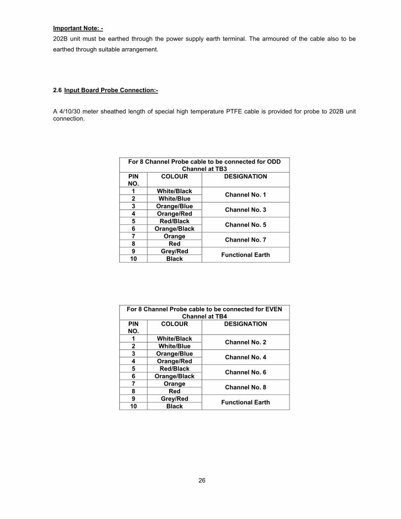
Important Note: - 202B unit must be earthed through the power supply earth terminal. The armoured of the cable also to be
earthed through suitable arrangement.
2.6 Input Board Probe Connection:-
A 4/10/30 meter sheathed length of special high temperature PTFE cable is provided for probe to 202B unit connection.
For 8 Channel Probe cable to be connected for ODD Channel at TB3
PIN NO.
COLOUR DESIGNATION
1 White/Black 2 White/Blue Channel No. 1
3 Orange/Blue 4 Orange/Red Channel No. 3
5 Red/Black 6 Orange/Black Channel No. 5
7 Orange 8 Red Channel No. 7
9 Grey/Red 10 Black Functional Earth
For 8 Channel Probe cable to be connected for EVEN Channel at TB4
PIN NO.
COLOUR DESIGNATION
1 White/Black 2 White/Blue Channel No. 2
3 Orange/Blue 4 Orange/Red Channel No. 4
5 Red/Black 6 Orange/Black Channel No. 6
7 Orange 8 Red Channel No. 8
9 Grey/Red 10 Black Functional Earth

27
For 16 Channel Probe cable to be connected for ODD Channel at TB9
PIN NO.
COLOUR DESIGNATION
1 White/Black 2 White/Blue Channel No. 1
3 Orange/Blue 4 Orange/Red Channel No. 3
5 Red/Black 6 Orange/Black Channel No. 5
7 Orange 8 Red Channel No. 7
9 Pink 10 White Channel No. 9
11 Blue 12 Brown Channel No. 11
13 Violet 14 Grey Channel No. 13
15 Red/Blue 16 Red/White Channel No. 15
17 Grey/Red 18 Black Functional Earth
For 16 channel Probe cable to be connected for EVEN Channel at TB10
PIN NO.
COLOUR DESIGNATION
1 White/Black 2 White/Blue Channel No. 2
3 Orange/Blue 4 Orange/Red Channel No. 4
5 Red/Black 6 Orange/Black Channel No. 6
7 Orange 8 Red Channel No. 8
9 Pink 10 White Channel No. 10
11 Blue 12 Brown Channel No. 12
13 Violet 14 Grey Channel No. 14
15 Red/Blue 16 Red/White Channel No. 16
17 Grey/Red 18 Black Functional Earth

28
For 32 Channel Probe cable to be connected for ODD Channel at TB9
PIN NO.
COLOUR DESIGNATION
1 White/Black 2 White/Blue Channel No. 1
3 Orange/Blue 4 Orange/Red Channel No. 3
5 Red/Black 6 Orange/Black Channel No. 5
7 Orange 8 Red Channel No. 7
9 Pink 10 White Channel No. 9
11 Blue 12 Brown Channel No. 11
13 Violet 14 Grey Channel No. 13
15 Red/Blue 16 Red/White Channel No. 15
17 Grey/Red 18 Black Functional Earth
For 32 channel Probe cable to be connected for rest ODD Channel at TB11
PIN NO.
COLOUR DESIGNATION
1 White/Black 2 White/Blue Channel No. 17
3 Orange/Blue 4 Orange/Red Channel No. 19
5 Red/Black 6 Orange/Black Channel No. 21
7 Orange 8 Red Channel No. 23
9 Pink 10 White Channel No. 25
11 Blue 12 Brown Channel No. 27
13 Violet 14 Grey Channel No. 29
15 Red/Blue 16 Red/White Channel No. 31
17 Grey/Red 18 Black Functional Earth

29
For 32 Channel Probe cable to be connected for EVEN Channel at TB10
PIN NO.
COLOUR DESIGNATION
1 White/Black 2 White/Blue Channel No. 2
3 Orange/Blue 4 Orange/Red Channel No. 4
5 Red/Black 6 Orange/Black Channel No. 6
7 Orange 8 Red Channel No. 8
9 Pink 10 White Channel No. 10
11 Blue 12 Brown Channel No. 12
13 Violet 14 Grey Channel No. 14
15 Red/Blue 16 Red/White Channel No. 16
17 Grey/Red 18 Black Functional Earth
For 32 channel Probe cable to be connected for rest EVEN Channel at TB12
PIN NO.
COLOUR DESIGNATION
1 White/Black 2 White/Blue Channel No. 18
3 Orange/Blue 4 Orange/Red Channel No. 20
5 Red/Black 6 Orange/Black Channel No. 22
7 Orange 8 Red Channel No. 24
9 Pink 10 White Channel No. 26
11 Blue 12 Brown Channel No. 28
13 Violet 14 Grey Channel No. 30
15 Red/Blue 16 Red/White Channel No. 32
17 Grey/Red 18 Black Functional Earth
The water column looming has been arranged for the cable to be clamped on the RH side with the ODD numbered probes on the LHS and EVEN numbered probes on the RHS. It is recommended that the cables are laced or strapped to the 6 mm (1/4”) vertical Tie Rods using steel tie wraps or PTFE sleeving. Enclosure cable connection for 8, 16 & 32 probe system.

30
2.7 Remote Display Connection (202B2503-8, 202B2503-16 & 202B2503-32)
Upto 10 nos. Remote display unit may be connected with the 202B main unit. Two remote display can be
powered from the local main unit, but all other through separate local supply. Four pair of Shielded Twisted
cable should be used for interconnection from input board to the respective remote unit. Two pair will be
treated for ODD serial data & other two pair for EVEN serial data. For distance more than 300 meters
[(maximum) restricted to 600 meters] it is better to use separate power supply to power the units.
Cable specification for external connection for 8/16 Channel CABLE SIZE &
SPECIFICATION FROM TO CABLE GLAND
SIZE 24 AWG, 22 core PTFE
Probe cable Water Column ODD side
Probe input board terminal TB3 (for 8Ch.) / TB9 (for
16Ch.) at ODD side PG9
24 AWG, 22 core PTFE Probe cable
Water Column EVEN side
Probe input board terminal TB4 (for 8Ch.) / TB10 (for
16Ch.) at ODD side PG9
3 core shielded Power cable, 18 AWG
Mains 1 input, 240V AC, 1 Phase, 50 Hz
Terminal CN1 mounted at Chassis plate PG 13.5
3 core shielded Power cable, 18 AWG
Mains 2 input, 240V AC, 1 Phase, 50 Hz
Terminal CN3 mounted at Chassis plate PG 13.5
1X5 Screened Twisted Pair Instrument cable, 22 AWG
(Length- <500 mtr.)
Terminal TB9 (for 8Ch.) / TB3 (for 16Ch.)
of ODD & TB10 (for 8Ch.) / TB4 (for 16Ch.) of EVEN Probe Input
Board
To RDU 1 (at Control Room or at Firing floor)
PG 13.5
1X5 Screened Twisted Pair Instrument cable, 22 AWG
(Length- <500 mtr.)
Terminal TB7 (for 8Ch.) / TB5 (for 16Ch.)
of ODD & TB8 (for 8Ch.) / TB6 (for 16Ch.) of EVEN Probe Input
Board
To RDU 2 (at Control Room or at Firing floor)
PG 13.5
Cable specification for external connection for 32 Channel CABLE SIZE &
SPECIFICATION FROM TO CABLE GLAND
SIZE 2 X 24 AWG, 22 core PTFE
Probe cable Water Column ODD side
Probe input board terminal TB9 & TB11 at ODD side 2 X PG9
2 X 24 AWG, 22 core PTFE Probe cable
Water Column EVEN side
Probe input board terminal TB10 & TB12 at EVEN side 2 X PG9
3 core shielded Power cable, 18 AWG
Mains 1 input, 240V AC, 1 Phase, 50 Hz
Terminal CN1 mounted at Chassis plate PG 13.5
3 core shielded Power cable, 18 AWG
Mains 2 input, 240V AC, 1 Phase, 50 Hz
Terminal CN3 mounted at Chassis plate PG 13.5
1X5 Screened Twisted Pair Instrument cable, 22 AWG
(Length- <500 mtr.)
Terminal TB3 of ODD & TB4 of EVEN Probe
Input Board
To RDU 1 (at Control Room or at Firing floor) PG 13.5
1X5 Screened Twisted Pair Instrument cable, 22 AWG
(Length- <500 mtr.)
Terminal TB5 of ODD & TB6 of EVEN Probe
Input Board
To RDU 2 (at Control Room or at Firing floor) PG 13.5

31
3.0 General Configuration:-
The probes are installed in a side-arm water column in two staggered vertical rows, numbered from the
bottom; the ODD numbered probes are located on one side of the column and the EVEN numbered probes on
the opposite side. A typical Water Column is shown in Fig 3.0/3.0a/3.0b/3.0c and all versions of Probe shown
in Fig 3.1.
Printed circuit boards contained in an IP65 (NEMA 4X) wall mounted enclosure provide water/steam
discrimination circuits, LED display, relay alarm outputs, 4-2OmA output and terminals for the connection of a
Remote Display Unit.
To avoid galvanic action at the probe and variations in sensing voltage due to changing electrolytic potentials,
an alternating voltage source is applied to the probe and the sensing circuit responds only to an alternating
waveform. Two low frequency oscillators are provided for the source voltage, one driving the odd numbered
channels and the other the even numbered channels. The voltage applied to the probe is less than 6 volts,
current limited to 50 microamps and presents no risk to personnel.
Collectively the discrimination or sensing channels may be set to one of three sensitivity selections for water
conductivity.
Each channel output drives a Green LED for Water detected or a Red LED for Steam detected and also
increments the 4-2OmA Transmission circuit.
Relay setting:-
1) Relay 1 for System Fault
2) Relay 2 to Relay 8 for Alarm & Trip as required.
Relay action can be selected for normally energised or normally de-energised depending on the alarm/trip
policy required through Hand Held Programmer.
To achieve the highest operational integrity, provision is made for Two Separate Mains Supply inputs to be
applied. The DC output voltages from separate SMPS are interconnected to all DC Output so that in the event
of one Mains Supply failing the 202B instrument remains fully operational. Either Mains failure is signalled
through the system fault alarm. Each SMPS is allocated to supply both the Odd numbered and Even
numbered Probe channels. All SMPS are short circuit protected and Hiccup mode, recovers automatically
after fault condition is removed.

32
Fig 3.0 Side Arm Water Column

33
Fig 3.0a Details of Water Column Type 501

34
Fig 3.0b Details of Water Column Type 502

35
Fig 3.0c Details of Water Column Type 503

36
3.1 Probe Details :- The 202B system employs multiple probes installed in a vertical column, usually in two diametrically opposite
rows. Three types of probes are available: (i) Type 801 – for pressure upto 150 bar; it is screwed directly into
the Type 501 water column and is gasket sealed (ii) Type 802 – for pressure upto 207 bar; compression fitted
to Type 502 water column and sealed by metal to metal contact and (iii) Type 803 – for pressure upto 207 bar;
gasket sealed clamp plate type mounting onto Type 503 water column held in position by four studs and nuts.
Both 801 and 803 probes use SS-grafoil Metaflex gasket seals as shown in Fig. 3.1
Probe Type 801 Probe Type 803 Probe Type 802 Rating: 150 bar, Rating: 207 bar, Rating: 207 bar, 340º C 370º C 370º C
Fig. 3.1 Probe Type 801, 803 and 802

37
4.0 Installation - General For Boiler applications the installation must conform to the accepted Regional or National Standards.
Pipework connections must be welded, tested and inspected to the relevant procedures. Ensure that the
appropriate Regulations are adhered to and procedures documented.
A typical Water Columns installation is shown in Fig. 3.0/3.0a/3.0b/3.0c but special versions may be required
for particular applications. In all cases it is essential to achieve the minimum length of connecting pipework to
the water column to minimise density errors. This is caused by heat loss which produces a temperature
difference and therefore a density difference between the water in the column and the water in the boiler or
heat exchanger. In particular the lower water connection should be as straight as possible with a slight
downward slope from the column to achieve good water circulation, preventing the accumulation of dissolved
solids and avoiding the possibility of level indication errors. The top equalising connection should project
inside the boiler shell to prevent surface condensate cascading down the pipework to the column, excessive
water flow in the column causes a pressure drop resulting in level indication errors. Both steam and water
shell tappings should terminate internally away from localised turbulence, which causes pressure differences,
and therefore level indication errors.
The inclusion of isolation valves requires the assembly to be supported by the top suspension lug of the
column ensuring there is no differential expansion between the support structure and the boiler drum.
If a boiler low or high water level trip circuit is connected to the 202B Electronic Unit it is recommended that all
isolation valves are lockable in the open position and the drain valve lockable in the closed position to prevent
spurious tripping by inadvertent valve operation.
The 202B Electronic Unit enclosure is usually sited adjacent to the Water Column within a distance suitable for
the 4m/10m/30m length of special high temperature PTFE cable supplied.
Sitting of the 202B enclosure must consider adequate visibility of the display, the routing of other cables away
from heat sources and the minimum risk of damage from surrounding plant or activities.

38
4.1 Water Column - Installation - General Requirements
For boiler side-arm columns Figs. 4.1a, 4.1.b the support structure should be installed, the column attached by
the top suspension lug. The support structure should be sufficient to take the weight of the column plus steam
and water isolation valves, drain valves and pipework.
Parallel slide or gate valves should be used particularly for water side isolation as they allow full bore opening
without restricting water flow. Straight run globe stop valves shall not be used (ASME) but if permitted by
other codes they must be mounted horizontally as shown. If the 202B System low and/or high water boiler trip
circuit is used it is recommended that all isolation valves are lockable in the open position and the drain valves
lockable in the closed position to prevent spurious tripping by inadvertent valve operation.
It is essential to ensure there is a continuous downward slope of at least 1:50 from the Water Column to the
Boiler Drum to enhance water circulation. (ASME Code: No part of this water connection shall be above the
point of connection at the Water Column. For the steam connection to the boiler there shall be no sag or offset
in the piping, which shall permit the accumulation of water)
The column connections are profiled for butt weld fitting to pipework; if socket weld fittings are to be used the
40º profile should be removed and the fittings supported to allow 2mm (0.08") spacing to the fully seated
position. After welding to documented procedures any temporary supports should be removed and alignment
to NWL checked prior to weld inspection.
Fit Guards to protect Probe seatings.
Lag steam and water pipework and valves.
Before commissioning install Probe Cable.
As a precaution ensure steam and water isolation valves are closed and drain valve open.

39
4.1.a Water Column Installation Detail
Fig 4.1.a Water Column Installation 1. The Water Column should be suspended such that there is no differential vertical movement between
the Boiler Drum and the Column. Generally a spring suspension should be provided where the spring rate includes column, isolation valves, drain valves and associated pipework.
2. The lower water connection to the Column must be above the level of the connection to the Drum to
prevent air locks. For the same reason the steam connection to the Column must be below the connection to the Drum. Preference should be given to the continuous slope of the water connection with no restrictions, to aid water circulation.
3. The water connection inside the Boiler Drum should avoid turbulence from down-comers, feedwater
inlets etc. The steam connection should protrude sufficiently (X) to avoid drum surface condensate flowing to the Column.
4. Procedures for site welding of pipework and valves must conform to the National or Accepted Standards
for boiler applications.
40
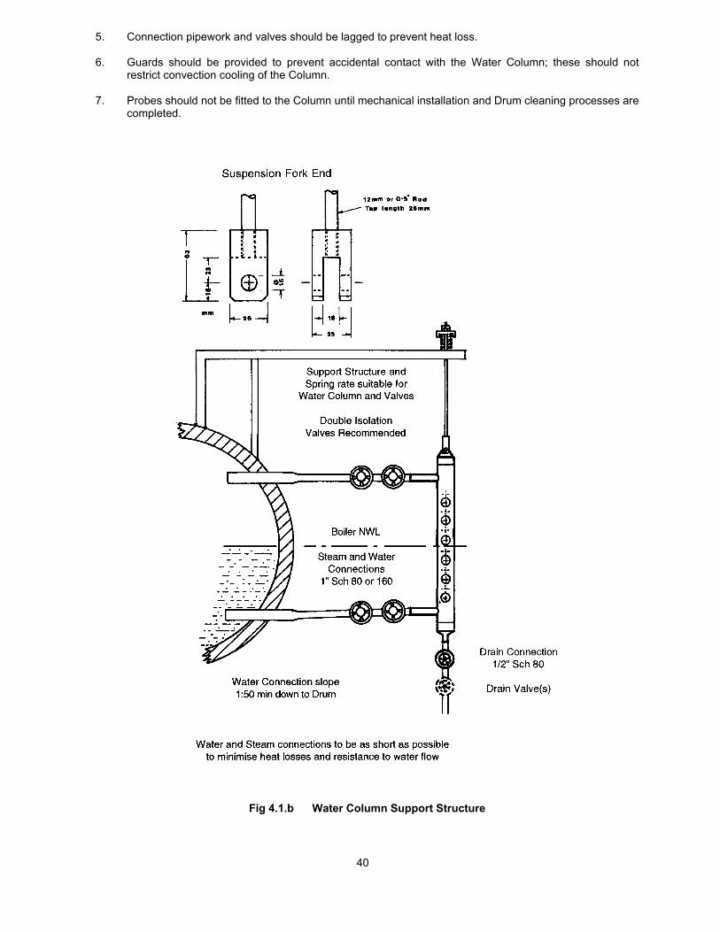
5. Connection pipework and valves should be lagged to prevent heat loss. 6. Guards should be provided to prevent accidental contact with the Water Column; these should not
restrict convection cooling of the Column. 7. Probes should not be fitted to the Column until mechanical installation and Drum cleaning processes are
completed.
Fig 4.1.b Water Column Support Structure
41
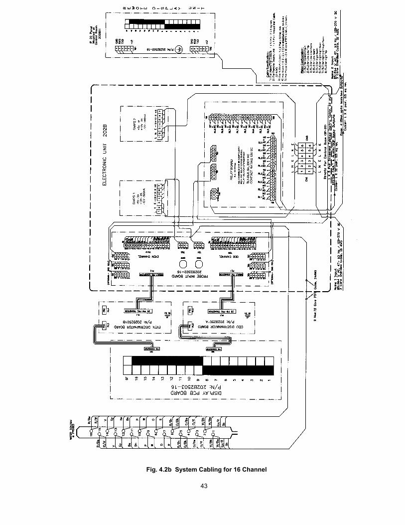
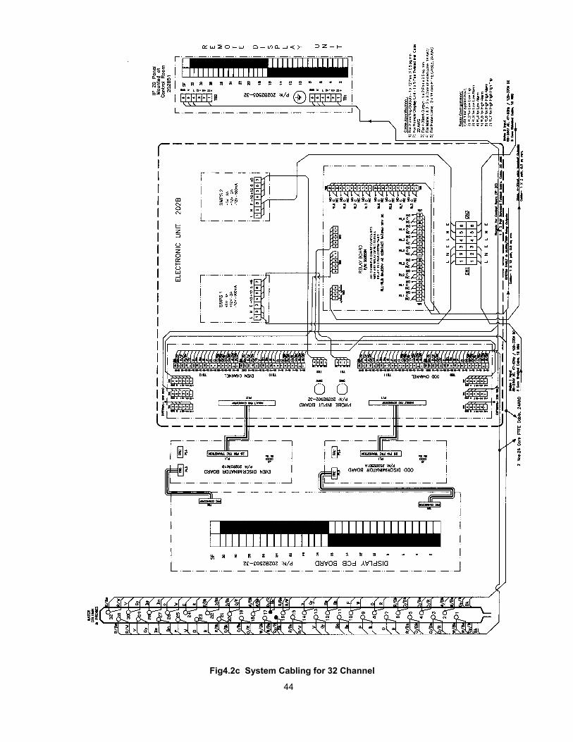
4.2 System Cabling
Fig. 4.2a, Fig. 4.2b & Fig. 4.2c shows the System Cabling requirements 202B-8, 202B-16 & 202B-32
respectively. Fig 4.2d shows Probe Cable Fixings on the water column.
A 4/10/30 metre sheathed length of special 2 X 22 core for 8/16 Channel & 4 X 22 core for 32 Channel high
temperature PTFE cable is provided for Probe to 202B Unit connections. The Water Column looming has
been arranged for the cable to be clamped on the right hand side with the ODD numbered Probes on the left
hand side and the EVEN numbered Probes on the right hand side. It is recommended that the cables are
taped to the 6mm (1/4") vertical Tie Rods using 12mm PTFE Thread Seal Tape (as used in pipe sealing RS
512-238).
2X3 core shielded cable for the Mains1 & mains2 Supply, 1X4 pair twisted screened cable for Remote Display,
1X12 pair for Alarm/Trip and 1X2 pair for 4-2OmA circuits are fitted as required using standard instrumentation
cable through the 202B Unit Cable Glands as shown.

42
Fig. 4.2a System Cabling for 8 Channel
43
Fig. 4.2b System Cabling for 16 Channel
44
Fig4.2c System Cabling for 32 Channel

45
Fig. 4.2d Probe Cable Routing on Water Column

46
4.3 Electronic Unit Enclosure –Type 202B
The FRP enclosure with overall dimensions of 500H x 400W x 200D mm (refer Fig 4.3a, Fig.4.3b & 4.3c) is
intended for wall mounting using four M8 fixing screws on base pads external to the cover sealing gasket. The
cover has a hinged front door with key operated cam locks. Nine cable glands (Eleven for 32 port) are
provided at the bottom of the enclosure. Protection rating for this enclosure is IP65. The front cover provides
two vertical columns of 8/16/32 LEDs, one column Red to indicate steam and the other column Green to
indicate water. Two nos. Yellow LED is provided on top to indicate system fault for ODD & EVEN channel. The
LED display provides excellent visibility and a wide viewing angle.

47
Fig. 4.3a Electronic Unit Enclosure for 202B-8 Channel

48
Fig. 4.3b Electronic Unit Enclosure for 202B-16 Channel

49
Fig. 4.3c Electronic Unit Enclosure for 202B 32 Channel

50
4.4 Installation of Remote Display Unit 202B2503-8, 202B2503-16 & 202B2503-32 (IP-20)
This unit is intended for panel mounting with cut-out size 155 mm x 94 mm and panel thickness to 6 mm
(0.25”) for 202B-8 Channel and 233 mm x 91 mm and panel thickness to 6mm (0.25") for 202B-16 Channel &
for 202B-32 Channel 267 x 91 mm and panel thickness to 6mm (0.25").
Method of fitting: -
1. Remove the rear cover by unplugging the terminal block and removing the four corner hexagonal
nuts.
2. Insert the bezel assemble from the front of the panel, fit the cover at the rear and tighten the four
hexagonal nuts.
3. Terminate the cable ends on the free terminal blocks and insert into Display Unit plugs. Clamp the
cable as shown in Fig. 4.4a for 202B-8 Channel, Fig. 4.4b for 202B-16 Channel & Fig. 4.4c for
202B-32 Channel.

51
Fig. 4.4a Installation of Remote Display Unit 202B2503-8 (IP-20)

52
Fig. 4.4b Installation of Remote Display Unit 202B2503-16 (IP-20)

53
Fig. 4.4c Installation of Remote Display Unit 202B2503-32 (IP-20)

54
4.5 Installation of Remote Display Unit 202B2503-16 & 202B2503-32 (IP-65)
Install the Remote unit in suitable place by using 04nos. M6 fixing screw.
Method of fitting :-
1. Open the front cover of the Remote enclosure.
2. Unplug the terminal blocks from Remote PCB. Terminate the cable ends on the free terminal blocks
and plug it on Remote PCB.
3. Close the front cover of the Display Unit.

55
Fig. 4.5a Remote Display Unit Type – 202B-8 (IP-65)

56
Fig. 4.5b Remote Display Unit Type – 202B-16 (IP-65)

57
Fig. 4.5c Remote Display Unit Type – 202B-32 (IP-65)

58
5.0 Commissioning
It is essential that Probes are not installed until acid or steam purging of the plant has been completed. The
water column may be valved off during this procedure or special Probe position blanking plugs can be inserted
(Part No. 5012201 for 501 Water Column, 5022201 for 502 and 5032201 for 503).
5.1 Probe Installation.
Caution : Handle Probes with care. Do not remove from packing until required for insertion. The Probe
insulators are high quality ceramic material which is liable to crack if subjected to impact - Do not use if
dropped!
Type 801 : 1. First clean the vessel seating recess ensuring it is dry and free from radial score marks. Do not
use any form of release coating or jointing compound on the seating face; the spiral wound
gasket has exfoliated graphite filler which does not stick to seating faces.
2. Use a Moly Disulphide anti-scuffing paste on threads avoiding contact with seating face and
Probe insulators.
3. Screw in each Probe and tighten. Do not exceed 70Nm (52 lb.ft).
4. Connect wires to Probe terminals, tighten knurled nuts using finger pressure only. Refit Guards
for Probe protection.
Type 802 : 1. Inspect the column seating taper ensuring it is clean, dry and free of radial score marks.
2. Use a Moly Disulphide anti-scuffing paste on threads.
3. Fit Probe and tighten retaining nut until Probe body is just nipped, i.e. where it just cannot be
rotated.
4. Apply 27mm A/F long socket and initially tighten just beyond one hex flat (75° to 80° ).
5. Subsequent insertion of Probes should only require 10° to 20° rotation using torque wrench.
6. Connect wires to Probe terminals tighten knurled nuts using finger pressure only.
7. Refit Insert End Cap for Probe connection.
Type 803 : 1. Inspect the vessel seating recess ensuring it is clean dry and free of radial score marks. Clean
butting faces of Clamp Plate and Vessel.
2. Insert Gasket and Probe to Vessel and carefully fit Clamp Plate over Probe and Studs.
3. Apply a thin film of Copper or Molybdenum based grease to exposed ends of studs.
4. Fit nuts finger tight; adjust nuts to obtain clamp plate parallel to vessel face (approx. 1mm gap).
59
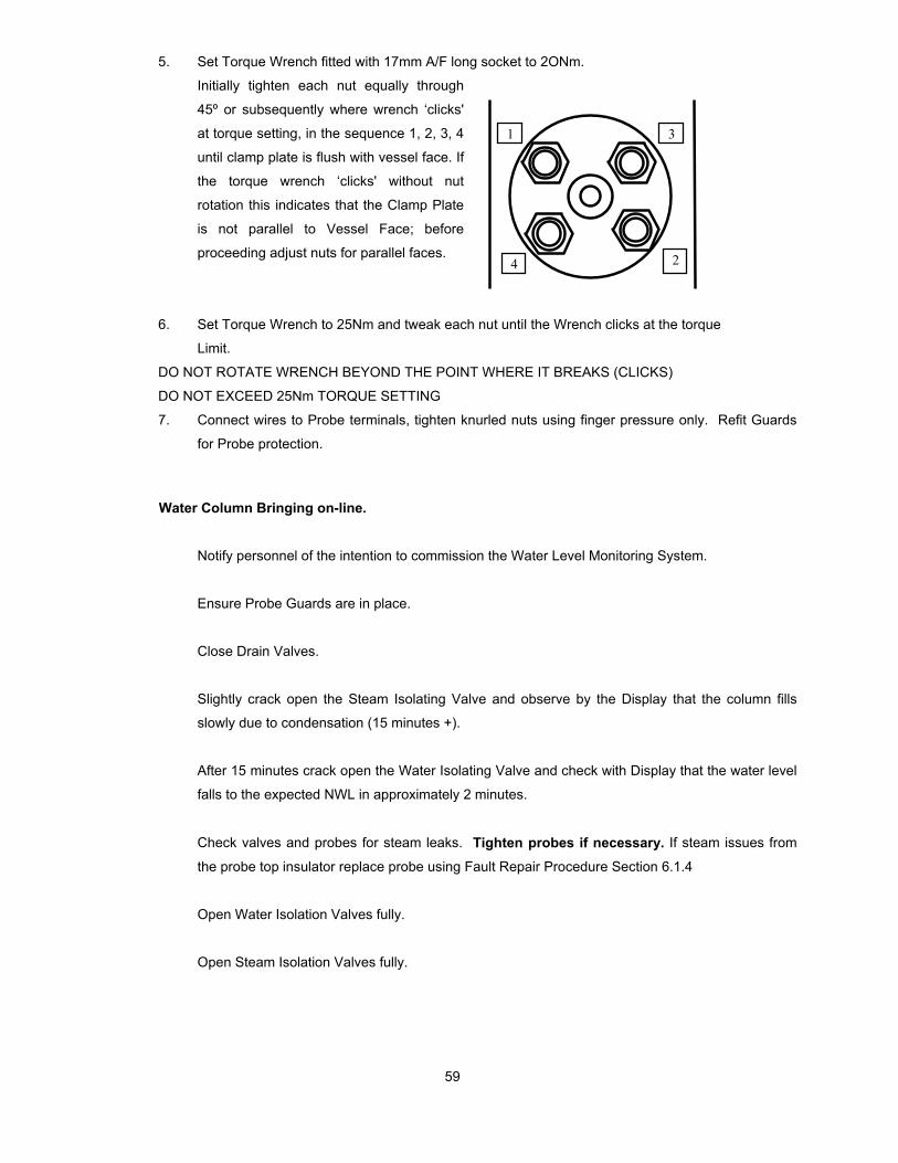
5. Set Torque Wrench fitted with 17mm A/F long socket to 2ONm.
Initially tighten each nut equally through
45º or subsequently where wrench ‘clicks'
at torque setting, in the sequence 1, 2, 3, 4
until clamp plate is flush with vessel face. If
the torque wrench ‘clicks' without nut
rotation this indicates that the Clamp Plate
is not parallel to Vessel Face; before
proceeding adjust nuts for parallel faces.
6. Set Torque Wrench to 25Nm and tweak each nut until the Wrench clicks at the torque
Limit.
DO NOT ROTATE WRENCH BEYOND THE POINT WHERE IT BREAKS (CLICKS)
DO NOT EXCEED 25Nm TORQUE SETTING
7. Connect wires to Probe terminals, tighten knurled nuts using finger pressure only. Refit Guards
for Probe protection.
Water Column Bringing on-line.
Notify personnel of the intention to commission the Water Level Monitoring System.
Ensure Probe Guards are in place.
Close Drain Valves.
Slightly crack open the Steam Isolating Valve and observe by the Display that the column fills
slowly due to condensation (15 minutes +).
After 15 minutes crack open the Water Isolating Valve and check with Display that the water level
falls to the expected NWL in approximately 2 minutes.
Check valves and probes for steam leaks. Tighten probes if necessary. If steam issues from
the probe top insulator replace probe using Fault Repair Procedure Section 6.1.4
Open Water Isolation Valves fully.
Open Steam Isolation Valves fully.
1
4 2
3

60
The System is now operational. Where valve locks are fitted these should be locked if the system
is to remain in service:
Isolation valves locked in the OPEN position.
Drain valves locked in the CLOSED position.
The above method allows the Column to fill slowly and to be heated at a controlled rate and avoids subjecting
the Probes to any significant thermal shock which could adversely affect the pressure sealing interfaces within
the Probe assembly.
CAUTION: DO NOT BLOW-DOWN THE WATER COLUMN WITH PROBES INSERTED.
6.0 Maintenance and Fault Identifications
6.1 Pressure Parts:-
The following sections outline fault identification and rectification procedures. No routine maintenance is
required apart from periodic dusting of Probe external insulators using a small paintbrush to remove the
possible accumulation of fly ash.
It is recommended in the interests of preventative maintenance that all Probes are replaced every 4 years, or
at least replace the lower Probes, which are continuously immersed in water within 4 years as some
dissolution of the ceramic insulator does occur.
A check on the condition of the lower Probes normally immersed in water is recommended every six months to
ensure they correctly switch to the steam condition when the Water Column is drained. With the system at
operational temperature isolate Column, Procedure as per 6.1.3. When fully drained check that all Probe
channels indicate the steam condition (Red). If any channel indicates water (Green) check that the Electronic
Unit and Probe connections are functioning correctly by removing the Probe connection and verify that the
indication changes from Green to Red, in which case the Probe is faulty and must be replaced. If a fault has
occurred on the Electronic Unit rectify this first then replace the Probe connection before determining whether
Probe is faulty.
The large bore thin wall Water Column permits heat loss which stimulates condensate flow preventing the
build-up of sediment which obviates the need for vessel blow-down. As periodic blow-down is not necessary
the system reliability is enhanced due to reduced valve operation. The high purity condensate keeps the
Probes clean and the flow maintains the Water Column temperature near the Drum water temperature which
minimises density errors. Any flow restriction or pressure loss due to Valve or Probe leaks can cause errors in
water level indication.
If a serious Probe leak occurs the Water Column should be isolated immediately otherwise gasket seat
erosion may entail re-machining of the Column seating faces.

61
For damaged seat faces on the Type 501, Type502 and Type 503 Water Columns
For the 501and 503 Water Columns, re-cut seating face to an N8C finish which must be accurately machined
at 90' to the centre line of the opening.
For damaged seating face of type 502, inserts re-cut taper seat at 40° included angel ensuring a surface finish
which must be better than N5C ensuring it is concentric with bore.
6.1.1 Valve steam leaks - requires replacement of steam gland packing. Drain valves not sealing
properly requires seat replacement or re-grinding. Rectification should follow the normal
practices for the particular valve types.
6.1.2 Probe leaks - It is difficult to distinguish between Probe internal seal failure or Probe to Column
seal failure unless the leak is small. Steam emanating from the Probe top ceramic insulator
indicates internal seal failure and requires Probe replacement. Steam emanating from the
Column/Probe seating area may be rectified by further tightening of the Probe but DO NOT
EXCEED specified Probe tightening torque - otherwise replace Probe or gasket using the
following procedures.
6.1.3 Column Isolation Procedure
(i) Ensure Operators are informed that erroneous indications and alarms are to be expected.
(ii) If shutdown or trip circuits are connected to the system ensure they are disarmed.
(iii) Close the Steam and Water Isolation Valves.
(iv) Slowly open the Drain Valve(s) and leave open.
(v) Check at Drain outlet that the Isolation Valves are sealing properly.
6.1.4 Probe Replacement Procedure
(i) Isolate Column as 6.1.3 above, ensuring Drain Valve is open, with Steam and Water Isolation
Valves closed and sealing properly.
(ii) Remove Probe Guard and disconnect Probe wire(s).
(iii) Replace Probe as procedure Section 6.1 for Type 801 or 803.
6.1.5 Column Re-commissioning Procedure
(i) Close Drain Valve(s).
(ii) Crack open the Steam Isolation Valve(s) and check with the display that the Column fills slowly
due to condensate (15 to 20 minutes).
(iii) Crack open the Water Isolation Valve(s) and check that the water level falls to the expected level.
(iv) Check Probes for steam leaks using procedure of 6.1.2.
(v) After approximately 10 minutes fully open Water then Steam Valves.
(vi) Ensure all Valves are correctly set (and locked).
(vii) Inform Operators that the Indication System is now in service.
(viii) Check that approximately normal water level is displayed before rearming any shutdown or trip
circuits connected to the System.

62
The above procedure allows the Column and Probes to be heated at a controlled rate to prevent the
Probes being subjected to excessive thermal shock which could damage the ceramic insulators.
6.1.6 Column or Pipework Blockage
If the Column and pipework installation complies with recommendations of Section 4 and with the intentional
stimulation of condensate flow through the Column pipework blockage should not occur. This is providing the
boiler water treatment conforms to recommended practices such as ASME "Consensus on Operating
Practices for the Control of Feedwater and Boiler Water Quality in Modern Industrial Boilers" or BS 2486
"Recommendations for treatment of water for land boilers".
If a partial blockage is suspected by the slow response times of the level indicator isolate the Water Column as
procedure 6.1.3. With the Drain Valve open slowly open the Steam Isolating Valve until there is free flow of
steam at the Drain outlet then close the Steam Valve. Slowly open the Water Isolating Valve until there is free
flow at the Drain outlet then close the Water Valve. Close the Drain Valve(s) and open Steam and Water
Valves. Ensure all valves are correctly set (and locked) and rearm trip circuits if fitted. If the response time is
still sluggish suspect problems with Isolation Valves not opening fully.

63
6.2 Electronic Unit Faults & Corrective Action:- Fault in the system will generally be indicated by the Yellow LEDs on the front panel and by the SF output on
the Relay board.
Fault indication arise with the following:
a) Electrode or wire short circuit or open circuit
b) Any one power supply failure
c) Detection of any circuit fault in Discriminator & Input Board.
Two Yellow LEDs at top are responsible for indication of the system fault. Left side Yellow LED for ODD
channel system fault and right side Yellow LED for EVEN channel system fault.
Note:- System fault Yellow LED’s will blink at 1 Hz. for any of the above abnormalities.
Indication Fault Corrective Action
1. Both the Yellow LEDs indicated but
no abnormalities in the process LEDs
i.e. Red & Green
Any one of the power
supply module failure.
Check the Green LED at power pack if
“OFF” then check the input A.C. voltage
at the particular power pack. If A.C.
voltage (Input 85-264V AC) or if DC
voltage (input 120-370V DC) is there
then change the power pack and restore
operation.
If Green LEDs at both the power pack is
‘ON’ then check the DC output voltage
at the power pack with the value in the
sticker at the power pack terminal. If any
absence of the DC voltage please
change the particular power pack.
2. Left hand Yellow LED is blinking at
1 Hz. and a particular green LED is
also blinking in synchronization with
Yellow LED.
Particular odd channel is
short circuit.
Remove the channel conductor from the
probe. If problem persist then conductor
short circuit/else if corresponding Red
LED is blinking in synchronization with
Yellow LED then short the two conductor
and it should indicate steam. This
indicates the probe short circuit. Change
the probe or conductor as required.

64
Indication Fault Corrective Action 3. Right hand Yellow LED is blinking at
1 Hz. and a particular green LED is
also blinking in synchronization with
Yellow LED.
Particular even channel is
short circuit.
Remove the channel conductor from
the probe. If problem persist then
conductor short circuit/else if
corresponding Red LED is blinking in
synchronization with Yellow LED then
short the two conductors and it should
indicate steam. This indicates the probe
short circuit. Change the probe or
conductor as required
4. Left hand yellow LED is blinking at
1 Hz. and a particular red LED is also
blinking in synchronization with yellow
LED.
Particular odd channel is
open circuit.
Remove the channel conductor from
the probe and short the two conductors,
if problem persist then conductor
disconnected. Check the connection of
particular channel at input board. If
problem persist then change the
conductor.
5. Right hand yellow LED is blinking at
1 Hz. and a particular red LED is also
blinking in synchronization with yellow
LED.
Particular even channel is
open circuit.
Remove the channel conductor from
the probe and short the two conductor,
if problem persist then conductor
disconnected . Check the connection of
particular channel at input board. If
problem persist then change the
conductor.
6. All odd LEDs are OFF, both at RDU
& Local Display.
Odd discriminator PCB
defective.
Change the odd side discriminator
PCB.
7. All odd LEDs are OFF, either at
RDU or Local Display.
Problem with odd Display
unit( RDU or Local ) or
communication failure.
Change the Display PCB. If problem
persist then check the communicating
cable connector.

65
Indication Fault Corrective Action 8. All even LEDs are OFF, both at
RDU & Local Display.
Even discriminator
PCB defective.
Change the even side discriminator PCB.
9. All even LEDs are OFF, either at
RDU or Local Display.
Problem with even
Display unit (RDU or
Local) or
communication
failure.
Change the Display PCB. If problem persist
then check the communicating cable
connector.
12. More than one Green LEDs
showing short circuit & both the
Yellow LED is blinking at 1 Hz.
Water conductivity is
> 100µs/cm. All
Yellow LEDs for
probes immersed in
water showing short
circuit.
This may happen when the conductivity of
water is greater than 100 µs/cm. Try to
improve the conductivity or disable the short
circuit option through programme.
13. System fault LED blinking at 1 Hz
and more than one channel showing
water above steam.
Discriminator PCB or
Input card faulty.
Try with changing discriminator card. If
problem persist then change the Input PCB
for rectification of the problem.
Also the check the wiring at terminal (Input
card) for proper installation.

66
7.0 202B-EDLI Parts List
Description Part No
Discriminator PCB (ODD) 202B2501A
Discriminator PCB (EVEN) 202B2501B
Probe Input Board PCB 202B2502-8 for 8 Channel
Probe Input Board PCB 202B2502-16 for 16 Channel
Probe Input Board PCB 202B2502-32 for 32 Channel
Display/Remote PCB 202B2503-8 for 8 Channel
Display/Remote PCB 202B2503-16 for 16 Channel
Display/Remote PCB 202B2503-32 for 32 Channel
Relay/4-20mA PCB 202B2504
Power Supply (SMPS) 202B2505
Probe Cable 4 metres 202B28-04
Probe Cable 10 metres 202B28-10
Blanking Plug for 501 Water Column 5012201
Blanking Plug for 502 Water Column 5022201
Blanking Plug for 503 Water Column 5032201
Installation Manual 202B6900-8 for 8 Channel
Installation Manual 202B6900-16 for 16 Channel
Installation Manual 202B6900-32 for 32 Channel

67
8.0 202B Electronic Unit Specification
Electronic Level Indicator Unit. Type 202B Enclosure:
Wall mounted glass-fibre reinforced polyester enclosure, IP65 / NEMA 4X protection for location in harsh
environments.
Dimensions (mm): 500 H x 400 W x 200D)
Temperature Rating:
Ambient: - 10 C to 65 C Storage: 50 C to 100 C
No of Channels:
Maximum 32 Channels. Configurable from 6 to 32 Channels through handheld programmer.
Power Supply:
Input 85-264V AC, Frequency - 47-63 Hz. / 120-370V DC;
Inputs:
From Conductivity types probes 2-wire connection. 32 Channels numbered in ascending order.
Probe Cable:
Special PTFE high temperature cable maximum 30 meters length.
System Measurement:
Microprocessor / Microcontroller Based fully integrated electronics unit. Separate controller are used for ODD
and EVEN channel to scan the probe signal and do necessary discrimination for Water, Steam, Open Circuit
and Short Circuit. System based on 8/16bit processor and having RS485 serial communication with the
peripherals and Remotes. Total 10 Cards, either Remote Display or Remote Relay card with additional power
supply, can be connected in daisy chain configuration with RS485. Programmer interface used to program the
field parameters through handheld programmer and diagnosis the system.
Display:
Two vertical columns of LED (BAR Graph) are provided on the front of the enclosure.
10 x 10 Sq. mm each LED for 8 & 16 Channels.
5 x 10 Sq. mm each LED for above 16 Channels to 32 Channels.
For any other combination of channels the top redundant LED will be blank i.e for 24 Channels, top 8 rows will
be blank.
Left column is GREEN LED and Right column is RED LED.
Two 10 x 10 Sq. mm. Yellow LED at top for System fault indication always in 1 Hz blinking during any system
fault.
Left yellow LED for ODD channel and Right yellow LED for EVEN channel.
System Fault:
System fault occurs during following conditions.
Any of the power supply / power pack failure.
Probe cable short circuit / open circuit in each channel.
Contamination or short circuit in probe.
68
DPDT sealed relay (RL1) is used as system fault relay in Relay output card and activate in any of above
system fault condition.
Contact rating: DPCO - 8 Amps, 250VAC / 30 VDC
Switching Power: 2000 VA / 240W
Output Alarm / Trip relays:
4 ( Max. 7 ) DPDT sealed relays are used for alarm and trip signalling and this can be extended up to 15
relays by an add-on relay card. Relays can be configured to any channel as per plant requirement in the field
through handheld programmer. On the configured channels any abnormalities will be indicated by 2 Hz
blinking of that particular channel along with the activation/ deactivation of the relay. Spurious Alarm / trip
action is prevented while fault occurs on respective alarm / trip configured channel.
Trip logic ensures positive trip on plant fault as well as eliminates spurious trips through its voting logic. Each
relay can be configured for normally energised or de-energised with time delay action for 1 to 20 sec.
Contact rating: DPCO - 8 Amps, 250VAC / 30 VDC
Switching Power: 2000 VA / 240W
4-20mA Signal:
Two 4-20 mA DC analogue output signal whereby each probe channel contributes a step change of ‘16 / no of
channel’ mA. Selection of 4 mA to represent the all water or all steam state can be configured through the
handheld programmer. Galvanic isolation is also available as optional with both the 4-20mA output.
Load impedance: 300-Ohm maximum for non-isolated output and 600-Ohm maximum for isolated output.
Remote Display Unit:
Remote display unit indication is identical with the main display unit. Remote display will be connected through
2 nos. (one for ODD channels and one for EVEN channels) 8 core screened twisted pare cables. Total two
remote display unit can be connected in cascade with main power supply. However, more remote display unit
can be connected with local power supply unit as additional. Maximum cable length from main to last remote
should not be more than 600 meters.
Number of terminals: 2 nos. 6 way terminal (one for ODD and other for EVEN)
Panel Mounting Size: 160mm x 99 mm for 8 Channels.
Panel Cut-out Dimension: 155mm x 94 mm for 8 Channels.
Number of terminals: 2 nos. 6 way terminal (one for ODD and other for EVEN)
Panel Mounting Size: 238mm x 96 mm for 16 Channels.
Panel Cut-out Dimension: 233mm x 91 mm for 16 Channels.
Number of terminals: 2 nos. 6 way terminal (one for ODD and other for EVEN)
Panel Mounting Size: 272mm x 96 mm for 32 Channels.
Panel Cut-out Dimension: 267mm x 91 mm for 32 Channels.
Enclosure protection class – IP20 OR IP65 (optional).