2010 Chrysler 300 Owner's Manual
538
300 OWNER’S MANUAL 2010
-
Upload
khangminh22 -
Category
Documents
-
view
1 -
download
0
Transcript of 2010 Chrysler 300 Owner's Manual

300OWNER ’ S M AN U A L
2 0 1 0

TABLE OF CONTENTSSECTION PAGE
1 INTRODUCTION . . . . . . . . . . . . . . . . . . . . . . . . . . . . . . . . . . . . . . . . . . . . . . . . . . . . . . . . . . . . 3
2 THINGS TO KNOW BEFORE STARTING YOUR VEHICLE . . . . . . . . . . . . . . . . . . . . . . . . . . . . . .9
3 UNDERSTANDING THE FEATURES OF YOUR VEHICLE . . . . . . . . . . . . . . . . . . . . . . . . . . . . . 85
4 UNDERSTANDING YOUR INSTRUMENT PANEL . . . . . . . . . . . . . . . . . . . . . . . . . . . . . . . . . . 209
5 STARTING AND OPERATING . . . . . . . . . . . . . . . . . . . . . . . . . . . . . . . . . . . . . . . . . . . . . . . . 305
6 WHAT TO DO IN EMERGENCIES . . . . . . . . . . . . . . . . . . . . . . . . . . . . . . . . . . . . . . . . . . . . . 399
7 MAINTAINING YOUR VEHICLE . . . . . . . . . . . . . . . . . . . . . . . . . . . . . . . . . . . . . . . . . . . . . . 421
8 MAINTENANCE SCHEDULES . . . . . . . . . . . . . . . . . . . . . . . . . . . . . . . . . . . . . . . . . . . . . . . . . 485
9 IF YOU NEED CONSUMER ASSISTANCE . . . . . . . . . . . . . . . . . . . . . . . . . . . . . . . . . . . . . . . . 505
10 INDEX . . . . . . . . . . . . . . . . . . . . . . . . . . . . . . . . . . . . . . . . . . . . . . . . . . . . . . . . . . . . . . . . . . . 515
1
2
3
4
5
6
7
8
9
10


INTRODUCTION
CONTENTS
� Introduction . . . . . . . . . . . . . . . . . . . . . . . . . . . 4
� How To Use This Manual . . . . . . . . . . . . . . . . . . 4
� Warnings And Cautions . . . . . . . . . . . . . . . . . . . 6
� Vehicle Identification Number . . . . . . . . . . . . . . 6
� Vehicle Modifications/Alterations . . . . . . . . . . . . 7
1

INTRODUCTIONCongratulations on selecting your new Chrysler GroupLLC vehicle. Be assured that it represents precisionworkmanship, distinctive styling, and high quality - allessentials that are traditional to our vehicles.
This Owner’s Manual has been prepared with the assis-tance of service and engineering specialists to acquaintyou with the operation and maintenance of your vehicle.It is supplemented by a Warranty Information Booklet,located on the DVD, and various customer-orienteddocuments. Please take the time to read these publica-tions carefully. Following the instructions and recom-mendations in this manual will help assure safe andenjoyable operation of your vehicle.
NOTE: After you read the manual, it should be storedin the vehicle for convenient referencing and remainwith the vehicle when sold, so that the new owner willbe aware of all safety warnings.
When it comes to service, remember that your authorizeddealer knows your vehicle best, has factory-trained tech-nicians and genuine MOPAR� parts, and cares aboutyour satisfaction.
HOW TO USE THIS MANUALConsult the Table of Contents to determine which sectioncontains the information you desire.
Since the specification of your vehicle depends on theitems of equipment ordered, certain descriptions andillustrations may differ from your vehicle’s equipment
The detailed index at the back of this Owner’s Manualcontains a complete listing of all subjects.
Consult the following table for a description of thesymbols that may be used on your vehicle or throughoutthis Owner’s Manual:
4 INTRODUCTION

1
INTRODUCTION 5

WARNINGS AND CAUTIONSThis Owner’s Manual contains WARNINGS against op-erating procedures that could result in an accident orbodily injury. It also contains CAUTIONS against proce-dures that could result in damage to your vehicle. If youdo not read this entire manual, you may miss importantinformation. Observe all Warnings and Cautions.
VEHICLE IDENTIFICATION NUMBERThe Vehicle Identification Number (VIN) is on the leftfront corner of the instrument panel. The VIN is visiblefrom outside of the vehicle through the windshield. Thisnumber also appears on the Automobile InformationDisclosure Label affixed to a window on your vehicle, thevehicle registration, and the title.
NOTE: It is illegal to remove or alter the VIN.VIN Location
6 INTRODUCTION

VEHICLE MODIFICATIONS/ALTERATIONS
WARNING!
Any modifications or alterations to this vehicle couldseriously affect its roadworthiness and safety andmay lead to an accident resulting in serious injury ordeath.
1
INTRODUCTION 7


THINGS TO KNOW BEFORE STARTING YOUR VEHICLE
CONTENTS
� A Word About Your Keys . . . . . . . . . . . . . . . . . 12
▫ Wireless Ignition Node (WIN) . . . . . . . . . . . . 12
▫ Key FOB . . . . . . . . . . . . . . . . . . . . . . . . . . . 13
▫ Removing Key FOB From Ignition . . . . . . . . . 14
▫ Key-In-Ignition Reminder . . . . . . . . . . . . . . . 15
� Sentry Key� . . . . . . . . . . . . . . . . . . . . . . . . . . 16
▫ Replacement Keys . . . . . . . . . . . . . . . . . . . . . 17
▫ Customer Key Programming . . . . . . . . . . . . . 17
▫ General Information . . . . . . . . . . . . . . . . . . . 17
� Vehicle Security Alarm — If Equipped . . . . . . . . 18
▫ Rearming Of The System . . . . . . . . . . . . . . . . 18
▫ To Arm The System . . . . . . . . . . . . . . . . . . . 18
▫ To Disarm The System . . . . . . . . . . . . . . . . . 19
� Illuminated Entry — If Equipped . . . . . . . . . . . 20
� Remote Keyless Entry (RKE) . . . . . . . . . . . . . . 20
▫ To Unlock The Doors . . . . . . . . . . . . . . . . . . 21
▫ To Lock The Doors . . . . . . . . . . . . . . . . . . . . 24
▫ To Unlatch The Trunk . . . . . . . . . . . . . . . . . . 25
2

▫ Using The Panic Alarm . . . . . . . . . . . . . . . . . 25
▫ Programming Additional Transmitters . . . . . . 25
▫ Transmitter Battery Replacement . . . . . . . . . . 26
▫ General Information . . . . . . . . . . . . . . . . . . . 27
� Remote Starting System — If Equipped . . . . . . . 27
▫ How To Use Remote Start . . . . . . . . . . . . . . . 28
� Door Locks . . . . . . . . . . . . . . . . . . . . . . . . . . . 30
▫ Manual Door Locks . . . . . . . . . . . . . . . . . . . 30
▫ Power Door Locks . . . . . . . . . . . . . . . . . . . . 32
▫ Passive Entry System — If Equipped . . . . . . . 35
▫ Child Protection Door Lock . . . . . . . . . . . . . . 37
� Windows . . . . . . . . . . . . . . . . . . . . . . . . . . . . 40
▫ Power Windows . . . . . . . . . . . . . . . . . . . . . . 40
▫ Wind Buffeting . . . . . . . . . . . . . . . . . . . . . . . 43
� Trunk Lock And Release . . . . . . . . . . . . . . . . . 43
� Trunk Safety Warning . . . . . . . . . . . . . . . . . . . 44
▫ Trunk Emergency Release . . . . . . . . . . . . . . . 44
� Occupant Restraints . . . . . . . . . . . . . . . . . . . . . 45
▫ Lap/Shoulder Belts . . . . . . . . . . . . . . . . . . . . 46
▫ Lap/Shoulder Belt Untwisting Procedure . . . . 52
▫ Automatic Locking Retractors (ALR) Mode— If Equipped . . . . . . . . . . . . . . . . . . . . . . . 52
▫ Seat Belt Pretensioners — If Equipped . . . . . . 53
▫ Enhanced Seat Belt Use Reminder System(BeltAlert�) . . . . . . . . . . . . . . . . . . . . . . . . . 53
▫ Seat Belts And Pregnant Women . . . . . . . . . . 55
▫ Seat Belt Extender . . . . . . . . . . . . . . . . . . . . . 55
10 THINGS TO KNOW BEFORE STARTING YOUR VEHICLE

▫ Supplemental Restraint System (SRS) —Airbags . . . . . . . . . . . . . . . . . . . . . . . . . . . . 56
▫ Airbag Deployment Sensors And Controls . . . 62
▫ Event Data Recorder (EDR) . . . . . . . . . . . . . . 69
▫ Child Restraints . . . . . . . . . . . . . . . . . . . . . . 71
� Engine Break-In Recommendations . . . . . . . . . . 80
� Safety Tips . . . . . . . . . . . . . . . . . . . . . . . . . . . 81
▫ Transporting Passengers . . . . . . . . . . . . . . . . 81
▫ Exhaust Gas . . . . . . . . . . . . . . . . . . . . . . . . . 81
▫ Safety Checks You Should Make Inside TheVehicle . . . . . . . . . . . . . . . . . . . . . . . . . . . . . 82
▫ Periodic Safety Checks You Should MakeOutside The Vehicle . . . . . . . . . . . . . . . . . . . 84
2
THINGS TO KNOW BEFORE STARTING YOUR VEHICLE 11

A WORD ABOUT YOUR KEYSYour vehicle uses a keyless ignition system. This systemconsists of a Key Fob with Remote Keyless Entry (RKE)transmitter and a Wireless Ignition Node (WIN) withintegral ignition switch. You can insert the Key Fob intothe ignition switch with either side up.
Keyless Go FeatureThis vehicle may be equipped with the Keyless Gofeature, refer to “Starting Procedure” in “Starting AndOperating” for further information.
Wireless Ignition Node (WIN)The Wireless Ignition Node (WIN) operates similar to anignition switch. It has four operating positions, three withdetents and one that is spring-loaded. The detent posi-tions are OFF, ACC, and RUN. The START position is aspring-loaded momentary contact position. When re-leased from the START position, the switch automaticallyreturns to the RUN position.
NOTE: If your vehicle is equipped with Keyless Go, theElectronic Vehicle Information Center (EVIC) will displaythe ignition switch position (OFF/ACC/RUN). Refer to“Electronic Vehicle Information Center (EVIC) — IfEquipped” in “Understanding Your Instrument Panel”for further information.
12 THINGS TO KNOW BEFORE STARTING YOUR VEHICLE

Key FobThe Key Fob operates the ignition switch. It also containsthe Remote Keyless Entry (RKE) transmitter and anemergency key, which stores in the rear of the Key Fob.
NOTE: If your vehicle is equipped with Passive Entry/Keyless Go (PEKG), the Key Fob will also contain aspecial receiver that communicates with the vehicle.Passive Entry/Keyless Go Key Fobs can only be usedwith Passive Entry/Keyless Go equipped vehicles. Non-Passive Entry/Keyless Go Key Fobs can only be usedwith Non-Passive Entry/Keyless Go vehicles.
The emergency key allows for entry into the vehicleshould the battery in the vehicle or the RKE transmittergo dead. The emergency key is also for locking the glovebox. You can keep the emergency key with you whenvalet parking.
Wireless Ignition Node (WIN)
1 — OFF2 — ACC (ACCESSORY)3 — RUN4 — START
2
THINGS TO KNOW BEFORE STARTING YOUR VEHICLE 13

To remove the emergency key, slide the mechanical latchat the top of the Key Fob sideways with your thumb andthen pull the key out with your other hand.
NOTE: You can insert the double-sided emergency keyinto the lock cylinders with either side up.
Removing Key Fob From IgnitionPlace the shift lever in PARK. Turn the Key Fob to theOFF position and then remove the Key Fob.
With the Passive Entry/Keyless Go system, the EVIC willdisplay the ignition switch position “OFF/ACC/RUN”.Refer to “Electronic Vehicle Information Center (EVIC) —If Equipped” in “Understanding Your Instrument Panel”for further information.
NOTE:• For vehicles not equipped with the Electronic Vehicle
Information Center (EVIC), the power windowswitches, radio, power sunroof (if equipped), andpower outlets will remain active for 10 minutes afterthe ignition switch is placed in the OFF position.Opening either front door will cancel this feature.
• For vehicles equipped with the EVIC, the powerwindow switches, radio, power sunroof (if equipped),
Emergency Key Removal
14 THINGS TO KNOW BEFORE STARTING YOUR VEHICLE

and power outlets will remain active for up to 60 min-utes after the ignition switch is placed in the OFFposition. Opening either front door will cancel thisfeature. The time for this feature is programmable.Refer to “Electronic Vehicle Information Center (EVIC)— If Equipped/Personal Settings (Customer-Programmable Features)” in “Understanding Your In-strument Panel” for further information.
WARNING!
Never leave children alone in a vehicle. Leavingunattended children in a vehicle is dangerous for anumber of reasons. A child or others could be seri-ously or fatally injured. Do not leave the Key Fob inthe ignition or a vehicle equipped with Keyless Go inthe ACC or RUN mode. A child could operate powerwindows, other controls, or move the vehicle.
CAUTION!
An unlocked car is an invitation to thieves. Alwaysremove the Key Fob from the ignition and lock alldoors when leaving the vehicle unattended.
Key-In-Ignition ReminderOpening the driver’s door when the Key Fob is in theignition and the ignition switch position is OFF or ACC,sounds a signal to remind you to remove the Key Fob.
NOTE: The Key-In-Ignition reminder only soundswhen the Key Fob is placed in the OFF or ACC ignitionposition.
If your vehicle is equipped with Keyless Go, opening thedriver’s door when the vehicle’s ignition switch is placedin ACC or RUN (engine stopped) will cause the reminderchime to sound. Refer to “Starting Procedures” in “Start-ing And Operating” for further information.
2
THINGS TO KNOW BEFORE STARTING YOUR VEHICLE 15

SENTRY KEY�The Sentry Key� Immobilizer System prevents unautho-rized vehicle operation by disabling the engine. Thesystem does not need to be armed or activated. Operationis automatic, regardless of whether the vehicle is lockedor unlocked.
The system uses Key Fob with factory-mated RemoteKeyless Entry (RKE) transmitter and Wireless IgnitionNode (WIN) to prevent unauthorized vehicle operation.Therefore, only Key Fobs that are programmed to thevehicle can be used to start and operate the vehicle. Thesystem will not allow the engine to crank if an invalidKey Fob is used to start and operate the vehicle.
After placing the ignition switch in the RUN position, theVehicle Security Light will turn on for three seconds for abulb check. If the light remains on after the bulb check, it
indicates that there is a problem with the electronics. Thiscondition will result in the engine being shut off after twoseconds.
If the Vehicle Security Light turns on during normalvehicle operation (vehicle running for longer than 10 sec-onds), it indicates that there is a fault in the electronics.Should this occur, have the vehicle serviced as soon aspossible by an authorized dealer.
NOTE: The Sentry Key� Immobilizer System is notcompatible with aftermarket remote starting systems.Use of these systems may result in vehicle startingproblems and loss of security protection.
All of the Key Fobs provided with your new vehicle havebeen programmed to the vehicle electronics.
16 THINGS TO KNOW BEFORE STARTING YOUR VEHICLE

Replacement Keys
NOTE: Only Key Fobs that are programmed to thevehicle electronics can be used to start and operate thevehicle. Once a Key Fob is programmed to a vehicle, itcannot be programmed to any other vehicle.
CAUTION!
• Always remove the Key Fobs from the vehicle andlock all doors when leaving the vehicle unat-tended.
• For vehicles equipped with Keyless Go, alwaysremember to place the ignition in OFF.
At the time of purchase, the original owner is providedwith a four-digit Personal Identification Number (PIN).Keep the PIN in a secure location. This number isrequired for authorized dealer replacement of Key Fobs.
Duplication of Key Fobs may be performed at an autho-rized dealer, this procedure consists of programming ablank Key Fob to the vehicle electronics. A blank Key Fobis one that has never been programmed.
NOTE: When having the Sentry Key� ImmobilizerSystem serviced, bring all vehicle Key Fobs with you tothe authorized dealer.
Customer Key ProgrammingProgramming Key Fobs or RKE transmitters may beperformed at an authorized dealer.
General InformationThe Sentry Key� system complies with FCC rules Part 15and with RSS-210 of Industry Canada. Operation issubject to the following conditions:
• This device may not cause harmful interference.
2
THINGS TO KNOW BEFORE STARTING YOUR VEHICLE 17

• This device must accept any interference that may bereceived, including interference that may cause undes-ired operation.
VEHICLE SECURITY ALARM — IF EQUIPPEDThe Vehicle Security Alarm monitors the vehicle doorsfor unauthorized entry and the ignition switch (andKeyless Go Start/Stop button) for unauthorized opera-tion. If something triggers the alarm, the Vehicle SecurityAlarm will prevent the vehicle from starting and providethe following audible and visible signals: the horn willpulse, the headlights, park lamps and/or turn signalswill flash, and the Vehicle Security Light in the instru-ment cluster will flash.Rearming of the SystemIf something triggers the alarm, and no action is taken todisarm it, the Vehicle Security Alarm will turn the hornoff after three minutes, turn all of the visual signals offafter 15 minutes, and then the Vehicle Security Alarm willrearm itself.
To Arm the System
Vehicles Not Equipped with Keyless GoRemove the key from the ignition switch and either pressa power door LOCK switch while the driver or passengerdoor is open or press the LOCK button on the RemoteKeyless Entry (RKE) transmitter. After the last door isclosed, or if all doors are closed, the Vehicle SecurityAlarm will arm itself in about 16 seconds. During thattime, the Vehicle Security Light will flash. If it does notilluminate, the Vehicle Security Alarm is not arming. Inaddition, if you open a door during the arming period,the Vehicle Security Alarm will cancel the arming pro-cess. If you wish to rearm the Vehicle Security Alarm afterclosing the door, you must repeat one of the previously-described arming sequences.
Vehicles Equipped with Keyless GoPress the Keyless Go Start/Stop button until the Elec-tronic Vehicle Information Center (EVIC) indicates that
18 THINGS TO KNOW BEFORE STARTING YOUR VEHICLE

the vehicle ignition is �OFF� (refer to “Starting Proce-dures” in “Starting And Operating” for further informa-tion). Then either press the power door LOCK switchwhile the driver or passenger door is open, press theRemote Keyless Entry (RKE) transmitter LOCK button orpress the Passive Entry Door Handle LOCK button (referto “Door Locks” in “Things To Know Before Starting” forfurther information).
To Disarm the System
Vehicles Not Equipped with Keyless GoEither press the UNLOCK button on the RKE transmitteror insert a valid ignition key into the ignition switch andturn the key to the ON position.
NOTE:• The driver’s door key cylinder and the trunk button on
the RKE transmitter cannot arm or disarm the VehicleSecurity Alarm.
• The Vehicle Security Alarm remains armed duringtrunk entry. Pressing the TRUNK button will notdisarm the Vehicle Security Alarm. If someone entersthe vehicle through the trunk, and opens any door, thealarm will sound.
• When the Vehicle Security Alarm is armed, the interiorpower door lock switches will not unlock the doors.
The Vehicle Security Alarm is designed to protect yourvehicle; however, you can create conditions where theVehicle Security Alarm will give you a false alarm. If oneof the previously-described arming sequences has oc-curred, the Vehicle Security Alarm will arm regardless ofwhether you are in the vehicle or not. If you remain in thevehicle and open a door, the alarm will sound. If thisoccurs, disarm the Vehicle Security Alarm.
If the Vehicle Security Alarm is armed and the batterybecomes disconnected the Vehicle Security Alarm willremain armed when the battery is reconnected. The
2
THINGS TO KNOW BEFORE STARTING YOUR VEHICLE 19

exterior lights will flash, the horn will sound, and theignition will not start the vehicle. If this occurs, disarmthe Vehicle Security Alarm.
Vehicles Equipped with Keyless GoEither press the UNLOCK button on the RKE transmitteror grasp the Passive Entry Unlock Door Handle (refer to“Door Locks” in “Things To Know Before Starting” forfurther information), press the Keyless Go Start/Stopbutton (requires at least one valid Key Fob in the vehicle),or insert a valid Key Fob into the ignition switch (if theStart/Stop button is removed) and rotate it to the RUNposition.
Tamper AlertIf something has triggered the Vehicle Security Alarm inyour absence, the horn will sound three times when youdisarm the Vehicle Security Alarm. Check the vehicle fortampering.
ILLUMINATED ENTRY — IF EQUIPPEDThe courtesy lights will turn on when you use theRemote Keyless Entry (RKE) transmitter or unlock anydoor.
The lights will fade to off after approximately 30 secondsor they will immediately fade to off once the ignitionswitch is turned ON from the LOCK position.
NOTE: None of the courtesy lights will operate if thedimmer control is in the “defeat” position (extremedownward position), unless the overhead map/readinglights are turned on manually.
REMOTE KEYLESS ENTRY (RKE)The RKE system allows you to lock or unlock the doors,open the trunk, or activate the Panic Alarm from dis-tances up to approximately 66 ft (20 m) using a hand-heldKey Fob with RKE transmitter. The RKE transmitter doesnot need to be pointed at the vehicle to activate thesystem.
20 THINGS TO KNOW BEFORE STARTING YOUR VEHICLE

NOTE: Inserting the Key Fob with RKE transmitter intothe ignition switch disables all buttons on that RKEtransmitter; however, the buttons on the remaining RKEtransmitters will continue to work. Driving at speeds5 mph (8 km/h) and above disables all RKE transmitterbuttons for all RKE transmitters.
To Unlock the DoorsPress and release the UNLOCK button on the RKEtransmitter once to unlock the driver’s door or twicewithin five seconds to unlock all doors. The turn signallights will flash to acknowledge the unlock signal. Theilluminated entry system will also turn on.
If your vehicle is equipped with Passive Entry, refer to“Passive Entry System — If Equipped” under “DoorLocks” for further information.
Remote Key Unlock, Driver Door/All Doors 1stPressThis feature lets you program the system to unlock eitherthe driver’s door or all doors on the first press of theUNLOCK button on the RKE transmitter. To change thecurrent setting, proceed as follows:
• For vehicles equipped with the Electronic VehicleInformation Center (EVIC), refer to “Electronic VehicleInformation Center (EVIC) — If Equipped/Personal
Key Fob with RKE Transmitter
2
THINGS TO KNOW BEFORE STARTING YOUR VEHICLE 21

Settings (Customer-Programmable Features)” in “Un-derstanding Your Instrument Panel” for further infor-mation.
• For vehicles not equipped with the EVIC, perform thefollowing procedure:
1. Press and hold the LOCK button on a programmedRKE transmitter for at least 4 seconds, but no longer than10 seconds. Then, press and hold the UNLOCK buttonwhile still holding the LOCK button.
2. Release both buttons at the same time.
3. Test the feature while outside of the vehicle by press-ing the LOCK/UNLOCK buttons on the RKE transmitterwith the ignition switch in the OFF position and the keyremoved.
4. Repeat these steps if you want to return this feature toits previous setting.
NOTE: Pressing the LOCK button on the RKE transmit-ter while you are inside the vehicle will activate thesecurity alarm. Opening a door with the Vehicle SecurityAlarm armed will cause the alarm to sound. Press theUNLOCK button to deactivate the security alarm.
Flash Lights with Remote Key LockThis feature will cause the turn signal lights to flash whenthe doors are locked with the RKE transmitter. When thisfeature is turned on and the vehicle is equipped with thePassive Entry system, using the Passive Entry system toLOCK the vehicle will cause the parking lights to flash.This feature can be turned on or turned off. To change thecurrent setting, proceed as follows:
• For vehicles equipped with the EVIC, refer to “Elec-tronic Vehicle Information Center (EVIC) — IfEquipped/Personal Settings (Customer-Programmable Features)” in “Understanding Your In-strument Panel” for further information.
22 THINGS TO KNOW BEFORE STARTING YOUR VEHICLE

• For vehicles not equipped with the EVIC, perform thefollowing procedure:
1. Press and hold the UNLOCK button on a programmedRKE transmitter for at least 4 seconds, but no longer than10 seconds. Then, press and hold the LOCK button whilestill holding the UNLOCK button.
2. Release both buttons at the same time.
3. Test the feature while outside of the vehicle by press-ing the LOCK/UNLOCK buttons on the RKE transmitterwith the ignition switch in the OFF position and the keyremoved.
4. Repeat these steps if you want to return this feature toits previous setting.
NOTE: Pressing the LOCK button on the RKE transmit-ter while you are in the vehicle will activate the security
alarm. Opening a door with the security alarm activatedwill cause the alarm to sound. Press the UNLOCK buttonto deactivate the security alarm.
Turn Headlights On with Remote Key UnlockThis feature activates the headlights for up to 90 secondswhen the doors are unlocked with the RKE transmitter.When this feature is turned on and the vehicle isequipped with the Passive Entry system, using the Pas-sive Entry system to UNLOCK the vehicle will cause theparking lights to flash.
The time for this feature is programmable on vehiclesequipped with the EVIC. Refer to “Electronic VehicleInformation Center (EVIC) — If Equipped/Personal Set-tings (Customer-Programmable Features)” in “Under-standing Your Instrument Panel” for further information.
2
THINGS TO KNOW BEFORE STARTING YOUR VEHICLE 23

To Lock the DoorsPress and release the LOCK button on the RKE transmit-ter to lock all doors. The turn signal lights will flash andthe horn will chirp to acknowledge the signal.
If the vehicle is equipped with Passive Entry, refer to“Passive Entry System — If Equipped” under “DoorLocks” for further information.
Sound Horn with Remote Key LockThis feature will cause the horn to chirp when the doorsare locked with the RKE transmitter, or locked using thePassive Entry door handle lock button (if equipped). Thisfeature can be turned on or turned off. To change thecurrent setting, proceed as follows:
• For vehicles equipped with the EVIC, refer to “Elec-tronic Vehicle Information Center (EVIC) — IfEquipped/Personal Settings (Customer-Programmable Features)” in “Understanding Your In-strument Panel” for further information.
• For vehicles not equipped with the EVIC, perform thefollowing procedure:
1. Press the LOCK button on a programmed RKE trans-mitter for at least 4 seconds, but no longer than 10 sec-onds. Then, press the PANIC button while still holdingthe LOCK button.
2. Release both buttons at the same time.
3. Test the feature while outside of the vehicle by press-ing the LOCK button on the RKE transmitter with theignition switch in the LOCK position and the key re-moved.
4. Repeat these steps if you want to return this feature toits previous setting.
NOTE: Pressing the LOCK button on the RKE transmit-ter while you are in the vehicle will activate the security
24 THINGS TO KNOW BEFORE STARTING YOUR VEHICLE

alarm. Opening a door with the security alarm activatedwill cause the alarm to sound. Press the UNLOCK buttonto deactivate the security alarm.
To Unlatch the TrunkPress the TRUNK button on the RKE transmitter twotimes within five seconds to unlatch the trunk.
If the vehicle is equipped with Passive Entry, refer to“Passive Entry System — If Equipped” under “DoorLocks” for further information.
Using the Panic AlarmTo turn the Panic Alarm feature on or off, press and holdthe PANIC button on the RKE transmitter for at least onesecond and release. When the Panic Alarm is on, theheadlights and park lights will flash, the horn will pulseon and off, and the interior lights will turn on.
The Panic Alarm will stay on for three minutes unlessyou turn it off by either pressing the PANIC button asecond time or drive the vehicle at a speed of 15 mph(24 km/h) or greater.
NOTE:• The interior lights will turn off if you place the ignition
switch in the ACC or RUN position while the PanicAlarm is activated. However, the exterior lights andhorn will remain on.
• You may need to be less than 35 ft (11 m) from thevehicle when using the RKE transmitter to turn off thePanic Alarm due to the radio frequency noises emittedby the system.
Programming Additional TransmittersProgramming Key Fobs or RKE transmitters may beperformed at an authorized dealer.
2
THINGS TO KNOW BEFORE STARTING YOUR VEHICLE 25

Transmitter Battery ReplacementThe recommended replacement battery is one CR2032battery.
NOTE:• Do not touch the battery terminals that are on the back
housing or the printed circuit board.
1. Battery access is through a door located on the rear ofthe RKE transmitter. Insert a small, flat blade screwdriverinto the slot and gently pry open the access door.
2. Remove and replace the battery. Avoid touching thenew battery with your fingers. Skin oils may causebattery deterioration. If you touch a battery, clean it withrubbing alcohol.
Battery Replacement
1— Battery Access Door
26 THINGS TO KNOW BEFORE STARTING YOUR VEHICLE

3. Reposition the access door panel over the batteryopening and snap into place.
General InformationThis device complies with Part 15 of the FCC rules andRSS 210 of Industry Canada. Operation is subject to thefollowing conditions:
• This device may not cause harmful interference.
• This device must accept any interference received,including interference that may cause undesiredoperation.
NOTE: Changes or modifications not expressly ap-proved by the party responsible for compliance couldvoid the user’s authority to operate the equipment.
If your RKE transmitter fails to operate from a normaldistance, check for these two conditions:
1. A weak battery in the RKE transmitter. The expectedlife of the battery is a minimum of three years.
2. Closeness to a radio transmitter such as a radio stationtower, airport transmitter, and some mobile or CB radios.
REMOTE STARTING SYSTEM — IF EQUIPPEDThis system uses the Key Fob Remote KeylessEntry (RKE) transmitter to start the engineconveniently from outside the vehicle whilestill maintaining security. The system has a
range of approximately 300 ft (91 m).
NOTE:• The vehicle must be equipped with an automatic
transmission to be equipped with Remote Start.
• Obstructions between the vehicle and the Key Fobmay reduce this range.
2
THINGS TO KNOW BEFORE STARTING YOUR VEHICLE 27

How to Use Remote StartAll of the following conditions must be met before theengine will remote start:
• Shift lever in PARK
• Doors closed
• Hood closed
• Trunk closed
• Hazard switch off
• Brake switch inactive (brake pedal not pressed)
• Ignition key removed from ignition switch
• Battery at an acceptable charge level
• RKE PANIC button not pressed
NOTE: For vehicles equipped with Keyless Go, theremote start feature will operate with the Start/Stopbutton installed in the ignition switch.
WARNING!
• Do not start or run an engine in a closed garage orconfined area. Exhaust gas contains Carbon Mon-oxide (CO) which is odorless and colorless. Car-bon Monoxide is poisonous and can cause seriousinjury or death when inhaled.
• Keep Remote Keyless Entry (RKE) transmittersaway from children. Operation of the Remote StartSystem, windows, door locks or other controlscould cause serious injury or death.
28 THINGS TO KNOW BEFORE STARTING YOUR VEHICLE

To Enter Remote Start ModePress and release the REMOTE START buttonon the RKE transmitter twice, within five sec-onds. The parking lights will flash and the hornwill chirp twice (if programmed). Then, the
engine will start and the vehicle will remain in theRemote Start mode for a 15-minute cycle.
NOTE:• The park lamps will turn on and remain on during
Remote Start mode.
• For security, power window and power sunroof op-eration (if equipped) are disabled when the vehicle isin the Remote Start mode.
• The engine can be started two consecutive times (two15-minute cycles) with the RKE transmitter. However,the ignition switch must be cycled to the RUN positionbefore you can repeat the start sequence for a thirdcycle.
To Exit Remote Start Mode without Driving theVehiclePress and release the REMOTE START button one time,or allow the engine to run for the entire 15-minute cycle.
NOTE: To avoid unintentional shut downs, the systemwill disable the one time press of the REMOTE STARTbutton for two seconds after receiving a valid RemoteStart request.
To Exit Remote Start Mode and Drive the VehicleBefore the end of the 15-minute cycle, press and releasethe UNLOCK button on the RKE transmitter to unlockthe doors and disarm the Vehicle Security Alarm (ifequipped). Then, prior to the end of the 15-minute cycle,insert the Key Fob into the ignition switch and turn theswitch to the RUN position.
Vehicles Equipped with Passive EntryUse the Passive Entry feature to unlock the vehicle, pressthe Start/Stop button one time if the Keyless Go Start/
2
THINGS TO KNOW BEFORE STARTING YOUR VEHICLE 29

Stop button is installed in the ignition switch, otherwise,insert the Key Fob into the ignition switch and turn to theRUN position. Refer to the “Passive Entry System — IfEquipped” under “Door Locks” for more information.
NOTE:• For vehicles not equipped with Keyless Go feature, the
ignition switch must be in the ON position in order todrive the vehicle.
• For vehicles not equipped with Keyless Go feature, themessage “Insert Key/Turn To On” will display in theEVIC until you insert the Key Fob. Once inserted, themessage “Turn To On” will display in the EVIC untilyou turn the Key Fob to ON.
• For vehicles equipped with Keyless Go feature, themessage “Push Button/Insert Key” will display in theEVIC until you push the START button.
DOOR LOCKS
Manual Door LocksTo lock each door, push the door lock plunger on eachdoor trim panel downward. To unlock each door, pull thedoor lock plunger on each door trim panel upward.
Door Lock Plunger
30 THINGS TO KNOW BEFORE STARTING YOUR VEHICLE

If the door lock plunger is down when you shut the door,the door will lock. Make sure the key is not inside thevehicle before closing the door.
WARNING!
• For personal security and safety in the event of anaccident, lock the vehicle doors before you drive aswell as when you park and leave the vehicle.
• When leaving the vehicle, always remove the keyfrom the ignition and lock your vehicle. Unsuper-vised use of vehicle equipment may cause severepersonal injuries and death.
(Continued)
WARNING! (Continued)• Never leave children alone in a vehicle. Leaving
unattended children in a vehicle is dangerous for anumber of reasons. A child or others could beseriously or fatally injured. Don’t leave the key inthe ignition or leave a vehicle with Keyless Go inthe ACC or RUN position. A child could operatepower windows, other controls, or move thevehicle.
2
THINGS TO KNOW BEFORE STARTING YOUR VEHICLE 31

Power Door LocksA power door lock switch is on each front door trimpanel. Use this switch to lock or unlock the doors.
If you press the power door lock switch while the KeyFob is in the ignition, ACC or RUN position and any frontdoor is open, the power locks will not operate. This
prevents you from accidentally locking the Key Fob inthe vehicle. Removing the Key Fob, returning the ignitionmode to the OFF position, or closing the door will allowthe locks to operate. If a door is open, the Key Fob is inthe ignition OFF or ACC position, a chime will sound asa reminder to remove the Key Fob.
If your vehicle is equipped with Keyless Go, opening thedriver’s door when the vehicle’s ignition switch is placedin ACC or RUN (engine stopped) will cause the reminderchime to sound. Refer to “Starting Procedures” in “Start-ing And Operating” for further details.
Automatic Door LocksThe doors will lock automatically on vehicles with powerdoor locks if all of the following conditions are met:
1. The Automatic Door Locks feature is enabled.
2. The transmission is in gear.
3. All doors are closed.
Power Door Lock Switch
32 THINGS TO KNOW BEFORE STARTING YOUR VEHICLE

4. The throttle is pressed.
5. The vehicle speed is above 15 mph (24 km/h).
6. The doors were not previously locked using the powerdoor lock switch or Remote Keyless Entry (RKE)transmitter.
Automatic Door Locks ProgrammingThe Automatic Door Locks feature can be enabled ordisabled as follows:
• For vehicles equipped with the Electronic VehicleInformation Center (EVIC), refer to “Electronic VehicleInformation Center (EVIC)/Personal Settings(Customer-Programmable Features)” in “Understand-ing Your Instrument Panel” for further information.
• For vehicles not equipped with the EVIC, perform thefollowing procedure:
1. Close all doors and place the Key Fob in the ignitionswitch.
2. Cycle the ignition switch between OFF and RUN andthen back to OFF four times ending up in the OFFposition (do not start engine).
3. Press the power door LOCK switch to lock the doors.
4. A single chime will indicate the completion of theprogramming.
5. Cycle the ignition after performing steps one to fourfor the feature to be enabled or disabled.
6. Repeat these steps if you want to return this feature toits previous setting.
NOTE: Use the Automatic Door Locks feature in accor-dance with local laws.
2
THINGS TO KNOW BEFORE STARTING YOUR VEHICLE 33

Automatic Unlock Doors on ExitThe doors will unlock automatically on vehicles withpower door locks if:
1. The Automatic Unlock Doors On Exit feature is en-abled.
2. The transmission was in gear and the vehicle speedreturned to 0 mph (0 km/h).
3. The transmission is in NEUTRAL or PARK.
4. The driver door is opened.
5. The doors were not previously unlocked.
6. The vehicle speed is 0 mph (0 km/h).
Automatic Unlock Doors on Exit ProgrammingThe Automatic Unlock Doors On Exit feature can beenabled or disabled as follows:
• For vehicles equipped with the EVIC, refer to “Elec-tronic Vehicle Information Center (EVIC)/PersonalSettings (Customer-Programmable Features)” in “Un-derstanding Your Instrument Panel” for further infor-mation.
• For vehicles not equipped with the EVIC, perform thefollowing procedure:
1. Close all doors and place the Key Fob in the ignition.
2. Cycle the ignition switch between OFF and RUN andthen back to OFF four times ending up in the OFFposition (do not start engine).
3. Press the power door UNLOCK switch to unlock thedoors.
4. A single chime will indicate the completion of theprogramming.
34 THINGS TO KNOW BEFORE STARTING YOUR VEHICLE

5. Repeat these steps if you want to return this feature toits previous setting.
NOTE: Use the Automatic Unlock Doors On Exit featurein accordance with local laws.
Passive Entry System — If EquippedThe Passive Entry system is an enhancement to thevehicle’s Remote Keyless Entry (RKE) system. This fea-ture allows you to lock and unlock the vehicle’s door(s)without having to press the RKE transmitter lock orunlock buttons.
NOTE:• Passive Entry may be programmed ON/OFF, refer to
“Electronic Vehicle Information Center (EVIC)/Personal Settings (Customer-Programmable Fea-tures)” in “Understanding Your Instrument Panel” forfurther information.
• If a passive entry door handle has not been used for72 hours the passive entry feature for that handle maytime out. Also, if it has been raining on a passive entrydoor handle for 24 hours, that door handle’s passiveentry feature may be deactivated. Pulling the deacti-vated front door handle will reactivate that doorhandle’s passive entry feature.
• If wearing hand gloves, the Passive Entry door handleunlock sensitivity can be affected, resulting in a slowerresponse time.
To Unlock From The Driver’s Side:With a valid Passive Entry RKE transmitter within 5 ft(1.5 m) of the driver’s side of the vehicle, grab the frontdriver door handle to unlock the driver’s door automati-cally.
NOTE: If “Unlock All Doors 1st Press” is programmedall doors will unlock when you grab hold of the frontdriver’s door handle. To select between “Unlock Driver
2
THINGS TO KNOW BEFORE STARTING YOUR VEHICLE 35

Door 1st Press” and “Unlock All Doors 1st Press”, refer to“Electronic Vehicle Information Center (EVIC)/PersonalSettings (Customer-Programmable Features)” in “Under-standing Your Instrument Panel” for further information.
To Unlock From The Passenger Side:With a valid Passive Entry RKE transmitter within 5 ft(1.5 m) of the passenger side of the vehicle, grab the frontpassenger door handle to unlock all four doors automati-cally.
NOTE: All doors will unlock when the front passengerdoor handle is grabbed regardless of the driver’s doorunlock preference setting (“Unlock Driver Door 1stPress” or “Unlock All Doors 1st Press”).
Preventing Inadvertent Locking Of Passive Entry RKETransmitter In Vehicle
To minimize the possibility of unintentionally locking aPassive Entry RKE transmitter inside your vehicle, the
Passive Entry system is equipped with an automatic doorunlock feature. If one of the vehicle doors is open and thedoor panel switch is used to lock the vehicle, once allopen doors have been closed, the vehicle checks thepassenger compartment for any valid Passive Entry RKEtransmitters. If one of the vehicle’s Passive Entry RKEtransmitters is detected, the Passive Entry System auto-matically unlocks ALL vehicle doors and chirps the hornthree times (on the third attempt ALL doors will lock andthe Passive Entry RKE transmitter can be locked in thevehicle).
To Enter the TrunkWith a valid Passive Entry RKE transmitter within 3 ft(1.0 m) of the deck lid, press the button on the left side ofCHMSL, (Center High Mounted Stop Light) which islocated on the deck lid.
NOTE: If you inadvertently leave your vehicle’s PassiveEntry RKE transmitter in the trunk and try to close the
36 THINGS TO KNOW BEFORE STARTING YOUR VEHICLE

deck lid, the deck lid will automatically unlatch, unlessanother one of the vehicle’s Passive Entry RKE transmit-ters is outside the vehicle and within 3 ft (1.0 m) of thedeck lid.
To Lock the Vehicle’s DoorsThe front door handles have LOCK buttons located onthe outside of the handle, with one of the vehicle’sPassive Entry RKE transmitters within 5 ft (1.5 m) of thedriver’s side, press the driver’s door handle LOCKbutton to lock all four doors.
With one of the vehicle’s Passive Entry RKE transmitterswithin 5 ft (1.5 m) of the passenger side, press thepassenger’s door handle LOCK button to lock all fourdoors.
NOTE:• After an outside handle lock cycle, the system will not
allow a passive entry to unlock the same door for twoseconds. However, the RKE unlock function will workduring this time period.
• The passive entry system will not operate if the RKEtransmitter battery is dead.
The vehicle doors can also be locked by using the RKEtransmitter lock button or the lock button located on thevehicle’s interior door panel.
Child Protection Door LockTo provide a safer environment for small children ridingin the rear seats, the rear doors are equipped with a ChildProtection Door Lock system.
To Engage the Child Protection Door Lock System
1. Open the rear door.
2. Insert the tip of the emergency key (or similar object)into the child lock control and pull it upward.
2
THINGS TO KNOW BEFORE STARTING YOUR VEHICLE 37

NOTE: For emergency key information, refer to “AWord About Your Keys”.
3. Repeat Steps 1 and 2 for the opposite rear door.
NOTE: When the Child Protection Door Lock system isengaged, the door can be opened only by using theoutside door handle even though the inside door lock isin the unlocked position.
WARNING!
Avoid trapping anyone in a vehicle in a collision.Remember that the rear doors can only be openedfrom the outside when the child protection locks areengaged. Failure to follow this warning may result inserious injury or death.
NOTE:• After engaging the Child Protection Door Lock sys-
tem, always test the door from the inside to makecertain it is in the desired position.
Child Lock Control
38 THINGS TO KNOW BEFORE STARTING YOUR VEHICLE

• For emergency exit with the system engaged, movethe door lock plunger to the UNLOCK position, rolldown the window and open the door with the outsidedoor handle.
To Disengage the Child Protection Door LockSystem
1. Open the rear door.
2. Insert the tip of the emergency key (or similar object)into the child lock control and pull it downward.
3. Repeat Steps 1 and 2 for the opposite rear door.
NOTE: After disengaging the Child Protection DoorLock system, always test the door from the inside tomake certain it is in the desired position.
Child Lock Control
2
THINGS TO KNOW BEFORE STARTING YOUR VEHICLE 39

WINDOWS
Power WindowsThe window controls on the driver’s door control all thedoor windows.
There are single window controls on each passenger doortrim panel, which operate the passenger door windows.The window controls will operate only when the ignitionswitch is in the ACC or RUN position.
NOTE:• For vehicles not equipped with the Electronic Vehicle
Information Center (EVIC), the power windowswitches will remain active for 10 minutes after theignition switch is turned to the OFF position. Openingeither front door will cancel this feature.
• For vehicles equipped with the EVIC, the power win-dow switches will remain active for up to 60 minutesafter the ignition switch is turned to the OFF position.Opening either front door will cancel this feature. Thetime is programmable. Refer to “Electronic Vehicle In-formation Center (EVIC)/Personal Settings (Customer-Programmable Features)” in “Understanding Your In-strument Panel” for further information.
Power Window Switches
40 THINGS TO KNOW BEFORE STARTING YOUR VEHICLE

WARNING!
Never leave children in a vehicle with the key in theignition switch or leave a vehicle with Keyless Go inthe ACC or RUN position. Occupants, particularlyunattended children, can become entrapped by thewindows while operating the power windowswitches. Such entrapment may result in seriousinjury or death.
AUTO-Down FeatureThe driver door power window switch and some modelpassenger door power window switches have an AUTO-down feature. Press the window switch to the seconddetent, release, and the window will go down automati-cally.
To open the window part way, press the window switchto the first detent and release it when you want thewindow to stop.
To stop the window from going all the way down duringthe AUTO-down operation, pull up on the switch briefly.
AUTO-Up Feature with Anti–Pinch Protection — IfEquippedLift the window switch to the second detent, release, andthe window will go up automatically.
To stop the window from going all the way up during theAUTO-up operation, push down on the switch briefly.
To close the window part way, lift the window switch tothe first detent and release it when you want the windowto stop.
NOTE:• If the window runs into any obstacle during auto-
closure, it will reverse direction and then go backdown. Remove the obstacle and use the windowswitch again to close the window.
2
THINGS TO KNOW BEFORE STARTING YOUR VEHICLE 41

• Any impact due to rough road conditions may triggerthe auto-reverse function unexpectedly during auto-closure. If this happens, pull the switch lightly to thefirst detent and hold to close the window manually.
WARNING!
There is no anti-pinch protection when the windowis almost closed. Be sure to clear all objects from thewindow before closing.
Window Lockout SwitchThe window lockout switch on the driver’s door trimpanel allows you to disable the window controls on thepassenger doors. To disable the window controls, pressand release the window lockout button (setting it in theDOWN position). To enable the window controls, pressand release the window lockout button again (setting it inthe UP position).
ResetAnytime the vehicle battery is disconnected or goes dead,the AUTO-up function will be disabled. To reactivate theAUTO-up feature, perform the following procedure aftervehicle power is restored:
Window Lockout Switch
42 THINGS TO KNOW BEFORE STARTING YOUR VEHICLE

1. Pull the window switch up to close window com-pletely and continue to hold the switch up for anadditional two seconds after the window is closed.
Wind BuffetingWind buffeting can be described as the perception ofpressure on the ears or a helicopter-type sound in theears. Your vehicle may exhibit wind buffeting with thewindows down, or the sunroof (if equipped) in certainopen or partially open positions. This is a normal occur-rence and can be minimized. If the buffeting occurs withthe rear windows open, then open the front and rearwindows together to minimize the buffeting. If thebuffeting occurs with the sunroof open, then adjust thesunroof opening to minimize the buffeting.
TRUNK LOCK AND RELEASEThe trunk lid can be released from inside the vehicle bypressing the TRUNK RELEASE button located on theinstrument panel to the left of the steering wheel.
NOTE: The transmission must be in PARK before thebutton will operate.
The trunk lid can be released fromoutside the vehicle by pressing theTRUNK button on the RemoteKeyless Entry (RKE) transmittertwice within five seconds.
With the ignition switch in the RUN position, the TrunkOpen symbol will display in the instrument clusterindicating that the trunk is open. The odometer displaywill reappear once the trunk is closed.
Trunk ReleaseButton
2
THINGS TO KNOW BEFORE STARTING YOUR VEHICLE 43

With the ignition switch in the OFF position or the keyremoved from the ignition switch, the Trunk Open sym-bol will display until the trunk is closed.
Refer to “Passive Entry — If Equipped” under “DoorLocks” in this section for more information on trunkoperation with the Passive Entry feature.
TRUNK SAFETY WARNING
WARNING!
Do not allow children to have access to the trunk,either by climbing into the trunk from outside, orthrough the inside of the vehicle. Always close thetrunk lid when your vehicle is unattended. Once inthe trunk, young children may not be able to escape,even if they entered through the rear seat. If trappedin the trunk, children can die from suffocation orheat stroke.
Trunk Emergency ReleaseThe trunk of your vehicle is equipped with an emergencyrelease handle. It is located on the inside of the trunk lid,near the latch, and is coated so that it glows in a darkenedtrunk. Pull on the handle to open the trunk.
Trunk Emergency Release
44 THINGS TO KNOW BEFORE STARTING YOUR VEHICLE

OCCUPANT RESTRAINTSSome of the most important safety features in yourvehicle are the restraint systems:
• Three-point lap and shoulder belts for the driver andall passengers
• Advanced Front Airbags for driver and front passen-ger
• Supplemental Side Airbag Inflatable Curtains (SABIC)for the driver and passengers seated next to a window— if equipped
• An energy-absorbing steering column and steeringwheel
• Knee bolsters/blockers for front seat occupants
• Front seat belts incorporate pretensioners to enhanceoccupant protection by managing occupant energyduring an impact event — if equipped
If you will be carrying children too small for adult-sizedseat belts, the seat belts or the Lower Anchors and Tetherfor CHildren (LATCH) feature can be used to hold infantand child restraint systems. For more information onLATCH, see Lower Anchors and Tether for CHildren(LATCH).
NOTE: The Advanced Front Airbags have a multistageinflator design. This allows the airbag to have differentrates of inflation based on the severity and type ofcollision.
Please pay close attention to the information in thissection. It tells you how to use your restraint systemproperly, to keep you and your passengers as safe aspossible.
2
THINGS TO KNOW BEFORE STARTING YOUR VEHICLE 45

WARNING!
In a collision, you and your passengers can suffermuch greater injuries if you are not properly buckledup. You can strike the interior of your vehicle or otherpassengers, or you can be thrown out of the vehicle.Always be sure you and others in your vehicle arebuckled up properly.
Buckle up even though you are an excellent driver, evenon short trips. Someone on the road may be a poor driverand cause a collision that includes you. This can happenfar away from home or on your own street.
Research has shown that seat belts save lives, and theycan reduce the seriousness of injuries in a collision. Someof the worst injuries happen when people are thrownfrom the vehicle. Seat belts reduce the possibility of
ejection and the risk of injury caused by striking theinside of the vehicle. Everyone in a motor vehicle shouldbe belted at all times.
Lap/Shoulder BeltsAll seating positions in your vehicle are equipped withlap/shoulder belts.
The belt webbing retractor is designed to lock duringvery sudden stops or impacts. This feature allows theshoulder part of the belt to move freely with you undernormal conditions. However, in a collision, the belt willlock and reduce your risk of striking the inside of thevehicle or being thrown out.
46 THINGS TO KNOW BEFORE STARTING YOUR VEHICLE

WARNING!
• It is dangerous to ride in a cargo area, inside oroutside of a vehicle. In a collision, people riding inthese areas are more likely to be seriously injuredor killed.
• Do not allow people to ride in any area of yourvehicle that is not equipped with seats and seatbelts.
• Be sure everyone in your vehicle is in a seat andusing a seat belt properly.
• Wearing a seat belt incorrectly is dangerous. Seatbelts are designed to go around the large bones ofyour body. These are the strongest parts of yourbody and can take the forces of a collision best.
(Continued)
WARNING! (Continued)• Wearing your belt in the wrong place could make
your injuries in a collision much worse. You mightsuffer internal injuries, or you could even slide outof part of the belt. Follow these instructions towear your seat belt safely and to keep your pas-sengers safe, too.
• Two people should never be belted into a singleseat belt. People belted together can crash into oneanother in a collision, hurting one another badly.Never use a lap/shoulder belt or a lap belt for morethan one person, no matter what their size.
2
THINGS TO KNOW BEFORE STARTING YOUR VEHICLE 47

Lap/Shoulder Belt Operating Instructions
1. Enter the vehicle and close the door. Sit back andadjust the front seat.
2. The seat belt latch plate is above the back of your seat.Grasp the latch plate and pull out the belt. Slide the latchplate up the webbing as far as necessary to make the beltgo around your lap.
3. When the belt is long enough to fit, insert the latchplate into the buckle until you hear a “click.”
Pulling Out the Lap/Shoulder Belt Latch Plate
Inserting Latch Plate into Buckle
48 THINGS TO KNOW BEFORE STARTING YOUR VEHICLE

WARNING!
• A belt that is buckled into the wrong buckle willnot protect you properly. The lap portion couldride too high on your body, possibly causinginternal injuries. Always buckle your belt into thebuckle nearest you.
• A belt that is too loose will not protect youproperly. In a sudden stop, you could move too farforward, increasing the possibility of injury. Wearyour seat belt snugly.
(Continued)
WARNING! (Continued)• A belt that is worn under your arm is dangerous.
Your body could strike the inside surfaces of thevehicle in a collision, increasing head and neckinjury. A belt worn under the arm can causeinternal injuries. Ribs aren’t as strong as shoulderbones. Wear the belt over your shoulder so thatyour strongest bones will take the force in acollision.
• A shoulder belt placed behind you will not protectyou from injury during a collision. You are morelikely to hit your head in a collision if you do notwear your shoulder belt. The lap and shoulder beltare meant to be used together.
2
THINGS TO KNOW BEFORE STARTING YOUR VEHICLE 49

4. Position the lap belt across your thighs, below yourabdomen. To remove slack in the lap belt portion, pull upa bit on the shoulder belt. To loosen the lap belt if it is tootight, tilt the latch plate and pull on the lap belt. A snugbelt reduces the risk of sliding under the belt in acollision.
WARNING!
• A lap belt worn too high can increase the risk ofinternal injury in a collision. The belt forces won’tbe at the strong hip and pelvic bones, but acrossyour abdomen. Always wear the lap belt as low aspossible and keep it snug.
• A twisted belt can’t do its job properly. In acollision, it could even cut into you. Be sure thebelt is straight. If you can’t straighten a belt inyour vehicle, take it to your authorized dealerimmediately and have it fixed.
5. Position the shoulder belt on your chest so that it iscomfortable and not resting on your neck. The retractorwill withdraw any slack in the belt.
Removing Slack from Belt
50 THINGS TO KNOW BEFORE STARTING YOUR VEHICLE

6. To release the belt, push the red button on the buckle.The belt will automatically retract to its stowed position.If necessary, slide the latch plate down the webbing toallow the belt to retract fully.
WARNING!
A frayed or torn belt could rip apart in a collision andleave you with no protection. Inspect the belt systemperiodically, checking for cuts, frays, or loose parts.Damaged parts must be replaced immediately. Donot disassemble or modify the system. Seat beltassemblies must be replaced after a collision if theyhave been damaged (bent retractor, torn webbing,etc.).
Adjustable Upper Shoulder Belt AnchorageIn the driver and front passenger seats, the shoulder beltcan be adjusted upward or downward to position the beltaway from your neck. Push and fully depress the button
above the webbing to release the anchorage, then move itup or down to the position that fits you best.
As a guide, if you are shorter than average you willprefer a lower position, and if you are taller than average
Adjusting Upper Shoulder Belt
2
THINGS TO KNOW BEFORE STARTING YOUR VEHICLE 51

you will prefer a higher position. When you release theanchorage try to move it up and down to make sure thatit is locked in position.
In the rear seat, move toward the center of the seat toposition the belt away from your neck.
Lap/Shoulder Belt Untwisting ProcedureUse the following procedure to untwist a twisted lap/shoulder belt.
1. Position the latch plate as close as possible to theanchor point.
2. At about 6 to 12 in (15 to 30 cm) above the latch plate,grasp and twist the belt webbing 180 degrees to create afold that begins immediately above the latch plate.
3. Slide the latch plate upward over the folded webbing.The folded webbing must enter the slot at the top of thelatch plate.
4. Continue to slide the latch plate up until it clears thefolded webbing.
Automatic Locking Retractors (ALR) Mode — IfEquippedIn this mode, the shoulder belt is automatically pre-locked. The belt will still retract to remove any slack inthe shoulder belt. The Automatic Locking Mode is avail-able on all passenger-seating positions with a combina-tion lap/shoulder belt.
When To Use The Automatic Locking ModeUse the Automatic Locking Mode anytime a child safetyseat is installed in a seating position that has a belt withthis feature. Children 12 years old and younger shouldalways be properly restrained in the rear seat.
How To Engage The Automatic Locking Mode
1. Buckle the combination lap and shoulder belt.
52 THINGS TO KNOW BEFORE STARTING YOUR VEHICLE

2. Grasp the shoulder portion and pull downward untilthe entire belt is extracted.
3. Allow the belt to retract. As the belt retracts, you willhear a clicking sound. This indicates the safety belt isnow in the Automatic Locking Mode.
How To Disengage The Automatic Locking ModeUnbuckle the combination lap/shoulder belt and allow itto retract completely to disengage the Automatic LockingMode and activate the vehicle sensitive (emergency)locking mode.
Seat Belt Pretensioners — If EquippedThe seat belts for both front seating positions may beequipped with pretensioning devices that are designed toremove slack from the seat belt in the event of a collision.These devices improve the performance of the seat beltby assuring that the belt is tight about the occupant earlyin a collision. Pretensioners work for all size occupants,including those in child restraints.
NOTE: These devices are not a substitute for proper seatbelt placement by the occupant. The seat belt still must beworn snugly and positioned properly.
The pretensioners are triggered by the Occupant Re-straint Controller (ORC). Like the airbags, the pretension-ers are single use items. A deployed pretensioner or adeployed airbag, must be replaced immediately.
Enhanced Seat Belt Use Reminder System(BeltAlert�)If the driver’s or front passenger’s (if equipped with beltalert) seat belt has not been buckled within 60 seconds ofstarting the vehicle and if the vehicle speed is greaterthan 5 mph (8 km/h), the Enhanced Warning System(BeltAlert�) will alert the driver or front passenger tobuckle the seat belt. The driver should also instruct allother occupants to buckle their seat belts. Once thewarning is triggered, BeltAlert� will continue to chimeand flash the Seat Belt Reminder Light for 96 seconds or
2
THINGS TO KNOW BEFORE STARTING YOUR VEHICLE 53

until the driver’s or front passenger’s seat belt is buckled.BeltAlert� will be reactivated if the driver’s or passen-ger’s seat belt is unbuckled for more than 10 seconds andthe vehicle speed is greater than 5 mph (8 km/h).
For front passenger seats equipped with BeltAlert, yourvehicle is equipped to detect when it is occupied. TheBeltAlert� warning system is not activated when thefront passenger seat is unoccupied. The BeltAlert� warn-ing system may be triggered when an animal or heavyobject is on the front passenger seat or when the seat isfolded flat (if equipped). It is recommended that pets berestrained in the rear seat in pet harnesses or pet carriersthat are secured by seat belts and cargo is properlystowed.
BeltAlert� ProgrammingThe BeltAlert� can be enabled or disabled by yourauthorized dealer or by performing the following steps:
NOTE: Chrysler Group LLC does not recommend de-activating the BeltAlert�.
1. With all doors closed, and the ignition switch in anyposition except RUN or START, buckle the driver’s seatbelt.
2. Turn the ignition switch to the RUN position, but donot start the engine. Wait for the Seat Belt Reminder Lightto turn off and then proceed to the next step.
NOTE: You must perform the following steps within60 seconds of turning the ignition switch to the RUNposition.
3. Within 60 seconds of turning the ignition switch to theRUN position, unbuckle and then re-buckle the driver’sseat belt at least three times within 10 seconds, endingwith the seat belt buckled.
54 THINGS TO KNOW BEFORE STARTING YOUR VEHICLE

NOTE: Watch for the Seat Belt Reminder Light to turnon while unbuckling the seat belt and turn off whilere-buckling the seat belt. It may be necessary to retractthe seat belt.
4. Turn the ignition switch to the OFF position. A singlechime will sound to signify that you have successfullycompleted the programming.
BeltAlert� can be reactivated by repeating this procedure.
NOTE: Although BeltAlert� has been deactivated, theSeat Belt Reminder Light will continue to illuminate aslong as the driver’s seat belt is unbuckled.
Seat Belts and Pregnant WomenWe recommend that pregnant women use the seat beltsthroughout their pregnancy. Keeping the mother safe isthe best way to keep the baby safe.
Pregnant women should wear the lap part of the beltacross the thighs and as snug across the hips as possible.Keep the belt low so that it does not come across theabdomen. That way the strong bones of the hips will takethe force if there is a collision.
Seat Belt ExtenderIf a seat belt is too short even when fully extended andwhen the adjustable upper shoulder belt anchorage (if soequipped) is in its lowest position, your authorizeddealer can provide you with a seat belt extender. Thisextender should be used only if the existing belt is notlong enough. When it is not required, remove the ex-tender and store it.
2
THINGS TO KNOW BEFORE STARTING YOUR VEHICLE 55

WARNING!
Using a seat belt extender when not needed canincrease the risk of injury in a collision. Only usewhen the seat belt is not long enough when it is wornlow and snug and in the recommended seating posi-tions. Remove and store the extender when notneeded.
Supplemental Restraint System (SRS) — AirbagsThis vehicle has Advanced Front Airbags for both thedriver and front passenger as a supplement to the seatbelt restraint systems. The driver’s Advanced Front Air-bag is mounted in the center of the steering wheel. Thepassenger’s Advanced Front Airbag is mounted in theinstrument panel, above the glove compartment. Thewords SRS AIRBAG are embossed on the airbag covers.
NOTE: These airbags are certified to the new Federalregulations for Advanced Airbags.
Front Airbag Components
1 — Airbags2 — Knee Bolsters
56 THINGS TO KNOW BEFORE STARTING YOUR VEHICLE

The Advanced Front Airbags have a multistage inflatordesign. This allows the airbag to have different rates ofinflation based on the severity and type of collision.
This vehicle may be equipped with driver and/or frontpassenger seat track position sensors that may adjust theinflation rate of the Advanced Front Airbags based uponseat position.
This vehicle may be equipped with a driver and/or frontpassenger seat belt buckle switch that detects whetherthe driver or front passenger seat belt is fastened. Theseat belt buckle switch may adjust the inflation rate of theAdvanced Front Airbags.
This vehicle may also be equipped with SupplementalSide Airbag Inflatable Curtains (SABIC) to protect thedriver, front, and rear passengers sitting next to a win-dow. If the vehicle is equipped with SABIC airbags, theyare located above the side windows and their covers arealso labeled: SRS AIRBAG.
NOTE:• Airbag covers may not be obvious in the interior trim;
but they will open during airbag deployment.
• After any collision, the vehicle should be taken to anauthorized dealer immediately.
Airbag System ComponentsYour vehicle may be equipped with the following airbagsystem components:
• Occupant Restraint Controller (ORC)
• Airbag Warning Light
• Steering Wheel and Column
• Instrument Panel
• Knee Impact Bolster
• Driver Advanced Front Airbag
• Passenger Advanced Front Airbag
2
THINGS TO KNOW BEFORE STARTING YOUR VEHICLE 57

• Supplemental Side Airbag Inflatable Curtains (SABIC)
• Front and Side Impact Sensors
• Front Seat Belt Pretensioners, Seat Belt Buckle Switch,and Seat Track Position Sensors
Advanced Front Airbag FeaturesThe Advanced Front Airbag system has multistage driverand front passenger airbags. This system provides outputappropriate to the severity and type of collision asdetermined by the Occupant Restraint Controller (ORC),which may receive information from the front impactsensors.
The first stage inflator is triggered immediately during animpact that requires airbag deployment. The timing ofthe second stage determines whether the output force islow, medium, or high. If a low output is sufficient to meetthe need, the remaining gas in the inflator is expended.
WARNING!
• No objects should be placed over or near theairbag on the instrument panel, because any suchobjects could cause harm if the vehicle is in acollision severe enough to cause the airbag toinflate.
• Do not put anything on or around the airbagcovers or attempt to open them manually. You maydamage the airbags and you could be injuredbecause the airbags may no longer be functional.The protective covers for the airbag cushions aredesigned to open only when the airbags are inflat-ing.
• Do not drill, cut or tamper with the knee bolster inany way.
(Continued)
58 THINGS TO KNOW BEFORE STARTING YOUR VEHICLE

WARNING! (Continued)• Do not mount any accessories to the knee bolster
such as alarm lights, stereos, citizen band radios,etc.
Supplemental Side Airbag Inflatable Curtain(SABIC) — If EquippedSABIC airbags may offer side-impact and vehicle rolloverprotection to front and rear seat outboard occupants inaddition to that provided by the body structure. Eachairbag features inflated chambers placed adjacent to thehead of each outboard occupant that reduce the potentialfor side-impact head injuries. The curtains deploy down-ward, covering both windows on the impact side.
NOTE:• Should a vehicle rollover occur, the pretensioners
and/or SABIC airbags on both sides of the vehiclemay deploy.
• Airbag covers may not be obvious in the interior trim;but they will open during airbag deployment.
Supplemental Side Airbag Inflatable Curtains (SABIC)
2
THINGS TO KNOW BEFORE STARTING YOUR VEHICLE 59

The system includes side impact sensors adjacent to bothfront and rear seat occupants that are calibrated to deploythe SABIC airbags during impacts that require airbagoccupant protection.
WARNING!
• If your vehicle is equipped with left and rightSupplemental Side Airbag Inflatable Curtain(SABIC), do not stack luggage or other cargo uphigh enough to block the location of the SABIC.The area where the side curtain airbag is locatedshould remain free from any obstructions.
• Do not use accessory seat covers or place objectsbetween you and the side airbags; the performancecould be adversely affected and/or objects couldbe pushed into you, causing serious injury.
Knee Impact BolstersThe Knee Impact Bolsters help protect the knees of thedriver and the front passenger, and position front occu-pants for the best interaction with the Advanced FrontAirbags.
Along with seat belts and pretensioners, Advanced FrontAirbags work with the knee bolsters to provide improvedprotection for the driver and front passenger. Side airbagsalso work with seat belts to improve occupant protection.
Here are some simple steps you can take to minimize therisk of harm from a deploying airbag:
Children 12 years old and younger should always ridebuckled up in a rear seat.
60 THINGS TO KNOW BEFORE STARTING YOUR VEHICLE

WARNING!
Infants in rear-facing child restraints should NEVERride in the front seat of a vehicle with a passengerAdvanced Front Airbag. An airbag deployment cancause severe injury or death to infants in that posi-tion.
Children that are not big enough to wear the vehicle seatbelt properly (see Section on Child Restraints) should besecured in the rear seat in child restraints or belt-positioning booster seats. Older children who do not usechild restraints or belt-positioning booster seats shouldride properly buckled up in the rear seat. Never allowchildren to slide the shoulder belt behind them or undertheir arm.
If a child from 1 to 12 years old (not in a rear facing childseat) must ride in the front passenger seat, move the seatas far back as possible and use the proper child restraint.(Refer to “Child Restraints”)
You should read the instructions provided with yourchild restraint to make sure that you are using it properly.
All occupants should ALWAYS wear their lap and shoul-der belts properly.
The driver and front passenger seats should be movedback as far as practical to allow the Advanced FrontAirbags room to inflate.
Do not lean against the door or window. If your vehiclehas side airbags, and deployment occurs, the side airbagswill inflate forcefully into the space between you and thedoor.
2
THINGS TO KNOW BEFORE STARTING YOUR VEHICLE 61

If the airbag system in this vehicle needs to be modifiedto accommodate a disabled person, contact the CustomerCenter. Phone numbers are provided under �If You NeedAssistance�.
WARNING!
• Relying on the airbags alone could lead to moresevere injuries in a collision. The airbags workwith your seat belt to restrain you properly. Insome collisions, the airbags won’t deploy at all.Always wear your seat belts even though you haveairbags.
(Continued)
WARNING! (Continued)• Being too close to the steering wheel or instrument
panel during Advanced Front Airbag deploymentcould cause serious injury, including death. Air-bags need room to inflate. Sit back, comfortablyextending your arms to reach the steering wheel orinstrument panel.
• Side airbags also need room to inflate. Do not leanagainst the door or window. Sit upright in thecenter of the seat.
Airbag Deployment Sensors and Controls
Occupant Restraint Controller (ORC)The ORC is part of a Federally regulated safety systemrequired for this vehicle.
The ORC determines if deployment of the front and/orside airbags in a frontal or side collision is required.Based on the impact sensors signals, a central electronic
62 THINGS TO KNOW BEFORE STARTING YOUR VEHICLE

ORC deploys the Advanced Front Airbags, SABIC air-bags — if equipped, and front seat belt pretensioners —if equipped, as required, depending on the severity andtype of impact.
Advanced Front Airbags are designed to provide addi-tional protection by supplementing the seat belts incertain frontal collisions depending on the severity andtype of collision. Advanced Front Airbags are not ex-pected to reduce the risk of injury in rear, side, or rollovercollisions.
The Advanced Front Airbags will not deploy in all frontalcollisions, including some that may produce substantialvehicle damage — for example, some pole collisions,truck underrides, and angle offset collisions. On the otherhand, depending on the type and location of impact,Advanced Front Airbags may deploy in crashes withlittle vehicle front-end damage but that produce a severeinitial deceleration.
The side airbags will not deploy in all side collisions. Sideairbag deployment will depend on the severity and typeof collision.
Because airbag sensors measure vehicle deceleration overtime, vehicle speed and damage by themselves are notgood indicators of whether or not an airbag should havedeployed.
Seat belts are necessary for your protection in all colli-sions, and also are needed to help keep you in position,away from an inflating airbag.
The ORC monitors the readiness of the electronic parts ofthe airbag system whenever the ignition switch is in theSTART or RUN position. If the key is in the OFF position,in the ACC position, or not in the ignition, the airbagsystem is not on and the airbags will not inflate.
2
THINGS TO KNOW BEFORE STARTING YOUR VEHICLE 63

The ORC contains a backup power supply system thatmay deploy the airbags even if the battery loses power orit becomes disconnected prior to deployment.
Also, the ORC turns on the Airbag WarningLight in the instrument panel for approxi-mately six to eight seconds for a self-checkwhen the ignition is first turned on. After the
self-check, the Airbag Warning Light will turn off. If theORC detects a malfunction in any part of the system, itturns on the Airbag Warning Light, either momentarilyor continuously. A single chime will sound if the lightcomes on again after initial startup.
It also includes diagnostics that will illuminate the instru-ment cluster Airbag Warning Light if a malfunction isnoted that could affect the airbag system. The diagnosticsalso record the nature of the malfunction.
WARNING!
Ignoring the Airbag Warning Light in your instru-ment panel could mean you won’t have the airbags toprotect you in a collision. If the light does not comeon, stays on after you start the vehicle, or if it comeson as you drive, have the airbag system checked rightaway by an authorized dealer.
Driver and Passenger Airbag Inflator UnitsThe Driver and Passenger Airbag Inflator Units arelocated in the center of the steering wheel and the rightside of the instrument panel. When the ORC detects acollision requiring the Advanced Front Airbags, it signalsthe inflator units. A large quantity of non-toxic gas isgenerated to inflate the Advanced Front Airbags. Differ-ent airbag inflation rates are possible, based on thecollision type and severity. The steering wheel hub trimcover and the upper right side of the instrument panel
64 THINGS TO KNOW BEFORE STARTING YOUR VEHICLE
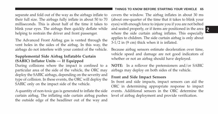
separate and fold out of the way as the airbags inflate totheir full size. The airbags fully inflate in about 50 to 70milliseconds. This is about half of the time it takes toblink your eyes. The airbags then quickly deflate whilehelping to restrain the driver and front passenger.
The Advanced Front Airbag gas is vented through thevent holes in the sides of the airbag. In this way, theairbags do not interfere with your control of the vehicle.
Supplemental Side Airbag Inflatable Curtain(SABIC) Inflator Units — If EquippedDuring collisions where the impact is confined to aparticular area of the side of the vehicle, the ORC maydeploy the SABIC airbags, depending on the severity andtype of collision. In these events, the ORC will deploy theSABIC only on the impact side of the vehicle.
A quantity of non-toxic gas is generated to inflate the sidecurtain airbag. The inflating side curtain airbag pushesthe outside edge of the headliner out of the way and
covers the window. The airbag inflates in about 30 ms(about one-quarter of the time that it takes to blink youreyes) with enough force to injure you if you are not beltedand seated properly, or if items are positioned in the areawhere the side curtain airbag inflates. This especiallyapplies to children. The side curtain airbag is only about3-1/2 in (9 cm) thick when it is inflated.
Because airbag sensors estimate deceleration over time,vehicle speed and damage are not good indicators ofwhether or not an airbag should have deployed.
NOTE: In a rollover the pretensioners and/or SABICairbags may deploy on both sides of the vehicle.
Front and Side Impact SensorsIn front and side impacts, impact sensors can aid theORC in determining appropriate response to impactevents. Additional sensors in the ORC determine thelevel of airbag deployment and provide verification.
2
THINGS TO KNOW BEFORE STARTING YOUR VEHICLE 65

Enhanced Accident Response SystemIn the event of an impact causing airbag deployment, ifthe communication network remains intact, and thepower remains intact, depending on the nature of theevent the ORC will determine whether to have theEnhanced Accident Response System perform the follow-ing functions:
• Cut off fuel to the engine.
• Flash hazard lights as long as the battery has power oruntil the ignition key is turned off.
• Turn on the interior lights, which remain on as long asthe battery has power, until the ignition key is re-moved or the ignition switch is changed to OFF usingthe Keyless Go Start/Stop button.
• Unlock the doors automatically.
If a Deployment OccursThe front airbags are designed to deflate immediatelyafter deployment.
NOTE: Front and/or side airbags will not deploy in allcollisions. This does not mean something is wrong withthe airbag system.
If you do have a collision which deploys the airbags, anyor all of the following may occur:
• The nylon airbag material may sometimes cause abra-sions and/or skin reddening to the driver and frontpassenger as the airbags deploy and unfold. Theabrasions are similar to friction rope burns or thoseyou might get sliding along a carpet or gymnasiumfloor. They are not caused by contact with chemicals.They are not permanent and normally heal quickly.However, if you haven’t healed significantly within afew days, or if you have any blistering, see your doctorimmediately.
66 THINGS TO KNOW BEFORE STARTING YOUR VEHICLE

• As the airbags deflate, you may see some smoke-likeparticles. The particles are a normal by-product of theprocess that generates the non-toxic gas used forairbag inflation. These airborne particles may irritatethe skin, eyes, nose, or throat. If you have skin or eyeirritation, rinse the area with cool water. For nose orthroat irritation, move to fresh air. If the irritationcontinues, see your doctor. If these particles settle onyour clothing, follow the garment manufacturer’s in-structions for cleaning.
Do not drive your vehicle after the airbags have de-ployed. If you are involved in another collision, theairbags will not be in place to protect you.
WARNING!
Deployed airbags and seat belt pretensioners cannotprotect you in another collision. Have the airbags,seat belt pretensioners, and the front passenger seatbelt retractor assembly replaced by an authorizeddealer immediately. Also, have the Occupant Re-straint Controller (ORC) system serviced as well.
2
THINGS TO KNOW BEFORE STARTING YOUR VEHICLE 67

Maintaining Your Airbag System
WARNING!
• Modifications to any part of the airbag systemcould cause it to fail when you need it. You couldbe injured if the airbag system is not there toprotect you. Do not modify the components orwiring, including adding any kind of badges orstickers to the steering wheel hub trim cover or theupper right side of the instrument panel. Do notmodify the front bumper, vehicle body structure,or add aftermarket side steps or running boards.
• It is dangerous to try to repair any part of theairbag system yourself. Be sure to tell anyone whoworks on your vehicle that it has an airbag system.
(Continued)
WARNING! (Continued)• Do not attempt to modify any part of your ad-
vanced airbag system. The airbag may inflateaccidentally or may not function properly if modi-fications are made. Take your vehicle to an autho-rized dealer for any advanced airbag system ser-vice. If your seat, including your trim cover andcushion, needs to be serviced in any way (includ-ing removal or loosening/tightening of seat attach-ment bolts), take the vehicle to your authorizeddealer. Only manufacturer approved seat accesso-ries may be used. If it is necessary to modify theairbag system for persons with disabilities, contactyour authorized dealer.
68 THINGS TO KNOW BEFORE STARTING YOUR VEHICLE

Airbag Warning LightYou will want to have the airbags ready toinflate for your protection in a collision. Whilethe airbag system is designed to be mainte-nance free, if any of the following occurs, have
an authorized dealer service the system immediately.• The Airbag Warning Light does not come on for
approximately six to eight seconds when the ignitionswitch is first placed into the RUN position.
• The Airbag Warning Light remains on after the ap-proximate six to eight-second interval.
• The Airbag Warning Light comes on intermittently orremains on while driving.
NOTE: If the speedometer, tachometer, or any enginerelated gauges are not working, the Occupant RestraintController (ORC) may also be disabled. The airbags maynot be ready to inflate for your protection. Promptlycheck the fuse block for blown fuses. Refer to the label
located on the inside of the fuse block cover for theproper airbag fuses. See your authorized dealer if thefuse is good.
Event Data Recorder (EDR)In the event of a collision, your vehicle is designed torecord up to five seconds of specific vehicle data param-eters (see list below) in an event data recorder prior to themoment of airbag deployment, or near deployment (ifapplicable), and up to a quarter second of either high-speed deceleration data or change in velocity duringand/or after airbag deployment or near-deployment.EDR data is ONLY recorded if an airbag deploys, ornearly deploys, and is otherwise unavailable.
NOTE:1. A near-deployment event occurs when the airbagsensor detects severe vehicle deceleration usually indica-tive of a crash, but not severe enough to warrant airbagdeployment.
2
THINGS TO KNOW BEFORE STARTING YOUR VEHICLE 69

2. Under certain circumstances, EDR data may not berecorded (e.g., loss of battery power).
In conjunction with other data gathered during a com-plete accident investigation, the electronic data may beused by Chrysler Group LLC and others to learn moreabout the possible causes of crashes and associatedinjuries in order to assess and improve vehicle perfor-mance. In addition to crash investigations initiated byChrysler Group LLC, such investigations may be re-quested by customers, insurance carriers, governmentofficials, and professional crash researchers, such as thoseassociated with universities, and with hospital and insur-ance organizations.
In the event that an investigation is undertaken byChrysler Group LLC (regardless of initiative), the com-pany or its designated representative will first obtainpermission of the appropriate custodial entity for thevehicle (usually the vehicle owner or lessee) before
accessing the electronic data stored, unless ordered toimage the data by a court with legal jurisdiction (i.e.,pursuant to a warrant). A copy of the data will beprovided to the custodial entity upon request. Generaldata that does not identify particular vehicles or crashesmay be released for incorporation in aggregate crashdatabases, such as those maintained by the U.S. govern-ment and various states. Data of a potentially sensitivenature, such as would identify a particular driver, ve-hicle, or crash, will be treated confidentially. Confidentialdata will not be disclosed by Chrysler Group LLC to anythird party except when:
1. Used for research purposes, such as to match datawith a particular crash record in an aggregate database,provided confidentiality of personal data is thereafterpreserved.
2. Used in defense of litigation involving a ChryslerGroup LLC product.
70 THINGS TO KNOW BEFORE STARTING YOUR VEHICLE

3. Requested by police under a legal warrant.
4. Otherwise required by law.
Data parameters that are recorded:
• Diagnostic trouble code(s) and warning light status forelectronically-controlled safety systems, including theairbag system
• Vehicle speed
• Engine RPM
• Brake switch status
• Pedal position
• And other parameters depending on vehicleconfiguration
Child RestraintsEveryone in your vehicle needs to be buckled up all thetime, including babies and children. Every state in the
United States and all Canadian provinces require thatsmall children ride in proper restraint systems. This is thelaw, and you can be prosecuted for ignoring it.
Children 12 years and younger should ride properlybuckled up in a rear seat, if available. According to crashstatistics, children are safer when properly restrained inthe rear seats rather than in the front.
WARNING!
In a collision, an unrestrained child, even a tiny baby,can become a projectile inside the vehicle. The forcerequired to hold even an infant on your lap couldbecome so great that you could not hold the child, nomatter how strong you are. The child and otherscould be badly injured. Any child riding in yourvehicle should be in a proper restraint for the child’ssize.
2
THINGS TO KNOW BEFORE STARTING YOUR VEHICLE 71

There are different sizes and types of restraints forchildren from newborn size to the child almost largeenough for an adult safety belt. Always check the childseat Owner’s Manual to ensure you have the correct seatfor your child. Use the restraint that is correct for yourchild.
Infants and Child Restraints
• Safety experts recommend that children riderearward-facing in the vehicle until they are at leastone year old and weigh at least 20 lbs (9 kg). Two typesof child restraints can be used rearward-facing, infantcarriers and convertible child seats.
• The infant carrier is only used rearward-facing in thevehicle. It is recommended for children who weigh upto about 20 lbs (9 kg). Convertible child seats can beused either rearward-facing or forward-facing in thevehicle. Convertible child seats often have a higherweight limit in the rearward-facing direction than
infant carriers do, so they can be used rearward-facingby children who weigh more than 20 lbs (9 kg) but areless than one year old. Both types of child restraints areheld in the vehicle by the lap/shoulder belt or theLATCH child restraint anchorage system. Refer to“LATCH — Child Seat Anchorage System (LowerAnchors and Tether for CHildren)”.
WARNING!
Rearward-facing child seats must NEVER be used inthe front seat of a vehicle with the front passengerairbag unless the airbag is turned off. An airbagdeployment could cause severe injury or death toinfants in this position.
Older Children and Child RestraintsChildren who weigh more than 20 lbs (9 kg) and who areolder than one year can ride forward-facing in thevehicle. Forward-facing child seats and convertible child
72 THINGS TO KNOW BEFORE STARTING YOUR VEHICLE

seats used in the forward-facing direction are for childrenwho weigh 20 to 40 lbs (9 to 18 kg) and who are olderthan one year. These child seats are also held in thevehicle by the lap/shoulder belt or the LATCH childrestraint anchorage system. Refer to “LATCH — ChildSeat Anchorage System (Lower Anchors and Tether forCHildren)”.
The belt-positioning booster seat is for children weighingmore than 40 lbs (18 kg), but who are still too small to fitthe vehicle’s seat belts properly. If the child cannot sitwith knees bent over the vehicle’s seat cushion while thechild’s back is against the seatback, they should use abelt-positioning booster seat. The child and belt-positioning booster seat are held in the vehicle by thelap/shoulder belt.
Children Too Large for Booster SeatsChildren who are large enough to wear the shoulder beltcomfortably and whose legs are long enough to bend
over the front of the seat when their back is against theseatback should use the lap/shoulder belt in a rear seat.
• Make sure that the child is upright in the seat.
• The lap portion should be low on the hips and as snugas possible.
• Check belt fit periodically. A child’s squirming orslouching can move the belt out of position.
• If the shoulder belt contacts the face or neck, move thechild closer to the center of the vehicle. Never allow achild to put the shoulder belt under an arm or behindtheir back.
NOTE: For additional information, refer towww.seatcheck.org or call 1–866–SEATCHECK. Cana-dian residents, should refer to Transport Canada’s web-site for additional information. http://www.tc.gc.ca/roadsafety/safedrivers/childsafety/index.htm
2
THINGS TO KNOW BEFORE STARTING YOUR VEHICLE 73

WARNING!
• Improper installation can lead to failure of aninfant or child restraint. It could come loose in acollision. The child could be badly injured orkilled. Follow the manufacturer’s directions ex-actly when installing an infant or child restraint.
• A rearward-facing child restraint should only beused in a rear seat. A rearward-facing child re-straint in the front seat may be struck by a deploy-ing passenger airbag, which may cause severe orfatal injury to the infant.
Here are some tips on getting the most out of your childrestraint:• Before buying any restraint system, make sure that it
has a label certifying that it meets all applicable SafetyStandards. We also recommend that you make surethat you can install the child restraint in the vehiclewhere you will use it before you buy it.
• The restraint must be appropriate for your child’sweight and height. Check the label on the restraint forweight and height limits.
• Carefully follow the instructions that come with therestraint. If you install the restraint improperly, it maynot work when you need it.
• Buckle the child into the seat according to the childrestraint manufacturer’s directions.
• When your child restraint is not in use, secure it in thevehicle with the seat belt or remove it from the vehicle.Do not leave it loose in the vehicle. In a sudden stop orcollision, it could strike the occupants or seatbacks andcause serious personal injury.
LATCH — Child Seat Anchorage System (LowerAnchors and Tether for CHildren)Your vehicle’s rear seat is equipped with the childrestraint anchorage system called LATCH. The LATCH
74 THINGS TO KNOW BEFORE STARTING YOUR VEHICLE

system provides for the installation of the child restraintwithout using the vehicle’s seat belts, instead securingthe child restraint using lower anchorages and uppertether straps from the child restraint to the vehiclestructure.LATCH-compatible child restraint systems are now avail-able. However, because the lower anchorages are to beintroduced over a period of years, child restraint systemshaving attachments for those anchorages will continue tohave features for installation using the vehicle’s seatbelts. Child restraints having tether straps and hooks forconnection to the top tether anchorages, have beenavailable for some time. For some older child restraints,many child restraint manufacturers offer add-on tetherstrap kits or retrofit kits. You are urged to take advantageof all the available attachments provided with your childrestraint in any vehicle.All three rear-seating positions have lower anchoragesthat are capable of accommodating LATCH-compatible
child seats. You should NEVER install LATCH-compatible child seats so that two seats share a commonlower anchorage. If installing child seats in adjacentrear-seating positions, or if your child restraints are notLATCH-compatible, install the restraints using the vehi-cle’s seat belts.
LATCH Anchorages
2
THINGS TO KNOW BEFORE STARTING YOUR VEHICLE 75

Installing the LATCH-Compatible Child RestraintSystemWe urge you to follow the manufacturer’s directionscarefully when installing your child restraint. Not allchild restraint systems will be installed as described here.Again, carefully follow the installation instructions thatare provided with the child restraint system.
The rear seat lower anchorages are round barslocated at the rear of the seat cushion where itmeets the seatback and are just visible whenyou lean into the rear seat to install the child
restraint. You will easily feel them if you run your fingeralong the intersection of the seatback and seat cushionsurfaces.
In addition, there are tether strap anchoragesbehind each rear seating position located in thepanel between the rear seatback and the rearwindow. These tether strap anchorages are
under a plastic cover with this symbol on it.
Many, but not all restraint systems will be equipped withseparate straps on each side, with each having a hook orconnector for attachment to the lower anchorage and ameans of adjusting the tension in the strap. Forward-facing toddler restraints and some rear-facing infantrestraints will also be equipped with a tether strap, ahook for attachment to the tether strap anchorage and ameans of adjusting the tension of the strap.
You will first loosen the adjusters on the lower straps andon the tether strap so that you can more easily attach thehooks or connectors to the vehicle anchorages. Next,attach the lower hooks or connectors over the top of theseat cover material. Then rotate the tether anchoragecover directly behind the seat where you are placing thechild restraint and attach the tether strap to the anchor-age, being careful to route the tether strap to provide themost direct path between the anchor and the childrestraint. Finally, tighten all three straps as you push the
76 THINGS TO KNOW BEFORE STARTING YOUR VEHICLE

child restraint rearward and downward into the seat,removing slack in the straps according to the childrestraint manufacturer’s instructions.
NOTE:• Ensure that the tether strap does not slip into the
opening between the seatbacks as you remove slack inthe strap.
• When using the LATCH attaching system to install achild restraint, please ensure that all seat belts notbeing used for occupant restraints are stowed and outof reach of children. It is recommended that beforeinstalling the child restraint, buckle the seat belt so theseat belt is tucked behind the child restraint and out ofreach. If the buckled seat belt interferes with the childrestraint installation, instead of tucking the seat beltbehind the child restraint, route the seat belt throughthe child restraint belt path and then buckle it. Thisshould stow the seat belt out of the reach of an
inquisitive child. Remind all children in the vehiclethat the seat belts are not toys and should not beplayed with, and never leave your child unattended inthe vehicle.
WARNING!
Improper installation of a child restraint to theLATCH anchorages can lead to failure of an infant orchild restraint. The child could be badly injured orkilled. Follow the manufacturer’s directions exactlywhen installing an infant or child restraint.
Installing Child Restraints Using the Vehicle SeatBeltsThe passenger seat belts are equipped with either cinch-ing latch plates or Automatic Locking Retractors (ALRs),which are designed to keep the lap portion tight aroundthe child restraint so that it is not necessary to use alocking clip. Pulling up on the shoulder portion of the
2
THINGS TO KNOW BEFORE STARTING YOUR VEHICLE 77

lap/shoulder belt will tighten the belt. The cinching latchplate will keep the belt tight; however, any seat beltsystem will loosen with time, so check the belt occasion-ally and pull it tight if necessary.
The seat belt must be in the Automatic Locking Mode inorder to enable a child restraint to be tightly installed.Refer to “Automatic Locking Mode”. A locking clipshould not be necessary once the automatic lockingfeature is enabled. Position the shoulder and lap belt onthe child restraint. The automatic locking retractor isactivated by first attaching the child seat, then pulling allof the webbing out of the retractor, then allowing thewebbing to retract back into the retractor. Tighten web-bing. To release, simply unbuckle the seat belt by de-pressing the button, allowing the webbing to retract intothe retractor.
In the rear seat, you may have trouble tightening thelap/shoulder belt on the child restraint because thebuckle or latch plate is too close to the belt path openingon the restraint. Disconnect the latch plate from thebuckle and twist the short buckle end belt several timesto shorten it. Insert the latch plate into the buckle with therelease button facing out.
If the belt still can’t be tightened, or if pulling andpushing on the restraint loosens the belt, you may needto do something more. Disconnect the latch plate fromthe buckle, turn the buckle around, and insert the latchplate into the buckle again. If you still can’t make thechild restraint secure, try a different seating position.
To attach a child restraint tether strap:
1. Rotate the cover over the anchor directly behind theseat where you are placing the child restraint.
78 THINGS TO KNOW BEFORE STARTING YOUR VEHICLE

2. Route the tether strap to provide the most direct pathfor the strap between the anchor and the child seat.
3. Attach the tether strap hook (A) of the child restraint tothe anchor (B) and remove slack in the tether strapaccording to the child restraint manufacturer’s instruc-tions.
NOTE: Ensure that the tether strap does not slip into theopening between the seatbacks as you remove slack inthe strap.
WARNING!
An incorrectly anchored tether strap could lead toincreased head motion and possible injury to thechild. Use only the anchor positions directly behindthe child seat to secure a child restraint top tetherstrap.
Tether Strap Mounting
1 — Cover A — Tether Strap Hook3 — Attaching Strap B — Tether Anchor
2
THINGS TO KNOW BEFORE STARTING YOUR VEHICLE 79

Transporting PetsAirbags deploying in the front seat could harm your pet.An unrestrained pet will be thrown about and possiblyinjured, or injure a passenger during panic braking or ina collision.
Pets should be restrained in the rear seat in pet harnessesor pet carriers that are secured by seat belts.
ENGINE BREAK-IN RECOMMENDATIONSA long break-in period is not required for the engine anddrivetrain (transmission and axle) in your vehicle.
Drive moderately during the first 300 miles (500 km).After the initial 60 miles (100 km), speeds up to 50 or55 mph (80 or 90 km/h) are desirable.
While cruising, brief full-throttle acceleration within thelimits of local traffic laws, contributes to a good break-in.Wide-open throttle acceleration in low gear can be detri-mental and should be avoided.
The engine oil installed in the engine at the factory is ahigh-quality energy conserving type lubricant. Oilchanges should be consistent with anticipated climateconditions under which vehicle operations will occur. Forthe recommended viscosity and quality grades refer to“Maintenance Procedures” in “Maintaining Your Ve-hicle”. NON-DETERGENT OR STRAIGHT MINERALOILS MUST NEVER BE USED.
A new engine may consume some oil during its first fewthousand miles (kilometers) of operation. This should beconsidered a normal part of the break-in and not inter-preted as an indication of difficulty.
80 THINGS TO KNOW BEFORE STARTING YOUR VEHICLE

SAFETY TIPS
Transporting PassengersNEVER TRANSPORT PASSENGERS IN THE CARGOAREA.
WARNING!
• Do not leave children or animals inside parkedvehicles in hot weather. Interior heat build-up maycause serious injury or death.
• It is extremely dangerous to ride in a cargo area,inside or outside of a vehicle. In a collision, peopleriding in these areas are more likely to be seri-ously injured or killed.
• Do not allow people to ride in any area of yourvehicle that is not equipped with seats and seatbelts.
(Continued)
WARNING! (Continued)• Be sure everyone in your vehicle is in a seat and
using a seat belt properly.
Exhaust Gas
WARNING!
Exhaust gases can injure or kill. They contain carbonmonoxide (CO), which is colorless and odorless.Breathing it can make you unconscious and caneventually poison you. To avoid breathing (CO)follow these safety tips:
Do not run the engine in a closed garage or in confinedareas any longer than needed to move your vehicle in orout of the area.
2
THINGS TO KNOW BEFORE STARTING YOUR VEHICLE 81

If it is necessary to sit in a parked vehicle with the enginerunning, adjust your heating or cooling controls to forceoutside air into the vehicle. Set the blower at high speed.If you are required to drive with the trunk/liftgate open,make sure that all windows are closed and the climatecontrol BLOWER switch is set at high speed. DO NOTuse the recirculation mode.
The best protection against carbon monoxide entry intothe vehicle body is a properly maintained engine exhaustsystem.Whenever a change is noticed in the sound of the exhaustsystem, when exhaust fumes can be detected inside thevehicle, or when the underside or rear of the vehicle isdamaged, have a competent mechanic inspect the com-plete exhaust system and adjacent body areas for broken,damaged, deteriorated, or mispositioned parts. Openseams or loose connections could permit exhaust fumesto seep into the passenger compartment. In addition,
inspect the exhaust system each time the vehicle is raisedfor lubrication or oil change. Replace as required.
Safety Checks You Should Make Inside theVehicleSeat BeltsInspect the belt system periodically, checking for cuts,frays, and loose parts. Damaged parts must be replacedimmediately. Do not disassemble or modify the system.
Front seat belt assemblies must be replaced after acollision. Rear seat belt assemblies must be replaced aftera collision if they have been damaged (i.e., bent retractor,torn webbing, etc.). If there is any question regarding beltor retractor condition, replace the belt.
Airbag Warning LightThe light should come on and remain on for four to eightseconds as a bulb check when the ignition switch is firstturned ON. If the light is not lit during starting, see your
82 THINGS TO KNOW BEFORE STARTING YOUR VEHICLE

authorized dealer. If the light stays on, flickers, or comeson while driving, have the system checked by an autho-rized dealer.
DefrosterCheck operation by selecting the defrost mode and placethe blower control on high speed. You should be able tofeel the air directed against the windshield. See yourauthorized dealer for service if your defroster isinoperable.
Floor Mat Safety InformationAlways use floor mats designed to fit the foot well ofyour vehicle. Use only floor mats that leave the pedalarea unobstructed and that are firmly secured so thatthey cannot slip out of position and interfere with thepedals or impair safe operation of your vehicle in otherways.
WARNING!
Pedals that cannot move freely can cause loss ofvehicle control and increase the risk of serious per-sonal injury.• Always make sure that floor mats are properly
attached to the floor mat fasteners.• Never place or install floor mats or other floor cover-
ings in the vehicle that cannot be properly secured toprevent them from moving and interfering with thepedals or the ability to control the vehicle.
• Never put floor mats or other floor coverings ontop of already installed floor mats. Additionalfloor mats and other coverings will reduce the sizeof the pedal area and interfere with the pedals.
• Check mounting of mats on a regular basis. Al-ways properly reinstall and secure floor mats thathave been removed for cleaning.
(Continued)
2
THINGS TO KNOW BEFORE STARTING YOUR VEHICLE 83

WARNING! (Continued)• Always make sure that objects cannot fall into the
driver foot well while the vehicle is moving.Objects can become trapped under the brake pedaland accelerator pedal causing a loss of vehiclecontrol.
• If required, mounting posts must be properlyinstalled, if not equipped from the factory.Failure to properly follow floor mat installation ormounting can cause interference with the brakepedal and accelerator pedal operation causing lossof control of the vehicle.
Periodic Safety Checks You Should Make Outsidethe Vehicle
TiresExamine tires for excessive tread wear and uneven wearpatterns. Check for stones, nails, glass, or other objects
lodged in the tread. Inspect the tread and sidewall forcuts and cracks. Check the wheel nuts for tightness.Check the tires (including spare) for proper pressure.
LightsHave someone observe the operation of exterior lightswhile you work the controls. Check turn signal and highbeam indicator lights on the instrument panel.
Door LatchesCheck for positive closing, latching, and locking.
Fluid LeaksCheck area under vehicle after overnight parking for fuel,engine coolant, oil, or other fluid leaks. Also, if gasolinefumes are detected or if fuel, power steering fluid, orbrake fluid leaks are suspected, the cause should belocated and corrected immediately.
84 THINGS TO KNOW BEFORE STARTING YOUR VEHICLE

UNDERSTANDING THE FEATURES OF YOUR VEHICLE
CONTENTS
� Mirrors . . . . . . . . . . . . . . . . . . . . . . . . . . . . . . 91
▫ Inside Day/Night Mirror . . . . . . . . . . . . . . . . 91
▫ Automatic Dimming Mirror — If Equipped . . . 92
▫ Outside Mirrors . . . . . . . . . . . . . . . . . . . . . . 92
▫ Outside Mirrors Folding Feature— If Equipped . . . . . . . . . . . . . . . . . . . . . . . 93
▫ Driver’s Automatic Dimming Mirror— If Equipped . . . . . . . . . . . . . . . . . . . . . . . 93
▫ Outside Mirrors With Turn Signal AndApproach Lighting — If Equipped . . . . . . . . . 93
▫ Tilt Mirrors In Reverse — If Equipped . . . . . . 94
▫ Power Mirrors . . . . . . . . . . . . . . . . . . . . . . . 94
▫ Heated Mirrors — If Equipped . . . . . . . . . . . . 95
▫ Illuminated Vanity Mirrors — If Equipped . . . 96
� Uconnect™ Phone — If Equipped . . . . . . . . . . . 96
▫ Operation . . . . . . . . . . . . . . . . . . . . . . . . . . 98
▫ Phone Call Features . . . . . . . . . . . . . . . . . . 106
▫ Uconnect™ Phone Features . . . . . . . . . . . . . 109
▫ Advanced Phone Connectivity . . . . . . . . . . . 114
3

▫ Things You Should Know About YourUconnect™ Phone . . . . . . . . . . . . . . . . . . . . 116
▫ General Information . . . . . . . . . . . . . . . . . . 124
� Voice Command — If Equipped . . . . . . . . . . . 124
▫ Voice Command System Operation . . . . . . . . 124
▫ Commands . . . . . . . . . . . . . . . . . . . . . . . . 126
▫ Voice Training . . . . . . . . . . . . . . . . . . . . . . 129
� Seats . . . . . . . . . . . . . . . . . . . . . . . . . . . . . . 129
▫ Power Seats . . . . . . . . . . . . . . . . . . . . . . . . 130
▫ Power Reclining Seats . . . . . . . . . . . . . . . . . 131
▫ Lumbar Support . . . . . . . . . . . . . . . . . . . . . 132
▫ Head Restraints . . . . . . . . . . . . . . . . . . . . . 132
▫ Heated Seats — If Equipped . . . . . . . . . . . . 134
▫ Folding Rear Seat . . . . . . . . . . . . . . . . . . . . 136
� Driver Memory Seat — If Equipped . . . . . . . . 138
▫ Programming The Memory Feature . . . . . . . 139
▫ Linking And Unlinking The Remote KeylessEntry Transmitter To Memory . . . . . . . . . . . 139
▫ Memory Position Recall . . . . . . . . . . . . . . . . 140
▫ Easy Entry/Exit Seat (Available WithMemory Seat Only) . . . . . . . . . . . . . . . . . . . 141
� To Open And Close The Hood . . . . . . . . . . . . 142
� Lights . . . . . . . . . . . . . . . . . . . . . . . . . . . . . 144
▫ Headlight Switch . . . . . . . . . . . . . . . . . . . . 144
▫ Automatic Headlights — If Equipped . . . . . . 145
▫ Headlights On With Wipers (Available WithAutomatic Headlights Only) . . . . . . . . . . . . 145
86 UNDERSTANDING THE FEATURES OF YOUR VEHICLE

▫ Headlight Time Delay . . . . . . . . . . . . . . . . . 145
▫ Smartbeam™ — If Equipped . . . . . . . . . . . . 146
▫ Daytime Running Lights — If Equipped . . . . 147
▫ Lights-On Reminder . . . . . . . . . . . . . . . . . . 147
▫ Fog Lights — If Equipped . . . . . . . . . . . . . . 147
▫ Multifunction Lever . . . . . . . . . . . . . . . . . . 148
▫ Turn Signals . . . . . . . . . . . . . . . . . . . . . . . . 148
▫ Lane Change Assist . . . . . . . . . . . . . . . . . . . 148
▫ High/Low Beam Switch . . . . . . . . . . . . . . . 149
▫ Flash-To-Pass . . . . . . . . . . . . . . . . . . . . . . . 149
▫ Overhead Console Map/Reading Lights . . . . 149
▫ Interior Lights . . . . . . . . . . . . . . . . . . . . . . 149
� Windshield Wipers And Washers . . . . . . . . . . 150
▫ Intermittent Wiper System . . . . . . . . . . . . . . 151
▫ Mist Feature . . . . . . . . . . . . . . . . . . . . . . . . 152
▫ Windshield Washers . . . . . . . . . . . . . . . . . . 152
▫ Headlights On With Wipers (Available WithAutomatic Headlights Only) . . . . . . . . . . . . 152
▫ Rain Sensing Wipers — If Equipped . . . . . . . 153
� Tilt/Telescoping Steering Column . . . . . . . . . . 154
� Power Tilt/Telescoping Steering Column— If Equipped . . . . . . . . . . . . . . . . . . . . . . . . 155
� Adjustable Pedals — If Equipped . . . . . . . . . . 156
� Electronic Speed Control . . . . . . . . . . . . . . . . 158
▫ To Activate . . . . . . . . . . . . . . . . . . . . . . . . . 159
▫ To Set At A Desired Speed . . . . . . . . . . . . . . 159
▫ To Deactivate . . . . . . . . . . . . . . . . . . . . . . . 160
3
UNDERSTANDING THE FEATURES OF YOUR VEHICLE 87

▫ To Resume Speed . . . . . . . . . . . . . . . . . . . . 160
▫ To Vary The Speed Setting . . . . . . . . . . . . . . 160
▫ To Accelerate For Passing . . . . . . . . . . . . . . 161
� Adaptive Cruise Control (ACC)— If Equipped . . . . . . . . . . . . . . . . . . . . . . . . 162
▫ Adaptive Cruise Control (ACC) Operation . . 164
▫ Activating Adaptive Cruise Control (ACC) . . 164
▫ To Activate . . . . . . . . . . . . . . . . . . . . . . . . . 165
▫ To Set a Desired ACC Speed . . . . . . . . . . . . 166
▫ To Cancel . . . . . . . . . . . . . . . . . . . . . . . . . . 167
▫ To Turn Off . . . . . . . . . . . . . . . . . . . . . . . . 168
▫ To Resume Speed . . . . . . . . . . . . . . . . . . . . 168
▫ To Vary The Speed Setting . . . . . . . . . . . . . . 168
▫ Setting The Following Distance In ACC . . . . 170
▫ Adaptive Cruise Control (ACC) Menu . . . . . 172
▫ Display Warnings And Maintenance . . . . . . . 175
▫ Precautions While Driving With ACC . . . . . . 178
▫ General Information . . . . . . . . . . . . . . . . . . 181
▫ Normal (Fixed Speed) Cruise ControlMode . . . . . . . . . . . . . . . . . . . . . . . . . . . . . 182
� Parksense� Rear Park Assist . . . . . . . . . . . . . . 184
▫ Parksense� System Usage Precautions . . . . . . 186
� Overhead Console . . . . . . . . . . . . . . . . . . . . . 189
▫ Courtesy/Reading Lights . . . . . . . . . . . . . . 189
▫ Sunglasses Storage . . . . . . . . . . . . . . . . . . . 189
88 UNDERSTANDING THE FEATURES OF YOUR VEHICLE

� Garage Door Opener — If Equipped . . . . . . . . 190
▫ Programming HomeLink� . . . . . . . . . . . . . . 191
▫ Gate Operator/Canadian Programming . . . . 194
▫ Using HomeLink� . . . . . . . . . . . . . . . . . . . 194
▫ Reprogramming A Single HomeLink�Button . . . . . . . . . . . . . . . . . . . . . . . . . . . . 195
▫ Security . . . . . . . . . . . . . . . . . . . . . . . . . . . 195
▫ Troubleshooting Tips . . . . . . . . . . . . . . . . . . 195
▫ General Information . . . . . . . . . . . . . . . . . . 196
� Power Sunroof — If Equipped . . . . . . . . . . . . 196
▫ Opening Sunroof — Express . . . . . . . . . . . . 197
▫ Closing Sunroof — Express . . . . . . . . . . . . . 197
▫ Pinch Protect Feature . . . . . . . . . . . . . . . . . 198
▫ Pinch Protect Override . . . . . . . . . . . . . . . . 198
▫ Venting Sunroof — Express . . . . . . . . . . . . . 198
▫ Sunshade Operation . . . . . . . . . . . . . . . . . . 198
▫ Wind Buffeting . . . . . . . . . . . . . . . . . . . . . . 199
▫ Sunroof Maintenance . . . . . . . . . . . . . . . . . 199
▫ Ignition Off Operation . . . . . . . . . . . . . . . . . 199
▫ Sunroof Fully Closed . . . . . . . . . . . . . . . . . . 199
� Electrical Power Outlets . . . . . . . . . . . . . . . . . 200
� Cupholders . . . . . . . . . . . . . . . . . . . . . . . . . . 203
▫ Front Seat Cupholders . . . . . . . . . . . . . . . . . 203
▫ Rear Seat Cupholders . . . . . . . . . . . . . . . . . 203
� Storage . . . . . . . . . . . . . . . . . . . . . . . . . . . . . 204
▫ Console Features . . . . . . . . . . . . . . . . . . . . 204
3
UNDERSTANDING THE FEATURES OF YOUR VEHICLE 89

▫ Cargo Area . . . . . . . . . . . . . . . . . . . . . . . . 205
� Cargo Area Features . . . . . . . . . . . . . . . . . . . 206
▫ Trunk Mat — If Equipped . . . . . . . . . . . . . . 206
� Rear Window Features . . . . . . . . . . . . . . . . . . 206
▫ Rear Window Defroster . . . . . . . . . . . . . . . . 206
� Load Leveling System — If Equipped . . . . . . . 207
90 UNDERSTANDING THE FEATURES OF YOUR VEHICLE

MIRRORS
Inside Day/Night MirrorA two-point pivot system allows for horizontal andvertical mirror adjustment. Adjust the mirror to center onthe view through the rear window. The mirror should beadjusted while set in the day position (toward the wind-shield).
Headlight glare can be reduced by moving the smallcontrol under the mirror to the night position (toward therear of the vehicle).
Adjusting Rearview Mirror
3
UNDERSTANDING THE FEATURES OF YOUR VEHICLE 91

Automatic Dimming Mirror — If EquippedThis mirror automatically adjusts for headlight glarefrom vehicles behind you. You can turn the feature on oroff by pressing the button at the base of the mirror. A lightnext to the button will illuminate to indicate when thedimming feature is activated.
CAUTION!
To avoid damage to the mirror during cleaning, neverspray any cleaning solution directly onto the mirror.Apply the solution onto a clean cloth and wipe themirror clean.
Outside MirrorsTo receive maximum benefit, adjust the outside mirror(s)to center on the adjacent lane of traffic and a slightoverlap of the view obtained from the inside mirror.
NOTE: The passenger side convex outside mirror willgive a much wider view to the rear, and especially of thelane next to your vehicle.
Automatic Dimming Mirror
92 UNDERSTANDING THE FEATURES OF YOUR VEHICLE

WARNING!
Vehicles and other objects seen in the passenger sideconvex mirror will look smaller and farther awaythan they really are. Relying too much on yourpassenger side convex mirror could cause you tocollide with another vehicle or other object. Use yourinside mirror when judging the size or distance of avehicle seen in the passenger side convex mirror.
Outside Mirrors Folding Feature — If EquippedSome models have outside mirrors that are hinged. Thehinge allows the mirror to pivot forward and rearward toresist damage. The hinge has three detent positions: fullforward, full rearward and normal.
Driver’s Automatic Dimming Mirror — If EquippedThe driver’s outside mirror will automatically adjust forglare from vehicles behind you. This feature is controlledby the inside automatic dimming mirror and can be
turned on or off by pressing the button at the base of theinside mirror. The mirror will automatically adjust forheadlight glare when the inside mirror adjusts.
NOTE: This feature is also available on the passenger’sside when equipped with turn signal and approachlighting.
Outside Mirrors with Turn Signal and ApproachLighting — If EquippedDriver and passenger outside mirrors with turn signaland approach lighting contain four LEDs, which arelocated in the upper outer corner of each mirror.
Three of the LEDs are turn signal indicators, which flashwith the corresponding turn signal lights in the front andrear of the vehicle. Turning on the Hazard Warningflashers will also activate these LEDs.
The fourth (uppermost) LED supplies illuminated entrylighting, which turns on in both mirrors when you use
3
UNDERSTANDING THE FEATURES OF YOUR VEHICLE 93

the Remote Keyless Entry (RKE) transmitter or open anydoor. This LED shines outward to illuminate the frontand rear door handles. It also shines downward toilluminate the area in front of the doors.
The Illuminated Entry lighting fades to off after about30 seconds or it will fade to off immediately once theignition is placed into the RUN position.
NOTE: The approach lighting will not function whenthe shift lever is moved out of the PARK position.
Tilt Mirrors in Reverse — If EquippedTilt Mirrors in Reverse provides automatic outside mirrorpositioning which will aid the driver’s view of theground rearward of the front doors. The outside mirrorswill move slightly downward from the present positionwhen the vehicle is shifted into REVERSE. The outsidemirrors will then return to the original position when the
vehicle is shifted out of the REVERSE position. Eachstored memory setting will have an associated Tilt Mir-rors in Reverse position.
NOTE: The Tilt Mirrors in Reverse feature is not en-abled when delivered from the factory. The Tilt Mirrors inReverse feature can be enabled or disabled through thecustomer-programmable features in the Electronic Ve-hicle Information Center (EVIC), Refer to “ElectronicVehicle Information Center (EVIC)/Customer-Programmable Features” in “Understanding Your Instru-ment Panel” for further information.
Power MirrorsThe power mirror switch is located on the driver’s doortrim panel, next to the power door lock switch. A rotaryknob selects the left mirror, right mirror or off position.
94 UNDERSTANDING THE FEATURES OF YOUR VEHICLE

After selecting a mirror, move the knob in the samedirection you want the mirror to move. Use the center offposition to guard against accidentally moving a mirrorposition.
NOTE: For vehicles equipped with Driver MemorySeat, you can use your Remote Keyless Entry (RKE)transmitter or the memory switch on the driver’s doortrim panel to return the power mirrors to pre-programmed positions. Refer to “Driver Memory Seat”in “Understanding the Features of Your Vehicle” forfurther information.
Heated Mirrors — If EquippedThese mirrors are heated to melt frost or ice. Thisfeature is activated whenever you turn on the rear
window defroster. Refer to “Rear Window Features” in“Understanding the Features of Your Vehicle” for furtherinformation.
Power Mirror Control
3
UNDERSTANDING THE FEATURES OF YOUR VEHICLE 95

Illuminated Vanity Mirrors — If EquippedAn illuminated vanity mirror is located on the sun visor.To use the mirror, rotate the sun visor downward andswing the mirror cover upward. The light turns onautomatically. Closing the mirror cover turns off the light.
Uconnect™ Phone — IF EQUIPPEDUconnect™ Phone is a voice-activated, hands-free, in-vehicle communications system. Uconnect™ Phone al-lows you to dial a phone number with your cellularphone using simple voice commands (e.g., �Call” �“Mike” �”Work� or �Dial” � “248-555-1212�). Your cellularphone’s audio is transmitted through your vehicle’saudio system; the system will automatically mute yourradio when using the Uconnect™ Phone.
NOTE: The Uconnect™ Phone requires a cellular phoneequipped with the Bluetooth� �Hands-Free Profile,� Ver-sion 0.96 or higher. See the Uconnect™ website forsupported phones.
For Uconnect™ customer support, visit the followingwebsites:
• www.chrysler.com/uconnect
• www.dodge.com/uconnectIlluminated Vanity Mirror
96 UNDERSTANDING THE FEATURES OF YOUR VEHICLE

• www.jeep.com/uconnect
• or call 1–877–855–8400
Uconnect™ Phone allows you to transfer calls betweenthe system and your cellular phone as you enter or exityour vehicle and enables you to mute the system’smicrophone for private conversation.
The Uconnect™ Phone is driven through yourBluetooth� “Hands-Free Profile” cellular phone.Uconnect™ features Bluetooth� technology - the globalstandard that enables different electronic devices to con-nect to each other without wires or a docking station, soUconnect™ Phone works no matter where you stow yourcellular phone (be it your purse, pocket, or briefcase), aslong as your phone is turned on and has been paired tothe vehicle’s Uconnect™ Phone. The Uconnect™ Phoneallows up to seven cellular phones to be linked to the
system. Only one linked (or paired) cellular phone can beused with the system at a time. The system is available inEnglish, Spanish, or French languages.
WARNING!
Any voice commanded system should be used onlyin safe driving conditions following local laws andphone use. All attention should be kept on theroadway ahead. Failure to do so may result in anaccident causing serious injury or death.
Uconnect™ Phone ButtonDepending on the vehicle options, either theradio or the mirror will contain the two controlbuttons (Uconnect™ Phone button) and
(Voice Command button) that will en-able you to access the system.
3
UNDERSTANDING THE FEATURES OF YOUR VEHICLE 97

Voice Command ButtonActual button location may vary with the ra-dio. The individual buttons are described in the“Operation” section.
The Uconnect™ Phone can be used with any Hands-FreeProfile certified Bluetooth� cellular phone. See theUconnect™ website for supported phones. If your cellu-lar phone supports a different profile (e.g., HeadsetProfile) you may not be able to use any Uconnect™Phone features. Refer to your cellular service provider orthe phone manufacturer for details.
The Uconnect™ Phone is fully integrated with the vehi-cle’s audio system. The volume of the Uconnect™ Phonecan be adjusted either from the radio volume controlknob or from the steering wheel radio control (rightswitch), if so equipped.
The radio display will be used for visual prompts fromthe Uconnect™ Phone such as �CELL� or caller ID oncertain radios.
OperationVoice commands can be used to operate the Uconnect™Phone and to navigate through the Uconnect™ Phonemenu structure. Voice commands are required after mostUconnect™ Phone prompts. You will be prompted for aspecific command and then guided through the availableoptions.
• Prior to giving a voice command, one must wait forthe beep, which follows the �Ready� prompt or anotherprompt.
• For certain operations, compound commands can beused. For example, instead of saying �Setup� and then�Phone Pairing,� the following compound commandcan be said: �Setup Phone Pairing.�
98 UNDERSTANDING THE FEATURES OF YOUR VEHICLE

• For each feature explanation in this section, only thecombined form of the voice command is given. Youcan also break the commands into parts and say eachpart of the command when you are asked for it. Forexample, you can use the combined form voice com-mand �Phonebook New Entry,� or you can break thecombined form command into two voice commands:�Phonebook� and �New Entry.� Please remember, theUconnect™ Phone works best when you talk in anormal conversational tone, as if speaking to someonesitting a few feet/meters away from you.
Voice Command TreeRefer to “Voice Tree” in this section.
Help CommandIf you need assistance at any prompt, or if you want toknow your options at any prompt, say �Help� followingthe beep. The Uconnect™ Phone will play all the optionsat any prompt if you ask for help.
To activate the Uconnect™ Phone from idle, simply pressthe button and follow the audible prompts fordirections. All Uconnect™ Phone sessions begin with apress of the button on the radio control head.
Cancel CommandAt any prompt, after the beep, you can say �Cancel� andyou will be returned to the main menu. However, in afew instances the system will take you back to theprevious menu.
Pair (Link) Uconnect™ Phone to a Cellular PhoneTo begin using your Uconnect™ Phone, you must pairyour compatible Bluetooth� enabled cellular phone.
To complete the pairing process, you will need to refer-ence your cellular phone Owner’s Manual. TheUconnect™ website may also provide detailed instruc-tions for pairing.
3
UNDERSTANDING THE FEATURES OF YOUR VEHICLE 99

The following are general phone to Uconnect™ Phonepairing instructions:
• Press the button to begin.
• After the �Ready� prompt and the following beep, say�Setup Phone Pairing.�
• When prompted, after the beep, say �Pair a Phone� andfollow the audible prompts.
• You will be asked to say a four-digit Personal Identi-fication Number (PIN), which you will later need toenter into your cellular phone. You can enter anyfour-digit PIN. You will not need to remember this PINafter the initial pairing process.
• For identification purposes, you will be prompted togive the Uconnect™ Phone a name for your cellularphone. Each cellular phone that is paired should begiven a unique phone name.
• You will then be asked to give your cellular phone apriority level between one and seven, with one beingthe highest priority. You can pair up to seven cellularphones to your Uconnect™ Phone. However, at anygiven time, only one cellular phone can be in use,connected to your Uconnect™ Phone. The priorityallows the Uconnect™ Phone to know which cellularphone to use if multiple cellular phones are in thevehicle at the same time. For example, if priority threeand priority five phones are present in the vehicle, theUconnect™ Phone will use the priority three cellularphone when you make a call. You can select to use alower priority cellular phone at any time (refer to�Advanced Phone Connectivity� in this section).
Dial by Saying a Number
• Press the button to begin.
• After the �Ready� prompt and the following beep, say�Dial.�
100 UNDERSTANDING THE FEATURES OF YOUR VEHICLE

• The system will prompt you to say the number youwant to call.
• For example, you can say �234-567-8901�.
• The Uconnect™ Phone will confirm the phone numberand then dial. The number will appear in the displayof certain radios.
Call by Saying a Name
• Press the button to begin.
• After the �Ready� prompt and the following beep, say“Call.�
• The system will prompt you to say the name of theperson you want to call.
• After the �Ready� prompt and the following beep, saythe name of the person you want to call. For example,you can say �John Doe,� where John Doe is a previ-ously stored name entry in the Uconnect™ phonebook
or downloaded phonebook. To learn how to store aname in the phonebook, refer to �Add Names to YourUconnect™ Phonebook,� in the phonebook.
• The Uconnect™ system will confirm the name andthen dial the corresponding phone number, whichmay appear in the display of certain radios.
Add Names to Your Uconnect™ Phonebook
NOTE: Adding names to the Uconnect™ Phonebook isrecommended when the vehicle is not in motion.
• Press the button to begin.
• After the �Ready� prompt and the following beep, say�Phonebook New Entry.�
• When prompted, say the name of the new entry. Use oflong names helps the Voice Command and it is recom-mended. For example, say �Robert Smith� or �Robert�instead of �Bob.�
3
UNDERSTANDING THE FEATURES OF YOUR VEHICLE 101

• When prompted, enter the number designation (e.g.,�Home,� �Work,� �Mobile,� or �Pager�). This will allowyou to store multiple numbers for each phonebookentry, if desired.
• When prompted, recite the phone number for thephonebook entry that you are adding.
After you are finished adding an entry into the phone-book, you will be given the opportunity to add morephone numbers to the current entry or to return to themain menu.
The Uconnect™ Phone will allow you to enter up to 32names in the phonebook with each name having up tofour associated phone numbers and designations. Eachlanguage has a separate 32-name phonebook accessibleonly in that language. In addition, if equipped andsupported by your phone, Uconnect™ Phone automati-cally downloads your cellular phone’s phonebook.
Phonebook Download – Automatic PhonebookTransfer From Cellular PhoneIf equipped and specifically supported by your phone,Uconnect™ Phone automatically downloads names (textnames) and number entries from the cellular phone’sphonebook. Specific Bluetooth� Phones with Phone BookAccess Profile may support this feature. See Uconnect™website for supported phones.
• To call a name from downloaded (or Uconnect™)Phonebook, follow the procedure in “Call by Saying aName” section.
• Automatic download and update, if supported, beginsas soon as the Bluetooth� wireless phone connection ismade to the Uconnect™ Phone, for example, after youstart the vehicle.
• A maximum of 1000 entries per phone will be down-loaded and updated every time a phone is connectedto the Uconnect™ Phone.
102 UNDERSTANDING THE FEATURES OF YOUR VEHICLE

• Depending on the maximum number of entries down-loaded, there may be a short delay before the latestdownloaded names can be used. Until then, if avail-able, the previous downloaded phonebook is availablefor use.
• Only the phonebook of the currently connected cellu-lar phone is accessible.
• Only the cellular phone’s phonebook is downloaded.SIM card phonebook is not part of the Mobile phone-book.
• This downloaded phonebook cannot be edited ordeleted on the Uconnect™ Phone. These can only beedited on the cellular phone. The changes are trans-ferred and updated to Uconnect™ Phone on the nextphone connection.
Phonebook Download — Single EntryIf equipped and supported by your phone, Uconnect™Phone allows the user to download entries from theirphone via Bluetooth�. To use this feature, press thebutton and say “Phonebook Download.” The systemprompts, “Ready to accept “V” card entry viaBluetooth�…” The system is now ready to accept phone-book entries from your phone using the Bluetooth�Object Exchange Profile (OBEX). Please see your phoneOwner’s Manual for specific instructions on how to sendthese entries from your phone.
NOTE:• The phone handset must support Bluetooth� OBEX
transfers of phonebook entries to use this feature.
• Some phones cannot send phonebook entries if theyare already connected to any system via Bluetooth�,and you may see a message on the phone display thatthe Bluetooth� link is busy. In this case, the user must
3
UNDERSTANDING THE FEATURES OF YOUR VEHICLE 103

first disconnect or drop the Bluetooth� connection tothe Uconnect™ Phone, and then send the addressbook entry via Bluetooth�. Please see your phoneOwner’s Manual for specific instructions on how todrop the Bluetooth� connection.
• If the phonebook entry is longer than 24 characters, itwill only use the first 24 characters.
Edit Uconnect™ Phonebook Entries
NOTE:• Editing names in the phonebook is recommended
when the vehicle is not in motion.
• Automatic downloaded phonebook entries cannot bedeleted or edited.
• Press the button to begin.
• After the �Ready� prompt and the following beep, say�Phonebook Edit.�
• You will then be asked for the name of the phonebookentry that you wish to edit.
• Next, choose the number designation (home, work,cellular, or pager) that you wish to edit.
• When prompted, recite the new phone number for thephonebook entry that you are editing.
After you are finished editing an entry in the phonebook,you will be given the opportunity to edit another entry inthe phonebook, call the number you just edited, or returnto the main menu.
�Phonebook Edit� can be used to add another phonenumber to a name entry that already exists in thephonebook. For example, the entry John Doe may have acellular and a home number, but you can add ”JohnDoe’s” work number later using the �Phonebook Edit�feature.
104 UNDERSTANDING THE FEATURES OF YOUR VEHICLE

Delete Uconnect™ Phonebook Entry
NOTE: Editing phonebook entries is recommendedwhen the vehicle is not in motion.
• Press the button to begin.
• After the �Ready� prompt and the following beep, say�Phonebook Delete.�
• After you enter the Phonebook Delete menu, you willthen be asked for the name of the entry that you wishto delete. You can either say the name of a phonebookentry that you wish to delete or you can say �ListNames� to hear a list of the entries in the phonebookfrom which you choose. To select one of the entriesfrom the list, press the button while theUconnect™ Phone is playing the desired entry and say�Delete.�
• After you enter the name, the Uconnect™ Phone willask you which designation you wish to delete: home,work, cellular, pager, or all. Say the designation youwish to delete.
• Note that only the phonebook entry in the currentlanguage is deleted.
• Automatic downloaded phonebook entries cannot bedeleted or edited.
Delete/Erase “All” Uconnect™ Phonebook Entries
• Press the button to begin.
• After the �Ready� prompt and the following beep, say�Phonebook Erase All.�
• The Uconnect™ Phone will ask you to verify that youwish to delete all the entries from the phonebook.
• After confirmation, the phonebook entries will bedeleted.
3
UNDERSTANDING THE FEATURES OF YOUR VEHICLE 105

• Note that only the phonebook in the current languageis deleted.
• Automatic downloaded phonebook entries cannot bedeleted or edited.
List All Names in the Uconnect™ Phonebook
• Press the button to begin.
• After the �Ready� prompt and the following beep, say�Phonebook List Names.�
• The Uconnect™ Phone will play the names of all thephonebook entries, including the downloaded phone-book entries, if available.
• To call one of the names in the list, press thebutton during the playing of the desired name, andsay �Call.�
NOTE: The user can also exercise �Edit� or �Delete�operations at this point.
• The Uconnect™ Phone will then prompt you as to thenumber designation you wish to call.
• The selected number will be dialed.
Phone Call FeaturesThe following features can be accessed through theUconnect™ Phone if the feature(s) are available on yourcellular service plan. For example, if your cellular serviceplan provides three-way calling, this feature can beaccessed through the Uconnect™ Phone. Check withyour cellular service provider for the features that youhave.
Answer or Reject an Incoming Call - No CallCurrently in ProgressWhen you receive a call on your cellular phone, theUconnect™ Phone will interrupt the vehicle audio sys-tem, if on, and will ask if you would like to answer thecall. Press the button to accept the call. To reject the
106 UNDERSTANDING THE FEATURES OF YOUR VEHICLE

call, press and hold the button until you hear asingle beep, indicating that the incoming call wasrejected.
Answer or Reject an Incoming Call - CallCurrently in ProgressIf a call is currently in progress and you have anotherincoming call, you will hear the same network tones forcall waiting that you normally hear when using yourcellular phone. Press the button to place the currentcall on hold and answer the incoming call.
NOTE: The Uconnect™ Phone compatible phones in themarket today do not support rejecting an incoming callwhen another call is in progress. Therefore, the user canonly answer an incoming call or ignore it.
Making a Second Call While Current Call is inProgressTo make a second call while you are currently on a call,press the button and say �Dial� or �Call� followed
by the phone number or phonebook entry you wish tocall. The first call will be on hold while the second call isin progress. To go back to the first call, refer to �TogglingBetween Calls� in this section. To combine two calls, referto �Conference Call� in this section.
Place/Retrieve a Call From HoldTo put a call on hold, press the button until you heara single beep. This indicates that the call is on hold. Tobring the call back from hold, press and hold thebutton until you hear a single beep.
Toggling Between CallsIf two calls are in progress (one active and one on hold),press the button until you hear a single beep,indicating that the active and hold status of the two callshave switched. Only one call can be placed on hold at atime.
3
UNDERSTANDING THE FEATURES OF YOUR VEHICLE 107

Conference CallWhen two calls are in progress (one active and one onhold), press and hold the button until you hear adouble beep indicating that the two calls have beenjoined into one conference call.
Three-Way CallingTo initiate three-way calling, press the buttonwhile a call is in progress, and make a second phone call,as described under �Making a Second Call While CurrentCall is in Progress.� After the second call has established,press and hold the button until you hear a doublebeep, indicating that the two calls have been joined intoone conference call.
Call TerminationTo end a call in progress, momentarily press thebutton. Only the active call(s) will be terminated and ifthere is a call on hold, it will become the new active call.If the active call is terminated by the phone far end, a call
on hold may not become active automatically. This is cellphone-dependent. To bring the call back from hold, pressand hold the button until you hear a single beep.
Redial
• Press the button to begin.
• After the �Ready� prompt and the following beep, say�Redial.�
• The Uconnect™ Phone will call the last number thatwas dialed from your cellular phone.
NOTE: This may not be the last number dialed from theUconnect™ Phone.
Call ContinuationCall continuation is the progression of a phone call on theUconnect™ Phone after the vehicle ignition key has beenswitched to OFF. Call continuation functionality avail-able on the vehicle can be any one of three types:
108 UNDERSTANDING THE FEATURES OF YOUR VEHICLE

• After the ignition key is switched to OFF, a call cancontinue on the Uconnect™ Phone either until the callends, or until the vehicle battery condition dictatescessation of the call on the Uconnect™ Phone andtransfer of the call to the cellular phone.
• After the ignition key is switched to OFF, a call cancontinue on the Uconnect™ Phone for a certain dura-tion, after which the call is automatically transferredfrom the Uconnect™ Phone to the cellular phone.
• An active call is automatically transferred to thecellular phone after the ignition key is switched toOFF.
Uconnect™ Phone Features
Language SelectionTo change the language that the Uconnect™ Phone isusing:
• Press the button to begin.
• After the �Ready� prompt and the following beep, saythe name of the language you wish to switch toEnglish, Espanol, or Francais.
• Continue to follow the system prompts to completethe language selection.
After selecting one of the languages, all prompts andvoice commands will be in that language.
NOTE: After every Uconnect™ Phone language changeoperation, only the language-specific 32-name phone-book is usable. The paired phone name is not language-specific and usable across all languages.
Emergency AssistanceIf you are in an emergency and the cellular phone isreachable:
• Pick up the phone and manually dial the emergencynumber for your area.
3
UNDERSTANDING THE FEATURES OF YOUR VEHICLE 109

If the phone is not reachable and the Uconnect™ Phone isoperational, you may reach the emergency number asfollows:
• Press the button to begin.
• After the �Ready� prompt and the following beep, say�Emergency� and the Uconnect™ Phone will instructthe paired cellular phone to call the emergency num-ber. This feature is supported in the U.S., Canada, andMexico.
NOTE:• The emergency number dialed is based on the country
where the vehicle is purchased (911 for the U.S. andCanada and 060 for Mexico). The number dialed maynot be applicable with the available cellular serviceand area.
• If supported, this number may be programmable onsome systems. To do this, press the button andsay ‘Setup’, followed by ‘Emergency’.
• The Uconnect™ Phone does slightly lower yourchances of successfully making a phone call as to thatfor the cellular phone directly.
WARNING!
Your phone must be turned on and paired to theUconnect™ Phone System to allow use of this vehiclefeature in emergency situations, when the cellularphone has network coverage and stays paired to theUconnect™ Phone System.
Towing AssistanceIf you need towing assistance:
• Press the button to begin.
110 UNDERSTANDING THE FEATURES OF YOUR VEHICLE

• After the �Ready� prompt and the following beep, say�Towing Assistance.�
NOTE:• The towing assistance number dialed is based on the
country where the vehicle is purchased (1-800-528-2069 for the U.S., 1-877-213-4525 for Canada, 55-14-3454 for Mexico City and 1-800-712-3040 for outsideMexico City in Mexico). Please refer to the 24-Hour�Towing Assistance� coverage details on the DVD inthe Warranty Information Booklet and the 24-HourTowing Assistance references.
• If supported, this number may be programmable onsome systems. To do this, press the button andsay “Setup”, followed by “Towing Assistance”.
PagingTo learn how to page, refer to �Working with AutomatedSystems.� Paging works properly except for pagers of
certain companies, which time out a little too soon towork properly with the Uconnect™ Phone.
Voice Mail CallingTo learn how to access your voice mail, refer to �Workingwith Automated Systems.�
Working with Automated SystemsThis method is used in instances where one generally hasto press numbers on the cellular phone keypad whilenavigating through an automated telephone system.
You can use your Uconnect™ Phone to access a voicemail system or an automated service, such as a pagingservice or automated customer service line. Some ser-vices require immediate response selection. In someinstances, that may be too quick for use of theUconnect™ Phone.
When calling a number with your Uconnect™ Phone thatnormally requires you to enter in a touch-tone sequence
3
UNDERSTANDING THE FEATURES OF YOUR VEHICLE 111

on your cellular phone keypad, you can press thebutton and say the sequence you wish to enter, followedby the word �Send.� For example, if required to enteryour PIN followed with a pound, (3 7 4 6 #), you canpress the button and say, �3 7 4 6 # Send.� Sayinga number, or sequence of numbers, followed by �Send,� isalso to be used for navigating through an automatedcustomer service center menu structure, and to leave anumber on a pager.
You can also send stored Uconnect™ phonebook entriesas tones for fast and easy access to voice mail and pagerentries. To use this feature, dial the number you wish tocall and then press the button and say, “Send.” Thesystem will prompt you to enter the name or number andsay the name of the phonebook entry you wish to send.The Uconnect™ Phone will then send the correspondingphone number associated with the phonebook entry, astones over the phone.
NOTE:• You may not hear all of the tones due to cellular phone
network configurations. This is normal.
• Some paging and voice mail systems have system timeout settings that are too short and may not allow theuse of this feature.
Barge In - Overriding PromptsThe “Voice Command” button can be used when youwish to skip part of a prompt and issue your voicecommand immediately. For example, if a prompt isasking �Would you like to pair a phone, clear a...,� youcould press the button and say, �Pair a Phone� toselect that option without having to listen to the rest ofthe voice prompt.
Turning Confirmation Prompts ON/OFFTurning confirmation prompts off will stop the systemfrom confirming your choices (e.g., the Uconnect™Phone will not repeat a phone number before you dial it).
112 UNDERSTANDING THE FEATURES OF YOUR VEHICLE

• Press the button to begin.
• After the �Ready� prompt and the following beep, say�Setup Confirmations.� The Uconnect™ Phone willplay the current confirmation prompt status and youwill be given the choice to change it.
Phone and Network Status IndicatorsIf available on the radio and/or on a premium displaysuch as the instrument panel cluster, and supported byyour cellular phone, the Uconnect™ Phone will providenotification to inform you of your phone and networkstatus when you are attempting to make a phone callusing Uconnect™ Phone. The status is given for roaming,network signal strength, phone battery strength, etc.
Dialing Using the Cellular Phone KeypadYou can dial a phone number with your cellular phonekeypad and still use the Uconnect™ Phone (while dialingvia the cellular phone keypad, the user must exercisecaution and take precautionary safety measures). By
dialing a number with your paired Bluetooth� cellularphone, the audio will be played through your vehicle’saudio system. The Uconnect™ Phone will work the sameas if you dial the number using Voice Command.
NOTE: Certain brands of cellular phones do not sendthe dial ring to the Uconnect™ Phone to play it on thevehicle audio system, so you will not hear it. Under thissituation, after successfully dialing a number the usermay feel that the call did not go through even though thecall is in progress. Once your call is answered, you willhear the audio.
Mute/Un-Mute (Mute OFF)When you mute the Uconnect™ Phone, you will still beable to hear the conversation coming from the otherparty, but the other party will not be able to hear you. Inorder to mute the Uconnect™ Phone:
• Press the button.
3
UNDERSTANDING THE FEATURES OF YOUR VEHICLE 113

• Following the beep, say �Mute.�
In order to un-mute the Uconnect™ Phone:
• Press the button.
• Following the beep, say �Mute off.�
Advanced Phone Connectivity
Transfer Call to and from Cellular PhoneThe Uconnect™ Phone allows ongoing calls to be trans-ferred from your cellular phone to the Uconnect™ Phonewithout terminating the call. To transfer an ongoing callfrom your Uconnect™ Phone paired cellular phone to theUconnect™ Phone or vice versa, press the buttonand say �Transfer Call.�
Connect or Disconnect Link Between theUconnect™ Phone and Cellular PhoneYour cellular phone can be paired with many differentelectronic devices, but can only be actively �connected�with one electronic device at a time.
If you would like to connect or disconnect the Bluetooth�connection between a Uconnect™ Phone paired cellularphone and the Uconnect™ Phone, follow the instructionsdescribed in your cellular phone User’s Manual.
List Paired Cellular Phone Names
• Press the button to begin.
• After the “Ready” prompt and the following beep, say“Setup Phone Pairing.”
• When prompted, say �List Phones.�
114 UNDERSTANDING THE FEATURES OF YOUR VEHICLE

• The Uconnect™ Phone will play the phone names ofall paired cellular phones in order from the highest tothe lowest priority. To “select” or “delete” a pairedphone being announced, press the button andsay “Select” or “Delete.” Also, see the next two sec-tions for an alternate way to “select” or “delete” apaired phone.
Select Another Cellular PhoneThis feature allows you to select and start using anotherphone paired with the Uconnect™ Phone.
• Press the button to begin.
• After the �Ready� prompt and the following beep, say�Setup Select Phone� and follow the prompts.
• You can also press the button at any time whilethe list is being played, and then choose the phone thatyou wish to select.
• The selected phone will be used for the next phonecall. If the selected phone is not available, theUconnect™ Phone will return to using the highestpriority phone present in or near (approximatelywithin 30 ft (9 m)) the vehicle.
Delete Uconnect™ Phone Paired Cellular Phones
• Press the button to begin.
• After the �Ready� prompt and the following beep, say�Setup Phone Pairing.�
• At the next prompt, say �Delete� and follow theprompts.
• You can also press the button at any time whilethe list is being played, and then choose the phone youwish to delete.
3
UNDERSTANDING THE FEATURES OF YOUR VEHICLE 115

Things You Should Know About Your Uconnect™Phone
Uconnect™ Phone TutorialTo hear a brief tutorial of the system features, press the
button and say “Uconnect™ Tutorial.”
Voice TrainingFor users experiencing difficulty with the system recog-nizing their voice commands or numbers, the Uconnect™Phone Voice Training feature may be used. To enter thistraining mode, follow one of the two following proce-dures:
From outside the Uconnect™ Phone mode (e.g., fromradio mode):
• Press and hold the button for five seconds untilthe session begins, or,
• Press the button and say the �Setup, VoiceTraining� command.
Repeat the words and phrases when prompted by theUconnect™ Phone. For best results, the Voice Trainingsession should be completed when the vehicle is parkedwith the engine running, all windows closed, and theblower fan switched off.
This procedure may be repeated with a new user. Thesystem will adapt to the last trained voice only.
To restore the Voice Command system to factory defaultsettings, enter the Voice Training session via the aboveprocedure and follow the prompts.
Voice Command
• For best performance, adjust the rearview mirror toprovide at least 1⁄2 in (1 cm) gap between the overheadconsole (if equipped) and the mirror.
• Always wait for the beep before speaking.
116 UNDERSTANDING THE FEATURES OF YOUR VEHICLE

• Speak normally, without pausing, just as you wouldspeak to a person sitting a few feet/meters away fromyou.
• Make sure that no one other than you is speakingduring a Voice Command period.
• Performance is maximized under:
• low-to-medium blower setting,
• low-to-medium vehicle speed,
• low road noise,
• smooth road surface,
• fully closed windows,
• dry weather condition.
• Even though the system is designed for users speakingin North American English, French, and Spanish ac-cents, the system may not always work for some.
• When navigating through an automated system suchas voice mail, or when sending a page, at the end ofspeaking the digit string, make sure to say �Send.�
• Storing names in the phonebook when the vehicle isnot in motion is recommended.
• It is not recommended to store similar soundingnames in the Uconnect™ Phonebook.
• Phonebook (Downloaded and Uconnect™ Phone Lo-cal) name recognition rate is optimized when theentries are not similar.
• Numbers must be spoken in single digits. “800” mustbe spoken “eight-zero-zero” not “eight hundred”.
• You can say �O� (letter �O�) for �0� (zero).
• Even though international dialing for most numbercombinations is supported, some shortcut dialingnumber combinations may not be supported.
3
UNDERSTANDING THE FEATURES OF YOUR VEHICLE 117

• In a convertible vehicle, system performance may becompromised with the convertible top down.
Phone Far End Audio Performance
• Audio quality is maximized under:
• low-to-medium blower setting,
• low-to-medium vehicle speed,
• low road noise,
• smooth road surface,
• fully closed windows,
• dry weather conditions, and
• operation from the driver’s seat.
• Performance, such as audio clarity, echo, and loudnessto a large degree rely on the phone and network, andnot the Uconnect™ Phone.
• Echo at the phone far end can sometimes be reducedby lowering the in-vehicle audio volume.
• In a convertible vehicle, system performance may becompromised with the convertible top down.
Bluetooth� Communication LinkCellular phones have been found to lose connection tothe Uconnect™ Phone. When this happens, the connec-tion can generally be reestablished by switching thephone off/on. Your cellular phone is recommended toremain in Bluetooth� ON mode.
Power-UpAfter switching the ignition key from OFF to either theON or ACC position, or after a language change, youmust wait at least five seconds prior to using the system.
118 UNDERSTANDING THE FEATURES OF YOUR VEHICLE

3
UNDERSTANDING THE FEATURES OF YOUR VEHICLE 119

120 UNDERSTANDING THE FEATURES OF YOUR VEHICLE

3
UNDERSTANDING THE FEATURES OF YOUR VEHICLE 121

Voice CommandsPrimary Alternate(s)zeroonetwothreefourfivesixseveneightninestar (*)plus (+)pound (#)add locationall
Voice CommandsPrimary Alternate(s)callcancelconfirmation promptscontinuedeletedialdownloadeditemergencyEnglisherase allEspanolFrancaishelphome
122 UNDERSTANDING THE FEATURES OF YOUR VEHICLE

Voice CommandsPrimary Alternate(s)languagelist nameslist phonesmobilemutemute offnew entrynopagerpair a phonephone pairing pairingphonebook phone bookpreviousrecord againredial
Voice CommandsPrimary Alternate(s)return to main menu return or main menuselect phone selectsendset up phone settings or phone
set uptowing assistancetransfer callUconnect™ Tutorialtry againvoice trainingworkyes
3
UNDERSTANDING THE FEATURES OF YOUR VEHICLE 123

General InformationThis device complies with Part 15 of the FCC rules andRSS 210 of Industry Canada. Operation is subject to thefollowing conditions:
• Changes or modifications not expressly approved bythe party responsible for compliance could void theuser’s authority to operate the equipment.
• This device may not cause harmful interference.
• This device must accept any interference received,including interference that may cause undesiredoperation.
VOICE COMMAND — IF EQUIPPED
Voice Command System OperationThis Voice Command system allows you tocontrol your AM, FM radio, satellite radio, discplayer, and a memo recorder.
NOTE: Take care to speak into the Voice InterfaceSystem as calmly and normally as possible. The ability ofthe Voice Interface System to recognize user voice com-mands may be negatively affected by rapid speaking or araised voice level.
WARNING!
Any voice commanded system should be used onlyin safe driving conditions following local laws andphone use. All attention should be kept on theroadway ahead. Failure to do so may result in anaccident causing serious injury or death.
When you press the Voice Command button, youwill hear a beep. The beep is your signal to give acommand.
124 UNDERSTANDING THE FEATURES OF YOUR VEHICLE

NOTE: If you do not say a command within a fewseconds, the system will present you with a list ofoptions.
If you ever wish to interrupt the system while it listsoptions, press the Voice Command button, listenfor the beep, and say your command.
Pressing the Voice Command button while thesystem is speaking is known as “barging in.” The systemwill be interrupted, and after the beep, you can add orchange commands. This will become helpful once youstart to learn the options.
NOTE: At any time, you can say the words “Cancel”,“Help” or “Main Menu”.
These commands are universal and can be used from anymenu. All other commands can be used depending uponthe active application.
For example, if you are in the disc menu and you arelistening to FM radio, you can speak commands from thedisc menu or from the FM radio menu.
When using this system, you should speak clearly and ata normal speaking volume.
The system will best recognize your speech if the win-dows are closed, and the heater/air conditioning fan isset to low.
At any point, if the system does not recognize one of yourcommands, you will be prompted to repeat it.
To hear the first available Menu, press the VoiceCommand button and say “Help” or “MainMenu”.
3
UNDERSTANDING THE FEATURES OF YOUR VEHICLE 125

CommandsThe Voice Command system understands two types ofcommands. Universal commands are available at alltimes. Local commands are available if the supportedradio mode is active.
Changing the Volume
1. Start a dialogue by pressing the Voice Commandbutton.
2. Say a command (e.g., “Help”).
3. Use the ON/OFF VOLUME rotary knob to adjust thevolume to a comfortable level while the Voice Commandsystem is speaking. Please note the volume setting forVoice Command is different than the audio system.
Main MenuStart a dialogue by pressing the Voice Commandbutton. You may say “Main Menu” to switch to the mainmenu.
In this mode, you can say the following commands:
• “Radio” (to switch to the radio mode)
• “Disc” (to switch to the disc mode)
• “Memo” (to switch to the memo recorder)
• “System Setup” (to switch to system setup)
Radio AM (or Radio Long Wave or Radio MediumWave — If Equipped)To switch to the AM band, say “AM” or “Radio AM”. Inthis mode, you may say the following commands:
• “Frequency” (to change the frequency)
• “Next Station” (to select the next station)
• “Previous Station” (to select the previous station)
• “Radio Menu” (to switch to the radio menu)
• “Main Menu” (to switch to the main menu)
126 UNDERSTANDING THE FEATURES OF YOUR VEHICLE
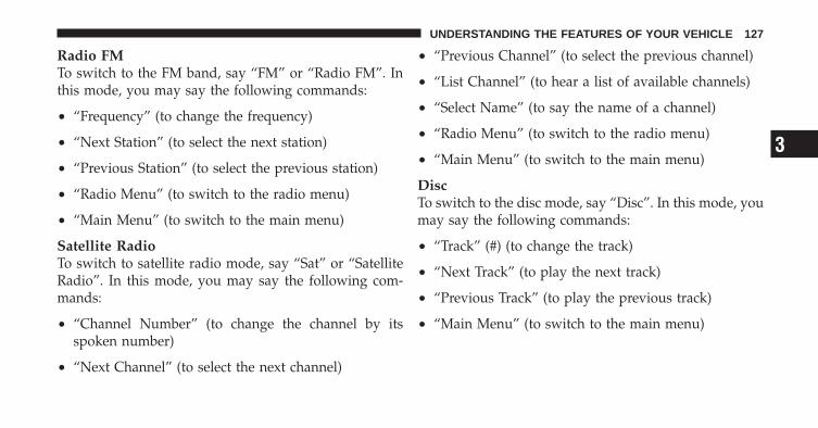
Radio FMTo switch to the FM band, say “FM” or “Radio FM”. Inthis mode, you may say the following commands:
• “Frequency” (to change the frequency)
• “Next Station” (to select the next station)
• “Previous Station” (to select the previous station)
• “Radio Menu” (to switch to the radio menu)
• “Main Menu” (to switch to the main menu)
Satellite RadioTo switch to satellite radio mode, say “Sat” or “SatelliteRadio”. In this mode, you may say the following com-mands:
• “Channel Number” (to change the channel by itsspoken number)
• “Next Channel” (to select the next channel)
• “Previous Channel” (to select the previous channel)
• “List Channel” (to hear a list of available channels)
• “Select Name” (to say the name of a channel)
• “Radio Menu” (to switch to the radio menu)
• “Main Menu” (to switch to the main menu)
DiscTo switch to the disc mode, say “Disc”. In this mode, youmay say the following commands:
• “Track” (#) (to change the track)
• “Next Track” (to play the next track)
• “Previous Track” (to play the previous track)
• “Main Menu” (to switch to the main menu)
3
UNDERSTANDING THE FEATURES OF YOUR VEHICLE 127

MemoTo switch to the voice recorder mode, say “Memo”. Inthis mode, you may say the following commands:
• “New Memo” (to record a new memo) — During therecording, you may press the Voice Commandbutton to stop recording. You proceed by saying one ofthe following commands:
− “Save” (to save the memo)
− “Continue” (to continue recording)
− “Delete” (to delete the recording)
• “Play Memos” (to play previously recorded memos)— During the playback you may press the VoiceCommand button to stop playing memos. Youproceed by saying one of the following commands:
− “Repeat” (to repeat a memo)
− “Next” (to play the next memo)
− “Previous” (to play the previous memo)
− “Delete” (to delete a memo)
• “Delete All” (to delete all memos)
System SetupTo switch to system setup, say “Setup”. In this mode, youmay say the following commands:
• “Language German”
• “Language Dutch”
• “Language Italian”
• “Language English”
• “Language French”
• “Language Spanish”
• “Tutorial”
• “Voice Training”
128 UNDERSTANDING THE FEATURES OF YOUR VEHICLE

NOTE: Keep in mind that you have to press the VoiceCommand button first and wait for the beepbefore speaking the “Barge In” commands.
Voice TrainingFor users experiencing difficulty with the system recog-nizing their voice commands or numbers the Uconnect™Voice “Voice Training” feature may be used.
1. Press the Voice Command button, say “SystemSetup” and once you are in that menu then say “VoiceTraining.” This will train your own voice to the systemand will improve recognition.
2. Repeat the words and phrases when prompted byUconnect™ Voice. For best results, the “Voice Training”session should be completed when the vehicle is parked,engine running, all windows closed, and the blower fanswitched off. This procedure may be repeated with a newuser. The system will adapt to the last trained voice only.
SEATSSeats are a primary part of the Occupant Restraint Systemof the vehicle. They need to be used properly for safeoperation of the vehicle.
WARNING!
• DO NOT allow people to ride in any area of yourvehicle that is not equipped with seats and seatbelts. In a collision, people riding in these areasare more likely to be seriously injured or killed.
• Be sure everyone in your vehicle is in a seat andusing a seat belt properly.
3
UNDERSTANDING THE FEATURES OF YOUR VEHICLE 129

Power SeatsThe power seat switch is located on the outboard side ofthe seat near the floor. Use this switch to move thedriver’s seat up or down, forward or rearward or torecline the seat. The passenger’s seat will move up ordown, forward or rearward.
WARNING!
Adjusting a seat while the vehicle is moving isdangerous. The sudden movement of the seat couldcause you to lose control. The seat belt might not beproperly adjusted and you could be injured. Adjustthe seat only while the vehicle is parked.
CAUTION!
DO NOT place any article under a power seat orimpede its ability to move as it may cause damage tothe seat controls. Seat travel may become limited ifmovement is stopped by an obstruction in the seat’spath.
Power Seat Switch
130 UNDERSTANDING THE FEATURES OF YOUR VEHICLE

Power Reclining SeatsThe recline control is used to adjust the position of theseatback. To adjust the seatback forward, move thecontrol toward the front of the vehicle. To move theseatback rearward, move the control toward the rear ofthe vehicle.
The recliner control is located on the outboard side of theseat.
Power Seat Recline Switch
3
UNDERSTANDING THE FEATURES OF YOUR VEHICLE 131

WARNING!
Do not ride with the seatback reclined so that theshoulder belt is no longer resting against your chest.In a collision you could slide under the seat belt andbe seriously or even fatally injured. Use the reclineronly when the vehicle is parked.
Lumbar SupportThis feature allows you to increase or decrease theamount of lumbar support. Turn the control lever for-ward to increase and rearward to decrease the desiredamount of lumbar support.
Head RestraintsHead restraints can reduce the risk of injury in the eventof a rear impact. The head restraint should be adjusted sothe top of the head restraint is located above the top ofyour ear.
Lumbar Support Control Lever
132 UNDERSTANDING THE FEATURES OF YOUR VEHICLE

To raise the head restraint, pull upward on the headrestraint. To lower the head restraint, press the largebutton, located on the base of the head restraint, andpush downward on the head restraint.
NOTE: The rear head restraints are not adjustable.
To remove the head restraint, pull upward on the headrestraint to it’s highest position, push in both buttons atthe base of each head restraint rod, and simultaneouslypull up on the head restraint.
Adjustable Head Restraints Removing Head Restraint
3
UNDERSTANDING THE FEATURES OF YOUR VEHICLE 133

To install the head restraint, insert the head restraint rodsinto each guide, apply pressure down on the headrestuntil the head restraint reaches the first lock position,push the large button in and push down and adjust headrestraint to desired position.
NOTE: Ensure that the front of the head restraint isfacing toward the front of the vehicle.
WARNING!
Driving a vehicle with the head restraints removed orimproperly adjusted could cause serious injury ordeath in the event of a collision. The head restraintsshould always be checked prior to operating thevehicle and never adjusted while the vehicle is inmotion. Always adjust the head restraints when thevehicle is in PARK.
Heated Seats — If EquippedThis feature heats the front driver and passenger seats.The controls for each front seat are located near thebottom center of the instrument panel.
Front Heated Seat Switch
134 UNDERSTANDING THE FEATURES OF YOUR VEHICLE

On vehicles equipped with rear heated seats, the seatsclosest to the doors are heated. The controls for theseseats are located on the rear of the center console.
After turning the ignition to RUN, you can choose froma High or Low heat setting. Amber indicator lights in
each switch indicate the level of heat in use. Two indica-tors will illuminate for High, one for Low and none forOff.
Press the switch once to select High-level heat-ing. Press the switch a second time to selectLow-level heating. Press the switch a third timeto shut the heating elements Off.
If the High-level heating is selected, the system willautomatically switch to Low-level heating after approxi-mately 30 minutes of continuous operation. At that time,the number of indicators illuminated changes from twoto one, indicating the change. Operation on the Low-levelsetting also turns Off automatically after approximately30 minutes.
NOTE: Once a heat setting is selected, heat will be feltwithin two to five minutes.
Rear Heated Seat Switch
3
UNDERSTANDING THE FEATURES OF YOUR VEHICLE 135

WARNING!
• Persons who are unable to feel pain to the skinbecause of advanced age, chronic illness, diabetes,spinal cord injury, medication, alcohol use, ex-haustion or other physical condition must exercisecare when using the seat heater. It may cause burnseven at low temperatures, especially if used forlong periods of time.
• Do not place anything on the seat that insulatesagainst heat, such as a blanket or cushion. Thismay cause the seat heater to overheat. Sitting in aseat that has been overheated could cause seriousburns due to the increased surface temperature ofthe seat.
CAUTION!
Repeated overheating of the seat could damage theheating element and/or degrade the material of theseat.
Folding Rear SeatThe rear seatbacks can be folded forward to provide anadditional storage area. Pull on the loops shown in theillustration to fold down either or both seatbacks. Theseloops can be tucked away when not in use.
136 UNDERSTANDING THE FEATURES OF YOUR VEHICLE

When the seatback is folded to the upright position, makesure it is latched by strongly pulling on the top of theseatback above the seat strap.
WARNING!
• Be certain that the seatback is securely locked intoposition. If the seatback is not securely locked intoposition, the seat will not provide the properstability for child seats and/or passengers. Animproperly latched seat could cause serious injury.
• The cargo area in the rear of the vehicle (with therear seatbacks in the locked-up or folded downposition) should not be used as a play area bychildren when the vehicle is in motion. They couldbe seriously injured in an accident. Childrenshould be seated and using the proper restraintsystem.
Folding Rear Seats
3
UNDERSTANDING THE FEATURES OF YOUR VEHICLE 137

DRIVER MEMORY SEAT — IF EQUIPPEDThis feature allows the driver to store up to two differentmemory profiles for easy recall through a memoryswitch. Each memory profile contains desired positionsettings for the driver seat, side mirrors, adjustablepedals (if equipped), and power tilt and telescopic steer-ing column (if equipped) and a set of desired radiostation presets. Your Remote Keyless Entry (RKE) trans-mitter can also be programmed to recall the same posi-tions when the UNLOCK button is pressed.
NOTE:• Only one RKE transmitter can be linked to each of the
memory positions.
• Passive Entry door handles cannot be linked to thememory function. Use either the memory recall switchor the RKE transmitter (if linked to the memoryfeature) to recall memory positions 1 or 2.
The memory switch is located on the driver’s door trimpanel. The switch contains an (S) button to activate thememory save function. It also contains a rocker switchlabeled with the number (1) and the number (2). Therocker switch allows the driver to recall either of twopre-programmed memory profiles by pressing the appro-priate side of the switch.
Memory Switch
138 UNDERSTANDING THE FEATURES OF YOUR VEHICLE

Programming The Memory Feature
NOTE: Saving a new memory profile will erase anexisting profile from memory.
To create a new memory profile, perform the following:
1. Place the ignition into the RUN position.
2. Adjust all memory profile settings to desired prefer-ences (i.e., seat, side mirror, adjustable pedals [ifequipped], power tilt and telescopic steering column [ifequipped], and radio station presets).
3. Press and release the SET (S) button on the memoryswitch.
4. Within five seconds, press and release the MEMORYbutton 1 or 2. The Electronic Vehicle Information Center(EVIC) (if equipped) will display which memory positionhas been set.
NOTE:• Memory profiles can be set without the vehicle in
PARK, but the vehicle must be in PARK to recall amemory profile.
• The Recall Memory with Remote Key Unlock featurecan be enabled through the EVIC (if equipped). Referto “Electronic Vehicle Information Center (EVIC)/Personal Settings (Customer-Programmable Fea-tures)” in “Understanding Your Instrument Panel” forfurther information.
Linking and Unlinking the Remote Keyless EntryTransmitter to MemoryYour RKE transmitters can be programmed to recall oneof two pre-programmed memory profiles by pressing theUNLOCK button on the RKE transmitter.
3
UNDERSTANDING THE FEATURES OF YOUR VEHICLE 139

To program your RKE transmitters, perform the follow-ing:
1. Remove the Key Fob from the ignition (or change theignition to OFF, for vehicles equipped with KeylessGo™).
2. Select desired memory profile 1 or 2.
3. Once the profile has been recalled, press and releasethe SET (S) button on the memory switch, then press andrelease the side of the rocker switch labeled 1 or 2accordingly. �Memory Profile Set” (1 or 2) will display inthe instrument cluster on vehicles equipped with theEVIC.
4. Press and release the LOCK button on the RKEtransmitter within 10 seconds.
NOTE: Your RKE transmitters can be unlinked to yourmemory settings by pressing the SET (S) button followedby the UNLOCK button on the RKE transmitter in Step 4above.
Memory Position Recall
NOTE:• The vehicle must be in PARK to recall memory posi-
tions. If a recall is attempted when the vehicle is not inPARK, a message will display in the EVIC (ifequipped).
• The driver’s seat belt must be unbuckled to recallmemory positions.
To recall the memory settings for driver one, pressMEMORY button number 1 on the driver’s door or theUNLOCK button on the RKE transmitter linked tomemory position 1.
140 UNDERSTANDING THE FEATURES OF YOUR VEHICLE

To recall the memory setting for driver two, pressMEMORY button number 2 on the driver’s door or theUNLOCK button on the RKE transmitter linked tomemory position 2.
A recall can be cancelled by pressing any of theMEMORY buttons (S, 1, or 2) on the driver’s door duringa recall. When a recall is cancelled, the driver seat, sidemirror, adjustable pedals (if equipped), and power tiltand telescopic steering column (if equipped) stop mov-ing. A delay of one second will occur before another recallcan be selected.
Easy Entry/Exit Seat (Available with Memory SeatOnly)This feature provides automatic driver seat positioning toenhance driver mobility when entering and exiting thevehicle.
The distance the driver seat moves depends on whereyou have the driver seat positioned when you remove the
Key Fob from the ignition (or change the ignition to OFF,for vehicles equipped with Keyless Go™).
• When you remove the Key Fob from the ignition (orchange the ignition to OFF, for vehicles equipped withKeyless Go™), the driver seat will move about 2.4 in(60 mm) rearward if the driver seat position is greaterthan or equal to 2.7 in (67.7 mm) forward of the rearstop. The seat will return to its previously set positionwhen you place the ignition into the ACC or RUNposition.
• When you remove the Key Fob from the ignition (orchange the ignition to OFF, for vehicles equipped withKeyless Go™), the driver seat will move to a position0.3 in (7.7 mm) forward of the rear stop if the driverseat position is between 0.9 in and 2.7 in (22.7 mm and67.7 mm) forward of the rear stop. The seat will returnto its previously set position when you place theignition to the ACC or RUN position.
3
UNDERSTANDING THE FEATURES OF YOUR VEHICLE 141

• The Easy Entry/Easy Exit feature is disabled when thedriver seat position is less than 0.9 in (22.7 mm)forward of the rear stop. At this position, there is nobenefit to the driver by moving the seat for Easy Exitor Easy Entry.
Each stored memory setting will have an associated EasyEntry and Easy Exit position.
NOTE: The Easy Entry/Easy Exit feature can be en-abled or disabled through the programmable features inthe EVIC. Refer to “Electronic Vehicle Information Center(EVIC)/Personal Settings (Customer-Programmable Fea-tures)” in “Understanding Your Instrument Panel” forfurther information.
TO OPEN AND CLOSE THE HOODTwo latches must be released to open the hood.
1. Pull the hood release lever located under the left sideof the instrument panel.
2. Move to the outside of the vehicle and push the safetycatch to the left. The safety catch is located under thecenter front edge of the hood.
Hood Release Lever
142 UNDERSTANDING THE FEATURES OF YOUR VEHICLE

Use the hood prop rod (if equipped) to secure the hood inthe open position.
CAUTION!
To prevent possible damage, do not slam the hood toclose it. Lower the hood, until it is open approxi-mately 6 in (15 cm), and then drop it. This shouldsecure both latches. Never drive your vehicle unlessthe hood is fully closed, with both latches engaged.
WARNING!
Be sure the hood is fully latched before driving yourvehicle. If the hood is not fully latched, it could openwhen the vehicle is in motion and block your vision.Failure to follow this warning could result in seriousinjury or death.
Hood Safety Catch
3
UNDERSTANDING THE FEATURES OF YOUR VEHICLE 143

LIGHTS
Headlight SwitchThe headlight switch is located on the left side ofthe instrument panel. This switch controls theoperation of the headlights, parking lights, instru-
ment panel lights, instrument panel light dimming, inte-rior lights and fog lights.
Rotate the headlight switch clockwise to the first detentfor parking light and instrument panel light operation.Rotate the headlight switch to the second detent forheadlight, parking light and instrument panel lightoperation.
Headlight Switch
144 UNDERSTANDING THE FEATURES OF YOUR VEHICLE

Automatic Headlights — If EquippedThis system automatically turns the headlights on or offaccording to ambient light levels. To turn the system on,rotate the headlight switch counterclockwise to the A(AUTO) position. When the system is on, the headlighttime delay feature is also on. This means the headlightswill stay on for up to 90 seconds after you place theignition into the OFF position. To turn the automaticsystem off, move the headlight switch out of the AUTOposition.NOTE: The engine must be running before the head-lights will come on in the automatic mode.
Headlights On with Wipers (Available withAutomatic Headlights Only)When this feature is active, the headlights will turn onapproximately 10 seconds after the wipers are turned onif the headlight switch is placed in the AUTO position. Inaddition, the headlights will turn off when the wipers areturned off if they were turned on by this feature.
The Headlights On with Wipers feature can be turned onor off through the Electronic Vehicle Information Center(EVIC) (if equipped). Refer to “Electronic Vehicle Infor-mation Center (EVIC)/Customer-Programmable Fea-tures” in “Understanding Your Instrument Panel” forfurther information.
Headlight Time DelayThis feature provides the safety of headlight illuminationfor up to 90 seconds (programmable) when leaving yourvehicle in an unlit area.
To activate the delay feature, place the ignition in the OFFposition while the headlights are still on. Then, turn offthe headlights within 45 seconds. The delay intervalbegins when the headlight switch is turned off.
If you turn the headlights or parking lights on, or placethe ignition in ACC or RUN, the system will cancel thedelay.
3
UNDERSTANDING THE FEATURES OF YOUR VEHICLE 145

If you turn the headlights off before the ignition, they willturn off in the normal manner.
NOTE: The lights must be turned off within 45 secondsof placing the ignition in the OFF position to activate thisfeature.
The headlight delay time is programmable on vehiclesequipped with the EVIC. Refer to “Electronic VehicleInformation Center (EVIC)/Customer-ProgrammableFeatures” in “Understanding Your Instrument Panel” forfurther information.
SmartBeam™ — If EquippedThe SmartBeam™ system provides increased forwardlighting at night by automating high beam controlthrough the use of a digital camera mounted on theinside rearview mirror. This camera detects vehicle spe-cific light and automatically switches from high beams tolow beams until the approaching vehicle is out of view.
To Activate
1. Select “Automatic High Beams — ON” through theEVIC. Refer to “Electronic Vehicle Information Center(EVIC)/Customer-Programmable Features” in “Under-standing Your Instrument Panel” for further information.
2. Rotate the headlight switch counterclockwise to the A(AUTO) position.
3. Push the multifunction lever away from you to switchthe headlights to the high beam position. Refer to “Mul-tifunction Lever” for further information.
NOTE: This system will not activate until the vehicle isat or above 25 mph (40 km/h).
To DeactivatePerform either of the following steps to deactivate theSmartBeam™ system.
146 UNDERSTANDING THE FEATURES OF YOUR VEHICLE

1. Pull the multifunction lever toward you to switch theheadlights from the high beam to the low beam position.
2. Rotate the headlight switch clockwise from the AUTOto the on position.
NOTE: Broken, muddy, or obstructed headlights andtaillights of vehicles in the field of view will causeheadlights to remain on longer (closer to the vehicle).Also, dirt, film, and other obstructions on the windshieldor camera lens will cause the system to functionimproperly.
Daytime Running Lights — If EquippedThe high beam headlights will come on as DaytimeRunning Lights whenever the ignition is placed in theRUN position, the headlights are off and the parkingbrake is off. The headlight switch must be used fornormal nighttime driving.
Lights-On ReminderIf the headlights or parking lights are on after the ignitionis placed in the OFF position, a chime will sound to alertthe driver when the driver’s door is opened.
Fog Lights — If EquippedThe front fog light switch is built into the head-light switch. To activate the front fog lights, turnon the parking lights or the low beam headlights
and press the headlight switch. To turn off the front foglights, either press the headlight switch a second time orturn off the headlight switch.
An indicator light in the instrument cluster illuminateswhen the fog lights are turned on.
NOTE: The fog lights will operate with the low beamheadlights or parking lights on. However, selecting thehigh beam headlights will turn off the fog lights.
3
UNDERSTANDING THE FEATURES OF YOUR VEHICLE 147

Multifunction LeverThe multifunction lever controls the operation of the turnsignals, headlight beam selection and passing lights. Themultifunction lever is located on the left side of thesteering column.
Turn SignalsMove the multifunction lever up or down and the arrowson each side of the instrument cluster flash to showproper operation of the front and rear turn signal lights.
NOTE:• If either light remains on and does not flash, or there is
a very fast flash rate, check for a defective outside lightbulb. If an indicator fails to light when the lever ismoved, it would suggest that the indicator bulb isdefective.
• A “Turn Signal On” message will appear in the EVIC(if equipped) and a continuous chime will sound if thevehicle is driven more than 1 mile (1.6 km) with eitherturn signal on.
Lane Change AssistTap the lever up or down once, without moving beyondthe detent, and the turn signal (right or left) will flashthree times then automatically turn off.
Multifunction Lever
148 UNDERSTANDING THE FEATURES OF YOUR VEHICLE

High/Low Beam SwitchPush the multifunction lever away from you to switchthe headlights to high beam. Pull the multifunction levertoward you to switch the headlights back to low beam.
Flash-to-PassYou can signal another vehicle with your headlights bylightly pulling the multifunction lever toward you. Thiswill turn on the high beams headlights until the lever isreleased.
Overhead Console Map/Reading LightsThese lights are mounted between the sun visors on theoverhead console. Each light is turned on by pressing thelens. Press the lens a second time to turn off the light.These lights also turn on when a door is opened, or whenthe UNLOCK button on the Remote Keyless Entry (RKE)transmitter is pressed or when the dimmer control isturned fully upward, past the second detent.
Interior LightsThe interior lights come on when a door is opened.
To protect the battery, the interior lights will turn offautomatically 10 minutes after the ignition is placed inthe OFF position. This will occur if the interior lightswere switched on manually or are on because a door is
Overhead Console
3
UNDERSTANDING THE FEATURES OF YOUR VEHICLE 149

open. This includes the glove box light, but not the trunklight. To restore interior light operation, either place theignition in the RUN position or cycle the light switch.
Dimmer ControlThe dimmer control is part of theheadlight switch and is located on theleft side of the instrument panel. Withthe parking lights or headlights on,rotating the dimmer control upwardwill increase the brightness of the in-strument panel lights and, if
equipped, the lighting in the door map pockets andcupholders.
Dome Light PositionRotate the dimmer control completely upward to thesecond detent to turn on the interior lights. The interiorlights will remain on when the dimmer control is in thisposition.
Interior Light Defeat (OFF)Rotate the dimmer control to the extreme bottom offposition. The interior lights will remain off when thedoors are open.
Parade Mode (Daytime Brightness Feature)Rotate the dimmer control upward to the first detent.This feature brightens all text displays such as theodometer, EVIC (if equipped), and radio when the park-ing lights or headlights are on.
WINDSHIELD WIPERS AND WASHERSThe multifunction lever operates the windshield wipersand washer when the ignition is placed in the RUNposition. The multifunction lever is located on the leftside of the steering column.
150 UNDERSTANDING THE FEATURES OF YOUR VEHICLE

Rotate the end of the multifunction lever to the firstdetent, past the intermittent settings for low-speed wiperoperation, or to the second detent past the intermittentsettings for high-speed wiper operation.
CAUTION!
Turn the windshield wipers off when drivingthrough an automatic car wash. Damage to the wind-shield wipers may result if the wiper switch is left inany position other than off.
Intermittent Wiper SystemUse the intermittent wiper when weather conditionsmake a single wiping cycle with a variable pause be-tween cycles desirable. Rotate the end of the multifunc-tion lever to select the desired delay interval. There aresix delay settings which allow you to regulate the wipeinterval from a minimum of one cycle every second to amaximum of approximately 23 seconds between cycles.
Windshield Wiper/Washer Control
3
UNDERSTANDING THE FEATURES OF YOUR VEHICLE 151

Mist FeatureLightly push the multifunction lever inward (toward thesteering column) to activate a single wipe cycle to clearoff road mist or spray from a passing vehicle. The wiperswill continue to operate until you release the multifunc-tion lever.
Windshield WashersTo use the washer, push the multifunction lever inwardcompletely (toward the steering column) and hold it foras long as washer spray is desired.
If you activate the washer while the windshield wipercontrol is in the delay range, the wipers will operate fortwo wipe cycles after releasing the lever and then resumethe intermittent interval previously selected.
If you activate the washer while the windshield wiper isturned off, the wipers will operate for three wipe cyclesand then turn off.
WARNING!
Sudden loss of visibility through the windshieldcould lead to an accident. You might not see othervehicles or other obstacles. To avoid sudden icing ofthe windshield during freezing weather, warm thewindshield with the defroster before and duringwindshield washer use.
Headlights On With Wipers (Available withAutomatic Headlights Only)When this feature is active, the headlights will turn onapproximately 10 seconds after the wipers are turned onif the headlight switch is placed in the AUTO position. Inaddition, the headlights will turn off when the wipers areturned off if they were turned on by this feature.
152 UNDERSTANDING THE FEATURES OF YOUR VEHICLE

The Headlights On with Wipers feature can be turned onor off through the Electronic Vehicle Information Center(EVIC) (if equipped). Refer to “Electronic Vehicle Infor-mation Center (EVIC)/Personal Settings (Customer-Programmable Features)” in “Understanding Your In-strument Panel” for further information.
Rain Sensing Wipers — If EquippedThis feature senses moisture on the windshield andautomatically activates the wipers for the driver. Thisfeature is especially useful for road splash or over sprayfrom the windshield washers of the vehicle ahead. Rotatethe end of the multifunction lever to one of the sixintermittent wiper settings to activate this feature.The sensitivity of the system is adjustable from themultifunction lever. Wiper delay position 1 is the leastsensitive and wiper delay position 6 is the most sensitive.Choose setting 3 or 4 for normal rain conditions. Choosesetting 2 or 1 if you desire less wiper sensitivity. Choosesetting 5 or 6 if you desire more sensitivity. The rain sense
wipers will automatically change between an intermit-tent wipe, slow wipe and a fast wipe depending on theamount of moisture that is sensed on the windshield.Place the multifunction lever in the off position when notusing the system.
NOTE:• The Rain Sensing feature will not operate when the
wiper speed is in the low or high position.• The Rain Sensing feature may not function properly
when ice or dried salt water is present on the wind-shield.
• Use of Rain-X� or products containing wax or siliconemay reduce rain sensor performance.
• The Rain Sensing feature can be turned on and offthrough the EVIC (if equipped). Refer to “ElectronicVehicle Information Center (EVIC)/Personal Settings(Customer-Programmable Features)” in “Understand-ing Your Instrument Panel” for further information.
3
UNDERSTANDING THE FEATURES OF YOUR VEHICLE 153

The Rain Sensing system has protective features for thewiper blades and arms. It will not operate under thefollowing conditions:
• Low Temperature Wipe Inhibit — The Rain Sensingfeature will not operate when the ignition is placed inthe RUN position, the vehicle is stationary and theoutside temperature is below 32°F (0°C), unless thewiper control on the multifunction lever is moved, thevehicle speed becomes greater than 0 mph (0 km/h) orthe outside temperature rises above freezing.
• Neutral Wipe Inhibit — The rain sensing feature willnot operate when the ignition is placed in the RUNposition, the transmission shift lever is in the NEU-TRAL position and the vehicle speed is less than5 mph (8 km/h), unless the wiper control on themultifunction lever is moved or the shift lever ismoved out of the NEUTRAL position.
TILT/TELESCOPING STEERING COLUMNThis feature allows you to tilt the steering columnupward or downward. It also allows you to lengthen orshorten the steering column. The tilt/telescoping controlhandle is located below the steering wheel at the end ofthe steering column.
Tilt/Telescoping Control Handle
154 UNDERSTANDING THE FEATURES OF YOUR VEHICLE

To unlock the steering column, pull the control handleoutward. To tilt the steering column, move the steeringwheel upward or downward as desired. To lengthen orshorten the steering column, pull the steering wheeloutward or push it inward as desired. To lock the steeringcolumn in position, push the control handle inward untilfully engaged.
WARNING!
Do not adjust the steering column while driving.Adjusting the steering column while driving or driv-ing with the steering column unlocked, could causethe driver to lose control of the vehicle. Be sure thesteering column is locked before driving your ve-hicle. Failure to follow this warning may result inserious injury or death.
POWER TILT/TELESCOPING STEERING COLUMN— IF EQUIPPEDThis feature allows you to tilt the steering columnupward or downward. It also allows you to lengthen orshorten the steering column. The power tilt/telescopingsteering column lever is located below the multifunctionlever on the steering column.
Power Tilt/Telescoping Steering
3
UNDERSTANDING THE FEATURES OF YOUR VEHICLE 155

To tilt the steering column, move the lever up or down asdesired. To lengthen or shorten the steering column, pullthe lever toward you or push the lever away from you asdesired.
NOTE: For vehicles equipped with Driver MemorySeat, you can use your Remote Keyless Entry (RKE)transmitter or the memory switch on the driver’s doortrim panel to return the tilt/telescopic steering column topre-programmed positions. Refer to “Driver MemorySeat” in this section.
WARNING!
Do not adjust the steering column while driving.Adjusting the steering column while driving or driv-ing with the steering column unlocked, could causethe driver to lose control of the vehicle. Be sure thesteering column is locked before driving your ve-hicle. Failure to follow this warning may result inserious injury or death.
ADJUSTABLE PEDALS — IF EQUIPPEDThe adjustable pedals system is designed to allow agreater range of driver comfort for steering wheel tilt andseat position. This feature allows both the brake andaccelerator pedal to move toward or away from thedriver to provide improved position with the steeringwheel. The switch is located on the front side of thedriver’s seat cushion side shield.
156 UNDERSTANDING THE FEATURES OF YOUR VEHICLE

Press the switch forward to move the pedals forward(toward the front of the vehicle).
Press the switch rearward to move the pedals rearward(toward the driver).
• The pedals can be adjusted with the ignition OFF.
• The pedals can be adjusted while driving.
• The pedals cannot be adjusted when the vehicle is inREVERSE or when the Electronic Speed Control is on.One of the following messages will display in theElectronic Vehicle Information Center (EVIC) (ifequipped) if a pedal adjustment is attempted when thesystem is locked out: “Adjustable Pedal Disabled —Cruise Control Engaged” or “Adjustable Pedal Dis-abled — Vehicle In Reverse.”
NOTE: For vehicles equipped with Driver MemorySeat, you can use your Remote Keyless Entry (RKE)transmitter or the memory switch on the driver’s doortrim panel to return the adjustable pedals to pre-programmed positions. Refer to “Driver Memory Seat”in “Understanding the Features of Your Vehicle” forfurther information.
Adjustable Pedals Switch
3
UNDERSTANDING THE FEATURES OF YOUR VEHICLE 157

CAUTION!
Do not place any article under the adjustable pedalsor impede its ability to move as it may cause damageto the pedal controls. Pedal travel may become lim-ited if movement is stopped by an obstruction in theadjustable pedal’s path.
WARNING!
Do not adjust the pedals while the vehicle is moving.You could lose control and have an accident. Alwaysadjust the pedals while the vehicle is parked.
ELECTRONIC SPEED CONTROLWhen engaged, Electronic Speed Control takes over theaccelerator operation at speeds greater than 25 mph(40 km/h).
The Electronic Speed Control lever, located on the right-side of the steering wheel, operates the system.
Electronic Speed Control Lever
158 UNDERSTANDING THE FEATURES OF YOUR VEHICLE

NOTE: In order to ensure proper operation, the Elec-tronic Speed Control System has been designed to shutdown if multiple Speed Control functions are operatedsimultaneously. If this occurs, the Electronic Speed Con-trol System can be reactivated by pushing the ElectronicSpeed Control ON/OFF button and resetting the desiredvehicle set speed.
To ActivatePush and release the ON/OFF button, located on the endof the Electronic Speed Control lever. The indicator lightin the instrument cluster will illuminate and the clusterwill display a “Cruise ON” message to show that thespeed control system is on. To turn the system off, pushand release the ON/OFF button again. The system,indicator light and message will turn off.
WARNING!
Leaving the Electronic Speed Control system onwhen not in use is dangerous. You could accidentallyset the system or cause it to go faster than you want.You could lose control and have an accident. Alwaysleave the Electronic Speed Control system off whenyou are not using it.
To Set At A Desired SpeedWhen the vehicle reaches the speed desired, push thelever downward to SET DECEL and release, the clusterwill display the “Cruise Set” message. Remove your footfrom the accelerator pedal and the vehicle will operate atthe selected speed.
3
UNDERSTANDING THE FEATURES OF YOUR VEHICLE 159

NOTE:• Electronic Speed Control will only function in 3rd, 4th,
or 5th gear when in the Autostick� mode (ifequipped).
• The Electronic Speed Control may not engage if adifferent size tire is installed on one wheel, such as thecompact spare tire.
To DeactivateThe system will disable Electronic Speed Control withouterasing the memory if you:
• Softly tap the brake pedal.
• Press the brake pedal.
• Pull the Electronic Speed Control lever toward you(CANCEL).
Pushing and releasing the ON/OFF button or turning theignition OFF erases the set speed from memory.
To Resume SpeedIf you deactivated the Electronic Speed Control withouterasing the set speed from memory and your vehiclespeed is above 20 mph (32 km/h) you can resume theprevious set speed. To do so, push the lever upward toRESUME ACCEL and release. Then remove your footfrom the accelerator pedal.
To Vary the Speed SettingWhen the Electronic Speed Control is set, you can in-crease speed by pushing up and holding the RESUMEACCEL lever. If the lever is continually held in theRESUME ACCEL position, the set speed will continue toincrease until the lever is released, then the new set speedwill be established.Tapping the Electronic Speed Control lever to RESUMEACCEL once will result in a 1 mph (1.6 km/h) speedincrease. Each time the lever is tapped speed increases, sotapping the lever three times will increase speed by3 mph (4.8 km/h), etc.
160 UNDERSTANDING THE FEATURES OF YOUR VEHICLE

To decrease speed while Electronic Speed Control is set,push down and hold the lever in SET DECEL. If the leveris continually held in the SET DECEL position, the setspeed will continue to until the lever is released. Releasethe lever when the desired speed is reached, and a newset speed will be established.
Tapping the Electronic Speed Control lever to SET DE-CEL once will result in a 1 mph (1.6 km/h) speeddecrease. Each time the lever is tapped, speed decreases.
To Accelerate For PassingPress the accelerator as you would normally. When thepedal is released, the vehicle will return to the set speed.
Using Electronic Speed Control on Hills
NOTE: The Electronic Speed Control system maintainsspeed up and down hills. A slight speed change onmoderate hills is normal.
The automatic transmission will downshift while climb-ing uphill or descending downhill. This downshift isnecessary to maintain vehicle set speed.
On steep hills, a greater speed loss or gain may occur, soit may be preferable to drive without Electronic SpeedControl.
WARNING!
Electronic Speed Control can be dangerous where thesystem cannot maintain a constant speed. Your ve-hicle could go too fast for the conditions and youcould lose control. An accident could be the result.Do not use Electronic Speed Control in heavy trafficor on roads that are winding, icy, snow-covered orslippery.
3
UNDERSTANDING THE FEATURES OF YOUR VEHICLE 161

ADAPTIVE CRUISE CONTROL (ACC) — IFEQUIPPEDAdaptive Cruise Control (ACC) increases the drivingconvenience provided by cruise control while travelingon highways and major roadways. However, it is not asafety system and not designed to prevent collisions.
ACC will allow you to keep cruise control engaged inlight to moderate traffic conditions without the constantneed to reset your cruise control. ACC utilizes an infraredsensor designed to detect a vehicle directly ahead of you.
NOTE:• If the sensor does not detect a vehicle ahead of you,
ACC will maintain a fixed set speed.
• If the ACC sensor detects a vehicle ahead, ACC willapply limited braking or acceleration automatically tomaintain a preset following distance, while matchingthe speed of the vehicle ahead.
WARNING!
• Adaptive Cruise Control (ACC) is a conveniencesystem. It is not a substitute for active drivinginvolvement. It is always the driver’s responsibil-ity to be attentive of road, traffic, and weatherconditions, vehicle speed, distance to the vehicleahead; and, most importantly, brake operation toensure safe operation of the vehicle under all roadconditions. Your complete attention is always re-quired while driving to maintain safe control ofyour vehicle. Failure to follow these warnings canresult in an accident or serious personal injury.TheACC system:
• Does not react to pedestrians, oncoming vehicles,and stationary objects (i.e., a stopped vehicle in atraffic jam or a disabled vehicle).
(Continued)
162 UNDERSTANDING THE FEATURES OF YOUR VEHICLE

WARNING! (Continued)• Cannot take street, traffic, and weather conditions
into account, and may be limited upon adversesight distance conditions.
• Does not predict the lane curvature or the move-ment of preceding vehicles and will not compen-sate for such changes.
• Does not always fully recognize complex drivingconditions, which can result in wrong or missingdistance warnings.
• May not detect a vehicle ahead when strong light(for example, sunrise or sunset) is directly shiningon the front of the vehicle.
• Can only apply a maximum of 25% of the vehicle’sbraking capability, and will not bring the vehicleto a complete stop.
WARNING!
You should switch off the ACC system:• When driving in fog, heavy rain, heavy snow,
sleet, heavy traffic, and complex driving situations(i.e., in highway construction zones).
• When entering a turn lane or highway off ramp;when driving on roads that are winding, icy,snow-covered, slippery, or have steep uphill ordownhill slopes; and when towing a trailer.
• When circumstances do not allow safe driving at aconstant speed.Failure to follow these warnings can result in anaccident or serious personal injury.
3
UNDERSTANDING THE FEATURES OF YOUR VEHICLE 163
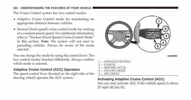
The Cruise Control system has two control modes:
• Adaptive Cruise Control mode for maintaining anappropriate distance between vehicles.
• Normal (fixed speed) cruise control mode for cruisingat a constant preset speed. For additional information,refer to “Normal (Fixed Speed) Cruise Control Mode”in this section. Note: The system will not react topreceding vehicles. Always be aware of the modeselected.
You can change the mode by using the control lever. Thetwo control modes function differently. Always confirmwhich mode is selected.
Adaptive Cruise Control (ACC) OperationThe speed control lever (located on the right side of thesteering wheel) operates the ACC system. Activating Adaptive Cruise Control (ACC)
You can only activate ACC if the vehicle speed is above25 mph (40 km/h).
1 — DISTANCE SETTING2 — CANCEL3 — RESUME/ACCEL4 — ON/OFF/MODE5 — SET/DECEL
164 UNDERSTANDING THE FEATURES OF YOUR VEHICLE

When the system is turned on and in the READY state,the Electronic Vehicle Information Center (EVIC) dis-plays “ACC READY.”
When the system is OFF, the EVIC displays “CRUISEOFF.”
NOTE: You cannot enable ACC under the followingconditions:
• When you apply the brakes.
• When the parking brake is set.
• When the automatic transmission is in PARK, RE-VERSE or NEUTRAL.
• When the Electronic Stability Program (ESP) isswitched off.
• When pushing the RESUME/ACCEL switch without apreviously set speed in memory.
To ActivatePush and release the ON/OFF/MODE button located onthe end of the speed control lever. The ACC menu in theEVIC displays “ACC READY.”
To turn the system OFF, push and release the ON/OFF/MODE button again. At this time, the system will turn offand the EVIC will display “CRUISE OFF.”
3
UNDERSTANDING THE FEATURES OF YOUR VEHICLE 165

WARNING!
Leaving the Adaptive Cruise Control (ACC) systemon when not in use is dangerous. You could acciden-tally set the system or cause it to go faster than youwant. You could lose control and have an accident.Always leave the system off when you are not usingit.
To Set a Desired ACC SpeedWhen the vehicle reaches the speed desired, push thelever downward (SET/DECEL) and release. The EVICwill display the set speed. Remove your foot from the accelerator pedal. If you do
not, the vehicle may continue to accelerate beyond the setspeed. If this occurs:
• The message “DRIVER OVERRIDE” will display inthe EVIC.
166 UNDERSTANDING THE FEATURES OF YOUR VEHICLE
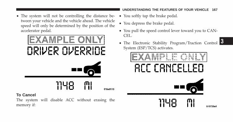
• The system will not be controlling the distance be-tween your vehicle and the vehicle ahead. The vehiclespeed will only be determined by the position of theaccelerator pedal.
To CancelThe system will disable ACC without erasing thememory if:
• You softly tap the brake pedal.
• You depress the brake pedal.
• You pull the speed control lever toward you to CAN-CEL.
• The Electronic Stability Program/Traction ControlSystem (ESP/TCS) activates.
3
UNDERSTANDING THE FEATURES OF YOUR VEHICLE 167

To Turn OffThe system will turn off and erase the set speed inmemory if:
• You push and release the ON/OFF/MODE button.
• You turn OFF the ignition.
• You switch off ESP.
To Resume SpeedPush the lever upward (RESUME/ACCEL) and release.Then remove your foot from the accelerator pedal. TheEVIC will display the last set speed.
WARNING!
The Resume function should only be used if trafficand road conditions permit. Resuming a set speedthat is too high or too low for prevailing traffic androad conditions could cause the vehicle to accelerateor decelerate too sharply for safe operation. Thiscould cause an accident and/or serious injury.
To Vary the Speed SettingWhile ACC is set, you can increase the set speed by liftingand holding the lever up (RESUME/ACCEL). If the leveris continually held, the set speed will continue to increasein 5 mph (10 km/h) increments until the lever is released.The increase in set speed is reflected in the EVIC display.
Tapping the lever up once will result in a 1 mph (1 km/h)increase in set speed. Each subsequent tap of the leverresults in an increase of 1 mph (1 km/h).
168 UNDERSTANDING THE FEATURES OF YOUR VEHICLE

While ACC is set, the set speed can be decreased bypushing and holding the lever down (SET/DECEL). Ifthe lever is continually held, the set speed will continueto decrease in 5 mph (10 km/h) increments until the leveris released. The decrease in set speed is reflected in theEVIC display.
Tapping the lever down once will result in a 1 mph(1 km/h) decrease in set speed. Each subsequent tap ofthe lever results in a decrease of 1 mph (1 km/h).
NOTE:• When you use the lever to decelerate, if the engine’s
braking power does not slow the vehicle sufficiently toreach the set speed, the brake system will automati-cally slow the vehicle.
• The ACC system can only apply a maximum of 25% ofthe vehicle’s braking capability and will not bring thevehicle to a complete stop.
• The ACC system maintains set speed when driving uphill and down hill. However, a slight speed change onmoderate hills is normal. In addition, downshiftingmay occur while climbing uphill or descending down-hill. This is normal operation and necessary to main-tain set speed.
3
UNDERSTANDING THE FEATURES OF YOUR VEHICLE 169

Setting the Following Distance in ACCThe specified following distance for ACC can be set byvarying the distance setting between long, medium, andshort. Using this distance setting and the vehicle speed,ACC calculates and sets the distance to the vehicle ahead.This distance setting displays in the EVIC.
To change the distance setting, push the lever away fromyou (DISTANCE) and release. Each time this is done, thedistance setting adjusts between long, medium, andshort.
If there is no vehicle ahead, the vehicle will maintain theset speed. If a slower moving vehicle is detected in thesame lane, the EVIC displays the “Sensed Vehicle Indi-cator” icon, and the system adjusts vehicle speed auto-matically to maintain the distance setting, regardless ofthe set speed.
The vehicle will then maintain the set distance until:
• The vehicle ahead accelerates to a speed above the setspeed.
• The vehicle ahead moves out of your lane or view ofthe sensor.
1 — Sensor Bars. Default Distance Setting is Three Bars = Long.
170 UNDERSTANDING THE FEATURES OF YOUR VEHICLE

• The vehicle ahead slows to a speed below 15 mph(24 km/h) and the system automatically disengagesitself.
• The distance setting is changed.
• The system disengages. (Refer to the information onACC Activation).
The maximum braking applied by ACC is limited; how-ever, the driver can always apply the brakes manually, ifnecessary.
NOTE: The brake lights will illuminate whenever theACC system applies the brakes.
A Proximity Warning will alert the driver if ACC predictsthat its maximum braking level is not sufficient tomaintain the set distance. If this occurs, a visual alert“ATTENTION” will flash in the EVIC and a chime willsound while ACC continues to apply its maximum
braking capacity. When this occurs, you should immedi-ately apply the brakes as needed to maintain a safedistance from the vehicle ahead.
3
UNDERSTANDING THE FEATURES OF YOUR VEHICLE 171

Adaptive Cruise Control (ACC) MenuThe EVIC displays the current ACC system settings. TheEVIC is located in the upper part of the instrumentcluster between the speedometer and the tachometer. Theinformation it displays depends on ACC system status.
Press the MENU button (located on the steer-ing wheel) repeatedly until one of the follow-ing displays in the EVIC:
CRUISE OFF
− When ACC is deactivated, the display will read“CRUISE OFF.”
ACC READY
− When ACC is activated but the vehicle speed settinghas not been selected, the display will read “ACCREADY.”
MenuButton
172 UNDERSTANDING THE FEATURES OF YOUR VEHICLE

ACC SET
− When ACC is set, the set speed will display.
1 — Sensed Vehicle Indicator2 — Set Speed3 — Your Vehicle4 — Following Distance Setting: Three Bars = Long; Two Bars =Medium; One Bar = Short.
3
UNDERSTANDING THE FEATURES OF YOUR VEHICLE 173

The set speed will continue to display in place of theodometer reading when changing the EVIC displaywhile ACC is set.
The ACC SET screen will display once again if any ACCactivity occurs, which may include any of the following:
• Set speed change
• Distance setting change
• System cancel
• Acquisition/loss of Target
• Driver override
• System off
• Proximity warning
• ACC warning
The EVIC will return to the last display selectedafter five seconds of no ACC display activity.
174 UNDERSTANDING THE FEATURES OF YOUR VEHICLE

Display Warnings and Maintenance
ACC Blinded WarningThe ACC Blinded Warning will display when conditionstemporarily limit system performance. This most oftenoccurs at times of poor visibility, such as in snow, fog,heavy rain, or when driving into direct sunlight (sunriseor sunset). The ACC system may also become tempo-rarily blinded due to obstructions, such as dirt or ice. Inthese cases, the EVIC will display “ACC Blinded” andthe system will deactivate.
NOTE: If the ACC Blinded Warning is active Normal(Fixed Speed) Cruise Control is still available. For addi-tional information refer to “Normal (Fixed Speed) CruiseControl Mode” in this section.
3
UNDERSTANDING THE FEATURES OF YOUR VEHICLE 175

If weather conditions are not a factor, the driver shouldexamine the sensor. It may require cleaning or removal ofan obstruction. The sensor is located behind the grille,slightly offset from the center of the grille.
To keep the ACC System operating properly, it is impor-tant to note the following maintenance items:
• Always keep the sensor clean. Carefully wipe thesensor lens with a soft cloth. Be cautious not todamage the sensor lens.
• Do not remove any screws from the sensor or thesensor mount. Doing so could cause an ACC systemmalfunction or failure and require a sensor realign-ment.
• If the sensor is damaged due to an accident, see yourauthorized dealer for service.
• Do not attach or install any accessories near the sensor,including transparent material or aftermarket grilles.Doing so could cause an ACC system failure ormalfunction.
When the condition that deactivated the system is nolonger present, the system will return to the “CRUISEOFF” state and will resume function by simply reactivat-ing it.
ACC Sensor Location
176 UNDERSTANDING THE FEATURES OF YOUR VEHICLE

NOTE: Installing a vehicle front-end protector or anaftermarket grille or modifying the grille is not recom-mended. Doing so may block the sensor and inhibit ACCoperation.
ACC Unavailable WarningIf the system turns off, and the EVIC displays �ACCUNAVAILABLE,� there may be a temporary malfunctionthat limits ACC functionality. Although the vehicle is stilldrivable under normal conditions, ACC will be tempo-rarily unavailable. If this occurs, try activating ACC againlater, following a key cycle. If the problem persists, seeyour authorized dealer. Service ACC Warning
If the system turns off, and the EVIC displays “SERVICEACC,” it indicates there is an internal system fault.Although the vehicle is still drivable under normalconditions, have the system checked by an authorizeddealer.
3
UNDERSTANDING THE FEATURES OF YOUR VEHICLE 177

Precautions While Driving with ACCIn certain driving situations, ACC may have detectionissues. In these cases, ACC may brake late or unexpect-edly. The driver needs to stay alert and may need tointervene.
Adding a Trailer HitchThe weight of a trailer hitch may affect the performanceof ACC. If there is a noticeable change in performancefollowing the installation of a hitch, such as reduceddetection range, please see your authorized dealer forservice.
Offset DrivingACC may not detect a vehicle in the same lane that isoffset from your direct line of travel. There will not besufficient distance to the vehicle ahead. The offset vehiclemay move in and out of the line of travel, which cancause your vehicle to brake or accelerate unexpectedly.
Turns and BendsIn turns or bends, ACC may detect a vehicle ahead toolate or too early. This may cause your vehicle to brake lateor unexpectedly. Give extra attention in curves and beready to apply the brakes if necessary. Be sure to select anappropriate speed while driving in curves.
178 UNDERSTANDING THE FEATURES OF YOUR VEHICLE

ACC may occasionally provide braking and/or a driveralert that you consider unnecessary. This may be thesystem’s response to signs, guardrails, and other station-ary objects in a curve. This may also occur at the base ofsteep hills. This is normal operation and your vehicledoes not require service.
Using ACC on HillsWhen driving on hills, ACC may not detect a vehicle inyour lane. Depending on the speed, vehicle load, trafficconditions, and the steepness of the hills, ACC perfor-mance may be limited.
3
UNDERSTANDING THE FEATURES OF YOUR VEHICLE 179

Lane ChangingACC will not detect a vehicle until it is completely in thelane in which you are traveling. In the illustration shown,ACC has not yet detected the vehicle changing lanes andit may detect the vehicle until it’s too late for the ACCsystem to take action. ACC will not detect a vehicle untilit is completely in the lane. There will not be sufficientdistance to the lane-changing vehicle. Always be atten-tive and ready to apply the brakes if necessary.
Narrow VehiclesSome narrow vehicles traveling near the outer edges ofthe lane or edging into the lane are not detected until theyhave moved fully into the lane. There will not be suffi-cient distance to the vehicle ahead.
180 UNDERSTANDING THE FEATURES OF YOUR VEHICLE

Stationary Objects and VehiclesACC does not react to stationary objects and stationaryvehicles. For example, ACC will not react in situationswhere the vehicle you are following exits your lane andthe vehicle ahead is stopped in your lane. Always beattentive and ready to apply the brakes if necessary.
General Information
CLASS 1 LASER PRODUCTClassification Specifications:
21 C.F.R part 1040.10 & 1040.11DIN EN 60825-1:2003
IEC 60825-1:2001
3
UNDERSTANDING THE FEATURES OF YOUR VEHICLE 181

Normal (Fixed Speed) Cruise Control ModeIn addition to adaptive cruise control mode, a normal(fixed speed) cruise control mode is available for cruisingat fixed speeds. The Normal cruise control mode isdesigned to maintain a set cruising speed without requir-ing the driver to operate the accelerator. Cruise controlcan only be operated if the vehicle speed is above 25 mph(40 km/h).
To change modes, press and hold the ON/OFF/MODEbutton for at least one second in either the OFF state orthe READY state. �Normal Cruise Ready� will be dis-played once the mode becomes available. To switch backto ACC, press and hold the ON/OFF/MODE buttonagain for at least one second.
WARNING!
In the normal cruise control mode, the system willnot react to vehicles ahead. In addition, the proximitywarning does not activate and no alarm will soundeven if you are too close to the vehicle ahead sincethe presence of the vehicle ahead nor the vehicle-to-vehicle distance is detected. Be sure to maintain asafe distance between your vehicle and the vehicleahead. Always be aware which mode is selected.
To set a Desired SpeedWhen the vehicle reaches the speed desired, tap the leverdown and release (SET/DECEL). The EVIC will displaythe set speed.
NOTE: You must observe the display when setting orchanging speed, not the speedometer.
182 UNDERSTANDING THE FEATURES OF YOUR VEHICLE

To Vary the Speed SettingThere are two ways to change the set speed:
• Use the accelerator pedal to adjust the vehicle to thedesired speed and push the lever down (SET/DECEL).
• Tap the stalk up (ACCEL) or down (DECEL) toincrease or decrease the set speed in 1 mph (1 km/h)increments respectively. Hold the lever up (ACCEL) ordown (DECEL) for 5 mph (10 km/h) increments.
To CancelThe system will disable Normal cruise control withouterasing the memory if:
• You softly tap or depress the brake pedal.
• You pull the speed control lever toward you (CAN-CEL).
• The Electronic Stability Program/Traction ControlSystem (ESP/TCS) activates.
To ResumePush the lever up and release (RESUME/ACCEL) andthen remove your foot from the accelerator pedal. TheEVIC will display the last set speed.
To Turn OffThe system will turn off and erase the set speed inmemory if:
• You push and release the ON/OFF/MODE button.
• You turn off the ignition.
• You switch off ESP.
If the cruise control system is turned off and reactivated,the system will return to the Vehicle-to-vehicle (adaptive)distance control mode.
3
UNDERSTANDING THE FEATURES OF YOUR VEHICLE 183

PARKSENSE� REAR PARK ASSISTThe ParkSense� Rear Park Assist system is a driver aidthat senses for obstacles behind the vehicle. Refer toParkSense� System Usage Precautions for limitations ofthis system and recommendations.
ParkSense� is active when the driver shifts the transmis-sion into the REVERSE position, and the parking brake isnot applied, and the vehicle speed is less than 10 mph(16 km/h).
ParkSense� can be turned on or off through the ElectronicVehicle Information Center (EVIC) when the vehicle is inPARK. Refer to “Electronic Vehicle Information Center(EVIC)/Personal Settings (Customer-Programmable Fea-tures)” in “Understanding Your Instrument Panel” forfurther information.
ParkSense� uses four sensors located in the rear bumperto scan for obstacles up to 79 in (200 cm) away from therear bumper fascia. The ParkSense� Warning Displaylocated above the rear window provides both visible andaudible warnings to indicate the range of the object.
ParkSense� LED Display
184 UNDERSTANDING THE FEATURES OF YOUR VEHICLE

The Warning Display contains two sets of yellow and redindicators, one set to warn of obstacles behind the leftrear of the vehicle and the other set to warn of obstaclesbehind the right rear of the vehicle. The driver can viewthe indicators either through the rearview mirror or bylooking at the display above the rear window.
ParkSense� dimly illuminates the two inner most yellowindicators when it is ON and detecting no obstacles. Thefollowing chart shows the warning display operationwhen the system is detecting an obstacle:
WARNING DISPLAY DISTANCES
DISPLAY INDICA-TOR
OBSTACLE DISTANCE FROM: INDICATORCOLOR
AUDIBLE SIGNALREAR CORNERS REAR CENTER
Inner LED 79 in (200 cm) Yellow Yes, Half Second1st LED 51.2 in (130 cm) Yellow No2nd LED 45.3 in (115 cm) Yellow No3rd LED 31.5 in (80 cm) 39.3 in (100 cm) Yellow No4th LED 25.5 in (65 cm) 33.5 in (85 cm) Yellow No5th LED 20 in (50 cm) 27.6 in (70 cm) Yellow No6th LED 16 in (40 cm) 19.7 in (50 cm) Red Yes, Intermittent7th LED 6 in (15 cm) 11.8 in (30 cm) Red Yes, Continuous
3
UNDERSTANDING THE FEATURES OF YOUR VEHICLE 185

ParkSense� System Usage Precautions
NOTE:• Ensure that the rear bumper is free of snow, ice, mud,
dirt and debris to keep the ParkSense� Rear ParkAssist system operating properly.
• Jackhammers, large trucks, and other vibrations couldaffect the performance of the ParkSense� Rear ParkAssist system.
• When you turn ParkSense� off, the instrument clusterwill display “PARK ASSIST DISABLED.” Further-more, once you turn ParkSense� off, it remains offuntil you turn it on again, even if you cycle the ignitionkey.
• When you move the shift lever to the REVERSEposition and ParkSense� is turned off, the instrumentcluster will display “PARK ASSIST DISABLED” mes-sage for as long as the vehicle is in REVERSE.
• ParkSense�, when on, will MUTE the radio when it issounding a tone.
• If a ParkSense� system malfunction occurs, a singlechime will sound once per ignition cycle. In addition,the Electronic Vehicle Information Center (EVIC) willdisplay “SERVICE PARK ASSIST SYSTEM” and theLED in the ParkSense� switch will illuminate. If thisoccurs after making sure the rear fascia/bumper isclean and clear of snow, ice, mud, dirt, or otherobstruction, see your authorized dealer for service.
• Clean the ParkSense� sensors regularly, taking carenot to scratch or damage them. The sensors must notbe covered with ice, snow, slush, mud, dirt, or debris.Failure to do so can result in ParkSense� not workingproperly. The ParkSense� system might not detect anobstacle behind the fascia/bumper, or it could providea false indication that an obstacle is behind the fascia/bumper.
186 UNDERSTANDING THE FEATURES OF YOUR VEHICLE

• Objects must not be within 12 in (30 cm) from the rearfascia/bumper while driving the vehicle. Failure to doso can result in the system misinterpreting a closeobject as a sensor problem, causing the “SERVICEPARK ASSIST SYSTEM” message to be displayed inthe instrument cluster.
CAUTION!
• The ParkSense� Rear Park Assist system is only aparking aid and it is unable to recognize everyobstacle, including small obstacles. Parking curbsmight be temporarily detected or not detected atall. Obstacles located above or below the sensorswill not be detected when they are in close prox-imity.
(Continued)
CAUTION! (Continued)• The vehicle must be driven slowly when using the
ParkSense� Rear Park Assist system to be able tostop in time when the obstacle is detected. It isrecommended that the driver looks over his/hershoulder when using ParkSense�. 3
UNDERSTANDING THE FEATURES OF YOUR VEHICLE 187

WARNING!
• Drivers must be careful when backing up evenwhen using the ParkSense� Rear Park Assist sys-tem. Always check carefully behind your vehicle,look behind you, and be sure to check for pedes-trians, animals, other vehicles, obstructions, andblind spots before backing up. You are responsiblefor safety and must continue to pay attention toyour surroundings. Failure to do so can result inserious injury or death.
(Continued)
WARNING! (Continued)• Before using the ParkSense� Rear Park Assist
system, it is strongly recommended that the ballmount and hitch ball assembly is disconnectedfrom the vehicle when the vehicle is not used fortowing. Failure to do so can result in injury ordamage to vehicles or obstacles because the hitchball will be much closer to the obstacle than therear fascia when the warning display turns on thesingle flashing arc and sounds the continuoustone. Also, the ParkSense� sensors could detectthe ball mount and hitch ball assembly, dependingon its size and shape, giving a false indication thatan obstacle is behind the vehicle.
188 UNDERSTANDING THE FEATURES OF YOUR VEHICLE

OVERHEAD CONSOLEThe overhead console contains courtesy/reading lightsand storage for sunglasses. Universal Garage DoorOpener (HomeLink�) buttons and power sunroof switchmay also be included, if equipped.
Courtesy/Reading Lights
At the forward end of the console are two courtesy/reading lights.
Press the lens to turn on the light. Press it a second timeto turn off the light.
These lights also turn on when a door is opened, whenthe UNLOCK button on the Remote Keyless Entry (RKE)transmitter is pressed, when the Passive Entry doorhandle is used (refer to “Passive Entry” in “Things toKnow Before Starting Your Vehicle” for further informa-tion) or when the dimmer control is turned fully upward,past the second detent.
Sunglasses StorageAt the rear of the overhead console, a compartment isprovided for the storage of a pair of sunglasses.
Overhead Console
3
UNDERSTANDING THE FEATURES OF YOUR VEHICLE 189

The storage compartment access is a �push/push� design.Push on the raised bar on the compartment door to open.Push on the raised bar to close.
GARAGE DOOR OPENER — IF EQUIPPEDHomeLink� replaces up to three remote controls (hand-held transmitters) that operate devices such as garagedoor openers, motorized gates, lighting or home securitysystems. The HomeLink� unit operates off your vehicle’sbattery.
The HomeLink� buttons are located in the overheadconsole, and contain one, two or three dots/lines desig-nating the different HomeLink� channels.
NOTE: HomeLink� is disabled when the Vehicle Secu-rity Alarm is active.
HomeLink� Buttons
190 UNDERSTANDING THE FEATURES OF YOUR VEHICLE

WARNING!
• Your motorized door or gate will open and closewhile you are training the Universal Transceiver.Do not train the transceiver if people, pets, orother objects are in the path of the door or gate.Only use this transceiver with a garage dooropener that has a “stop and reverse” feature asrequired by federal safety standards. This includesmost garage door opener models manufacturedafter 1982. Do not use a garage door opener with-out these safety features. Call toll-free 1–800–355–3515 or, on the Internet at www.HomeLink.com forsafety information or assistance.
• Vehicle exhaust contains carbon monoxide, a dan-gerous gas. Do not run your vehicle in the garagewhile training the transceiver. Exhaust gas cancause serious injury or death.
Programming HomeLink�
Before You BeginIf you have not trained any of the HomeLink� buttons,erase all channels before you begin training.
To do this, press and hold the two outside buttons for upto 20 seconds. The EVIC will display “CLEARINGCHANNELS.” Release the buttons when the EVIC mes-sage states “CHANNELS CLEARED.”
It is recommended that a new battery be placed in thehandheld transmitter of the device that is being copied toHomeLink� for more efficient training and accuratetransmission of the radio-frequency signal.
Your vehicle should be parked outside of the garagewhile training.
1. Place the ignition in the RUN position.
3
UNDERSTANDING THE FEATURES OF YOUR VEHICLE 191

2. Place the handheld transmitter 1 to 3 in (3 to 8 cm)from the HomeLink� buttons while keeping the EVICdisplay in view.
For optimal training, point the battery end of the hand-held transmitter away from the HomeLink�.
3. Simultaneously, press and hold both the chosenHomeLink� button and the handheld transmitter buttonuntil the EVIC display changes from “CHANNEL #TRAINING” to “CHANNEL # TRAINED.”
Then release both the HomeLink� and handheld trans-mitter buttons.
If the EVIC display states “DID NOT TRAIN” repeatStep 3. If the signal is too weak, replace the battery in thehandheld transmitter.
It may take up to 30 seconds or longer in rare cases. Thegarage door may open and close while you train.
NOTE: Some gate operators and garage door openersmay require you to replace Step 3 with procedures notedin the “Gate Operator/Canadian Programming” section.
4. Press and hold the just-trained HomeLink� button. Ifthe channel has been trained, the EVIC display will nowstate “CHANNEL # TRANSMIT.”
If the EVIC display still states “CHANNEL # TRAIN-ING” repeat Step 3.
NOTE: After training a HomeLink� channel, if thegarage door does not operate with HomeLink� and thegarage door opener was manufactured after 1995, thegarage door opener may have rolling code. If so, proceedto the heading “Programming A Rolling Code System.”
5. PROGRAMMING A ROLLING CODE SYSTEMAt the garage door opener motor (in the garage), locatethe “Learn” or “Training” button.
192 UNDERSTANDING THE FEATURES OF YOUR VEHICLE

This can usually be found where the hanging antennawire is attached to the garage door opener motor (it isNOT the button normally used to open and close thedoor).
6. Firmly press and release the LEARN or TRAININGbutton. The name and color of the button may vary bymanufacturer.
NOTE: You have 30 seconds in which to initiate the nextstep after the LEARN button has been pressed.
7. Return to the vehicle and press the programmedHomeLink� button twice (holding the button for twoseconds each time). If the device is plugged in andactivates, programming is complete.
If the device does not activate, press the button a thirdtime (for two seconds) to complete the training.
If you have any problems, or require assistance, pleasecall toll-free 1–800–355–3515 or, on the Internet atwww.HomeLink.com for information or assistance.
To program the remaining two HomeLink� buttons,repeat each step for each remaining button. DO NOTerase the channels.
1 — Garage Door Opener2 — Training Button
3
UNDERSTANDING THE FEATURES OF YOUR VEHICLE 193

Gate Operator/Canadian ProgrammingCanadian radio-frequency laws require transmitter sig-nals to “time-out” (or quit) after several seconds oftransmission – which may not be long enough forHomeLink� to pick up the signal during programming.Similar to this Canadian law, some U.S. gate operators aredesigned to “time-out” in the same manner.
It may be helpful to unplug the device during the cyclingprocess to prevent possible overheating of the garagedoor or gate motor.
If you are having difficulties programming a garage dooropener or a gate operator, replace “ProgrammingHomeLink” Step 3 with the following:
3. Continue to press and hold the HomeLink� button,while you press and release (“cycle”), your handheldtransmitter every two seconds until HomeLink� has
successfully accepted the frequency signal. The EVICdisplay will change from “CHANNEL # TRAINING” to“CHANNEL # TRAINED.”
If you unplugged the device for training, plug it back inat this time.
Then proceed with Step 4 under “ProgrammingHomeLink�” earlier in this section.
Using HomeLink�To operate, press and release the programmedHomeLink� button. Activation will now occur for thetrained device (i.e., garage door opener, gate operator,security system, entry door lock, home/office lighting,etc.,). The handheld transmitter of the device may also beused at any time.
194 UNDERSTANDING THE FEATURES OF YOUR VEHICLE

Reprogramming A Single HomeLink� ButtonTo reprogram a channel that has been previously trained,follow these steps:
1. Place the ignition in the RUN position.
2. Press and hold the desired HomeLink� button for20 seconds until the EVIC display states “CHANNEL #TRAINING.” Do not release the button.
3. Without releasing the button, proceed with Program-ming HomeLink� Step 2 and follow all remaining steps.
SecurityIt is advised to erase all channels before you sell or turnin your vehicle.
To do this, press and hold the two outside buttons for20 seconds until the EVIC message states “CHANNELSCLEARED.” Note that all channels will be erased. Indi-vidual channels cannot be erased.
The HomeLink� Universal Transceiver is disabled whenthe Vehicle Security Alarm is active.
Troubleshooting TipsIf you are having trouble programming HomeLink�, hereare some of the most common solutions:
• Replace the battery in the original transmitter.
• Press the LEARN button on the garage door opener tocomplete the training for rolling code.
• Did you unplug the device for training, and rememberto plug it back in?
If you are having any problems or require assistance,please call toll-free 1–800–355–3515 or, on the Internet atwww.HomeLink.com for information or assistance.
3
UNDERSTANDING THE FEATURES OF YOUR VEHICLE 195

General InformationThis device complies with FCC rules Part 15 and IndustryCanada RSS-210. Operation is subject to the followingtwo conditions:
1. This device may not cause harmful interference
2. This device must accept any interference that may bereceived including interference that may cause undesiredoperation
NOTE: The transmitter has been tested and it complieswith FCC and IC rules. Changes or modifications notexpressly approved by the party responsible for compli-ance could void the user’s authority to operate thedevice.
The term “IC:” before the certification/registration num-ber only signifies that Industry Canada technical specifi-cations were met.
POWER SUNROOF — IF EQUIPPEDThe power sunroof switch is located between the sunvisors on the overhead console.
Power Sunroof Controls
196 UNDERSTANDING THE FEATURES OF YOUR VEHICLE

WARNING!
• Never leave children in a vehicle with the key inthe ignition switch (or with the ignition in theAccessory or Run position, for vehicles equippedwith Keyless Go™). Occupants, particularly unat-tended children, can become entrapped by thepower sunroof while operating the power sunroofswitch. Such entrapment may result in seriousinjury or death.
• In an accident, there is a greater risk of beingthrown from a vehicle with an open sunroof. Youcould also be seriously injured or killed. Alwaysfasten your seat belt properly and make sure allpassengers are also properly secured.
(Continued)
WARNING! (Continued)• Do not allow small children to operate the sun-
roof. Never allow your fingers, other body parts, orany object, to project through the sunroof opening.Injury may result.
Opening Sunroof — ExpressPress the switch rearward and release, and the sunroofwill open automatically from any position. The sunroofwill open fully and then stop automatically. This is called“Express Open”. During Express Open operation, anymovement of the sunroof switch will stop the sunroof.
Closing Sunroof — ExpressPress the switch forward and release, and the sunroofwill close automatically from any position. The sunroofwill close fully and stop automatically. This is called“Express Close”. During Express Close operation, anymovement of the sunroof switch will stop the sunroof.
3
UNDERSTANDING THE FEATURES OF YOUR VEHICLE 197

Pinch Protect FeatureThis feature will detect an obstruction in the opening ofthe sunroof during Express Close operation. If an ob-struction in the path of the sunroof is detected, thesunroof will automatically retract. If this occurs removethe obstruction and press the switch forward and releaseto Express Close.
Pinch Protect OverrideIf a known obstruction (ice, debris, etc.) prevents closing,press the switch forward and hold for two seconds afterthe reversal occurs. This allows the sunroof to movetoward the closed position.
NOTE: Pinch protection is disabled while the switch ispressed.
Venting Sunroof — ExpressPress and release the Vent button in the center of theswitch, and the sunroof will open to the vent position.This is called “Express Vent”, which operates regardlessof sunroof position. During Express Vent operation, anymovement of the sunroof switch will stop the sunroof.
Sunshade OperationThe sunshade can be opened manually. However, thesunshade will open automatically as the sunroof opens.
NOTE: The sunshade cannot be closed if the sunroof isopen.
198 UNDERSTANDING THE FEATURES OF YOUR VEHICLE

Wind BuffetingWind buffeting can be described as the perception ofpressure on the ears or a helicopter-type sound in theears. Your vehicle may exhibit wind buffeting with thewindows down, or the sunroof (if equipped) in certainopen or partially open positions. This is a normal occur-rence and can be minimized. If the buffeting occurs withthe rear windows open, then open the front and rearwindows together to minimize the buffeting. If thebuffeting occurs with the sunroof open, then adjust thesunroof opening to minimize the buffeting or open anywindow.
Sunroof MaintenanceUse only a nonabrasive cleaner and a soft cloth to cleanthe glass panel.
Ignition Off OperationFor vehicles not equipped with the Electronic VehicleInformation Center (EVIC), the power sunroof switch
will remain active for 10 minutes after the ignition isplaced in the OFF position. Opening either front doorwill cancel this feature.
For vehicles equipped with the EVIC, the power sunroofswitch will remain active for up to 60 minutes after theignition is placed in the OFF position. Opening eitherfront door will cancel this feature. The time is program-mable. Refer to “Electronic Vehicle Information Center(EVIC)/Personal Settings (Customer-Programmable Fea-tures)” in “Understanding Your Instrument Panel” forfurther information.
Sunroof Fully ClosedPress the switch forward and release to ensure that thesunroof is fully closed.
3
UNDERSTANDING THE FEATURES OF YOUR VEHICLE 199

ELECTRICAL POWER OUTLETSThere are two 12 Volt (13 Amp) electrical power outletson this vehicle. Both of the power outlets are protected bya fuse.
Insert cigar lighter or accessory plug into the poweroutlets for use to ensure proper operation.
NOTE:• To ensure proper operation a MOPAR� knob and
element must be used.
• Do not exceed the maximum power of 160 Watts (13Amps) at 12 Volts. If the 160 Watt (13 Amp) powerrating is exceeded the fuse protecting the system willneed to be replaced.
The 12 Volt power outlet next to the ash receiver tray haspower available only when the ignition is placed in theACC or RUN position.
WARNING!
Do not place ashes inside the cubby bin located onthe center console on vehicle’s not equipped with theash receiver tray. A fire leading to bodily injury couldresult.
Front Power Outlet
200 UNDERSTANDING THE FEATURES OF YOUR VEHICLE

The center console outlet is powered directly from thebattery (power available at all times). Items plugged intothis outlet may discharge the battery and/or prevent theengine from starting.
WARNING!
To avoid serious injury or death:• Only devices designed for use in this type of
outlet should be inserted into any 12 Volt outlet.• Do not touch with wet hands.• Close the lid when not in use and while driving
the vehicle.• If this outlet is mishandled, it may cause an
electric shock and failure.
Center Console Power Outlet
3
UNDERSTANDING THE FEATURES OF YOUR VEHICLE 201

CAUTION!
• Many accessories that can be plugged in drawpower from the vehicle’s battery even when not inuse (i.e., cellular phones, etc.). Eventually, ifplugged in long enough, the vehicle’s battery willdischarge sufficiently to degrade battery lifeand/or prevent the engine from starting.
• Accessories that draw higher power (i.e., coolers,vacuum cleaners, lights, etc.) will degrade thebattery even more quickly. Only use these inter-mittently and with greater caution.
(Continued)
CAUTION! (Continued)• After the use of high power draw accessories or
long periods of the vehicle not being started (withaccessories still plugged in), the vehicle must bedriven a sufficient length of time to allow thealternator to recharge the vehicle’s battery.
• Power outlets are designed for accessory plugsonly. Do not hang any type of accessory or acces-sory bracket from the plug. Improper use of thepower outlet can cause damage.
202 UNDERSTANDING THE FEATURES OF YOUR VEHICLE

CUPHOLDERS
Front Seat CupholdersThe cupholders are located in the forward edge of thecenter console.
Rear Seat CupholdersThe rear seat cupholders are located in the center armrestbetween the rear seats. The cupholders are positionedforward in the armrest and side-by-side to provideconvenient access to beverage cans or bottles whilemaintaining a resting place for the rear occupants elbows.
Front Seat Cupholders
Rear Seat Cupholders
3
UNDERSTANDING THE FEATURES OF YOUR VEHICLE 203

STORAGE
Console FeaturesThe center console contains two shift bezel cubby binswith rubber mats for holding small items. For vehiclesnot equipped with navigation radio, the console alsocontains an extra storage bin located below the climatecontrol, which holds up to four CD jewel cases.
Two separate storage compartments are also locatedunderneath the armrest.
1 — Release button for bottom compartment2 — Release button for top compartment3 — Top Compartment4 — Bottom Compartment. (You can access this compartmentdirectly, without first exposing the upper compartment, by oper-ating the Release Button for the bottom compartment with thearmrest down.)
204 UNDERSTANDING THE FEATURES OF YOUR VEHICLE

The top compartment holds small items, such as a penand note pad, while the larger bottom compartment willhold CDs and alike. The bottom compartment also con-tains a 12 Volt power outlet and a molded-in coin holder(designed to hold various size coins). A slot in the left andright side of the top compartment provides clearance forpower cords to pass conveniently out of the bin with thelid closed. This feature is ideal for games, laptop’s,cellular phones or other electrical equipment. The con-sole’s front opening lid allows for easy access to thesecompartments.
Cargo AreaThe 60/40 split-folding rear seat provides cargo-carryingversatility. The seatbacks fold down easily by pullingnylon tabs between the seatbacks and the bolsters. Whenthe seats are folded down, they provide a continuous,nearly-flat extension of the load floor.
WARNING!
The weight and position of cargo and passengers canchange the vehicle center of gravity and vehiclehandling. To avoid loss of control resulting in per-sonal injury, follow these guidelines for loading yourvehicle:• Always place cargo evenly on the cargo floor. Put
heavier objects as low and as far forward aspossible.
• Place as much cargo as possible in front of the rearaxle. Too much weight or improperly placedweight over or behind the rear axle can cause therear of the vehicle to sway.
• Do not pile luggage or cargo higher than the top ofthe seatback. This could impair visibility or be-come a dangerous projectile in a sudden stop orcollision.
3
UNDERSTANDING THE FEATURES OF YOUR VEHICLE 205

When the seatback is folded to the upright position, makesure it is latched by strongly pulling on the top of theseatback above the seat strap.
WARNING!
• Be certain that the seatback is securely locked intoposition. If the seatback in not securely lockedinto position, the seat will not provide the properstability for child seats and/or passengers. Animproperly latched seat could cause serious injury.
• The cargo area in the rear of the vehicle (with therear seatbacks in the locked-up or folded downposition) should not be used as a play area bychildren when the vehicle is in motion. They couldbe seriously injured in an accident. Childrenshould be seated and using the proper restraintsystem.
(Continued)
WARNING! (Continued)• To help protect against personal injury, passengers
should not be seated in the rear cargo area. Therear cargo space is intended for load carryingpurposes only, not for passengers, who should sitin seats and use seat belts.
CARGO AREA FEATURES
Trunk Mat — If EquippedA reversible trunk mat covers the bottom of the cargoarea. The rubber side of the mat is used to protect theinterior of the trunk from mud, snow, and debris. Itprovides a nonskid surface to keep cargo from sliding.
REAR WINDOW FEATURES
Rear Window DefrosterThe rear window defroster button is located on theclimate control. Press this button to turn on the
206 UNDERSTANDING THE FEATURES OF YOUR VEHICLE

rear window defroster and the heated outside mirrors (ifequipped). An indicator in the button will illuminatewhen the rear window defroster is on. The rear windowdefroster automatically turns off after approximately10 minutes. For an additional five minutes of operation,press the button a second time.
CAUTION!
Failure to follow these cautions can cause damage tothe heating elements:• Use care when washing the inside of the rear
window. Do not use abrasive window cleaners onthe interior surface of the window. Use a soft clothand a mild washing solution, wiping parallel tothe heating elements. Labels can be peeled offafter soaking with warm water.
(Continued)
CAUTION! (Continued)• Do not use scrapers, sharp instruments, or abra-
sive window cleaners on the interior surface of thewindow.
• Keep all objects a safe distance from the window.
LOAD LEVELING SYSTEM — IF EQUIPPEDThe automatic load leveling system will provide a level-riding vehicle under most passenger and cargo loadingconditions.
A hydraulic pump contained within the shock absorbersraises the rear of the vehicle to the correct height. It takesapproximately 1 mile (1.6 km) of driving for the levelingto complete depending on road surface conditions.
If the leveled vehicle is not moved for approximately15 hours, the leveling system will bleed itself down. Thevehicle must be driven to reset the system.
3
UNDERSTANDING THE FEATURES OF YOUR VEHICLE 207


UNDERSTANDING YOUR INSTRUMENT PANEL
CONTENTS
� Instrument Panel Features . . . . . . . . . . . . . . . 213
� Instrument Cluster — Base . . . . . . . . . . . . . . . 214
� Instrument Cluster — Premium . . . . . . . . . . . 215
� Instrument Cluster Descriptions . . . . . . . . . . . 216
� Electronic Vehicle Information Center (EVIC)— If Equipped . . . . . . . . . . . . . . . . . . . . . . . . 230
▫ Electronic Vehicle Information Center (EVIC)Displays . . . . . . . . . . . . . . . . . . . . . . . . . . . 232
▫ Oil Change Required . . . . . . . . . . . . . . . . . . 236
▫ Trip Functions . . . . . . . . . . . . . . . . . . . . . . 236
▫ Keyless Go Display — If Equipped . . . . . . . . 240
▫ Automatic All Wheel Drive (AWD) Displays— If Equipped . . . . . . . . . . . . . . . . . . . . . . 241
▫ Driver-Selectable Surround Sound (DSS)– If Equipped . . . . . . . . . . . . . . . . . . . . . . . 242
▫ Compass Display . . . . . . . . . . . . . . . . . . . . 242
▫ Navigation — If Equipped . . . . . . . . . . . . . . 244
▫ Personal Settings (Customer-ProgrammableFeatures) . . . . . . . . . . . . . . . . . . . . . . . . . . 245
� Setting The Analog Clock . . . . . . . . . . . . . . . . 251
4

� Media Center 730N/430 (RER/REN/RBZ) —AM/FM Stereo Radio And CD/DVD/HDD/NAV — If Equipped . . . . . . . . . . . . . . . . . . . . 252
▫ Operating Instructions — Voice CommandSystem — If Equipped . . . . . . . . . . . . . . . . . 252
▫ Operating Instructions —Uconnect™ phone — If Equipped . . . . . . . . 252
▫ Clock Setting Procedure — RBZ Radio . . . . . 252
▫ Clock Setting Procedure —RER/REN Radio . . . . . . . . . . . . . . . . . . . . . 254
� Media Center 130 (RES) — AM/FM StereoRadio With CD Player (MP3 AUX Jack). . . . . . . 256
▫ Operating Instructions — Radio Mode . . . . . 256
▫ Operation Instructions — CD Mode For CDAnd MP3 Audio Play . . . . . . . . . . . . . . . . . 259
▫ Notes On Playing MP3 Files . . . . . . . . . . . . 262
▫ Operation Instructions - Auxiliary Mode . . . . 264
� Media Center 130 (RES/RSC) — AM/FMStereo Radio With CD Player (MP3 AUX Jack)And Sirius Radio . . . . . . . . . . . . . . . . . . . . . . 265
▫ Operating Instructions — Radio Mode . . . . . 265
▫ Operation Instructions — CD Mode For CDAnd MP3 Audio Play . . . . . . . . . . . . . . . . . 271
▫ Notes On Playing MP3 Files . . . . . . . . . . . . 273
▫ List Button (CD Mode For MP3 Play) . . . . . . 275
▫ Info Button (CD Mode For MP3 Play) . . . . . . 276
� Universal Consumer Interface (UCI) 0.5— If Equipped . . . . . . . . . . . . . . . . . . . . . . . . 277
▫ Connecting The iPod� . . . . . . . . . . . . . . . . . 278
210 UNDERSTANDING YOUR INSTRUMENT PANEL

▫ Using This Feature . . . . . . . . . . . . . . . . . . . 278
▫ Controlling The iPod� Using Radio Buttons . 278
▫ Play Mode . . . . . . . . . . . . . . . . . . . . . . . . . 279
▫ List Or Browse Mode . . . . . . . . . . . . . . . . . 280
� Uconnect™ Multimedia (Satellite Radio)— If Equipped (REN/RER/RES Radios Only) . . 282
▫ System Activation . . . . . . . . . . . . . . . . . . . . 282
▫ Electronic Serial Number/SiriusIdentification Number (ESN/SID) . . . . . . . . . 283
▫ Selecting Uconnect™ Multimedia (Satellite)Mode . . . . . . . . . . . . . . . . . . . . . . . . . . . . . 283
▫ Satellite Antenna . . . . . . . . . . . . . . . . . . . . . 283
▫ Reception Quality . . . . . . . . . . . . . . . . . . . . 284
▫ Operating Instructions - Uconnect™Multimedia (Satellite) Mode . . . . . . . . . . . . . 284
▫ Operating Instructions - Uconnect™ Phone(If Equipped) . . . . . . . . . . . . . . . . . . . . . . . 286
� Kicker� High Performance Sound System WithDriver-Selectable Surround (DSS)– If Equipped . . . . . . . . . . . . . . . . . . . . . . . . . 287
� Video Entertainment System (VES)™— If Equipped . . . . . . . . . . . . . . . . . . . . . . . . 288
� Remote Sound System Controls— If Equipped . . . . . . . . . . . . . . . . . . . . . . . . 290
� CD/DVD Disc Maintenance . . . . . . . . . . . . . . 292
� Radio Operation And Cellular Phones . . . . . . . 292
� Climate Controls . . . . . . . . . . . . . . . . . . . . . . 292
4
UNDERSTANDING YOUR INSTRUMENT PANEL 211

▫ Manual Air Conditioning And HeatingSystem . . . . . . . . . . . . . . . . . . . . . . . . . . . . 293
▫ Automatic Temperature Control— If Equipped . . . . . . . . . . . . . . . . . . . . . . 296
▫ Operating Tips . . . . . . . . . . . . . . . . . . . . . . 301
212 UNDERSTANDING YOUR INSTRUMENT PANEL

INSTRUMENT PANEL FEATURES
1 — Air Outlet 7 — Radio 13 — Ignition Switch2 — Instrument Cluster 8 — Climate Control 14 — Hood Release3 — Hazard Switch 9 — Heated Seat Switch* 15 — Trunk Release Button4 — Analog Clock 10 — Power Outlet 16 — Headlight Switch5 — Electronic Stability Program Off But-ton* / Traction Control System Off Button*
11 — Ash Tray* * If Equipped
6 — Glove Compartment 12 — Storage Compartment*
4
UNDERSTANDING YOUR INSTRUMENT PANEL 213

INSTRUMENT CLUSTER — BASE
214 UNDERSTANDING YOUR INSTRUMENT PANEL

INSTRUMENT CLUSTER — PREMIUM
4
UNDERSTANDING YOUR INSTRUMENT PANEL 215

INSTRUMENT CLUSTER DESCRIPTIONS
1. Electronic Speed Control / Adaptive Cruise Control(ACC) Indicator Light — If Equipped
This light will turn on when the electronicspeed control or Adaptive Cruise Control(ACC) is ON.
2. Low Fuel Indicator LightThis light will turn on and a single chime willsound when the fuel level drops to 1/8 tank.
3. Front Fog Light Indicator — If EquippedThis indicator will illuminate when the front foglights are on.
4. Turn Signal IndicatorsThe arrow will flash with the exterior turn signalwhen the turn signal lever is operated.
NOTE:• A continuous chime will sound if the vehicle is driven
more than 1 mile (1.6 km) with either turn signal on.
• Check for an inoperative outside light bulb if eitherindicator flashes at a rapid rate.
5. SpeedometerIndicates vehicle speed.
6. Odometer / Trip Odometer / Electronic VehicleInformation Center (EVIC) Display Area — If EquippedThe odometer shows the total distance the vehicle hasbeen driven. The trip odometer shows individual tripmileage. Refer to “Trip Odometer Button” for additionalinformation.
216 UNDERSTANDING YOUR INSTRUMENT PANEL

NOTE: U.S. Federal regulations require that upon trans-fer of vehicle ownership, the seller certify to the pur-chaser the correct mileage that the vehicle has beendriven. If your odometer needs to be repaired or serviced,the repair technician should leave the odometer readingthe same as it was before the repair or service. If s/hecannot do so, then the odometer must be set at zero, anda sticker must be placed in the door jamb stating what themileage was before the repair or service. It is a good ideafor you to make a record of the odometer reading beforethe repair/service, so that you can be sure that it isproperly reset, or that the door jamb sticker is accurate ifthe odometer must be reset at zero.Vehicle Odometer MessagesWhen the appropriate conditions exist, the followingwarning messages will display in the odometer:
ECO . . . . . . . . . . . . . . . . . . . . . . Fuel Saver Indicator2drivE . . . . . . . . Vehicle is in Rear Wheel Drive (RWD)
4drivE . . . . . . . . . . Vehicle is in All Wheel Drive (AWDtCASE . . . . . . . . . . . . . . . . . . . . . AWD System FaultgASCAP . . . . . . . . . . . . Loose Fuel Filler Cap MessageLo tirE . . . . . . . . . . . . . . . . . . . . . . Low Tire PressurenoFUSE . . . . . . . . . . . . . . . . . . . . . . . . . . Fuse FaultCHAngE OIL . . . . . . . . . . . . . . . Oil Change Required
On vehicles equipped with a Premium Instrument Clus-ter, this display shows the Electronic Vehicle InformationCenter (EVIC) messages when the appropriate conditionsexist. Refer to Electronic Vehicle Information Center(EVIC) for further information.
ECO (Fuel Saver Indicator) — If EquippedThe ECO indicator will illuminate when you are drivingin a fuel efficient manner and can be used to modifydriving habits in order to increase fuel economy. TheECO display will toggle on and off depending on drivinghabits and vehicle usage.
4
UNDERSTANDING YOUR INSTRUMENT PANEL 217

Rear Wheel Drive (RWD) / All Wheel Drive (AWD)Displays (Base Cluster)On vehicles equipped with a Base Instrument Cluster, theodometer will display “2drivE” when the vehicle is inRear Wheel Drive (RWD), and “4drivE” when All WheelDrive (AWD) is activated.
If the odometer displays the “tCASE” warning messageafter engine start up, or during driving, the AWD systemis not functioning properly and service is required.
NOTE: Vehicles equipped with Electronic Vehicle Infor-mation Center (EVIC) will display “ALL WHEELDRIVE” and “REAR WHEEL DRIVE” when the appro-priate condition exists. The EVIC will display “SERVICEAWD SYSTEM” if the system is not functioning properlyand service is required. Refer to “Electronic VehicleInformation Center (EVIC)” for further information.
gASCAPIf the vehicle diagnostic system determines that the fuelfiller cap is loose, improperly installed, or damaged, a“gASCAP” message will display in the odometer displayarea. Tighten the fuel filler cap properly and press theTRIP ODOMETER button to turn off the message. If theproblem continues, the message will appear the next timethe vehicle is started.
A loose, improperly installed, or damaged fuel filler capmay also turn on the Malfunction Indicator Light (MIL).
Lo tirEWhen the appropriate tire pressure is low, the odometerdisplay will toggle between Lo and tirE for three cycles.
noFUSEIf the vehicle diagnostic system determines that theIgnition Off Draw (IOD) fuse is improperly installed, or
218 UNDERSTANDING YOUR INSTRUMENT PANEL

damaged, a “noFUSE” message will display in the odom-eter display area. For further information on fuses andfuse locations refer to “Fuses” in “Maintaining YourVehicle”.
CHAngE OILYour vehicle is equipped with an engine oil changeindicator system. The “CHAngE OIL” message will flashin the instrument cluster odometer for approximately12 seconds after a single chime has sounded to indicatethe next scheduled oil change interval. The engine oilchange indicator system is duty cycle based, whichmeans the engine oil change interval may fluctuatedependent upon your personal driving style.
Unless reset, this message will continue to display eachtime you place the ignition switch in the RUN position.To turn off the message temporarily, press and release theTRIP ODOMETER button on the instrument cluster. To
reset the oil change indicator system (after performingthe scheduled maintenance) perform the following pro-cedure:
1. Place the ignition switch in the RUN position. (Donot start the engine).
2. Fully depress the accelerator pedal slowly threetimes within 10 seconds.
3. Place the ignition switch in the OFF position.
NOTE: If the indicator message illuminates when youstart the vehicle, the oil change indicator system did notreset. If necessary, repeat this procedure.
On vehicles equipped with a Premium Instrument Clus-ter, this display shows the Electronic Vehicle InformationCenter (EVIC) messages when the appropriate conditionsexist.
4
UNDERSTANDING YOUR INSTRUMENT PANEL 219
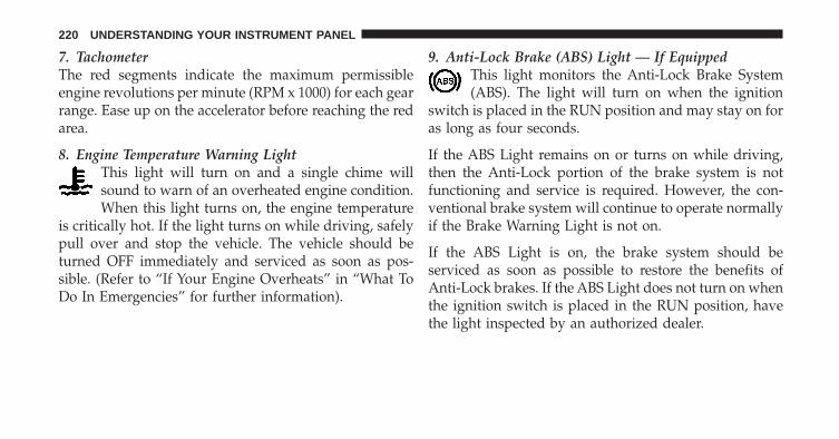
7. TachometerThe red segments indicate the maximum permissibleengine revolutions per minute (RPM x 1000) for each gearrange. Ease up on the accelerator before reaching the redarea.
8. Engine Temperature Warning LightThis light will turn on and a single chime willsound to warn of an overheated engine condition.When this light turns on, the engine temperature
is critically hot. If the light turns on while driving, safelypull over and stop the vehicle. The vehicle should beturned OFF immediately and serviced as soon as pos-sible. (Refer to “If Your Engine Overheats” in “What ToDo In Emergencies” for further information).
9. Anti-Lock Brake (ABS) Light — If EquippedThis light monitors the Anti-Lock Brake System(ABS). The light will turn on when the ignition
switch is placed in the RUN position and may stay on foras long as four seconds.
If the ABS Light remains on or turns on while driving,then the Anti-Lock portion of the brake system is notfunctioning and service is required. However, the con-ventional brake system will continue to operate normallyif the Brake Warning Light is not on.
If the ABS Light is on, the brake system should beserviced as soon as possible to restore the benefits ofAnti-Lock brakes. If the ABS Light does not turn on whenthe ignition switch is placed in the RUN position, havethe light inspected by an authorized dealer.
220 UNDERSTANDING YOUR INSTRUMENT PANEL

10. Electronic Stability Program (ESP) / Brake AssistSystem (BAS) Malfunction Indicator Light
The yellow Electronic Stability Program (ESP)/ Brake Assist System (BAS) Malfunction Indi-cator Light will turn on when the key in theignition switch is placed in the RUN position.
The light should go out with the engine running. Thesystem will turn this light on continuously while theengine is running if it detects a malfunction in either theESP, the BAS or both.
WARNING!
If a warning light remains on the system may not beworking and you will not have the benefit of ESP orBAS. Under certain driving conditions, where ESP orBAS would be beneficial, you - if you have notadjusted your driving speeds and stopping in or toaccount for the lack of the feature, may be in acci-dent.
11. Airbag Warning LightThis light will turn on for six to eight secondsas a bulb check when the ignition switch is firstplaced in the RUN position. If the light is eithernot on during starting, or stays on, or turns on
while driving, then have the system inspected at anauthorized dealer as soon as possible. Refer to “OccupantRestraints” in “Things To Know Before Starting YourVehicle” for further information.
4
UNDERSTANDING YOUR INSTRUMENT PANEL 221

12. Brake Warning LightThis light monitors various brake functions,including brake fluid level and parking brakeapplication. If the brake light turns on, it mayindicate that the parking brake is applied, that
the brake fluid level is low, or that there is a problem withthe anti-lock brake system reservoir.
If the light remains on when the parking brake has beendisengaged, and the fluid level is at the full mark on themaster cylinder reservoir, it indicates a possible brakehydraulic system malfunction. In this case, the light willremain on until the condition has been corrected.
The dual brake system provides a reserve braking capac-ity in the event of a failure to a portion of the hydraulicsystem. A leak in either half of the dual brake system isindicated by the Brake Warning Light which will turn onwhen the brake fluid level in the master cylinder hasdropped below a specified level.
The light will remain on until the cause is corrected.
NOTE: The light may flash momentarily during sharpcornering maneuvers which change fluid level condi-tions. The vehicle should have service performed, andthe brake fluid level checked.
If brake failure is indicated, immediate repair is neces-sary.
WARNING!
Driving a vehicle with the brake light on is danger-ous. Part of the brake system may have failed. It willtake longer to stop the vehicle. You could have anaccident. Have the vehicle checked immediately.
222 UNDERSTANDING YOUR INSTRUMENT PANEL

Vehicles equipped with the Anti-Lock Brake System(ABS), are also equipped with Electronic Brake ForceDistribution (EBD). In the event of an EBD failure, theBrake Warning Light will turn on along with the ABSLight. Immediate repair to the ABS system is required.
Operation of the Brake Warning Light can be checked byturning the ignition switch from the OFF position to theRUN position. The light should illuminate for approxi-mately two seconds. The light should then turn off unlessthe parking brake is applied or a brake fault is detected.If the light does not illuminate, have the light inspectedby an authorized dealer.
The light also will turn on when the parking brake isapplied with the ignition switch in the RUN position.
NOTE: This light shows only that the parking brake isapplied. It does not show the degree of brake application.
13. Electronic Stability Program (ESP) / TractionControl System (TCS) Indicator Light — If Equipped
If this indicator light flashes during accelera-tion, ease up on the accelerator and apply aslittle throttle as possible. Adapt your speed anddriving to the prevailing road conditions, and
do not switch off the Electronic Stability Program (ESP).
14. Temperature GaugeThe temperature gauge shows engine coolant tempera-ture. Any reading within the normal range indicates thatthe engine cooling system is operating satisfactorily.
The gauge pointer will likely indicate a higher tempera-ture when driving in hot weather, up mountain grades,or when towing a trailer. It should not be allowed toexceed the upper limits of the normal operating range.
4
UNDERSTANDING YOUR INSTRUMENT PANEL 223

CAUTION!
Driving with a hot engine cooling system coulddamage your vehicle. If the temperature gauge reads“H,” pull over and stop the vehicle. Idle the vehiclewith the air conditioner turned off until the pointerdrops back into the normal range. If the pointerremains on the “H,” and you hear continuous chimes,turn the engine OFF immediately and call for service.
WARNING!
A hot engine cooling system is dangerous. You orothers could be badly burned by steam or boilingcoolant. You may want to call a service center if yourvehicle overheats. If you decide to look under thehood yourself, refer to “Maintaining Your Vehicle”and follow the warnings under the Cooling SystemPressure Cap paragraph.
15. Trip Odometer Button
Trip Odometer Button — Base ClusterThe word �TRIP� will appear when this button is pressed.Push in and hold the button for two seconds when thetrip odometer displays to reset it to 0 miles (km). Asecond press of the button will display the outsidetemperature in the odometer.
Trip Odometer Button — Premium ClusterPress this button to change the display from odometer toeither of two trip odometer settings. The letter “A” or “B”will appear when in the trip odometer mode. Push in andhold the button for two seconds to reset the trip odometerto 0 miles (km). The odometer must be in TRIP mode toreset it.
224 UNDERSTANDING YOUR INSTRUMENT PANEL

16. High Beam IndicatorThis indicator will turn on when the high beamheadlights are ON. Push the multifunction lever
away from the steering wheel to switch the headlights tohigh beam.17. Shift Lever IndicatorThe Shift Lever Indicator is self-contained within theinstrument cluster. It displays the gear position of theautomatic transmission.
18. Seat Belt Reminder LightThis light will turn on for five to eight seconds asa bulb check when the ignition switch is firstplaced in the RUN position. A chime will sound if
the driver’s seat belt is unbuckled during the bulb check.The Seat Belt Reminder Light will flash or remain oncontinuously if the driver’s seat belt remains unbuckledafter the bulb check or when driving. Refer to “OccupantRestraints” in “Things To Know Before Starting YourVehicle” for further information.
19. Vehicle Security Light — If EquippedThe Vehicle Security Light flashes rapidlywhen the Vehicle Security Alarm is arming,and slowly when the Vehicle Security Alarm isarmed.
20. Fuel GaugeThe pointer shows the level of fuel in the fuel tank whenthe ignition switch is placed in the RUN position.
21. Electronic Throttle Control (ETC) LightThis light will turn on briefly as a bulb checkwhen the ignition switch is placed in the RUNposition. This light will also turn on while theengine is running if there is a problem with the
Electronic Throttle Control (ETC) system.
If the light comes on while the engine is running, safelybring the vehicle to a complete stop as soon as possible,place the shift lever in PARK, and cycle the ignitionthrough the ACC and RUN positions. The light should
4
UNDERSTANDING YOUR INSTRUMENT PANEL 225

turn off. If the light remains lit with the engine running,your vehicle will usually be drivable. However, see anauthorized dealer for service as soon as possible.
If the light is flashing when the engine is running,immediate service is required. In this case, you mayexperience reduced performance, an elevated/rough idleor engine stall, and your vehicle may require towing.
Also, have the system checked by an authorized dealer ifthe light does not come on during starting.
22. Tire Pressure Monitoring Telltale LightEach tire, including the spare (if provided),should be checked monthly when cold andinflated to the inflation pressure recommendedby the vehicle manufacturer on the vehicle
placard or tire inflation pressure label. (If your vehiclehas tires of a different size than the size indicated on the
vehicle placard or tire inflation pressure label, you shoulddetermine the proper tire inflation pressure for thosetires.)
As an added safety feature, your vehicle has beenequipped with a Tire Pressure Monitoring System(TPMS) that illuminates a low tire pressure telltale whenone or more of your tires is significantly under-inflated.Accordingly, when the low tire pressure telltale illumi-nates, you should stop and check your tires as soon aspossible, and inflate them to the proper pressure. Drivingon a significantly under-inflated tire causes the tire tooverheat and can lead to tire failure. Under-inflation alsoreduces fuel efficiency and tire tread life, and may affectthe vehicle’s handling and stopping ability.
Please note that the TPMS is not a substitute for propertire maintenance, and it is the driver’s responsibility to
226 UNDERSTANDING YOUR INSTRUMENT PANEL

maintain correct tire pressure, even if under-inflation hasnot reached the level to trigger illumination of the TPMSlow tire pressure telltale.
Your vehicle has also been equipped with a TPMSmalfunction indicator to indicate when the system is notoperating properly. The TPMS malfunction indicator iscombined with the low tire pressure telltale. When thesystem detects a malfunction, the telltale will flash forapproximately one minute and then remain continuouslyilluminated. This sequence will continue upon subse-quent vehicle start-ups as long as the malfunction exists.When the malfunction indicator is illuminated, the sys-tem may not be able to detect or signal low tire pressureas intended. TPMS malfunctions may occur for a varietyof reasons, including the installation of replacement oralternate tires or wheels on the vehicle that prevent theTPMS from functioning properly. Always check theTPMS malfunction telltale after replacing one or more
tires or wheels on your vehicle to ensure that the replace-ment or alternate tires and wheels allow the TPMS tocontinue to function properly.
CAUTION!
The TPMS has been optimized for the originalequipment tires and wheels. TPMS pressures andwarning have been established for the tire sizeequipped on your vehicle. Undesirable system opera-tion or sensor damage may result when using re-placement equipment that is not of the same size,type, and/or style. Aftermarket wheels can causesensor damage. Do not use aftermarket tire sealantsor balance beads if your vehicle is equipped with aTPMS, as damage to the sensors may result.
4
UNDERSTANDING YOUR INSTRUMENT PANEL 227

23. Charging System LightThis light shows the status of the electrical charg-ing system. The light should come on when the
ignition switch is first placed in the RUN position andremain on briefly as a bulb check. If the light stays on orcomes on while driving, turn off some of the vehicle’snon-essential electrical devices or increase engine speed(if at idle). If the charging system light remains on, itmeans that the vehicle is experiencing a problem with thecharging system. Obtain SERVICE IMMEDIATELY. Seean authorized dealer.
If jump starting is required, refer to “Jump StartingProcedures” in “What To Do In Emergencies”.
24. Malfunction Indicator Light (MIL)The Malfunction Indicator Light (MIL) is part ofan onboard diagnostic system called OBD. TheOBD system monitors engine and automatic
transmission control systems. The MIL will turn on when
the ignition is placed in the RUN position before enginestart. If the MIL does not come on when turning theignition from the OFF to RUN position, have the condi-tion checked promptly.
Certain conditions such as a loose or missing gas cap,poor fuel quality, etc., may illuminate the MIL afterengine start. The vehicle should be serviced if the MILstays on through several of your typical driving cycles. Inmost situations, the vehicle will drive normally and willnot require towing.
CAUTION!
Prolonged driving with the MIL on could causedamage to the engine control system. It also couldaffect fuel economy and drivability. If the MIL isflashing, severe catalytic converter damage andpower loss will soon occur. Immediate service isrequired.
228 UNDERSTANDING YOUR INSTRUMENT PANEL

WARNING!
A malfunctioning catalytic converter, as referencedabove, can reach higher temperatures than in normaloperating conditions. This can cause a fire if youdrive slowly or park over flammable substances suchas dry plants or wood or cardboard, etc. This couldresult in death or serious injury to the driver, occu-pants or others.
25. Oil Pressure Warning LightThis light indicates low engine oil pressure. Thelight should turn on momentarily when the engine
is started. If the light turns on while driving, stop thevehicle, and shut OFF the engine as soon as possible. Asingle chime will sound when this light turns on.
Do not operate the vehicle until the cause is corrected.This light does not indicate how much oil is in the engine.The engine oil level must be checked using the procedureshown in “Maintaining Your Vehicle”.
26. Door Ajar IndicatorThis light will turn on to indicate that one or moredoor may be ajar.
27. Decklid Ajar IndicatorThis light will turn on to indicate that thedecklid may be ajar.
28. Windshield Washer Fluid Low IndicatorThis light will turn on to indicate the windshieldwasher fluid is low.
4
UNDERSTANDING YOUR INSTRUMENT PANEL 229

ELECTRONIC VEHICLE INFORMATION CENTER(EVIC) — IF EQUIPPEDThe Electronic Vehicle Information Center (EVIC) fea-tures a driver-interactive display that is located in theinstrument cluster.
This system conveniently allows the driver to select avariety of useful information by pressing the switchesmounted on the steering wheel. The EVIC consists of thefollowing:
• System status
• Vehicle information warning message displays
• Tire Pressure Monitor System (if equipped)
• Personal Settings (Customer-Programmable Features)
• Compass display
• Outside temperature display
• Trip computer functions
• Uconnect™ Phone displays (if equipped)
• Navigation system screens (if equipped)
• Audio mode displayElectronic Vehicle Information Center (EVIC)
230 UNDERSTANDING YOUR INSTRUMENT PANEL

• Surround Sound modes (if equipped with Driver-Selectable Surround [DSS])
The system allows the driver to select information bypressing the following buttons mounted on the steeringwheel.
Press and release the MENU button and themode displayed will change between TripFunctions, Navigation (if equipped), SystemStatus, and Personal Settings.
Press the FUNCTION SELECT button to accepta selection. The FUNCTION SELECT buttonalso functions as a remote sound system con-trol. Refer to “Remote Sound System Controls”.
Press the SCROLL button to scroll through TripFunctions, Navigation (if equipped), SystemStatus Messages, and Personal Settings(Customer-Programmable Features). TheSCROLL button also functions as a remotesound system control. Refer to “Remote Sound
System Controls”.
Press the AUDIO MODE button to select theCompass/Temp/Audio screen. Along withcompass reading and outside temperature, thisscreen will display radio and media modeinformation depending on which radio is in thevehicle. Refer to “Remote Sound SystemControls”.
MENUButton
FUNCTIONSELECTButton
SCROLLButton
AUDIOMODEButton
4
UNDERSTANDING YOUR INSTRUMENT PANEL 231

Electronic Vehicle Information Center (EVIC)DisplaysWhen the appropriate conditions exist, the EVIC displaysthe following messages:
• Turn Signal On (with a continuous warning chime ifthe vehicle is driven more than 1 mile [1.6 km] witheither turn signal on)
• Left Front Turn Signal Light Out (with a single chime)
• Left Rear Turn Signal Light Out (with a single chime)
• Right Front Turn Signal Light Out (with a singlechime)
• Right Rear Turn Signal Light Out (with a single chime)
• Memory #1/#2 Profile Set
• Memory #1/#2 Profile Recall
• Memory System Disabled – Vehicle Not In PARK (witha single chime)
• Memory System Disabled – Seat Belt Buckled (with asingle chime)
• Personal Settings Not Available – Vehicle Not in PARK
• Left/Right Front Door Ajar (one or more, with a singlechime if speed is above 1 mph [1.6 km/h])
• Left/Right Rear Door Ajar (one or more, with a singlechime if speed is above 1 mph [1.6 km/h])
• Door(s) Ajar (with a single chime if vehicle is inmotion)
• Trunk Ajar (with a single chime)
• Low Washer Fluid (with a single chime)
• ECO – Fuel Saver Indicator
232 UNDERSTANDING YOUR INSTRUMENT PANEL

• SERVICE AWD SYSTEM — All Wheel Drive (AWD)system is not functioning properly and service isrequired.
• Normal Cruise Ready — When Adaptive Cruise Con-trol (ACC) system is turned off and Normal (FixedSpeed) Cruise Control mode is available. Refer to“Adaptive Cruise Control (ACC)” in “UnderstandingThe Features Of Your Vehicle” (if equipped).
• Cruise Off — When the Adaptive Cruise Control(ACC) system is turned off. Refer to “Adaptive CruiseControl (ACC)” in “Understanding The Features OfYour Vehicle” (if equipped).
• ACC Ready — When the ACC system is activated.Refer to “Adaptive Cruise Control (ACC)” in “Under-standing The Features Of Your Vehicle” (if equipped).
• ACC Set — After setting the desired speed in the ACCsystem. Refer to “Adaptive Cruise Control (ACC)” in“Understanding The Features Of Your Vehicle” (ifequipped).
• ACC Cancelled — To disable the ACC system. Refer to“Adaptive Cruise Control (ACC)” in “UnderstandingThe Features Of Your Vehicle” (if equipped).
• Sensed Vehicle Indicator — The system detects aslower moving vehicle in the same lane. Refer to“Adaptive Cruise Control (ACC)” in “UnderstandingThe Features Of Your Vehicle” (if equipped).
• Driver Override — If you apply the accelerator aftersetting the desired speed in the ACC system. Refer to“Adaptive Cruise Control (ACC)” in “UnderstandingThe Features Of Your Vehicle” (if equipped).
4
UNDERSTANDING YOUR INSTRUMENT PANEL 233

• Distance Set — After changing the desired followingdistance in the ACC system, this message will displaymomentarily. Refer to “Adaptive Cruise Control(ACC)” in “Understanding The Features Of YourVehicle” (if equipped).
• Attention — If the ACC system predicts that itsmaximum braking level is not sufficient to maintainthe set distance, this message will flash and a chimewill sound while ACC continues to apply its maxi-mum braking capacity. When this occurs, you shouldimmediately apply the brakes as needed to maintain asafe distance from the vehicle ahead. Refer to “Adap-tive Cruise Control (ACC)” in “Understanding TheFeatures Of Your Vehicle” (if equipped).
• ACC Blinded — If the ACC system deactivates due toperformance limiting conditions. Refer to “AdaptiveCruise Control (ACC)” in “Understanding The Fea-tures Of Your Vehicle” (if equipped).
• ACC Unavailable — If the ACC system turns off dueto a temporary malfunction that limits functionality.Refer to “Adaptive Cruise Control (ACC)” in “Under-standing The Features Of Your Vehicle” (if equipped).
• Service ACC — If the ACC system turns off due to aninternal system fault that requires service from anauthorized dealer. Refer to “Adaptive Cruise Control(ACC)” in “Understanding The Features Of YourVehicle” (if equipped).
• Adjustable Pedals Disabled – Cruise Engaged (with asingle chime) — only available on vehicles equippedwith memory seats.
• Adjustable Pedals Disabled – Vehicle In REVERSE(with a single chime) — only available on vehiclesequipped with memory seats.
• Channel # Transmit
• Channel # Training
234 UNDERSTANDING YOUR INSTRUMENT PANEL

• Channel # Trained
• Clearing Channels
• Channels Cleared
• Did Not Train
• Left Front Low Pressure (with a single chime). Refer toinformation on “Tire Pressure” and “Tire PressureMonitor” under “Starting And Operating.”
• Left Rear Low Pressure (with a single chime). Refer toinformation on “Tire Pressure” and “Tire PressureMonitor” under “Starting And Operating.”
• Right Front Low Pressure (with a single chime). Referto information on “Tire Pressure” and “Tire PressureMonitor” under “Starting And Operating.”
• Right Rear Low Pressure (with a single chime). Referto information on “Tire Pressure” and “Tire PressureMonitor” under “Starting And Operating.”
• Check TPM System (with a single chime). Refer toinformation on “Tire Pressure Monitor” under “Start-ing And Operating.”
• Check Gascap (refer to “Adding Fuel” in “StartingAnd Operating”)
• Service Park Assist System (with a single chime)
• Turn To Run (refer to “Remote Starting System” in“Things To Know Before Starting Your Vehicle”)
• Key Fob Battery Low
• Service Keyless System
• Wrong Key
• Push Button or Insert Key/Turn To Run (refer to“Remote Starting System” in “Things To Know BeforeStarting Your Vehicle”)
• Oil Change Required (with a single chime)
4
UNDERSTANDING YOUR INSTRUMENT PANEL 235

Oil Change RequiredYour vehicle is equipped with an engine oil changeindicator system. The “Oil Change Required” messagewill flash in the EVIC display for approximately 10 sec-onds after a single chime has sounded to indicate the nextscheduled oil change interval. The engine oil changeindicator system is duty cycle based, which means theengine oil change interval may fluctuate dependent uponyour personal driving style.
Unless reset, this message will continue to display eachtime you turn the ignition switch to the RUN position. Toturn off the message temporarily, press and release theMENU button. To reset the oil change indicator system(after performing the scheduled maintenance) performthe following procedure:
1. Place the ignition switch in the RUN position (Do notstart the engine).
2. Fully depress the accelerator pedal slowly three timeswithin 10 seconds.
3. Place the ignition in the OFF position.
NOTE: If the indicator message illuminates when youstart the vehicle, the oil change indicator system did notreset. If necessary, repeat this procedure.
Trip FunctionsPress and release the MENU button until one of thefollowing Trip Functions displays in the EVIC:
• Average Fuel Economy / Fuel Saver Mode
• Distance To Empty
• Trip A
• Trip B
• Elapsed Time
236 UNDERSTANDING YOUR INSTRUMENT PANEL

• Display Units of Measure in
Press the SCROLL button to cycle through all the TripComputer functions.
The Trip Functions mode displays the following informa-tion.
• Average Fuel Economy / Fuel Saver Mode — IfEquipped
Shows the average fuel economy since the last reset.When the fuel economy is reset, the display will read“RESET” or show dashes for two seconds. Then, thehistory information will be erased, and the averaging willcontinue from the last fuel average reading before thereset.
The FUEL SAVER MODE message will display above theaverage fuel economy in the EVIC display. This message
will appear whenever MDS (if equipped) allows theengine to operate on four cylinders, or if you are drivingin a fuel efficient manner.
Fuel Saver Mode — On
4
UNDERSTANDING YOUR INSTRUMENT PANEL 237

This feature allows you to monitor when you are drivingin a fuel efficient manner, and it can be used to modifydriving habits in order to increase fuel economy.
• Distance To Empty (DTE)Shows the estimated distance that can be traveled withthe fuel remaining in the tank. This estimated distance isdetermined by a weighted average of the instantaneousand average fuel economy, according to the current fueltank level. DTE cannot be reset through the FUNCTIONSELECT button.
NOTE: Significant changes in driving style or vehicleloading will greatly affect the actual drivable distance ofthe vehicle, regardless of the DTE displayed value.
When the DTE value is less than 30 miles (48 km)estimated driving distance, the DTE display will changeto a text display of �LOW FUEL.� This display willcontinue until the vehicle runs out of fuel. Adding asignificant amount of fuel to the vehicle will turn off the�LOW FUEL� text and a new DTE value will display.
Fuel Saver Mode — Off
238 UNDERSTANDING YOUR INSTRUMENT PANEL

• Trip AShows the total distance traveled for Trip A since the lastreset.
• Trip BShows the total distance traveled for Trip B since the lastreset.
• Elapsed TimeShows the total elapsed time of travel since the last resetwhen the ignition switch is in the ACC position. Elapsedtime will increment when the ignition switch is in theRUN or START position.
• Display Units of Measure inTo make your selection, press and release the FUNC-TION SELECT button until “ENGLISH” or “METRIC”appears.
To Reset The DisplayReset will only occur while a resettable function is beingdisplayed. Press and release the FUNCTION SELECTbutton once to clear the resettable function being dis-played. To reset all resettable functions, press and releasethe FUNCTION SELECT button a second time withinthree seconds of resetting the currently-displayed func-tion. (Reset ALL will display during this three-secondwindow).
4
UNDERSTANDING YOUR INSTRUMENT PANEL 239

Keyless Go Display — If EquippedWhen the ENGINE START/STOP button is pressed tochange ignition switch positions, the Keyless Go iconmomentarily appears in the EVIC display showing thenew ignition switch position.
The round symbol in the middle rotates to point at thenew ignition switch position. If desired, the ignitionswitch position graphic can be set to be constantly visibleby pressing the EVIC MENU button until the displayappears.
Refer to “Keyless Go” in “Starting And Operating” formore information.
NOTE: Under certain conditions, the display may besuperseded by another display of higher priority. Butwhen the ignition switch position is changed, the displayalways re-appears.
Keyless Go Display
240 UNDERSTANDING YOUR INSTRUMENT PANEL

Automatic All Wheel Drive (AWD) Displays — IfEquippedAutomatic AWD operation could be activated by outsidetemperature, wheel slip, or other predetermined condi-tions, when the vehicle automatically transitions fromRWD to AWD the EVIC will display the followingmessage for five seconds.
When the vehicle automatically transitions from AWD toRWD the EVIC will display the following message forfive seconds.
Refer to “All Wheel Drive — If Equipped” in “StartingAnd Operating” for more information on the All WheelDrive (AWD) system.
Rear Wheel Drive (RWD) to All Wheel Drive (AWD)
All Wheel Drive (AWD) to Rear Wheel Drive (RWD)
4
UNDERSTANDING YOUR INSTRUMENT PANEL 241

Driver-Selectable Surround Sound (DSS) – IfEquippedPress and release the MENU button until “SurroundSound” displays in the EVIC. The EVIC provides infor-mation on the current surround mode.
• Stereo
• Video Surround
• Audio Surround
While in the Surround Sound menu, press the FUNC-TION SELECT button to change surround modes. TheVideo Surround Mode will only be available for videomedia sources (DVDs, Video CDs, or other video mediasupported by the radio).
Compass DisplayThe compass readings indicate the directionthe vehicle is facing. Press and release theHOME button to display one of eight compassreadings and the outside temperature.
NOTE: The system will display the last known outsidetemperature when starting the vehicle and may need tobe driven several minutes before the updated tempera-ture is displayed. Engine temperature can also affect thedisplayed temperature, therefore temperature readingsare not updated when the vehicle is not moving.
Automatic Compass CalibrationThis compass is self-calibrating, which eliminates theneed to set the compass manually. When the vehicle isnew, the compass may appear erratic and the EVIC willdisplay “CAL” until the compass is calibrated. You mayalso calibrate the compass by completing one or more 360
HOMEButton
242 UNDERSTANDING YOUR INSTRUMENT PANEL

degree turns (in an area free from large metal or metallicobjects) until the “CAL” message displayed in the EVICturns off. The compass will now function normally.
Manual Compass CalibrationIf the compass appears erratic and the “CAL” messagedoes not appear in the EVIC display, you must put thecompass into the Calibration Mode manually as follows:
1. Place the ignition switch in the RUN position.
2. Press and hold the HOME button for approximatelytwo seconds.
3. Press the SCROLL button until “Calibrate Compass”displays in the EVIC.
4. Press and release the FUNCTION SELECT button tostart the calibration. The message “CAL” will display inthe EVIC.
5. Complete one or more 360 degree turns (in an area freefrom large metal or metallic objects) until the “CAL”message turns off. The compass will now functionnormally.
Compass VarianceCompass Variance is the difference between MagneticNorth and Geographic North. To compensate for thedifferences, the variance should be set for the zone wherethe vehicle is driven, per the zone map. Once properlyset, the compass will automatically compensate for thedifferences and provide the most accurate compass head-ing.
4
UNDERSTANDING YOUR INSTRUMENT PANEL 243

NOTE: Keep magnetic materials away from the top ofthe instrument panel, such as iPod’s, Cell Phones, Lap-tops and Radar Detectors. This is where the compassmodule is located, and it can cause interference with thecompass sensor, and it may give false readings.
1. Place the ignition switch in the RUN position.
2. Press and hold the HOME button for approximatelytwo seconds.
3. Press the SCROLL button until “Compass Variance”message and the last variance zone number displays inthe EVIC.
4. Press and release FUNCTION SELECT button untilthe proper variance zone is selected according to themap.
5. Press and release the HOME button to exit.
Navigation — If Equipped
Navigation Display ControlPress and release the MENU button until Navigationdisplays in the EVIC. When the Navigation System is On,the steering wheel buttons can be used to select the Mapor Menu display on the Navigation Unit. When the Menudisplay is active, the SCROLL button can be used to scrollthrough the list, the FUNCTION SELECT button can be
Compass Variance Map
244 UNDERSTANDING YOUR INSTRUMENT PANEL

used to select an item, and the AUDIO MODE button canbe used to return to the previous menu. When the Mapdisplay is active, pressing the FUNCTION SELECT but-ton will change the Navigation Unit Display to the Menu.
Turn-by-Turn DirectionsThe EVIC displays turn-by-turn directions to a pro-grammed destination when Turn-by-Turn Navigation isenabled through Personal Settings. When enabled, theEVIC displays the name of the approaching road at thetop of the screen, followed by an arrow to indicate thedirection to turn the vehicle, and a count down toindicate the distance to the turn.
NOTE: Refer to your “Navigation User’s Manual” fordetailed operating instructions.
Personal Settings (Customer-ProgrammableFeatures)Personal Settings allows the driver to set and recallfeatures when the transmission is in PARK.
Press and release the MENU button until Personal Set-tings displays in the EVIC.
Use the SCROLL button to display one of the followingchoices.
“Language”When in this display you may select one of five lan-guages for all display nomenclature, including the tripfunctions and the navigation system (if equipped). Pressthe FUNCTION SELECT button while in this display toselect English, Espanol, Deutsch, Italiano, or Francais.Then, as you continue, the information will display in theselected language.
NOTE: The EVIC will not change the Uconnect™ lan-guage selection.
4
UNDERSTANDING YOUR INSTRUMENT PANEL 245

“Lock Doors Automatically at 15 mph (24 km/h)”When ON is selected, all doors will lock automaticallywhen the vehicle reaches a speed of 15 mph (24 km/h).To make your selection, press and release the FUNC-TION SELECT button until “ON” or “OFF” appears.
“Unlock Doors Automatically on Exit”When ON is selected, all doors will unlock when thevehicle is stopped and the transmission is in the PARK orNEUTRAL position and the driver’s door is opened. Tomake your selection, press and release the FUNCTIONSELECT button until “ON” or “OFF” appears.
“Remote Key Unlock”When Driver Door 1st Press is selected, only the driver’sdoor will unlock on the first press of the Remote KeylessEntry (RKE) transmitter UNLOCK button. When DriverDoor 1st Press is selected, you must press the RKEtransmitter UNLOCK button twice to unlock the passen-ger’s doors. When All Doors 1st Press is selected, all of
the doors will unlock on the first press of the RKEtransmitter UNLOCK button. To make your selection,press and release the FUNCTION SELECT button until“Driver Door 1st Press” or “All Doors 1st Press” appears.
NOTE: If the vehicle is equipped with Passive Entryand the EVIC is programmed to Unlock All Doors 1stPress, all doors will unlock no matter which PassiveEntry equipped door handle is grasped. If Driver Door1st Press is programmed, only the driver’s door willunlock when the driver’s door is grasped. With PassiveEntry, if Driver Door 1st Press is programmed touchingthe handle more than once will only result in the driver’sdoor opening. You have to touch a passenger PassiveEntry equipped door handle to unlock all doors passivelywhen Driver’s Door Only is programmed in the EVIC.
246 UNDERSTANDING YOUR INSTRUMENT PANEL

“Recall Memory with Remote Key Unlock” — IfEquippedWhen ON is selected, you can use your RKE transmitterto recall one of two pre-programmed memory profiles.Each memory profile contains desired position settingsfor the driver seat, side mirror, adjustable pedals (ifequipped), power tilt and telescopic steering column (ifequipped), and a set of desired radio station presets.When OFF is selected, only the MEMORY switch on thedriver’s door trim panel will recall memory profiles. Tomake your selection, press and release the FUNCTIONSELECT button until “ON” or “OFF” appears. Refer to“Driver Memory Seat” in “Understanding The FeaturesOf Your Vehicle”.
“Sound Horn with Remote Key Lock”When ON is selected, a short horn sound will occur whenthe RKE LOCK button is pressed. This feature may beselected with or without the Flash Lights with Remote
Key Lock feature. To make your selection, press andrelease the FUNCTION SELECT button until “ON” or“OFF” appears.
“Rain Sensing Intermittent Wipers” — If EquippedWhen ON is selected, the system will automaticallyactivate the windshield wipers if it senses moisture onthe windshield. To make your selection, press and releasethe FUNCTION SELECT button until “ON” or “OFF”appears. When OFF is selected, the system reverts to thestandard intermittent wiper operation.
“Automatically Move Seat Back on Exit” — IfEquippedThis feature provides automatic driver seat positioning toenhance driver mobility when entering and exiting thevehicle. To make your selection, press and release theFUNCTION SELECT button until “ON” or “OFF” ap-pears.
4
UNDERSTANDING YOUR INSTRUMENT PANEL 247

NOTE: The seat will return to the memorized seatlocation (if Recall Memory with Remote Key Unlock is setto ON) when the RKE transmitter is used to unlock thedoor. Refer to “Driver Memory Seat” in “UnderstandingThe Features Of Your Vehicle” for further information.
“Flash Lights with Remote Key Lock”When ON is selected, the front and rear turn signals willflash when the doors are locked or unlocked with theRKE transmitter. This feature may be selected with orwithout the sound horn on lock feature selected. To makeyour selection, press and release the FUNCTION SE-LECT button until “ON” or “OFF” appears.
“Headlights On with Wipers” (Available with AutoHeadlights Only)When ON is selected, and the HEADLIGHT switch is inthe AUTO position, the headlights will turn on approxi-mately 10 seconds after the wipers are turned on. Theheadlights will also turn off when the wipers are turned
off if they were turned on by this feature. To make yourselection, press and release the FUNCTION SELECTbutton until “ON” or “OFF” appears.
NOTE: Turning the headlights on during the daytimecauses the instrument panel lights to dim. To increase thebrightness, refer to “Lights” in “Understanding TheFeatures Of Your Vehicle”.
“Delay Turning Headlights Off”When this feature is selected, the driver can choose tohave the headlights remain on for 0, 30, 60, or 90 secondswhen exiting the vehicle. To make your selection, pressand release the FUNCTION SELECT button until “0,”“30,” “60,” or “90” appears.
“Tilt Mirrors Down in Reverse” — If EquippedWhen ON is selected, the outside rearview mirrors willtilt downward when the ignition switch is in the RUNposition and the transmission is in the REVERSE posi-tion. The mirrors will move back to their previous
248 UNDERSTANDING YOUR INSTRUMENT PANEL

position when the transmission is shifted out of RE-VERSE. To make your selection, press and release theFUNCTION SELECT button until “ON” or “OFF”appears.
“Turn Headlights On with Remote Key Unlock”When this feature is selected, the headlights will activateand remain on for up to 90 seconds when the doors areunlocked with the RKE transmitter. To make your selec-tion, press and release the FUNCTION SELECT buttonuntil “OFF,” “30 sec.,” “60 sec.,” or “90 sec.” appears.
“Delay Power Off to Accessories Until Exit”When this feature is selected, the power WINDOWswitches, radio, hands-free system (if equipped), DVDvideo system (if equipped), power sunroof (if equipped),and power outlets will remain active for up to 60 minutesafter the ignition switch is placed in the OFF position.Opening a vehicle door will cancel this feature. To make
your selection, press and release the FUNCTION SE-LECT button until “Off,” “45 sec.,” “5 min.,” “10 min.,”“30 min.,” or “60 min.” appears.
“AWD System Displays”When in this display you may select “ON” or “OFF”.When ON is selected, the EVIC displays the currentmode of the transfer-case. A five second display appearsany time the transfer-case changes from All Wheel Drive(AWD) to Rear Wheel Drive (RWD) or from RWD toAWD. The EVIC also displays the current mode of thetransfer-case when you shift into drive or reverse. Tomake your selection, press and release the FUNCTIONSELECT button until “ON” or “OFF” appears.
4
UNDERSTANDING YOUR INSTRUMENT PANEL 249

“Confirmation of Voice Commands” — IfEquippedWhen ON is selected, all voice commands from theUconnect™ system are confirmed. To make your selec-tion, press and release the FUNCTION SELECT buttonuntil “ON” or “OFF” appears.
“Park Assist System” — If EquippedWhen ON is selected, the system will scan for objectsbehind the vehicle when the transmission is in theREVERSE or NEUTRAL position. To make your selec-tion, press and release the FUNCTION SELECT buttonuntil “ON” or “OFF” appears.
“Turn-by-Turn Navigation” — If EquippedWhen ON is selected, the turn-by-turn directions willappear in the display as the vehicle approaches a desig-nated turn within a programmed route. To make yourselection, press and release the FUNCTION SELECTbutton until “ON” or “OFF” appears.
“Display ECO” — If EquippedThe “ECO” message is located in the Compass/Temperature display, this message can be turned on oroff. To make your selection, press and release the FUNC-TION SELECT button until “ON” or “OFF” appears.
“Display Units of Measure in”The EVIC, odometer, and navigation system (ifequipped) can be changed between English and Metricunits of measure. To make your selection, press andrelease the FUNCTION SELECT button until “EN-GLISH” or “METRIC” appears.
“Automatic High Beams” — If EquippedWhen this feature is selected, the high beam headlightswill deactivate automatically under certain conditions. Tomake your selection, press and release the FUNCTIONSELECT button until “ON” or “OFF” appears. Refer to“SmartBeam™” in “Understanding The Features Of YourVehicle” for further information.
250 UNDERSTANDING YOUR INSTRUMENT PANEL

“Passive Entry” — If EquippedThe Passive Entry system is an enhancement to thevehicle’s Remote Keyless Entry (RKE) system. When ONis selected, this feature allows you to lock and unlock thevehicle’s door(s) without having to press the RKE trans-mitter lock or unlock buttons. To make your selection,press and release the FUNCTION SELECT button until“ON” or “OFF” appears. Refer to “Door Locks/PassiveEntry — If Equipped” in “Things To Know BeforeStarting Your Vehicle” for further information.
SETTING THE ANALOG CLOCKTo set the analog clock at the top center of the instrumentpanel, press and hold the button until the setting iscorrect.
Analog Clock
4
UNDERSTANDING YOUR INSTRUMENT PANEL 251

MEDIA CENTER 730N/430 (RER/REN/RBZ) —AM/FM STEREO RADIO AND CD/DVD/HDD/NAV —IF EQUIPPED
NOTE: The sales code is located on the lower right sideof the unit’s faceplate.
The REN, RER and RBZ radios contain a CD/DVDplayer, USB port, and a 30-gigabyte hard drive (HDD).Sirius Satellite Radio is optional. The 6.5 in (16.5 cm)touch screen allows for easy menu selection.
The RER radio also contains a Global Positioning System(GPS)-based Navigation system.
Refer to your Uconnect™ Multimedia REN, RER or RBZuser’s manual for detailed operating instructions.
Operating Instructions — Voice CommandSystem — If EquippedFor the radio, refer to “Voice Command” in “Understand-ing The Features Of Your Vehicle”.
Operating Instructions — Uconnect™ Phone —If EquippedRefer to “Uconnect™ Phone” in “Understanding TheFeatures Of Your Vehicle”.
Clock Setting Procedure — RBZ Radio
To Manually Set the Clock
1. Turn on the radio.
2. Touch the screen where the time is displayed, the clocksetting menu will appear on the screen.
3. To move the hour forward, touch the screen where theword “Hour” with the arrow pointing upward is dis-played. To move the hour backward, touch the screenwhere the word “Hour” with the arrow pointing down-ward is displayed.
4. To move the minute forward, touch the screen wherethe word “Min” with the arrow pointing upward is
252 UNDERSTANDING YOUR INSTRUMENT PANEL

displayed. To move the minute backward, touch thescreen where the word “Min” with the arrow pointingdownward is displayed.
5. To save the new time setting, touch the screen wherethe word “Save” is displayed.
Changing Daylight Savings TimeWhen selected, this feature will display the time of day indaylight savings time. Proceed as follows to change thecurrent setting:
1. Turn on the radio.
2. Touch the screen where the time is displayed. Theclock setting menu will appear on the screen.
3. When this feature is on, a check mark will appear inthe box next to the words “Daylight Savings.” Touch thescreen where the words “Daylight Savings” are dis-played to change the current setting.
Show Time if Radio is OffWhen selected, this feature will display the time of dayon the touch screen when the radio is turned off. Proceedas follows to change the current setting:
1. Turn on the radio.
2. Touch the screen where the time is displayed. Theclock setting menu will appear on the screen.
3. When this feature is on, a check mark will appear inthe box next to the words “Show Time if Radio is Off.”Touch the screen where the words “Show Time if Radio isOff” are displayed to change the current setting.
Changing the Time Zone
1. Turn on the radio.
2. Touch the screen where the time is displayed. Theclock setting menu will appear on the screen.
4
UNDERSTANDING YOUR INSTRUMENT PANEL 253

3. Touch the screen where the words “Set Time Zone” aredisplayed. The time zone selection menu will appear onthe screen.
4. Select a time zone by touching the screen where yourselection appears. If you do not see a time zone that youwant to select, touch the screen where the word “Page” isdisplayed to view additional time zones in the menu.
5. Touch the screen where the word “Save” is displayed.
Clock Setting Procedure — RER/REN Radio
Uconnect� gps — RER OnlyThe GPS receiver used in this system is synchronized tothe time data being transmitted by the GPS satellite. Thesatellite clock is Greenwich Mean Time (GMT). This is theworldwide standard for time. This makes the system’sclock very accurate once the appropriate time zone anddaylight savings information is set.
To Manually Set the Clock — RER/REN
1. Turn on the radio.
2. Touch the screen where the time is displayed.
3. Touch the screen where “User Clock” is displayed, theclock setting menu will appear on the screen.
4. To move the hour forward, touch the screen where theword “Hour” with the arrow pointing upward is dis-played. To move the hour backward, touch the screenwhere the word “Hour” with the arrow pointing down-ward is displayed.
5. To move the minute forward, touch the screen wherethe word “Min” with the arrow pointing upward isdisplayed. To move the minute backward, touch thescreen where the word “Min” with the arrow pointingdownward is displayed.
254 UNDERSTANDING YOUR INSTRUMENT PANEL

6. To save the new time setting, touch the screen wherethe word “Save” is displayed.
Changing Daylight Savings TimeWhen selected, this feature will display the time of day indaylight savings time. Proceed as follows to change thecurrent setting:
1. Turn on the radio.
2. Touch the screen where “User Clock” is displayed, theclock setting menu will appear on the screen.
3. When this feature is on, a check mark will appear inthe box next to the words “Daylight Savings.” Touch thescreen where the words “Daylight Savings” are dis-played to change the current setting.
Show Time if Radio is OffWhen selected, this feature will display the time of dayon the touch screen when the radio is turned off. Proceedas follows to change the current setting:
1. Turn on the radio.
2. Touch the screen where the time is displayed.
3. Touch the screen where “User Clock” is displayed, theclock setting menu will appear on the screen.
4. When this feature is on, a check mark will appear inthe box next to the words “Show Time if Radio is Off.”Touch the screen where the words “Show Time if Radio isOff” are displayed to change the current setting.
Changing the Time Zone
1. Turn on the radio.
2. Touch the screen where the time is displayed.
3. Touch the screen where “User Clock” is displayed, theclock setting menu will appear on the screen.
4
UNDERSTANDING YOUR INSTRUMENT PANEL 255

4. Touch the screen where the words “Set Time Zone” aredisplayed. The time zone selection menu will appear onthe screen.
5. Select a time zone by touching the screen where yourselection appears. If you do not see a time zone that youwant to select, touch the screen where the word “Page” isdisplayed to view additional time zones in the menu.
6. Touch the screen where the word “Save” is displayed.
MEDIA CENTER 130 (RES) — AM/FM STEREORADIO WITH CD PLAYER (MP3 AUX JACK)
NOTE: The radio sales code is located on the lower rightside of the radio faceplate. Operating Instructions — Radio Mode
NOTE: The ignition switch must be in the ON or ACCposition to operate the radio.
RES Radio
256 UNDERSTANDING YOUR INSTRUMENT PANEL

Power Switch/Volume Control (Rotary)Push the ON/VOLUME control knob to turn on theradio. Push the ON/VOLUME control knob a secondtime to turn off the radio.
Electronic Volume ControlThe electronic volume control turns continuously (360degrees) in either direction, without stopping. Turningthe ON/VOLUME control knob to the right increases thevolume, and to the left decreases it.
When the audio system is turned on, the sound will beset at the same volume level as last played.
SEEK ButtonsPress and release the SEEK buttons to search for the nextlistenable station in AM/FM mode. Press the right switchto seek up and the left switch to seek down. The radiowill remain tuned to the new station until you makeanother selection. Holding either button will bypassstations without stopping, until you release it.
TIME ButtonPress the TIME button to alternate display of the timeand radio frequency.
Clock Setting Procedure
1. Press and hold the TIME button until the hours blink.
2. Adjust the hours by turning the right side TUNE/SCROLL control knob.
3. After adjusting the hours, press the right side TUNE/SCROLL control knob to set the minutes. The minuteswill begin to blink.
4. Adjust the minutes using the right side TUNE/SCROLL control knob. Press the TUNE/SCROLL controlknob to save time change.
5. To exit, press any button/knob, or wait five seconds.
4
UNDERSTANDING YOUR INSTRUMENT PANEL 257

RW/FFPressing the RW (Rewind) or FF (Fast Forward) buttonscauses the tuner to search for the next frequency in thedirection of the arrows. This feature operates in eitherAM or FM frequencies.
TUNE ControlTurn the rotary TUNE/SCROLL control knob clockwiseto increase or counterclockwise to decrease the frequency.
Setting the Tone, Balance, and FadePush the rotary TUNE/SCROLL control knob and BASSwill display. Turn the TUNE/SCROLL control knob tothe right or left to increase or decrease the bass tones.
Push the rotary TUNE/SCROLL control knob a secondtime and MID will display. Turn the TUNE/SCROLLcontrol knob to the right or left to increase or decrease themid-range tones.
Push the rotary TUNE/SCROLL control knob a thirdtime and TREBLE will display. Turn the TUNE/SCROLLcontrol knob to the right or left to increase or decrease thetreble tones.
Push the rotary TUNE/SCROLL control knob a fourthtime and BALANCE will display. Turn the TUNE/SCROLL control knob to the right or left to adjust thesound level from the right or left side speakers.
Push the rotary TUNE/SCROLL control knob a fifth timeand FADE will display. Turn the TUNE/SCROLL controlknob to the left or right to adjust the sound level betweenthe front and rear speakers.
Push the rotary TUNE/SCROLL control knob again toexit setting tone, balance, and fade.
AM/FM ButtonPress the buttons to select either AM or FM mode.
258 UNDERSTANDING YOUR INSTRUMENT PANEL

SET/RND Button — To Set the PushbuttonMemoryWhen you are receiving a station that you wish tocommit to pushbutton memory, press the SET/RNDbutton. The symbol SET 1 will now show in the displaywindow. Select the button (1 to 6) you wish to lock ontothis station and press and release that button. If a buttonis not selected within five seconds after pressing theSET/RND button, the station will continue to play butwill not be stored into pushbutton memory.
You may add a second station to each pushbutton byrepeating the above procedure with this exception: Pressthe SET/RND button twice and SET 2 will show in thedisplay window. Each button can be set for SET 1 andSET 2 in both AM and FM. This allows a total of 12 AMand 12 FM stations to be stored into pushbutton memory.The stations stored in SET 2 memory can be selected bypressing the pushbutton twice.
Every time a preset button is used, a correspondingbutton number will display.
Buttons 1 - 6These buttons tune the radio to the stations that youcommit to pushbutton memory (12 AM and 12 FMstations).
DISC ButtonPressing the DISC button will allow you to switch fromAM/FM modes to Disc modes.
Operation Instructions — CD MODE For CD AndMP3 Audio Play
NOTE:• The ignition switch must be in the ON or ACC
position to operate the radio.
• This radio is capable of playing compact discs (CD),recordable compact discs (CD-R), rewritable compact
4
UNDERSTANDING YOUR INSTRUMENT PANEL 259

discs (CD-RW), compact discs with MP3 tracks andmultisession compact discs with CD and MP3 tracks.
Inserting Compact Disc(s)Gently insert one CD into the CD player with the CDlabel facing up. The CD will automatically be pulled intothe CD player and the CD icon will illuminate on theradio display. If a CD does not go into the slot more than1.0 in (2.5 cm), a disc may already be loaded and must beejected before a new disc can be loaded.
If you insert a disc with the ignition ON and the radioON, the unit will switch from radio to CD mode andbegin to play when you insert the disc. The display willshow the track number, and index time in minutes andseconds. Play will begin at the start of track 1.
CAUTION!
• This CD player will accept 4-3/4 in (12 cm) discsonly. The use of other sized discs may damage theCD player mechanism.
• Do not use adhesive labels. These labels can peelaway and jam the player mechanism.
• RES is a single CD player. Do not attempt to inserta second CD if one is already loaded.
• Dual-media disc types (one side is a DVD, theother side is a CD) should not be used, and theycan cause damage to the player.
260 UNDERSTANDING YOUR INSTRUMENT PANEL

EJECT Button - Ejecting a CDPress the EJECT button to eject the CD.
If you have ejected a disc and have not removed it within10 seconds, it will be reloaded. If the CD is not removed,the radio will reinsert the CD but will not play it.
A disc can be ejected with the radio and ignition OFF.
NOTE: Ejecting with the ignition OFF is not allowed onconvertible or soft-top models (if equipped).
SEEK ButtonPress the right SEEK button for the next selection on theCD. Press the left SEEK button to return to the beginningof the current selection, or return to the beginning of theprevious selection if the CD is within the first second of
the current selection. Pressing and holding the SEEKbutton will allow faster scrolling through the tracks inCD and MP3 modes.
TIME ButtonPress this button to change the display from a large CDplaying time display to a small CD playing time display.RW/FFPress and hold the FF (Fast Forward) button and the CDplayer will begin to fast forward until FF is released, orRW or another CD button is pressed. The RW (Reverse)button works in a similar manner.
AM/FM ButtonPress the button to select either AM or FM mode.
SET/RND Button (Random Play Button)Press this button while the CD is playing to activateRandom Play. This feature plays the selections on thecompact disc in random order to provide an interestingchange of pace.
4
UNDERSTANDING YOUR INSTRUMENT PANEL 261

Press the right SEEK button to move to the next ran-domly selected track.
Press the RND button a second time to stop RandomPlay.
Notes on Playing MP3 FilesThe radio can play MP3 files; however, acceptable MP3file recording media and formats are limited. Whenwriting MP3 files, pay attention to the following restric-tions.
Supported Media (Disc Types)The MP3 file recording media supported by the radio areCDDA, CD-R, CD-RW, MP3, and CDDA+MP3.
Supported Medium Formats (File Systems)The medium formats supported by the radio are ISO 9660Level 1 and Level 2 and includes the Joliet extension.When reading discs recorded using formats other thanISO 9660 Level 1 and Level 2, the radio may fail to read
files properly and may be unable to play the file nor-mally. UDF and Apple HFS formats are not supported.
The radio uses the following limits for file systems:
• Maximum number of folder levels: 8
• Maximum number of files: 255
• Maximum number of folders. (The radio display of filenames and folder names is limited. For large numbersof files and/or folders, the radio may be unable todisplay the file name and folder name, and will assigna number instead. With a maximum number of files,exceeding 20 folders will result in this display. With200 files, exceeding 50 folders will result in thisdisplay.)
• Maximum number of characters in file/folder names:
• Level 1: 12 (including a separator �.� and a three-character extension)
262 UNDERSTANDING YOUR INSTRUMENT PANEL

• Level 2: 31 (including a separator �.� and a three-character extension)
Multisession disc formats are supported by the radio.Multisession discs may contain combinations of normalCD audio tracks and computer files (including MP3 files).Discs created with an option such as �keep disc open afterwriting� are most likely multisession discs. The use ofmultisession for CD audio or MP3 playback may result inlonger disc loading times.
Supported MP3 File FormatsThe radio will recognize only files with the *.MP3 exten-sion as MP3 files. Non-MP3 files named with the *.MP3extension may cause playback problems. The radio isdesigned to recognize the file as an invalid MP3 and willnot play the file.
When using the MP3 encoder to compress audio data toan MP3 file, the bit rate and sampling frequencies in thefollowing table are supported. In addition, variable bit
rates (VBR) are also supported. The majority of MP3 filesuse a 44.1 kHz sampling rate and a 192, 160, 128, 96 orVBR bit rate.
MPEGSpecification
SamplingFrequency (kHz) Bit Rate (kbps)
MPEG-1 AudioLayer 3 48, 44.1, 32
320, 256, 224,192, 160, 128,
112, 96, 80, 64,56, 48, 40, 32
MPEG-2 AudioLayer 3 24, 22.05, 16
160, 128, 144,112, 96, 80, 64,
56, 48, 40, 32, 24,16, 8
ID3 Tag information for artist, song title, and album titleare supported for version 1 ID3 tags. ID3 version 2 is notsupported by the radios.
Playlist files are not supported. MP3 Pro files are notsupported.
4
UNDERSTANDING YOUR INSTRUMENT PANEL 263

Playback of MP3 FilesWhen a medium containing MP3 data is loaded, theradio checks all files on the medium. If the mediumcontains a lot of folders or files, the radio will take moretime to start playing the MP3 files.
Loading times for playback of MP3 files may be affectedby the following:
• Media - CD-RW media may take longer to load thanCD-R media
• Medium formats - Multisession discs may take longerto load than non-multisession discs
• Number of files and folders - Loading times willincrease with more files and folders
To increase the speed of disc loading, it is recommendedto use CD-R media and single-session discs. To create asingle-session disc, enable the “Disc at Once” optionbefore writing to the disc.
Operation Instructions - Auxiliary ModeThe auxiliary (AUX) jack is an audio input jack, whichallows the user to plug in a portable device, such as anMP3 player, or cassette player, and utilize the vehicle’saudio system to amplify the source and play through thevehicle speakers.
Pressing the DISC/AUX button will change the mode toauxiliary device if the AUX jack is connected.
NOTE: The AUX device must be turned on and thedevice’s volume set to proper level. If the AUX audio isnot loud enough, turn the device’s volume up. If the AUXaudio sounds distorted, turn the device’s volume down.
TIME Button (Auxiliary Mode)Press this button to change the display to time of day. Thetime of day will display for five seconds (when ignition isOFF).
264 UNDERSTANDING YOUR INSTRUMENT PANEL

MEDIA CENTER 130 (RES/RSC) — AM/FMSTEREO RADIO WITH CD PLAYER (MP3 AUXJACK) AND SIRIUS RADIO
NOTE: The radio sales code is located on the lower rightside of the radio faceplate.
Operating Instructions — Radio Mode
NOTE: The ignition switch must be in the ON or ACCposition to operate the radio.
Power Switch/Volume Control (Rotary)Push the ON/VOLUME control knob to turn on theradio. Push the ON/VOLUME control knob a secondtime to turn off the radio.
Electronic Volume ControlThe electronic volume control turns continuously (360degrees) in either direction without stopping. Turning theON/VOLUME control knob to the right increases thevolume and to the left decreases it.
When the audio system is turned on, the sound will beset at the same volume level as last played.
SEEK ButtonsPress and release the SEEK buttons to search for the nextlistenable station in AM/FM mode. Press the right switch
RES/RSC Radio
4
UNDERSTANDING YOUR INSTRUMENT PANEL 265

to seek up and the left switch to seek down. The radiowill remain tuned to the new station until you makeanother selection. Holding either button will bypassstations without stopping until you release it.
Voice Command System (Radio) — If EquippedRefer to “Voice Command” in “Understanding The Fea-tures If Your Vehicle”.
Voice Command Button Uconnect™ Phone — IfEquippedPress this button to operate the Uconnect™ Phone feature(if equipped). Refer to “Uconnect™ Phone” in “Under-standing The Features If Your Vehicle”.
If your vehicle is not equipped with or this feature is notavailable on your vehicle, a “Not Equipped WithUconnect” message will display on the radio screen.
Phone Button Uconnect™ Phone — If EquippedPress this button to operate the Uconnect™ Phone feature(if equipped). Refer to “Uconnect™ Phone” in “Under-standing The Features If Your Vehicle”.
If your vehicle is not equipped with or this feature is notavailable on your vehicle, a “Not Equipped WithUconnect” message will display on the radio screen.
TIME ButtonPress the TIME button to alternate display of the timeand radio frequency.
Clock Setting Procedure
1. Press and hold the TIME button until the hours blink.
2. Adjust the hours by turning the right side TUNE/SCROLL control knob.
266 UNDERSTANDING YOUR INSTRUMENT PANEL

3. After adjusting the hours, press the right side TUNE/SCROLL control knob to set the minutes. The minuteswill begin to blink.
4. Adjust the minutes using the right side TUNE/SCROLL control knob. Press the TUNE/SCROLL controlknob to save time change.
5. To exit, press any button/knob or wait five seconds.
The clock can also be set by pressing the SETUP button.For vehicles equipped with satellite radio, press theSETUP button, use the TUNE/SCROLL control to selectSET CLOCK, and then follow the above procedure,starting at Step 2. For vehicles not equipped with satelliteradio, press the SETUP button and then follow the aboveprocedure, starting at Step 2.
INFO ButtonPress the INFO button for an RDS station (one with callletters displayed). The radio will return a Radio Textmessage broadcast from an FM station (FM mode only).
RW/FFPressing the RW (Rewind) or FF (Fast Forward) buttonscauses the tuner to search for the next frequency in thedirection of the arrows. This feature operates in eitherAM or FM frequencies.
TUNE ControlTurn the rotary TUNE/SCROLL control knob clockwiseto increase or counterclockwise to decrease the frequency.
Setting the Tone, Balance, and FadePush the rotary TUNE/SCROLL control knob and BASSwill display. Turn the TUNE/SCROLL control knob tothe right or left to increase or decrease the bass tones.
4
UNDERSTANDING YOUR INSTRUMENT PANEL 267

Push the rotary TUNE/SCROLL control knob a secondtime and MID will display. Turn the TUNE/SCROLLcontrol knob to the right or left to increase or decrease themid-range tones.
Push the rotary TUNE/SCROLL control knob a thirdtime and TREBLE will display. Turn the TUNE/SCROLLcontrol knob to the right or left to increase or decrease thetreble tones.
Push the rotary TUNE/SCROLL control knob a fourthtime and BALANCE will display. Turn the TUNE/SCROLL control knob to the right or left to adjust thesound level from the right or left side speakers.
Push the rotary TUNE/SCROLL control knob a fifth timeand FADE will display. Turn the TUNE/SCROLL controlknob to the left or right to adjust the sound level betweenthe front and rear speakers.
Push the rotary TUNE/SCROLL control knob again toexit setting tone, balance, and fade.
MUSIC TYPE ButtonPressing this button once will turn on the Music Typemode for five seconds. Pressing the MUSIC TYPE buttonor turning the TUNE/SCROLL control knob within fiveseconds will allow the program format type to be se-lected. Many radio stations do not currently broadcastMusic Type information.
Toggle the MUSIC TYPE button to select the followingformat types:
Program Type 16-Digit Character Dis-play
No program type or un-defined None
Adult Hits Adlt HitClassical Classicl
268 UNDERSTANDING YOUR INSTRUMENT PANEL

Program Type 16-Digit Character Dis-play
Classic Rock Cls RockCollege CollegeCountry Country
Foreign Language LanguageInformation Inform
Jazz JazzNews News
Nostalgia NostalgaOldies Oldies
Personality PersnltyPublic Public
Rhythm and Blues R & BReligious Music Rel MuscReligious Talk Rel Talk
Rock Rock
Program Type 16-Digit Character Dis-play
Soft SoftSoft Rock Soft Rck
Soft Rhythm and Blues Soft R&BSports SportsTalk Talk
Top 40 Top 40Weather Weather
By pressing the SEEK button when the Music Type iconis displayed, the radio will be tuned to the next frequencystation with the same selected Music Type name. TheMusic Type function only operates when in the FMmode.
If a preset button is activated while in the Music Type(Program Type) mode, the Music Type mode will beexited and the radio will tune to the preset station.
4
UNDERSTANDING YOUR INSTRUMENT PANEL 269

SETUP ButtonPressing the SETUP button allows you to select betweenthe following items:
• Set Clock — Pressing the SELECT button will allowyou to set the clock. Adjust the hours by turning theTUNE/SCROLL control knob. After adjusting thehours, press the TUNE/SCROLL control knob to setthe minutes. The minutes will begin to blink. Adjustthe minutes using the right side TUNE/SCROLLcontrol knob. Press the TUNE/SCROLL control knobto save time change.
AM/FM ButtonPress the button to select either AM or FM mode.
SET/RND Button — To Set the PushbuttonMemoryWhen you are receiving a station that you wish tocommit to pushbutton memory, press the SET/RNDbutton. The symbol SET 1 will now show in the display
window. Select the button (1–6) you wish to lock onto thisstation and press and release that button. If a button isnot selected within five seconds after pressing the SET/RND button, the station will continue to play but will notbe stored into pushbutton memory.
You may add a second station to each pushbutton byrepeating the above procedure with this exception: Pressthe SET/RND button twice and SET 2 will show in thedisplay window. Each button can be set for SET 1 andSET 2 in both AM and FM. This allows a total of 12 AMand 12 FM stations to be stored into pushbutton memory.The stations stored in SET 2 memory can be selected bypressing the pushbutton twice.
Every time a preset button is used, a correspondingbutton number will display.
270 UNDERSTANDING YOUR INSTRUMENT PANEL

Buttons 1 - 6These buttons tune the radio to the stations that youcommit to pushbutton memory (12 AM and 12 FMstations).
DISC/AUX ButtonPressing the DISC/AUX button will allow you to switchfrom AM/FM modes to DISC/AUX mode.
Operation Instructions — CD MODE for CD andMP3 Audio Play
NOTE:• The ignition switch must be in the ON or ACC
position to operate the radio.
• This radio is capable of playing compact discs (CD),recordable compact discs (CD-R), rewritable compactdiscs (CD-RW), compact discs with MP3 tracks andmultisession compact discs with CD and MP3 tracks.
Inserting Compact Disc(s)Gently insert one CD into the CD player with the CDlabel facing up. The CD will automatically be pulled intothe CD player and the CD icon will illuminate on theradio display. If a CD does not go into the slot more than1.0 in (2.5 cm), a disc may already be loaded and must beejected before a new disc can be loaded.
If you insert a disc with the ignition ON and the radioON, the unit will switch from radio to CD mode andbegin to play when you insert the disc. The display willshow the track number, and index time in minutes andseconds. Play will begin at the start of track 1.
CAUTION!
• This CD player will accept 4–3/4 in (12 cm) discsonly. The use of other sized discs may damage theCD player mechanism.
(Continued)
4
UNDERSTANDING YOUR INSTRUMENT PANEL 271

CAUTION! (Continued)• Do not use adhesive labels. These labels can peel
away and jam the player mechanism.• RES is a single CD player. Do not attempt to insert
a second CD if one is already loaded.• Dual-media disc types (one side is a DVD, the
other side is a CD) should not be used, and theycan cause damage to the player.
EJECT Button - Ejecting a CDPress the EJECT button to eject the CD.
If you have ejected a disc and have not removed it within10 seconds, it will be reloaded. If the CD is not removed,the radio will reinsert the CD but will not play it.
A disc can be ejected with the radio and ignition OFF.
NOTE: Ejecting with the ignition OFF is not allowed onconvertible or soft-top models (if equipped).
SEEK ButtonPress the right SEEK button for the next selection on theCD. Press the left SEEK button to return to the beginningof the current selection, or return to the beginning of theprevious selection if the CD is within the first second ofthe current selection. Pressing and holding the SEEKbutton will allow faster scrolling through the tracks inCD and MP3 modes.
TIME ButtonPress this button to change the display from a large CDplaying time display to a small CD playing time display.
RW/FFPress and hold FF (Fast Forward) and the CD player willbegin to fast forward until FF is released or RW oranother CD button is pressed. The RW (Reverse) buttonworks in a similar manner.
272 UNDERSTANDING YOUR INSTRUMENT PANEL

AM/FM ButtonPress the button to select either AM or FM mode.
SET/RND Button (Random Play Button)Press this button while the CD is playing to activateRandom Play. This feature plays the selections on thecompact disc in random order to provide an interestingchange of pace.
Press the right SEEK button to move to the next ran-domly selected track.
Press the SET/RND button a second time to stop Ran-dom Play.
Notes On Playing MP3 FilesThe radio can play MP3 files; however, acceptable MP3file recording media and formats are limited. Whenwriting MP3 files, pay attention to the following restric-tions.
Supported Media (Disc Types)The MP3 file recording media supported by the radio areCDDA, CD-R, CD-RW, MP3, and CDDA+MP3.
Supported Medium Formats (File Systems)The medium formats supported by the radio are ISO 9660Level 1 and Level 2 and includes the Joliet extension.When reading discs recorded using formats other thanISO 9660 Level 1 and Level 2, the radio may fail to readfiles properly and may be unable to play the file nor-mally. UDF and Apple HFS formats are not supported.
The radio uses the following limits for file systems:
• Maximum number of folder levels: 8
• Maximum number of files: 255
• Maximum number of folders. (The radio display of filenames and folder names is limited. For large numbersof files and/or folders, the radio may be unable todisplay the file name and folder name and will assign
4
UNDERSTANDING YOUR INSTRUMENT PANEL 273

a number instead. With a maximum number of files,exceeding 20 folders will result in this display. With200 files, exceeding 50 folders will result in thisdisplay.)
• Maximum number of characters in file/folder names:
• Level 1: 12 (including a separator �.� and a three-character extension)
• Level 2: 31 (including a separator �.� and a three-character extension)
Multisession disc formats are supported by the radio.Multisession discs may contain combinations of normalCD audio tracks and computer files (including MP3 files).Discs created with an option such as �keep disc open afterwriting� are most likely multisession discs. The use ofmultisession for CD audio or MP3 playback may result inlonger disc loading times.
Supported MP3 File FormatsThe radio will recognize only files with the *.MP3 exten-sion as MP3 files. Non-MP3 files named with the *.MP3extension may cause playback problems. The radio isdesigned to recognize the file as an invalid MP3 and willnot play the file.
When using the MP3 encoder to compress audio data toan MP3 file, the bit rate and sampling frequencies in thefollowing table are supported. In addition, variable bitrates (VBR) are also supported. The majority of MP3 filesuse a 44.1 kHz sampling rate and a 192, 160, 128, 96 orVBR bit rates.
MPEG Specifi-cation
Sampling Fre-quency (kHz) Bit Rate (kbps)
MPEG-1 AudioLayer 3 48, 44.1, 32
320, 256, 224,192, 160, 128,
112, 96, 80, 64,56, 48, 40, 32
274 UNDERSTANDING YOUR INSTRUMENT PANEL

MPEG Specifi-cation
Sampling Fre-quency (kHz) Bit Rate (kbps)
MPEG-2 AudioLayer 3 24, 22.05, 16
160, 128, 144,112, 96, 80, 64,
56, 48, 40, 32, 24,16, 8
ID3 Tag information for artist, song title, and album titleare supported for version 1 ID3 tags. ID3 version 2 is notsupported by the radios.
Playlist files are not supported. MP3 Pro files are notsupported.
Playback of MP3 FilesWhen a medium containing MP3 data is loaded, theradio checks all files on the medium. If the mediumcontains a lot of folders or files, the radio will take moretime to start playing the MP3 files.
Loading times for playback of MP3 files may be affectedby the following:
• Media - CD-RW media may take longer to load thanCD-R media
• Medium formats - Multisession discs may take longerto load than non-multisession discs
• Number of files and folders - Loading times willincrease with more files and folders
To increase the speed of disc loading, it is recommendedto use CD-R media and single-session discs. To create asingle-session disc, enable the “Disc at Once” optionbefore writing to the disc.
LIST Button (CD Mode for MP3 Play)Pressing the LIST button will bring up a list of all folderson the disc. Scrolling up or down the list is done byturning the TUNE/SCROLL control knob. Selecting afolder by pressing the TUNE/SCROLL control knob will
4
UNDERSTANDING YOUR INSTRUMENT PANEL 275

begin playing the files contained in that folder (or thenext folder in sequence if the selection does not containplayable files).
The folder list will time out after five seconds.
INFO Button (CD Mode for MP3 Play)Pressing the INFO button repeatedly will scroll throughthe following TAG information: Song Title, Artist, FileName, and Folder Name (if available).
Press the INFO button once more to return to �elapsedtime� priority mode.
Press and hold the INFO button for three seconds ormore and the radio will display song titles for each file.
Press and hold the INFO button again for three secondsto return to �elapsed time� display.
Operation Instructions - Auxiliary ModeThe auxiliary (AUX) jack is an audio input jack whichallows the user to plug in a portable device such as anMP3 player or cassette player and utilize the vehicle’saudio system to amplify the source and play through thevehicle speakers.
Pressing the AUX button will change the mode to auxil-iary device if the AUX jack is connected.
NOTE: The AUX device must be turned on and thedevice’s volume set to the proper level. If the AUX audiois not loud enough, turn the device’s volume up. If theAUX audio sounds distorted, turn the device’s volumedown.
TIME Button (Auxiliary Mode)Press this button to change the display to time of day. Thetime of day will display for five seconds (when theignition is OFF).
276 UNDERSTANDING YOUR INSTRUMENT PANEL

Operating Instructions - Uconnect™ Phone (IfEquipped)Refer to “Uconnect™ Phone” in “Understanding TheFeatures If Your Vehicle”.
Operating Instructions - Uconnect™ Multimedia(Satellite Radio) (If Equipped)Refer to “Uconnect™ Multimedia (Satellite Radio)”.
UNIVERSAL CONSUMER INTERFACE (UCI) 0.5 —IF EQUIPPED
NOTE: This section is for sales code RES and REQ/REL/RET radios only with uconnect™. For sales codeRER, RBZ, REN, REP, REW, RB2 or REZ touch-screenradio UCI feature, refer to the separate RER, REN, RBZ,RB2 or REZ User’s Manual. UCI is available only ifequipped as an option with these radios.
This feature allows an iPod� to be plugged into thevehicle’s sound system through a 16–pin connector, usingthe provided interface cable.
UCI supports Mini, 4G, Photo, Nano, 5G iPod� andiPhone� devices. Some iPod� software versions may notfully support the UCI features. Please visit Apple’swebsite for software updates.
NOTE:• If the radio has a USB port, connecting an iPod� to this
port does not play the media. For playing an iPod�,use the separate 16–pin connector port (in the glovecompartment on some vehicles).
• Connecting an iPod� to the AUX port located in theradio faceplate, plays media, but does not use the UCIfeature to control the connected device.
4
UNDERSTANDING YOUR INSTRUMENT PANEL 277

Connecting The iPod�Use the provided connection cable to connect an iPod� tothe vehicle’s 16–pin connector port (which is located inthe glove compartment on some vehicles). Once theiPod� is connected and synchronized to the vehicle’s UCIsystem (iPod� may take a few seconds to connect), theiPod� starts charging and is ready for use by pressingradio switches, as described below.
NOTE:• It may be necessary to remove the connector pin
protection cap from the 16–pin connector port, prior toconnecting the cable.
• If the iPod� battery is completely discharged, it maynot communicate with the UCI system until a mini-mum charge is attained. Leaving the iPod� connectedto the UCI system may charge it to the required level.
Using This FeatureBy using the provided connection cable to connect aniPod� to the vehicle’s UCI 16–pin connector port:
• The iPod� audio can be played on the vehicle’s soundsystem, providing metadata (artist, track title, album,etc.) information on the radio display.
• The iPod� can be controlled using the radio buttons toPlay, Browse, and List the iPod� contents.
• The iPod� battery charges when plugged into the UCIconnector (if supported by the specific iPod� device)
Controlling The iPod� Using Radio ButtonsTo get into the UCI (iPod�) mode and access a connectediPod�, press the “AUX” button on the radio faceplate.Once in the UCI (iPod�) mode, iPod� audio tracks (ifavailable from iPod�) start playing over the vehicle’saudio system.
278 UNDERSTANDING YOUR INSTRUMENT PANEL

Play ModeWhen switched to UCI mode, the iPod� automaticallystarts Play mode. In Play mode, use the following buttonson the radio faceplate to control the iPod� and displaydata:
• Use the TUNE control knob to select the next orprevious track.
• Turning it clockwise (forward) by one click, whileplaying a track, skips to the next track.
• Turning it counterclockwise (backward) by oneclick, during the first two seconds of the track, willjump to the previous track in the list. Turning thisbutton at any other time in the track, will jump tothe beginning of the current track.
• Jump backward in the current track by pressing andholding the << RW button. Holding the << RWbutton long enough will jump to the beginning ofthe current track.
• Jump forward in the current track by pressing andholding the FF >> button.
• A single press backward << RW or forward FF >> willjump backward or forward respectively, for fiveseconds.
• Use the << SEEK and SEEK >> buttons to jump to theprevious or next track. If the << SEEK button ispressed during the first two seconds of the track, it willjump to the previous track in the list; pressing thisbutton at any other time in the track, it will jump to thebeginning of the track. Pressing the SEEK >> buttonduring play mode, it will jump to the next track in thelist.
4
UNDERSTANDING YOUR INSTRUMENT PANEL 279

• While a track is playing, press the INFO button to seethe associated metadata (artist, track title, album, etc.)for that track. Pressing the INFO button again jumpsto the next screen of data for that track. Once allscreens have been viewed, the last INFO button presswill go back to the play mode screen on the radio.
• Pressing the REPEAT button will change the iPod�mode to repeat the current playing track.
• Press the SCAN button to use iPod� scan mode, whichwill play the first five seconds of each track in thecurrent list and then forward to the next song. To stopSCAN mode and start playing the desired track, whenit is playing the track, press the SCAN button again.During Scan mode, pressing the << SEEK and SEEK>> buttons will select the previous and next tracks.
• RND button (available on sales code RES radio only):Pressing this button toggles between Shuffle ON andShuffle OFF modes for the iPod�. If the RND icon isshowing on the radio display, then the shuffle mode isON.
List Or Browse ModeDuring Play mode, pressing any of the buttons describedbelow, will bring up List mode. List mode enablesscrolling through the list of menus and tracks on theiPod�.
• TUNE control knob: The TUNE control knob functionsin a similar manner as the scroll wheel on the iPod�.
• Turning it clockwise (forward) and counterclock-wise (backward) scrolls through the lists, displayingthe track detail on the radio display. Once the trackto be played is highlighted on the radio display,press the TUNE control knob to select and startplaying the track. Turning the TUNE control knob
280 UNDERSTANDING YOUR INSTRUMENT PANEL

fast will scroll through the list faster. During fastscroll, a slight delay in updating the information onthe radio display may be noticed.
• During all List modes, the iPod� displays all lists in“wrap-around” mode. So if the track is at thebottom of the list, just turn the wheel backwards(counter-clockwise) to get to the track faster.
• In List mode, the radio PRESET buttons are used asshortcuts to the following lists on the iPod�.
• Preset 1 – Playlists
• Preset 2 – Artists
• Preset 3 – Albums
• Preset 4 – Genres
• Preset 5 – Audiobooks
• Preset 6 – Podcasts
• Pressing a PRESET button will display the currentlist on the top line and the first item in that list onthe second line.
• To Exit List mode without selecting a track, press thesame PRESET button again to go back to Playmode.
• LIST button: The LIST button will display the toplevel menu of the iPod�. Turn the TUNE control knobto list the top-menu item to be selected and press theTUNE control knob. This will display the next sub-menu list item on the iPod� then follow the same stepsto go to the desired track in that list. Not all iPod�sub-menu levels are available on this system.
• MUSIC TYPE button: The MUSIC TYPE button isanother shortcut button to the genre listing on youriPod�.
4
UNDERSTANDING YOUR INSTRUMENT PANEL 281

CAUTION!
• Leaving the iPod� (or any supported device) any-where in the vehicle in extreme heat or cold canalter the operation or damage the device. Followthe device manufacturer’s guidelines.
• Placing items on the iPod�, or connections to theiPod� in the vehicle, can cause damage to thedevice and/or to the connectors.
WARNING!
Do not plug in or remove the iPod� while driving.Failure to follow this warning could result in anaccident.
Uconnect™ Multimedia (SATELLITE RADIO) — IFEQUIPPED (REN/RER/RES RADIOS ONLY)Satellite radio uses direct satellite-to-receiver broadcast-ing technology to provide clear digital sound, coast tocoast. The subscription service provider is Sirius SatelliteRadio. This service offers over 130 channels of music,sports, news, entertainment, and programming for chil-dren, directly from its satellites and broadcasting studios.
NOTE: Sirius service is not available in Hawaii and haslimited coverage in Alaska.
System ActivationSirius Satellite Radio service is pre-activated, and youmay begin listening immediately to the one year of audioservice that is included with the factory-installed satelliteradio system in your vehicle. Sirius will supply a wel-come kit that contains general information, includinghow to setup your on-line listening account. For further
282 UNDERSTANDING YOUR INSTRUMENT PANEL

information, call the toll-free number 888-539-7474, orvisit the Sirius web site at www.sirius.com, or at www-.siriuscanada.ca for Canadian residents.
Electronic Serial Number/Sirius IdentificationNumber (ESN/SID)Please have the following information available whencalling:
1. The Electronic Serial Number/Sirius IdentificationNumber (ESN/SID).
2. Your Vehicle Identification Number.
To access the ESN/SID, refer to the following steps:
ESN/SID Access With RES RadiosWith the ignition switch in the ON/RUN or ACC posi-tion and the radio on, press the SETUP button and scrollusing the TUNE/SCROLL control knob until Sirius ID isselected. Press the TUNE/SCROLL control knob and the
Sirius ID number will display. The Sirius ID numberdisplay will time out in two minutes. Press any button onthe radio to exit this screen.
ESN/SID Access With REN/RER RadiosWhile in SAT mode, press the MENU button on the radiofaceplate.
Next, touch the SUBSCRIPTION tab on the touch screen.All the ESNs that apply to your vehicle will display.
Selecting Uconnect™ Multimedia (Satellite) ModePress the SAT button until �SAT� appears in the display. ACD may remain in the radio while in the Satellite radiomode.
Satellite AntennaTo ensure optimum reception, do not place items on theroof around the rooftop antenna location. Metal objectsplaced within the line of sight of the antenna will causedecreased performance. Larger luggage items such as
4
UNDERSTANDING YOUR INSTRUMENT PANEL 283

bikes should be placed as far rearward as possible, withinthe loading design of the rack. Do not place items directlyon or above the antenna.
Reception QualitySatellite reception may be interrupted due to one of thefollowing reasons:
• The vehicle is parked in an underground parkingstructure or under a physical obstacle.
• Dense tree coverage may interrupt reception in theform of short audio mutes.
• Driving under wide bridges or along tall buildings cancause intermittent reception.
• Placing objects over or too close to the antenna cancause signal blockage.
Operating Instructions - Uconnect™ Multimedia(Satellite) Mode
NOTE: The ignition switch must be in the ON or ACCposition to operate the radio.
SEEK ButtonsPress and release the SEEK buttons to search for the nextchannel in Satellite mode. Press the right switch to seekup and the left switch to seek down. The radio willremain tuned to the new channel until you make anotherselection. Holding either button will bypass channelswithout stopping until you release it.
SCAN ButtonPressing the SCAN button causes the tuner to search forthe next channel, pausing for eight seconds before con-tinuing to the next. To stop the search, press the SCANbutton a second time.
284 UNDERSTANDING YOUR INSTRUMENT PANEL

INFO ButtonPressing the INFO button will cycle the display informa-tion between Artist, Song Title, and Composer (if avail-able). Also, pressing and holding the INFO button for anadditional three seconds will make the radio display theSong Title all of the time (press and hold again to returnto normal display).
RW/FFPressing the RW (Rewind) or FF (Fast Forward) buttonscauses the tuner to search for the next channel in thedirection of the arrows.
TUNE Control (Rotary)Turn the rotary TUNE/SCROLL control knob clockwiseto increase or counterclockwise to decrease the channel.
MUSIC TYPE ButtonPressing this button once will turn on the Music Typemode for five seconds. Pressing the MUSIC TYPE buttonor turning the TUNE/SCROLL control knob within fiveseconds will allow the program format type to be se-lected.
Toggle the MUSIC TYPE button again to select the musictype.
By pressing the SEEK button when the Music Typefunction is active, the radio will be tuned to the nextchannel with the same selected Music Type name.
If a preset button is activated while in the Music Type(Program Type) mode, the Music Type mode will beexited and the radio will tune to the preset channel.
4
UNDERSTANDING YOUR INSTRUMENT PANEL 285

SETUP ButtonPressing the SETUP button allows you to select thefollowing items:
• Display Sirius ID number — Press the AUDIO/SELECT button to display the Sirius ID number. Thisnumber is used to activate, deactivate, or change theSirius subscription.
SET Button – To Set the Pushbutton MemoryWhen you are receiving a channel that you wish tocommit to pushbutton memory, press the SET button.The symbol SET 1 will now show in the display window.Select the button (1-6) you wish to lock onto this channeland press and release that button. If a button is notselected within five seconds after pressing the SET but-ton, the channel will continue to play but will not bestored into pushbutton memory.
You may add a second channel to each pushbutton byrepeating the above procedure with this exception: Press
the SET button twice and SET 2 will show in the displaywindow. Each button can be set for SET 1 and SET 2. Thisallows a total of 12 Satellite channels to be stored intopushbutton memory. The channels stored in SET 2memory can be selected by pressing the pushbuttontwice.
Every time a preset button is used, a correspondingbutton number will display.
Buttons 1 - 6These buttons tune the radio to the channels that youcommit to pushbutton memory (12 Satellite stations).
Operating Instructions - Uconnect™ Phone (IfEquipped)Refer to “Uconnect™ Phone” in “Understanding TheFeatures Of Your Vehicle”.
286 UNDERSTANDING YOUR INSTRUMENT PANEL

KICKER� HIGH PERFORMANCE SOUND SYSTEMWITH DRIVER-SELECTABLE SURROUND (DSS) –IF EQUIPPED
Your vehicle is equipped with a state of the art audioamplifier that provides 5.1-channel surround sound from
any stereo audio source. A new feature of the KICKER�audio system offers the ability to choose surround soundfor any audio source.
“Audio Surround” is optimized for front seat passengersfor any audio source. This surround effect is available foraudio from any source – AM/FM/CD/ Satellite Radio orAUX – and is activated through the Electronic VehicleInformation Center (EVIC). Refer to “Driver-SelectableSurround Sound (DSS)” under “Electronic Vehicle Infor-mation Center (EVIC)” in “Understanding Your Instru-ment Panel”.
DSS modes for audio sources are “Stereo” and “AudioSurround,” which is surround sound equalized for thefront seat occupants. Please note that DSS effects aredependent on the mix of the original recording. Someaudio will sound better in DSS modes, others in Stereomode.
4
UNDERSTANDING YOUR INSTRUMENT PANEL 287

NOTE: Dependent on the audio source, the output maysound better in stereo or DDS surround mode.
When in “Audio Surround” mode, balance is set auto-matically. Fader control is available to add more sur-round audio if desired.
VIDEO ENTERTAINMENT SYSTEM (VES)™ — IFEQUIPPEDThe optional Video Entertainment System (VES)™ in-cludes the following components for rear seat entertain-ment:
• A diagonal 7 in (17.8 cm) Liquid Crystal Display (LCD)screen integrated into the center console armrest. Thescreen features brightness control for optimum day-time and nighttime viewing.
• The LCD screen swings up from the rear of the armrestto allow the rear seat passenger(s) to view the display.
Opening the Rear Seat VES™
288 UNDERSTANDING YOUR INSTRUMENT PANEL

NOTE: Close the armrest after the LCD screen has beenraised to its viewing position.
• The radio and DVD player controls allow front seatoperation for easy setup in the case of younger rearseat passengers.
• A battery-powered infrared remote control snaps intoa molded compartment in the center console armrestupper storage bin.
• Two wireless infrared headsets allow rear seat passen-gers to listen to the same or individual audio sources.
VES™ Video Screen
VES™ Remote Control
4
UNDERSTANDING YOUR INSTRUMENT PANEL 289

Audio/Video RCA Jacks (AUX Jacks)on the rear of the center console enablethe monitor to display video directlyfrom a video camera, connect videogames for display on the screen, orplay music directly from an MP3player.
1. Video in (yellow)
2. Left audio in (white)
3. Right audio in (red)
NOTE: Refer to the “Uconnect™ Multimedia” section ofUconnect™ User Manual located on the DVD for furtherdetails.
REMOTE SOUND SYSTEM CONTROLS — IFEQUIPPEDThe remote sound system controls are located on thesurface of the steering wheel at the three and nine o’clockpositions.
Remote Sound System Controls
290 UNDERSTANDING YOUR INSTRUMENT PANEL

Vehicles equipped with steering wheel-mounted buttonsare also equipped with the Electronic Vehicle InformationCenter (EVIC). The EVIC features a driver-interactivedisplay which is located in the instrument cluster.
The VOLUME button controls the sound levelof the sound system. Press the top of theVOLUME button to increase the sound level.Press the bottom of the VOLUME button todecrease the sound level.
Press the AUDIO MODE button to select theCompass/Temp/Audio screen. This screendisplays radio and media mode informationdepending on which radio is in the vehicle.
If the Compass/Temp/Audio screen is already displayedwhen the AUDIO MODE button is pressed, then themode will change (i.e. from AM to FM, to Media mode,etc., depending on which radio is in the vehicle).
When the EVIC is in the Compass/Temp/Audio screen, press the FUNCTION SELECTbutton to operate various radio, media, andUniversal Customer Interface (UCI) functions(i.e., advance presets, select next folder, jump toor start playing songs in playlists, etc., depend-
ing on which radio is in the vehicle and if equipped withUCI).
When the EVIC is in the Compass/Temp/Audio screen, press the SCROLL button to seekup and down radio stations, tracks, chapters,files, etc., depending on which radio is in thevehicle.
VOLUMEButton
AUDIOMODEButton
FUNCTIONSELECTButton
SCROLLButton
4
UNDERSTANDING YOUR INSTRUMENT PANEL 291

CD/DVD DISC MAINTENANCETo keep a CD/DVD in good condition, take the followingprecautions:
1. Handle the disc by its edge; avoid touching thesurface.
2. If the disc is stained, clean the surface with a soft cloth,wiping from center to edge.
3. Do not apply paper or tape to the disc; avoid scratch-ing the disc.
4. Do not use solvents such as benzene, thinner, cleaners,or anti-static sprays.
5. Store the disc in its case after playing.
6. Do not expose the disc to direct sunlight.
7. Do not store the disc where temperatures may becometoo high.
NOTE: If you experience difficulty in playing a particu-lar disc, it may be damaged (i.e., scratched, reflectivecoating removed, a hair, moisture or dew on the disc)oversized, or have protection encoding. Try a knowngood disc before considering disc player service.
RADIO OPERATION AND CELLULAR PHONESUnder certain conditions, the cellular phone being on inyour vehicle can cause erratic or noisy performance fromyour radio. This condition may be lessened or eliminatedby relocating the cellular phone antenna. This conditionis not harmful to the radio. If your radio performancedoes not satisfactorily “clear” by the repositioning of theantenna, it is recommended that the radio volume beturned down or off during cellular phone operation.
CLIMATE CONTROLSThe air conditioning and heating system is designed tomake you comfortable in all types of weather.
292 UNDERSTANDING YOUR INSTRUMENT PANEL

Manual Air Conditioning and Heating System Blower ControlThe rotary knob on the left controls theblower. The control has an OFF posi-tion and four speed settings. Theblower will remain on until the con-trol is turned to the OFF position orthe ignition is turned OFF.
NOTE: For vehicles equipped with Remote Start, theclimate controls will not function during Remote Startoperation if the blower control is left in the “O” (Off)position.
Manual Temperature Controls
4
UNDERSTANDING YOUR INSTRUMENT PANEL 293

Temperature ControlThe rotary knob in the center controlsair temperature. Rotate the control tothe left for cooler air temperature andto the right for warmer air tempera-ture. Rotating the control to the ex-treme left provides the coldest setting.Rotating the control to the extreme
right provides the warmest setting.
Mode ControlThe rotary knob on the right controlsairflow distribution. Dots betweeneach of the mode selections identifyintermediate modes that allow the op-erator to fine-tune airflow distribu-tion. The mode settings are as follows:
• DefrostAir is directed to the windshield through theoutlets at the base of the windshield. Air is also
directed to the front door windows through the sidewindow demister grilles.
NOTE: To improve fuel economy, leave in defrost onlywhen necessary.
• Defrost/FloorAir flows through the front and rear floor outletsand the outlets at the base of the windshield. Air isalso directed to the front door windows through the
side window demister grilles.
• FloorAir flows through the floor outlets located underthe instrument panel and into the rear seating area
through vents under the front seats.
294 UNDERSTANDING YOUR INSTRUMENT PANEL

• Bi-LevelAir flows through the outlets located in the instru-ment panel and through the outlets located on the
floor. Air flows through the registers in the back of thecenter console to the rear seat passengers. These registerscan be closed to partially block airflow.
• PanelAir flows through the outlets located in the instru-ment panel. Air flows through the registers in the
back of the center console to the rear seat passengers.These registers can be closed to block airflow.
• Recirculation ControlThe mode control knob also controls the recir-culation feature. You can choose Bi-Level Re-circulation air outlets, Panel Recirculation airoutlets, or a mix or both while in this mode.
Normally, air enters from outside the vehicle. However,when in Recirculation mode air inside the vehicle is
re-used. Use this mode to cool the inside of the vehiclerapidly. The Recirculation mode can also be used totemporarily block out outside odors, smoke, and dust.
Air Conditioning ControlPress this button to turn the air conditioning onand off. When the air conditioning is turnedon, cool dehumidified air will flow through theoutlets selected with the mode control. Press
this button a second time to turn off the air conditioning.An indicator in the button will illuminate when compres-sor operation is selected.
4
UNDERSTANDING YOUR INSTRUMENT PANEL 295

Automatic Temperature Control — If Equipped
Automatic OperationThe Dual-Zone Climate Control System automaticallymaintains the climate in the cabin of the vehicle at thecomfort levels desired by the driver and passenger.
Operation of the system is quite simple. Begin by turningthe mode control knob (on the right) to AUTO, and placethe blower control knob (on the left) to either LO AUTOor HI AUTO. The LO AUTO position should be used forfront seat occupants only. The HI AUTO position shouldbe used when more airflow is desired, or when rear seatoccupants are present. Then, dial in the temperature youwould like the system to maintain by rotating the driveror passenger temperature control knob. Once the comfortlevel is selected, the system will maintain that levelautomatically using the heating system. Should the de-sired comfort level require air conditioning, the systemwill automatically make the adjustment.
You will experience the greatest efficiency by simplyallowing the system to function automatically. Selectingthe OFF position on the fan control stops the systemcompletely and closes the outside air intake.
Automatic Temperature Controls
296 UNDERSTANDING YOUR INSTRUMENT PANEL

72°F (22°C) is the recommended setting for maximumcomfort for the average person; however, this may vary.
NOTE: The temperature setting can be adjusted at anytime without affecting automatic operation.
Air conditioning in this system is automatic.Pressing the air conditioning control button whilein AUTO mode will cause the indicator in the
control button to flash three times and then turn off. Thisindicates that the system is in AUTO mode and request-ing the air conditioning is not necessary.
The system will automatically control recircu-lation. However, pressing the recirculation con-trol button will temporarily put the system inRecirculation mode (10 minutes). This can be
used when outside conditions such as smoke, odors,dust, or high humidity are present. Activating recircula-tion will cause the indicator in the control button to
illuminate. After 10 minutes, the system will return tonormal AUTO mode function and the indicator will turnoff.
NOTE:• The surface of the climate control panel and the top
center of the instrument panel should be kept free ofdebris due to the location of the climate controlsensors. Mud on the windshield may also cause pooroperation of this system.
• Extended use of recirculation may cause the windowsto fog. If the interior of the windows begin to fog, pressthe recirculation button to return to outside air. Sometemp/humidity conditions will cause captured inte-rior air to condense on windows and hamper visibility.For this reason, the system will not allow recirculationto be selected while in Defrost or Defrost/Floor mode.
4
UNDERSTANDING YOUR INSTRUMENT PANEL 297

Attempting to use the recirculation while in thesemodes will cause the indicator in the control button toblink and then turn off.
Manual OperationThis system offers a full complement of manual overridefeatures, which consist of blower preferred automatic,mode preferred automatic, or blower and mode preferredautomatic. This means the operator can override theblower, the mode, or both. There is a manual blowerrange for times when the AUTO setting is not desired.The blower can be set to any fixed blower speed byrotating the blower control knob (on the left).
NOTE: Please read the automatic temperature controloperation chart that follows for details.
298 UNDERSTANDING YOUR INSTRUMENT PANEL

4
UNDERSTANDING YOUR INSTRUMENT PANEL 299

The operator can override the AUTO mode setting tochange airflow distribution by rotating the mode controlknob (on the right) to one of the following positions.
• DefrostAir is directed to the windshield through theoutlets at the base of the windshield. Air is also
directed to the front door windows through the sidewindow demister grilles.
• Defrost/FloorAir flows through the front and rear floor outletsand the outlets at the base of the windshield. Air isalso directed to the front door windows through the
side window demister grilles.
• FloorAir flows through the floor outlets located underthe instrument panel and into the rear seating area
through vents under the front seats.
• Bi-LevelAir flows through the outlets located in the instru-ment panel and through the outlets located on the
floor. Air flows through the registers in the back of thecenter console to the rear seat passengers. These registerscan be closed to block airflow.• Panel
Air flows through the outlets located in the instru-ment panel. Air flows through the registers in the
back of the center console to the rear seat passengers.These registers can be closed to block airflow.
• Air Conditioning ControlPress this button to turn on the air conditioningduring manual operation only. When the air con-ditioning is turned on, cool dehumidified air will
flow through the outlets selected with the mode controldial. Press this button a second time to turn off the airconditioning. An indicator in the button illuminateswhen manual compressor operation is selected.
300 UNDERSTANDING YOUR INSTRUMENT PANEL

NOTE: To control the air conditioning manually, themode selector must be moved out of the AUTO position.
• Recirculation ControlThis button can be used to block out smoke,odors, dust, high humidity, or if rapid coolingis desired. The Recirculation mode should onlybe used temporarily. An indicator in the button
illuminates when the Recirculation mode is active. Youmay use this feature separately.
NOTE: Extended use of recirculation may cause thewindows to fog. If the interior of the windows begins tofog, press the recirculation button to return to outside air.Some temp/humidity conditions will cause capturedinterior air to condense on windows and hamper visibil-ity. For this reason, the system will not allow recirculationto be selected while in Defrost or Defrost/Floor mode.
Attempting to use the recirculation while in these modeswill cause the indicator in the control button to blink andthen turn off.
Operating Tips
NOTE: Refer to the chart at the end of this section forsuggested control settings for various weather condi-tions.
Summer OperationThe engine cooling system in air-conditioned vehiclesmust be protected with a high-quality antifreeze coolantto provide proper corrosion protection and to protectagainst engine overheating. A solution of 50% ethyleneglycol antifreeze coolant and 50% water is recommended.Refer to “Maintenance Procedures” in “Maintaining YourVehicle” for proper coolant selection.
4
UNDERSTANDING YOUR INSTRUMENT PANEL 301

Winter OperationUse of the air Recirculation mode during Winter monthsis not recommended because it may cause windowfogging.
Vacation StorageAny time you store your vehicle or keep it out of service(i.e., vacation) for two weeks or more, run the airconditioning system at idle for about five minutes in thefresh air and high blower setting. This will ensureadequate system lubrication to minimize the possibilityof compressor damage when the system is started again.Window FoggingInterior fogging on the windshield can be quickly re-moved by turning the mode selector to Defrost. TheDefrost/Floor mode can be used to maintain a clearwindshield and provide sufficient heating. If side win-dow fogging becomes a problem increase blower speed.Vehicle windows tend to fog on the inside in mild butrainy or humid weather.
NOTE: Recirculate without A/C should not be used forlong periods, as fogging may occur.
Outside Air IntakeMake sure the air intake, located directly in front of thewindshield, is free of obstructions such as leaves. Leavescollected in the air intake may reduce airflow, and if theyenter the plenum, they could plug the water drains. InWinter months, make sure the air intake is clear of ice,slush, and snow.
A/C Air FilterThe climate control system filters outside air containingdust, pollen and some odors. Strong odors cannot betotally filtered out. Refer to “Maintenance Procedures” in“Maintaining Your Vehicle” for filter replacementinstructions.
302 UNDERSTANDING YOUR INSTRUMENT PANEL

Control Setting Suggestions for Various Weather Conditions
4
UNDERSTANDING YOUR INSTRUMENT PANEL 303


STARTING AND OPERATING
CONTENTS
� Starting Procedures . . . . . . . . . . . . . . . . . . . . 309
▫ Automatic Transmission . . . . . . . . . . . . . . . 309
▫ Keyless Go™ . . . . . . . . . . . . . . . . . . . . . . . 310
▫ Normal Starting . . . . . . . . . . . . . . . . . . . . . 311
▫ Extreme Cold Weather (Below �20°F Or�29°C) . . . . . . . . . . . . . . . . . . . . . . . . . . . . 312
▫ If Engine Fails To Start . . . . . . . . . . . . . . . . 312
▫ After Starting . . . . . . . . . . . . . . . . . . . . . . . 314
� Engine Block Heater — If Equipped . . . . . . . . 314
� Automatic Transmission . . . . . . . . . . . . . . . . . 314
▫ General Information . . . . . . . . . . . . . . . . . . 315
▫ Key Ignition Park Interlock . . . . . . . . . . . . . 317
▫ Brake/Transmission Shift Interlock System . . 317
▫ Brake/Transmission Interlock ManualOverride . . . . . . . . . . . . . . . . . . . . . . . . . . 318
▫ Four-Speed Automatic Transmission– If Equipped . . . . . . . . . . . . . . . . . . . . . . . 319
▫ Gear Ranges . . . . . . . . . . . . . . . . . . . . . . . . 319
5

▫ Five-Speed Automatic Transmission– If Equipped . . . . . . . . . . . . . . . . . . . . . . . 324
▫ Gear Ranges . . . . . . . . . . . . . . . . . . . . . . . . 324
� AutoStick� — If Equipped . . . . . . . . . . . . . . . 328
▫ Operation . . . . . . . . . . . . . . . . . . . . . . . . . 329
� All-Wheel Drive (AWD) — If Equipped . . . . . . 329
� Driving On Slippery Surfaces . . . . . . . . . . . . . 330
▫ Acceleration . . . . . . . . . . . . . . . . . . . . . . . . 330
▫ Traction . . . . . . . . . . . . . . . . . . . . . . . . . . . 331
� Driving Through Water . . . . . . . . . . . . . . . . . 331
▫ Flowing/Rising Water . . . . . . . . . . . . . . . . . 332
▫ Shallow Standing Water . . . . . . . . . . . . . . . 332
� Power Steering . . . . . . . . . . . . . . . . . . . . . . . 334
▫ Power Steering Fluid Check . . . . . . . . . . . . . 334
� Multi-Displacement System (MDS)(If Equipped) – 5.7L Engine Only . . . . . . . . . . . 335
� Parking Brake . . . . . . . . . . . . . . . . . . . . . . . . 335
� Anti-Lock Brake System . . . . . . . . . . . . . . . . . 338
� Electronic Brake Control System . . . . . . . . . . . 340
▫ Anti-Lock Brake System (ABS) . . . . . . . . . . . 340
▫ Traction Control System (TCS) . . . . . . . . . . . 340
▫ Brake Assist System (BAS) . . . . . . . . . . . . . . 341
▫ Electronic Stability Program (ESP) . . . . . . . . 341
▫ Synchronizing ESP . . . . . . . . . . . . . . . . . . . 344
▫ ESP/BAS Malfunction Indicator Light AndESP/TCS Indicator Light . . . . . . . . . . . . . . . 344
306 STARTING AND OPERATING

� Tire Safety Information . . . . . . . . . . . . . . . . . 345
▫ Tire Markings . . . . . . . . . . . . . . . . . . . . . . . 345
▫ Tire Identification Number (TIN) . . . . . . . . . 349
▫ Tire Terminology And Definitions . . . . . . . . . 350
▫ Tire Loading And Tire Pressure . . . . . . . . . . 351
� Tires — General Information . . . . . . . . . . . . . 355
▫ Tire Pressure . . . . . . . . . . . . . . . . . . . . . . . 355
▫ Tire Inflation Pressures . . . . . . . . . . . . . . . . 356
▫ Tire Pressures For High Speed Operation . . . 358
▫ Radial Ply Tires . . . . . . . . . . . . . . . . . . . . . 358
▫ Compact Spare Tire – If Equipped . . . . . . . . 358
▫ Limited-Use Spare – If Equipped . . . . . . . . . 359
▫ Tire Spinning . . . . . . . . . . . . . . . . . . . . . . . 360
▫ Tread Wear Indicators . . . . . . . . . . . . . . . . . 360
▫ Life Of Tire . . . . . . . . . . . . . . . . . . . . . . . . 361
▫ Replacement Tires . . . . . . . . . . . . . . . . . . . . 362
� Self-Sealing Tires — If Equipped . . . . . . . . . . . 363
� Snow Tires . . . . . . . . . . . . . . . . . . . . . . . . . . 363
� Tire Rotation Recommendations . . . . . . . . . . . 364
� Tire Pressure Monitor System (TPMS) . . . . . . . 365
▫ Base System . . . . . . . . . . . . . . . . . . . . . . . . 367
▫ Premium System – If Equipped . . . . . . . . . . 370
▫ General Information . . . . . . . . . . . . . . . . . . 374
� Fuel Requirements . . . . . . . . . . . . . . . . . . . . . 374
▫ 2.7L Engine . . . . . . . . . . . . . . . . . . . . . . . . 374
▫ 3.5L And 5.7L Engine . . . . . . . . . . . . . . . . . 374
5
STARTING AND OPERATING 307

▫ Reformulated Gasoline . . . . . . . . . . . . . . . . 375
▫ Gasoline/Oxygenate Blends . . . . . . . . . . . . . 375
▫ E85 Usage In Non-Flex Fuel Vehicles . . . . . . 376
▫ MMT In Gasoline . . . . . . . . . . . . . . . . . . . . 377
▫ Materials Added To Fuel . . . . . . . . . . . . . . . 377
▫ Fuel System Cautions . . . . . . . . . . . . . . . . . 377
▫ Carbon Monoxide Warnings . . . . . . . . . . . . 378
� Adding Fuel . . . . . . . . . . . . . . . . . . . . . . . . . 379
▫ Fuel Filler Cap (Gas Cap) . . . . . . . . . . . . . . 379
▫ Loose Fuel Filler Cap Message . . . . . . . . . . . 381
� Vehicle Loading . . . . . . . . . . . . . . . . . . . . . . 381
▫ Vehicle Certification Label . . . . . . . . . . . . . . 382
▫ Gross Vehicle Weight Rating (GVWR) . . . . . . 382
▫ Gross Axle Weight Rating (GAWR) . . . . . . . . 382
▫ Overloading . . . . . . . . . . . . . . . . . . . . . . . . 383
▫ Loading . . . . . . . . . . . . . . . . . . . . . . . . . . . 383
� Trailer Towing . . . . . . . . . . . . . . . . . . . . . . . . 384
▫ Common Towing Definitions . . . . . . . . . . . . 384
▫ Trailer Hitch Classification . . . . . . . . . . . . . . 386
▫ Trailer Towing Weights (Maximum TrailerWeight Ratings) . . . . . . . . . . . . . . . . . . . . . 388
▫ Trailer And Tongue Weight . . . . . . . . . . . . . 388
▫ Towing Requirements . . . . . . . . . . . . . . . . . 389
▫ Towing Tips . . . . . . . . . . . . . . . . . . . . . . . . 395
� Recreational Towing (Behind Motorhome, Etc.) . 396
▫ Two-Wheel Drive And All-Wheel Drive . . . . 396
308 STARTING AND OPERATING

STARTING PROCEDURESBefore starting your vehicle, adjust your seat, adjust theinside and outside mirrors, fasten your seat belt, and ifpresent, instruct all other occupants to buckle their seatbelts.
WARNING!
Never leave children alone in a vehicle. Leavingunattended children in a vehicle is dangerous for anumber of reasons. A child or others could be seri-ously or fatally injured. Do not leave the key fob inthe ignition switch. A child could operate powerwindows, other controls, or move the vehicle.
Automatic TransmissionThe shift lever must be in the NEUTRAL or PARKposition before you can start the engine. Apply the brakesbefore shifting into any driving gear.
CAUTION!
Damage to the transmission may occur if the follow-ing precautions are not observed:• Shift into PARK only after the vehicle has come to
a complete stop.• Shift into or out of REVERSE only after the
vehicle has come to a complete stop and the engineis at idle speed.
• Do not shift from REVERSE, PARK, or NEUTRALinto any forward gear when the engine is aboveidle speed.
• Before shifting into any gear, make sure your footis firmly on the brake pedal.
Using Fob With Integrated Key (Tip Start)
NOTE: Normal starting of either a cold or a warmengine is obtained without pumping or pressing theaccelerator pedal.
5
STARTING AND OPERATING 309

Do not press the accelerator. Use the Fob with IntegratedKey to briefly turn the ignition switch to the STARTposition and release it as soon as the starter engages. Thestarter motor will continue to run, and it will disengageautomatically when the engine is running. If the enginefails to start, the starter will disengage automatically in10 seconds. If this occurs, turn the ignition switch to theLOCK position, wait 10 to 15 seconds, then repeat the“Normal Starting” procedure.
Keyless Go™This feature allows the driver to oper-ate the ignition switch with the pushof a button, as long as the ENGINESTART/STOP button is installed andthe Remote Keyless Entry (RKE) trans-mitter is in the passenger compart-ment.
Installing and Removing the ENGINESTART/STOP Button
Installing the Button
1. Remove the key fob from the ignition switch.
2. Insert the ENGINE START/STOP button into theignition switch with the lettering facing up and readable.
3. Press firmly on the center of the button to secure it intoposition.
Removing the Button
1. The ENGINE START/STOP button can be removedfrom the ignition switch for key fob use.
2. Insert the metal part of the emergency key under thechrome bezel at the 6 o’clock position and gently pry thebutton loose.
310 STARTING AND OPERATING

NOTE: The ENGINE START/STOP button should onlybe removed or inserted with the ignition in the LOCKposition (OFF position for Keyless Go™).
Normal Starting
Using the ENGINE START/STOP Button
NOTE: Normal starting of either a cold or a warmengine is obtained without pumping or pressing theaccelerator pedal.
To start the engine, the transmission must be in PARK orNEUTRAL. Press and hold the brake pedal while press-ing the ENGINE START/STOP button once. The systemtakes over and attempts to start the vehicle. If the vehiclefails to start, the starter will disengage automatically after10 seconds. If you wish to stop the cranking of the engineprior to the engine starting, press the button again.
To Turn Off the Engine Using ENGINESTART/STOP Button
1. Place the shift lever in PARK, then press and releasethe ENGINE START/STOP button.
2. The ignition switch will return to the OFF position.
3. If the shift lever is not in PARK, the ENGINE START/STOP button must be held for two seconds and vehiclespeed must be above 5 mph (8 km/h) before the enginewill shut off. The ignition switch position will remain inthe ACC position until the shift lever is in PARK and thebutton is pressed twice to the OFF position. If the shiftlever is not in PARK and the ENGINE START/STOPbutton is pressed once, the EVIC (if equipped) willdisplay a “Vehicle Not In Park” message and the enginewill remain running. Never leave a vehicle out of thePARK position, or it could roll.
5
STARTING AND OPERATING 311

NOTE: If the ignition switch is left in the ACC or RUN(engine not running) position and the transmission is inPARK, the system will automatically time out after60 minutes of inactivity and the ignition will switch to theOFF position.Keyless Go™ Functions – With Driver’s Foot OFFthe Brake Pedal Pedal (In PARK or NEUTRALPosition)The Keyless Go™ feature operates similar to an ignitionswitch. It has four positions, OFF, ACC, RUN and START.To change the ignition switch positions without startingthe vehicle and use the accessories follow these steps.• Starting with the ignition switch in the OFF position:• Press the ENGINE START/STOP button once to
change the ignition switch to the ACC position (EVICdisplays “IGNITION MODE ACCESSORY”),
• Press the ENGINE START/STOP button a second timeto change the ignition switch to the RUN position(EVIC displays “IGNITION MODE RUN”),
• Press the ENGINE START/STOP button a third timeto return the ignition switch to the OFF position (EVICdisplays “IGNITION MODE OFF”).
Extreme Cold Weather (Below �20°F or �29°C)To ensure reliable starting at these temperatures, use ofan externally powered electric engine block heater (avail-able from your authorized dealer) is recommended.
If Engine Fails To Start
WARNING!
• Never pour fuel or other flammable liquids intothe throttle body air inlet opening in an attempt tostart the vehicle. This could result in a flash firecausing serious personal injury.
(Continued)
312 STARTING AND OPERATING

WARNING! (Continued)• Do not attempt to push or tow your vehicle to get
it started. Vehicles equipped with an automatictransmission cannot be started this way. Unburnedfuel could enter the catalytic converter and oncethe engine has started, ignite and damage theconverter and vehicle. If the vehicle has a dis-charged battery, booster cables may be used toobtain a start from a booster battery or the batteryin another vehicle. This type of start can be dan-gerous if done improperly. Refer to “Jump Start-ing” in “What To Do In Emergencies” for furtherinformation.
Clearing a Flooded Engine (Using ENGINESTART/STOP Button)If the engine fails to start after you have followed the“Normal Starting” or “Extreme Cold Weather� proce-dures, it may be flooded. To clear any excess fuel, press
and hold the brake pedal, push the accelerator pedal allthe way to the floor and hold it, then press and release theENGINE START/STOP button once. The starter motorwill engage automatically, run for 10 seconds, and thendisengage. Once this occurs, release the accelerator pedaland the brake pedal, wait 10 to 15 seconds, then repeatthe “Normal Starting” procedure.
Clearing A Flooded Engine (Using Fob WithIntegrated Key)If the engine fails to start after you have followed the“Normal Starting” or “Extreme Cold Weather” proce-dures, it may be flooded. To clear any excess fuel, pushthe accelerator pedal all the way to the floor and hold it.Then, turn the ignition switch to the START position andrelease it as soon as the starter engages. The starter motorwill disengage automatically in 10 seconds. Once thisoccurs, release the accelerator pedal, turn the ignitionswitch to the LOCK position, wait 10 to 15 seconds, thenrepeat the “Normal Starting” procedure.
5
STARTING AND OPERATING 313

CAUTION!
To prevent damage to the starter, wait 10 to 15 sec-onds before trying again.
After StartingThe idle speed is controlled automatically and it willdecrease as the engine warms up.
ENGINE BLOCK HEATER — IF EQUIPPEDThe engine block heater warms the engine, and permitsquicker starts in cold weather. Connect the cord to astandard 110-115 Volt AC electrical outlet with agrounded, three-wire extension cord.
The engine block heater cord is routed under the hood onthe driver side of the vehicle. It has a removable cap thatis located on the driver side of the Integrated PowerModule.
WARNING!
Remember to disconnect the cord before driving.Damage to the 110-115 Volt electrical cord could causeelectrocution.
AUTOMATIC TRANSMISSION
CAUTION!
Damage to the transmission may occur if the follow-ing precautions are not observed:• Shift into PARK only after the vehicle has come to
a complete stop.• Shift into or out of REVERSE only after the
vehicle has come to a complete stop and the engineis at idle speed.
(Continued)
314 STARTING AND OPERATING

CAUTION! (Continued)• Do not shift from REVERSE, PARK, or NEUTRAL
into any forward gear when the engine is aboveidle speed.
• Before shifting into any gear, make sure your footis firmly on the brake pedal.
WARNING!
It is dangerous to move the shift lever out of PARK orNEUTRAL if the engine speed is higher than idlespeed. If your foot is not firmly on the brake pedal,the vehicle could accelerate quickly forward or inreverse. You could lose control of the vehicle and hitsomeone or something. Only shift into gear when theengine is idling normally and when your right foot isfirmly on the brake pedal.
General InformationThe automatic transmission selects individual gears au-tomatically, dependent upon:
• Altitude
• Vehicle loading
• Driving style
• Shift lever position
• Accelerator position
• Vehicle speed
The gear shifting process is continuously adapted, de-pendent on the driving style, the driving situation, andthe road characteristics.
5
STARTING AND OPERATING 315

NOTE:• After selecting any driving position, wait a moment to
allow the gear to engage fully before accelerating,especially when the engine is cold.
• If there is a need to restart the engine, be sure to turnthe ignition switch to the LOCK position (OFF positionwith Keyless Go™) before restarting. Transmissionengagement may be delayed up to 10 seconds afterrestart if the ignition switch is not turned to the LOCKposition (OFF position with Keyless Go™) first.
• The electronically-controlled transmission provides aprecise shift schedule. The transmission electronics areself-calibrating. Therefore, the first few shifts on a newvehicle may be somewhat abrupt or soft until after thebreak-in period. This is a normal condition, and pre-cision shifts will develop within a few shift cycles.
The shift lever is automatically locked while in the PARKposition. To move the shift lever out of the PARKposition, the brake pedal must be firmly pressed beforethe shift lock will release.
Move the shift lever to the desired position only when theengine is idling normally and the brake pedal is applied.Do not release the brake pedal until ready to drive. Thevehicle may otherwise accelerate quickly when the shiftlever is in the DRIVE or REVERSE position.
316 STARTING AND OPERATING

WARNING!
Unintended movement of a vehicle could injurethose in and near the vehicle. As with all vehicles,you should never exit a vehicle while the engine isrunning. Before exiting a vehicle, you should alwaysshift the transmission into PARK, remove the key fobfrom the ignition, and apply the parking brake. Oncethe key fob is removed from the ignition, the shiftlever is locked in the PARK position, securing thevehicle against unwanted movement. Furthermore,you should never leave unattended children inside avehicle.
Over-Temperature ModeThe transmission electronics constantly monitor thetransmission oil temperature. If the transmission exceedsnormal operating temperature, the transmission willchange the way it shifts to help control the condition.
This may result in a slightly different feeling or responseduring normal operation in the DRIVE position. After thetransmission cools down, it will return to normaloperation.
Key Ignition Park InterlockThis vehicle is equipped with a Key Ignition Park Inter-lock which requires the shift lever to be placed in PARKprior to rotating the key fob to the LOCK position. Thekey fob can only be removed from the ignition when theignition is in the LOCK position and once removed theshift lever is locked in PARK.
Brake/Transmission Shift Interlock SystemThis vehicle is equipped with a Brake Transmission ShiftInterlock System (BTSI) that holds the shift lever in thePARK position when the ignition switch is in the LOCKposition (OFF position with Keyless Go™). To move theshift lever out of the PARK position, the ignition switchmust be turned to the ON or START position (enginerunning or not) and the brake pedal must be pressed.
5
STARTING AND OPERATING 317

Brake/Transmission Interlock Manual OverrideThere is an override for the BTSI that allows you to movethe shift lever out of the PARK position if an electricalsystem malfunction occurs (i.e., dead battery). To accessthe override, remove the rubber tray from the storage binlocated to the right of the shift lever. The override accessport is at the top of the bin to the right of the shift levergate.
1. Turn the ignition switch to the ACC or ON position(RUN position with Keyless Go™) without starting theengine.
2. Firmly set the parking brake.
3. Press and maintain firm pressure on the brake pedal.
4. Using the screwdriver, press and hold the override tabthrough the access port on the center console.
5. Move the shift lever into the NEUTRAL position.
6. The vehicle may then be started in NEUTRAL.
7. Reinstall the override cover.
Interlock Manual Override
318 STARTING AND OPERATING

With Keyless Go™ – If EquippedIf the engine is running, press the START/STOP button toturn it off. Release the brake pedal and press the START/STOP button once or twice to go to the ACC or RUNposition. Do not start the engine. Then, follow the in-structions shown above to activate the override.
Four-Speed Automatic Transmission – IfEquipped
NOTE: Under extreme cold temperatures (-6°F (-21°C)and when in DRIVE, transmission operation may bebriefly limited to only second gear operation. Normaloperation will resume once the transmission temperaturehas risen to a suitable level.
Shifting from DRIVE to PARK or REVERSE should bedone only after the accelerator pedal is released and thevehicle is stopped. Be sure to keep your foot on the brakepedal when moving the shift lever between these gears.
Gear Ranges
PARKThis range supplements the parking brake by locking thetransmission. The engine can be started in this range.Never use PARK while the vehicle is in motion. Applythe parking brake when leaving the vehicle in this range.
Shift Lever
5
STARTING AND OPERATING 319

When parking on a flat surface, place the shift lever in thePARK position first, and then apply the parking brake.
When parking on a hill, it is important to set the parkingbrake before placing the shift lever in PARK, otherwisethe load on the transmission locking mechanism maymake it difficult to move the shift lever out of park. As anadded precaution, turn the front wheels toward the curbon a downhill grade and away from the curb on an uphillgrade.
WARNING!
Never use the PARK position as a substitute for theparking brake. Always apply the parking brake fullywhen parked to guard against vehicle movement andpossible injury or damage.
The following indicators should be used to ensure thatyou have engaged the shift lever in the PARK position:
• When shifting into PARK move the shift lever all theway forward and left until it stops and is fully seated.
• Look at the shift indicator display on the instrumentpanel to ensure it is in the PARK position.
CAUTION!
Damage to the shifter could result if the shift lever ismoved out of PARK before the ignition switch isturned from the LOCK (OFF position with KeylessGo™) to the ON position (RUN position with Key-less Go™).
REVERSEThis range is used for moving the vehicle rearward.Always stop before moving the shift lever to REVERSE.
320 STARTING AND OPERATING

NEUTRALThis range is used when the vehicle is standing forprolonged periods with the engine running. The enginemay be started in this range. Set the parking brake if youmust leave the vehicle.
CAUTION!
Coasting the vehicle or driving for any other reasonwith shift lever in NEUTRAL can result in transmis-sion damage.
WARNING!
Do not coast in NEUTRAL and never turn off theignition to coast down a hill. These are unsafepractices that limit your response to changing trafficor road conditions. You might lose control of thevehicle and have an accident.
“D” (Overdrive)This range is used for most city and highway driving. Itprovides the smoothest up shifts and down shifts and thebest fuel economy. Select the “3” range when frequenttransmission shifting occurs when using the Overdriverange, such as when operating the vehicle under heavyloading conditions (in hilly terrain, traveling into stronghead winds, or while towing heavy trailers).
NOTE:• If the vehicle is started in cold temperatures, shifts into
Overdrive may be delayed. Normal Overdrive andshifting operation will resume when the temperatureof the transmission reaches the appropriate tempera-ture. Refer to the “Note” under “Torque ConverterClutch” later in this section.
5
STARTING AND OPERATING 321

• If the transmission temperature gets too hot, thetransmission may downshift out of Overdrive or en-gage Overdrive at higher vehicle speeds until thetransmission cools down. After cooldown, Overdrivewill resume normal operation.
“3” (Third)This range eliminates shifts into Overdrive. The transmis-sion will operate normally in 1st, 2nd, and 3rd while inthis range. The “3” position should also be used whendescending steep grades to prevent brake system dis-tress.
NOTE: Using the “3” range while operating the vehicleunder heavy operating conditions will improve perfor-mance and extend transmission life by reducing exces-sive shifting and heat buildup.
“L” (Low)This range should be used for engine braking whendescending very steep grades. In this range, upshifts will
occur only to prevent engine overspeed while downshiftsoccur earlier than in other gear range selections.
CAUTION!
Never race the engine with the brakes on and thevehicle in gear, and never hold the vehicle on anincline without applying the brakes. These practicescan cause overheating and damage to the transmis-sion.
Torque Converter ClutchA feature designed to improve fuel economy has beenadded to the automatic transmission in this vehicle. Aclutch within the torque converter engages automaticallyat calibrated speeds. This may result in a slightly differ-ent feeling or response during normal operation in highgear. When the vehicle speed drops or during accelera-tion, the clutch automatically and smoothly disengages.
322 STARTING AND OPERATING

NOTE:• The torque converter clutch will not engage until the
transmission fluid and engine coolant is warm (usu-ally after 1–3 miles [1.6–4.8 km] of driving). Becauseengine speed is higher when the torque converterclutch is not engaged, it may seem as if the transmis-sion is not shifting into Overdrive when cold. This isconsidered a normal condition. Pulling the shift leverinto the “3” position will show that the transmission isable to shift into and out of Overdrive.
• If the vehicle has not been driven for several days, thefirst few seconds of operation after shifting the trans-mission into gear may seem sluggish. This is due to thetransmission fluid partially draining from the torqueconverter into the transmission. This is considered anormal condition and it will not cause damage to thetransmission. The torque converter will refill withinfive seconds of shifting from PARK into any other gearposition.
Transmission Limp Home ModeThe transmission is monitored for abnormal conditions.If a condition is detected that could cause damage, thetransmission automatically shifts into second gear. Thetransmission remains in second gear despite the forwardgear selected. PARK, REVERSE, and NEUTRAL willcontinue to operate. This reset feature allows the vehicleto be driven to an authorized dealer for service withoutdamaging the transmission.
If the problem has been momentary, the transmission canbe reset to regain all forward gears.
• Stop the vehicle and shift into PARK.
• Turn the ignition switch to the LOCK position (OFFposition with Keyless Go™), then start the engine.
• Shift into DRIVE and resume driving.
5
STARTING AND OPERATING 323

NOTE: Even if the transmission can be reset, we recom-mend that you visit an authorized dealer at your earliestpossible convenience. Your authorized dealer has diag-nostic equipment to determine if the problem couldrecur.
If the transmission cannot be reset, authorized dealerservice is required.
Five-Speed Automatic Transmission – IfEquippedShifting from DRIVE to PARK or REVERSE should bedone only after the accelerator pedal is released and thevehicle is stopped. Be sure to keep your foot on the brakepedal when moving the shift lever between these gears. Gear Ranges
PARKThis range supplements the parking brake by locking thetransmission. The engine can be started in this range.Never use PARK while the vehicle is in motion. Applythe parking brake when leaving the vehicle in this range.
Shift Lever
324 STARTING AND OPERATING

When parking on a flat surface, place the shift lever in thePARK position first, and then apply the parking brake.
When parking on a hill, it is important to set the parkingbrake before placing the shift lever in PARK, otherwisethe load on the transmission locking mechanism maymake it difficult to move the shift lever out of PARK. Asan added precaution, turn the front wheels toward thecurb on a downhill grade and away from the curb on anuphill grade.
WARNING!
Never use the PARK position as a substitute for theparking brake. Always apply parking brake fullywhen parked to guard against vehicle movement andpossible injury or damage.
The following indicators should be used to ensure thatyou have engaged the shift lever in the PARK position:
• When shifting into PARK, move the shift lever all theway forward and left until it stops and is fully seated.
• Look at the shift indicator display on the instrumentpanel to ensure it is in the PARK position.
CAUTION!
Damage to the shifter could result if the shift lever ismoved out of PARK before the ignition switch isturned from the LOCK (OFF position with KeylessGo™) to the ON position (RUN position with Key-less Go™).
REVERSEThis range is used for moving the vehicle rearward.Always stop before moving the shift lever to REVERSE.
5
STARTING AND OPERATING 325

NEUTRALThis range is used when the vehicle is standing forprolonged periods with the engine running. The enginemay be started in this range. Set the parking brake if youmust leave the vehicle.
CAUTION!
Coasting the vehicle or driving for any other reasonwith shift lever in NEUTRAL can result in transmis-sion damage.
WARNING!
Do not coast in NEUTRAL and never turn off theignition to coast down a hill. These are unsafepractices that limit your response to changing trafficor road conditions. You might lose control of thevehicle and have an accident.
DRIVEThis range should be used for most city and highwaydriving. It provides the smoothest upshifts and down-shifts and the best fuel economy.
The transmission automatically upshifts through fifthgear. The DRIVE position provides optimum drivingcharacteristics under all normal operating conditions.
When frequent transmission shifting occurs (such aswhen operating the vehicle under heavy loading condi-tions, in hilly terrain, traveling into strong head winds, orwhile towing heavy trailers), use the AutoStick�/Electronic Range Select (ERS) mode to select a lower gear.
Delayed Shifts in Cold TemperaturesDuring cold temperature operation, you may noticedelayed upshifts depending on engine and transmissiontemperature as well as vehicle speed. This feature im-proves warm up time of the engine and transmission toachieve maximum efficiency.
326 STARTING AND OPERATING

Temporary Transmission Limp Home ModeThe transmission is monitored for abnormal conditions.If a condition is detected that could result in transmissiondamage, the transmission will engage Limp Home Mode.If vehicle acceleration worsens, or the transmission nolonger shifts, the transmission is most likely operating inthe Limp Home Mode. In this mode, the transmissionwill remain in the current gear until the vehicle isbrought to a stop. After the vehicle has stopped, PARK,REVERSE, and NEUTRAL will continue to operate. Sec-ond gear will operate in the DRIVE position. The Mal-function Indicator Light (MIL) may be illuminated.
If the problem has been momentary, the transmission canbe reset to regain all forward gears. To reset the trans-mission, use the following procedure:
1. Stop the vehicle.
2. Move the shift lever to the PARK position.
3. Turn the engine off.
4. Wait approximately 10 seconds.
5. Restart the engine.
6. Move the shift lever to the desired range. If theproblem is no longer detected, the transmission willreturn to normal operation.
If the transmission cannot be reset, see your authorizeddealer.
NOTE: Even if the transmission can be reset, we recom-mend that you visit your authorized dealer at yourearliest possible convenience. Your authorized dealer hasdiagnostic equipment to determine if the problem couldrecur.
Have the transmission checked at your authorized dealeras soon as possible.
5
STARTING AND OPERATING 327

AutoStick�/Electronic Range Select (ERS)Your vehicle may be equipped with AutoStick� or Elec-tronic Range Select (ERS) to provide greater driver con-trol of automatic transmission operation. Refer to“AutoStick�” in this section.
Electronic Range Select (ERS) – If EquippedElectronic Range Select (ERS) allows the driver to limitthe highest available transmission gear, providing youwith more control of the vehicle. ERS allows you tomaximize engine braking, eliminate undesirable upshifts,and improve overall vehicle performance. This systemcan also provide you with more control during mountaindriving, trailer towing, and other situations.
ERS OperationWhen the shift lever is in the Drive position, the trans-mission will operate automatically, shifting between thefive available gears. Moving the shift lever to the left (D-)will activate ERS, downshift the transmission, and dis-play the top available gear in the instrument cluster. Once
in ERS mode, tapping the shift lever to the left (D-) orright (D+) will change the top available gear. The trans-mission will not shift above the indicated gear, but willshift up and down normally (automatically) through thelower gears. Holding the shift lever to the left (D-) willshift the transmission to the lowest gear possible (with-out overspeeding the engine) for maximum engine brak-ing. Holding the shift lever to the right (D+) for a fewseconds will disengage ERS mode.
AUTOSTICK� — IF EQUIPPEDAutoStick� is a driver-interactive transmission featurethat offers manual gear shifting to provide you with morecontrol of the vehicle. AutoStick� allows you to maximizeengine braking, eliminate undesirable upshifts anddownshifts, and improve overall vehicle performance.This system can also provide you with more controlduring passing, city driving, cold slippery conditions,mountain driving, trailer towing, and many other situa-tions.
328 STARTING AND OPERATING

OperationWhen the shift lever is in the DRIVE position, thetransmission will operate automatically, shifting betweenthe five available gears. To engage AutoStick�, simplymove the shift lever to the right or left (D+/D-) while inthe DRIVE position. The gear position will display in theinstrument cluster. In the AutoStick� mode, the transmis-sion will shift up and down when left or right (D-/D+) ismanually selected by the driver. It will remain in theselected gear until another upshift or downshift is cho-sen. The transmission will automatically downshift as thevehicle slows to a stop (to prevent engine lugging) andwill display the current gear. Tapping the shift lever tothe D+ position (at a stop) will allow starting in secondgear. After a stop, the driver should manually upshift(D+) the transmission as the vehicle is accelerated.
To disengage AutoStick� mode, hold the shift lever to theright (D+) for a few seconds. You can shift in or out of theAutoStick� mode at any time without taking your foot offthe accelerator pedal.
WARNING!
Do not downshift for additional engine braking on aslippery surface. The drive wheels could lose theirgrip and the vehicle could skid, causing an accidentor personal injury.
ALL-WHEEL DRIVE (AWD) — IF EQUIPPEDThis vehicle is equipped with an active on-demandAll-Wheel Drive (AWD) system which makes availableoptimum traction for a wide variety of road surface anddriving conditions. The system minimizes wheel slip byautomatically redirecting torque to the front and rearwheels as necessary.
5
STARTING AND OPERATING 329

To maximize fuel economy, your AWD vehicle automati-cally defaults to rear-wheel drive (RWD) when road andenvironmental conditions are such that wheel slip isunlikely to occur. When specific road and environmentalconditions require increased levels of road traction, thevehicle automatically shifts into AWD mode. AutomaticAWD operation could be activated by outside tempera-ture, wheel slip, or other predetermined conditions (theremay be a slight delay for AWD engagement after a wheelslip condition occurs). AWD can also be manually se-lected by moving the shift lever into the AutoStick� mode(+/-) or activating the windshield wipers for an extendedperiod of time. Drive mode, RWD or AWD, is displayedmomentarily in the Electronic Vehicle Information Center(EVIC) in the gage area of the vehicle display when thetransmission is first shifted into gear, and if the drivemode changes during vehicle operation.
NOTE: If the “t CASE” or “SERVICE AWD SYSTEM”warning message appears after engine start up, or during
driving, it means that the AWD system is not functioningproperly and that service is required. Refer to “ElectronicVehicle Information Center (EVIC)” in “UnderstandingYour Instrument Panel” for further information.
CAUTION!
All wheels must have the same size and type tires.Unequal tire sizes must not be used. Unequal tiresize may cause failure of the front differential and/orthe transfer case.
DRIVING ON SLIPPERY SURFACES
AccelerationRapid acceleration on snow covered, wet, or other slip-pery surfaces may cause the rear wheels to pull errati-cally to the right or left. This phenomenon occurs whenthere is a difference in the surface traction under the rear(driving) wheels.
330 STARTING AND OPERATING

WARNING!
Rapid acceleration on slippery surfaces is dangerous.Unequal traction can cause sudden pulling of the rearwheels. You could lose control of the vehicle andpossibly have an accident. Accelerate slowly andcarefully whenever there is likely to be poor traction(ice, snow, wet mud, loose sand, etc.).
TractionWhen driving on wet or slushy roads, it is possible for awedge of water to build up between the tire and roadsurface. This is known as hydroplaning and may causepartial or complete loss of vehicle control and stoppingability. To reduce this possibility, the following precau-tions should be observed:
1. Slow down during rainstorms or when the roads areslushy.
2. Slow down if the road has standing water or puddles.
3. Replace tires when tread wear indicators first becomevisible.
4. Keep tires properly inflated.
5. Maintain sufficient distance between your vehicle andthe vehicle in front of you to avoid a collision in a suddenstop.
DRIVING THROUGH WATERDriving through water more than a few inches/centimeters deep will require extra caution to ensuresafety and prevent damage to your vehicle.
5
STARTING AND OPERATING 331

Flowing/Rising Water
WARNING!
Do not drive on or across a road or path where wateris flowing and/or rising (as in storm run-off). Flow-ing water can wear away the road or path’s surfaceand cause your vehicle to sink into deeper water.Furthermore, flowing and/or rising water can carryyour vehicle away swiftly. Failure to follow thiswarning may result in injuries that are serious orfatal to you, your passengers, and others around you.
Shallow Standing WaterAlthough your vehicle is capable of driving throughshallow standing water, consider the following Cautionand Warning before doing so.
CAUTION!
• Always check the depth of the standing waterbefore driving through it. Never drive throughstanding water that is deeper than the bottom ofthe tire rims mounted on the vehicle.
• Determine the condition of the road or the paththat is under water and if there are any obstacles inthe way before driving through the standing wa-ter.
• Do not exceed 5 mph (8 km/h) when drivingthrough standing water. This will minimize waveeffects.
(Continued)
332 STARTING AND OPERATING

CAUTION! (Continued)• Driving through standing water may cause dam-
age to your vehicle’s drivetrain components. Al-ways inspect your vehicle’s fluids (i.e., engine oil,transmission, axle, etc.) for signs of contamination(i.e., fluid that is milky or foamy in appearance)after driving through standing water. Do not con-tinue to operate the vehicle if any fluid appearscontaminated, as this may result in further dam-age. Such damage is not covered by the NewVehicle Limited Warranty.
• Getting water inside your vehicle’s engine cancause it to lock up and stall out, and cause seriousinternal damage to the engine. Such damage is notcovered by the New Vehicle Limited Warranty.
WARNING!
• Driving through standing water limits your vehi-cle’s traction capabilities. Do not exceed 5 mph(8 km/h) when driving through standing water.
• Driving through standing water limits your vehi-cle’s braking capabilities, which increases stop-ping distances. Therefore, after driving throughstanding water, drive slowly and lightly press onthe brake pedal several times to dry the brakes.
• Getting water inside your vehicle’s engine cancause it to lock up and stall out, and leave youstranded.
• Failure to follow these warnings may result ininjuries that are serious or fatal to you, yourpassengers, and others around you.
5
STARTING AND OPERATING 333

POWER STEERINGThe standard power steering system will give you goodvehicle response and increased ease of maneuverabilityin tight spaces. The system will provide mechanicalsteering capability if power assist is lost.If for some reason the power assist is interrupted, it willstill be possible to steer your vehicle. Under these condi-tions, you will observe a substantial increase in steeringeffort, especially at very low vehicle speeds and duringparking maneuvers.
NOTE:• Increased noise levels at the end of the steering wheel
travel are considered normal and do not indicate thatthere is a problem with the power steering system.
• Upon initial start-up in cold weather, the power steer-ing pump may make noise for a short amount of time.This is due to the cold, thick fluid in the steeringsystem. This noise should be considered normal, and itdoes not in any way damage the steering system.
WARNING!
Continued operation with reduced power steeringassist could pose a safety risk to yourself and others.Service should be obtained as soon as possible.
CAUTION!
Prolonged operation of the steering system at the endof the steering wheel travel will increase the steeringfluid temperature and it should be avoided whenpossible. Damage to the power steering pump mayoccur.
Power Steering Fluid CheckChecking the power steering fluid level at a definedservice interval is not required. The fluid should only bechecked if a leak is suspected, abnormal noises are
334 STARTING AND OPERATING

apparent, and/or the system is not functioning as antici-pated. Coordinate inspection efforts through an autho-rized dealer.
CAUTION!
Do not use chemical flushes in your power steeringsystem as the chemicals can damage your powersteering components. Such damage is not covered bythe New Vehicle Limited Warranty.
WARNING!
Fluid level should be checked on a level surface andwith the engine off to prevent injury from movingparts and to ensure accurate fluid level reading. Donot overfill. Use only manufacturer’s recommendedpower steering fluid.
If necessary, add fluid to restore to the proper indicatedlevel. With a clean cloth, wipe any spilled fluid from allsurfaces. Refer to “Fluids, Lubricants, and GenuineParts” in “Maintaining Your Vehicle” for furtherinformation.
MULTI-DISPLACEMENT SYSTEM (MDS) (IFEQUIPPED) – 5.7L ENGINE ONLYThis feature offers improved fuel economy by shuttingoff four of the engine’s eight cylinders during light loadand cruise conditions. The system is automatic with nodriver inputs or additional driving skills required.
NOTE: The MDS system may take some time to returnto full functionality after a battery disconnect.
PARKING BRAKEBefore leaving the vehicle, make sure that the parkingbrake is fully applied and place the shift lever in thePARK position.
5
STARTING AND OPERATING 335

The foot operated parking brake is located below thelower left corner of the instrument panel. To apply thepark brake, firmly push the park brake pedal fully. Torelease the parking brake, press the park brake pedal asecond time and let your foot up as you feel the brakedisengage.
When the parking brake is applied with the ignitionswitch in the ON position, the “Brake Warning Light” inthe instrument cluster will illuminate.
NOTE:• When the parking brake is applied and the transmis-
sion is placed in gear, the “Brake Warning Light” willflash. If vehicle speed is detected, a chime will soundto alert the driver. Fully release the parking brakebefore attempting to move the vehicle.
• This light only shows that the parking brake is ap-plied. It does not show the degree of brake application.
When parking on a hill, it is important to turn the frontwheels toward the curb on a downhill grade and awayfrom the curb on an uphill grade. Apply the parkingbrake before placing the shift lever in PARK, otherwisethe load on the transmission locking mechanism may
Parking Brake
336 STARTING AND OPERATING

make it difficult to move the shift lever out of PARK. Theparking brake should always be applied whenever thedriver is not in the vehicle.
WARNING!
• Never use the PARK position as a substitute forthe parking brake. Always apply the parkingbrake fully when parked to guard against vehiclemovement and possible injury or damage.
• Never leave children alone in a vehicle. Leavingunattended children in a vehicle is dangerous for anumber of reasons. A child or others could beseriously or fatally injured.
• Do not leave the key fob in the ignition switch. Achild could operate power windows, other con-trols, or move the vehicle.
(Continued)
WARNING! (Continued)• Be sure the parking brake is fully disengaged
before driving; failure to do so can lead to brakefailure and an accident.
• Always fully apply the parking brake when leav-ing your vehicle, or it may roll and cause damageor injury. Also be certain to leave the transmissionin PARK. Failure to do so may allow the vehicle toroll and cause damage or injury.
CAUTION!
If the “Brake Warning Light” remains on with theparking brake released, a brake system malfunctionis indicated. Have the brake system serviced by anauthorized dealer immediately.
5
STARTING AND OPERATING 337

ANTI-LOCK BRAKE SYSTEMThe Anti-Lock Brake System (ABS) provides increasedvehicle stability and brake performance under mostbraking conditions. The system automatically “pumps”the brakes during severe braking conditions to preventwheel lock-up.
The Electronic Brake Force Distribution (EBD) preventsthe rear wheels from over-braking and provides greatercontrol of available braking forces applied to the rearaxle.
When the vehicle is driven over 7 mph (11 km/h), youmay also hear a slight clicking sound as well as somerelated motor noises. These noises are the system per-forming its self check cycle to ensure that the ABS isworking properly. This self check occurs each time thevehicle is started and accelerated past 7 mph (11 km/h).
ABS is activated during braking under certain road orstopping conditions. ABS-inducing conditions can in-clude ice, snow, gravel, bumps, railroad tracks, loosedebris, or panic stops.
You also may experience the following when the brakesystem goes into Anti-Lock:
• The ABS motor running (it may continue to run for ashort time after the stop),
• The clicking sound of solenoid valves,
• Brake pedal pulsations, and
• A slight drop or fall away of the brake pedal at the endof the stop.
These are all normal characteristics of ABS.
338 STARTING AND OPERATING

WARNING!
• The ABS contains sophisticated electronic equip-ment that may be susceptible to interferencecaused by improperly installed or high outputradio transmitting equipment. This interferencecan cause possible loss of anti-lock braking capa-bility. Installation of such equipment should beperformed by qualified professionals.
• Pumping of the Anti-Lock Brakes will diminishtheir effectiveness and may lead to an accident.Pumping makes the stopping distance longer. Justpress firmly on your brake pedal when you needto slow down or stop.
(Continued)
WARNING! (Continued)• The ABS cannot prevent the natural laws of phys-
ics from acting on the vehicle, nor can it increasebraking or steering efficiency beyond that af-forded by the condition of the vehicle brakes andtires or the traction afforded.
• The ABS cannot prevent accidents, includingthose resulting from excessive speed in turns,following another vehicle too closely, or hydro-planing. Only a safe, attentive, and skillful drivercan prevent accidents.
• The capabilities of an ABS equipped vehicle mustnever be exploited in a reckless or dangerousmanner that could jeopardize the user’s safety orthe safety of others.
All vehicle wheels and tires must be the same size andtype and tires must be properly inflated to produceaccurate signals for the computer.
5
STARTING AND OPERATING 339

ELECTRONIC BRAKE CONTROL SYSTEMYour vehicle is equipped with an advanced electronicbrake control system that include Anti-Lock Brake Sys-tem (ABS), Traction Control System (TCS), Brake AssistSystem (BAS), and the Electronic Stability Program (ESP).All four of these systems work together to enhancevehicle stability and control in various driving condi-tions.
Anti-Lock Brake System (ABS)
This system aids the driver in maintaining vehicle controlunder adverse braking conditions by controlling hydrau-lic brake pressure. This prevents wheel lock-up to helpavoid skidding on slippery surfaces during braking.Refer to “Anti-Lock Brake System” in “Starting andOperating” for further information.
WARNING!
The ABS cannot prevent the natural laws of physicsfrom acting on the vehicle, nor can it increase thetraction afforded by prevailing road conditions. TheABS cannot prevent accidents, including those re-sulting from excessive speed in turns, driving onvery slippery surfaces, or hydroplaning. Only a safe,attentive, and skillful driver can prevent accidents.The capabilities of an ABS-equipped vehicle mustnever be exploited in a reckless or dangerous mannerthat could jeopardize the user’s safety or the safety ofothers.
Traction Control System (TCS)This system monitors the amount of wheel spin of eachdriven wheel. If wheel spin is detected, brake pressure isapplied to the slipping wheel(s) and engine power isreduced to provide enhanced acceleration and stability.
340 STARTING AND OPERATING

Brake Assist System (BAS)This system complements the ABS by optimizing thevehicle braking capability during emergency brake ma-neuvers. This system detects an emergency braking situ-ation by sensing the rate and amount of brake applicationand then applies optimum pressure to the brakes. Thiscan help reduce braking distances.
Applying the brakes very quickly results in the best BASassistance. To receive the benefits of this system, youmust apply continuous brake pedal pressure during thestopping sequence. Do not reduce brake pedal pressureunless braking is no longer desired. Once the brake pedalis released, the BAS is deactivated.
WARNING!
The BAS cannot prevent the natural laws of physicsfrom acting on the vehicle, nor can it increase thetraction afforded by prevailing road conditions. TheBAS cannot prevent accidents, including those re-sulting from excessive speed in turns, driving onvery slippery surfaces, or hydroplaning. Only a safe,attentive, and skillful driver can prevent accidents.The capabilities of a BAS-equipped vehicle mustnever be exploited in a reckless or dangerous mannerthat could jeopardize the user’s safety or the safety ofothers.
Electronic Stability Program (ESP)This system enhances directional control and stability ofthe vehicle under various driving conditions. The ESPcorrects for oversteering and understeering the vehicleby applying the brake of the appropriate wheel. Engine
5
STARTING AND OPERATING 341

power may also be reduced to assist in counteracting thecondition of oversteer or understeer and help the vehiclemaintain the desired path.
The ESP uses sensors in the vehicle to determine the paththat the driver intends to steer the vehicle and comparesit to the actual path of the vehicle. When the actual pathdoes not match the intended path, the ESP applies thebrake of the appropriate wheel to assist in counteractingthe condition of oversteer or understeer.
• Oversteer - when the vehicle is turning more thanappropriate for the steering wheel position.
• Understeer - when the vehicle is turning less thanappropriate for the steering wheel position.
The “ESP/TCS Indicator Light” located in theinstrument cluster, starts to flash as soon as thetires lose traction and the ESP system becomesactive. The “ESP/TCS Indicator Light” also
flashes when the TCS is active. If the “ESP/TCS IndicatorLight” begins to flash during acceleration, ease up on theaccelerator and apply as little throttle as possible. Be sureto adapt your speed and driving to the prevailing roadconditions.
WARNING!
The ESP cannot prevent the natural laws of physicsfrom acting on the vehicle, nor can it increase thetraction afforded by prevailing road conditions. TheESP cannot prevent accidents, including those result-ing from excessive speed in turns, driving on veryslippery surfaces, or hydroplaning. Only a safe, at-tentive, and skillful driver can prevent accidents. Thecapabilities of an ESP-equipped vehicle must neverbe exploited in a reckless or dangerous manner thatcould jeopardize the user’s safety or the safety ofothers.
342 STARTING AND OPERATING

The ESP system has two available operating modes:
ESP OnThis is the normal operating mode for the ESP. Wheneverthe vehicle is started, the ESP system will be in this mode.This mode should be used for most driving conditions.The ESP should only be turned OFF for specific reasonsas noted in the following paragraphs.
Partial OffThe “Partial Off” mode is intended for times when amore spirited driving experience is desired. It is alsointended for driving in deep snow, sand, or gravel. Thismode disables the TCS portion of the ESP and raises thethreshold for ESP activation, which allows for morewheel spin than what ESP normally allows.
The ESP OFF switch is located on the switch bank in thecenter of the instrument panel. To enter the “Partial Off”mode, momentarily press the ESP OFF switch and the“ESP/TCS Indicator Light” will illuminate. To turn the
ESP on again, momentarily press the ESP OFF switch andthe “ESP/TCS Indicator Light” will turn off.
NOTE: To improve the vehicle’s traction when drivingwith snow chains, or when starting off in deep snow,sand, or gravel, it may be desirable to switch to the“Partial Off” mode by momentarily pressing the ESP OFF
ESP OFF Switch
5
STARTING AND OPERATING 343

switch. Once the situation requiring “Partial Off” mode isovercome, turn the ESP on again by momentarily press-ing the ESP OFF switch. This may be done while thevehicle is in motion.
Synchronizing ESPThe Malfunction Indicator Light for the ESP iscombined with BAS indicator. If the powersupply is interrupted (battery disconnected ordischarged), the “ESP/BAS Malfunction Indi-
cator Light” may illuminate with the engine running. Ifthis should occur, turn the steering wheel completely tothe left and then to the right. The “ESP/BAS MalfunctionIndicator Light” should go out. However, if the lightremains on, have the ESP and BAS checked at yourauthorized dealer as soon as possible.
ESP/BAS Malfunction Indicator Light andESP/TCS Indicator Light
The Malfunction Indicator Light for the ESP iscombined with the BAS indicator. The “ESP/BAS Malfunction Indicator Light” and the“ESP/TCS Indicator Light” in the instrument
cluster both come on when the ignition switch is turnedto the ON position. They should go out with the enginerunning.
The system will turn the “ESP/BAS Malfunction Indica-tor Light” on continuously while the engine running if itdetects a malfunction in either the ESP or the BAS orboth. If the light remains on after several ignition switchcycles, and you have driven the vehicle several miles(kilometers) at speeds greater than 30 mph (48 km/h),and the ESP is synchronized (refer to Synchronizing ESP),see your authorized dealer as soon as possible to have theproblem diagnosed and corrected.
344 STARTING AND OPERATING

NOTE:• The “ESP/TCS Indicator Light” and the “ESP/BAS
Malfunction Indicator Light” will turn on momen-tarily each time the ignition switch is turned to the ONposition.
• Each time the ignition switch is turned to the ONposition, the ESP system will be on even if it wasturned off previously.
• The ESP control system will make buzzing or clickingsounds when it is active. This is NORMAL; the soundswill stop when ESP becomes inactive following themaneuver that caused the ESP activation.
TIRE SAFETY INFORMATION
Tire Markings
1 — U.S. DOT Safety Stan-dards Code (TIN)
4 — Maximum Load
2 — Size Designation 5 — Maximum Pressure3 — Service Description 6 — Treadwear, Traction and
Temperature Grades
5
STARTING AND OPERATING 345

NOTE:• P (Passenger) - Metric tire sizing is based on U.S.
design standards. P-Metric tires have the letter “P”molded into the sidewall preceding the size designa-tion. Example: P215/65R15 95H.
• European-Metric tire sizing is based on Europeandesign standards. Tires designed to this standard havethe tire size molded into the sidewall beginning withthe section width. The letter �P� is absent from this tiresize designation. Example: 215/65R15 96H.
• LT (Light Truck) - Metric tire sizing is based on U.S.design standards. The size designation for LT-Metrictires is the same as for P-Metric tires except for theletters “LT” that are molded into the sidewall preced-ing the size designation. Example: LT235/85R16.
• Temporary spare tires are high-pressure compactspares designed for temporary emergency use only.Tires designed to this standard have the letter “T”molded into the sidewall preceding the size designa-tion. Example: T145/80D18 103M.
• High flotation tire sizing is based on U.S. designstandards and it begins with the tire diameter moldedinto the sidewall. Example: 31x10.5 R15 LT.
346 STARTING AND OPERATING

Tire Sizing Chart
EXAMPLE:Size Designation:
P = Passenger car tire size based on U.S. design standards�....blank....� = Passenger car tire based on European design standardsLT = Light truck tire based on U.S. design standardsT = Temporary spare tire31 = Overall diameter in inches (in)215 = Section width in millimeters (mm)65 = Aspect ratio in percent (%)
— Ratio of section height to section width of tire10.5 = Section width in inches (in)R = Construction code
— �R� means radial construction—�D� means diagonal or bias construction
15 = Rim diameter in inches (in)
5
STARTING AND OPERATING 347

EXAMPLE:Service Description:
95 = Load Index— A numerical code associated with the maximum load a tire can carry
H = Speed Symbol— A symbol indicating the range of speeds at which a tire can carry a load correspondingto its load index under certain operating conditions— The maximum speed corresponding to the speed symbol should only be achieved underspecified operating conditions (i.e., tire pressure, vehicle loading, road conditions, andposted speed limits)
Load Identification:�....blank....� = Absence of any text on the sidewall of the tire indicates a Standard Load (SL) tireExtra Load (XL) = Extra load (or reinforced) tireLight Load = Light load tireC, D, E = Load range associated with the maximum load a tire can carry at a specified pressure
Maximum Load — Maximum load indicates the maximum load this tire is designed to carryMaximum Pressure — Maximum pressure indicates the maximum permissible cold tire inflation pressure forthis tire
348 STARTING AND OPERATING

Tire Identification Number (TIN)The TIN may be found on one or both sides of the tire,however, the date code may only be on one side. Tireswith white sidewalls will have the full TIN, including thedate code, located on the white sidewall side of the tire.
Look for the TIN on the outboard side of black sidewalltires as mounted on the vehicle. If the TIN is not found onthe outboard side, then you will find it on the inboardside of the tire.
EXAMPLE:DOT MA L9 ABCD 0301
DOT = Department of Transportation— This symbol certifies that the tire is in compliance with the U.S. Department of Transportation tiresafety standards and is approved for highway use
MA = Code representing the tire manufacturing location (two digits)L9 = Code representing the tire size (two digits)ABCD = Code used by the tire manufacturer (one to four digits)03 = Number representing the week in which the tire was manufactured (two digits)
—03 means the 3rd week.01 = Number representing the year in which the tire was manufactured (two digits)
—01 means the year 2001— Prior to July 2000, tire manufacturers were only required to have one number to represent theyear in which the tire was manufactured. Example: 031 could represent the 3rd week of 1981 or 1991
5
STARTING AND OPERATING 349

Tire Terminology and Definitions
Term DefinitionB-Pillar The vehicle B-Pillar is a structural member of the body located
between the front and rear door (of a four-door vehicle) runningfrom the sill to the roof.
Cold Tire Pressure Cold tire inflation pressure is defined as the tire pressure after thevehicle has not been driven for at least 3 hours, or driven lessthan 1 mile (1.6 km) after sitting for a three hour period. Inflationpressure is measured in units of PSI (pounds per square inch) orKPa (kilopascals).
Maximum Inflation Pressure The maximum inflation pressure is the maximum permissible coldtire inflation pressure for this tire. The max inflation pressure ismolded into the sidewall.
Recommended Inflation Pressure Vehicle manufacturer’s recommended tire inflation pressure asshown on the tire placard.
Tire Placard A paper label permanently attached to the vehicle showing thevehicle’s loading capacity, the original equipment tire size and therecommended inflation pressure.
350 STARTING AND OPERATING

Tire Loading and Tire Pressure
Tire Placard Location
NOTE: The proper cold tire inflation pressure is listedon the driver’s side B-Pillar.
Tire and Loading Information Placard
This placard tells you important information about the:1) number of people that can be carried in the vehicle2) total weight your vehicle can carry3) tire size designed for your vehicle4) cold tire inflation pressures for the front, rear, andspare tires.
Tire Placard Location
Tire and Loading Information Placard
5
STARTING AND OPERATING 351

LoadingThe vehicle maximum load on the tire must not exceedthe load carrying capacity of the tire on your vehicle. Youwill not exceed the tire’s load carrying capacity if youadhere to the loading conditions, tire size, and cold tireinflation pressures specified on the Tire and LoadingInformation placard and in the “Vehicle Loading” sectionof this manual.
NOTE: Under a maximum loaded vehicle condition,gross axle weight ratings (GAWRs) for the front and rearaxles must not be exceeded. For further information onGAWRs, vehicle loading, and trailer towing, refer to“Vehicle Loading” in this section.
To determine the maximum loading conditions of yourvehicle, locate the statement “The combined weight ofoccupants and cargo should never exceed XXX lbs orXXX kg” on the Tire and Loading Information placard.The combined weight of occupants, cargo/luggage andtrailer tongue weight (if applicable) should never exceedthe weight referenced here.
Steps for Determining Correct Load Limit
1. Locate the statement “The combined weight of occu-pants and cargo should never exceed XXX lbs or XXX kg”on your vehicle’s placard.
2. Determine the combined weight of the driver andpassengers that will be riding in your vehicle.
3. Subtract the combined weight of the driver and pas-sengers from XXX lbs or XXX kg.
352 STARTING AND OPERATING

4. The resulting figure equals the available amount ofcargo and luggage load capacity. For example, if “XXX”amount equals 1,400 lbs (635 kg) and there will be five150 lb (68 kg) passengers in your vehicle, the amount ofavailable cargo and luggage load capacity is 650 lbs(295 kg) (since 5 x 150 = 750, and 1400 – 750 = 650 lbs[295 kg]).
5. Determine the combined weight of luggage and cargobeing loaded on the vehicle. That weight may not safelyexceed the available cargo and luggage load capacitycalculated in Step 4.
6. If your vehicle will be towing a trailer, load from yourtrailer will be transferred to your vehicle. Consult thismanual to determine how this reduces the availablecargo and luggage load capacity of your vehicle.
NOTE:• The following table shows examples on how to calcu-
late total load, cargo/luggage, and towing capacitiesof your vehicle with varying seating configurationsand number and size of occupants. This table is forillustration purposes only and may not be accurate forthe seating and load carry capacity of your vehicle.
• For the following example, the combined weight ofoccupants and cargo should never exceed 865 lbs(392 kg). 5
STARTING AND OPERATING 353

354 STARTING AND OPERATING

WARNING!
Overloading of your tires is dangerous. Overloadingcan cause tire failure, affect vehicle handling, andincrease your stopping distance. Use tires of therecommended load capacity for your vehicle. Neveroverload them.
TIRES — GENERAL INFORMATION
Tire PressureProper tire inflation pressure is essential to the safe andsatisfactory operation of your vehicle. Three primaryareas are affected by improper tire pressure:
Safety
WARNING!
• Improperly inflated tires are dangerous and cancause accidents.
• Under-inflation increases tire flexing and can re-sult in tire over-heating and failure.
• Over-inflation reduces a tire’s ability to cushionshock. Objects on the road and chuckholes cancause damage that result in tire failure.
• Unequal tire pressures can cause steering prob-lems. You could lose control of your vehicle.
• Over-inflated or under-inflated tires can affectvehicle handling and can fail suddenly, resultingin loss of vehicle control.
(Continued)
5
STARTING AND OPERATING 355

WARNING! (Continued)• Unequal tire pressures from one side of the ve-
hicle to the other can cause the vehicle to drift tothe right or left.
• Always drive with each tire inflated to the recom-mended cold tire inflation pressure.
EconomyImproper inflation pressures can cause uneven wearpatterns to develop across the tire tread. These abnormalwear patterns will reduce tread life resulting in a need forearlier tire replacement. Under-inflation also increasestire rolling resistance and results in higher fuelconsumption.
Ride Comfort and Vehicle StabilityProper tire inflation contributes to a comfortable ride.Over-inflation produces a jarring and uncomfortableride.
Tire Inflation PressuresThe proper cold tire inflation pressure is listed on thedriver’s side “B” Pillar.
Some vehicles may have Supplemental Tire PressureInformation for vehicle loads that are less than themaximum loaded vehicle condition. These pressure con-ditions will be found in the “Supplemental Tire PressureInformation” section of this manual.
The pressure should be checked and adjusted as well asinspecting for signs of tire wear or visible damage at leastonce a month. Use a good quality pocket-type gauge tocheck tire pressure. Do not make a visual judgementwhen determining proper inflation. Radial tires may lookproperly inflated even when they are under-inflated.
356 STARTING AND OPERATING

CAUTION!
After inspecting or adjusting the tire pressure, al-ways reinstall the valve stem cap. This will preventmoisture and dirt from entering the valve stem,which could damage the valve stem.
Inflation pressures specified on the placard are always“cold tire inflation pressure.” Cold tire inflation pressureis defined as the tire pressure after the vehicle has notbeen driven for at least three hours, or driven less than1 mile (1.6 km) after a three hour period. The cold tireinflation pressure must not exceed the maximum infla-tion pressure molded into the tire sidewall.
Check tire pressures more often if subject to a wide rangeof outdoor temperatures, as tire pressures vary withtemperature changes.
Tire pressures change by approximately 1 psi (7 kPa) per12°F (7°C) of air temperature change. Keep this in mindwhen checking tire pressure inside a garage, especially inthe Winter.
Example: If garage temperature = 68°F (20°C) and theoutside temperature = 32°F (0°C) then the cold tireinflation pressure should be increased by 3 psi (21 kPa),which equals 1 psi (7 kPa) for every 12°F (7°C) for thisoutside temperature condition.
Tire pressure may increase from 2 to 6 psi (13 to 40 kPa)during operation. DO NOT reduce this normal pressurebuild up or your tire pressure will be too low.
5
STARTING AND OPERATING 357

Tire Pressures for High Speed OperationThe manufacturer advocates driving at safe speedswithin posted speed limits. Where speed limits or condi-tions are such that the vehicle can be driven at highspeeds, maintaining correct tire inflation pressure is veryimportant. Increased tire pressure and reduced vehicleloading may be required for high-speed vehicle opera-tion. Refer to original equipment or an authorized tiredealer for recommended safe operating speeds, loadingand cold tire inflation pressures.
WARNING!
High speed driving with your vehicle under maxi-mum load is dangerous. The added strain on yourtires could cause them to fail. You could have aserious accident. Do not drive a vehicle loaded to themaximum capacity at continuous speeds above75 mph (120 km/h).
Radial Ply Tires
WARNING!
Combining radial ply tires with other types of tireson your vehicle will cause your vehicle to handlepoorly. The instability could cause an accident. Al-ways use radial ply tires in sets of four. Nevercombine them with other types of tires.
Cuts and punctures in radial tires are repairable only inthe tread area because of sidewall flexing. Consult yourauthorized tire dealer for radial tire repairs.
Compact Spare Tire – If EquippedThe compact spare is for temporary emergency use withradial tires. It is engineered to be used on your stylevehicle only. Since this tire has limited tread life, theoriginal tire should be repaired (or replaced) and rein-stalled at the first opportunity.
358 STARTING AND OPERATING

WARNING!
Temporary use spare tires are for emergency use only.With these tires, do not drive more than 50 mph(80 km/h). Temporary use spare tires have limitedtread life. When the tread is worn to the tread wearindicators, the temporary use spare tire needs to bereplaced. Be sure to follow the warnings, whichapply to your spare. Failure to do so could result inspare tire failure and loss of vehicle control.
Do not install a wheel cover or attempt to mount aconventional tire on the compact spare wheel, since thewheel is designed specifically for the compact spare.
Do not install more than one compact spare tire/wheelon the vehicle at any given time.
CAUTION!
Because of the reduced ground clearance, do not takeyour vehicle through an automatic car wash with thecompact spare installed. Damage to the vehicle mayresult.
Limited-Use Spare – If EquippedThe limited-use spare tire is for temporary emergencyuse on your vehicle. This tire is identified by a limited-use spare tire warning label located on the limited-usespare tire and wheel assembly. This tire may look like theoriginal equipped tire on the front or rear axle of yourvehicle, but it is not. Installation of this limited-use sparetire affects vehicle handling. Since it is not the same tire,replace (or repair) the original tire and reinstall on thevehicle at the first opportunity.
5
STARTING AND OPERATING 359

WARNING!
The limited-use spare tires are for emergency useonly. Installation of this limited-use spare tire affectsvehicle handling. With this tire, do not drive morethan 50 mph (80 km/h). Keep inflated to the cold tireinflation pressure listed on either your tire placard orlimited-use spare tire and wheel assembly. Replace(or repair) the original tire at the first opportunityand reinstall it on your vehicle. Failure to do so couldresult in loss of vehicle control.
Tire SpinningWhen stuck in mud, sand, snow, or ice conditions, do notspin your vehicle’s wheels faster than 30 mph (48 km/h)or for longer than 30 seconds continuously withoutstopping when you are stuck.
WARNING!
Fast spinning tires can be dangerous. Forces gener-ated by excessive wheel speeds may cause tire dam-age or failure. A tire could explode and injure some-one. Do not spin your vehicle’s wheels faster than30 mph (48 km/h) or for more than 30 secondscontinuously when you are stuck, and do not letanyone near a spinning wheel, no matter what thespeed.
Tread Wear IndicatorsTread wear indicators are in the original equipment tiresto help you in determining when your tires should bereplaced.
360 STARTING AND OPERATING

These indicators are molded into the bottom of the treadgrooves. They will appear as bands when the tread depthbecomes 1/16 in (2 mm). When the tread is worn to thetread wear indicators, the tire should be replaced.
Life of TireThe service life of a tire is dependent upon varyingfactors including, but not limited to:
• Driving style
• Tire pressure
• Distance driven
WARNING!
Tires and the spare tire should be replaced after sixyears, regardless of the remaining tread. Failure tofollow this warning can result in sudden tire failure.You could lose control and have an accident resultingin serious injury or death.
Keep dismounted tires in a cool, dry place with as littleexposure to light as possible. Protect tires from contactwith oil, grease, and gasoline.
1 — Worn Tire2 — New Tire
5
STARTING AND OPERATING 361

Replacement TiresThe tires on your new vehicle provide a balance of manycharacteristics. They should be inspected regularly forwear and correct cold tire inflation pressure. The manu-facturer strongly recommends that you use tires equiva-lent to the originals in size, quality and performancewhen replacement is needed. (Refer to the paragraph on“Tread Wear Indicators”). Refer to the “Tire and LoadingInformation” placard for the size designation of your tire.The service description and load identification will befound on the original equipment tire. Failure to useequivalent replacement tires may adversely affect thesafety, handling, and ride of your vehicle. We recommendthat you contact your original equipment or an autho-rized tire dealer with any questions you may have on tirespecifications or capability.
WARNING!
• Do not use a tire, wheel size or rating other thanthat specified for your vehicle. Some combinationsof unapproved tires and wheels may change sus-pension dimensions and performance characteris-tics, resulting in changes to steering, handling, andbraking of your vehicle. This can cause unpredict-able handling and stress to steering and suspen-sion components. You could lose control and havean accident resulting in serious injury or death.Use only the tire and wheel sizes with load ratingsapproved for your vehicle.
• Never use a tire with a smaller load index orcapacity, other than what was originally equippedon your vehicle. Using a tire with a smaller loadindex could result in tire overloading and failure.You could lose control and have an accident.
(Continued)
362 STARTING AND OPERATING

WARNING! (Continued)• Failure to equip your vehicle with tires having
adequate speed capability can result in sudden tirefailure and loss of vehicle control.
CAUTION!
Replacing original tires with tires of a different sizemay result in false speedometer and odometer read-ings.
SELF-SEALING TIRES — IF EQUIPPEDA non-hardening viscous sealant applied to the innerliner of each tire fills punctures up to 0.19 in (5 mm) tominimize the loss of air pressure. This contributes to thesafety of the vehicle by significantly reducing the prob-ability of a roadside stop due to a flat tire.
SNOW TIRESSome areas of the country require the use of snow tiresduring the winter. Standard tires are of the all season typeand satisfy this requirement as indicated by the M+Sdesignation on the tire sidewall.
If you need snow tires, select tires equivalent in size andtype to the original equipment tires. Use snow tires onlyin sets of four. Failure to do so may adversely affect thesafety and handling of your vehicle.
Snow tires generally have lower speed ratings than whatwas originally equipped with your vehicle and shouldnot be operated at sustained speeds over 75 mph(120 km/h).
5
STARTING AND OPERATING 363

TIRE ROTATION RECOMMENDATIONSTires on the front and rear axles of vehicles operate atdifferent loads and perform different steering, driving,and braking functions. For these reasons, they wear atunequal rates.
These effects can be reduced by timely rotation of tires.The benefits of rotation are especially worthwhile withaggressive tread designs such as those on all season typetires. Rotation will increase tread life, help to maintainmud, snow and wet traction levels, and contribute to asmooth, quiet ride.
Refer to “Maintenance Schedule” for the proper mainte-nance intervals. The reasons for any rapid or unusualwear should be corrected prior to rotation being per-formed.
The suggested rotation method is the “forward cross”shown in the following diagram. This rotation patterndoes not apply to some directional tires that must not bereversed.
Tire Rotation
364 STARTING AND OPERATING

TIRE PRESSURE MONITOR SYSTEM (TPMS)The Tire Pressure Monitor System (TPMS) will warn thedriver of a low tire pressure based on the vehicle recom-mended cold placard pressure.
The tire pressure will vary with temperature by about1 psi (6.9 kPa) for every 12°F (6.5°C). This means thatwhen the outside temperature decreases, the tire pressurewill decrease. Tire pressure should always be set basedon cold inflation tire pressure. This is defined as the tirepressure after the vehicle has not been driven for at leastthree hours, or driven less than 1 mile (1.6 km) after athree hour period. The cold tire inflation pressure mustnot exceed the maximum inflation pressure molded intothe tire sidewall. Refer to “Tires – General Information”in “Starting and Operating” for information on how toproperly inflate the vehicle’s tires. The tire pressure willalso increase as the vehicle is driven - this is normal andthere should be no adjustment for this increased pres-sure.
The TPMS will warn the driver of a low tire pressure ifthe tire pressure falls below the low-pressure warninglimit for any reason, including low temperature effectsand natural pressure loss through the tire.
The TPMS will continue to warn the driver of low tirepressure as long as the condition exists, and will not turnoff until the tire pressure is at or above the recommendedcold placard pressure. Once the low tire pressure warn-ing (Tire Pressure Monitoring [TPM] Telltale Light) illu-minates, you must increase the tire pressure to therecommended cold placard pressure in order for the TPMTelltale Light to turn off. The system will automaticallyupdate and the TPM Telltale Light will turn off once thesystem receives the updated tire pressures. The vehiclemay need to be driven for up to 20 minutes above 15 mph(25 km/h) in order for the TPMS to receive this informa-tion.
5
STARTING AND OPERATING 365

For example, your vehicle may have a recommendedcold (parked for more than three hours) placard pressureof 30 psi (207 kPa). If the ambient temperature is 68°F(20°C) and the measured tire pressure is 27 psi (186 kPa),a temperature drop to 20°F (-7°C) will decrease the tirepressure to approximately 23 psi (158 kPa). This tirepressure is sufficiently low enough to turn ON the TPMTelltale Light. Driving the vehicle may cause the tirepressure to rise to approximately 27 psi (186 kPa), but theTPM Telltale Light will still be ON. In this situation, theTPM Telltale Light will turn OFF only after the tires areinflated to the vehicle’s recommended cold placard pres-sure value.
CAUTION!
• The TPMS has been optimized for the originalequipment tires and wheels. TPMS pressures andwarning have been established for the tire sizeequipped on your vehicle. Undesirable systemoperation or sensor damage may result when us-ing replacement equipment that is not of the samesize, type, and/or style. Aftermarket wheels cancause sensor damage. Do not use aftermarket tiresealants or balance beads if your vehicle isequipped with a TPMS, as damage to the sensorsmay result.
• After inspecting or adjusting the tire pressure,always reinstall the valve stem cap. This willprevent moisture and dirt from entering the valvestem, which could damage the TPM sensor.
366 STARTING AND OPERATING

NOTE:• The TPMS is not intended to replace normal tire care
and maintenance or to provide warning of a tire failureor condition.
• The TPMS should not be used as a tire pressure gaugewhile adjusting your tire pressure.
• Driving on a significantly under-inflated tire causesthe tire to overheat and can lead to tire failure.Under-inflation also reduces fuel efficiency and tiretread life, and may affect the vehicle’s handling andstopping ability.
• The TPMS is not a substitute for proper tire mainte-nance, and it is the driver’s responsibility to maintaincorrect tire pressure using an accurate tire pressuregauge, even if under-inflation has not reached thelevel to trigger illumination of the TPM Telltale Light.
• Seasonal temperature changes will affect tire pressure,and the TPMS will monitor the actual tire pressure inthe tire.
Base SystemThe Tire Pressure Monitor System (TPMS) uses wirelesstechnology with wheel rim mounted electronic sensors tomonitor tire pressure levels. Sensors mounted to eachwheel as part of the valve stem transmit tire pressurereadings to the receiver module.
NOTE: It is particularly important for you to check thetire pressure in all of the tires on your vehicle monthlyand to maintain the proper pressure.
The TPMS consists of the following components:
• Receiver module,
• Four TPM sensors, and
• TPM Telltale Light
The matching full size spare wheel and tire assembly (ifequipped) has a TPM sensor. The matching full size sparecan be used in place of any of the four road tires. The
5
STARTING AND OPERATING 367

TPMS will only monitor the pressure in the full size sparewhen it is used in place of a road tire. Otherwise, a sparewith a pressure below the low-pressure limit will notcause the TPM Telltale Light to illuminate or the chime tosound.
Tire Pressure Monitoring Low Pressure WarningsThe TPM Telltale Light will illuminate in theinstrument cluster and a chime will sound whentire pressure is low in one or more of the four
active road tires. Should this occur, you should stop assoon as possible, check the inflation pressure of each tireon your vehicle, and inflate each tire to the vehicle’srecommended cold placard pressure value. Once thesystem receives the updated tire pressures, the systemwill automatically update and the TPM Telltale Light willturn off. The vehicle may need to be driven for up to20 minutes above 15 mph (25 km/h) in order for theTPMS to receive this information.
Check TPMS WarningIf a system fault is detected, the TPM Telltale Light willflash on and off for 75 seconds and then remain on solid.The system fault will also sound a chime. If the ignitionswitch is cycled, this sequence will repeat, providing thesystem fault still exists. The TPM Telltale Light will turnoff when the fault condition no longer exists. A systemfault can occur due to any of the following:
1. Signal interference due to electronic devices or drivingnext to facilities emitting the same radio frequencies asthe TPM sensors.
2. Installing aftermarket window tinting that containsmaterials that may block radio wave signals.
3. Accumulation of snow or ice around the wheels orwheel housings.
4. Using tire chains on the vehicle.
5. Using wheels/tires not equipped with TPM sensors.
368 STARTING AND OPERATING

Vehicles with Full Size Spare
1. The matching full size spare wheel and tire assemblyhas a TPM sensor that can be monitored by the TPMS.
2. If you install the full size spare in place of a road tirethat has a pressure below the low-pressure warning limit,upon the next ignition switch cycle, a chime will soundand the TPM Telltale Light will turn ON.
3. Driving the vehicle for up to 20 minutes above 15 mph(25 km/h) will turn off the TPM Telltale Light, as long asno tire pressure is below the low-pressure warning limitin any of the four active road tires.
Vehicles with Compact Spare
1. The compact spare tire does not have a TPM sensor.Therefore, the TPMS will not monitor the pressure in thecompact spare tire.
2. If you install the compact spare tire in place of a roadtire that has a pressure below the low-pressure warninglimit, upon the next ignition switch cycle, a chime willsound and the TPM Telltale Light will turn ON.
3. After driving the vehicle for up to 20 minutes above15 mph (25 km/h), the TPM Telltale Light will flash onand off for 75 seconds and then remain on solid.
4. For each subsequent ignition switch cycle, a chime willsound and the TPM Telltale Light will flash on and off for75 seconds and then remain on solid.
5. Once you repair or replace the original road tire, andreinstall it on the vehicle in place of the compact spare,the TPMS will update automatically and the TPM TelltaleLight will turn OFF, as long as no tire pressure is belowthe low-pressure warning limit in any of the four activeroad tires. The vehicle may need to be driven for up to20 minutes above 15 mph (25 km/h) in order for theTPMS to receive this information.
5
STARTING AND OPERATING 369

Premium System – If EquippedThe Tire Pressure Monitor System (TPMS) uses wirelesstechnology with wheel rim mounted electronic sensors tomonitor tire pressure levels. Sensors mounted to eachwheel as part of the valve stem transmit tire pressurereadings to the receiver module.
NOTE: It is particularly important for you to check thetire pressure in all of the tires on your vehicle monthlyand to maintain the proper pressure.
The TPMS consists of the following components:
• Receiver module,
• Four TPM sensors,
• Various TPMS messages, which display in the Elec-tronic Vehicle Information Center (EVIC), and
• TPM Telltale Light
The matching full size spare wheel and tire assembly (ifequipped) has a TPM sensor. The full size spare can beused in place of any of the four road tires. A spare with apressure below the low-pressure limit will not cause theTPM Telltale Light to illuminate or the chime to sound.
Tire Pressure Monitoring Low Pressure WarningsThe TPM Telltale Light will illuminate in theinstrument cluster and a chime will sound whentire pressure is low in one or more of the four
active road tires. In addition, the EVIC will display one ormore low pressure messages (Left Front, Left Rear, RightFront, Right Rear) for three seconds and a graphicshowing the pressure values of each tire with the low tirepressure values flashing.
370 STARTING AND OPERATING

Should this occur, you should stop as soon as possibleand inflate the tires with a low pressure condition (thoseflashing in the EVIC graphic) to the vehicle’s recom-mended cold placard pressure inflation value. Once the
system receives the updated tire pressures, the systemwill automatically update, the graphic display in theEVIC will stop flashing, and the TPM Telltale Light willturn off. The vehicle may need to be driven for up to20 minutes above 15 mph (25 km/h) in order for theTPMS to receive this information.
Check TPMS WarningIf a system fault is detected, the TPM Telltale Light willflash on and off for 75 seconds and then remain on solid.The system fault will also sound a chime. In addition, theEVIC will display a �CHECK TPM SYSTEM� message forthree seconds and then display dashes (- -) in place of thepressure value to indicate which sensor is not beingreceived.
5
STARTING AND OPERATING 371

If the ignition switch is cycled, this sequence will repeat,providing the system fault still exists. If the system faultno longer exists, the TPM Telltale Light will no longerflash, and the �CHECK TPM SYSTEM� message will nolonger display, and a pressure value will display in placeof the dashes. A system fault can occur due to any of thefollowing:
1. Signal interference due to electronic devices or drivingnext to facilities emitting the same radio frequencies asthe TPM sensors.
2. Installing aftermarket window tinting that containsmaterials that may block radio wave signals.
3. Accumulation of snow or ice around the wheels orwheel housings.
4. Using tire chains on the vehicle.
5. Using wheels/tires not equipped with TPM sensors.
Vehicles with Full Size Spare
1. The matching full size spare wheel and tire assemblyhas a TPM sensor that can be monitored by the TPMS.
2. If you install the full size spare in place of a road tirethat has a pressure below the low-pressure warning limit,upon the next ignition switch cycle, a chime will soundand the TPM Telltale Light will turn ON. In addition, the
372 STARTING AND OPERATING

EVIC will display a low pressure message and a graphicshowing the low tire pressure value flashing.
3. After driving the vehicle for up to 20 minutes above15 mph (25 km/h) the TPM Telltale Light will turn OFF,as long as no tire pressure is below the low-pressurewarning limit in any of the four active road tires.
Vehicles with Compact Spare
1. The compact spare tire does not have a TPM sensor.Therefore, the TPMS will not monitor the pressure in thecompact spare tire.
2. If you install the compact spare tire in place of a roadtire that has a pressure below the low-pressure warninglimit, upon the next ignition switch cycle, the TPMTelltale Light will remain ON and a chime will sound. Inaddition, the graphic in the EVIC will still display aflashing pressure value.
3. After driving the vehicle for up to 20 minutes above15 mph (25 km/h), the TPM Telltale Light will flash onand off for 75 seconds and then remain on solid. Inaddition, the EVIC will display a �CHECK TPM SYS-TEM� message for three seconds and then display dashes(- -) in place of the pressure value.
4. For each subsequent ignition switch cycle, a chime willsound, the TPM Telltale Light will flash on and off for75 seconds and then remain on solid, and the EVIC willdisplay a �CHECK TPM SYSTEM� message for threeseconds and then display dashes (- -) in place of thepressure value.
5. Once you repair or replace the original road tire andreinstall it on the vehicle in place of the compact spare,the TPMS will update automatically. In addition, theTPM Telltale Light will turn OFF and the graphic in theEVIC will display a new pressure value instead of dashes(- -), as long as no tire pressure is below the low-pressure
5
STARTING AND OPERATING 373

warning limit in any of the four active road tires. Thevehicle may need to be driven for up to 20 minutes above15 mph (25 km/h) in order for the TPMS to receive thisinformation.
General InformationThis device complies with Part 15 of the FCC rules andRSS 210 of Industry Canada. Operation is subject to thefollowing conditions:
• This device may not cause harmful interference.
• This device must accept any interference received,including interference that may cause undesiredoperation.
The TPM sensors are regulated under one of the follow-ing licenses:
United States . . . . . . . . . . . . . . . . . . . . . KR5S120123Canada . . . . . . . . . . . . . . . . . . . . . . . . 2671-S120123
FUEL REQUIREMENTS
2.7L EngineThe 2.7L engine is designed to meet allemissions regulations and provide excel-lent fuel economy and performance whenusing high-quality unleaded “regular”gasoline having an octane rating of 87. Theuse of premium gasoline is not recom-
mended, as it will not provide any benefit over regulargasoline in these engines.
3.5L and 5.7L EngineThe 3.5L and 5.7L engine is designed tomeet all emissions regulations and providesatisfactory fuel economy and perfor-mance when using high-quality unleadedgasoline having an octane range of 87 to89. The manufacturer recommends the use
of 89 octane for optimum performance. The use of
374 STARTING AND OPERATING

premium gasoline is not recommended, as it will notprovide any benefit over regular gasoline in these en-gines.
Light spark knock at low engine speeds is not harmful toyour engine. However, continued heavy spark knock athigh speeds can cause damage and immediate service isrequired. Poor quality gasoline can cause problems suchas hard starting, stalling, and hesitations. If you experi-ence these symptoms, try another brand of gasolinebefore considering service for the vehicle.
Over 40 auto manufacturers worldwide have issued andendorsed consistent gasoline specifications (the WorldWide Fuel Charter, WWFC) which define fuel propertiesnecessary to deliver enhanced emissions, performance,and durability for your vehicle. The manufacturer recom-mends the use of gasoline that meets the WWFC speci-fications, if they are available.
Reformulated GasolineMany areas of the country require the use of cleanerburning gasoline referred to as “Reformulated Gasoline.”Reformulated gasoline contains oxygenates and are spe-cifically blended to reduce vehicle emissions and im-prove air quality.
The manufacturer supports the use of reformulated gaso-line. Properly blended reformulated gasoline will pro-vide excellent performance and durability of engine andfuel system components.
Gasoline/Oxygenate BlendsSome fuel suppliers blend unleaded gasoline with oxy-genates such as 10% ethanol, MTBE, and ETBE. Oxygen-ates are required in some areas of the country during thewinter months to reduce carbon monoxide emissions.Fuels blended with these oxygenates may be used inyour vehicle.
5
STARTING AND OPERATING 375

CAUTION!
DO NOT use gasoline containing Methanol or E85Ethanol. Use of these blends may result in startingand driveability problems and may damage criticalfuel system components.
Problems that result from using methanol/gasoline orE85 ethanol blends are not the responsibility of themanufacturer. While MTBE is an oxygenate made frommethanol, it does not have the negative effects ofmethanol.
E85 Usage In Non-Flex Fuel VehiclesNon-FFV vehicles are compatible with gasoline contain-ing 10% ethanol (E10). Gasoline with higher ethanolcontent may void the vehicle’s warranty.
If a Non-FFV vehicle is inadvertently fueled with E85fuel, the engine will have some or all of these symptoms:
• operate in a lean mode
• OBD II “Malfunction Indicator Light” on
• poor engine performance
• poor cold start and cold driveability
• increased risk for fuel system component corrosion
To fix a Non-FFV vehicle inadvertently fueled once withE85 perform the following:
• change the engine oil and oil filter
• disconnect and reconnect the battery
• drain the fuel tank (see your authorized dealer)
More extensive repairs will be required for prolongedexposure to E85 fuel.
376 STARTING AND OPERATING

MMT In GasolineMMT is a manganese-containing metallic additive that isblended into some gasoline to increase octane. Gasolineblended with MMT provides no performance advantagebeyond gasoline of the same octane number withoutMMT. Gasoline blended with MMT reduces spark pluglife and reduces emissions system performance in somevehicles. The manufacturer recommends that gasolinewithout MMT be used in your vehicle. The MMT contentof gasoline may not be indicated on the gasoline pump,therefore, you should ask your gasoline retailer whetherthe gasoline contains MMT. It is even more important tolook for gasoline without MMT in Canada, because MMTcan be used at levels higher than those allowed in theUnited States. MMT is prohibited in Federal and Califor-nia reformulated gasoline.
Materials Added to FuelAll gasoline sold in the United States is required tocontain effective detergent additives. Use of additionaldetergents or other additives is not needed under normalconditions and they would result in additional cost.Therefore, you should not have to add anything to thefuel.
Fuel System Cautions
CAUTION!
Follow these guidelines to maintain your vehicle’sperformance:• The use of leaded gas is prohibited by Federal law.
Using leaded gasoline can impair engine perfor-mance and damage the emissions control system.
(Continued)
5
STARTING AND OPERATING 377

CAUTION! (Continued)• An out-of-tune engine or certain fuel or ignition
malfunctions can cause the catalytic converter tooverheat. If you notice a pungent burning odor orsome light smoke, your engine may be out of tuneor malfunctioning and may require immediateservice. Contact your authorized dealer for serviceassistance.
• The use of fuel additives, which are now beingsold as octane enhancers, is not recommended.Most of these products contain high concentra-tions of methanol. Fuel system damage or vehicleperformance problems resulting from the use ofsuch fuels or additives is not the responsibility ofthe manufacturer.
NOTE: Intentional tampering with the emissions con-trol system can result in civil penalties being assessedagainst you.
Carbon Monoxide Warnings
WARNING!
Carbon monoxide (CO) in exhaust gases is deadly.Follow the precautions below to prevent carbonmonoxide poisoning:• Do not inhale exhaust gases. They contain carbon
monoxide, a colorless and odorless gas, which cankill. Never run the engine in a closed area, such asa garage, and never sit in a parked vehicle with theengine running for an extended period. If thevehicle is stopped in an open area with the enginerunning for more than a short period, adjust theventilation system to force fresh, outside air intothe vehicle.
(Continued)
378 STARTING AND OPERATING

WARNING! (Continued)• Guard against carbon monoxide with proper
maintenance. Have the exhaust system inspectedevery time the vehicle is raised. Have any abnor-mal conditions repaired promptly. Until repaired,drive with all side windows fully open.
• Keep the trunk closed when driving your vehicleto prevent carbon monoxide and other poisonousexhaust gases from entering the vehicle.
ADDING FUEL
Fuel Filler Cap (Gas Cap)The gas cap is located behind the fuel filler door on theleft side of the vehicle. Push in on the left side (near theedge) of the fuel filler door to access the fuel filler cap. Ifthe gas cap is lost or damaged, be sure the replacementcap is for use with this vehicle.
Fuel Filler Door
5
STARTING AND OPERATING 379

NOTE: When removing the fuel filler cap, lay the captether in the hook, located on the fuel filler cap doorreinforcement.
CAUTION!
• Damage to the fuel system or emissions controlsystem could result from using an improper fueltank filler tube cap (gas cap).
• A poorly fitting gas cap could let impurities intothe fuel system.
• A poorly fitting gas cap may cause the Malfunc-tion Indicator Light (MIL) to turn on.
• To avoid fuel spillage and overfilling, do not “topoff” the fuel tank after filling. When the fuelnozzle “clicks” or shuts off, the fuel tank is full.
WARNING!
• Never have any smoking materials lit in or nearthe vehicle when the gas cap is removed or thetank filled.
(Continued)
Gas Cap Tether Hook
380 STARTING AND OPERATING

WARNING! (Continued)• Never add fuel to the vehicle when the engine is
running.• A fire may result if gasoline is pumped into a
portable container that is inside of a vehicle. Youcould be burned. Always place gas containers onthe ground while filling.
NOTE:• Tighten the gas cap until you hear a “clicking” sound.
This is an indication that the gas cap is tightenedproperly. The MIL in the instrument cluster may turnon if the gas cap is not secured properly. Make surethat the gas cap is tightened each time the vehicle isrefueled.
• When the fuel nozzle “clicks” or shuts off, the fueltank is full.
Loose Fuel Filler Cap MessageIf the vehicle diagnostic system determines that the fuelfiller cap is loose, improperly installed, or damaged, a”gASCAP” message will display in the odometer or a“Check Gascap” message will display in the ElectronicVehicle Information Center (EVIC) (if equipped). If thisoccurs, tighten the fuel filler cap properly and press theTRIP ODOMETER button to turn off the message. If theproblem continues, the message will appear the next timethe vehicle is started.
A loose, improperly installed, or damaged fuel filler cap mayalso turn on the MIL. Refer to “Onboard Diagnostic System”in “Maintaining Your Vehicle” for further information.
VEHICLE LOADINGThe load carrying capacity of your vehicle is shown onthe “Vehicle Certification Label.” This informationshould be used for passenger and luggage loading asindicated.
5
STARTING AND OPERATING 381

Do not exceed the specified Gross Vehicle Weight Rating(GVWR) or the Gross Axle Weight Rating (GAWR).
Vehicle Certification LabelYour vehicle has a Vehicle Certification Label affixed tothe rear of the driver’s door.
The label contains the following information:
• Name of manufacturer
• Month and year of manufacture
• Gross Vehicle Weight Rating (GVWR)
• Gross Axle Weight Rating (GAWR) front
• Gross Axle Weight Rating (GAWR) rear
• Vehicle Identification Number (VIN)
• Type of Vehicle
• Month Day and Hour of Manufacture (MDH)
The bar code allows a computer scanner to read the VIN.
Gross Vehicle Weight Rating (GVWR)The GVWR is the total allowable weight of your vehicle.This includes driver, passengers, and cargo. The totalload must be limited so that you do not exceed theGVWR.
Gross Axle Weight Rating (GAWR)The GAWR is the maximum capacity of the front and rearaxles. Distribute the load over the front and rear axlesevenly. Make sure that you do not exceed either front orrear GAWR.
WARNING!
Because the front wheels steer the vehicle, it isimportant that you do not exceed the maximum frontor rear GAWR. A dangerous driving condition canresult if either rating is exceeded. You could losecontrol of the vehicle and have an accident.
382 STARTING AND OPERATING

OverloadingThe load carrying components (axle, springs, tires,wheels, etc.) of your vehicle will provide satisfactoryservice as long as you do not exceed the GVWR and thefront and rear GAWR.
The best way to figure out the total weight of yourvehicle is to weigh it when it is fully loaded and ready foroperation. Weigh it on a commercial scale to ensure thatit is not over the GVWR.
Figure out the weight on the front and rear of the vehicleseparately. It is important that you distribute the loadevenly over the front and rear axles.
Overloading can cause potential safety hazards andshorten useful service life. Heavier axles or suspensioncomponents do not necessarily increase the vehicle’sGVWR.
LoadingTo load your vehicle properly, first figure out its emptyweight, axle-by-axle and side-by-side. Store heavier itemsdown low and be sure you distribute their weight asevenly as possible. Stow all loose items securely beforedriving. If weighing the loaded vehicle shows that youhave exceeded either GAWR, but the total load is withinthe specified GVWR, you must redistribute the weight.Improper weight distribution can have an adverse effecton the way your vehicle steers and handles and the waythe brakes operate.
NOTE:• Refer to the “Vehicle Certification Label” affixed to the
rear of the driver’s door for your vehicle’s GVWR andGAWRs.
• Refer to the “Tire Placard” for your vehicle’s propertire pressure.
5
STARTING AND OPERATING 383

TRAILER TOWINGIn this section, you will find safety tips and informationon limits to the type of towing you can reasonably dowith your vehicle. Before towing a trailer, carefullyreview this information to tow your load as efficientlyand safely as possible.
To maintain warranty coverage, follow the requirementsand recommendations in this manual concerning ve-hicles used for trailer towing.
Common Towing DefinitionsThe following trailer towing related definitions will assistyou in understanding the following information:
Gross Vehicle Weight Rating (GVWR)The GVWR is the total allowable weight of your vehicle.This includes driver, passengers, cargo, and tongueweight. The total load must be limited so that you do not
exceed the GVWR. Refer to “Vehicle Loading/VehicleCertification Label” in “Starting and Operating” forfurther information.
Gross Trailer Weight (GTW)The GTW is the weight of the trailer plus the weight of allcargo, consumables, and equipment (permanent or tem-porary) loaded in or on the trailer in its �loaded andready for operation� condition.
The recommended way to measure GTW is to put yourfully loaded trailer on a vehicle scale. The entire weightof the trailer must be supported by the scale.
Gross Combination Weight Rating (GCWR)The GCWR is the total permissible weight of your vehicleand trailer when weighed in combination.
NOTE: The GCWR rating includes a 150 lbs (68 kg)allowance for the presence of a driver.
384 STARTING AND OPERATING

Gross Axle Weight Rating (GAWR)The GAWR is the maximum capacity of the front and rearaxles. Distribute the load over the front and rear axlesevenly. Make sure that you do not exceed either front orrear GAWR. Refer to “Vehicle Loading/Vehicle Certifica-tion Label” in “Starting and Operating” for furtherinformation.
WARNING!
It is important that you do not exceed the maximumfront or rear GAWR. A dangerous driving conditioncan result if either rating is exceeded. You could losecontrol of the vehicle and have an accident.
Tongue Weight (TW)The tongue weight is the downward force exerted on thehitch ball by the trailer. In most cases, it should not be lessthan 10% or more than 15% of the trailer load. You mustconsider this as part of the load on your vehicle.
Frontal AreaThe frontal area is the maximum height multiplied by themaximum width of the front of a trailer.
Trailer Sway ControlThe trailer sway control is a telescoping link that can beinstalled between the hitch receiver and the trailer tonguethat typically provides adjustable friction associated withthe telescoping motion to dampen any unwanted trailerswaying motions while traveling.
Weight-Carrying HitchA weight-carrying hitch supports the trailer tongueweight, just as if it were luggage located at a hitch ball orsome other connecting point of the vehicle. These kindsof hitches are the most popular on the market today andthey are commonly used to tow small- and medium-sized trailers.
5
STARTING AND OPERATING 385

Weight-Distributing HitchA weight-distributing system works by applying lever-age through spring (load) bars. They are typically usedfor heavier loads to distribute trailer tongue weight to thetow vehicle’s front axle and the trailer axle(s). When usedin accordance with the manufacturer’s directions, it pro-vides for a more level ride, offering more consistentsteering and brake control thereby enhancing towingsafety. The addition of a friction / hydraulic sway controlalso dampens sway caused by traffic and crosswinds andcontributes positively to tow vehicle and trailer stability.Trailer sway control and a weight distributing (loadequalizing) hitch are recommended for heavier TongueWeights (TW) and may be required depending on vehicleand trailer configuration / loading to comply with GrossAxle Weight Rating (GAWR) requirements.
WARNING!
• An improperly adjusted weight distributing hitchsystem may reduce handling, stability, brakingperformance, and could result in an accident.
• Weight distributing systems may not be compat-ible with surge brake couplers. Consult with yourhitch and trailer manufacturer or a reputable rec-reational vehicle dealer for additionalinformation.
Trailer Hitch ClassificationYour vehicle may be factory equipped for safe towing oftrailers weighing over 2,000 lbs (907 kg) with the optionalTrailer Tow Prep Package. See your authorized dealer forpackage content.
386 STARTING AND OPERATING

The following chart provides the industry standard forthe maximum trailer weight a given trailer hitch class cantow and should be used to assist you in selecting thecorrect trailer hitch for your intended towing condition.Refer to the “Trailer Towing Weights (Maximum TrailerWeight Ratings)” chart for the Maximum GTW towablefor your given drivetrain.
Trailer Hitch Classification Definitions
Class Max. Trailer Hitch Indus-try Standards
Class I - Light Duty 2,000 lbs (907 kg)Class II - Medium Duty 3,500 lbs (1 587 kg)Class III - Heavy Duty 5,000 lbs (2 268 kg)
Trailer Hitch Classification Definitions
Class Max. Trailer Hitch Indus-try Standards
Class IV - Extra HeavyDuty
10,000 lbs (4 540 kg)
Refer to the “Trailer Towing Weights (MaximumTrailer Weight Ratings)” chart for the MaximumGross Trailer Weight (GTW) towable for your givendrivetrain.
All trailer hitches should be professionally installed onyour vehicle.
5
STARTING AND OPERATING 387

Trailer Towing Weights (Maximum Trailer Weight Ratings)The following chart provides the maximum trailer weight ratings towable for your given drivetrain.
Engine/Transmission Frontal Area Max. GTW(Gross Trailer Wt.)
Max. Tongue Wt.(See Note)
2.7L & 3.5L Rear WheelDrive (RWD) Automatic
22 sq ft (2.04 sq m) 1,000 lbs (454 kg) 100 lbs (45 kg)
3.5L All Wheel Drive(AWD) & 5.7L Automatic
32 sq ft (2.97 sq m) 2,000 lbs (907 kg) 200 lbs (91 kg)
Refer to local laws for maximum trailer towing speedsNOTE: The trailer tongue weight must be considered as part of the combined weight of occupants andcargo, and it should never exceed the weight referenced on the “Tire and Loading Information” placard. Re-fer to “Tire Safety Information” in “Starting and Operating” for further information.
Trailer and Tongue WeightAlways load a trailer with 60% to 65% of the weight inthe front of the trailer. This places 10% to 15% of theGross Trailer Weight (GTW) on the tow hitch of yourvehicle. Loads balanced over the wheels or heavier in therear can cause the trailer to sway severely side to side
which will cause loss of control of the vehicle and trailer.Failure to load trailers heavier in front is the cause ofmany trailer accidents.
Never exceed the maximum tongue weight stamped onyour bumper or trailer hitch.
388 STARTING AND OPERATING

Consider the following items when computing theweight on the rear axle of the vehicle:
• The tongue weight of the trailer.
• The weight of any other type of cargo or equipmentput in or on your vehicle.
• The weight of the driver and all passengers.
NOTE: Remember that everything put into or on thetrailer adds to the load on your vehicle. Also, additionalfactory-installed options or dealer-installed options mustbe considered as part of the total load on your vehicle.Refer to the “Tire and Loading Information” placard forthe maximum combined weight of occupants and cargofor your vehicle.
Towing RequirementsTo promote proper break-in of your new vehicle drive-train components the following guidelines are recom-mended:
CAUTION!
• Do not tow a trailer at all during the first 500 miles(805 km) the new vehicle is driven. The engine,axle or other parts could be damaged.
(Continued)
5
STARTING AND OPERATING 389

CAUTION! (Continued)• During the first 500 miles (805 km) that a trailer is
towed, do not drive over 50 mph (80 km/h) and donot make starts at full throttle. This helps theengine and other parts of the vehicle wear in at theheavier loads.
WARNING!
Improper towing can lead to an injury accident.Follow these guidelines to make your trailer towingas safe as possible:
(Continued)
WARNING! (Continued)• Make certain that the load is secured in the trailer
and it will not shift during travel. When traileringcargo that is not fully secured, dynamic load shiftscan occur that may be difficult for the driver tocontrol. You could lose control of your vehicle andhave an accident.
• When hauling cargo or towing a trailer, do notoverload your vehicle or trailer. Overloading cancause a loss of control, poor performance, or dam-age to brakes, axle, engine, transmission, steering,suspension, chassis structure, or tires.
• Safety chains must always be used between yourvehicle and trailer. Always connect the chains tothe frame or hook retainers of the vehicle hitch.Cross the chains under the trailer tongue andallow enough slack for turning corners.
(Continued)
390 STARTING AND OPERATING

WARNING! (Continued)• Vehicles with trailers should not be parked on a
grade. When parking, apply the parking brake onthe tow vehicle. Put the tow vehicle automatictransmission in PARK. Always, block or �chock�the trailer wheels.
• GCWR must not be exceeded.• Total weight must be distributed between the tow
vehicle and the trailer such that the following fourratings are not exceeded:1. Max loading as defined on the “Tire and Load-ing Information” placard.2. GTW3. GAWR
(Continued)
WARNING! (Continued)4. Tongue weight rating for the trailer hitch utilized.(This requirement may limit the ability to alwaysachieve the 10% to 15% range of tongue weight as apercentage of total trailer weight.)
Towing Requirements – Tires
− Do not attempt to tow a trailer while using a compactspare tire.
− Proper tire inflation pressures are essential to the safeand satisfactory operation of your vehicle. Refer to“Tires – General Information” in “Starting and Oper-ating” for information on tire pressures and for propertire inflation procedures.
− Check the trailer tires for proper tire inflation pres-sures before trailer usage.
5
STARTING AND OPERATING 391

− Check for signs of tire wear or visible tire damagebefore towing a trailer. Refer to “Tires – GeneralInformation” in “Starting and Operating” for informa-tion on tread wear indicators and for the properinspection procedure.
− When replacing tires, refer to “Tires – General Infor-mation” in “Starting and Operating” for informationon replacement tires and for the proper tire replace-ment procedures. Replacing tires with a higher loadcarrying capacity will not increase the vehicle’s GVWRand GAWR limits.
Towing Requirements – Trailer Brakes
− Do not interconnect the hydraulic brake system orvacuum system of your vehicle with that of the trailer.This could cause inadequate braking and possiblepersonal injury.
− An electronically actuated trailer brake controller isrequired when towing a trailer with electronicallyactuated brakes. When towing a trailer equipped witha hydraulic surge actuated brake system, an electronicbrake controller is not required.
− Trailer brakes are recommended for trailers over1,000 lbs (454 kg) and required for trailers in excess of2,000 lbs (907 kg).
CAUTION!
If the trailer weighs more than 1,000 lbs (454 kg)loaded, it should have its own brakes, and theyshould be of adequate capacity. Failure to do thiscould lead to accelerated brake lining wear, higherbrake pedal effort, and longer stopping distances.
392 STARTING AND OPERATING

WARNING!
• Do not connect trailer brakes to your vehicle’shydraulic brake lines. It can overload your brakesystem and cause it to fail. You might not havebrakes when you need them and could have anaccident.
• Towing any trailer will increase your stoppingdistance. When towing, you should allow for ad-ditional space between your vehicle and the ve-hicle in front of you. Failure to do so could resultin an accident.
Towing Requirements – Trailer Lights and WiringWhenever you pull a trailer, regardless of the trailer size,stoplights and turn signals on the trailer are required formotoring safety.
The Trailer Tow Package may include a four and seven-pin wiring harness. Use a factory approved trailer har-ness and connector.
NOTE: Do not cut or splice wiring into the vehicleswiring harness.
The electrical connections are all complete to the vehiclebut you must mate the harness to a trailer connector.Refer to the following illustrations.
5
STARTING AND OPERATING 393

Four-Pin Connector
1 — Female Pins 4 — Park2 — Male Pin 5 — Left Stop/Turn3 — Ground 6 — Right Stop/Turn
Seven-Pin Connector
1 — Battery 5 — Ground2 — Backup Lamps 6 — Left Stop/Turn3 — Right Stop/Turn 7 — Running Lamps4 — Electric Brakes
394 STARTING AND OPERATING

Towing TipsBefore setting out on a trip, practice turning, stopping,and backing up the trailer in an area located away fromheavy traffic.
Automatic TransmissionThe DRIVE range can be selected when towing. How-ever, if frequent shifting occurs while in this range, selecta lower gear range using the “3” position (if equipped) orthe AutoStick�/ERS feature (if equipped).
NOTE: Selecting a lower gear range while operating thevehicle under heavy operating conditions will improveperformance and extend transmission life by reducingexcessive shifting and heat build up. This action will alsoprovide better engine braking.
If you REGULARLY tow a trailer for more than 45 min-utes of continuous operation, then change the automatictransmission fluid and filter according to the intervalspecified for “police, taxi, fleet, or frequent trailer tow-ing.” Refer to “Maintenance Schedule” for the propermaintenance intervals.
Electronic Speed Control – If Equipped
− Do not use in hilly terrain or with heavy loads.
− When using the speed control, if you experience speeddrops greater than 10 mph (16 km/h), disengage untilyou can get back to cruising speed.
− Use speed control in flat terrain and with light loads tomaximize fuel efficiency.
5
STARTING AND OPERATING 395

AutoStick�/Electronic Range Select (ERS) – IfEquipped
− By using the AutoStick�/Electronic Range Select (ERS)mode and selecting a specific gear range, frequentshifting can be avoided. The highest gear range shouldbe selected that allows for adequate performance. Forexample, choose “4” if the desired speed can bemaintained. Choose “3” or “2” if needed to maintainthe desired speed.
− Extended driving at high RPM should be avoided toprevent excess heat generation. A reduction in vehiclespeed may be required to avoid extended driving athigh RPM. Return to a higher gear range or vehiclespeed when road conditions and RPM level allows.
Cooling SystemTo reduce potential for engine and transmission over-heating, take the following actions:
− City DrivingWhen stopped for short periods of time, shift the trans-mission into NEUTRAL and increase engine idle speed.
− Highway DrivingReduce speed.
− Air ConditioningTurn off temporarily.
RECREATIONAL TOWING (BEHINDMOTORHOME, ETC.)
Two-Wheel Drive and All-Wheel DriveRecreational towing (with all four wheels on the ground)is allowed ONLY if the rear driveshaft is removed andthe transmission is in NEUTRAL (for both RWD andAWD vehicles).
396 STARTING AND OPERATING

WARNING!
If the driveshaft is removed, the vehicle can roll evenif the transmission is in PARK, which could causeserious injury or death.
The parking brake must be firmly engaged and thewheels chocked during driveshaft removal and installa-tion. The parking brake must remain engaged unless thevehicle is securely and properly connected to the towvehicle, or the driveshaft is completely reinstalled. Seeyour authorized dealer for proper driveshaft removaland reinstallation procedures, including flangeorientation/alignment, use of thread-locking compound,proper bolt torque specifications, etc.
CAUTION!
Towing this vehicle in violation of the above require-ments can cause severe transmission and/or transfercase damage. Such damage is not covered by the NewVehicle Limited Warranty.
5
STARTING AND OPERATING 397


WHAT TO DO IN EMERGENCIES
CONTENTS
� Hazard Warning Flasher . . . . . . . . . . . . . . . . 400
� If Your Engine Overheats . . . . . . . . . . . . . . . . 400
� Jacking And Tire Changing . . . . . . . . . . . . . . . 401
▫ Jack Location/Spare Tire Stowage . . . . . . . . 402
▫ Preparations For Jacking . . . . . . . . . . . . . . . 404
▫ Jacking And Changing a Tire . . . . . . . . . . . . 404
▫ Compact Spare Tire . . . . . . . . . . . . . . . . . . . 410
▫ Wheel Cover Or Center Cap Installation— If Equipped . . . . . . . . . . . . . . . . . . . . . . 410
� Jump-Starting Procedures . . . . . . . . . . . . . . . . 413
▫ Preparations For Jump-Start . . . . . . . . . . . . . 413
▫ Jump-Starting Procedure . . . . . . . . . . . . . . . 415
� Freeing A Stuck Vehicle . . . . . . . . . . . . . . . . . 417
� Towing A Disabled Vehicle . . . . . . . . . . . . . . . 418
▫ Without The Ignition Key FOB . . . . . . . . . . . 418
▫ Towing This Vehicle Behind AnotherVehicle . . . . . . . . . . . . . . . . . . . . . . . . . . . . 418
▫ Towing This Vehicle Behind Another VehicleWith A Tow Dolly . . . . . . . . . . . . . . . . . . . . 419
6

HAZARD WARNING FLASHERThe Hazard Warning flasher switch is located in thecenter of the instrument panel between the center airoutlets.
Press the switch to turn on the Hazard Warningflasher. When the switch is activated, all directionalturn signals will flash on and off to warn oncoming
traffic of an emergency. Press the switch a second time toturn off the Hazard Warning flasher.
This is an emergency warning system and it should notbe used when the vehicle is in motion. Use it when yourvehicle is disabled and it is creating a safety hazard forother motorists.
When you must leave the vehicle to seek assistance, theHazard Warning flasher will continue to operate eventhough the ignition is placed in the OFF position.
NOTE: With extended use the Hazard Warning flashermay wear down your battery.
IF YOUR ENGINE OVERHEATSIn any of the following situations, you can reduce thepotential for overheating by taking the appropriate ac-tion.
• On the highways — slow down.
• In city traffic — while stopped, place the transmissionin NEUTRAL, but do not increase the engine idlespeed.
NOTE: There are steps that you can take to slow downan impending overheat condition:
• If your air conditioner (A/C) is on, turn it off. The A/Csystem adds heat to the engine cooling system andturning the A/C off can help remove this heat.
400 WHAT TO DO IN EMERGENCIES

• You can also turn the temperature control to maximumheat, the mode control to floor and the blower controlto high. This allows the heater core to act as asupplement to the radiator and aids in removing heatfrom the engine cooling system.
CAUTION!
Driving with a hot cooling system could damageyour vehicle. If the temperature gauge reads “H,”pull over and stop the vehicle. Idle the vehicle withthe air conditioner turned off until the pointer dropsback into the normal range. If the pointer remains onthe “H,” turn the engine off immediately and call forservice.
WARNING!
You or others can be badly burned by hot enginecoolant (antifreeze) or steam from your radiator. Ifyou see or hear steam coming from under the hood,do not open the hood until the radiator has had timeto cool. Never try to open a cooling system pressurecap when the radiator or coolant bottle is hot.
JACKING AND TIRE CHANGING
WARNING!
• Do not attempt to change a tire on the side of thevehicle close to moving traffic. Pull far enough offthe road to avoid the danger of being hit whenoperating the jack or changing the wheel.
(Continued)
6
WHAT TO DO IN EMERGENCIES 401

WARNING! (Continued)• Getting under a jacked-up vehicle is dangerous.
The vehicle could slip off the jack and fall on you.You could be crushed. Never get any part of yourbody under a vehicle that is on a jack. Never startor run the engine while the vehicle is on a jack. Ifyou need to get under a raised vehicle, take it to aservice center where it can be raised on a lift.
• The jack is designed to use as a tool for changingtires only. The jack should not be used to lift thevehicle for service purposes. The vehicle shouldbe jacked on a firm level surface only. Avoid ice orslippery areas.
Jack Location/Spare Tire Stowage
The jack and spare tire are both stowed under an accesscover in the trunk. Follow these steps to access the jackand spare tire.
NOTE: The spare tire must be removed in order toaccess the jack.
1. Open the trunk.
2. Lift the access cover using the pull strap.
Opening The Access Panel
402 WHAT TO DO IN EMERGENCIES

3. Remove the fastener securing the spare tire.
4. Remove the spare tire.
5. Remove the fastener securing the jack.
WARNING!
A loose tire or jack thrown forward in a collision orhard stop could endanger the occupants of the ve-hicle. Always stow the jack parts and the spare tire inthe places provided.
Spare Tire Fastener
Jack Fastener6
WHAT TO DO IN EMERGENCIES 403

Preparations for Jacking
1. Park the vehicle on a firm, level surface as far from theedge of the roadway as possible. Avoid icy or slipperyareas.
WARNING!
Do not attempt to change a tire on the side of thevehicle close to moving traffic. Pull far enough offthe road to avoid being hit when operating the jackor changing the wheel.
2. Set the parking brake.
3. Place the shift lever into PARK.
4. Turn OFF the ignition.
5. Turn on the Hazard Warning flasher.
6. Block the front and rear of thewheel diagonally opposite of the jack-ing position. For example, if changingthe right front tire, block the left rearwheel.
NOTE: Passengers should not remain in the vehiclewhen the vehicle is being jacked.
Jacking and Changing a Tire
WARNING!
Carefully follow these tire changing warnings tohelp prevent personal injury or damage to yourvehicle:
(Continued)
404 WHAT TO DO IN EMERGENCIES

WARNING! (Continued)• Always park on a firm, level surface as far from
the edge of the roadway as possible before raisingthe vehicle.
• Block the wheel diagonally opposite the wheel tobe raised.
• Set the parking brake firmly and set an automatictransmission in PARK; a manual transmission inREVERSE.
• Never start or run the engine with the vehicle on ajack.
• Do not let anyone sit in the vehicle when it is on ajack.
• Do not get under the vehicle when it is on a jack.• Only use the jack in the positions indicated and
for lifting this vehicle during a tire change.
(Continued)
WARNING! (Continued)• If working on or near a roadway, be extremely
careful of motor traffic.• To assure that spare tires, flat or inflated, are
securely stowed, spares must be stowed with thevalve stem facing the ground.
• Turn on the Hazard Warning flasher.
1. Remove the spare tire, jack, and lug wrench.Jack Warning Label
6
WHAT TO DO IN EMERGENCIES 405

2. If equipped with steel wheels, do not remove thewheel cover at this time. If equipped with aluminumwheels where the center cap covers the lug nuts, use thelug wrench to pry the center cap off carefully beforeraising the vehicle.
WARNING!
To avoid possible personal injury, handle the wheelcovers with care to avoid contact with the metal edgesand retention teeth.
Center Cap Removal
406 WHAT TO DO IN EMERGENCIES

3. Before raising the vehicle, use the lug wrench toloosen, but not remove, the lug nuts on the wheel withthe flat tire. Turn the lug nuts counterclockwise one turnwhile the wheel is still on the ground.
4. Place the jack underneath the lift area that is closest tothe flat tire. Turn the jack screw clockwise to firmlyengage the jack saddle with the lift area of the sill flange.
Lug Nut Removal/Installation
1 — Tighten2 — Loosen
6
WHAT TO DO IN EMERGENCIES 407

Jack Engagement Locations
408 WHAT TO DO IN EMERGENCIES

5. Raise the vehicle just enough to remove the flat tireand install the spare tire.
WARNING!
Raising the vehicle higher than necessary can makethe vehicle less stable. It could slip off the jack andhurt someone near it. Raise the vehicle only enoughto remove the tire.
6. Remove the lug nuts, wheel cover (if equipped), andtire. Remove the cover by hand. Do not pry it off.
7. Mount the spare tire.
NOTE: For vehicles equipped with a center cap orwheel cover, do not attempt to install it on the compactspare. However, when reinstalling the road tire, followthe procedure under “Wheel Cover or Center Cap Instal-lation” in place of the remaining steps in this procedure.
8. Install the lug nuts with the cone shaped end of the lugnut toward the wheel. Lightly tighten the lug nuts. Toavoid the risk of forcing the vehicle off the jack, do nottighten the lug nuts fully until the vehicle is lowered tothe ground.
9. Lower the vehicle to the ground by turning the jackhandle counterclockwise.
10. Finish tightening the lug nuts. Push down on thewrench while tightening for increased leverage. Alternatelug nuts until each nut has been tightened twice. Thecorrect tightness of each lug nut is 100 ft/lb. (135 N·m). Ifin doubt about the correct tightness, have them checkedwith a torque wrench by your authorized dealer or at aservice station.
11. Stow the jack, tools and flat tire. Make sure the baseof the jack faces the rear of the vehicle before tighteningdown the fastener.
6
WHAT TO DO IN EMERGENCIES 409

WARNING!
A loose tire or jack thrown forward in a collision orhard stop could endanger the occupants of the ve-hicle. Always stow the jack parts and the spare tire inthe places provided.
Compact Spare TireThe compact spare tire is for temporary emergency usewith radial tires. It is engineered to be used on your stylevehicle only. Since this tire has limited tread life, theoriginal tire should be repaired (or replaced) and rein-stalled at the first opportunity.
• Keep tire inflated to 60 psi (414 KPa) cold inflationpressure.
• This tire is designed as an emergency spare only. Donot exceed 50 mph (80 km/h) speed.
WARNING!
The limited-use spare tires are for emergency useonly. Installation of this limited-use spare tire affectsvehicle handling. With this tire, do not drive morethan 60 mph (100 km/h). Keep inflated to the cold tireinflation pressure listed on either your tire placard orlimited-use spare tire and wheel assembly. Replace(or repair) the original tire at the first opportunityand reinstall it on your vehicle. Failure to do so couldresult in loss of vehicle control.
Wheel Cover or Center Cap Installation — IfEquipped
NOTE: Do not attempt to install a center cap or wheelcover on the compact spare.
410 WHAT TO DO IN EMERGENCIES

1. Mount the road tire on the axle. For vehicles equippedwith wheel covers, perform Steps 2 and 3. For vehiclesequipped with center caps, proceed to Step 4.
2. Install two lug nuts on the mounting studs, which areon each side of the stud that is in alignment with thevalve stem. Install the lug nuts with the cone shaped endof the nut toward the wheel. Lightly tighten the lug nuts.To avoid the risk of forcing the vehicle off the jack, do nottighten the lug nuts fully until the vehicle is lowered tothe ground.
Tire and Wheel Cover Or Center Cap
1 — Valve Stem 4 — Wheel Cover2 — Valve Notch 5 — Mounting Stud3 — Wheel Lug Nut
6
WHAT TO DO IN EMERGENCIES 411

3. Align the valve notch in the wheel cover with thevalve stem on the wheel. Install the cover by hand,snapping the cover over the two lug nuts. Do not use ahammer or excessive force to install the cover.
4. Install the remaining lug nuts with the cone shapedend of the nut toward the wheel. Lightly tighten the lugnuts. To avoid the risk of forcing the vehicle off the jack,do not tighten the lug nuts fully until the vehicle islowered to the ground.
5. Lower the vehicle to the ground by turning the jackhandle counterclockwise.
6. Finish tightening the lug nuts. Push down on thewrench while tightening for increased leverage. Alternatelug nuts until each nut has been tightened twice. Thecorrect tightness of each lug nut is 100 ft/lb. (135 N·m). Ifin doubt about the correct tightness, have them checkedwith a torque wrench by your authorized dealer or at aservice station.
7. For vehicles equipped with center caps, install thecenter cap by hand. Do not use a hammer or excessiveforce to install the center cap.
8. Stow the jack, tools, and spare tire. Make sure the baseof the jack faces the rear of the vehicle before tighteningdown the fastener.
WARNING!
A loose tire or jack thrown forward in a collision orhard stop could endanger the occupants of the ve-hicle. Always stow the jack parts and the spare tire inthe places provided.
412 WHAT TO DO IN EMERGENCIES

JUMP-STARTING PROCEDURESIf your vehicle has a discharged battery it can be jump-started using a set of jumper cables and a battery inanother vehicle or by using a portable battery boosterpack. Jump-starting can be dangerous if done improperlyso please follow the procedures in this section carefully.
NOTE: When using a portable battery booster packfollow the manufacturer’s operating instructions andprecautions.
CAUTION!
Do not use a portable battery booster pack or anyother booster source with a system voltage greaterthan 12 Volts or damage to the battery, starter motor,alternator or electrical system may occur.
WARNING!
Do not attempt jump-starting if the battery is frozen.It could rupture or explode and cause personal injury.
Preparations for Jump-StartThe battery is stored under an access cover in the trunk.Remote battery posts are located on the right side of theengine compartment for jump-starting.
NOTE: The remote battery posts are viewed by standingon the right side of the vehicle looking over the fender. 6
WHAT TO DO IN EMERGENCIES 413

Remote Battery Posts
WARNING!
• Take care to avoid the radiator cooling fan when-ever the hood is raised. It can start anytime theignition switch is on. You can be injured bymoving fan blades.
• Remove any metal jewelry such as watch bands orbracelets that might make an inadvertent electricalcontact. You could be seriously injured.
• Batteries contain sulfuric acid that can burn yourskin or eyes and generate hydrogen gas which isflammable and explosive. Keep open flames orsparks away from the battery.
1. Set the parking brake, shift the automatic transmissioninto PARK and turn the ignition to LOCK.
1 — Remote Negative (-) Post2 — Remote Positive (+) Post
414 WHAT TO DO IN EMERGENCIES

2. Turn off the heater, radio, and all unnecessary electri-cal accessories.
3. If using another vehicle to jump-start the battery, parkthe vehicle within the jumper cables reach, set theparking brake and make sure the ignition is OFF.
WARNING!
Do not allow vehicles to touch each other as thiscould establish a ground connection and personalinjury could result.
Jump-Starting Procedure
WARNING!
Failure to follow this procedure could result in per-sonal injury or property damage due to battery ex-plosion.
CAUTION!
Failure to follow these procedures could result indamage to the charging system of the booster vehicleor the discharged vehicle.
1. Connect the positive (+) end of the jumper cable to theremote positive (+) post of the discharged vehicle.
2. Connect the opposite end of the positive (+) jumpercable to the positive (+) post of the booster battery.
3. Connect the negative end (-) of the jumper cable to thenegative (-) post of the booster battery.
4. Connect the opposite end of the negative (-) jumpercable to the remote negative (-) post of the vehicle withthe discharged battery.
6
WHAT TO DO IN EMERGENCIES 415

WARNING!
Do not connect the cable to the negative post (-) of thedischarged battery. The resulting electrical sparkcould cause the battery to explode and could result inpersonal injury.
5. Start the engine in the vehicle that has the boosterbattery, let the engine idle a few minutes, and then startthe engine in the vehicle with the discharged battery.
Once the engine is started, remove the jumper cables inthe reverse sequence:
6. Disconnect the negative (-) jumper cable from theremote negative (-) post of the vehicle with the dis-charged battery.
7. Disconnect the negative end (-) of the jumper cablefrom the negative (-) post of the booster battery.
8. Disconnect the opposite end of the positive (+) jumpercable from the positive (+) post of the booster battery.
9. Disconnect the positive (+) end of the jumper cablefrom the remote positive (+) post of the dischargedvehicle.
If frequent jump-starting is required to start your vehicleyou should have the battery and charging system in-spected at your authorized dealer.
CAUTION!
Accessories that can be plugged into the vehiclepower outlets draw power from the vehicle’s battery,even when not in use (i.e., cellular phones, etc.).Eventually, if plugged in long enough, the vehicle’sbattery will discharge sufficiently to degrade batterylife and/or prevent the engine from starting.
416 WHAT TO DO IN EMERGENCIES

FREEING A STUCK VEHICLEIf your vehicle becomes stuck in mud, sand, or snow, itcan often be moved by a rocking motion. Turn yoursteering wheel right and left to clear the area around thefront wheels. Then shift back and forth between RE-VERSE and DRIVE. Using minimal accelerator pedalpressure to maintain the rocking motion, without spin-ning the wheels, is most effective.
NOTE: Turn off the Electronic Stability Program (ESP)— if equipped, or Traction Control System (TCS) — ifequipped before rocking the vehicle. Refer to “ElectronicBrake Control” in “Starting and Operating” for furtherinformation.
CAUTION!
• When “rocking” a stuck vehicle by moving be-tween 1st and REVERSE, do not spin the wheelsfaster than 15 mph (24 km/h), or drivetrain damagemay result.
• Revving the engine or spinning the wheels too fastmay lead to transmission overheating and failure.It can also damage the tires. Do not spin thewheels above 30 mph (48 km/h) while in gear (notransmission shifting occurring).
6
WHAT TO DO IN EMERGENCIES 417

WARNING!
Fast spinning tires can be dangerous. Forces gener-ated by excessive wheel speeds may cause damage, oreven failure, of the axle and tires. A tire couldexplode and injure someone. Do not spin your vehi-cle’s wheels faster than 30 mph (48 km/h) or forlonger than 30 seconds continuously without stop-ping when you are stuck and do not let anyone neara spinning wheel, no matter what the speed.
TOWING A DISABLED VEHICLE
Without The Ignition Key FobSpecial care must be taken when the vehicle is towedwith the ignition in the OFF position. The only approvedmethod of towing without the ignition key is with aflatbed truck. Proper towing equipment is necessary toprevent damage to the vehicle.
Towing This Vehicle Behind Another VehicleFlatbed towing is recommended. DO NOT tow an AWDvehicle with the rear wheels on the ground unless therear driveshaft is removed and the transmission is inNEUTRAL.
Vehicles WITHOUT AWD may be towed (with rearwheels on the ground) with the transmission in NEU-TRAL under the following conditions:
• The distance to be traveled must not exceed 15 miles(24 km).
• The towing speed must not exceed 30 mph (48 km/h).
CAUTION!
Exceeding these towing limits may cause severetransmission damage. Such damage is not covered bythe New Vehicle Limited Warranty.
418 WHAT TO DO IN EMERGENCIES

Vehicles equipped with AWD can be towed with thetransmission in NEUTRAL and the rear wheels OFF theground (or the rear driveshaft removed) with no limita-tion on speed or distance.
CAUTION!
• Do not attempt to tow this vehicle from the frontwith sling-type towing equipment. Damage to thefront fascia will result.
• If the transmission is not operative or if thevehicle is to be towed more than 15 miles (24 km)or faster than 30 mph (48 kph), then the onlyapproved method of towing is with a flatbedtruck. Otherwise, damage to the transmission mayresult.
• Do not tow the vehicle from the rear. Damage tothe rear sheet metal and fascia will occur.
(Continued)
CAUTION! (Continued)• Do not push or tow this vehicle with another
vehicle as damage to the bumper fascia and trans-mission may result.
If you must use the accessories (wipers, defrosters, etc.)while being towed, the ignition must be placed in theRUN position, not the ACC position. Make certain thetransmission remains in NEUTRAL.
Towing This Vehicle Behind Another Vehicle WithA Tow DollyThe manufacturer does not recommend that you tow thisvehicle on a tow dolly. Vehicle damage may occur.
6
WHAT TO DO IN EMERGENCIES 419


MAINTAINING YOUR VEHICLE
CONTENTS
� Engine Compartment — 2.7L . . . . . . . . . . . . . 423
� Engine Compartment — 3.5L . . . . . . . . . . . . . 424
� Engine Compartment — 5.7L . . . . . . . . . . . . . 425
� Onboard Diagnostic System — OBD II . . . . . . 426
▫ Loose Fuel Filler Cap . . . . . . . . . . . . . . . . . 426
� Emissions Inspection And MaintenancePrograms . . . . . . . . . . . . . . . . . . . . . . . . . . . . 427
� Replacement Parts . . . . . . . . . . . . . . . . . . . . . 428
� Dealer Service . . . . . . . . . . . . . . . . . . . . . . . . 428
� Maintenance Procedures . . . . . . . . . . . . . . . . . 429
▫ Engine Oil . . . . . . . . . . . . . . . . . . . . . . . . . 430
▫ Engine Oil Filter . . . . . . . . . . . . . . . . . . . . . 433
▫ Engine Air Cleaner Filter . . . . . . . . . . . . . . . 433
▫ Maintenance-Free Battery . . . . . . . . . . . . . . 434
▫ Air Conditioner Maintenance . . . . . . . . . . . . 436
▫ A/C Air Filter . . . . . . . . . . . . . . . . . . . . . . 437
▫ Body Lubrication . . . . . . . . . . . . . . . . . . . . 439
▫ Windshield Wiper Blades . . . . . . . . . . . . . . . 440
7

▫ Adding Washer Fluid . . . . . . . . . . . . . . . . . 440
▫ Exhaust System . . . . . . . . . . . . . . . . . . . . . 441
▫ Cooling System . . . . . . . . . . . . . . . . . . . . . 444
▫ Brake System . . . . . . . . . . . . . . . . . . . . . . . 449
▫ Automatic Transmission . . . . . . . . . . . . . . . 452
▫ All Wheel Drive (AWD) – If Equipped . . . . . 454
▫ Rear Axle . . . . . . . . . . . . . . . . . . . . . . . . . . 454
▫ Appearance Care And Protection FromCorrosion . . . . . . . . . . . . . . . . . . . . . . . . . . 455
� Fuses . . . . . . . . . . . . . . . . . . . . . . . . . . . . . . 460
▫ Integrated Power Module . . . . . . . . . . . . . . 460
▫ Rear Power Distribution Center . . . . . . . . . . 463
� Vehicle Storage . . . . . . . . . . . . . . . . . . . . . . . 468
� Replacement Bulbs . . . . . . . . . . . . . . . . . . . . 468
� Bulb Replacement . . . . . . . . . . . . . . . . . . . . . 470
▫ Low Beam Headlamp, High BeamHeadlamp, Park/Turn Lamp, Inner ParkLamp, And Outer Park Lamp – 300 Models . . 470
▫ Low Beam Headlamp, High BeamHeadlamp, And Park/Turn Lamp – 300C . . . 472
▫ Backup Lamp, Side Marker Lamp, AndTail/Stop Turn Lamp — 300 Models . . . . . . . 472
▫ Tail/Stop, Tail, Turn Signal Lamp, AndBackup Lamp — 300C Models . . . . . . . . . . . 476
▫ License Lamp . . . . . . . . . . . . . . . . . . . . . . . 479
� Fluid Capacities . . . . . . . . . . . . . . . . . . . . . . 480
� Fluids, Lubricants, And Genuine Parts . . . . . . . 482
▫ Engine . . . . . . . . . . . . . . . . . . . . . . . . . . . . 482
▫ Chassis . . . . . . . . . . . . . . . . . . . . . . . . . . . 483
422 MAINTAINING YOUR VEHICLE

ENGINE COMPARTMENT — 2.7L
1 — Integrated Power Module 6 — Air Cleaner Filter2 — Engine Oil Dipstick 7 — Engine Oil Fill3 — Brake Fluid Reservoir Access Cover 8 — Remote Jump Start (Positive Battery Post)4 — Engine Coolant Reservoir 9 — Washer Fluid Reservoir5 — Power Steering Fluid Reservoir
7
MAINTAINING YOUR VEHICLE 423

ENGINE COMPARTMENT — 3.5L
1 — Integrated Power Module 6 — Engine Oil Fill2 — Air Cleaner Filter 7 — Engine Oil Dipstick3 — Brake Fluid Reservoir Access Cover 8 — Remote Jump Start (Positive Battery Post)4 — Engine Coolant Reservoir 9 — Washer Fluid Reservoir5 — Power Steering Fluid Reservoir
424 MAINTAINING YOUR VEHICLE

ENGINE COMPARTMENT — 5.7L
1 — Integrated Power Module 6 — Air Cleaner Filter2 — Coolant Pressure Cap 7 — Engine Oil Fill3 — Brake Fluid Reservoir Access Cover 8 — Engine Oil Dipstick4 — Engine Coolant Reservoir 9 — Remote Jump Start (Positive Battery Post)5 — Power Steering Fluid Reservoir 10 — Washer Fluid Reservoir
7
MAINTAINING YOUR VEHICLE 425

ONBOARD DIAGNOSTIC SYSTEM — OBD IIYour vehicle is equipped with a sophisticated onboarddiagnostic system called OBD II. This system monitorsthe performance of the emissions, engine, and automatictransmission control systems. When these systems areoperating properly, your vehicle will provide excellentperformance and fuel economy, as well as engine emis-sions well within current government regulations.
If any of these systems require service, the OBD II systemwill turn on the “Malfunction Indicator Light (MIL).” Itwill also store diagnostic codes and other information toassist your service technician in making repairs. Al-though your vehicle will usually be drivable and notneed towing, see your authorized dealer for service assoon as possible.
CAUTION!
• Prolonged driving with the MIL on could causefurther damage to the emissions control system. Itcould also affect fuel economy and driveability.The vehicle must be serviced before any emissionstests can be performed.
• If the MIL is flashing while the engine is running,severe catalytic converter damage and power losswill soon occur. Immediate service is required.
Loose Fuel Filler CapIf the vehicle diagnostic system determines that the fuelfiller cap is loose, improperly installed, or damaged, a”gASCAP” message will appear in the odometer or a“Check Gascap” message will display in the ElectronicVehicle Information Center (EVIC) (if equipped). If thisoccurs, tighten the fuel filler cap properly and press the
426 MAINTAINING YOUR VEHICLE

TRIP ODOMETER button to turn off the message. If theproblem continues, the message will appear the next timethe vehicle is started.
A loose, improperly installed, or damaged fuel filler capmay also turn on the MIL.
EMISSIONS INSPECTION AND MAINTENANCEPROGRAMSIn some localities, it may be a legal requirement to passan inspection of your vehicle’s emissions control system.Failure to pass could prevent vehicle registration.
For states that require an Inspection and Mainte-nance (I/M), this check verifies the “MalfunctionIndicator Light (MIL)” is functioning and is not
on when the engine is running, and that the OBD IIsystem is ready for testing.
Normally, the OBD II system will be ready. The OBD IIsystem may not be ready if your vehicle was recently
serviced, recently had a dead battery or a battery replace-ment. If the OBD II system should be determined notready for the I/M test, your vehicle may fail the test.
Your vehicle has a simple ignition key-actuated test,which you can use prior to going to the test station. Tocheck if your vehicle’s OBD II system is ready, you mustdo the following:
1. Turn the ignition switch to the ON position, but do notcrank or start the engine.
2. If you crank or start the engine, you will have to startthis test over.
3. As soon as you turn the ignition switch to the ONposition, you will see the MIL symbol come on as part ofa normal bulb check.
4. Approximately 15 seconds later, one of two things willhappen:
7
MAINTAINING YOUR VEHICLE 427

a. The MIL will flash for about 10 seconds and thenreturn to being fully illuminated until you turn OFFthe ignition or start the engine. This means that yourvehicle’s OBD II system is not ready and you shouldnot proceed to the I/M station.
b. The MIL will not flash at all and will remain fullyilluminated until you turn OFF the ignition or start theengine. This means that your vehicle’s OBD II systemis ready and you can proceed to the I/M station.
If your OBD II system is not ready, you should see yourauthorized dealer or repair facility. If your vehicle wasrecently serviced or had a battery failure or replacement,you may need to do nothing more than drive yourvehicle as you normally would in order for your OBD IIsystem to update. A recheck with the above test routinemay then indicate that the system is now ready.
Regardless of whether your vehicle’s OBD II system isready or not, if the MIL is illuminated during normal
vehicle operation you should have your vehicle servicedbefore going to the I/M station. The I/M station can failyour vehicle because the MIL is on with the enginerunning.
REPLACEMENT PARTSUse of genuine MOPAR� parts for normal/scheduledmaintenance and repairs is highly recommended to en-sure the designed performance. Damage or failurescaused by the use of non-MOPAR� parts for maintenanceand repairs will not be covered by the manufacturer’swarranty.
DEALER SERVICEYour authorized dealer has the qualified service person-nel, special tools, and equipment to perform all serviceoperations in an expert manner. Service Manuals areavailable which include detailed service information foryour vehicle. Refer to these Service Manuals beforeattempting any procedure yourself.
428 MAINTAINING YOUR VEHICLE

NOTE: Intentional tampering with emissions controlsystems may void your warranty and could result in civilpenalties being assessed against you.
WARNING!
You can be badly injured working on or around amotor vehicle. Only do service work for which youhave the knowledge and the proper equipment. Ifyou have any doubt about your ability to perform aservice job, take your vehicle to a competent me-chanic.
MAINTENANCE PROCEDURESThe pages that follow contain the required maintenanceservices determined by the engineers who designed yourvehicle.
Besides those maintenance items specified in the fixedmaintenance schedule, there are other components whichmay require servicing or replacement in the future.
CAUTION!
• Failure to properly maintain your vehicle or per-form repairs and service when necessary couldresult in more costly repairs, damage to othercomponents or negatively impact vehicle perfor-mance. Immediately have potential malfunctionsexamined by an authorized Chrysler Group LLCdealership or qualified repair center.
(Continued) 7
MAINTAINING YOUR VEHICLE 429

CAUTION! (Continued)• Your vehicle has been built with improved fluids
that protect the performance and durability ofyour vehicle and also allow extended maintenanceintervals. Do not use chemical flushes in thesecomponents as the chemicals can damage yourengine, transmission, power steering or air condi-tioning. Such damage is not covered by the NewVehicle Limited Warranty. If a flush is neededbecause of component malfunction, use only thespecified fluid for the flushing procedure.
Engine OilChecking Oil Level – 2.7L and 3.5L EnginesTo assure proper engine lubrication, the engine oil mustbe maintained at the correct level. Check the oil level atregular intervals, such as every fuel stop. The best time tocheck the engine oil level is about five minutes after afully warmed engine is shut off.
Checking the oil while the vehicle is on level ground willimprove the accuracy of the oil level readings. Maintainthe oil level between the MIN and MAX markings on thedipstick. Adding 1.0 qt (1.0 L) of oil when the reading isat the MIN mark will result in a MAX reading on theseengines.
CAUTION!
Overfilling or underfilling will cause oil aeration orloss of oil pressure. This could damage your engine.
Checking Oil Level – 5.7L EngineTo assure proper engine lubrication, the engine oil mustbe maintained at the correct level. Check the oil level atregular intervals, such as every fuel stop. The best time tocheck the engine oil level is about five minutes after afully warmed engine is shut off.
430 MAINTAINING YOUR VEHICLE

Checking the oil while the vehicle is on level ground willimprove the accuracy of the oil level readings. Maintainthe oil level in the “SAFE” range. Adding 1.0 qt (1.0 L) ofoil when the reading is at the bottom of the “SAFE” rangewill result in an oil level at the top of the “SAFE” rangeon these engines.
CAUTION!
Overfilling or underfilling will cause oil aeration orloss of oil pressure. This could damage your engine.
Change Engine OilThe oil change indicator system will remind you that it istime to take your vehicle in for scheduled maintenance.Refer to “Maintenance Schedule” for the proper mainte-nance intervals.
NOTE: Under no circumstances should oil changeintervals exceed 6,000 miles (10 000 km) or six months,whichever occurs first.
Engine Oil SelectionFor best performance and maximum protection under alltypes of operating conditions, the manufacturer onlyrecommends engine oils that are API Certified and meetthe requirements of Chrysler Material Standard MS-6395.
American Petroleum Institute (API) Engine OilIdentification Symbol
This symbol means that the oil hasbeen certified by the AmericanPetroleum Institute (API). Themanufacturer only recommendsAPI Certified engine oils.
7
MAINTAINING YOUR VEHICLE 431

CAUTION!
Do not use chemical flushes in your engine oil as thechemicals can damage your engine. Such damage isnot covered by the New Vehicle Limited Warranty.
Engine Oil Viscosity (SAE Grade) – 2.7L and 5.7LEnginesSAE 5W-20 engine oil is recommended for all operatingtemperatures. This engine oil improves low temperaturestarting and vehicle fuel economy.
The engine oil filler cap also shows the recommendedengine oil viscosity for your engine. For information onengine oil filler cap location, refer to “Engine Compart-ment” in “Maintaining Your Vehicle” for further informa-tion.
NOTE: Vehicles equipped with a 5.7L engine must useSAE 5W-20 oil. Failure to do so may result in improper
operation of the Multi-Displacement System (MDS). Re-fer to “Multi-Displacement System” in “Starting andOperating” for further information.
Lubricants which do not have both, the engine oil certi-fication mark and the correct SAE viscosity grade num-ber should not be used.
Engine Oil Viscosity (SAE Grade) – 3.5L EngineSAE 10W-30 engine oil is recommended for all operatingtemperatures.
The engine oil filler cap also shows the recommendedengine oil viscosity for your engine. For information onengine oil filler cap location, refer to “Engine Compart-ment” in “Maintaining Your Vehicle” for further informa-tion.
Lubricants which do not have both, the engine oil certi-fication mark and the correct SAE viscosity grade num-ber should not be used.
432 MAINTAINING YOUR VEHICLE

Synthetic Engine OilsYou may use synthetic engine oils provided the recom-mended oil quality requirements are met, and the recom-mended maintenance intervals for oil and filter changesare followed.
Materials Added to Engine OilDo not add any supplemental materials, other than leakdetection dyes, to your engine oil. Engine oil is anengineered product and its performance may be im-paired by supplemental additives.
Disposing of Used Engine Oil and Oil FiltersCare should be taken in disposing of used engine oil andoil filters from your vehicle. Used oil and oil filters,indiscriminately discarded, can present a problem to theenvironment. Contact your authorized dealer, servicestation, or governmental agency for advice on how andwhere used oil and oil filters can be safely discarded inyour area.
Engine Oil FilterThe engine oil filter should be replaced with a new filterat every engine oil change.
Engine Oil Filter SelectionThis manufacturer’s engines have a full-flow type oilfilter. Use a filter of this type for replacement. The qualityof replacement filters varies considerably. Only highquality filters should be used to assure most efficientservice. MOPAR� engine oil filters are a high quality oilfilter and are recommended.
Engine Air Cleaner FilterRefer to “Maintenance Schedule” for the proper mainte-nance intervals. 7
MAINTAINING YOUR VEHICLE 433

WARNING!
The air induction system (air cleaner, hoses, etc.) canprovide a measure of protection in the case of enginebackfire. Do not remove the air induction system (aircleaner, hoses, etc.) unless such removal is necessaryfor repair or maintenance. Make sure that no one isnear the engine compartment before starting thevehicle with the air induction system (air cleaner,hoses, etc.) removed. Failure to do so can result inserious personal injury.
Engine Air Cleaner Filter SelectionThe quality of replacement engine air cleaner filtersvaries considerably. Only high quality filters should beused to assure most efficient service. MOPAR� engine aircleaner filters are a high quality filter and arerecommended.
Maintenance-Free BatteryYour vehicle is equipped with a maintenance-free battery.You will never have to add water, nor is periodic main-tenance required.
NOTE: The battery is stored under an access cover inthe trunk. Remote battery terminals are located in theengine compartment for jump starting. Refer to “Jump-Starting Procedures” in “What To Do In Emergencies” forfurther information.
434 MAINTAINING YOUR VEHICLE

WARNING!
• Battery fluid is a corrosive acid solution and canburn or even blind you. Do not allow battery fluidto contact your eyes, skin, or clothing. Do not leanover a battery when attaching clamps. If acidsplashes in eyes or on skin, flush the area imme-diately with large amounts of water.
• Battery gas is flammable and explosive. Keepflame or sparks away from the battery. Do not usea booster battery or any other booster source withan output greater than 12 Volts. Do not allow cableclamps to touch each other.
• Battery posts, terminals, and related accessoriescontain lead and lead compounds. Wash handsafter handling.
(Continued)
Battery Location7
MAINTAINING YOUR VEHICLE 435

WARNING! (Continued)• The battery in this vehicle has a vent hose that
should not be disconnected and should only bereplaced with a battery of the same type (vented).
CAUTION!
• It is essential when replacing the cables on thebattery that the positive cable is attached to thepositive post and the negative cable is attached tothe negative post. Battery posts are marked posi-tive (+) and negative (-) and are identified on thebattery case. Cable clamps should be tight on theterminal posts and free of corrosion.
• If a “fast charger” is used while the battery is inthe vehicle, disconnect both vehicle battery cablesbefore connecting the charger to the battery. Donot use a “fast charger” to provide starting voltage.
Air Conditioner MaintenanceFor best possible performance, your air conditionershould be checked and serviced by an authorized dealerat the start of each warm season. This service shouldinclude cleaning of the condenser fins and a performancetest. Drive belt tension should also be checked at thistime.
CAUTION!
Do not use chemical flushes in your air conditioningsystem as the chemicals can damage your air condi-tioning components. Such damage is not covered bythe New Vehicle Limited Warranty.
436 MAINTAINING YOUR VEHICLE

WARNING!
• Use only refrigerants and compressor lubricantsapproved by the manufacturer for your air condi-tioning system. Some unapproved refrigerants areflammable and can explode, injuring you. Otherunapproved refrigerants or lubricants can causethe system to fail, requiring costly repairs. Refer tothe Warranty Information Book, located on theDVD, for further warranty information.
• The air conditioning system contains refrigerantunder high pressure. To avoid risk of personalinjury or damage to the system, adding refrigerantor any repair requiring lines to be disconnectedshould be done by an experienced technician.
Refrigerant Recovery and RecyclingR-134a Air Conditioning Refrigerant is a hydrofluoro-carbon (HFC) that is endorsed by the EnvironmentalProtection Agency and is an ozone-saving product. How-ever, the manufacturer recommends that air conditioningservice be performed by authorized dealers or otherservice facilities using recovery and recycling equipment.
NOTE: Use only manufacturer approved A/C systemsealers, stop leak products, seal conditioners, compressoroil, and refrigerants.
A/C Air FilterThe filter is located in the fresh air inlet under the hood,behind a removable panel in the cowl on the passengerside of the vehicle, next to the windshield wipers. Wheninstalling a new filter, ensure its proper orientation.
7
MAINTAINING YOUR VEHICLE 437

1. Remove the access door in the cowl screen by pressingthe retaining clips.
2. Slide the lid on the filter adapter forward and downand remove the used filter.
Access Door
438 MAINTAINING YOUR VEHICLE

3. Install the new filter with arrows pointing in thedirection of airflow, which is toward the rear of thevehicle (text and arrows on the filter will indicate this).
Refer to “Maintenance Schedule” for the proper mainte-nance intervals.
Body LubricationLocks and all body pivot points, including such items asseat tracks, door hinge pivot points and rollers, liftgate,tailgate, sliding doors and hood hinges, should be lubri-cated periodically with a lithium based grease, such asMOPAR� Spray White Lube or equivalent to assurequiet, easy operation and to protect against rust andwear. Prior to the application of any lubricant, the partsconcerned should be wiped clean to remove dust andgrit; after lubricating excess oil and grease should beremoved. Particular attention should also be given tohood latching components to ensure proper function.When performing other underhood services, the hoodlatch, release mechanism and safety catch should becleaned and lubricated.
A/C Air Filter
7
MAINTAINING YOUR VEHICLE 439

The external lock cylinders should be lubricated twice ayear, preferably in the Fall and Spring. Apply a smallamount of a high quality lubricant, such as MOPAR�Lock Cylinder Lubricant or equivalent, directly into thelock cylinder.
Windshield Wiper BladesClean the rubber edges of the wiper blades and thewindshield periodically with a sponge or soft cloth and amild nonabrasive cleaner. This will remove accumula-tions of salt or road film.
Operation of the wipers on dry glass for long periodsmay cause deterioration of the wiper blades. Always usewasher fluid when using the wipers to remove salt or dirtfrom a dry windshield.
Avoid using the wiper blades to remove frost or ice fromthe windshield. Keep the blade rubber out of contact withpetroleum products such as engine oil, gasoline, etc.
NOTE: Life expectancy of wiper blades varies depend-ing on geographical area and frequency of use. Poorperformance of blades may be present with chattering,marks, water lines or wet spots. If any condition ispresent please proceed to clean wiper blades with humidcloth removing any debris that may be affecting itsfunction.
Adding Washer FluidThe windshield washer and the headlight washer (ifequipped) share the same fluid reservoir. The fluidreservoir is located in the front of the engine compart-ment. Be sure to check the fluid level in the reservoir atregular intervals. Fill the reservoir with windshieldwasher solvent (not radiator antifreeze) and operate thesystem for a few seconds to flush out the residual water.
When refilling the washer fluid reservoir, apply somewasher fluid to a cloth or towel and wipe the wiperblades clean. This will help blade performance.
440 MAINTAINING YOUR VEHICLE

To prevent freeze-up of your windshield washer systemin cold weather, select a solution or mixture that meets orexceeds the temperature range of your climate. Thisrating information can be found on most washer fluidcontainers.
The fluid reservoir will hold nearly 1 gal (4 L) of washerfluid when the message “Low Washer Fluid” appears inthe Electronic Vehicle Information Center (EVIC) (ifequipped).
WARNING!
Commercially available windshield washer solventsare flammable. They could ignite and burn you. Caremust be exercised when filling or working aroundthe washer solution.
Exhaust SystemThe best protection against carbon monoxide entry intothe vehicle body is a properly maintained engine exhaustsystem.
If you notice a change in the sound of the exhaust system;or if the exhaust fumes can be detected inside the vehicle;or when the underside or rear of the vehicle is damaged;have an authorized technician inspect the complete ex-haust system and adjacent body areas for broken, dam-aged, deteriorated, or mispositioned parts. Open seamsor loose connections could permit exhaust fumes to seepinto the passenger compartment. In addition, inspect theexhaust system each time the vehicle is raised for lubri-cation or oil change. Replace as required.
7
MAINTAINING YOUR VEHICLE 441

WARNING!
• Exhaust gases can injure or kill. They containcarbon monoxide (CO), which is colorless andodorless. Breathing it can make you unconsciousand can eventually poison you. To avoid breathingCO, refer to “Safety Tips/Exhaust Gas” in “ThingsTo Know Before Starting Your Vehicle” for furtherinformation.
• A hot exhaust system can start a fire if you parkover materials that can burn. Such materials mightbe grass or leaves coming into contact with yourexhaust system. Do not park or operate your ve-hicle in areas where your exhaust system cancontact anything that can burn.
CAUTION!
• The catalytic converter requires the use of un-leaded fuel only. Leaded gasoline will destroy theeffectiveness of the catalyst as an emissions con-trol device and may seriously reduce engine per-formance and cause serious damage to the engine.
• Damage to the catalytic converter can result if yourvehicle is not kept in proper operating condition.In the event of engine malfunction, particularlyinvolving engine misfire or other apparent loss ofperformance, have your vehicle serviced promptly.Continued operation of your vehicle with a severemalfunction could cause the converter to overheat,resulting in possible damage to the converter andvehicle.
442 MAINTAINING YOUR VEHICLE

Under normal operating conditions, the catalytic con-verter will not require maintenance. However, it is im-portant to keep the engine properly tuned to assureproper catalyst operation and prevent possible catalystdamage.
NOTE: Intentional tampering with emissions controlsystems can result in civil penalties being assessedagainst you.
In unusual situations involving grossly malfunctioningengine operation, a scorching odor may suggest severeand abnormal catalyst overheating. If this occurs, stopthe vehicle, turn off the engine and allow it to cool.Service, including a tune-up to manufacturer’s specifica-tions, should be obtained immediately.
To minimize the possibility of catalytic converter dam-age:
• Do not shut off the engine or interrupt the ignition,when the transmission is in gear and the vehicle is inmotion.
• Do not try to start the engine by pushing or towing thevehicle.
• Do not idle the engine with any spark plug wiresdisconnected or removed, such as when diagnostictesting, or for prolonged periods during very roughidle or malfunctioning operating conditions.
7
MAINTAINING YOUR VEHICLE 443

Cooling System
WARNING!
• When working near the radiator cooling fan, dis-connect the fan motor lead or turn the ignitionswitch to the LOCK position (OFF position forKeyless Go™). The fan is temperature controlledand can start at any time the ignition switch is inthe ON position (RUN position for Keyless Go™).
• You or others can be badly burned by hot enginecoolant (antifreeze) or steam from your radiator. Ifyou see or hear steam coming from under thehood, do not open the hood until the radiator hashad time to cool. Never try to open a coolingsystem pressure cap when the radiator is hot.
Coolant ChecksCheck engine coolant (antifreeze) protection every12 months (before the onset of freezing weather, where
applicable). If the engine coolant (antifreeze) is dirty orrusty in appearance, the system should be drained,flushed, and refilled with fresh coolant. Check the frontof the A/C condenser for any accumulation of bugs,leaves, etc. If dirty, clean by gently spraying water from agarden hose vertically down the face of the condenser.
Check the coolant recovery bottle tubing for brittle rub-ber, cracking, tears, cuts, and tightness of the connectionat the bottle and radiator. Inspect the entire system forleaks.
With the engine at normal operating temperature (butnot running), check the cooling system pressure cap forproper vacuum sealing by draining a small amount ofengine coolant (antifreeze) from the radiator drain cock.If the cap is sealing properly, the engine coolant (anti-freeze) will begin to drain from the coolant recoverybottle. DO NOT REMOVE THE COOLANT PRESSURECAP WHEN THE COOLING SYSTEM IS HOT.
444 MAINTAINING YOUR VEHICLE

Cooling System – Drain, Flush, and RefillIf the engine coolant (antifreeze) is dirty or contains aconsiderable amount of sediment, clean and flush with areliable cooling system cleaner. Follow with a thoroughrinsing to remove all deposits and chemicals. Properlydispose of the old engine coolant (antifreeze) solution.
Refer to “Maintenance Schedule” for the proper mainte-nance intervals.
Selection of CoolantUse only the manufacturer’s recommended engine cool-ant (antifreeze). Refer to “Fluids, Lubricants, and Genu-ine Parts” in “Maintaining Your Vehicle” for furtherinformation.
CAUTION!
• Mixing of engine coolant (antifreeze) other thanspecified HOAT engine coolant (antifreeze), mayresult in engine damage and may decrease corro-sion protection. If a non-HOAT engine coolant(antifreeze) is introduced into the cooling systemin an emergency, it should be replaced with thespecified engine coolant (antifreeze) as soon aspossible.
• Do not use water alone or alcohol-based enginecoolant (antifreeze) products. Do not use addi-tional rust inhibitors or antirust products, as theymay not be compatible with the radiator enginecoolant (antifreeze) and may plug the radiator.
(Continued)
7
MAINTAINING YOUR VEHICLE 445

CAUTION! (Continued)• This vehicle has not been designed for use with
propylene glycol-based engine coolant (anti-freeze). Use of propylene glycol-based enginecoolant (antifreeze) is not recommended.
Adding CoolantYour vehicle has been built with an improved enginecoolant (antifreeze) that allows extended maintenanceintervals. This engine coolant (antifreeze) can be used upto five years or 102,000 miles (170 000 km) beforereplacement. To prevent reducing this extended mainte-nance period, it is important that you use the sameengine coolant (antifreeze) throughout the life of yourvehicle.
Please review these recommendations for using HybridOrganic Additive Technology (HOAT) engine coolant(antifreeze). When adding engine coolant (antifreeze):
• The manufacturer recommends using MOPAR�Antifreeze/Coolant 5 Year/100,000 Mile FormulaHOAT (Hybrid Organic Additive Technology) orequivalent.
• Mix a minimum solution of 50% HOAT engine coolant(antifreeze) and distilled water. Use higher concentra-tions (not to exceed 70%) if temperatures below �34°F(�37°C) are anticipated.
• Use only high purity water such as distilled or deion-ized water when mixing the water/engine coolant(antifreeze) solution. The use of lower quality waterwill reduce the amount of corrosion protection in theengine cooling system.
Please note that it is the owner’s responsibility to main-tain the proper level of protection against freezing ac-cording to the temperatures occurring in the area wherethe vehicle is operated.
446 MAINTAINING YOUR VEHICLE

NOTE: Mixing engine coolant (antifreeze) types willdecrease the life of the engine coolant (antifreeze) andwill require more frequent engine coolant (antifreeze)changes.
Cooling System Pressure CapThe cap must be fully tightened to prevent loss of enginecoolant (antifreeze), and to ensure that engine coolant(antifreeze) will return to the radiator from the coolantrecovery bottle.
The cap should be inspected and cleaned if there is anyaccumulation of foreign material on the sealing surfaces.
WARNING!
• The warning words “DO NOT OPEN HOT” onthe cooling system pressure cap are a safety pre-caution. Never add engine coolant (antifreeze)when the engine is overheated. Do not loosen orremove the cap to cool an overheated engine. Heatcauses pressure to build up in the cooling system.To prevent scalding or injury, do not remove thepressure cap while the system is hot or underpressure.
• Do not use a pressure cap other than the onespecified for your vehicle. Personal injury or en-gine damage may result. 7
MAINTAINING YOUR VEHICLE 447

Disposal of Used CoolantUsed ethylene glycol-based engine coolant (antifreeze) isa regulated substance requiring proper disposal. Checkwith your local authorities to determine the disposalrules for your community. To prevent ingestion by ani-mals or children, do not store ethylene glycol-basedengine coolant (antifreeze) in open containers or allow itto remain in puddles on the ground. If ingested by a childor pet, seek emergency assistance immediately. Clean upany ground spills immediately.
Coolant LevelThe coolant bottle provides a quick visual method fordetermining that the coolant level is adequate. With theengine OFF and cold, the level of the coolant in the bottleshould be between the ranges indicated on the bottle.
The radiator normally remains completely full, so there isno need to remove the radiator cap unless checking for
engine coolant (antifreeze) freeze point or replacing en-gine coolant (antifreeze). Advise your service attendantof this. As long as the engine operating temperature issatisfactory, the coolant bottle need only be checked oncea month.
When additional engine coolant (antifreeze) is needed tomaintain the proper level, it should be added to thecoolant bottle. Do not overfill.
Points to Remember
NOTE: When the vehicle is stopped after a few miles(kilometers) of operation, you may observe vapor comingfrom the front of the engine compartment. This is nor-mally a result of moisture from rain, snow, or highhumidity accumulating on the radiator and being vapor-ized when the thermostat opens, allowing hot enginecoolant (antifreeze) to enter the radiator.
448 MAINTAINING YOUR VEHICLE

If an examination of your engine compartment shows noevidence of radiator or hose leaks, the vehicle may besafely driven. The vapor will soon dissipate.
• Do not overfill the coolant recovery bottle.
• Check engine coolant (antifreeze) freeze point in theradiator and in the coolant recovery bottle. If enginecoolant (antifreeze) needs to be added, contents ofcoolant recovery bottle must also be protected againstfreezing.
• If frequent engine coolant (antifreeze) additions arerequired, or if the level in the coolant recovery bottledoes not drop when the engine cools, the coolingsystem should be pressure tested for leaks.
• Maintain engine coolant (antifreeze) concentration at50% HOAT engine coolant (antifreeze) (minimum)and distilled water for proper corrosion protection ofyour engine, which contains aluminum components.
• Make sure that the radiator and coolant recoverybottle overflow hoses are not kinked or obstructed.
• Keep the front of the radiator clean. If your vehicle isequipped with air conditioning, keep the front of thecondenser clean.
• Do not change the thermostat for Summer or Winteroperation. If replacement is ever necessary, installONLY the correct type thermostat. Other designs mayresult in unsatisfactory engine coolant (antifreeze)performance, poor gas mileage, and increasedemissions.
Brake SystemIn order to assure brake system performance, all brakesystem components should be inspected periodically.Refer to “Maintenance Schedule” for the proper mainte-nance intervals.
7
MAINTAINING YOUR VEHICLE 449

WARNING!
Riding the brakes can lead to brake failure andpossibly an accident. Driving with your foot restingor riding on the brake pedal can result in abnormallyhigh brake temperatures, excessive lining wear, andpossible brake damage. You would not have your fullbraking capacity in an emergency.
Master Cylinder – Brake Fluid Level CheckCheck the fluid level in the master cylinder immediatelyif the brake system warning light indicates system fail-ure.
Check the fluid level in the master cylinder when per-forming underhood services.
Clean the top of the master cylinder area before removingthe cap. Add fluid to bring the level up to the “MAX”mark on the side of the master cylinder reservoir.
Add enough fluid to bring the level up to the require-ments described on the brake fluid reservoir. With discbrakes, fluid level can be expected to fall as the brakepads wear. However, low fluid level may be caused by aleak and a checkup may be needed.
Use only manufacturer’s recommended brake fluid. Re-fer to “Fluids, Lubricants, and Genuine Parts” in “Main-taining Your Vehicle” for further information.
450 MAINTAINING YOUR VEHICLE

WARNING!
• Use only manufacturer’s recommended brakefluid. Refer to “Fluids, Lubricants, and GenuineParts” in “Maintaining Your Vehicle” for furtherinformation. Using the wrong type of brake fluidcan severely damage your brake system and/orimpair its performance. The proper type of brakefluid for your vehicle is also labeled on the origi-nal factory installed hydraulic master cylinderreservoir.
(Continued)
WARNING! (Continued)• To avoid contamination from foreign matter or
moisture, use only new brake fluid or fluid thathas been in a tightly closed container. Keep themaster cylinder reservoir cap secured at all times.Brake fluid in a open container absorbs moisturefrom the air resulting in a lower boiling point.This may cause it to boil unexpectedly during hardor prolonged braking, resulting in sudden brakefailure. This could result in a accident.
• Overfilling the brake fluid reservoir can result inspilling brake fluid on hot engine parts, causingthe brake fluid to catch fire. Brake fluid can alsodamage painted and vinyl surfaces, care should betaken to avoid its contact with these surfaces.
(Continued)
7
MAINTAINING YOUR VEHICLE 451

WARNING! (Continued)• Do not allow petroleum based fluid to contami-
nate the brake fluid. Brake seal components couldbe damaged, causing partial or complete brakefailure. This could result in an accident.
Automatic Transmission
Fluid Level CheckRegular automatic transmission fluid level checks are notrequired. For this reason, the dipstick is omitted.
If you notice fluid loss or transmission malfunction, haveyour authorized dealer check the transmission fluid level.
CAUTION!
• Using a transmission fluid other than the manu-facturer’s recommended fluid may cause deterio-ration in transmission shift quality and/or torqueconverter shudder. Using a transmission fluidother than that recommended by the manufacturerwill result in more frequent fluid and filterchanges. Refer to “Fluids, Lubricants, and Genu-ine Parts” in “Maintaining Your Vehicle” for fur-ther information.
• The fluid level is preset at the factory and it doesnot require adjustment under normal operatingconditions. If a transmission fluid leak occurs,visit your authorized dealer immediately. Severedamage to the transmission may occur. Your au-thorized dealer has the proper tools to adjust thefluid level accurately.
452 MAINTAINING YOUR VEHICLE

Fluid and Filter ChangesRefer to “Maintenance Schedule” for the proper mainte-nance intervals.
If the transmission is disassembled for any reason, thefluid and filter should be changed.
Selection of LubricantIt is important that the proper lubricant is used in thetransmission to assure optimum transmission perfor-mance. Use only manufacturer’s recommended transmis-sion fluid. Refer to “Fluids, Lubricants, and GenuineParts” in “Maintaining Your Vehicle” for further informa-tion. It is important that the transmission fluid be main-tained at the prescribed level using the recommendedfluid. No chemical flushes should be used in any trans-mission; only the approved lubricant may be used.
Special AdditivesAutomatic Transmission Fluid (ATF) is an engineeredproduct and its performance may be impaired by supple-mental additives. Therefore, do not add any fluid addi-tives to the transmission. The only exception to thispolicy is the use of special dyes to aid in detecting fluidleaks. In addition, avoid using transmission sealers asthey may adversely affect seals.
CAUTION!
Do not use chemical flushes in your transmission asthe chemicals can damage your transmission compo-nents. Such damage is not covered by the NewVehicle Limited Warranty.
7
MAINTAINING YOUR VEHICLE 453

All Wheel Drive (AWD) – If EquippedThe all wheel drive system consists of a transfer case andfront differential. The exterior surface of these compo-nents should be inspected for evidence of fluid leaks.Confirmed leaks should be repaired as soon as possible.
The transfer case fluid fill/inspection plug is located inthe middle of the rear housing. To inspect the transfercase fluid level, remove the fill/inspection plug. Thefluid level should be even with the bottom of the hole.Use this plug to add fluid as required.
The front differential fill plug is located on the outercover near the halfshaft attachment. To inspect the differ-ential fluid level, remove the fill plug. The fluid levelshould be even with or slightly below the bottom of thehole.
Fluid ChangesRefer to “Maintenance Schedule” for the proper mainte-nance intervals.
Rear AxleFor normal service, periodic fluid level checks are notrequired. When the vehicle is serviced for other reasonsthe exterior surfaces of the axle assembly should beinspected. If gear oil leakage is suspected inspect thefluid level. Refer to “Fluids, Lubricants, and GenuineParts” in “Maintaining Your Vehicle” for further informa-tion.
Fluid Level CheckCheck the fluid level by removing the fill plug on theaxle. The fluid level should be at the bottom of the fillhole. Add fluid, if necessary, to maintain the proper level.Refer to “Fluids, Lubricants, and Genuine Parts” in“Maintaining Your Vehicle” for further information.
Change Axle FluidRefer to “Maintenance Schedule” for the proper mainte-nance intervals.
454 MAINTAINING YOUR VEHICLE

Appearance Care and Protection from Corrosion
Protection of Body and Paint from CorrosionVehicle body care requirements vary according to geo-graphic locations and usage. Chemicals that make roadspassable in snow and ice, and chemicals that are sprayedon trees and road surfaces during other seasons, arehighly corrosive to the metal in your vehicle. Outsideparking, which exposes your vehicle to airborne contami-nants, road surfaces on which the vehicle is operated,extreme hot or cold weather and other extreme condi-tions will have an adverse effect on paint, metal trim, andunderbody protection.
The following maintenance recommendations will enableyou to obtain maximum benefit from the corrosionresistance built into your vehicle.
What Causes Corrosion?Corrosion is the result of deterioration or removal ofpaint and protective coatings from your vehicle.
The most common causes are:
• Road salt, dirt, and moisture accumulation.
• Stone and gravel impact.
• Insects, tree sap, and tar.
• Salt in the air near seacoast localities.
• Atmospheric fallout/industrial pollutants.
Washing
• Wash your vehicle regularly. Always wash your ve-hicle in the shade using MOPAR� Car Wash or a mildcar wash soap, and rinse the panels completely withclear water.
• If insects, tar, or other similar deposits have accumu-lated on your vehicle, use MOPAR� Super Kleen Bugand Tar Remover or equivalent to remove.
7
MAINTAINING YOUR VEHICLE 455

• Use a high quality cleaner wax, such as MOPAR�Cleaner Wax or equivalent to remove road film, stainsand to protect your paint finish. Take care never toscratch the paint.
• Avoid using abrasive compounds and power buffingthat may diminish the gloss or thin out the paintfinish.
CAUTION!
• Do not use abrasive or strong cleaning materialssuch as steel wool or scouring powder that willscratch metal and painted surfaces.
• Use of power washers exceeding 1,200 psi(8 274 kPa) can result in damage or removal ofpaint and decals.
Special Care
• If you drive on salted or dusty roads or if you drivenear the ocean, hose off the undercarriage at least oncea month.
• It is important that the drain holes in the lower edgesof the doors, rocker panels, and trunk be kept clearand open.
• If you detect any stone chips or scratches in the paint,touch them up immediately. The cost of such repairs isconsidered the responsibility of the owner.
• If your vehicle is damaged due to an accident orsimilar cause, which destroys the paint and protectivecoating, have your vehicle repaired as soon as pos-sible. The cost of such repairs is considered the respon-sibility of the owner.
456 MAINTAINING YOUR VEHICLE

• If you carry special cargo such as chemicals, fertilizers,de-icer salt, etc., be sure that such materials are wellpackaged and sealed.
• If a lot of driving is done on gravel roads, considermud or stone shields behind each wheel.
• Use MOPAR� Touch Up Paint or equivalent onscratches as soon as possible. Your authorized dealerhas touch up paint to match the color of your vehicle.
Wheel and Wheel Trim CareAll wheels and wheel trim, especially aluminum andchrome-plated wheels should be cleaned regularly with amild soap and water to prevent corrosion. To removeheavy soil and/or excessive brake dust, use MOPAR�Wheel Cleaner or equivalent or select a nonabrasive,non-acidic cleaner. Do not use scouring pads, steel wool,a bristle brush, or metal polishes. Only MOPAR� orequivalent is recommended. Do not use oven cleaner.
Avoid automatic car washes that use acidic solutions orharsh brushes that may damage the wheels’ protectivefinish.
Stain Repel Fabric Cleaning Procedure – IfEquippedStain Repel seats may be cleaned in the following man-ner:
• Remove as much of the stain as possible by blottingwith a clean, dry towel.
• Blot any remaining stain with a clean, damp towel.
• For tough stains, apply MOPAR� Total Clean or a mildsoap solution to a clean, damp cloth and remove thestain. Use a fresh, damp towel to remove soap residue.
• For grease stains, apply MOPAR� Multi-PurposeCleaner or equivalent to a clean, damp cloth andremove the stain. Use a fresh, damp towel to removesoap residue.
7
MAINTAINING YOUR VEHICLE 457

• Do not use any harsh solvents or any other form ofprotectants on Stain Repel products.
Interior CareUse MOPAR� Fabric Cleaner or equivalent to clean fabricupholstery and MOPAR� Carpet Cleaner or equivalentfor carpeting.
Interior Trim should be cleaned starting with a dampcloth, or MOPAR� Satin Select or equivalent. Do not useharsh cleaners or Armor All�. Use MOPAR� Total Cleanor equivalent to clean vinyl upholstery.
MOPAR� Total Clean or equivalent is specifically recom-mended for leather upholstery.
Your leather upholstery can be best preserved by regularcleaning with a damp soft cloth. Small particles of dirtcan act as an abrasive and damage the leather upholsteryand should be removed promptly with a damp cloth.Stubborn soils can be removed easily with a soft cloth
and appropriate products such as MOPAR� Total Cleanor equivalent. Care should be taken to avoid soakingyour leather upholstery with any liquid. Please do notuse polishes, oils, cleaning fluids, solvents, detergents, orammonia-based cleaners to clean your leather upholstery.Application of a leather conditioner is not required tomaintain the original condition.
WARNING!
Do not use volatile solvents for cleaning purposes.Many are potentially flammable, and if used inclosed areas they may cause respiratory harm.
Cleaning HeadlightsYour vehicle has plastic headlights that are lighter andless susceptible to stone breakage than glass headlights.
Plastic is not as scratch resistant as glass and thereforedifferent lens cleaning procedures must be followed.
458 MAINTAINING YOUR VEHICLE

To minimize the possibility of scratching the lenses andreducing light output, avoid wiping with a dry cloth. Toremove road dirt, wash with a mild soap solution fol-lowed by rinsing.
Do not use abrasive cleaning components, solvents, steelwool or other aggressive material to clean the lenses.
Glass SurfacesAll glass surfaces should be cleaned on a regular basiswith MOPAR� Glass Cleaner or any commercialhousehold-type glass cleaner. Never use an abrasive typecleaner. Use caution when cleaning the inside rear win-dow equipped with electric defrosters or the right rearquarter window equipped with the radio antenna. Donot use scrapers or other sharp instrument that mayscratch the elements.
When cleaning the rear view mirror, spray cleaner on thetowel or rag that you are using. Do not spray cleanerdirectly on the mirror.
Cleaning Plastic Instrument Cluster LensesThe lenses in front of the instruments in this vehicle aremolded in clear plastic. When cleaning the lenses, caremust be taken to avoid scratching the plastic.
1. Clean with a wet soft rag or micro-fiber towel. A mildsoap solution may be used, but do not use high alcoholcontent or abrasive cleaners. If soap is used, wipe cleanwith a clean damp rag.
2. Dry with a soft tissue.
Seat Belt MaintenanceDo not bleach, dye, or clean the belts with chemicalsolvents or abrasive cleaners. This will weaken the fabric.Sun damage can also weaken the fabric.
If the belts need cleaning, use MOPAR� Total Clean, amild soap solution, or lukewarm water. Do not removethe belts from the vehicle to wash them.
7
MAINTAINING YOUR VEHICLE 459

Replace the belts if they appear frayed or worn or if thebuckles do not work properly.
Cleaning the Center Console CupholdersClean with a damp cloth or towel using a mild detergentwith the cupholder in the center console.
NOTE: The cupholder cannot be removed.
FUSES
Integrated Power ModuleThe Integrated Power Module (IPM) is located in theengine compartment. This module contains fuses andrelays. Integrated Power Module
460 MAINTAINING YOUR VEHICLE

CAUTION!
• When installing the integrated power modulecover, it is important to ensure the cover is prop-erly positioned and fully latched. Failure to do somay allow water to get into the integrated powermodule and possibly result in an electrical systemfailure.
• When replacing a blown fuse, it is important touse only a fuse having the correct amperage rating.The use of a fuse with a rating other than indicatedmay result in a dangerous electrical system over-load. If a properly rated fuse continues to blow, itindicates a problem in the circuit that must becorrected.
Cavity Car-tridgeFuse
Mini-Fuse
Description
1 — 15 AmpBlue
Washer Motor
2 — 25 AmpNeutral
Powertrain ControlModule (PCM)
3 — 25 AmpNeutral
Ignition Run/Start
4 — 25 AmpNeutral
Alternator/EGR Sole-noid
5 — — —6 — 25 Amp
NeutralIgnition Coils/Injectors/Short Runner Valve
7 — — —
7
MAINTAINING YOUR VEHICLE 461

Cavity Car-tridgeFuse
Mini-Fuse
Description
8 — 30 AmpGreen
Starter
9 — — —10 30 Amp
Pink— Windshield Wiper
11 30 AmpPink
— Anti-Lock Brake System(ABS) Valves – IfEquipped
12 40 AmpGreen
— Radiator Fan
13 50 AmpRed
— Anti-Lock Brake System(ABS) Pump Motor – IfEquipped
Cavity Car-tridgeFuse
Mini-Fuse
Description
14 — — —15 50 Amp
Red— Radiator Fan
16 — — —17 — — —18 — — —19 — — —20 — — —21 — — —22 — — —
462 MAINTAINING YOUR VEHICLE

Rear Power Distribution CenterThere is also a power distribution center located in thetrunk under the spare tire access panel. This centercontains fuses and relays.
Opening The Access Panel
Rear Power Distribution Center7
MAINTAINING YOUR VEHICLE 463

CAUTION!
• When installing the power distribution centercover, it is important to ensure the cover is prop-erly positioned and fully latched. Failure to do somay allow water to get into the power distributioncenter and possibly result in an electrical systemfailure.
• When replacing a blown fuse, it is important touse only a fuse having the correct amperage rating.The use of a fuse with a rating other than indicatedmay result in a dangerous electrical system over-load. If a properly rated fuse continues to blow, itindicates a problem in the circuit that must becorrected.
Cavity Car-tridgeFuse
Mini-Fuse
Description
1 60 AmpYellow
— Ignition Off Draw (IOD)Cavity 1 of the RearPower DistributionCenter contains a blackIOD fuse needed forvehicle processing dur-ing assembly. The ser-vice replacement part isa 60 Amp yellow car-tridge fuse.
2 40 AmpGreen
— Integrated Power Mod-ule (IPM)
3 — — —4 40 Amp
Green— Integrated Power Mod-
ule (IPM)
464 MAINTAINING YOUR VEHICLE

Cavity Car-tridgeFuse
Mini-Fuse
Description
5 30 AmpPink
— Heated Seats – IfEquipped
6 — 20 AmpYellow
Fuel Pump
7 — 15 AmpBlue
Rear Heated Seats – IfEquipped
8 — 15 AmpBlue
Diagnostic Link Connec-tor (DLC)/Wireless Con-trol Module (WCM)/Wireless Ignition Node(WIN)
9 — 20 AmpYellow
Power Outlet
10 — — —11 * — — —12 * — — —
Cavity Car-tridgeFuse
Mini-Fuse
Description
13 * — — —14 — 10 Amp
RedAC Heater Control/Cluster/Security Mod-ule – If Equipped
15 — 20 AmpYellow
Trailer Tow Brake Mod-ule – If Equipped
16 — — —17 — 20 Amp
YellowCluster
18 — 20 AmpYellow
Selectable Power Outlet
19 — 10 AmpRed
Stop Lights
20 — — —21 — — —
7
MAINTAINING YOUR VEHICLE 465

Cavity Car-tridgeFuse
Mini-Fuse
Description
22 — — —23 — — —24 — — —25 — — —26 — — —27 — 10 Amp
RedOccupant Restraint Con-troller (ORC)
28 — 10 AmpRed
Ignition Run, AC HeaterControl/Headlights/Park Assist – IfEquipped/Tire PressureMonitoring – IfEquipped/OccupantRestraint Controller(ORC)
Cavity Car-tridgeFuse
Mini-Fuse
Description
29 — 5 AmpOrange
Adaptive Cruise Control(ACC) – If Equipped/Cluster/Electronic Sta-bility Program (ESP) – IfEquipped/PowertrainControl Module (PCM)/STOP LIGHT Switch
30 — 10 AmpRed
Door Modules/PowerMirrors/Steering Con-trol Module (SCM)
31 — — —32 — — —33 — — —34 — — —
466 MAINTAINING YOUR VEHICLE

Cavity Car-tridgeFuse
Mini-Fuse
Description
35 — 5 AmpOrange
Antenna Module – IfEquipped/PowerMirrors/Rain Sensor – IfEquipped
36 — 25 AmpNatural
Hands-Free Phone – IfEquipped/Video Moni-tor – If Equipped/Radio
37 — 15 AmpBlue
Transmission
38 — 10 AmpRed
Analog Clock/CargoLight/Satellite Receiver(SDARS) Video – IfEquipped/Vehicle Infor-mation Module – IfEquipped
Cavity Car-tridgeFuse
Mini-Fuse
Description
39 — 10 AmpRed
Heated Mirrors – IfEquipped
40 — 5 AmpOrange
Auto Inside RearviewMirror – If Equipped/Heated Seats – IfEquipped/Switch Bank
41 — 15 AmpBlue
AWD Module – IfEquipped
42 30 AmpPink
— Front Blower Motor
43 30 AmpPink
— Rear Window Defroster
44 20 AmpBlue
— Amplifier – IfEquipped/Sunroof – IfEquipped
7
MAINTAINING YOUR VEHICLE 467

* Cavities 11, 12, and 13 contain self-resetting fuses(circuit breakers) that are only serviceable by an autho-rized dealer. The cluster, the driver seat switch (ifequipped), and the memory module (if equipped) arefused by the 25 Amp circuit breaker in Cavity 11. Thepassenger seat switch (if equipped) is fused by the25 Amp circuit breaker in Cavity 12. The door modules,the driver power window switch, and the passengerpower window switch are fused by the 25 Amp circuitbreaker in Cavity 13. If you experience temporary orpermanent loss of these systems, see your authorizeddealer for service.
VEHICLE STORAGEIf you are leaving your vehicle dormant for more than21 days, you may want to take these steps to protect yourbattery.
• Disconnect the negative cable from the battery.
• Anytime you store your vehicle, or keep it out ofservice (i.e., vacation) for two weeks or more, run theair conditioning system at idle for about five minutesin the fresh air and high blower setting. This willensure adequate system lubrication to minimize thepossibility of compressor damage when the system isstarted again.
REPLACEMENT BULBS
Interior Bulb NumberRear Courtesy/Reading Lamps . . . . . . . . . . . . . W5WRear Compartment (Trunk) Lamp . . . . . . . . . . . . . 562Overhead Console Reading Lamps . . . . . . . . . . . . 578Visor Vanity Lamps . . . . . . . . . . . . . . . . . . . . . A6220Glove Box Lamp – If Equipped. . . . . . . . . . . . . . . 194Door Courtesy . . . . . . . . . . . . . . . . . . . . . . . . . . 562Shift Indicator Lamp . . . . . . . . . . . . . . . . . JKLE14140Optional Door Map Pocket/Cupholder . . . . . . . . LED
(Serviced at Authorized Dealer)
468 MAINTAINING YOUR VEHICLE

NOTE: For lighted switches, see your authorized dealerfor replacement instructions.
All of the interior bulbs are glass wedge base or glasscartridge types. Aluminum base bulbs are not approvedand should not be used for replacement.
Exterior (300 Models) Bulb NumberLow Beam Headlamp. . . . . . . . . . . . . . . . . . . . . 9006High Beam Headlamp . . . . . . . . . . . . . . . . . . . . 9005Front Park/Turn Lamp . . . . . . . . . . . . . . . . . . . . 3157Front Inner Park Lamp . . . . . . . . . . . . . . . . . . 194NAFront Outer Park Lamp . . . . . . . . . . . . . . . . . . 194NAFront Fog Lamp – If Equipped. . . . . . . . . . . . PSX24WFront Sidemarker . . . . . . . . . . . . . . . . . . . . . . . W5W
(Serviced at Authorized Dealer)Tail/Stop/Turn Lamp. . . . . . . . . . . . . . . . . . . . . 3057Rear Sidemarker . . . . . . . . . . . . . . . . . . . . . . . . . 168Backup Lamp . . . . . . . . . . . . . . . . . . . . . . . . . . 3057Center High Mount Stop Lamp (CHMSL). . . . . . . LED
(Serviced at Authorized Dealer)License . . . . . . . . . . . . . . . . . . . . . . . . . . . . . . . . 168
Exterior (300C Models) Bulb NumberLow Beam Headlamp (Standard Halogen) . . . . 9006XSLow Beam Headlamp – High Intensity Discharge(HID) . . . . . . . . . . . . . . . . . . . . . . . . . . . . . . . . D1S
(Serviced at Authorized Dealer)High Beam Headlamp . . . . . . . . . . . . . . . . . . . . 9005Front Park/Turn Lamp . . . . . . . . . . . . . . . . . 3157AKFront Fog Lamp . . . . . . . . . . . . . . . . . . . . . . PSX24WFront Sidemarker . . . . . . . . . . . . . . . . . . . . . . . W5W
(Serviced at Authorized Dealer)Tail/Stop Lamp . . . . . . . . . . . . . . . . . . . . . . . . . 3057Tail Lamp . . . . . . . . . . . . . . . . . . . . . . . . . . . . . 3057Turn Signal Lamp . . . . . . . . . . . . . . . . . . . . . . 3757ABackup Lamp . . . . . . . . . . . . . . . . . . . . . . . . . . 3057Center High Mount Stop Lamp (CHMSL). . . . . . . LED
(Serviced at Authorized Dealer)Outside Mirror Turn Signal & Approach Lamps . . LED(Serviced at Authorized Dealer)License . . . . . . . . . . . . . . . . . . . . . . . . . . . . . . W5W
7
MAINTAINING YOUR VEHICLE 469

BULB REPLACEMENT
Low Beam Headlamp, High Beam Headlamp,Park/Turn Lamp, Inner Park Lamp, and OuterPark Lamp – 300 Models
1. Open the hood.
NOTE: Removal of the air cleaner filter housing may benecessary prior to replacing bulbs in the headlampassembly on the driver side of the vehicle.
2. Twist the appropriate bulb and socket assembly coun-terclockwise, and then pull it out of the headlampassembly.
3. Disconnect the bulb from the socket assembly andinstall the replacement bulb.
4. Reinstall the bulb and socket assembly into the head-lamp assembly, and then turn it clockwise.
1 — High Beam Headlamp Bulb2 — Low Beam Headlamp Bulb
470 MAINTAINING YOUR VEHICLE

3 — Park/Turn Lamp Bulb 4 — Inner Park Lamp Bulb5 — Outer Park Lamp Bulb 7
MAINTAINING YOUR VEHICLE 471

CAUTION!
Do not touch the new bulb with your fingers. Oilcontamination will severely shorten bulb life. If thebulb comes in contact with an oily surface, clean thebulb with rubbing alcohol.
Low Beam Headlamp, High Beam Headlamp, andPark/Turn Lamp – 300C
High Intensity Discharge Headlamps (HID) — IfEquippedThe headlamps are a type of high voltage discharge tube.High voltage can remain in the circuit even with theheadlamp switch off and the key removed. Because ofthis, you should not attempt to service a headlamp bulbyourself. If a headlamp bulb fails, take your vehicle toan authorized dealer for service.
WARNING!
A transient high tension occurs at the bulb sockets ofHID headlamps when the headlamp switch is turnedON. It may cause serious electrical shock or electro-cution if not serviced properly. See your authorizeddealer for service.
NOTE: On vehicles equipped with HID headlamps,when the headlamps are turned on, there is a blue hue tothe lights. This diminishes and becomes more white afterapproximately 10 seconds, as the system charges.
Backup Lamp, Side Marker Lamp, and Tail/StopTurn Lamp — 300 Models
1. Open the trunk.
472 MAINTAINING YOUR VEHICLE

2. Remove two fasteners from the back of the tail lampassembly.
3. Pull back the trunk liner.
4. Remove the remaining fastener from the back of thetail lamp assembly.
5. Push the electrical connector locking tab to the side.
6. Disconnect the electrical connector.
7
MAINTAINING YOUR VEHICLE 473

7. Pull the tail lamp assembly clear from the vehicle toaccess the bulbs.
8. Turn the appropriate bulb and socket assembly coun-terclockwise to remove it from the tail lamp assembly.
1 — Backup Lamp Bulb
2 — Side Marker Lamp Bulb
474 MAINTAINING YOUR VEHICLE

9. Disconnect the bulb from the socket assembly andinstall the replacement bulb.
10. Reinstall the bulb and socket assembly into the taillamp assembly, and then turn it clockwise.
11. Reinstall the tail lamp assembly, fasteners, electricalconnector, and trunk liner.
12. Close the trunk.
3 — Tail/Stop/Turn Lamp Bulb7
MAINTAINING YOUR VEHICLE 475

Tail/Stop, Tail, Turn Signal Lamp, and BackupLamp — 300C Models
1. Open the trunk.
2. Remove two fasteners from the back of the tail lampassembly.
3. Pull back the trunk liner.
4. Remove the remaining fastener from the back of thetail lamp assembly.
5. Push the electrical connector locking tab to the side.
6. Disconnect the electrical connector.
476 MAINTAINING YOUR VEHICLE

7. Pull the tail lamp assembly clear from the vehicle toaccess the bulbs. Turn bulb sockets counterclockwise toremove.
8. Turn the appropriate bulb and socket assembly coun-terclockwise to remove it from the tail lamp assembly.
1 — Tail/Stop Lamp Bulb
2 — Tail Lamp Bulb7
MAINTAINING YOUR VEHICLE 477

9. Disconnect the bulb from the socket assembly andinstall the replacement bulb.
10. Reinstall the bulb and socket assembly into the taillamp assembly, and then turn it clockwise.
3 — Turn Signal Lamp Bulb 4 — Backup Lamp Bulb
478 MAINTAINING YOUR VEHICLE

11. Reinstall the tail lamp assembly, fasteners, electricalconnector, and trunk liner.
12. Close the trunk.
License Lamp
1. Remove the screws securing the lamp to the rearfascia.
2. Remove the bulb and socket assembly.
3. Disconnect the bulb from the socket assembly andinstall the replacement bulb.
4. Reinstall the bulb and socket assembly.
5. Reattach the lamp to the rear fascia, and then installthe screws.
1 — License Lamp Bulb2 — Socket 7
MAINTAINING YOUR VEHICLE 479

FLUID CAPACITIES
U.S. MetricFuel (Approximate)2.7 Liter Engine 18 Gallons 68 Liters3.5 Liter Engine without All Wheel Drive 18 Gallons 68 Liters3.5 Liter Engine with All Wheel Drive 19 Gallons 72 Liters5.7 Liter Engine 19 Gallons 72 LitersEngine Oil with Filter2.7 Liter Engine (SAE 5W-20, API Certified) 6.0 Quarts 5.7 Liters3.5 Liter Engine (SAE 10W-30, API Certified) 6.0 Quarts 5.7 Liters5.7 Liter Engine (SAE 5W-20, API Certified) 7.0 Quarts 6.6 LitersCooling System *2.7 Liter Engine (MOPAR� Antifreeze/Coolant 5 Year/100,000 MileFormula or equivalent)
9.9 Quarts 9.4 Liters
480 MAINTAINING YOUR VEHICLE

U.S. Metric3.5 Liter Engine without All Wheel Drive (MOPAR� Antifreeze/Coolant 5 Year/100,000 Mile Formula or equivalent)
11.1 Quarts 10.5 Liters
3.5 Liter Engine with All Wheel Drive (MOPAR� Antifreeze/Coolant5 Year/100,000 Mile Formula or equivalent)
11.4 Quarts 10.8 Liters
5.7 Liter Engine without Severe Duty II Cooling System (MOPAR�Antifreeze/Coolant 5 Year/100,000 Mile Formula or equivalent)
14.7 Quarts 13.9 Liters
5.7 Liter Engine with Severe Duty II Cooling System (MOPAR�Antifreeze/Coolant 5 Year/100,000 Mile Formula or equivalent)
15.1 Quarts 14.3 Liters
* Includes heater and coolant recovery bottle filled to MAX level.
7
MAINTAINING YOUR VEHICLE 481

FLUIDS, LUBRICANTS, AND GENUINE PARTS
Engine
Component Fluid, Lubricant, or Genuine PartEngine Coolant MOPAR� Antifreeze/Coolant 5 Year/100,000 Mile Formula HOAT (Hy-
brid Organic Additive Technology) or equivalent.Engine Oil – 2.7L Engine Use API Certified SAE 5W-20 Engine Oil, meeting the requirements of
Chrysler Material Standard MS-6395. Refer to the engine oil fill cap forcorrect SAE grade.
Engine Oil – 3.5L Engine Use API Certified SAE 10W-30 Engine Oil, meeting the requirements ofChrysler Material Standard MS-6395. Refer to the engine oil fill cap forcorrect SAE grade.
Engine Oil – 5.7L Engine Use API Certified SAE 5W-20 Engine Oil, meeting the requirements ofChrysler Material Standard MS-6395. Refer to the engine oil fill cap forcorrect SAE grade.
Engine Oil Filter MOPAR� Engine Oil Filter or equivalent.Spark Plugs – 2.7L Engine TE10MCC5 (Gap 0.050 in [1.27 mm])Spark Plugs – 3.5L Engine ZFR5LP–13G (Gap 0.050 in [1.27 mm])Spark Plugs – 5.7L Engine LZFR5C–11 (Gap 0.043 in [1.1 mm])
482 MAINTAINING YOUR VEHICLE

Component Fluid, Lubricant, or Genuine PartFuel Selection – 2.7L Engine 87 OctaneFuel Selection – 3.5L and 5.7L En-gines
87 Octane Acceptable — 89 Octane Recommended
Chassis
Component Fluid, Lubricant, or Genuine PartAutomatic Transmission MOPAR� ATF+4� Automatic Transmission Fluid or equivalent licensed
ATF+4� product.Brake Master Cylinder MOPAR� DOT 3 and SAE J1703 should be used or equivalent. If DOT 3
brake fluid is not available, then DOT 4 is acceptable. Use only recom-mended brake fluids.
Power Steering Reservoir MOPAR� Power Steering Fluid + 4, MOPAR� ATF+4� Automatic Trans-mission Fluid or equivalent licensed ATF+4� product.
Front Axle API GL-5 SAE 75W90 Synthetic Gear Lubricant or equivalent.Rear Axle API GL-5 SAE 75W140 Synthetic Gear Lubricant or equivalent.Transfer Case MOPAR� Transfer Case Lubricant for BorgWarner 44–40 or equivalent.
7
MAINTAINING YOUR VEHICLE 483


MAINTENANCE SCHEDULES
CONTENTS
� Emissions Control System Maintenance . . . . . . 486
� Maintenance Schedule . . . . . . . . . . . . . . . . . . 486
▫ Required Maintenance Intervals . . . . . . . . . . 488
8
MAINTENANCE
SCHEDULES

EMISSIONS CONTROL SYSTEM MAINTENANCEThe Scheduled Maintenance services listed in bold typemust be done at the times or mileages specified to ensurethe continued proper functioning of the emissions controlsystem. These and all other maintenance services in-cluded in this manual, should be done to provide bestvehicle performance and reliability. More frequent main-tenance may be needed for vehicles in severe operatingconditions, such as dusty areas and very short tripdriving.
Inspection and service should also be done anytime amalfunction is suspected.
NOTE: Maintenance, replacement or repair of the emis-sions control devices and systems on your vehicle may beperformed by any automotive repair establishment orindividual using any automotive part that has beencertified pursuant to U.S. EPA or in the State of Califor-nia, California Air Resources Board regulations.
MAINTENANCE SCHEDULEThe oil change indicator system will remind you that it istime to take your vehicle in for scheduled maintenance.
On Electronic Vehicle Information Center (EVIC)equipped vehicles, “Oil Change Required” will be dis-played in the EVIC and a single chime will sound,indicating that an oil change is necessary.
On Non-EVIC equipped vehicles, “Change Oil” will flashin the instrument cluster odometer and a single chimewill sound, indicating that an oil change is necessary.
Based on engine operation conditions, the oil changeindicator message will illuminate. This means that ser-vice is required for your vehicle. Have your vehicleserviced as soon as possible, within the next 500 miles(805 km).
8
MAINTENANCE
SCHEDULES
486 MAINTENANCE SCHEDULES

NOTE:• The oil change indicator message will not monitor the
time since the last oil change. Change your vehicle’soil if it has been six months since your last oil change,even if the oil change indicator message is NOTilluminated.
• Change your engine oil more often if you drive yourvehicle off-road for an extended period of time.
• Under no circumstances should oil change intervalsexceed 6,000 miles (10,000 km) or six months, which-ever comes first.
Your authorized dealer will reset the oil change indicatormessage after completing the scheduled oil change. If ascheduled oil change is performed by someone otherthan your authorized dealer, the message can be reset byreferring to the steps described under “Electronic VehicleInformation Center (EVIC)/Oil Change Required” in
“Understanding Your Instrument Panel” or under “In-strument Cluster Description/Odometer/Trip Odom-eter” in “Understanding Your Instrument Panel” forfurther information.
At Each Stop for Fuel
• Check the engine oil level. Refer to “MaintenanceProcedures/Engine Oil” in “Maintaining Your Ve-hicle” for further information.
• Check the windshield washer solvent and add ifrequired.
Once a Month
• Check tire pressure and look for unusual wear ordamage.
• Inspect the battery, and clean and tighten the terminalsas required.
8
MAINTENANCE
SCHEDULES
MAINTENANCE SCHEDULES 487

• Check the fluid levels of the coolant reservoir, brakemaster cylinder, and power steering, add as needed.
• Check all lights and other electrical items for correctoperation.
At Each Oil Change
• Change the engine oil filter.
• Inspect the brake hoses and lines.
CAUTION!
Failure to perform the required maintenance itemsmay result in damage to the vehicle.
Required Maintenance IntervalsRefer to the Maintenance Schedules on the followingpages for the required maintenance intervals.
8
MAINTENANCE
SCHEDULES
488 MAINTENANCE SCHEDULES

6,000 Miles (10,000 km) or6 Months Maintenance ServiceSchedule❏ Change the engine oil and engine oil
filter.❏ Rotate tires.
Odometer Reading Date
Repair Order # Dealer Code
Signature Authorized Chrysler Dealer
12,000 Miles (20,000 km) or 12 Months Maintenance ServiceSchedule❏ Change the engine oil and engine oil filter.❏ Rotate tires.❏ If using your vehicle for any of the following: Dusty or off-road conditions. Inspect the
engine air cleaner filter; replace if necessary.❏ Replace the air conditioning filter (if equipped)❏ Inspect the brake linings; replace if necessary.❏ Inspect the CV joints. Perform the first inspection at 12,000 miles (20 000 km) or
12 months.❏ Inspect exhaust system. Perform the first inspection at 12,000 miles (20 000 km) or
12 months.❏ Inspect the front suspension, tie rod ends and boot seals for cracks or leaks and all parts for
damage, wear, improper looseness or end play; replace if necessary.
Odometer Reading Date
Repair Order # Dealer Code
Signature Authorized Chrysler Dealer
8
MAINTENANCE
SCHEDULES
MAINTENANCE SCHEDULES 489

18,000 Miles (30,000 km) or18 Months MaintenanceService Schedule❏ Change the engine oil and engine oil
filter.❏ Rotate tires.❏ Inspect the rear axle fluid. Inspect the
front axle fluid — All Wheel Drive(AWD).
Odometer Reading Date
Repair Order # Dealer Code
Signature Authorized Chrysler Dealer
24,000 Miles (40,000 km) or 24 Months Maintenance ServiceSchedule❏ Change the engine oil and engine oil filter.❏ Rotate tires.❏ If using your vehicle for any of the following: Dusty or off-road conditions. Inspect the
engine air cleaner filter; replace if necessary.❏ Replace the air conditioning filter (if equipped)❏ Inspect the brake linings; replace if necessary.❏ Inspect the CV joints.❏ Inspect exhaust system.❏ Inspect the front suspension, tie rod ends and boot seals for cracks or leaks and all parts for
damage, wear, improper looseness or end play; replace if necessary.
Odometer Reading Date
Repair Order # Dealer Code
Signature Authorized Chrysler Dealer
8
MAINTENANCE
SCHEDULES
490 MAINTENANCE SCHEDULES

30,000 Miles (50,000 km) or30 Months MaintenanceService Schedule❏ Change the engine oil and engine oil
filter.❏ Rotate tires.❏ Replace the engine air cleaner filter.❏ Replace the spark plugs (5.7L Engine).❏ Inspect the transfer case fluid — All
Wheel Drive (AWD).❏ Adjust parking brake on vehicles
equipped with four-wheel disc brakes.
Odometer Reading Date
Repair Order # Dealer Code
Signature Authorized Chrysler Dealer
36,000 Miles (60,000 km) or 36 Months Maintenance ServiceSchedule❏ Change the engine oil and engine oil filter.❏ Rotate tires.❏ If using your vehicle for any of the following: Dusty or off-road conditions. Inspect the
engine air cleaner filter; replace if necessary.❏ Replace the air conditioning filter (if equipped)❏ Inspect the rear axle fluid. Inspect the front axle fluid — All Wheel Drive (AWD).❏ Inspect the brake linings; replace if necessary.❏ Inspect the front suspension, tie rod ends and boot seals for cracks or leaks and all parts for
damage, wear, improper looseness or end play; replace if necessary.
Odometer Reading Date
Repair Order # Dealer Code
Signature Authorized Chrysler Dealer
8
MAINTENANCE
SCHEDULES
MAINTENANCE SCHEDULES 491

42,000 Miles (70,000 km) or42 Months MaintenanceService Schedule❏ Change the engine oil and engine oil
filter.❏ Rotate tires.
Odometer Reading Date
Repair Order # Dealer Code
Signature Authorized Chrysler Dealer
48,000 Miles (80,000 km) or 48 Months Maintenance ServiceSchedule❏ Change the engine oil and engine oil filter.❏ Rotate tires.❏ If using your vehicle for any of the following: Dusty or off-road conditions. Inspect the
engine air cleaner filter; replace if necessary.❏ Replace the air conditioning filter (if equipped)❏ Inspect the brake linings; replace if necessary.❏ Inspect the CV joints.❏ Inspect exhaust system.❏ Inspect the front suspension, tie rod ends and boot seals for cracks or leaks and all parts for
damage, wear, improper looseness or end play; replace if necessary.❏ Change the rear axle fluid and on models equipped with All Wheel Drive (AWD) change the
front axle fluid if using your vehicle for any of the following: police, taxi, fleet, off-road, orfrequent trailer towing.
Odometer Reading Date
Repair Order # Dealer Code
Signature Authorized Chrysler Dealer
8
MAINTENANCE
SCHEDULES
492 MAINTENANCE SCHEDULES

54,000 Miles (90,000 km) or54 Months MaintenanceService Schedule❏ Change the engine oil and engine oil
filter.❏ Rotate tires.❏ Inspect the rear axle fluid. Inspect the
front axle fluid — All Wheel Drive(AWD).
Odometer Reading Date
Repair Order # Dealer Code
Signature Authorized Chrysler Dealer
8
MAINTENANCE
SCHEDULES
MAINTENANCE SCHEDULES 493

60,000 Miles (100,000 km) or 60 Months Maintenance Service Schedule❏ Change the engine oil and engine oil filter.❏ Rotate tires.❏ Replace the engine air cleaner filter.❏ Replace the spark plugs (5.7L Engine).❏ Replace the air conditioning filter (if equipped)❏ Inspect the brake linings; replace if necessary.❏ Adjust parking brake on vehicles equipped with four-wheel disc brakes.❏ Change the automatic transmission fluid and filter if using your vehicle for any of the following: police, taxi, fleet, or frequent trailer towing.❏ Change the transfer case fluid if using your vehicle for any of the following: police, taxi, fleet, or frequent trailer towing — All Wheel Drive
(AWD).❏ Flush and replace the engine coolant at 60 months if not done at 102,000 miles (170 000 km).❏ Inspect the front suspension, tie rod ends and boot seals for cracks or leaks and all parts for damage, wear, improper looseness or end play;
replace if necessary.
Odometer Reading Date
Repair Order # Dealer Code
Signature Authorized Chrysler Dealer
8
MAINTENANCE
SCHEDULES
494 MAINTENANCE SCHEDULES

66,000 Miles (110,000 km) or66 Months MaintenanceService Schedule❏ Change the engine oil and engine oil
filter.❏ Rotate tires.
Odometer Reading Date
Repair Order # Dealer Code
Signature Authorized Chrysler Dealer
72,000 Miles (120,000 km) or 72 Months Maintenance ServiceSchedule❏ Change the engine oil and engine oil filter.❏ Rotate tires.❏ If using your vehicle for any of the following: Dusty or off-road conditions. Inspect the
engine air cleaner filter; replace if necessary.❏ Replace the air conditioning filter (if equipped)❏ Inspect the rear axle fluid. Inspect the front axle fluid — All Wheel Drive (AWD).❏ Inspect the brake linings; replace if necessary.❏ Inspect the CV joints.❏ Inspect exhaust system.❏ Inspect the front suspension, tie rod ends and boot seals for cracks or leaks and all parts for
damage, wear, improper looseness or end play; replace if necessary.
Odometer Reading Date
Repair Order # Dealer Code
Signature Authorized Chrysler Dealer
8
MAINTENANCE
SCHEDULES
MAINTENANCE SCHEDULES 495

78,000 Miles (130,000 km) or78 Months MaintenanceService Schedule❏ Change the engine oil and engine oil
filter.❏ Rotate tires.
Odometer Reading Date
Repair Order # Dealer Code
Signature Authorized Chrysler Dealer
84,000 Miles (140,000 km) or 84 Months Maintenance ServiceSchedule❏ Change the engine oil and engine oil filter.❏ Rotate tires.❏ If using your vehicle for any of the following: Dusty or off-road conditions. Inspect the
engine air cleaner filter; replace if necessary.❏ Replace the air conditioning filter (if equipped)❏ Inspect the brake linings; replace if necessary.❏ Inspect the front suspension, tie rod ends and boot seals for cracks or leaks and all parts for
damage, wear, improper looseness or end play; replace if necessary.
Odometer Reading Date
Repair Order # Dealer Code
Signature Authorized Chrysler Dealer
8
MAINTENANCE
SCHEDULES
496 MAINTENANCE SCHEDULES

90,000 Miles (150,000 km) or 90 Months Maintenance ServiceSchedule❏ Change the engine oil and engine oil filter.❏ Rotate tires.❏ Replace the engine air cleaner filter.❏ Replace the spark plugs (5.7L Engine).❏ Inspect and replace PCV valve if necessary. †❏ Inspect the rear axle fluid. Inspect the front axle fluid — All Wheel Drive (AWD).❏ Inspect the transfer case fluid — All Wheel Drive (AWD).❏ Adjust parking brake on vehicles equipped with four-wheel disc brakes.
Odometer Reading Date
Repair Order # Dealer Code
Signature Authorized Chrysler Dealer
8
MAINTENANCE
SCHEDULES
MAINTENANCE SCHEDULES 497

96,000 Miles (160,000 km) or 96 Months Maintenance ServiceSchedule❏ Change the engine oil and engine oil filter.❏ Rotate tires.❏ If using your vehicle for any of the following: Dusty or off-road conditions. Inspect the
engine air cleaner filter; replace if necessary.❏ Replace the air conditioning filter (if equipped)❏ Inspect the brake linings; replace if necessary.❏ Inspect the CV joints.❏ Inspect exhaust system.❏ Inspect the front suspension, tie rod ends and boot seals for cracks or leaks and all parts for
damage, wear, improper looseness or end play; replace if necessary.❏ Change the rear axle fluid and on models equipped with All Wheel Drive (AWD) change the
front axle fluid if using your vehicle for any of the following: police, taxi, fleet, off-road, orfrequent trailer towing.
Odometer Reading Date
Repair Order # Dealer Code
Signature Authorized Chrysler Dealer
102,000 Miles (170,000 km) or102 Months MaintenanceService Schedule❏ Change the engine oil and engine oil
filter.❏ Rotate tires.❏ Replace the spark plugs (2.7L and
3.5L Engines).❏ Replace the timing belt (3.5L Engine).❏ Flush and replace the engine coolant if
not done at 60 months.
Odometer Reading Date
Repair Order # Dealer Code
Signature Authorized Chrysler Dealer
8
MAINTENANCE
SCHEDULES
498 MAINTENANCE SCHEDULES

108,000 Miles (180,000 km) or 108 Months Maintenance ServiceSchedule❏ Change the engine oil and engine oil filter.❏ Rotate tires.❏ If using your vehicle for any of the following: Dusty or off-road conditions. Inspect the
engine air cleaner filter; replace if necessary.❏ Replace the air conditioning filter (if equipped)❏ Inspect the rear axle fluid. Inspect the front axle fluid — All Wheel Drive (AWD).❏ Inspect the brake linings; replace if necessary.❏ Inspect the front suspension, tie rod ends and boot seals for cracks or leaks and all parts for
damage, wear, improper looseness or end play; replace if necessary.
Odometer Reading Date
Repair Order # Dealer Code
Signature Authorized Chrysler Dealer
114,000 Miles (190,000 km) or114 Months MaintenanceService Schedule❏ Change the engine oil and engine oil
filter.❏ Rotate tires.
Odometer Reading Date
Repair Order # Dealer Code
Signature Authorized Chrysler Dealer
8
MAINTENANCE
SCHEDULES
MAINTENANCE SCHEDULES 499

120,000 Miles (200,000 km) or 120 Months Maintenance Service Schedule❏ Change the engine oil and engine oil filter.❏ Rotate tires.❏ Replace the engine air cleaner filter.❏ Replace the air conditioning filter (if equipped)❏ Replace the spark plugs (5.7L Engine).❏ Inspect the brake linings; replace if necessary.❏ Adjust parking brake on vehicles equipped with four-wheel disc brakes.❏ Inspect the CV joints.❏ Inspect exhaust system.❏ Inspect the front suspension, tie rod ends and boot seals for cracks or leaks and all parts for damage, wear, improper looseness or end play;
replace if necessary.❏ Change the automatic transmission fluid and filter.❏ Change the transfer case fluid if using your vehicle for any of the following: police, taxi, fleet, or frequent trailer towing — All Wheel Drive
(AWD).❏ Replace the accessory drive belt (2.7L/3.5L Engines).
Odometer Reading Date
Repair Order # Dealer Code
Signature Authorized Chrysler Dealer
8
MAINTENANCE
SCHEDULES
500 MAINTENANCE SCHEDULES

126,000 Miles (210,000 km) or126 Months MaintenanceService Schedule❏ Change the engine oil and engine oil
filter.❏ Rotate tires.❏ Inspect the rear axle fluid. Inspect the
front axle fluid — All Wheel Drive(AWD).
Odometer Reading Date
Repair Order # Dealer Code
Signature Authorized Chrysler Dealer
132,000 Miles (220,000 km) or 132 Months Maintenance ServiceSchedule❏ Change the engine oil and engine oil filter.❏ Rotate tires.❏ If using your vehicle for any of the following: Dusty or off-road conditions. Inspect the
engine air cleaner filter; replace if necessary.❏ Replace the air conditioning filter (if equipped)❏ Inspect the brake linings; replace if necessary.❏ Inspect the front suspension, tie rod ends and boot seals for cracks or leaks and all parts for
damage, wear, improper looseness or end play; replace if necessary.
Odometer Reading Date
Repair Order # Dealer Code
Signature Authorized Chrysler Dealer
8
MAINTENANCE
SCHEDULES
MAINTENANCE SCHEDULES 501

138,000 Miles (230,000 km) or138 Months MaintenanceService Schedule❏ Change the engine oil and engine oil
filter.❏ Rotate tires.
Odometer Reading Date
Repair Order # Dealer Code
Signature Authorized Chrysler Dealer
144,000 Miles (240,000 km) or 144 Months Maintenance ServiceSchedule❏ Change the engine oil and engine oil filter.❏ Rotate tires.❏ If using your vehicle for any of the following: Dusty or off-road conditions. Inspect the
engine air cleaner filter; replace if necessary.❏ Replace the air conditioning filter (if equipped)❏ Inspect the brake linings; replace if necessary.❏ Inspect the CV joints.❏ Inspect exhaust system.❏ Inspect the front suspension, tie rod ends and boot seals for cracks or leaks and all parts for
damage, wear, improper looseness or end play; replace if necessary.❏ Change the rear axle fluid and on models equipped with All Wheel Drive (AWD) change the
front axle fluid if using your vehicle for any of the following: police, taxi, fleet, off-road, orfrequent trailer towing.
Odometer Reading Date
Repair Order # Dealer Code
Signature Authorized Chrysler Dealer
8
MAINTENANCE
SCHEDULES
502 MAINTENANCE SCHEDULES

† This maintenance is recommended by the manufacturerto the owner, but is not required to maintain emissionswarranty.
WARNING!
• You can be badly injured working on or around amotor vehicle. Do only service work for which youhave the knowledge and the right equipment. Ifyou have any doubt about your ability to performa service job, take your vehicle to a competentmechanic.
• Failure to properly inspect and maintain yourvehicle could result in a component malfunctionand effect vehicle handling and performance. Thiscould cause an accident
150,000 Miles (250,000 km) or150 Months MaintenanceService Schedule❏ Change the engine oil and engine oil
filter.❏ Rotate tires.❏ Replace the engine air cleaner filter.❏ Replace the spark plugs (5.7L
Engines).❏ Inspect the transfer case fluid — All
Wheel Drive (AWD).❏ Adjust parking brake on vehicles
equipped with four-wheel disc brakes.
Odometer Reading Date
Repair Order # Dealer Code
Signature Authorized Chrysler Dealer
8
MAINTENANCE
SCHEDULES
MAINTENANCE SCHEDULES 503


IF YOU NEED CONSUMER ASSISTANCE
CONTENTS
� Suggestions For Obtaining Service For YourVehicle . . . . . . . . . . . . . . . . . . . . . . . . . . . . . . 507
▫ Prepare For The Appointment . . . . . . . . . . . 507
▫ Prepare A List . . . . . . . . . . . . . . . . . . . . . . 507
▫ Be Reasonable With Requests . . . . . . . . . . . . 507
� If You Need Assistance . . . . . . . . . . . . . . . . . 507
▫ Chrysler Group LLC Customer Center . . . . . 508
▫ Chrysler Canada Inc. Customer Center . . . . . 508
▫ In Mexico Contact . . . . . . . . . . . . . . . . . . . . 508
▫ Customer Assistance For The Hearing OrSpeech Impaired (TDD/TTY) . . . . . . . . . . . . 509
▫ Service Contract . . . . . . . . . . . . . . . . . . . . . 509
� Warranty Information . . . . . . . . . . . . . . . . . . 510
� MOPAR� Parts . . . . . . . . . . . . . . . . . . . . . . . 510
� Reporting Safety Defects . . . . . . . . . . . . . . . . 510
▫ In The 50 United States And Washington,D.C. . . . . . . . . . . . . . . . . . . . . . . . . . . . . . . 510
▫ In Canada . . . . . . . . . . . . . . . . . . . . . . . . . 511 9

� Publication Order Forms . . . . . . . . . . . . . . . . 511
� Department Of Transportation Uniform TireQuality Grades . . . . . . . . . . . . . . . . . . . . . . . . 513
▫ Treadwear . . . . . . . . . . . . . . . . . . . . . . . . . 513
▫ Traction Grades . . . . . . . . . . . . . . . . . . . . . 513
▫ Temperature Grades . . . . . . . . . . . . . . . . . . 514
506 IF YOU NEED CONSUMER ASSISTANCE

SUGGESTIONS FOR OBTAINING SERVICE FORYOUR VEHICLE
Prepare For The AppointmentIf you’re having warranty work done, be sure to have theright papers with you. Take your warranty folder. Allwork to be performed may not be covered by thewarranty. Discuss additional charges with the servicemanager. Keep a maintenance log of your vehicle’sservice history. This can often provide a clue to thecurrent problem.
Prepare A ListMake a written list of your vehicle’s problems or thespecific work you want done. If you’ve had an accidentor work done that is not on your maintenance log, let theservice advisor know.
Be Reasonable With RequestsIf you list a number of items and you must have yourvehicle by the end of the day, discuss the situation with
the service advisor and list the items in order of priority.At many authorized dealers, you may obtain a rentalvehicle at a minimal daily charge. If you need a rental, itis advisable to make these arrangements when you callfor an appointment.
IF YOU NEED ASSISTANCEThe manufacturer and its authorized dealers are vitallyinterested in your satisfaction. We want you to be happywith our products and services.
Warranty service must be done by an authorized dealer.We strongly recommend that you take the vehicle to anauthorized dealer. They know your vehicle the best, andare most concerned that you get prompt and high qualityservice. The manufacturer’s authorized dealers have thefacilities, factory-trained technicians, special tools, andthe latest information to ensure the vehicle is fixedcorrectly and in a timely manner. 9
IF YOU NEED CONSUMER ASSISTANCE 507

This is why you should always talk to an authorizeddealer’s service manager first. Most matters can be re-solved with this process.
• If for some reason you are still not satisfied, talk to thegeneral manager or owner of the authorized dealer-ship. They want to know if you need assistance.
• If an authorized dealership is unable to resolve theconcern, you may contact the manufacturer’s customercenter.
Any communication to the manufacturer’s customer cen-ter should include the following information:
• Owner’s name and address
• Owner’s telephone number (home and office)
• Authorized dealership name
• Vehicle Identification Number (VIN)
• Vehicle delivery date and mileage
Chrysler Group LLC Customer CenterP.O. Box 21–8004Auburn Hills, MI 48321–8004Phone: (800) 247–9753
Chrysler Canada Inc. Customer CenterP.O. Box 1621Windsor, Ontario N9A 4H6Phone: (800) 465–2001
In Mexico contact:Av. Prolongacion Paseo de la Reforma, 1240Sante Fe C.P. 05109Mexico, D. F.In Mexico City: 5081-7568Outside Mexico City: 1-800-505-1300
508 IF YOU NEED CONSUMER ASSISTANCE

Customer Assistance For The Hearing Or SpeechImpaired (TDD/TTY)To assist customers who have hearing difficulties, themanufacturer has installed special TDD (Telecommuni-cation Devices for the Deaf) equipment at its customercenter. Any hearing or speech impaired customer, whohas access to a TDD or a conventional teletypewriter(TTY) in the United States, can communicate with themanufacturer by dialing 1–800–380–CHRY.Canadian residents with hearing difficulties that requireassistance can use the special needs relay service offeredby Bell Canada. For TTY teletypewriter users, dial 711and for Voice callers, dial 1 800 855-0511 to connect witha Bell Relay Service operator.
Service ContractYou may have purchased a service contract for a vehicleto help protect you from the high cost of unexpectedrepairs after the manufacturer’s New Vehicle LimitedWarranty expires. The manufacturer stands behind only
the manufacturer’s service contracts. If you purchased amanufacturer’s service contract, you will receive PlanProvisions and an Owner Identification Card in the mailwithin three weeks of the vehicle delivery date. If youhave any questions about the service contract, call themanufacturer’s Service Contract National Customer Hot-line at 1-800-521-9922 (Canadian residents, call 1-800-485-2001).
The manufacturer will not stand behind any servicecontract that is not the manufacturer’s service contract. Itis not responsible for any service contract other than themanufacturer’s service contract. If you purchased a ser-vice contract that is not a manufacturer’s service contract,and you require service after the manufacturer’s NewVehicle Limited Warranty expires, please refer to thecontract documents, and contact the person listed inthose documents. 9
IF YOU NEED CONSUMER ASSISTANCE 509

We appreciate that you have made a major investmentwhen you purchased the vehicle. An authorized dealerhas also made a major investment in facilities, tools, andtraining to assure that you are absolutely delighted withthe ownership experience. You’ll be pleased with theirsincere efforts to resolve any warranty issues or relatedconcerns.
WARNING!
Engine exhaust, some of its constituents, and certainvehicle components contain, or emit, chemicalsknown to the State of California to cause cancer andbirth defects, or other reproductive harm. In addi-tion, certain fluids contained in vehicles and certainproducts of component wear contain, or emit, chemi-cals known to the State of California to cause cancerand birth defects, or other reproductive harm.
WARRANTY INFORMATIONSee the Warranty Information Booklet, located on theDVD, for the terms and provisions of Chrysler GroupLLC warranties applicable to this vehicle and market.
MOPAR� PARTSMOPAR� fluids, lubricants, parts, and accessories areavailable from an authorized dealer. They are recom-mended for your vehicle in order to help keep the vehicleoperating at its best.
REPORTING SAFETY DEFECTS
In the 50 United States and Washington, D.C.If you believe that your vehicle has a defect that couldcause a crash or cause injury or death, you shouldimmediately inform the National Highway Traffic SafetyAdministration (NHTSA) in addition to notifying themanufacturer.
510 IF YOU NEED CONSUMER ASSISTANCE

If NHTSA receives similar complaints, it may open aninvestigation, and if it finds that a safety defect exists ina group of vehicles, it may order a recall and remedycampaign. However, NHTSA cannot become involved inindividual problems between you, your authorizeddealer, and the manufacturer.
To contact NHTSA, you may either call the Auto SafetyHotline toll free at 1–888–327–4236 (TTY: 1–800–424–9153), or go to http://www.safercar.gov; or write to:Administrator, NHTSA, 1200 New Jersey Avenue, SE.,West Building, Washington, D.C. 20590. You can alsoobtain other information about motor vehicle safety fromhttp://www.safercar.gov.
In CanadaIf you believe that your vehicle has a safety defect, youshould contact the Customer Service Department imme-diately. Canadian customers who wish to report a safetydefect to the Canadian government should write to:
Transport Canada, Motor Vehicle Defect Investigationsand Recalls, 2780 Sheffield Road, Ottawa, Ontario K1B3V9.
PUBLICATION ORDER FORMSTo order the following manuals, you may use either thewebsite or the phone numbers listed below. Visa, Mas-tercard, American Express, and Discover orders are ac-cepted. If you prefer mailing your payment, please callfor an order form.
NOTE: A street address is required when orderingmanuals (no P.O. Boxes).
• Service Manuals
These comprehensive Service Manuals provide theinformation that students and professional techniciansneed in diagnosing/troubleshooting, problem solving,maintaining, servicing, and repairing Chrysler GroupLLC vehicles. A complete working knowledge of the
9
IF YOU NEED CONSUMER ASSISTANCE 511

vehicle, system, and/or components is written instraightforward language with illustrations, diagrams,and charts.
• Diagnostic Procedure Manuals
Diagnostic Procedure Manuals are filled with dia-grams, charts and detailed illustrations. These practi-cal manuals make it easy for students and techniciansto find and fix problems on computer-controlled ve-hicle systems and features. They show exactly how tofind and correct problems the first time, using step-by-step troubleshooting and drivability procedures,proven diagnostic tests and a complete list of all toolsand equipment.
• Owner’s Manuals
These Owner’s Manuals have been prepared with theassistance of service and engineering specialists to
acquaint you with specific Chrysler Group LLC ve-hicles. Included are starting, operating, emergencyand maintenance procedures as well as specifications,capabilities and safety tips.
Call toll free at:
• 1–800–890–4038 (U.S.)
• 1–800–387–1143 (Canada)
Or
Visit us on the Worldwide Web at:
• www.techauthority.com
512 IF YOU NEED CONSUMER ASSISTANCE

DEPARTMENT OF TRANSPORTATION UNIFORMTIRE QUALITY GRADESThe following tire grading categories were established bythe National Highway Traffic Safety Administration. Thespecific grade rating assigned by the tire’s manufacturerin each category is shown on the sidewall of the tires onyour vehicle.
All passenger car tires must conform to Federal safetyrequirements in addition to these grades.
TreadwearThe Treadwear grade is a comparative rating, based onthe wear rate of the tire when tested under controlledconditions on a specified government test course. Forexample, a tire graded 150 would wear one and one-halftimes as well on the government course as a tire graded100. The relative performance of tires depends upon theactual conditions of their use, however, and may depart
significantly from the norm due to variations in drivinghabits, service practices, and differences in road charac-teristics and climate.
Traction GradesThe Traction grades, from highest to lowest, are AA, A, B,and C. These grades represent the tire’s ability to stop onwet pavement, as measured under controlled conditionson specified government test surfaces of asphalt andconcrete. A tire marked C may have poor traction perfor-mance.
WARNING!
The traction grade assigned to this tire is based onstraight-ahead braking traction tests, and does notinclude acceleration, cornering, hydroplaning, orpeak traction characteristics.
9
IF YOU NEED CONSUMER ASSISTANCE 513

Temperature GradesThe temperature grades are A (the highest), B, and C,representing the tire’s resistance to the generation of heatand its ability to dissipate heat, when tested undercontrolled conditions on a specified indoor laboratorytest wheel. Sustained high temperature can cause thematerial of the tire to degenerate and reduce tire life, andexcessive temperature can lead to sudden tire failure. Thegrade C corresponds to a level of performance, which allpassenger car tires must meet under the Federal MotorVehicle Safety Standard No. 109. Grades B and A repre-sent higher levels of performance on the laboratory testwheel, than the minimum required by law.
WARNING!
The temperature grade for this tire is established fora tire that is properly inflated and not overloaded.Excessive speed, under-inflation, or excessive load-ing, either separately or in combination, can causeheat buildup and possible tire failure.
514 IF YOU NEED CONSUMER ASSISTANCE

INDEX
10

About Your Brakes . . . . . . . . . . . . . . . . . . . . . . . 335ABS (Anti-Lock Brake System) . . . . . . . . . . . . . . 338Adaptive Cruise Control (ACC) (Cruise Control) . . 162Adding Engine Coolant (Antifreeze) . . . . . . . . . . 446Adding Fuel . . . . . . . . . . . . . . . . . . . . . . . . . . . 379Adding Washer Fluid . . . . . . . . . . . . . . . . . . . . . 440Additives, Fuel . . . . . . . . . . . . . . . . . . . . . . . . . 377Adjustable Pedals . . . . . . . . . . . . . . . . . . . . . . . 156Air Cleaner, Engine (Engine Air Cleaner Filter) . . . 433Air Conditioner Maintenance . . . . . . . . . . . . . . . 436Air Conditioning . . . . . . . . . . . . . . . . . . . . . 293,295Air Conditioning Controls . . . . . . . . . . . . . . . . . 293Air Conditioning Filter . . . . . . . . . . . . . . . . . 302,437Air Conditioning, Operating Tips . . . . . . . . . . . . 303Air Conditioning Refrigerant . . . . . . . . . . . . . 436,437Air Conditioning System . . . . . . . . . . 293,295,296,436Air Pressure, Tires . . . . . . . . . . . . . . . . . . . . 226,356Airbag . . . . . . . . . . . . . . . . . . . . . . . . . . . . . . 56,65Airbag Deployment . . . . . . . . . . . . . . . . . . . . . . . 66
Airbag Light . . . . . . . . . . . . . . . . . . . . . 64,69,82,221Airbag Maintenance . . . . . . . . . . . . . . . . . . . . . . . 68Airbag, Side . . . . . . . . . . . . . . . . . . . . . . . . . . 62,65Airbag, Window (Side Curtain) . . . . . . . . . . . 59,62,65Alarm, Panic . . . . . . . . . . . . . . . . . . . . . . . . . . . . 25Alarm (Security Alarm) . . . . . . . . . . . . . . . . . 18,225Alarm System (Security Alarm) . . . . . . . . . . . . . . . 18All Wheel Drive (AWD) . . . . . . . . . . . . . . . . 329,454Alterations/Modifications, Vehicle . . . . . . . . . . . . . 7Antenna, Satellite Radio . . . . . . . . . . . . . . . . . . . 283Antifreeze (Engine Coolant) . . . . . . . . . . . 445,446,480
Disposal . . . . . . . . . . . . . . . . . . . . . . . . . . . . 448Anti-Lock Brake System (ABS) . . . . . . . . . . . . 338,340Anti-Lock Warning Light . . . . . . . . . . . . . . . . . . 220Anti-Theft Security Alarm (Theft Alarm) . . . . . . . . 18Appearance Care . . . . . . . . . . . . . . . . . . . . . . . . 455Arming Theft System (Security Alarm) . . . . . . . . . 18Assistance Towing . . . . . . . . . . . . . . . . . . . . . . . 110Auto Down Power Windows . . . . . . . . . . . . . . . . 41
516 INDEX

Auto Unlock, Doors . . . . . . . . . . . . . . . . . . . . . . . 34Auto Up Power Windows . . . . . . . . . . . . . . . . . . 41Automatic Dimming Mirror . . . . . . . . . . . . . . . . . 92Automatic Door Locks . . . . . . . . . . . . . . . . . . . 32,34Automatic Headlights . . . . . . . . . . . . . . . . . . . . 145Automatic Oil Change Indicator . . . . . . . . . . 219,236Automatic Temperature Control (ATC) . . . . . . . . . 296Automatic Transaxle
Special Additives . . . . . . . . . . . . . . . . . . . . . . 453Automatic Transmission . . . . . . . . . . . 319,324,452,453
Adding Fluid . . . . . . . . . . . . . . . . . . . . . . 453,483Autostick . . . . . . . . . . . . . . . . . . . . . . . . . . . . 328Fluid and Filter Changes . . . . . . . . . . . . . . . . . 453Fluid Change . . . . . . . . . . . . . . . . . . . . . . . . . 453Fluid Level Check . . . . . . . . . . . . . . . . . . . . . 452Fluid Type . . . . . . . . . . . . . . . . . . . . . . . . . . . 483Gear Ranges . . . . . . . . . . . . . . . . . . . . . . . 319,324Overdrive . . . . . . . . . . . . . . . . . . . . . . . . . . . 321Shifting . . . . . . . . . . . . . . . . . . . . . . . . . . 319,324
Special Additives . . . . . . . . . . . . . . . . . . . . . . 453Torque Converter . . . . . . . . . . . . . . . . . . . . . . 322
Automatic Transmission Limp Home Mode . . 323,327Autostick . . . . . . . . . . . . . . . . . . . . . . . . . . . . . 328Axle Fluid . . . . . . . . . . . . . . . . . . . . . . . . . . . . . 483Axle Lubrication (Axle Fluid) . . . . . . . . . . . . . . . 483
Battery . . . . . . . . . . . . . . . . . . . . . . . . . . . . . . . 434Keyless Transmitter Replacement (RKE) . . . . . . . 26Location . . . . . . . . . . . . . . . . . . . . . . . . . . . . 434
Belts, Seat . . . . . . . . . . . . . . . . . . . . . . . . . . . . 46,82Body Mechanism Lubrication . . . . . . . . . . . . . . . 439B-Pillar Location . . . . . . . . . . . . . . . . . . . . . . . . 351Brake Assist System . . . . . . . . . . . . . . . . . . . . . . 341Brake Control System, Electronic . . . . . . . . . . . . . 340Brake Fluid . . . . . . . . . . . . . . . . . . . . . . . . . . . . 483Brake, Parking . . . . . . . . . . . . . . . . . . . . . . . . . . 335Brake System . . . . . . . . . . . . . . . . . . . . . . . . . . . 449
Anti-Lock (ABS) . . . . . . . . . . . . . . . . . . . . . . . 338 10
INDEX 517

Fluid Check . . . . . . . . . . . . . . . . . . . . . . . 450,483Master Cylinder . . . . . . . . . . . . . . . . . . . . . . . 450Parking . . . . . . . . . . . . . . . . . . . . . . . . . . . . . 335Warning Light . . . . . . . . . . . . . . . . . . . . . . . . 222
Brakes . . . . . . . . . . . . . . . . . . . . . . . . . . . . . . . 449Brake/Transmission Interlock . . . . . . . . . . . . . . . 317Break-In Recommendations, New Vehicle . . . . . . . . 80Brightness, Interior Lights . . . . . . . . . . . . . . . . . . 150Bulb Replacement . . . . . . . . . . . . . . . . . . . . . 468,470Bulbs, Light . . . . . . . . . . . . . . . . . . . . . . . . . . 84,468
Calibration, Compass . . . . . . . . . . . . . . . . . . . . . 243Capacities, Fluid . . . . . . . . . . . . . . . . . . . . . . . . 480Caps, Filler
Fuel . . . . . . . . . . . . . . . . . . . . . . . . . . . . . . . 379Oil (Engine) . . . . . . . . . . . . . . . . . . . . . . . . . . 432Power Steering . . . . . . . . . . . . . . . . . . . . . . . . 334Radiator (Coolant Pressure) . . . . . . . . . . . . . . . 447
Car Washes . . . . . . . . . . . . . . . . . . . . . . . . . . . . 455
Carbon Monoxide Warning . . . . . . . . . . . . . . . 81,378Cargo (Vehicle Loading) . . . . . . . . . . . . . . . . . . . 381Cellular Phone . . . . . . . . . . . . . . . . . . . . . . . . 96,292Certification Label . . . . . . . . . . . . . . . . . . . . . . . 382Changing A Flat Tire . . . . . . . . . . . . . . . . . . . . . 401Chart, Tire Sizing . . . . . . . . . . . . . . . . . . . . . . . . 347Check Engine Light(Malfunction Indicator Light) . . . . . . . . . . . . . . . 427Checking Your Vehicle For Safety . . . . . . . . . . . . . 81Checks, Safety . . . . . . . . . . . . . . . . . . . . . . . . . . . 81Child Restraint . . . . . . . . . . . . . . . . . . 71,72,73,76,77Child Restraint Tether Anchors . . . . . . . . . . . . . 74,76Child Safety Locks . . . . . . . . . . . . . . . . . . . . . . . . 37Clean Air Gasoline . . . . . . . . . . . . . . . . . . . . . . . 375Cleaning
Wheels . . . . . . . . . . . . . . . . . . . . . . . . . . . . . 457Windshield Wiper Blades . . . . . . . . . . . . . . . . 440
Climate Control . . . . . . . . . . . . . . . . . . . . . . . . . 292Clock . . . . . . . . . . . . . . . . . . . . . 251,252,254,257,266
518 INDEX

Coin Holder . . . . . . . . . . . . . . . . . . . . . . . . . . . 204Cold Weather Operation . . . . . . . . . . . . . . . . . . . 312Compact Disc (CD) Maintenance . . . . . . . . . . . . . 292Compact Spare Tire . . . . . . . . . . . . . . . . . . . . . . 358Compass . . . . . . . . . . . . . . . . . . . . . . . . . . . . . . 242Compass Calibration . . . . . . . . . . . . . . . . . . . . . 243Compass Variance . . . . . . . . . . . . . . . . . . . . . . . 243Computer, Trip/Travel . . . . . . . . . . . . . . . . . . . . 236Connector
UCI . . . . . . . . . . . . . . . . . . . . . . . . . . . . . . . . 277Universal Consumer Interface (UCI) . . . . . . . . . 277
Conserving Fuel . . . . . . . . . . . . . . . . . . . . . . . . 236Console, Floor . . . . . . . . . . . . . . . . . . . . . . . . . . 204Console, Overhead . . . . . . . . . . . . . . . . . . . . . . . 189Contract, Service . . . . . . . . . . . . . . . . . . . . . . . . 509Coolant Pressure Cap (Radiator Cap) . . . . . . . . . . 447Cooling System . . . . . . . . . . . . . . . . . . . . . . . . . 444
Adding Coolant (Antifreeze) . . . . . . . . . . . . . . 446Coolant Capacity . . . . . . . . . . . . . . . . . . . . . . 480
Coolant Level . . . . . . . . . . . . . . . . . . . . . . 444,448Disposal of Used Coolant . . . . . . . . . . . . . . . . 448Drain, Flush, and Refill . . . . . . . . . . . . . . . . . . 445Inspection . . . . . . . . . . . . . . . . . . . . . . . . . . . 448Points to Remember . . . . . . . . . . . . . . . . . . . . 448Pressure Cap . . . . . . . . . . . . . . . . . . . . . . . . . 447Radiator Cap . . . . . . . . . . . . . . . . . . . . . . . . . 447Selection of Coolant (Antifreeze) . . . . . . 445,480,482
Corrosion Protection . . . . . . . . . . . . . . . . . . . . . 455Cruise Control (Speed Control) . . . . . . . . . . . 158,162Cruise Light . . . . . . . . . . . . . . . . . . . . . . . . . . . 216Cupholders . . . . . . . . . . . . . . . . . . . . . . . . . 203,460Customer Assistance . . . . . . . . . . . . . . . . . . . . . 507Customer Programmable Features . . . . . . . . . . . . 245
Daytime Brightness, Interior Lights . . . . . . . . . . . 150Daytime Running Lights . . . . . . . . . . . . . . . . . . . 147Dealer Service . . . . . . . . . . . . . . . . . . . . . . . . . . 428Deck Lid, Emergency Release . . . . . . . . . . . . . . . . 44 10
INDEX 519

Deck Lid, Power Release . . . . . . . . . . . . . . . . . . . 43Defroster, Rear Window . . . . . . . . . . . . . . . . . . . 206Defroster, Windshield . . . . . . . . . . . . . . . . 83,294,300Delay (Intermittent) Wipers . . . . . . . . . . . . . . . . . 151Diagnostic System, Onboard . . . . . . . . . . . . . . . . 426Dimmer Switch, Headlight . . . . . . . . . . . . . . . . . 149Dipsticks
Oil (Engine) . . . . . . . . . . . . . . . . . . . . . . . . . . 430Power Steering . . . . . . . . . . . . . . . . . . . . . . . . 334
Disabled Vehicle Towing . . . . . . . . . . . . . . . . . . . 418Disposal
Antifreeze (Engine Coolant) . . . . . . . . . . . . . . . 448Engine Oil . . . . . . . . . . . . . . . . . . . . . . . . . . . 433
Door Locks . . . . . . . . . . . . . . . . . . . . . . . . . . . . . 30Door Locks, Automatic . . . . . . . . . . . . . . . . . . . . 32Door Opener, Garage . . . . . . . . . . . . . . . . . . . . . 190Driving
On Slippery Surfaces . . . . . . . . . . . . . . . . . . . 330
Through Flowing, Rising, or ShallowStanding Water . . . . . . . . . . . . . . . . . . . . . . . . 331
DVD Player (Video Entertainment System™) . . . . 288
Electric Rear Window Defrost . . . . . . . . . . . . . . . 206Electric Remote Mirrors . . . . . . . . . . . . . . . . . . . . 94Electrical Power Outlets . . . . . . . . . . . . . . . . . . . 200Electronic Brake Control System . . . . . . . . . . . . . 340
Anti-Lock Brake System . . . . . . . . . . . . . . . . . 340Brake Assist System . . . . . . . . . . . . . . . . . . . . 341Electronic Stability Program . . . . . . . . . . . . . . . 341Traction Control System . . . . . . . . . . . . . . . . . 340
Electronic Power Distribution Center (Fuses) . . . . 460Electronic Speed Control (Cruise Control) . . . . 158,162Electronic Stability Program (ESP) . . . . . . . . . . . . 341Electronic Throttle Control Warning Light . . . . . . 225Electronic Vehicle Information Center (EVIC) . . . . 230Emergency Deck Lid Release . . . . . . . . . . . . . . . . 44
520 INDEX

Emergency, In Case ofFreeing Vehicle When Stuck . . . . . . . . . . . . . . . 417Hazard Warning Flasher . . . . . . . . . . . . . . . . . 400Jacking . . . . . . . . . . . . . . . . . . . . . . . . . . . . . 401Jump Starting . . . . . . . . . . . . . . . . . . . . . . . . . 413Overheating . . . . . . . . . . . . . . . . . . . . . . . . . . 400Towing . . . . . . . . . . . . . . . . . . . . . . . . . . . . . 418
Emergency Trunk Release . . . . . . . . . . . . . . . . . . . 44Emission Control System Maintenance . . . . . . 427,486Engine . . . . . . . . . . . . . . . . . . . . . . . . . . 423,424,425
Air Cleaner . . . . . . . . . . . . . . . . . . . . . . . . . . 433Block Heater . . . . . . . . . . . . . . . . . . . . . . . . . 314Break-In Recommendations . . . . . . . . . . . . . . . . 80Checking Oil Level . . . . . . . . . . . . . . . . . . . . . 430Compartment . . . . . . . . . . . . . . . . . . . 423,424,425Coolant (Antifreeze) . . . . . . . . . . . . . . . . . 444,482Cooling . . . . . . . . . . . . . . . . . . . . . . . . . . . . . 444Exhaust Gas Caution . . . . . . . . . . . . . . . . . . 81,378Fails to Start . . . . . . . . . . . . . . . . . . . . . . . . . . 312
Flooded, Starting . . . . . . . . . . . . . . . . . . . . . . 312Fuel Requirements . . . . . . . . . . . . . . . . . . . . . 374Jump Starting . . . . . . . . . . . . . . . . . . . . . . . . . 413Multi-Displacement . . . . . . . . . . . . . . . . . . . . 335Oil . . . . . . . . . . . . . . . . . . . . . . . . . . . 430,480,482Oil Change Interval . . . . . . . . . . . . . . . 219,236,431Oil Filler Cap . . . . . . . . . . . . . . . . . . . . . . . . . 432Oil Filter . . . . . . . . . . . . . . . . . . . . . . . . . . . . 433Oil Filter Disposal . . . . . . . . . . . . . . . . . . . . . 433Oil Selection . . . . . . . . . . . . . . . . . . . . . . . 431,480Oil Synthetic . . . . . . . . . . . . . . . . . . . . . . . . . 433Overheating . . . . . . . . . . . . . . . . . . . . . . . . . . 400Starting . . . . . . . . . . . . . . . . . . . . . . . . . . . . . 309Temperature Gauge . . . . . . . . . . . . . . . . . . . . 223
Engine Oil Viscosity . . . . . . . . . . . . . . . . . . . . . . 432Enhanced Accident Response Feature . . . . . . . . . . 66Entry System, Illuminated . . . . . . . . . . . . . . . . . . 20Ethanol . . . . . . . . . . . . . . . . . . . . . . . . . . . . . . . 375Exhaust Gas Caution . . . . . . . . . . . . . . . . . . . 81,378 10
INDEX 521

Exhaust System . . . . . . . . . . . . . . . . . . . . . . . 81,441Exterior Folding Mirrors . . . . . . . . . . . . . . . . . . . 93Exterior Lighting . . . . . . . . . . . . . . . . . . . . . . . . 144Exterior Lights . . . . . . . . . . . . . . . . . . . . . . . . . . 84
FiltersAir Cleaner . . . . . . . . . . . . . . . . . . . . . . . . . . 433Air Conditioning . . . . . . . . . . . . . . . . . . . . 302,437Engine Oil . . . . . . . . . . . . . . . . . . . . . . . . 433,482Engine Oil Disposal . . . . . . . . . . . . . . . . . . . . 433
FlashersHazard Warning . . . . . . . . . . . . . . . . . . . . . . . 400Turn Signal . . . . . . . . . . . . . . . . . . . . . . 84,148,216
Flash-To-Pass . . . . . . . . . . . . . . . . . . . . . . . . . . . 149Flat Tire Changing . . . . . . . . . . . . . . . . . . . . . . . 401Flooded Engine Starting . . . . . . . . . . . . . . . . . . . 312Floor Console . . . . . . . . . . . . . . . . . . . . . . . . . . 204Fluid, Brake . . . . . . . . . . . . . . . . . . . . . . . . . . . 483Fluid Capacities . . . . . . . . . . . . . . . . . . . . . . . . . 480
Fluid Leaks . . . . . . . . . . . . . . . . . . . . . . . . . . . . . 84Fluid Level Checks
Automatic Transmission . . . . . . . . . . . . . . . . . 452Brake . . . . . . . . . . . . . . . . . . . . . . . . . . . . . . 450Cooling System . . . . . . . . . . . . . . . . . . . . . . . 444Engine Oil . . . . . . . . . . . . . . . . . . . . . . . . . . . 430Power Steering . . . . . . . . . . . . . . . . . . . . . . . . 334Transfer Case . . . . . . . . . . . . . . . . . . . . . . . . . 454
Fluids . . . . . . . . . . . . . . . . . . . . . . . . . . . . . . . . 482Fluids, Lubricants and Genuine Parts . . . . . . . . . . 482Fog Lights . . . . . . . . . . . . . . . . . . . . . . . . . . 147,216Folding Rear Seat . . . . . . . . . . . . . . . . . . . . . . . . 136Freeing A Stuck Vehicle . . . . . . . . . . . . . . . . . . . 417Fuel . . . . . . . . . . . . . . . . . . . . . . . . . . . . . . . . . 374
Adding . . . . . . . . . . . . . . . . . . . . . . . . . . . . . 379Additives . . . . . . . . . . . . . . . . . . . . . . . . . . . . 377Clean Air . . . . . . . . . . . . . . . . . . . . . . . . . . . . 375Conserving . . . . . . . . . . . . . . . . . . . . . . . . . . 236Ethanol . . . . . . . . . . . . . . . . . . . . . . . . . . . . . 375
522 INDEX

Filler Cap (Gas Cap) . . . . . . . . . . . . . . . . . . . . 379Gasoline . . . . . . . . . . . . . . . . . . . . . . . . . . . . 374Gauge . . . . . . . . . . . . . . . . . . . . . . . . . . . . . . 225Materials Added . . . . . . . . . . . . . . . . . . . . . . . 377Methanol . . . . . . . . . . . . . . . . . . . . . . . . . . . . 375Octane Rating . . . . . . . . . . . . . . . . . . . . . . 374,482Requirements . . . . . . . . . . . . . . . . . . . . . . . . . 374Saver Mode . . . . . . . . . . . . . . . . . . . . . . . . . . 236Specifications . . . . . . . . . . . . . . . . . . . . . . . . . 482Tank Capacity . . . . . . . . . . . . . . . . . . . . . . . . 480
Fuel System Caution . . . . . . . . . . . . . . . . . . . . . 380Fueling . . . . . . . . . . . . . . . . . . . . . . . . . . . . . . . 379Fuses . . . . . . . . . . . . . . . . . . . . . . . . . . . . . . . . 460
Garage Door Opener (HomeLink�) . . . . . . . . . . . 190Gas Cap (Fuel Filler Cap) . . . . . . . . . . . . . . . 379,426Gasoline, Clean Air . . . . . . . . . . . . . . . . . . . . . . 375Gasoline (Fuel)
Conserving . . . . . . . . . . . . . . . . . . . . . . . . . . 236
Gasoline, Reformulated . . . . . . . . . . . . . . . . . . . 375Gauges
Coolant Temperature . . . . . . . . . . . . . . . . . . . 223Fuel . . . . . . . . . . . . . . . . . . . . . . . . . . . . . . . 225Odometer . . . . . . . . . . . . . . . . . . . . . . . . . . . 216Speedometer . . . . . . . . . . . . . . . . . . . . . . . . . 216Tachometer . . . . . . . . . . . . . . . . . . . . . . . . . . 220
Gear Ranges . . . . . . . . . . . . . . . . . . . . . . . . 319,324General Information . . . . . . . . . . . . 17,27,124,181,374General Maintenance . . . . . . . . . . . . . . . . . . . . . 429Glass Cleaning . . . . . . . . . . . . . . . . . . . . . . . . . . 459Gross Axle Weight Rating . . . . . . . . . . . . . . . 382,385Gross Vehicle Weight Rating . . . . . . . . . . . . . 382,384GVWR . . . . . . . . . . . . . . . . . . . . . . . . . . . . . . . 382
Hands-Free Phone (Uconnect™) . . . . . . . . . . . . . . 96Hazard
Driving Through Flowing, Rising, or ShallowStanding Water . . . . . . . . . . . . . . . . . . . . . . . . 331 10
INDEX 523

Hazard Warning Flasher . . . . . . . . . . . . . . . . . . . 400Head Restraints . . . . . . . . . . . . . . . . . . . . . . . . . 132Head Rests . . . . . . . . . . . . . . . . . . . . . . . . . . . . 132Headlight Washers . . . . . . . . . . . . . . . . . . . . . . . 440Headlights . . . . . . . . . . . . . . . . . . . . . . . . . . . . 472
Automatic . . . . . . . . . . . . . . . . . . . . . . . . . . . 145Bulb Replacement . . . . . . . . . . . . . . . . . . . . . . 470Cleaning . . . . . . . . . . . . . . . . . . . . . . . . . . . . 458Delay . . . . . . . . . . . . . . . . . . . . . . . . . . . . . . 145High Beam/Low Beam Select Switch . . . . . . . . 149Lights On Reminder . . . . . . . . . . . . . . . . . . . . 147On With Wipers . . . . . . . . . . . . . . . . . . . . 145,152Passing . . . . . . . . . . . . . . . . . . . . . . . . . . . . . 149Switch . . . . . . . . . . . . . . . . . . . . . . . . . . . . . . 144Time Delay . . . . . . . . . . . . . . . . . . . . . . . . . . 145
Heated Mirrors . . . . . . . . . . . . . . . . . . . . . . . . . . 95Heated Seats . . . . . . . . . . . . . . . . . . . . . . . . . . . 134Heater . . . . . . . . . . . . . . . . . . . . . . . . . . . . . . . 293Heater, Engine Block . . . . . . . . . . . . . . . . . . . . . 314
High Beam/Low Beam Select (Dimmer) Switch . . 149Hitches
Trailer Towing . . . . . . . . . . . . . . . . . . . . . . . . 386Holder, Coin . . . . . . . . . . . . . . . . . . . . . . . . . . . 204Holder, Cup . . . . . . . . . . . . . . . . . . . . . . . . . . . 203HomeLink� (Garage Door Opener) Transmitter . . . 190Hood Release . . . . . . . . . . . . . . . . . . . . . . . . . . 142
Ignition . . . . . . . . . . . . . . . . . . . . . . . . . . . . . . . 14Key . . . . . . . . . . . . . . . . . . . . . . . . . . . . . . . 12,14
Ignition Key Removal . . . . . . . . . . . . . . . . . . . . . 14Illuminated Entry . . . . . . . . . . . . . . . . . . . . . . . . 20Immobilizer (Sentry Key) . . . . . . . . . . . . . . . . . . . 16Infant Restraint . . . . . . . . . . . . . . . . . . . . . . . . 71,72Inflation Pressure Tires . . . . . . . . . . . . . . . . . . . . 226Information Center, Vehicle . . . . . . . . . . . . . . . . . 230Inside Rearview Mirror . . . . . . . . . . . . . . . . . . . . 91Instrument Cluster . . . . . . . . . . . . . . . . . . . . 214,216Instrument Panel and Controls . . . . . . . . . . . . . . 213
524 INDEX

Instrument Panel Lens Cleaning . . . . . . . . . . . . . 459Integrated Power Module (Fuses) . . . . . . . . . . . . 460Interior Appearance Care . . . . . . . . . . . . . . . . . . 458Interior Fuses . . . . . . . . . . . . . . . . . . . . . . . . . . 460Interior Lights . . . . . . . . . . . . . . . . . . . . . . . . . . 149Intermittent Wipers (Delay Wipers) . . . . . . . . . . . 151Introduction . . . . . . . . . . . . . . . . . . . . . . . . . . . . . 4
Jack Location . . . . . . . . . . . . . . . . . . . . . . . . . . . 402Jack Operation . . . . . . . . . . . . . . . . . . . . . . . . . . 404Jacking Instructions . . . . . . . . . . . . . . . . . . . . . . 404Jump Starting . . . . . . . . . . . . . . . . . . . . . . . . . . 413
Key, Programming . . . . . . . . . . . . . . . . . . . . . . . . 17Key, Replacement . . . . . . . . . . . . . . . . . . . . . . . . 17Key, Sentry (Immobilizer) . . . . . . . . . . . . . . . . . . . 16Key-In Reminder . . . . . . . . . . . . . . . . . . . . . . . . . 15Keyless Entry System . . . . . . . . . . . . . . . . . . . . . . 20Keyless Go . . . . . . . . . . . . . . . . . . . . . . . 12,240,310
Keys . . . . . . . . . . . . . . . . . . . . . . . . . . . . . . . . . 12Kicker Sound System . . . . . . . . . . . . . . . . . . . . . 287Knee Bolster . . . . . . . . . . . . . . . . . . . . . . . . . . . . 56
Lane Change and Turn Signals . . . . . . . . . . . . . . 148Lane Change Assist . . . . . . . . . . . . . . . . . . . . . . 148Lap/Shoulder Belts . . . . . . . . . . . . . . . . . . . . . . . 46LATCH (Lower Anchors and Tether forCHildren) . . . . . . . . . . . . . . . . . . . . . . . . . . . . 74,76Latch Plate . . . . . . . . . . . . . . . . . . . . . . . . . . . . . 48Latches . . . . . . . . . . . . . . . . . . . . . . . . . . . . . . . . 84
Hood . . . . . . . . . . . . . . . . . . . . . . . . . . . . . . 142Lead Free Gasoline . . . . . . . . . . . . . . . . . . . . . . 374Leaks, Fluid . . . . . . . . . . . . . . . . . . . . . . . . . . . . 84Life of Tires . . . . . . . . . . . . . . . . . . . . . . . . . . . . 361Light Bulbs . . . . . . . . . . . . . . . . . . . . . . . . . . 84,468Lights . . . . . . . . . . . . . . . . . . . . . . . . . . . . . . 84,144
Airbag . . . . . . . . . . . . . . . . . . . . . . . . 64,69,82,221Anti-Lock . . . . . . . . . . . . . . . . . . . . . . . . . . . 220 10
INDEX 525

Automatic Headlights . . . . . . . . . . . . . . . . . . . 145Brake Assist Warning . . . . . . . . . . . . . . . . . . . 344Brake Warning . . . . . . . . . . . . . . . . . . . . . . . . 222Bulb Replacement . . . . . . . . . . . . . . . . . . . 468,470Courtesy/Reading . . . . . . . . . . . . . . . . . . . 149,189Cruise . . . . . . . . . . . . . . . . . . . . . . . . . . . . . . 216Daytime Running . . . . . . . . . . . . . . . . . . . . . . 147Dimmer Switch, Headlight . . . . . . . . . . . . . 148,149Electronic Stability Program (ESP) Indicator . . . 344Electronic Throttle Control Warning . . . . . . . . . 225Engine Temperature Warning . . . . . . . . . . . . . . 220Exterior . . . . . . . . . . . . . . . . . . . . . . . . . . . . . . 84Fog . . . . . . . . . . . . . . . . . . . . . . . . . . . . . 147,216Hazard Warning Flasher . . . . . . . . . . . . . . . . . 400Headlight Switch . . . . . . . . . . . . . . . . . . . . . . 144Headlights . . . . . . . . . . . . . . . . . . . . . . . . 144,472Headlights On Reminder . . . . . . . . . . . . . . . . . 147Headlights On With Wipers . . . . . . . . . . . . 145,152High Beam . . . . . . . . . . . . . . . . . . . . . . . . 149,225
High Beam Indicator . . . . . . . . . . . . . . . . . . . . 225High Beam/Low Beam Select . . . . . . . . . . . . . 149Illuminated Entry . . . . . . . . . . . . . . . . . . . . . . . 20Instrument Cluster . . . . . . . . . . . . . . . . . . 144,216Intensity Control . . . . . . . . . . . . . . . . . . . . . . 150Interior . . . . . . . . . . . . . . . . . . . . . . . . . . 149,189License . . . . . . . . . . . . . . . . . . . . . . . . . . . . . 479Lights On Reminder . . . . . . . . . . . . . . . . . . . . 147Low Fuel . . . . . . . . . . . . . . . . . . . . . . . . . . . . 216Low Tire . . . . . . . . . . . . . . . . . . . . . . . . . . . . 226Malfunction Indicator (Check Engine) . . . . . . . . 228Map Reading . . . . . . . . . . . . . . . . . . . . . . 149,189Oil Pressure . . . . . . . . . . . . . . . . . . . . . . . . . . 229Parade Mode (Daytime Brightness) . . . . . . . . . 150Passing . . . . . . . . . . . . . . . . . . . . . . . . . . . . . 149Reading . . . . . . . . . . . . . . . . . . . . . . . . . . 149,189Seat Belt Reminder . . . . . . . . . . . . . . . . . . . . . 225Service . . . . . . . . . . . . . . . . . . . . . . . . . . . 468,470Service Engine Soon (Malfunction Indicator) . . . 228
526 INDEX

SmartBeams . . . . . . . . . . . . . . . . . . . . . . . . . . 146Tire Pressure Monitoring (TPMS) . . . . . . . . 226,365Traction Control . . . . . . . . . . . . . . . . . . . . . . . 344Turn Signal . . . . . . . . . . . . . . . . . . . . . . 84,148,216Vanity Mirror . . . . . . . . . . . . . . . . . . . . . . . . . . 96Voltage . . . . . . . . . . . . . . . . . . . . . . . . . . . . . 228Warning (Instrument Cluster Description) . . . . . 216
Load Leveling System . . . . . . . . . . . . . . . . . . . . 207Loading Vehicle . . . . . . . . . . . . . . . . . . . . . . 381,383
Capacities . . . . . . . . . . . . . . . . . . . . . . . . . . . 383Tires . . . . . . . . . . . . . . . . . . . . . . . . . . . . . . . 351
Locks . . . . . . . . . . . . . . . . . . . . . . . . . . . . . . . . . 30Auto Unlock . . . . . . . . . . . . . . . . . . . . . . . . . . 34Automatic Door . . . . . . . . . . . . . . . . . . . . . . . . 32Child Protection . . . . . . . . . . . . . . . . . . . . . . . . 37Door . . . . . . . . . . . . . . . . . . . . . . . . . . . . . . . . 30Power Door . . . . . . . . . . . . . . . . . . . . . . . . . . . 32
Low Tire Pressure System . . . . . . . . . . . . . . . . . . 365
Lower Anchors and Tether for CHildren(LATCH) . . . . . . . . . . . . . . . . . . . . . . . . . . . . 74,76Lubrication, Body . . . . . . . . . . . . . . . . . . . . . . . 439Lumbar Support . . . . . . . . . . . . . . . . . . . . . . . . 132
Maintenance Free Battery . . . . . . . . . . . . . . . . . . 434Maintenance, General . . . . . . . . . . . . . . . . . . . . . 429Maintenance Procedures . . . . . . . . . . . . . . . . . . . 429Maintenance Schedule . . . . . . . . . . . . . . . . . . . . 486Maintenance, Sunroof . . . . . . . . . . . . . . . . . . . . . 199Malfunction Indicator Light (Check Engine) . . 228,427Manual, Service . . . . . . . . . . . . . . . . . . . . . . . . . 511Manual Transmission . . . . . . . . . . . . . . . . . . . . . 454
Fluid Level Check . . . . . . . . . . . . . . . . . . . . . 454Map/Reading Lights . . . . . . . . . . . . . . . . . . 149,189Master Cylinder (Brakes) . . . . . . . . . . . . . . . . . . 450Memory Feature (Memory Seat) . . . . . . . . . . . . . 138Memory Seat . . . . . . . . . . . . . . . . . . . . . . . . . . . 138Memory Seats and Radio . . . . . . . . . . . . . . . . . . 138 10
INDEX 527

Methanol . . . . . . . . . . . . . . . . . . . . . . . . . . . . . 375Mini-Trip Computer . . . . . . . . . . . . . . . . . . . . . . 236Mirrors . . . . . . . . . . . . . . . . . . . . . . . . . . . . . . . . 91
Automatic Dimming . . . . . . . . . . . . . . . . . . . . . 92Electric Powered . . . . . . . . . . . . . . . . . . . . . . . 94Electric Remote . . . . . . . . . . . . . . . . . . . . . . . . 94Exterior Folding . . . . . . . . . . . . . . . . . . . . . . . . 93Heated . . . . . . . . . . . . . . . . . . . . . . . . . . . . . . 95Outside . . . . . . . . . . . . . . . . . . . . . . . . . . . . . . 92Rearview . . . . . . . . . . . . . . . . . . . . . . . . . . . . . 91Vanity . . . . . . . . . . . . . . . . . . . . . . . . . . . . . . . 96
ModeFuel Saver . . . . . . . . . . . . . . . . . . . . . . . . . . . 236
Modifications/Alterations, Vehicle . . . . . . . . . . . . . 7Monitor, Tire Pressure System . . . . . . . . . . . . . . . 365Mopar Parts . . . . . . . . . . . . . . . . . . . . . . . . . 428,510MTBE/ETBE . . . . . . . . . . . . . . . . . . . . . . . . . . . 375Multi-Displacement Engine System . . . . . . . . . . . 335Multi-Function Control Lever . . . . . . . . . . . . . . . 148
New Vehicle Break-In Period . . . . . . . . . . . . . . . . 80
Occupant Restraints . . . . . . . . . . . . . . . . . . . 45,62,66Occupant Restraints (Sedan) . . . . . . . . . . . . . 59,62,65Octane Rating, Gasoline (Fuel) . . . . . . . . . . . . 374,482Odometer . . . . . . . . . . . . . . . . . . . . . . . . . . 216,224
Trip . . . . . . . . . . . . . . . . . . . . . . . . . . . . . 216,224Oil Change Indicator . . . . . . . . . . . . . . . . . . 219,236Oil Change Indicator, Reset . . . . . . . . . . . . . . 219,236Oil, Engine . . . . . . . . . . . . . . . . . . . . . . . . . 430,482
Capacity . . . . . . . . . . . . . . . . . . . . . . . . . . . . 480Change Interval . . . . . . . . . . . . . . . . . . 219,236,431Checking . . . . . . . . . . . . . . . . . . . . . . . . . . . . 430Dipstick . . . . . . . . . . . . . . . . . . . . . . . . . . . . . 430Disposal . . . . . . . . . . . . . . . . . . . . . . . . . . . . 433Filter . . . . . . . . . . . . . . . . . . . . . . . . . . . . 433,482Filter Disposal . . . . . . . . . . . . . . . . . . . . . . . . 433Identification Logo . . . . . . . . . . . . . . . . . . . . . 431Materials Added to . . . . . . . . . . . . . . . . . . . . . 433
528 INDEX

Recommendation . . . . . . . . . . . . . . . . . . . 431,480Synthetic . . . . . . . . . . . . . . . . . . . . . . . . . . . . 433Viscosity . . . . . . . . . . . . . . . . . . . . . . . . . 432,480
Oil Filter, Change . . . . . . . . . . . . . . . . . . . . . . . . 433Oil Filter, Selection . . . . . . . . . . . . . . . . . . . . . . . 433Onboard Diagnostic System . . . . . . . . . . . . . . 426,427Opener, Garage Door (HomeLink�) . . . . . . . . . . . 190Operating Precautions . . . . . . . . . . . . . . . . . . . . 426Operator Manual (Owner’s Manual) . . . . . . . . . . . . 4Outside Rearview Mirrors . . . . . . . . . . . . . . . . . . 92Overdrive . . . . . . . . . . . . . . . . . . . . . . . . . . . . . 321Overhead Console . . . . . . . . . . . . . . . . . . . . . . . 189Overheating, Engine . . . . . . . . . . . . . . . . . . . 224,400Owner’s Manual (Operator Manual) . . . . . . . . . 4,511
Paint Care . . . . . . . . . . . . . . . . . . . . . . . . . . . . . 455Panic Alarm . . . . . . . . . . . . . . . . . . . . . . . . . . . . 25Park Sense System, Rear . . . . . . . . . . . . . . . . . . . 184Parking Brake . . . . . . . . . . . . . . . . . . . . . . . . . . 335
Passing Light . . . . . . . . . . . . . . . . . . . . . . . . . . . 149Passive Entry . . . . . . . . . . . . . . . . . . . . . . . . . . . 35Pedals, Adjustable . . . . . . . . . . . . . . . . . . . . . . . 156Personal Settings . . . . . . . . . . . . . . . . . . . . . . . . 245Pets . . . . . . . . . . . . . . . . . . . . . . . . . . . . . . . . . . 80Phone, Cellular . . . . . . . . . . . . . . . . . . . . . . . . . . 96Phone, Hands-Free (Uconnect™) . . . . . . . . . . . . . . 96Placard, Tire and Loading Information . . . . . . . . . 351Power
Deck Lid Release . . . . . . . . . . . . . . . . . . . . . . . 43Distribution Center (Fuses) . . . . . . . . . . . . 460,463Door Locks . . . . . . . . . . . . . . . . . . . . . . . . . . . 32Mirrors . . . . . . . . . . . . . . . . . . . . . . . . . . . . . . 94Outlet (Auxiliary Electrical Outlet) . . . . . . . . . . 200Seats . . . . . . . . . . . . . . . . . . . . . . . . . . . . . . . 130Steering . . . . . . . . . . . . . . . . . . . . . . . . . . . . . 334Sunroof . . . . . . . . . . . . . . . . . . . . . . . . . . . . . 196Tilt/Telescoping Steering Column . . . . . . . . . . 155Windows . . . . . . . . . . . . . . . . . . . . . . . . . . . . . 40 10
INDEX 529

Power Steering Fluid . . . . . . . . . . . . . . . . . . . . . 483Pregnant Women and Seat Belts . . . . . . . . . . . . . . 55Preparation for Jacking . . . . . . . . . . . . . . . . . . . . 404Pretensioners
Seat Belts . . . . . . . . . . . . . . . . . . . . . . . . . . . . 53Programmable Electronic Features . . . . . . . . . . . . 245Programming Transmitters(Remote Keyless Entry) . . . . . . . . . . . . . . . . . . . . 20
Radial Ply Tires . . . . . . . . . . . . . . . . . . . . . . . . . 358Radiator Cap (Coolant Pressure Cap) . . . . . . . . . . 447Radio Operation . . . . . . . . . . . . . . . . . . . . . . . . 292Radio Remote Controls . . . . . . . . . . . . . . . . . . . . 290Radio, Satellite (Uconnect� studios) . . . . . . . . . . . 282Rain Sensitive Wiper System . . . . . . . . . . . . . . . . 153Rear Cupholder . . . . . . . . . . . . . . . . . . . . . . . . . 203Rear Park Sense System . . . . . . . . . . . . . . . . . . . 184Rear Seat, Folding . . . . . . . . . . . . . . . . . . . . . . . 136Rear Window Defroster . . . . . . . . . . . . . . . . . . . 206
Rear Window Features . . . . . . . . . . . . . . . . . . . . 206Rearview Mirrors . . . . . . . . . . . . . . . . . . . . . . . . 91Reclining Front Seats . . . . . . . . . . . . . . . . . . . . . 131Recreational Towing . . . . . . . . . . . . . . . . . . . . . . 396Reformulated Gasoline . . . . . . . . . . . . . . . . . . . . 375Refrigerant . . . . . . . . . . . . . . . . . . . . . . . . . . . . 437Release, Hood . . . . . . . . . . . . . . . . . . . . . . . . . . 142Reminder, Lights On . . . . . . . . . . . . . . . . . . . . . 147Reminder, Seat Belt . . . . . . . . . . . . . . . . . . . . . . . 53Remote Control
Starting System . . . . . . . . . . . . . . . . . . . . . . . . 27Remote Keyless Entry (RKE) . . . . . . . . . . . . . . . . . 20Remote Sound System (Radio) Controls . . . . . . . . 290Remote Starting System . . . . . . . . . . . . . . . . . . . . 27Remote Trunk Release . . . . . . . . . . . . . . . . . . . . . 43Replacement Bulbs . . . . . . . . . . . . . . . . . . . . . . . 468Replacement Keys . . . . . . . . . . . . . . . . . . . . . . . . 17Replacement Parts . . . . . . . . . . . . . . . . . . . . . . . 428Replacement Tires . . . . . . . . . . . . . . . . . . . . . . . 362
530 INDEX

Reporting Safety Defects . . . . . . . . . . . . . . . . . . . 510Resetting Oil Change Indicator . . . . . . . . . . . 219,236Restraint, Head . . . . . . . . . . . . . . . . . . . . . . . . . 132Restraints, Child . . . . . . . . . . . . . . . . . . . . . . . . . 71Restraints, Occupant . . . . . . . . . . . . . . . . . . . . . . 45Rocking Vehicle When Stuck . . . . . . . . . . . . . . . . 417Rotation, Tires . . . . . . . . . . . . . . . . . . . . . . . . . . 364
Safety Checks Inside Vehicle . . . . . . . . . . . . . . . . . 82Safety Checks Outside Vehicle . . . . . . . . . . . . . . . 84Safety Defects, Reporting . . . . . . . . . . . . . . . . . . 510Safety, Exhaust Gas . . . . . . . . . . . . . . . . . . . . . . . 81Safety Information, Tire . . . . . . . . . . . . . . . . . . . 345Safety Tips . . . . . . . . . . . . . . . . . . . . . . . . . . . . . 81Satellite Radio Antenna . . . . . . . . . . . . . . . . . . . 283Satellite Radio (Uconnect� studios) . . . . . . . . . . . 282Schedule, Maintenance . . . . . . . . . . . . . . . . . . . . 486Seat Belt Maintenance . . . . . . . . . . . . . . . . . . . . 459Seat Belt Reminder . . . . . . . . . . . . . . . . . . . . . . . 53
Seat Belts . . . . . . . . . . . . . . . . . . . . . . . . . . 45,46,82Adjustable Upper Shoulder Anchorage . . . . . . . . 51And Pregnant Women . . . . . . . . . . . . . . . . . . . 55Child Restraint . . . . . . . . . . . . . . . . . . . 71,72,73,77Extender . . . . . . . . . . . . . . . . . . . . . . . . . . . . . 55Front Seat . . . . . . . . . . . . . . . . . . . . . . . . . . 46,48Inspection . . . . . . . . . . . . . . . . . . . . . . . . . . . . 82Operating Instructions . . . . . . . . . . . . . . . . . . . 48Pretensioners . . . . . . . . . . . . . . . . . . . . . . . . . . 53Rear Seat . . . . . . . . . . . . . . . . . . . . . . . . . . . . . 46Reminder . . . . . . . . . . . . . . . . . . . . . . . . . . . . 225Untwisting Procedure . . . . . . . . . . . . . . . . . . . . 52
Seats . . . . . . . . . . . . . . . . . . . . . . . . . . . . . . . . . 129Adjustment . . . . . . . . . . . . . . . . . . . . . . . . . . 129Easy Entry . . . . . . . . . . . . . . . . . . . . . . . . . . . 141Head Restraints . . . . . . . . . . . . . . . . . . . . . . . 132Heated . . . . . . . . . . . . . . . . . . . . . . . . . . . . . 134Height Adjustment . . . . . . . . . . . . . . . . . . . . . 130Lumbar Support . . . . . . . . . . . . . . . . . . . . . . . 132 10
INDEX 531

Memory . . . . . . . . . . . . . . . . . . . . . . . . . . . . 138Power . . . . . . . . . . . . . . . . . . . . . . . . . . . . . . 130Rear Folding . . . . . . . . . . . . . . . . . . . . . . . . . 136Reclining . . . . . . . . . . . . . . . . . . . . . . . . . . . . 131Seatback Release . . . . . . . . . . . . . . . . . . . . . . . 136Tilting . . . . . . . . . . . . . . . . . . . . . . . . . . . . . . 130
Security Alarm (Theft Alarm) . . . . . . . . . . . . . . . . 18Selection of Coolant (Antifreeze) . . . . . . . . . . 445,482Selection of Oil . . . . . . . . . . . . . . . . . . . . . . . . . 431Self-Sealing Tires . . . . . . . . . . . . . . . . . . . . . . . . 363Sentry Key (Immobilizer) . . . . . . . . . . . . . . . . . . . 16Sentry Key Programming . . . . . . . . . . . . . . . . . . . 17Sentry Key Replacement . . . . . . . . . . . . . . . . . . . 17Service Assistance . . . . . . . . . . . . . . . . . . . . . . . 507Service Contract . . . . . . . . . . . . . . . . . . . . . . . . . 509Service Engine Soon Light(Malfunction Indicator) . . . . . . . . . . . . . . . . . . . . 228Service Manuals . . . . . . . . . . . . . . . . . . . . . . . . . 511Setting the Clock . . . . . . . . . . . . . 251,252,254,257,266
Settings, Personal . . . . . . . . . . . . . . . . . . . . . . . . 245Shifting . . . . . . . . . . . . . . . . . . . . . . . . . . . . . . . 314
Automatic Transmission . . . . . . . . . . . . 314,319,324Shoulder Belt Upper Anchorage . . . . . . . . . . . . . . 51Shoulder Belts . . . . . . . . . . . . . . . . . . . . . . . . . . . 46Side View Mirror Adjustment . . . . . . . . . . . . . . . . 92Signals, Turn . . . . . . . . . . . . . . . . . . . . . . 84,148,216Slippery Surfaces, Driving On . . . . . . . . . . . . . . . 330SmartBeams . . . . . . . . . . . . . . . . . . . . . . . . . . . 146Snow Tires . . . . . . . . . . . . . . . . . . . . . . . . . . . . 363Sound System
Kicker . . . . . . . . . . . . . . . . . . . . . . . . . . . . . . 287Spare Tire . . . . . . . . . . . . . . . . . . . . . . . 358,359,402Spark Plugs . . . . . . . . . . . . . . . . . . . . . . . . . . . . 482Specifications
Fuel (Gasoline) . . . . . . . . . . . . . . . . . . . . . . . . 482Oil . . . . . . . . . . . . . . . . . . . . . . . . . . . . . . . . 482
Speed Control (Cruise Control) . . . . . . . . . . . 158,162Speedometer . . . . . . . . . . . . . . . . . . . . . . . . . . . 216
532 INDEX

Starting . . . . . . . . . . . . . . . . . . . . . . . . . . . . . 27,309Automatic Transmission . . . . . . . . . . . . . . . . . 309Cold Weather . . . . . . . . . . . . . . . . . . . . . . . . . 312Engine Fails to Start . . . . . . . . . . . . . . . . . . . . 312Remote . . . . . . . . . . . . . . . . . . . . . . . . . . . . . . 27
Starting and Operating . . . . . . . . . . . . . . . . . . . . 309Starting Procedures . . . . . . . . . . . . . . . . . . . . . . 309Steering
Column Controls . . . . . . . . . . . . . . . . . . . . . . 148Column Lock . . . . . . . . . . . . . . . . . . . . . . . . . 154Power . . . . . . . . . . . . . . . . . . . . . . . . . . . . . . 334Tilt Column . . . . . . . . . . . . . . . . . . . . . . . 154,155Wheel, Tilt . . . . . . . . . . . . . . . . . . . . . . . . 154,155
Steering Wheel Mounted SoundSystem Controls . . . . . . . . . . . . . . . . . . . . . . . . . 290Storage . . . . . . . . . . . . . . . . . . . . . . . . . . . . 204,468Storage, Vehicle . . . . . . . . . . . . . . . . . . . . . . 302,468Storing Your Vehicle . . . . . . . . . . . . . . . . . . . . . . 468Stuck, Freeing . . . . . . . . . . . . . . . . . . . . . . . . . . 417
Sun Roof . . . . . . . . . . . . . . . . . . . . . . . . . . . . . . 196Sunglasses Storage . . . . . . . . . . . . . . . . . . . . . . . 189Sunroof Maintenance . . . . . . . . . . . . . . . . . . . . . 199Supplemental Restraint System - Airbag . . . . . . . . 56Sway Control, Trailer . . . . . . . . . . . . . . . . . . . . . 385Synthetic Engine Oil . . . . . . . . . . . . . . . . . . . . . . 433System, Remote Starting . . . . . . . . . . . . . . . . . . . . 27
Tachometer . . . . . . . . . . . . . . . . . . . . . . . . . . . . 220Telescoping Steering Column . . . . . . . . . . . . . 154,155Temperature Control, Automatic (ATC) . . . . . . . . 296Temperature Gauge, Engine Coolant . . . . . . . 223,401Tether Anchor, Child Restraint . . . . . . . . . . . . . . . 74Theft Alarm (Security Alarm) . . . . . . . . . . . . . . . . 18Theft System (Security Alarm) . . . . . . . . . . . . . . . 18Tilt Steering Column . . . . . . . . . . . . . . . . . . . 154,155Time Delay, Headlight . . . . . . . . . . . . . . . . . . . . 145Tire and Loading Information Placard . . . . . . . . . 351Tire Identification Number (TIN) . . . . . . . . . . . . . 349 10
INDEX 533

Tire Markings . . . . . . . . . . . . . . . . . . . . . . . . . . 345Tire Safety Information . . . . . . . . . . . . . . . . . . . . 345Tires . . . . . . . . . . . . . . . . . . . . . . . . . . . . 84,355,513
Aging (Life of Tires) . . . . . . . . . . . . . . . . . . . . 361Air Pressure . . . . . . . . . . . . . . . . . . . . . . . . . . 355Changing . . . . . . . . . . . . . . . . . . . . . . . . . 401,404Compact Spare . . . . . . . . . . . . . . . . . . . . . . . . 358Flat Changing . . . . . . . . . . . . . . . . . . . . . . . . 401General Information . . . . . . . . . . . . . . . . . . . . 355High Speed . . . . . . . . . . . . . . . . . . . . . . . . . . 358Inflation Pressures . . . . . . . . . . . . . . . . . . . . . 356Jacking . . . . . . . . . . . . . . . . . . . . . . . . . . . . . 404Life of Tires . . . . . . . . . . . . . . . . . . . . . . . . . . 361Load Capacity . . . . . . . . . . . . . . . . . . . . . 351,352Pressure Monitor System (TPMS) . . . . . . . . . . . 365Quality Grading . . . . . . . . . . . . . . . . . . . . . . . 513Radial . . . . . . . . . . . . . . . . . . . . . . . . . . . . . . 358Replacement . . . . . . . . . . . . . . . . . . . . . . . . . 362Rotation . . . . . . . . . . . . . . . . . . . . . . . . . . . . 364
Safety . . . . . . . . . . . . . . . . . . . . . . . . . . . 345,355Self-Sealing . . . . . . . . . . . . . . . . . . . . . . . . . . 363Sizes . . . . . . . . . . . . . . . . . . . . . . . . . . . . . . . 347Snow Tires . . . . . . . . . . . . . . . . . . . . . . . . . . . 363Spare Tire . . . . . . . . . . . . . . . . . . . . . . . . . . . 402Spinning . . . . . . . . . . . . . . . . . . . . . . . . . . . . 360Trailer Towing . . . . . . . . . . . . . . . . . . . . . . . . 391Tread Wear Indicators . . . . . . . . . . . . . . . . . . . 360
To Open Hood . . . . . . . . . . . . . . . . . . . . . . . . . . 142Tongue Weight/Trailer Weight . . . . . . . . . . . . . . 388Torque Converter Clutch . . . . . . . . . . . . . . . . . . 322Towing . . . . . . . . . . . . . . . . . . . . . . . . . . . . . . . 384
24-Hour Towing Assistance . . . . . . . . . . . . . . . 110Behind a Motor Home . . . . . . . . . . . . . . . . . . 396Disabled Vehicle . . . . . . . . . . . . . . . . . . . . . . . 418Guide . . . . . . . . . . . . . . . . . . . . . . . . . . . . . . 388Recreational . . . . . . . . . . . . . . . . . . . . . . . . . . 396Weight . . . . . . . . . . . . . . . . . . . . . . . . . . . . . . 388
Towing Assistance . . . . . . . . . . . . . . . . . . . . . . . 110
534 INDEX

Towing Vehicle Behind a Motor Home . . . . . . . . . 396Traction Control . . . . . . . . . . . . . . . . . . . . . . . . . 340Trailer Towing . . . . . . . . . . . . . . . . . . . . . . . . . . 384
Cooling System Tips . . . . . . . . . . . . . . . . . . . . 396Hitches . . . . . . . . . . . . . . . . . . . . . . . . . . . . . 386Minimum Requirements . . . . . . . . . . . . . . . . . 389Tips . . . . . . . . . . . . . . . . . . . . . . . . . . . . . . . . 395Trailer and Tongue Weight . . . . . . . . . . . . . . . 388Wiring . . . . . . . . . . . . . . . . . . . . . . . . . . . . . . 393
Trailer Towing Guide . . . . . . . . . . . . . . . . . . . . . 388Trailer Weight . . . . . . . . . . . . . . . . . . . . . . . . . . 388Transfer Case . . . . . . . . . . . . . . . . . . . . . . . . . . . 454
Fluid . . . . . . . . . . . . . . . . . . . . . . . . . . . . 454,483Maintenance . . . . . . . . . . . . . . . . . . . . . . . . . 454
Transmission . . . . . . . . . . . . . . . . . . . . . . . . . . . 452Automatic . . . . . . . . . . . . . . . . . . . 314,319,324,452Fluid . . . . . . . . . . . . . . . . . . . . . . . . . . . . . . . 483Range Indicator . . . . . . . . . . . . . . . . . . . . 319,324Shifting . . . . . . . . . . . . . . . . . . . . . . . . . . . . . 314
Transmitter Battery Service(Remote Keyless Entry) . . . . . . . . . . . . . . . . . . . . 26Transmitter, Garage Door Opener (HomeLink�) . . 190Transmitter Programming(Remote Keyless Entry) . . . . . . . . . . . . . . . . . . . . 20Transmitter, Remote Keyless Entry (RKE) . . . . . . . . 20Transporting Pets . . . . . . . . . . . . . . . . . . . . . . . . 80Tread Wear Indicators . . . . . . . . . . . . . . . . . . . . 360Trip Odometer . . . . . . . . . . . . . . . . . . . . . . . 216,224Trunk Lid (Deck Lid) . . . . . . . . . . . . . . . . . . . . 43,44Trunk Release, Emergency . . . . . . . . . . . . . . . . . . 44Trunk Release Remote Control . . . . . . . . . . . . . . . 43Turn Signals . . . . . . . . . . . . . . . . . . . . . . . . . 148,216
UCI Connector . . . . . . . . . . . . . . . . . . . . . . . . . 277Uconnect™ (Hands-Free Phone) . . . . . . . . . . . . . . 96Uniform Tire Quality Grades . . . . . . . . . . . . . . . . 513Universal Consumer Interface (UCI) Connector . . . 277Universal Transmitter . . . . . . . . . . . . . . . . . . . . . 190 10
INDEX 535

Unleaded Gasoline . . . . . . . . . . . . . . . . . . . . . . . 374Untwisting Procedure, Seat Belt . . . . . . . . . . . . . . 52
Vanity Mirrors . . . . . . . . . . . . . . . . . . . . . . . . . . . 96Variance, Compass . . . . . . . . . . . . . . . . . . . . . . . 243Vehicle Certification Label . . . . . . . . . . . . . . . . . 382Vehicle Identification Number (VIN) . . . . . . . . . . . . 6Vehicle Loading . . . . . . . . . . . . . . . . . . . 352,381,383Vehicle Modifications/Alterations . . . . . . . . . . . . . . 7Vehicle Storage . . . . . . . . . . . . . . . . . . . . . . . 302,468Vehicle Theft Alarm (Security Alarm) . . . . . . . . . . 18Video Entertainment System™(Rear Seat Video System) . . . . . . . . . . . . . . . . . . 288Viscosity, Engine Oil . . . . . . . . . . . . . . . . . . . . . . 432Voice Recognition System (VR) . . . . . . . . . . . . . . 124
Warning Flasher, Hazard . . . . . . . . . . . . . . . . . . 400Warning Lights(Instrument Cluster Description) . . . . . . . . . . . . . 216Warnings and Cautions . . . . . . . . . . . . . . . . . . . . . 6
Warranty Information . . . . . . . . . . . . . . . . . . . . . 510Washer, Adding Fluid . . . . . . . . . . . . . . . . . . . . . 440Washers, Windshield . . . . . . . . . . . . . . . . . . 152,440Washing Vehicle . . . . . . . . . . . . . . . . . . . . . . . . . 455Water
Driving Through . . . . . . . . . . . . . . . . . . . . . . 331Wheel and Wheel Trim . . . . . . . . . . . . . . . . . . . . 457Wheel and Wheel Trim Care . . . . . . . . . . . . . . . . 457Wind Buffeting . . . . . . . . . . . . . . . . . . . . . . . 43,199Window Fogging . . . . . . . . . . . . . . . . . . . . . . . . 302Windows . . . . . . . . . . . . . . . . . . . . . . . . . . . . . . 40
Power . . . . . . . . . . . . . . . . . . . . . . . . . . . . . . . 40Windshield Defroster . . . . . . . . . . . . . . . . 83,294,300Windshield Washers . . . . . . . . . . . . . . . . . . . 150,152Windshield Wiper Blades . . . . . . . . . . . . . . . . . . 440Windshield Wipers . . . . . . . . . . . . . . . . . . . . . . . 150Wiper Blade Replacement . . . . . . . . . . . . . . . . . . 440Wipers, Intermittent . . . . . . . . . . . . . . . . . . . . . . 151Wipers, Rain Sensitive . . . . . . . . . . . . . . . . . . . . 153
536 INDEX

Chrysler Group LLC10C481-126-AC 3rd Edition Printed in U.S.A.