2012 Chrysler 200 Sedan Owner's Guide - Dealer E Process
508
200 Sedan OWNER’S MANUAL 2012
-
Upload
khangminh22 -
Category
Documents
-
view
3 -
download
0
Transcript of 2012 Chrysler 200 Sedan Owner's Guide - Dealer E Process

200 SedanChrysler Group LLC
O W N E R ’ S M A N U A L2 0 1 2
2012 200 Sedan
12C41-126-AA First Edition Printed in U.S.A.
906108 200 Sedan OM cover.indd 1 3/31/11 10:41 AM
Information Provided by:

VEHICLES SOLD IN CANADAWith respect to any Vehicles Sold in Canada, the name ChryslerGroup LLC shall be deemed to be deleted and the name ChryslerCanada Inc. used in substitution therefore.
DRIVING AND ALCOHOLDrunken driving is one of the most frequent causes of accidents.
Your driving ability can be seriously impaired with blood alcohollevels far below the legal minimum. If you are drinking, don’t drive.Ride with a designated non-drinking driver, call a cab, a friend, or usepublic transportation.
WARNING!
Driving after drinking can lead to an accident. Your percep-tions are less sharp, your reflexes are slower, and your judg-ment is impaired when you have been drinking. Never drinkand then drive.
This manual illustrates and describes the operation of features andequipment that are either standard or optional on this vehicle. Thismanual may also include a description of features and equipmentthat are no longer available or were not ordered on this vehicle.Please disregard any features and equipment described in thismanual that are not on this vehicle.
Chrysler Group LLC reserves the right to make changes in designand specifications, and/or make additions to or improvements to itsproducts without imposing any obligation upon itself to install themon products previously manufactured.
Copyright © 2011 Chrysler Group LLC
Information Provided by:

TABLE OF CONTENTSSECTION PAGE
1 INTRODUCTION . . . . . . . . . . . . . . . . . . . . . . . . . . . . . . . . . . . . . . . . . . . . . . . . . . . . . . . . . . . . 3
2 THINGS TO KNOW BEFORE STARTING YOUR VEHICLE . . . . . . . . . . . . . . . . . . . . . . . . . . . . . .9
3 UNDERSTANDING THE FEATURES OF YOUR VEHICLE . . . . . . . . . . . . . . . . . . . . . . . . . . . . . 91
4 UNDERSTANDING YOUR INSTRUMENT PANEL . . . . . . . . . . . . . . . . . . . . . . . . . . . . . . . . . . 189
5 STARTING AND OPERATING . . . . . . . . . . . . . . . . . . . . . . . . . . . . . . . . . . . . . . . . . . . . . . . . 289
6 WHAT TO DO IN EMERGENCIES . . . . . . . . . . . . . . . . . . . . . . . . . . . . . . . . . . . . . . . . . . . . . 385
7 MAINTAINING YOUR VEHICLE . . . . . . . . . . . . . . . . . . . . . . . . . . . . . . . . . . . . . . . . . . . . . . 407
8 MAINTENANCE SCHEDULES . . . . . . . . . . . . . . . . . . . . . . . . . . . . . . . . . . . . . . . . . . . . . . . . . 459
9 IF YOU NEED CONSUMER ASSISTANCE . . . . . . . . . . . . . . . . . . . . . . . . . . . . . . . . . . . . . . . . 475
10 INDEX . . . . . . . . . . . . . . . . . . . . . . . . . . . . . . . . . . . . . . . . . . . . . . . . . . . . . . . . . . . . . . . . . . . 485
1
2
3
4
5
6
7
8
9
10Information Provided by:

Information Provided by:

INTRODUCTION
CONTENTS
� Introduction . . . . . . . . . . . . . . . . . . . . . . . . . . . 4
� How To Use This Manual . . . . . . . . . . . . . . . . . . 4
� Warnings And Cautions . . . . . . . . . . . . . . . . . . . 6
� Vehicle Identification Number . . . . . . . . . . . . . . 6
� Vehicle Modifications/Alterations . . . . . . . . . . . . 7
1
Information Provided by:

INTRODUCTIONCongratulations on selecting your new Chrysler GroupLLC vehicle. Be assured that it represents precisionworkmanship, distinctive styling, and high quality - allessentials that are traditional to our vehicles.
This Owner’s Manual has been prepared with the assis-tance of service and engineering specialists to acquaintyou with the operation and maintenance of your vehicle.It is supplemented by Warranty Information, and variouscustomer-oriented documents. Please take the time toread these publications carefully. Following the instruc-tions and recommendations in this manual will helpassure safe and enjoyable operation of your vehicle.
NOTE: After reviewing the owner information, itshould be stored in the vehicle for convenient referenc-ing and remain with the vehicle when sold.
When it comes to service, remember that your authorizeddealer knows your vehicle best, has factory-trained tech-nicians and genuine MOPAR� parts, and cares aboutyour satisfaction.
HOW TO USE THIS MANUALConsult the Table of Contents to determine which sectioncontains the information you desire.
Since the specification of your vehicle depends on theitems of equipment ordered, certain descriptions andillustrations may differ from your vehicle’s equipment.
The detailed index at the back of this Owner’s Manualcontains a complete listing of all subjects.
Consult the following table for a description of thesymbols that may be used on your vehicle or throughoutthis Owner’s Manual:
4 INTRODUCTION
Information Provided by:

INTRODUCTION 5
Information Provided by:

WARNINGS AND CAUTIONSThis Owner’s Manual contains WARNINGS against op-erating procedures that could result in a collision orbodily injury. It also contains CAUTIONS against proce-dures that could result in damage to your vehicle. If youdo not read this entire manual, you may miss importantinformation. Observe all Warnings and Cautions.
VEHICLE IDENTIFICATION NUMBERThe Vehicle Identification Number (VIN) is on the leftfront corner of the instrument panel and is visible fromoutside of the vehicle through the windshield. Thisnumber also appears stamped on the right front door sillunder the sill moulding and printed on the AutomobileInformation Disclosure Label affixed to a window onyour vehicle, the vehicle registration and title.
Vehicle Identification Number
6 INTRODUCTION
Information Provided by:

NOTE: It is illegal to remove or alter the VIN.
VEHICLE MODIFICATIONS/ALTERATIONS
WARNING!
Any modifications or alterations to this vehicle couldseriously affect its roadworthiness and safety andmay lead to a collision resulting in serious injury ordeath.
Stamped VIN Location
1
INTRODUCTION 7
Information Provided by:

Information Provided by:

THINGS TO KNOW BEFORE STARTING YOUR VEHICLE
CONTENTS
� A Word About Your Keys . . . . . . . . . . . . . . . . . 12
▫ Ignition Key Removal . . . . . . . . . . . . . . . . . . 12
▫ Key-In-Ignition Reminder . . . . . . . . . . . . . . . 15
▫ Locking The Doors With The Key . . . . . . . . . . 15
� Sentry Key� . . . . . . . . . . . . . . . . . . . . . . . . . . 15
▫ Replacement Keys . . . . . . . . . . . . . . . . . . . . . 16
▫ Customer Key Programming . . . . . . . . . . . . . 17
▫ General Information . . . . . . . . . . . . . . . . . . . 18
� Vehicle Security Alarm — If Equipped . . . . . . . . 18
▫ Rearming The System . . . . . . . . . . . . . . . . . . 18
▫ To Arm The System . . . . . . . . . . . . . . . . . . . 19
▫ To Disarm The System . . . . . . . . . . . . . . . . . 19
� Illuminated Entry — If Equipped . . . . . . . . . . . 20
� Remote Keyless Entry (RKE) — If Equipped . . . 21
▫ To Unlock The Doors . . . . . . . . . . . . . . . . . . 22
▫ To Lock The Doors . . . . . . . . . . . . . . . . . . . . 24
▫ To Unlatch The Trunk . . . . . . . . . . . . . . . . . . 25
2
Information Provided by:

▫ Using The Panic Alarm . . . . . . . . . . . . . . . . . 25
▫ Programming Additional Transmitters . . . . . . 25
▫ Transmitter Battery Replacement . . . . . . . . . . 26
▫ General Information . . . . . . . . . . . . . . . . . . . 27
� Remote Start System — If Equipped . . . . . . . . . 27
▫ How To Use Remote Start . . . . . . . . . . . . . . . 27
� Door Locks . . . . . . . . . . . . . . . . . . . . . . . . . . . 30
▫ Manual Door Locks . . . . . . . . . . . . . . . . . . . 30
▫ Power Door Locks . . . . . . . . . . . . . . . . . . . . 32
▫ Child-Protection Door Lock System — RearDoors . . . . . . . . . . . . . . . . . . . . . . . . . . . . . 34
� Power Windows . . . . . . . . . . . . . . . . . . . . . . . 35
▫ Power Window Switches . . . . . . . . . . . . . . . . 35
▫ Auto Window Down — If Equipped . . . . . . . 36
▫ Auto Window Up With Anti-PinchProtection — If Equipped . . . . . . . . . . . . . . . 37
▫ Window Lockout Switch . . . . . . . . . . . . . . . . 38
▫ Wind Buffeting . . . . . . . . . . . . . . . . . . . . . . . 38
� Trunk Lock And Release . . . . . . . . . . . . . . . . . 38
� Trunk Safety Warning . . . . . . . . . . . . . . . . . . . 39
▫ Trunk Internal Emergency Release . . . . . . . . . 40
� Occupant Restraints . . . . . . . . . . . . . . . . . . . . . 40
▫ Lap/Shoulder Belts . . . . . . . . . . . . . . . . . . . . 44
▫ Lap/Shoulder Belt Untwisting Procedure . . . . 49
▫ Adjustable Upper Shoulder Belt Anchorage . . . 49
▫ Rear Seat Belts . . . . . . . . . . . . . . . . . . . . . . . 50
10 THINGS TO KNOW BEFORE STARTING YOUR VEHICLE
Information Provided by:

▫ Seat Belts In Passenger Seating Positions . . . . . 50
▫ Automatic Locking Retractor Mode (ALR) —If Equipped . . . . . . . . . . . . . . . . . . . . . . . . . 51
▫ Energy Management Feature . . . . . . . . . . . . . 52
▫ Seat Belt Pretensioners . . . . . . . . . . . . . . . . . 52
▫ Supplemental Active Head Restraints (AHR)— If Equipped . . . . . . . . . . . . . . . . . . . . . . . 52
▫ Enhanced Seat Belt Use Reminder System(BeltAlert�) . . . . . . . . . . . . . . . . . . . . . . . . . 56
▫ Seat Belts And Pregnant Women . . . . . . . . . . 57
▫ Seat Belt Extender . . . . . . . . . . . . . . . . . . . . . 57
▫ Supplemental Restraint System (SRS) — AirBags . . . . . . . . . . . . . . . . . . . . . . . . . . . . . . 58
▫ Air Bag System Components . . . . . . . . . . . . . 60
▫ Advanced Front Air Bag Features . . . . . . . . . . 60
▫ Air Bag Deployment Sensors And Controls . . . 64
▫ Event Data Recorder (EDR) . . . . . . . . . . . . . . 71
▫ Child Restraints . . . . . . . . . . . . . . . . . . . . . . 72
▫ Transporting Pets . . . . . . . . . . . . . . . . . . . . . 84
� Engine Break-In Recommendations . . . . . . . . . . 84
� Safety Tips . . . . . . . . . . . . . . . . . . . . . . . . . . . 85
▫ Transporting Passengers . . . . . . . . . . . . . . . . 85
▫ Exhaust Gas . . . . . . . . . . . . . . . . . . . . . . . . . 86
▫ Safety Checks You Should Make Inside TheVehicle . . . . . . . . . . . . . . . . . . . . . . . . . . . . . 87
▫ Periodic Safety Checks You Should MakeOutside The Vehicle . . . . . . . . . . . . . . . . . . . 89
2
THINGS TO KNOW BEFORE STARTING YOUR VEHICLE 11
Information Provided by:

A WORD ABOUT YOUR KEYSThe authorized dealer that sold you your vehicle has thekey code numbers for your vehicle locks. These numberscan be used to order duplicate keys from your authorizeddealer. Ask your authorized dealer for these numbersand keep them in a safe place.
You can insert the double-sided keys into the locks witheither side up.
Ignition Key Removal
Automatic TransaxlePlace the shift lever in PARK. Turn the ignition switch tothe ACC position, push the key and cylinder inward,rotate the key to the LOCK position, and remove the key.
Vehicle Key
12 THINGS TO KNOW BEFORE STARTING YOUR VEHICLE
Information Provided by:

NOTE:• If you try to remove the key before you place the shift
lever in PARK, the key may become trapped tempo-rarily in the ignition switch lock cylinder. If this
occurs, rotate the key to the right slightly, then removethe key as described. If a malfunction occurs, thesystem will trap the key in the ignition switch lockcylinder to warn you that this safety feature is inop-erable. The engine can be started and stopped, but thekey cannot be removed until you obtain service.
• For vehicles not equipped with the Electronic VehicleInformation Center (EVIC), the power windowswitches, radio, hands–free system (if equipped), andpower outlets will remain active for 45 seconds afterthe ignition switch is turned to the LOCK position.Opening either door will cancel this feature.
• For vehicles equipped with the Electronic VehicleInformation Center (EVIC), the power windowswitches, radio, hands–free system (if equipped), andpower outlets will remain active for up to 10 minutesafter the ignition switch is turned to the LOCK posi-tion. Opening either front door will cancel this feature.
Ignition Switch Positions
1 — LOCK 3 — ON/RUN2 — ACC (ACCESSORY) 4 — START
2
THINGS TO KNOW BEFORE STARTING YOUR VEHICLE 13
Information Provided by:

The time for this feature is programmable. Refer to“Electronic Vehicle Information Center (EVIC)/Personal Settings (Customer-Programmable Fea-tures)” in “Understanding Your Instrument Panel” forfurther information.
WARNING!
• Before exiting a vehicle, always apply the parkingbrake, shift the transmission into PARK, and re-move the key fob from the ignition. When leavingthe vehicle, always lock your vehicle.
• Never leave children alone in a vehicle, or withaccess to an unlocked vehicle.
(Continued)
WARNING! (Continued)• Allowing children to be in a vehicle unattended is
dangerous for a number of reasons. A child orothers could be seriously or fatally injured. Chil-dren should be warned not to touch the parkingbrake, brake pedal or the shift lever.
• Do not leave the key fob in or near the vehicle, anddo not leave the ignition in the ACC or ON/RUNposition. A child could operate power windows,other controls, or move the vehicle.
CAUTION!
An unlocked car is an invitation to thieves. Alwaysremove key from the ignition and lock all doorswhen leaving the vehicle unattended.
14 THINGS TO KNOW BEFORE STARTING YOUR VEHICLE
Information Provided by:

Key-In-Ignition ReminderOpening the driver’s door when the key is in the ignitionsounds a signal to remind you to remove the key.
NOTE:• The Key-In-Ignition reminder only sounds when the
ignition key is placed in the LOCK or ACC position.
• With either front door open, and the key in theignition, both the power door locks and Remote Key-less Entry (RKE) transmitter will not function.
Locking the Doors with the KeyThere is only one external door lock cylinder which islocated in the driver’s door.
You can insert the key with either side up. To lock thedoor, turn the key rearward. To unlock the door, turn thekey forward. For door lock lubrication, see “MaintenanceProcedures” in “Maintaining Your Vehicle” of thismanual.
SENTRY KEY�The Sentry Key� Immobilizer System prevents unauthor-ized vehicle operation by disabling the engine. Thesystem does not need to be armed or activated. Operationis automatic, regardless of whether the vehicle is lockedor unlocked.
The system uses ignition keys which have an embeddedelectronic chip (transponder) to prevent unauthorizedvehicle operation. Therefore, only keys that are pro-grammed to the vehicle can be used to start and operatethe vehicle. The system will shut the engine off in twoseconds if someone uses an invalid key to start theengine.
NOTE: A key which has not been programmed is alsoconsidered an invalid key even if it is cut to fit theignition switch lock cylinder for that vehicle.
During normal operation, after turning on the ignitionswitch, the Vehicle Security Light will turn on for three
2
THINGS TO KNOW BEFORE STARTING YOUR VEHICLE 15
Information Provided by:

seconds for a bulb check. If the light remains on after thebulb check, it indicates that there is a problem with theelectronics. In addition, if the light begins to flash afterthe bulb check, it indicates that someone used an invalidkey to start the engine. Either of these conditions willresult in the engine being shut off after two seconds.
If the Vehicle Security Light turns on during normalvehicle operation (vehicle running for longer than 10 sec-onds), it indicates that there is a fault in the electronics.Should this occur, have the vehicle serviced as soon aspossible by an authorized dealer.
CAUTION!
The Sentry Key� Immobilizer system is not compat-ible with some after-market remote starting systems.Use of these systems may result in vehicle startingproblems and loss of security protection.
All of the keys provided with your vehicle have beenprogrammed to the vehicle electronics.
Replacement Keys
NOTE: Only keys that have been programmed to thevehicle electronics can be used to start the vehicle. Oncea Sentry Key� has been programmed to a vehicle, itcannot be programmed to any other vehicle.
CAUTION!
Always remove the Sentry Key� from the vehicle andlock all doors when leaving the vehicle unattended.
At the time of purchase, the original owner is providedwith a four-digit Personal Identification Number (PIN).The PIN is required for authorized dealer replacement ofkeys. Duplication of keys may be performed at an
16 THINGS TO KNOW BEFORE STARTING YOUR VEHICLE
Information Provided by:

authorized dealer or by using the Customer Key Pro-gramming procedure. This procedure consists of pro-gramming a blank key to the vehicle electronics. A blankkey is one which has never been programmed.
NOTE: When having the Sentry Key� ImmobilizerSystem serviced, bring all vehicle keys with you to theauthorized dealer.
Customer Key ProgrammingYou can program new keys to the system if you have twovalid Sentry Keys� by performing the following proce-dure:
1. Cut the additional Sentry Key� Transponder blank(s)to match the ignition switch lock cylinder key code.
2. Insert the first valid key into the ignition switch. Turnthe ignition switch to the ON/RUN position for at leastthree seconds, but no longer than 15 seconds. Then, turnthe ignition switch to the LOCK position and remove thefirst key.
3. Insert the second valid key into the ignition switch.Turn the ignition switch to the ON/RUN position within15 seconds. After ten seconds, a chime will sound. Inaddition, the Vehicle Security Light will begin to flash.Turn the ignition switch to the LOCK position andremove the second key.
4. Insert a blank Sentry Key� into the ignition switch.Turn the ignition switch to the ON/RUN position within60 seconds. After 10 seconds, a single chime will sound.In addition, the Vehicle Security Light will stop flashing.To indicate that programming is complete, the indicatorlight will turn on again for three seconds and then turnoff.
The new Sentry Key� is programmed. The RemoteKeyless Entry (RKE) transmitter will also be pro-grammed during this procedure.
2
THINGS TO KNOW BEFORE STARTING YOUR VEHICLE 17
Information Provided by:

Repeat this procedure to program up to eight keys. If youdo not have a programmed Sentry Key� contact yourauthorized dealer for details.
NOTE: If a programmed key is lost, see your authorizeddealer to have all remaining keys erased from the sys-tems memory. This will prevent the lost key from startingyour vehicle. The remaining keys must then be repro-grammed. All vehicle keys must be taken to your autho-rized dealer at the time of service to be reprogrammed.
General InformationThe Sentry Key� system complies with FCC rules part 15and with RSS-210 of Industry Canada. Operation issubject to the following conditions:
• This device may not cause harmful interference.
• This device must accept any interference that may bereceived, including interference that may cause unde-sired operation.
VEHICLE SECURITY ALARM — IF EQUIPPEDThe Vehicle Security Alarm monitors the doors and trunkfor unauthorized entry and ignition switch for unauthor-ized operation. While the Vehicle Security Alarm isarmed, interior switches for door locks and decklidrelease are disabled.
If something triggers the alarm, the Vehicle SecurityAlarm will signal for about 18 minutes. For the first threeminutes, the horn will sound intermittently, the head-lights will turn on, the park lamps and/or turn signalswill flash and the Vehicle Security Light in the cluster willflash. Then the exterior lights will flash for another15 minutes.
Rearming The SystemIf something triggers the alarm, and no action is taken todisarm it, the Vehicle Security Alarm will turn off thehorn after three minutes, turn off all of the visual signalsafter 15 minutes, and then the Vehicle Security Alarm willrearm itself.
18 THINGS TO KNOW BEFORE STARTING YOUR VEHICLE
Information Provided by:

To Arm The System
1. Remove the keys from the ignition switch and get outof the vehicle.
2. Lock the door using either the power door lock switch(one door must be open) or the LOCK button on theRemote Keyless Entry (RKE) transmitter (doors can beopen or closed), and close all doors.
NOTE: The Vehicle Security Alarm will not arm if youlock the doors with the manual door lock plungers.
3. The Vehicle Security Light in the instrument clusterwill flash for 16 seconds. This shows that the VehicleSecurity Alarm is arming. During this period, if a door isopened, the ignition switch is turned to ON/RUN, or thepower door locks are unlocked in any manner, theVehicle Security Alarm will automatically disarm.
NOTE:• During the 16-second arming period, if a door is
opened or the ignition switch is turned to ON/RUN,the Vehicle Security Alarm will automatically disarm.
• Once armed, the Vehicle Security Alarm disables theunlock switch on the driver door trim panel andpassenger door trim panel, the trunk release button onthe instrument panel, and the HomeLink�/GarageDoor Opener (if equipped).
To Disarm The SystemEither press the UNLOCK button on the RKE transmitteror insert a valid Sentry Key� into the ignition lockcylinder and turn the key to the ON/START position.
NOTE:• The driver’s door key cylinder and the trunk button on
the RKE transmitter cannot arm or disarm the VehicleSecurity Alarm.
2
THINGS TO KNOW BEFORE STARTING YOUR VEHICLE 19
Information Provided by:

• The Vehicle Security Alarm remains armed duringtrunk entry. Pressing the trunk button will not disarmthe Vehicle Security Alarm. If someone enters thevehicle through the trunk and opens any door, thealarm will sound.
The Vehicle Security Alarm is designed to protect yourvehicle; however, you can create conditions where theVehicle Security Alarm will give you a false alarm. If oneof the previously described arming sequences has oc-curred, the Vehicle Security Alarm will arm regardless ofwhether you are in the vehicle or not. If you remain in thevehicle and open a door, the alarm will sound. If thisoccurs, disarm the Vehicle Security Alarm.
If the Vehicle Security Alarm is armed and the batterybecomes disconnected the Vehicle Security Alarm willremain armed when the battery is reconnected. Theexterior lights will flash, and the horn will sound. If thisoccurs, disarm the Vehicle Security Alarm.
Tamper AlertIf the alarm was triggered, but the warning signals havetimed out, the park and taillights flash three times, andthe horn will chirp three times, when unlocking thevehicle with a valid RKE transmitter to alert the driver.
ILLUMINATED ENTRY — IF EQUIPPEDThe courtesy lights will turn on when you press theunlock button on the Remote Keyless Entry (RKE) trans-mitter or open any door.
This feature also turns on the approach lighting in theoutside mirrors (if equipped). Refer to “Mirrors” in“Understanding The Features Of Your Vehicle” for fur-ther information.
The interior lights will fade to off after approximately30 seconds or they will immediately fade to off once theignition switch is turned to ON/RUN from the OFFposition..
20 THINGS TO KNOW BEFORE STARTING YOUR VEHICLE
Information Provided by:

NOTE:• The front courtesy overhead console and door cour-
tesy lights will remain on if the dimmer control is inthe �Dome ON� position (extreme top position).
• The Illuminated Entry system will not operate if thedimmer control is in the “Dome defeat” position(extreme bottom position).
REMOTE KEYLESS ENTRY (RKE) — IFEQUIPPEDThis system allows you to lock or unlock the doors, openthe trunk, or activate the Panic Alarm from distancesapproximately 66 ft (20 m) using a Remote Keyless Entry(RKE) transmitter. The RKE transmitter does not need tobe pointed at the vehicle to activate the system.
NOTE:• The line of transmission must not be blocked with
metal objects.
• Inserting the key into the ignition switch disables allbuttons on the RKE transmitter.
Vehicle Key
2
THINGS TO KNOW BEFORE STARTING YOUR VEHICLE 21
Information Provided by:

To Unlock The DoorsPress and release the UNLOCK button on the RKEtransmitter once to unlock the driver’s door, or twice tounlock all doors. The turn signal lights will flash toacknowledge the unlock signal. The Illuminated Entrysystem (if equipped) will also turn on.
Remote Key Unlock, Driver Door/All Doors FirstPressThis feature lets you program the system to unlock eitherthe driver’s door or all doors on the first press of theUNLOCK button on the RKE transmitter. To change thecurrent setting, proceed as follows:
• For vehicles equipped with the Electronic Vehicle Infor-mation Center (EVIC), refer to “Electronic Vehicle In-formation Center (EVIC)/Personal Settings (Customer-Programmable Features)” in “Understanding Your In-strument Panel” for further information.
• For vehicles not equipped with the EVIC, perform thefollowing procedure:
1. Press and hold the LOCK button on a programmedRKE transmitter for at least four seconds, but not longerthan 10 seconds. Then, press and hold the UNLOCKbutton while still holding the LOCK button.
2. Release both buttons at the same time.
3. Test the feature while outside of the vehicle by press-ing the LOCK/UNLOCK buttons on the RKE transmitterwith the ignition in the LOCK position and the keyremoved.
4. Repeat these steps if you want to return this feature toits previous setting.
22 THINGS TO KNOW BEFORE STARTING YOUR VEHICLE
Information Provided by:

NOTE: If there is no key in the ignition switch, pressingthe LOCK button on the RKE transmitter while you areinside the vehicle will activate the Vehicle Security Alarmsystem. Opening a door with the system activated willcause the alarm to sound. Press the UNLOCK button todeactivate the Vehicle Security Alarm system.
Flash Lights With LockThe feature will cause the turn signal lights to flash whenthe doors are locked or unlocked with the RKE transmit-ter. This feature can be turned on or turned off. To changethe current setting, proceed as follows:
• For vehicles equipped with the Electronic Vehicle Infor-mation Center (EVIC), refer to “Electronic Vehicle In-formation Center (EVIC)/Personal Settings (Customer-Programmable Features)” in “Understanding Your In-strument Panel” for further information.
• For vehicles not equipped with the EVIC, perform thefollowing procedure:
1. Press and hold the UNLOCK button on a programmedRKE transmitter for at least four seconds, but not longerthan 10 seconds. Then, press and hold the LOCK buttonwhile still holding the UNLOCK button.
2. Release both buttons at the same time.
3. Test the feature while outside of the vehicle by press-ing the LOCK/UNLOCK buttons on the RKE transmitterwith the ignition in the LOCK position and the keyremoved.
4. Repeat these steps if you want to return this feature toits previous setting.
2
THINGS TO KNOW BEFORE STARTING YOUR VEHICLE 23
Information Provided by:

NOTE: If there is no key in the ignition switch, pressingthe LOCK button on the RKE transmitter while you are inthe vehicle will activate the Vehicle Security Alarmsystem. Opening a door with the system activated willcause the alarm to sound. Press the UNLOCK button todeactivate the Vehicle Security Alarm system.
Illuminated Approach — If EquippedThis feature activates the headlights for up to 90 secondswhen the doors are unlocked with the RKE transmitter.The time for this feature is programmable on vehiclesequipped with EVIC. For details, refer to “ElectronicVehicle Information Center (EVIC)/Personal Settings(Customer-Programmable Features)” in “UnderstandingYour Instrument Panel” for further information.
To Lock The DoorsPress and release the LOCK button on the RKE transmit-ter to lock all doors. The turn signal lights will flash andthe horn will chirp once to acknowledge the lock signal.
Sound Horn With LockThis feature will cause the horn to chirp when the doorsare locked with the RKE transmitter. This feature can beturned on or off. To change the current setting, proceed asfollows:
• For vehicles equipped with EVIC, refer to “ElectronicVehicle Information Center (EVIC)/Personal Settings(Customer-Programmable Features)” in “Understand-ing Your Instrument Panel” for further information.
• For vehicles not equipped with the EVIC, perform thefollowing steps:
1. Press the LOCK button on a programmed RKE trans-mitter for at least four seconds, but not longer than10 seconds. Then, press the PANIC button while stillholding the LOCK button.
2. Release both buttons at the same time.
24 THINGS TO KNOW BEFORE STARTING YOUR VEHICLE
Information Provided by:

3. Test the feature while outside of the vehicle by press-ing the LOCK button on the RKE transmitter with theignition in the LOCK position and the key removed.
4. Repeat these steps if you want to return this feature toits previous setting.
NOTE: If there is no key in the ignition switch, pressingthe LOCK button on the RKE transmitter while you are inthe vehicle will activate the Vehicle Security Alarm.Opening a door with the alarm activated will cause thealarm to sound. Press the UNLOCK button to deactivatethe Vehicle Security Alarm.
To Unlatch The TrunkPress the TRUNK button on the RKE transmitter twotimes to unlatch the trunk.
Using The Panic AlarmTo turn the Panic Alarm feature on or off, press and holdthe PANIC button on the RKE transmitter for at least one
second and release. When the Panic Alarm is on, theheadlights turn on, the park lights will flash, the hornwill pulse on and off, and the Illuminated Entry system(if equipped) will turn on.
The Panic Alarm will stay on for three minutes unlessyou turn it off by pressing the PANIC button a secondtime or if the vehicle speed is 5 mph (8 km/h) or greater.
NOTE: You may need to be close to the vehicle whenusing the RKE transmitter to turn off the Panic Alarm dueto the Radio Frequency (RF) noises emitted by thesystem.
Programming Additional Transmitters
Refer to Sentry Key� “Customer Key Programming.”
If you do not have a programmed RKE transmitter,contact your authorized dealer for details.
2
THINGS TO KNOW BEFORE STARTING YOUR VEHICLE 25
Information Provided by:

Transmitter Battery ReplacementThe recommended replacement battery is CR2032.
NOTE: Perchlorate Material — special handling mayapply. See www.dtsc.ca.gov/hazardouswaste/perchlorate
1. With the RKE transmitter buttons facing down, use aflat blade screwdriver to pry the two halves of the RKEtransmitter apart. Make sure not to damage the sealduring removal.
2. Remove and replace the battery. Avoid touching thenew battery with your fingers. Skin oils may causebattery deterioration. If you touch a battery, clean it withrubbing alcohol.
3. To assemble the RKE transmitter case, snap the twohalves together.
Separating RKE Transmitter Halves
26 THINGS TO KNOW BEFORE STARTING YOUR VEHICLE
Information Provided by:

General InformationThis device complies with part 15 of FCC rules and withRS-210 of Industry Canada. Operation is subject to thefollowing conditions:
1. This device may not cause harmful interference.
2. This device must accept any interference that may bereceived including interference that may cause undesiredoperation.
NOTE: Changes or modifications not expressly ap-proved by the party responsible for compliance couldvoid the user’s authority to operate the equipment.
If your RKE transmitter fails to operate from a normaldistance, check for these two conditions.
1. Weak battery in the RKE transmitter. The expected lifeof a battery is five years.
2. Closeness to a radio transmitter such as a radio stationtower, airport transmitter, military base, and some mobileor CB radios.
REMOTE START SYSTEM — IF EQUIPPEDThis system uses the Remote Keyless Entry(RKE) transmitter to start the engine conve-niently from outside the vehicle while stillmaintaining security. The system has a range of
approximately 300 ft (91 m).
NOTE: The vehicle must be equipped with an auto-matic transmission to be equipped with Remote Start.
How To Use Remote StartAll of the following conditions must be met before theengine will remote start:
• Shift lever in PARK
• Doors closed
2
THINGS TO KNOW BEFORE STARTING YOUR VEHICLE 27
Information Provided by:

• Hood closed
• Trunk closed
• Hazard switch off
• Brake switch inactive (brake pedal not pressed)
• Ignition key removed from ignition switch
• Battery at an acceptable charge level, and
• RKE PANIC button not pressed
• System not disabled from previous remote start event
• Vehicle theft alarm not active
WARNING!
• Do not start or run an engine in a closed garage orconfined area. Exhaust gas contains Carbon Mon-oxide (CO) which is odorless and colorless. Car-bon Monoxide is poisonous and can cause seriousinjury or death when inhaled.
• Keep Remote Keyless Entry (RKE) transmittersaway from children. Operation of the Remote StartSystem, windows, door locks or other controlscould cause serious injury or death.
Remote Start Abort Message On Electronic VehicleInformation Center (EVIC) — If EquippedThe following messages will display in the EVIC if thevehicle fails to remote start or exits remote start prema-turely:
• Remote Start Aborted — Door Ajar
28 THINGS TO KNOW BEFORE STARTING YOUR VEHICLE
Information Provided by:

• Remote Start Aborted — Hood Ajar
• Remote Start Aborted — Trunk Ajar
• Remote Start Aborted — Fuel Low
• Remote Start Aborted — System Fault
The EVIC message stays active until the ignition is cycledto the ON/RUN position.
To Enter Remote Start ModePress and release the REMOTE START buttonon the RKE transmitter twice within five sec-onds. The parking lights will flash and the hornwill chirp twice (if programmed). Then, the
engine will start and the vehicle will remain in theRemote Start mode for a 15-minute cycle.
NOTE:• If an engine fault is present the vehicle will start and
then shut down 10 seconds later.
• For security, power window operation is disabledwhen the vehicle is in the Remote Start mode.
• The engine can be started two consecutive times (two15 minute cycles) with the RKE transmitter. However,the ignition switch must be cycled to the ON/RUNposition before you can repeat the start sequence for athird cycle.
Remote start will also cancel if any of the following occur:
• The engine stalls or RPM exceeds 2500
• Any engine warning lamps come on
• Low Fuel Light turns on
• The hood is opened
• The hazard switch is pressed
• The transmission is moved out of PARK
• The brake pedal is pressed
2
THINGS TO KNOW BEFORE STARTING YOUR VEHICLE 29
Information Provided by:

To Exit Remote Start Mode Without Driving TheVehiclePress and release the REMOTE START button one time orallow the engine to run for the entire 15 minute cycle.
NOTE: To avoid unintentional shut downs, the systemwill disable the one-time press of the Remote Start buttonfor two seconds after receiving a valid remote startrequest.
To Exit Remote Start Mode And Drive The VehicleBefore the end of the 15 minute cycle, press and releasethe UNLOCK button on the RKE transmitter to unlockthe doors and disarm the Vehicle Security Alarm (ifequipped). Then insert the key into the ignition switchand turn the switch to the ON/RUN position.
NOTE: The ignition switch must be in the ON/RUNposition in order to drive the vehicle.
DOOR LOCKS
Manual Door LocksTo lock each door, push the door lock knob on each doortrim panel downward. To unlock each door, pull theinside door handle.
Manual Lock Knob
30 THINGS TO KNOW BEFORE STARTING YOUR VEHICLE
Information Provided by:

WARNING!
• For personal security and safety in the event of anaccident, lock the vehicle doors as you drive aswell as when you park and leave the vehicle.
• When leaving the vehicle, always remove the keyfob from the ignition and lock your vehicle.
• Never leave children alone in a vehicle, or withaccess to an unlocked vehicle.
• Allowing children to be in a vehicle unattended isdangerous for a number of reasons. A child orothers could be seriously or fatally injured. Chil-dren should be warned not to touch the parkingbrake, brake pedal or the shift lever.
(Continued)
WARNING! (Continued)• Do not leave the key fob in or near the vehicle, and
do not leave the ignition in the ACC or ON/RUNposition. A child could operate power windows,other controls, or move the vehicle.
CAUTION!
An unlocked vehicle is an invitation to thieves.Always remove the key from the ignition and lock allof the doors when leaving the vehicle unattended.
2
THINGS TO KNOW BEFORE STARTING YOUR VEHICLE 31
Information Provided by:

Power Door LocksA door lock switch is located on the driver and passengerdoor panel. Press this switch to lock or unlock the doors.
Automatic Door Locks — If EquippedThe auto door lock feature default condition is enabled.When enabled, the door locks will lock automatically
when the vehicle’s speed exceeds 15 mph (24 km/h). Theauto door lock feature can be enabled or disabled by yourauthorized dealer. Please see your authorized dealer forservice.
Auto Unlock On ExitThe doors will unlock automatically on vehicles withpower door locks if:
1. The Automatic Unlock Doors On Exit feature is en-abled.
2. The transmission was in gear and the vehicle speedreturned to 0 mph (0 km/h).
3. The transmission is in NEUTRAL or PARK.
4. The driver door is opened.
5. The doors were not previously unlocked.
6. The vehicle speed is 0 mph (0 km/h).
Power Door Lock Switch
32 THINGS TO KNOW BEFORE STARTING YOUR VEHICLE
Information Provided by:

Auto Unlock On Exit ProgrammingThe Automatic Unlock Doors On Exit feature can beenabled or disabled as follows:
• For vehicles equipped with the Electronic VehicleInformation Center (EVIC), refer to “Electronic VehicleInformation Center (EVIC)/Personal Settings(Customer-Programmable Features)” in “Understand-ing Your Instrument Panel” for further information.
• For vehicles not equipped with the EVIC, perform thefollowing procedure:
1. Close all doors and place the key in the ignition.
2. Cycle the ignition switch between LOCK and ON/RUN and then back to LOCK four times, ending up in theLOCK position.
3. Press the power door unlock switch to unlock thedoors.
4. A single chime will indicate the completion of theprogramming.
5. Repeat these steps if you want to return this feature toits previous setting.
NOTE: Use the Automatic Unlock Doors On Exit featurein accordance with local laws.
2
THINGS TO KNOW BEFORE STARTING YOUR VEHICLE 33
Information Provided by:

Child-Protection Door Lock System — RearDoorsTo provide a safer environment for children riding in therear seat, the rear doors of your vehicle have a Child-Protection Door Lock system.
The Child-Protection Door Locks are located inside therear edge of the door. Insert the tip of the ignition key orsimilar flat-bladed object into the lock and rotate approxi-mately one-quarter turn to the lock or unlock position (asindicated by the stamped icons).
Child-Protection Door Lock Location Child Lock Control
34 THINGS TO KNOW BEFORE STARTING YOUR VEHICLE
Information Provided by:

WARNING!
Avoid trapping anyone in a vehicle in a collision.Remember that the rear doors can only be openedfrom the outside when the Child-Protection locks areengaged.
NOTE: For emergency exit with the system engaged,move the lock knob up (UNLOCKED position), rolldown the window, and open the door with the outsidedoor handle.
POWER WINDOWS
Power Window SwitchesThe control on the driver’s door has up/down switchesthat give you fingertip control of all four power win-dows.
There is a single window control on the front and rearpassenger’s door trim panel, which operates the frontand rear passenger door windows. The window controlswill operate when the ignition switch is turned to theON/RUN or ACC position, and when the accessorydelay feature is active.
AUTO Power Window Switch
2
THINGS TO KNOW BEFORE STARTING YOUR VEHICLE 35
Information Provided by:

WARNING!
Never leave children in a vehicle, with the keys inthe ignition switch. Occupants, particularly unat-tended children, can become entrapped by the win-dows while operating the power window switches.Such entrapment may result in serious injury ordeath.
Auto Window Down — If EquippedThe front window controls on the driver and passengerdoor trim panels have an Auto-Down feature. Theseswitches are labeled AUTO to indicate this capability.Push the window switch past the first detent, release, andthe window will go down automatically.
To open the window part way, push the window switchto the first detent and release it when you want thewindow to stop.
To cancel the Auto-Down movement, operate the switcheither in the up or down direction and release the switch.
For vehicles not equipped with the Electronic VehicleInformation Center (EVIC), the power window switcheswill remain active for 45 seconds after the ignition switchis turned to the LOCK position. Opening either door willcancel this feature.
For vehicles equipped with EVIC, the power windowswitches will remain active for up to 10 minutes after theignition switch is turned off. Opening either door willcancel this feature. The time for this feature is program-mable. Refer to “Electronic Vehicle Information Center(EVIC)/Personal Settings (Customer-Programmable Fea-tures)” in “Understanding Your Instrument Panel” forfurther information.
36 THINGS TO KNOW BEFORE STARTING YOUR VEHICLE
Information Provided by:
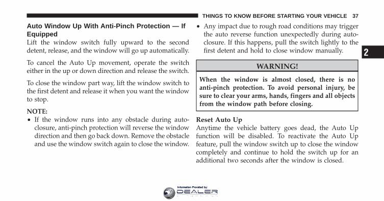
Auto Window Up With Anti-Pinch Protection — IfEquippedLift the window switch fully upward to the seconddetent, release, and the window will go up automatically.
To cancel the Auto Up movement, operate the switcheither in the up or down direction and release the switch.
To close the window part way, lift the window switch tothe first detent and release it when you want the windowto stop.
NOTE:• If the window runs into any obstacle during auto-
closure, anti-pinch protection will reverse the windowdirection and then go back down. Remove the obstacleand use the window switch again to close the window.
• Any impact due to rough road conditions may triggerthe auto reverse function unexpectedly during auto-closure. If this happens, pull the switch lightly to thefirst detent and hold to close window manually.
WARNING!
When the window is almost closed, there is noanti-pinch protection. To avoid personal injury, besure to clear your arms, hands, fingers and all objectsfrom the window path before closing.
Reset Auto UpAnytime the vehicle battery goes dead, the Auto Upfunction will be disabled. To reactivate the Auto Upfeature, pull the window switch up to close the windowcompletely and continue to hold the switch up for anadditional two seconds after the window is closed.
2
THINGS TO KNOW BEFORE STARTING YOUR VEHICLE 37
Information Provided by:

Window Lockout SwitchThe window lockout switch on the driver’s door allowsyou to disable the window control on the other doors. Todisable the window controls on the other doors, press thewindow LOCK button. To enable the window controls,press the window control button again.
Wind BuffetingWind buffeting can be described as the perception ofpressure on the ears or a helicopter-type sound in theears. Your vehicle may exhibit wind buffeting with thewindows down, or the sunroof (if equipped) in certainopen or partially open positions. This is a normal occur-rence and can be minimized. If the buffeting occurs withthe rear windows open, then open the front and rearwindows together to minimize the buffeting. If thebuffeting occurs with the sunroof open, then adjust thesunroof opening to minimize the buffeting.
TRUNK LOCK AND RELEASEUse the Remote Keyless Entry (RKE)transmitter to open the trunk fromoutside the vehicle. From inside thevehicle the trunk lid can be released bypressing the TRUNK RELEASE buttonlocated on the instrument panel to theleft of the steering wheel.
Window Lockout Switch
38 THINGS TO KNOW BEFORE STARTING YOUR VEHICLE
Information Provided by:

NOTE: The shift lever must be in PARK for this buttonto operate.
To unlatch the trunk lid from outside the vehicle, pressand release the TRUNK button on the RKE transmittertwo times.
With the ignition switch in the ON/RUN position, theword “dECK ” will display in place of the odometerdisplay indicating that the trunk is open. The odometerdisplay will reappear once the trunk is closed or if thetrip button is depressed.
With the ignition switch in the LOCK position or with thekey out, the word “dECK” will display until the trunk isclosed.
On EVIC-equipped vehicles, the words “Trunk Ajar” willdisplay.
TRUNK SAFETY WARNING
WARNING!
Do not allow children to have access to the trunk,either by climbing into the trunk from outside, orthrough the inside of the vehicle. Always close thetrunk lid when your vehicle is unattended. Once inthe trunk, young children may not be able to escape,even if they entered through the rear seat. If trappedin the trunk, children can die from suffocation orheat stroke.
2
THINGS TO KNOW BEFORE STARTING YOUR VEHICLE 39
Information Provided by:

Trunk Internal Emergency ReleaseAs a security measure, a Trunk Internal EmergencyRelease lever is built into the trunk latching mechanism.In the event of an individual being locked inside thetrunk, the trunk can be simply opened by pulling on theglow-in-the-dark handle attached to the trunk latchingmechanism.
OCCUPANT RESTRAINTSSome of the most important safety features in yourvehicle are the restraint systems:
• Three-point lap and shoulder belts for all seatingpositions
• Advanced Front Air Bags for driver and front passen-ger
• Supplemental Active Head Restraints (AHR) locatedon top of the front seats (integrated into the headrestraint) — if equipped
• Supplemental Side Air Bag Inflatable Curtains(SABIC) for the driver and passengers seated next to awindow
• Supplemental Seat-Mounted Side Air Bags (SAB)
• An energy-absorbing steering column and steeringwheel
Trunk Internal Emergency Release
40 THINGS TO KNOW BEFORE STARTING YOUR VEHICLE
Information Provided by:

• Knee bolsters/blockers for front seat occupants
• Front seat belts incorporate pretensioners that mayenhance occupant protection by managing occupantenergy during an impact event
• All seat belt systems (except the driver’s) includeAutomatic Locking Retractors (ALRs), which lock theseat belt webbing into position by extending the beltall the way out and then adjusting the belt to thedesired length to restrain a child seat or secure a largeitem in a seat
Please pay close attention to the information in thissection. It tells you how to use your restraint systemproperly, to keep you and your passengers as safe aspossible.
If you will be carrying children too small for adult-sizedseat belts, the seat belts or the Lower Anchors and Tetherfor CHildren (LATCH) feature also can be used to holdinfant and child restraint systems. For more informationon LATCH, refer to Lower Anchors and Tether forCHildren (LATCH).
NOTE: The Advanced Front Air Bags have a multistageinflator design. This allows the air bag to have differentrates of inflation based on several factors, including theseverity and type of collision.
Here are some simple steps you can take to minimize therisk of harm from a deploying air bag:
1. Children 12 years old and under should always ridebuckled up in a rear seat.
2
THINGS TO KNOW BEFORE STARTING YOUR VEHICLE 41
Information Provided by:

WARNING!
Infants in rear facing child restraints should neverride in the front seat of a vehicle with a passengerAdvanced Front Air Bag. An air bag deployment cancause severe injury or death to infants in that posi-tion.
Children that are not big enough to wear the vehicle seatbelt properly (see section on Child Restraints) should besecured in the rear seat in child restraints or belt-positioning booster seats. Older children who do not usechild restraints or belt-positioning booster seats shouldride properly buckled up in the rear seat. Never allowchildren to slide the shoulder belt behind them or undertheir arm.
If a child from 1 to 12 years old (not in a rear facing childseat) must ride in the front passenger seat, move the seatas far back as possible and use the proper child restraint.(Refer to “Child Restraints”)
You should read the instructions provided with yourchild restraint to make sure that you are using it properly.
2. All occupants should always wear their lap andshoulder belts properly.
3. The driver and front passenger seats should bemoved back as far as practical to allow the AdvancedFront Air Bags room to inflate.
4. Do not lean against the door or window. If yourvehicle has side air bags, and deployment occurs, theside air bags will inflate forcefully into the spacebetween you and the door.
42 THINGS TO KNOW BEFORE STARTING YOUR VEHICLE
Information Provided by:

5. If the air bag system in this vehicle needs to bemodified to accommodate a disabled person, contactthe Customer Center. Phone numbers are providedunder �If You Need Assistance�.
WARNING!
• Relying on the air bags alone could lead to moresevere injuries in a collision. The air bags workwith your seat belt to restrain you properly. Insome collisions, the air bags won’t deploy at all.Always wear your seat belts even though you haveair bags.
(Continued)
WARNING! (Continued)• Being too close to the steering wheel or instrument
panel during Advanced Front Air Bag deploymentcould cause serious injury, including death. AirBags need room to inflate. Sit back, comfortablyextending your arms to reach the steering wheel orinstrument panel.
• Supplemental Side Air Bag Inflatable Curtain(SABIC) and Seat-Mounted Side Air Bags (SAB)also need room to inflate. Do not lean against thedoor or window. Sit upright in the center of theseat.
• In a collision, you and your passengers can suffermuch greater injuries if you are not properlybuckled up. You can strike the interior of yourvehicle or other passengers, or you can be thrownout of the vehicle. Always be sure you and othersin your vehicle are buckled up properly.
2
THINGS TO KNOW BEFORE STARTING YOUR VEHICLE 43
Information Provided by:

Buckle up even though you are an excellent driver, evenon short trips. Someone on the road may be a poor driverand cause a collision that includes you. This can happenfar away from home or on your own street.
Research has shown that seat belts save lives, and theycan reduce the seriousness of injuries in a collision. Someof the worst injuries happen when people are thrownfrom the vehicle. Seat belts reduce the possibility ofejection and the risk of injury caused by striking theinside of the vehicle. Everyone in a motor vehicle shouldbe belted at all times.
Lap/Shoulder BeltsAll seating positions in your vehicle are equipped withlap/shoulder belts.
The belt webbing retractor will lock only during verysudden stops or collisions. This feature allows the shoul-der part of the belt to move freely with you under normal
conditions. However, in a collision the belt will lock andreduce your risk of striking the inside of the vehicle orbeing thrown out.
WARNING!
• Be sure everyone in your vehicle is in a seat andusing a seat belt properly.
• It is dangerous to ride in a cargo area, inside oroutside of a vehicle. In a collision, people riding inthese areas are more likely to be seriously injuredor killed.
• Wearing a seat belt incorrectly is dangerous. Seatbelts are designed to go around the large bones ofyour body. These are the strongest parts of yourbody and can take the forces of a collision the best.
(Continued)
44 THINGS TO KNOW BEFORE STARTING YOUR VEHICLE
Information Provided by:

WARNING! (Continued)• Wearing your belt in the wrong place could make
your injuries in a collision much worse. You mightsuffer internal injuries, or you could even slide outof part of the belt. Follow these instructions towear your seat belt safely and to keep your pas-sengers safe, too.
• Two people should never be belted into a singleseat belt. People belted together can crash into oneanother in a collision, hurting one another badly.Never use a lap/shoulder belt or lap belt for morethan one person, no matter what their size.
Lap/Shoulder Belt Operating Instructions
1. Enter the vehicle and close the door. Sit back andadjust the seat.
2. The seat belt latch plate is above the back of the frontseat, next to your arm. Grasp the latch plate and pull outthe belt. Slide the latch plate up the webbing as far asnecessary to allow the belt to go around your lap.
3. When the belt is long enough to fit, insert the latchplate into the buckle until you hear a “click.”
Pulling Out The Latch Plate
2
THINGS TO KNOW BEFORE STARTING YOUR VEHICLE 45
Information Provided by:

WARNING!
• A belt that is buckled into the wrong buckle willnot protect you properly. The lap portion couldride too high on your body, possibly causinginternal injuries. Always buckle your belt into thebuckle nearest you.
• A belt that is too loose will not protect youproperly. In a sudden stop, you could move too farforward, increasing the possibility of injury. Wearyour seat belt snugly.
Inserting Latch Plate Into Buckle
46 THINGS TO KNOW BEFORE STARTING YOUR VEHICLE
Information Provided by:
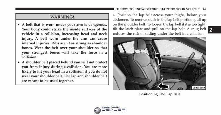
WARNING!
• A belt that is worn under your arm is dangerous.Your body could strike the inside surfaces of thevehicle in a collision, increasing head and neckinjury. A belt worn under the arm can causeinternal injuries. Ribs aren’t as strong as shoulderbones. Wear the belt over your shoulder so thatyour strongest bones will take the force in acollision.
• A shoulder belt placed behind you will not protectyou from injury during a collision. You are morelikely to hit your head in a collision if you do notwear your shoulder belt. The lap and shoulder beltare meant to be used together.
4. Position the lap belt across your thighs, below yourabdomen. To remove slack in the lap belt portion, pull upon the shoulder belt. To loosen the lap belt if it is too tight,tilt the latch plate and pull on the lap belt. A snug beltreduces the risk of sliding under the belt in a collision.
Positioning The Lap Belt
2
THINGS TO KNOW BEFORE STARTING YOUR VEHICLE 47
Information Provided by:
WARNING!
• A lap belt worn too high can increase the risk ofinternal injury in a collision. The belt forces won’tbe at the strong hip and pelvic bones, but acrossyour abdomen. Always wear the lap belt as low aspossible and keep it snug.
• A twisted belt may not protect you properly. In acollision, it could even cut into you. Be sure thebelt is straight. If you can’t straighten a belt inyour vehicle, take it to your authorized dealerimmediately and have it fixed.
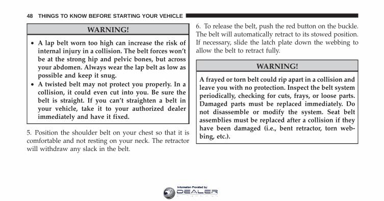
5. Position the shoulder belt on your chest so that it iscomfortable and not resting on your neck. The retractorwill withdraw any slack in the belt.
6. To release the belt, push the red button on the buckle.The belt will automatically retract to its stowed position.If necessary, slide the latch plate down the webbing toallow the belt to retract fully.
WARNING!
A frayed or torn belt could rip apart in a collision andleave you with no protection. Inspect the belt systemperiodically, checking for cuts, frays, or loose parts.Damaged parts must be replaced immediately. Donot disassemble or modify the system. Seat beltassemblies must be replaced after a collision if theyhave been damaged (i.e., bent retractor, torn web-bing, etc.).
48 THINGS TO KNOW BEFORE STARTING YOUR VEHICLE
Information Provided by:

Lap/Shoulder Belt Untwisting ProcedureUse the following procedure to untwist a twisted lap/shoulder belt.
1. Position the latch plate as close as possible to theanchor point.
2. At about 6 to 12 in (15 to 30 cm) above the latch plate,grasp and twist the belt webbing 180 degrees to create afold that begins immediately above the latch plate.
3. Slide the latch plate upward over the folded webbing.The folded webbing must enter the slot at the top of thelatch plate.
4. Continue to slide the latch plate up until it clears thefolded webbing.
Adjustable Upper Shoulder Belt AnchorageIn the front seat, the shoulder belt can be adjustedupward or downward to position the belt away fromyour neck. Push anchorage button to release the anchor-age, and move it up or down to the position that servesyou best.
Adjustable Anchorage
2
THINGS TO KNOW BEFORE STARTING YOUR VEHICLE 49
Information Provided by:

As a guide, if you are shorter than average, you willprefer a lower position, and if you are taller than average,you will prefer a higher position. When you release theanchorage, try to move it up or down to make sure thatit is locked in position.
Rear Seat BeltsThe shoulder belt anchorages of the rear three-point beltsare nonadjustable for outboard and center rear passen-gers on sedans. The center belt is mounted to the rearshelf panel and exits through a bezel in the panel.
Seat Belts In Passenger Seating PositionsThe seat belts in the passenger seating positions areequipped with Automatic Locking Retractors (ALR)which are used to secure a child restraint system. Foradditional information, refer to “Installing Child Re-straints Using The Vehicle Seat Belt” under the “ChildRestraints” section. The chart below defines the type offeature for each seating position.
Driver Center PassengerFirst Row N/A N/A ALR
Second Row ALR ALR ALR
• N/A — Not Applicable
• ALR — Automatic Locking Retractor
If the passenger seating position is equipped with anALR and is being used for normal usage:
Only pull the belt webbing out far enough to comfortablywrap around the occupant’s mid-section so as to notactivate the ALR. If the ALR is activated, you will hear aratcheting sound as the belt retracts. Allow the webbingto retract completely in this case and then carefully pullout only the amount of webbing necessary to comfort-ably wrap around the occupant’s mid-section. Slide thelatch plate into the buckle until you hear a �click.�
50 THINGS TO KNOW BEFORE STARTING YOUR VEHICLE
Information Provided by:

Automatic Locking Retractor Mode (ALR) — IfEquippedIn this mode, the shoulder belt is automatically pre-locked. The belt will still retract to remove any slack inthe shoulder belt. The Automatic Locking Mode is avail-able on all passenger-seating positions with a combina-tion lap/shoulder belt. Use the Automatic Locking Modeanytime a child safety seat is installed in a seatingposition that has a belt with this feature. Children12 years old and under should always be properlyrestrained in the rear seat.
How To Engage The Automatic Locking Mode
1. Buckle the combination lap and shoulder belt.
2. Grasp the shoulder portion and pull downward untilthe entire belt is extracted.
3. Allow the belt to retract. As the belt retracts, you willhear a clicking sound. This indicates the safety belt isnow in the Automatic Locking Mode.
How To Disengage The Automatic Locking ModeUnbuckle the combination lap/shoulder belt and allow itto retract completely to disengage the Automatic LockingMode and activate the vehicle sensitive (emergency)locking mode.
WARNING!
• The belt and retractor assembly must be replacedif the seat belt assembly Automatic Locking Re-tractor (ALR) feature or any other seat belt func-tion is not working properly when checked ac-cording to the procedures in the Service Manual.
• Failure to replace the belt and retractor assemblycould increase the risk of injury in collisions.
2
THINGS TO KNOW BEFORE STARTING YOUR VEHICLE 51
Information Provided by:

Energy Management FeatureThis vehicle has a safety belt system with an EnergyManagement feature in the front seating positions to helpfurther reduce the risk of injury in the event of a head-oncollision. This safety belt system has a retractor assemblythat is designed to release webbing in a controlledmanner. This feature is designed to help reduce the beltforce acting on the occupant’s chest.
Seat Belt PretensionersThe seat belts for both front seating positions areequipped with pretensioning devices that are designed toremove slack from the seat belt in the event of a collision.These devices may improve the performance of the seatbelt by assuring that the belt is tight about the occupantearly in a collision. Pretensioners work for all size occu-pants, including those in child restraints.
NOTE: These devices are not a substitute for proper seatbelt placement by the occupant. The seat belt still must beworn snugly and positioned properly.
The pretensioners are triggered by the Occupant Re-straint Controller (ORC). Like the air bags, the preten-sioners are single use items. A deployed pretensioner ora deployed air bag must be replaced immediately.
Supplemental Active Head Restraints (AHR) — IfEquippedThese head restraints are passive, deployable compo-nents, and vehicles with this equipment cannot be readilyidentified by any markings, only through visual inspec-tion of the head restraint. The head restraint will be splitin two halves, with the front half being soft foam andtrim, the back half being decorative plastic.
52 THINGS TO KNOW BEFORE STARTING YOUR VEHICLE
Information Provided by:

How The Active Head Restraints (AHR) WorkThe Occupant Restraint Controller (ORC) determineswhether the severity, or type of rear impact will requirethe Active Head Restraints (AHR) to deploy. If a rearimpact requires deployment, both the driver and frontpassenger seat AHRs will be deployed.
When AHRs deploy during a rear impact, the front halfof the head restraint extends forward to minimize the gapbetween the back of the occupant’s head and the AHR.This system is designed to help prevent or reduce theextent of injuries to the driver and front passenger incertain types of rear impacts.
NOTE: The Active Head Restraints (AHR) may or maynot deploy in the event of a front or side impact.However if during a front impact, a secondary rearimpact occurs, the AHR may deploy based on severalfactors, including the severity and type of the impact.
Active Head Restraint (AHR) Components
1 — Head Restraint Front Half(Soft Foam and Trim)
3 — Head Restraint Back Half(Decorative Plastic RearCover)
2 — Seatback 4 — Head Restraint GuideTubes
2
THINGS TO KNOW BEFORE STARTING YOUR VEHICLE 53
Information Provided by:

CAUTION!
All occupants, including the driver, should not oper-ate a vehicle or sit in a vehicle’s seat until the headrestraints are placed in their proper positions in orderto minimize the risk of neck injury in the event of acollision.
NOTE: For more information on properly adjusting andpositioning the head restraint, refer to “Adjusting ActiveHead Restraints” in “Understanding The Features OfYour Vehicle”.
Resetting Active Head Restraints (AHR)If the Active Head Restraints are triggered in a collision,you must reset the head restraint on the driver’s andfront passenger seat. You can recognize when the ActiveHead Restraint has been triggered by the fact that theyhave moved forward (as shown in step three of theresetting procedure).
1. Grasp the deployed AHR from the rear seat.
2. Position the hands on the top of the deployed AHR ata comfortable position.
3. Pull down then rearward towards the rear of thevehicle then down to engage the locking mechanism.
Hand Positioning Points On AHR
54 THINGS TO KNOW BEFORE STARTING YOUR VEHICLE
Information Provided by:

1 — Downward Movement2 — Rearward Movement
3 — Final Downward Movement To Engage Locking Mechanism
2
THINGS TO KNOW BEFORE STARTING YOUR VEHICLE 55
Information Provided by:

4. The AHR front soft foam and trim half should lockinto the back decorative plastic half.
NOTE:• If you have difficulties or problems resetting the
Active Head Restraints, see an authorized dealer.
• For safety reasons, have the Active Head Restraintschecked by a qualified specialist at an authorizeddealer.
Enhanced Seat Belt Use Reminder System(BeltAlert�)BeltAlert� is a feature intended to remind the driver andfront passenger (if equipped with front passengerBeltAlert�) to fasten their seat belts. The feature is activewhenever the ignition is on. If the driver or front seatpassenger is unbelted, the Seat Belt Reminder Light willturn on and remain on until both front seat belts arefastened.
The BeltAlert� warning sequence begins after the vehiclespeed is over 5 mph (8 km/h), by blinking the Seat BeltReminder Light and sounding an intermittent chime.Once the sequence starts, it will continue for the entireduration or until the respective seatbelts are fastened.After the sequence completes, the Seat Belt Reminder
AHR In Reset Position
56 THINGS TO KNOW BEFORE STARTING YOUR VEHICLE
Information Provided by:

Light remains illuminated until the respective seat beltsare fastened. The driver should instruct all other occu-pants to fasten their seat belts. If a front seat belt isunbuckled while traveling at speeds greater than 5 mph(8 km/h), BeltAlert� will provide both audio and visualnotification.
The front passenger seat BeltAlert� is not active when thefront passenger seat is unoccupied. BeltAlert� may betriggered when an animal or heavy object is on the frontpassenger seat or when the seat is folded flat (ifequipped). It is recommended that pets be restrained inthe rear seat in pet harnesses or pet carriers that aresecured by seat belts, and cargo is properly stowed.
BeltAlert� can be enabled or disabled by your authorizeddealer. Chrysler Group LLC does not recommend deac-tivating BeltAlert�.
NOTE: Although BeltAlert� has been deactivated, theSeat Belt Reminder Light will continue to illuminatewhile the driver’s or front passenger (if equipped withBeltAlert�) seat belt remains unfastened.
Seat Belts And Pregnant WomenWe recommend that pregnant women use the seat beltsthroughout their pregnancy. Keeping the mother safe isthe best way to keep the baby safe.
Pregnant women should wear the lap part of the beltacross the thighs and as snug across the hips as possible.Keep the belt low so that it does not come across theabdomen. That way the strong bones of the hips will takethe force if there is a collision.
Seat Belt ExtenderIf a seat belt is too short, even when fully extended andwhen the adjustable upper shoulder belt anchorage (ifequipped) is in its lowest position, your authorizeddealer can provide you with a seat belt extender. This
2
THINGS TO KNOW BEFORE STARTING YOUR VEHICLE 57
Information Provided by:

extender should be used only if the existing belt is notlong enough. When it is not required, remove the ex-tender, and store it.
WARNING!
Using a seat belt extender when not needed canincrease the risk of injury in a collision. Only usewhen the lap belt is not long enough when it is wornlow and snug, and in the recommended seatingpositions. Remove and store the extender when notneeded.
Supplemental Restraint System (SRS) — Air BagsThis vehicle has Advanced Front Air Bags for both thedriver and front passenger as a supplement to the seatbelt restraint systems. The driver’s Advanced Front AirBag is mounted in the center of the steering wheel. Thepassenger’s Advanced Front Air Bag is mounted in the
instrument panel, above the glove compartment. Thewords SRS AIRBAG are embossed on the air bag covers.
Advanced Front Air Bag And Knee Bolster Locations
1 — Driver And Passenger Advanced Front Air Bags2 — Knee Bolster
58 THINGS TO KNOW BEFORE STARTING YOUR VEHICLE
Information Provided by:

NOTE: The Driver and Front Passenger Advanced FrontAir Bags are certified to the new Federal regulations forAdvanced Air Bags.
The Advanced Front Air Bags have a multistage inflatordesign. This allows the air bag to have different rates ofinflation that are based on several factors, including theseverity and type of collision.
This vehicle may be equipped with driver and/or frontpassenger seat track position sensors that may adjust theinflation rate of the Advanced Front Air Bags based uponseat position.
This vehicle may be equipped with a driver and/or frontpassenger seat belt buckle switch that detects whetherthe driver or front passenger seat belt is fastened. Theseat belt buckle switch may adjust the inflation rate of theAdvanced Front Air Bags.
This vehicle is equipped with Supplemental Side Air BagInflatable Curtains (SABIC) to protect the driver, front,and rear passengers sitting next to a window. If thevehicle is equipped with SABIC, they are located abovethe side windows. The trim covering the side air bags islabeled SRS AIRBAG.
This vehicle is equipped with Supplemental Seat-Mounted Side Air Bags (SAB) to provide enhancedprotection for an occupant during a side impact. TheSABs are located in the outboard side of the front seats.
NOTE:• Air Bag covers may not be obvious in the interior trim,
but they will open during air bag deployment.
• After any accident, the vehicle should be taken to anauthorized dealer immediately.
2
THINGS TO KNOW BEFORE STARTING YOUR VEHICLE 59
Information Provided by:

Air Bag System ComponentsYour vehicle may be equipped with the following air bagsystem components:
• Occupant Restraint Controller (ORC)
• Air Bag Warning Light
• Steering Wheel and Column
• Instrument Panel
• Knee Impact Bolster
• Driver Advanced Front Air Bag
• Passenger Advanced Front Air Bag
• Supplemental Seat-Mounted Side Air Bags (SAB)
• Supplemental Side Air Bag Inflatable Curtains(SABIC)
• Front and Side Impact Sensors
• Front Seat Belt Pretensioners, Seat Belt Buckle Switch,and Seat Track Position Sensors
Advanced Front Air Bag FeaturesThe Advanced Front Air Bag system has multistagedriver and front passenger air bags. This system providesoutput appropriate to the severity and type of collision asdetermined by the Occupant Restraint Controller (ORC),which may receive information from the front impactsensors.
The first stage inflator is triggered immediately during animpact that requires air bag deployment. This low outputis used in less severe collisions. A higher energy output isused for more severe collisions.
60 THINGS TO KNOW BEFORE STARTING YOUR VEHICLE
Information Provided by:

WARNING!• No objects should be placed over or near the air
bag on the instrument panel, because any suchobjects could cause harm if the vehicle is in acollision severe enough to cause the air bag toinflate.
• Do not put anything on or around the air bagcovers or attempt to open them manually. You maydamage the air bags and you could be injuredbecause the air bags may no longer be functional.The protective covers for the air bag cushions aredesigned to open only when the air bags areinflating.
• Do not drill, cut or tamper with the knee bolster inany way.
• Do not mount any accessories to the knee bolstersuch as alarm lights, stereos, citizen band radios,etc.
Supplemental Seat-Mounted Side Air Bags (SAB)Supplemental Seat-Mounted Side Air Bags (SAB) mayprovide enhanced protection to help protect an occupantduring a side impact. The SAB is marked with an air baglabel sewn into the outboard side of the front seats.
Supplemental Seat-Mounted Side Air Bag Label
2
THINGS TO KNOW BEFORE STARTING YOUR VEHICLE 61
Information Provided by:

When the air bag deploys, it opens the seam between thefront and side of the seat’s trim cover. Each air bagdeploys independently; a left side impact deploys the leftair bag only and a right-side impact deploys the right airbag only.
Supplemental Side Air Bag Inflatable Curtain(SABIC)SABIC air bags may offer side-impact protection to frontand rear seat outboard occupants in addition to thatprovided by the body structure. Each air bag featuresinflated chambers placed adjacent to the head of eachoutboard occupant that reduce the potential for side-impact head injuries. The SABIC air bags deploy down-ward, covering both windows on the impact side.
NOTE:• Air Bag covers may not be obvious in the interior trim;
but they will open during air bag deployment.
• Being too close to the SAB and SABIC air bags duringdeployment could cause you to be severely injured orkilled.
Side Air Bag Inflatable Curtains (SABIC) Location
62 THINGS TO KNOW BEFORE STARTING YOUR VEHICLE
Information Provided by:

The system includes side impact sensors that are cali-brated to deploy the side air bags during impacts thatrequire air bag occupant protection.
WARNING!
• If your vehicle is equipped with left and rightSupplemental Side Air Bag Inflatable Curtain(SABIC), do not stack luggage or other cargo uphigh enough to block the location of the SABIC.The area where the SABIC is located should re-main free from any obstructions.
• Do not use accessory seat covers or place objectsbetween you and the side air bags; the perfor-mance could be adversely affected and/or objectscould be pushed into you, causing serious injury.
(Continued)
WARNING! (Continued)• If your vehicle is equipped with SABIC air bags,
do not have any accessory items installed whichwill alter the roof, including adding a sunroof toyour vehicle. Do not add roof racks that requirepermanent attachments (bolts or screws) for instal-lation on the vehicle roof. Do not drill into the roofof the vehicle for any reason.
Knee Impact BolstersThe Knee Impact Bolsters help protect the knees of thedriver and the front passenger, and position front occu-pants for the best interaction with the Advanced FrontAir Bags.
2
THINGS TO KNOW BEFORE STARTING YOUR VEHICLE 63
Information Provided by:

Along with seat belts and pretensioners, Advanced FrontAir Bags work with the knee bolsters to provide im-proved protection for the driver and front passenger. Sideair bags also work with seat belts to improve occupantprotection.
Air Bag Deployment Sensors And Controls
Occupant Restraint Controller (ORC)The ORC is part of a Federally regulated safety systemrequired for this vehicle.
The ORC determines if deployment of the front and/orside air bags in a frontal or side collision is required.Based on the impact sensor’s signals, a central electronicORC deploys the Advanced Front Air Bags, SABIC airbags, Supplemental Seat-Mounted Side Air Bags, andfront seat belt pretensioners, as required, depending onseveral factors, including the severity and type of impact.
Advanced Front Air Bags are designed to provide addi-tional protection by supplementing the seat belts incertain frontal collisions depending on several factors,including the severity and type of collision. AdvancedFront Air Bags are not expected to reduce the risk ofinjury in rear, side, or rollover collisions.
The Advanced Front Air Bags will not deploy in allfrontal collisions, including some that may produce sub-stantial vehicle damage — for example, some pole colli-sions, truck underrides, and angle offset collisions. Onthe other hand, depending on the type and location ofimpact, Advanced Front Air Bags may deploy in crasheswith little vehicle front-end damage but that produce asevere initial deceleration.
The side air bags will not deploy in all side collisions.Side air bag deployment will depend on the severity andtype of collision.
64 THINGS TO KNOW BEFORE STARTING YOUR VEHICLE
Information Provided by:
Because air bag sensors measure vehicle decelerationover time, vehicle speed and damage by themselves arenot good indicators of whether or not an air bag shouldhave deployed.
Seat belts are necessary for your protection in all colli-sions, and also are needed to help keep you in position,away from an inflating air bag.
The ORC monitors the readiness of the electronic parts ofthe air bag system whenever the ignition switch is in theSTART or ON/RUN position. If the key is in the OFFposition, in the ACC position, or not in the ignition, theair bag system is not on and the air bags will not inflate.
The ORC contains a backup power supply system thatmay deploy the air bags even if the battery loses power orit becomes disconnected prior to deployment.
Also, the ORC turns on the Air Bag WarningLight in the instrument panel for approxi-mately four to eight seconds for a self-checkwhen the ignition is first turned on. After the
self-check, the Air Bag Warning Light will turn off. If theORC detects a malfunction in any part of the system, itturns on the Air Bag Warning Light, either momentarilyor continuously. A single chime will sound if the lightcomes on again after initial startup.
It also includes diagnostics that will illuminate the instru-ment cluster Air Bag Warning Light if a malfunction isnoted that could affect the air bag system. The diagnos-tics also record the nature of the malfunction.
2
THINGS TO KNOW BEFORE STARTING YOUR VEHICLE 65
Information Provided by:

WARNING!
Ignoring the Air Bag Warning Light in your instru-ment panel could mean you won’t have the air bagsto protect you in a collision. If the light does not comeon as a bulb check when the ignition is first turnedon, stays on after you start the vehicle, or if it comeson as you drive, have an authorized dealer service theair bag system immediately.
Driver And Passenger Advanced Front Air BagInflator UnitsThe Driver and Passenger Advanced Front Air BagInflator Units are located in the center of the steeringwheel and on the right side of the instrument panel.When the ORC detects a collision requiring the Ad-vanced Front Air Bags, it signals the inflator units. A largequantity of non-toxic gas is generated to inflate theAdvanced Front Air Bags. Different air bag inflation rates
are possible, based on the collision type and severity. Thesteering wheel hub trim cover and the upper right side ofthe instrument panel separate and fold out of the way asthe air bags inflate to their full size. The air bags fullyinflate in about 50 to 70 milliseconds. This is about half ofthe time it takes to blink your eyes. The air bags thenquickly deflate while helping to restrain the driver andfront passenger.
The Advanced Front Air Bag gas is vented through thevent holes in the sides of the air bag. In this way, the airbags do not interfere with your control of the vehicle.
Supplemental Seat-Mounted Side Air Bag (SAB)Inflator UnitsThe Supplemental Seat-Mounted Side Air Bags (SAB) aredesigned to activate only in certain side collisions.
The ORC determines if a side collision requires the sideair bags to inflate, based on several factors, including theseverity and type of collision.
66 THINGS TO KNOW BEFORE STARTING YOUR VEHICLE
Information Provided by:

Based on several factors, including the severity and typeof collision, the side air bag inflator on the crash side ofthe vehicle may be triggered, releasing a quantity ofnon-toxic gas. The inflating SAB exits through the seatseam into the space between the occupant and the door.The SAB fully inflate in about 10 milliseconds. The sideair bag moves at a very high speed and with such a highforce that it could injure you if you are not seatedproperly, or if items are positioned in the area where theside air bag inflates. This especially applies to children.
Supplemental Side Air Bag Inflatable Curtain(SABIC) Inflator UnitsDuring collisions where the impact is confined to aparticular area of the side of the vehicle, the ORC maydeploy the SABIC air bags, depending on several factors,including the severity and type of collision. In theseevents, the ORC will deploy the SABIC only on theimpact side of the vehicle.
A quantity of non-toxic gas is generated to inflate the sidecurtain air bag. The inflating side curtain air bag pushesthe outside edge of the headliner out of the way andcovers the window. The air bag inflates in about 30milliseconds (about one-quarter of the time that it takesto blink your eyes) with enough force to injure you if youare not belted and seated properly, or if items arepositioned in the area where the side curtain air baginflates. This especially applies to children. The sidecurtain air bag is only about 3-1/2 in (9 cm) thick whenit is inflated.
Because air bag sensors estimate deceleration over time,vehicle speed and damage are not good indicators ofwhether or not an air bag should have deployed.
Front And Side Impact SensorsIn front and side impacts, impact sensors can aid theORC in determining appropriate response to impactevents.
2
THINGS TO KNOW BEFORE STARTING YOUR VEHICLE 67
Information Provided by:

Enhanced Accident Response SystemIn the event of an impact causing air bag deployment, ifthe communication network remains intact, and thepower remains intact, depending on the nature of theevent the ORC will determine whether to have theEnhanced Accident Response System perform the follow-ing functions:
• Cut off fuel to the engine.
• Flash hazard lights as long as the battery has power oruntil the ignition key is turned off.
• Turn on the interior lights, which remain on as long asthe battery has power or until the ignition key isremoved.
• Unlock the doors automatically.
In order to reset the Enhanced Accident Response Systemfunctions after an event, the ignition switch must bechanged from IGN ON to IGN OFF.
If A Deployment OccursThe Advanced Front Air Bags are designed to deflateimmediately after deployment.
NOTE: Front and/or side air bags will not deploy in allcollisions. This does not mean something is wrong withthe air bag system.
If you do have a collision, which deploys the air bags, anyor all of the following may occur:
• The nylon air bag material may sometimes causeabrasions and/or skin reddening to the driver andfront passenger as the air bags deploy and unfold. Theabrasions are similar to friction rope burns or thoseyou might get sliding along a carpet or gymnasiumfloor. They are not caused by contact with chemicals.They are not permanent and normally heal quickly.However, if you haven’t healed significantly within afew days, or if you have any blistering, see your doctorimmediately.
68 THINGS TO KNOW BEFORE STARTING YOUR VEHICLE
Information Provided by:

• As the air bags deflate, you may see some smoke-likeparticles. The particles are a normal by-product of theprocess that generates the non-toxic gas used for airbag inflation. These airborne particles may irritate theskin, eyes, nose, or throat. If you have skin or eyeirritation, rinse the area with cool water. For nose orthroat irritation, move to fresh air. If the irritationcontinues, see your doctor. If these particles settle onyour clothing, follow the garment manufacturer’s in-structions for cleaning.
Do not drive your vehicle after the air bags have de-ployed. If you are involved in another collision, the airbags will not be in place to protect you.
WARNING!
Deployed air bags and seat belt pretensioners cannotprotect you in another collision. Have the air bags,seat belt pretensioners, and the front seat belt retrac-tor assemblies replaced by an authorized dealer im-mediately. Also, have the Occupant Restraint Con-troller System serviced as well.
2
THINGS TO KNOW BEFORE STARTING YOUR VEHICLE 69
Information Provided by:

Maintaining Your Air Bag System
WARNING!
• Modifications to any part of the air bag systemcould cause it to fail when you need it. You couldbe injured if the air bag system is not there toprotect you. Do not modify the components orwiring, including adding any kind of badges orstickers to the steering wheel hub trim cover or theupper right side of the instrument panel. Do notmodify the front bumper, vehicle body structure,or add aftermarket side steps or running boards.
• It is dangerous to try to repair any part of the airbag system yourself. Be sure to tell anyone whoworks on your vehicle that it has an air bag system.
(Continued)
WARNING! (Continued)• Do not attempt to modify any part of your air bag
system. The air bag may inflate accidentally ormay not function properly if modifications aremade. Take your vehicle to an authorized dealerfor any air bag system service. If your seat includ-ing your trim cover and cushion needs to beserviced in any way (including removal orloosening/tightening of seat attachment bolts),take the vehicle to your authorized dealer. Onlymanufacturer approved seat accessories may beused. If it is necessary to modify the air bag systemfor persons with disabilities, contact your autho-rized dealer.
70 THINGS TO KNOW BEFORE STARTING YOUR VEHICLE
Information Provided by:

Air Bag Warning LightYou will want to have the air bags ready toinflate for your protection in a collision. TheAir Bag Warning Light monitors the internalcircuits and interconnecting wiring associated
with air bag system electrical components. While the airbag system is designed to be maintenance free, if any ofthe following occurs, have an authorized dealer servicethe air bag system immediately.
• The Air Bag Warning Light does not come on duringthe four to eight seconds when the ignition switch isfirst turned to the ON/RUN position.
• The Air Bag Warning Light remains on after the four toeight-second interval.
• The Air Bag Warning Light comes on intermittently orremains on while driving.
NOTE: If the speedometer, tachometer, or any enginerelated gauges are not working, the Occupant RestraintController (ORC) may also be disabled. The air bags maynot be ready to inflate for your protection. Promptlycheck the fuse block for blown fuses. Refer to the labellocated on the inside of the fuse block cover for theproper air bag fuses. See your authorized dealer if thefuse is good.
Event Data Recorder (EDR)This vehicle is equipped with an event data recorder(EDR). The main purpose of an EDR is to record, incertain crash or near crash-like situations, such as an airbag deployment or hitting a road obstacle, data that willassist in understanding how a vehicle’s systems per-formed. The EDR is designed to record data related tovehicle dynamics and safety systems for a short period oftime, typically 30 seconds or less. The EDR in this vehicleis designed to record such data as:
• How various systems in your vehicle were operating;
2
THINGS TO KNOW BEFORE STARTING YOUR VEHICLE 71
Information Provided by:

• Whether or not the driver and passenger safety beltswere buckled/fastened;
• How far (if at all) the driver was depressing theaccelerator and/or brake pedal; and,
• How fast the vehicle was traveling.
These data can help provide a better understanding ofthe circumstances in which crashes and injuries occur.
NOTE: EDR data are recorded by your vehicle only if anon-trivial crash situation occurs; no data are recorded bythe EDR under normal driving conditions and no per-sonal data (e.g., name, gender, age, and crash location)are recorded. However, other parties, such as law en-forcement, could combine the EDR data with the type ofpersonally identifying data routinely acquired during acrash investigation.
To read data recorded by an EDR, special equipment isrequired, and access to the vehicle or the EDR is needed.In addition to the vehicle manufacturer, other parties,such as law enforcement, that have the special equip-ment, can read the information if they have access to thevehicle or the EDR.
Child RestraintsEveryone in your vehicle needs to be buckled up all thetime, including babies and children. Every state in theUnited States and all Canadian provinces require thatsmall children ride in proper restraint systems. This is thelaw, and you can be prosecuted for ignoring it.
Children 12 years or younger should ride properlybuckled up in a rear seat, if available. According to crashstatistics, children are safer when properly restrained inthe rear seats, rather than in the front.
72 THINGS TO KNOW BEFORE STARTING YOUR VEHICLE
Information Provided by:

WARNING!
In a collision, an unrestrained child, even a tiny baby,can become a projectile inside the vehicle. The forcerequired to hold even an infant on your lap couldbecome so great that you could not hold the child, nomatter how strong you are. The child and otherscould be badly injured. Any child riding in yourvehicle should be in a proper restraint for the child’ssize.
There are different sizes and types of restraints forchildren from newborn size to the child almost largeenough for an adult safety belt. Always check the childseat owner’s manual to ensure you have the correct seatfor your child. Use the restraint that is correct for yourchild.
Infants And Child RestraintsSafety experts recommend that children ride rearward-facing in the vehicle until they are two years old or untilthey reach either the height or weight limit of their rearfacing child safety seat. Two types of child restraints canbe used rearward-facing: infant carriers and convertiblechild seats.
The infant carrier is only used rearward-facing in thevehicle. It is recommended for children from birth untilthey reach the weight or height limit of the infant carrier.Convertible child seats can be used either rearward-facing or forward-facing in the vehicle. Convertible childseats often have a higher weight limit in the rearward-facing direction than infant carriers do, so they can beused rearward-facing by children who have outgrowntheir infant carrier but are still less than at least two yearsold. Children should remain rearward-facing until theyreach the highest weight or height allowed by theirconvertible child seat. Both types of child restraints are
2
THINGS TO KNOW BEFORE STARTING YOUR VEHICLE 73
Information Provided by:

held in the vehicle by the lap/shoulder belt or theLATCH child restraint anchor system. Refer to “LowerAnchors and Tether for CHildren (LATCH)”.
WARNING!
Rearward-facing child seats must never be used inthe front seat of a vehicle with the front passenger airbag. An air bag deployment could cause severeinjury or death to infants in this position.
Older Children And Child RestraintsChildren who are two years old or who have outgrowntheir rear-facing convertible child seat can ride forward-facing in the vehicle. Forward-facing child seats andconvertible child seats used in the forward-facing direc-tion are for children who are over two years old or whohave outgrown the rear-facing weight or height limit oftheir rear-facing convertible child seat. Children shouldremain in a forward-facing child seat with a harness for
as long as possible, up to the highest weight or heightallowed by the child seat. These child seats are also heldin the vehicle by the lap/shoulder belt or the LATCHchild restraint anchorage system. Refer to “Lower An-chors and Tether for CHildren (LATCH)”.
All children whose weight or height is above theforward-facing limit for the child seat should use abelt-positioning booster seat until the vehicle’s seat beltsfit properly. If the child cannot sit with knees bent overthe vehicle’s seat cushion while the child’s back is againstthe seatback, they should use a belt-positioning boosterseat. The child and belt-positioning booster seat are heldin the vehicle by the lap/shoulder belt.
74 THINGS TO KNOW BEFORE STARTING YOUR VEHICLE
Information Provided by:

WARNING!
• Improper installation can lead to failure of aninfant or child restraint. It could come loose in acollision. The child could be badly injured orkilled. Follow the manufacturer’s directions ex-actly when installing an infant or child restraint.
• A rearward-facing child restraint should only beused in a rear seat. A rearward-facing child re-straint in the front seat may be struck by a deploy-ing passenger air bag which may cause severe orfatal injury to the infant.
Here are some tips on getting the most out of yourchild restraints:
• Children who are large enough to wear the shoulderbelt comfortably, and whose legs are long enough to
bend over the front of the seat when their back isagainst the seatback, should use the lap/shoulder beltin a rear seat.
• Before buying any restraint system, make sure that ithas a label certifying that it meets all applicable SafetyStandards. Chrysler Group LLC also recommends thatyou make sure that you can install the child restraint inthe vehicle where you will use it, before you buy it.
• The restraint must be appropriate for your child’sweight and height. Check the label on the restraint forweight and height limits.
• Carefully follow the instructions that come with therestraint. If you install the restraint improperly, it maynot work when you need it.
2
THINGS TO KNOW BEFORE STARTING YOUR VEHICLE 75
Information Provided by:

• All passenger seating positions contain automaticlocking retractors. However, any seat belt system willloosen with time, so check the belt occasionally andpull it tight if necessary.
• In the rear seat, you may have trouble tightening thelap/shoulder belt on the child restraint because thebuckle or latch plate is too close to the belt pathopening on the restraint. Disconnect the latch platefrom the buckle and twist the short buckle end of thebelt several times to shorten it. Insert the latch plateinto the buckle with the release button facing out.
• If the belt still can’t be tightened, or if pulling andpushing on the restraint loosens the belt, disconnectthe latch plate from the buckle, turn the latch platearound, and insert the latch plate into the buckleagain. If you still can’t make the child restraint secure,try a different seating position.
• Buckle the child into the seat according to the childrestraint manufacturer’s directions.
WARNING!
When your child restraint is not in use, secure it inthe vehicle with the seat belt or remove it from thevehicle. Do not leave it loose in the vehicle. In asudden stop or accident, it could strike the occupantsor seatbacks and cause serious personal injury.
NOTE: For additional information, refer towww.seatcheck.org or call 1–866–SEATCHECK. Cana-dian residents should refer to Transport Canada’s web-site for additional information: http://www.tc.gc.ca/roadsafety/safedrivers/childsafety/index.htm
76 THINGS TO KNOW BEFORE STARTING YOUR VEHICLE
Information Provided by:

Lower Anchors and Tether for CHildren (LATCH)Your vehicle is equipped with the child restraint anchor-age system called LATCH, which stands for LowerAnchors and Tether for CHildren. The LATCH systemprovides for the installation of the child restraint withoutusing the vehicle seat belt. All rear seating positions havelower anchorages that are capable of accommodatingLATCH-compatible child seats having flexible, webbing-mounted lower attachments. Child seats with fixed lowerattachments must be installed in the outboard positionsonly. Regardless of the specific type of lower attachment,
never install LATCH-compatible child seats such thattwo seats share a common lower anchorage. If you areinstalling LATCH-compatible child restraints in adjacentrear seating positions, you can use the LATCH anchors orthe vehicle’s seat belt for the outboard position, but youmust use the vehicle’s seat belt at the center position. Ifyour child restraints are not LATCH-compatible, you canonly install the child restraints using the vehicle’s seatbelts. For typical installation instructions, refer to “In-stalling The LATCH-Compatible Child RestraintSystem”.
2
THINGS TO KNOW BEFORE STARTING YOUR VEHICLE 77
Information Provided by:

Rear Seat LATCH AnchorsChild restraints systems having attachments designed toconnect to the lower anchorages are now available. Childrestraints having tether straps and hooks for connectionto the top tether anchorage, have been available for sometime. In fact, many child restraint manufacturers willprovide add-on tether strap kits for some of their olderproducts. Tether anchorage kits are also available formost older vehicles.
Because the lower anchorages are to be introduced topassenger carrying vehicles over a period of years, childrestraint systems having attachments for those anchor-ages will continue to have features for installation invehicles using the lap or lap/shoulder belt. They will also
Rear Seat LATCH Anchors
78 THINGS TO KNOW BEFORE STARTING YOUR VEHICLE
Information Provided by:

have tether straps, and you are urged to take advantageof all of the available attachments provided with yourchild restraint in any vehicle.
NOTE: When using the LATCH attaching system toinstall a child restraint, please ensure that all seat beltsnot being used for occupant restraints are stowed and outof reach of children. It is recommended that beforeinstalling the child restraint, buckle the seat belt so theseat belt is tucked behind the child restraint and out ofreach. If the buckled seat belt interferes with the childrestraint installation, instead of tucking the seat beltbehind the child restraint, route the seat belt through thechild restraint belt path and then buckle it. This shouldstow the seat belt out of the reach of an inquisitive child.Remind all children in the vehicle that the seat belts arenot toys and should not be played with, and never leaveyour child unattended in the vehicle.
Installing The LATCH-Compatible Child RestraintSystemWe urge you to carefully follow the directions of themanufacturer when installing your child restraint. Not allchild restraint systems will be installed as described here.Again, carefully follow the installation instructions thatwere provided with the child restraint system.
The rear seat lower anchorages are round bars,located at the rear of the seat cushion where itmeets the seatback, and are just visible whenyou lean into the rear seat to install the child
restraint. You will easily feel them if you run your fingeralong the intersection of the seatback and seat cushionsurfaces.
In addition, there are tether strap anchoragesbehind each rear seating position located in thepanel between the rear seatback and the rear
2
THINGS TO KNOW BEFORE STARTING YOUR VEHICLE 79
Information Provided by:

window. These tether strap anchorages are under aplastic cover with this symbol on it.
Many, but not all, restraint systems will be equipped withseparate straps on each side, with each having a hook orconnector for attachment to the lower anchorage and ameans of adjusting the tension in the strap. Forward-facing toddler restraints and some rear-facing infantrestraints will also be equipped with a tether strap, ahook for attachment to the tether strap anchorage and ameans of adjusting the tension of the strap.
You will first loosen the child seat adjusters on the lowerstraps and on the tether strap so that you can more easilyattach the hooks or connectors to the vehicle anchorages.Next, attach the lower hooks or connectors over the topof the seat cover material. Then, rotate the tether anchor-age cover directly behind the seat where you are placingthe child restraint and attach the tether strap to theanchorage, being careful to route the tether strap to
provide the most direct path between the anchor and thechild restraint. Finally, tighten all three straps as youpush the child restraint rearward and downward into theseat, removing slack in the straps according to the childrestraint manufacturer’s instructions.
NOTE:• Ensure that the tether strap does not slip into the
opening between the seatbacks as you remove slack inthe strap.
• When using the LATCH attaching system to install achild restraint, please ensure that all seat belts notbeing used for occupant restraints are stowed and outof reach of children. It is recommended that beforeinstalling the child restraint, buckle the seat belt so theseat belt is tucked behind the child restraint and out ofreach. If the buckled seat belt interferes with the childrestraint installation, instead of tucking the seat beltbehind the child restraint, route the seat belt through
80 THINGS TO KNOW BEFORE STARTING YOUR VEHICLE
Information Provided by:

the child restraint belt path and then buckle it. Thisshould stow the seat belt out of the reach of aninquisitive child. Remind all children in the vehiclethat the seat belts are not toys and should not beplayed with, and never leave your child unattended inthe vehicle.
WARNING!
Improper installation of a child restraint to theLATCH anchorages can lead to failure of an infant orchild restraint. The child could be badly injured orkilled. Follow the manufacturer’s directions exactlywhen installing an infant or child restraint.
Installing Child Restraint Tether Strap
1. Rotate the cover over the anchor directly behind theseat where you are placing the child restraint.
2. Route the tether strap to provide the most direct pathfor the strap between the anchor and the child seat. Ifyour vehicle is equipped with adjustable rear headrestraints, raise the head restraint, and where possible,
Installing Child Restraint Tether Strap
1 — Cover A — Tether Strap Hook3 — Attaching Strap B — Tether Anchor
2
THINGS TO KNOW BEFORE STARTING YOUR VEHICLE 81
Information Provided by:

route the tether strap under the head restraint andbetween the two posts. If not possible, lower the headrestraint and pass the tether strap around the outboardside of the head restraint.
3. Attach the tether strap hook (A) of the child restraintto the anchor (B) and remove slack in the tether strapaccording to the child restraint manufacturer’sinstructions.
WARNING!
An incorrectly anchored tether strap could lead toincreased head motion and possible injury to thechild. Use only the anchor positions directly behindthe child seat to secure a child restraint top tetherstrap.
Installing Child Restraints Using The Vehicle SeatBeltsThe seat belts in the passenger seating positions areequipped with an Automatic Locking Retractor to securea Child Restraint System (CRS). These types of seat beltsare designed to keep the lap portion of the seat belt tightaround the child restraint so that it is not necessary to usea locking clip. The ALR will make a ratcheting noise ifyou extract the entire belt from the retractor and thenallow the belt to retract into the retractor. For additionalinformation on ALR, refer to “Automatic Locking Mode”description under “Seat Belts In Passenger Seating Posi-tions” section. The chart below defines the seating posi-tions with an Automatic Locking Retractor (ALR) or acinching latch plate.
82 THINGS TO KNOW BEFORE STARTING YOUR VEHICLE
Information Provided by:

Driver Center PassengerCRS Lock CRS Lock CRS Lock
First Row N/A N/A ALRSecond Row ALR ALR ALR
• N/A — Not Applicable
• ALR — Automatic Locking Retractor
Installing a Child Restraint with an ALR:
1. To install a child restraint with ALR, first, pull enoughof the seat belt webbing from the retractor to route itthrough the belt path of the child restraint. Slide the latchplate into the buckle until you hear a “click.” Next,extract all the seat belt webbing out of the retractor andthen allow the belt to retract into the retractor. As the beltretracts, you will hear a ratcheting sound. This indicatesthe safety belt is now in the Automatic Locking mode.
2. Finally, pull on any excess webbing to tighten the lapportion around the child restraint. Any seat belt systemwill loosen with time, so check the belt occasionally, andpull it tight if necessary.
In the rear seat, you may have trouble tightening thelap/shoulder belt on the child restraint because thebuckle or latch plate is too close to the belt path openingon the restraint. Disconnect the latch plate from thebuckle and twist the short buckle-end belt several timesto shorten it. Insert the latch plate into the buckle with therelease button facing out.
If the belt still can’t be tightened, or if pulling andpushing on the restraint loosens the belt, disconnect thelatch plate from the buckle, turn the buckle around, andinsert the latch plate into the buckle again. If you stillcan’t make the child restraint secure, try a differentseating position.
2
THINGS TO KNOW BEFORE STARTING YOUR VEHICLE 83
Information Provided by:

Children Too Large For Booster SeatsChildren who are large enough to wear the shoulder beltcomfortably, and whose legs are long enough to bendover the front of the seat when their back is against theseatback, should use the lap/shoulder belt in a rear seat.Make sure that:
• The child is upright in the seat.
• The lap portion should be low on the hips and as snugas possible.
• Check belt fit periodically. A child’s squirming orslouching can move the belt out of position.
• If the shoulder belt contacts the face or neck, move thechild closer to the center of the vehicle. Never allow achild to put the shoulder belt under an arm or behindtheir back.
Transporting PetsAir Bags deploying in the front seat could harm your pet.An unrestrained pet will be thrown about and possiblyinjured, or injure a passenger during panic braking or ina collision.
Pets should be restrained in the rear seat in pet harnessesor pet carriers that are secured by seat belts.
ENGINE BREAK-IN RECOMMENDATIONSA long break-in period is not required for the engine anddrivetrain (transmission and axle) in your vehicle.
Drive moderately during the first 300 miles (500 km).After the initial 60 miles (100 km), speeds up to 50 or55 mph (80 or 90 km/h) are desirable.
While cruising, brief full-throttle acceleration within thelimits of local traffic laws contributes to a good break-in.Wide-open throttle acceleration in low gear can be detri-mental and should be avoided.
84 THINGS TO KNOW BEFORE STARTING YOUR VEHICLE
Information Provided by:

The engine oil installed in the engine at the factory is ahigh-quality energy conserving type lubricant. Oilchanges should be consistent with anticipated climateconditions under which vehicle operations will occur. Forthe recommended viscosity and quality grades, refer to“Maintenance Procedures” in “Maintaining Your Ve-hicle”.
CAUTION!
Never use Non-Detergent Oil or Straight Mineral Oilin the engine or damage may result.
NOTE: A new engine may consume some oil during itsfirst few thousand miles (kilometers) of operation. Thisshould be considered a normal part of the break-in andnot interpreted as an indication of difficulty.
SAFETY TIPS
Transporting PassengersNEVER TRANSPORT PASSENGERS IN THE CARGOAREA.
WARNING!• Do not leave children or animals inside parked
vehicles in hot weather. Interior heat build-up maycause serious injury or death.
• It is extremely dangerous to ride in a cargo area,inside or outside of a vehicle. In a collision, peopleriding in these areas are more likely to be seri-ously injured or killed.
• Do not allow people to ride in any area of yourvehicle that is not equipped with seats and seatbelts.
• Be sure everyone in your vehicle is in a seat andusing a seat belt properly.
2
THINGS TO KNOW BEFORE STARTING YOUR VEHICLE 85
Information Provided by:

Exhaust Gas
WARNING!
Exhaust gases can injure or kill. They contain carbonmonoxide (CO), which is colorless and odorless.Breathing it can make you unconscious and caneventually poison you. To avoid breathing (CO),follow these safety tips:• Do not run the engine in a closed garage or in
confined areas any longer than needed to moveyour vehicle in or out of the area.
• If you are required to drive with the trunk/liftgateopen, make sure that all windows are closed andthe climate control BLOWER switch is set at highspeed. DO NOT use the recirculation mode.
(Continued)
WARNING! (Continued)• If it is necessary to sit in a parked vehicle with the
engine running, adjust your heating or coolingcontrols to force outside air into the vehicle. Setthe blower at high speed.
The best protection against carbon monoxide entry intothe vehicle body is a properly maintained engine exhaustsystem.
Whenever a change is noticed in the sound of the exhaustsystem, when exhaust fumes can be detected inside thevehicle, or when the underside or rear of the vehicle isdamaged, have a competent mechanic inspect the com-plete exhaust system and adjacent body areas for broken,damaged, deteriorated, or mispositioned parts. Openseams or loose connections could permit exhaust fumesto seep into the passenger compartment. In addition,
86 THINGS TO KNOW BEFORE STARTING YOUR VEHICLE
Information Provided by:

inspect the exhaust system each time the vehicle is raisedfor lubrication or oil change. Replace as required.
Safety Checks You Should Make Inside TheVehicle
Seat BeltsInspect the belt system periodically, checking for cuts,frays, and loose parts. Damaged parts must be replacedimmediately. Do not disassemble or modify the system.
Front seat belt assemblies must be replaced after acollision. Rear seat belt assemblies must be replaced aftera collision if they have been damaged (i.e., bent retractor,torn webbing, etc.). If there is any question regarding beltor retractor condition, replace the belt.
Air Bag Warning LightThe light should come on and remain on for four to eightseconds as a bulb check when the ignition switch is firstturned ON. If the light is not lit during starting, see your
authorized dealer. If the light stays on, flickers, or comeson while driving, have the system checked by an autho-rized dealer.
DefrosterCheck operation by selecting the defrost mode and placethe blower control on high speed. You should be able tofeel the air directed against the windshield. See yourauthorized dealer for service if your defroster isinoperable.
Floor Mat Safety InformationAlways use floor mats designed to fit the footwell of yourvehicle. Use only floor mats that leave the pedal areaunobstructed and that are firmly secured so that theycannot slip out of position and interfere with the pedalsor impair safe operation of your vehicle in other ways.
2
THINGS TO KNOW BEFORE STARTING YOUR VEHICLE 87
Information Provided by:

WARNING!
Pedals that cannot move freely can cause loss ofvehicle control and increase the risk of serious per-sonal injury.• Always make sure that floor mats are properly
attached to the floor mat fasteners.• Never place or install floor mats or other floor
coverings in the vehicle that cannot be properlysecured to prevent them from moving and inter-fering with the pedals or the ability to control thevehicle.
• Never put floor mats or other floor coverings ontop of already installed floor mats. Additionalfloor mats and other coverings will reduce the sizeof the pedal area and interfere with the pedals.
(Continued)
WARNING! (Continued)• Check mounting of mats on a regular basis. Al-
ways properly reinstall and secure floor mats thathave been removed for cleaning.
• Always make sure that objects cannot fall into thedriver footwell while the vehicle is moving. Ob-jects can become trapped under the brake pedaland accelerator pedal causing a loss of vehiclecontrol.
• If required, mounting posts must be properlyinstalled, if not equipped from the factory.Failure to properly follow floor mat installation ormounting can cause interference with the brakepedal and accelerator pedal operation causing lossof control of the vehicle.
88 THINGS TO KNOW BEFORE STARTING YOUR VEHICLE
Information Provided by:

Periodic Safety Checks You Should Make OutsideThe Vehicle
TiresExamine tires for excessive tread wear and uneven wearpatterns. Check for stones, nails, glass, or other objectslodged in the tread or sidewall. Inspect the tread for cutsand cracks. Inspect sidewalls for cuts, cracks and bulges.Check the wheel nuts for tightness. Check the tires(including spare) for proper cold inflation pressure.
LightsHave someone observe the operation of exterior lightswhile you work the controls. Check turn signal and highbeam indicator lights on the instrument panel.
Door LatchesCheck for positive closing, latching, and locking.
Fluid LeaksCheck area under vehicle after overnight parking for fuel,engine coolant, oil, or other fluid leaks. Also, if gasolinefumes are detected or if fuel, power steering fluid, orbrake fluid leaks are suspected, the cause should belocated and corrected immediately.
2
THINGS TO KNOW BEFORE STARTING YOUR VEHICLE 89
Information Provided by:

Information Provided by:

UNDERSTANDING THE FEATURES OF YOUR VEHICLE
CONTENTS
� Mirrors . . . . . . . . . . . . . . . . . . . . . . . . . . . . . . 96
▫ Inside Day/Night Mirror . . . . . . . . . . . . . . . . 96
▫ Automatic Dimming Mirror — If Equipped . . . 96
▫ Power Mirrors . . . . . . . . . . . . . . . . . . . . . . . 98
▫ Adjusting Sideview Mirrors . . . . . . . . . . . . . . 99
▫ Exterior Mirrors Folding Feature . . . . . . . . . . 99
▫ Heated Mirrors — If Equipped . . . . . . . . . . . . 99
▫ Illuminated Vanity Mirrors — If Equipped . . 100
� Uconnect™ Phone — If Equipped . . . . . . . . . . 100
▫ Operation . . . . . . . . . . . . . . . . . . . . . . . . . 102
▫ Phone Call Features . . . . . . . . . . . . . . . . . . 109
▫ Uconnect™ Phone Features . . . . . . . . . . . . . 112
▫ Advanced Phone Connectivity . . . . . . . . . . . 117
▫ Things You Should Know About YourUconnect™ Phone . . . . . . . . . . . . . . . . . . . . 119
▫ General Information . . . . . . . . . . . . . . . . . . 130
3
Information Provided by:

� Voice Command — If Equipped . . . . . . . . . . . 130
▫ Voice Command System Operation . . . . . . . . 130
▫ Commands . . . . . . . . . . . . . . . . . . . . . . . . 131
▫ Voice Training . . . . . . . . . . . . . . . . . . . . . . 135
� Seats . . . . . . . . . . . . . . . . . . . . . . . . . . . . . . 135
▫ Power Seats — If Equipped . . . . . . . . . . . . . 136
▫ Heated Seats — If Equipped . . . . . . . . . . . . 137
▫ Manual Front Seat Adjustment . . . . . . . . . . . 139
▫ Driver Seat Manual Height Adjuster — IfEquipped . . . . . . . . . . . . . . . . . . . . . . . . . . 140
▫ Reclining Seats . . . . . . . . . . . . . . . . . . . . . . 140
▫ Lumbar Support — If Equipped . . . . . . . . . . 141
▫ Head Restraints . . . . . . . . . . . . . . . . . . . . . 141
▫ Fold-Flat Passenger Seatback . . . . . . . . . . . . 145
▫ Folding Rear Seat . . . . . . . . . . . . . . . . . . . . 146
▫ Folding Rear Seat Center Armrest . . . . . . . . 147
� To Open And Close The Hood . . . . . . . . . . . . 148
� Lights . . . . . . . . . . . . . . . . . . . . . . . . . . . . . 149
▫ Multifunction Lever . . . . . . . . . . . . . . . . . . 149
▫ Headlights And Parking Lights . . . . . . . . . . 150
▫ Automatic Headlights — If Equipped . . . . . . 151
▫ Headlight Time Delay . . . . . . . . . . . . . . . . . 151
▫ Turn Signals . . . . . . . . . . . . . . . . . . . . . . . . 152
▫ Lane Change Assist . . . . . . . . . . . . . . . . . . . 152
▫ High/Low Beam Switch . . . . . . . . . . . . . . . 152
▫ Flash-To-Pass . . . . . . . . . . . . . . . . . . . . . . . 153
92 UNDERSTANDING THE FEATURES OF YOUR VEHICLE
Information Provided by:

▫ Fog Lights — If Equipped . . . . . . . . . . . . . . 153
▫ Daytime Running Lights — If Equipped . . . . 153
▫ Lights On Reminder . . . . . . . . . . . . . . . . . . 154
▫ Instrument Panel Dimmer . . . . . . . . . . . . . . 154
▫ Map/Reading/Interior Lights . . . . . . . . . . . 155
� Windshield Wipers And Washers . . . . . . . . . . 156
▫ Intermittent Wiper System . . . . . . . . . . . . . . 157
▫ Windshield Washers . . . . . . . . . . . . . . . . . . 158
▫ Mist Feature . . . . . . . . . . . . . . . . . . . . . . . . 159
▫ Headlights With Wipers Feature (AvailableWith Automatic Headlights Only) . . . . . . . . . 159
� Tilt/Telescoping Steering Column . . . . . . . . . . 160
� Electronic Speed Control — If Equipped . . . . . 161
▫ To Activate . . . . . . . . . . . . . . . . . . . . . . . . . 162
▫ To Set A Desired Speed . . . . . . . . . . . . . . . . 162
▫ To Deactivate . . . . . . . . . . . . . . . . . . . . . . . 162
▫ To Resume Speed . . . . . . . . . . . . . . . . . . . . 163
▫ To Vary The Speed Setting . . . . . . . . . . . . . . 163
▫ To Accelerate For Passing . . . . . . . . . . . . . . 163
� Garage Door Opener — If Equipped . . . . . . . . 164
▫ Before You Begin ProgrammingHomeLink� . . . . . . . . . . . . . . . . . . . . . . . . 165
▫ Programming A Rolling Code . . . . . . . . . . . 166
▫ Programming A Non-Rolling Code . . . . . . . . 168
▫ Canadian/Gate Operator Programming . . . . 169
3
UNDERSTANDING THE FEATURES OF YOUR VEHICLE 93
Information Provided by:

▫ Using HomeLink� . . . . . . . . . . . . . . . . . . . 170
▫ Security . . . . . . . . . . . . . . . . . . . . . . . . . . . 171
▫ Troubleshooting Tips . . . . . . . . . . . . . . . . . . 171
▫ General Information . . . . . . . . . . . . . . . . . . 172
� Power Sunroof — If Equipped . . . . . . . . . . . . 173
▫ Opening Sunroof — Express . . . . . . . . . . . . 174
▫ Opening Sunroof — Manual Mode . . . . . . . . 174
▫ Closing Sunroof — Express . . . . . . . . . . . . . 174
▫ Closing Sunroof — Manual Mode . . . . . . . . 174
▫ Pinch Protect Feature . . . . . . . . . . . . . . . . . 174
▫ Venting Sunroof — Express . . . . . . . . . . . . . 175
▫ Sunshade Operation . . . . . . . . . . . . . . . . . . 175
▫ Wind Buffeting . . . . . . . . . . . . . . . . . . . . . . 175
▫ Sunroof Maintenance . . . . . . . . . . . . . . . . . 175
▫ Ignition Off Operation . . . . . . . . . . . . . . . . . 175
� Electrical Power Outlets . . . . . . . . . . . . . . . . . 176
� Cigar Lighter And Ash Receiver —If Equipped . . . . . . . . . . . . . . . . . . . . . . . . . . 180
� Cupholders . . . . . . . . . . . . . . . . . . . . . . . . . . 180
▫ Front Seat Cupholders . . . . . . . . . . . . . . . . . 180
▫ Rear Cupholders . . . . . . . . . . . . . . . . . . . . . 180
� Storage . . . . . . . . . . . . . . . . . . . . . . . . . . . . . 182
▫ Glovebox Storage Compartment . . . . . . . . . . 182
� Console Features . . . . . . . . . . . . . . . . . . . . . . 182
▫ Storage . . . . . . . . . . . . . . . . . . . . . . . . . . . 182
94 UNDERSTANDING THE FEATURES OF YOUR VEHICLE
Information Provided by:

� Cargo Area Features . . . . . . . . . . . . . . . . . . . 184
▫ Ski Pass-Through . . . . . . . . . . . . . . . . . . . . 186
� Rear Window Features . . . . . . . . . . . . . . . . . . 186
▫ Rear Window Defroster . . . . . . . . . . . . . . . . 186
3
UNDERSTANDING THE FEATURES OF YOUR VEHICLE 95
Information Provided by:

MIRRORS
Inside Day/Night MirrorA two-point pivot system allows for horizontal andvertical mirror adjustment. Adjust the mirror to center onthe view through the rear window.
Headlight glare can be reduced by moving the smallcontrol under the mirror to the night position (toward therear of the vehicle). The mirror should be adjusted whileset in the day position (toward the windshield).
Automatic Dimming Mirror — If EquippedThis mirror automatically adjusts for headlight glarefrom vehicles behind you. You can turn the feature on oroff by pressing the button at the base of the mirror. A light
Adjusting Rearview Mirror
96 UNDERSTANDING THE FEATURES OF YOUR VEHICLE
Information Provided by:

to the left of the button will illuminate to indicate whenthe dimming feature is activated. The sensor to the rightof the button does not illuminate.
NOTE: This feature is disabled when the vehicle ismoving in reverse.
CAUTION!
To avoid damage to the mirror during cleaning, neverspray any cleaning solution directly onto the mirror.Apply the solution onto a clean cloth and wipe themirror clean.
Automatic Dimming Mirror
3
UNDERSTANDING THE FEATURES OF YOUR VEHICLE 97
Information Provided by:

Power MirrorsThe power mirror controls are located on the driver’sdoor trim panel.
To adjust a mirror, turn the control wand toward the leftor right mirror positions indicated. Tilt the control wandin the direction you want the mirror to move.
When you are finished adjusting the mirror, turn thecontrol to the center position to prevent accidentallymoving a mirror.Power Mirror Switch
Mirror Directions
98 UNDERSTANDING THE FEATURES OF YOUR VEHICLE
Information Provided by:

Adjusting Sideview Mirrors
Outside Mirror — Driver SideAdjust the outside mirror to center on the adjacent lane oftraffic, with a slight overlap of the view obtained on theinside mirror.
Outside Mirror — Passenger SideAdjust the convex outside mirror so you can just see theside of your vehicle in the part of the mirror closest to thevehicle.
WARNING!Vehicles and other objects seen in the passenger sideconvex mirror will look smaller and farther awaythan they really are. Relying too much on yourpassenger side mirror could cause you to collide withanother vehicle or other objects. Use your insidemirror when judging the size or distance of a vehicleseen in the passenger side mirror.
Exterior Mirrors Folding FeatureAll exterior mirrors are hinged and may be moved eitherforward or rearward to resist damage. The hinges havethree detent positions: full forward, full rearward andnormal.
Heated Mirrors — If EquippedThese mirrors are heated to melt frost or ice. This featureis activated whenever you turn on the rear windowdefroster. Refer to “Rear Window Features” in “Under-standing the Features of Your Vehicle” for furtherinformation.
3
UNDERSTANDING THE FEATURES OF YOUR VEHICLE 99
Information Provided by:

Illuminated Vanity Mirrors — If EquippedAn illuminated vanity mirror is on each sun visor. To usethe mirror, lower the sun visor and rotate the mirrorcover upward. The lights will turn on automatically.Closing the mirror cover turns off the lights.
Uconnect™ Phone — IF EQUIPPEDUconnect™ Phone is a voice-activated, hands-free, in-vehicle communications system. Uconnect™ Phone al-lows you to dial a phone number with your mobilephone using simple voice commands (e.g., “Call” �“Mike” � “Work” or “Dial” � “248-555-1212”). Yourmobile phone’s audio is transmitted through your vehi-cle’s audio system; the system will automatically muteyour radio when using the Uconnect™ Phone.
NOTE: The Uconnect™ Phone requires a mobile phoneequipped with the Bluetooth� “Hands-Free Profile”, Ver-sion 0.96 or higher. See the Uconnect™ website forsupported phones.
For Uconnect™ customer support, visit the followingwebsites:
• www.chrysler.com/uconnect
• www.dodge.com/uconnectIlluminated Vanity Mirror
100 UNDERSTANDING THE FEATURES OF YOUR VEHICLE
Information Provided by:

• www.jeep.com/uconnect
• or call 1–877–855–8400
Uconnect™ Phone allows you to transfer calls betweenthe system and your mobile phone as you enter or exityour vehicle and enables you to mute the system’smicrophone for private conversation.
The Uconnect™ Phone is driven through yourBluetooth� “Hands-Free Profile” mobile phone.Uconnect™ features Bluetooth� technology - the globalstandard that enables different electronic devices to con-nect to each other without wires or a docking station, soUconnect™ Phone works no matter where you stow yourmobile phone (be it your purse, pocket, or briefcase), aslong as your phone is turned on and has been paired tothe vehicle’s Uconnect™ Phone. The Uconnect™ Phoneallows up to seven mobile phones to be linked to the
system. Only one linked (or paired) mobile phone can beused with the system at a time. The system is available inEnglish, Spanish, or French languages.
WARNING!
Any voice commanded system should be used onlyin safe driving conditions following local laws andphone use. All attention should be kept on theroadway ahead. Failure to do so may result in acollision causing serious injury or death.
Uconnect™ Phone ButtonThe radio or steering wheel controls (ifequipped) will contain the two control buttons(Uconnect™ Phone button and Voice Com-mand button) that will enable you to
access the system. When you press the button you willhear the word Uconnect™ followed by a BEEP. The beepis your signal to give a command.
3
UNDERSTANDING THE FEATURES OF YOUR VEHICLE 101
Information Provided by:

Voice Command ButtonActual button location may vary with the ra-dio. The individual buttons are described in the“Operation” section.
The Uconnect™ Phone can be used with any Hands-FreeProfile certified Bluetooth� mobile phone. See theUconnect™ website for supported phones. Refer to yourmobile service provider or the phone manufacturer fordetails.
The Uconnect™ Phone is fully integrated with the vehi-cle’s audio system. The volume of the Uconnect™ Phonecan be adjusted either from the radio volume controlknob or from the steering wheel radio control (rightswitch), if so equipped.
The radio display will be used for visual prompts fromthe Uconnect™ Phone such as “CELL” or caller ID oncertain radios.
OperationVoice commands can be used to operate the Uconnect™Phone and to navigate through the Uconnect™ Phonemenu structure. Voice commands are required after mostUconnect™ Phone prompts. You will be prompted for aspecific command and then guided through the availableoptions.
• Prior to giving a voice command, one must wait forthe beep, which follows the “Ready” prompt or an-other prompt.
• For certain operations, compound commands can beused. For example, instead of saying “Setup” and then“Pair a Device”, the following compound commandcan be said: “Pair a Bluetooth� Device”.
• For each feature explanation in this section, only thecompound form of the voice command is given. Youcan also break the commands into parts and say eachpart of the command when you are asked for it. For
102 UNDERSTANDING THE FEATURES OF YOUR VEHICLE
Information Provided by:

example, you can use the compound form voicecommand “Phonebook New Entry”, or you can breakthe compound form command into two voice com-mands: “Phonebook” and “New Entry”. Please re-member, the Uconnect™ Phone works best when youtalk in a normal conversational tone, as if speaking tosomeone sitting a few feet/meters away from you.
Voice Command TreeRefer to “Voice Tree” in this section.
Help CommandIf you need assistance at any prompt, or if you want toknow your options at any prompt, say “Help” followingthe beep. The Uconnect™ Phone will play some of theoptions at any prompt if you ask for help.
To activate the Uconnect™ Phone, simply press thebutton and follow the audible prompts for directions.Uconnect™ Phone sessions begin with a press of thebutton on the radio control head.
Cancel CommandAt any prompt, after the beep, you can say “Cancel” andyou will be returned to the main menu. However, in afew instances the system will take you back to theprevious menu.
Pair (Link) Uconnect™ Phone To A Mobile PhoneTo begin using your Uconnect™ Phone, you must pairyour compatible Bluetooth� enabled mobile phone.
To complete the pairing process, you will need to refer-ence your mobile phone Owner’s Manual. TheUconnect™ website may also provide detailed instruc-tions for pairing.
The following are general phone to Uconnect™ Phonepairing instructions:
• Press the button to begin.
• After the “Ready” prompt and the following beep, say“Device Pairing”.
3
UNDERSTANDING THE FEATURES OF YOUR VEHICLE 103
Information Provided by:

• When prompted, after the beep, say “Pair a Device”and follow the audible prompts.
• You will be asked to say a four-digit Personal Identi-fication Number (PIN), which you will later need toenter into your mobile phone. You can enter anyfour-digit PIN. You will not need to remember this PINafter the initial pairing process.
• For identification purposes, you will be prompted togive the Uconnect™ Phone a name for your mobilephone. Each mobile phone that is paired should begiven a unique phone name.
• You will then be asked to give your mobile phone apriority level between one and seven, with one beingthe highest priority. You can pair up to seven mobilephones to your Uconnect™ Phone. However, at anygiven time, only one mobile phone can be in use,connected to your Uconnect™ System. The priorityallows the Uconnect™ Phone to know which mobile
phone to use if multiple mobile phones are in thevehicle at the same time. For example, if priority threeand priority five phones are present in the vehicle, theUconnect™ Phone will use the priority three mobilephone when you make a call. You can select to use alower priority mobile phone at any time (refer to“Advanced Phone Connectivity” in this section).
Dial By Saying A Number
• Press the button to begin.
• After the “Ready” prompt and the following beep, say“Dial”.
• The system will prompt you to say the number youwant to call.
• For example, you can say “234-567-8901”.
• The Uconnect™ Phone will confirm the phone numberand then dial. The number will appear in the displayof certain radios.
104 UNDERSTANDING THE FEATURES OF YOUR VEHICLE
Information Provided by:

Call By Saying A Name
• Press the button to begin.
• After the “Ready” prompt and the following beep, say“Call”.
• The system will prompt you to say the name of theperson you want to call.
• After the “Ready” prompt and the following beep, saythe name of the person you want to call. For example,you can say “John Doe”, where John Doe is a previ-ously stored name entry in the Uconnect™ phonebookor downloaded phonebook. To learn how to store aname in the phonebook, refer to “Add Names to YourUconnect™ Phonebook”, in the phonebook.
• The Uconnect™ system will confirm the name andthen dial the corresponding phone number, whichmay appear in the display of certain radios.
Add Names To Your Uconnect™ Phonebook
NOTE: Adding names to the Uconnect™ Phonebook isrecommended when the vehicle is not in motion.
• Press the button to begin.
• After the “Ready” prompt and the following beep, say“Phonebook New Entry”.
• When prompted, say the name of the new entry. Use oflong names helps the Voice Command and it is recom-mended. For example, say “Robert Smith” or “Robert”instead of “Bob”.
• When prompted, enter the number designation (e.g.,“Home”, “Work”, “Mobile”, or “Other”). This willallow you to store multiple numbers for each phone-book entry, if desired.
• When prompted, recite the phone number for thephonebook entry that you are adding.
3
UNDERSTANDING THE FEATURES OF YOUR VEHICLE 105
Information Provided by:

After you are finished adding an entry into the phone-book, you will be given the opportunity to add morephone numbers to the current entry or to return to themain menu.
The Uconnect™ Phone will allow you to enter up to 32names in the phonebook with each name having up tofour associated phone numbers and designations. Eachlanguage has a separate 32-name phonebook accessibleonly in that language. In addition, if equipped andsupported by your phone, Uconnect™ Phone automati-cally downloads your mobile phone’s phonebook.
Phonebook Download – Automatic PhonebookTransfer From Mobile PhoneIf equipped and specifically supported by your phone,Uconnect™ Phone automatically downloads names (textnames) and number entries from your mobile phone’sphonebook. Specific Bluetooth� Phones with Phone BookAccess Profile may support this feature. See Uconnect™website for supported phones.
• To call a name from the Uconnect™ Phonebook ordownloaded Phonebook, follow the procedure in“Call by Saying a Name” section.
• Automatic download and update, if supported, beginsas soon as the Bluetooth� wireless phone connection ismade to the Uconnect™ Phone, for example, after youstart the vehicle.
• A maximum of 1000 entries per phone will be down-loaded and updated every time a phone is connectedto the Uconnect™ Phone.
• Depending on the maximum number of entries down-loaded, there may be a short delay before the latestdownloaded names can be used. Until then, if avail-able, the previously downloaded phonebook is avail-able for use.
• Only the phonebook of the currently connected mobilephone is accessible.
106 UNDERSTANDING THE FEATURES OF YOUR VEHICLE
Information Provided by:

• Only the mobile phone’s phonebook is downloaded.SIM card phonebook is not part of the Mobile phone-book.
• This downloaded phonebook cannot be edited ordeleted on the Uconnect™ Phone. These can only beedited on the mobile phone. The changes are trans-ferred and updated to Uconnect™ Phone on the nextphone connection.
Edit Uconnect™ Phonebook Entries
NOTE:• Editing names in the phonebook is recommended
when the vehicle is not in motion.
• Automatic downloaded phonebook entries cannot bedeleted or edited.
• Press the button to begin.
• After the “Ready” prompt and the following beep, say“Phonebook Edit Entry”.
• You will then be asked for the name of the phonebookentry that you wish to edit.
• Next, choose the number designation (home, work,mobile, or other) that you wish to edit.
• When prompted, recite the new phone number for thephonebook entry that you are editing.
After you are finished editing an entry in the phonebook,you will be given the opportunity to edit another entry inthe phonebook, call the number you just edited, or returnto the main menu.
“Phonebook Edit Entry” can be used to add anotherphone number to a name entry that already exists in thephonebook. For example, the entry John Doe may have a
3
UNDERSTANDING THE FEATURES OF YOUR VEHICLE 107
Information Provided by:

mobile and a home number, but you can add “JohnDoe’s” work number later using the “Phonebook EditEntry” feature.
Delete Uconnect™ Phonebook Entry
NOTE: Editing phonebook entries is recommendedwhen the vehicle is not in motion.
• Press the button to begin.
• After the “Ready” prompt and the following beep, say“Phonebook Delete”.
• After you enter the Phonebook Delete menu, you willthen be asked for the name of the entry that you wish todelete. You can either say the name of a phonebookentry that you wish to delete or you can say “ListNames” to hear a list of the entries in the phonebookfrom which you choose. To select one of the entries fromthe list, press the button while the Uconnect™Phone is playing the desired entry and say “Delete”.
• After you enter the name, the Uconnect™ Phone willask you which designation you wish to delete: home,work, mobile, other, or all. Say the designation youwish to delete.
• Note that only the phonebook entry in the currentlanguage is deleted.
• Automatic downloaded phonebook entries cannot bedeleted or edited.
Delete/Erase “All” Uconnect™ Phonebook Entries
• Press the button to begin.
• After the “Ready” prompt and the following beep, say“Phonebook Erase All”.
• The Uconnect™ Phone will ask you to verify that youwish to delete all the entries from the phonebook.
• After confirmation, the phonebook entries will bedeleted.
108 UNDERSTANDING THE FEATURES OF YOUR VEHICLE
Information Provided by:

• Note that only the phonebook in the current languageis deleted.
• Automatic downloaded phonebook entries cannot bedeleted or edited.
List All Names In The Uconnect™ Phonebook
• Press the button to begin.
• After the “Ready” prompt and the following beep, say“Phonebook List Names”.
• The Uconnect™ Phone will play the names of all thephonebook entries, including the downloaded phone-book entries, if available.
• To call one of the names in the list, press thebutton during the playing of the desired name, andsay “Call”.
NOTE: The user can also exercise “Edit” or “Delete”operations at this point.
• The Uconnect™ Phone will then prompt you as to thenumber designation you wish to call.
• The selected number will be dialed.
Phone Call FeaturesThe following features can be accessed through theUconnect™ Phone if the feature(s) are available on yourmobile service plan. For example, if your mobile serviceplan provides three-way calling, this feature can beaccessed through the Uconnect™ Phone. Check withyour mobile service provider for the features that youhave.
Answer Or Reject An Incoming Call — No CallCurrently In ProgressWhen you receive a call on your mobile phone, theUconnect™ Phone will interrupt the vehicle audio sys-tem, if on, and will ask if you would like to answer thecall. Press the button to accept the call. To reject the
3
UNDERSTANDING THE FEATURES OF YOUR VEHICLE 109
Information Provided by:

call, press and hold the button until you hear a singlebeep, indicating that the incoming call was rejected.
Answer Or Reject An Incoming Call — CallCurrently In ProgressIf a call is currently in progress and you have anotherincoming call, you will hear the same network tones forcall waiting that you normally hear when using yourmobile phone. Press the button to place the currentcall on hold and answer the incoming call.
NOTE: The Uconnect™ Phone compatible phones in themarket today do not support rejecting an incoming callwhen another call is in progress. Therefore, the user canonly answer an incoming call or ignore it.
Making A Second Call While Current Call Is InProgressTo make a second call while you are currently on a call,press the button and say “Dial” or “Call” followedby the phone number or phonebook entry you wish to
call. The first call will be on hold while the second call isin progress. To go back to the first call, refer to “TogglingBetween Calls” in this section. To combine two calls, referto “Conference Call” in this section.
Place/Retrieve A Call From HoldTo put a call on hold, press the button until you heara single beep. This indicates that the call is on hold. Tobring the call back from hold, press and hold thebutton until you hear a single beep.
Toggling Between CallsIf two calls are in progress (one active and one on hold),press the button until you hear a single beep,indicating that the active and hold status of the two callshave switched. Only one call can be placed on hold at atime.
110 UNDERSTANDING THE FEATURES OF YOUR VEHICLE
Information Provided by:

Conference CallWhen two calls are in progress (one active and one onhold), press and hold the button until you hear adouble beep indicating that the two calls have beenjoined into one conference call.
Three-Way CallingTo initiate three-way calling, press the button whilea call is in progress, and make a second phone call, asdescribed under “Making a Second Call While CurrentCall is in Progress”. After the second call has established,press and hold the button until you hear a doublebeep, indicating that the two calls have been joined intoone conference call.
Call TerminationTo end a call in progress, momentarily press thebutton. Only the active call(s) will be terminated and ifthere is a call on hold, it will become the new active call.If the active call is terminated by the phone far end, a callon hold may not become active automatically. This is cellphone-dependent. To bring the call back from hold, pressand hold the button until you hear a single beep.
Redial
• Press the button to begin.
• After the “Ready” prompt and the following beep, say“Redial”.
• The Uconnect™ Phone will call the last number thatwas dialed from your mobile phone.
NOTE: This may not be the last number dialed from theUconnect™ Phone.
3
UNDERSTANDING THE FEATURES OF YOUR VEHICLE 111
Information Provided by:
Call ContinuationCall continuation is the progression of a phone call on theUconnect™ Phone after the vehicle ignition key has beenswitched to OFF. Call continuation functionality avail-able on the vehicle can be any one of three types:
• After the ignition key is switched to OFF, a call cancontinue on the Uconnect™ Phone either until the callends, or until the vehicle battery condition dictatescessation of the call on the Uconnect™ Phone andtransfer of the call to the mobile phone.
• After the ignition key is switched to OFF, a call cancontinue on the Uconnect™ Phone for a certain dura-tion, after which the call is automatically transferredfrom the Uconnect™ Phone to the mobile phone.
• An active call is automatically transferred to themobile phone after the ignition key is switched to OFF.
Uconnect™ Phone Features
Language SelectionTo change the language that the Uconnect™ Phone isusing:
• Press the button to begin.
• After the “Ready” prompt and the following beep, saythe name of the language you wish to switch toEnglish, Espanol, or Francais.
• Continue to follow the system prompts to completethe language selection.
After selecting one of the languages, all prompts andvoice commands will be in that language.
NOTE: After every Uconnect™ Phone language changeoperation, only the language-specific 32-name phone-book is usable. The paired phone name is not language-specific and is usable across all languages.
112 UNDERSTANDING THE FEATURES OF YOUR VEHICLE
Information Provided by:

Emergency AssistanceIf you are in an emergency and the mobile phone isreachable:
• Pick up the phone and manually dial the emergencynumber for your area.
If the phone is not reachable and the Uconnect™ Phone isoperational, you may reach the emergency number asfollows:
• Press the button to begin.
• After the “Ready” prompt and the following beep, say“Emergency” and the Uconnect™ Phone will instructthe paired mobile phone to call the emergency num-ber. This feature is supported in the U.S., Canada, andMexico.
NOTE:• The emergency number dialed is based on the country
where the vehicle is purchased (911 for the U.S. and
Canada and 060 for Mexico). The number dialed maynot be applicable with the available mobile service andarea.
• If supported, this number may be programmable onsome systems. To do this, press the button and say“Setup”, followed by “Emergency”.
• The Uconnect™ Phone does slightly lower yourchances of successfully making a phone call as to thatfor the mobile phone directly.
WARNING!
To use your Uconnect™ Phone System in an emer-gency, your mobile phone must be:• turned on,• paired to the Uconnect™ System,• and have network coverage.
3
UNDERSTANDING THE FEATURES OF YOUR VEHICLE 113
Information Provided by:

Towing AssistanceIf you need towing assistance:
• Press the button to begin.
• After the “Ready” prompt and the following beep, say“Towing Assistance”.
NOTE:• The towing assistance number dialed is based on the
country where the vehicle is purchased (1-800-528-2069 for the U.S., 1-877-213-4525 for Canada, 55-14-3454 for Mexico City and 1-800-712-3040 for outsideMexico City in Mexico). Please refer to the 24-Hour“Towing Assistance” coverage details on the DVD inthe Warranty Information Booklet and the 24-HourTowing Assistance references.
• If supported, this number may be programmable onsome systems. To do this, press the button and say“Setup”, followed by “Towing Assistance”.
PagingTo learn how to page, refer to “Working with AutomatedSystems”. Paging works properly except for pagers ofcertain companies, which time out a little too soon towork properly with the Uconnect™ Phone.
Voice Mail CallingTo learn how to access your voice mail, refer to “Workingwith Automated Systems”.
Working With Automated SystemsThis method is used in instances where one generally hasto press numbers on the mobile phone keypad whilenavigating through an automated telephone system.
You can use your Uconnect™ Phone to access a voicemail system or an automated service, such as a pagingservice or automated customer service line. Some ser-vices require immediate response selection. In someinstances, that may be too quick for use of theUconnect™ Phone.
114 UNDERSTANDING THE FEATURES OF YOUR VEHICLE
Information Provided by:

When calling a number with your Uconnect™ Phone thatnormally requires you to enter in a touch-tone sequenceon your mobile phone keypad, you can press thebutton and say the sequence you wish to enter, followedby the word “Send”. For example, if required to enteryour PIN followed with a pound, (3 7 4 6 #), you canpress the button and say, “3 7 4 6 # Send”. Sayinga number, or sequence of numbers, followed by “Send”,is also to be used for navigating through an automatedcustomer service center menu structure, and to leave anumber on a pager.
You can also send stored Uconnect™ phonebook entriesas tones for fast and easy access to voice mail and pagerentries. To use this feature, dial the number you wish tocall and then press the button and say, “Send.” Thesystem will prompt you to enter the name or number andsay the name of the phonebook entry you wish to send.
The Uconnect™ Phone will then send the correspondingphone number associated with the phonebook entry, astones over the phone.
NOTE:• You may not hear all of the tones due to mobile phone
network configurations. This is normal.
• Some paging and voice mail systems have system timeout settings that are too short and may not allow theuse of this feature.
Barge In — Overriding PromptsThe “Voice Command” button can be used when youwish to skip part of a prompt and issue your voicecommand immediately. For example, if a prompt isasking “Would you like to pair a phone, clear a...,” youcould press the button and say, “Pair a Phone” toselect that option without having to listen to the rest ofthe voice prompt.
3
UNDERSTANDING THE FEATURES OF YOUR VEHICLE 115
Information Provided by:

Turning Confirmation Prompts ON/OFFTurning confirmation prompts off will stop the systemfrom confirming your choices (e.g., the Uconnect™Phone will not repeat a phone number before you dial it).
• Press the button to begin.
• After the “Ready” prompt and the following beep, sayone of the following:
− “Setup Confirmation Prompts On”
− “Setup Confirmation Prompts Off”
Phone And Network Status IndicatorsIf available on the radio and/or on a premium displaysuch as the instrument panel cluster, and supported byyour mobile phone, the Uconnect™ Phone will providenotification to inform you of your phone and networkstatus when you are attempting to make a phone callusing Uconnect™ Phone. The status is given for networksignal strength, phone battery strength, etc.
Dialing Using The Mobile Phone KeypadYou can dial a phone number with your mobile phonekeypad and still use the Uconnect™ Phone (while dialingvia the mobile phone keypad, the user must exercisecaution and take precautionary safety measures). Bydialing a number with your paired Bluetooth� mobilephone, the audio will be played through your vehicle’saudio system. The Uconnect™ Phone will work the sameas if you dial the number using Voice Command.
NOTE: Certain brands of mobile phones do not send thedial ring to the Uconnect™ Phone to play it on the vehicleaudio system, so you will not hear it. Under this situa-tion, after successfully dialing a number the user may feelthat the call did not go through even though the call is inprogress. Once your call is answered, you will hear theaudio.
116 UNDERSTANDING THE FEATURES OF YOUR VEHICLE
Information Provided by:

Mute/Un-Mute (Mute OFF)When you mute the Uconnect™ Phone, you will still beable to hear the conversation coming from the otherparty, but the other party will not be able to hear you. Inorder to mute the Uconnect™ Phone:
• Press the button.
• Following the beep, say “Mute”.
In order to un-mute the Uconnect™ Phone:
• Press the button.
• Following the beep, say “Mute off”.
Advanced Phone Connectivity
Transfer Call To And From Mobile PhoneThe Uconnect™ Phone allows ongoing calls to be trans-ferred from your mobile phone to the Uconnect™ Phonewithout terminating the call. To transfer an ongoing call
from your Uconnect™ Phone paired mobile phone to theUconnect™ Phone or vice versa, press the buttonand say “Transfer Call”.
Connect Or Disconnect Link Between TheUconnect™ Phone And Mobile PhoneYour mobile phone can be paired with many differentelectronic devices, but can only be actively “connected”with one electronic device at a time.
If you would like to connect or disconnect the Bluetooth�connection between your mobile phone and theUconnect™ Phone System, follow the instructions de-scribed in your mobile phone User’s Manual.
List Paired Mobile Phone Names
• Press the button to begin.
• After the “Ready” prompt and the following beep, say“Setup Phone Pairing”.
3
UNDERSTANDING THE FEATURES OF YOUR VEHICLE 117
Information Provided by:

• When prompted, say “List Phones”.
• The Uconnect™ Phone will play the phone names ofall paired mobile phones in order from the highest tothe lowest priority. To “Select” or “Delete” a pairedphone being announced, press the button andsay “Select” or “Delete”. Also, see the next two sec-tions for an alternate way to “Select” or “Delete” apaired phone.
Select Another Mobile PhoneThis feature allows you to select and start using anotherphone paired with the Uconnect™ Phone.
• Press the button to begin.
• After the “Ready” prompt and the following beep, say“Setup Select Phone” and follow the prompts.
• You can also press the button at any time while thelist is being played, and then choose the phone thatyou wish to select.
• The selected phone will be used for the next phonecall. If the selected phone is not available, theUconnect™ Phone will return to using the highestpriority phone present in or near (approximatelywithin 30 ft (9 m)) the vehicle.
Delete Uconnect™ Phone Paired Mobile Phones
• Press the button to begin.
• After the “Ready” prompt and the following beep, say“Setup Phone Pairing”.
• At the next prompt, say “Delete” and follow theprompts.
• You can also press the button at any time while thelist is being played, and then choose the phone youwish to delete.
118 UNDERSTANDING THE FEATURES OF YOUR VEHICLE
Information Provided by:

Things You Should Know About Your Uconnect™Phone
Uconnect™ Phone TutorialTo hear a brief tutorial of the system features, press the
button and say “Uconnect™ Tutorial.”
Voice TrainingFor users experiencing difficulty with the system recog-nizing their voice commands or numbers, the Uconnect™Phone Voice Training feature may be used. To enter thistraining mode, follow one of the two following proce-dures:
From outside the Uconnect™ Phone mode (e.g., fromradio mode):
• Press and hold the button for five seconds untilthe session begins, or,
• Press the button and say the “Voice Training,System Training, or Start Voice Training” command.
You can either press the Uconnect™ Phone button torestore the factory setting or repeat the words andphrases when prompted by the Uconnect™ Phone. Forbest results, the Voice Training session should be com-pleted when the vehicle is parked with the enginerunning, all windows closed, and the blower fanswitched off.
This procedure may be repeated with a new user. Thesystem will adapt to the last trained voice only.
Reset
• press the button.
• After the “Ready” prompt, and the following beep, say“Setup”, then “Reset”.
This will delete all phone pairing, phone book entries,and other settings in all language modes. The System willprompt you before resetting to factory settings.
3
UNDERSTANDING THE FEATURES OF YOUR VEHICLE 119
Information Provided by:
Voice Command
• For best performance, adjust the rearview mirror toprovide at least 1⁄2 in (1 cm) gap between the overheadconsole (if equipped) and the mirror.
• Always wait for the beep before speaking.
• Speak normally, without pausing, just as you wouldspeak to a person sitting a few feet/meters away fromyou.
• Make sure that no one other than you is speakingduring a Voice Command period.
• Performance is maximized under:
• low-to-medium blower setting,
• low-to-medium vehicle speed,
• low road noise,
• smooth road surface,
• fully closed windows,
• dry weather condition.
• Even though the system is designed for users speakingin North American English, French, and Spanish ac-cents, the system may not always work for some.
• When navigating through an automated system suchas voice mail, or when sending a page, at the end ofspeaking the digit string, make sure to say “Send”.
• Storing names in the phonebook when the vehicle isnot in motion is recommended.
• It is not recommended to store similar soundingnames in the Uconnect™ Phonebook.
• Phonebook (Downloaded and Uconnect™ Phone Lo-cal) name recognition rate is optimized when theentries are not similar.
120 UNDERSTANDING THE FEATURES OF YOUR VEHICLE
Information Provided by:

• Numbers must be spoken in single digits. “800” mustbe spoken “eight-zero-zero” not “eight hundred”.
• You can say “O” (letter “O”) for “0” (zero).
• Even though international dialing for most numbercombinations is supported, some shortcut dialingnumber combinations may not be supported.
• In a convertible vehicle, system performance may becompromised with the convertible top down.
Far End Audio Performance
• Audio quality is maximized under:
• low-to-medium blower setting,
• low-to-medium vehicle speed,
• low road noise,
• smooth road surface,
• fully closed windows,
• dry weather conditions, and
• operation from the driver’s seat.
• Performance, such as audio clarity, echo, and loudnessto a large degree rely on the phone and network, andnot the Uconnect™ Phone.
• Echo at the phone far end can sometimes be reducedby lowering the in-vehicle audio volume.
• In a convertible vehicle, system performance may becompromised with the convertible top down.
Recent CallsIf your phone supports “Automatic Phonebook Down-load”, Uconnect™ Phone can list your Outgoing, Incom-ing and Missed Calls.
3
UNDERSTANDING THE FEATURES OF YOUR VEHICLE 121
Information Provided by:

SMSUconnect™ Phone can read or send new messages onyour phone.
Read Messages:If you receive a new text message while your phone isconnected to Uconnect™ Phone, an announcement willbe made to notify you that you have a new text message.If you wish to hear the new message:
• Press the button.
• After the “Ready” prompt and the following beep, say“SMS Read” or “Read Messages.”
• Uconnect™ Phone will play the new text message foryou.
After reading a message, you can “Reply” or “Forward”the message using Uconnect™ Phone.
Send Messages:You can send messages using Uconnect™ Phone. To senda new message:
• Press the button.
• After the “Ready” prompt and the following beep, say“SMS Send” or “Send Message.”
• You can either say the message you wish to send or say“List Messages.” There are 20 preset messages.
To send a message, press the button while thesystem is listing the message and say “Send.”
Uconnect™ Phone will prompt you to say the name ornumber of the person you wish to send the message to.
122 UNDERSTANDING THE FEATURES OF YOUR VEHICLE
Information Provided by:

List of Preset Messages:
1. Yes
2. No
3. Where are you?
4. I need more direction.
5. L O L
6. Why
7. I love you
8. Call me
9. Call me later
10. Thanks
11. See You in 15 minutes
12. I am on my way
13. I’ll be late
14. Are you there yet?
15. Where are we meeting?
16. Can this wait?
17. Bye for now
18. When can we meet
19. Send number to call
20. Start without me
3
UNDERSTANDING THE FEATURES OF YOUR VEHICLE 123
Information Provided by:

Turn SMS Incoming Announcement ON/OFFTurning the SMS Incoming Announcement OFF will stopthe system from announcing the new incoming mes-sages.
• Press the button.
• After the “Ready” prompt and the following beep, say“Setup, SMS Incoming Message Announcement,” youwill then be given a choice to change it.
Bluetooth� Communication LinkMobile phones have been found to lose connection to theUconnect™ Phone. When this happens, the connectioncan generally be reestablished by switching the phoneoff/on. Your mobile phone is recommended to remain inBluetooth� ON mode.
Power-UpAfter switching the ignition key from OFF to either theON or ACC position, or after a language change, youmust wait at least fifteen seconds prior to using thesystem.
124 UNDERSTANDING THE FEATURES OF YOUR VEHICLE
Information Provided by:

3
UNDERSTANDING THE FEATURES OF YOUR VEHICLE 125
Information Provided by:

126 UNDERSTANDING THE FEATURES OF YOUR VEHICLE
Information Provided by:

3
UNDERSTANDING THE FEATURES OF YOUR VEHICLE 127
Information Provided by:

Voice CommandsPrimary Alternate(s)zeroonetwothreefourfivesixseveneightninestar (*)plus (+)pound (#)add locationall
Voice CommandsPrimary Alternate(s)callcancelconfirmation promptscontinuedeletedialdownloadeditemergencyEnglisherase allEspanolFrancaishelphome
128 UNDERSTANDING THE FEATURES OF YOUR VEHICLE
Information Provided by:

Voice CommandsPrimary Alternate(s)languagelist nameslist phonesmobilemutemute offnew entrynootherpair a phonephone pairing pairingphonebook phone bookpreviousrecord againredial
Voice CommandsPrimary Alternate(s)return to main menu return or main menuselect phone selectsendset up phone settings or phone
set uptowing assistancetransfer callUconnect™ Tutorialtry againvoice trainingworkyes
3
UNDERSTANDING THE FEATURES OF YOUR VEHICLE 129
Information Provided by:

General InformationThis device complies with Part 15 of the FCC rules andRSS 210 of Industry Canada. Operation is subject to thefollowing conditions:
• Changes or modifications not expressly approved bythe party responsible for compliance could void theuser’s authority to operate the equipment.
• This device may not cause harmful interference.
• This device must accept any interference received,including interference that may cause undesiredoperation.
VOICE COMMAND — IF EQUIPPED
Voice Command System OperationThis Voice Command system allows you tocontrol your AM, FM radio, satellite radio, discplayer, and a memo recorder.
NOTE: Take care to speak into the Voice InterfaceSystem as calmly and normally as possible. The ability ofthe Voice Interface System to recognize user voice com-mands may be negatively affected by rapid speaking or araised voice level.
WARNING!
Any voice commanded system should be used onlyin safe driving conditions following local laws. Allattention should be kept on the roadway ahead.Failure to do so may result in a collision causingserious injury or death.
When you press the Voice Command button, youwill hear a beep. The beep is your signal to give acommand.
NOTE: If you do not say a command within a fewseconds, the system will present you with a list of options.
130 UNDERSTANDING THE FEATURES OF YOUR VEHICLE
Information Provided by:

If you ever wish to interrupt the system while it listsoptions, press the Voice Command button, listenfor the beep, and say your command.
Pressing the Voice Command button while thesystem is speaking is known as “barging in.” The systemwill be interrupted, and after the beep, you can add orchange commands. This will become helpful once youstart to learn the options.
NOTE: At any time, you can say the words “Cancel”,“Help” or “Main Menu”.
These commands are universal and can be used from anymenu. All other commands can be used depending uponthe active application.
When using this system, you should speak clearly and ata normal speaking volume.
The system will best recognize your speech if the win-dows are closed, and the heater/air conditioning fan isset to low.
At any point, if the system does not recognize one of yourcommands, you will be prompted to repeat it.
To hear the first available Menu, press the Voice Com-mand button and say “Help” or “Main Menu”.
CommandsThe Voice Command system understands two types ofcommands. Universal commands are available at alltimes. Local commands are available if the supportedradio mode is active.
Changing the Volume
1. Start a dialogue by pressing the Voice Commandbutton.
2. Say a command (e.g., “Help”).
3
UNDERSTANDING THE FEATURES OF YOUR VEHICLE 131
Information Provided by:

3. Use the ON/OFF VOLUME rotary knob to adjust thevolume to a comfortable level while the Voice Commandsystem is speaking. Please note the volume setting forVoice Command is different than the audio system.
Main MenuStart a dialogue by pressing the Voice Commandbutton. You may say “Main Menu” to switch to the mainmenu.
In this mode, you can say the following commands:
• “Radio” (to switch to the radio mode)
• “Disc” (to switch to the disc mode)
• “Memo” (to switch to the memo recorder)
• “Setup” (to switch to system setup)
Radio AMTo switch to the AM band, say “AM” or “Radio AM”. Inthis mode, you may say the following commands:
• “Frequency #” (to change the frequency)
• “Next Station” (to select the next station)
• “Previous Station” (to select the previous station)
• “Radio Menu” (to switch to the radio menu)
• “Main Menu” (to switch to the main menu)
Radio FMTo switch to the FM band, say “FM” or “Radio FM”. Inthis mode, you may say the following commands:
• “Frequency #” (to change the frequency)
• “Next Station” (to select the next station)
• “Previous Station” (to select the previous station)
132 UNDERSTANDING THE FEATURES OF YOUR VEHICLE
Information Provided by:

• “Menu Radio” (to switch to the radio menu)
• “Main Menu” (to switch to the main menu)
Satellite RadioTo switch to satellite radio mode, say “Sat” or “SatelliteRadio”. In this mode, you may say the following com-mands:
• “Channel Number” (to change the channel by itsspoken number)
• “Next Channel” (to select the next channel)
• “Previous Channel” (to select the previous channel)
• “List Channel” (to hear a list of available channels)
• “Select Name” (to say the name of a channel)
• “Menu Radio” (to switch to the radio menu)
• “Main Menu” (to switch to the main menu)
DiscTo switch to the disc mode, say “Disc”. In this mode, youmay say the following commands:
• “Track” (#) (to change the track)
• “Next Track” (to play the next track)
• “Previous Track” (to play the previous track)
• “Main Menu” (to switch to the main menu)
MemoTo switch to the voice recorder mode, say “Memo”. Inthis mode, you may say the following commands:
• “New Memo” (to record a new memo) — During therecording, you may press the Voice Commandbutton to stop recording. You proceed by saying one ofthe following commands:
− “Save” (to save the memo)
3
UNDERSTANDING THE FEATURES OF YOUR VEHICLE 133
Information Provided by:

− “Continue” (to continue recording)
− “Delete” (to delete the recording)
• “Play Memos” (to play previously recorded memos)— During the playback you may press the VoiceCommand button to stop playing memos. Youproceed by saying one of the following commands:
− “Repeat” (to repeat a memo)
− “Next” (to play the next memo)
− “Previous” (to play the previous memo)
− “Delete” (to delete a memo)
• “Delete All” (to delete all memos)
SetupTo switch to system setup, you may say on of thefollowing:
• “Change to setup”
• “Switch to system setup”
• “Change to setup”
• “Main menu setup” or
• “Switch to setup”
In this mode, you may say the following commands:
• “Language English”
• “Language French”
• “Language Spanish”
• “Tutorial”
• “Voice Training”
NOTE: Keep in mind that you have to press the VoiceCommand button first and wait for the beep beforespeaking the “Barge In” commands.
134 UNDERSTANDING THE FEATURES OF YOUR VEHICLE
Information Provided by:

Voice TrainingFor users experiencing difficulty with the system recog-nizing their voice commands or numbers the Uconnect™Voice “Voice Training” feature may be used.
1. Press the Voice Command button, say “SystemSetup” and once you are in that menu then say “VoiceTraining.” This will train your own voice to the systemand will improve recognition.
2. Repeat the words and phrases when prompted byUconnect™ Voice. For best results, the “Voice Training”session should be completed when the vehicle is parked,engine running, all windows closed, and the blower fanswitched off. This procedure may be repeated with a newuser. The system will adapt to the last trained voice only.
SEATSSeats are a part of the Occupant Restraint System of thevehicle.
WARNING!
• It is dangerous to ride in a cargo area, inside oroutside of a vehicle. In a collision, people riding inthese areas are more likely to be seriously injuredor killed.
• Do not allow people to ride in any area of yourvehicle that is not equipped with seats and seatbelts. In a collision, people riding in these areasare more likely to be seriously injured or killed.
• Be sure everyone in your vehicle is in a seat andusing a seat belt properly.
3
UNDERSTANDING THE FEATURES OF YOUR VEHICLE 135
Information Provided by:

Power Seats — If EquippedThe power seat switches are on the outboard side of theseat near the floor. Use the bottom switch to move theseat up, down, forward, rearward, or to tilt the seat. Thetop switch controls the seatback recliner.
Adjusting The Seat Forward Or RearwardThe seat can be adjusted both forward and rearward.Push the seat switch forward or rearward, the seat willmove in the direction of the switch. Release the switchwhen the desired position is reached.
Adjusting The Seat Up Or DownThe height of the seats can be adjusted up or down. Pullupward or push downward on the rear of the seat switch,the seat will move in the direction of the switch. Releasethe switch when the desired position is reached.
Tilting The Seat Up Or DownThe angle of the seat cushion can be adjusted in fourdirections. Pull upward or push downward on the frontor rear of the seat switch, the front or rear of the seatcushion will move in the direction of the switch. Releasethe switch when the desired position is reached.
Power Seat Switches
136 UNDERSTANDING THE FEATURES OF YOUR VEHICLE
Information Provided by:

Reclining The SeatbackThe angle of the seatback can be adjusted forward orbackward. Push the seatback switch forward or rear-ward, the seat will move in the direction of the switch.Release the switch when the desired position is reached.
WARNING!
• Adjusting a seat while driving may be dangerous.Moving a seat while driving could result in loss ofcontrol which could cause a collision and seriousinjury or death.
• Seats should be adjusted before fastening the seatbelts and while the vehicle is parked. Seriousinjury or death could result from a poorly adjustedseat belt.
(Continued)
WARNING! (Continued)• Do not ride with the seatback reclined so that the
shoulder belt is no longer resting against yourchest. In a collision you could slide under the seatbelt, which could result in serious injury or death.
CAUTION!
Do not place any article under a power seat orimpede its ability to move as it may cause damage tothe seat controls. Seat travel may become limited ifmovement is stopped by an obstruction in the seat’spath.
Heated Seats — If EquippedThere are two heated seat switches that allow the driverand passenger to operate the seats independently. Thecontrols for each heater are located on the center of theinstrument panel (above the climate controls).
3
UNDERSTANDING THE FEATURES OF YOUR VEHICLE 137
Information Provided by:

You can choose from HIGH, LOW or OFF heat settings.Amber indicator lights in each switch indicate the level ofheat in use. Two indicator lights will illuminate forHIGH, one for LOW and none for OFF.
Press the switch once to select HIGH-levelheating. Press the switch a second time to selectLOW-level heating. Press the switch a thirdtime to shut the heating elements OFF.
NOTE: Once a heat setting is selected, heat will be feltwithin two to five minutes.
When the HIGH-level setting is selected, the heater willprovide a boosted heat level during the first four minutesof operation. Then, the heat output will drop to thenormal HIGH-level. If the HIGH-level setting is selected,the system will automatically switch to LOW-level after amaximum of 60 minutes of continuous operation. At thattime, the number of illuminated LEDs changes from two
to one, indicating the change. The LOW-level setting willturn OFF automatically after a maximum of 45 minutes.
WARNING!
• Persons who are unable to feel pain to the skinbecause of advanced age, chronic illness, diabetes,spinal cord injury, medication, alcohol use, ex-haustion or other physical condition must exercisecare when using the seat heater. It may cause burnseven at low temperatures, especially if used forlong periods of time.
• Do not place anything on the seat that insulatesagainst heat, such as a blanket or cushion. Thismay cause the seat heater to overheat. Sitting in aseat that has been overheated could cause seriousburns due to the increased surface temperature ofthe seat.
138 UNDERSTANDING THE FEATURES OF YOUR VEHICLE
Information Provided by:
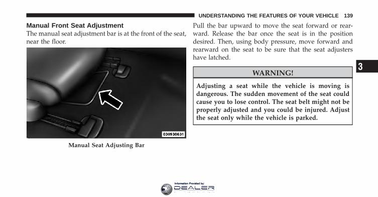
Manual Front Seat AdjustmentThe manual seat adjustment bar is at the front of the seat,near the floor.
Pull the bar upward to move the seat forward or rear-ward. Release the bar once the seat is in the positiondesired. Then, using body pressure, move forward andrearward on the seat to be sure that the seat adjustershave latched.
WARNING!
Adjusting a seat while the vehicle is moving isdangerous. The sudden movement of the seat couldcause you to lose control. The seat belt might not beproperly adjusted and you could be injured. Adjustthe seat only while the vehicle is parked.
Manual Seat Adjusting Bar
3
UNDERSTANDING THE FEATURES OF YOUR VEHICLE 139
Information Provided by:

Driver Seat Manual Height Adjuster — IfEquippedA lever style height adjustment feature enhances comfortfor petite as well as tall drivers. A lever with a ratchetingmechanism, located on the outboard side of the seat,raises and lowers it. Total travel is 2.2 in (56 mm).
Reclining SeatsThe recliner control is located on the side of the seat. Torecline, lean forward slightly before lifting the lever, thenlean back to the desired position and release the lever.Lean forward and lift the lever to return the seatback toits normal position.
Manual Seat Height Adjustment Lever Seatback Adjustment
140 UNDERSTANDING THE FEATURES OF YOUR VEHICLE
Information Provided by:

WARNING!
• Adjusting a seat while the vehicle is moving isdangerous. The sudden movement of the seatcould cause you to lose control. The seat belt mightnot be properly adjusted and you could be injured.Adjust the seat only while the vehicle is parked.
• Do not ride with the seatback reclined so that theshoulder belt is no longer resting against yourchest. In a collision you could slide under the seatbelt and be seriously or even fatally injured. Usethe recliner only when the vehicle is parked.
Lumbar Support — If EquippedThis feature allows you to increase or decrease theamount of lumbar support. The control lever is locatedon the outboard side of the driver’s seatback. Turn thecontrol lever downward to increase and upward todecrease the desired amount of lumbar support.
Head RestraintsHead restraints are designed to reduce the risk of injuryby restricting head movement in the event of a rearimpact. Head restraints should be adjusted so that the topof the head restraint is located above the top of your ear.
Lumbar Support
3
UNDERSTANDING THE FEATURES OF YOUR VEHICLE 141
Information Provided by:

WARNING!
The head restraints for all occupants must be prop-erly adjusted prior to operating the vehicle or occu-pying a seat. Head restraints should never be ad-justed while the vehicle is in motion. Driving avehicle with the head restraints improperly adjustedor removed could cause serious injury or death in theevent of a collision.
Active Head Restraints — Front SeatsActive Head Restraints are passive, deployable compo-nents, and vehicles with this equipment cannot be readilyidentified by any markings, only through visual inspec-tion of the head restraint. The head restraint will be splitin two halves, with the front half being soft foam andtrim, the back half being decorative plastic.
When AHRs deploy during a rear impact, the front halfof the head restraint extends forward to minimize the gapbetween the back of the occupant’s head and the AHR.This system is designed to help prevent or reduce theextent of injuries to the driver and front passenger incertain types of rear impacts. Refer to “Occupant Re-straints” in “Things To Know Before Starting Your Ve-hicle” for further information.
To raise the head restraint, pull upward on the headrestraint. To lower the head restraint, press the pushbutton, located at the base of the head restraint, and pushdownward on the head restraint.
142 UNDERSTANDING THE FEATURES OF YOUR VEHICLE
Information Provided by:

For comfort the Active Head Restraints can be tiltedforward and rearward. To tilt the head restraint closer tothe back of your head, pull forward on the bottom of thehead restraint. Push rearward on the bottom of the headrestraint to move the head restraint away from yourhead.
Push Button Active Head Restraint (Normal Position)
3
UNDERSTANDING THE FEATURES OF YOUR VEHICLE 143
Information Provided by:
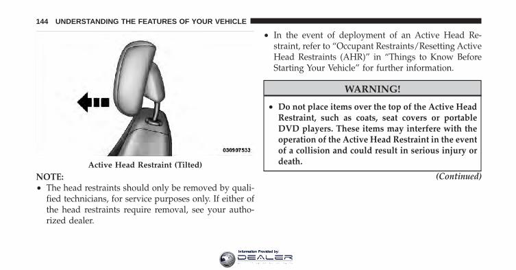
NOTE:• The head restraints should only be removed by quali-
fied technicians, for service purposes only. If either ofthe head restraints require removal, see your autho-rized dealer.
• In the event of deployment of an Active Head Re-straint, refer to “Occupant Restraints/Resetting ActiveHead Restraints (AHR)” in “Things to Know BeforeStarting Your Vehicle” for further information.
WARNING!
• Do not place items over the top of the Active HeadRestraint, such as coats, seat covers or portableDVD players. These items may interfere with theoperation of the Active Head Restraint in the eventof a collision and could result in serious injury ordeath.
(Continued)Active Head Restraint (Tilted)
144 UNDERSTANDING THE FEATURES OF YOUR VEHICLE
Information Provided by:

WARNING! (Continued)• Active Head Restraints may be deployed if they
are struck by an object such as a hand, foot or loosecargo. To avoid accidental deployment of the Ac-tive Head Restraint ensure that all cargo is se-cured, as loose cargo could contact the Active HeadRestraint during sudden stops. Failure to followthis warning could cause personal injury if theActive Head Restraint is deployed.
Head Restraints — Rear SeatsThe rear seat head restraints are fixed and cannot beadjusted. For proper routing of a Child Seat Tether referto “Occupant Restraints” in “Things to Know BeforeStarting Your Vehicle” for further information.
Fold-Flat Passenger SeatbackThe recline handle on the front passenger seat alsoreleases the seatback to fold forward.
Seatback Adjustment
3
UNDERSTANDING THE FEATURES OF YOUR VEHICLE 145
Information Provided by:

The hard seatback features a work surface and a moldedrim for retaining items stored on the seatback panel.
Folding Rear SeatTo provide additional storage area, the rear seatback canbe folded forward. Pull on the loops shown in the pictureto fold down either or both seatbacks.
When returning the rear seatback to the upright position,be sure the seatback is latched.
Fold-Flat Front Passenger Seat Folding Rear Seats
146 UNDERSTANDING THE FEATURES OF YOUR VEHICLE
Information Provided by:

WARNING!
The rear cargo area of the vehicle (with the rearseatbacks in the locked-up or folded down position)should not be used as a play area by children. Theycould be seriously injured in a collision. Childrenshould be seated and using the proper restraintsystem.
Folding Rear Seat Center ArmrestThe rear seat is equipped with a folding armrest withcupholders.
Folding Rear Seat Armrest
3
UNDERSTANDING THE FEATURES OF YOUR VEHICLE 147
Information Provided by:

TO OPEN AND CLOSE THE HOODTo open the hood, two latches must be released.
1. Pull the hood release lever located under the left sideof the instrument panel.
2. Then lift the secondary latch located under the frontedge of the hood, near the center and raise the hood.
Use the hood prop rod to secure the hood in the openposition. Place the upper end of the prop rod in the holeon the left underside of the hood.
Hood Release Lever
Hood Safety Catch
148 UNDERSTANDING THE FEATURES OF YOUR VEHICLE
Information Provided by:

NOTE: Before closing the hood, make sure to stow theprop rod in its proper location.
CAUTION!
To prevent possible damage, do not slam the hood toclose it. Use a firm downward push at the center ofthe hood to ensure that both latches engage.
WARNING!
Be sure the hood is fully latched before driving yourvehicle. If the hood is not fully latched, it could openwhen the vehicle is in motion and block your vision.Failure to follow this warning could result in seriousinjury or death.
LIGHTS
Multifunction LeverThe multifunction lever controls the operation of theparking lights, headlights, headlight beam selection,
Hood Prop Rod Hole Location
3
UNDERSTANDING THE FEATURES OF YOUR VEHICLE 149
Information Provided by:

passing light, fog lights, instrument panel light dimmingand turn signals. The multifunction lever is located onthe left side of the steering column.
Headlights And Parking LightsTurn the end of the multifunction lever to the first detentfor parking light operation. Turn to the second detent forheadlight operation.
Multifunction LeverHeadlight Switch
150 UNDERSTANDING THE FEATURES OF YOUR VEHICLE
Information Provided by:

Automatic Headlights — If EquippedTurning the end of the multifunction lever to the thirddetent (AUTO), will activate the automatic headlightsystem.
With the engine running and the multifunction lever inthe AUTO position, the headlights will turn on and turnoff based on the surrounding light levels.
Headlight Time DelayThere is also a feature that delays turning off the vehiclelights for 30, 60 or 90 seconds after the ignition switch isturned OFF. To activate the headlight delay, the multi-function lever must be rotated to the off position after theignition switch is turned OFF. Only the headlights willilluminate during this time. Refer to “Electronic VehicleInformation Center (EVIC)/Customer-ProgrammableFeatures” in “Understanding Your Instrument Panel” forfurther information.
Headlight Switch
3
UNDERSTANDING THE FEATURES OF YOUR VEHICLE 151
Information Provided by:

Turn SignalsMove the multifunction lever up or down and the arrowson each side of the instrument cluster flash to showproper operation of the front and rear turn signal lights.
NOTE: If either light remains on and does not flash, orthere is a very fast flash rate, check for a defective outsidelight bulb. If an indicator fails to light when the lever ismoved, it would suggest that the indicator bulb isdefective.
Lane Change AssistTap the lever up or down once, without moving beyondthe detent, and the turn signal (right or left) will flashthree times then automatically turn off.
High/Low Beam SwitchPush the multifunction lever away from you to switchthe headlights to high beam. Pull the lever toward you, toswitch the headlights back to low beam.
Turn Signal Control
152 UNDERSTANDING THE FEATURES OF YOUR VEHICLE
Information Provided by:

Flash-To-PassYou can signal another vehicle with your headlights bylightly pulling the multifunction lever toward you. Thiswill turn on the high beam headlights until the lever isreleased.
NOTE: If the multifunction lever is held in the flash-to-pass position for more than 15 seconds, the high beamswill shut off. If this occurs, wait 30 seconds for the nextflash-to-pass operation.
Fog Lights — If EquippedThe front fog light switch is on the multifunctionlever. To activate the front fog lights, turn on theparking lights or the low beam headlights and pull
out the end of the multifunction lever.NOTE: The front fog lights will only operate with theheadlights on low beam. Selecting high beam headlightswill turn off the front fog lights.
Daytime Running Lights — If EquippedThe front turn signal lamps will turn on as DaytimeRunning Lights whenever the ignition is ON, the engine
Front Fog Light Control
3
UNDERSTANDING THE FEATURES OF YOUR VEHICLE 153
Information Provided by:

is running, the headlight switch is off, the parking brakeis released and the shift lever is in any position exceptPARK.
NOTE: The Daytime Running Lights will flash when aturn signal is in operation and return to DRL mode whenthe turn signal is not operating.
Lights On ReminderIf the headlights or parking lights are on after the ignitionis turned OFF, a chime will sound to alert the driverwhen the driver’s door is opened.
Instrument Panel DimmerRotate the center portion of the lever to the extremebottom position to fully dim the instrument panel lightsand prevent the interior lights from illuminating when adoor is opened.
Rotate the center portion of the lever up to increase thebrightness of the instrument panel lights when the park-ing lights or headlights are on.
Rotate the center portion of the lever upward to the nextdetent position to brighten the odometer and radio whenthe parking lights or headlights are on.
Rotate the center portion of the lever upward to the lastdetent to turn on the interior lighting.
Dimmer Control
154 UNDERSTANDING THE FEATURES OF YOUR VEHICLE
Information Provided by:

Map/Reading/Interior LightsThese lights are mounted between the sun visors abovethe rearview mirror. Each light can be turned on bypressing the barrel. Press the barrel a second time to turnthe light off. Both of these lights can swivel so that thelight can be aimed at a specific spot, if desired. The lightswill remain on until the switch is pressed a second time,so be sure they have been turned off before leaving thevehicle. They will not turn off automatically. Interiorlighting also comes on when a door is opened or thedimmer control is turned fully upward, past the seconddetent.
There is a second light located midway back in theheadliner.
Interior Dome Lamp
3
UNDERSTANDING THE FEATURES OF YOUR VEHICLE 155
Information Provided by:
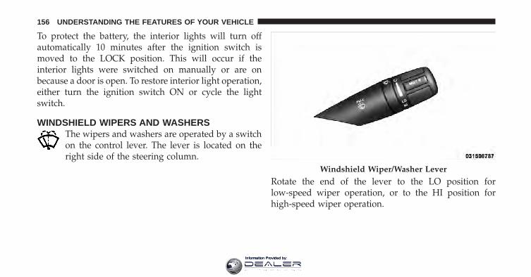
To protect the battery, the interior lights will turn offautomatically 10 minutes after the ignition switch ismoved to the LOCK position. This will occur if theinterior lights were switched on manually or are onbecause a door is open. To restore interior light operation,either turn the ignition switch ON or cycle the lightswitch.
WINDSHIELD WIPERS AND WASHERSThe wipers and washers are operated by a switchon the control lever. The lever is located on theright side of the steering column.
Rotate the end of the lever to the LO position forlow-speed wiper operation, or to the HI position forhigh-speed wiper operation.
Windshield Wiper/Washer Lever
156 UNDERSTANDING THE FEATURES OF YOUR VEHICLE
Information Provided by:

NOTE: The wipers will automatically return to the parkposition if you turn the ignition switch OFF while theyare operating. The wipers will resume operation whenyou turn the ignition switch to the ON position again.
CAUTION!
• Turn the windshield wipers off when drivingthrough an automatic car wash. Damage to thewindshield wipers may result if the wiper controlis left in any position other than off.
• Always remove any buildup of snow that preventsthe windshield wiper blades from returning to theoff position. If the windshield wiper control isturned off and the blades cannot return to the offposition, damage to the wiper motor may occur.
Intermittent Wiper SystemUse the intermittent wiper system when weather condi-tions make a single wiping cycle with a variable pausebetween cycles desirable. Rotate the end of the wind-shield wiper/washer control lever to the first detent, andthen turn the end of the lever to select the desired delayinterval. There are five delay settings, which allow you to
Changing Wiper Speeds
3
UNDERSTANDING THE FEATURES OF YOUR VEHICLE 157
Information Provided by:

regulate the wipe interval from a minimum of one cycleevery second to a maximum of approximately 18 secondsbetween cycles.
NOTE: The wiper delay times depend on vehicle speed.If the vehicle is moving less than 10 mph (16 km/h),delay times will be doubled.
Windshield WashersTo use the washer, pull the windshield wiper/washercontrol lever toward you and hold it for as long aswasher spray is desired.
If you activate the washer while the wiper control is inthe delay range, the wipers will operate in low-speed fortwo wipe cycles after releasing the lever and then resumethe intermittent interval previously selected.
If you activate the washer while the wiper control is inthe off position, the wipers will operate for two wipecycles and then turn off.
Changing Intermittent Settings
158 UNDERSTANDING THE FEATURES OF YOUR VEHICLE
Information Provided by:

WARNING!
Sudden loss of visibility through the windshieldcould lead to a collision. You might not see othervehicles or other obstacles. To avoid sudden icing ofthe windshield during freezing weather, warm thewindshield with defroster before and during wind-shield washer use.
Mist FeaturePush down on the wiper control lever to activate a singlewipe to clear the windshield of road mist or spray froma passing vehicle. As long as the lever is held down, thewipers will continue to operate.
NOTE: The mist feature does not activate the washerpump; therefore, no washer fluid will be sprayed on thewindshield. The wash function must be used in order tospray the windshield with washer fluid.
Headlights With Wipers Feature (Available WithAutomatic Headlights Only)When this feature is active, the headlights will turn onapproximately 10 seconds after the wipers are turned onif the multifunction lever (on the left side of the steering
Mist Control
3
UNDERSTANDING THE FEATURES OF YOUR VEHICLE 159
Information Provided by:

column) is placed in the AUTO position. In addition, theheadlights will turn off when the wipers are turned off ifthey were turned on by this feature.
The headlights with wipers feature can be turned on oroff through the Electronic Vehicle Information Center(EVIC) — if equipped. Refer to “Electronic Vehicle Infor-mation Center (EVIC)/Personal Settings (Customer-Programmable Features)” in “Understanding Your In-strument Panel” for further information.
TILT/TELESCOPING STEERING COLUMNThis feature allows you to tilt the steering columnupward or downward. It also allows you to lengthen orshorten the steering column. The tilt/telescoping lever islocated below the steering wheel at the end of thesteering column.
To unlock the steering column, push the lever down-ward. To tilt the steering column, move the steeringwheel upward or downward as desired. To lengthen orshorten the steering column, pull the steering wheel
Tilt/Telescoping Lever
160 UNDERSTANDING THE FEATURES OF YOUR VEHICLE
Information Provided by:

outward or push it inward as desired. To lock the steeringcolumn in position, pull the lever upward until fullyengaged.
WARNING!
Do not adjust the steering column while driving.Adjusting the steering column while driving or driv-ing with the steering column unlocked, could causethe driver to lose control of the vehicle. Be sure thesteering column is locked before driving your ve-hicle. Failure to follow this warning may result inserious injury or death.
ELECTRONIC SPEED CONTROL — IF EQUIPPEDWhen engaged, the Electronic Speed Control takes overaccelerator operations at speeds greater than 25 mph(40 km/h).
The Electronic Speed Control buttons are located on theright side of the steering wheel.
NOTE: In order to ensure proper operation, the Elec-tronic Speed Control System has been designed to shutdown if multiple Speed Control functions are operated at
1 — ON/OFF 2 — RES +4 — CANCEL 3 — SET -
3
UNDERSTANDING THE FEATURES OF YOUR VEHICLE 161
Information Provided by:

the same time. If this occurs, the Electronic Speed ControlSystem can be reactivated by pushing the ElectronicSpeed Control ON/OFF button and resetting the desiredvehicle set speed.
To ActivatePush the ON/OFF button. The Cruise Indicator Light inthe instrument cluster will illuminate. To turn the systemoff, push the ON/OFF button a second time. The CruiseIndicator Light will turn off. The system should beturned off when not in use.
WARNING!
Leaving the Electronic Speed Control system onwhen not in use is dangerous. You could accidentallyset the system or cause it to go faster than you want.You could lose control and have an accident. Alwaysleave the system OFF when you are not using it.
To Set A Desired SpeedTurn the Electronic Speed Control ON. When the vehiclehas reached the desired speed, press the SET (-) buttonand release. Release the accelerator and the vehicle willoperate at the selected speed.
NOTE: The vehicle should be traveling at a steadyspeed and on level ground before pressing the SETbutton.
To DeactivateA soft tap on the brake pedal, pushing the CANCELbutton, or normal brake pressure while slowing thevehicle will deactivate Electronic Speed Control withouterasing the set speed memory. Pressing the ON/OFFbutton or turning the ignition switch OFF erases the setspeed memory.
162 UNDERSTANDING THE FEATURES OF YOUR VEHICLE
Information Provided by:

To Resume SpeedTo resume a previously set speed, push the RES (+)button and release. Resume can be used at any speedabove 20 mph (32 km/h).
To Vary The Speed SettingWhen the Electronic Speed Control is set, you can in-crease speed by pushing the RES (+) button. If the buttonis continually pressed, the set speed will continue toincrease until the button is released, then the new setspeed will be established.
Pressing the RES (+) button once will result in a 1 mph(2 km/h) increase in set speed. Each subsequent tap ofthe button results in an increase of 1 mph (2 km/h).
To decrease speed while the Electronic Speed Control isset, push the SET (-) button. If the button is continuallyheld in the SET (-) position, the set speed will continue to
decrease until the button is released. Release the buttonwhen the desired speed is reached, and the new set speedwill be established.
Pressing the SET (-) button once will result in a 1 mph(2 km/h) decrease in set speed. Each subsequent tap ofthe button results in a decrease of 1 mph (2 km/h).
To Accelerate For PassingPress the accelerator as you would normally. When thepedal is released, the vehicle will return to the set speed.
Using Electronic Speed Control On HillsThe transmission may downshift on hills to maintain thevehicle set speed.
NOTE: The Electronic Speed Control system maintainsspeed up and down hills. A slight speed change onmoderate hills is normal.
3
UNDERSTANDING THE FEATURES OF YOUR VEHICLE 163
Information Provided by:

On steep hills, a greater speed loss or gain may occur soit may be preferable to drive without Electronic SpeedControl.
WARNING!
Electronic Speed Control can be dangerous where thesystem cannot maintain a constant speed. Your ve-hicle could go too fast for the conditions, and youcould lose control and have an accident. Do not useElectronic Speed Control in heavy traffic or on roadsthat are winding, icy, snow-covered or slippery.
GARAGE DOOR OPENER — IF EQUIPPEDHomeLink� replaces up to three hand-held transmittersthat operate devices such as garage door openers, motor-ized gates, lighting or home security systems. TheHomeLink� unit is powered by your vehicles 12 Voltbattery.
The HomeLink� buttons, located on either the overheadconsole, headliner or sunvisor, designate the three differ-ent HomeLink� channels. The HomeLink� indicator islocated above the center button.
HomeLink� Buttons/Overhead Consoles
164 UNDERSTANDING THE FEATURES OF YOUR VEHICLE
Information Provided by:

NOTE: HomeLink� is disabled when the Vehicle Secu-rity Alarm is active.
Before You Begin Programming HomeLink�Be sure that your vehicle is parked outside of the garagebefore you begin programming.
For more efficient programming and accurate transmis-sion of the radio-frequency signal it is recommended thata new battery be placed in the hand-held transmitter ofthe device that is being programmed to the HomeLink�system.
Erase all channels before you begin programming. Toerase the channels place the ignition in the ON/RUNposition and press and hold the two outside HomeLink�buttons (I and III) for up 20 seconds or until the redindicator flashes.
NOTE:• Erasing all channels should only be performed when
programming HomeLink� for the first time. Do noterase channels when programming additional buttons.
HomeLink� Buttons/Sunvisor/Headliner
3
UNDERSTANDING THE FEATURES OF YOUR VEHICLE 165
Information Provided by:

• If you have any problems, or require assistance, pleasecall toll-free 1–800–355–3515 or, on the Internet atwww.HomeLink.com for information or assistance.
Programming A Rolling CodeFor programming garage door openers that were manu-factured after 1995. These garage door openers can beidentified by the “LEARN” or “TRAIN” button locatedwhere the hanging antenna is attached to the garage dooropener. It is NOT the button that is normally used toopen and close the door. The name and color of thebutton may vary by manufacturer.
1. Turn the ignition switch to the ON/RUN position.
2. Place the hand-held transmitter 1 to 3 in (3 to 8 cm)away from the HomeLink� button you wish to programwhile keeping the HomeLink� indicator light in view.
Training The Garage Door Opener
1 — Door Opener2 — Training Button
166 UNDERSTANDING THE FEATURES OF YOUR VEHICLE
Information Provided by:

3. Simultaneously press and hold both the Homelink�button you want to program and the hand-held transmit-ter button.
4. Continue to hold both buttons and observe the indi-cator light. The Homelink� indicator will flash slowlyand then rapidly after Homelink� has received the fre-quency signal from the hand-held transmitter. Releaseboth buttons after the indicator light changes from slowto rapid.
5. At the garage door opener motor (in the garage),locate the “LEARN” or “TRAINING” button. This canusually be found where the hanging antenna wire isattached to the garage door opener/device motor. Firmlypress and release the “LEARN” or “TRAINING” button.On some garage door openers/devices there may be alight that blinks when the garage door opener/device isin the LEARN/TRAIN mode.
NOTE: You have 30 seconds in which to initiate the nextstep after the LEARN button has been pressed.
6. Return to the vehicle and press the programmedHomeLink� button twice (holding the button for twoseconds each time). If the garage door opener/deviceactivates, programming is complete.
NOTE: If the garage door opener/device does notactivate, press the button a third time (for two seconds) tocomplete the training.
To program the remaining two HomeLink� buttons,repeat each step for each remaining button. DO NOTerase the channels.
Reprogramming A Single HomeLink� ButtonTo reprogram a channel that has been previously trained,follow these steps:
1. Turn the ignition switch to the ON/RUN position.
3
UNDERSTANDING THE FEATURES OF YOUR VEHICLE 167
Information Provided by:

2. Press and hold the desired HomeLink� button untilthe indicator light begins to flash after 20 seconds. Do notrelease the button.
3. Without releasing the button proceed with “Program-ming A Rolling Code” Step 2 and follow all remainingsteps.
Programming A Non-Rolling CodeFor programming Garage Door Openers manufacturedbefore 1995.
1. Turn the ignition switch to the ON/RUN position.
2. Place the hand-held transmitter 1 to 3 in (3 to 8 cm)away from the HomeLink� button you wish to programwhile keeping the HomeLink� indicator light in view.
3. Simultaneously press and hold both the Homelink�button you want to program and the hand-held transmit-ter button.
4. Continue to hold both buttons and observe the indi-cator light. The Homelink� indicator will flash slowlyand then rapidly after Homelink� has received the fre-quency signal from the hand-held transmitter. Releaseboth buttons after the indicator light changes from slowto rapid.
5. Press and hold the programmed HomeLink� buttonand observe the indicator light.
• If the indicator light stays on constantly, program-ming is complete and the garage door/deviceshould activate when the HomeLink� button ispressed.
• To program the two remaining HomeLink� buttons,repeat each step for each remaining button. DONOT erase the channels.
168 UNDERSTANDING THE FEATURES OF YOUR VEHICLE
Information Provided by:

Reprogramming A Single HomeLink� ButtonTo reprogram a channel that has been previously trained,follow these steps:
1. Turn the ignition switch to the ON/RUN position.
2. Press and hold the desired HomeLink� button untilthe indicator light begins to flash after 20 seconds. Do notrelease the button.
3. Without releasing the button proceed with “Program-ming A Non-Rolling Code” Step 2 and follow all remain-ing steps.
Canadian/Gate Operator ProgrammingFor programming transmitters in Canada/United Statesthat require the transmitter signals to “time-out” afterseveral seconds of transmission.
Canadian radio frequency laws require transmitter sig-nals to time-out (or quit) after several seconds of trans-mission – which may not be long enough for HomeLink�
to pick up the signal during programming. Similar to thisCanadian law, some U.S. gate operators are designed totime-out in the same manner.
It may be helpful to unplug the device during the cyclingprocess to prevent possible overheating of the garagedoor or gate motor.
1. Turn the ignition switch to the ON/RUN position.
2. Place the hand-held transmitter 1 to 3 in (3 to 8 cm)away from the HomeLink� button you wish to programwhile keeping the HomeLink� indicator light in view.
3. Continue to press and hold the HomeLink� button,while you press and release (“cycle”), your hand-heldtransmitter every two seconds until HomeLink� hassuccessfully accepted the frequency signal. The indicatorlight will flash slowly and then rapidly when fullytrained.
3
UNDERSTANDING THE FEATURES OF YOUR VEHICLE 169
Information Provided by:

4. Watch for the HomeLink� indicator to change flashrates. When it changes, it is programmed. It may take upto 30 seconds or longer in rare cases. The garage doormay open and close while you are programming.
5. Press and hold the programmed HomeLink� buttonand observe the indicator light.
• If the indicator light stays on constantly, program-ming is complete and the garage door/deviceshould activate when the HomeLink� button ispressed.
• To program the two remaining HomeLink� buttons,repeat each step for each remaining button. DONOT erase the channels.
If you unplugged the garage door opener/device forprogramming, plug it back in at this time.
Reprogramming A Single HomeLink� ButtonTo reprogram a channel that has been previously trained,follow these steps:
1. Turn the ignition switch to the ON/RUN position.
2. Press and hold the desired HomeLink� button untilthe indicator light begins to flash after 20 seconds. Do notrelease the button.
3. Without releasing the button proceed with“Canadian/Gate Operator Programming” Step 2 andfollow all remaining steps.
Using HomeLink�To operate, press and release the programmedHomeLink� button. Activation will now occur for theprogrammed device (i.e., garage door opener, gate opera-tor, security system, entry door lock, home/office light-ing, etc.,). The hand-held transmitter of the device mayalso be used at any time.
170 UNDERSTANDING THE FEATURES OF YOUR VEHICLE
Information Provided by:
SecurityIt is advised to erase all channels before you sell or turnin your vehicle.
To do this, press and hold the two outside buttons for20 seconds until the red indicator flashes. Note that allchannels will be erased. Individual channels cannot beerased.
The HomeLink� Universal Transceiver is disabled whenthe Vehicle Security Alarm is active.
Troubleshooting TipsIf you are having trouble programming HomeLink�, hereare some of the most common solutions:
• Replace the battery in the original hand-held transmit-ter.
• Press the LEARN button on the Garage Door Openerto complete the training for a Rolling Code.
• Did you unplug the device for programming andremember to plug it back in?
If you have any problems, or require assistance, pleasecall toll-free 1–800–355–3515 or, on the Internet atwww.HomeLink.com for information or assistance.
3
UNDERSTANDING THE FEATURES OF YOUR VEHICLE 171
Information Provided by:

WARNING!
• Your motorized door or gate will open and closewhile you are programming the universal trans-ceiver. Do not program the transceiver if people,pets or other objects are in the path of the door orgate. Only use this transceiver with a garage dooropener that has a “stop and reverse” feature asrequired by Federal safety standards. This includesmost garage door opener models manufacturedafter 1982. Do not use a garage door opener withoutthese safety features. Call toll-free 1–800–355–3515or, on the Internet at www.HomeLink.com forsafety information or assistance.
• Vehicle exhaust contains carbon monoxide, a dan-gerous gas. Do not run your vehicle in the garagewhile programming the transceiver. Exhaust gascan cause serious injury or death.
General InformationThis device complies with FCC rules Part 15 and IndustryCanada RSS-210. Operation is subject to the followingtwo conditions:
1. This device may not cause harmful interference.
2. This device must accept any interference that may bereceived including interference that may cause undesiredoperation.
NOTE:• The transmitter has been tested and it complies with
FCC and IC rules. Changes or modifications notexpressly approved by the party responsible for com-pliance could void the user’s authority to operate thedevice.
• The term IC before the certification/registration num-ber only signifies that Industry Canada technicalspecifications were met.
172 UNDERSTANDING THE FEATURES OF YOUR VEHICLE
Information Provided by:

POWER SUNROOF — IF EQUIPPEDThe sunroof controls are mounted between the dome/reading lights.
WARNING!
• Never leave children in a vehicle with the key inthe ignition switch. Occupants, particularly unat-tended children, can become entrapped by thepower sunroof while operating the power sunroofswitch. Such entrapment may result in seriousinjury or death.
• In a collision, there is greater risk of being thrownfrom a vehicle with an open sunroof. You couldalso be seriously injured or killed. Always fastenyour seat belt properly and make sure all passen-gers are properly secured too.
• Do not allow small children to operate the sun-roof. Never allow your fingers, other body parts, orany object to project through the sunroof opening.Injury may result.
Power Sunroof Switch
3
UNDERSTANDING THE FEATURES OF YOUR VEHICLE 173
Information Provided by:

Opening Sunroof — ExpressPress the switch rearward and release it within one-halfsecond and the sunroof will open automatically from anyposition. The sunroof will open fully and stop automati-cally. This is called “Express Open”. During ExpressOpen operation, any movement of the sunroof switchwill stop the sunroof.
Opening Sunroof — Manual ModeTo open the sunroof, press and hold the switch rearwardto full open. Any release of the switch will stop themovement and the sunroof will remain in a partiallyopened condition until the switch is pushed and heldrearward again.
Closing Sunroof — ExpressPress the switch forward and release it within one-halfsecond and the sunroof will close automatically from any
position. The sunroof will close fully and stop automati-cally. This is called “Express Close”. During ExpressClose operation, any movement of the switch will stopthe sunroof.
Closing Sunroof — Manual ModeTo close the sunroof, press and hold the switch in theforward position. Any release of the switch will stop themovement and the sunroof will remain in a partiallyclosed condition until the switch is pushed and heldforward again.
Pinch Protect FeatureThis feature will detect an obstruction in the opening ofthe sunroof during Express Close operation. If an ob-struction in the path of the sunroof is detected, thesunroof will automatically retract. Remove the obstruc-tion if this occurs. Next, press the switch forward andrelease to Express Close.
174 UNDERSTANDING THE FEATURES OF YOUR VEHICLE
Information Provided by:

NOTE: Pinch protection is disabled while the switch ispressed.
Venting Sunroof — ExpressPress and release the Vent button within one half secondand the sunroof will open to the vent position. This iscalled “Express Vent”, and it will occur regardless ofsunroof position. During Express Vent operation, anymovement of the switch will stop the sunroof.
Sunshade OperationThe sunshade can be opened manually. However, thesunshade will open automatically as the sunroof opens.
NOTE: The sunshade cannot be closed if the sunroof isopen.
Wind BuffetingWind buffeting can be described as the perception ofpressure on the ears or a helicopter-type sound in theears. Your vehicle may exhibit wind buffeting with the
windows down, or the sunroof (if so equipped) is incertain open or partially open positions. This is a normaloccurrence and can be minimized. If the buffeting occurswith the rear windows open, then open the front and rearwindows together to minimize the buffeting. If thebuffeting occurs with the sunroof open, adjust the sun-roof opening to minimize the buffeting.
Sunroof MaintenanceUse only a non-abrasive cleaner and a soft cloth to cleanthe glass panel.
Ignition Off OperationFor vehicles not equipped with the Electronic VehicleInformation Center (EVIC), the power sunroof switchwill remain active for 45 seconds after the ignition switchis turned OFF. Opening either front door will cancel thisfeature.
3
UNDERSTANDING THE FEATURES OF YOUR VEHICLE 175
Information Provided by:

For vehicles equipped with the EVIC, the power sunroofswitch will remain active for up to 10 minutes after theignition switch is turned OFF. Opening either front doorwill cancel this feature. The time is programmable. Referto “Electronic Vehicle Information Center (EVIC)/Personal Settings (Customer-Programmable Features)” in“Understanding Your Instrument Panel” for furtherinformation.
ELECTRICAL POWER OUTLETSThere are two 12 Volt (13 Amp) electrical power outletson this vehicle. Both of the power outlets are protected bya fuse.
The instrument panel power outlet, located below theclimate control knobs, has power available only when theignition is ON. This power outlet will also operate aconventional cigar lighter unit.
NOTE: To preserve the heating element, do not hold thelighter in the heating position.
Instrument Panel Power Outlet
176 UNDERSTANDING THE FEATURES OF YOUR VEHICLE
Information Provided by:

A second power outlet is located inside the center con-sole.
The center console power outlet is powered directly fromthe battery (power available at all times). Items pluggedinto this power outlet may discharge the battery and/orprevent the engine from starting.
NOTE: To ensure proper operation a MOPAR� knoband element must be used.
Center Console
3
UNDERSTANDING THE FEATURES OF YOUR VEHICLE 177
Information Provided by:
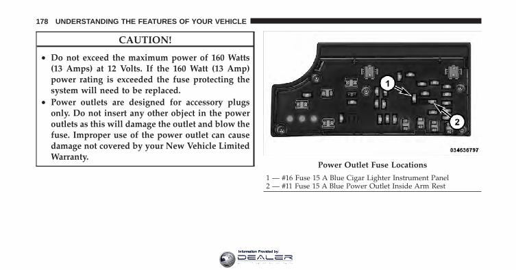
CAUTION!
• Do not exceed the maximum power of 160 Watts(13 Amps) at 12 Volts. If the 160 Watt (13 Amp)power rating is exceeded the fuse protecting thesystem will need to be replaced.
• Power outlets are designed for accessory plugsonly. Do not insert any other object in the poweroutlets as this will damage the outlet and blow thefuse. Improper use of the power outlet can causedamage not covered by your New Vehicle LimitedWarranty.
Power Outlet Fuse Locations
1 — #16 Fuse 15 A Blue Cigar Lighter Instrument Panel2 — #11 Fuse 15 A Blue Power Outlet Inside Arm Rest
178 UNDERSTANDING THE FEATURES OF YOUR VEHICLE
Information Provided by:

WARNING!
To avoid serious injury or death:• Only devices designed for use in this type of
outlet should be inserted into any 12 Volt outlet.• Do not touch with wet hands.• Close the lid when not in use and while driving
the vehicle.• If this outlet is mishandled, it may cause an
electric shock and failure.
CAUTION!
• Many accessories that can be plugged in drawpower from the vehicle’s battery, even when not inuse (i.e., cellular phones, etc.). Eventually, ifplugged in long enough, the vehicle’s battery willdischarge sufficiently to degrade battery lifeand/or prevent the engine from starting.
• Accessories that draw higher power (i.e., coolers,vacuum cleaners, lights, etc.) will degrade thebattery even more quickly. Only use these inter-mittently and with greater caution.
• After the use of high power draw accessories, orlong periods of the vehicle not being started (withaccessories still plugged in), the vehicle must bedriven a sufficient length of time to allow thegenerator to recharge the vehicle’s battery.
3
UNDERSTANDING THE FEATURES OF YOUR VEHICLE 179
Information Provided by:

CIGAR LIGHTER AND ASH RECEIVER — IFEQUIPPEDAn optional ash receiver is available from your autho-rized dealer and will fit in the center console frontcupholder.
The optional ash receiver also comes with a cigar lighterthat can be used with the power outlets. Refer to “PowerOutlets” in “Understanding the Features of Your Vehicle”for further information.
CUPHOLDERS
Front Seat CupholdersThe cupholders in the center console will accommodateeither two large size cups or two 20 oz (.5 L) bottles orcans. The one-peice insert can be easily removed forcleaning. An optional removable ashtray may be locatedin one of the cupholders.
Rear CupholdersThe rear seat cupholders are located in the armrestbetween the rear seats. Pull down the armrest to use thecupholders.
Front Cupholders
180 UNDERSTANDING THE FEATURES OF YOUR VEHICLE
Information Provided by:

Rear Seat Bottle HolderThere are built-in bottle holders located in both rear doortrim panels.
WARNING!
If containers of hot liquid are placed in the bottleholder, they can spill when the door is closed, burn-ing the occupants. Be careful when closing the doorsto avoid injury.
Rear Cupholders Rear Bottle Holder
3
UNDERSTANDING THE FEATURES OF YOUR VEHICLE 181
Information Provided by:

STORAGE
Glovebox Storage CompartmentThe glovebox storage compartment is located on the rightside of the instrument panel. To open the glovebox, pulloutward on the latch handle located on the front of theglovebox.
CONSOLE FEATURES
StorageThe center console is located between the front driverand passenger seats. The center console armrest slidesforward from design position to provide added usercomfort. The center console can be used for storage andis also equipped with an electrical power outlet. Refer to“Power Outlets” in “Understanding The Feature of YourVehicle” for further information.
Glovebox Storage Compartment
182 UNDERSTANDING THE FEATURES OF YOUR VEHICLE
Information Provided by:

Two separate storage compartments are also locatedunderneath the armrest.
The top compartment holds small items, such as a penand note pad, while the larger bottom compartment willhold CDs and alike. The bottom compartment also con-tains a 12 Volt power outlet. The console’s front openinglid allows for easy access to these compartments.
Center Console Center Console Storage
3
UNDERSTANDING THE FEATURES OF YOUR VEHICLE 183
Information Provided by:

NOTE:• A notch in the front of the console base allows for use
of a cellular phone while it is plugged into the poweroutlet with the armrest latched down.
• The power outlet can also energize the cigar lighter inthe optional cup holder ash receiver.
WARNING!
Do not operate this vehicle with a console compart-ment lid in the open position. Cellular phones, musicplayers, and other handheld electronic devicesshould be stowed while driving. Use of these deviceswhile driving can cause an accident due to distrac-tion, resulting in death or injury.
CARGO AREA FEATURESThe 60/40 split-folding rear seat provides cargo-carryingversatility. The seatbacks fold down easily by pullingnylon tabs between the seatbacks and the bolsters. Whenthe seats are folded down, they provide a continuous,nearly flat extension of the load floor.
When the seatback is folded to the upright position, makesure it is latched by strongly pulling on the top of theseatback above the seat strap.
WARNING!
• Be certain that the seatback is securely locked intoposition. If the seatback in not securely lockedinto position, the seat will not provide the properstability for child seats and/or passengers. Animproperly latched seat could cause serious injury.
(Continued)
184 UNDERSTANDING THE FEATURES OF YOUR VEHICLE
Information Provided by:
WARNING! (Continued)• The cargo area in the rear of the vehicle (with the
rear seatbacks in the locked-up or folded downposition) should not be used as a play area bychildren when the vehicle is in motion. They couldbe seriously injured in a collision. Childrenshould be seated and using the proper restraintsystem.
• To help protect against personal injury, passengersshould not be seated in the rear cargo area. Therear cargo space is intended for load carryingpurposes only, not for passengers, who should sitin seats and use seat belts.
• The weight and position of cargo and passengerscan change the vehicle center of gravity and ve-hicle handling. To avoid loss of control resultingin personal injury, follow these guidelines forloading your vehicle:
Always place cargo evenly on the cargo floor. Put heavierobjects as low and as far forward as possible. Place asmuch cargo as possible in front of the rear axle. Too muchweight or improperly placed weight over or behind therear axle can cause the rear of the vehicle to sway.
Do not pile luggage or cargo higher than the top of theseatback. This could impair visibility or become a dan-gerous projectile in a sudden stop or collision.
3
UNDERSTANDING THE FEATURES OF YOUR VEHICLE 185
Information Provided by:

Ski Pass-ThroughThere is a ski pass-through door located behind the rearseat armrest that allows longer items, such as snow skis,to be stored in the rear cargo area. Lower the armrest andpull downward on the latch to open the ski pass-throughdoor.
REAR WINDOW FEATURES
Rear Window DefrosterThe rear window defroster button is located on theclimate control (Mode) knob. Press this button to
turn on the rear window defroster and the heated outsidemirrors (if equipped). An indicator in the button willilluminate when the rear window defroster is on. Therear window defroster automatically turns off after ap-proximately 10 minutes. For an additional five minutes ofoperation, press the button a second time.
NOTE: To prevent excessive battery drain, use the rearwindow defroster only when the engine is operating.
Ski Pass-Through
186 UNDERSTANDING THE FEATURES OF YOUR VEHICLE
Information Provided by:

CAUTION!
Failure to follow these cautions can cause damage tothe heating elements:• Use care when washing the inside of the rear
window. Do not use abrasive window cleaners onthe interior surface of the window. Use a soft clothand a mild washing solution, wiping parallel tothe heating elements. Labels can be peeled offafter soaking with warm water.
(Continued)
CAUTION! (Continued)• Do not use scrapers, sharp instruments, or abra-
sive window cleaners on the interior surface of thewindow.
• Keep all objects a safe distance from the window. 3
UNDERSTANDING THE FEATURES OF YOUR VEHICLE 187
Information Provided by:

Information Provided by:

UNDERSTANDING YOUR INSTRUMENT PANEL
CONTENTS
� Instrument Panel Features . . . . . . . . . . . . . . . 192
� Instrument Cluster . . . . . . . . . . . . . . . . . . . . 193
� Instrument Cluster Descriptions . . . . . . . . . . . 194
� Mini-Trip Computer — If Equipped . . . . . . . . 207
▫ Control Buttons . . . . . . . . . . . . . . . . . . . . . 208
� Electronic Vehicle Information Center (EVIC) —If Equipped . . . . . . . . . . . . . . . . . . . . . . . . . . 209
▫ Electronic Vehicle Information Center (EVIC)Displays . . . . . . . . . . . . . . . . . . . . . . . . . . . 211
▫ Oil Change Required — If Equipped . . . . . . 212
▫ EVIC Main Menu . . . . . . . . . . . . . . . . . . . . 213
▫ Compass Display . . . . . . . . . . . . . . . . . . . . 214
▫ Average Fuel Economy . . . . . . . . . . . . . . . . 217
▫ Distance To Empty (DTE) . . . . . . . . . . . . . . 217
▫ Tire PSI . . . . . . . . . . . . . . . . . . . . . . . . . . . 217
▫ Elapsed Time . . . . . . . . . . . . . . . . . . . . . . . 218
▫ EVIC Units Selection (Units In Display) . . . . 218
▫ System Status . . . . . . . . . . . . . . . . . . . . . . . 218
▫ Personal Settings(Customer-Programmable Features) . . . . . . . 219
4
Information Provided by:

� Setting The Analog Clock . . . . . . . . . . . . . . . . 221
� Media Center 230 (REQ) — AM/FM StereoRadio And 6–Disc CD/DVD Changer(MP3/WMA AUX Jack) . . . . . . . . . . . . . . . . . . 222
▫ Operating Instructions - Radio Mode . . . . . . 222
▫ Operation Instructions - (Disc Mode For CDAnd MP3/WMA Audio Play, DVD-Video) . . . 230
▫ Notes On Playing MP3/WMA Files . . . . . . . 232
▫ List Button(Disc Mode For MP3/WMA Play) . . . . . . . . . 235
▫ Info Button(Disc Mode For MP3/WMA Play) . . . . . . . . . 235
▫ Uconnect™ Multimedia (Satellite Radio) — IfEquipped . . . . . . . . . . . . . . . . . . . . . . . . . . 237
� Media Center 730N/430/430N (RHR/RER/RBZ/RHB) CD/DVD/HDD/NAV — IfEquipped . . . . . . . . . . . . . . . . . . . . . . . . . . . . 241
▫ Operating Instructions (Voice CommandSystem) — If Equipped . . . . . . . . . . . . . . . . 241
▫ Operating Instructions(Uconnect™ Phone) — If Equipped . . . . . . . 241
� Media Center 130 (Sales Code RES) . . . . . . . . . 241
▫ Operating Instructions — Radio Mode . . . . . 242
▫ Operation Instructions — CD Mode For CDAnd MP3 Audio Play . . . . . . . . . . . . . . . . . 245
▫ Notes On Playing MP3 Files . . . . . . . . . . . . 247
▫ Operation Instructions - Auxiliary Mode . . . . 249
� Media Center 130 With Satellite Radio(Sales Code RES+RSC). . . . . . . . . . . . . . . . . . . 250
▫ Operating Instructions — Radio Mode . . . . . 250
190 UNDERSTANDING YOUR INSTRUMENT PANEL
Information Provided by:

▫ Operation Instructions — CD Mode For CDAnd MP3 Audio Play . . . . . . . . . . . . . . . . . 256
▫ Notes On Playing MP3 Files . . . . . . . . . . . . 258
▫ List Button (CD Mode For MP3 Play) . . . . . . 260
▫ Info Button (CD Mode For MP3 Play) . . . . . . 260
▫ Uconnect™ Multimedia (Satellite Radio) — IfEquipped . . . . . . . . . . . . . . . . . . . . . . . . . . 261
� iPod�/USB/MP3 Control — If Equipped . . . . . 265
▫ Connecting The iPod� Or External USBDevice . . . . . . . . . . . . . . . . . . . . . . . . . . . . 266
▫ Using This Feature . . . . . . . . . . . . . . . . . . . 267
▫ Controlling The iPod� Or External USBDevice Using Radio Buttons . . . . . . . . . . . . . 267
▫ Play Mode . . . . . . . . . . . . . . . . . . . . . . . . . 267
▫ List Or Browse Mode . . . . . . . . . . . . . . . . . 269
▫ Bluetooth Streaming Audio (BTSA) . . . . . . . . 271
� Steering Wheel Audio Controls —If Equipped . . . . . . . . . . . . . . . . . . . . . . . . . . 272
▫ Radio Operation . . . . . . . . . . . . . . . . . . . . . 273
▫ CD Player . . . . . . . . . . . . . . . . . . . . . . . . . 273
� CD/DVD Disc Maintenance . . . . . . . . . . . . . . 274
� Radio Operation And Mobile Phones . . . . . . . 274
� Climate Controls . . . . . . . . . . . . . . . . . . . . . . 274
▫ Manual Heating And Air Conditioning . . . . . 275
▫ Automatic Temperature Control (ATC) — IfEquipped . . . . . . . . . . . . . . . . . . . . . . . . . . 279
▫ Operating Tips . . . . . . . . . . . . . . . . . . . . . . 285
4
UNDERSTANDING YOUR INSTRUMENT PANEL 191
Information Provided by:

INSTRUMENT PANEL FEATURES
1 — Air Outlet 6 — Radio 11 — Storage Compartment2 — Side Window Demister Outlet 7 — Passenger Airbag 12 — Climate Control3 — Instrument Cluster 8 — Glove Compartment 13 — Trunk Release Button4 — Ignition Switch 9 — Heated Seat Switch – If Equipped 14 — Power Outlet5 — Analog Clock 10 — Hazard Switch
192 UNDERSTANDING YOUR INSTRUMENT PANEL
Information Provided by:

INSTRUMENT CLUSTER
4
UNDERSTANDING YOUR INSTRUMENT PANEL 193
Information Provided by:

INSTRUMENT CLUSTER DESCRIPTIONS
1. Temperature GaugeThe temperature gauge shows engine coolant tempera-ture. Any reading below the H (red) mark of the gaugeshows that the engine cooling system is operating prop-erly. The gauge pointer may show a higher than normaltemperature when driving in hot weather, up mountaingrades, in heavy stop and go traffic, or when towing atrailer.
If the pointer rises to the H (red) mark, the instrumentcluster will sound a chime. Pull over and stop the vehicle.Idle the vehicle with the air conditioner turned off untilthe pointer drops back into the normal range. If thepointer remains on the H (red) mark, turn the engine offimmediately and call for service.
There are steps that you can take to slow down animpending overheat condition. If your air conditioning ison, turn it off. The air conditioning system adds heat to
the engine cooling system and turning off the A/Cremoves this heat. You can also turn the Temperaturecontrol to maximum heat, the Mode control to Floor andthe Fan control to High. This allows the heater core to actas a supplement to the radiator and aids in removing heatfrom the engine cooling system.
2. Fuel Door ReminderThis is a reminder that the Fuel Filler Door islocated on the left side of the vehicle.
3. Fuel GaugeWhen the ignition switch is in the ON/RUN position, thepointer will show the level of fuel remaining in the fueltank.
4. SpeedometerIndicates the vehicle speed in miles per hour (MPH) andkilometers per hour (km/h).
194 UNDERSTANDING YOUR INSTRUMENT PANEL
Information Provided by:

5. Low Fuel LightWhen the fuel level drops to approximately 2.0 gal-lons (7.6 Liters), the fuel symbol will light and asingle chime will sound.
NOTE: This light will remain on until a minimum ofapproximately 3.0 gallons of fuel is added.
6. Charging System LightThis light shows the status of the electrical charg-ing system. The light should come on briefly when
the ignition is first turned on and remain on briefly as abulb check. If the light stays on or comes on whiledriving, turn off some of the vehicle’s electrical devices,such as the Front Fog Lights or Rear Window Defroster.If the Charging System Light remains on, it means thatthe vehicle is experiencing a problem with the chargingsystem. Obtain SERVICE IMMEDIATELY. See your localauthorized dealer.
If jump starting is required, refer to “Jump StartingProcedures” in “What To Do In Emergencies”.
7. Air Bag Warning LightThis light will turn on for four to eight secondsas a bulb check when the ignition switch is firstturned to ON/RUN. If the light is either not onduring starting, stays on, or turns on while
driving, have the system inspected at an authorizeddealer as soon as possible. Refer to “Occupant Restraints”in “Things To Know Before Starting Your Vehicle” forfurther information.
8. Seat Belt Reminder LightWhen the ignition switch is first turned to ON/RUN, this light will turn on for four to eightseconds as a bulb check. During the bulb check, if
the driver’s seat belt is unbuckled, a chime will sound.After the bulb check or when driving, if the driver seatbelt remains unbuckled, the Seat Belt Warning Light will
4
UNDERSTANDING YOUR INSTRUMENT PANEL 195
Information Provided by:

flash or remain on continuously. Refer to “OccupantRestraints” in “Things To Know Before Starting YourVehicle” for further information.
9. Oil Pressure Warning LightThis light indicates low engine oil pressure. Thelight will come on and remain on when the
ignition switch is turned from the OFF to the ON/RUNposition, and the light will turn off after the engine isstarted. If the bulb does not come on during starting,have the system checked by an authorized dealer.
If the light comes on and remains on while driving, stopthe vehicle and shut off the engine. DO NOT OPERATETHE VEHICLE UNTIL THE CAUSE IS CORRECTED.
The light does not show the quantity of oil in the engine.This can be determined using the procedure shown in“Maintaining Your Vehicle”.
10. Engine Temperature Warning LightThis light warns of an overheated engine condi-tion. As engine coolant temperatures rise and thegauge approaches H , this indicator will illuminate
and a single chime will sound after reaching a setthreshold. Further overheating will cause the tempera-ture gauge to pass H , the indicator will continuouslyflash and a continuous chime will occur until the engineis allowed to cool.
If the light turns on while driving, safely pull over andstop the vehicle. If the A/C system is on, turn it off. Also,shift the transmission into NEUTRAL and idle the ve-hicle. If the temperature reading does not return tonormal, turn the engine off immediately and call forservice. Refer to “If Your Engine Overheats” in “What ToDo In Emergencies” for further information.
196 UNDERSTANDING YOUR INSTRUMENT PANEL
Information Provided by:

11. Brake Warning LightThis light monitors various brake functions,including brake fluid level and parking brakeapplication. If the brake light turns on it mayindicate that the parking brake is applied, that
the brake fluid level is low, or that there is a problem withthe anti-lock brake system.
The dual brake system provides a reserve braking capac-ity in the event of a failure to a portion of the hydraulicsystem. Failure of either half of the dual brake system isindicated by the Brake Warning Light which will turn onwhen the brake fluid level in the master cylinder hasdropped below a specified level.
The light will remain on until the cause is corrected.
NOTE: The light may flash momentarily during sharpcornering maneuvers which change fluid level condi-tions. The vehicle should have service performed, andthe brake fluid level checked.
If brake failure is indicated, immediate repair is neces-sary.
WARNING!
Driving a vehicle with the brake light on is danger-ous. Part of the brake system may have failed. It willtake longer to stop the vehicle. You could have acollision. Have the vehicle checked immediately.
Vehicles equipped with Anti-Lock brakes (ABS), are alsoequipped with Electronic Brake Force Distribution (EBD).In the event of an EBD failure, the Brake Warning Lightwill turn on along with the ABS Light. Immediate repairto the ABS system is required.
The operation of the Brake Warning Light can be checkedby turning the ignition switch from the OFF position tothe ON/RUN position. The light should illuminate forapproximately three seconds. The light should then turn
4
UNDERSTANDING YOUR INSTRUMENT PANEL 197
Information Provided by:

off unless the parking brake is applied or a brake fault isdetected. If the light does not illuminate, have the lightinspected by an authorized dealer.
The light also will turn on when the parking brake isapplied with the ignition switch in the ON/RUN posi-tion.
NOTE: This light shows only that the parking brake isapplied. It does not show the degree of brake application.
12. TachometerThe silver area of the scale shows the permissible enginerevolutions-per-minute (RPM x 1000) for each gear range.Before reaching the red area, ease up on the accelerator toprevent engine damage.
13. Shift Lever IndicatorThe Shift Lever Indicator is self-contained within theinstrument cluster. It displays the gear position of theautomatic transmission.
NOTE: You must apply the brakes before shifting fromPARK.
14. Odometer Display/Trip Odometer DisplayThe odometer display shows the total distance the ve-hicle has been driven. U.S. Federal regulations requirethat upon transfer of vehicle ownership, the seller certifyto the purchaser the correct mileage that the vehicle hasbeen driven. If your odometer needs to be repaired orserviced, the repair technician should leave the odometerreading the same as it was before the repair or service. Ifs/he cannot do so, then the odometer must be set at zero,and a sticker must be placed in the door jamb statingwhat the mileage was before the repair or service. It is agood idea for you to make a record of the odometerreading before the repair/service, so that you can be surethat it is properly reset, or that the door jamb sticker isaccurate if the odometer must be reset at zero.
198 UNDERSTANDING YOUR INSTRUMENT PANEL
Information Provided by:

The two trip odometers show individual trip mileage. Toswitch from odometer to trip odometers, press andrelease the Trip Odometer button. To reset a trip odom-eter, display the desired trip odometer to be reset thenpush and hold the button until the display resets (ap-proximately 2 seconds). Refer to “Trip Odometer Button”for additional information.
Vehicle Odometer MessagesWhen the appropriate conditions exist, the odometer willdisplay the following messages:
door . . . . . . . . . . . . . . . . . . . . . . . . . . . . . Door AjardECK . . . . . . . . . . . . . . . . . . . . . . . . . . . . Trunk AjarLoW tirE. . . . . . . . . . . . . . . . . . . . . Low Tire PressureCHANgE OIL. . . . . . . . . . . . . . . Oil Change RequiredgASCAP . . . . . . . . . . . . . . . . . . . . . . . Fuel Cap FaultHOTOIL . . . . . . . . . . . Engine Oil Temperature Exceeds
Safe Threshold
NOTE: If the instrument cluster is equipped with theoptional Electronic Vehicle Information Center (EVIC),then warnings such as ”Low Tire,” “Door Ajar” and“Trunk Ajar” will display in the EVIC. (Refer to “Elec-tronic Vehicle Information Center (EVIC)” for specificmessages).
LoW tirEWhen the appropriate condition exists, the odometerdisplay will toggle between LoW and tirE for threecycles.
HOTOILWhen this message is displayed there is a engine oilover-temperature condition. When this condition occurs,the “HOTOIL” message will be displayed in the odom-eter along with a chime.
Refer to “If Your Engine Overheats” in “What To Do InEmergencies”.
4
UNDERSTANDING YOUR INSTRUMENT PANEL 199
Information Provided by:

gASCAPIf the vehicle diagnostic system detects a leak or changein the evaporative system, or the fuel filler cap is loose,improperly installed, or damaged, the words “gASCAP”will display in the odometer display area. If this occurs,tighten the fuel filler cap properly and press the odom-eter reset button to turn off the “gASCAP” message.(Refer to “Onboard Diagnostic System — OBDII” in“Maintaining Your Vehicle” for further information). Ifthe problem continues, the message will appear the nexttime the vehicle is started. See your authorized dealerservice center as soon as possible.
CHANgE OILYour vehicle is equipped with an engine oil changeindicator system. The “CHANgE OIL” message will flashin the instrument cluster odometer for approximately12 seconds after a single chime has sounded to indicatethe next scheduled oil change interval. The engine oilchange indicator system is duty cycle based, which
means the engine oil change interval may fluctuatedependent upon your personal driving style.
Unless reset, this message will continue to display eachtime you turn the ignition switch to the “ON” position.To turn off the message temporarily, press and release theTrip Odometer button on the instrument cluster. To resetthe oil change indicator system (after performing thescheduled maintenance) perform the following proce-dure:
1. Turn the ignition switch to the ON/RUN position(do not start the engine).
2. Fully depress the accelerator pedal slowly 3 timeswithin 10 seconds.
3. Turn the ignition switch to the LOCK position.
NOTE: If the indicator message illuminates when youstart the vehicle, the oil change indicator system did notreset. If necessary, repeat this procedure.
200 UNDERSTANDING YOUR INSTRUMENT PANEL
Information Provided by:

4. For vehicles equipped with the Electronic VehicleInformation Center (EVIC), refer to “Electronic VehicleInformation Center (EVIC)”.
15. Cruise Indicator — If EquippedThis indicator shows that the Electronic SpeedControl System is ON.
16. Odometer/Trip Odometer Reset Button
Trip OdometerPress and release this button to change the display fromodometer to “Trip A.” Press and release it a second timeto change the display to “Trip B.” Press and release it athird time to change the display back to the odometer.
To reset the trip odometer, first display the trip mileagethat you want to reset, “Trip A” or “Trip B.” Then pushand hold the button (approximately 2 seconds) until thedisplay resets to 0 miles (km). The odometer must be inTrip Mode to reset the trip odometer.
17. Electronic Throttle Control (ETC) Indicator LightThis light informs you of a problem with theElectronic Throttle Control (ETC) system. If aproblem is detected, the light will come onwhile the engine is running. If the light remains
lit with the engine running, your vehicle will usually bedrivable and not need towing, however see your autho-rized dealer for service as soon as possible.
If the light is flashing when the engine is running youmay experience power loss, an elevated/rough idle, andincreased brake pedal effort, and your vehicle mayrequire towing. Immediate service is required.
The light will come on when the ignition switch is firstturned on and remain briefly as a bulb check. This isnormal. If the light does not come on during starting,have the system checked by an authorized dealer.
4
UNDERSTANDING YOUR INSTRUMENT PANEL 201
Information Provided by:

18. Park/Headlight ON Indicator — If EquippedThis indicator will illuminate when the parklights or headlights are turned on.
19. Electronic Stability Control (ESC) OFF IndicatorLight — If Equipped
This light indicates the Electronic Stability Con-trol system (ESC) has been turned off by thedriver.
20. Turn Signal IndicatorsThe arrows will flash in unison with the exteriorturn signal, when using the turn signal lever. A
chime will sound if the vehicle is driven more than 1 mile(1.6 km) with either turn signal on.
NOTE: If either indicator flashes at a rapid rate, checkfor a defective outside light bulb.
21. Front Fog Light Indicator — If EquippedThis indicator will illuminate when the front foglights are on.
22. Vehicle Security Light — If EquippedThis light will flash rapidly for approximately16 seconds when the alarm system is arming.The light will begin to flash slowly indicatingthat the system is armed. The light will stop
flashing when the vehicle is disarmed.
23. Anti-Lock Brake (ABS) Light — If EquippedThis light monitors the ABS. This light willcome on when the ignition key is turned to theON/RUN position and may stay on for ap-proximately three seconds.
202 UNDERSTANDING YOUR INSTRUMENT PANEL
Information Provided by:

If the ABS light remains on or comes on during driving,it indicates that the Anti-Lock portion of the brake systemis not functioning and that service is required, however,the conventional brake system will continue to operatenormally provided that the BRAKE warning light is noton.
If the ABS light is on, the brake system should be servicedas soon as possible to restore the benefit of Anti-LockBrakes.
The ABS warning light should be checked frequently toassure that it is operating properly. Turn the ignition keyto the on position, but do not start the vehicle. The lightshould come on. If the light does not come on, have thesystem inspected by an authorized dealer.
24. Electronic Stability Control (ESC) Activation/Malfunction Indicator Light — If Equipped
The “ESC Activation/Malfunction IndicatorLight” in the instrument cluster will come onwhen the ignition switch is turned to theON/RUN position. It should go out with the
engine running. If the “ESC Activation/Malfunction In-dicator Light” comes on continuously with the enginerunning, a malfunction has been detected in the ESCsystem. If this light remains on after several ignitioncycles, and the vehicle has been driven several miles(kilometers) at speeds greater than 30 mph (48 km/h), seeyour authorized dealer as soon as possible to have theproblem diagnosed and corrected.
NOTE:• The “ESC Off Indicator Light” and the “ESC
Activation/Malfunction Indicator Light” come on mo-mentarily each time the ignition switch is turned toON/RUN.
4
UNDERSTANDING YOUR INSTRUMENT PANEL 203
Information Provided by:

• Each time the ignition is turned to ON/RUN, the ESCsystem will be ON, even if it was turned off previously.
• The ESC system will make buzzing or clicking soundswhen it is active. This is normal; the sounds will stopwhen ESC becomes inactive following the maneuverthat caused the ESC activation.
25. Tire Pressure Monitoring Telltale LightEach tire, including the spare (if provided),should be checked monthly when cold andinflated to the inflation pressure recommendedby the vehicle manufacturer on the vehicle
placard or tire inflation pressure label. (If your vehiclehas tires of a different size than the size indicated on thevehicle placard or tire inflation pressure label, you shoulddetermine the proper tire inflation pressure for thosetires.)
As an added safety feature, your vehicle has beenequipped with a Tire Pressure Monitoring System(TPMS) that illuminates a low tire pressure telltale whenone or more of your tires is significantly under-inflated.Accordingly, when the low tire pressure telltale illumi-nates, you should stop and check your tires as soon aspossible, and inflate them to the proper pressure. Drivingon a significantly under-inflated tire causes the tire tooverheat and can lead to tire failure. Under-inflation alsoreduces fuel efficiency and tire tread life, and may affectthe vehicle’s handling and stopping ability.
Please note that the TPMS is not a substitute for propertire maintenance, and it is the driver’s responsibility tomaintain correct tire pressure, even if under-inflation hasnot reached the level to trigger illumination of the TPMSlow tire pressure telltale.
204 UNDERSTANDING YOUR INSTRUMENT PANEL
Information Provided by:

Your vehicle has also been equipped with a TPMSmalfunction indicator to indicate when the system is notoperating properly. The TPMS malfunction indicator iscombined with the low tire pressure telltale. When thesystem detects a malfunction, the telltale will flash forapproximately one minute and then remain continuouslyilluminated. This sequence will continue upon subse-quent vehicle start-ups as long as the malfunction exists.When the malfunction indicator is illuminated, the sys-tem may not be able to detect or signal low tire pressureas intended. TPMS malfunctions may occur for a varietyof reasons, including the installation of replacement oralternate tires or wheels on the vehicle that prevent theTPMS from functioning properly. Always check theTPMS malfunction telltale after replacing one or moretires or wheels on your vehicle, to ensure that thereplacement or alternate tires and wheels allow the TPMSto continue to function properly.
CAUTION!
The TPMS has been optimized for the originalequipment tires and wheels. TPMS pressures andwarning have been established for the tire sizeequipped on your vehicle. Undesirable system opera-tion or sensor damage may result when using re-placement equipment that is not of the same size,type, and/or style. Aftermarket wheels can causesensor damage. Do not use tire sealant from a can orbalance beads if your vehicle is equipped with aTPMS, as damage to the sensors may result.
26. Malfunction Indicator Light (MIL)The Malfunction Indicator Light (MIL) is part ofan onboard diagnostic system called OBD thatmonitors emissions, engine, and automatic trans-
mission control systems. The light will illuminate whenthe key is in the ON/RUN position before engine start. If
4
UNDERSTANDING YOUR INSTRUMENT PANEL 205
Information Provided by:

the bulb does not come on when turning the key fromLOCK to ON/RUN, have the condition checkedpromptly.
Certain conditions, such as a loose or missing gas cap,poor fuel quality, etc., may illuminate the light afterengine start. The vehicle should be serviced if the lightstays on through several of your typical driving cycles. Inmost situations, the vehicle will drive normally and willnot require towing.
CAUTION!
Prolonged driving with the MIL on could causedamage to the engine control system. It also couldaffect fuel economy and drivability. If the MIL isflashing, severe catalytic converter damage andpower loss will soon occur. Immediate service isrequired.
WARNING!
A malfunctioning catalytic converter, as referencedabove, can reach higher temperatures than in normaloperating conditions. This can cause a fire if youdrive slowly or park over flammable substances suchas dry plants, wood, cardboard, etc. This could resultin death or serious injury to the driver, occupants orothers.
27. Transmission Temperature Warning Light — IfEquipped
This light indicates that the transmission fluidtemperature is running hot. This may occurwith severe usage, such as trailer towing. If thislight turns on while driving, safely pull over
and stop the vehicle. Then, shift the transmission intoNEUTRAL and run the engine at idle or faster until thelight turns off.
206 UNDERSTANDING YOUR INSTRUMENT PANEL
Information Provided by:

CAUTION!
Continuous driving with the Transmission Tempera-ture Warning Light illuminated will eventually causesevere transmission damage or transmission failure.
WARNING!
If the Transmission Temperature Warning Light isilluminated and you continue operating the vehicle,in some circumstances you could cause the fluid toboil over, come in contact with hot engine or exhaustcomponents and cause a fire.
28. High Beam IndicatorThis light indicates that the headlights are on highbeam. Pull the turn signal lever toward the steer-
ing wheel to switch the headlights to low beam.
29. Electronic Vehicle Information Center (EVIC)Display — If EquippedThis display shows the EVIC messages when the appro-priate conditions exist. Refer to “Electronic Vehicle Infor-mation Center (EVIC)” for further information.
MINI-TRIP COMPUTER — IF EQUIPPEDThe Mini-Trip Computer is located in the instrumentcluster and features a driver-interactive trip informationand temperature display.
NOTE: The system will display the last known outsidetemperature when starting the vehicle and may need tobe driven several minutes before the updated tempera-ture is displayed. Engine temperature can also affect thedisplayed temperature; therefore, temperature readingsare not updated when the vehicle is not moving.
4
UNDERSTANDING YOUR INSTRUMENT PANEL 207
Information Provided by:

Control Buttons
STEP ButtonPress the STEP button located on the steering wheel toscroll through sub menus (i.e., Temperature, Trip Func-tions: Odometer, Trip A, Trip B).
RESET ButtonTo reset the display shown, turn the ignition switch to theON position, then press and hold the RESET buttonlocated on the steering wheel.
The following displays can be reset or changed:
• Trip A
• Trip B
Trip Odometer (ODO)This display shows the distance traveled since the lastreset. Press and release the STEP button on the instru-ment cluster to switch from odometer, to Trip A or Trip B.
Trip AShows the total distance traveled for Trip A since the lastreset.
Trip BShows the total distance traveled for Trip B since the lastreset.
Mini-Trip Control Buttons
208 UNDERSTANDING YOUR INSTRUMENT PANEL
Information Provided by:

ELECTRONIC VEHICLE INFORMATION CENTER(EVIC) — IF EQUIPPEDThe Electronic Vehicle Information Center (EVIC) fea-tures a driver-interactive display that is located in theinstrument cluster.
The EVIC consists of the following:
• Compass Heading Display (N, S, E, W, NE, NW, SE,SW)
• Mileage (Avg/MPG)
• Miles To Empty
• Low Tire Information (Tire Pressure Monitor System(TPMS) Displays) — if equipped
• Timer
• Units
• System Warnings (Door Ajar, etc.)
• Personal Settings (Customer-Programmable Features)
• Outside Temperature Display (°F or °C)
• Audio Mode Displays – 12 preset Radio Stations or CDTitle and Track number when playing
Electronic Vehicle Information Center (EVIC)
4
UNDERSTANDING YOUR INSTRUMENT PANEL 209
Information Provided by:

The system allows the driver to select information bypressing the following buttons on the instrument panelswitch bank located below the climate controls:
Press and release the MENU button to advancethe display to each of the EVIC Main Menufeatures. Upon reaching the last item in theMain Menu the EVIC will advance to the firstitem in the Main Menu with the next MENUbutton press and release.
Press and release the DOWN button to advancethe display through the various Trip Functionsor Personal Settings.
Press and release the COMPASS button todisplay the compass heading, the outsidetemperature, and Audio Info (when the ra-dio is on) screen when the current screen isnot the compass, outside temp, audio infoscreen.
EVIC Steering Wheel Buttons
MENUButton
DOWNButton
COMPASSButton
210 UNDERSTANDING YOUR INSTRUMENT PANEL
Information Provided by:

Press and release the SELECT Button to accepta selection. The SELECT Button also resetsvarious Trip Functions.
Electronic Vehicle Information Center (EVIC)DisplaysWhen the appropriate conditions exist, the EVIC displaysthe following messages:
• Turn Signal On (with a continuous warning chimeafter one mile traveled)
• Left Front Turn Signal Lamp Out (with a single chime)
• Left Rear Turn Signal Lamp Out (with a single chime)
• Right Front Turn Signal Lamp Out (with a singlechime)
• Right Rear Turn Signal Lamp Out (with a singlechime)
• RKE (Remote Keyless Entry) Battery Low (with asingle chime)
• Personal Settings Not Avail – Vehicle Not In PARK
• Personal Settings Not Avail – Vehicle in Motion
• Door Ajar (with vehicle graphic showing which dooris open. A single chime sounds if the vehicle is inmotion).
• Doors Ajar (with vehicle graphic showing which doorsare open. A single chime sounds if the vehicle is inmotion).
• Trunk Open (with vehicle graphic showing and opentrunk and A single chime )
• Lights On
SELECTButton
4
UNDERSTANDING YOUR INSTRUMENT PANEL 211
Information Provided by:

• Key In Ignition
• Remote start aborted — Door ajar
• Remote start aborted — Hood ajar
• Remote start aborted — Trunk ajar
• Remote start aborted — Fuel low
• Remote start disabled — System fault
• Oil Change Required (with a single chime)
• Low Tire (with a graphic of the car showing whichtire(s) is/are low - with a single chime). Refer to �TirePressure Monitoring System� in �Starting and Operat-ing�.
• Check TPM System (with a single chime) Refer to �TirePressure Monitoring System� in �Starting andOperating�.
Oil Change Required — If EquippedYour vehicle is equipped with an engine oil changeindicator system. The Oil Change Required message willflash in the EVIC display for approximately five secondsafter a single chime has sounded to indicate the nextscheduled oil change interval. The engine oil changeindicator system is duty cycle based, which means theengine oil change interval may fluctuate dependent uponyour personal driving style.
Unless reset, this message will continue to display eachtime you turn the ignition switch to the ON/RUNposition. To turn off the message temporarily, press andrelease the MENU button. To reset the oil change indica-tor system (after performing the scheduled maintenance),perform the following procedure:
1. Turn the ignition switch to the ON position (Do notstart the engine.)
212 UNDERSTANDING YOUR INSTRUMENT PANEL
Information Provided by:

2. Fully depress the accelerator pedal slowly three timeswithin 10 seconds.
3. Turn the ignition switch to the LOCK position.
NOTE: If the indicator message illuminates when youstart the vehicle, the oil change indicator system did notreset. If necessary repeat this procedure.
EVIC Main MenuTo step to each main menu feature press and release theMENU button once for each step. A step from the lastitem in the list will cause the first item in the feature listto be displayed. The following features are in the Mainmenu:
• Compass
• Outside Temperature
• Audio Information (if radio is on) display
• Average Fuel Economy
• Distance to Empty
• Tire Pressure Status display
• Elapsed Time
• EVIC Units Selection
• System Status
• Personal Settings
NOTE: For features in the EVIC that can be reset(Average Fuel Economy and Elapsed Time), the EVICprompts a reset with a SELECT button graphic and theword RESET next to it.
When the SELECT button is pressed, the selected featurewill reset and RESET ALL will display next to theSELECT button graphic. Pressing SELECT a second timewill reset both Average Fuel Economy and Elapsed Time.
4
UNDERSTANDING YOUR INSTRUMENT PANEL 213
Information Provided by:

After three seconds without pressing SELECT, RESETALL will return to RESET and only the selected featurewill have been reset.
Compass DisplayThe compass heading indicates the directionthe vehicle is facing. Press and release thecompass button to display one of eightcompass headings, the outside temperature,and audio information (if the radio is on) ifthe EVIC display is not already displayingthis screen.
NOTE: The system will display the last known outsidetemperature when starting the vehicle and may need tobe driven several minutes before the updated tempera-ture is displayed. Engine temperature can also affect thedisplayed temperature; therefore, temperature readingsare not updated when the vehicle is not moving.
Automatic Compass CalibrationThis compass is self-calibrating, which eliminates theneed to calibrate the compass manually. When the ve-hicle is new, the compass may appear erratic and theEVIC will flash the “CAL” indicator until the compass iscalibrated. You may calibrate the compass by completingone or more 360–degree turns (in an area free from largemetal or metallic objects) until the CAL indicator in theEVIC turns off. The compass will now function normally.
NOTE: A good calibration requires a level surface andan environment free from large metallic objects such asbuildings, bridges, underground cables, railroad tracks,etc.
COMPASSButton
214 UNDERSTANDING YOUR INSTRUMENT PANEL
Information Provided by:

Manual Compass CalibrationIf the compass appears erratic or inaccurate, and thevariance has been properly set, you may wish to manu-ally recalibrate the compass. To manually calibrate thecompass:
1. Start the engine. Leave the shift lever in PARK in orderto enter the EVIC Programming Menus.
2. Press and release the MENU button until “PersonalSettings” displays in the EVIC.
3. Press and release the DOWN button until “CalibrateCompass Yes” displays in the EVIC.
4. Press and release the SELECT button and the “CAL”indicator will start flashing.
5. Drive the vehicle slowly (under 5 mph / 8 km/h),completing one or more circles (in an area free from largemetal or metallic objects) until the “CAL” indicator turnsoff. The compass will now function normally.
Compass VarianceCompass Variance is the difference between MagneticNorth and Geographic North. To compensate for thedifferences, the variance should be set for the zone wherethe vehicle is driven, per the zone map. Once properlyset, the compass will automatically compensate for thedifferences and provide the most accurate compass head-ing.
4
UNDERSTANDING YOUR INSTRUMENT PANEL 215
Information Provided by:

NOTE: Magnetic and battery powered devices, (such ascell phones, iPod’s, radar detectors, PDA’s and laptops)should be kept away from the top of the instrumentpanel. This is where the compass module is located andsuch devices may interfere and cause false compassreadings.
To Change Compass Variance:
1. Turn the ignition switch to the ON position. Leave theshift lever in PARK.
2. Press and release the MENU button until “PersonalSettings” displays in the EVIC.
3. Press and release the DOWN button until “CompassVariance” and the current Variance Value displays in theEVIC.
4. Press and release the SELECT button to increment theVariance Value by one, (one button press per update),until the proper variance zone is selected according to themap.
NOTE: The Variance Values will wrap around from 15back to 1. The Default Variance is Zone 8.
Compass Variance Map
216 UNDERSTANDING YOUR INSTRUMENT PANEL
Information Provided by:

Average Fuel Economy
Shows the average fuel economy since the last reset.Average Fuel Economy can be reset by pressing andholding the SELECT button (as prompted in the EVICdisplay). Upon reset, the history information will beerased, and the averaging will continue from the last fuelaverage reading before the reset.
Distance To Empty (DTE)
Shows the estimated distance that can be traveled withthe fuel remaining in the tank. This estimated distance isdetermined by a weighted average of the instantaneousand average fuel economy, according to the current fueltank level. DTE cannot be reset.
NOTE: Significant changes in driving style or vehicleloading will greatly affect the actual drivable distance ofthe vehicle, regardless of the DTE display value.
When the DTE value is less than 30 miles (48 km)estimated driving distance, the DTE display will changeto a text display of �LOW FUEL”. This display willcontinue until the vehicle runs out of fuel. Adding asignificant amount of fuel to the vehicle will turn off theLOW FUEL text and a new DTE value will display.
Tire PSIPress and release the MENU button until �Tire PSI� isdisplayed.
Tire pressure information is displayed as follows:
• If tire pressure is OK for all tires, TIRE and a vehiclegraphic are displayed with tire pressure values in eachcorner or the graphic.
• If one or more tires have low pressure, LOW TIRE anda vehicle graphic are displayed with tire pressurevalues in each corner of the graphic. Tire pressurevalues that are too low will be flashing.
4
UNDERSTANDING YOUR INSTRUMENT PANEL 217
Information Provided by:

• If the Tire Pressure System requires service, �CheckTPM System� is displayed. Tire PSI is an informationonly function and cannot be reset.
Elapsed Time
Shows the total elapsed time of travel since the last reset.Elapsed time will increment when the ignition switch isin the RUN or START position.
Elapsed time is displayed as follows:
hours:minutes:seconds
Elapsed time can be reset by pressing and holding theSELECT button (as prompted in the EVIC display). Uponreset all digits will change to zeros and time will startincrementing again if the ignition switch is in RUN orSTART.
EVIC Units Selection (UNITS IN Display)
Displays the units used for the Outside Temperature,Average Fuel Economy, Distance to Empty and TirePressure features. Press and Release the SELECT buttonto toggle units between �U.S.� and �METRIC�.
System Status
Displays SYSTEM OK if there are no active WarningMessages stored. Pressing and releasing the DOWNbutton when SYSTEM OK is displayed will do nothing.Displays SYSTEM WARNINGS PRESENT if there areactive Warning Messages stored. Pressing and releasingthe DOWN button when SYSTEM WARNINGS PRES-ENT is displayed will display each stored warning foreach button press. Press and Release the MENU button toreturn to the Main Menu.
218 UNDERSTANDING YOUR INSTRUMENT PANEL
Information Provided by:

Personal Settings(Customer-Programmable Features)Personal Settings allows the driver to set and recallfeatures when the automatic transaxle is in PARK.
Press and release the MENU button until “PersonalSettings” displays in the EVIC.
Press and release the DOWN button to display thefollowing programmable features:
LanguageWhen in this display you may select different languagesfor all display nomenclature, including the trip functions.Pressing the SELECT button while in this display selectsEnglish, Spanish, French, German, Italian, or Dutch de-pending on availability. As you continue, the displayedinformation will be shown in the selected language.
Auto Unlock on ExitWhen ON is selected and the transaxle is in the PARK orNEUTRAL position, all doors will unlock when thedriver’s door is opened. To make your selection, press theSELECT button until ON or OFF appears.
RKE UnlockWhen “Driver Door 1st Press” is selected, only thedriver’s door will unlock on the first press of the RemoteKeyless Entry (RKE) transmitter UNLOCK button. WhenDriver Door 1st Press is selected, you must press the RKEtransmitter UNLOCK button twice to unlock the passen-ger’s doors. When “All Doors 1st Press” is selected, all ofthe doors will unlock on the first press of the RKEtransmitter UNLOCK button. To make your selection,press and release the SELECT button until “Driver Door1st Press” or “All Doors 1st Press” appears.
4
UNDERSTANDING YOUR INSTRUMENT PANEL 219
Information Provided by:

Sound Horn with LockWhen ON is selected, a short horn sound will occur whenthe RKE transmitter LOCK button is pressed. This featuremay be selected with or without the Flash Lamp withLock feature. To make your selection, press and releasethe SELECT button until ON or OFF appears.
Flash Lamp with LockWhen ON is selected, the front and rear turn signals willflash when the doors are locked or unlocked with theRKE transmitter. This feature may be selected with orwithout the Sound Horn on lock feature selected. Tomake your selection, press and release the SELECTbutton until ON or OFF appears.
Headlamp Off DelayWhen this feature is selected, the driver can choose tohave the headlights remain on for 0, 30, 60, or 90 secondswhen exiting the vehicle. To make your selection, pressthe SELECT button until 0, 30, 60, or 90 seconds appears.
Headlamps With Wipers(Available with Auto Headlights Only)When ON is selected, and the headlight switch is in theAUTO position, the headlights will turn on approxi-mately 10 seconds after the wipers are turned on. Theheadlights will also turn off when the wipers are turnedoff if they were turned on by this feature. To make yourselection, press the SELECT button until ON or OFFappears.
NOTE: Turning the headlights on during the daytimecauses the instrument panel lights to dim. To increase thebrightness, refer to “Lights” in “Understanding TheFeatures Of Your Vehicle.”
Key-Off Power DelayWhen this feature is selected, the power windowswitches, radio, Uconnect™ phone (if equipped), andpower outlets will remain active for up to 10 minutesafter the ignition switch is turned to the LOCK position.
220 UNDERSTANDING YOUR INSTRUMENT PANEL
Information Provided by:

Opening either front vehicle door will cancel this feature.To make your selection, press the SELECT button untilOff, 45 sec., 5 min., or 10 min. appears.
Illumin. ApproachWhen this feature is selected, the headlights will activateand remain on for up to 90 seconds when the doors areunlocked with the remote keyless entry transmitter. Tomake your selection, press the SELECT button until“OFF,” “30 sec,” “60 sec,” or “90 sec” appears.
Display Units InThe EVIC and odometer can be changed between Englishand Metric units of measure. To make your selection,press and release the SELECT button until “U.S.” or“METRIC” appears.
Compass VarianceRefer to “Compass Display” for more information.
Calibrate CompassRefer to “Compass Display” for more information.
SETTING THE ANALOG CLOCK
To set the analog clock, located at the top center of theinstrument panel, press and hold the button in until thesetting is correct. The clock will adjust slowly at first andthen quicker the longer the button is held.
Setting The Analog Clock
4
UNDERSTANDING YOUR INSTRUMENT PANEL 221
Information Provided by:

MEDIA CENTER 230 (REQ) — AM/FM STEREORADIO AND 6–DISC CD/DVD CHANGER(MP3/WMA AUX JACK)
NOTE: The radio sales code is located on the lower rightside of the radio faceplate.
Operating Instructions - Radio Mode
NOTE: The ignition switch must be in the ON or ACCposition to operate the radio.
Power Switch/Volume Control (Rotary)Push the ON/VOLUME control knob to turn on theradio. Press the ON/VOLUME control knob a secondtime to turn off the radio.
Electronic Volume ControlThe electronic volume control turns continuously (360degrees) in either direction without stopping. Turning theON/VOLUME control knob to the right increases thevolume and to the left decreases it.
When the audio system is turned ON, the sound will beset at the same volume level as last played.
SEEK ButtonsPress and release the SEEK buttons to search for the nextlistenable station in AM/FM mode. Press the right switch
Media Center 230 (REQ)
222 UNDERSTANDING YOUR INSTRUMENT PANEL
Information Provided by:

to seek up and the left switch to seek down. The radiowill remain tuned to the new station until you makeanother selection. Holding either button will bypassstations without stopping until you release it.
SCAN ButtonPressing the SCAN button causes the tuner to search forthe next listenable station in AM, FM or Satellite (ifequipped) frequencies, pausing for five seconds at eachlistenable station before continuing to the next. To stopthe search, press the SCAN button a second time.
Voice Command Button Uconnect™ Phone — IfEquippedPress this button to operate the Uconnect™ Phone feature(if equipped). Refer to “Voice Command in theUconnect™ User Manual located on the DVD for furtherdetails.
If your vehicle is not equipped with or this feature is notavailable on your vehicle, a “Not Equipped WithUconnect Phone” message will display on the radioscreen.
Phone Button Uconnect™ Phone — If EquippedPress this button to operate the Uconnect™ Phone feature(if equipped). Refer to “Uconnect™ Phone” in theUconnect™ User Manual located on the DVD for furtherdetails.
If your vehicle is not equipped with or this feature is notavailable on your vehicle, a “Not Equipped WithUconnect Phone” message will display on the radioscreen.
TIME ButtonPress the TIME button to alternate locations of the timeand frequency display.
4
UNDERSTANDING YOUR INSTRUMENT PANEL 223
Information Provided by:

Clock Setting Procedure
1. Press and hold the TIME button until the hours blink.
2. Adjust the hours by turning the right side TUNE/SCROLL control knob.
3. After adjusting the hours, press the right side TUNE/SCROLL control knob to set the minutes. The minuteswill begin to blink.
4. Adjust the minutes using the right side TUNE/SCROLL control knob. Press the TUNE/SCROLL controlknob to save the time change.
5. To exit, press any button/knob or wait five seconds.
The clock can also be set by pressing the SETUP buttonand selecting the “SET HOME CLOCK” entry. Once inthis display follow the above procedure, starting atstep 2.
INFO ButtonPress the INFO button for an RDS station (one with callletters displayed). The radio will return a Radio Textmessage broadcast from an FM station (FM mode only).
RW/FFPressing the RW (Rewind) or FF (Fast Forward) buttonscauses the tuner to search for the next frequency in thedirection of the arrows. This feature operates in AM, FMor Satellite (if equipped) frequencies.
TUNE ControlTurn the rotary TUNE/SCROLL control knob clockwiseto increase or counterclockwise to decrease the frequency.
Setting the Tone, Balance, and FadePush the rotary TUNE/SCROLL control knob and BASSwill display. Turn the TUNE/SCROLL control knob tothe right or left to increase or decrease the bass tones.
224 UNDERSTANDING YOUR INSTRUMENT PANEL
Information Provided by:

Push the rotary TUNE/SCROLL control knob a secondtime and MID will display. Turn the TUNE/SCROLLcontrol knob to the right or left to increase or decrease themid-range tones.
Push the rotary TUNE/SCROLL control knob a thirdtime and TREBLE will display. Turn the TUNE/SCROLLcontrol knob to the right or left to increase or decrease thetreble tones.
Push the rotary TUNE/SCROLL control knob a fourthtime and BALANCE will display. Turn the TUNE/SCROLL control knob to the right or left to adjust thesound level from the right or left side speakers.
Push the rotary TUNE/SCROLL control knob a fifth timeand FADE will display. Turn the TUNE/SCROLL controlknob to the left or right to adjust the sound level betweenthe front and rear speakers.
Push the rotary TUNE/SCROLL control knob again toexit setting tone, balance, and fade.
MUSIC TYPE ButtonPressing this button once will turn on the Music Typemode for five seconds. Pressing the MUSIC TYPE buttonor turning the TUNE/SCROLL control knob within fiveseconds will allow the program format type to be se-lected. Many radio stations do not currently broadcastMusic Type information.
Toggle the MUSIC TYPE button to select the followingformat types:
Program Type 16-Digit Character DisplayNo program type or
undefined None
Adult Hits Adlt HitClassical Classicl
Classic Rock Cls RockCollege CollegeCountry Country
Foreign Language Language
4
UNDERSTANDING YOUR INSTRUMENT PANEL 225
Information Provided by:

Program Type 16-Digit Character DisplayInformation Inform
Jazz JazzNews News
Nostalgia NostalgaOldies Oldies
Personality PersnltyPublic Public
Rhythm and Blues R & BReligious Music Rel MuscReligious Talk Rel Talk
Rock RockSoft Soft
Soft Rock Soft RckSoft Rhythm and Blues Soft R & B
Sports SportsTalk Talk
Program Type 16-Digit Character DisplayTop 40 Top 40
Weather Weather
By pressing the SEEK button when the Music Type iconis displayed, the radio will be tuned to the next frequencystation with the same selected Music Type name. TheMusic Type function only operates when in the FMmode.
If a preset button is activated while in the Music Type(Program Type) mode, the Music Type mode will beexited and the radio will tune to the preset station.
SETUP ButtonPressing the SETUP button allows you to select betweenthe following items:
NOTE: Turn the TUNE/SCROLL control knob to scrollthrough the entries. Push the AUDIO/SELECT button toselect an entry and make changes.
226 UNDERSTANDING YOUR INSTRUMENT PANEL
Information Provided by:

• DVD Enter - When the disc is in DVD Menu mode,selecting DVD Enter will allow you to play the currenthighlighted selection. Use the remote control to scrollup and down the menu (if equipped).
• DISC Play/Pause - You can toggle betweenplaying the DVD and pausing the DVD bypushing the SELECT button (if equipped).
• DVD Play Options - Selecting the DVD Play Optionswill display the following:
• Subtitle – Repeatedly pressing SELECT will switchsubtitles to different subtitle languages that areavailable on the disc (if equipped).
• Audio Stream – Repeatedly pressing SELECT willswitch to different audio languages (if supported onthe disc) (if equipped).
• Angle – Repeatedly pressing SELECT will changethe viewing angle if supported by the DVD disc (ifequipped).
NOTE:• The available selections for each of the above entries
varies depending upon the disc.
• These selections can only be made while playing aDVD.
• VES™ Power - Allows you to turn VES™ ON andOFF (if equipped).
• VES™ Lock - Locks out rear VES™ remote controls (ifequipped).
• VES™ CH1/CH2 - Allows the user to change themode of either the IR1 or IR2 wireless headphones bypressing the AUDIO/SELECT button (if equipped).
4
UNDERSTANDING YOUR INSTRUMENT PANEL 227
Information Provided by:

• Set Home Clock - Pressing the SELECT button allowsyou to set the clock. Turn the TUNE/SCROLL controlknob to adjust the hours and then press and turn theTUNE/SCROLL control knob to adjust the minutes.Press the TUNE/SCROLL control knob again to savechanges.
• Player Defaults - Selecting this item will allow theuser to scroll through the following items and setdefaults according to customer preference.
Menu Language — If EquippedSelecting this item will allow the user to choose thedefault startup DVD menu language (effective only iflanguage supported by disc). If you want to select alanguage not listed, then scroll down and select �other.�Enter the four-digit country code using the TUNE/SCROLL control knob to scroll up and down to select thenumber and then push to select.
Audio Language — If EquippedSelecting this item allows you to choose a default audiolanguage (effective only if the language is supported bythe disc). You can select a language not listed by scrollingdown and selecting �other.� Enter the country code usingthe TUNE/SCROLL control knob to scroll up and downto select the number and then push to select.
Subtitle Language — If EquippedSelecting this item allows you to choose a default subtitlelanguage (effective only if the language is supported bythe disc). You can select a language not listed by scrollingdown and selecting �other.� Enter the country code usingthe TUNE/SCROLL control knob to scroll up and downto select the number and then push to select.
Subtitles — If EquippedSelecting this item allows you to choose between subtitleOff or On.
228 UNDERSTANDING YOUR INSTRUMENT PANEL
Information Provided by:

Audio DRC — If EquippedSelecting this item allows you to limit maximum audiodynamic range. The default is set to �High,� and underthis setting, dialogues will play at 11 db higher than if thesetting is �Normal.�
Aspect Ratio — If EquippedSelecting this item allows you to choose between widescreen, pan scan, and letter box.
AutoPlay — If EquippedWhen this is set to On and a DVD video is inserted, it willbypass the DVD menu screen and automatically play themovie. In some rare cases, the DVD player may notauto-play the main title. In such cases, use the MENUbutton on the remote control to select desired title to play.
NOTE: The user will have to set these defaults beforeloading a disc. If changes are made to these settings after
a disc is loaded, changes will not be effective. Also, thedefaults are effective only if the disc supports thecustomer-preferred settings.
AM and FM ButtonsPress the buttons to select AM or FM mode.
SET Button — To Set the Pushbutton MemoryWhen you are receiving a station that you wish tocommit to pushbutton memory, press the SET button.The symbol SET 1 will now show in the display window.Select the button (1-6) you wish to lock onto this stationand press and release that button. If a button is notselected within five seconds after pressing the SET but-ton, the station will continue to play but will not bestored into pushbutton memory.
You may add a second station to each pushbutton byrepeating the above procedure with this exception: Pressthe SET button twice and SET 2 will show in the displaywindow. Each button can be set for SET 1 and SET 2 in
4
UNDERSTANDING YOUR INSTRUMENT PANEL 229
Information Provided by:

both AM and FM. This allows a total of 12 AM, 12 FM,and 12 Satellite (if equipped) stations to be stored intopushbutton memory. The stations stored in SET 2memory can be selected by pressing the pushbuttontwice.
Every time a preset button is used, a correspondingbutton number will display.
Buttons 1 - 6These buttons tune the radio to the stations that youcommit to pushbutton memory {12 AM, 12 FM, and 12Satellite (if equipped) stations}.
DISC ButtonPressing the DISC button will allow you to switch fromAM/FM modes to Disc modes.
Operation Instructions - (DISC MODE for CD andMP3/WMA Audio Play, DVD-VIDEO)The radio DVD player and many DVD discs are coded bygeographic region. These region codes must match inorder for the disc to play. If the region code for the DVDdisc does not match the region code for the radio DVDplayer, it will not play the disc. Customers may take theirvehicle to an authorized dealer to change the region codeof the player a maximum of five times.
CAUTION!
The radio may shut down during extremely hotconditions. When this occurs, the radio will indicate“Disc Hot” and shut off until a safe temperature isreached. This shutdown is necessary to protect theoptics of the DVD player and other radio internalcomponents.
230 UNDERSTANDING YOUR INSTRUMENT PANEL
Information Provided by:

NOTE: The ignition switch must be in the ON or ACCposition to operate the radio.
LOAD Button — Loading Compact Disc(s)Press the LOAD button and the pushbutton with thecorresponding number (1-6) where the CD is beingloaded. The radio will display PLEASE WAIT andprompt when to INSERT DISC. After the radio displays�INSERT DISC,� insert the CD into the player.
Radio display will show �LOADING DISC� when the discis loading and “READING DISC” when the radio isreading the disc.
CAUTION!
This CD player will accept 4–3/4 in (12 cm) discs only.The use of other sized discs may damage the CDplayer mechanism.
Eject Button — Ejecting Compact Disc(s)Press the EJECT button and the pushbuttonwith the corresponding number (1-6) where theCD was loaded and the disc will unload andmove to the entrance for easy removal. Radio
display will show �EJECTING DISC� when the disc isbeing ejected and prompt the user to remove the disc.
Press and hold the EJECT button for five seconds and allCDs will be ejected from the radio.
The disc can be ejected with the radio and ignition OFF.
SEEK Button (CD MODE)Press the right SEEK button for the next selection on theCD. Press the left SEEK button to return to the beginningof the current selection, or return to the beginning of theprevious selection if the CD is within the first second ofthe current selection. Pressing and holding the SEEKbutton will allow you to scroll through the tracks faster inCD and MP3/MWA modes.
4
UNDERSTANDING YOUR INSTRUMENT PANEL 231
Information Provided by:

SCAN Button (CD MODE)Press the SCAN button to scan through each track on theCD currently playing.
TIME Button (CD MODE)Press this button to change the display from a large CDplaying time display to a small CD playing time display.
RW/FF (CD MODE)Press and hold FF (Fast Forward) and the CD player willbegin to fast forward until FF is released, or RW oranother CD button is pressed. The RW (Rewind) buttonworks in a similar manner.
AM or FM Button (CD MODE)Switches the radio into the AM or FM radio mode.
Notes On Playing MP3/WMA FilesThe radio can play MP3/WMA files; however, acceptableMP3/WMA file recording media and formats are limited.When writing MP3/WMA files, pay attention to thefollowing restrictions.
Supported Media (Disc Types)The MP3/WMA file recording media supported by theradio are CDDA, CD-R, CD-RW, MP3,WMA, DVD Video,DVD-R, DVD-RW, DVD+R, DVD+RW, and CDDA+MP3.
Supported Medium Formats (File Systems)The medium formats supported by the radio are ISO 9660Level 1 and Level 2 and includes the Joliet extension.When reading discs recorded using formats other thanISO 9660 Level 1 and Level 2, the radio may fail to readfiles properly and may be unable to play the file nor-mally. UDF and Apple HFS formats are not supported.
232 UNDERSTANDING YOUR INSTRUMENT PANEL
Information Provided by:

The radio uses the following limits for file systems:
• Maximum number of directory levels: 8
• Maximum number of files: 255
• Maximum number of folders: 100
• Maximum number of characters in file/folder names:
• Level 1: 12 (including a separator �.� and a three-character extension)
• Level 2: 31 (including a separator �.� and a three-character extension)
Multisession disc formats are supported by the radio.Multisession discs may contain combinations of normalCD audio tracks and computer files (including MP3/WMA files). Discs created with an option such as �keepdisc open after writing� are most likely multisessiondiscs. The use of multisession for CD audio or MP3/WMA playback may result in longer disc loading times.
If a disc contains multi-formats, such as CD audio andMP3/WMA tracks, the radio will only play the MP3/WMA tracks on that disc.
Supported MP3/WMA File FormatsThe radio will recognize only files with the *.MP3/WMAextension as MP3/WMA files. Non-MP3/WMA filesnamed with the *.MP3/WMA extension may cause play-back problems. The radio is designed to recognize the fileas an invalid MP3/WMA and will not play the file.
When using the MP3/WMA encoder to compress audiodata to an MP3/WMA file, the bit rate and samplingfrequencies in the following table are supported. Inaddition, variable bit rates (VBR) are also supported. Themajority of MP3/WMA files use a 44.1 kHz sampling rateand a 192, 160, 128, 96 or VBR bit rates.
4
UNDERSTANDING YOUR INSTRUMENT PANEL 233
Information Provided by:

MPEGSpecification
Sampling Fre-quency (kHz) Bit Rate (kbps)
MPEG-1 AudioLayer 3 48, 44.1, 32
320, 256, 224,192, 160, 128,
112, 96, 80, 64,56, 48
MPEG-2 AudioLayer 3 24, 22.05, 16
160, 128, 144,112, 96, 80, 64,
56, 48
WMASpecification
Sampling Fre-quency (kHz) Bit Rate (kbps)
WMA 44.1 and 48 48, 64, 96, 128,160, 192 VBR
ID3 Tag information for artist, song title, and album titleare supported for ID3 version 1 tags. ID3 version 2 is notsupported by the radios.
Playlist files are not supported. MP3 Pro files are notsupported.
Playback of MP3/WMA FilesWhen a medium containing MP3/WMA data is loaded,the radio checks all files on the medium. If the mediumcontains a lot of folders or files, the radio will take moretime to start playing the MP3/WMA files.
Loading times for playback of MP3/WMA files may beaffected by the following:
• Media - CD-RW media may take longer to load thanCD-R media
• Medium formats - Multisession discs may take longerto load than non-multisession discs
• Number of files and folders - Loading times willincrease with more files and folders
To increase the speed of disc loading, it is recommendedto use CD-R media and single-session discs. To create asingle-session disc, enable the “Disc at Once” optionbefore writing to the disc.
234 UNDERSTANDING YOUR INSTRUMENT PANEL
Information Provided by:

LIST Button (DISC Mode for MP3/WMA Play)Pressing the LIST button will bring up a list of all folderson the disc. Scrolling up or down the list is done byturning the TUNE/SCROLL control knob. Selecting afolder by pressing the TUNE/SCROLL control knob willbegin playing the files contained in that folder (or thenext folder in sequence if the selection does not containplayable files).
The folder list will time out after five seconds.
INFO Button (DISC Mode for MP3/WMA Play)Pressing the INFO button repeatedly will scroll throughthe following TAG information: Song Title, Artist, FileName, and Folder Name (if available).
Press the INFO button once more to return to �elapsedtime� priority mode.
Press and hold the INFO button for three seconds ormore and radio will display song titles for each file.
Press and hold the INFO button again for three secondsto return to �elapsed time� display.
Operation Instructions - Auxiliary ModeThe auxiliary (AUX) jack is an audio input jack whichallows the user to plug in a portable device such as anMP3/WMA player, cassette player, or microphone andutilize the vehicle’s audio system to amplify the sourceand play through the vehicle speakers.
Pressing the AUX button will change the mode to auxil-iary device if the AUX jack is connected.
NOTE: The AUX device must be turned on and thedevice’s volume set to the proper level. If the AUX audiois not loud enough, turn the device’s volume up. If theAUX audio sounds distorted, turn the device’s volumedown.
SEEK Button (Auxiliary Mode)No function.
4
UNDERSTANDING YOUR INSTRUMENT PANEL 235
Information Provided by:

SCAN Button (Auxiliary Mode)No function.
EJECT Button (Auxiliary Mode)No function.
TIME Button (Auxiliary Mode)Press the TIME button to change the display fromelapsed playing time to time of day. The time of day willdisplay for five seconds.
RW/FF (Auxiliary Mode)No function.
SET Button (Auxiliary Mode)No function.
Operating Instructions — Voice Command System(If Equipped)For the radio, Refer to “Voice Command” in theUconnect™ User Manual located on the DVD for furtherdetails.
Operating Instructions - Uconnect™ Phone (IfEquipped)Refer to “Uconnect™ Phone” in the Uconnect™ UserManual located on the DVD for further details.
Operating Instructions - Video EntertainmentSystem (VES)™ (If Equipped)Refer to “Video Entertainment System (VES)™” for fur-ther details.
Dolby�Manufactured under license from Dolby� Laboratories.�Dolby�� and the double-D symbol are trademarks ofDolby� Laboratories.
236 UNDERSTANDING YOUR INSTRUMENT PANEL
Information Provided by:

MacrovisionThis product incorporates copyright protection technol-ogy that is protected by U.S. patents and other intellec-tual property rights. Use of this copyright protectiontechnology must be authorized by Macrovision, and isintended for home and other limited viewing uses only,unless otherwise authorized by Macrovision. Reverseengineering or disassembly is prohibited.
DTS™�DTS™� and �DTS™ 2.0� are trademarks of Digital The-ater Systems, Inc.
Uconnect™ Multimedia (Satellite Radio) — IfEquippedSatellite radio uses direct satellite-to-receiver broadcast-ing technology to provide clear digital sound, coast tocoast. The subscription service provider is Sirius SatelliteRadio. This service offers over 130 channels of music,sports, news, entertainment, and programming for chil-dren, directly from its satellites and broadcasting studios.
NOTE: Sirius service is not available in Hawaii and haslimited coverage in Alaska.
System ActivationSirius Satellite Radio service is pre-activated, and youmay begin listening immediately to the one year of audioservice that is included with the factory-installed satelliteradio system in your vehicle. Sirius will supply a wel-come kit that contains general information, includinghow to setup your on-line listening account. For furtherinformation, call the toll-free number 888-539-7474, orvisit the Sirius web site at www.sirius.com, or at www-.siriuscanada.ca for Canadian residents.
Electronic Serial Number/Sirius IdentificationNumber (ESN/SID)Please have the following information available whencalling:
1. The Electronic Serial Number/Sirius IdentificationNumber (ESN/SID).
4
UNDERSTANDING YOUR INSTRUMENT PANEL 237
Information Provided by:

2. Your Vehicle Identification Number.
To access the ESN/SID, refer to the following steps:
ESN/SID AccessWith the ignition switch in the ON/RUN or ACC posi-tion and the radio on, press the SETUP button and scrollusing the TUNE/SCROLL control knob until Sirius ID isselected. Press the TUNE/SCROLL control knob and theSirius ID number will display. The Sirius ID numberdisplay will time out in two minutes. Press any button onthe radio to exit this screen.
Selecting Uconnect™ Multimedia (Satellite) ModePress the SAT button until �SAT� appears in the display. ACD may remain in the radio while in the Satellite radiomode.
Satellite AntennaTo ensure optimum reception, do not place items on theroof around the rooftop antenna location. Metal objects
placed within the line of sight of the antenna will causedecreased performance. Larger luggage items such asbikes should be placed as far rearward as possible, withinthe loading design of the rack. Do not place items directlyon or above the antenna.
Reception QualitySatellite reception may be interrupted due to one of thefollowing reasons:
• The vehicle is parked in an underground parkingstructure or under a physical obstacle.
• Dense tree coverage may interrupt reception in theform of short audio mutes.
• Driving under wide bridges or along tall buildings cancause intermittent reception.
• Placing objects over or too close to the antenna cancause signal blockage.
238 UNDERSTANDING YOUR INSTRUMENT PANEL
Information Provided by:

Operating Instructions - Uconnect™ Multimedia(Satellite) Mode
NOTE: The ignition switch must be in the ON/RUN orACC position to operate the radio.
SEEK ButtonsPress and release the SEEK buttons to search for the nextchannel in Satellite mode. Press the right switch to seekup and the left switch to seek down. The radio willremain tuned to the new channel until you make anotherselection. Holding either button will bypass channelswithout stopping until you release it.
SCAN ButtonPressing the SCAN button causes the tuner to search forthe next channel, pausing for eight seconds before con-tinuing to the next. To stop the search, press the SCANbutton a second time.
INFO ButtonPressing the INFO button will cycle the display informa-tion between Artist, Song Title, and Composer (if avail-able). Also, pressing and holding the INFO button for anadditional three seconds will make the radio display theSong Title all of the time (press and hold again to returnto normal display).
RW/FFPressing the RW (Rewind) or FF (Fast Forward) buttonscauses the tuner to search for the next channel in thedirection of the arrows.
TUNE Control (Rotary)Turn the rotary TUNE/SCROLL control knob clockwiseto increase or counterclockwise to decrease the channel.
MUSIC TYPE ButtonPressing this button once will turn on the Music Typemode for five seconds. Pressing the MUSIC TYPE button
4
UNDERSTANDING YOUR INSTRUMENT PANEL 239
Information Provided by:

or turning the TUNE/SCROLL control knob within fiveseconds will allow the program format type to be selected.
Toggle the MUSIC TYPE button again to select the musictype.
By pressing the SEEK button when the Music Typefunction is active, the radio will be tuned to the nextchannel with the same selected Music Type name.
If a preset button is activated while in the Music Type(Program Type) mode, the Music Type mode will beexited and the radio will tune to the preset channel.
SETUP ButtonPressing the SETUP button allows you to select thefollowing items:
• Display Sirius ID number — Press the AUDIO/SELECT button to display the Sirius ID number. Thisnumber is used to activate, deactivate, or change theSirius subscription.
SET Button – To Set the Pushbutton MemoryWhen you are receiving a channel that you wish tocommit to pushbutton memory, press the SET button.The symbol SET 1 will now show in the display window.Select the button (1-6) you wish to lock onto this channeland press and release that button. If a button is notselected within five seconds after pressing the SET but-ton, the channel will continue to play but will not bestored into pushbutton memory.
You may add a second channel to each pushbutton byrepeating the above procedure with this exception: Pressthe SET button twice and SET 2 will show in the displaywindow. Each button can be set for SET 1 and SET 2. Thisallows a total of 12 Satellite channels to be stored intopushbutton memory. The channels stored in SET 2memory can be selected by pressing the pushbutton twice.
Every time a preset button is used, a correspondingbutton number will display.
240 UNDERSTANDING YOUR INSTRUMENT PANEL
Information Provided by:

Buttons 1 - 6These buttons tune the radio to the channels that youcommit to pushbutton memory (12 Satellite stations).
MEDIA CENTER 730N/430/430N (RHR/RER/RBZ/RHB) CD/DVD/HDD/NAV — IF EQUIPPED
NOTE: The sales code is located on the lower right sideof the unit’s faceplate.
Refer to your Uconnect™ Multimedia RHR, RER, RBZ orRHB user’s manual for detailed operating instructions.
Operating Instructions (Voice Command System)— If EquippedRefer to “Voice Command” in the Uconnect™ UserManual located on the DVD for further details.
Operating Instructions (Uconnect™ Phone) — IfEquippedRefer to “Uconnect™ Phone” in the Uconnect™ UserManual located on the DVD for further details.
MEDIA CENTER 130 (SALES CODE RES)
NOTE: The radio sales code is located on the lower rightside of the radio faceplate.
Media Center 130 (RES)
4
UNDERSTANDING YOUR INSTRUMENT PANEL 241
Information Provided by:

Operating Instructions — Radio Mode
NOTE: The ignition switch must be in the ON or ACCposition to operate the radio.
Power Switch/Volume Control (Rotary)Push the ON/VOLUME control knob to turn on theradio. Push the ON/VOLUME control knob a secondtime to turn off the radio.
Electronic Volume ControlThe electronic volume control turns continuously (360degrees) in either direction, without stopping. Turningthe ON/VOLUME control knob to the right increases thevolume, and to the left decreases it.
When the audio system is turned on, the sound will beset at the same volume level as last played.
SEEK ButtonsPress and release the SEEK buttons to search for the nextlistenable station in AM/FM mode. Press the right switchto seek up and the left switch to seek down. The radiowill remain tuned to the new station until you makeanother selection. Holding either button will bypassstations without stopping, until you release it.
TIME ButtonPress the TIME button to alternate display of the timeand radio frequency.
Clock Setting Procedure
1. Press and hold the TIME button until the hours blink.
2. Adjust the hours by turning the right side TUNE/SCROLL control knob.
3. After adjusting the hours, press the right side TUNE/SCROLL control knob to set the minutes. The minuteswill begin to blink.
242 UNDERSTANDING YOUR INSTRUMENT PANEL
Information Provided by:

4. Adjust the minutes using the right side TUNE/SCROLL control knob. Press the TUNE/SCROLL controlknob to save time change.
5. To exit, press any button/knob, or wait five seconds.
RW/FFPressing the RW (Rewind) or FF (Fast Forward) buttonscauses the tuner to search for the next frequency in thedirection of the arrows. This feature operates in eitherAM or FM frequencies.
TUNE ControlTurn the rotary TUNE/SCROLL control knob clockwiseto increase or counterclockwise to decrease the frequency.
Setting the Tone, Balance, and FadePush the rotary TUNE/SCROLL control knob and BASSwill display. Turn the TUNE/SCROLL control knob tothe right or left to increase or decrease the bass tones.
Push the rotary TUNE/SCROLL control knob a secondtime and MID will display. Turn the TUNE/SCROLLcontrol knob to the right or left to increase or decrease themid-range tones.
Push the rotary TUNE/SCROLL control knob a thirdtime and TREBLE will display. Turn the TUNE/SCROLLcontrol knob to the right or left to increase or decrease thetreble tones.
Push the rotary TUNE/SCROLL control knob a fourthtime and BALANCE will display. Turn the TUNE/SCROLL control knob to the right or left to adjust thesound level from the right or left side speakers.
Push the rotary TUNE/SCROLL control knob a fifth timeand FADE will display. Turn the TUNE/SCROLL controlknob to the left or right to adjust the sound level betweenthe front and rear speakers.
4
UNDERSTANDING YOUR INSTRUMENT PANEL 243
Information Provided by:

Push the rotary TUNE/SCROLL control knob again toexit setting tone, balance, and fade.
AM/FM ButtonPress the buttons to select either AM or FM mode.
SET/RND Button — To Set the PushbuttonMemoryWhen you are receiving a station that you wish tocommit to pushbutton memory, press the SET/RNDbutton. The symbol SET 1 will now show in the displaywindow. Select the button (1 to 6) you wish to lock ontothis station and press and release that button. If a buttonis not selected within five seconds after pressing theSET/RND button, the station will continue to play butwill not be stored into pushbutton memory.
You may add a second station to each pushbutton byrepeating the above procedure with this exception: Pressthe SET/RND button twice and SET 2 will show in thedisplay window. Each button can be set for SET 1 and
SET 2 in both AM and FM. This allows a total of 12 AMand 12 FM stations to be stored into pushbutton memory.The stations stored in SET 2 memory can be selected bypressing the pushbutton twice.
Every time a preset button is used, a correspondingbutton number will display.
Buttons 1 - 6These buttons tune the radio to the stations that youcommit to pushbutton memory (12 AM and 12 FMstations).
DISC ButtonPressing the DISC button will allow you to switch fromAM/FM modes to Disc modes.
244 UNDERSTANDING YOUR INSTRUMENT PANEL
Information Provided by:

Operation Instructions — CD MODE For CD AndMP3 Audio Play
NOTE:• The ignition switch must be in the ON or ACC
position to operate the radio.
• This radio is capable of playing compact discs (CD),recordable compact discs (CD-R), rewritable compactdiscs (CD-RW), compact discs with MP3 tracks andmultisession compact discs with CD and MP3 tracks.
Inserting Compact Disc(s)Gently insert one CD into the CD player with the CDlabel facing up. The CD will automatically be pulled intothe CD player and the CD icon will illuminate on theradio display. If a CD does not go into the slot more than1.0 in (2.5 cm), a disc may already be loaded and must beejected before a new disc can be loaded.
If you insert a disc with the ignition ON and the radioON, the unit will switch from radio to CD mode andbegin to play when you insert the disc. The display willshow the track number, and index time in minutes andseconds. Play will begin at the start of track 1.
CAUTION!
• This CD player will accept 4-3/4 in (12 cm) discsonly. The use of other sized discs may damage theCD player mechanism.
• Do not use adhesive labels. These labels can peelaway and jam the player mechanism.
• The RES Media Center is a single CD player. Donot attempt to insert a second CD if one is alreadyloaded.
EJECT Button - Ejecting a CDPress the EJECT button to eject the CD.
4
UNDERSTANDING YOUR INSTRUMENT PANEL 245
Information Provided by:

If you have ejected a disc and have not removed it within10 seconds, it will be reloaded. If the CD is not removed,the radio will reinsert the CD but will not play it.
A disc can be ejected with the radio and ignition OFF.
NOTE: Ejecting with the ignition OFF is not allowed onconvertible or soft-top models (if equipped).
SEEK ButtonPress the right SEEK button for the next selection on theCD. Press the left SEEK button to return to the beginningof the current selection, or return to the beginning of theprevious selection if the CD is within the first second ofthe current selection. Pressing and holding the SEEKbutton will allow faster scrolling through the tracks inCD and MP3 modes.
TIME ButtonPress this button to change the display from a large CDplaying time display to a small CD playing time display.
RW/FFPress and hold the FF (Fast Forward) button and the CDplayer will begin to fast forward until FF is released, orRW or another CD button is pressed. The RW (Reverse)button works in a similar manner.
AM/FM ButtonPress the button to select either AM or FM mode.
SET/RND Button (Random Play Button)Press this button while the CD is playing to activateRandom Play. This feature plays the selections on thecompact disc in random order to provide an interestingchange of pace.
Press the right SEEK button to move to the next ran-domly selected track.
Press the RND button a second time to stop RandomPlay.
246 UNDERSTANDING YOUR INSTRUMENT PANEL
Information Provided by:

Notes on Playing MP3 FilesThe radio can play MP3 files; however, acceptable MP3file recording media and formats are limited. Whenwriting MP3 files, pay attention to the following restric-tions.
Supported Media (Disc Types)The MP3 file recording media supported by the radio areCDDA, CD-R, CD-RW, MP3, and CDDA+MP3.
Supported Medium Formats (File Systems)The medium formats supported by the radio are ISO 9660Level 1 and Level 2 and includes the Joliet extension.When reading discs recorded using formats other thanISO 9660 Level 1 and Level 2, the radio may fail to readfiles properly and may be unable to play the file nor-mally. UDF and Apple HFS formats are not supported.
The radio uses the following limits for file systems:
• Maximum number of folder levels: 8
• Maximum number of files: 255
• Maximum number of folders. (The radio display of filenames and folder names is limited. For large numbersof files and/or folders, the radio may be unable todisplay the file name and folder name, and will assigna number instead. With a maximum number of files,exceeding 20 folders will result in this display. With200 files, exceeding 50 folders will result in thisdisplay.)
• Maximum number of characters in file/folder names:
• Level 1: 12 (including a separator �.� and a three-character extension)
• Level 2: 31 (including a separator �.� and a three-character extension)
Multisession disc formats are supported by the radio.Multisession discs may contain combinations of normalCD audio tracks and computer files (including MP3 files).
4
UNDERSTANDING YOUR INSTRUMENT PANEL 247
Information Provided by:

Discs created with an option such as �keep disc open afterwriting� are most likely multisession discs. The use ofmultisession for CD audio or MP3 playback may result inlonger disc loading times.
Supported MP3 File FormatsThe radio will recognize only files with the *.MP3 exten-sion as MP3 files. Non-MP3 files named with the *.MP3extension may cause playback problems. The radio isdesigned to recognize the file as an invalid MP3 and willnot play the file.
When using the MP3 encoder to compress audio data toan MP3 file, the bit rate and sampling frequencies in thefollowing table are supported. In addition, variable bitrates (VBR) are also supported. The majority of MP3 filesuse a 44.1 kHz sampling rate and a 192, 160, 128, 96 orVBR bit rate.
MPEGSpecification
Sampling Fre-quency (kHz) Bit Rate (kbps)
MPEG-1 AudioLayer 3 48, 44.1, 32
320, 256, 224,192, 160, 128,
112, 96, 80, 64,56, 48, 40, 32
MPEG-2 AudioLayer 3 24, 22.05, 16
160, 128, 144,112, 96, 80, 64,
56, 48, 40, 32, 24,16, 8
ID3 Tag information for artist, song title, and album titleare supported for version 1 ID3 tags. ID3 version 2 is notsupported by the radios.
Playlist files are not supported. MP3 Pro files are notsupported.
248 UNDERSTANDING YOUR INSTRUMENT PANEL
Information Provided by:

Playback of MP3 FilesWhen a medium containing MP3 data is loaded, theradio checks all files on the medium. If the mediumcontains a lot of folders or files, the radio will take moretime to start playing the MP3 files.
Loading times for playback of MP3 files may be affectedby the following:
• Media - CD-RW media may take longer to load thanCD-R media
• Medium formats - Multisession discs may take longerto load than non-multisession discs
• Number of files and folders - Loading times willincrease with more files and folders
To increase the speed of disc loading, it is recommendedto use CD-R media and single-session discs. To create asingle-session disc, enable the “Disc at Once” optionbefore writing to the disc.
Operation Instructions - Auxiliary ModeThe auxiliary (AUX) jack is an audio input jack, whichallows the user to plug in a portable device, such as anMP3 player, or cassette player, and utilize the vehicle’saudio system to amplify the source and play through thevehicle speakers.
Pressing the DISC/AUX button will change the mode toauxiliary device if the AUX jack is connected.
NOTE: The AUX device must be turned on and thedevice’s volume set to proper level. If the AUX audio isnot loud enough, turn the device’s volume up. If the AUXaudio sounds distorted, turn the device’s volume down.
TIME Button (Auxiliary Mode)Press this button to change the display to time of day. Thetime of day will display for five seconds (when ignition isOFF).
4
UNDERSTANDING YOUR INSTRUMENT PANEL 249
Information Provided by:

MEDIA CENTER 130 WITH SATELLITE RADIO(SALES CODE RES+RSC)
NOTE: The radio sales code is located on the lower rightside of the radio faceplate.
Operating Instructions — Radio Mode
NOTE: The ignition switch must be in the ON or ACCposition to operate the radio.
Power Switch/Volume Control (Rotary)Push the ON/VOLUME control knob to turn on theradio. Push the ON/VOLUME control knob a secondtime to turn off the radio.
Electronic Volume ControlThe electronic volume control turns continuously (360degrees) in either direction without stopping. Turning theON/VOLUME control knob to the right increases thevolume and to the left decreases it.
When the audio system is turned on, the sound will beset at the same volume level as last played.
SEEK ButtonsPress and release the SEEK buttons to search for the nextlistenable station in AM/FM mode. Press the right switch
Media Center 130 (RES/RSC)
250 UNDERSTANDING YOUR INSTRUMENT PANEL
Information Provided by:

to seek up and the left switch to seek down. The radiowill remain tuned to the new station until you makeanother selection. Holding either button will bypassstations without stopping until you release it.
Voice Command System (Radio) — If EquippedRefer to “Voice Command” in “Understanding The Fea-tures Of Your Vehicle”.
Voice Command Button Uconnect™ Phone — IfEquippedPress this button to operate the Uconnect™ Phone feature(if equipped). Refer to “Uconnect™ Phone” in “Under-standing The Features Of Your Vehicle”.
If your vehicle is not equipped with or this feature is notavailable on your vehicle, a “Not Equipped WithUconnect Phone” message will display on the radioscreen.
Phone Button Uconnect™ Phone — If EquippedPress this button to operate the Uconnect™ Phone feature(if equipped). Refer to “Uconnect™ Phone” in “Under-standing The Features Of Your Vehicle”.
If your vehicle is not equipped with or this feature is notavailable on your vehicle, a “Not Equipped WithUconnect Phone” message will display on the radioscreen.
TIME ButtonPress the TIME button to alternate display of the timeand radio frequency.
Clock Setting Procedure
1. Press and hold the TIME button until the hours blink.
2. Adjust the hours by turning the right side TUNE/SCROLL control knob.
4
UNDERSTANDING YOUR INSTRUMENT PANEL 251
Information Provided by:

3. After adjusting the hours, press the right side TUNE/SCROLL control knob to set the minutes. The minuteswill begin to blink.
4. Adjust the minutes using the right side TUNE/SCROLL control knob. Press the TUNE/SCROLL controlknob to save time change.
5. To exit, press any button/knob or wait five seconds.
The clock can also be set by pressing the SETUP button.For vehicles equipped with satellite radio, press theSETUP button, use the TUNE/SCROLL control to selectSET CLOCK, and then follow the above procedure,starting at Step 2. For vehicles not equipped with satelliteradio, press the SETUP button and then follow the aboveprocedure, starting at Step 2.
INFO ButtonPress the INFO button for an RDS station (one with callletters displayed). The radio will return a Radio Textmessage broadcast from an FM station (FM mode only).
RW/FFPressing the RW (Rewind) or FF (Fast Forward) buttonscauses the tuner to search for the next frequency in thedirection of the arrows. This feature operates in eitherAM or FM frequencies.
TUNE ControlTurn the rotary TUNE/SCROLL control knob clockwiseto increase or counterclockwise to decrease the frequency.
Setting the Tone, Balance, and FadePush the rotary TUNE/SCROLL control knob and BASSwill display. Turn the TUNE/SCROLL control knob tothe right or left to increase or decrease the bass tones.
252 UNDERSTANDING YOUR INSTRUMENT PANEL
Information Provided by:

Push the rotary TUNE/SCROLL control knob a secondtime and MID will display. Turn the TUNE/SCROLLcontrol knob to the right or left to increase or decrease themid-range tones.
Push the rotary TUNE/SCROLL control knob a thirdtime and TREBLE will display. Turn the TUNE/SCROLLcontrol knob to the right or left to increase or decrease thetreble tones.
Push the rotary TUNE/SCROLL control knob a fourthtime and BALANCE will display. Turn the TUNE/SCROLL control knob to the right or left to adjust thesound level from the right or left side speakers.
Push the rotary TUNE/SCROLL control knob a fifth timeand FADE will display. Turn the TUNE/SCROLL controlknob to the left or right to adjust the sound level betweenthe front and rear speakers.
Push the rotary TUNE/SCROLL control knob again toexit setting tone, balance, and fade.
MUSIC TYPE ButtonPressing this button once will turn on the Music Typemode for five seconds. Pressing the MUSIC TYPE buttonor turning the TUNE/SCROLL control knob within fiveseconds will allow the program format type to be se-lected. Many radio stations do not currently broadcastMusic Type information.
Toggle the MUSIC TYPE button to select the followingformat types:
Program Type 16-Digit Character DisplayNo program type or
undefined None
Adult Hits Adlt HitClassical Classicl
Classic Rock Cls RockCollege CollegeCountry Country
Foreign Language Language
4
UNDERSTANDING YOUR INSTRUMENT PANEL 253
Information Provided by:
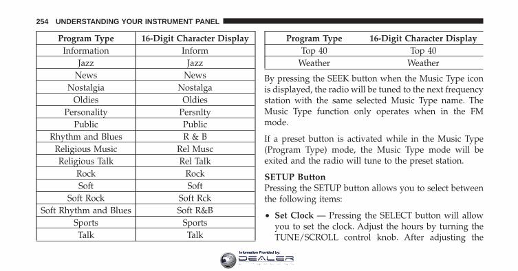
Program Type 16-Digit Character DisplayInformation Inform
Jazz JazzNews News
Nostalgia NostalgaOldies Oldies
Personality PersnltyPublic Public
Rhythm and Blues R & BReligious Music Rel MuscReligious Talk Rel Talk
Rock RockSoft Soft
Soft Rock Soft RckSoft Rhythm and Blues Soft R&B
Sports SportsTalk Talk
Program Type 16-Digit Character DisplayTop 40 Top 40
Weather Weather
By pressing the SEEK button when the Music Type iconis displayed, the radio will be tuned to the next frequencystation with the same selected Music Type name. TheMusic Type function only operates when in the FMmode.
If a preset button is activated while in the Music Type(Program Type) mode, the Music Type mode will beexited and the radio will tune to the preset station.
SETUP ButtonPressing the SETUP button allows you to select betweenthe following items:
• Set Clock — Pressing the SELECT button will allowyou to set the clock. Adjust the hours by turning theTUNE/SCROLL control knob. After adjusting the
254 UNDERSTANDING YOUR INSTRUMENT PANEL
Information Provided by:

hours, press the TUNE/SCROLL control knob to setthe minutes. The minutes will begin to blink. Adjustthe minutes using the right side TUNE/SCROLLcontrol knob. Press the TUNE/SCROLL control knobto save time change.
AM/FM ButtonPress the button to select either AM or FM mode.
SET/RND Button — To Set the PushbuttonMemoryWhen you are receiving a station that you wish tocommit to pushbutton memory, press the SET/RNDbutton. The symbol SET 1 will now show in the displaywindow. Select the button (1–6) you wish to lock onto thisstation and press and release that button. If a button isnot selected within five seconds after pressing the SET/RND button, the station will continue to play but will notbe stored into pushbutton memory.
You may add a second station to each pushbutton byrepeating the above procedure with this exception: Pressthe SET/RND button twice and SET 2 will show in thedisplay window. Each button can be set for SET 1 andSET 2 in both AM and FM. This allows a total of 12 AMand 12 FM stations to be stored into pushbutton memory.The stations stored in SET 2 memory can be selected bypressing the pushbutton twice.
Every time a preset button is used, a correspondingbutton number will display.
Buttons 1 - 6These buttons tune the radio to the stations that youcommit to pushbutton memory (12 AM and 12 FMstations).
DISC/AUX ButtonPressing the DISC/AUX button will allow you to switchfrom AM/FM modes to DISC/AUX mode.
4
UNDERSTANDING YOUR INSTRUMENT PANEL 255
Information Provided by:

Operation Instructions — CD MODE for CD andMP3 Audio Play
NOTE:• The ignition switch must be in the ON or ACC
position to operate the radio.
• This radio is capable of playing compact discs (CD),recordable compact discs (CD-R), rewritable compactdiscs (CD-RW), compact discs with MP3 tracks andmultisession compact discs with CD and MP3 tracks.
Inserting Compact Disc(s)Gently insert one CD into the CD player with the CDlabel facing up. The CD will automatically be pulled intothe CD player and the CD icon will illuminate on theradio display. If a CD does not go into the slot more than1.0 in (2.5 cm), a disc may already be loaded and must beejected before a new disc can be loaded.
If you insert a disc with the ignition ON and the radioON, the unit will switch from radio to CD mode andbegin to play when you insert the disc. The display willshow the track number, and index time in minutes andseconds. Play will begin at the start of track 1.
CAUTION!
• This CD player will accept 4–3/4 in (12 cm) discsonly. The use of other sized discs may damage theCD player mechanism.
• Do not use adhesive labels. These labels can peelaway and jam the player mechanism.
• The RES Media Center is a single CD player. Donot attempt to insert a second CD if one is alreadyloaded.
EJECT Button - Ejecting a CDPress the EJECT button to eject the CD.
256 UNDERSTANDING YOUR INSTRUMENT PANEL
Information Provided by:

If you have ejected a disc and have not removed it within10 seconds, it will be reloaded. If the CD is not removed,the radio will reinsert the CD but will not play it.
A disc can be ejected with the radio and ignition OFF.
NOTE: Ejecting with the ignition OFF is not allowed onconvertible or soft-top models (if equipped).
SEEK ButtonPress the right SEEK button for the next selection on theCD. Press the left SEEK button to return to the beginningof the current selection, or return to the beginning of theprevious selection if the CD is within the first second ofthe current selection. Pressing and holding the SEEKbutton will allow faster scrolling through the tracks inCD and MP3 modes.
TIME ButtonPress this button to change the display from a large CDplaying time display to a small CD playing time display.
RW/FFPress and hold FF (Fast Forward) and the CD player willbegin to fast forward until FF is released or RW oranother CD button is pressed. The RW (Reverse) buttonworks in a similar manner.
AM/FM ButtonPress the button to select either AM or FM mode.
SET/RND Button (Random Play Button)Press this button while the CD is playing to activateRandom Play. This feature plays the selections on thecompact disc in random order to provide an interestingchange of pace.
Press the right SEEK button to move to the next ran-domly selected track.
Press the SET/RND button a second time to stop Ran-dom Play.
4
UNDERSTANDING YOUR INSTRUMENT PANEL 257
Information Provided by:

Notes On Playing MP3 FilesThe radio can play MP3 files; however, acceptable MP3file recording media and formats are limited. Whenwriting MP3 files, pay attention to the following restric-tions.
Supported Media (Disc Types)The MP3 file recording media supported by the radio areCDDA, CD-R, CD-RW, MP3, and CDDA+MP3.
Supported Medium Formats (File Systems)The medium formats supported by the radio are ISO 9660Level 1 and Level 2 and includes the Joliet extension.When reading discs recorded using formats other thanISO 9660 Level 1 and Level 2, the radio may fail to readfiles properly and may be unable to play the file nor-mally. UDF and Apple HFS formats are not supported.
The radio uses the following limits for file systems:
• Maximum number of folder levels: 8
• Maximum number of files: 255
• Maximum number of folders. (The radio display of filenames and folder names is limited. For large numbersof files and/or folders, the radio may be unable todisplay the file name and folder name and will assigna number instead. With a maximum number of files,exceeding 20 folders will result in this display. With200 files, exceeding 50 folders will result in thisdisplay.)
• Maximum number of characters in file/folder names:
• Level 1: 12 (including a separator �.� and a three-character extension)
• Level 2: 31 (including a separator �.� and a three-character extension)
Multisession disc formats are supported by the radio.Multisession discs may contain combinations of normalCD audio tracks and computer files (including MP3 files).
258 UNDERSTANDING YOUR INSTRUMENT PANEL
Information Provided by:

Discs created with an option such as �keep disc open afterwriting� are most likely multisession discs. The use ofmultisession for CD audio or MP3 playback may result inlonger disc loading times.
Supported MP3 File FormatsThe radio will recognize only files with the *.MP3 exten-sion as MP3 files. Non-MP3 files named with the *.MP3extension may cause playback problems. The radio isdesigned to recognize the file as an invalid MP3 and willnot play the file.
When using the MP3 encoder to compress audio data toan MP3 file, the bit rate and sampling frequencies in thefollowing table are supported. In addition, variable bitrates (VBR) are also supported. The majority of MP3 filesuse a 44.1 kHz sampling rate and a 192, 160, 128, 96 orVBR bit rates.
MPEGSpecification
Sampling Fre-quency (kHz) Bit Rate (kbps)
MPEG-1 AudioLayer 3 48, 44.1, 32
320, 256, 224,192, 160, 128,
112, 96, 80, 64,56, 48, 40, 32
MPEG-2 AudioLayer 3 24, 22.05, 16
160, 128, 144,112, 96, 80, 64,
56, 48, 40, 32, 24,16, 8
ID3 Tag information for artist, song title, and album titleare supported for version 1 ID3 tags. ID3 version 2 is notsupported by the radios.
Playlist files are not supported. MP3 Pro files are notsupported.
4
UNDERSTANDING YOUR INSTRUMENT PANEL 259
Information Provided by:

Playback of MP3 FilesWhen a medium containing MP3 data is loaded, theradio checks all files on the medium. If the mediumcontains a lot of folders or files, the radio will take moretime to start playing the MP3 files.
Loading times for playback of MP3 files may be affectedby the following:
• Media - CD-RW media may take longer to load thanCD-R media
• Medium formats - Multisession discs may take longerto load than non-multisession discs
• Number of files and folders - Loading times willincrease with more files and folders
To increase the speed of disc loading, it is recommendedto use CD-R media and single-session discs. To create asingle-session disc, enable the “Disc at Once” optionbefore writing to the disc.
LIST Button (CD Mode for MP3 Play)Pressing the LIST button will bring up a list of all folderson the disc. Scrolling up or down the list is done byturning the TUNE/SCROLL control knob. Selecting afolder by pressing the TUNE/SCROLL control knob willbegin playing the files contained in that folder (or thenext folder in sequence if the selection does not containplayable files).
The folder list will time out after five seconds.
INFO Button (CD Mode for MP3 Play)Pressing the INFO button repeatedly will scroll throughthe following TAG information: Song Title, Artist, FileName, and Folder Name (if available).
Press the INFO button once more to return to �elapsedtime� priority mode.
Press and hold the INFO button for three seconds ormore and the radio will display song titles for each file.
260 UNDERSTANDING YOUR INSTRUMENT PANEL
Information Provided by:

Press and hold the INFO button again for three secondsto return to �elapsed time� display.
Operation Instructions - Auxiliary ModeThe auxiliary (AUX) jack is an audio input jack whichallows the user to plug in a portable device such as anMP3 player or cassette player and utilize the vehicle’saudio system to amplify the source and play through thevehicle speakers.
Pressing the AUX button will change the mode to auxil-iary device if the AUX jack is connected.
NOTE: The AUX device must be turned on and thedevice’s volume set to the proper level. If the AUX audiois not loud enough, turn the device’s volume up. If theAUX audio sounds distorted, turn the device’s volumedown.
TIME Button (Auxiliary Mode)Press this button to change the display to time of day. Thetime of day will display for five seconds (when theignition is OFF).
Uconnect™ Multimedia (Satellite Radio) — IfEquippedSatellite radio uses direct satellite-to-receiver broadcast-ing technology to provide clear digital sound, coast tocoast. The subscription service provider is Sirius SatelliteRadio. This service offers over 130 channels of music,sports, news, entertainment, and programming for chil-dren, directly from its satellites and broadcasting studios.
NOTE: Sirius service is not available in Hawaii and haslimited coverage in Alaska.
System ActivationSirius Satellite Radio service is pre-activated, and youmay begin listening immediately to the one year of audioservice that is included with the factory-installed satellite
4
UNDERSTANDING YOUR INSTRUMENT PANEL 261
Information Provided by:

radio system in your vehicle. Sirius will supply a wel-come kit that contains general information, includinghow to setup your on-line listening account. For furtherinformation, call the toll-free number 888-539-7474, orvisit the Sirius web site at www.sirius.com, or at www-.siriuscanada.ca for Canadian residents.
Electronic Serial Number/Sirius IdentificationNumber (ESN/SID)Please have the following information available whencalling:
1. The Electronic Serial Number/Sirius IdentificationNumber (ESN/SID).
2. Your Vehicle Identification Number.
To access the ESN/SID, refer to the following steps:
ESN/SID AccessWith the ignition switch in the ON/RUN or ACC posi-tion and the radio on, press the SETUP button and scroll
using the TUNE/SCROLL control knob until Sirius ID isselected. Press the TUNE/SCROLL control knob and theSirius ID number will display. The Sirius ID numberdisplay will time out in two minutes. Press any button onthe radio to exit this screen.
Selecting Uconnect™ Multimedia (Satellite) ModePress the SAT button until �SAT� appears in the display. ACD may remain in the radio while in the Satellite radiomode.
Satellite AntennaTo ensure optimum reception, do not place items on theroof around the rooftop antenna location. Metal objectsplaced within the line of sight of the antenna will causedecreased performance. Larger luggage items such asbikes should be placed as far rearward as possible, withinthe loading design of the rack. Do not place items directlyon or above the antenna.
262 UNDERSTANDING YOUR INSTRUMENT PANEL
Information Provided by:

Reception QualitySatellite reception may be interrupted due to one of thefollowing reasons:
• The vehicle is parked in an underground parkingstructure or under a physical obstacle.
• Dense tree coverage may interrupt reception in theform of short audio mutes.
• Driving under wide bridges or along tall buildings cancause intermittent reception.
• Placing objects over or too close to the antenna cancause signal blockage.
Operating Instructions - Uconnect™ Multimedia(Satellite) Mode
NOTE: The ignition switch must be in the ON/RUN orACC position to operate the radio.
SEEK ButtonsPress and release the SEEK buttons to search for the nextchannel in Satellite mode. Press the right switch to seekup and the left switch to seek down. The radio willremain tuned to the new channel until you make anotherselection. Holding either button will bypass channelswithout stopping until you release it.
SCAN ButtonPressing the SCAN button causes the tuner to search forthe next channel, pausing for eight seconds before con-tinuing to the next. To stop the search, press the SCANbutton a second time.
INFO ButtonPressing the INFO button will cycle the display informa-tion between Artist, Song Title, and Composer (if avail-able). Also, pressing and holding the INFO button for anadditional three seconds will make the radio display theSong Title all of the time (press and hold again to returnto normal display).
4
UNDERSTANDING YOUR INSTRUMENT PANEL 263
Information Provided by:

RW/FFPressing the RW (Rewind) or FF (Fast Forward) buttonscauses the tuner to search for the next channel in thedirection of the arrows.
TUNE Control (Rotary)Turn the rotary TUNE/SCROLL control knob clockwiseto increase or counterclockwise to decrease the channel.
MUSIC TYPE ButtonPressing this button once will turn on the Music Typemode for five seconds. Pressing the MUSIC TYPE buttonor turning the TUNE/SCROLL control knob within fiveseconds will allow the program format type to be se-lected.
Toggle the MUSIC TYPE button again to select the musictype.
By pressing the SEEK button when the Music Typefunction is active, the radio will be tuned to the nextchannel with the same selected Music Type name.
If a preset button is activated while in the Music Type(Program Type) mode, the Music Type mode will beexited and the radio will tune to the preset channel.
SETUP ButtonPressing the SETUP button allows you to select thefollowing items:
• Display Sirius ID number — Press the AUDIO/SELECT button to display the Sirius ID number. Thisnumber is used to activate, deactivate, or change theSirius subscription.
SET Button – To Set the Pushbutton MemoryWhen you are receiving a channel that you wish tocommit to pushbutton memory, press the SET button.The symbol SET 1 will now show in the display window.
264 UNDERSTANDING YOUR INSTRUMENT PANEL
Information Provided by:

Select the button (1-6) you wish to lock onto this channeland press and release that button. If a button is notselected within five seconds after pressing the SET but-ton, the channel will continue to play but will not bestored into pushbutton memory.
You may add a second channel to each pushbutton byrepeating the above procedure with this exception: Pressthe SET button twice and SET 2 will show in the displaywindow. Each button can be set for SET 1 and SET 2. Thisallows a total of 12 Satellite channels to be stored intopushbutton memory. The channels stored in SET 2memory can be selected by pressing the pushbuttontwice.
Every time a preset button is used, a correspondingbutton number will display.
Buttons 1 - 6These buttons tune the radio to the channels that youcommit to pushbutton memory (12 Satellite stations).
Operating Instructions - Uconnect™ Phone (IfEquipped)Refer to “Uconnect™ Phone” in “Understanding TheFeatures Of Your Vehicle”.
iPod�/USB/MP3 CONTROL — IF EQUIPPED
NOTE: This section is for sales code RES and REQ/REL/RET radios only with Uconnect™. For sales codeRBZ/RHB, RHR, RHP, RHW or RB2 touch-screen radioiPod�/USB/MP3 control feature, refer to the separateRBZ/RHB, RHR, RHP, RHW or RB2 User’s Manual.iPod�/USB/MP3 control is available only if equipped asan option with these radios.
This feature allows an iPod� or external USB device to beplugged into the USB port, located in the center of theinstrument panel below the climate controls.
4
UNDERSTANDING YOUR INSTRUMENT PANEL 265
Information Provided by:

iPod� control supports Mini, 4G, Photo, Nano, 5G iPod�and iPhone� devices. Some iPod� software versions maynot fully support the iPod� control features. Please visitApple’s website for software updates.
NOTE:• If the radio has a USB port, refer to the appropriate
Uconnect™ Multimedia radio User’s Manual foriPod� or external USB device support capability.
• Connecting an iPod� or consumer electronic audiodevice to the AUX port located in the radio faceplate,plays media, but does not use the iPod� /MP3 controlfeature to control the connected device.
Connecting The iPod� Or External USB DeviceUse the connection cable to connect an iPod� or externalUSB device to the vehicle’s USB connector port which islocated in the center of the instrument panel below theclimate controls.
Once the audio device is connected and synchronized tothe vehicle’s iPod�/USB/MP3 control system (iPod� orexternal USB device may take a few minutes to connect),the audio device starts charging and is ready for use bypressing radio switches, as described below.
USB Connector Port
266 UNDERSTANDING YOUR INSTRUMENT PANEL
Information Provided by:

NOTE: If the audio device battery is completely dis-charged, it may not communicate with the iPod�/USB/MP3 control system until a minimum charge is attained.Leaving the audio device connected to the iPod�/USB/MP3 control system may charge it to the required level.
Using This FeatureBy using iPod cable or external USB device to connect toUSB port:
• The audio device can be played on the vehicle’s soundsystem, providing metadata (artist, track title, album,etc.) information on the radio display.
• The audio device can be controlled using the radiobuttons to Play, Browse, and List the iPod� contents.
• The audio device battery charges when plugged intothe USB/AUX connector (if supported by the specificaudio device)
Controlling The iPod� Or External USB DeviceUsing Radio ButtonsTo get into the iPod�/USB/MP3 control mode and accessa connected audio device, either press the “AUX” buttonon the radio faceplate or press the VR button and say�USB� or �Switch to USB�. Once in the iPod�/USB/MP3control mode, audio tracks (if available from audiodevice) start playing over the vehicle’s audio system.
Play ModeWhen switched to iPod�/USB/MP3 control mode, theiPod� or external USB device automatically starts Playmode. In Play mode, the following buttons on the radiofaceplate may be used to control the iPod� or externalUSB device and display data:
• Use the TUNE control knob to select the next orprevious track.
4
UNDERSTANDING YOUR INSTRUMENT PANEL 267
Information Provided by:

• Turning it clockwise (forward) by one click, whileplaying a track, skips to the next track or press theVR button and say �Next Track�.
• Turning it counterclockwise (backward) by oneclick, will jump to the previous track in the list orpress the VR button and say �Previous Track�
• Jump backward in the current track by pressing andholding the << RW button. Holding the << RWbutton long enough will jump to the beginning ofthe current track.
• Jump forward in the current track by pressing andholding the FF >> button.
• A single press backward << RW or forward FF >> willjump backward or forward respectively, for fiveseconds.
• Use the << SEEK and SEEK >> buttons to jump to theprevious or next track. Pressing the SEEK >> button
during play mode will jump to the next track in thelist, or press the VR button and say �Next or PreviousTrack�.
• While a track is playing, press the INFO button to seethe associated metadata (artist, track title, album, etc.)for that track. Pressing the INFO button again jumpsto the next screen of data for that track. Once allscreens have been viewed, the last INFO button presswill go back to the play mode screen on the radio.
• Pressing the REPEAT button will change the audiodevice mode to repeat the current playing track orpress the VR button and say �Repeat ON� or �RepeatOff�.
• Press the SCAN button to use iPod�/USB/MP3 de-vice scan mode, which will play the first 10 seconds ofeach track in the current list and then forward to thenext song. To stop SCAN mode and start playing thedesired track, when it is playing the track, press the
268 UNDERSTANDING YOUR INSTRUMENT PANEL
Information Provided by:

SCAN button again. During Scan mode, pressing the<< SEEK and SEEK >> buttons will select the previ-ous and next tracks.
• RND button (available on sales code RES radio only):Pressing this button toggles between Shuffle ON andShuffle OFF modes for the iPod� or external USBdevice, or press the VR button and say �Shuffle ON� or�Shuffle Off�. If the RND icon is showing on the radiodisplay, then the shuffle mode is ON.
List Or Browse ModeDuring Play mode, pressing any of the buttons describedbelow, will bring up List mode. List mode enablesscrolling through the list of menus and tracks on theaudio device.
• TUNE control knob: The TUNE control knob functionsin a similar manner as the scroll wheel on the audiodevice or external USB device.
• Turning it clockwise (forward) and counterclock-wise (backward) scrolls through the lists, displayingthe track detail on the radio display. Once the trackto be played is highlighted on the radio display,press the TUNE control knob to select and startplaying the track. Turning the TUNE control knobfast will scroll through the list faster. During fastscroll, a slight delay in updating the information onthe radio display may be noticeable.
• During all List modes, the iPod� displays all lists in“wrap-around” mode. So if the track is at thebottom of the list, just turn the wheel backward(counterclockwise) to get to the track faster.
• In List mode, the radio PRESET buttons are used asshortcuts to the following lists on the iPod� orexternal USB device.
• Preset 1 – Playlists
4
UNDERSTANDING YOUR INSTRUMENT PANEL 269
Information Provided by:

• Preset 2 – Artists
• Preset 3 – Albums
• Preset 4 – Genres
• Preset 5 – Audiobooks
• Preset 6 – Podcasts
• Pressing a PRESET button will display the currentlist on the top line and the first item in that list onthe second line.
• To exit List mode without selecting a track, press thesame PRESET button again to go back to Playmode.
• LIST button: The LIST button will display the toplevel menu of the iPod� or external USB device. Turnthe TUNE control knob to list the top-menu item to beselected and press the TUNE control knob. This willdisplay the next sub-menu list item on the audio
device, then follow the same steps to go to the desiredtrack in that list. Not all iPod� or external USB devicesub-menu levels are available on this system.
• MUSIC TYPE button: The MUSIC TYPE button isanother shortcut button to the genre listing on youraudio device.
CAUTION!
• Leaving the iPod� or external USB device (or anysupported device) anywhere in the vehicle inextreme heat or cold can alter the operation ordamage the device. Follow the device manufactur-er’s guidelines.
• Placing items on the iPod� or external USB device,or connections to the iPod� or external USB devicein the vehicle, can cause damage to the deviceand/or to the connectors.
270 UNDERSTANDING YOUR INSTRUMENT PANEL
Information Provided by:

WARNING!
Do not plug in or remove the iPod� or external USBdevice while driving. Failure to follow this warningcould result in an accident.
Bluetooth Streaming Audio (BTSA)Music can be streamed from your cellular phone to theUconnect™ phone system.
Controlling BTSA Using Radio ButtonsTo get into the BTSA mode, press either “AUX” button onthe radio or press the VR button and say “BluetoothStreaming Audio”.
Play ModeWhen switched to BTSA mode, some audio devices canstart playing music over the vehicle’s audio system, butsome devices require the music to be initiated on thedevice first, then it will get streamed to the Uconnect™phone system. Seven devices can be paired to theUconnect™ phone system, but just one can be selectedand played.
Selecting Different Audio Device
1. Press PHONE button to begin.
2. After the �Ready� prompt and the following beep, say�Setup�, then �Select Audio Devices�.
3. Say the name of the audio device or ask theUconnect™ phone system to list audio devices.
4
UNDERSTANDING YOUR INSTRUMENT PANEL 271
Information Provided by:

Next TrackUse the SEEK UP button, or press the VR button on theradio and say “Next Track” to jump to the next trackmusic on your cellular phone.
Previous TrackUse the SEEK DOWN button, or press the VR button onthe radio and say “Previous Track” to jump to theprevious track music on your cellular phone.
BrowseBrowsing is not available on a BTSA device. Only thecurrent song that is playing will display info.
STEERING WHEEL AUDIO CONTROLS — IFEQUIPPED
The remote sound system controls are located on the rearsurface of the steering wheel, at the three and nineo’clock positions.
Remote Sound System Controls(Back View Of Steering Wheel)
272 UNDERSTANDING YOUR INSTRUMENT PANEL
Information Provided by:

The right-hand rocker switch has a pushbutton in thecenter, and controls the volume and mode of the soundsystem. Pressing the top of the rocker switch will increasethe volume. Pressing the bottom of the rocker switch willdecrease the volume. Pressing the center button changesthe operation of the radio from AM to FM, or to CDmode, depending on which radio is in the vehicle.
The left-hand rocker switch has a pushbutton in thecenter. The function of the left-hand switch is different,depending on which mode you are in.
The following describes the left-hand rocker switch op-eration in each mode.
Radio OperationPressing the top of the switch will SEEK up for the nextlistenable station, and pressing the bottom of the switchwill SEEK down for the next listenable station.
The button located in the center of the left-hand switchwill tune to the next preset station that you have pro-grammed in the radio preset pushbutton.
CD PlayerPressing the top of the switch once will go to the nexttrack on the CD. Pressing the bottom of the switch oncewill go to the beginning of the current track, or to thebeginning of the previous track if it is within one secondafter the current track begins to play.
If you press the switch up or down twice it plays thesecond track; three times, it will play the third, etc.
The button in the center of the left-hand switch has nofunction in this mode.
4
UNDERSTANDING YOUR INSTRUMENT PANEL 273
Information Provided by:

CD/DVD DISC MAINTENANCETo keep a CD/DVD in good condition, take the followingprecautions:
1. Handle the disc by its edge; avoid touching thesurface.
2. If the disc is stained, clean the surface with a soft cloth,wiping from center to edge.
3. Do not apply paper or tape to the disc; avoid scratch-ing the disc.
4. Do not use solvents such as benzene, thinner, cleaners,or anti-static sprays.
5. Store the disc in its case after playing.
6. Do not expose the disc to direct sunlight.
7. Do not store the disc where temperatures may becometoo high.
NOTE: If you experience difficulty in playing a particu-lar disc, it may be damaged (i.e., scratched, reflectivecoating removed, a hair, moisture or dew on the disc)oversized, or have protection encoding. Try a knowngood disc before considering disc player service.
RADIO OPERATION AND MOBILE PHONESUnder certain conditions, the mobile phone being on inyour vehicle can cause erratic or noisy performance fromyour radio. This condition may be lessened or eliminatedby relocating the mobile phone antenna. This condition isnot harmful to the radio. If your radio performance doesnot satisfactorily “clear” by the repositioning of theantenna, it is recommended that the radio volume beturned down or off during mobile phone operation whennot using Uconnect™ (if equipped).
CLIMATE CONTROLSThe air conditioning and heating system is designed tomake you comfortable in all types of weather.
274 UNDERSTANDING YOUR INSTRUMENT PANEL
Information Provided by:
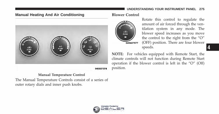
Manual Heating And Air Conditioning
The Manual Temperature Controls consist of a series ofouter rotary dials and inner push knobs.
Blower ControlRotate this control to regulate theamount of air forced through the ven-tilation system in any mode. Theblower speed increases as you movethe control to the right from the “O”(OFF) position. There are four blowerspeeds.
NOTE: For vehicles equipped with Remote Start, theclimate controls will not function during Remote Startoperation if the blower control is left in the “O” (Off)position.
Manual Temperature Control
4
UNDERSTANDING YOUR INSTRUMENT PANEL 275
Information Provided by:

Temperature ControlRotate this control to regulate the tem-perature of the air inside the passengercompartment. Rotating the dial leftinto the blue area of the scale indicatescooler temperatures, while rotatingright into the red area indicateswarmer temperatures.
NOTE: If your air conditioning performance seemslower than expected, check the front of the A/C con-denser located in front of the radiator for an accumula-tion of dirt or insects. Clean with a gentle water sprayfrom behind the radiator and through the condenser.Fabric front fascia protectors may reduce airflow to thecondenser, reducing air conditioning performance.
Mode Control (Air Direction)Rotate this control to choose from sev-eral patterns of air distribution. Youcan select either a primary mode asidentified by the symbols on the con-trol, or a blend of two of these modes.The closer the setting is to a particularsymbol, the more air distribution you
receive from that mode.
PanelAir is directed through the outlets in the instrumentpanel. These outlets can be adjusted to direct airflow.
NOTE: The center instrument panel outlets can beaimed so that they are directed toward the rear seatpassengers for maximum airflow to the rear.
Bi-LevelAir is directed through the panel and floor outlets.
276 UNDERSTANDING YOUR INSTRUMENT PANEL
Information Provided by:

NOTE: For all settings, except full cold or full hot, thereis a difference in temperature between the upper andlower outlets. The warmer air flows to the floor outlets.This feature gives improved comfort during sunny butcool conditions.
FloorAir is directed through the floor outlets with asmall amount flowing through the defrost and side
window demist outlets.
MixAir is directed through the floor, defrost, and sidewindow demist outlets. This setting works best incold or snowy conditions that require extra heat to
the windshield. This setting is good for maintainingcomfort while reducing moisture on the windshield.
DefrostAir is directed through the windshield and sidewindow demist outlets. Use this mode with maxi-
mum blower and temperature settings for best wind-shield and side window defrosting.
NOTE: The air conditioning compressor operates inMix, Defrost, or a blend of these modes, even if the AirConditioning (A/C) button is not pressed. This dehu-midifies the air to help dry the windshield. To improvefuel economy, use these modes only when necessary.
Recirculation ControlPressing the Recirculation Control button willtemporarily put the system in recirculationmode. This can be used when outside condi-tions such as smoke, odors, dust, or high
humidity are present. Activating recirculation will causethe LED in the control button to illuminate. After tenminutes, the system will return to normal mode functionand the LED will turn off.
4
UNDERSTANDING YOUR INSTRUMENT PANEL 277
Information Provided by:
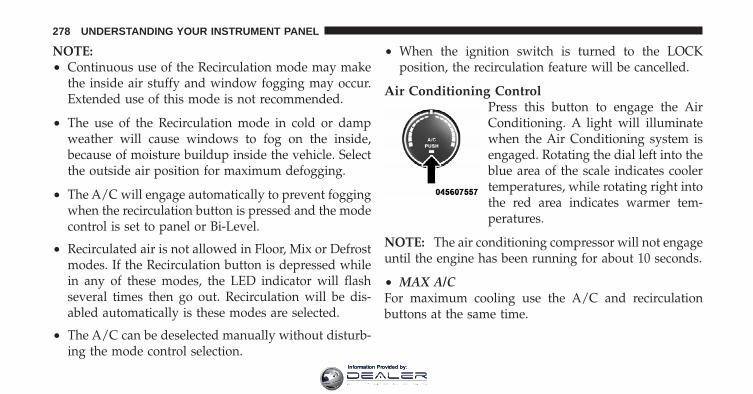
NOTE:• Continuous use of the Recirculation mode may make
the inside air stuffy and window fogging may occur.Extended use of this mode is not recommended.
• The use of the Recirculation mode in cold or dampweather will cause windows to fog on the inside,because of moisture buildup inside the vehicle. Selectthe outside air position for maximum defogging.
• The A/C will engage automatically to prevent foggingwhen the recirculation button is pressed and the modecontrol is set to panel or Bi-Level.
• Recirculated air is not allowed in Floor, Mix or Defrostmodes. If the Recirculation button is depressed whilein any of these modes, the LED indicator will flashseveral times then go out. Recirculation will be dis-abled automatically is these modes are selected.
• The A/C can be deselected manually without disturb-ing the mode control selection.
• When the ignition switch is turned to the LOCKposition, the recirculation feature will be cancelled.
Air Conditioning ControlPress this button to engage the AirConditioning. A light will illuminatewhen the Air Conditioning system isengaged. Rotating the dial left into theblue area of the scale indicates coolertemperatures, while rotating right intothe red area indicates warmer tem-peratures.
NOTE: The air conditioning compressor will not engageuntil the engine has been running for about 10 seconds.
• MAX A/CFor maximum cooling use the A/C and recirculationbuttons at the same time.
278 UNDERSTANDING YOUR INSTRUMENT PANEL
Information Provided by:
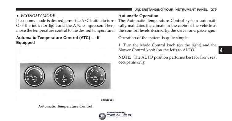
• ECONOMY MODEIf economy mode is desired, press the A/C button to turnOFF the indicator light and the A/C compressor. Then,move the temperature control to the desired temperature.
Automatic Temperature Control (ATC) — IfEquipped
Automatic OperationThe Automatic Temperature Control system automati-cally maintains the climate in the cabin of the vehicle atthe comfort levels desired by the driver and passenger.
Operation of the system is quite simple.
1. Turn the Mode Control knob (on the right) and theBlower Control knob (on the left) to AUTO.
NOTE: The AUTO position performs best for front seatoccupants only.
Automatic Temperature Control
4
UNDERSTANDING YOUR INSTRUMENT PANEL 279
Information Provided by:
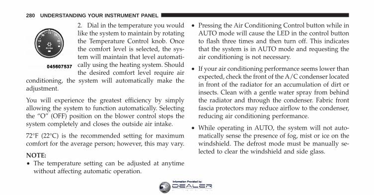
2. Dial in the temperature you wouldlike the system to maintain by rotatingthe Temperature Control knob. Oncethe comfort level is selected, the sys-tem will maintain that level automati-cally using the heating system. Shouldthe desired comfort level require air
conditioning, the system will automatically make theadjustment.
You will experience the greatest efficiency by simplyallowing the system to function automatically. Selectingthe “O” (OFF) position on the blower control stops thesystem completely and closes the outside air intake.
72°F (22°C) is the recommended setting for maximumcomfort for the average person; however, this may vary.
NOTE:• The temperature setting can be adjusted at anytime
without affecting automatic operation.
• Pressing the Air Conditioning Control button while inAUTO mode will cause the LED in the control buttonto flash three times and then turn off. This indicatesthat the system is in AUTO mode and requesting theair conditioning is not necessary.
• If your air conditioning performance seems lower thanexpected, check the front of the A/C condenser locatedin front of the radiator for an accumulation of dirt orinsects. Clean with a gentle water spray from behindthe radiator and through the condenser. Fabric frontfascia protectors may reduce airflow to the condenser,reducing air conditioning performance.
• While operating in AUTO, the system will not auto-matically sense the presence of fog, mist or ice on thewindshield. The defrost mode must be manually se-lected to clear the windshield and side glass.
280 UNDERSTANDING YOUR INSTRUMENT PANEL
Information Provided by:

Blower ControlFor full automatic operation or forautomatic blower operation, turn theknob to the AUTO position. In manualmode there are seven blower speedsthat can be individual selected. In offposition the blower will shut off.
Manual OperationThis system offers a full complement of manual overridefeatures, which consist of Blower Preferred Automatic,
Mode Preferred Automatic, or Blower and Mode Pre-ferred Automatic. This means the operator can overridethe blower, the mode, or both. There is a manual blowerrange for times when the AUTO setting is not desired.The blower can be set to any fixed blower speed byrotating the Blower Control knob (on the left).
NOTE: Please read the Automatic Temperature ControlOperation Chart that follows for details. 4
UNDERSTANDING YOUR INSTRUMENT PANEL 281
Information Provided by:

282 UNDERSTANDING YOUR INSTRUMENT PANEL
Information Provided by:

The operator can override the AUTO mode setting tochange airflow distribution by rotating the Mode Controlknob (on the right) to one of the following positions.
• PanelAir is directed through the outlets in the instrumentpanel. These outlets can be adjusted to direct airflow.
NOTE: The center instrument panel outlets can beaimed so that they are directed toward the rear seatpassengers for maximum airflow to the rear.
• Bi-LevelAir is directed through the panel and floor outlets.
NOTE: For all settings, except full cold or full hot, thereis a difference in temperature between the upper andlower outlets. The warmer air flows to the floor outlets.This feature gives improved comfort during sunny butcool conditions.
• FloorAir is directed through the floor outlets with asmall amount flowing through the defrost and side
window demist outlets.
• MixAir is directed through the floor, defrost, and sidewindow demist outlets. This setting works best incold or snowy conditions that require extra heat to
the windshield. This setting is good for maintainingcomfort while reducing moisture on the windshield.
• DefrostAir is directed through the windshield and sidewindow demist outlets. Use this mode with maxi-
mum blower and temperature settings for best wind-shield and side window defrosting.
4
UNDERSTANDING YOUR INSTRUMENT PANEL 283
Information Provided by:

• Air Conditioner ControlPress this button to turn on the airconditioning during manual operationonly. When the air conditioning isturned on, cool dehumidified air willflow through the outlets selected withthe Mode control dial. Press this but-ton a second time to turn OFF the air
conditioning. An LED in the button illuminates whenmanual compressor operation is selected.
• Recirculation ControlThe system will automatically control recircu-lation. However, pressing the RecirculationControl button will temporarily put the systemin recirculation mode. This can be used when
outside conditions such as smoke, odors, dust, or highhumidity are present. Activating recirculation will causethe LED in the control button to illuminate.
NOTE:• When the ignition switch is turned to the LOCK
position, the recirculation feature will be cancelled.
• In cold weather, use of the Recirculation mode maylead to excessive window fogging. The Recirculationmode is not allowed in the floor, defrost, or Mix modein order to improve window clearing. Recirculationwill be disabled automatically if these modes areselected.
• Extended use of recirculation may cause the windowsto fog. If the interior of the windows begins to fog,press the Recirculation button to return to outside air.Some temp/humidity conditions will cause capturedinterior air to condense on windows and hampervisibility. For this reason, the system will not allowRecirculation to be selected while in floor, defrost, orMix mode. Attempting to use the recirculation while inthese modes will cause the LED in the control buttonto blink and then turn off.
284 UNDERSTANDING YOUR INSTRUMENT PANEL
Information Provided by:

• Most of the time, when in Automatic Operation, youcan temporarily put the system into RecirculationMode by pressing the Recirculation button. However,under certain conditions, while in Automatic Mode,the system is blowing air out the defrost vents. Whenthese conditions are present, and the Recirculationbutton is pressed, the indicator will flash and then turnoff. This tells you that you are unable to go intoRecirculation Mode at this time. If you would like thesystem to go into Recirculation Mode, you must firstmove the Mode knob to Panel, Mix and then press theRecirculation button. This feature reduces the possibil-ity of window fogging.
Operating Tips
NOTE: Refer to the chart at the end of this section forsuggested control settings for various weather condi-tions.
Summer OperationThe engine cooling system in air-conditioned vehiclesmust be protected with a high-quality antifreeze coolantto provide proper corrosion protection and to protectagainst engine overheating. A solution of 50% ethyleneglycol antifreeze coolant and 50% water is recommended.Refer to “Maintenance Procedures” in “Maintaining YourVehicle” for proper coolant selection.
Winter OperationUse of the air Recirculation Mode during winter months isnot recommended because it may cause window fogging.
Vacation StorageAnytime you store your vehicle, or keep it out of service(i.e., vacation) for two weeks or more, run the airconditioning system at idle for about five minutes in thefresh air and high blower settings. This will ensureadequate system lubrication to minimize the possibilityof compressor damage when the system is started again.
4
UNDERSTANDING YOUR INSTRUMENT PANEL 285
Information Provided by:

Window FoggingInterior fogging on the windshield can be quickly re-moved by turning the mode selector to Defrost. The Mixmode can be used to maintain a clear windshield andprovide sufficient heating. If side window fogging be-comes a problem, increase blower speed. Vehicle win-dows tend to fog on the inside in mild but rainy or humidweather.
NOTE: Recirculate without A/C should not be used forlong periods as fogging may occur.
Side Window DemistersA side window demister outlet is located at each end ofthe instrument panel. These non-adjustable outlets directair toward the side windows when the system is in theFLOOR, MIX, or DEFROST mode. The air is directed atthe area of the windows through which you view theoutside mirrors.
Outside Air IntakeMake sure the air intake, located directly in front of thewindshield, is free of obstructions such as leaves. Leavescollected in the air intake may reduce airflow, and if theyenter the plenum, they could plug the water drains. Inwinter months, make sure the air intake is clear of ice,slush, and snow.
A/C Air Filter — If EquippedThe A/C Filter prevents most dust and pollen fromentering the cabin. The filter acts on air coming fromoutside the vehicle and recirculated air within the pas-senger compartment. Refer to “Maintenance Procedures”in “Maintaining Your Vehicle” for A/C Air Filter serviceinformation or see your authorized dealer for service.Refer to “Maintenance Schedules” for filter serviceintervals.
286 UNDERSTANDING YOUR INSTRUMENT PANEL
Information Provided by:

Control Setting Suggestions for Various Weather Conditions
4
UNDERSTANDING YOUR INSTRUMENT PANEL 287
Information Provided by:

Information Provided by:

STARTING AND OPERATING
CONTENTS
� Starting Procedures . . . . . . . . . . . . . . . . . . . . 294
▫ Automatic Transmission . . . . . . . . . . . . . . . 294
▫ Normal Starting . . . . . . . . . . . . . . . . . . . . . 294
▫ Extreme Cold Weather(Below –20°F Or �29°C) . . . . . . . . . . . . . . . 295
▫ If Engine Fails To Start . . . . . . . . . . . . . . . . 295
▫ After Starting . . . . . . . . . . . . . . . . . . . . . . . 297
� Engine Block Heater — If Equipped . . . . . . . . 297
� Automatic Transmission . . . . . . . . . . . . . . . . . 297
▫ Automatic Transmission Ignition InterlockSystems . . . . . . . . . . . . . . . . . . . . . . . . . . . 299
▫ Key Ignition Park Interlock . . . . . . . . . . . . . 299
▫ Brake/Transmission Interlock System . . . . . . 299
▫ Four-Speed Automatic Transmission — IfEquipped . . . . . . . . . . . . . . . . . . . . . . . . . . 300
▫ Gear Ranges . . . . . . . . . . . . . . . . . . . . . . . . 300
▫ Six-Speed Automatic Transmission(62TE) — If Equipped . . . . . . . . . . . . . . . . . 307
5
Information Provided by:

▫ Gear Ranges . . . . . . . . . . . . . . . . . . . . . . . . 308
� AutoStick� — If Equipped . . . . . . . . . . . . . . . 315
▫ Operation . . . . . . . . . . . . . . . . . . . . . . . . . 315
▫ General Information . . . . . . . . . . . . . . . . . . 316
� Driving On Slippery Surfaces . . . . . . . . . . . . . 316
▫ Acceleration . . . . . . . . . . . . . . . . . . . . . . . . 316
▫ Traction . . . . . . . . . . . . . . . . . . . . . . . . . . . 317
� Driving Through Water . . . . . . . . . . . . . . . . . 317
▫ Flowing/Rising Water . . . . . . . . . . . . . . . . . 318
▫ Shallow Standing Water . . . . . . . . . . . . . . . 318
� Power Steering . . . . . . . . . . . . . . . . . . . . . . . 320
▫ Power Steering Fluid Check . . . . . . . . . . . . . 321
� Parking Brake . . . . . . . . . . . . . . . . . . . . . . . . 322
� Anti-Lock Brake System (ABS) . . . . . . . . . . . . 324
� Electronic Brake Control System . . . . . . . . . . . 326
▫ Anti-Lock Brake System (ABS) . . . . . . . . . . . 327
▫ Traction Control System (TCS) . . . . . . . . . . . 327
▫ Brake Assist System (BAS) . . . . . . . . . . . . . . 327
▫ Electronic Stability Control (ESC) . . . . . . . . . 328
▫ ESC Activation/Malfunction Indicator LightAnd ESC Off Indicator Light . . . . . . . . . . . . 331
� Tire Safety Information . . . . . . . . . . . . . . . . . 332
▫ Tire Markings . . . . . . . . . . . . . . . . . . . . . . . 332
▫ Tire Identification Number (TIN) . . . . . . . . . 335
▫ Tire Terminology And Definitions . . . . . . . . . 336
▫ Tire Loading And Tire Pressure . . . . . . . . . . 337
290 STARTING AND OPERATING
Information Provided by:

� Tires — General Information . . . . . . . . . . . . . 341
▫ Tire Pressure . . . . . . . . . . . . . . . . . . . . . . . 341
▫ Tire Inflation Pressures . . . . . . . . . . . . . . . . 342
▫ Radial-Ply Tires . . . . . . . . . . . . . . . . . . . . . 344
▫ Spare Tire Matching Original Equipped TireAnd Wheel – If Equipped . . . . . . . . . . . . . . 344
▫ Compact Spare Tire – If Equipped . . . . . . . . 345
▫ Full Size Spare – If Equipped . . . . . . . . . . . . 346
▫ Limited-Use Spare – If Equipped . . . . . . . . . 346
▫ Tire Spinning . . . . . . . . . . . . . . . . . . . . . . . 347
▫ Tread Wear Indicators . . . . . . . . . . . . . . . . . 348
▫ Life Of Tire . . . . . . . . . . . . . . . . . . . . . . . . 348
▫ Replacement Tires . . . . . . . . . . . . . . . . . . . . 349
� Tire Chains . . . . . . . . . . . . . . . . . . . . . . . . . . 350
� Snow Tires . . . . . . . . . . . . . . . . . . . . . . . . . . 351
� Tire Rotation Recommendations . . . . . . . . . . . 351
� Tire Pressure Monitor System (TPMS) . . . . . . . 352
▫ Base System . . . . . . . . . . . . . . . . . . . . . . . . 355
▫ Premium System – If Equipped . . . . . . . . . . 357
▫ General Information . . . . . . . . . . . . . . . . . . 360
� Fuel Requirements . . . . . . . . . . . . . . . . . . . . . 360
▫ Reformulated Gasoline . . . . . . . . . . . . . . . . 361
▫ Gasoline/Oxygenate Blends . . . . . . . . . . . . . 361
▫ E-85 Usage In Non-Flex Fuel Vehicles . . . . . . 362
▫ MMT In Gasoline . . . . . . . . . . . . . . . . . . . . 362
▫ Materials Added To Fuel . . . . . . . . . . . . . . . 363
5
STARTING AND OPERATING 291
Information Provided by:

▫ Fuel System Cautions . . . . . . . . . . . . . . . . . 363
▫ Carbon Monoxide Warnings . . . . . . . . . . . . 364
� Flexible Fuel (3.6L Engine Only) —If Equipped . . . . . . . . . . . . . . . . . . . . . . . . . . 365
▫ E-85 General Information . . . . . . . . . . . . . . . 365
▫ Ethanol Fuel (E-85) . . . . . . . . . . . . . . . . . . . 366
▫ Fuel Requirements . . . . . . . . . . . . . . . . . . . 366
▫ Selection Of Engine Oil For Flexible FuelVehicles (E-85) And Gasoline Vehicles . . . . . . 367
▫ Starting . . . . . . . . . . . . . . . . . . . . . . . . . . . 367
▫ Cruising Range . . . . . . . . . . . . . . . . . . . . . . 368
▫ Replacement Parts . . . . . . . . . . . . . . . . . . . 368
▫ Maintenance . . . . . . . . . . . . . . . . . . . . . . . . 368
� Adding Fuel . . . . . . . . . . . . . . . . . . . . . . . . . 368
▫ Fuel Filler Cap (Gas Cap) . . . . . . . . . . . . . . 368
▫ Loose Filler Cap Message . . . . . . . . . . . . . . 371
� Vehicle Loading . . . . . . . . . . . . . . . . . . . . . . 371
▫ Vehicle Certification Label . . . . . . . . . . . . . . 371
▫ Gross Vehicle Weight Rating (GVWR) . . . . . . 372
▫ Gross Axle Weight Rating (GAWR) . . . . . . . . 372
▫ Overloading . . . . . . . . . . . . . . . . . . . . . . . . 372
▫ Loading . . . . . . . . . . . . . . . . . . . . . . . . . . . 373
� Trailer Towing . . . . . . . . . . . . . . . . . . . . . . . . 373
▫ Common Towing Definitions . . . . . . . . . . . . 373
▫ Trailer Hitch Classification . . . . . . . . . . . . . . 375
292 STARTING AND OPERATING
Information Provided by:

▫ Trailer Towing Weights(Maximum Trailer Weight Ratings) . . . . . . . . 376
▫ Trailer And Tongue Weight . . . . . . . . . . . . . 377
▫ Towing Requirements . . . . . . . . . . . . . . . . . 378
▫ Towing Tips . . . . . . . . . . . . . . . . . . . . . . . . 382
� Recreational Towing(Behind Motorhome, Etc.) . . . . . . . . . . . . . . . . 383
▫ Towing This VehicleBehind Another Vehicle . . . . . . . . . . . . . . . . 383
▫ Recreational Towing – All Models . . . . . . . . 384
5
STARTING AND OPERATING 293
Information Provided by:

STARTING PROCEDURESBefore starting your vehicle, adjust your seat, adjust theinside and outside mirrors, fasten your seat belt, and ifpresent, instruct all other occupants to buckle their seatbelts.
WARNING!
• When leaving the vehicle, always remove the keyfob from the ignition and lock your vehicle.
• Never leave children alone in a vehicle, or withaccess to an unlocked vehicle. Allowing childrento be in a vehicle unattended is dangerous for anumber of reasons. A child or others could beseriously or fatally injured. Children should bewarned not to touch the parking brake, brakepedal or the shift lever.
Automatic TransmissionThe shift lever must be in the PARK or NEUTRALposition before you can start the engine. Apply the brakesbefore shifting to any driving gear.
NOTE: The ignition switch must be in the ON position,and you must press the brake pedal before shifting out ofPARK.
Normal Starting
NOTE: Normal starting of either a cold or a warmengine is obtained without pumping or pressing theaccelerator pedal.
For vehicles not equipped with Tip Start (Four-SpeedTransmission), turn the ignition switch to the STARTposition and release it when the engine starts. If theengine fails to start within 10 seconds, turn the ignitionswitch to the LOCK position, wait 10 to 15 seconds, thenrepeat the “Normal Starting” procedure.
294 STARTING AND OPERATING
Information Provided by:

For vehicles equipped with Tip Start (Six-Speed Trans-mission), turn the ignition switch to the START positionand release it as soon as the starter engages. The startermotor will continue to run, and it will disengage auto-matically when the engine is running. If the engine failsto start, the starter will disengage automatically in 10 sec-onds. If this occurs, turn the ignition switch to the LOCKposition, wait 10 to 15 seconds, then repeat the “NormalStarting” procedure.
Extreme Cold Weather (Below –20°F or �29°C)To ensure reliable starting at these temperatures, use ofan externally powered electric engine block heater (avail-able from your dealer) is recommended.
If Engine Fails To Start
WARNING!
• Never pour fuel or other flammable liquids intothe throttle body air inlet opening in an attempt tostart the vehicle. This could result in a flash firecausing serious personal injury.
• Do not attempt to push or tow your vehicle to get itstarted. Vehicles equipped with an automatic trans-mission cannot be started this way. Unburned fuelcould enter the catalytic converter and once theengine has started, ignite and damage the converterand vehicle. If the vehicle has a discharged battery,booster cables may be used to obtain a start from abooster battery or the battery in another vehicle.This type of start can be dangerous if done improp-erly. Refer to “Jump Starting” in “What To Do InEmergencies” for further information.
5
STARTING AND OPERATING 295
Information Provided by:

Without Tip StartIf the engine fails to start after you have followed the“Normal Starting” or “Extreme Cold Weather” proce-dures, it may be flooded. Push the accelerator pedal allthe way to the floor and hold it there while cranking theengine. This should clear any excess fuel in case theengine is flooded.
CAUTION!
To prevent damage to the starter, do not crank theengine for more than 15 seconds at a time. Wait 10 to15 seconds before trying again.
If the engine is flooded, it may start to run, but not haveenough power to continue running when the key isreleased. If this occurs, continue cranking up to 15 sec-onds with the accelerator pedal pushed all the way to thefloor.
If the engine shows no sign of starting after two 15-second periods of cranking with the accelerator pedalheld to the floor, repeat the “Normal Starting” or “Ex-treme Cold Weather” procedures.
With Tip StartIf the engine fails to start after you have followed the“Normal Starting” or “Extreme Cold Weather” proce-dures, it may be flooded. To clear any excess fuel, pushthe accelerator pedal all the way to the floor and hold it.Then, turn the ignition switch to the START position andrelease it as soon as the starter engages. The starter motorwill disengage automatically in 10 seconds. Once thisoccurs, release the accelerator pedal, turn the ignitionswitch to the LOCK position, wait 10 to 15 seconds, thenrepeat the “Normal Starting” procedure.
296 STARTING AND OPERATING
Information Provided by:

CAUTION!
To prevent damage to the starter, wait 10 to 15 sec-onds before trying again.
After StartingThe idle speed will automatically decrease as the enginewarms up.
ENGINE BLOCK HEATER — IF EQUIPPEDThe engine block heater warms the engine, and permitsquicker starts in cold weather. Connect the cord to astandard 110-115 Volt AC electrical outlet with agrounded, three-wire extension cord.
The engine block heater cord is bundled under the hoodbetween the headlight assembly and the Totally Inte-grated Power Module (Fuse Box) on the driver’s side ofthe vehicle.
The engine block heater must be plugged in at least onehour to have an adequate warning effect on the engine.
WARNING!
Remember to disconnect the engine block heatercord before driving. Damage to the 110-115 Voltelectrical cord could cause electrocution.
AUTOMATIC TRANSMISSION
CAUTION!
Damage to the transmission may occur if the follow-ing precautions are not observed:• Shift into PARK only after the vehicle has come to
a complete stop.
(Continued)
5
STARTING AND OPERATING 297
Information Provided by:

CAUTION! (Continued)• Shift into or out of REVERSE only after the
vehicle has come to a complete stop and the engineis at idle speed.
• Do not shift between PARK, REVERSE, NEU-TRAL, or DRIVE when the engine is above idlespeed.
• Before shifting into any gear, make sure your footis firmly pressing on the brake pedal.
NOTE: You MUST press and hold the brake pedal whileshifting out of PARK.
WARNING!
• It is dangerous to move the shift lever out of PARKor NEUTRAL if the engine speed is higher thanidle speed. If your foot is not firmly pressing onthe brake pedal, the vehicle could acceleratequickly forward or in reverse. You could losecontrol of the vehicle and hit someone or some-thing. Only shift into gear when the engine isidling normally and when your foot is firmlypressing on the brake pedal.
(Continued)
298 STARTING AND OPERATING
Information Provided by:

WARNING! (Continued)• Unintended movement of a vehicle could injure
those in and near the vehicle. As with all vehicles,you should never exit a vehicle while the engine isrunning. Before exiting a vehicle, always apply theparking brake, shift the transmission into PARK,and remove the ignition key. Once the key isremoved, the shift lever is locked in the PARKposition, securing the vehicle against unwantedmovement. Furthermore, you should never leavechildren unattended inside a vehicle.
Automatic Transmission Ignition InterlockSystemsThese systems prevent the key fob from being removedunless the shift lever is in PARK. They also preventshifting out of PARK unless the ignition switch is in theON/RUN position and the brake pedal is applied.
Key Ignition Park InterlockThis vehicle is equipped with a Key Ignition Park Inter-lock which requires the shift lever to be placed in PARKbefore the ignition switch can be turned to the LOCK/OFF position. The key fob can only be removed from theignition when the ignition is in the LOCK/OFF positionand once removed the shift lever is locked in PARK.
NOTE: If a malfunction occurs, the system will trap thekey in the ignition cylinder to warn you that this safetyfeature is inoperable. The engine can be started and stopped,but the key cannot be removed until you obtain service.
Brake/Transmission Interlock SystemThis vehicle is equipped with a Brake Transmission ShiftInterlock (BTSI) that holds the shift lever in the PARKposition unless the brakes are applied. To move the shiftlever out of the PARK position, the ignition switch mustbe turned to the ON/RUN or START position (enginerunning or not) and the brake pedal must be pressed.
5
STARTING AND OPERATING 299
Information Provided by:

Four-Speed Automatic Transmission — IfEquippedThe shift lever position display (located in the instrumentpanel cluster) indicates the transmission gear range. Youmust press the brake pedal to move the shift lever out ofthe PARK position (refer to “Brake/Transmission ShiftInterlock System” in this section). To drive, move the shiftlever from PARK or NEUTRAL to the DRIVE position.
The electronically-controlled transmission provides aprecise shift schedule. The transmission electronics areself-calibrating; therefore, the first few shifts on a newvehicle may be somewhat abrupt. This is a normalcondition, and precision shifts will develop within a fewhundred miles (kilometers).
Shifting from DRIVE to PARK or REVERSE should bedone only after the accelerator pedal is released and thevehicle is stopped. Be sure to keep your foot on the brakepedal when moving the shift lever between these gears.
Gear RangesDO NOT race the engine when shifting from PARK orNEUTRAL into another gear range.
PARKThis range supplements the parking brake by locking thetransmission. The engine can be started in this range.Never attempt to use PARK while vehicle is in motion.Apply the parking brake when leaving vehicle in thisrange.
When parking on a level surface, you may place the shiftlever in the PARK position first, and then apply theparking brake.
When parking on a hill, apply the parking brake beforeplacing the shift lever in PARK, otherwise the load on thetransmission locking mechanism may make it difficult tomove the shift lever out of PARK. As an added precau-tion, turn the front wheels toward the curb on a downhillgrade and away from the curb on an uphill grade.
300 STARTING AND OPERATING
Information Provided by:

WARNING!
• Never use the PARK position as a substitute forthe parking brake. Always apply the parkingbrake fully when parked to guard against vehiclemovement and possible injury or damage.
• Your vehicle could move and injure you and othersif it is not completely in PARK. Check by trying tomove the shift lever rearward (with the brakepedal released) after you have placed it in PARK.Make sure the transmission is in PARK beforeleaving the vehicle.
(Continued)
WARNING! (Continued)• It is dangerous to move the shift lever out of PARK
or NEUTRAL if the engine speed is higher thanidle speed. If your foot is not firmly pressing onthe brake pedal, the vehicle could acceleratequickly forward or in reverse. You could losecontrol of the vehicle and hit someone or some-thing. Only shift into gear when the engine isidling normally and your foot is firmly pressingthe brake pedal.
(Continued)
5
STARTING AND OPERATING 301
Information Provided by:

WARNING! (Continued)• Unintended movement of a vehicle could injure
those in or near the vehicle. As with all vehicles,you should never exit a vehicle while the engine isrunning. Before exiting a vehicle, always apply theparking brake, shift the transmission into PARK,and remove the ignition key. Once the key isremoved, the shift lever is locked in the PARKposition, securing the vehicle against unwantedmovement.
(Continued)
WARNING! (Continued)• When leaving the vehicle, always remove the key
fob from the ignition and lock your vehicle. Neverleave children alone in a vehicle, or with access toan unlocked vehicle. Allowing children to be in avehicle unattended is dangerous for a number ofreasons. A child or others could be seriously orfatally injured. Children should be warned not totouch the parking brake, brake pedal or the shiftlever.
302 STARTING AND OPERATING
Information Provided by:
CAUTION!
• Before moving the shift lever out of PARK, youmust turn the ignition switch from the LOCK/OFFposition to the ON/RUN position, and also pressthe brake pedal. Otherwise, damage to the shiftlever could result.
• DO NOT race the engine when shifting fromPARK or NEUTRAL into another gear range, asthis can damage the drivetrain.
The following indicators should be used to ensure thatyou have placed the shift lever into the PARK position:
• When shifting into PARK, move the shift lever all theway forward and to the left until it stops and is fullyseated.
• Look at the shift lever position display and verify thatit indicates the PARK position.
• With brake pedal released, verify that the shift leverwill not move out of PARK.
REVERSEThis range is for moving the vehicle backward. Shift intoREVERSE only after the vehicle has come to a completestop.
NEUTRALUse this range when the vehicle is standing for prolongedperiods with the engine running. The engine may bestarted in this range. Set the parking brake and shift thetransmission into PARK if you must leave the vehicle.
WARNING!Do not coast in NEUTRAL and never turn off theignition to coast down a hill. These are unsafepractices that limit your response to changing trafficor road conditions. You might lose control of thevehicle and have a collision.
5
STARTING AND OPERATING 303
Information Provided by:

CAUTION!
Towing the vehicle, coasting, or driving for any otherreason with the transmission in NEUTRAL can resultin severe transmission damage. Refer to “Recre-ational Towing” in “Starting And Operating” and“Towing A Disabled Vehicle” in What To Do InEmergencies” for further information.
DRIVEThis range should be used for most city and highwaydriving. It provides the smoothest upshifts and down-shifts, and the best fuel economy. The transmissionautomatically upshifts through all forward gears. TheDRIVE position provides optimum driving characteris-tics under all normal operating conditions.
When frequent transmission shifting occurs (such aswhen operating the vehicle under heavy loading condi-tions, in hilly terrain, traveling into strong head winds, or
while towing heavy trailers), select the �3� range. Underthese conditions, using the �3� range will improve perfor-mance and extend transmission life by reducing exces-sive shifting and heat buildup.
If the transmission operating temperature exceeds nor-mal operating limits, the powertrain controller willmodify the DRIVE and “3” range shift points. This isdone to prevent transmission damage due to overheat-ing.
During cold temperatures, transmission operation maybe modified depending on engine and transmissiontemperature as well as vehicle speed. This feature im-proves warm up time of the engine and transmission toachieve maximum efficiency. Engagement of the torqueconverter clutch is inhibited until the transmission fluidis warm (refer to the “Note” under “Torque ConverterClutch” in this section). During extremely cold tempera-tures (-16°F [-27°C] or below), operation may briefly be
304 STARTING AND OPERATING
Information Provided by:

limited to second gear only. Normal operation will re-sume once the transmission temperature has risen to asuitable level.
DRIVE 3This range eliminates shifts into fourth gear. The trans-mission will operate normally in first and second gear.Shifts into third may be delayed to provide second gearoperation at higher speeds. Using the �3� range whileoperating the vehicle under heavy operating conditionswill improve performance and extend transmission lifeby reducing excessive shifting and heat build-up. The �3�range should also be used when descending steep gradesto avoid brake system distress.
LOWThis range should be used for engine braking whendescending very steep grades. In this range, the trans-mission will downshift for maximum engine braking,and upshifts will occur only to prevent engine overspeed.
Transmission Limp Home ModeTransmission function is monitored electronically forabnormal conditions. If a condition is detected that couldresult in transmission damage, Transmission Limp HomeMode is activated. In this mode, the transmission remainsin second gear regardless of which forward gear isselected. PARK, REVERSE, and NEUTRAL will continueto operate. The Malfunction Indicator Light (MIL) may beilluminated. Limp Home Mode allows the vehicle to bedriven to an authorized dealer for service without dam-aging the transmission.
In the event of a momentary problem, the transmissioncan be reset to regain all forward gears by performing thefollowing steps:
1. Stop the vehicle.
2. Shift the transmission into PARK.
3. Turn the ignition switch to the LOCK/OFF position.
5
STARTING AND OPERATING 305
Information Provided by:

4. Wait approximately 10 seconds.
5. Restart the engine.
6. Shift into the desired gear range. If the problem is nolonger detected, the transmission will return to normaloperation.
NOTE: Even if the transmission can be reset, it isrecommended that you visit your authorized dealer atyour earliest possible convenience. Your authorizeddealer has diagnostic equipment to determine if theproblem could recur.
If the transmission cannot be reset, dealer service isrequired.
Overdrive OperationThe automatic transmission includes an electronicallycontrolled Overdrive (fourth gear). The transmission willautomatically shift into the Overdrive gear if the follow-ing conditions are present:
• the shift lever is in the DRIVE position,
• the transmission fluid has reached an adequate tem-perature,
• the engine coolant has reached an adequate tempera-ture,
• vehicle speed is sufficiently high, and
• the driver is not heavily pressing the accelerator.
306 STARTING AND OPERATING
Information Provided by:

Torque Converter ClutchA feature designed to improve fuel economy has beenincluded in the automatic transmission on your vehicle.A clutch within the torque converter engages automati-cally at calibrated speeds. This may result in a slightlydifferent feeling or response during normal operation inthe upper gears. When the vehicle speed drops or duringsome accelerations, the clutch automatically disengages.
NOTE: The torque converter clutch will not engageuntil the transmission fluid and engine coolant are warm[usually after 1 to 3 miles (1.6 to 4.8 km) of driving].Because the engine speed is higher when the torqueconverter clutch is not engaged, it may seem as if thetransmission is not shifting into Overdrive when cold.This is normal. Shifting between the DRIVE and 3 ranges,when the transmission is sufficiently warm, will demon-strate that the transmission is able to shift into and out ofOverdrive.
Six-Speed Automatic Transmission (62TE) — IfEquippedThe shift lever position display (located in the instrumentpanel cluster) indicates the transmission gear range. Youmust press the brake pedal to move the shift lever out ofthe PARK position (refer to “Brake/Transmission ShiftInterlock System” in this section). To drive, move the shiftlever from PARK or NEUTRAL to the DRIVE position.
The electronically-controlled transmission provides aprecise shift schedule. The transmission electronics areself-calibrating; therefore, the first few shifts on a newvehicle may be somewhat abrupt. This is a normalcondition, and precision shifts will develop within a fewhundred miles (kilometers).
5
STARTING AND OPERATING 307
Information Provided by:

Shifting from DRIVE to PARK or REVERSE should bedone only after the accelerator pedal is released and thevehicle is stopped. Be sure to keep your foot on the brakepedal when moving the shift lever between these gears.
The transmission shift lever has PARK, REVERSE, NEU-TRAL, DRIVE, and AutoStick� shift positions. Manualshifts can be made using the AutoStick� shift control(refer to “AutoStick�” in “Starting And Operating” forfurther information). Moving the shift lever to the left orright (-/+) while in the AutoStick� position (below theDrive position) will manually select the transmissiongear, and will display the current gear in the instrumentcluster as 6, 5, 4, 3, 2, 1. Gear Ranges
DO NOT race the engine when shifting from PARK orNEUTRAL into another gear range.
Shift Lever
308 STARTING AND OPERATING
Information Provided by:

PARKThis range supplements the parking brake by locking thetransmission. The engine can be started in this range.Never attempt to use PARK while vehicle is in motion.Apply the parking brake when leaving vehicle in thisrange.
When parking on a level surface, you may place the shiftlever in the PARK position first, and then apply theparking brake.
When parking on a hill, apply the parking brake beforeplacing the shift lever in PARK, otherwise the load on thetransmission locking mechanism may make it difficult tomove the shift lever out of PARK. As an added precau-tion, turn the front wheels toward the curb on a downhillgrade and away from the curb on an uphill grade.
WARNING!
• Never use the PARK position as a substitute forthe parking brake. Always apply the parkingbrake fully when parked to guard against vehiclemovement and possible injury or damage.
• Your vehicle could move and injure you and othersif it is not completely in PARK. Check by trying tomove the shift lever rearward (with the brakepedal released) after you have placed it in PARK.Make sure the transmission is in PARK beforeleaving the vehicle.
(Continued)
5
STARTING AND OPERATING 309
Information Provided by:
WARNING! (Continued)• It is dangerous to move the shift lever out of PARK
or NEUTRAL if the engine speed is higher thanidle speed. If your foot is not firmly pressing onthe brake pedal, the vehicle could acceleratequickly forward or in reverse. You could losecontrol of the vehicle and hit someone or some-thing. Only shift into gear when the engine isidling normally and your foot is firmly pressingthe brake pedal.
(Continued)
WARNING! (Continued)• Unintended movement of a vehicle could injure
those in or near the vehicle. As with all vehicles,you should never exit a vehicle while the engine isrunning. Before exiting a vehicle, always apply theparking brake, shift the transmission into PARK,and remove the ignition key. Once the key isremoved, the shift lever is locked in the PARKposition, securing the vehicle against unwantedmovement.
(Continued)
310 STARTING AND OPERATING
Information Provided by:

WARNING! (Continued)• When leaving the vehicle, always remove the key
fob from the ignition and lock your vehicle. Neverleave children alone in a vehicle, or with access toan unlocked vehicle. Allowing children to be in avehicle unattended is dangerous for a number ofreasons. A child or others could be seriously orfatally injured. Children should be warned not totouch the parking brake, brake pedal or the shiftlever.
CAUTION!
• Before moving the shift lever out of PARK, youmust turn the ignition switch from the LOCK/OFFposition to the ON/RUN position, and also pressthe brake pedal. Otherwise, damage to the shiftlever could result.
• DO NOT race the engine when shifting fromPARK or NEUTRAL into another gear range, asthis can damage the drivetrain.
The following indicators should be used to ensure thatyou have engaged the shift lever into the PARK position:
• When shifting into PARK, move the shift lever all theway forward and to the left until it stops and is fullyseated.
• Look at the shift lever position display and verify thatit indicates the PARK position.
5
STARTING AND OPERATING 311
Information Provided by:

• With brake pedal released, verify that the shift leverwill not move out of PARK.
REVERSEThis range is for moving the vehicle backward. Shift intoREVERSE only after the vehicle has come to a completestop.
NEUTRALUse this range when vehicle is standing for prolongedperiods with engine running. The engine may be startedin this range. Set the parking brake and shift the trans-mission into PARK if you must leave the vehicle.
WARNING!Do not coast in NEUTRAL and never turn off theignition to coast down a hill. These are unsafepractices that limit your response to changing trafficor road conditions. You might lose control of thevehicle and have a collision.
CAUTION!
Towing the vehicle, coasting, or driving for any otherreason with the transmission in NEUTRAL can resultin severe transmission damage. Refer to “Recre-ational Towing” in “Starting And Operating” and“Towing A Disabled Vehicle” in What To Do InEmergencies” for further information.
DRIVEThis range should be used for most city and highwaydriving. It provides the smoothest upshifts and down-shifts, and the best fuel economy. The transmissionautomatically upshifts through underdrive first, second,third, and fourth gears, direct fifth gear and overdrivesixth gear. The DRIVE position provides optimum driv-ing characteristics under all normal operating conditions.
312 STARTING AND OPERATING
Information Provided by:

When frequent transmission shifting occurs (such aswhen operating the vehicle under heavy loading condi-tions, in hilly terrain, traveling into strong head winds, orwhile towing heavy trailers), use the AutoStick� mode(refer to “AutoStick�” in “Starting And Operating” forfurther information) to select a lower gear range. Underthese conditions, using a lower gear range will improveperformance and extend transmission life by reducingexcessive shifting and heat buildup.
During cold temperatures, transmission operation maybe modified depending on engine and transmissiontemperature as well as vehicle speed. This feature im-proves warm up time of the engine and transmission toachieve maximum efficiency. Engagement of the torqueconverter clutch is inhibited until the transmission fluidis warm (refer to the “Note” under “Torque ConverterClutch” in this section). During extremely cold tempera-tures (-16°F [-27°C] or below), operation may briefly be
limited to third gear only. Normal operation will resumeonce the transmission temperature has risen to a suitablelevel.
Transmission Limp Home ModeTransmission function is monitored electronically forabnormal conditions. If a condition is detected that couldresult in transmission damage, Transmission Limp HomeMode is activated. In this mode, the transmission remainsin third gear regardless of which forward gear is selected.PARK, REVERSE, and NEUTRAL will continue to oper-ate. The Malfunction Indicator Light (MIL) may be illu-minated. Limp Home Mode allows the vehicle to bedriven to an authorized dealer for service without dam-aging the transmission.
In the event of a momentary problem, the transmissioncan be reset to regain all forward gears by performing thefollowing steps:
1. Stop the vehicle.
5
STARTING AND OPERATING 313
Information Provided by:

2. Shift the transmission into PARK.
3. Turn the ignition switch to the LOCK/OFF position.
4. Wait approximately 10 seconds.
5. Restart the engine.
6. Shift into the desired gear range. If the problem is nolonger detected, the transmission will return to normaloperation.
NOTE: Even if the transmission can be reset, we recom-mend that you visit an authorized dealer at your earliestpossible convenience. Your authorized dealer has diag-nostic equipment to determine if the problem couldrecur.
If the transmission cannot be reset, authorized dealerservice is required.
Overdrive OperationThe automatic transmission includes an electronicallycontrolled Overdrive (sixth gear). The transmission willautomatically shift into the Overdrive gear if the follow-ing conditions are present:
• the shift lever is in the DRIVE position,
• the transmission fluid has reached an adequate tem-perature,
• the engine coolant has reached an adequate tempera-ture,
• vehicle speed is sufficiently high, and
• the driver is not heavily pressing the accelerator.
Torque Converter ClutchA feature designed to improve fuel economy has beenincluded in the automatic transmission on your vehicle.
314 STARTING AND OPERATING
Information Provided by:

A clutch within the torque converter engages automati-cally at calibrated speeds. This may result in a slightlydifferent feeling or response during normal operation inthe upper gears. When the vehicle speed drops or duringsome accelerations, the clutch automatically disengages.
NOTE: The torque converter clutch will not engageuntil the transmission fluid and engine coolant are warm[usually after 1 to 3 miles (1.6 to 4.8 km) of driving].Because the engine speed is higher when the torqueconverter clutch is not engaged, it may seem as if thetransmission is not shifting into Overdrive when cold.This is normal. Using the AutoStick� feature, when thetransmission is sufficiently warm, will demonstrate thatthe transmission is able to shift into and out of Overdrive.
AUTOSTICK� — IF EQUIPPEDAutoStick� is a driver-interactive feature providingmanual shift control, giving you more control of the
vehicle. AutoStick� allows you to maximize engine brak-ing, eliminate undesirable upshifts and downshifts, andimprove overall vehicle performance. This system canalso provide you with more control during passing, citydriving, cold slippery conditions, mountain driving, andmany other situations.
OperationWhen the shift lever is in the AutoStick� position (belowthe DRIVE position), it can be moved from side to side.This allows the driver to manually select the transmissiongear being used. Moving the shift lever to the left (-)triggers a downshift and to the right (+) an upshift. Thegear position will display in the instrument cluster on thetransmission range indicator.
NOTE: In AutoStick� mode, the transmission will onlyshift up or down when the driver moves the shift lever tothe right (+) or left (-), or as described below.
5
STARTING AND OPERATING 315
Information Provided by:

AutoStick� is deactivated when the shift lever is movedfrom the AutoStick (+/-) position into the DRIVEposition.
General Information
• You can start out, from a stop, in any gear except sixth.The system will ignore attempts to upshift at too lowof a vehicle speed.
• If a ratio other than first gear is selected, and thevehicle is brought to a stop, the transmission controllogic will automatically select the first gear ratio.
• Starting out in second gear is helpful in snowy or icyconditions. To select second gear after the vehicle isbrought to a stop, tap the shift lever to the right (+)once.
• Avoid using speed control when AutoStick� is en-gaged.
• The transmission will automatically shift up whenmaximum engine speed is reached while AutoStick� isengaged.
• Transmission shifting will be more noticeable whenAutoStick� is engaged.
• If a downshift would cause the engine to overspeed,that shift will not occur until it is safe for the engine.
• If the system detects powertrain overheating, thetransmission will revert to the automatic shift modeand remain in that mode until the powertrain cools off.
DRIVING ON SLIPPERY SURFACES
AccelerationRapid acceleration on snow covered, wet, or other slip-pery surfaces may cause the driving wheels to pullerratically to the right or left. This phenomenon occurswhen there is a difference in the surface traction underthe front (driving) wheels.
316 STARTING AND OPERATING
Information Provided by:
WARNING!
Rapid acceleration on slippery surfaces is dangerous.Unequal traction can cause sudden pulling of thefront wheels. You could lose control of the vehicleand possibly have a collision. Accelerate slowly andcarefully whenever there is likely to be poor traction(ice, snow, wet, mud, loose sand, etc.).
TractionWhen driving on wet or slushy roads, it is possible for awedge of water to build up between the tire and roadsurface. This is hydroplaning and may cause partial orcomplete loss of vehicle control and stopping ability. Toreduce this possibility, the following precautions shouldbe observed:
1. Slow down during rainstorms or when the roads areslushy.
2. Slow down if the road has standing water or puddles.
3. Replace the tires when tread wear indicators firstbecome visible.
4. Keep tires properly inflated.
5. Maintain sufficient distance between your vehicle andthe vehicle in front of you to avoid a collision in a suddenstop.
DRIVING THROUGH WATERDriving through water more than a few inches/centimeters deep will require extra caution to ensuresafety and prevent damage to your vehicle.
5
STARTING AND OPERATING 317
Information Provided by:

Flowing/Rising Water
WARNING!
Do not drive on or across a road or path where wateris flowing and/or rising (as in storm run-off). Flow-ing water can wear away the road or path’s surfaceand cause your vehicle to sink into deeper water.Furthermore, flowing and/or rising water can carryyour vehicle away swiftly. Failure to follow thiswarning may result in injuries that are serious orfatal to you, your passengers, and others around you.
Shallow Standing WaterAlthough your vehicle is capable of driving throughshallow standing water, consider the following Cautionand Warning before doing so.
CAUTION!
• Always check the depth of the standing waterbefore driving through it. Never drive throughstanding water that is deeper than the bottom ofthe tire rims mounted on the vehicle.
• Determine the condition of the road or the paththat is under water and if there are any obstacles inthe way before driving through the standing wa-ter.
• Do not exceed 5 mph (8 km/h) when drivingthrough standing water. This will minimize waveeffects.
(Continued)
318 STARTING AND OPERATING
Information Provided by:

CAUTION! (Continued)• Driving through standing water may cause dam-
age to your vehicle’s drivetrain components. Al-ways inspect your vehicle’s fluids (i.e., engine oil,transmission, axle, etc.) for signs of contamination(i.e., fluid that is milky or foamy in appearance)after driving through standing water. Do not con-tinue to operate the vehicle if any fluid appearscontaminated, as this may result in further dam-age. Such damage is not covered by the NewVehicle Limited Warranty.
• Getting water inside your vehicle’s engine cancause it to lock up and stall out, and cause seriousinternal damage to the engine. Such damage is notcovered by the New Vehicle Limited Warranty.
WARNING!
• Driving through standing water limits your vehi-cle’s traction capabilities. Do not exceed 5 mph(8 km/h) when driving through standing water.
• Driving through standing water limits your vehi-cle’s braking capabilities, which increases stop-ping distances. Therefore, after driving throughstanding water, drive slowly and lightly press onthe brake pedal several times to dry the brakes.
• Getting water inside your vehicle’s engine cancause it to lock up and stall out, and leave youstranded.
• Failure to follow these warnings may result ininjuries that are serious or fatal to you, yourpassengers, and others around you.
5
STARTING AND OPERATING 319
Information Provided by:

POWER STEERINGThe standard power steering system will give you goodvehicle response and increased ease of maneuverabilityin tight spaces. The system will provide mechanicalsteering capability if power assist is lost.
If for some reason the power assist is interrupted, it willstill be possible to steer your vehicle. Under these condi-tions, you will observe a substantial increase in steeringeffort, especially at very low vehicle speeds and duringparking maneuvers.
NOTE:• Increased noise levels at the end of the steering wheel
travel are considered normal and do not indicate thatthere is a problem with the power steering system.
• Upon initial start-up in cold weather, the power steer-ing pump may make noise for a short amount of time.This is due to the cold, thick fluid in the steeringsystem. This noise should be considered normal, and itdoes not in any way damage the steering system.
WARNING!
Continued operation with reduced power steeringassist could pose a safety risk to yourself and others.Service should be obtained as soon as possible.
CAUTION!
Prolonged operation of the steering system at the endof the steering wheel travel will increase the steeringfluid temperature and it should be avoided whenpossible. Damage to the power steering pump mayoccur.
320 STARTING AND OPERATING
Information Provided by:

Power Steering Fluid CheckChecking the power steering fluid level at a definedservice interval is not required. The fluid should only bechecked if a leak is suspected, abnormal noises areapparent, and/or the system is not functioning as antici-pated. Coordinate inspection efforts through an autho-rized dealer.
CAUTION!
Do not use chemical flushes in your power steeringsystem as the chemicals can damage your powersteering components. Such damage is not covered bythe New Vehicle Limited Warranty.
WARNING!
Fluid level should be checked on a level surface andwith the engine off to prevent injury from movingparts and to ensure accurate fluid level reading. Donot overfill. Use only manufacturer’s recommendedpower steering fluid.
If necessary, add fluid to restore to the proper indicatedlevel. With a clean cloth, wipe any spilled fluid from allsurfaces. Refer to “Fluids, Lubricants, and GenuineParts” in “Maintaining Your Vehicle” for furtherinformation.
5
STARTING AND OPERATING 321
Information Provided by:

PARKING BRAKEBefore leaving the vehicle, make sure that the parkingbrake is fully applied. Also, be certain to leave thetransmission in PARK.
The parking brake lever is located in the center console.To apply the parking brake, pull the lever up as firmly aspossible. To release the parking brake, pull the lever upslightly, press the center button, then lower the levercompletely.
When the parking brake is applied with the ignitionswitch ON, the “Brake Warning Light” in the instrumentcluster will illuminate.
NOTE:• When the parking brake is applied and the transmis-
sion is placed in gear, the “Brake Warning Light” willflash. If vehicle speed is detected, a chime will soundto alert the driver. Fully release the parking brakebefore attempting to move the vehicle.
• This light only shows that the parking brake is ap-plied. It does not show the degree of brake application.
Parking Brake
322 STARTING AND OPERATING
Information Provided by:
When parking on a hill, it is important to turn the frontwheels toward the curb on a downhill grade and awayfrom the curb on an uphill grade. Apply the parkingbrake before placing the shift lever in PARK, otherwisethe load on the transmission locking mechanism maymake it difficult to move the shift lever out of PARK. Theparking brake should always be applied whenever thedriver is not in the vehicle.
WARNING!
• Never use the PARK position as a substitute forthe parking brake. Always apply the parkingbrake fully when parked to guard against vehiclemovement and possible injury or damage.
• When leaving the vehicle, always remove the keyfob from the ignition and lock your vehicle.
(Continued)
WARNING! (Continued)• Never leave children alone in a vehicle, or with
access to an unlocked vehicle. Allowing childrento be in a vehicle unattended is dangerous for anumber of reasons. A child or others could beseriously or fatally injured. Children should bewarned not to touch the parking brake, brakepedal or the shift lever.
• Be sure the parking brake is fully disengagedbefore driving; failure to do so can lead to brakefailure and a collision.
• Always fully apply the parking brake when leav-ing your vehicle or it may roll and cause damage orinjury. Also, be certain to leave the transmission inPARK. Failure to do so may cause the vehicle toroll and cause damage or injury.
5
STARTING AND OPERATING 323
Information Provided by:

CAUTION!
If the “Brake Warning Light” remains on with theparking brake released, a brake system malfunctionis indicated. Have the brake system serviced by anauthorized dealer immediately.
ANTI-LOCK BRAKE SYSTEM (ABS)The Anti-Lock Brake System (ABS) provides increasedvehicle stability and brake performance under mostbraking conditions. The system operates with a separatecomputer to modulate the hydraulic pressure to preventwheel lock-up and avoid skidding on slippery surfaces.
WARNING!
• Pumping of the anti-lock brakes will diminishtheir effectiveness and may lead to a collision.Pumping makes the stopping distance longer. Justpress firmly on your brake pedal when you needto slow down or stop.
• The ABS cannot prevent the natural laws of phys-ics from acting on the vehicle, nor can it increasebraking or steering efficiency beyond that af-forded by the condition of the vehicle brakes andtires or the traction afforded.
• The ABS cannot prevent collisions, includingthose resulting from excessive speed in turns,following another vehicle too closely, or hydro-planing.
(Continued)
324 STARTING AND OPERATING
Information Provided by:

WARNING! (Continued)• The capabilities of an ABS-equipped vehicle must
never be exploited in a reckless or dangerousmanner, which could jeopardize the user’s safetyor the safety of others.
The “Anti-Lock Brake Warning Light” moni-tors the Anti-Lock Brake System. The light willcome on when the ignition switch is turned tothe ON position and may stay on for as long as
four seconds.
If the “Anti-Lock Brake Warning Light” remains on orcomes on while driving, it indicates that the anti-lockportion of the brake system is not functioning and thatservice is required. However, the conventional brakesystem will continue to operate normally if the “BrakeWarning Light” is not on.
If the “Anti-Lock Brake Warning Light” is on, the brakesystem should be serviced as soon as possible to restorethe benefits of anti-lock brakes. If the “Anti-Lock BrakeWarning Light” does not come on when the ignitionswitch is turned to the ON position, have the bulbrepaired as soon as possible.
If both the “Brake Warning Light” and the “Anti-LockBrake Warning Light” remain on, the Anti-Lock Brake(ABS) and Electronic Brake Force Distribution (EBD)Systems are not functioning. Immediate repair to the ABSsystem is required. See your authorized dealer.
When the vehicle is driven over 7 mph (11 km/h), youmay hear a slight clicking sound as well as some relatedmotor noises. These noises are the system performing itsself-check cycle to ensure that the ABS system is workingproperly. This self check occurs each time the vehicle isstarted and accelerated past 7 mph (11 km/h).
5
STARTING AND OPERATING 325
Information Provided by:

ABS is activated during braking under certain road orstopping conditions. ABS-inducing conditions can in-clude ice, snow, gravel, bumps, railroad tracks, loosedebris, or panic stops.
You also may experience the following when the brakesystem goes into anti-lock:
• The ABS motor running (it may continue to run for ashort time after the stop),
• the clicking sound of solenoid valves,
• brake pedal pulsations,
• and a slight drop or fall away of the brake pedal at theend of the stop.
These are all normal characteristics of ABS.
WARNING!
The Anti-Lock Brake System contains sophisticatedelectronic equipment that may be susceptible tointerference caused by improperly installed or highoutput radio transmitting equipment. This interfer-ence can cause possible loss of anti-lock brakingcapability. Installation of such equipment should beperformed by qualified professionals.
All vehicle wheels and tires must be the same size andtype, and tires must be properly inflated to produceaccurate signals for the computer.
ELECTRONIC BRAKE CONTROL SYSTEMYour vehicle may be equipped with an optional ad-vanced electronic brake control system that includesAnti-Lock Brake System (ABS), Traction Control System(TCS), Brake Assist System (BAS), and Electronic StabilityControl (ESC). All systems work together to enhance
326 STARTING AND OPERATING
Information Provided by:

vehicle stability and control in various driving conditionsand are commonly referred to as ESC.
Anti-Lock Brake System (ABS)This system aids the driver in maintaining vehicle controlunder adverse braking conditions. The system controlshydraulic brake pressure to prevent wheel lock-up andhelp avoid skidding on slippery surfaces during braking.Refer to “Anti-Lock Brake System” in “Starting andOperating” for further information.
Traction Control System (TCS)This system monitors the amount of wheel spin of each ofthe driven wheels. If wheel spin is detected, brakepressure is applied to the slipping wheel(s) and enginepower is reduced to provide enhanced acceleration andstability. A feature of the TCS system functions similar toa limited slip differential and controls the wheel spinacross a driven axle. If one wheel on a driven axle isspinning faster than the other, the system will apply the
brake of the spinning wheel. This will allow more enginetorque to be applied to the wheel that is not spinning.This feature remains active even if TCS and ESC are inthe “Partial Off” mode. Refer to “Electronic StabilityControl (ESC)” in this section of this manual.
Brake Assist System (BAS)The BAS is designed to optimize the vehicle’s brakingcapability during emergency braking maneuvers. Thesystem detects an emergency braking situation by sens-ing the rate and amount of brake application and thenapplies optimum pressure to the brakes. This can helpreduce braking distances. The BAS complements theAnti-Lock Brake System (ABS). Applying the brakes veryquickly results in the best BAS assistance. To receive thebenefit of the system, you must apply continuous brak-ing pressure during the stopping sequence. Do notreduce brake pedal pressure unless braking is no longerdesired. Once the brake pedal is released, the BAS isdeactivated.
5
STARTING AND OPERATING 327
Information Provided by:

WARNING!
• The BAS cannot prevent the natural laws of phys-ics from acting on the vehicle, nor can it increasebraking efficiency beyond that afforded by thecondition of the vehicle brakes and tires or thetraction afforded.
• The BAS cannot prevent collisions, includingthose resulting from excessive speed in turns,following another vehicle too closely, or hydro-planing.
• The capabilities of a BAS-equipped vehicle mustnever be exploited in a reckless or dangerousmanner, which could jeopardize the user’s safetyor the safety of others.
Electronic Stability Control (ESC)
This system enhances directional control and stability ofthe vehicle under various driving conditions. ESC cor-rects for over/under steering of the vehicle by applyingthe brake of the appropriate wheel to assist in counter-acting the over/under steer condition. Engine powermay also be reduced to help the vehicle maintain thedesired path. ESC uses sensors in the vehicle to deter-mine the vehicle path intended by the driver and com-pares it to the actual path of the vehicle. When the actualpath does not match the intended path, ESC applies thebrake of the appropriate wheel to assist in counteractingthe oversteer or understeer condition
• Over-steer - when the vehicle is turning more thanappropriate for the steering wheel position.
• Under-steer - when the vehicle is turning less thanappropriate for the steering wheel position.
328 STARTING AND OPERATING
Information Provided by:

WARNING!
Electronic Stability Control (ESC) cannot prevent thenatural laws of physics from acting on the vehicle,nor can it increase the traction afforded by prevailingroad conditions. ESC cannot prevent accidents, in-cluding those resulting from excessive speed inturns, driving on very slippery surfaces, or hydro-planing. ESC also cannot prevent accidents resultingfrom loss of vehicle control due to inappropriatedriver input for the conditions. Only a safe, attentive,and skillful driver can prevent accidents. The capa-bilities of an ESC equipped vehicle must never beexploited in a reckless or dangerous manner whichcould jeopardize the user’s safety or the safety ofothers.
ESC Operating ModesAll ESC equipped vehicles can choose the following ESCoperating modes:
ESC OnThis is the normal operating mode for ESC. Wheneverthe vehicle is started the ESC system will be in this mode.This mode should be used for almost all driving situa-tions. ESC should only be turned to “Partial Off” forspecific reasons as noted below.
Partial ESC ModeThis mode is entered by momentarily pressing the “ESCOff” switch (located in the lower switch bank below theheater/air conditioning controls). When in “Partial Off”mode, the TCS portion of ESC, except for the limited slipfeature described in the TCS section, has been disabledand the “ESC Activation/Malfunction Indicator Light”will be illuminated. All other stability features of ESCfunction normally, with the exception of engine power
5
STARTING AND OPERATING 329
Information Provided by:

reduction. This mode is intended to be used if the vehicleis in deep snow, sand, or gravel conditions and morewheel spin than ESC would normally allow is required togain traction.
To turn ESC on again, momentarily press the “ESC Off”switch. This will restore the normal “ESC On” mode ofoperation.
WARNING!
In partial ESC mode, the engine power reductionfeature of ESC is disabled. Therefore, enhancedvehicle stability offered by the ESC system is re-duced.
NOTE: To improve the vehicle’s traction when drivingwith snow chains, or starting off in deep snow, sand orgravel, it may be desirable to switch to the “Partial Off”mode by pressing the “ESC Off” switch. Once the situa-tion requiring ESC to be switched to the “Partial Off”mode is overcome, turn ESC on again by momentarilypressing the “ESC Off” switch. This may be done whilethe vehicle is in motion.
ESC Off Switch
330 STARTING AND OPERATING
Information Provided by:

ESC Activation/Malfunction Indicator Light AndESC OFF Indicator Light
The “ESC Activation/Malfunction IndicatorLight” in the instrument cluster will come onwhen the ignition switch is turned to the ONposition. It should go out with the engine
running. If the “ESC Activation/Malfunction IndicatorLight” comes on continuously with the engine running, amalfunction has been detected in the ESC system. If thislight remains on after several ignition cycles, and thevehicle has been driven several miles (kilometers) atspeeds greater than 30 mph (48 km/h), see your autho-rized dealer as soon as possible to have the problemdiagnosed and corrected.
The “ESC Activation/Malfunction Indicator Light” (lo-cated in the instrument cluster) starts to flash as soon asthe tires lose traction and the ESC system becomes active.The “ESC Activation/Malfunction Indicator Light” alsoflashes when TCS is active. If the “ESC Activation/
Malfunction Indicator Light” begins to flash during ac-celeration, ease up on the accelerator and apply as littlethrottle as possible. Be sure to adapt your speed anddriving to the prevailing road conditions.
NOTE:• The “ESC Activation/Malfunction Indicator Light”
and the “ESC OFF Indicator Light” come on momen-tarily each time the ignition switch is turned ON.
• Each time the ignition is turned ON, the ESC systemwill be ON even if it was turned off previously.
• The ESC system will make buzzing or clicking soundswhen it is active. This is normal; the sounds will stopwhen ESC becomes inactive following the maneuverthat caused the ESC activation.
The “ESC OFF Indicator Light” indicates theElectronic Stability Control (ESC) is off.
5
STARTING AND OPERATING 331
Information Provided by:

TIRE SAFETY INFORMATION
Tire Markings
NOTE:• P (Passenger) - Metric tire sizing is based on U.S.
design standards. P-Metric tires have the letter “P”molded into the sidewall preceding the size designa-tion. Example: P215/65R15 95H.
• European-Metric tire sizing is based on Europeandesign standards. Tires designed to this standard havethe tire size molded into the sidewall beginning withthe section width. The letter �P� is absent from this tiresize designation. Example: 215/65R15 96H.
• LT (Light Truck) - Metric tire sizing is based on U.S.design standards. The size designation for LT-Metrictires is the same as for P-Metric tires except for theletters “LT” that are molded into the sidewall preced-ing the size designation. Example: LT235/85R16.
• Temporary spare tires are spares designed for tempo-rary emergency use only. Temporary high pressure
1 — U.S. DOT SafetyStandards Code (TIN)
4 — Maximum Load
2 — Size Designation 5 — Maximum Pressure3 — Service Description 6 — Treadwear, Traction and
Temperature Grades
332 STARTING AND OPERATING
Information Provided by:

compact spare tires have the letter “T” or “S” moldedinto the sidewall preceding the size designation. Ex-ample: T145/80D18 103M.
• High flotation tire sizing is based on U.S. designstandards and it begins with the tire diameter moldedinto the sidewall. Example: 31x10.5 R15 LT.
Tire Sizing Chart
EXAMPLE:Size Designation:
P = Passenger car tire size based on U.S. design standards�....blank....� = Passenger car tire based on European design standardsLT = Light truck tire based on U.S. design standardsT or S = Temporary spare tire31 = Overall diameter in inches (in)215 = Section width in millimeters (mm)65 = Aspect ratio in percent (%)
— Ratio of section height to section width of tire10.5 = Section width in inches (in)R = Construction code
— �R� means radial construction— �D� means diagonal or bias construction
15 = Rim diameter in inches (in)
5
STARTING AND OPERATING 333
Information Provided by:

EXAMPLE:Service Description:
95 = Load Index— A numerical code associated with the maximum load a tire can carry
H = Speed Symbol— A symbol indicating the range of speeds at which a tire can carry a load correspondingto its load index under certain operating conditions— The maximum speed corresponding to the speed symbol should only be achieved underspecified operating conditions (i.e., tire pressure, vehicle loading, road conditions, andposted speed limits)
Load Identification:�....blank....� = Absence of any text on the sidewall of the tire indicates a Standard Load (SL) tireExtra Load (XL) = Extra load (or reinforced) tireLight Load (LL) = Light load tireC, D, E, F, G = Load range associated with the maximum load a tire can carry at a specified pressure
Maximum Load — Maximum load indicates the maximum load this tire is designed to carryMaximum Pressure — Maximum pressure indicates the maximum permissible cold tire inflation pressure forthis tire
334 STARTING AND OPERATING
Information Provided by:

Tire Identification Number (TIN)The TIN may be found on one or both sides of the tire,however, the date code may only be on one side. Tireswith white sidewalls will have the full TIN, including thedate code, located on the white sidewall side of the tire.
Look for the TIN on the outboard side of black sidewalltires as mounted on the vehicle. If the TIN is not found onthe outboard side, then you will find it on the inboardside of the tire.
EXAMPLE:DOT MA L9 ABCD 0301
DOT = Department of Transportation— This symbol certifies that the tire is in compliance with the U.S. Department of Transportation tiresafety standards and is approved for highway use
MA = Code representing the tire manufacturing location (two digits)L9 = Code representing the tire size (two digits)ABCD = Code used by the tire manufacturer (one to four digits)03 = Number representing the week in which the tire was manufactured (two digits)
—03 means the 3rd week.01 = Number representing the year in which the tire was manufactured (two digits)
—01 means the year 2001— Prior to July 2000, tire manufacturers were only required to have one number to represent theyear in which the tire was manufactured. Example: 031 could represent the 3rd week of 1981 or 1991
5
STARTING AND OPERATING 335
Information Provided by:

Tire Terminology And Definitions
Term DefinitionB-Pillar The vehicle B-Pillar is the structural member of the body located
behind the front door.Cold Tire Inflation Pressure Cold tire inflation pressure is defined as the tire pressure after the
vehicle has not been driven for at least 3 hours, or driven lessthan 1 mile (1.6 km) after sitting for a three hour period. Inflationpressure is measured in units of PSI (pounds per square inch) orkPa (kilopascals).
Maximum Inflation Pressure The maximum inflation pressure is the maximum permissible coldtire inflation pressure for this tire. The maximum inflation pres-sure is molded into the sidewall.
Recommended Cold Tire InflationPressure
Vehicle manufacturer’s recommended cold tire inflation pressureas shown on the tire placard.
Tire Placard A paper label permanently attached to the vehicle describing thevehicle’s loading capacity, the original equipment tire sizes andthe recommended cold tire inflation pressures.
336 STARTING AND OPERATING
Information Provided by:

Tire Loading And Tire Pressure
Tire And Loading Information Placard Location
NOTE: The proper cold tire inflation pressure is listedon the driver’s side B-Pillar or the rear edge of thedriver’s side door.
Tire And Loading Information Placard
This placard tells you important information about the:1) number of people that can be carried in the vehicle2) total weight your vehicle can carry3) tire size designed for your vehicle4) cold tire inflation pressures for the front, rear, andspare tires.
Tire Placard Location
Tire and Loading Information Placard
5
STARTING AND OPERATING 337
Information Provided by:

LoadingThe vehicle maximum load on the tire must not exceedthe load carrying capacity of the tire on your vehicle. Youwill not exceed the tire’s load carrying capacity if youadhere to the loading conditions, tire size, and cold tireinflation pressures specified on the Tire and LoadingInformation placard and in the “Vehicle Loading” sectionof this manual.
NOTE: Under a maximum loaded vehicle condition,gross axle weight ratings (GAWRs) for the front and rearaxles must not be exceeded. For further information onGAWRs, vehicle loading, and trailer towing, refer to“Vehicle Loading” in this section.
To determine the maximum loading conditions of yourvehicle, locate the statement “The combined weight ofoccupants and cargo should never exceed XXX lbs orXXX kg” on the Tire and Loading Information placard.
The combined weight of occupants, cargo/luggage andtrailer tongue weight (if applicable) should never exceedthe weight referenced here.
Steps For Determining Correct Load Limit
1. Locate the statement “The combined weight of occu-pants and cargo should never exceed XXX lbs or XXX kg”on your vehicle’s placard.
2. Determine the combined weight of the driver andpassengers that will be riding in your vehicle.
3. Subtract the combined weight of the driver and pas-sengers from XXX lbs or XXX kg.
338 STARTING AND OPERATING
Information Provided by:

4. The resulting figure equals the available amount ofcargo and luggage load capacity. For example, if “XXX”amount equals 1,400 lbs (635 kg) and there will be five150 lb (68 kg) passengers in your vehicle, the amount ofavailable cargo and luggage load capacity is 650 lbs(295 kg) (since 5 x 150 = 750, and 1400 – 750 = 650 lbs[295 kg]).
5. Determine the combined weight of luggage and cargobeing loaded on the vehicle. That weight may not safelyexceed the available cargo and luggage load capacitycalculated in Step 4.
6. If your vehicle will be towing a trailer, load from yourtrailer will be transferred to your vehicle. Consult thismanual to determine how this reduces the availablecargo and luggage load capacity of your vehicle.
NOTE:• The following table shows examples on how to calcu-
late total load, cargo/luggage, and towing capacitiesof your vehicle with varying seating configurationsand number and size of occupants. This table is forillustration purposes only and may not be accurate forthe seating and load carry capacity of your vehicle.
• For the following example, the combined weight ofoccupants and cargo should never exceed 865 lbs(392 kg). 5
STARTING AND OPERATING 339
Information Provided by:

340 STARTING AND OPERATING
Information Provided by:

WARNING!
Overloading of your tires is dangerous. Overloadingcan cause tire failure, affect vehicle handling, andincrease your stopping distance. Use tires of therecommended load capacity for your vehicle. Neveroverload them.
TIRES — GENERAL INFORMATION
Tire PressureProper tire inflation pressure is essential to the safe andsatisfactory operation of your vehicle. Three primaryareas are affected by improper tire pressure:
Safety
WARNING!
• Improperly inflated tires are dangerous and cancause collisions.
• Under-inflation increases tire flexing and can re-sult in over-heating and tire failure.
• Over-inflation reduces a tire’s ability to cushionshock. Objects on the road and chuckholes cancause damage that result in tire failure.
• Over-inflated or under-inflated tires can affectvehicle handling and can fail suddenly, resultingin loss of vehicle control.
• Unequal tire pressures can cause steering prob-lems. You could lose control of your vehicle.
(Continued)
5
STARTING AND OPERATING 341
Information Provided by:

WARNING! (Continued)• Unequal tire pressures from one side of the ve-
hicle to the other can cause the vehicle to drift tothe right or left.
• Always drive with each tire inflated to the recom-mended cold tire inflation pressure.
EconomyImproper inflation pressures can cause uneven wearpatterns to develop across the tire tread. These abnormalwear patterns will reduce tread life resulting in a need forearlier tire replacement. Under-inflation, also increasestire rolling resistance resulting in higher fuelconsumption.
Ride Comfort And Vehicle StabilityProper tire inflation contributes to a comfortable ride.Over-inflation produces a jarring and uncomfortableride.
Tire Inflation PressuresThe proper cold tire inflation pressure is listed on thedriver’s side B-Pillar or rear edge of the driver’s sidedoor.
Some vehicles may have Supplemental Tire PressureInformation for vehicle loads that are less than themaximum loaded vehicle condition. These pressure con-ditions will be found in the “Supplemental Tire PressureInformation” section of this manual.
The pressure should be checked and adjusted as well asinspecting for signs of tire wear or visible damage at leastonce a month. Use a good quality pocket-type gauge tocheck tire pressure. Do not make a visual judgementwhen determining proper inflation. Radial tires may lookproperly inflated even when they are under-inflated.
342 STARTING AND OPERATING
Information Provided by:

CAUTION!
After inspecting or adjusting the tire pressure, al-ways reinstall the valve stem cap. This will preventmoisture and dirt from entering the valve stem,which could damage the valve stem.
Inflation pressures specified on the placard are always“cold tire inflation pressure.” Cold tire inflation pressureis defined as the tire pressure after the vehicle has notbeen driven for at least three hours, or driven less than1 mile (1.6 km) after a three hour period. The cold tireinflation pressure must not exceed the maximum infla-tion pressure molded into the tire sidewall.
Check tire pressures more often if subject to a wide rangeof outdoor temperatures, as tire pressures vary withtemperature changes.
Tire pressures change by approximately 1 psi (7 kPa) per12°F (7°C) of air temperature change. Keep this in mindwhen checking tire pressure inside a garage, especially inthe winter.
Example: If garage temperature = 68°F (20°C) and theoutside temperature = 32°F (0°C) then the cold tireinflation pressure should be increased by 3 psi (21 kPa),which equals 1 psi (7 kPa) for every 12°F (7°C) for thisoutside temperature condition.
Tire pressure may increase from 2 to 6 psi (13 to 40 kPa)during operation. DO NOT reduce this normal pressurebuild up or your tire pressure will be too low.
5
STARTING AND OPERATING 343
Information Provided by:

Tire Pressures For High Speed OperationThe manufacturer advocates driving at safe speedswithin posted speed limits. Where speed limits or condi-tions are such that the vehicle can be driven at highspeeds, maintaining correct tire inflation pressure is veryimportant. Increased tire pressure and reduced vehicleloading may be required for high-speed vehicle opera-tion. Refer to original equipment or an authorized tiredealer for recommended safe operating speeds, loadingand cold tire inflation pressures.
WARNING!
High speed driving with your vehicle under maxi-mum load is dangerous. The added strain on yourtires could cause them to fail. You could have aserious collision. Do not drive a vehicle loaded to themaximum capacity at continuous speeds above75 mph (120 km/h).
Radial-Ply Tires
WARNING!
Combining radial ply tires with other types of tireson your vehicle will cause your vehicle to handlepoorly. The instability could cause a collision. Al-ways use radial ply tires in sets of four. Nevercombine them with other types of tires.
Cuts and punctures in radial tires are repairable only inthe tread area because of sidewall flexing. Consult yourauthorized tire dealer for radial tire repairs.
Spare Tire Matching Original Equipped Tire AndWheel – If EquippedYour vehicle may be equivalent with a spare tire andwheel in look and function as the original equipment tireand wheel found on the front or rear axle of your vehicle.This spare tire may be used in the tire rotation for your
344 STARTING AND OPERATING
Information Provided by:

vehicle. If your vehicle has this option refer to anauthorized tire dealer for the recommended tire rotationpattern.
If your vehicle is not equipped with an original equip-ment tire and wheel as a spare, a non-matching tempo-rary emergency use spare may be equipped with yourvehicle. Temporary use spares are engineered to be usedonly with your vehicle. Your vehicle may be equippedwith one of the following types of non-matching tempo-rary use spares; compact, full size, or limited-use. Do notinstall more than one non-matching temporary use sparetire/wheel on the vehicle at any given time.
CAUTION!
Because of the reduced ground clearance, do not takeyour vehicle through an automatic car wash with acompact, full size or limited-use temporary spareinstalled. Damage to the vehicle may result.
Compact Spare Tire – If EquippedThe compact spare is for temporary emergency use only.You can identify if your vehicle is equipped with acompact spare by looking at the spare tire description onthe Tire and Loading Information Placard located on thedriver’s side door opening or on the sidewall of the tire.Compact spare tire descriptions begin with the letter “T”or “S” preceding the size designation. Example: T145/80D18 103M.
T, S = Temporary Spare Tire
Since this tire has limited tread life the original equip-ment tire should be repaired (or replaced) and reinstalledon your vehicle at the first opportunity.
Do not install a wheel cover or attempt to mount aconventional tire on the compact spare wheel, since thewheel is designed specifically for the compact spare tire.Do not install more than one compact spare tire andwheel on the vehicle at any given time
5
STARTING AND OPERATING 345
Information Provided by:

WARNING!
Compact spares are for temporary emergency useonly. With these spares, do not drive more than50 mph (80 km/h). Temporary use spares have limitedtread life. When the tread is worn to the tread wearindicators, the temporary use spare tire needs to bereplaced. Be sure to follow the warnings, whichapply to your spare. Failure to do so could result inspare tire failure and loss of vehicle control.
Full Size Spare – If EquippedThe full size spare is for temporary emergency use only.This tire may look like the original equipped tire on thefront or rear axle of your vehicle, but it is not. This sparetire may have limited tread life. When the tread is wornto the tread wear indicators, the temporary use full sizespare tire needs to be replaced. Since it is not the same as
your original equipment tire, replace (or repair) theoriginal equipment tire and reinstall on the vehicle at thefirst opportunity.
Limited-Use Spare – If EquippedThe limited-use spare tire is for temporary emergencyuse only. This tire is identified by a label located on thelimited-use spare wheel. This label contains the drivinglimitations for this spare. This tire may look like theoriginal equipped tire on the front or rear axle of yourvehicle, but it is not. Installation of this limited-use sparetire affects vehicle handling. Since it is not the same asyour original equipment tire, replace (or repair) theoriginal equipment tire and reinstall on the vehicle at thefirst opportunity.
346 STARTING AND OPERATING
Information Provided by:

WARNING!
Limited-use spares are for emergency use only. In-stallation of this limited-use spare tire affects vehiclehandling. With this tire, do not drive more than thespeed listed on the limit-use spare wheel. Keepinflated to the cold tire inflation pressure listed onyour Tire and Loading Information Placard locatedon the driver’s side door opening. Replace (or repair)the original equipment tire at the first opportunityand reinstall it on your vehicle. Failure to do so couldresult in loss of vehicle control.
Tire SpinningWhen stuck in mud, sand, snow, or icy conditions, do notspin your vehicle’s wheels faster than 30 mph (48 km/h)or for longer than 30 seconds continuously withoutstopping.
Refer to “Freeing A Stuck Vehicle” in “What To Do InEmergencies” for further information.
WARNING!
Fast spinning tires can be dangerous. Forces gener-ated by excessive wheel speeds may cause tire dam-age or failure. A tire could explode and injure some-one. Do not spin your vehicle’s wheels faster than30 mph (48 km/h) or for more than 30 secondscontinuously when you are stuck, and do not letanyone near a spinning wheel, no matter what thespeed.
5
STARTING AND OPERATING 347
Information Provided by:

Tread Wear IndicatorsTread wear indicators are in the original equipment tiresto help you in determining when your tires should bereplaced.
These indicators are molded into the bottom of the treadgrooves. They will appear as bands when the tread depthbecomes 1/16 in (2 mm). When the tread is worn to thetread wear indicators, the tire should be replaced.
Life Of TireThe service life of a tire is dependent upon varyingfactors including but not limited to:
• Driving style
• Tire pressure
• Distance driven
WARNING!Tires and spare tire should be replaced after six years,regardless of the remaining tread. Failure to followthis warning can result in sudden tire failure. Youcould lose control and have a collision resulting inserious injury or death.
1 — Worn Tire2 — New Tire
348 STARTING AND OPERATING
Information Provided by:

Keep dismounted tires in a cool, dry place with as littleexposure to light as possible. Protect tires from contactwith oil, grease, and gasoline.
Replacement TiresThe tires on your new vehicle provide a balance of manycharacteristics. They should be inspected regularly forwear and correct cold tire inflation pressure. The manu-facturer strongly recommends that you use tires equiva-lent to the originals in size, quality and performancewhen replacement is needed (refer to the paragraph on“Tread Wear Indicators”). Refer to the “Tire and LoadingInformation” placard for the size designation of your tire.The Load Index and Speed Symbol for your tire will befound on the original equipment tire sidewall. See theTire Sizing Chart example found in the Tire SafetyInformation section of this manual for more informationrelating to the Load Index and Speed Symbol of a tire.
It is recommended to replace the two front tires or tworear tires as a pair. Replacing just one tire can seriouslyaffect your vehicle’s handling. If you ever replace awheel, make sure that the wheel’s specifications matchthose of the original wheels.
It is recommended you contact your original equipmentor an authorized tire dealer with any questions you mayhave on tire specifications or capability. Failure to useequivalent replacement tires may adversely affect thesafety, handling, and ride of your vehicle. 5
STARTING AND OPERATING 349
Information Provided by:

WARNING!
• Do not use a tire, wheel size or rating other thanthat specified for your vehicle. Some combinationsof unapproved tires and wheels may change sus-pension dimensions and performance characteris-tics, resulting in changes to steering, handling, andbraking of your vehicle. This can cause unpredict-able handling and stress to steering and suspen-sion components. You could lose control and havea collision resulting in serious injury or death. Useonly the tire and wheel sizes with load ratingsapproved for your vehicle.
• Never use a tire with a smaller load index orcapacity, other than what was originally equippedon your vehicle. Using a tire with a smaller loadindex could result in tire overloading and failure.You could lose control and have a collision.
(Continued)
WARNING! (Continued)• Failure to equip your vehicle with tires having
adequate speed capability can result in sudden tirefailure and loss of vehicle control.
CAUTION!Replacing original tires with tires of a different sizemay result in false speedometer and odometer read-ings.
TIRE CHAINSDue to limited clearance, tire chains are not recom-mended.
CAUTION!Damage to the vehicle may result if tire chains areused.
350 STARTING AND OPERATING
Information Provided by:

SNOW TIRESSome areas of the country require the use of snow tiresduring the winter. All season tires can be identified by theM+S designation on the tire sidewall.
If you need snow tires, select tires equivalent in size andtype to the original equipment tires. Use snow tires onlyin sets of four; failure to do so may adversely affect thesafety and handling of your vehicle.
Snow tires generally have lower speed ratings than whatwas originally equipped with your vehicle and shouldnot be operated at sustained speeds over 75 mph(120 km/h). For speeds above 75 mph (120 km/h) refer tooriginal equipment or an authorized tire dealer forrecommended safe operating speeds, loading and coldtire inflation pressures.
While studded tires improve performance on ice, skidand traction capability on wet or dry surfaces may be
poorer than that of non-studded tires. Some states pro-hibit studded tires; therefore, local laws should bechecked before using these tire types.
TIRE ROTATION RECOMMENDATIONSTires on the front and rear axles of vehicles operate atdifferent loads and perform different steering, driving,and braking functions. For these reasons, they wear atunequal rates.
These effects can be reduced by timely rotation of tires.The benefits of rotation are especially worthwhile withaggressive tread designs such as those on all season typetires. Rotation will increase tread life, help to maintainmud, snow and wet traction levels, and contribute to asmooth, quiet ride.
Refer to the “Maintenance Schedule” for the propermaintenance intervals. The reasons for any rapid orunusual wear should be corrected prior to rotation beingperformed.
5
STARTING AND OPERATING 351
Information Provided by:

The suggested rotation method is the “rearward cross”shown in the following diagram. This rotation patterndoes not apply to some directional tires that must not bereversed.
TIRE PRESSURE MONITOR SYSTEM (TPMS)The Tire Pressure Monitor System (TPMS) will warn thedriver of a low tire pressure based on the vehicle recom-mended cold placard pressure.
The tire pressure will vary with temperature by about1 psi (7 kPa) for every 12°F (6.5°C). This means that whenthe outside temperature decreases, the tire pressure willdecrease. Tire pressure should always be set based oncold inflation tire pressure. This is defined as the tirepressure after the vehicle has not been driven for at leastthree hours, or driven less than 1 mile (1.6 km) after athree hour period. The cold tire inflation pressure mustnot exceed the maximum inflation pressure molded intothe tire sidewall. Refer to “Tires – General Information”in “Starting and Operating” for information on how toproperly inflate the vehicle’s tires. The tire pressure willalso increase as the vehicle is driven - this is normal andthere should be no adjustment for this increased pres-sure.
Tire Rotation
352 STARTING AND OPERATING
Information Provided by:

The TPM System will warn the driver of a low tirepressure if the tire pressure falls below the low-pressurewarning limit for any reason, including low temperatureeffects and natural pressure loss through the tire.
The TPM System will continue to warn the driver of lowtire pressure as long as the condition exists, and will notturn off until the tire pressure is at or above the recom-mended cold placard pressure. Once the low tire pressurewarning (Tire Pressure Monitoring Telltale Light) illumi-nates, you must increase the tire pressure to the recom-mended cold placard pressure in order for the “TirePressure Monitoring Telltale Light” to turn off. Thesystem will automatically update and the “Tire PressureMonitoring Telltale Light” will turn off once the systemreceives the updated tire pressures. The vehicle may needto be driven for up to 20 minutes above 15 mph(24 km/h) in order for the TPMS to receive this informa-tion.
For example, your vehicle may have a recommendedcold (parked for more than three hours) placard pressureof 30 psi (207 kPa). If the ambient temperature is 68°F(20°C) and the measured tire pressure is 27 psi (186 kPa),a temperature drop to 20°F (-7°C) will decrease the tirepressure to approximately 23 psi (158 kPa). This tirepressure is sufficiently low enough to turn ON the “TirePressure Monitoring Telltale Light.” Driving the vehiclemay cause the tire pressure to rise to approximately27 psi (186 kPa), but the “Tire Pressure MonitoringTelltale Light” will still be ON. In this situation, the “TirePressure Monitoring Telltale Light” will turn OFF onlyafter the tires are inflated to the vehicle’s recommendedcold placard pressure value.
5
STARTING AND OPERATING 353
Information Provided by:

CAUTION!
• The TPMS has been optimized for the originalequipment tires and wheels. TPMS pressures andwarning have been established for the tire sizeequipped on your vehicle. Undesirable systemoperation or sensor damage may result when us-ing replacement equipment that is not of the samesize, type, and/or style. Aftermarket wheels cancause sensor damage. Do not use aftermarket tiresealants or balance beads if your vehicle isequipped with a TPMS, as damage to the sensorsmay result.
• After inspecting or adjusting the tire pressure,always reinstall the valve stem cap. This willprevent moisture and dirt from entering the valvestem, which could damage the Tire Pressure Moni-toring Sensor.
NOTE:• The TPMS is not intended to replace normal tire care
and maintenance, or to provide warning of a tirefailure or condition.
• The TPMS should not be used as a tire pressure gaugewhile adjusting your tire pressure.
• Driving on a significantly under-inflated tire causesthe tire to overheat and can lead to tire failure.Under-inflation also reduces fuel efficiency and tiretread life, and may affect the vehicle’s handling andstopping ability.
• The TPMS is not a substitute for proper tire mainte-nance, and it is the driver’s responsibility to maintaincorrect tire pressure using an accurate tire pressuregauge, even if under-inflation has not reached thelevel to trigger illumination of the “Tire PressureMonitoring Telltale Light.”
354 STARTING AND OPERATING
Information Provided by:

• Seasonal temperature changes will affect tire pressure,and the TPMS will monitor the actual tire pressure inthe tire.
Base SystemThe Tire Pressure Monitor System (TPMS) uses wirelesstechnology with wheel rim mounted electronic sensors tomonitor tire pressure levels. Sensors, mounted to eachwheel as part of the valve stem, transmit tire pressurereadings to the Receiver Module.
NOTE: It is particularly important for you to check thetire pressure in all of the tires on your vehicle monthlyand to maintain the proper pressure.
The TPMS consists of the following components:
• Receiver Module
• Four Tire Pressure Monitoring Sensors
• Tire Pressure Monitoring Telltale Light
Tire Pressure Monitoring Low Pressure WarningsThe “Tire Pressure Monitoring Telltale Light” willilluminate in the instrument cluster, a �LOW TIRE�message will be displayed for a minimum of five
seconds and a chime will sound when tire pressure is lowin one or more of the four active road tires. Should thisoccur, you should stop as soon as possible, check theinflation pressure of each tire on your vehicle, and inflateeach tire to the vehicle’s recommended cold placardpressure value. Once the system receives the updated tirepressures, the system will automatically update and the“Tire Pressure Monitoring Telltale Light” and �LOWTIRE� message will turn off. The vehicle may need to bedriven for up to 20 minutes above 15 mph (24 km/h) inorder for the TPMS to receive this information.
5
STARTING AND OPERATING 355
Information Provided by:

Check TPMS WarningThe “Tire Pressure Monitoring Telltale Light” will flashon and off for 75 seconds and then remain on solid whena system fault is detected. The system fault will alsosound a chime. If the ignition key is cycled, this sequencewill repeat, providing the system fault still exists. The“Tire Pressure Monitoring Telltale Light” will turn offwhen the fault condition no longer exists. A system faultcan occur due to any of the following:
1. Jamming due to electronic devices or driving next tofacilities emitting the same Radio Frequencies as the TPMsensors.
2. Installing some form of aftermarket window tintingthat affects radio wave signals.
3. Lots of snow or ice around the wheels or wheelhousings.
4. Using tire chains on the vehicle.
5. Using wheels/tires not equipped with TPM sensors.
NOTE:1. The compact spare tire (if equipped) does not have atire pressure monitoring sensor. Therefore, the TPMS willnot monitor the pressure in the compact spare tire.
2. If you install the compact spare tire in place of a roadtire that has a pressure below the low-pressure warninglimit, upon the next ignition key cycle, a chime willsound and the “Tire Pressure Monitoring Telltale Light”will turn ON and a �LOW TIRE� message will be dis-played for a minimum of five seconds.
3. After driving the vehicle for up to 20 minutes above15 mph (24 km/h), the “Tire Pressure Monitoring TelltaleLight” will flash on and off for 75 seconds and thenremain on solid.
356 STARTING AND OPERATING
Information Provided by:

4. For each subsequent ignition key cycle, a chime willsound and the “Tire Pressure Monitoring Telltale Light”will flash on and off for 75 seconds and then remain onsolid.
5. Once you repair or replace the original road tire, andreinstall it on the vehicle in place of the compact spare,the TPMS will update automatically and the “Tire Pres-sure Monitoring Telltale Light” will turn OFF, as long notire pressure is below the low-pressure warning limit inany of the four active road tires. The vehicle may need tobe driven for up to 20 minutes above 15 mph (24 km/h)in order for the TPMS to receive this information.
Premium System – If EquippedThe Tire Pressure Monitor System (TPMS) uses wirelesstechnology with wheel rim mounted electronic sensors tomonitor tire pressure levels. Sensors, mounted to eachwheel as part of the valve stem, transmit tire pressurereadings to the Receiver Module.
NOTE: It is particularly important for you to check thetire pressure in all of the tires on your vehicle monthlyand to maintain the proper pressure.
The TPMS consists of the following components:
• Receiver Module
• Four Tire Pressure Monitoring Sensors
• Three Trigger Modules (mounted in three of the fourwheel-wells)
• Various Tire Pressure Monitoring System Messages,which display in the Electronic Vehicle InformationCenter (EVIC)
• Tire Pressure Monitoring Telltale Light
Tire Pressure Monitoring Low Pressure WarningsThe “Tire Pressure Monitoring Telltale Light” willilluminate in the instrument cluster and a chimewill sound when tire pressure is low in one or
5
STARTING AND OPERATING 357
Information Provided by:

more of the four active road tires. In addition, theElectronic Vehicle Information Center (EVIC) will displaya graphic showing the pressure values of each tire withthe low tire pressure values flashing.
Should this occur, you should stop as soon as possible,and inflate all tires with low pressure (those flashing inthe EVIC graphic) to the vehicle’s recommended coldplacard pressure value. Once the system receives theupdated tire pressures, the system will automaticallyupdate, the graphic display in the EVIC will stop flash-ing, and the “Tire Pressure Monitoring Telltale Light”will turn off. The vehicle may need to be driven for up to20 minutes above 15 mph (24 km/h) in order for theTPMS to receive this information.
Check TPMS WarningWhen a system fault is detected, a chime will sound andthe “Tire Pressure Monitoring Telltale Light” will flash onand off for 75 seconds and then remain on solid. In
addition, the EVIC will display a �CHECK TPM SYS-TEM� message for a minimum of five seconds and thendisplay dashes (- -) in place of the pressure value toindicate which sensor is not being received.
If the ignition key is cycled, this sequence will repeat,providing the system fault still exists. If the system faultno longer exists, the “Tire Pressure Monitoring TelltaleLight” will no longer flash, and the �CHECK TPMSYSTEM� message will no longer display, and a pressurevalue will display in place of the dashes. A system faultcan occur due to any of the following:
1. Jamming due to electronic devices or driving next tofacilities emitting the same Radio Frequencies as the TPMsensors.
2. Installing some form of aftermarket window tintingthat affects radio wave signals.
358 STARTING AND OPERATING
Information Provided by:

3. Lots of snow or ice around the wheels or wheelhousings.
4. Using tire chains on the vehicle.
5. Using wheels/tires not equipped with TPM sensors.
The EVIC will also display a �CHECK TPM SYSTEM�message for a minimum of five seconds when a systemfault related to an incorrect sensor location fault isdetected. In this case, the �CHECK TPM SYSTEM� mes-sage is then followed with a graphic display with pres-sure values still shown. This indicates that the pressurevalues are still being received from the TPM sensors butthey may not be located in the correct vehicle position.The system still needs to be serviced as long as the�CHECK TPM SYSTEM� message is displayed.
NOTE:1. The compact spare tire (if so equipped) does not havea tire pressure monitoring sensor. Therefore, the TPMSwill not monitor the pressure in the compact spare tire.
2. If you install the compact spare tire in place of a roadtire that has a pressure below the low-pressure warninglimit, upon the next ignition key cycle, the “Tire PressureMonitoring Telltale Light” will remain ON, a chime willsound, and the EVIC will still display a flashing pressurevalue in the graphic display.
3. After driving the vehicle for up to 20 minutes above15 mph (24 km/h), the “Tire Pressure Monitoring TelltaleLight” will flash on and off for 75 seconds and thenremain on solid. In addition, the EVIC will display a�CHECK TPM SYSTEM� message for a minimum of fiveseconds and then display dashes (- -) in place of thepressure value.
4. For each subsequent ignition key cycle, a chime willsound, the “Tire Pressure Monitoring Telltale Light” willflash on and off for 75 seconds and then remain on solid,and the EVIC will display a �CHECK TPM SYSTEM�message for a minimum of five seconds and then displaydashes (- -) in place of the pressure value.
5
STARTING AND OPERATING 359
Information Provided by:

5. Once you repair or replace the original road tire, andreinstall it on the vehicle in place of the compact spare,the TPMS will update automatically. In addition, the“Tire Pressure Monitoring Telltale Light” will turn OFFand the graphic in the EVIC will display a new pressurevalue instead of dashes (- -), as long no tire pressure isbelow the low-pressure warning limit in any of the fouractive road tires. The vehicle may need to be driven forup to 20 minutes above 15 mph (24 km/h) in order for theTPMS to receive this information.
General InformationThis device complies with part 15 of the FCC rules andRSS 210 of Industry Canada. Operation is subject to thefollowing conditions:
• This device may not cause harmful interference.
• This device must accept any interference received,including interference that may cause undesiredoperation.
The tire pressure sensors are covered under one of thefollowing licenses:
United States . . . . . . . . . . . . . . . . . . . KR5S18002015BCanada . . . . . . . . . . . . . . . . . . . . . . . . 267T-S180015B
FUEL REQUIREMENTSThis engine is designed to meet all emis-sions regulations and provide excellentfuel economy and performance when us-ing high-quality unleaded “regular” gaso-line having an octane rating of 87. The useof premium gasoline is not recommended,
as it will not provide any benefit over regular gasoline inthese engines.
Light spark knock at low engine speeds is not harmful toyour engine. However, continued heavy spark knock athigh speeds can cause damage and immediate service isrequired. Poor quality gasoline can cause problems such
360 STARTING AND OPERATING
Information Provided by:

as hard starting, stalling, and hesitations. If you experi-ence these symptoms, try another brand of gasolinebefore considering service for the vehicle.
Over 40 auto manufacturers worldwide have issued andendorsed consistent gasoline specifications (the World-wide Fuel Charter, WWFC) which define fuel propertiesnecessary to deliver enhanced emissions, performance,and durability for your vehicle. The manufacturer recom-mends the use of gasolines that meet the WWFC speci-fications if they are available.
Reformulated GasolineMany areas of the country require the use of cleanerburning gasoline referred to as “Reformulated Gasoline.”Reformulated gasoline contains oxygenates and are spe-cifically blended to reduce vehicle emissions and im-prove air quality.
The manufacturer supports the use of reformulated gaso-line. Properly blended reformulated gasoline will pro-vide excellent performance and durability of engine andfuel system components.
Gasoline/Oxygenate BlendsSome fuel suppliers blend unleaded gasoline with oxy-genates such as Ethanol. Fuels blended with oxygenatesmay be used in your vehicle.
CAUTION!
DO NOT use gasoline containing Methanol or gaso-line containing more than 10% Ethanol. Use of theseblends may result in starting and driveability prob-lems, damage critical fuel system components, causeemissions to exceed the applicable standard, and/orcause the “Malfunction Indicator Light” to illumi-nate. Pump labels should clearly communicate if afuel contains greater than 10% Ethanol.
5
STARTING AND OPERATING 361
Information Provided by:

Problems that result from using gasoline containingMethanol or gasoline containing more than 10% Ethanolare not the responsibility of the manufacturer and maynot be covered under warranty.
E-85 Usage In Non-Flex Fuel VehiclesNon-FFV vehicles are compatible with gasoline contain-ing 10% ethanol (E10). Gasoline with higher ethanolcontent may void the vehicle’s warranty.
If a Non-FFV vehicle is inadvertently fueled with E-85fuel, the engine will have some or all of these symptoms:
• operate in a lean mode
• OBD II “Malfunction Indicator Light” on
• poor engine performance
• poor cold start and cold driveability
• increased risk for fuel system component corrosion
To fix a Non-FFV vehicle inadvertently fueled once withE-85 perform the following:
• change the engine oil and oil filter
• disconnect and reconnect the battery
• drain the fuel tank (see your authorized dealer)
More extensive repairs will be required for prolongedexposure to E-85 fuel.
MMT In GasolineMMT is a manganese-containing metallic additive that isblended into some gasoline to increase octane. Gasolineblended with MMT provides no performance advantagebeyond gasoline of the same octane number withoutMMT. Gasoline blended with MMT reduces spark pluglife and reduces emissions system performance in somevehicles. The manufacturer recommends that gasolinewithout MMT be used in your vehicle. The MMT contentof gasoline may not be indicated on the gasoline pump,
362 STARTING AND OPERATING
Information Provided by:

therefore, you should ask your gasoline retailer whetherthe gasoline contains MMT. It is even more important tolook for gasoline without MMT in Canada, because MMTcan be used at levels higher than those allowed in theUnited States. MMT is prohibited in Federal and Califor-nia reformulated gasoline.
Materials Added To FuelAll gasoline sold in the United States is required tocontain effective detergent additives. Use of additionaldetergents or other additives is not needed under normalconditions and they would result in additional cost.Therefore, you should not have to add anything to thefuel.
Fuel System Cautions
CAUTION!
Follow these guidelines to maintain your vehicle’sperformance:• The use of leaded gas is prohibited by Federal law.
Using leaded gasoline can impair engine perfor-mance and damage the emissions control system.
• An out-of-tune engine or certain fuel or ignitionmalfunctions can cause the catalytic converter tooverheat. If you notice a pungent burning odor orsome light smoke, your engine may be out of tuneor malfunctioning and may require immediateservice. Contact your authorized dealer for serviceassistance.
(Continued)
5
STARTING AND OPERATING 363
Information Provided by:

CAUTION! (Continued)• The use of fuel additives, which are now being
sold as octane enhancers, is not recommended.Most of these products contain high concentra-tions of methanol. Fuel system damage or vehicleperformance problems resulting from the use ofsuch fuels or additives is not the responsibility ofthe manufacturer.
NOTE: Intentional tampering with the emissions con-trol system can result in civil penalties being assessedagainst you.
Carbon Monoxide Warnings
WARNING!
Carbon monoxide (CO) in exhaust gases is deadly.Follow the precautions below to prevent carbonmonoxide poisoning:• Do not inhale exhaust gases. They contain carbon
monoxide, a colorless and odorless gas, which cankill. Never run the engine in a closed area, such asa garage, and never sit in a parked vehicle with theengine running for an extended period. If thevehicle is stopped in an open area with the enginerunning for more than a short period, adjust theventilation system to force fresh, outside air intothe vehicle.
(Continued)
364 STARTING AND OPERATING
Information Provided by:

WARNING! (Continued)• Guard against carbon monoxide with proper
maintenance. Have the exhaust system inspectedevery time the vehicle is raised. Have any abnor-mal conditions repaired promptly. Until repaired,drive with all side windows fully open.
• Keep the trunk closed when driving your vehicleto prevent carbon monoxide and other poisonousexhaust gases from entering the vehicle.
FLEXIBLE FUEL (3.6L ENGINE ONLY) — IFEQUIPPED
E-85 General InformationThe information in this section is for Flexible Fuel ve-hicles only. These vehicles can be identified by a uniquefuel filler door label that states Ethanol (E-85) or Un-leaded Gasoline Only. This section only covers thosesubjects that are unique to these vehicles. Please refer to
the other sections of this manual for information onfeatures that are common between Flexible Fuel andgasoline-only powered vehicles.
E-85 Fuel Cap
5
STARTING AND OPERATING 365
Information Provided by:

CAUTION!
Only vehicles with the E-85 fuel filler door label canoperate on E-85.
Ethanol Fuel (E-85)E-85 is a mixture of approximately 85% fuel ethanol and15% unleaded gasoline.
WARNING!
Ethanol vapors are extremely flammable and couldcause serious personal injury. Never have any smok-ing materials lit in or near the vehicle when remov-ing the fuel filler tube cap (gas cap) or filling thetank. Do not use E-85 as a cleaning agent and neveruse it near an open flame.
Fuel RequirementsYour vehicle will operate on both unleaded gasoline withan octane rating of 87, or E-85 fuel, or any mixture ofthese two. For best results, a refueling pattern thatalternates between E-85 and unleaded gasoline should beavoided.
When you do switch fuel types it is recommended that:
• you do not switch when the fuel gauge indicates lessthan 1/4 full
• you do not add less than 5 gallons (19 Liters) whenrefueling
• you operate the vehicle immediately after refueling fora period of at least 5 minutes
Observing these precautions will avoid possible hardstarting and/or significant deterioration in driveabilityduring warm up.
366 STARTING AND OPERATING
Information Provided by:

NOTE:• When the ambient temperature is above 90° F (32° C),
you may experience hard starting and rough idlefollowing start up even if the above recommendationsare followed.
• Some additives used in regular gasoline are not fullycompatible with E-85 and may form deposits in yourengine. To eliminate driveability issues that may becaused by these deposits, a supplemental gasolineadditive, such as MOPAR� Injector Cleanup orTechron may be used.
Selection Of Engine Oil For Flexible Fuel Vehicles(E-85) And Gasoline VehiclesFFV vehicles operated on E-85 require specially formu-lated engine oils. These special requirements are includedin MOPAR� engine oils, and in equivalent oils meetingChrysler Specification MS-6395. The manufacturer re-quires engine oils that are API Certified and meet the
requirements of Material Standard MS-6395. MS-6395contains additional requirements, developed during ex-tensive fleet testing, to provide additional protection toChrysler Group LLC engines. Use MOPAR� or anequivalent oil meeting the specification MS-6395.
StartingThe characteristics of E-85 fuel make it unsuitable for usewhen ambient temperatures fall below 0°F (-18°C). In therange of 0°F (-18°C) to 32°F (0°C), you may experience anincrease in the time it takes for your engine to start, anda deterioration in driveability (sags and/or hesitations)until the engine is fully warmed up.
NOTE: Use of the engine block heater (if equipped) isbeneficial for E-85 startability when the ambient tempera-ture is less than 32°F (0°C).
5
STARTING AND OPERATING 367
Information Provided by:

Cruising RangeBecause E-85 fuel contains less energy per gallon/literthan gasoline, you will experience an increase in fuelconsumption. You can expect your miles per gallon(mpg)/miles per liter and your driving range to decreaseby about 30%, compared to gasoline operation.
Replacement PartsMany components in your Flexible Fuel Vehicle (FFV) aredesigned to be compatible with ethanol. Always be surethat your vehicle is serviced with correct ethanol com-patible parts.
CAUTION!
Replacing fuel system components with non-ethanolcompatible components can damage your vehicle.
Maintenance
CAUTION!
Do not use ethanol mixture greater than 85% in yourvehicle. It will cause difficulty in cold starting andmay affect driveability.
ADDING FUEL
Fuel Filler Cap (Gas Cap)
The gas cap is behind the fuel filler door, on the left rearquarter panel of the vehicle. If the gas cap is lost ordamaged, be sure the replacement cap is for use with thisvehicle.
368 STARTING AND OPERATING
Information Provided by:

After removing the gas cap, place the gas cap tether cableover a hook on the inside of the fuel door. This keeps thegas cap suspended away from and protects the vehicle’ssurface.
NOTE: If the gas cap is lost or damaged, be sure thereplacement cap is for use with this vehicle.
Fuel Filler Door Tether Cable
5
STARTING AND OPERATING 369
Information Provided by:

CAUTION!
• Damage to the fuel system or emission controlsystem could result from using an improper fueltank filler tube cap (gas cap).
• A poorly fitting gas cap may cause the “Malfunc-tion Indicator Light (MIL)” to turn on.
• To avoid fuel spillage and overfilling, do not “topoff” the fuel tank after filling. When the fuelnozzle “clicks” or shuts off, the fuel tank is full.
WARNING!
• Never have any smoking materials lit in or nearthe vehicle when the gas cap is removed or thetank is being filled.
(Continued)
WARNING! (Continued)• Never add fuel when the engine is running. This is
in violation of most state and federal fire regula-tions and doing so may cause the MIL to turn on.
• A fire may result if gasoline is pumped into aportable container that is inside of a vehicle. Youcould be burned. Always place gas containers onthe ground while filling.
NOTE:• Tighten the gas cap until you hear a “clicking” sound.
This is an indication that the gas cap is tightenedproperly. The MIL in the instrument cluster may turnon if the gas cap is not secured properly. Make surethat the gas cap is tightened each time the vehicle isrefueled.
• When the fuel nozzle “clicks” or shuts off, the fueltank is full.
370 STARTING AND OPERATING
Information Provided by:

Loose Filler Cap MessageIf the vehicles diagnostic system determines that the fuelfiller cap in loose, improperly installed, or damaged, a“gASCAP” message will be displayed in the instrumentcluster. Tighten the gas cap until a “clicking” sound isheard. This is an indication that the gas cap is properlytightened. Press the trip odometer reset button to turn offthe message. If the problem persists, the message willappear the next time the vehicle is started. This mightindicate a damaged cap. If the problem is detected twicein a row, the system will turn on the MIL. Resolving theproblem will turn the MIL off.
VEHICLE LOADING
Vehicle Certification LabelYour vehicle has a certification label attached to the rearof the driver’s door.
The label contains the following information:
• Name of manufacturer
• Month and year of manufacture
• Gross Vehicle Weight Rating (GVWR)
• Gross Axle Weight Rating (GAWR) front
• Gross Axle Weight Rating (GAWR) rear
• Vehicle Identification Number (VIN)
• Type of Vehicle
• Month Day and Hour of Manufacture (MDH)
The bar code allows a computer scanner to read theVehicle Identification Number (VIN).
5
STARTING AND OPERATING 371
Information Provided by:

Gross Vehicle Weight Rating (GVWR)The GVWR is the total allowable weight of your vehicle.This includes driver, passengers, and cargo. The totalload must be limited so that you do not exceed theGVWR.
Gross Axle Weight Rating (GAWR)The GAWR is the maximum capacity of the front and rearaxles. Distribute the load over the front and rear axlesevenly. Make sure that you do not exceed either front orrear GAWR.
WARNING!
Because the front wheels steer the vehicle, it isimportant that you do not exceed the maximum frontor rear GAWR. A dangerous driving condition canresult if either rating is exceeded. You could losecontrol of the vehicle and have a collision.
OverloadingThe load carrying components (axle, springs, tires,wheels, etc.) of your vehicle will provide satisfactoryservice as long as you do not exceed the GVWR and frontand rear GAWR.
The best way to figure out the total weight of yourvehicle is to weigh it when it is fully loaded and ready foroperation. Weigh it on a commercial scale to ensure thatit is not over the GVWR.
Figure out the weight on the front and rear of the vehicleseparately. It is important that you distribute the loadevenly over the front and rear axles.
Overloading can cause potential safety hazards andshorten useful service life. Heavier axles or suspensioncomponents do not necessarily increase the vehicle’sGVWR.
372 STARTING AND OPERATING
Information Provided by:

LoadingTo load your vehicle properly, first figure out its emptyweight, axle by axle and side by side. Store heavier itemsdown low and be sure you distribute their weight asevenly as possible. Stow all loose items securely beforedriving. If weighing the loaded vehicle shows that youhave exceeded either GAWR, but the total load is withinthe specified GVWR, you must redistribute the weight.Improper weight distribution can have an adverse effecton the way your vehicle steers and handles and the waythe brakes operate.
TRAILER TOWINGIn this section, you will find safety tips and informationon limits to the type of towing you can reasonably dowith your vehicle. Before towing a trailer, carefullyreview this information to tow your load as efficientlyand safely as possible.
To maintain warranty coverage, follow the requirementsand recommendations in this manual concerning ve-hicles used for trailer towing.
If you have any questions or concerns after reviewingthis section, please consult your dealer to for full detailson the towing capabilities of the vehicle.
Common Towing DefinitionsThe following trailer towing related definitions will assistyou in understanding the following information:
Gross Vehicle Weight Rating (GVWR)The GVWR is the total allowable weight of your vehicle.This includes driver, passengers, cargo, and tongueweight. The total load must be limited so that you do notexceed the GVWR. Refer to “Vehicle Loading/VehicleCertification Label” in “Starting and Operating” forfurther information.
5
STARTING AND OPERATING 373
Information Provided by:

Gross Trailer Weight (GTW)The GTW is the weight of the trailer plus the weight of allcargo, consumables and equipment (permanent or tem-porary) loaded in or on the trailer in its �loaded andready for operation� condition.
The recommended way to measure GTW is to put yourfully loaded trailer on a vehicle scale. The entire weightof the trailer must be supported by the scale.
Gross Combination Weight Rating (GCWR)The GCWR is the total permissible weight of your vehicleand trailer when weighed in combination.
NOTE: The GCWR rating includes a 150 lbs (68 kg)allowance for the presence of a driver.
Gross Axle Weight Rating (GAWR)The GAWR is the maximum capacity of the front and rearaxles. Distribute the load over the front and rear axlesevenly. Make sure that you do not exceed either front or
rear GAWR. Refer to “Vehicle Loading/Vehicle Certifica-tion Label” in “Starting and Operating” for furtherinformation.
WARNING!
It is important that you do not exceed the maximumfront or rear GAWR. A dangerous driving conditioncan result if either rating is exceeded. You could losecontrol of the vehicle and have a collision.
Trailer Tongue Weight (TW)The tongue weight is the downward force exerted on thehitch ball by the trailer. In most cases it should not be lessthan or more than 10% of the trailer load. You mustconsider this as part of the load on your vehicle.
Frontal AreaThe frontal area is the maximum height multiplied by themaximum width of the front of a trailer.
374 STARTING AND OPERATING
Information Provided by:

Weight-Carrying HitchA weight-carrying hitch supports the trailer tongueweight, just as if it were luggage located at a hitch ball orsome other connecting point of the truck. These kinds ofhitches are the most popular on the market today andthey are commonly used to tow small- and medium-sized trailers.
Trailer Hitch ClassificationThe following chart provides the industry standard forthe maximum trailer weight a given trailer hitch class cantow and should be used to assist you in selecting thecorrect trailer hitch for your intended towing condition.Refer to the Trailer Towing Weights (Maximum TrailerWeight Ratings) chart for the Max. GTW towable for yourgiven drivetrain.
Trailer Hitch Classification DefinitionsClass Max. Trailer Hitch Industry
StandardsClass I - Light Duty 2,000 lbs (907 kg)Class II - MediumDuty
3,500 lbs (1 587 kg)
Class III - Heavy Duty 5,000 lbs (2 268 kg)Class IV - ExtraHeavy Duty
10,000 lbs (4 540 kg)
Refer to the “Trailer Towing Weights (MaximumTrailer Weight Ratings)” chart for the MaximumGross Trailer Weight (GTW) towable for your givendrivetrain.
All trailer hitches should be professionally installed onyour vehicle.
5
STARTING AND OPERATING 375
Information Provided by:
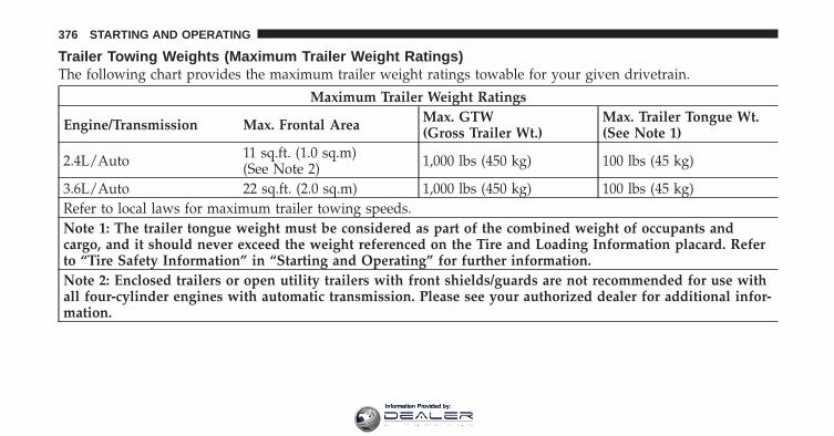
Trailer Towing Weights (Maximum Trailer Weight Ratings)The following chart provides the maximum trailer weight ratings towable for your given drivetrain.
Maximum Trailer Weight Ratings
Engine/Transmission Max. Frontal Area Max. GTW(Gross Trailer Wt.)
Max. Trailer Tongue Wt.(See Note 1)
2.4L/Auto 11 sq.ft. (1.0 sq.m)(See Note 2) 1,000 lbs (450 kg) 100 lbs (45 kg)
3.6L/Auto 22 sq.ft. (2.0 sq.m) 1,000 lbs (450 kg) 100 lbs (45 kg)Refer to local laws for maximum trailer towing speeds.Note 1: The trailer tongue weight must be considered as part of the combined weight of occupants andcargo, and it should never exceed the weight referenced on the Tire and Loading Information placard. Referto “Tire Safety Information” in “Starting and Operating” for further information.Note 2: Enclosed trailers or open utility trailers with front shields/guards are not recommended for use withall four-cylinder engines with automatic transmission. Please see your authorized dealer for additional infor-mation.
376 STARTING AND OPERATING
Information Provided by:

CAUTION!
Towing a trailer with a larger than recommendedfrontal area could cause the engine to overheat orcause severe engine damage under extreme condi-tions.
Trailer And Tongue WeightAlways load a trailer with 60% to 65% of the weight inthe front of the trailer. This places 10% of the Gross TrailerWeight (GTW) on the tow hitch of your vehicle. Loadsbalanced over the wheels or heavier in the rear can causethe trailer to sway severely side to side which will causeloss of control of vehicle and trailer. Failure to loadtrailers heavier in front is the cause of many trailercollisions.
Never exceed the maximum trailer tongue weightstamped on your bumper or trailer hitch.
Consider the following items when computing theweight on the rear axle of the vehicle:
• The trailer tongue weight of the trailer.
• The weight of any other type of cargo or equipmentput in or on your vehicle.
• The weight of the driver and all passengers.
5
STARTING AND OPERATING 377
Information Provided by:

NOTE: Remember that everything put into or on thetrailer adds to the load on your vehicle. Also, additionalfactory-installed options, or authorized dealer-installedoptions, must be considered as part of the total load onyour vehicle. Refer to “Tire Safety Information/Tire andLoading Information Placard” in “Starting and Operat-ing” for the maximum combined weight of occupantsand cargo for your vehicle.
CAUTION!
Incorrect trailer tongue weight could result in in-creased yaw or vehicle instability. A negative trailertongue weight could unload the rear suspension ofthe tow vehicle decreasing vehicle stability. Negativetrailer tongue weight could cause the trailer to squatand potentially become disengaged from the towvehicle resulting in a runaway trailer condition.
Towing RequirementsTo promote proper break-in of your new vehicle drive-train components the following guidelines are recom-mended:
CAUTION!
• Do not tow a trailer at all during the first 500 miles(805 km) the new vehicle is driven. The engine,axle or other parts could be damaged.
• Then, during the first 500 miles (805 km) that atrailer is towed, do not drive over 50 mph(80 km/h) and do not make starts at full throttle.This helps the engine and other parts of thevehicle wear in at the heavier loads.
378 STARTING AND OPERATING
Information Provided by:

WARNING!
Improper towing can lead to a collision. Follow theseguidelines to make your trailer towing as safe aspossible:• Make certain that the load is secured in the trailer
and that it will not shift during travel. Whentrailering cargo that is not fully secured, dynamicload shifts can occur that may be difficult for thedriver to control. You could lose control of yourvehicle and have a collision.
• When hauling cargo, or towing a trailer, do notoverload your vehicle or trailer. Overloading cancause a loss of control, poor performance, or dam-age to brakes, axle, engine, transmission, steering,suspension, chassis structure, or tires.
(Continued)
WARNING! (Continued)• Safety chains must always be used between your
vehicle and trailer. Always connect the chains tothe frame or hook retainers of the vehicle hitch.Cross the chains under the trailer tongue andallow enough slack for turning corners.
• Vehicles with trailers should not be parked on agrade. When parking, apply the parking brake onthe tow vehicle. Put the tow vehicle automatictransmission in PARK. Always, block or �chock�the trailer wheels.
• GCWR must not be exceeded.• Total weight must be distributed between the tow
vehicle and the trailer such that the following fourratings are not exceeded:1. GVWR2. GTW
(Continued)
5
STARTING AND OPERATING 379
Information Provided by:

WARNING! (Continued)3. GAWR4. Trailer tongue weight rating for the trailer hitchutilized (This requirement may limit the ability toalways achieve 10% of trailer tongue weight as apercentage of total trailer weight).
Towing Requirements – Tires
• Do not attempt to tow a trailer while using a compactspare tire.
• Proper tire inflation pressures are essential to the safeand satisfactory operation of your vehicle. Refer to“Tires – General Information” in “Starting and Oper-ating” for proper tire inflation procedures.
• Check the trailer tires for proper tire inflation pres-sures before trailer usage.
• Check for signs of tire wear or visible tire damagebefore towing a trailer. Refer to “Tires – GeneralInformation” in “Starting and Operating” for informa-tion on tread wear indicators and for proper inspectionprocedure.
• When replacing tires, refer to “Tires – General Infor-mation” in “Starting and Operating” for informationon replacement tires and for proper tire replacementprocedures. Replacing tires with a higher load carry-ing capacity will not increase the vehicle’s GVWR andGAWR limits.
Towing Requirements – Trailer Brakes
• Do not interconnect the hydraulic brake system orvacuum system of your vehicle with that of the trailer.This could cause inadequate braking and possiblepersonal injury.
380 STARTING AND OPERATING
Information Provided by:

• An electronically actuated trailer brake controller isrequired when towing a trailer with electronicallyactuated brakes. When towing a trailer equipped witha hydraulic surge actuated brake system, an electronicbrake controller is not required.
• Trailer brakes are recommended for trailers over1,000 lbs (450 kg) and required for trailers in excess of2,000 lbs (907 kg).
CAUTION!
If the trailer weighs more than 1,000 lbs (450 kg)loaded, it should have its own brakes with adequatebraking capacity. Failure to do this could lead toaccelerated brake lining wear, higher brake pedaleffort, and longer stopping distances.
WARNING!
• Do not connect trailer brakes to your vehicle’shydraulic brake lines. It can overload your brakesystem and cause it to fail. You might not havebrakes when you need them and could have acollision.
• Towing any trailer will increase your stoppingdistance. When towing, you should allow for ad-ditional space between your vehicle and the ve-hicle in front of you. Failure to do so could resultin a collision.
Towing Requirements – Trailer Lights And WiringWhenever you pull a trailer, regardless of the trailer size,stop lights and turn signals on the trailer are required formotoring safety.
5
STARTING AND OPERATING 381
Information Provided by:

Towing TipsBefore setting out on a trip, practice turning, stopping,and backing the trailer in an area located away fromheavy traffic.
Make sure all trailer and vehicle lights are workingproperly — including hazard flashers.
Automatic TransmissionThe DRIVE range can be selected when towing. How-ever, if frequent shifting occurs, select the �3� range (for afour-speed automatic) or select a lower gear using theAutoStick� shift control.
NOTE: Using a lower gear while operating the vehicleunder heavy operating conditions, will improve perfor-mance and extend transmission life by reducing exces-sive shifting and heat build-up. This action will alsoprovide better engine braking.
If you REGULARLY TOW a trailer for more than 45 min-utes of continuous operation, then change the automatictransmission fluid and filter according to the intervalspecified for “police, taxi, fleet, or frequent trailer tow-ing.” Refer to the “Maintenance Schedule” for the propermaintenance intervals.
NOTE: Check the four-speed automatic transmissionfluid level before towing. Six-speed transmissions do notrequire a fluid level check before towing. If, however, younotice fluid leakage or transmission malfunction, seeyour authorized dealership service center for assistance.
Electronic Speed Control – If Equipped
• Do not use in hilly terrain or with heavy loads.
• When using the speed control, if you experience speeddrops greater than 10 mph (16 km/h), disengage untilyou can get back to cruising speed.
• Use speed control in flat terrain and with light loads tomaximize fuel efficiency.
382 STARTING AND OPERATING
Information Provided by:

Cooling SystemTo reduce potential for engine and transmission over-heating, take the following actions:
• City DrivingWhen stopped for short periods of time, shift the trans-mission into NEUTRAL and increase engine idle speed.
• Highway DrivingReduce speed.
• Air ConditioningTurn off temporarily.
RECREATIONAL TOWING (BEHIND MOTORHOME, ETC.)Towing This Vehicle Behind Another Vehicle
Towing Condition Wheels OFF theGround
All Models
Flat Tow NONE NOT ALLOWED
Dolly TowFront OKRear NOT ALLOWED
On Trailer ALL OK
5
STARTING AND OPERATING 383
Information Provided by:

Recreational Towing – All ModelsRecreational towing is allowed ONLY if the front wheelsare OFF the ground. This may be accomplished using atow dolly or vehicle trailer. If using a tow dolly, followthis procedure:
1. Properly secure the dolly to the tow vehicle, followingthe dolly manufacturer’s instructions.
2. Drive the front wheels onto the tow dolly.
3. Firmly apply the parking brake. Place the transmis-sion in PARK.
4. Properly secure the front wheels to the dolly, followingthe dolly manufacturer’s instructions.
CAUTION!
• DO NOT flat tow this vehicle. Damage to thedrivetrain will result.
• Towing this vehicle in violation of the aboverequirements can cause severe transmission dam-age. Damage from improper towing is not coveredunder the New Vehicle Limited Warranty.
384 STARTING AND OPERATING
Information Provided by:

WHAT TO DO IN EMERGENCIES
CONTENTS
� Hazard Warning Flashers . . . . . . . . . . . . . . . . 386
� If Your Engine Overheats . . . . . . . . . . . . . . . . 386
▫ Engine Oil Overheating (2.4L Engine Only)— If Equipped . . . . . . . . . . . . . . . . . . . . . . 387
� Jacking And Tire Changing . . . . . . . . . . . . . . . 388
▫ Jack Location . . . . . . . . . . . . . . . . . . . . . . . 388
▫ Spare Tire Stowage . . . . . . . . . . . . . . . . . . . 388
▫ Preparations For Jacking . . . . . . . . . . . . . . . 389
▫ Jacking Instructions . . . . . . . . . . . . . . . . . . . 390
▫ Road Tire Installation . . . . . . . . . . . . . . . . . 396
� Jump-Starting . . . . . . . . . . . . . . . . . . . . . . . . 398
▫ Preparations For Jump-Start . . . . . . . . . . . . . 398
▫ Jump-Starting Procedure . . . . . . . . . . . . . . . 400
� Freeing A Stuck Vehicle . . . . . . . . . . . . . . . . . 402
� Shift Lever Override . . . . . . . . . . . . . . . . . . . 403
� Towing A Disabled Vehicle . . . . . . . . . . . . . . . 404
▫ Automatic Transmission . . . . . . . . . . . . . . . 405
▫ Without The Ignition Key . . . . . . . . . . . . . . 406
6
Information Provided by:

HAZARD WARNING FLASHERSThe Hazard Warning flasher switch is located on theinstrument panel, below the radio.
Press the switch to turn on the Hazard Warningflasher. When the switch is activated, all directionalturn signals will flash on and off to warn oncoming
traffic of an emergency. Press the switch a second time toturn off the Hazard Warning flashers.
This is an emergency warning system and it should notbe used when the vehicle is in motion. Use it when yourvehicle is disabled and it is creating a safety hazard forother motorists.
When you must leave the vehicle to seek assistance, theHazard Warning flashers will continue to operate eventhough the ignition is placed in the OFF position.
NOTE: With extended use the Hazard Warning flashersmay wear down your battery.
IF YOUR ENGINE OVERHEATSIn any of the following situations, you can reduce thepotential for overheating by taking the appropriate ac-tion.
• On the highways — Slow down.
• In city traffic — While stopped, put transaxle inNEUTRAL, but do not increase engine idle speed.
CAUTION!
Driving with a hot cooling system could damageyour vehicle. If temperature gauge reads “H”, pullover and stop the vehicle with the engine at idle,when safe. Turn the air conditioner off and wait untilthe pointer drops back into the normal range. Afterappropriate action has been taken, if the pointerremains on the “H”, turn the engine off immediately,and call for service.
386 WHAT TO DO IN EMERGENCIES
Information Provided by:

NOTE: There are steps that you can take to slow downan impending overheat condition:
• If your air conditioner (A/C) is on, turn it off. The A/Csystem adds heat to the engine cooling system andturning the A/C off can help remove this heat.
• You can also turn the temperature control to maximumheat, the mode control to floor and the blower controlto high. This allows the heater core to act as asupplement to the radiator and aids in removing heatfrom the engine cooling system.
WARNING!You or others can be badly burned by hot enginecoolant (antifreeze) or steam from your radiator. Ifyou see or hear steam coming from under the hood,do not open the hood until the radiator has had timeto cool. Never try to open a cooling system pressurecap when the radiator or coolant bottle is hot.
Engine Oil Overheating (2.4L Engine Only) — IfEquippedDuring sustained high-speed driving or trailer tow uplong grades on a hot day, the engine oil temperature maybecome too hot. If this happens, the “HOTOIL” messageflashes in the odometer and the vehicle speed will bereduced to 53 mph (85 km/h) until the engine oiltemperature is reduced.
NOTE: The vehicle speed is reduced to a maximum of53 mph (85 km/h). You may of course, reduce yourvehicle speed further if needed. 6
WHAT TO DO IN EMERGENCIES 387
Information Provided by:

JACKING AND TIRE CHANGING
WARNING!
• Do not attempt to change a tire on the side of thevehicle close to moving traffic. Pull far enough offthe road to avoid the danger of being hit whenoperating the jack or changing the wheel.
• Being under a jacked-up vehicle is dangerous. Thevehicle could slip off the jack and fall on you. Youcould be crushed. Never put any part of your bodyunder a vehicle that is on a jack. If you need to getunder a raised vehicle, take it to a service centerwhere it can be raised on a lift.
• Never start or run the engine while the vehicle ison a jack.
(Continued)
WARNING! (Continued)• The jack is designed to be used as a tool for
changing tires only. The jack should not be used tolift the vehicle for service purposes. The vehicleshould be jacked on a firm level surface only.Avoid ice or slippery areas.
Jack LocationThe jack and jack-handle are stowed under the load floorin the trunk.
Spare Tire StowageThe compact spare tire is stowed under the rear load floorin the trunk.
Spare Tire RemovalLift up the load floor cover and remove the hold down.
388 WHAT TO DO IN EMERGENCIES
Information Provided by:

Preparations For Jacking
1. Park the vehicle on a firm, level surface. Avoid ice orslippery areas.
WARNING!
Do not attempt to change a tire on the side of thevehicle close to moving traffic, pull far enough offthe road to avoid the danger of being hit whenoperating the jack or changing the wheel.
2. Turn on the Hazard Warning flashers.
3. Set the parking brake.
4. Place the shift lever into PARK (automatic transmis-sion) or REVERSE (manual transmission).
5. Turn OFF the ignition.Spare Tire and Jack Stowage
6
WHAT TO DO IN EMERGENCIES 389
Information Provided by:

6. Block both the front and rear of thewheel diagonally opposite the jackingposition. For example, if changing theright front tire, block the left rearwheel.
NOTE: Passengers should not remain in the vehiclewhile the vehicle is being jacked.
Jacking Instructions
WARNING!
Carefully follow these tire changing warnings tohelp prevent personal injury or damage to yourvehicle:
(Continued)
WARNING! (Continued)• Always park on a firm, level surface as far from
the edge of the roadway as possible before raisingthe vehicle.
• Turn on the Hazard Warning flashers.• Block the wheel diagonally opposite the wheel to
be raised.• Set the parking brake firmly and set an automatic
transmission in PARK; a manual transmission inREVERSE.
• Never start or run the engine while the vehicle ison a jack.
• Do not let anyone sit in the vehicle when it is on ajack.
• Do not get under the vehicle when it is on a jack.• Only use the jack in the positions indicated and
for lifting this vehicle during a tire change.
(Continued)
390 WHAT TO DO IN EMERGENCIES
Information Provided by:

WARNING! (Continued)• If working on or near a roadway, be extremely
careful of motor traffic.• To assure that spare tires, flat or inflated, are
securely stowed, spares must be stowed with thevalve stem facing the ground.
CAUTION!
Do not attempt to raise the vehicle by jacking onlocations other than those indicated in the JackingInstructions for this vehicle.
NOTE: Refer to the Compact Spare Tire section ofTires--General Information--for information about thespare tire, its use, and operation.
1. Remove the scissors jack and lug wrench from thespare wheel as an assembly. Turn the jack screw to the leftto loosen the lug wrench, and remove the wrench fromthe jack assembly.
Jack Warning Label
6
WHAT TO DO IN EMERGENCIES 391
Information Provided by:

NOTE: The jack handle attaches to the side of the jackwith two attachment points. When the jack is partiallyexpanded, the tension between the two attachmentpoints holds the jack handle in place.
2. Loosen, but do not remove, the wheel nuts by turningthem to the left one turn while the wheel is still on theground.
CAUTION!
Do not attempt to raise the vehicle by jacking onlocations other than those indicated in Step 3.
Removing Jack Handle From Jack
Jacking Locations
392 WHAT TO DO IN EMERGENCIES
Information Provided by:

3. There is a front and rear jacking location on each sideof the vehicle.
4. Turn the jack screw to the left until the jack can beplaced under the jacking location. Once the jack ispositioned, turn the jack screw to the right until the jackhead is properly engaged with the lift area closest to thewheel to be changed. Do not raise the vehicle until youare sure the jack is securely engaged.
Front Jacking Location
Rear Jacking Location6
WHAT TO DO IN EMERGENCIES 393
Information Provided by:
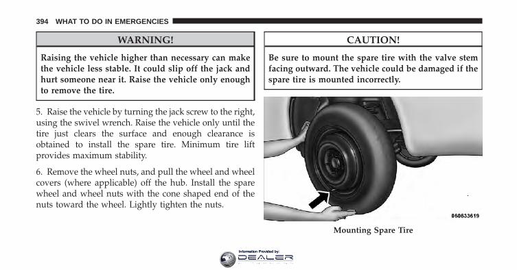
WARNING!
Raising the vehicle higher than necessary can makethe vehicle less stable. It could slip off the jack andhurt someone near it. Raise the vehicle only enoughto remove the tire.
5. Raise the vehicle by turning the jack screw to the right,using the swivel wrench. Raise the vehicle only until thetire just clears the surface and enough clearance isobtained to install the spare tire. Minimum tire liftprovides maximum stability.
6. Remove the wheel nuts, and pull the wheel and wheelcovers (where applicable) off the hub. Install the sparewheel and wheel nuts with the cone shaped end of thenuts toward the wheel. Lightly tighten the nuts.
CAUTION!
Be sure to mount the spare tire with the valve stemfacing outward. The vehicle could be damaged if thespare tire is mounted incorrectly.
Mounting Spare Tire
394 WHAT TO DO IN EMERGENCIES
Information Provided by:

WARNING!
• To avoid the risk of forcing the vehicle off the jack,do not tighten the wheel nuts fully until thevehicle has been lowered. Failure to follow thiswarning may result in personal injury.
• To avoid possible personal injury, handle thewheel covers with care to avoid contact with anysharp edges.
7. Lower the vehicle by turning the jack screw to the left.
8. Finish tightening the nuts. Push down on the wrenchwhile at the end of the handle for increased leverage.Tighten the lug nuts in a star pattern until each nut hasbeen tightened twice. The correct wheel nut torque is100 ft lbs (135 N·m). If you doubt that you have tightenedthe nuts correctly, have them checked with a torquewrench by your authorized dealer or at a service station.
9. Remove the wheel blocks and lower the jack until it isfree. Reassemble the lug wrench to the jack assembly andstow it in the spare tire area. Secure the assembly usingthe means provided.
Release the parking brake before driving the vehicle.
WARNING!
A loose tire or jack thrown forward in a collision orhard stop could endanger the occupants of the ve-hicle. Always stow the jack parts and the spare tire inthe places provided.
10. Place the deflated (flat) tire in the cargo area and havethe tire repaired or replaced as soon as possible.
11. Check the tire pressure as soon as possible. Correctthe tire pressure as required.
6
WHAT TO DO IN EMERGENCIES 395
Information Provided by:

Road Tire Installation
Vehicles Equipped With Wheel Covers
1. Mount the road tire on the axle.
2. To ease the installation process for steel wheels withwheel covers, install two lug nuts on the mounting studswhich are on each side of the valve stem. Install the lugnuts with the cone shaped end of the nut toward thewheel. Lightly tighten the lug nuts.
WARNING!
To avoid the risk of forcing the vehicle off the jack,do not tighten the wheel nuts fully until the vehiclehas been lowered. Failure to follow this warning mayresult in personal injury.
3. Align the valve notch in the wheel cover with thevalve stem on the wheel. Install the cover by hand,snapping the cover over the two lug nuts. Do not use ahammer or excessive force to install the cover.
Tire And Wheel Cover Or Center Cap
1 — Valve Stem 4 — Wheel Cover2 — Valve Notch 5 — Mounting Stud3 — Wheel Lug Nut
396 WHAT TO DO IN EMERGENCIES
Information Provided by:

4. Install the remaining lug nuts with the cone shapedend of the nut toward the wheel. Lightly tighten the lugnuts.
WARNING!
To avoid the risk of forcing the vehicle off the jack,do not tighten the wheel nuts fully until the vehiclehas been lowered. Failure to follow this warning mayresult in personal injury.
5. Lower the vehicle to the ground by turning the jackhandle counterclockwise.
6. Finish tightening the lug nuts. Push down on thewrench while at the end of the handle for increasedleverage. Tighten the lug nuts in a star pattern until eachnut has been tightened twice. The correct tightness ofeach lug nut is 100 ft/lbs (135 N·m). If in doubt about thecorrect tightness, have them checked with a torquewrench by your authorized dealer or service station.
7. After 25 miles (40 km) check the lug nut torque with atorque wrench to ensure that all lug nuts are properlyseated against the wheel.
Vehicles Without Wheel Covers
1. Mount the road tire on the axle.
2. Install the remaining lug nuts with the cone shapedend of the nut toward the wheel. Lightly tighten the lugnuts.
WARNING!
To avoid the risk of forcing the vehicle off the jack,do not tighten the wheel nuts fully until the vehiclehas been lowered. Failure to follow this warning mayresult in personal injury.
3. Lower the vehicle to the ground by turning the jackhandle counterclockwise.
6
WHAT TO DO IN EMERGENCIES 397
Information Provided by:
4. Finish tightening the lug nuts. Push down on thewrench while at the end of the handle for increasedleverage. Tighten the lug nuts in a star pattern until eachnut has been tightened twice. The correct tightness ofeach lug nut is 100 ft/lbs (135 N·m). If in doubt about thecorrect tightness, have them checked with a torquewrench by your authorized dealer or service station.
5. After 25 miles (40 km) check the lug nut torque with atorque wrench to ensure that all lug nuts are properlyseated against the wheel.
JUMP-STARTINGIf your vehicle has a discharged battery it can be jump-started using a set of jumper cables and a battery inanother vehicle or by using a portable battery boosterpack. Jump-starting can be dangerous if done improperlyso please follow the procedures in this section carefully.
NOTE: When using a portable battery booster packfollow the manufacturer’s operating instructions andprecautions.
CAUTION!
Do not use a portable battery booster pack or anyother booster source with a system voltage greaterthan 12 Volts or damage to the battery, starter motor,alternator or electrical system may occur.
WARNING!
Do not attempt jump-starting if the battery is frozen.It could rupture or explode and cause personal injury.
Preparations For Jump-StartThe battery in your vehicle is located between the leftfront headlight assembly and the left front wheel splash
398 WHAT TO DO IN EMERGENCIES
Information Provided by:

shield. To allow jump-starting there are remote batteryposts located on the left side of the engine compartment.
WARNING!
• Take care to avoid the radiator cooling fan when-ever the hood is raised. It can start anytime theignition switch is on. You can be injured bymoving fan blades.
• Remove any metal jewelry such as watch bands orbracelets that might make an inadvertent electricalcontact. You could be seriously injured.
• Batteries contain sulfuric acid that can burn yourskin or eyes and generate hydrogen gas which isflammable and explosive. Keep open flames orsparks away from the battery.
1. Set the parking brake, shift the automatic transmissioninto PARK and turn the ignition to LOCK.
2. Turn off the heater, radio, and all unnecessary electri-cal accessories.
Remote Battery Posts
1 — Remote Positive (+) Post (covered with protective cap)2 — Remote Negative (-) Post
6
WHAT TO DO IN EMERGENCIES 399
Information Provided by:

3. Remove the protective cover over the remote positive(+) battery post. To remove the cover, press the lockingtab and pull upward on the cover.
4. If using another vehicle to jump-start the battery, parkthe vehicle within the jumper cables reach, set theparking brake and make sure the ignition is OFF.
WARNING!
Do not allow vehicles to touch each other as thiscould establish a ground connection and personalinjury could result.
Jump-Starting Procedure
WARNING!
Failure to follow this procedure could result in per-sonal injury or property damage due to battery ex-plosion.
CAUTION!
Failure to follow these procedures could result indamage to the charging system of the booster vehicleor the discharged vehicle.
Locking Tab
400 WHAT TO DO IN EMERGENCIES
Information Provided by:

1. Connect the positive (+) end of the jumper cable to theremote positive (+) post of the discharged vehicle.
2. Connect the opposite end of the positive (+) jumpercable to the positive (+) post of the booster battery.
3. Connect the negative end (-) of the jumper cable to thenegative (-) post of the booster battery.
4. Connect the opposite end of the negative (-) jumpercable to the remote negative (-) post of the vehicle withthe discharged battery.
WARNING!
Do not connect the cable to the negative post (-) of thedischarged battery. The resulting electrical sparkcould cause the battery to explode and could result inpersonal injury.
5. Start the engine in the vehicle that has the boosterbattery, let the engine idle a few minutes, and then startthe engine in the vehicle with the discharged battery.
Once the engine is started, remove the jumper cables inthe reverse sequence:
6. Disconnect the negative (-) jumper cable from theremote negative (-) post of the vehicle with the dis-charged battery.
7. Disconnect the negative end (-) of the jumper cablefrom the negative (-) post of the booster battery.
8. Disconnect the opposite end of the positive (+) jumpercable from the positive (+) post of the booster battery.
9. Disconnect the positive (+) end of the jumper cablefrom the remote positive (+) post of the dischargedvehicle.
6
WHAT TO DO IN EMERGENCIES 401
Information Provided by:

10. Reinstall the protective cover over the remote posi-tive (+) battery post of the discharged vehicle.
If frequent jump-starting is required to start your vehicleyou should have the battery and charging system in-spected at your authorized dealer.
CAUTION!
Accessories that can be plugged into the vehiclepower outlets draw power from the vehicle’s battery,even when not in use (i.e., cellular phones, etc.).Eventually, if plugged in long enough, the vehicle’sbattery will discharge sufficiently to degrade batterylife and/or prevent the engine from starting.
FREEING A STUCK VEHICLEIf your vehicle becomes stuck in mud, sand, or snow, itcan often be moved by a rocking motion. Turn yoursteering wheel right and left to clear the area around the
front wheels. Then shift back and forth between DRIVEand REVERSE. Using minimal accelerator pedal pressureto maintain the rocking motion, without spinning thewheels, is most effective.
CAUTION!
Racing the engine or spinning the wheels may lead totransmission overheating and failure. Allow the en-gine to idle with the shift lever in NEUTRAL for atleast one minute after every five rocking-motioncycles. This will minimize overheating and reducethe risk of transmission failure during prolongedefforts to free a stuck vehicle.
NOTE: If your vehicle is equipped with ElectronicStability Control (ESC), turn the system to Partial OFFbefore attempting to “rock” the vehicle. Refer to “Elec-tronic Brake Control” in “Starting and Operating” forfurther information.
402 WHAT TO DO IN EMERGENCIES
Information Provided by:
CAUTION!
• When “rocking” a stuck vehicle by moving be-tween DRIVE and REVERSE, do not spin thewheels faster than 15 mph (24 km/h), or drivetraindamage may result.
• Revving the engine or spinning the wheels too fastmay lead to transmission overheating and failure.It can also damage the tires. Do not spin thewheels above 30 mph (48 km/h) while in gear (notransmission shifting occurring).
WARNING!
Fast spinning tires can be dangerous. Forces gener-ated by excessive wheel speeds may cause damage, oreven failure, of the axle and tires. A tire couldexplode and injure someone. Do not spin your vehi-cle’s wheels faster than 30 mph (48 km/h) or forlonger than 30 seconds continuously without stop-ping when you are stuck and do not let anyone neara spinning wheel, no matter what the speed.
SHIFT LEVER OVERRIDEIf a malfunction occurs and the shift lever cannot bemoved out of the PARK position, you can use thefollowing procedure to temporarily move the shift lever:
1. Firmly apply the parking brake.
2. Remove the cupholder liner.
6
WHAT TO DO IN EMERGENCIES 403
Information Provided by:

3. Turn the ignition to the ON/RUN position withoutstarting the engine.
4. Press and maintain firm pressure on the brake pedal.
5. Insert a screwdriver or similar tool into the hole at thefront of the cupholder and push and hold the overridelever forward.
6. Move the shift lever into the NEUTRAL position.
7. The vehicle may then be started in NEUTRAL.
8. Reinstall the cupholder liner.
TOWING A DISABLED VEHICLE
Towing Condition Wheels OFF the Ground Automatic TransmissionsFlat Tow NONE If transmission is operable:
• Transmission in NEUTRAL• 25 mph (40 km/h)max speed• 15 mi (24 km) max distanceWheel Lift Or Dolly Tow
Rear
Front OKFlatbed ALL BEST METHOD
404 WHAT TO DO IN EMERGENCIES
Information Provided by:

Proper towing or lifting equipment is required to preventdamage to your vehicle. Use only tow bars and otherequipment designed for the purpose, following equip-ment manufacturer’s instructions. Use of safety chains ismandatory. Attach a tow bar or other towing device tomain structural members of the vehicle, not to bumpersor associated brackets. State and local laws applying tovehicles under tow must be observed.
If you must use the accessories (wipers, defrosters, etc.)while being towed, the ignition must be in the ON/RUNposition, not the ACC position.
CAUTION!
• Do not use sling type equipment when towing.Damage to the fascia will occur.
(Continued)
CAUTION! (Continued)• When securing the vehicle to a flatbed truck, do
not attach to front or rear suspension components.Damage to your vehicle may result from impropertowing.
• Do not push or tow this vehicle with anothervehicle as damage to the bumper fascia and trans-mission may result.
• If the vehicle being towed requires steering, theignition switch must be in the ON position, notthe LOCK or ACC positions.
Automatic TransmissionThe manufacturer recommends towing your vehicle withall four wheels OFF the ground using a flatbed.
6
WHAT TO DO IN EMERGENCIES 405
Information Provided by:

If flatbed equipment is not available, and the transmissionis operable, the vehicle may be flat towed (with all fourwheels on the ground) under the following conditions:
• The shift lever must be in NEUTRAL.
• The towing distance must not exceed 15 mi (24 km).
• The towing speed must not exceed 25 mph (40 km/h).
If the transmission is not operable, or the vehicle mustbe towed faster than 25 mph (40 km/h) or farther than 15mi (24 km), it must be towed with the front wheels OFFthe ground (using a flatbed truck, towing dolly, orwheel lift equipment with the front wheels raised).
CAUTION!Towing faster than 25 mph (40 km/h) or farther than 15mi (24 km) with front wheels on the ground can causesevere damage to the transmission. Such damage isnot covered by the New Vehicle Limited Warranty.
Without The Ignition KeySpecial care must be taken when the vehicle is towedwith the ignition in the LOCK position. Flatbed towing isthe preferred towing method. However, if a flatbedtowing vehicle is not available, wheel lift towing equip-ment may be used. Rear towing (with the front wheels onthe ground) is not allowed, as transmission damage willoccur. If rear towing is the only alternative, the frontwheels must be placed on a towing dolly. Proper towingequipment is necessary to prevent damage to the vehicle.
CAUTION!
Failure to follow these towing methods can causesevere damage to the transmission. Such damage isnot covered by the New Vehicle Limited Warranty.
406 WHAT TO DO IN EMERGENCIES
Information Provided by:

MAINTAINING YOUR VEHICLE
CONTENTS
� Engine Compartment — 2.4L . . . . . . . . . . . . . 409
� Engine Compartment — 3.6L . . . . . . . . . . . . . 410
� Onboard Diagnostic System — OBD II . . . . . . 411
▫ Loose Fuel Filler Cap Message . . . . . . . . . . . 411
� Emissions Inspection And MaintenancePrograms . . . . . . . . . . . . . . . . . . . . . . . . . . . . 412
� Replacement Parts . . . . . . . . . . . . . . . . . . . . . 413
� Dealer Service . . . . . . . . . . . . . . . . . . . . . . . . 414
� Maintenance Procedures . . . . . . . . . . . . . . . . . 414
▫ Engine Oil . . . . . . . . . . . . . . . . . . . . . . . . . 415
▫ Engine Oil Filter . . . . . . . . . . . . . . . . . . . . . 418
▫ Engine Air Cleaner Filter . . . . . . . . . . . . . . . 419
▫ Maintenance-Free Battery . . . . . . . . . . . . . . 419
▫ Air Conditioner Maintenance . . . . . . . . . . . . 421
▫ A/C Air Filter – If Equipped . . . . . . . . . . . . 422
▫ Body Lubrication . . . . . . . . . . . . . . . . . . . . 423
▫ Windshield Wiper Blades . . . . . . . . . . . . . . . 424
7
Information Provided by:

▫ Adding Washer Fluid . . . . . . . . . . . . . . . . . 425
▫ Exhaust System . . . . . . . . . . . . . . . . . . . . . 425
▫ Cooling System . . . . . . . . . . . . . . . . . . . . . 428
▫ Brake System . . . . . . . . . . . . . . . . . . . . . . . 433
▫ Automatic Transmission . . . . . . . . . . . . . . . 435
▫ Appearance Care And Protection FromCorrosion . . . . . . . . . . . . . . . . . . . . . . . . . . 438
▫ Cleaning Center Console Cupholders . . . . . . 444
� Fuses . . . . . . . . . . . . . . . . . . . . . . . . . . . . . . 444
▫ Integrated Power Module . . . . . . . . . . . . . . 444
� Vehicle Storage . . . . . . . . . . . . . . . . . . . . . . . 449
� Replacement Bulbs . . . . . . . . . . . . . . . . . . . . 449
� Bulb Replacement . . . . . . . . . . . . . . . . . . . . . 450
▫ Headlamp . . . . . . . . . . . . . . . . . . . . . . . . . 450
▫ Front Turn Signal . . . . . . . . . . . . . . . . . . . . 452
▫ Front Fog Lamp . . . . . . . . . . . . . . . . . . . . . 452
▫ Backup Lamps . . . . . . . . . . . . . . . . . . . . . . 453
▫ License Plate Lamp . . . . . . . . . . . . . . . . . . . 454
� Fluid Capacities . . . . . . . . . . . . . . . . . . . . . . 455
� Fluids, Lubricants, And Genuine Parts . . . . . . . 456
▫ Engine . . . . . . . . . . . . . . . . . . . . . . . . . . . . 456
▫ Chassis . . . . . . . . . . . . . . . . . . . . . . . . . . . 457
408 MAINTAINING YOUR VEHICLE
Information Provided by:

ENGINE COMPARTMENT — 2.4L
1 — Engine Coolant Reservoir 7 — Air Cleaner Filter2 — Power Steering Fluid Reservoir 8 — Engine Oil Fill3 — Automatic Transmission Dipstick 9 — Coolant Pressure Cap4 — Brake Fluid Reservoir 10 — Engine Oil Dipstick5 — Power Distribution Center (Fuses) 11 — Washer Fluid Reservoir6 — Integrated Power Module (Fuses)
7
MAINTAINING YOUR VEHICLE 409
Information Provided by:

ENGINE COMPARTMENT — 3.6L
1 — Engine Coolant Reservoir 5 — Air Cleaner Filter2 — Power Steering Fluid Reservoir 6 — Engine Oil Dipstick3 — Brake Fluid Reservoir 7 — Engine Oil Fill4 — Integrated Power Module (Fuses) 8 — Washer Fluid Reservoir
410 MAINTAINING YOUR VEHICLE
Information Provided by:

ONBOARD DIAGNOSTIC SYSTEM — OBD IIYour vehicle is equipped with a sophisticated onboarddiagnostic system called OBD II. This system monitorsthe performance of the emissions, engine, and automatictransmission control systems. When these systems areoperating properly, your vehicle will provide excellentperformance and fuel economy, as well as engine emis-sions well within current government regulations.
If any of these systems require service, the OBD II systemwill turn on the “Malfunction Indicator Light” (MIL). Itwill also store diagnostic codes and other information toassist your service technician in making repairs. Al-though your vehicle will usually be drivable and notneed towing, see your authorized dealer for service assoon as possible.
CAUTION!
• Prolonged driving with the MIL on could causefurther damage to the emission control system. Itcould also affect fuel economy and drivability. Thevehicle must be serviced before any emissionstests can be performed.
• If the MIL is flashing while the engine is running,severe catalytic converter damage and power losswill soon occur. Immediate service is required.
Loose Fuel Filler Cap MessageAfter fuel is added, the vehicle diagnostic system candetermine if the fuel filler cap is possibly loose orimproperly installed. A “GASCAP” message will bedisplayed in the instrument cluster. Tighten the gas capuntil a �clicking� sound is heard. This is an indication thatthe gas cap is properly tightened. Press the trip odometer“Reset” button to turn off the message. If the problem
7
MAINTAINING YOUR VEHICLE 411
Information Provided by:

persists, the message will appear the next time thevehicle is started. This might indicate a damaged cap. Ifthe problem is detected twice in a row, the system willturn on the “Malfunction Indicator Light (MIL).” Resolv-ing the problem will turn the MIL light off.
EMISSIONS INSPECTION AND MAINTENANCEPROGRAMSIn some localities, it may be a legal requirement to passan inspection of your vehicle’s emissions control system.Failure to pass could prevent vehicle registration.
For states that require an Inspection and Mainte-nance (I/M), this check verifies the “MalfunctionIndicator Light (MIL)” is functioning and is not
on when the engine is running, and that the OBD IIsystem is ready for testing.
Normally, the OBD II system will be ready. The OBD IIsystem may not be ready if your vehicle was recentlyserviced, recently had a dead battery or a battery replace-ment. If the OBD II system should be determined notready for the I/M test, your vehicle may fail the test.
Your vehicle has a simple ignition key-actuated test,which you can use prior to going to the test station. Tocheck if your vehicle’s OBD II system is ready, you mustdo the following:
1. Turn the ignition switch to the ON position, but do notcrank or start the engine.
2. If you crank or start the engine, you will have to startthis test over.
3. As soon as you turn the ignition switch to the ONposition, you will see the MIL symbol come on as part ofa normal bulb check.
412 MAINTAINING YOUR VEHICLE
Information Provided by:

4. Approximately 15 seconds later, one of two things willhappen:
a. The MIL will flash for about 10 seconds and thenreturn to being fully illuminated until you turn OFFthe ignition or start the engine. This means that yourvehicle’s OBD II system is not ready and you shouldnot proceed to the I/M station.
b. The MIL will not flash at all and will remain fullyilluminated until you turn OFF the ignition or start theengine. This means that your vehicle’s OBD II systemis ready and you can proceed to the I/M station.
If your OBD II system is not ready, you should see yourauthorized dealer or repair facility. If your vehicle wasrecently serviced or had a battery failure or replacement,you may need to do nothing more than drive yourvehicle as you normally would in order for your OBD IIsystem to update. A recheck with the above test routinemay then indicate that the system is now ready.
Regardless of whether your vehicle’s OBD II system isready or not, if the MIL is illuminated during normalvehicle operation you should have your vehicle servicedbefore going to the I/M station. The I/M station can failyour vehicle because the MIL is on with the enginerunning.
REPLACEMENT PARTSUse of genuine MOPAR� parts for normal/scheduledmaintenance and repairs is highly recommended to en-sure the designed performance. Damage or failurescaused by the use of non-MOPAR� parts for maintenanceand repairs will not be covered by the manufacturer’swarranty. 7
MAINTAINING YOUR VEHICLE 413
Information Provided by:

DEALER SERVICEYour authorized dealer has the qualified service person-nel, special tools, and equipment to perform all serviceoperations in an expert manner. Service Manuals areavailable which include detailed service information foryour vehicle. Refer to these Service Manuals beforeattempting any procedure yourself.
NOTE: Intentional tampering with emissions controlsystems may void your warranty and could result in civilpenalties being assessed against you.
WARNING!
You can be badly injured working on or around amotor vehicle. Only do service work for which youhave the knowledge and the proper equipment. Ifyou have any doubt about your ability to perform aservice job, take your vehicle to a competent me-chanic.
MAINTENANCE PROCEDURESThe pages that follow contain the required maintenanceservices determined by the engineers who designed yourvehicle.
Besides those maintenance items specified in the fixedmaintenance schedule, there are other components whichmay require servicing or replacement in the future.
CAUTION!
• Failure to properly maintain your vehicle or per-form repairs and service when necessary couldresult in more costly repairs, damage to othercomponents or negatively impact vehicle perfor-mance. Immediately have potential malfunctionsexamined by an authorized Chrysler Group LLCdealership or qualified repair center.
(Continued)
414 MAINTAINING YOUR VEHICLE
Information Provided by:

CAUTION! (Continued)• Your vehicle has been built with improved fluids
that protect the performance and durability ofyour vehicle and also allow extended maintenanceintervals. Do not use chemical flushes in thesecomponents as the chemicals can damage yourengine, transmission, power steering or air condi-tioning. Such damage is not covered by the NewVehicle Limited Warranty. If a flush is neededbecause of component malfunction, use only thespecified fluid for the flushing procedure.
Engine Oil
Checking Oil LevelTo assure proper engine lubrication, the engine oil mustbe maintained at the correct level. Check the oil level atregular intervals, such as every fuel stop. The best time tocheck the engine oil level is about five minutes after a
fully warmed engine is shut off. Do not check oil levelbefore starting the engine after it has sat overnight.Checking engine oil level when the engine is cold willgive you an incorrect reading.
Checking the oil while the vehicle is on level ground andonly when the engine is hot, will improve the accuracy ofthe oil level readings. Maintain the oil level between therange markings on the dipstick. Either the range mark-ings consist of a crosshatch zone marked SAFE or acrosshatch zone marked with MIN at the low end of therange and MAX at the high end of the range. Adding onequart of oil when the reading is at the low end of therange marking will raise the oil level to the high end ofthe range marking.
7
MAINTAINING YOUR VEHICLE 415
Information Provided by:

CAUTION!
Do not overfill the engine. Overfilling the enginewill cause oil aeration, which can lead to loss of oilpressure and an increase in oil temperature. Thiscould damage your engine. Also, be sure the oil fillcap is replaced and tightened after adding oil.
Change Engine OilThe oil change indicator system will remind you that it istime to take your vehicle in for scheduled maintenance.Refer to “Maintenance Schedule” for further information.
NOTE: Under no circumstances should oil changeintervals exceed 8,000 miles (13 000 km) or six months,whichever occurs first.
Engine Oil SelectionFor best performance and maximum protection under alltypes of operating conditions, the manufacturer recom-mends engine oils that are API Certified and meet therequirements of Chrysler Material Standard MS-6395.
American Petroleum Institute (API) Engine OilIdentification Symbol
This symbol means that the oil hasbeen certified by the AmericanPetroleum Institute (API). Themanufacturer only recommendsAPI Certified engine oils.
416 MAINTAINING YOUR VEHICLE
Information Provided by:

CAUTION!
Do not use chemical flushes in your engine oil as thechemicals can damage your engine. Such damage isnot covered by the New Vehicle Limited Warranty.
Engine Oil Viscosity (SAE Grade) – 2.4L EngineSAE 5W-20 engine oil is recommended for all operatingtemperatures. This engine oil improves low temperaturestarting and vehicle fuel economy. Your engine oil fillercap also shows the recommended engine oil viscosity foryour vehicle.
The engine oil filler cap also shows the recommendedengine oil viscosity for your engine. For information onengine oil filler cap location, refer to “Engine Compart-ment” in “Maintaining Your Vehicle” for further informa-tion.
Lubricants which do not have both the engine oil certi-fication mark and the correct SAE viscosity grade num-ber should not be used.
Engine Oil Viscosity (SAE Grade) – 3.6L EngineSAE 5W-30 engine oil is preferred for all operatingtemperatures. The engine oil filler cap also shows therecommended engine oil viscosity for your vehicle.
Lubricants which do not have both, the engine oil certi-fication mark and the correct SAE viscosity grade num-ber should not be used.
The engine oil filler cap also shows the recommendedengine oil viscosity for your engine. For information onengine oil filler cap location, refer to “Engine Compart-ment” in “Maintaining Your Vehicle” for further informa-tion.
7
MAINTAINING YOUR VEHICLE 417
Information Provided by:

Lubricants which do not have both, the engine oil certi-fication mark and the correct SAE viscosity grade num-ber should not be used.
Synthetic Engine OilsYou may use synthetic engine oils provided the recom-mended oil quality requirements are met, and the recom-mended maintenance intervals for oil and filter changesare followed.
Materials Added To Engine OilsDo not add any supplemental materials, other than leakdetection dyes, to your engine oil. Engine oil is anengineered product and it’s performance may be im-paired by supplemental additives.
Disposing Of Used Engine Oil And Oil FiltersCare should be taken in disposing of used engine oil andoil filters from your vehicle. Used oil and oil filters,indiscriminately discarded, can present a problem to theenvironment. Contact your authorized dealer, servicestation, or governmental agency for advice on how andwhere used oil and oil filters can be safely discarded inyour area.
Engine Oil FilterThe engine oil filter should be replaced with a new filterat every engine oil change.
Engine Oil Filter SelectionAll of this manufacturer’s engines have a full-flow typedisposable oil filter. Use a filter of this type for replace-ment. The quality of replacement filters varies consider-ably. Only high quality filters should be used to assuremost efficient service. MOPAR� engine oil filters are highquality oil filters and are recommended.
418 MAINTAINING YOUR VEHICLE
Information Provided by:
Engine Air Cleaner Filter
WARNING!
The air induction system (air cleaner, hoses, etc.) canprovide a measure of protection in the case of enginebackfire. Do not remove the air induction system (aircleaner, hoses, etc.) unless such removal is necessaryfor repair or maintenance. Make sure that no one isnear the engine compartment before starting thevehicle with the air induction system (air cleaner,hoses, etc.) removed. Failure to do so can result inserious personal injury.
Refer to the “Maintenance Schedule” for the propermaintenance intervals.
Engine Air Cleaner Filter SelectionThe quality of replacement engine air cleaner filtersvaries considerably. Only high quality filters should beused to assure most efficient service. MOPAR� engine aircleaner filters are high quality and are recommended.
Maintenance-Free BatteryYour vehicle is equipped with a maintenance-free battery.You will never have to add water, nor is periodic main-tenance required.
NOTE: The battery is stored in a compartment behindthe left front fender and is accessible without removingthe tire and wheel. Remote battery terminals are locatedin the engine compartment for jump-starting. Refer to“Jump-Starting Procedures” in “What To Do In Emergen-cies” for further information.
To access the battery, turn the steering wheel fully to theright and remove the inner fender shield.
7
MAINTAINING YOUR VEHICLE 419
Information Provided by:
WARNING!
• Battery fluid is a corrosive acid solution and canburn or even blind you. Do not allow battery fluidto contact your eyes, skin, or clothing. Do not leanover a battery when attaching clamps. If acidsplashes in eyes or on skin, flush the area imme-diately with large amounts of water.
• Battery gas is flammable and explosive. Keepflame or sparks away from the battery. Do not usea booster battery or any other booster source withan output greater than 12 Volts. Do not allow cableclamps to touch each other.
• Battery posts, terminals, and related accessoriescontain lead and lead compounds. Wash handsafter handling.
CAUTION!
• It is essential when replacing the cables on thebattery that the positive cable is attached to thepositive post and the negative cable is attached tothe negative post. Battery posts are marked posi-tive (+) and negative (-) and are identified on thebattery case. Cable clamps should be tight on theterminal posts and free of corrosion.
• If a “fast charger” is used while the battery is inthe vehicle, disconnect both vehicle battery cablesbefore connecting the charger to the battery. Donot use a “fast charger” to provide starting voltage.
420 MAINTAINING YOUR VEHICLE
Information Provided by:

Air Conditioner MaintenanceFor best possible performance, your air conditionershould be checked and serviced by an authorized dealerat the start of each warm season. This service shouldinclude cleaning of the condenser fins and a performancetest.
CAUTION!
Do not use chemical flushes in your air conditioningsystem as the chemicals can damage your air condi-tioning components. Such damage is not covered bythe New Vehicle Limited Warranty.
WARNING!
• Use only refrigerants and compressor lubricantsapproved by the manufacturer for your air condi-tioning system. Some unapproved refrigerants areflammable and can explode, injuring you. Otherunapproved refrigerants or lubricants can causethe system to fail, requiring costly repairs. Refer toWarranty Information Book, located on the DVD,for further warranty information.
• The air conditioning system contains refrigerantunder high pressure. To avoid risk of personalinjury or damage to the system, adding refrigerantor any repair requiring lines to be disconnectedshould be done by an experienced technician.
7
MAINTAINING YOUR VEHICLE 421
Information Provided by:

Refrigerant Recovery And RecyclingR-134a air conditioning refrigerant is a hydrofluoro-carbon (HFC) that is endorsed by the EnvironmentalProtection Agency and is an ozone-saving product. How-ever, the manufacturer recommends that air conditioningservice be performed by authorized dealers or otherservice facilities using recovery and recycling equipment.
NOTE: Use only manufacturer approved A/C SystemSealers, Stop Leak Products, Seal Conditioners, Compres-sor Oil, and Refrigerants.
A/C Air Filter – If EquippedRefer to the “Maintenance Schedule” for the propermaintenance intervals.
WARNING!
Do not remove the A/C Air Filter while the blower isoperating or personal injury may result.
The A/C Air Filter is located in the fresh air inlet behindthe glove box. Perform the following procedure to re-place the filter:
1. Open the glove box and remove all contents.
2. Push in on the sides of the glove box and lower thedoor.
3. Disconnect the glove box door dampener from the sloton the side of the box. This is done by grasping thedampener connector (on the outside of the box) and theend of the connector pin (on the inside of the box) withyour thumb and forefinger and pulling outward whilelightly lifting upward on the door with your other hand.Once disconnected, the dampener will retract under-neath the instrument panel if you release it.
4. Pivot the glove box downward.
5. Disengage the two retaining tabs that secure the filtercover to the HVAC housing and remove the cover.
422 MAINTAINING YOUR VEHICLE
Information Provided by:

6. Remove the A/C Air Filter by pulling it straight out ofthe housing.
7. Install the A/C Air Filter with the arrow on the filterpointing toward the floor. When installing the filtercover, make sure the retaining tabs fully engage thecover.
CAUTION!
The A/C Air Filter is identified with an arrow toindicate airflow direction through the filter. Failureto install the filter properly will result in the need toreplace it more often.
8. Reinstall the glove box door dampener and glove box.
Body LubricationLocks and all body pivot points, including such items asseat tracks, door hinge pivot points and rollers, liftgate,tailgate, sliding doors and hood hinges, should be lubri-cated periodically with a lithium based grease, such asMOPAR� Spray White Lube or equivalent, to assurequiet, easy operation and to protect against rust andwear. Prior to the application of any lubricant, the partsconcerned should be wiped clean to remove dust andgrit; after lubricating excess oil and grease should beremoved. Particular attention should also be given to
A/C Air Filter Replacement7
MAINTAINING YOUR VEHICLE 423
Information Provided by:

hood latching components to ensure proper function.When performing other underhood services, the hoodlatch, release mechanism and safety catch should becleaned and lubricated.
The external lock cylinders should be lubricated twice ayear, preferably in the Fall and Spring. Apply a smallamount of a high quality lubricant, such as MOPAR�Lock Cylinder Lubricant or equivalent directly into thelock cylinder.
Windshield Wiper BladesClean the rubber edges of the wiper blades and thewindshield periodically with a sponge or soft cloth and amild non-abrasive cleaner or use the washer solvent. Thiswill remove accumulations of salt, waxes, or road filmand help reduce streaking and smearing.
Operation of the wipers on dry glass for long periodsmay cause deterioration of the wiper blades. Always usewasher fluid when using the wipers to remove salt or dirtfrom a dry windshield.
Avoid using the wiper blades to remove frost or ice fromthe windshield. Make sure that they are not frozen to theglass before turning them on to avoid damaging theblade.
Keep the blade rubber out of contact with petroleumproducts such as engine oil, gasoline, etc.
NOTE: Life expectancy of wiper blades varies depend-ing on geographical area and frequency of use. Poorperformance of blades may be present with chattering,marks, water lines or wet spots. If any of these conditionsare present, clean the wiper blades or replace asnecessary.
424 MAINTAINING YOUR VEHICLE
Information Provided by:

Adding Washer FluidThe windshield washer and the rear window washershare the same fluid reservoir. The fluid reservoir islocated in the engine compartment. Be sure to check thefluid level in the reservoir at regular intervals. Fill thereservoir with windshield washer solvent (not radiatorantifreeze) and operate the system for a few seconds toflush out the residual water.
When refilling the washer fluid reservoir, apply somewasher fluid to a cloth or towel and wipe the wiperblades clean. This will help blade performance.
To prevent freeze-up of your windshield washer systemin cold weather, select a solution or mixture that meets orexceeds the temperature range of your climate. Thisrating information can be found on most washer fluidcontainers.
WARNING!
Commercially available windshield washer solventsare flammable. They could ignite and burn you. Caremust be exercised when filling or working aroundthe washer solution.
Exhaust SystemThe best protection against carbon monoxide entry intothe vehicle body is a properly maintained engine exhaustsystem.
If you notice a change in the sound of the exhaust system;or if the exhaust fumes can be detected inside the vehicle;or when the underside or rear of the vehicle is damaged;have an authorized technician inspect the complete ex-haust system and adjacent body areas for broken, dam-aged, deteriorated, or mispositioned parts. Open seamsor loose connections could permit exhaust fumes to seep
7
MAINTAINING YOUR VEHICLE 425
Information Provided by:

into the passenger compartment. In addition, inspect theexhaust system each time the vehicle is raised for lubri-cation or oil change. Replace as required.
WARNING!
• Exhaust gases can injure or kill. They containcarbon monoxide (CO), which is colorless andodorless. Breathing it can make you unconsciousand can eventually poison you. To avoid breathingCO, refer to “Safety Tips/Exhaust Gas” in “ThingsTo Know Before Starting Your Vehicle” for furtherinformation.
• A hot exhaust system can start a fire if you parkover materials that can burn. Such materials mightbe grass or leaves coming into contact with yourexhaust system. Do not park or operate your ve-hicle in areas where your exhaust system cancontact anything that can burn.
CAUTION!
• The catalytic converter requires the use of un-leaded fuel only. Leaded gasoline will destroy theeffectiveness of the catalyst as an emissions con-trol device and may seriously reduce engine per-formance and cause serious damage to the engine.
• Damage to the catalytic converter can result if yourvehicle is not kept in proper operating condition.In the event of engine malfunction, particularlyinvolving engine misfire or other apparent loss ofperformance, have your vehicle serviced promptly.Continued operation of your vehicle with a severemalfunction could cause the converter to overheat,resulting in possible damage to the converter andvehicle.
426 MAINTAINING YOUR VEHICLE
Information Provided by:
Under normal operating conditions, the catalytic con-verter will not require maintenance. However, it is im-portant to keep the engine properly tuned to assureproper catalyst operation and prevent possible catalystdamage.
NOTE: Intentional tampering with emissions controlsystems can result in civil penalties being assessedagainst you.
In unusual situations involving grossly malfunctioningengine operation, a scorching odor may suggest severeand abnormal catalyst overheating. If this occurs, stopthe vehicle, turn off the engine and allow it to cool.Service, including a tune-up to manufacturer’s specifica-tions, should be obtained immediately.
To minimize the possibility of catalytic converter dam-age:
• Do not shut off the engine or interrupt the ignition,when the transmission is in gear and the vehicle is inmotion.
• Do not try to start the engine by pushing or towing thevehicle.
• Do not idle the engine with any spark plug wiresdisconnected or removed, such as when diagnostictesting, or for prolonged periods during very roughidle or malfunctioning operating conditions.
7
MAINTAINING YOUR VEHICLE 427
Information Provided by:

Cooling System
WARNING!
• When working near the radiator cooling fan, dis-connect the fan motor lead or turn the ignitionswitch to the LOCK position. The fan is tempera-ture controlled and can start at anytime the igni-tion switch is in the ON position.
• You or others can be badly burned by hot enginecoolant (antifreeze) or steam from your radiator. Ifyou see or hear steam coming from under thehood, do not open the hood until the radiator hashad time to cool. Never try to open a coolingsystem pressure cap when the radiator is hot.
Coolant ChecksCheck engine coolant (antifreeze) protection every12 months (before the onset of freezing weather, whereapplicable). If the engine coolant (antifreeze) is dirty or
rusty in appearance, the system should be drained,flushed, and refilled with fresh engine coolant (anti-freeze). Check the front of the A/C condenser for anyaccumulation of bugs, leaves, etc. If dirty, clean by gentlyspraying water from a garden hose vertically down theface of the condenser.
Check the coolant recovery bottle tubing for brittle rub-ber, cracking, tears, cuts, and tightness of the connectionat the bottle and radiator. Inspect the entire system forleaks.
Cooling System – Drain, Flush, And RefillIf the engine coolant (antifreeze) is dirty or contains aconsiderable amount of sediment, clean and flush with areliable cooling system cleaner. Follow with a thoroughrinsing to remove all deposits and chemicals. Properlydispose of the old engine coolant (antifreeze).
Refer to the “Maintenance Schedule” for the propermaintenance intervals.
428 MAINTAINING YOUR VEHICLE
Information Provided by:

Selection Of CoolantUse only the manufacturer’s recommended coolant. Re-fer to “Fluids, Lubricants, and Genuine Parts” in “Main-taining Your Vehicle” for further information.
CAUTION!
• Mixing of engine coolant (antifreeze) other thanspecified HOAT engine coolant (antifreeze), mayresult in engine damage and may decrease corro-sion protection. If a non-HOAT engine coolant(antifreeze) is introduced into the cooling systemin an emergency, it should be replaced with thespecified engine coolant (antifreeze) as soon aspossible.
(Continued)
CAUTION! (Continued)• Do not use water alone or alcohol-based engine
coolant (antifreeze) products. Do not use addi-tional rust inhibitors or antirust products, as theymay not be compatible with the engine coolant(antifreeze) and may plug the radiator.
• This vehicle has not been designed for use withPropylene Glycol based engine coolant (anti-freeze). Use of Propylene Glycol based enginecoolant (antifreeze) is not recommended.
Adding CoolantYour vehicle has been built with an improved enginecoolant (antifreeze) that allows extended maintenanceintervals. This engine coolant (antifreeze) can be used upto five years or 104,000 miles (169 000 km) before replace-ment. To prevent reducing this extended maintenanceperiod, it is important that you use the same enginecoolant (antifreeze) throughout the life of your vehicle.
7
MAINTAINING YOUR VEHICLE 429
Information Provided by:

Please review these recommendations for using HybridOrganic Additive Technology (HOAT) engine coolant(antifreeze). When adding engine coolant (antifreeze):
• The manufacturer recommends using MOPAR�Antifreeze/Coolant 5 Year/100,000 Mile FormulaHOAT (Hybrid Organic Additive Technology) orequivalent.
• Mix a minimum solution of 50% HOAT engine coolantand distilled water. Use higher concentrations (not toexceed 70%) if temperatures below �34°F (�37°C) areanticipated.
• Use only high purity water such as distilled or deion-ized water when mixing the water/engine coolant(antifreeze) solution. The use of lower quality waterwill reduce the amount of corrosion protection in theengine cooling system.
Please note that it is the owner’s responsibility to main-tain the proper level of protection against freezing ac-cording to the temperatures occurring in the area wherethe vehicle is operated.
NOTE: Mixing engine coolant (antifreeze) types willdecrease the life of the engine coolant (antifreeze) andwill require more frequent coolant changes.
Cooling System Pressure CapThe cap must be fully tightened to prevent loss of enginecoolant (antifreeze), and to ensure that the engine coolant(antifreeze) will return to the radiator from the coolantrecovery bottle.
The cap should be inspected and cleaned if there is anyaccumulation of foreign material on the sealing surfaces.
430 MAINTAINING YOUR VEHICLE
Information Provided by:

WARNING!
• The warning words “DO NOT OPEN HOT” onthe cooling system pressure cap are a safety pre-caution. Never add engine coolant (antifreeze)when the engine is overheated. Do not loosen orremove the cap to cool an overheated engine. Heatcauses pressure to build up in the cooling system.To prevent scalding or injury, do not remove thepressure cap while the system is hot or underpressure.
• Do not use a pressure cap other than the onespecified for your vehicle. Personal injury or en-gine damage may result.
Disposal Of Used Engine CoolantUsed ethylene glycol based engine coolant (antifreeze) isa regulated substance requiring proper disposal. Checkwith your local authorities to determine the disposal
rules for your community. To prevent ingestion by ani-mals or children, do not store ethylene glycol basedengine coolant (antifreeze) in open containers or allow itto remain in puddles on the ground. If ingested by a childor pet, seek emergency assistance immediately. Clean upany ground spills immediately.
Coolant LevelFour-Cylinder Engines – the coolant bottle provides aquick visual method for determining that the enginecoolant (antifreeze) level is adequate. With the engineidling and warm to normal operating temperature, thelevel of the engine coolant (antifreeze) in the bottleshould be between the “ADD” and “FULL” lines, shownon the bottle.
Six-Cylinder Engines – the level of the engine coolant(antifreeze) in the pressurized coolant bottle should bebetween the “COLD” and “FULL” range on the bottlewhen the engine is cold.
7
MAINTAINING YOUR VEHICLE 431
Information Provided by:

The radiator normally remains completely full, so there isno need to remove the radiator cap unless checking forengine coolant (antifreeze) freeze point or replacing cool-ant. Advise your service attendant of this. As long as theengine operating temperature is satisfactory, the coolantbottle need only be checked once a month. When addi-tional engine coolant (antifreeze) is needed to maintainthe proper level, it should be added to the coolant bottle.Do not overfill.
Points To Remember
NOTE: When the vehicle is stopped after a few miles(kilometers) of operation, you may observe vapor comingfrom the front of the engine compartment. This is nor-mally a result of moisture from rain, snow, or highhumidity accumulating on the radiator and being vapor-ized when the thermostat opens, allowing hot enginecoolant (antifreeze) to enter the radiator.
If an examination of your engine compartment shows noevidence of radiator or hose leaks, the vehicle may besafely driven. The vapor will soon dissipate.
• Do not overfill the coolant recovery bottle.
• Check engine coolant (antifreeze) freeze point in theradiator and in the coolant recovery bottle. If enginecoolant (antifreeze) needs to be added, the contents ofthe coolant recovery bottle must also be protectedagainst freezing.
• If frequent engine coolant (antifreeze) additions arerequired, or if the level in the coolant recovery bottledoes not drop when the engine cools, the coolingsystem should be pressure tested for leaks.
• Maintain engine coolant (antifreeze) concentration at50% HOAT engine coolant (antifreeze) (minimum)and distilled water for proper corrosion protection ofyour engine, which contains aluminum components.
432 MAINTAINING YOUR VEHICLE
Information Provided by:

• Make sure that the radiator and coolant recoverybottle overflow hoses are not kinked or obstructed.
• Keep the front of the radiator clean. If your vehicle isequipped with air conditioning, keep the front of thecondenser clean.
• Do not change the thermostat for Summer or Winteroperation. If replacement is ever necessary, installONLY the correct type thermostat. Other designs mayresult in unsatisfactory cooling performance, poor gasmileage, and increased emissions.
Brake SystemIn order to assure brake system performance, all brakesystem components should be inspected periodically.Refer to the “Maintenance Schedule” for the propermaintenance intervals.
WARNING!
Riding the brakes can lead to brake failure andpossibly a collision. Driving with your foot resting orriding on the brake pedal can result in abnormallyhigh brake temperatures, excessive lining wear, andpossible brake damage. You would not have your fullbraking capacity in an emergency.
Master Cylinder – Brake Fluid Level CheckCheck the fluid level in the master cylinder immediatelyif the brake system warning light indicates system fail-ure.
Check the fluid level in the master cylinder when per-forming underhood services.
7
MAINTAINING YOUR VEHICLE 433
Information Provided by:

Clean the top of the master cylinder area before removingthe cap. If necessary, add fluid to bring the fluid level upto the requirements described on the brake fluid reser-voir.
Overfilling of fluid is not recommended because it maycause leaking in the system.
Fluid level can be expected to fall as the brake pads wear.Brake fluid level should be checked when pads arereplaced. However, low fluid level may be caused by aleak and a checkup may be needed.
Use only manufacturer’s recommended brake fluid. Re-fer to “Fluids, Lubricants, and Genuine Parts” in “Main-taining Your Vehicle” for further information.
WARNING!
• Use only manufacturer’s recommended brakefluid. Refer to “Fluids, Lubricants, and GenuineParts” in “Maintaining Your Vehicle” for furtherinformation. Using the wrong type of brake fluidcan severely damage your brake system and/orimpair its performance. The proper type of brakefluid for your vehicle is also identified on theoriginal factory installed hydraulic master cylin-der reservoir.
(Continued)
434 MAINTAINING YOUR VEHICLE
Information Provided by:

WARNING! (Continued)• To avoid contamination from foreign matter or
moisture, use only new brake fluid or fluid thathas been in a tightly closed container. Keep themaster cylinder reservoir cap secured at all times.Brake fluid in a open container absorbs moisturefrom the air resulting in a lower boiling point.This may cause it to boil unexpectedly during hardor prolonged braking, resulting in sudden brakefailure. This could result in a collision.
• Overfilling the brake fluid reservoir can result inspilling brake fluid on hot engine parts, causingthe brake fluid to catch fire. Brake fluid can alsodamage painted and vinyl surfaces, care should betaken to avoid its contact with these surfaces.
(Continued)
WARNING! (Continued)• Do not allow petroleum based fluid to contami-
nate the brake fluid. Brake seal components couldbe damaged, causing partial or complete brakefailure. This could result in a collision.
Automatic TransmissionThe automatic transmission and differential assembly arecontained within a single housing.
The fluid level in the automatic transmission should bechecked whenever the vehicle is serviced. Operation withan improper fluid level will greatly reduce the life of thetransmission and the fluid. 7
MAINTAINING YOUR VEHICLE 435
Information Provided by:

Selection Of LubricantIt is important that the proper lubricant is used in thetransmission to assure optimum transmission performance.Use only the manufacturer’s recommended transmissionfluid. Refer to “Fluids, Lubricants, and Genuine Parts” in“Maintaining Your Vehicle” for further information. It isimportant that the transmission fluid be maintained at theprescribed level using the recommended fluid.
CAUTION!
Using a transmission fluid other than the manufac-turer’s recommended fluid may cause deteriorationin transmission shift quality and/or torque convertershudder. Using a transmission fluid other than themanufacturer’s recommended fluid will requiremore frequent fluid and filter changes. Refer to“Fluids, Lubricants, and Genuine Parts” in “Main-taining Your Vehicle” for further information.
Special AdditivesAutomatic Transmission Fluid (ATF) is an engineeredproduct and its performance may be impaired by supple-mental additives. Therefore, do not add any fluid addi-tives to the transmission. The only exception to thispolicy is the use of special dyes to aid in detecting fluidleaks. In addition, avoid using transmission sealers asthey may adversely affect seals.
CAUTION!
Do not use chemical flushes in your transmission asthe chemicals can damage your transmission compo-nents. Such damage is not covered by the NewVehicle Limited Warranty.
436 MAINTAINING YOUR VEHICLE
Information Provided by:

Fluid Level Check – Four-Speed AutomaticTransmissionUse the following procedure to check the automatictransmission fluid level properly:
1. Park the vehicle on level ground.
2. Run the engine at curb idle speed for a minimum of60 seconds.
3. Apply the parking brake fully.
4. Place the shift lever momentarily into each gear posi-tion ending with the lever in PARK.
5. Wipe the area around the dipstick clean to eliminatethe possibility of dirt entering the transmission.
6. Remove the dipstick and determine if the fluid is hotor cold. Hot fluid is approximately 180° F (82° C), whichis the normal operating temperature after the vehicle is
driven at least 15 miles (24 km). Hot fluid cannot be heldcomfortably between the fingertips. Cold fluid is at atemperature below 80° F (27° C).
7. Wipe the dipstick clean and reinsert until seated. Then,remove dipstick and note the reading.
a. If the fluid is hot, the reading should be in thecrosshatched area marked “HOT” (between the uppertwo holes in the dipstick).
b. If the fluid is cold, the fluid level should be betweenthe lower two holes in the area marked “COLD.”
If the fluid level is low, add sufficient fluid through thefiller (dipstick) tube to bring it to the proper level. Do notoverfill.
7
MAINTAINING YOUR VEHICLE 437
Information Provided by:

CAUTION!
• Using a transmission fluid other than the manu-facturer’s recommended fluid may cause deterio-ration in transmission shift quality and/or torqueconverter shudder. Using a transmission fluidother than that recommended by the manufacturerwill require more frequent fluid and filterchanges. Refer to “Fluids, Lubricants, and Genu-ine Parts” in “Maintaining Your Vehicle” for fur-ther information.
• Dirt and water in the transmission can causeserious damage. To prevent dirt and water fromentering the transmission after checking or replen-ishing fluid, make certain that the dipstick cap isre-seated properly.
Fluid Level Check – Six-Speed AutomaticTransmissionThe automatic transmission has no dipstick and is dealerserviced only.
Transmission Fluid And Filter ChangesRefer to the “Maintenance Schedule” for the propermaintenance intervals.
In addition, change the fluid and filter if the transmissionis disassembled for any reason.
Appearance Care And Protection From Corrosion
Protection Of Body And Paint From CorrosionVehicle body care requirements vary according to geo-graphic locations and usage. Chemicals that make roadspassable in snow and ice and those that are sprayed ontrees and road surfaces during other seasons are highlycorrosive to the metal in your vehicle. Outside parking,which exposes your vehicle to airborne contaminants,
438 MAINTAINING YOUR VEHICLE
Information Provided by:

road surfaces on which the vehicle is operated, extremehot or cold weather and other extreme conditions willhave an adverse effect on paint, metal trim, and under-body protection.
The following maintenance recommendations will enableyou to obtain maximum benefit from the corrosionresistance built into your vehicle.
What Causes Corrosion?Corrosion is the result of deterioration or removal ofpaint and protective coatings from your vehicle.
The most common causes are:
• Road salt, dirt, and moisture accumulation.
• Stone and gravel impact.
• Insects, tree sap, and tar.
• Salt in the air near seacoast localities.
• Atmospheric fallout/industrial pollutants.
Washing
• Wash your vehicle regularly. Always wash your ve-hicle in the shade using MOPAR� Car Wash or equiva-lent, or a mild car wash soap, and rinse the panelscompletely with clear water.
• If insects, tar, or other similar deposits have accumu-lated on your vehicle, use MOPAR� Super Kleen Bugand Tar Remover or equivalent to remove.
• Use a high quality cleaner wax, such as MOPAR�Cleaner Wax or equivalent to remove road film, stainsand to protect your paint finish. Take care never toscratch the paint.
• Avoid using abrasive compounds and power buffingthat may diminish the gloss or thin out the paintfinish.
7
MAINTAINING YOUR VEHICLE 439
Information Provided by:

CAUTION!
• Do not use abrasive or strong cleaning materialssuch as steel wool or scouring powder, which willscratch metal and painted surfaces.
• Use of power washers exceeding 1,200 psi(8 274 kPa) can result in damage or removal ofpaint and decals.
Special Care
• If you drive on salted or dusty roads or if you drivenear the ocean, hose off the undercarriage at least oncea month.
• It is important that the drain holes in the lower edgesof the doors, rocker panels, and trunk be kept clearand open.
• If you detect any stone chips or scratches in the paint,touch them up immediately. The cost of such repairs isconsidered the responsibility of the owner.
• If your vehicle is damaged due to a collision or similarcause which destroys the paint and protective coating,have your vehicle repaired as soon as possible. Thecost of such repairs is considered the responsibility ofthe owner.
• If you carry special cargo such as chemicals, fertilizers,de-icer salt, etc., be sure that such materials are wellpackaged and sealed.
• If a lot of driving is done on gravel roads, considermud or stone shields behind each wheel.
• Use MOPAR� Touch Up Paint or equivalent onscratches as soon as possible. Your authorized dealerhas touch up paint to match the color of your vehicle.
440 MAINTAINING YOUR VEHICLE
Information Provided by:

Wheel And Wheel Trim Care
• All wheels and wheel trim, especially aluminum andchrome plated wheels, should be cleaned regularlywith a mild soap and water to prevent corrosion.
• To remove heavy soil and/or excessive brake dust, useMOPAR� Wheel Cleaner or equivalent or select anon-abrasive, non-acidic cleaner.
CAUTION!
Do not use scouring pads, steel wool, a bristle brush,or metal polishes. Do not use oven cleaner. Theseproducts may damage the wheel’s protective finish.Avoid automatic car washes that use acidic solutionsor harsh brushes that may damage the wheel’s pro-tective finish. Only MOPAR� Wheel Cleaner orequivalent is recommended.
Cleaning HeadlightsYour vehicle has plastic headlights that are lighter andless susceptible to stone breakage than glass headlights.
Plastic is not as scratch resistant as glass and thereforedifferent lens cleaning procedures must be followed.
To minimize the possibility of scratching the lenses andreducing light output, avoid wiping with a dry cloth. Toremove road dirt, wash with a mild soap solution fol-lowed by rinsing.
Do not use abrasive cleaning components, solvents, steelwool or other aggressive material to clean the lenses.
Stain Repel Fabric Cleaning Procedure – IfEquippedStain Repel seats may be cleaned in the following man-ner:
• Remove as much of the stain as possible by blottingwith a clean, dry towel.
7
MAINTAINING YOUR VEHICLE 441
Information Provided by:

• Blot any remaining stain with a clean, damp towel.
• For tough stains, apply MOPAR� Total Clean orequivalent, or a mild soap solution to a clean, dampcloth and remove the stain. Use a fresh, damp towel toremove soap residue.
• For grease stains, apply MOPAR� Multi-PurposeCleaner or equivalent to a clean, damp cloth andremove the stain. Use a fresh, damp towel to removesoap residue.
• Do not use any harsh solvents or any other form ofprotectants on Stain Repel products.
Interior Care
Instrument Panel CoverThe instrument panel cover has a low glare surface,which minimizes reflections in the windshield. Do not
use protectants or other products, which may causeundesirable reflections. Use soap and warm water torestore the low glare surface.
Cleaning Interior TrimInterior Trim should be cleaned starting with a dampcloth, a damp cloth with MOPAR� Total Clean or equiva-lent, then MOPAR� Spot & Stain Remover or equivalentif absolutely necessary. Do not use harsh cleaners orArmor All�. Use MOPAR� Total Clean or equivalent toclean vinyl upholstery.
Cleaning Leather UpholsteryMOPAR� Total Clean or equivalent is specifically recom-mended for leather upholstery.
Your leather upholstery can be best preserved by regularcleaning with a damp soft cloth. Small particles of dirtcan act as an abrasive and damage the leather upholsteryand should be removed promptly with a damp cloth.Stubborn soils can be removed easily with a soft cloth
442 MAINTAINING YOUR VEHICLE
Information Provided by:

and MOPAR� Total Clean or equivalent. Care should betaken to avoid soaking your leather upholstery with anyliquid. Please do not use polishes, oils, cleaning fluids,solvents, detergents, or ammonia-based cleaners to cleanyour leather upholstery. Application of a leather condi-tioner is not required to maintain the original condition.
WARNING!
Do not use volatile solvents for cleaning purposes.Many are potentially flammable, and if used inclosed areas they may cause respiratory harm.
Glass SurfacesAll glass surfaces should be cleaned on a regular basiswith MOPAR� Glass Cleaner or any commercialhousehold-type glass cleaner. Never use an abrasive typecleaner. Use caution when cleaning the inside rear win-dow equipped with electric defrosters or the right rear
quarter window equipped with the radio antenna. Donot use scrapers or other sharp instruments, which mayscratch the elements.
When cleaning the rear view mirror, spray cleaner on thetowel or rag that you are using. Do not spray cleanerdirectly on the mirror.
Cleaning Plastic Instrument Cluster LensesThe lenses in front of the instruments in this vehicle aremolded in clear plastic. When cleaning the lenses, caremust be taken to avoid scratching the plastic.
1. Clean with a wet, soft rag. A mild soap solution maybe used, but do not use high alcohol content or abrasivecleaners. If soap is used, wipe clean with a clean damprag.
2. Dry with a soft cloth.
7
MAINTAINING YOUR VEHICLE 443
Information Provided by:

Seat Belt MaintenanceDo not bleach, dye, or clean the belts with chemicalsolvents or abrasive cleaners. This will weaken the fabric.Sun damage can also weaken the fabric.
If the belts need cleaning, use a mild soap solution orlukewarm water. Do not remove the belts from the car towash them. Dry with a soft cloth.
Replace the belts if they appear frayed or worn or if thebuckles do not work properly.
Cleaning Center Console Cupholders
RemovalGrab the rubber portion of the cupholder and liftupward.
CleaningSoak the rubber cupholder liner in a mixture of mediumhot tap water and one teaspoon of mild liquid dish soap.Let soak for approximately one hour. After one hour pull
the liner from the water and dip it back into the waterabout six times. This will loosen any remaining debris.Rinse the liner thoroughly under warm running water.Shake the excess water from the liner and dry the outersurfaces with a clean soft cloth.
InstallationAlign the liner in the cupholder and press down firmly.
FUSES
Integrated Power ModuleThe Integrated Power Module is located in the enginecompartment near the air cleaner assembly. This centercontains cartridge fuses and mini fuses. A label thatidentifies each component may be printed on the insideof the cover. Refer to the graphic below for FUSES/TIPMlocation.
444 MAINTAINING YOUR VEHICLE
Information Provided by:

Cavity CartridgeFuse
MiniFuse Description
1 40 AmpGreen — Power Top Module –
If Equipped
2 — 20 AmpYellow Brake Vacuum Pump
Cavity CartridgeFuse
MiniFuse Description
3 — 10 AmpRed
Center HighMounted Stop Light(CHMSL)/BrakeSwitch
4 — 10 AmpRed Ignition Switch
5 — 20 AmpYellow
Trailer Tow – IfEquipped
6 — 10 AmpRed
Power MirrorSwitch/Climate Con-trols
7 — 30 AmpGreen
Ignition Off Draw(IOD) Sense 1
8 — 30 AmpGreen
Ignition Off Draw(IOD) Sense 2
9 40 AmpGreen
Battery Feed – PowerSeats – If Equipped
Integrated Power Module7
MAINTAINING YOUR VEHICLE 445
Information Provided by:

Cavity CartridgeFuse
MiniFuse Description
10 — 20 AmpYellow
Instrument Panel/Power Locks/InteriorLights
11 — 15 AmpLt Blue
Selectable Power Out-let (Inside CenterArm Rest)
12 — — —
13 — 20 AmpYellow
Ignition/CigarLighter
14 — 10 AmpRed Instrument Panel
15 40 AmpGreen — Radiator Fan Relay
16 — 15 AmpLt. Blue
Sunroof – IfEquipped
Cavity CartridgeFuse
MiniFuse Description
17 — 10 AmpRed
Wireless ControlModule (WCM)/Clock/Steering Con-trol Module (SCM)
18 40 AmpGreen — Auto Shutdown
(ASD) Relay
19 — 20 AmpYellow
Audio Amplifier – IfEquipped
20 — 15 AmpLt. Blue Radio
21 — 10 AmpRed Siren – If Equipped
22 — 10 AmpRed
Ignition Run – Cli-mate Controls/HotCupholder – IfEquipped
446 MAINTAINING YOUR VEHICLE
Information Provided by:

Cavity CartridgeFuse
MiniFuse Description
23 — 15 AmpLt. Blue
Auto Shutdown(ASD) Relay 3
24 — 25 AmpNatural
Sunroof – IfEquipped
25 — 10 AmpRed
Ignition Run —Heated Mirrors - IfEquipped
26 — 15 AmpLt. Blue
Auto Shutdown(ASD) Relay 2
27 — 10 AmpRed
Ignition Run – Occu-pant ClassificationModule (OCM)/Occupant RestraintController (ORC)
Cavity CartridgeFuse
MiniFuse Description
28 — 10 AmpRed
Ignition Run — Occu-pant ClassificationModule (OCM)/Occupant RestraintController (ORC)
29 — — Hot Car (No FuseRequired)
30 — 20 AmpYellow
Ignition Run –Heated Seats – IfEquipped
31 — — Spare
32 30 AmpPink — Auto Shutdown
(ASD) Relay 17
MAINTAINING YOUR VEHICLE 447
Information Provided by:

Cavity CartridgeFuse
MiniFuse Description
33 — 10 AmpRed
Switch Bank/Diagnostic LinkConnector/Powertrain ControlModule (PCM)
34 30 AmpPink —
Anti-Lock Brakes(ABS) Module – IfEquipped/ElectronicStability Control(ESC) Module – IfEquipped
35 40 AmpGreen —
Anti-Lock Brakes(ABS) Module – IfEquipped/ElectronicStability Control(ESC) Module – IfEquipped
Cavity CartridgeFuse
MiniFuse Description
36 30 AmpPink —
Passenger Door Mod-ule (PDM)/DriverDoor Module (DDM)
37 — 25 AmpNatural
Power Top Module –If Equipped
CAUTION!
• When installing the Integrated Power Modulecover, it is important to ensure the cover is prop-erly positioned and fully latched. Failure to do somay allow water to get into the Integrated PowerModule, and possibly result in an electrical systemfailure.
(Continued)
448 MAINTAINING YOUR VEHICLE
Information Provided by:

CAUTION! (Continued)• When replacing a blown fuse, it is important to
use only a fuse having the correct amperage rating.The use of a fuse with a rating other than indicatedmay result in a dangerous electrical system over-load. If a properly rated fuse continues to blow, itindicates a problem in the circuit that must becorrected.
VEHICLE STORAGEIf you will not be using your vehicle for more than21 days, you may want to take steps to preserve yourbattery.
• Disengage the mini-fuse in the Power DistributionCenter labeled IOD (Ignition Off-Draw).
• Or disconnect the negative cable from the battery.
• Anytime you store your vehicle, or keep it out ofservice (i.e., vacation) for two weeks or more, run theair conditioning system at idle for about five minutesin the fresh air and high blower setting. This willensure adequate system lubrication to minimize thepossibility of compressor damage when the system isstarted again.
REPLACEMENT BULBSAll the inside bulbs are brass or glass wedge base.Aluminum base bulbs are not approved and should notbe used for replacement.
LIGHT BULBS – Interior Bulb No.Front Courtesy/Reading Lamp . . . . . . . . . . 578/W5WCenter Courtesy/Reading Lamp. . . . . . . . . . 578/W5WVisor Vanity Lamp . . . . . . . . . . . . . . . . . . . . . . A6220Glove Box Lamp . . . . . . . . . . . . . . . . . . . . . . . A6220Shift Indicator Lamp . . . . . . . . . . . . . . . . . IKLE14140Rear Compartment (Trunk) Lamp . . . . . . . . . . . . . 579
7
MAINTAINING YOUR VEHICLE 449
Information Provided by:

NOTE: For lighted switches, see your authorized dealerfor replacement.
LIGHT BULBS – Exterior Bulb No.Bi-Halogen Headlamp . . . . . . . . . . . . . . . . . . . . HIR2Front Turn Signal Lamp. . . . . . . . . . . . . . . . 3157NAKFront Park Lamp . . LED (Serviced at Authorized Dealer)Front Fog Lamp . . . . . . . . . . . . . . . . . . . . . . . . . H11Center High Mounted Stop (CHMSL) Lamp . . . . . LED
(Serviced at Authorized Dealer)Rear Tail/Stop/Turn Lamp . . . . . . . . . . . . . . . . . LED
(Serviced at Authorized Dealer)Backup Lamp . . . . . . . . . . . . . . . . . . . . . . . . . . . 921License Lamp. . . . . . . . . . . . . . . . . . . . . . . . . . W5W
BULB REPLACEMENT
Headlamp
1. Raise and prop open the hood. Locate the connectorbehind the headlamp.
NOTE: It may be necessary to remove the air cleanerfilter housing and position the totally integrated powermodule aside prior to replacing the low beam headlampon the driver’s side of the vehicle.
2. Reach into engine compartment and from behind thelamp assembly and grasp the connector.
450 MAINTAINING YOUR VEHICLE
Information Provided by:

3. Rotate bulb and connector one-quarter turn and pulloutward from assembly.
CAUTION!
Do not touch the new bulb with your fingers. Oilcontamination will severely shorten bulb life.
4. Pull the bulb out of the socket and replace the bulb.
5. If the bulb comes in contact with any oily surface,clean the bulb with rubbing alcohol.
6. Reinsert the bulb and socket assembly and rotateclockwise one-quarter turn to secure.
7
MAINTAINING YOUR VEHICLE 451
Information Provided by:

Front Turn Signal
1. Raise and prop open the hood.
2. Rotate the bulb’s electrical connector one-quarter turncounterclockwise and remove it from the headlamphousing.
3. Remove the bulb from the connector socket and installthe replacement bulb.
4. Install the bulb and connector assembly into theheadlamp housing and rotate the connector one-quarterturn clockwise to lock it in place.
Front Fog Lamp
NOTE: Access to the lamps through the lower fasciacutout is limited. We recommend you access the lamps byturning the steering wheel to allow access and removethe inner fender shield.
1. Rotate the bulb’s electrical connector one-quarter turncounterclockwise and remove it from the fog lamp hous-ing.
2. Remove the bulb from the connector socket and installthe replacement bulb.
CAUTION!
Do not touch the new bulb with your fingers. Oilcontamination will severely shorten bulb life. If thebulb comes in contact with an oily surface, clean thebulb with rubbing alcohol.
3. Install the bulb and connector assembly into the foglamp housing and rotate the connector one-quarter turnclockwise to lock it in place.
452 MAINTAINING YOUR VEHICLE
Information Provided by:

Backup Lamps
1. Open the trunk and gently pull back the trunk linerbehind the tail lamp (requires removal of a push pinholding the trunk trim in place near the tail lamp).
2. Remove the two plastic wing nuts from the tail lamphousing.
NOTE: Placing a small flat head screwdriver or similartool between the lamp outboard ball stud and plasticgrommet from inside the trunk can help to disengage theoutboard edge of the tail lamp.
3. Grasp the tail lamp by both the outboard and inboardsides, and pull firmly to disengage the tail lamp from thevehicle.
7
MAINTAINING YOUR VEHICLE 453
Information Provided by:

NOTE: It is normal to hear a loud sound when the lowertail lamp area unsnaps from the vehicle mountingbracket during tail lamp removal.
4. Twist and remove socket from lamp.
5. Remove bulb from socket and replace.
6. Reinstall the tail lamp, fasteners, and trunk liner.
License Plate Lamp
1. Using a small screwdriver, press inward the lockingtab on the side of the lamp assembly and pull down onthe lamp assembly for removal.
2. Pull bulb from socket, replace, and reinstall the lampassembly into place ensuring the locking tab is secure.
454 MAINTAINING YOUR VEHICLE
Information Provided by:

FLUID CAPACITIES
U.S. MetricFuel (Approximate)All Engines — (Except 2.4L PZEV) 16.9 Gallons 64 Liters2.4L PZEV (Partial Zero Emissions Vehicle) 18.5 Gallons 70 LitersEngine Oil with Filter2.4L Engine (SAE 5W-20, API Certified) 4.5 Quarts 4.4 Liters3.6L Engine (SAE 5W-30, API Certified) 6 Quarts 5.6 LitersCooling System*2.4L Engine (MOPAR� Antifreeze/Coolant5 Year/100,000 Mile Formula or equivalent) 7.7 Quarts 7.3 Liters
3.6L Engine (MOPAR� Antifreeze/Coolant5 Year/100,000 Mile Formula or equivalent) 11.6 Quarts 11 Liters
* Includes heater and coolant recovery bottle filled to MAX level.
7
MAINTAINING YOUR VEHICLE 455
Information Provided by:

FLUIDS, LUBRICANTS, AND GENUINE PARTS
Engine
Component Fluid, Lubricant, or Genuine Part
Engine Coolant MOPAR� Antifreeze/Coolant 5 Year/100,000 Mile Formula HOAT (HybridOrganic Additive Technology) or equivalent.
Engine Oil – 2.4L EngineUse API Certified SAE 5W-20 Engine Oil, meeting the requirements ofChrysler Material Standard MS-6395. Refer to your engine oil filler cap forcorrect SAE grade.
Engine Oil – 3.6L Engine Use API Certified SAE 5W-30 Engine Oil, meeting Chrysler Material Stan-dard MS-6395. Refer to your engine oil filler cap for correct SAE grade.
Engine Oil Filter MOPAR� Engine Oil Filter or equivalent.Spark Plugs – 2.4L Engine exceptPZEV* ZFR5F-11 (Gap 0.043 in [1.1 mm])
Spark Plugs – 2.4L with PZEV* ZFR5AP (Gap 0.031 in [0.8 mm])Spark Plugs – 3.6L Engine RER8ZWYCB4 (Gap 0.043 in [1.1 mm])Fuel Selection 87 Octane* PZEV = Partial Zero Emission Vehicle
456 MAINTAINING YOUR VEHICLE
Information Provided by:

Chassis
Component Fluid, Lubricant, or Genuine PartAutomatic Transmission –Four-Speed
MOPAR� ATF+4� Automatic Transmission Fluid or equivalent licensedATF+4� product.
Automatic Transmission –Six-Speed (62TE)
MOPAR� ATF+4� Automatic Transmission Fluid or equivalent licensedATF+4� product.
Brake Master Cylinder MOPAR� DOT 3 and SAE J1703 should be used. If DOT 3 brake fluid is notavailable, then DOT 4 is acceptable. Use only recommended brake fluids.
Power Steering Reservoir MOPAR� Power Steering Fluid +4, MOPAR� ATF+4� Automatic Transmis-sion Fluid or equivalent licensed ATF+4� product.
7
MAINTAINING YOUR VEHICLE 457
Information Provided by:

Information Provided by:

MAINTENANCE SCHEDULES
CONTENTS
� Maintenance Schedule . . . . . . . . . . . . . . . . . . 460
▫ Required Maintenance Intervals . . . . . . . . . . 462
8
MAINTENANCE
SCHEDULES
Information Provided by:

MAINTENANCE SCHEDULEThe Scheduled Maintenance services listed in thismanual must be done at the times or mileages specifiedto protect your vehicle warranty and ensure the bestvehicle performance and reliability. More frequent main-tenance may be needed for vehicles in severe operatingconditions, such as dusty areas and very short tripdriving. Inspection and service should also be doneanytime a malfunction is suspected.
Your vehicle is equipped with an automatic oil changeindicator system. The oil change indicator system willremind you that it is time to take your vehicle in forscheduled maintenance.
On Electronic Vehicle Information Center (EVIC)equipped vehicles, “Oil Change Required” will be dis-played in the EVIC and a single chime will sound,indicating that an oil change is necessary.
On Non-EVIC equipped vehicles, “Change Oil” will flashin the instrument cluster odometer and a single chimewill sound, indicating that an oil change is necessary.
Based on engine operation conditions, the oil changeindicator message will illuminate. This means that ser-vice is required for your vehicle. Operating conditionssuch as frequent short-trips, trailer tow, extremely hot orcold ambient temperatures, and E85 fuel usage willinfluence when the “Change Oil” message is displayed.Depending on operating conditions, the message mayappear as early as 3,500 miles (5 630 km) since last reset.Have your vehicle serviced as soon as possible, withinthe next 500 miles (805 km).
8
MAINTENANCE
SCHEDULES
460 MAINTENANCE SCHEDULES
Information Provided by:

NOTE:• The oil change indicator message will not monitor the
time since the last oil change. Change your vehicle’soil if it has been six months since your last oil change,even if the oil change indicator message is NOTilluminated.
• Change your engine oil more often if you drive yourvehicle off-road for an extended period of time.
• Under no circumstances should oil change intervalsexceed 8,000 miles (13,000 km) or six months, which-ever comes first.
Your authorized dealer will reset the oil change indicatormessage after completing the scheduled oil change. If ascheduled oil change is performed by someone otherthan your authorized dealer, the message can be reset by
referring to the steps described under “Electronic VehicleInformation Center (EVIC)/Oil Change Required” in“Understanding Your Instrument Panel” or under “In-strument Cluster Description/Odometer/Trip Odom-eter” in “Understanding Your Instrument Panel” forfurther information.
At Each Stop For Fuel
• Check the engine oil level about five minutes after afully warmed engine is shut off. Checking the oil levelwhile the vehicle is on level ground will improve theaccuracy of the oil level reading. Add oil only whenthe level is at or below the ADD or MIN mark.
• Check the windshield washer solvent and add ifrequired. 8
MAINTENANCE
SCHEDULES
MAINTENANCE SCHEDULES 461
Information Provided by:

Once A Month
• Check tire pressure and look for unusual wear ordamage.
• Inspect the battery and clean and tighten the terminalsas required.
• Check the fluid levels of coolant reservoir, brakemaster cylinder, and transmission and add as needed.
• Check all lights and other electrical items for correctoperation.
At Each Oil Change
• Change the engine oil filter.
• Inspect the brake hoses and lines.
CAUTION!
Failure to perform the required maintenance itemsmay result in damage to the vehicle.
Required Maintenance IntervalsRefer to the Maintenance Schedules on the followingpages for the required maintenance intervals.
8
MAINTENANCE
SCHEDULES
462 MAINTENANCE SCHEDULES
Information Provided by:

8,000 Miles (13,000 km) or6 Months Maintenance ServiceSchedule❏ Change the engine oil and engine oil
filter.❏ Rotate the tires, rotate at the first sign of
irregular wear, even if it occurs before8,000 miles (13 000 km).
Odometer Reading Date
Repair Order # Dealer Code
Signature, Authorized Service Center
16,000 Miles (26,000 km) or 12 Months Maintenance ServiceSchedule❏ Change the engine oil and engine oil filter.❏ Rotate the tires, rotate at the first sign of irregular wear, even if it occurs before
16,000 miles (26 000 km).❏ If using your vehicle for any of the following: Dusty or off-road conditions. Inspect the
engine air cleaner filter; replace if necessary.❏ Replace the air conditioning filter.❏ Inspect the brake linings, replace if necessary.❏ Inspect exhaust system. Perform the first inspection at 16,000 miles (26 000 km) or
12 months.❏ Inspect the front suspension, tie rod ends and boot seals for cracks or leaks and all parts for
damage, wear, improper looseness or end play; replace if necessary.
Odometer Reading Date
Repair Order # Dealer Code
Signature, Authorized Service Center
8
MAINTENANCE
SCHEDULES
MAINTENANCE SCHEDULES 463
Information Provided by:

24,000 Miles (39,000 km) or18 Months MaintenanceService Schedule❏ Change the engine oil and engine oil
filter.❏ Rotate the tires, rotate at the first sign of
irregular wear, even if it occurs before24,000 miles (39 000 km).
❏ Inspect the CV joints.❏ Inspect exhaust system.
Odometer Reading Date
Repair Order # Dealer Code
Signature, Authorized Service Center
32,000 Miles (52,000 km) or 24 Months Maintenance ServiceSchedule❏ Change the engine oil and engine oil filter.❏ Rotate the tires, rotate at the first sign of irregular wear, even if it occurs before
32,000 miles (52 000 km).❏ Replace the spark plugs (2.4L Engine).❏ Replace the engine air cleaner filter.❏ Replace the air conditioning filter.❏ Inspect the brake linings, replace if necessary.❏ Adjust parking brake on all vehicles equipped with four wheel disc brakes.❏ Inspect the front suspension, tie rod ends and boot seals for cracks or leaks and all parts for
damage, wear, improper looseness or end play; replace if necessary.
Odometer Reading Date
Repair Order # Dealer Code
Signature, Authorized Service Center
8
MAINTENANCE
SCHEDULES
464 MAINTENANCE SCHEDULES
Information Provided by:

40,000 Miles (65,000 km) or30 Months MaintenanceService Schedule❏ Change the engine oil and engine oil
filter.❏ Rotate the tires, rotate at the first sign of
irregular wear, even if it occurs before40,000 miles (65 000 km).
Odometer Reading Date
Repair Order # Dealer Code
Signature, Authorized Service Center
48,000 Miles (78,000 km) or 36 Months Maintenance ServiceSchedule❏ Change the engine oil and engine oil filter.❏ Rotate the tires, rotate at the first sign of irregular wear, even if it occurs before
48,000 miles (78 000 km).❏ If using your vehicle for any of the following: Dusty or off-road conditions. Inspect the
engine air cleaner filter; replace if necessary.❏ Replace the air conditioning filter.❏ Inspect the brake linings, replace if necessary.❏ Inspect the CV joints.❏ Inspect exhaust system.❏ Inspect the front suspension, tie rod ends and boot seals for cracks or leaks and all parts for
damage, wear, improper looseness or end play; replace if necessary.
Odometer Reading Date
Repair Order # Dealer Code
Signature, Authorized Service Center
8
MAINTENANCE
SCHEDULES
MAINTENANCE SCHEDULES 465
Information Provided by:

56,000 Miles (91,000 km) or42 Months MaintenanceService Schedule❏ Change the engine oil and engine oil
filter.❏ Rotate the tires, rotate at the first sign of
irregular wear, even if it occurs before56,000 miles (91 000 km).
Odometer Reading Date
Repair Order # Dealer Code
Signature, Authorized Service Center
64,000 Miles (104,000 km) or 48 Months Maintenance ServiceSchedule❏ Change the engine oil and engine oil filter.❏ Rotate the tires, rotate at the first sign of irregular wear, even if it occurs before
64,000 miles (104 000 km).❏ Replace the spark plugs (2.4L Engine).❏ Replace the engine air cleaner filter.❏ Replace the air conditioning filter.❏ Inspect the brake linings; replace if necessary.❏ Adjust parking brake on all vehicles equipped with four wheel disc brakes.❏ Change the automatic transmission fluid and filter(s) if using your vehicle for any of the
following: police, taxi, fleet, or frequent trailer towing.❏ Inspect the front suspension, tie rod ends and boot seals for cracks or leaks and all parts for
damage, wear, improper looseness or end play; replace if necessary.
Odometer Reading Date
Repair Order # Dealer Code
Signature, Authorized Service Center
8
MAINTENANCE
SCHEDULES
466 MAINTENANCE SCHEDULES
Information Provided by:

72,000 Miles (117,000 km) or54 Months MaintenanceService Schedule❏ Change the engine oil and engine oil
filter.❏ Rotate the tires, rotate at the first sign of
irregular wear, even if it occurs before72,000 miles (117 000 km).
❏ Inspect the CV joints.❏ Inspect exhaust system.
Odometer Reading Date
Repair Order # Dealer Code
Signature, Authorized Service Center
80,000 Miles (130,000 km) or 60 Months Maintenance ServiceSchedule❏ Change the engine oil and engine oil filter.❏ Rotate the tires, rotate at the first sign of irregular wear, even if it occurs before
80,000 miles (130 000 km).❏ If using your vehicle for any of the following: Dusty or off-road conditions. Inspect the
engine air cleaner filter; replace if necessary.❏ Replace the air conditioning filter.❏ Flush and replace the engine coolant at 60 months or 104,000 miles (169 000 km) whichever
comes first.❏ Inspect the brake linings, replace if necessary.❏ Inspect the front suspension, tie rod ends and boot seals for cracks or leaks and all parts for
damage, wear, improper looseness or end play; replace if necessary.
Odometer Reading Date
Repair Order # Dealer Code
Signature, Authorized Service Center
8
MAINTENANCE
SCHEDULES
MAINTENANCE SCHEDULES 467
Information Provided by:

88,000 Miles (143,000 km) or66 Months MaintenanceService Schedule❏ Change the engine oil and engine oil
filter.❏ Rotate the tires, rotate at the first sign of
irregular wear, even if it occurs before88,000 miles (143 000 km).
Odometer Reading Date
Repair Order # Dealer Code
Signature, Authorized Service Center
96,000 Miles (156,000 km) or 72 Months Maintenance ServiceSchedule❏ Change the engine oil and engine oil filter.❏ Rotate the tires, rotate at the first sign of irregular wear, even if it occurs before
96,000 miles (156 000 km).❏ Replace the spark plugs (2.4L Engine).❏ Replace the spark plugs (3.6L Engine).❏ Inspect and replace PCV Valve if necessary.❏ Replace the engine air cleaner filter.❏ Replace the air conditioning filter.❏ Inspect the brake linings, replace if necessary.❏ Adjust parking brake on all vehicles equipped with four wheel disc brakes.❏ Inspect the CV joints.❏ Inspect exhaust system.❏ Inspect the front suspension, tie rod ends and boot seals for cracks or leaks and all parts for
damage, wear, improper looseness or end play; replace if necessary.
Odometer Reading Date
Repair Order # Dealer Code
Signature, Authorized Service Center
8
MAINTENANCE
SCHEDULES
468 MAINTENANCE SCHEDULES
Information Provided by:
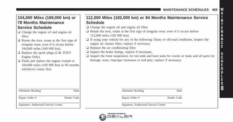
104,000 Miles (169,000 km) or78 Months MaintenanceService Schedule❏ Change the engine oil and engine oil
filter.❏ Rotate the tires, rotate at the first sign of
irregular wear, even if it occurs before104,000 miles (169 000 km).
❏ Replace the spark plugs (2.4L PZEVEngine Only).
❏ Flush and replace the engine coolant at104,000 miles (169 000 km) or 60 monthswhichever comes first.
Odometer Reading Date
Repair Order # Dealer Code
Signature, Authorized Service Center
112,000 Miles (182,000 km) or 84 Months Maintenance ServiceSchedule❏ Change the engine oil and engine oil filter.❏ Rotate the tires, rotate at the first sign of irregular wear, even if it occurs before
112,000 miles (182 000 km).❏ If using your vehicle for any of the following: Dusty or off-road conditions. Inspect the
engine air cleaner filter; replace if necessary.❏ Replace the air conditioning filter.❏ Inspect the brake linings, replace if necessary.❏ Inspect the front suspension, tie rod ends and boot seals for cracks or leaks and all parts for
damage, wear, improper looseness or end play; replace if necessary.
Odometer Reading Date
Repair Order # Dealer Code
Signature, Authorized Service Center
8
MAINTENANCE
SCHEDULES
MAINTENANCE SCHEDULES 469
Information Provided by:
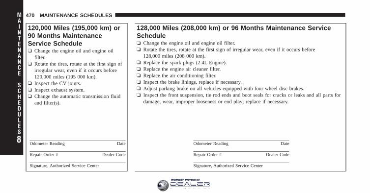
120,000 Miles (195,000 km) or90 Months MaintenanceService Schedule❏ Change the engine oil and engine oil
filter.❏ Rotate the tires, rotate at the first sign of
irregular wear, even if it occurs before120,000 miles (195 000 km).
❏ Inspect the CV joints.❏ Inspect exhaust system.❏ Change the automatic transmission fluid
and filter(s).
Odometer Reading Date
Repair Order # Dealer Code
Signature, Authorized Service Center
128,000 Miles (208,000 km) or 96 Months Maintenance ServiceSchedule❏ Change the engine oil and engine oil filter.❏ Rotate the tires, rotate at the first sign of irregular wear, even if it occurs before
128,000 miles (208 000 km).❏ Replace the spark plugs (2.4L Engine).❏ Replace the engine air cleaner filter.❏ Replace the air conditioning filter.❏ Inspect the brake linings, replace if necessary.❏ Adjust parking brake on all vehicles equipped with four wheel disc brakes.❏ Inspect the front suspension, tie rod ends and boot seals for cracks or leaks and all parts for
damage, wear, improper looseness or end play; replace if necessary.
Odometer Reading Date
Repair Order # Dealer Code
Signature, Authorized Service Center
8
MAINTENANCE
SCHEDULES
470 MAINTENANCE SCHEDULES
Information Provided by:

136,000 Miles (221,000 km) or102 Months MaintenanceService Schedule❏ Change the engine oil and engine oil
filter.❏ Rotate the tires, rotate at the first sign of
irregular wear, even if it occurs before136,000 miles (221 000 km).
Odometer Reading Date
Repair Order # Dealer Code
Signature, Authorized Service Center
144,000 Miles (234,000 km) or 108 Months Maintenance ServiceSchedule❏ Change the engine oil and engine oil filter.❏ Rotate the tires, rotate at the first sign of irregular wear, even if it occurs before
144,000 miles (234 000 km).❏ If using your vehicle for any of the following: Dusty or off-road conditions. Inspect the
engine air cleaner filter; replace if necessary.❏ Replace the air conditioning filter.❏ Inspect the brake linings, replace if necessary.❏ Inspect the CV joints.❏ Inspect exhaust system.❏ Inspect the front suspension, tie rod ends and boot seals for cracks or leaks and all parts for
damage, wear, improper looseness or end play; replace if necessary.
Odometer Reading Date
Repair Order # Dealer Code
Signature, Authorized Service Center
8
MAINTENANCE
SCHEDULES
MAINTENANCE SCHEDULES 471
Information Provided by:

152,000 Miles (247,000 km) or114 Months MaintenanceService Schedule❏ Change the engine oil and engine oil
filter.❏ Rotate the tires, rotate at the first sign of
irregular wear, even if it occurs before152,000 miles (247 000 km).
Odometer Reading Date
Repair Order # Dealer Code
Signature, Authorized Service Center
8
MAINTENANCE
SCHEDULES
472 MAINTENANCE SCHEDULES
Information Provided by:

WARNING!
• You can be badly injured working on or around amotor vehicle. Do only service work for which youhave the knowledge and the right equipment. Ifyou have any doubt about your ability to performa service job, take your vehicle to a competentmechanic.
• Failure to properly inspect and maintain yourvehicle could result in a component malfunctionand effect vehicle handling and performance. Thiscould cause an accident.
8
MAINTENANCE
SCHEDULES
MAINTENANCE SCHEDULES 473
Information Provided by:

Information Provided by:

IF YOU NEED CONSUMER ASSISTANCE
CONTENTS
� Suggestions For Obtaining Service For YourVehicle . . . . . . . . . . . . . . . . . . . . . . . . . . . . . . 477
▫ Prepare For The Appointment . . . . . . . . . . . 477
▫ Prepare A List . . . . . . . . . . . . . . . . . . . . . . 477
▫ Be Reasonable With Requests . . . . . . . . . . . . 477
� If You Need Assistance . . . . . . . . . . . . . . . . . 477
▫ Chrysler Group LLC Customer Center . . . . . 478
▫ Chrysler Canada Inc. Customer Center . . . . . 478
▫ In Mexico Contact . . . . . . . . . . . . . . . . . . . . 478
▫ Customer Assistance For The Hearing OrSpeech Impaired (TDD/TTY) . . . . . . . . . . . . 479
▫ Service Contract . . . . . . . . . . . . . . . . . . . . . 479
� Warranty Information . . . . . . . . . . . . . . . . . . 480
� MOPAR� Parts . . . . . . . . . . . . . . . . . . . . . . . 480
� Reporting Safety Defects . . . . . . . . . . . . . . . . 480
▫ In The 50 United States And Washington,D.C. . . . . . . . . . . . . . . . . . . . . . . . . . . . . . . 480
▫ In Canada . . . . . . . . . . . . . . . . . . . . . . . . . 481
� Publication Order Forms . . . . . . . . . . . . . . . . 481
9
Information Provided by:

� Department Of Transportation Uniform TireQuality Grades . . . . . . . . . . . . . . . . . . . . . . . . 483
▫ Treadwear . . . . . . . . . . . . . . . . . . . . . . . . . 483
▫ Traction Grades . . . . . . . . . . . . . . . . . . . . . 483
▫ Temperature Grades . . . . . . . . . . . . . . . . . . 484
476 IF YOU NEED CONSUMER ASSISTANCE
Information Provided by:

SUGGESTIONS FOR OBTAINING SERVICE FORYOUR VEHICLE
Prepare For The AppointmentIf you’re having warranty work done, be sure to have theright papers with you. Take your warranty folder. Allwork to be performed may not be covered by thewarranty. Discuss additional charges with the servicemanager. Keep a maintenance log of your vehicle’sservice history. This can often provide a clue to thecurrent problem.
Prepare A ListMake a written list of your vehicle’s problems or thespecific work you want done. If you’ve had an accidentor work done that is not on your maintenance log, let theservice advisor know.
Be Reasonable With RequestsIf you list a number of items and you must have yourvehicle by the end of the day, discuss the situation with
the service advisor and list the items in order of priority.At many authorized dealers, you may obtain a rentalvehicle at a minimal daily charge. If you need a rental, itis advisable to make these arrangements when you callfor an appointment.
IF YOU NEED ASSISTANCEThe manufacturer and its authorized dealers are vitallyinterested in your satisfaction. We want you to be happywith our products and services.
Warranty service must be done by an authorized dealer.We strongly recommend that you take the vehicle to anauthorized dealer. They know your vehicle the best, andare most concerned that you get prompt and high qualityservice. The manufacturer’s authorized dealers have thefacilities, factory-trained technicians, special tools, andthe latest information to ensure the vehicle is fixedcorrectly and in a timely manner. 9
IF YOU NEED CONSUMER ASSISTANCE 477
Information Provided by:

This is why you should always talk to an authorizeddealer’s service manager first. Most matters can be re-solved with this process.
• If for some reason you are still not satisfied, talk to thegeneral manager or owner of the authorized dealer-ship. They want to know if you need assistance.
• If an authorized dealership is unable to resolve theconcern, you may contact the manufacturer’s customercenter.
Any communication to the manufacturer’s customer cen-ter should include the following information:
• Owner’s name and address
• Owner’s telephone number (home and office)
• Authorized dealership name
• Vehicle Identification Number (VIN)
• Vehicle delivery date and mileage
Chrysler Group LLC Customer CenterP.O. Box 21–8004Auburn Hills, MI 48321–8004Phone: (800) 247–9753
Chrysler Canada Inc. Customer CenterP.O. Box 1621Windsor, Ontario N9A 4H6Phone: (800) 465–2001 English / (800) 387–9983 French
In Mexico contact:Av. Prolongacion Paseo de la Reforma, 1240Sante Fe C.P. 05109Mexico, D. F.In Mexico City: 5081-7568Outside Mexico City: 1-800-505-1300
478 IF YOU NEED CONSUMER ASSISTANCE
Information Provided by:

Customer Assistance For The Hearing Or SpeechImpaired (TDD/TTY)To assist customers who have hearing difficulties, themanufacturer has installed special TDD (Telecommuni-cation Devices for the Deaf) equipment at its customercenter. Any hearing or speech impaired customer, whohas access to a TDD or a conventional teletypewriter(TTY) in the United States, can communicate with themanufacturer by dialing 1–800–380–CHRY.Canadian residents with hearing difficulties that requireassistance can use the special needs relay service offeredby Bell Canada. For TTY teletypewriter users, dial 711and for Voice callers, dial 1 800 855-0511 to connect witha Bell Relay Service operator.
Service ContractYou may have purchased a service contract for a vehicleto help protect you from the high cost of unexpectedrepairs after the manufacturer’s New Vehicle LimitedWarranty expires. The manufacturer stands behind only
the manufacturer’s service contracts. If you purchased amanufacturer’s service contract, you will receive PlanProvisions and an Owner Identification Card in the mailwithin three weeks of the vehicle delivery date. If youhave any questions about the service contract, call themanufacturer’s Service Contract National CustomerHotline at 1-800-521-9922 (Canadian residents, call (800)465–2001 English / (800) 387–9983 French).
The manufacturer will not stand behind any servicecontract that is not the manufacturer’s service contract. Itis not responsible for any service contract other than themanufacturer’s service contract. If you purchased a ser-vice contract that is not a manufacturer’s service contract,and you require service after the manufacturer’s NewVehicle Limited Warranty expires, please refer to thecontract documents, and contact the person listed inthose documents. 9
IF YOU NEED CONSUMER ASSISTANCE 479
Information Provided by:

We appreciate that you have made a major investmentwhen you purchased the vehicle. An authorized dealerhas also made a major investment in facilities, tools, andtraining to assure that you are absolutely delighted withthe ownership experience. You’ll be pleased with theirsincere efforts to resolve any warranty issues or relatedconcerns.
WARNING!
Engine exhaust, some of its constituents, and certainvehicle components contain, or emit, chemicalsknown to the State of California to cause cancer andbirth defects, or other reproductive harm. In addi-tion, certain fluids contained in vehicles and certainproducts of component wear contain, or emit, chemi-cals known to the State of California to cause cancerand birth defects, or other reproductive harm.
WARRANTY INFORMATIONSee the Warranty Information Booklet, located on theDVD, for the terms and provisions of Chrysler GroupLLC warranties applicable to this vehicle and market.
MOPAR� PARTSMOPAR� fluids, lubricants, parts, and accessories areavailable from an authorized dealer. They are recom-mended for your vehicle in order to help keep the vehicleoperating at its best.
REPORTING SAFETY DEFECTS
In the 50 United States and Washington, D.C.If you believe that your vehicle has a defect that couldcause a crash or cause injury or death, you shouldimmediately inform the National Highway Traffic SafetyAdministration (NHTSA) in addition to notifying themanufacturer.
480 IF YOU NEED CONSUMER ASSISTANCE
Information Provided by:

If NHTSA receives similar complaints, it may open aninvestigation, and if it finds that a safety defect exists ina group of vehicles, it may order a recall and remedycampaign. However, NHTSA cannot become involved inindividual problems between you, your authorizeddealer, and the manufacturer.
To contact NHTSA, you may either call the Auto SafetyHotline toll free at 1–888–327–4236 (TTY: 1–800–424–9153), or go to http://www.safercar.gov; or write to:Administrator, NHTSA, 1200 New Jersey Avenue, SE.,West Building, Washington, D.C. 20590. You can alsoobtain other information about motor vehicle safety fromhttp://www.safercar.gov.
In CanadaIf you believe that your vehicle has a safety defect, youshould contact the Customer Service Department imme-diately. Canadian customers who wish to report a safetydefect to the Canadian government should contact Trans-port Canada, Motor Vehicle Defect Investigations andRecalls at 1-800-333-0510 or go tohttp://www.tc.gc.ca/roadsafety/
PUBLICATION ORDER FORMSTo order the following manuals, you may use either thewebsite or the phone numbers listed below. Visa, Mas-tercard, American Express, and Discover orders are ac-cepted. If you prefer mailing your payment, please callfor an order form.
NOTE: A street address is required when orderingmanuals (no P.O. Boxes). 9
IF YOU NEED CONSUMER ASSISTANCE 481
Information Provided by:

• Service Manuals
These comprehensive Service Manuals provide theinformation that students and professional techniciansneed in diagnosing/troubleshooting, problem solving,maintaining, servicing, and repairing Chrysler GroupLLC vehicles. A complete working knowledge of thevehicle, system, and/or components is written instraightforward language with illustrations, diagrams,and charts.
• Diagnostic Procedure Manuals
Diagnostic Procedure Manuals are filled with dia-grams, charts and detailed illustrations. These practi-cal manuals make it easy for students and techniciansto find and fix problems on computer-controlled ve-hicle systems and features. They show exactly how tofind and correct problems the first time, using step-by-step troubleshooting and drivability procedures,proven diagnostic tests and a complete list of all toolsand equipment.
• Owner’s Manuals
These Owner’s Manuals have been prepared with theassistance of service and engineering specialists toacquaint you with specific Chrysler Group LLC ve-hicles. Included are starting, operating, emergencyand maintenance procedures as well as specifications,capabilities and safety tips.
Call toll free at:
• 1–800–890–4038 (U.S.)
• 1–800–387–1143 (Canada)
Or
Visit us on the Worldwide Web at:
• www.techauthority.com
482 IF YOU NEED CONSUMER ASSISTANCE
Information Provided by:

DEPARTMENT OF TRANSPORTATION UNIFORMTIRE QUALITY GRADESThe following tire grading categories were established bythe National Highway Traffic Safety Administration. Thespecific grade rating assigned by the tire’s manufacturerin each category is shown on the sidewall of the tires onyour vehicle.
All passenger car tires must conform to Federal safetyrequirements in addition to these grades.
TreadwearThe Treadwear grade is a comparative rating, based onthe wear rate of the tire when tested under controlledconditions on a specified government test course. Forexample, a tire graded 150 would wear one and one-halftimes as well on the government course as a tire graded100. The relative performance of tires depends upon theactual conditions of their use, however, and may depart
significantly from the norm due to variations in drivinghabits, service practices, and differences in road charac-teristics and climate.
Traction GradesThe Traction grades, from highest to lowest, are AA, A, B,and C. These grades represent the tire’s ability to stop onwet pavement, as measured under controlled conditionson specified government test surfaces of asphalt andconcrete. A tire marked C may have poor traction perfor-mance.
WARNING!
The traction grade assigned to this tire is based onstraight-ahead braking traction tests, and does notinclude acceleration, cornering, hydroplaning, orpeak traction characteristics.
9
IF YOU NEED CONSUMER ASSISTANCE 483
Information Provided by:

Temperature GradesThe temperature grades are A (the highest), B, and C,representing the tire’s resistance to the generation of heatand its ability to dissipate heat, when tested undercontrolled conditions on a specified indoor laboratorytest wheel. Sustained high temperature can cause thematerial of the tire to degenerate and reduce tire life, andexcessive temperature can lead to sudden tire failure. Thegrade C corresponds to a level of performance, which allpassenger car tires must meet under the Federal MotorVehicle Safety Standard No. 109. Grades B and A repre-sent higher levels of performance on the laboratory testwheel, than the minimum required by law.
WARNING!
The temperature grade for this tire is established fora tire that is properly inflated and not overloaded.Excessive speed, under-inflation, or excessive load-ing, either separately or in combination, can causeheat buildup and possible tire failure.
484 IF YOU NEED CONSUMER ASSISTANCE
Information Provided by:

INDEX
10Information Provided by:

About Your Brakes . . . . . . . . . . . . . . . . . . . . . . . 322ABS (Anti-Lock Brake System) . . . . . . . . . . . . . . 324Adding Engine Coolant (Antifreeze) . . . . . . . . . . 429Adding Fuel . . . . . . . . . . . . . . . . . . . . . . . . . . . 368Adding Washer Fluid . . . . . . . . . . . . . . . . . . . . . 425Additives, Fuel . . . . . . . . . . . . . . . . . . . . . . . . . 363Air Cleaner, Engine (Engine Air Cleaner Filter) . . . 419Air Conditioner Maintenance . . . . . . . . . . . . . . . 421Air Conditioning . . . . . . . . . . . . . . . . . . . . . . . . 275Air Conditioning Controls . . . . . . . . . . . . . . . . . 275Air Conditioning Filter . . . . . . . . . . . . . . . . . 286,422Air Conditioning Refrigerant . . . . . . . . . . . . . 421,422Air Conditioning System . . . . . . . . . . . . . 275,279,421Air Conditioning, Operating Tips . . . . . . . . . . . . 287Air Pressure, Tires . . . . . . . . . . . . . . . . . . . . . . . 342Airbag . . . . . . . . . . . . . . . . . . . . . . . . . . . . . . 58,67Airbag Deployment . . . . . . . . . . . . . . . . . . . . . . . 68Airbag Light . . . . . . . . . . . . . . . . . . . 65,66,71,87,195Airbag Maintenance . . . . . . . . . . . . . . . . . . . . . . . 70
Airbag, Side . . . . . . . . . . . . . . . . . . . . . . 61,64,66,67Airbag, Window (Side Curtain) . . . . . . . . . . . 62,64,67Alarm System (Security Alarm) . . . . . . . . . . . . 18,202Alterations/Modifications, Vehicle . . . . . . . . . . . . . 7Antenna, Satellite Radio . . . . . . . . . . . . . . . . 238,262Anti-Lock Brake System (ABS) . . . . . . . . . . . . . . 324Anti-Lock Warning Light . . . . . . . . . . . . . . . . . . 324Anti-Theft Security Alarm (Theft Alarm) . . . . . . . . 18Antifreeze (Engine Coolant) . . . . . . . . . . . . . . 429,455
Disposal . . . . . . . . . . . . . . . . . . . . . . . . . . . 431Appearance Care . . . . . . . . . . . . . . . . . . . . . . . . 438Ashtray . . . . . . . . . . . . . . . . . . . . . . . . . . . . . . . 180Assistance Towing . . . . . . . . . . . . . . . . . . . . . . . 114Auto Down Power Windows . . . . . . . . . . . . . . . . 36Auto Unlock, Doors . . . . . . . . . . . . . . . . . . . . . . . 32Auto Up Power Windows . . . . . . . . . . . . . . . . . . 37Automatic Dimming Mirror . . . . . . . . . . . . . . . . . 96Automatic Door Locks . . . . . . . . . . . . . . . . . . . . . 32Automatic Oil Change Indicator . . . . . . . . . . 200,212
486 INDEX
Information Provided by:

Automatic Temperature Control (ATC) . . . . . . . . . 279Automatic Transaxle . . . . . . . . . . . . . . . . . . . . 12,294
Adding Fluid . . . . . . . . . . . . . . . . . . . . . . . 457Selection Of Lubricant . . . . . . . . . . . . . . . . . 457
Automatic Transmission . . . . . . . . . . . . . . . . 297,435Adding Fluid . . . . . . . . . . . . . . . . . . . . 437,438Fluid and Filter Changes . . . . . . . . . . . . . . . 438Fluid Level Check . . . . . . . . . . . . . . . . . 437,438Fluid Type . . . . . . . . . . . . . . . . . . . . . . . . . 436Gear Ranges . . . . . . . . . . . . . . . . . . . . . 300,308Special Additives . . . . . . . . . . . . . . . . . . . . . 436
Autostick . . . . . . . . . . . . . . . . . . . . . . . . . . . . . 315
B-Pillar Location . . . . . . . . . . . . . . . . . . . . . . . . 337Battery . . . . . . . . . . . . . . . . . . . . . . . . . . . . . . . 419
Jump Starting . . . . . . . . . . . . . . . . . . . . . . . . 30Keyless Transmitter Replacement (RKE) . . . . . 26Location . . . . . . . . . . . . . . . . . . . . . . . . . . . 419
Belts, Seat . . . . . . . . . . . . . . . . . . . . . . . . . . . . . . 87
Body Mechanism Lubrication . . . . . . . . . . . . . . . 423Brake Assist System . . . . . . . . . . . . . . . . . . . . . . 327Brake System . . . . . . . . . . . . . . . . . . . . . . . . . . . 433
Anti-Lock (ABS) . . . . . . . . . . . . . . . . . . . . . 324Fluid Check . . . . . . . . . . . . . . . . . . . . . 433,457Master Cylinder . . . . . . . . . . . . . . . . . . . . . 433Parking . . . . . . . . . . . . . . . . . . . . . . . . . . . 322Warning Light . . . . . . . . . . . . . . . . . . . . . . . 197
Brake, Parking . . . . . . . . . . . . . . . . . . . . . . . . . . 322Brake/Transmission Interlock . . . . . . . . . . . . . . . 299Brakes . . . . . . . . . . . . . . . . . . . . . . . . . . . . . . . 433Break-In Recommendations, New Vehicle . . . . . . . . 84Bulb Replacement . . . . . . . . . . . . . . . . . . . . . 449,450Bulbs, Light . . . . . . . . . . . . . . . . . . . . . . . . . . 89,449
Calibration, Compass . . . . . . . . . . . . . . . . . . . . . 215Capacities, Antifreeze (Engine Coolant) . . . . . . . . . 20Capacities, Fluid . . . . . . . . . . . . . . . . . . . . . . . . 455
10
INDEX 487
Information Provided by:

Caps, FillerFuel . . . . . . . . . . . . . . . . . . . . . . . . . . . . . . 368Oil (Engine) . . . . . . . . . . . . . . . . . . . . . 409,417Power Steering . . . . . . . . . . . . . . . . . . . . . . 321Radiator (Coolant Pressure) . . . . . . . . . . . . . 430
Car Washes . . . . . . . . . . . . . . . . . . . . . . . . . . . . 439Carbon Monoxide Warning . . . . . . . . . . . . . . . 86,364Cellular Phone . . . . . . . . . . . . . . . . . . . . . . . 100,274Chains, Tire . . . . . . . . . . . . . . . . . . . . . . . . . . . . 350Changing A Flat Tire . . . . . . . . . . . . . . . . . . . . . 388Chart, Tire Sizing . . . . . . . . . . . . . . . . . . . . . . . . 333Check Engine Light(Malfunction Indicator Light) . . . . . . . . . . . . . . . 412Checking Your Vehicle For Safety . . . . . . . . . . . . . 85Checks, Safety . . . . . . . . . . . . . . . . . . . . . . . . . . . 85Child Restraint . . . . . . . . . . . . . . . . . . . . 72,74,79,82Child Restraint Tether Anchors . . . . . . . . . . . . . 77,79Child Safety Locks . . . . . . . . . . . . . . . . . . . . . . . . 34Cigar Lighter . . . . . . . . . . . . . . . . . . . . . . . . . . . 180
Clean Air Gasoline . . . . . . . . . . . . . . . . . . . . . . . 361Cleaning
Wheels . . . . . . . . . . . . . . . . . . . . . . . . . . . . 441Windshield Wiper Blades . . . . . . . . . . . . . . . 424
Climate Control . . . . . . . . . . . . . . . . . . . . . . . . . 274Clock . . . . . . . . . . . . . . . . . . . . . . . . 221,224,242,251Coin Holder . . . . . . . . . . . . . . . . . . . . . . . . . . . 182Compact Disc (CD) Maintenance . . . . . . . . . . . . . 274Compact Spare Tire . . . . . . . . . . . . . . . . . . . . . . 345Compass . . . . . . . . . . . . . . . . . . . . . . . . . . . 207,214Compass Calibration . . . . . . . . . . . . . . . . . . . . . 215Compass Variance . . . . . . . . . . . . . . . . . . . . . . . 215Computer, Trip/Travel . . . . . . . . . . . . . . . . . . 20,213Connector
UCI . . . . . . . . . . . . . . . . . . . . . . . . . . . . . . 265Universal Consumer Interface (UCI) . . . . . . . 265
Console . . . . . . . . . . . . . . . . . . . . . . . . . . . . . . 147Console, Floor . . . . . . . . . . . . . . . . . . . . . . . 147,182Contract, Service . . . . . . . . . . . . . . . . . . . . . . . . 479
488 INDEX
Information Provided by:

Coolant Pressure Cap (Radiator Cap) . . . . . . . . . . 430Cooling System . . . . . . . . . . . . . . . . . . . . . . . . . 428
Adding Coolant (Antifreeze) . . . . . . . . . . . . . 429Coolant Capacity . . . . . . . . . . . . . . . . . . . . . 455Coolant Level . . . . . . . . . . . . . . . . . . . . 428,431Disposal of Used Coolant . . . . . . . . . . . . . . . 431Drain, Flush, and Refill . . . . . . . . . . . . . . . . 428Inspection . . . . . . . . . . . . . . . . . . . . . . . . . . 431Points to Remember . . . . . . . . . . . . . . . . . . 432Pressure Cap . . . . . . . . . . . . . . . . . . . . . . . . 430Radiator Cap . . . . . . . . . . . . . . . . . . . . . . . 430Selection of Coolant (Antifreeze) . . . . 429,455,456
Corrosion Protection . . . . . . . . . . . . . . . . . . . . . 438Crankcase Ventilation Module . . . . . . . . . . . . . . . 20Cruise Light . . . . . . . . . . . . . . . . . . . . . . . . . . . 201Cupholders . . . . . . . . . . . . . . . . . . . . . . 147,180,444Customer Assistance . . . . . . . . . . . . . . . . . . . . . 477Customer Programmable Features . . . . . . . . . . . . 219
Data Recorder, Event . . . . . . . . . . . . . . . . . . . . . . 71Daytime Running Lights . . . . . . . . . . . . . . . . . . . 153Dealer Service . . . . . . . . . . . . . . . . . . . . . . . . . . 414Deck Lid, Power Release . . . . . . . . . . . . . . . . . . . 38Defroster, Rear Window . . . . . . . . . . . . . . . . . . . 186Defroster, Windshield . . . . . . . . . . . . . . . . 87,277,283Delay (Intermittent) Wipers . . . . . . . . . . . . . . . 30,157Diagnostic System, Onboard . . . . . . . . . . . . . . . . 411Dimmer Switch, Headlight . . . . . . . . . . . . . . . . . 152Dipsticks
Automatic Transmission . . . . . . . . . . . . . 437,438Oil (Engine) . . . . . . . . . . . . . . . . . . . . . . . . 415Power Steering . . . . . . . . . . . . . . . . . . . . . . 321
Disabled Vehicle Towing . . . . . . . . . . . . . . . . . . . 404Disposal
Antifreeze (Engine Coolant) . . . . . . . . . . . . . 431Engine Oil . . . . . . . . . . . . . . . . . . . . . . . . . 418
Door Locks, Automatic . . . . . . . . . . . . . . . . . . . . 32Door Opener, Garage . . . . . . . . . . . . . . . . . . . . . 164 10
INDEX 489
Information Provided by:

DrivingOn Slippery Surfaces . . . . . . . . . . . . . . . . . . 316Through Flowing, Rising, or ShallowStanding Water . . . . . . . . . . . . . . . . . . . . . . 317
E-85 Fuel . . . . . . . . . . . . . . . . . . . . . . . . . . . . . 365Electric Rear Window Defrost . . . . . . . . . . . . . . . 186Electric Remote Mirrors . . . . . . . . . . . . . . . . . . . . 98Electrical Power Outlets . . . . . . . . . . . . . . . . . . . 176Electronic Speed Control (Cruise Control) . . . . . . 161Electronic Stability Control (ESC) . . . . . . . . . . . . . 328Electronic Vehicle Information Center (EVIC) . . . . 209Emergency Trunk Release . . . . . . . . . . . . . . . . . 39,40Emergency, In Case of
Jacking . . . . . . . . . . . . . . . . . . . . . . . . . . . . 388Jump Starting . . . . . . . . . . . . . . . . . . . . . . . 398Towing . . . . . . . . . . . . . . . . . . . . . . . . . . . . 404
Emission Control System Maintenance . . . . . . . . . 412
Engine . . . . . . . . . . . . . . . . . . . . . . . . . . . . . . . 409Air Cleaner . . . . . . . . . . . . . . . . . . . . . . . . . 419Block Heater . . . . . . . . . . . . . . . . . . . . . . . . 297Break-In Recommendations . . . . . . . . . . . . . . 84Checking Oil Level . . . . . . . . . . . . . . . . . . . 415Compartment . . . . . . . . . . . . . . . . . . . . . . . 410Compartment Identification . . . . . . . . . . . . . 410Coolant (Antifreeze) . . . . . . . . . . . . . . . . 428,456Cooling . . . . . . . . . . . . . . . . . . . . . . . . . . . 428Exhaust Gas Caution . . . . . . . . . . . . . . . . 86,364Fails to Start . . . . . . . . . . . . . . . . . . . . . . . . 295Flooded, Starting . . . . . . . . . . . . . . . . . . . . . 295Fuel Requirements . . . . . . . . . . . . . . . . . 360,455Jump Starting . . . . . . . . . . . . . . . . . . . . . . . 398Oil . . . . . . . . . . . . . . . . . . . . . . . . . 415,455,456Oil Change Interval . . . . . . . . . . . . . 200,212,416Oil Filler Cap . . . . . . . . . . . . . . . . . . . . 409,417Oil Filter . . . . . . . . . . . . . . . . . . . . . . . . . . . 418Oil Filter Disposal . . . . . . . . . . . . . . . . . . . . 418
490 INDEX
Information Provided by:

Oil Selection . . . . . . . . . . . . . . . . . . . . . 416,455Oil Synthetic . . . . . . . . . . . . . . . . . . . . . . . . 418Overheating . . . . . . . . . . . . . . . . . . . . . . . . 386Starting . . . . . . . . . . . . . . . . . . . . . . . . . . . 294Temperature Gauge . . . . . . . . . . . . . . . . . . . 194
Engine Oil Viscosity . . . . . . . . . . . . . . . . . . . . . . 417Enhanced Accident Response Feature . . . . . . . . . . 68Entry System, Illuminated . . . . . . . . . . . . . . . . . . 20Ethanol . . . . . . . . . . . . . . . . . . . . . . . . . . . . . . . 361Event Data Recorder . . . . . . . . . . . . . . . . . . . . . . 71Exhaust Gas Caution . . . . . . . . . . . . . . . . . . . 86,364Exhaust System . . . . . . . . . . . . . . . . . . . . . . . 86,425Extender, Seat Belt . . . . . . . . . . . . . . . . . . . . . . . . 57Exterior Lights . . . . . . . . . . . . . . . . . . . . . . . . . . 89
Fabric Care . . . . . . . . . . . . . . . . . . . . . . . . . . . . 442Filler Location Fuel . . . . . . . . . . . . . . . . . . . . 194,368
FiltersAir Cleaner . . . . . . . . . . . . . . . . . . . . . . . . . 419Air Conditioning . . . . . . . . . . . . . . . . . . 286,422Automatic Transmission . . . . . . . . . . . . . . . . 438Engine Oil . . . . . . . . . . . . . . . . . . . . . . . 418,456Engine Oil Disposal . . . . . . . . . . . . . . . . . . . 418
Flash-To-Pass . . . . . . . . . . . . . . . . . . . . . . . . . . . 153Flashers . . . . . . . . . . . . . . . . . . . . . . . . . . . . . . 386
Hazard Warning . . . . . . . . . . . . . . . . . . . . . 386Turn Signal . . . . . . . . . . . . . . . . . . . . . . . 89,453
Flexible Fuel VehiclesCruising Range . . . . . . . . . . . . . . . . . . . . . . 368Engine Oil . . . . . . . . . . . . . . . . . . . . . . . . . 367Fuel Requirements . . . . . . . . . . . . . . . . . 365,366Maintenance . . . . . . . . . . . . . . . . . . . . . . . . 368Replacement Parts . . . . . . . . . . . . . . . . . . . . 368Starting . . . . . . . . . . . . . . . . . . . . . . . . . . . 367
Flooded Engine Starting . . . . . . . . . . . . . . . . . . . 295Floor Console . . . . . . . . . . . . . . . . . . . . . . . . . . 182 10
INDEX 491
Information Provided by:

Fluid Capacities . . . . . . . . . . . . . . . . . . . . . . . . . 455Fluid Leaks . . . . . . . . . . . . . . . . . . . . . . . . . . . . . 89Fluid Level Checks
Automatic Transmission . . . . . . . . . . . . . 437,438Brake . . . . . . . . . . . . . . . . . . . . . . . . . . 433,457Cooling System . . . . . . . . . . . . . . . . . . . . . . 428Engine Oil . . . . . . . . . . . . . . . . . . . . . . . . . 415Power Steering . . . . . . . . . . . . . . . . . . . 321,457
Fluids . . . . . . . . . . . . . . . . . . . . . . . . . . . . . . . . 456Fluids, Lubricants and Genuine Parts . . . . . . . . . . 456Fog Light Service . . . . . . . . . . . . . . . . . . . . . . . . 452Fog Lights . . . . . . . . . . . . . . . . . . . . . . . 153,202,452Folding Rear Seat . . . . . . . . . . . . . . . . . . . . . 146,147Freeing A Stuck Vehicle . . . . . . . . . . . . . . . . . . . 402Fuel . . . . . . . . . . . . . . . . . . . . . . . . . . . . . . . . . 360
Adding . . . . . . . . . . . . . . . . . . . . . . . . . . . 368Additives . . . . . . . . . . . . . . . . . . . . . . . . . . 363Clean Air . . . . . . . . . . . . . . . . . . . . . . . . . . 361Ethanol . . . . . . . . . . . . . . . . . . . . . . . . . . . 361
Filler Cap (Gas Cap) . . . . . . . . . . . . . . . 194,368Filler Door (Gas Cap) . . . . . . . . . . . . . . . . . . 194Gasoline . . . . . . . . . . . . . . . . . . . . . . . . . . . 360Gauge . . . . . . . . . . . . . . . . . . . . . . . . . . . . 194Light . . . . . . . . . . . . . . . . . . . . . . . . . . . . . 195Materials Added . . . . . . . . . . . . . . . . . . . . . 363Methanol . . . . . . . . . . . . . . . . . . . . . . . . . . 361Octane Rating . . . . . . . . . . . . . . . . . . . . 360,456Requirements . . . . . . . . . . . . . . . . . . . . 360,455Tank Capacity . . . . . . . . . . . . . . . . . . . . . . . 455
Fuel System Caution . . . . . . . . . . . . . . . . . . . . . 370Fuel, Flexible . . . . . . . . . . . . . . . . . . . . . . . . . . . 365Fueling . . . . . . . . . . . . . . . . . . . . . . . . . . . . . . . 368Fuses . . . . . . . . . . . . . . . . . . . . . . . . . . . . . . . . 444
Garage Door Opener (HomeLink®) . . . . . . . . . . . 164Gas Cap (Fuel Filler Cap) . . . . . . . . . . . . 368,371,411Gasoline, Clean Air . . . . . . . . . . . . . . . . . . . . . . 361Gasoline, Reformulated . . . . . . . . . . . . . . . . . . . 361
492 INDEX
Information Provided by:

GaugesCoolant Temperature . . . . . . . . . . . . . . . . . . 194Fuel . . . . . . . . . . . . . . . . . . . . . . . . . . . . . . 194Odometer . . . . . . . . . . . . . . . . . . . . . . . . . . 198Tachometer . . . . . . . . . . . . . . . . . . . . . . . . . 198
Gear Ranges . . . . . . . . . . . . . . . . . . . . . . . . 300,308Gear Select Lever Override . . . . . . . . . . . . . . . . . 403General Information . . . . . . . . . . . . . . . . . 18,130,360General Maintenance . . . . . . . . . . . . . . . . . . . . . 414Glass Cleaning . . . . . . . . . . . . . . . . . . . . . . . . . . 443Gross Axle Weight Rating . . . . . . . . . . . . . . . 372,374Gross Vehicle Weight Rating . . . . . . . . . . . . . 372,373GVWR . . . . . . . . . . . . . . . . . . . . . . . . . . . . . . . 372
Hands-Free Phone (Uconnect™) . . . . . . . . . . . . . 100Hazard
Driving Through Flowing, Rising, or ShallowStanding Water . . . . . . . . . . . . . . . . . . . . . . 317
Hazard Warning Flasher . . . . . . . . . . . . . . . . . . . 386
Head Restraints . . . . . . . . . . . . . . . . . . . . . . . . . 141Headlights . . . . . . . . . . . . . . . . . . . . . . . . . . . . 450
Bulb Replacement . . . . . . . . . . . . . . . . . . . . 450Cleaning . . . . . . . . . . . . . . . . . . . . . . . . . . . 441High Beam . . . . . . . . . . . . . . . . . . . . . . 152,207High Beam/Low Beam Select Switch . . . . . . 152On With Wipers . . . . . . . . . . . . . . . . . . . . . 159Passing . . . . . . . . . . . . . . . . . . . . . . . . . . . . 153Replacing . . . . . . . . . . . . . . . . . . . . . . . . . . 450Switch . . . . . . . . . . . . . . . . . . . . . . . . . . . . 150
Heated Seats . . . . . . . . . . . . . . . . . . . . . . . . . . . 137Heater . . . . . . . . . . . . . . . . . . . . . . . . . . . . . . . 275Heater, Engine Block . . . . . . . . . . . . . . . . . . . . . 297Hitches
Trailer Towing . . . . . . . . . . . . . . . . . . . . . . . 375HomeLink® (Garage Door Opener) Transmitter . . 164Hood Prop . . . . . . . . . . . . . . . . . . . . . . . . . . . . 148Hood Release . . . . . . . . . . . . . . . . . . . . . . . . . . 148
10
INDEX 493
Information Provided by:

Ignition . . . . . . . . . . . . . . . . . . . . . . . . . . . . . . . 12Key . . . . . . . . . . . . . . . . . . . . . . . . . . . . . . . 12Lock . . . . . . . . . . . . . . . . . . . . . . . . . . . . . . 12
Ignition Key Removal . . . . . . . . . . . . . . . . . . . . . 12Illuminated Entry . . . . . . . . . . . . . . . . . . . . . . . . 20Immobilizer (Sentry Key) . . . . . . . . . . . . . . . . . . . 15Infant Restraint . . . . . . . . . . . . . . . . . . . . . . . . 72,73Information Center, Vehicle . . . . . . . . . . . . . . . . . 209Inside Rearview Mirror . . . . . . . . . . . . . . . . . . . . 96Instrument Cluster . . . . . . . . . . . . . . . . . . . . 193,194Instrument Panel and Controls . . . . . . . . . . . . . . 192Instrument Panel Cover . . . . . . . . . . . . . . . . . . . 442Instrument Panel Lens Cleaning . . . . . . . . . . . . . 443Integrated Power Module (Fuses) . . . . . . . . . . . . 444Interior Appearance Care . . . . . . . . . . . . . . . . . . 442Interior Lights . . . . . . . . . . . . . . . . . . . . . . . . . . 155Intermittent Wipers (Delay Wipers) . . . . . . . . . . . 157Introduction . . . . . . . . . . . . . . . . . . . . . . . . . . . . . 4
Jack Location . . . . . . . . . . . . . . . . . . . . . . . . . . . 388Jack Operation . . . . . . . . . . . . . . . . . . . . . . . 388,390Jacking Instructions . . . . . . . . . . . . . . . . . . . . . . 390Jump Starting . . . . . . . . . . . . . . . . . . . . . . . . . . 398
Key-In Reminder . . . . . . . . . . . . . . . . . . . . . . . . . 15Key, Programming . . . . . . . . . . . . . . . . . . . . . . . . 17Key, Replacement . . . . . . . . . . . . . . . . . . . . . . . . 16Key, Sentry (Immobilizer) . . . . . . . . . . . . . . . . . . . 15Keyless Entry System . . . . . . . . . . . . . . . . . . . . . . 21Keyless Entry System (Sedan) . . . . . . . . . . . . . . . . 21Keys . . . . . . . . . . . . . . . . . . . . . . . . . . . . . . . . . 12Knee Bolster . . . . . . . . . . . . . . . . . . . . . . . . . . . . 58
Lane Change and Turn Signals . . . . . . . . . . . 202,453Lane Change Assist . . . . . . . . . . . . . . . . . . . . . . 152Lap/Shoulder Belts . . . . . . . . . . . . . . . . . . . . . . . 44LATCH(Lower Anchors and Tether for CHildren) . . . . . . . 79
494 INDEX
Information Provided by:

Latches . . . . . . . . . . . . . . . . . . . . . . . . . . . . . . . . 89Hood . . . . . . . . . . . . . . . . . . . . . . . . . . . . . 148
Lead Free Gasoline . . . . . . . . . . . . . . . . . . . . . . 360Leaks, Fluid . . . . . . . . . . . . . . . . . . . . . . . . . . . . 89Life of Tires . . . . . . . . . . . . . . . . . . . . . . . . . . . . 348Light Bulbs . . . . . . . . . . . . . . . . . . . . . . . . . . 89,449Lights . . . . . . . . . . . . . . . . . . . . . . . . . . . . . . 89,149
Airbag . . . . . . . . . . . . . . . . . . . . 65,66,71,87,195Back-Up . . . . . . . . . . . . . . . . . . . . . . . . . . . 453Brake Assist Warning . . . . . . . . . . . . . . . . . . 331Brake Warning . . . . . . . . . . . . . . . . . . . . . . 197Bulb Replacement . . . . . . . . . . . . . . . . . . . . 450Daytime Running . . . . . . . . . . . . . . . . . . . . 153Electronic Stability Program (ESP) Indicator . . 331Engine Temperature Warning . . . . . . . . . . . . 196Exterior . . . . . . . . . . . . . . . . . . . . . . . . . . . . 89Fog . . . . . . . . . . . . . . . . . . . . . . . . . 153,202,452Headlight Switch . . . . . . . . . . . . . . . . . . . . . 150Headlights . . . . . . . . . . . . . . . . . . . . . . . . . 150
Headlights On With Wipers . . . . . . . . . . . . . 159High Beam Indicator . . . . . . . . . . . . . . . . . . 207Illuminated Entry . . . . . . . . . . . . . . . . . . . . . 20Instrument Cluster . . . . . . . . . . . . . . . . . . . 150Interior . . . . . . . . . . . . . . . . . . . . . . . . . . . . 155License . . . . . . . . . . . . . . . . . . . . . . . . . . . . 454Lights On Reminder . . . . . . . . . . . . . . . . . . 154Low Fuel . . . . . . . . . . . . . . . . . . . . . . . . . . 195Malfunction Indicator (Check Engine) . . . . . . 205Map Reading . . . . . . . . . . . . . . . . . . . . . . . 155Oil Pressure . . . . . . . . . . . . . . . . . . . . . . . . 196Passing . . . . . . . . . . . . . . . . . . . . . . . . . . . . 153Seat Belt Reminder . . . . . . . . . . . . . . . . . . . 195Security Alarm (Theft Alarm) . . . . . . . . . . . . . 19Theft Alarm (Security Alarm) . . . . . . . . . . . . 202Tire Pressure Monitoring (TPMS) . . . . . . . 204,352Traction Control . . . . . . . . . . . . . . . . . . . . . 331Turn Signal . . . . . . . . . . . . . . 89,152,202,452,453Voltage . . . . . . . . . . . . . . . . . . . . . . . . . . . . 195 10
INDEX 495
Information Provided by:

Warning (Instrument Cluster Description) . . . 194Loading Vehicle . . . . . . . . . . . . . . . . . . . . . . 371,373
Capacities . . . . . . . . . . . . . . . . . . . . . . . . . . 373Tires . . . . . . . . . . . . . . . . . . . . . . . . . . . . . . 337
LocksAuto Unlock . . . . . . . . . . . . . . . . . . . . . . . . . 32Automatic Door . . . . . . . . . . . . . . . . . . . . . . 32Child Protection . . . . . . . . . . . . . . . . . . . . . . 34Power Door . . . . . . . . . . . . . . . . . . . . . . . . . 32
Low Tire Pressure System . . . . . . . . . . . . . . . . . . 352Lower Anchors and Tether forCHildren (LATCH) . . . . . . . . . . . . . . . . . . . . . . . 79Lubrication, Body . . . . . . . . . . . . . . . . . . . . . . . 423Lumbar Support . . . . . . . . . . . . . . . . . . . . . . . . 141
Maintenance Free Battery . . . . . . . . . . . . . . . . . . 419Maintenance Procedures . . . . . . . . . . . . . . . . . . . 414Maintenance Schedule . . . . . . . . . . . . . . . . . . . . 460Maintenance, General . . . . . . . . . . . . . . . . . . . . . 414
Malfunction Indicator Light (Check Engine) . . 205,412Manual, Service . . . . . . . . . . . . . . . . . . . . . . . . . 481Map/Reading Lights . . . . . . . . . . . . . . . . . . . . . 155Master Cylinder (Brakes) . . . . . . . . . . . . . . . . . . 433Methanol . . . . . . . . . . . . . . . . . . . . . . . . . . . . . 361Mini-Trip Computer . . . . . . . . . . . . . . . . . . . 207,213Mirrors . . . . . . . . . . . . . . . . . . . . . . . . . . . . . . . . 96
Automatic Dimming . . . . . . . . . . . . . . . . . . . 96Electric Powered . . . . . . . . . . . . . . . . . . . . . . 98Outside . . . . . . . . . . . . . . . . . . . . . . . . . . . . 99Rearview . . . . . . . . . . . . . . . . . . . . . . . . . . . 96Vanity . . . . . . . . . . . . . . . . . . . . . . . . . . . . 100
Modifications/Alterations, Vehicle . . . . . . . . . . . . . 7Monitor, Tire Pressure System . . . . . . . . . . . . . . . 352Mopar Parts . . . . . . . . . . . . . . . . . . . . . . . . . 413,480MTBE/ETBE . . . . . . . . . . . . . . . . . . . . . . . . . . . 361
New Vehicle Break-In Period . . . . . . . . . . . . . . . . 84
496 INDEX
Information Provided by:

Occupant Restraints . . . . . . . . . . . . . . . . . . . . . 64,68Occupant Restraints (Sedan) . . . . . . . . . 40,61,62,64,67Octane Rating, Gasoline (Fuel) . . . . . . . . . . . . . . 360Odometer . . . . . . . . . . . . . . . . . . . . . . . . . . . . . 198
Trip . . . . . . . . . . . . . . . . . . . . . . . . . . . 198,201Oil Change Indicator . . . . . . . . . . . . . . . . . . 200,212Oil Change Indicator, Reset . . . . . . . . . . . . . . 200,212Oil Filter, Change . . . . . . . . . . . . . . . . . . . . . . . . 418Oil Filter, Selection . . . . . . . . . . . . . . . . . . . . . . . 418Oil Pressure Light . . . . . . . . . . . . . . . . . . . . . . . 196Oil, Engine . . . . . . . . . . . . . . . . . . . . . . . . . 415,456
Capacity . . . . . . . . . . . . . . . . . . . . . . . . . . . 455Change Interval . . . . . . . . . . . . . . . . 200,212,416Checking . . . . . . . . . . . . . . . . . . . . . . . . . . 415Dipstick . . . . . . . . . . . . . . . . . . . . . . . . . . . 415Disposal . . . . . . . . . . . . . . . . . . . . . . . . . . . 418Filter . . . . . . . . . . . . . . . . . . . . . . . . . . 418,456Filter Disposal . . . . . . . . . . . . . . . . . . . . . . . 418Identification Logo . . . . . . . . . . . . . . . . . . . 416
Materials Added to . . . . . . . . . . . . . . . . . . . 418Recommendation . . . . . . . . . . . . . . . . . . 416,455Synthetic . . . . . . . . . . . . . . . . . . . . . . . . . . 418Viscosity . . . . . . . . . . . . . . . . . . . . . . . . 417,455
Onboard Diagnostic System . . . . . . . . . . . . . . 411,412Opener, Garage Door (HomeLink®) . . . . . . . . . . . 164Operator Manual (Owner’s Manual) . . . . . . . . . . . . 4Overheating, Engine . . . . . . . . . . . . . . . . . . . . . . 386Owner’s Manual (Operator Manual) . . . . . . . . . 4,481
Paint Care . . . . . . . . . . . . . . . . . . . . . . . . . . . . . 438Panic Alarm . . . . . . . . . . . . . . . . . . . . . . . . . . . . 25Parking Brake . . . . . . . . . . . . . . . . . . . . . . . . . . 322Passing Light . . . . . . . . . . . . . . . . . . . . . . . . . . . 153Personal Settings . . . . . . . . . . . . . . . . . . . . . . . . 219Pets . . . . . . . . . . . . . . . . . . . . . . . . . . . . . . . . . . 84Phone, Cellular . . . . . . . . . . . . . . . . . . . . . . . . . 100Phone, Hands-Free (Uconnect™) . . . . . . . . . . . . . 100Placard, Tire and Loading Information . . . . . . . . . 337 10
INDEX 497
Information Provided by:

PowerDeck Lid Release . . . . . . . . . . . . . . . . . . . . . 38Door Locks . . . . . . . . . . . . . . . . . . . . . . . . . 32Mirrors . . . . . . . . . . . . . . . . . . . . . . . . . . . . 98Outlet (Auxiliary Electrical Outlet) . . . . . . . . 176Seats . . . . . . . . . . . . . . . . . . . . . . . . . . . . . 136Steering . . . . . . . . . . . . . . . . . . . . . . . . 320,321Sunroof . . . . . . . . . . . . . . . . . . . . . . . . . . . 173Windows . . . . . . . . . . . . . . . . . . . . . . . . . . . 35
Pregnant Women and Seat Belts . . . . . . . . . . . . . . 57Preparation for Jacking . . . . . . . . . . . . . . . . . . . . 389Pretensioners
Seat Belts . . . . . . . . . . . . . . . . . . . . . . . . . . . 52Programmable Electronic Features . . . . . . . . . . . . 219Programming Transmitters(Remote Keyless Entry) . . . . . . . . . . . . . . . . . . . . 25
Radial Ply Tires . . . . . . . . . . . . . . . . . . . . . . . . . 344Radiator Cap (Coolant Pressure Cap) . . . . . . . . . . 430
Radio Operation . . . . . . . . . . . . . . . . . . . . . . . . 274Radio Remote Controls . . . . . . . . . . . . . . . . . . . . 272Rear Cupholder . . . . . . . . . . . . . . . . . . . . . . . . . 181Rear Seat, Folding . . . . . . . . . . . . . . . . . . . . 146,147Rear Window Defroster . . . . . . . . . . . . . . . . . . . 186Rear Window Features . . . . . . . . . . . . . . . . . . . . 186Rearview Mirrors . . . . . . . . . . . . . . . . . . . . . . . . 96Recorder, Event Data . . . . . . . . . . . . . . . . . . . . . . 71Recreational Towing . . . . . . . . . . . . . . . . . . . . . . 383Reformulated Gasoline . . . . . . . . . . . . . . . . . . . . 361Refrigerant . . . . . . . . . . . . . . . . . . . . . . . . . . . . 422Reminder, Seat Belt . . . . . . . . . . . . . . . . . . . . . . . 56Remote Control
Door Locks . . . . . . . . . . . . . . . . . . . . . . . . . 21Security Alarm . . . . . . . . . . . . . . . . . . . . . . . 18
Remote Keyless Entry (RKE) . . . . . . . . . . . . . . . . . 21Remote Keyless Entry (Sedan) . . . . . . . . . . . . . . . 21Remote Sound System (Radio) Controls . . . . . . . . 272Remote Starting System . . . . . . . . . . . . . . . . . . . . 27
498 INDEX
Information Provided by:

Remote Trunk Release . . . . . . . . . . . . . . . . . . . . . 38Replacement Bulbs . . . . . . . . . . . . . . . . . . . . . . . 449Replacement Keys . . . . . . . . . . . . . . . . . . . . . . . . 16Replacement Parts . . . . . . . . . . . . . . . . . . . . . . . 413Replacement Tires . . . . . . . . . . . . . . . . . . . . . . . 349Reporting Safety Defects . . . . . . . . . . . . . . . . . . . 480Resetting Oil Change Indicator . . . . . . . . . . . 200,212Restraint, Head . . . . . . . . . . . . . . . . . . . . . . . . . 141Restraints, Child . . . . . . . . . . . . . . . . . . . . . . . . . 72Rotation, Tires . . . . . . . . . . . . . . . . . . . . . . . . . . 351
Safety Checks Inside Vehicle . . . . . . . . . . . . . . . . . 87Safety Checks Outside Vehicle . . . . . . . . . . . . . . . 89Safety Defects, Reporting . . . . . . . . . . . . . . . . . . 480Safety Information, Tire . . . . . . . . . . . . . . . . . . . 332Safety Tips . . . . . . . . . . . . . . . . . . . . . . . . . . . . . 85Safety, Exhaust Gas . . . . . . . . . . . . . . . . . . . . . . . 86Satellite Radio Antenna . . . . . . . . . . . . . . . . . 238,262Schedule, Maintenance . . . . . . . . . . . . . . . . . . . . 460
Seat Belt Maintenance . . . . . . . . . . . . . . . . . . . . 444Seat Belt Reminder . . . . . . . . . . . . . . . . . . . . . . . 56Seat Belts . . . . . . . . . . . . . . . . . . . . . . . . . . . . . . 87
Adjustable Shoulder Belt . . . . . . . . . . . . . . . . 49Adjustable Upper Shoulder Anchorage . . . . . . 49And Pregnant Women . . . . . . . . . . . . . . . . . . 57Child Restraint . . . . . . . . . . . . . . . . . . . 72,73,82Extender . . . . . . . . . . . . . . . . . . . . . . . . . . . 57Front Seat . . . . . . . . . . . . . . . . . . . . . . . . . 44,45Inspection . . . . . . . . . . . . . . . . . . . . . . . . . . 87Operating Instructions . . . . . . . . . . . . . . . . . . 45Pretensioners . . . . . . . . . . . . . . . . . . . . . . . . 52Rear Seat . . . . . . . . . . . . . . . . . . . . . . . . . . . 44Reminder . . . . . . . . . . . . . . . . . . . . . . . . . . 195Untwisting Procedure . . . . . . . . . . . . . . . . . . 49
Seat Belts (Sedan) . . . . . . . . . . . . . . . . . . . . . . . . 40Seats . . . . . . . . . . . . . . . . . . . . . . . . . . . . . . . . . 135
Adjustment . . . . . . . . . . . . . . . . . . . . . . . . . 139Cleaning . . . . . . . . . . . . . . . . . . . . . . . . . . . 147 10
INDEX 499
Information Provided by:

Heated . . . . . . . . . . . . . . . . . . . . . . . . . . . . 137Lumbar Support . . . . . . . . . . . . . . . . . . . . . 141Power . . . . . . . . . . . . . . . . . . . . . . . . . . . . 136Rear Folding . . . . . . . . . . . . . . . . . . . . . 146,147Reclining . . . . . . . . . . . . . . . . . . . . . . . . . . 140
Security Alarm (Theft Alarm) . . . . . . . . . . . . . . . . 18Selection of Coolant (Antifreeze) . . . . . . . . . . 429,456Selection of Oil . . . . . . . . . . . . . . . . . . . . . . . . . 416Sentry Key (Immobilizer) . . . . . . . . . . . . . . . . . . . 15Sentry Key Programming . . . . . . . . . . . . . . . . . . . 17Service Assistance . . . . . . . . . . . . . . . . . . . . . . . 477Service Contract . . . . . . . . . . . . . . . . . . . . . . . . . 479Service Manuals . . . . . . . . . . . . . . . . . . . . . . . . 481Setting the Clock . . . . . . . . . . . . . . . . 221,224,242,251Settings, Personal . . . . . . . . . . . . . . . . . . . . . . . . 219Shift Lever Override . . . . . . . . . . . . . . . . . . . . . . 403Short Message Service (SMS) . . . . . . . . . . . . . . . . 122Shoulder Belts . . . . . . . . . . . . . . . . . . . . . . . . . . . 44Side Airbag . . . . . . . . . . . . . . . . . . . . . . . . . . . . . 66
Side Window Demisters (Defrosters) . . . . . . . . . . 286Signals, Turn . . . . . . . . . . . . . . . . . . . . . . . . . 89,453Slippery Surfaces, Driving On . . . . . . . . . . . . . . . 316Snow Chains (Tire Chains) . . . . . . . . . . . . . . . . . 350Snow Tires . . . . . . . . . . . . . . . . . . . . . . . . . . . . 351Spare Tire . . . . . . . . . . . . . . . . . . . . . . . 345,346,388Specifications
Oil . . . . . . . . . . . . . . . . . . . . . . . . . . . . . . . 416Speed Control (Cruise Control) . . . . . . . . . . . 161,201Speedometer . . . . . . . . . . . . . . . . . . . . . . . . . . . 194Starting . . . . . . . . . . . . . . . . . . . . . . . . . . . . . . . 294
Engine Fails to Start . . . . . . . . . . . . . . . . . . 295Starting and Operating . . . . . . . . . . . . . . . . . . . . 294Starting Procedures . . . . . . . . . . . . . . . . . . . . . . 294Steering
Power . . . . . . . . . . . . . . . . . . . . . . . . . . 320,321Tilt Column . . . . . . . . . . . . . . . . . . . . . . . . 160Wheel, Tilt . . . . . . . . . . . . . . . . . . . . . . . . . 160
Steering Wheel Audio Controls . . . . . . . . . . . . . . 272
500 INDEX
Information Provided by:

Steering Wheel Mounted SoundSystem Controls . . . . . . . . . . . . . . . . . . . . . . . . . 272Storage . . . . . . . . . . . . . . . . . . . . . . . . . . . . 182,449Storage, Vehicle . . . . . . . . . . . . . . . . . . . . . . . . . 285Stuck, Freeing . . . . . . . . . . . . . . . . . . . . . . . . . . 402Sun Roof . . . . . . . . . . . . . . . . . . . . . . . . . . . . . . 173Supplemental Restraint System - Airbag . . . . . . . . 58Synthetic Engine Oil . . . . . . . . . . . . . . . . . . . . . . 418
Tachometer . . . . . . . . . . . . . . . . . . . . . . . . . . . . 198Taillights . . . . . . . . . . . . . . . . . . . . . . . . . . . . . . 453Telescoping Steering Column . . . . . . . . . . . . . . . 160Temperature Control, Automatic (ATC) . . . . . . . . 279Temperature Gauge, Engine Coolant . . . . . . . 194,386Tether Anchor, Child Restraint . . . . . . . . . . . . . . . 77Text Messaging . . . . . . . . . . . . . . . . . . . . . . . . . 122Theft Alarm (Security Alarm) . . . . . . . . . . . . . . . . 18Theft System (Security Alarm) . . . . . . . . . . . . . . . 18Tilt Steering Column . . . . . . . . . . . . . . . . . . . . . 160
Time Delay, Headlight . . . . . . . . . . . . . . . . . . . . 151Tire and Loading Information Placard . . . . . . . . . 337Tire Identification Number (TIN) . . . . . . . . . . . . . 335Tire Markings . . . . . . . . . . . . . . . . . . . . . . . . . . 332Tire Safety Information . . . . . . . . . . . . . . . . . . . . 332Tires . . . . . . . . . . . . . . . . . . . . . . . . . . . . 89,341,483
Aging (Life of Tires) . . . . . . . . . . . . . . . . . . 348Air Pressure . . . . . . . . . . . . . . . . . . . . . . . . 341Chains . . . . . . . . . . . . . . . . . . . . . . . . . . . . 350Changing . . . . . . . . . . . . . . . . . . . . . . . . . . 388Compact Spare . . . . . . . . . . . . . . . . . . . . . . 345General Information . . . . . . . . . . . . . . . . . . 341High Speed . . . . . . . . . . . . . . . . . . . . . . . . . 344Inflation Pressures . . . . . . . . . . . . . . . . . . . . 342Jacking . . . . . . . . . . . . . . . . . . . . . . . . . . . . 388Life of Tires . . . . . . . . . . . . . . . . . . . . . . . . 348Load Capacity . . . . . . . . . . . . . . . . . . . . 337,338Pressure Monitor System (TPMS) . . . . . . . . . 352Pressure Warning Light . . . . . . . . . . . . . . . . 204 10
INDEX 501
Information Provided by:

Quality Grading . . . . . . . . . . . . . . . . . . . . . 483Radial . . . . . . . . . . . . . . . . . . . . . . . . . . . . 344Replacement . . . . . . . . . . . . . . . . . . . . . . . . 349Rotation . . . . . . . . . . . . . . . . . . . . . . . . . . . 351Safety . . . . . . . . . . . . . . . . . . . . . . . . . . 332,341Sizes . . . . . . . . . . . . . . . . . . . . . . . . . . . . . 333Snow Tires . . . . . . . . . . . . . . . . . . . . . . . . . 351Spare Tire . . . . . . . . . . . . . . . . . . . . . . . . . . 388Spinning . . . . . . . . . . . . . . . . . . . . . . . . . . . 347Tread Wear Indicators . . . . . . . . . . . . . . . . . 348
Tongue Weight/Trailer Weight . . . . . . . . . . . . . . 377Towing . . . . . . . . . . . . . . . . . . . . . . . . . . . . . . . 373
24-Hour Towing Assistance . . . . . . . . . . . . . 114Disabled Vehicle . . . . . . . . . . . . . . . . . . . . . 404Guide . . . . . . . . . . . . . . . . . . . . . . . . . . . . . 376Recreational . . . . . . . . . . . . . . . . . . . . . . . . 383Weight . . . . . . . . . . . . . . . . . . . . . . . . . . . . 376
Towing Assistance . . . . . . . . . . . . . . . . . . . . . . . 114Traction . . . . . . . . . . . . . . . . . . . . . . . . . . . . . . 317
Trailer Towing . . . . . . . . . . . . . . . . . . . . . . . . . . 373Cooling System Tips . . . . . . . . . . . . . . . . . . 383Hitches . . . . . . . . . . . . . . . . . . . . . . . . . . . . 375Minimum Requirements . . . . . . . . . . . . . . . . 378Trailer and Tongue Weight . . . . . . . . . . . . . . 377
Trailer Towing Guide . . . . . . . . . . . . . . . . . . . . . 376Trailer Weight . . . . . . . . . . . . . . . . . . . . . . . . . . 376Transaxle
Automatic . . . . . . . . . . . . . . . . . . . . . . . 12,294Autostick . . . . . . . . . . . . . . . . . . . . . . . . . . 315Selection of Lubricant . . . . . . . . . . . . . . . . . 457
TransmissionAutomatic . . . . . . . . . . . . . . . . . . . . . . . 297,435Filter . . . . . . . . . . . . . . . . . . . . . . . . . . . . . 438Maintenance . . . . . . . . . . . . . . . . . . . . . . . . 435
Transmitter Battery Service(Remote Keyless Entry) . . . . . . . . . . . . . . . . . . . . 26Transmitter Programming(Remote Keyless Entry) . . . . . . . . . . . . . . . . . . . . 25
502 INDEX
Information Provided by:
Transmitter, Garage Door Opener (HomeLink®) . . 164Transporting Pets . . . . . . . . . . . . . . . . . . . . . . . . 84Tread Wear Indicators . . . . . . . . . . . . . . . . . . . . 348Trip Computer . . . . . . . . . . . . . . . . . . . . . . . . . . 207Trip Odometer . . . . . . . . . . . . . . . . . . . . . . . . . . 198Trip Odometer Reset Button . . . . . . . . . . . . . . . . 201Trunk Lid (Deck Lid) . . . . . . . . . . . . . . . . . . . . . . 38Trunk Release Remote Control . . . . . . . . . . . . . . . 38Trunk Release, Emergency . . . . . . . . . . . . . . . . 39,40Turn Signals . . . . . . . . . . . . . . . . . . . . . . 152,202,453
UCI Connector . . . . . . . . . . . . . . . . . . . . . . . . . 265Uconnect™ (Hands-Free Phone) . . . . . . . . . . . . . 100Understanding Your Instrument Panel . . . . . . . . . 192Uniform Tire Quality Grades . . . . . . . . . . . . . . . . 483Universal Consumer Interface (UCI) Connector . . . 265Universal Transmitter . . . . . . . . . . . . . . . . . . . . . 164Unleaded Gasoline . . . . . . . . . . . . . . . . . . . . . . . 360
Untwisting Procedure, Seat Belt . . . . . . . . . . . . . . 49Upholstery Care . . . . . . . . . . . . . . . . . . . . . . . . 442
Vanity Mirrors . . . . . . . . . . . . . . . . . . . . . . . . . . 100Variance, Compass . . . . . . . . . . . . . . . . . . . . . . . 215Vehicle Certification Label . . . . . . . . . . . . . . . . . 371Vehicle Identification Number (VIN) . . . . . . . . . . . . 6Vehicle Loading . . . . . . . . . . . . . . . . . . . 338,371,373Vehicle Modifications/Alterations . . . . . . . . . . . . . . 7Vehicle Storage . . . . . . . . . . . . . . . . . . . . . . . 285,449Vehicle Theft Alarm (Security Alarm) . . . . . . . . . . 18Viscosity, Engine Oil . . . . . . . . . . . . . . . . . . . . . . 417Voice Recognition System (VR) . . . . . . . . . . . . . . 130
Warning Lights(Instrument Cluster Description) . . . . . . . . . . . . . 194Warnings and Cautions . . . . . . . . . . . . . . . . . . . . . 6Warranty Information . . . . . . . . . . . . . . . . . . . . . 480
10
INDEX 503
Information Provided by:

WasherAdding Fluid . . . . . . . . . . . . . . . . . . . . . . . 425
Washers, Windshield . . . . . . . . . . . . . . . . 156,158,425Washing Vehicle . . . . . . . . . . . . . . . . . . . . . . . . . 439Water
Driving Through . . . . . . . . . . . . . . . . . . . . . 317Wheel and Wheel Trim . . . . . . . . . . . . . . . . . . . . 441Wheel and Wheel Trim Care . . . . . . . . . . . . . . . . 441Wind Buffeting . . . . . . . . . . . . . . . . . . . . . . . 38,175Window Fogging . . . . . . . . . . . . . . . . . . . . . . . . 286
Windows . . . . . . . . . . . . . . . . . . . . . . . . . . . . . . 35Power . . . . . . . . . . . . . . . . . . . . . . . . . . . . . 35
Windshield Defroster . . . . . . . . . . . . . . . . 87,277,283Windshield Washers . . . . . . . . . . . . . . . . . . . 156,158
Fluid . . . . . . . . . . . . . . . . . . . . . . . . . . . . . 425Windshield Wiper Blades . . . . . . . . . . . . . . . . . . 424Windshield Wipers . . . . . . . . . . . . . . . . . . . . . . . 156Wiper Blade Replacement . . . . . . . . . . . . . . . . . . 424Wipers, Intermittent . . . . . . . . . . . . . . . . . . . . . . 157
504 INDEX
Information Provided by:

INSTALLATION OF RADIO TRANSMITTINGEQUIPMENTSpecial design considerations are incorporated into thisvehicle’s electronic system to provide immunity to radiofrequency signals. Mobile two-way radios and telephoneequipment must be installed properly by trained person-nel. The following must be observed during installation.
The positive power connection should be made directlyto the battery and fused as close to the battery as possible.The negative power connection should be made to bodysheet metal adjacent to the negative battery connection.This connection should not be fused.
Antennas for two-way radios should be mounted on theroof or the rear area of the vehicle. Care should be usedin mounting antennas with magnet bases. Magnets mayaffect the accuracy or operation of the compass onvehicles so equipped.
The antenna cable should be as short as practical androuted away from the vehicle wiring when possible. Useonly fully shielded coaxial cable.
Carefully match the antenna and cable to the radio toensure a low Standing Wave Ratio (SWR).
Mobile radio equipment with output power greater thannormal may require special precautions.
All installations should be checked for possible interfer-ence between the communications equipment and thevehicle’s electronic systems.
Information Provided by:

Chrysler Group LLC12C41-126-AE 5th Edition Printed in U.S.A.Information Provided by: