2019 Chrysler Pacifica Owner's Manual - Dealer E Process
718
Pacifica OWNER’S MANUAL 2019
-
Upload
khangminh22 -
Category
Documents
-
view
1 -
download
0
Transcript of 2019 Chrysler Pacifica Owner's Manual - Dealer E Process

PacificaO W N E R ’ S M A N U A L
2 0 1 9

VEHICLES SOLD IN CANADAWith respect to any Vehicles Sold in Canada, the nameFCA US LLC shall be deemed to be deleted and the nameFCA Canada Inc. used in substitution therefore.
DRIVING AND ALCOHOLDrunken driving is one of the most frequent causes ofaccidents.Your driving ability can be seriously impaired with bloodalcohol levels far below the legal minimum. If you aredrinking, don’t drive. Ride with a designated non-drinking driver, call a cab, a friend, or use public trans-portation.
WARNING!
Driving after drinking can lead to an accident.Your perceptions are less sharp, your reflexes areslower, and your judgment is impaired when youhave been drinking. Never drink and then drive.
This manual illustrates and describes the operation offeatures and equipment that are either standard or op-tional on this vehicle. This manual may also include adescription of features and equipment that are no longeravailable or were not ordered on this vehicle. Pleasedisregard any features and equipment described in thismanual that are not on this vehicle.
FCA US LLC reserves the right to make changes in designand specifications, and/or make additions to or improve-ments to its products without imposing any obligationupon itself to install them on products previously manu-factured.
Copyright © 2018 FCA US LLC

TABLE OF CONTENTSSECTION PAGE
1 INTRODUCTION . . . . . . . . . . . . . . . . . . . . . . . . . . . . . . . . . . . . . . . . . . . . . . . . . . . . . . . . . . . . . . . . . . . 3
2 GRAPHICAL TABLE OF CONTENTS . . . . . . . . . . . . . . . . . . . . . . . . . . . . . . . . . . . . . . . . . . . . . . . . . . . . . . 7
3 GETTING TO KNOW YOUR VEHICLE . . . . . . . . . . . . . . . . . . . . . . . . . . . . . . . . . . . . . . . . . . . . . . . . . . . 13
4 GETTING TO KNOW YOUR INSTRUMENT PANEL . . . . . . . . . . . . . . . . . . . . . . . . . . . . . . . . . . . . . . . . . 189
5 SAFETY . . . . . . . . . . . . . . . . . . . . . . . . . . . . . . . . . . . . . . . . . . . . . . . . . . . . . . . . . . . . . . . . . . . . . . . . 219
6 STARTING AND OPERATING . . . . . . . . . . . . . . . . . . . . . . . . . . . . . . . . . . . . . . . . . . . . . . . . . . . . . . . . . 317
7 IN CASE OF EMERGENCY . . . . . . . . . . . . . . . . . . . . . . . . . . . . . . . . . . . . . . . . . . . . . . . . . . . . . . . . . . . 441
8 SERVICING AND MAINTENANCE . . . . . . . . . . . . . . . . . . . . . . . . . . . . . . . . . . . . . . . . . . . . . . . . . . . . . 507
9 TECHNICAL SPECIFICATIONS . . . . . . . . . . . . . . . . . . . . . . . . . . . . . . . . . . . . . . . . . . . . . . . . . . . . . . . . 569
10 MULTIMEDIA . . . . . . . . . . . . . . . . . . . . . . . . . . . . . . . . . . . . . . . . . . . . . . . . . . . . . . . . . . . . . . . . . . . . 581
11 CUSTOMER ASSISTANCE . . . . . . . . . . . . . . . . . . . . . . . . . . . . . . . . . . . . . . . . . . . . . . . . . . . . . . . . . . . . 693
12 INDEX . . . . . . . . . . . . . . . . . . . . . . . . . . . . . . . . . . . . . . . . . . . . . . . . . . . . . . . . . . . . . . . . . . . . . . . . . . 699
1
2
3
4
5
6
7
8
9
10
11
12


INTRODUCTION
CONTENTS� INTRODUCTION . . . . . . . . . . . . . . . . . . . . . . . . .4
� HOW TO USE THIS MANUAL . . . . . . . . . . . . . . .5
▫ Essential Information . . . . . . . . . . . . . . . . . . . . . .5
▫ Symbols . . . . . . . . . . . . . . . . . . . . . . . . . . . . . . .5
� WARNINGS AND CAUTIONS . . . . . . . . . . . . . . . .5
� VEHICLE MODIFICATIONS/ALTERATIONS . . . . .5
1

INTRODUCTION
Dear Customer,
Congratulations on selecting your new vehicle. Be assuredthat it represents precision workmanship, distinctive styl-ing, and high quality. This Owner’s Manual has beenprepared with the assistance of service and engineeringspecialists to acquaint you with the operation and mainte-nance of your vehicle. It is supplemented by WarrantyInformation, and customer oriented documents. In theattached Warranty Booklet, you will find a description ofthe services that FCA offers to its customers, the WarrantyCertificate and the details of the terms and conditions formaintaining its validity. Please take the time to read all ofthese publications carefully before driving your vehicle forthe first time. Following the instructions, recommenda-tions, tips, and important warnings in this manual willhelp assure safe and enjoyable operation of your vehicle.Be sure you are familiar with all vehicle controls, particu-larly those used for braking, steering, transmission, andtransfer case shifting (if equipped). Learn how your vehiclehandles on different road surfaces. Your driving skills willimprove with experience.
This Owner’s Manual describes all versions of this vehicle.Options and equipment dedicated to specific markets orversions are not expressly indicated in the text. Therefore,you should only consider the information which is relatedto the trim level, engine, and version that you havepurchased. Any content introduced throughout the Own-er’s Information, that may or may not be applicable to yourvehicle, will be identified with the wording “If Equipped”.All data contained in this publication are intended to helpyou use your vehicle in the best possible way. FCA aims ata constant improvement of the vehicles produced. For thisreason, it reserves the right to make changes to the modeldescribed for technical and/or commercial reasons. Forfurther information, contact an authorized dealer.
NOTE: After reviewing the Owner’s Information, it shouldbe stored in the vehicle for convenient referencing, andremain with the vehicle when sold.
When it comes to service, remember that an authorizeddealer knows your vehicle best, has factory-trained techni-cians and genuine MOPAR® parts, and cares about yoursatisfaction.
4 INTRODUCTION

HOW TO USE THIS MANUAL
Essential Information
Consult the Table of Contents to determine which sectioncontains the information you desire.
Since the specification of your vehicle depends on the itemsof equipment ordered, certain descriptions and illustra-tions may differ from your vehicle’s equipment.
The detailed index at the back of this Owner’s Manualcontains a complete listing of all subjects.
Symbols
Some vehicle components have colored labels whose sym-bols indicate precautions to be observed when using thiscomponent. Refer to “Warning Lights and Messages” in“Getting To Know Your Instrument Panel” for furtherinformation on the symbols used in your vehicle.
WARNINGS AND CAUTIONS
This Owner’s Manual contains WARNINGS against oper-ating procedures that could result in a collision, bodilyinjury and/or death. It also contains CAUTIONS againstprocedures that could result in damage to your vehicle. Ifyou do not read this entire Owner’s Manual, you may missimportant information. Observe all Warnings and Cau-tions.
VEHICLE MODIFICATIONS/ALTERATIONS
WARNING!
Any modifications or alterations to this vehicle couldseriously affect its roadworthiness and safety and maylead to a collision resulting in serious injury or death.
1
INTRODUCTION 5

GRAPHICAL TABLE OF CONTENTS
CONTENTS� FRONT VIEW . . . . . . . . . . . . . . . . . . . . . . . . . . . .8
� REAR VIEW . . . . . . . . . . . . . . . . . . . . . . . . . . . . .9
� INSTRUMENT PANEL . . . . . . . . . . . . . . . . . . . . .10
� INTERIOR . . . . . . . . . . . . . . . . . . . . . . . . . . . . . .11
2

FRONT VIEW
Front View
1 — Hood/Engine Compartment2 — Windshield3 — Exterior Mirrors
4 — Doors5 — Wheels/Tires6 — Headlights
8 GRAPHICAL TABLE OF CONTENTS
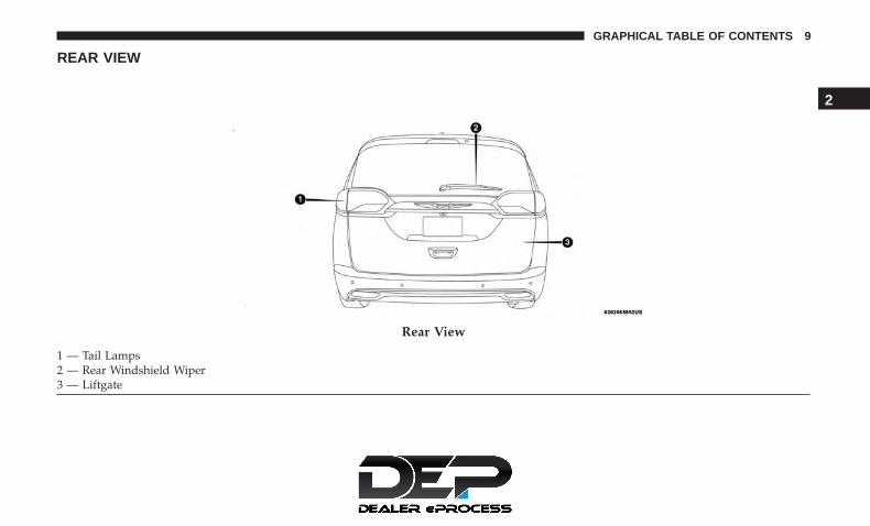
REAR VIEW
Rear View
1 — Tail Lamps2 — Rear Windshield Wiper3 — Liftgate
2
GRAPHICAL TABLE OF CONTENTS 9

INSTRUMENT PANEL
Instrument Panel1 — Multifunction Lever 9 — Switch Panel2 — Instrument Cluster Display Controls 10 — Electronic Park Brake Switch3 — Instrument Cluster 11 — Gear Selector4 — Windshield Wiper Lever 12 — Ignition5 — Uconnect System 13 — Speed Controls6 — Glove Compartment 14 — Steering Wheel7 — Front Center Stack AUX Jack and USB Port 15 — Hood Release8 — Climate Controls 16 — Headlight Switch
10 GRAPHICAL TABLE OF CONTENTS

INTERIOR
Interior Features
1 — Power Window/Door Lock Switches2 — Door Handles3 — Seats4 — Storage Compartment
2
GRAPHICAL TABLE OF CONTENTS 11


GETTING TO KNOW YOUR VEHICLE
CONTENTS� VEHICLE USER GUIDE — IF EQUIPPED . . . . . . .18
� KEYS . . . . . . . . . . . . . . . . . . . . . . . . . . . . . . . . .20
▫ Key Fob . . . . . . . . . . . . . . . . . . . . . . . . . . . . . .20
� IGNITION SWITCH . . . . . . . . . . . . . . . . . . . . . . .28
▫ Keyless Enter-N-Go — Ignition . . . . . . . . . . . . . .28
� REMOTE STARTING SYSTEM — IF EQUIPPED . . .30
▫ How To Use Remote Start. . . . . . . . . . . . . . . . . .30
▫ Remote Start Cancel Message — If Equipped . . . .31
▫ To Enter Remote Start Mode . . . . . . . . . . . . . . . .32
▫ To Exit Remote Start Mode Without Driving TheVehicle . . . . . . . . . . . . . . . . . . . . . . . . . . . . . . .32
▫ To Exit Remote Start Mode And Drive TheVehicle . . . . . . . . . . . . . . . . . . . . . . . . . . . . . . .32
▫ Remote Start Comfort Systems — If Equipped . . .33
▫ General Information . . . . . . . . . . . . . . . . . . . . .33
� SENTRY KEY . . . . . . . . . . . . . . . . . . . . . . . . . . .33
▫ Key Programming . . . . . . . . . . . . . . . . . . . . . .34
▫ Replacement Keys . . . . . . . . . . . . . . . . . . . . . . .34
▫ General Information . . . . . . . . . . . . . . . . . . . . .34
� VEHICLE SECURITY ALARM — IF EQUIPPED . . .35
▫ To Arm The System . . . . . . . . . . . . . . . . . . . . .35
▫ To Disarm The System . . . . . . . . . . . . . . . . . . .35
▫ Rearming Of The System . . . . . . . . . . . . . . . . . .36
� DOORS . . . . . . . . . . . . . . . . . . . . . . . . . . . . . . .36
▫ Manual Lock . . . . . . . . . . . . . . . . . . . . . . . . . . .36
▫ Central Lock/Unlock — If Equipped . . . . . . . . . .39
▫ Unlock Doors Automatically On Exit — IfEquipped . . . . . . . . . . . . . . . . . . . . . . . . . . . . .39
▫ Keyless Enter-N-Go — Passive Entry . . . . . . . . .39
3

▫ Manual Sliding Side Door. . . . . . . . . . . . . . . . . .43
▫ Power Sliding Side Door — If Equipped . . . . . . .45
▫ Hands-Free Sliding Doors — If Equipped. . . . . . .47
▫ Child Locks. . . . . . . . . . . . . . . . . . . . . . . . . . . .48
� SEATS . . . . . . . . . . . . . . . . . . . . . . . . . . . . . . . .50
▫ Manual Adjustment (Front Seats) — If Equipped .50
▫ Manual Adjustment (Rear Seats) . . . . . . . . . . . .52
▫ Power Adjustment (Front Seats) — If Equipped . .73
▫ Power Adjustment (Rear Seats) — If Equipped . .75
▫ Driver Memory Seat — If Equipped . . . . . . . . . .79
▫ Heated Seats . . . . . . . . . . . . . . . . . . . . . . . . . . .81
▫ Ventilated Seats — If Equipped . . . . . . . . . . . . . .83
▫ Adjustable Armrest (Front Seats) — If Equipped. .84
▫ Plastic Grocery Bag Retainer Hooks. . . . . . . . . . .84
� HEAD RESTRAINTS . . . . . . . . . . . . . . . . . . . . . .85
▫ Head Restraints — Front Seats . . . . . . . . . . . . . .85
▫ Head Restraints — Second Row Quad Seats . . . . .87
▫ Head Restraints — Second Row Bench. . . . . . . . .87
▫ Head Restraints — Third Row . . . . . . . . . . . . . .88
� STEERING WHEEL . . . . . . . . . . . . . . . . . . . . . . .90
▫ Tilt/Telescoping Steering Column . . . . . . . . . . . .90
▫ Heated Steering Wheel — If Equipped . . . . . . . .91
� MIRRORS . . . . . . . . . . . . . . . . . . . . . . . . . . . . . .92
▫ Inside Day/Night Mirror — If Equipped . . . . . .92
▫ Automatic Dimming Mirror — If Equipped . . . . .92
▫ Outside Mirrors . . . . . . . . . . . . . . . . . . . . . . . .93
▫ Driver’s Outside Automatic Dimming Mirror — IfEquipped . . . . . . . . . . . . . . . . . . . . . . . . . . . . .93
▫ Conversation Mirror . . . . . . . . . . . . . . . . . . . . .94
▫ Power Mirrors — If Equipped . . . . . . . . . . . . . .94
▫ Outside Mirrors Folding Feature . . . . . . . . . . . .95
▫ Heated Mirrors — If Equipped . . . . . . . . . . . . .95
▫ Tilt Side Mirrors In Reverse (Available WithMemory Seat Only) — If Equipped . . . . . . . . . . .95
▫ Power Folding Mirrors — If Equipped. . . . . . . . .95
14 GETTING TO KNOW YOUR VEHICLE

▫ Illuminated Vanity Mirrors — If Equipped . . . . .96
� EXTERIOR LIGHTS . . . . . . . . . . . . . . . . . . . . . . .97
▫ Multifunction Lever . . . . . . . . . . . . . . . . . . . . . .97
▫ Headlight Switch . . . . . . . . . . . . . . . . . . . . . . . .97
▫ Daytime Running Lights — If Equipped . . . . . . .98
▫ High/Low Beam Switch . . . . . . . . . . . . . . . . . . .98
▫ Automatic High Beam — If Equipped . . . . . . . .98
▫ Flash-To-Pass . . . . . . . . . . . . . . . . . . . . . . . . . .99
▫ Automatic Headlights — If Equipped . . . . . . . . .99
▫ Headlights On With Wipers — If Equipped . . . . .99
▫ Headlight Delay — If Equipped . . . . . . . . . . . . .99
▫ Lights-On Reminder . . . . . . . . . . . . . . . . . . . .100
▫ Front Fog Lights — If Equipped . . . . . . . . . . . .100
▫ Turn Signals . . . . . . . . . . . . . . . . . . . . . . . . . .100
▫ Lane Change Assist — If Equipped . . . . . . . . . .101
▫ Battery Protection . . . . . . . . . . . . . . . . . . . . . .101
� INTERIOR LIGHTS . . . . . . . . . . . . . . . . . . . . . .101
▫ Courtesy/Interior Lighting . . . . . . . . . . . . . . . .101
� WINDSHIELD WIPER AND WASHERS . . . . . . . .104
▫ Windshield Wiper Operation . . . . . . . . . . . . . .104
▫ Rain Sensing Wipers — If Equipped . . . . . . . . .106
▫ Rear Wiper And Washer . . . . . . . . . . . . . . . . . .107
� CLIMATE CONTROLS . . . . . . . . . . . . . . . . . . . .108
▫ Manual Climate Controls Overview . . . . . . . . .108
▫ Automatic Uconnect 4 Climate ControlOverview . . . . . . . . . . . . . . . . . . . . . . . . . . . .121
▫ Automatic Uconnect 4C/4C NAV Climate ControlOverview . . . . . . . . . . . . . . . . . . . . . . . . . . . .122
▫ Climate Control Functions. . . . . . . . . . . . . . . . .134
▫ Automatic Temperature Control (ATC) — IfEquipped . . . . . . . . . . . . . . . . . . . . . . . . . . . .135
▫ Operating Tips . . . . . . . . . . . . . . . . . . . . . . . .136
3
GETTING TO KNOW YOUR VEHICLE 15

� WINDOWS . . . . . . . . . . . . . . . . . . . . . . . . . . . .138
▫ Power Windows. . . . . . . . . . . . . . . . . . . . . . . .138
� PANORAMIC SUNROOF — IF EQUIPPED . . . . .141
▫ Opening Sunroof . . . . . . . . . . . . . . . . . . . . . . .142
▫ Closing Sunroof . . . . . . . . . . . . . . . . . . . . . . . .143
▫ Wind Buffeting . . . . . . . . . . . . . . . . . . . . . . . .143
▫ Power Sun Shade — If Equipped. . . . . . . . . . . .143
▫ Pinch Protect Feature . . . . . . . . . . . . . . . . . . . .144
▫ Sunroof Maintenance . . . . . . . . . . . . . . . . . . . .144
▫ Ignition Off Operation . . . . . . . . . . . . . . . . . . .144
� HOOD . . . . . . . . . . . . . . . . . . . . . . . . . . . . . . .145
▫ Opening . . . . . . . . . . . . . . . . . . . . . . . . . . . . .145
▫ Closing . . . . . . . . . . . . . . . . . . . . . . . . . . . . . .146
� LIFTGATE . . . . . . . . . . . . . . . . . . . . . . . . . . . . .146
▫ Opening . . . . . . . . . . . . . . . . . . . . . . . . . . . . .146
▫ Closing . . . . . . . . . . . . . . . . . . . . . . . . . . . . .147
▫ Power Liftgate — If Equipped . . . . . . . . . . . . .148
▫ Hands-Free Liftgate — If Equipped . . . . . . . . . .150
▫ Cargo Area Features . . . . . . . . . . . . . . . . . . . .152
� GARAGE DOOR OPENER — IF EQUIPPED . . . .160
▫ Before You Begin Programming HomeLink . . . . .160
▫ Canadian/Gate Operator Programming . . . . . . .163
▫ Using HomeLink . . . . . . . . . . . . . . . . . . . . . . .164
▫ Security. . . . . . . . . . . . . . . . . . . . . . . . . . . . . .165
▫ Troubleshooting Tips . . . . . . . . . . . . . . . . . . . .165
▫ General Information . . . . . . . . . . . . . . . . . . . . .166
� INTERNAL EQUIPMENT . . . . . . . . . . . . . . . . . .166
▫ Storage . . . . . . . . . . . . . . . . . . . . . . . . . . . . . .166
▫ Sun Screens — If Equipped . . . . . . . . . . . . . . . .173
▫ Power Outlets . . . . . . . . . . . . . . . . . . . . . . . . .174
▫ Power Inverter — If Equipped . . . . . . . . . . . . .177
▫ Wireless Charging Pad — If Equipped . . . . . . .177
16 GETTING TO KNOW YOUR VEHICLE

▫ Cigar Lighter — If Equipped . . . . . . . . . . . . . .179
▫ Smoker’s Package Kit — If Equipped . . . . . . . .179
▫ Overhead Sunglass Storage . . . . . . . . . . . . . . .180
� ROOF LUGGAGE RACK — IF EQUIPPED . . . . . .180
▫ Deploying The Crossbars . . . . . . . . . . . . . . . . .181
▫ Stowing The Crossbars . . . . . . . . . . . . . . . . . . .1833
GETTING TO KNOW YOUR VEHICLE 17

VEHICLE USER GUIDE — IF EQUIPPED
Access your Owner’s Information right through yourUconnect 4C or 4C NAV touchscreen system — IfEquipped.
To access the Vehicle User Guide on your Uconnect Touch-screen: Press the Uconnect Apps button. From there, pressthe Vehicle User Guide icon on your touchscreen. NoUconnect registration is required.
NOTE: Vehicle User Guide features are not available whilethe vehicle is moving. If you try to access while the vehicleis in motion, the system will display: Feature not availablewhile the vehicle is in motion.
Uconnect 4C NAV With 8.4–inch Display Vehicle UserGuide Touchscreen Icon
18 GETTING TO KNOW YOUR VEHICLE

Pre-Installed Features
Your User Guide — Up-dated in real-time
Available when and whereyou need it
Touchscreen convenience Customizable interfaceMaintenance schedulesand information
Multilingual
Comprehensive icon &symbol glossary
Once you launch your Vehicle User Guide, you will be ableto explore your warranty information and radio manualwhen and where you need them. Your Uconnect systemdisplays the Vehicle User Guide on your touchscreen radioto assist in better understanding your vehicle. There’s noapp to download, no phone to connect and no externaldevice needed for playback. Plus, it’s updated throughoutthe year, in real-time, so it never goes out of date.
Features/Benefits
• Pre-installed on your Uconnect touchscreen radio
• Enhanced search and browsing capability
• Robust NAV application — If Equipped
• Add selected topics to a fast-access Favorites category
• Icon and symbol glossary
• Warranty information
• Crucial driver information and assistance:
Operating Instructions Maintenance SchedulesWarranty Information Emergency ProceduresFluid Level Standards 911 Contact and More
Tip: When viewing a topic, tap the star icon to add it toyour Favorites, for easy access in the future.
3
GETTING TO KNOW YOUR VEHICLE 19

KEYS
Key Fob
Your vehicle uses a keyless ignition system. The ignitionsystem consists of a key fob with Remote Keyless Entry(RKE) and a START/STOP push button ignition system.The Remote Keyless Entry system uses a receiver modulein the vehicle that wirelessly links with the key fob.
NOTE: The key fob may not be found if it is located next toa mobile phone, laptop or other electronic device; thesedevices may block the key fob’s wireless signal.
This system allows you to lock or unlock the doors andliftgate, activate the Panic Alarm, optional power liftgate,
left power sliding door, and right power sliding door fromdistances up to approximately 66 ft (20 m) using a key fob.When any button on the key fob is pushed, or when anysignal is being transferred between the key fob and thevehicle, an LED light on the key fob will flash as anindicator. The key fob does not need to be pointed at thevehicle to activate the system.
NOTE: The emergency key allows for entry into thevehicle should the battery in the vehicle or the key fob godead. The emergency key is also for locking/unlocking theglove compartment. You can keep the emergency key withyou when valet parking.
20 GETTING TO KNOW YOUR VEHICLE

In case the ignition switch does not change with the pushof a button, the key fob may have a low or fully depletedbattery. A low key fob battery can be verified by referringto the instrument cluster, which will display directions tofollow.
NOTE:
• A low key fob battery condition may be indicated by amessage in the instrument cluster display, or by the LEDlight on the key fob. If the LED key fob light no longerilluminates from key fob button pushes, then the key fobbattery requires replacement.
• The key fob LED light brightness is designed for indoorlight viewing, so the LED light may not be visible indirect sunlight.
In a situation where the battery is low or fully depleted, aback up method can be used to operate the ignition switch.Put the nose side of the key fob (side opposite of theEmergency Key) against the ENGINE START/STOP buttonand push to operate the ignition switch.
Key Fob
1 — Lock2 — Remote Start3 — Right Power Sliding Side Door4 — PANIC Alarm5 — Emergency Key6 — Left Power Sliding Side Door7 — Liftgate8 — Unlock
3
GETTING TO KNOW YOUR VEHICLE 21

To Unlock The Doors
NOTE: Uconnect Settings lets you program the system tounlock either the driver’s side doors on the first push(default) or unlock all doors on the first push of the unlockbutton on the key fob. To change the default setting, referto “Uconnect Settings” in “Multimedia” for further infor-mation.
1st Push Of Key Fob Unlocks
Push and release the unlock button on the key fob once tounlock the driver front door and sliding door or twicewithin five seconds to unlock all doors and liftgate. Thehazard lights will flash to acknowledge the unlock signal.The illuminated entry system will be activated. 2nd Push Of Key Fob Unlocks
Push and release the unlock button on the key fob twicewithin five seconds to unlock all doors and liftgate. Theturn signal lights will flash to acknowledge the unlocksignal. The illuminated entry system will be activated.
First Push Unlock
22 GETTING TO KNOW YOUR VEHICLE
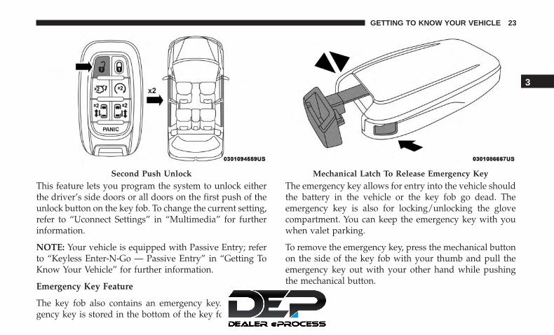
This feature lets you program the system to unlock eitherthe driver’s side doors or all doors on the first push of theunlock button on the key fob. To change the current setting,refer to “Uconnect Settings” in “Multimedia” for furtherinformation.
NOTE: Your vehicle is equipped with Passive Entry; referto “Keyless Enter-N-Go — Passive Entry” in “Getting ToKnow Your Vehicle” for further information.
Emergency Key Feature
The key fob also contains an emergency key. The emer-gency key is stored in the bottom of the key fob.
The emergency key allows for entry into the vehicle shouldthe battery in the vehicle or the key fob go dead. Theemergency key is also for locking/unlocking the glovecompartment. You can keep the emergency key with youwhen valet parking.
To remove the emergency key, press the mechanical buttonon the side of the key fob with your thumb and pull theemergency key out with your other hand while pushingthe mechanical button.
Second Push Unlock Mechanical Latch To Release Emergency Key
3
GETTING TO KNOW YOUR VEHICLE 23

To Lock The Doors And Liftgate
Push and release the lock button on the key fob to lock alldoors and liftgate. The hazard lights will flash once and thehorn will chirp once to acknowledge the signal. Settings inradio can change to lights only, chirp only, or both.
Refer to “Keyless Enter-N-Go — Passive Entry” in “GettingTo Know Your Vehicle” for further information.
Key Fob With Remote Control And Integrated VehicleKey
If one or more doors are open or the liftgate is open, thedoors can be locked. This is signaled by a quick flash of theturn signals.
Vehicles Equipped With Keyless Enter-N-Go — PassiveEntry
If one or more doors are open, or the liftgate is open, thedoors can be locked. The doors will unlock again only if thekey is inside the passenger compartment.
Key Fob Battery Replacement
The recommended replacement battery is one CR2032battery.
NOTE:
• Batteries contain harmful chemicals. Dispose old batter-ies by placing them in correct containers according to thelaw or by taking them to a dealership, where they will behandled appropriately.
• Perchlorate Material — special handling may apply. Seewww.dtsc.ca.gov/hazardouswaste/perchlorate
• Do not touch the battery terminals that are on the backhousing or the printed circuit board.
1. Remove the emergency key by pushing the mechanicalrelease button on the side of the key fob with yourthumb and then pull the key out with your other hand.
24 GETTING TO KNOW YOUR VEHICLE

2. Insert a coin, a flat blade screw driver, or the tip of youremergency key into the now exposed slot and carefullypry on both sides to disengage the snaps. Gently removethe back cover from the fob being careful not to damageany of the snaps.
3. Remove the battery by sliding the battery rearward in itspocket until the battery lifts up. Remove the depletedbattery from the battery pocket and dispose appropri-ately.
4. Fit a new CR2032 battery ensuring that the positive (+)side is facing upwards. Push the battery into the pocketuntil it is firmly seated in place and secured under bothtabs.
5. Align the back cover into its original position and snapit back in place by pushing it against the fob until it isseated all around.
Emergency Key Removal Separating The Key Fob Case
3
GETTING TO KNOW YOUR VEHICLE 25

Programming Additional Key Fobs
Programming the key fob may be performed by an autho-rized dealer.
NOTE: Once a key fob is programmed to a vehicle, itcannot be repurposed and reprogrammed to another ve-hicle.
Request For Additional Remote Controls
NOTE: Only key fobs that are programmed to the vehicleelectronics can be used to start and operate the vehicle.Once a key fob is programmed to a vehicle, it cannot beprogrammed to any other vehicle.
CAUTION!
• Always remove the key fobs from the vehicle andlock all doors when leaving the vehicle unattended.
• For vehicles equipped with Keyless Enter-N-Go —Ignition, always remember to place the ignition inthe OFF position.
Duplication of key fobs may be performed at an authorizeddealer. This procedure consists of programming a blankkey fob to the vehicle electronics. A blank key fob is onethat has never been programmed.
NOTE: When having the Sentry Key Immobilizer Systemserviced, bring all vehicle keys with you to an authorizeddealer.
KeySense Features — If Equipped
This feature provides the vehicle owner with the ability tocustomize vehicle settings that can be applied to determinethe driving experience for other drivers of the vehicle. Thevehicle settings are protected by a unique 4-digit PIN,which the vehicle owner creates when accessing the spe-cific settings for the first time.
This feature also has additional features that are alwaysenabled when the specific key is in use that cannot be setby the vehicle owner. While this specific key fob is in use,the vehicle will respond accordingly to the customizedvehicle settings and mandatory features. This includesenhanced driving assistance features, increased driveralerts, and the locking of certain optional features.
26 GETTING TO KNOW YOUR VEHICLE

KeySense Unique Splash Screen
At start-up the KeySense splash screen should inform thedriver that the vehicle will be functioning in KeySensemode when the KeySense key is in use.
Start Up Display Features
• Unique splash screen graphic
• Telltale illuminated
• After unique splash screen, and after stored messagesare cycled, then start-up KeySense messages (Range &Max Speed) are displayed
The following features are always enabled when this key isin use:
• Entertainment Audio Muted if 1st row occupied SeatBelts are not Fastened
• Consistent Seat Belt Unfastened Chime
• Maximum Radio Volume limited to 15 out of 39
• Daytime Running Lights
• Headlights with Wipers
• Rain Sensing Auto Wipers
• Auto Dim High Beams
For additional information please refer to “Uconnect Set-tings” in “Multimedia” for further information.
General Information
The following regulatory statement applies to all radiofrequency (RF) devices equipped in this vehicle:
This device complies with Part 15 of the FCC Rules andwith Industry Canada license-exempt RSS standard(s).Operation is subject to the following two conditions:
1. This device may not cause harmful interference, and
KeySense Key Fob
3
GETTING TO KNOW YOUR VEHICLE 27

2. This device must accept any interference received, in-cluding interference that may cause undesired opera-tion.
NOTE: Changes or modifications not expressly approvedby the party responsible for compliance could void theuser’s authority to operate the equipment.
IGNITION SWITCH
Keyless Enter-N-Go — Ignition
This feature allows the driver to start the vehicle with thepush of a button, as long as the key fob is in the passengercompartment, and the drivers foot on the brake pedal.
The Keyless Push Button Ignition has four operatingpositions; three of which are labeled and will illuminatewhen in position. The three positions are OFF, ACC, andON/RUN. The fourth position is START, during start RUNwill illuminate.
The ignition can be placed in the following positions:
OFF
• The engine is stopped.
• Some electrical devices are available.
ACC
• The engine is stopped.
• Some electrical devices are available.
Keyless Push Button Ignition
28 GETTING TO KNOW YOUR VEHICLE

ON/RUN
• Driving position.
• All the electrical devices are available.
START
• Start the vehicle.
The engine only runs in the ON/RUN ignition position orfrom a remote start request.
In case the ignition switch does not change with the pushof a button, the key fob may have a low or dead battery. Inthis situation, a back up method can be used to operate theignition switch. Put the nose side (side opposite of theemergency key) of the key fob against the ENGINESTART/STOP button and push to operate the ignitionswitch.
NOTE: The key fob may not be able to be detected by thevehicle keyless-go system if it is located next to a mobilephone, laptop or other electronic device; these devices mayblock the key fob’s wireless signal and prevent thekeyless-go system from starting the vehicle.
WARNING!
• When leaving the vehicle, always remove the key fobfrom the vehicle and lock your vehicle.
• Never leave children alone in a vehicle, or withaccess to an unlocked vehicle.
(Continued)
Backup Starting Method
3
GETTING TO KNOW YOUR VEHICLE 29

WARNING! (Continued)• Allowing children to be in a vehicle unattended is
dangerous for a number of reasons. A child or otherscould be seriously or fatally injured. Childrenshould be warned not to touch the parking brake,brake pedal or the gear selector.
• Do not leave the key fob in or near the vehicle, or ina location accessible to children, and do not leave theignition of a vehicle equipped with Keyless Enter-N-Go in the RUN mode. A child could operate powerwindows, other controls, or move the vehicle.
• Do not leave children or animals inside parkedvehicles in hot weather. Interior heat build-up maycause serious injury or death.
CAUTION!
An unlocked car is an invitation. Always remove thekey fobs from the vehicle and lock all doors whenleaving the vehicle unattended.
NOTE: For further information, refer to �Starting TheEngine� in �Starting And Operating.�
REMOTE STARTING SYSTEM — IF EQUIPPED
This system uses the key fob to start the engineconveniently from outside the vehicle while stillmaintaining security. The system has a range of328 ft (100 m).
The Remote Starting System also activates the ClimateControl, vented seats (if equipped) in temperatures above80° F (26.7° C), and the optional heated seats, and optionalheated steering wheel in temperatures below 40° F (4.4° C).
NOTE:
• The vehicle must be equipped with an automatic trans-mission to be equipped with Remote Start.
• Obstructions between the vehicle and key fob mayreduce this range.
How To Use Remote Start
• Push Remote Start button on the key fob twice withinfive seconds. Pushing the Remote Start button a thirdtime shuts the engine off.
• To drive the vehicle, push unlock button, and place theignition in the ON/RUN position.
30 GETTING TO KNOW YOUR VEHICLE

• With remote start, the engine will only run for 15minutes (timeout) unless the ignition key is placed in theON/RUN position.
• The vehicle must be started with the key after twoconsecutive timeouts.
All of the following conditions must be met before theengine will remote start:
• Gear Selector in PARK
• Doors closed
• Hood closed
• Liftgate closed
• Hazard switch off
• Brake switch inactive (brake pedal not pushed)
• Battery at an acceptable charge level
• PANIC button not pushed
• System not disabled from previous remote start event
• Vehicle alarm system indicator flashing
• Ignition in STOP/OFF position
• Fuel level meets minimum requirement
WARNING!
• Do not start or run an engine in a closed garage orconfined area. Exhaust gas contains Carbon Monox-ide (CO) which is odorless and colorless. CarbonMonoxide is poisonous and can cause serious injuryor death when inhaled.
• Keep key fobs away from children. Operation of theRemote Start System, windows, door locks or othercontrols could cause serious injury or death.
Remote Start Cancel Message — If Equipped
The following messages will display in the instrumentcluster if the vehicle fails to remote start or exits remotestart prematurely:
• Remote Start Cancelled — Door Open
• Remote Start Cancelled — Hood Open
• Remote Start Cancelled — Fuel Low
• Remote Start Cancelled — Liftgate Open
• Remote Start Cancelled — Too Cold
• Remote Start Cancelled — Time Expired
• Remote Start Disabled — Start Vehicle To Reset
3
GETTING TO KNOW YOUR VEHICLE 31
The message will stay active until the ignition is placed inthe ON/RUN position.
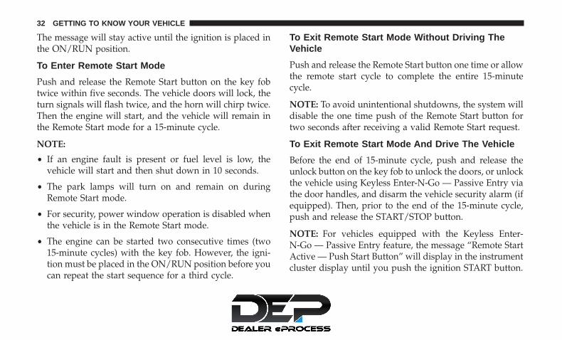
To Enter Remote Start Mode
Push and release the Remote Start button on the key fobtwice within five seconds. The vehicle doors will lock, theturn signals will flash twice, and the horn will chirp twice.Then the engine will start, and the vehicle will remain inthe Remote Start mode for a 15-minute cycle.
NOTE:
• If an engine fault is present or fuel level is low, thevehicle will start and then shut down in 10 seconds.
• The park lamps will turn on and remain on duringRemote Start mode.
• For security, power window operation is disabled whenthe vehicle is in the Remote Start mode.
• The engine can be started two consecutive times (two15-minute cycles) with the key fob. However, the igni-tion must be placed in the ON/RUN position before youcan repeat the start sequence for a third cycle.
To Exit Remote Start Mode Without Driving TheVehicle
Push and release the Remote Start button one time or allowthe remote start cycle to complete the entire 15-minutecycle.
NOTE: To avoid unintentional shutdowns, the system willdisable the one time push of the Remote Start button fortwo seconds after receiving a valid Remote Start request.
To Exit Remote Start Mode And Drive The Vehicle
Before the end of 15-minute cycle, push and release theunlock button on the key fob to unlock the doors, or unlockthe vehicle using Keyless Enter-N-Go — Passive Entry viathe door handles, and disarm the vehicle security alarm (ifequipped). Then, prior to the end of the 15-minute cycle,push and release the START/STOP button.
NOTE: For vehicles equipped with the Keyless Enter-N-Go — Passive Entry feature, the message “Remote StartActive — Push Start Button” will display in the instrumentcluster display until you push the ignition START button.
32 GETTING TO KNOW YOUR VEHICLE

Remote Start Comfort Systems — If Equipped
When Remote Start is activated, the Climate Control,vented seats (if equipped) are also activated in tempera-tures above 80° F (26.7° C), and the optional heated seats,and optional heated steering wheel in temperatures below40° F (4.4° C). These features will stay on through theduration of Remote Start or until the ignition switch iscycled to the ON/RUN position.
General Information
The following regulatory statement applies to all radiofrequency (RF) devices equipped in this vehicle:
This device complies with Part 15 of the FCC Rules andwith Industry Canada license-exempt RSS standard(s).Operation is subject to the following two conditions:
1. This device may not cause harmful interference, and
2. This device must accept any interference received, in-cluding interference that may cause undesired opera-tion.
NOTE: Changes or modifications not expressly approvedby the party responsible for compliance could void theuser’s authority to operate the equipment.
SENTRY KEY
The Sentry Key Immobilizer system prevents unauthorizedvehicle operation by disabling the engine. The system doesnot need to be armed or activated. Operation is automatic,regardless of whether the vehicle is locked or unlocked.
The system uses a key fob, keyless push button ignitionand a RF receiver to prevent unauthorized vehicle opera-tion. Therefore, only key fobs that are programmed to thevehicle can be used to start and operate the vehicle. Thesystem cannot reprogram a key fob obtained from anothervehicle.
After turning the ignition switch to the ON/RUN position,the vehicle security light will turn on for three seconds fora bulb check. If the light remains on after the bulb check, itindicates that there is a problem with the electronics. Inaddition, if the light begins to flash after the bulb check, itindicates that someone attempted to start the engine withan invalid key fob. In the event that a valid key fob is usedto start the engine but there is an issue with the vehicleelectronics, the engine will start and shut off after twoseconds.
If the vehicle security light turns on during normal vehicleoperation (vehicle running for longer than ten seconds), itindicates that there is a fault in the electronics. Should this
3
GETTING TO KNOW YOUR VEHICLE 33
occur, have the vehicle serviced as soon as possible by anauthorized dealer.
CAUTION!
The Sentry Key Immobilizer system is not compatiblewith some aftermarket remote starting systems. Use ofthese systems may result in vehicle starting problemsand loss of security protection.
All of the key fobs provided with your new vehicle havebeen programmed to the vehicle electronics.
Key Programming
Key fob programming is performed at an authorizeddealer.
Replacement Keys
NOTE: Only key fobs that are programmed to the vehicleelectronics can be used to start and operate the vehicle.Once a key fob is programmed to a vehicle, it cannot beprogrammed to any other vehicle.
CAUTION!
Always remove the key fobs from the vehicle and lockall doors when leaving the vehicle unattended.
NOTE: Duplication of key fobs may be performed at anauthorized dealer. This procedure consists of programminga blank key fob to the vehicle electronics. A blank key fobis one that has never been programmed.
When having the Sentry Key Immobilizer System serviced,bring all vehicle keys with you to an authorized dealer.
General Information
The following regulatory statement applies to all radiofrequency (RF) devices equipped in this vehicle:
This device complies with Part 15 of the FCC Rules andwith Industry Canada license-exempt RSS standard(s).Operation is subject to the following two conditions:
1. This device may not cause harmful interference, and
2. This device must accept any interference received, includ-ing interference that may cause undesired operation.
34 GETTING TO KNOW YOUR VEHICLE

NOTE: Changes or modifications not expressly approvedby the party responsible for compliance could void theuser’s authority to operate the equipment.
VEHICLE SECURITY ALARM — IF EQUIPPED
The vehicle security alarm monitors the vehicle doors forunauthorized entry and the ignition switch for unauthor-ized operation. When the alarm is activated, the interiorswitches for door locks, power sliding doors and powerliftgate are disabled. The vehicle security alarm providesboth audible and visible signals. If something triggers thealarm, the vehicle security alarm will provide the followingaudible and visible signals: the horn will pulse, the parklamps and/or turn signals will flash, and the vehiclesecurity light in the instrument cluster will flash.
To Arm The System
Follow these steps to arm the vehicle security alarm:
1. Make sure the vehicles ignition is cycled to the “OFF”position (refer to �Starting The Engine� in �Starting AndOperating� for further information).• For vehicles equipped with Keyless Enter-N-Go —
Passive Entry, make sure the vehicle ignition systemis OFF.
2. Perform one of the following methods to lock thevehicle:• Push lock on the interior power door lock switch with
the driver and/or passenger door open.• Push the lock button on the exterior Passive Entry
Door Handle with a valid key fob available in the sameexterior zone (refer to �Keyless Enter-N-Go — PassiveEntry� in �Getting To Know Your Vehicle� for furtherinformation).
• Push the lock button on the key fob.
3. If any doors are open, close them.
To Disarm The System
The vehicle security alarm can be disarmed using any ofthe following methods:
• Push the unlock button on the key fob.
• Grasp the Passive Entry Unlock Door Handle (ifequipped, refer to �Keyless Enter-N-Go — Passive En-try� under �Getting To Know Your Vehicle� for furtherinformation).
• Hands Free Liftgate passive entry activation (ifequipped with Hands Free Liftgate passive entry).
3
GETTING TO KNOW YOUR VEHICLE 35
• Cycle the vehicle ignition system out of the OFF posi-tion.• For vehicles equipped with Keyless Enter-N-Go —
Passive Entry, push the keyless ignition START/STOPbutton (requires at least one valid key fob in thevehicle).
NOTE:
• The driver’s door key cylinder and the liftgate button onthe key fob cannot arm or disarm the vehicle securityalarm.
• The vehicle security alarm remains armed during powerliftgate entry. Pushing the liftgate button will not disarmthe vehicle security alarm. If someone enters the vehiclethrough the liftgate and opens any door, the alarm willsound.
• When the vehicle security alarm is armed, the interiorpower door lock switches will not unlock the doors.
The vehicle security alarm is designed to protect yourvehicle. However, you can create conditions where thesystem will give you a false alarm. If one of the previouslydescribed arming sequences has occurred, the vehiclesecurity alarm will arm regardless of whether you are in
the vehicle or not. If you remain in the vehicle and open adoor, the alarm will sound. If this occurs, disarm thevehicle security alarm.
If the vehicle security alarm is armed and the batterybecomes disconnected, the vehicle security alarm willremain armed when the battery is reconnected; the exteriorlights will flash, and the horn will sound. If this occurs,disarm the vehicle security alarm.
Rearming Of The System
If something triggers the alarm, and no action is taken todisarm it, the vehicle security alarm will turn the horn offafter 29 seconds, 5 seconds between cycles, up to 8 cycles ifthe trigger remains active and then the vehicle securityalarm will rearm itself.
DOORS
Manual Lock
To lock each door, rotate the door lock knob on each doortrim panel forward. To unlock the front doors, pull theinside door handle to the first detent or rotate the door lockbutton until the ribbing is visible. To unlock the rear doors,rotate the door lock button until the red indicator is visible.
36 GETTING TO KNOW YOUR VEHICLE

Manual Front Door Lock Location
1 — Manual Door Lock2 — Door Handle
Manual Door Lock Rocker Switch
3
GETTING TO KNOW YOUR VEHICLE 37

If the door lock button is locked (no ribbing is visible)when you shut the door, the door will lock. Therefore,make sure the key fob is not inside the vehicle beforeclosing the door.
NOTE: The manual door locks will not lock or unlock theliftgate.
WARNING!
• For personal security and safety in the event of acollision, lock the vehicle doors before you drive aswell as when you park and leave the vehicle.
• Never use the PARK position as a substitute for theparking brake. Always apply the parking brake fullywhen parked to guard against vehicle movement andpossible injury or damage.
• When exiting the vehicle, always make sure thekeyless ignition node is in the “OFF” mode, removethe key fob from the vehicle and lock the vehicle.
• Never leave children alone in a vehicle, or withaccess to an unlocked vehicle. Allowing children tobe in a vehicle unattended is dangerous for a numberof reasons. A child or others could be seriously orfatally injured. Children should be warned not totouch the parking brake, brake pedal or the gearselector.
• Do not leave the key fob in or near the vehicle, or ina location accessible to children, and do not leave theignition of a vehicle equipped with Keyless Enter-N-Go in the ACC or ON/RUN mode. A child couldoperate power windows, other controls, or move thevehicle.
Manual Rear Door Lock Location
1 — Door Handle2 — Manual Door Lock
38 GETTING TO KNOW YOUR VEHICLE

Central Lock/Unlock — If Equipped
A power door lock switch is on each front door trim panel.Use this switch to lock or unlock the doors.
If you push the power door lock switch while the ignitionis in the ACC or ON/RUN position, and any front door isopen, the power locks will not operate. This prevents youfrom accidentally locking your keys in the vehicle. Placingthe ignition in the OFF position or closing the door will
allow the locks to operate. A chime will sound if theignition is in the ACC or ON/RUN position and a door isopen, as a reminder to place the ignition in the OFFposition and remove the key fob.
Unlock Doors Automatically On Exit — If Equipped
The Unlock Doors Automatically On Exit feature unlocksall of the vehicle doors when any door is opened. This willoccur only after the gear selector has been placed into thePARK position, after the vehicle has been driven (the gearselector has been placed out of PARK and all doors closed).
The Unlock Doors Automatically On Exit feature will notoperate if there is any manual operation of the door locks(lock or unlock).
For further information, refer to “Uconnect Settings” in“Multimedia”.
Keyless Enter-N-Go — Passive Entry
The Passive Entry system is an enhancement to the vehi-cle’s Remote Keyless Entry system and a feature of KeylessEnter-N-Go. This feature allows you to lock and unlock thevehicle’s door(s) without having to push the key fob lockor unlock buttons.
Driver Power Door Lock Switches
1 — Power Unlock Switch2 — Power Lock Switch
3
GETTING TO KNOW YOUR VEHICLE 39

NOTE:
• Passive Entry may be programmed ON/OFF. Refer to“Uconnect Settings” in “Multimedia” for further infor-mation.
• If wearing gloves on your hands, or if it has beenraining/snowing on the Passive Entry door handle, theunlock sensitivity can be affected, resulting in a slowerresponse time.
• If the vehicle is unlocked by Passive Entry and no dooris opened within 60 seconds, the vehicle will re-lock andif equipped will arm the security alarm.
• The sliding side doors can be unlocked from the outsideusing the hands free or Passive Entry system.
• The key fob may not be able to be detected by the vehiclepassive entry system if it is located next to a mobilephone, laptop, wireless charging pad, or other electronicdevice; these devices may block the key fob’s wirelesssignal and prevent the passive entry handle fromlocking/unlocking the vehicle.
• If set by the customer in the Uconnect Settings, unlock-ing with Passive Entry will initiate illuminated approach
(low beams, license plate lamp, position lamps) for thetime 0, 30(default), 60 or 90 seconds. Passive Entry alsoinitiates two flashes of the turn lamps.
To Unlock From The Driver’s Side:
With a valid key fob within 5 ft (1.5 m) of the driver’s doorhandle, grab the driver’s front door handle to unlock thedrivers side doors (driver/sliding door) automatically. Theinterior door panel rocker knob will rotate when the dooris unlocked.
Grab The Door Handle To Unlock
40 GETTING TO KNOW YOUR VEHICLE

NOTE: If “Unlock All Doors 1st Press” is programmed, alldoors and liftgate will unlock when you grab hold of thedriver’s front door handle. To select between “UnlockDriver Door 1st Press” and “Unlock All Doors 1st Press,”refer to “Uconnect Settings” in “Multimedia” for furtherinformation.
To Unlock From The Passenger Side:
With a valid key fob within 5 ft (1.5 m) of the passengerdoor handle, grab the front passenger door handle tounlock all four doors and the liftgate automatically. Theinterior door panel lock knob will rotate when the door isunlocked.
NOTE: All doors will unlock when the front passengerdoor handle is grabbed regardless of the driver’s doorunlock preference setting (“Unlock Driver Door 1st Press”or “Unlock All Doors 1st Press”).
Preventing Inadvertent Locking Of Key Fob In Vehicle(FOBIK-Safe)
To minimize the possibility of unintentionally locking akey fob inside your vehicle, the Passive Entry system isequipped with an automatic door unlock feature.
FOBIK-Safe only executes in vehicles with Passive Entry.There are three situations that trigger a FOBIK-Safe searchin any Passive Entry vehicle:
• A lock request is made by a valid key fob while a dooris open.
• A lock request is made by the Passive Entry door handlewhile a door is open.
• A lock request is made by the door panel switch whilethe door is open.
When any of these situations occur, after all open doors areshut, the FOBIK-Safe search will be executed. If it finds akey fob inside the car, and it does not find any key foboutside the car, then the car will unlock and alert thecustomer.
NOTE: The vehicle will only unlock the doors when a validkey fob is detected inside the vehicle, and no valid key fobis detected outside the vehicle. The vehicle will not unlockthe doors when any of the following conditions are met:
• The doors are manually locked using the door lockknobs.
• There is a valid key fob outside the vehicle and within5 ft (1.5 m) of either Passive Entry door handle.
3
GETTING TO KNOW YOUR VEHICLE 41

• Three attempts are made to lock the doors using thedoor panel switch and then close the doors.
NOTE: On the third attempt ALL doors will lock and thekey fob can be locked in the vehicle.
To Enter The Liftgate
With a valid key fob within 5 ft (1.5 m) of the liftgate, cyclethe handle to open the liftgate and pull the liftgate openwith one fluid motion.
NOTE: If “Unlock Driver Door 1st Press” is programmed,only the liftgate will unlock when the liftgate releasehandle is pulled. If “Unlock All Doors 1st Press” is pro-grammed, all doors and the liftgate will unlock when theliftgate release handle is pulled. To select between “UnlockDriver Door 1st Press” and “Unlock All Doors 1st Press,”refer to “Uconnect Settings” in “Multimedia” for furtherinformation.
To Lock The Vehicle’s Doors
With one of the vehicle’s key fobs within 5 ft (1.5 m) of thedriver or passenger front door handle, push the doorhandle lock button to lock all four doors and the liftgate.
Do NOT grab the door handle, when pushing the doorhandle button. This could unlock the door(s).
Push The Door Handle Button To Lock
42 GETTING TO KNOW YOUR VEHICLE

NOTE:
• After pushing the door handle button, you must waittwo seconds before you can lock or unlock the doors,using either Passive Entry door handle. This is done toallow you to check if the vehicle is locked by pulling thedoor handle, without the vehicle reacting and unlocking.
• The Passive Entry system will not operate if the key fobbattery is dead.
The vehicle doors can also be locked by using the key foblock button, or the lock button located on the vehicle’sinterior door panel.
General Information
The following regulatory statement applies to all radiofrequency (RF) devices equipped in this vehicle:
This device complies with Part 15 of the FCC Rules andwith Industry Canada license-exempt RSS standard(s).Operation is subject to the following two conditions:
1. This device may not cause harmful interference, and
2. This device must accept any interference received, in-cluding interference that may cause undesired opera-tion.
NOTE: Changes or modifications not expressly approvedby the party responsible for compliance could void theuser’s authority to operate the equipment.
Manual Sliding Side Door
The sliding door may be opened from the inside or theoutside. Pull outward on the exterior handle to open thesliding door. The sliding door inside handle functions byrocking forward and back. Rocking the handle backwards
Do NOT Grab The Door Handle When Locking
3
GETTING TO KNOW YOUR VEHICLE 43

opens the door and rocking forward releases the hold openlatch in order to close the door.
To keep your door operating properly, observe the follow-ing guidelines:
• Always open the door smoothly.
• Avoid high impacts against the door stop when openingthe door. This is very important when your vehicle isparked on an incline as the door will slide faster in thedownhill direction.
• There is a hold-open latch that is activated when thesliding door is fully opened. This latch will keep yoursliding door open on any incline. To close the slidingdoor after the hold-open latch is activated, you mustrock the inside handle forward or pull outward on theexterior handle.
Always make sure that the sliding door is fully latchedanytime the vehicle is in motion.
NOTE: The left side sliding door cannot be opened whilethe fuel door is open.
Side Door Handle And Lock Functions
1 — Door Handle2 — Door Lock
44 GETTING TO KNOW YOUR VEHICLE

Power Sliding Side Door — If Equipped
The power sliding door may be power opened or closed inseveral ways:
• Key fob
• Inside or outside handles
• Buttons located:– In the overhead console– Just inside the sliding door– On the outside handle
Push the button on the key fob twice within fiveseconds to open, close, or reverse a power slidingdoor.
The key fob and the overhead console button will operatethe door when the door is locked. All other ways requirethe sliding door to be unlocked. If the vehicle is equippedwith Passive Entry, pressing the button on the outsidehandle or Hands-Free feature (if equipped) will unlock andopen the sliding door, with a valid Passive Entry key fobwithin 5 ft (1.5 m) of the door handle.
There are power sliding side door switches located on theB-Pillar trim panel, just in front of the power sliding doorfor the rear seat passengers.
Overhead Console Power Switches
1 — Liftgate2 — Right Sliding Door3 — Sliding Door Power Off4 — Left Sliding Door
3
GETTING TO KNOW YOUR VEHICLE 45

To operate the sliding door manually with the handles or toavoid unintentional operation of the power sliding doorsfrom the rear seats, push the power sliding door power offbutton, located in the overhead console, to remove powerto the handles and buttons just inside the sliding doors.The power off LED, in the overhead console, will be litwhen the handles are manual. When the LED is lit, pushingthe power sliding door power off button will return thehandles to power operation.
NOTE:
• If anything obstructs the power sliding side door whileit is closing or opening, the door will automaticallyreverse to the closed or open position and an audibletone will sound, provided it meets sufficient resistance.The turn signals will flash with sliding door movements.
• If the power sliding door stops in the middle due toobstacles, it will power open on the next command.
Driver Side Power Sliding Side Door Switch
46 GETTING TO KNOW YOUR VEHICLE

WARNING!
Personal injury or cargo damage may occur if caught inthe path of the sliding door. Make sure the door path isclear before closing the door.
WARNING!
Before driving off, check the instrument cluster for asliding door or door open message or warning indica-tor. Failure to do this could result in unintentionallyleaving the sliding door open while driving.
Hands-Free Sliding Doors — If Equipped
To open the Hands-Free Sliding Doors, use a straight inand out kicking motion under the vehicle in the general
Passenger Side Power Sliding Side Door Switch
Hands-Free Sliding Doors
3
GETTING TO KNOW YOUR VEHICLE 47

location below the door handle(s). Do not move your footsideways or in a sweeping motion or the sensors may notdetect the motion.
When a valid kicking motion is completed, the sliding doorwill chime, the hazard lights will flash and the sliding doorwill open almost instantaneously. This assumes all optionsare enabled in the radio settings.
NOTE:
• To open the Hands-Free Sliding Doors requires a validPassive Entry key fob within 5 ft (1.5 m) of the doorhandle. If a valid Passive Entry key fob is not within 5 ft(1.5 m), the door will not respond to any kicks.
• The Hands-Free Sliding Door will only operate when thetransmission is in PARK.
• With every movement of the Hands-Free sliding doors,an audible tone will sound and the turn signals willflash. Refer to “Uconnect Settings” in “Multimedia” inthe Owner’s Manual for further information on turningthese alerts on or off.
• If anything obstructs the power sliding side door whileit is closing or opening, the door will automaticallyreverse to the closed or open position and an audible
tone will sound, provided it meets sufficient resistance.The turn signals will flash with sliding door movements.
• If the power sliding doors encounters multiple obstruc-tions within the same cycle, the system will automati-cally stop.
The Hands-Free Sliding Doors feature may be turned offthrough Uconnect Settings. Refer to “Uconnect Settings” in“Multimedia” for further information. The Hands-FreeSliding Doors feature should be turned off during Jacking,Tire Changing, and Vehicle Service.
Child Locks
To provide a safer environment for small children riding inthe rear seats, the sliding doors are equipped with a ChildProtection Door Lock system.
To Engage The Child Protection Door Lock
1. Open the sliding side door.
2. On the rear of the sliding door, slide the Child ProtectionDoor Lock control inward (toward the vehicle) to en-gage the Child Protection Door Lock.
48 GETTING TO KNOW YOUR VEHICLE

3. Repeat Steps 1 and 2 on the opposite sliding door.
NOTE:
• After engaging (or disengaging) the Child ProtectionDoor Lock, always test the inside door handle with thesliding door closed to make certain the Child ProtectionDoor Lock is in the desired position. The inside doorhandle will not open the sliding door when the ChildProtection Door Lock is engaged.
• The power sliding door will operate from the switchlocated just inside the sliding door, regardless of theChild Protection Door Lock lever position.
• To avoid unintentional operation of the power slidingdoor from the rear seats, push the Sliding Door PowerOff button, located in the overhead console. When theoverhead console power OFF LED is lit, the sliding doormay not be power opened or closed by pushing thebuttons just inside the sliding doors or pulling on thehandles.
WARNING!
Avoid trapping anyone in the vehicle in a collision.Remember that the sliding doors cannot be openedfrom the inside door handle when the Child ProtectionDoor Locks are engaged.
To Disengage The Child Protection Door Lock
1. Open the sliding side door.
2. Slide the Child Protection Door Lock control outward(away from the vehicle) to disengage the Child Protec-tion Door Lock.
Child Protection Door Locks
3
GETTING TO KNOW YOUR VEHICLE 49

3. Repeat Steps 1 and 2 on the opposite sliding door.
NOTE:
• After disengaging (or engaging) the Child ProtectionDoor Lock, always test the inside door handle with thesliding door closed to make certain the Child ProtectionDoor Lock is in the desired position. The inside doorhandle will open the sliding door when the ChildProtection Door Lock is disengaged.
SEATS
Seats are a part of the Occupant Restraint System of thevehicle.
WARNING!
• It is dangerous to ride in a cargo area, inside oroutside of a vehicle. In a collision, people riding inthese areas are more likely to be seriously injured orkilled.
• Do not allow people to ride in any area of yourvehicle that is not equipped with seats and seat belts.In a collision, people riding in these areas are morelikely to be seriously injured or killed.
(Continued)
WARNING! (Continued)• Be sure everyone in your vehicle is in a seat and
using a seat belt properly.
Manual Adjustment (Front Seats) — If Equipped
WARNING!
• Adjusting a seat while the vehicle is moving isdangerous. The sudden movement of the seat couldcause you to lose control. The seat belt might not beadjusted properly and you could be injured. Adjustthe seat only while the vehicle is parked.
• Do not ride with the seatback reclined so that theshoulder belt is no longer resting against your chest.In a collision you could slide under the seat belt andbe seriously or even fatally injured. Use the reclineronly when the vehicle is parked.
Manual Front Adjuster
Both front seats are adjustable forward or rearward. Themanual seat adjustment handle is located under the seatcushion at the front edge of each seat.
50 GETTING TO KNOW YOUR VEHICLE

While sitting in the seat, pull up on the handle and slide theseat forward or rearward. Release the bar once you havereached the desired position. Then, using body pressure,move forward and rearward on the seat to be sure that theseat adjusters have latched.
WARNING!
• Adjusting a seat while driving may be dangerous.Moving a seat while driving could result in loss ofcontrol which could cause a collision and seriousinjury or death.
• Seats should be adjusted before fastening the seatbelts and while the vehicle is parked. Serious injury ordeath could result from a poorly adjusted seat belt.
Seat Height Adjustment
The driver’s seat height can be raised or lowered by usinga lever, located on the outboard side of the seat. Pump thelever upward to raise the seat height or pump the leverdownward to lower the seat height.
Manual Reclining Seats — If Equipped
For models equipped with manual seats, the recline lever islocated on the outboard side of the seat.
Manual Seat Adjustment
1 — Forward/Rearward Adjustment Handle2 — Height Adjustment3 — Recline Lever
3
GETTING TO KNOW YOUR VEHICLE 51
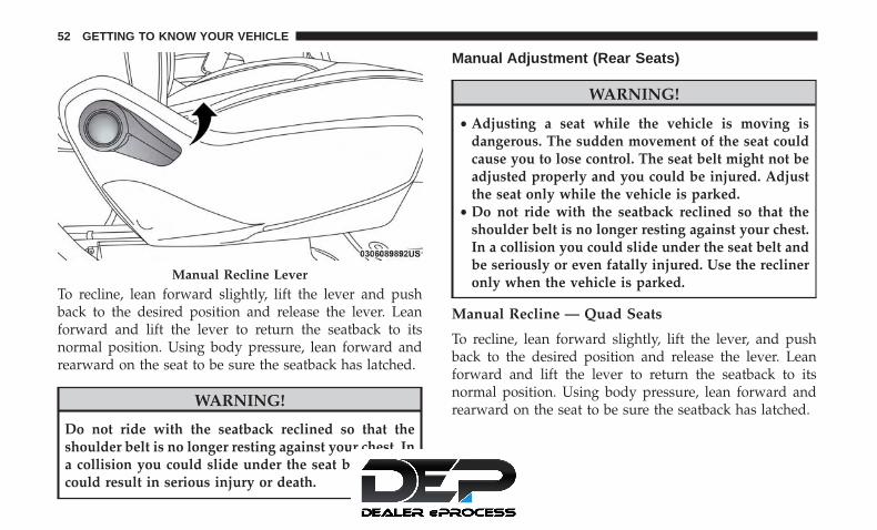
To recline, lean forward slightly, lift the lever and pushback to the desired position and release the lever. Leanforward and lift the lever to return the seatback to itsnormal position. Using body pressure, lean forward andrearward on the seat to be sure the seatback has latched.
WARNING!
Do not ride with the seatback reclined so that theshoulder belt is no longer resting against your chest. Ina collision you could slide under the seat belt, whichcould result in serious injury or death.
Manual Adjustment (Rear Seats)
WARNING!
• Adjusting a seat while the vehicle is moving isdangerous. The sudden movement of the seat couldcause you to lose control. The seat belt might not beadjusted properly and you could be injured. Adjustthe seat only while the vehicle is parked.
• Do not ride with the seatback reclined so that theshoulder belt is no longer resting against your chest.In a collision you could slide under the seat belt andbe seriously or even fatally injured. Use the reclineronly when the vehicle is parked.
Manual Recline — Quad Seats
To recline, lean forward slightly, lift the lever, and pushback to the desired position and release the lever. Leanforward and lift the lever to return the seatback to itsnormal position. Using body pressure, lean forward andrearward on the seat to be sure the seatback has latched.
Manual Recline Lever
52 GETTING TO KNOW YOUR VEHICLE

WARNING!
Do not ride with the seatback reclined so that theshoulder belt is no longer resting against your chest. Ina collision you could slide under the seat belt, whichcould result in serious injury or death.
Second Row Bench Seat — If Equipped
The second row bench seat can accommodate two passen-gers, while providing easy access to the third row seatswithout any folding of the second row seats.
To recline the seatback, lean forward slightly, lift the reclinelever located on the outboard side of the seat cushion, andpush back to the desired position and release the lever.Lean forward and lift the lever to return the seatback to itsnormal position. Using body pressure, lean forward andrearward on the seat to be sure the seatback has latched.
The bench seat does not stow in the floor, but is removablefor added cargo space.
Removing The Bench Seat
1. Adjust the driver and passenger seats forward to allowroom for the bench seat removal.
Recline Lever
Recline Lever
3
GETTING TO KNOW YOUR VEHICLE 53

2. Raise the armrest completely, then lift the recline leverlocated on the outboard side of the seat to fold theseatback flat against the seat cushion.
3. Pull the release strap located behind the seat, in thecenter near the floor to release the latches.
Folded PositionRelease Strap Location
54 GETTING TO KNOW YOUR VEHICLE

4. Once the latches are released, tilt the entire seat towardthe front of the vehicle. The seat can now be removedthrough either sliding side door, or through the lift gate.
NOTE:
• Due to the weight of the bench seat, it is recommendedthat two people are utilized for its removal.
• When storing the removed bench seat, it is important tokeep the seatback in the folded position.
Reinstalling The Bench Seat
1. To reinstall the bench seat, align the seats front attach-ments into the detent positions on the floor.
2. Tilt seat rearward to lock the seat back into its originalposition.
NOTE: Push downward to ensure the rear latches are inthe locked position.
3. Lift the recline handle and return the seat back to theseating position.
WARNING!
If not properly latched, the seat could become loose.Personal injuries could result.
Tilt Bench Seat Forward
3
GETTING TO KNOW YOUR VEHICLE 55

Second Row Removable 8th Seat — If Equipped
While the 8th seat does not stow in the floor, it is foldableand removable for added cargo space.
The release strap is located on the front of the seat, near thefloor. To remove the seat, pull the release strap to releasethe rear latches. The seat assembly can now be removed
from the vehicle by moving it in a rearward direction fromthe detent positions in the floor.
NOTE: Seat can be removed easier with one outboard seatstowed in the load floor.
Second Row 8th Seat Fold Flat Strap
Release Strap
56 GETTING TO KNOW YOUR VEHICLE

To reinstall the seat, align the seat into the detent positionson the floor. Tilt seat rearward to lock the seat back into itsoriginal position.
WARNING!
If not properly latched, the seat could become loose.Personal injuries could result.
Fold-Flat — Quad Seats
To fold the seat, lift the recliner lever to the full upwardposition and push the seatback forward until it rests on theseat cushion.
In Floor Detent Guides
Fold-Flat Seat Recline Lever
3
GETTING TO KNOW YOUR VEHICLE 57

NOTE:
• The seatback may lock into the fold flat position. Use therecline lever to unlock the seatback.
• When returning the seat to the original position, theheadrest must be folded back to the original position.
Easy Entry
Easy Tilt Seat — With Or Without Child Seat Installed
The second row seats can be tilted forward for easy entryinto the third row with or without a child seat installed.
1. Located in the seatback of the second row seat is ahandle that provides easier access to the third row bytilting the seat forward.
Fold Headrest To Upward Position
Easy Tilt Seat Handle
58 GETTING TO KNOW YOUR VEHICLE
2. To put the seat back into original position, just pull backon the seatback and lock the seat into position.
WARNING!
Do not use this feature with a child in seat. Seriousinjury or death my occur.
Easy Entry — With The Seat Folded Flat
The seats can be folded and tilted for more accessibility forpassengers to enter and exit the third row.
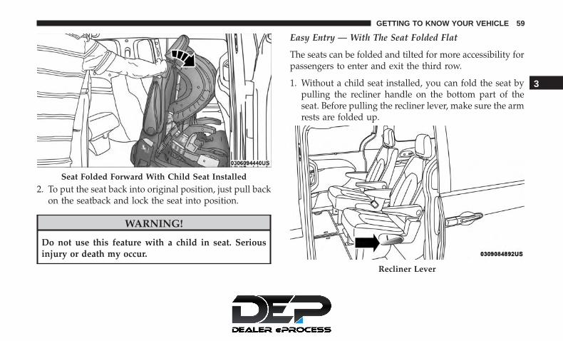
1. Without a child seat installed, you can fold the seat bypulling the recliner handle on the bottom part of theseat. Before pulling the recliner lever, make sure the armrests are folded up.
Seat Folded Forward With Child Seat Installed
Recliner Lever
3
GETTING TO KNOW YOUR VEHICLE 59

Pull the strap on the back of the seat and the seat will tiltforward.
2. To put it back into position, pull back on the folded seatand make sure that it locks into position. Then, pull theseatback toward the back and fold down the arm rests.
Exit For Third Row Passengers
For passengers seated in the third row, there is a pull straplocated on the outboard side of the seat near the bottom ofthe seat back. Third row passengers can pull on the strapand push the seat forward for folding the seatback downand tilting the seat to the floor.
NOTE: This process is for when there is no child seatinstalled. Use the easy entry lever if a child seat is installed.
Pull Strap
Pull Strap For Third Row Passengers
60 GETTING TO KNOW YOUR VEHICLE

Manually Folding Third Row Seats — If Equipped
1. Lower the center head restraint down to the seatback bypushing the button on the guide and pushing the headrestraint down.
2. Pull release strap marked “1” to release the anchors.
3. Pull release strap marked “2” and tumble the seatrearward into the storage bin.
Release Strap “1”
Strap “2”
3
GETTING TO KNOW YOUR VEHICLE 61

To Unfold Third Row Seats
1. Pull up on the assist strap to lift the seat out of thestorage bin and push the seat forward until the anchorslatch.
Stowed Third Row Seat
Assist Straps
62 GETTING TO KNOW YOUR VEHICLE

2. Pulling strap “2” releases the seatback to return to itsfull upright position.
3. Raise the head restraint to its upright position.
WARNING!
• In a collision, you or others in your vehicle could beinjured if seats are not properly latched to their floorattachments. Always be sure the seats are fullylatched.
(Continued)
WARNING! (Continued)• Sitting in a seat with the head restraint in its lowered
position could result in serious injury or death in acollision. Always make sure the head restraints are intheir upright positions when the seat is to be occu-pied.
Stow ’n Go Seating
On vehicles equipped with Stow ’n Go seating, the secondand third row seats can be folded into the floor forconvenient storage.
Auto Advance ‘n Return — If Equipped
On vehicles equipped with the Auto Advance ‘n Returnfeature, the front seat will move forward automatically to alocation that will allow the second row Stow ‘n Go seatmovement, without interference by the front seat. After thesecond row seat is stowed, the front seat will move back tothe previous location once the Auto Advance ‘n Returnbutton is pushed again.
The Auto Advance ‘n Return feature is available to both thefront driver and passenger power seats, if equipped.
Strap “2”
3
GETTING TO KNOW YOUR VEHICLE 63

WARNING!
During power seat operation, personal injury or cargodamage may occur. Ensure the front seat is not occu-pied and the seat travel path is clear.
A one-touch Auto Advance ‘n Return button is located onthe B-pillar trim panel, just in front of the power slidingdoor.
Using the Auto Advance ‘n Return Feature
NOTE:
• The button is only functional when the power slidingdoor is open and the vehicle is in PARK. If the door isnot open or the vehicle is not in PARK when the buttonis pushed, the front seat will not move and a messagewill be displayed in instrument cluster display.
• If the power sliding door is closing when the button ispushed, the front seat will not move and a message willbe displayed in the instrument cluster display.
1. Push and release the Auto Advance ‘n Return button.The front seat cushion and seat back will move asnecessary to a location that will allow space for thesecond row Stow ‘n Go seat movement.
2. Perform the second row Stow ‘n Go seat movement.Refer to “Second Row Stow ‘n Go” for further informa-tion.
3. Push and release the Auto Advance ‘n Return button asecond time. The front seat cushion and seat back willreturn to the original starting location.
Auto Advance ‘n Return Button
64 GETTING TO KNOW YOUR VEHICLE

NOTE:
• To abort seat operation while seat is in motion, push theAuto Advance ‘n Return button, or push the front powerseat button to stop the seat movement. Pushing the AutoAdvance ‘n Return button again will return the frontseat to the original starting location.
• The Auto Advance ‘n Return system includes obstacledetection. When the system detects an obstacle, the seatwill stop, reverse direction, and return to the previouslocation. A message will be displayed in the instrumentcluster indicating that an obstacle has been detected.
• If the front seat is already in a location that will allowspace for Stow ‘n Go of the second row seat, the frontseat will not move and a message will be displayed inthe instrument cluster.
• If calibration of the front seat is lost, the seat willautomatically re-calibrate when the Auto Advance ‘nReturn button is pushed. This may result in the seatcushion moving forward and downward, before movingto the location that will allow space for the second rowStow ‘n Go seat movement.
Second Row Stow ’n Go
For Manual Seats: To stow the seat in the floor, move thefront seat all the way forward using the manual seatadjustment bar. Move the seat back all the way forwardusing the recliner handle located on the outboard side ofthe cushion. Move the seat height to at least mid positionusing the height adjuster handle in the outboard side of thecushion.
For Power Seats: Push the Auto Advance ‘n Return buttonlocated on the B pillar trim (if equipped.) Refer to �AutoAdvance ‘n Return - If Equipped� in this section forinstructions.
1. To access the storage bin, place the lock rod in the lockedposition.
3
GETTING TO KNOW YOUR VEHICLE 65

NOTE:
• Push the lock rod inward for the locked position.
• Pull outward on the lock rod for the unlocked position.
• For information on storage bin function with the seatsrearward refer to “Second Row Floor Storage Bins” in“Internal Equipment” for further information.
2. Pull the latch located near the second row seat to openthe floor panel.
Lock Rod
Floor Latch
66 GETTING TO KNOW YOUR VEHICLE

3. Pull the floor panel and position it toward the front seatswhile folding the top half down and rest it against thefront seats.
4. Fold the armrest upward and stow the seat by grabbingthe strap on the lower part of the seat back, and guidethe seat into the tub.
Push Panel Forward Pull Strap
3
GETTING TO KNOW YOUR VEHICLE 67

5. Push down on the seat back to lock the seat in the tub. 6. Close the floor by pulling the floor panel backwards bythe bottom corner edge of the panel.
Push To LockExtend Floor Panel
68 GETTING TO KNOW YOUR VEHICLE

7. Push down on floor panel to lock into place.
8. Readjust the front seat as needed.
WARNING!
In a collision, serious injury could result if the seatstorage bin covers are not properly latched:• Do not drive the vehicle with the storage bin covers
open.• Keep the storage bin covers closed and latched while
the vehicle is in motion.• Do not use a storage bin latch as a tie down.
CAUTION!
• The storage bin cover must be locked and flat toavoid damage from contact with the front seat tracks,which have minimal clearance to the cover.
• Do not sit on the second row seat when it is in thestowed position with the seatback upright otherwisedamage to the seat may occur.
To Unstow Second Row Seats
For Manual Seats: To unstow the seat from the floor, movethe front seat all the way forward using the manual seatadjustment bar.
For Power Seats: Push the Auto Advance ‘n Return buttonlocated on the B pillar trim (if equipped). Refer to �AutoAdvance ‘n Return - If Equipped� in this section forinstructions.
1. To access the storage bin, place the lock rod in the lockedposition.
Push To Lock
3
GETTING TO KNOW YOUR VEHICLE 69
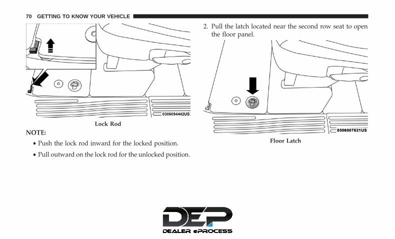
NOTE:
• Push the lock rod inward for the locked position.
• Pull outward on the lock rod for the unlocked position.
2. Pull the latch located near the second row seat to openthe floor panel.
Lock Rod
Floor Latch
70 GETTING TO KNOW YOUR VEHICLE

3. Pull the floor panel and position it toward the front seatswhile folding the top half down and rest it against thefront seats.
4. Pull the strap located on the seat and pull the seat out ofthe storage bin. Push the seat rearward making sure thatit locks into the floor. Fold the seatback into the uprightposition and pull the headrest up.
NOTE: The seatback may be locked, if it is, it will benecessary to use the recliner handle to unlock the backbefore folding into the upright position.
Push Panel Forward
Pull Strap
3
GETTING TO KNOW YOUR VEHICLE 71

5. To position the floor panel back into its original state,grab the bottom corner and extend it outward.
6. Lay the floor panel flat and push down until it clicksinto position. Replace the floor mat as needed.
7. Readjust the front seat as needed.
WARNING!
• In a collision, you or others in your vehicle could beinjured if seats are not properly latched to their floorattachments. Always be sure the seats are fullylatched.
(Continued)
Extend Panel Push Down To Lock
72 GETTING TO KNOW YOUR VEHICLE

WARNING! (Continued)• Sitting in a seat with the head restraint in its lowered
position could result in serious injury or death in acollision. Always make sure the head restraints are intheir upright positions when the seat is to be occu-pied.
Power Adjustment (Front Seats) — If Equipped
Some models may be equipped with eight-way powerseats for the driver and front passenger. The power seatswitches are located on the outboard side of the seat. Theswitches control the movement of the seat cushion and theseatback.
WARNING!
• Adjusting a seat while driving may be dangerous.Moving a seat while driving could result in loss ofcontrol which could cause a collision and seriousinjury or death.
(Continued)
Driver Power Seat Switches
1 — Seat Switch2 — Seatback Switch3 — Lumbar Switch
3
GETTING TO KNOW YOUR VEHICLE 73

WARNING! (Continued)• Seats should be adjusted before fastening the seat
belts and while the vehicle is parked. Serious injuryor death could result from a poorly adjusted seat belt.
• Do not ride with the seatback reclined so that theshoulder belt is no longer resting against your chest.In a collision you could slide under the seat belt,which could result in serious injury or death.
CAUTION!
Do not place any article under a power seat or impedeits ability to move as it may cause damage to the seatcontrols. Seat travel may become limited if movementis stopped by an obstruction in the seat’s path.
Adjusting The Seat Forward Or Rearward
The seat can be adjusted both forward and rearward. Pushthe seat switch forward or rearward, and the seat willmove in the direction of the switch. Release the switchwhen the desired position has been reached.
Adjusting The Seat Up Or Down
The height of the seats can be adjusted up or down. Pullupward or push downward on the rear of seat switch, the
seat will move in the direction of the switch. Release theswitch when the desired position has been reached.
Tilting The Seat Up Or Down
The angle of the seat cushion can be adjusted in twodirections. Pull upward or push downward on the front ofthe seat switch, the front of the seat cushion will move inthe direction of the switch. Release the switch when thedesired position has been reached.
Reclining The Seatback
The angle of the seatback can be adjusted forward orrearward. Push the seatback switch forward or rearward,the seat will move in the direction of the switch. Release theswitch when the desired position is reached.
WARNING!
• Adjusting a seat while driving may be dangerous.Moving a seat while driving could result in loss ofcontrol which could cause a collision and seriousinjury or death.
• Seats should be adjusted before fastening the seatbelts and while the vehicle is parked. Serious injuryor death could result from a poorly adjusted seat belt.
(Continued)
74 GETTING TO KNOW YOUR VEHICLE

WARNING! (Continued)• Do not ride with the seatback reclined so that the
shoulder belt is no longer resting against your chest.In a collision you could slide under the seat belt,which could result in serious injury or death.
CAUTION!
Do not place any article under a power seat or impedeits ability to move as it may cause damage to the seatcontrols. Seat travel may become limited if movementis stopped by an obstruction in the seat’s path.
Power Lumbar — If Equipped
Vehicles equipped with power driver or passenger seatsmay be equipped with power lumbar. The power lumbarswitch is located on the outboard side of the power seat.Push the switch forward or rearward to increase or de-crease the lumbar support. Push the switch upward ordownward to raise or lower the lumbar support.
Power Adjustment (Rear Seats) — If Equipped
WARNING!
• Adjusting a seat while driving may be dangerous.Moving a seat while driving could result in loss ofcontrol which could cause a collision and seriousinjury or death.
• Seats should be adjusted before fastening the seatbelts and while the vehicle is parked. Serious injuryor death could result from a poorly adjusted seat belt.
• Do not ride with the seatback reclined so that theshoulder belt is no longer resting against your chest.In a collision you could slide under the seat belt,which could result in serious injury or death.
• Do not place the seat belt webbing behind the thirdrow stow clip when using the seat belt to restrain anoccupant. The seat belt will not be positioned prop-erly on the occupant and they could be more seri-ously injured in an accident as a result.
3
GETTING TO KNOW YOUR VEHICLE 75

CAUTION!
Do not place any article under a power seat or impedeits ability to move as it may cause damage to the seatcontrols. Seat travel may become limited if movementis stopped by an obstruction in the seat’s path.
Third Row Power Recline — If Equipped
The power recline feature, located on the trim panel next tothe seat, adjusts the seatback angle forward/rearward foroccupant comfort.
Reclining The Seatback
The angle of the seatback can be adjusted forward orrearward. Push and hold the forward or rearward button,the seat will move in the direction of the button push.Release the button when the desired position is reached.
Third Row Power Stow ‘n Go Seat — If Equipped
A one-touch power folding seat switch is located in theright rear trim panel as part of a switch bank.
NOTE: The third row outboard seat belts may interferewith the power folding of the seat. Place the seat beltwebbing behind the stow clip before stowing or openingthe seat. When the seat is in the desired position, removethe webbing from the stow clip so that it is ready for use.Never leave the seat belt in the stow clip when it is used torestrain an occupant.
Third Row Power Seat Switch
76 GETTING TO KNOW YOUR VEHICLE

NOTE:
• The outer head restraints will lower automatically asnecessary when the power seat begins to move.
• The center head restraint raises and lowers manually butwill not lower automatically.
• The head restraint can also be lowered manually usingthe pull strap located at the back of the seat. Refer to�Head Restraints - Third Row� in �Head Restraints� forfurther information.
The switch is only functional when the liftgate is open andthe vehicle is in PARK.
The rear switch bank allows multiple power folding andunfolding positions for the third row seats.
Left and right third row seats can be folded individually ortogether. The third row power folding seat adjusts to thefollowing positions using the switch bank located on theleft rear trim panel:
To move the selected seat(s) to the normal (seated) position,push and release the “Normal” button. The seat willautomatically stop when the Normal position is reached.
To move the selected seat(s) to the stow position, push andrelease the “Stow” button. The seat will automatically stopwhen the Stow position is reached.
Rear Panel Power Switch Bank
1 — Open To Normal 3 — Fold Forward/Rearward2 — Stow 4 — Right/Left Seats/Both Seats
3
GETTING TO KNOW YOUR VEHICLE 77

To move the selected seat(s) back in the forward or reversedirection, push and hold the “Fold Forward/Back” button.Release the button when the desired position is reached.
NOTE:
1. Disconnect the center shoulder belt from the mini-buckle before attempting to fold/stow the power thirdrow seats.
2. Before pushing the “Normal” or “Stow” button, placethe outboard seat belt webbing behind the stow clipslocated on the rear trim panel. When the seat reaches thedesired position, remove the webbing from the clip so itis ready for use to restrain an occupant.
3. To abort seat operation while seat is in motion, push adifferent seat position selector switch to stop the seat.Once the seat stops moving, then the desired positioncan be selected.
4. The third row power seat system includes obstacledetection. When the system detects an obstacle, themotors will stop and reverse direction. Should thisoccur, remove the obstacle before pushing the buttonagain.
Seat Belt Stowage Clip
78 GETTING TO KNOW YOUR VEHICLE

Driver Memory Seat — If Equipped
The Memory Buttons (1) and (2) on the driver’s door panelcan be programmed to recall the driver’s seat, outsidemirrors, and radio station preset settings. Your key fobs canalso be programmed to recall the same positions when theunlock button is pushed.
Your vehicle may have been delivered with two key fobs,one key fob can be linked to each of the memory positions.
Programming The Memory Feature
To create a new memory profile, perform the following:
1. Cycle the vehicle’s ignition to the ON/RUN position (donot start the engine).
2. Adjust all memory profile settings to desired prefer-ences (i.e., driver’s seat, outside mirrors and radiostation presets).
3. Push and release the set (S) button on the memoryswitch.
4. Within five seconds, push and release either of thememory buttons (1) or (2). The instrument cluster dis-play will show which memory position has been set.
NOTE:
• Memory profiles can be set without the vehicle in PARK,but the vehicle must be in PARK to recall a memoryprofile.
• To set a memory profile to your key fob, refer to“Linking And Unlinking The Remote Keyless Entry KeyFob To Memory” in this section.
Driver Memory Switch
1 — Memory Button 12 — Set Button3 — Memory Button 2
3
GETTING TO KNOW YOUR VEHICLE 79

Linking And Unlinking The Remote Keyless EntryKey Fob To Memory
Your key fob can be programmed to recall one of twopre-programmed memory profiles by pushing the unlockbutton on the key fob.
NOTE: Before programming your key fob you must selectthe “Personal Settings Linked to Key Fob” feature throughthe Uconnect Settings. Refer to “Uconnect Settings” in“Multimedia” for further information.
To program your key fob, perform the following:
1. Cycle the vehicle’s ignition to the OFF position.
2. Select a desired memory profile 1 or 2.
NOTE: If a memory profile has not already been set, referto �Programming The Memory Feature� in this section forinstructions on how to set a memory profile.
3. Once the profile has been recalled, push and release theset (S) button on the memory switch.
4. Push and release button (1) or (2) accordingly. “MemoryProfile Set” (1 or 2) will display in the instrumentcluster.
5. Push and release the lock button on the key fob within10 seconds.
NOTE: Your key fob can be unlinked to your memorysettings by pushing the set (S) button, and within 10 seconds,followed by pushing the unlock button on the key fob.
Memory Position Recall
NOTE: The vehicle speed must be less than or equal to5 mph (8 km/h) to recall memory positions. If a recall isattempted when the vehicle speed is greater than 5 mph(8 km/h), a message will be displayed in the instrumentcluster display.
To recall the memory settings for driver one, push memorybutton (1) on the driver’s door or the unlock button on thekey fob linked to memory position 1.
To recall the memory setting for driver two, push memorybutton (2) on the driver’s door or the unlock button on thekey fob linked to memory position 2.
A recall can be cancelled by pushing any of the memorybuttons on the driver’s door during a recall (S, 1, or 2).When a recall is cancelled, the driver’s seat stops moving.A delay of one second will occur before another recall canbe selected.
80 GETTING TO KNOW YOUR VEHICLE

NOTE: Pushing the mirror adjust switch will cancel thememory mirror recall.
Easy Entry/Exit Seat (Available With Memory SeatOnly)
This feature provides automatic driver seat positioning toenhance driver mobility when entering and exiting thevehicle.
The distance the driver seat moves depends on where youhave the driver seat positioned when you cycle the vehi-cle’s ignition to the OFF position.
• When the ignition is cycled to the OFF position, thedriver seat will move about 2.4 inches (60 mm) rearwardif the driver seat position is greater than or equal to 2.7inches (67.7 mm) forward of the rear stop. The seat willreturn to its previously set position when the ignition iscycled out of the OFF position.
• When the ignition is cycled to the OFF position, thedriver seat will move to a position 0.3 inches (7.7 mm)forward of the rear stop if the driver seat position isbetween 0.9 – 2.7 inches (22.7 – 67.7 mm) forward of therear stop. The seat will return to its previously setposition when the ignition is cycled out of the OFFposition.
• The Easy Entry/Easy Exit feature is disabled when thedriver seat position is less than 0.9 inches (22.7 mm)forward of the rear stop. At this position, there is nobenefit to the driver by moving the seat for Easy Exit orEasy Entry.
Each stored memory setting will have an associated EasyEntry and Easy Exit Position.
NOTE: The Easy Entry/Easy Exit feature can be enabled ordisabled through the programmable features in the instru-ment cluster display. For further information, refer to“Instrument Cluster Display” in “Getting To Know YourInstrument Panel”.
Heated Seats
Front Heated Seats — If Equipped
The front heated seats control buttons are located withinthe climate or controls screen of the touchscreen.
You can choose from HI, LO or off heat settings. Theindicator lights in each switch indicate the level of heat inuse. Two indicator lights will illuminate for HI, one for LOand none for off.
• Press the heated seat button once to turn the HIsetting on.
3
GETTING TO KNOW YOUR VEHICLE 81

• Press the heated seat button a second time to turnthe LO setting on.
• Press the heated seat button a third time to turn theheating elements off.
If the HI-level setting is selected, the system will automati-cally switch to LO-level after approximately 60 minutes ofcontinuous operation. At that time, the display will changefrom HI to LO, indicating the change. The LO-level settingwill turn off automatically after approximately 45 minutes.
NOTE:
• Once a heat setting is selected, heat will be felt withintwo to five minutes.
• The engine must be running for the heated seats tooperate.
Vehicles Equipped With Remote Start
On models that are equipped with remote start, the heatedseats can be programmed to come on during a remote start.
This feature can be programmed through the Uconnectsystem. Refer to “Uconnect Settings” in “Multimedia” forfurther information.
WARNING!
• Persons who are unable to feel pain to the skinbecause of advanced age, chronic illness, diabetes,spinal cord injury, medication, alcohol use, exhaus-tion or other physical condition must exercise carewhen using the seat heater. It may cause burns evenat low temperatures, especially if used for longperiods of time.
• Do not place anything on the seat or seatback thatinsulates against heat, such as a blanket or cushion.This may cause the seat heater to overheat. Sitting ina seat that has been overheated could cause seriousburns due to the increased surface temperature of theseat.
Rear Heated Seats — If Equipped
On some models, the second row seats are equipped withheaters. There are two heated seat switches that allow thesecond row passengers to operate the seats independently.The heated seat switches are located on the sliding sidedoor handle trim panels.
82 GETTING TO KNOW YOUR VEHICLE

You can choose from HI, LO or off heat settings. Amberindicator lights in each switch indicate the level of heat inuse. Two indicator lights will illuminate for HI, one for LOand none for off.
Push the switch once to select HI-level heating. Push theswitch a second time to select LO-level heating. Push theswitch a third time to shut the heating elements off.
NOTE: Once a heat setting is selected, heat will be feltwithin two to five minutes.
When the HI-level setting is selected, the heater willprovide a boosted heat level during the initial stages of
operation. Then, the heat output will drop to the normalHI-level. If the HI-level setting is selected, the system willautomatically switch to LO-level after approximately 60minutes of continuous operation. At that time, the displaywill change from HI to LO, indicating the change. TheLO-level setting will turn off automatically after approxi-mately 45 minutes.
Ventilated Seats — If Equipped
Located in the first row seat cushions are small fans thatdraw the air from the passenger compartment and moveair through fine perforations in the seat cover to help keepthe driver and front passenger cooler in higher ambienttemperatures. The fans operate at two speeds, HI and LO.
The front ventilated seats control buttons are locatedwithin the climate or controls screen of the touchscreen.
• Press the ventilated seat button once to choose HI.
• Press the ventilated seat button a second time tochoose LO.
• Press the ventilated seat button a third time to turnthe ventilated seat off.
NOTE: The engine must be running for the ventilated seatsto operate.
Second Row Heated Seat Switch
3
GETTING TO KNOW YOUR VEHICLE 83
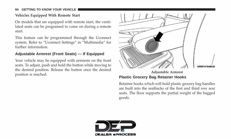
Vehicles Equipped With Remote Start
On models that are equipped with remote start, the venti-lated seats can be programed to come on during a remotestart.
This feature can be programmed through the Uconnectsystem. Refer to “Uconnect Settings” in “Multimedia” forfurther information.
Adjustable Armrest (Front Seats) — If Equipped
Your vehicle may be equipped with armrests on the frontseats. To adjust, push and hold the button while moving tothe desired position. Release the button once the desiredposition is reached.
Plastic Grocery Bag Retainer Hooks
Retainer hooks which will hold plastic grocery bag handlesare built into the seatbacks of the first and third row rearseats. The floor supports the partial weight of the baggedgoods.
Adjustable Armrest
84 GETTING TO KNOW YOUR VEHICLE

HEAD RESTRAINTS
Head restraints are designed to reduce the risk of injury byrestricting head movement in the event of a rear impact.Head restraints should be adjusted so that the top of thehead restraint is located above the top of your ear.
WARNING!
• All occupants, including the driver, should not oper-ate a vehicle or sit in a vehicle’s seat until the headrestraints are placed in their proper positions inorder to minimize the risk of neck injury in the eventof a crash.
• Head restraints should never be adjusted while thevehicle is in motion. Driving a vehicle with the headrestraints improperly adjusted or removed couldcause serious injury or death in the event of acollision.
Head Restraints — Front Seats
The front driver and passenger seats are equipped withfour-way head restraints.
To raise the head restraint, pull upward on the headrestraint. To lower the head restraint, push the adjustmentbutton, located at the base of the head restraint, and pushdownward. The front head restraints are also adjustableforward and rearward. To adjust forward, pull the headrestraint toward the front of the vehicle to desired position.To adjust the head restraint rearward, pull forward on thehead restraint to furthest forward position and head re-straint will reset to furthest rearward position.
NOTE: To remove the head restraint, raise it as far as it cango. Then, push the release button and the adjustmentbutton at the base of each post while pulling the headrestraint up. Seatback angle may need to be adjusted tofully remove the head restraint. To reinstall the head
3
GETTING TO KNOW YOUR VEHICLE 85

restraint, put the head restraint posts into the holes andpush downward. Then, adjust the head restraint to theappropriate height.
Front Head Restraint
1 — Adjustment Button2 — Release Button
Normal Position
86 GETTING TO KNOW YOUR VEHICLE

WARNING!
• A loose head restraint thrown forward in a collisionor hard stop could cause serious injury or death tooccupants of the vehicle. Always securely stow re-moved head restraints in a location outside theoccupant compartment.
• ALL the head restraints MUST be reinstalled in thevehicle to properly protect the occupants. Follow there-installation instructions above prior to operatingthe vehicle or occupying a seat.
Head Restraints — Second Row Quad Seats
The second row outboard head restraints, as well as theremovable 8th passenger seat (if equipped) have adjustablehead restraints.
To raise the head restraint, pull upward on the headrestraint. To lower the head restraint, push the adjustmentbutton, located at the base of the head restraint, and pushdownward.
NOTE: If equipped with Stow ‘n Go seating, the headrestraints are non-adjustable. Do not pull on non-adjustable head restraints when folding.
Head Restraints — Second Row Bench
The second row bench seat is equipped with adjustablehead restraints.
To raise the head restraint, pull upward on the headrestraint. To lower the head restraint, push the adjustmentbutton, located at the base of the head restraint, and pushdownward.
Forward Adjustment
3
GETTING TO KNOW YOUR VEHICLE 87
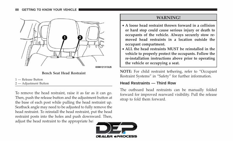
To remove the head restraint, raise it as far as it can go.Then, push the release button and the adjustment button atthe base of each post while pulling the head restraint up.Seatback angle may need to be adjusted to fully remove thehead restraint. To reinstall the head restraint, put the headrestraint posts into the holes and push downward. Then,adjust the head restraint to the appropriate height.
WARNING!
• A loose head restraint thrown forward in a collisionor hard stop could cause serious injury or death tooccupants of the vehicle. Always securely stow re-moved head restraints in a location outside theoccupant compartment.
• ALL the head restraints MUST be reinstalled in thevehicle to properly protect the occupants. Follow there-installation instructions above prior to operatingthe vehicle or occupying a seat.
NOTE: For child restraint tethering, refer to “OccupantRestraint Systems” in “Safety” for further information.
Head Restraints — Third Row
The outboard head restraints can be manually foldedforward for improved rearward visibility. Pull the releasestrap to fold them forward.
Bench Seat Head Restraint
1 — Release Button2 — Adjustment Button
88 GETTING TO KNOW YOUR VEHICLE

NOTE:
• The head restraints must be raised manually whenoccupying the third row.
• Do not fold if there are passengers seated in the thirdrow seats.
The head restraint in the center position can be raised andlowered for tether routing or height adjustment. Refer to“Occupant Restraint Systems” in “Safety” for further infor-mation.
NOTE: To remove the center head restraint, raise it as far asit can go. Then, push the release button and the adjustmentbutton at the base of each post while pulling the headrestraint up. To reinstall the head restraint, put the headrestraint posts into the holes and push downward. Then,using the adjustment button, adjust the head restraint tothe appropriate height.
Release Strap
Adjustment Button
3
GETTING TO KNOW YOUR VEHICLE 89

WARNING!
ALL the head restraints MUST be reinstalled in thevehicle to properly protect the occupants. Follow there-installation instructions above prior to operating thevehicle or occupying a seat.
Power Folding Third Row Head Restraints — IfEquipped
For improved visibility, the third row outboard headrestraints can be folded using the Uconnect System.
Press the “Controls” button located on the bottom of theUconnect display.
Press the Head Restraint Fold button to power fold thethird row head restraints.
NOTE:
• The head restraints can be folded downward using theHead Restraint button or using the manual release strap.The head restraints must be raised manually whenoccupying the third row.
• Do not fold if there are passengers seated in the thirdrow seats.
STEERING WHEEL
Tilt/Telescoping Steering Column
This feature allows you to tilt the steering column upwardor downward. It also allows you to lengthen or shorten thesteering column. The tilt/telescoping lever is located left ofthe steering wheel at the end of the steering column.
To unlock the steering column, push the lever downward(toward the floor). To tilt the steering column, move thesteering wheel upward or downward as desired. Tolengthen or shorten the steering column, pull the steeringwheel outward or push it inward as desired. To lock the
Tilt/Telescoping Lever
90 GETTING TO KNOW YOUR VEHICLE

steering column in position, push the lever upward untilfully engaged.
WARNING!
Do not adjust the steering column while driving.Adjusting the steering column while driving or driv-ing with the steering column unlocked, could cause thedriver to lose control of the vehicle. Failure to followthis warning may result in serious injury or death.
Heated Steering Wheel — If Equipped
The steering wheel contains a heating element that helpswarm your hands in cold weather. The heated steeringwheel has only one temperature setting. Once the heatedsteering wheel has been turned on, it will operate for anaverage of 80 minutes or more before automatically shut-ting off. This time may vary depending on the temperatureof the environment. The heated steering wheel can shut offearly or may not turn on when the steering wheel isalready warm.
The heated steering wheel control button is located withinthe Uconnect system. You can gain access to the controlbutton through the climate screen or the controls screen.
• Press the heated steering wheel button once to turnthe heating element on.
• Press the heated steering wheel button a second timeto turn the heating element off.
NOTE: The engine must be running for the heated steeringwheel to operate.
Vehicles Equipped With Remote Start
On models that are equipped with remote start, the heatedsteering wheel can be programmed to come on during aremote start through the Uconnect system. Refer to“Uconnect Settings” in “Multimedia” for further information.
WARNING!
• Persons who are unable to feel pain to the skinbecause of advanced age, chronic illness, diabetes,spinal cord injury, medication, alcohol use, exhaus-tion, or other physical conditions must exercise carewhen using the steering wheel heater. It may cause
(Continued)
3
GETTING TO KNOW YOUR VEHICLE 91

WARNING! (Continued)burns even at low temperatures, especially if usedfor long periods.
• Do not place anything on the steering wheel thatinsulates against heat, such as a blanket or steeringwheel covers of any type and material. This maycause the steering wheel heater to overheat.
MIRRORS
Inside Day/Night Mirror — If Equipped
A single ball joint mirror is used to allow the driver toadjust up, down and left, right. Mirror should be adjustedto center on the view through the rear window.
Headlight glare can be reduced by moving the smallcontrol under the mirror to the night position (toward therear of the vehicle). The mirror should be adjusted whileset in the day position (toward the windshield).
Automatic Dimming Mirror — If Equipped
This mirror automatically adjusts for headlight glare fromvehicles behind you. You can turn the feature on or off bypushing the button at the base of the mirror. A light to theleft of the button will illuminate to indicate when thedimming feature is activated. The sensor to the right of thebutton does not illuminate.
NOTE: This feature is disabled when the vehicle is inREVERSE.
Manual Rearview Mirror
92 GETTING TO KNOW YOUR VEHICLE

CAUTION!
To avoid damage to the mirror during cleaning, neverspray any cleaning solution directly onto the mirror.Apply the solution onto a clean cloth and wipe themirror clean.
Outside Mirrors
To receive maximum benefit, adjust the outside mirror(s) tocenter on the adjacent lane of traffic with a slight overlap ofthe view obtained on the inside mirror.
WARNING!
Vehicles and other objects seen in an outside convexmirror will look smaller and farther away than theyreally are. Relying too much on side convex mirrorscould cause you to collide with another vehicle or otherobject. Use your inside mirror when judging the size ordistance of a vehicle seen in a side convex mirror.
Driver’s Outside Automatic Dimming Mirror — IfEquipped
The driver’s outside mirror will automatically adjust forglare from vehicles behind you. This feature is controlledby the inside automatic dimming mirror and will automati-cally adjust for headlight glare when the inside mirroradjusts.
Automatic Dimming Mirror
3
GETTING TO KNOW YOUR VEHICLE 93

Conversation Mirror
Located in the overhead console there is a conversationmirror to view all the passengers in the vehicle. Push thepanel to release the drop down mirror. Raise the mirror andpush to latch it back in the stowed position.
Power Mirrors — If Equipped
The power mirror controls are located on the driver-sidedoor trim panel.
The power mirror controls consist of mirror select buttonsand a four-way mirror control switch. To adjust a mirror,push either the L (left) or R (right) to select the mirror thatyou want to adjust.
NOTE: A light in the selected button will illuminateindicating the mirror is activated and can be adjusted.
Conversation Mirror
Power Mirror Controls
94 GETTING TO KNOW YOUR VEHICLE

Using the mirror control switch, push on any of the fourarrows for the direction that you want the mirror to move.
Left and Right side power mirror preselected positions canbe controlled by the optional Driver Memory Seat Feature.Refer to “Driver Memory Seat” in “Seats” for furtherinformation.
Outside Mirrors Folding Feature
All outside mirrors are hinged and may be moved eitherforward or rearward to resist damage. The hinges havethree detent positions:
• Full forward position
• Full rearward position
• Normal position
Heated Mirrors — If Equipped
These mirrors are heated to melt frost or ice. Thisfeature will be activated whenever you turn on the
rear window defroster (if equipped).
Refer to “Climate Controls” in this section for furtherinformation.
Tilt Side Mirrors In Reverse (Available WithMemory Seat Only) — If Equipped
Tilt Side Mirrors In Reverse provides automatic outsidemirror positioning which will aid the driver’s view of theground rearward of the front doors. The driver’s outsidemirror will move slightly downward from the presentposition when the vehicle is shifted into REVERSE. Thedriver’s outside mirror will then return to the originalposition when the vehicle is shifted out of the REVERSEposition. Each stored memory setting will have an associ-ated Tilt Side Mirrors In Reverse position.
NOTE: The Tilt Side Mirrors In Reverse feature is notenabled when delivered from the factory. The Tilt SideMirrors In Reverse feature can be enabled or disabledthrough the radio touchscreen. Refer to “Uconnect Set-tings” in “Multimedia” for further information.
Power Folding Mirrors — If Equipped
The switch for the power folding mirrors is located be-tween the power mirror switches L (left) and R (right).Push the switch once and the mirrors will fold in, pushingthe switch a second time will return the mirrors to thenormal driving position.
3
GETTING TO KNOW YOUR VEHICLE 95

NOTE: If the vehicle speed is greater than 10 mph(16 km/h), the folding feature will be disabled.
If the mirrors are in the folded position, and vehicle speedis equal or greater than 10 mph (16 km/h), they willautomatically unfold.
Resetting The Power Folding Outside Mirrors
You may need to reset the power folding mirrors if thefollowing occurs:
• The mirrors are accidentally blocked while folding.
• The mirrors are accidentally manually folded/unfolded.
• The mirrors come out of the unfolded position.
• The mirrors shake and vibrate at normal driving speeds.
To reset the power folding mirrors: fold and unfold themby pushing the button (this may require multiple buttonpushes). This resets them to their normal position.
Illuminated Vanity Mirrors — If Equipped
An illuminated vanity mirror is located on the sun visor. Touse the mirror, rotate the sun visor down and swing themirror cover upward. The lights turn on automatically.Closing the mirror cover turns off the lights.
Power Folding Mirror Switch
Illuminated Mirror
96 GETTING TO KNOW YOUR VEHICLE

EXTERIOR LIGHTS
Multifunction Lever
The multifunction lever is located on the left side of thesteering column. The multifunction lever controls the turnsignals, headlight high/low beams, and flash-to-pass func-tions.
Headlight Switch
The headlight switch is located on the left side of theinstrument panel. The switch controls the operation of theheadlights, parking lights, instrument panel lights, interiorlights and the fog lights.
Rotate the headlight switch clockwise to the second detentfor parking light and instrument panel light operation.
Multifunction Lever
1 — Turn Signals2 — Flash-To-Pass3 — Headlight Beams Low/High
Headlight Switch
1 — Rotate Headlight Switch2 — Ambient Dimmer Control3 — Instrument Panel Dimmer4 — Fog Lamps Button
3
GETTING TO KNOW YOUR VEHICLE 97

Rotate the headlight switch to the third detent for head-light, parking light and instrument panel operation.
Daytime Running Lights — If Equipped
The headlights or LED light bars on your vehicle willilluminate when the engine is started. This provides aconstant lights on condition until the ignition is turnedOFF. If the parking brake is applied, the Daytime RunningLights (DRL) will turn off. Also, if a turn signal is activated,the DRL lamp on the same side of the vehicle will turn offfor the duration of the turn signal activation. Once the turnsignal is no longer active, the DRL lamp will illuminate.
High/Low Beam Switch
When the headlights are turned on, pushing the multifunc-tion lever toward the instrument panel will switch fromlow beams to high beams. Pulling back to the neutralposition returns the headlights to the low beam operation.
Automatic High Beam — If Equipped
The Automatic High Beam system provides increasedforward lighting at night by automating high beam controlthrough the use of a digital camera mounted on thewindshield. This camera detects vehicle specific light andautomatically switches from high beams to low beamsuntil the approaching vehicle is out of view.
NOTE: Broken, muddy, or obstructed headlights and tail-lights of vehicles in the field of view will cause headlightsto remain on longer (closer to the vehicle). Also, dirt, filmand other obstructions on the windshield or camera lenswill cause the system to function improperly.
To Activate
1. Select “Automatic High Beams — ON” through theUconnect system. Refer to �Uconnect Settings” in “Mul-timedia” for further information.
2. Rotate the headlight switch clockwise to the AUTOposition.
3. Push the multifunction lever away from you to switchthe headlights to the high beam position. Refer to“Multifunction Lever” for further information.
NOTE: This system will not activate until the vehicle is at,or above 16 mph (25 km/h).
To Deactivate
Perform either of the following steps to deactivate theAutomatic High Beam system.
1. Select “Automatic High Beams — OFF” through theUconnect System. Refer to “Uconnect Settings” in “Mul-timedia” for further information.
98 GETTING TO KNOW YOUR VEHICLE

2. Pull the multifunction lever toward you to switch theheadlights from the high beam to the low beam position.
3. Rotate the headlight switch counterclockwise from theAUTO to the on position.
NOTE: Once active, the Automatic High Beam system willstop functioning below 12 mph (20 km/h).
Flash-To-Pass
You can signal another vehicle with your headlights bylightly pulling the multifunction lever toward you. Thiswill cause the high beam headlights to turn on, and remainon, until the lever is released.
Automatic Headlights — If Equipped
This system automatically turns your headlights on or offbased on ambient light levels. To turn the system on, turnthe headlight switch to the extreme clockwise positionaligning the indicator with the AUTO on the headlightswitch. When the system is on, the Headlight Time Delayfeature is also on. This means your headlights will stay onfor up to 90 seconds after you turn the ignition switch OFF.To turn the Automatic System off, turn the headlight switchcounterclockwise to the O (off) position.
NOTE: The engine must be running before the headlightswill come on in the Automatic mode.
Headlights On With Wipers — If Equipped
When your headlights are in the AUTO mode and theengine is running, the headlights will automatically turnon when the wiper system is also turned on. Headlights onwhen windshield wipers are on may be found on vehiclesequipped with an automatic headlight system.
NOTE: The Headlights with Wipers feature can be turnedon or off through the Uconnect system. Refer to “UconnectSettings” in “Multimedia” for further information.
Headlight Delay — If Equipped
This feature provides the safety of headlight illuminationfor up to 90 seconds after exiting your vehicle.
To activate the delay feature, turn the ignition OFF whilethe headlights are still on. The 90 second delay intervalbegins when headlight switch is turned off. If the head-lights or parking lights are turned back on or the ignitionswitch is turned ON, the delay will be cancelled.
3
GETTING TO KNOW YOUR VEHICLE 99

When exiting the vehicle the driver can choose to have theheadlights remain on for 30, 60, or 90 seconds or not remainon. To change the timer setting, select the proper settingthrough the Uconnect System.
Refer to “Uconnect Settings” in “Multimedia” for furtherinformation.
If the headlights are turned off before the ignition, they willturn off in the normal manner.
NOTE: The headlights must be turned off within 45 sec-onds of turning the ignition OFF to activate this feature.
Lights-On Reminder
If the headlights or the parking lights are left on after theignition switch is turned OFF, a chime will sound when thedriver’s door is opened.
Front Fog Lights — If Equipped
To activate the front fog lights, turn on the parking lights orthe low beam headlights and push in the headlight switchcontrol knob. Pushing the headlight switch control knob ina second time will turn the front fog lights off.
Turn Signals
Move the multifunction lever up or down and the arrowson each side of the instrument cluster flash to show properoperation of the front and rear turn signal lights.
NOTE: If either light remains on and does not flash, orthere is a very fast flash rate, check for a defective outsidelight bulb. If an indicator fails to light when the lever ismoved, it would suggest that the indicator bulb is defec-tive.
Fog Light Switch
100 GETTING TO KNOW YOUR VEHICLE

Turn Signal Warning
If the vehicle electronics sense that the vehicle has traveledfor about 1 mile (1.6 km) with the turn signals on, a chimewill sound and a message will display in the cluster to alertthe driver.
Lane Change Assist — If Equipped
Tap the multifunction lever up or down once, withoutmoving beyond the detent, and the turn signal (right orleft) will flash three times then automatically turn off.
Battery Protection
This feature provides battery protection to avoid wearingdown the battery if the headlights or parking lights are lefton for extended periods of time when the ignition is in theOFF position. After eight minutes of the ignition being inthe OFF position and the headlight switch in any positionother than OFF or AUTO, the lights will turn off automati-cally until the next cycle of the ignition or headlight switch.
The battery protection feature will be disabled if theignition is placed in any position other than OFF during theeight minute delay.
INTERIOR LIGHTS
Courtesy/Interior Lighting
The courtesy light switches are used to turn the courtesylights on/off.
Courtesy Light Switches
3
GETTING TO KNOW YOUR VEHICLE 101

To operate the courtesy lights, push either the driver orpassenger light switch.
NOTE:
• Before exiting the vehicle, make sure that the interiorlights are turned off. This will prevent the battery fromdischarging once the doors are closed.
• If a light is left on, it will automatically be turned offapproximately 10 minutes after the ignition is in theSTOP/OFF position.
Rear Courtesy/Reading Lights — If Equipped
Located above the rear passengers are courtesy/readinglights. The lights turn on when a front door, a sliding dooror the liftgate is opened. If your vehicle is equipped withremote keyless entry the lights will also turn on when theunlock button on the key fob is pushed.
The courtesy lights also function as reading lights. Push thelens to turn these lights on while inside the vehicle. Pushthe lens a second time to turn each light off.
Reading Lights
102 GETTING TO KNOW YOUR VEHICLE

Ambient Light Control — If Equipped
Rotate the ambient dimmer control upward or downwardto increase or decrease the brightness of the ambient lightlocated in the overhead console, door handle lights, underI/P lights, door map pocket lights, and cubby bin lights.
Interior Lighting Off
Rotate the right (instrument panel) dimmer control to theoff position (extreme bottom). The interior lights willremain off when the doors or liftgate are open.
Instrument Panel Dimmer Control
The instrument panel dimmer control is part of the head-light switch, and is located on the driver’s side of theinstrument panel.
With the parking lights or headlights on, rotate the instru-ment panel dimmer control upward or downward toincrease or decrease the brightness of the instrument panel.At the top detent of the instrument panel dimmer, all theinterior lights will also illuminate. At the bottom most
Ambient Light/Door Handle Light Dimmer
3
GETTING TO KNOW YOUR VEHICLE 103

setting (extreme bottom) interior lights are turned off(dome off), and the cluster, radio and instrument lightinggo to their lowest dimmable setting.
Parade Mode (Daytime Brightness Feature)
Rotate the instrument panel dimmer control upward to thefirst detent. This feature brightens all text displays such asthe odometer, instrument cluster display, and radio whenthe position lights or headlights are on.
WINDSHIELD WIPER AND WASHERS
Windshield Wiper Operation
The wipers and washers are operated by a switch withinthe wiper lever. Rotate the end of the lever upward, to thefirst detent past the intermittent settings for low-speedwiper operation. Rotate the end of the lever upward to thesecond detent past the intermittent settings for high-speedwiper operation.
Instrument Panel Dimmer
Washer And Wiper Controls
104 GETTING TO KNOW YOUR VEHICLE

NOTE: Always remove any buildup of snow that preventsthe windshield wiper blades from returning to the offposition. If the windshield wiper switch is turned off andthe blades cannot return to the off position, damage to thewiper motor may occur.
WARNING!
Sudden loss of visibility through the windshield couldlead to a collision. You might not see other vehicles orother obstacles. To avoid sudden icing of the wind-shield during freezing weather, warm the windshieldwith the defroster before and during windshieldwasher use.
Intermittent Wiper System
Use the intermittent wiper when weather conditions makea single wiping cycle with a variable pause between cyclesdesirable. Rotate the end of the wiper lever to the firstdetent position, and then turn the end of the lever to selectthe desired delay interval. There are four delay settings,which allow you to regulate the wipe interval from aminimum of one cycle every second to a maximum ofapproximately 36 seconds between cycles. The delay inter-vals will double in duration when the vehicle speed is10 mph (16 km/h) or less.
Windshield Washers
To use the washer, pull the lever rearward toward you andhold while spray is desired. If the lever is pulled while onthe intermittent setting, the wipers will turn on and operatefor several wipe cycles after the lever is released, and thenresume the intermittent interval previously selected. If thelever is pulled while the wipers are in the off position, thewipers will operate several wipe cycles, then turn off.
Mist Feature
Use the Mist feature when weather conditions make occa-sional usage of the wipers necessary. Push the lever up-ward to the MIST position and release for a single wipingcycle.
NOTE: The mist feature does not activate the washerpump; therefore, no washer fluid will be sprayed on thewindshield. The wash function must be used in order tospray the windshield with washer fluid.
3
GETTING TO KNOW YOUR VEHICLE 105

Rain Sensing Wipers — If Equipped
This feature senses rain or snowfall on the windshield andautomatically activates the wipers for the driver. Thisfeature is especially useful for road splash or oversprayfrom the windshield washers of the vehicle ahead. Rotatethe end of the multifunction lever to one of the fourintermittent wiper sensitivity settings to activate this fea-ture.
The sensitivity of the system is adjustable from the multi-function lever. Wiper sensitivity position 3 has been cali-brated for best overall wiping sensitivity. If the operatordesires more wiping sensitivity, they may select sensitivityposition 4. If the operator desires less wiping sensitivity,they may select sensitivity positions 2 or 1. Place themultifunction lever in the OFF position when not using thesystem.
NOTE:
• The Rain Sensing feature will not operate when thewiper speed is in the low or high position.
• The Rain Sensing feature may not function properlywhen ice or dried saltwater is present on the windshield.
• Use of Rain-X or products containing wax or siliconemay reduce rain sensor performance.
• The Rain Sensing feature can be turned on and offthrough the Uconnect System. Refer to “Uconnect Set-tings” in “Multimedia” for further information.
The Rain Sensing system has protective features for thewiper blades and arms. It will not operate under thefollowing conditions:
• Low Temperature Wipe Inhibit — The Rain Sensingfeature will not operate when the ignition is firstswitched ON, when the vehicle is stationary and theoutside temperature is below 32°F (0°C), unless thewiper control on the multifunction lever is moved, thevehicle speed becomes greater than 3 mph (5 km/h) orthe outside temperature rises above freezing.
106 GETTING TO KNOW YOUR VEHICLE
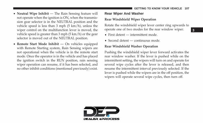
• Neutral Wipe Inhibit — The Rain Sensing feature willnot operate when the ignition is ON, when the transmis-sion gear selector is in the NEUTRAL position and thevehicle speed is less than 3 mph (5 km/h), unless thewiper control on the multifunction lever is moved, thevehicle speed is greater than 3 mph (5 km/h) or the gearselector is moved out of the NEUTRAL position.
• Remote Start Mode Inhibit — On vehicles equippedwith Remote Starting system, Rain Sensing wipers arenot operational when the vehicle is in the remote startmode. Once the operator is in the vehicle and has placedthe ignition switch in the RUN position, rain sensingwiper operation can resume, if it has been selected, andno other inhibit conditions (mentioned previously) exist.
Rear Wiper And Washer
Rear Windshield Wiper Operation
Rotate the windshield wiper lever center ring upwards tooperate one of two modes for the rear window wiper:
• First detent — intermittent mode.
• Second detent — continuous mode.
Rear Windshield Washer Operation
Pushing the windshield wiper lever forward activates therear window washer. If the lever is pushed while on theintermittent setting, the wipers will turn on and operate forseveral wipe cycles after the lever is released, and thenresume the intermittent interval previously selected. If thelever is pushed while the wipers are in the off position, thewipers will operate several wipe cycles, then turn off.
3
GETTING TO KNOW YOUR VEHICLE 107

CLIMATE CONTROLS
Manual Climate Controls Overview
Uconnect 4 With 7–inch Display Manual Climate Controls
108 GETTING TO KNOW YOUR VEHICLE

Uconnect 4/4C NAV With 8.4–inch Display Manual Climate Controls
3
GETTING TO KNOW YOUR VEHICLE 109

Manual Climate Control Descriptions
Icon DescriptionMAX A/C ButtonPress and release to change the current setting, the indicator illuminates when MAX A/C is ON.Performing this function again will cause the MAX A/C operation to switch into manual modeand the MAX A/C indicator will turn off.
NOTE:The MAX A/C setting is only available on the touchscreen.A/C ButtonPress and release to change the current setting, the indicator illuminates when A/C is ON.
Recirculation ButtonPress and release this button to change the system between recirculation mode and outside airmode. Recirculation can be used when outside conditions such as smoke, odors, dust, or highhumidity are present. Recirculation can be used in all modes except for Defrost. Recirculationmay be unavailable (button on the touchscreen greyed out) if conditions exist that could createfogging on the inside of the windshield. The A/C can be deselected manually without disturb-ing the mode control selection. Continuous use of the Recirculation mode may make the insideair stuffy and window fogging may occur. Extended use of this mode is not recommended.
110 GETTING TO KNOW YOUR VEHICLE

Icon DescriptionFront Defrost ButtonPress and release to change the current airflow setting to Defrost mode. The indicator illumi-nates when this feature is ON. Air comes from the windshield and side window demist outlets.When the defrost button is selected, the blower level may increase. Use Defrost mode withmaximum temperature settings for best windshield and side window defrosting and defogging.Performing this function will cause the ATC to switch into manual mode. If the front defrostmode is turned off the climate system will return the previous setting.Rear Defrost ButtonPush and release the Rear Defrost Control button to turn on the rear window defroster and theheated outside mirrors (if equipped). An indicator will illuminate when the rear window de-froster is on. The rear window defroster automatically turns off after ten minutes.
Rear Climate Rear Climate Control ButtonPress and release this button to access the rear climate controls. The indicator will illuminatewhen the rear climate controls are on.Driver and Passenger Temperature UP and DOWN ButtonsProvides the driver and passenger with independent temperature control. Push the red buttonon the faceplate or touchscreen or press and slide the temperature bar towards the red arrowbutton on the touchscreen for warmer temperature settings. Push the blue button on the face-plate or touchscreen or press and slide the temperature bar towards the blue arrow button onthe touchscreen for cooler temperature settings.
3
GETTING TO KNOW YOUR VEHICLE 111
Icon DescriptionSYNC ButtonPress the SYNC button on the touchscreen to toggle the Sync feature on/off. The SYNC indica-tor is illuminated when this feature is enabled. SYNC is used to synchronize the front and rearpassenger temperature settings with the driver temperature setting. Changing the front or rearpassenger temperature setting while in SYNC will automatically exit this feature.
NOTE: The SYNC setting is only available on the touchscreen.Blower ControlFaceplate Knob
TouchscreenButtons
Blower ControlBlower Control is used to regulate the amount of air forced through the climate system. Thereare seven blower speeds available. The speeds can be selected using either the blower controlknob on the faceplate or the buttons on the touchscreen.• Faceplate: The blower speed increases as you turn the blower control knob clockwise from
the lowest blower setting. The blower speed decreases as you turn the blower control knobcounterclockwise.
• Touchscreen: Use the small blower icon to reduce the blower setting and the large blowericon to increase the blower setting. Blower speed can also be selected by pressing the blowerbar area between the icons.
Modes ControlFaceplate Knob
Modes Control• Faceplate: Push the button in the center of the knob to change the airflow distribution
mode.• Touchscreen: Select Mode by pressing one of the Mode Buttons on the touchscreen. The
airflow distribution mode can be adjusted so air comes from the instrument panel outlets,floor outlets, defrost outlets and demist outlets. The Mode settings are as follows:
112 GETTING TO KNOW YOUR VEHICLE

Icon DescriptionPanel Mode Panel Mode
Air comes from the outlets in the instrument panel. Each of these outlets can be individuallyadjusted to direct the flow of air. The air vanes of the center outlets and outboard outlets can bemoved up and down or side to side to regulate airflow direction. There is a shut off wheel lo-cated below the air vanes to shut off or adjust the amount of airflow from these outlets.
Bi-Level Mode Bi-Level ModeAir comes from the instrument panel outlets and floor outlets. A slight amount of air is directedthrough the defrost and side window demister outlets.
NOTE:Bi-Level mode is designed under comfort conditions to provide cooler air out of the panel out-lets and warmer air from the floor outlets.
Floor Mode Floor ModeAir comes from the floor outlets. A slight amount of air is directed through the defrost and sidewindow demister outlets.
3
GETTING TO KNOW YOUR VEHICLE 113
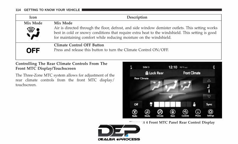
Icon DescriptionMix Mode Mix Mode
Air is directed through the floor, defrost, and side window demister outlets. This setting worksbest in cold or snowy conditions that require extra heat to the windshield. This setting is goodfor maintaining comfort while reducing moisture on the windshield.
Climate Control OFF ButtonPress and release this button to turn the Climate Control ON/OFF.
Controlling The Rear Climate Controls From TheFront MTC Display/Touchscreen
The Three-Zone MTC system allows for adjustment of therear climate controls from the front MTC display/touchscreen.
Uconnect 4 Front MTC Panel Rear Control Display
114 GETTING TO KNOW YOUR VEHICLE

To change the rear system settings:
• Press the �REAR CLIMATE� button on the touchscreento change control to rear control mode, Rear displayappears. Control functions now operate rear system.
• To return to the Front screen on the Uconnect system,press the �Front Climate� button on the touchscreen.
Icon DescriptionRear Lock ButtonPress and release to lock out the rear manual temperature controls from adjusting the rear tem-perature and blower settings.
Uconnect 4C/4C NAV Front MTC Panel Rear ControlDisplay
3
GETTING TO KNOW YOUR VEHICLE 115
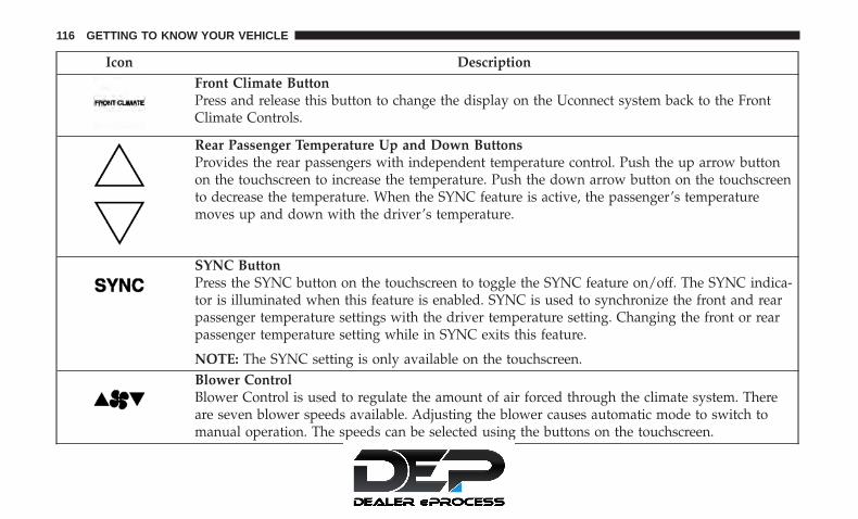
Icon DescriptionFront Climate ButtonPress and release this button to change the display on the Uconnect system back to the FrontClimate Controls.
Rear Passenger Temperature Up and Down ButtonsProvides the rear passengers with independent temperature control. Push the up arrow buttonon the touchscreen to increase the temperature. Push the down arrow button on the touchscreento decrease the temperature. When the SYNC feature is active, the passenger’s temperaturemoves up and down with the driver’s temperature.
SYNC ButtonPress the SYNC button on the touchscreen to toggle the SYNC feature on/off. The SYNC indica-tor is illuminated when this feature is enabled. SYNC is used to synchronize the front and rearpassenger temperature settings with the driver temperature setting. Changing the front or rearpassenger temperature setting while in SYNC exits this feature.
NOTE: The SYNC setting is only available on the touchscreen.Blower ControlBlower Control is used to regulate the amount of air forced through the climate system. Thereare seven blower speeds available. Adjusting the blower causes automatic mode to switch tomanual operation. The speeds can be selected using the buttons on the touchscreen.
116 GETTING TO KNOW YOUR VEHICLE

Icon DescriptionRear Passenger Climate Control OFF ButtonPress and release this button to turn the Rear Climate Controls off.
Panel Mode Panel ModePress this button on the touchscreen to change the air distribution mode to Panel Mode. InPanel Mode, air comes from the outlets in the instrument panel. Each of these outlets can beindividually adjusted to direct the flow of air. The air vanes of the center outlets and outboardoutlets can be moved up and down or side to side to regulate airflow direction. There is a shutoff wheel located below the air vanes to shut off or adjust the amount of airflow from these out-lets.
Bi-Level Mode Bi-Level ModePress this button on the touchscreen to change the air distribution mode to Bi-Level Mode. InBi-Level Mode, air comes from the instrument panel outlets and floor outlets. A slight amountof air is directed through the defrost and side window demister outlets.
NOTE: Bi-Level mode is designed under comfort conditions to provide cooler air out of thepanel outlets and warmer air from the floor outlets.
Floor Mode Floor ModePress this button on the touchscreen to change the air distribution mode to Floor Mode. In FloorMode, air comes from the floor outlets. A slight amount of air is directed through the defrostand side window demister outlets.
3
GETTING TO KNOW YOUR VEHICLE 117

Rear Manual Temperature Control
The rear MTC system has floor air outlets at the rear rightside of the 3rd Row seats and overhead outlets at eachoutboard rear seating position. The system provides heatedair through the floor outlets or cool, dehumidified airthrough the headliner outlets.
The rear system temperature control buttons are located onthe headliner on the passenger side of the vehicle.
Icon DescriptionRear Mode ControlPush this button on the Rear Climate Hard Controls to change the air distribution mode for therear passengers to one of the following:
Panel Mode Panel ModeAir comes from the outlets in the headliner. Each of these outlets can be individually adjusted todirect the flow of air. Moving the air vanes of the outlets to one side will shut off the airflow.
Rear Manual Climate Controls
118 GETTING TO KNOW YOUR VEHICLE

Icon DescriptionBi-Level Mode Bi-Level Mode
Air comes from both the headliner outlets and the floor outlets.
NOTE: In many temperature positions, the Bi-Level mode is designed to provide cooler air out ofthe headliner outlets and warmer air from the floor outlets.
Floor Mode Floor ModeAir comes from the floor outlets.
Rear Temperature Control• Rear Passenger Temperature Up Button To change the temperature in the rear of the vehicle,
push temperature control up button to raise the temperature. The rear temperature settingsare displayed in control head.
• Rear Passenger Temperature Down Button To change the temperature in the rear of thevehicle, push temperature control down button to lower the temperature. The rear tempera-ture settings are displayed in control head.
Rear Blower ControlsThe rear blower control can be manually set to off, or any fixed blower speed by pushing theblower control buttons. This allows the rear seat occupants to control the volume of air circulatedin the rear of the vehicle. The larger of the two icons increases blower speed, whereas the smallerof the two icons decreases the blower speed.
3
GETTING TO KNOW YOUR VEHICLE 119

Icon DescriptionRear Climate Control/Blower OffTo manually set the rear blower controls to off, press the Rear Climate Control/Blower Off button.
CAUTION!
Interior air enters the Rear Automatic TemperatureControl System through an intake grille, located infloor under the passengers’ seats. Do not block or placeobjects directly in front of the inlet grille or heateroutlets. The electrical system could overload causingdamage to the blower motor.
120 GETTING TO KNOW YOUR VEHICLE

Automatic Uconnect 4 Climate Control Overview
Uconnect 4 With 7–inch Display Automatic Temperature Controls
3
GETTING TO KNOW YOUR VEHICLE 121

Automatic Uconnect 4C/4C NAV Climate Control Overview
Uconnect 4C/4C With 8.4–inch Display NAV Automatic Climate Controls
122 GETTING TO KNOW YOUR VEHICLE

Automatic Climate Control Descriptions
Icon DescriptionMAX A/C ButtonPress and release to change the current setting, the indicator illuminates when MAX A/C is ON.Performing this function again will cause the MAX A/C operation to switch into manual modeand the MAX A/C indicator will turn off.
NOTE: The MAX A/C setting is only available on the touchscreen.A/C ButtonPress and release to change the current setting, the indicator illuminates when A/C is ON.
Recirculation ButtonPress and release this button to change the system between recirculation mode and outside air.Recirculation can be used when outside conditions such as smoke, odors, dust, or high humid-ity are present. Recirculation can be used in all modes. Recirculation may be unavailable (buttonon the touchscreen greyed out) if conditions exist that could create fogging on the inside of thewindshield. The A/C can be deselected manually without disturbing the mode control selection.Continuous use of Recirculation mode may make the inside air stuffy and window fogging mayoccur. Extended use of this mode if not recommended.
3
GETTING TO KNOW YOUR VEHICLE 123

Icon DescriptionAUTO ButtonAutomatically controls the interior cabin temperature by adjusting airflow distribution andamount. Performing this function will cause the system to switch between manual mode andautomatic modes. Refer to “Automatic Operation” within this section for more information.Front Defrost ButtonPress and release to change the current airflow setting to Defrost mode. The indicator illumi-nates when this feature is ON. Air comes from the windshield and side window demist outlets.When the defrost button is selected, the blower level may increase. Use Defrost mode withmaximum temperature settings for best windshield and side window defrosting and defogging.Performing this function will cause the ATC to switch into manual mode. If the front defrostmode is turned off the climate system will return the previous setting.Rear Defrost ButtonPush and release the Rear Defrost Control button to turn ON the rear window defroster and theheated outside mirrors (if equipped). An indicator will illuminate when the rear window de-froster is ON. The rear window defroster automatically turns OFF after ten minutes.
Rear Climate Rear Climate Control ButtonPress and release this button to access the rear climate controls. The indicator will illuminatewhen the rear climate controls are ON.
124 GETTING TO KNOW YOUR VEHICLE

Icon DescriptionDriver And Passenger Temperature UP And DOWN ButtonsProvides the driver and passenger with independent temperature control. Push the red buttonon the faceplate or touchscreen or press and slide the temperature bar towards the red arrowbutton on the touchscreen for warmer temperature settings. Push the blue button on the face-plate or touchscreen or press and slide the temperature bar towards the blue arrow button onthe touchscreen for cooler temperature settings.
SYNC ButtonPress the Sync button on the touchscreen to toggle the Sync feature On/Off. The Sync indicatoris illuminated when this feature is enabled. SYNC is used to synchronize the front and rear pas-senger temperature settings. Changing the front or rear passenger temperature setting while inSYNC will automatically exit this feature.
NOTE: The SYNC setting is only available on the touchscreen.Faceplate Knob
TouchscreenButtons
Blower ControlBlower Control is used to regulate the amount of air forced through the climate system. Thereare seven blower speeds available. The speeds can be selected using either the blower controlknob on the faceplate or the buttons on the touchscreen.• Faceplate: The blower speed increases as you turn the blower control knob clockwise from
the lowest blower setting. The blower speed decreases as you turn the blower control knobcounterclockwise.
• Touchscreen: Use the small blower icon to reduce the blower setting and the large blowericon to increase the blower setting. Blower speed can also be selected by pressing the blowerbar area between the icons.
3
GETTING TO KNOW YOUR VEHICLE 125

Icon DescriptionModes Control Modes Control
The airflow distribution mode can be adjusted so air comes from the instrument panel outlets,floor outlets, defrost outlets and demist outlets. The Mode settings are as follows:Faceplate: Push the button in the center of the knob to change the airflow distribution mode.Touchscreen: Select Mode by pressing one of the Mode Buttons on the touchscreen.
Panel Mode Panel ModeAir comes from the outlets in the instrument panel. Each of these outlets can be individuallyadjusted to direct the flow of air. The air vanes of the center outlets and outboard outlets can bemoved up and down or side to side to regulate airflow direction. There is a shut off wheel lo-cated below the air vanes to shut off or adjust the amount of airflow from these outlets.
Bi-Level Mode Bi-Level ModeAir comes from the instrument panel outlets and floor outlets. A slight amount of air is directedthrough the defrost and side window demister outlets.
NOTE:Bi-Level mode is designed under comfort conditions to provide cooler air out of the panel out-lets and warmer air from the floor outlets.
Floor Mode Floor ModeAir comes from the floor outlets. A slight amount of air is directed through the defrost and sidewindow demister outlets.
126 GETTING TO KNOW YOUR VEHICLE

Icon DescriptionMix Mode Mix Mode
Air is directed through the floor, defrost, and side window demister outlets. This setting worksbest in cold or snowy conditions that require extra heat to the windshield. This setting is goodfor maintaining comfort while reducing moisture on the windshield.
Climate Control OFF ButtonPress and release this button to turn the Climate Control ON/OFF.
Controlling The Rear Climate Controls From TheFront ATC Panel—If Equipped
The Three-Zone ATC system allows for adjustment of therear climate controls from the front ATC panel.
To change the rear system settings:
• Press the �REAR CLIMATE� button on the touchscreento change control to rear control mode, Rear displayappears. Control functions now operate rear system.
• To return to the Front screen on the Uconnect system,press the �Front Climate� or “Done” button on thetouchscreen.
Uconnect 4 Front ATC Panel Rear Control Display
3
GETTING TO KNOW YOUR VEHICLE 127

Icon DescriptionREAR AUTO Rear Auto Button
Automatically controls the rear interior cabin temperature by adjusting airflow distribution andamount. Performing this function causes the system to switch between manual mode and auto-matic modes. Refer to “Automatic Operation” within this section for more information.Rear Lock ButtonPress and release to lock out the rear manual temperature controls from adjusting the rear tem-perature and blower settings.
Uconnect 4C/4C NAV Front ATC Panel Rear ControlDisplay
128 GETTING TO KNOW YOUR VEHICLE

Icon DescriptionFront Climate ButtonPress and release this button to change the display on the Uconnect system back to the FrontClimate Controls.
Rear Passenger Temperature Up And Down ButtonsProvides the front occupants with the ability to control the rear temperature. Push the up arrowbutton on the touchscreen to increase the temperature. Push the down arrow button on thetouchscreen to decrease the temperature. When the SYNC feature is active, the passenger’s tem-perature will move up and down with the driver’s temperature.
SYNC ButtonPress the SYNC button on the touchscreen to toggle the SYNC feature on/off. The SYNC indica-tor is illuminated when this feature is enabled. SYNC is used to synchronize the front and rearpassenger temperature settings with the driver temperature setting. Changing the front or rearpassenger temperature/mode/blower settings while in SYNC will automatically exit this fea-ture.
NOTE: The SYNC setting is only available on the touchscreen.Blower ControlBlower Control is used to regulate the amount of air forced through the climate system. Thereare seven blower speeds available. Adjusting the blower causes automatic mode to switch tomanual operation. The speeds can be selected using the buttons on the touchscreen.
3
GETTING TO KNOW YOUR VEHICLE 129

Icon DescriptionRear Passenger Climate Control OFF ButtonPress and release this button to turn the Rear Climate Controls off.
Panel Mode Panel ModePress this button on the touchscreen to change the air distribution mode to Panel Mode. InPanel Mode, air comes from the outlets in the headliner. Each of these outlets can be individu-ally adjusted to direct the flow of air. Moving the air vanes of the outlets to one side will shutoff the airflow.
Bi-Level Mode Bi-Level ModePress this button on the touchscreen to change the air distribution mode to Bi-Level Mode. InBi-Level Mode, air comes from both the headliner outlets and the floor outlets.
NOTE: Bi-Level mode is designed under comfort conditions to provide cooler air out of thepanel outlets and warmer air from the floor outlets.
Floor Mode Floor ModePress this button on the touchscreen to change the air distribution mode to Floor Mode. In FloorMode, air comes from the floor outlets.
130 GETTING TO KNOW YOUR VEHICLE

Rear Automatic Temperature Control (ATC) — IfEquipped
The rear ATC system has floor air outlets underneath thepassengers’ seats, and overhead outlets at each outboardrear seating position. The system provides heated airthrough the floor outlets or cool, dehumidified air throughthe headliner outlets.
Rear second row occupants can only adjust the rear ATCcontrol when the Rear Temperature Lock button is turnedoff.
The rear ATC system is located in the headliner, on thepassenger side of the vehicle.
1. Adjust the rear blower, rear temperature and the rearmodes to suit your comfort needs.
2. ATC is selected by pushing the AUTO button.
Once the desired temperature is displayed, the ATC Systemwill automatically achieve and maintain that comfort level.When the system is set up for your comfort level, it is notnecessary to change the settings. You will experience
Rear Automatic Climate Controls
3
GETTING TO KNOW YOUR VEHICLE 131

the greatest efficiency by simply allowing the system tofunction automatically.
NOTE:
• It is not necessary to move the temperature settings. Thesystem automatically adjusts the temperature, mode andfan speed to provide comfort as quickly as possible.
Icon DescriptionRear Mode ControlPush this button on the Rear Climate Hard Controls to change the air distribution mode for therear passengers to one of the following:
Panel Mode Panel ModeAir comes from the outlets in the headliner. Each of these outlets can be individually adjusted todirect the flow of air. Moving the air vanes of the outlets to one side will shut off the airflow.
Bi-Level Mode Bi-Level ModeAir comes from both the headliner outlets and the floor outlets.
NOTE: In many temperature positions, the Bi-Level mode is designed to provide cooler air out ofthe headliner outlets and warmer air from the floor outlets.
132 GETTING TO KNOW YOUR VEHICLE

Icon DescriptionFloor Mode Floor Mode
Air comes from the floor outlets.
Rear Temperature Control• Rear Passenger Temperature Up Button To change the temperature in the rear of the vehicle,
push temperature control up button to raise the temperature. The rear temperature settings aredisplayed in control head.
• Rear Passenger Temperature Down Button To change the temperature in the rear of the ve-hicle, push temperature control down button to lower the temperature. The rear temperaturesettings are displayed in control head.
Rear Blower ControlThe rear blower control can be manually set to off, or any fixed blower speed by pushing theblower control buttons. This allows the rear seat occupants to control the volume of air circulatedin the rear of the vehicle. The larger of the two icons increases blower speed, whereas the smallerof the two icons decreases the blower speed.
3
GETTING TO KNOW YOUR VEHICLE 133

Icon DescriptionAUTO ButtonAutomatically controls the interior cabin temperature by adjusting airflow distribution andamount. Performing this function will cause the system to switch between manual mode and auto-matic modes.Refer to “Automatic Operation” within this section for more information.Rear Climate Control/Blower OffTo manually set the rear blower controls to off, press the Rear Climate Control/Blower Off button.
Climate Control Functions
Air Conditioning (A/C)
The Air Conditioning (A/C) button allows the operator tomanually activate or deactivate the air conditioning sys-tem. When in A/C mode with the ATC set to a cooltemperature, dehumidified air flows through the air out-lets. If Economy mode is desired, push the A/C button toturn off the A/C mode in the ATC display and deactivatethe A/C system.
NOTE:
• If the system is in Mix or Defrost Mode, the A/C can beturned off, but the A/C system shall remain active toprevent fogging of the windows.
• If not operating in AUTO mode, the system will notautomatically sense the presence of fog, mist or ice onthe windshield. Defrost Mode must be manually se-lected to clear the windshield and side glass.
• If fog or mist appears on the windshield or side glass,select Defrost Mode and adjust blower speed if needed.
134 GETTING TO KNOW YOUR VEHICLE

Recirculation For Automatic Temperature Control
When outside air contains smoke, odors, or high humidity,or if rapid cooling is desired, you may wish to recirculateinterior air by pressing the Recirculation control button.The recirculation indicator will illuminate when this buttonis selected. Press the button a second time to turn off theRecirculation mode and allow outside air into the vehicle.
NOTE: In cold weather, use of recirculation mode may leadto excessive window fogging. The recirculation featuremay be unavailable (button on the touchscreen greyed out)if conditions exist that could create fogging on the inside ofthe windshield. On systems with Manual Climate Controls,the Recirculation mode is not allowed in Defrost mode toimprove window clearing operation. Recirculation will bedisabled automatically if this mode is selected. Attemptingto use Recirculation while in this mode will cause the LEDin the control button to blink and then turn off.
Automatic Temperature Control (ATC) — IfEquipped
Automatic Operation
1. Push the AUTO button on the faceplate, or the AUTObutton on the touchscreen on the Automatic Tempera-ture Control (ATC) Panel.
2. Next, adjust the temperature you would like the systemto maintain by adjusting the driver and passengertemperature control buttons. Once the desired tempera-ture is displayed, the system will achieve and automati-cally maintain that comfort level.
3. When the system is set up for your comfort level, it isnot necessary to change the settings. You will experiencethe greatest efficiency by simply allowing the system tofunction automatically.
NOTE:
• It is not necessary to move the temperature settings forcold or hot vehicles. The system automatically adjuststhe temperature, mode, and blower speed to providecomfort as quickly as possible.
• The temperature can be displayed in U.S. or Metric unitsby selecting the US/Metric customer-programmable fea-ture. Refer to the “Uconnect Settings” in “Multimedia”for further information.
To provide you with maximum comfort in the Automaticmode during cold start-ups, the blower fan will remain onlow until the engine warms up. The blower will increase inspeed and transition into Auto mode.
3
GETTING TO KNOW YOUR VEHICLE 135

Manual Operation Override
This system offers a full complement of manual overridefeatures. The AUTO symbol in the front ATC display willbe turned off when the system is being used in the manualmode.
Operating Tips
NOTE: Refer to the chart at the end of this section forsuggested control settings for various weather conditions.
Summer Operation
The engine cooling system must be protected with ahigh-quality antifreeze coolant to provide proper corrosionprotection and to protect against engine overheating. OATcoolant (conforming to MS.90032) is recommended. Referto “Fluids And Lubricants” in “Technical Specifications”for proper coolant selection.
Winter Operation
To ensure the best possible heater and defroster perfor-mance, make sure the engine cooling system is functioningproperly and the proper amount, type, and concentrationof coolant is used. Refer to “Fluids And Lubricants” in“Technical Specifications” for proper coolant selection. Use
of the air Recirculation mode during Winter months is notrecommended, because it may cause window fogging.
Vacation/Storage
Before you store your vehicle, or keep it out of service (i.e.,vacation) for two weeks or more, run the air conditioningsystem at idle for about five minutes, in fresh air with theblower setting on high. This will ensure adequate systemlubrication to minimize the possibility of compressor dam-age when the system is started again.
Window Fogging
Vehicle windows tend to fog on the inside in mild, rainy,and/or humid weather. To clear the windows, select De-frost or Mix mode and increase the front blower speed. Donot use the Recirculation mode without A/C for longperiods, as fogging may occur.
CAUTION!
Failure to follow these cautions can cause damage tothe heating elements:• Use care when washing the inside of the rear win-
dow. Do not use abrasive window cleaners on the
(Continued)
136 GETTING TO KNOW YOUR VEHICLE

CAUTION! (Continued)interior surface of the window. Use a soft cloth and amild washing solution, wiping parallel to the heat-ing elements. Labels can be peeled off after soakingwith warm water.
• Do not use scrapers, sharp instruments, or abrasivewindow cleaners on the interior surface of the win-dow.
• Keep all objects a safe distance from the window.
Outside Air Intake
Make sure the air intake, located directly in front of thewindshield, is free of obstructions such as leaves. Leavescollected in the air intake may reduce airflow, and if theyenter the plenum, they could plug the water drains. Inwinter months, make sure the air intake is clear of ice,slush, and snow.
A/C Air Filter
The climate control system filters out dust and pollen fromthe air. Refer to an authorized dealer for filter replacementinstructions.
Operating Tips Chart
3
GETTING TO KNOW YOUR VEHICLE 137

WINDOWS
Power Windows
You can control either the front or rear windows usingcontrols located on the driver’s door trim panel.
The driver may lock out the rear power windows bypushing the bar control just below the power windowcontrols.
The controls will operate only when the ignition switch isin the ON/RUN or ACC position and during poweraccessory delay.
Driver’s Power Window Controls
1 — Front Driver And Passenger Window Controls2 — Rear Passenger Window Controls3 — Power Window Lockout Switch — If Equipped
138 GETTING TO KNOW YOUR VEHICLE

NOTE: Power Window controls will also remain active forup to 10 minutes after the ignition switch has been turnedto OFF, depending upon the accessory delay setting. Open-ing a front door will cancel this feature.
There is a single control on the front passenger’s door trimpanel which operates the passenger door window and a setof controls that lock and unlock all doors. The controls willoperate only when the ignition switch is in the ON/RUNor ACC position and during power accessory delay.
Auto Up Feature With Anti-Pinch Protection — IfEquipped
The front driver and front passenger controls may beequipped with an Auto Up feature. Lift the window controlfully upward to the second detent, release, and the windowwill go up automatically.
To stop the window from going all the way up during theAuto Up operation, push down on the control briefly.
To close the window part way, lift the window control tothe first detent and release when you want the window tostop.
NOTE:
• If the window runs into any obstacle during auto-closure, it will reverse direction and then go back down.Remove the obstacle and use the window control againto close the window.
• Any impact due to rough road conditions may triggerthe auto reverse function unexpectedly during auto-closure. If this happens, pull the control lightly to thefirst detent and hold to close window manually.
Front Passenger Power Door Controls
1 — Window Open/Close2 — Power Door Locks
3
GETTING TO KNOW YOUR VEHICLE 139

WARNING!
There is no anti-pinch protection when the window isalmost closed. To avoid personal injury be sure to clearyour arms, hands, fingers and all objects from thewindow path before closing.
Auto Up Reset — If Equipped
To reactivate the Auto Up feature, perform the followingsteps after vehicle power is restored:
1. Pull the window control up to close the window com-pletely and continue to hold the control up for anadditional two seconds after the window is closed.
2. Push the window control down firmly to the seconddetent to open the window completely and continue tohold the control down for an additional two secondsafter the window is fully open.
Sliding Side Door Power Window Control — IfEquipped
Second row passengers may open and close the slidingdoor window by a single control on the door handleassembly.
The controls will operate only when the ignition switch isin the ON/RUN or ACC position and during poweraccessory delay.
NOTE: The controls will not operate if the driver hasactivated the Power Window Lockout.
NOTE: The sliding door windows do not fully open,stopping several inches above the window sill.
Wind Buffeting
Wind buffeting can be described as the perception ofpressure on the ears or a helicopter-type sound in the ears.
Sliding Door Power Window Control
140 GETTING TO KNOW YOUR VEHICLE

Your vehicle may exhibit wind buffeting with the windowsdown, or the sunroof (if equipped) in certain open orpartially open positions. This is a normal occurrence andcan be minimized. If the rear windows are open andbuffeting occurs, open the front and rear windows togetherto minimize the buffeting. If the buffeting occurs with thesunroof open, adjust the sunroof opening to minimize thebuffeting.
PANORAMIC SUNROOF — IF EQUIPPED
The Panoramic Sunroof switch is located to the left be-tween the sun visors on the overhead console.
The Power Shade switch is located to the right between thesun visors on the overhead console.
WARNING!
• Never leave children unattended in a vehicle, or withaccess to an unlocked vehicle. Never leave the keyfob in or near the vehicle, or in a location accessibleto children. Do not leave the ignition of a vehicleequipped with Keyless Enter-N-Go in the ACC or
(Continued)
Panoramic Sunroof And Power Shade Switches
1 — Sunroof Switch2 — Power Shade Switch
3
GETTING TO KNOW YOUR VEHICLE 141

WARNING! (Continued)ON/RUN mode. Occupants, particularly unattendedchildren, can become entrapped by the power sun-roof while operating the power sunroof switch. Suchentrapment may result in serious injury or death.
• In a collision, there is a greater risk of being thrownfrom a vehicle with an open sunroof. You could alsobe seriously injured or killed. Always fasten yourseat belt properly and make sure all passengers arealso properly secured.
• Do not allow small children to operate the sunroof.Never allow your fingers, other body parts, or anyobject, to project through the sunroof opening. In-jury may result.
Opening Sunroof
Express Mode
Push the switch rearward and release it within one second.The sunroof will open automatically from any position andstop at the full open position. This is called “ExpressOpen.” During Express Open operation, any other actua-tion of the sunroof switch will stop the sunroof.
NOTE: If the sunshade is in the closed position when theopen switch is pushed, the sunshade will automaticallycycle to the halfway open position prior to the sunroofopening.
Manual Mode
Push and hold the switch rearward and the sunroof willopen to the full open position. Any release of the switchwill stop the movement. The sunroof will remain in apartially opened condition until the sunroof switch ispushed again.
Venting Sunroof — Express
Push and release the �Vent� button within one second andthe sunroof will open to the vent position. This is called“Express Vent”, and it will occur regardless of sunroofposition.
NOTE: If the sunshade is in the closed position when thevent switch is pushed, the sunshade will automaticallycycle to the halfway open position prior to the sunroofopening to the Vent position.
142 GETTING TO KNOW YOUR VEHICLE

Closing Sunroof
Express Mode
Push the switch forward and release it within one secondand the sunroof will close automatically from any position.The sunroof will close fully and stop automatically. This iscalled “Express Close.” During Express Close operation,any other actuation of the switch will stop the sunroof.
Manual Mode
To close the sunroof, push and hold the switch in theforward position. Any release of the switch will stop themovement and the sunroof will remain in a partially closedcondition until the sunroof switch is pushed again.
Wind Buffeting
Wind buffeting can be described as the perception ofpressure on the ears or a helicopter-type sound in the ears.Your vehicle may exhibit wind buffeting with the windowsdown, or the sunroof (if equipped) in certain open orpartially open positions. This is a normal occurrence andcan be minimized. If the buffeting occurs with the rearwindows open, open the front and rear windows togetherto minimize the buffeting. If the buffeting occurs with thesunroof open, adjust the sunroof opening to minimize thebuffeting or open any window.
Power Sun Shade — If Equipped
The sunshade has two programmed open positions: half-open and full-open. When opening the sunshade from theclosed position, the sunshade will always stop at thehalf-open position regardless of express or manual openoperation. The switch must be actuated again to continueto the full-open position.
Opening Power Shade — Express Mode
Push the sunshade switch rearward and release it withinone second and the sunshade will open to the half-openposition and stop automatically. Push and release theswitch again from the half-open position and the sunshadewill open to the full-open position and stop automatically.This is called “Express Open.” During Express open opera-tion, any movement of the sunshade switch will stop theshade.
Opening Power Shade — Manual Mode
Push and hold the sunshade switch rearward and theshade will open to the half-open position and stop auto-matically. Push and hold the sunshade switch rearwardagain and the shade will open automatically to the full-open position. Any release of the switch will stop the
3
GETTING TO KNOW YOUR VEHICLE 143

movement and the sunshade will remain in a partiallyopened condition until the switch is pushed again.
Closing Power Shade — Express Mode
Push the switch forward and release it within one secondand the shade will close automatically from any position. Ifthe sunroof is completely closed the shade will close fullyand stop automatically. This is called “Express Close”.During Express Close operation, any other actuation of theswitch will stop the shade.
NOTE: If the sunroof is open, the shade will close to thehalf-open position. Pushing the shade close button againwill automatically close both the sunroof and shade com-pletely.
Closing Power Shade — Manual Mode
To close the shade, push and hold the switch in the forwardposition. Any release of the switch will stop the movementand the shade will remain in a partially closed conditionuntil the switch is pushed again.
Pinch Protect Feature
This feature will detect an obstruction in the closing of thesunroof during the Express Close operation. If an obstruc-tion in the path of the sunroof is detected, the sunroof willautomatically retract. Remove the obstruction if this oc-curs.
NOTE: If three consecutive sunroof close attempts result inPinch Protect reversals, Pinch Protect will disable and thesunroof must be closed in Manual Mode.
Sunroof Maintenance
Use only a non-abrasive cleaner and a soft cloth to clean theglass panel.
Ignition Off Operation
The power sunroof switch will remain active for up toapproximately 10 minutes after the ignition switch isturned to the OFF/LOCK position. Opening either frontdoor will cancel this feature.
NOTE: Ignition Off time is programmable through theUconnect System. Refer to “Uconnect Settings” in “Multi-media” for further information.
144 GETTING TO KNOW YOUR VEHICLE

HOOD
Opening
The hood release lever (to open the primary latch) andsafety latch (to open the secondary latch) must be releasedto open the hood.
1. Pull the hood release lever located under the driver’sside of the instrument panel.
2. Move to the outside of the front of the vehicle.
3. Push the safety latch release lever toward the passengerside of the vehicle. The safety latch is located behind thecenter front edge of the hood.
4. Remove the support rod from the locking tab and insertit into the seat located on the underside of the hood.
NOTE:• Before lifting the hood, check that the wiper arms are not
in motion and not in the lifted position.• While lifting the hood, use both hands.• Vehicle must be at a stop and the transmission must be
in PARK.
Hood Release Lever
Safety Latch Release Lever Location
3
GETTING TO KNOW YOUR VEHICLE 145

Closing
1. Hold up the hood with one hand and with the otherhand remove the support rod from its seat and reinsertit into the locking tab.
2. Lower the hood to approximately 12 inches (30 cm) fromthe engine compartment and drop it. Make sure that thehood is completely closed.
WARNING!
Be sure the hood is fully latched before driving yourvehicle. If the hood is not fully latched, it could openwhen the vehicle is in motion and block your vision.Failure to follow this warning could result in seriousinjury or death.
CAUTION!
To prevent possible damage, do not slam the hood toclose it. Lower hood to approximately 12 inches (30 cm)and drop the hood to close. Make sure hood is fullyclosed for both latches. Never drive vehicle unlesshood is fully closed, with both latches engaged.
LIFTGATE
Opening
To Unlock/Enter The Liftgate
The liftgate may be released in several ways:
• Overhead console liftgate button
• Key fob
• Outside handle
Push the liftgate button on the key fob twice within fiveseconds to release the liftgate.
Unlock Liftgate Using Key Fob
146 GETTING TO KNOW YOUR VEHICLE

The key fob and the overhead console button will releasethe liftgate when the liftgate is locked. The outside handlerequires the liftgate to be unlocked. If the vehicle isequipped with Passive Entry, pulling the outside handlewill unlock and release the liftgate, with a valid PassiveEntry key fob within 5 ft (1.5 m) of the liftgate.
NOTE: If 1st Press of key fob Unlocks “All Doors” isprogrammed in Uconnect Settings, all doors will unlockwith a Passive Entry handle activation. If 1st Press of keyfob Unlocks “Driver Door” is programmed in Uconnect
Settings, the liftgate will only unlock with handle activa-tion. Refer to “Uconnect Settings” in “Multimedia” forfurther information.
Closing
To Close The Liftgate
Grasp the liftgate closing handle and initiate lowering theliftgate. Release the handle when the liftgate takes over theclosing effort.
To Lock The Vehicle
With a valid Passive Entry key fob within 5 ft (1.5 m) of theliftgate, pushing the passive entry lock button located tothe right of the outside handle will lock the vehicle.
WARNING!
• Driving with the liftgate open can allow poisonousexhaust gases into your vehicle. You and your pas-sengers could be injured by these fumes. Keep theliftgate closed when you are operating the vehicle.
• If you are required to drive with the liftgate open,make sure that all windows are closed, and theclimate control blower switch is set at high speed. Donot use the recirculation mode.
Unlock Liftgate Using Passive Entry
3
GETTING TO KNOW YOUR VEHICLE 147

Power Liftgate — If Equipped
The power liftgate may be opened or closed in severalways:
• Overhead console liftgate button
• Key fob
• Outside handle (opens liftgate only)
• Button just inside the liftgate on the upper left trim(when liftgate is open)
• Hands-Free Liftgate (opens liftgate only) — If Equipped
Using the above ways:
• When the liftgate is fully closed, the liftgate will open
• When the liftgate is fully open, the liftgate will close
• When the liftgate is moving, the liftgate will reverse
Push the Power Liftgate button on the Overhead Consoleto open or close the liftgate.
Push the liftgate button on the key fob twice within fiveseconds to open or close the liftgate.
The key fob and the overhead console button will operatethe liftgate when the liftgate is locked. The outside handlerequires the liftgate to be unlocked. If the vehicle isequipped with Passive Entry, depressing the touch pad onthe outside handle or Hands-Free Liftgate foot activation
Overhead Console Power Switches
1 — Liftgate2 — Right Sliding Door3 — Sliding Door Power Off4 — Left Sliding Door
148 GETTING TO KNOW YOUR VEHICLE
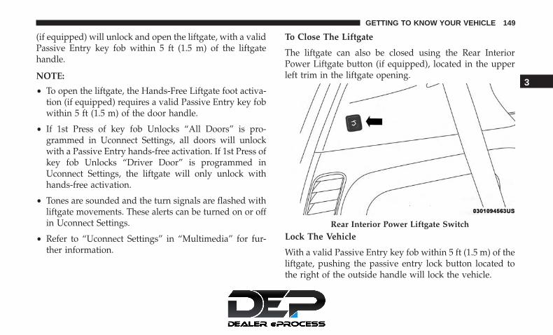
(if equipped) will unlock and open the liftgate, with a validPassive Entry key fob within 5 ft (1.5 m) of the liftgatehandle.
NOTE:
• To open the liftgate, the Hands-Free Liftgate foot activa-tion (if equipped) requires a valid Passive Entry key fobwithin 5 ft (1.5 m) of the door handle.
• If 1st Press of key fob Unlocks “All Doors” is pro-grammed in Uconnect Settings, all doors will unlockwith a Passive Entry hands-free activation. If 1st Press ofkey fob Unlocks “Driver Door” is programmed inUconnect Settings, the liftgate will only unlock withhands-free activation.
• Tones are sounded and the turn signals are flashed withliftgate movements. These alerts can be turned on or offin Uconnect Settings.
• Refer to “Uconnect Settings” in “Multimedia” for fur-ther information.
To Close The Liftgate
The liftgate can also be closed using the Rear InteriorPower Liftgate button (if equipped), located in the upperleft trim in the liftgate opening.
Lock The Vehicle
With a valid Passive Entry key fob within 5 ft (1.5 m) of theliftgate, pushing the passive entry lock button located tothe right of the outside handle will lock the vehicle.
Rear Interior Power Liftgate Switch
3
GETTING TO KNOW YOUR VEHICLE 149

Hands-Free Liftgate — If Equipped
To open the liftgate using hands-free activation, use astraight in and out kicking motion under the vehicleactivation zone in the general location below the liftgatedoor handle. Do not move your foot sideways or in asweeping motion or the sensors may not detect the motion.
Vehicles Equipped With A Trailer Tow Package
NOTE: If your vehicle is equipped with the Trailer TowPackage, the hands-free activation zone(s) for the PowerLiftgate will be located on the left and right side of thereceiver. Use a straight kicking motion under either activa-tion zone to open the Hands-Free Liftgate.
When a valid kicking motion is completed, the liftgate willchime, the hazard lights will flash and the liftgate will openafter approximately one second. This assumes all optionsare enabled in the radio.
Hands-Free Liftgate Activation Zone
Hands-Free Liftgate Trailer Tow Activation Zones
150 GETTING TO KNOW YOUR VEHICLE

NOTE: To open the Hands-Free Liftgate requires a validPassive Entry key fob within 5 ft (1.5 m) of the door handle.If a valid Passive Entry key fob is not within 5 ft (1.5 m), theliftgate will not respond to any kicks.
CAUTION!
The Hands-Free Liftgate feature may be turned on oroff in Uconnect Settings. Refer to “Uconnect Settings”in “Multimedia” for further information. The Hands-Free Liftgate feature should be turned off duringJacking, Tire Changing, and Vehicle Service.
NOTE:
• The Hands-Free Liftgate will only operate when thetransmission is in PARK.
• If anything obstructs the Hands-Free liftgate while it isopening or closing, the liftgate will automatically re-verse to the closed position, provided it meets sufficientresistance.
• There are pinch sensors attached to the side of theliftgate opening. Light pressure anywhere along thesestrips will cause the liftgate to return to the openposition.
• If the power liftgate encounters multiple obstructionswithin the same cycle, the system will automaticallystop. If this occurs, the liftgate must be operated manu-ally.
• The power liftgate will release, but not power open, intemperatures below −12° F (−24° C). Be sure to removeany buildup of snow or ice from the liftgate beforeopening the liftgate.
• If the liftgate is left open for an extended period of time,the liftgate may need to be closed manually to resetpower liftgate functionality.
WARNING!
• Driving with the liftgate open can allow poisonousexhaust gases into your vehicle. You and your pas-sengers could be injured by these fumes. Keep theliftgate closed when you are operating the vehicle.
• If you are required to drive with the liftgate open,make sure that all windows are closed, and theclimate control blower switch is set at high speed. Donot use the recirculation mode.
3
GETTING TO KNOW YOUR VEHICLE 151

Gas props support the liftgate in the open position. How-ever, because the gas pressure drops with temperature, itmay be necessary to assist the props when opening theliftgate in cold weather.
NOTE: Allow the power system to open the liftgate.Manually pushing or pulling the liftgate may activate theliftgate obstacle detection feature and stop the poweroperation or reverse its direction.
WARNING!
During power operation, personal injury or cargodamage may occur. Ensure the liftgate travel path isclear. Make sure the liftgate is closed and latchedbefore driving away.
Cargo Area Features
Cargo Area Storage
When the third row seats are not in the stowed position,there is a large area for cargo storage.
NOTE: With all rear seats stowed or removed, 4 x 8 ft (1.2x 2.4 m) sheets of building material will fit on the vehiclefloor with the liftgate closed. The front seats must bemoved slightly forward of the rearmost position.
Stow ‘n Vac Integrated Vacuum — If Equipped
Your vehicle may be equipped with an integrated vacuumsystem. This vacuum is for in-vehicle use only and shouldonly be used on dry materials and on in-vehicle surfaces. Itis located in the rear trim panel behind the sliding door onthe driver’s side of the vehicle.
Rear Cargo Area
152 GETTING TO KNOW YOUR VEHICLE

IMPORTANT SAFETY INSTRUCTIONS
Read all instructions before using. When using yourvacuum, basic precautions should be followed, includingthe following:
WARNING!
• Never leave children alone in a vehicle, or withaccess to an unlocked vehicle. Allowing children tobe in a vehicle unattended is dangerous for a numberof reasons. A child or others could be seriously orfatally injured. Children should be warned not totouch the parking brake, brake pedal or the gearselector.
• Do not leave the key fob in or near the vehicle, or ina location accessible to children, and do not leave theignition of a vehicle equipped with Keyless Enter-N-Go in either ACC mode or engine running (ON)unless you are using the vacuum system. Be aware achild could operate power windows, other controls,or move the vehicle when the vacuum system is inuse. ALWAYS push ignition button to place ignitionin the OFF mode when finished using the vacuumsystem.
WARNING!
To reduce the risk of fire, serious injury or death:• Do not use vacuum while vehicle is in motion or
while driving.
• Do not vacuum wet surfaces or any liquids.• Do not use to vacuum up anything outside of the
vehicle.• Do not vacuum any flammable liquids, such as
gasoline, or use around explosive vapors. Vaporsfrom flammable liquids may form an explosive mix-ture with air and can be ignited by heat, sparks, orflames. Vapors may travel to a source of ignition andexplode.
• Do not vacuum anything that is burning or smoking,such as cigarettes, matches, or hot ashes/embers.
(Continued)
3
GETTING TO KNOW YOUR VEHICLE 153

WARNING! (Continued)• Do not allow to be used as a toy. Close attention is
necessary when used by or near children.• Do not leave the vacuum running while unattended.• Use only as described in this manual. Use only
attachments provided with your vehicle.• Do not put any object into openings. Do not use with
any opening blocked; keep free of dust, lint, hair,and anything that may reduce air flow.
• Do not vacuum toxic material such as chlorinebleach, ammonia, drain cleaner, etc.
• Do not vacuum hard or sharp objects such as glass,nails, screws, coins, etc.
• Keep hair, loose clothing, fingers, and all parts ofbody away from openings and moving parts.
• Only use with filter in place. Periodically check thatthe filter is in place and in good condition.
WARNING!
This equipment incorporates parts such as switches,motors, or the like that tend to produce arcs or sparksthat can cause an explosion. When using your vacuum
(Continued)
WARNING! (Continued)near gasoline-dispensing equipment or service sta-tions, park vehicle at least 20 ft (6 m) away from theexterior enclosure of any dispensing pump. Thevacuum is mounted more than 18 inches (45 cm) aboveground level in your vehicle.
1. Before Using Vacuum:
Accessory (ACC) Mode Operation - For up to 10 minutesof operation
Always apply the parking brake, shift the transmission intoPARK, and push ignition button to place ignition inAccessory (ACC) mode. The engine will not be running inthis mode. Do not leave the key fob in or near the vehicle,or in a location accessible to children.
NOTE: The vacuum system will run for 10 minutes offbattery power and then the vacuum will shut down. A lowbattery indication light (LOW PWR) located below thevacuum nozzle storage location will come on one minutebefore the vacuum shuts down.
154 GETTING TO KNOW YOUR VEHICLE

Engine Running (ON) Operation - For more than 10minutes of operation
• Position vehicle outdoors and fully open all sidewindows.
• Always apply the parking brake, shift the transmissioninto PARK, and leave engine running.
WARNING!
Carbon monoxide (CO) in exhaust gases can causeserious injury or death. Follow the precautions belowto prevent carbon monoxide poisoning:• Do not inhale exhaust gases.• Do not start or run an engine in a closed garage or
confined area. Always position vehicle outdoors andfully open all side windows before using vacuumsystem with the engine running.
• Guard against carbon monoxide with proper main-tenance. Have the exhaust system inspected everytime the vehicle is raised. Have any abnormal condi-tions repaired promptly.
2. Unclip the vacuum nozzle and pull to extend vacuumhose from the storage location.
NOTE: The hose can reach every corner of the vehicle floor.
3. Install desired attachment if needed.
NOTE: To access crevice or upholstery attachments, openthe front Attachment Compartment.
• Crevice Tool — Able to reach into tight spaces includ-ing the seat latches located in the floor.
• Upholstery Tool — Use to agitate dirt and debris fromcarpets and seats. This tool can also be used to pick uppet hair.
Front Storage Compartments
1 — Vacuum Nozzle Storage Location2 — Attachment Compartment
3
GETTING TO KNOW YOUR VEHICLE 155

• Hose Extension — Use to add another 12 ft (3.6 m) ofusable length to the vacuum hose. Hose extension islocated in the upper access panel behind the third rowseat on the driver’s side.
4. Push vacuum On/Off button located under thevacuum nozzle storage location. Use vacuum asneeded.
NOTE:
• When the vacuum is ON, the LED indicator on theOn/Off button will illuminate.
• When the vacuum is OFF, the LED indicator will alsobe off.
• After nine minutes of operation in ACC mode (enginenot running), the Low Power Indicator Light (LOWPWR) will illuminate.
Power Buttons
1 — Low Power Indicator Light2 — On/Off Button
156 GETTING TO KNOW YOUR VEHICLE

WARNING!
For in vehicle use ONLY. To reduce the risk of fire,serious injury or death:• Do not use vacuum while vehicle is in motion or
while driving.
• Do not vacuum wet surfaces or any liquids.• Do not use to vacuum up anything outside of the
vehicle.• Do not vacuum any flammable liquids, such as gasoline,
or use around explosive vapors. Vapors from flammableliquids may form an explosive mixture with air and canbe ignited by heat, sparks, or flames. Vapors may travelto a source of ignition and explode.
• Do not vacuum anything that is burning or smoking,such as cigarettes, matches, or hot ashes/embers.
(Continued)
WARNING! (Continued)• Do not allow to be used as a toy. Close attention is
necessary when used by or near children.• Do not leave the vacuum running while unattended.• Use only as described in this manual. Use only
attachments provided with your vehicle.• Do not put any object into openings. Do not use with
any opening blocked; keep free of dust, lint, hair,and anything that may reduce air flow.
• Do not vacuum toxic material such as chlorinebleach, ammonia, drain cleaner, etc.
• Do not vacuum hard or sharp objects such as glass,nails, screws, coins, etc.
• Keep hair, loose clothing, fingers, and all parts ofbody away from openings and moving parts.
• Only use with filter in place. Periodically check thatthe filter is in place and in good condition.
WARNING!
This equipment incorporates parts such as switches,motors, or the like that tend to produce arcs or sparksthat can cause an explosion. When using your vacuum
(Continued)
3
GETTING TO KNOW YOUR VEHICLE 157

WARNING! (Continued)near gasoline-dispensing equipment or service sta-tions, park vehicle at least 20 ft (6 m) away from theexterior enclosure of any dispensing pump. Thevacuum is mounted more than 18 inches (45 cm) aboveground level in your vehicle.
5. When finished, push power button to turn vacuum offand store vacuum hose and any attachments.
6. Before exiting the vehicle:• If vehicle is in ACC mode, push ignition button to
place ignition in the OFF mode, remove key fob fromthe vehicle, and lock the vehicle.
• If the engine is running, raise all of the windows, pushignition button to place ignition in the OFF mode,remove key fob from the vehicle, close all of the doorsand the liftgate and lock the vehicle.
Vacuum Troubleshooting
• DO NOT use with any opening blocked. If an objectbecomes lodged in the hose, attempt to fully extend thehose in a straight line while the vacuum motor isrunning. If this does not dislodge the object, turn thevacuum OFF and remove the hose from the vehicle
following the removal instructions below. If the filter isclogged, follow the emptying debris bin procedure andlightly tap the filter on the collection bin to remove anycollected debris from the filter. Both the bin and the filtercan be rinsed with water if needed. To avoid mold andstale odors, allow both to dry completely before rein-stalling in your vehicle. If filter has tears, holes or otherdamage and needs to be replaced, please contact yourauthorized dealer.
• If there are any other issues with your vacuum, contactyour authorized dealer. Your vacuum has no user ser-viceable parts.
Debris Bin
The debris bin is located behind the lower access panelbehind the third row seat on the driver’s side.
To Empty
1. Push power button to turn vacuum OFF.
2. Open the lower access panel by pulling the finger griptowards you and then pull downward.
158 GETTING TO KNOW YOUR VEHICLE

3. Twist the release knob counterclockwise and pull the bintowards you.
4. Remove the filter and dump the debris in a trash can.Lightly tap the filter on the collection bin to removeloose debris from the filter. If the filter is clogged fromextended use, have the filter replaced by your autho-rized dealer.
5. Reverse the procedure to reinstall.
NOTE: The debris bin must be fully installed and lockedfor the vacuum to function properly.
Hose Access Port
The hose access port is located behind the upper accesspanel behind the third row seat on the driver’s side.
To Remove Vacuum Hose For Cleaning
1. Unclip the hose from the hose access port located in therear of the vehicle by pushing the yellow vacuum hoserelease lever with right thumb and lifting the hose withindex finger.
Debris Bin Release Knob
Vacuum System Access Panels
1 — Upper Access Panel2 — Lower Access Panel
3
GETTING TO KNOW YOUR VEHICLE 159

2. Return to vacuum nozzle storage location located be-hind the sliding door.
3. Grab the vacuum nozzle and gently pull the hose outthrough vacuum nozzle storage location.
4. Shake the hose to remove any objects stuck in the hose.Take care not to perforate the hose while attempting todislodge any objects.
5. Reverse the procedure to reinstall and clip the hose intoplace.
GARAGE DOOR OPENER — IF EQUIPPED
HomeLink replaces up to three hand-held transmitters thatoperate devices such as garage door openers, motorizedgates, lighting or home security systems. The HomeLinkunit is powered by your vehicle’s 12 Volt battery.
The HomeLink buttons, located on the driver’s sunvisor,designate the three different HomeLink channels. TheHomeLink indicator is located above the center button.
NOTE: HomeLink is disabled when the Vehicle SecurityAlarm is active.
Before You Begin Programming HomeLink
Be sure that your vehicle is parked outside of the garagebefore you begin programming.
For more efficient programming and accurate transmissionof the radio-frequency signal it is recommended that a newbattery be placed in the hand-held transmitter of the devicethat is being programmed to the HomeLink system.
HomeLink Buttons/Overhead Console
160 GETTING TO KNOW YOUR VEHICLE
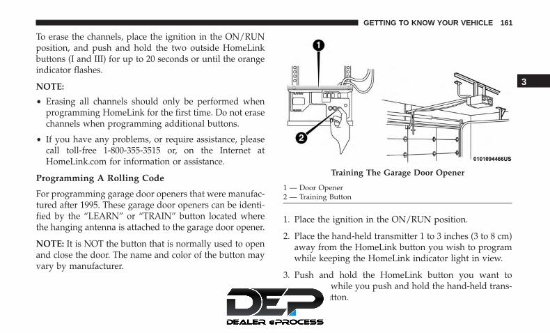
To erase the channels, place the ignition in the ON/RUNposition, and push and hold the two outside HomeLinkbuttons (I and III) for up to 20 seconds or until the orangeindicator flashes.
NOTE:
• Erasing all channels should only be performed whenprogramming HomeLink for the first time. Do not erasechannels when programming additional buttons.
• If you have any problems, or require assistance, pleasecall toll-free 1-800-355-3515 or, on the Internet atHomeLink.com for information or assistance.
Programming A Rolling Code
For programming garage door openers that were manufac-tured after 1995. These garage door openers can be identi-fied by the “LEARN” or “TRAIN” button located wherethe hanging antenna is attached to the garage door opener.
NOTE: It is NOT the button that is normally used to openand close the door. The name and color of the button mayvary by manufacturer.
1. Place the ignition in the ON/RUN position.
2. Place the hand-held transmitter 1 to 3 inches (3 to 8 cm)away from the HomeLink button you wish to programwhile keeping the HomeLink indicator light in view.
3. Push and hold the HomeLink button you want toprogram while you push and hold the hand-held trans-mitter button.
Training The Garage Door Opener
1 — Door Opener2 — Training Button
3
GETTING TO KNOW YOUR VEHICLE 161

4. Continue to hold both buttons and observe the indicatorlight. The HomeLink indicator will flash slowly andthen rapidly after HomeLink has received the frequencysignal from the hand-held transmitter. Release bothbuttons after the indicator light changes from slow torapid.
5. At the garage door opener motor (in the garage), locatethe “LEARN” or “TRAINING” button. This can usuallybe found where the hanging antenna wire is attached tothe garage door opener/device motor. Firmly push andrelease the “LEARN” or “TRAINING” button. On somegarage door openers/devices there may be a light thatblinks when the garage door opener/device is in theLEARN/TRAIN mode.
NOTE: You have 30 seconds in which to initiate the nextstep after the LEARN button has been pushed.
6. Return to the vehicle and push the programmedHomeLink button twice (holding the button for twoseconds each time). If the garage door opener/deviceactivates, programming is complete.
NOTE: If the garage door opener/device does not activate,push the button a third time (for two seconds) to completethe training.
To program the remaining two HomeLink buttons, repeateach step for each remaining button. DO NOT erase thechannels.
Reprogramming A Single HomeLink Button (RollingCode)
To reprogram a channel that has been previously trained,follow these steps:
1. Cycle the ignition to the ON/RUN position.
2. Push and hold the desired HomeLink button until theindicator light begins to flash after 20 seconds. Do notrelease the button.
3. Without releasing the button proceed with “Program-ming A Rolling Code” step 2 and follow all remainingsteps.�
Programming A Non-Rolling Code
For programming Garage Door Openers manufacturedbefore 1995.
1. Cycle the ignition to the ON/RUN position.
2. Place the hand-held transmitter 1 to 3 inches (3 to 8 cm)away from the HomeLink button you wish to programwhile keeping the HomeLink indicator light in view.
162 GETTING TO KNOW YOUR VEHICLE

3. Press and hold the HomeLink button you want toprogram while you press and hold the hand-held trans-mitter button.
4. Continue to hold both buttons and observe the indicatorlight. The HomeLink indicator will flash slowly andthen rapidly after HomeLink has received the frequencysignal from the hand-held transmitter. Release bothbuttons after the indicator light changes from slow torapid.
5. Press and hold the programmed HomeLink button andobserve the indicator light.• If the indicator light stays on constantly, programming
is complete and the garage door/device should acti-vate when the HomeLink button is pressed.
• To program the two remaining HomeLink buttons,repeat each step for each remaining button. DO NOTerase the channels.
Reprogramming A Single HomeLink Button (Non-Rolling Code)
To reprogram a channel that has been previously trained,follow these steps:
1. Cycle the ignition to the ON/RUN position.
2. Press and hold the desired HomeLink button until theindicator light begins to flash after 20 seconds. Do notrelease the button.
3. Without releasing the button, proceed with “Program-ming A Non-Rolling Code” step 2 and follow all remain-ing steps.
Canadian/Gate Operator Programming
For programming transmitters in Canada/United Statesthat require the transmitter signals to “time-out” afterseveral seconds of transmission.
Canadian radio frequency laws require transmitter signalsto time-out (or quit) after several seconds of transmission –which may not be long enough for HomeLink to pick upthe signal during programming. Similar to this Canadianlaw, some U.S. gate operators are designed to time-out inthe same manner.
It may be helpful to unplug the device during the cyclingprocess to prevent possible overheating of the garage dooror gate motor.
1. Cycle the ignition to the ON/RUN position.
3
GETTING TO KNOW YOUR VEHICLE 163
2. Place the hand-held transmitter 1 to 3 inches (3 to 8 cm)away from the HomeLink button you wish to programwhile keeping the HomeLink indicator light in view.
3. Continue to press and hold the HomeLink button, whileyou press and release (“cycle”) your hand-held trans-mitter every two seconds until HomeLink has success-fully accepted the frequency signal. The indicator lightwill flash slowly and then rapidly when fully trained.
4. Watch for the HomeLink indicator to change flash rates.When it changes, it is programmed. It may take up to 30seconds or longer in rare cases. The garage door mayopen and close while you are programming.
5. Press and hold the programmed HomeLink button andobserve the indicator light.
NOTE:
• If the indicator light stays on constantly, programmingis complete and the garage door/device should acti-vate when the HomeLink button is pressed.
• To program the two remaining HomeLink buttons,repeat each step for each remaining button. DO NOTerase the channels.
If you unplugged the garage door opener/device forprogramming, plug it back in at this time.
Reprogramming A Single HomeLink Button (Canadian/Gate Operator)
To reprogram a channel that has been previously trained,follow these steps:
1. Cycle the ignition to the ON/RUN position.
2. Press and hold the desired HomeLink button until theindicator light begins to flash after 20 seconds. Do notrelease the button.
3. Without releasing the button, proceed with “Canadian/Gate Operator Programming” step 2 and follow allremaining steps.
Using HomeLink
To operate, push and release the programmed HomeLinkbutton. Activation will now occur for the programmeddevice (i.e. garage door opener, gate operator, securitysystem, entry door lock, home/office lighting, etc.). Thehand-held transmitter of the device may also be used atany time.
164 GETTING TO KNOW YOUR VEHICLE

Security
It is advised to erase all channels before you sell or turn inyour vehicle.
To do this, push and hold the two outside buttons for 20seconds until the orange indicator flashes. Note that allchannels will be erased. Individual channels cannot beerased.
The HomeLink Universal Transceiver is disabled when theVehicle Security Alarm is active.
Troubleshooting Tips
If you are having trouble programming HomeLink, hereare some of the most common solutions:
• Replace the battery in the Garage Door Opener hand-held transmitter.
• Push the LEARN button on the Garage Door Opener tocomplete the training for a Rolling Code.
• Did you unplug the device for programming andremember to plug it back in?
If you have any problems, or require assistance, please calltoll-free 1-800-355-3515 or, on the Internet atHomeLink.com for information or assistance.
WARNING!
• Vehicle exhaust contains carbon monoxide, a danger-ous gas. Do not run your vehicle in the garage whileprogramming the transceiver. Exhaust gas can causeserious injury or death.
• Your motorized door or gate will open and closewhile you are programming the universal trans-ceiver. Do not program the transceiver if people, petsor other objects are in the path of the door or gate.Only use this transceiver with a garage door openerthat has a “stop and reverse” feature as required byFederal safety standards. This includes most garagedoor opener models manufactured after 1982. Do notuse a garage door opener without these safety fea-tures. Call toll-free 1-800-355-3515 or, on the Internetat HomeLink.com for safety information or assis-tance.
3
GETTING TO KNOW YOUR VEHICLE 165

General Information
The following regulatory statement applies to all RadioFrequency (RF) devices equipped in this vehicle:
This device complies with Part 15 of the FCC Rules andwith Innovation, Science and Economic DevelopmentCanada license-exempt RSS standard(s). Operation is sub-ject to the following two conditions:
1. This device may not cause harmful interference, and
2. This device must accept any interference received, in-cluding interference that may cause undesired opera-tion.
NOTE: Changes or modifications not expressly approvedby the party responsible for compliance could void theuser’s authority to operate the equipment.
INTERNAL EQUIPMENT
Storage
Glove Compartment
The glove compartment is located on the passenger side ofthe instrument panel.
To open the glove compartment, pull the release handle.
Release Handle
166 GETTING TO KNOW YOUR VEHICLE

Front Door Storage
Both interior front door panels have multiple pockets forstorage.
WARNING!
If containers of hot liquid are placed in the bottleholder, they can spill when the door is closed, burningthe occupants. Be careful when closing the doors toavoid injury.
Instrument Panel Drawer
There is a storage drawer located in the lower center of theinstrument panel. It can be released by pushing the accessbutton above it. The drawer is actuator assisted once theaccess button is pushed. Pull drawer outward to the fullyopen position.
Front Door Storage
Drawer Access Button
3
GETTING TO KNOW YOUR VEHICLE 167

CAUTION!
The storage drawer must be closed while driving. Ifleft open during a collision, additional damage mayoccur to property or the drawer mechanism.
Drawer Released Drawer Fully Open
168 GETTING TO KNOW YOUR VEHICLE

Front Seatback Storage — If Equipped
The front seatbacks have a storage pocket on some models.
Umbrella Holder
An umbrella holder has been conveniently molded into thefront door entry scuff moldings.
Front Seatback StorageUmbrella Holder
3
GETTING TO KNOW YOUR VEHICLE 169

Second Row Floor Storage Bins
The area below the load floor, located in front of the secondrow seats, is available for storage.
1. To access the storage bin with front seats in the rearwardposition, place the lock rod in the unlocked position sothe load floor can fold upwards towards the seatback.
NOTE:
• Push the lock rod inward for the locked position.
• Pull outward on the lock rod for the unlocked position.
In Floor Storage Location Lock Rod
170 GETTING TO KNOW YOUR VEHICLE

2. Pull the latch located near the second row seat to openthe floor panel.
WARNING!
In a collision, serious injury could result if the seatstorage bin covers are not properly latched.• Do not drive the vehicle with the storage bin covers
open.• Keep the storage bin covers closed and latched while
the vehicle is in motion.
(Continued)
WARNING! (Continued)• Do not operate the storage bin covers while the
vehicle is in motion.• Do not use a storage bin latch as a tie down.
CAUTION!
The storage bin cover must lay flat and be locked toavoid damage from contact with the front seat tracks,which have minimal clearance to the cover. If thestorage bin cover is left in the open position, front seatadjustment may damage the cover.
Storage Bin Safety Warning
Carefully follow these warnings to help prevent personalinjury or damage to your vehicle:
WARNING!
• Always close the storage bin covers when yourvehicle is unattended.
• Do not allow children to have access to the secondrow seat storage bins. Once in the storage bin, young
(Continued)
Floor Latch
3
GETTING TO KNOW YOUR VEHICLE 171

WARNING! (Continued)children may not be able to escape. If trapped in thestorage bin, children can die from suffocation or heatstroke.
• In a collision, serious injury could result if the seatstorage bin covers are not properly latched.
• Do not drive the vehicle with the storage bin coversopen. Keep the storage bin covers closed and latchedwhile the vehicle is in motion.
• Do not operate the storage bin covers while thevehicle is in motion.
• Do not use a storage bin latch as a tie down.
CAUTION!
The storage bin cover must lay flat and be locked toavoid damage from contact with the front seat tracks,which have minimal clearance to the cover. If thestorage bin cover is left in the open position, front seatadjustment may damage the cover.
Seat Storage Bin Cover Emergency Release Lever
As a security measure, the Seat Storage Bin Cover has anEmergency Release Lever built into the latching mecha-nism.
NOTE: In the event of an individual being locked insidethe storage bin, the storage bin cover can be opened frominside of the bin by pushing on the glow-in-the-dark leverattached to the storage bin cover latching mechanism.
Storage Bin Cover Emergency Release Lever
172 GETTING TO KNOW YOUR VEHICLE

Coat Hooks — If Equipped
Coat hooks are located along the headliner for the secondand third row seating positions. The coat hook load limit is10 lbs (4.5 kg). Exceeding the recommended load limit cancause the coat hooks to break or disengage from thevehicle.
Sun Screens — If Equipped
Sun screens are available for second and third row seatingwindows. The screens store in the sill trim panels, and thetops of the windows are equipped with hooks that the sunscreens attach to when pulled out.
Gently pull up on the tab to raise the sun screen. Continuepulling the sun screen until the tab is near the top of thewindow.
Coat HookSun Screen Retracted
3
GETTING TO KNOW YOUR VEHICLE 173

Once the screen is completely to the top of the window,extend the top bar of the sun screen over the two hooksattached to the top of the window.
To lower the sun screen, gently lift the tab upward todisengage the hooks, and feed the screen back into the basesill.
Power Outlets
Your vehicle is equipped with 12 Volt (15 Amp) poweroutlets, and 5 Volt (2.5 Amp) USB power outlets, that canbe used to power cellular phones, small electronics andother low powered electrical accessories. The power outletscan be labeled with either a “key” or a “battery” symbol toindicate how the outlet is powered. Power outlets labeledwith a “key” are powered when the ignition is in the ON orACC position, while the outlets labeled with a “battery”are connected directly to the battery and powered at alltimes.
NOTE:
• All accessories connected to the “battery” poweredoutlets should be removed or turned off when thevehicle is not in use to protect the battery againstdischarge.
CAUTION!
Power outlets are designed for accessory plugs only.Do not insert any other object in the power outlets asthis will damage the outlet and blow the fuse. Im-proper use of the power outlet can cause damage notcovered by your New Vehicle Limited Warranty.
Sun Screen Extended
174 GETTING TO KNOW YOUR VEHICLE

The front power outlet is located at the bottom of theinstrument panel.
In addition to the front power outlets, there is also a poweroutlet located in the rear cargo area.
The rear power outlet is located in the right rear cargo area.
12 Volt Front Power OutletRear Power Outlet
3
GETTING TO KNOW YOUR VEHICLE 175
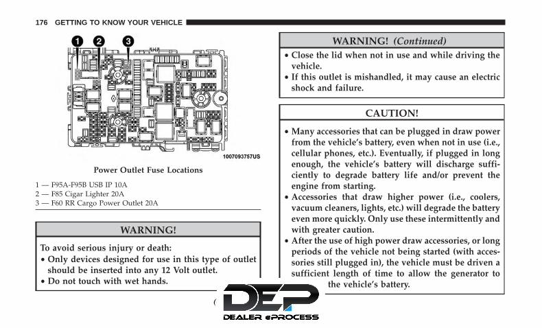
WARNING!
To avoid serious injury or death:• Only devices designed for use in this type of outlet
should be inserted into any 12 Volt outlet.• Do not touch with wet hands.
(Continued)
WARNING! (Continued)• Close the lid when not in use and while driving the
vehicle.• If this outlet is mishandled, it may cause an electric
shock and failure.
CAUTION!
• Many accessories that can be plugged in draw powerfrom the vehicle’s battery, even when not in use (i.e.,cellular phones, etc.). Eventually, if plugged in longenough, the vehicle’s battery will discharge suffi-ciently to degrade battery life and/or prevent theengine from starting.
• Accessories that draw higher power (i.e., coolers,vacuum cleaners, lights, etc.) will degrade the batteryeven more quickly. Only use these intermittently andwith greater caution.
• After the use of high power draw accessories, or longperiods of the vehicle not being started (with acces-sories still plugged in), the vehicle must be driven asufficient length of time to allow the generator torecharge the vehicle’s battery.
Power Outlet Fuse Locations
1 — F95A-F95B USB IP 10A2 — F85 Cigar Lighter 20A3 — F60 RR Cargo Power Outlet 20A
176 GETTING TO KNOW YOUR VEHICLE

Power Inverter — If Equipped
There is a 115 Volt, 150 Watt Power Inverter outlet locatedon the right side of the vehicle, before the third row of seatsto convert DC current to AC current. The Power Invertercan power cellular phones, electronics and other lowpower devices requiring up to 150 Watts. Certain high-endvideo game consoles will exceed this power limit, as willmost power tools.
The Power Inverter turns on when the device is plugged in,and the ignition is in RUN mode. It turns off when thedevice is unplugged or the ignition is no longer in RUNmode.
The Power Inverter is designed with built-in overloadprotection. If the power rating of 150 Watts is exceeded, thePower Inverter shuts down. Once the electrical device hasbeen removed from the Power Inverter, it resets. To avoidoverloading the circuit, check the power ratings on electri-cal devices prior to using the Power Inverter.
WARNING!
To avoid serious injury or death:• Do not insert any objects into the receptacles.• Do not touch with wet hands.• Close the lid when not in use.• If this outlet is mishandled, it may cause an electric
shock and failure.
Wireless Charging Pad — If Equipped
Your vehicle may be equipped with an Open Dots compat-ible wire-free phone charging surface located below theinstrument panel near the front power outlet. The wirelesscharger features continuous wireless charging during ve-hicle operation and allows for uninterrupted Bluetoothstreaming to properly equipped vehicle audio systems.
Power Inverter
3
GETTING TO KNOW YOUR VEHICLE 177

In order to enjoy the convenience of Open Dots wire-freecharging, you must obtain an aftermarket wireless-enabledcase and then install the case on your phone. Set the phoneon the wireless charging pad face up. The charging indi-cator on your phone will light up indicating that yourphone is charging.
NOTE: The charging pad is safe to the touch. However, ifmetallic items are placed on the charging surface while inuse, the device will turn off. Clean all spills immediatelyand allow to dry before using.
For phones that already have built-in wireless chargingcapability (Samsung, Apple iPhone 8, 8 Plus and XPhones), a Qi Adapter is available to charge your phoneusing the Open Dot wire-free phone charging surface.Simply place the Qi Adapter (dot side down) on thecharging surface and then place your built-in chargingcapable phone face up on top of the Qi Adapter. Thisproduct may not be compatible with all vehicle/Open Dotscompatible wire-free phone charging surface combina-tions.
CAUTION!
The key fob should not be placed on the charging pador within 15 cm (150 mm) of it. Doing so can causeexcessive heat buildup and damage to the fob. Placingthe fob in close proximity of the charging pad blocksthe fob from being detected by the vehicle and pre-vents the vehicle from starting.
To get your free aftermarket phone case or Qi Adapter, goto http://invehiclewirelesscharging.com. You will needyour vehicle/voucher identification number (located inyour vehicle’s glove box). If you have any questions or arenot sure if you need a phone case or the Qi Adapter, pleasecall our customer support line for assistance: 877–360–7702
Wireless Charging Pad
178 GETTING TO KNOW YOUR VEHICLE

Cigar Lighter — If Equipped
NOTE: Cigar lighters can be purchased at an authorizeddealer through Mopar parts.
The cigar lighter is located at the bottom of the instrumentpanel. Push lighter inward to heat.
After a few seconds, the lighter automatically returns to itsinitial position and is ready to be used.
WARNING!
When the cigar lighter is in use it becomes very hot. Toavoid serious injury, handle the cigar lighter with care.Always check that the cigar lighter has turned off.
CAUTION!
Do not connect devices with power higher than180 Watts (15 Amps) to the socket. Do not damage thesocket by using unsuitable adaptors. If the 180 Watt(15 Amp) power rating is exceeded the fuse protectingthe system will need to be replaced.
Smoker’s Package Kit — If Equipped
With the optional authorized dealer-installed Smoker’sPackage Kit, a removable ash receiver is inserted into oneof the two cupholders in the center floor console. To installthe ash receiver, align the receiver so the thumb grip on thelid is facing rearward. Push the ash receiver into either ofthe cup wells to secure. Pull upward on the ash receiver toremove for cleaning and/or storage.
The left rear trim panel cupholder is designed to accom-modate a second ash receiver, if desired.
3
GETTING TO KNOW YOUR VEHICLE 179

Overhead Sunglass Storage
At the front of the overhead console, a compartment isprovided for the storage of one pair of sunglasses.
From the closed position, push the intention to open thecompartment.
The door will slowly rotate to the full open position.
ROOF LUGGAGE RACK — IF EQUIPPED
The crossbars and side rails are designed to carry weighton vehicles equipped with a luggage rack. The load mustnot exceed 150 lbs (68 kg), and should be uniformlydistributed over the luggage rack crossbars.
The crossbars on your vehicle are delivered stowedwithin the roof rack side rails. Crossbars should always beused whenever cargo is placed on the roof rack. Check the
Overhead Sunglass Door Latch
Full Open Position
180 GETTING TO KNOW YOUR VEHICLE

straps frequently to be sure that the load remains securelyattached.
The roof rack does not increase the total load carryingcapacity of the vehicle. Be sure the total load of cargo insidethe vehicle plus that on the external rack does not exceedthe maximum vehicle load capacity.
Deploying The Crossbars
1. To deploy the crossbars, completely loosen the thumbscrews at both ends of the crossbar and lift the crossbarfrom its stowed position in the side rail. Repeat withcrossbar on the opposite side.
NOTE: The thumb screws cannot be fully removed.
Roof Rack
1 — Side Rail2 — Crossbar
Thumb Screw
3
GETTING TO KNOW YOUR VEHICLE 181
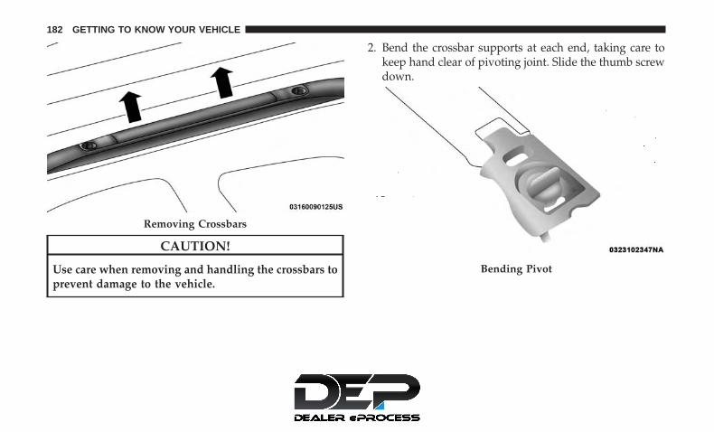
CAUTION!
Use care when removing and handling the crossbars toprevent damage to the vehicle.
2. Bend the crossbar supports at each end, taking care tokeep hand clear of pivoting joint. Slide the thumb screwdown.
Removing Crossbars
Bending Pivot
182 GETTING TO KNOW YOUR VEHICLE

3. Position the crossbars across the roof making sure theletters on the crossbars align with the matching letterson the side rail.
4. Once the crossbar is in place, tighten both thumb screwscompletely.
5. Deploy and tighten the second crossbar to complete thedeployment of the crossbars.
NOTE: The crossbars are not identical and have fixeddeployment positions. Rear crossbar can be deployed intwo different positions.
Stowing The Crossbars
1. Starting with one crossbar, completely loosen the thumbscrews at both ends. Lift the crossbar away from thematching letter to remove it from the deployed position.Repeat with the other crossbar.
Positioning Crossbars
Installing Crossbars
3
GETTING TO KNOW YOUR VEHICLE 183

CAUTION!
Use care when removing and handling the crossbars toprevent damage to the vehicle.
2. Starting with the one crossbar, bend up the pivotsupports at each end.
3. Then, position the crossbar along the correct side rail.Make sure the letters on the crossbar align with thematching letters on the side rail.
Crossbar Pivot
Stowing Crossbars
184 GETTING TO KNOW YOUR VEHICLE

4. The crossbar will nest fully within the side rail. 5. Once the driver’s side crossbar is in place, tighten thethumb screws completely.
Crossbar To Side RailTightening Crossbar
3
GETTING TO KNOW YOUR VEHICLE 185

6. Repeat the procedure to stow the second crossbar on theopposite side.
NOTE:
• To help control wind noise, stow the crossbars in the siderails when they are not in use.
• If any metallic object is placed over the satellite radioantenna (if equipped), you may experience interruptionof satellite radio reception.
WARNING!
Cargo must be securely tied down before driving yourvehicle. Improperly secured loads can fly off the ve-hicle, particularly at high speeds, resulting in personalinjury or property damage. Follow the roof rack cau-tions when carrying cargo on your roof rack.
CAUTION!
• To prevent damage to the roof of your vehicle, DONOT carry any loads on the roof rack without thecrossbars deployed. The load should be secured andplaced on top of the crossbars, not directly on theroof. If it is necessary to place the load on the roof,place a blanket or other protective layer between theload and the roof surface.
• To avoid damage to the roof rack and vehicle, do notexceed the maximum roof rack load capacity of 150 lb(68 kg). Always distribute heavy loads as evenly aspossible and secure the load appropriately.
• Load should always be secured to cross bars first,with tie down loops used as additional securing
(Continued)
Stowed Crossbars
186 GETTING TO KNOW YOUR VEHICLE

CAUTION! (Continued)points if needed. Tie loops are intended as supple-mentary tie down points only. Do not use ratchetingmechanisms with the tie loops. Check the straps andthumb wheels frequently to be sure that the loadremains securely attached.
• Long loads that extend over the windshield, such aswood panels or surfboards, or loads with largefrontal area should be secured to both the front andrear of the vehicle.
• Travel at reduced speeds and turn corners carefullywhen carrying large or heavy loads on the roof rack.Wind forces, due to natural causes or nearby trucktraffic, can add sudden upward lift to a load. This isespecially true on large flat loads and may result indamage to the cargo or your vehicle.
3
GETTING TO KNOW YOUR VEHICLE 187


GETTING TO KNOW YOUR INSTRUMENT PANEL
CONTENTS� INSTRUMENT CLUSTER . . . . . . . . . . . . . . . . . .190
▫ Instrument Cluster Descriptions . . . . . . . . . . . .191
� INSTRUMENT CLUSTER DISPLAY . . . . . . . . . . .192
▫ Instrument Cluster Display Location AndControls . . . . . . . . . . . . . . . . . . . . . . . . . . . . .193
▫ Oil Life Reset . . . . . . . . . . . . . . . . . . . . . . . . .194
▫ KeySense Cluster Messages — If Equipped. . . . .196
▫ Instrument Cluster Display Menu Items . . . . . .197
▫ Battery Saver On/Battery Saver Mode Message —Electrical Load Reduction Actions — IfEquipped . . . . . . . . . . . . . . . . . . . . . . . . . . . .202
� TRIP COMPUTER . . . . . . . . . . . . . . . . . . . . . . .204
� WARNING LIGHTS AND MESSAGES . . . . . . . . .204
▫ Red Warning Lights . . . . . . . . . . . . . . . . . . . . .205
▫ Yellow Warning Lights . . . . . . . . . . . . . . . . . . .209
▫ Yellow Indicator Lights . . . . . . . . . . . . . . . . . . .214
▫ Green Indicator Lights . . . . . . . . . . . . . . . . . . .214
▫ Blue Indicator Lights . . . . . . . . . . . . . . . . . . . .215
▫ White Indicator Lights . . . . . . . . . . . . . . . . . . .215
� ONBOARD DIAGNOSTIC SYSTEM — OBD II . . .216
▫ Onboard Diagnostic System (OBD II)Cybersecurity . . . . . . . . . . . . . . . . . . . . . . . . .216
� EMISSIONS INSPECTION AND MAINTENANCEPROGRAMS . . . . . . . . . . . . . . . . . . . . . . . . . . .217
4

INSTRUMENT CLUSTER
Base Instrument Cluster
190 GETTING TO KNOW YOUR INSTRUMENT PANEL

Instrument Cluster Descriptions
1. Tachometer• Indicates the engine speed in revolutions per minute
(RPM x 1000).
2. Instrument Cluster Display• When the appropriate conditions exist, this display
shows the instrument cluster display messages. Referto “Instrument Cluster Display” located in “Getting ToKnow Your Instrument Panel” for further information.
Premium Instrument Cluster
4
GETTING TO KNOW YOUR INSTRUMENT PANEL 191

3. Speedometer• Indicates vehicle speed.
4. Fuel Gauge• The gauge shows the level of fuel in the fuel tank when
the ignition switch is in the ON/RUN position.• The fuel pump symbol points to the side of the
vehicle where the fuel door is located.
5. Temperature Gauge• The temperature gauge shows engine coolant tem-
perature. Any reading within the normal range indi-cates that the engine cooling system is operatingsatisfactorily.
• The gauge can indicate a higher temperature whendriving in hot weather or up mountain grades. Itshould not be allowed to exceed the upper limits of thenormal operating range.
WARNING!
Driving with a hot engine cooling system could dam-age your vehicle. If the temperature gauge reaches “H”pull over and stop the vehicle. Idle the vehicle with theair conditioner turned off until the gauge drops back
(Continued)
WARNING! (Continued)into the normal range and is no longer red. If the gaugeremains on the “H”, turn the engine off immediatelyand call an authorized dealer for service.
WARNING!
A hot engine cooling system is dangerous. You orothers could be badly burned by steam or boilingcoolant. You may want to call an authorized dealer forservice if your vehicle overheats. If you decide to lookunder the hood yourself, see “Servicing And Mainte-nance”.
NOTE: The hard telltales will illuminate for a bulb checkwhen the ignition is first cycled.
INSTRUMENT CLUSTER DISPLAY
Your vehicle is equipped with an instrument cluster dis-play, which offers useful information to the driver. With theignition in the STOP/OFF position (and the key removed,for vehicles with mechanical key), opening/closing of adoor will activate the display for viewing, and display thetotal miles or kilometers in the odometer. Your instrument
192 GETTING TO KNOW YOUR INSTRUMENT PANEL

cluster display is designed to display important informa-tion about your vehicle’s systems and features. Using adriver interactive display located on the instrument panel,your instrument cluster display can show you how sys-tems are working and give you warnings when they arenot. The steering wheel mounted controls allow you toscroll through and enter the main menus and sub-menus.You can access the specific information you want and makeselections and adjustments.
Instrument Cluster Display Location And Controls
The vehicle’s instrument cluster is equipped with aninstrument cluster display (base or premium cluster),which offers useful information to the driver.
The instrument cluster display controls allows the driver toselect information by pushing the directional buttonsmounted on the steering wheel:
• Up Arrow Button
Push and release the up arrow button to scrollupward through the Main Menu items.
• Down Arrow Button
Push and release the down arrow button to scrolldownward through the Main Menu items.
Instrument Cluster Display Control Buttons
4
GETTING TO KNOW YOUR INSTRUMENT PANEL 193

• Right Arrow Button
Push and release the right arrow button to accessthe information screens or submenu screens of amain menu item.
• Back/Left Arrow Button
Push and release the left arrow button to accessthe information screens or submenu screens of amain menu item.
• OK Button
Push the OK button to access/select the informationscreens or submenu screens of a Main Menu item. Pushand hold the OK button for two seconds to resetdisplayed/selected features that can be reset.
The instrument cluster display (base/premium cluster)features a driver-interactive display that is located in thecenter of the instrument cluster, and may include thefollowing menu/submenu items:
• Speedometer
• Vehicle Info
• Driver Assist — If Equipped
• Fuel Economy
• Trip (Trip A/Trip B)
• Stop/Start — If Equipped
• Audio
• Messages
• Screen Setup
Oil Life Reset
• Your vehicle is equipped with an engine oil changeindicator system. The “Oil Change Required” messagewill display for approximately five seconds after a singlechime has sounded, to indicate the next scheduled oilchange interval. The engine oil change indicator systemis duty cycle based, which means the engine oil changeinterval may fluctuate, dependent upon your personaldriving style.
• Unless reset, this message will continue to display eachtime the ignition is cycled to the ON/RUN position.
• To reset the oil change indicator after performing thescheduled maintenance, refer to the following proce-dure.
194 GETTING TO KNOW YOUR INSTRUMENT PANEL

Oil Life Reset
Without pressing the brake pedal, push the ENGINESTART/STOP button and place the ignition in the ON/RUN position (do not start the vehicle.)
1. Push the OK button to enter the instrument clusterdisplay menu screen.
2. Push and release the down arrow button to access the”Oil Life” menu screen.
3. Push the left arrow button or right arrow button toaccess the “Vehicle Info” submenu.
4. Hold the OK button to reset the “Oil Life” to 100%.
5. Push the up arrow button to exit the instrument clusterdisplay menu screen.
Secondary Method For Oil Life Reset Procedure
1. Without pushing the brake pedal, place the ignition inthe ON/RUN position (do not start the engine).
2. Fully press the accelerator pedal, slowly, three timeswithin ten seconds.
3. Without pushing the brake pedal, place the ignition inthe OFF/LOCK position.
NOTE: If the indicator message illuminates when youstart the vehicle, the oil change indicator system did notreset. If necessary, repeat this procedure.
4
GETTING TO KNOW YOUR INSTRUMENT PANEL 195

KeySense Cluster Messages — If Equipped
When the KeySense key is in use there will be:
• Continuous, dedicated telltale
• Unique Display Splash Screen
With KeySense in use there will be multiple associatedmessages shown in the following table:
Setting Instrument Cluster Display MessageNone – With vehicle
ignition ON“KeySense in use. Max vehicle speed set to xx MPH/or km/h”
Max Vehicle Speed • “Max speed reached. KeySense in use” supported by a chime• “Approaching max speed xx MPH/km” supported by a chime
Start Up Fuel Alert message “Range to empty xxx miles or km”Early Low Fuel Alert Message “Fuel Low”
ParkSense “Feature cannot be disabled. KeySense in use”Blind Spot “Feature cannot be disabled. KeySense in use”
Forward Collision Warning “Feature cannot be disabled. KeySense in use”
196 GETTING TO KNOW YOUR INSTRUMENT PANEL

Instrument Cluster Display Menu Items
NOTE: The instrument cluster display menu items displayin the center of the instrument cluster. Menu items mayvary depending on your vehicle features.
Speedometer
Push and release the up or down arrow button untilSpeedometer is highlighted in the instrument cluster dis-play. Push and release the OK button to toggle betweenMPH and km/h.
Vehicle Info
Push and release the up or down arrow button untilVehicle Info is highlighted in the instrument cluster dis-play. Push the left or right arrow button to scroll throughthe following information submenus:
Tire Pressure
If tire pressure is OK for all tires, a vehicle ICON isdisplayed with tire pressure values in each corner of theICON.
If one or more tires have low pressure, “Inflate Tire To XX”is displayed with the vehicle ICON, and the tire pressure
values in each corner of the ICON with the pressure valueof the low tire displayed in a different color than the othertire pressure value.
If the Tire Pressure system requires service, “Service TirePressure System” is displayed.
Tire PSI is an information only function and cannot bereset. Refer to “Tire Pressure Monitoring System (TPMS)”under “Safety” for further information.
Coolant Temperature
Displays the actual coolant temperature.
Transmission Temperature
Displays the actual transmission temperature.
Oil Temperature
Displays the actual oil temperature.
Oil Pressure
Displays the actual oil pressure.
Battery Voltage
Displays the actual battery voltage.
4
GETTING TO KNOW YOUR INSTRUMENT PANEL 197

Engine Hours — If Equipped
Displays the number of hours of engine operation.
Oil Life
To reset the Oil Life, you must hold the OK button. The“Hold OK to Reset” instruction will be displayed at alltimes, but the following conditions will need to be met inorder to reset Oil Life:
• The vehicle must be off
• The ignition must be in the ON/RUN position
If the conditions are met, holding the OK button will resetthe gauge and the numeric display will return to 100%.
If the conditions are not met, a popup message will displayfor 5 seconds, describing the required conditions, and thenthe Oil Life screen will reappear.
Driver Assist
Push and release the up or down arrow button until theDriver Assist display icon is highlighted in the instrumentcluster display. Refer to “Adaptive Cruise Control (ACC)— If Equipped” in “Starting And Operating” for furtherinformation.
Fuel Economy
Push and release the up or down arrow button until theFuel Economy Menu item is highlighted in the instrumentcluster display. The Fuel Economy Menu will display thefollowing:
• Two sub menu pages that can be toggled between usingthe left and right arrow buttons; one with Current Valuedisplayed and one without the Current Value displayed:– Average Fuel Economy (MPG, L/100 km, or km/l)– Range To Empty (miles or km)– Current Fuel Economy (MPG, L/100 km, or km/l)– The Max and Min values will correspond to the
particular engine requirements
• Hold OK to reset average fuel economy information.
Trip Info
Push and release the up or down arrow button until theTrip Menu item is highlighted in the instrument clusterdisplay. Push the left or right arrow button to scrollthrough the Trip A and Trip B submenus. The Trip infor-mation will display the following:
• Distance
• Average Fuel Economy
198 GETTING TO KNOW YOUR INSTRUMENT PANEL
• Elapsed Time
Hold the OK button to reset feature information.
Stop/Start – If Equipped
Push and release the up or down arrow button until theStop/Start menu title is displayed in the instrument clusterdisplay.
Audio
Push and release the up or down arrow button until theAudio Menu displays in the instrument cluster display.
Messages
Push and release the up or down arrow button untilMessages is highlighted in the instrument cluster display.
This feature shows the number of stored warning mes-sages. Pushing the right arrow button will allow you to seewhat the stored messages are.
NOTE: The popup messages indicate the status of thesystem and/or the conditions that need to be met. Mes-sages remain in the stored stack until condition is cleared.
Screen Setup
Push and release the up or down arrow button until theScreen Setup Menu displays in the instrument clusterdisplay. Push and release the OK button to enter thesubmenus. The Screen Setup feature allows you to changewhat information is displayed in the instrument cluster aswell as the location that information is displayed.
Premium Instrument Cluster Display Screen Setup Options:1 — Lower Left • None
• Compass (Default)• Outside Temp.• Time• Range• Average/Current (MPG, L/100km, or km/L)• Trip A Distance• Trip B Distance
4
GETTING TO KNOW YOUR INSTRUMENT PANEL 199

Premium Instrument Cluster Display Screen Setup Options:2 — Center • None
• Compass• Outside Temp.• Time• Range• Average/Current (MPG, L/100km, or km/L)• Trip A Distance• Trip B Distance• Audio• Digital Speed• Menu Title (Default)
3 — Lower Right • None• Compass• Outside Temp. (Default)• Time• Range• Average/Current (MPG, L/100km, or km/L)• Trip A Distance• Trip B Distance
4 — Odometer (Premium Instrument Cluster) • Show — Default• Hide (Odometer will still appear when door is open)
5 — Defaults • Restore• Cancel
200 GETTING TO KNOW YOUR INSTRUMENT PANEL

Base Instrument Cluster Display Screen Setup Options:1 — Upper Left • None
• Compass (Default)• Outside Temp.• Time• Range• Average/Current (MPG, L/100km, or km/L)
2 — Upper Right • None• Compass• Outside Temp (Default)• Time• Range• Average/Current (MPG, L/100km, or km/L)
3 — Center • None• Compass• Outside Temp.• Time• Range• Average/Current (MPG, L/100km, or km/L)• Trip A Distance• Trip B Distance• Audio Menu Title• Menu Title (Default)• Digital Speed
4
GETTING TO KNOW YOUR INSTRUMENT PANEL 201

Base Instrument Cluster Display Screen Setup Options:4 — Defaults • Restore
• Cancel
Battery Saver On/Battery Saver Mode Message —Electrical Load Reduction Actions — If Equipped
This vehicle is equipped with an Intelligent Battery Sensor(IBS) to perform additional monitoring of the electricalsystem and status of the vehicle battery.
In cases when the IBS detects charging system failure, orthe vehicle battery conditions are deteriorating, electricalload reduction actions will take place to extend the drivingtime and distance of the vehicle. This is done by reducingpower to or turning off non-essential electrical loads.
Load reduction is only active when the engine is running.It will display a message if there is a risk of batterydepletion to the point where the vehicle may stall due tolack of electrical supply, or will not restart after the currentdrive cycle.
When load reduction is activated, the message “BatterySaver On” or “Battery Saver Mode” will appear in theinstrument cluster display.
These messages indicate the vehicle battery has a low stateof charge and continues to lose electrical charge at a ratethat the charging system cannot sustain.
NOTE:
• The charging system is independent from load reduc-tion. The charging system performs a diagnostic on thecharging system continuously.
• If the Battery Charge Warning Light is on it may indicatea problem with the charging system. Refer to “BatteryCharge Warning Light” in “Warning Lights And Mes-sages” located in ”Getting To Know Your InstrumentPanel” for further information.
The electrical loads that may be switched off (if equipped),and vehicle functions which can be effected by loadreduction:
• Heated Seat/Vented Seats/Heated Wheel
• Heated/Cooled Cup Holders — If Equipped
• Rear Defroster And Heated Mirrors
202 GETTING TO KNOW YOUR INSTRUMENT PANEL

• HVAC System
• 150W Power Inverter System
• Audio and Telematics System
Loss of the battery charge may indicate one or more of thefollowing conditions:
• The charging system cannot deliver enough electricalpower to the vehicle system because the electrical loadsare larger than the capability of charging system. Thecharging system is still functioning properly.
• Turning on all possible vehicle electrical loads (e.g.HVAC to max settings, exterior and interior lights,overloaded power outlets +12V, 150W, USB ports) dur-ing certain driving conditions (city driving, towing,frequent stopping).
• Installing options like additional lights, upfitter electri-cal accessories, audio systems, alarms and similar de-vices.
• Unusual driving cycles (short trips separated by longparking periods).
• The vehicle was parked for an extended period of time(weeks, months).
• The battery was recently replaced and was not chargedcompletely.
• The battery was discharged by an electrical load left onwhen the vehicle was parked.
• The battery was used for an extended period with theengine not running to supply radio, lights, chargers,+12V portable appliances like vacuum cleaners, gameconsoles and similar devices.
What to do when an electrical load reduction actionmessage is present (“Battery Saver On” or “Battery SaverMode”)
During a trip:
• Reduce power to unnecessary loads if possible:– Turn off redundant lights (interior or exterior)– Check what may be plugged in to power outlets +12V,
150W, USB ports– Check HVAC settings (blower, temperature)– Check the audio settings (volume)
4
GETTING TO KNOW YOUR INSTRUMENT PANEL 203

After a trip:
• Check if any aftermarket equipment was installed (ad-ditional lights, upfitter electrical accessories, audio sys-tems, alarms) and review specifications if any (load andIgnition Off Draw currents).
• Evaluate the latest driving cycles (distance, driving timeand parking time).
• The vehicle should have service performed if the mes-sage is still present during consecutive trips and theevaluation of the vehicle and driving pattern did nothelp to identify the cause.
TRIP COMPUTER
The Trip Computer is located in the instrument clusterdisplay. Push and release the up or down arrow buttonuntil “Trip Info” is highlighted in the instrument clusterdisplay. Push OK to enter the menu. Navigate between TripA or Trip B by using the right and left arrows.
For each trip the following information will be displayed:
Trip A
• Shows the total distance traveled for Trip A since the lastreset.
• Shows the Average MPG for Trip A since the last reset.
• Shows the elapsed time traveled for Trip A since the lastreset. Elapsed time will increment when the ignitionswitch is in the ON or START position.
Trip B
• Shows the total distance traveled for Trip B since the lastreset.
• Shows the Average MPG for Trip B since the last reset.
• Shows the elapsed time traveled for Trip B since the lastreset. Elapsed time will increment when the ignitionswitch is in the ON or START position.
To Reset A Trip Function
Push and hold the OK button to reset the currentlydisplayed trip.
WARNING LIGHTS AND MESSAGES
The warning/indicator lights will illuminate in the instru-ment panel together with a dedicated message and/oracoustic signal when applicable. These indications areindicative and precautionary and as such must not beconsidered as exhaustive and/or alternative to the infor-mation contained in the Owner’s Manual, which you are
204 GETTING TO KNOW YOUR INSTRUMENT PANEL

advised to read carefully in all cases. Always refer to theinformation in this chapter in the event of a failure indica-tion. All active telltales will display first if applicable. Thesystem check menu may appear different based uponequipment options and current vehicle status. Some tell-tales are optional and may not appear.
Red Warning Lights
— Air Bag Warning Light
This warning light will illuminate to indicate a fault withthe air bag, and will turn on for four to eight seconds as abulb check when the ignition is placed in the ON/RUN orACC/ON/RUN position. This light will illuminate with asingle chime when a fault with the air bag has beendetected, it will stay on until the fault is cleared. If the lightis either not on during startup, stays on, or turns on whiledriving, have the system inspected at an authorized dealeras soon as possible.
— Brake Warning Light
This warning light monitors various brake functions, in-cluding brake fluid level and parking brake application. Ifthe brake light turns on it may indicate that the parking
brake is applied, that the brake fluid level is low, or thatthere is a problem with the anti-lock brake system reser-voir.
If the light remains on when the parking brake has beendisengaged, and the fluid level is at the full mark on themaster cylinder reservoir, it indicates a possible brakehydraulic system malfunction or that a problem with theBrake Booster has been detected by the Anti-Lock BrakeSystem (ABS) / Electronic Stability Control (ESC) system.In this case, the light will remain on until the condition hasbeen corrected. If the problem is related to the brakebooster, the ABS pump will run when applying the brake,and a brake pedal pulsation may be felt during each stop.
The dual brake system provides a reserve braking capacityin the event of a failure to a portion of the hydraulicsystem. A leak in either half of the dual brake system isindicated by the Brake Warning Light, which will turn onwhen the brake fluid level in the master cylinder hasdropped below a specified level.
The light will remain on until the cause is corrected.
4
GETTING TO KNOW YOUR INSTRUMENT PANEL 205

NOTE: The light may flash momentarily during sharpcornering maneuvers, which change fluid level conditions.The vehicle should have service performed, and the brakefluid level checked.
If brake failure is indicated, immediate repair is necessary.
WARNING!
Driving a vehicle with the red brake light on isdangerous. Part of the brake system may have failed. Itwill take longer to stop the vehicle. You could have acollision. Have the vehicle checked immediately.
Vehicles equipped with the Anti-Lock Brake System (ABS)are also equipped with Electronic Brake Force Distribution(EBD). In the event of an EBD failure, the Brake WarningLight will turn on along with the ABS Light. Immediaterepair to the ABS system is required.
Operation of the Brake Warning Light can be checked byturning the ignition switch from the OFF position to theON/RUN position. The light should illuminate for ap-proximately two seconds. The light should then turn offunless the parking brake is applied or a brake fault isdetected. If the light does not illuminate, have the lightinspected by an authorized dealer.
The light also will turn on when the parking brake isapplied with the ignition switch in the ON/RUN position.
NOTE: This light shows only that the parking brake isapplied. It does not show the degree of brake application.
— Door Open Warning Light — If Equipped
This warning light will illuminate when a door is ajar/open and not fully closed. This indicator will reflect whichdoors are open.
NOTE: If the vehicle is moving, there will also be a singlechime.
— Electric Power Steering Fault Warning Light
This warning light will turn on when there’s a fault withthe EPS (Electric Power Steering) system. Refer to “PowerSteering” in “Starting And Operating” for further informa-tion.
WARNING!
Continued operation with reduced assist could pose asafety risk to yourself and others. Service should beobtained as soon as possible.
206 GETTING TO KNOW YOUR INSTRUMENT PANEL

— Electronic Throttle Control (ETC) WarningLight
This warning light will illuminate to indicate a problemwith the Electronic Throttle Control (ETC) system. If aproblem is detected while the vehicle is running, the lightwill either stay on or flash depending on the nature of theproblem. Cycle the ignition when the vehicle is safely andcompletely stopped and the transmission is placed in thePARK position. The light should turn off. If the lightremains on with the vehicle running, your vehicle willusually be drivable; however, see an authorized dealer forservice as soon as possible.
NOTE: This light may turn on if the accelerator and brakepedals are pressed at the same time.
If the light continues to flash when the vehicle is running,immediate service is required and you may experiencereduced performance, an elevated/rough idle, or enginestall and your vehicle may require towing. The light willcome on when the ignition is placed in the ON/RUN orACC/ON/RUN position and remain on briefly as a bulbcheck. If the light does not come on during starting, havethe system checked by an authorized dealer.
— Engine Coolant Temperature Warning Light
This warning light warns of an overheated engine condi-tion. If the engine coolant temperature is too high, thisindicator will illuminate and a single chime will sound. Ifthe temperature reaches the upper limit, a continuouschime will sound for four minutes or until the engine isable to cool: whichever comes first.
If the light turns on while driving, safely pull over and stopthe vehicle. If the A/C system is on, turn it off. Also, shiftthe transmission into NEUTRAL and idle the vehicle. If thetemperature reading does not return to normal, turn theengine off immediately and call for service.
Refer to “If Your Engine Overheats” in “In Case OfEmergency” for further information.
— Battery Charge Warning Light
This warning light will illuminate when the battery is notcharging properly. If it stays on while the engine is run-ning, there may be a malfunction with the charging system.Contact an authorized dealer as soon as possible.
This indicates a possible problem with the electrical systemor a related component.
4
GETTING TO KNOW YOUR INSTRUMENT PANEL 207

— Hood Open Warning Light
This warning light will illuminate when the hood is leftopen and not fully closed.
NOTE: If the vehicle is moving, there will also be a singlechime.
— Liftgate Open Warning Light
This warning light will illuminate when the liftgate is open.
NOTE: If the vehicle is moving, there will also be a singlechime.
— Seat Belt Reminder Warning Light
This warning light indicates when the driver or passengerseat belt is unbuckled. When the ignition is first placed inthe ON/RUN or ACC/ON/RUN position and if thedriver’s seat belt is unbuckled, a chime will sound and thelight will turn on. When driving, if the driver or frontpassenger seat belt remains unbuckled, the Seat Belt Re-minder Light will flash or remain on continuously and achime will sound.
Refer to “Occupant Restraint Systems” in “Safety” forfurther information.
— Transmission Temperature Warning Light — IfEquipped
This warning light will illuminate to warn of a hightransmission fluid temperature. This may occur withstrenuous usage such as trailer towing. If this light turnson, stop the vehicle and run the engine at idle or slightlyfaster, with the transmission in PARK or NEUTRAL, untilthe light turns off. Once the light turns off, you maycontinue to drive normally.
WARNING!
If you continue operating the vehicle when the Trans-mission Temperature Warning Light is illuminated youcould cause the fluid to boil over, come in contact withhot engine or exhaust components and cause a fire.
CAUTION!
Continuous driving with the Transmission Tempera-ture Warning Light illuminated will eventually causesevere transmission damage or transmission failure.
208 GETTING TO KNOW YOUR INSTRUMENT PANEL
— Vehicle Security Warning Light — If Equipped
This warning light will flash at a fast rate for approxi-mately 15 seconds when the vehicle security alarm isarming, and then will flash slowly until the vehicle isdisarmed.
— Oil Temperature Warning Light
This warning light will illuminate to indicate the engine oiltemperature is high. If the light turns on while driving,stop the vehicle and shut off the engine as soon as possible.Wait for oil temperature to return to normal levels.
— Oil Pressure Warning Light
This warning light will illuminate to indicate low engineoil pressure. If the light turns on while driving, stop thevehicle, shut off the engine as soon as possible, and contactan authorized dealer. A chime will sound when this lightturns on.
Do not operate the vehicle until the cause is corrected. Thislight does not indicate how much oil is in the engine. Theengine oil level must be checked under the hood.
Yellow Warning Lights
— Adaptive Cruise Control (ACC) Fault WarningLight — If Equipped
This warning light will illuminate to indicate a fault in theACC system. Contact a local authorized dealer for service.
For further information, refer to “Adaptive Cruise Control(ACC)” in “Starting And Operating.”
— Anti-Lock Brake (ABS) Warning Light
This warning light monitors the Anti-Lock Brake System(ABS). The light will turn on when the ignition is placed inthe ON/RUN or ACC/ON/RUN position and may stay onfor as long as four seconds.
If the ABS light remains on or turns on while driving, thenthe Anti-Lock portion of the brake system is not function-ing and service is required as soon as possible. However,the conventional brake system will continue to operatenormally, assuming the Brake Warning Light is not also on.
If the ABS light does not turn on when the ignition isplaced in the ON/RUN or ACC/ON/RUN position, havethe brake system inspected by an authorized dealer.
4
GETTING TO KNOW YOUR INSTRUMENT PANEL 209

— Electronic Park Brake Warning Light
This warning light will illuminate to indicate the ElectronicPark Brake is not functioning properly and service isrequired. Contact an authorized dealer.
— Electronic Stability Control (ESC) Off WarningLight — If Equipped
This warning light indicates the Electronic Stability Control(ESC) is off.
Each time the ignition is turned to ON/RUN or ACC/ON/RUN, the ESC system will be on, even if it was turned offpreviously.
— Electronic Stability Control (ESC) ActiveWarning Light — If Equipped
This warning light will indicate when the Electronic Sta-bility Control system is Active. The “ESC Indicator Light”in the instrument cluster will come on when the ignition isplaced in the ON/RUN or ACC/ON/RUN position, andwhen ESC is activated. It should go out with the enginerunning. If the “ESC Indicator Light” comes on continu-ously with the engine running, a malfunction has beendetected in the ESC system. If this warning light remainson after several ignition cycles, and the vehicle has beendriven several miles (kilometers) at speeds greater than
30 mph (48 km/h), see an authorized dealer as soon aspossible to have the problem diagnosed and corrected.
• The “ESC Off Indicator Light” and the “ESC IndicatorLight” come on momentarily each time the ignition isplaced in the ON/RUN or ACC/ON/RUN position.
• The ESC system will make buzzing or clicking soundswhen it is active. This is normal; the sounds will stopwhen ESC becomes inactive.
• This light will come on when the vehicle is in an ESCevent.
— Service LaneSense Warning Light — IfEquipped
This warning light will illuminate when the LaneSensesystem is not operating and requires service. Please see anauthorized dealer.
— LaneSense Warning Light — If Equipped
The LaneSense Warning Light will be solid yellow whenthe vehicle is approaching a lane marker. The warning lightwill flash when the vehicle is crossing the lane marker.
Refer to “LaneSense — If Equipped� in “Starting AndOperating” for further information.
210 GETTING TO KNOW YOUR INSTRUMENT PANEL

— Low Fuel Warning Light
When the fuel level reaches approximately 1.85 gal (7 L)this warning light will turn on, and remain on until fuel isadded.
A single warning chime will sound with Low Fuel Warn-ing.
— Low Washer Fluid Warning Light — IfEquipped
This warning light will illuminate when the windshieldwasher fluid is low.
— Engine Check/Malfunction Indicator WarningLight (MIL)
The Engine Check/Malfunction Indicator Light (MIL) is apart of an Onboard Diagnostic System called OBD II thatmonitors engine and automatic transmission control sys-tems. This warning light will illuminate when the ignitionis in the ON/RUN position before engine start. If the bulbdoes not come on when turning the ignition switch fromOFF to ON/RUN, have the condition checked promptly.
Certain conditions, such as a loose or missing gas cap, poorquality fuel, etc., may illuminate the light after engine start.The vehicle should be serviced if the light stays on through
several typical driving styles. In most situations, the ve-hicle will drive normally and will not require towing.
When the engine is running, the MIL may flash to alertserious conditions that could lead to immediate loss ofpower or severe catalytic converter damage. The vehicleshould be serviced by an authorized dealer as soon aspossible if this occurs.
WARNING!
A malfunctioning catalytic converter, as referencedabove, can reach higher temperatures than in normaloperating conditions. This can cause a fire if you driveslowly or park over flammable substances such as dryplants, wood, cardboard, etc. This could result in deathor serious injury to the driver, occupants or others.
CAUTION!
Prolonged driving with the Malfunction IndicatorLight (MIL) on could cause damage to the vehiclecontrol system. It also could affect fuel economy anddriveability. If the MIL is flashing, severe catalyticconverter damage and power loss will soon occur.Immediate service is required.
4
GETTING TO KNOW YOUR INSTRUMENT PANEL 211

— Service Forward Collision Warning (FCW)Light — If Equipped
This warning light will illuminate to indicate a fault in theForward Collision Warning System. Contact an authorizeddealer for service.
Refer to �Forward Collision Warning (FCW)� in �Safety� forfurther information.
— Service Stop/Start System Warning Light — IfEquipped
This warning light will illuminate when the Stop/Startsystem is not functioning properly and service is required.Contact an authorized dealer for service.
— Tire Pressure Monitoring System (TPMS)Warning Light
The warning light switches on and a message is displayedto indicate that the tire pressure is lower than the recom-mended value and/or that slow pressure loss is occurring.In these cases, optimal tire duration and fuel consumptionmay not be guaranteed.
Should one or more tires be in the condition mentionedabove, the display will show the indications correspondingto each tire.
CAUTION!
Do not continue driving with one or more flat tires ashandling may be compromised. Stop the vehicle,avoiding sharp braking and steering. If a tire punctureoccurs, repair immediately using the dedicated tirerepair kit and contact an authorized dealer as soon aspossible.
Each tire, including the spare (if provided), should bechecked monthly when cold and inflated to the inflationpressure recommended by the vehicle manufacturer on thevehicle placard or tire inflation pressure label. (If yourvehicle has tires of a different size than the size indicatedon the vehicle placard or tire inflation pressure label, youshould determine the proper tire inflation pressure forthose tires.)
As an added safety feature, your vehicle has beenequipped with a Tire Pressure Monitoring System (TPMS)that illuminates a low tire pressure telltale when one or
212 GETTING TO KNOW YOUR INSTRUMENT PANEL

more of your tires is significantly under-inflated. Accord-ingly, when the low tire pressure telltale illuminates, youshould stop and check your tires as soon as possible, andinflate them to the proper pressure. Driving on a signifi-cantly under-inflated tire causes the tire to overheat andcan lead to tire failure. Under-inflation also reduces fuelefficiency and tire tread life, and may affect the vehicle’shandling and stopping ability.
Please note that the TPMS is not a substitute for proper tiremaintenance, and it is the driver’s responsibility to main-tain correct tire pressure, even if under-inflation has notreached the level to trigger illumination of the TPMS lowtire pressure telltale.
Your vehicle has also been equipped with a TPMS malfunc-tion indicator to indicate when the system is not operatingproperly. The TPMS malfunction indicator is combinedwith the low tire pressure telltale. When the system detectsa malfunction, the telltale will flash for approximately oneminute and then remain continuously illuminated. Thissequence will continue upon subsequent vehicle start-upsas long as the malfunction exists. When the malfunctionindicator is illuminated, the system may not be able todetect or signal low tire pressure as intended. TPMSmalfunctions may occur for a variety of reasons, including
the installation of replacement or alternate tires or wheelson the vehicle that prevent the TPMS from functioningproperly. Always check the TPMS malfunction telltale afterreplacing one or more tires or wheels on your vehicle toensure that the replacement or alternate tires and wheelsallow the TPMS to continue to function properly.
CAUTION!
The TPMS has been optimized for the original equip-ment tires and wheels. TPMS pressures and warninghave been established for the tire size equipped onyour vehicle. Undesirable system operation or sensordamage may result when using replacement equip-ment that is not of the same size, type, and/or style.Aftermarket wheels can cause sensor damage. Usingaftermarket tire sealants may cause the Tire PressureMonitoring System (TPMS) sensor to become inoper-able. After using an aftermarket tire sealant it isrecommended that you take your vehicle to your au-thorized dealer to have your sensor function checked.
4
GETTING TO KNOW YOUR INSTRUMENT PANEL 213

Yellow Indicator Lights
— Forward Collision Warning Off Indicator Light— If Equipped
This indicator light illuminates to indicate that ForwardCollision Warning is off.
Green Indicator Lights
— Adaptive Cruise Control (ACC) Set WithTarget Vehicle Detected Light — If Equipped
This indicator light will illuminate when the AdaptiveCruise Control speed is SET and the target vehicle isdetected. Refer to �Adaptive Cruise Control (ACC) — IfEquipped� in �Starting And Operating� for further infor-mation.
— Adaptive Cruise Control (ACC) Set With NoTarget Detected Light — If Equipped
This indicator light will illuminate when the AdaptiveCruise Control speed is SET and there is no target vehicledetected. Refer to �Adaptive Cruise Control (ACC) — IfEquipped� in �Starting And Operating� for further infor-mation.
— Cruise Control Set Indicator Light — IfEquipped
This indicator light will illuminate when the cruise controlis set to the desired speed. Refer to “Speed Control” in“Starting And Operating” for further information.
— Front Fog Indicator Light — If Equipped
This indicator light will illuminate when the front foglights are on.
— KeySense Indicator Light — If Equipped
The KeySense indicator is illuminated when a KeySensekey is detected upon startup of the vehicle. The indicatorwill remain lit for the entire key cycle as a reminder that theKeySense key is in use. While the KeySense key is in use,the vehicle will respond to settings associated with theKeySense profile. Refer to “Keys� in “Getting to Know YourVehicle” for further information.
— LaneSense Indicator Light — If Equipped
The LaneSense indicator light illuminates solid green whenboth lane markings have been detected and the system is“armed” and ready to provide visual and torque warningsif an unintentional lane departure occurs.
214 GETTING TO KNOW YOUR INSTRUMENT PANEL

Refer to “LaneSense — If Equipped� in “Starting AndOperating” for further information.
— Stop/Start Active Indicator Light — IfEquipped
This indicator light will illuminate when the Stop/Startfunction is in “Autostop” mode.
— Park/Headlight On Indicator Light
This indicator light will illuminate when the park lights orheadlights are turned on.
— Turn Signal Indicator Lights
When the left or right turn signal is activated, the turnsignal indicator will flash independently and the corre-sponding exterior turn signal lamps will flash. Turn signalscan be activated when the multifunction lever is moveddown (left) or up (right).
NOTE:
• A continuous chime will sound if the vehicle is drivenmore than 1 mile (1.6 km) with either turn signal on.
• Check for an inoperative outside light bulb if eitherindicator flashes at a rapid rate.
Blue Indicator Lights
— High Beam Indicator Light
This indicator light will illuminate to indicate that the highbeam headlights are on. With the low beams activated,push the multifunction lever forward (toward the front ofthe vehicle) to turn on the high beams. Pull the multifunc-tion lever rearward (toward the rear of the vehicle) to turnoff the high beams. If the high beams are off, pull the levertoward you for a temporary high beam on, �flash to pass�scenario.
White Indicator Lights
— Adaptive Cruise Control (ACC) Ready Light —If Equipped
This indicator light will illuminate when the vehicleequipped with Adaptive Cruise Control (ACC) has beenturned on but not set. Refer to “Adaptive Cruise Control(ACC) — If Equipped” in “Starting And Operating” forfurther information.
— Cruise Control Ready Indicator
This indicator light will illuminate when the cruise controlis ready, but not set. Refer to “Speed Control” in “StartingAnd Operating” for further information.
4
GETTING TO KNOW YOUR INSTRUMENT PANEL 215

— LaneSense Indicator Light — If Equipped
When the LaneSense system is ON, but not armed, theLaneSense indicator light illuminates solid white. Thisoccurs when only left, right, or neither lane line has beendetected. If a single lane line is detected, the system isready to provide only visual warnings if an unintentionallane departure occurs on the detected lane line.
Refer to “LaneSense — If Equipped� in “Starting AndOperating” for further information.
— Set Speed Display
The Set Speed Display indicator light indicates the setspeed for the Speed Control and Adaptive Cruise Control(ACC) settings.
ONBOARD DIAGNOSTIC SYSTEM — OBD II
Your vehicle is equipped with a sophisticated OnboardDiagnostic system called OBD II. This system monitors theperformance of the emissions, engine, and automatic trans-mission control systems. When these systems are operatingproperly, your vehicle will provide excellent performanceand fuel economy, as well as emissions well within currentgovernment regulations.
If any of these systems require service, the OBD II systemwill turn on the Malfunction Indicator Light (MIL). It willalso store diagnostic codes and other information to assistyour service technician in making repairs. Although yourvehicle will usually be drivable and not need towing, seean authorized dealer for service as soon as possible.
CAUTION!
• Prolonged driving with the MIL on could causefurther damage to the emission control system. Itcould also affect fuel economy and driveability. Thevehicle must be serviced before any emissions testscan be performed.
• If the MIL is flashing while the vehicle is running,severe catalytic converter damage and power losswill soon occur. Immediate service is required.
Onboard Diagnostic System (OBD II) Cybersecurity
Your vehicle is required to have an Onboard Diagnosticsystem (OBD II) and a connection port to allow access toinformation related to the performance of your emissionscontrols. Authorized service technicians may need to ac-cess this information to assist with the diagnosis andservice of your vehicle and emissions system.
216 GETTING TO KNOW YOUR INSTRUMENT PANEL

WARNING!
• ONLY an authorized service technician should con-nect equipment to the OBD II connection port inorder to read the VIN, diagnose, or service yourvehicle.
• If unauthorized equipment is connected to theOBD II connection port, such as a driver-behaviortracking device, it may:• Be possible that vehicle systems, including safety
related systems, could be impaired or a loss ofvehicle control could occur that may result in anaccident involving serious injury or death.
• Access, or allow others to access, informationstored in your vehicle systems, including personalinformation.
For further information, refer to “Cybersecurity” in “Mul-timedia”.
EMISSIONS INSPECTION AND MAINTENANCEPROGRAMS
In some localities, it may be a legal requirement to pass aninspection of your vehicle’s emissions control system.Failure to pass could prevent vehicle registration.
For states that require an Inspection and Main-tenance (I/M), this check verifies the “Malfunc-tion Indicator Light (MIL)” is functioning and isnot on when the engine is running, and that the
OBD II system is ready for testing.
Normally, the OBD II system will be ready. The OBD IIsystem may not be ready if your vehicle was recentlyserviced, recently had a dead battery or a battery replace-ment. If the OBD II system should be determined not readyfor the I/M test, your vehicle may fail the test.
Your vehicle has a simple ignition actuated test, which youcan use prior to going to the test station. To check if yourvehicle’s OBD II system is ready, you must do the following:
1. Cycle the ignition switch to the ON position, but do notcrank or start the engine.
NOTE: If you crank or start the engine, you will have tostart this test over.
4
GETTING TO KNOW YOUR INSTRUMENT PANEL 217

2. As soon as you cycle the ignition switch to the ONposition, you will see the “Malfunction Indicator Light(MIL)” symbol come on as part of a normal bulb check.
3. Approximately 15 seconds later, one of two things willhappen:
• The MIL will flash for about ten seconds and then returnto being fully illuminated until you turn OFF the igni-tion or start the engine. This means that your vehicle’sOBD II system is not ready and you should not proceedto the I/M station.
• The MIL will not flash at all and will remain fullyilluminated until you place the ignition in the off posi-tion or start the engine. This means that your vehicle’sOBD II system is ready and you can proceed to the I/Mstation.
If your OBD II system is not ready, you should see anauthorized dealer or repair facility. If your vehicle wasrecently serviced or had a battery failure or replacement,you may need to do nothing more than drive your vehicleas you normally would in order for your OBD II system toupdate. A recheck with the above test routine may thenindicate that the system is now ready.
Regardless of whether your vehicle’s OBD II system isready or not, if the MIL is illuminated during normalvehicle operation you should have your vehicle servicedbefore going to the I/M station. The I/M station can failyour vehicle because the MIL is on with the enginerunning.
218 GETTING TO KNOW YOUR INSTRUMENT PANEL

SAFETY
CONTENTS� SAFETY FEATURES . . . . . . . . . . . . . . . . . . . . . .220
▫ Anti-Lock Brake System (ABS) . . . . . . . . . . . . .220
▫ Electronic Brake Control System . . . . . . . . . . . .221
� AUXILIARY DRIVING SYSTEMS . . . . . . . . . . . . .229
▫ Blind Spot Monitoring (BSM) — If Equipped . . .229
▫ Forward Collision Warning (FCW) With Mitigation— If Equipped . . . . . . . . . . . . . . . . . . . . . . . .237
▫ Tire Pressure Monitor System (TPMS) . . . . . . . .241
� OCCUPANT RESTRAINT SYSTEMS . . . . . . . . . .246
▫ Occupant Restraint Systems Features . . . . . . . .246
▫ Important Safety Precautions . . . . . . . . . . . . . .246
▫ Seat Belt Systems . . . . . . . . . . . . . . . . . . . . . .247
▫ Supplemental Restraint Systems (SRS) . . . . . . . .263
▫ Child Restraints . . . . . . . . . . . . . . . . . . . . . . .283
▫ Transporting Pets . . . . . . . . . . . . . . . . . . . . . .311
� SAFETY TIPS . . . . . . . . . . . . . . . . . . . . . . . . . . .311
▫ Transporting Passengers . . . . . . . . . . . . . . . . . .311
▫ Exhaust Gas . . . . . . . . . . . . . . . . . . . . . . . . . .312
▫ Safety Checks You Should Make Inside TheVehicle . . . . . . . . . . . . . . . . . . . . . . . . . . . . . .312
▫ Periodic Safety Checks You Should Make OutsideThe Vehicle . . . . . . . . . . . . . . . . . . . . . . . . . . .315
5

SAFETY FEATURES
Anti-Lock Brake System (ABS)
The Anti-Lock Brake System (ABS) provides increasedvehicle stability and brake performance under most brak-ing conditions. The system automatically prevents wheellock, and enhances vehicle control during braking.
The ABS performs a self-check cycle to ensure that the ABSis working properly each time the vehicle is started anddriven. During this self-check, you may hear a slightclicking sound as well as some related motor noises.
ABS is activated during braking when the system detectsone or more wheels begin to lock. Road conditions such asice, snow, gravel, bumps, railroad tracks, loose debris, orpanic stops may increase the likelihood of ABS activa-tion(s).
You also may experience the following when ABS activates:
• The ABS motor noise (it may continue to run for a shorttime after the stop).
• The clicking sound of solenoid valves.
• Brake pedal pulsations.
• A slight drop of the brake pedal at the end of the stop.
These are all normal characteristics of ABS.
WARNING!
• The ABS contains sophisticated electronic equip-ment that may be susceptible to interference causedby improperly installed or high output radio trans-mitting equipment. This interference can cause pos-sible loss of anti-lock braking capability. Installationof such equipment should be performed by qualifiedprofessionals.
• Pumping of the Anti-Lock Brakes will diminish theireffectiveness and may lead to a collision. Pumpingmakes the stopping distance longer. Just press firmlyon your brake pedal when you need to slow down orstop.
• The ABS cannot prevent the natural laws of physicsfrom acting on the vehicle, nor can it increase brak-ing or steering efficiency beyond that afforded by thecondition of the vehicle brakes and tires or thetraction afforded.
• The ABS cannot prevent collisions, including thoseresulting from excessive speed in turns, followinganother vehicle too closely, or hydroplaning.
(Continued)
220 SAFETY

WARNING! (Continued)• The capabilities of an ABS equipped vehicle must
never be exploited in a reckless or dangerous mannerthat could jeopardize the user’s safety or the safety ofothers.
ABS is designed to function with the OEM tires. Modifica-tion may result in degraded ABS performance.
Anti-Lock Brake Warning Light
The yellow “Anti-Lock Brake Warning Light” will turn onwhen the ignition is turned to the ON/RUN mode andmay stay on for as long as four seconds.
If the “Anti-Lock Brake Warning Light” remains on orcomes on while driving, it indicates that the anti-lockportion of the brake system is not functioning and thatservice is required. However, the conventional brake sys-tem will continue to operate normally if the “Anti-LockBrake Warning Light” is on.
If the “Anti-Lock Brake Warning Light” is on, the brakesystem should be serviced as soon as possible to restore the
benefits of anti-lock brakes. If the “Anti-Lock Brake Warn-ing Light” does not come on when the ignition is turned tothe ON/RUN mode, have the light repaired as soon aspossible.
Electronic Brake Control System
Your vehicle is equipped with an advanced ElectronicBrake Control system (EBC). This system includes Elec-tronic Brake Force Distribution (EBD), Anti-Lock BrakeSystem (ABS), Brake Assist System (BAS), Hill Start Assist(HSA), Traction Control System (TCS), Electronic StabilityControl (ESC), and Electronic Roll Mitigation (ERM). Thesesystems work together to enhance both vehicle stabilityand control in various driving conditions.
Your vehicle may also be equipped with Ready AlertBraking (RAB), Rain Brake Support (RBS), Trailer SwayControl (TSC), and Dynamic Steering Torque (DST).
Traction Control System (TCS)
This system monitors the amount of wheel spin of each ofthe driven wheels. If wheel spin is detected, the TCS mayapply brake pressure to the spinning wheel(s) and/orreduce vehicle power to provide enhanced accelerationand stability. A feature of the TCS, Brake Limited Differen-tial (BLD), functions similar to a limited slip differential
5
SAFETY 221

and controls the wheel spin across a driven axle. If onewheel on a driven axle is spinning faster than the other, thesystem will apply the brake of the spinning wheel. Thiswill allow more vehicle torque to be applied to the wheelthat is not spinning. BLD may remain enabled even if TCSand ESC are in a reduced mode.
Brake Assist System (BAS)
The BAS is designed to optimize the vehicle’s brakingcapability during emergency braking maneuvers. The sys-tem detects an emergency braking situation by sensing therate and amount of brake application and then appliesoptimum pressure to the brakes. This can help reducebraking distances. The BAS complements the anti-lockbrake system (ABS). Applying the brakes very quicklyresults in the best BAS assistance. To receive the benefit ofthe system, you must apply continuous braking pressureduring the stopping sequence, (do not “pump” the brakes).Do not reduce brake pedal pressure unless braking is nolonger desired. Once the brake pedal is released, the BAS isdeactivated.
WARNING!
The Brake Assist System (BAS) cannot prevent thenatural laws of physics from acting on the vehicle, norcan it increase the traction afforded by prevailing roadconditions. BAS cannot prevent collisions, includingthose resulting from excessive speed in turns, drivingon very slippery surfaces, or hydroplaning. The capa-bilities of a BAS-equipped vehicle must never beexploited in a reckless or dangerous manner, whichcould jeopardize the user’s safety or the safety ofothers.
Brake System Warning Light
The red “Brake System Warning Light” will turn on whenthe ignition is turned to the ON/RUN mode and may stayon for as long as four seconds.
If the “Brake System Warning Light” remains on or comeson while driving, it indicates that the brake system is notfunctioning properly and that immediate service is re-quired. If the “Brake System Warning Light” does not comeon when the ignition is turned to the ON/RUN mode, havethe light repaired as soon as possible.
222 SAFETY

Dynamic Steering Torque (DST)
Dynamic Steering Torque is a feature of the ESC andElectric Power Steering (EPS) modules that providestorque at the steering wheel for certain driving conditionsin which the ESC module is detecting vehicle instability.The torque that the steering wheel receives is only meant tohelp the driver realize optimal steering behavior in order toreach/maintain vehicle stability. The only notification thedriver receives that the feature is active is the torqueapplied to the steering wheel.
NOTE: The DST feature is only meant to help the driverrealize the correct course of action through small torqueson the steering wheel, which means the effectiveness of theDST feature is highly dependent on the driver’s sensitivityand overall reaction to the applied torque. It is veryimportant to realize that this feature will not steer thevehicle, meaning the driver is still responsible for steeringthe vehicle.
Electronic Brake Force Distribution (EBD)
This function manages the distribution of the brakingtorque between the front and rear axles by limiting brakingpressure to the rear axle. This is done to prevent overslip ofthe rear wheels to avoid vehicle instability, and to preventthe rear axle from entering ABS before the front axle.
Electronic Roll Mitigation (ERM)
This system anticipates the potential for wheel lift bymonitoring the driver’s steering wheel input and the speedof the vehicle. When ERM determines that the rate ofchange of the steering wheel angle and vehicle’s speed aresufficient to potentially cause wheel lift, it then applies theappropriate brake and may also reduce engine power tolessen the chance that wheel lift will occur. ERM can onlyreduce the chance of wheel lift occurring during severe orevasive driving maneuvers; it cannot prevent wheel liftdue to other factors, such as road conditions, leaving theroadway, or striking objects or other vehicles.
WARNING!
Many factors, such as vehicle loading, road conditionsand driving conditions, influence the chance thatwheel lift or rollover may occur. ERM cannot preventall wheel lift or roll overs, especially those that involveleaving the roadway or striking objects or other ve-hicles. The capabilities of an ERM-equipped vehiclemust never be exploited in a reckless or dangerousmanner which could jeopardize the user’s safety or thesafety of others.
5
SAFETY 223

Electronic Stability Control (ESC)
This system enhances directional control and stability ofthe vehicle under various driving conditions. ESC correctsfor oversteering or understeering of the vehicle by apply-ing the brake of the appropriate wheel(s) to assist incounteracting the oversteer or understeer condition. En-gine power may also be reduced to help the vehiclemaintain the desired path.
ESC uses sensors in the vehicle to determine the vehiclepath intended by the driver and compares it to the actualpath of the vehicle. When the actual path does not matchthe intended path, ESC applies the brake of the appropriatewheel to assist in counteracting the oversteer or understeercondition.
• Oversteer — when the vehicle is turning more thanappropriate for the steering wheel position.
• Understeer — when the vehicle is turning less thanappropriate for the steering wheel position.
The “ESC Activation/Malfunction Indicator Light” locatedin the instrument cluster will start to flash as soon as theESC system becomes active. The “ESC Activation/Malfunction Indicator Light” also flashes when the TCS isactive. If the “ESC Activation/Malfunction Indicator
Light” begins to flash during acceleration, ease up on theaccelerator and apply as little throttle as possible. Be sure toadapt your speed and driving to the prevailing roadconditions.
WARNING!
• Electronic Stability Control (ESC) cannot prevent thenatural laws of physics from acting on the vehicle,nor can it increase the traction afforded by prevailingroad conditions. ESC cannot prevent accidents, in-cluding those resulting from excessive speed inturns, driving on very slippery surfaces, or hydro-planing. ESC also cannot prevent accidents resultingfrom loss of vehicle control due to inappropriatedriver input for the conditions. Only a safe, attentive,and skillful driver can prevent accidents. The capa-bilities of an ESC equipped vehicle must never beexploited in a reckless or dangerous manner whichcould jeopardize the user’s safety or the safety ofothers.
• Vehicle modifications, or failure to properly main-tain your vehicle, may change the handling charac-teristics of your vehicle, and may negatively affect
(Continued)
224 SAFETY

WARNING! (Continued)the performance of the ESC system. Changes to thesteering system, suspension, braking system, tiretype and size or wheel size may adversely affect ESCperformance. Improperly inflated and unevenlyworn tires may also degrade ESC performance. Anyvehicle modification or poor vehicle maintenancethat reduces the effectiveness of the ESC system canincrease the risk of loss of vehicle control, vehiclerollover, personal injury and death.
ESC Operating Modes
NOTE: Depending upon model and mode of operation, theESC system may have multiple operating modes.
ESC On
This is the normal operating mode for the ESC. Wheneverthe vehicle is started, the ESC system will be in this mode.This mode should be used for most driving conditions.Alternate ESC modes should only be used for specificreasons as noted in the following paragraphs.
Partial Off
The “Partial Off” mode is intended for times when a morespirited driving experience is desired. This mode maymodify TCS and ESC thresholds for activation, whichallows for more wheel spin than normally allowed. Thismode may be useful if the vehicle becomes stuck.
To enter the “Partial Off” mode, momentarily push the“ESC Off” button and the “ESC Off Indicator Light” willilluminate. To turn the ESC on again, momentarily pushthe “ESC Off” button and the “ESC Off Indicator Light”will turn off.
NOTE: When driving with snow chains, or when startingoff in deep snow, sand, or gravel, it may be desirable toallow more wheel spin. This can be accomplished bymomentarily pushing the “ESC Off” button to enter partialmode “Partial Off” mode. Once the situation requiring“Partial Off” mode is overcome, turn ESC back on bymomentarily pushing the “ESC Off” button. This may bedone while the vehicle is in motion.
5
SAFETY 225

WARNING!
• When in “Partial Off” mode, the TCS functionalityof ESC, (except for the limited slip feature describedin the TCS section), has been disabled and the “ESCOff Indicator Light” will be illuminated. When in“Partial Off” mode, the engine power reductionfeature of TCS is disabled, and the enhanced vehiclestability offered by the ESC system is reduced.
• Trailer Sway control (TSC) is disabled when the ESCsystem is in the “Partial Off” mode.
ESC Activation/Malfunction Indicator Light AndESC OFF Indicator Light
The “ESC Activation/Malfunction IndicatorLight” in the instrument cluster will come onwhen the ignition is turned to the ON mode. Itshould go out with the engine running. If the
“ESC Activation/Malfunction Indicator Light” comes oncontinuously with the engine running, a malfunction hasbeen detected in the ESC system. If this light remains on
after several ignition cycles, and the vehicle has beendriven several miles (kilometers) at speeds greater than30 mph (48 km/h), see an authorized dealer as soon aspossible to have the problem diagnosed and corrected.
The “ESC Activation/Malfunction Indicator Light” (lo-cated in the instrument cluster) starts to flash as soon as thetires lose traction and the ESC system becomes active. The“ESC Activation/Malfunction Indicator Light” also flasheswhen TCS is active. If the “ESC Activation/MalfunctionIndicator Light” begins to flash during acceleration, easeup on the accelerator and apply as little throttle as possible.Be sure to adapt your speed and driving to the prevailingroad conditions.
NOTE:
• The “ESC Activation/Malfunction Indicator Light” andthe “ESC OFF Indicator Light” come on momentarilyeach time the ignition is turned ON.
• Each time the ignition is turned ON, the ESC system willbe on even if it was turned off previously.
226 SAFETY

• The ESC system will make buzzing or clicking soundswhen it is active. This is normal; the sounds will stopwhen ESC becomes inactive following the maneuverthat caused the ESC activation.
The “ESC OFF Indicator Light” indicates thecustomer has elected to have the Electronic Sta-bility Control (ESC) in a reduced mode.
Hill Start Assist (HSA)
The HSA system is designed to mitigate roll back from acomplete stop while on an incline. If the driver releases thebrake while stopped on an incline, HSA will continue tohold the brake pressure for a short period. If the driverdoes not apply the throttle before this time expires, thesystem will release brake pressure and the vehicle will rolldown the hill as normal.
The following conditions must be met in order for HSA toactivate:
• The feature must be enabled.
• The vehicle must be stopped.
• Park brake must be off.
• Driver door must be closed.
• The vehicle must be on a sufficient grade.
• The gear selection must match vehicle uphill direction(i.e., vehicle facing uphill is in forward gear; vehiclebacking uphill is in REVERSE gear).
• HSA will work in REVERSE gear and all forward gears.The system will not activate if the transmission is inPARK or NEUTRAL. For vehicles equipped with amanual transmission, if the clutch is pressed, HSA willremain active.
WARNING!
There may be situations where the Hill Start Assist(HSA) will not activate and slight rolling may occur,such as on minor hills or with a loaded vehicle, orwhile pulling a trailer. HSA is not a substitute foractive driving involvement. It is always the driver’sresponsibility to be attentive to distance to other ve-hicles, people, and objects, and most importantly brakeoperation to ensure safe operation of the vehicle underall road conditions. Your complete attention is alwaysrequired while driving to maintain safe control of yourvehicle. Failure to follow these warnings can result ina collision or serious personal injury.
5
SAFETY 227

Towing With HSA
HSA will also provide assistance to mitigate roll back whiletowing a trailer.
WARNING!
• If you use a trailer brake controller with your trailer,the trailer brakes may be activated and deactivatedwith the brake switch. If so, there may not be enoughbrake pressure to hold both the vehicle and thetrailer on a hill when the brake pedal is released. Inorder to avoid rolling down an incline while resum-ing acceleration, manually activate the trailer brakeor apply more vehicle brake pressure prior to releas-ing the brake pedal.
• HSA is not a parking brake. Always apply theparking brake fully when exiting your vehicle. Also,be certain to place the transmission in PARK.
• Failure to follow these warnings can result in acollision or serious personal injury.
Disabling And Enabling HSA
This feature can be turned on or turned off. To change thecurrent setting, proceed as follows:
• If disabling HSA using Uconnect Settings, refer to“Uconnect Settings” in “Multimedia” for further infor-mation.
Rain Brake Support (RBS)
Rain Brake Support may improve braking performance inwet conditions. It will periodically apply a small amount ofbrake pressure to remove any water buildup on the frontbrake rotors. It functions when the windshield wipers arein LO or HI speed. When Rain Brake Support is active,there is no notification to the driver and no driver interac-tion is required.
Ready Alert Braking (RAB)
Ready Alert Braking may reduce the time required to reachfull braking during emergency braking situations. It antici-pates when an emergency braking situation may occur bymonitoring how fast the throttle is released by the driver.The EBC will prepare the brake system for a panic stop.
228 SAFETY

Trailer Sway Control (TSC)
TSC uses sensors in the vehicle to recognize an excessivelyswaying trailer and will take the appropriate actions toattempt to stop the sway. TSC will become active automati-cally once an excessively swaying trailer is recognized.Note that TSC cannot stop all trailers from swaying.Always use caution when towing a trailer and follow thetrailer tongue weight recommendations. Refer to “TrailerTowing” in “Starting And Operating” for further informa-tion. When TSC is functioning, the “ESC Activation/Malfunction Indicator Light” will flash, the engine powermay be reduced and you may feel the brakes being appliedto individual wheels to attempt to stop the trailer fromswaying. TSC is disabled when the ESC system is in the“Partial Off” mode.
WARNING!
If TSC activates while driving, slow the vehicle down,stop at the nearest safe location, and adjust the trailerload to eliminate trailer sway.
AUXILIARY DRIVING SYSTEMS
Blind Spot Monitoring (BSM) — If Equipped
The Blind Spot Monitoring (BSM) system uses two radar-based sensors, located inside the rear bumper fascia, todetect highway licensable vehicles (automobiles, trucks,motorcycles, etc.) that enter the blind spot zones from therear/front/side of the vehicle.
When the vehicle is started, the BSM warning light willmomentarily illuminate in both outside rear view mirrorsto let the driver know that the system is operational. The
Rear Detection Zones
5
SAFETY 229

BSM system sensors operate when the vehicle is in anyforward gear or REVERSE and enters stand-by mode whenthe vehicle is in PARK.
The BSM detection zone covers approximately one lanewidth on both sides of the vehicle 12 ft (3.8 m). The zonelength starts at the outside rear view mirror and extendsapproximately 10 ft (3 m) beyond the rear bumper of thevehicle. The BSM system monitors the detection zones onboth sides of the vehicle when the vehicle speed reachesapproximately 6 mph (10 km/h) or higher and will alertthe driver of vehicles in these areas.
NOTE:
• The BSM system DOES NOT alert the driver aboutrapidly approaching vehicles that are outside the detec-tion zones.
• The BSM system detection zone DOES NOT change ifyour vehicle is towing a trailer. Therefore, visually verifythe adjacent lane is clear for both your vehicle and trailerbefore making a lane change. If the trailer or other object(i.e., bicycle, sports equipment) extends beyond the sideof your vehicle, this may result in false detections. TheBSM warning light may even remain illuminated theentire time the vehicle is in a forward gear.
• The Blind Spot Monitoring (BSM) system may experi-ence drop outs (blinking on and off) of the side mirrorWarning Indicator lamps when a motorcycle or anysmall object remains at the side of the vehicle forextended periods of time (more than a couple of sec-onds).
The area on the rear fascia where the radar sensors arelocated must remain free of snow, ice, and dirt/roadcontamination so that the BSM system can function prop-erly. Do not block the area of the rear fascia where the radarsensors are located with foreign objects (bumper stickers,bicycle racks, etc.).
Sensor Location
230 SAFETY

If the system detects degraded performance due to con-tamination or foreign objects, a message will warn you of ablocked sensor and the warning indicators in side viewmirrors will be on. The warning indicators will remainilluminated until blockage clearing conditions are met.First clear the fascia area around the sensors of the block-age. After removing the blockage, the following procedurecan be used to reset the system:
• Cycle the ignition from on to off and then back on.
If the blockage message is still present after cycling theignition and driving in traffic, check again for a blockage.
The BSM system notifies the driver of objects in thedetection zones by illuminating the BSM warning lightlocated in the outside mirrors in addition to sounding anaudible (chime) alert and reducing the radio volume. Referto “Modes Of Operation” in this section for further infor-mation.
The BSM system monitors the detection zone from threedifferent entry points (side, rear, front) while driving to seeif an alert is necessary. The BSM system will issue an alertduring these types of zone entries.
Warning Light Location
5
SAFETY 231

Entering From The Side
Vehicles that move into your adjacent lanes from eitherside of the vehicle.
Entering From The Rear
Vehicles that come up from behind your vehicle on eitherside and enter the rear detection zone with a relative speedof less than 30 mph (48 km/h).
Side MonitoringRear Monitoring
232 SAFETY
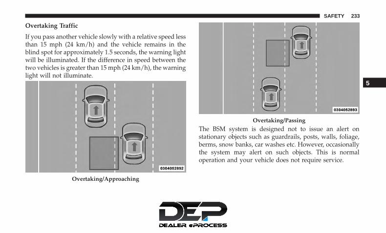
Overtaking Traffic
If you pass another vehicle slowly with a relative speed lessthan 15 mph (24 km/h) and the vehicle remains in theblind spot for approximately 1.5 seconds, the warning lightwill be illuminated. If the difference in speed between thetwo vehicles is greater than 15 mph (24 km/h), the warninglight will not illuminate.
The BSM system is designed not to issue an alert onstationary objects such as guardrails, posts, walls, foliage,berms, snow banks, car washes etc. However, occasionallythe system may alert on such objects. This is normaloperation and your vehicle does not require service.
Overtaking/Approaching
Overtaking/Passing
5
SAFETY 233

The BSM system will not alert you of objects that aretraveling in the opposite direction of the vehicle in adjacentlanes.
WARNING!
The Blind Spot Monitoring system is only an aid tohelp detect objects in the blind spot zones. The BSMsystem is not designed to detect pedestrians, bicyclists,or animals. Even if your vehicle is equipped with theBSM system, always check your vehicle’s mirrors,glance over your shoulder, and use your turn signalbefore changing lanes. Failure to do so can result inserious injury or death.
Stationary Objects Opposing Traffic
234 SAFETY

Rear Cross Path (RCP)
The Rear Cross Path (RCP) feature is intended to aid thedriver when backing out of parking spaces where theirvision of oncoming vehicles may be blocked. Proceedslowly and cautiously out of the parking space until therear end of the vehicle is exposed. The RCP system willthen have a clear view of the cross traffic and if anoncoming vehicle is detected, alert the driver.
RCP monitors the rear detection zones on both sides of thevehicle, for objects that are moving toward the side of thevehicle with a minimum speed of approximately 3 mph
(5 km/h), to objects moving a maximum of approximately20 mph (32 km/h), such as in parking lot situations.
NOTE: In a parking lot situation, oncoming vehicles can beobscured by vehicles parked on either side. If the sensorsare blocked by other structures or vehicles, the system willnot be able to alert the driver. Additionally, if the hostvehicle is obscured by a flat object on one side the systemcan false alert on vehicles approaching from the oppositedirection.
When RCP is on and the vehicle is in REVERSE, the driveris alerted using both the visual and audible alarms, includ-ing reducing the radio volume.
WARNING!
Rear Cross Path Detection (RCP) is not a back up aidsystem. It is intended to be used to help a driver detectan oncoming vehicle in a parking lot situation. Driversmust be careful when backing up, even when usingRCP. Always check carefully behind your vehicle, lookbehind you, and be sure to check for pedestrians,animals, other vehicles, obstructions, and blind spotsbefore backing up. Failure to do so can result in seriousinjury or death.
RCP Detection Zones
5
SAFETY 235

Modes Of Operation
Three selectable modes of operation are available in theUconnect System. Refer to “Uconnect Settings” in “Multi-media” for further information.
Blind Spot Alert Lights Only — Default Setting
When operating in Blind Spot Alert mode, the BSM systemwill provide a visual alert in the appropriate side viewmirror based on a detected object. However, when thesystem is operating in Rear Cross Path (RCP) mode, thesystem will respond with both visual and audible alertswhen a detected object is present. Whenever an audiblealert is requested, the radio is muted.
Blind Spot Alert Lights/Chime
When operating in Blind Spot Alert Lights/Chime mode,the BSM system will provide a visual alert in the appro-priate side view mirror based on a detected object. If theturn signal is then activated, and it corresponds to an alertpresent on that side of the vehicle, an audible chime willalso be sounded. Whenever a turn signal and detectedobject are present on the same side at the same time, boththe visual and audible alerts will be issued. In addition tothe audible alert the radio (if on) will also be muted.
NOTE: Whenever an audible alert is requested by the BSMsystem, the radio is also muted.
When the system is in RCP, the system shall respond withboth visual and audible alerts when a detected object ispresent. Whenever an audible alert is requested, the radiois also muted. Turn/hazard signal status is ignored; theRCP state always requests the chime.
Blind Spot Alert Off
When the BSM system is turned off there will be no visualor audible alerts from either the BSM or RCP systems.
NOTE:
• The BSM system will store the current operating modewhen the vehicle is shut off. Each time the vehicle isstarted the previously stored mode will be recalled andused.
• The BSM system can work in conjunction with theKeysense function of the vehicle if equipped. Refer to“KeySense Cluster Messages� in “Getting To Know YourInstrument Panel” for further information.
236 SAFETY

General Information
The following regulatory statement applies to all RadioFrequency (RF) devices equipped in this vehicle:
This device complies with Part 15 of the FCC Rules andwith Industry Canada license-exempt RSS standard(s).Operation is subject to the following two conditions:
1. This device may not cause harmful interference.
2. This device must accept any interference received, in-cluding interference that may cause undesired opera-tion.
NOTE: Changes or modifications not expressly approvedby the party responsible for compliance could void theuser’s authority to operate the equipment.
Forward Collision Warning (FCW) With Mitigation— If Equipped
The Forward Collision Warning (FCW) system with miti-gation provides the driver with audible warnings, visualwarnings (within the instrument cluster display), and mayapply a brake jerk to warn the driver when it detects apotential frontal collision. The warnings and limited brak-ing are intended to provide the driver with enough time toreact, avoid or mitigate the potential collision.
NOTE: FCW monitors the information from the forwardlooking sensors as well as the Electronic Brake Controller(EBC), to calculate the probability of a forward collision.When the system determines that a forward collision isprobable, the driver will be provided with audible andvisual warnings and may provide a brake jerk warning.
If the driver does not take action based upon these pro-gressive warnings, then the system will provide a limitedlevel of active braking to help slow the vehicle and mitigatethe potential forward collision. If the driver reacts to thewarnings by braking and the system determines that thedriver intends to avoid the collision by braking but has notapplied sufficient brake force, the system will compensateand provide additional brake force as required.
If a FCW with Mitigation event begins at a speed below26 mph (42 km/h), the system may provide the maximumbraking possible to mitigate the potential forward collision.If the Forward Collision Warning with Mitigation eventstops the vehicle completely, the system will hold thevehicle at standstill for two seconds and then release thebrakes.
5
SAFETY 237
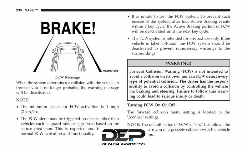
When the system determines a collision with the vehicle infront of you is no longer probable, the warning messagewill be deactivated.
NOTE:
• The minimum speed for FCW activation is 1 mph(2 km/h).
• The FCW alerts may be triggered on objects other thanvehicles such as guard rails or sign posts based on thecourse prediction. This is expected and is a part ofnormal FCW activation and functionality.
• It is unsafe to test the FCW system. To prevent suchmisuse of the system, after four Active Braking eventswithin a key cycle, the Active Braking portion of FCWwill be deactivated until the next key cycle.
• The FCW system is intended for on-road use only. If thevehicle is taken off-road, the FCW system should bedeactivated to prevent unnecessary warnings to thesurroundings.
WARNING!
Forward Collision Warning (FCW) is not intended toavoid a collision on its own, nor can FCW detect everytype of potential collision. The driver has the respon-sibility to avoid a collision by controlling the vehiclevia braking and steering. Failure to follow this warn-ing could lead to serious injury or death.
Turning FCW On Or Off
The forward collision menu setting is located in theUconnect settings.
NOTE: The default status of FCW is “on,” this allows thesystem to warn you of a possible collision with the vehiclein front of you.
FCW Message
238 SAFETY

Changing the FCW status to “off” deactivates the system,so no warning or active braking will be available in case ofa possible collision
NOTE:
• The FCW system state is kept in memory from one keycycle to the next. If the system is turned off, it willremain off when the vehicle is restarted.
• FCW can work in conjunction with the KeySense func-tion of the vehicle if equipped. Refer to “KeySenseCluster Messages� in “Getting To Know Your InstrumentPanel” for further information.
FCW Braking Status And Sensitivity
The FCW Sensitivity and Active Braking status are program-mable through the Uconnect System. Refer to “UconnectSettings” in “Multimedia” for further information.
The default sensitivity of FCW is the “Medium” settingand the system status is “Warning & Braking”. This allowsthe system to warn the driver of a possible collision withthe vehicle in front using audible/visual warnings and itapplies autonomous braking.
Changing the FCW status to “Far” setting allows the systemto warn the driver of a possible collision with the vehicle in
front using audible/visual warning when the latter is at afarther distance than �Medium� setting. This provides themost reaction time to avoid a possible collision.
Changing the FCW status to the “Near” setting, allows thesystem to warn the driver of a possible collision with thevehicle in front when the distance between the vehicle inthe front is much closer. This setting provides less reactiontime than the “Far” and “Medium” settings, which allowsfor a more dynamic driving experience.
NOTE:
• Changing the FCW status to “Only Warning” preventsthe system from providing limited active braking, oradditional brake support if the driver is not brakingadequately in the event of a potential frontal collision,but maintains the audible and visual warnings.
• Changing the FCW status to “Off” prevents the systemfrom providing autonomous braking, or additionalbrake support if the driver is not braking adequately inthe event of a potential frontal collision.
• The system will retain the last setting selected by thedriver after ignition shut down.
• FCW may not react to irrelevant objects such as over-head objects, ground reflections, objects not in the path
5
SAFETY 239

of the vehicle, stationary objects that are far away,oncoming traffic, or leading vehicles with the same orhigher rate of speed.
• FCW will be disabled like ACC, with the unavailablescreens.
FCW Limited Warning
If the instrument cluster displays “ACC/FCW LimitedFunctionality” or “ACC/FCW Limited Functionality CleanFront Windshield” momentarily, there may be a conditionthat limits FCW functionality. Although the vehicle is stilldrivable under normal conditions, the active braking maynot be fully available. Once the condition that limited thesystem performance is no longer present, the system willreturn to its full performance state. If the problem persists,see your authorized dealer.
Service FCW Warning
If the system turns off, and the instrument cluster displays:
• ACC/FCW Unavailable Service Required
• Cruise/FCW Unavailable Service Required
This indicates there is an internal system fault. Althoughthe vehicle is still drivable under normal conditions, havethe system checked by an authorized dealer.
General Information
The following regulatory statement applies to all RadioFrequency (RF) devices equipped in this vehicle:
This device complies with Part 15 of the FCC Rules andwith Industry Canada license-exempt RSS standard(s).Operation is subject to the following two conditions:
1. This device may not cause harmful interference.
2. This device must accept any interference received, in-cluding interference that may cause undesired opera-tion.
NOTE: Changes or modifications not expressly approvedby the party responsible for compliance could void theuser’s authority to operate the equipment.
240 SAFETY

Tire Pressure Monitor System (TPMS)
The Tire Pressure Monitor System (TPMS) will warn thedriver of a low tire pressure based on the vehicle recom-mended cold placard pressure.
NOTE: The TPMS Warning Light will illuminate in theinstrument cluster and a chime will sound when tirepressure is low in one or more of the four active road tires.In addition, the instrument cluster will display a graphicshowing the pressure values of each tire with the low tirepressure values in a different color, or the Uconnect radiowill display a TPMS message, when this occurs you mustincrease the tire pressure to the recommended cold placardpressure in order for the TPMS Warning Light to turn off.
The tire pressure will vary with temperature by approxi-mately 1 psi (7 kPa) for every 12°F (6.5°C). This means thatwhen the outside temperature decreases, the tire pressurewill decrease. Tire pressure should always be set based oncold inflation tire pressure. This is defined as the tirepressure after the vehicle has not been driven for at leastthree hours, or driven less than 1 mile (1.6 km) after a threehour period. The cold tire inflation pressure must notexceed the maximum inflation pressure molded into thetire sidewall. Refer to “Tires” in “Servicing and Mainte-nance” for information on how to properly inflate the
vehicle’s tires. The tire pressure will also increase as thevehicle is driven. This is normal and there should be noadjustment for this increased pressure.
The TPMS will warn the driver of a low tire pressure if thetire pressure falls below the low-pressure warning limit forany reason, including low temperature effects and naturalpressure loss through the tire.
The TPMS will continue to warn the driver of low tirepressure as long as the condition exists, and will not turnoff until the tire pressure is at or above the recommendedcold placard pressure. Once the low tire pressure warning(TPMS Warning Light) illuminates, you must increase thetire pressure to the recommended cold placard pressure inorder for the TPMS Warning Light to turn off.
The system will automatically update and the TPMSWarning Light will turn off once the system receives theupdated tire pressures. The vehicle may need to be drivenfor up to 20 minutes above 15 mph (24 km/h) in order forthe TPMS to receive this information.
For example, your vehicle may have a recommended cold(parked for more than three hours) placard pressure of 33 psi(227 kPa). If the ambient temperature is 68°F (20°C) and themeasured tire pressure is 28 psi (193 kPa), a temperature
5
SAFETY 241
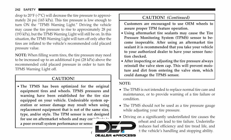
drop to 20°F (-7°C) will decrease the tire pressure to approxi-mately 24 psi (165 kPa). This tire pressure is low enough toturn ON the “TPMS Warning Light.” Driving the vehiclemay cause the tire pressure to rise to approximately 28 psi(193 kPa), but the TPMS Warning Light will still be on. In thissituation, the TPMS Warning Light will turn off only after thetires are inflated to the vehicle’s recommended cold placardpressure value.
NOTE: When filling warm tires, the tire pressure may needto be increased up to an additional 4 psi (28 kPa) above therecommended cold placard pressure in order to turn theTPMS Warning Light off.
CAUTION!
• The TPMS has been optimized for the originalequipment tires and wheels. TPMS pressures andwarning have been established for the tire sizeequipped on your vehicle. Undesirable system op-eration or sensor damage may result when usingreplacement equipment that is not of the same size,type, and/or style. The TPM sensor is not designedfor use on aftermarket wheels and may contribute toa poor overall system performance or sensor damage.
(Continued)
CAUTION! (Continued)Customers are encouraged to use OEM wheels toassure proper TPM feature operation.
• Using aftermarket tire sealants may cause the TirePressure Monitoring System (TPMS) sensor to be-come inoperable. After using an aftermarket tiresealant it is recommended that you take your vehicleto your authorized dealer to have your sensor func-tion checked.
• After inspecting or adjusting the tire pressure alwaysreinstall the valve stem cap. This will prevent mois-ture and dirt from entering the valve stem, whichcould damage the TPMS sensor.
NOTE:
• The TPMS is not intended to replace normal tire care andmaintenance, or to provide warning of a tire failure orcondition.
• The TPMS should not be used as a tire pressure gaugewhile adjusting your tire pressure.
• Driving on a significantly underinflated tire causes thetire to overheat and can lead to tire failure. Underinfla-tion also reduces fuel efficiency and tire tread life, andmay affect the vehicle’s handling and stopping ability.
242 SAFETY

• The TPMS is not a substitute for proper tire mainte-nance, and it is the driver’s responsibility to maintaincorrect tire pressure using an accurate tire pressuregauge, even if underinflation has not reached the level totrigger illumination of the TPMS Warning Light.
• Seasonal temperature changes will affect tire pressure, andthe TPMS will monitor the actual tire pressure in the tire.
Premium System
The Tire Pressure Monitor System (TPMS) uses wirelesstechnology with wheel rim mounted electronic sensors tomonitor tire pressure levels. Sensors, mounted to eachwheel as part of the valve stem, transmit tire pressurereadings to the receiver module.
NOTE: It is particularly important for you to check the tirepressure in all of the tires on your vehicle monthly and tomaintain the proper pressure.
The TPMS consists of the following components:• Receiver module• Four tire pressure monitoring sensors• Various tire pressure monitoring system messages,
which display in the instrument cluster• Tire Pressure Monitoring System Warning Light
Tire Pressure Monitoring Low Pressure Warnings
The TPMS Warning Light will illuminate in theinstrument cluster and a chime will sound when tire
pressure is low in one or more of the four active road tires.In addition, the instrument cluster will display an �Inflateto XX� message and a graphic showing the pressure valuesof each tire with the low tire pressure values in a differentcolor.
Should this occur, you should stop as soon as possible andinflate the tires with low pressure (those in a different color
Tire Pressure Monitoring System
5
SAFETY 243

in the instrument cluster graphic) to the vehicle’s recom-mended cold placard pressure value as shown in the�Inflate to XX� message. Once the system receives theupdated tire pressures, the system will automatically up-date, the pressure values in the graphic display in theinstrument cluster will return to their original color, andthe TPMS Warning Light will turn off. The vehicle mayneed to be driven for up to 20 minutes above 15 mph(24 km/h) in order for the TPMS to receive this informa-tion.
Service TPMS Warning
When a system fault is detected, the Tire Pressure Moni-toring System (TPMS) Warning Light will flash on and offfor 75 seconds and then remain on solid. The system faultwill also sound a chime. In addition, the instrument clusterwill display a �SERVICE TPM SYSTEM� message for aminimum of five seconds and then display dashes (- -) inplace of the pressure value to indicate which sensor is notbeing received.
If the ignition is cycled, this sequence will repeat, provid-ing the system fault still exists. If the system fault no longerexists, the TPMS Warning Light will no longer flash, andthe “SERVICE TPM SYSTEM” message will no longer
display, and a pressure value will display in place of thedashes. A system fault can occur due to any of thefollowing:
• Jamming due to electronic devices or driving next tofacilities emitting the same radio frequencies as theTPMS sensors.
• Installing some form of aftermarket window tinting thataffects radio wave signals.
• Lots of snow or ice around the wheels or wheel hous-ings.
• Using tire chains on the vehicle.
• Using wheels/tires not equipped with TPMS sensors.
Vehicles With Compact Spare — If Equipped
1. The compact spare tire does not have a tire pressuremonitoring sensor. Therefore, the TPMS will not moni-tor the pressure in the compact spare tire.
2. If you install the compact spare tire in place of a road tirethat has a pressure below the low-pressure warninglimit, upon the next ignition cycle, the TPMS WarningLight will remain on and a chime will sound. Inaddition, the graphic in the instrument cluster will stilldisplay a different color pressure value.
244 SAFETY

3. After driving the vehicle for up to 20 minutes above15 mph (24 km/h), the TPMS Warning Light will flashon and off for 75 seconds and then remain on solid. Inaddition, the instrument cluster will display a “SER-VICE TPM SYSTEM” message for five seconds and thendisplay dashes (- -) in place of the pressure value.
4. For each subsequent ignition cycle, a chime will sound,the TPMS Warning Light will flash on and off for 75seconds and then remain on solid, and the instrumentcluster will display a “SERVICE TPM SYSTEM” mes-sage for five seconds and then display dashes (- -) inplace of the pressure value.
5. Once you repair or replace the original road tire andreinstall it on the vehicle in place of the compact spare,the TPMS will update automatically. In addition, theTPMS Warning Light will turn off and the graphic in theinstrument cluster will display a new pressure valueinstead of dashes (- -), as long as no tire pressure isbelow the low-pressure warning limit in any of the fouractive road tires. The vehicle may need to be driven forup to 20 minutes above 15 mph (24 km/h) in order forthe TPMS to receive this information.
TPMS Deactivation — If Equipped
The Tire Pressure Monitoring System (TPMS) can be deac-tivated if replacing all four wheel and tire assemblies (roadtires) with wheel and tire assemblies that do not haveTPMS Sensors, such as when installing winter wheel andtire assemblies on your vehicle.
To deactivate the TPMS, first, replace all four wheel andtire assemblies (road tires) with tires not equipped withTire Pressure Monitoring (TPM) Sensors. Then, drive thevehicle for 20 minutes above 15 mph (24 km/h). The TPMSwill chime, the TPMS Warning Light will flash on and offfor 75 seconds and then remain on. The instrument clusterwill display the “SERVICE TPM SYSTEM” message andthen display dashes (--) in place of the pressure values.
Beginning with the next ignition cycle, the TPMS will nolonger chime or display the “SERVICE TPM SYSTEM”message in the instrument cluster but dashes (--) willremain in place of the pressure values.
To reactivate the TPMS, replace all four wheel and tireassemblies (road tires) with tires equipped with TPMsensors. Then, drive the vehicle for up to 20 minutes above15 mph (24 km/h). The TPMS will chime, the TPMSWarning Light will flash on and off for 75 seconds and thenturn off. The instrument cluster will display the “SERVICE
5
SAFETY 245

TPM SYSTEM” message and then display pressure valuesin place of the dashes. On the next ignition cycle the�SERVICE TPM SYSTEM� message will no longer be dis-played as long as no system fault exists.
General Information
The following regulatory statement applies to all radiofrequency (RF) devices equipped in this vehicle:
This device complies with Part 15 of the FCC Rules andwith Industry Canada license-exempt RSS standard(s).Operation is subject to the following two conditions:
(1) This device may not cause harmful interference, and
(2) This device must accept any interference received,including interference that may cause undesired operation.
NOTE: Changes or modifications not expressly approvedby the party responsible for compliance could void theuser’s authority to operate the equipment.
OCCUPANT RESTRAINT SYSTEMS
Some of the most important safety features in your vehicleare the restraint systems:
Occupant Restraint Systems Features
• Seat Belt Systems
• Supplemental Restraint Systems (SRS) Air Bags
• Child Restraints
Some of the safety features described in this section may bestandard equipment on some models, or may be optionalequipment on others. If you are not sure, ask an authorizeddealer.
Important Safety Precautions
Please pay close attention to the information in this section.It tells you how to use your restraint system properly, tokeep you and your passengers as safe as possible.
Here are some simple steps you can take to minimize therisk of harm from a deploying air bag:
1. Children 12 years old and under should always ridebuckled up in the rear seat of a vehicle with a rear seat.
2. A child who is not big enough to wear the vehicle seatbelt properly (Refer to “Child Restraints” in this section
246 SAFETY
for further information) must be secured in the appro-priate child restraint or belt-positioning booster seat in arear seating position.
3. If a child from 2 to 12 years old (not in a rear-facing childrestraint) must ride in the front passenger seat, move theseat as far back as possible and use the proper childrestraint (Refer to “Child Restraints” in this section forfurther information).
4. Never allow children to slide the shoulder belt behindthem or under their arm.
5. You should read the instructions provided with yourchild restraint to make sure that you are using itproperly.
6. All occupants should always wear their lap and shoul-der belts properly.
7. The driver and front passenger seats should be movedback as far as practical to allow the front air bags roomto inflate.
8. Do not lean against the door or window. If your vehiclehas side air bags, and deployment occurs, the side airbags will inflate forcefully into the space between occu-pants and the door and occupants could be injured.
9. If the air bag system in this vehicle needs to be modifiedto accommodate a disabled person, refer to the “Cus-tomer Assistance” section for customer service contactinformation.
WARNING!
• Never place a rear-facing child restraint in front of anair bag. A deploying passenger front air bag cancause death or serious injury to a child 12 years oryounger, including a child in a rear-facing childrestraint.
• Never install a rear-facing child restraint in the frontseat of a vehicle. Only use a rear-facing child re-straint in the rear seat. If the vehicle does not have arear seat, do not transport a rear-facing child restraintin that vehicle.
Seat Belt Systems
Buckle up even though you are an excellent driver, even onshort trips. Someone on the road may be a poor driver andcould cause a collision that includes you. This can happenfar away from home or on your own street.
Research has shown that seat belts save lives, and they canreduce the seriousness of injuries in a collision. Some of the
5
SAFETY 247

worst injuries happen when people are thrown from thevehicle. Seat belts reduce the possibility of ejection and therisk of injury caused by striking the inside of the vehicle.Everyone in a motor vehicle should be belted at all times.
Enhanced Seat Belt Use Reminder System (BeltAlert)
Driver and Passenger BeltAlert (if equipped)
BeltAlert is a feature intended to remind the driverand outboard front seat passenger (if equipped withoutboard front passenger seat BeltAlert) to buckle theirseat belts. The Belt Alert feature is active whenever theignition switch is in the START or ON/RUN position.
Initial Indication
If the driver is unbuckled when the ignition switch is firstin the START or ON/RUN position, a chime will signal fora few seconds. If the driver or outboard front seat passen-ger (if equipped with outboard front passenger seatBeltAlert) is unbuckled when the ignition switch is first inthe START or ON/RUN position the Seat Belt ReminderLight will turn on and remain on until both outboard frontseat belts are buckled. The outboard front passenger seatBeltAlert is not active when an outboard front passengerseat is unoccupied.
BeltAlert Warning Sequence
The BeltAlert warning sequence is activated when thevehicle is moving above a specified vehicle speed rangeand the driver or outboard front seat passenger is unbuck-led (if equipped with outboard front passenger seatBeltAlert) (the outboard front passenger seat BeltAlert isnot active when the outboard front passenger seat isunoccupied). The BeltAlert warning sequence starts byblinking the Seat Belt Reminder Light and sounding anintermittent chime. Once the BeltAlert warning sequencehas completed, the Seat Belt Reminder Light will remain onuntil the seat belts are buckled. The BeltAlert warningsequence may repeat based on vehicle speed until thedriver and occupied outboard front seat passenger seatbelts are buckled. The driver should instruct all occupantsto buckle their seat belts.
Change of Status
If the driver or outboard front seat passenger (if equippedwith outboard front passenger seat BeltAlert) unbucklestheir seat belt while the vehicle is traveling, the BeltAlertwarning sequence will begin until the seat belts are buck-led again.
The outboard front passenger seat BeltAlert is not activewhen the outboard front passenger seat is unoccupied.
248 SAFETY

BeltAlert may be triggered when an animal or other itemsare placed on the outboard front passenger seat or whenthe seat is folded flat (if equipped). It is recommended thatpets be restrained in the rear seat (if equipped) in petharnesses or pet carriers that are secured by seat belts, andcargo is properly stowed.
BeltAlert can be activated or deactivated by an authorizeddealer. FCA US LLC does not recommend deactivatingBeltAlert.
NOTE: If BeltAlert has been deactivated and the driver oroutboard front seat passenger (if equipped with outboardfront passenger seat BeltAlert) is unbuckled the Seat BeltReminder Light will turn on and remain on until the driverand outboard front seat passenger seat belts are buckled.
Lap/Shoulder Belts
All seating positions in your vehicle are equipped withlap/shoulder belts.
The seat belt webbing retractor will lock only during verysudden stops or collisions. This feature allows the shoulderpart of the seat belt to move freely with you under normalconditions. However, in a collision the seat belt will lock
and reduce your risk of striking the inside of the vehicle orbeing thrown out of the vehicle.
WARNING!
• Relying on the air bags alone could lead to moresevere injuries in a collision. The air bags work withyour seat belt to restrain you properly. In somecollisions, the air bags won’t deploy at all. Alwayswear your seat belt even though you have air bags.
• In a collision, you and your passengers can suffermuch greater injuries if you are not properly buckledup. You can strike the interior of your vehicle orother passengers, or you can be thrown out of thevehicle. Always be sure you and others in yourvehicle are buckled up properly.
• It is dangerous to ride in a cargo area, inside oroutside of a vehicle. In a collision, people riding inthese areas are more likely to be seriously injured orkilled.
• Do not allow people to ride in any area of yourvehicle that is not equipped with seats and seat belts.
• Be sure everyone in your vehicle is in a seat andusing a seat belt properly. Occupants, including the
(Continued)
5
SAFETY 249

WARNING! (Continued)driver, should always wear their seat belts whetheror not an air bag is also provided at their seatingposition to minimize the risk of severe injury ordeath in the event of a crash.
• Wearing your seat belt incorrectly could make yourinjuries in a collision much worse. You might sufferinternal injuries, or you could even slide out of theseat belt. Follow these instructions to wear your seatbelt safely and to keep your passengers safe, too.
• Two people should never be belted into a single seatbelt. People belted together can crash into one an-other in a collision, hurting one another badly. Neveruse a lap/shoulder belt or a lap belt for more than oneperson, no matter what their size.
WARNING!
• A lap belt worn too high can increase the risk ofinjury in a collision. The seat belt forces won’t be atthe strong hip and pelvic bones, but across yourabdomen. Always wear the lap part of your seat beltas low as possible and keep it snug.
(Continued)
WARNING! (Continued)• A twisted seat belt may not protect you properly. In
a collision, it could even cut into you. Be sure the seatbelt is flat against your body, without twists. If youcan’t straighten a seat belt in your vehicle, take it toan authorized dealer immediately and have it fixed.
• A seat belt that is buckled into the wrong buckle willnot protect you properly. The lap portion could ridetoo high on your body, possibly causing internalinjuries. Always buckle your seat belt into thebuckle nearest you.
• A seat belt that is too loose will not protect youproperly. In a sudden stop, you could move too farforward, increasing the possibility of injury. Wearyour seat belt snugly.
• A seat belt that is worn under your arm is dangerous.Your body could strike the inside surfaces of thevehicle in a collision, increasing head and neckinjury. A seat belt worn under the arm can causeinternal injuries. Ribs aren’t as strong as shoulderbones. Wear the seat belt over your shoulder so thatyour strongest bones will take the force in a collision.
(Continued)
250 SAFETY

WARNING! (Continued)• A shoulder belt placed behind you will not protect
you from injury during a collision. You are morelikely to hit your head in a collision if you do notwear your shoulder belt. The lap and shoulder beltare meant to be used together.
• A frayed or torn seat belt could rip apart in a collisionand leave you with no protection. Inspect the seatbelt system periodically, checking for cuts, frays, orloose parts. Damaged parts must be replaced imme-diately. Do not disassemble or modify the seat beltsystem. Seat belt assemblies must be replaced after acollision.
Lap/Shoulder Belt Operating Instructions
1. Enter the vehicle and close the door. Sit back and adjustthe seat.
2. The seat belt latch plate is above the back of the frontseat, and next to your arm in the rear seat (for vehiclesequipped with a rear seat). Grasp the latch plate andpull out the seat belt. Slide the latch plate up thewebbing as far as necessary to allow the seat belt to goaround your lap.
Pulling Out The Latch Plate
5
SAFETY 251

3. When the seat belt is long enough to fit, insert the latchplate into the buckle until you hear a “click.”
4. Position the lap belt so that it is snug and lies low acrossyour hips, below your abdomen. To remove slack in thelap belt portion, pull up on the shoulder belt. To loosenthe lap belt if it is too tight, tilt the latch plate and pullon the lap belt. A snug seat belt reduces the risk ofsliding under the seat belt in a collision.
5. Position the shoulder belt across the shoulder and chestwith minimal, if any slack so that it is comfortable andnot resting on your neck. The retractor will withdrawany slack in the shoulder belt.
6. To release the seat belt, push the red button on thebuckle. The seat belt will automatically retract to itsstowed position. If necessary, slide the latch plate downthe webbing to allow the seat belt to retract fully.
Inserting Latch Plate Into Buckle
Positioning The Lap Belt
252 SAFETY

Lap/Shoulder Belt Untwisting Procedure
Use the following procedure to untwist a twisted lap/shoulder belt.
1. Position the latch plate as close as possible to the anchorpoint.
2. At about 6 to 12 inches (15 to 30 cm) above the latchplate, grasp and twist the seat belt webbing 180 degreesto create a fold that begins immediately above the latchplate.
3. Slide the latch plate upward over the folded webbing.The folded webbing must enter the slot at the top of thelatch plate.
4. Continue to slide the latch plate up until it clears thefolded webbing and the seat belt is no longer twisted.
Adjustable Upper Shoulder Belt Anchorage
In the front and second row outboard seats the shoulderbelt can be adjusted upward or downward to position theseat belt away from your neck. Push or squeeze theanchorage button to release the anchorage, and move it upor down to the position that serves you best.
As a guide, if you are shorter than average, you will preferthe shoulder belt anchorage in a lower position, and if youare taller than average, you will prefer the shoulder beltanchorage in a higher position. After you release theanchorage button, try to move it up or down to make surethat it is locked in position.
NOTE: The adjustable upper shoulder belt anchorage isequipped with an Easy Up feature. This feature allows theshoulder belt anchorage to be adjusted in the upward positionwithout pushing or squeezing the release button. To verify the
Adjustable Anchorage
5
SAFETY 253

shoulder belt anchorage is latched, pull downward on theshoulder belt anchorage until it is locked into position.
WARNING!
• Wearing your seat belt incorrectly could make yourinjuries in a collision much worse. You might sufferinternal injuries, or you could even slide out of theseat belt. Follow these instructions to wear your seatbelt safely and to keep your passengers safe, too.
• Position the shoulder belt across the shoulder andchest with minimal, if any slack so that it is comfort-able and not resting on your neck. The retractor willwithdraw any slack in the shoulder belt.
• Misadjustment of the seat belt could reduce theeffectiveness of the safety belt in a crash.
• Always make all seat belt height adjustments whenthe vehicle is stationary.
Second Row Center (If Equipped) And Third RowCenter Seat Belt Operating Instructions
The second row center (if equipped) and third row centerseat belts feature a seat belt with a mini-latch plate and
buckle, which allows the seat belt to detach from the loweranchor when the seat is folded. The mini-latch plate andregular latch plate can then be stored out of the way in theheadliner for added convenience to open up utilization ofthe storage areas behind the front seats when the seat is notoccupied.
1. Remove the mini-latch plate and regular latch platefrom its stowed position in the headliner slightly behindthe second or third row seat.
Mini-Latch Stowage
254 SAFETY

2. Grasp the mini-latch plate and pull the seat belt over theseat.
3. Route the shoulder belt to the inside of the left headrestraint.
Mini-Latch Plate Routing The Rear Seat Belt Latch Plate
1 — Seat Belt Latch Plate
5
SAFETY 255

4. When the seat belt is long enough to fit, insert themini-latch plate into the mini-buckle until you hear a“click.”
5. Sit back in seat. Slide the regular latch plate up thewebbing as far as necessary to allow the seat belt to goaround your lap.
Connect Mini-Latch To Mini-Buckle Rear Center Seat Belt Buckled
1 — Seat Belt Latch Plate2 — Seat Belt Buckle
256 SAFETY

6. When the seat belt is long enough to fit, insert the latchplate into the buckle until you hear a “click.”
7. Position the lap belt so that it is snug and lies low acrossyour hips, below your abdomen. To remove slack in thelap belt portion, pull up on the shoulder belt. To loosenthe lap belt if it is too tight, pull on the lap belt. A snugseat belt reduces the risk of sliding under the seat belt ina collision.
8. Position the shoulder belt on your chest so that it iscomfortable and not resting on your neck. The retractorwill withdraw any slack in the seat belt.
9. To release the seat belt, push the red button on thebuckle.
10. To disengage the mini-latch plate from the mini-bucklefor storage, insert the regular latch plate into the centerred slot on the mini-buckle. The seat belt will automati-cally retract to its stowed position. If necessary, slidethe latch plate down the webbing to allow the seat beltto retract fully. Insert the mini-latch plate and regularlatch plate into its stowed position.
WARNING!
• If the mini-latch plate and mini-buckle are not prop-erly connected when the seat belt is used by anoccupant, the seat belt will not be able to provideproper restraint and will increase the risk of injury ina collision.
• When reattaching the mini-latch plate and mini-buckle, ensure the seat belt webbing is not twisted.If the webbing is twisted, follow the precedingprocedure to detach the mini-latch plate and mini-buckle, untwist the webbing, and reattach the mini-latch plate and mini-buckle.
Latch Plate And Buckle Connected
5
SAFETY 257

Seat Belt Extender
If a seat belt is not long enough to fit properly, even whenthe webbing is fully extended and the adjustable uppershoulder belt anchorage (if equipped) is in its lowestposition, an authorized dealer can provide you with a SeatBelt Extender. The Seat Belt Extender should be used onlyif the existing seat belt is not long enough. When the SeatBelt Extender is not required for a different occupant, itmust be removed.
WARNING!
• ONLY use a Seat Belt Extender if it is physicallyrequired in order to properly fit the original seat beltsystem. DO NOT USE the Seat Belt Extender if,when worn, the distance between the front edge ofthe Seat Belt Extender buckle and the center of theoccupant’s body is LESS than 6 inches.
• Using a Seat Belt Extender when not needed canincrease the risk of serious injury or death in acollision. Only use the Seat Belt Extender when thelap belt is not long enough and only use in therecommended seating positions. Remove and storethe Seat Belt Extender when not needed.
Seat Belts And Pregnant Women
Seat belts must be worn by all occupants including preg-nant women: the risk of injury in the event of an accidentis reduced for the mother and the unborn child if they arewearing a seat belt.
Position the lap belt snug and low below the abdomen andacross the strong bones of the hips. Place the shoulder beltacross the chest and away from the neck. Never place theshoulder belt behind the back or under the arm.
Pregnant Women And Seat Belts
258 SAFETY

Seat Belt Pretensioner
The front outboard seat belt system is equipped withpretensioning devices that are designed to remove slackfrom the seat belt in the event of a collision. These devicesmay improve the performance of the seat belt by removingslack from the seat belt early in a collision. Pretensionerswork for all size occupants, including those in childrestraints.
NOTE: These devices are not a substitute for proper seatbelt placement by the occupant. The seat belt still must beworn snugly and positioned properly.
The pretensioners are triggered by the Occupant RestraintController (ORC). Like the air bags, the pretensioners aresingle use items. A deployed pretensioner or a deployed airbag must be replaced immediately.
Energy Management Feature
The front outboard seat belt system is equipped with anEnergy Management feature that may help further reducethe risk of injury in the event of a collision. The seat beltsystem has a retractor assembly that is designed to releasewebbing in a controlled manner.
Switchable Automatic Locking Retractors (ALR)
The seat belts in the passenger seating positions areequipped with a Switchable Automatic Locking Retractor(ALR) which is used to secure a child restraint system. Foradditional information, refer to “Installing Child RestraintsUsing The Vehicle Seat Belt” under the “Child Restraints”section of this manual. The figure below illustrates thelocking feature for each seating position.
7 Passenger Bench Seat Automatic Locking Retractor(ALR) Locations
ALR — Switchable Automatic Locking Retractor
5
SAFETY 259

If the passenger seating position is equipped with an ALRand is being used for normal usage, only pull the seat beltwebbing out far enough to comfortably wrap around theoccupant’s mid-section so as to not activate the ALR. If theALR is activated, you will hear a clicking sound as the seatbelt retracts. Allow the webbing to retract completely inthis case and then carefully pull out only the amount ofwebbing necessary to comfortably wrap around the occu-pant’s mid-section. Slide the latch plate into the buckleuntil you hear a �click.�
7 Passenger Stow ‘n Go Seating Automatic LockingRetractor (ALR) Locations
ALR — Switchable Automatic Locking Retractor
8 Passenger Automatic Locking Retractor (ALR) Locations
ALR — Switchable Automatic Locking Retractor
260 SAFETY

In Automatic Locking Mode, the shoulder belt is automati-cally pre-locked. The seat belt will still retract to removeany slack in the shoulder belt. Use the Automatic LockingMode anytime a child restraint is installed in a seatingposition that has a seat belt with this feature. Children 12years old and under should always be properly restrainedin the rear seat of a vehicle with a rear seat.
WARNING!
• Never place a rear-facing child restraint in front of anair bag. A deploying passenger front air bag cancause death or serious injury to a child 12 years oryounger, including a child in a rear-facing childrestraint.
• Never install a rear-facing child restraint in the frontseat of a vehicle. Only use a rear-facing child re-straint in the rear seat. If the vehicle does not have arear seat, do not transport a rear-facing child restraintin that vehicle.
How To Engage The Automatic Locking Mode
1. Buckle the combination lap and shoulder belt.
2. Grasp the shoulder portion and pull downward untilthe entire seat belt is extracted.
3. Allow the seat belt to retract. As the seat belt retracts,you will hear a clicking sound. This indicates the seatbelt is now in the Automatic Locking Mode.
How To Disengage The Automatic Locking Mode
Unbuckle the combination lap/shoulder belt and allow itto retract completely to disengage the Automatic LockingMode and activate the vehicle sensitive (emergency) lock-ing mode.
WARNING!
• The seat belt assembly must be replaced if theswitchable Automatic Locking Retractor (ALR) fea-ture or any other seat belt function is not workingproperly when checked according to the proceduresin the Service Manual.
• Failure to replace the seat belt assembly could in-crease the risk of injury in collisions.
• Do not use the Automatic Locking Mode to restrainoccupants who are wearing the seat belt or childrenwho are using booster seats. The locked mode is onlyused to install rear-facing or forward-facing childrestraints that have a harness for restraining thechild.
5
SAFETY 261

Seat Belt Park Stitch — If Equipped
The rear outboard seat belts may be equipped with a parkstitch to raise the latch plate for easier access to occupants.If the park stitch interferes with the tight installation of achild restraint, slide the latch plate over the stitching toshorten the lap portion of the belt and install the car seatnormally. When the car seat is removed from the vehicle,slide the latch plate above the park stitch to enable occu-pants to latch the seatbelt securely.
Third Row Stow Clip - If Equipped
Your vehicle may be equipped with a stow clip on thelower trim behind the third row. This clip is used to holdthe seat belt out of the path of the power folding third rowseat. Only place the seat belt webbing in this clip whilefolding and opening the seat. Do not leave the webbingbehind the clip when using the belt to restrain an occupant.
Seat Belt Park Stitch Location
Third Row Stow Clip
262 SAFETY

WARNING!
Do not place the seat belt webbing behind the thirdrow stow clip when using the seat belt to restrain anoccupant. The seat belt will not be positioned properlyon the occupant and they could be more seriouslyinjured in an accident as a result.
Supplemental Restraint Systems (SRS)
Some of the safety features described in this section may bestandard equipment on some models, or may be optionalequipment on others. If you are not sure, ask an authorizeddealer.
The air bag system must be ready to protect you in acollision. The Occupant Restraint Controller (ORC) moni-tors the internal circuits and interconnecting wiring asso-ciated with the electrical Air Bag System Components.Your vehicle may be equipped with the following Air BagSystem Components:
Air Bag System Components
• Occupant Restraint Controller (ORC)
• Air Bag Warning Light
• Steering Wheel and Column
• Instrument Panel
• Knee Impact Bolsters
• Driver and Front Passenger Air Bags
• Seat Belt Buckle Switch
• Supplemental Side Air Bags
• Supplemental Knee Air Bags
• Front and Side Impact Sensors
• Seat Belt Pretensioners
• Seat Track Position Sensors
• Occupant Classification System
Air Bag Warning Light
The ORC monitors the readiness of the electronicparts of the air bag system whenever the ignitionswitch is in the START or ON/RUN position. Ifthe ignition switch is in the OFF position or in the
ACC position, the air bag system is not on and the air bagswill not inflate.
The ORC contains a backup power supply system that maydeploy the air bag system even if the battery loses power orit becomes disconnected prior to deployment.
5
SAFETY 263

The ORC turns on the Air Bag Warning Light in theinstrument panel for approximately four to eight secondsfor a self-check when the ignition switch is first in theON/RUN position. After the self-check, the Air Bag Warn-ing Light will turn off. If the ORC detects a malfunction inany part of the system, it turns on the Air Bag WarningLight, either momentarily or continuously. A single chimewill sound to alert you if the light comes on again afterinitial startup.
The ORC also includes diagnostics that will illuminate theinstrument panel Air Bag Warning Light if a malfunction isdetected that could affect the air bag system. The diagnos-tics also record the nature of the malfunction. While the airbag system is designed to be maintenance free, if any of thefollowing occurs, have an authorized dealer service the airbag system immediately.
• The Air Bag Warning Light does not come on during thefour to eight seconds when the ignition switch is first inthe ON/RUN position.
• The Air Bag Warning Light remains on after the four toeight-second interval.
• The Air Bag Warning Light comes on intermittently orremains on while driving.
NOTE: If the speedometer, tachometer, or any enginerelated gauges are not working, the Occupant RestraintController (ORC) may also be disabled. In this conditionthe air bags may not be ready to inflate for your protection.Have an authorized dealer service the air bag systemimmediately.
WARNING!
Ignoring the Air Bag Warning Light in your instrumentpanel could mean you won’t have the air bag system toprotect you in a collision. If the light does not come onas a bulb check when the ignition is first turned on,stays on after you start the vehicle, or if it comes on asyou drive, have an authorized dealer service the air bagsystem immediately.
Redundant Air Bag Warning Light
If a fault with the Air Bag Warning Light isdetected, which could affect the SupplementalRestraint System (SRS), the Redundant Air BagWarning Light will illuminate on the instrument
panel. The Redundant Air Bag Warning Light will stay onuntil the fault is cleared. In addition, a single chime willsound to alert you that the Redundant Air Bag Warning
264 SAFETY

Light has come on and a fault has been detected. If theRedundant Air Bag Warning Light comes on intermittentlyor remains on while driving have an authorized dealerservice the vehicle immediately.
For additional information regarding the Redundant AirBag Warning Light refer to “Getting To Know Your Instru-ment Panel” section of this manual.
Front Air Bags
This vehicle has front air bags and lap/shoulder belts forboth the driver and front passenger. The front air bags area supplement to the seat belt restraint systems. The driverfront air bag is mounted in the center of the steering wheel.The passenger front air bag is mounted in the instrumentpanel, above the glove compartment. The words “SRSAIRBAG” or “AIRBAG” are embossed on the air bagcovers.
WARNING!
• Being too close to the steering wheel or instrumentpanel during front air bag deployment could causeserious injury, including death. Air bags need room
(Continued)
Front Air Bag/Knee Bolster Locations
1 — Driver And Passenger Front Air Bags2 — Passenger Knee Impact Bolster/Supplemental Passenger KneeAir Bag3 — Driver Knee Impact Bolster/Supplemental Driver Knee Air Bag
5
SAFETY 265

WARNING! (Continued)to inflate. Sit back, comfortably extending your armsto reach the steering wheel or instrument panel.
• Never place a rear-facing child restraint in front of anair bag. A deploying passenger front air bag cancause death or serious injury to a child 12 years oryounger, including a child in a rear-facing childrestraint.
• Never install a rear-facing child restraint in the frontseat of a vehicle. Only use a rear-facing child re-straint in the rear seat. If the vehicle does not have arear seat, do not transport a rear-facing child restraintin that vehicle.
Driver And Passenger Front Air Bag Features
The Advanced Front Air Bag system has multistage driverand front passenger air bags. This system provides outputappropriate to the severity and type of collision as deter-mined by the Occupant Restraint Controller (ORC), whichmay receive information from the front impact sensors (ifequipped) or other system components.
The first stage inflator is triggered immediately during animpact that requires air bag deployment. A low energyoutput is used in less severe collisions. A higher energyoutput is used for more severe collisions.
This vehicle may be equipped with a driver and/or frontpassenger seat belt buckle switch that detects whether thedriver or front passenger seat belt is buckled. The seat beltbuckle switch may adjust the inflation rate of the Ad-vanced Front Air Bags.
This vehicle may be equipped with driver and/or frontpassenger seat track position sensors that may adjust theinflation rate of the Advanced Front Air Bags based uponseat position.
This vehicle is equipped with a right front passengerOccupant Classification System (“OCS”) that is designed toprovide Passenger Advanced Front Air Bag output appro-priate to the occupant’s seated weight input, as determinedby the OCS.
WARNING!
• No objects should be placed over or near the air bagon the instrument panel or steering wheel because
(Continued)
266 SAFETY
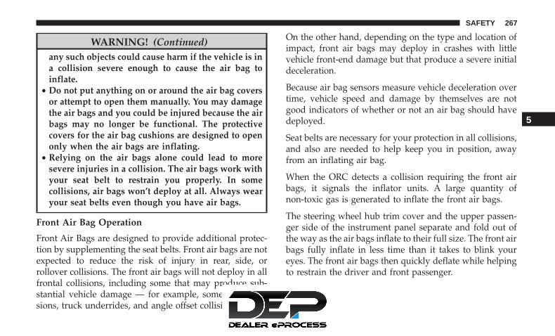
WARNING! (Continued)any such objects could cause harm if the vehicle is ina collision severe enough to cause the air bag toinflate.
• Do not put anything on or around the air bag coversor attempt to open them manually. You may damagethe air bags and you could be injured because the airbags may no longer be functional. The protectivecovers for the air bag cushions are designed to openonly when the air bags are inflating.
• Relying on the air bags alone could lead to moresevere injuries in a collision. The air bags work withyour seat belt to restrain you properly. In somecollisions, air bags won’t deploy at all. Always wearyour seat belts even though you have air bags.
Front Air Bag Operation
Front Air Bags are designed to provide additional protec-tion by supplementing the seat belts. Front air bags are notexpected to reduce the risk of injury in rear, side, orrollover collisions. The front air bags will not deploy in allfrontal collisions, including some that may produce sub-stantial vehicle damage — for example, some pole colli-sions, truck underrides, and angle offset collisions.
On the other hand, depending on the type and location ofimpact, front air bags may deploy in crashes with littlevehicle front-end damage but that produce a severe initialdeceleration.
Because air bag sensors measure vehicle deceleration overtime, vehicle speed and damage by themselves are notgood indicators of whether or not an air bag should havedeployed.
Seat belts are necessary for your protection in all collisions,and also are needed to help keep you in position, awayfrom an inflating air bag.
When the ORC detects a collision requiring the front airbags, it signals the inflator units. A large quantity ofnon-toxic gas is generated to inflate the front air bags.
The steering wheel hub trim cover and the upper passen-ger side of the instrument panel separate and fold out ofthe way as the air bags inflate to their full size. The front airbags fully inflate in less time than it takes to blink youreyes. The front air bags then quickly deflate while helpingto restrain the driver and front passenger.
5
SAFETY 267
Occupant Classification System (OCS) — FrontPassenger Seat
The OCS is part of a Federally regulated safety system forthis vehicle. It is designed to provide Passenger AdvancedFront Air Bag output appropriate to the occupant’s seatedweight, as determined by the OCS.
The Occupant Classification System (OCS) consists of thefollowing:
• Occupant Restraint Controller (ORC)
• Occupant Classification Module (OCM) and Sensor lo-cated in the front passenger seat
• Air Bag Warning Light
Occupant Classification Module (OCM) and Sensor
The Occupant Classification Module (OCM) is locatedunderneath the front passenger seat. The Sensor is locatedbeneath the passenger seat cushion foam. Any weight onthe seat will be sensed by the Sensor. The OCM uses inputfrom the Sensor to determine the front passenger’s mostprobable classification. The OCM communicates this infor-mation to the ORC. The ORC may reduce the inflation rateof the Passenger Advanced Front Air Bag deploymentbased on occupant classification. In order for the OCS to
operate as designed, it is important for the front passengerto be seated properly and properly wearing the seat belt.
The OCS will NOT prevent deployment of the PassengerAdvanced Front Air Bag. The OCS may reduce the inflationrate of the Passenger Advanced Front Air Bag if the OCSestimates that:
• The front passenger seat is unoccupied or has very lightobjects on it; or
• The front passenger seat is occupied by a small passen-ger, including a child; or
• The front passenger seat is occupied by a rear-facingchild restraint; or
• The front passenger is not properly seated or his or herweight is taken off of the seat for a period of time.
Front Passenger Seat Oc-cupant Status
Front Passenger Air BagOutput
Rear-facing child restraint Reduced-power deploy-ment
Child, including a child ina forward-facing child re-straint or booster seat*
Reduced-power deploy-ment OR Full-power de-ployment
268 SAFETY

Front Passenger Seat Oc-cupant Status
Front Passenger Air BagOutput
Properly seated adult Full-power deploymentOR reduced-power de-ployment
Unoccupied seat Reduced-power deploy-ment
* It is possible for a child to be classified as an adult,allowing a full-power Passenger Advanced Front Air Bagdeployment. Never allow children to ride in the frontpassenger seat and never install a child restraint system,including a rear-facing child restraint, in the front passen-ger seat.
WARNING!
• Never place a rear-facing child restraint in front of anair bag. A deploying passenger front air bag cancause death or serious injury to a child 12 years oryounger, including a child in a rear-facing childrestraint.
(Continued)
WARNING! (Continued)• Never install a rear-facing child restraint in the front
seat of a vehicle. Only use a rear-facing child re-straint in the rear seat. If the vehicle does not have arear seat, do not transport a rear-facing child restraintin that vehicle.
• Children 12 years or younger should always ridebuckled up in the rear seat of a vehicle with a rearseat.
The OCS determines the front passenger’s most probableclassification. The OCS estimates the seated weight on thefront passenger seat and where that weight is located. TheOCS communicates the classification status to the ORC.The ORC uses the classification to determine whether thePassenger Advanced Front Air Bag inflation rate should beadjusted.
In order for the OCS to operate as designed, it is importantfor the front passenger to be seated properly and properlywearing the seat belt. Properly seated passengers are:
• Sitting upright
• Facing forward
5
SAFETY 269

• Sitting in the center of the seat with their feet comfort-ably on or near the floor
• Sitting with their back against the seatback and theseatback in an upright position
Lighter Weight Passengers (Including Small Adults)
When a lighter weight passenger, including a small adult,occupies the front passenger seat, the OCS may reduce theinflation rate of the Passenger Advanced Front Air Bag.This does not mean that the OCS is working improperly.
Do not decrease OR increase the front passenger’s seatedweight on the front passenger seat
The front passenger’s seated weight must be properlypositioned on the front passenger seat. Failure to do so mayresult in serious injury or death. The OCS determines themost probable classification of the occupant that it detects.The OCS will detect the front passenger’s decreased orincreased seated weight, which may result in an adjustedinflation rate of the Passenger Advanced Front Air Bag in acollision. This does not mean that the OCS is workingimproperly. Decreasing the front passenger’s seated weighton the front passenger seat may result in a reduced-powerdeployment of the Passenger Advanced Front Air Bag.Increasing the front passenger’s seated weight on the frontpassenger seat may result in a full-power deployment ofthe Passenger Advanced Front Air Bag.
Examples of improper front passenger seating include:
• The front passenger’s weight is transferred to anotherpart of the vehicle (like the door, arm rest or instrumentpanel).
• The front passenger leans forward, sideways, or turns toface the rear of the vehicle.
• The front passenger’s seatback is not in the full uprightposition.
Seated Properly
270 SAFETY

• The front passenger carries or holds an object whileseated (e.g., backpack, box, etc.).
• Objects are lodged under the front passenger seat.
• Objects are lodged between the front passenger seat andcenter console.
• Accessories that may change the seated weight on thefront passenger seat are attached to the front passengerseat.
• Anything that may decrease or increase the front pas-senger’s seated weight.
The OCS determines the front passenger’s most probableclassification. If an occupant in the front passenger seat isseated improperly, the occupant may provide an outputsignal to the OCS that is different from the occupant’sproperly seated weight input, for example:
Not Seated Properly
5
SAFETY 271

Not Seated Properly Not Seated Properly
272 SAFETY

WARNING!
• If a child restraint system, child, small teenager oradult in the front passenger seat is seated improp-erly, the occupant may provide an output signal tothe OCS that is different from the occupant’s prop-erly seated weight input. This may result in seriousinjury or death in a collision.
• Always wear your seat belt and sit properly, with theseatback in an upright position, your back against
(Continued)
WARNING! (Continued)the seatback, sitting upright, facing forward, in thecenter of the seat, with your feet comfortably on ornear the floor.
• Do not carry or hold any objects (e.g., backpacks,boxes, etc.) while seated in the front passenger seat.Holding an object may provide an output signal tothe OCS that is different than the occupant’s prop-erly seated weight input, which may result in seriousinjury or death in a collision.
• Placing an object on the floor under the front pas-senger seat may prevent the OCS from workingproperly, which may result in serious injury or deathin a collision. Do not place any objects on the floorunder the front passenger seat.
The Air Bag Warning Light in the instrument panelwill turn on whenever the OCS is unable to classify thefront passenger seat status. A malfunction in the OCSmay affect the operation of the air bag system.
If the Air Bag Warning Light does not come on, orstays on after you start the vehicle, or it comes on as youdrive, take the vehicle to an authorized dealer forservice immediately.
Not Seated Properly
5
SAFETY 273

The passenger seat assembly contains critical OCS compo-nents that may affect the Passenger Advanced Front AirBag inflation. In order for the OCS to properly classify theseated weight of a front seat passenger, the OCS compo-nents must function as designed. Do not make any modi-fications to the front passenger seat components, assembly,or to the seat cover. If the seat, trim cover, or cushion needsservice for any reason, take the vehicle to an authorizeddealer. Only FCA US LLC approved seat accessories maybe used.
The following requirements must be strictly followed:
• Do not modify the front passenger seat assembly orcomponents in any way.
• Do not use prior or future model year seat covers orcushions not designated by FCA US LLC for the specificmodel being repaired. Always use the correct seat coverand cushion specified for the vehicle.
• Do not replace the seat cover or cushion with anaftermarket seat cover or cushion.
• Do not add a secondary seat cover or mat.
• At no time should any Supplemental Restraint System(SRS) component or SRS related component or fastener
be modified or replaced with any part except thosewhich are approved by FCA US LLC.
WARNING!
• Unapproved modifications or service procedures tothe passenger seat assembly, its related components,seat cover or cushion may inadvertently change theair bag deployment in case of a frontal collision. Thiscould result in death or serious injury to the frontpassenger if the vehicle is involved in a collision. Amodified vehicle may not comply with requiredFederal Motor Vehicle Safety Standards (FMVSS)and/or Canadian Motor Vehicle Safety Standards(CMVSS).
• If it is necessary to modify the air bag system forpersons with disabilities, contact an authorizeddealer.
Knee Impact Bolsters
The Knee Impact Bolsters help protect the knees of thedriver and front passenger, and position the front occu-pants for improved interaction with the front air bags.
274 SAFETY

WARNING!
• Do not drill, cut, or tamper with the knee impactbolsters in any way.
• Do not mount any accessories to the knee impactbolsters such as alarm lights, stereos, citizen bandradios, etc.
Supplemental Driver And Front Passenger Knee AirBags
This vehicle is equipped with a Supplemental Driver KneeAir Bag mounted in the instrument panel below thesteering column and a Supplemental Passenger Knee AirBag mounted in the instrument panel below the glovecompartment. The Supplemental Knee Air Bags provideenhanced protection during a frontal impact by workingtogether with the seat belts, pretensioners, and front airbags.
Supplemental Side Air Bags
Supplemental Seat-Mounted Side Air Bags (SABs)
This vehicle is equipped with Supplemental Seat-MountedSide Air Bags (SABs).
Supplemental Seat-Mounted Side Air Bags (SABs) arelocated in the outboard side of the front seats. The SABs aremarked with “SRS AIRBAG” or “AIRBAG” on a label or onthe seat trim on the outboard side of the seats.
The SABs may help to reduce the risk of occupant injuryduring certain side impacts, in addition to the injuryreduction potential provided by the seat belts and bodystructure.
When the SAB deploys, it opens the seam on the outboardside of the seatback’s trim cover. The inflating SAB deploys
Front Supplemental Seat-Mounted Side Air Bag
5
SAFETY 275

through the seat seam into the space between the occupantand the door. The SAB moves at a very high speed andwith such a high force that it could injure occupants if theyare not seated properly, or if items are positioned in thearea where the SAB inflates. Children are at an even greaterrisk of injury from a deploying air bag.
WARNING!
Do not use accessory seat covers or place objectsbetween you and the Side Air Bags; the performancecould be adversely affected and/or objects could bepushed into you, causing serious injury.
Supplemental Side Air Bag Inflatable Curtains (SABICs)
This vehicle is equipped with Supplemental Side Air BagInflatable Curtains (SABICs).
Supplemental Side Air Bag Inflatable Curtains (SABICs)are located above the side windows. The trim covering theSABICs is labeled “SRS AIRBAG” or “AIRBAG.”
SABICs may help reduce the risk of head and other injuriesto front and rear seat outboard occupants in certain sideimpacts, in addition to the injury reduction potentialprovided by the seat belts and body structure.
The SABIC deploys downward, covering the side win-dows. An inflating SABIC pushes the outside edge of theheadliner out of the way and covers the window. TheSABICs inflate with enough force to injure occupants ifthey are not belted and seated properly, or if items are
Supplemental Side Air Bag Inflatable Curtain (SABIC)Label Location
276 SAFETY

positioned in the area where the SABICs inflate. Childrenare at an even greater risk of injury from a deploying airbag.
The SABICs may help reduce the risk of partial or completeejection of vehicle occupants through side windows incertain side impact events.
WARNING!
• Do not mount equipment, or stack luggage or othercargo up high enough to block the deployment of theSABICs. The trim covering above the side windowswhere the SABIC and its deployment path are lo-cated should remain free from any obstructions.
• In order for the SABICs to work as intended, do notinstall any accessory items in your vehicle whichcould alter the roof. Do not add an aftermarketsunroof to your vehicle. Do not add roof racks thatrequire permanent attachments (bolts or screws) forinstallation on the vehicle roof. Do not drill into theroof of the vehicle for any reason.
Side Impacts
The Side Air Bags are designed to activate in certain sideimpacts. The Occupant Restraint Controller (ORC) deter-mines whether the deployment of the Side Air Bags in aparticular impact event is appropriate, based on the sever-ity and type of collision. The side impact sensors aid theORC in determining the appropriate response to impactevents. The system is calibrated to deploy the Side Air Bagson the impact side of the vehicle during impacts thatrequire Side Air Bag occupant protection. In side impacts,the Side Air Bags deploy independently; a left side impactdeploys the left Side Air Bags only and a right-side impactdeploys the right Side Air Bags only. Vehicle damage byitself is not a good indicator of whether or not Side AirBags should have deployed.
The Side Air Bags will not deploy in all side collisions,including some collisions at certain angles, or some sidecollisions that do not impact the area of the passengercompartment. The Side Air Bags may deploy duringangled or offset frontal collisions where the front air bagsdeploy.
5
SAFETY 277

Side Air Bags are a supplement to the seat belt restraintsystem. Side Air Bags deploy in less time than it takes toblink your eyes.
WARNING!
• Occupants, including children, who are up against orvery close to Side Air Bags can be seriously injuredor killed. Occupants, including children, shouldnever lean on or sleep against the door, side win-dows, or area where the side air bags inflate, even ifthey are in an infant or child restraint.
• Seat belts (and child restraints where appropriate)are necessary for your protection in all collisions.They also help keep you in position, away from aninflating Side Air Bag. To get the best protectionfrom the Side Air Bags, occupants must wear theirseat belts properly and sit upright with their backsagainst the seats. Children must be properly re-strained in a child restraint or booster seat that isappropriate for the size of the child.
WARNING!
• Side Air Bags need room to inflate. Do not leanagainst the door or window. Sit upright in the centerof the seat.
• Being too close to the Side Air Bags during deploy-ment could cause you to be severely injured orkilled.
• Relying on the Side Air Bags alone could lead tomore severe injuries in a collision. The Side Air Bagswork with your seat belt to restrain you properly. Insome collisions, Side Air Bags won’t deploy at all.Always wear your seat belt even though you haveSide Air Bags.
NOTE: Air bag covers may not be obvious in the interiortrim, but they will open during air bag deployment.
Rollover Events
Side Air Bags are designed to activate in certain rolloverevents. The ORC determines whether the deployment ofthe Side Air Bags in a particular rollover event is appro-priate, based on the severity and type of collision. Vehicledamage by itself is not a good indicator of whether or notSide Air Bags should have deployed.
278 SAFETY

The Side Air Bags will not deploy in all rollover events. Therollover sensing system determines if a rollover event maybe in progress and whether deployment is appropriate. Inthe event the vehicle experiences a rollover or near rolloverevent, and deployment of the Side Air Bags is appropriate,the rollover sensing system will also deploy the seat beltpretensioners on both sides of the vehicle.
The SABICs may help reduce the risk of partial or completeejection of vehicle occupants through side windows incertain rollover or side impact events.
Air Bag System Components
NOTE: The Occupant Restraint Controller (ORC) monitorsthe internal circuits and interconnecting wiring associatedwith electrical Air Bag System Components listed below:
• Occupant Restraint Controller (ORC)
• Air Bag Warning Light
• Steering Wheel and Column
• Instrument Panel
• Knee Impact Bolsters
• Driver and Front Passenger Air Bags
• Seat Belt Buckle Switch
• Supplemental Side Air Bags
• Supplemental Knee Air Bags
• Front and Side Impact Sensors
• Seat Belt Pretensioners
• Seat Track Position Sensors
• Occupant Classification System
If A Deployment Occurs
The front air bags are designed to deflate immediately afterdeployment.
NOTE: Front and/or side air bags will not deploy in allcollisions. This does not mean something is wrong with theair bag system.
If you do have a collision which deploys the air bags, anyor all of the following may occur:
• The air bag material may sometimes cause abrasionsand/or skin reddening to the occupants as the air bagsdeploy and unfold. The abrasions are similar to frictionrope burns or those you might get sliding along a carpetor gymnasium floor. They are not caused by contact withchemicals. They are not permanent and normally heal
5
SAFETY 279

quickly. However, if you haven’t healed significantlywithin a few days, or if you have any blistering, see yourdoctor immediately.
• As the air bags deflate, you may see some smoke-likeparticles. The particles are a normal by-product of theprocess that generates the non-toxic gas used for air baginflation. These airborne particles may irritate the skin,eyes, nose, or throat. If you have skin or eye irritation,rinse the area with cool water. For nose or throatirritation, move to fresh air. If the irritation continues,see your doctor. If these particles settle on your clothing,follow the garment manufacturer’s instructions forcleaning.
Do not drive your vehicle after the air bags have deployed.If you are involved in another collision, the air bags willnot be in place to protect you.
WARNING!
Deployed air bags and seat belt pretensioners cannotprotect you in another collision. Have the air bags, seatbelt pretensioners, and the seat belt retractor assem-blies replaced by an authorized dealer immediately.Also, have the Occupant Restraint Controller Systemserviced as well.
NOTE:
• Air bag covers may not be obvious in the interior trim,but they will open during air bag deployment.
• After any collision, the vehicle should be taken to anauthorized dealer immediately.
Enhanced Accident Response System
In the event of an impact, if the communication networkremains intact, and the power remains intact, dependingon the nature of the event, the ORC will determine whetherto have the Enhanced Accident Response System performthe following functions:
• Cut off fuel to the engine (If Equipped)
• Cut off battery power to the electric motor (If Equipped)
• Flash hazard lights as long as the battery has power
• Turn on the interior lights, which remain on as long as thebattery has power or for 15 minutes from the interventionof the Enhanced Accident Response System.
• Unlock the power door locks.
280 SAFETY

Your vehicle may also be designed to perform any of theseother functions in response to the Enhanced AccidentResponse System:
• Turn off the Fuel Filter Heater, Turn off the HVACBlower Motor, Close the HVAC Circulation Door
• Cut off battery power to the:• Engine• Electric Motor (if equipped)• Electric power steering• Brake booster• Electric park brake• Automatic transmission gear selector• Horn• Front wiper• Headlamp washer pump
NOTE: After an accident, remember to cycle the ignitionto the STOP (OFF/LOCK) position and remove the keyfrom the ignition switch to avoid draining the battery.Carefully check the vehicle for fuel leaks in the enginecompartment and on the ground near the engine compart-ment and fuel tank before resetting the system and startingthe engine. If there are no fuel leaks or damage to thevehicle electrical devices (e.g. headlights) after an accident,reset the system by following the procedure describedbelow. If you have any doubt, contact an authorized dealer.
Enhanced Accident Response System ResetProcedure
In order to reset the Enhanced Accident Response Systemfunctions after an event, the ignition switch must bechanged from ignition START or ON/RUN to ignition OFF.Carefully check the vehicle for fuel leaks in the enginecompartment and on the ground near the engine compart-ment and fuel tank before resetting the system and startingthe engine.
5
SAFETY 281

Maintaining Your Air Bag System
WARNING!
• Modifications to any part of the air bag system couldcause it to fail when you need it. You could beinjured if the air bag system is not there to protectyou. Do not modify the components or wiring, in-cluding adding any kind of badges or stickers to thesteering wheel hub trim cover or the upper passengerside of the instrument panel. Do not modify the frontbumper, vehicle body structure, or add aftermarketside steps or running boards.
• It is dangerous to try to repair any part of the air bagsystem yourself. Be sure to tell anyone who works onyour vehicle that it has an air bag system.
• Do not attempt to modify any part of your air bagsystem. The air bag may inflate accidentally or maynot function properly if modifications are made.Take your vehicle to an authorized dealer for any airbag system service. If your seat, including your trimcover and cushion, needs to be serviced in any way(including removal or loosening/tightening of seatattachment bolts), take the vehicle to an authorized
(Continued)
WARNING! (Continued)dealer. Only manufacturer approved seat accessoriesmay be used. If it is necessary to modify the air bagsystem for persons with disabilities, contact an au-thorized dealer.
Event Data Recorder (EDR)
This vehicle is equipped with an event data recorder(EDR). The main purpose of an EDR is to record, in certaincrash or near crash-like situations, such as an air bagdeployment or hitting a road obstacle, data that will assistin understanding how a vehicle’s systems performed. TheEDR is designed to record data related to vehicle dynamicsand safety systems for a short period of time, typically 30seconds or less. The EDR in this vehicle is designed torecord such data as:
• How various systems in your vehicle were operating;
• Whether or not the driver and passenger safety beltswere buckled/fastened;
• How far (if at all) the driver was depressing the accel-erator and/or brake pedal; and,
• How fast the vehicle was traveling.
282 SAFETY

These data can help provide a better understanding of thecircumstances in which crashes and injuries occur.
NOTE: EDR data are recorded by your vehicle only if anon-trivial crash situation occurs; no data are recorded bythe EDR under normal driving conditions and no personaldata (e.g., name, gender, age, and crash location) arerecorded. However, other parties, such as law enforcement,could combine the EDR data with the type of personallyidentifying data routinely acquired during a crash investi-gation.
To read data recorded by an EDR, special equipment isrequired, and access to the vehicle or the EDR is needed. Inaddition to the vehicle manufacturer, other parties, such aslaw enforcement, that have the special equipment, can readthe information if they have access to the vehicle or theEDR.
Child Restraints
Everyone in your vehicle needs to be buckled up at alltimes, including babies and children. Every state in theUnited States, and every Canadian province, requires thatsmall children ride in proper restraint systems. This is thelaw, and you can be prosecuted for ignoring it.
Children 12 years or younger should ride properly buckledup in a rear seat, if available. According to crash statistics,children are safer when properly restrained in the rearseats rather than in the front.
WARNING!
In a collision, an unrestrained child can become aprojectile inside the vehicle. The force required to holdeven an infant on your lap could become so great thatyou could not hold the child, no matter how strong youare. The child and others could be badly injured orkilled. Any child riding in your vehicle should be in aproper restraint for the child’s size.
There are different sizes and types of restraints for childrenfrom newborn size to the child almost large enough for anadult safety belt. Always check the child seat Owner’sManual to make sure you have the correct seat for yourchild. Carefully read and follow all the instructions andwarnings in the child restraint Owner’s Manual and on allthe labels attached to the child restraint.
Before buying any restraint system, make sure that it has alabel certifying that it meets all applicable Safety Stan-dards. You should also make sure that you can install it inthe vehicle where you will use it.
5
SAFETY 283

NOTE:
• For additional information, refer to http://www.nhtsa.gov/parents-and-caregivers or call: 1–888–327–4236
• Canadian residents should refer to Transport Canada’swebsite for additional information: http://www.tc.gc.ca/eng/motorvehiclesafety/safedrivers-childsafety-index-53.htm
Summary Of Recommendations For Restraining Children In Vehicles
Child Size, Height, Weight Or AgeRecommended Type Of Child
RestraintInfants and Toddlers Children who are two years old or
younger and who have not reachedthe height or weight limits of their
child restraint
Either an Infant Carrier or a Convert-ible Child Restraint, facing rearward
in a rear seat of the vehicle
Small Children Children who are at least two yearsold or who have outgrown the
height or weight limit of their rear-facing child restraint
Forward-Facing Child Restraint witha five-point Harness, facing forward
in a rear seat of the vehicle
Larger Children Children who have outgrown theirforward-facing child restraint, but
are too small to properly fit the vehi-cle’s seat belt
Belt Positioning Booster Seat and thevehicle seat belt, seated in a rear seat
of the vehicle
284 SAFETY

Child Size, Height, Weight Or AgeRecommended Type Of Child
RestraintChildren Too Large for
Child RestraintsChildren 12 years old or younger,who have outgrown the height orweight limit of their booster seat
Vehicle Seat Belt, seated in a rear seatof the vehicle
Infant And Child Restraints
Safety experts recommend that children ride rear-facing inthe vehicle until they are two years old or until they reacheither the height or weight limit of their rear-facing childrestraint. Two types of child restraints can be used rear-facing: infant carriers and convertible child seats.
The infant carrier is only used rear-facing in the vehicle. Itis recommended for children from birth until they reachthe weight or height limit of the infant carrier. Convertiblechild seats can be used either rear-facing or forward-facingin the vehicle. Convertible child seats often have a higherweight limit in the rear-facing direction than infant carriersdo, so they can be used rear-facing by children who haveoutgrown their infant carrier but are still less than at leasttwo years old. Children should remain rear-facing untilthey reach the highest weight or height allowed by theirconvertible child seat.
WARNING!
• Never place a rear-facing child restraint in front of anair bag. A deploying passenger front air bag cancause death or serious injury to a child 12 years oryounger, including a child in a rear-facing childrestraint.
• Never install a rear-facing child restraint in the frontseat of a vehicle. Only use a rear-facing child re-straint in the rear seat. If the vehicle does not have arear seat, do not transport a rear-facing child restraintin that vehicle.
WARNING!
Do not install a rear-facing car seat using a rear supportleg in this vehicle. The floor of this vehicle is notdesigned to manage the crash forces of this type of car
(Continued)
5
SAFETY 285

WARNING! (Continued)seat. In a crash, the support leg may not function as itwas designed by the car seat manufacturer, and yourchild may be more severely injured as a result.
Older Children And Child Restraints
Children who are two years old or who have outgrowntheir rear-facing convertible child seat can ride forward-facing in the vehicle. Forward-facing child seats and con-vertible child seats used in the forward-facing direction arefor children who are over two years old or who haveoutgrown the rear-facing weight or height limit of their
rear-facing convertible child seat. Children should remainin a forward-facing child seat with a harness for as long aspossible, up to the highest weight or height allowed by thechild seat.
All children whose weight or height is above the forward-facing limit for the child seat should use a belt-positioningbooster seat until the vehicle’s seat belts fit properly. If thechild cannot sit with knees bent over the vehicle’s seatcushion while the child’s back is against the seatback, theyshould use a belt-positioning booster seat. The child andbelt-positioning booster seat are held in the vehicle by theseat belt.
WARNING!
• Improper installation can lead to failure of an infantor child restraint. It could come loose in a collision.The child could be badly injured or killed. Followthe child restraint manufacturer’s directions exactlywhen installing an infant or child restraint.
• After a child restraint is installed in the vehicle, donot move the vehicle seat forward or rearward be-cause it can loosen the child restraint attachments.
(Continued)
286 SAFETY

WARNING! (Continued)Remove the child restraint before adjusting the ve-hicle seat position. When the vehicle seat has beenadjusted, reinstall the child restraint.
• When your child restraint is not in use, secure it inthe vehicle with the seat belt or LATCH anchorages,or remove it from the vehicle. Do not leave it loose inthe vehicle. In a sudden stop or accident, it couldstrike the occupants or seatbacks and cause seriouspersonal injury.
Children Too Large For Booster Seats
Children who are large enough to wear the shoulder beltcomfortably, and whose legs are long enough to bend overthe front of the seat when their back is against the seatback,should use the seat belt in a rear seat. Use this simple 5-steptest to decide whether the child can use the vehicle’s seatbelt alone:
1. Can the child sit all the way back against the back of thevehicle seat?
2. Do the child’s knees bend comfortably over the front ofthe vehicle seat – while the child is still sitting all theway back?
3. Does the shoulder belt cross the child’s shoulder be-tween the neck and arm?
4. Is the lap part of the belt as low as possible, touching thechild’s thighs and not the stomach?
5. Can the child stay seated like this for the whole trip?
If the answer to any of these questions was “no,” then thechild still needs to use a booster seat in this vehicle. If thechild is using the lap/shoulder belt, check seat belt fitperiodically and make sure the seat belt buckle is latched.A child’s squirming or slouching can move the belt out ofposition. If the shoulder belt contacts the face or neck,move the child closer to the center of the vehicle, or use abooster seat to position the seat belt on the child correctly.
WARNING!
Never allow a child to put the shoulder belt under anarm or behind their back. In a crash, the shoulder beltwill not protect a child properly, which may result inserious injury or death. A child must always wear boththe lap and shoulder portions of the seat belt correctly.
5
SAFETY 287

Recommendations For Attaching Child Restraints
Restraint Type CombinedWeight of theChild + Child
Restraint
Use Any Attachment Method Shown With An “X” BelowLATCH – Lower
Anchors OnlySeat Belt Only LATCH – Lower
Anchors + TopTether Anchor
Seat Belt + TopTether Anchor
Rear-FacingChild Restraint
Up to 65 lbs(29.5 kg)
X X
Rear-FacingChild Restraint
More than 65 lbs(29.5 kg)
X
Forward-FacingChild Restraint
Up to 65 lbs(29.5 kg)
X X
Forward-FacingChild Restraint
More than 65 lbs(29.5 kg)
X
288 SAFETY

Lower Anchors And Tethers For CHildren (LATCH)Restraint System
Your vehicle is equipped with the child restraint anchoragesystem called LATCH, which stands for Lower Anchorsand Tethers for CHildren. The LATCH system has threevehicle anchor points for installing LATCH-equipped childseats. There are two lower anchorages located at the backof the seat cushion where it meets the seatback and one toptether anchorage located behind the seating position. Theseanchorages are used to install LATCH-equipped child seatswithout using the vehicle’s seat belts. Some seating posi-tions may have a top tether anchorage but no loweranchorages. In these seating positions, the seat belt must beused with the top tether anchorage to install the childrestraint. Please see the following table for moreinformation.LATCH Label
5
SAFETY 289

LATCH Positions For Installing Child Restraints InThis Vehicle
7 Passenger Bench Seat LATCH Positions
Lower Anchorage Symbol 2 anchorages per seating positionTop Tether Anchorage Symbol
7 Passenger Stow ‘n Go Seating LATCH Positions
Lower Anchorage Symbol 2 anchorages per seating positionTop Tether Anchorage Symbol
290 SAFETY

Frequently Asked Questions About Installing Child Restraints With LATCHWhat is the weight limit (child’sweight + weight of the child re-
straint) for using the LATCH anchor-age system to attach the child re-
straint?
65 lbs (29.5 kg) Use the LATCH anchorage systemuntil the combined weight of the
child and the child restraint is 65 lbs(29.5 kg). Use the seat belt and tetheranchor instead of the LATCH system
once the combined weight is morethan 65 lbs (29.5 kg).
8 Passenger LATCH Positions
Lower Anchorage Symbol 2 anchorages per seating positionTop Tether Anchorage Symbol
5
SAFETY 291

Frequently Asked Questions About Installing Child Restraints With LATCHCan the LATCH anchorages and theseat belt be used together to attach a
rear-facing or forward-facing childrestraint?
No Do not use the seat belt when youuse the LATCH anchorage system toattach a rear-facing or forward-facing
child restraint.Booster seats may be attached to theLATCH anchorages if allowed by thebooster seat manufacturer. See your
booster seat owner’s manual formore information.
Can two child restraints be attachedusing a common lower LATCH an-
chorage?
No Never “share” a LATCH anchoragewith two or more child restraints. If
the center position does not havededicated LATCH lower anchorages,use the seat belt to install a child seatin the center position next to a childseat using the LATCH anchorages in
an outboard position.Can the rear-facing child restraint
touch the back of the front passengerseat?
Yes The child seat may touch the back ofthe front passenger seat if the childrestraint manufacturer also allows
contact. See your child restraint own-er’s manual for more information.
292 SAFETY

Frequently Asked Questions About Installing Child Restraints With LATCHCan the rear head restraints be
removed?Yes The 2nd row head restraints on
bench and the center head restraintin the 8 passenger vehicle can be re-moved if they interfere with the in-stallation of the child restraint. 2ndrow Stow ’n Go head restraints arenot removable. The 3rd row center
head restraint is removable in all ve-hicles, but the 3rd row outboard
head restraints are not removable.Refer to “Head Restraints” in “Get-ting To Know Your Vehicle” for fur-
ther information.
NOTE: If the folding, non-adjustable head restraint inter-feres with the installation of the child restraint, the headrestraint may be folded and the child seat installed in frontof it.
WARNING!
Always make sure the head restraint is in its uprightposition when the seat is to be used by an occupantwho is not in a child restraint. Sitting in a seat with thehead restraint in its lowered position could result inserious injury or death in a collision.
5
SAFETY 293

Locating The LATCH Anchorages
The lower anchorages are round bars that arefound at the rear of the seat cushion where itmeets the seatback, below the anchorage sym-bols on the seatback. They are just visible when
you lean into the rear seat to install the child restraint. Youwill easily feel them if you run your finger along the gapbetween the seatback and seat cushion.
Car Seat With Head Restraint Folded
1 — Folded Headrest2 — Child Restraint
LATCH Anchorages (Second Row Anchorages Shown)7 Passenger Stow n’ Go Seating
294 SAFETY
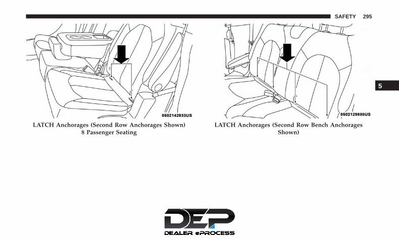
LATCH Anchorages (Second Row Anchorages Shown)8 Passenger Seating
LATCH Anchorages (Second Row Bench AnchoragesShown)
5
SAFETY 295
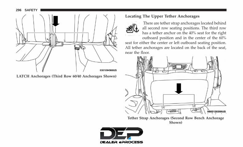
Locating The Upper Tether Anchorages
There are tether strap anchorages located behindall second row seating positions. The third rowhas a tether anchor on the 40% seat for the rightoutboard position and in the center of the 60%
seat for either the center or left outboard seating position.All tether anchorages are located on the back of the seat,near the floor.
LATCH Anchorages (Third Row 60/40 Anchorages Shown)
Tether Strap Anchorages (Second Row Bench AnchorageShown)
296 SAFETY

Tether Strap Anchorages (Second Row 7 Passenger Stow n’Go Anchorage Shown)
Tether Strap Anchorages (Second Row 8 PassengerAnchorage Shown)
5
SAFETY 297
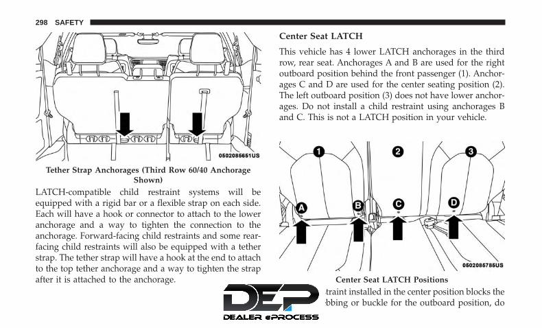
LATCH-compatible child restraint systems will beequipped with a rigid bar or a flexible strap on each side.Each will have a hook or connector to attach to the loweranchorage and a way to tighten the connection to theanchorage. Forward-facing child restraints and some rear-facing child restraints will also be equipped with a tetherstrap. The tether strap will have a hook at the end to attachto the top tether anchorage and a way to tighten the strapafter it is attached to the anchorage.
Center Seat LATCH
This vehicle has 4 lower LATCH anchorages in the thirdrow, rear seat. Anchorages A and B are used for the rightoutboard position behind the front passenger (1). Anchor-ages C and D are used for the center seating position (2).The left outboard position (3) does not have lower anchor-ages. Do not install a child restraint using anchorages Band C. This is not a LATCH position in your vehicle.
If a child restraint installed in the center position blocks theseat belt webbing or buckle for the outboard position, do
Tether Strap Anchorages (Third Row 60/40 AnchorageShown)
Center Seat LATCH Positions
298 SAFETY

not use that outboard position. If a child seat in the centerposition blocks the outboard LATCH anchors or seat belt,do not install a child seat in that outboard position.
WARNING!
• Use anchorages C and D to install a LATCH-compatible child restraint in the center seating posi-tion (2). Do not install a LATCH-compatible childrestraint using anchorages B and C. This is not aLATCH-compatible position in your vehicle.
• Never use the same lower anchorage to attach morethan one child restraint. Please refer to �To Install ALATCH-Compatible Child Restraint� for typical in-stallation instructions.
Always follow the directions of the child restraint manu-facturer when installing your child restraint. Not all childrestraint systems will be installed as described here.
To Install A LATCH-Compatible Child Restraint
If the selected seating position has a Switchable AutomaticLocking Retractor (ALR) seat belt, stow the seat belt,following the instructions below. See the section “InstallingChild Restraints Using the Vehicle Seat Belt” to check whattype of seat belt each seating position has.
1. Loosen the adjusters on the lower straps and on thetether strap of the child seat so that you can more easilyattach the hooks or connectors to the vehicle anchor-ages.
2. Place the child seat between the lower anchorages forthat seating position. For some second row seats, youmay need to recline the seat and / or raise the headrestraint (if adjustable) to get a better fit. If the rear seatcan be moved forward and rearward in the vehicle, youmay wish to move it to its rear-most position to makeroom for the child seat. You may also move the front seatforward to allow more room for the child seat.
3. Attach the lower hooks or connectors of the childrestraint to the lower anchorages in the selected seatingposition.
4. If the child restraint has a tether strap, connect it to thetop tether anchorage. See the section “Installing ChildRestraints Using the Top Tether Anchorage” for direc-tions to attach a tether anchor.
5. Tighten all of the straps as you push the child restraintrearward and downward into the seat. Remove slack inthe straps according to the child restraint manufactur-er’s instructions.
5
SAFETY 299

6. Test that the child restraint is installed tightly by pullingback and forth on the child seat at the belt path. Itshould not move more than 1 inch (25.4 mm) in anydirection.
How To Stow An Unused Switchable-ALR (ALR)Seat Belt:
When using the LATCH attaching system to install a childrestraint, stow all ALR seat belts that are not being used byother occupants or being used to secure child restraints. Anunused belt could injure a child if they play with it andaccidentally lock the seat belt retractor. Before installing achild restraint using the LATCH system, buckle the seatbelt behind the child restraint and out of the child’s reach.If the buckled seat belt interferes with the child restraintinstallation, instead of buckling it behind the child re-straint, route the seat belt through the child restraint beltpath and then buckle it. Do not lock the seat belt. Remindall children in the vehicle that the seat belts are not toys andthat they should not play with them.
WARNING!
• Improper installation of a child restraint to theLATCH anchorages can lead to failure of the re-straint. The child could be badly injured or killed.Follow the child restraint manufacturer’s directionsexactly when installing an infant or child restraint.
• Child restraint anchorages are designed to withstandonly those loads imposed by correctly-fitted childrestraints. Under no circumstances are they to beused for adult seat belts, harnesses, or for attachingother items or equipment to the vehicle.
Installing Child Restraints Using The Vehicle SeatBelt
Child restraint systems are designed to be secured invehicle seats by lap belts or the lap belt portion of alap/shoulder belt.
WARNING!
• Improper installation or failure to properly secure achild restraint can lead to failure of the restraint. Thechild could be badly injured or killed.
(Continued)
300 SAFETY

WARNING! (Continued)• Follow the child restraint manufacturer’s directions
exactly when installing an infant or child restraint.
The seat belts in the passenger seating positions areequipped with a Switchable Automatic Locking Retractor(ALR) that is designed to keep the lap portion of the seatbelt tight around the child restraint so that it is notnecessary to use a locking clip. The ALR retractor can be“switched” into a locked mode by pulling all of thewebbing out of the retractor and then letting the webbingretract back into the retractor. If it is locked, the ALR willmake a clicking noise while the webbing is pulled back intothe retractor.
Refer to the “Automatic Locking Mode” description in“Switchable Automatic Locking Retractors (ALR)” under“Occupant Restraint Systems” for additional informationon ALR.
Please see the table below and the following sections formore information.
Lap/Shoulder Belt Systems For Installing ChildRestraints In This Vehicle
7 Passenger Bench Seat Automatic Locking Retractor(ALR) Locations
ALR = Switchable Automatic Locking RetractorTop Tether Anchorage Symbol
5
SAFETY 301

7 Passenger Stow ‘n Go Seating Automatic LockingRetractor (ALR) Locations
ALR = Switchable Automatic Locking RetractorTop Tether Anchorage Symbol
8 Passenger Automatic Locking Retractor (ALR) Locations
ALR = Switchable Automatic Locking RetractorTop Tether Anchorage Symbol
302 SAFETY

Frequently Asked QuestionsWhat is the weight limit (child’sweight + weight of the child re-
straint) for using the Tether Anchorwith the seat belt to attach a forward
facing child restraint?
Weight limit of the Child Restraint Always use the tether anchor whenusing the seat belt to install a for-
ward facing child restraint, up to therecommended weight limit of the
child restraint.Can the rear-facing child restraint
touch the back of the front passengerseat?
Yes Contact between the front passengerseat and the child restraint is al-
lowed, if the child restraint manufac-turer also allows contact.
Can the rear head restraints beremoved?
Yes The 2nd row head restraints onbench and the center head restraintin the 8 passenger vehicle can be re-moved if they interfere with the in-stallation of the child restraint. 2ndrow Stow ’n Go head restraints arenot removable. The 3rd row center
head restraint is removable in all ve-hicles, but the 3rd row outboard
head restraints are not removable.Refer to “Head Restraints” in “Get-ting To Know Your Vehicle” for fur-
ther information.
5
SAFETY 303

Frequently Asked QuestionsCan the buckle stalk be twisted to
tighten the seat belt against the beltpath of the child restraint?
No Do not twist the buckle stalk in aseating position with an ALR retrac-
tor.
NOTE: If the folding, non-adjustable head restraint inter-feres with the installation of the child restraint, the headrestraint may be folded and the child seat installed in frontof it.
WARNING!
Always make sure the head restraint is in its uprightposition when the seat is to be used by an occupantwho is not in a child restraint. Sitting in a seat with thehead restraint in its lowered position could result inserious injury or death in a collision.
Car Seat With Head Restraint Folded
1 — Folded Headrest2 — Child Restraint
304 SAFETY

Installing A Child Restraint With A SwitchableAutomatic Locking Retractor (ALR):
Child restraint systems are designed to be secured invehicle seats by lap belts or the lap belt portion of alap/shoulder belt.
WARNING!
• Improper installation or failure to properly secure achild restraint can lead to failure of the restraint. Thechild could be badly injured or killed.
• Follow the child restraint manufacturer’s directionsexactly when installing an infant or child restraint.
1. Place the child seat in the center of the seating position.For some second row seats, you may need to recline theseat and/or raise the head restraint (if adjustable) to geta better fit. If the rear seat can be moved forward andrearward in the vehicle, you may wish to move it to itsrear-most position to make room for the child seat. Youmay also move the front seat forward to allow moreroom for the child seat.
2. Pull enough of the seat belt webbing from the retractorto pass it through the belt path of the child restraint. Donot twist the belt webbing in the belt path.
3. Slide the latch plate into the buckle until you hear a“click.”
4. Pull on the webbing to make the lap portion tightagainst the child seat.
5. To lock the seat belt, pull down on the shoulder part ofthe belt until you have pulled all the seat belt webbingout of the retractor. Then, allow the webbing to retractback into the retractor. As the webbing retracts, you willhear a clicking sound. This means the seat belt is now inthe Automatic Locking mode.
6. Try to pull the webbing out of the retractor. If it islocked, you should not be able to pull out any webbing.If the retractor is not locked, repeat step 5.
7. Finally, pull up on any excess webbing to tighten the lapportion around the child restraint while you push thechild restraint rearward and downward into the vehicleseat.
8. If the child restraint has a top tether strap and theseating position has a top tether anchorage, connect thetether strap to the anchorage and tighten the tetherstrap. See the section “Installing Child Restraints Usingthe Top Tether Anchorage” for directions to attach atether anchor.
5
SAFETY 305
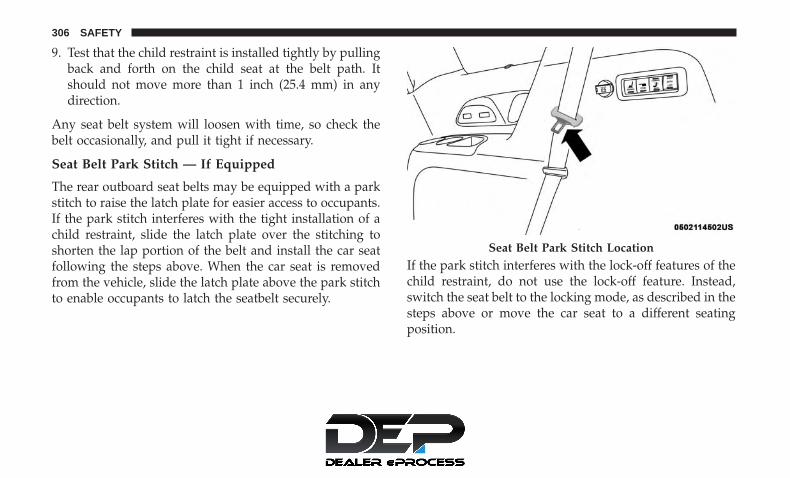
9. Test that the child restraint is installed tightly by pullingback and forth on the child seat at the belt path. Itshould not move more than 1 inch (25.4 mm) in anydirection.
Any seat belt system will loosen with time, so check thebelt occasionally, and pull it tight if necessary.
Seat Belt Park Stitch — If Equipped
The rear outboard seat belts may be equipped with a parkstitch to raise the latch plate for easier access to occupants.If the park stitch interferes with the tight installation of achild restraint, slide the latch plate over the stitching toshorten the lap portion of the belt and install the car seatfollowing the steps above. When the car seat is removedfrom the vehicle, slide the latch plate above the park stitchto enable occupants to latch the seatbelt securely.
If the park stitch interferes with the lock-off features of thechild restraint, do not use the lock-off feature. Instead,switch the seat belt to the locking mode, as described in thesteps above or move the car seat to a different seatingposition.
Seat Belt Park Stitch Location
306 SAFETY

Installing Child Restraints Using the Top TetherAnchorage
WARNING!
Do not attach a tether strap for a rear-facing car seat toany location in front of the car seat, including the seatframe or a tether anchorage. Only attach the tetherstrap of a rear-facing car seat to the tether anchoragethat is approved for that seating position, locatedbehind the top of the vehicle seat. See the section
(Continued)
WARNING! (Continued)“Lower Anchors and Tethers for CHildren (LATCH)Restraint System” for the location of approved tetheranchorages in your vehicle.
1. Look behind the seating position where you plan toinstall the child restraint to find the tether anchorage.You may need to move the seat forward to providebetter access to the tether anchorage. If there is no toptether anchorage for that seating position, move thechild restraint to another position in the vehicle if one isavailable.
Seat Belt Park Stitch
5
SAFETY 307
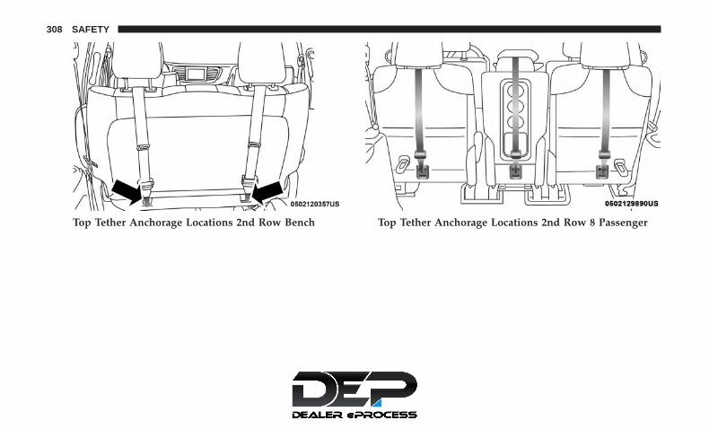
Top Tether Anchorage Locations 2nd Row Bench Top Tether Anchorage Locations 2nd Row 8 Passenger
308 SAFETY

2. Route the tether strap to provide the most direct path forthe strap between the anchor and the child seat. If yourvehicle is equipped with adjustable rear head restraints,raise the head restraint, and where possible, route thetether strap under the head restraint and between thetwo posts. If not possible, lower the head restraint andpass the tether strap around the outboard side of thehead restraint.
3. Attach the tether strap hook of the child restraint to thetop tether anchorage as shown in the diagram.
4. Remove slack in the tether strap according to the childrestraint manufacturer’s instructions.
WARNING!
• An incorrectly anchored tether strap could lead toincreased head motion and possible injury to thechild. Use only the anchorage position directly be-hind the child seat to secure a child restraint toptether strap.
(Continued)
Top Tether Anchorage Locations 3rd Row
Rear Seat Tether Strap Attachment (Second Row 7Passenger Stow n’ Go Anchorage Shown)
5
SAFETY 309

WARNING! (Continued)• If your vehicle is equipped with a split rear seat,
make sure the tether strap does not slip into theopening between the seatbacks as you remove slackin the strap.
Third Row Tether Attachment
The tether anchorage found on the back of the 60% seat inthe third row may be used by either the left outboard or thecenter seating position. Only tether one child restraint tothe tether anchorage at a time.
To connect the tether strap hook to the tether anchorage foreither seating position on the 60% third row seat:
1. Route the tether strap to provide the most direct path forthe strap between the anchor and the child seat.
2. If the car seat is in the center, raise the center headrestraint and route the tether strap around the inboard(left) side of the head restraint support posts, as shownin the diagram.
3. Attach the tether strap hook of the child restraint to thetop tether anchorage as shown in the diagram.
4. Remove slack in the tether strap according to the childrestraint manufacturer’s instructions.
Center Tether Attachment – 3rd Row
310 SAFETY

WARNING!
Do not connect the tether strap for more than one childrestraint to the tether anchorage on the 60% seat in thethird row. This anchorage is intended for one childrestraint at a time.
Transporting Pets
Air Bags deploying in the front seat could harm your pet.An unrestrained pet will be thrown about and possiblyinjured, or injure a passenger during panic braking or ina collision.Pets should be restrained in the rear seat (if equipped) inpet harnesses or pet carriers that are secured by seat belts.
SAFETY TIPS
Transporting Passengers
NEVER TRANSPORT PASSENGERS IN THE CARGOAREA.
WARNING!
• Do not leave children or animals inside parkedvehicles in hot weather. Interior heat build-up maycause serious injury or death.
• It is extremely dangerous to ride in a cargo area,inside or outside of a vehicle. In a collision, peopleriding in these areas are more likely to be seriouslyinjured or killed.
• Do not allow people to ride in any area of yourvehicle that is not equipped with seats and seat belts.
(Continued)
Outboard Tether Attachments – 3rd Row
5
SAFETY 311

WARNING! (Continued)• Be sure everyone in your vehicle is in a seat and
using a seat belt properly.
Exhaust Gas
WARNING!
Exhaust gases can injure or kill. They contain carbonmonoxide (CO), which is colorless and odorless.Breathing it can make you unconscious and can even-tually poison you. To avoid breathing (CO), followthese safety tips:• Do not run the engine in a closed garage or in
confined areas any longer than needed to move yourvehicle in or out of the area.
• If you are required to drive with the trunk/liftgate/rear doors open, make sure that all windows areclosed and the climate control BLOWER switch is setat high speed. DO NOT use the recirculation mode.
• If it is necessary to sit in a parked vehicle with theengine running, adjust your heating or cooling con-trols to force outside air into the vehicle. Set theblower at high speed.
The best protection against carbon monoxide entry into thevehicle body is a properly maintained engine exhaustsystem.
Whenever a change is noticed in the sound of the exhaustsystem, when exhaust fumes can be detected inside thevehicle, or when the underside or rear of the vehicle isdamaged, have a competent mechanic inspect the completeexhaust system and adjacent body areas for broken, dam-aged, deteriorated, or mispositioned parts. Open seams orloose connections could permit exhaust fumes to seep intothe passenger compartment. In addition, inspect the ex-haust system each time the vehicle is raised for lubricationor oil change. Replace as required.
Safety Checks You Should Make Inside The Vehicle
Seat Belts
Inspect the seat belt system periodically, checking for cuts,frays, and loose parts. Damaged parts must be replacedimmediately. Do not disassemble or modify the system.
Front seat belt assemblies must be replaced after a collision.Rear seat belt assemblies must be replaced after a collisionif they have been damaged (i.e., bent retractor, torn web-bing, etc.). If there is any question regarding seat belt orretractor condition, replace the seat belt.
312 SAFETY

Air Bag Warning Light
The Air Bag warning light will turn on for four toeight seconds as a bulb check when the ignition switchis first turned to ON/RUN. If the light is either not onduring starting, stays on, or turns on while driving,have the system inspected at an authorized dealer assoon as possible. After the bulb check, this light willilluminate with a single chime when a fault with the AirBag System has been detected. It will stay on until thefault is removed. If the light comes on intermittently orremains on while driving, have an authorized dealerservice the vehicle immediately.
Refer to “Occupant Restraint Systems” in “Safety” forfurther information.
Defroster
Check operation by selecting the defrost mode and placethe blower control on high speed. You should be able tofeel the air directed against the windshield. See an autho-rized dealer for service if your defroster is inoperable.
Floor Mat Safety Information
Always use floor mats designed to fit your vehicle. Onlyuse a floor mat that does not interfere with the operation ofthe accelerator, brake or clutch pedals. Only use a floor mat
that is securely attached using the floor mat fasteners so itcannot slip out of position and interfere with the accelera-tor, brake or clutch pedals or impair safe operation of yourvehicle in other ways.
WARNING!
An improperly attached, damaged, folded, or stackedfloor mat, or damaged floor mat fasteners may causeyour floor mat to interfere with the accelerator, brake,or clutch pedals and cause a loss of vehicle control.To prevent SERIOUS INJURY or DEATH:• ALWAYS securely attach your floor mat using the
floor mat fasteners. DO NOT install your floor matupside down or turn your floor mat over. Lightly pullto confirm mat is secured using the floor mat fasten-ers on a regular basis.
• ALWAYS REMOVE THE EXISTING FLOOR MATFROM THE VEHICLE before installing any otherfloor mat. NEVER install or stack an additional floormat on top of an existing floor mat.
• ONLY install floor mats designed to fit your vehicle.NEVER install a floor mat that cannot be properlyattached and secured to your vehicle. If a floor mat
(Continued)
5
SAFETY 313

WARNING! (Continued)needs to be replaced, only use a FCA approved floormat for the specific make, model, and year of yourvehicle.
• ONLY use the driver’s side floor mat on the driver’sside floor area. To check for interference, with thevehicle properly parked with the engine off, fullydepress the accelerator, the brake, and the clutchpedal (if present) to check for interference. If yourfloor mat interferes with the operation of any pedal,or is not secure to the floor, remove the floor matfrom the vehicle and place the floor mat in yourtrunk.
• ONLY use the passenger’s side floor mat on thepassenger’s side floor area.
• ALWAYS make sure objects cannot fall or slide intothe driver’s side floor area when the vehicle is
(Continued)
WARNING! (Continued)moving. Objects can become trapped under accelera-tor, brake, or clutch pedals and could cause a loss ofvehicle control.
• NEVER place any objects under the floor mat (e.g.,towels, keys, etc.). These objects could change theposition of the floor mat and may cause interferencewith the accelerator, brake, or clutch pedals.
• If the vehicle carpet has been removed and re-installed, always properly attach carpet to the floorand check the floor mat fasteners are secure to thevehicle carpet. Fully depress each pedal to check forinterference with the accelerator, brake, or clutchpedals then re-install the floor mats.
• It is recommended to only use mild soap and waterto clean your floor mats. After cleaning, always checkyour floor mat has been properly installed and issecured to your vehicle using the floor mat fastenersby lightly pulling mat.
314 SAFETY

Periodic Safety Checks You Should Make OutsideThe Vehicle
Tires
Examine tires for excessive tread wear and uneven wearpatterns. Check for stones, nails, glass, or other objectslodged in the tread or sidewall. Inspect the tread for cutsand cracks. Inspect sidewalls for cuts, cracks, and bulges.Check the wheel nuts for tightness. Check the tires (includ-ing spare) for proper cold inflation pressure.
Lights
Have someone observe the operation of brake lights andexterior lights while you work the controls. Check turnsignal and high beam indicator lights on the instrumentpanel.
Door Latches
Check for proper closing, latching, and locking.
Fluid Leaks
Check area under the vehicle after overnight parking forfuel, coolant, oil, or other fluid leaks. Also, if gasolinefumes are detected or if fuel, or brake fluid leaks aresuspected. The cause should be located and correctedimmediately.
5
SAFETY 315


STARTING AND OPERATING
CONTENTS� STARTING THE ENGINE . . . . . . . . . . . . . . . . . .321
▫ Normal Starting . . . . . . . . . . . . . . . . . . . . . . .321
▫ Cold Weather Operation(Below –22°F Or −30°C) . . . . . . . . . . . . . . . . . .326
▫ After Starting — Warming Up The Engine . . . . .326
▫ If Engine Fails To Start . . . . . . . . . . . . . . . . . .326
▫ To Turn Off The Engine Using ENGINESTART/STOP Button . . . . . . . . . . . . . . . . . . . .326
� ENGINE BLOCK HEATER — IF EQUIPPED . . . .327
� ENGINE BREAK-IN RECOMMENDATIONS . . . .328
� PARK BRAKE . . . . . . . . . . . . . . . . . . . . . . . . . .328
▫ Electric Park Brake (EPB) . . . . . . . . . . . . . . . . .328
� AUTOMATIC TRANSMISSION . . . . . . . . . . . . . .333
▫ Ignition Park Interlock . . . . . . . . . . . . . . . . . . .334
▫ Brake/Transmission Shift Interlock System . . . .334
▫ Nine-Speed Automatic Transmission . . . . . . . . .335
▫ Gear Ranges . . . . . . . . . . . . . . . . . . . . . . . . . .336
� ACTIVE NOISE CANCELLATION . . . . . . . . . . . .341
� POWER STEERING . . . . . . . . . . . . . . . . . . . . . .341
� STOP/START SYSTEM — IF EQUIPPED. . . . . . . .342
▫ Auto Stop/Start . . . . . . . . . . . . . . . . . . . . . . . .342
▫ Possible Reasons The Engine Does NotAutostop . . . . . . . . . . . . . . . . . . . . . . . . . . . .343
▫ To Start The Engine While In Auto Stop/Start. . .344
▫ To Manually Turn Off The Stop/Start System . . .344
▫ To Manually Turn On The Stop/Start System . . .345
▫ System Malfunction . . . . . . . . . . . . . . . . . . . . .345
� SPEED CONTROL — IF EQUIPPED . . . . . . . . . .346
▫ To Activate . . . . . . . . . . . . . . . . . . . . . . . . . . .346
6

▫ To Set A Desired Speed. . . . . . . . . . . . . . . . . . .347
▫ To Vary The Speed Setting . . . . . . . . . . . . . . . .347
▫ To Accelerate For Passing . . . . . . . . . . . . . . . . .348
▫ To Resume Speed . . . . . . . . . . . . . . . . . . . . . .348
▫ To Deactivate . . . . . . . . . . . . . . . . . . . . . . . . .348
� ADAPTIVE CRUISE CONTROL (ACC) — IFEQUIPPED . . . . . . . . . . . . . . . . . . . . . . . . . . . .348
▫ Adaptive Cruise Control (ACC) Operation . . . . .350
▫ Activating Adaptive Cruise Control (ACC) . . . . .351
▫ To Activate/Deactivate . . . . . . . . . . . . . . . . . . .351
▫ To Set A Desired ACC Speed. . . . . . . . . . . . . . .352
▫ To Cancel . . . . . . . . . . . . . . . . . . . . . . . . . . . .352
▫ To Turn Off . . . . . . . . . . . . . . . . . . . . . . . . . . .353
▫ To Resume . . . . . . . . . . . . . . . . . . . . . . . . . . .353
▫ To Vary The Speed Setting . . . . . . . . . . . . . . . .353
▫ Setting The Following Distance In ACC . . . . . . .355
▫ Overtake Aid . . . . . . . . . . . . . . . . . . . . . . . . . .358
▫ ACC Operation At Stop . . . . . . . . . . . . . . . . . .358
▫ Adaptive Cruise Control (ACC) Menu . . . . . . . .359
▫ Display Warnings And Maintenance . . . . . . . . .360
▫ Precautions While Driving With ACC. . . . . . . . .362
▫ General Information . . . . . . . . . . . . . . . . . . . . .365
▫ Normal (Fixed Speed) Cruise Control Mode . . . .365
� PARKSENSE REAR PARK ASSIST — IFEQUIPPED . . . . . . . . . . . . . . . . . . . . . . . . . . . .368
▫ ParkSense Sensors . . . . . . . . . . . . . . . . . . . . . .370
▫ ParkSense Visual Alert . . . . . . . . . . . . . . . . . . .370
▫ ParkSense Display . . . . . . . . . . . . . . . . . . . . . .370
▫ Enabling And Disabling ParkSense . . . . . . . . . .375
▫ Service The ParkSense Rear Park Assist System. .375
▫ Cleaning The ParkSense System. . . . . . . . . . . . .376
▫ ParkSense System Usage Precautions . . . . . . . . .376
� PARKSENSE FRONT AND REAR PARK ASSIST —IF EQUIPPED . . . . . . . . . . . . . . . . . . . . . . . . . .378
▫ ParkSense Sensors . . . . . . . . . . . . . . . . . . . . . .379
318 STARTING AND OPERATING

▫ ParkSense Visual Alert . . . . . . . . . . . . . . . . . . .380
▫ ParkSense Display . . . . . . . . . . . . . . . . . . . . . .380
▫ Enabling And Disabling ParkSense . . . . . . . . . .389
▫ Service The ParkSense Park Assist System . . . . .389
▫ Cleaning The ParkSense System. . . . . . . . . . . . .390
▫ ParkSense System Usage Precautions . . . . . . . . .390
� PARKSENSE ACTIVE PARK ASSIST SYSTEM — IFEQUIPPED . . . . . . . . . . . . . . . . . . . . . . . . . . . .392
▫ Enabling And Disabling The ParkSense ActivePark Assist System . . . . . . . . . . . . . . . . . . . . . .393
▫ Parallel Parking Space AssistanceOperation/Display . . . . . . . . . . . . . . . . . . . . . .394
▫ Perpendicular Parking Space AssistanceOperation/Display . . . . . . . . . . . . . . . . . . . . . .403
� LANESENSE — IF EQUIPPED . . . . . . . . . . . . . .412
▫ LaneSense Operation . . . . . . . . . . . . . . . . . . . .412
▫ Turning LaneSense On Or Off . . . . . . . . . . . . . .413
▫ LaneSense Warning Message . . . . . . . . . . . . . . .414
▫ Changing LaneSense Status . . . . . . . . . . . . . . . .416
� PARKVIEW REAR BACK UP CAMERA . . . . . . . .416
� SURROUND VIEW CAMERA SYSTEM — IFEQUIPPED . . . . . . . . . . . . . . . . . . . . . . . . . . . .419
� REFUELING THE VEHICLE . . . . . . . . . . . . . . . .422
� VEHICLE LOADING . . . . . . . . . . . . . . . . . . . . .424
▫ Certification Label . . . . . . . . . . . . . . . . . . . . . .424
� TRAILER TOWING . . . . . . . . . . . . . . . . . . . . . .426
▫ Common Towing Definitions. . . . . . . . . . . . . . .426
▫ Trailer Hitch Classification . . . . . . . . . . . . . . . .428
▫ Trailer Towing Weights (Maximum Trailer WeightRatings) . . . . . . . . . . . . . . . . . . . . . . . . . . . . .429
▫ Vehicle Loading Chart . . . . . . . . . . . . . . . . . . .430
▫ Trailer And Tongue Weight . . . . . . . . . . . . . . .432
▫ Towing Requirements . . . . . . . . . . . . . . . . . . .432
▫ Towing Tips . . . . . . . . . . . . . . . . . . . . . . . . . .436
6
STARTING AND OPERATING 319

� RECREATIONAL TOWING (BEHINDMOTORHOME, ETC.) . . . . . . . . . . . . . . . . . . . .437
▫ Towing This Vehicle Behind Another Vehicle. . . .437
▫ Recreational Towing — All Models . . . . . . . . . .438
� DRIVING TIPS . . . . . . . . . . . . . . . . . . . . . . . . . .438
▫ Driving On Slippery Surfaces . . . . . . . . . . . . . .438
▫ Driving Through Water . . . . . . . . . . . . . . . . . .439
320 STARTING AND OPERATING

STARTING THE ENGINE
Before starting your vehicle, adjust your seat, adjust bothinside and outside mirrors, and fasten your seat belts.
WARNING!
• When exiting the vehicle, always remove the key fobfrom the vehicle and lock your vehicle.
• Never leave children alone in a vehicle, or withaccess to an unlocked vehicle.
• Allowing children to be in a vehicle unattended isdangerous for a number of reasons. A child or otherscould be seriously or fatally injured. Childrenshould be warned not to touch the parking brake,brake pedal or the transmission gear selector.
• Do not leave the key fob in or near the vehicle, or ina location accessible to children, and do not leave theignition of a vehicle equipped with Keyless Enter-N-Go in the ACC or ON/RUN mode. A child couldoperate power windows, other controls, or move thevehicle.
• Do not leave children or animals inside parkedvehicles in hot weather. Interior heat build-up maycause serious injury or death.
Start the engine with the gear selector in the NEUTRAL orPARK position. Apply the brake before shifting to anydriving range.
Normal Starting
NOTE: Normal starting of either a cold or a warm engineis obtained without pumping or pressing the acceleratorpedal.
To Turn On The Engine Using ENGINE START/STOPButton
1. The transmission must be in PARK or NEUTRAL.
2. Press and hold the brake pedal while pushing theENGINE START/STOP button once.
3. The system takes over and attempts to start the vehicle.If the vehicle fails to start, the starter will disengageautomatically after 10 seconds.
4. If you wish to stop the cranking of the engine prior tothe engine starting, push the button again.
6
STARTING AND OPERATING 321

ENGINE START/STOP Button Functions — With Driv-er’s Foot OFF The Brake Pedal (In PARK Or NEUTRALPosition)
The ENGINE START/STOP button operates similar to anignition switch. It has three positions, OFF, ACC, and RUN.To change the ignition positions without starting the ve-hicle and use the accessories follow these steps:
• Starting with the ignition in the OFF position,
• Push the ENGINE START/STOP button once to placethe ignition to the ACC position (instrument cluster willdisplay “ACC”),
• Push the ENGINE START/STOP button a second time toplace the ignition to the RUN position (instrumentcluster will display “ON/RUN”),
• Push the ENGINE START/STOP button a third time toreturn the ignition to the OFF position (instrumentcluster will display “OFF”).
NOTE: Only press one pedal at a time while driving thevehicle. Torque performance of the vehicle could be reducedif both pedals are pressed at the same time. If pressure isdetected on both pedals simultaneously, a warning messagewill display in the instrument cluster. For further informa-tion, refer to “Instrument Cluster Display” in “Getting ToKnow Your Instrument Panel”.
AutoPark
AutoPark is a supplemental feature to assist in placing thevehicle in PARK should the situations on the followingpages occur. It is a back up system and should not be reliedupon as the primary method by which the driver shifts thevehicle into PARK.
The conditions under which AutoPark will engage areoutlined on the following pages.
WARNING!
• Driver inattention could lead to failure to place thevehicle in PARK. ALWAYS DO A VISUAL CHECKthat your vehicle is in PARK by verifying that a solid(not blinking) “P” is indicated in the instrumentcluster display and near the gear selector. If the �P�indicator is blinking, your vehicle is not in PARK. Asan added precaution, always apply the parking brakewhen exiting the vehicle.
• AutoPark is a supplemental feature. It is not de-signed to replace the need to shift your vehicle intoPARK. It is a back up system and should not berelied upon as the primary method by which thedriver shifts the vehicle into PARK.
322 STARTING AND OPERATING

ALWAYS DO A VISUAL CHECK that your vehicle is inPARK by looking for the “P” in the Instrument ClusterDisplay and on the shifter. As an added precaution, alwaysapply the parking brake.
If the vehicle is not in PARK and the driver attempts toturn off the engine, if certain conditions are met, thevehicle will AutoPark, automatically shifting the vehi-cle’s transmission to the PARK position. The rotaryshifter will automatically reset itself to the PARK posi-tion. The vehicle’s ignition will then move to the OFFposition (Engine OFF). When AutoPark is activated theinstrument cluster will display the message “AutoParkEngaged”
AutoPark will engage when all of these conditions are met:
• Vehicle is equipped with a rotary selector
• Vehicle is not in PARK
• Vehicle Speed is 1.2 MPH (1.9 km/h) or less
• Driver has pushed the ENGINE START/STOP BUTTON
If the vehicle is not in PARK and the driver exits thevehicle with the engine running, if certain conditions aremet, the vehicle will AutoPark, automatically shifting thevehicle’s transmission to the PARK position. The Electric
Park Brake SAFE HOLD feature will also activate insome conditions. Please reference SAFE HOLD pages foradditional information regarding this function.
CAUTION!
Engine will remain running.
AutoPark will engage when all of these conditions are met:
• Vehicle is equipped with a rotary selector
• Vehicle is not in PARK
• Vehicle speed is 1.2 MPH (1.9 km/h) or less
• Driver’s door is ajar
• Driver’s seat belt is unbuckled
• Brake Pedal is not depressed
The MESSAGE “ AutoPark Engaged”will display in theinstrument cluster.
AutoPark In Stop/Start Autostop Mode
• AutoPark will engage when all of these conditions aremet:
• Vehicle is equipped with a rotary shifter
6
STARTING AND OPERATING 323

• Vehicle is not in PARK
• Vehicle speed is 1.2 MPH (1.9 km/h) or less
• Driver’s door is ajar
• Driver’s seat belt is unbuckled or Brake Pedal is notdepressed
The MESSAGE “ AutoPark Engaged”will display in theinstrument cluster.
WARNING!
• Never use the PARK position as a substitute for theparking brake. Always apply the parking brake fullywhen exiting the vehicle to guard against vehiclemovement and possible injury or damage.
• Your vehicle could move and injure you and others ifit is not in PARK. Check by trying to move thetransmission gear selector out of PARK with thebrake pedal released. Make sure the transmission isin PARK before exiting the vehicle.
• The transmission may not engage PARK if the ve-hicle is moving. Always bring the vehicle to acomplete stop before shifting to PARK, and verifythat the transmission gear position indicator solidly
(Continued)
WARNING! (Continued)indicates PARK (P) without blinking. Ensure that thevehicle is completely stopped, and the PARK posi-tion is properly indicated, before exiting the vehicle.
• It is dangerous to shift out of PARK or NEUTRAL ifthe engine speed is higher than idle speed. If yourfoot is not firmly pressing the brake pedal, thevehicle could accelerate quickly forward or in re-verse. You could lose control of the vehicle and hitsomeone or something. Only shift into gear when theengine is idling normally and your foot is firmlypressing the brake pedal.
• Unintended movement of a vehicle could injurethose in or near the vehicle. As with all vehicles, youshould never exit a vehicle while the engine isrunning. Before exiting a vehicle, always come to acomplete stop, then apply the parking brake, shiftthe transmission into PARK, and turn the ignitionOFF. When the ignition is in the OFF mode, thetransmission is locked in PARK, securing the vehicleagainst unwanted movement.
(Continued)
324 STARTING AND OPERATING
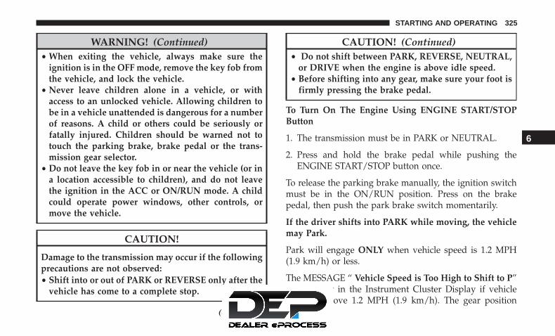
WARNING! (Continued)• When exiting the vehicle, always make sure the
ignition is in the OFF mode, remove the key fob fromthe vehicle, and lock the vehicle.
• Never leave children alone in a vehicle, or withaccess to an unlocked vehicle. Allowing children tobe in a vehicle unattended is dangerous for a numberof reasons. A child or others could be seriously orfatally injured. Children should be warned not totouch the parking brake, brake pedal or the trans-mission gear selector.
• Do not leave the key fob in or near the vehicle (or ina location accessible to children), and do not leavethe ignition in the ACC or ON/RUN mode. A childcould operate power windows, other controls, ormove the vehicle.
CAUTION!
Damage to the transmission may occur if the followingprecautions are not observed:• Shift into or out of PARK or REVERSE only after the
vehicle has come to a complete stop.
(Continued)
CAUTION! (Continued)• Do not shift between PARK, REVERSE, NEUTRAL,
or DRIVE when the engine is above idle speed.• Before shifting into any gear, make sure your foot is
firmly pressing the brake pedal.
To Turn On The Engine Using ENGINE START/STOPButton
1. The transmission must be in PARK or NEUTRAL.
2. Press and hold the brake pedal while pushing theENGINE START/STOP button once.
To release the parking brake manually, the ignition switchmust be in the ON/RUN position. Press on the brakepedal, then push the park brake switch momentarily.
If the driver shifts into PARK while moving, the vehiclemay Park.
Park will engage ONLY when vehicle speed is 1.2 MPH(1.9 km/h) or less.
The MESSAGE “ Vehicle Speed is Too High to Shift to P”will display in the Instrument Cluster Display if vehiclespeed is above 1.2 MPH (1.9 km/h). The gear position
6
STARTING AND OPERATING 325

indicator will blink continuously until the selector is re-turned to the proper position, or the requested shift can becompleted.
WARNING!
If vehicle speed is not below 1.2 MPH (1.9 km/h) whenthe driver shifts into PARK, the transmission will de-fault to NEUTRAL until the vehicle speed drops below1.2 MPH (1.9 km/h) and the above condition are met,enabling AutoPark. A vehicle left in the NEUTRALposition can roll. As an added precaution, always applythe parking brake when exiting the vehicle.
Cold Weather Operation (Below –22°F Or −30°C)
To ensure reliable starting at these temperatures, use of anexternally powered electric engine block heater (availablefrom your authorized dealer) is recommended.
After Starting — Warming Up The Engine
The idle speed is controlled automatically and it willdecrease as the engine warms up.
If Engine Fails To Start
WARNING!
• Never pour fuel or other flammable liquid into thethrottle body air inlet opening in an attempt to startthe vehicle. This could result in flash fire causingserious personal injury.
• Do not attempt to push or tow your vehicle to get itstarted. Vehicles equipped with an automatic trans-mission cannot be started this way. Unburned fuelcould enter the catalytic converter and once theengine has started, ignite and damage the converterand vehicle.
• If the vehicle has a discharged battery, booster cablesmay be used to obtain a start from a booster batteryor the battery in another vehicle. This type of startcan be dangerous if done improperly. Refer to “JumpStarting Procedure” in “In Case Of Emergency” forfurther information.
To Turn Off The Engine Using ENGINESTART/STOP Button
1. Place the gear selector in PARK, then push and releasethe ENGINE START/STOP button.
326 STARTING AND OPERATING

2. The ignition switch will return to the OFF position.
3. If the gear selector is not in PARK, the ENGINE START/STOP button must be held for two seconds or three shortpushes in a row with the vehicle speed above 5 mph(8 km/h) before the engine will shut off. The ignitionswitch position will remain in the ACC position until thegear selector is in PARK and the button is pushed twiceto the OFF position. If the gear selector is not in PARKand the ENGINE START/STOP button is pushed once,the instrument cluster will display a “Vehicle Not InPark” message and the engine will remain running.Never leave a vehicle out of the PARK position, or itcould roll.
NOTE: If the ignition switch is left in the ACC or RUN(engine not running) position and the transmission is inPARK, the system will automatically time out after 30minutes of inactivity and the ignition will switch to theOFF position.
ENGINE BLOCK HEATER — IF EQUIPPED
The engine block heater warms the engine and permitsquicker starts in cold weather.
Connect the cord to a 110-115 Volt AC electrical outlet witha grounded, three-wire extension cord.
For ambient temperatures below 0°F (-18°C), the engineblock heater is recommended. For ambient temperaturesbelow -20°F (-29°C), the engine block heater is required.
The engine block heater cord is routed under the hood,behind to the passenger’s side headlamp. Follow the stepsbelow to properly use the engine block heater:
1. Locate the engine block heater cord (behind the passen-ger’s side headlamp).
2. Undo the hook-and-loop strap that secures the heatercord in place.
3. Pull the cord to the front of the vehicle and plug it intoa grounded, three-wire extension cord.
4. After the vehicle is running, reattach the cord to thehook-and-loop strap and properly stow away behindthe passenger’s side headlamp.
NOTE:
• The engine block heater cord is a factory installedoption. If your vehicle is not equipped, heater cords areavailable from your authorized Mopar dealer.
• The engine block heater will require 110 Volts AC and6.5 Amps to activate the heater element.
6
STARTING AND OPERATING 327

• The engine block heater must be plugged in at least onehour to have an adequate warming effect on the engine.
WARNING!
Remember to disconnect the engine block heater cordbefore driving. Damage to the 110-115 Volt electricalcord could cause electrocution.
ENGINE BREAK-IN RECOMMENDATIONS
A long break-in period is not required for the engine anddrivetrain (transmission and axle) in your vehicle.
Drive moderately during the first 300 miles (500 km). Afterthe initial 60 miles (100 km), speeds up to 50 or 55 mph (80or 90 km/h) are desirable.
While cruising, brief full-throttle acceleration within thelimits of local traffic laws contributes to a good break-in.Wide-open throttle acceleration in low gear can be detri-mental and should be avoided.
The engine oil installed in the engine at the factory is ahigh-quality energy conserving type lubricant. Oil changesshould be consistent with anticipated climate conditions
under which vehicle operations will occur. For the recom-mended viscosity and quality grades, refer to “DealerService” in “Servicing And Maintenance”.
CAUTION!
Never use Non-Detergent Oil or Straight Mineral Oilin the engine or damage may result.
NOTE: A new engine may consume some oil during itsfirst few thousand miles (kilometers) of operation. Thisshould be considered a normal part of the break-in and notinterpreted as a problem.
PARK BRAKE
Electric Park Brake (EPB)
Your vehicle is equipped with an Electric Park BrakeSystem (EPB) that offers simple operation, and someadditional features that make the park brake more conve-nient and useful.
The park brake is primarily intended to prevent the vehiclefrom rolling while parked. Before leaving the vehicle, makesure that the park brake is applied. Also, be certain to leavethe transmission in PARK.
328 STARTING AND OPERATING

You can engage the park brake in two ways;
• Manually, by applying the park brake switch.
• Automatically, by enabling the Auto Park Brake featurein the customer programmable features section of theUconnect Settings.
The park brake switch is located in the integrated centerstack.
To apply the park brake manually, push the switch mo-mentarily. You may hear a slight whirring sound from theback of the vehicle while the park brake engages. Once thepark brake is fully engaged, the BRAKE warning lamp in
the instrument cluster and an indicator on the switch willilluminate. If your foot is on the brake pedal while youapply the park brake, you may notice a small amount ofbrake pedal movement. The park brake can be appliedeven when the ignition switch is OFF, however, it can onlybe released when the ignition switch in the ACC orON/RUN position.
NOTE: The EPB fault lamp will illuminate if the EPBswitch is held for longer than 180 seconds. The light willextinguish upon releasing the switch.
If the Auto Park Brake feature is enabled, the parking brakewill automatically engage whenever the transmission isplaced into PARK. Once the park brake is engaged, theBRAKE warning lamp in the instrument cluster and theLED indicator on the switch will illuminate. If your foot ison the brake pedal, you may notice a small amount ofbrake pedal movement while the parking brake is engag-ing.
The park brake will release automatically when the igni-tion is cycled to the ON/RUN position, the transmission isin DRIVE or REVERSE, and the driver seat belt is buckledand an attempt is made to drive the vehicle away bypressing the accelerator pedal.
Electric Park Brake Switch
6
STARTING AND OPERATING 329

To release the parking brake manually, the ignition switchmust be in the ON/RUN position. Press on the brakepedal, then push the park brake switch momentarily. Youmay hear a slight whirring sound from the back of thevehicle while the parking brake disengages. You may alsonotice a small amount of movement in the brake pedal.Once the park brake is fully disengaged, the BRAKEwarning lamp in the instrument cluster and the LEDindicator on the switch will extinguish.
NOTE: When parking on a hill, it is important to turn thefront wheels toward the curb on a downhill grade andaway from the curb on an uphill grade. Apply the parkbrake before placing the gear selector in PARK, otherwisethe load on the transmission locking mechanism may makeit difficult to move the gear selector out of PARK. The parkbrake should always be applied whenever the driver is notin the vehicle.
WARNING!
• Never use the PARK position as a substitute for theparking brake. Always apply the parking brake fullywhen parked to guard against vehicle movement andpossible injury or damage.
(Continued)
WARNING! (Continued)• When exiting the vehicle, always make sure the
ignition is in the OFF mode, remove the key fob fromthe vehicle, and lock your vehicle.
• Never leave children alone in a vehicle, or withaccess to an unlocked vehicle. Allowing children tobe in a vehicle unattended is dangerous for a numberof reasons. A child or others could be seriously orfatally injured. Children should be warned not totouch the parking brake, brake pedal or the trans-mission gear selector.
• Do not leave the key fob in or near the vehicle, (or ina location accessible to children), and do not leavethe ignition in the ACC or ON/RUN mode. A childcould operate power windows, other controls, ormove the vehicle.
• Be sure the parking brake is fully disengaged beforedriving; failure to do so can lead to brake failure anda collision.
• Always fully apply the parking brake when leavingyour vehicle, or it may roll and cause damage orinjury. Also be certain to leave the transmission in
(Continued)
330 STARTING AND OPERATING

WARNING! (Continued)PARK. Failure to do so may allow the vehicle to rolland cause damage or injury.
• Driving the vehicle with the parking brake engaged,or repeated use of the parking brake to slow thevehicle may cause serious damage to the brakesystem.
CAUTION!
If the Brake System Warning Light remains on with theparking brake released, a brake system malfunction isindicated. Have the brake system serviced by an au-thorized dealer immediately.
If exceptional circumstances should make it necessary toengage the park brake while the vehicle is in motion, pushon the electric park brake switch for as long as engagementis desired. The BRAKE warning lamp will illuminate, anda continuous chime will sound. The rear stop lamps willalso be illuminated automatically while the vehicle re-mains in motion.
To disengage the park brake while the vehicle is in motion,release the switch. If the vehicle is brought to a complete
stop using the park brake, when the vehicle reachesapproximately 3 mph (4.8 km/h), the park brake willremain engaged.
In the unlikely event of a malfunction of the Electric ParkBrake system, a yellow EPB fault lamp will illuminate. Thismay be accompanied by the BRAKE warning lamp flash-ing. In this case, urgent service of the electric park brakesystem is required. Do not rely on the park brake to holdthe vehicle stationary.
Auto Park Brake
The Electric Park Brake can be programmed to be appliedautomatically whenever the vehicle is at a standstill andthe automatic transmission is placed in PARK. Auto ParkBrake is enabled and disabled by customer selectionthrough the “Customer Programmable Features” section ofthe “Uconnect Settings”.
SafeHold
SafeHold is a safety feature of the Electric Park BrakeSystem that will engage the park brake automatically if thevehicle is left unsecured. If the automatic transmission isnot in PARK, the seat belt is unbuckled, the driver door isopen, the vehicle is at a standstill, and there is no attempt
6
STARTING AND OPERATING 331

to depress the brake pedal or accelerator pedal, the parkbrake will automatically engage to prevent the vehiclefrom rolling.
SafeHold can be temporarily bypassed by pushing theElectric Park Brake Switch while the driver door is openand brake pedal is pressed. Once manually bypassed,SafeHold will be enabled again once the vehicle reaches12 mph (20 km/h) or the ignition is cycled to the OFFposition and back to ON again.
Brake Service Mode
We recommend having your brakes serviced by yourauthorized dealer. You should only make repairs for whichyou have the knowledge and the right equipment. Youshould only enter Brake Service Mode during brake ser-vice.
When servicing your rear brakes, it may be necessary foryou or your technician to push the rear piston into the rearcaliper bore. With the Electric Park Brake system, this canonly be done after retracting the Electric Park Brakeactuator. Fortunately, actuator retraction can be done easilyby entering the “Brake Service” through the “UconnectSettings” in your vehicle. This menu based system willguide you through the steps necessary to retract the EPBactuator in order to perform rear brake service.
Brake Service Mode has requirements that must be met inorder to be activated:
• The vehicle must be at a standstill.
• The park brake must be unapplied.
• The transmission must be in PARK or NEUTRAL.
While in service mode, the Electric Park Brake fault lampwill flash continuously while the ignition switch is ON.
When brake service work is complete, the following stepsmust be followed to reset the parking brake system tonormal operation:
• Ensure the vehicle is at a standstill.
• Press the brake pedal with moderate force.
• Apply the Electric Park Brake Switch.
WARNING!
You can be badly injured working on or around amotor vehicle. Do only that service work for which youhave the knowledge and the right equipment. If youhave any doubt about your ability to perform a servicejob, take your vehicle to a competent mechanic.
332 STARTING AND OPERATING

AUTOMATIC TRANSMISSION
WARNING!
• Never use the PARK position as a substitute for theparking brake. Always apply the parking brake fullywhen exiting the vehicle to guard against vehiclemovement and possible injury or damage.
• Your vehicle could move and injure you and others ifit is not in PARK. Check by trying to move thetransmission gear selector out of PARK with thebrake pedal released. Make sure the transmission isin PARK before exiting the vehicle.
• The transmission may not engage PARK if the ve-hicle is moving. Always bring the vehicle to acomplete stop before shifting to PARK, and verifythat the transmission gear position indicator solidlyindicates PARK (P) without blinking. Ensure that thevehicle is completely stopped, and the PARK posi-tion is properly indicated, before exiting the vehicle.
• It is dangerous to shift out of PARK or NEUTRAL ifthe engine speed is higher than idle speed. If yourfoot is not firmly pressing the brake pedal, the
(Continued)
WARNING! (Continued)vehicle could accelerate quickly forward or in re-verse. You could lose control of the vehicle and hitsomeone or something. Only shift into gear when theengine is idling normally and your foot is firmlypressing the brake pedal.
• Unintended movement of a vehicle could injurethose in or near the vehicle. As with all vehicles, youshould never exit a vehicle while the engine isrunning. Before exiting a vehicle, always come to acomplete stop, then apply the parking brake, shiftthe transmission into PARK, and turn the ignitionOFF. When the ignition is in the OFF mode, thetransmission is locked in PARK, securing the vehicleagainst unwanted movement.
• When exiting the vehicle, always make sure theignition is in the OFF mode, remove the key fob fromthe vehicle, and lock the vehicle.
• Never leave children alone in a vehicle, or withaccess to an unlocked vehicle. Allowing children tobe in a vehicle unattended is dangerous for a numberof reasons. A child or others could be seriously orfatally injured. Children should be warned not to
(Continued)
6
STARTING AND OPERATING 333
WARNING! (Continued)touch the parking brake, brake pedal or the trans-mission gear selector.
• Do not leave the key fob in or near the vehicle (or ina location accessible to children), and do not leavethe ignition in the ACC or ON/RUN mode. A childcould operate power windows, other controls, ormove the vehicle.
CAUTION!
Damage to the transmission may occur if the followingprecautions are not observed:• Shift into or out of PARK or REVERSE only after the
vehicle has come to a complete stop.• Do not shift between PARK, REVERSE, NEUTRAL,
or DRIVE when the engine is above idle speed.• Before shifting into any gear, make sure your foot is
firmly pressing the brake pedal.
NOTE: You must press and hold the brake pedal whileshifting out of PARK.
Ignition Park Interlock
This vehicle is equipped with an Ignition Park Interlockwhich requires the transmission to be in PARK before theignition can be turned to the OFF mode. This helps thedriver avoid inadvertently leaving the vehicle withoutplacing the transmission in PARK. This system also locksthe transmission in PARK whenever the ignition is in theOFF mode.
NOTE: The transmission is NOT locked in PARK when theignition is in the ACC mode (even though the engine willbe off). Ensure that the transmission is in PARK, and theignition is OFF (not in ACC mode) before exiting thevehicle.
Brake/Transmission Shift Interlock System
This vehicle is equipped with a Brake Transmission ShiftInterlock system (BTSI) that holds the transmission gearselector in PARK unless the brakes are applied. To shift thetransmission out of PARK, the engine must be running andthe brake pedal must be pressed. The brake pedal mustalso be pressed to shift from NEUTRAL into DRIVE orREVERSE when the vehicle is stopped or moving at lowspeeds.
334 STARTING AND OPERATING

Nine-Speed Automatic Transmission
The transmission is controlled using a rotary electronicgear selector located on the center console. The transmis-sion gear selector has PARK, REVERSE, NEUTRAL,DRIVE, and LOW shift positions. Using the LOW positionmanually downshifts the transmission to a lower gearbased on vehicle speed. The transmission gear range(PRNDL) is displayed both above the gear selector and inthe instrument cluster. To select a gear range, simply rotatethe gear selector. Push down on the gear selector and thenrotate it, to access the L position. You must also press thebrake pedal to shift the transmission out of PARK (orNEUTRAL, when stopped or moving at low speeds). Toshift past multiple gear ranges at once (such as PARK toDRIVE), simply rotate the gear selector to the appropriatedetent. Select the DRIVE range for normal driving.
NOTE: In the event of a mismatch between the gearselector position and the actual transmission gear (forexample, driver selects PARK while driving), the positionindicator will blink continuously until the selector is re-turned to the proper position, or the requested shift can becompleted.
The electronically-controlled transmission adapts its shiftschedule based on driver inputs, along with environmentaland road conditions. The transmission electronics are self-calibrating; therefore, the first few shifts on a new vehiclemay be somewhat abrupt. This is a normal condition, andprecision shifts will develop within a few hundred miles(kilometers).
The nine-speed transmission has been developed to meetthe needs of current and future FWD/AWD vehicles.Software and calibration is refined to optimize the custom-er’s driving experience and fuel economy. By design, somevehicle and driveline combinations utilize 9th gear only invery specific driving situations and conditions.
6
STARTING AND OPERATING 335

Only shift from DRIVE to PARK or REVERSE when theaccelerator pedal is released and the vehicle is stopped. Besure to keep your foot on the brake pedal when shiftingbetween these gears.
Gear Ranges
Do not depress the accelerator pedal when shifting fromPARK or NEUTRAL into another gear range.
NOTE: After selecting any gear range, wait a moment toallow the selected gear to engage before accelerating. Thisis especially important when the engine is cold.
PARK (P)
This range supplements the parking brake by locking thetransmission. The engine can be started in this range.Never attempt to use PARK while the vehicle is in motion.Apply the parking brake when exiting the vehicle in thisrange.
When parking on a level surface, you may shift thetransmission into PARK first, and then apply the parkingbrake.
When parking on a hill, apply the parking brake beforeshifting the transmission to PARK. As an added precau-tion, turn the front wheels toward the curb on a downhillgrade and away from the curb on an uphill grade.
When exiting the vehicle, always:
• Apply the parking brake.
• Shift the transmission into PARK.
• Turn the ignition OFF.
• Remove the key fob from the vehicle.
Transmission Gear Selector
336 STARTING AND OPERATING

WARNING!
• Never use the PARK position as a substitute for theparking brake. Always apply the parking brake fullywhen exiting the vehicle to guard against vehiclemovement and possible injury or damage.
• Your vehicle could move and injure you and others ifit is not in PARK. Check by trying to move thetransmission gear selector out of PARK with thebrake pedal released. Make sure the transmission isin PARK before exiting the vehicle.
• The transmission may not engage PARK if the ve-hicle is moving. Always bring the vehicle to acomplete stop before shifting to PARK, and verifythat the transmission gear position indicator solidlyindicates PARK (P) without blinking. Ensure that thevehicle is completely stopped, and the PARK posi-tion is properly indicated, before exiting the vehicle.
• It is dangerous to shift out of PARK or NEUTRAL ifthe engine speed is higher than idle speed. If yourfoot is not firmly pressing the brake pedal, thevehicle could accelerate quickly forward or in re-verse. You could lose control of the vehicle and hitsomeone or something. Only shift into gear when the
(Continued)
WARNING! (Continued)engine is idling normally and your foot is firmlypressing the brake pedal.
• Unintended movement of a vehicle could injurethose in or near the vehicle. As with all vehicles, youshould never exit a vehicle while the engine isrunning. Before exiting a vehicle, always come to acomplete stop, then apply the parking brake, shiftthe transmission into PARK, and turn the ignitionOFF. When the ignition is in the OFF mode, thetransmission is locked in PARK, securing the vehicleagainst unwanted movement.
• When exiting the vehicle, always make sure theignition is in the OFF mode, remove the key fob fromthe vehicle, and lock the vehicle.
• Never leave children alone in a vehicle, or withaccess to an unlocked vehicle. Allowing children tobe in a vehicle unattended is dangerous for a numberof reasons. A child or others could be seriously orfatally injured. Children should be warned not totouch the parking brake, brake pedal or the trans-mission gear selector.
(Continued)
6
STARTING AND OPERATING 337

WARNING! (Continued)• Do not leave the key fob in or near the vehicle (or in
a location accessible to children), and do not leavethe ignition in the ACC or ON/RUN mode. A childcould operate power windows, other controls, ormove the vehicle.
CAUTION!
• Before moving the transmission gear selector out ofPARK, you must start the engine, and also press thebrake pedal. Otherwise, damage to the gear selectorcould result.
• DO NOT race the engine when shifting from PARKor NEUTRAL into another gear range, as this candamage the drivetrain.
The following indicators should be used to ensure that youhave properly engaged the transmission into the PARKposition:
• Look at the transmission gear position display andverify that it indicates the PARK position (P), and is notblinking.
• With brake pedal released, verify that the gear selectorwill not move out of PARK.
REVERSE (R)
This range is for moving the vehicle backward. Shift intoREVERSE only after the vehicle has come to a completestop.
NEUTRAL (N)
Use this range when the vehicle is standing for prolongedperiods with the engine running. The engine may bestarted in this range. Apply the park brake and shift thetransmission into PARK if you must exit the vehicle.
WARNING!
Do not coast in NEUTRAL and never turn off theignition to coast down a hill. These are unsafe practicesthat limit your response to changing traffic or roadconditions. You might lose control of the vehicle andhave a collision.
338 STARTING AND OPERATING

CAUTION!
Towing the vehicle, coasting, or driving for any otherreason with the transmission in NEUTRAL can causesevere transmission damage.Refer to “Recreational Towing” in “Starting And Op-erating” and “Towing A Disabled Vehicle” in “In CaseOf Emergency” for further information.
DRIVE (D)
This range should be used for most city and highwaydriving. It provides the smoothest upshifts and downshifts,and the best fuel economy. The transmission automaticallyupshifts through all forward gears. The DRIVE positionprovides optimum driving characteristics under all normaloperating conditions.
If the transmission temperature exceeds normal operatinglimits, the transmission controller may modify the trans-mission shift schedule, reduce engine torque, and/or ex-pand the range of torque converter clutch engagement.This is done to prevent transmission damage due tooverheating.
If the transmission becomes extremely hot, the �Transmis-sion Temperature Warning Light� will illuminate, a warn-ing message will appear in the instrument cluster, and thetransmission may operate differently until the transmissioncools down.
During cold temperatures, transmission operation may bemodified depending on engine and transmission tempera-ture as well as vehicle speed. This feature improves warmup time of the engine and transmission to achieve maxi-mum efficiency. Engagement of the torque converterclutch, and shifts into 8th or 9th gear, are inhibited until thetransmission fluid is warm (refer to the “Note” under“Torque Converter Clutch” in this section). Normal opera-tion will resume once the transmission temperature hasrisen to a suitable level.
LOW (L)
Use this range for engine braking when descending verysteep grades. In this range, the transmission will downshiftfor increased engine braking. To access the LOW position,push down on the gear selector and rotate it fully clock-wise.
6
STARTING AND OPERATING 339

Transmission Limp Home Mode
Transmission function is monitored electronically for ab-normal conditions. If a condition is detected that couldresult in transmission damage, Transmission Limp HomeMode is activated. In this mode, the transmission mayoperate only in a fixed gear, or may remain in NEUTRAL.The Malfunction Indicator Light (MIL) may be illuminated.Limp Home Mode may allow the vehicle to be driven to anauthorized dealer for service without damaging the trans-mission.
In the event of a momentary problem, the transmission canbe reset to regain all forward gears by performing thefollowing steps:
1. Stop the vehicle.
2. Shift the transmission into PARK, if possible. If not, shiftthe transmission to NEUTRAL.
3. Push and hold the ignition switch until the engine turnsOFF.
4. Wait approximately 30 seconds.
5. Restart the engine.
6. Shift into the desired gear range. If the problem is nolonger detected, the transmission will return to normaloperation.
NOTE: Even if the transmission can be reset, we recom-mend that you visit an authorized dealer at your earliestpossible convenience. An authorized dealer has diagnosticequipment to assess the condition of your transmission. Ifthe transmission cannot be reset, authorized dealer serviceis required.
Torque Converter Clutch
A feature designed to improve fuel economy has beenincluded in the automatic transmission on your vehicle. Aclutch within the torque converter engages automaticallyat calibrated speeds. This may result in a slightly differentfeeling or response during normal operation in the uppergears. When the vehicle speed drops or during someaccelerations, the clutch automatically disengages.
NOTE: The torque converter clutch will not engage untilthe engine and/or transmission is warm (usually after 1 to3 miles [2 to 5 km] of driving). Because the engine speed ishigher when the torque converter clutch is not engaged, itmay seem as if the transmission is not shifting properlywhen the vehicle is cold. This is normal. The torque
340 STARTING AND OPERATING

converter clutch will function normally once the pow-ertrain is sufficiently warm.
ACTIVE NOISE CANCELLATION
Your vehicle is equipped with an Active Noise CancellationSystem. This system is designed to address exhaust andengine noise. The system relies on four microphonesembedded in the headliner, which monitor exhaust andengine noise, and assists an onboard frequency generator,which creates counteracting sound waves in the audiosystem’s speakers. This helps keep the vehicle quiet at idleand during drive.
POWER STEERING
The electric power steering system will give you goodvehicle response and increased ease of maneuverability intight spaces. The system will vary its assist to provide lightefforts while parking and good feel while driving. If theelectric steering system experiences a fault that reducesassist or prevents the vehicle from providing assist, youwill still have the ability to steer the vehicle manually.
WARNING!
Continued operation with reduced assist could pose asafety risk to yourself and others. Service should beobtained as soon as possible.
If the Steering icon is displayed and the “POWER STEER-ING SYSTEM OVER TEMP” message is displayed on theinstrument cluster screen, they indicate that extreme steer-ing maneuvers may have occurred which caused an overtemperature condition in the power steering system. Oncedriving conditions are safe, pull over and let the vehicleidle for a few moments until the icon and message turn off.Refer to “Instrument Cluster Display” in “Getting To KnowYour Instrument Panel” for further information.
If the “SERVICE POWER STEERING� OR�POWER STEERING ASSIST OFF - SERVICESYSTEM” message and a steering wheel icon aredisplayed on the instrument cluster screen, it
indicates that the vehicle needs to be taken to the dealer forservice. It is likely the vehicle has lost power steeringassistance. Refer to “Warning Lights And Messages” in“Getting To Know Your Instrument Panel” for furtherinformation.
6
STARTING AND OPERATING 341

NOTE:
• Even if the power steering assistance is no longeroperational, it is still possible to steer the vehicle. Underthese conditions there will be a substantial increase insteering effort, especially at low speeds and duringparking maneuvers.
• The power steering system is fully electric; it requires nopower steering fluid.
• If the condition persists, see your authorized dealer forservice.
STOP/START SYSTEM — IF EQUIPPED
The Stop/Start function is developed to reduce fuel con-sumption. The system will stop the engine automaticallyduring a vehicle stop if the required conditions are met.Releasing the brake pedal, pressing the accelerator pedal orshifting out of DRIVE (D) will automatically re-start theengine.
This vehicle has been upgraded with a heavy duty starter,enhanced battery, and other upgraded engine parts, tohandle the additional engine starts.
Auto Stop/Start
The Stop/Start feature is enabled after everynormal customer engine start. At that time, thesystem will go into STOP/START READY and ifall other conditions are met, can go into a STOP/
START AUTOSTOP ACTIVE.
To Activate Auto STOP/START, The Following MustOccur:
• The system must be in STOP/START READY state. ASTOP/START READY message will be displayed in theinstrument cluster within the Stop/Start section. Refer to“Instrument Cluster Display” in “Getting To Know YourInstrument Panel” for further information.
• The vehicle must be completely stopped.
• The shifter must be in a forward gear and the brakepedal depressed.
The engine will shut down, the tachometer will move tothe zero position and the Stop/Start telltale will illuminateindicating you are in Autostop. Customer settings will bemaintained throughout the Auto Stop/Start process.
342 STARTING AND OPERATING

Possible Reasons The Engine Does Not Autostop
Prior to engine shut down, the system will check manysafety and comfort conditions for Stop/Start and ensurethey are fulfilled. Detailed information about the operationof the Stop/Start system may be viewed in the instrumentcluster display Stop/Start screen. In the following situa-tions the engine will not stop:
• If Stop/Start is manually disabled by the Stop/Start Offbutton.
• Driver’s seat belt is not buckled.
• Driver’s door is not closed.
• Battery temperature is too warm or cold.
• Battery charge is low. During this time a message willdisplay �Stop/Start Not Ready Battery Charging�.
• The vehicle is on a steep grade.
• Cabin heating or cooling is in process and an acceptablecabin temperature has not been achieved.
• HVAC is set to full defrost mode at a high blower speed.
• HVAC set to MAX A/C.
• Engine has not reached normal operating temperature.
• The transmission is not in a forward gear.
• Hood is open.
• Brake pedal is not pressed with sufficient pressure.
Other Factors Which Can Inhibit Autostop Include:
• Accelerator pedal input.
• Engine temp too high.
• 5 MPH threshold not achieved from previous AU-TOSTOP.
• Steering angle beyond threshold.
• ACC is on and speed is set.
It may be possible for the vehicle to be driven several timeswithout the STOP/START system going into a STOP/START READY state under more extreme conditions of theitems listed above.
6
STARTING AND OPERATING 343

To Start The Engine While In Auto Stop/Start
While in a forward gear, the engine will start when thebrake pedal is released or the throttle pedal is depressed.The transmission will automatically re-engage upon en-gine restart.
Conditions That Will Cause The Engine To Start Auto-matically While In Auto Stop/Start:
• The transmission selector is moved out of DRIVE.
• To maintain cabin temperature comfort.
• HVAC is set to full defrost mode.
• HVAC system temperature or fan speed is manuallyadjusted.
• Battery voltage drops too low. During this time a mes-sage will display �Stop/Start Not Ready Battery Charg-ing�.
• Low brake vacuum (e.g. after several brake pedal appli-cations).
• STOP/START OFF switch is pushed.
• A STOP/START system error occurs.
To Manually Turn Off The Stop/Start System
1. Push the STOP/START OFF switch (located on theinstrument panel). The light on the switch will illumi-nate.
2. The “STOP/START OFF” message will appear in theinstrument cluster display. Refer to “Instrument ClusterDisplay” in “Getting To Know Your Instrument Panel”for further information.
3. At the next vehicle stop (after turning off the STOP/START system) the engine will not be stopped.
Stop/Start Button
344 STARTING AND OPERATING

4. The STOP/START system will reset itself back to an ONcondition every time the ignition is turned off and backon.
Automatic Shutdown
This vehicle is equipped with an automatic shutdownfeature. If the vehicle is left in READY mode (vehiclerunning) with the gear selector in PARK for one hour afterthe driver exits, this feature will automatically turn thevehicle off. Notifications have been added into this featureto raise awareness of the timed event:
• In the interior of the vehicle, the instrument cluster willdisplay “Ready To Drive”, and will be accompanied bythree audible chimes while exiting. These interior warn-ings will occur regardless of whether the key fob re-mains in the vehicle or is removed.
• For the exterior of the vehicle, the horn will sound threetimes if the fob is removed from the vehicle and thevehicle is in the “READY” mode.
Please consider this feature when intentionally running thevehicle for extended periods of time over one hour. Torestart the vehicle, follow the normal vehicle startingprocess.
NOTE: If the vehicle is left in the ACC or RUN (engine notrunning) position and the transmission is in PARK, thesystem will automatically time out (shut down) after aninitial 30 minutes of inactivity, followed by the additionalamount of time for power accessory delay selected in theradio settings menu. Once the vehicle times out, it willswitch to the OFF position.
To Manually Turn On The Stop/Start System
After turning off the STOP/START system, push theSTOP/START OFF switch again (located on the instrumentpanel). The light on the switch will turn off.
System Malfunction
If there is a malfunction in the STOP/START system, thesystem will not shut down the engine. A “SERVICE STOP/START SYSTEM” message will appear in the instrumentcluster display and the Stop/Start telltale will remainyellow. Refer to “Instrument Cluster Display” in “GettingTo Know Your Instrument Panel” for further information.
If the “SERVICE STOP/START SYSTEM” message appearsin the instrument cluster display, have the system checkedby your authorized dealer.
6
STARTING AND OPERATING 345

SPEED CONTROL — IF EQUIPPED
When engaged, the Speed Control takes over acceleratoroperations at speeds greater than 25 mph (40 km/h).
The Speed Control buttons are located on the right side ofthe steering wheel.
NOTE: In order to ensure proper operation, the SpeedControl System has been designed to shut down if multipleSpeed Control functions are operated at the same time. Ifthis occurs, the Speed Control System can be reactivated bypushing the Speed Control on/off button and resetting thedesired vehicle set speed.
WARNING!
Speed Control can be dangerous where the systemcannot maintain a constant speed. Your vehicle couldgo too fast for the conditions, and you could losecontrol and have an accident. Do not use Speed Controlin heavy traffic or on roads that are winding, icy,snow-covered or slippery.
To Activate
Push the on/off button to activate the Speed Control. Thecruise indicator light in the instrument cluster display willilluminate. To turn the system off, push the on/off buttona second time. The cruise indicator light will turn off. Thesystem should be turned off when not in use.
Speed Control Buttons
1 — On/Off 4 — SET (-)/Decel2 — SET (+)/Accel 5 — CANC/Cancel3 — RES/Resume
346 STARTING AND OPERATING

WARNING!
Leaving the Speed Control system on when not in useis dangerous. You could accidentally set the system orcause it to go faster than you want. You could losecontrol and have an accident. Always leave the systemoff when you are not using it.
To Set A Desired Speed
Turn the Speed Control on.
NOTE: The vehicle should be traveling at a steady speedand on level ground before pushing the SET (+) or SET (-)button.
When the vehicle has reached the desired speed, push theSET (+) or SET (-) button and release. Release the accelera-tor and the vehicle will operate at the selected speed.
To Vary The Speed Setting
To Increase Speed
When the Speed Control is set, you can increase speed bypushing the SET (+) button.
The driver’s preferred units can be selected through theinstrument panel settings. Refer to ”Instrument Cluster
Display” in “Getting To Know Your Instrument Panel” formore information. The speed increment shown is depen-dent on the chosen speed unit of U.S. (mph) or Metric(km/h):
U.S. Speed (mph)
• Pushing the SET (+) button once will result in a 1 mphincrease in set speed. Each subsequent tap of the buttonresults in an increase of 1 mph.
• If the button is continually pushed, the set speed willcontinue to increase until the button is released, then thenew set speed will be established.
Metric Speed (km/h)
• Pushing the SET (+) button once will result in a 1 km/hincrease in set speed. Each subsequent tap of the buttonresults in an increase of 1 km/h.
• If the button is continually pushed, the set speed willcontinue to increase until the button is released, then thenew set speed will be established.
To Decrease Speed
When the Speed Control is set, you can decrease speed bypushing the SET (-) button.
6
STARTING AND OPERATING 347
The driver’s preferred units can be selected through theinstrument panel settings. Refer to ”Instrument ClusterDisplay” in “Getting To Know Your Instrument Panel” formore information. The speed increment shown is depen-dent on the chosen speed unit of U.S. (mph) or Metric(km/h):
U.S. Speed (mph)
• Pushing the SET (-) button once will result in a 1 mphdecrease in set speed. Each subsequent tap of the buttonresults in a decrease of 1 mph.
• If the button is continually pushed, the set speed willcontinue to decrease until the button is released, then thenew set speed will be established.
Metric Speed (km/h)
• Pushing the SET (-) button once will result in a 1 km/hdecrease in set speed. Each subsequent tap of the buttonresults in a decrease of 1 km/h.
• If the button is continually pushed, the set speed willcontinue to decrease until the button is released, then thenew set speed will be established.
To Accelerate For Passing
Press the accelerator as you would normally. When thepedal is released, the vehicle will return to the set speed.
To Resume Speed
To resume a previously set speed, push the RES button andrelease. Resume can be used at any speed above 20 mph(32 km/h).
To Deactivate
A soft tap on the brake pedal, pushing the CANC (cancel)button, or normal brake pressure while slowing the vehiclewill deactivate the speed control without erasing the setspeed from memory.
Pushing the on/off button or cycling the ignition to OFF,erases the set speed from memory.
ADAPTIVE CRUISE CONTROL (ACC) — IFEQUIPPED
Adaptive Cruise Control (ACC) increases the driving con-venience provided by cruise control while traveling onhighways and major roadways. However, it is not a safetysystem and not designed to prevent collisions. SpeedControl function performs differently. Please refer to theproper section within this chapter.
348 STARTING AND OPERATING

ACC will allow you to keep cruise control engaged in lightto moderate traffic conditions without the constant need toreset your cruise control. ACC utilizes a radar sensor and aforward facing camera designed to detect a vehicle directlyahead of you.
NOTE:
• If the sensor does not detect a vehicle ahead of you, ACCwill maintain a fixed set speed.
• If the ACC sensor detects a vehicle ahead, ACC willapply limited braking or accelerate (not to exceed theoriginal set speed) automatically to maintain a presetfollowing distance, while matching the speed of thevehicle ahead.
The Cruise Control system has two control modes:
• Adaptive Cruise Control mode for maintaining an ap-propriate distance between vehicles.
• Normal (Fixed Speed) Cruise Control mode for cruisingat a constant preset speed. For additional information,refer to “Normal (Fixed Speed) Cruise Control Mode” inthis section.
NOTE: Normal (Fixed Speed) Cruise Control will not reactto preceding vehicles. Always be aware of the modeselected.
You can change the mode by using the Cruise Controlbuttons. The two control modes function differently.Always confirm which mode is selected.
WARNING!
• Adaptive Cruise Control (ACC) is a conveniencesystem. It is not a substitute for active drivinginvolvement. It is always the driver’s responsibilityto be attentive of road, traffic, and weather condi-tions, vehicle speed, distance to the vehicle ahead;and, most importantly, brake operation to ensure safeoperation of the vehicle under all road conditions.Your complete attention is always required whiledriving to maintain safe control of your vehicle.Failure to follow these warnings can result in acollision and death or serious personal injury.
• The ACC system:• Does not react to pedestrians, oncoming vehicles,
and stationary objects (e.g., a stopped vehicle in atraffic jam or a disabled vehicle).
(Continued)
6
STARTING AND OPERATING 349

WARNING! (Continued)• Cannot take street, traffic, and weather conditions
into account, and may be limited upon adversesight distance conditions.
• Does not always fully recognize complex drivingconditions, which can result in wrong or missingdistance warnings.
• Will bring the vehicle to a complete stop whilefollowing a target vehicle and hold the vehicle forapproximately 3 minutes in the stop position. If thetarget vehicle does not start moving within 3minutes the parking brake will be activated, andthe ACC system will be cancelled.
You should switch off the ACC system:• When driving in fog, heavy rain, heavy snow, sleet,
heavy traffic, and complex driving situations (i.e., inhighway construction zones).
• When entering a turn lane or highway off ramp;when driving on roads that are winding, icy, snow-covered, slippery, or have steep uphill or downhillslopes.
• When towing a trailer up or down steep slopes.• When circumstances do not allow safe driving at a
constant speed.
Adaptive Cruise Control (ACC) Operation
The speed control buttons (located on the right side of thesteering wheel) operates the ACC system.
Adaptive Cruise Control Buttons
1 — Normal (Fixed Speed) Cruise Control On/Off2 — SET (+)/Accel3 — RES/Resume4 — SET (-)/Decel5 — Distance Setting Increase6 — Adaptive Cruise Control (ACC) On/Off7 — Distance Setting Decrease8 — CANC/Cancel
350 STARTING AND OPERATING

NOTE: Any chassis/suspension or tire size modificationsto the vehicle will effect the performance of the AdaptiveCruise Control and Forward Collision Warning System.
Activating Adaptive Cruise Control (ACC)
You can only engage ACC if the vehicle speed is above0 mph (0 km/h).
The minimum set speed for the ACC system is 20 mph(32 km/h).
When the system is turned on and in the READY state, theinstrument cluster displays “ACC Ready.”
When the system is OFF, the instrument cluster display“Adaptive Cruise Control (ACC) Off.”
NOTE: You cannot engage ACC under the following con-ditions:
• When you apply the brakes.
• When the parking brake is applied.
• When the automatic transmission is in PARK, REVERSEor NEUTRAL.
• When the vehicle speed is outside of the speed range.
• When the brakes are overheated.
• When the driver door is open at low speed.
• When the driver seat belt is unbuckled at low speed.
To Activate/Deactivate
Push and release the Adaptive Cruise Control (ACC)on/off button. The ACC menu in the instrument clusterdisplays “ACC Ready.”
To turn the system off, push and release the AdaptiveCruise Control (ACC) on/off button again. At this time, thesystem will turn off and the instrument cluster display willshow “Adaptive Cruise Control (ACC) Off.”
Adaptive Cruise Control Ready
6
STARTING AND OPERATING 351

WARNING!
Leaving the Adaptive Cruise Control (ACC) system onwhen not in use is dangerous. You could accidentallyset the system or cause it to go faster than you want.You could lose control and have a collision. Alwaysleave the system off when you are not using it.
To Set A Desired ACC Speed
When the vehicle reaches the speed desired, push the SET(+) button or the SET (-) button and release. The instrumentcluster display will show the set speed.
If the system is set when the vehicle speed is below 20 mph(32 km/h), the set speed shall be defaulted to 20 mph(32 km/h). If the system is set when the vehicle speed isabove 20 mph (32 km/h), the set speed shall be the currentspeed of the vehicle.
NOTE: ACC cannot be set if there is a stationary vehicle infront of your vehicle in close proximity.
Remove your foot from the accelerator pedal, after theACC has been set. If you do not, the vehicle may continueto accelerate beyond the set speed. If this occurs:
• The message “ACC DRIVER OVERRIDE” will displayin the instrument cluster display.
• The system will not be controlling the distance betweenyour vehicle and the vehicle ahead. The vehicle speedwill only be determined by the position of the accelera-tor pedal.
To Cancel
The following conditions cancel the system:
• The brake pedal is applied.
• The CANC (cancel) button is pushed.
• An Anti-Lock Brake System (ABS) event occurs.
Adaptive Cruise Control Off
352 STARTING AND OPERATING

• The gear selector is removed from the DRIVE position.
• The Electronic Stability Control/Traction Control Sys-tem (ESC/TCS) activates.
• The vehicle parking brake is applied.
• Driver seatbelt is unbuckled at low speeds.
• Driver door is opened at low speeds.
To Turn Off
The system will turn off and clear the set speed in memoryif:
• The Adaptive Cruise Control (ACC) on/off button ispushed.
• The Normal (Fixed Speed) Cruise Control on/off buttonis pushed.
• The ignition is turned OFF.
To Resume
If there is a set speed in memory push the RES (resume)button and then remove your foot from the acceleratorpedal. The instrument cluster display will display the lastset speed.
NOTE:
• If your vehicle stays at standstill for longer than twoseconds, then the driver will either have to push the RES(resume) button, or apply the accelerator pedal to reen-gage the ACC to the existing set speed.
• ACC cannot be resumed if there is a stationary vehiclein-front of your vehicle in close proximity.
WARNING!
The Resume function should only be used if trafficand road conditions permit. Resuming a set speed thatis too high or too low for prevailing traffic and roadconditions could cause the vehicle to accelerate ordecelerate too sharply for safe operation. Failure tofollow these warnings can result in a collision anddeath or serious personal injury.
To Vary The Speed Setting
To Increase Speed
While ACC is set, you can increase the set speed bypushing the SET (+) button.
The driver’s preferred units can be selected through theinstrument cluster. Refer to “Instrument Cluster Display”
6
STARTING AND OPERATING 353

in “Getting To Know Your Instrument Panel” for moreinformation. The speed increment shown is dependant onthe chosen speed unit of U.S. (mph) or Metric (km/h):
U.S. Speed (mph)
• Pushing the SET (+) button once will result in a 1 mphincrease in set speed. Each subsequent tap of the buttonresults in an increase of 1 mph.
• If the button is continually pushed, the set speed willcontinue to increase in 5 mph increments until thebutton is released. The increase in set speed is reflectedin the instrument cluster display.
Metric Speed (km/h)
• Pushing the SET (+) button once will result in a 1 km/hincrease in set speed. Each subsequent tap of the buttonresults in an increase of 1 km/h.
• If the button is continually pushed, the set speed willcontinue to increase in 10 km/h increments until thebutton is released. The increase in set speed is reflectedin the instrument cluster display.
To Decrease Speed
While ACC is set, the set speed can be decreased bypushing the SET (-) button.
The driver’s preferred units can be selected through theinstrument cluster. Refer to “Instrument Cluster Display”in “Getting To Know Your Instrument Panel” for moreinformation. The speed decrement shown is dependant onthe chosen speed unit of U.S. (mph) or Metric (km/h):
U.S. Speed (mph)
• Pushing the SET (-) button once will result in a 1 mphdecrease in set speed. Each subsequent tap of the buttonresults in a decrease of 1 mph.
• If the button is continually pushed, the set speed willcontinue to decrease in 5 mph decrements until thebutton is released. The decrease in set speed is reflectedin the instrument cluster display.
Metric Speed (km/h)
• Pushing the SET (-) button once will result in a 1 km/hdecrease in set speed. Each subsequent tap of the buttonresults in a decrease of 1 km/h.
• If the button is continually pushed, the set speed willcontinue to decrease in 10 km/h decrements until thebutton is released. The decrease in set speed is reflectedin the instrument cluster display.
354 STARTING AND OPERATING

NOTE:
• When you override and push the SET (+) button or SET(-) buttons, the new set speed will be the current speedof the vehicle.
• When you use the SET (-) button to decelerate, if thepowertrain braking power does not slow the vehiclesufficiently to reach the set speed, the brake system willautomatically slow the vehicle.
• The ACC system decelerates the vehicle to a full stopwhen following a target vehicle. If an ACC host vehiclefollows a target vehicle to a standstill, after two secondsthe driver will either have to push the RES (resume)button, or apply the accelerator pedal to reengage theACC to the existing set speed.
• The ACC system maintains set speed when driving uphill and down hill. However, a slight speed change onmoderate hills is normal. In addition, downshifting mayoccur while climbing uphill or descending downhill.This is normal operation and necessary to maintain setspeed. When driving up hill and down hill, the ACCsystem will cancel if the braking temperature exceedsnormal range (overheated).
Setting The Following Distance In ACC
The specified following distance for ACC can be set byvarying the distance setting between four bars (longest),three bars (long), two bars (medium) and one bar (short).Using this distance setting and the vehicle speed, ACCcalculates and sets the distance to the vehicle ahead. Thisdistance setting displays in the instrument cluster display.
Distance Setting 4 Bars (Longest)
6
STARTING AND OPERATING 355

Distance Setting 3 Bars (Long) Distance Setting 2 Bars (Medium)
356 STARTING AND OPERATING

To increase the distance setting, push the Distance Setting— Increase button and release. Each time the button ispushed, the distance setting increases by one bar (longer).
To decrease the distance setting, push the Distance Setting— Decrease button and release. Each time the button ispushed, the distance setting decreases by one bar (shorter).
If there is no vehicle ahead, the vehicle will maintain the setspeed. If a slower moving vehicle is detected in the samelane, the instrument cluster displays the “Sensed Vehicle
Indicator” icon, and the system adjusts vehicle speedautomatically to maintain the distance setting, regardlessof the set speed.
The vehicle will then maintain the set distance until:
• The vehicle ahead accelerates to a speed above the setspeed.
• The vehicle ahead moves out of your lane or view of thesensor.
• The distance setting is changed.
• The system disengages. (Refer to the information onACC Activation).
The maximum braking applied by ACC is limited; how-ever, the driver can always apply the brakes manually, ifnecessary.
NOTE: The brake lights will illuminate whenever the ACCsystem applies the brakes.
A Proximity Warning will alert the driver if ACC predictsthat its maximum braking level is not sufficient to maintainthe set distance. If this occurs, a visual alert “BRAKE” willflash in the instrument cluster display and a chime willsound while ACC continues to apply its maximum brakingcapacity.
Distance Setting 1 Bar (Short)
6
STARTING AND OPERATING 357

NOTE: The “Brake!” Screen in the instrument clusterdisplay is a warning for the driver to take action and doesnot necessarily mean that the Forward Collision Warningsystem is applying the brakes autonomously.
Overtake Aid
When driving with ACC engaged and following a vehicle,the system will provide an additional acceleration up to theACC set speed to assist in passing the vehicle. Thisadditional acceleration is triggered when the driver utilizesthe left turn signal and will only be active when passing onthe left hand side.
ACC Operation At Stop
If the ACC system brings your vehicle to a standstill whilefollowing a target vehicle, and the target vehicle startsmoving within two seconds of your vehicle coming to astandstill, your vehicle will resume motion without theneed for any driver action.
If the target vehicle does not start moving within twoseconds of your vehicle coming to a standstill, the driverwill either have to push the RES (resume) button, or applythe accelerator pedal to reengage the ACC. The vehicle willaccelerate to the existing set speed.
NOTE: After the ACC system holds your vehicle at astandstill for approximately three consecutive minutes, theparking brake will be activated, and the ACC system willbe cancelled.
While the ACC system is holding your vehicle at a stand-still, if the driver seatbelt is unbuckled or the driver door isopened, the parking brake will be activated, and the ACCsystem will be cancelled.
Brake Alert
358 STARTING AND OPERATING

WARNING!
When the ACC system is resumed, the driver mustensure that there are no pedestrians, vehicles or objectsin the path of the vehicle. Failure to follow thesewarnings can result in a collision and death or seriouspersonal injury.
Adaptive Cruise Control (ACC) Menu
The instrument cluster displays the current ACC systemsettings. The instrument cluster display is located in thecenter of the instrument cluster. The information it displaysdepends on ACC system status.
Push the Adaptive Cruise Control (ACC) on/off button(located on the steering wheel) until one of the followingdisplays in the instrument cluster display:
Adaptive Cruise Control Off
When ACC is deactivated, the display will read “AdaptiveCruise Control Off.”
Adaptive Cruise Control Ready
When ACC is activated but the vehicle speed setting hasnot been selected, the display will read “Adaptive CruiseControl Ready.”
Push the SET (+) or the SET (-) button (located on thesteering wheel) and the following will display in theinstrument cluster display:
ACC SET
When ACC is set, the set speed will display in theinstrument cluster.
The ACC screen may display once again if any ACCactivity occurs, which may include any of the following:
• System Cancel
• Driver Override
• System Off
• ACC Proximity Warning
• ACC Unavailable Warning
The instrument cluster display will return to the lastdisplay selected after five seconds of no ACC displayactivity
6
STARTING AND OPERATING 359

Display Warnings And Maintenance
“Wipe Front Radar Sensor In Front Of Vehicle”Warning
The “ACC/FCW Unavailable Wipe Front Radar Sensor”warning will display and also a chime will indicate whenconditions temporarily limit system performance.
This most often occurs at times of poor visibility, such as insnow or heavy rain. The ACC system may also becometemporarily blinded due to obstructions, such as mud, dirtor ice. In these cases, the instrument cluster display willshow “ACC/FCW Unavailable Wipe Front Radar Sensor”and the system will deactivate.
The “ACC/FCW Unavailable Wipe Front Radar Sensor”message can sometimes be displayed while driving inhighly reflective areas (i.e. tunnels with reflective tiles, orice and snow). The ACC system will recover after thevehicle has left these areas. Under rare conditions, whenthe radar is not tracking any vehicles or objects in its paththis warning may temporarily occur.
NOTE: If the “ACC/FCW Unavailable Wipe Front RadarSensor” warning is active Normal (Fixed Speed) CruiseControl is still available. For additional information refer to
“Normal (Fixed Speed) Cruise Control Mode” in thissection.
If weather conditions are not a factor, the driver shouldexamine the sensor. It may require cleaning or removal ofan obstruction. The sensor is located in the center of thevehicle behind the lower grille.
To keep the ACC System operating properly, it is importantto note the following maintenance items:
• Always keep the sensor clean. Carefully wipe the sensorlens with a soft cloth. Be cautious not to damage thesensor lens.
• Do not remove any screws from the sensor. Doing socould cause an ACC system malfunction or failure andrequire a sensor realignment.
• If the sensor or front end of the vehicle is damaged dueto a collision, see your authorized dealer for service.
• Do not attach or install any accessories near the sensor,including transparent material or aftermarket grilles. Do-ing so could cause an ACC system failure or malfunction.
360 STARTING AND OPERATING

When the condition that deactivated the system is nolonger present, the system will return to the “AdaptiveCruise Control Off” state and will resume function bysimply reactivating it.
NOTE: If the “ACC/FCW Unavailable Wipe Front RadarSensor” message occurs frequently (e.g. more than once onevery trip) without any snow, rain, mud, or other obstruc-tion, have the radar sensor realigned at your authorizeddealer.
“Clean Front Windshield” Warning
The “ACC/FCW Limited Functionality Clean Front Wind-shield” warning will display and also a chime will indicatewhen conditions temporarily limit system performance.This most often occurs at times of poor visibility, such as insnow or heavy rain and fog. The ACC system may alsobecome temporarily blinded due to obstructions, such asmud, dirt, or ice on windshield, driving directly into thesun and fog on the inside of glass. In these cases, theinstrument cluster display will show “ACC/FCW LimitedFunctionality Clean Front Windshield” and the system willhave degraded performance.
The “ACC/FCW Limited Functionality Clean Front Wind-shield” message can sometimes be displayed while drivingin adverse weather conditions. The ACC/FCW system will
recover after the vehicle has left these areas. Under rareconditions, when the camera is not tracking any vehicles orobjects in its path this warning may temporarily occur.
If weather conditions are not a factor, the driver shouldexamine the windshield and the camera located on theback side of the inside rear view mirror. They may requirecleaning or removal of an obstruction.
When the condition that created limited functionality is nolonger present, the system will return to full functionality.
NOTE: If the “ACC/FCW Limited Functionality CleanFront Windshield” message occurs frequently (e.g. morethan once on every trip) without any snow, rain, mud, orother obstruction, have the windshield and forward facingcamera inspected at your authorized dealer.
Service ACC/FCW Warning
If the system turns off, and the instrument cluster displays“ACC/FCW Unavailable Service Required” or “Cruise/FCW Unavailable Service Required”, there may be aninternal system fault or a temporary malfunction thatlimits ACC functionality. Although the vehicle is still
6
STARTING AND OPERATING 361
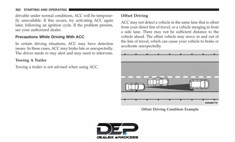
drivable under normal conditions, ACC will be temporar-ily unavailable. If this occurs, try activating ACC againlater, following an ignition cycle. If the problem persists,see your authorized dealer.
Precautions While Driving With ACC
In certain driving situations, ACC may have detectionissues. In these cases, ACC may brake late or unexpectedly.The driver needs to stay alert and may need to intervene.
Towing A Trailer
Towing a trailer is not advised when using ACC.
Offset Driving
ACC may not detect a vehicle in the same lane that is offsetfrom your direct line of travel, or a vehicle merging in froma side lane. There may not be sufficient distance to thevehicle ahead. The offset vehicle may move in and out ofthe line of travel, which can cause your vehicle to brake oraccelerate unexpectedly.
Offset Driving Condition Example
362 STARTING AND OPERATING

Turns And Bends
When driving on a curve with ACC engaged, the systemmay decrease the vehicle speed and acceleration for stabil-ity reasons, with no target vehicle detected. Once thevehicle is out of the curve the system will resume youroriginal Set Speed. This is a part of normal ACC systemfunctionality.
NOTE: On tight turns ACC performance may be limited.
Using ACC On Hills
When driving on hills, ACC may not detect a vehicle inyour lane. Depending on the speed, vehicle load, trafficconditions, and the steepness of the hills, ACC perfor-mance may be limited.
Lane Changing
ACC may not detect a vehicle until it is completely in thelane in which you are traveling. In the illustration shown,ACC has not yet detected the vehicle changing lanes and itmay not detect the vehicle until it’s too late for the ACCsystem to take action. ACC may not detect a vehicle until it
Turn Or Bend Example
ACC Hill Example
6
STARTING AND OPERATING 363

is completely in the lane. There may not be sufficientdistance to the lane-changing vehicle. Always be attentiveand ready to apply the brakes if necessary.
Narrow Vehicles
Some narrow vehicles traveling near the outer edges of thelane or edging into the lane are not detected until they havemoved fully into the lane. There may not be sufficientdistance to the vehicle ahead.
Lane Changing Example
Narrow Vehicle Example
364 STARTING AND OPERATING

Stationary Objects And Vehicles
ACC does not react to stationary objects and stationaryvehicles. For example, ACC will not react in situationswhere the vehicle you are following exits your lane and thevehicle ahead is stopped in your lane. Always be attentiveand ready to apply the brakes if necessary.
General Information
The following regulatory statement applies to all RadioFrequency (RF) devices equipped in this vehicle:
This device complies with Part 15 of the FCC Rules andwith Industry Canada license-exempt RSS standard(s).Operation is subject to the following two conditions:
1. This device may not cause harmful interference.
2. This device must accept any interference received, in-cluding interference that may cause undesired opera-tion.
NOTE: Changes or modifications not expressly approvedby the party responsible for compliance could void theuser’s authority to operate the equipment.
Normal (Fixed Speed) Cruise Control Mode
In addition to Adaptive Cruise Control mode, a Normal(Fixed Speed) Cruise Control mode is available for cruisingat fixed speeds. The Normal (Fixed Speed) Cruise Controlmode is designed to maintain a set cruising speed withoutrequiring the driver to operate the accelerator. CruiseControl can only be operated if the vehicle speed is above20 mph (32 km/h).
Stationary Object And Stationary Vehicle Example
6
STARTING AND OPERATING 365

To change between the different control modes, push theAdaptive Cruise Control (ACC) on/off button which turnsthe ACC and the Normal (Fixed Speed) Cruise Control off.Pushing the Normal (Fixed Speed) Cruise Control on/offbutton will result in turning on (changing to) the Normal(Fixed Speed) Cruise Control mode.
WARNING!
In the Normal (Fixed Speed) Cruise Control mode, thesystem will not react to vehicles ahead. In addition, theproximity warning does not activate and no alarm willsound even if you are too close to the vehicle aheadsince neither the presence of the vehicle ahead nor thevehicle-to-vehicle distance is detected. Be sure to main-tain a safe distance between your vehicle and thevehicle ahead. Always be aware which mode is se-lected.
To Set A Desired Speed
Turn the Normal (Fixed Speed) Cruise Controlon. When the vehicle has reached the desiredspeed, push the SET (+) or SET (-) button andrelease. Release the accelerator and the vehicle
will operate at the selected speed. Once a speed has been
set a message “CRUISE CONTROL SET TO MPH (km/h)”will appear indicating what speed was set. This light willturn on when the system is turned on via the on/offcontrol. It turns green when the cruise control is set.
To Vary The Speed Setting
To Increase Speed
When the Normal (Fixed Speed) Cruise Control is set, youcan increase speed by pushing the SET (+) button.
The driver’s preferred units can be selected through theinstrument cluster. Refer to “Instrument Cluster Display”in “Getting To Know Your Instrument Panel” for moreinformation. The speed increment shown is dependant onthe speed of U.S. (mph) or Metric (km/h) units:
U.S. Speed (mph)
• Pushing the SET (+) button once will result in a 1 mphincrease in set speed. Each subsequent tap of the buttonresults in an increase of 1 mph.
• If the button is continually pushed, the set speed willcontinue to increase in 5 mph increments until thebutton is released. The increase in set speed is reflectedin the instrument cluster display.
366 STARTING AND OPERATING
Metric Speed (km/h)
• Pushing the SET (+) button once will result in a 1 km/hincrease in set speed. Each subsequent tap of the buttonresults in an increase of 1 km/h.
• If the button is continually pushed, the set speed willcontinue to increase in 10 km/h increments until thebutton is released. The increase in set speed is reflectedin the instrument cluster display.
To Decrease Speed
When the Normal (Fixed Speed) Cruise Control is set, youcan decrease speed by pushing the SET (-) button.
The driver’s preferred units can be selected through theinstrument cluster. Refer to “Instrument Cluster Display”in “Getting To Know Your Instrument Panel” for moreinformation. The speed decrement shown is dependant onthe speed of U.S. (mph) or Metric (km/h) units:
U.S. Speed (mph)
• Pushing the SET (-) button once will result in a 1 mphdecrease in set speed. Each subsequent tap of the buttonresults in a decrease of 1 mph.
• If the button is continually pushed, the set speed willcontinue to decrease in 5 mph decrements until thebutton is released. The decrease in set speed is reflectedin the instrument cluster display.
Metric Speed (km/h)
• Pushing the SET (-) button once will result in a 1 km/hdecrease in set speed. Each subsequent tap of the buttonresults in a decrease of 1 km/h.
• If the button is continually pushed, the set speed willcontinue to decrease in 10 km/h decrements until thebutton is released. The decrease in set speed is reflectedin the instrument cluster display.
To Cancel
The following conditions will cancel the Normal (FixedSpeed) Cruise Control without clearing the memory:
• The brake pedal is applied.
• The CANC (cancel) button is pushed.
• The Electronic Stability Control/Traction Control Sys-tem (ESC/TCS) activates.
• The vehicle parking brake is applied.
6
STARTING AND OPERATING 367

• The braking temperature exceeds normal range (over-heated).
• The gear selector is removed from the DRIVE position.
To Resume Speed
To resume a previously set speed, push the RES button andrelease. Resume can be used at any speed above 20 mph(32 km/h).
To Turn Off
The system will turn off and erase the set speed in memoryif:
• The Normal (Fixed Speed) Cruise Control on/off buttonis pushed.
• The ignition is turned OFF.
• The Adaptive Cruise Control (ACC) on/off button ispushed.
PARKSENSE REAR PARK ASSIST — IF EQUIPPED
The ParkSense Rear Park Assist system provides visual andaudible indications of the distance between the rear fasciaand a detected obstacle when backing up, e.g. during aparking maneuver. If your vehicle is equipped with an
Automatic Transmission, the vehicle brakes may be auto-matically applied and released when performing a reverseparking maneuver if the system detects a possible collisionwith an obstacle.
NOTE:
• The driver can override the automatic braking functionby pressing the gas pedal, turning ParkSense off viaParkSense switch, or changing the gear while the auto-matic brakes are being applied.
• Automatic brakes will not be available if ESC is notavailable.
• Automatic brakes will not be available if there is afaulted condition detected with the ParkSense ParkAssist system or the Braking System Module.
• The automatic braking function may not provideenough vehicle deceleration to avoid colliding with adetected obstacle depending on vehicle speed, roadconditions, and brake capability.
• The automatic braking function may not be applied fastenough for moving obstacles that approach the rear ofthe vehicle from the left and / or right sides.
368 STARTING AND OPERATING

• The automatic braking function can be enabled/disabled from the Customer-Programmable Featuressection of the Uconnect System.
• ParkSense will retain its last known configuration statefor the automatic braking function through ignitioncycles.
The automatic braking function is intended to assist thedriver in avoiding possible collisions with detected ob-stacles when backing up in REVERSE gear.
NOTE:
• The driver is always responsible for controlling thevehicle.
• The system is provided to assist the driver and not tosubstitute the driver.
• The driver must stay in full control of the vehicle’sacceleration and braking and is responsible for thevehicle’s movements.
Refer to “ParkSense System Usage Precautions” for limita-tions of this system and recommendations.
ParkSense will retain the last system state (enabled ordisabled) from the last ignition cycle when the ignition ischanged to the ON/RUN position.
ParkSense can be active only when the gear selector is inREVERSE. If ParkSense is enabled at this gear selectorposition, the system will remain active until the vehiclespeed is increased to approximately 7 mph (11 km/h) orabove. When in REVERSE and above the system’s operat-ing speed, a warning will appear within the instrumentcluster display indicating the vehicle speed is too fast. Thesystem will become active again if the vehicle speed isdecreased to speeds less than approximately 6 mph(9 km/h).
6
STARTING AND OPERATING 369

ParkSense Sensors
The four ParkSense sensors, located in the rear fascia/bumper, monitor the area behind the vehicle that is withinthe sensors’ field of view. The sensors can detect obstaclesfrom approximately 12 inches (30 cm) up to 79 inches (200cm) from the rear fascia/bumper in the horizontal direc-tion, depending on the location, type and orientation of theobstacle.
ParkSense Visual Alert
The ParkSense Warning screen will only be displayed ifSound and Display is selected from the Customer - Pro-grammable Features section of the Uconnect System. Referto �Uconnect Settings” in “Multimedia” for further infor-mation.
The ParkSense Warning screen is located within the instru-ment cluster display. It provides visual warnings to indi-cate the distance between the rear fascia/bumper and thedetected obstacle. Refer to “Instrument Cluster Display” in“Getting To Know Your Instrument Panel” for furtherinformation.
ParkSense Display
When the vehicle is in REVERSE and an obstacle has beendetected, the warning display will turn on indicating thesystem status, and remain on until the vehicle is moved outof REVERSE.
The system will indicate a detected obstacle by showing asingle arc in one or more regions based on the obstacle’sdistance and location relative to the vehicle.
If an obstacle is detected in the center rear region, thedisplay will show a single solid arc in the center rear regionand will produce a one-half second tone. As the vehicle
Rear Sensor Locations
370 STARTING AND OPERATING
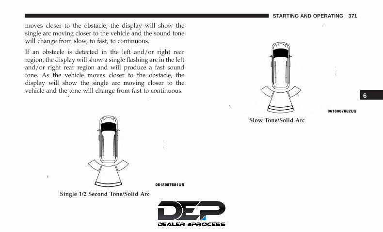
moves closer to the obstacle, the display will show thesingle arc moving closer to the vehicle and the sound tonewill change from slow, to fast, to continuous.
If an obstacle is detected in the left and/or right rearregion, the display will show a single flashing arc in the leftand/or right rear region and will produce a fast soundtone. As the vehicle moves closer to the obstacle, thedisplay will show the single arc moving closer to thevehicle and the tone will change from fast to continuous.
Single 1/2 Second Tone/Solid Arc
Slow Tone/Solid Arc
6
STARTING AND OPERATING 371

Slow Tone/Solid Arc Fast Tone/Flashing Arc
372 STARTING AND OPERATING

The vehicle is close to the obstacle when the warningdisplay shows one flashing arc and sounds a continuoustone. The following chart shows the warning alert opera-tion when the system is detecting an obstacle:
Fast Tone/Flashing Arc Continuous Tone/Flashing Arc
6
STARTING AND OPERATING 373

WARNING ALERTSRear
Distance(in/cm)
Greaterthan
79 inches(200 cm)
79-59 inches(200-150 cm)
59-47 inches(150-120 cm)
47-39 inches(120-100 cm)
39-25 inches(100-65 cm)
25-12 inches(65-30 cm)
Less than12 inches(30 cm)
Arcs — Left None None None None None 2nd Flash-ing
1st Flashing
Arcs —Center
None 6th Solid 5th Solid 4th Solid 3rd Flash-ing
2nd Flash-ing
1st Flashing
Arcs —Right
None None None None None 2nd Flash-ing
1st Flashing
AudibleAlert
Chime
None Single 1/2-Second
Tone(for rear
center only)
Slow(for rear
center only)
Slow(for rear
center only)
Fast(for rear
center only)
Fast Continuous
RadioVolumeReduced
No Yes Yes Yes Yes Yes Yes
NOTE: ParkSense will reduce the volume of the radio, ifon, when the system is sounding an audio tone.
374 STARTING AND OPERATING

Enabling And Disabling ParkSense
ParkSense can be enabled and disabled with theParkSense switch, located on the switch panelbelow the Uconnect display.
When the ParkSense switch is pushed to disable thesystem, the instrument cluster will display the“PARKSENSE OFF” message for approximately five sec-onds. Refer to “Instrument Cluster Display” in “Getting ToKnow Your Instrument Panel” for further information.When the gear selector is moved to REVERSE and thesystem is disabled, the instrument cluster display willshow the “PARKSENSE OFF” message for as long as thevehicle is in REVERSE.
The ParkSense switch LED will be on when ParkSense isdisabled or requires service. The ParkSense switch LEDwill be off when the system is enabled. If the ParkSenseswitch is pushed, and requires service, the ParkSenseswitch LED will blink momentarily, and then the LED willbe on.
NOTE: When KeySense feature is present, the ParkSenseSystem will reject customer input to turn the system off viathe hard switch. The instrument cluster display will show�KeySense in Use Selected Feature Cannot be Disabled�message.
Service The ParkSense Rear Park Assist System
During vehicle start up, when the ParkSense Rear ParkAssist System has detected a faulted condition, the instru-ment cluster will actuate a single chime, once per ignitioncycle, and it will display the “PARKSENSE UNAVAIL-ABLE WIPE REAR SENSORS” or the “PARKSENSE UN-AVAILABLE SERVICE REQUIRED” message. Refer to “In-strument Cluster Display” in “Getting To Know YourInstrument Panel” for further information. When the gearselector is moved to REVERSE and the system has detecteda faulted condition, the instrument cluster display willshow the �PARKSENSE UNAVAILABLE WIPE REAR SEN-SORS� or �PARKSENSE UNAVAILABLE SERVICE RE-QUIRED� message for five seconds while the vehicle is inREVERSE. Under this condition, ParkSense will not oper-ate and “PARKSENSE OFF” message will be displayed.
If “PARKSENSE UNAVAILABLE WIPE REAR SENSORS”appears in the instrument cluster display make sure theouter surface and the underside of the rear fascia/bumper
6
STARTING AND OPERATING 375

is clean and clear of snow, ice, mud, dirt or other obstruc-tion and then cycle the ignition. If the message continues toappear, see an authorized dealer.
If “PARKSENSE UNAVAILABLE SERVICE REQUIRED”appears in the instrument cluster display, see an autho-rized dealer.
Cleaning The ParkSense System
Clean the ParkSense sensors with water, car wash soap anda soft cloth. Do not use rough or hard cloths. Do not scratchor poke the sensors. Otherwise, you could damage thesensors.
ParkSense System Usage Precautions
NOTE:
• Ensure that the rear bumper is free of snow, ice, mud,dirt and debris to keep the ParkSense system operatingproperly.
• Jackhammers, large trucks, and other vibrations couldaffect the performance of ParkSense.
• When you turn ParkSense off, the instrument clusterwill display “PARKSENSE OFF”. Furthermore, once youturn ParkSense off, it remains off until you turn it onagain, even if you cycle the ignition.
• When you move the gear selector to the REVERSEposition and ParkSense is turned off, the instrumentcluster display will show “PARKSENSE OFF” messagefor as long as the vehicle is in REVERSE.
• ParkSense, when on, will reduce the volume of the radiowhen it is sounding a tone.
• Clean the ParkSense sensors regularly, taking care not toscratch or damage them. The sensors must not becovered with ice, snow, slush, mud, dirt or debris.Failure to do so can result in the system not workingproperly. The ParkSense system might not detect anobstacle behind the fascia/bumper, or it could provide afalse indication that an obstacle is behind the fascia/bumper.
• ParkSense should be disabled when the liftgate is in theopen position.
376 STARTING AND OPERATING

• Use the ParkSense switch to turn the ParkSense systemOFF if objects such as bicycle carriers, trailer hitches, etc.are placed within 12 inches (30 cm) from the rearfascia/bumper. Failure to do so can result in the systemmisinterpreting a close object as a sensor problem,causing the “PARKSENSE UNAVAILABLE SERVICEREQUIRED” message to be displayed in the instrumentcluster display.
WARNING!
• Drivers must be careful when backing up even whenusing ParkSense. Always check carefully behindyour vehicle, look behind you, and be sure to checkfor pedestrians, animals, other vehicles, obstructions,and blind spots before backing up. You are respon-sible for safety and must continue to pay attention toyour surroundings. Failure to do so can result inserious injury or death.
• Before using ParkSense, it is strongly recommendedthat the ball mount and hitch ball assembly isdisconnected from the vehicle when the vehicle isnot used for towing. Failure to do so can result ininjury or damage to vehicles or obstacles because the
(Continued)
WARNING! (Continued)hitch ball will be much closer to the obstacle than therear fascia when the loudspeaker sounds the con-tinuous tone. Also, the sensors could detect the ballmount and hitch ball assembly, depending on its sizeand shape, giving a false indication that an obstacleis behind the vehicle.
CAUTION!
• ParkSense is only a parking aid and it is unable torecognize every obstacle, including small obstacles.Parking curbs might be temporarily detected or notdetected at all. Obstacles located above or below thesensors will not be detected when they are in closeproximity.
• The vehicle must be driven slowly when usingParkSense in order to be able to stop in time when anobstacle is detected. It is recommended that thedriver looks over his/her shoulder when usingParkSense.
6
STARTING AND OPERATING 377

PARKSENSE FRONT AND REAR PARK ASSIST —IF EQUIPPED
The ParkSense Park Assist system provides visual andaudible indications of the distance between the rear and/orfront fascia and a detected obstacle when backing up ormoving forward, e.g. during a parking maneuver. If yourvehicle is equipped with an Automatic Transmission, thevehicle brakes may be automatically applied and releasedwhen performing a reverse parking maneuver if the sys-tem detects a possible collision with an obstacle.
NOTE:
• The driver can override the automatic braking functionby pressing the gas pedal, turning ParkSense off viaParkSense switch, or changing the gear while the auto-matic brakes are being applied.
• Automatic brakes will not be available if ESC is notavailable.
• Automatic brakes will not be available if there is afaulted condition detected with the ParkSense ParkAssist system or the Braking System Module.
• The automatic braking function may not provideenough vehicle deceleration to avoid colliding with adetected obstacle depending on vehicle speed, roadconditions, and brake capability.
• The automatic braking function may not be applied fastenough for moving obstacles that approach the rear ofthe vehicle from the left and / or right sides.
• The automatic braking function can be enabled/disabled from the Customer-Programmable Featuressection of the Uconnect System.
• ParkSense will retain its last known configuration statefor the automatic braking function through ignitioncycles.
The automatic braking function is intended to assist thedriver in avoiding possible collisions with detected ob-stacles when backing up in REVERSE gear.
NOTE:
• The driver is always responsible for controlling thevehicle.
• The system is provided to assist the driver and not tosubstitute the driver.
378 STARTING AND OPERATING

• The driver must stay in full control of the vehicle’sacceleration and braking and is responsible for thevehicle’s movements.
Refer to “ParkSense System Usage Precautions” for limita-tions of this system and recommendations.
ParkSense will retain the last system state (enabled ordisabled) from the last ignition cycle when the ignition ischanged to the ON/RUN position.
ParkSense can be active only when the gear selector is inREVERSE or DRIVE. If ParkSense is enabled at one of thesegear selector positions, the system will remain active untilthe vehicle speed is increased to approximately 7 mph(11 km/h) or above. When in REVERSE and above thesystem’s operating speed, a warning will appear in theinstrument cluster display indicating the vehicle speed istoo fast. The system will become active again if the vehiclespeed is decreased to speeds less than approximately6 mph (9 km/h).
ParkSense Sensors
The six ParkSense sensors, located in the rear fascia/bumper, monitor the area behind the vehicle that is withinthe sensors’ field of view. The sensors can detect obstaclesfrom approximately 12 inches (30 cm) up to 79 in (200 cm)from the rear fascia/bumper in the horizontal direction,depending on the location, type and orientation of theobstacle.
The six ParkSense sensors, located in the front fascia/bumper, monitor the area in front of the vehicle that iswithin the sensors’ field of view. The sensors can detectobstacles from approximately 12 inches (30 cm) up to 47 in
Rear Sensor Locations
6
STARTING AND OPERATING 379

(120 cm) from the front fascia/bumper in the horizontaldirection, depending on the location, type and orientationof the obstacle.
ParkSense Visual Alert
The ParkSense Warning screen will only be displayed if“Sound and Display” is selected from the Customer -Programmable Features section of the Uconnect System.Refer to �Uconnect Settings” in “Multimedia” for furtherinformation.
The ParkSense Warning screen is located within the instru-ment cluster display. It provides visual warnings to indi-cate the distance between the rear fascia/bumper and/orfront fascia/bumper and the detected obstacle. Refer to“Instrument Cluster Display” in “Getting To Know YourInstrument Panel” for further information.
ParkSense Display
Rear Park Assist
When the vehicle is in REVERSE, the warning display willturn ON indicating the system status.
The system will indicate a detected obstacle by showing asingle arc in one or more regions based on the obstacle’sdistance and location relative to the vehicle.
If an obstacle is detected in the center rear region, thedisplay will show a single solid arc in the center rear regionand will produce a one-half second tone. As the vehiclemoves closer to the obstacle, the display will show thesingle arc moving closer to the vehicle and the sound tonewill change from slow, to fast, to continuous.
380 STARTING AND OPERATING

If an obstacle is detected in the left and/or right rearregion, the display will show a single flashing arc in the leftand/or right rear region and will produce a fast soundtone. As the vehicle moves closer to the obstacle, thedisplay will show the single arc moving closer to thevehicle and the tone will change from fast to continuous.
Single 1/2 Second Tone/Solid Arc
Slow Tone/Solid Arc
6
STARTING AND OPERATING 381

Slow Tone/Solid Arc Fast Tone/Flashing Arc
382 STARTING AND OPERATING

The vehicle is close to the obstacle when the warningdisplay shows one flashing arc and sounds a continuoustone. The following chart shows the warning alert opera-tion when the system is detecting an obstacle:
Fast Tone/Flashing Arc Continuous Tone/Flashing Arc
6
STARTING AND OPERATING 383

WARNING ALERTSRear
Distance(inches/cm)
Greaterthan
79 inches(200 cm)
79-59 inches(200-150 cm)
59-47 inches(150-120 cm)
47-39 inches(120-100 cm)
39-25 inches(100-65 cm)
25-12 inches(65-30 cm)
Less than12 inches(30 cm)
Arcs — Left None None None None None 2nd Flash-ing
1st Flashing
Arcs —Center
None 6th Solid 5th Solid 4th Solid 3rd Flash-ing
2nd Flash-ing
1st Flashing
Arcs —Right
None None None None None 2nd Flash-ing
1st Flashing
AudibleAlert
Chime
None Single 1/2-Second
Tone(for rear
center only)
Slow(for rear
center only)
Slow(for rear
center only)
Fast(for rear
center only)
Fast Continuous
RadioVolumeReduced
No Yes Yes Yes Yes Yes Yes
NOTE: ParkSense will reduce the volume of the radio, ifon, when the system is sounding an audio tone.
384 STARTING AND OPERATING

Front Park Assist
When the vehicle is in DRIVE the ParkSense Warningscreen will be displayed when an obstacle is detected.
The system will indicate a detected obstacle by showing asingle arc in one or more regions based on the obstacle’sdistance and location relative to the vehicle.
If an obstacle is detected in the center front region, thedisplay will show a single arc in the center front region. Asthe vehicle moves closer to the obstacle, the display willshow the single arc moving closer to the vehicle. A fastsound tone will be produced when reaching the secondflashing arc and will change to a continuous sound tonewhen the first flashing arc appears.
If an obstacle is detected in the left and/or right frontregion, the display will show a single flashing arc in the leftand/or right front region and will produce a fast soundtone. As the vehicle moves closer to the obstacle, thedisplay will show the single arc moving closer to thevehicle and the tone will change from fast to continuous.
No Tone/Solid Arc
6
STARTING AND OPERATING 385
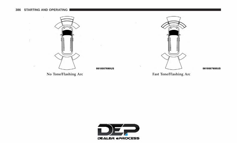
No Tone/Flashing Arc Fast Tone/Flashing Arc
386 STARTING AND OPERATING

The vehicle is close to the obstacle when the warningdisplay shows one flashing arc and sounds a continuoustone. The following chart shows the warning alert opera-tion when the system is detecting an obstacle:
Continuous Tone/Flashing Arc
6
STARTING AND OPERATING 387

WARNING ALERTSFront Distance
(inches/cm)Greater than
47 inches (120 cm)47-39 inches(120-100 cm)
39-25 inches(100-65 cm)
25-12 inches(65-30 cm)
Less than12 inches (30 cm)
Arcs — Left None None None 2nd Flashing 1st FlashingArcs — Center None 4th Solid 3rd Flashing 2nd Flashing 1st FlashingArcs — Right None None None 2nd Flashing 1st FlashingAudible Alert
ChimeNone None None Fast Continuous
Radio VolumeReduced
No No No Yes Yes
NOTE: ParkSense will reduce the volume of the radio, ifon, when the system is sounding an audio tone.
Front Park Assist Audible Alerts
ParkSense will turn off the Front Park Assist audible alert(chime) after approximately three seconds when an ob-stacle has been detected, the vehicle is stationary, and brakepedal is applied.
Adjustable Chime Volume Settings
Front and Rear chime volume settings can be selected fromthe Customer-Programmable Features section of theUconnect System, refer to “Uconnect Settings” in “Multi-media” for further information.
If the Uconnect System is equipped, chime volume settingswill not be accessible from the instrument cluster display.
The chime volume settings include LOW, MEDIUM, andHIGH. The factory default volume setting is MEDIUM.
ParkSense will retain its last known configuration statethrough ignition cycles.
388 STARTING AND OPERATING

Enabling And Disabling ParkSense
ParkSense can be enabled and disabled with theParkSense switch, located on the switch panelbelow the Uconnect display.
When the ParkSense switch is pushed to disable thesystem, the instrument cluster will display the“PARKSENSE OFF” message for approximately five sec-onds. Refer to “Instrument Cluster Display” in “Getting ToKnow Your Instrument Panel” for further information.When the gear selector is moved to REVERSE and thesystem is disabled, the instrument cluster display willshow the “PARKSENSE OFF” message for as long as thevehicle is in REVERSE.
The ParkSense switch LED will be on when ParkSense isdisabled or requires service. The ParkSense switch LEDwill be off when the system is enabled. If the ParkSenseswitch is pushed, and requires service, the ParkSenseswitch LED will blink momentarily, and then the LED willbe on.
NOTE: When KeySense feature is present, the ParkSenseSystem will reject customer input to turn the system off viathe hard switch. The instrument cluster display will show
�KeySense in Use Selected Feature Cannot be Disabled�message.
Service The ParkSense Park Assist System
During vehicle start up, when the ParkSense System hasdetected a faulted condition, the instrument cluster willactuate a single chime, once per ignition cycle, and it willdisplay the �PARKSENSE UNAVAILABLE WIPE REARSENSORS�, �PARKSENSE UNAVAILABLE WIPE FRONTSENSORS�, or the �PARKSENSE UNAVAILABLE SERVICEREQUIRED� message for five seconds. When the gearselector is moved to REVERSE and the system has detecteda faulted condition, the instrument cluster display willshow a �PARKSENSE UNAVAILABLE WIPE REAR SEN-SORS�, �PARKSENSE UNAVAILABLE WIPE FRONT SEN-SORS� or �PARKSENSE UNAVAILABLE SERVICE RE-QUIRED� pop up message for five seconds. After fiveseconds, a vehicle graphic will be displayed with a �WIPEOFF� or “SERVICE” overlay, depending on the location andfault type. The system will continue to provide arc alertsfor the side that is functioning properly. These arc alertswill interrupt the �PARKSENSE UNAVAILABLE WIPEREAR SENSORS�, �PARKSENSE UNAVAILABLE WIPEFRONT SENSORS�, or �PARKSENSE UNAVAILABLE SER-VICE REQUIRED� messages if an object is detected within
6
STARTING AND OPERATING 389

the five second pop-up duration. The vehicle graphic willremain displayed for as long as the vehicle is in REVERSE.
Refer to “Instrument Cluster Display” in “Getting To KnowYour Instrument Panel” for further information.
If �PARKSENSE UNAVAILABLE WIPE REAR SENSORS�or �PARKSENSE UNAVAILABLE WIPE FRONT SEN-SORS� appears in the instrument cluster display make surethe outer surface and the underside of the rear fascia/bumper and/or front fascia/bumper is clean and clear ofsnow, ice, mud, dirt or other obstruction and then cycle theignition. If the message continues to appear see an autho-rized dealer.
If the �PARKSENSE UNAVAILABLE SERVICE RE-QUIRED� message appears in the instrument cluster dis-play, see an authorized dealer.
Cleaning The ParkSense System
Clean the ParkSense sensors with water, car wash soap anda soft cloth. Do not use rough or hard cloths. Do not scratchor poke the sensors. Otherwise, you could damage thesensors.
ParkSense System Usage Precautions
NOTE:
• Ensure that the front and rear bumper are free of snow,ice, mud, dirt and debris to keep the ParkSense systemoperating properly.
• Construction equipment, large trucks, and other vibra-tions could affect the performance of ParkSense.
• When you turn ParkSense off, the instrument clusterwill display “PARKSENSE OFF.” Furthermore, once youturn ParkSense off, it remains off until you turn it onagain, even if you cycle the ignition key.
• When you move the gear selector to the REVERSEposition and ParkSense is turned off, the instrumentcluster will display “PARKSENSE OFF” for five secondswhile the vehicle is in REVERSE.
• ParkSense, when on, will reduce the volume of the radiowhen it is sounding a tone.
• Clean the ParkSense sensors regularly, taking care not toscratch or damage them. The sensors must not becovered with ice, snow, slush, mud, dirt or debris.Failure to do so can result in the system not workingproperly. The ParkSense system might not detect anobstacle behind or in front of the appropriate fascia/
390 STARTING AND OPERATING

bumper, or it could provide a false indication that anobstacle is behind or in front of the appropriate fascia/bumper.
• Use the ParkSense switch to turn the ParkSense systemoff if objects such as bicycle carriers, trailer hitches, etc.are placed within 12 inches (30 cm) from the rearfascia/bumper. Failure to do so can result in the systemmisinterpreting a close object as a sensor problem,causing the “PARKSENSE UNAVAILABLE SERVICEREQUIRED” message to be displayed in the instrumentcluster.
• ParkSense should be disabled when the liftgate is in theopen position.
• There may be a delay in the object detection rate if theobject is moving. This may cause the automatic brakingapplication to be delayed.
WARNING!
• Drivers must be careful when backing up even whenusing ParkSense. Always check carefully behindyour vehicle, look behind you, and be sure to checkfor pedestrians, animals, other vehicles, obstructions,
(Continued)
WARNING! (Continued)and blind spots before backing up. You are respon-sible for safety and must continue to pay attention toyour surroundings. Failure to do so can result inserious injury or death.
• Before using ParkSense, it is strongly recommendedthat the ball mount and hitch ball assembly isdisconnected from the vehicle when the vehicle isnot used for towing. Failure to do so can result ininjury or damage to vehicles or obstacles because thehitch ball will be much closer to the obstacle than therear fascia when the loudspeaker sounds the con-tinuous tone. Also, the sensors could detect the ballmount and hitch ball assembly, depending on its sizeand shape, giving a false indication that an obstacleis behind the vehicle.
CAUTION!
• ParkSense is only a parking aid and it is unable torecognize every obstacle, including small obstacles.Parking curbs might be temporarily detected or notdetected at all. Obstacles located above or below the
(Continued)
6
STARTING AND OPERATING 391

CAUTION! (Continued)sensors will not be detected when they are in closeproximity.
• The vehicle must be driven slowly when usingParkSense in order to be able to stop in time when anobstacle is detected. It is recommended that thedriver looks over his/her shoulder when usingParkSense.
PARKSENSE ACTIVE PARK ASSIST SYSTEM — IFEQUIPPED
The ParkSense Active Park Assist system is intended toassist the driver during parallel and perpendicular parkingmaneuvers by identifying a proper parking space, provid-ing audible/visual instructions, and controlling the steer-ing wheel. The ParkSense Active Park Assist system isdefined as “semi-automatic” since the driver maintainscontrol of the accelerator, gear selector and brakes. De-pending on the driver’s parking maneuver selection, theParkSense Active Park Assist system is capable of maneu-vering a vehicle into a parallel or a perpendicular parkingspace on either side (i.e., driver side or passenger side).
NOTE:
• The driver is always responsible for controlling thevehicle, responsible for any surrounding objects, andmust intervene as required.
• The system is provided to assist the driver and not tosubstitute the driver.
• During a semi-automatic maneuver, if the driver touchesthe steering wheel after being instructed to remove theirhands from the steering wheel, the system will cancel,and the driver will be required to manually complete theparking maneuver.
• The system may not work in all conditions (e.g. envi-ronmental conditions such as heavy rain, snow, etc., or ifsearching for a parking space that has surfaces that willabsorb the ultrasonic sensor waves).
• New vehicles from the dealership must have at least 30miles (48 km) accumulated before the ParkSense ActivePark Assist system is fully calibrated and performsaccurately. This is due to the system’s dynamic vehiclecalibration to improve the performance of the feature.The system will also continuously perform the dynamicvehicle calibration to account for differences such asover or under inflated tires and new tires.
392 STARTING AND OPERATING

Enabling And Disabling The ParkSense Active ParkAssist System
The ParkSense Active Park Assist system can beenabled and disabled with the ParkSense ActivePark Assist switch, located on the switch panelbelow the Uconnect display.
To enable the ParkSense Active Park Assist system, push theParkSense Active Park Assist switch once (LED turns on).
To disable the ParkSense Active Park Assist system, push theParkSense Active Park Assist switch again (LED turns off).
The ParkSense Active Park Assist system will turn offautomatically for any of the following conditions:
• The parking maneuver is completed.
• Vehicle speed greater than 18 mph (30 km/h) whensearching for a parking space.
• Vehicle speed greater than 5 mph (7 km/h) during activesteering guidance into the parking space.
• Touching the steering wheel during active steering guid-ance into the parking space.
• Pushing the ParkSense Front and Rear Park Assistswitch.
• The driver’s door is opened.
• The liftgate is opened.
• Electronic Stability Control/Anti-lock Braking Systemintervention.
• The ParkSense Active Park Assist system will allow amaximum of eight shifts between DRIVE and REVERSE. Ifthe maneuver cannot be completed within eight shifts, thesystem will cancel and the instrument cluster display willinstruct the driver to complete the maneuver manually.
The ParkSense Active Park Assist system will only operateand search for a parking space when the following condi-tions are present:
• The gear position is in DRIVE.
• The ignition is in the RUN position.
• The ParkSense Active Park Assist switch is activated.
• The driver’s door is closed.
• The liftgate is closed.
• Vehicle speed is less than 15 mph (25 km/h).
6
STARTING AND OPERATING 393

NOTE: If the vehicle is driven above approximately15 mph (25 km/h), the instrument cluster display willinstruct the driver to slow down. If the vehicle is drivenabove approximately 18 mph (30 km/h), the system willcancel. The driver must then reactivate the system bypushing the ParkSense Active Park Assist switch.
• The outer surface and the underside of the front and rearfascias/bumpers are clean and clear of snow, ice, mud,dirt or other obstruction.
When pushed, the LED on the ParkSense Active ParkAssist switch will blink momentarily, and then the LEDwill turn off if any of the above conditions are not present.
Parallel Parking Space Assistance Operation/Display
When the ParkSense Active Park Assist system is enabledthe “Active ParkSense Searching - Push OK for Perpen-dicular Park” message will appear in the instrument clus-ter display. You may switch to perpendicular parking ifyou desire. Push the OK button on the left side steeringwheel switch to change your parking space setting.
NOTE:
• When searching for a parking space, use the turn signalindicator to select which side of the vehicle you want toperform the parking maneuver. The ParkSense ActivePark Assist system will automatically search for a park-ing space on the passenger’s side of the vehicle if theturn signal is not activated.
• The driver needs to make sure that the selected parkingspace for the maneuver remains free and clear of anyobstructions (e.g. pedestrians, bicycles, etc.).
• The driver is responsible to ensure that the selectedparking space is suitable for the maneuver and free/clear of anything that may be overhanging or protrudinginto the parking space (e.g., ladders, tailgates, etc. fromsurrounding objects/vehicles).
• When seeking for a parking space, the driver shoulddrive as parallel or perpendicular (depending on thetype of maneuver) to other vehicles as possible.
394 STARTING AND OPERATING

• The feature will only indicate the last detected parkingspace (example: if passing multiple available parkingspaces, the system will only indicate the last detectedparking space for the maneuver).
When an available parking space has been found, and thevehicle is not in position, you will be instructed to moveforward to position the vehicle for a parallel parkingsequence.
Active ParkSense Searching Parking Space Found — Keep Moving Forward
6
STARTING AND OPERATING 395

Once the vehicle is in position, you will be instructed tostop the vehicle’s movement and remove your hands fromthe steering wheel.
Once the vehicle is at a standstill with your hands removedfrom the steering wheel, you will be instructed to place thegear selector into the REVERSE position.
Parking Space Found — Stop And Remove Hands FromWheel
Parking Space Found — Shift To Reverse
396 STARTING AND OPERATING

When the driver places the gear selector into the REVERSEposition, the system may instruct the driver to wait forsteering to complete.
The system will then instruct the driver to check theirsurroundings and move backward.
NOTE:
• It is the driver’s responsibility to use the brake andaccelerator during the semi-automatic parking maneuver.
• When the system instructs the driver to remove theirhands from the steering wheel, the driver should checktheir surroundings and begin to back up slowly.
Check Surroundings — Wait For Steering To CompleteCheck Surroundings — Move Backward
6
STARTING AND OPERATING 397

• The ParkSense Active Park Assist system will allow amaximum of eight shifts between DRIVE or REVERSE.If the maneuver cannot be completed within eight shifts,the system will cancel and the instrument cluster displaywill instruct the driver to complete the maneuver manu-ally.
• The system will cancel the maneuver if the vehicle speedexceeds 5 mph (7 km/h) during active steering guidanceinto the parking space. The system will provide awarning to the driver at 3 mph (5 km/h) that tells themto slow down. The driver is then responsible for com-pleting the maneuver if the system is canceled.
• If the system is canceled during the maneuver for anyreason, the driver must take full control of the vehicle.
When the vehicle has reached the end of its backwardmovement, the system will instruct the driver to checktheir surroundings and stop the vehicle’s movement.
NOTE: It is the driver’s responsibility to use the brake andstop the vehicle. The driver should check their surround-ings and be prepared to stop the vehicle either wheninstructed to, or when driver intervention is required.
Check Surroundings — STOP
398 STARTING AND OPERATING

Once the vehicle is in a standstill condition, the driver willbe instructed to place the gear selector into the DRIVEposition.
When the driver places the gear selector into the DRIVEposition, the system may instruct the driver to wait forsteering to complete.
Check Surroundings — Shift To Drive Check Surroundings — Wait For Steering To Complete
6
STARTING AND OPERATING 399

The system will then instruct the driver to check theirsurroundings and move forward.
When the vehicle has reached the end of its forwardmovement, the system will instruct the driver to checktheir surroundings and stop the vehicle’s movement.
NOTE: It is the driver’s responsibility to use the brake andstop the vehicle. The driver should check their surround-ings and be prepared to stop the vehicle either wheninstructed to, or when driver intervention is required.
Check Surroundings — Move ForwardCheck Surroundings — STOP
400 STARTING AND OPERATING

Once the vehicle is in a standstill condition, the driver willbe instructed to place the gear selector into the REVERSEposition.
When the driver places the gear selector into the REVERSEposition, the system may instruct the driver to wait forsteering to complete.
Check Surroundings — Shift To Reverse Check Surroundings — Wait For Steering To Complete
6
STARTING AND OPERATING 401

The system will then instruct the driver to check theirsurroundings and move backward.
Your vehicle is now in the parallel park position. When themaneuver is complete, the driver will be instructed tocheck the vehicle’s parking position. If the driver is satis-fied with the vehicle position, they should shift to PARK.The �Active ParkSense Complete - Check Parking Position�message will be momentarily displayed.
Check Surroundings — Move Backward
Active ParkSense Complete — Check Parking Position
402 STARTING AND OPERATING

Perpendicular Parking Space AssistanceOperation/Display
When the ParkSense Active Park Assist system is enabled,the “Active ParkSense Searching - Push OK for Perpen-dicular Park” message will show in the instrument clusterdisplay. Push the OK button on the left side steering wheelswitch to change your parking space setting to a perpen-dicular maneuver. You may switch back to parallel parkingif you desire.
Once the driver pushes OK for a perpendicular parkingmaneuver, the “Active ParkSense Searching - Push OK forParallel Park” message will appear in the instrumentcluster display.
NOTE:
• When searching for a parking space, use the turn signalindicator to select which side of the vehicle you want toperform the parking maneuver. The ParkSense ActivePark Assist system will automatically search for a park-ing space on the passenger’s side of the vehicle if theturn signal is not activated.
• The driver needs to make sure that the selected parkingspace for the maneuver remains free and clear of anyobstructions (e.g. pedestrians, bicycles, etc.).
Active ParkSense Searching Display
6
STARTING AND OPERATING 403

• The driver is responsible to ensure that the selectedparking space is suitable for the maneuver and free/clear of anything that may be overhanging or protrudinginto the parking space (e.g., ladders, tailgates, etc. fromsurrounding objects/vehicles).
• When seeking for a parking space, the driver shoulddrive as parallel or perpendicular (depending on thetype of maneuver) to other vehicles as possible.
• The feature will only indicate the last detected parkingspace (example: if passing multiple available parkingspaces, the system will only indicate the last detectedparking space for the maneuver).
When an available parking space has been found, and thevehicle is not in position, you will be instructed to moveforward to position the vehicle for a perpendicular parkingsequence.
Parking Space Found — Keep Moving Forward
404 STARTING AND OPERATING

Once the vehicle is in position, you will be instructed tostop the vehicle’s movement and remove your hands fromthe steering wheel.
Once the vehicle is at a standstill with your hands removedfrom the steering wheel, you will be instructed to place thegear selector into the REVERSE position.
Parking Space Found — Stop And Remove Hands FromWheel
Parking Space Found — Shift To Reverse
6
STARTING AND OPERATING 405

When the driver places the gear selector into the REVERSEposition, the system may instruct the driver to wait forsteering to complete.
The system will then instruct the driver to check theirsurroundings and move backward.
NOTE:
• It is the driver’s responsibility to use the brake andaccelerator during the semi-automatic parking maneu-ver.
• When the system instructs the driver to remove theirhands from the steering wheel, the driver should checktheir surroundings and begin to back up slowly.
Check Surroundings — Wait For Steering To CompleteCheck Surroundings — Move Backwards
406 STARTING AND OPERATING

• The ParkSense Active Park Assist system will allow amaximum of eight shifts between DRIVE or REVERSE.If the maneuver cannot be completed within eight shifts,the system will cancel and the instrument cluster displaywill instruct the driver to complete the maneuver manu-ally.
• The system will cancel the maneuver if the vehicle speedexceeds 5 mph (7 km/h) during active steering guidanceinto the parking space. The system will provide awarning to the driver at 3 mph (5 km/h) that tells themto slow down. The driver is then responsible for com-pleting the maneuver if the system is canceled.
• If the system is canceled during the maneuver for anyreason, the driver must take control of the vehicle.
When the vehicle has reached the end of its backwardmovement, the system will instruct the driver to checktheir surroundings and stop the vehicle’s movement.
NOTE: It is the driver’s responsibility to use the brake andstop the vehicle. The driver should check their surround-ings and be prepared to stop the vehicle either wheninstructed to, or when driver intervention is required.
Check Surroundings — STOP
6
STARTING AND OPERATING 407

Once the vehicle is in a standstill condition, the driver willbe instructed to place the gear selector into the DRIVEposition.
When the driver places the gear selector into the DRIVEposition, the system may instruct the driver to wait forsteering to complete.
Check Surroundings — Shift To Drive Check Surroundings — Wait For Steering To Complete
408 STARTING AND OPERATING

The system will then instruct the driver to check theirsurroundings and move forward.
When the vehicle has reached the end of its forwardmovement, the system will instruct the driver to checktheir surroundings and stop the vehicle’s movement.
NOTE: It is the driver’s responsibility to use the brake andstop the vehicle. The driver should check their surround-ings and be prepared to stop the vehicle either wheninstructed to, or when driver intervention is required.
Check Surroundings — Move ForwardCheck Surroundings — STOP
6
STARTING AND OPERATING 409

Once the vehicle is in a standstill condition, the driver willbe instructed to place the gear selector into the REVERSEposition.
When the driver places the gear selector into the REVERSEposition, the system may instruct the driver to wait forsteering to complete.
Check Surroundings — Shift To Reverse Check Surroundings — Wait For Steering To Complete
410 STARTING AND OPERATING

The system will then instruct the driver to check theirsurroundings and move backward.
Your vehicle is now in the perpendicular park position.When the maneuver is complete, the driver will be in-structed to check the vehicle’s parking position. If thedriver is satisfied with the vehicle position, they should
shift to PARK. The �Active ParkSense Complete - CheckParking Position� message will be momentarily displayed.
WARNING!
Drivers must be careful when performing parallel orperpendicular parking maneuvers even when usingthe ParkSense Active Park Assist system. Alwayscheck carefully behind and in front of your vehicle,look behind and in front of you, and be sure to checkfor pedestrians, animals, other vehicles, obstructions,
(Continued)
Check Surroundings — Move Backwards Active ParkSense Complete — Check Parking Position
6
STARTING AND OPERATING 411

WARNING! (Continued)and blind spots before backing up and moving for-ward. You are responsible for safety and must continueto pay attention to your surroundings. Failure to do socan result in serious injury or death.
CAUTION!
• The ParkSense Active Park Assist system is only aparking aid and it is unable to recognize everyobstacle, including small obstacles. Parking curbsmight be temporarily detected or not detected at all.Obstacles located above or below the sensors willnot be detected when they are in close proximity.
• The vehicle must be driven slowly when using theParkSense Active Park Assist system in order to beable to stop in time when an obstacle is detected. It isrecommended that the driver looks over his/hershoulder when using the ParkSense Active ParkAssist system.
LANESENSE — IF EQUIPPED
LaneSense Operation
The LaneSense system is operational at speeds above37 mph (60 km/h) and below 112 mph (180 km/h). It usesa forward looking camera to detect lane markings andmeasure vehicle position within the lane boundaries.
When both lane markings are detected and the driverunintentionally drifts out of the lane (no turn signalapplied), the LaneSense system provides a haptic warningin the form of torque applied to the steering wheel toprompt the driver to remain within the lane boundaries.The LaneSense system will also provide a visual warningthrough the instrument cluster display to prompt thedriver to remain within the lane boundaries.
The driver may manually override the haptic warning byapplying torque into the steering wheel at any time.
When only a single lane marking is detected and the driverunintentionally drifts across that lane marking (no turnsignal applied), the LaneSense system provides a visualwarning through the instrument cluster display to promptthe driver to remain within the lane. When only a singlelane marking is detected, a haptic (torque) warning will notbe provided.
412 STARTING AND OPERATING
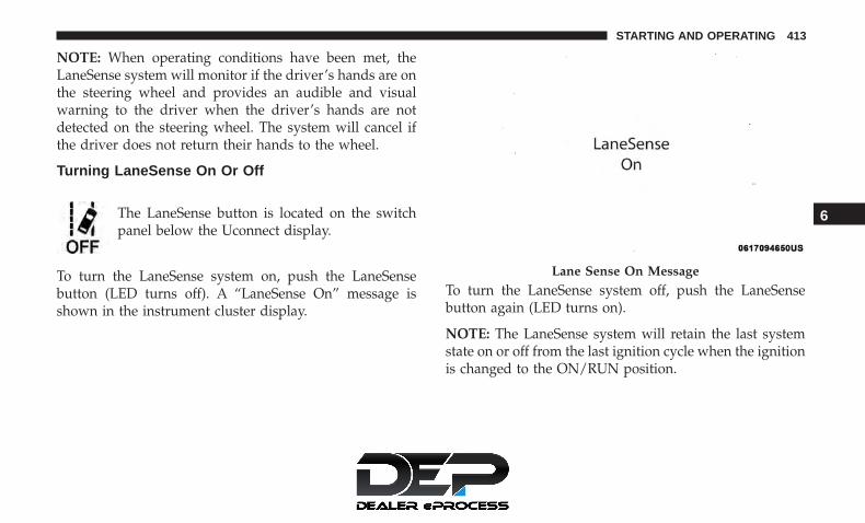
NOTE: When operating conditions have been met, theLaneSense system will monitor if the driver’s hands are onthe steering wheel and provides an audible and visualwarning to the driver when the driver’s hands are notdetected on the steering wheel. The system will cancel ifthe driver does not return their hands to the wheel.
Turning LaneSense On Or Off
The LaneSense button is located on the switchpanel below the Uconnect display.
To turn the LaneSense system on, push the LaneSensebutton (LED turns off). A “LaneSense On” message isshown in the instrument cluster display.
To turn the LaneSense system off, push the LaneSensebutton again (LED turns on).
NOTE: The LaneSense system will retain the last systemstate on or off from the last ignition cycle when the ignitionis changed to the ON/RUN position.
Lane Sense On Message
6
STARTING AND OPERATING 413

LaneSense Warning Message
The LaneSense system will indicate the current lane driftcondition through the instrument cluster display.
Instrument Cluster Display
When the LaneSense system is ON; the lane lines are graywhen both of the lane boundaries have not been detectedand the LaneSense telltale is solid white.
Left Lane Departure — Only Left Lane Detected
• When the LaneSense system is ON, the LaneSenseTelltale is solid white only when the left lane
marking has been detected and the system is ready toprovide visual warnings in the instrument clusterdisplay if an unintentional lane departure occurs onthe left side.
• When the LaneSense system senses the lane has beenapproached and is in a lane departure situation, thevisual warning in the instrument cluster display willshow the left inside lane line flashing yellow (on/off),while the outside lane line on the left of the display willremain solid yellow. The LaneSense telltale changesfrom solid white to flashing yellow.
System ON (Gray Lines) With White Telltale
Lane Approached (Flashing Yellow Inside Line, SolidYellow Outside Line/Flashing) With Yellow Telltale
414 STARTING AND OPERATING

NOTE: The LaneSense system operates with the similarbehavior for a right lane departure when only the rightlane marking has been detected.
Left Lane Departure — Both Lane Lines Detected
• When the LaneSense system is ON, the lane lines turnfrom gray to white. The LaneSense telltale is solidgreen when both lane markings have been detectedand the system is “armed” to provide visual warn-ings in the instrument cluster display and a torquewarning in the steering wheel if an unintentional lanedeparture occurs.
• When the LaneSense system senses a lane drift situation,the left inside and outside lane lines turn solid yellow.The LaneSense telltale changes from solid green tosolid yellow. At this time torque is applied to thesteering wheel in the opposite direction of the laneboundary.
• For example: If approaching the left side of the lane thesteering wheel will turn to the right.
• When the LaneSense system senses the lane has beenapproached and is in a lane departure situation, the leftinside lane line flashes yellow (on/off) while the leftLanes Sensed (White Lines) With Green Telltale
Lane Sensed (Solid Yellow Inside Line, Solid YellowOutside Line) With Solid Yellow Telltale
6
STARTING AND OPERATING 415

outside line remains solid yellow. The LaneSense telltalechanges from solid yellow to flashing yellow. At
this time torque is applied to the steering wheel in theopposite direction of the lane boundary.
• For example: If approaching the left side of the lane thesteering wheel will turn to the right.
NOTE: The LaneSense system operates with the similarbehavior for a right lane departure.
Changing LaneSense Status
The LaneSense system has settings to adjust the intensity ofthe torque warning and the warning zone sensitivity(Early/Medium/Late) that you can configure through theUconnect system screen. Refer to “Uconnect Settings” in“Multimedia” for further information.
NOTE:
• When enabled the system operates above 37 mph(60 km/h) and below 112 mph (180 km/h).
• Use of the turn signal suppresses the warnings.
• The system will not apply torque to the steering wheelwhenever a safety system engages (anti-lock brakes,traction control system, electronic stability control, for-ward collision warning, etc.).
PARKVIEW REAR BACK UP CAMERA
The ParkView Rear Back Up Camera allows you to see anon-screen image of the rear surroundings of your vehiclewhenever the gear selector is put into REVERSE. Theimage will be displayed on the touchscreen display alongwith a caution note “Check Entire Surroundings” acrossthe top of the screen. After five seconds, this note will
Lane Approached (Flashing Yellow Inside Line, SolidYellow Outside Line) With Flashing Yellow Telltale
416 STARTING AND OPERATING

disappear. The ParkView Rear Back Up Camera is locatedon the rear of the vehicle above the rear license plate.
NOTE: The ParkView Rear Back Up Camera has program-mable modes of operation that may be selected through theUconnect System. Refer to “Uconnect Settings” in “Multi-media” for further information.
When the vehicle is shifted out of REVERSE (with cameradelay turned off), the rear camera mode is exited and thenavigation or audio screen appears again.
When the vehicle is shifted out of REVERSE (with cameradelay turned on), the camera image will continue to bedisplayed for up to 10 seconds after shifting out of RE-VERSE unless the vehicle speed exceeds 8 mph (13 km/h),the vehicle is shifted into PARK or the ignition is switchedto the OFF position.
A touch screen button to disable display of the cameraimage is made available when the vehicle is not in RE-VERSE gear. Display of the camera image after shifting outof REVERSE can be disabled via a touch screen buttonpersonalization entry in the camera settings menu.
When enabled, active guide lines are overlaid on the imageto illustrate the width of the vehicle and its projectedbackup path based on the steering wheel position.
Different colored zones indicate the distance to the rear ofthe vehicle.
ParkView Camera Location
6
STARTING AND OPERATING 417

The following table shows the approximate distances foreach zone:
Zone Distance To The Rear Of The VehicleRed 0 - 1 ft (0 - 30 cm)
Yellow 1 ft - 6.5 ft (30 cm - 2 m)Green 6.5 ft or greater (2 m or greater)
NOTE: If snow, ice, mud, or any foreign substance buildsup on the camera lens, clean the lens, rinse with water, anddry with a soft cloth. Do not cover the lens.
WARNING!
Drivers must be careful when backing up even whenusing the ParkView Rear Back Up Camera. Alwayscheck carefully behind your vehicle, and be sure tocheck for pedestrians, animals, other vehicles, obstruc-tions, or blind spots before backing up. You are re-sponsible for the safety of your surroundings and mustcontinue to pay attention while backing up. Failure todo so can result in serious injury or death.
CAUTION!
• To avoid vehicle damage, ParkView should only beused as a parking aid. The ParkView camera isunable to view every obstacle or object in your drivepath.
• To avoid vehicle damage, the vehicle must be drivenslowly when using ParkView to be able to stop intime when an obstacle is seen. It is recommendedthat the driver look frequently over his/her shoulderwhen using ParkView.
418 STARTING AND OPERATING
SURROUND VIEW CAMERA SYSTEM — IFEQUIPPED
Your vehicle may be equipped with the Surround ViewCamera System that allows you to see an on-screen imageof the surroundings and top view of your vehicle when-ever the gear selector is put into REVERSE or a differentview is selected through the �on screen soft buttons�. Thetop view of the vehicle will show which doors are open.The image will be displayed on the touchscreen displayalong with a caution note “Check Entire Surroundings”across the top of the screen. After five seconds, this notewill disappear. The Surround View Camera System iscomprised of four sequential cameras located in the frontgrille, rear liftgate and side mirrors.
NOTE: The Surround View Camera System has program-mable settings that may be selected through the UconnectSystem. Refer to “Uconnect Settings” in “Multimedia” forfurther information.
When the vehicle is shifted into REVERSE, the rear cameraview and top view is the default view of the system.
When the vehicle is shifted out of REVERSE (with cameradelay turned on), the camera image will continue to bedisplayed for up to 10 seconds after shifting out of RE-VERSE unless the vehicle speed exceeds 8 mph (13 km/h),the vehicle is shifted into PARK or the ignition is switchedto the OFF position. There is a touch screen button (X) todisable the display of the camera image.
When the vehicle is shifted out of REVERSE (with cameradelay turned off), the surround view camera mode is exitedand the last known screen appears again.
When enabled, active guide lines are overlaid on the imageto illustrate the width of the vehicle, including the sideview mirrors and its projected backup path based on thesteering wheel position.
Different colored zones indicate the distance to the rear ofthe vehicle.
6
STARTING AND OPERATING 419
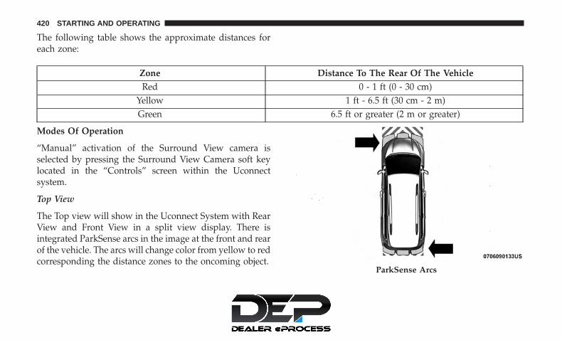
The following table shows the approximate distances foreach zone:
Zone Distance To The Rear Of The VehicleRed 0 - 1 ft (0 - 30 cm)
Yellow 1 ft - 6.5 ft (30 cm - 2 m)Green 6.5 ft or greater (2 m or greater)
Modes Of Operation
“Manual” activation of the Surround View camera isselected by pressing the Surround View Camera soft keylocated in the “Controls” screen within the Uconnectsystem.
Top View
The Top view will show in the Uconnect System with RearView and Front View in a split view display. There isintegrated ParkSense arcs in the image at the front and rearof the vehicle. The arcs will change color from yellow to redcorresponding the distance zones to the oncoming object.
ParkSense Arcs
420 STARTING AND OPERATING

NOTE:
• Front tires will be in image when the tires are turned.
• Due to wide angle cameras in mirror, the image willappear distorted.
• Top view will show which sliding doors are open.
• Open front doors will remove outside image.
Rear View
This is the Default view of the system inREVERSE and is always paired with theTop view of the vehicle with optionalactive guide lines for the projected pathwhen enabled.
Rear Cross Path View
Pressing the Rear Cross Path soft keywill give the driver a wider angle viewof the rear camera system. The Top viewwill be disabled when this is selected.
Front View
The Front view will show you what isimmediately in front of the vehicle andis always paired with the Top view ofthe vehicle.
Front Cross Path View
Pressing the Front Cross Path soft keywill give the driver a wider angle viewof the front camera system. The Topview will be disabled when this is se-lected.
Deactivation
The system can be deactivated in the following conditions:
• The speed of the vehicle reaches greater than 8 mph(13 km/h).
• The vehicle shifted into PARK from a different gear.
• If the vehicle is in any gear other than REVERSE, pressthe “X” button.
6
STARTING AND OPERATING 421

• The camera delay system is turned off manually throughthe Uconnect settings menu. Refer to “Uconnect Set-tings” in “Multimedia” for further information.
NOTE:
• If snow, ice, mud, or any foreign substance builds up onthe camera lenses, clean the lenses, rinse with water, anddry with a soft cloth. Do not cover the lenses.
• If a malfunction with the system has occurred, see yournearest authorized dealer.
WARNING!
Drivers must be careful when backing up even whenusing the Surround View Camera. Always check care-fully behind your vehicle, and be sure to check forpedestrians, animals, other vehicles, obstructions, orblind spots before backing up. You are responsible forthe safety of your surroundings and must continue topay attention while backing up. Failure to do so canresult in serious injury or death.
CAUTION!
• To avoid vehicle damage, Surround View shouldonly be used as a parking aid. The Surround Viewcamera is unable to view every obstacle or object inyour drive path.
• To avoid vehicle damage, the vehicle must be drivenslowly when using Surround View to be able to stopin time when an obstacle is seen. It is recommendedthat the driver look frequently over his/her shoulderwhen using Surround View.
REFUELING THE VEHICLE
There is no fuel filler cap. Two flapper doors inside the pipeseal the system.
WARNING!
• Never have any smoking materials lit in or near thevehicle when the fuel door is open or the tank isbeing filled.
• Never add fuel when the engine is running. This isin violation of most state and federal fire regulations
(Continued)
422 STARTING AND OPERATING

WARNING! (Continued)and may cause the “Malfunction Indicator Light” toturn on.
• A fire may result if fuel is pumped into a portablecontainer that is inside of a vehicle. You could beburned. Always place fuel containers on the groundwhile filling.
CAUTION!
To avoid fuel spillage and overfilling, do not “top off”the fuel tank after filling.
1. Put the vehicle in park and switch the ignition off.
2. Push the center-rear edge of the fuel filler door (3 o’clockposition) and release to open.
3. Insert the fuel nozzle fully into the filler pipe, the nozzleopens and holds both flapper doors while refueling.
4. When the fuel nozzle “clicks” or shuts off, the fuel tankis full.
5. Keep the nozzle in the filler for five seconds after nozzleclicks to allow fuel to drain from the nozzle.
6. Remove the fuel filler nozzle.
7. To close the fuel filler door, push the center-rear edge (3o’clock position) of the fuel filler door and then release.The fuel filler door will latch closed.
Fuel Filler Cap Latch
6
STARTING AND OPERATING 423
NOTE:
• In certain cold conditions, ice may prevent the fuel fillerdoor from opening. If this occurs, lightly push on thefuel filler door around the perimeter to break the icebuild up.
• Take care to open both flappers with the funnel to avoidspills.
VEHICLE LOADING
Certification Label
As required by National Highway Traffic Safety Adminis-tration regulations, your vehicle has a certification labelaffixed to the driver’s side door or pillar.
This label contains the month and year of manufacture,Gross Vehicle Weight Rating (GVWR), Gross Axle WeightRating (GAWR) front and rear, and Vehicle IdentificationNumber (VIN). A Month-Day-Hour (MDH) number isincluded on this label and indicates the Month, Day andHour of manufacture. The bar code that appears on thebottom of the label is your VIN.
Gross Vehicle Weight Rating (GVWR)
The GVWR is the total permissible weight of your vehicleincluding driver, passengers, vehicle, options and cargo.
The label also specifies maximum capacities of front andrear axle systems (GAWR). Total load must be limited soGVWR and front and rear GAWR are not exceeded.
Payload
The payload of a vehicle is defined as the allowable loadweight a truck can carry, including the weight of the driver,all passengers, options and cargo.
Gross Axle Weight Rating (GAWR)
The GAWR is the maximum permissible load on the frontand rear axles. The load must be distributed in the cargoarea so that the GAWR of each axle is not exceeded.
Each axle GAWR is determined by the components in thesystem with the lowest load carrying capacity (axle,springs, tires or wheels). Heavier axles or suspensioncomponents sometimes specified by purchasers for in-creased durability does not necessarily increase the vehi-cle’s GVWR.
Tire Size
The tire size on the Vehicle Certification Label representsthe actual tire size on your vehicle. Replacement tires mustbe equal to the load capacity of this tire size.
424 STARTING AND OPERATING

Rim Size
This is the rim size that is appropriate for the tire sizelisted.
Inflation Pressure
This is the cold tire inflation pressure for your vehicle forall loading conditions up to full GAWR.
Curb Weight
The curb weight of a vehicle is defined as the total weightof the vehicle with all fluids, including vehicle fuel, at fullcapacity conditions, and with no occupants or cargo loadedinto the vehicle. The front and rear curb weight values aredetermined by weighing your vehicle on a commercialscale before any occupants or cargo are added.
Loading
The actual total weight and the weight of the front and rearof your vehicle at the ground can best be determined byweighing it when it is loaded and ready for operation.
The entire vehicle should first be weighed on a commercialscale to insure that the GVWR has not been exceeded. Theweight on the front and rear of the vehicle should then be
determined separately to be sure that the load is properlydistributed over the front and rear axle. Weighing thevehicle may show that the GAWR of either the front or rearaxles has been exceeded but the total load is within thespecified GVWR. If so, weight must be shifted from front torear or rear to front as appropriate until the specifiedweight limitations are met. Store the heavier items downlow and be sure that the weight is distributed equally. Stowall loose items securely before driving.
Improper weight distributions can have an adverse effecton the way your vehicle steers and handles and the waythe brakes operate.
CAUTION!
Do not load your vehicle any heavier than the GVWRor the maximum front and rear GAWR. If you do, partson your vehicle can break, or it can change the wayyour vehicle handles. This could cause you to losecontrol. Also overloading can shorten the life of yourvehicle.
6
STARTING AND OPERATING 425

TRAILER TOWING
In this section you will find safety tips and information onlimits to the type of towing you can reasonably do withyour vehicle. Before towing a trailer, carefully review thisinformation to tow your load as efficiently and safely aspossible.
To maintain the New Vehicle Limited Warranty coverage,follow the requirements and recommendations in thismanual concerning vehicles used for trailer towing.
Common Towing Definitions
The following trailer towing related definitions will assistyou in understanding the following information:
Gross Vehicle Weight Rating (GVWR)
The GVWR is the total allowable weight of your vehicle.This includes driver, passengers, cargo and tongue weight.The total load must be limited so that you do not exceedthe GVWR. Refer to “Vehicle Loading/Vehicle CertificationLabel” in “Starting And Operating” for further informa-tion.
Gross Trailer Weight (GTW)
The GTW is the weight of the trailer plus the weight of allcargo, consumables and equipment (permanent or tempo-rary) loaded in or on the trailer in its �loaded and ready foroperation� condition.
The recommended way to measure GTW is to put yourfully loaded trailer on a vehicle scale. The entire weight ofthe trailer must be supported by the scale.
Gross Axle Weight Rating (GAWR)
The GAWR is the maximum capacity of the front and rearaxles. Distribute the load over the front and rear axlesevenly. Make sure that you do not exceed either front orrear GAWR. Refer to “Vehicle Loading/Vehicle Certifica-tion Label” in “Starting And Operating” for further infor-mation.
WARNING!
It is important that you do not exceed the maximumfront or rear GAWR. A dangerous driving conditioncan result if either rating is exceeded. You could losecontrol of the vehicle and have a collision.
426 STARTING AND OPERATING

Tongue Weight (TW)
The tongue weight is the downward force exerted on thehitch ball by the trailer. You must consider this as part ofthe load on your vehicle.
Trailer Frontal Area
The frontal area is the maximum height multiplied by themaximum width of the front of a trailer.
Trailer Sway Control
The trailer sway control can be a mechanical telescopinglink that can be installed between the hitch receiver and thetrailer tongue that typically provides adjustable frictionassociated with the telescoping motion to dampen anyunwanted trailer swaying motions while traveling.
If equipped, the electronic Trailer Sway Control (TSC)recognizes a swaying trailer and automatically appliesindividual wheel brakes and/or reduces engine power toattempt to eliminate the trailer sway.
Weight-Carrying Hitch
A weight-carrying hitch supports the trailer tongue weight,just as if it were luggage located at a hitch ball or someother connecting point of the vehicle. These kinds ofhitches are the most popular on the market today and theyare commonly used to tow small and medium sizedtrailers.
Weight-Distributing Hitch
A weight-distributing system works by applying leveragethrough spring (load) bars. They are typically used forheavier loads to distribute trailer tongue weight to the towvehicle’s front axle and the trailer axle(s). When used inaccordance with the manufacturer’s directions, it providesfor a more level ride, offering more consistent steering andbrake control thereby enhancing towing safety. The addi-tion of a friction/hydraulic sway control also dampenssway caused by traffic and crosswinds and contributespositively to tow vehicle and trailer stability. Trailer swaycontrol and a weight distributing (load equalizing) hitchare recommended for heavier Tongue Weights (TW) andmay be required depending on vehicle and trailerconfiguration/loading to comply with Gross Axle WeightRating (GAWR) requirements.
6
STARTING AND OPERATING 427

WARNING!
• An improperly adjusted Weight Distributing Hitchsystem may reduce handling, stability, braking per-formance, and could result in a collision.
• Weight Distributing Systems may not be compatiblewith Surge Brake Couplers. Consult with your hitchand trailer manufacturer or a reputable RecreationalVehicle dealer for additional information.
Trailer Hitch Classification
The following chart provides the industry standard for themaximum trailer weight a given trailer hitch class can towand should be used to assist you in selecting the correcttrailer hitch for your intended towing condition.
Trailer Hitch Classification DefinitionsClass Max. Trailer Hitch Industry Standards
Class I - Light Duty 2,000 lbs (907 kg)Class II - Medium Duty 3,500 lbs (1,587 kg)Class III - Heavy Duty 5,000 lbs (2,267 kg)
Class IV - Extra Heavy Duty 10,000 lbs (4,535 kg)Refer to the “Trailer Towing Weights (Maximum Trailer Weight Ratings)” chart for the Maximum Gross Trailer Weight(GTW) towable for your given drivetrain.All trailer hitches should be professionally installed on your vehicle.
428 STARTING AND OPERATING

Trailer Towing Weights (Maximum Trailer WeightRatings)
The following chart provides the maximum trailer weightratings towable for your given drivetrain.
Engine/Transmission
Trailer TowPackage
GCWR (GrossCombined
Weight Rating)Frontal Area
Max. GTW(Gross Trailer
Weight)
Max. TongueWeight
3.6L/Automatic Yes 8,600 lbs(3,900 kg)
40 sq ft(3.72 sq m)
3,600 lbs(1,632 kg)
360 lbs(163 kg)
No 6,500 lbs(2,948 kg)
40 sq ft(3.72 sq m)
1500 lbs(680 kg)
149 lbs(67 kg)
Refer to local laws for maximum trailer towing speeds.
NOTE: The trailer tongue weight must be considered aspart of the combined weight of occupants and cargo, andshould never exceed the weight referenced on the Tire andLoading Information placard. Refer to “Tires” in “ServicingAnd Maintenance” for further information.
6
STARTING AND OPERATING 429

Vehicle Loading Chart
Follow these steps to determine the total weight the vehiclecan carry.
1. Determine the cargo capacity of your vehicle.• Load Capacity = GVWR – Curb (weight of vehicle full
fluids NO Occupants).
2. Determine occupant count.• For calculation purposes, average weight of an occu-
pant is 150 lb (68 kg).
EXAMPLE:
• GVWR = 6005 lbs (2723 kg)
• CURB = 4500 lbs (2041 kg)
• Load Capacity = GVWR – CURB = 6005 lbs (2723 kg) -4500 lbs (2041 kg) = 1505 lbs (682 kg)
4 Occupants (at 150 lbs [68 kg]) + Max Trailer =
• 1505 lbs (682 kg) – 600 lbs (272 kg) (4 x 150 lbs [68 kg])– 360 lbs (163 kg) (10% of 3600 lbs [1632 kg]) = 545 lbs(247 kg) of cargo in vehicle
Number Of Persons / Weight Of Occupants Max Cargo NoTrailer
Tongue Load,Max Trailer
Max Cargo WithMax Trailer
360 lb (136 kg)Tongue Load
2 People / 300 lbs (136) kg 1205 lbs (546 kg)
1205 lbs (546 kg)– 360 lbs
(136 kg) =845 lbs (383 kg)
845 lbs (383 kg)
430 STARTING AND OPERATING

Number Of Persons / Weight Of Occupants Max Cargo NoTrailer
Tongue Load,Max Trailer
Max Cargo WithMax Trailer
360 lb (136 kg)Tongue Load
4 people / 600 lbs (272 kg) 955 lbs (433 kg)
955 lbs (433 kg)– 360 lbs
(136 kg) =545 lbs (247 kg)
545 lbs (247 kg)
7 people / 1050 lbs (476 kg)455 lbs (206 kg)
455 lbs (206 kg)– 360 lbs
(163 kg) = 95 lbs(43 kg)
95 lbs (43 kg)
• Make sure loading does not exceed GAWR of front orrear axles.
• GAWR is found on sticker in Driver’s Side Door Jam.
6
STARTING AND OPERATING 431

Trailer And Tongue Weight
Never exceed the maximum tongue weight stamped onyour bumper or trailer hitch.
Consider the following items when computing the weighton the rear axle of the vehicle:
• The tongue weight of the trailer.
• The weight of any other type of cargo or equipment putin or on your vehicle.
• The weight of the driver and all passengers.
NOTE: Remember that everything put into or on thetrailer adds to the load on your vehicle. Also, additionalfactory-installed options or dealer-installed options mustbe considered as part of the total load on your vehicle.Refer to the “Tire And Loading Information” placard forthe maximum combined weight of occupants and cargo foryour vehicle.
Towing Requirements
To promote proper break-in of your new vehicle drivetraincomponents, the following guidelines are recommended.
CAUTION!
• Do not tow a trailer at all during the first 500 miles(805 km) the new vehicle is driven. The engine, axleor other parts could be damaged.
• Then, during the first 500 miles (805 km) that a traileris towed, do not drive over 50 mph (80 km/h) and donot make starts at full throttle. This helps the engineand other parts of the vehicle wear in at the heavierloads.
Perform the maintenance listed in the “Scheduled Servic-ing”. Refer to “Scheduled Servicing” in “Servicing And
Weight Distribution
432 STARTING AND OPERATING

Maintenance” for the proper maintenance intervals. Whentowing a trailer, never exceed the GAWR or GCWR ratings.
WARNING!
Improper towing can lead to a collision. Follow theseguidelines to make your trailer towing as safe aspossible:• Make certain that the load is secured in the trailer
and will not shift during travel. When traileringcargo that is not fully secured, dynamic load shiftscan occur that may be difficult for the driver tocontrol. You could lose control of your vehicle andhave a collision.
• When hauling cargo or towing a trailer, do notoverload your vehicle or trailer. Overloading cancause a loss of control, poor performance or damageto brakes, axle, engine, transmission, steering, sus-pension, chassis structure or tires.
• Safety chains must always be used between yourvehicle and trailer. Always connect the chains to thehook retainers of the vehicle hitch. Cross the chainsunder the trailer tongue and allow enough slack forturning corners.
(Continued)
WARNING! (Continued)• Vehicles with trailers should not be parked on a
grade. When parking, apply the parking brake on thetow vehicle. Put the tow vehicle transmission inPARK. For four-wheel drive vehicles, make sure thetransfer case is not in NEUTRAL. Always, block or�chock� the trailer wheels.
• GCWR must not be exceeded.• Total weight must be distributed between the tow
vehicle and the trailer such that the following fourratings are not exceeded:
1. GVWR
2. GTW
3. GAWR
4. Tongue weight rating for the trailer hitch utilized.
Towing Requirements — Tires
• Do not attempt to tow a trailer while using a compactspare tire.
• Do not drive more than 50 mph (80 km/h) when towingwhile using a full size spare tire.
6
STARTING AND OPERATING 433

• Proper tire inflation pressures are essential to the safeand satisfactory operation of your vehicle. Refer to“Tires” in “Servicing And Maintenance” for proper tireinflation procedures.
• Check the trailer tires for proper tire inflation pressuresbefore trailer usage.
• Check for signs of tire wear or visible tire damage beforetowing a trailer. Refer to “Tires” in “Servicing AndMaintenance” for the proper inspection procedure.
• When replacing tires, refer to “Tires” in “Servicing AndMaintenance” for the proper tire replacement procedures.Replacing tires with a higher load carrying capacity will notincrease the vehicle’s GVWR and GAWR limits.
Towing Requirements — Trailer Brakes
• Do not interconnect the hydraulic brake system orvacuum system of your vehicle with that of the trailer.This could cause inadequate braking and possible per-sonal injury.
• An electronically actuated trailer brake controller isrequired when towing a trailer with electronically actu-ated brakes. When towing a trailer equipped with ahydraulic surge actuated brake system, an electronicbrake controller is not required.
• Trailer brakes are recommended for trailers over1,000 lbs (453 kg) and required for trailers in excess of2,000 lbs (907 kg).
WARNING!
• Do not connect trailer brakes to your vehicle’s hy-draulic brake lines. It can overload your brake sys-tem and cause it to fail. You might not have brakeswhen you need them and could have an accident.
• Towing any trailer will increase your stopping dis-tance. When towing, you should allow for additionalspace between your vehicle and the vehicle in frontof you. Failure to do so could result in an accident.
CAUTION!
If the trailer weighs more than 1,000 lbs (453 kg)loaded, it should have its own brakes and they shouldbe of adequate capacity. Failure to do this could lead toaccelerated brake lining wear, higher brake pedaleffort, and longer stopping distances.
434 STARTING AND OPERATING

Towing Requirements — Trailer Lights And Wiring
Whenever you pull a trailer, regardless of the trailer size,stoplights and turn signals on the trailer are required formotoring safety.
The Trailer Tow Package may include a four- and seven-pinwiring harness. Use a factory approved trailer harness andconnector.
NOTE: Do not cut or splice wiring into the vehicle’s wiringharness.
The electrical connections are all complete to the vehiclebut you must mate the harness to a trailer connector. Referto the following illustrations.
NOTE:
• Disconnect trailer wiring connector from the vehiclebefore launching a boat (or any other device pluggedinto vehicle’s electrical connect) into water.
• Be sure to reconnect once clear from water area.
Four-Pin Connector
1 — Female Pins 4 — Park2 — Male Pin 5 — Left Stop/Turn3 — Ground 6 — Right Stop/Turn
6
STARTING AND OPERATING 435

Towing Tips
Before setting out on a trip, practice turning, stopping, andbacking up the trailer in an area located away from heavytraffic.
Automatic Transmission
Select the DRIVE range when towing. The transmissioncontrols include a drive strategy to avoid frequent shiftingwhen towing. For increased engine braking on steep down-hill grades, select the LOW range.
Speed Control — If Equipped
• Do not use on hilly terrain or with heavy loads.
• When using the speed control, if you experience speeddrops greater than 10 mph (16 km/h), disengage untilyou can get back to cruising speed.
• Use speed control in flat terrain and with light loads tomaximize fuel efficiency.
Seven-Pin Connector
1 — Battery 5 — Ground2 — Backup Lamps 6 — Left Stop/Turn3 — Right Stop/Turn 7 — Running Lamps4 — Electric Brakes
436 STARTING AND OPERATING

Cooling System
To reduce potential for engine and transmission overheat-ing, take the following actions:
City Driving
• In city traffic — while stopped, place the transmission inNEUTRAL, but do not increase engine idle speed.
Highway Driving
• Reduce speed.
• Temporarily turn off air conditioning.
RECREATIONAL TOWING (BEHIND MOTORHOME, ETC.)Towing This Vehicle Behind Another Vehicle
Towing Condition Wheel OFF The Ground All ModelsFlat Tow NONE NOT ALLOWED
Dolly Tow Front OKRear NOT ALLOWED
On Trailer ALL OK
NOTE:
• To avoid inadvertent Electric Park Brake engagement,you must ensure that the Auto Park Brake feature isdisabled before towing this vehicle (if rear wheels are onthe ground). The Auto Park Brake feature is enabled ordisabled via the customer programmable features in theUconnect Settings.
• When towing your vehicle, always follow applicablestate and provincial laws. Contact state and provincialHighway Safety offices for additional details.
• If your vehicle is disabled and in need of commercialtowing service, please refer to “Towing A DisabledVehicle” in “In Case Of Emergency”.
6
STARTING AND OPERATING 437

Recreational Towing — All Models
DO NOT flat tow this vehicle. Damage to the drivetrainwill result.
CAUTION!
• DO NOT flat tow this vehicle. Damage to the drive-train will result. If this vehicle requires towing,make sure the drive wheels are OFF the ground.
• Ensure that the Electric Park Brake is released, andremains released, while being towed.
• Towing this vehicle in violation of the above require-ments can cause severe transmission damage. Dam-age from improper towing is not covered under theNew Vehicle Limited Warranty.
Recreational towing is allowed ONLY if the front wheelsare OFF the ground. This may be accomplished using a towdolly (front wheels off the ground) or vehicle trailer (allfour wheels off the ground). If using a tow dolly, follow thisprocedure:
1. Properly secure the dolly to the tow vehicle, followingthe dolly manufacturer’s instructions.
2. Drive the front wheels onto the tow dolly.
3. Apply the park brake.
4. Place the transmission in PARK.
5. Turn the ignition OFF.
6. Properly secure the front wheels to the dolly, followingthe dolly manufacturer’s instructions.
7. Turn the ignition to the ON/RUN mode, but do not startthe vehicle.
8. Press and hold the brake pedal.
9. Release the park brake.
10. Turn the ignition OFF.
11. Release the brake pedal.
DRIVING TIPS
Driving On Slippery Surfaces
Information in this section will aid in safe controlledlaunches in adverse conditions.
Acceleration
Rapid acceleration on snow covered, wet, or other slipperysurfaces may cause the driving wheels to pull erratically tothe right or left. This phenomenon occurs when there is a
438 STARTING AND OPERATING

difference in the surface traction under the front (driving)wheels.
WARNING!
Rapid acceleration on slippery surfaces is dangerous.Unequal traction can cause sudden pulling of the frontwheels. You could lose control of the vehicle andpossibly have a collision. Accelerate slowly and care-fully whenever there is likely to be poor traction (ice,snow, wet, mud, loose sand, etc.).
Traction
When driving on wet or slushy roads, it is possible for awedge of water to build up between the tire and roadsurface. This is hydroplaning and may cause partial orcomplete loss of vehicle control and stopping ability. Toreduce this possibility, the following precautions should beobserved:
• Slow down during rainstorms or when the roads areslushy.
• Slow down if the road has standing water or puddles.
• Replace the tires when tread wear indicators first be-come visible.
• Keep tires properly inflated.
• Maintain sufficient distance between your vehicle andthe vehicle in front of you to avoid a collision in asudden stop.
Driving Through Water
Driving through water more than a few inches/centimetersdeep will require extra caution to ensure safety and pre-vent damage to your vehicle.
Flowing/Rising Water
WARNING!
Do not drive on or across a road or path where water isflowing and/or rising (as in storm run-off). Flowingwater can wear away the road or path’s surface andcause your vehicle to sink into deeper water. Further-more, flowing and/or rising water can carry your ve-hicle away swiftly. Failure to follow this warning mayresult in injuries that are serious or fatal to you, yourpassengers, and others around you.
6
STARTING AND OPERATING 439

Shallow Standing Water
Although your vehicle is capable of driving through shal-low standing water, consider the following Cautions andWarnings before doing so.
WARNING!
• Driving through standing water limits your vehicle’straction capabilities. Do not exceed 5 mph (8 km/h)when driving through standing water.
• Driving through standing water limits your vehicle’sbraking capabilities, which increases stopping dis-tances. Therefore, after driving through standingwater, drive slowly and lightly press on the brakepedal several times to dry the brakes.
• Failure to follow these warnings may result in inju-ries that are serious or fatal to you, your passengers,and others around you.
CAUTION!
• Always check the depth of the standing water beforedriving through it. Never drive through standing
(Continued)
CAUTION! (Continued)water that is deeper than the bottom of the tire rimsmounted on the vehicle.
• Determine the condition of the road or the path thatis under water and if there are any obstacles in theway before driving through the standing water.
• Do not exceed 5 mph (8 km/h) when driving throughstanding water. This will minimize wave effects.
• Driving through standing water may cause damageto your vehicle’s drivetrain components. Always in-spect your vehicle’s fluids (i.e., engine oil, transmis-sion, axle, etc.) for signs of contamination (i.e., fluidthat is milky or foamy in appearance) after drivingthrough standing water. Do not continue to operatethe vehicle if any fluid appears contaminated, as thismay result in further damage. Such damage is notcovered by the New Vehicle Limited Warranty.
• Getting water inside your vehicle’s engine can causeit to lock up and stall out, and cause serious internaldamage to the engine. Such damage is not covered bythe New Vehicle Limited Warranty.
440 STARTING AND OPERATING

IN CASE OF EMERGENCY
CONTENTS� HAZARD WARNING FLASHERS . . . . . . . . . . . .443
� ASSIST AND SOS MIRROR — IF EQUIPPED . . . .443
� BULB REPLACEMENT . . . . . . . . . . . . . . . . . . . .449
▫ Replacement Bulbs . . . . . . . . . . . . . . . . . . . . . .449
▫ Replacing Exterior Bulbs . . . . . . . . . . . . . . . . . .451
� FUSES . . . . . . . . . . . . . . . . . . . . . . . . . . . . . . . .456
▫ General Information . . . . . . . . . . . . . . . . . . . . .456
▫ Fuse Location . . . . . . . . . . . . . . . . . . . . . . . . .457
▫ Underhood Fuses . . . . . . . . . . . . . . . . . . . . . . .457
� JACKING AND TIRE CHANGING — IFEQUIPPED . . . . . . . . . . . . . . . . . . . . . . . . . . . .466
▫ Jack And Spare Tire Location . . . . . . . . . . . . . .466
▫ Equipment Removal . . . . . . . . . . . . . . . . . . . .467
▫ Preparations For Jacking . . . . . . . . . . . . . . . . .467
▫ Jacking Instructions . . . . . . . . . . . . . . . . . . . . .468
▫ Road Tire Installation . . . . . . . . . . . . . . . . . . . .474
▫ Portable Air Compressor — If Equipped. . . . . . .476
▫ Tire Service Kit For Inflating Tire — IfEquipped . . . . . . . . . . . . . . . . . . . . . . . . . . . .479
▫ Return Inflatable Spare Tire. . . . . . . . . . . . . . . .484
� TIRE SERVICE KIT — IF EQUIPPED . . . . . . . . . .484
� JUMP STARTING . . . . . . . . . . . . . . . . . . . . . . . .495
▫ Preparations For Jump Start . . . . . . . . . . . . . . .496
▫ Jump Starting Procedure . . . . . . . . . . . . . . . . . .497
� REFUELING IN EMERGENCY . . . . . . . . . . . . . .499
� IF YOUR ENGINE OVERHEATS . . . . . . . . . . . . .499
7

� MANUAL PARK RELEASE . . . . . . . . . . . . . . . . .500
� FREEING A STUCK VEHICLE . . . . . . . . . . . . . .501
� TOWING A DISABLED VEHICLE . . . . . . . . . . . .503
� ENHANCED ACCIDENT RESPONSE SYSTEM(EARS) . . . . . . . . . . . . . . . . . . . . . . . . . . . . . . .505
� EVENT DATA RECORDER (EDR) . . . . . . . . . . . .506
442 IN CASE OF EMERGENCY

HAZARD WARNING FLASHERS
The Hazard Warning flasher switch is located in the lowercenter area of the instrument panel.
Push the switch to turn on the Hazard Warningflasher. When the switch is activated, all direc-tional turn signals will flash on and off to warnoncoming traffic of an emergency. Push the
switch a second time to turn off the Hazard Warningflashers.
This is an emergency warning system and it should not beused when the vehicle is in motion. Use it when yourvehicle is disabled and it is creating a safety hazard forother motorists.
When you must leave the vehicle to seek assistance, theHazard Warning flashers will continue to operate eventhough the ignition is placed in the OFF position.
NOTE: With extended use, the Hazard Warning flashersmay wear down your battery.
ASSIST AND SOS MIRROR — IF EQUIPPED
If equipped, the rearview mirror contains an ASSIST and aSOS button.
Assist And SOS Mirror
1 — SOS Button2 — ASSIST Button
7
IN CASE OF EMERGENCY 443

WARNING!
ALWAYS obey traffic laws and pay attention to theroad. ALWAYS drive safely with your hands on thesteering wheel. You have full responsibility and as-sume all risks related to the use of the features andapplications in this vehicle. Only use the features andapplications when it is safe to do so. Failure to do somay result in an accident involving serious injury ordeath.
NOTE:
• Your vehicle may be transmitting data as authorized bythe subscriber.
• The SOS and ASSIST buttons will only function if youare connected to an operable LTE (voice/data) or 4G(data) network. Other Uconnect services will only beoperable if your SiriusXM Guardian service is active andyou are connected to an operable LTE (voice/data) or 4G(data) network.
ASSIST Call
The ASSIST Button is used to automatically connect you toany one of the following support centers:
• Roadside Assistance – If you get a flat tire, or need a tow,just push the ASSIST button and you will be connectedto a representative for assistance. Roadside Assistancewill know what vehicle you’re driving and its location.Additional fees may apply for roadside assistance.
• SiriusXM Guardian Customer Care – In-vehicle supportfor SiriusXM Guardian.
• Vehicle Customer Care – Total support for all othervehicle issues.
SOS Call
1. Push the SOS Call button on the Rearview Mirror.
NOTE: In case the SOS Call button is pushed in error, therewill be a ten second delay before the SOS Call systeminitiates a call to a SOS operator. To cancel the SOS Callconnection, push the SOS call button on the RearviewMirror or press the cancellation button on the DeviceScreen. Termination of the SOS Call will turn off the greenLED light on the Rearview Mirror.
444 IN CASE OF EMERGENCY

2. The LED light located between the ASSIST and SOSbuttons on the Rearview Mirror will turn green once aconnection to a SOS operator has been made.
3. Once a connection between the vehicle and a SOSoperator is made, the SOS Call system may transmit thefollowing important vehicle information to a SOS op-erator:
• Indication that the occupant placed a SOS Call.
• The vehicle brand.
• The last known GPS coordinates of the vehicle.
4. You should be able to speak with the SOS operatorthrough the vehicle audio system to determine if addi-tional assistance is needed.
WARNING!
ALWAYS obey traffic laws and pay attention to theroad. ALWAYS drive safely with your hands on thesteering wheel. You have full responsibility and as-sume all risks related to the use of the features andapplications in this vehicle. Only use the features and
(Continued)
WARNING! (Continued)applications when it is safe to do so. Failure to do somay result in an accident involving serious injury ordeath.
NOTE:
• Your vehicle may be transmitting data as authorizedby the subscriber.
• Once a connection is made between the vehicle’s SOSCall system and the SOS operator, the SOS operatormay be able to open a voice connection with thevehicle to determine if additional assistance is needed.Once the SOS operator opens a voice connection withthe vehicle’s SOS Call system, the operator should beable to speak with you or other vehicle occupants andhear sounds occurring in the vehicle. The vehicle’sSOS Call system will attempt to remain connectedwith the SOS operator until the SOS operator termi-nates the connection.
5. The SOS operator may attempt to contact appropriateemergency responders and provide them with impor-tant vehicle information and GPS coordinates.
7
IN CASE OF EMERGENCY 445
WARNING!
• If anyone in the vehicle could be in danger (e.g., fireor smoke is visible, dangerous road conditions orlocation), do not wait for voice contact from anEmergency Services Agent. All occupants should exitthe vehicle immediately and move to a safe location.
• Never place anything on or near the vehicle’s oper-able network and GPS antennas. You could preventoperable network and GPS signal reception, whichcan prevent your vehicle from placing an emergencycall. An operable network and GPS signal receptionis required for the SOS Call system to functionproperly.
• The SOS Call system is embedded into the vehicle’selectrical system. Do not add aftermarket electricalequipment to the vehicle’s electrical system. Thismay prevent your vehicle from sending a signal toinitiate an emergency call. To avoid interference thatcan cause the SOS Call system to fail, never addaftermarket equipment (e.g., two-way mobile radio,CB radio, data recorder, etc.) to your vehicle’s electri-cal system or modify the antennas on your vehicle. IFYOUR VEHICLE LOSES BATTERY POWER FOR
(Continued)
WARNING! (Continued)ANY REASON (INCLUDING DURING OR AFTERAN ACCIDENT), THE UCONNECT FEATURES,APPS AND SERVICES, AMONG OTHERS, WILLNOT OPERATE.
• Modifications to any part of the SOS Call systemcould cause the air bag system to fail when you needit. You could be injured if the air bag system is notthere to help protect you.
SOS Call System Limitations
Vehicles sold in Mexico DO NOT have SOS Call systemcapabilities.
SOS or other emergency line operators in Mexico may notanswer or respond to SOS system calls.
If the SOS Call system detects a malfunction, any of thefollowing may occur at the time the malfunction is de-tected, and at the beginning of each ignition cycle:
• The Rearview Mirror light located between the ASSISTand SOS buttons will continuously be illuminated red.
• The Device Screen will display the following message“Vehicle device requires service. Please contact yourdealer.”
446 IN CASE OF EMERGENCY

• An In-Vehicle Audio message will state “Vehicle devicerequires service. Please contact your dealer.”
WARNING!
• Ignoring the Rearview Mirror light could mean youwill not have SOS Call services. If the RearviewMirror light is illuminated, have your authorizeddealer service the SOS Call system immediately.
• The Occupant Restraint Control module turns on theair bag Warning Light on the instrument panel if amalfunction in any part of the system is detected. Ifthe Air Bag Warning Light is illuminated, have yourauthorized dealer service the Occupant RestraintControl system immediately.
Even if the SOS Call system is fully functional, factorsbeyond FCA US LLC’s control may prevent or stop the SOSCall system operation. These include, but are not limitedto, the following factors:
• Delayed accessories mode is active.
• The ignition is in the OFF position.
• The vehicle’s electrical systems are not intact.
• The SOS Call system software and/or hardware aredamaged during a crash.
• The vehicle battery loses power or becomes discon-nected during a vehicle crash.
• LTE (voice/data) or 4G (data) network and/or GlobalPositioning Satellite signals are unavailable or ob-structed.
• Equipment malfunction at the SOS operator facility.
• Operator error by the SOS operator.
• LTE (voice/data) or 4G (data) network congestion.
• Weather.
• Buildings, structures, geographic terrain, or tunnels.
WARNING!
ALWAYS obey traffic laws and pay attention to theroad. ALWAYS drive safely with your hands on thesteering wheel. You have full responsibility andassume all risks related to the use of the features and
(Continued)
7
IN CASE OF EMERGENCY 447

WARNING! (Continued)applications in this vehicle. Only use the features andapplications when it is safe to do so. Failure to do somay result in an accident involving serious injury ordeath.
NOTE:
• Your vehicle may be transmitting data as authorized bythe subscriber.
• Never place anything on or near the vehicle’s LTE(voice/data) or 4G (data) and GPS antennas. You couldprevent LTE (voice/data) or 4G (data) and GPS signalreception, which can prevent your vehicle from placingan emergency call. An operable LTE (voice/data) or 4G(data) network connection and a GPS signal is requiredfor the SOS Call system to function properly.
General Information
This device complies with Part 15 of the FCC Rules.Operation is subject to the following two conditions: (1)This device may not cause harmful interference, and (2)this device must accept any interference received, includ-ing interference that may cause undesired operation.
NOTE: Changes or modifications not expressly approvedby the party responsible for compliance could void theuser’s authority to operate the equipment.
CAUTION!
To avoid damage to the mirror during cleaning, neverspray any cleaning solution directly onto the mirror.Apply the solution onto a clean cloth and wipe themirror clean.
448 IN CASE OF EMERGENCY

BULB REPLACEMENT
Replacement Bulbs
Interior Bulbs
Lamps Bulb NumberCenter & Rear Dome Lamp LED (Serviced At Authorized Dealer)Center & Rear Reading Lamps LED (Serviced At Authorized Dealer)Front Door Courtesy Lamp LED (Serviced At Authorized Dealer)Front Header Reading Lamps – If Equipped LED (Serviced At Authorized Dealer)Instrument Cluster Lamps LED (Serviced At Authorized Dealer)Liftgate Lamp(s) LED (Serviced At Authorized Dealer)Overhead Console Reading Lamps LED (Serviced At Authorized Dealer)Removable Console Lamp – If Equipped LED (Serviced At Authorized Dealer)Visor Vanity Lamps 6501966
Exterior Bulbs
Lamps Bulb NumberHigh Intensity Discharge Headlamp Low Beam - D3S
High Beam - 9005LLHalogen Headlamp Reflector Low Beam - H11LL
Projector Halogen Low Beam - 9005HL+All High Beams - 9005LL
7
IN CASE OF EMERGENCY 449

Lamps Bulb NumberDedicated Daytime Running Lamp (If Equipped) LED (Serviced at Authorized Dealer)Front Turn Signal Lamp PWY24WNA (If Halogen Headlamp Equipped)
PWY24WSV (If HID Headlamp Equipped)Side Marker Lamp W3WFront Park Lamp PWY24WNA (If Bulb Equipped)
LED (Serviced At Authorized Dealer)Front Fog Lamp H11LLLED Front Fog Lamp LED (Serviced At Authorized Dealer)Center High Mounted Stop (CHMSL) Lamp LED (Serviced At Authorized Dealer)Stop/Turn Signal Lamp W21/5WLLRear Tail/Side Marker Lamp Rear Tail - Body Side - W21/5WLL (If Bulb Equipped);
LED (Serviced at Authorized Dealer)Rear Tail - Liftgate - W5WLL (If Bulb Equipped);
LED (Serviced at Authorized Dealer)Rear Side Marker: W3W
Backup Lamp W21WLicense Lamp LED (Serviced At Authorized Dealer)
450 IN CASE OF EMERGENCY

Replacing Exterior Bulbs
High Intensity Discharge (HID) Headlamps — IfEquipped
The headlamps contain a type of high voltage dischargelight source. High voltage can remain in the circuit evenwith the headlamp switch off. Because of this, you shouldnot attempt to service a HID headlamp light source your-self. If an HID headlamp light source fails, take yourvehicle to an authorized dealer for service.
NOTE: On vehicles equipped with HID headlamps, whenthe headlamps are turned on, there is a blue hue to thelights. This diminishes and becomes more white afterapproximately 10 seconds, as the system charges.
WARNING!
A transient high voltage occurs at the bulb sockets ofHID headlamps when the headlamp switch is turnedON. It may cause serious electrical shock or electrocu-tion if not serviced properly. See your authorizeddealer for service.
Halogen Headlamps
1. Reach behind the headlamp housing to access theheadlamp bulb cap.
2. Firmly grasp the headlamp bulb cap and rotate itcounterclockwise to unlock it.
Headlamp Bulb Cap
7
IN CASE OF EMERGENCY 451

3. Firmly grasp the headlamp bulb socket assembly androtate counterclockwise to remove from the housing.
4. Disconnect the bulb from the electrical connector andthen connect the replacement bulb.
CAUTION!
Do not touch the new bulb with your fingers. Oilcontamination will severely shorten bulb life. If thebulb comes in contact with any oily surface, clean thebulb with rubbing alcohol.
5. Install the bulb and connector assembly into the head-lamp housing and rotate clockwise to lock it in place.
Headlamp Bulb Socket Headlamp Bulb
452 IN CASE OF EMERGENCY

6. Install the headlamp bulb cap in the headlamp housingand rotate clockwise to lock it in place.
Front Turn Signal Lamp
1. Open the hood.
2. Twist the front turn signal lamp socket assembly coun-terclockwise, and then remove the front turn signallamp assembly from the lamp housing.
3. Pull the bulb out of the socket and insert the replace-ment bulb.
4. Install the front turn signal lamp socket assembly intothe housing, and rotate the front turn signal lamp socketclockwise to lock it in place.
Front And Rear Side Marker Lamps
1. Remove the three fasteners from the inner wheel linerand carefully peel back liner for access.
2. Firmly grasp the front side marker lamp socket androtate 1/4 turn counterclockwise to remove it from thelamp assembly.
Front Turn Signal Lamp Socket
Inner Wheel Liner Fasteners
7
IN CASE OF EMERGENCY 453

3. Remove bulb from the front side marker lamp socketand replace with a new bulb.
4. Install front side marker lamp socket in lamp assemblyand rotate 1/4 turn clockwise to lock into place.
5. Position the inner wheel liner in place and install thethree fasteners.
Front Fog Lamp — Halogen
1. Remove fasteners from inner wheel liner and carefullypeel back liner for access.
2. Reach through the front fascia to fog lamp housing toaccess the bulb.
3. Rotate the front fog lamp bulb counterclockwise, andremove the bulb from the front fog lamp housing.
4. Disconnect the bulb from the electrical connector andthen connect the replacement bulb.
Front Side Marker Lamp Bulb Removal
Front Fog Lamp Socket
454 IN CASE OF EMERGENCY

CAUTION!
Do not touch the new bulb with your fingers. Oilcontamination will severely shorten bulb life. If thebulb comes in contact with any oily surface, clean thebulb with rubbing alcohol.
5. Install the front fog lamp bulb into the front fog lamphousing, and rotate the bulb clockwise to lock it in place.
6. Position the inner wheel liner in place and installfasteners.
Rear Liftgate Mounted Back-Up Lamps And TailLamps (If Bulb Equipped)
1. Raise the liftgate.
2. Use a fiber stick or flat blade screw driver to pry off thebulb access cover on the lower liftgate trim.
3. Back-up lamps/tail lamp (if bulb equipped) are nowvisible. Rotate socket(s) counter clockwise.
4. Remove/replace bulb(s).
5. Reinstall the socket(s)
6. Reverse process to reinstall the liftgate trim.
Rear Bodyside Mounted Taillamps
1. Raise the liftgate.
2. Remove two torx head screws on bodyside lamp usinga T30 screwdriver.
3. Remove lamp from vehicle body and locate bulb socketon rear of lamp. Rotate socket counter-clockwise.
4. Remove/replace bulb(s).
5. Reinstall the socket(s)
6. Reverse process to reinstall the lamp onto vehicle.
Center High-Mounted Stop Lamp (CHMSL)
The center high-mounted stop lamp is an LED assembly.See your authorized dealer for replacement.
Rear License Lamp
The rear license lamps are LED. See your authorized dealerfor replacement.
7
IN CASE OF EMERGENCY 455

FUSES
WARNING!
• When replacing a blown fuse, always use an appro-priate replacement fuse with the same amp rating asthe original fuse. Never replace a fuse with anotherfuse of higher amp rating. Never replace a blownfuse with metal wires or any other material. Do notplace a fuse inside a circuit breaker cavity or viceversa. Failure to use proper fuses may result inserious personal injury, fire and/or property damage.
• Before replacing a fuse, make sure that the ignition isoff and that all the other services are switched offand/or disengaged.
• If the replaced fuse blows again, contact an autho-rized dealer.
• If a general protection fuse for safety systems (airbag system, braking system), power unit systems(engine system, transmission system) or steeringsystem blows, contact an authorized dealer.
General Information
The fuses protect electrical systems against excessive cur-rent.
When a device does not work, you must check the fuseelement inside the blade fuse for a break/melt.
Also, please be aware that when using power outlets forextended periods of time with the engine off may result invehicle battery discharge.
Blade Fuses
1 — Fuse Element2 — Blade Fuse with a good/functional fuse element.3 — Blade fuse with a NOT functional / BAD fuse element (blownfuse).
456 IN CASE OF EMERGENCY

Fuse Location
The fuses are grouped into a controller located in theengine compartment.
Underhood Fuses
The Power Distribution Center is located in the enginecompartment near the battery. This center contains car-tridge fuses, mini-fuses, micro-fuses, circuit breakers andrelays. A label that identifies each component is printed onthe inside of the cover.
Before any procedure is done on the PDC, make sureengine is turned off.
Remove the cover by unlatching the two locks located ateach side of the PDC cover, avoid the usage of screwdrivers or any other tool to remove the cover, since theymay apply excessive force and result in a broken/damagedpart.
After service is done, secure the cover with its two locks.
Cavity Cartridge Fuse Blade Fuse DescriptionF06 – – Not UsedF07 – 25 Amp Clear Ignition Coil/Fuel InjectorF08 – – Not UsedF09 – 25 Amp Clear Amplifier/ANC
Power Distribution Center
7
IN CASE OF EMERGENCY 457
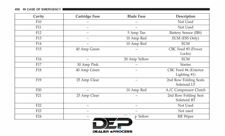
Cavity Cartridge Fuse Blade Fuse DescriptionF10 – – Not UsedF11 – – Not UsedF12 – 5 Amp Tan Battery Sensor (IBS)F13 – 10 Amp Red ECM (ESS Only)F14 – 10 Amp Red ECMF15 40 Amp Green – CBC Feed #3 (Power
Locks)F16 – 20 Amp Yellow ECMF17 30 Amp Pink – StarterF18 40 Amp Green – CBC Feed #4 (Exterior
Lighting #1)F19 25 Amp Clear – 2nd Row Folding Seats
Solenoid LTF20 – 10 Amp Red A/C Compressor ClutchF21 25 Amp Clear – 2nd Row Folding Seat
Solenoid RTF22 – – Not UsedF23 – – Not usedF24 – 20 Amp Yellow RR Wiper
458 IN CASE OF EMERGENCY
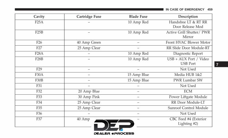
Cavity Cartridge Fuse Blade Fuse DescriptionF25A – 10 Amp Red Handsfree LT & RT RR
Door Release ModF25B – 10 Amp Red Active Grill Shutter/ PWR
MirrorF26 40 Amp Green – Front HVAC Blower MotorF27 25 Amp Clear – RR Slide Door Module-RT
F28A – 10 Amp Red Diagnostic ReportF28B – 10 Amp Red USB + AUX Port / Video
USB PortF29 – – Not Used
F30A – 15 Amp Blue Media HUB 1&2F30B – 15 Amp Blue PWR Lumbar SWF31 – – Not UsedF32 20 Amp Blue – ECMF33 30 Amp Pink – Power Liftgate ModuleF34 25 Amp Clear – RR Door Module-LTF35 25 Amp Clear – Sunroof Control ModuleF36 – – Not UsedF37 40 Amp Green – CBC Feed #4 (Exterior
Lighting #2)
7
IN CASE OF EMERGENCY 459

Cavity Cartridge Fuse Blade Fuse DescriptionF38 60 Amp Yellow – Vacuum CleanerF39 25 Amp Clear – Rear HVAC Blower MotorF40 – – Not UsedF41 – – Not UsedF42 40 Amp Green – Folding Seat ModuleF43 – 20 Amp Yellow Fuel Pump MotorF44 30 Amp Pink – CBC Feed #1 (Interior
Lights)F45 30 Amp Pink – Power InverterF46 30 Amp Pink – Driver Door ModuleF47 30 Amp Pink – Passenger Door ModuleF48 – – Not UsedF49 25 Amp Clear – RR Sliding Door
Module-LTF50 25 Amp Clear – RR Door Module-RTF51 30 Amp Pink – Front WiperF52 30 Amp Pink – Brake Vacuum PumpF53 – – Not UsedF54 40 Amp Green – ESP-ECU And Valves
460 IN CASE OF EMERGENCY

Cavity Cartridge Fuse Blade Fuse DescriptionF55A – 15 Amp Blue Radio Frequency HUB/
Keyless Ignition System(KIN) / (Electronic Steering
Lock-BUX ONLY)F55B – 15 Amp Blue DVD / Video Routing
Module (VRMF56A – 10 Amp Red Front and Rear HVAC Con-
trol Module / OccupantClassification Module
(OCM)/Electronic SteeringLock (ESL)
F56B – 10 Amp Red ESP/ESCF57 – – Not UsedF58 – – Not UsedF59 30 Amp Pink – Trailer Tow Receptacle — If
EquippedF60 – 20 Amp Yellow Rear Cargo APOF61 – 20 Amp Yellow Trailer Tow Right Stop/
Turn — If EquippedF62 – – Not Used
7
IN CASE OF EMERGENCY 461

Cavity Cartridge Fuse Blade Fuse DescriptionF63 – 20 Amp Yellow Trailer Tow Left Stop/Turn
— If EquippedF64 – 15 Amp Blue RT HID HeadlampF65 – – Not UsedF66 – 15 Amp Blue Instrument Panel Cluster
(IPC)F67 – 10 Amp Red Haptic Lane Feedback
Module (HALF) / Park-tronics System (PTS)/Drivers Assist System
Module (DASM)F68 – – Not UsedF69 – – Not UsedF70 – – Not UsedF71 – 20 Amp Yellow HornF72 – 10 Amp Red Heated Mirrors – If
EquippedF73 30 Amp Pink – Rear Defroster (EBL)F74 20 Amp Blue – Trailer Tow BackupF75 – 5 Amp Tan Overhead Console / RR
ISC
462 IN CASE OF EMERGENCY

Cavity Cartridge Fuse Blade Fuse DescriptionF76 – 20 Amp Yellow Uconnect/DCSD/
TelematicsF77A – 10 Amp Red RR Entertainment Screen 1
& 2/Media HUB 1 & 2/3rdRow USB Charge Only/
2nd Row USB ChargeOnly/Vaccum Cleaner SW/3rd Row Recline ST SW/LT& RT Stow N Go SW/LT &RT Sliding Door SW Back-
lightF77B – 10 Amp Red Rain Sensor/Sunroof
/CRVMMF78A – 15 Amp Blue Transmission Control Mod-
ule (TCM)/ E-ShifterF78B – 15 Amp Blue Instrument ClusterF79 – 10 Amp Red ICS/Front And Rear
HVAC/ SCCM/ EPBF80 – – Not UsedF81 – – Not UsedF82 – – Not Used
7
IN CASE OF EMERGENCY 463

Cavity Cartridge Fuse Blade Fuse DescriptionF83 20 Amp Blue – TT Park Lights — If
Equipped30 Amp Pink – Headlamp Washer Pump
— If EquippedF84 – – Not UsedF85 – 20 Amp Yellow Cigar LighterF86 – – Not UsedF87 – – Not UsedF88 – 20 Amp Yellow Front Heated SeatsF89 – 20 Amp Yellow Rear Heated SeatsF90 – – Not UsedF91 – 15 Amp Blue Front Ventilated Seats/
Heated Steering WheelF92 – 5 Amp Tan Security GatewayF93 – – Not UsedF94 40 Amp Green – ESC Motor Pump
F95A – 10 Amp Red USB Charge Port — ACCRUN
F95B – 10 Amp Red Selectable Fuse Location
464 IN CASE OF EMERGENCY

Cavity Cartridge Fuse Blade Fuse DescriptionF96 – 10 Amp Red Occupant Restraint Con-
troller (ORC) (Airbag)F97 – 10 Amp Red Occupant Restraint Con-
troller (ORC) (Airbag)F98 – 15 Amp Blue Left HID HeadlampF99 30 Amp Pink – Trailer Tow Module - If
EquippedF100A – 10 Amp Red AHLMF100B – 10 Amp Red Rear Camera/LBSS/RBSS/
CVPM/HumiditySensor/In Vehicle Tempera-
ture SensorCircuit Breakers
CB1 25 Amp Power Seats (Driver)CB2 25 Amp * Power Seats (Pass)CB3 25 Amp FRT PWR Window W/O
Door Nodes + RR PWRWindow Lockout
* 30A mini fuse is substituted for 25A Circuit Breaker.
7
IN CASE OF EMERGENCY 465

JACKING AND TIRE CHANGING — IF EQUIPPED
WARNING!
• Do not attempt to change a tire on the side of thevehicle close to moving traffic. Pull far enough offthe road to avoid the danger of being hit whenoperating the jack or changing the wheel.
• Being under a jacked-up vehicle is dangerous. Thevehicle could slip off the jack and fall on you. Youcould be crushed. Never put any part of your bodyunder a vehicle that is on a jack. If you need to getunder a raised vehicle, take it to a service centerwhere it can be raised on a lift.
• The jack is designed to be used as a tool for changingtires only. The jack should not be used to lift thevehicle for service purposes. The vehicle should bejacked on a firm level surface only. Avoid ice orslippery areas.
Jack And Spare Tire Location
The jacking tools, spare tire and portable air compressor (ifequipped) or tire service kit (if equipped) are stowedbehind an access panel on the left hand side of the vehicle.
Jacking Equipment Location
466 IN CASE OF EMERGENCY
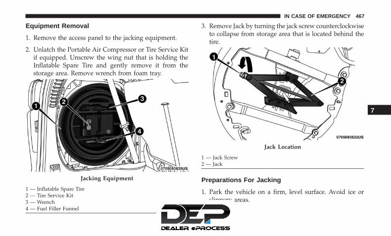
Equipment Removal
1. Remove the access panel to the jacking equipment.
2. Unlatch the Portable Air Compressor or Tire Service Kitif equipped. Unscrew the wing nut that is holding theInflatable Spare Tire and gently remove it from thestorage area. Remove wrench from foam tray.
3. Remove Jack by turning the jack screw counterclockwiseto collapse from storage area that is located behind thetire.
Preparations For Jacking
1. Park the vehicle on a firm, level surface. Avoid ice orslippery areas.
Jacking Equipment
1 — Inflatable Spare Tire2 — Tire Service Kit3 — Wrench4 — Fuel Filler Funnel
Jack Location
1 — Jack Screw2 — Jack
7
IN CASE OF EMERGENCY 467

WARNING!
Do not attempt to change a tire on the side of thevehicle close to moving traffic. Pull far enough off theroad to avoid being hit when operating the jack orchanging the wheel.
2. Turn on the Hazard Warning flasher.
3. Apply the parking brake.
4. Place the gear selector into PARK.
5. Place the ignition in OFF mode.
6. Block both the front and rear of the wheel diagonallyopposite the jacking position. For example, if the rightfront wheel is being changed, block the left rear wheel.
NOTE: Passengers should not remain in thevehicle when the vehicle is being jacked.
Jacking Instructions
WARNING!
Carefully follow these tire changing warnings to helpprevent personal injury or damage to your vehicle:• Always park on a firm, level surface as far from the
edge of the roadway as possible before raising thevehicle.
• Turn on the Hazard Warning flasher.• Block the wheel diagonally opposite the wheel to be
raised.• Apply the parking brake firmly and set the transmis-
sion in PARK.• Do not let any passenger sit in the vehicle when it is
on a jack.• Do not get under the vehicle when it is on a jack. If
you need to get under a raised vehicle, take it to aservice center where it can be raised on a lift.
• Only use the jack in the positions indicated and forlifting this vehicle during a tire change.
• If working on or near a roadway, be extremelycareful of motor traffic.
468 IN CASE OF EMERGENCY

CAUTION!
Do not attempt to raise the vehicle by jacking onlocations other than those indicated in the JackingInstructions for this vehicle.
NOTE: Refer to “Tires” in “Servicing And Maintenance� forinformation about the inflatable spare tire, its use, andoperation.
1. Loosen (but do not remove) the wheel lug nuts byturning them to the left one turn while the wheel is stillon the ground.
Jack Warning Label Extending The Wrench
7
IN CASE OF EMERGENCY 469
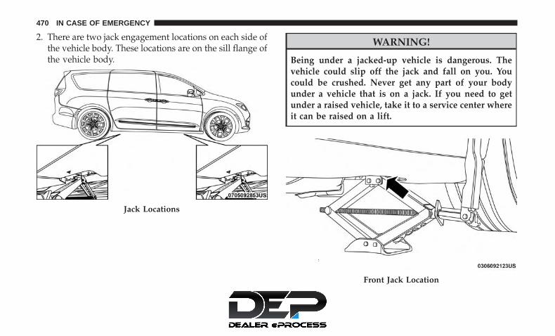
2. There are two jack engagement locations on each side ofthe vehicle body. These locations are on the sill flange ofthe vehicle body.
WARNING!
Being under a jacked-up vehicle is dangerous. Thevehicle could slip off the jack and fall on you. Youcould be crushed. Never get any part of your bodyunder a vehicle that is on a jack. If you need to getunder a raised vehicle, take it to a service center whereit can be raised on a lift.
Jack Locations
Front Jack Location
470 IN CASE OF EMERGENCY

Front Jack Engaged Rear Jacking Location
7
IN CASE OF EMERGENCY 471

CAUTION!
Do not attempt to raise the vehicle by jacking onlocations other than those indicated.
3. Place the wrench on the jack screw and turn to the rightuntil the jack head is properly engaged in the describedlocation. Do not raise the vehicle until you are sure thejack is securely engaged.
4. Raise the vehicle by turning the jack screw to the right,using the swivel wrench. Raise the vehicle only until the
tire just clears the surface and enough clearance isobtained to install the compact spare tire. Minimum tirelift provides maximum stability.
WARNING!
Raising the vehicle higher than necessary can make thevehicle less stable. It could slip off the jack and hurtsomeone near it. Raise the vehicle only enough toremove the tire.
5. Remove the wheel lug nuts, for vehicles with wheelcovers, remove the cover from the wheel by hand. Donot pry the wheel cover off. Then pull the wheel off thehub.
6. Install the inflatable spare on the vehicle, located in therear cargo area of the vehicle.
WARNING!
To avoid the risk of forcing the vehicle off the jack, donot tighten the wheel nuts fully until the vehicle hasbeen lowered. Failure to follow this warning mayresult in serious injury.
Rear Jack Engaged
472 IN CASE OF EMERGENCY

CAUTION!
Be sure to mount the inflatable spare tire with thevalve stem facing outward. The vehicle could be dam-aged if the inflatable spare tire is mounted incorrectly.
NOTE: Do not install the wheel cover on the inflatablespare tire.
7. Leave the vehicle on the jack and start inflating theinflatable spare after the tire has been mounted to thevehicle. Secure the wheel to the hub by tightening the
nuts with wrench. After inflation, once the vehicle islowered you will have a second opportunity to “torque”the lug nuts.
8. Inflate the tire to the prescribed pressure 60 psi (4.2 Bar)using the Portable Air Compressor or Tire Service Kit ifequipped. Refer to “Portable Air Compressor” in thissection for usage procedure if equipped. Refer to “TireService Kit For Inflating Tire” in this section for usageprocedure if equipped.
9. Lower the vehicle once the inflatable Spare has reachedits pressure and the compressor-hose has been removedfrom the tire valve.
10. Finish tightening the lug nuts. Push down on thewrench while at the end of the handle for increasedleverage. Tighten the lug nuts in a star pattern untileach nut has been tightened twice. Refer to “TorqueSpecifications” in “Technical Specifications” for properwheel lug nut torque. If in doubt about the correcttightness, have them checked with a torque wrench byyour authorized dealer or at a service station.
Mounting Inflatable Spare Tire
7
IN CASE OF EMERGENCY 473

11. Lower the jack to its fully-closed position.
WARNING!
A loose tire or jack thrown forward in a collision orhard stop could endanger the occupants of the vehicle.Always stow the jack parts and the spare tire in theplaces provided. Have the deflated (flat) tire repairedor replaced immediately.
12. Place the deflated (flat) tire and foam tray coverassembly in the rear cargo area. Do not stow thedeflated tire in the inflatable spare tire location. Havethe full-sized tire repaired or replaced, as soon aspossible.
13. Stow the jack back in the stowage compartment andplace the access panel back. The stud of the storagearea must be threaded through the lower part of thejack. Then turn the Jack Screw clockwise to secure it inplace.
NOTE: Stow the foam tray and components in the cargoarea.
Road Tire Installation
Vehicles Equipped With Wheel Covers
1. Mount the road tire on the axle.
2. To ease the installation process for steel wheels withwheel covers, install two lug nuts on the mountingstuds which are on each side of the valve stem. Install
Storing The Jack
1 — Jack Screw2 — Jack3 — Stud
474 IN CASE OF EMERGENCY

the lug nuts with the cone shaped end of the nut towardthe wheel. Lightly tighten the lug nuts.
3. Align the valve notch in the wheel cover with the valvestem on the wheel. Install the cover by hand, snappingthe cover over the two lug nuts. Do not use a hammer orexcessive force to install the cover.
4. Install the remaining lug nuts with the cone shaped endof the nut toward the wheel. Lightly tighten all the lugnuts until the wheel sits flush onto the hub and there isno play. The nuts will have to be fully tightened once thevehicle is lowered. Tightening an improperly seatedwheel under vehicle load can damage the threads, causevibration, and undermine safety.
WARNING!
To avoid the risk of forcing the vehicle off the jack, donot tighten the wheel nuts fully until the vehicle hasbeen lowered. Failure to follow this warning mayresult in serious injury.
5. Lower the vehicle to the ground by turning the jackhandle counterclockwise.
6. Finish tightening the lug nuts. Push down on thewrench while at the end of the handle for increasedleverage. Tighten the lug nuts in a star pattern until eachnut has been tightened twice. Refer to “Torque Specifi-cations” in “Technical Specifications” for proper wheellug nut torque. If in doubt about the correct tightness,have them checked with a torque wrench by an autho-rized dealer or at a service station.
Tire And Wheel Cover Or Center Cap
1 — Valve Stem 4 — Wheel Cover2 — Valve Notch 5 — Mounting Stud3 — Wheel Lug Nut
7
IN CASE OF EMERGENCY 475

7. After 25 miles (40 km) check the lug nut torque with atorque wrench to ensure that all lug nuts are properlyseated against the wheel.
Vehicles Without Wheel Covers
1. Mount the road tire on the axle.
2. Install the remaining lug nuts with the cone shaped endof the nut toward the wheel. Lightly tighten all the lugnuts until the wheel sits flush onto the hub and there isno play. The nuts will have to be fully tightened once thevehicle is lowered. Tightening an improperly seatedwheel under vehicle load can damage the threads, causevibration, and undermine safety.
WARNING!
To avoid the risk of forcing the vehicle off the jack, donot tighten the wheel nuts fully until the vehicle hasbeen lowered. Failure to follow this warning mayresult in serious injury.
3. Lower the vehicle to the ground by turning the jackhandle counterclockwise.
4. Finish tightening the lug nuts. Push down on thewrench while at the end of the handle for increasedleverage. Tighten the lug nuts in a star pattern until eachnut has been tightened twice. Refer to “Torque Specifi-cations” in the “Technical Specifications” section forproper wheel lug nut torque. If in doubt about thecorrect tightness, have them checked with a torquewrench by your authorized dealer or at a service station.
5. After 25 miles (40 km) check the lug nut torque with atorque wrench to ensure that all lug nuts are properlyseated against the wheel.
Portable Air Compressor — If Equipped
Your vehicle may be equipped with a Portable Air Com-pressor. Use the Portable Air Compressor located in theside compartment of the cargo area to inflate the inflatabletire to 60 psi (4.2 Bar).
476 IN CASE OF EMERGENCY

Portable Air Compressor Usage With Inflatable SpareTire
1. Remove the Portable Air Compressor from the storagelocation.
2. Raise the vehicle as described in the Jacking Instructionswithin this section.
3. Install the Inflatable Spare tire as described in the JackInstructions section in this manual.Make sure that the valve stem islocated near the ground, and thenscrew the air hose of the Portable AirCompressor to the valve stem.
Portable Air Compressor
1 — Power Plug2 — Deflation Button3 — Pressure Gauge4 — Power Button5 — Air Hose
7
IN CASE OF EMERGENCY 477

4. Uncoil the power plug and connect it the vehicles 12Volt power Outlet.
5. Always start the engine before turning ON the PortableAir Compressor.
6. Switch the power button ON.
7. Inflate the tire to 60 psi (4.2 Bar) recommended as perthe label on the wheel or if the vehicleequipped with the inflatable sparetire pressure indicated on the Tireand Loading information label lo-cated on the driver-side door open-ing.
NOTE: If the tire is over inflated, use the deflation buttonto reduce the tire air pressure.
8. After the tire reaches the recommended pressure, lowerthe vehicle with the jack as describedin the Jack Instructions section in thismanual.
478 IN CASE OF EMERGENCY

9. Remove the speed limit label sticker from the PortableAir Compressor and place it on thecenter of the steering wheel.
10. Return the Portable Air Compressor to the foam trayand secure it with the strap. Store the foam tray in thecargo area.
WARNING!
• Do not lift or carry the Portable Air Compressor bythe hose.
• Always stow the Portable Air Compressor only in theprovided place.
• The metal end fitting from Power Plug may get hotafter use, so it should be handled carefully.
• Keep the Portable Air Compressor away from openflames or heat source.
Tire Service Kit For Inflating Tire — If Equipped
Your vehicle may be equipped with a Tire Service Kit. Usethe Tire Service Kit located in the side compartment of thecargo area to inflate the inflatable tire to 60 psi (4.2 Bar).
7
IN CASE OF EMERGENCY 479

Tire Service Kit And Components And Operation Using The Mode Select Knob And Hoses
Your Tire Service Kit is equipped with the followingsymbols to indicate the air or sealant mode.
Selecting Air Mode
Push in the Mode Select Knob and turnto this position for air mode operationonly.
Selecting Sealant Mode
Push in the Mode Select Knob and turnto this position to inject the Tire ServiceKit Sealant and to inflate the tire.
Tire Service Kit Components
1 — Mode Select Knob2 — Sealant/Air Hose3 — Hose Accessories4 — Sealant Bottle5 — Power Plug6 — Power Switch7 — Deflation Button8 — Pressure Gauge
480 IN CASE OF EMERGENCY

Using The Power Button
Push and release the Power Button onceto turn On the Tire Service Kit. Push andrelease the Power Button again to turnOff the Tire Service Kit.
Using The Deflation Button
Push the Deflation Button to reduce theair pressure in the tire if it becomesover-inflated.
WARNING!
• Keep Tire Service Kit away from open flames or heatsource.
• A loose Tire Service Kit thrown forward in a collisionor hard stop could endanger the occupants of thevehicle. Always stow the Tire Service Kit in the place
(Continued)
WARNING! (Continued)provided. Failure to follow these warnings can resultin injuries that are serious or fatal to you, yourpassengers, and others around you.
• Take care not to allow the contents of Tire Service Kitto come in contact with hair, eyes, or clothing. TireService Kit sealant is harmful if inhaled, swallowed,or absorbed through the skin. It causes skin, eye, andrespiratory irritation. Flush immediately with plentyof water if there is any contact with eyes or skin.Change clothing as soon as possible, if there is anycontact with clothing.
• Tire Service Kit Sealant solution contains latex. Incase of an allergic reaction or rash, consult a physi-cian immediately. Keep Tire Service Kit out of reachof children. If swallowed, rinse mouth immediatelywith plenty of water and drink plenty of water. Donot induce vomiting! Consult a physician immedi-ately.
7
IN CASE OF EMERGENCY 481

Whenever You Stop To Use Tire Service Kit:
1. Pull over to a safe location and turn on the vehicle’sHazard Warning flashers.
2. Verify that the valve stem (on the wheel with thedeflated tire) is in a position that is near to the ground.This will allow the Tire Service Kit Hose to reach thevalve stem and keep the Tire Service Kit flat on theground. This will provide the best positioning of the kitwhen running the air pump. Move the vehicle asnecessary to place the valve stem in this position beforeproceeding.
3. Place the transmission in PARK and cycle the ignition inthe OFF position.
4. Ensure the park brake is engaged.
Setting Up To Use Tire Service Kit:
1. Remove the Tire Service Kit from the storage location.
2. Uncoil the Sealant/Air Hose. Remove the cap from thevalve stem and then screw the fittingin at the end of the Sealant/Air Hoseclockwise onto the valve stem.
3. Uncoil the Power Plug and insert the plug into thevehicle’s 12 Volt power outlet.
4. Place the Tire Service Kit on the ground next to thedeflated tire.
482 IN CASE OF EMERGENCY

5. Engage parking brake before turning the engine ON.
6. Always start the engine before turn-ing ON the Tire Service Kit.
7. Turn the Mode Select Knob to Air Mode position.
NOTE: Do not fill inflatable spare tirewith sealant. Refer to “Tire Service Kit”in this chapter for repairing tires.
8. Switch the power button ON.
9. Inflate the tire to 60 psi (4.2 Bar) recommended as per thelabel on the wheel or if the vehicleequipped with the inflatable spare tirepressure indicated on the Tire andLoading information label located onthe driver-side door opening.
NOTE: If the tire is over inflated, use the deflation buttonto reduce the tire air pressure.
10. After the tire reaches the recommended pressure,lower the vehicle with the jack asdescribed in the Jack Instructionssection in this manual.
7
IN CASE OF EMERGENCY 483

11. Remove the speed limit label sticker from the TireService Kit and place it on the centerof the steering wheel.
12. Return the Tire Service Kit to the foam tray and secureit with the strap. Store the foam tray in the cargo area.
Return Inflatable Spare Tire
To return Inflatable Spare Tire to its storage location.
1. Return the Jack.
2. Deflate the spare tire. Use the Tire Service Kit or PortableAir Compressor and push the deflation button to do thisstep. Refer to “Tire Service Kit” or “Portable Air Com-pressor” if equipped in this section for additional infor-mation. The inflatable spare tire will return to its origi-nal shape.
3. Install the inflatable spare tire back into its originalstowage location and position facing outward.
4. Install the foam tray with wrench and funnel installed.
5. Install and tighten the wing nut by hand.
6. Install the Tire Service Kit or Portable Air Compressor ifequipped and tighten the strap.
7. Install access panel door.
TIRE SERVICE KIT — IF EQUIPPED
Your vehicle may be equipped with a Tire Service Kit.Small punctures up to 1/4 inch (6 mm) in the tire tread canbe sealed with Tire Service Kit. Foreign objects (e.g., screwsor nails) should not be removed from the tire. Tire ServiceKit can be used in outside temperatures down to approxi-mately -4°F (-20°C). This kit will provide a temporary tireseal, allowing you to drive your vehicle up to 100 miles(160 km) with a maximum speed of 50 mph (80 km/h).
484 IN CASE OF EMERGENCY
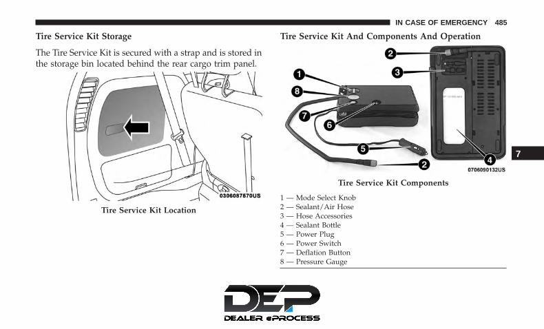
Tire Service Kit Storage
The Tire Service Kit is secured with a strap and is stored inthe storage bin located behind the rear cargo trim panel.
Tire Service Kit And Components And Operation
Tire Service Kit Location
Tire Service Kit Components
1 — Mode Select Knob2 — Sealant/Air Hose3 — Hose Accessories4 — Sealant Bottle5 — Power Plug6 — Power Switch7 — Deflation Button8 — Pressure Gauge
7
IN CASE OF EMERGENCY 485

Using The Mode Select Knob And Hoses
Your Tire Service Kit is equipped with the followingsymbols to indicate the air or sealant mode.
Selecting Air Mode
Push in the Mode Select Knob and turnto this position for air pump operationonly.
Selecting Sealant Mode
Push in the Mode Select Knob and turnto this position to inject the Tire ServiceKit Sealant and to inflate the tire.
Using The Power Button
Push and release the Power Button onceto turn On the Tire Service Kit. Push andrelease the Power Button again to turnOff the Tire Service Kit.
Using The Deflation Button
Push the Deflation Button to reduce theair pressure in the tire if it becomesover-inflated.
Tire Service Kit Usage Precautions
• Replace the Tire Service Kit Sealant Bottle prior to theexpiration date (printed at the lower right hand corneron the bottle label) to assure optimum operation of thesystem. Refer to “Sealant Bottle Replacement” in thissection.
486 IN CASE OF EMERGENCY

• The Sealant Bottle is a one tire application use and needsto be replaced after each use. Always replace thesecomponents immediately at your original equipmentvehicle dealer.
• When the Tire Service Kit sealant is in a liquid form,clean water, and a damp cloth will remove the materialfrom the vehicle or tire and wheel components. Once thesealant dries, it can easily be peeled off and properlydiscarded.
• For optimum performance, make sure the valve stem onthe wheel is free of debris before connecting the TireService Kit.
• The Tire Service Kit Sealant is only intended to sealpunctures less than 1/4 inch (6 mm) diameter in thetread/contact surface of your vehicle’s tires.
• The Tire Service Kit Sealant is not intended to sealpunctures on the tires’ side walls.
• You can use the Tire Service Kit air pump to inflatebicycle tires. The kit also comes with two needles,located in the Accessory Storage Compartment (on thebottom of the air pump) for inflating sport balls, rafts, orsimilar inflatable items. However, use only the Air Pump
and make sure the Mode Select Knob is in the Air Modewhen inflating such items to avoid injecting sealant intothem.
• Do not lift or carry the Tire Service Kit by the hoses.
WARNING!
• Do not attempt to seal a tire on the side of the vehicleclosest to traffic. Pull far enough off the road to avoidthe danger of being hit when using the Tire ServiceKit.
• Do not use Tire Service Kit or drive the vehicle underthe following circumstances:– If the puncture in the tire tread is approximately
1/4 inch (6 mm) or larger.– If the tire has any sidewall damage.– If the tire has any damage from driving with
extremely low tire pressure.– If the tire has any damage from driving on a flat
tire.– If the wheel has any damage.– If you are unsure of the condition of the tire or the
wheel.
(Continued)
7
IN CASE OF EMERGENCY 487

WARNING! (Continued)• Keep Tire Service Kit away from open flames or heat
source.• A loose Tire Service Kit thrown forward in a collision
or hard stop could endanger the occupants of thevehicle. Always stow the Tire Service Kit in the placeprovided. Failure to follow these warnings can resultin injuries that are serious or fatal to you, yourpassengers, and others around you.
• Take care not to allow the contents of Tire Service Kitto come in contact with hair, eyes, or clothing. TireService Kit sealant is harmful if inhaled, swallowed,or absorbed through the skin. It causes skin, eye, andrespiratory irritation. Flush immediately with plentyof water if there is any contact with eyes or skin.Change clothing as soon as possible, if there is anycontact with clothing.
• Tire Service Kit Sealant solution contains latex. Incase of an allergic reaction or rash, consult a physi-cian immediately. Keep Tire Service Kit out of reachof children. If swallowed, rinse mouth immediatelywith plenty of water and drink plenty of water. Donot induce vomiting! Consult a physician immedi-ately.
Sealing A Tire With Tire Service Kit
Whenever You Stop To Use Tire Service Kit:
1. Pull over to a safe location and turn on the vehicle’sHazard Warning flashers.
2. Verify that the valve stem (on the wheel with thedeflated tire) is in a position that is near to the ground.This will allow the Tire Service Kit Hose to reach thevalve stem and keep the Tire Service Kit flat on theground. This will provide the best positioning of the kitwhen injecting the sealant into the deflated tire andrunning the air pump. Move the vehicle as necessary toplace the valve stem in this position before proceeding.
3. Place the transmission in PARK and cycle the ignition inthe OFF position.
4. Apply the parking brake.
Setting Up To Use Tire Service Kit:
1. Uncoil the Sealant Hose and then remove the cap fromthe fitting at the end of the hose.
2. Place the Tire Service Kit flat on the ground next to thedeflated tire.
488 IN CASE OF EMERGENCY

3. Remove the cap from the valve stem and then screw thefitting at the end of the Sealant Hoseonto the valve stem.
4. Uncoil the Power Plug and insert the plug into thevehicle’s 12 Volt power outlet.
NOTE: Do not remove foreign objects (e.g., screws or nails)from the tire.
Injecting Tire Service Kit Sealant Into The Deflated Tire:
1. Always start the vehicle before turning the Tire ServiceKit on.
2. Ensure the Mode Select Knob is to the Sealant Modeposition.
3. After pushing the Power Button, the sealant (whitefluid) will flow from the SealantBottle through the Sealant Hose andinto the tire.
7
IN CASE OF EMERGENCY 489

NOTE: Sealant may leak out through the puncture in thetire.
If the sealant (white fluid) does not flow within 0 – 10seconds through the Sealant Hose:
1. Push the Power Button to turn the Tire Service Kit off.Disconnect the Sealant Hose from the valve stem. Makesure the valve stem is free of debris. Reconnect theSealant Hose to the valve stem. Check that the ModeSelect Knob is in the Sealant Mode position and not AirMode. Push the Power Button to turn the Tire ServiceKit on.
2. Connect the Power Plug to a different 12 Volt poweroutlet in your vehicle or another vehicle, if available.Make sure the vehicle is running before turning the TireService Kit on.
3. The Sealant Bottle may be empty due to previous use.Call for assistance.
If the sealant (white fluid) does flow through the SealantHose:
1. Continue to operate the pump until sealant is no longerflowing through hose (typically takes30 - 70 seconds). As the sealant flowsthrough the Sealant Hose, the Pres-sure Gauge can read as high as 70 psi(4.8 Bar). The Pressure Gauge willdecrease quickly from approximately70 psi (4.8 Bar) to the actual tire
pressure when the Sealant Bottle is empty.
2. The pump will start to inject air into the tire immedi-ately after the Sealant Bottle is empty.Continue to operate the pump andinflate the tire to the cold tire inflationpressure found on the tire and load-ing information label located in thedriver-side door opening. Check thetire pressure by looking at the Pres-
sure Gauge.
490 IN CASE OF EMERGENCY

If the tire does not inflate to at least 26 psi (1.8 Bar)pressure within 15 minutes:
• The tire is too badly damaged. Do not attempt to drivethe vehicle further. Call for assistance.
If the tire inflates to the recommended pressure or is atleast 26 psi (1.8 Bar) pressure within 15 minutes:
NOTE: If the tire becomes over-inflated, push the DeflationButton to reduce the tire pressure to the recommendedinflation pressure before continuing.
1. Push the Power Button to turn theTire Service Kit off.
2. Remove the speed limit label from the Tire Service Kitand place sticker on the steeringwheel.
3. Immediately disconnect the Sealant Hose from the valvestem, reinstall the cap on the fitting at the end of thehose, and place the Tire Service Kit in the vehicle storagelocation. Proceed to “Drive Vehicle.”
Drive Vehicle:
Immediately after injecting sealant and inflating the tire,drive the vehicle 5 miles (8 km) or 10minutes to ensure distribution of theTire Service Kit Sealant within the tire.Do not exceed 50 mph (80 km/h).
WARNING!
The Tire Service Kit is not a permanent flat tire repair.Have the tire inspected and repaired or replaced afterusing the Tire Service Kit. Do not exceed 50 mph(80 km/h) until the tire is repaired or replaced. Failureto follow this warning can result in injuries that areserious or fatal to you, your passengers, and othersaround you. Have the tire checked as soon as possibleat your authorized dealer.
7
IN CASE OF EMERGENCY 491

After Driving:
Pull over to a safe location. Refer to “Whenever You StopTo Use Tire Service Kit” in this section before continuing.
1. Uncoil the Sealant Hose, and then remove the cap fromthe fitting at the end of the hose.
2. Place the Tire Service Kit flat on the ground next to thedeflated tire.
3. Remove the cap from the valve stem, and then screw thefitting at the end of the Sealant Hoseonto the valve stem.
4. Uncoil the Power Plug and insert the plug into thevehicle’s 12 Volt power outlet.
5. Uncoil the Hose and screw the fitting at the end of thehose onto the valve stem.
6. Turn the Mode Select Knob and turn to the Air Modeposition.
7. Check the pressure in the tire by reading the PressureGauge.
If tire pressure is less than 19 psi (1.3 Bar):
The tire is too badly damaged. Do not attempt to drive thevehicle further. Call for assistance.
492 IN CASE OF EMERGENCY

If the tire pressure is 19 psi (1.3 Bar) or higher:
1. Push the Power Button to turn on Tire Service Kit andinflate the tire to the cold tire inflationpressure found on the tire and load-ing information label located in thedriver-side door opening.
NOTE: If the tire becomes over-inflated,push the Deflation Button to reduce thetire pressure to the recommended infla-
tion pressure before continuing.
2. Disconnect the Tire Service Kit from the valve stem,reinstall the cap on the valve stem and unplug from12 Volt outlet.
3. Place the Tire Service Kit in its proper storage area in thevehicle.
4. Have the tire inspected and repaired or replaced at theearliest opportunity at an authorized dealer or tireservice center.
5. Remove the Speed Limit sticker from the steering wheelafter the tire has been repaired.
6. Replace the Sealant Bottle at an authorized dealer assoon as possible. Refer to “Sealant Bottle Replacement”.
NOTE: When having the tire serviced, advise the autho-rized dealer or service center that the tire has been sealedusing the Tire Service Kit.
Sealant Bottle Replacement:
1. Unwrap the power cord.
2. Unwrap the hose.
Unwrap The Hose
7
IN CASE OF EMERGENCY 493

3. Remove the bottle cover. 4. Rotate the bottle up beyond vertical to release.
Remove The Bottle Cover Rotate The Bottle Up
494 IN CASE OF EMERGENCY

5. Pull the bottle away from the Compressor.
NOTE:
• For sealant bottle installation, follow these steps reverseorder.
• Replacement sealant bottles are available at authorizedservice centers.
JUMP STARTING
If your vehicle has a discharged battery it can be jumpstarted using a set of jumper cables and a battery in anothervehicle or by using a portable battery booster pack. Jumpstarting can be dangerous if done improperly so pleasefollow the procedures in this section carefully.
NOTE: When using a portable battery booster pack followthe manufacturer’s operating instructions and precautions.
WARNING!
Do not attempt jump starting if the battery is frozen. Itcould rupture or explode and cause personal injury.
CAUTION!
Do not use a portable battery booster pack or any otherbooster source with a system voltage greater than12 Volts or damage to the battery, starter motor, alter-nator or electrical system may occur.
Remove The Bottle
7
IN CASE OF EMERGENCY 495
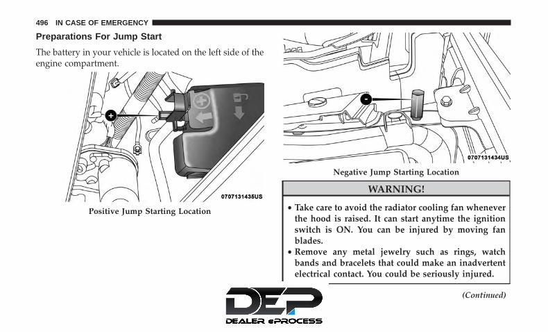
Preparations For Jump Start
The battery in your vehicle is located on the left side of theengine compartment.
WARNING!
• Take care to avoid the radiator cooling fan wheneverthe hood is raised. It can start anytime the ignitionswitch is ON. You can be injured by moving fanblades.
• Remove any metal jewelry such as rings, watchbands and bracelets that could make an inadvertentelectrical contact. You could be seriously injured.
(Continued)
Positive Jump Starting Location
Negative Jump Starting Location
496 IN CASE OF EMERGENCY

WARNING! (Continued)• Batteries contain sulfuric acid that can burn your
skin or eyes and generate hydrogen gas which isflammable and explosive. Keep open flames orsparks away from the battery.
1. Apply the parking brake, shift the automatic transmis-sion into PARK and place the ignition to OFF.
2. Turn off the heater, radio, and all unnecessary electricalaccessories.
3. If using another vehicle to jump start the battery, parkthe vehicle within the jumper cables reach, set theparking brake and make sure the ignition is OFF.
WARNING!
Do not allow vehicles to touch each other as this couldestablish a ground connection and personal injurycould result.
Jump Starting Procedure
WARNING!
Failure to follow this jump starting procedure couldresult in personal injury or property damage due tobattery explosion.
CAUTION!
Failure to follow these procedures could result indamage to the charging system of the booster vehicleor the discharged vehicle.
Connecting The Jumper Cables
1. Connect the positive (+) end of the jumper cable to thepositive (+) post of the vehicle with the dischargedbattery.
2. Connect the opposite end of the positive (+) jumpercable to the positive (+) post of the booster battery.
3. Connect the negative (-) end of the jumper cable to thenegative (-) post of the booster battery.
7
IN CASE OF EMERGENCY 497

4. Connect the opposite end of the negative (-) jumpercable to the negative post near the windshield cowl(exposed metal part of the discharged vehicle’s engine).
WARNING!
Do not connect the jumper cable to the negative (-) postof the discharged battery. The resulting electrical sparkcould cause the battery to explode and could result inpersonal injury. Only use the specific ground point, donot use any other exposed metal parts.
5. Start the engine in the vehicle that has the boosterbattery, let the engine idle a few minutes, and then startthe engine in the vehicle with the discharged battery.
6. Once the engine is started, remove the jumper cables inthe reverse sequence:
Disconnecting The Jumper Cables
1. Disconnect the negative (-) end of the jumper cable fromthe engine ground of the vehicle with the dischargedbattery.
2. Disconnect the opposite end of the negative (-) jumpercable from the negative (-) post of the booster battery.
3. Disconnect the positive (+) end of the jumper cable fromthe positive (+) post of the booster battery.
4. Disconnect the opposite end of the positive (+) jumpercable from the positive (+) post of the vehicle with thedischarged battery.
If frequent jump starting is required to start your vehicleyou should have the battery and charging system in-spected at an authorized dealer.
CAUTION!
Accessories plugged into the vehicle power outletsdraw power from the vehicle’s battery, even when notin use (i.e., cellular devices, etc.). Eventually, if pluggedin long enough without engine operation, the vehicle’sbattery will discharge sufficiently to degrade batterylife and/or prevent the engine from starting.
498 IN CASE OF EMERGENCY

REFUELING IN EMERGENCY
The funnel for the Cap-Less Fuel System is located with thespare tire (if equipped) or in the upper storage bin. If yourvehicle is out of fuel and an auxiliary fuel can is needed,insert the funnel into the filler neck and proceed to fill thevehicle.
For more information on the Cap-Less Fuel System refer to“Refueling The Vehicle” in “Starting And Operating” inthis manual.
IF YOUR ENGINE OVERHEATS
In any of the following situations, you can reduce thepotential for overheating by taking the appropriate action.
• On the highways — slow down.
• In city traffic — while stopped, place the transmission inNEUTRAL, but do not increase engine idle speed.
NOTE: There are steps that you can take to slow down animpending overheat condition:
• If your air conditioner (A/C) is on, turn it off. The A/Csystem adds heat to the engine cooling system andturning the A/C off can help remove this heat.
• You can also turn the temperature control to maximumheat, the mode control to floor and the blower control tohigh. This allows the heater core to act as a supplementto the radiator and aids in removing heat from theengine cooling system.
WARNING!
You or others can be badly burned by hot enginecoolant (antifreeze) or steam from your radiator. If yousee or hear steam coming from under the hood, do not
(Continued)
Emergency Fuel Fill Funnel
7
IN CASE OF EMERGENCY 499

WARNING! (Continued)open the hood until the radiator has had time to cool.Never try to open a cooling system pressure cap whenthe radiator or coolant bottle is hot.
CAUTION!
Driving with a hot cooling system could damage yourvehicle. If temperature gauge reads “H”, pull over andstop the vehicle. Idle the vehicle with the air condi-tioner turned off until the pointer drops back into thenormal range. If the pointer remains on the “H”, turnthe engine off immediately, and call for service.
MANUAL PARK RELEASE
WARNING!
You should be seated in the driver’s seat with your footfirmly placed on the brake pedal to maintain control ofthe vehicle before activating the Manual Park Release.
(Continued)
WARNING! (Continued)If possible, you should apply the parking brake. Acti-vating the Manual Park Release will allow your ve-hicle to roll away if it is not secured or properlyconnected to a tow vehicle. Activating the Manual ParkRelease on an unsecured vehicle could lead to seriousinjury or death for those in or around the vehicle.
In order to move the vehicle in cases where the transmis-sion will not shift out of PARK (such as a dead battery), aManual Park Release is available.
Manual Park Release Access Cover
500 IN CASE OF EMERGENCY

Follow These Steps To Activate The Manual Park Re-lease:
1. Apply firm pressure to the brake pedal while seated inthe driver’s seat.
2. Apply the parking brake, if possible.
3. Using a small screwdriver or similar tool, remove theManual Park Release access cover, which is to the lowerleft of the steering column.
4. The Manual Park Release access cover is connected to ared tether strap. Pull the tether strap out as far as it willgo, then release it. The transmission should now be inNEUTRAL, allowing the vehicle to be moved.
NOTE: When the lever is locked in the released position,the tether will remain outside of the trim panel and theaccess cover cannot be re-installed.
5. Release the parking brake only when the vehicle issecurely connected to a tow vehicle.
To Reset The Manual Park Release:
1. Apply firm pressure to the brake pedal while seated inthe driver’s seat.
2. Pull the tether strap out again, then release it.
3. Allow the tether to retract with the lever back to itsoriginal position.
4. Verify that the transmission is in PARK.
5. Confirm that the tether has retracted fully and re-installthe access cover. If the access cover cannot be re-installed, repeat steps 1 through 4.
FREEING A STUCK VEHICLE
If your vehicle becomes stuck in mud, sand or snow, it canoften be moved using a rocking motion. Turn the steeringwheel right and left to clear the area around the frontwheels. Then shift back and forth between DRIVE andREVERSE while gently pressing the accelerator.
NOTE: Shifts between DRIVE and REVERSE can only beachieved at wheel speeds of 5 mph (8 km/h) or less.Whenever the transmission remains in NEUTRAL for morethan two seconds, you must press the brake pedal toengage DRIVE or REVERSE.
Use the least amount of accelerator pedal pressure that willmaintain the rocking motion without spinning the wheelsor racing the engine.
7
IN CASE OF EMERGENCY 501

NOTE: Push the �ESC Off� switch to place the ElectronicStability Control (ESC) system in �Partial Off� mode, beforerocking the vehicle. Refer to “Electronic Brake Control” in“Safety” for further information. Once the vehicle has beenfreed, push the �ESC Off� switch again to restore �ESC On�mode.
WARNING!
Fast spinning tires can be dangerous. Forces generatedby excessive wheel speeds may cause damage, or evenfailure, of the axle and tires. A tire could explode andinjure someone. Do not spin your vehicle’s wheelsfaster than 30 mph (48 km/h) or for longer than 30seconds continuously without stopping when you arestuck and do not let anyone near a spinning wheel, nomatter what the speed.
CAUTION!
• Racing the engine or spinning the wheels may leadto transmission overheating and failure. Allow theengine to idle with the transmission in NEUTRALfor at least one minute after every five rocking-motion cycles. This will minimize overheating andreduce the risk of transmission failure during pro-longed efforts to free a stuck vehicle.
• When “rocking” a stuck vehicle by shifting betweenDRIVE and REVERSE, do not spin the wheels fasterthan 15 mph (24 km/h), or drivetrain damage mayresult.
• Revving the engine or spinning the wheels too fastmay lead to transmission overheating and failure. Itcan also damage the tires. Do not spin the wheelsabove 30 mph (48 km/h) while in gear (no transmis-sion shifting occurring).
502 IN CASE OF EMERGENCY

TOWING A DISABLED VEHICLE
This section describes procedures for towing a disabledvehicle using a commercial towing service.
Towing Condition Wheel OFF The Ground ALL MODELSFlat Tow NONE NOT ALLOWED
Wheel Lift Or Dolly Tow Front OKRear NOT ALLOWED
Flatbed ALL BEST METHOD
Proper towing or lifting equipment is required to preventdamage to your vehicle. Use only tow bars and otherequipment designed for this purpose, following equipmentmanufacturer’s instructions. Use of safety chains is man-datory. Attach a tow bar or other towing device to mainstructural members of the vehicle, not to bumpers orassociated brackets. State and local laws regarding vehiclesunder tow must be observed.
NOTE:
• You must ensure that the Auto Park Brake feature isdisabled before towing this vehicle (if rear wheels are onthe ground), to avoid inadvertent Electric Park Brakeengagement. The Auto Park Brake feature is enabled ordisabled via the customer programmable features in theUconnect Settings.
• Vehicles with a discharged battery or total electricalfailure when the Electric Parking Brake (EPB) is en-gaged, will need a wheel dolly or jack to raise the rearwheels off the ground when moving the vehicle onto aflatbed.
7
IN CASE OF EMERGENCY 503
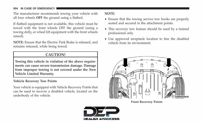
The manufacturer recommends towing your vehicle withall four wheels OFF the ground using a flatbed.
If flatbed equipment is not available, this vehicle must betowed with the front wheels OFF the ground (using atowing dolly, or wheel lift equipment with the front wheelsraised).
NOTE: Ensure that the Electric Park Brake is released, andremains released, while being towed.
CAUTION!
Towing this vehicle in violation of the above require-ments can cause severe transmission damage. Damagefrom improper towing is not covered under the NewVehicle Limited Warranty.
Vehicle Recovery Tow Points
Your vehicle is equipped with Vehicle Recovery Points thatcan be used to recover a disabled vehicle, located on theunderbody of the vehicle.
NOTE:
• Ensure that the towing service tow hooks are properlyseated and secured in the attachment points.
• This recovery tow feature should be used by a trainedprofessional only.
• Use approved receptacle location to free the disabledvehicle from its environment.
Front Recovery Points
504 IN CASE OF EMERGENCY
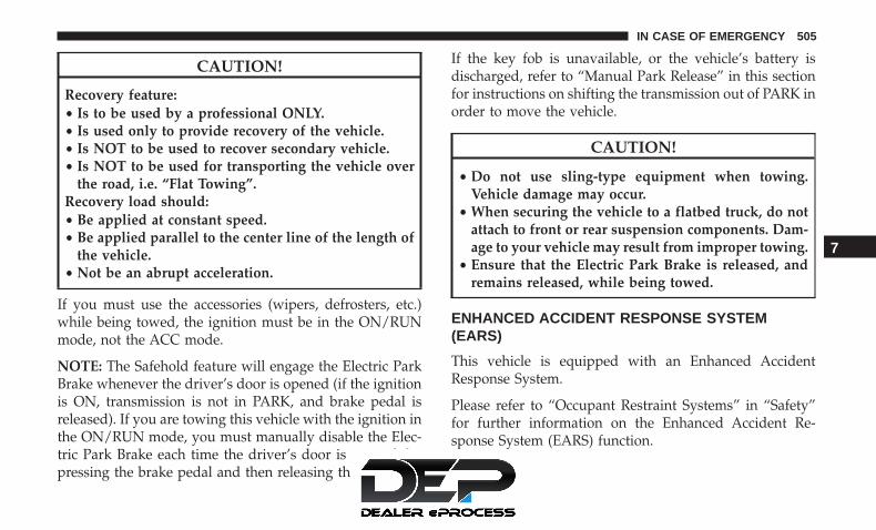
CAUTION!
Recovery feature:• Is to be used by a professional ONLY.• Is used only to provide recovery of the vehicle.• Is NOT to be used to recover secondary vehicle.• Is NOT to be used for transporting the vehicle over
the road, i.e. “Flat Towing”.Recovery load should:• Be applied at constant speed.• Be applied parallel to the center line of the length of
the vehicle.• Not be an abrupt acceleration.
If you must use the accessories (wipers, defrosters, etc.)while being towed, the ignition must be in the ON/RUNmode, not the ACC mode.
NOTE: The Safehold feature will engage the Electric ParkBrake whenever the driver’s door is opened (if the ignitionis ON, transmission is not in PARK, and brake pedal isreleased). If you are towing this vehicle with the ignition inthe ON/RUN mode, you must manually disable the Elec-tric Park Brake each time the driver’s door is opened, bypressing the brake pedal and then releasing the EPB.
If the key fob is unavailable, or the vehicle’s battery isdischarged, refer to “Manual Park Release” in this sectionfor instructions on shifting the transmission out of PARK inorder to move the vehicle.
CAUTION!
• Do not use sling-type equipment when towing.Vehicle damage may occur.
• When securing the vehicle to a flatbed truck, do notattach to front or rear suspension components. Dam-age to your vehicle may result from improper towing.
• Ensure that the Electric Park Brake is released, andremains released, while being towed.
ENHANCED ACCIDENT RESPONSE SYSTEM(EARS)
This vehicle is equipped with an Enhanced AccidentResponse System.
Please refer to “Occupant Restraint Systems” in “Safety”for further information on the Enhanced Accident Re-sponse System (EARS) function.
7
IN CASE OF EMERGENCY 505

EVENT DATA RECORDER (EDR)
This vehicle is equipped with an Event Data Recorder(EDR). The main purpose of an EDR is to record data thatwill assist in understanding how a vehicle’s systems per-formed under certain crash or near crash-like situations,such as an air bag deployment or hitting a road obstacle.
Please refer to “Occupant Restraint Systems” in “Safety”for further information on the Event Data Recorder (EDR).
506 IN CASE OF EMERGENCY

SERVICING AND MAINTENANCE
CONTENTS� SCHEDULED SERVICING . . . . . . . . . . . . . . . . .509
▫ Maintenance Plan . . . . . . . . . . . . . . . . . . . . . .510
▫ Heavy Duty Use Of The Vehicle . . . . . . . . . . . .512
� ENGINE COMPARTMENT . . . . . . . . . . . . . . . . .513
▫ 3.6L Engine . . . . . . . . . . . . . . . . . . . . . . . . . .513
▫ Checking Oil Level . . . . . . . . . . . . . . . . . . . . .514
▫ Adding Washer Fluid . . . . . . . . . . . . . . . . . . .514
▫ Maintenance-Free Battery . . . . . . . . . . . . . . . . .515
� DEALER SERVICE . . . . . . . . . . . . . . . . . . . . . . .516
▫ Engine Oil . . . . . . . . . . . . . . . . . . . . . . . . . . .516
▫ Engine Oil Filter . . . . . . . . . . . . . . . . . . . . . . .518
▫ Engine Air Cleaner Filter . . . . . . . . . . . . . . . . .518
▫ Accessory Drive Belt Inspection . . . . . . . . . . . .519
▫ Air Conditioner Maintenance . . . . . . . . . . . . . .520
▫ Body Lubrication . . . . . . . . . . . . . . . . . . . . . .523
▫ Windshield Wiper Blades . . . . . . . . . . . . . . . . .524
▫ Exhaust System . . . . . . . . . . . . . . . . . . . . . . . .529
▫ Cooling System . . . . . . . . . . . . . . . . . . . . . . . .530
▫ Brake System . . . . . . . . . . . . . . . . . . . . . . . . .535
▫ Automatic Transmission . . . . . . . . . . . . . . . . . .536
� RAISING THE VEHICLE . . . . . . . . . . . . . . . . . .538
� TIRES . . . . . . . . . . . . . . . . . . . . . . . . . . . . . . . .538
▫ Tire Safety Information . . . . . . . . . . . . . . . . . .538
▫ Tires — General Information . . . . . . . . . . . . . .548
▫ Tire Types . . . . . . . . . . . . . . . . . . . . . . . . . . . .554
▫ Spare Tires — If Equipped . . . . . . . . . . . . . . . .555
▫ Wheel And Wheel Trim Care . . . . . . . . . . . . . .558
▫ Tire Chains (Traction Devices) . . . . . . . . . . . . .559
8

▫ Tire Rotation Recommendations . . . . . . . . . . . .560
� DEPARTMENT OF TRANSPORTATION UNIFORMTIRE QUALITY GRADES . . . . . . . . . . . . . . . . . .561
▫ Treadwear . . . . . . . . . . . . . . . . . . . . . . . . . . . .561
▫ Traction Grades . . . . . . . . . . . . . . . . . . . . . . . .561
▫ Temperature Grades . . . . . . . . . . . . . . . . . . . . .562
� STORING THE VEHICLE . . . . . . . . . . . . . . . . . .562
� BODYWORK . . . . . . . . . . . . . . . . . . . . . . . . . . .563
▫ Protection From Atmospheric Agents . . . . . . . .563
▫ Body And Underbody Maintenance . . . . . . . . . .564
▫ Preserving The Bodywork . . . . . . . . . . . . . . . . .564
� INTERIORS . . . . . . . . . . . . . . . . . . . . . . . . . . . .565
▫ Seats And Fabric Parts . . . . . . . . . . . . . . . . . . .565
▫ Plastic And Coated Parts. . . . . . . . . . . . . . . . . .566
▫ Leather Parts . . . . . . . . . . . . . . . . . . . . . . . . . .566
▫ Glass Surfaces . . . . . . . . . . . . . . . . . . . . . . . . .567
508 SERVICING AND MAINTENANCE
SCHEDULED SERVICING
Your vehicle is equipped with an automatic oil changeindicator system. The oil change indicator system willremind you that it is time to take your vehicle in forscheduled maintenance.
Based on engine operation conditions, the oil changeindicator message will illuminate. This means that serviceis required for your vehicle. Operating conditions such asfrequent short-trips, trailer tow, extremely hot or coldambient temperatures will influence when the “Oil ChangeRequired” message is displayed. Severe Operating Condi-tions can cause the change oil message to illuminate asearly as 3,500 miles (5,600 km) since last reset. Have yourvehicle serviced as soon as possible, within the next 500miles (805 km).
Your authorized dealer will reset the oil change indicatormessage after completing the scheduled oil change. If ascheduled oil change is performed by someone other thanyour authorized dealer, the message can be reset byreferring to “Instrument Cluster Display” in “Getting ToKnow Your Instrument Panel”.
NOTE: Under no circumstances should oil change inter-vals exceed 10,000 miles (16,000 km), 12 months or 350hours of engine run time, whichever comes first. The 350hours of engine run or idle time is generally only a concernfor fleet customers.
Severe Duty All Models
Change Engine Oil at 4,000 miles (6,500 km) or 350 hours ofengine run time if the vehicle is operated in a dusty and offroad environment or is operated predominately at idle oronly very low engine RPM’s. This type of vehicle use isconsidered Severe Duty.
Once A Month Or Before A Long Trip:
• Check engine oil level.
• Check windshield washer fluid level.
• Check tire pressure and look for unusual wear ordamage. Rotate tires at the first sign of irregular wear,even if it occurs before the oil indicator system turns on.
• Check the fluid levels of the coolant reservoir and brakemaster cylinder, fill as needed.
• Check function of all interior and exterior lights.
8
SERVICING AND MAINTENANCE 509

Maintenance Plan
Required Maintenance Intervals
Refer to the required maintenance intervals on the follow-ing page.
At Every Oil Change Interval As Indicated By Oil Change Indicator System:• Change oil and filter• Rotate the tires
Rotate at the first sign of irregular wear, even if it occurs before the oil indicator system turns on• Inspect battery and clean and tighten terminals as required• Inspect brake pads, shoes, rotors, drums, hoses and park brake• Inspect engine cooling system protection and hoses• Inspect exhaust system• Inspect engine air cleaner if using in dusty or off-road conditions
510 SERVICING AND MAINTENANCE

Mileage or time passed (whichever comes first)
20,0
00
30,0
00
40,0
00
50,0
00
60,0
00
70,0
00
80,0
00
90,0
00
100,
000
110,
000
120,
000
130,
000
140,
000
150,
000
Or Years: 2 3 4 5 6 7 8 9 10 11 12 13 14 15Or Kilometers:
32,0
00
48,0
00
64,0
00
80,0
00
96,0
00
112,
000
128,
000
144,
000
160,
000
176,
000
192,
000
208,
000
224,
000
240,
000
Additional InspectionsInspect the CV joints. X X X X X X XInspect front suspension, boot seals, tie rod ends,and replace if necessary. X X X X X X X
Inspect the brake linings, parking brake function. X X X X X X XInspect front accessory drive belt, tensioner, idler pul-ley, and replace if necessary X
Additional MaintenanceReplace engine air cleaner filter. X X X X XReplace air conditioning/cabin air filter. X X X X X X XReplace spark plugs** XFlush and replace the engine coolant at 10 years or150,000 miles (240,000 km) whichever comes first. X X
Inspect and replace PCV valve if necessary. X
** The spark plug change interval is mileage based only,yearly intervals do not apply.
8
SERVICING AND MAINTENANCE 511

WARNING!
• You can be badly injured working on or around amotor vehicle. Do only service work for which youhave the knowledge and the right equipment. If youhave any doubt about your ability to perform aservice job, take your vehicle to a competent me-chanic.
• Failure to properly inspect and maintain your vehiclecould result in a component malfunction and effectvehicle handling and performance. This could causean accident.
Heavy Duty Use Of The Vehicle
Change engine oil at 4,000 miles (6,500 km) or 350 hours ofengine run time if the vehicle is operated in a dusty and offroad environment or is operated predominately at idle oronly very low engine RPM’s. This type of vehicle use isconsidered Severe Duty.
512 SERVICING AND MAINTENANCE

ENGINE COMPARTMENT
3.6L Engine
1 — Engine Coolant Pressure Cap 5 — Power Distribution Center (Fuses)2 — Engine Oil Fill 6 — Battery3 — Brake Fluid Reservoir 7 — Engine Oil Dipstick4 — Engine Air Cleaner 8 — Windshield Washer Fill
8
SERVICING AND MAINTENANCE 513

Checking Oil Level
To assure proper engine lubrication, the engine oil must bemaintained at the correct level. Check the oil level atregular intervals, such as every fuel stop. The best time tocheck the engine oil level is about five minutes after a fullywarmed engine is shut OFF.
Checking the oil while the vehicle is on level ground willimprove the accuracy of the oil level readings. Maintain theoil level between the MIN and MAX markings on thedipstick. Adding one quart or one liter of oil when thereading is at the MIN mark will result in a MAX reading onthese engines.
CAUTION!
• Overfilling or underfilling will cause oil aeration, orloss of oil pressure. This could damage your engine.
• Never use Non-Detergent Oil or Straight Mineral Oilin the engine or damage may result.
Adding Washer Fluid
The fluid reservoir is located in the front of the enginecompartment. Be sure to check the fluid level in thereservoir at regular intervals. Fill the reservoir with wind-shield washer solvent (not radiator antifreeze) and operatethe system for a few seconds to flush out the residualwasher fluid.
When refilling the washer fluid reservoir, take somewasher fluid, apply it to a cloth or towel, and wipe cleanthe wiper blades; this will help blade performance.
Windshield Washer Fluid Cap
514 SERVICING AND MAINTENANCE

To prevent freeze-up of your windshield washer system incold weather, select a solution or mixture that meets orexceeds the temperature range of your climate. This ratinginformation can be found on most washer fluid containers.
WARNING!
Commercially available windshield washer solventsare flammable. They could ignite and burn you. Caremust be exercised when filling or working around thewasher solution.
Maintenance-Free Battery
Your vehicle is equipped with a maintenance-free battery.You will never have to add water, nor is periodic mainte-nance required.
WARNING!
• Battery fluid is a corrosive acid solution and canburn or even blind you. Do not allow battery fluid tocontact your eyes, skin, or clothing. Do not lean overa battery when attaching clamps. If acid splashes ineyes or on skin, flush the area immediately with
(Continued)
WARNING! (Continued)large amounts of water. Refer to “Jump StartingProcedure” in “In Case Of Emergency” for furtherinformation.
• Battery gas is flammable and explosive. Keep flameor sparks away from the battery. Do not use a boosterbattery or any other booster source with an outputgreater than 12 Volts. Do not allow cable clamps totouch each other.
• Battery posts, terminals, and related accessories con-tain lead and lead compounds. Wash hands afterhandling.
CAUTION!
• It is essential when replacing the cables on thebattery that the positive cable is attached to thepositive post and the negative cable is attached to thenegative post. Battery posts are marked positive (+)and negative (-) and are identified on the batterycase. Cable clamps should be tight on the terminalposts and free of corrosion.
(Continued)
8
SERVICING AND MAINTENANCE 515

CAUTION! (Continued)• If a “fast charger” is used while the battery is in the
vehicle, disconnect both vehicle battery cables beforeconnecting the charger to the battery. Do not use a“fast charger” to provide starting voltage.
DEALER SERVICE
An authorized dealer has the qualified service personnel,special tools, and equipment to perform all service opera-tions in an expert manner. Service Manuals are availablewhich include detailed service information for your ve-hicle. Refer to these Service Manuals before attempting anyprocedure yourself.
NOTE: Intentional tampering with emissions control sys-tems may void your warranty and could result in civilpenalties being assessed against you.
WARNING!
You can be badly injured working on or around amotor vehicle. Only do service work for which you
(Continued)
WARNING! (Continued)have the knowledge and the proper equipment. If youhave any doubt about your ability to perform a servicejob, take your vehicle to a competent mechanic.
Engine Oil
Change Engine Oil
Refer to “Scheduled Servicing” in this section for theproper maintenance intervals.
NOTE: Under no circumstances should oil change inter-vals exceed 10,000 miles (16,000 km), 12 months or 350hours of engine run time, whichever comes first. The 350hours of engine run or idle time is generally only a concernfor fleet customers.
Gasoline Engine Oil Selection
For best performance and maximum protection under alltypes of operating conditions, the manufacturer only rec-ommends engine oils that are API Certified and meet therequirements of FCA Material Standard MS-6395.
516 SERVICING AND MAINTENANCE

American Petroleum Institute (API) Engine OilIdentification Symbol
This symbol means that the oil hasbeen certified by the American Pe-troleum Institute (API). The manu-facturer only recommends API Cer-tified engine oils.
This symbol certifies 0W-20, 5W-20,0W-30, 5W-30 and 10W-30 engineoils.
CAUTION!
Do not use chemical flushes in your engine oil as thechemicals can damage your engine. Such damage is notcovered by the New Vehicle Limited Warranty.
Engine Oil Viscosity
Mopar SAE 0W-20 engine oil approved to FCA MaterialStandard MS-6395 such as Pennzoil, Shell Helix or equiva-lent is recommended for all operating temperatures. Thisengine oil improves low temperature starting and vehiclefuel economy.
The engine oil filler cap also shows the recommendedengine oil viscosity for your engine. For information onengine oil filler cap location, refer to the “Engine Compart-ment” illustration in this section.
Lubricants which do not have both the engine oil certifi-cation mark and the correct SAE viscosity grade numbershould not be used.
Synthetic Engine Oils
You may use synthetic engine oils provided the recom-mended oil quality requirements are met, and the recom-mended maintenance intervals for oil and filter changes arefollowed.
Synthetic engine oils which do not have both the engine oilcertification mark and the correct SAE viscosity gradenumber should not be used.
Materials Added To Engine Oil
The manufacturer strongly recommends against the addi-tion of any additives (other than leak detection dyes) to theengine oil. Engine oil is an engineered product and itsperformance may be impaired by supplemental additives.
8
SERVICING AND MAINTENANCE 517
Disposing Of Used Engine Oil And Oil Filters
Care should be taken in disposing of used engine oil andoil filters from your vehicle. Used oil and oil filters,indiscriminately discarded, can present a problem to theenvironment. Contact an authorized dealer, service stationor governmental agency for advice on how and where usedoil and oil filters can be safely discarded in your area.
Engine Oil Filter
The engine oil filter should be replaced with a new filter atevery engine oil change.
Engine Oil Filter Selection
This manufacturer’s engines have a full-flow type dispos-able oil filter. Use a filter of this type for replacement. Thequality of replacement filters varies considerably. Onlyhigh quality filters should be used to assure most efficientservice. Mopar engine oil filters are high quality oil filtersand are recommended.
Engine Air Cleaner Filter
Refer to the “Maintenance Plan” in this section for theproper maintenance intervals.
NOTE: Be sure to follow the “Severe Duty Conditions”maintenance interval if applicable.
WARNING!
The air induction system (air cleaner, hoses, etc.) canprovide a measure of protection in the case of enginebackfire. Do not remove the air induction system (aircleaner, hoses, etc.) unless such removal is necessaryfor repair or maintenance. Make sure that no one isnear the engine compartment before starting the ve-hicle with the air induction system (air cleaner, hoses,etc.) removed. Failure to do so can result in seriouspersonal injury.
Engine Air Cleaner Filter Selection
The quality of replacement engine air cleaner filters variesconsiderably. Only high quality filters should be used toassure most efficient service. Mopar engine air cleanerfilters are a high quality filter and are recommended.
518 SERVICING AND MAINTENANCE

Accessory Drive Belt Inspection
WARNING!
• Do not attempt to inspect an accessory drive beltwith vehicle running.
• When working near the radiator cooling fan, discon-nect the fan motor lead. The fan is temperaturecontrolled and can start at any time regardless ofignition mode. You could be injured by the movingfan blades.
• You can be badly injured working on or around amotor vehicle. Only do service work for which youhave the knowledge and the proper equipment. Ifyou have any doubt about your ability to perform aservice job, take your vehicle to a competent me-chanic.
When inspecting accessory drive belts, small cracks thatrun across ribbed surface of belt from rib to rib, areconsidered normal. These are not a reason to replace belt.However, cracks running along a rib (not across) are notnormal. Any belt with cracks running along a rib must bereplaced. Also have the belt replaced if it has excessivewear, frayed cords or severe glazing.
Conditions that would require replacement:
• Rib chunking (one or more ribs has separated from beltbody)
• Rib or belt wear
• Longitudinal belt cracking (cracks between two ribs)
• Belt slips
• “Groove jumping� (belt does not maintain correct posi-tion on pulley)
• Belt broken (note: identify and correct problem beforenew belt is installed)
Accessory Belt (Serpentine Belt) 8
SERVICING AND MAINTENANCE 519
• Noise (objectionable squeal, squeak, or rumble is heardor felt while drive belt is in operation)
Some conditions can be caused by a faulty component suchas a belt pulley. Belt pulleys should be carefully inspectedfor damage and proper alignment.Belt replacement on some models requires the use ofspecial tools, we recommend having your vehicle servicedat an authorized dealer.
Air Conditioner Maintenance
For best possible performance, your air conditioner shouldbe checked and serviced by an authorized dealer at thestart of each warm season. This service should includecleaning of the condenser fins and a performance test.Drive belt tension should also be checked at this time.
WARNING!
• Use only refrigerants and compressor lubricants ap-proved by the manufacturer for your air conditioningsystem. Some unapproved refrigerants are flammableand can explode, injuring you. Other unapproved re-frigerants or lubricants can cause the system to fail,requiring costly repairs. Refer to Warranty Information
(Continued)
WARNING! (Continued)Book, located in your owner’s information kit, forfurther warranty information.
• The air conditioning system contains refrigerant un-der high pressure. To avoid risk of personal injury ordamage to the system, adding refrigerant or anyrepair requiring lines to be disconnected should bedone by an experienced technician.
CAUTION!
Do not use chemical flushes in your air conditioningsystem as the chemicals can damage your air condition-ing components. Such damage is not covered by theNew Vehicle Limited Warranty.
Refrigerant Recovery And Recycling — R–1234yf
R–1234yf Air Conditioning Refrigerant is a hydrofluo-roolefin (HFO) that is endorsed by the EnvironmentalProtection Agency and is an ozone-friendly substance witha low global-warming potential. The manufacturer
520 SERVICING AND MAINTENANCE

recommends that air conditioning service be performed byan authorized dealer using recovery and recycling equip-ment.
NOTE: Use only manufacturer approved A/C systemPAG compressor oil, and refrigerants.
Air Conditioning Filter Replacement (Cabin AirFilter)
WARNING!
Do not remove the cabin air filter while the vehicle isrunning, or while the ignition is in the ACC or ON/RUN mode. With the cabin air filter removed and theblower operating, the blower can contact hands andmay propel dirt and debris into your eyes, resulting inpersonal injury.
The cabin air filter is located in the fresh air inlet behind theglove compartment. Perform the following procedure toreplace the filter:
1. Remove all contents from the glove compartment.
2. Open the glove compartment door partially, leavingextra slack on the glove compartment tension tether.Detach the glove compartment tension tether by slidingthe black tension tether clip down, and popping it out ofthe slot on the side of the glove compartment door.
3. There are glove compartment travel stops on either sideof the glove compartment door. To release them, push
Glove Compartment
1 — Glove Compartment Travel Stops2 — Glove Compartment Tension Tether Clip
8
SERVICING AND MAINTENANCE 521

inward on each travel stop, and pull the glove compart-ment door down until the travel stops pass clear of theirhooking points.
4. Open the glove compartment door as far as possible togain access to the cabin air filter compartment cover.
5. Pry up the lid of each individual compartment snap,and detach it from the rest of the snap. There is a smallspace on the side of each snap to use for separating the
lid from the snap. Once detached, remove the rest of thesnap completely from the compartment cover.
6. After removing the snaps, lift up the compartment coverto gain access to the fresh air inlet.
7. Remove the filter cover by prying back each of theretaining tabs from their hooking points, and then
Cabin Air Filter Compartment Cover
1 — Compartment Cover2 — Compartment Snap
Fresh Air Inlet
1 — Filter Cover2 — Retaining Tab
522 SERVICING AND MAINTENANCE

pulling out the filter cover to expose the cabin air filter.Remove the air filter by pulling it straight out of thehousing.
8. Install the new air filter with the arrow on the filterpointing toward the floor.
CAUTION!
The cabin air filter is identified with an arrow toindicate airflow direction through the filter. Failure toproperly install the filter will result in the need toreplace it more often.
9. Once the filter is replaced, reinstall the filter cover,making sure the retaining tabs are fully secured intotheir housings.
10. Close the cabin air filter compartment cover, andreinsert the snaps into their slots. Push the snap lidsuntil fully attached.
11. Push the glove compartment door to the near closedposition to reengage the glove compartment travelstops. Finally, pull the glove compartment tensiontether clip down and slide it back into the slot on theside of the glove compartment door.
Body Lubrication
Locks and all body pivot points, including such items asseat tracks, door hinge pivot points and rollers, liftgate,tailgate, decklid, sliding doors and hood hinges, should belubricated periodically with a lithium based grease, such asMopar Spray White Lube to assure quiet, easy operationand to protect against rust and wear. Prior to the applica-tion of any lubricant, the parts concerned should be wipedclean to remove dust and grit; after lubricating excess oiland grease should be removed. Particular attention shouldalso be given to hood latching components to ensureproper function. When performing other underhood ser-vices, the hood latch, release mechanism and safety catchshould be cleaned and lubricated.
The external lock cylinders should be lubricated twice ayear, preferably in the Fall and Spring. Apply a smallamount of a high quality lubricant, such as Mopar LockCylinder Lubricant directly into the lock cylinder.
8
SERVICING AND MAINTENANCE 523

Windshield Wiper Blades
Clean the rubber edges of the wiper blades and thewindshield periodically with a sponge or soft cloth and amild nonabrasive cleaner. This will remove accumulationsof salt or road film.
Operation of the wipers on dry glass for long periods maycause deterioration of the wiper blades. Always use washerfluid when using the wipers to remove salt or dirt from adry windshield.
Avoid using the wiper blades to remove frost or ice fromthe windshield. Keep the blade rubber out of contact withpetroleum products such as engine oil, gasoline, etc.
NOTE: Life expectancy of wiper blades varies dependingon geographical area and frequency of use. Poor perfor-mance of blades may be present with chattering, marks,water lines or wet spots. If any of these conditions arepresent, clean the wiper blades or replace as necessary.
The wiper blades and wiper arms should be inspectedperiodically, not just when wiper performance problemsare experienced. This inspection should include the follow-ing points:
• Wear or uneven edges
• Foreign material
• Hardening or cracking
• Deformation or fatigue
If a wiper blade or wiper arm is damaged, replace theaffected wiper arm or blade with a new unit. Do notattempt to repair a wiper arm or blade that is damaged.
Front Wiper Blade Removal/Installation
CAUTION!
Do not allow the wiper arm to spring back against theglass without the wiper blade in place or the glass maybe damaged.
1. Lift the wiper arm to raise the wiper blade off of theglass, until the wiper arm is in the full up position.
524 SERVICING AND MAINTENANCE

2. To disengage the wiper blade from the wiper arm, flipup the release tab on the wiper blade and while holdingthe wiper arm with one hand, slide the wiper bladedown towards the base of the wiper arm.
3. With the wiper blade disengaged, remove the wiperblade from the wiper arm by holding the wiper armwith one hand and separating the wiper blade from thewiper arm with the other hand (move the wiper blade
Wiper Blade With Release Tab In Locked Position
1 — Wiper Blade2 — Release Tab3 — Wiper Arm
Wiper Blade With Release Tab In Unlocked Position
1 — Wiper Blade2 — Release Tab3 — Wiper Arm
8
SERVICING AND MAINTENANCE 525

toward the right side of the vehicle to separate the wiperblade from the wiper arm).
4. Gently lower the wiper arm onto the glass.
Installing The Front Wipers
1. Lift the wiper arm off of the glass, until the wiper arm isin the full up position.
2. Position the wiper blade near the hook on the tip of thewiper arm with the wiper release tab open and the bladeside of the wiper facing up and away from the wind-shield.
3. Insert the hook on the tip of the arm through theopening in the wiper blade under the release tab.
4. Slide the wiper blade up into the hook on the wiper armand rotate the wiper blade until it is flush against thewiper arm. Fold down the latch release tab and snap itinto its locked position. Latch engagement will beaccompanied by an audible click.
5. Gently lower the wiper blade onto the glass.
Wiper Blade Removed From Wiper Arm
1 — Wiper Blade2 — Wiper Arm3 — Release Tab
526 SERVICING AND MAINTENANCE

Rear Wiper Blade Removal/Installation
1. Lift the rear wiper arm pivot cap away from the glass toallow the rear wiper blade to be raised off of the glass.
NOTE: The rear wiper arm cannot be fully raised off theglass unless the wiper arm pivot cap is unsnapped first.Attempting to fully raise the rear wiper arm withoutunsnapping the wiper arm pivot cap may damage thevehicle.
Wiper Pivot Cap In Unlocked Position
1 — Wiper Arm Pivot Cap2 — Wiper Arm
8
SERVICING AND MAINTENANCE 527

2. Lift the rear wiper arm fully off the glass.
3. To remove the wiper blade from the wiper arm, graspthe bottom end of the wiper blade nearest to wiper armwith your right hand. With your left hand hold thewiper arm as you pull the wiper blade away from thewiper arm past its stop far enough to unsnap the wiperblade pivot pin from the receptacle on the end of thewiper arm.
NOTE: Resistance will be accompanied by an audiblesnap.
4. Still grasping the bottom end of the wiper blade, movethe wiper blade upward and away from the wiper armto disengage.
5. Gently lower the tip of the wiper arm onto the glass.
Wiper Blade In Folded Out Position
1 — Wiper Arm Pivot Cap2 — Wiper Arm3 — Wiper Blade
Wiper Blade Removed From Wiper Arm
1 — Wiper Blade2 — Wiper Blade Pivot Pin3 — Wiper Arm4 — Wiper Arm Receptacle
528 SERVICING AND MAINTENANCE

Installing The Rear Wiper
1. Lift the rear wiper arm pivot cap away from the glass toallow the rear wiper blade to be raised off of the glass.
NOTE: The rear wiper arm cannot be fully raised off theglass unless the wiper arm pivot cap is unsnapped first.Attempting to fully raise the rear wiper arm withoutunsnapping the wiper arm pivot cap may damage thevehicle.
2. Lift the rear wiper arm fully off the glass.
3. Insert the wiper blade pivot pin into the opening on theend of the wiper arm. Grab the bottom end of the wiperarm with one hand, and press the wiper blade flushwith the wiper arm until it snaps into place.
4. Lower the wiper blade onto the glass and snap thewiper arm pivot cap back into place.
Exhaust System
The best protection against carbon monoxide entry into thevehicle body is a properly maintained engine exhaustsystem.
If you notice a change in the sound of the exhaust system;or if the exhaust fumes can be detected inside the vehicle;
or when the underside or rear of the vehicle is damaged;have an authorized technician inspect the complete ex-haust system and adjacent body areas for broken, dam-aged, deteriorated, or mispositioned parts. Open seams orloose connections could permit exhaust fumes to seep intothe passenger compartment. In addition, have the exhaustsystem inspected each time the vehicle is raised for lubri-cation or oil change. Replace as required.
WARNING!
• Exhaust gases can injure or kill. They contain carbonmonoxide (CO), which is colorless and odorless.Breathing it can make you unconscious and caneventually poison you. To avoid breathing CO, referto “Safety Tips” in “Safety” for further information.
• A hot exhaust system can start a fire if you park overmaterials that can burn. Such materials might begrass or leaves coming into contact with your exhaustsystem. Do not park or operate your vehicle in areaswhere your exhaust system can contact anything thatcan burn.
8
SERVICING AND MAINTENANCE 529

CAUTION!
• The catalytic converter requires the use of unleadedfuel only. Leaded gasoline will destroy the effective-ness of the catalyst as an emissions control deviceand may seriously reduce engine performance andcause serious damage to the engine.
• Damage to the catalytic converter can result if yourvehicle is not kept in proper operating condition. Inthe event of engine malfunction, particularly involv-ing engine misfire or other apparent loss of perfor-mance, have your vehicle serviced promptly. Contin-ued operation of your vehicle with a severemalfunction could cause the converter to overheat,resulting in possible damage to the converter andvehicle.
Under normal operating conditions, the catalytic converterwill not require maintenance. However, it is important tokeep the engine properly tuned to assure proper catalystoperation and prevent possible catalyst damage.
NOTE: Intentional tampering with emissions control sys-tems can result in civil penalties being assessed againstyou.
In unusual situations involving grossly malfunctioningengine operation, a scorching odor may suggest severe andabnormal catalyst overheating. If this occurs, stop thevehicle, turn off the engine and allow it to cool. Service,including a tune-up to manufacturer’s specifications,should be obtained immediately.
To minimize the possibility of catalytic converter damage:
• Do not interrupt the ignition when the transmission is ingear and the vehicle is in motion.
• Do not try to start the vehicle by pushing or towing thevehicle.
• Do not idle the engine with any ignition componentsdisconnected or removed, such as when diagnostictesting, or for prolonged periods during very rough idleor malfunctioning operating conditions.
Cooling System
WARNING!
• You or others can be badly burned by hot enginecoolant (antifreeze) or steam from your radiator. Ifyou see or hear steam coming from under the hood,
(Continued)
530 SERVICING AND MAINTENANCE

WARNING! (Continued)do not open the hood until the radiator has had timeto cool. Never open a cooling system pressure capwhen the radiator or coolant bottle is hot.
• Keep hands, tools, clothing, and jewelry away fromthe radiator cooling fan when the hood is raised. Thefan starts automatically and may start at any time,whether the engine is running or not.
• When working near the radiator cooling fan, discon-nect the fan motor lead or turn the ignition to theOFF mode. The fan is temperature controlled and canstart at any time the ignition is in the ON mode.
Engine Coolant Checks
Check the engine coolant (antifreeze) protection every 12months (before the onset of freezing weather, where appli-cable). If the engine coolant (antifreeze) is dirty, the systemshould be drained, flushed, and refilled with fresh OATcoolant (conforming to MS.90032) by an authorized dealer.Check the front of the A/C condenser for any accumula-tion of bugs, leaves, etc. If dirty, clean by gently sprayingwater from a garden hose vertically down the face of thecondenser.
Check the engine cooling system hoses for brittle rubber,cracking, tears, cuts, and tightness of the connection at thecoolant recovery bottle and radiator. Inspect the entiresystem for leaks. DO NOT REMOVE THE COOLANTPRESSURE CAP WHEN THE COOLING SYSTEM IS HOT.
Cooling System — Drain, Flush And Refill
NOTE: Some vehicles require special tools to add coolantproperly. Failure to fill these systems properly could lead tosevere internal engine damage. If any coolant is needed tobe added to the system please contact an authorized dealer.
If the engine coolant (antifreeze) is dirty or contains visiblesediment, have an authorized dealer clean and flush withOAT coolant (antifreeze) (conforming to MS.90032).
Refer to the “Maintenance Plan” in this section for theproper maintenance intervals.
Selection Of Coolant
Refer to “Fluids And Lubricants” in “Technical Specifica-tions” for further information.
8
SERVICING AND MAINTENANCE 531

NOTE:
• Mixing of engine coolant (antifreeze) other than speci-fied Organic Additive Technology (OAT) engine coolant(antifreeze), may result in engine damage and maydecrease corrosion protection. Organic Additive Tech-nology (OAT) engine coolant is different and should notbe mixed with Hybrid Organic Additive Technology(HOAT) engine coolant (antifreeze) or any “globallycompatible” coolant (antifreeze). If a non-OAT enginecoolant (antifreeze) is introduced into the cooling systemin an emergency, the cooling system will need to bedrained, flushed, and refilled with fresh OAT coolant(conforming to MS.90032), by an authorized dealer assoon as possible.
• Do not use water alone or alcohol-based engine coolant(antifreeze) products. Do not use additional rust inhibi-tors or antirust products, as they may not be compatiblewith the radiator engine coolant and may plug theradiator.
• This vehicle has not been designed for use with propyl-ene glycol-based engine coolant (antifreeze). Use ofpropylene glycolbased engine coolant (antifreeze) is notrecommended.
• Some vehicles require special tools to add coolant prop-erly. Failure to fill these systems properly could lead tosevere internal engine damage. If any coolant is neededto be added to the system please contact an authorizeddealer.
Adding Coolant
Your vehicle has been built with an improved enginecoolant (OAT coolant conforming to MS.90032) that allowsextended maintenance intervals. This engine coolant (anti-freeze) can be used up to ten years or 150,000 miles(240,000 km) before replacement. To prevent reducing thisextended maintenance period, it is important that you usethe same engine coolant (OAT coolant conforming toMS.90032) throughout the life of your vehicle.
Please review these recommendations for using OrganicAdditive Technology (OAT) engine coolant (antifreeze)that meets the requirements of FCA Material StandardMS.90032. When adding engine coolant (antifreeze):
• We recommend using Mopar Antifreeze/Coolant 10Year/150,000 Mile (240,000 km) Formula OAT (OrganicAdditive Technology) that meets the requirements ofFCA Material Standard MS.90032.
532 SERVICING AND MAINTENANCE

• Mix a minimum solution of 50% OAT engine coolantthat meets the requirements of FCA Material StandardMS.90032 and distilled water. Use higher concentrations(not to exceed 70%) if temperatures below −34°F (−37°C)are anticipated. Please contact an authorized dealer forassistance.
• Use only high purity water such as distilled or deionizedwater when mixing the water/engine coolant (anti-freeze) solution. The use of lower quality water willreduce the amount of corrosion protection in the enginecooling system.
NOTE:
• It is the owner’s responsibility to maintain the properlevel of protection against freezing according to thetemperatures occurring in the area where the vehicle isoperated.
• Some vehicles require special tools to add coolant prop-erly. Failure to fill these systems properly could lead tosevere internal engine damage. If any coolant is neededto be added to the system, please contact a local autho-rized dealer.
• Mixing engine coolant (antifreeze) types is not recom-mended and can result in cooling system damage. If HOAT
and OAT coolant are mixed in an emergency, have aauthorized dealer drain, flush, and refill with OAT coolant(conforming to MS.90032) as soon as possible.
Cooling System Pressure Cap
The cap must be fully tightened to prevent loss of enginecoolant (antifreeze), and to ensure that engine coolant(antifreeze) will return to the radiator from the coolantexpansion bottle/recovery tank if so equipped.
The cap should be inspected and cleaned if there is anyaccumulation of foreign material on the sealing surfaces.
WARNING!
• Do not open hot engine cooling system. Never addengine coolant (antifreeze) when the engine is over-heated. Do not loosen or remove the cap to cool anoverheated engine. Heat causes pressure to build upin the cooling system. To prevent scalding or injury,do not remove the pressure cap while the system ishot or under pressure.
• Do not use a pressure cap other than the one speci-fied for your vehicle. Personal injury or enginedamage may result.
8
SERVICING AND MAINTENANCE 533

Disposal Of Used Coolant
Used ethylene glycol-based coolant (antifreeze) is a regu-lated substance requiring proper disposal. Check with yourlocal authorities to determine the disposal rules for yourcommunity. To prevent ingestion by animals or children,do not store ethylene glycol-based coolant in open contain-ers or allow it to remain in puddles on the ground. Ifingested by a child or pet, seek emergency assistanceimmediately. Clean up any ground spills immediately.
Coolant Level
The coolant expansion bottle provides a quick visualmethod for determining that the coolant level is adequate.With the engine off and cold, the level of the coolant(antifreeze) in the bottle should be between the “MAX” and“MIN” lines marked on the bottle.
As long as the engine operating temperature is satisfactory,the coolant bottle need only be checked once a month.
When additional coolant (antifreeze) is needed to maintainthe proper level, it should be added to the coolant bottle.Do not overfill.
See an authorized dealer for service.
Points To Remember
NOTE: When the vehicle is stopped after a few miles/kilometers of operation, you may observe vapor comingfrom the front of the engine compartment. This is normallya result of moisture from rain, snow, or high humidityaccumulating on the radiator and being vaporized whenthe thermostat opens, allowing hot engine coolant (anti-freeze) to enter the radiator.
If an examination of your engine compartment shows noevidence of radiator or hose leaks, the vehicle may besafely driven. The vapor will soon dissipate.
• Do not overfill the coolant expansion bottle.
• Check the coolant freeze point in the radiator and in thecoolant expansion bottle. If engine coolant (antifreeze)needs to be added, the contents of the coolant expansionbottle must also be protected against freezing.
• If frequent engine coolant (antifreeze) additions arerequired, the cooling system should be pressure testedfor leaks.
• Maintain engine coolant (antifreeze) concentration at aminimum of 50% OAT coolant (conforming to
534 SERVICING AND MAINTENANCE

MS.90032) and distilled water for proper corrosion pro-tection of your engine which contains aluminum com-ponents.
• Make sure that the coolant expansion bottle overflowhoses are not kinked or obstructed.
• Keep the front of the radiator clean. If your vehicle isequipped with air conditioning, keep the front of thecondenser clean.
• Do not change the thermostat for Summer or Winteroperation. If replacement is ever necessary, install ONLYthe correct type thermostat. Other designs may result inunsatisfactory engine coolant (antifreeze) performance,poor gas mileage, and increased emissions.
Brake System
In order to assure brake system performance, all brakesystem components should be inspected periodically. Referto the “Maintenance Plan” in this section for the propermaintenance intervals.
WARNING!
Riding the brakes can lead to brake failure and possi-bly a collision. Driving with your foot resting or ridingon the brake pedal can result in abnormally high braketemperatures, excessive lining wear, and possiblebrake damage. You would not have your full brakingcapacity in an emergency.
Brake Master Cylinder
The fluid in the master cylinder should be checked whenperforming under hood services or immediately if the“Brake Warning Light” is illuminated.
Be sure to clean the top of the master cylinder area beforeremoving the cap. If necessary, add fluid to bring the fluidlevel up to the requirements described on the brake fluidreservoir. With disc brakes, fluid level can be expected tofall as the brake pads wear. Brake fluid level should bechecked when pads are replaced. However, low fluid levelmay be caused by a leak and a checkup may be needed.
Use only manufacturer’s recommended brake fluid. Referto “Fluids And Lubricants” in “Technical Specifications”for further information.
8
SERVICING AND MAINTENANCE 535

WARNING!
• Use only manufacturer’s recommended brake fluid.Refer to “Fluids And Lubricants” in “TechnicalSpecifications” for further information. Using thewrong type of brake fluid can severely damage yourbrake system and/or impair its performance. Theproper type of brake fluid for your vehicle is alsoidentified on the original factory installed hydraulicmaster cylinder reservoir.
• To avoid contamination from foreign matter or mois-ture, use only new brake fluid or fluid that has beenin a tightly closed container. Keep the master cylin-der reservoir cap secured at all times. Brake fluid ina open container absorbs moisture from the airresulting in a lower boiling point. This may cause itto boil unexpectedly during hard or prolonged brak-ing, resulting in sudden brake failure. This couldresult in a collision.
• Overfilling the brake fluid reservoir can result inspilling brake fluid on hot engine parts, causing thebrake fluid to catch fire. Brake fluid can also damagepainted and vinyl surfaces, care should be taken toavoid its contact with these surfaces.
(Continued)
WARNING! (Continued)• Do not allow petroleum based fluid to contaminate
the brake fluid. Brake seal components could bedamaged, causing partial or complete brake failure.This could result in a collision.
Automatic Transmission
Selection Of Lubricant
It is important to use the proper transmission fluid toensure optimum transmission performance and life. Useonly the manufacturer’s specified transmission fluid. Referto “Fluids And Lubricants” in “Technical Specifications”for fluid specifications. It is important to maintain thetransmission fluid at the correct level using the recom-mended fluid.
NOTE: No chemical flushes should be used in any trans-mission; only the approved lubricant should be used.
CAUTION!
Using a transmission fluid other than the manufactur-er’s recommended fluid may cause deterioration in
(Continued)
536 SERVICING AND MAINTENANCE

CAUTION! (Continued)transmission shift quality and/or torque convertershudder. Refer to “Fluids And Lubricants” in “Techni-cal Specifications” for fluid specifications.
Special Additives
The manufacturer strongly recommends against using anyspecial additives in the transmission. Automatic Transmis-sion Fluid (ATF) is an engineered product and its perfor-mance may be impaired by supplemental additives. There-fore, do not add any fluid additives to the transmission.Avoid using transmission sealers as they may adverselyaffect seals.
CAUTION!
Do not use chemical flushes in your transmission asthe chemicals can damage your transmission compo-nents. Such damage is not covered by the New VehicleLimited Warranty.
Fluid Level Check
The fluid level is preset at the factory and does not requireadjustment under normal operating conditions. Routine
fluid level checks are not required; therefore the transmis-sion has no dipstick. An authorized dealer can check yourtransmission fluid level using special service tools. If younotice fluid leakage or transmission malfunction, visit anauthorized dealer immediately to have the transmissionfluid level checked. Operating the vehicle with an im-proper fluid level can cause severe transmission damage.
CAUTION!
If a transmission fluid leak occurs, visit an authorizeddealer immediately. Severe transmission damage mayoccur. An authorized dealer has the proper tools toadjust the fluid level accurately.
Fluid And Filter Changes
Under normal operating conditions, the fluid installed atthe factory will provide satisfactory lubrication for the lifeof the vehicle.
Routine fluid and filter changes are not required. However,change the fluid and filter if the fluid becomes contami-nated (with water, etc.), or if the transmission is disas-sembled for any reason.
8
SERVICING AND MAINTENANCE 537

RAISING THE VEHICLE
In the case where it is necessary to raise the vehicle, go toan authorized dealer or service station.
TIRES
Tire Safety Information
Tire safety information will cover aspects of the followinginformation: Tire Markings, Tire Identification Numbers,Tire Terminology and Definitions, Tire Pressures, and TireLoading.
Tire Markings
Tire Markings
1 — U.S. DOT SafetyStandards Code (TIN)
4 — Maximum Load
2 — Size Designation 5 — Maximum Pressure3 — Service Description 6 — Treadwear, Traction
and Temperature Grades
538 SERVICING AND MAINTENANCE
NOTE:
• P (Passenger) — Metric tire sizing is based on U.S.design standards. P-Metric tires have the letter “P”molded into the sidewall preceding the size designation.Example: P215/65R15 95H.
• European — Metric tire sizing is based on Europeandesign standards. Tires designed to this standard havethe tire size molded into the sidewall beginning with thesection width. The letter �P� is absent from this tire sizedesignation. Example: 215/65R15 96H.
• LT (Light Truck) — Metric tire sizing is based on U.S.design standards. The size designation for LT-Metrictires is the same as for P-Metric tires except for the letters“LT” that are molded into the sidewall preceding thesize designation. Example: LT235/85R16.
• Temporary spare tires are designed for temporary emer-gency use only. Temporary high pressure compact sparetires have the letter “T” or “S” molded into the sidewallpreceding the size designation. Example: T145/80D18103M.
• High flotation tire sizing is based on U.S. design stan-dards and it begins with the tire diameter molded intothe sidewall. Example: 31x10.5 R15 LT.
8
SERVICING AND MAINTENANCE 539

Tire Sizing Chart
EXAMPLE:Example Size Designation: P215/65R15XL 95H, 215/65R15 96H, LT235/85R16C, T145/80D18 103M, 31x10.5 R15 LTP = Passenger car tire size based on U.S. design standards, or�....blank....� = Passenger car tire based on European design standards, orLT = Light truck tire based on U.S. design standards, orT or S = Temporary spare tire or31 = Overall diameter in inches (in)215, 235, 145 = Section width in millimeters (mm)65, 85, 80 = Aspect ratio in percent (%)– Ratio of section height to section width of tire, or10.5 = Section width in inches (in)R = Construction code– �R� means radial construction, or– �D� means diagonal or bias construction15, 16, 18 = Rim diameter in inches (in)
540 SERVICING AND MAINTENANCE

EXAMPLE:Service Description:95 = Load Index– A numerical code associated with the maximum load a tire can carryH = Speed Symbol– A symbol indicating the range of speeds at which a tire can carry a load corresponding to its load index under cer-
tain operating conditions– The maximum speed corresponding to the speed symbol should only be achieved under specified operating condi-
tions (i.e., tire pressure, vehicle loading, road conditions, and posted speed limits)Load Identification:Absence of the following load identification symbols on the sidewall of the tire indicates a Standard Load (SL) tire:• XL = Extra load (or reinforced) tire, or• LL = Light load tire or• C, D, E, F, G = Load range associated with the maximum load a tire can carry at a specified pressureMaximum Load – Maximum load indicates the maximum load this tire is designed to carryMaximum Pressure – Maximum pressure indicates the maximum permissible cold tire inflation pressure for this tire
Tire Identification Number (TIN)
The TIN may be found on one or both sides of the tire;however, the date code may only be on one side. Tires withwhite sidewalls will have the full TIN, including the datecode, located on the white sidewall side of the tire. Look for
the TIN on the outboard side of black sidewall tires asmounted on the vehicle. If the TIN is not found on theoutboard side, then you will find it on the inboard side ofthe tire.
8
SERVICING AND MAINTENANCE 541

EXAMPLE:DOT MA L9 ABCD 0301
DOT = Department of Transportation– This symbol certifies that the tire is in compliance with the U.S. Department of Transportation tire safety standards
and is approved for highway useMA = Code representing the tire manufacturing location (two digits)L9 = Code representing the tire size (two digits)ABCD = Code used by the tire manufacturer (one to four digits)03 = Number representing the week in which the tire was manufactured (two digits)– 03 means the 3rd week01 = Number representing the year in which the tire was manufactured (two digits)– 01 means the year 2001– Prior to July 2000, tire manufacturers were only required to have one number to represent the year in which the
tire was manufactured. Example: 031 could represent the 3rd week of 1981 or 1991
542 SERVICING AND MAINTENANCE

Tire Terminology And Definitions
Term DefinitionB-Pillar The vehicle B-Pillar is the structural member of the body located be-
hind the front door.Cold Tire Inflation Pressure Cold tire inflation pressure is defined as the tire pressure after the
vehicle has not been driven for at least three hours, or driven lessthan 1 mile (1.6 km) after sitting for a minimum of three hours. In-flation pressure is measured in units of PSI (pounds per square inch)or kPa (kilopascals).
Maximum Inflation Pressure The maximum inflation pressure is the maximum permissible coldtire inflation pressure for this tire. The maximum inflation pressure ismolded into the sidewall.
Recommended Cold Tire Inflation Pressure Vehicle manufacturer’s recommended cold tire inflation pressure asshown on the tire placard.
Tire Placard A label permanently attached to the vehicle describing the vehicle’sloading capacity, the original equipment tire sizes and the recom-mended cold tire inflation pressures.
8
SERVICING AND MAINTENANCE 543

Tire Loading And Tire Pressure
NOTE: The proper cold tire inflation pressure is listed onthe driver’s side B-Pillar or the rear edge of the driver’sside door.
Check the inflation pressure of each tire, including thespare tire (if equipped), at least monthly and inflate to therecommended pressure for your vehicle.
Example Tire Placard Location (Door)
Example Tire Placard Location (B-Pillar)
544 SERVICING AND MAINTENANCE

Tire And Loading Information Placard
This placard tells you important information about the:
1. Number of people that can be carried in the vehicle.
2. Total weight your vehicle can carry.
3. Tire size designed for your vehicle.
4. Cold tire inflation pressures for the front, rear, and sparetires.
Loading
The vehicle maximum load on the tire must not exceed theload carrying capacity of the tire on your vehicle. You willnot exceed the tire’s load carrying capacity if you adhere tothe loading conditions, tire size, and cold tire inflationpressures specified on the Tire and Loading Informationplacard in “Vehicle Loading” in the “Starting And Operat-ing” section of this manual.
NOTE: Under a maximum loaded vehicle condition, grossaxle weight ratings (GAWRs) for the front and rear axlesmust not be exceeded.
For further information on GAWRs, vehicle loading, andtrailer towing, refer to “Vehicle Loading” in the “StartingAnd Operating” section of this manual.
To determine the maximum loading conditions of yourvehicle, locate the statement “The combined weight ofoccupants and cargo should never exceed XXX kg orXXX lbs” on the Tire and Loading Information placard. Thecombined weight of occupants, cargo/luggage and trailertongue weight (if applicable) should never exceed theweight referenced here.
Tire And Loading Information Placard8
SERVICING AND MAINTENANCE 545

Steps For Determining Correct Load Limit—
(1) Locate the statement “The combined weight ofoccupants and cargo should never exceed XXX kg orXXX lbs.” on your vehicle’s placard.
(2) Determine the combined weight of the driver andpassengers that will be riding in your vehicle.
(3) Subtract the combined weight of the driver andpassengers from XXX kg or XXX lbs.
(4) The resulting figure equals the available amount ofcargo and luggage load capacity. For example, if “XXX”amount equals 1400 lbs. and there will be five 150 lbpassengers in your vehicle, the amount of availablecargo and luggage load capacity is 650 lbs. (1400-750(5x150) = 650 lbs.)
(5) Determine the combined weight of luggage andcargo being loaded on the vehicle. That weight may notsafely exceed the available cargo and luggage loadcapacity calculated in Step 4.
(6) If your vehicle will be towing a trailer, load fromyour trailer will be transferred to your vehicle. Consult
this manual to determine how this reduces the availablecargo and luggage load capacity of your vehicle.
Metric Example For Load Limit
For example, if “XXX” amount equals 635 kg and there willbe five 68 kg passengers in your vehicle, the amount ofavailable cargo and luggage load capacity is 295 kg (635-340 (5x68) = 295 kg) as shown in step 4.
NOTE:
• If your vehicle will be towing a trailer, load from yourtrailer will be transferred to your vehicle. The followingtable shows examples on how to calculate total load,cargo/luggage, and towing capacities of your vehiclewith varying seating configurations and number andsize of occupants. This table is for illustration purposesonly and may not be accurate for the seating and loadcarry capacity of your vehicle.
• For the following example, the combined weight ofoccupants and cargo should never exceed 865 lbs(392 kg).
546 SERVICING AND MAINTENANCE

WARNING!
Overloading of your tires is dangerous. Overloadingcan cause tire failure, affect vehicle handling, andincrease your stopping distance. Use tires of the rec-ommended load capacity for your vehicle. Never over-load them.
8
SERVICING AND MAINTENANCE 547

Tires — General Information
Tire Pressure
Proper tire inflation pressure is essential to the safe andsatisfactory operation of your vehicle. Four primary areasare affected by improper tire pressure:
• Safety and Vehicle Stability
• Economy
• Tread Wear
• Ride Comfort
Safety
WARNING!
• Improperly inflated tires are dangerous and cancause collisions.
• Underinflation increases tire flexing and can resultin overheating and tire failure.
• Overinflation reduces a tire’s ability to cushionshock. Objects on the road and chuckholes can causedamage that result in tire failure.
(Continued)
WARNING! (Continued)• Overinflated or underinflated tires can affect vehicle
handling and can fail suddenly, resulting in loss ofvehicle control.
• Unequal tire pressures can cause steering problems.You could lose control of your vehicle.
• Unequal tire pressures from one side of the vehicleto the other can cause the vehicle to drift to the rightor left.
• Always drive with each tire inflated to the recom-mended cold tire inflation pressure.
Both under-inflation and over-inflation affect the stabilityof the vehicle and can produce a feeling of sluggishresponse or over responsiveness in the steering.
NOTE:
• Unequal tire pressures from side to side may causeerratic and unpredictable steering response.
• Unequal tire pressure from side to side may cause thevehicle to drift left or right.
548 SERVICING AND MAINTENANCE

Fuel Economy
Underinflated tires will increase tire rolling resistanceresulting in higher fuel consumption.
Tread Wear
Improper cold tire inflation pressures can cause abnormalwear patterns and reduced tread life, resulting in the needfor earlier tire replacement.
Ride Comfort And Vehicle Stability
Proper tire inflation contributes to a comfortable ride.Over-inflation produces a jarring and uncomfortable ride.
Tire Inflation Pressures
The proper cold tire inflation pressure is listed on thedriver’s side B-Pillar or rear edge of the driver’s side door.
At least once a month:
• Check and adjust tire pressure with a good qualitypocket-type pressure gauge. Do not make a visualjudgement when determining proper inflation. Tiresmay look properly inflated even when they are under-inflated.
• Inspect tires for signs of tire wear or visible damage.
CAUTION!
After inspecting or adjusting the tire pressure, alwaysreinstall the valve stem cap. This will prevent moistureand dirt from entering the valve stem, which coulddamage the valve stem.
Inflation pressures specified on the placard are always“cold tire inflation pressure”. Cold tire inflation pressure isdefined as the tire pressure after the vehicle has not beendriven for at least three hours, or driven less than 1 mile(1.6 km) after sitting for a minimum of three hours. Thecold tire inflation pressure must not exceed the maximuminflation pressure molded into the tire sidewall.
Check tire pressures more often if subject to a wide rangeof outdoor temperatures, as tire pressures vary with tem-perature changes.
Tire pressures change by approximately 1 psi (7 kPa) per12°F (7°C) of air temperature change. Keep this in mindwhen checking tire pressure inside a garage, especially inthe Winter.
Example: If garage temperature = 68°F (20°C) and theoutside temperature = 32°F (0°C) then the cold tire inflation
8
SERVICING AND MAINTENANCE 549

pressure should be increased by 3 psi (21 kPa), whichequals 1 psi (7 kPa) for every 12°F (7°C) for this outsidetemperature condition.
Tire pressure may increase from 2 to 6 psi (13 to 40 kPa)during operation. DO NOT reduce this normal pressurebuild up or your tire pressure will be too low.
Tire Pressures For High Speed Operation
The manufacturer advocates driving at safe speeds andwithin posted speed limits. Where speed limits or condi-tions are such that the vehicle can be driven at high speeds,maintaining correct tire inflation pressure is very impor-tant. Increased tire pressure and reduced vehicle loadingmay be required for high-speed vehicle operation. Refer toan authorized tire dealer or original equipment vehicledealer for recommended safe operating speeds, loadingand cold tire inflation pressures.
WARNING!
High speed driving with your vehicle under maximumload is dangerous. The added strain on your tires couldcause them to fail. You could have a serious collision.Do not drive a vehicle loaded to the maximum capacityat continuous speeds above 75 mph (120 km/h).
Radial Ply Tires
WARNING!
Combining radial ply tires with other types of tires onyour vehicle will cause your vehicle to handle poorly.The instability could cause a collision. Always useradial ply tires in sets of four. Never combine themwith other types of tires.
Tire Repair
If your tire becomes damaged, it may be repaired if it meetsthe following criteria:
• The tire has not been driven on when flat.
• The damage is only on the tread section of your tire(sidewall damage is not repairable).
• The puncture is no greater than a ¼ of an inch (6 mm).
Consult an authorized tire dealer for tire repairs andadditional information.
Damaged Run Flat tires, or Run Flat tires that haveexperienced a loss of pressure should be replaced immedi-ately with another Run Flat tire of identical size and service
550 SERVICING AND MAINTENANCE

description (Load Index and Speed Symbol). Replace thetire pressure sensor as well as it is not designed to bereused.
Run Flat Tires — If Equipped
Run Flat tires allow you the capability to drive 50 miles(80 km) at 50 mph (80 km/h) after a rapid loss of inflationpressure. This rapid loss of inflation is referred to as theRun Flat mode. A Run Flat mode occurs when the tireinflation pressure is of/or below 14 psi (96 kPa). Once aRun Flat tire reaches the run flat mode it has limiteddriving capabilities and needs to be replaced immediately.A Run Flat tire is not repairable. When a run flat tire ischanged after driving with underinflated tire condition,please replace the TPM sensor as it is not designed to bereused when driven under run flat mode (14 psi (96 kPa))condition.
NOTE: TPM Sensor must be replaced after driving thevehicle on a flat tire condition.
It is not recommended driving a vehicle loaded at fullcapacity or to tow a trailer while a tire is in the run flatmode.
See the tire pressure monitoring section for more informa-tion.
Tire Spinning
When stuck in mud, sand, snow, or ice conditions, do notspin your vehicle’s wheels above 30 mph (48 km/h) or forlonger than 30 seconds continuously without stopping.
Refer to “Freeing A Stuck Vehicle” in “In Case Of Emer-gency” for further information.
WARNING!
Fast spinning tires can be dangerous. Forces generatedby excessive wheel speeds may cause tire damage orfailure. A tire could explode and injure someone. Donot spin your vehicle’s wheels faster than 30 mph(48 km/h) for more than 30 seconds continuously whenyou are stuck, and do not let anyone near a spinningwheel, no matter what the speed.
8
SERVICING AND MAINTENANCE 551

Tread Wear Indicators
Tread wear indicators are in the original equipment tires tohelp you in determining when your tires should be re-placed.
These indicators are molded into the bottom of the treadgrooves. They will appear as bands when the tread depth
becomes a 1/16 of an inch (1.6 mm). When the tread isworn to the tread wear indicators, the tire should bereplaced.
Refer to “Replacement Tires” in this section for furtherinformation.
Life Of Tire
The service life of a tire is dependent upon varying factorsincluding, but not limited to:
• Driving style.
• Tire pressure - Improper cold tire inflation pressures cancause uneven wear patterns to develop across the tiretread. These abnormal wear patterns will reduce treadlife, resulting in the need for earlier tire replacement.
• Distance driven.
• Performance tires, tires with a speed rating of V orhigher, and Summer tires typically have a reduced treadlife. Rotation of these tires per the vehicle scheduledmaintenance is highly recommended.
Tire Tread
1 — Worn Tire2 — New Tire
552 SERVICING AND MAINTENANCE

WARNING!
Tires and the spare tire should be replaced after sixyears, regardless of the remaining tread. Failure tofollow this warning can result in sudden tire failure.You could lose control and have a collision resulting inserious injury or death.
NOTE: Wheel Valve Stem must be replaced as well wheninstalling new tires due to wear and tear in existing tires.
Keep dismounted tires in a cool, dry place with as littleexposure to light as possible. Protect tires from contact withoil, grease, and gasoline.
Replacement Tires
The tires on your new vehicle provide a balance of manycharacteristics. They should be inspected regularly forwear and correct cold tire inflation pressures. The manu-facturer strongly recommends that you use tires equivalentto the originals in size, quality and performance whenreplacement is needed. Refer to the paragraph on “TreadWear Indicators” in this section. Refer to the Tire andLoading Information placard or the Vehicle Certification
Label for the size designation of your tire. The Load Indexand Speed Symbol for your tire will be found on theoriginal equipment tire sidewall.
See the Tire Sizing Chart example found in the “Tire SafetyInformation” section of this manual for more informationrelating to the Load Index and Speed Symbol of a tire.
It is recommended to replace the two front tires or two reartires as a pair. Replacing just one tire can seriously affectyour vehicle’s handling. If you ever replace a wheel, makesure that the wheel’s specifications match those of theoriginal wheels.
It is recommended you contact an authorized tire dealer ororiginal equipment dealer with any questions you mayhave on tire specifications or capability. Failure to useequivalent replacement tires may adversely affect thesafety, handling, and ride of your vehicle.
WARNING!
• Do not use a tire, wheel size, load rating, or speedrating other than that specified for your vehicle.Some combinations of unapproved tires and wheels
(Continued)
8
SERVICING AND MAINTENANCE 553

WARNING! (Continued)may change suspension dimensions and perfor-mance characteristics, resulting in changes to steer-ing, handling, and braking of your vehicle. This cancause unpredictable handling and stress to steeringand suspension components. You could lose controland have a collision resulting in serious injury ordeath. Use only the tire and wheel sizes with loadratings approved for your vehicle.
• Never use a tire with a smaller load index or capacity,other than what was originally equipped on yourvehicle. Using a tire with a smaller load index couldresult in tire overloading and failure. You could losecontrol and have a collision.
• Failure to equip your vehicle with tires having ad-equate speed capability can result in sudden tirefailure and loss of vehicle control.
CAUTION!
Replacing original tires with tires of a different sizemay result in false speedometer and odometer read-ings.
Tire Types
All Season Tires — If Equipped
All Season tires provide traction for all seasons (Spring,Summer, Fall, and Winter). Traction levels may vary be-tween different all season tires. All season tires can beidentified by the M+S, M&S, M/S or MS designation on thetire sidewall. Use all season tires only in sets of four; failureto do so may adversely affect the safety and handling ofyour vehicle.
Summer Or Three Season Tires — If Equipped
Summer tires provide traction in both wet and dry condi-tions, and are not intended to be driven in snow or on ice.If your vehicle is equipped with Summer tires, be awarethese tires are not designed for Winter or cold drivingconditions. Install Winter tires on your vehicle when am-bient temperatures are less than 40°F (5°C) or if roads arecovered with ice or snow. For more information, contact anauthorized dealer.
Summer tires do not contain the all season designation ormountain/snowflake symbol on the tire sidewall. UseSummer tires only in sets of four; failure to do so mayadversely affect the safety and handling of your vehicle.
554 SERVICING AND MAINTENANCE

WARNING!
Do not use Summer tires in snow/ice conditions. Youcould lose vehicle control, resulting in severe injury ordeath. Driving too fast for conditions also creates thepossibility of loss of vehicle control.
Snow Tires
Some areas of the country require the use of snow tiresduring the Winter. Snow tires can be identified by a“mountain/snowflake” symbol on the tire sidewall.
If you need snow tires, select tiresequivalent in size and type to the origi-nal equipment tires. Use snow tires onlyin sets of four; failure to do so mayadversely affect the safety and handlingof your vehicle.
Snow tires generally have lower speed ratings than whatwas originally equipped with your vehicle and should notbe operated at sustained speeds over 75 mph (120 km/h).For speeds above 75 mph (120 km/h) refer to originalequipment or an authorized tire dealer for recommendedsafe operating speeds, loading and cold tire inflationpressures.
While studded tires improve performance on ice, skid andtraction capability on wet or dry surfaces may be poorerthan that of non-studded tires. Some states prohibit stud-ded tires; therefore, local laws should be checked beforeusing these tire types.
Spare Tires — If Equipped
NOTE: For vehicles equipped with Tire Service Kit insteadof a spare tire, please refer to “Tire Service Kit” in “In CaseOf Emergency” for further information.
CAUTION!
Because of the reduced ground clearance, do not takeyour vehicle through an automatic car wash with acompact or limited use temporary spare installed.Damage to the vehicle may result.
Refer to the “Towing Requirements - Tires” in “StartingAnd Operating” for restrictions when towing with a sparetire designated for temporary emergency use.
Spare Tire Matching Original Equipped Tire AndWheel — If Equipped
Your vehicle may be equipped with a spare tire and wheelequivalent in look and function to the original equipment
8
SERVICING AND MAINTENANCE 555

tire and wheel found on the front or rear axle of yourvehicle. This spare tire may be used in the tire rotation foryour vehicle. If your vehicle has this option, refer to anauthorized tire dealer for the recommended tire rotationpattern.
Compact Spare Tire — If Equipped
The compact spare is for temporary emergency use only.You can identify if your vehicle is equipped with a compactspare by looking at the spare tire description on the Tireand Loading Information Placard located on the driver’sside door opening or on the sidewall of the tire. Compactspare tire descriptions begin with the letter “T” or “S”preceding the size designation. Example: T145/80D18103M.
T, S = Temporary Spare Tire
Since this tire has limited tread life, the original equipmenttire should be repaired (or replaced) and reinstalled onyour vehicle at the first opportunity.
Do not install a wheel cover or attempt to mount aconventional tire on the compact spare wheel, since thewheel is designed specifically for the compact spare tire.
Do not install more than one compact spare tire and wheelon the vehicle at any given time.
WARNING!
Compact and collapsible spares are for temporaryemergency use only. With these spares, do not drivemore than 50 mph (80 km/h). Temporary use spareshave limited tread life. When the tread is worn to thetread wear indicators, the temporary use spare tireneeds to be replaced. Be sure to follow the warnings,which apply to your spare. Failure to do so could resultin spare tire failure and loss of vehicle control.
Collapsible Spare Tire — If Equipped
The collapsible spare is for temporary emergency use only.You can identify if your vehicle is equipped with a collaps-ible spare by looking at the spare tire description on theTire and Loading Information Placard located on thedriver’s side door opening or on the sidewall of the tire.
Collapsible spare tire description example: 165/80-17 101P.
Since this tire has limited tread life, the original equipmenttire should be repaired (or replaced) and reinstalled onyour vehicle at the first opportunity.
556 SERVICING AND MAINTENANCE

Inflate collapsible tire only after the wheel is properlyinstalled to the vehicle. Inflate the collapsible tire using theelectric air pump before lowering the vehicle.
Do not install a wheel cover or attempt to mount aconventional tire on the collapsible spare wheel, since thewheel is designed specifically for the collapsible spare tire.
WARNING!
Compact and Collapsible spares are for temporaryemergency use only. With these spares, do not drivemore than 50 mph (80 km/h). Temporary use spareshave limited tread life. When the tread is worn to thetread wear indicators, the temporary use spare tireneeds to be replaced. Be sure to follow the warnings,which apply to your spare. Failure to do so could resultin spare tire failure and loss of vehicle control.
Full Size Spare — If Equipped
The full size spare is for temporary emergency use only.This tire may look like the originally equipped tire on thefront or rear axle of your vehicle, but it is not. This sparetire may have limited tread life. When the tread is worn tothe tread wear indicators, the temporary use full size sparetire needs to be replaced. Since it is not the same as your
original equipment tire, replace (or repair) the originalequipment tire and reinstall on the vehicle at the firstopportunity.
Limited Use Spare — If Equipped
The limited use spare tire is for temporary emergency useonly. This tire is identified by a label located on the limiteduse spare wheel. This label contains the driving limitationsfor this spare. This tire may look like the original equippedtire on the front or rear axle of your vehicle, but it is not.Installation of this limited use spare tire affects vehiclehandling. Since it is not the same as your original equip-ment tire, replace (or repair) the original equipment tireand reinstall on the vehicle at the first opportunity.
WARNING!
Limited use spares are for emergency use only. Instal-lation of this limited use spare tire affects vehiclehandling. With this tire, do not drive more than thespeed listed on the limited use spare wheel. Keepinflated to the cold tire inflation pressures listed onyour Tire and Loading Information Placard located onthe driver’s side B-Pillar or the rear edge of the driver’s
(Continued)
8
SERVICING AND MAINTENANCE 557

WARNING! (Continued)side door. Replace (or repair) the original equipmenttire at the first opportunity and reinstall it on yourvehicle. Failure to do so could result in loss of vehiclecontrol.
Wheel And Wheel Trim Care
All wheels and wheel trim, especially aluminum andchrome plated wheels, should be cleaned regularly usingmild (neutral Ph) soap and water to maintain their lusterand to prevent corrosion. Wash wheels with the same soapsolution recommended for the body of the vehicle andremember to always wash when the surfaces are not hot tothe touch.
Your wheels are susceptible to deterioration caused by salt,sodium chloride, magnesium chloride, calcium chloride,etc., and other road chemicals used to melt ice or controldust on dirt roads. Use a soft cloth or sponge and mild soapto wipe away promptly. Do not use harsh chemicals or astiff brush. They can damage the wheel’s protective coatingthat helps keep them from corroding and tarnishing.
CAUTION!
Avoid products or automatic car washes that use acidicsolutions or strong alkaline additives or harsh brushes.Many aftermarket wheel cleaners and automatic carwashes may damage the wheel’s protective finish.Such damage is not covered by the New VehicleLimited Warranty. Only car wash soap, Mopar WheelCleaner or equivalent is recommended.
When cleaning extremely dirty wheels including excessivebrake dust, care must be taken in the selection of tire andwheel cleaning chemicals and equipment to prevent dam-age to the wheels. Mopar Wheel Treatment or MoparChrome Cleaner or their equivalent is recommended orselect a non-abrasive, non-acidic cleaner for aluminum orchrome wheels.
CAUTION!
Do not use scouring pads, steel wool, a bristle brush,metal polishes or oven cleaner. These products maydamage the wheel’s protective finish. Such damage isnot covered by the New Vehicle Limited Warranty.
(Continued)
558 SERVICING AND MAINTENANCE

CAUTION! (Continued)Only car wash soap, Mopar Wheel Cleaner or equiva-lent is recommended.
NOTE: If you intend parking or storing your vehicle for anextended period after cleaning the wheels with wheelcleaner, drive your vehicle and apply the brakes to removethe water droplets from the brake components. This activ-ity will remove the red rust on the brake rotors and preventvehicle vibration when braking.
Dark Vapor Chrome, Black Satin Chrome, or Low GlossClear Coat Wheels
CAUTION!
If your vehicle is equipped with these specialtywheels, DO NOT USE wheel cleaners, abrasives, orpolishing compounds. They will permanently damagethis finish and such damage is not covered by the NewVehicle Limited Warranty. HAND WASH ONLY US-ING MILD SOAP AND WATER WITH A SOFTCLOTH. Used on a regular basis; this is all that isrequired to maintain this finish.
Tire Chains (Traction Devices)
Use of traction devices require sufficient tire-to-body clear-ance. Follow these recommendations to guard againstdamage:
• Traction device must be of proper size for the tire, asrecommended by the traction device manufacturer.
• Install on front tires only.
• For a 235/65R17 or 235/60R18 tire, use of a snowtraction device with a maximum projection of 9 mmbeyond the tire profile is recommended.
WARNING!
Using tires of different size and type (M+S, Snow)between front and rear axles can cause unpredictablehandling. You could lose control and have a collision.
CAUTION!
To avoid damage to your vehicle or tires, observe thefollowing precautions:• Because of restricted traction device clearance be-
tween tires and other suspension components, it is
(Continued)
8
SERVICING AND MAINTENANCE 559

CAUTION! (Continued)important that only traction devices in good condi-tion are used. Broken devices can cause seriousdamage. Stop the vehicle immediately if noise occursthat could indicate device breakage. Remove thedamaged parts of the device before further use.
• Install device as tightly as possible and then re-tighten after driving about ½ mile (0.8 km).
• Do not exceed 30 mph (48 km/h).• Drive cautiously and avoid severe turns and large
bumps, especially with a loaded vehicle.• Do not drive for a prolonged period on dry pave-
ment.• Observe the traction device manufacturer’s instruc-
tions on the method of installation, operating speed,and conditions for use. Always use the suggestedoperating speed of the device manufacturer’s if it isless than 30 mph (48 km/h).
• Do not use traction devices on a compact spare tire.
Tire Rotation Recommendations
The tires on the front and rear of your vehicle operate atdifferent loads and perform different steering, driving, andbraking functions. For these reasons, they wear at unequalrates.
These effects can be reduced by timely rotation of tires. Thebenefits of rotation are especially worthwhile with aggres-sive tread designs such as those on all season type tires.Rotation will increase tread life, help to maintain mud,snow and wet traction levels, and contribute to a smooth,quiet ride.
Refer to the “Scheduled Servicing” for the proper mainte-nance intervals. The reasons for any rapid or unusual wearshould be corrected prior to rotation being performed.
The suggested rotation method is the “forward cross”shown in the following diagram. This rotation pattern doesnot apply to some directional tires that must not bereversed.
560 SERVICING AND MAINTENANCE

DEPARTMENT OF TRANSPORTATION UNIFORMTIRE QUALITY GRADES
The following tire grading categories were establishedby the National Highway Traffic Safety Administration.The specific grade rating assigned by the tire’s manu-facturer in each category is shown on the sidewall of thetires on your vehicle.
All passenger vehicle tires must conform to Federalsafety requirements in addition to these grades.
Treadwear
The Treadwear grade is a comparative rating, based onthe wear rate of the tire when tested under controlledconditions on a specified government test course. Forexample, a tire graded 150 would wear one and one-halftimes as well on the government course as a tire graded100. The relative performance of tires depends upon theactual conditions of their use, however, and may departsignificantly from the norm due to variations in drivinghabits, service practices, and differences in road charac-teristics and climate.
Traction Grades
The Traction grades, from highest to lowest, are AA, A,B, and C. These grades represent the tire’s ability to stopon wet pavement, as measured under controlled condi-tions on specified government test surfaces of asphaltand concrete. A tire marked C may have poor tractionperformance.
WARNING!
The traction grade assigned to this tire is based onstraight-ahead braking traction tests, and does not
(Continued)
Tire Rotation 8
SERVICING AND MAINTENANCE 561

WARNING! (Continued)include acceleration, cornering, hydroplaning, orpeak traction characteristics.
Temperature Grades
The Temperature grades are A (the highest), B, and C,representing the tire’s resistance to the generation ofheat and its ability to dissipate heat, when tested undercontrolled conditions on a specified indoor laboratorytest wheel.
Sustained high temperature can cause the material ofthe tire to degenerate and reduce tire life, and excessivetemperature can lead to sudden tire failure. The grade Ccorresponds to a level of performance, which all pas-senger vehicle tires must meet under the Federal MotorVehicle Safety Standard No. 109. Grades B and Arepresent higher levels of performance on the laboratorytest wheel, than the minimum required by law.
WARNING!
The temperature grade for this tire is established fora tire that is properly inflated and not overloaded.
(Continued)
WARNING! (Continued)Excessive speed, under-inflation, or excessive load-ing, either separately or in combination, can causeheat buildup and possible tire failure.
STORING THE VEHICLE
If the vehicle should remain stationary for more than amonth, observe the following precautions:
• Park your vehicle in a covered, dry and possibly airylocation the windows open slightly.
• Check that the Electric Park Brake is not engaged.
• Disconnect the negative (-) terminal from the batterypost and be sure that the battery is fully charged. Duringstorage check battery charge quarterly.
• If you do not disconnect the battery from the electricalsystem, check the battery charge every 30 days.
• Clean and protect the painted parts by applying protec-tive waxes.
• Clean and protect polished metal parts by applyingprotective waxes.
562 SERVICING AND MAINTENANCE

• Apply talcum powder to the front and rear wiper bladesand leave raised from the glass.
• Cover the vehicle with an appropriate cover taking carenot to damage the painted surface by dragging acrossdirty surfaces. Do not use plastic sheeting which will notallow the evaporation of moisture present on the surfaceof the vehicle.
• Inflate the tires at a pressure of +7.25 psi (+0.5 bar)higher than recommended on the tire placard and checkit periodically.
• Do not drain the vehicle’s cooling system.
• Whenever you leave the vehicle stationary for twoweeks or more, idle the vehicle for approximately fiveminutes, with the air conditioning system on and highfan speed. This will ensure proper lubrication of thesystem, thus minimizing the possibility of damage to thecompressor when the vehicle is put back into operation.
CAUTION!
Before removal of the positive and negative terminalsto the battery, wait at least a minute with ignition
(Continued)
CAUTION! (Continued)switch in the OFF position and close the drivers door.When reconnecting the positive and negative terminalsto the battery be sure the ignition switch is in the OFFposition and the drivers door is closed.
BODYWORK
Protection From Atmospheric Agents
Vehicle body care requirements vary according to geo-graphic locations and usage. Chemicals that make roadspassable in snow and ice and those that are sprayed ontrees and road surfaces during other seasons are highlycorrosive to the metal in your vehicle. Outside parking,which exposes your vehicle to airborne contaminants, roadsurfaces on which the vehicle is operated, extreme hot orcold weather and other extreme conditions will have anadverse effect on paint, metal trim, and underbody protec-tion.
The following maintenance recommendations will enableyou to obtain maximum benefit from the corrosion resis-tance built into your vehicle.
8
SERVICING AND MAINTENANCE 563
What Causes Corrosion?
Corrosion is the result of deterioration or removal of paintand protective coatings from your vehicle.
The most common causes are:
• Road salt, dirt and moisture accumulation.
• Stone and gravel impact.
• Insects, tree sap and tar.
• Salt in the air near seacoast localities.
• Atmospheric fallout/industrial pollutants.
Body And Underbody Maintenance
Cleaning Headlights
Your vehicle is equipped with plastic headlights and foglights that are lighter and less susceptible to stone breakagethan glass headlights.
Plastic is not as scratch resistant as glass and thereforedifferent lens cleaning procedures must be followed.
To minimize the possibility of scratching the lenses andreducing light output, avoid wiping with a dry cloth. Toremove road dirt, wash with a mild soap solution followedby rinsing.
Do not use abrasive cleaning components, solvents, steelwool or other aggressive material to clean the lenses.
Preserving The Bodywork
Washing
• Wash your vehicle regularly. Always wash your vehiclein the shade using Mopar Car Wash, or a mild car washsoap, and rinse the panels completely with clear water.
• If insects, tar, or other similar deposits have accumulatedon your vehicle, use Mopar Super Kleen Bug and TarRemover to remove.
• Use a high quality cleaner wax, such as Mopar CleanerWax to remove road film, stains and to protect yourpaint finish. Take care never to scratch the paint.
• Avoid using abrasive compounds and power buffingthat may diminish the gloss or thin out the paint finish.
564 SERVICING AND MAINTENANCE

CAUTION!
• Do not use abrasive or strong cleaning materials suchas steel wool or scouring powder that will scratchmetal and painted surfaces.
• Use of power washers exceeding 1,200 psi (8,274 kPa)can result in damage or removal of paint and decals.
Special Care
• If you drive on salted or dusty roads or if you drive nearthe ocean, hose off the undercarriage at least once amonth.
• It is important that the drain holes in the lower edges ofthe doors, rocker panels, and trunk be kept clear andopen.
• If you detect any stone chips or scratches in the paint,touch them up immediately. The cost of such repairs isconsidered the responsibility of the owner.
• If your vehicle is damaged due to a collision or similarcause that destroys the paint and protective coating,have your vehicle repaired as soon as possible. The costof such repairs is considered the responsibility of theowner.
• If you carry special cargo such as chemicals, fertilizers,de-icer salt, etc., be sure that such materials are wellpackaged and sealed.
• If a lot of driving is done on gravel roads, consider mudor stone shields behind each wheel.
• Use Mopar Touch Up Paint on scratches as soon aspossible. An authorized dealer has touch up paint tomatch the color of your vehicle.
INTERIORS
Seats And Fabric Parts
Use Mopar Total Clean to clean fabric upholstery andcarpeting.
WARNING!
Do not use volatile solvents for cleaning purposes.Many are potentially flammable, and if used in closedareas they may cause respiratory harm.
Seat Belt Maintenance
Do not bleach, dye or clean the belts with chemical solventsor abrasive cleaners. This will weaken the fabric. Sundamage can also weaken the fabric.
8
SERVICING AND MAINTENANCE 565

If the belts need cleaning, use a mild soap solution orlukewarm water. Do not remove the belts from the vehicleto wash them. Dry with a soft cloth.
Replace the belts if they appear frayed or worn or if thebuckles do not work properly.
WARNING!
A frayed or torn belt could rip apart in a collision andleave you with no protection. Inspect the belt systemperiodically, checking for cuts, frays, or loose parts.Damaged parts must be replaced immediately. Do notdisassemble or modify the system. Seat belt assembliesmust be replaced after a collision if they have beendamaged (i.e., bent retractor, torn webbing, etc.).
Plastic And Coated Parts
Use Mopar Total Clean to clean vinyl upholstery.
CAUTION!
• Direct contact of air fresheners, insect repellents,suntan lotions, or hand sanitizers to the plastic,
(Continued)
CAUTION! (Continued)painted, or decorated surfaces of the interior maycause permanent damage. Wipe away immediately.
• Damage caused by these type of products may not becovered by your New Vehicle Limited Warranty.
Cleaning Plastic Instrument Cluster Lenses
The lenses in front of the instruments in this vehicle aremolded in clear plastic. When cleaning the lenses, caremust be taken to avoid scratching the plastic.
1. Clean with a wet soft cloth. A mild soap solution may beused, but do not use high alcohol content or abrasivecleaners. If soap is used, wipe clean with a clean dampcloth.
2. Dry with a soft cloth.
Leather Parts
Mopar Total Clean is specifically recommended for leatherupholstery.
Your leather upholstery can be best preserved by regularcleaning with a damp soft cloth. Small particles of dirt canact as an abrasive and damage the leather upholstery andshould be removed promptly with a damp cloth. Stubborn
566 SERVICING AND MAINTENANCE

soils can be removed easily with a soft cloth and MoparTotal Clean. Care should be taken to avoid soaking yourleather upholstery with any liquid. Please do not usepolishes, oils, cleaning fluids, solvents, detergents, orammonia-based cleaners to clean your leather upholstery.Application of a leather conditioner is not required tomaintain the original condition.
NOTE: If equipped with light colored leather, it tends toshow any foreign material, dirt, and fabric dye transfermore so than darker colors. The leather is designed for easycleaning, and FCA recommends Mopar total care leathercleaner applied on a cloth to clean the leather seats asneeded.
CAUTION!
Do not use Alcohol and Alcohol-based and/or Ketonebased cleaning products to clean leather seats, asdamage to the seat may result.
Glass Surfaces
All glass surfaces should be cleaned on a regular basis withMopar Glass Cleaner, or any commercial household-typeglass cleaner. Never use an abrasive type cleaner. Usecaution when cleaning the inside rear window equippedwith electric defrosters or windows equipped with radioantennas. Do not use scrapers or other sharp instrumentsthat may scratch the elements.
When cleaning the rear view mirror, spray cleaner on thetowel or cloth that you are using. Do not spray cleanerdirectly on the mirror.
8
SERVICING AND MAINTENANCE 567


TECHNICAL SPECIFICATIONS
CONTENTS� IDENTIFICATION DATA. . . . . . . . . . . . . . . . . . .570
▫ Vehicle Identification Number . . . . . . . . . . . . .570
� BRAKE SYSTEM . . . . . . . . . . . . . . . . . . . . . . . .570
� WHEEL AND TIRE TORQUE SPECIFICATIONS . .571
▫ Torque Specifications . . . . . . . . . . . . . . . . . . . .571
� FUEL REQUIREMENTS . . . . . . . . . . . . . . . . . . .572
▫ 3.6L Engine . . . . . . . . . . . . . . . . . . . . . . . . . .572
▫ Reformulated Gasoline . . . . . . . . . . . . . . . . . .573
▫ Materials Added To Fuel . . . . . . . . . . . . . . . . .573
▫ Gasoline/Oxygenate Blends . . . . . . . . . . . . . . .574
▫ Do Not Use E-85 In Non-Flex Fuel Vehicles . . . .574
▫ CNG And LP Fuel System Modifications . . . . . .574
▫ MMT In Gasoline . . . . . . . . . . . . . . . . . . . . . . .575
▫ Fuel System Cautions . . . . . . . . . . . . . . . . . . . .575
▫ Carbon Monoxide Warnings . . . . . . . . . . . . . . .576
� FLUID CAPACITIES . . . . . . . . . . . . . . . . . . . . . .576
� FLUIDS AND LUBRICANTS . . . . . . . . . . . . . . . .577
▫ Engine . . . . . . . . . . . . . . . . . . . . . . . . . . . . . .577
▫ Chassis . . . . . . . . . . . . . . . . . . . . . . . . . . . . .579
9

IDENTIFICATION DATA
Vehicle Identification Number
The Vehicle Identification Number (VIN) is on the left frontcorner of the instrument panel and is visible from outsideof the vehicle through the windshield. This number alsoappears stamped under the right rear sliding door trimpanel and printed on the Automobile Information Disclo-sure Label affixed to a window on your vehicle, the vehicleregistration and title.
NOTE: It is illegal to remove or alter the VIN.
BRAKE SYSTEM
Your vehicle is equipped with dual hydraulic brake sys-tems. If either of the two hydraulic systems loses normalcapability, the remaining system will still function. How-ever, there will be some loss of overall braking effective-ness. You may notice increased pedal travel during appli-cation, greater pedal force required to slow or stop, andpotential activation of the Brake Warning Light.Vehicle Identification Number
Vehicle Identification Number
570 TECHNICAL SPECIFICATIONS

In the event power assist is lost for any reason (i.e.,repeated brake applications with the engine off) the brakeswill still function. However, the effort required to brake thevehicle will be much greater than that required with thepower system operating.
WHEEL AND TIRE TORQUE SPECIFICATIONS
Proper lug nut/bolt torque is very important to ensure thatthe wheel is properly mounted to the vehicle. Any time awheel has been removed and reinstalled on the vehicle, thelug nuts/bolts should be torqued using a properly cali-brated torque wrench using a high quality six sided (hex)deep wall socket.
Torque Specifications
Lug Nut/BoltTorque
**Lug Nut/BoltSize
Lug Nut/BoltSocket Size
100 Ft-Lbs(135 N·m)
M12 x 1.5 19 mm
**Use only your authorized dealer recommended lug nuts/bolts and clean or remove any dirt or oil before tightening.
Inspect the wheel mounting surface prior to mounting thetire and remove any corrosion or loose particles.
Tighten the lug nuts/bolts in a star pattern until eachnut/bolt has been tightened twice. Ensure that the socket isfully engaged on the lug nut/bolt (do not insert it half-way).
Wheel Mounting Surface 9
TECHNICAL SPECIFICATIONS 571

After 25 miles (40 km) check the lug nut/bolt torque to besure that all the lug nuts/bolts are properly seated againstthe wheel.
WARNING!
To avoid the risk of forcing the vehicle off the jack, donot tighten the lug nuts/bolts fully until the vehicle hasbeen lowered. Failure to follow this warning mayresult in personal injury.
FUEL REQUIREMENTS
3.6L Engine
Do not use E-85 flex fuel or ethanol blends greater than15% in this engine.
These engines are designed to meet allemissions regulations and provide opti-mum fuel economy and performancewhen using high quality unleaded“Regular” gasoline having a posted oc-tane number of 87 as specified by the(R+M)/2 method. The use of higher
octane “Premium” gasoline is not required, as it will notprovide any benefit over “Regular” gasoline in theseengines.
While operating on gasoline with an octane number of 87,hearing a light knocking sound from the engine is not acause for concern. However, if the engine is heard makinga heavy knocking sound, see your dealer immediately. Useof gasoline with an octane number lower than 87 can causeengine failure and may void or not be covered by the NewVehicle Limited Warranty.
Torque Patterns
572 TECHNICAL SPECIFICATIONS

Poor quality gasoline can cause problems such as hardstarting, stalling, and hesitations. If you experience thesesymptoms, try another brand of gasoline before consider-ing service for the vehicle.
Reformulated Gasoline
Many areas of the country require the use of cleanerburning gasoline referred to as “Reformulated Gasoline”.Reformulated gasoline contains oxygenates and are specifi-cally blended to reduce vehicle emissions and improve airquality.
The use of reformulated gasoline is recommended. Prop-erly blended reformulated gasoline will provide improvedperformance and durability of engine and fuel systemcomponents.
Materials Added To Fuel
Besides using unleaded gasoline with the proper octanerating, gasolines that contain detergents, corrosion andstability additives are recommended. Using gasolines thathave these additives will help improve fuel economy,reduce emissions, and maintain vehicle performance.
Designated TOP TIER Detergent Gaso-line contains a higher level of detergentsto further aide in minimizing engineand fuel system deposits. When avail-able, the usage of TOP TIER Detergentgasoline is recommended. Visitwww.toptiergas.com for a list of TOP
TIER Detergent Gasoline Retailers.
Indiscriminate use of fuel system cleaning agents should beavoided. Many of these materials intended for gum andvarnish removal may contain active solvents or similaringredients. These can harm fuel system gasket and dia-phragm materials.
9
TECHNICAL SPECIFICATIONS 573

Gasoline/Oxygenate Blends
Some fuel suppliers blend unleaded gasoline with oxygen-ates such as ethanol.
CAUTION!
DO NOT use E-85, gasoline containing methanol, orgasoline containing more than 15% ethanol (E-15). Useof these blends may result in starting and drivabilityproblems, damage critical fuel system components,cause emissions to exceed the applicable standard,and/or cause the Malfunction Indicator Light to illu-minate. Please observe pump labels as they shouldclearly communicate if a fuel contains greater than 15%ethanol (E-15).
Problems that result from using gasoline containing morethan 15% ethanol (E-15) or gasoline containing methanolare not the responsibility of the manufacturer and mayvoid or not be covered under New Vehicle Limited War-ranty.
Do Not Use E-85 In Non-Flex Fuel Vehicles
Non-Flex Fuel Vehicles (FFV) are compatible with gasolinecontaining up to 15% ethanol (E-15). Use of gasoline withhigher ethanol content may void the New Vehicle LimitedWarranty.
If a Non-FFV vehicle is inadvertently fueled with E-85 fuel,the engine will have some or all of these symptoms:
• Operate in a lean mode.
• OBD II Malfunction Indicator Light on.
• Poor engine performance.
• Poor cold start and cold drivability.
• Increased risk for fuel system component corrosion.
CNG And LP Fuel System Modifications
Modifications that allow the engine to run on CompressedNatural Gas (CNG) or Liquid Propane (LP) may result indamage to the engine, emissions, and fuel system compo-nents. Problems that result from running CNG or LP arenot the responsibility of the manufacturer and may void ornot be covered under the New Vehicle Limited Warranty.
574 TECHNICAL SPECIFICATIONS

MMT In Gasoline
Methylcyclopentadienyl Manganese Tricarbonyl (MMT) isa manganese-containing metallic additive that is blendedinto some gasoline to increase octane. Gasoline blendedwith MMT provides no performance advantage beyondgasoline of the same octane number without MMT. Gaso-line blended with MMT reduces spark plug life andreduces emissions system performance in some vehicles.The manufacturer recommends that gasoline withoutMMT be used in your vehicle. The MMT content ofgasoline may not be indicated on the gasoline pump;therefore, you should ask your gasoline retailer whetherthe gasoline contains MMT. MMT is prohibited in Federaland California reformulated gasoline.
Fuel System Cautions
CAUTION!
Follow these guidelines to maintain your vehicle’sperformance:• The use of leaded gasoline is prohibited by Federal
law. Using leaded gasoline can impair engine perfor-mance and damage the emissions control system.
(Continued)
CAUTION! (Continued)• An out-of-tune engine or certain fuel or ignition
malfunctions can cause the catalytic converter tooverheat. If you notice a pungent burning odor orsome light smoke, your engine may be out of tune ormalfunctioning and may require immediate service.Contact an authorized dealer for service assistance.
• The use of fuel additives, which are now being soldas octane enhancers, is not recommended. Most ofthese products contain high concentrations of metha-nol. Fuel system damage or vehicle performanceproblems resulting from the use of such fuels oradditives is not the responsibility of the manufac-turer and may void or not be covered under the NewVehicle Limited Warranty.
NOTE: Intentional tampering with the emissions controlsystem can result in civil penalties being assessed againstyou.
9
TECHNICAL SPECIFICATIONS 575

Carbon Monoxide Warnings
WARNING!
Carbon monoxide (CO) in exhaust gases is deadly.Follow the precautions below to prevent carbon mon-oxide poisoning:• Do not inhale exhaust gases. They contain carbon
monoxide, a colorless and odorless gas, which cankill. Never run the engine in a closed area, such as agarage, and never sit in a parked vehicle with the
(Continued)
WARNING! (Continued)engine running for an extended period. If the vehicleis stopped in an open area with the engine runningfor more than a short period, adjust the ventilationsystem to force fresh, outside air into the vehicle.
• Guard against carbon monoxide with proper main-tenance. Have the exhaust system inspected everytime the vehicle is raised. Have any abnormal condi-tions repaired promptly. Until repaired, drive withall side windows fully open.
FLUID CAPACITIES
U.S. MetricFuel (Approximate)3.6L Engines 19 Gallons 71 LitersEngine Oil With Filter3.6 Liter Engine (SAE 0W-20 , APICertified)
5 quarts 4.7 liters
576 TECHNICAL SPECIFICATIONS

U.S. MetricCooling System*3.6 Liter Engine (Mopar Antifreeze/Engine Coolant 10 Year/150,000 Mile(240,000 km) Formula)
13.1 Quarts — Standard Duty Cooling13.4 Quarts — Heavy Duty Cooling
12.4 Liters — Standard Duty Cooling12.7 Liters — Heavy Duty Cooling
* Includes heater and coolant reservoir filled to MAX level.
FLUIDS AND LUBRICANTS
Engine
Component Fluid, Lubricant, or Genuine PartEngine Coolant We recommend you use Mopar Antifreeze/Coolant 10
Year/150,000 Mile (240,000 km) Formula OAT (OrganicAdditive Technology) or equivalent meeting the require-ments of FCA Material Standard MS.90032.
Engine Oil – 3.6L Engine We recommend you use API Certified SAE 0W-20 EngineOil, meeting the requirements of FCA Material StandardMS-6395 such as Mopar, Pennzoil, and Shell Helix. Refer toyour engine oil filler cap for correct SAE grade.
Engine Oil Filter We recommend you use a Mopar Engine Oil Filter.
9
TECHNICAL SPECIFICATIONS 577
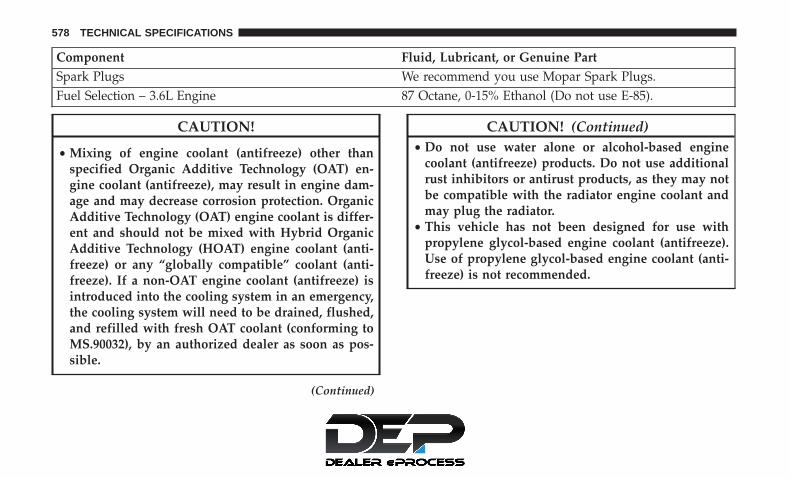
Component Fluid, Lubricant, or Genuine PartSpark Plugs We recommend you use Mopar Spark Plugs.Fuel Selection – 3.6L Engine 87 Octane, 0-15% Ethanol (Do not use E-85).
CAUTION!
• Mixing of engine coolant (antifreeze) other thanspecified Organic Additive Technology (OAT) en-gine coolant (antifreeze), may result in engine dam-age and may decrease corrosion protection. OrganicAdditive Technology (OAT) engine coolant is differ-ent and should not be mixed with Hybrid OrganicAdditive Technology (HOAT) engine coolant (anti-freeze) or any “globally compatible” coolant (anti-freeze). If a non-OAT engine coolant (antifreeze) isintroduced into the cooling system in an emergency,the cooling system will need to be drained, flushed,and refilled with fresh OAT coolant (conforming toMS.90032), by an authorized dealer as soon as pos-sible.
(Continued)
CAUTION! (Continued)• Do not use water alone or alcohol-based engine
coolant (antifreeze) products. Do not use additionalrust inhibitors or antirust products, as they may notbe compatible with the radiator engine coolant andmay plug the radiator.
• This vehicle has not been designed for use withpropylene glycol-based engine coolant (antifreeze).Use of propylene glycol-based engine coolant (anti-freeze) is not recommended.
578 TECHNICAL SPECIFICATIONS
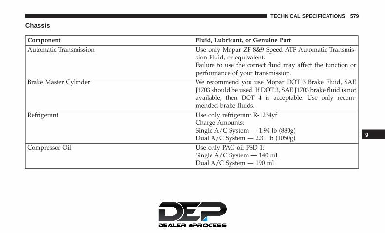
Chassis
Component Fluid, Lubricant, or Genuine PartAutomatic Transmission Use only Mopar ZF 8&9 Speed ATF Automatic Transmis-
sion Fluid, or equivalent.Failure to use the correct fluid may affect the function orperformance of your transmission.
Brake Master Cylinder We recommend you use Mopar DOT 3 Brake Fluid, SAEJ1703 should be used. If DOT 3, SAE J1703 brake fluid is notavailable, then DOT 4 is acceptable. Use only recom-mended brake fluids.
Refrigerant Use only refrigerant R-1234yfCharge Amounts:Single A/C System — 1.94 lb (880g)Dual A/C System — 2.31 lb (1050g)
Compressor Oil Use only PAG oil PSD-1:Single A/C System — 140 mlDual A/C System — 190 ml
9
TECHNICAL SPECIFICATIONS 579


MULTIMEDIA
CONTENTS� UCONNECT SYSTEMS . . . . . . . . . . . . . . . . . . .584
� DRAG & DROP MENU BAR . . . . . . . . . . . . . . .584
� CYBERSECURITY . . . . . . . . . . . . . . . . . . . . . . .585
� UCONNECT SETTINGS . . . . . . . . . . . . . . . . . . .586
▫ Customer Programmable Features — Uconnect 4Settings . . . . . . . . . . . . . . . . . . . . . . . . . . . . .587
▫ Customer Programmable Features — Uconnect4C/4C NAV Settings . . . . . . . . . . . . . . . . . . . .613
� STEERING WHEEL AUDIO CONTROLS . . . . . . .639
▫ Radio Operation. . . . . . . . . . . . . . . . . . . . . . . .639
▫ Media Mode . . . . . . . . . . . . . . . . . . . . . . . . . .639
� AUX/USB/MP3 CONTROL . . . . . . . . . . . . . . . .640
� UCONNECT THEATER — IF EQUIPPED . . . . . .641
▫ Uconnect Theater Overview . . . . . . . . . . . . . . .641
▫ Getting Started . . . . . . . . . . . . . . . . . . . . . . . .642
▫ Accessing The System From The UconnectSystem . . . . . . . . . . . . . . . . . . . . . . . . . . . . . .642
▫ Uconnect Theater Controls . . . . . . . . . . . . . . . .643
▫ Accessing The System From The Uconnect TheaterRear Screens . . . . . . . . . . . . . . . . . . . . . . . . . .644
▫ Pairing The Remote . . . . . . . . . . . . . . . . . . . . .645
▫ Unpairing The Remote . . . . . . . . . . . . . . . . . . .646
▫ Media Sources . . . . . . . . . . . . . . . . . . . . . . . . .647
▫ Uconnect Theater Remote Control . . . . . . . . . . .648
▫ Uconnect Theater Home Screen And Controls . . .649
▫ General Information . . . . . . . . . . . . . . . . . . . . .651
▫ Play A DVD/Blu-ray Or USB Media File FromUconnect System . . . . . . . . . . . . . . . . . . . . . . .651
▫ Disc Menu. . . . . . . . . . . . . . . . . . . . . . . . . . . .654
▫ Blu-ray Controls – Disc Specific Functions . . . . .654
10

▫ Uconnect Theater Apps. . . . . . . . . . . . . . . . . . .655
▫ Using The Rear Video USB Port. . . . . . . . . . . . .657
▫ Play Video Games . . . . . . . . . . . . . . . . . . . . . .658
▫ Headphones Operation . . . . . . . . . . . . . . . . . . .658
▫ Display Settings . . . . . . . . . . . . . . . . . . . . . . . .661
▫ Listening To Audio With The Screen Closed . . . .661
▫ Rear Climate Controls. . . . . . . . . . . . . . . . . . . .662
▫ Accessibility — If Equipped . . . . . . . . . . . . . . .664
▫ Wireless Streaming — If Equipped. . . . . . . . . . .664
▫ BD And DVD Region Codes . . . . . . . . . . . . . . .667
▫ Product Agreement . . . . . . . . . . . . . . . . . . . . .669
▫ General Information . . . . . . . . . . . . . . . . . . . . .672
▫ FCC/IC Regulatory Notices . . . . . . . . . . . . . . .672
� RADIO OPERATION AND MOBILE PHONES . . .673
▫ Regulatory And Safety Information . . . . . . . . . .673
� UCONNECT VOICE RECOGNITION QUICKTIPS . . . . . . . . . . . . . . . . . . . . . . . . . . . . . . . . .675
▫ Introducing Uconnect . . . . . . . . . . . . . . . . . . . .675
▫ Get Started . . . . . . . . . . . . . . . . . . . . . . . . . . .676
▫ Basic Voice Commands . . . . . . . . . . . . . . . . . . .677
▫ Radio . . . . . . . . . . . . . . . . . . . . . . . . . . . . . . .677
▫ Media . . . . . . . . . . . . . . . . . . . . . . . . . . . . . . .678
▫ Phone . . . . . . . . . . . . . . . . . . . . . . . . . . . . . . .679
▫ Voice Text Reply . . . . . . . . . . . . . . . . . . . . . . .680
▫ Climate . . . . . . . . . . . . . . . . . . . . . . . . . . . . . .682
▫ Navigation (4C NAV) . . . . . . . . . . . . . . . . . . . .683
▫ SiriusXM Guardian (4C/4C NAV) — IfEquipped . . . . . . . . . . . . . . . . . . . . . . . . . . . .684
▫ Register (4C/4C NAV) . . . . . . . . . . . . . . . . . . .684
▫ Vehicle Health Report/Alert (4C/4C NAV) . . . . .685
▫ Mobile App (4C/4C NAV) . . . . . . . . . . . . . . . .685
582 MULTIMEDIA
▫ SiriusXM Travel Link (4C NAV). . . . . . . . . . . . .686
▫ Siri Eyes Free — If Equipped . . . . . . . . . . . . . .686
▫ Using Do Not Disturb . . . . . . . . . . . . . . . . . . .687
▫ Android Auto — If Equipped . . . . . . . . . . . . . .688
▫ Apple CarPlay — If Equipped. . . . . . . . . . . . . .690
▫ General Information . . . . . . . . . . . . . . . . . . . . .691
▫ Additional Information . . . . . . . . . . . . . . . . . . .692
� CD/DVD DISC MAINTENANCE . . . . . . . . . . . .692
10
MULTIMEDIA 583

UCONNECT SYSTEMS
For detailed information about your Uconnect system,refer to your Uconnect Owner’s Manual Supplement.
NOTE: Uconnect screen images are for illustration pur-poses only and may not reflect exact software for yourvehicle.
DRAG & DROP MENU BAR
The Uconnect features and services in the main menu barare easily changed for your convenience. Simply followthese steps:
1. Press the “Apps ” button to open the App screen.
2. Press and hold, then drag the selected App to replace anexisting shortcut in the main menu bar.
The new shortcut will now be an active App/shortcut onthe main menu bar.
Uconnect 4 Drag & Drop Menu Bar
Uconnect 4C/4C NAV Drag & Drop Menu Bar
584 MULTIMEDIA

CYBERSECURITY
Your vehicle may be a connected vehicle and may beequipped with both wired and wireless networks. Thesenetworks allow your vehicle to send and receive informa-tion. This information allows systems and features in yourvehicle to function properly.
Your vehicle may be equipped with certain security fea-tures to reduce the risk of unauthorized and unlawfulaccess to vehicle systems and wireless communications.Vehicle software technology continues to evolve over timeand FCA US LLC, working with its suppliers, evaluatesand takes appropriate steps as needed. Similar to a com-puter or other devices, your vehicle may require softwareupdates to improve the usability and performance of yoursystems or to reduce the potential risk of unauthorized andunlawful access to your vehicle systems.
The risk of unauthorized and unlawful access to yourvehicle systems may still exist, even if the most recentversion of vehicle software (such as Uconnect software) isinstalled.
WARNING!
• It is not possible to know or to predict all of thepossible outcomes if your vehicle’s systems arebreached. It may be possible that vehicle systems,including safety related systems, could be impairedor a loss of vehicle control could occur that mayresult in an accident involving serious injury ordeath.
• ONLY insert media (e.g., USB, SD card, or CD) intoyour vehicle if it came from a trusted source. Mediaof unknown origin could possibly contain malicioussoftware, and if installed in your vehicle, it mayincrease the possibility for vehicle systems to bebreached.
• As always, if you experience unusual vehicle behav-ior, take your vehicle to your nearest authorizeddealer immediately.
10
MULTIMEDIA 585
NOTE:
• FCA US LLC or your dealer may contact you directlyregarding software updates.
• To help further improve vehicle security and minimizethe potential risk of a security breach, vehicle ownersshould:• Routinely check www.driveuconnect.com (U.S. Resi-
dents) or www.driveuconnect.ca (Canadian Residents)to learn about available Uconnect software updates.
• Only connect and use trusted media devices (e.g.personal mobile phones, USBs, CDs).
Privacy of any wireless and wired communications cannotbe assured. Third parties may unlawfully intercept infor-mation and private communications without your consent.For further information, refer to “Data Collection & Pri-vacy” in your Uconnect Owner’s Manual Supplement or“Onboard Diagnostic System (OBD II) Cybersecurity” in“Getting To Know Your Instrument Panel”.
UCONNECT SETTINGS
The Uconnect system uses a combination of buttons on thetouchscreen and/or buttons on the faceplate located on thecenter of the instrument panel that allow you to access andchange the customer programmable features. Many fea-tures can vary by vehicle.
Buttons on the touchscreen are accessible on the Uconnecttouchscreen.
Buttons on the faceplate are located below, and in thecenter of the instrument panel. In addition, there is aScroll/Enter control knob located on the right side. Turnthe control knob to scroll through menus and changesettings (i.e., 30, 60, 90), push the center of the control knobone or more times to select or change a setting (i.e., ON,OFF).
Your Uconnect system may also have Screen Off and Mutebuttons on the faceplate.
Push the Screen Off button on the faceplate to turn off theUconnect screen. Push the Screen Off button on the face-plate a second time to turn the screen on.
586 MULTIMEDIA
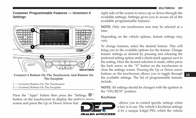
Customer Programmable Features — Uconnect 4Settings
Press the ”Apps” button then press the “Settings ”button on the touchscreen to display the settings menuscreen and press the Up or Down Arrow buttons on the
right side of the screen to move up or down through theavailable settings. Settings gives you to access all of theavailable programmable features.
NOTE: Only one touchscreen area may be selected at atime.
Depending on the vehicle options, feature settings mayvary.
To change features, select the desired feature. This willbring you to the available options for the feature. Changefeature settings as desired by pressing and releasing thepreferred setting option until a check-mark appears next tothe setting. Once the desired selection is made, either pressthe back arrow or the “X” button on the touchscreen toclose the settings screen. Pressing the Up or Down arrowbuttons on the touchscreen allows you to toggle throughthe available settings. The list of programmable featuresinclude:
NOTE: All settings should be changed with the ignition inthe “ON/RUN” position.
KeySense
This feature allows you to control specific settings whenthe KeySense key is in use. The vehicle’s KeySense settingsare protected by a unique 4-digit PIN, which the vehicle
Uconnect 4 Buttons On The Touchscreen And Buttons OnThe Faceplate
1 — Uconnect Buttons On The Touchscreen2 — Uconnect Buttons On The Faceplate
10
MULTIMEDIA 587

owner creates when accessing the specific settings for thefirst time. This 4-digit PIN can only be reset by an autho-rized dealer.
After pressing the “KeySense” button on the touchscreen,and entering the KeySense PIN, the following settings willbe available:
Setting Name Selectable OptionsParkSense — If Equipped Sound Only Sound and Display
NOTE:The “ParkSense” system setting will scan for objects behind the vehicle when the transmission gear selector is in RE-VERSE and the vehicle speed is less than 7 mph (11 km/h), when enabled. It will provide an alert (audible and/orvisual) to indicate the proximity to other objects. The system can be enabled with “Sound Only,” or “Sound and Dis-play.”
Front ParkSense Volume Low Medium HighRear ParkSense Volume Low Medium HighRear ParkSense Braking
AssistOn Off
NOTE:When the “Rear ParkSense Braking Assist” feature is selected, the park assist system will detect objects located be-hind the vehicle and utilize autonomous braking to stop the vehicle.
588 MULTIMEDIA

Setting Name Selectable OptionsBlind Spot Alert — If
EquippedLights Lights & Chime
NOTE:When the “Blind Spot Alert” feature is selected, it will alert, visibly and/or audibly, to indicate objects are in yourblind spot. The “Blind Spot Alert” feature can be activated in “Lights” mode. When this mode is selected, the BlindSpot Monitor (BSM) system is activated and will only show a visual alert in the exterior mirrors. When “Lights &Chime” mode is activated, the Blind Spot Monitor (BSM) will show a visual alert in the exterior mirrors as well as anaudible alert when the turn signal is on. If your vehicle has experienced any damage in the area where the sensor islocated, even if the fascia is not damaged, the sensor may have become misaligned. Take your vehicle to an autho-rized dealer to verify sensor alignment. Having a sensor that is misaligned will result in the BSM not operating tospecification.Maximum Vehicle Speed + -
NOTE:The “Maximum Vehicle Speed” feature can be set to 65, 70, 75, 80, or 85 mph (90, 95, 100, 105, 110 km/h). 10
MULTIMEDIA 589

Setting Name Selectable OptionsStart Up Fuel Level
MessageOn Off
Early Low Fuel Alert On Off
SiriusXM Setup Channel Skip Subscription Information
NOTE:SiriusXM can be programmed to skip channels. To make your selection, press the “Channel Skip” button on thetouchscreen, and select the channels you would like to skip.New vehicle purchasers or lessees will receive a free limited time subscription to SiriusXM Satellite Radio with yourradio. Following the expiration of the free services, it will be necessary to access the information on the SubscriptionInformation screen to re-subscribe.
1. Press the “Subscription Info” button on the touchscreen to access the Subscription Information screen.
2. Write down the Sirius ID numbers for your receiver. To reactivate your service, either call the number listed on thescreen or visit the provider online.
590 MULTIMEDIA

Language
After pressing the “Language” button on the touchscreen,the following settings will be available:
Setting Name Selectable OptionsLanguage English Français Español
NOTE:When the “Set Language” feature is selected, you may select one of multiple languages (English / Français / Espa-ñol) for all display nomenclature, including the trip functions and the navigation system (if equipped). Press the “SetLanguage” button on the touchscreen, then press the desired language button on the touchscreen until a check-markappears next to the language, showing that setting has been selected.
10
MULTIMEDIA 591

Display
After pressing the “Display” button on the touchscreen, thefollowing settings will be available.
Setting Name Selectable OptionsDisplay Mode Auto Manual
Display Brightness With HeadlightsON
1-10 1-10
NOTE:To make changes to the �Display Brightness with Headlights ON� setting, the headlights must be on and the interiordimmer switch must not be in the �party� or �parade� positions. The setting can be changed from 1-10.Display Brightness With Headlights
OFF1-10 1-10
NOTE:To make changes to the �Display Brightness with Headlights OFF� setting, the headlights must be off and the interiordimmer switch must not be in the �party� or �parade� positions.
Set Theme List of Themes
NOTE:When the “Set Theme” feature is selected, you may select the theme for the display screen. To make your selection,press the �Set Theme� button on the touchscreen, then select the desired theme option button until a check-mark ap-pears showing that the setting has been selected.
592 MULTIMEDIA

Setting Name Selectable OptionsTouchscreen Beep On Off
Control Screen Time-Out — IfEquipped
On Off
NOTE:When the “Control Screen Time-Out” feature is selected, the Controls Screen will stay open for five seconds beforethe screen times out. With the feature deselected, the screen will stay open until it is manually closed.Navigation Turn-By-Turn In Cluster
— If EquippedOn Off
NOTE:When the “Navigation Turn-By-Turn In Cluster” feature is selected, the turn-by-turn directions will appear in the in-strument cluster display as the vehicle approaches a designated turn within a programmed route.
Phone Pop-Ups Displayed inCluster
On Off
10
MULTIMEDIA 593

Units
After pressing the “Units” button on the touchscreen, thefollowing settings will be available:
Setting Name Selectable OptionsUnits US Metric Custom
NOTE:The “Custom” option allows you to set the “Speed” (MPH, or km/h), “Distance” (mi, or km), “Fuel Consumption”[MPG (US), MPG (UK), L/100 km, or km/L], “Pressure” (psi, kPa, or bar), and “Temperature” (°C, or °F) units ofmeasure independently.
Voice
After pressing the “Voice” button on the touchscreen, thefollowing settings will be available:
Setting Name Selectable OptionsVoice Response Length Brief DetailedShow Command List Always With Help Never
594 MULTIMEDIA

Clock
After pressing the “Clock” button on the touchscreen, thefollowing settings will be available:
Setting Name Selectable OptionsSync Time With GPS — If
EquippedOn Off
Set Time Hours + -
NOTE:The “Set Time Hours” feature will allow you to adjust the hours. The “Sync Time With GPS” button on the touch-screen must be unchecked.
Set Time Minutes + -
NOTE:The “Set Time Minutes” feature will allow you to adjust the minutes. The “Sync Time With GPS” button on thetouchscreen must be unchecked.
Time Format 12 hr 24 hrAM PM
NOTE:Within the “Set Time and Format” setting, press the corresponding arrow buttons on the touchscreen to adjust to thecorrect time.
10
MULTIMEDIA 595
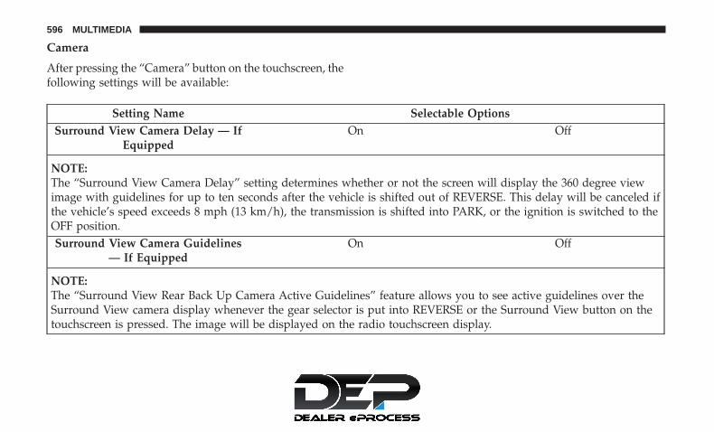
Camera
After pressing the “Camera” button on the touchscreen, thefollowing settings will be available:
Setting Name Selectable OptionsSurround View Camera Delay — If
EquippedOn Off
NOTE:The “Surround View Camera Delay” setting determines whether or not the screen will display the 360 degree viewimage with guidelines for up to ten seconds after the vehicle is shifted out of REVERSE. This delay will be canceled ifthe vehicle’s speed exceeds 8 mph (13 km/h), the transmission is shifted into PARK, or the ignition is switched to theOFF position.Surround View Camera Guidelines
— If EquippedOn Off
NOTE:The “Surround View Rear Back Up Camera Active Guidelines” feature allows you to see active guidelines over theSurround View camera display whenever the gear selector is put into REVERSE or the Surround View button on thetouchscreen is pressed. The image will be displayed on the radio touchscreen display.
596 MULTIMEDIA

Setting Name Selectable OptionsActive ParkView Backup Camera
Guide LinesOn Off
NOTE:The “ParkView Backup Camera Active Guide Lines” setting overlays the Rear Backup Camera image with active, ordynamic, grid lines to help illustrate the width of the vehicle and its project back up path, based on the steeringwheel position when the option is checked. A dashed center line overlay indicates the center of the vehicle to assistwith parking or aligning to a hitch/receiver.
Fixed ParkView Backup CameraGuide Lines
On Off
Safety/Assistance
After pressing the “Safety/Assistance” button on thetouchscreen, the following settings will be available:
Setting Name Selectable OptionsLaneSense Warning — If
EquippedEarly Medium Late
NOTE:The “LaneSense Warning” setting determines at what distance the LaneSense system warns you, through steeringwheel feedback, of a possible lane departure.
10
MULTIMEDIA 597

Setting Name Selectable OptionsLaneSense Strength — If
EquippedLow Medium High
ParkSense — If Equipped Sound Only Sound and DisplayFront ParkSense Volume Low Medium HighRear ParkSense Volume Low Medium HighRear ParkSense Braking
Assist — If EquippedOn Off
Blind Spot Alert — IfEquipped
Off Lights Lights and Chime
NOTE:When the “Blind Spot Alert” feature is selected, the Blind Spot Monitor (BSM) system is activated and will show avisual alert in the outside mirrors, or it will show a visual alert in the outside mirrors as well as play an audible alertwhen the turn signal is on. When “Off” is selected, the Blind Spot Monitor (BSM) system is deactivated.If your vehicle has experienced any damage in the area where the sensor is located, even if the fascia is not damaged,the sensor may have become misaligned. Take your vehicle to an authorized dealer to verify sensor alignment. A sen-sor that is misaligned will result in the BSM not operating to specification.
Hill Start Assist — IfEquipped
On Off
Keysense On Off
598 MULTIMEDIA

Mirrors & Wipers
After pressing the “Mirror and Wipers” button on thetouchscreen, the following settings will be available:
Setting Name Selectable OptionsTilt Side Mirrors in Reverse On OffRain Sensing Auto Wipers On Off
Headlights with Wipers On Off
Brakes
After pressing the “Brakes” button on the touchscreen, thefollowing settings will be available:
Setting Name Selectable OptionsAuto Park Brake On Off
Brake Service Yes No
NOTE:Selecting the “Brake Service” feature will display a pop-up asking whether or you would like to retract the parkbrakes to all break system service.
10
MULTIMEDIA 599

Lights
After pressing the “Lights” button on the touchscreen, thefollowing settings will be available.
Setting Name Selectable OptionsHeadlight Off Delay 0 sec 60 sec
30 sec 90 sec
NOTE:When the “Headlight Off Delay” feature is selected, it allows the adjustment of the amount of time the headlightsremain on after the engine is shut off.
Headlight Illumination On Ap-proach
0 sec 60 sec30 sec 90 sec
NOTE:When this feature is selected, it allows the adjustment of the amount of time the headlights remain on after the doorsare unlocked with the key fob.
Headlights With Wipers — IfEquipped
On Off
Auto Dim High Beams— IfEquipped
On Off
Daytime Running Lights Yes No
600 MULTIMEDIA

Setting Name Selectable OptionsFlash Lights With Lock On Off
Flash Lights With Sliding Door On Off
Doors & Locks
After pressing the “Doors & Locks” button on the touch-screen, the following settings will be available:
NOTE: The auto door lock feature default condition isenabled. When enabled, the door locks will lock automati-cally when the vehicle’s speed exceeds 12 mph (20 km/h).The auto door lock feature can be enabled or disabled by anauthorized dealer per written request of the customer.Please see an authorized dealer for service.
Setting Name Selectable OptionsAuto Unlock On Exit On Off
NOTE:When the “Auto Unlock On Exit” feature is selected, all doors will unlock when the vehicle is stopped and the trans-mission is in the PARK or NEUTRAL position and the driver’s door is opened.
Flash Lights With Lock On OffSound Horn With Lock Off 1st Press 2nd Press
Sound Horn With Remote On Off
10
MULTIMEDIA 601

Setting Name Selectable OptionsStart — If Equipped
1st Press of Key Fob Un-locks — If Equipped
Driver All
NOTE:When the “1st Press Of Key Fob Unlocks” feature’s “Driver” option is selected, only the driver’s door will unlock onthe first push of the key fob unlock button; you must push the key fob unlock button twice to unlock the passenger’sdoors. When “All” is selected, all of the doors will unlock on the first press of the key fob unlock button. If “All” isprogrammed, all doors will unlock no matter which Passive Entry equipped door handle is grasped. If “Driver” isprogrammed, only the driver’s door will unlock when the driver’s door is grasped. Touching the handle more thanonce will only result in the driver’s door opening once. If the driver door is opened, the interior door lock/unlockswitch can be used to unlock all doors (or use key fob).
Passive Entry On OffPower Liftgate Alert On Off
NOTE:When the “Power Liftgate Alert” feature is selected, an alert plays when the power liftgate is raising or lowering.
Sliding Door Alert On Off
NOTE:The “Sliding Door Alert” feature only occurs when the hands free feature is used, and not for other methods of open-ing the sliding door.”Flashing Lights with Slid-ing Door — If Equipped
On Off
602 MULTIMEDIA

Setting Name Selectable OptionsHands Free Power Lift
GateOn Off
Hands Free Power SlidingDoor
On Off
Personal Settings Linkedto Key Fob — If Equipped
On Off
NOTE:The “Personal Settings Linked to Key Fob” feature provides automatic recall of all settings stored to a memory loca-tion (driver’s seat, exterior mirrors, steering column position and radio station pre-sets) to enhance driver mobilitywhen entering and exiting the vehicle.The seat returns to the memorized seat location, if the settings is set to “On,” when the key fob is used to unlock thedoor.Remote Door Unlock/Door
Unlock — If EquippedDriver All
NOTE:When the “Remote Door Unlock/Door Unlock” feature’s “Driver” option is selected, only the driver’s door will un-lock on the first push of the key fob unlock button; you must push the key fob unlock button twice to unlock thepassenger’s doors. When “All” is selected, all of the doors will unlock on the first press of the key fob unlock button.If “All” is programmed, all doors will unlock no matter which Passive Entry equipped door handle is grasped. If“Driver” is programmed, only the driver’s door will unlock when the driver’s door is grasped. Touching the handlemore than once will only result in the driver’s door opening once. If the driver door is opened, the interior doorlock/unlock switch can be used to unlock all doors (or use key fob).
10
MULTIMEDIA 603

Auto-On Comfort — If Equipped
After pressing the “Auto-On Comfort ” button on thetouchscreen, the following settings will be available:
Setting Name Selectable OptionsAuto-On Driver Heated/
Ventilated Seat & SteeringWheel With Vehicle Start
— If Equipped
Off Remote Start All Starts
NOTE:When this feature is selected the driver’s heated seat and heated steering wheel will automatically turn ON whentemperatures are below 40° F (4.4° C). When temperatures are above 80° F (26.7° C) the driver vented seat willturn on.
Engine Off Options
After pressing the “Engine Off Options” button on thetouchscreen, the following settings will be available:
Setting Name Selectable OptionsEngine Off Power Delay — If
Equipped0 sec 45 sec5 min 10 min
604 MULTIMEDIA

Setting Name Selectable Options
NOTE:When the “Engine Off Power Delay” feature is selected, the power window switches, radio, Uconnect phone system(if equipped), DVD video system (if equipped), power sunroof (if equipped), and power outlets will remain active forup to ten minutes after the ignition is cycled to OFF. Opening either front door will cancel this feature.
Headlight Off Delay 0 sec 30 sec60 sec 90 sec
NOTE:When the “Headlight Off Delay” feature is selected, it allows the adjustment of the amount of time the headlightsremain on after the engine is shut off.
Easy Exit Seat — If Equipped On Off
NOTE:When the “Easy Exit Seat” feature is selected, it provides automatic driver seat positioning to enhance driver mobilitywhen entering and exiting the vehicle. 10
MULTIMEDIA 605

Audio
After pressing the “Audio” button on the touchscreen, thefollowing settings will be available:
Setting Name Selectable OptionsEqualizer Bass Mid Treble
NOTE:When in this display you may adjust the “Bass”, “Mid” and “Treble” settings. Adjust the settings with the “+” and“–” setting buttons on the touchscreen or by selecting any point on the scale between the “+” and “–” buttons on thetouchscreen. Bass/Mid/Treble also allow you to simply slide your finger up or down to change the setting, as well aspress directly on the desired setting.
Balance/Fade Up ArrowButton
Down Ar-row Button
Left ArrowButton
Right Ar-row Button
Center “C”Button
NOTE:When in this display you may adjust the “Balance/Fade” of the audio by using the “Arrow” button on the touch-screen to adjust the sound level from the front and rear or right and left side speakers. Press the “Center ‘C’ Button”on the touchscreen to reset the balance and fade to the factory setting.
606 MULTIMEDIA

Setting Name Selectable OptionsSpeed Adjusted Volume Off 1 2 3
Surround Sound — If Equipped On OffLoudness Yes No
NOTE:This feature improves sound quality at lower volumes when enabled.
AUX Volume Offset — If Equipped On Off
NOTE:This feature provides the ability to tune the audio level for portable devices connected through the AUX input.
AutoPlay On Off
NOTE:The “AutoPlay” setting, when activated, automatically starts playing music off of a connect device as soon as it isconnected.
10
MULTIMEDIA 607

Compass Settings — If Equipped
After pressing the “Compass Settings” button on thetouchscreen, the following settings will be available:
NOTE: Before compass calibration is performed, the com-pass variance zone should be set for best results.
Setting Name Selectable OptionsCompass Variance 1 2 3 4 5 6 7 8 9 10 11 12 13 14 15
NOTE:When the “Compass Variance” feature is selected, it allows the compass variance to be set to any number from 1 to15 per the compass variance zone map figure.Compass Variance is the difference between Magnetic North and Geographic North. To compensate for the differ-ences the variance should be set for the zone where the vehicle is being driven, illustrated in the zone map. Onceproperly set, the compass will automatically compensate for the differences when calibrated, and provide the mostaccurate compass headings.
CompassCalibration
Yes
NOTE:Press “Compass Calibration” on the touchscreen to enter calibration. To start calibration of the compass, press the“Yes” button on the touchscreen and complete one or more 360-degree turns (in an area free from large metal or me-tallic objects). A message will appear on the touchscreen when the compass has been successfully calibrated.Keep magnetic materials away from the rear view mirror, such as Mobile Phones, Laptops and Radar Detectors. Thisis where the compass module is located, and it can cause interference with the compass sensor, and it may give falsereadings.
608 MULTIMEDIA

Compass Variance Zone Map
10
MULTIMEDIA 609

Phone/Bluetooth
After pressing the “Phone/Bluetooth” button on the touch-screen, the following settings will be available:
Setting Name Selectable OptionsPhone Pop-ups Displayed in Cluster On Off
Do Not Disturb List of Settings
NOTE:The “Do Not Disturb” feature allows the paired phone to send a predetermined call, text, or both, to any incomingcall, or text, before sending it directly to voicemail. It also keeps a counter of all missed calls and texts while on theroad.
Paired Phones and Audio Devices List of Paired Phones
NOTE:This feature shows which phones are paired to the Phone/Bluetooth system. For further information, refer to theUconnect Owner’s Manual Supplement.
Smartphone Projection Manager List Of Connected Phones
NOTE:Pressing “Smartphone Projection Manager” feature allows you to see a list of all connected phones and gives you theoption to determine which phone will be used for projection (Apple CarPlay or Android Auto).
610 MULTIMEDIA

SiriusXM Setup — If Equipped
After pressing the “SiriusXM Setup” button on the touch-screen, the following settings will be available:
Setting Name Selectable OptionsTune Start On Off
Channel Skip List of Channels
NOTE:SiriusXM can be programmed to designate a group of channels that are the most desirable to listen to or to excludeundesirable channels while scanning. This feature allows you to select the channels you would like to skip.
Subscription Info Sirius ID
NOTE:New vehicle purchasers or lessees will receive a free limited time subscription to SiriusXM Satellite Radio with yourradio. Following the expiration of the free services, it will be necessary to access the information on the SubscriptionInformation screen to re-subscribe.
1. Press the “Subscription Info” button on the touchscreen to access the Subscription Information screen.
2. Write down the Sirius ID numbers for your receiver. To reactivate your service, either call the number listed on thescreen or visit the provider online.
10
MULTIMEDIA 611

Restore Settings
After pressing the “Restore Settings” button on the touch-screen, the following settings will be available:
Setting Name Selectable OptionsReset App Drawer to Default Order OK Cancel
Restore Settings to Default OK Cancel
NOTE:When the “Restore Settings to Default” feature is selected it resets all settings to their default settings.
Clear Personal Data OK Cancel
NOTE: When the “Clear Personal Data” feature is selected it will remove all personal data including Bluetooth de-vices and presets.
612 MULTIMEDIA
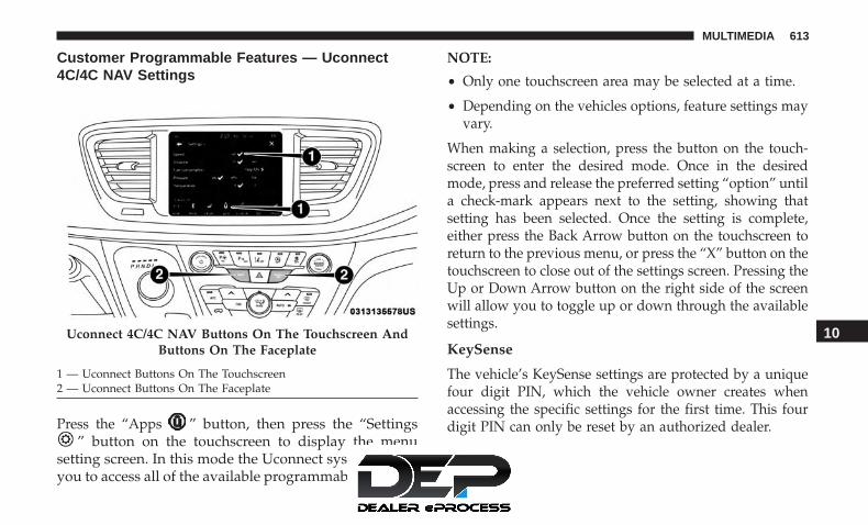
Customer Programmable Features — Uconnect4C/4C NAV Settings
Press the “Apps ” button, then press the “Settings” button on the touchscreen to display the menu
setting screen. In this mode the Uconnect system allowsyou to access all of the available programmable features.
NOTE:
• Only one touchscreen area may be selected at a time.
• Depending on the vehicles options, feature settings mayvary.
When making a selection, press the button on the touch-screen to enter the desired mode. Once in the desiredmode, press and release the preferred setting “option” untila check-mark appears next to the setting, showing thatsetting has been selected. Once the setting is complete,either press the Back Arrow button on the touchscreen toreturn to the previous menu, or press the “X” button on thetouchscreen to close out of the settings screen. Pressing theUp or Down Arrow button on the right side of the screenwill allow you to toggle up or down through the availablesettings.
KeySense
The vehicle’s KeySense settings are protected by a uniquefour digit PIN, which the vehicle owner creates whenaccessing the specific settings for the first time. This fourdigit PIN can only be reset by an authorized dealer.
Uconnect 4C/4C NAV Buttons On The Touchscreen AndButtons On The Faceplate
1 — Uconnect Buttons On The Touchscreen2 — Uconnect Buttons On The Faceplate
10
MULTIMEDIA 613

After pressing the “KeySense” button on the touchscreen,and entering the KeySense PIN, the following settings willbe available:
Setting Name Selectable OptionsAutomatic Emergency
Braking — If EquippedList Of Settings
When “Automatic Emergency Braking” is selected, the following options will appear:• Forward Collision Warning — If Equipped: Select “Only Warning” or “Warning + Active Braking”
NOTE:Changing the FCW status to “Off” prevents the system from warning you of a possible collision with the vehiclein front of you.The FCW system state is kept in memory from one ignition cycle to the next. If the system is turned OFF, it willremain off when the vehicle is restarted.Forward Collision Warning includes Advanced Brake Assist (ABA). The ABA applies additional brake pressurewhen the driver requests insufficient brake pressure to avoid a potential frontal collision. When the “Sound Only”option is selected a chime will sound alerting you of a possible collision with the vehicle in front of you and morebrake pressure is needed. When the “Sound and Brake” option is selected, it will apply the brakes to slow yourvehicle in case of potential forward collision and sound an audible chime to alert you.
614 MULTIMEDIA

Setting Name Selectable Options• Forward Collision Warning Sensitivity — If Equipped: Select “Near,” “Med” or “Far”
NOTE:The “Forward Collision Warning Sensitivity” setting determines at what relative distance the vehicle directly infront of you needs to be at, before the system will warn you of a possible collision with the vehicle directly infront of you, based on the option is selected. “Far” will give you the most amount of reaction time, whereas“Near” will give you the least amount of reaction time, based on the distance between the two vehicles.
Rear ParkSense Volume Low Medium HighRear ParkSense Braking
AssistOn Off
NOTE:When the “Rear ParkSense Braking Assist” feature is selected, the park assist system will detect objects located be-hind the vehicle and utilize autonomous braking to stop the vehicle.
10
MULTIMEDIA 615

Setting Name Selectable OptionsBlind Spot Alert — If
EquippedLights Lights & Chime
NOTE:When the “Blind Spot Alert” feature is selected, it will alert, visibly and/or audibly, to indicate objects are in yourblind spot. The “Blind Spot Alert” feature can be activated in “Lights” mode. When this mode is selected, the BlindSpot Monitor (BSM) system is activated and will only show a visual alert in the exterior mirrors. When “Lights &Chime” mode is activated, the Blind Spot Monitor (BSM) will show a visual alert in the exterior mirrors as well as anaudible alert when the turn signal is on. If your vehicle has experienced any damage in the area where the sensor islocated, even if the fascia is not damaged, the sensor may have become misaligned. Take your vehicle to an autho-rized dealer to verify sensor alignment. Having a sensor that is misaligned will result in the BSM not operating tospecification.Maximum Vehicle Speed + -
NOTE:The “Maximum Vehicle Speed” feature can be set to 65, 70, 75, 80, or 85 mph (90, 95, 100, 105, 110 km/h).
SiriusXM Setup Channel Skip Subscription Information
NOTE:SiriusXM can be programmed to skip channels. To make your selection, press the “Channel Skip” button on thetouchscreen, select the channels you would like to skip.New vehicle purchasers or lessees will receive a free limited time subscription to SiriusXM Satellite Radio with yourradio. Following the expiration of the free services, it will be necessary to access the information on the SubscriptionInformation screen to re-subscribe.
616 MULTIMEDIA
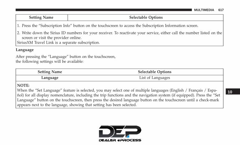
Setting Name Selectable Options
1. Press the “Subscription Info” button on the touchscreen to access the Subscription Information screen.
2. Write down the Sirius ID numbers for your receiver. To reactivate your service, either call the number listed on thescreen or visit the provider online.
SiriusXM Travel Link is a separate subscription.
Language
After pressing the “Language” button on the touchscreen,the following settings will be available:
Setting Name Selectable OptionsLanguage List of Languages
NOTE:When the “Set Language” feature is selected, you may select one of multiple languages (English / Français / Espa-ñol) for all display nomenclature, including the trip functions and the navigation system (if equipped). Press the “SetLanguage” button on the touchscreen, then press the desired language button on the touchscreen until a check-markappears next to the language, showing that setting has been selected.
10
MULTIMEDIA 617

Display
After pressing the “Display” button on the touchscreen, thefollowing settings will be available:
Setting Name Selectable OptionsDisplay Mode Manual Auto
Display Brightness WithHeadlights ON
+ -
NOTE:To make changes to the �Display Brightness with Headlights ON� setting, the headlights must be on and the interiordimmer switch must not be in the �party� or �parade� positions.
Display Brightness WithHeadlights OFF
+ -
NOTE:To make changes to the �Display Brightness with Headlights OFF� setting, the headlights must be off and the interiordimmer switch must not be in the �party� or �parade� positions.
Set Theme On Off
NOTE:When the “Set Theme” feature is selected, you may select the theme for the display screen. To make your selection,press the �Set Theme� button on the touchscreen, then select the desired theme option button until a check-mark ap-pears showing that the setting has been selected.
618 MULTIMEDIA

Setting Name Selectable OptionsTouchscreen Beep On Off
Control Screen Time-Out —If Equipped
On Off
NOTE:When the “Control Screen Time-Out” feature is selected, the Controls Screen will stay open for five seconds beforethe screen times out. With the feature deselected, the screen will stay open until it is manually closed.Navigation Turn-By-Turn In
Cluster — If EquippedOn Off
NOTE:When the “Navigation Turn-By-Turn In Cluster” feature is selected, the turn-by-turn directions will appear in the in-strument cluster display as the vehicle approaches a designated turn within a programmed route.Phone Pop-ups Displayed in
ClusterOn Off
10
MULTIMEDIA 619

Units
After pressing the “Units” button on the touchscreen, thefollowing settings will be available:
Setting Name Selectable OptionsUnits US Metric Custom
NOTE:The “Custom” option allows you to set the “Speed” (MPH, or km/h), “Distance” (mi, or km), “Fuel Consumption”[MPG (US), MPG (UK), L/100 km, or km/L], “Pressure” (psi, kPa, or bar), and “Temperature” (°C, or °F) units ofmeasure independently.
Voice
After pressing the “Voice” button on the touchscreen, thefollowing settings will be available:
Setting Name Selectable OptionsVoice Response Length Brief DetailedShow Command List Never With Help Always
620 MULTIMEDIA

Camera
After pressing the “Camera” button on the touchscreen, thefollowing settings will be available:
Setting Name Selectable OptionsSurround View Camera — If
EquippedOn Off
NOTE:The “Surround View Camera” feature displays a complete 360 degree view of the vehicle’s exterior environmentwhile backing up.Surround View Camera Delay — If
EquippedOn Off
NOTE:The “Surround View Camera Delay” setting determines whether or not the screen will display the 360 degree viewimage with guidelines for up to ten seconds after the vehicle is shifted out of REVERSE. This delay will be canceled ifthe vehicle’s speed exceeds 8 mph (13 km/h), the transmission is shifted into PARK, or the ignition is switched to theOFF position.
10
MULTIMEDIA 621

Setting Name Selectable OptionsSurround View Camera Guidelines
— If EquippedOn Off
NOTE:The “Surround View Rear Back Up Camera Active Guidelines” feature allows you to see active guidelines over theSurround View camera display whenever the gear selector is put into REVERSE or the Surround View button on thetouchscreen is pressed. The image will be displayed on the radio touchscreen display.
ParkView Backup Camera Delay On Off
NOTE:The “ParkView Backup Camera Delay” setting determines whether or not the screen will display the rear view imagewith dynamic grid lines for up to ten seconds after the vehicle is shifted out of REVERSE. This delay will be canceledif the vehicle’s speed exceeds 8 mph (13 km/h), the transmission is shifted into PARK, or the ignition is switched tothe OFF position.
ParkView Backup Camera ActiveGuide Lines
On Off
NOTE:The “ParkView Backup Camera Active Guide Lines” feature overlays the Rear Backup Camera image with active, ordynamic, grid lines to help illustrate the width of the vehicle and its project back up path, based on the steeringwheel position when the option is checked. A dashed center line overlay indicates the center of the vehicle to assistwith parking or aligning to a hitch/receiver.
622 MULTIMEDIA

Clock
After pressing the “Clock” button on the touchscreen, thefollowing settings will be available:
Setting Name Selectable OptionsSync Time With GPS — If Equipped On Off
Set Time Hours + -
NOTE:The “Set Time Hours” feature will allow you to adjust the hours. The “Sync Time With GPS” button on the touch-screen must be unchecked.
Set Time Minutes + -
NOTE:The “Set Time Minutes” feature will allow you to adjust the minutes. The “Sync Time with GPS” button on the touch-screen must be unchecked.
Time Format 12hrs 24hrsAM PM
10
MULTIMEDIA 623

Safety & Driving Assistance
After pressing the “Safety & Driving Assistance” button onthe touchscreen, the following settings will be available:
Setting Name Selectable OptionsAutomatic Emergency
Braking — If EquippedList Of Settings
When “Automatic Emergency Braking” is selected, the following options will appear:• Forward Collision Warning — If Equipped: Select “Only Warning” or “Warning + Active Braking”
NOTE:Changing the FCW status to “Off” prevents the system from warning you of a possible collision with the vehicle infront of you.The FCW system state is kept in memory from one ignition cycle to the next. If the system is turned OFF, it will re-main off when the vehicle is restarted.Forward Collision Warning includes Advanced Brake Assist (ABA). The ABA applies additional brake pressure whenthe driver requests insufficient brake pressure to avoid a potential frontal collision. When the “Sound Only” option isselected a chime will sound alerting you of a possible collision with the vehicle in front of you and more brake pres-sure is needed. When the “Sound and Brake” option is selected, it will apply the brakes to slow your vehicle in caseof potential forward collision and sound an audible chime to alert you.
624 MULTIMEDIA

Setting Name Selectable Options• Forward Collision Warning Sensitivity — If Equipped: Select “Near,” “Med” or “Far”
NOTE:The “Forward Collision Warning Sensitivity” setting determines at what relative distance the vehicle directly in frontof you needs to be at, before the system will warn you of a possible collision with the vehicle directly in front of you,based on the option selected. “Far” will give you the most amount of reaction time, whereas “Near” will give you theleast amount of reaction time, based on the distance between the two vehicles.ParkSense — If Equipped Sound Only Sound and Display
NOTE:The “ParkSense” system setting will scan for objects behind the vehicle when the transmission gear selector is in RE-VERSE and the vehicle speed is less than 7 mph (11 km/h), when enabled. It will provide an alert (audible and/orvisual) to indicate the proximity to other objects. The system can be enabled with “Sound Only,” or “Sound and Dis-play.”
Front ParkSense Volume Low Medium HighRear ParkSense Volume Low Medium HighSliding Door Alert — If
EquippedOn Off
NOTE:When the “Sliding Door Alert” feature is selected, a chime plays when the sliding door reverses or an obstacle issensed.
10
MULTIMEDIA 625

Setting Name Selectable OptionsLaneSense Warning — If
EquippedEarly Medium Late
NOTE:The “LaneSense Warning” setting determines at what distance the LaneSense system will warn you, through steeringwheel feedback, of a possible lane departure.LaneSense Strength — If
EquippedLow Medium High
Blind Spot Alert — IfEquipped
Off Lights Lights and Chime
NOTE:When the “Blind Spot Alert” feature is selected, the Blind Spot Monitor (BSM) system is activated and will show avisual alert in the outside mirrors, or it will show a visual alert in the outside mirrors as well as play an audible alertwhen the turn signal is on. When “Off” is selected, the Blind Spot Monitor (BSM) system is deactivated.If your vehicle has experienced any damage in the area where the sensor is located, even if the fascia is not damaged,the sensor may have become misaligned. Take your vehicle to an authorized dealer to verify sensor alignment. A sen-sor that is misaligned will result in the BSM not operating to specification.
Hill Start Assist — IfEquipped
On Off
626 MULTIMEDIA

Mirrors & Wipers
After pressing the “Mirror and Wipers” button on thetouchscreen, the following settings will be available:
Setting Name Selectable OptionsRain Sensing Auto Wipers On Off
Tilt Side Mirrors in Reverse On OffHeadlights with Wipers On Off
Brakes
After pressing the “Brakes” button on the touchscreen, thefollowing settings will be available:
Setting Name Selectable OptionsAuto Park Brake On Off
Brake Service Yes No
NOTE:Selecting the “Brake Service” feature will display a pop-up asking whether or you would like to retract the parkbrakes to all break system service.
10
MULTIMEDIA 627

Lights
After pressing the “Lights” button on the touchscreen, thefollowing settings will be available:
Setting Name Selectable OptionsHeadlight Off Delay 0 sec 30 sec
60 sec 90 sec
NOTE:When the “Headlight Off Delay” feature is selected, it allows the adjustment of the amount of time the headlightsremain on after the vehicle is shut off.
Headlight Illumination OnApproach
0 sec 30 sec60 sec 90 sec
NOTE:When the “Headlight Illumination On Approach” feature is selected, it allows the adjustment of the amount of timethe headlights remain on after the doors are unlocked with the key fob.
Headlights With Wipers — IfEquipped
On Off
Auto Dim High Beams— IfEquipped
On Off
628 MULTIMEDIA

Setting Name Selectable Options
NOTE:When the “Auto Dim High Beams” feature is selected, the high beam headlights will activate/deactivate automati-cally under certain conditions.
Daytime Running Lights On OffFlash Lights With Lock On Off
Flash Lights With Sliding Door On Off
Doors & Locks
After pressing the “Doors & Locks” button on the touch-screen, the following settings will be available:
NOTE: The auto door lock feature default condition isenabled. When enabled, the door locks will lock automati-cally when the vehicle’s speed exceeds 12 mph (20 km/h).
The auto door lock feature can be enabled or disabled by anauthorized dealer per written request of the customer.Please see an authorized dealer for service.
Setting Name Selectable OptionsAuto Unlock On Exit On Off
NOTE:When the “Auto Unlock On Exit” feature is selected, all doors will unlock when the vehicle is stopped and the trans-mission is in the PARK or NEUTRAL position and the driver’s door is opened.
10
MULTIMEDIA 629

Setting Name Selectable OptionsFlash Lights With Lock On Off
Sound Horn With Lock — IfEquipped
Off 1st Press 2nd Press
Sound Horn With Remote Start— If Equipped
On Off
1st Press Of Key Fob Unlocks Driver Door All Doors
NOTE:When the “1st Press Of Key Fob Unlocks” feature’s “Driver” option is selected, only the driver’s door will unlock onthe first push of the key fob unlock button; you must push the key fob unlock button twice to unlock the passenger’sdoors. When “All” is selected, all of the doors will unlock on the first press of the key fob unlock button. If “All” isprogrammed, all doors will unlock no matter which Passive Entry equipped door handle is grasped. If “Driver” isprogrammed, only the driver’s door will unlock when the driver’s door is grasped. Touching the handle more thanonce will only result in the driver’s door opening once. If the driver door is opened, the interior door lock/unlockswitch can be used to unlock all doors (or use key fob).
Passive Entry On OffPower Liftgate Alert On Off
NOTE:When the “Power Liftgate Alert” feature is selected, an alert plays when the power liftgate is raising or lowering.
630 MULTIMEDIA

Setting Name Selectable OptionsSliding Door Alert On Off
NOTE:When the “Sliding Door Alert” feature is selected, a chime plays when the sliding door reverses or an obstacle issensed.Flash Lights with Sliding Door On Off
Hands Free Power Lift Gate On OffHands Free Sliding Door On Off
Personal Settings Linked to KeyFob — If Equipped
On Off
NOTE:The “Personal Settings Linked to Key Fob” feature provides automatic recall of all settings stored to a memory loca-tion (driver’s seat, exterior mirrors, steering column position and radio station pre-sets) to enhance driver mobilitywhen entering and exiting the vehicle.The seat returns to the memorized seat location, if the settings is set to “On,” when the key fob is used to unlock thedoor.
10
MULTIMEDIA 631

Auto-On Comfort — If Equipped
After pressing the “Auto-On Comfort” button on thetouchscreen, the following settings will be available:
Setting Name Selectable OptionsAuto-On Driver Heated/
Ventilated Seat & SteeringWheel With Vehicle Start
— If Equipped
Off Remote Start All Starts
NOTE:When this feature is selected, the driver’s heated seat and heated steering wheel will automatically turn on when tem-peratures are below 40° F (4.4° C). When temperatures are above 80° F (26.7° C) the driver vented seat will turn on.
Engine Off Options
After pressing the “Engine Off Options” button on thetouchscreen, the following settings will be available:
Setting Name Selectable OptionsEngine Off Power Delay — If
Equipped0 sec 45 sec5 min 10 min
632 MULTIMEDIA

Setting Name Selectable Options
NOTE:When the “Engine Off Power Delay” feature is selected, the power window switches, radio, Uconnect phone system(if equipped), DVD video system (if equipped), power sunroof (if equipped), and power outlets will remain active forup to ten minutes after the ignition is cycled to OFF. Opening either front door will cancel this feature.
Headlight Off Delay 0 sec 30 sec60 sec 90 sec
NOTE:When the “Headlight Off Delay” feature is selected, it allows the adjustment of the amount of time the headlightsremain on after the engine is shut off.
Easy Exit Seat — If Equipped On Off
NOTE:When the “Easy Exit Seat” feature is selected, it provides automatic driver seat positioning to enhance driver mobilitywhen entering and exiting the vehicle. 10
MULTIMEDIA 633

Audio
After pressing the “Audio” button on the touchscreen, thefollowing settings will be available:
Setting Name Selectable OptionsBalance/Fade Speaker Icon
NOTE:When in this display you may adjust the “Balance/Fade” of the audio by pressing and dragging the “Speaker Icon”toward any location in the box.
Equalizer Bass Mid Treble
NOTE:When in this display you may adjust the “Bass”, “Mid” and “Treble” settings. Adjust the settings with the “+” and“–” setting buttons on the touchscreen or by selecting any point on the scale between the “+” and “–” buttons on thetouchscreen. Bass/Mid/Treble also allow you to simply slide your finger up or down to change the setting, as well aspress directly on the desired setting.
Speed Adjusted Volume Off 1 2 3Surround Sound — If Equipped On Off
AUX Volume Offset — If Equipped + -
NOTE:This feature provides the ability to tune the audio level for portable devices connected through the AUX input.
Auto Play On Off
634 MULTIMEDIA

Phone/Bluetooth
After pressing the “Phone/Bluetooth” button on the touch-screen, the following settings will be available:
Setting Name Selectable OptionsPhone Pop-ups Displayed in Cluster On Off
Do Not Disturb List Of Settings
NOTE:Press “Do Not Disturb” to access the available settings. The following settings are: Auto Reply (both, text, call), AutoReply Message (custom, default) and Custom Auto Reply Message (create message).Paired Phones And Audio Devices List Of Paired Phones
NOTE:This feature shows which phones and audio devices are paired to the Phone/Bluetooth system. For further informa-tion, refer to the Uconnect Owner’s Manual Supplement.
Smartphone Projection Manager On Off10
MULTIMEDIA 635

SiriusXM Setup — If Equipped
After pressing the “SiriusXM Setup” button on the touch-screen, the following settings will be available:
Setting Name Selectable OptionsTune Start On Off
Channel Skip List of Channels
NOTE:SiriusXM can be programmed to designate a group of channels that are the most desirable to listen to or to excludeundesirable channels while scanning. This feature allows you to select the channels you would like to skip.
Subscription Info Sirius ID
NOTE:New vehicle purchasers or lessees receive a free limited time subscription to SiriusXM Satellite Radio with your radio.Following the expiration of the free services, it will be necessary to access the information on the Subscription Infor-mation screen to re-subscribe.
1. Press the “Subscription Info” button on the touchscreen to access the Subscription Information screen.
2. Write down the Sirius ID numbers for your receiver. To reactivate your service, either call the number listed on thescreen or visit the provider online.
SiriusXM Travel Link is a separate subscription.
636 MULTIMEDIA

Accessibility — If Equipped
After pressing the “Accessibility” button on the touch-screen, the following settings will be available:
Setting Name Selectable OptionsAccessibility On Off
NOTE:The “Accessibility” feature announces a function prior to performing the action selected when using DVD/Blu-rayand USB Video functions, when it is activated. For example, when activated, and the “Play” button is selected, thesystem will announce “Play button selected”, and then once pressed again the “Play” button will perform its action.
Reset
After pressing the “Reset” button on the touchscreen, thefollowing settings will be available:
Setting Name Selectable OptionsRestore App Drawer to Default
OrderOK Cancel
Restore Settings OK Cancel
NOTE:When the “Restore Settings” feature is selected it will reset all settings to their default settings.
10
MULTIMEDIA 637
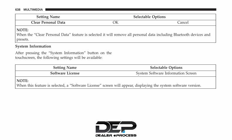
Setting Name Selectable OptionsClear Personal Data OK Cancel
NOTE:When the “Clear Personal Data” feature is selected it will remove all personal data including Bluetooth devices andpresets.
System Information
After pressing the “System Information” button on thetouchscreen, the following settings will be available:
Setting Name Selectable OptionsSoftware License System Software Information Screen
NOTE:When this feature is selected, a “Software License” screen will appear, displaying the system software version.
638 MULTIMEDIA

STEERING WHEEL AUDIO CONTROLS
The remote sound system controls are located on the rearsurface of the steering wheel at the three and nine o’clockpositions. Both controls are rocker-type switches with apush-button in the center.
The right-hand control is a rocker-type switch with apush-button in the center and controls the volume andmode of the sound system. Pushing the top of the rockerswitch will increase the volume, and pushing the bottom ofthe rocker switch will decrease the volume.
Pushing the center button will make the radio switchbetween the various modes available (AM/FM/SXM orMedia etc.)
The left-hand control is a rocker-type switch with a push-button in the center. The function of the left-hand control isdifferent depending on which mode you are in.
The following describes the left-hand control operation ineach mode.
Radio Operation
Pushing the top of the switch will “Seek” up for the nextlistenable station and pushing the bottom of the switch will“Seek” down for the next listenable station.
The button located in the center of the left-hand controlwill tune to the next preset station that you have pro-grammed in the radio preset button.
Media Mode
Pushing the top of the switch once goes to the next track onthe selected media (AUX/USB/Bluetooth). Pushing thebottom of the switch once goes to the beginning of thecurrent track, or to the beginning of the previous track if itis within eight seconds after the current track begins toplay.
Steering Wheel Audio Controls (Back View Of SteeringWheel)
10
MULTIMEDIA 639

AUX/USB/MP3 CONTROL
There are numerous USB ports located throughout thevehicle. This feature allows an external USB device to beplugged into the USB port.
For further information, refer to the Uconnect Owner’sManual Supplement.
The data USB ports are located on the instrument panelbelow the climate controls.
There are multiple USB “charge only” ports in this vehicle.
• In the center console
• On the back of the front row seats in the UconnectTheater Media hubs
• Above the rear cup holders in the third row of seats
Front Center Stack AUX Jack And USB Ports
1 — USB Port2 — AUX Jack3 — Uconnect Theater Rear Data USB Port
Center Console USB Charging Port
640 MULTIMEDIA

NOTE: The USB outlet in the bottom of the instrumentpanel can be switched from “ignition” only to constant“battery” powered all the time. See an authorized dealerfor details.
NOTE: The USB “Charge Only” ports will recharge batteryoperated USB devices when connected.
UCONNECT THEATER — IF EQUIPPED
Uconnect Theater Overview
Your Uconnect Theater is designed to give your familyyears of enjoyment.
There are multiple ways to interact with your UconnectTheater system;
• Play your favorite CDs, DVDs or Blu-ray Discs
• Plug and play a variety of standard video games ordevices into the HDMI port
• Listen to audio over the wireless headphones
• Plug and play a variety of devices into the Video USBport
• Plug in standard headphones to listen to audio
• Project your mobile phone, or tablet screen onto the rearUconnect Theater touchscreens — If Equipped
Please review this Owner’s Manual to become familiarwith its features and operation.
3rd Row USB Charging Port
10
MULTIMEDIA 641

Getting Started
There are three different ways to operate the features of theUconnect Theater:• The Remote Control• The Uconnect System• The Individual Uconnect Theater Touchscreens
Accessing The System From The Uconnect System
You can access your Uconnect Theater system from theradio touchscreen following the steps below:
Option 1
1. Press the “Media” button.
2. Press the “Uconnect Theater” button icon.
Uconnect Theater Screen1 — Uconnect Theater Touchscreen (Rear Touchscreens)2 — Uconnect System (Front Touchscreen)3 — Uconnect Theater Media Hub (Headphone Jack, HDMI Input,USB Charge Only Port)
Uconnect Theater Button
642 MULTIMEDIA

Option 2
1. Press the “Apps” button on the bottom of the touch-screen.
2. Press the Uconnect Theater button on the touchscreen.You may need to navigate to different pages in the Appsdrawer to find the Uconnect Theater button.
NOTE: The Uconnect Theater icon may be dragged anddropped down from the Apps drawer to the drag & dropmenu to create an App/shortcut. Refer to “Drag & DropMenu Bar” in this section for more information.
Uconnect Theater Controls
Uconnect Theater Summary Screen
1 — Power All On/Off (Con-trols Both Screens)2 — Mute All On/Off (ControlsBoth Screens)3 — Lock All On/Off (ControlsBoth Screens)4 — Source Drop Down List forCurrent Screen
5 — Lock On/Off for CurrentScreen6 — Mute On/Off for CurrentScreen7 — Power On/Off for CurrentScreen
10
MULTIMEDIA 643

Parents can control certain features of the system with the“Uconnect Theater Controls” screens, right from theUconnect touchscreen radio. Options include:
• Change media sources or select APPS by using the dropdown list
• Lock one or both screens
• Mute an individual screen or both screens
• Turn on/off one or both screens
• View media showing on a specific screen while gearselector is in PARK
• Listen in to a particular Uconnect Theater screenthrough the vehicle’s sound system by selecting the“Listen In” feature after selecting the “Press to Enter”option.
Accessing The System From The UconnectTheater Rear Screens
You can also access your Uconnect Theater system from therear screens from the steps below:
1. Lift screen upward, the system will automatically poweron.
NOTE: A message asking if you would like to pair aremote will pop up if one has not already been paired tothe system.
Individual Main Screen Listen In Feature
644 MULTIMEDIA

2. If “YES” is selected to Pair a Remote, push any buttonon the remote and pairing will immediately start.
3. If “NO” is selected, the Uconnect Theater home screenwill pop up.
NOTE:
• There will be a touchscreen notification message whenpairing is successful.
• Test to make sure the remote is successfully paired bydragging your finger across the gesture pad. If you donot see the on screen arrow, try using the “Screen”button on the remote to switch between rear screen oneand rear screen two to make sure the remote is control-ling the intended screen. It may take several seconds forthe remote to react when initially paired.
• If remote does not pair, refer to “Pairing The Remote”section for an alternative pairing process.
Pairing The Remote
If the remote needs to be paired to your Uconnect Theatersystem, follow the procedure below:
1. Install batteries into both remotes.
2. Press the Settings icon found in the lower right portionof the Uconnect Theater touchscreen.
Remote Pairing
10
MULTIMEDIA 645
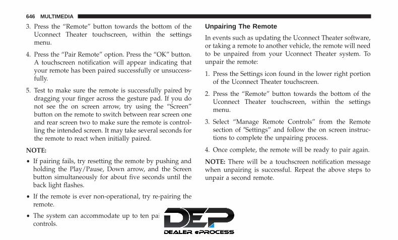
3. Press the “Remote” button towards the bottom of theUconnect Theater touchscreen, within the settingsmenu.
4. Press the “Pair Remote” option. Press the “OK” button.A touchscreen notification will appear indicating thatyour remote has been paired successfully or unsuccess-fully.
5. Test to make sure the remote is successfully paired bydragging your finger across the gesture pad. If you donot see the on screen arrow, try using the “Screen”button on the remote to switch between rear screen oneand rear screen two to make sure the remote is control-ling the intended screen. It may take several seconds forthe remote to react when initially paired.
NOTE:
• If pairing fails, try resetting the remote by pushing andholding the Play/Pause, Down arrow, and the Screenbutton simultaneously for about five seconds until theback light flashes.
• If the remote is ever non-operational, try re-pairing theremote.
• The system can accommodate up to ten paired remotecontrols.
Unpairing The Remote
In events such as updating the Uconnect Theater software,or taking a remote to another vehicle, the remote will needto be unpaired from your Uconnect Theater system. Tounpair the remote:
1. Press the Settings icon found in the lower right portionof the Uconnect Theater touchscreen.
2. Press the “Remote” button towards the bottom of theUconnect Theater touchscreen, within the settingsmenu.
3. Select “Manage Remote Controls” from the Remotesection of �Settings” and follow the on screen instruc-tions to complete the unpairing process.
4. Once complete, the remote will be ready to pair again.
NOTE: There will be a touchscreen notification messagewhen unpairing is successful. Repeat the above steps tounpair a second remote.
646 MULTIMEDIA

Media Sources Users can select content for each screen from the front radiotouchscreen by choosing desired content from the “SelectInput” drop down menu. Options include Blu-Ray Disc,HDMI, USB, Apps, and Viewing the other rear screen.
NOTE: Use the “View Screen” function to pull contentfrom one screen to the other with a single press of a button.Doing this however will disable and gray out certainplayer controls on the screen viewing the other screen’scontent.
Media Source Selection
1 – Selected Source Screen 12 – Screen 2 Source Selection Drop Down
10
MULTIMEDIA 647

Uconnect Theater Remote Control
1. Gesture Pad — Control pointer position by runningyour finger over this area and tapping to select items onthe touchscreen, functions similar to a computer/laptopmouse.
2. Mute Button — Mutes headphone audio.
3. Home Button — Push to access available “Sources”.
4. Arrow Buttons — Push the arrow buttonsto highlight an item or scroll through menus.
5. Fast Forward Button — Push and hold to fastforward through the current audio track or videochapter. Push once to skip to the next track.
6. Play/Pause Button � — Begin/resume or pausedisc play.
7. Fast Rewind Button — Push and hold to fastrewind through the current audio track or videochapter. Push once to revert back to the previoustrack.
8. OK Button — Push to select the highlighted option in amenu.
9. Screen Selector Button — Push the screen selector totoggle between screen 1 (Driver Side), or screen 2(Passenger Side).
10. Back Button — Push to exit out of menus or return toprevious screen.
11. Power Button — Turns the screen for the selectedchannel on or off.
12. Screen Indicator — Indicates which screen (1 or 2) isbeing controlled by the remote control.
Remote Control
648 MULTIMEDIA

Replacing The Remote Control Batteries
Each remote control requires two AAA batteries for opera-tion.
To replace the batteries:
1. Locate the battery compartment on the back of theremote, then slide the battery cover downward.
2. Remove the old batteries and follow battery recyclingprocedures for your area.
3. Install new batteries, making sure to orient them accord-ing to the polarity diagram shown inside the batterycompartment.
4. Replace the battery compartment cover.
Uconnect Theater Home Screen And Controls
Uconnect Theater Home Screen (Rear Touchscreens)
1 — Search Button (Front USBMedia Search)2 — Power Button3 — Settings Button4 — Toggle Button List AndIcon View
5 — Source Card Page Indicator6 — Wired Headphone Volume7 — Rear Climate Control Button8 — Home Button9 — Source Cards
10
MULTIMEDIA 649

You can choose sources such as HDMI, USB, Apps, orBlu-ray. You may also view content of the opposite screenin one step by choosing the “View Screen” source card.
NOTE:
• Source card order can be changed by pressing theSettings button on the touchscreen and scrolling downto �Source Card Order�.
• Use the “View Screen” function to pull content from onescreen to the other in a single press of a button. Doingthis however will disable and gray out certain playercontrols on the screen viewing the other screen’s content.
General Settings
To change source card order, select “Source Card Reorder”,then press and hold source card on the touchscreen, anddrag and drop in desired order.
You can also adjust settings such as:
• Brightness
• Media port lighting on and off
• Clock on and off
NOTE: System information can also be displayed underGeneral Settings.
Remote Settings
Under this setting, you can access the following:
• Manage Remotes (this allows you to unpair remotes)
• Pair Remote
• Remote sensitivity (this adjusts the speed and sensitiv-ity of cursor on screen when using gesture pad)
Source Card Selection
650 MULTIMEDIA

General Information
The following regulatory statement applies to all RadioFrequency (RF) devices equipped in this vehicle:
This device complies with Part 15 of the FCC Rules andwith Industry Canada license-exempt RSS standard(s).Operation is subject to the following two conditions:
1. This device may not cause harmful interference, and
2. This device must accept any interference received, in-cluding interference that may cause undesired opera-tion.
NOTE: Changes or modifications not expressly approvedby the party responsible for compliance could void theuser’s authority to operate the equipment.
Play A DVD/Blu-ray Or USB Media File FromUconnect System
1. Insert a Blu-ray disc or DVD disc into the disc playerwith the label facing up, or insert a USB drive into rearVideo USB port.
NOTE: The DVD/Blu-ray Disc player and Video USB portare both located under the radio controls in the instrumentpanel.
2. Press the “Uconnect Theater” button on the radio touch-screen.
Refer to “Accessing The System From The Uconnect Sys-tem” in this section for further information.
3. Select Disc or USB from the source controls (i.e. selectthe desired source from the “Select Input 1” or “SelectInput 2” menu for the respective screen).
4. For DVD/Blu-ray disc – press the “Press to Enter”feature in the Movie Snapshot on the radio touchscreen,then press “OK” on the following screen. The steps tostart a DVD are dependent on the steps required by thatspecific DVD. For USB Media Files - Press Music, Movie,or Folders, then select media title from list(s).
10
MULTIMEDIA 651
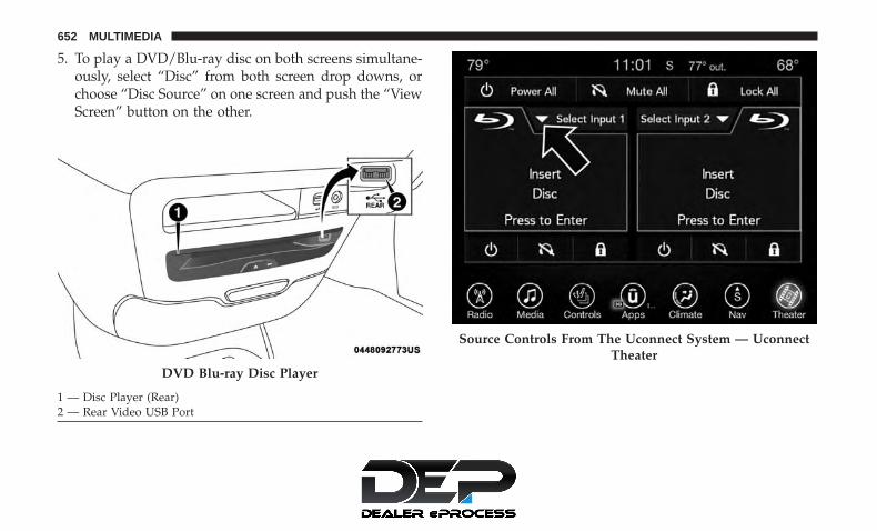
5. To play a DVD/Blu-ray disc on both screens simultane-ously, select “Disc” from both screen drop downs, orchoose “Disc Source” on one screen and push the “ViewScreen” button on the other.
DVD Blu-ray Disc Player
1 — Disc Player (Rear)2 — Rear Video USB Port
Source Controls From The Uconnect System — UconnectTheater
652 MULTIMEDIA

NOTE: After selecting “Press to Enter” or the MovieSnapshot, the control functions for that screen appears.These controls only apply to the individual screen selectedand include:
1. Power
Press to turn “Selected Screen” On/Off.
2. Mute
Mute rear headphones for selected source for the currentignition cycle. Pressing mute again will unmute rear head-phones.
3. Lock
Press to enable/disable Remote Control functions and RearTouchscreen Controls for the selected source.
4. View
Select this button to view full screen video if vehicle is notmoving. Button is disabled when not viewing a videosource or when the vehicle is in motion.
5. Listen In
Select this button to play one of the rear screens audio overthe vehicle’s audio system.
NOTE: To view video content on the radio screen, bring thevehicle to a stop.
Uconnect System Media Control Screen 10
MULTIMEDIA 653

Disc Menu
When listening to a CD Audio disc, CD Data disc, DVD orBlu-ray, pushing the remote control’s arrow buttons willnavigate the cursor on the rear touchscreen in the desireddirection, on whichever touchscreen is selected. The UP,DOWN, LEFT, and RIGHT arrow buttons, and the OK andMENU buttons on the remote, along with the correspond-ing buttons overlaid on the radio touchscreen, can be usedto navigate the disc menu when it appears. This can beused to select specific chapters in a movie, navigate specialfeatures, or to play the movie from the menu.
NOTE: Inserting a disc into the player will “auto play” thedisc if already in the �Disc� source menu on the rearscreens, and the disc supports “auto play.”
Blu-ray Controls – Disc Specific Functions
The four colored buttons (red, green, blue, yellow) aredesigned for use with certain Blu-ray disc movie titles toaccess particular features or software on the disc. See thedocumentation provided with your Blu-ray disc movie tosee if these buttons can be used. The 5-way control buttons
located to the right of the four colored buttons, are used tonavigate and select items in the disc’s menu, like playmovie, scene selection, etc.
Rear Touchscreen Blu-ray Controls – Disc SpecificFunctions
1 — Red Button2 — Green Button3 — Blue Button4 — Yellow Button
5 — 5-Way Control Buttons6 — Move 5-Way Controls But-ton
654 MULTIMEDIA

Uconnect Theater Apps
Select the Apps source card to play pre-loaded games.Pressing the “Help” button teaches users how to play eachgame. Pick from games:
• Back Seat Bingo
• Checkers
• Hanging Fruit
• License Plate Game
Apps Home Screen
Sudoku App Home Screen
10
MULTIMEDIA 655

• Math Flash Cards
• Solitaire
• Sudoku
• Tic Tac Toe
NOTE: To exit a game, press “Exit Button” then “BackArrow,” or “Home Button” on the touchscreen.
Are We There Yet? — Uconnect 4C NAV
When a navigation route has been set from the Uconnectsystem, the second row passengers can use “Are We ThereYet?” for an animated screen showing distance and timeremaining on navigation routes, as well as the estimatedtime of arrival with pop-up notifications. Notifications and
Are We There Yet? App
1 — Decrease Timing Between Notifications Button2 — Notifications ON/OFF Button3 — Increase Timing Between Notifications Button4 — Arrival Time5 — Time Remaining Until Destination Is Reached6 — Distance Remaining
656 MULTIMEDIA

their frequency can be set up for route information byusing the arrow buttons, and can be turned on and offusing the “Notifications” button on the “Are We ThereYet?” App. Estimated time of arrival notifications pop-upat the bottom center of the screen.
Using The Rear Video USB Port
Plug in a USB drive, iPhone, iPod or mass storage deviceand play your favorite music or movies.
NOTE: To view USB media on the rear theater screens,insert a USB drive into the port next to the DVD/Blu-raydisc player. The USB drive port is located under the radiocontrols in the instrument panel.
On the rear screen you can browse the content of the USBdevice by going to the USB source. Use the search featureto find your music faster.
Rear Video USB Port
Search Screen
10
MULTIMEDIA 657
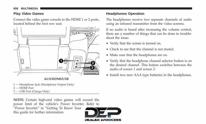
Play Video Games
Connect the video game console to the HDMI 1 or 2 ports,located behind the first row seat.
NOTE: Certain high-end video games will exceed thepower limit of the vehicle’s Power Inverter. Refer to“Power Inverter” in “Getting To Know Your Vehicle” inthis guide for further information.
Headphones Operation
The headphones receive two separate channels of audiousing an infrared transmitter from the video screens.
If no audio is heard after increasing the volume control,there are a number of things that can be done to trouble-shoot the issue:
• Verify that the screen is turned on.
• Check to see that the channel is not muted.
• Make sure that the headphones are on.
• Verify that the headphone channel selector button is onthe desired channel. This button switches between theaudio of screen 1 and screen 2.
• Install two new AAA type batteries in the headphones.AUX/HDMI/USB
1 — Headphone Jack (Headphone Output Only)2 — HDMI Port3 — USB Port (Charge Only)
658 MULTIMEDIA

The headphone power indicator and controls are locatedon the right ear cup.
NOTE: Uconnect Theater must be turned on before soundcan be heard from the headphones. To conserve battery life,the headphones will automatically turn off approximatelythree minutes after the Uconnect Theater system is turnedoff.
Changing The Audio Mode For Headphones
1. Ensure the remote control and the headphones are onthe same channel.
2. Push the Home button on the remote control.
3. When the Home menu appears on the touchscreen, usethe arrow buttons on the remote control to navigate tothe available modes and push the OK button to selectthe new mode or use the Gesture Pad at the top of theremote control.
Uconnect Theater Headphones
1 — Power ON/OFF Button2 — Volume Control Wheel3 — Channel Selector Button
Headphone Channel Selector Button
10
MULTIMEDIA 659

Replacing The Headphone Batteries
Each set of headphones requires two AAA batteries foroperation.
To replace the batteries:
1. Locate the battery compartment on the left ear cup ofthe headphones, and then slide the battery cover down-ward.
2. Remove the old batteries and follow battery recyclingprocedures for your area.
3. Install new batteries, making sure to orient them accord-ing to the polarity diagram shown inside the batterycompartment.
4. Replace the battery compartment cover.
Stereo Headphone Lifetime Limited Warranty
Who Does This Warranty Cover? This warranty covers theinitial user or purchaser (�you� or �your�) of this particularAptiv PLC (“Aptiv”) wireless headphone (�Product�). Thewarranty is not transferable.
How Long Does the Coverage Last? This warranty lasts aslong as you own the Product.
What Does This Warranty Cover? Except as specifiedbelow, this warranty covers any Product that in normal useis defective in workmanship or materials.
What Does This Warranty Not Cover? This warranty doesnot cover any damage or defect that results from misuse,abuse or modification of the Product other than by Aptiv.Foam earpieces, which will wear over time through normaluse, are specifically not covered (replacement foam isavailable for a nominal charge). APTIV IS NOT LIABLEFOR ANY INJURIES OR DAMAGES TO PERSONS ORPROPERTY RESULTING FROM THE USE OF, OR ANYFAILURE OR DEFECT IN, THE PRODUCT, NOR IS AP-TIV LIABLE FOR ANY GENERAL, SPECIAL, DIRECT,INDIRECT, INCIDENTAL, CONSEQUENTIAL, EXEM-PLARY, PUNITIVE OR OTHER DAMAGES OF ANYKIND OR NATURE WHATSOEVER. Some states andjurisdictions may not allow the exclusion or limitation ofincidental or consequential damages, so the above limita-tion may not apply to you. This warranty gives you specificlegal rights. You may also have other rights, which varyfrom jurisdiction to jurisdiction.
What Will Aptiv Do? Aptiv, at its option, will repair orreplace any defective Product. Aptiv reserves the right toreplace any discontinued Product with a comparable
660 MULTIMEDIA

model. THIS WARRANTY IS THE SOLE WARRANTY FOR THIS PRODUCT, SETS FORTH YOUR EXCLUSIVE REMEDY REGARDING DEFECTIVE PRODUCTS, AND IS IN LIEU OF ALL OTHER WARRANTIES (EXPRESS OR IMPLIED), INCLUDING ANY WARRANTY FOR MER-CHANTABILITY OR FITNESS FOR A PARTICULAR PUR-POSE.
If you have any questions or comments regarding your Aptiv wireless headphones, please email [email protected] or phone:
888-293-3332
Display Settings
When watching a video source, pressing “Settings”icon on the touchscreen activates the Settings menu.
These settings control the appearance of the video on the screen. The factory default settings are already set for optimum viewing, so there is no need to change these settings under normal circumstances.
To change the settings, use one of the touchscreens or remote. To reset all values back to the original settings, select “Reset to Defaults”, then select “YES.”
Listening To Audio With The Screen Closed
To listen to only audio portion of the channel with thescreen closed:
• Set the audio to the desired source and channel.
• Close the video screen.
• When the screen is reopened, the video screen willautomatically turn back on and show the appropriatedisplay menu or media.
If the screen is closed and there is no audio heard, verifythat the headphones are turned on (the ON indicator isilluminated) and the headphone selector switch is on thedesired channel. If the headphones are turned on, push theremote control’s power button to turn audio on. If audio isstill not heard, check that fully charged batteries areinstalled in the headphones. 10
MULTIMEDIA 661

Rear Climate Controls
The rear climate controls can also be controlled using theUconnect Theater system. Refer to “Climate Controls” in“Getting To Know Your Vehicle” for further information.
Icon DescriptionON Climate Control ON Button
Press and release this button to turn the Rear Climate.OFF Climate Control OFF Button
Press and release this button to turn the Climate Controls off.AUTO ButtonAutomatically controls the rear interior cabin temperature by adjusting airflow distribution and amount.Toggling this function will cause the system to switch between manual mode and automatic modes.Refer to “Automatic Operation” in �Getting To Know Your Vehicle” for more information.
Rear Climate Controls
662 MULTIMEDIA

Icon DescriptionRear Passenger Temperature Up and Down ButtonsProvides the rear passengers with independent temperature control. Press the button on the touchscreento increase or decrease the temperature. The temperature will get warmer as you move up toward thered arrow and colder as you move down toward the blue arrow.
HeadlinerMode
Headliner ModeAir comes from the outlets in the headliner. Each of these outlets can be individually adjusted to directthe flow of air. Moving the air vanes of the outlets to one side will shut off the airflow.
Bi-LevelMode
Bi-Level ModeAir comes from both the headliner outlets and the floor outlets.
NOTE: In many temperature positions, the Bi-Level mode is designed to provide cooler air out of theheadliner outlets and warmer air from the floor outlets.
FloorMode
Floor ModeAir comes from the floor outlets.
10
MULTIMEDIA 663

Icon DescriptionBlower ControlBlower Control is used to regulate the amount of air forced through the climate system. There are sevenblower speeds available. Adjusting the blower will cause automatic mode to switch to manual operation.
Accessibility — If Equipped
Accessibility is a feature of the DVD/Blu-ray/USB Videosystem that announces a function prior to performing theaction. For further information refer to “Uconnect Settings”in “Multimedia.”
Wireless Streaming — If Equipped
Your Uconnect Theater System may be equipped withWireless Streaming functionality that allows you to projectyour smartphone or tablet onto your rear Uconnect Theatertouchscreens. This Source Card will allow you to wirelesslylink your compatible Android devices to your UconnectTheater system and stream your device onto the touch-screens.
Choose the Wireless Streaming Source Card on your rearUconnect Theater touchscreen.
Wireless Streaming Source Card
664 MULTIMEDIA

The first row passengers can also access wireless streamingby choosing the source in the Uconnect Theater menu onthe front Uconnect touchscreen.
NOTE: For system compatibility, consult your device’sOwner’s Manual or www.uconnectphone.com to see ifyour device supports wireless streaming technology com-patibility. Apple devices do not support this feature.
To link your device to the rear Uconnect Theater touch-screens:
1. Enable your device’s Wi-Fi.
2. Select the Wireless Streaming feature on your device.The name of this feature is device dependent and couldinclude: mirror, cast or smart view.
NOTE: Refer to your device’s Owners Manual orwww.uconnectphone.com for further information.
3. Select “Pacifica Wireless Network” from the list ofavailable networks on your device.
4. When prompted by an Authentication Screen, press“Accept” on the touchscreen to begin wireless streamingon your device. If prompted, verify that the code on therear touchscreen and the device match.
Streaming Source On Front Uconnect Touchscreen
Streaming Device Source Card
10
MULTIMEDIA 665

Your phone will be added as an additional source card onthe Uconnect Theater touchscreens.
NOTE: The Authentication Screen will appear on both reartouchscreens. The touchscreen screen on which “Accept” isselected will be the primary controller for the wirelessstreaming session.
NOTE:
• Some devices will allow you to control your devicethrough the Uconnect Theater rear touchscreens. Theywill react to your selections from the touchscreen and berepresented on your device as well. When supported,the Uconnect Theater task bar will appear at the top andbottom of the Uconnect Theater touchscreen, framingyour streaming device.
• Devices that do not support this feature will not respondto Uconnect Theater touchscreen but can still be con-trolled using the streaming device.
Settings
Below is a list of the settings available for the WirelessStreaming feature of your Uconnect Theater system:
• Wireless: ON/OFF – Turn on and off the wireless featureof the Uconnect Theater system.
• Manage Devices – Allows the user to delete the paireddevices.
• Local Network Name – Allows the user to rename thePacifica Wireless Network.
Wireless Streaming Settings
666 MULTIMEDIA

Refer to the Wireless Streaming video on the UconnectYouTube Channel at www.youtube.com/DriveUconnectfor tips and additional information on the Wireless Stream-ing function.
BD And DVD Region Codes
Many BD and DVD discs are coded by geographic region.These region codes must match in order for the disc to play.If the region code for the BD or DVD disc does not matchthe region code for the Blu-ray Disc player, the disc will notplay. USA and Canada are set for BD : code A / DVD : code1.
Recorded Discs
The Blu-ray Disc player will play CD-R and CD-RW discsrecorded in CD-Audio or Video-CD format, or as a CD-ROM containing MP3, AAC or WMA files. The player willalso play DVD-Video content recorded to a DVD-R orDVD-RW disc. DVD-ROM discs (either pressed or re-corded) are not supported. Compressed audio and DivXrecorded on DVD is playable.
If you record a disc using a personal computer, there maybe cases where the Blu-ray Disc player may not be able toplay some or the entire disc, even if it is recorded in a
compatible format and is playable on other players. To helpavoid playback problems, use the following guidelineswhen recording discs.
• Open sessions are ignored. Only sessions that are closedare playable.
• For multi-session CDs that contain only multiple CD-Audio sessions, the player will renumber the tracks soeach track number is unique.
• For CD Data (or CD-ROM) discs, always use the ISO-9660 (Level 1 or Level 2), Joliet, or Romeo format. Otherformats (such as HFS, or others) are not supported.
• The player recognizes a maximum of 2000 files and 255folders (includes the ROOT folder) per CD-R andCD-RW disc.
• Mixed media recordable DVD formats will only play theVideo_TS portion of the disc.
If you are still having trouble writing a disc that is playablein the Blu-ray Disc player, check with the disc recordingsoftware publisher for more information about burningplayable discs.
The recommended method for labeling recordable discs(CD-R, CD-RW, and DVD-R) is with a permanent marker.
10
MULTIMEDIA 667

Do not use adhesive labels as they may separate from thedisc, become stuck, and cause permanent damage to theDVD player.
Compressed Audio Files (MP3, WMA and AAC)
The Blu-ray Disc player is capable of playing MP3(MPEG-1 Audio Layer 3), WMA (Windows Media Audio)files and AAC (Advanced Audio Coding) from a CD Datadisc (usually a CD-R or CD-RW) or DVD Data disc (usuallya DVD-R or DVD-RW).
• The Blu-ray Disc player always uses the file extension todetermine the audio format, so MP3 files must alwaysend with the extension “.mp3” or “.MP3” and WMAfiles must always end with the extension “.wma” or“.WMA” and AAC files must always end with theextension and “.aac” or “.AAC” or “m4a”. To preventincorrect playback, do not use these extensions for anyother types of files.
• For MP3 files, ID3v1, ID3v2 tag data (such as artistname, track title, album, etc.) are supported.
• Any file that is copy protected (such as those down-loaded from many online music stores) will not play. TheBlu-ray player will automatically skip the file and beginplaying the next available file.
• Other compression formats such as MP3 Pro, OggVorbis, and ATRAC3 will not play. The Blu-ray playerwill automatically skip the file and begin playing thenext available file.
• If you are creating your own files, the recommendedfixed bit rate for MP3 files is between 32 and 320Kbpsand the recommended fixed bit rate for WMA files isbetween 16 and 192Kbps. Variable bit rates are alsosupported. For both formats, the recommended samplerate is either 44.1kHz or 48kHz.
• To change the current file, use the remote control “SeekForward” or “Seek Back” buttons to return to the start ofthe current or previous file.
• AAC (MPEG-4 AAC, Low Complexity Profile) support.
• AAC HE v1 (AAC High Efficiency v1 aka. AAC/MPEG4v2 AAC+) support.
• HE-AAC v1, v2 support.
Disc Errors
If the Blu-ray Disc player is unable to read the disc, a �DiscError� message is displayed on the rear screen and Radiodisplays. A dirty, damaged, or incompatible disc format areall potential causes for a �Disc Error� message.
668 MULTIMEDIA

If a disc has a damaged track which results in audible orvisible errors that persists for two seconds, the Blu-ray Discplayer will attempt to continue playing the disc by skip-ping forward one to three seconds at a time. If the end ofthe disc is reached, the Blu-ray Disc player will return tothe beginning of the disc and attempt to play the start ofthe first track.
The Blu-ray Disc player may shut down during extremelyhot conditions, such as when the vehicle’s interior tem-perature is above 140° F (60.0° C). When this occurs, theplayer will display �High Temp� and will shut off the RearSeat displays until a safe temperature is reached. Thisshutdown is necessary to protect the optics of the Blu-rayDisc player.
Product Agreement
Open Source Software
The software built into this product, are composed ofmultiple software components, and there are the copy-rights of our company or third parties in each softwarecomponent. Also, in this product, the following opensource software has been installed.
• The licensed software for our company is based on GNUGENERAL PUBLIC LICENSE V2.0 (�GPL�).
• The licensed software for our company is based on GNULESSER GENERAL PUBLIC LICENSE V2.1 (�LGPL�).
• The software which has the copyrights of a third partyand is distributed as free software.
Please refer the contract details which are disclosed in thefollowing websites, for example, concerning these abovesoftware. http://www.gnu.org/licenses/old-licenses/gpl-2.0-standalone.html, http://www.gnu.org/licenses/lgpl-2.1-standalone.html.
You have the right of acquisition, modification, and distri-bution of the source code of the GPL/LGPL software.These are distributed in the hope that it will be useful byitself. However, including the absence of an implied war-ranty on the �suitability for a particular purpose� or �mer-chantability�, the warranty of any kind will not be made.You may download Source Code from the indicating URLby the pressed button of “Open Source Software” on theSetup Menu. Also, please refrain from contact about thecontents of the source code of open source. The source codeof the software in which there are the copyrights of ourcompany or third parties, is not subject to distribution.
10
MULTIMEDIA 669

kernel 2.6.16.29 FreeType 2 2.2.1 gcc sh4eb 3.4.5 glibc 2.3.5 boot_loader sh-ipl +g1.00
libgcc_s-3.4.5 bash-3.0-31 busybox 1.00 MAKE DEV 1.1.0 module-init-tools 3.1.0libtermcap 2.0.8 mtd-utils 20050619 initscripts 8.11.1-1 libstdc+ +3.4.5-10 libiconv 1.11
coreutils 6.9 dosfstools 2.10-3 directfb 1.0.0-rc1 kxml 1.21 binutils-sh4eb2.16.91.0.2
v2lin 0.1 - - - -
Dolby
Manufactured under license from Dolby Laboratories.Dolby and the double-D symbol are trademarks of DolbyLaboratories.
DTS
For DTS patents, see http://dts.com/patents. Manufac-tured under license from DTS Licensing Limited. DTS, theSymbol, & DTS and the Symbol together are registeredtrademarks, and DTS 2.0 Channel is a trademark ofDTS, Inc. © DTS, Inc. All Rights Reserved.
DVD
�The DVD logo” is a trademark of DVD Format/LogoLicensing Corporation.� or � DVD logo is a trademark ofDVD Format/Logo Licensing Corporation registered in theU.S., Japan and other countries.�
BDA
“Blu-ray Disc, Blu-ray, BD-Live, BONUSVIEW, AVCRECand the logos are trademarks of the Blu-ray Disc Associa-tion.”
AVCHD
�AVCHD� and the �AVCHD� logo are trademarks of Pana-sonic Corporation and Sony Corporation.
BD-J
Java is a registered trademark of Oracle and/or its affili-ates.
MPEG
THIS PRODUCT IS LICENSED UNDER THE AVC PAT-ENT PORTFOLIO LICENSE FOR THE PERSONAL AND
670 MULTIMEDIA

NON-COMMERCIAL USE OF A CONSUMER TO (i) EN-CODE VIDEO IN COMPLIANCE WITH THE AVC STAN-DARD (�AVC VIDEO�) AND/OR (ii) DECODE AVCVIDEO THAT WAS ENCODED BY A CONSUMER EN-GAGED IN A PERSONAL AND NON-COMMERCIALACTIVITY AND/OR WAS OBTAINED FROM A VIDEOPROVIDER LICENSED TO PROVIDE AVC VIDEO. NOLICENSE IS GRANTED OR SHALL BE IMPLIED FORANY OTHER USE. ADDITIONAL INFORMATION MAYBE OBTAINED FROM MPEG LA, L.L.C. SEEWWW.MPEGLA.COM .
DivX
This DivX Certified device has passed rigorous testing toensure it plays DivX video. To play purchased DivXmovies, first register your device at http://www.divx.com/en/vod. Find your registration code in theDivX VOD section of your device setup menu. DivX, DivXCertified and associated logos are trademarks of DivX, LLCand are used under license.
Cinavia
�Cinavia Notice This product uses Cinavia technology tolimit the use of unauthorized copies of some commercially-produced film and videos and their soundtracks. When aprohibited use of an unauthorized copy is detected, a
message will be displayed and playback or copying will beinterrupted. More information about Cinavia technology isprovided at the Cinavia Online Consumer InformationCenter at http://www.cinavia.com. To request additionalinformation about Cinavia by mail, send a postcard withyour mailing address to: Cinavia Consumer InformationCenter, P.O. Box 86851, San Diego, CA, 92138, USA.” “Thisproduct incorporates proprietary technology under licensefrom Verance Corporation and is protected by U.S. Patent7,369,677 and other U.S. and worldwide patents issued andpending as well as copyright and trade secret protection forcertain aspects of such technology. Cinavia is a trademarkof Verance Corporation. Copyright 2004-2012 VeranceCorporation. All rights reserved by Verance. Reverse engi-neering or disassembly is prohibited.
CAUTION!
Use of controls or adjustments or performance ofprocedures other than those specified herein may re-sult in hazardous radiation exposure.
10
MULTIMEDIA 671

General Information
The following regulatory statement applies to all RadioFrequency (RF) devices equipped in this vehicle:
This device complies with Part 15 of the FCC Rules andwith Industry Canada license-exempt RSS standard(s).Operation is subject to the following two conditions:
1. This device may not cause harmful interference, and
2. This device must accept any interference received, in-cluding interference that may cause undesired opera-tion.
NOTE: Changes or modifications not expressly approvedby the party responsible for compliance could void theuser’s authority to operate the equipment.
FCC/IC Regulatory Notices
Modification Statement
Any changes or modifications not expressly approved bythe party responsible for compliance could void the user’sauthority to operate this equipment.
Interference Statement
This device complies with Part 15 of the FCC Rules andIndustry Canada licence-exempt RSS standard(s). Opera-tion is subject to the following two conditions: (1) thisdevice may not cause interference, and (2) this device mustaccept any interference, including interference that maycause undesired operation of the device.
Wireless Notice
This device complies with FCC/IC radiation exposurelimits set forth for an uncontrolled environment and meetsthe FCC radio frequency (RF) Exposure Guidelines andRSS-102 of the IC radio frequency (RF) Exposure rules. Thistransmitter must not be co-located or operating in conjunc-tion with any other antenna or transmitter.
FCC Class B Digital Device Notice
This equipment has been tested and found to comply withthe limits for a Class B digital device, pursuant to part 15 ofthe FCC Rules. These limits are designed to providereasonable protection against harmful interference in aresidential installation. This equipment generates, uses andcan radiate radio frequency energy and, if not installed andused in accordance with the instructions, may cause harm-ful interference to radio communications. However, there
672 MULTIMEDIA

is no guarantee that interference will not occur in aparticular installation. If this equipment does cause harm-ful interference to radio or television reception, which canbe determined by turning the equipment off and on, theuser is encouraged to try to correct the interference by oneor more of the following measures:
• Reorient or relocate the receiving antenna.
• Increase the separation between the equipment andreceiver.
• Connect the equipment into an outlet on a circuitdifferent from that to which the receiver is connected.
• Consult the dealer or an experienced radio/TV techni-cian for help.
CAN ICES-3 (B) / NMB-3 (B)
This Class B digital apparatus complies with CanadianICES-003.
RADIO OPERATION AND MOBILE PHONES
Under certain conditions, the mobile phone being on inyour vehicle can cause erratic or noisy performance fromyour radio. This condition may be lessened or eliminatedby relocating the mobile phone antenna. This condition isnot harmful to the radio. If your radio performance does
not satisfactorily “clear” by the repositioning of the an-tenna, it is recommended that the radio volume be turneddown or off during mobile phone operation when notusing Uconnect (if equipped).
Regulatory And Safety Information
USA/CANADA
Exposure to Radio Frequency Radiation
The radiated output power of the internal wireless radio isfar below the FCC and IC radio frequency exposure limits.Nevertheless, the wireless radio will be used in such amanner that the radio is 8 in (20 cm) or further from thehuman body.
The internal wireless radio operates within guidelinesfound in radio frequency safety standards and recommen-dations, which reflect the consensus of the scientific com-munity.
The radio manufacturer believes the internal wireless radiois safe for use by consumers. The level of energy emitted isfar less than the electromagnetic energy emitted by wire-less devices such as mobile phones. However, the use ofwireless radios may be restricted in some situations or
10
MULTIMEDIA 673

environments, such as aboard airplanes. If you are unsureof restrictions, you are encouraged to ask for authorizationbefore turning on the wireless radio.
The following regulatory statement applies to all RadioFrequency (RF) devices equipped in this vehicle:
This device complies with Part 15 of the FCC Rules andwith Industry Canada license-exempt RSS standard(s).Operation is subject to the following two conditions:
1. This device may not cause harmful interference, and
2. This device must accept any interference received, in-cluding interference that may cause undesired opera-tion.
NOTE: Changes or modifications not expressly approvedby the party responsible for compliance could void theuser’s authority to operate the equipment.
NOTE:
• This equipment has been tested and found to complywith the limits for a Class B digital device, pursuant toPart 15 of the FCC Rules. These limits are designed toprovide reasonable protection against harmful interfer-ence in a residential installation. This equipment gener-ates, uses and can radiate radio frequency energy and, ifnot installed and used in accordance with the instruc-tions, may cause harmful interference to radio commu-nications. However, there is no guarantee that interfer-ence will not occur in a particular installation.
• If this equipment does cause harmful interference toradio or television reception, which can be determinedby turning the equipment off and on, the user is encour-aged to try to correct the interference by one or more ofthe following measures:
1. Increase the separation between the equipment andreceiver.
2. Consult an authorized dealer or an experienced radiotechnician for help.
674 MULTIMEDIA

UCONNECT VOICE RECOGNITION QUICK TIPS
Introducing Uconnect
Start using Uconnect Voice Recognition with these helpfulquick tips. It provides the key Voice Commands and tipsyou need to know to control your Uconnect system.
NOTE: If you see the NAV icon on the bottom bar, or in theApps menus, of your touchscreen, you have the Uconnect4C NAV system. If not, you have a Uconnect 4C system.
Uconnect 4
Uconnect 4C NAV 10
MULTIMEDIA 675

Get Started
All you need to control your Uconnect system with yourvoice are the buttons on your steering wheel.
Helpful hints for using Voice Recognition:
• Visit UconnectPhone.com to check mobile device andfeature compatibility and to find phone pairing instruc-tions.
• Reduce background noise. Wind and passenger conver-sations are examples of noise that may impact recogni-tion.
• Speak clearly at a normal pace and volume while facingstraight ahead. The microphone is positioned on therearview mirror and aimed at the driver.
• Each time you give a Voice Command, you must firstpush either the Voice Recognition (VR) or Phone button,wait until after the beep, then say your Voice Command.
• You can interrupt the help message or system promptsby pushing the VR or Phone button and saying a VoiceCommand from the current category.
Uconnect Voice Command Buttons
1 — Push To Initiate Or To Answer A Phone Call, Send Or ReceiveA Text2 — For All Radios: Push To Begin Radio, Media, Or Climate Func-tions. For Uconnect 4C NAV System Only: Push To Begin Naviga-tion Function3 — Push To End Call
676 MULTIMEDIA

Basic Voice Commands
The basic Voice Commands below can be given at anypoint while using your Uconnect system.
Push the VR button . After the beep, say:
• “ Cancel” to stop a current voice session
• “ Help” to hear a list of suggested Voice Commands
• “ Repeat” to listen to the system prompts again
Notice the visual cues that inform you of your voicerecognition system’s status. Cues appear on the touch-screen.
Radio
Use your voice to quickly get to the AM, FM or SiriusXMSatellite Radio stations you would like to hear. (Subscrip-tion or included SiriusXM Satellite Radio trial required.)
Push the VR button . After the beep, say:
• “ Tune to ninety-five-point-five FM”
• “ Tune to Satellite Channel Hits 1”
TIP: At any time, if you are not sure of what to say or wantto learn a Voice Command, push the VR button and say,“ Help.” The system provides you with a list of com-mands.
Uconnect 4 Radio
10
MULTIMEDIA 677

Media
Uconnect offers connections via USB, Bluetooth and auxil-iary ports (if equipped). Voice operation is only availablefor connected USB and AUX devices.
Push the VR button . After the beep, say one of thefollowing commands and follow the prompts to switchyour media source or choose an artist.
• “ Change source to Bluetooth”
• “ Change source to AUX”
• “ Change source to USB”
• “ Play artist Beethoven”; “ Play album Greatest Hits”; “Play song Moonlight Sonata”; “ Play genre Classical”
TIP: Press the Browse button on the touchscreen to see allof the music on your USB device. Your Voice Commandmust match exactly how the artist, album, song and genreinformation is displayed.
Uconnect 4C/4C NAV Radio
Uconnect 4 Media
678 MULTIMEDIA

Phone
Making and answering hands-free phone calls is easy withUconnect. When the Phonebook button is illuminated onyour touchscreen, your system is ready. CheckUconnectPhone.com for mobile phone compatibility andpairing instructions.
Push the Phone button . After the beep, say one of thefollowing commands:
• “ Call John Smith”
• “ Dial 123-456-7890 and follow the system prompts”
• “ Redial (call previous outgoing phone number)”
• “ Call back (call previous incoming phone number)”
Uconnect 4C/4C NAV Media 10
MULTIMEDIA 679

TIP: When providing a Voice Command, push the Phonebutton and say “ Call,” then pronounce the nameexactly as it appears in your phone book. When acontact has multiple phone numbers, you can say “ CallJohn Smith work.”
Voice Text Reply
Uconnect announces incoming text messages. Push thePhone button and say “ Listen.” (Must have compat-ible mobile phone paired to Uconnect system.)
1. Once an incoming text message is read to you, push thePhone button . After the beep, say: “ Reply.”
Uconnect 4 Phone
Uconnect 4C/4C NAV Phone
680 MULTIMEDIA

2. Listen to the Uconnect prompts. After the beep, repeatone of the pre-defined messages and follow the systemprompts.
PRE-DEFINED VOICE TEXT REPLY RESPONSESYes. Stuck in traffic. See you later.No. Start without
me.I’ll be late.
Okay. Where are you? I will be <num-ber> minutes
late.Call me. Are you there
yet?I’ll call you later. I need
directions.See you in
<number> ofminutes.I’m on my way. Can’t talk right
now.I’m lost. Thanks.
TIP: Your mobile phone must have the full implementationof the Message Access Profile (MAP) to take advantage ofthis feature. For details about MAP, visitUconnectPhone.com.
Apple iPhone iOS 6 or later supports reading incomingtext messages only. To enable this feature on your AppleiPhone, follow these four simple steps:
TIP: Voice Text Reply is not compatible with iPhone, but ifyour vehicle is equipped with Siri Eyes Free, you can useyour voice to send a text message.
iPhone Notification Settings
1 — Select “Settings”2 — Select “Bluetooth”3 — Select The (i) For The Paired Vehicle4 — Turn On “Show Notifications”
10
MULTIMEDIA 681
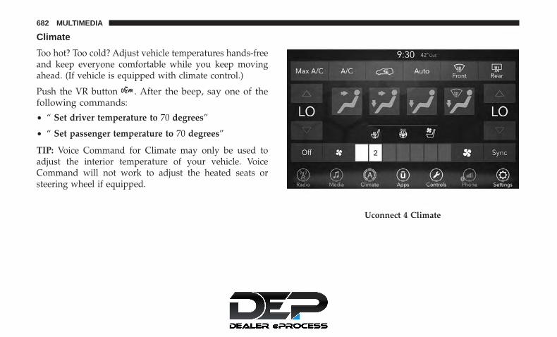
Climate
Too hot? Too cold? Adjust vehicle temperatures hands-freeand keep everyone comfortable while you keep movingahead. (If vehicle is equipped with climate control.)
Push the VR button . After the beep, say one of thefollowing commands:
• “ Set driver temperature to 70 degrees”
• “ Set passenger temperature to 70 degrees”
TIP: Voice Command for Climate may only be used toadjust the interior temperature of your vehicle. VoiceCommand will not work to adjust the heated seats orsteering wheel if equipped.
Uconnect 4 Climate
682 MULTIMEDIA

Navigation (4C NAV)
The Uconnect navigation feature helps you save time andbecome more productive when you know exactly how toget to where you want to go.
1. To enter a destination, push the VR button . After thebeep, say: “ Find address 800 Chrysler Drive AuburnHills, Michigan.”
2. Then follow the system prompts.
TIP: To start a POI search, push the VR button . Afterthe beep, say: “ Find nearest coffee shop.”
Uconnect 4C/4C NAV Climate
Uconnect 4C NAV With 8.4–inch Display Navigation
10
MULTIMEDIA 683

SiriusXM Guardian (4C/4C NAV) — If Equipped
CAUTION!
Some SiriusXM Guardian services, including SOS Calland Roadside Assistance Call will NOT work withoutan operable LTE (voice/data) or 3G or 4G (data) net-work connection compatible with your device.
NOTE: Your vehicle may be transmitting data as autho-rized by the subscriber.
An included trial and/or subscription is required to takeadvantage of the SiriusXM Guardian services in the nextsection of this guide. To register with SiriusXM Guardian,press the Apps button on the Uconnect 4C/4C NAVtouchscreen to get started.
NOTE: SiriusXM Guardian is available only on equippedvehicles purchased within the continental United States,Alaska, Hawaii and Canada. Services can only be usedwhere coverage is available; see coverage map for details.
SOS Call
Theft Alarm Notification
Remote Door Lock/Unlock
Send & Go
Vehicle Finder
Stolen Vehicle Assistance
Remote Vehicle Start**
Remote Horn & Lights
Roadside Assistance Call
Vehicle Health Reports**
Vehicle Health Alert**
Performance Pages Plus**
**If vehicle is equipped.
Register (4C/4C NAV)
To unlock the full potential of SiriusXM Guardian in yourvehicle, you must activate your SiriusXM Guardian ser-vices.
1. Press the Apps icon on the bottom of your in-vehicletouchscreen.
2. Select the Activate Services icon from your list of apps.
684 MULTIMEDIA

3. Select “Customer Care” to speak with a SiriusXMGuardian Customer Care agent who will activate ser-vices in your vehicle, or select “Enter Email” to activateon the web.
• U.S. residents visit: www.siriusxm.com/guardian.
• Canadian residents visit: www.siriusxm.ca/guardian.
Vehicle Health Report/Alert (4C/4C NAV)
Your vehicle will send you a monthly email report, whichsummarizes the performance of your vehicle’s key systemsso you can stay on top of your vehicle’s maintenance needsif you are registered for SiriusXM Guardian. Your vehiclewill also send you Vehicle Health Alerts when it detectsissues with its key systems that need your attention. Forfurther information, refer to your Uconnect Owner’sManual Supplement.
Mobile App (4C/4C NAV)
You’re only a few steps away from using remote com-mands and sending a destination from your phone to yourvehicle.
To use the Uconnect Mobile App:
• Once you have registered your SiriusXM Guardianservices, download the Uconnect App to your mobiledevice. Use your Owner Account login and password toopen the app.
Mobile App10
MULTIMEDIA 685

• Once on the “Remote” screen, you can begin usingRemote Door Lock/Unlock, Remote Vehicle Start, andactivate your horn and lights remotely, if equipped.
• Press the “Location” button on the bottom menu bar ofthe app to bring up a map to locate your vehicle or senda location to your Uconnect Navigation using VehicleFinder and Send & Go , if equipped.
• Press the “Settings” side menu in the upper left corner ofthe app to bring up app settings.
NOTE: For further information please visitDriveUconnect.com (U.S. Residents) or DriveUconnect.ca(Canadian Residents).
SiriusXM Travel Link (4C NAV)
Need to find a gas station, view local movie listings, checka sports score or the 5 - day weather forecast? SiriusXMTravel Link is a suite of services that brings a wealth ofinformation right to your Uconnect 4C NAV system.
Push the VR button . After the beep, say one of thefollowing commands:
• “ Show fuel prices”
• “ Show 5 - day weather forecast”
• “ Show extended weather”
TIP: Traffic alerts are not accessible with Voice Command.
Siri Eyes Free — If Equipped
Siri lets you use your voice to send text messages, selectmedia, place phone calls and much more. Siri uses yournatural language to understand what you mean and re-sponds back to confirm your requests. The system is
SiriusXM Travel Link
686 MULTIMEDIA

designed to keep your eyes on the road and your hands onthe wheel by letting Siri help you perform useful tasks.
To enable Siri, push and hold, then release the UconnectVoice Recognition (VR) button on the steering wheel. Afteryou hear a double beep you can ask Siri to play podcastsand music, get directions, read text messages and manyother useful requests.
Using Do Not Disturb
With Do Not Disturb, you can disable notifications fromincoming calls and texts, allowing you to keep your eyeson the road and hands on the wheel. For your convenience,there is a counter display to keep track of your missed callsand text messages while you were using Do Not Disturb.Uconnect 4 Siri Eyes Free Available
Uconnect 4C/4C NAV With 8.4–inch Siri Eyes FreeAvailable
10
MULTIMEDIA 687

Do Not Disturb can automatically reply with a text mes-sage, a call or both, when declining an incoming call andsend it to voicemail.
Automatic reply messages can be:
• “I am driving right now, I will get back to you shortly.”
• Create a custom auto reply message up to 160 characters.
While in Do Not Disturb, Conference Call can be selectedso you can still place a second call without being inter-rupted by incoming calls.
NOTE:
• Only the beginning of your custom message will be seenon the touchscreen.
• Reply with text message is not compatible with iPhones.
• Auto reply with text message is only available onphones that supporting Bluetooth MAP.
Android Auto — If Equipped
NOTE: Feature availability depends on your carrier andmobile phone manufacturer. Some Android Auto featuresmay or may not be available in every region and/orlanguage.
Android Auto allows you to use your voice to interact withAndroid’s best-in-class speech technology through yourvehicle’s voice recognition system, and use your smart-phone’s data plan to project your Android powered smart-phone and a number of its apps onto your Uconnecttouchscreen. Connect your Android 5.0 (Lollipop), orhigher, to one of the media USB ports, using the factory-provided USB cable, and press the new Android Auto iconthat replaces your “Phone” icon on the main menu bar tobegin Android Auto. Push and hold the VR button on thesteering wheel, or press and hold the “Microphone” iconwithin Android Auto, to activate Android’s VR, which
688 MULTIMEDIA

recognizes natural voice commands, to use a list of yoursmartphone’s features:
• Maps
• Music
• Phone
• Text Messages
• Additional Apps
Refer to your Uconnect Owner’s Manual Supplement forfurther information.
NOTE: Requires compatible smartphone runningAndroid™ 5.0 Lollipop or higher and download app onGoogle Play. Android, Android Auto, and Google Play aretrademarks of Google Inc.
Android Auto On 7-inch Display
Android Auto On 8.4-inch Display 10
MULTIMEDIA 689

Apple CarPlay — If Equipped
NOTE: Feature availability depends on your carrier andmobile phone manufacturer. Some Apple CarPlay featuresmay or may not be available in every region and/orlanguage.
Apple CarPlay allows you to use your voice to interactwith Siri through your vehicle’s voice recognition system,and use your smartphone’s data plan to project youriPhone and a number of its apps onto your Uconnecttouchscreen. Connect your iPhone 5, or higher, to one ofthe media USB ports, using the factory-provided Lightningcable, and press the new CarPlay icon that replaces your“Phone” icon on the main menu bar to begin AppleCarPlay. Press and hold the VR button on the steeringwheel, or press and hold the “Home” button within AppleCarPlay, to activate Siri, which recognizes natural voicecommands to use a list of your iPhone’s features:
• Phone
• Music
• Messages
• Maps
• Additional Apps
Apple CarPlay On 7-inch Display
690 MULTIMEDIA

Refer to your Uconnect Owner’s Manual Supplement forfurther information.
NOTE: Requires compatible iPhone. See dealer for phonecompatibility. Data plan rates apply. Vehicle user interfaceis a product of Apple®. Apple CarPlay is a trademark ofApple Inc. iPhone is a trademark of Apple Inc., registeredin the US and other countries. Apple terms of use andprivacy statements apply.
General Information
The following regulatory statement applies to all RadioFrequency (RF) devices equipped in this vehicle:
This device complies with Part 15 of the FCC Rules andwith Industry Canada license-exempt RSS standard(s).Operation is subject to the following two conditions:
1. This device may not cause harmful interference, and
2. This device must accept any interference received, in-cluding interference that may cause undesired opera-tion.
NOTE: Changes or modifications not expressly approvedby the party responsible for compliance could void theuser’s authority to operate the equipment.
Apple CarPlay On 8.4-inch Display 10
MULTIMEDIA 691

Additional Information
© 2018 FCA US LLC. All rights reserved. Mopar andUconnect are registered trademarks and Mopar OwnerConnect is a trademark of FCA US LLC. Android is atrademark of Google Inc. SiriusXM and all related marksand logos are trademarks of SiriusXM Radio Inc.
Uconnect System Support:
• U.S. residents visit www.DriveUconnect.com or call:1-877-855-8400(24 hours a day 7 days a week)
• Canadian residents visit www.DriveUconnect.ca or call:1-800-465-2001(English) or 1-800-387-9983(French)
SiriusXM Guardian services support:
• U.S. residents visit www.siriusxm.com/guardian or call:1-844-796-4827
• Canadian residents visit www.siriusxm.ca/guardian orcall: 1-877-324-9091
CD/DVD DISC MAINTENANCE
To keep a CD/DVD in good condition, take the followingprecautions:
1. Handle the disc by its edge; avoid touching the surface.
2. If the disc is stained, clean the surface with a soft cloth,wiping from center to edge.
3. Do not apply paper or tape to the disc; avoid scratchingthe disc.
4. Do not use solvents such as benzene, thinner, cleaners,or anti-static sprays.
5. Store the disc in its case after playing.
6. Do not expose the disc to direct sunlight.
7. Do not store the disc where temperatures may becometoo high.
NOTE: If you experience difficulty in playing a particulardisc, it may be damaged (e.g., scratched, reflective coatingremoved, a hair, moisture or dew on the disc), oversized, orhave protection encoding. Try a known good disc beforeconsidering disc player service.
692 MULTIMEDIA

CUSTOMER ASSISTANCE
CONTENTS� SUGGESTIONS FOR OBTAINING SERVICE FOR
YOUR VEHICLE . . . . . . . . . . . . . . . . . . . . . . . .694
▫ Prepare For The Appointment . . . . . . . . . . . . . .694
▫ Prepare A List . . . . . . . . . . . . . . . . . . . . . . . . .694
▫ Be Reasonable With Requests . . . . . . . . . . . . . .694
� IF YOU NEED ASSISTANCE . . . . . . . . . . . . . . . .694
▫ FCA US LLC Customer Center . . . . . . . . . . . . .695
▫ FCA Canada Inc. Customer Center. . . . . . . . . . .695
▫ In Mexico Contact . . . . . . . . . . . . . . . . . . . . . .695
▫ Puerto Rico And U.S. Virgin Islands. . . . . . . . . .695
▫ Customer Assistance For The Hearing Or SpeechImpaired (TDD/TTY) . . . . . . . . . . . . . . . . . . . .695
▫ Service Contract . . . . . . . . . . . . . . . . . . . . . . .696
� WARRANTY INFORMATION . . . . . . . . . . . . . . .697
� MOPAR PARTS . . . . . . . . . . . . . . . . . . . . . . . . .697
� REPORTING SAFETY DEFECTS . . . . . . . . . . . . .697
▫ In The 50 United States And Washington, D.C. . .697
▫ In Canada . . . . . . . . . . . . . . . . . . . . . . . . . . . .697
� PUBLICATION ORDER FORMS . . . . . . . . . . . . .69811

SUGGESTIONS FOR OBTAINING SERVICE FORYOUR VEHICLE
Prepare For The Appointment
If you are having warranty work done, be sure to have theright papers with you. Take your warranty folder. All workto be performed may not be covered by the warranty.Discuss additional charges with the service manager. Keepa maintenance log of your vehicle’s service history. Thiscan often provide a clue to the current problem.
Prepare A List
Make a written list of your vehicle’s problems or thespecific work you want done. If you’ve had an accident orwork done that is not on your maintenance log, let theservice advisor know.
Be Reasonable With Requests
If you list a number of items and you must have yourvehicle by the end of the day, discuss the situation with theservice advisor and list the items in order of priority. Atmany authorized dealers, you may obtain a rental vehicleat a minimal daily charge. If you need a rental, it isadvisable to make these arrangements when you call for anappointment.
IF YOU NEED ASSISTANCE
The manufacturer and its authorized dealer are vitallyinterested in your satisfaction. We want you to be happywith our products and services.
Warranty service must be done by an authorized dealer. Westrongly recommend that you take the vehicle to an autho-rized dealer. They know your vehicle the best, and are mostconcerned that you get prompt and high quality service.The manufacturer’s authorized dealer have the facilities,factory-trained technicians, special tools, and the latestinformation to ensure the vehicle is fixed correctly and in atimely manner.
This is why you should always talk to an authorized dealerservice manager first. Most matters can be resolved withthis process.
• If for some reason you are still not satisfied, talk to thegeneral manager or owner of the authorized dealer.They want to know if you need assistance.
• If an authorized dealer is unable to resolve the concern,you may contact the manufacturer’s customer center.
694 CUSTOMER ASSISTANCE

Any communication to the manufacturer’s customer centershould include the following information:
• Owner’s name and address
• Owner’s telephone number (home and office)
• Authorized dealer name
• Vehicle Identification Number (VIN)
• Vehicle delivery date and mileage
FCA US LLC Customer Center
P.O. Box 21–8004
Auburn Hills, MI 48321–8004
Phone: (800) 247-9753
FCA Canada Inc. Customer Center
P.O. Box 1621
Windsor, Ontario N9A 4H6
Phone: (800) 465-2001 English / (800) 387-9983 French
In Mexico Contact
Av. Prolongacion Paseo de la Reforma, 1240
Sante Fe C.P. 05109
Mexico, D. F.
In Mexico City: 800-505-1300
Outside Mexico City: +(52)55 50817568
Puerto Rico And U.S. Virgin Islands
FCA Caribbean LLC
P.O. Box 191857
San Juan 00919-1857
Phone: (800) 247-9753
Fax: (787) 782-3345
Customer Assistance For The Hearing Or SpeechImpaired (TDD/TTY)
To assist customers who have hearing difficulties, themanufacturer has installed special TDD (Telecommunica-tion Devices for the Deaf) equipment at its customer center.Any hearing or speech impaired customer, who has access
11
CUSTOMER ASSISTANCE 695

to a TDD or a conventional teletypewriter (TTY) in theUnited States, can communicate with the manufacturer bydialing 1-800-380-CHRY.
Canadian residents with hearing difficulties that requireassistance can use the special needs relay service offered byBell Canada. For TTY teletypewriter users, dial 711 and forVoice callers, dial 1-800-855-0511 to connect with a BellRelay Service operator.
Service Contract
You may have purchased a service contract for a vehicle tohelp protect you from the high cost of unexpected repairsafter the manufacturer’s New Vehicle Limited Warrantyexpires. The manufacturer stands behind only the manu-facturer’s service contracts. If you purchased a manufac-turer’s service contract, you will receive Plan Provisionsand an Owner Identification Card in the mail within threeweeks of the vehicle delivery date. If you have anyquestions about the service contract, call the manufactur-er’s Service Contract National Customer Hotline at 1-800-521-9922 (Canadian residents, call (800) 465-2001 English /(800) 387-9983 French).
The manufacturer will not stand behind any service con-tract that is not the manufacturer’s service contract. It is not
responsible for any service contract other than the manu-facturer’s service contract. If you purchased a servicecontract that is not a manufacturer’s service contract, andyou require service after the manufacturer’s New VehicleLimited Warranty expires, please refer to the contractdocuments, and contact the person listed in those docu-ments.
We appreciate that you have made a major investmentwhen you purchased the vehicle. An authorized dealer hasalso made a major investment in facilities, tools, andtraining to assure that you are absolutely delighted withthe ownership experience. You will be pleased with theirsincere efforts to resolve any warranty issues or relatedconcerns.
WARNING!
Engine exhaust (internal combustion engines only),some of its constituents, and certain vehicle compo-nents contain, or emit, chemicals known to the State ofCalifornia to cause cancer and birth defects, or otherreproductive harm. In addition, certain fluids con-tained in vehicles and certain products of componentwear contain, or emit, chemicals known to the State of
(Continued)
696 CUSTOMER ASSISTANCE

WARNING! (Continued)California to cause cancer and birth defects, or otherreproductive harm.
WARRANTY INFORMATION
See the Warranty Information Booklet for the terms andprovisions of FCA US LLC warranties applicable to thisvehicle and market.
MOPAR PARTS
Mopar fluids, lubricants, parts, and accessories are avail-able from an authorized dealer. They are recommended foryour vehicle in order to help keep the vehicle operating atits best.
REPORTING SAFETY DEFECTS
In The 50 United States And Washington, D.C.
If you believe that your vehicle has a defect that couldcause a crash or cause injury or death, you shouldimmediately inform the National Highway TrafficSafety Administration (NHTSA) in addition to notifyingFCA US LLC.
If NHTSA receives similar complaints, it may open aninvestigation, and if it finds that a safety defect exists ina group of vehicles, it may order a recall and remedycampaign. However, NHTSA cannot become involvedin individual problems between you, an authorizeddealer or FCA US LLC.
To contact NHTSA, you may call the Vehicle SafetyHotline toll free at 1-888-327-4236 (TTY: 1-800-424-9153);or go to http://www.safercar.gov; or write to: Admin-istrator, NHTSA, 1200 New Jersey Avenue, SE., WestBuilding, Washington, D.C. 20590. You can also obtainother information about motor vehicle safety fromhttp://www.safercar.gov.
In Canada
If you believe that your vehicle has a safety defect, youshould contact the Customer Service Department imme-diately. Canadian customers who wish to report a safetydefect to the Canadian government should contactTransport Canada, Motor Vehicle Defect Investigationsand Recalls at 1-800-333-0510 or go to http://www.tc.gc.ca/roadsafety/.
11
CUSTOMER ASSISTANCE 697

PUBLICATION ORDER FORMS
To order the following manuals, you may use either thewebsite or the phone numbers listed below.
Service Manuals
These comprehensive Service Manuals provide the infor-mation that students and professional technicians need indiagnosing/troubleshooting, problem solving, maintain-ing, servicing, and repairing FCA US LLC vehicles. Acomplete working knowledge of the vehicle, system,and/or components is written in straightforward languagewith illustrations, diagrams, and charts.
Diagnostic Procedure Manuals
Diagnostic Procedure Manuals are filled with diagrams,charts and detailed illustrations. These practical manualsmake it easy for students and technicians to find and fixproblems on computer-controlled vehicle systems and fea-tures. They show exactly how to find and correct problemsthe first time, using step-by-step troubleshooting and driv-ability procedures, proven diagnostic tests and a completelist of all tools and equipment.
Owner’s Manuals
These Owner’s Manuals have been prepared with theassistance of service and engineering specialists to acquaintyou with specific FCA US LLC vehicles. Included arestarting, operating, emergency and maintenance proce-dures as well as specifications, capabilities and safety tips.
Call toll free at:
• 1-800-890-4038 (U.S.)
• 1-800-387-1143 (Canada)
Or
Visit us on the Worldwide Web at:
• www.techauthority.com (U.S.)
698 CUSTOMER ASSISTANCE

INDEX
12

About Your Brakes . . . . . . . . . . . . . . . . . . . . . . . . .570Adaptive Cruise Control (ACC) (Cruise Control) . . . .348Adding Engine Coolant (Antifreeze) . . . . . . . . . . . . .532Additives, Fuel . . . . . . . . . . . . . . . . . . . . . . . . . . . .573Adjust
Down . . . . . . . . . . . . . . . . . . . . . . . . . . . . . . . . .74Forward . . . . . . . . . . . . . . . . . . . . . . . . . . . . . . . .74Rearward . . . . . . . . . . . . . . . . . . . . . . . . . . . . . . .74Up . . . . . . . . . . . . . . . . . . . . . . . . . . . . . . . . . . . .74
Air Bag . . . . . . . . . . . . . . . . . . . . . . . . . . . . . . . . .265Air Bag Operation . . . . . . . . . . . . . . . . . . . . . . . .267Air Bag Warning Light . . . . . . . . . . . . . . . . .263, 268Driver Knee Air Bag . . . . . . . . . . . . . . . . . . . . . .275Enhanced Accident Response . . . . . . . . . . . . .280, 505Event Data Recorder (EDR) . . . . . . . . . . . . . . . . .506Front Air Bag . . . . . . . . . . . . . . . . . . . . . . . . . . .268If Deployment Occurs . . . . . . . . . . . . . . . . . . . . .279Knee Impact Bolsters . . . . . . . . . . . . . . . . . . . . . .274Maintaining Your Air Bag System . . . . . . . . . . . . .282Maintenance . . . . . . . . . . . . . . . . . . . . . . . . . . . .282Redundant Air Bag Warning Light . . . . . . . . . . . .264Side Air Bags . . . . . . . . . . . . . . . . . . . . . . . . . . .275Transporting Pets . . . . . . . . . . . . . . . . . . . . . . . . .311
Air Bag Light. . . . . . . . . . . . . . . . . . . . . . .205, 263, 313Air Cleaner, Engine (Engine Air Cleaner Filter). . . . . .518
Air Conditioner Maintenance . . . . . . . . . . . . . . . . . .520Air Conditioner Refrigerant . . . . . . . . . . . . . . . . . . .520Air Conditioner System . . . . . . . . . . . . . . . . . . . . . .520Air Conditioning Filter . . . . . . . . . . . . . . . . . . .137, 521Air Conditioning, Operating Tips . . . . . . . . . . . . . . .136Air Filter . . . . . . . . . . . . . . . . . . . . . . . . . . . . . . . .518Air Pressure
Tires . . . . . . . . . . . . . . . . . . . . . . . . . . . . . . . . . .549Alarm
Arm The System . . . . . . . . . . . . . . . . . . . . . . . . . .35Disarm The System . . . . . . . . . . . . . . . . . . . . . . . .35Security Alarm . . . . . . . . . . . . . . . . . . . . . . . . . .209
Alterations/ModificationsVehicle . . . . . . . . . . . . . . . . . . . . . . . . . . . . . . . . .5
Android Auto . . . . . . . . . . . . . . . . . . . . . . . . . . . . .688Antifreeze (Engine Coolant) . . . . . . . . . . . . . . . .531, 576
Disposal . . . . . . . . . . . . . . . . . . . . . . . . . . . . . . .534Anti-Lock Brake System (ABS) . . . . . . . . . . . . . . . . .220Anti-Lock Warning Light . . . . . . . . . . . . . . . . . . . . .209Apple CarPlay . . . . . . . . . . . . . . . . . . . . . . . . . . . .690Ashtray . . . . . . . . . . . . . . . . . . . . . . . . . . . . . . . . .179Assist, Hill Start . . . . . . . . . . . . . . . . . . . . . . . . . . .227Audio Jack . . . . . . . . . . . . . . . . . . . . . . . . . . . . . . .640Audio Systems (Radio). . . . . . . . . . . . . . . . . . . . . . .584Automatic Dimming Mirror . . . . . . . . . . . . . . . . . . . .92
700 INDEX

Automatic Headlights . . . . . . . . . . . . . . . . . . . . . . . .99Automatic Temperature Control (ATC) . . . . . . . . . . .135Automatic Transaxle . . . . . . . . . . . . . . . . . . . . . . . .333Automatic Transmission . . . . . . . . . . . . . . . . . . . . . .335
Adding Fluid . . . . . . . . . . . . . . . . . . . . . . . .537, 579Fluid And Filter Change . . . . . . . . . . . . . . . . . . .537Fluid Change . . . . . . . . . . . . . . . . . . . . . . . . . . .537Fluid Level Check . . . . . . . . . . . . . . . . . . . . .536, 537Fluid Type . . . . . . . . . . . . . . . . . . . . . . . . . .536, 579Special Additives . . . . . . . . . . . . . . . . . . . . . . . . .537
AUX Cord . . . . . . . . . . . . . . . . . . . . . . . . . . . . . . .640Auxiliary Electrical Outlet (Power Outlet) . . . . . . . . .174Axle Lubrication . . . . . . . . . . . . . . . . . . . . . . . . . . .579
Back-Up Camera . . . . . . . . . . . . . . . . . . . . . . . . . . .416Battery. . . . . . . . . . . . . . . . . . . . . . . . . . . . . . .207, 515
Charging System Light . . . . . . . . . . . . . . . . . . . .207Jump Starting . . . . . . . . . . . . . . . . . . . . . . . . . . .495Keyless Key Fob Replacement . . . . . . . . . . . . . . . .24
Battery Saver Feature . . . . . . . . . . . . . . . . . . . . . . . .101Belts, Seat . . . . . . . . . . . . . . . . . . . . . . . . . . . . . . . .312Blind Spot Monitoring . . . . . . . . . . . . . . . . . . . . . . .229Body Mechanism Lubrication . . . . . . . . . . . . . . . . . .523B-Pillar Location . . . . . . . . . . . . . . . . . . . . . . . . . . .544Brake Assist System. . . . . . . . . . . . . . . . . . . . . . . . .222
Brake Control System, Electronic. . . . . . . . . . . . . . . .221Brake Fluid . . . . . . . . . . . . . . . . . . . . . . . . . . . . . . .579Brake System . . . . . . . . . . . . . . . . . . . . . . . . . .535, 570
Anti-Lock (ABS) . . . . . . . . . . . . . . . . . . . . . . . . .570Fluid Check . . . . . . . . . . . . . . . . . . . . . . . . .535, 579Master Cylinder . . . . . . . . . . . . . . . . . . . . . . . . .535Parking . . . . . . . . . . . . . . . . . . . . . . . . . . . . . . .328Warning Light . . . . . . . . . . . . . . . . . . . . . . . . . . .205
Brake/Transmission Interlock . . . . . . . . . . . . . . . . . .334Brightness, Interior Lights . . . . . . . . . . . . . . . . . . . .103Bulb Replacement . . . . . . . . . . . . . . . . . . . . . . .449, 453Bulbs, Light . . . . . . . . . . . . . . . . . . . . . . . .315, 449, 453
Camera . . . . . . . . . . . . . . . . . . . . . . . . . . . . . . . . .416Camera, Rear . . . . . . . . . . . . . . . . . . . . . . . . . .416, 419Capacities, Fluid . . . . . . . . . . . . . . . . . . . . . . . . . . .576Caps, Filler
Fuel . . . . . . . . . . . . . . . . . . . . . . . . . . . . . . .422, 499Oil (Engine) . . . . . . . . . . . . . . . . . . . . . . . . . . . .513Radiator (Coolant Pressure) . . . . . . . . . . . . . . . . .533
Carbon Monoxide Warning . . . . . . . . . . . . . . . .312, 576Cargo
Vehicle Loading . . . . . . . . . . . . . . . . . . . . . . . . . .152Cargo Area Cover . . . . . . . . . . . . . . . . . . . . . . . . . .152
12
INDEX 701
Cargo CompartmentLuggage Carrier . . . . . . . . . . . . . . . . . . . . . . . . .180
Cargo Load Floor . . . . . . . . . . . . . . . . . . . . . . . . . .152Cargo Tie-Downs. . . . . . . . . . . . . . . . . . . . . . . . . . .152Car Washes. . . . . . . . . . . . . . . . . . . . . . . . . . . . . . .564Cellular Phone . . . . . . . . . . . . . . . . . . . . . . . . . . . .673Center High Mounted Stop Light . . . . . . . . . . . . . . .455Certification Label . . . . . . . . . . . . . . . . . . . . . . . . . .424Chains, Tire . . . . . . . . . . . . . . . . . . . . . . . . . . . . . .559Change Oil Indicator . . . . . . . . . . . . . . . . . . . . . . . .194Changing A Flat Tire . . . . . . . . . . . . . . . . . . . . .466, 538Charging
Wireless . . . . . . . . . . . . . . . . . . . . . . . . . . . . . . .177Chart, Tire Sizing. . . . . . . . . . . . . . . . . . . . . . . . . . .540Check Engine Light (Malfunction Indicator Light). . . .217Checking Your Vehicle For Safety . . . . . . . . . . . . . . .311Checks, Safety . . . . . . . . . . . . . . . . . . . . . . . . . . . . .311Child Restraint . . . . . . . . . . . . . . . . . . . . . . . . . . . .283Child Restraints
Booster Seats . . . . . . . . . . . . . . . . . . . . . . . . . . . .287Center Seat LATCH . . . . . . . . . . . . . . . . . . . . . . .298Child Seat Installation . . . . . . . . . . . . . . . . . .301, 305How To Stow An unused ALR Seat Belt . . . . . . . .300Infant And Child Restraints . . . . . . . . . . . . . . . . .285Lower Anchors And Tethers For Children . . . . . . .289
Older Children And Child Restraints . . . . . . . . . . .286Seating Positions . . . . . . . . . . . . . . . . . . . . . . . . .288Using The Top Tether Anchorage . . . . . . . . . . . . .307
Cigar Lighter . . . . . . . . . . . . . . . . . . . . . . . . . . . . .179Clean Air Gasoline . . . . . . . . . . . . . . . . . . . . . . . . .573Cleaning
Wheels . . . . . . . . . . . . . . . . . . . . . . . . . . . . . . . .558Climate Control. . . . . . . . . . . . . . . . . . . . . . . . . . . .108
Automatic . . . . . . . . . . . . . . . . . . . . . . . . . .121, 122Manual . . . . . . . . . . . . . . . . . . . . . . . . . . . . . . . .108Rear . . . . . . . . . . . . . . . . . . . . . . . . . . . . . .118, 131
Coat Hook . . . . . . . . . . . . . . . . . . . . . . . . . . . . . . .173Cold Weather Operation. . . . . . . . . . . . . . . . . . . . . .326Compact Disc (CD) Maintenance. . . . . . . . . . . . . . . .692Compact Spare Tire . . . . . . . . . . . . . . . . . . . . . . . . .556Computer, Trip/Travel . . . . . . . . . . . . . . . . . . . . . . .204Contract, Service . . . . . . . . . . . . . . . . . . . . . . . . . . .696Cooling Pressure Cap (Radiator Cap) . . . . . . . . . . . .533Cooling System . . . . . . . . . . . . . . . . . . . . . . . . . . . .530
Adding Coolant (Antifreeze) . . . . . . . . . . . . . . . . .532Coolant Level . . . . . . . . . . . . . . . . . . . . . . . . . . .534Cooling Capacity . . . . . . . . . . . . . . . . . . . . . . . . .576Disposal Of Used Coolant . . . . . . . . . . . . . . . . . .534Drain, Flush, And Refill . . . . . . . . . . . . . . . . . . . .531Inspection . . . . . . . . . . . . . . . . . . . . . . . . . .531, 534
702 INDEX

Points To Remember . . . . . . . . . . . . . . . . . . . . . .534Pressure Cap . . . . . . . . . . . . . . . . . . . . . . . . . . . .533Radiator Cap . . . . . . . . . . . . . . . . . . . . . . . . . . .533Selection Of Coolant (Antifreeze) . . . . . . .531, 576, 577
Corrosion Protection . . . . . . . . . . . . . . . . . . . . . . . .563Cruise Control (Speed Control) . . . . . . . . . . . . . . . . .348Cruise Light . . . . . . . . . . . . . . . . . . . . . . . . . . .214, 215Customer Assistance . . . . . . . . . . . . . . . . . . . . . . . .694Cybersecurity . . . . . . . . . . . . . . . . . . . . . . . . . . . . .585
Daytime Brightness, Interior Lights . . . . . . . . . . . . . .104Daytime Running Lights . . . . . . . . . . . . . . . . . . . . . .97Dealer Service . . . . . . . . . . . . . . . . . . . . . . . . . . . . .516Defroster, Windshield. . . . . . . . . . . . . . . . . . . . . . . .313Delay (Intermittent) Wipers . . . . . . . . . . . . . . . . . . .105Diagnostic System, Onboard . . . . . . . . . . . . . . . . . . .216Dimmer Switch
Headlight . . . . . . . . . . . . . . . . . . . . . . . . . . . . . . .97Dipsticks
Oil (Engine) . . . . . . . . . . . . . . . . . . . . . . . . . . . .514Disable Vehicle Towing . . . . . . . . . . . . . . . . . . . . . .503Disposal
Antifreeze (Engine Coolant) . . . . . . . . . . . . . . . . .534Disturb. . . . . . . . . . . . . . . . . . . . . . . . . . . . . . . . . .687Door Ajar. . . . . . . . . . . . . . . . . . . . . . . . . . . . .206, 208
Door Ajar Light . . . . . . . . . . . . . . . . . . . . . . . .206, 208Drag And Drop Menu . . . . . . . . . . . . . . . . . . . . . . .584Driver’s Seat Back Tilt . . . . . . . . . . . . . . . . . . . . . . . .50Driving
Through Flowing, Rising, Or Shallow StandingWater . . . . . . . . . . . . . . . . . . . . . . . . . . . . . . . . .439
DVD Player (Video Entertainment System). . . . . . . . .641
Electric Brake Control System . . . . . . . . . . . . . . . . . .221Anti-Lock Brake System . . . . . . . . . . . . . . . . . . . .220Traction Control System . . . . . . . . . . . . . . . . . . . .221
Electric Parking Brake . . . . . . . . . . . . . . . . . . . . . . .328Electric Remote Mirrors . . . . . . . . . . . . . . . . . . . . . . .94Electronic Speed Control (Cruise Control) . . . . . . . . .346Electronic Stability Control (ESC) . . . . . . . . . . . . . . .224Electronic Throttle Control Warning Light . . . . . . . . .207Emergency, In Case Of
Hazard Warning Flasher . . . . . . . . . . . . . . . . . . .443Jacking . . . . . . . . . . . . . . . . . . . . . . . . .466, 468, 538Jump Starting . . . . . . . . . . . . . . . . . . . . . . . . . . .495Overheating . . . . . . . . . . . . . . . . . . . . . . . . . . . .499Towing . . . . . . . . . . . . . . . . . . . . . . . . . . . . . . . .503
Emission Control System Maintenance. . . . . . . . . . . .217Engine . . . . . . . . . . . . . . . . . . . . . . . . . . . . . . . . . .513
Air Cleaner . . . . . . . . . . . . . . . . . . . . . . . . . . . . .518Block Heater . . . . . . . . . . . . . . . . . . . . . . . . . . . .327
12
INDEX 703

Break-In Recommendations . . . . . . . . . . . . . . . . .328Checking Oil Level . . . . . . . . . . . . . . . . . . . . . . .514Compartment . . . . . . . . . . . . . . . . . . . . . . . . . . .513Compartment Identification . . . . . . . . . . . . . . . . .513Coolant (Antifreeze) . . . . . . . . . . . . . . . . . . . . . .577Cooling . . . . . . . . . . . . . . . . . . . . . . . . . . . . . . .530Exhaust Gas Caution . . . . . . . . . . . . . . . . . . .312, 576Fails To Start . . . . . . . . . . . . . . . . . . . . . . . . . . . .326Flooded, Starting . . . . . . . . . . . . . . . . . . . . . . . . .326Fuel Requirements . . . . . . . . . . . . . . . . . . . . . . . .572Oil . . . . . . . . . . . . . . . . . . . . . . . . . . . .516, 576, 577Oil Filler Cap . . . . . . . . . . . . . . . . . . . . . . . . . . .513Oil Filter . . . . . . . . . . . . . . . . . . . . . . . . . . . . . . .518Oil Selection . . . . . . . . . . . . . . . . . . . . . . . . .516, 576Oil Synthetic . . . . . . . . . . . . . . . . . . . . . . . . . . . .517Overheating . . . . . . . . . . . . . . . . . . . . . . . . . . . .499Starting . . . . . . . . . . . . . . . . . . . . . . . . . . . . . . .321
Engine Oil Viscosity. . . . . . . . . . . . . . . . . . . . . . . . .517Engine Oil Viscosity Chart . . . . . . . . . . . . . . . . . . . .517Enhanced Accident Response Feature . . . . . . . . .280, 505Ethanol. . . . . . . . . . . . . . . . . . . . . . . . . . . . . . . . . .574Exhaust Gas Cautions . . . . . . . . . . . . . . . . . . . .312, 576Exhaust System . . . . . . . . . . . . . . . . . . . . . . . .312, 529Exterior Lighting . . . . . . . . . . . . . . . . . . . . . . . .97, 453
Exterior Lights . . . . . . . . . . . . . . . . . . .97, 315, 449, 453
FiltersAir Cleaner . . . . . . . . . . . . . . . . . . . . . . . . . . . . .518Air Conditioning . . . . . . . . . . . . . . . . . . . . .137, 521Engine Oil . . . . . . . . . . . . . . . . . . . . . . . . . .518, 577Engine Oil Disposal . . . . . . . . . . . . . . . . . . . . . . .518
FlashersHazard Warning . . . . . . . . . . . . . . . . . . . . . . . . .443Turn Signals . . . . . . . . . . . . . . . . . . .97, 215, 315, 453
Flash-To-Pass . . . . . . . . . . . . . . . . . . . . . . . . . . . .97, 99Flooded Engine Starting . . . . . . . . . . . . . . . . . . . . . .326Fluid, Brake . . . . . . . . . . . . . . . . . . . . . . . . . . . . . .579Fluid Capacities. . . . . . . . . . . . . . . . . . . . . . . . . . . .576Fluid Leaks. . . . . . . . . . . . . . . . . . . . . . . . . . . . . . .315Fluid Level Checks
Brake . . . . . . . . . . . . . . . . . . . . . . . . . . . . . . . . .535Fluids And Lubricants . . . . . . . . . . . . . . . . . . . . . . .577Fog Lights. . . . . . . . . . . . . . . . . . . . . . . . . .97, 100, 454Fog Lights, Service . . . . . . . . . . . . . . . . . . . . . . . . .454Fold-Flat Seats . . . . . . . . . . . . . . . . . . . . . . . . . . . . .50Fold In Floor (Stow ‘n Go) Seating . . . . . . . . . . . . . . .63Forward Collision Warning. . . . . . . . . . . . . . . . . . . .237Freeing A Stuck Vehicle . . . . . . . . . . . . . . . . . . . . . .501Front Position Light . . . . . . . . . . . . . . . . . . . . . . . . .453
704 INDEX

Fuel . . . . . . . . . . . . . . . . . . . . . . . . . . . . . . . . . . . .572Additives . . . . . . . . . . . . . . . . . . . . . . . . . . . . . .573Clean Air . . . . . . . . . . . . . . . . . . . . . . . . . . . . . .573Ethanol . . . . . . . . . . . . . . . . . . . . . . . . . . . . . . .574Filler Cap (Gas Cap) . . . . . . . . . . . . . . . . . . . . . .422Gasoline . . . . . . . . . . . . . . . . . . . . . . . . . . . . . . .572Materials Added . . . . . . . . . . . . . . . . . . . . . . . . .573Methanol . . . . . . . . . . . . . . . . . . . . . . . . . . . . . .574Octane Rating . . . . . . . . . . . . . . . . . . . . . . . .572, 577Requirements . . . . . . . . . . . . . . . . . . . . . . . . . . .572Specifications . . . . . . . . . . . . . . . . . . . . . . . . . . .577Tank Capacity . . . . . . . . . . . . . . . . . . . . . . . . . . .576
Fuses . . . . . . . . . . . . . . . . . . . . . . . . . . . . . . . . . . .456
Garage Door Opener (HomeLink) . . . . . . . . . . . . . . .160Gas Cap (Fuel Filler Cap) . . . . . . . . . . . . . . . . . . . . .422Gasoline, Clean Air . . . . . . . . . . . . . . . . . . . . . . . . .573Gasoline, (Fuel) . . . . . . . . . . . . . . . . . . . . . . . . . . . .572Gasoline, Reformulated . . . . . . . . . . . . . . . . . . . . . .573Gear Ranges . . . . . . . . . . . . . . . . . . . . . . . . . . . . . .336Glass Cleaning . . . . . . . . . . . . . . . . . . . . . . . . . . . .567Gross Axle Weight Rating. . . . . . . . . . . . . . . . . . . . .426Gross Vehicle Weight Rating . . . . . . . . . . . . . . . . . . .426GVWR . . . . . . . . . . . . . . . . . . . . . . . . . . . . . . . . . .424
HazardDriving Through Flowing, Rising, Or Shallow StandingWater . . . . . . . . . . . . . . . . . . . . . . . . . . . . . . . . .439
Hazard Warning Flashers . . . . . . . . . . . . . . . . . . . . .443Headlights . . . . . . . . . . . . . . . . . . . . . . . . . . . . . . . .97
Bulb Replacement . . . . . . . . . . . . . . . . . . . . . . . .451Cleaning . . . . . . . . . . . . . . . . . . . . . . . . . . . . . . .564High Beam/Low Beam Select Switch . . . . . . . . . . .97Lights On Reminder . . . . . . . . . . . . . . . . . . . .97, 100Passing . . . . . . . . . . . . . . . . . . . . . . . . . . . . . .97, 99Replacing . . . . . . . . . . . . . . . . . . . . . . . . . . . . . .451Switch . . . . . . . . . . . . . . . . . . . . . . . . . . . . . . . . .97Time Delay . . . . . . . . . . . . . . . . . . . . . . . . . . . . . .97Washers . . . . . . . . . . . . . . . . . . . . . . . . . . . . . . . .99
Head Restraints . . . . . . . . . . . . . . . . . . . . . . . . . . . .85Heated Mirrors . . . . . . . . . . . . . . . . . . . . . . . . . .92, 95Heater, Engine Block . . . . . . . . . . . . . . . . . . . . . . . .327Hill Start Assist . . . . . . . . . . . . . . . . . . . . . . . . . . . .227Hitches
Trailer Towing . . . . . . . . . . . . . . . . . . . . . . . . . . .428HomeLink (Garage Door Opener) . . . . . . . . . . . . . . .160Hood Prop . . . . . . . . . . . . . . . . . . . . . . . . . . . . . . .145Hood Release . . . . . . . . . . . . . . . . . . . . . . . . . . . . .145Hook, Coat . . . . . . . . . . . . . . . . . . . . . . . . . . . . . . .173
12
INDEX 705

Ignition . . . . . . . . . . . . . . . . . . . . . . . . . . . . . . . . . .28Switch . . . . . . . . . . . . . . . . . . . . . . . . . . . . . . . . .28
Inside Rearview Mirror . . . . . . . . . . . . . . . . . . . .92, 443Instrument Cluster. . . . . . . . . . . . . . . . . . . . . . . . . .191
Descriptions . . . . . . . . . . . . . . . . . . . . . . . . . . . .215Display . . . . . . . . . . . . . . . . . . . . . . . . . . . . . . .192Menu Items . . . . . . . . . . . . . . . . . . . . . . . . . . . .197
Instrument Panel Lens Cleaning . . . . . . . . . . . . . . . .566Interior And Instrument Lights . . . . . . . . . . . . . . . . .101Interior Appearance Care . . . . . . . . . . . . . . . . . . . . .565Interior Lights . . . . . . . . . . . . . . . . . . . . . . . . . . . . .101Intermittent Wipers (Delay Wipers) . . . . . . . . . . . . . .105Introduction . . . . . . . . . . . . . . . . . . . . . . . . . . . . . . . .4In Vehicle Help
Vehicle User Guide . . . . . . . . . . . . . . . . . . . . . . . .18Inverter
Power . . . . . . . . . . . . . . . . . . . . . . . . . . . . . . . .177
Jack Location . . . . . . . . . . . . . . . . . . . . . . . . . . . . .466Jack Operation . . . . . . . . . . . . . . . . . . . . . . . . .466, 538Jump Starting . . . . . . . . . . . . . . . . . . . . . . . . . . . . .495
Key Fob . . . . . . . . . . . . . . . . . . . . . . . . . . . . . . . . . .20Arm The System . . . . . . . . . . . . . . . . . . . . . . . . . .35Disarm The Alarm . . . . . . . . . . . . . . . . . . . . . . . .35
Programming Additional Key Fobs . . . . . . . . . .26, 34Key Fob Battery Service (Remote Keyless Entry) . . . . .24Key Fob Programming (Remote Keyless Entry) . . . . . .26Keys . . . . . . . . . . . . . . . . . . . . . . . . . . . . . . . . . . . .20
Replacement . . . . . . . . . . . . . . . . . . . . . . . . . . . . .34
Lane Change And Turn Signals . . . . . . . . . . . . . . . . .97Lane Change Assist . . . . . . . . . . . . . . . . . . . . . .97, 101LaneSense. . . . . . . . . . . . . . . . . . . . . . . . . . . . . . . .412Lap/Shoulder Belts . . . . . . . . . . . . . . . . . . . . . . . . .249Latches. . . . . . . . . . . . . . . . . . . . . . . . . . . . . . . . . .315
Hood . . . . . . . . . . . . . . . . . . . . . . . . . . . . . . . . .145Lead Free Gasoline . . . . . . . . . . . . . . . . . . . . . . . . .572Leaks, Fluid . . . . . . . . . . . . . . . . . . . . . . . . . . . . . .315Life Of Tires . . . . . . . . . . . . . . . . . . . . . . . . . . . . . .552Liftgate. . . . . . . . . . . . . . . . . . . . . . . . . . . . . . . . . .146
Power . . . . . . . . . . . . . . . . . . . . . . . . . . . . . . . .148Light Bulbs . . . . . . . . . . . . . . . . . . . . . . . . . . .315, 453Lighter
Cigar . . . . . . . . . . . . . . . . . . . . . . . . . . . . . . . . .179Lights. . . . . . . . . . . . . . . . . . . . . . . . . . . . . . . . . . .315
Air Bag . . . . . . . . . . . . . . . . . . . . . . . . .205, 263, 313Battery Saver . . . . . . . . . . . . . . . . . . . . . . . . . . .101Brake Assist Warning . . . . . . . . . . . . . . . . . . . . . .226Brake Warning . . . . . . . . . . . . . . . . . . . . . . . . . .205
706 INDEX

Bulb Replacement . . . . . . . . . . . . . . . . . . . . .449, 453Center Mounted Stop . . . . . . . . . . . . . . . . . . . . . .455Cruise . . . . . . . . . . . . . . . . . . . . . . . . . . . . .214, 215Daytime Running . . . . . . . . . . . . . . . . . . . . . . . . .97Dimmer Switch, Headlight . . . . . . . . . . . . . . . . . . .97Engine Temperature Warning . . . . . . . . . . . . . . . .207Exterior . . . . . . . . . . . . . . . . . . . . . . . . . . . .315, 453Fog . . . . . . . . . . . . . . . . . . . . . . . . . . . . . . .100, 454Headlights . . . . . . . . . . . . . . . . . . . . . . . .97, 99, 451High Beam/Low Beam Select . . . . . . . . . . . . . . . . .97Instrument Cluster . . . . . . . . . . . . . . . . . . . . . . . .97Intensity Control . . . . . . . . . . . . . . . . . . . . . . . . .103Interior . . . . . . . . . . . . . . . . . . . . . . . . . . . . . . . .101Lights On Reminder . . . . . . . . . . . . . . . . . . . .97, 100Malfunction Indicator (Check Engine) . . . . . . . . . .211Parade Mode (Daytime Brightness) . . . . . . . . . . . .104Park . . . . . . . . . . . . . . . . . . . . . . . . . . . . . . . . . .215Passing . . . . . . . . . . . . . . . . . . . . . . . . . . . . . .97, 99Reading . . . . . . . . . . . . . . . . . . . . . . . . . . . . . . .101Seat Belt Reminder . . . . . . . . . . . . . . . . . . . . . . .208Security Alarm . . . . . . . . . . . . . . . . . . . . . . . . . .209Service . . . . . . . . . . . . . . . . . . . . . . . . . . . . . . . .449Side Marker . . . . . . . . . . . . . . . . . . . . . . . . . . . .453SmartBeams . . . . . . . . . . . . . . . . . . . . . . . . . . . . .98Traction Control . . . . . . . . . . . . . . . . . . . . . . . . .226
Turn Signals . . . . . . . . . . . . . . . . . . .97, 215, 315, 453Warning Instrument Cluster Descriptions . . . .207, 215
Load Floor, Cargo . . . . . . . . . . . . . . . . . . . . . . . . . .152Loading Vehicle . . . . . . . . . . . . . . . . . . . . . . . .152, 424
Tires . . . . . . . . . . . . . . . . . . . . . . . . . . . . . . . . . .544Load Shed Battery Saver Mode . . . . . . . . . . . . . . . . .202Load Shed Battery Saver On. . . . . . . . . . . . . . . . . . .202Load Shed Electrical Load Reduction. . . . . . . . . . . . .202Load Shed Intelligent Battery Sensor . . . . . . . . . . . . .202Low Tire Pressure System. . . . . . . . . . . . . . . . . . . . .241Lubrication, Body . . . . . . . . . . . . . . . . . . . . . . . . . .523Luggage Carrier . . . . . . . . . . . . . . . . . . . . . . . . . . .180Lug Nuts . . . . . . . . . . . . . . . . . . . . . . . . . . . . . . . .571
Maintenance Free Battery . . . . . . . . . . . . . . . . . . . . .515Maintenance Schedule . . . . . . . . . . . . . . . . . . . . . . .509Malfunction Indicator Light (Check Engine). . . . .211, 217Manual
Park Release . . . . . . . . . . . . . . . . . . . . . . . . . . . .500Service . . . . . . . . . . . . . . . . . . . . . . . . . . . . . . . .698
Map/Reading Lights . . . . . . . . . . . . . . . . . . . . . . . .101Marker Lights, Side . . . . . . . . . . . . . . . . . . . . . . . . .453Media Hub . . . . . . . . . . . . . . . . . . . . . . . . . . . . . . .640Memory Feature (Memory Seats) . . . . . . . . . . . . . . . .50Memory Seat . . . . . . . . . . . . . . . . . . . . . . . . . . . .50, 94
12
INDEX 707

Memory Seats And Radio . . . . . . . . . . . . . . . . . . . . .50Methanol . . . . . . . . . . . . . . . . . . . . . . . . . . . . . . . .574Mini-Trip Computer. . . . . . . . . . . . . . . . . . . . . . . . .204Mirrors . . . . . . . . . . . . . . . . . . . . . . . . . . . . . . . . . .92
Automatic Dimming . . . . . . . . . . . . . . . . . . . . . . .92Electric Remote . . . . . . . . . . . . . . . . . . . . . . . . . . .94Exterior Folding . . . . . . . . . . . . . . . . . . . . . . . . . .95Heated . . . . . . . . . . . . . . . . . . . . . . . . . . . . . .92, 95Outside . . . . . . . . . . . . . . . . . . . . . . . . . . . . . .92, 93Rearview . . . . . . . . . . . . . . . . . . . . . . . . . . . .92, 443Vanity . . . . . . . . . . . . . . . . . . . . . . . . . . . . . . . . .96
Modifications/AlterationsVehicle . . . . . . . . . . . . . . . . . . . . . . . . . . . . . . . . .5
Monitor, Tire Pressure System. . . . . . . . . . . . . . . . . .241Mopar Parts . . . . . . . . . . . . . . . . . . . . . . . . . . . . . .697MP3 Control . . . . . . . . . . . . . . . . . . . . . . . . . . . . . .640Multi-Function Control Lever . . . . . . . . . . . . . . . . . . .97
New Vehicle Break-In Period . . . . . . . . . . . . . . . . . .328
Occupant Restraints . . . . . . . . . . . . . . . . . . . . . . . . .246Octane Rating, Gasoline (Fuel) . . . . . . . . . . . . . .572, 577Oil Change Indicator . . . . . . . . . . . . . . . . . . . . . . . .194
Reset . . . . . . . . . . . . . . . . . . . . . . . . . . . . . . . . .194Oil, Engine . . . . . . . . . . . . . . . . . . . . . . . . . . . .516, 577
Capacity . . . . . . . . . . . . . . . . . . . . . . . . . . . . . . .576Change Interval . . . . . . . . . . . . . . . . . . . . . . . . .516Checking . . . . . . . . . . . . . . . . . . . . . . . . . . . . . .514Disposal . . . . . . . . . . . . . . . . . . . . . . . . . . . . . . .518Filter . . . . . . . . . . . . . . . . . . . . . . . . . . . . . .518, 577Filter Disposal . . . . . . . . . . . . . . . . . . . . . . . . . . .518Identification Logo . . . . . . . . . . . . . . . . . . . . . . .517Materials Added To . . . . . . . . . . . . . . . . . . . . . . .517Pressure Warning Light . . . . . . . . . . . . . . . . . . . .209Recommendation . . . . . . . . . . . . . . . . . . . . .516, 576Synthetic . . . . . . . . . . . . . . . . . . . . . . . . . . . . . .517Viscosity . . . . . . . . . . . . . . . . . . . . . . . . . . .517, 576
Oil Filter, Change . . . . . . . . . . . . . . . . . . . . . . . . . .518Oil Filter, Selection. . . . . . . . . . . . . . . . . . . . . . . . . .518Oil Pressure Light . . . . . . . . . . . . . . . . . . . . . . . . . .209Onboard Diagnostic System . . . . . . . . . . . . . . . . . . .216Operating Precautions . . . . . . . . . . . . . . . . . . . . . . .216Operator Manual
Owner’s Manual . . . . . . . . . . . . . . . . . . . . . . .5, 698Outside Rearview Mirrors. . . . . . . . . . . . . . . . . . .92, 93Overheating, Engine . . . . . . . . . . . . . . . . . . . . . . . .499Owner’s Manual (Operator Manual). . . . . . . . . . . . . . .5
Paint Care. . . . . . . . . . . . . . . . . . . . . . . . . . . . . . . .563Parking Brake . . . . . . . . . . . . . . . . . . . . . . . . . . . . .328
708 INDEX
ParkSense System, Rear . . . . . . . . . . . . . . . . . . .368, 378Personalized Main Menu . . . . . . . . . . . . . . . . . . . . .584Pets . . . . . . . . . . . . . . . . . . . . . . . . . . . . . . . . . . . .311Placard, Tire And Loading Information . . . . . . . . . . .544Power
Brakes . . . . . . . . . . . . . . . . . . . . . . . . . . . . . . . .570Inverter . . . . . . . . . . . . . . . . . . . . . . . . . . . . . . .177Mirrors . . . . . . . . . . . . . . . . . . . . . . . . . . . . . . . .94Outlet (Auxiliary Electrical Outlet) . . . . . . . . . . . .174Seats . . . . . . . . . . . . . . . . . . . . . . . . . . . . . . . .73, 75Steering . . . . . . . . . . . . . . . . . . . . . . . . . . . . . . .341
Power SeatsDown . . . . . . . . . . . . . . . . . . . . . . . . . . . . . . . . .74Forward . . . . . . . . . . . . . . . . . . . . . . . . . . . . . . . .74Rearward . . . . . . . . . . . . . . . . . . . . . . . . . . . . . . .74Up . . . . . . . . . . . . . . . . . . . . . . . . . . . . . . . . . . . .74
Power Sliding DoorOn / Off Switch . . . . . . . . . . . . . . . . . . . . . . .45, 148
Pregnant Women And Seat Belts . . . . . . . . . . . . . . . .258Preparation For Jacking . . . . . . . . . . . . . . . . . . . . . .467Pretensioners
Seat Belts . . . . . . . . . . . . . . . . . . . . . . . . . . . . . .259
Radial Ply Tires . . . . . . . . . . . . . . . . . . . . . . . . . . . .550Radiator Cap (Coolant Pressure Cap). . . . . . . . . . . . .533
Radio FrequencyGeneral Information . . . . . . . . . . . . . . . .27, 33, 34, 43
Radio Operation . . . . . . . . . . . . . . . . . . . . . . . . . . .673Rear Air Conditioning . . . . . . . . . . . . . . . . . . . .118, 131Rear Camera . . . . . . . . . . . . . . . . . . . . . . . . . . . . . .419Rear Cross Path. . . . . . . . . . . . . . . . . . . . . . . . . . . .235Rear ParkSense System . . . . . . . . . . . . . . . . . . .368, 378Rear Seat Removal . . . . . . . . . . . . . . . . . . . . . . . . . .53Rear View . . . . . . . . . . . . . . . . . . . . . . . . . . . . . . . .92Reclining Front Seats . . . . . . . . . . . . . . . . . . . . . . . . .51Recreational Towing. . . . . . . . . . . . . . . . . . . . . . . . .437Reformulated Gasoline. . . . . . . . . . . . . . . . . . . . . . .573Refrigerant . . . . . . . . . . . . . . . . . . . . . . . . . . . . . . .520Release, Hood . . . . . . . . . . . . . . . . . . . . . . . . . . . . .145Reminder, Lights On . . . . . . . . . . . . . . . . . . . . . . . . .97Reminder, Seat Belt . . . . . . . . . . . . . . . . . . . . . . . . .248Remote Control
Starting System . . . . . . . . . . . . . . . . . . . . . . . . . . .30Remote Keyless Entry
Arm The Alarm . . . . . . . . . . . . . . . . . . . . . . . . . .35Disarm The Alarm . . . . . . . . . . . . . . . . . . . . . . . .35Programming Additional Key Fobs . . . . . . . . . .26, 34
Remote StartingExit Remote Start Mode . . . . . . . . . . . . . . . . . . . . .32Uconnect Customer Programmable Features . . . . . .33
12
INDEX 709
Uconnect Settings . . . . . . . . . . . . . . . . . . . . . . . . .33Remote Starting System . . . . . . . . . . . . . . . . . . . . . . .30Replacement Bulbs . . . . . . . . . . . . . . . . . . . . . . . . .449Replacement Keys . . . . . . . . . . . . . . . . . . . . . . . . . . .34Replacement Tires . . . . . . . . . . . . . . . . . . . . . . . . . .553Reporting Safety Defects . . . . . . . . . . . . . . . . . . . . .697Restraints, Child . . . . . . . . . . . . . . . . . . . . . . . . . . .283Restraints, Head . . . . . . . . . . . . . . . . . . . . . . . . . . . .85Roof Luggage Rack . . . . . . . . . . . . . . . . . . . . . . . . .180Rotation, Tires . . . . . . . . . . . . . . . . . . . . . . . . . . . . .560
Safety Checks Inside Vehicle . . . . . . . . . . . . . . . . . . .312Safety Checks Outside Vehicle . . . . . . . . . . . . . . . . .315Safety Defects, Reporting . . . . . . . . . . . . . . . . . . . . .697Safety, Exhaust Gas . . . . . . . . . . . . . . . . . . . . . . . . .312Safety Information, Tire . . . . . . . . . . . . . . . . . . . . . .538Safety Tips . . . . . . . . . . . . . . . . . . . . . . . . . . . . . . .311Schedule, Maintenance. . . . . . . . . . . . . . . . . . . . . . .509Seat Belt Reminder . . . . . . . . . . . . . . . . . . . . . . . . .208Seat Belts . . . . . . . . . . . . . . . . . . . . . . . . . . . . .247, 312
Adjustable Shoulder Belt . . . . . . . . . . . . . . . . . . .253Adjustable Upper Shoulder Anchorage . . . . . . . . .253Adjustable Upper Shoulder Belt Anchorage . . . . . .253Automatic Locking Retractor (ALR) . . . . . . . . . . .259Child Restraints . . . . . . . . . . . . . . . . . . . . . . . . .283
Energy Management Feature . . . . . . . . . . . . . . . .259Extender . . . . . . . . . . . . . . . . . . . . . . . . . . . . . . .258Front Seat . . . . . . . . . . . . . . . . . . . . . . .247, 249, 251Inspection . . . . . . . . . . . . . . . . . . . . . . . . . . . . . .312Lap/Shoulder Belt Operation . . . . . . . . . . . . . . . .251Lap/Shoulder Belts . . . . . . . . . . . . . . . . . . . . . . .249Lap/Shoulder Belt Untwisting . . . . . . . . . . . . . . .253Operating Instructions . . . . . . . . . . . . . . . . . . . . .251Pregnant Women . . . . . . . . . . . . . . . . . . . . . . . . .258Pretensioners . . . . . . . . . . . . . . . . . . . . . . . . . . .259Rear Seat . . . . . . . . . . . . . . . . . . . . . . . . . . . . . .249Reminder . . . . . . . . . . . . . . . . . . . . . . . . . . . . . .248Seat Belt Extender . . . . . . . . . . . . . . . . . . . . . . . .258Seat Belt Pretensioner . . . . . . . . . . . . . . . . . . . . .259Untwisting Procedure . . . . . . . . . . . . . . . . . . . . .253
Seat Belts Maintenance. . . . . . . . . . . . . . . . . . . . . . .565Seats . . . . . . . . . . . . . . . . . . . . . . . . . . . . . . .50, 74, 81
Adjustment . . . . . . . . . . . . . . . . . . . . . .50, 52, 53, 74Bench . . . . . . . . . . . . . . . . . . . . . . . . . . . . . . . . .53Heated . . . . . . . . . . . . . . . . . . . . . . . . . . . . . . . . .81Power . . . . . . . . . . . . . . . . . . . . . . . . . . . . . . .73, 75Rear Folding . . . . . . . . . . . . . . . . . . . . . . . . . . . . .50Reclining . . . . . . . . . . . . . . . . . . . . . . . . . . . . . . .51Seatback Release . . . . . . . . . . . . . . . . . . . . .50, 52, 53Stow ‘n Go (Fold in Floor) . . . . . . . . . . . . . . . . . . .63
710 INDEX

Tilting . . . . . . . . . . . . . . . . . . . . . . . . . . . . . . .50, 52Security Alarm . . . . . . . . . . . . . . . . . . . . . . . . . . . .209
Arm The System . . . . . . . . . . . . . . . . . . . . . . . . . .35Disarm The System . . . . . . . . . . . . . . . . . . . . . . . .35
Selection Of Coolant (Antifreeze) . . . . . . . . . . . . . . .577Sentry Key
Key Programming . . . . . . . . . . . . . . . . . . . . . . . . .34Sentry Key (Immobilizer) . . . . . . . . . . . . . . . . . . . . . .33Sentry Key Replacement . . . . . . . . . . . . . . . . . . . . . .34Service Assistance . . . . . . . . . . . . . . . . . . . . . . . . . .694Service Contract . . . . . . . . . . . . . . . . . . . . . . . . . . .696Service Manuals . . . . . . . . . . . . . . . . . . . . . . . . . . .698Shifting
Automatic Transmission . . . . . . . . . . . . . . . . . . . .335Shoulder Belts . . . . . . . . . . . . . . . . . . . . . . . . . . . . .249Side View Mirror Adjustment. . . . . . . . . . . . . . . . . . .92Signals, Turn. . . . . . . . . . . . . . . . . . . . .97, 215, 315, 453Siri. . . . . . . . . . . . . . . . . . . . . . . . . . . . . . . . . . . . .686SiriusXM Guardian
Vehicle Health Alert . . . . . . . . . . . . . . . . . . . . . . .685SmartBeams . . . . . . . . . . . . . . . . . . . . . . . . . . . . . . .98Snow Chains (Tire Chains) . . . . . . . . . . . . . . . . . . . .559Snow Tires . . . . . . . . . . . . . . . . . . . . . . . . . . . . . . .555Spare Tires . . . . . . . . . . . . . . . . . . . . .467, 555, 556, 557Spark Plugs . . . . . . . . . . . . . . . . . . . . . . . . . . . . . .577
SpecificationsOil . . . . . . . . . . . . . . . . . . . . . . . . . . . . . . . . . . .577
Speed ControlAccel/Decel (ACC Only) . . . . . . . . . . . . . . . . . . .353Cancel . . . . . . . . . . . . . . . . . . . . . . . . . . . . . . . .348Resume . . . . . . . . . . . . . . . . . . . . . . . . . . . . . . .348
Speed Control (Cruise Control). . . . . . . . . . . . . .346, 348Starting . . . . . . . . . . . . . . . . . . . . . . . . . . . . . . .30, 321
Button . . . . . . . . . . . . . . . . . . . . . . . . . . . . . . . . .28Cold Weather . . . . . . . . . . . . . . . . . . . . . . . . . . .326Engine Fails To Start . . . . . . . . . . . . . . . . . . . . . .326Remote . . . . . . . . . . . . . . . . . . . . . . . . . . . . . . . .30
Starting And Operating . . . . . . . . . . . . . . . . . . . . . .321Starting Procedures . . . . . . . . . . . . . . . . . . . . . . . . .321Steering . . . . . . . . . . . . . . . . . . . . . . . . . . . . . . . . .341
Tilt Column . . . . . . . . . . . . . . . . . . . . . . . . . . . . .90Wheel, Heated . . . . . . . . . . . . . . . . . . . . . . . . . . .90Wheel, Tilt . . . . . . . . . . . . . . . . . . . . . . . . . . . . . .90
Steering Wheel Audio Controls . . . . . . . . . . . . . . . . .639Steering Wheel Mounted Sound System Controls . . . .639Storage, Vehicle . . . . . . . . . . . . . . . . . . . . . . . . . . . .136Stow ‘n Go (Fold In Floor) Seats . . . . . . . . . . . . . . . . .63Stow ‘n Vac. . . . . . . . . . . . . . . . . . . . . . . . . . . . . . .152Stuck, Freeing . . . . . . . . . . . . . . . . . . . . . . . . . . . . .501Sunglasses Storage. . . . . . . . . . . . . . . . . . . . . . . . . .180
12
INDEX 711

Sun Roof . . . . . . . . . . . . . . . . . . . . . . . . . . . . . . . .141Supplemental Restraint System – Air Bag. . . . . . . . . .265Sway Control, Trailer . . . . . . . . . . . . . . . . . . . . . . . .229Synthetic Engine Oil . . . . . . . . . . . . . . . . . . . . . . . .517System, Remote Starting . . . . . . . . . . . . . . . . . . . . . .30
Telescoping Steering Column . . . . . . . . . . . . . . . . . . .90Temperature Control, Automatic (ATC) . . . . . . . . . . .135Tie Down Hooks, Cargo . . . . . . . . . . . . . . . . . . . . . .152Tilt Steering Column . . . . . . . . . . . . . . . . . . . . . . . . .90Time Delay
Headlight . . . . . . . . . . . . . . . . . . . . . . . . . . . . . . .97Tire And Loading Information Placard. . . . . . . . . . . .544Tire Markings . . . . . . . . . . . . . . . . . . . . . . . . . . . . .538Tires . . . . . . . . . . . . . . . . . . . . . . . . . .315, 548, 555, 561
Aging (Life Of Tires) . . . . . . . . . . . . . . . . . . . . . .552Air Pressure . . . . . . . . . . . . . . . . . . . . . . . . . . . .548Chains . . . . . . . . . . . . . . . . . . . . . . . . . . . . . . . .559Changing . . . . . . . . . . . . . . . . . . . . . . . . . . .466, 538Compact Spare . . . . . . . . . . . . . . . . . . . . . . . . . .556General Information . . . . . . . . . . . . . . . . . . .548, 555High Speed . . . . . . . . . . . . . . . . . . . . . . . . . . . . .550Inflation Pressure . . . . . . . . . . . . . . . . . . . . . . . .549Jacking . . . . . . . . . . . . . . . . . . . . . . . . .466, 468, 538Life Of Tires . . . . . . . . . . . . . . . . . . . . . . . . . . . .552
Load Capacity . . . . . . . . . . . . . . . . . . . . . . .544, 545Pressure Monitoring System (TPMS) . . . .197, 212, 241Quality Grading . . . . . . . . . . . . . . . . . . . . . . . . .561Radial . . . . . . . . . . . . . . . . . . . . . . . . . . . . . . . .550Replacement . . . . . . . . . . . . . . . . . . . . . . . . . . . .553Rotation . . . . . . . . . . . . . . . . . . . . . . . . . . . . . . .560Safety . . . . . . . . . . . . . . . . . . . . . . . . . . . . .538, 548Sizes . . . . . . . . . . . . . . . . . . . . . . . . . . . . . . . . .540Snow Tires . . . . . . . . . . . . . . . . . . . . . . . . . . . . .555Spare Tires . . . . . . . . . . . . . . . . . . . . . .467, 555, 557Spinning . . . . . . . . . . . . . . . . . . . . . . . . . . . . . . .551Trailer Towing . . . . . . . . . . . . . . . . . . . . . . . . . . .433Tread Wear Indicators . . . . . . . . . . . . . . . . . . . . .552Wheel Nut Torque . . . . . . . . . . . . . . . . . . . . . . . .571
Tire Safety Information. . . . . . . . . . . . . . . . . . . . . . .538Tire Service Kit . . . . . . . . . . . . . . . . . . . . . . . . . . . .484Tongue Weight/Trailer Weight . . . . . . . . . . . . . . . . .432To Open Hood . . . . . . . . . . . . . . . . . . . . . . . . . . . .145Towing . . . . . . . . . . . . . . . . . . . . . . . . . . . . . . . . . .426
Disabled Vehicle . . . . . . . . . . . . . . . . . . . . . . . . .503Guide . . . . . . . . . . . . . . . . . . . . . . . . . . . . . . . . .429Recreational . . . . . . . . . . . . . . . . . . . . . . . . . . . .437Weight . . . . . . . . . . . . . . . . . . . . . . . . . . . . . . . .429
Towing Behind A Motorhome . . . . . . . . . . . . . . . . . .437Traction . . . . . . . . . . . . . . . . . . . . . . . . . . . . . .438, 439
712 INDEX

Traction Control . . . . . . . . . . . . . . . . . . . . . . . . . . .221Trailer Sway Control (TSC) . . . . . . . . . . . . . . . . . . . .229Trailer Towing. . . . . . . . . . . . . . . . . . . . . . . . . . . . .426
Cooling System Tips . . . . . . . . . . . . . . . . . . . . . .437Hitches . . . . . . . . . . . . . . . . . . . . . . . . . . . . . . . .428Minimum Requirements . . . . . . . . . . . . . . . . . . . .432Tips . . . . . . . . . . . . . . . . . . . . . . . . . . . . . . . . . .436Trailer And Tongue Weight . . . . . . . . . . . . . . . . . .432Wiring . . . . . . . . . . . . . . . . . . . . . . . . . . . . . . . .435
Trailer Towing Guide . . . . . . . . . . . . . . . . . . . . . . . .429Trailer Weight . . . . . . . . . . . . . . . . . . . . . . . . . . . . .429Transaxle
Automatic . . . . . . . . . . . . . . . . . . . . . . . . . . . . .333Operation . . . . . . . . . . . . . . . . . . . . . . . . . . . . . .333
Transmission . . . . . . . . . . . . . . . . . . . . . . . . . . . . . .335Automatic . . . . . . . . . . . . . . . . . . . . . . . . . .335, 536Maintenance . . . . . . . . . . . . . . . . . . . . . . . . . . . .536
Transporting Pets. . . . . . . . . . . . . . . . . . . . . . . . . . .311Tread Wear Indicators . . . . . . . . . . . . . . . . . . . . . . .552Turn Signals . . . . . . . . . . . . . . . . . . . . . . . .97, 215, 453
UconnectTheater . . . . . . . . . . . . . . . . . . . . . . . . . . . . . . . .641Uconnect Settings . . . . . . . . . . . . . . . . . . . . . .33, 586
Uconnect 4C/4C Nav With 8.4-Inch Display. . . . . . . .613
Uconnect 4 With 7-Inch Display . . . . . . . . . . . . . . . .587Uconnect Settings
Customer Programmable Features . . . . . . . . . .33, 586Uconnect Voice Command . . . . . . . . . . . . . . . . . . . .675Umbrella Holder . . . . . . . . . . . . . . . . . . . . . . . . . . .169Uniform Tire Quality Grades . . . . . . . . . . . . . . . . . .561Universal Garage Door Opener (HomeLink). . . . . . . .160Universal Transmitter. . . . . . . . . . . . . . . . . . . . . . . .160Unleaded Gasoline . . . . . . . . . . . . . . . . . . . . . . . . .572Untwisting Procedure, Seat Belt . . . . . . . . . . . . . . . .253USB . . . . . . . . . . . . . . . . . . . . . . . . . . . . . . . . . . . .640
Vacuum . . . . . . . . . . . . . . . . . . . . . . . . . . . . . . . . .152Stow ‘n Vac . . . . . . . . . . . . . . . . . . . . . . . . . . . .152
Vanity Mirrors . . . . . . . . . . . . . . . . . . . . . . . . . . . . .96Vehicle Identification Number (VIN) . . . . . . . . . . . . .570Vehicle Loading . . . . . . . . . . . . . . . . . . . . . . . .424, 545Vehicle Modifications/Alterations. . . . . . . . . . . . . . . . .5Vehicle Storage . . . . . . . . . . . . . . . . . . . . . . . . . . . .136Vehicle User Guide
In Vehicle Help . . . . . . . . . . . . . . . . . . . . . . . . . . .18Navigation . . . . . . . . . . . . . . . . . . . . . . . . . . . . . .18Operating Instructions . . . . . . . . . . . . . . . . . . . . . .18Searching User Guide . . . . . . . . . . . . . . . . . . . . . .18
Viscosity, Engine Oil . . . . . . . . . . . . . . . . . . . . . . . .517
12
INDEX 713
Voice Recognition System (VR) . . . . . . . . . . . . . . . . .675
Warning Lights (Instrument Cluster Descriptions). . . .210Warnings And Cautions . . . . . . . . . . . . . . . . . . . . . . .5Warranty Information . . . . . . . . . . . . . . . . . . . . . . .697Washers, Windshield . . . . . . . . . . . . . . . . . . . . . . . .514Washing Vehicle . . . . . . . . . . . . . . . . . . . . . . . . . . .564Water
Driving Through . . . . . . . . . . . . . . . . . . . . . . . . .439Wheel And Wheel Tire Care . . . . . . . . . . . . . . . . . . .558Wheel And Wheel Tire Trim . . . . . . . . . . . . . . . . . . .558Wind Buffeting . . . . . . . . . . . . . . . . . . . . . . . . . . . .143Window Fogging. . . . . . . . . . . . . . . . . . . . . . . . . . .136Windshield Defroster . . . . . . . . . . . . . . . . . . . . . . . .313Windshield Washers . . . . . . . . . . . . . . . . . . . . .104, 514
Fluid . . . . . . . . . . . . . . . . . . . . . . . . . . . . . . . . .514Windshield Wiper Blades . . . . . . . . . . . . . . . . . . . . .524Wipers Blade Replacement . . . . . . . . . . . . . . . . . . . .524Wipers, Intermittent . . . . . . . . . . . . . . . . . . . . .104, 105Wireless Charging Pad . . . . . . . . . . . . . . . . . . . . . . .177Wrecker Towing . . . . . . . . . . . . . . . . . . . . . . . . . . .503
714 INDEX

INSTALLATION OF RADIO TRANSMITTINGEQUIPMENT
Special design considerations are incorporated into thisvehicle’s electronic system to provide immunity to radiofrequency signals. Mobile two-way radios and telephoneequipment must be installed properly by trained person-nel. The following must be observed during installation.
The positive power connection should be made directlyto the battery and fused as close to the battery as possible.The negative power connection should be made to bodysheet metal adjacent to the negative battery connection.This connection should not be fused.
Antennas for two-way radios should be mounted on theroof or the rear area of the vehicle. Care should be usedin mounting antennas with magnet bases. Magnets mayaffect the accuracy or operation of the compass onvehicles so equipped.
The antenna cable should be as short as practical androuted away from the vehicle wiring when possible. Useonly fully shielded coaxial cable.
Carefully match the antenna and cable to the radio toensure a low Standing Wave Ratio (SWR).
Mobile radio equipment with output power greater thannormal may require special precautions.
All installations should be checked for possible interfer-ence between the communications equipment and thevehicle’s electronic systems.
WARNING:
Operating, servicing and maintaining apassenger vehicle or off-road highwaymotor vehicle can expose you to chemicalsincluding engine exhaust, carbon monoxide,phthalates, and lead, which are known tothe State of California to cause cancer andbirth defects or other reproductive harm.To minimize exposure, avoid breathingexhaust, do not idle the engine except asnecessary, service your vehicle in awell-ventilated area and wear gloves orwash your hands frequently when servicingyour vehicle. For more information go towww.P65Warnings.ca.gov/passenger-vehicle.

First EditionPrinted in the U.S.A.
19RU-126-AA©2018 FCA US LLC. All Rights Reserved.Chrysler is a registered trademark of FCA US LLC.