2009 Digestor CFD2009
6
Seventh International Conference on CFD in the Minerals and Process Industries CSIRO, Melbourne, Australia 9-11 December 2009 Copyright © 2009 CSIRO Australia 1 PERFORMANCE IMPROVEMENT OF ALUMINA DIGESTORS T. Kumaresan 1* , S.S. Thakre 1 , B. Basu 1 and K. Kaple 2 , H.P. Gupta 2 , A. Bandi 2 , P. Chaturvedi 2 , N.N. Roy 2 , S.N. Gararia 2 , V. Sapra 2 , R.P. Shah 2 1 Process Engineering & Sciences, Aditya Birla Science and Technology Company Ltd., Navi Mumbai, Maharashtra 410208, INDIA 2 Alumina Technical, Hindalco Industries Ltd., Renukoot, Uttar Pradesh 231217, INDIA *Corresponding author, E-mail address: [email protected] ABSTRACT The Hindalco industries limited is the flagship company of Aditya Birla group and one of the premium Aluminium producer. Hindalco’s Alumina Refinery operates on conventional Bayer’s process comprising of material handling, bauxite slurry heaters, digestors, clarifiers, precipitators, filtration units, evaporators and calciners. The digestion efficiency is significantly affected by the mixing process occurring at all scales. Computational fluid dynamics (CFD) simulations were performed to analyse the flow pattern and Residence time distribution (RTD) of bauxite slurry in the digestor using the commercial package ANSYS-CFX 11. A 3D, single phase, steady state, k turbulence model was used to simulate the flow pattern followed with the RTD study. In the present study, the effect of various design and operating parameters such as inlet/outlet configuration, presence of internals (baffle design), presence of impeller (impeller design/speed) have been investigated. The overall objective was to optimize the digester performance with respect to mixing characteristics of bauxite slurry. CFD analysis facilitated the selection of an optimal design for the possible improvements in the flow pattern and RTD of the Digestor. The plant implementation of the optimal design resulted in the substantial improvement of the alumina extraction efficiency. NOMENCLATURE B baffle width [m] c concentration [kg/m 3 ] DImp diameter of the paddle Impeller [m] D dispersion coefficient [m 2 /s] H height of the digestor [m] k turbulent kinetic energy [m 2 /s 2 ] L characteristic length [m] M mass flow rate of inlet slurry [kg/s] Q volumetric flow rate of slurry inlet [m 3 /s] S source term DT diameter of the digestor [m] t time [s] tm mean residence time [s] u velocity [m/s] V volume of the slurry in digestor [m 3 ] energy dissipation rate [kW/m 3 ] density [kg/m 3 ] dynamic viscosity [kg/m-s] standard deviation [s] t coefficient of variance, m t / [-] stress tensor [kg/m.s 2 ] Subscripts sl Slurry m Mean value Dimensionless groups uL D dispersion number E exit age distribution function t coefficient of variance ( m t / ) INTRODUCTION The Alumina refinery at Hindalco, Renukoot, India is based on the Bayer’s Technology. Digestion is the basic operation of this technology. The main raw material for digestion operation of alumina plant is bauxite slurry after desilication. The main chemical reaction in digestion is O H NaAlO NaOH O H O Al 2 2 2 3 2 4 2 2 3 . During the digestion process (dissolution), the alumina contained in the bauxite is digested using concentrated sodium hydroxide generally operated at higher temperature and pressure. As a result, the alumina from bauxite gets dissolved in the Bayer liquor in the form of sodium aluminate and the insoluble residue (red mud) will be separated from sodium aluminate in the subsequent operation. In general, the effectiveness of the dissolution process strongly depends upon the reaction kinetics, operating conditions and hydrodynamics prevailing in the digestor. At Hindalco, Renukoot, the Alumina plant has four different digestion circuits and each circuit has different digestor configurations. Even though the bauxite property and operating conditions are more or less similar with all the four circuits, the extraction efficiency varies drastically from one circuit to the other. The variations are with respect to the shape, size, inlet/outlet (location, orientation, design), internals (baffles) and with or without additional power (agitators). This implies that hydrodynamics play a major role in the effective dissolution
-
Upload
independent -
Category
Documents
-
view
0 -
download
0
Transcript of 2009 Digestor CFD2009
Seventh International Conference on CFD in the Minerals and Process Industries CSIRO, Melbourne, Australia 9-11 December 2009
Copyright © 2009 CSIRO Australia 1
PERFORMANCE IMPROVEMENT OF ALUMINA DIGESTORS
T. Kumaresan1*, S.S. Thakre1, B. Basu1 and K. Kaple2, H.P. Gupta2, A. Bandi2, P. Chaturvedi2, N.N. Roy2, S.N. Gararia2,
V. Sapra2, R.P. Shah2
1 Process Engineering & Sciences, Aditya Birla Science and Technology Company Ltd., Navi Mumbai, Maharashtra 410208, INDIA
2 Alumina Technical, Hindalco Industries Ltd., Renukoot, Uttar Pradesh 231217, INDIA *Corresponding author, E-mail address: [email protected]
ABSTRACT The Hindalco industries limited is the flagship company of Aditya Birla group and one of the premium Aluminium producer. Hindalco’s Alumina Refinery operates on conventional Bayer’s process comprising of material handling, bauxite slurry heaters, digestors, clarifiers, precipitators, filtration units, evaporators and calciners. The digestion efficiency is significantly affected by the mixing process occurring at all scales. Computational fluid dynamics (CFD) simulations were performed to analyse the flow pattern and Residence time distribution (RTD) of bauxite slurry in the digestor using the commercial package ANSYS-CFX 11. A 3D, single phase, steady state, k turbulence model was used to simulate the flow pattern followed with the RTD study. In the present study, the effect of various design and operating parameters such as inlet/outlet configuration, presence of internals (baffle design), presence of impeller (impeller design/speed) have been investigated. The overall objective was to optimize the digester performance with respect to mixing characteristics of bauxite slurry. CFD analysis facilitated the selection of an optimal design for the possible improvements in the flow pattern and RTD of the Digestor. The plant implementation of the optimal design resulted in the substantial improvement of the alumina extraction efficiency.
NOMENCLATURE B baffle width [m] c concentration [kg/m3] DImp diameter of the paddle Impeller [m] D dispersion coefficient [m2/s] H height of the digestor [m] k turbulent kinetic energy [m2/s2] L characteristic length [m] M mass flow rate of inlet slurry [kg/s] Q volumetric flow rate of slurry inlet [m3/s] S source term DT diameter of the digestor [m] t time [s] tm mean residence time [s] u velocity [m/s] V volume of the slurry in digestor [m3]
energy dissipation rate [kW/m3] density [kg/m3] dynamic viscosity [kg/m-s] standard deviation [s]
t coefficient of variance, mt/ [-] stress tensor [kg/m.s2] Subscripts sl Slurry m Mean value Dimensionless groups
uLD dispersion number E exit age distribution function
t coefficient of variance (mt/ )
INTRODUCTION The Alumina refinery at Hindalco, Renukoot, India is based on the Bayer’s Technology. Digestion is the basic operation of this technology. The main raw material for digestion operation of alumina plant is bauxite slurry after desilication. The main chemical reaction in digestion is OHNaAlONaOHOHOAl 22232 4223. During the digestion process (dissolution), the alumina contained in the bauxite is digested using concentrated sodium hydroxide generally operated at higher temperature and pressure. As a result, the alumina from bauxite gets dissolved in the Bayer liquor in the form of sodium aluminate and the insoluble residue (red mud) will be separated from sodium aluminate in the subsequent operation. In general, the effectiveness of the dissolution process strongly depends upon the reaction kinetics, operating conditions and hydrodynamics prevailing in the digestor. At Hindalco, Renukoot, the Alumina plant has four different digestion circuits and each circuit has different digestor configurations. Even though the bauxite property and operating conditions are more or less similar with all the four circuits, the extraction efficiency varies drastically from one circuit to the other. The variations are with respect to the shape, size, inlet/outlet (location, orientation, design), internals (baffles) and with or without additional power (agitators). This implies that hydrodynamics play a major role in the effective dissolution
Copyright © 2009 CSIRO Australia 2
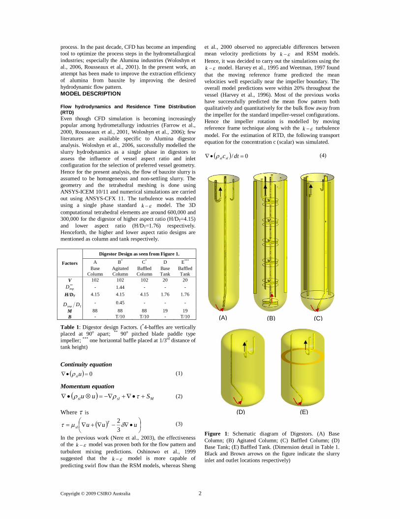
process. In the past decade, CFD has become an impending tool to optimize the process steps in the hydrometallurgical industries; especially the Alumina industries (Woloshyn et al., 2006, Rousseaux et al., 2001). In the present work, an attempt has been made to improve the extraction efficiency of alumina from bauxite by improving the desired hydrodynamic flow pattern. MODEL DESCRIPTION Flow hydrodynamics and Residence Time Distribution (RTD) Even though CFD simulation is becoming increasingly popular among hydrometallurgy industries (Farrow et al., 2000, Rousseaux et al., 2001, Woloshyn et al., 2006); few literatures are available specific to Alumina digestor analysis. Woloshyn et al., 2006, successfully modelled the slurry hydrodynamics as a single phase in digestors to assess the influence of vessel aspect ratio and inlet configuration for the selection of preferred vessel geometry. Hence for the present analysis, the flow of bauxite slurry is assumed to be homogeneous and non-settling slurry. The geometry and the tetrahedral meshing is done using ANSYS-ICEM 10/11 and numerical simulations are carried out using ANSYS-CFX 11. The turbulence was modeled using a single phase standard k model. The 3D computational tetrahedral elements are around 600,000 and 300,000 for the digestor of higher aspect ratio (H/DT=4.15) and lower aspect ratio (H/DT=1.76) respectively. Henceforth, the higher and lower aspect ratio designs are mentioned as column and tank respectively.
Factors
Digestor Design as seen from Figure 1.
A B* C* D E*** Base
Column Agitated Column
Baffled Column
Base Tank
Baffled Tank
V 102 102 102 20 20 **
impD - 1.44 - - - H/DT 4.15 4.15 4.15 1.76 1.76
Timp DD
- 0.45 - - -
M 88 88 88 19 19 B - T/10 T/10 - T/10
Table 1: Digestor design Factors. (*4-baffles are vertically placed at 90o apart; ** 90o pitched blade paddle type impeller; *** one horizontal baffle placed at 1/3rd distance of tank height)
Continuity equation 0 usl (1)
Momentum equation Mslsl Suu (2)
Where is
uuu T
sl 32 (3)
In the previous work (Nere et al., 2003), the effectiveness of the k model was proven both for the flow pattern and turbulent mixing predictions. Oshinowo et al., 1999 suggested that the k model is more capable of predicting swirl flow than the RSM models, whereas Sheng
et al., 2000 observed no appreciable differences between mean velocity predictions by k and RSM models. Hence, it was decided to carry out the simulations using the
k model. Harvey et al., 1995 and Weetman, 1997 found that the moving reference frame predicted the mean velocities well especially near the impeller boundary. The overall model predictions were within 20% throughout the vessel (Harvey et al., 1996). Most of the previous works have successfully predicted the mean flow pattern both qualitatively and quantitatively for the bulk flow away from the impeller for the standard impeller-vessel configurations. Hence the impeller rotation is modelled by moving reference frame technique along with the k turbulence model. For the estimation of RTD, the following transport equation for the concentration c (scalar) was simulated.
0/ dtcslsl (4)
Figure 1: Schematic diagram of Digestors. (A) Base Column; (B) Agitated Column; (C) Baffled Column; (D) Base Tank; (E) Baffled Tank. (Dimension detail in Table 1. Black and Brown arrows on the figure indicate the slurry inlet and outlet locations respectively)
(B) (A) (C)
(D) (E)
Copyright © 2009 CSIRO Australia 3
After computation of the velocity information and the turbulence characteristics, the tracer blending process was modeled by solving the above conservation equation (4). Here, the dispersive transport of the tracer due to turbulent motion in the reactor is accounted by the turbulent diffusivity. A simple dispersion model is used to predict the axial dispersion. In any continuous unit operation/processes, as soon as the pulse tracer is introduced into the vessel, the pulse spreads with respect to the nature of the flow pattern and finally it exits from the outlet of the digestor. The two main important parameters to be observed are the mean residence time, mt and variance of the tracer, 2 (Levenspiel, 1999). The deviation from the plug flow is characterized by the dispersion number, uLD . The “E” curve in the subsequent discussion is taken from equation (5).
uLDtttt
uLDE mm
41exp
41 2
(5)
The “E” is nothing but the normalized exit age distribution function. The purpose of keeping it normalized is that the flow distribution inside the reactors of different scales can be compared directly. Rousseaux et al., 2001, validated their CFD based RTD with the lithium ion tracer experiments for thickeners at plant. The successful predictions show the validation of a CFD model.
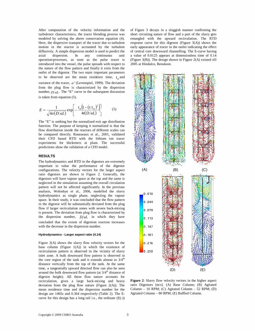
RESULTS The hydrodynamics and RTD in the digestors are extremely important to value the performance of the digestor configurations. The velocity vectors for the larger aspect ratio digestors are shown in Figure 2. Generally, the digestors will have vapour space at the top and the same is neglected in the simulation assuming the overall circulation pattern will not be affected significantly. In the previous analysis, Woloshyn et al., 2006, modelled the slurry hydrodynamics as single phase, neglecting the vapour space. In their study, it was concluded that the flow pattern in the digestor will be substantially deviated from the plug flow if larger recirculation zones with severe back-mixing is present. The deviation from plug flow is characterized by the dispersion number, uLD in which they have concluded that the extent of digestion reaction increases with the decrease in the dispersion number. Hydrodynamics - Larger aspect ratio (4.14) Figure 2(A) shows the slurry flow velocity vectors for the base column (Figure 1(A)) in which the existence of recirculation pattern is observed in the vicinity of slurry inlet zone. A bulk downward flow pattern is observed in the core region of the tank and it extends almost to 3/4th distance vertically from the top of the tank. At the same time, a tangentially upward directed flow can also be seen around the bulk downward flow pattern (at 3/4th distance of digestor height). All these flow nature accounts for recirculation, gives a large back-mixing and heavy deviation from the plug flow nature (Figure 2(A)). The mean residence time and the dispersion number for the design are 1465s and 0.364 respectively (Table 2). The E-curve for this design has a long tail i.e., the ordinate (E(-))
of Figure 3 decays in a sluggish manner confirming the short circuiting nature of flow and a part of the slurry gets entangled with the upward recirculation. The RTD response curve for this digestor (Figure 3(A)) shows the early appearance of tracer in the outlet indicating the effect of central core downward channelling. The E-curve having a value of 0.0125 appears at dimensionless time of 0.14 (Figure 3(B)). The design shown in Figure 2(A) existed till 2005 at Hindalco, Renukoot. Figure 2: Slurry flow velocity vectors in the higher aspect ratio Digestors [m/s]. (A) Base Column; (B) Agitated Column – 10 RPM; (C) Agitated Column – 52 RPM; (D) Agitated Column – 80 RPM; (E) Baffled Column.
(A)
(E)
(B) (C)
(D)
Copyright © 2009 CSIRO Australia 4
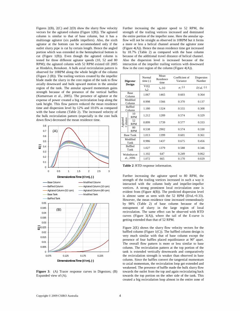
Figures 2(B), 2(C) and 2(D) show the slurry flow velocity vectors for the agitated column (Figure 1(B)). The agitated column is similar to that of base column, but it has a multistage agitator (six paddle impellers). Also, the sixth agitator at the bottom can be accommodated only if the outlet slurry pipe is cut by certain length. Hence the angled portion which was extended in the hemispherical bottom is cut (Figure 1(B)). Even though the agitated column is tested for three different agitator speeds (10, 52 and 80 RPM); the agitated column with 52 RPM existed till 2005 at Hindalco, Renukoot. A bulk axial recirculation pattern is observed for 10RPM along the whole height of the column (Figure 2 (B)). The trailing vortices created by the impeller blade made the slurry in the core region of the tank to flow axially downward and bulk upward motion in the annular region of the tank. The annular upward momentum gains strength because of the presence of the vertical baffles (Kumaresan et al., 2005). The presence of agitator at the expense of power created a big recirculation loop along the tank height. This flow pattern reduced the mean residence time and dispersion level by 12% and 10.6% as compared with the base column (Table 2). The increased velocity of the bulk recirculation pattern (especially in the core bulk down flow) decreased the mean residence time. Figure 3: (A) Tracer response curves in Digestors; (B) Expanded view of (A).
Further increasing the agitator speed to 52 RPM, the strength of the trailing vortices increased and dominated the entire portion of the impeller zone. Here the annular up-flow will not be straight as observed in 10RPM but it forms a more or less a helical channel around the agitator zone (Figure 4(A)). Hence the mean residence time got increased by 18.7% (Table 2) as compared with the base column because of the additional travel distance of helical channel. Also the dispersion level is increased because of the interaction of the impeller trailing vortices with downward flow in the core region of the column (Figure 4(A)).
Digestor Design
Normal time (-)
Mean Residence
time
Coefficient of Variance
Dispersion Number
V/(Q tm) tm (s) t (-) uLD (-)
Base Column 1.067 1465 0.603 0.364
Modified Column 0.998 1566 0.370 0.137
Baffled Column 1.180 1324 0.555 0.308
Agi
tate
d C
olum
n
10 RPM 1.212 1289 0.574 0.329
52 RPM 0.899 1739 0.577 0.333
80 RPM 0.538 2902 0.574 0.330
Base Tank 1.013 1399 0.601 0.361 Modified
Tank 0.986 1437 0.675 0.456
Baffled Tank 1.027 1379 0.588 0.346
Woloshyn et al., 2006
1.102 647 0.249 0.062
1.072 665 0.170 0.029
Table 2: RTD response information.
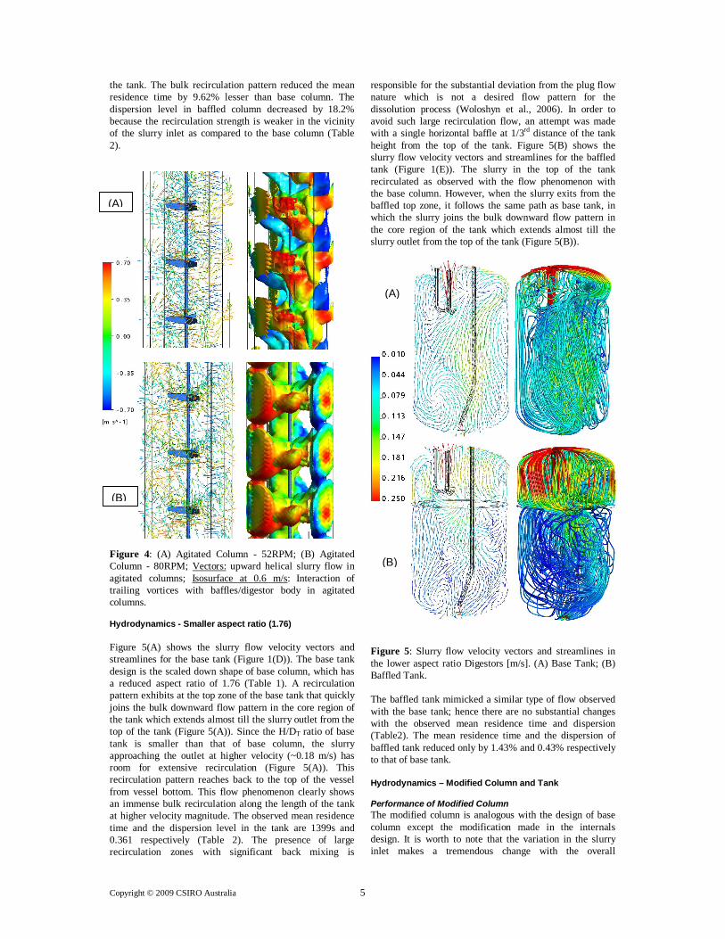
Further increasing the agitator speed to 80 RPM, the strength of the trailing vortices increased in such a way it interacted with the column body and impeller-impeller vortices. A strong prominent local recirculation zone is evident from (Figure 4(B)). The predicted dispersion level is almost same as seen with the 52 RPM (D/uL=0.33). However, the mean residence time increased tremendously by 98% (Table 2) of base column because of the entrapment of slurry in the large region of local recirculation. The same effect can be observed with RTD curves (Figure 3(A)), where the tail of the E-curve is getting extended than that of 52 RPM. Figure 2(E) shows the slurry flow velocity vectors for the baffled column (Figure 1(C)). The baffled column design is very much similar with that of base column except the presence of four baffles placed equidistance at 90o apart. The overall flow pattern is more or less similar to base column. The recirculation pattern at the top portion of the tank is extended vertically downwards and comparatively the recirculation strength is weaker than observed in base column. Since the baffles convert the tangential momentum to axial momentum, the recirculation loop got extended and weakened. The presence of baffle made the bulk slurry flow towards the outlet from the top and again recirculating back towards the top portion on the other side of the tank. This created a big recirculation loop almost in the entire zone of
0
0.1
0.2
0.3
0.4
0.5
0.6
0.7
0.8
0 0.5 1 1.5 2 2.5 3
E (-
)
Dimensionless Time (t/tm), (-)
Base Column Modified Column
Baffled Column Agitated Column (10 rpm)
Agitated Column (52 rpm) Agitated Column (80 rpm)
Base Tank Modified Tank
Baffled Tank
0
0.005
0.01
0.015
0.02
0.025
0.03
0.035
0.04
0.045
0.05
0.075 0.125 0.175 0.225
E (-
)
Dimensionless Time (t/tm), (-)
(A)
(B)
Copyright © 2009 CSIRO Australia 5
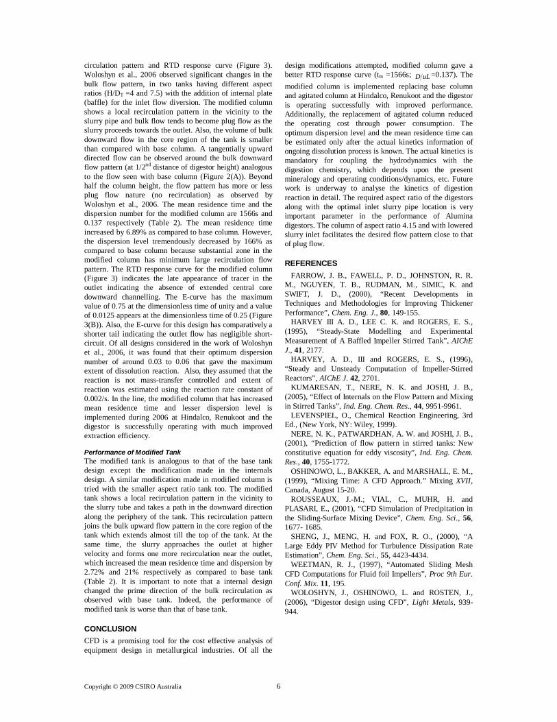
the tank. The bulk recirculation pattern reduced the mean residence time by 9.62% lesser than base column. The dispersion level in baffled column decreased by 18.2% because the recirculation strength is weaker in the vicinity of the slurry inlet as compared to the base column (Table 2). Figure 4: (A) Agitated Column - 52RPM; (B) Agitated Column - 80RPM; Vectors: upward helical slurry flow in agitated columns; Isosurface at 0.6 m/s: Interaction of trailing vortices with baffles/digestor body in agitated columns. Hydrodynamics - Smaller aspect ratio (1.76) Figure 5(A) shows the slurry flow velocity vectors and streamlines for the base tank (Figure 1(D)). The base tank design is the scaled down shape of base column, which has a reduced aspect ratio of 1.76 (Table 1). A recirculation pattern exhibits at the top zone of the base tank that quickly joins the bulk downward flow pattern in the core region of the tank which extends almost till the slurry outlet from the top of the tank (Figure 5(A)). Since the H/DT ratio of base tank is smaller than that of base column, the slurry approaching the outlet at higher velocity (~0.18 m/s) has room for extensive recirculation (Figure 5(A)). This recirculation pattern reaches back to the top of the vessel from vessel bottom. This flow phenomenon clearly shows an immense bulk recirculation along the length of the tank at higher velocity magnitude. The observed mean residence time and the dispersion level in the tank are 1399s and 0.361 respectively (Table 2). The presence of large recirculation zones with significant back mixing is
responsible for the substantial deviation from the plug flow nature which is not a desired flow pattern for the dissolution process (Woloshyn et al., 2006). In order to avoid such large recirculation flow, an attempt was made with a single horizontal baffle at 1/3rd distance of the tank height from the top of the tank. Figure 5(B) shows the slurry flow velocity vectors and streamlines for the baffled tank (Figure 1(E)). The slurry in the top of the tank recirculated as observed with the flow phenomenon with the base column. However, when the slurry exits from the baffled top zone, it follows the same path as base tank, in which the slurry joins the bulk downward flow pattern in the core region of the tank which extends almost till the slurry outlet from the top of the tank (Figure 5(B)). Figure 5: Slurry flow velocity vectors and streamlines in the lower aspect ratio Digestors [m/s]. (A) Base Tank; (B) Baffled Tank. The baffled tank mimicked a similar type of flow observed with the base tank; hence there are no substantial changes with the observed mean residence time and dispersion (Table2). The mean residence time and the dispersion of baffled tank reduced only by 1.43% and 0.43% respectively to that of base tank. Hydrodynamics – Modified Column and Tank Performance of Modified Column The modified column is analogous with the design of base column except the modification made in the internals design. It is worth to note that the variation in the slurry inlet makes a tremendous change with the overall
(A)
(B)
(B)
(A)
Copyright © 2009 CSIRO Australia 6
circulation pattern and RTD response curve (Figure 3). Woloshyn et al., 2006 observed significant changes in the bulk flow pattern, in two tanks having different aspect ratios (H/DT =4 and 7.5) with the addition of internal plate (baffle) for the inlet flow diversion. The modified column shows a local recirculation pattern in the vicinity to the slurry pipe and bulk flow tends to become plug flow as the slurry proceeds towards the outlet. Also, the volume of bulk downward flow in the core region of the tank is smaller than compared with base column. A tangentially upward directed flow can be observed around the bulk downward flow pattern (at 1/2nd distance of digestor height) analogous to the flow seen with base column (Figure 2(A)). Beyond half the column height, the flow pattern has more or less plug flow nature (no recirculation) as observed by Woloshyn et al., 2006. The mean residence time and the dispersion number for the modified column are 1566s and 0.137 respectively (Table 2). The mean residence time increased by 6.89% as compared to base column. However, the dispersion level tremendously decreased by 166% as compared to base column because substantial zone in the modified column has minimum large recirculation flow pattern. The RTD response curve for the modified column (Figure 3) indicates the late appearance of tracer in the outlet indicating the absence of extended central core downward channelling. The E-curve has the maximum value of 0.75 at the dimensionless time of unity and a value of 0.0125 appears at the dimensionless time of 0.25 (Figure 3(B)). Also, the E-curve for this design has comparatively a shorter tail indicating the outlet flow has negligible short-circuit. Of all designs considered in the work of Woloshyn et al., 2006, it was found that their optimum dispersion number of around 0.03 to 0.06 that gave the maximum extent of dissolution reaction. Also, they assumed that the reaction is not mass-transfer controlled and extent of reaction was estimated using the reaction rate constant of 0.002/s. In the line, the modified column that has increased mean residence time and lesser dispersion level is implemented during 2006 at Hindalco, Renukoot and the digestor is successfully operating with much improved extraction efficiency. Performance of Modified Tank The modified tank is analogous to that of the base tank design except the modification made in the internals design. A similar modification made in modified column is tried with the smaller aspect ratio tank too. The modified tank shows a local recirculation pattern in the vicinity to the slurry tube and takes a path in the downward direction along the periphery of the tank. This recirculation pattern joins the bulk upward flow pattern in the core region of the tank which extends almost till the top of the tank. At the same time, the slurry approaches the outlet at higher velocity and forms one more recirculation near the outlet, which increased the mean residence time and dispersion by 2.72% and 21% respectively as compared to base tank (Table 2). It is important to note that a internal design changed the prime direction of the bulk recirculation as observed with base tank. Indeed, the performance of modified tank is worse than that of base tank.
CONCLUSION CFD is a promising tool for the cost effective analysis of equipment design in metallurgical industries. Of all the
design modifications attempted, modified column gave a better RTD response curve (tm =1566s; uLD =0.137). The modified column is implemented replacing base column and agitated column at Hindalco, Renukoot and the digestor is operating successfully with improved performance. Additionally, the replacement of agitated column reduced the operating cost through power consumption. The optimum dispersion level and the mean residence time can be estimated only after the actual kinetics information of ongoing dissolution process is known. The actual kinetics is mandatory for coupling the hydrodynamics with the digestion chemistry, which depends upon the present mineralogy and operating conditions/dynamics, etc. Future work is underway to analyse the kinetics of digestion reaction in detail. The required aspect ratio of the digestors along with the optimal inlet slurry pipe location is very important parameter in the performance of Alumina digestors. The column of aspect ratio 4.15 and with lowered slurry inlet facilitates the desired flow pattern close to that of plug flow.
REFERENCES FARROW, J. B., FAWELL, P. D., JOHNSTON, R. R.
M., NGUYEN, T. B., RUDMAN, M., SIMIC, K. and SWIFT, J. D., (2000), “Recent Developments in Techniques and Methodologies for Improving Thickener Performance”, Chem. Eng. J., 80, 149-155.
HARVEY III A. D., LEE C. K. and ROGERS, E. S., (1995), “Steady-State Modelling and Experimental Measurement of A Baffled Impeller Stirred Tank”, AIChE J., 41, 2177.
HARVEY, A. D., III and ROGERS, E. S., (1996), “Steady and Unsteady Computation of Impeller-Stirred Reactors”, AIChE J. 42, 2701.
KUMARESAN, T., NERE, N. K. and JOSHI, J. B., (2005), “Effect of Internals on the Flow Pattern and Mixing in Stirred Tanks”, Ind. Eng. Chem. Res., 44, 9951-9961.
LEVENSPIEL, O., Chemical Reaction Engineering, 3rd Ed., (New York, NY: Wiley, 1999).
NERE, N. K., PATWARDHAN, A. W. and JOSHI, J. B., (2001), “Prediction of flow pattern in stirred tanks: New constitutive equation for eddy viscosity”, Ind. Eng. Chem. Res., 40, 1755-1772.
OSHINOWO, L., BAKKER, A. and MARSHALL, E. M., (1999), “Mixing Time: A CFD Approach.” Mixing XVII, Canada, August 15-20.
ROUSSEAUX, J.-M.; VIAL, C., MUHR, H. and PLASARI, E., (2001), “CFD Simulation of Precipitation in the Sliding-Surface Mixing Device”, Chem. Eng. Sci., 56, 1677- 1685.
SHENG, J., MENG, H. and FOX, R. O., (2000), “A Large Eddy PIV Method for Turbulence Dissipation Rate Estimation”, Chem. Eng. Sci., 55, 4423-4434.
WEETMAN, R. J., (1997), “Automated Sliding Mesh CFD Computations for Fluid foil Impellers”, Proc 9th Eur. Conf. Mix. 11, 195.
WOLOSHYN, J., OSHINOWO, L. and ROSTEN, J., (2006), “Digestor design using CFD”, Light Metals, 939-944.