200613065.pdf - Pure
178
/ faculty of architecture building and planning tu eindhoven bouwstenen Perica Savanovic Integral design method in the context of sustainable building design 140 Closing the gap between design theory and practice
-
Upload
khangminh22 -
Category
Documents
-
view
1 -
download
0
Transcript of 200613065.pdf - Pure

/ faculty of architecture building and planning tu eindhoven/ faculty of architecture building and planning
Where innovation starts
bouwstenen
Perica Savanovic
To meet the unique challenges in the present day built environment, we need to move beyond redesign and optimization, and generate new concepts and knowledge that represent the necessary conditions to arrive at new design solutions.Housing the research within the Design Research Methodology framework, the Integral Design Method (ID-method) was iteratively developed using workshops in which experienced professionals participated. The first step of the ID-method is (to record and structure) the design team’s interpretation of the design task, resulting in a dynamic list of functions/aspects. The simultaneous generation of sub solutions per defined function/aspect, which is guided by morphological analysis, needs to remain based on individual disciplines in order to result in an overview of the design team’s object-design-knowledge. The next step of the ID-method concerns the combination of generated sub solutions, resulting in redesigns, and/or transformation of generated sub solutions, resulting in new concepts. The necessity of concept creation is shown by C-K theory that defines design as the interplay between two interdependent spaces, knowledge space K and concept space C.The ID-method represents a set of necessary conditions for the creation of integral design concepts. More importantly, reflected by the expressed satisfaction of the majority of the workshop participants, the ID-method represents an important step in what is argued as a necessary cultural change within the Dutch building domain.
Uitnodigingtot het bijwonen
van deopenbare verdediging van
mijn proefontwerp
Integral design method in the context of sustainable building design
op dinsdag24 november 2009
om 16.00 uur
Aansluitendaan deze plechtigheid zaleen receptie plaatsvinden
waarvoor u van harte bent uitgenodigd
De promotie zal plaatsvinden in zaal 5
van het Auditorium van de
Technische Universiteit Eindhoven
Integral design method in the contextof sustainable building design
140
Closing the gap between design theory and practiceIntegral design m
ethod in the context of sustainable building design140
Perica Savanovic

Integral design method in the context of sustainable building design:
closing the gap between design theory and practice PROEFONTWERP ter verkrijging van de graad van doctor aan de Technische Universiteit Eindhoven, op gezag van de rector magnificus, prof.dr.ir. C.J. van Duijn, voor een commissie aangewezen door het College voor Promoties in het openbaar te verdedigen op dinsdag 24 november 2009 om 16.00 uur door Perica Savanovi� geboren te Sarajevo, voormalig Joegoslavië

De documentatie van het proefontwerp is goedgekeurd door de promotor: prof.ir. W. Zeiler

INTEGRAL DESIGN METHOD IN THE CONTEXT OF
SUSTAINABLE BUILDING DESIGN
closing the gap between design theory and practice

Samenstelling kerncommissie:
prof.ir. W. Zeiler, Technische Universiteit Eindhoven, promotor
prof.dr.ir. L.T.M. Blessing, Univeristé du Luxembourg, Luxembourg
prof.dr. A. Hatchuel, MINES ParisTech, France
prof.dr. H.J.P. Timmermans, Technische Universiteit Eindhoven
prof.dr.ir. J.A. van Aken, Technische Universiteit Eindhoven
A catalogue record is available from the Eindhoven University of Technology Library
ISBN: 978-90-386-2048-0
NUR: 955
Edited by Duncan Harkness
Book design by Marc Suvaal, cover adjusted by Ton van Gennip
Printed by the Eindhoven University Press, Eindhoven, The Netherlands
Published as issue 140 in de Bouwstenen series of the Faculty of Architecture,
Building and Planning of the Eindhoven University of Technology
© Perica Savanovi�, 2009

i
Integral design method in the context of sustainable building design: closing the gap between design theory and practice
The Dutch building domain is characterized by a lack of true integration of building
disciplines in the conceptual design phase. Traditional methods essentially lead to
redesign and optimization, whereas to meet the unique challenges in the present day
built environment, we need to go further and generate new concepts and knowledge that
represent the necessary conditions to arrive at new design solutions.
This research set out to develop a method to create a more integral process that
would create the opportunity to introduce a greater variety and amount of design
knowledge from the outset of the conceptual design phase. The Integral Design method
(ID-method) developed here, given the right cultural environment, may in time lead to the
generation of new building concepts that will allow us the opportunity to move beyond
redesign and optimization. The necessity of concept creation is shown by C-K theory that
defines design as the interplay between two interdependent spaces, knowledge space K
and concept space C, which allows us to conceive of the possibility to transform the
building design team’s knowledge into new concepts.
Using workshops in which experienced professionals participated, a workable
method was arrived at through iterative improvement of four key elements: design team,
design model, design tool and design setting. The iterative development of the method
results from housing the research within the Design Research Methodology framework.
Within the ID-method the structured presentation of object-design-knowledge is guided
by morphological analysis. The first step of the ID-method is (to record and structure) the
design team’s interpretation of the design task, resulting in a dynamic list of func-
tions/aspects. The simultaneous generation of sub solutions per defined function/aspect
needs to remain based on individual disciplines in order to result in an overview of the
design team’s object-design-knowledge. Iterations are possible and this is where the
added value of morphological overviews’ structuring is most apparent. Feedback can take
place after each iteration; morphological overviews represent a transparent record of the
design process, which external parties can refer to in order to determine whether all
necessary functions and aspects are adequately addressed. The next step of the ID-
method concerns the combination of generated sub solutions, resulting in redesigns,
and/or transformation of generated sub solutions, resulting in new concepts. The ID-
method makes the team design process explicit and provides an audit trail.
The results showed that the ID-method did prove successful in facilitating the
inclusion of engineering knowledge from the outset of the conceptual design phase. This
in itself rendered the design process more efficient as it removed an unnecessary
iteration, that is, the architect beginning the design task on his own before receiving
SUMMARY

ii
input from engineering disciplines. However, what the disciplines within design teams
ended up doing in many instances amounted to no more than seeking to fit solutions to
design tasks. In essence, the design teams’ approaches could best be categorised as
‘integrated’ rather than the desired ‘integral’ design. This research therefore cannot claim
to have realised the aim of using the ID-method to arrive at integral design concepts.
Nonetheless, the ID-method represents a set of necessary conditions for the creation of
integral design concepts. More importantly, reflected by the expressed satisfaction of the
majority of the participants, the ID-method represents an important step in what is
argued as a necessary cultural change within the Dutch building domain.

SUMMARY .................................................................................................................... i 1 Introduction.............................................................................................................. 1
1.1 Problem definition .......................................................................................................1
1.2 Aims and objectives.................................................................................................... 4
1.3 Methodology .............................................................................................................. 5
1.4 Thesis outline ............................................................................................................. 7
2 Background .............................................................................................................. 9
2.1 Introduction ................................................................................................................ 9
2.2 Reflective vs. problem solving approaches ................................................................ 9
2.3 C-K theory ..................................................................................................................13
2.4 The importance of engineers in architectural design ............................................... 16
2.5 Working definitions .................................................................................................. 18
3 Methodology .......................................................................................................... 21
3.1 Introduction ...............................................................................................................21
3.2 Theoretical Framework: Design Research Methodology ...........................................21
3.2.1 The four stages of DRM research..........................................................................................................21
3.3 Research design and setting .................................................................................... 23
3.3.1 Research design .................................................................................................................................. 23
3.3.2 Research setting ................................................................................................................................. 24
3.4 Observation methods ............................................................................................... 24
3.5 Triangulation ............................................................................................................ 25
4 Descriptive study I results: literature studies........................................................28
4.1 Introduction .............................................................................................................. 28
4.2 DRM stage 1: Research clarification ......................................................................... 28
4.3 DRM stage 2: Descriptive study I.............................................................................. 29
4.3.1 Introduction ........................................................................................................................................ 29
4.3.2 Case studies of energy-efficient building design projects in The Netherlands .................................... 30
4.3.3 Morphological analysis as basis for team design................................................................................ 32
4.3.4 An automobile industry example of team design using morphological approach ............................... 36
4.3.5 Influence of the identified factors on the measurable criteria............................................................. 39
5 Prescriptive study results: developing the integral design method ..................... 43
5.1 Introduction.............................................................................................................. 43
5.2 DRM stage 3: Prescriptive study.............................................................................. 43
5.2.1 Pre-test workshop 1: over prescription of the design tool will lead to unsuccessful application ........ 43
5.2.2 Pre-test workshop 2: loose prescription of the design tool will lead to successful application........... 45
5.2.3 Extended Methodical Design Model based workshop (configuration A) ............................................. 47
5.2.4 Extended Methodical Design Model based workshop (configuration B) ............................................. 54
5.2.5 Comparison between Extended Methodical Design Model based workshop configurations A and B ...57
5.2.6 Comparison with Extended Methodical Design Model based student workshops ...............................61
Contents

5.2.7 Working Design Model based workshop configuration ....................................................................... 65
5.2.8 Integral Design workshop configuration ............................................................................................. 69
5.3 The Integral Design Method ..................................................................................... 75
6 Descriptive study II results: testing the integral design method......................80
6.1 Introduction .............................................................................................................. 80
6.2 DRM stage 4: Descriptive study II............................................................................. 80
6.2.1 Final Integral Design workshop analysis ..............................................................................................81
6.3 Evaluations of the workshops by the participants.................................................. 105
7 Discussion and conclusion................................................................................... 108
References ...............................................................................................................114
Appendix ..................................................................................................................118
I Workshop programs ................................................................................................118
A. Test-workshop 1 program ....................................................................................................................... 118
B. Test-workshop 2 program....................................................................................................................... 118
C. Extended Methodical Design Model based workshops........................................................................... 118
D. Working Design Model based workshop ................................................................................................ 119
E. Integral Design workshops .....................................................................................................................120
II Workshop design tasks .......................................................................................... 122
A. Zero energy office ...................................................................................................................................122
B. Parasite ..................................................................................................................................................124
C. School.....................................................................................................................................................124
D. Renovation ............................................................................................................................................. 125
III Workshop questionnaires....................................................................................... 126
A. Test directly after workshops..................................................................................................................126
B. Post-test six months after workshops ....................................................................................................128
IV Workshop series 5 analysis .................................................................................... 129
1st design setting, ‘parasite’ design task .....................................................................................................129
Design team 1 .............................................................................................................................................130
Design team 2.............................................................................................................................................132
Design team 3............................................................................................................................................. 135
Design team 4............................................................................................................................................. 135
Design team 5............................................................................................................................................. 135
Average results of all five design teams...................................................................................................... 137
2nd design setting, ‘zero energy office’ design task.....................................................................................138
Design team 1 .............................................................................................................................................138
Design team 2.............................................................................................................................................140
Design team 3.............................................................................................................................................140
Design team 4.............................................................................................................................................140
Design team 5............................................................................................................................................. 141
Average results of all five design teams......................................................................................................142
4th design setting, ‘school’ design task.......................................................................................................143
Design team 1 .............................................................................................................................................143
Design team 2............................................................................................................................................. 145

Design team 3............................................................................................................................................. 147
Design team 4............................................................................................................................................. 151
Design team 5............................................................................................................................................. 153
Average results of all five design teams...................................................................................................... 153
Acknowledgements................................................................................................. 154
Curriculum Vitae ..................................................................................................... 156


1
1.1 Problem definition
After graduating as a Master of Science in Architecture from Delft University of Technology in
2001, I set out full of enthusiasm and ideals to embark upon a career in the field. I entered the
professional world at a middle-sized architectural office in The Netherlands, where, during my 3�
years of work, I was fortunate enough to experience a variety of design tasks (small interior to
large master plan assignments), “from furniture to urban scale” as they say. While working on
design problems was fulfilling in many respects, I was highly frustrated by the nature of the
design process: although many individual specialists from a variety of building disciplines are
required to work on complex design tasks, the traditional approach to the design process does
not allow for proper integration of such disciplines. To put it simply, I experienced a general lack
of an ‘integral approach’ in current building design practice. With this problem in mind, I
considered returning to university to look for a solution.
Fortunately, at the end of 2004 I discovered a project on the subject within the Building
Physics & Systems unit at the Department of Architecture, Building and Planning at Eindhoven
University of Technology. The main area of interest of the project’s supervisor, Professor Zeiler,
can be described as integral design within a multidisciplinary design team setting. Professor
Zeiler is Master of Science in Mechanical Engineering and has more than 20 years experience in
the field as engineer. From 2001, when he became full professor of Building Services, Professor
Zeiler’s efforts to work towards an ‘integral approach’ have been mainly informed by research
within the fields of ‘Integral Design’ and ‘Sustainable Energy in the Built Environment’.
The lack of integration during the design process has also been noted in the literature.
Previous research in the Netherlands has shown that cooperation between building design
disciplines is unsatisfactory and that better organization of the design process is necessary
[Friedl 2000, Quanjel 2003]. Marketing research conducted through a series of inquiries in the
Dutch building sector [USP 2001, 2005, 2007, 2008], showed considerable increase in failure
costs: from 7.7% in 2001 to 11.4% of the annual turnover in 2008 [USP 2008]. The Dutch
knowledge centre for housing and utility construction, Stichting Bouwresearch (SBR), defines
failure costs as the costs arising from: unnecessary inefficient processes, not meeting the agreed
quality of the end product, and repairs. The main reasons cited by USP for these failure costs
were poor information exchange and communication. It is worthy to note here that SBR identified
that the most important decisions concerning buildings are made during the early phases of
building design [Wichers Hoeth and Fleuren 2001], even though not all relevant information is
available then. A good example of this is that the consultants tend to be involved too late in the
building design process. Their input is then used to ‘optimize’ architectural design, often leading
to add-on solutions that disturb rather than enhance the proposed building layout and form
[Zeiler et al 2005].
Experience and literature, then, both show that the Dutch building domain at least, and
probably also those in most other similarly developed countries, is characterized by a lack of true
1 Introduction

INTRODUCTION
2
integration of building disciplines in the conceptual design phase. This is undesirable because
when the integration does come, usually in the final design phase, it is difficult, expensive and
problematic to fully integrate and often leads to unforeseen problems and costs. To remedy this
situation, the building design process must improve.
At this point it is useful to define the differences between an ‘integrated’ and an ‘integral’
approach more explicitly. Within integrated design two or more disciplines are combined in order
to become more effective. Within integral design all disciplines are considered necessary and
important, and as such are treated as part of, or contained within, the whole building design
approach from the early stages of a project. To put it another way, within integrated design the
input of different disciplines, often contributed separately and in different design phases, is
made to fit. In contrast, within integral design all necessary design disciplines are given the
opportunity to participate in team design and contribute their knowledge from the outset.
Notwithstanding this non-optimal integrated design process, the present situation of
building design is characterized by the need to meet ever more complex demands. This growing
complexity necessitates input from a wide variety of fields. However, even though the input from
many individuals from various fields is essential, the nature of the teamwork in the current
building design environment could be described as maintaining a traditional, hierarchical
approach, in which building design is largely seen as the creative act of an individual. In this
traditional approach, the design is generally first generated by an architect before being refined
after input from other, largely engineering, professionals. Although the norm, there is a growing
acceptance that this approach is far from optimal and often leads to undesirable failure costs. A
recurrent observation on this process [De Wilde 2001, 2004] is that key information from
engineers is introduced too late in the design process. This finding has been confirmed as
recently as 2009 [Brunsgaard et al 2009]. This potentially leads to the initial designer having to
amend the original design on the basis of the new input on, for example, HVAC (heating,
ventilation and air conditioning) requirements, which are the expertise of engineers. Had this
information been available sooner, then this extra iteration in the process may have been
avoided.
It appeals to the intuition that we can expect that whatever failure costs arise from the
current approach will only grow larger in the future due in no small part to the increasing
demands for sustainability within buildings. Achieving greater sustainability relies on integrating
the insights from various engineering disciplines within the process. At present, however, such
disciplines are customarily only brought into the process to optimize already proposed designs.
In this sense, such professionals can be described as being somewhat appended to the design
process, rather than being an integral and equal part from the outset. In the status quo, then,
there exists something of a tension between the architect and engineer.
A nuanced view of the tension between the architect and the engineer can be found in the
work of Habraken. John Habraken, a Dutch citizen and one of the founders and first chairperson
of the Department of Architecture at the Eindhoven University of Technology (in 1967), as well as
founder and former director (from 1965 to 1975) of SAR (Foundation for Architects Research in the
Netherlands), spent the latter part of his career at MIT, Cambridge. Although Habraken’s later
career took place in the US, his globally inspired insights are still highly applicable to the Dutch
situation.

INTRODUCTION
3
In his book Palladio’s children, Habraken considers the general design process for buil-
dings in recent times. He confirms that the designing of buildings is largely seen as the creative
act of an individual. This is certainly the case for the conceptual design phase, where it is the
architect who is responsible for laying down the vision of the whole building. Moreover, “the
belief that a single designer should be in control of all levels of environmental form” [Habraken
2005, p.89] is even seen as a professional ideal. This belief has led the architectural profession to
become singularly obsessed with perfecting form and crafting it down to the last detail,
[Habraken 2005, p.111]. However, despite this characterisation of the architect as the sole
creative force, Habraken points out that the proliferation of consultant specialists required to
solve complex design tasks bring into play de facto co-designers due to the sheer complexity of
the contemporary built environment. “Paradoxically, while consultant design may not appear
prominently in the completed project, it frequently establishes dimensions, spans, story heights,
and other fundamental aspects of architectural character.” [2005, p.122]
While it appears from the hierarchical nature of the design process that the architect is the
only true creator, Habraken points out that the input of other professions, whenever that may
appear in the process, is essential to the design, and as such the architect should not be
considered as omnipotent. Although the architect sits at the top of the pyramid, so to speak, one
cannot underestimate the essential role that other members of the design team play. The
importance, then, of timely input from team members cannot be underestimated. Put simply,
what we can conclude from Habraken is that engineers must be seen as more than just
appendages to the design process: they must be an integral part of it.
Not only is greater involvement of individual disciplines within the design process desirable
on a theoretical level, it is a clear practical necessity, owing to the growing complexity of
contemporary design problems. Recent research in the Netherlands, from within the HVAC
sector, for example, has shown the need to better integrate comfort and sustainable energy
systems in buildings [Boerstra et al 2006, Opstelten et al 2007, Zeiler and Boxem 2008]. In an
attempt to explore the machinations of multidisciplinary team work within design, in 2000, the
Royal Institute of Dutch Architects (BNA), the Dutch Society for Building Services (TVVL), and the
Delft University of Technology (TUD) participated in a research project named Integral Design
[Quanjel 2003, Quanjel and Zeiler 2003]. The aim of the project was to gather professionals from
the relevant fields of design, construction and real estate management to explore what changes
to current design practice are necessary to arrive at a ‘seamless whole’ in terms of building
design. This thesis takes this initial work as a starting point to develop a concrete method based
on the integral approach.
One clear goal of improving teamwork in building design is the reduction of failure costs.
However, another important advantage of effective teamwork within the design process is the
increased possibility to arrive at new building concepts, which may well prove essential for the
development of a sustainable built environment. Many factors influence the sustainability of the
built environment, however, man-made climate change and the measures that are needed to
counteract such change seem to be by far the main problems of our time [IPCC 2007]: “Changes in
atmospheric concentrations of greenhouse gases (GHGs) and aerosols, land cover and solar
radiation alter the energy balance of the climate system… Carbon dioxide (CO2) is the most
important anthropogenic GHG… Global increases in CO2 concentrations are due primarily to fossil

INTRODUCTION
4
fuel use, with land-use change providing another significant but smaller contribution” [p.37]. To
understand the impact of building design on the environment, recent research has shown that
40% of the total energy output of The Netherlands is consumed by the built environment, and
this figure rises to 70% when social services such as healthcare are included [Uitdenbogerd
2007]. To understand the importance of achieving sustainable buildings, within The Netherlands
the Energy research Centre of the Netherlands (ECN) and Netherlands Organisation for Applied
Scientific Research (TNO) have set stringent energy reduction targets. By the year 2030 CO2
emissions should be reduced by 50%, and by the year 2050 The Netherlands should be a net
energy neutral built environment [ECN and TNO 2004].
The unsatisfactory cooperation between building design disciplines has resulted in calls for
better organization of the design process [Friedl 2000, Wichers Hoeth and Fleuren 2001]. These
calls gain more importance when we consider the increased complexity in current design
processes arising from, amongst other things, growing sustainability demands. In this context,
traditional approaches to organize and plan these complex processes may no longer suffice [Van
Aken 2005]. This is more understandable when we consider that traditional methods essentially
lead to redesign and optimization, whereas to meet the unique challenges in the modern built
environment, we need to go further and generate new concepts and knowledge that, it will be
argued, will represent the necessary conditions to arrive at new design solutions.
1.2 Aims and objectives
There are two main aims to be addressed in this research: the first a practical one and the second
somewhat more abstract. First and foremost, a method needs to be developed to allow other,
largely engineering, building disciplines to be integrated into the design process from the outset
in a meaningful way. This re-evaluation of the design process and the individual disciplines
within it should facilitate the inclusion of all relevant team members at the outset and give proper
recognition to the influence their knowledge and input has on the final design. The standpoint in
this research is that a more integral process will not only improve the design process, it will also
create the opportunity to introduce a greater variety and amount of design knowledge from the
outset of the conceptual design phase.
The second more abstract and longer term goal of the research, although not the main aim
of this particular project, is that the method developed here, given the right cultural environment,
may in time lead to the generation of new “concepts”. New concepts, it is argued, will allow us
the opportunity to move beyond redesign and optimization towards real “Design”. This
argument will be developed further based on theoretical distinctions and definitions, which can
be found in the following chapter.
This longer term goal is reliant on real cultural change. The endemic hierarchical relation-
ships between architects and other building design disciplines currently hinder both communi-
cation and knowledge use. What is needed therefore is an egalitarian working environment. It will
be shown that this is not only a matter of the architect coming down from the mountain top, so to
speak, it is also a matter of the engineer stepping up and meeting the architect half way. Without

INTRODUCTION
5
such cultural change implementing any method that requires true cooperation between
disciplines may prove very difficult.
Not only is the method developed here aimed at professionals in the field, it is also aimed
at students, who will become the professionals of tomorrow. It is worthy to note here that new
approaches are commonly developed within educational institutions and then unveiled to
professionals, who ultimately decide their worth. In contrast, the method developed in this
research was first tested with professionals from the Dutch building design field, and then
applied in educational courses. This dual inclusion of professionals and students should help to
accelerate the necessary cultural evolution of the building design process.
Even though arriving at concepts is highly desirable as it may allow us to reach break-
through solutions to help solve the world’s environmental problems related to the present energy
consumption of the built environment, much preparatory work is necessary before this can be
realistically tested for. Therefore this goal, however laudable, cannot be considered central to
this thesis. Rather, the focus here is on achieving the more realistic goal of developing a method
for practical use that can foster the integration of engineers into the conceptual phase of building
design from the outset. This has the potential to allow the design team to generate a greater
number of design solutions of a greater quality. Logically, this will lead to better optimizations of
designs and ultimately to better buildings.
In essence, the research carried out to achieve the main goal of this project represents the
necessary preparatory conditions to test the second, long term goal. Due to the limitations of PhD
research, only the first goal could be addressed in depth. However, it is hoped that the
preliminary test on the second goal will pave the way for future research.
In the present research, the key variables that need to be manipulated in order to develop
an integral design method are the design team, the design tools, the design model and the
setting. Conditions relevant for a team design method were defined via a literature review and
refined during the research; the initial conditions identified from literature studies are listed at
the end of section 4.3.3. In addition, the research methodology used, Design Research Metho-
dology (DRM), which is introduced in section 1.3 and explained in detail in chapter 3, emphasises
the need to formulating success as well as measurable criteria. These criteria need to be defined
in the first stage of the research (section 4.2), so that they can be measured in the final stage of
the research (section 6.2). Essentially, within DRM these criteria can be seen as a list of require-
ments for the research.
1.3 Methodology
Within the Department of Architecture, Building and Planning there are two distinct possibilities
to approach a PhD research project: proefschrift (dissertation) and proefontwerp (technological
design). While dissertations are seen as more germane for theoretical study, technological
design is aimed rather at solving more practical problems in the field. According to the ‘Doctorate
regulation 2009’ of the Eindhoven University of Technology, a technological design “is
understood to mean a design that has come into being through the application of appropriate
INTRODUCTION
6
theoretical knowledge and methods” and “which must make an original contribution to the
further development of existing scientific knowledge”.
In the present PhD research project the design that has to come into being is the ‘Integral
Design Method’. The main theoretical knowledge and methods that are applied are the
Methodical Design model [Van den Kroonenberg and Siers 1992], Design Research Methodology
[Blessing and Chakrabarti 2002, Blessing and Chakrabarti 2009] and C-K theory [Hatchuel and
Weil 2003, Hatchuel and Weil 2008]. The contribution that this technological design can offer is
twofold: first, it can remedy the poor integration and the problems that arise there from during
the conceptual design process; and, second, it can create the necessary conditions to work
towards innovative sustainable building concepts.
In order to work towards these goals the research needs to be housed within a relevant
theoretical framework. It has been noted in the literature that a good deal of research within
design fields suffers from the lack of a systematic research methodology, resulting in arguments
that a discipline for design research needs to be developed that proceeds in a rigours way and
yields results that are transparent and testable [Cross 2001, Cross 2006]. In other words, there is
a call within the field for systematic research methodologies that create an audit trail for the
research carried out. A recently developed and particularly suitable framework developed in
response to these concerns is offered by Design Research Methodology (DRM) [Blessing and
Chakrabarti 2002, 2009]. DRM, which is described in chapter 3, focuses the research both on the
study of the phenomenon of design as well as the development of design support. In the present
research the phenomena of interest is team design, and the design support to be developed is
the integral design method, which aims to prescribe a method to allow multidisciplinary design
teams to work in an integral manner during the conceptual design process.
As design can be described as being practical, rather than theoretical, design research
projects are often based on experience rather than an exhaustive review of literature. In such
cases, the research needs to proceed on the basis of common sense assumptions [Blessing
2006]. In order to pursue the goals of the present research, two key starting assumptions were
made.
The first assumption related to the choice of design model. In brief, the model needs to
facilitate the inclusion of the knowledge of largely engineering disciplines within a design team.
It was deemed important therefore to use a model that engineering disciplines would be
comfortable with. The first key assumption was that models from solely engineering domains
could be adapted for the desired use within multidisciplinary teams. Here, the Extended
Methodical Design model [Zeiler 1993] was chosen because its simplicity and adaptability were
considered to render it user friendly for both the architectural and engineering disciplines within
the design team. The second assumption related to research setting. Since there were no known
examples of ‘integral design teams’ working in practice that could be studied, a semi-authentic
environment needed to be created for this research. Here, based largely on the results of
previous research [Quanjel 2003], a workshop setting was chosen. The project must therefore
test both the model and the setting.
In the design chosen for this research, since many individual assumptions needed to be
tested both for the setting and for the model, an iterative approach was considered most
suitable. In short, assumptions were made about the setup of both setting and the model. These

INTRODUCTION
7
assumptions were then tested within a workshop. After each workshop the results of the tests
fed in to the redesign of the subsequent workshops and led to the optimization of the model.
Therefore, the method and the results in this research are inextricably linked. As such, some of
the methodological steps taken, i.e. the iterative improvements to the model and the workshops,
are included in the results sections in this work.
The research design followed here cannot be described as empirical research, largely
because of the lack of an authentic setting. Although the workshops did facilitate the iterative
improvement of the method, due to the implied complexity involved and to time restrictions, they
did not control for all of the variables at play. A true empirical piece of research would, for
example, have to ensure that the individual participants of the workshops did not have a
significant influence on the results. Other limitations of the present research can be found in the
discussion section. Although validity was not the guiding requirement of the research, since the
aim was to design a method for use in practice, investigating external validity was desirable. This
was attempted by sending post-test questionnaires to the participants six months after their
workshop participation (section 6.3).
The main results of the research were as follows: the iterative improvement of the Extended
Methodical Design model led to the development of the Integral Design model; in combination
with the above, the iterative improvements of workshops led to the Integral Design Method.
1.4 Thesis outline
The thesis is organized as follows. In chapter 2 the (theoretical) background and main definitions
used are given. Here, the main focus is on the explanation of differences between reflective and
problem solving approaches to design, and the possibility of using a common framework to
integrate these seemingly discordant approaches. In the definitions section the focus is on the
explanation of differences between redesign and design, and on the types of design knowledge
and its possible use. The main theoretical source used to motivate this explanation and definition
was C-K theory, which is explained and discussed in section 2.3.
In chapter 3, Design Research Methodology is explained in more detail. Here, it is
explained how DRM can be used to frame the present research on both a global and a local level.
Globally, DRM can be used to frame the overall research project, and locally to frame the
development of the workshop settings used during the research. The use of different observation
methods applied during the workshops is also briefly described here; more detailed explanation
is presented together with the results.
In chapters 4, 5 and 6 the results are presented following the DRM stages. As will be
shown in chapter 4, the first two DRM stages represent the preliminary research required for later
testing. The third stage represents the iterative development of the ID-method. The results of
stage 3 and 4 will follow a consistent format. As mentioned earlier, to develop a method to allow
the integration of engineering building design disciplines into the design process, a semi-
authentic setting needed to be devised. In this research workshops were deemed a good option.
Therefore, in order to strengthen the results, not only the success of the approach, but also the
set up of the workshops had to be controlled. With this in mind, each workshop was designed on

INTRODUCTION
8
the basis of assumptions regarding both the workshop setting and the design model. In chapters
5 and 6 then, the assumptions for each workshop are presented, followed by analysis of the
workshop setting. The results of each setting were used to inform the design of the subsequent
workshop setting. For this reason, the results are described chronologically. In chapter 5, the
final ID-method is presented as the result of the iterative improvements in stage 3. After this, the
fourth DRM stage, which represents the main testing of the research project, is described in
chapter 6. Chapter 6 ends with the results of participants’ evaluations of the workshops.
In chapter 7, the broad findings are discussed, some of which were partly confirmed by
follow-up results of two workshops conducted in practice. The discussion begins by focusing on
the immediate, practical goal of the research before turning to the longer term idealistic goal of
the project. The thesis ends with conclusions of the project and recommendations for further
research, largely concerning the creation of integral design concepts.

9
2.1 Introduction
In this chapter, in order to understand the highlighted tension between the architect and engi-
neer, in section 2.2, two different approaches are contrasted: the reflective versus the problem
solving approach. It is argued that within the status quo we can understand the traditional
conception of the architect as belonging to the former approach, and the engineer to the latter.
This conception is useful to understand a further argument in this thesis. Namely, that, in the
status quo, during the building process the engineer can only be described as being part of a
redesign and optimization process. What is required is for the engineer to be truly integrated into
a real “design” process. This section ends with a brief review of methods that have emerged
within the problem solving approach. Here, the Methodical Design model, parts of which were
used in the present research, is described in some detail.
In section 2.3, to develop the above arguments use will be made of Hatchuel and
Weil’s C-K theory [2003]. One of the key values of C-K theory is that it forces us to reconsider our
views on “design” and the role that knowledge and concepts play within it. This is necessary as
traditional approaches have been described as being insufficient to solve contemporary, complex
design problems [Van Aken 2005]. It is with C-K theory that we can aim for the long term goal of
arriving at innovative sustainable buildings. In 2.4, to understand the importance of seeking new
building concepts, a snapshot is given of the current complex picture of architectural design. The
section ends in 2.5 with the working definitions necessary for this thesis.
2.2 Reflective vs. problem solving approaches
Following [Dorst 1997], it is commonly accepted that design can be generally represented by two
design paradigms: design as rational problem solving [Simon 1969]; and design as reflective
practice [Schön 1983].
The development of rational methods evolved into the Design Methodology movement of
the 1960’s [Cross 2001], culminating as far as architecture is concerned, in the early work of
Christopher Alexander. Christopher Alexander noted back in the 1960’s that “the intuitive
resolution of contemporary design problems simply lies beyond a single individual’s integrative
grasp” [Alexander 1964]. His proposal to tackle this situation was strictly rational and analytic,
while still meant for an individual architectural designer. According to Alexander, by defining
requirements and interactions of requirements, a systematic decomposition of the design task is
achieved, which allows for practically automated fitting of different (sub) solutions. Throughout
his work Alexander adjusted his approach, moving from the linear ‘tree structure’ through
‘semilattice’ [Alexander 1965] to ‘a pattern language’ [Alexander et al 1977]. His theory was that
architectural design is a language consisting of patterns, which are to be used as building blocks
for designing.
2 Background
BACKGROUND
10
Alexander’s work was seen by architects as definitive proof that a rational problem solving
approach was not suitable for design. This belief substantially influenced architectural education.
In his own words, Alexander postulated that “There is so little in what is called ‘design methods’
that has anything useful to say about how to design buildings that I never even read the literature
anymore... I would say forget it, forget the whole thing…” [Alexander 1971]. Subsequently,
intuitive and artistic approaches were preferred over methodical and systematic ones.
Within research that followed the ‘design methods movement’, a computational frame-of-
reference was developed [Franz 1994]. Franz states that the first of the two main directions,
computer-aided design (CAD), proved, however, to be effective only in handling well-defined
problems. The second direction, knowledge-based design, where automated systems would
increasingly behave like humans drawing on different knowledge bases, are still not able to fulfil
their promise.
The direction that schools of architecture, as most other design schools, are still following
is best described by representing designers as reflective practitioners [Schön 1983]. Reflective
practice theory involves thoughtfully considering one's own experiences in applying knowledge
to practice while being coached by professionals in the discipline: “in ‘reflective conversation
with situation’ designers work by naming the relevant factors in the situation, framing a problem
in a certain way, making moves toward a solution and evaluating those moves” [Dorst 1997,
p.67].
Within the design studio education students take on a design project under the supervision
of a master designer. Schön’s work, which advocates the studio model in education, additionally
provides an attractive option for design educators who seek to base themselves on a theory
[Goldschmidt 2008]. Since “there seems to be a certain kind of knowledge and understanding
that it is very hard to attain in any other way than by actually designing seriously” [Lawson 2004,
p.7], this educational approach is believed to be particularly well suited for architectural
education.
While over the last couple of centuries studio-based architectural education has grown into
a global subculture, its profoundly conservative nature has changed rather little [Nasar et al
2007]. Nasar et al state that architectural schools “probably now teach a smaller fraction of the
totality of knowledge and skill required for practice than in any period since professional
programs were established” [p.15]; Habraken goes even so far as to state that “studio training
does not prepare architects to work in a field where each intervention is one among many, where
design must be shared and coordinated” [Habraken 2005, p.153]. The majority of literature in
architectural education still focuses on the genius of an individual designer. In essence,
individual designers are seen as viewing a design (method) as a means to generate form [cf:
Jormakka 2008].
Alexander’s rejection of design methodology in the architectural field was followed by the
turn that Jones, the other founding father of the design methods movement, made on the
engineering design side [Jones 1977]: “I dislike… the continual attempt to fix the whole of life into
a logical framework”. In his seminal book, Design Methods [Jones 1970, last edition published in
1992], Jones shows that traditional methods do not adequately address the complexity of
demands upon today’s designer.

BACKGROUND
11
One could say that in both Alexander’s and Jones’ cases the then dominant approach to
designing, a purely problem-solving activity, was believed to lead to scientific optimization.
However, the issue here was that this approach can not truly be described as scientific, rather, it
can be understood as more of a ‘designerly way of knowing’ [Cross 2006].
Design problems are by now widely recognized as generally open and ‘ill-structured’
[Simon 1969] or ‘wicked’ [Rittel and Webber 1973]. However, any model or descriptive method
that tries to reduce design to ill-structured problem solving is bound to miss important aspects of
the design activity [Hatchuel 2002]. According to Hatchuel, and well summarized by Dorst and
Royakkers [2006], design differs from problem-solving in the following key aspects:
• design includes the expansion of the concepts in which the situation is initially expressed
and framed; this makes the solution process a project, involving several formative steps,
instead of a problem.
• design requires the design and use of ‘learning devices’ in order to get to a solution; these
‘learning devices’ are sub-processes that help ‘learn about what has to be learned or
should be learned’.
• in designing, the understanding and designing of the social interactions is part of the
design process itself; the stakeholders need to develop a way of reaching a solution, which
cannot be supposed to exist before the design situation arises.
In contrast to approaches in architecture, after the 1970’s the rational problem solving paradigm
continued to provide the background for the development of process-oriented approaches in
Engineering. This was possible because of the way engineering design problems were generally
(and largely still are) perceived and modelled [Roozenburg and Cross 1991]:
“Machines and products are technical systems that transform energy, material and
information. The functional behaviour of a technical system is determined by physical
principles and can be described by physical laws. The engineering design problem is
to find and define the geometry and the materials of the system in such a way that
required and pre-specified physical behaviour is realized in the most effective and
efficient way.”
A number of engineering design process models were created, various overviews and compa-
risons of which can be found throughout the literature [Broadbent 1979, Cross 1984, Blessing
1994, Hubka and Eder 1996, Bayazit 2004, Pahl et al 2007]. One of the latest examples can be
seen in Table 1. The column headings used in Table 1 demonstrate the general agreement of
design authors on common stages/phases (often synonymously named), comprising the four
major design phases [Howard et al 2008]: ‘analysis of task’, ‘conceptual design’, ‘embodiment
design’ and ‘detailed design’. The present research focuses on the conceptual design stage. In
the table below this stage is bordered in bold. Preceding these four phases is the ‘establishing a
need’ phase, where the driver for the design is recognised. Within the conceptual design phase
the designer, or in this project the design team, is responsible for interpreting this need.
Following the four major phases is the ‘implementation phase’, included by several authors,
which explains what happens when the final engineering ‘drawings’ and instructions are
BACKGROUND
12
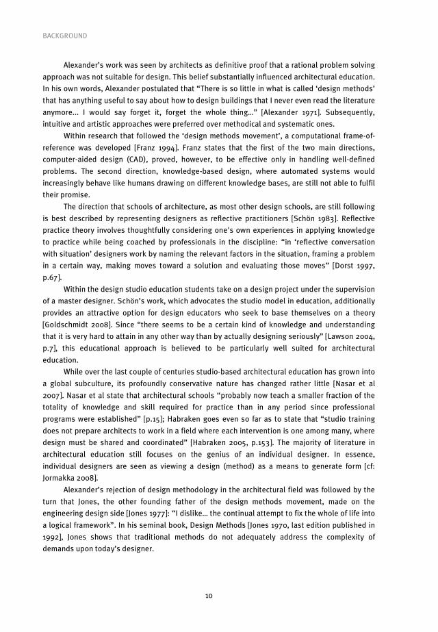
completed. The stages are usually defined as being executed sequentially (in principle only
once), and are related to the states of the product.
Table 1. A comparison of engineering design process models [Howard et al 2008, p.163]
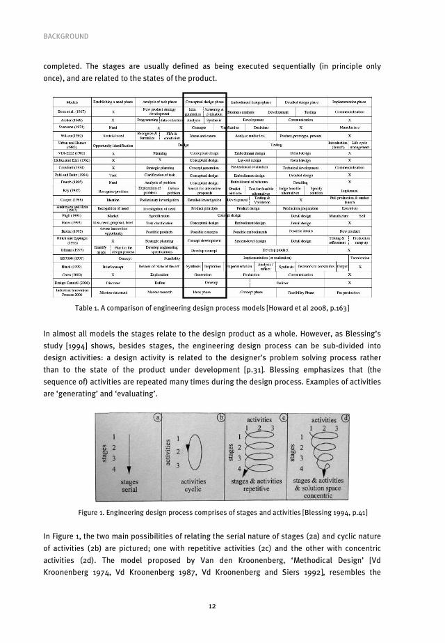
In almost all models the stages relate to the design product as a whole. However, as Blessing’s
study [1994] shows, besides stages, the engineering design process can be sub-divided into
design activities: a design activity is related to the designer’s problem solving process rather
than to the state of the product under development [p.31]. Blessing emphasizes that (the
sequence of) activities are repeated many times during the design process. Examples of activities
are ‘generating’ and ‘evaluating’.
Figure 1. Engineering design process comprises of stages and activities [Blessing 1994, p.41]
In Figure 1, the two main possibilities of relating the serial nature of stages (2a) and cyclic nature
of activities (2b) are pictured; one with repetitive activities (2c) and the other with concentric
activities (2d). The model proposed by Van den Kroonenberg, ‘Methodical Design’ [Vd
Kroonenberg 1974, Vd Kroonenberg 1987, Vd Kroonenberg and Siers 1992], resembles the

BACKGROUND
13
repetitive activities in each stage (2c). Although not widely known outside The Netherlands, this
model is based on the combination of the German design school [Matousek 1962, Hansen 1968,
Roth et al 1972, Hubka 1980, Pahl and Beitz 1984] and the Anglo-American school [Hall 1962,
Asimov 1964, Archer 1965, Gregory 1966, Krick 1969, Jones 1970]. It distinguishes, based on
functional hierarchy, various product abstractions or complexity levels and requires all stages
and activities to be repeated for each one of them. The model is listed in the 3rd edition of
‘Engineering Design – A Systematic Approach’ [Pahl et al 2007, p.21], which arguably provides the
most comprehensive chronological overview of the development of engineering design
methodology.
The motivation for using this model in the present research was twofold. First, any model
chosen needed to be problem valid. In our case it had to facilitate the inclusion of knowledge of
all building design disciplines. Second, the model would have to be user friendly in order for the
different disciplines, which often act on different abstraction levels, to be able to exploit it
effectively. Here, a cultural point needs to be made. As mentioned earlier, arriving at an
egalitarian design process involves movement from both of the major poles of architecture and
engineering. Whereas the main movement from the architect concerns becoming more open, the
engineer needs to present their knowledge in a way that is usable for designing buildings. In this
sense the engineer has more of a distance to travel, and may therefore require more support to
allow them enjoy a full participatory role in design team. With this assumption in mind, the
argument here is that an engineering design model, Methodical Design, can be developed to be
problem valid for this task.
The above theoretical review leads to the methodological choices to design a project aimed
at solving an immediate practical problem: how to integrate engineers at the outset of the
conceptual design phase. However, if we wish to realise a more integral design process that
could lead to new sustainable building concepts, bringing perhaps exponential added value, then
C-K theory offers a conception of how this ideal may be realized.
2.3 C-K theory
Pragmatic views of design as well as existing design theories [Yoshikawa 1981, Suh 1990, Gero
1996, Braha and Reich 2003] define design as a (dynamic) mapping process between required
functions and selected structures [Hatchuel and Weil 2008]. Hatchuel and Weil argue that
dynamic mapping is not sufficient to describe the generation of new objects and new knowledge,
which, according to them, are distinctive features of design. Their statement that “there is no
design if there are no concepts” [Hatchuel and Weil 2003, p.5] underpins the logic of C-K theory
and of the present research.
The explanatory power of Hatchuel and Weil’s C-K theory is useful for both researchers and
designers. For researchers C-K theory crystallises the distinction between re-designing and
optimising on the one hand, and designing on the other. C-K theory defines design as the
interplay between two interdependent spaces having different structures and logics. This process
generates co-expansion of two spaces: space of concepts C and space of knowledge K. According
to C-K theory, space K “contains all established (true) propositions (the available knowledge)”,

BACKGROUND
14
while space C “contains concepts which are undecidable propositions in K (neither true nor false
in K)” [Hatchuel and Weil 2008]. Within this research, in the case of a building design team, the
available knowledge within this team represents space K. Since C-K theory defines a piece of
knowledge as a “proposition with a logical status for the designer or the person receiving the
design” [Hatchuel and Weil 2002, p.11], all explicit representations of a design team’s knowledge
are considered to form part of space K. The overview of this knowledge is captured using
morphological design tools, as will be explained later. Within C-K theory a design concept is a
proposition that cannot be logically valued in K. Concepts are candidates to be transformed into
propositions of K, but are not themselves elements of K (properties of K can however be
incorporated into concepts). If a proposition were true in K, it would mean that it already exists
and all is known that is needed about it (including its feasibility). Design would then immediately
stop. Accordingly, there is no design if there are no concepts. Without the distinction between the
expansions of C and K, design disappears or is reduced to mere computation or optimization.
This distinction is useful to focus the designers during the design process. It makes them
consider more carefully what possibilities exist in terms of design, allowing them to assess any
design they are working on in a new light. C-K theory uses four different operators to explain the
whole design process, two ‘external’ (from C�K and from K�C) and two ‘internal’ (from C�C
and from K�K). The definition below of the operators and the resulting C-K design square is
taken over from Hatchuel and Weil:
• The K�C operator adds to or subtracts from concepts in C some properties coming from K.
It creates ‘disjunctions’ when it transforms elements from K into a concept. This also
corresponds to what is usually called the “generation of alternatives”. Yet, concepts are not
alternatives but potential ‘seeds’ for alternatives. This operator expands the space C with
elements coming from K.
• The C�K operator seeks for properties in K that could be added to or subtracted from to
reach propositions with a logical status; it creates conjunctions which could be accepted as
‘finished designs’ (a K-relative qualification). Practically, it corresponds to validation tools
or methods in classical design, of which the most common are: tests; experimental plans;
prototypes; and mock-ups. These methods expand the available knowledge in K while
being triggered by the concept expansion in C.
• The C�C operator minimally comprises of the classical rules in set theory that control
partition or inclusion, but it can be enriched if necessary by consistency rules in C.
• The K�K operator minimally comprises the classical rules of logic and propositional
calculus that allow a knowledge space to have a self- expansion (proving new theorems).
[Hatchuel and Weil 2003,p.9]
What is important to recognise is that with the K�K operator dynamic mappings can be
simulated, while the other operators underline the major role of space C. Design theories based
on a problem-solving view of design essentially only cover the K�K operator, i.e. they are not
suitable to explain the possibilities for new design concepts or to change the existing solution
definitions. It can be argued that in the face of the environmental concerns noted earlier, where
new definitions of buildings are needed, a C-K theory notion of design is necessary.

BACKGROUND
15
Figure 2. The C-K design square [Hatchuel and Weil 2003]
Proposed as a unified design theory, C-K theory focuses on innovative design [Hatchuel and
Weil 2003]. However, the majority of cases in building design practice do indeed concern mere
computation, optimization and/or combination. Therefore, an explanation of how design
knowledge can be used within the design process needs to be made. In order to do so, a more
specific explanation of design knowledge is required.
General design knowledge can be differentiated into three categories: object knowledge,
realization knowledge and process knowledge [Van Aken 2005, p.388]. Van Aken states that the
repertoire of a designer typically consists of general object knowledge: that is, knowledge of the
characteristics and properties of artefacts and their material. As such, a designer produces
representations of the artefact to be made; the object-design [Van Aken 2005, p.381]. These
representations are regarded in this research as the building blocks for design concepts. On this
basis it is assumed that individual designers must be able to explicate their object-design-
knowledge by generating object-design representations driven by individual interpretations of
the design task.
From the perspective of C-K theory, the initial object-design-knowledge that participants
bring into the design team defines space K. From here, two types of synthesis are possible: either
the representations are combined, using the K�K operator, or are transformed, using the K�C
operator. In this thesis the former possibility leads to ‘redesigns’ (RE), while the latter leads to
‘integral design concepts’ (ID) [Savanovi� and Zeiler 2007]. Ultimately, evaluation of RE-design
can only result in the same object-design-knowledge, while from ID-concepts new object-design-
knowledge can be created. The difference between the two possible design processes, thus, is
that the first one leads to knowledge transfer between design team members, while the second
one additionally allows for the possibility of knowledge creation. It could be said that with the
first type of described design process, the first main aim of introducing engineering knowledge
into conceptual building design process can be realised, while with the second type of design
process the second main aim of the research, the additional creation of design concepts, can be
achieved.
According to Boden [1990] people can be credited with creativity in two senses, described
as P-creativity and H-creativity: P stands for psychological and H for historical. P-creativity
represents the creation of ideas that are new to the person who proposes them. These ideas are
considered ‘new’ no matter how many other people may have previously had the same idea. H-

BACKGROUND
16
creative ideas are novel with respect to the whole of human history, and people usually refer to
them when they speak of ‘real’ creativity and ‘real’ innovative proposals. Concerning design, the
transformation of object-design-knowledge into ID-concepts is regarded as a design team P-
creativity process.
In discussing creativity, it is important to remark that despite the significance of creativity
in design, it was never the intention of this research to investigate its relation to team design
and/or the related development of shared mental models [Badke-Schaub et al 2007]. Mental
models are generally seen as a basic theoretical concept for understanding how designers think
and act [Badke-Schaub 2007]. Instead, the focus of the research was on the results of the
inclusion and assimilation of the explicit object-design-knowledge within building design teams,
assuming equality between individual design disciplines.
In conclusion, C-K theory is essential in terms of the second long-term goal. It shows the
necessity of concept creation, and allows us to conceive of the possibility to transform the
building design team’s object-design-knowledge into concepts. Besides their importance for new
design knowledge, the creation of these concepts represents the potential for realization of
innovative sustainable buildings.
2.4 The importance of engineers in architectural design
Since the 19th century, buildings have increasingly been specified in quantitative ways, and in
ways in which specific aspects of performance are explicitly laid out [Davis 2008]. This is reflected
in the explanation of the beginnings of Modern architecture, which can be traced back to the
middle of the 18th century when “some sub-domains of architecture, such as climatic control,
economic management and construction safety became more objective, rational and empirical”
[Lefaivre and Tzonis 2004]. Responsibility for these sub-domains is generally ascribed to
engineering disciplines. As a consequence of engineering disciplines being responsible for the
more technical elements, the role of the architect is perceived as being restricted to the more
aesthetic aspects of building design. The architect is commonly understood to have control over
what the building looks like – the zone of space that is six inches or so deep, around the outer
skin. From this perspective the architect could be viewed as a problem-solving engineer: s/he is
optimizing well-defined quantitative variables. An interesting discussion of this point can be
found in Vermaas et al [2008]:
In a way, architecture has narrowed its systems boundaries through a new emphasis
upon building performance and the physical sciences. This is a development that
brings parts of architectural world much closer to engineering design. Here, as in
traditional engineering design, design problems are approached primarily in a
reductive and not in an expansive way. [p.9-10]
The growing complexity of engineering design reduces the distinction between it and design in
architecture, leading to gradual development of engineering design towards a model more like
architectural design. In today’s environmentally conscious society architects and engineers have
to consider the full “life cycle” of the products that they create. This cycle begins with the design

BACKGROUND
17
phase and ends with the disassembly of a product. In response, in different engineering fields
systems engineering has emerged and become a branch in its own right. Vermaas et al point out
that “[o]riginally this new field of engineering focused on the design of complex, large
technological systems, and on the organisation of technologically complex production processes,
including complex design processes.” [p.8]
The point raised by Vermaas et al is that in the design of socio-technical systems for
environmental sustainability engineers must move, as in architectural practice, toward an
expansive understanding of design problems, and that part of this expansion of responsibility will
be imposed from outside by the ever growing complexity of design problems in the present day.
The sustainability issues are of such importance and magnitude that, in design terms, they
pose a kind of coherence-in-variety requirement, similar to the ‘Renaissance type of innovation’.
The task is to design keeping in mind that not only a specific relation between systems is
required, but also the possibility to implement that relation differently each time: that is, a
definition of principles and concepts with which one can design further, instead of only plug-and-
play solutions. This type of concept definition is closely connected to (design) knowledge
development. Today, the task of design knowledge development needed for new sustainable
solutions requires a multidisciplinary effort. During modern times this multidisciplinary effort was
absent due to a mono-discipline inventiveness and originality, based merely on aesthetic/stylis-
tic preference.
The view forwarded in this dissertation is that the discussion in architectural design should
primarily be about the type of choices that need to be made during building design rather than
the choice of building form [Tzonis and Lefaivre 1991]. The ultimate physical result of building
design remains, however, a certain form – defining spaces for use and/or experience. Regardless
of its complexity, both in composition and materialization, the number of different expectations
and judgements from a variety of stakeholders that a building has to meet makes it extremely
demanding for an individual discipline, let alone an individual designer, to translate the required
(technical) solutions into a form that encompasses all the demands.
Isolating design as a discrete discipline during the Renaissance opened the path to
innovation [Habraken 2005]; throughout history, architecture and building (innovation) had
always been systematic, in the sense that ways of building rested on shared elements brought
together in fixed and familiar ways. Alexander refers to this as ‘timeless way of building’.
Nowadays, however, regarding the building as largely a composition of systems, the architect is
neither the designer of all systems, nor does s/he design with all systems in mind. The most
important role of the architect is to orchestrate and coordinate the team of co-designers, which is
assembled ad hoc for each project. More than half-century ago Sybil Maholy-Nagy pointed out
that the architects’ role is to coordinate between two extremes: Le Corbusier’s purely aesthetic
view of architecture and Buckminster Fuller’s purely technological view of architecture [Maholy-
Nagy 1957].
Mahony-Nagy’s above quote is underpinned by the common belief arising from his body of
work that Le Corbusier viewed form as the sole concern of the architect. However, towards the
end of his distinguished career, Le Corbusier summarized the relation between architects and
engineers as equals with different tasks and responsibilities [Le Corbusier 1960]. If we consider
BACKGROUND
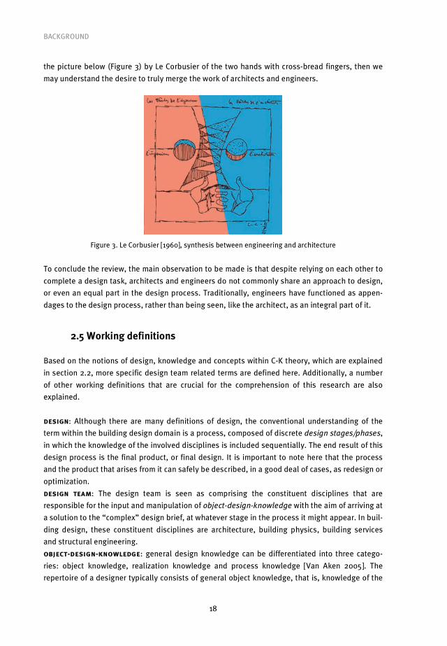
18
the picture below (Figure 3) by Le Corbusier of the two hands with cross-bread fingers, then we
may understand the desire to truly merge the work of architects and engineers.
Figure 3. Le Corbusier [1960], synthesis between engineering and architecture
To conclude the review, the main observation to be made is that despite relying on each other to
complete a design task, architects and engineers do not commonly share an approach to design,
or even an equal part in the design process. Traditionally, engineers have functioned as appen-
dages to the design process, rather than being seen, like the architect, as an integral part of it.
2.5 Working definitions
Based on the notions of design, knowledge and concepts within C-K theory, which are explained
in section 2.2, more specific design team related terms are defined here. Additionally, a number
of other working definitions that are crucial for the comprehension of this research are also
explained.
design: Although there are many definitions of design, the conventional understanding of the
term within the building design domain is a process, composed of discrete design stages/phases,
in which the knowledge of the involved disciplines is included sequentially. The end result of this
design process is the final product, or final design. It is important to note here that the process
and the product that arises from it can safely be described, in a good deal of cases, as redesign or
optimization.
design team: The design team is seen as comprising the constituent disciplines that are
responsible for the input and manipulation of object-design-knowledge with the aim of arriving at
a solution to the “complex” design brief, at whatever stage in the process it might appear. In buil-
ding design, these constituent disciplines are architecture, building physics, building services
and structural engineering.
object-design-knowledge: general design knowledge can be differentiated into three catego-
ries: object knowledge, realization knowledge and process knowledge [Van Aken 2005]. The
repertoire of a designer typically consists of general object knowledge, that is, knowledge of the

BACKGROUND
19
characteristics and properties of artefacts and their material; as such, a designer produces
representations of the artefact to be made [p.381]. In this research, the building object-design-
knowledge is seen as discipline based. The main focus was on use of this knowledge within team
setting.
design stages/phases: the ‘standard tasks description 2009’ [DNR-STB 2009] of ‘The New
Rules 2005’ [DNR 2005], legal relationship client-architect, engineer and consultant DNR 2005
developed by BNA and ONRI, defines 10 different project phases. The phases 3 to 8 represent
design phases: structural design, preliminary design, final design, technical design and
construction-ready design. The research in this thesis is focused on conceptual design, which
comprises both phase 3 and 4 of the DNR 2005.
redesign: The process of combining object-design-knowledge to arrive at a final, yet not novel,
design solution.
optimization: The process of maximizing advantage from combining knowledge in known ways.
design: on the basis of definitions from C-K theory, there is no design if there are no concepts.
Therefore, this thesis argues that we can only talk of Design when it is evident that object-design-
knowledge has led to new design concepts. With this in mind, from this point forward ‘design’
follows a traditional meaning, and ‘Design’ refers only to new design concepts.
integrated design: The process in which the input of different disciplines, often contributed
separately and in different design phases, is made to fit.
integral design: The process in which the constituent design disciplines are given the
opportunity to participate in team design and contribute their knowledge from the outset of the
conceptual design phase. As will be argued later this is a necessary condition for the creation of
integral design concepts.
integral design concept: Within C-K theory a concept is derivable from existing knowledge.
Within integral design, an integral design concept is derivable from the explicated object-design-
knowledge of the design team. Following Van Aken [2005], an important condition for the
realization of an integral design concept is that its derivation must be traceable to the design
team’s object-design-knowledge. In the absence of this condition, there is no way of knowing if
the end concept was no more than the creative result of one team member.
design model: within the design process a design model, through the use of a design tool,
serves to record the activities within the design process. Design models can be categorized as
either being descriptive or prescriptive. Prescriptive models also function to force the direction of
the activities within design process. The design model developed in this thesis, the Integral
Design model, is prescriptive in nature.
design tool: an artifact that is used to support the design process. The choice of design tool in
this thesis was morphological charts; a two-dimensional representation used to explicate and
structure design aspects and sub solutions, i.e. representations of discipline-based object-
design-knowledge. The process of combining the knowledge from the charts into an overview is
negotiated within the design team and results in the design team’s morphological overviews.
Once the morphological overview has been filled in, it can act as the basis to stimulate the
transformation of the recorded knowledge into new concepts.

BACKGROUND
20
design method: to qualify as a design method the following components must be included:
• a clear purpose or goal in the design process,
• clearly distinguishable, sequential steps that are fully and clearly communicated, making
them replicable to others,
• Determinable criteria to establish that steps have been conducted correctly and have
indeed been concluded.

21
3.1 Introduction
This chapter begins in section 3.2 with the explanation of the research methodology used, the
theoretical framework of Design Research Methodology. In section 3.3, research design and re-
search setting are explained. Observation methods used within the research setting are explain-
ed in section 3.4. The chapter ends with discussion on triangulation of methods in section 3.5.
3.2 Theoretical Framework: Design Research Methodology
In response to what they saw as the lack of existing rigorous methods for design research,
Blessing and Chakrabarti [2009] developed Design Research Methodology (DRM). They observed
that since design research is currently conducted using a mixture of methodologies from different
fields, it is very difficult to compare different instances of design research. DRM can be seen as a
generic design research methodology that fits these research areas together, and provides a
framework that connects research questions and addresses them in a systematic way. This call
for increased systematicity is in line with earlier observations [Cross 1982]. Cross even goes so far
as to propose ‘design as a discipline’; a ‘science of design’ based on the ‘reflective practice of
design’ [Cross 2001, Cross 2006] that would result in design being studied in its own terms.
Design research not only aims at understanding the phenomenon of design, but also at
using this understanding in order to change the way design is carried out. It is this latter
improvement to the design process that DRM has largely been used to address in previous
research [Blessing 2006, Blessing and Chakrabarti 2009]. This is also the case in the present
research. In order to improve the design process, design research within the DRM framework
must not only describe the status quo, it must also prescribe a more desirable future status quo.
The research focus within DRM is founded on assumptions, leading to research questions that
need to be tested in order to move from the described status quo to the desired future status
quo. DRM research is housed within four separate stages. The four stages could be seen as a
problem-solution structure, which is seen as the benchmark of quality of research in many fields.
A clear consequence of framing research as motivated by a problem is the need to define
criteria for the successful solution of the problem. DRM emphasises the need to formulate
success as well as measurable criteria. These criteria need to be defined in the first stage of the
DRM research, so that they can be measured against in the fourth and final stage of DRM. Each of
the stages is described in detail below.
3.2.1 The four stages of DRM research
DRM consists of four stages: research clarification, descriptive study I, prescriptive study and
descriptive study II (Figure 4). Blessing and Chakrabarti emphasise that it cannot be expected
that each of the stages of the methodology will be executed in depth in every single project.
Resources might be limited or it might not be necessary to do so. DRM is not a purely sequential
3 Methodology

METHODOLOGY
22
process: many iterations can take place, and some stages may have to run in parallel. Several
variations of the methodology are possible and necessary to suit the focus and constraints of a
particular project. In this research the steps according to variation three, as shown in below
figure, were taken.
RESEARCH
CLARIFICATION
DESCRIPTIVE
STUDY I
PRESCRIPTIVE
STUDY
DESCRIPTIVE
STUDY II
1 Review Detailed
2 Review Detailed Initial
3 Review Review Detailed Initial
4 Review Review Review Detailed
Initial / Detailed
5 Review Detailed Detailed Initial
6 Review
Review Detailed Detailed
7 Review
Detailed Detailed Detailed
Figure 4. Variations within four DRM stages [Blessing and Chakrabarti 2002]
The dissertation format of this research brings with it the responsibility of providing a problem
definition in the introduction of the text. It necessitates the realisation of important academic
functions, such as justifying the problem and providing a realistic approach with which to attempt
to solve it. Within DRM, the research clarification stage imposes these same responsibilities on
the design researcher. The role of the first stage, Research Clarification, is:
• to identify the aim that the research is expected to fulfil and the focus of the research
project;
• to focus Descriptive Study I on finding the factors that contribute to or prohibit success;
• to focus the Prescriptive Study on developing support that address those factors that are
likely to have most influence;
• to enable evaluation of the developed support (Descriptive Study II).
The second stage, Descriptive Study I, emphasizes the need to increase understanding of design
in order to inform the development of design support. This means that the current state of design
practice has to be observed and analysed, on the basis of which improvements can be made. The
way this was done for the development of the ID-method is explained in detail in Chapter 4. The
role of the Descriptive Study I stage is:
• to identify the factors that influence the formulated measurable criteria and how they
influence these;
• to provide a basis for the development of support to improve design;
• to provide more details that can be used to evaluate developed design support.
METHODOLOGY
23
The third stage, Prescriptive Study, represents the actual development of design support in a
systematic way. This is the stage where the ID-method was designed, tested, adjusted, and
iteratively fine-tuned. In Chapter 5 all these steps are explained in detail. The main role of the
Prescriptive Study stage is:
• to develop support in a systematic way;
• to evaluate the support with respect to its in-built functionality, consistency, etc.
The fourth and final stage, Descriptive Study II (Chapter 6), is used to identify whether the
support does represent a solution to the problem it was intended for. The role of the Descriptive
Study II stage is:
• to identify whether the support can be used in the situation for which it is intended and that
it does address the factors it is supposed to address (application evaluation);
• success evaluation to identify whether this indeed contributes to success (see the feedback
arrows in Figure 4). This evaluation answers questions about usefulness, implications and
side-effects.
3.3 Research design and setting
To develop the method for an integral building design approach, both the design model and the
setting had to be worked on. Following the DRM approach, this was done within the stages of the
research. After the research clarification stage in which the problem was defined and measurable
criteria were derived, the research proceeded on the basis of making assumptions regarding the
key variables to be manipulated. In this project these were the design team, the design tools, i.e.
the morphological charts and overviews, the design model and the setting. On the basis of the
assumptions regarding these variables, research questions were derived and then tested. The
results of the testing fed into the design of the subsequent design and testing.
3.3.1 Research design
In order to develop a method to solve the problem at hand, the four key elements of team, model,
design tool and setting were considered.
Following the definition in section 2.5, a design team is seen as comprising of represen-
tatives of four disciplines: architecture, building physics, building services and structural engi-
neering. This team design was adopted in the current research. In order to ‘guarantee’ the com-
petence of individual designers, cooperation from professional organizations was sought.
Fortunately, the two main branch organizations in the Dutch building design domain, the Royal
Institute of Dutch Architects (BNA) and the Dutch Association of Consulting Engineers (ONRI),
were happy to be involved in the research and provided a pool of professional participants from
the required disciplines.
As mentioned in the introduction, the Extended Methodical Design model [Zeiler 1993] was
adapted for use in this research. The model was chosen as starting point as, coming from the
engineering domain, it was considered user friendly for engineers while also being comprehensi-
ble to architects. The central design tool of the Extended Design Model is the morphological
chart. This tool, as the results of descriptive study I show, offered the necessary structural

METHODOLOGY
24
elements to allow the object-design-knowledge of the design team to be introduced and
recorded. This is necessary both to create an audit trail within the design process and to provide
data for analysis within this research project.
Finally, in order to test whether the model could be used by a design team to reach the
desired goals, a setting for the testing had to be decided upon. Because of the clear gap in the
status quo, and because of the limitations implied by PhD research, it was not possible to
perform testing in authentic environments. That is, there are few or no examples of integral
design in practice, and even if one were discovered, due to market considerations it would be
highly unlikely that the stakeholders would open up their design process to a researcher. With
this in mind the standpoint in this thesis is that the best one could aim for at present is to gather
the relevant disciplines in a semi-controlled environment in order to simulate the conceptual
design phase. The organisations involved ensured the necessary professionals. But, it was up to
us to provide the environment. We considered a workshop setting as particularly suitable in
terms of guiding the research towards the two main goals. In terms of the first goal the
participation of professionals from the relevant disciplines would certainly allow us to draw
conclusions as to the usability of the method. The possibility for knowledge exchange and the
implied need for cooperation within a workshop setting vicariously address the cultural change
that is necessary to realise the second goal.
3.3.2 Research setting
Within this research project pretesting was performed before the main testing was carried out.
The pre-test phase consisted of two separate test workshops, while the main testing took place
in five subsequent workshop series. In each of the workshops a number of design teams
participated.
The first workshop functioned as a pre-test of the setting in which informal observations
were carried out by professional researchers, mainly to verify the suitability of workshops as a
setting for team design. Additionally, the workshop was used to test the contention that rigid
prescription of the design tool would not work. Specifically, we tested rigid prescription of the
use of morphological charts.
The second workshop, alternatively, functioned as a pre-test for loose prescription of the
use of morphological charts. Additionally, in order to guarantee that other key assumptions were
tested, two researchers from the department were included in the design teams. Once the
suitability of the research setting was agreed upon, all future tests exploited the workshop
format.
3.4 Observation methods
Generally, there is no consensus within the design research community on how to observe and
analyse design meetings [Blessing 2006, McDonnell and Lloyd (eds.) 2009]. Therefore, following
the DRM approach assumptions were made on how best to proceed with the observation, and
were subsequently tested in the workshops and then amended. As will be shown in the
prescriptive study results section, there was indeed a need to iteratively improve the method of
observation. The motivation for the choice of the first observational set-up is explained here, but
METHODOLOGY
25
the rationale behind the subsequent observation set-ups is included in the prescriptive study
results section. This is done because the subsequent set-ups were based upon the answers to
the research questions that were tested in each workshop.
The first observational set-up was used in the first workshop series. The two previously
conducted test workshops only required informal observation to verify the base assumptions that
were tested there. From the first workshop series onwards formal observation methods were
used.
In the first workshop series the following aspects needed to be observed: individual
activities of design teams’ members, communication within design teams and use of morpho-
logical charts. Individual activities were categorised as proactive or reactive, with further
distinction based on differences between visual and verbal introduction of new design
aspects/functions and (sub) solutions. Communication patterns were categorised as towards a
design team member and towards the whole design team. The use of morphological overviews as
a design tool was categorised in design and communication activities, further distinguished into
report and insight sub categories.
As this seemed a large task, it was deemed necessary to break the observation down in the
component parts. Each part was to be the concern of one observer. This led in the first setting to
three observers for each design team. Realistically, due to the number of design teams in the
research set-up, we could not expect to find the number of professionals required to perform this
observation task. However, since the research was part of the university project, we had access to
an abundance of master students with a relevant background. Students from the design
methodology course, offered to master students at the Department of Architecture, Building and
Planning of TU/e, were considered the most suitable candidates for the observation tasks at
hand. In the first set-up each observer was given a predefined observation form to fill in during
the workshop.
Although subsequent observational set-ups are described in detail in the results section,
the sequence of their development is described here in brief. First, the above described set-up
including three master student observers was used. Following feedback from the professional
participants it was deemed necessary to change the configuration of observers. In workshops
series that followed the feedback received resulted in the removal of human observers
altogether. In the final set-up, in place of human observers we used video recording devices. In
addition, in order to register the development of the team design process all workshop set-ups
were photographed at 10-minute intervals. Finally, in order to get feedback, on both the
workshop set-ups and the ID-method developed within them, questionnaires were administered
to the participants.
3.5 Triangulation
A common way to check the validity of the research findings is through triangulation of methods.
According to the British Educational Research Association (BERA) triangulation was first applied
to research by Campbell and Fiske [1959] and later developed by Webb [1966]. Webb argued that
researchers should employ more than one instrument to measure variables [p.3]: “Once a
METHODOLOGY
26
proposition has been confirmed by two or more independent measurement processes, the
uncertainty of its interpretation is greatly reduced. The most persuasive evidence comes through
a triangulation of measurement processes.” As this implies, triangulation was first associated
with quantitative research, but its relevance to qualitative methods was soon explored. Denzin
[1970, 1978] was a major proponent of the use of triangulation by researchers working within the
interpretivist paradigm. Writing from a symbolic interactionist perspective, Denzin views the
researcher as an active participant in the social world, which he or she ‘acts on’ through the use
of method. Therefore, to get as full and as accurate a picture as possible, researchers must use
more than one strategy. Denzin identifies two types of methodological triangulation – ‘within-
method’ and ‘between’ or ‘across’ method. A study using the ‘within-method’ approach is
confined to one method but uses different strategies within it. Denzin is rather dismissive of this
approach, giving the example of a survey which uses a number of different scales to measure the
same variable. The researcher may think he is measuring the same phenomenon in several ways,
but the decision to stay within one method means the biases associated with that method remain
unchallenged. Much more satisfactory, in Denzin’s opinion, is the ‘between’ or ‘across methods’
approach which, by combining at least two different methods in one study reaps the benefits of
each approach while also compensating for their weaknesses. In the present research project two
different research methods, questionnaires and observations, were combined.
Besides triangulation of methods, which is the most common application of the term
triangulation, there are three other types of triangulation: triangulation of investigators,
triangulation of data and theoretical triangulation.
The rationale of triangulation of investigators is to reduce bias and increase reliability.
Using this approach, two or more researchers are employed to carry out the same tasks, be it to
gather and/or to interpret data. In this research, triangulation of investigators was limited to the
pilot observations of the video recorded final workshop series. Prior to the analysis of all work-
shop design sessions in this series, as a pre-test measure, in order to check whether separate
individuals could arrive at the same analysis, two researchers from the Building Physics and
Systems unit at TU/e independently reviewed the video recording of one team per design setting.
Triangulating data sources allows the researcher to use the same method to maximum
theoretical advantage. Choosing dissimilar settings to study the same phenomenon allows the
researcher to identify which explanations, or aspects of them, hold true across the board and
which are context-specific. There are three sub-types in this category: time, space and person.
Data can be collected about different people doing the same activity, it can be collected at
different times, and it can be collected in different places. Besides, there are also three levels at
which data can be analysed: the aggregate, where data were collected from separate, unrelated
individuals; the interactive, where interaction between people or groups is the focus of analysis;
and the collectivity, where the unit to be observed is a group, community or society. The most
complex form of data triangulation combines some or all of the sub-types with some or all of the
levels of analyses. In this research, the triangulation of data was achieved by collecting data of
different design teams doing the same activity. Additionally, the design teams were treated on
two levels: they were seen both collectively as a set of complex units, and separately as a
collection of different individual designers. The former view can be associated with the aggregate

METHODOLOGY
27
data analysis, where averages of different design teams sets were quantitatively compared, while
the latter explains the results of each separate design team qualitative analysis.
The most difficult type of triangulation is theoretical triangulation, described by Denzin as
“pitting alternative theories against the same body of data”. Triangulating theory will avoid the
risk of researchers reaching ‘a-theoretical’ conclusions, selecting only those data which suit their
pet views or developing small scale theory which has little relevance beyond the immediate
situation. In this research, theoretical triangulation was not used.
Accepting the fact that triangulation is an important aspect of rigorous research, in the
present research project it was attempted as far as possible. However, in the recommendations
for future work section it is explained how experimentation may allow further triangulation in
order to strengthen the results.

28
4.1 Introduction
As mentioned earlier, the design of this research was iteratively improved upon throughout the
project. Therefore, the methodological steps taken and the ensuing result are inextricably linked.
In this and the following results chapters then, it is necessary to describe both the results and
some of the methodological steps taken to achieve them. The iterative development of the
method results from housing the research within the DRM framework. The chapters are therefore
organised according to the four stages within the DRM research: research clarification and des-
criptive study I in chapter 4; prescriptive study in chapter 5; and descriptive study II in chapter 6.
In the research clarification the problem within the status quo is further defined, as are the
main aims of the research project. In addition, the criteria to measure the success of these aims
are derived. Descriptive study I is the place where the designated problem in the status quo is
checked or verified in a realistic setting. In the present research, the main aims include improving
upon current building design process, and improving on cooperation between engineers and
architects in the conceptual design phase. With these aims in mind, it is important to note here
that the motivation for this project is the clear lack of such integral approaches in practice.
Therefore, it was not possible to look at practice directly in order to solve the problem.
Consequently, the decision was made to address the problem indirectly, by looking at case-
studies that could inform us about either elements regarding process and/or design tools aiming
to solve similar problems.
4.2 DRM stage 1: Research clarification
The main contention in this thesis is the following: there is a lack of true integration of building
disciplines in the conceptual design phase. This is undesirable because when the integration
does come, usually in the final design phase, it is difficult, expensive and problematic to fully
integrate and often leads to unforeseen problems and costs. To remedy this situation, the
building design process must improve.
Therefore:
a method needs to be developed to allow engineering building design disciplines to be
included into the design process in a meaningful way from the outset
In terms of the current research, this need translates into the following two goals. The first goal is
to fully include engineering knowledge in the conceptual design phase. This is done with a view
to arriving at a better starting design proposal for further optimization and redesign and with a
view to improving the efficiency of the design process by removing unnecessary iterations. The
second goal is to secure the preconditions for the potential creation of innovative building
concepts. This goal could not be realistically researched until the first goal had been successfully
4 Descriptive study I results: literature studies

DESCRIPTIVE STUDY I RESULTS
29
achieved. In this sense the first goal acted as a necessary precursor to the second, and as such
received the majority of research time available in this project, meaning that the second goal
could only be minimally researched.
The aim of the research was to design an Integral Design Method that would facilitate the
explicit introduction and subsequent integration of knowledge from all design disciplines within
the conceptual design phase. Used within design teams in a face-to-face setting, this ID-method
sets the preconditions for the creation of new (object) design knowledge and the subsequent
possible realisation of innovative buildings. This led to the following two hypotheses:
• Hypothesis 1: following the ID-method will result in the inclusion of engineering design
knowledge in the conceptual building design phase.
• Hypothesis 2: following the ID-method can lead to innovative building design concepts
An important note needs to be made here. Since no approach is capable of providing sufficient
conditions to guarantee innovative buildings/concepts, the approach involving the use of the ID-
method can only ever represent the necessary conditions for the realisation of goal 2. In addition,
to truly assess the viability of the ID-method in terms of the second goal, it would need to be
applied to authentic building projects aimed at innovative building design. As mentioned earlier,
in this research this was not possible. What was achievable in this project was to test for the aims
in the semi-authentic setting of a workshop.
The measurable criteria for the first goal are increased amount of explicitly introduced
object design knowledge and number of design aspects considered by the design team within the
design process. Ultimately, on the product level, the success criterion for the first goal would be
the realisation of better optimization and redesign. Logically, one may assume that an improved
process has a greater chance of resulting in better redesign and optimization. In terms of the
second goal, the measurable criterion is the realisation of integral design concepts. ID-concepts
theoretically increase the possibility of arriving to ‘satisficing’ final solutions – innovative
sustainable buildings – in the subsequent design phases, which can be understood as the
ultimate success criterion of the ID-method. The final measurable criterion is the acceptance of
the method by the professionals (BNA architects and ONRI engineers) involved in its
development and use.
The value of this research can be seen as twofold. On the practical level, the development
of the ID-method provides a useful tool to be exploited during the design process. On a
theoretical level, incorporating C-K theory into the research and to some extent validating its use
in a new setting represents a valuable contribution to the existing body of knowledge on design.
4.3 DRM stage 2: Descriptive study I
4.3.1 Introduction
Descriptive study I of DRM emphasizes the need to increase understanding of design in order to
inform the development of design support. In addition to usual analysis of the current state of
design practice, on the basis of which the (working mode for) improvements could be made, DRM
explicitly mentions (field) observation. However, the approach in this project was only analytical

DESCRIPTIVE STUDY I RESULTS
30
and no direct observations of design activities in practice were part of the used research
methods. Since there were no authentic settings to study, a pragmatic approach was taken in
which it was attempted to learn from previous research. After an initial broad review of literature
was performed, the decision was made to focus only on the literature sources that were actually
used in this research. This selection of literature sources was based on the criterion ‘fit for
purpose’ [Denyer et al 2008]; simply by ‘judging whether or not the particular cases added
anything new to understanding the phenomenon’ [Pawson 2002] at hand in the research project.
In descriptive study I three separately focused literature studies were conducted. The main
focus of the first literature study was on the design process and the role engineers play in it. The
cases covered in this study all concerned building design in the context of sustainability issues.
Thus, they are classifiable by definition as complex design problems, and as such were
considered highly relevant. The main focus of the second literature study was on assessing a
general approach to structuring and organising team knowledge. The main focus of the third
literature study was on a specific application of a morphological tool to structure design team
knowledge and activities. All of the literature studies begin with guided research questions,
which are answered at the end of each review.
4.3.2 Case studies of energy-efficient building design projects in The Netherlands
The aim of this review was to look for answers to the following two research questions:
At what point in the design process is engineering knowledge integrated?
How is this knowledge used?
This review focuses on case studies performed within a PhD research conducted at Delft
University of Technology [De Wilde 2004]. In developing “strategy to provide computational
support during the building design process for rational design decisions regarding the selection
of energy saving building components” [p.7], De Wilde analysed the current ways of selecting
energy saving building components during the design of energy-efficient building projects in The
Netherlands. The study of design processes of these cases in general was not his objective. The
importance of his study for the ID-method development resides in the insight it gave of the
mechanisms used for the selection of energy saving building components during the building
design processes.
Three case studies were conducted by De Wilde to gather information on the selection of
energy saving building components, the comparison of which provided a general view of building
practice regarding this specific aspect. Additionally, De Wilde conducted a survey to verify
whether or not the results of the case studies hold for a larger sample. The three case studies
concerned large office building projects, ‘Dynamic Office’ in Haarlem (offices, shops, and part of
the railway station) completed in 1997, ‘Rijnland Office’ in Leiden (Headquarters of the Regional
Water Authority) completed in 1999, and ‘ECN Building 42’ (Energy research Centre of The
Netherlands) completed in 2001.
The brief of the ‘Dynamic Office’ required an office building in accordance with (at that
time) current market standards; it did not state any specific requirements regarding energy
efficiency. However, energy saving components were introduced in order to meet the thermal

DESCRIPTIVE STUDY I RESULTS
31
comfort requirements. All of them (façade with overhangs, thermal mass, energy-efficient
lighting, energy-efficient computers) were proposed by the consultant for HVAC-systems
(heating, ventilation and air conditioning). The procedure for selection of components was based
on repeated computational assessment of the thermal comfort during the preliminary and final
design phases. The impact of the specific components on the other performance aspects was
assessed only later, when the selection of these components was finalized.
The brief of the ‘Rijnland Office’ only provided general instructions: requiring the design to
be environmentally friendly. The further elaboration of this term was left to the design team. The
decision to make the building energy-efficient was initiated by the architect, who considered
energy efficiency to be a part of the broader objective of designing an environmentally friendly
building. Most of the components were, however, suggested by the consultant, who had used
them in the previous projects (long term energy storage, heat pumps, low-temperature heating,
high-temperature cooling, heat exchangers, climate façade, and atrium). The mostly HVAC-
components, which were selected during the conceptual design phase, had little impact on the
architectural design allowing building design process to be separated from the HVAC-system
design. The consultant for HVAC-systems joined the design team very early; he was part of the
team when the use of energy saving building components was discussed for the first time. His
decisions were based on his earlier as well as on reference projects.
The brief for ‘ECN Building 42’ requested Energy Performance Coefficient (EPC) of 0,9 or
lower; the standard at the time was EPC of 1,6. The energy saving components were all selected
by the architect during the conceptual design phase. For each of the considered aspects (heating,
cooling, ventilation, day lighting and use of renewable energy) he added components: for heating
an (existing) cogeneration unit, for cooling fixed shading devices and a nocturnal ventilation
system, for ventilation a combination of a natural and a mechanical ventilation system including
heat exchangers, for day lighting a number of atria, and for renewable energy photovoltaic
arrays. Both architect and consultant calculated the EPC only after completion of the conceptual
design to verify whether or not the design met the value of 0,9.
De Wilde used following phasing of the design process: feasibility study, conceptual
design, preliminary design, final design, and preparation of building specifications and construc-
tion drawings. These were his observations concerning the common process of the selection of
energy saving building components in the three cases:
• selection of most components took place during conceptual design,
• this selection was based on the use of these components by architects or consultants in
earlier projects, or in reference projects,
• there was virtually no selection based on an equivalent comparison of the performance of
several design variants.
In order to verify if the results of case studies hold for a larger sample, De Wilde conducted a
survey targeting an additional 67 building projects selected from literature on energy-efficient
architecture in The Netherlands. The returned questionnaires combined partial data sets
(response from either architect or consultant) for 42 projects and full data sets for 10 projects.
The overall conclusion from the results of the survey was that selection of energy saving building
components seemed to be mainly based on earlier use and analogy: approximately 80% of all

DESCRIPTIVE STUDY I RESULTS
32
components were selected without considering alternatives, demonstrating that the decisions
were highly intuitive. The findings of the survey were therefore in line with the findings from the
case studies. A striking insight resulting from the survey was that architects and consultants
appeared to have different perceptions concerning the phases in which energy saving building
components had been selected. According to architects, most of the components had been
selected during the phase of conceptual design (57%). Percentages of energy saving building
components selected in other phases were: feasibility study 16%, preliminary design 13%, final
design 10%, and preparation of building specifications and construction drawings 4%. According
to consultants, most of the components in the related building projects were selected during the
phase of feasibility study (44%). Percentages for other phases were: conceptual design 28%,
preliminary design 21%, final design 4%, and preparation of building specifications and
construction drawings 3%. The reasons for these differences were unclear; a possible
explanation offered by De Wilde was that consultants might experience their own involvement as
the start of the design process, even if this coincides with a later phase of the overall design
phasing. Anyhow, the results conflict with the expectation that the activities of all participants in
the design process of ‘energy saving buildings’ are interrelated.
De Wilde’s research confirms the importance of the conceptual building design phase, as
highlighted in previous chapters. Interestingly, De Wilde consistently refers to ‘selecting’ the
energy saving building components. Seen from this ‘selection point of view’ it is understandable
that he tried to develop computational support. In order to create new sustainable solutions,
selection only is however not sufficient. And even in case of selecting suitable components, De
Wilde concluded that only a small subset of energy saving components in the projects was
selected from a set of alternatives that consisted of at least one other option.
Although approached as mainly a decision making process, or maybe exactly because of
this emphasis on selection and choice, De Wilde’s research is indicative of the current state of
building design. It shows that even within a narrow context of energy saving aspects, as a part of
the larger framework of sustainable building, improvement of conceptual building design phase
is needed. The challenge is to, for a start, provide a basis for equal involvement of different
design disciplines, after which work can be done on matching their interpretations of design
tasks and introduction of their respective knowledge.
To conclude the review, the research questions are restated and answers are given.
Q1. At what point in the design process is engineering knowledge integrated?
A1. Engineering knowledge is integrated late in the design process, in most cases after the
overall design solution was already selected.
Q2. How is engineering knowledge used?
A2. Engineering knowledge is used primarily for optimization of the selected solutions.
4.3.3 Morphological analysis as basis for team design
The aim of this review was to look for answers to the following two research questions:
Can morphological analysis approach facilitate timely integration of all disciplines within
the (design) team?
Can morphological analysis lead to unified team design interpretation?

DESCRIPTIVE STUDY I RESULTS
33
The research program initiated in the early 1990's at the Swedish Defence Research Agency (FOI)
[Ritchey 2002], aimed at developing a methodological framework for creating ‘models of systems
and processes which cannot be meaningfully quantified’ (for example because of strong social-
political dimensions and conscious self-reference among actors), showed a possible practical
approach for team design. Its emphasis was on problem structuring and subsequent analysis-
synthesis cycles. Regarding the context of building design the FOI approach is interesting in that
its problem structuring aspect provides some guidelines for explication of object-design-
knowledge within building design teams. The analysis-synthesis aspect, and its sharp distinction
with problem structuring, highlights a number of pitfalls which preferably should be avoided in
building design.
The FOI program was based on ‘general morphological analysis’ (GMA), a non-quantified
method for investigating problem complexes that cannot be treated by formal mathematical
methods, causal modelling and simulation [Ritchey 2006]. The starting point of their approach,
rooted in Operational Research, was the distinction between two general ways of problem
structuring – using influence diagrams and morphological/topological methods: “In general, an
influence diagram is a qualitative model of a system which depicts influence relationships
between different elements or aspects of the system, shows the direction of such influences and
(usually, but not always) allows for feedback loops or circular causality. A complementary
approach, which goes under the broad designation of morphological and typological methods, is
based not on networks of causal relationships and hierarchal structures, but on constructed
parameter spaces, linked by way of logical relationships.” [Ritchey 2002, Ritchey 2006] The basic
assumption at FOI was that as an alternative to formal (mathematical) methods and causal
modelling, which proved to be ineffective in tackling ‘wicked problems’ or ‘messes’, a
judgemental approach must be taken. Their question was however: could a judgemental
approach, carried out in groups of subject specialists, be put on a sound methodological and
scientific basis (the FOI’s concern was the possibility of an ‘audit trail’ – tracing of what you have
done and how you have come to your conclusions)? The FOI’s conclusion was that general
morphological analysis (GMA) could provide the answer.
In his overview of GMA development, Ritchey, a former Research Director for the Institution
for Technology Foresight and Assessment at the FOI, explains how GMA seeks to be integrative
and to help discover new relationships or configurations [Ritchey 2006]. Importantly, he states, it
encourages the identification and investigation of boundary conditions, i.e. the limits and
extremes of different parameters within the problem space. The advantage of GMA as a problem
structuring method would be that it defines an actual (internally specified) parameter space in
which different inputs could be given, alternative outputs obtained, and inferences (“what-if”
assertions) made. In terms of building design teams, the ‘parameter space’ can be interpreted as
the overview of discipline-based object-design-knowledge. Ritchey emphasizes that much of the
utility of the morphological structuring process is the process itself. One of the implicit outcomes
is a shared terminology and problem concept among participants, and a better understanding of
wider contexts: “facilitated group interaction is a central feature of the process, since we are not
only structuring a complex problem, but creating among the participants shared concepts and a
common modelling framework… what is essentially a process of collective creativity is best

DESCRIPTIVE STUDY I RESULTS
34
facilitated in dialog between participants… for this reason, we have found it best to work with
subject specialist groups of no more than 6-7 persons.” [Ritchey 2006]
Besides having apparently definite advantages for scientific communication, the GMA was
praised for suitability for group work. As a process, the method demands that parameters,
conditions and the issues underlying these be clearly defined, turning ‘messes’ or ‘wicked’
design problems into (structured) problems. Here a parallel can be made with the need for
design-team-interpretation of a building design task. However, contrary to the FOI approach, the
aim of integral building design is not to turn design tasks into structured problems, but to
structure the ‘messes’ of individual design interpretations into overviews of explicit object-
design-knowledge. In the FOI approach the totality of the parameters and their respective values
is seen as a morphological field (Figure 5). It is recommended to keep the field relatively small at
the beginning, since ‘one can always expand it later’. Interestingly, definition of parameters is
done once-only, after which analysis-synthesis iterations are done. The possibility of adjusting or
changing them is never mentioned. This again highlights one of the main differences between
design and problem-solving, namely that design aspects and functions evolve in time, meaning
that in the case of building design the iterations have to include both ‘definition of parameters’
and ‘analysis and synthesis of solutions’ since they are mutually influenced.
Figure 5. Zwicky box (left) and FOI morphological field (right) [Ritchey 2002, p.6]
Morphological fields originate from the n-dimensional morphological box of Fritz Zwicky [Zwicky
1948, Zwicky and Wilson 1967]. The morphological box was developed in the period after WWII,
when methodologists had the desire to base design processes on objectivity and rationality
[Cross 2001], and requires all functions to be defined and all possible solutions for each function
to be listed, resulting in framing of the solution space. Looked at it in this way, morphological
analysis certainly represents “totality research”, the term used by its founding father Fritz
Zwicky: “an unbiased way attempting to derive all the solutions of any given problem” [Zwicky
1969]. Normally, there are many solutions or configurations in a morphological field; far too many
to look at and check by hand if one would want to examine all of them. The FOI approach
therefore focused on reducing the number of configurations in a field by using computers to

DESCRIPTIVE STUDY I RESULTS
35
perform cross-consistency assessment in order to exclude conditions that were mutually
contradictory. This way the field can be reduced to a list of configurations that represent the
solution space of a particular problem complex; according to Ritchey [2002, 2006] a typical
morphological field can be reduced by up to 90 or even 99%, depending on the problem
structure. Generally, in FOI’s view, poorly defined concepts become immediately (and
embarrassingly) evident when they are cross-referenced and assessed for internal consistency.
However, in view of C-K theory’s notion of concept and knowledge spaces development, the FOI
approach can only lead to redesign and never to integral design concepts. It therefore concerns
mainly decision supporting method, although it may help to discover relationships or
configurations which may not be so evident, or which might be overlooked: “Everyone working
through morphological field learns something new – since the whole point is to relate different
aspects of the problem complex to each other.” [Ritchey 2006]
Ritchey rightfully highlights that, as is the case with all problem structuring methods and
models, the output of a morphological analysis is no better than the quality of its input. However,
he argues the morphological approach still has some advantages: it expressly provides for a
good deal of in-built “garbage detection”, since poorly defined parameters and incomplete
ranges of conditions are immediately revealed when one begins the task of cross-consistency
assessment. These assessments according to him simply cannot be made until the morphological
field is well defined and the working group is in agreement about what these definitions mean,
which is extremely important when working with wicked problems. The same essentially applies
for building team design, however taking into account that team interpretation is bound to
change during the design process and accordingly with it the whole ‘morphological field’.
Nevertheless, some elements of the FOI approach seem valuable for explication and structuring
of discipline-based object-design-knowledge within a design team. Besides looking at ‘poorly
defined parameters’, one could for example also assess the design team configuration and based
on the individual inputs decide to possibly modify the design team itself.
Baring in mind the danger of too much ‘Gründlichkeit’, which is essentially main negative
remark, general morphological analysis offers a possibility to get "out of the box" while still
using certain (necessary) constraints to guide team design. Being around since the first
conference on design methods in London [Norris 1963], the morphological approach has amongst
others been used to “become part of the design task formulation process, and not simply a
‘receiver’ of pre-defined problems” [Müller-Mebach 1975], as a majority of building design
disciplines still often experience. Ritchey’s work culminated in the formulation of five conditions
used by FOI for the computerised support for morphological analysis. These five conditions are
repeated below:
1. The method should be process and group oriented. In other words, it is the process that the
subject-specialist group goes through in doing morphology that is the most important
result.
2. The method should be generic. Morphological analysis is a general method for non-
quantified modelling. It sets no specific preconditions on the working group. You start with
a blank slate, and the group successively builds up a non-quantified model.
3. The method should be transparent. There are no black boxes. All the cards are on the table.
You cannot hide anything.

DESCRIPTIVE STUDY I RESULTS
36
4. The method should leave an audit trail. You should be able to trace what you have done
and how you have come to your conclusions. Although judgemental processes will never be
as traceable as, for example, a mathematical proof, morphological analysis allows for as
much traceability as is possible under such circumstances.
5. The method should be easy to update. If one works with a complex problem area, and
comes back to the client after a (longer) time period, and somebody says “a new dimension
or variable has become important”, one should be able to build this new input into the prior
work, without having to start from scratch. [Ritchey 2002, p.5]
The above conditions, it can be concluded, are also valid for development of team design method
as well.
To conclude the review, the research questions are restated and answers are given.
Q3. Can morphological analysis approach facilitate timely integration of all disciplines
within the (design) team?
A3. Yes!
Q4. Can morphological analysis lead to unified team design interpretation?
A4. Yes! (unified team design interpretations were certainly much more evident here than in
the De Wilde case studies)
4.3.4 An automobile industry example of team design using morphological approach
The aim of this review was to look for answers to the following research question:
Can General Morphological Analysis be used to systematically ‘force’ the integration of
team member knowledge?
If so, where does this lead?
A systematic method utilizing morphological analysis in ‘cross-functional teams’ was developed
within a running product development project of a Swedish car manufacturer [Almefelt 2005a,
Almefelt 2005b]. Reflecting the specific industrial and theoretical background, the main idea of
the method was to support ‘early balancing of properties’ when synthesising a product concept:
‘a method highlighting synergies’. The aim of that project was to demonstrate, explore, and
evaluate the method’s practical effects in use; its application also meant that the acceptance of
the method was tested through ‘verification by acceptance’. The method was to be applied in the
early concept phase involving the use of ‘vague information and engineering assessment’, and
needed to be ‘easy to learn and apply, to support co-operation, and to facilitate learning in the
development team’. The method prescribes use of a ‘morphological matrix’, which just as a
‘morphological field’ essentially is a specific version of the Zwicky’s box.
The main activities of the proposed systematic method are shown in Figure 6. The work
process starts with setting up a desired performance profile, based on the most central
requirements for the envisaged product or system. The next activity is to generate or collect
solution proposals per function and arrange them in a morphological matrix. The solution
proposals should be generated by all project parties in co-operation, or at least originate from all
parties. The morphological matrix has then to be re-arranged with regards to the relative

DESCRIPTIVE STUDY I RESULTS
37
complexity of the functions: the most complex function is to be put at the top of the matrix, etc.
Complexity is assessed in terms of the number (and effect) of potential interactions with other
functions (sub-systems). An overall concept proposal is then elaborated by stepwise synthesis,
working top-down in the matrix (Figure 7). Each synthesis step involves active seeking for
synergies between solution proposals on consecutive function rows.
Figure 6. Synthesis and balancing method [Almefelt 2005a]
Figure 7. Synthesis steps including synergy analysis [Almefelt 2005a]

DESCRIPTIVE STUDY I RESULTS
38
The procedure essentially prescribes performance and performance/cost ratio always to be
evaluated for the overall concept integration. If overall performance is not adequate, the
complete synthesis procedure is to be repeated. The outcomes of the procedure are called
‘promising’ product concepts.
The method implies the work effort to be focused on solution combinations and integra-
tions deemed as ‘promising’. No time is spent on analysing interactions in every theoretically
possible solution combination, as was more the case in FOI’s approach. The general idea behind
the procedure was that involving ‘synergy’ and ‘multi-property considerations’ results in a ‘high
quality synthesis’. Almefelt presupposes that an efficient balancing support requires concept
synthesis and balancing to be done in parallel, by claiming that most property synergies or
conflicts become evident (and can be best managed) when different solution proposals are
combined. It is important to note again the emphasis put on combination; it resembles the
‘selection of components’ in De Wilde’s case studies as well as ‘exclusion of contradictory
conditions’ of Ritchey’s FOI approach.
An important phenomenon highlighted by Almefelt is that concept solutions presented in a
team tend to quickly become fixed in people’s minds, making balancing after the actual concept
synthesis more difficult. Therefore, the driving thought behind his method was to analyse and
utilise the interplay between different sub-systems of the product in order to reduce the risk for
sub-systems and components being optimised in their isolated contexts.
Almefelt applied the proposed synthesis and balancing method through action research,
on-site at the Swedish car manufacturer, within an ongoing advanced engineering project dealing
with the conceptual design of a door module. A seven-member cross-functional team (plus him,
the researcher) took part in the concept development work. The alternative solution proposals
per function were generated through a brainstorming session involving all team members; the
brainstorming focussed on one function at a time. The functions were predefined by the project
leader and the researcher in collaboration, and referred to the main functions of the door module.
This is a very important part of Almefelt’s explanation. Here the problem-solving engineering type
approach to designing is highlighted again. A team had no chance to make own interpretation of
the assignment, but only had to produce solutions to the specifically presented problems.
In doing the concept synthesis including synergy analysis, the team was split into two
groups. In total four complete concept proposals were generated through two half-day sessions.
The performance evaluation and performance/cost assessment of the four synthesised concepts
were conducted through two half-day sessions having the whole team present. Almefelt states
that the overall weighted performance was similar for all concepts generated; his conclusion was
that the concept proposals produced all had an improved overall performance as well as
performance/cost ratio. The improvement in overall performance was confirmed by the team
members, who thought that all important properties set-up had been incorporated. The team
members also found the property balance significantly improved. Based on interview responses,
Almefelt concluded that use of the method facilitated project management. All team members
thought that the method supported making ‘agreed’ decisions, as well as the establishment of
common views and mutual understanding. This was attributed to the availability of all relevant
information and the fact that the solutions were produced in collaboration. Finally, the team
members thought that the method’s level of structure was adequate: “a structure is good to
DESCRIPTIVE STUDY I RESULTS
39
focus one’s creative efforts on the right issues”. The question however remains what was
considered as the ‘right issue’?
Interestingly, Almefelt explained that during the concept synthesis one of the groups
applied the synthesis procedure in a disciplined manner, while the other group made synthesis of
multiple functions instead of the intended stepwise procedure. Accordingly, the groups made
their concept syntheses in seven and two steps respectively. Almefelt clearly stated that the
method does not guarantee the ‘ultimate, optimal concept’, since its intention was not to study
all possible combinations in morphological matrices, while factors not included in the method
may also affect the overall performance. However, it is difficult to see how the strict application of
the procedure as shown in Figure 7 does produce an ‘effective concept solution using minimal
resources’, which clearly was the claim, when different applications apparently lead to the same
results. Nevertheless, the proposed concept synthesis and balancing method was shown to be
well accepted by the team members, which in a way demonstrated a different type of
effectiveness for which the strict application of the method is not necessary. Although the results
presented by Almefelt were basically bound to the context of the method application, in a holistic
sense many of his findings can be transferred to other settings.
To conclude the review, the research questions is restated and answers are given.
Q5. Can General Morphological Analyis be used to systematically ‘force’ the integration of
team member knowledge?
A5. Yes!
Q5.1 If so, where does this lead?
A5.1 At present it currently leads to optimisations.
4.3.5 Influence of the identified factors on the measurable criteria
In a setting where one is dealing with highly complex design problems that include sustainability
aspects as additional requirements to an already complex task of building design, an integral
design method for team design is needed since:
a. different disciplines are involved at different times in the design process, as De Wilde’s
case-studies showed, resulting in decisions based mostly on intuition and previous pro-
jects (references);
b. the design activities of participants are not (sufficiently) interrelated, resulting in treatment
of sustainability issues as add-ons to be ‘selected’, highly reducing possibility of integral
design.
In section 4.2 three measurable criteria regarding integral building design were presented:
1. The amount of considered sub solutions represented as object-design-knowledge,
2. Acceptance of the ID-method as a suitable support for multidisciplinary team design, and
3. The emergence of integral design concepts using the ID-method.
The ‘Integral Design project’ [Quanjel 2003] showed that bringing designers together is the first
prerequisite for knowledge exchange between different disciplines. This is the major factor that
influences the first two measurable criteria: the actual presence of different disciplines, bringing
them together in a design team setting. Research on communication in construction teams
DESCRIPTIVE STUDY I RESULTS
40
[Emmitt and Gorse 2003, Emmitt and Gorse 2007] shows that face-to-face (interpersonal) commu-
nication is the most effective communication medium, which is the first step towards team
design. The involvement of different disciplines needs to be facilitated in a way that makes
knowledge exchange and its subsequent use for design possible.
The two literature studies, the first of the Swedish Research Agency (FOI) and the second of
a Swedish car manufacturer, demonstrate this need. The FOI’s aim was to find a way to present
the ‘field of possibilities’ for complex problems. This can be seen as explicating the available
discipline-based object-design-knowledge for each defined ‘parameter’. The totality of the
parameters and their respective values are presented in FOI’s approach in a morphological field.
The main activity is then to exclude combinations that are mutually contradictory, preferably in
an automated fashion. After that, one can focus on selection between the remaining ‘valid’
solutions. The ‘morphological field’ clearly helps as a tool to communicate the parameters and its
solutions. However, there is no concept creation, and therefore no team design involved in
subsequent decision making process. The other case, of a Swedish car company, attempts to go
one step further. In that case the initial ‘solution catalogue’, in which a number of alternative
solutions are listed for each of a number of selected functions using a ‘morphological matrix’
[Almefelt 2005b, p.60], is re-arranged after which a stepwise top-down synthesis is performed.
Although very rigid and systemized, the procedure comes close to ‘partitioning the concepts’ as
described by C-K theory, but by only (re)combining the initially presented solutions it continues
to operate solely in K space.
Both approaches used two-dimensional representations of Zwicky’s morphological box:
calling them morphological field and morphological matrix. In both cases their use refers to a
general method for “widen[ing] the area of search for solutions to a design problem” [Jones 1970,
p.292 in 1992’s 2nd edition], described as the ‘morphological chart’ by Jones, which has become
the common term for the two-dimensional morphological box of Zwicky. Morphological charts
require all functions to be defined and all possible solutions for each function to be listed,
resulting in framing of the solution space. This is essentially the common starting point of both
presented Swedish cases. The difference is that while one tries to reduce the number of possible
solution combinations, the other focuses on stepwise hierarchical optimisation and selection
process. While both approaches always operate in initial K spaces, and as such are not suitable
for integral concept development, they do, however, succeed in explicating the available design
knowledge using general morphological analysis.
In explaining morphological charts, Jones remarks that “there appears to be some
justification for the belief that to make a morphological chart one must already possess sufficient
knowledge, or sufficient imagination, to predict what the chart is going to reveal” [Jones 1992,
p.295]. For the individual or mono-discipline view on design this remark can understandably pose
a significant problem, but seen from a multi-discipline design team view on design it highlights
the possible role that morphological charts can have in team design. As such, the use of
morphological analysis can be seen as the second factor that influences the measurable criteria.
Although morphological charts are based on Zwicky’s ‘totality research box’, morphological
analysis is not meant to be imposed on architects as an objective and rational engineering
method. Rather, it’s neutral and hands-on characteristics are seen as appropriate to accom-
modate variety of design approaches, and as such it is considered suitable for use in

DESCRIPTIVE STUDY I RESULTS
41
multidisciplinary building design teams. Seen from C-K perspective, morphological charts simply
offer a framework to explicate and structure a design team’s knowledge space.
Figure 8. Morphological overviews are made by merging morphological charts
In case of building design, morphological charts can be used to explicate discipline-based object-
design knowledge. Merging morphological charts of all involved disciplines results in
morphological overview of the available object-design-knowledge within a design team.
However, morphological overviews are not to be regarded as the end result of the team design
process, rather as the initial phase based on which integral design can be done. Contrary to
Almefelt’s approach in the context of a Swedish car company, morphological overviews need to
be incorporated into the ID-method as primarily a design and not decision making tool.
The third and last factor that influences the measurable criteria is not the direct result of
the descriptive study, but the conclusion that a learning tool for the ID-method is also needed.
Generally, in order to be able to effectively apply a new method, one has to first understand it,
make it his own [Jones 1992]. It can be said that the ID-method technological design is based on
‘CIMO-logic’ [Denyer et al 2008], which is constructed as follows: in this class of problematic
Contexts, use this Intervention type to invoke these generative Mechanism(s), to deliver these
Outcome(s). This translates into: in case of highly complex building design problems involving
sustainability aspects (Context), use morphological approach for team design (Intervention) in
order to transform the initial discipline-based object-design knowledge, following the notion of
knowledge and concept space expansions of the C-K theory (Mechanism), into integral design
concepts (Outcome). Denyer et al [2008] state that in application, design propositions based on
CIMO-logic and those taken from academic research often involve a comprehensive learning
process rather than the straightforward execution of a simple rule.
As demonstrated by the ‘Integral Design project’ [Quanjel 2003], a workshop setting can be
applied as ‘training’ for integral design, both in practice and education. Using it primarily as a
learning tool, a workshop setting can at the same time serve to test the ID-method. As other
research fields show, using human subjects in laboratory experiments as a study object can
provide valuable insights [Frey and Dym 2006]. However, generalizing the results from

DESCRIPTIVE STUDY I RESULTS
42
experiments entails a certain risk. The real-world setting requires activities in ways that artificial
settings can rarely simulate. Schön [1987] proposes a practicum as a means to ‘test’ design,
where a practicum is “a virtual world, relatively free of the pressures, distractions, and risks of
the real one, to which, nevertheless, it refers” [Schön 1987, p. 37]. In Schön’s practicum a person
or a team of persons has to carry out the design. A practicum can asses a design method and the
degree to which it fits human cognitive and psychological attributes [Frey and Dym, 2006]. The
simulation of the ‘typical’ design situation is crucial. A workshop can be seen as a specific kind of
practicum. It is a self-evident way of working for designers that occurs both in practice and during
their education. As such, a workshop provides a suitable environment for testing one’s approach.
Besides a full design team line-up there are a number of other advantages of workshops with
regard to standard office situations, while at the same time retaining practice-like situations as
much as possible. Workshops make it possible to gather a large number of professionals in a
relatively short time, to repeat the same assignment and to compare different design teams and
their results. Nevertheless the workshops are a virtual world: ‘contexts for experiment within
which practitioners can suspend or control some of everyday impediments to rigorous reflection-
in-action’ [Schön 1983, p. 162]. Schön refers further to the dilemma of rigor and relevance in
professional practice [p. 42]: there is a choice to stay on ‘high, hard grounds were practitioners
can make effective use of research-based theory and technique’, or to descend to ‘swampy
lowland where situations are confusing’ and engage the most important and challenging
problems.
The basis for the development of support to improve building design was provided by a
workshop formula, where different disciplines could engage in face-to-face team design, in
combination with a morphological approach for the explication of discipline-based object-design-
knowledge using morphological charts, and the transformation of this knowledge into integral
design concepts using the resulting morphological overviews.
43
5.1 Introduction
On the basis of the findings of descriptive study I, described in the previous chapter, the
prescriptive study progresses towards realising the aims of the research. To this end,
assumptions are made upon which the research design is developed and subsequently tested.
This process can be iteratively repeated. In this research project, the prescriptive study
comprised a number of workshops in which the method was developed. The design of both the
setting and of the model was iteratively improved upon after the analysis of each workshop. The
results of the prescriptive study are described chronologically in section 5.2, where each
conducted workshop is presented and the acquired sub results explained. The final result, the
Integral Design Method, is presented in section 5.3.
5.2 DRM stage 3: Prescriptive study
In this section, the development of the main Integral Design method elements, namely workshop
setting and integral design model, is presented.
During the research project a total of 5 workshop series for BNA and ONRI professionals
were organized between 2005 and 2008:
1. May/June 2005, BNA-ONRI 3-day series
2. October/November 2005, BNA-ONRI 3-day series
3. June 2006, BNA-ONRI 3-day series
4. May 2007, BNA-ONRI 2-day series
5. February 2008, BNA-ONRI 2-day series
The first four workshop series represent the iterative steps in the development of the ID-
method, which are explained in this section. The analysis of the fifth workshop series is part of
the last DRM stage, and as such is presented in section 6.2. The last workshop series concerns
repetition of the final workshop setting, which was confirmed as the final setting in May 2007
(workshop series 4). Before conducting testing in the above workshops, some pretesting was
deemed necessary. Two key aspects were investigated: the appropriate level of prescription of
the design tool, and the usefulness of team design in a face-to-face setting.
5.2.1 Pre-test workshop 1: over prescription of the design tool will lead to
unsuccessful application
This workshop was based on the following assumptions:
1) Face-to-face meetings are usable for design in teams.
2) More than one representative per discipline leads to greater consideration and thus greater
restraint in forwarding ideas, leaving more space for input from other team members.
3) Over prescription of the design tool leads to unsuccessful application.
5 Prescriptive study results: developing the integral design method

PRESCRIPTIVE STUDY RESULTS
44
These assumptions led to the formulation of the following research questions:
Did face-to-face workshop setting prove usable?
Did arrangement of two architects per design team result in greater consideration of design
aspects?
To what extent were the predefined morphological overviews used?
A central aim of the 1st pre-test workshop was to assess the reaction of the designers to the
proposed face-to-face setting, which was seen as a vital prerequisite for integral building design
and as such for the development of the ID-method. Partly based on the results from the ‘Integral
Design’ project [Quanjel 2003], it was assumed that architects would occupy the leading role
within design teams. Therefore, two architects per team were used with the hope that this would
mitigate their influence in the process and provide more ‘space’ for other disciplines. Morpho-
logical analysis was used in a rigidly prescriptive way to assess the reactions of building design
disciplines. Additionally, two specific sustainable systems, PV/T (photovoltaic thermal collector)
and Oxycell (indirect adiabatic cooling system), not yet commonly used but deemed very
promising for the future, were ‘forced’ upon design teams as solution drivers.
Workshop Test workshop 1
June 2004
Length � day Design sessions 1
Length design sessions 90 minutes Design task ‘zero energy office’
Number of participants 15 Architects 8
Building services consultants
3
Structural engineers 4 Teams 4 (2A+BS+SE) 3-discipline
Observation 1 TU/e researcher per team Additional Questionnaire
Table 2. First �-day test workshop (A stands for architect, BS for building services consultant, SE for
structural engineer, where a number precedes the initial this represents the number of individuals); see Appendix for detailed descriptions of workshop programs, used design tasks and questionnaires
Solutions Functions
Form Construction Building services
Cooling
Heating
Ventilating
Lighting
Figure 9. Prescribed morphological overview for the first pre-test workshop
PRESCRIPTIVE STUDY RESULTS
45
The positive response to the face-to-face setting, which was repeatedly witnessed in all following
workshops, actually exceeded expectations. The readiness to work in design teams and
eagerness to jointly proceed with design tasks was such that one could not help but wonder why
this was not happening on a regular basis in practice. There was a clear demonstration of the
willingness of all disciplines to do things together. However, the manner in which different
disciplines approached the design task appeared to be influenced by current practice in the field.
That is, although the engineering disciplines were integrated at the outset, there was evidence
that they still, to some extent, reacted to the architect. It could be said then that while all
disciplines were working together, they were not working in the truly integral way that is desired.
In an attempt to affect this reactive approach of the engineering disciplines, in the
following pre-test workshop two researchers, both qualified architects, played the role of
architect in respective teams. One performed the traditional leading role of the architect, while
the other sought to provoke more proactive input from the engineering disciplines.
Where all disciplines agreed was in their rejection of the strictly prescribed application of
morphological analysis, and the ‘obliged’ use of specific sustainable systems. In both cases the
teams essentially refused to follow the prescriptions. This shows that within the present culture
of the building domain, designers tend to see their role as those who ‘discover’ solutions on their
own. For the development of the ID-method the 1st pre-test workshop demonstrated that
morphological analysis cannot be prescribed rigidly.
To conclude, the research questions are restated and answers are given.
Q6. Did face-to-face workshop setting prove usable?
A6. Yes! There were no complaints or discussions regarding the face-to-face setting, all
participants enthusiastically engaged in team activities.
Q7. Did arrangement of two architects per design team result in greater consideration of
design aspects?
A7. No. There was no evidence that number of architects influence the level of constraint in
terms of introduction of ideas, leading to the preliminary conclusion that it is not the
number of representatives but the presence of a certain discipline that matters.
Q8. To what extent were predefined morphological overviews used?
A8. Not at all. The participants did not use predefined morphological overviews
whatsoever, just as they did not try to implement the suggested specific sustainable
comfort systems.
5.2.2 Pre-test workshop 2: loose prescription of the design tool will lead to successful
application This workshop was based on the following assumptions: 1) Proactive participation of the architect results in ‘functional’ design team.
2) Reactive participation of the architect results in ‘non-functional’ design team.
3) When given a chance, team members voluntarily engage in consultations with clients.
4) Loose prescription of the design tool leads to successful application.

PRESCRIPTIVE STUDY RESULTS
46
These assumptions led to the formulation of the following research questions:
Did the proactive approach of the architect-researcher result in ‘functional’ design team?
Did the reactive approach of the architect-researcher result in ‘non-functional’ design
team?
Did the presence of the client result in voluntary consultations from design teams?
Did design teams use the loosely prescribed, ‘blank’ morphological overviews?
The 2nd test workshop was used to assess a more ‘loose’ application of morphological analysis,
and to acquire first-hand experience of the dynamics within the design teams via active
participation. Additionally, one of the organisers acted as the client, and could be consulted at
any time during the design sessions.
Workshop Test workshop 2 September 2004
Duration � day Design sessions 2
Total duration design sessions 180 minutes Design task ‘zero energy office’
Number of participants 22 Architects 7
Building services consultants 8 Structural engineers 7
Teams 7 (A+BS+SE) 3-discipline Observation 1 TU/e student per team
Additional Questionnaire
Table 3. Second -day test workshop; see Appendix for detailed descriptions of workshop programs, used design tasks and questionnaires
Functions:
Solutions:
Figure 10. Morphological overview used during the second pre-test workshop
Morphological overviews were used during the workshop. However, their use was purely for
communication purposes. In essence, the overviews were not used by design teams to introduce
their object design knowledge. Rather, the teams used the overviews for archiving and
presentation purposes. The experience of the researchers playing the role of architects in two of

PRESCRIPTIVE STUDY RESULTS
47
the teams demonstrated the largely reactive nature of the engineering disciplines. This
observation was also confirmed in the other five design teams within the same workshop
session. Although the client’s role was also introduced during the workshop, none of the teams
took the opportunity to speak to the client before the presentation of results. Again, the 2nd pre-
test workshop further demonstrated the suitability of a face-to-face workshop setting.
To conclude, the research questions are restated and answers are given.
Q9. Did the proactive approach of the architect-researcher result in ‘functional’ design
team?
A9. Yes!
Q10. Did the reactive approach of the architect-researcher result in ‘non-functional’ design
team?
A10. Yes!
Q11. Did the presence of the client result in voluntary consultations from design teams?
A11. No.
Q12. Did design teams use the loosely prescribed, ‘blank’ morphological overviews?
A12. Yes! (but only for communication purposes) In summary, the two pre-test workshops showed that a face-to-face setting for team design was a
good medium. Two representatives from the same discipline in one design team did not result in
any changes to team design, since they automatically divided the responsibility and actually
acted as one unit within a team. It indicated that not the number of individuals, but the number of
disciplines within a team might be more important. The workshops also showed that rigid
application of prescriptive methods does not work within the domain of building design. The test
workshops demonstrated that morphological analysis needs to be used ‘loosely’; detailed
prescription of criteria and/or the introduction of (sub) solution directions were not appreciated.
However, when used ‘loosely’, it was apparent that designers needed (more) time to learn to use
the method. The participation in team design demonstrated the mainly reactive attitude of other
disciplines besides architecture, reflected in the use of morphological charts by all design teams
mainly for communication purposes. This led to the definition of a new workshop setting were
Extended Methodical Design model steps were used as a guideline.
Figure 11. Extended Methodical Design Model steps
5.2.3 Extended Methodical Design Model based workshop (configuration A)
This workshop was based on the following assumptions:
1) Morphological charts can be used for all four steps of the Extended Methodical Design
model.
2) Additionally, using the ‘Kesselring method’ for the third, selection step would result in
inclusion of the client in the team design process.

PRESCRIPTIVE STUDY RESULTS
48
These assumptions led to the formulation of the following research questions:
Did the design teams use morphological charts for four steps of the EMD model?
Did the design teams use the ‘Kesselring method’? And, if so, did it lead to inclusion of the
client in the design process?
BNA-ONRI
May/June 2005
Duration three �-days Design sessions 3x 2 (total 6)
Total duration design sessions 3x120min (total 360 minutes) Design task Day 1 ‘parasite’
Day 2&3 ‘zero-energy office’ Number of participants 24 in total, (day 1 – 20, day 2 – 17, day 3 – 17)
11 during all three days Architects 5 (d1-5, d2-4, d3-4) 4 same
Building physics consultants 5 (d1-5, d2-5, d3-4) 4 same Building services consultants 8 (d1-6, d2-5, d3-5) 2 same
Structural engineers 6 (d1-4, d2-3, d3-4) 1 same Teams 5 (see Table 7)
Observation 3 TU/e students per team Additional Questionnaires
Photographs
Table 4. The first BNA-ONRI workshop series; see Appendix for detailed descriptions of the workshop
programs, used design tasks and questionnaires
The first BNA-ONRI workshop series was conducted in May/June ’05. The main focus was on the
use of morphological charts for the four steps of the Extended Methodical Design model, and not
solely for general communication purposes. Focus was also placed on providing more time for the
teams to adapt to working with morphological charts. Accordingly, the workshop setup was
reconfigured into three �-days, where two design team tasks were used; one to get acquainted
to working with morphological charts (during the first �-day) and the other to accommodate all
four Extended Methodical Design model steps (during the second and third �-day).
The first �-day essentially resembled the configuration of the test workshops. The
emphasis was on the use of morphological overviews solely for generating solutions and
structuring of the object-design-knowledge. The ‘parasite’ design task used during this first �-
day was less complex compared to the ‘zero-energy office’ design task (see Appendix II for
description of both), worked on during both the second and third �-days.
One additional discipline was added to the design teams: building physics consultants.
Besides the fact that they are frequently needed during the conceptual building design phase,
the addition of building physics consultants seemed to add more balance to design teams since
they can be seen to relate to building services consultants in a similar way as structural engineers
relate to architects. One could then say that structural engineers and building physics
consultants formed a connection between architects and building services consultants.
These professionals, members of the BNA and the ONRI, were informed about the
organisation of the ‘Integral Design’ workshop series. Since there was no pre-selection, the ones

PRESCRIPTIVE STUDY RESULTS
49
that applied were randomly split into design teams. The aim was to have at least one participant
from each design discipline per design team. After the initial team configurations, the
participants stayed in the same teams during the whole workshop series. The idea was to
observe the use of morphological overviews for different design activities by the same design
team, in order to be able to assess their usability. However, similar to what happens in practice,
there were changes within design teams’ arrangements due to replacements or participants
having other priorities and missing some of the workshop days.
Figure 12. The workshop series 1 lasted three �-days; MC stands for morphological charts, MO
stands for morphological overviews
In this series the client was only involved during the last �-day, when a separate session for the
selection step was planned (Figure 12). This was done because of previous experiences where
design teams did not voluntarily consult the client during design sessions. Theoretically, the
feedback with the client could take place after each Extended Methodical Design- model step.
Since there was not enough time to simulate all of these steps during the workshop, and based
on the consideration that the crucial moment in relation with the client is decision making /
selection, the choice was made to emphasise only this specific feedback. The idea was, besides
the importance of interaction with the client, to encourage design teams to reflect on their use of
morphological charts (Figure 13). It was considered that the obligation to present and hence
receive the reactions of an external stakeholder would result in the design team having to reflect
on their work. To this end, the potential of morphological overviews for archiving design
decisions was emphasized, which proves helpful when design team members change or projects
experience long periods of delay.
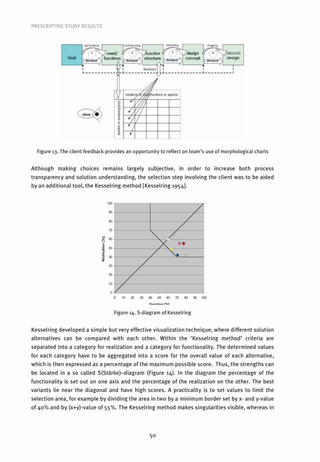
PRESCRIPTIVE STUDY RESULTS
50
Figure 13. The client feedback provides an opportunity to reflect on team’s use of morphological charts
Although making choices remains largely subjective, in order to increase both process
transparency and solution understanding, the selection step involving the client was to be aided
by an additional tool, the Kesselring method [Kesselring 1954].
0
10
20
30
40
50
60
70
80
90
100
0 10 20 30 40 50 60 70 80 90 100
Function [%]
Re
ali
sa
tio
n [
%]
Figure 14. S-diagram of Kesselring
Kesselring developed a simple but very effective visualization technique, where different solution
alternatives can be compared with each other. Within the ‘Kesselring method’ criteria are
separated into a category for realization and a category for functionality. The determined values
for each category have to be aggregated into a score for the overall value of each alternative,
which is then expressed as a percentage of the maximum possible score. Thus, the strengths can
be located in a so called S(Stärke)–diagram (Figure 14). In the diagram the percentage of the
functionality is set out on one axis and the percentage of the realization on the other. The best
variants lie near the diagonal and have high scores. A practicality is to set values to limit the
selection area, for example by dividing the area in two by a minimum border set by x- and y-value
of 40% and by (x+y)-value of 55%. The Kesselring method makes singularities visible, whereas in

PRESCRIPTIVE STUDY RESULTS
51
normal tables and bar diagrams they can only be retrieved with much effort. In the Kesselring
diagram it is easy to see if the improvements must take place on the functionality or on the
realization side.
In order to better understand how the various team members interacted and in order to
gather data for analysis of the workshop, observation was necessary. For the 1st BNA-ONRI
workshop series the idea was that the TU/e master students could represent the link in the
practice-research-education chain. The students would provide data for research and at the same
time would acquire first-hand experience of how different building design disciplines collaborate.
The students deployed as observers were all following, or had followed the TU/e course ‘Design
Methodology’, and were extensively instructed on which aspects of team design they needed to
record. In addition to observations, design teams were photographed at ten minute intervals. All
of the produced material was collected and the participants were asked to fill in the
questionnaires at the end of each workshop day.
Figure 15. Design teams and student observers during the 1st BNA-ONRI workshop series
Since live observation of design activities is extremely difficult even for experienced researchers,
the students were instructed to observe only specific aspects of team design. They were given
predefined forms, on which they could note the specific activities. There were three students
deployed per design team, using three different forms. One student had to record the individual
contributions of team members (Figure 16), one recorded communication patterns within design
team (Figure 17), and one recorded the use of morphological charts (Figure 18).
Even though student observations worked relatively well, the participants complained that
the presence of three students per one design team was overwhelming and distracting. The
students necessarily required some space around the tables, which resulted in more physical
distance between team members. The awareness of participants that they were watched was
notably high in this setup. This led to subsequent adjustments to observation methods in future
workshops.

PRESCRIPTIVE STUDY RESULTS
52
Figure 16. Observation form (1) and example of its use
Figure 17. Observation form (2) and example of its use

PRESCRIPTIVE STUDY RESULTS
53
Figure 18. Observation form (3) and example of its use
The observations showed that the ‘Kesselring method’ proved to be a bridge too far for the
participants: their argument for not using the method was that adapting to the team setting and
learning to use morphological overviews was already enough to deal with. However, an
alternative explanation could be that since the workshop was just a simulation of authentic
practice, the participants may not have taken the simulated role of the client seriously. Indeed,
many participants mentioned that their main interest in the workshops lay in learning integral
design in design team setting. Because the Kesselring method was not used, and it was meant as
part of the selection step op the EMD model, this selection step was not performed during the
workshop series. However, observations also showed that designers tended to combine the four
separate EMD steps into essentially two activities, resulting in sub solutions and overall design
proposals respectively.
To conclude, the research questions are restated and answers are given.
Q13. Did design teams use morphological charts for four steps of the EMD model?
A13. No, they combined the steps into two design activities.
Q14. Did design teams use the ‘Kesselring method’?
A14. No.
Q14.1. If so, did it lead to inclusion of the client in the design process?
A14.1. -
In summary, this workshop showed that the participants tended towards simplifying steps in the
process when possible. This was clear from the collapsing of the steps in the EMD model, which
allowed the participants to move through the task more quickly and shift the teams’ focus to the

PRESCRIPTIVE STUDY RESULTS
54
areas that they considered most important. This prioritising tendency of the participants was also
evident in their omission of the Kesselring method. It appeared that the teams considered the
Kesselring method an unwarranted complication, and as such chose to focus on other aspects of
the design tasks. The participants demonstrated a clear tendency towards simplification, which
consolidated the idea that the more generic the method the more applicable it becomes.
5.2.4 Extended Methodical Design Model based workshop (configuration B)
This workshop was based on the following assumptions:
1) Using morphological charts to provide feedback to the client would emphasize and
explicate the selection step, and therefore separate it from other activities.
This assumption led to the formulation of the following research questions:
Did the design teams use morphological charts for feedback with the client? And, if so, did
it result in explication of the selection step of the EDM model?
BNA-ONRI
Oct/Nov 2005
Duration three �-days Design sessions 3x 2 (total 6)
Total duration design sessions 3x120min (total 360 minutes) Design task Day 1 ‘parasite’
Day 2&3 ‘zero-en. office’ Number of participants 19 in total, (day 1 – 18, day 2 – 17, day 3 – 17)
14 during all three days Architects 6 (d1-5, d2-5, d3-5) 4 same
Building physics con. 5 (d1-5, d2-5, d3-4) 4 same Building services con. 6 (d1-6, d2-5, d3-6) 5 same
Structural engineers 1 (d1-1, d2-1, d3-1) 1 same Manager 1 (d1-1, d2-0, d3-1)
Teams 5 (see Table 7) Observation 1 ADMS student per team
Additional Questionnaires Photographs
Table 5. The first three-�-day BNA-ONRI workshop series; see Appendix for detailed descriptions of the
workshop programs, used design tasks and questionnaires
In order to explicate the third EMD model step the feedback with the client was changed during
the second BNA-ONRI series (October/November ’05). In this workshop set-up the Kesselring
method was not used for reasons explained above. It was considered more useful to ask the
participants to discuss the results of the first two EMD model steps (interpretation of the design
task and subsequent production of sub solutions; overview of available object-design-
knowledge) with the client, and jointly select the ‘reviewed’ object-design-knowledge for further
design activities.

PRESCRIPTIVE STUDY RESULTS
55
Figure 19. The client feedback session was introduced during the last -day of the 2nd workshop series
Figure 20. Observation form and example of its use
The need for a reduced number of observers was identified by the participants during the 1st BNA-
ONRI workshop series. For the 2nd series only one student per team was deployed, using a new
observation form (Figure 20) that was derived from the separate ‘observation form for
communication’ and ‘observation form for use of design tool’ used during the previous workshop.

PRESCRIPTIVE STUDY RESULTS
56
The ‘individual activities’ needed no separate observation, since it was possible to derive this
aspect from the data acquired using the other two forms.
These changes also placed new requirements on the observers. Since the observation task
had became more complex, it was considered necessary to use more experienced students to
perform it. While during the 1st BNA-ONRI workshop series TU/e master students were used, for
the 2nd series the students from the postgraduate technological designers program ‘Architectural
Design Management Systems (ADMS)’ were used. The ADMS students were regarded as more
competent compared to the TU/e master students, since a number of them also had experience in
practice in addition to a completed master education. Just as the TU/e students, they were also
highly motivated to participate in the workshops as non-participant observers after getting
extensive explanation on how to perform these observations. However, even though the presence
of observers was significantly reduced, a number of participants still complained about
distraction they caused during the workshop.
Again, the observations showed that design teams still did not execute the four Extended
Methodical Design model steps separately, which resulted in overall solutions being proposed
already before the client feedback. The effect was that the selection step essentially changed into
evaluation and optimisation of the proposed solutions. The consequence of the first two BNA-
ONRI workshop series was adjustment of the Extended Methodical Design model into a working
design model for team design during the third BNA-ONRI workshop series (Figure 25 in section
5.2.7). Furthermore, the client role within the design process was definitely excluded from the
workshop setting. This decision was taken based on the reactions of participants, and after
exclusion of the ‘Kesselring method’ it added to a further reduction of the complexity of the
workshop.
To conclude, the research questions are restated and answers are given.
Q15. Did design teams use morphological charts for feedback with the client?
A15. No.
Q15.1. If so, did it result in explication of the selection step of the EDM model?
A15.1. No. (design teams still combined four steps of the EDM model into two design
activities)
In summary, the second workshop series showed that the EDM model was not suitable for team
design in the conceptual building design phase. This was a very important step in the develop-
ment of the method, since had the EDM model not been tested with experienced professionals,
the final method would have been entirely based only on theoretical assumptions. Because the
aim of the research was to work on closing the gap between theory and practice, it was very
important to be sure that the interventions made had a desirable effect. This was clearly not the
case with the EDM model, even after the first workshop series. However, in order to avoid making
changes too hastily, the model was given a second chance so to speak, and was used for first two
workshop series. The second workshop series also showed that the focus of the participants was
solely on the team design, and that the role of the client was effectively only seen as a distraction
by the participants in the workshops.

PRESCRIPTIVE STUDY RESULTS
57
5.2.5 Comparison between Extended Methodical Design Model based workshop
configurations A and B
Despite not resulting in confirmation of the suitability of the EMD model for team design, the first
two workshop series produced some interesting results, leading to valuable insights regarding
team configurations and differences between 3-discipline and 4-discipline design teams. Prior to
presenting the comparisons between different design teams, it is important to note that just as
there was effectively no interaction between design teams and the client, there was also no
interaction whatsoever between the design teams. Besides the exclusion of the ‘Kesselring
method’, and adjustment of the feedback with the client, the most significant change between
the 1st and the 2nd BNA-ONRI workshop series occurred organically. Namely, since the participants
voluntarily applied for the workshop via their respective branch organisations, it transpired that
only one structural engineer participated during the 2nd workshop series. This proved not to be an
exception, since there were always less structural engineers than representatives from other
disciplines in later workshops. Also, the structural engineers that did participate were often
marked by others as the most passive within the design team.
Because of the almost identical setting of the 1st and the 2nd workshop series, the two
series could be compared by looking at the averages of the design teams’ results. To emphasize
again, the most important finding during the first two workshop series was the combination of
interpretation/generation and generation/selection activities by the participants. However,
general communication patterns and use of morphological overviews were also observed.
Overall, clear differences between the two workshop series could be recognized (see average
results in Table 6). At the same time, two tendencies were identified: an increase of team
communication over the course of workshops and more extensive use of morphological
overviews for the generation of design possibilities during the second day.
1st and 2nd workshop series comparison Day 1
1st 2nd Day 2
1st 2nd Day 3
1st 2nd average 1st 2nd
arch – cons 44% 52% 41% 32% 36% 27% 40% 37% 1 on 1
cons – cons 37% 11% 31% 14% 34% 14% 34% 13% Communication
Team 19% 37% 28% 55% 30% 59% 26% 50%
Report 24% 43% 62% 60% 24% 40% 37% 48% Design
Insight 16% 23% 2% 18% 19% 16% 12% 19%
Report 12% 14% 5% 4% 20% 19% 12% 12%
Morphological charts
Comm. Insight 48% 20% 31% 18% 37% 25% 39% 21%
Table 6. Observation results of the 1st and 2nd BNA-ONRI workshop series
The fact that there were not enough structural engineers during the 2nd workshop series made it
possible to make a comparison based on different design teams’ configurations. The distinction
between design teams with four (A3, A4), and design teams with three (B2, B3, B5) design
disciplines was made (Table 7).

PRESCRIPTIVE STUDY RESULTS
58
1st workshop series 2nd workshop series
Day Team A1
Team A2
Team A3
Team A4
Team A5
Team B1
Team B2
Team B3
Team B4
Team B5
1 AB-K ABCK ABCK ABCK ABCKK ABCK AB-K AB-KK ABBMK AB-K
2 ABCK ABCKK ABCK ABB-K ABCK AB-K AB-K AB-K AAB-K
3 ABCK ABCKK ABCK ABCK A-CK AB-K AB-KK ABBMK AB-K
Table 7. Design teams configurations during the first two BNA-ONRI workshop series (A=architect,
B=building physics consultant, BM=building manager, C=structural engineer, K=building services
consultant); in bold are the team members that remained the same
A3-A4 vs. B2-B3-B5 Day 1
A’s B’s Day 2
A’s B’s Day 3
A’s B’s average
A’s B’s
arch – cons 35% 67% 44% 29% 33% 31% 37% 42% 1 on 1
cons – cons 42% 11% 34% 12% 34% 16% 37% 13% Communication
Team 23% 22% 23% 58% 33% 53% 26% 44%
Report 22%* 41% 68% 71% 31% 53% 40% 55% Design
Insight 0%* 25% 1% 11% 6% 13% 2% 16%
Report 13%* 13% 3% 4% 15% 15% 10% 11%
Morphological charts
Comm. Insight 64%* 21% 28% 14% 48% 18% 47% 18%
Table 8. Comparison between 4-discipline (A’s) and 3-discipline (B’s) design teams; (*- A3 not observed)
A number of observations could be pointed out (Table 8). First, the amount of reporting/archiving
(‘morphological chart – communication – report’ fields) were similar, which means that all teams
presented their design proposals more or less in the same way. This could be confirmed by the
overall observation results (Table 6). Second, the main difference between design teams was the
extent to which morphological overviews were used for explanatory communication
(‘morphological chart – communication – insight’ fields), which was bigger within 4-discipline
team configurations. Third, the amount of team communication was clearly bigger within 3-
discipline design teams, suggesting that some kind of mutual understanding was reached faster
– leading to less explanatory communication and more new design insights.
A1-A5-B1 changes Day 1
A5-B1 A1 Day 2
A1-B1 A5 Day 3
A1-A5 B1 average
4-disc 3-disc
arch – cons 41% 60% 30% 33% 38% 0% 36% 31% 1 on 1
cons – cons 24% 25% 26% 8% 34% 0% 28% 11% Communication
Team 35% 15% 45% 59% 27% 100 36% 58%
Report 43% 20% 55% 78% 19% 24% 39% 41% Design
Insight 8% 29% 8% 0% 30% 22% 15% 17%
Report 14% 15% 8% 22% 19% 34% 14% 24%
Morphological overviews
Comm. Insight 36% 37% 31% 0% 33% 20% 33% 19%
Table 9. Comparison of observations regarding teams with shifting configurations (left columns show the
results of 4-discipline and right columns of 3-discipline configurations for each day)
An additional evaluation of observation results of 3- and 4-discipline configurations was made
(Table 9). Three design teams (A1, A5 and B1) shifted during the workshop series either from 3- to
4-discipline or from 4- to 3-discipline configurations (Table 7). This made it possible to see if the
configuration had an impact on communication and use of morphological overviews. On average,

PRESCRIPTIVE STUDY RESULTS
59
it could be confirmed that team communication in 3-discipline design teams was much greater. In
addition, morphological overviews were used more for communication in 4-discipline design
teams, in the sense of providing insight to other team members. The amount of repor-
ting/archiving differed, however, from the overall observations. Curiously, this difference
originated from the 3-discipline design teams. More specifically, the high amount of reporting/ar-
chiving on days 2 and 3 represented the real difference, precisely at the moments when team
configuration changes occurred. These changes in configuration, which did not occur within
‘standard’ teams, could be the explanation for the encountered differing results. Since the
sample is small, these results can only be considered as indicative.
Based on the above findings, the first conclusion that could be drawn is that (development
of) design team communication was dependent on the number of design disciplines within a
design team. The 3-discipline design teams developed some kind of mutual understanding and
agreement faster than 4-discipline design teams. An additional conclusion was that this was not
directly related to the use of morphological overviews for communication purposes. On the
contrary, the 4-discipline design teams, which internally communicated more on a 1-on-1 basis,
used morphological overviews more frequently for communication purposes. However, the
influence of morphological overviews in achieving mutual understanding in 3-discipline teams
was not assessed. Generally, from observation results it could be concluded that morphological
overviews were helpful in aiding communication and structuring object-design-knowledge of the
design teams, especially in more complex situations (when more disciplines were involved).
Morphological overviews also proved useful for archiving discussed proposals. The results
showed that in 10-15% of cases they were used for this purpose.
Figure 21. A design team’s presentation during the 2nd BNA-ONRI workshop series
By photographically recording the teams at work it was possible to register the amount of
proposals generated in time. The second day was the most important for this type of
measurement, since morphological charts were then used for generation of solution proposals.
The first day was a training session, while during the third day the focus was on the selection of
the generated proposals. It was observed that both 3- and 4-discipline design teams needed the

PRESCRIPTIVE STUDY RESULTS
60
same amount of time to define the functions/aspects they were going to work on (this lasted
between 35-45 minutes). From there on the number of produced alternatives by 4-discipline
teams was much bigger than by 3-discipline teams (Figure 22).
Figure 22. Interpretation vs. generation activity of the 3- and 4-discipline design teams
In order to get feedback from professionals, at the end of both workshop series the participants
were asked to fill in a questionnaire (see Appendix III). In general, these opinions were largely
positive. The following are the average results of the questionnaires that the participants filled in
at the end of both workshop series. The importance of the proposed approach for daily practice
was confirmed by 61% of participants, 29% was in doubt, and 10% thought of it as unimportant.
Only 6% of participants considered the use of morphological charts irrelevant for their discipline,
while thirteen percent thought they were not positive for communication within design teams.
The majority of participants were convinced that the use of morphological charts was beneficial
for many purposes. Sixty six percent of participants (average rating of 6.8 on a scale 1-10)
answered that they considered charts to lead to an increased number of relevant alternatives.
The average scores for three key areas were also encouragingly high: team design process (7.2),
awareness-raising on contribution by other disciplines (7.4), and communication (7.2). Overall,
participants deemed working within design teams as very positive; 76% of participants
vindicated this approach, and the average rating of all participants was 7.8. However, some
negative results were also found. Only 43% of the participants considered morphological
charts/overviews to have a positive effect on the final design proposals. In short, as will be
discussed later, this could well be due to the participants focus in the workshops being different
from the researchers. Finally, only 36% of participants considered it highly likely that
morphological overviews would be exploited in their own future practice. Later discussion of this
point (section 6.3) will argue that this may have more to do with cultural norms than with the
usefulness of the approach.
0
10
20
30
40
50
60
70
0min 10min 20min 30min 40min 50min 60min 70min 80min 90min
3-disc. INTERPRETATION 4-disc. INTERPRETATION 3-disc. GENERATION 4-disc. GENERATION
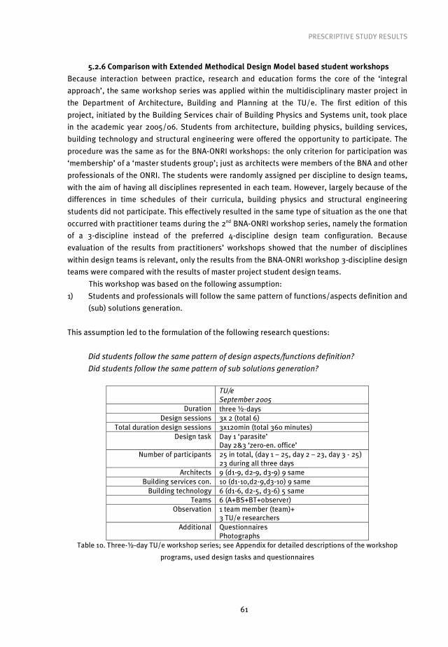
PRESCRIPTIVE STUDY RESULTS
61
5.2.6 Comparison with Extended Methodical Design Model based student workshops
Because interaction between practice, research and education forms the core of the ‘integral
approach’, the same workshop series was applied within the multidisciplinary master project in
the Department of Architecture, Building and Planning at the TU/e. The first edition of this
project, initiated by the Building Services chair of Building Physics and Systems unit, took place
in the academic year 2005/06. Students from architecture, building physics, building services,
building technology and structural engineering were offered the opportunity to participate. The
procedure was the same as for the BNA-ONRI workshops: the only criterion for participation was
‘membership’ of a ‘master students group’; just as architects were members of the BNA and other
professionals of the ONRI. The students were randomly assigned per discipline to design teams,
with the aim of having all disciplines represented in each team. However, largely because of the
differences in time schedules of their curricula, building physics and structural engineering
students did not participate. This effectively resulted in the same type of situation as the one that
occurred with practitioner teams during the 2nd BNA-ONRI workshop series, namely the formation
of a 3-discipline instead of the preferred 4-discipline design team configuration. Because
evaluation of the results from practitioners’ workshops showed that the number of disciplines
within design teams is relevant, only the results from the BNA-ONRI workshop 3-discipline design
teams were compared with the results of master project student design teams.
This workshop was based on the following assumption:
1) Students and professionals will follow the same pattern of functions/aspects definition and
(sub) solutions generation.
This assumption led to the formulation of the following research questions:
Did students follow the same pattern of design aspects/functions definition?
Did students follow the same pattern of sub solutions generation?
TU/e
September 2005
Duration three �-days Design sessions 3x 2 (total 6)
Total duration design sessions 3x120min (total 360 minutes) Design task Day 1 ‘parasite’
Day 2&3 ‘zero-en. office’ Number of participants 25 in total, (day 1 – 25, day 2 – 23, day 3 - 25)
23 during all three days Architects 9 (d1-9, d2-9, d3-9) 9 same
Building services con. 10 (d1-10,d2-9,d3-10) 9 same Building technology 6 (d1-6, d2-5, d3-6) 5 same
Teams 6 (A+BS+BT+observer) Observation 1 team member (team)+
3 TU/e researchers Additional Questionnaires
Photographs Table 10. Three-�-day TU/e workshop series; see Appendix for detailed descriptions of the workshop
programs, used design tasks and questionnaires

PRESCRIPTIVE STUDY RESULTS
62
A comparison of experienced professionals and students revealed big differences regarding
communication as well as use of morphological charts (Table 11). The student teams showed
much more difficulty in reaching shared understanding, leading to less team communication but
at the same time to more intensive use of morphological overviews for communication purposes.
3-discipline teams comparison professionals vs. students
averages prac. vs stud.
arch – cons 42% 58% 1 on 1 cons – cons 13% 27% Communication:
Team 44% 14%
Design 71% 36% Morphological overviews use:
Communication 29% 64%
Table 11. Comparison of observation results between practitioners’ and students’ 3-discipline design teams
(arch stands for architect, cons for consultant)
Conducting questionnaires helped to further evaluate the use of morphological charts. The
importance of the proposed approach for education purposes was underlined by 52% of
students, while 41% was in doubt and only 7% did not see any benefit in its use. The student
evaluations showed that students were generally more cautious than professionals: 21% of
students considered the use of morphological overviews irrelevant for their discipline. However,
none of the students thought that the use of morphological overviews had a negative impact on
communication within design teams. The majority of students were convinced that the use of
morphological overviews was beneficial in many aspects. Seventy four percent (with an average
rating of 7.8) considered morphological overviews to lead to a greater number of relevant
alternatives. Similar to professionals, the students also considered morphological overviews
beneficial in three key areas: team design process (6.6), to raise the awareness of the
contribution from other disciplines (7.5) and for communication (7.4). Again, student results were
highly positive in terms of the benefit of working within design teams. Here, the average rating
was 7.8. There were key differences between the results of students and professionals. Students
on average considered the effect that morphological overviews had on final design proposals
rather negatively, with only 37% of participants considering it beneficial. This aspect was given
slightly higher rating by professionals with 43% considering it positive. However, the students
were more positive than the professionals in their expectation of use of morphological overviews
in their future carriers. Here, 50% of students rated their future use as ‘highly likely’.
Morphological charts are relevant for: BNA-ONRI TU/e number of alternatives 6.8 7.8 team design process 7.2 6.6 contribution of ‘others’ 7.4 7.5 Communication 7.2 7.4
Table 12. Ratings of BNA-ONRI and TU/e workshop participants (on 1-10 scale) regarding the use of
morphological charts

PRESCRIPTIVE STUDY RESULTS
63
BNA-ONRI TU/e Find proposed approach important 61% 52% Liked working within design teams 76% 74% Expect to use morphological overviews 36% 50% Overviews beneficial for final proposals 43% 37%
Table 13. Percentage of positive reactions by practitioners and students respectively
Figure 23. The number of produced functions/aspects and alternatives by professional and student design
teams
The work of student design teams was also photographed in 10 minute intervals. In the above
figure the average development of the number of generated alternatives by the professional and
by the student design teams is shown. It is interesting to see that there is no big difference in the
definition of the amount of aspects, but the number of proposed alternatives and the way the
teams generate them is completely different. Generally speaking the professional design teams
tended to define the aspects first and then produce the relevant alternatives. This was even more
obvious with 4-discipline design teams. In the above figure only the results of the 3-discipline
design teams are shown. The student design teams generated the proposals and the
functions/aspects more in parallel. However, they continued generating new proposals even
during the third and final day of the workshop series. It appeared that they often did not know
what to do with the produced (sub) results. The experience of the professional designers seemed
to give them some advantage regarding this phase of the conceptual building design. These
results indicated that students should not be used for the development of an integral design
method, since they apparently have difficulties making the integration step. Instead, the
development should be done with professionals and the developed method used for education of
students. On the other hand the amount of proposed alternatives by student teams was much
bigger, meaning that the potential for discovering new possibilities could also be larger. It needs
to be stressed that the quality of the generated alternatives/proposals was not assessed. The
professionals vs students
0
20
40
60
80
100
120
0min 10min 20min 30min 40min 50min 60min 70min 80min
functions/aspects professionals functions/aspects students alternatives professionals alternatives students

PRESCRIPTIVE STUDY RESULTS
64
purpose was to research if the use of the morphological charts would lead to a widening of the
field of possibilities, which did seem to be the case. The comparison between 3-discipline and 4-
discipline professional design teams showed that this is even more evident with the more
complex teams. That is something we were not able to confirm with the student design teams,
because all of them consisted of the three different design disciplines.
Figure 24. A student design team working with morphological overviews during the 3rd workshop day
To conclude, the research questions are restated and answers are given.
Q16. Did students follow the same pattern of design aspects/functions definition?
A16. Yes!
Q17. Did students follow the same pattern of sub solutions generation?
A17. No. (they continued generating new proposals, appearing to have difficulties to
produce overall solutions)

PRESCRIPTIVE STUDY RESULTS
65
5.2.7 Working Design Model based workshop configuration
For the third BNA-ONRI workshop series (June 2006) the newly derived working design model
was used (Figure 25), with the sole focus on defining a workshop setting that would allow
comparison of different types of design settings.
Figure 25. Working Design Model for team design during BNA-ONRI workshop series
This workshop was based on the following assumptions:
1) This is the right workshop set-up for testing the use of morphological charts.
2) This is the right workshop set-up for participants to apply the morphological charts.
3) The application of the morphological charts will be successful.
These assumptions led to the formulation of the following research questions:
Is this workshop setup suitable to test the use of morphological charts?
Is this workshop setup suitable to allow participants to apply the morphological charts?
Was the application of the morphological charts successful?
BNA-ONRI
June 2006 Duration three �-days
Design sessions 3x 2 (total 6) Total duration design
sessions 3x120min (total 360 minutes)
Design task Day 1 ‘zero-energy office’ Day 2 ‘parasite’ Day 3 ‘school’
Number of participants 23 in total, (day 1 – 23, day 2 – 21, day 3 – 20) 20 during all three days
Architects 7 (d1-7, d2-6, d3-6) 6 same Building physics con. 6 (d1-6, d2-6, d3-6) 6 same
Building services con. 7 (d1-7, d2-6, d3-5) 5 same Structural engineers 3 (d1-3, d2-3, d3-3) 3 same
Teams 6 to 5 on d3 Observation 1 ADMS student per team
Additional Questionnaires Photographs
Table 14. Third three-�-day BNA-ONRI workshop series
The previous workshops confirmed that morphological analysis and use of morphological charts
were useful for building team design. Therefore, a workshop setting was needed where the

PRESCRIPTIVE STUDY RESULTS
66
effects of morphological analysis could be measured. This workshop series started with the
traditional design setting, in order to provide a reference point, followed by the stepwise
introduction of the two main changes to the traditional building design. In the second design
setting all disciplines were brought together in a face-to-face team design configuration. Finally,
in the third setting morphological analysis was included, using morphological charts and
overviews. The resulting workshop setup again followed a 3-day format, but this time different
teams worked on different design tasks in different design settings.
Figure 26. New workshop configuration, with gradual introduction of the two main changes to the
traditional design process; using one design task per day
During previous workshops the average results of different workshop days were compared,
focusing on different activities within the same design process type. The focus shifted now to
comparison of the same activities within different types of design processes. The usual approach
for this type of enquiry would be ‘matched design teams’ [Van Vliet 1995, Herzog 1996]. However,
the (random) use of experienced professionals in a semi-authentic setting excluded this
possibility. The solution was not to have the same design team(s) performing different design
processes, but to compare average results of each design setting while changing the design
team’s configurations. This meant different teams for different settings, but at the same time
consisting of the same group of participating designers. In order to prevent design team
members from becoming too familiar with each other and to avoid any learning effect, the only
rule was that two designers could be in the same team only once. In addition to methodological
research requirements, this design team shuffling offered more possibilities for socialising; one
of the reasons why designers applied to participate in workshops.
The aim was to have 4-6 design teams during each design setting; using the same
designers in different design team configurations would then make it possible to compare the
average results of different design processes. The first design setting needed to simulate
traditional design, since there were no known situations in Dutch building design that could

PRESCRIPTIVE STUDY RESULTS
67
provide reference values. Besides, this approach requires that the same participants are used in
all design settings. The approach also meant that morphological analysis could not be introduced
at the start of the workshop series. The sequence of different design settings was as follows:
first, a traditional building design was simulated; then, team design was introduced at the
beginning of the conceptual design phase; finally, the design teams were required to use
morphological analysis during the last design task (Figure 26). Any other order or use of
counterbalancing was not possible, since it would clearly result in a learning effect. The
empirically derived working design model, which consisted of two combined design activities,
made it possible to use two design sessions per design task. The result was one design task per
design setting per one �-day (Figure 26). During the first �-day the traditional design process
was simulated. In the first design session only the architect worked on the design task, while
after the break design teams including other building design disciplines were formed. During the
second �-day new design teams were formed directly at the start of the first design session to
work on a new design task; the teams remained the same during the first and second sessions.
During the third �-day again newly formed design teams started working on the third design task
using morphological analysis. Although different, all the design assignments had the same
sustainability requirements, which made them classifiable as very complex design tasks.
Descriptions of all design tasks can be found in Appendix II.
Since the practice setting was to be as authentic as possible, attempts were made to
remove all distractions reported in previous workshops. Therefore, for this, 3rd BNA-ONRI
workshop series, two adjustments were made. Firstly, to remove undesired distractions from
observers, two out of five design teams involved in the workshop were video recorded as a trial
measure. Secondly, where observers remained, their position, relative to the observed design
teams, was adjusted (Figure 27). The observers, ADMS students, were asked not to sit at the
table with the designers as a part of the team, as was usually the case during previous
workshops, but in a way that would cause the minimum distraction possible. This allowed us to
determine whether our preferred observation method, human observation, could be achieved in a
non-obtrusive way and thus used in future workshops.
The teams that were observed via video camera reported almost no distraction at all, apart
from the first couple of minutes of design sessions. The teams that were observed by students
reported much less distraction than in previous workshops, although it was noticeable that the
observers and the teams did interact. Regarding the video recordings of the two design teams,
some problems were experienced. Because all the teams were situated in the same room, it was
hard and in some cases even impossible to discern which ‘sounds’ were being made by what
design team. The poor sound quality meant that the recordings of the 3rd BNA-ONRI workshop
series could not be fully analysed. This, perhaps, was not as serious a problem for the research
as it may sound, since, as explained below, the overall goal of the workshop setup was not
reached. Ultimately, this meant that our setup needed further refinement.

PRESCRIPTIVE STUDY RESULTS
68
Figure 27. Position of the observer, within (above, 2nd workshop series) and outside design team ‘circle’
(below, 3rd workshop series)
The workshop series resulted for the first time in overwhelmingly negative reactions from the
participants. This was remarkable since the working atmosphere created by changing design
teams was felt to be generally better than during previous workshops, with visibly more
enthusiastic participants. However, the participants were disappointed about, in their eyes, the
abrupt end to the workshop series. From the participants’ perspective the disappointment arose
from the morphological analysis being introduced “too late”. Since morphological analysis forms
the core of the ID-method, the participants felt the need for greater feedback. Essentially, they
felt that they missed the possibility of a full learning cycle in which they could try-out the
proposed design tool. This perceived lack of a ‘training’ also meant that observation results
would have limited value. Since participants struggled to apply the proposed approach, no
sensible comparison between different design settings could be made.
There was one important positive aspect observed during the workshop. Due to unforeseen
circumstances the first day of the workshop program needed to be adjusted at the last minute.
Whereas it was planned to run a 60+60 minute format for the two design sessions, external
factors meant that only 30 minutes were available for the first session. Therefore, the second
session was allotted 90 minutes by way of compensation. In order to keep the same format, this
‘accidentally’ adjusted duration of design sessions was repeated during the second and third

PRESCRIPTIVE STUDY RESULTS
69
workshop day. From observation and feedback it transpired that this new time setup was more
advantageous than the previous, since it improved the balance between interpretation of design
task and generation of possible solutions during the team design.
The participants also reacted positively to the used sequence of design settings. Their
comments indicated that ‘learning by doing’ was indeed an effective formula for the introduction
of a new team design approach. It could be said then that the main effect of the 3rd BNA-ONRI
workshop series was the realization of the importance of the learning aspect of the ID-method.
The consequence was however that the workshop and the ID-method became entangled to a
degree that it was difficult to separate them.
To conclude, the research questions are restated and answers are given.
Q18. Is this workshop setup suitable to test the use of morphological charts?
A18. Yes! The setup where average results for each design setting were compared offered
the possibility to test the use of morphological charts.
Q19. Is this workshop setup suitable to allow participants to apply the morphological
charts?
A19. No. The absence of practice sessions made the application of morphological charts too
difficult for design teams.
Q20. Was the application of the morphological charts successful??
A20. No. Morphological charts could not even be applied in the first place, let alone
successfully.
To emphasize once again, the main lesson learned from the third workshop series was the need
for a learning cycle. The participants indicated that it was very difficult for them to use the
proposed approach in ‘one-go’ within design teams; this was the case for all involved disciplines.
The participants acted as a true team in this regard. The importance of a learning cycle means
that the workshop-like learning environment is required for successful application of the method
developed, and as such becomes almost a part of it.
5.2.8 Integral Design workshop configuration
On the basis of the results from the previous workshop, changes to the setup were necessary.
However, the present workshop set out to achieve the very same goals as the previous setup.
Therefore, very same assumptions and research questions are used. Since one of the research
questions (Q18) from the previous setup received a positive answer, it was removed from
consideration in the present setup.
Assumptions:
1) This is the right workshop set-up for participants to apply the morphological charts.
2) The application of the morphological charts will be successful.
These assumptions led to the formulation of the following research questions:
Is this workshop setup suitable to allow participants to apply the morphological charts?
Was the application of the morphological charts successful?
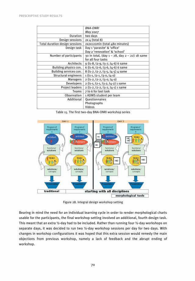
PRESCRIPTIVE STUDY RESULTS
70
BNA-ONRI
May 2007
Duration two days Design sessions 2x 4 (total 8)
Total duration design sessions 2x2x120min (total 480 minutes) Design task Day 1 ‘parasite’ & ‘office’
Day 2 ‘renovation’ & ‘school’ Number of participants 30 in total, (day 1 – 28, day 2 – 22) 18 same
for all four tasks Architects 9 (t1-8, t2-9, t3-7, t4-6) 6 same
Building physics con. 6 (t1-6, t2-6, t3-6, t4-6) 6 same Building services con. 8 (t1-7, t2-7, t3-5, t4-5) 4 same
Structural engineers 1 (t1-1, t2-1, t3-0, t4-0) Managers 2 (t1-2, t2-2, t3-0, t4-0)
Developers 2 (t1-1, t2-1, t3-2, t4-2) 1 same Project leaders 2 (t1-2, t2-2, t3-2, t4-1) 1 same
Teams 7 to 6 for last task Observation 1 ADMS student per team
Additional Questionnaires Photographs Videos
Table 15. The first two-day BNA-ONRI workshop series
Figure 28. Integral design workshop setting
Bearing in mind the need for an individual learning cycle in order to render morphological charts
usable for the participants, the final workshop setting involved an additional, fourth design task.
This meant that an extra �-day had to be included. Rather than running four �-day workshops on
separate days, it was decided to run two �-day workshop sessions per day for two days. With
changes in workshop configurations it was hoped that this extra session would remedy the main
objections from previous workshop, namely a lack of feedback and the abrupt ending of
workshop.

PRESCRIPTIVE STUDY RESULTS
71
During the workshop series the transition from traditional to team design consisted of first
letting all disciplines start working on a design task at the same time, but separately, offering
them the possibility to practice working with morphological analysis, before finally joining them
in design teams (Figure 28).
During this workshop two observation methods were used. Notwithstanding the problem of
needing to analyse recordings, it was deemed essential to record all teams to ensure that no
important data was missed. On top of this it was deemed worthwhile to make a final attempt at
using live observers in an unobtrusive way.
Structured observational measures, such as Interaction Process Analysis [Bales 1950], offer
a possible solution to the problem of objectivity in observations by helping observers categorize
group behaviour. As one of the most widely used techniques to study group interaction [Emmitt
and Gorse 2003], the IPA was considered a suitable basis for BNA-ONRI workshops observations.
The IPA has proved to be a consistent and reliable tool in social sciences research, and has also
been used for research in building construction [Gorse 2002]. Emmitt and Gorse found that the
majority of construction professionals were reluctant to be recorded during projects. However,
this disadvantage was not found in our previous workshops, perhaps because the workshops
were simulations and as such did not contain any confidential or sensitive information.
Nonetheless, due to the inherent risk noted by Emmitt and Gorse, the IPA presented an alterna-
tive, tried and tested method allowing the observation and classification of communication acts
without the need for recordings [Emmitt and Gorse 2003].
The IPA coding systems consists of 12 categories (Table 16), divided into socio-emotional
and task activity areas.
1 Shows solidarity 2 Shows tension release 3 Agrees
Positive reactions
4 Disagrees 5 Shows tension 6 Shows antagonism
Negative reactions
Social-emotional area
7 Asks for orientation 8 Asks for opinion 9 Asks for suggestion
Questions
10 Gives suggestion 11 Gives opinion 12 Gives orientation
Attempted answers
Task area
Table 16. Bales’ Interaction Process Analysis (IPA) coding
To use the IPA, observers must learn to identify the 12 types of behaviour defined by Bales [1950].
They must practice listening to a group discussion, break the verbal content down into the
smallest meaningful units that can be identified, and then categorise these units [p.7]. Thus,
considerable training is involved in this form of observation. For this reason, but also in order to
exclusively focus on task related activities, the IPA coding needed to be simplified. In developing
the ID-method, the focus was always primarily on the task related communication and activities.
Within all used workshop settings design teams had a restricted amount of time to work on
design tasks. The assumption was that this would automatically lead to more task related
communication; some research results support this assumption by showing that time pressure

PRESCRIPTIVE STUDY RESULTS
72
prevents teams from engaging in ‘social niceties’ [De Grada et al 1999]. Therefore, the IPA’s
coding for socio-emotional activities was excluded in the observation form used during the 4th
BNA-ONRI workshop series.
IPA 4th BNA-ONRI workshop
1 Asks for orientation 1 Asks for orientation 2 Asks for opinion 2 Asks for opinion 3 Asks for suggestion - Workshop question!
4 Gives suggestion - Design task!
3 Gives positive opinion 5 Gives opinion
4 Gives negative opinion
Task area
6 Gives orientation 5 Gives orientation
Table 17. For the 4th BNA-ONRI workshop some of IPA’s task area coding were used
The resulting observation form (Figure 29) was used once again for live observations. The
observers were the same ADMS students that also observed the 3rd workshop series. Since ADMS
students already had experience of attending the previous workshop, the idea was that they
could perform the observations without the extensive preparations advised when using the IPA
coding.
In order to improve the sound quality, separate external microphones for each design team
were used for the 4th BNA-ONRI workshop series. All design teams remained situated in one room
in order to minimize the laboratory feel. Situating the design teams in one room created a design-
studio-like atmosphere, which was appreciated by the workshop participants. The observers
were asked to try not to interfere in team work in any way, and if possible to physically distance
themselves from the tables design teams were working at.
The adjusted IPA coding scheme proved to be not workable, both for live observations
using the forms (Figure 29) and for analysis of the recordings. The coding scheme caused
confusion in interpretation of explicit design object related aspects, such as functions and
solution proposals, and design process related aspects, such as evaluations of
functions/proposals, which were not followed by concrete implications for / adjustments of the
object being designed. The aim of the PhD project was to concentrate on the former, while the
latter appeared to consume most attention of the observers. The result was a clear lack of focus
and acquisition of less relevant data.
The video recordings of design sessions were of good quality. The situation that initially
was aimed to be avoided re-emerged, where live observation was either not wanted or did not
work. This resulted in protocol analysis being the only available means to analyse the recorded
material. The IPA coding also proved to be misleading for quick (scan) analysis of recorded team
design sessions. Even though the test sessions went well, the researchers who tried to analyse
recordings as if doing live observations could not reach consensus on the coding interpretation.

PRESCRIPTIVE STUDY RESULTS
73
Figure 29. The observation form and an example of its use during the 4th BNA-ONRI workshop series

PRESCRIPTIVE STUDY RESULTS
74
Figure 30. Position of the observer during the videotaped design sessions of the 4th BNA-ONRI
workshop series
Ultimately, the last design setting of the 4th BNA-ONRI workshop series was, even before
experiencing it, seen as needless by the participants. After the third design task the majority of
participants agreed that this could be the optimal formula and were reluctant to proceed with the
fourth and last design setting. Their clear preference to start working individually with morpho-
logical charts and then move on to the design team configuration was based on reasoning
(expressed both before and after the last two design sessions) that within design teams there is
always somebody who takes the lead, leaving less assertive team members little space to bring
their views forward. Although it was observed that it was often the architect that led the design
sessions, assuming its ‘natural’ role of design leader, the participants did not single out
architect’s influence when making these remarks. Rather, they ascribed the possibility to the
personal characteristics of individual designers, regardless of the discipline they represented.
Using morphological charts to separately interpret the design task and propose solutions from
one’s own perspective, by actually getting it on paper as preparation for discussion, was
according to them a good solution to these problems. It was interesting to observe that the
‘mutiny’ was led by developers and project leaders, who were the first to raise the issue and were
the most vocal on the subject. Although it was rewarding to hear that participants regarded the
proposed changes to traditional building design worthwhile, the reactions of the participants to
the 4th workshop series setup suggesting that the last design setting was obsolete were
disappointing. More importantly, due to their lack of faith in the last design setting they
approached the last task with very little enthusiasm, which made it unsuitable for the intended
comparison with the first, traditional design setting.
Notwithstanding the problems relating to the last design setting, overall the fourth BNA-
ONRI workshop series proved largely to be a success, as the positive answers to the research
questions below show. This positive evaluation will be discussed further in the analysis of the
participant questionnaires in section 6.3. As such, this setting was considered as the final one,

PRESCRIPTIVE STUDY RESULTS
75
and was used for the fifth and final BNA-ONRI workshop series in February 2008, but only with
the participation of design disciplines.
To conclude, the research questions are restated and answers are given.
Q19. Is this workshop setup suitable to allow participants to apply the morphological
charts?
A19. Yes! Introduction of a full ‘learning cycle’ enables participants to apply morphological
charts during the last, integral design setting.
Q20. Was the application of the morphological charts successful?
A20. Yes! This can be seen in the successful application of the morphological charts as
shown in Appendix IV.
To summarize the last crucial step in the development of the method, the fourth workshop series
showed that an individual learning cycle was needed for the new method. This learning cycle,
represented by the third design setting, was so successful that the participants even thought that
the final design setting, the one for which the method was actually developed, was not needed.
In a sense, this firm standpoint of the participants justified the conclusion that the fourth
workshop setting was sufficiently good for both the learning and testing of the developed
method.
5.3 The Integral Design Method
The goal of developing a workable Integral Design Method was reached iteratively by using
workshops in which different design tasks involving sustainability aspects (Appendix II) were
worked on by different design teams in different design settings. As mentioned earlier, the four
key elements that needed to be integrated to reach this goal are: design team, design model,
design tool and setting. At this point in the research all four elements have been determined,
which allows full explanation of the ID-method.
As pointed out in Descriptive study I (section 4.3.5), the ID-method technological design
can also be explained by CCIMO-logic: in case of highly complex building design problems
involving sustainability aspects (CContext), use morphological approach for team design
(IIntervention) in order to transform the initial discipline-based object-design knowledge,
following the notion of knowledge and concept space expansions of the C-K theory (MMechanism),
into integral design concepts (OOutcome). In order to describe the intended results, the four key
elements of the ID-method are discussed using CIMO-logic.
The configuration of the design team turned out not to need any iterative improvement
upon our original conception. Indeed, in situations where the team design differed from our
original conception, results sometimes suffered as a consequence. By the end of the workshop
series observations, feedback from participants and the results gained verified the configuration
of the design team defined in the working definition section (2.5). Briefly, design team consisted
of a minimum of one representative of the following disciplines: architecture, building physics
consultancy, building services consultancy and structural engineering. This defines the first

PRESCRIPTIVE STUDY RESULTS
76
intervention in using the ID-method, namely that a multidisciplinary building design team that
works on a design task from the outset of conceptual design phase is needed.
Figure 31. Extended Methodical Design Model
As a starting point, the Extended Methodical Design model was chosen (Figure 31). In this model
four steps (generating, synthesising, selecting, shaping) are defined. However, on the basis of
observed design teams’ activities, the Working Design Model was derived (Figure 32), which was
used to improve the workshop setting.
Figure 32. Working Design Model
Whereas in the EMD model the focus was placed on the selection step, the working design model
shows no distinction between RE-design and ID-concepts. In order to show this distinction and
help explain the mechanism of the ID-method, the Integral Design model (Figure 33) was
developed. The ID-model, which is based on the two-step pattern of the WD model, seeks to force
the focus on the distinction between redesign (K-K) and concept generation (K-C).
Figure 33. Integral Design model
PRESCRIPTIVE STUDY RESULTS
77
The ID-model is relevant for both aims of this research. In terms of aim one, the model can be
used to demonstrate the need for the explication of individual disciplines object-design-
knowledge. In terms of aim two, the model can focus design teams on this object-knowledge in
order to encourage the creation of ID-concepts. Although object-design representations can be
driven by individual interpretations of the design task, as explained in section 2.3, in order to
arrive at integral design concepts it is necessary that at a certain point the team agrees on design
aspects / functions.
The main characteristic of the ID-method is the use of design teams’ object-design-
knowledge as ‘building blocks’ for either redesign (RE) or integral design concepts (ID). The clear
distinction between the two, redesign and design concepts, is only possible by using C-K theory.
Building object-design-knowledge is discipline based, and getting an overview of the knowledge
needed to produce a sustainable building concept in a specific context implies a team design
approach as the first prerequisite. A most promising way to get different disciplines truly working
together is in a face-to-face setting [Abadi 2005, Emmitt and Gorse 2007]. Our experiences
through the workshops and the feedback from the participants confirmed this. In addition,
creating a workshop environment allowed professionals to work openly and freely, without the
burdens that a laboratory setting brings with it. The workshop setting also proved suitable as a
learning setting for both professionals and students.
The second prerequisite is making this knowledge explicit and structuring it in a
transparent way, in order to provide the possibility for all involved disciplines to use it. Within the
ID-approach the structured presentation of object-design-knowledge is guided by morphological
analysis; the second intervention in using the ID-method. The general morphological analysis
principle is translated to building team design through use of morphological charts and
morphological overviews, which are a refinement of Zwicky’s morphological box [Zwicky 1969].
The advantage of using morphological design tools is that they allow the assimilation of
contributions from all team members. As such, they represent an audit trail for the design task
which can prove very useful when presenting to a client or when returning to a project after some
delay.
Even though the use of morphological charts and overviews would be ‘theoretically
optimal’ if carried out according to strict prescription, pre-tests showed that rigid prescription
essentially did not work. The designers either refused to follow the prescribed steps or simply
proceed in a different way. This is the motivation for allowing design teams to use morphological
charts/overviews the way they think fits best, even though research-wise this can create
problems (no consistent definitions, the structure does not follow clear pattern and/or
abstraction levels etc.). Team interpretation of the design task is therefore the single most
emphasized aspect of the ID-method.
Figure 8 in section 4.3.5 shows how morphological charts and overviews can be used to
generate, define and record design aspects/functions and sub solutions. The interpretation of the
design task results in a dynamic lists of functions/aspects, preferably arranged according to
abstraction levels (different building scales). Since the aim is to realise the design team’s
interpretation of the design task, this process can take several forms:
I. direct design team interpretation using morphological overviews, or
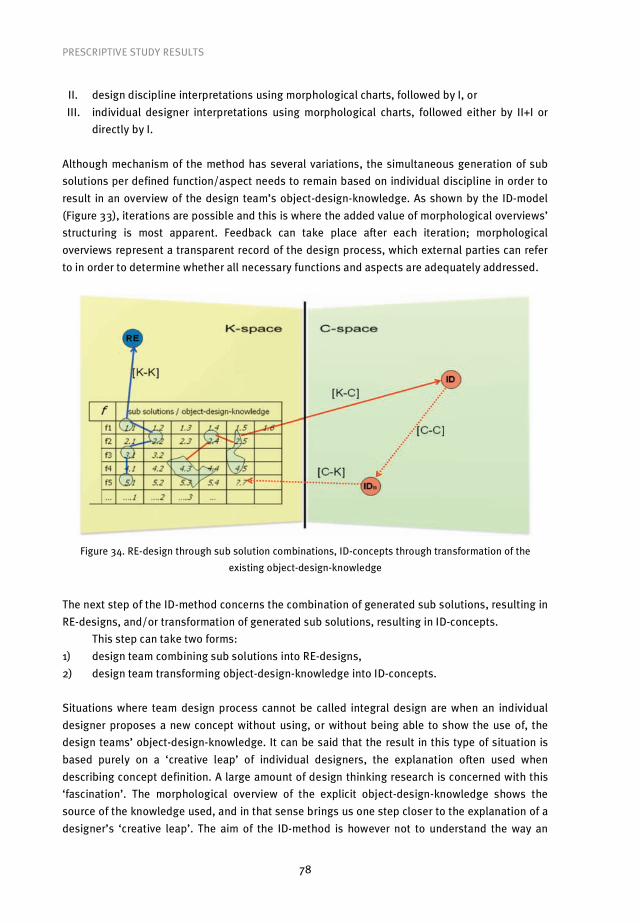
PRESCRIPTIVE STUDY RESULTS
78
II. design discipline interpretations using morphological charts, followed by I, or
III. individual designer interpretations using morphological charts, followed either by II+I or
directly by I.
Although mechanism of the method has several variations, the simultaneous generation of sub
solutions per defined function/aspect needs to remain based on individual discipline in order to
result in an overview of the design team’s object-design-knowledge. As shown by the ID-model
(Figure 33), iterations are possible and this is where the added value of morphological overviews’
structuring is most apparent. Feedback can take place after each iteration; morphological
overviews represent a transparent record of the design process, which external parties can refer
to in order to determine whether all necessary functions and aspects are adequately addressed.
Figure 34. RE-design through sub solution combinations, ID-concepts through transformation of the
existing object-design-knowledge
The next step of the ID-method concerns the combination of generated sub solutions, resulting in
RE-designs, and/or transformation of generated sub solutions, resulting in ID-concepts.
This step can take two forms:
1) design team combining sub solutions into RE-designs,
2) design team transforming object-design-knowledge into ID-concepts.
Situations where team design process cannot be called integral design are when an individual
designer proposes a new concept without using, or without being able to show the use of, the
design teams’ object-design-knowledge. It can be said that the result in this type of situation is
based purely on a ‘creative leap’ of individual designers, the explanation often used when
describing concept definition. A large amount of design thinking research is concerned with this
‘fascination’. The morphological overview of the explicit object-design-knowledge shows the
source of the knowledge used, and in that sense brings us one step closer to the explanation of a
designer’s ‘creative leap’. The aim of the ID-method is however not to understand the way an

PRESCRIPTIVE STUDY RESULTS
79
individual designer might think. Instead, it aims to provide the relevant input in the relevant
setting for, and tries to track and explain the results of, team design process. The ID-method
makes the team design process explicit, and thanks to C-K theory it is possible to follow and act
on it.
Figure 35. The ID-method steps according to the C-K theory operators
In this research the main area of interest lies in the conceptual phase of the design process. Here,
the focus is on K-K and K-C relations. Nonetheless, C-K theory also presents value in subsequent
building design stages, where it can be used to focus on C-C and C-K relations. In essence, in the
current research ID-concepts are seen as essential for the creation of new, innovative building
designs, which increase the possibility to ultimately realise sustainable building solutions.
Perhaps more importantly, ID-concepts represent the potential for the definition of new object
design knowledge, which can then be exploited to solve future design problems.
Following CIMO-logic, ID-concepts, which are defined as the measurable criterion for the
second goal of the current research project, represent the ultimate outcome of the ID-method.
The emergence of ID-concepts is measured against in the fourth and final stage of DRM.

80
6.1 Introduction
This research has been housed within the framework of DRM. As such, after trying to establish a
clear picture of the status quo in descriptive study I, the research design progressed on the basis
of assumptions which were tested in this research via the observation of the workshops. The
resulting findings led to iterative improvements of the research design in prescriptive study
stage. Descriptive study II represents the final stage of DRM research, in which validation is
sought for the final research design by looking at the outcomes of the ID-method use. In other
words, this stage represents the testing of the solution to the identified problem in the status
quo.
At this point it is useful to restate the goals of the research project. Essentially, there are
two main goals, one a short term, practical goal, and one more abstract, long term goal. The first
goal is to integrate engineering disciplines into a team design process with the view to gaining
access to their knowledge from the outset of the conceptual design process. Following the DRM
approach, determining whether a goal has been reached, is a matter of determining whether
measurable criteria have been realized. The measurable criterion for the first goal is the amount
of aspects and solutions generated within the conceptual design phase. If the assumptions in this
research are correct, then the interventions should lead to a greater amount of aspects and sub
solutions than in the status quo.
In terms of the second goal, merging such knowledge is seen as a necessary precondition
for the creation of innovative design concepts, which are desirable in the context of complex
design tasks such as designing sustainable buildings. The measurable criterion for this goal is
creation of integral design concepts. The final workshop set-up needed to be able to test against
these measurable criteria.
6.2 DRM stage 4: Descriptive study II
In the final workshop set-up the same four design settings as in the previous workshop were
used. Here, the first setting functions to simulate the status quo in building design in which the
architect takes a leading role in the design process. In the second setting, in contrast to the
status quo, individual disciplines are required to work on the design brief from the outset before
integrating into multidisciplinary teams. A comparison of settings one and two will show the
impact that a simultaneous approach has on the design task.
This comparison will serve the purpose of testing whether goal 1 can be reached with the
method developed from the research design. Setting three, as mentioned earlier, essentially
represents a learning phase for the participants of the workshops. What is to be learned here is
how to structure the knowledge of the individual design team members into an integrated picture
6 Descriptive study II results: testing the integral design method
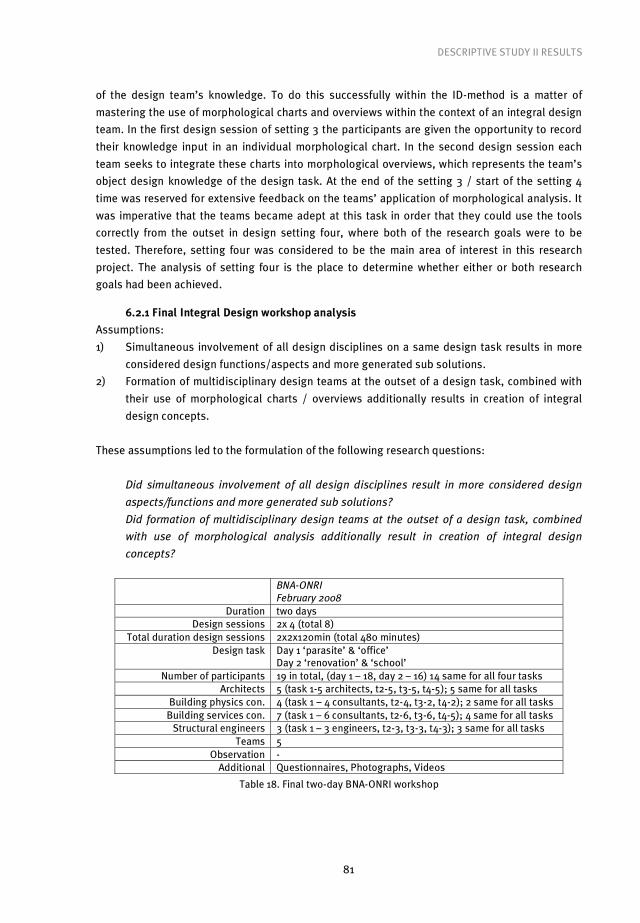
DESCRIPTIVE STUDY II RESULTS
81
of the design team’s knowledge. To do this successfully within the ID-method is a matter of
mastering the use of morphological charts and overviews within the context of an integral design
team. In the first design session of setting 3 the participants are given the opportunity to record
their knowledge input in an individual morphological chart. In the second design session each
team seeks to integrate these charts into morphological overviews, which represents the team’s
object design knowledge of the design task. At the end of the setting 3 / start of the setting 4
time was reserved for extensive feedback on the teams’ application of morphological analysis. It
was imperative that the teams became adept at this task in order that they could use the tools
correctly from the outset in design setting four, where both of the research goals were to be
tested. Therefore, setting four was considered to be the main area of interest in this research
project. The analysis of setting four is the place to determine whether either or both research
goals had been achieved.
6.2.1 Final Integral Design workshop analysis
Assumptions:
1) Simultaneous involvement of all design disciplines on a same design task results in more
considered design functions/aspects and more generated sub solutions.
2) Formation of multidisciplinary design teams at the outset of a design task, combined with
their use of morphological charts / overviews additionally results in creation of integral
design concepts.
These assumptions led to the formulation of the following research questions:
Did simultaneous involvement of all design disciplines result in more considered design
aspects/functions and more generated sub solutions?
Did formation of multidisciplinary design teams at the outset of a design task, combined
with use of morphological analysis additionally result in creation of integral design
concepts?
BNA-ONRI
February 2008
Duration two days Design sessions 2x 4 (total 8)
Total duration design sessions 2x2x120min (total 480 minutes) Design task Day 1 ‘parasite’ & ‘office’
Day 2 ‘renovation’ & ‘school’ Number of participants 19 in total, (day 1 – 18, day 2 – 16) 14 same for all four tasks
Architects 5 (task 1-5 architects, t2-5, t3-5, t4-5); 5 same for all tasks Building physics con. 4 (task 1 – 4 consultants, t2-4, t3-2, t4-2); 2 same for all tasks
Building services con. 7 (task 1 – 6 consultants, t2-6, t3-6, t4-5); 4 same for all tasks Structural engineers 3 (task 1 – 3 engineers, t2-3, t3-3, t4-3); 3 same for all tasks
Teams 5 Observation -
Additional Questionnaires, Photographs, Videos
Table 18. Final two-day BNA-ONRI workshop
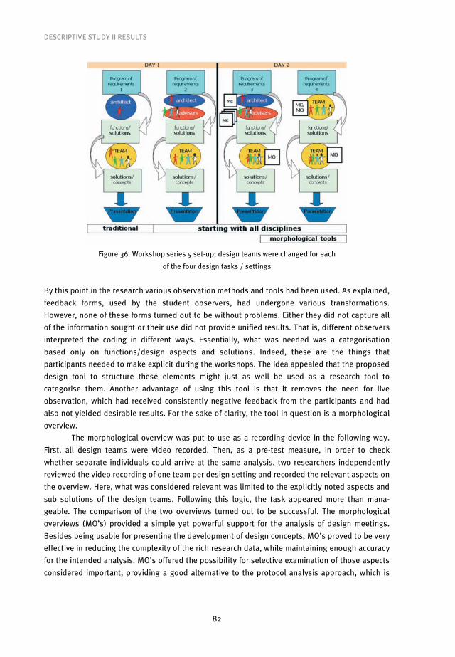
DESCRIPTIVE STUDY II RESULTS
82
Figure 36. Workshop series 5 set-up; design teams were changed for each
of the four design tasks / settings
By this point in the research various observation methods and tools had been used. As explained,
feedback forms, used by the student observers, had undergone various transformations.
However, none of these forms turned out to be without problems. Either they did not capture all
of the information sought or their use did not provide unified results. That is, different observers
interpreted the coding in different ways. Essentially, what was needed was a categorisation
based only on functions/design aspects and solutions. Indeed, these are the things that
participants needed to make explicit during the workshops. The idea appealed that the proposed
design tool to structure these elements might just as well be used as a research tool to
categorise them. Another advantage of using this tool is that it removes the need for live
observation, which had received consistently negative feedback from the participants and had
also not yielded desirable results. For the sake of clarity, the tool in question is a morphological
overview.
The morphological overview was put to use as a recording device in the following way.
First, all design teams were video recorded. Then, as a pre-test measure, in order to check
whether separate individuals could arrive at the same analysis, two researchers independently
reviewed the video recording of one team per design setting and recorded the relevant aspects on
the overview. Here, what was considered relevant was limited to the explicitly noted aspects and
sub solutions of the design teams. Following this logic, the task appeared more than mana-
geable. The comparison of the two overviews turned out to be successful. The morphological
overviews (MO’s) provided a simple yet powerful support for the analysis of design meetings.
Besides being usable for presenting the development of design concepts, MO’s proved to be very
effective in reducing the complexity of the rich research data, while maintaining enough accuracy
for the intended analysis. MO’s offered the possibility for selective examination of those aspects
considered important, providing a good alternative to the protocol analysis approach, which is

DESCRIPTIVE STUDY II RESULTS
83
more suitable for analysis of a limited amount of data, as was the case with the famous Delft
Protocols Workshop explained by Cross et al [1996].
In design setting 1 each team was given the same design task: to design a ‘parasite’
structure to be placed on the building the workshop was taking place in. For full description of
the design task see Appendix II. All teams proceeded with the task in the same way. Initially, in
the first design session, which lasted approximately 30 minutes, the architect worked alone on
the design. Basically, this was done to mirror the status quo in which the architect is responsible
for the original design, which is then presented to engineering disciplines. Incidentally, in one
team (team 1), the architect came up with two alternative sketches. Nevertheless, since one of the
sketches was quickly rejected even by the architect himself, this had no real effect on the
process. Following this, the other engineering disciplines of the design team joined the architect
in order to discuss the proposed design. In this sense, the design team members of the
engineering disciplines adopted the reactive role that is the norm in the status quo, and gave
their reactions to different aspect of the design proposal. On the basis of these reactions the
architect made adjustments to his original design. These adjustments led to optimisation of the
design in all but one of the teams, where the input led to a redesign. As will be explained, the
team that ended up redesigning did not strictly follow the design brief that was set, and for this
reason their result can be considered as anomalous.
In order to demonstrate what occurred in design setting 1, the work and analysis of two
teams is presented below, while the work of the other three teams can be found in Appendix V. As
the work of four of the teams (1, 2, 4 and 5) followed the same pattern, analysis of any of those
teams is sufficient to demonstrate the results. For this purpose the work of team 4 will be
analysed below. The work of team 3 is included in order to demonstrate why their end result was
different from the other four groups. The analysis of each team’s work proceeded as follows:
• First, the architect’s explanation of the initial proposal at the beginning of second design
session is translated into table of aspects and sub solutions;
• This resulting sequential list is then structured into the architect’s morphological chart;
• After which the architect’s sketches are shown;
• Then, a table of aspects and sub solutions considered by the design team is made based on
videotaped design team activities;
• Again, the resulting sequential list is structured into the design team’s morphological
overview;
• Finally, the design team’s proposal is depicted.
As mentioned above the design process of team 4 and the product that resulted from it was
essentially the same as three of the other four groups. After the initial design session, in which
the architect worked alone, all team members met to discuss the design. Here, the architect led
the discussion. He did so by first explaining the considerations he took into account while
working on his design. Through analysis of the session, these considerations were recorded in
the Table 19.

DESCRIPTIVE STUDY II RESULTS
84
Time (design
session II)
Who Aspect
or sub solution
Description Text/sketch
or verbally
00h04min A Sub solution (1-1) On the roof playground Verbally
00h07min A Aspect (2) Form / image Text (session I)
00h07min A Sub solution (2-1) Contrasting existing building, with ‘natural flowing’ roof Sketch, text (session I)
00h08min A Sub solution (3-1) Photo voltaic on the roof Text (session I)
00h08min A Aspect (4) Materialisation Text (session I)
00h08min A Sub solution (4-1) Wood (façade, roof structure) Text (session I)
00h09min A Aspect (5) Roof Sketch (session I)
00h09min A Sub solution (5-1) ‘tick’, for building services etc. Sketch (session I)
00h09min A Aspect (6) Façade Verbally
00h09min A Sub solution (6-1) Curtain wall Sketch (session I)
Table 19. Aspects and (sub) solutions as explained by architect 4 to design team 4 (session II)
In terms of analysis, a morphological chart was created in order to categorise and visualise the
considerations of the architect. The analytically derived morphological chart of team 4’s architect
is presented below.
Design asp ects/ functions:
Sub solutions:
(1) [positioning]
(1-1) On the building
{A} (2)
Form / image {A}
(2-1) Contrasting (roof)
{A} (3)
[self-supporting]
(3-1) PV on the new roof
{A} (4)
Materialisation {A}
(4-1) Wood (façade, roof)
{A} (5)
Roof {A}
(5-1) ‘tick’, for var. provisions
{A} (6)
[Façade]
(6-1) Curtain wall
{A}
Figure 37. Architect 4’s morphological chart
While explaining his reasoning to the other team members, the architect also presented a sketch
of his design as a basis for further discussion. The sketch from the architect of team four is shown
in Figure 38.

DESCRIPTIVE STUDY II RESULTS
85
Figure 38. Architect 4’s sketch
Mirroring authentic practice, the architect led the discussion and the other team members from
engineering disciplines reacted to the architect’s input. The architect also used this discussion to
evaluate aspects of his design on the basis of the knowledge of the relevant engineering
disciplines. In other words, he was interested in determining whether his ideas were workable
from an engineering perspective. Where his solutions turned out not to be workable, the architect
asked for solutions from the other team members. Analysis of this discussion allowed the
elements brought up to be depicted in the following table.
Time (design
session II)
Who Aspect
or sub solution
Description Text/sketch
or verbally
00h11min BP Aspect (7) Inside climate Verbally
00h11min BP Sub solution (7-1) Adjustable individually per function Verbally
00h13min BP Optimisation (7-1) With use of windows Verbally
00h15min A Sub solution (5-2) Light construction Verbally
00h16min BS Sub solution (5-3) ‘tropical roof’ Verbally
00h17min BS Aspect (8) Sustainable building Verbally
00h17min BS Sub solution (8-1) ‘Gray water circuit’ Verbally
00h18min A Aspect (3) Self-supporting Verbally
00h19min BP Aspect (9) Acoustic Verbally
00h20min BP Sub solution (9-1) High quality inner walls Verbally
00h20min A Sub solution (7-2) Building services in floor Verbally
00h20min BS Optimisation (7-2) Standard ‘grid size’ Verbally
00h25min BP Aspect (10) Construction Verbally
00h25min BP Sub solution (10-1) Wooden framework Verbally
00h30min BP Optimisation(10-1) Columns in the space, and façade Sketch (A)
00h32min A Draws (7-2) Sketch
00h33min A Optimisation (7-2) ‘Computer floor’ Verbally
00h34min BP Sub solution (9-2),
optimisation (7-2)
High quality sound isolation computer floors Verbally
00h37min BP Sub solution (7-3) Locally natural air intake Sketch (A)
00h39min BS Optimisation (7-3) Combined with induction units Sketch
00h43min BP Sub solution (7-4) Balanced ventilation Text (A)

DESCRIPTIVE STUDY II RESULTS
86
00h50min BS Sub solution (3-2) Wind turbine Text (A)
00h50min BS Sub solution (3-3) Fuel cell Text (A)
00h51min BS Sub solution (3-4) ‘trombe wall’ / mass activation... Sketch
00h53min BP Optimisation (3-4) ... as ventilated double wall const. Sketch
00h55min BP Sub solution (10-2) Steel frame (as ducts/piping) Text
00h58min A Aspect (11) Light (shading) Text
00h59min BP Sub solution (11-1) Screens Text
01h04min BS Sub solution (11-2) ‘climate facade’ Text
01h09min BP Optimisation (3-4) Energy production from airflow; ‘thermal
pressure difference’
Sketch
01h13min BS Optimisation (3-4) Warmed air also use for ventilation Sketch
01h20min A,BP,BS Draw presentation sheets Sketch
Table 20. Sequential overview of aspects and (sub) solutions produced by design team 4
In order to allow comparison between different design teams and settings, these tables were
reconfigured into the form of morphological overviews. The analytically derived morphological
overview of team 4 is presented below.
Design asp ects/ functions:
Sub solutions:
(3) self-supporting
{A}
(3-1) PV on the new roof
{A}
(3-2) Wind turbine
{BS}
(3-3) Fuel cell
{BS}
(3-4) ‘trombewand’
{BP} (5)
Roof
{A}
(5-1) ‘tick’, for var. provisions
{A}
(5-2) Light construction
{A}
(5-3) ‘tropical roof’
{BS}
(7) Inside climate
{BP}
(7-1) adjustable per function
{BP}
(7-2) building services in floor
{A}
(7-3) locally natural air intake
{BP}
(7-4) balanced ventilation
{BP} (8)
Sustainable building {BS}
(8-1) ‘gray water circuit’
{BS}
(9) Acoustic
{BP}
(9-1) high quality walls
{BP}
(9-2) high quality floor {BP}
(10) Construction
{BP}
(10-1) wooden framework {BP}
(10-2) Steel frame (as ducts /
piping) {BP}
(11) Light (shading)
{A}
(11-1) Screens
{BP}
(11-2) ‘climate facade’
{BS}
Figure 39. Design team’s morphological overview (italic – items defined during the first design session)
On the basis of these discussion points, the architect made relevant adjustments to his plan. In
essence, what the architect did was optimize his design. This optimized design was subsequently
agreed upon by the other team members. The teams were asked to present the end product of
this process on acetate sheets to be used for overhead projection. The end product of team 4 is
presented below. As can be deduced by looking at the end product, the team did not work in what
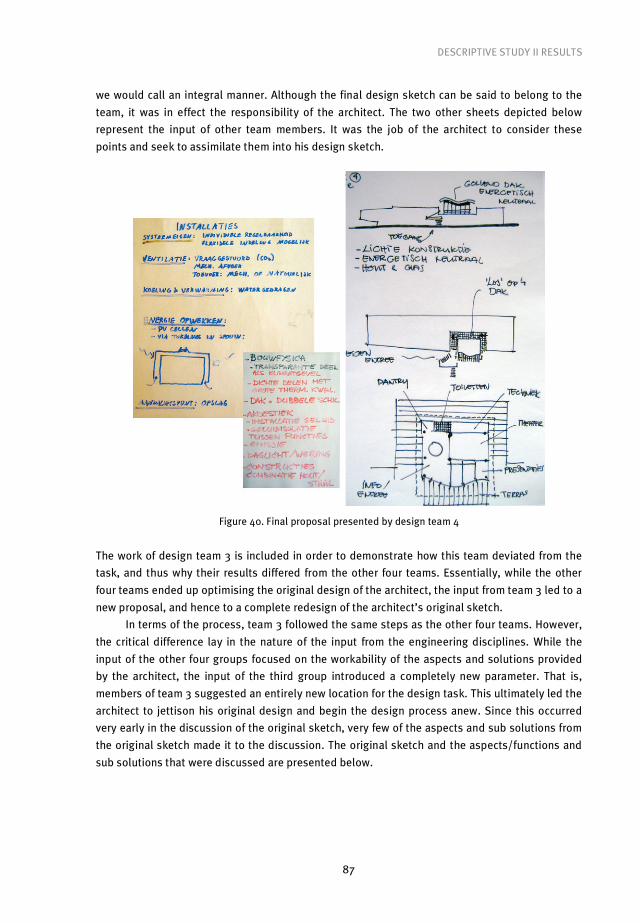
DESCRIPTIVE STUDY II RESULTS
87
we would call an integral manner. Although the final design sketch can be said to belong to the
team, it was in effect the responsibility of the architect. The two other sheets depicted below
represent the input of other team members. It was the job of the architect to consider these
points and seek to assimilate them into his design sketch.
Figure 40. Final proposal presented by design team 4
The work of design team 3 is included in order to demonstrate how this team deviated from the
task, and thus why their results differed from the other four teams. Essentially, while the other
four teams ended up optimising the original design of the architect, the input from team 3 led to a
new proposal, and hence to a complete redesign of the architect’s original sketch.
In terms of the process, team 3 followed the same steps as the other four teams. However,
the critical difference lay in the nature of the input from the engineering disciplines. While the
input of the other four groups focused on the workability of the aspects and solutions provided
by the architect, the input of the third group introduced a completely new parameter. That is,
members of team 3 suggested an entirely new location for the design task. This ultimately led the
architect to jettison his original design and begin the design process anew. Since this occurred
very early in the discussion of the original sketch, very few of the aspects and sub solutions from
the original sketch made it to the discussion. The original sketch and the aspects/functions and
sub solutions that were discussed are presented below.
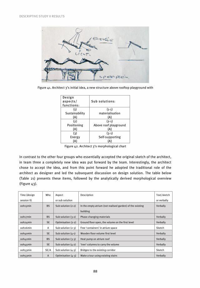
DESCRIPTIVE STUDY II RESULTS
88
Figure 41. Architect 3’s initial idea, a new structure above rooftop playground with
Design asp ects/ functions:
Sub solutions:
(1) Sustainability
{A}
(1-1) materialisation
{A} (2)
Positioning {A}
(2-1) Above roof playground
{A} (3)
Energy {A}
(3-1) Self-supporting
{A}
Figure 42. Architect 3’s morphological chart
In contrast to the other four groups who essentially accepted the original sketch of the architect,
in team three a completely new idea was put forward by the team. Interestingly, the architect
chose to accept the idea, and from this point forward he adopted the traditional role of the
architect as designer and led the subsequent discussion on design solution. The table below
(Table 21) presents these items, followed by the analytically derived morphological overview
(Figure 43).
Time (design
session II)
Who Aspect
or sub solution
Description Text/sketch
or verbally
00h15min BS Sub solution (2-2) In the empty atrium (not realised garden) of the existing
building
Verbally
00h17min BS Sub solution (3-2) Phase-changing-materials Verbally
00h24min SE Optimisation (2-2) Ground floor open, the volume on the first level Verbally
00h26min A Sub solution (2-3) Free ‘containers’ in atrium space Sketch
00h40min SE Sub solution (4-1) Wooden floor volume first level Verbally
00h41min BS Sub solution (3-3) Heat pump on atrium roof Verbally
00h45min SE Sub solution (4-2) ‘tree’-columns to carry the volume Verbally
00h53min SE/A Sub solution (4-3) Bridges to the existing corridor Sketch
00h53min A Optimisation (4-3) Make a tour using existing stairs Verbally

DESCRIPTIVE STUDY II RESULTS
89
00h56min SE Sub solution (1-2) Use of waste material / elements Verbally
00h58min SE Sub solution (1-3) Demountable Verbally
01h00min A Aspect (5) Inside climate Text
01h01min BS Sub solution (5-1) From exist. nozzles to ‘containers’ Sketch
01h01min A Sub solution (5-2) Self supporting ‘containers’ Verbally
01h01min BS Optimisation (5-2) Air intake from above / roof Sketch
01h05min BS Sub solution (5-3) PCM’s as walls in exposition space Verbally
01h10min A Draws presentation sheets Sketch
01h15min SE Optimisation (4-2) ‘trees’ leaning in opposite directions for stability Verbally
01h29min Team Design brief check Verbally
Table 21. Sequential overview of aspects and (sub) solutions produced by design team 3
Design asp ects/ functions:
Sub solutions:
(1) Sustainability
{A}
(1-1) materialisation
{A}
(1-2) waste material
{SE}
(1-3) Demountable
{SE} (2)
Positioning
{A}
(2-1) Above roof playground
{A}
(2-2) In existing (empty) atrium
{BS}
(2-3) ‘Containers’
{A} (3)
Energy
{A}
(3-1)
Self-supporting
{A}
(3-2) phase changing
materials {BS}
(3-3) Heat pump on atrium {BS}
(4) [volume /
‘container’]
(4-1) Wooden floors
{SE}
(4-2) ‘tree’ columns
{SE}
(4-3) Bridges to existing corridor
{SE/A} (5)
Inside climate {A}
(5-1) use existing nozzles
{BS}
(5-2) Self-supporting
‘containers’ {A}
(5-3) PCM’s as walls
{BS}
Figure 43. Design team’s morphological overview (italic – items defined during the first design session)
As in the other teams, the architect took the responsibility to assimilate the information from the
various team members in order to arrive at the final design. The final design of team 3 is
presented below. A quick comparison of the architect’s original sketch (Figure 41) shows that
rather than being a case of optimisation, this final product is a striking example of redesign.
Although the end product was markedly different from the architect’s original sketch, the process
that the team went through to arrive at the final product was essentially the same as that
followed by the other teams and professionals in the field. An important point to make of all teams is that their end products represented nothing
more than the recombination of existing solutions. In the work of none of the teams can we
identify the emergence of new design concepts. All of the work is simply optimisation and
redesign. In this process only aspects and sub solutions were discussed. These aspects and sub
solutions will prove useful for comparison purposes with those generated under the conditions of
settings 2 and 4.

DESCRIPTIVE STUDY II RESULTS
90
Figure 44. Final proposal presented by design team 3; structure inside atrium attached to the existing
traffic spaces/elements
The primary goal of this research was to find a way to integrate engineering disciplines into the
design process from the outset. Throughout the workshops that we conducted the participants
routinely expressed their desire for all disciplines to be involved at the beginning of design
process. There was a general dissatisfaction even among the architects at the hierarchical nature
of design processes in the status quo, in which the architect is the sole professional involved at
the outset and engineering disciplines are brought in later and occupy a largely reactive role. The
end goal of this research is to provide a means to integrate engineers at the outset of the design
process in a meaningful way. This is attempted in setting four when the teams had learned the
prerequisite aspects to do so. The goal of setting two was to make minimal changes to the status
quo and measure the effect on the design process and the final product. To reach this goal, at the
beginning of the design process in design session 1 all disciplines were asked to respond to the
design brief, as opposed to only the architect in the previous setting. In practice the participants
worked together with members of the other teams from the same discipline. In effect, this led to
the creation of four mono-disciplinary teams. All of these teams ended up with one finished
product. The individual disciplines took this product back to the multidisciplinary team. These
discipline-based responses were then brought to a team discussion in design session two. How
much of this product was used in the multidisciplinary team and in what way was down to the
representative of each discipline.
The logic for following this procedure was to see if asking all disciplines to work on the task
from the outset had any effect on the amount of aspects/functions and sub solutions that were
generated by design teams during design session II. To make this determination the sub
solutions generated are first presented and then compared to those in setting I. First, the results
of design session I are presented, after which the analysis of the team work in design session II is
shown.
The analysis of design sessions of the second workshop design setting is presented as
follows:
• First, chronological lists and morphological charts from mono-disciplinary teams in design
session I are shown;
• Then, a table of aspects and sub solutions considered by design teams during session II
made based on videotaped design team activities is shown;
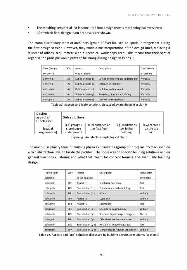
DESCRIPTIVE STUDY II RESULTS
91
• The resulting sequential list is structured into design team’s morphological overviews;
• After which final design team proposals are shown.
The mono-disciplinary team of architects (group of five) focused on spatial arrangement during
the first design session. However, they made a misinterpretation of the design brief, replacing a
‘cluster of offices’ requirement with a ‘technical workshops area’. This meant that their spatial
organisation principle would prove to be wrong during design sessions II.
Time (design
session II)
Who Aspect
or sub solution
Description Text/sketch
or verbally
00h17min A4 Sub solution (1-1) Garage and storehouse underground Verbally
00h17min A1 Sub solution (1-2) Entrance on first floor Verbally
00h20min A3 Optimisation (1-1) Half floor underground Verbally
00h26min A2 Sub solution (1-3) Workshops low in the building Verbally
00h33min A4 Sub solution (1-4) Canteen on the top floor Verbally
Table 22. Aspects and (sub) solutions discussed by architects (session I)
Design asp ects/ functions:
Sub solutions:
(1) [spatial
organisation]
(1-1) garage / storehouse
underground
(1-2) entrance on the first floor
(1-3) workshops low in the building
(1-4) canteen on the top
floor
Figure 45. Architects’ morphological chart
The mono-disciplinary team of building physics consultants (group of three) mainly discussed on
which abstraction level to tackle the problem. The focus was on specific building solutions and on
general functions clustering and what that meant for concept forming and eventually building
design.
Time (design
session II)
Who Aspect
or sub solution
Description Text/sketch
or verbally
00h07min BP5 Aspect (1) Clustering functions Text
00h13min BP2 Sub solution (1-1) Climate zones in the building Text
00h14min BP2 Sub solution (1-2) Atrium Verbally
00h15min BP1 Aspect (2) Light, sun Verbally
00h19min BP2 Aspect (3) Orientation Text
00h20min BP1 Sub solution (2-1) Shading on southern side Verbally
00h21min BP2 Sub solution (3-1) Southern façade longest/biggest Sketch
00h23min BP2 Sub solution (4-1) Office heat use for storehouse Verbally
00h25min BP2 Sub solution (4-2) Heat buffer in parking garage Text
00h29min BP5 Sub solution (4-3) Climate façade / hybrid ventilation Verbally
Table 23. Aspects and (sub) solutions discussed by building physics consultants (session I)
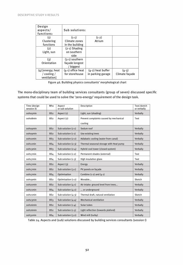
DESCRIPTIVE STUDY II RESULTS
92
Design asp ects/ functions:
Sub solutions:
(1) Clustering functions
(1-1) Climate zones in the building
(1-2) Atrium
(2) Light, sun
(2-1) Shading on southern
side
(3) Orientation
(3-1) southern façade longest
/ biggest
(4) [energy; heat / cooling / ventilation]
(4-1) office heat for storehouse
(4-2) heat buffer in parking garage
(4-3) Climate façade
Figure 46. Building physics consultants’ morphological chart
The mono-disciplinary team of building services consultants (group of seven) discussed specific
systems that could be used to solve the ‘zero-energy’ requirement of the design task.
Time (design session II)
Who Aspect or sub solution
Description Text/sketch or verbally
00h05min BS2 Aspect (1) Light, sun (shading) Verbally
00h08min BS2 Aspect (2) Prevent complaints caused by mechanical
cooling
Text
00h09min BS2 Sub solution (2-1) Sedum roof Verbally
00h09min BS2 Sub solution (1-1) Use existing trees Verbally
00h10min BS3 Sub solution (2-2) Adiabatic cooling (water from canal) Verbally
00h11min BS4 Sub solution (2-3) Thermal seasonal storage with Heat pump Verbally
00h13min BS3 Sub solution (2-4) Hybrid cool tower (closed system) Verbally
00h17min BS4 Sub solution (1-2) Permanent shades (external) Text
00h17min BS4 Sub solution (1-3) High insulation glass Text
00h17min BS2 Aspect (3) Energy Verbally
00h17min BS2 Sub solution (3-1) PV panels on façade Verbally
00h17min BS4 Optimisation Combine (1-2) and (4-1) Verbally
00h19min BS2 Optimisation (1-2) Movable... Sketch
00h20min BS2 Sub solution (4-1) Air intake: ground level from trees... Verbally
00h21min BS4 Sub solution (4-2) ... or underground Verbally
00h21min BS2 Sub solution (4-3) Thermal draft, natural ventilation Sketch
00h23min BS3 Sub solution (4-4) Mechanical ventilation Verbally
00h26min BS2 Sub solution (1-4) Solar tubes Verbally
00h26min BS2 Sub solution (1-5) Light reflection (towards plafond) Verbally
00h31min BS4 Sub solution (3-2) Wind mill (turby) Verbally
Table 24. Aspects and (sub) solutions discussed by building services consultants (session I)

DESCRIPTIVE STUDY II RESULTS
93
Design asp ects/ functions:
Sub solutions:
(1) Light, sun (shading)
(1-1) Existing trees
(1-2) Permanent
external shades
(1-3) High insulation
glass
(1-4) Solar tubes
(1-5) Light reflection
(2) mechanical cooling
complaints
(2-1) Sedum roof
(2-2) Adiabatic cooling
(2-3) Thermal
seasonal storage with heat pump
(2-4) hybrid cool tower (closed
system)
(3) Energy (solar)
(3-1) PV panels on façade
(3-2) Wind mill (turby)
(4) [ventilation]
(4-1) Ground level
air intake
(4-2) Underground air
intake
(4-3) natural thermal
draft
(4-4) Mechanical ventilation
Figure 47. Building services consultants’ morphological chart
The mono-disciplinary team of structural engineers (group of three) used design session I for
discussion on sustainable materials. More specifically, the question they posed was if it was
possible to use a material other than the traditionally used concrete, steel, glass and wood.
Time (design session II)
Who Aspect or sub solution
Description Text/sketch or verbally
00h00min SE4 Aspect (1) Materials Text
00h02min SE5 Optimisation (1) Up-cycling Verbally
00h03min SE3 Aspect (2) Demountable Verbally
00h04min SE3 Sub solution (2-1) Mechanical joints for concrete Verbally
00h05min SE5 Sub solution (1-1) Steel Verbally
00h08min SE5 Sub solution (1-2) Strokes concrete reuse
(cutting)
Verbally
00h10min SE3 Sub solution (1-3) Wood (good detailed joints) Verbally
00h27min SE3 Sub solution (1-4) Glass (load bearing) Verbally
Table 25. Aspects and (sub) solutions discussed by structural engineers (session I)
Design asp ects/ functions:
Sub solutions:
(1) Materials
(1-1) Steel
(1-2) strokes concrete reuse
(cutting)
(1-3) wood, good detailing
(1-4) Glass, load-
bearing (2)
Demountable
(2-1) concrete, mechanical
joints
Figure 48. Structural engineers’ morphological chart
In order to demonstrate what occurred in design setting 2, the work and analysis of two teams is
presented below, while the work of the other three teams can be found in Appendix V. As the
work of four of the teams (1, 2, 4 and 5) followed the same pattern, analysis of any of those teams
is sufficient to demonstrate the results. For this purpose the work of team 2 will be analysed

DESCRIPTIVE STUDY II RESULTS
94
below. Again, the work of team 3 differed markedly from the other teams. It is presented here to
demonstrate these differences.
Teams 1, 2, 4 and 5 all followed very similar pattern during design session two. First,
representatives of the individual disciplines explained the results of their work from the mono-
disciplinary team in design session 1. After these individual explanations, team discussion
ensued. The focus of this discussion was on fitting sub solutions into a final design. Here, the
majority of participants motivated their turns by mentioning personal experience in previous
projects. Decisions on how to fit these sub solutions into a final design were made relatively
quickly in these four teams. All of these four teams managed to produce a final design sketch
accompanied by explanations of specific systems or building elements used. The focus of all four
teams was largely on building parts rather than on building as a whole.
In design team 2, after the results of the first design session were presented, the building
physics consultant remarked that that the sub solutions and ideas presented were reminiscent of
a sustainable office building that his firm had recently completed in The Netherlands (Figure 49),
and represented a successful solution. This benchmark building is presented below.
Figure 49. Example project – Rabobank De Lier (Architectenbureau Böhtlingk)
After accepting the building physics consultant’s argument, the team agreed to use this
completed building as a benchmark with which to work out which sub solutions to use and how
to fit them into the final design proposal.
Time (design
session II)
Who Aspect
or sub solution
Description Text/sketch
or verbally
00h32min Team Solution! Oval building, example Rabobank ‘De Lier’ Verbally
00h35min BS Sub solution (1-1) Solar tubes for parking garage Verbally
00h38min BP Sub solution (1-2) Rainwater for pond in atrium – light reflection + ‘gray water circuit’ Verbally
00h49min BS Sub solution (2-1) Ventilation with air via ground Verbally
00h57min BP Sub solution (2-2) Hybrid ventilation Verbally
01h05min BS Sub solution (2-3) Season regulated double façade Sketch
Table 26. Aspects and (sub) solutions explicated by design team 2 (session II)

DESCRIPTIVE STUDY II RESULTS
95
Design asp ects/ functions:
Sub solutions:
(1) [light]
(1-1) solar tubes for
garage {BS}
(1-2) rainwater for pond in atrium
{BP}
(2) [ventilation]
(2-1) Air via ground
{BS}
(2-2) Hybrid
{BP}
(2-3) season regulated façade
{BS}
Figure 50. Design team 2’s morphological chart
The design team essentially recombined the successfully applied systems of the existing building
in order to arrive at the following sketch representing their solution to the design task.
Figure 51. Final proposal presented by design team 2
Design team 3 differed from the other four teams in two key aspects. First, although they
followed more or less the same steps as the other groups, rather than focusing on specifics as the
other teams did, team 3 focused more on general principles. Second, whereas the other four
teams arrived at a well developed final building design sketch, team 3 did not. Rather, it
produced proposals for specific building parts. As such, the team essentially did not answer the
given task, since they produced no building design. The table containing the aspects and sub
solutions considered by design team 3, and the morphological overview where these are
structured, are shown below.
Time (design
session II)
Who Aspect
or sub solution
Description Text/sketch
or verbally
00h11min BS Sub solution (1-1) Water cooled ventilation system Verbally
00h15min BS Sub solution (1-2) Mechanical air outlet Sketch
00h18min A Aspect (2) High-tech image Verbally
00h21min A Sub solution (2-1) Nearby Amsterdam Rijn canal water for heating and cooling Verbally

DESCRIPTIVE STUDY II RESULTS
96
00h26min A Aspect (3) Materialisation Verbally
00h28min SE Sub solution (3-1) Recycled concrete floor elements... Verbally
00h29min A Sub solution (3-2) ... in steel framework Verbally
00h31min A Optimisation (2-1) Concrete core activation Verbally
00h41min BS Sub solution (2-2) PV panels on (south) façade Verbally
00h46min BS Sub solution (2-3) LED lighting Verbally
Table 27. Aspects and (sub) solutions explicated by design team 3 (session II)
Design asp ects/ functions:
Sub solutions:
(1) [ventilation]
(1-1) water cooled system
{BS}
(1-2) mechanical air outlet
{BS}
(2) High-tech image
{A}
(2-1) canal water heating /
cooling {A}
(2-2) PV panels on façade
{BS}
(2-3) LED lighting
{BS} (3)
Materialisation {A}
(3-1) recycled concrete
elements {SE}
(3-2) Steel framework
{A}
Figure 52. Design team 3’s morphological chart
As mentioned above, the work of design team 3 did not culminate in a building design proposal.
Rather, what was presented were a collection of sub principles that would need to be integrated
into a final design. Their end product is shown below.
Figure 53. Final proposal presented by design team 3; principles only, without building design
In order to determine the effect of the set-up of setting two it must be compared to setting one.
The main point of interest is to assess whether requiring individual disciplines to consider the

DESCRIPTIVE STUDY II RESULTS
97
task from the outset had any effect on the number of sub solutions generated when the
individuals came together as a multi-disciplinary team.
In order to make this comparison two tables are presented below: the first table contains
the aspects and sub solutions from each individual team in setting I, the second table contains
the aspects and sub solutions from each individual team in setting II.
Team 1 Team 2 Team 3 Team 4 Team 5 Average
No. of aspects 5 7 2 5 7 5.2
No. of sub solutions 13 16 12 16 17 14.8
Table 28. Additional aspects addressed and (sub) solutions produced by design teams (setting I)
Team 1 Team 2 Team 3 Team 4 Team 5 Average
No. of aspects 5 2 3 3 3 3.2
No. of sub solutions 13 5 7 8 7 8.0
Table 29. Additional aspects addressed and (sub) solutions produced by design teams (setting II)
As can be seen from the table, contrary to what one might have expected, the intervention of
introducing other disciplines into the design process from the outset did not result in the
generation of a greater number of aspects and sub solutions. On the contrary, in setting two
fewer aspects and sub solutions were generated than in setting I, which was meant to simulate
the status quo. The graphic below clearly demonstrates that the intervention led to a declining
number of generated aspects and sub solutions.
Figure 54. Averages of the amount of design aspects and sub solutions generated
by design teams during design settings 1 and 2
In brief, a likely explanation for this is that the teams proceeded with the design task in what can
be described as an integrated rather than the desired integral approach. In effect, this integrated
approach led to the teams seeking to quickly assimilate aspects that were seen as workable in
terms of the final design. This approach therefore did not led to the accomplishment of the first
goal of this research.
The aim of setting three was to train the participants to produce morphological charts and
morphological overviews. The morphological charts are used to record and structure discipline
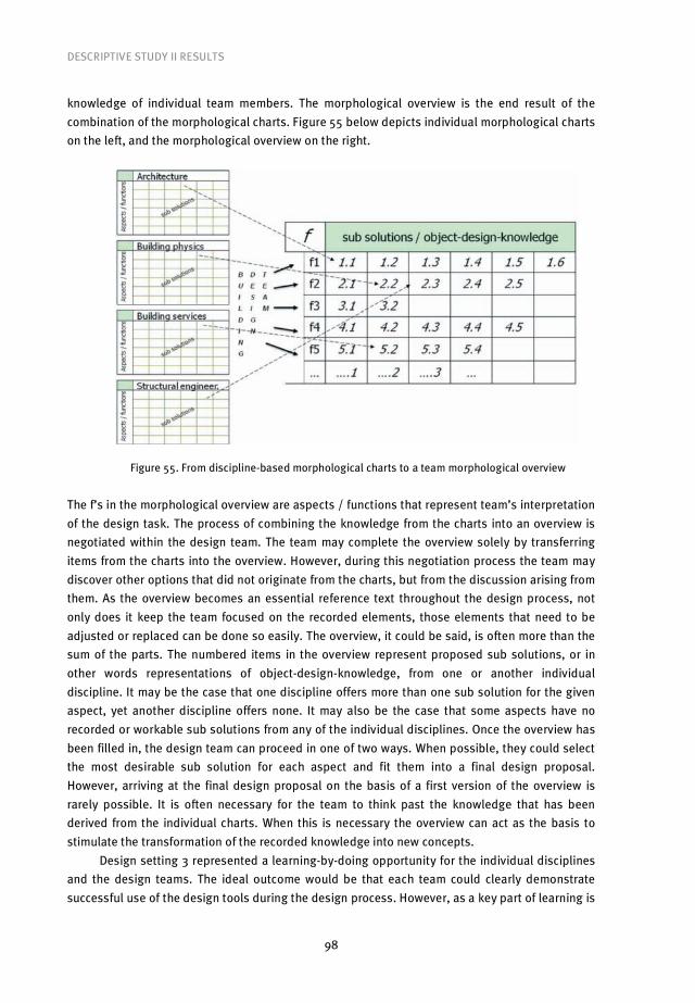
DESCRIPTIVE STUDY II RESULTS
98
knowledge of individual team members. The morphological overview is the end result of the
combination of the morphological charts. Figure 55 below depicts individual morphological charts
on the left, and the morphological overview on the right.
Figure 55. From discipline-based morphological charts to a team morphological overview
The f’s in the morphological overview are aspects / functions that represent team’s interpretation
of the design task. The process of combining the knowledge from the charts into an overview is
negotiated within the design team. The team may complete the overview solely by transferring
items from the charts into the overview. However, during this negotiation process the team may
discover other options that did not originate from the charts, but from the discussion arising from
them. As the overview becomes an essential reference text throughout the design process, not
only does it keep the team focused on the recorded elements, those elements that need to be
adjusted or replaced can be done so easily. The overview, it could be said, is often more than the
sum of the parts. The numbered items in the overview represent proposed sub solutions, or in
other words representations of object-design-knowledge, from one or another individual
discipline. It may be the case that one discipline offers more than one sub solution for the given
aspect, yet another discipline offers none. It may also be the case that some aspects have no
recorded or workable sub solutions from any of the individual disciplines. Once the overview has
been filled in, the design team can proceed in one of two ways. When possible, they could select
the most desirable sub solution for each aspect and fit them into a final design proposal.
However, arriving at the final design proposal on the basis of a first version of the overview is
rarely possible. It is often necessary for the team to think past the knowledge that has been
derived from the individual charts. When this is necessary the overview can act as the basis to
stimulate the transformation of the recorded knowledge into new concepts.
Design setting 3 represented a learning-by-doing opportunity for the individual disciplines
and the design teams. The ideal outcome would be that each team could clearly demonstrate
successful use of the design tools during the design process. However, as a key part of learning is

DESCRIPTIVE STUDY II RESULTS
99
feedback, after the teams completed tasks set in setting 3, time was given to compare and
appraise the teams’ work and to answer any questions that arose.
It turned out that all teams managed the tasks at least partially and three of the teams completed
the tasks fully. The first two teams, 3 and 4, successfully created individual morphological charts.
It appeared that they spent a good deal of time discussing the contents of the individual charts
during the second design session. What they did not achieve was to derive from the charts a
morphological overview. Instead, they deemed morphological charts as sufficient to proceed
directly to address the design task. During the feedback, however, both groups demonstrated
that they understood how charts may be converted into an overview. As an example of fully
completed task the charts and overview of team 1 are displayed in Figure 56 below.
A
BS
SE
Figure 56. Design team 1’s morphological overview; note that only some aspects are taken over from
individual morphological charts
Design setting 4 represents the very last stage in the cycle of research in this research project. All
of the individual interventions that were used in the earlier research stages are combined so that
1 1-1 1-2
3 3-2
4 4-1 4-2 4-3
2-2
4-4
5
6 6-1 6-2
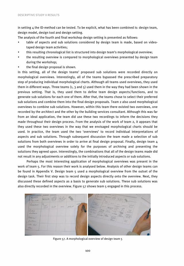
DESCRIPTIVE STUDY II RESULTS
100
in setting 4 the ID-method can be tested. To be explicit, what has been combined is: design team,
design model, design tool and design setting.
The analysis of the fourth and final workshop design setting is presented as follows: • table of aspects and sub solutions considered by design team is made, based on video-
taped design team activities;
• this resulting chronological list is structured into design team’s morphological overview;
• the resulting overview is compared to morphological overviews presented by design team
during the workshop;
• the final design proposal is shown.
In this setting, all of the design teams’ proposed sub solutions were recorded directly on
morphological overviews. Interestingly, all of the teams bypassed the prescribed preparatory
step of producing individual morphological charts. Although all teams used overviews, they used
them in different ways. Three teams (1, 3 and 5) used them in the way they had been shown in the
previous setting. That is, they used them to define team design aspects/functions, and to
generate sub solutions for each one of them. After that, the teams chose to select their preferred
sub solutions and combine them into the final design proposals. Team 2 also used morphological
overviews to combine sub solutions. However, within this team there existed two overviews, one
recorded by the architect and the other by the building services consultant. Although this was far
from an ideal application, the team did use these two recordings to inform the decisions they
made throughout their design process. From the analysis of the work of team 2, it appears that
they used these two overviews in the way that we envisaged morphological charts should be
used. In practice, the team used the two ‘overviews’ to record individual interpretations of
aspects and sub solutions. Through subsequent discussion the team made a selection of sub
solutions from both overviews in order to arrive at final design proposal. Finally, design team 4
used the morphological overview solely for the purposes of archiving and presenting the
solutions they agreed upon. Interestingly, the combinations that all of the design teams made did
not result in any adjustments or additions to the initially introduced aspects or sub solutions.
Perhaps the most interesting application of morphological overviews was present in the
work of team 5. For this reason their work is analysed below. Analysis of other design teams can
be found in Appendix V. Design team 5 used a morphological overview from the outset of the
design task. Their first step was to record design aspects directly onto the overview. Next, they
discussed these defined aspects as a basis to generate sub solutions. These sub solutions was
also directly recorded in the overview. Figure 57 shows team 5 engaged in this process.
Figure 57. A morphological overview of design team 5

DESCRIPTIVE STUDY II RESULTS
101
The most interesting aspect of team 5’s work was their appreciation that morphological
overviews could be applied at different levels of abstraction. This realisation came to team 5
while they were discussing a particular aspect they recorded in their morphological overview.
They considered the sub solutions generated to warrant further consideration. What they did
then is essentially to convert these sub solutions into aspects, which could then be worked on
further. Figure 58 below illustrates this move. In the left picture the row of sub solutions is
bordered. In the right picture the contents of this row are arranged into the left hand column,
which is the placeholder for aspects in an overview.
Figure 58. Sub solutions from one overview used as aspects in other overview
The aspects and sub solutions generated by team 5 were analysed and recorded in Table 30
below. The recording was arranged chronologically. Below this table, in Figure 59 a
morphological overview was constructed out of these items. This was done by the researcher for
all design teams in setting 4 to allow for a comparison with the results from the workshop setting
1, representing the status quo.
Time (design session II)
Who Aspect or sub solution
Description Text/sketch or verbally
00h06min A Aspect (1) Spatial organisation Text
00h07min BP Aspect (2) Health Text
00h07min BP Aspect (3) Sustainable energy Text
00h08min A Aspect (4) Materials (sustainable) Text
00h10min BS Aspect (5) Learning-by-doing Text
00h11min A Sub solution (1-1) Corridor with rooms Sketch
00h11min A Sub solution (1-2) Hall with rooms Sketch
00h11min BP Sub solution (1-3) ‘wings’ with central space Sketch
00h12min BP Sub solution (1-4) Clusters Sketch
00h13min A Sub solution (2-1) Light (natural) Text
00h16min BP Sub solution (2-2) Air (CO2) Text
00h16min BP Sub solution (2-3) Sound Text
00h16min BS Sub solution (2-4) Heat/cool Text
00h20min BP Sub solution (1-5) Dome with units underneath Sketch
00h21min BP Sub solution (3-1) PV/T Text
00h21min BP Sub solution (3-2) Adiabatic cooling Text
00h22min BS Sub solution (3-3) Balanced CO2 driven ventilation Text
00h23min BP Sub solution (3-4) Greenhouse; 2nd façade Text
00h24min BS Sub solution (3-5) Wind (as learning case) Text
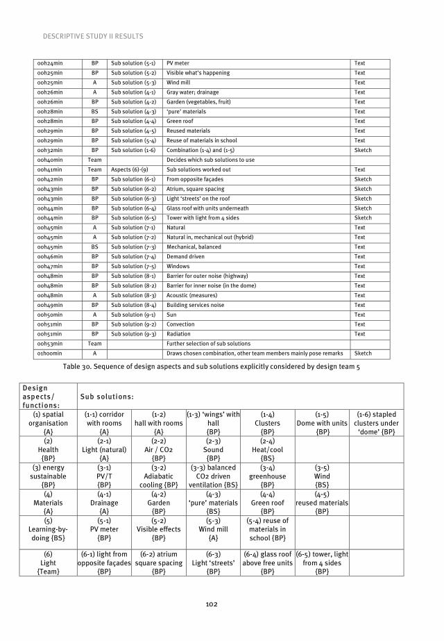
DESCRIPTIVE STUDY II RESULTS
102
00h24min BP Sub solution (5-1) PV meter Text
00h25min BP Sub solution (5-2) Visible what’s happening Text
00h25min A Sub solution (5-3) Wind mill Text
00h26min A Sub solution (4-1) Gray water; drainage Text
00h26min BP Sub solution (4-2) Garden (vegetables, fruit) Text
00h28min BS Sub solution (4-3) ‘pure’ materials Text
00h28min BP Sub solution (4-4) Green roof Text
00h29min BP Sub solution (4-5) Reused materials Text
00h29min BP Sub solution (5-4) Reuse of materials in school Text
00h32min BP Sub solution (1-6) Combination (1-4) and (1-5) Sketch
00h40min Team Decides which sub solutions to use
00h41min Team Aspects (6)-(9) Sub solutions worked out Text
00h42min BP Sub solution (6-1) From opposite façades Sketch
00h43min BP Sub solution (6-2) Atrium, square spacing Sketch
00h43min BP Sub solution (6-3) Light ‘streets’ on the roof Sketch
00h44min BP Sub solution (6-4) Glass roof with units underneath Sketch
00h44min BP Sub solution (6-5) Tower with light from 4 sides Sketch
00h45min A Sub solution (7-1) Natural Text
00h45min A Sub solution (7-2) Natural in, mechanical out (hybrid) Text
00h45min BS Sub solution (7-3) Mechanical, balanced Text
00h46min BP Sub solution (7-4) Demand driven Text
00h47min BP Sub solution (7-5) Windows Text
00h48min BP Sub solution (8-1) Barrier for outer noise (highway) Text
00h48min BP Sub solution (8-2) Barrier for inner noise (in the dome) Text
00h48min A Sub solution (8-3) Acoustic (measures) Text
00h49min BP Sub solution (8-4) Building services noise Text
00h50min A Sub solution (9-1) Sun Text
00h51min BP Sub solution (9-2) Convection Text
00h51min BP Sub solution (9-3) Radiation Text
00h53min Team Further selection of sub solutions
01h00min A Draws chosen combination, other team members mainly pose remarks Sketch
Table 30. Sequence of design aspects and sub solutions explicitly considered by design team 5
Design asp ects/ functions:
Sub solutions:
(1) spatial organisation
{A}
(1-1) corridor with rooms
{A}
(1-2) hall with rooms
{A}
(1-3) ‘wings’ with hall {BP}
(1-4) Clusters
{BP}
(1-5) Dome with units
{BP}
(1-6) stapled clusters under
‘dome’ {BP} (2)
Health {BP}
(2-1) Light (natural)
{A}
(2-2) Air / CO2
{BP}
(2-3) Sound
{BP}
(2-4) Heat/cool
{BS}
(3) energy sustainable
{BP}
(3-1) PV/T {BP}
(3-2) Adiabatic
cooling {BP}
(3-3) balanced CO2 driven
ventilation {BS}
(3-4) greenhouse
{BP}
(3-5) Wind {BS}
(4) Materials
{A}
(4-1) Drainage
{A}
(4-2) Garden
{BP}
(4-3) ‘pure’ materials
{BS}
(4-4) Green roof
{BP}
(4-5) reused materials
{BP}
(5) Learning-by-doing {BS}
(5-1) PV meter
{BP}
(5-2) Visible effects
{BP}
(5-3) Wind mill
{A}
(5-4) reuse of materials in school {BP}
(6) Light
{Team}
(6-1) light from opposite façades
{BP}
(6-2) atrium square spacing
{BP}
(6-3) Light ‘streets’
{BP}
(6-4) glass roof above free units
{BP}
(6-5) tower, light from 4 sides
{BP}

DESCRIPTIVE STUDY II RESULTS
103
(7) Air
{Team}
(7-1) Natural
{A}
(7-2) Hybrid
{A}
(7-3) Balanced
{BS}
(7-4) Demand driven
{BP}
(7-5) Windows
{BP}
(8) Sound {Team}
(8-1) barrier outer
noise {BP}
(8-2) barrier inner noise
{BP}
(8-3) Acoustic
{A}
(8-4) building services noise
{BP}
(9) Heat/cool
{Team}
(9-1) Sun {A}
(9-2) Convection
{BP}
(9-3) Radiation
{BP}
(10) school experience
(10-1) Discovery
(10-2) experience
(10-3) learning
(10-4) doing
(10-5) Interactive
Figure 59. Morphological overview of design team 5
The morphological overview above was made by the researcher, while team 5 generated two
small overviews which they used during the design process. On the basis of these two overviews
the architect from team 5 sketched the final design proposal. Both of the overviews and the final
design proposal are presented below. The overviews clearly show how the design team made
selections from the knowledge they had recorded.
Figure 60. The presented solution by design team 5
To conclude this section comparison is made between settings 1 and 4, and the research
questions that were stated for setting 4 are answered. The two tables below contain information

DESCRIPTIVE STUDY II RESULTS
104
on the number of aspects and sub solutions generated by the teams in the two different settings.
The tables clearly show that, as expected, more aspects and sub solutions were generated in
setting 4.
Team 1 Team 2 Team 3 Team 4 Team 5 Average
No. of aspects 5 7 2 5 7 5.2
No. of sub solutions 13 16 12 16 17 14.8
Table 31. Design aspects addressed and (sub) solutions produced by design teams (setting I)
Team 1 Team 2 Team 3 Team 4 Team 5 Average
No. of aspects 5 11 11 5 10 8.4
No. of sub solutions 24 26 39 20 46 31.0
Table 32. Design aspects addressed and (sub) solutions produced by design teams (setting IV)
In order to offer an even clearer demonstration of the effect of the intervention a further graphic is
provided. Here, the result is abundantly evident.
Figure 61. Averages of the amount of design aspects and sub solutions generated by design teams during
design settings 1 and 4
The research questions that were stated for this workshop are repeated below and answered. The
first question (Q21) pertains to the comparison between design settings 2 and 1, while the second
question (Q22) pertains to the comparison between design settings 4 and 1. The reasoning was
that involvement of all disciplines from the outset of the conceptual design phase would create
the opportunity for more contributions and hence likely result in more aspects and sub solutions
being considered than in the traditional setting. The subsequent introduction of morphological
analysis was expected to force the teams to explicate their input and reflect on it, which would
likely increase these amounts even further. However, it was also hoped that the use of
morphological overviews would, as explained earlier, stimulate creation of new design concepts.
Q21. Did simultaneous involvement of all design disciplines result in more considered
design aspects/functions and more generated sub solutions?
A21. No. On the contrary, there were less aspects and sub solutions considered in setting 2.

DESCRIPTIVE STUDY II RESULTS
105
Q22. Did formation of multidisciplinary design teams at the outset of a design task,
combined with use of morphological analysis, additionally result in creation of integral
design concepts?
A22. No. There were no concepts created in setting 4, all teams used explicated object
design knowledge to make recombination of existing solutions. However, there were more
aspects and sub solutions considered than in setting 1.
6.3 Evaluations of the workshops by the participants
A practical aim of this research was to develop a working method that would allow architectural
and engineering professionals to work in an integral team approach with the view to arriving at a
more efficient design process and better design products. Ultimately, the measurable criterion to
determine whether this aim has been met is the level of the acceptance of the method by the
designers (BNA and ONRI professionals) involved in its development and use.
Since the workshops were designed for professionals in practice, great value was attached
to their responses. Based on these results the workshop and the ID-method were adjusted and
applied in education. All workshop participants were asked to fill in questionnaires. The same
questionnaires (Appendix III) were used for all five workshops, which allowed for a general
comparison of the workshops series. The designers that were present during all design settings
of the workshop they participated in were approached six months after the sessions in order to
get their ‘second opinion’ (a post-evaluation) on the proposed approach and to assess the effects
it might have had on their practices. The number of design disciplines participants that were
present during all design sessions was 73, out of a total of 108 that participated in five BNA-ONRI
workshop series. The response to post-evaluations was 66%, meaning that 48 out of 73
designers reacted. The response to the questionnaire directly after the workshops was
comparatively much higher at 95%.
Evaluations directly after the workshop Series 1 Series 2 Series 3 Series 4 Series 5
1. Workshop rating 7,8 6,7 6,6 6,7 7,7 2. Importance of approach for practice 7,8 8,2 6,6 7,6 7,5 3. Relevance of morphological charts use 7,4 7,6 6,4 7,8 8,0 4. Need to stimulate use of morph. charts 6,7 7,2 6,4 7,9 8,2 5. Expected use of morphological charts 6,6 6,1 5,3 6,9 7,2 6. Workshop as professional education 9,0 7,6 7,6 8,3 8,9
Reactions from last-day participants 16 (94%) 17(100%) 19 (95%) 21 (95%) 15 (94%)
Table 33. Selection of participants’ workshop series evaluations
Evaluations after six months Series 1 Series 2 Series 3 Series 4 Series 5
1. Workshop rating 8,0 6,6 7,0 6,7 6,8 2. Importance of approach for practice 4,8 6,0 6,3 5,1 5,2 3. Relevance of morphological charts use 6,5 6,9 6,4 5,8 6,8 4. Need to stimulate use of morh.ch. 6,5 6,9 6,7 6,2 8,0 5. Morphological charts used in last 6 m. 5,0 4,0 3,6 4,0 4,4 6. Workshop for professionals education 9,5 7,4 8,7 7,8 8,6
Reactions from all-days participants 8 (73%) 7 (50%) 14 (70%) 9 (56%) 10 (71%)
Table 34. Selection of participants’ workshop series post-evaluations

DESCRIPTIVE STUDY II RESULTS
106
Comparing the results of the 4th and 5th workshop series in Tables 33 and 34, the biggest
difference (more than one point) can be seen regarding item four. After six months the
participants of the 5th workshop series responded strongly that it was necessary to stimulate the
use of morphological charts, even though they, just as the participants from previous workshops,
had not managed to use them in practice (Table 34, item 5). The main reason provided by the
ones that tried but did not succeed in using the ID-method and morphological analysis in their
practice was that they were “stuck in ongoing projects”. The results indicate that designers
appreciate the value of the ID-method and desire opportunities to use it in the real world. In this
sense it can be concluded that the measurable criteria for the acceptance of the ID-method have
indeed been met at least to some extent.
Working within design teams from the beginning of the preliminary design phase was
positively experienced by more than 80% of all workshop series participants; with � of them
even thinking that it led to the creation of synergy within design teams. The average rating of the
workshop after six months was similar to the average rating directly after the workshops: 7.0 and
7.3 respectively on a 1 to 10 scale. The importance of the proposed approach in the last six
months of their practices was rated 5.5. Although this raw figure may appear as a rather negative
evaluation, the participant explanations that accompanied this item show a rather more mixed
picture. On the one hand, many participants reported that day-to-day working methods had not
radically changed after the workshops, but their general awareness of others’ positions within
building design process had increased. For some, the approach was too theoretical and therefore
hard to apply in such a short period of time. Because projects usually last far longer than six
months, the majority of participants were not able to (try to) apply the method during the
preliminary/conceptual design phases (mainly because being ‘stuck’ in ongoing projects).
Figure 62. Participants’ ratings from all five workshop series
on use of morphological tools for *
The lack of application in practice also resulted in lower ratings regarding the relevance of
working with morphological charts/overviews: average of 6.5 compared to 7.4 immediately after
the workshops. Figure 62 shows participants’ ratings for all five workshop series regarding the

DESCRIPTIVE STUDY II RESULTS
107
use of morphological design tools. In cases where practitioners were in a position to experiment
with them during projects, they found that both the type of projects and clients’ attitude towards
integral design had to be favourable in order to be able to use them as during the workshops. The
majority of respondents was still in favour of stimulating use of morphological analysis and
regarded the workshop series as highly important for professionals’ education with an average
rating of 8.5 out of 10.
108
This research set out with two goals in mind. First and foremost, a method needed to be
developed to allow engineering disciplines to be included into the building design process from
the outset in a meaningful way. The second more abstract and longer term goal of the research,
although not the main aim of this particular project, is that the method developed here, given the
right cultural environment, may in time lead to the generation of innovative building concepts.
In order to achieve these goals this research was housed within the framework of Design
Research Methodology (DRM). In the first stage of DRM the research problem is clarified and the
measurable and success criteria are derived. Stages two, three and four of DRM allow the
researcher to decompose the research problem into discrete and manageable solution steps.
These three stages of DRM research allow the researcher to progress stepwise towards the
research goal. DRM facilitates iterative improvement of the research design where necessary.
Within the DRM approach research design is iteratively improved on the basis of the results of
the research steps taken. Therefore, the significance of many individual results has already been
discussed in the results chapters. As such, only a selection of key results is discussed here, after
which the extent to which the main goals of this project have been realised are discussed.
The goal of the research was to arrive at the ID-method. Doing so amounted to mani-
pulating the four key elements of design team, design model, design setting and design tools.
However, these elements were not tested in isolation, but rather in combination. Although the
discussion section is loosely structured around these elements, there will be overlap on many of
the points made. The section ends with recommendations for future research.
The configuration of the design team was the easiest aspect of the ID-method design to
decide. Bearing the goals of the research project in mind, choosing the required individual
disciplines was a straight forward matter. All that was needed was to identify the key engineering
disciplines to work alongside the architect. The key engineering disciplines whose design
knowledge is seen as relevant to the conceptual phase of building design are: building physics
consultants, building services consultants and structural engineers. Therefore, the design teams
used in this research ideally consisted of one member of each of these disciplines. Although at
times more than one representative of each discipline was present in a team, the included
disciplines remained the same throughout the entire research.
On a small number of occasions some of the participants turned out not to belong to the
disciplines named above, but to some other building related disciplines, such as building
managers, developers, project leaders. Rather than exclude these individuals from participation
in the workshops, they were assigned to design teams. Interestingly, the design teams effectively
excluded these disciplines from their consideration of design tasks. Ultimately, these individuals
themselves reported that they could not contribute to the tasks at hand. This could be seen as a
vindication for the chosen configuration of the design teams in our research.
Since it was not possible to conduct the research in an authentic setting, a semi-authentic
setting needed to be devised. As workshops had proved a useful setting for similar research in
the past, it was considered a good choice here also. The first pre-test workshop confirmed the
usefulness of the setting. The need for face-to-face communication within the workshop setting
7 Discussion and conclusion
DISCUSSION AND CONCLUSION
109
seemed to facilitate the required interaction among the design team members. Indeed, all of the
individual design disciplines expressed their enthusiasm for this face-to-face setting. The
workshop format remained throughout the research, yet the configuration of individual workshop
series needed to reflect the different elements that were being tested. Therefore, the
configuration of design settings was particular for a given workshop series.
The design of each workshop series was based to some extent on the results of previous
series. What resulted in the biggest change was the participants’ difficulty in completing the task
set in the third workshop series. Analysis and discussion of this series showed that the
participants felt the need for a learning cycle before being asked to use the design tools fully. The
necessity for an individual learning cycle arose from the fact that in third workshop series many
participants felt that the teams still operated under some kind of hierarchy in which one team
member or another seemed to be taking a leading role. This leading of the team represented a
potential threat to the learning of individual participants. Since operationalising the tool was
essential for the research it was considered imperative to provide the best learning possibility
available to the participants. This meant an individual learning cycle. Workshop series four then
was adapted to include this element. Since it could not be presumed that all teams would
manage to use the tools to their best advantage, feedback time was made available to discuss
the teams’ attempts. Here, C-K theory was used to explain the distinction between redesign and
real Design. This explanation focused the participants on the need to record the knowledge of all
included disciplines as a basis upon which to approach a design task. In effect, this explanation
served to remove the participants’ scepticism of the need to exploit new design tools to go
further than the norm in the status quo.
Although this adaptation did have a positive effect overall in that it led to a largely
successful application of the design tool, it did also result in a significant limitation in the
research. Ideally, a comparison should have been possible between a setting in which the design
teams began a task from the outset with the prescribed design tool, and an earlier setting where
the design teams worked on a task without the prescribed design tool. Although workshop series
three was designed with this end in mind, the failure of the teams to use the tool effectively in
this workshop set-up made a comparison impossible. It was not possible to solve this problem
simply by repeating the final design setting, as this would also imply a learning effect.
Much of the research conducted in the workshops was done in order to arrive at the final
set-up in which the main aims of the research could be tested. Descriptive study II represents this
final stage of the research. Looking at descriptive study II is in itself enough to determine
whether or not the aims had been realised. The first aim was to develop a method that was
capable of integrating engineering design knowledge into the design process during the
conceptual design phase. This aim was undoubtedly realised. The evidence for this is abundant.
All of the teams managed to exploit the morphological design tools to successfully include
knowledge from the individual disciplines. The one caveat that needs to be made here is that
regardless of these successful applications of the ID-method, many participants expressed a view
that it may be difficult to use the ID-method in actual practice. The reasons participants cited
were largely cultural ones. This should come as little surprise as the status quo is categorised by
a lack of such integral approaches. In this sense, it is not a lack of merit in the method itself, but a
lack of will that may hinder its future use.

DISCUSSION AND CONCLUSION
110
In terms of the first goal, the ID-method did prove successful in facilitating inclusion of
engineering knowledge from the outset of the conceptual design phase. This in itself rendered
the design process more efficient as it removed an unnecessary iteration, that is, the architect
beginning the design task on his own before seeing input from engineering disciplines. The
efficiency was also improved by the exigent way in which the participants used the design tools.
Often, the teams sought to achieve their goals in the quickest way possible. This could be seen in
their collapsing of the EMD model from four steps to two and also in many instances in the
application of the morphological tools. While the morphological chart was seen as necessary to
safeguard the input of individual disciplines, during the workshops there were many instances
when this safeguard appeared unnecessary. The teams seemed to be working so well that it was
possible for them to record all of the individual knowledge directly onto one team overview.
When this was done, there were no complaints from any of the participants that their input had
been neglected or minimised. However, an important point needs to be made here. These exigent
approaches of the teams could be said to result from the roles of individual disciplines within the
status quo. What the disciplines ended up doing in many instances amounted to no more than
seeking to fit solutions to design tasks. Their desire to do this as quickly as possible came at the
expense of extensive discussion of proposed sub solutions and aspects.
In essence, the teams’ approaches could best be categorised as integrated rather than
desired integral design. To consolidate this point, participant responses, especially from the
fourth workshop series, showed that the majority of the individuals considered the third design
setting to be ideal. This third setting seemingly represents the comfort zone of the majority of
professionals. Since within this setting none of the disciplines complained about use of
morphological analysis, it shows that the tools are neutral enough to work with by all partici-
pants. It is not individual explication of one’s discipline-based object-design-knowledge using
morphological analysis that posed a challenge, but its use within a design team setting.
This research cannot claim to have realised the second aim of using the ID-method to arrive
at integral design concepts. Nonetheless, this does not mean that the ID-method is not capable
of doing so. It is argued here that what the ID-method represents is nothing more than a set of
necessary conditions for the creation of ID-concepts. Neither the ID-method nor any other
method that was developed could claim to represent sufficient conditions for the creation of ID-
concepts. This is so because the parameters of any given design task and the individuals that set
out to realise it will always be important variables influencing the emergence or otherwise of
creative Designs.
The original motivation for this research arose from dissatisfaction with current practice.
The method derived in this research would ideally be used on authentic tasks in the future. This,
of course, will only be possible if professionals from the field accept its worth. In order to assess
whether this is the case, participants of the workshops were asked to evaluate the method. In
general, the majority of the participants expressed satisfaction with the ID-method. This
satisfaction grew as iterative improvements were made to the method, and by the final setup the
satisfaction ratings were very encouraging (see Appendix III). On top of participants’ satisfaction,
BNA, the organisation that provided the architectural participants also displayed great satisfac-
tion with the ID approach. Not only did they positively appraise the workshops, they also

DISCUSSION AND CONCLUSION
111
subsequently included an ID-method training course in their permanent professionals training
program.
An important caveat needs to be made here. The theoretical argument in this thesis is that
the integration of architectural and engineering disciplines into integral design teams is both
desirable and useful. However, practical considerations that vary by country must not be
forgotten. One of the important aspects is the legal position of architects, which shows marked
differences within the EU member states, varying from a wide ranging regulatory system to no
legal regulations [Visscher and Meijer 2008]. In the first case not only the title of architect is
protected, but also the architectural profession. This means, for example, that only architects can
submit building plans to the local authorities to obtain a building permit. Hence, this legal
requirement may lead to greater resistance of architects to work in non-hierarchical teams. In The
Netherlands, where this research was carried out, the title of architect gained legal protection in
1988, but the profession has no such official status. Although sometimes described as
threatening for architects, this situation is arguably more favourable for implementation of
integral design, than other, more regulatory systems offer.
A final measure of the acceptance of the ID-method came rather unexpectedly. A number of
the participants considered the method so desirable that they sought to integrate it into their
working practice. This led in two instances to real companies inviting the researchers to
implement the ID-method on real projects. These projects obviously fell outside of the current
research project and as such the results are not included herein. In addition, although
researchers from this project were invited by these companies to help introduce the ID-method
into the projects at hand, the researchers did not remain as part of the process. Therefore,
unfortunately, the end results of this application of the ID-method in an authentic setting were
not known at the time of publication of this thesis. Nonetheless, the fact that real companies
sought to use the ID-method on authentic design tasks goes a long way in itself. This gives hope
that the method may indeed be used in practice in the future.
The value of the current research can be seen as twofold. First, the method that has been
developed has been shown to have a practical use within the building design process. Second,
the development of the ID-method represents an important step in what is argued as a necessary
cultural change within the Dutch building domain. Not only have many individual professionals
been included, a variety of professional organisations and companies have also embraced this
change.
Although the overall result of the research done in the workshops had led us to conclude
that the ID-method has been proved usable and successful, at least to some extent, the results
are not truly generalisible, due to the way the research was carried out. Many areas of the
research design could be altered in order to yield more scientific results. This research was
conducted in workshops, which were observed and analysed. However, this could not be
described as true empirical observation as many variables could not be accounted for within the
current research design. For example, in which way the teams were variables themselves was not
checked. Subsequent research could employ matched teams to control for this variable. Doing so
would also remove the problem, noted in the discussion, of not being able to conduct the design
setting where the learning cycle takes place at the level of the team rather than the individual. By

DISCUSSION AND CONCLUSION
112
employing controlled groups of participants the learning effect of repeating the same design
setting could be taken into account.
Although much of the data that was analysed in this research was triangulated, the
research methods employed were not. For example, although in the current research different
observation methods were used, they were used at different times for different tasks. To add
more value to the research, multiple means of observation could be employed on each task.
Despite the fact that this research set out to bring fields in design practice together, the
research design was in effect mono-disciplinary. A multi-disciplinary research design would
automatically bring with it certain advantages. First, it would provide researchers from a variety
of fields. In all likelihood integrating the knowledge from these other fields would allow for the
triangulation of methods and possibly also of theory. The fields that could make an interesting
contribution include industrial design, engineering, management and social sciences.
The second goal of the research was to arrive at integral design concepts, which also
involves a certain amount of creativity. Unfortunately, no great creative leaps occurred so to
speak as a result of applying the method in building design teams. In addition to the use of
existing team’s object-design-knowledge future research could go one step further and propose
initial concepts as a driver for integral design. The problems associated with researching
creativity are well documented and outside of the realm of what is generally accepted as
architectural or engineering knowledge. Social science researchers and psychologist could offer
useful insights into how research might seek to stimulate and measure creativity. In addition,
since the notion of integral teams is central to the research, and this implies a common view on
design, it would be interesting to investigate if and how shared mental models can be generated
within building design teams.
A final recommendation is that future research should be carried out in an authentic
setting, if and when possible. As mentioned earlier, it was not possible at the time of this
research to look to practice to see what result an integral approach to building design would
yield. Therefore, the research had to simulate this situation, which led to certain problems. First,
it could not be guaranteed that all of the roles that needed to be simulated were taken seriously.
This was most evident in the role of the client, whose importance was overlooked by all teams. An
application of the ID-method in practice should result in all of the roles being fully respected. An
initial attempt to determine the usability of the method was done through post-evaluation
questionnaires. Although the responses could be seen as an encouraging first small step towards
external validation, in addition to designers’ appreciation of the potential value of the ID-method
for real-time projects, measurements of the method’s use and outcomes in authentic settings are
needed in order to be able to truly validate it. A live application of the ID-method would also
present the opportunity to test the potential of using morphological overviews as a means to
record key activities of the design team working on a design task in real time. In the workshop
settings the design task was compressed into a 120-minute time slot. Here, the morphological
overview proved to be a useful observation tool. It would be useful to confirm the worth of the
overview as an observation tool during the much greater time span taken to complete an
authentic design task.
In addition, an authentic application may serve to improve the confidence of potential end
users of the ID-method. A first step towards an authentic application is the course that the Royal

DISCUSSION AND CONCLUSION
113
Institute of Dutch Architects (BNA) and the Dutch Society for Building Services (TVVL), the two
parties that back in 2000 initiated the first research project on Integral Design, plan to run in the
near future. As the course is aimed at experienced professionals, it is hoped that their
participation may help to disseminate news of the integral approach into the Dutch building
domain. This may improve the chances that the ID-method can be applied on a truly authentic
design task. Because of the logic of the market, it may always prove difficult to convince
commercial enterprises to proceed with a new approach. Although there are trailblazers in every
market, a more likely source of support may be found in building projects where economic factors
are not the only drivers. Examples may include pilot projects conducted primarily to learn, or non-
profit and public sector projects, which are driven by a variety of concerns, such as the desire to
stimulate innovation.

114
Abadi, M. (2005) Issues and challenges in communication within design teams in the construction industry,
PhD Thesis, University of Manchester, UK
Alexander, C. (1964) Notes on the Synthesis of Form, Cambridge, Massachusetts: Harvard University Press
Alexander, C. (1965), A City is not a Tree, Architectural Forum, Vol 122, No 1, April 1965, pp 58-62 (Part I),
Vol.122, No.2, May 1965, pp.58-62 (Part II)
Alexander, C. (1971) The state of the art in design methods, DMG Newsletter, Vol.5, nr.3, pp.17-20
Alexander, C., Ishikawa, S., Silverstein, M., Jacobson, M., Fiksdahl-King. I. and Angel, S., (1977) A Pattern
Language, New York, Oxford University Press
Almefelt, L., (2005a) Balancing Properties while Synthesising a Product Concept – A Method Highlighting
Synergies, Proceedings of ICED’05, Melbourne, Australia, Paper Number 300.46.
Almefelt, L. (2005b) Requirements Driven Product Innovation, Methods and Tools Reflecting Industrial Needs,
PhD thesis, Chalmers University of Technology, Göteborg
Archer, L.B. (1965) Systematic method for designs, Council of Designers, London
Asimov, M. (1964), Introduction to Design, Prentence Hall, NewYork
Badke-Schaub, P. (2007) Team mental models in design (editorial), CoDesign, Vol.3, No.1, pp.1-3
Badke-Schaub, P., Neuman, A., Lauche, K. and Mohammed, S. (2007) Mental models in design teams: a valid
approach to performance in design collaboration?, CoDesign, Vol.3, No.1, pp.5-20
Bales, R. F. (1950) Interaction Process Analysis: A Method for the Study of Small Groups, Addison-Wesley
Press, Cambridge, MA
Bayazit, N. (2004) Investigating Design: A Review of Forty Years of Design Research, Design Issues, Vol.20,
No.1, pp.16-29
Blessing, L.T.M. (1994) A process-based approach to computer-supported engineering design, PhD-thesis,
Universiteit Twente, Enschede
Blessing, L.T.M. and Chakrabarti, A. (2002) DRM: A Design Research Methodology, Proceedings of Les
Sciences de la Conception, INSA de Lyon, Lyon
Blessing, L.T.M. (2006) 8th Summer School on Engineering Design Research, 28 May – 3 June & 23-29 July,
Samobor & Baden-Baden
Blessing, L.T.M. and Chakrabarti C. (2009) DRM, a Design Research Methodology, Springer.
Boden, M.A. (1990) The creative mind: myths & mechanisms, Weidenfeld and Nicolson, London
Boerstra, A.C., Haans, L., Van Dijken, F. (2006) Literatuuronderzoek binnenmilieu en energiegebruik in
Nederlandse scholen [Dutch; English translation: Literature research on interior climate and energy
use in Dutch schools], SenterNovem, Utrecht
Braha, D. and Reich, Y. (2003) Topological structures for modelling engineering design processes, Research
in Engineering Design, Vol.14, No.4, pp.185-199
Broadbent, G. (1979) The Development of Design Methods, Design Methods and Theories, 13-1, pp.41-45
Brunsgaard, C., Knudstrup, M. and Heiselberg, P. (2009) The First “Comfort Houses” in Denmark: Experiences
of different design processes, Proceedings of the 26th Conference on Passive and Low Energy
Architecture, Quebec City, 22-24 June 2009
Campbell, D. and Fiske, D.W. (1959) Convergent and discriminate validation by the multitrait-multimethod
matrix, Psychological Bulletin, 54, 297-312
Cross, N. (1982) Designerly ways of knowing, Design Studies, Vol.3, No.4, pp.221-227
Cross, N. (1984) Developments in Design Methodology, Wiley & Sons, Chichester
Cross, N., Christiaans, H., and Dorst, K. (1996) Analysing design activity, Wiley, Chichester
Cross, N. (2001) Design Discipline Versus Design Science, Design Issues, Vol.17, No.3, pp.49-55
Cross, N. (2006) Designerly Ways of Knowing, Springer-Verlag, London
References

REFERENCES
115
Davis, H. (2008) Form and Process in the Transformation of the Architect’s Role in Society, in Philosophy and
Design, Vermaas, P.E., Kroes, P., Light, A. and Moore, S.A. (editors), Springer
De Grada, E., Kruglanski, A.W., Mannetti, L. and Pierro, A. (1999) Motivation cognition and group interaction:
need for closure affects the contents and processes of collective negotiations, Journal of Experimental
Social Psychology, 35, pp.346-365
De Wilde, P., Augenbroek, G. and Van der Voorden, M. (2001) A strategy to provide computational support for
selection of energy saving building components, in Proceedings of IBPSA conference, Rio de Janeiro
De Wilde, P. (2004) Computational support for Selection of Energy Saving Building Components, PhD Thesis,
TU Delft
Denyer, D., Tranfield, D. and Van Aken, J.E. (2008) Developing Design Propositions through Research
Synthesis, Organization Studies, 29, 393
Denzin, N.K. (1970) The Research Act in Sociology, Butterworth, London
Denzin, N.K. (1978) The Research Act: A theoretical introduction to sociological methods, McGraw-Hilll, New
York
DNR (2005) The New Rules, BNA and ONRI, www.bna.nl/nl/service/dnr2005
DNR-STB (2009) Standard tasks description, BNA and ONRI, www.bna.nl/nl/service/stb2009,index.html
Dorst, K. (1997) Describing design – a comparison of paradigms, PhD Thesis, TU Delft
Dorst. K. and Royakkers, L. (2006) The design analogy: a model for moral problem solving, Design Studies,
Vol.27, No.6, pp.633-656
ECN and TNO (2004) Building Future, report number: 2004-BBE-B-597/KNB
Emmitt, S. and Gorse, C.A. (2003) Construction communication, Blackwell, Oxford
Emmitt, S. and Gorse, C.A. (2007) Communication in construction teams, Taylor and Francis, London
Franz, J.M. (1994) A critical framework for methodological research in architecture, Design Studies, Vol.15,
No.4, pp.433-447
Frey, D.D. and Dym C.L. (2006) Validation of design methods: lessons from medicine, Research in Engineering
Design, Vol.17, No.1, pp.45-57
Friedl, G. (2000) Modellering van het ontwerpproces [Dutch; English translation: Modelling of the design
process], PDEng thesis, Technische Universiteit Eindhoven, Stan Ackermans Instituut, Eindhoven
Gero, J.S. (1996) Creativity, emergence and evolution in design: concepts and framework, Knowledge Based
Systems, Vol.9, No.7, pp.435-448
Goldschmidt, G. (2008) Book review: The Cognitive Artifacts of Designing, Design Studies, Vol.29, No.1,
pp.93-96
Gorse, C.A. (2002) Effective Interpersonal Communication and Group Interaction During Construction
Management and Design Team Meetings, Leicester
Gregory, S.A. (1966) The design method, Butterworths, London
Habraken, N.J. (2005) Palladio’s Children, Taylor & Francis, New York
Hall, A.D. (1962) A methodology for systems engineering, Nostrand, Princeon
Hansen, F. (1968) Konstruktionssystematik, VEB-Verlag, Berlin
Hatchuel, A. (2002) Towards design theory and expandable rationality: the unfinished program of Herbert
Simon, Journal of Management and Governance, Vol.5. No.3-4, pp.260-273
Hatchuel, A. and Weil, B. (2002) C-K theory: Notions and applications of a unified design theory, Proceedings
of the Herbert Simon International Conference on Design Sciences, Lyon, 15-16 March 2002
Hatchuel, A. and Weil, B. (2003) A new approach of innovative design: an introduction to C-K theory, 14th
International Conference on Engineering Design, Stockholm
Hatchuel, A. and Weil, B. (2008) C-K design theory: an advanced formulation, Research in Engineering
Design, online 19 August 2008
Herzog, T. (1996) Research methods in the social sciences, HarperCollins Publishers, New York
Howard, T.J., Culley, S.J. and Dekonick, E. (2008) Describing the creative design process by the integration of
engineering design and cognitive psychology literature, Design Studies, Vol.29, No.2, pp.160-180
REFERENCES
116
Hubka, V. (1980) Principles of engineering design, Butterwurth Scientific, London
Hubka, V. and Eder, E. (1996) Design Science, Springer Verlag, London
IPCC (2007) Climate Change 2007, An Assessment of the Intergovernmental Panel on Climate Change, 17
November 2007, Valencia www.ipcc.ch
Jones, J.C. (1970, 1992 2nd edition) Design Methods, John Wiley & Sons Ltd, Chichester
Jones, J.C. (1977) How my thoughts about design methods have changed during the years, Design Methods
and Theories, Vol 11, No. 1, pp. 48-62
Jormakka, K. (2008) Basics Design Methods, Birkhäuser, Basel
Kesselring, F. (1954) Technische Kompositionslehre: Anleitung ze technisch-wirtschaftlichem und
verantwortungsbewusstem Schaffen, Springer, Berlin
Krick, E.V. (1969) An introduction to engineering and engineering design, Wiley, London
Lefaivre, L. and Tzonis, A. (2004) The Emergance of Modern Architecture, Routledge, London and New York
Lawson, B. (2004) What designers know, Architectural Press, London
Le Corbusier (1960) Nouvelle révolution, Science & Vie, No.513, p.39
Matousek, R. (1962), Engineering in Design, Blacky and Son, London
McDonnell, J. and Lloyd, P. (eds.) (2009) About: Designing Analysing, Analysing Design Meetings, Taylor and
Francis Group, London
Moholy-Nagy, S. (1957) Native genius in anonymous architecture, Horizon Press, New York
Müller-Merbach, H. (1975) The Use of Morphological Techniques for OR-Approaches to Problems, in Haley,
K.B. (ed.) (1976) Operational Research ’75, North Holland Publishing Company
Nasar, J.L., Preiser, W.F.E. and Fisher T. (2007), Designing for Designers: Lessons Learned from Schools of
Architecture, Fairchild Publications Inc., New York
Norris, K. W. (1963) The Morphological Approach to Engineering Design, In: Jones, J. C. and Thornley, D. G.
(eds.) Conference on Design Methods, Pergamon Press, Inc: Elmsford, pp. 115-140.
Opstelten, I.J., Bakker, E.-J., Sinke, W.C., de Bruijn, F.A., Borsboom, W.A. and Krosse, L. (2007) Potentials for
energy efficiency and renewable energy sources in the Netherlands, WSED2007 – Energy Future 2030,
Wels, Austria
Pahl, G. and Beitz, W. (1984) Engineering Design, Springer/Design Council, London
Pahl, G., Beitz, W., Feldhusen, J. and Grote, K.H. (2007) Engineering Design: A Systematic Approach, 3rd
edition, Wallace, K. and Blessing, L. Translators and Editors, Springer-Verlag, New York
Pawson, R. (2002) Evidence based policy: In search of a method, Evaluation, 8/2, pp.157–181
Quanjel, E.M.C.J. (2003) Eindrapportage Integraal Ontwerpen [Dutch; English translation: Final rapport
Integral Design project], OBOM Onderzoeksgroep, TU Delft
Quanjel, E.M.C.J., and Zeiler, W. (2003) Babylon voorbij, OBOM TU Delft, Delft
Ritchey, T. (2002) General Morphological Analysis, A general method for non-quantified modeling, Adapted
from the paper "Fritz Zwicky, Morphologie and Policy Analysis", presented at the 16th EURO Conferen-
ce on Operational Analysis, Brussels, 1998, the Swedish Morphological Society, www.swemorph.com
Ritchey,T. (2006) Problem Structuring using computer-aided morphological analysis, Journal of the
Operational Research Society, 57, pp.792–801
Rittel, H. and Webber, M. (1973) Dilemmas in a general theory of planning, Policy Sciences, Vol. 4, pp. 155-
169
Roozenburg, N.F.M. and Cross, N.G. (1991) Models of the design process: integrating across the disciplines,
Design Studies, Vol.12, No.4, pp.215-220
Roth, K., Franke, H.J. and Simonek, R. (1972) Die Allgemeine Funktionsstruktur, ein wesentliches Hilfsmittel
zum konstruieren, Konstruktion 24, Heft 7
Savanovi�, P. and Zeiler, W. (2007) Using methodical design for culture change in Dutch building design
practice: ‘learning by doing' workshops, Design Principles & Practices: An International Journal, 1(2),
pp.71-82.
Simon, H.A. (1969) The Sciences of the Artificial, MIT Press, Cambridge, MA

REFERENCES
117
Schön, D. (1983) The Reflective Practitioner, Temple Smith, London
Schön, D. (1987) Educating the Reflective Practitioner, Jossey-Bass Inc., U.S.
Suh, N.P. (1990) Principles of design, Oxford University Press, New York
Tzonis, A. and Lefaivre, L. (1991) Het architectonisch denken, SUN, Nijmegen [3rd Dutch edition with additional
essays of Towards a Non-oppressive Environment (1972), MIT Press, Cambridge]
Uitdenbogerd, D.E. (2007) Energy and Households, PhD Thesis, Wageningen Universiteit
USP Marketing Consultancy (2001) Bouw denkt zelf jaarlijks 6 miljard te verspillen door faalkosten [Dutch;
The building sector estimates 6 billion euro are squandered by failure costs], USP Faalkosten
Bouwbarometer, Rotterdam, www.usp-mc.nl
USP Marketing Consultancy (2005) Verspilling in de bouw gaat door [Dutch; Squandering in building sector
continues], USP Bouwsignalen, 31 October 2007, Rotterdam, www.usp-mc.nl
USP Marketing Consultancy (2007) Gebrekkige communicatie grootste veroorzaker faalkosten [Dutch; Poor
communication main reason for failure costs], USP Bouwsignalen, 31 October 2007, Rotterdam,
www.usp-mc.nl
USP Marketing Consultancy (2008) Faalkosten in de bouw naar hoogtepunt [Dutch; Failure costs in building
sector peak], USP Bouwsignalen, 11 April 2008, Rotterdam, www.usp-mc.nl
Van Aken, J. E. (2005) Valid knowledge for the professional design of large and complex design processes,
Design Studies, Vol.26, No.4, pp.379-404
Van den Kroonenberg, H.H. (1974) Methodisch ontwerpen [Dutch; English translation: Methodical Design], De
Ingenieur, no.47, 21 november 1974
Van den Kroonenberg, H.H. (1987) Stimulating creativity and innovations by methodical design, Report of the
First European Conference on Creativity and Innovation, Delft, The Netherlands, 13-16 December 1987
Van den Kroonenberg, H. H., and Siers, F. J. (1992) Methodisch ontwerpen [Dutch; English translation:
Methodical Design], Educaboek, Culemborg
Van Vliet, G. (1995) Denken en doen bij experimenteel onderzoek [Dutch; English translation: Thinking and
doing in research experiments], Van Gorcum, Assen
Vermaas, P.E. (2008) Editorial introduction, in Philosophy and Design, Vermaas, P.E., Kroes, P., Light, A. and
Moore, S.A. (editors), Springer
Visscher, H.J. and Meijer, F.M. (2008) The meaning of the protection of the architects title in European
countries, In R. Haigh and D Amaratunga (Eds.), Building Resilience (pp. 1287-1298), Salford, UK:
School of the built environment, University of Salford
Webb, E. (1966) Unconventionality, Triangulation and Inference, in Proceedings of the Invitational Conference
on Testing Problems, Princeton, New Jersey
Wichers Hoeth, A.W. and Fleuren, K.G.A. (2001) De bouw moet om [Dutch; English translation: The building
sector has to turn round], Stichting Bouwresearch, Rotterdam
Yoshikawa, H. (1981) General design theory and a CAD system, in Sata, E. and Warman, E, (Eds.) Man-machine
communication in CAD/CAM, pp.35-58, Amsterdam
Zeiler, W. (1993) Methodical Design Framework for Design Improvement, In Proceedings of the 4th
International Congress of Industrial Engineering, Marseille
Zeiler, W., Quanjel, E., Savanovi�, P., Borsboom, W. and Trum, H., (2005) Integral Design Methodology for the
Built Environment, Proceedings Design Research in the Netherlands, Achten, H. (ed.), TU Eindhoven,
Eindhoven
Zeiler, W., Boxem, G. (2008) Ventilatie van Nederlandse scholen [Dutch; English translation: Ventilation in
Dutch schools], TVVL Magazine, 37(4), pp.52-57
Zwicky, F. (1948) The Morphological Method of Analysis and Construction, Courant, Anniversary Volume
Zwicky, F. and Wilson, A.G. (eds.) (1967) New Methods of Thought and Procedure, Contributions to the
Symposium on Methodologies, Pasadena, Springer-Verlag, New York.
Zwicky, F. (1969) Discovery, Invention, Research - Through the Morphological Approach, The Macmillan
Company, Toronto.
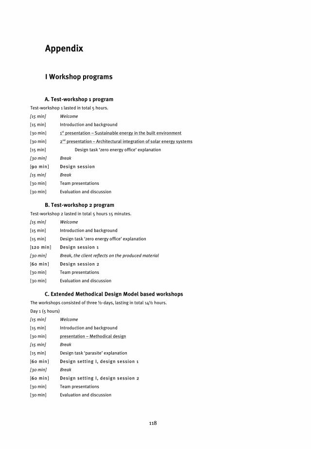
118
I Workshop programs
A. Test-workshop 1 program
Test-workshop 1 lasted in total 5 hours.
[15 min] Welcome
[15 min] Introduction and background
[30 min] 1st presentation – Sustainable energy in the built environment
[30 min] 2nd presentation – Architectural integration of solar energy systems
[15 min] Design task ‘zero energy office’ explanation
[30 min] Break
[990 min] DDesign session
[15 min] Break
[30 min] Team presentations
[30 min] Evaluation and discussion
B. Test-workshop 2 program
Test-workshop 2 lasted in total 5 hours 15 minutes.
[15 min] Welcome
[15 min] Introduction and background
[15 min] Design task ‘zero energy office’ explanation
[1120 min] DDesign session 1
[30 min] Break, the client reflects on the produced material
[660 min] DDesign session 2
[30 min] Team presentations
[30 min] Evaluation and discussion
C. Extended Methodical Design Model based workshops
The workshops consisted of three �-days, lasting in total 14� hours.
Day 1 (5 hours)
[15 min] Welcome
[15 min] Introduction and background
[30 min] presentation – Methodical design
[15 min] Break
[15 min] Design task ‘parasite’ explanation
[660 min] DDesign setting I, design session 1
[30 min] Break
[660 min] DDesign setting I, design session 2
[30 min] Team presentations
[30 min] Evaluation and discussion
Appendix

APPENDIX
119
Day 2 (4� hours)
[15 min] Welcome
[15 min] Feedback day 1
[30 min] presentation – Sustainable comfort systems
[15 min] Break
[15 min] Design task ‘zero energy office’ explanation
[660 min] DDesign setting I I, design session 1
[30 min] Break
[660 min] DDesign setting I I, design session 2
[30 min] Evaluation and discussion
Day 3 (5 hours)
[15 min] Welcome
[15 min] Feedback day 2
[30 min] presentation – Kesselring method (workshop configuration A), Relation between the client and design
team guarantee for quality (configuration B)
[15 min] Break
[660 min] DDesign setting I I, design session 3
[30 min] Break
[660 min] DDesign setting I I, design session 4
[30 min] Team presentations
[30 min] Evaluation and discussion
[15 min] BNA and ONRI reflection
D. Working Design Model based workshop
The workshop consisted of three �-days, lasting in total 16 hours.
Day 1 (6 hours)
[10 min] Welcome (architects)
[10 min] Design task ‘zero energy office’ explanation
[660 min] DDesign setting I, design session 1
[10 min] Welcome (consultants)
[60 min] Tour of the building the workshop is held in
[30 min] Break
[10 min] ‘Introduction’ and background
[20 min] presentation – Sustainable comfort systems
[10 min] Break
[10 min] Design task ‘zero energy office’ explanation
[660 min] DDesign setting I, design session 2
[10 min] Break
[30 min] Team presentations
[30 min] Evaluation and discussion
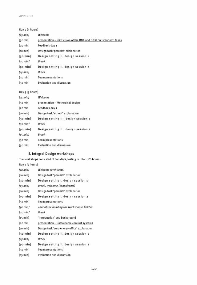
APPENDIX
120
Day 2 (5 hours)
[15 min] Welcome
[30 min] presentation – Joint vision of the BNA and ONRI on ‘standard’ tasks
[20 min] Feedback day 1
[10 min] Design task ‘parasite’ explanation
[330 min] DDesign setting I I, design session 1
[30 min] Break
[990 min] DDesign setting I I, design session 2
[15 min] Break
[30 min] Team presentations
[30 min] Evaluation and discussion
Day 3 (5 hours)
[15 min] Welcome
[30 min] presentation – Methodical design
[20 min] Feedback day 1
[10 min] Design task ‘school’ explanation
[330 min] DDesign setting I II, design session 1
[30 min] Break
[990 min] DDesign setting I II, design session 2
[15 min] Break
[30 min] Team presentations
[30 min] Evaluation and discussion
E. Integral Design workshops
The workshops consisted of two days, lasting in total 17� hours.
Day 1 (9 hours)
[10 min] Welcome (architects)
[10 min] Design task ‘parasite’ explanation
[330 min] DDesign setting I, design session 1
[15 min] Break, welcome (consultants)
[10 min] Design task ‘parasite’ explanation
[990 min] DDesign setting I, design session 2
[30 min] Team presentations
[90 min] Tour of the building the workshop is held in
[30 min] Break
[15 min] ‘Introduction’ and background
[20 min] presentation – Sustainable comfort systems
[10 min] Design task ‘zero energy office’ explanation
[330 min] DDesign setting I I, design session 1
[15 min] Break
[990 min] DDesign setting I I, design session 2
[30 min] Team presentations
[15 min] Evaluation and discussion

APPENDIX
121
Day 2 (8� hours)
[15 min] Welcome
[45 min] Feedback day 1
[20 min] presentation – Methodical design
[10 min] Design task ‘renovation’ explanation
[330 min] DDesign setting I II, design session 1
[15 min] Break
[990 min] DDesign setting I II, design session 2
[30 min] Team presentations
[30 min] Break
[20 min] presentation/feedback – Morphological analysis and C-K theory
[10 min] Design task ‘school’ explanation
[330 min] DDesign setting IV, de sign session 1
[15 min] Break
[990 min] DDesign setting IV, de sign session 2
[30 min] Team presentations
[30 min] Evaluation and discussion
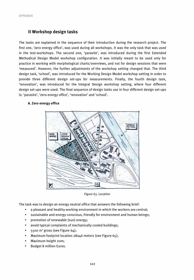
APPENDIX
122
II Workshop design tasks
The tasks are explained in the sequence of their introduction during the research project. The
first one, ‘zero energy office’, was used during all workshops. It was the only task that was used
in the test-workshops. The second one, ‘parasite’, was introduced during the first Extended
Methodical Design Model workshop configuration. It was initially meant to be used only for
practice in working with morphological charts/overviews, and not for design sessions that were
‘measured’. However, the further adjustments of the workshop setting changed that. The third
design task, ‘school’, was introduced for the Working Design Model workshop setting in order to
provide three different design set-ups for measurements. Finally, the fourth design task,
‘renovation’, was introduced for the Integral Design workshop setting, where four different
design set-ups were used. The final sequence of design tasks use in four different design set-ups
is: ‘parasite’, ‘zero energy office’, ‘renovation’ and ‘school’.
A. Zero energy office
Figure 63. Location
The task was to design an energy neutral office that answers the following brief:
• a pleasant and healthy working environment in which the workers are central;
• sustainable and energy conscious, friendly for environment and human beings;
• promotion of renewable (sun) energy;
• avoid typical complaints of mechanically cooled buildings;
• 5500 m2 gross (see Figure 64);
• Maximum footprint location 28x46 meters (see Figure 65);
• Maximum height 20m;
• Budget 8 million Euros.

APPENDIX
123
Figure 64. Spatial requirements
Figure 65. Footprint and height restrictions
During the 1st pre-test workshop participants were asked to use two specific sustainable systems as
solution drivers, PV/T (photovoltaic thermal collector) and Oxycell (indirect adiabatic cooling
system). The principle of Oxycell, as shown in below figure, was also presented during all

APPENDIX
124
subsequent workshops as a new promising development, but it was not forced upon teams to use
it.
Figure 66. Natural principle of Oxycell’s indirect adiabatic cooling
B. Parasite
The task was to design a multimedia pavilion for sustainable building; on the building in which
the workshop was held. Besides the drawings of the building the design teams got the following
‘brief’:
• the pavilion has to be an appropriate addition to the existing building, qua form, function
and appearance;
• it has to be ‘a symbol’ of sustainable building;
• it has to offer space for groups of up to 30 persons (students, scientists, researchers);
• the orientation regarding the existing entrances/exits has to be ‘clear’, also for access of
goods;
• functioning of the pavilion must not negatively influence the existing building functions in
any way, and vice versa;
• all spaces need to comply to the general comfort requirements for A-location offices;
• maximum occupancy 30 persons for maximum of 1� hours, permanent presence of only 1
technician and 2 guides;
• interior must be replaceable each year, the whole pavilion must be removable after 5
years;
• spatial requirements (net 308m2 total): welcome area 50 m2, information area general 20
m2, presentation area, in theatre setting 80m2, presentation rooms 2x18m2, toilets 20m2,
pantry 10m2, technical room 10m2.
C. School
The task was to design a school with healthy and sustainable environment for children. The most
important requirement was to avoid typical complaint of naturally ventilated classes. The same
location as for ‘zero energy office’ design task was used, with only adjustment the bigger
footprint and reduced building height asked.
The students are clustered in two domains, ‘undergraduate’ (1st and 2nd year) and
‘graduate’ (years 3-6). Each domain comprises of next spaces: silent room, working places for
students and groups, and instruction rooms. All these spaces need to be designed in such way
that they can ‘grow and shrink’, being it through interchange between the domains or through
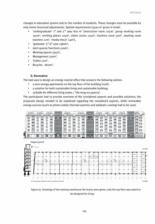
APPENDIX
125
changes in education system and/or the number of students. These changes must be possible by
only minor structural adjustments. Spatial requirements (5500 m2 gross in total):
• ‘undergraduate’ 1st and 2nd year 810 m2 (instruction room 225m2, group working room
250m2, working places 125m2, silent rooms 125m2, teachers room 50m2, meeting room
teachers 12m2, ‘media theca’ 24m2),
• ‘graduate’ 3rd-6th year 1380m2,
• Joint spaces/functions 500m2,
• Meeting spaces 335m2,
• Management 310m2,
• Toilets 75m2,
• Bicycles ~800m2.
D. Renovation
The task was to design an energy neutral office that answers the following wishes:
• a zero energy apartments on the top floor of the building (roof);
• a solution for both sustainable living and sustainable building;
• suitable for different living styles / ‘life-long occupancy’.
The participants had to provide overview of the considered aspects and possible solutions; the
proposed design needed to be explained regarding the considered aspects, while renewable
energy sources (such as photo-voltaic-thermal systems and adiabatic cooling) had to be used.
Figure 67. Drawings of the existing warehouse the teams were given; only the top floor was asked to
be designed for living
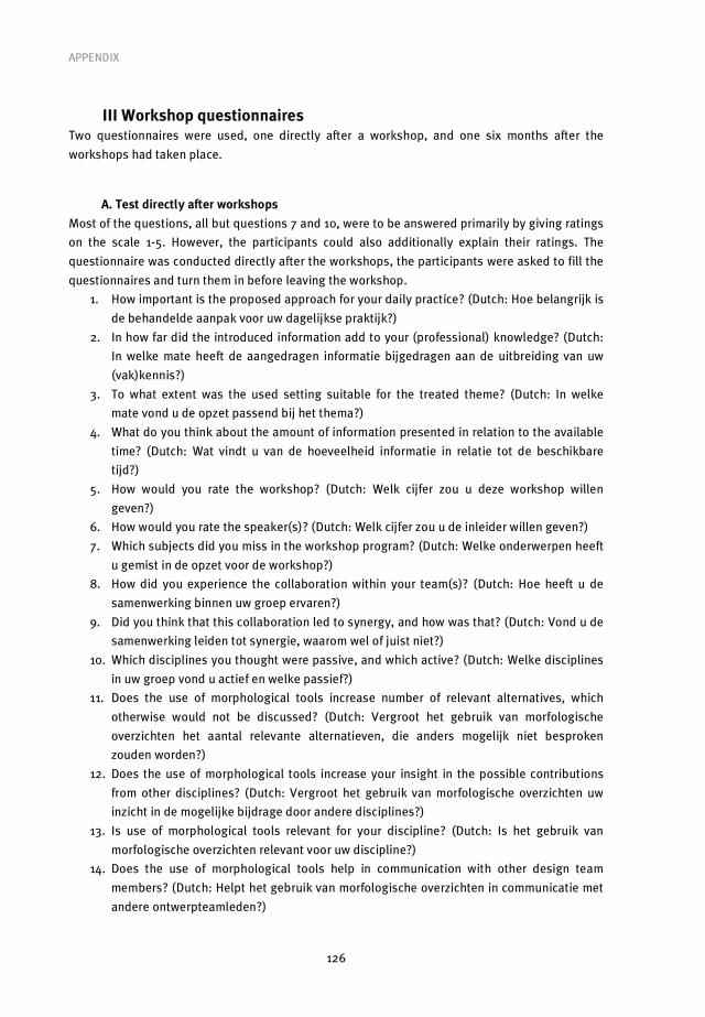
APPENDIX
126
III Workshop questionnaires Two questionnaires were used, one directly after a workshop, and one six months after the
workshops had taken place.
A. Test directly after workshops
Most of the questions, all but questions 7 and 10, were to be answered primarily by giving ratings
on the scale 1-5. However, the participants could also additionally explain their ratings. The
questionnaire was conducted directly after the workshops, the participants were asked to fill the
questionnaires and turn them in before leaving the workshop.
1. How important is the proposed approach for your daily practice? (Dutch: Hoe belangrijk is
de behandelde aanpak voor uw dagelijkse praktijk?)
2. In how far did the introduced information add to your (professional) knowledge? (Dutch:
In welke mate heeft de aangedragen informatie bijgedragen aan de uitbreiding van uw
(vak)kennis?)
3. To what extent was the used setting suitable for the treated theme? (Dutch: In welke
mate vond u de opzet passend bij het thema?)
4. What do you think about the amount of information presented in relation to the available
time? (Dutch: Wat vindt u van de hoeveelheid informatie in relatie tot de beschikbare
tijd?)
5. How would you rate the workshop? (Dutch: Welk cijfer zou u deze workshop willen
geven?)
6. How would you rate the speaker(s)? (Dutch: Welk cijfer zou u de inleider willen geven?)
7. Which subjects did you miss in the workshop program? (Dutch: Welke onderwerpen heeft
u gemist in de opzet voor de workshop?)
8. How did you experience the collaboration within your team(s)? (Dutch: Hoe heeft u de
samenwerking binnen uw groep ervaren?)
9. Did you think that this collaboration led to synergy, and how was that? (Dutch: Vond u de
samenwerking leiden tot synergie, waarom wel of juist niet?)
10. Which disciplines you thought were passive, and which active? (Dutch: Welke disciplines
in uw groep vond u actief en welke passief?)
11. Does the use of morphological tools increase number of relevant alternatives, which
otherwise would not be discussed? (Dutch: Vergroot het gebruik van morfologische
overzichten het aantal relevante alternatieven, die anders mogelijk niet besproken
zouden worden?)
12. Does the use of morphological tools increase your insight in the possible contributions
from other disciplines? (Dutch: Vergroot het gebruik van morfologische overzichten uw
inzicht in de mogelijke bijdrage door andere disciplines?)
13. Is use of morphological tools relevant for your discipline? (Dutch: Is het gebruik van
morfologische overzichten relevant voor uw discipline?)
14. Does the use of morphological tools help in communication with other design team
members? (Dutch: Helpt het gebruik van morfologische overzichten in communicatie met
andere ontwerpteamleden?)
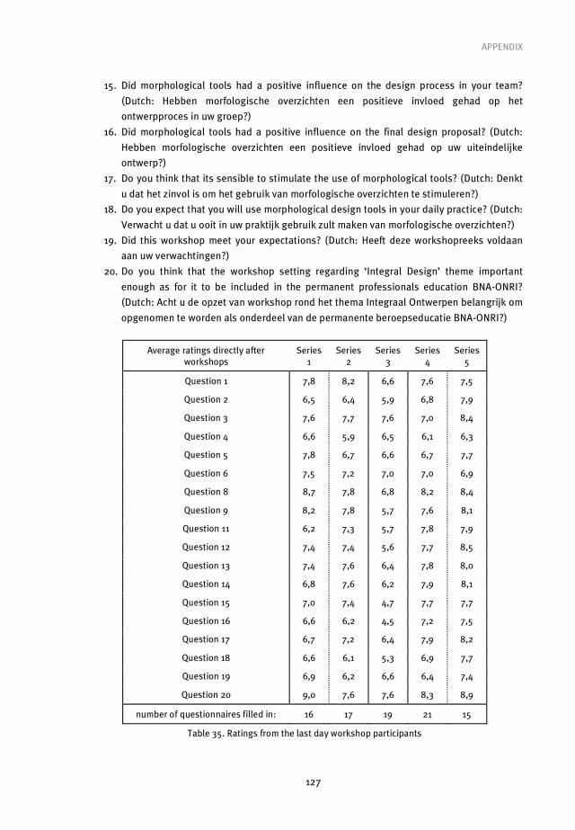
APPENDIX
127
15. Did morphological tools had a positive influence on the design process in your team?
(Dutch: Hebben morfologische overzichten een positieve invloed gehad op het
ontwerpproces in uw groep?)
16. Did morphological tools had a positive influence on the final design proposal? (Dutch:
Hebben morfologische overzichten een positieve invloed gehad op uw uiteindelijke
ontwerp?)
17. Do you think that its sensible to stimulate the use of morphological tools? (Dutch: Denkt
u dat het zinvol is om het gebruik van morfologische overzichten te stimuleren?)
18. Do you expect that you will use morphological design tools in your daily practice? (Dutch:
Verwacht u dat u ooit in uw praktijk gebruik zult maken van morfologische overzichten?)
19. Did this workshop meet your expectations? (Dutch: Heeft deze workshopreeks voldaan
aan uw verwachtingen?)
20. Do you think that the workshop setting regarding ‘Integral Design’ theme important
enough as for it to be included in the permanent professionals education BNA-ONRI?
(Dutch: Acht u de opzet van workshop rond het thema Integraal Ontwerpen belangrijk om
opgenomen te worden als onderdeel van de permanente beroepseducatie BNA-ONRI?)
Average ratings directly after workshops
Series 1
Series 2
Series 3
Series 4
Series 5
Question 1 7,8 8,2 6,6 7,6 7,5
Question 2 6,5 6,4 5,9 6,8 7,9
Question 3 7,6 7,7 7,6 7,0 8,4
Question 4 6,6 5,9 6,5 6,1 6,3
Question 5 7,8 6,7 6,6 6,7 7,7
Question 6 7,5 7,2 7,0 7,0 6,9
Question 8 8,7 7,8 6,8 8,2 8,4
Question 9 8,2 7,8 5,7 7,6 8,1
Question 11 6,2 7,3 5,7 7,8 7,9
Question 12 7,4 7,4 5,6 7,7 8,5
Question 13 7,4 7,6 6,4 7,8 8,0
Question 14 6,8 7,6 6,2 7,9 8,1
Question 15 7,0 7,4 4,7 7,7 7,7
Question 16 6,6 6,2 4,5 7,2 7,5
Question 17 6,7 7,2 6,4 7,9 8,2
Question 18 6,6 6,1 5,3 6,9 7,7
Question 19 6,9 6,2 6,6 6,4 7,4
Question 20 9,0 7,6 7,6 8,3 8,9
number of questionnaires filled in: 16 17 19 21 15
Table 35. Ratings from the last day workshop participants

APPENDIX
128
B. Post-test six months after workshops
The questionnaire was conducted using Surveyworld.net website, the participants had two weeks
to respond. The participants were asked to rate the questions on the scale 1-5, and if deemed
necessary to provide additional explanations:
1. How would you, after a half year, rate the workshop series? (Dutch: Hoe zou u nu, na een
half jaar, de workshop beoordelen?)
2. Thinking back on workshop series, did it meet your expectations? (Dutch: Nu u
terugdenkt aan de workshop, heeft deze voldaan aan uw verwachtingen?)
3. How important was the proposed integral approach for your practice in the last six
months? (Dutch: Hoe belangrijk was de behandelde aanpak in de laatste half jaar voor uw
dagelijkse praktijk gebleken?)
4. Did you apply the introduced/acquired knowledge about methodical design in the last six
months? (Dutch: Heeft u in de laatste half jaar de aangedragen kennis over methodisch
ontwerpen kunnen toepassen?)
5. Did you apply the introduced/acquired knowledge about sustainable comfort systems in
the last six months? (Dutch: Heeft u in de laatste half jaar de aangedragen kennis over
duurzame comfort systemen kunnen toepassen?)
6. Did you use morphological overviews in the last six months? (Dutch: Heeft u in de laatste
half jaar gebruik gemaakt van de morfologische overzichten?)
7. Is use of morphological overviews relevant for your discipline? (Dutch: Is het gebruik van
morfologische overzichten relevant voor uw discipline?)
8. Dou you think it’s appropriate to stimulate use of morphological overviews? (Dutch:
Denkt u dat het zinvol is om het gebruik van morfologische overzichten te stimuleren?)
9. Do you regard workshop series setting around ‘Integral Design’ as important for
continuous BNA-ONRI professionals’ education? (Dutch: Acht u de opzet van de
workshops rond het thema Integraal Ontwerpen belangrijk om onderdeel te zijn van de
permanente beroepseducatie BNA-ONRI?)
Average ratings six months after workshops Series
1 Series
2 Series
3 Series
4 Series
5
Question 1 8,0 6,6 7,0 6,7 6,8
Question 2 6,8 6,9 7,4 6,7 7,4
Question 3 4,8 6,0 6,3 5,1 5,2
Question 4 6,3 5,1 6,4 5,6 5,2
Question 5 5,0 5,1 4,9 5,6 5,6
Question 6 5,0 4,0 3,6 4,0 4,4
Question 7 6,5 6,9 6,4 5,8 6,8
Question 8 6,5 6,9 6,7 6,2 8,0
Question 9 9,5 7,4 8,7 7,8 8,6
number of questionnaires filled in: 8 7 14 9 10
Table 36. Ratings from the professionals that participated in all design sessions during a workshop series
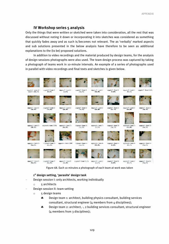
APPENDIX
129
IV Workshop series 5 analysis Only the things that were written or sketched were taken into consideration, all the rest that was
discussed without noting it down or incorporating it into sketches was considered as something
that quickly fades away and as such is/becomes not relevant. The as ‘verbally’ marked aspects
and sub solutions presented in the below analysis have therefore to be seen as additional
explanations to the (to be) proposed solutions.
In addition to video recordings and the material produced by design teams, for the analysis
of design sessions photographs were also used. The team design process was captured by taking
a photograph of teams work in 10-minute intervals. An example of a series of photographs used
in parallel with video recordings and final texts and sketches is given below.
Figure 68. Each 10 minutes a photograph of each team at work was taken
1st design setting, ‘parasite’ design task
- Design session I: only architects, working individually
o 5 architects
- Design session II: team setting
o 5 design teams
� Design team 1: architect, building physics consultant, building services
consultant, structural engineer (4 members from 4 disciplines);
� Design team 2: architect, -, 2 building services consultant, structural engineer
(4 members from 3 disciplines);

APPENDIX
130
� Design team 3: architect, -, building services consultant, structural engineer
(3 members from 3 disciplines);
� Design team 4: architect, building physics consultant, building services
consultant, - (3 members from 3 disciplines);
� Design team 5: architect, building physics consultant, 2 building services
consultants, - (4 members from 3 disciplines);
The analysis of each team’s work proceeded as follows:
• First, the architect’s explanation of the initial proposal at the beginning of second design
session is translated into table of aspects and sub solutions;
• This resulting sequential list is then structured into the architect’s morphological chart;
• After which the architect’s sketches are shown;
• Then, a table of aspects and sub solutions considered by the design team is made based on
videotaped design team activities;
• Again, the resulting sequential list is structured into the design team’s morphological
overview;
• Finally, the design team’s proposal is depicted.
Design team 1
A, BP, BS, and SE: architect, building physics consultant, building services consultant, structural
engineer (4 members from 4 disciplines)
Time (design session II)
Who Aspect or sub solution
Description Text/sketch or verbally
00h04min A Aspect (1) Form Text (session I)
00h04min A Aspect (2) Materialisation Text (session I)
00h04min A Sub solution (1-1, 2-1) Contrasting to the existing building Text (session I)
00h04min A Sub solution (2-2, 3-1) Wood Text (session I)
00h05min A Sub solution (2-3) Open structure Text (session I)
00h05min A Aspect (3) Sustainability Text (session I)
00h05min A Sub solution (4-1) On (the existing building) Text (session I)
00h05min A Sub solution (4-2) Against (the existing building) Text (session I)
00h05min A Sub solution (4-3) Loose (from to the existing building) Text (session I)
00h06min A Sub solution (4-4) In the middle (of existing building) Text (session I)
00h06min A Solution! ‘Roof’ on the existing roof… Sketch (session I)
00h09min A Solution! Loose, vertical spiral addition… Sketch (session I)
Table 37. Aspects and (sub) solutions as explained by architect 1 to design team 1 (session II)
Design asp ects/ functions:
Sub solutions:
(1) Form {A}
(1-1) Contrasting
{A}
(2) Materialisation
{A}
(2-1) Contrasting
{A}
(2-2) Wood
{A}
(2-3) Open structure
{A}

APPENDIX
131
(3) Sustainability
{A}
(3-1) Wood
{A}
(4) [positioning]
(4-1) On {A}
(4-2) Against
{A}
(4-3) Loose
{A}
(4-4) In the middle
{A}
Figure 69. Architect’s morphological chart
Figure 70. Architect’s sketches, showing two proposals for the parasite pavilion
Time (design session II)
Who Aspect or sub solution
Description Text/sketch or verbally
00h15min SE Aspect (5) Demountable Verbally
00h16min SE Sub solution (5-1) Flexible, prefab system Verbally
00h18min BP Sub solution (4-1-1) Rotate 90° and put on own ‘legs’ Verbally
00h18min A Draws the BF 4-1 optimization Sketch
00h18min A Sub solution (6-1) Separate, independent, entrance Sketch
00h19min A Optimization(4-1-2) Beam, from façade to façade Verbally
00h20min A Optimization (5-1) Base construction flexible Verbally
00h21min Team Sub solution (5-2) Plug-and-play building services Verbally
00h26min A Sub solution (6-2) Use, extend, existing entrance Verbally
00h33min A Draws 5-1 Sketch
00h43min BS Aspect (7) Flexibility Verbally
00h43min A Sub solution (7-1) Theatre space at the ‘end’ of pavilion Verbally
00h43min BP Optimization (7-1) At the north side Verbally
00h44min BP Aspect (8) Orientation (sun) Verbally
00h44min A Sub solution (8-1) Roof wider than floor for shadow… Verbally
00h44min BP Sub solution (7-2) Entrance on west side, rest on east Verbally
00h51min SE Optimization(4-1-2) Two 35-meter beams… Sketch
00h52min SE Optimization(4-1-2) … with prefab concrete floor Verbally
01h00min BP Sub solution (3-2) Heat pump Verbally
01h02min BP Sub solution (3-3) Natural ventilation… Verbally
01h06min A Optimization(4-1-1) ...+ variable height for diff. functions Verbally
01h08min A Optimization(4-1-2) Use the existing building for stability Verbally
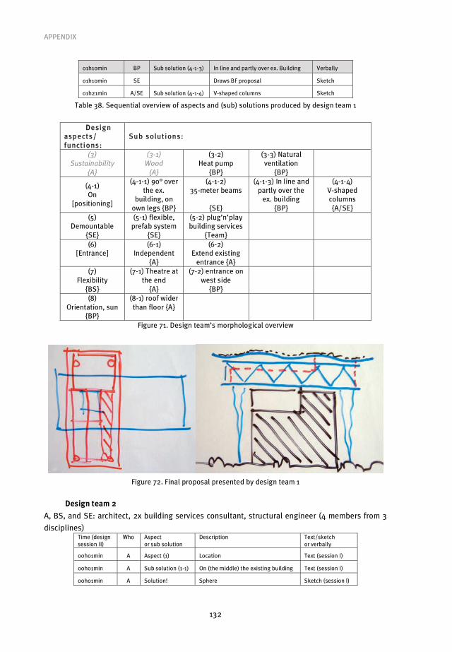
APPENDIX
132
01h10min BP Sub solution (4-1-3) In line and partly over ex. Building Verbally
01h10min SE Draws BF proposal Sketch
01h21min A/SE Sub solution (4-1-4) V-shaped columns Sketch
Table 38. Sequential overview of aspects and (sub) solutions produced by design team 1
DDesign asp ects/ functions:
Sub solutions:
(3)
Sustainability
{A}
(3-1)
Wood
{A}
(3-2) Heat pump
{BP}
(3-3) Natural ventilation
{BP}
(4-1) On
[positioning]
(4-1-1) 90° over the ex.
building, on own legs {BP}
(4-1-2) 35-meter beams
{SE}
(4-1-3) In line and partly over the
ex. building {BP}
(4-1-4) V-shaped columns {A/SE}
(5) Demountable
{SE}
(5-1) flexible, prefab system
{SE}
(5-2) plug’n’play building services
{Team}
(6) [Entrance]
(6-1) Independent
{A}
(6-2) Extend existing
entrance {A}
(7) Flexibility
{BS}
(7-1) Theatre at the end
{A}
(7-2) entrance on west side
{BP}
(8) Orientation, sun
{BP}
(8-1) roof wider than floor {A}
Figure 71. Design team’s morphological overview
Figure 72. Final proposal presented by design team 1
Design team 2
A, BS, and SE: architect, 2x building services consultant, structural engineer (4 members from 3
disciplines) Time (design session II)
Who Aspect or sub solution
Description Text/sketch or verbally
00h01min A Aspect (1) Location Text (session I)
00h01min A Sub solution (1-1) On (the middle) the existing building Text (session I)
00h01min A Solution! Sphere Sketch (session I)

APPENDIX
133
A Sphere as solution for design brief... Verbally
00h05min A Sub solution (2-1) Steal construction (oversized) Sketch (session I)
Table 39. Aspects and (sub) solutions as explained by architect 2 to design team 2 (session II)
Design asp ects/ functions:
Sub solutions:
(1) Location
{A}
(1-1) On, in the middle of the existing building
{A} (2)
[fire safety]
(2-1) Steal construction (oversized)
{A}
Figure 73. Architect’s morphological chart
Figure 74. Architect’s sketch, sphere on the existing building
Time (design session II)
Who Aspect or sub solution
Description Text/sketch or verbally
00h11min BS Aspect (3) Heating / thermal comfort Text
00h11min BS Aspect (4) Light(ing) Text
00h11min BS Aspect (5) Casco flexibility (same building services system for
diff. functions)
Text
00h12min BS Aspect (6) Energy Text
00h17min BS Aspect (7) Theatre / presentation space Text
00h17min A Sub solution (7-1) Different shape/form Verbally
00h18min BS Aspect (8) Ventilation Text
00h24min BS Optimization (3) Cooling also needed Verbally
00h25min BS Sub solution (8-1) Mechanical Verbally
00h27min BS Optimization (8-1) Combined with heat recovery system Verbally
00h27min BS Optimization (8-1), sub solution (3-1) Adiabatic cooling... Verbally
00h33min BS Optimisation (3-1) ...using rain water Verbally
00h33min BS Sub solution (3-2) Heating elements Verbally
00h41min A Sub solution (3-3) Floor heating / ‘concrete activation’ Sketch
00h43min BS Sub solution (7-2) Separate, closed spaces Verbally
00h46min A Sub solution (3-4) Shades to keep the sun heat out Verbally

APPENDIX
134
00h48min BS Sub solution (6-1) Couple to existing building Verbally
00h49min Team Decision (4-1)+(6-1)+(1-1) Verbally
00h50min BS Sub solution (4-1) LED’s Verbally
00h52min A Sub solution (4-2) Indirect lighting, example airports Sketch
00h52min A Sub solution (4-3) (Projection) screen in the sphere Sketch
00h55min BS Optimisation (4-1) In façade as screen/ shading, light reflection; (2-
2),(2-3) optimisation
Verbally
00h59min SE Aspect (9) Firmness of load bearing structure Text
01h01min SE Sub solution (9-1) ‘umbrella principle’, load bearing façade with
hanged in floors
Sketch
01h03min SE Optimisation (9-1) Light materials Verbally
01h03min A Sub solution (9-2) Heavy floors with ‘free’ façade Verbally
01h04min BS Optimisation (9-2)
Sub solution (5-1)
With separate ‘functional boxes’, loose from façade Verbally
01h09min SE Optimisation (9-2) Central core for stability Sketch
01h12min BS Optimisation (9-2)
Sub solution (5-2)
Aorta for water, air etc... Verbally
01h12min BS Optimisation (9-2), (5-2) ...including staircases Verbally
01h13min SE Optimisation (9-2) Octagon lay-out Sketch
01h21min A Optimisation (3-4) Different panel-types façade (open/ closed/PV) Verbally
01h25min BS Sub solution (8-2) Natural ventilation (through aorta) Sketch
01h26min A,BS,SE Draw presentation sheets Sketch
Table 40. Sequential overview of aspects and (sub) solutions produced by design team 2
Design asp ects/ functions:
Sub solutions:
(3) Thermal comfort
{BS}
(3-1) Adiabatic cooling
{BS}
(3-2) Heating elements
{BS}
(3-3) Floor heating
{A}
(3-4) Shades
{A} (4)
Light(ing) {BS}
(4-1) LED {BS}
(4-2) Indirect
{A}
(4-3) Projection screen
{A}
(5) Casco flexibility
{BS}
(5-1) functional ‘boxes’ {BS}
(5-2) central ‘aorta’ {BS}
(6) Energy
{BS}
(6-1) Existing building
{BS}
(7) Theatre space
{BS}
(7-1) different shape
{A}
(7-2) Separate, closed spaces
{BS}
(8) Ventilation
{BS}
(8-1) Mechanical
{BS}
(8-2) natural, through aorta
{BS}
(9) Firmness
{SE}
(9-1) Umbrella principle
{SE}
(9-2) central core / floors {SE/A}
Figure 75. Design team’s morphological overview

APPENDIX
135
Figure 76. Final proposal presented by design team 2
Design team 3
A, BS, and SE: architect, building services consultant, structural engineer (3 members from 3
disciplines)
See section 4.6.1 for the analysis.
Design team 4
A, BP, and BS: architect, building physics consultant, building services consultant (3 members
from 3 disciplines)
See section 4.6.1 for the analysis.
Design team 5
A, BP and BS: architect, building physics consultant, 2x building services consultant (4 members
from 3 disciplines)
Figure 77. Architect’s sketches

APPENDIX
136
Time (design session II)
Who Aspect or sub solution
Description Text/sketch or verbally
00h04min A Sub solution (1-1) On the middle roof playground Sketch (session I)
00h06min BS Aspect (2) Materialisation Verbally
00h07min BS Aspect (3) Sustainability Verbally
00h09min BS Sub solution (4-1) Natural ventilation Verbally
00h10min BS Optimisation (4-1) Intake air via the ground Verbally
00h12min BS Aspect (5) Demountable Verbally
00h12min A Sub solution (5-1) Light building Verbally
00h12min BS Sub solution (3-1) Wood Verbally
00h13min BP Sub solution (3-2) In any case prefabricated elements Verbally
00h17min BS Aspect (6) Form / shape Verbally
00h17min A Sub solution (6-1) ‘plain’ box, to spare material Sketch (session I)
00h19min BS Sub solution (2-1) Contrasting Verbally
00h19min BP Sub solution (2-2) ‘plain’ materials, contrasting Verbally
00h21min BS Sub solution (2-3) Plants, on the façade Verbally
00h28min BP Aspect (7) Routing Verbally
00h28min BS Sub solution (6-2) Two levels / floors Verbally
00h29min BP Sub solution (7-1) Entrance staircase Verbally
00h30min BS Optimisation (7-1) Theatre space fits underneath Verbally
00h33min A Sub solution (6-3) Reception under theatre space Sketch (session I)
00h33min A Sub solution (3-3) Compact volume Sketch (session I)
00h35min BS Sub solution (2-4) ‘Green’ roof Verbally
00h38min BS Sub solution (6-4) ‘Coliseum’ idea; combination stairs and theatre space... Sketch
00h44min A Optimisation (6-4),
optimisation (7-1)
...ending with presentation rooms on the roof, view on
surroundings
Verbally
00h46min A Draws (6-4) Sketch
00h47min BP Sub solution (3-4) PV panels Verbally
00h49min BP Optimisation (3-4) All-electric Verbally
00h54min BS Optimisation (3-4) Semi transparent above theatre Sketch
00h56min BS Sub solution (8-1) cloths underneath PV/glass roof Sketch
01h03min BS Sub solution (3-5) Wind turbines Sketch
01h06min Team Checks square meters but eventually decides not to solve
form problems
Sketch
01h22min A Draws presentation sheets Sketch
Table 41. Sequential overview of aspects and (sub) solutions produced by design team 5
Design asp ects/ functions:
Sub solutions:
(1) [positioning]
(1-1) On existing
building {A}
(2) Materialisation
{BS}
(2-1) Contrasting
{BS}
(2-2) ‘plain’ materials
{BP}
(2-3) Plants, façade
{BS}
(2-4) Green roof
{BS}

APPENDIX
137
(3) Sustainability
{BS}
(3-1) Wood {BS}
(3-2) Prefabricated
{BP}
(3-3) Compact volume
{A}
(3-4) PV/all-electric
{BP}
(3-5) Wind turbines
{BS} (4)
[ventilation]
(4-1) Natural, via ground {BS}
(5) Demountable
{BS}
(5-1) Light building
{A}
(6) Form {BS}
(6-1) ‘plain’ box
{A}
(6-2) Two-level volume
{BS}
(6-3) reception under theatre
space {A}
(6-4) Coliseum idea
{BS}
(7) Routing
{BP}
(7-1) entrance ‘Spanish stair’
{BP}
(8) [shading]
(8-1) cloths under glass
roof {BS}
Figure 78. Design team’s morphological overview
Figure 79. Final proposal presented by design team 5
Average results of all five design teams
Architect 1 Architect 2 Architect 3 Architect 4 Architect 5 Average
No. of aspects 4 2 3 6 1 3.2
No. of sub solutions 9 2 3 6 1 4.2
Table 42. Aspects addressed and (sub) solutions produced by architects (design session I)
BP 1 BP 4 BP 5 Average
No. of aspects 1 3 1 1.7
No. of sub solutions 5 9 4 6.0
Table 43. Aspects addressed and (sub) solutions produced by BP consultants (session II)
BS 1 BS 2 BS 3 BS 4 BS 5 Average
No. of aspects 1 6 0 1 4 2.4
No. of sub solutions 0 9 5 5 9 5.6
Table 44. Aspects addressed and (sub) solutions produced by BS consultants (session II)

APPENDIX
138
SE 1 SE 2 SE 3 Average
No. of aspects 1 1 0 0.7
No. of sub solutions 3 2 5 3.3
Table 45. Aspects addressed and (sub) solutions produced by BS consultants (session II)
Team 1 Team 2 Team 3 Team 4 Team 5 Average
No. of aspects 5 7 2 5 7 5.2
No. of sub solutions 13 16 12 16 17 14.8
Table 46. Additional aspects addressed and (sub) solutions produced by design teams (session II)
Averages A’s BP’s BS’s SE’s Teams
No. of aspects 33.2 2.8 1.2 0.7 5.2
No. of sub solutions 44.2 6.5 4.0 3.3 14.8
Table 47. Additional aspects addressed and (sub) solutions produced by design teams (session II)
2nd design setting, ‘zero energy office’ design task
- Design session I all disciplines separately
o 5 architects
o 3 building physics consultants
o 7 building services consultants
o 3 structural engineers
- Design session II team setting
o 5 design teams
� Design team 1: architect, building physics consultant, building services
consultant, - (3 members from 3 disciplines);
� Design team 2: architect, building physics consultant, 2 building services
consultant, - (4 members from 3 disciplines);
� Design team 3: architect, -, 2 building services consultant, structural engineer
(4 members from 3 disciplines);
� Design team 4: architect, -, building services consultant, structural engineer (3
members from 3 disciplines);
� Design team 5: architect, building physics consultant, building services
consultant, structural engineer (4 members from 4 disciplines).
The analysis of the second design sessions of the second workshop design setting is
presented as follows:
• A table of aspects and sub solutions considered by design teams during session II made
based on videotaped design team activities is shown;
• The resulting sequential list is structured into design team’s morphological overviews;
• After which final design team proposals are shown.
Design team 1
A, BP and BS: architect, building physics consultant, building services consultant, (3 members
from 3 disciplines)

APPENDIX
139
Time (design session II)
Who Aspect or sub solution
Description Text/sketch or verbally
00h20min A Aspect (1) Keep sun out Text
00h20min BP Sub solution (1-1) Trees Text
00h20min BS Sub solution (1-2) Overhangs (with PV panels) Text
00h21min BP Sub solution (1-3) Sun reflective glazing Text
00h21min BP Aspect (2) Light Text
00h23min BP Sub solution (2-1) High-frequency lighting Text
00h23min BS Aspect (3) Heating Text
00h24min BP Sub solution (3-1) Heat from offices use for storehouse Text
00h26min A Sub solution (2-2) Solar tubes Text
00h30min BP Sub solution (3-2) Seasonal thermal storage Text
00h30min BS Sub solution (4-1) Adiabatic cooling (not!) Text
00h30min BS Sub solution (4-2) Night ventilation Text
00h31min A Sub solution (4-3) Air intake underground Text
00h40min BS Sub solution (3-3) Sedum roof Sketch
00h42min A Aspect (5) Electricity Verbally
00h42min BS Sub solution (5-1) Wind (turbine) Sketch
Table 48. Aspects and (sub) solutions as explained by architect 1 to design team 1 (session II)
Design asp ects/ functions:
Sub solutions:
(1) Keep sun out
{A}
(1-1) Trees {BP}
(1-2) Overhangs (with PV panels) {BS}
(1-3) sun reflective glazing
{BP}
(2) Light {BP}
(2-1) High-frequency
lighting {BP}
(2-2) Solar tubes
{A}
(3) Heating
{BS}
(3-1) office to
storehouse {BP}
(3-2) seasonal thermal
storage {BP}
(3-3) sedum roof
{BS}
(4) [cooling]
(4-1)Adiabatic cooling (not!)
{BS}
(4-2) Night ventilation
{BS}
(4-3) air intake underground
{A}
(4-4) In the middle
{A} (5)
Electricity {A}
(5-1) Wind turbine
{BS}
Figure 80. Design team 1 morphological chart

APPENDIX
140
Figure 81. Final proposal presented by design team 1
Design team 2
A, BP and 2xBS: architect, building physics consultant, two building services consultants, (4
members from 3 disciplines)
See section 4.6.1 for the analysis.
Design team 3
A, 2x BS and SE: architect, two building services consultants, structural engineer (4 members
from 3 disciplines)
See section 4.6.1 for the analysis.
Design team 4
A, BS and SE: architect, building services consultant, structural engineer (3 members from 3
disciplines)
Time (design session II)
Who Aspect or sub solution
Description Text/sketch
00h15min SE Sub solution (1-1) Steel construction frame (choice!) Text (session I)
00h15min SE Sub solution (1-2) Glass floors Text (session I)
00h23min A Sub solution (2-1) Climate façade Sketch
00h24min A Sub solution (1-3) Wooden floors Sketch
00h27min A Sub solution (2-2) Radiating panels (for cooling) Sketch
00h27min BS Sub solution (2-3) Convectors Sketch
00h28min A Sub solution (2-4) PV panels as sun shades Sketch
00h29min A Solution! Combine the above... Verbally
00h29min BS Sub solution (3-1) Seasonal thermal storage Verbally
Table 49. Aspects and (sub) solutions design team 4 (session II)

APPENDIX
141
Design asp ects/ functions:
Sub solutions:
(1) [materials]
(1-1) Steel construction
{SE}
(1-2) Glass floors
{SE}
(1-3) Wooden floors
{A}
(2) [heating /cooling]
(2-1) Climate façade
{A}
(2-2) Radiating panels
{A}
(2-3) Convectors
{BS}
(2-4) PV panels as sun shades
{A}
(3) [energy]
(3-1) Seasonal thermal
storage {BS}
Figure 82. Design team 4 morphological chart
Figure 83. Final proposal presented by design team 4
Design team 5
A, BP, BS and SE: architect, building physics consultant, building services consultant, structural
engineer (4 members from 4 disciplines)
Time (design session II)
Who Aspect or sub solution
Description Text/sketch or verbally
00h12min SE Aspect (1) Building that can be recycled Text
00h12min BP Aspect (2) Façade Verbally
00h12min BS Sub solution (2-1) Overhangs with PV panels Sketch
00h17min SE Sub solution (2-2) Use prefabricated concrete from demolished buildings Verbally
00h21min A Sub solution (2-3) (Rain) water through double façade Verbally
00h26min A Solution! Strokes façade (west/south) open (PV) and closed (adiabatic cooling) Sketch
00h29min SE Optimisation Curved south/west façade Verbally
00h31min SE Sub solution (2-4) East/north façade traditional, with external sun shades Verbally
00h35min BP Sub solution (3-1) Mass for thermal accumulation Verbally
00h40min BP Sub solution (3-2) Hybrid ventilation Verbally
00h49min SE Optimisation (3-2) Use of wind when possible Sketch
00h52min A Draws presentation sheets Sketch
00h54min BS Sub solution (3-3) Atrium with air intake underground Sketch (SE)
Table 50. Aspects and (sub) solutions design team 5 (session II)

APPENDIX
142
Design asp ects/ functions:
Sub solutions:
(1) recycling building
{SE}
(2) Façade
{BP}
(2-1) overhang with PV
{BS}
(2-2) prefab demolished
{SE}
(2-3) water through façade
{A}
(2-4) east / west façade
traditional {SE} (3)
[energy, ventilation]
(3-1) thermal accumulation,
mass {BP}
(3-2) Hybrid ventilation
{BP}
(3-3) atrium, air in underground
{BS}
Figure 84. Design team 5 morphological chart
Figure 85. Final proposal presented by design team 5
Average results of all five design teams
Architect 1 Architect 2 Architect 3 Architect 4 Architect 5 Average
No. of aspects 2 0 2 0 0 0.8
No. of sub solutions 3 0 2 4 1 2.0
Table 51. Aspects addressed and (sub) solutions produced by architects (design session II)
BP 1 BP 2 BP 5 Average
No. of aspects 1 0 1 0.7
No. of sub solutions 5 2 2 3.0
Table 52. Aspects addressed and (sub) solutions produced by BP consultants (session II)
BS 1 BS 2 avg. BS 3 avg. BS 4 BS 5 Average
No. of aspects 1 0 0 0 0 0.2
No. of sub solutions 5 3 4 2 2 3.2
Table 53. Aspects addressed and (sub) solutions produced by BS consultants (session II)
SE 3 SE 4 SE 5 Average
No. of aspects 0 0 1 0.3
No. of sub solutions 1 2 2 1.7
Table 54. Aspects addressed and (sub) solutions produced by BS consultants (session II)
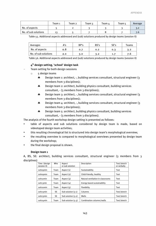
APPENDIX
143
Team 1 Team 2 Team 3 Team 4 Team 5 Average
No. of aspects 5 2 3 3 3 3.2
No. of sub solutions 13 5 7 8 7 7.6
Table 55. Additional aspects addressed and (sub) solutions produced by design teams (session II)
Averages A’s BP’s BS’s SE’s Teams
No. of aspects 00.8 0.7 0.2 0.3 3.2
No. of sub solutions 22.0 3.0 3.2 1.7 7.6
Table 56. Additional aspects addressed and (sub) solutions produced by design teams (session II)
4th design setting, ‘school’ design task
- Team setting for both design sessions
o 5 design teams
� Design team 1: architect, -, building services consultant, structural engineer (3
members from 3 disciplines);
� Design team 2: architect, building physics consultant, building services
consultant, - (3 members from 3 disciplines);
� Design team 3: architect, -, building services consultant, structural engineer (3
members from 3 disciplines);
� Design team 4: architect, -, building services consultant, structural engineer (3
members from 3 disciplines);
� Design team 5: architect, building physics consultant, building services
consultant, - (3 members from 3 disciplines).
The analysis of the fourth workshop design setting is presented as follows:
• table of aspects and sub solutions considered by design team is made, based on
videotaped design team activities;
• this resulting chronological list is structured into design team’s morphological overview;
• the resulting overview is compared to morphological overviews presented by design team
during the workshop;
• the final design proposal is shown.
Design team 1
A, BS, SE: architect, building services consultant, structural engineer (3 members from 3
disciplines) Time (design session II)
Who Aspect or sub solution
Description Text/sketch or verbally
00h09min Team Aspect (1) Sustainability Text
00h09min Team Aspect (2) Child-friendly, healthy Text
00h10min Team Aspect (3) Natural ventilation in classrooms Text
00h13min Team Aspect (4) Energy based sustainability Text
00h20min Team Aspect (5) Flexibility Text
00h23min SE Sub solution (5-1) Columns Text/sketch
00h23min SE Sub solution (5-2) Walls Text/sketch
00h24min Team Sub solution (5-3) Combination columns/walls Text/sketch
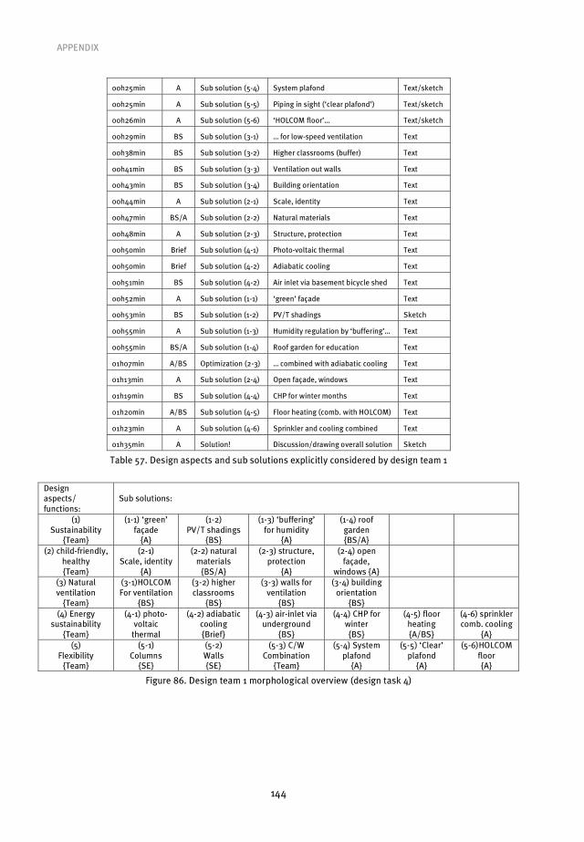
APPENDIX
144
00h25min A Sub solution (5-4) System plafond Text/sketch
00h25min A Sub solution (5-5) Piping in sight (‘clear plafond’) Text/sketch
00h26min A Sub solution (5-6) ‘HOLCOM floor’… Text/sketch
00h29min BS Sub solution (3-1) … for low-speed ventilation Text
00h38min BS Sub solution (3-2) Higher classrooms (buffer) Text
00h41min BS Sub solution (3-3) Ventilation out walls Text
00h43min BS Sub solution (3-4) Building orientation Text
00h44min A Sub solution (2-1) Scale, identity Text
00h47min BS/A Sub solution (2-2) Natural materials Text
00h48min A Sub solution (2-3) Structure, protection Text
00h50min Brief Sub solution (4-1) Photo-voltaic thermal Text
00h50min Brief Sub solution (4-2) Adiabatic cooling Text
00h51min BS Sub solution (4-2) Air inlet via basement bicycle shed Text
00h52min A Sub solution (1-1) ‘green’ façade Text
00h53min BS Sub solution (1-2) PV/T shadings Sketch
00h55min A Sub solution (1-3) Humidity regulation by ‘buffering’… Text
00h55min BS/A Sub solution (1-4) Roof garden for education Text
01h07min A/BS Optimization (2-3) … combined with adiabatic cooling Text
01h13min A Sub solution (2-4) Open façade, windows Text
01h19min BS Sub solution (4-4) CHP for winter months Text
01h20min A/BS Sub solution (4-5) Floor heating (comb. with HOLCOM) Text
01h23min A Sub solution (4-6) Sprinkler and cooling combined Text
01h35min A Solution! Discussion/drawing overall solution Sketch
Table 57. Design aspects and sub solutions explicitly considered by design team 1
Design aspects/ functions:
Sub solutions:
(1) Sustainability
{Team}
(1-1) ‘green’ façade
{A}
(1-2) PV/T shadings
{BS}
(1-3) ‘buffering’ for humidity
{A}
(1-4) roof garden {BS/A}
(2) child-friendly, healthy {Team}
(2-1) Scale, identity
{A}
(2-2) natural materials
{BS/A}
(2-3) structure, protection
{A}
(2-4) open façade,
windows {A}
(3) Natural ventilation
{Team}
(3-1)HOLCOM For ventilation
{BS}
(3-2) higher classrooms
{BS}
(3-3) walls for ventilation
{BS}
(3-4) building orientation
{BS}
(4) Energy sustainability
{Team}
(4-1) photo-voltaic
thermal
(4-2) adiabatic cooling {Brief}
(4-3) air-inlet via underground
{BS}
(4-4) CHP for winter {BS}
(4-5) floor heating {A/BS}
(4-6) sprinkler comb. cooling
{A} (5)
Flexibility {Team}
(5-1) Columns
{SE}
(5-2) Walls {SE}
(5-3) C/W Combination
{Team}
(5-4) System plafond
{A}
(5-5) ‘Clear’ plafond
{A}
(5-6)HOLCOM floor {A}
Figure 86. Design team 1 morphological overview (design task 4)
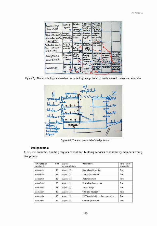
APPENDIX
145
Figure 87. The morphological overview presented by design team 1; clearly marked chosen sub solutions
Figure 88. The end proposal of design team 1
Design team 2
A, BP, BS: architect, building physics consultant, building services consultant (3 members from 3
disciplines)
Time (design session II)
Who Aspect or sub solution
Description Text/sketch or verbally
00h05min BS Aspect (1) Spatial configuration Text
00h06min BS Aspect (2) Energy (restriction) Text
00h06min BS Aspect (3) Materialisation Text
00h06min BS Aspect (4) Flexibility (floor plans) Text
00h10min BS Aspect (5) Sober ‘image’ Text
00h10min BS Aspect (6) ‘life-long housing’ Text
00h11min BS Aspect (7) PV/T & adiabatic cooling promotion Text
00h12min BP Aspect (8) Comfort (acoustic) Text

APPENDIX
146
00h12min BP Aspect (9) Comfort (light) Text
00h12min BP Aspect (10) Comfort (air) Text
00h13min BP Sub solution (1-1) Clustering Text
00h18min A Sub solution (3-1) ‘skeleton’ with flexible walls Text
00h18min BS Sub solution (3-2) Wood Text
00h19min BS Sub solution (3-3) Light materials Text
00h20min BS Sub solution (6-1) Flexible floor plans Text
00h20min A Sub solution (6-2) Flexible façade and building function Text
00h20min BS Sub solution (7-1) Visibility Text
00h23min BP Sub solution (8-1) Massive floors Text
00h25min BP Sub solution (10-1) Air flow through garage (preheating) Text
00h27min BP Sub solution (4-1) Functions partly in garage Text
00h28min BP Sub solution (10-2) Hybrid ventilation via façade Sketch
00h39min BS Sub solution (5-1) Concrete (sober) Text
00h39min BP Sub solution (5-2) Wood (sober) Text
00h39min A Optimisation (5) Inside and outside different Text
00h39min A Sub solution (5-3) Reduce glass Text
00h40min BP Sub solution (5-4) Reduce maintenance Text
00h42min BS Sub solution (2-1) Insulation Text
00h42min BS Sub solution (2-2) Orientation building Text
00h42min BS Sub solution (2-3) Shades Text
00h42min BS Sub solution (2-4) Reduce glass Text
00h42min BS Sub solution (2-5) High quality glass Text
00h44min BS Sub solution (2-6) Move warmth to north Verbally
00h49min A Optimisation (2-3) Perforated steel plate free of façade Verbally
00h55min BS Optimisation (2-6) Use steel plate with water Sketch
01h01min BS Optimisation (2-6) In combination with double façade Sketch
01h10min BP Sub solution (10-3) Balanced ventilation for shared spaces Text
01h15min A Draws chosen combination Sketch
01h21min BS Aspect (11) Roof Text
01h21min A Sub solution (11-1) Playground Text
01h21min BP Sub solution (11-2) Green roof Text
01h21min BP Sub solution (11-3) Atrium Sketch (A)
01h23min A Sub solution (11-4) PV/T Sketch
Table 58. Design aspects and sub solutions explicitly considered by design team 2
Design aspects/ functions:
Sub solutions:
(1) Special
configuration {BS}
(1-1) Clustering
{BP}
(2) energy restriction
{BS}
(2-1) Insulation
{BS}
(2-2) Orientation
building {BS}
(2-3) Shades
{BS}
(2-4) Reduce glass
{BS}
(2-5) high-quality glass
{BS}
(2-6) move warmth to north {BS}

APPENDIX
147
(3) materialisation
{BS}
(3-1) skeleton and flexible
walls {A}
(3-2) Wood {BS}
(3-3) Light materials
{BS}
(4) flexibility
{BS}
(4-1) functions partly in garage
{BP}
(5) Sober image
{BS}
(5-1) Concrete
{BS}
(5-2) Wood {BP}
(5-3) Reduce glass
{A}
(5-4) reduce maintenance
{BP}
(6) ‘life-long living’
{BS}
(6-1) flexible floor plans
{BS}
(6-2) flexible façade / building
function {A}
(7) PV/T and adiabatic
cooling {BS}
(7-1) Visibility
{BS}
(8) comfort acoustic
{BP}
(8-1) Massive floors
{BP}
(9) comfort light {BP}
(10) comfort air
{BP}
(10-1) air flow through garage
{BP}
(10-2) hybrid ventilation via
façade {BP}
(10-3) shared spaces, vent. balanced {BP}
(11) Roof {BS}
(11-1) Playground
{A}
(11-2) Green roof
{BP}
(11-3) Atrium
{BP}
(11-4) PV/T {A}
Figure 89. Design team 2 morphological overview (design task 4)
Figure 90. The presented solution by design team 2
Design team 3
A, BS, SE: architect, building services consultant, structural engineer (3 members from 3
disciplines)

APPENDIX
148
Time (design session II)
Who Aspect or sub solution
Description Text/sketch or verbally
00h05min A Aspect (1) Flexibility Text
00h06min BS Optimisation (1) Flexibility of floor-plans Sketch
00h06min BS Sub solution (1-1) Corridor with rooms / units Sketch
00h06min BS Sub solution (1-2) Curved (inner) walls Sketch
00h07min BS Optimisation (1-2) Made of (re)movable canvas Text
00h09min SE Aspect (2) Flexibility as expanding/shrinking Text
00h09min A Sub solution (2-1) Expansion by containers Sketch
00h10min BS Sub solution (2-2) Big ‘hall’ with removable boxes in Sketch
00h10min A Sub solution (2-3) Big roof with removable boxes under Verbally
00h10min BS Optimisation (2-3) Canopy roof... Sketch
00h12min BS Sub solution (2-4) Plug-and-play floor Sketch
00h14min SE Sub solution (2-5) Extension by building out Sketch
00h14min SE Sub solution (1-3) ‘growing’ spaces / adding elements Sketch
00h16min SE Sub solution (1-4) Loose units Sketch
00h17min SE Aspect (3) Functional flexibility Text
00h18min BS Sub solution (3-1) Centralized Text
00h18min BS Sub solution (3-2) Decentralized Text
00h20min SE Optimisation (3), (3-1), (3-2) Also architectural functionality Text
00h23min BS Aspect (4) Light(ing) Text
00h23min BS Sub solution (4-1) Light-dome / ‘roof light’ Sketch
00h23min A Sub solution (4-2) ‘shed light’ Sketch
00h24min BS Sub solution (4-3) Light tubes with diffuser Sketch
00h26min BS Sub solution (4-4) TL Sketch
00h27min SE Sub solution (4-5) Windows / side light Sketch
00h27min A Aspect (5) Heating/cooling Text
00h31min BS Sub solution (5-1) Using air Sketch
00h31min BS Sub solution (5-2) Using water (above/in/under floor) Sketch
00h36min BS Sub solution (5-3) Convection (in floor) Sketch
00h38min SE Aspect (6) Ventilation Text
00h40min BS Sub solution (5-4) Low-pressure air / floor perforations Sketch
00h43min BS Aspect (7) Heat/cool generation Text
00h43min SE Sub solution (6-1) Natural ventilation Text
00h44min BS Sub solution (7-1) AHU Sketch
00h46min BS Sub solution (7-2) AHU with adiabatic cooling Sketch
00h47min BS Sub solution (7-3) Desiccant cooling Text
00h51min BS Sub solution (7-4) Heating boiler Text
00h51min BS Sub solution (7-5) Cooler Text
00h52min BS Sub solution (7-6) Water on roof Sketch
00h54min BS Optimisation (6-1) Mechanical out, natural in Text
00h55min BS Sub solution (6-2) Thermal draft (chimney) Sketch
00h55min A Optimisation (6-2) Black canvas roof Verbally

APPENDIX
149
00h56min BS Optimisation (6-2) Combined with trees for cooling Verbally
01h02min SE Aspect (8) Firmness / strength Text
01h02min SE Aspect (9) Stiffness Text
01h02min SE Aspect (10) Stability Text
01h03min A Sub solution (8-1) Effective use of materials Sketch
01h03min SE Sub solution (9-1) Floor height Text
01h06min SE Sub solution (10-1) Rigid frame Sketch
01h06min SE Sub solution (10-2) Wind crosses Sketch
01h06min SE Sub solution (10-3) Façade as rigid tube Sketch
01h07min SE Sub solution (10-4) Rigid core Sketch
01h07min SE Optimisation (10-4) Made of (9-1) and/or (9-2) Sketch
01h08min A Optimisation (10-4) Made of concrete Verbally
01h09min BS Solution! Concrete core with tent-cloth roof Verbally
01h10min BS Aspect (11) Energy production Text
01h11min A Sub solution (11-1) Flexible PV Sketch
01h11min BS Sub solution (11-2) Light through PV panels Sketch
01h12min BS Sub solution (11-3) ‘intelligent’ current driven glass Sketch
01h14min BS Sub solution (11-4) CHP Text
01h16min BS Sub solution (7-6) Asphalt Text
01h17min Team Combinations Selection and combination
Table 59. Sequence of design aspects and sub solutions explicitly considered by design team 3
Figure 91. Morphological overview of design team 3 (part I)
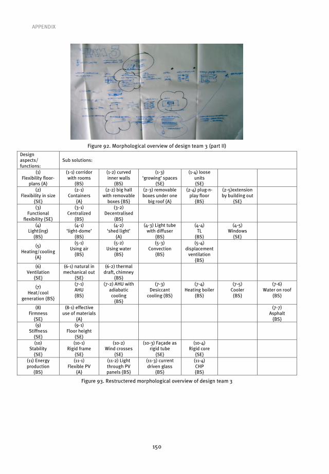
APPENDIX
150
Figure 92. Morphological overview of design team 3 (part II)
Design aspects/ functions:
Sub solutions:
(1) Flexibility floor-
plans {A}
(1-1) corridor with rooms
{BS)
(1-2) curved inner walls
{BS)
(1-3) ‘growing’ spaces
{SE}
(1-4) loose units {SE}
(2) Flexibility in size
{SE}
(2-1) Containers
{A}
(2-2) big hall with removable
boxes {BS}
(2-3) removable boxes under one
big roof {A}
(2-4) plug-n-play floor
{BS}
(2-5)extension by building out
{SE}
(3) Functional
flexibility {SE}
(3-1) Centralized
{BS}
(3-2) Decentralised
(BS}
(4) Light(ing)
{BS}
(4-1) ‘light-dome’
{BS}
(4-2) ‘shed light’
{A}
(4-3) Light tube with diffuser
{BS}
(4-4) TL
{BS}
(4-5) Windows
{SE}
(5) Heating/cooling
{A}
(5-1) Using air
{BS}
(5-2) Using water
{BS}
(5-3) Convection
{BS}
(5-4) displacement
ventilation {BS}
(6) Ventilation
{SE}
(6-1) natural in mechanical out
{SE}
(6-2) thermal draft, chimney
{BS}
(7) Heat/cool
generation {BS}
(7-1) AHU {BS}
(7-2) AHU with adiabatic cooling
{BS}
(7-3) Desiccant
cooling {BS}
(7-4) Heating boiler
{BS}
(7-5) Cooler
{BS}
(7-6) Water on roof
{BS}
(8) Firmness
{SE}
(8-1) effective use of materials
{A}
(7-7) Asphalt
{BS} (9)
Stiffness {SE}
(9-1) Floor height
{SE}
(10) Stability
{SE}
(10-1) Rigid frame
{SE}
(10-2) Wind crosses
{SE}
(10-3) Façade as rigid tube
{SE}
(10-4) Rigid core
{SE}
(11) Energy production
{BS}
(11-1) Flexible PV
{A}
(11-2) Light through PV panels {BS}
(11-3) current driven glass
{BS}
(11-4) CHP {BS}
Figure 93. Restructered morphological overview of design team 3
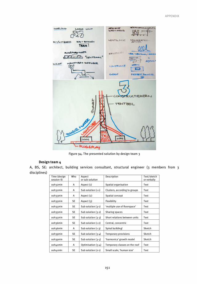
APPENDIX
151
Figure 94. The presented solution by design team 3
Design team 4
A, BS, SE: architect, building services consultant, structural engineer (3 members from 3
disciplines) Time (design session II)
Who Aspect or sub solution
Description Text/sketch or verbally
00h32min A Aspect (1) Spatial organisation Text
00h32min A Sub solution (1-1) Clusters, according to groups Text
00h33min A Aspect (2) Spatial concept Text
00h35min SE Aspect (3) Flexibility Text
00h35min SE Sub solution (3-1) ‘multiple use of floorspace’ Text
00h35min SE Sub solution (3-2) Sharing spaces Text
00h35min SE Sub solution (3-3) Short relations between units Text
00h36min SE Sub solution (1-2) Central, concentric Text
00h36min A Sub solution (1-3) Spiral building! Sketch
00h39min SE Sub solution (3-4) Temporary provisions Sketch
00h39min SE Sub solution (3-5) ‘harmonica’ growth model Sketch
00h40min A Optimisation (3-4) Temporary classes on the roof Text
00h41min SE Sub solution (2-1) Small scale; ‘human size’ Text
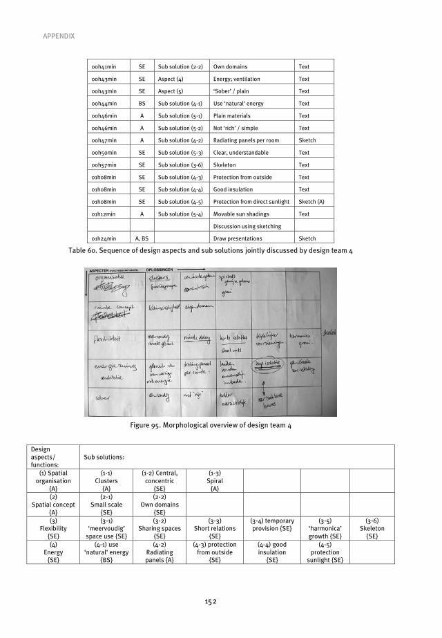
APPENDIX
152
00h41min SE Sub solution (2-2) Own domains Text
00h43min SE Aspect (4) Energy; ventilation Text
00h43min SE Aspect (5) ‘Sober’ / plain Text
00h44min BS Sub solution (4-1) Use ‘natural’ energy Text
00h46min A Sub solution (5-1) Plain materials Text
00h46min A Sub solution (5-2) Not ‘rich’ / simple Text
00h47min A Sub solution (4-2) Radiating panels per room Sketch
00h50min SE Sub solution (5-3) Clear, understandable Text
00h57min SE Sub solution (3-6) Skeleton Text
01h08min SE Sub solution (4-3) Protection from outside Text
01h08min SE Sub solution (4-4) Good insulation Text
01h08min SE Sub solution (4-5) Protection from direct sunlight Sketch (A)
01h12min A Sub solution (5-4) Movable sun shadings Text
Discussion using sketching
01h24min A, BS Draw presentations Sketch
Table 60. Sequence of design aspects and sub solutions jointly discussed by design team 4
Figure 95. Morphological overview of design team 4
Design aspects/ functions:
Sub solutions:
(1) Spatial organisation
{A}
(1-1) Clusters
{A}
(1-2) Central, concentric
{SE}
(1-3) Spiral
{A}
(2) Spatial concept
{A}
(2-1) Small scale
{SE}
(2-2) Own domains
{SE}
(3) Flexibility
{SE}
(3-1) ‘meervoudig’
space use {SE}
(3-2) Sharing spaces
{SE}
(3-3) Short relations
{SE}
(3-4) temporary provision {SE}
(3-5) ‘harmonica’ growth {SE}
(3-6) Skeleton
{SE} (4)
Energy {SE}
(4-1) use ‘natural’ energy
{BS}
(4-2) Radiating panels {A}
(4-3) protection from outside
{SE}
(4-4) good insulation
{SE}
(4-5) protection
sunlight {SE}
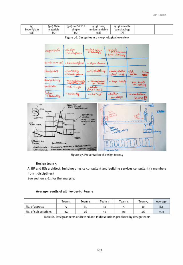
APPENDIX
153
(5) Sober/plain
{SE}
(5-1) Plain materials
{A}
(5-2) not ‘rich’ / simple
{A}
(5-3) clear, understandable
{SE}
(5-4) movable sun shadings
{A}
Figure 96. Design team 4 morphological overview
Figure 97. Presentation of design team 4
Design team 5
A, BP and BS: architect, building physics consultant and building services consultant (3 members
from 3 disciplines)
See section 4.6.1 for the analysis.
Average results of all five design teams
Team 1 Team 2 Team 3 Team 4 Team 5 Average
No. of aspects 5 11 11 5 10 8.4
No. of sub solutions 24 26 39 20 46 31.0
Table 61. Design aspects addressed and (sub) solutions produced by design teams

154
During this interesting journey, which this (re)search for integral design certainly was, I have met
and worked with a number of people who deserve thanks for their help and influence on my work.
The journey would not even have started without Emile Quanjel, a colleague with whom I first
discussed the perceived lack of an integral approach, which soon became our shared view on
Dutch building design practice. Halfway through 2004, when I started to seriously consider
research as a possible way to tackle this issue, he provided the final push that tilted the scale
towards the academic direction. The following year Emile decided to work closely with us,
continuing the journey that origininated in the ‘Integral Design’ project, which Emile conducted
from 2000-2003 together with Wim Zeiler. Although Emile’s involvement in the research was only
on a part time basis, he can be seen as being largely responsible for instigating the ‘integral
design group’ that the three of us (Wim, Emile and me) formed at TU/e.
My promotor, Wim Zeiler, has provided important motivation and inspiration throughout my
research. During the years that I have worked with Wim, he has shown himself not only to be a
committed academic, but also a true family man. Wim would often remind me that all that we do
is essentially for our family and that without family much of it would fail to be important. This
concern for family, I would like to point out, underlies Wim’s drive to work towards a sustainable
environment. Although Wim demands a strong work ethic from his colleagues, which is reinforced
by his own commitment and energy within the department, he also points out that one needs to
keep everything in perspective and know what the true priorities are during our journey. Wim has
witnessed major changes in my life: my marriage in the first year of research; the birth of my first
child in the second year of research; the purchase of my first house in the third year of the
research; and the birth of my second child in the fourth and final year of the research. On each of
these occasions he made me more aware and appreciative of these events than I would probably
have been without his insight and kind advice.
Besides my promotor, I would also like to thank the members of the core committee; Luciënne
Blessing, for two inspiring summer school weeks where I learned about Design Research
Methodology even before the book written about it was published; Harry Timmermans, for
emphasizing the importance of research methodology in general and for the useful explanations
he provided; Armand Hatchuel, first of all for working out C-K theory, which was a real eye opener
for me, and also for the stimulating discussions that we had about it in Paris; Joan van Aken for
delivering his sharp, critical and to-the-point remarks with a kind and gentle touch. Although he
was not able to take part in the committee due to circumstances beyond his control, I would like
to thank Henk Trum for being my daily supervisor in the earliest phases of research; I often
remembered his words later on when I realized how important his role was. It has been a
privilege to be able to learn from all of these people.
Acknowledgements

ACKNOWLEDGEMENTS
155
I would like to thank the following parties for their contributions: the Netherlands Organisation
for Applied Scientific Research (TNO), Oxycom Fresh Air B.V., Kropman installatietechniek B.V.,
and Foundation PIT (Stichting Promotie Installatietechniek), whose generous support made this
research possible. Special thanks go to Wouter Borsboom and Aart de Geus from TNO Built
Environment and Geosciences, who provided a working place in Delft that made life much easier,
since it was much closer to my home in Rotterdam than TU/e in Eindhoven is.
The two other persons that were of great importance for this research were Barbara Renier, who
was the main contact at the Royal Institute of Dutch Architects (BNA), and Jan-Andries Boon, her
counterpart at the Dutch Association of Consulting Engineers (ONRI). Their drive at the start of
research was essential for the successful inclusion of professionals in the research workshops.
Last, but not least, I would like to thank my friends Marc Suvaal and Duncan Harkness. Marc
found time to design this book in the final weeks of his partner’s pregnancy, and I know how
hectic those days can be. Being responsible for the passion I developed for motorcycle riding,
Marc was always up for a ride to ‘keep the freshness of mind’. One of the biggest personal
achievements during this journey was the friendship that developed with Duncan Harkness,
whom I first met at the ‘Writing articles in English’ course that he thought at TU/e. Out of the
many positive things that I appreciate about Duncan, I must highlight his professionalism and
ability to focus on the task at hand in any situation. I am more than grateful for Duncan’s
excellent editing of this thesis, and for the time he dedicated to do it. I would also like to thank
Duncan and Emile for their willingness to be the seconds during the defense ceremony.
Finally, I would like to mention all of my family, without which none of this obviously would ever
have happened. I have received unconditional support from them throughout my entire
education, for which I will always be grateful. I am proud of my parents and my sister for their
unshaken attitude and beliefs; I know how much this means to them after the uncertain years we
went through when war in the former Yugoslavia broke out and we had to flee to a new country. It
would certainly take a whole chapter to thank each member of family who, in one way or another,
had a positive influence on me. I know that my family will forgive me for only mentioning my
uncle, who secured the conditions to allow for the uninterrupted continuation of the education of
my sister and I when we arrived in The Netherlands. Together with my parents, he laid the
foundations for all the results that followed. The person that ultimately has to bear the
consequences, both good and otherwise, of my continuous strife for new knowledge is my loving
wife, in whose understanding and encouragement I find comfort. No words can express my
gratitude, but I want you to know that you can always count on me as I have counted on you.
Perica Savanovi�, October 2009

156
Perica Savanovi� was born in former Yugoslavia on February 6, 1975. In 1989 he
completed his primary education at the O.�. ‘Andrija Ra�o’ elementary school in
Sarajevo. His secondary education took place at the ET�C ‘Jaroslav �erni’ Electrical
Engineering Professional School in Sarajevo between 1989 and 1992, but was interrupted
in the final year due to the outbreak of war. As a result, he moved to The Netherlands the
same year and between 1992 and 1994 he completed his pre-university education, VWO,
at the O.S.G. ‘Wolfert van Borselen’, Rotterdam. He studied at the Faculty of Electrical
Engineering at Delft University of Technology between 1994 and 1995, before switching to
the Faculty of Architecture, where he studied between 1995 and 2001, and attained his
Master of Science in Architecture (cum laude). From 2001 to 2004 he worked as an
architect at a middle-sized architectural office in The Netherlands on interior to master
plan assignments. In 2004 he took a position as a PhD candidate in the Architecture,
Building and Planning department at Eindhoven University of Technology.
Curriculum Vitae


BOUWSTENEN is een publikatiereeks van de Faculteit Bouwkunde, Technische Universiteit Eindhoven.Zij presenteert resultaten van onderzoek en andere aktiviteiten op het vakgebied der Bouwkunde, uitgevoerd in het kader van deze Faculteit.
BOUWSTENEN zijn telefonisch te bestellen op nummer040 - 2472383
KernredaktieMTOZ

Reeds verschenen in de serie BOUWSTENEN
nr 1Elan, a computermodel for building energy design, theory and validationM.H. de WitH.H. DriessenR.M.M. van der Velden
nr 2Kwaliteit, keuzevrijheid en kostenEvaluatie van experiment Klarendal, Arnhemdrs J. SmeetsC. le Nobel, arch. HBOM. Broos, J. Frenken, A. v.d. Sanden
nr 3Crooswijkvan 'bijzonder' naar 'gewoon'drs V. Smitir K. Noort nr 4Staal in de woningbouwir E.J.F. Delsing
nr 5Mathematical theory of stressed skin action in profiled sheeting with various edge conditionsir A.W.A.M.J. v.d. Bogaard
nr 6Hoe berekenbaar en betrouwbaar is de coëfficiënt k in x - ko en x - ks?ir K.B. Lubdrs A.J. Bosch
nr 7Het typologisch gereedschapEen verkennende studie omtrent typologie en omtrent de aanpak typologisch onderzoek J.H. Luiten arch. HBO
nr 8Informatievoorziening en beheerprocessenir A. Nauta / drs J. Smeets (red.)Prof. H. Fassbinder (projectleider)ir A. Proveniers, drs J.v.d. Moosdijk
nr.9Strukturering en verwerking van tijdgegevens voor de uitvoering van bouwwerkenir W.F. Schaeferir P.A. Erkelens
nr 10Stedebouw en de vorming van een speciale wetenschapK. Doevendans
nr 11Informatica en ondersteuning van ruimtelijke besluitvormingdr G.G. van der Meulen
nr 12Staal in de woningbouw, korrosie-bescherming van de begane grondvloerir E.J.F. Delsing
nr 13Een thermisch model voor de berekening van staalplaatbeton- vloeren onder brandomstandighedenir A.F. Hamerlinck
nr 14De wijkgedachte in NederlandGemeenschapsstreven in een stedebouwkundige contextdr ir K. Doevendansdr R. Stolzenburg
nr 15Diaphragm effect of trapezoidally profiled steel sheets. Experimental research into the influence of force applicationir A.W.A.M.W. v.d. Bogaard
nr 16Versterken met spuit-ferrocement.Het mechanische gedrag van met spuit-ferrocement versterkte gewapende betonbalkenir K.B. Lubir M.C.G. van Wanroy

nr 17De tractaten van Jean Nicolas Louis Durandir G. van Zeyl
nr 18Wonen onder een plat dak.Drie opstellen over enkele vooronder-stellingen van de stedebouwdr ir K. Doevendans
nr 19Supporting decision making processesA graphical and interactive analysis of multivariate datadrs W. Adams
nr 20Self-help building productivityA method for improving house building by low-income groups applied to Kenya 1990-2000ir P. A. Erkelens
nr 21De verdeling van woningen: een kwestie van onderhandelendrs V. Smit
nr 22Flexibiliteit en kosten in het ontwerp- proces Een besluitvormingonder-steunend modelir M. Prins
nr 23Spontane nederzettingen begeleidVoorwaarden en criteria in Sri Lankair P.H. Thung
nr 24Fundamentals of the design of bamboo structuresO. Arce-Villalobos
nr 25Concepten van de bouwkundeProf. dr ir M.F.Th. Bax (red.) dr ir H.M.G.J. Trum (red.)
nr 26Meaning of the siteXiaodong Li
nr 27Het woonmilieu op begrip gebrachtJaap Ketelaar
nr 28Urban environment in developing countrieseditors: dr ir Peter A. Erkelens dr George G. van der Meulen
nr 29Stategische plannen voor de stadOnderzoek en planning in drie stedenProf. dr H. Fassbinder (red.)ir H. Rikhof (red.)
nr 30Stedebouwkunde en stadsbestuurir Piet Beekman
nr 31De architectuur van DjennéEen onderzoek naar de historische stad P.C.M. Maas
nr 32Conjoint experiments and retail planningHarmen Oppewal
nr 33Strukturformen Indonesischer Bautechnik Entwicklung methodischer Grundlagen für eine 'konstruktive pattern language' in IndonesienHeinz Frick
nr 34Styles of architectural designingEmpirical research on working styles and personality dispositionsAnton P.M. van Bakel
nr 35Conjoint choice models for urban tourism planning and marketingBenedict Dellaert
nr 36Stedelijke Planvorming als co-produktieProf. dr H. Fassbinder (red.)
nr 37 Design Research in the Netherlandseditors: Prof. dr R.M.Oxman, Prof. dr ir. M.F.Th. Bax,Ir H.H. Achten
nr 38 Communication in the Building IndustryBauke de Vries
nr 39 Optimaal dimensioneren van gelaste plaatliggers
nr 40 Huisvesting en overwinning van armoededr.ir. P.H. Thung en dr.ir. P. Beekman (red.)
nr 41 Urban Habitat: The environmentof tomorrowGeorge G. van der Meulen, Peter A. Erkelens
nr 42A typology of jointsJohn C.M. Olie
nr 43Modeling constraints-based choices for leisure mobility planningMarcus P. Stemerding
nr 44Activity-based travel demand modelingD. Ettema
nr 45Wind-induced pressure fluctuations on building facadesChris Geurts
nr 46Generic RepresentationsHenri Achten
nr 47Johann Santini AichelDirk De Meyer
nr 48Concrete behaviour in multiaxialcompressionErik van Geel
nr 49Modelling site selectionFrank Witlox
nr 50Ecolemma modelFerdinand Beetstra
nr 51Conjoint approaches to developing activity-based modelsDonggen Wang
nr 52On the effectiveness of ventilationAd Roos
nr 53Conjoint modeling approaches for residential group preverencesEric Molin
nr 54Modelling architectural design information by featuresJos van Leeuwen
nr 55A spatial decision support system forthe planning of retail and servicefacilitiesTheo Arentze
nr 56Integrated lighting system assistantEllie de Groot
nr 57Ontwerpend leren, leren ontwerpendr.ir. J.T. Boekholt
nr 58Temporal aspects of theme park choice behavoirAstrid Kemperman
nr 59Ontwerp van een geïndustrialiseerde funderingswijzeFaas Moonen

nr 60Merlin: A decision support system foroutdoor leisure planningManon van Middelkoop
nr 61The aura of modernityJos Bosman (nog niet gepubliceerd)
nr 62Urban Form and Activity-Travel PatternsDaniëlle Snellen
nr 63Design Research in the Netherlands 2000Henri Achten
nr 64Computer Aided DimensionalControl in Building ConstructionRui Wu
nr 65Beyond Sustainable Buildingeditors: Peter A. Erkelens Sander de Jonge August A.M. van Vlietco-editor: Ruth J.G. Verhagen
nr 66Das globalrecyclingfähige HausHans Löfflad
nr 67Cool Schools For Hot SuburbsRené J. Dierkx
nr 68A Bamboo Building Design Decision Support ToolFitri Mardjono
nr 69Driving rain on building envelopesFabien van Mook
nr 70Heating Monumental ChurchesHenk Schellen
nr 71Van Woningverhuurder naar Aanbieder van WoongenotPatrick Dogge
nr 72Moisture transfer properties of coated gypsumEmile Goossens
nr 73Plybamboo Wall-panels for HousingGuillermo E. González-Beltrán
nr 74The Future Site-ProceedingsGer MaasFrans van Gassel
nr 75Radon transport in Autoclaved Aerated ConcreteMichel van der Pal
nr 76The Reliability and Validity of Interactive Virtual Reality Computer ExperimentsAmy Tan
nr 77Measuring Housing Preferences Using Virtual Reality And Belief NetworksMaciej A. Orzechowski
nr 78Computational Representations of Words and Associations in Architectural DesignNicole Segers
nr 79Measuring and Predicting Adaptationin Multidimensional Activity-Travel PatternsChang-Hyeon Joh
nr 80Strategic BriefingFayez Al Hassan
nr 81Well Being in HospitalsSimona Di Cicco
nr 82Solares BauenImplementierungs- und Umsetzungs-aspekte in der Hochschulausbildung in ÖsterreichGerhard Schuster

nr 83Supporting Strategic Design of workplace Environments with Case-Based Reasoning Shauna Mallory-Hill
nr 84ACCEL: a Tool for Supporting Concept Generation in the Early Design PhaseMaxim IvashkovMaxim Ivashkovnr 85Brick-mortar interaction in masonry under compressionAd Vermeltfoort
nr 86 Zelfredzaam WonenGuus van Vliet
nr 87Een ensemble met grootstedelijke allureJos Bosman/Hans Schippers
nr 88On the Computation of Well-Structured Graphic Representations inArchitectural Design Henri Achten
nr 89De Evolutie van een West-Afrikaanse Vernaculaire ArchitectuurWolf Schijns
nr 90ROMBO tactiekChristoph Maria Ravesloot
nr 91External coupling between building energy simulation and computational fluid dynamicsEry Djunaedy
nr 92Design Research in theNetherlands 2005Editors:Henri AchtenKees DorstPieter Jan StappersBauke de Vries
nr 93Ein Modell zur baulichen TransformationJalil H.Saber Zaimian
nr 94Human Lighting DemandsHealthy Lighting in an Office EnvironmentMyriam Aries
nr 95A Spatial Decision Support System for the Provision and Monitoring of Urban GreenspaceClaudia Pelizaro
nr 96Leren CreërenAdri Proveniers
nr 97SimlandscapeRob de Waard
nr 98Design Team CommunicationAd den Otter
nr 99Humaan-EcologischGeoriënteerde WoningbouwJuri Czabanowski
nr 100HambaseMartin de Wit
nr 101Sound Transmission through Pipe Systems and into Building StructuresSusanne Bron - van der Jagt
nr 102Het Bouwkundig ContrapuntJan Francis Boelen
nr 103A Framework for a Multi-Agent Planning Support SystemDick Saarloos
nr 104Bracing Steel Frames with Calcium Silicate Element WallsBright Mweene Ng'andu

nr 105Naar een nieuwe houtskeletbouwF.N.G. De Medts
nr 106Anatomy of DwellingEnno Wiersma(nog niet gepubliceerd)
nr 107Healing ArchitectureEwa Mosiniak(nog niet gepubliceerd)
nr 108Geborgenheiddrs T.E.L. van Pinxteren(nog niet gepubliceerd)
nr 109Modelling Strategic Behaviourin Anticipation of CongestionQi Han
nr 110Reflecties op het WoondomeinFred Sanders
nr 111On Assessment of Wind Comfort by Sand ErosionGabor Dezso
nr 112Bench Heating in Monumental Churches Dionne Limpens-Neilen
nr 113RE. ArchitectureAna Pereira Roders
nr 114Toward Applicable Green ArchitectureUsama El Fiky
nr 115Knowledge Representation UnderInherent Uncertainty in a Multi-AgentSystem for Land Use PlanningLiying Ma
nr 116Integrated Heat Air and MoistureModeling and SimulationJos van Schijndel
nr 117Concrete behaviour in multiaxial compressionJ.P.W. Bongers
nr 118The Image of the Urban LandscapeAna Moya Pellitero
nr 119The Self-Organizing City in VietnamStephanie Geertman
nr 120A Multi-Agent Planning Support System for Assessing Externalities of Urban Form ScenariosRachel Katoshevski-Cavari
nr 121Den Schulbau neu denken, fühlen und wollenUrs Christian Maurer-Dietrich
nr 122Peter Eisenman Theories and PracticesBernhard Kormoss
nr 123User Simulation of Space UtilisationVincent Tabak
nr 124Moisture Transport in Cavity Brick WallA. Aghai(nog niet gepubliceerd)
nr 125In Search of a Complex System ModelOswald Devisch
nr 126Lighting in Work Environment direct Effects of Lighting Level and Spectrum on Pshychophysiological Variables Grazyna Goricka
nr 127Flanking Sound Transmission trough Lightweight Framed Double Leaf WallsStefan Schoenwald
nr 128Bounded Rationality and Spatial- Temporal Pedestrian Shopping BehaviourWei Zhu

nr 128Bounded Rationality and Spatial- Temporal Pedestrian Shopping BehaviourWei Zhu(nog niet gepubliceerd)
nr 129Travel information Impact on activity travel patternZhongwei
nr 130Co-simulation for performence prediction of innovative integrated mechanical energy systems in buildingsMarija Trcka
nr 131Allemaal WinnenM.J. Bakker(nog niet gepubliceerd)
nr 132Architectural Cue Model in EvacuationSimulation for Underground Space DesignChengyu Sun
nr 133Uncertainty and sensitivity analysis in building performance simulation fordecision support and design optimizationChristina Hopfe
nr 134Facilitating distributed collaborationin the AEC/FM sector using Semantic Web TechnologiesJacob Beetz
nr 135Circumferentially Adhesive Bonded Glass Panes for Bracing Steel Frame in FaçadesEdwin Huveners
nr 136Influence of temperature on concretebeams strengthened in flexure with CFRPErnst-Lucas Klamer
nr 137Nog niet bekendMariette van Stralen(nog niet gepubliceerd)
nr 138Nog niet bekendJos Smeets(nog niet gepubliceerd)
nr 139Lateral behavior of steel frames with discretely connected precast concrete infill panelsPaul Teewen


/ faculty of architecture building and planning tu eindhoven/ faculty of architecture building and planning
Where innovation starts
bouwstenen
Perica Savanovic
To meet the unique challenges in the present day built environment, we need to move beyond redesign and optimization, and generate new concepts and knowledge that represent the necessary conditions to arrive at new design solutions.Housing the research within the Design Research Methodology framework, the Integral Design Method (ID-method) was iteratively developed using workshops in which experienced professionals participated. The first step of the ID-method is (to record and structure) the design team’s interpretation of the design task, resulting in a dynamic list of functions/aspects. The simultaneous generation of sub solutions per defined function/aspect, which is guided by morphological analysis, needs to remain based on individual disciplines in order to result in an overview of the design team’s object-design-knowledge. The next step of the ID-method concerns the combination of generated sub solutions, resulting in redesigns, and/or transformation of generated sub solutions, resulting in new concepts. The necessity of concept creation is shown by C-K theory that defines design as the interplay between two interdependent spaces, knowledge space K and concept space C.The ID-method represents a set of necessary conditions for the creation of integral design concepts. More importantly, reflected by the expressed satisfaction of the majority of the workshop participants, the ID-method represents an important step in what is argued as a necessary cultural change within the Dutch building domain.
Uitnodigingtot het bijwonen
van deopenbare verdediging van
mijn proefontwerp
Integral design method in the context of sustainable building design
op dinsdag24 november 2009
om 16.00 uur
Aansluitendaan deze plechtigheid zaleen receptie plaatsvinden
waarvoor u van harte bent uitgenodigd
De promotie zal plaatsvinden in zaal 5
van het Auditorium van de
Technische Universiteit Eindhoven
Integral design method in the contextof sustainable building design
140
Closing the gap between design theory and practice
Integral design method in the context of sustainable building design
140
Perica Savanovic