2005 SS 645 - Singapore Standards
106
CP 10 : 2005 SS 645 : 2019 (ICS13.220.20; 13.320) (ICS 13.220.20; 13.320) SINGAPORE STANDARD Code of practice for the installation and servicing of electrical fire alarm systems [Formerly CP 10] Published by
-
Upload
khangminh22 -
Category
Documents
-
view
0 -
download
0
Transcript of 2005 SS 645 - Singapore Standards

CP 10 : 2005 SS 645 : 2019 (ICS13.220.20; 13.320) (ICS 13.220.20; 13.320)
SINGAPORE STANDARD
Code of practice for the installation and
servicing of electrical fire alarm systems
[Formerly CP 10]
Published by
SS 645 : 2019 (ICS 13.220.20; 13.320)
SINGAPORE STANDARD
Code of practice for the installation and servicing
of electrical fire alarm systems
CP 10 : 2005 (ICS 13.220.20; 13.320)
Code of practice for installation and
servicing of electrical fire alarm
systems
Published by Enterprise Singapore
All rights reserved. Unless otherwise specified, no part of this Singapore Standard may be
reproduced or utilised in any form or by any means, electronic or mechanical, including
photocopying and microfilming, without permission in writing from Enterprise Singapore.
Request for permission can be sent to: [email protected].
ISBN 978-981-4154-0148-3575-6

SS 645 : 2019
2
COPYRIGHT
2
COPYRIGHT
The content of this Singapore Standard was approved on 24 May 2019 by the Electrical and Electronic Standards Committee on behalf of (EESC) under the purview of the Singapore Standards Council of Singapore on 22 March 2005.
First published as CP10, 1980 First revision, 1993 Second revision, 2005 Third revision and re-designated as SS 645, 2019
The Electrical and Electronic Standards Committee appointed by the Standards Council EESC consists of
the following members:
Name Representation
Chairman : Er. Peter Leong Weng Kwai Individual Capacity
Deputy Chairmen : Mr Andrew Chow Individual Capacity
Dr Kang Cheng Guan Energy Market Authority
Advisor : Mr Renny Yeo Ah Kiang Individual Capacity
Secretary : Mr Jason Low Enterprise Singapore
Members : Dr Ashwin Khambadkone National University of Singapore
Dr Chua Sze Wey Agency for Science, Technology & Research
Mr Michael Goh Chye Soon Singapore Electrical Contractors and Licensed Electrical Workers Association
Assoc Prof Gooi Hoay Beng Nanyang Technological University
Er. Hashim Bin Mansoor Building and Construction Authority
Er. Kwang Cheok Sen Housing & Development Board
Mr Cedric Lee Say Teck SP Group
Mr Lee Wee Keong Singapore Civil Defence Force
Er. Lim Say Leong Individual Capacity
Er. Ling Shiang Yun Association of Consulting Engineers Singapore
Er. Kenneth Liu Individual Capacity
Mr Ng Soon Lee TÜV SÜD PSB Pte Ltd
Mr Sim Wee Meng Land Transport Authority
Mr Tan Beng Koon Singapore Manufacturing Federation
Er. Tan Hak Khoon Individual Capacity
Mr Roland Tan National Environment Agency
Er. Joseph Toh Siaw Hui The Institution of Engineers, Singapore
Mr Andrew Yap Enterprise Singapore
Mr Nelson Yeap Singapore Electrical Trades Association

SS 645 : 2019
3
COPYRIGHT
3
COPYRIGHT
EESC sets up the Technical Committee on Building Facilities and Services to oversee the preparation of this standard. The Technical Committee consists of the following members:
Name Capacity Representation
Chairman : Er. Kenneth Liu Mr Renny Yeo Ah Kiang
Individual CapacityMember, Standards Council
Deputy Chairman : Er. Mr Lim Say Leong Hashim
Bin Mansoor Member, Standards Council Building and Construction Authority
Secretary : Mr Ong Chih Hsing Allan Koh SPRING Enterprise Singapore
Members : Assoc Prof Chan Tat Wai Nanyang Technological University
Mr Chong Weng Hoe PSB Corporation Pte Ltd
Mr Chua Kok Yong SP PowerGrid Ltd
Mr Ho Fui Chan Housing & Development Board

SS 645 : 2019
4
COPYRIGHT
4
COPYRIGHT
Members : Er. Cai Linfan Land Transport Authority
Mr Matthew Chan Singapore Electrical Trades Association
Mr David Goh King Siang Singapore Manufacturing Federation
Er. Ken Jung Gee Keong* Singapore Electrical Contractors and Licensed Electrical Workers Association
Er. Adeline Koh Association of Consulting Engineers Singapore
Assoc Prof Koh Liang Mong Nanyang Technological University
Mr Peter Leong Singapore International Chamber of Commerce
Prof Liew Ah Choy National University of Singapore Mr Benedict Koh Yong Pheng
Kenneth Liu Fire Safety Managers’ Association of
Consulting Engineers Singapore Mr Ng Kim Leong Eng Sin Institution of Engineers Singapore JTC
Corporation Mr Ng Kin Ming Pang Tong
Teck Singapore Civil Defence ForceSingapore Electrical Contractors and Licensed Electrical Workers Association
Mr Michael Ong SPRING Singapore
Er. Ong Ser Huan Institution of Engineers Singapore Mr K Seshadri Singapore Manufacturers’ Federation Individual
Capacity
Mr Sim Wee Meng Land Transport Authority Mr Tan Boon Chong Sim Kooi
Chuan
Singapore Manufacturers’ Federation Institute of Architects
Mr Er. Tan Hak Khoon Kok Koon
Housing & Development BoardEnergy Market Authority
Mr Jimi Ms Corine Wong Yick Chee
Singapore Electrical Trades Association
National Environment Agency Prof Yeo Tat Soon Dr Zhou Yi National University The Institution of
Engineers, Singapore * till 15 August 2018
The Technical Committee sets up the Working Group on Emergency Alarm and Communication Systems appointed by the Electrical and Electronic Standards Committee and responsible for the preparation of to prepare this standard. The Working Group consists of representatives from the following organisations experts who contribute in their individual capacity:
Name Capacity
Chairman : Mr Kenneth Liu Member, Electrical and Electronic Standards Committee
Deputy Chairman : Mr David Goh King Siang Singapore Manufacturers’ Federation
Secretary : Mr Ong Chih Hsing SPRING Singapore
Members : Mr Chan Gabin Housing & Development Board
Mr Foo Chee Yan Infocomm Development Authority of Singapore
Mr Loke Yee Weng Institution of Engineers Singapore
Mr Low Kim Seong Singapore Electrical Trades Association
Cpt Md Nizam Agil Singapore Civil Defence Force
Mr Sng Chun Hui Land Transport Authority
Mr George Tan Hai Ping PSB Corporation Pte Ltd
Mr John Wu Fire Safety Managers' Association (Singapore)
Mr Yee Cheong In PSB Corporation Pte Ltd

SS 645 : 2019
5
COPYRIGHT
5
COPYRIGHT
The Working Group appointed by the Technical Committee to assist in the preparation of this standard comprises the following experts who contribute in their individual capacity:
Convenor : Mr David Goh King Siang
Secretary : Mr Ray Wang Sirui
Members : Mr Benjamin Gan Benedict Koh Yong Pheng
Mr Eddie Lai Mr Er. Kenneth Liu Mr Er. Loke Yee Weng
Mr Low Kim SeongCpt Md Nizam Agil CPT Nur Hazwan Bin Amin
Mr Ong Chew Seng Mr Rajasararan s/o Lechimanah Er. Tan Boon Tong
Mr George Tan Hai Ping Hiok Pheng
The organisations in which the experts of the Working Group are nominated/recommended by the following organisations involved are:
Celtec Systems Pte Ltd
Donnelley Simpson Cleary & Oehlers
GIB Automation Pte Ltd
Loke & Associates Patent Engineering Co Pte Ltd PSB Corporation
Pte Ltd
Association of Consulting Engineers Singapore
Fire Safety Managers’ Association Singapore
Housing & Development Board
Land Transport Authority
Singapore Civil Defence Force
Vision Fire and Security
Singapore Electrical Trades Association
Singapore Manufacturing Federation
The Institution of Engineers, Singapore
TÜV SÜD PSB Pte Ltd

SS 645 : 2019
6
COPYRIGHT
6
COPYRIGHT
(blank page)

SS 645 : 2019
7
COPYRIGHT
7
COPYRIGHT
Contents
Page Foreword
8 9
CLAUSES
Section One – Scope and general requirements
1.1 Scope 10 11 1.2 Normative referencesApplication 10 11 1.3 Definitions Terms and definitions 10 12 1.4 General requirements 12 14 4.1 Equipment colour 14 1.4.12 Areas to be protected 12 14 1.4.23 Locations where protection is not required 14 18 1.4.34 Alarm zone limitation 15 18 1.4.45 Connection to alarm monitoring station 16 19 4.6 Requirements for alarm monitoring station 20 5 Section Two – Design considerations 20
2 5.1 System components and equipment 17 20 2 5.1.1 General 17 20 2 5.1.2 Compatibility 17 21 2 5.1.3 Special environment 17 21 2 5.1.4 Building management system 17 21 5.1.5 Fire alarm management equipment 21 2 5.1.56 Design process for limitation of false alarms 18 22 2 5.2 Alarm panel 18 22 2 5.2.1 Main/sub alarm panel 18 22 2 5.2.2 Zone chart plan/mimic panel 19 23 2 5.2.3 Location 19 24 5.2.4 Fire alarm panel cabinet 24 5.2.2.45 Alarm zone facilities 19 24 5.2.2.56 Precaution against failure Fault monitoring 20 25 5.2.2.67 Visible indication for alarm panels 20 25 5.2.2.78 Other indications during the fire alarm condition 21 26 5.2.2.89 Identification and marking of fire alarm indicators 21 26 5.2.2.910 Signals to fire service signalling transmitter 22 27
2.2.10 Fire alarm panel cabinet 22
2 5.2.11 Records 22 27 2 5.2.12 Program-controlled fire alarm system 22 27 2 5.3 Power supply 23 28
2 5.3.1 Operating voltage 23 28

SS 645 : 2019
8
COPYRIGHT
8
COPYRIGHT
Page
2 5.3.2 Form of supply 23 28 2 5.3.3 Battery charger 23 28
2.3.4 Battery capacity 23
2 5.3.54 Battery and battery location 23 28 5.3.5 Battery capacity 29 2 5.4 Connection of additional ancillary equipment 24 29 2 5.4.1 When permitted Ancillary equipment 24 29 2 5.4.2 Connection requirements 24 29 2 5.5 Audible and, visual alarms and emergency voice communication
system 24 29 2 5.5.1 General 24 29 2 5.5.2 Audible alarm sounders 24 30 2 5.5.3 Audibility of general alarms 24 30 2 5.5.4 Code signalling 25 30 2.5.5.5 Restricted alarms 25 30 2 5.5.6 Multi-stage Visual alarm devices 25 31 2 5.5.7 Visual Fire alarm signal acknowledgement 26 31 2 5.5.8 Fire alarm sounder silencing Interface with the emergency voice
communication (EVC) system 26 32 2 5.5.9 Fire alarm buzzer silencing 26 33 2 5.5.10 Fault buzzer silencing 27 33 2 5.5.11 Alarm verification feature (AVF) 27 33 2 5.6 Manual call points 28 34 2 5.6.1 General 28 34 2 5.6.2 Manual call point 28 34 2 5.6.3 Special environment 28 35 2 5.6.4 Operation 28 35 2 5.6.5 Supervision 28 35 2 5.6.6 Location 28 35 2 5.6.7 Alarm zone 28 35 2 5.7 Heat detection systems 28 35 2 5.7.1 General 28 35 2 5.7.2 Detectors 29 35 2 5.7.3 Spacing and location of detectors 29 36 5.7.4 Linear heat detectors 39 2 5.8 Smoke detection systems 35 43 2 5.8.1 General 35 43 2 5.8.2 Detectors 35 43 2 5.8.3 Spacing and location of detectors 35 43 2 5.9 Flame detection systems 44 52 2 5.9.1 General 44 52 2 5.9.2 Stability and sensitivity 44 52 2 5.9.3 Spacing and location of detectors detector 44 52 2 5.9.4 Fixing of detectors 44 52 2 5.9.5 Detector lenses 44 53

SS 645 : 2019
9
COPYRIGHT
9
COPYRIGHT
Page
2 5.9.6 Outdoor applications 44 53 5.1 Video image fire detection system 53 5.10.1 General 53 5.10.2 Application 53 5.10.3 System configurations 53 5.10.4 System requirements 54 6 Section Three – Installation, operation and maintenance 55
3 6.1 Installation 45 55 3 6.1.1 General 45 55 3 6.1.2 Cables and wiring 45 55 3 6.1.3 Conductor sizing 45 56 3 6.1.4 Protection against electromagnetic interference 46 56 3 6.1.5 Joints and terminations 46 56 3 6.1.6 Mounting of detectors 46 57 3 6.1.7 Separation Segregation from other systems 46 57 6.1.8 False alarms in new installations 57 6.2 Operations 57 6.3 Maintenance 57 6.3.1 General 57 6.3.2 Limitation of false alarms 58 6.3.3 Regular testing and inspection 59 3.2 6.4 Operation and maintenance manuals and “as installed” drawings
46 61
3.3 Symbols 46
3.4 Maintenance 46
3.4.1 General 46
3.4.2 False alarm 47
3.4.3 Regular testing and inspection 47
3.5 Operations 49
Annexes
A Fire alarm system and associated systems, functions and equipment
(informative) 62 B Recommended format of records for fire alarm system (informative) 65 A C Type of sounder circuits (informative) 67 B D Guidance for the selection of detectors (informative) 50 68 E Fire alarm symbols (normative) 59 81
Tables
1 Smoke detector spacing based on air change rate 45 A.1 Functions and examples of relevant equipment 63

SS 645 : 2019
10
COPYRIGHT
10
COPYRIGHT
Page
C D.1 Daily log – Records for automatic fire alarm installations Increased fire size required for equivalent heat detector effectiveness based on ceiling height 60 71
D Components of a fire alarm system 62
Figures
FIGURES
1 Detector clearance – Goods or materials 15 2 Detector clearance – Isolated attachments 15 3 Alarm verification feature (AVF) function 34 1 4 Typical heat detector spacing – Flat ceilings 31 39 2 5 Heat detector locations for concealed spaces with apex and sloping roof
surfaces 32 40 3 6 Design criteria for point-type heat detectors and linear-type detectors
33 41 4 7 Typical smoke detector spacing – Flat ceilings 38 46 5 8 Point-type smoke detector locations for concealed spaces with apex and
sloping roof surfaces 39 47 6 9 Typical beam-type smoke detector locations for sloping surfaces and
maximum spacing 40 48 7 10 Design criteria for point-type and beam-type smoke detectors located at
apex of ceiling or, roof or surface 41 49
8 Smoke detector locations 43
9 11 Design criteria for point-type smoke detectors in structures with deep beams 43 51
12 An illustration of the system network
54 A.1 Fire alarm system and associated systems, functions and equipment 62 C.1 Radial sounder circuits
67 C.2 Ring sounder circuits 67 A1 D.1 Typical field of view of flame detector 58 78 A2 D.2 Typical floor area protected by one flame detector 58 78 A3 D.3 Multiple coverage provided by four flame detectors 58 79 D1 The components of a typical fire alarm system 62

SS 645 : 2019
11
COPYRIGHT
11
COPYRIGHT
Foreword
This Singapore Standard is a revision of CP 10 : 1993 and was prepared by the Technical Committee Working Group on Emergency Alarm and Communication Systems set up by the Technical Committee on Building Facilities and Services under the purview of the Electrical and Electronic Standards Committee. The EESC.
This standard is a revision of Singapore Standard CP 10 : 2005 “Code provides recommendations of
practice for the installation and servicing of fire alarm systems in buildings.” and is re-designated as
SS 645. In this revision, existing requirements were reviewed and revised to bring the Code in line
with the latest fire alarm concept concepts and technology. The principal key changes made in this
revision are as follows:
(a) The requirements for locations where fire protection is not required have been updated (1.4.2);
b) A New requirement for permitted extension detection circuit fault covering more than one floor of zones extending beyond a single fire compartment the building has been added (1.4.3.2.1 d);
c) New features and (b) New requirements of clearances for alarm panels and detectors have been added (4.2.2);
(c) Requirements for connection to alarm monitoring station have been amended (4.5) and new
requirements for alarm monitoring station have been added (4.6);
(d) Requirements for main/sub alarm panels and repeater panel have been included, in line with new technology (1.3.18, 2.2.1, 2.2.5, 2.2.6, 2.2.7, 2.5.8 and 3.1.2);
d) The requirements for , zone chart plan/mimic panel have been included, as advised by the
regulatory authority (2.2.2 amended (5.2.1, 5.2.2 and 5.2.4);
(e) New requirements for interface with the alarm verification feature (AVF) emergency voice communication (EVC) system have been added (2.5.115.8);
(f) Provision for a resettable flexible element type of call point and operation has been added (5.6.2);
(g) Requirements for the mounting height of the manual call point have been amended (5.6.6);
(h) The Requirements for spacing between detectors have been updated amended to be in line
with AS 1670.1 : 1995. The previous edition of CP 10 was based on AS 1670 : 1986 (2.7 and 2: 2015 (5.7 and 5.8);
g) Guidelines on the (i) New requirements for design process and maintenance of the linear heat detectors have been added (5.7.4);
(j) New requirements for video image fire alarm detection system and the selection have been added
(5.10);
(k) New requirements for limitation of detectors to limit false alarms are provided ( 2.1.5, 3.4.2 have been added (6.3.2); and
(l) Provision for carbon monoxide fire detectors, flame detectors and A.2.2); video image fire
detectors has been added (D.5, D.6 and D.7).
h) The design requirement for beam-type smoke detectors is provided (2.8.3.2.2 and 2.8.3.8).

SS 645 : 2019
12
COPYRIGHT
12
COPYRIGHT
It is presupposed that in the course of their work, users will comply with all relevant regulatory and statutory requirements, e.g. Code of Practice for Fire Precautions in Buildings. The Singapore Standards Council and Enterprise Singapore will not be responsible for identifying all of such legal obligations.
In the preparation of the preparing this standard, reference was made to the following standards publications:
AS 1670.1 : 1995 2015 Automatic Fire detection, warning, control and alarm intercom
systems – System design, installation, and commissioning – Part 1 : Fire
BS 5839-1 : 2002 2017 Fire detection and fire alarm systems for buildings – Part 1 : Code of practice for system design, installation, commissioning and maintenance of systems in non-domestic premises
BS EN 54-2 : 1998 Fire detection and fire alarm systems – Part 2 : Control and indicating equipment

SS 645 : 2019
13
COPYRIGHT
13
COPYRIGHT
NOTE
1. Singapore Standards (SSs) and Technical References (TRs) are reviewed periodically to keep abreast of technical
changes, technological developments and industry practices. The changes are documented through the issue of either amendments or revisions. Where SSs are deemed to be stable, i.e. no foreseeable changes in them, they will be classified as “Mature standards”. Mature Standards will not be subject to further review, unless there are requests to review such standards.
2. An SS or TR is voluntary in nature except when it is made mandatory by a regulatory authority. It can also be cited in
contracts making its application a business necessity. Users are advised to assess and determine whether the SS or TR is suitable for their intended use or purpose. If required, they should refer to the relevant professionals or experts for advice on the use of the document. Enterprise Singapore and the Singapore Standards Council shall not be liable for any damages whether directly or indirectly suffered by anyone or any organisation as a result of the use of any SS or TR. Although care has been taken to draft this standard, users are also advised to ensure that they apply the information after due diligence.
3. Compliance with a SS or TR does not exempt users from any legal obligations.
Acknowledgment is made to Standards Australia Limited and BSI Standards Limited for their kind permission to reproduce materials from the above publications into SS 645. Copyright remains with the respective organisations.
In particular, the following requirements have been based on the AS 1670.1 : 1995:
a) The spacing, location and mounting of heat, smoke and flame detectors;
b) Optical beam line-type smoke detector and aspirating smoke detection systems.
Attention is drawn to the possibility that some of the elements of this Singapore Standard may be the subject of patent rights. Enterprise Singapore shall not be held responsible for identifying any or all of such patent rights.
SS 645 : 2019
14
COPYRIGHT
14
COPYRIGHT
Code of practice for the installation and servicing of electrical fire alarm systems
Section One – Scope and general requirements
1.1 Scope
This Code of Practice applies to the installation and servicing of electrical fire alarm system systems in buildings. It covers fire alarm systems using manual call points, heat detectors, smoke detectors and, flame detectors. and video image fire detectors.
1.2 Application All In this Code, installations of automatic fire detection and alarm systems shall comply with the general requirements of Clause 1.4, with the additional requirements of Section 2 Clause 5 according to the detector type, and with the installation, operation and maintenance requirements of Section 3 Clause 6. Manual call points installed in conjunction with an automatic fire detection and alarm system or as a separate system shall comply with the general installation requirements of Section 2 Clause 5 with the additional specific requirements of Clause 2 5.6.
Where an automatic fire detection and alarm system is ancillary to an automatic fire-extinguishing system and/or an engineered smoke control system, the detection system shall comply with the appropriate requirements of this Code.
1.3 2 Normative references
The following referenced documents are indispensable for the application of this standard. For dated references, only the edition cited applies. For undated references, the latest edition of the referenced document (including any amendments) applies.
IEC 60227-4 Polyvinyl chloride insulated cables of rated voltages up to and including
450 / 750 V – Part 4 : Sheathed cables for fixed wiring
IEC 60331-25 Tests for electric cables under fire conditions – Circuit integrity – Part 25: Procedures and requirements – Optical fibre cables
IEC 60794-1-1 Optical fibre cables – Part 1-1: Generic specification – General
IEC 61386 Conduit systems for cable management
SS 249 Specification for steel surface cable trunking and accessories
SS 299-1 Specification for fire resistance cables – Part 1 : Performance requirements for cables required to maintain circuit integrity under fire conditions
SS 358 Specification for polyvinyl chloride insulated cables of rated voltages up to and including 450 / 750 V
Part 1 : General requirements
Part 2 : Test methods
Part 3 : Non-sheathed cables for fixed wiring
Part 5 : Flexible cables (cords)
SS 546 Code of practice for emergency voice communication systems in buildings
SS 638 Code of practice for electrical installations

SS 645 : 2019
15
COPYRIGHT
3 Terms and definitions
For the purpose of this Code the following definitions shall apply:.
1.3.1 Addressable system
A system in which signals from each detector, call point and/or activating device are individually identified at the control panel and indicating equipment.
1.3.2 Alarm indicator
A device which by visual means indicates the zone and/or compartment from which an alarm has originated.
1.3.3 Alarm zone
A subdivision of the protected premises such that the detection of a fire within it will be indicated separately and independently from an indication of fire in any other subdivision.
1.3.4 Alarm zone facility
Part of the control and indicating equipment which that registers and indicates signals (alarm and fault) received from its alarm zone circuit.
1.3.5 Control and indicating equipment (CIE)
A component of a fire detection and fire alarm system which that controls the receipt and transmission of signals within the fire detection and alarm system or initiates other another action, and provides an indication of any warning signals (alarm and fault) received.
1.3.6 Corridor
A narrow enclosed thoroughfare (other than a lift lobby, smoke stop lobby and fire fighting firefighting lobby) within a building not more than 3.6 m wide and not used for trade or storage purposes.
1.3.7 Extra low voltage
Normally not exceeding 50 V a.c. (AC) or 120 V d.c., (DC), whether between conductors or to Earth.
1.3.8 Fire alarm device
Component of a fire alarm system, not incorporated in the control and indicating equipment, which is used to give a an audio/visual warning of fire.
1.3.9 Fire alarm monitoring station
A centre that monitors the state of the fire detection alarm system and transmits the fire alarm signals to the fire fighting relevant authority for activation of the fire fighting to activate firefighting measures.
1.3.10 Fire compartment
Parts of building separated by walls, floors and ceilings, having an approved fire-resistance rating, with openings protected by approved devices.

SS 645 : 2019
16
COPYRIGHT
1.3.11 Fire detector
A component of a fire detection system which that contains at least one sensor which that constantly monitors at least one suitable physical and/or chemical phenomenon associated with fire, and that provides at least one corresponding signal to the control and indicating equipment.
1.3.12 Fire service signalling transmitter
A device to transmit signals to an approved monitoring station.
1.3.13 Flat ceiling
A ceiling having with a slope not exceeding 1 in 20.
1.3.14 Main alarm panel (MAP)
A control and indicating equipment that controls the receipt and transmission of signals from the sub alarm panel (SAP) and all other alarm signals within the fire alarm system or initiates other actions and transmits such signals to the alarm monitoring station if required.
1.3.15 Manual call point
A component of a fire detection and alarm system which that is used for to manually initiate the manual initiation of an alarm.
1.3.16 Maximum alarm load
Maximum load imposed on a fire alarm system power supply under fire conditions, comprising the power required for simultaneous operation of all fire alarm devices, fire signals from all automatic fire detectors and manual call points in the building, any power drawn by other systems and equipment in the alarm condition and any power required for transmission of fire signals to a fire alarm monitoring station (if provided).
3.17 Mimic panel
A panel which repeats that displays the alarm zone indication status in a diagrammatic form.
1.3.1718 Protected area
An area of a building equipped with an automatic fire detection and alarm system installed in accordance with this Code or an approved automatic fire suppression system.
1.3.1819 Relevant authority
An organisation or authorised individual responsible for enforcing the requirements of a code or standard, or for approving equipment, materials, installation or procedure.
3.20 Repeater alarm panel
A duplicate alarm panel for indication only.
1.3.1921 Shall
Indicates a mandatory that the requirement is strictly to be followed in order to conform to the standard and from which no deviation is permitted.

SS 645 : 2019
17
COPYRIGHT
1.3.2022 Should
Indicates a recommendation.
1.3.2123 Sounders
An audible fire alarm device which that is used to give a warning of fire.
1.3.2224 Sub alarm panel (SAP)
A control and indicating equipment that is located remotely away from the main alarm panel and having with either alarm zone facilities or indicators to show the location of the alarm and transmits such the alarm signal to the main alarm panel.
1. 3.25 Visual alarm device
A visible fire alarm device that is used to give a warning of fire.
3.26 Zone plan
A diagrammatic representation of a building, showing specific topographic information and the division of the building into fire detection zones.
4 General requirements
The 4.1 Equipment colour
of All fire panels and bells manual call points shall be red in colour. Other colours may be used for fire panels, subject to the approval of the relevant authority. However, the colour of the manual call point must be red.
1.4.12 Areas to be protected
1.4.12.1 General
The following general consideration considerations shall apply in determining the areas to be protected:
(a) Detectors and manual call points shall be installed throughout all parts of the building as required by the relevant authority authorities and under Sections Clauses 1, 2 3, 4, 5 and 3 6.
NOTE – Areas specified in 1.4.23 are exempted from this requirement.
(b) Each room shall be separately protected. Where a room is divided into sections by walls,
partitions or storage racks reaching within 300 mm of the ceiling (or of the soffits of the beams where there is no false ceiling), each section shall be separately protected. Goods or materials shall not be piled so as to divide rooms into sections unless separate protection is provided for each such section.
(c) The area covered by detectors that may be rendered out of operation due to any a single electrical wiring fault shall not be more than 2000 m2. Such fault(s) faults shall not affect detectors of in other areas.
1.4.1.2 Clearances
(d) A single short circuit and/or open circuit fault on an automatic fire detector shall neither disable protection within an area of more than 2000 m2 nor on more than one floor of the building plus a maximum of five devices (automatic detection, manual call points, sounders or a combination of these) on the floor immediately above and five devices on the floor immediately below that floor.

SS 645 : 2019
18
COPYRIGHT
Cartons
C eiling
Less than 300mm
Min. 600mm depth
Cartons
Clear Space
4.2.2 Clearance requirements
The following are the clearance requirements for alarm panels and detectors:
(a) All alarm panels shall be located and mounted such that the indicators and controls are clearly visible and readily accessible for operation and maintenance purposes.
Except in shop windows, A minimum clearance of 1000 mm shall be maintained from the front of the alarm panel’s enclosure.
(b) A clear space of at least 300 mm radius, to a depth of 600 mm, measured from the detector shall be maintained. No goods or materials shall be placed within the area. See Figure 1.
Min. 300mm Radius
treated as a wall
Storage stack ( for example)
Figure 1 – Detector clearance – Goods or materials
(c) Isolated attachments to the ceiling such as light fitting, structural beams or ductwork create obstacles to the general flow of smoke or hot gas. Detectors shall not be mounted too close to such attachments; the distance shall not be less than twice the depth of the attachment. See Figure 2.
Ceiling
Z Y
Y shall be not less than 2Z
Detector.
Light fitting or other projection
Figure 2 – Detector clearance – Isolated attachments
SS 645 : 2019
19
COPYRIGHT
4.12.3 Specific locations
1.4.12.3.1 Concealed spaces
Protection and adequate access for maintenance requirements shall be provided in all concealed spaces, except the following:
(a) Concealed spaces to which there is no access and which do not contain electrical services and
combustible materials;
(b) Concealed spaces below a raised floor not more than 150 mm in height;
(c) Concealed spaces not more than 800 mm deep in roofs;
(d) Concealed ceiling spaces not more than 800 mm deep.
Where personnel entry to the concealed space is required, the access dimensions shall be not less than 450 mm x 350 mm.
Where a concealed space less than 800 mm deep in roof or ceiling contains electrical equipment connected to the electricity supply mains and such equipment is not enclosed in a non-combustible container, the equipment shall have a detector mounted in the concealed space not more than 1.5 m of the equipment location. Electrical wiring approved by the relevant authority does not require protection from the equipment location. Detection is not required when the electrical are light fittings not rated above 100 W, power equipment with moving parts not rated above 100 W and/or other power equipment not rated above 500 W.
Detectors A concealed space less than 800 mm deep in roof or ceiling with electrical wiring installed in metal conduit/trunking in compliance with SS 638 does not require protection.
4.2.3.2 Remote alarm indication for concealed spaces
Each detector installed in a concealed space shall be provided with a remote alarm indicators indicator located in a position clearly visible from the occupied area. If necessary, a label or zone chart should
Alternatively, remote alarm indicators can be provided on a zone plan within the protected room to show the location of the detector(s).) installed in a concealed space.
1. Remote alarm indicators provided on a zone plan adjacent to fire alarm panels shall be subject to the approval of the relevant authority.
4.12.3.23 Vertical risers, shafts and openings
Hoists, lift hoistways, Vertical risers and other on a ceiling slab shall be protected if:
(a) the riser area exceeds 0.3 m2 for housing fire risk contents such as electrical or communication equipment, gas pipe, fuel pipe etc; or
(b) the openings riser area exceeds 1 m2 or has a depth exceeding 750 mm;
Lift shafts and vertical shafts with shaft area exceeding 0.1 m2 in area between storeys shall be protected within the riser shaft at the top.
Where such openings vertical shafts penetrate any storey and are not fire-isolated, detectors compartmented from other areas, a detector shall be placed located outside the shaft on the ceiling at of each floor level, storey and not more than 1.5 m away, measured horizontally distant from such openings the shaft opening.

SS 645 : 2019
20
COPYRIGHT
Any area which contains a non-fire-isolated opening exceeding 9 m2 between storeys shall have one detector located on the ceiling within 1.5 m of each side of the opening and spaced not more than 7.2 m apart around the perimeter of the opening. Such detectors may be regarded as part of the general protection of the area. If the opening is less than 0.5 m from a wall, detectors are not required between the wall and the opening.
A fire-isolatedcompartmented lift hoistway shaft with approved automatic self-closing fire-rated doors does not require a detector within 1.5 m of the lift door. Normal spacing of the detectors shall, therefore, apply in to the lift lobby.
1.4.1.3.3 Staircases
Approved Any ceiling with openings exceeding 9 m2 and permits the free travel of fire between storeys shall have detectors located within 1.5 m of the edge of the opening, and spaced not more than 7 m apart around the perimeter of the opening. Such detectors may be regarded as part of the general protection for the area below the opening. If the opening is less than 0.5 m from a wall, no detectors are required between the wall and the opening.
4.2.3.4 Staircases
Fire-isolated staircases should do not require protection. All other staircases shall be protected at each main floor level.
NOTE – As a form of good practice, it is advisable that all staircases should be protected at each main floor level.
1.4.1.3.4.2.3.5 Near fire doors
A detector shall be placed inside the protected area not more than 1.5 m from any fire door, where the door separates the protected area from an unprotected area (see also 1.4.12.3.2).3). This does not apply where a fire door separates two protected areas, a detector is not necessary within 1.5 m of the fire door.
1.4.12.3.56 Return air ducts
It is presupposed that where smoke detection is required in the return air duct under SS CP 13, such detection should be, this is done via an air sampling device in accordance with regulatory and statutory requirements.
1.4.12.3.67 Open-grid (or egg crate) ceilings
Detectors may be omitted from under open-grid portions of the ceiling which have not less than two- third thirds of the ceiling area open to the free flow of air and have detectors installed on the ceiling above the open-grid. Where any solid portion of the ceiling has a dimension in excess of above 2 m and has an area in excess of above 5 m2, normal protection shall be supplied applied to the solid portion of the open-grid ceiling.
Where flame detectors are used, they shall be installed both above and below the open-grid ceiling.
1.4.12.3.78 Monitor, sawtooth or gable ceilings or roofs
Where a structure has a monitor, sawtooth or gable ceiling or roof, a row of detectors shall be installed between 0.5 m and 1.5 m from the apex measured horizontally (see Figures 3b and 7b). 0.5 m to 1.5 m from the apex measured horizontally (see figures 6b and 10b). The rest of the ceiling or roof shall be protected in accordance with the general requirements of this Code.

SS 645 : 2019
21
COPYRIGHT
1.4.12.3.89 Tunnels
Tunnels linking two or more buildings shall be protected unless the buildings are fire-isolated from the tunnel by approved means.
1.4.12.3.910 Strongrooms, vaults, or the like
In a strongroom, vault, or the like, each room shall have a separate alarm zone facility or a suitably labelled and monitored indicating alarm zone. A visual alarm device shall be installed outside the room. The indication visual alarm device shall latch be latched on until the alarm zone facility is manually reset.
1.4.12.3.1011 Other structures
Additional protection should be provided where any special feature or condition calls for such protection. NOTE – Under loading platforms, mechanically ventilated cupboards, vertical service ducts, spray painting booths, kitchen hoods, walk-in type air handling plants and the like should be considered as requiring additional protection.
1.4.23 Locations where protection is not required
Notwithstanding the foregoing requirements, detectors are not required in the following locations:
(a) Sanitary spaces: any water closet, shower-recess or bathroom, with a floor area of less than 3.5 m2 and opening off a protected area.
(b) Covered waysOpen covered areas: verandas, balconies, colonnades, open-sided covered
walkways and staircases (one-sided or more), overhanging roof areas, and the like constructed of material not deemed combustible, and not used for the storage of goods or as a car park.
(c) External open-sided linkways (two-sided) not exceeding 5 m in width, measured from eave to
eave, provided there are no commercial activities or storage within these areas.
(d) (c Areas which are covered with trellises, louvres or perforated panels having 50% or more evenly distributed effective free openings.
(e) Under all structures such as platforms, hoods, ducts and the like, within a protected room or area, which are less than 2 m in width and do not obstruct the free flow of air from reaching the detector(s) mounted above.
(df) Any non-recessed or free-standing switchboard or switchboard cubicle protected by the normal
protection of the area in which it is contained.
(e(g) Skylights, as follows:
(i) With an opening on the ceiling of less than 0 1.5 m2 and not used for ventilation;
(ii) Installed in areas not requiring detection (such as sanitary spaces);
(iii) That have less than 4.0 m2With an area below 4 m2, a recess height of not more than 800 mm and are not used for ventilation;
(iv) With an opening on the ceiling of less than 0.15 m2, regardless of whether it is used for
ventilation.
SS 645 : 2019
22
COPYRIGHT
(f) Air locks, not used as a washroom (h) Airlocks, with opening openings on both sides into protected areas, provided that air locks they have an area of less than 3.5 m2, do not contain electrical equipment connected to the electricity supply mains or are not used for the storage of goods or for access to cupboards.
(g) Concealed spaces as follows (see 1.4.1.3.1):
(i) Concealed spaces to which there is no access and which do not contain electrical services
and combustible materials washrooms;
(ii) Concealed spaces below raised floor not more than 150 mm;
(iii) Concealed spaces not more than 800 mm deep in roofs;
(iv) Concealed ceiling spaces not more than 800 mm deep.
(h) Any walk-in type enclosure which is less than 2 m high or having side extending
to the ceiling and has:
(i) a floor area not exceeding 1 m2, provided its content is of minimal fire risk;
(ii) a floor area not exceeding 0.3 m2 if housing electrical or communication equipment.
(i) Exhaust ducts: in ducts exhausting from toilets, or rooms containing single ironing and laundry facilities.
1.4.34 Alarm zone limitation
1.4.34.1 Area limitation
A separate alarm zone shall be provided for each 2000 m2 of protected floor area. The number of detectors required for this area shall not exceed the number 40, as specified in Clauses 2 5.7 to 2.9, according to the type of detector fitted and 5.8.
There shall be a separate alarm zone for each floor and each fire compartment.
Protected areas to which there is no access from inside the building shall have separate alarm zone facilities from those having with access.
NOTE – For Intermixing of detector systems – intermixing of the various different detectors on one alarm zone circuit is permitted, provided that if the detectors are suitably rated for the system voltages and are compatible.

SS 645 : 2019
23
COPYRIGHT
1.4.34.2 Permitted extension
Notwithstanding 1.4.34.1, extension of the area covered by one alarm group may be permitted under the following circumstances:
(a) Detectors protecting concealed spaces not exceeding 500 m2 area may be connected to the
alarm zone below the concealed space, provided that the total number of detectors does not exceed the number specified in 1.4.34.1 and the total area covered does not exceed 2000 m2;
(b) The mezzanine floor may be connected to the same alarm zone as the main floor, provided that the total number of detectors does not exceed the number specified in 1.4.34.1 and the total area covered does not exceed 2000 m2;
(c) Where a zone extends beyond a single fire compartment, the zone boundaries should be
boundaries of fire compartments and the its floor area of the zone should not exceed 300 m2.
1.4.34.3 Fire extinguishing alarm initiating devices
Flow switches, pressure switches and the like associated with fixed fire extinguishing systems that are used to initiate an alarm, shall be individually connected under separate alarm zones on the fire alarm panel. Flow switches used shall incorporate time-delay devices to avoid false alarm due to water surges.
Initiation of the alarm signal shall occur within 90 seconds s of water flow at the alarm-initiating device when flow occurs that is equal to or greater than that from a single sprinkler of the smallest orifice size installed in the system.
1.4.34.4 Connection to existing alarm systems
Where the work is an extension of an existing alarm system, the combined systems shall be thoroughly tested to ensure that all parts of the systems are compatible and that it will satisfactorily perform the required function. The new part of the system shall comply with the requirements of this Code.
1.4.45 Connection to alarm monitoring station
1.4.45.1 Fire service signalling transmitter
All transmitting equipment shall be approved by the relevant authority authorities. The transmitting equipment shall have at least the following features:
(a) Transmission of signal via “ a leased-line” or “wireless system”; which serves as primary;
(b) Alternative transmission path via direct exchange telephone line which or wireless that serves as back up;
(c) Be designed so that all connections are completely enclosed and not accessible to
unauthorised persons;
(d) IndicationsStatus indicators for status of phone the signal transmission line, system test, alarm and power supply.
1.4.45.2 Power supply
The power supply requirement for transmitting equipment shall comply with the relevant requirement of Clause 2 requirements in 5.3. It may be derived from the same power source of the main alarm panel.

SS 645 : 2019
24
COPYRIGHT
1.4.45.3 Means of transmission
“Leased-line” or “wireless system” shall be the primary means of signal transmission with an automatic switch over switchover to normal direct exchange telephone line a backup transmission path upon failure of the “leased-line” or “wireless system”..
Where the same means of wireless transmission is used for primary and backup, different service providers shall be used.
Where fibre optics are used for the leased-line and/or backup line, backup supplies to fibre optics equipment shall be provided for at least 24 h.
In 1. the event that fibre optics are used for the leased-line and back up line, two independent fibre optics lines with independent fibre optics equipment for the lease line and backup line are to be connected independently shall be provided.
4.45.4 Signal transmission
The following signals shall be transmitted to the monitoring station:
(a) Fire alarm/fire alarm reset;
(b) “Leased-line” or “wireless system” failure/restored;
(c) Fire alarm system fault/restored.
Such signals shall appear as indicators in the monitoring stations in both audio and visual forms.
If other signals, such as a security alarm signals, are to be transmitted through the same “leased-line” or “wireless system”, then, the transmission of the fire alarm signals shall have an overriding priority over other non-fire alarm signals.
1.4.45.5 Box for transmitting equipment
The transmitting equipment shall be housed in a tamper resistance-resistant box consistent with that of the main alarm panel. The transmitting module may be housed within the main alarm panel.
Section Two – 4.6 Requirements for alarm monitoring station
The alarm monitoring station is required to perform to the following:
(a) All the fire and fault alarm signals shall be promptly and accurately verified with its subscribers when triggered. The relevant authority shall be informed of the nature of the alarm as soon as possible, and not exceeding 2 min, from the trigger of the fire alarm.
(b) The records of all fire and fault alarm signals received shall be retained for at least 1 year.
5 Design considerations
2 5.1 System components and equipment
2 5.1.1 General
The purpose of a fire alarm system is to detect fire fires at the earliest time and to give an alarm so that appropriate action can be taken. It may be is installed for the protection of life, property, or both.

SS 645 : 2019
25
COPYRIGHT
The control and indicating equipment of a fire alarm system shall be contained within its own enclosure(s). Other systems should only be connected to the fire alarm system if their connection does not cause the performance of the system or any component to fail outside the limits specified by relevant parts of this Code. Interfacing is permitted to provide data to the Building Management System. An illustration of the components of a typical fire alarm system can be seen in Annex D is permitted.
To meet the overall performance and functionality requirements of a fire alarm system, fundamental operations and functions shall be carried out. Ancillary equipment and/or functions can be integrated into the fire alarm system to provide users with additional accessibility.
Fundamental operations and functions can be achieved by equipment inter-connected by wire, communication or other applicable means to ensure the overall performance of the fire alarm system. The performance and functionality requirements of a fire alarm system can be met by employing one or more pieces of equipment.
An illustration of the components of a typical fire alarm system and associated systems, functions and equipment can be found in Annex A. All system equipment used shall be listed by institutions recognised by the relevant authority, and suitable for use locally. All system equipment used shall be listed by institutions recognised by the relevant authority, and suitable for use locally. Consideration shall be given for to local ambient conditions such as temperature and, relative humidity and electromagnetic compatibility.
2 Where an automatic fire alarm system is ancillary to an automatic fire-extinguishing system and/or an engineered smoke control system, the detection system shall comply with the requirements of this Code.
5.1.2 Compatibility All the individual components of a fire alarm system shall be compatible. This is particularly important if the components of an installation are made by different manufacturers.
2 5.1.3 Special environment If any equipment is located in a position where it is exposed to dampness, corrosion, extreme temperature, large fluctuation of temperature or other special condition, the design and construction shall be such that the reliability of the system is not adversely affected by these conditions. In particular, any equipment which is installed in places where flammable or explosive gas or dust may be present shall comply with the appropriate Singapore Standard Standards or any other standards accepted by the relevant authorities for the use in such hazardous environment.
2 5.1.4 Building management system Where a Building Management System (BMS) is installed in a building, the BMS shall not be used to replace in total or in part the fire alarm system specified in this Code. If the BMS is meant to provide surveillance as well as monitoring of the fire alarm system, the fire alarm system shall be capable of operating independently at all times.

SS 645 : 2019
26
COPYRIGHT
2.1.5 5.1.5 Fire alarm management equipment
Where a fire alarm management system or equipment is installed and connected to the fire alarm system for remote access and monitoring, the fire alarm system shall be capable of operating independently at all time such that the operation and malfunction of the fire alarm management system or equipment shall not in any way affect the performance of the fire alarm system specified in this Code, particularly the control function for all the fire protection systems and equipment
5.1.6 Design process for limitation of false alarms
At the design stage of every system, there should be formal consideration of the potential for false alarms, with a view to confirming the design is such that the frequency of false alarms is likely to be acceptable.
In principle, measures to limit false alarms may be divided into:
- (a) Siting and selection of manual call points;
- (b) Selection and siting of automatic fire detectors;
- (c) Protection against electromagnetic interference;
- (d) Performance monitoring of newly commissioned systems;
- (e) System management;
- (f) Regular servicing and maintenance.
2 5.2 Alarm panel
2 5.2.1 Main/sub alarm panel
5.2.1.1 The main/sub alarm panel with the associated control and supervisory functions shall consists consist of the following:
(a) Fire alarm indication (Red) A general visible indicator followed by a separate visible indicator for each zone, to identify the source of the alarm location.
(b) System fault indication (Yellow) A general visible indicator followed by a separate visible indicator for each fault covered in 5.2.2.56.
(c) System energisation indication (Green) A visible indicator to show that the system is energised.
(d) Isolation/Disablement indication (Yellow)
A general visible indicator followed by a separate visible indicator for each zone, to show that the alarm zone has been isolated/disabled.
(e) System reset facility A switch facility to manually reset the system to normal after the fault and/or alarm has been cleared.
(f) Power supply monitoring facility
A circuitry to monitor the condition of the system power supply.

SS 645 : 2019
27
COPYRIGHT
(g) Audible fault warning buzzer
A buzzer to alert the operator that a fault is present in the system.
(h) Fault buzzer silencing switch facility A switch facility to manually silence the fault warning buzzer (see 2 5.5.10).
(i) Fire alarm buzzer
A buzzer to inform the operator that a fire alarm has been activated, and. It may be the same as that used for fault warning.
(j) Fire alarm buzzer silencing switch facility A switch facility to manually silence only the fire alarm buzzer, and. It may be the same as that used for silencing the fault warning buzzer (see 2 5.5.9).
(k) Fire alarm sounder silencing switch acknowledgement facility A switch facility to manually acknowledge that the fire alarm has been noted by the operator and to silence the fire alarm sounder deactivate both audio and visual devices (see 2.5.85.7). A yellow visible indication shall be shown when the fire alarm sounder acknowledgment facility is being silenced activated.
(l) Evacuation switch facility A switch facility to energise manually activate all the alarm sounders audio and visual alarms so as to alert all personnel that a fire has been detected and to leave the premises immediately.
(m) Indicator test facility
A manual operation facility to energise manually activate all visible and audible indicators to detect for detecting any faulty ones indicators.
(n) Fire alarm signal for remote monitoring
A provision for the automatic transmission of fire alarm signals to the fire service signalling transmitter (see 5.2.2.910). The transmission of the signal shall be indicated by a red visible indicator, and shall remain until the fire alarm condition is reset.
(o) Fault signal for remote monitoring A provision for the automatic transmission of fault signals to the fire service signalling transmitter (see 5.2.2.910). This output shall signal all faults specified in 5.2.2.56.
For sub alarm panel, items (n) and (o) are not applicable.
5.2.1.2 Where sub alarm panels are used, each sub alarm panel is to be provided with a single alarm
zone facility at the main alarm panel. Sub alarm panel shall be required in a large building or multi-building complex.
Sub alarm panel(s) shall be provided in each building in a multi-building complex without any fire command centre.
For NOTE – buildings that require automatic fire alarm systems, sub alarm panel(s) or mimic panel(s) shall be provided at each storey with five or more zones in a multi-storey building.
Where sub alarm panels are installed in locations remote to the main alarm panel the following shall apply:
(a) A single fault in the transmission paths between main alarm panel and sub alarm panels and/or between sub alarm panels shall not prevent an alarm from other sub alarm panels.

SS 645 : 2019
28
COPYRIGHT
(b) A failure of a sub alarm panel installed in a location remote to the main alarm panel shall not inhibit the correct operation of other sub alarm panels.
Each general visible indication and system energisation indication shall be given via a separate light- emitting indicator.
2 5.2.2 Zone chart plan/mimic panel
A zone chart plan shall be provided at each main/sub/repeater alarm panel location. For
Zone plans provided shall be securely mounted and easily accessible. The plan shall be in the form of a permanent diagram that is water resistant and fade resistant. The lettering shall be a minimum of 3 mm in height and shall include the following information (where applicable):
(a) The layout of the building in which the fire alarm system is installed;
(b) The area covered by each zone.
(c) The location of main alarm panel and sub alarm panel(s) and marked “YOU ARE HERE”.
(d) The location of special hazards control panel, fire fan control panel and emergency voice communication control station.
(e) The location of any fire suppression system controls. The location of the building’s main electrical switchboard.
(g) The year of original installation and the date of the latest revision to the zone plan.
For any panel that uses only an alphanumeric display to identify its alarm location, mimic panels with light-emitting indicators shall be fixed on the diagram of the mimic panel zone plan shall be provided to show its alarm location.
The zone plan/mimic diagram panel shall be installed in accordance with its floor or building orientation.
2 The locations of all other firefighting facilities such as landing valves, hose reels, fire extinguishers, etc. may be included in the zone plan.
5.2.3 Location
The main alarm panel shall be sited in the building building’s Fire Command Centre. If a Fire Command Centre is not available, it should be sited ideally in a position clearly visible from the main entrance lobby. Alternatively, where the main fire alarm panel is mounted in a remotely located control point acceptable to the relevant authority, a mimic or repeater panel should be installed in a position clearly visible from the main entrance lobby. If necessary, a suitable notice should indicate its position.
Where Sub alarm or mimic panels are used, they, when required, shall be located at the fire lift lobby, smoke stop lobby, protected staircase in that order of priority, or at the main point of entry into the area covered by the alarm zone.
2 5.2.4 Fire alarm panel cabinet
The following are the requirements for fire alarm panel cabinets:

SS 645 : 2019
29
COPYRIGHT
(a) The cabinet shall be red and of robust construction with a lockable front panel. A glass-fronted box shall be provided to house the key for unlocking the fire alarm panel cabinet. Such key shall be located next to the cabinet or as part of the cabinet. The properties of the glass of the glass-fronted box shall be such that it is easily breakable and will shatter without the need to use any special tools. A lockable front panel is not required in a Fire Command Centre.
(b) The fire alarm panel shall be easily identifiable.
(c) The manufacturer’s name, together with any other appropriate means of identification of the
alarm system, shall be clearly and permanently marked on the front face of the fire alarm panel. The above information shall include the type of panel and the model number.
5.2.5 Alarm zone facilities
Each alarm zone shall be provided with the following facilities:
(a) Alarm indication. – A visible indication by means of a separate light-emitting indicator for each zone and/or an alphanumeric display for ease of identifying its alarm location.
(b) Fault indication. – A visible indication by means of a separate light-emitting indicator for each zone and/or an alphanumeric display for ease of identifying its fault location.
(c) Isolation/disablement facility. – A means to manually isolate/disable an alarm zone. A visible indication by means of a separate light-emitting indicator for each zone and/or an alphanumeric display for ease of identifying to help identify its isolated/disabled location. Only authorised personnel appointed by the building management shall have access to this function. Upon isolation/disablement of an alarm zone, the facility shall inhibit all subsequent fault and fire signals from that isolated/disabled zone and shall not impair the normal functioning of any other alarm zones in the system.
2.2.5 Precaution against failure 5.2.6 Fault monitoring
A separate visible and audible fault indication shall be given on the panel. The visible indications may be suppressed during the fire alarm condition for any of the following faults except items (c), (d), (e), (l), (m) and (n):
(a) Removal or disconnection of any detector from its circuit;
(b) Disconnection of any manual call point from its circuit;
(c) Short-circuit of any leads to fire alarm devices (sounders) external to the fire alarm panel;
(d) Disconnection of any leads to fire audio and visual alarm devices from the circuit;
(d) Open circuit of any cables of audio and visual alarm devices circuit;
(e) Short circuit of any cables of audio and visual alarm devices (sounders) external to the fire alarm
panel circuit;
(e) Short-circuit (f) Loss of primary power supply source, battery charging equipment and or battery;
(f) Disconnection of primary power supply source, battery charging equipment and battery;
(g) Open circuit in any cable of alarm zone circuit;

SS 645 : 2019
30
COPYRIGHT
(h) Short -circuit in any cable of alarm zone circuit;
(i) Electrical earth fault of cables containing direct power source;
(j) Short-Open circuit of a transmission path, which affects the transmission of fault signals to the fire service signalling transmitter;
(k) DisconnectionShort circuit of a transmission path, which affects the transmission of fault
signals to the fire service signalling transmitter;
(l) Short-Open circuit of a transmission path, which affects the transmission of fire alarm signals to the fire service signalling transmitter;
(m) DisconnectionShort circuit of a transmission path, which affects the transmission of fire alarm
signals to the fire service signalling transmitter;
(n) CPUSystem fault such as CPU fault in the case of a software-controlled fire alarm panel (see 2 5.2.12).
NOTE – CPU fault visible indication shall be given by means of a separate light-emitting indicator.
5.2.2.67 Visible indication for alarm panels
The visible indication shall be by means of a separate light-emitting indicator and/or an alphanumeric display. No filament lamp shall be used for visible indication. If the indication is on an alphanumeric display, the following conditions shall apply:
(a) Fire alarm condition. – If the zonal indications are on an alphanumeric display, which due to
its limited capacity cannot simultaneously indicate all the zones in alarm, the following shall apply:
(i) The first zone in alarm shall be displayed in a field at the top of the display.
(ii) The most recent zone in alarm shall be permanently displayed in another field.
(iii) The total number of zones in alarm shall be permanently displayed.
(iv) Zones in alarm not currently indicated shall be capable of being displayed. A single manual action shall be required for the display of each additional zone in alarm, which shall either be in the field used for the first zone in alarm, or in another field. In the former case, the display shall revert to the first zone in alarm between 15 seconds and within 30 seconds s following the last interrogation.
(b) Fault warning condition. – If the indication is on an alphanumeric display, which cannot
simultaneously indicate all of the faults due to its limited capacity, the following shall apply:
(i) The presence of fault indications that have been suppressed shall be indicated;
(ii) Suppressed fault indications shall be capable of being displayed by means of a manual operation, which interrogates only fault indications.
(c) Isolated/disabled condition. – If the indication is on an alphanumeric display, which cannot
simultaneously indicate all of the isolation/disablement due to its limited capacity, the following shall apply:
(i) The presence of isolation/disablement indications that have been suppressed shall be indicated;
SS 645 : 2019
31
COPYRIGHT
(ii) Suppressed indications shall be capable of being displayed, independently of other indications, by means of a manual operation.
NOTE 1 – The The use of different colours is not necessary for indications on alphanumeric displays do not require the use of different colours.. However, if different colours are used it shall follow the relevant colour codes for fire alarm, fault warning and
isolated conditions.
for different indications, the colours used shall be as specified in 5. NOTE 2 – .1.1(a) to (d).
All visible indicators shall be visible on the fire alarm panel, without the need to open a door.
5.2.2.78 Other indications during the fire alarm condition
If the fire alarm indications are on an alphanumeric display, the following shall apply to the display of other information:
(a) Information not related to the fire alarm condition shall be suppressed, unless the display has more than one window, one of which is exclusively reserved for fire alarm indications.
(b) Suppressed indications of faults and isolations/disablements shall each be capable of being
displayed at any time by manual operations. If the display is in the field where the first zone in alarm is displayed, the indication shall revert to the first zone in alarm between 15 seconds and within 30 seconds s following the last interrogation.
5.2.2.89 Identification and marking of fire alarm indicators
The arrangement of fire alarm indicators shall be such that the operation of any indicator clearly shows the fire alarm zone location.
Where, because of the size of the building and the location of the detectors, it is not possible to adequately describe all detector locations concisely on the main/sub alarm panel, the location of the detectors should be permanently indicated on a separate panel, within or adjacent to the main/sub alarm panel.
If the fire alarm indications are on an alphanumeric display, a field shall be capable of containing at least the following either:
(a) At least 16 characters, where the display of a fire alarm uses a cross-reference to other information to identify the location;
(b) At least 40 characters, where the display is intended to include complete information on the location of a fire alarm.
5.2.2.910 Signals to fire service signalling transmitter
The main alarm panel shall be able to transmit fire alarm and fault signals to the fire service signalling transmitter. There shall be no delay and no isolation is allowed for the transmission of fire alarm and fault signals to the fire service signalling transmitter. A fault output signal to the fire service signalling transmitter shall be provided if the CIE control and indicating equipment is de-energised.
2.2.10 Fire alarm panel cabinet
(a) The cabinet shall be red and of robust construction;
(b) the fire alarm panel must be easily identifiable;

SS 645 : 2019
32
COPYRIGHT
(c) The manufacturer’s name, together with any other appropriate means of identification of the
alarm system, shall be clearly and permanently marked on the front face of the fire alarm panel. The above information shall include the type of panel and the model number.
2 5.2.11 Records
A log record shall be kept in which details of all alarms (genuine, false, practice, or test), faults, service, tests and routine attention given shall be properly maintained and updated. The log record It shall be in the form of soft copy, print out printout or log book. If the log record is kept in the form of a log book, a recommended format for the log book is described in Annex C.
2 The following information shall be recorded:
(a) The name(s) of the member(s) of the premises management to whom responsibility for the fire detection and fire alarm system is delegated;
(b) Brief details of maintenance arrangements;
(c) Dates and times of all fire alarm signals (regardless of whether the signal is a false alarm or is initiated as the result of a test, fire drill or genuine fire); if the fire alarm signal has resulted from the operation of a manual call point or fire detector, the device and its location shall be recorded;
(d) Causes, circumstances surrounding and category of all false alarms (see 6.3);
(e) Dates, times and types of all tests;
(f) Dates, times and types of all faults and detectors;
(g) Dates and types of all maintenance (e.g. service visit or non-routine attention).
For post-investigation purposes, all records shall be kept for a minimum of 12 months.
A recommended format of the record is described in Annex B.
5.2.12 Program-controlled fire alarm system
A program-controlled fire alarm system performs its primary function via microprocessors or similar devices, in which the particular characteristics of a system are dependent on a stored program. In addition to the requirements listed in this Code, such systems shall comply with the following:
(a) Facilities provided for the alteration of the stored program shall be protected against unauthorised alteration.
(b) ThoseThe functions of the system which that are required in this Code shall not depend on
programs stored on rotating disks, other storage media using moving parts, or any other form of easily corruptible memory.
NOTE – When an external CPU is used to record the events and/or generate graphics, this equipment is acceptable as an enhancement to the main fire alarm system only.
(c) The operation of processors shall be continuously monitored. This is particularly important where it is possible for if the stored program to can be accidentally corrupted (e.g. by transient interference) in such a way as to interfere with the correct operation of the system. In the event of a failure state, a fault warning shall be given (see 5.2.2.56) and shall remain until a manual reset and/or another manual operation. The restart procedure should check the contents of the memories, and if necessary, re-initialise running data to ensure that the fire alarm system enters a safe operating state.

SS 645 : 2019
33
COPYRIGHT
2 5.3 Power supply
2 5.3.1 Operating voltage
The operating voltage for the alarm system shall be extra low voltage.
2 5.3.2 Form of supply
The primary power supply for the fire alarm system shall be a.c. AC supply from an authorised electricity provider and shall be exclusive to the alarm system. The secondary (standby) power supply shall be in the form of storage batteries with an automatic charger.
The secondary power supply shall be capable of operating the alarm system in the event of failure of the primary power supply and vice versa.
A fault warning shall be given in the event of failure of the primary/secondary power supply individually.
2 Transition between the normal supply and the standby supply, and vice versa, shall not cause any interruption to the operation of the system or result in a false alarm.
A fault in the normal supply shall not adversely affect the standby supply or vice versa. The operation of a single protective device should not result in the failure of both the normal and standby supply.
Normal and standby supplies shall each be independently capable of supplying the maximum alarm load of the system (see 3.16), irrespective of the condition of the other supply.
5.3.3 Battery charger
A battery charger of the appropriate type and rating shall keep the storage batteries under constant voltage charge. The charger shall incorporate automatic control features with output designed to charge and maintain the batteries within the limits specified by the battery manufacturer, taking into account any quiescent load imposed by the associated system.
The charger shall be designed and rated so that a battery discharged to its final voltage can be recharged to at least 80% of its rated capacity within 24 hours h and to its rated capacity within another 48 hours h.
The charger should be connected to the building emergency mains supply if the supply is available. The primary power mains supply shall come be a dedicated final circuit that comes directly from the electrical distribution board and the circuit shall not be used for any other purposes purpose. The protective isolating device controlling this circuit shall be clearly labelled to indicate that it controls the fire alarm system. The primary power mains supply circuit shall be terminated using a switched socket outlet installed inside the fire alarm panel or directly at its integral power supply unit. No external intermediary switch shall be provided between the protective isolation device at the electrical distribution board and the fire alarm panel/integral power supply unit.
5.3.4 Battery and battery location
Batteries shall be of a maintenance-free type and labels indicating their date of installation shall be fixed to all batteries. The labels shall be so sited that they can be read without disturbing the batteries.

SS 645 : 2019
34
COPYRIGHT
Batteries shall be kept in a cool, dry and well-ventilated environment. Where the batteries are not housed within the fire alarm panel cabinet, they shall be kept in a separate locked cabinet. Such a cabinet or container shall be readily accessible for inspection and shall not be above the fire alarm panel cabinet. The interior of the cabinet or container shall be protected against corrosion.2.3.4
5.3.5 Battery capacity The capacity of the storage battery used to power the alarm system shall be such that in the event of primary power supply failure, the battery is will be capable of maintaining the system in normal working condition for at least 24 hours h. Thereafter it shall be capable of supplying an additional a maximum alarm load resulting from an alarm originating in two separate alarm zones for a period of half an hour and, if utilised to supply emergency evacuation alarms, it shall in addition be capable of supplying the full emergency evacuation alarm load for a period of at least 10 minutes. NOTE – Care shall be taken to size In sizing the battery capacity to include, the load controlling the operation of all ancillary equipment shall be included (see 2 5.4.2).
2.3.5 Battery location
Batteries shall be kept in a separate cool, dry and well-ventilated location. They shall be kept in a locked cabinet. Such cabinet or container shall be readily accessible for inspection and shall not be above the control cabinet. The interior of the cabinet or container shall be protected against corrosion. Maintenance-free batteries need not have a separate location.
5.2.4 Connection of additional ancillary equipment
2 5.4.1 When permitted Ancillary equipment
Ancillary equipment not forming an essential part of the approved fire alarm system may be connected either through relay(s) or interfacing device(s), provided that such additional device(s) will they do not adversely affect the system or otherwise prejudice the its performance of the approved system.
2 5.4.2 Connection requirements Voltages in excess of extra low voltage associated with remote control functions shall not enter the alarm panels. This requirement does not apply to the primary power supply feeding the alarm panels. Where provision is to be made for the operation of ancillary equipment under fire alarm conditions as required by the relevant authority (such as the control of air handling equipment, lift homing, pressurisation fans and fire suppression system), a fire alarm signal in the form of current limited extra low voltage supply may or dry contact shall be provided from the fire alarm panel to operate a relay or similar operating device controlling the equipment in question. There shall be no delay in the transmission of the fire alarm signal to the ancillary equipment during fire alarm condition. The circuit controlling this operation shall be supervised or be of a “fail-safe” type. Visible and audible fault indications shall be provided at the front of alarm panel.
Overload protection shall be provided such that any short circuit or malfunction of any ancillary equipment cannot impede the proper functioning of other ancillary equipment, the fire alarm panel and other connected equipment. In cases where electrically operated ancillary equipment requires a continuous power supply, such power supply shall be separate and distinct from the power supply of the fire alarm system.

SS 645 : 2019
35
COPYRIGHT
2 5.5 Audible and, visual alarms and emergency voice communication system
2 5.5.1 General
The installation of an automatic fire alarm system using audible and visual alarms appliances shall comply with Sections Clause 1, 3, 4, 5 and 2 6, in so far as they are applicable and appropriate, and with this clause.
Audible and visual alarm appliances shall form part of the fire alarm system and shall be installed in a building so that audible alarm signals are clearly audible and visible throughout the building(s)/floor(s) in which they are installed. It is essential that audible and visual alarm signals are sufficient in nature and of the extent to warn and initiate evacuation of all persons for whom the alarm signals are intended.
2 5.5.2 Audible alarm sounders All audible alarm sounders shall generate the continuous tone of an alarm bell. In special environments where the use of an alarm bell tone is impractical or in areas of with high background noise level, other tones may be used, in which case the relevant authority’s permission must shall be sought. It is essential that All audible alarm sounders in a particular installation shall produce a similar tone.
2 5.5.3 Audibility of general alarms The number of audible alarm sounders used shall be sufficient to produce a minimum sound level of either 65 dBA, or 5 dBA above the ambient noise level likely to persist for a period longer than 30 seconds s, whichever is greater. In all parts of the buildings building, the sound level produced by audible alarm sounders signalling shall not exceed 120 dBA. If levels higher than this are required, special provisions such as visual alarm signal should be considered (refer to 2.5.7). In order To prevent excessive sound levels in some areas, it may be preferable to install a larger number of quieter alarm sounders rather than a few very loud sounders. Generally, all alarm sounders in the building shall be activated simultaneously throughout the whole building in the event of an the fire alarm unless it is permissible under 2.5.6 activated.
In discos, night -clubs and other places of entertainment, the sound system shall be electrically interlocked with the fire alarm system to enable the sound to be automatically cut-off in the event that the fire alarm is activated. 2.5.4 Code signalling
The system shall incorporate at least two fire alarm sounder circuits, each with minimum one fire alarm sounder, even if the recommended sound pressure levels can be achieved with one sounder [see Annex C, (Figure C.1)]. In the event of a single open circuit and/or short circuit fault on any loop circuit that serves fire alarm sounders, at least one single fire alarm sounder, normally located in the vicinity of the control and indicating equipment, shall still sound correctly if a fire alarm condition occurs anywhere within the building [see Annex C (Figure C.2].
5.5.4 Code signalling Code signalling on audible alarms, for example: (e.g. one ring means “first floor” and two rings means “second floor””, etc.,.), shall not be used. Such coded signals on audible alarms as they are liable to misinterpretation.

SS 645 : 2019
36
COPYRIGHT
2 5.5.5 Restricted alarms In some installations, and subject to the approval of the relevant authority, where the control point is under continuous and competent watch during the whole time the premises are occupied, it may be advisable that in order to avoid unnecessary dislocation, to evacuation, restrict the alarm in the first place to the locality from which it arises and to resort to the sounding activation of a an audible and visual general alarm only if a responsible person considers it desirable to do so. Such a restricted alarm This system shall always incorporate a suitable means of summoning fire-fighting firefighting staff to the outbreak on the operation of the alarm.
An audible and visual general alarm is undesirable where distress or disturbance hazardous situations might arise as in health care facilities and the like.. In such places, it is desirable that the alarm system shall be restricted to the provision of audible and visual alarms out of hearing/sight of the public or patient. The audible and visual alarms shall be supplemented by adequate discreet special audio and visual alarms devices throughout the premises for staff recognition only and/or by discreet special sounders. The staff. Personnel in such premises should be sufficient in number and properly drilled to conduct other occupants to safety in the event of an activation of fire alarm. In all cases, there shall be effective arrangements for giving an audible and visual general alarm throughout the premises. An acceptable arrangement is to provide a delay timer to set off the audible and visual general alarm after a predetermined delay to be approved by the relevant authority. A manual evacuation switch shall be provided to give an immediate audible and visual general alarm. The relevant authority should be consulted very early in the design stage as to the best method of providing an appropriate system.
In the case cases where the system is directly linked to the fire alarm monitoring station, the delay timer shall not delay the immediate transmission of the fire signal to the fire alarm monitoring station.
2 5.5.6 Multi-stageVisual alarm devices
In certain large and/or high rise building(s), a multi-stage fire alarm arrangement might be more appropriate. In the multi-stage fire alarm system, the initial warning of fire is given in a restricted area, or is restricted
5.5.6.1 General
Visual alarm signals shall be provided to key personnel, but can be extended in the further stages to ultimately warn all occupants of the premises alert.
For evacuation, it might be desirable to firstly evacuate from those floors of the premises at the greater risk, usually those closest to the fire or immediately above and below the floor(s). Other floors are evacuated thereafter. In such a case, a multi-stage alarm shall be subjected to the approval of the relevant authority.
It is important that in such a system, an evacuation manual switch shall be provided at the main alarm panel to activate all the fire alarm sounders for total evacuation. In any case if the alarm is not acknowledged/reset after a predetermined delay specified by the relevant authority, all the fire alarm sounders in the building shall be activated.

SS 645 : 2019
37
COPYRIGHT
2.5.7 Visual alarm signal
In areas where audible alarms may be ineffective, e.g. where the background noise is excessive, where there are alert people with impaired hearing or where hearing protection is likely to be worn,. Visual alarm signals shall be provided.
In general, visual signals shall not be used in place of audible alarms. alarm signals. The intensity of the light shall be sufficient to draw the attention of people in the vicinity.
2.5.8 Fire5.6.2 Location of visual alarm sounder silencing devices
The visual alarm devices shall be located within line of sight in spaces in a building where there is a chance of the hearing impaired being in isolation. These isolation spaces include designated bedrooms for the hearing impaired in buildings with stay-in facilities such as hotels, serviced apartments, hostels, prominent locations such as toilet cubicles in washrooms, car park floors and lift lobbies. The visual alarm devices can take the form of a flashing beacon or strobe light. In addition, visual alarm devices shall also be provided where audible alarm sounders are located. Where they are not readily visible from all accessible locations, additional visual alarms shall be provided.
At least 10% of the hotel guestrooms, or serviced apartment units, or hostels/dormitory accommodation units shall be provided with visual alarms.
Visual alarms shall be provided in discos, night clubs, and other places of entertainment outlets or areas where audible alarms can be ineffective (e.g. high background noise). Where special effects lighting systems are installed, they shall be interlocked with the fire alarm system to enable these systems to be automatically cut-off when the fire alarm system is activated.
The visual alarm signal shall comply with the following:
(a) Visual alarm devices shall be sufficient in number and their distribution should be readily visible from all accessible locations.
(b) The housing for visual alarm devices shall be red in colour, labelled with the word “Fire”, at least 15 mm in height and the lettering colour shall contrast with the background.
(c) Visual alarm devices shall be securely mounted at a height of 2 m to 2.5 m above the finished
floor level, such that it is visible from all corners of the floor.
(d) The visual alarm signal shall be clearly distinguishable from any other visual signal used in the
premises.
(e) The visual alarm signal shall flash at a rate within the range of 30 to 130 flashes per minute.
(f) The visual alarm signal shall be either in white or red.
(g) The flashing or strobe lights of visual alarm signal shall be synchronised with the flash rate of
such multiple devices installed within a space or a room. The intensity of the light signal shall be sufficient to draw the attention of people in the vicinity.
5.5.7 Fire alarm acknowledgement
The principle of system operation shall be such that once an alarm has been given the fire alarm sounders is activated the audio and visual alarms shall continue to operate until normal conditions have been restored. No isolation and delay facilities shall be allowed for the transmission of fire alarm signals to fire the audio and visual alarm sounders devices.

SS 645 : 2019
38
COPYRIGHT
If a building does not have an approved emergency voice communication system complying with SS CP 25 546, whenever the fire alarm system enters a new fire alarm condition, only the first alarm audio and visual devices shall be permitted to be silenced deactivated after 3 minutes min and any subsequent alarms may be silenced deactivated immediately. An appropriate instruction Appropriate instructions shall be provided for this function. Where a building is provided with an approved emergency voice communication system complying with SS CP 25, alarm sounders may be silenced immediately. In this case when the fire alarm sounder is silenced, a recorded voice message shall automatically be activated to inform
The indication of the alarm or any indicator concerned at all the occupants in the building of the alarm. A yellow visible indication that the alarm has been silenced shall be provided at the front of the main/sub alarm panel. The indication of the alarm on any indicator concerned alarm panels shall not be cancelled whilst while the fire alarm sounders audio and visual devices are still in operation.
The silencing acknowledgement of the fire alarm sounders whilst while an alarm condition exists shall:
(a) Not prevent the transmission of the alarm signal to the approved monitoring station;
(b) Not cancel the indication of the alarm or any indicator concerned at all the alarm panels;
(c) Not prevent the proper receipt of alarm signal on any circuit not already providing the alarm activated from subsequent alarms from other zones, and shall not prevent the starting or restarting of the fire alarm sounder; audio and visual devices; and
(d) Not prevent the correct operation of any control for starting or restarting the fire alarm
sounders audio and visual devices.
Where a building is provided with an approved emergency voice communication system complying with SS 546, the following 5.5.8 shall comply. In this case when the audio and visual alarms are deactivated, a recorded voice message shall be activated automatically or manually to inform building occupants of the alarm. When the message is announced, any subsequent alarms shall not activate the audio and visual alarm devices. The visual devices shall only be re-activated when an evacuation/emergency message is announced. A yellow visible indication shall be shown when the audio and visual devices are deactivated at the front of the main and sub alarm panel.
The acknowledgement of the fire alarm shall only be permitted at the activated main and sub alarm panel.
5.5.8 Interface with the emergency voice communication (EVC) system
When the loudspeakers are in use for fire/emergency announcements, a manual or automatic switching facility shall be provided to deactivate all the audio and visual devices in the building, but only after the fire alarms have operated for not less than 15 s. This switching facility shall only deactivate all the audio and visual devices and not affect the other operation of the fire alarm system.
The fire alarm system and the EVC system should be linked to maintain the integrity of the overall operation.
If the link is provided, it is important that alarm messages which have been initiated by the fire alarm system continue to be broadcasted even in the event of a subsequent fault in the interconnecting link between the two systems. Removal of the triggering signal(s) from the fire alarm system shall not silence or reset the messages initiated by the fire alarm system. It might be desirable for systems with distributed control equipment to provide a link at more than one control equipment location rather than rely on a central location. To maintain the integrity of the fire alarm interface between the fire alarm system and the EVC system, the following requirements should be complied:

SS 645 : 2019
39
COPYRIGHT
(a) A short-circuit or disconnection of the link(s) between the fire alarm system and the EVC system should be indicated at the fire alarm system control and indicating equipment.
(b) The interlinking cable(s) between the fire alarm system and EVC system should be protected against fire and mechanical damage and pass through areas of low fire risk.
(cThe silencing of the general fire alarm sounders shall only be permitted at the activated main/sub alarm panel.
2.5.9 Fire alarm buzzer silencing (c) The fire alarm interface wiring should be arranged such that a single fault on the wiring does not disable the interface between the fire alarm system and the EVC system, unless both the
fire alarm system control and indicating equipment and the EVC control station are less than 10 m apart and located in the same area of low fire risk.
(d) If communication between the fire alarm system and the EVC is achieved via the fire detection circuit, then the removal of any detector(s) should not inhibit the operation of the EVC system.
(e) A single fault on a fire detection circuit should not affect communication with the EVC system. (f) Where multiple links exist between a networked fire alarm system and EVC systems, the system should be designed such that faults do not result in conflicting commands to the EVC system. If the fire alarm system and EVC are linked and an emergency announcement has been initiated automatically from the fire alarm system or manually, it shall continue until overridden by a higher priority announcement initiated from the fire alarm system or manually from the EVC system. In the event of subsequent alarm activation from another zone, the first emergency announcement shall be replaced by a higher priority or evacuation announcement initiated from the fire alarm system or manually from the EVC system. When an emergency announcement has been initiated automatically from the fire alarm system, the first emergency announcement shall be replaced by a higher priority announcement or an evacuation announcement, to be initiated from the EVC system after a maximum of 2 min from the first announcement and no manual acknowledgement by the building operators.
5.5.9 Fire alarm buzzer silencing The principle of system operation shall be such that once a fire alarm condition has been received, the fire alarm buzzer shall continue to operate until normal conditions have been are restored. The fire alarm buzzer shall not be silenced automatically.
The silencing of the fire alarm buzzer whilst an alarm condition exists shall:
(a) Not cancel the indication of the alarm or any indicator concerned; at all the alarm panels; and
(b) Not prevent the proper receipt of alarm signal on any circuit not already providing the alarm from other zones, and shall not prevent the restarting of the fire alarm buzzer.

SS 645 : 2019
40
COPYRIGHT
2 5.5.10 Fault buzzer silencing
The principle of system operation shall be such that once a fault condition has been received, the fault buzzer shall continue to operate until normal conditions have been restored.
The silencing of the fault buzzer whilst while a fault condition exists shall:
(a) Not cancel the indication of the fault or any indicator concerned; at all the alarm panels; and
(b) Not prevent the proper receipt of fault warning on any circuit not already providing the fault.
2 5.5.11 Alarm verification feature (AVF)
To reduce the effects of minimise false alarms caused by transient environmental conditions, which may cause various types of detectors to be activated, an automatic fire alarm system may be provided with an alarm verification feature, subject to the approval of the relevant authority.
Such an alarm verification feature, if provided, shall operate in the following manner. Upon activation of a detector in any zone, the fire alarm system shall go into an alarm retard state for a period not exceeding 20 s at the control unit. After the expiry of this period, the fire alarm system shall go into an alarm confirmation state for a period not less then than 120 s and not exceeding 300 s. Only when the same detector or another detector within the same zone or panel is activated during this alarm confirmation period, shall the fire alarm system go into full operation. (see Figure 3).

SS 645 : 2019
41
COPYRIGHT
Receipt of first
alarm signal
The activation of the AVF function for the selected zone shall be through done using selector switch or programming.
Receipt of first alarm signal
Time (s)
0 20 140 (min) 320 (max)
Normal state Alarm retard
state
Alarm confirmation
state Normal state
Figure 3 – Alarm verification feature (AVF) function
A visible indication in the form of a yellow light-emitting indicator or an alphanumeric display shall be provided when the fire alarm system enters into the alarm retard state and/or alarm confirmation state.
When the fire alarm system is in the AVF mode, the activation of the system reset facility shall not reset the AVF operation.
The following components of the fire alarm system shall not be subject to this feature:
(a) Alarm zone facilities containing only manual call points;
(b) Circuits between sub alarm panels and the main alarm panels;
(c) Detectors used to activate fire suppression systems;
(d) Detectors installed in high-risk areas; and
(e) Alarm zone circuits from fire suppression systems.
Time (s)
0 20 140 (min) 320 (max)

SS 645 : 2019
42
COPYRIGHT
2 5.6 Manual call points
2 5.6.1 General
It is presupposed that manual call points are provided in compliance with regulatory and statutory requirements.
Manual call points can be omitted in carparks, irrespective whether the parking facility is standalone type or forms part of the building
A clearly marked signage with words (e.g. “In case of fire, call 995”) shall be provided in accordance with the latest Code of Practice at every manual call point for Fire Precautions in Buildings a manual fire alarm system that is not linked to an alarm monitoring station.
2 5.6.2 Manual call point
Manual call point shall be bright red in colour and shall be of the “break glass” or resettable flexible elements type. The glass of the “break glass” type call point shall be of the non-fragmental type. Other types of manual call point points may be used, subject to the approval by of the relevant authority.
2 NOTE – A resettable flexible element can be returned to its original position without replacement for the
manual call point to be able to return to the normal condition.
5.6.3 Special environment
Special consideration shall be given to provide the provision of suitable type of call points installed in extreme conditions such as outdoor, damp, corrosive, flammable or explosive environment.
2 5.6.4 Operation
The method of operation of all manual call points in an installation shall be identical unless there is a special reason for differentiation.
The delay between the operation of a call point and activation of the general alarm shall not exceed 3 seconds s.
2 5.6.5 Supervision
Manual call points shall be connected to the alarm zone circuit protecting the area where they are installed and it they shall be electrically supervised.
2 5.6.6 Location
Manual call points shall be provided on every storey of the building or part of the building. It They should be located on exit routes preferably next to hose reels and in particular on the floor landings of exit staircases and at exits to the street(s). streets.
Manual call points should be fixed at a height of 1.4 m shall be located between 800 mm and 1200 mm above the finished floor level and shall be located at easily accessible and conspicuous position free from obstructions. It shall be so located that no person needs to travel more than 30 m from any position within the building to activate the alarm. It shall also be installed in well-lighted positions and against a contrasting background so that they can be seen easily.
2 In areas where manual call points are likely to be subjected to casual, malicious operation or accidental damage, a manual call point with a transparent hinged cover is acceptable. Operation of this two-action manual call point then involves lifting the cover and operating the manual call point in the normal manner.

SS 645 : 2019
43
COPYRIGHT
5.6.7 Alarm zone
Manual call points shall not share the same alarm zone with other detectors.
Each manual call point should have its alarm zone number indelibly clearly marked on the unit so that it is clearly visible.
2 5.7 Heat detection systems
2 5.7.1 General
The installations installation of an automatic fire alarm system using heat detectors shall comply with Sections Clauses 1, 3, 4, 5 and 2 6, in so far as they are applicable and appropriate, and with this clause.
This clause applies only to conventional basic point-type and linear heat detectors. Fire alarm systems based on a different heat detection concept may be used, subject to the approval of the relevant authority.
2 5.7.2 Detectors
5.7.2.1 There are two main basic types of heat-sensitive elements in each form as follows:
(a) Rate-of-rise of temperature elements which are designed to operate when their temperature
rises abnormally quickly; and
(b) Fixed-temperature (static) elements which that are designed to operate when they reach a preselected temperature.
Detectors containing only rate-of rise elements shall not be used.
The delay between the activation of a heat detector and the activation of the general alarm shall not exceed 10 seconds s.
5.7.2.2 The type types of detectors used shall be as follows:
(a) Type A – Normal temperature duty, incorporating both fixed-temperature and rate-of-rise
actuation. This type of detector shall be considered for use in the majority of applications with moderate ambient temperatures below 45 °C where rapid temperature increases are not normally experienced (see Note).
(b) Type B – Normal temperature duty, fixed-temperature actuation only. This type of detector shall
be considered where rapid temperature increases are normally encountered and the maximum ambient temperature does not normally exceed 45 °C.
(c) Type C – High temperature duty, incorporating both fixed-temperature and rate-of-rise
actuation. This type of detector shall be considered for use in applications with high ambient temperatures exceeding 45 °C but below 75 °C where rapid temperature increases are not normally experienced (see Note).
(d) Type D – High temperature duty, fixed-temperature actuation only. This type of detector shall
be considered where rapid temperature increases are normally encountered and the maximum ambient temperature exceeds 45 °C but does not normally exceed 75 °C.

SS 645 : 2019
44
COPYRIGHT
(e) Type E – Special purpose fixed-temperature actuation. Type E detectors are intended to provide protection in areas which cannot be satisfactorily protected by Types A to D owing to some factors associated with the environment, such as extremely high ambient temperatures, severe corrosion, and the like.
The maximum coverage of Type E detectors is 9 m2 for a detector of point-type construction. (for all other types of Type E detectors, the advice of the relevant authority should be sought prior to the inclusion of this type of detector in a fire protection system, if it is to be considered as the only type of detector for the area.)).
NOTE – Although Type A or Type C detectors are intended to protect the majority of areas, special circumstances may prevent or interfere with reliable operation. Such circumstances may dictate the use of a Type B, Type D, or Type E detector manufactured to suit the special environment.
2 5.7.3 Spacing and location of detectors
2 5.7.3.1 General
The location of detectors shall be to the best advantage for sited where it is most advantageous in detecting a fire. The maximum spacing and location of detectors shall comply with the requirements of s 2 5.7.3.2 to 2 5.7.3.78 (see figures 1, 2 4, 5 and 3 6 for detector locations).
2 5.7.3.2 Location
Detectors shall be installed in at the highest point of the ceiling where appropriate. However, where the ceiling is constructed with beams or joists less than 300 mm deep, the detector may be installed on the underside of the beam or joist.
Isolated attachments to the ceiling such as lighting fittings and luminaries do not normally act as obstructions to the general flow of smoke or hot gas. They may, however cause a local disturbance, and detectors should not be mounted too close to such attachments; the distance should be more than twice the depth of the attachment.
Care shall be taken in the location of detectors to ensure that their correct operation is not prejudiced by special conditions of dampness, high ambient temperature (see 2 5.7.2), vibration, air currents (e.g. from air conditioning outlets) or the like. Detectors shall not be installed closer than 400 mm to any air supply outlet.
2 5.7.3.3 Spacing between detectors for flat ceilings
For flat ceiling ceilings not exceeding 3.5 m in height, excluding corridors, the distance from any point on the ceiling of the protected area to the nearest detector does shall not exceed 5.1 m (see Figure 1a 4a). In addition, the distance between detectors shall not exceed:
(a) 7.2 m for areas other than corridors (see Figure 1a); 4a); and
(b) 10.2 m for corridors (see Figure 1b 4b).
2 5.7.3.4 Spacing of detectors for sloping surface
This clause applies to all sloping surfaces, including curved surfaces such as a barrel-vaulted ceiling.
Detectors shall be installed 0.5 – 1.5 m from the apex and spaced longitudinally at a maximum of 7 m between detectors. Lower rows of heat detectors shall be no more than 7 m apart, measured horizontally from adjacent rows, the outside wall or partition. The spacing between heat detectors within lower rows shall only be extended up to 14 m, provided the detectors are offset equally between the detectors on the adjacent rows (see Figure 5).

SS 645 : 2019
45
COPYRIGHT
Apex detectors shall comply with this clause and Figure 6.
Detectors are always on the side with least slope.
Due to solar radiation, infrared scans of a building have shown heat pockets at apices of roof structure. Therefore, to obtain effective fire detection, the detectors shall be located below these pockets.
5.7.3.5 Spacing of detectors from walls or, partitions or air supply openings
The distance from the nearest row of detectors to any wall or partition shall not be less than 300 mm or exceed half the relevant maximum allowable distance between detectors given in 2 5.7.3.3, 2.7.3., 5 and 2.7.3.6 and 5.7.3.7. For corridors, this distance shall only be taken from end walls.
2 Detectors shall not be installed closer than 400 mm to any air supply opening.
5.7.3.56 Reduced spacing
For all types of heat detectors, closer spacing may be required to take into account the special structural characteristics of the protected area. In particular, the following requirements shall be observed:
(a) Where the ceiling of the protected area is segmented by beams, joists or ducts, and the vertical depth of such members is greater than 300 mm, the distance between detectors shall be reduced to but not exceeding:
(i) 5 m for areas other than corridors; and
(ii) 7 m for corridors.
(b) Where the height of the flat ceiling exceeds 3.5 m, the distance between detectors shall be reduced to but not exceeding:
(i) 6 m for areas other than corridors; and
(ii) 8 m for corridors.
Where the height of the ceiling above the protected area is greater than 6 m, it is recommended that a more sensitive type of detector shall be considered used.
2 5.7.3.67 Spacing of detectors in concealed spaces
Concealed spaces for which protection is required, other than those exempted under 1.4.12.3.1, shall be protected in accordance with the following:
(a) Concealed spaces with upper-level surfaces in excess of 2 m high shall have detectors spaced in accordance with 2 5.7.3.3, 2 5.7.3.45 and 2 5.7.3.56.
(b) For concealed spaces with upper level surfaces less than 2 m high and having with downward
projections, such as beams and ducts, not exceeding 300 mm from the upper surface of the space, the spacing between detectors shall not exceed 10 m., and the distance between any wall or partition to the nearest detector shall not exceed 5 m. Where the downward projections exceed 300 mm, the spacing of detectors shall be in accordance with 2 5.7.3.45 and 2 5.7.3.56.

SS 645 : 2019
46
COPYRIGHT
(c) For concealed spaces with apices, the spacing between detectors in the longitudinal direction at the apex and sloping roof shall not exceed 7.2 m and 14.4 m respectively. On the sloping roof, the horizontal distance between rows parallel to the apex shall not exceed 7.2 m with the lowest row of detectors located not more than 7.2 m measured horizontally towards the apex from a position where the vertical height, between the upper and lower surfaces of the space, is 800 mm. The longitudinal spaces between the detectors on the lower rows shall be arranged so that the detectors are spaced equally between the detectors on the adjacent rows (see Figure 2 5).
2 5.7.3.78 Detector mounting
Each detector shall be installed in such a way that the sensing element is not less than 15 mm or more than 100 mm below the ceiling or roof. Where roof purlins inhibit the free flow of heat to the detector, the detector may be installed on the underside of such purlins provided that the sensing element is not further than 350 300 mm from the roof.
Heat detectors beneath roofs and ceilings subject to solar radiation shall be installed with the sensing element between 180 mm and 350 not further than 300 mm vertically below the roof or ceiling.
2 Detectors shall be installed 0.5 – 1.5 m from the highest point of the ceiling (see Figure 5) however, where the ceiling is constructed with beams or joists or a step, the detector shall only be installed on the underside of the beam or joist provided it is no more than 300 mm from the ceiling.
5.7.3.89 Arrangement of alarm zones
Not No more than 40 heat detectors shall be connected on a single alarm zone. (see 1.4.34.1)).
NOTE – Where a single alarm circuit is connected with more than 40 point-type heat detectors, means shall be specified and provided which ensure that a short circuit or an interruption in this detection alarm circuit does not prevent the indication of a fire alarm from more than 40 point-type heat detectors.
The alarm zone limitation shall be 2000 m2 of protected floor area regardless of the number of heat detectors provided within the zone.

SS 645 : 2019
47
COPYRIGHT
5.7.4 Linear heat detectors
Installation of linear heat detectors shall comply with the appropriate requirements of 5.7.3.1 to 5.7.3.8 and with the following requirements:
(a) The maximum area covered by each linear heat detection device shall be in accordance with
the area limitation specified in 4.4.1.
(b) All linear heat detection circuits shall be installed so that they are not subject to mechanical damage.
(c) The heat-sensing portion of the linear heat detection circuit shall not be installed in more than
one alarm zone unless adequate precautions are taken to prevent incorrect alarm zone identification and that a single fault does not affect more than one alarm zone.
(d) Linear heat detection circuit shall be installed throughout the protected area so there is not more
than 7 m between any two adjacent lines and within 3.5 m of any wall or partition. In the roof bays, there shall be a detection circuit for each apex, even though these apices may be less than 7 m apart.
(e) Where the linear heat detector is made up of a number of individual elements, each element shall be considered as a point-type detector for spacing purposes.
Figure 1 4 – Typical heat detector spacing – Flat ceilings
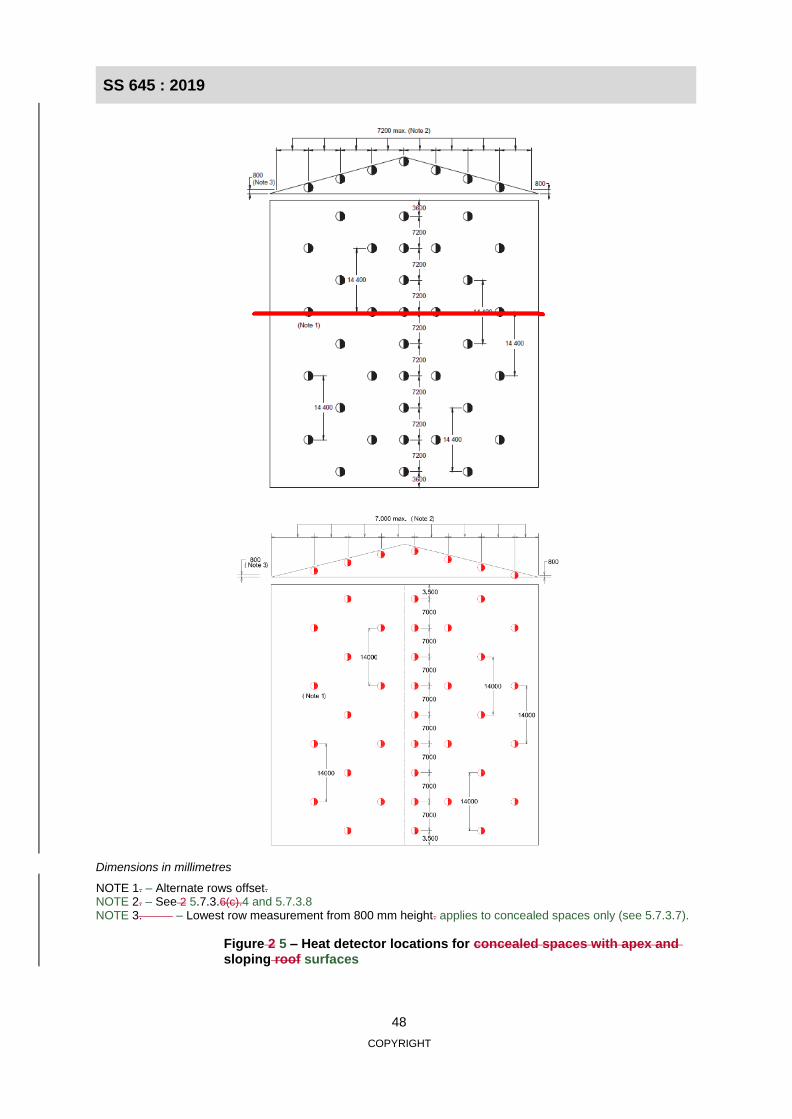
SS 645 : 2019
48
COPYRIGHT
Dimensions in millimetres
NOTE 1. – Alternate rows offset. NOTE 2. – See 2 5.7.3.6(c).4 and 5.7.3.8 NOTE 3. – Lowest row measurement from 800 mm height. applies to concealed spaces only (see 5.7.3.7).
Figure 2 5 – Heat detector locations for concealed spaces with apex and sloping roof surfaces

SS 645 : 2019
49
COPYRIGHT

SS 645 : 2019
50
COPYRIGHT
Figure 6 – Design criteria for point-type heat detectors and linear-type detectors

SS 645 : 2019
51
COPYRIGHT

SS 645 : 2019
52
COPYRIGHT
(f) Ventilated ridge (g) Narrow apex
(h)
Dimensions in millimetres
(i) Broad ridge vent
NOTE – Detector always on side with least slope.
Figure 3 (in part) 6 – Design criteria for point-type heat detectors (continued)

SS 645 : 2019
53
COPYRIGHT

SS 645 : 2019
54
COPYRIGHT
2 5.8 Smoke detection systems
2 5.8.1 General
The installations of an automatic fire alarm system using smoke detectors shall comply with Sections Clauses 1, 3, 4, 5 and 2 6, in so far as they are applicable and appropriate, and with this clause.
This clause applies only to point-type and optical beam line-type smoke detectors. Fire alarm systems based on a different smoke detection concept may be used subject to the approval by the relevant authority.
2 5.8.2 Detectors
The type of detectors for use in various locations is described in Annex A D.
2 The delay between the activation of a smoke detector and the activation of the general alarm shall not exceed 10 s.
5.8.3 Spacing and location of detectors
2 5.8.3.1 General
The location of detectors shall be to the best advantage for detecting a fire. The maximum spacing and location of detectors shall comply with the requirements of of 2 5.8.3.2 to 2 5.8.3.78 (See figures 4, 5, 6, 7, 8 and, 9, 10, and 11 for detector locations).
2 5.8.3.2 Location
2.8.3.2.1 In determining the point detector position, consideration shall be given to the following:
(a) High temperatures close to ceilings or roofs. It may be necessary to extend the location of the detector downwards below the ceiling to obtain earliest response.
(b) Detector mounting height over 3 m from the floor. The minimum distances of the sensing elements
below the ceiling line shall comply with Figure 8 (b.
(c) Effects of airflow on the detector and the movement of smoke. Detectors shall not be installed
closer than 400 mm to any air supply outlet. Where ceiling fans are installed, detectors shall not be installed closer than 400 mm outside the circumference of the blades of the fan.
(d) Isolated attachments to the ceiling such as light fittings and luminaries normally
do not act as obstructions to the general flow of smoke. They may however cause local disturbance. Detectors should not be mounted too close to such attachments; the distance should be more than twice the depth of the attachment.
2.8.3.2.2 In determining optical beam line-type detector position, consideration shall be given to the following:
(a) High temperatures close to ceilings or roofs. It may be necessary to extend the location of the
detector downwards below the ceiling to obtain earliest response.
(b) Detector mounting height over 8 m from the floor. The minimum distances of the
transmitter/receiver units below the ceiling line shall comply with Figure 8. (b

SS 645 : 2019
55
COPYRIGHT
(c) Care should be taken to ensure that beam detectors’ receiver units are not exposed to strong light, especially direct sunlight.
2 5.8.3.3 Spacing between detectors for flat ceilings
For flat ceiling ceilings, the distance from any point on the ceiling of the protected area to the nearest detector shall not exceed 7.2 m. In addition, the distance between point-type detectors shall not exceed 10.2 m. (see Figure 4 7).
For optical beam line-type detectors, the distance to the next transmitter / /receiver shall not exceed 14 m.
NOTE – For ceiling height above 10 m the same spacing requirements may still (see Figure 9b), and be applicable
provided not more than 7 m from wall. The transmitters, receivers and reflectors shall not be more than 3.5 m from any end wall or smoke curtain.
Arrangement of siting of transmitter/receiver position shall be in accordance to the manufacturer’s recommendation.
Point type smoke detectors shall not be used unless the detector has been type-tested and approved for use in a particular situation for ceiling heights above 10.5 m.
2 A point-type smoke detector may be used for ceiling heights up to 12 m provided it does not exceed 10% of the total ceiling area.
5.8.3.4 Spacing of between detectors from walls or partitions on sloping surfaces
This clause applies to all sloping surfaces including curved surfaces such as barrel-vaulted ceilings.
Detectors shall be installed 0.5–1.5 m from the apex and spaced longitudinally at a maximum of 10 m between detectors. Lower rows of smoke detectors shall be no more than 10 m apart, measured horizontally from adjacent rows, the outside wall or partition. The spacing between smoke detectors within lower rows shall only be extended up to 20 m, provided that the detectors are offset equally between the detectors on the adjacent rows (see Figure 8).
For optical beam smoke detectors on sloping ceilings, the distance between detector beams and side walls shall not be extended to more than 14 m (see Figure 9a).
Apex detectors shall comply with this clause, and Figures 8, 9 and 10.
Detectors are always on the side with least slope.
Infrared scans of a building have shown heat pockets at apices of roof structures due to solar radiation. Therefore, to obtain fire detection, the detectors The distance from the nearest row of detectors to any wall or partition shall not be less than 300 mm or exceed half the relevant maximum allowable distance between detectors given in 2.8.3.3, 2.8.3.5 and 2.8.3.6. For the purpose of this clause, smoke barriers shall be considered partitions.
2.8.3.5 Spacing of detectors where additional protection is required
shall be located below these pockets.
5.8.3.5 Location of detectors on level surfaces with beams
Where roofs or level surfaces are compartmentalised by structural features which could have the effect of restricting the free flow of smoke, the detectors shall be located so that early detection is ensured, subject to the following for point-type detectors (see Figure 9 11):

SS 645 : 2019
56
COPYRIGHT
(a) For areas with ceiling height equal to or greater than 4 m and beam depth not exceeding 100
300 mm (see Area 4 1, Figure 9), 11), the spacing of detectors shall be mounted on the
underside of the beams and spaced in accordance with 2 5.8.3.3 and 2 5.8.3.46.
NOTE – Additional detectors shall be provided in interbeam area in cases where the interbeam area is so large that the spacing of detectors located on the underside of beams does not comply with 2.8.3.3 and 2.8.3.4.
(b) For areas with ceiling height not exceeding 2 m and a beam depth exceeding 300 mm (see Area 2, Figure 11), the spacing of detectors shall be in accordance with 5.8.3.3 and 5.8.3.6.
(c) For areas with a ceiling height greater than 2 m but not exceeding 4 m, a beam depth exceeding
300 mm (see Area 3, Figure 9 11) and the interbeam an inter-beam area less than 4 m2, detectors shall be mounted on the underside of the beams and spaced in accordance with 2 5.8.3.3 and 5.8.3.6.
(cd) For areas such as item (bc) above, where the interbeam inter-beam area is equal to or greater
than 4 m2, detectors at least one detector shall be mounted in each interbeam inter-beam area
(see Area 3, Figure 9).11),
(d) For areas with ceiling height not exceeding 4 m and beam depth not exceeding 300 mm (see Area
1, Figure 9), the spacing of the detectors shall be in accordance with 2 5.8.3.3 and 2 5.8.3.46.
(e) For areas with ceiling height not exceeding 2 m heights equal to or greater than 4 m, a beam depth exceeding 300 mm (see Area 4, Figure 11), and an inter-beam area less than 9 m2, detectors shall be mounted on the underside of the beams and spaced in accordance with 5.8.3.3 and 5.8.3.6.
(f) For areas with ceiling heights equal to or greater than 4 m, a beam depth exceeding 300 mm
(see Area 2 4, Figure 11), and an inter-beam area equal to or greater than 9), the spacing of m2, detectors shall be mounted in the inter-beam area and spaced in accordance with 2 5.8.3.3 and 2 5.8.3.46.
NOTE – Where airflow reduces the response of the detector located in these areas, the detectors should be relocated in a more favourable position. Nevertheless, the spacing requirements of the above clauses should not be exceeded.
2 5.8.3.6 Reduced spacing
For all types Spacing of smoke detector, closer spacing may be required to take account of special characteristics of the protected area. detectors from walls or partitions
The distance between from the nearest row of detectors to any wall or partition shall not exceed 7 m in the following areas where:
(a) the ceiling height is greater than 2 m but not exceeding 4 m, the beam depth exceeding 300 mm and
the interbeam area be less than 4 m2; or 300 mm or exceed half the relevant maximum allowable distance between detectors given in 5.8.3.3, 5.8.3.5 and
(b) the number of air changes exceeds 15 per hour.
5.8.3.7. For the purposes of this clause, smoke barriers shall be considered partitions.
5.8.3.7 Reduced spacing – Areas of high air exchange rates
For areas of high airflow with mechanical ventilation, the spacing of detectors shall be in accordance with Table 1.

SS 645 : 2019
57
COPYRIGHT
Table 1 – Smoke detector spacing based on air change rate
Air changes per hour Distance between detectors (m) Distance from walls or partitions (m)
<15
15 – <20
20 – <30
10
7
5
5
3.5
2.5
NOTE 1 – For areas with high air velocities (i.e. in excess of 3 m/s, or air exchange rate exceeding 30 air changes per hour), the detector spacing may need to be further reduced or more sensitive detection equipment may need to be installed.
NOTE 2 – Certain applications such as computer rooms and data centres where asset protection is an important consideration, additional or specific measures are to be considered.
5.8.3.78 Spacing of detectors in concealed spaces
Concealed spaces for which protection is required under 1.4.12.3.1 shall be protected in accordance with the following:
(a) Concealed spaces with upper-level surfaces in excess of 2 m high shall have detectors spaced in accordance with 2 5.8.3.3 and 2 5.8.3.46.
(b) For concealed spaces with upper level surface not exceeding 2 m high and having with
downward projections, such as beams and ducts, not exceeding 300 mm from the upper surface of the space, the spacing between detectors shall not exceed 15 m., and the distance between any wall or partition to the nearest detector shall not exceed 10 m. Where the downward projections exceed 300 mm, the spacing of detectors shall be in accordance with 2 5.8.3.5. (b).
(c) For concealed spaces with apices, the spacing between detectors in the longitudinal direction
at the apex and sloping roof shall not exceed 10.2 m and 20.4 m respectively. On the a sloping roof, the horizontal distances distance between rows parallel to the apex shall not exceed 10.2 m, with the lowest row of detectors located not more than 10.2 m, measured horizontally towards the apex from a position where the vertical height, between the upper and lower surfaces of the space, is 800 mm. The longitudinal spaces between the detectors on the lower rows shall be arranged so that the detectors are spaced equally between the detectors on the adjacent rows (see Figure 5 8).

SS 645 : 2019
58
COPYRIGHT
2 5.8.3.89 Detector mounting
The sensing element for ceiling-mounted point-type detectors shall be not less than 25 mm below the ceiling, roof or apex unless they have been assessed for less than 25 mm and normally not more than 600 mm, below the ceiling or roof (see Figure 8). 300 mm below the ceiling, roof or apex. For ceiling heights between 4 m to 12 m, the sensing element shall not be more than 600 mm below the ceiling roof or apex.
Where the ceiling or roof height is more than 12 m from the floor, the detector type and location may require additional engineering considerations of the smoke plume within the building environment. Optical beam line-type smoke detectors spaced in accordance with Figure 9 shall be mounted not less than 300 25 mm and not more than 600 mm below the ceiling or roof. Beam-type smoke detectors may be installed more than 600 mm below the ceiling, provided that the spacing between beams is reduced to half the mounting height of the beam above the floor taken into account the likely spread of a smoke plume as a function of height. Additional optical beam line-type detectors should be installed in vertical shafts, (e.g. atria and warehouse, etc.) at lower levels (see Figure 8)..
2 5.8.3.910 Arrangement of alarm zones
Not No more than 20 40 smoke detectors shall be connected on in a single alarm zone. (see 4.4.1).
NOTE – Where a single alarm circuit is connected with more than 20 40 point-type smoke detectors, then means shall be specified and provided which ensure that a short circuit or an interruption in this detection alarm circuit does not prevent the indication of a fire alarm from more than 20 40 point-type smoke detectors.
The alarm zone limitation shall be 2000 m2 of protected floor area regardless of the number of smoke detectors provided within the zone.

SS 645 : 2019
59
COPYRIGHT
Dimensions in millimetres
NOTE 1 – Smoke detector spacing in corridors are the same as general protected areas.
Dimensions in millimetres
Figure 4 7 – Typical smoke detector spacing – Flat ceilings

SS 645 : 2019
60
COPYRIGHT
Figure 5 – Point-type smoke detector locations for concealed spaces with apex and sloping roof

SS 645 : 2019
61
COPYRIGHT
Dimensions in millimetres
NOTE 1 – Alternate rows offset. NOTE 2 See 2.8.3.7 (c).
NOTE 3 2 – Lowest row measurement taken from 800 mm height. applies to concealed spaces only (see 5.8.3.8).
Figure 8 – Point-type smoke detector locations for sloping surfaces

SS 645 : 2019
62
COPYRIGHT
(a) Optical beam smoke detector on sloping surface
(b) Optical beam smoke detector on level surface
Dimensions in millimetres
Figure 9 – Typical beam-type smoke detector locations and maximum spacing

SS 645 : 2019
63
COPYRIGHT
(a) Unequal sloping surface (b) Sawtooth ceiling, roof or surface
(c) Equal sloping surface
(d) Louvred ceiling or roof with louvred riser (e) Ceiling, roof or surface with skylight
Figure 10 – Design criteria for point-type and beam-type smoke detectors located at apex of ceiling, roof or surface

SS 645 : 2019
64
COPYRIGHT
Dimensions in millimetres X = 10 000 for point-type detector. X = 14 000 for beam-type detectors. Y = For ceiling heights between 4 m and 12 m, detection sensing element should be between 25 mm and 600 mm below the ceiling.
Figure 10 – Design criteria for point-type and beam-type smoke detectors located at apex of ceiling, roof or surface (continued)

SS 645 : 2019
65
COPYRIGHT
Dimensions in millimetres
Figure 11 – Design criteria for point-type smoke detectors in structures with deep beams
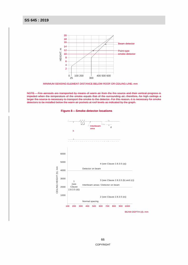
SS 645 : 2019
66
COPYRIGHT
0 25
100 200 300
400 500 600
20
18
16 Beam detector
14
12 Point-type
10 smoke detector
8
6
4
2
MINIMUM SENSING ELEMENT DISTANCE BELOW ROOF OR CEILING LINE. mm
NOTE – Fire aerosols are transported by means of warm air from the fire source and their vertical progress is impeded when the temperature of the smoke equals that of the surrounding air; therefore, for high ceilings a larger fire source is necessary to transport the smoke to the detector. For this reason, it is necessary for smoke detectors to be installed below the warm air pockets at roof levels as indicated by the graph.
Figure 8 – Smoke detector locations
Interbeam area
h
100 200 300 400 500 600 700 800 900 1000
BEAM DEPTH (d). mm
6000
5000
4000
4 (see Clause 2.8.3.5 (a))
Detector on beam
3000
2000
1
(see
Clause
2.8.3.5 (d))
3 (see Clause 2.8.3.5 (b) and (c))
Interbeam areas / Detector on beam
1000 2 (see Clause 2.8.3.5 (e))
Normal spacing
CE
ILIN
G H
EIG
HT
(h
). m
m
HE
IGH
T. m
d

SS 645 : 2019
67
COPYRIGHT
2 5.9 Flame detection systems
2 5.9.1 General
The design, installation and maintenance of automatic fire alarm systems in which flame-responsive detectors are used as a fire warning system shall comply with Sections Clauses 1, 3, 4, 5 and 2 6, in so far as they are applicable and appropriate, and with this clause.
Flame detectors detect the infrared and/or ultraviolet radiation that is emitted by flame. Both types use radiation-sensitive cells that “see” fire either directly or through built-in lenses or reflectors.
Infrared flame detectors are usually designed to respond to flame characteristics such as flicker, size or more than one specific radiation frequency. Types intended for outdoor use can be designed to respond to specific infrared frequency bands that are not characteristic of solar radiation.
Ultraviolet flame detectors normally operate within wavelengths that the ozone layer filters out of solar radiation. Hence, ultraviolet detectors do not normally respond to sunlight and may generally be used outdoors.
2 5.9.2 Stability and sensitivity
The stability and sensitivity of detectors should be such that incorrect operation does not occur as a result of extraneous natural light or radiation from artificial light sources or steady infrared sources, or of variations in ambient temperature.
NOTE – Regarding See 5.1.3 for use in special situations, refer to 2.1.3 environments.
2 5.9.3 Spacing and location of detectors
Flame detectors do not rely on convection, but detect the radiation emitted from flame flames. Accordingly, they do not need to be mounted on ceilings, and they are not, in any case, affected by stratification. Their sensitivity to a fire does decrease, however, as their distance from the fire increases, as the intensity of the radiation decreases approximately in proportion to the square of the distance from its source. On the other hand, they may be mounted at a relatively low level within a high space to maximise sensitivity to a fire at ground level; preclude early detection of a shielded fire.
Detectors shall be spaced placed to ensure that the risk areas are protected with a minimum of shadowing or blind spots.
The spacing of flame detectors should be within maximum limits specified by the manufacturer.
Where flame detectors are intended to provide general area/special hazard(s) protection, there should be a clear line of sight between all points/hazard(s) within the protected area and one or more flame detectors.
2 Flame detectors should not be located in areas in which sources of infra-red or ultraviolet radiation create the potential for unwanted alarms. Since various techniques can be adopted in the design of the detector to minimise the likelihood of unwanted alarms as a result of radiation from non-fire sources, the guidance of the manufacturer of the detector, with respect to the sensitivity of detectors to such sources, should be taken into account.
5.9.4 Fixing of detectors
Detectors shall be rigidly fixed to a stable support so that vibration or shocks will not cause spurious false alarm signals or misalignment of the detector leading to loss of protection.

SS 645 : 2019
68
COPYRIGHT
2 5.9.5 Detector lenses
Lenses of flame detectors through which flame radiation is received shall be appropriately designed for the coverage required. Where detectors are placed in environments likely to lead to the build-up of particles on the lens, appropriate baffles or purging equipment shall be fitted to ensure that the detector’s sensitivity is retained between service periods.
2 5.9.6 Outdoor applications
Detectors mounted outdoors shall be of the weatherproof type. They shall be fixed and supported so that they are not liable to movement due to wind or other causes.
5.10 Video image fire detection system
5.10.1 General
A video image fire detection system (VIFDS) is a video image flame and/or smoke detection system. VIFDS is a video image analysing system used to detect the presence of flame and/or smoke in a protected space. The system comprises cameras, processing equipment and interfaces, and performs analysis of real-time video images for geometry, plume, pattern, movement, colour, light intensity and consistency over time to identify characteristics of flame and/or smoke; and outputs alarm and video signals through networking and interfacing devices to alert the occupants and users. The system generally needs a clear line-of-sight with the area viewed by the camera and requires primary and secondary power supplies to be provided as part of a fire alarm system.
5.10.2 Application
VIFDS is used to protect large spaces in commercial and industrial buildings. It is not recommended in areas where the environment may cause inaccuracy in detection or false alarms. Such areas include rooms/spaces with varying and non-uniform lighting levels or obstructions to the detector. Detectors should be placed to ensure that the risk areas are protected with minimum shadowing or blind spots.
5.10.3 System configurations
VIFDS consists of, but is not limited to, the following main components:
(a) Video cameras (detectors) – for capturing flame and/or smoke images;
(b) Central image processing and management unit – for recording and analysing images captured
by cameras;
(c) Network and interfacing device – for connecting system components and sending an alarm signal to relevant parties/devices; and
(d) Monitoring device – for monitoring video images and alarm signals.

SS 645 : 2019
69
COPYRIGHT
Central Image Processing & Management Unit
An illustration of the system network is shown in Figure 12.
Camera3
Cameran
NOTE – The solid line denotes mandatory requirements and the dotted line denotes optional requirements.
Figure 12 – An illustration of the system network
5.10.4 System requirements
5.10.4.1 General
VIFDS should recognise and detect flame and/or smoke from the captured images and trigger the building’s fire alarm. The design and installation of the system should minimise the occurrences of false alarm. All images captured should be recorded and stored in the system for a specified duration. The system should be able to supply vital and situational real-time live video to a control centre located within the building and at remote locations.
5.10.4.2 Locations of cameras and system components
The following factors should be taken into consideration when determining the locations of the cameras:
(a) Sensitivity of the camera;
(b) Ceiling height;
(c) Ceiling shape, surface and obstructions;
(d) Structural features, size and shape;
(e) Ambient environment;
(f) Ventilation system provided;
(g) Configuration of the contents within the area;
(h) Burning characteristics of the combustible materials present;
Internet
Building Fire Alarm System
Camera2 Camera1
Building Management System
Image Monitoring
Security Monitoring System
Image Monitoring
Fire Alarm Monitoring
Station
Remote Image
Monitoring
SS 645 : 2019
70
COPYRIGHT
Section Three – Manufacturer’s recommendations; and
(j) Line of sight.
5.10.4.3 Detection function
The system shall give consistent fire alarm responses in a specified time not exceeding 30 s. It shall be able to detect reflected fire light when the fire is obstructed and capable of detecting flame and/or smoke under minimum lighting condition.
5.10.4.4 Recording of video images
The system shall be able to record video images at all times to facilitate fire investigation. The system shall have adequate storage capacity to store video images for up to 30 days for immediate retrieval, if the need arises. Video records shall contain essential details such as date, time and location of the video images being taken. Provision shall be made available for transferring the video records to other storage devices.
5.10.4.5 System fault and false alarm
The system shall be able to give warnings on system faults, including detector, circuit and other system components malfunction or failure. The system shall be able to adapt to environmental variations to minimise false alarm.
6 Installation, operation and maintenance
3 6.1 Installation
3 6.1.1 General
The fire alarm system installation shall be kept separate and distinct from other system installations. Wiring for a fire alarm system shall comply with the requirements stipulated in this Code. All other In addition, all wiring shall be installed in accordance with the appropriate provisions of SS CP 5, except as stipulated by 3.1.2 to 3.1.7.
638. Particular attention should be given to the protection and segregation of the fire alarm system from other systems. If fibre optics are used in the fire alarm system, then approval by the relevant authority is required.
3 6.1.2 Cables and wiring
Cables insulated with general purpose PVC shall not be installed in any situation places where the sustained ambient air temperature is liable to might exceed 65 oC for long periods. If such situations cannot be avoided, cables having heat fire resistant PVC insulation cables complying with the requirements of SS 299-1 shall be used.
Suitable additional protection for the cable cables shall be provided at any point where they are likely to be subjected to mechanical damage.
PVC-insulated non-sheathed cable cables shall be laid in metal conduit complying with SS 504 IEC 61386 or metal trunking complying to SS 249, exclusive to the fire alarm system.. The cable cables shall comply with the requirements of SS 358. Rigid PVC In an environment where metal conduits and fittings or metal trunking is not suitable, a rigid PVC conduit or PVC trunking may be used in situations where the ambient temperature is below 60 oC. .

SS 645 : 2019
71
COPYRIGHT
Suitable additional protection for the conduits conduit or trunking shall be provided at any point where they are likely to be subjected to have a high risk of mechanical damage.
If a common duct or trunking is to be used to contain both fire alarm circuits and those of any other services, the fire alarm circuits shall be wired in a fire-resistant cable. Alternatively, they may be wired in PVC-insulated cable cables, provided they are separated from the cables of other services by a rigid and continuous partition of non-combustible material affording them complete enclosure when the covers of the duct or trunking are in place.
Cables laid underground shall be run in ducts. A PVC-insulated and sheathed cable conforming to the requirements of IEC 60227-4 shall be used. Cables laid direct in the ground shall be PVC insulated and sheathed, armoured and sheathed overall.
Any telephone telecommunication-type cable should be allowed for use in the wiring between the fire alarm panel and the repeater or mimic panel for secondary indication and shall be protected against mechanical damage by the use of conduit conduits or trunking.
3 If fibre optics are used in the fire alarm system, the integrity and reliability of the installation shall be equivalent to the protection and segregation requirements of this Code for the wiring installations. The fibre optic cables used shall conform to the requirements of IEC 60794-1-1. In situations where fire- resistant fibre optic cables are to be used, it shall conform to the requirements of IEC 60331-25. 6.1.3 Conductor sizing All cable conductors shall be sized to comply with the requirements of the relevant Singapore Standard(s). Standards. In selecting conductor sizes, regard attention should be paid to physical strength and to limitations imposed by voltage drop. The voltage drop across a cable should not be such as to prevent devices from operating within their specification limits, even under minimum supply and maximum load conditions. Consideration should be given to any possible extensions to the system.
3 6.1.4 Protection against electromagnetic interference
In order To minimise equipment damage and false alarms, equipment (including cabling) should not be sited in places likely to have high levels of electromagnetic interference. Adequate electromagnetic protection should be provided if such an arrangement could not cannot be achieved.
3 (a) Any cable specifications stipulated by the manufacturer as important for the compliance with the requirements of the Electromagnetic Compatibility (EMC) Directive should be followed.
(b) Correct earthing of equipment is vital for adequate EMC performance and electrical safety.
(c) In the case where screened cables are used, exposure of the cores outside of the screen should be kept to a minimum, consistent with practical installation requirements.
(d) If the system is sensitive to multiple screen earths for each circuit, the control equipment manufacturer’s instructions should be followed.
(e) Where required, the screen should have continuity throughout the whole circuit.
(f) Where it is necessary to cross fire alarm system cables with those that can potentially cause interference, the cables should be crossed at right angles.

SS 645 : 2019
72
COPYRIGHT
6.1.5 Joints and terminations
A loop-in system of wiring shall be used for parallel connected detectors, call points and sounders, etc;.; each incoming and outgoing conductor of the same potential shall be connected to the appropriate terminal provided.
Joints in conductors shall not be permitted except in runs in excess of 100 m. Joints and terminations shall only be made in a suitable metal terminal box in an accessible space. Cables that are joined shall be appropriately marked within the terminal box. The words “FIRE ALARM” shall be marked on the terminal box in a contrasting colour.
3 6.1.6 Mounting of detectors
Provision Provisions shall be made to prevent contact between live parts (including terminals) and the ceiling on which the detector is mounted. The loop-in system of wiring shall be observed throughout.
3 6.1.7 SeparationSegregation from other systems
The wiring of a fire alarm system shall not be used for other services.
The wiring of the fire alarm system shall be kept separate and distinct from the wiring of any other services. Except in common duct or trunking as provided for in 3.1.2, fire alarm wiring and shall be spaced at least 50 mm away from the wiring of any other service., except in common ducts or trunking as provided for in 6.1.2. Where crossings are unavoidable, however, a bridge of suitable non- combustible insulating material at least 6 mm thick shall be securely fitted at the crossing. In no case shall the fire alarm equipment or connections be mounted in or on boxes, cover plates or blocks carrying accessories of connections of any other service unless effectively separated by means of strong and rigidly fixed covering or partitions.
The mains feed to the power supply equipment of the fire alarm system shall be segregated from the wiring of all other services and also from all other circuits of the fire alarm system.
3 6.1.8 False alarms in new installations
During commissioning, a check shall be carried out to ensure there is no obvious potential for false alarms. The completion of the check shall be recorded on the commissioning report along with any potential false alarm problems that should be subject to further consideration at the time of future service visits.
6.2 Operations
The owner shall appoint a competent person to supervise and coordinate all matters in relation to the fire alarm systems. The person should be trained in operating the fire alarm system effectively.
When a signal is announced on the fire alarm panels, fire or non-fire, the person should be capable of analysing and interpreting the signal correctly and taking appropriate actions.
In a false alarm or other fault annunciation, the source of the false alarm or fault signal shall be made available in a log. Recommendations to prevent recurrence of such events should also be included in the log.
The person shall also be responsible for keeping all the log records on routine preventiveOperation and maintenance manuals and “as installed” drawings, repair and alteration works carried out on the system (see Annex B).
Operation and maintenance manuals and “as installed” drawings of the complete installation including a single-line diagram of the system, the fire alarm panel layout and the positions of the detectors and alarm zones should be provided to the user before a final inspection is made.

SS 645 : 2019
73
COPYRIGHT
6.3.3 Symbols
Symbols as shown in Annex B shall be used on all drawings relevant to the fire alarm systems.
3.4 Maintenance
6.3.4.1 General
To ensure the system’s continuous reliability of the system, the owner or owner’s representative should establish an agreement to carry out regular maintenance of the installation with the manufacturer or manufacturer’s representative or a competent contractor. The arrangements for maintenance should be such as will ensure that a qualified person is available on call at all times to provide service in the event of any fault that develops at the installation. The name and telephone number of the servicing organisation should be prominently displayed at the control and indicating equipment.
Where a service contract cannot be arranged, the owner or owner’s representative with suitable experience of operating the fire alarm system and with special training with from the manufacturers, suppliers or contractors should shall carry out simple necessary servicing. However, he this person should be instructed not to attempt to exceed the scope of such training.
The arrangements for maintenance with or without service contract shall be such as will ensure that a competent person is on call at all times, in the event of any fault that develops at the installation.
The details of any service call shall be entered in the log record, which shall be provided for convenient reference. The alarm monitoring station and owner or owner’s representative are to be notified when any portion of a system is isolated for maintenance and likewise notified when this portion is reconnected.
Operating instruction instructions comprising EVACUATE, ALARM SILENCE, FAULT SILENCE & SYSTEM RESET should shall be provided prominently at on the fire alarm panel.
6.3.4.2 False alarmLimitation of false alarms
6.3.2.1 Categories of false alarms
False alarms can be a major hazard to any fire alarm system since they lead to a loss of confidence in the system. It is important that any alarm from the system be treated as an alarm of fire until it can be is proved to be false, rather than being treated as false until proven to be a fire.
It is a common misconception that most false alarms arise from faults in equipment. In fact, most false alarms arise from a combination of environmental influences, fire-like phenomena, inappropriate action by people in the building and accidental damage.
False alarms can be categorised into the following:
(a) Unwanted alarms – inappropriate action by people in the building and accidental damage.
(b) Equipment false alarms – arising from the malfunction of equipment.
(c) Malicious false alarms – arising from malicious action.
(d) False alarms with good intent – involving genuine belief by a person that there is a fire.

SS 645 : 2019
74
COPYRIGHT
For any investigation of false alarms to be successful and for appropriate action to be taken on false alarms, it is important records be kept of the category of false alarms whenever this can be accurately determined. Where any doubt exists, the cause should be recorded as “unknown”.
NOTE – In the absence of other information, a false alarm need not necessarily have arisen from an equipment fault.
Where an alarm has been found to be false, the following immediate actions should shall be taken immediately by the responsible person or a person to whom he/she has delegated this duty:
(a) Where possible, identify the particular detector or call point which has initiated the alarm. If detectors having with individual indicators are in use, any indications will be cancelled by resetting, and hence it is important that the detectors are examined before the system is reset.
(b) Where possible, establish the cause of the false alarm. and record the category of false alarm. It is possible that the actual cause of the alarm would have been lost in the operations resulting from the alarm. Where this is so, a record should be kept of any events or activities near the detector immediately prior to the alarm.
(c) Record the false alarm in the log record and inform the organisation responsible for servicing.
Information recorded shall include the following:
(i) Date and time;
(ii) Identity and location of device;
(iii) Reason for false alarm;
(iv) Activity in the area;
(v) Action taken; and
(vi) The person responsible for recording the information.
The owner shall ensure that building defects (e.g. leaking roofs), plant defects (e.g. steam leaks) and environment problems (e.g. inadequate ventilation) that could cause unwanted alarms receive suitable attention.
If one detector or group of detectors gives false alarms repeatedly then the organisation responsible for servicing should shall be informed and required to investigate.
Any installations, detectors or detector locations having with higher false alarm rates should shall be subject to special investigation.
6.3.2.2 Preventive maintenance
The number of false alarms that can be anticipated is virtually proportional to the number of automatic fire detectors installed. The constant of proportionality will normally be highest where the fire detectors are smoke detectors. Systems incorporating only manual call points or manual call points in conjunction with heat detectors do not normally produce many false alarms.
Smoke detection systems with signal processing incorporating techniques specifically intended to discriminate between certain unwanted alarms and real fires are likely to offer better immunity to false alarms.
Systems with a pre-alarm warning feature enable the investigation of conditions that would lead to an unwanted alarm if no action is taken.

SS 645 : 2019
75
COPYRIGHT
The owner’s representative, competent contractor or servicing organisation shall inspect the signal processing data available from the smoke detection systems regularly and investigate any pre-alarm warning.
Regular cleaning or replacement of smoke detectors is necessary for smoke detection systems without signal processing.
It is the responsibility of the owner of the protected building to prevent false alarms, by taking adequate measures to prevent activation of the detectors caused by cutting, welding, sawing, smoking, heating, cooking, exhaust fumes, etc.
6.3.4.3 Regular testing and inspection
6.3.4.3.1 General
It is the responsibility of the owner of the protected building to ensure that the installation is tested in accordance with the requirements specified in this Code and with any additional tests which that may be required by the relevant authority authorities. The tests should shall be conducted by the owner or his representative responsible for the maintenance of the installation and all results of the tests should shall be entered in the log record as prescribed in 2 5.2.11 and acknowledged by the owner and/or his representative as appropriate.
It is important to ensure that regular testing and servicing operations do not result in a false alarm. The occupants of the premises should be notified of any test of the system that may result in the sounders audible and visual general alarm being operated.
Where the heat-sensitive element of thermal detectors or the enclosure of other detectors are found to be coated with paint or any other material likely to affect the operation of the detectors, such material shall be removed. If necessary, the detector shall be replaced.
6.3.4.3.2 Daily check
A check should be made every day to ascertain if the system is operating normally. Fault(s) Faults detected should be recorded and steps taken immediately to ensure that the fault(s) is they are rectified.
If a fault is detected, the responsible person should ensure that the following actions are taken:
(a) Determine the area affected by the fault and decide whether special action (such as fire patrols)
are needed in that area;.
(b) If possible, determine the cause of the fault, or note the activities immediately prior to the fault in the area affected;, and
(c) Enter the fault in the log record, inform the organisation responsible for servicing and arrange for
repair.
6.3.4.3.3 Weekly test
The following tests and checks should be made every week:
(a) Carry out a simulation & and transmission of fire alarm and fault signals to the monitoring station and confirm it is functioning correctly;

SS 645 : 2019
76
COPYRIGHT
NOTE – . It will be is necessary to contact the monitoring station prior to the before transmitting of the a simulated fire alarm and fault signals signal to inform them of the test and. It is also necessary to check with the monitoring station after completion of the test to ensure the fire alarm and fault signals were received and to advise them when the system has been normalised.
(b) Check the battery voltage and conditions;.
(c) On completion of the test, take corrective action immediately on any abnormality or fault(s) faults encountered within the system;, and
(d) Enter the test result(s) results and follow-up actions, if any, in the log record.
6.3.4.3.4 Monthly test
In addition to the weekly test tests and checks specified above in 6.3.3.3, the following checking and testing procedures should be carried out each every month:
(a) Simulate fire and fault condition at the manual call points and detectors on all alarm zones to ensure it is operational. Confirm with the monitoring station that the fire alarm and fault signals have been received.
(b) Check charger voltage and charging current in accordance with the manufacturer’s instructions.
(c) Check batteries and their terminals as specified by the manufacturer to ensure that they are in good serviceable condition. Carry out measurement of Measure the impedance of the battery.
(d) Check the condition of battery cabinet for corrosion and ensure that batteries are stored in a
secure condition.
(e) Check to ensure that all indicating lights are operating correctly and replace if faulty.
(f) Check the operation of all alarm sounders/visual alarm devices.
(g) Check and confirm the battery monitoring function is operational.
(h) Test the system under the failure of electrical supply to the fire alarm panel to confirm it is operational ( [see 5.2.2.5 (e), 2.2.56 (f), 2 5.3.3 and 2 5.3.4).5].
(i) Simulate fire alarm conditions and check the output signals available to initiate the remote auxiliary functions that is are required to be in operation in the event of fire.
(j) Check and ensure the fire alarm panels, zone charts plans and all necessary indicators, printer, where applicable, are clean and in clearly visible condition.
(k) Visually inspect the condition of components, terminations and cables.
(l) Ensure that faulty parts are satisfactorily replaced and recorded. Enter in the log record any
fault(s) faults that requires require repair.
(m) Check that all switches are returned to their operating positions after the test.
(n) Enter the test results and follow-up actions, if any, in the log record.
6.3.4.3.5 Annual test
The annual test should consist of all In addition to the inspection monthly tests and testing procedures checks specified in 6.3.4.3.4 and, the following should be carried out each year:

SS 645 : 2019
77
COPYRIGHT
(a) The maintenance personnel should arrange to check the operation of at least 20 percent% of the manual call points and detectors in an installation each year. The selection of manual call points and detectors to be tested should be spread over as many zones as possible and should be made in such a way that all manual call points and detectors in an installation should have been checked at least once in 5 years.
The checking of the manual call points and detectors should take the form of in-situ testing to ensure it is operational.
(b) Circuits connecting ancillary equipment which require automatic voltage regulated supplies
should be checked to ensure correct operation and voltage output.
(c) Where the heat-sensitive element of thermal detectors or the enclosure of other detectors are found to be coated with paint or any other material likely to affect the operation of the detectors, such material should be cleaned off or if necessary, have the detector replaced.
(d (c) The smoke detectors shall be cleaned, tested or calibrated according to the manufacturer’s recommendation.
(ed) Enter the test results and follow-up actions, if any, in the log record.
3.5 Operations
The owner shall appoint a competent person to supervise and coordinate all matters in relation to the fire alarm systems. The person should be trained in operating the fire alarm system effectively.
When a signal 6.4 Operation and maintenance manuals and “as installed” drawings
Operation and maintenance manuals and “as installed” drawings of the complete installation including the following should be provided to the user before a final inspection is annunciated made:
(a) A single-line diagram of the system;
(b) The fire alarm panel layout;
(c) The positions of the detectors and alarm zones; and
(d) The relevant information about the technology of the fire detection and alarm system.
Symbols shown in Annex E shall be used on all drawings relevant to the fire alarm panels, systems.

SS 645 : 2019
78
COPYRIGHT
Annex A (informative)
Fire alarm system and associated systems, functions and equipment
An illustration of the components of a typical fire or non- alarm system and associated systems, functions and equipment is shown in Figure A.1.
NOTE: Function within the fire alarm system - Function 1-10 Detection and activation functions - Function 3 and 4 Control functions for actions. - Functions 7,8,9, and 10 Local associated functions - Function 11 Remote associated functions - Function 12,13 and 14
Exchange of information between functions -
Figure A.1 – Fire alarm system and associated systems, functions and equipment

SS 645 : 2019
79
COPYRIGHT
Table A.1 shows the examples of the equipment and systems carrying out the functions of fire alarm systems and associated systems.
Table A.1 – Functions and examples of relevant equipment
Reference Functions Example of equipment carrying out the function
(1) Control and indication function
Control and indicating equipment Networked control and indicating equipment
(2) Power supply function Power supply equipment (PSE)
(3) Automatic fire detection function
Fire detectors such as:
• Smoke detectors (point detectors)
• Line smoke detectors (optical beam detectors)
• Duct smoke detectors
• Heat detectors (point detectors)
• Line type heat detectors
• Line type heat detectors, non-resettable
• Flame detectors (point detectors)
• Multi-sensor fire detectors:
• Video image fire detectors: Input device for auxiliary detection functions such as:
• Sprinkler activated input
• Input device for connection of secondary detection
• circuit to a Primary detection circuit
(4) Manual initiating function Manual call points
(5) Fire alarm function Voice alarm loudspeaker Fire alarm devices such as:
• Audible alarm sounders
• Visual alarm devices
(6) Control and indication function for alarm annunciation
Voice alarm control and indicating equipment (VACIE) Control for other fire evacuation measures
(7) Control function for fire protection system or equipment
Output device to trigger fire protection equipment Output to fire protection equipment
(8) Fire alarm routing function Fire service signalling transmitter (alarm transmission)
(9) Fault warning routing function
Fire service signalling transmitter (fault transmission)
(10) Ancillary input or output function
Data communication interface
(11) Fire protection system or equipment
Duct-mounted fire dampers
Electrically controlled hold-open device for fire/smoke doors Smoke control systems Fixed firefighting systems: gas extinguishing systems Firefighting systems: sprinkler or water spray systems Other fire protection measures

SS 645 : 2019
80
COPYRIGHT
Reference Functions Example of equipment carrying out the function
(12) Fire alarm receiving function
Alarm monitoring station (fire alarm signal)
(13) Fault warning receiving function
Alarm monitoring station (fault alarm signal)
(14) Ancillary management function
Visualisation system Building management system
Exchange of information between functions
Short circuit isolators

Events other than false alarms or maintenance work
Date
Time
Event ᴬ⁾
Zone ᴮ⁾
Device ᴮ⁾
Action required ᴮ⁾
Date
completed ᴮ⁾
Initials
ᴬ⁾ For example test, fire alarm signal, fault
ᴮ⁾ Where applicable
False alarms
Date
Time
Zone
Device that
Triggered
alarm signal
Cause
(if known)
Brief
circumstances ᴬ⁾
Maintenance
visit
required?
(Yes/No)
Findings of
maintenance
technician ᴮ⁾
Category of
false alarm
Further
actions
required ᴮ⁾
Action
completed
ᴮ⁾
ᴬ⁾ Where cause in unknown, record activities in this area
ᴮ⁾ Where applicable
Maintenance Work
Date
Time
Zone ᴬ⁾
Device ᴬ⁾
Reason for work
Work carried out
Further work
required
Signature
ᴬ⁾Where applicable
SS
64
5 : 2
019
An
ne
x B
(in
form
ativ
e)
Re
co
mm
en
de
d fo
rma
t of re
co
rds fo
r fire a
larm
sy
ste
ms
B.1
E
ve
nt lo
g
81
CO
PY
RIG
HT

SS 645 : 2019
82
COPYRIGHT
B.2 Weekly / monthly / annual test report
OWNER:
LOCATION: TIME:
TYPE OF TEST: WEEKLY/MONTHLY/ANNUAL* DATE:
ALARM ZONE NUMBER
DEVICES+
HEAT DETECTOR
ALARM TEST
FAULT TEST
ISOLATION
SMOKE DETECTOR
ALARM TEST
FAULT TEST
ISOLATION
FLAME DETECTOR
ALARM TEST
FAULT TEST
ISOLATION
MANUAL CALL POINT
ALARM TEST
FAULT TEST
ISOLATION
POWER
SUPPLY+
OPERATIVE
NON- OPERATIVE
REMARKS
MAIN SUPPLY
CHARGER
BATTERY
ALARM MONITORING STATION
ALARM TEST
FAULT TEST
ALARMS+
AND ANCILLARY
AUDIBLE ALARM SOUNDER
VISUAL ALARM DEVICE
ANCILLARY CONTROL
REMARKS:
I HEREBY CERTIFY THAT THE ABOVE TESTS HAVE BEEN CARRIED OUT
Tester's Name
Signature
Owner's Name
Signature
* Delete if not applicable In a false alarm or other fault annunciation, the source of the false alarm or fault signal shall be made available in a log record. Recommendations to prevent recurrence of such events should also be included in the log record + Tick if satisfactory; put 'x' if unsatisfactory and provide details in the remarks section
The person shall also be responsible for keeping all the log records on routine preventive maintenance, repair and alteration works carried out on the systems.

SS 645 : 2019
83
COPYRIGHT
Annex A C (informative)
Type of sounder circuits
Figure C.1 – Radial sounder circuits (see 5.5.3)
Figure C.2 – Ring sounder circuits [e.g. addressable loops (see 5.5.3)]

SS 645 : 2019
84
COPYRIGHT
Annex D (informative)
Guidance for the selection of detectors (Informative)
A D.1 Introduction
These recommendations should be applied with due regard to the attributes of each type of detector and its prime function for life safety and protection.
A fire detection installation is intended to enable a fire to be detected at a sufficiently early stage so that people who are at risk can be made safe either by escaping from the fire, or by the fire being extinguished (also to prevent extensive property damage). Neither of these measures can be used until people are made aware of the fire.
The effectiveness of the fire detection and alarm system depends on the stage of the fire at which it is operated. In order For all the occupants to escape without too much difficulty, an early alarm should operate before the escape routes route becomes smoke-logged to such an extent as will cause occupants to have difficulty finding their way out of the building.
Explosive or flammable atmospheres require special suppression systems automatically actuated by the detection system.
Premises where people sleep require different criteria for the selection of the detection and alarm system from those for premises where occupants are continuously supervising the area.
A D.2 Fire detectors
D.2.1 General notes on detectors
Fire detectors are designed to detect one or more of the four five characteristics of a fire, namely:
- heat
- smoke
- (a) Heat;
(b) Smoke;
(c) Combustion gas (such as carbon monoxide));
- (d) Infrared or ultraviolet radiation.; and
(e) Video image.
In some fire detection systems, a fire signal is initiated when the characteristic reaches a pre-determined threshold. A signal may, instead or in addition, be initiated when the rate-of-change of the characteristic is representative of a fire.

SS 645 : 2019
85
COPYRIGHT
In the case of point detectors, the characteristic is detected at a defined point(s) within the protected area. In contrast, ” “line” detectors are capable of detecting the characteristic along a defined line within the protected space. In an “integrating line detector”,, the effect of the characteristic on the detector is integrated along the line. In a “non-integrating line detector”,, this is not the case, and the detector behaves, effectively, as though it comprises an infinite number of point detectors arranged along the line.
In multi-sensor fire detectors, each detector contains more than one sensor and thus monitors more than one of the characteristic fire phenomena (e.g. heat and smoke). By analysis of analysing the signals received from the sensors, potential response to phenomena other than fire can be reduced while still providing an adequate response to the fire.
No one type of detector is the most suitable for all applications and the final choice will depend on individual circumstances. In some premises, it may be useful to combine different types of detectors to achieve the best results.
The likely fire behaviour of the contents of each part of the building, the processes taking place, and the design of the building should be considered. The susceptibility of the contents to heat, smoke, and water damage should also be considered.
A D.2.12 Choice of fire detectors
In any automatic fire detection system, the detector has to discriminate distinguish between a fire and the normal conditions existing within the building. The system chosen should have detectors that are suited to these conditions and provide the earliest reliable warning. Each type of detector responds at a different rate to different kinds of fire. With a slowly developing or smouldering fire such as the initial stages of a fire involving cardboard, a smoke detector would probably be activated first. A fire that evolves heat rapidly and with very little smoke could activate a heat detector before a smoke detector. With a flammable liquid fire, a flame detector could be activated first.
In general, smoke detectors give appreciably faster responses than heat detectors, but may be more liable to give false alarms, so care must shall be taken in their selection and location. Where there are productions or other processes that produce smoke, fumes, dust, etc., which might activate smoke detectors, an appropriate type of fire detector should be used.
If detectors are installed for the protection of a room’s the occupants of a room and have a direct effect on their escape routes, smoke detectors should be used. If detectors are installed in order to give warning of fire before it spreads to other areas of the building, then either smoke or heat detectors may be used.
Heat and smoke detectors rely on the transport of products from the fire to the detector by convection. The plume above a fire is relatively narrow, and in general, these detectors rely on the presence of a ceiling (or other another similar near-horizontal surface) to direct the products outwards from the plume to the detectors. Heat and smoke detectors are therefore suitable for use in most buildings, but are generally unsuitable for complete open-air applications.
Radiation (flame) detectors are particularly suited to outside for outdoor applications, where there is no ceiling to direct the products outwards. They are especially suited to risks in which smouldering is unlikely (such as in liquid fuels). Flame detectors in buildings are mainly suitable for supplementing used to supplement heat and smoke detectors in high ceiling compartments, provided that an unobstructed view is possible, and for special applications such as outdoor storage and chemical processes employing flammable liquids.

SS 645 : 2019
86
COPYRIGHT
Aspirating smoke detection systems commonly incorporate a detector of much higher sensitivity than point or optical beam smoke detectors. Such “high-sensitivity aspirating detection systems” are often used to protect critical electronic equipment rooms, in which even a very small fire can result in unacceptable damage.
Aspirating smoke detection systems are also used, sometimes, to protect spaces in which point-type smoke detectors would present difficulties on the basis of:
• (a) Aesthetics (aspirating pipe work might be run in floor voids, with a capillary tube sampling air from the space below via a small hole drilled in the ceiling);
•(b) Height of the space (the high sensitivity of some aspirating systems, coupled with the possibility of running pipe work vertically on walls and storage racks, can provide enhanced protection compared with point smoke detectors mounted at a high level); and
• (c) The temperature of the space (e.g. in cold stores, the detector can be located outside the space, so that it is not directly exposed to low temperature).
For aspirating systems, specialist application guidance needs to be sought from the manufacturer.
The choice of fire detector may also be affected by the environmental conditions within the premises. In general, heat detectors have greater resistance to adverse environmental conditions than other types of fire detectors.
All fire detectors will respond to some extent to phenomena other than fire and therefore careful choice of detectors and their location is essential crucial.
A D.2.23 False alarms
It is essential that utmost care should be taken by system designers, installers and users to reduce the incidence of false alarms. Common cause causes of false alarms include the following:
(a) Mechanical and electrical faults, often resulting from the effects of vibration, impact or corrosion;
(b) Ambient conditions such as heat, smoke or flame from cooking or work processes, fumes from engine exhaust, or high air velocities due to strong winds outside the building;
(c) Work being carried out in a protected area without the knowledge of, or in neglect of, the
necessary precautions;
(d) Communication faults arising from servicing or testing work carried out without prior notification to the alarm monitoring station;
(e) Electrical transients or radio interference;
(f) Inadequate maintenance and servicing;
(g) The build-up of dust or dirt within a detector, or the entry of insects;
(h) Change of use or changes within the building;
(i) Accidental or malicious activation of manual call points or detectors; and
(j) Changes of outdoor environmental conditions (e.g. temperature, relative humidity.).
Installations, detectors or detector locations having with higher false alarm rates should be subject to special investigation.

SS 645 : 2019
87
COPYRIGHT
A D.3 Heat detectors
A.3.1 GeneralHeat detectors are in general, less sensitive than smoke detectors. They are unlikely to respond to smouldering fires, and as a simple rule of thumb, will require the flames from the fire to reach about one- third of the distance to the ceiling before they will operate. They are therefore not suitable for the protection of places where unacceptable losses could be caused by small fires, (e.g. in computer rooms.).
There are two main forms types of heat-sensitive detector. One is the “point” -type of” detector, which is affected by the hot gas layer immediately adjacent to it. The other is the “line” -type of” detector, which is sensitive to the heat effect produced along any portion of the detector line.
Point-type heat detectors are generally suitable for use in most buildings. Line-type heat detectors may be particularly suitable for protecting items of plant or cabling. When used for these purposes, the detector should be mounted as close as possible to the place where fire or overheating might occur, and be either mounted above the risk or in contact with it.
Heat detectors with rate-of-rise elements are more suitable where ambient temperatures are low or vary slowly, while fixed temperature detectors are more suitable where the ambient temperature is likely to fluctuate rapidly over short periods.
It must be appreciated that A rate-of-rise detector will respond to the presence of fire conditions faster than a fixed-temperature type because of its ability to sense rapid increases in temperature. Accordingly, the use of detectors with both rate-of-rise and fixed-temperature is preferred for the general protection of areas.
Where environmental conditions of a building are not conducive to the use of rate-of-rise detectors owing to normally occurring rapid increases in temperature, consideration should be given to the installation of fixed-temperature type detectors to reduce the incidence of false alarms. The following are typical Examples where such temperature variations can be expected: include boiler rooms, above furnaces, kitchens, cold- rooms, bathrooms, and laundries.
A Heat detectors are not usually suitable for the protection of places where large losses could be caused by small fires (e.g. computer rooms). Before the final selection of a detector, an estimate should be made of the likely extent of the damage caused before operation of the heat detector.
Designers should pay attention to the size to which a fire must develop before detection. Heat detectors mounted on higher ceilings will only detect fires of a larger fire size (see Table D.1).
Table D.1 – Increased fire size required for equivalent heat detector effectiveness based on ceiling height
Heat detector mounting height (m) Fire size ratio required for equivalent
detection performance
3 1
6 5.5
9 15.5
D.4 Smoke detectors
A D.4.1 General
There are two smoke sensing principles commonly used for in smoke detectors as follows:

SS 645 : 2019
88
COPYRIGHT
(a) IonizationIonisation chamber type which operates on the detectors sense a change in the current flowing through an ionisation chamber upon entry of smoke particles.
(b) Optical type which operates on detectors sense a change in the scattering or absorption of light by smoke particles in a light beam.
There are single-point and multipoint detectors that detect smoke at one or more positions and may be based on optical or ionisation principles.
Duct sampling units draw air from within the duct to point-type smoke detectors.
Multipoint aspirating smoke detectors sample air from the protected area to a common sensor via a pipe network. The sensor is designed for very high sensitivity and responds to optically dense smoke and small particles. Holes drilled in the pipe network sample air from specific locations as required. Computer-aided design tools are commonly often used to determine the correct holes hole size and sampling point sensitivity.
Optical beam smoke detectors are effectively line detectors working on obscuration principles. Some beam detectors can also detect thermal turbulence by the refraction of the beam at turbulent interfaces between hot and cold air.
Ionisation chamber smoke detectors respond quickly to smoke containing small particles normally produced in clean burning fires, but may respond slowly to optically dense smoke containing large particles, which may be produced by smouldering materials. Certain materials, (e.g. PVC,), when smouldering produce mainly large particles to which ionisation detectors are less sensitive.
Optical smoke detectors respond quickly to smoke that is optically dense. Both optical and ionisation detectors have sufficiently wide ranges of response for general use.
A D.4.2 Application
A D.4.2.1 General
The operation of all types of smoke detectors depends on combustion products entering the sensing- chamber or light beam. Where Operation happens when sufficient concentration is present, operation is obtained.. Since the detectors are usually mounted on the ceiling, their response time depends upon on the nature of the fire. A hot fire will drive the combustion products up to the ceiling rapidly. A smouldering fire produces little heat, therefore the time for smoke to reach the detector will be increased increases.
The optical beam smoke detector will respond when the light path at the receiver is interrupted or obscured. It is therefore important therefore that the light path be kept is clear of obstacles at all times.
Smoke detectors other than those incorporating thermal turbulence detectors do not detect fumes from burning alcohol and other clean burning liquids which do not produce smoke particles. This is not a serious disadvantage because a fire will normally involve other combustible materials at an early stage. Combined optical beam smoke detectors and thermal turbulence detectors may be suitable for such risk, but heat or flame detectors should also be considered.
Smoke detectors incorporating thermal turbulence detectors may be unsuitable for installation immediately above ceiling-mounted blower heaters or industrial processes that produce appreciable heat.
Multi-sensor detectors contain more than one sensor, each of which responds to a different physical and/or chemical characteristic of fire. The purpose of combining sensors in this way is to enhance the performance of the system in the detection of fire, or its resistance to at least certain categories of false alarm, or both.

SS 645 : 2019
89
COPYRIGHT
The method (if any) of combining the signals from each sensor varies between different proprietary multi-sensor fire detection systems. In some such systems, there is significant potential for the reduction of many types of false alarms.
Aspirating smoke detection systems are suitable for applications where a very high sensitivity is desirable. They are also suitable for large areas where smoke detection is required at high and normal sensitivity levels. However, where a large area is covered the precise location of the smoke sensed cannot be determined.
A D.4.2.2 Location considerations
The location of smoke detectors should result from an evaluation based upon on engineering judgement or a field test. Ceiling shape and surfaces, ceiling height, configuration of contents, burning characteristics and ventilation are some of the factors that must shall be considered.
In extreme environments, the selection of smoke detectors should be confined to those capable of withstanding the environmental conditions.
A D.4.2.3 Ceiling surfaces
As mentioned in A D.4.2.2, the ceiling surface is one of the factors that must shall be considered before the locations of smoke detectors are established.
Some typical ceiling surfaces where the use of smoke detectors should be evaluated are as follows:
(a) Smooth ceilings. – Heated air and smoke usually rise. When they reach smooth ceilings, they travel along the ceiling. As these products flow along the ceiling, their concentration decreases as the distance from the source increases.
(b) Other ceilings. – Where deep beams or other obstructions form pockets in the ceiling, the products collect in the pocket and, if sufficient products are being generated, will eventually “spill over” into adjacent pockets.
Sawtooth, sloping, open joist, beam construction, or other shaped ceilings must shall receive special consideration as smoke usually travels in a longitudinal direction at the highest point.
(c) High ceilings. – As smoke rises from a fire, it tends to spread upwards in the general form of an inverted cone. Therefore, the concentration within the cone varies approximately inversely as the square of the distance from the source.
In high ceilings, such as high rack storage warehouses, it may be necessary to install detectors at more than one level to take advantage of the higher concentrations near the floor to provide for faster response.
For atria-type constructions, smoke beams at several levels may be necessary because of stratification (see A D.4.2.4). Natural or forced ventilation assists the smoke reaching detectors at high ceiling levels (see A D.4.2.5).
A D.4.2.4 Stratification
As mentioned in A D.4.2.3, smoke is driven upwards by the heat from the fire source.

SS 645 : 2019
90
COPYRIGHT
Smoke released from slow burning or small fires may not be hot enough to penetrate the normally heated air which collects at the ceiling. This is especially true in warehouses with metal roofs. During the day, the air under the roof is heated by the sun and a thermal barrier exists, which prevents the warm combustion products from reaching the ceiling. The smoke will then stratify at a level which that prevents the warm combustion products from reaching the ceiling. The smoke will then stratify at a level beneath the ceiling. Generally, at night this condition will not exist. Proper protection may require detectors at two levels; one group at the ceiling level and another at some distance below the ceiling.
A D.4.2.5 Airflow
Smoke can be diluted by airflow caused by updraughts, open windows, forced ventilating systems or air-conditioning systems.
It may be necessary to conduct air circulation observation tests in a room to ensure proper placement of detectors.
For air-conditioned facilities and others where forced ventilation is present, it is good practice to take advantage of air currents to transport smoke to a detector. However, in such situations, smoke dilution and high airflow may cause the detector to respond slowly.
The effects of airflow on the detector and the movement of smoke where detectors are installed near air ducts and in air-conditioned rooms may in some cases require repositioning of the detector.
A D.4.2.6 Ducts
Smoke detectors used for sensing smoke in air-handling ducts may be installed where the best sample of smoke can be obtained. Air-sampling probes are necessary to achieve an adequate response. The installation of air-sampling probes should be in accordance with the manufacturer’s recommendations and tests should be conducted to ensure satisfactory sampling of the ducted air.
D.4.2.7 Special environmental considerations
The location of smoke detectors should be determined after taking into consideration the special environments where false activation or non-activation is likely.
Some typical environments where the use of smoke detectors should be carefully evaluated are as follows include:
(a) Areas where gases may be present from exhausts and normal manufacturing processes;
(b) In kitchens, bathrooms, and other areas subject to cooking fumes and vapours;
(c) Near openings, such as doors, windows, or other inlets, where the introduction of outside industrial gases or products of combustion may be possible;
(d) In areas where the detector is subject to movement and excessive vibration, in particular where
beam detectors are used;
(e) In dusty areas or in areas where particulate matter, such as aerosols, could enter the detector;
(f) Areas where high concentrations of tobacco smoke are expected;
(g) In areas where steam or condensation vapour is expected;
(h) In the vicinity of certain materials, such as polyvinyl chloride (PVC), which during smouldering produce mainly large particles to which optical detectors are more responsive.; and
SS 645 : 2019
91
COPYRIGHT
(i) Areas subject to high-velocity air currents.
NOTE – A sampling-type detection system may be used
D.5 Carbon monoxide fire detectors
D.5.1 General
A carbon monoxide (CO) fire detector sensor may have a limited service life because, as the sensor ages, it may become less sensitive. These detectors should be maintained strictly in accordance with the manufacturer's requirements.
D.5.2 Application
D.5.2.1 General
CO fire detectors may be better suited to applications where other smoke detection techniques are prone to false alarms (e.g. dust, stream and cooking vapours).
CO fire detectors react promptly to slow smouldering fires involving carbonaceous materials because CO does not solely depend on convection, but also moves by diffusion.
CO fire detectors may not be suitable for fires involving:
(a) Clean burning liquids;
(b) PVC insulated cables;
(c) Combustible metals;
(d) Certain self-oxidizing chemicals; and
(e) Non-carbonaceous materials.
D.5.2.2 Stratification
CO fire detectors may be less affected by stratification.
D.5.2.3 Airflow
Air movement does not significantly affect the response of a CO fire detector; however, while CO has greater mobility than smoke, it can be diluted by ventilation systems and hence the same considerations as for a smoke detector should be taken in account.
Recirculating systems confined to a single room has little effect on dilution as this is similar to the natural diffusion of CO.
D.5.2.4 Ducts
CO fire detectors are not considered suitable for use with duct sampling units due to CO dilution.
D.5.2.5 Special considerations
The location of CO fire detectors should take into account areas where false activation or non-activation is likely.

SS 645 : 2019
92
COPYRIGHT
Some typical locations where the use of CO fire detector should be carefully evaluated are as follows:
(a) Areas where CO gas may be present from exhausts and normal manufacturing processes, such as car parks, car park return air plenums, and loading docks.
(b) Cigarette smoke generally does not have sufficient CO to cause alarms even though smoke may be clearly visible; however, in heavy smoking or incense burning areas, the CO level should be measured before installing CO fire detectors.
(c) Where the environment has a high level of film-forming mists or dust that may block the diffusion barrier of the sensing element.
D.6 Flame detectors
A.5 D.6.1 Flame characteristics
Flames from most fire sources emit electromagnetic radiation, which includes an ultraviolet component, visible light, and infrared radiation in various intensities characteristic of each particular source. Flames from sources such as petrol and oil tend to generate greater quantities of infrared radiation, whereas gas flames and solvents such as methylated spirits have a much higher ultraviolet component. Other sources, particularly sunlight and building lighting, generate radiation in the same parts of the spectrum and therefore the flame detectors must chosen shall be selected able to discriminate flame from other radiation sources.
A.5 D.6.2 Detector characteristics
Flame (radiation) detectors are sensitive to radiation that travels from the fire to the detector in negligible time irrespective of distance. They may be of the ultraviolet or infrared-type detectors and respond when the radiant energy in their respective sensing band exceeds a preset pre-set threshold. The amount of radiation received by the detector will be reduced, and the response time of the detector may be increased, with increased distance from the fire. A clear line of sight to the protected area is desirable, although reflected radiation, (e.g. by mirrors,) may actuate trigger a detector with reduced sensitivity.
The distance from the seat of the fire to the detectors influences radiation intensity. The intensity of the radiation striking the detector decreases by the square of the distance from the seat of the fire. This means that if this distance is doubled, the intensity of the fire must shall be four times greater in order to activate an alarm.
In order To discriminate flames from other sources, many infrared flame detectors operate on the “flicker principle” (i.e. they have a filter which only allows them to respond to radiation pulsing around a central frequency of 5 Hz to 15 Hz, which is characteristic of many types of flames.).
Ultraviolet flame detectors mostly discriminate flames from sunlight by sensing only radiation at wavelengths between 185 nm and 270 nm, which is outside the solar spectrum.
A.5 D.6.3 Selection
D.6.3.1 General
Flame detectors should be chosen for applications where there is the likelihood of rapid flame development so that an alarm can be raised before products of combustion or heat would have reached smoke detectors or heat detectors. Combinations UV/IR, IR/IR and IR3 detectors can be used to reduce or eliminate the potential for spurious false alarms in applications where UV or IR detectors may experience problems.

SS 645 : 2019
93
COPYRIGHT
D.6.3.2 Ultraviolet (UV) flame detectors
Ultraviolet (UV) flame detectors are inherently solar blind and resistant to giving false alarms for high- temperature sources. These are suitable for both hydrocarbon and metal-based fires.
The detectors can operate very quickly, but the ability to do so may increase the number of false alarms from the device. These are also sensitive to arc welding, electrical arcs, X-rays and lightning.
Oil mists or films, heavy smoke or hydrocarbon vapour and water films or ice can significantly reduce the intensity of the ultraviolet signal if present in the flame detection path.
D.6.3.3 Single-channel infra-red (IR) flame detectors
Most single-channel infra-red detectors are solar blind by using filtering techniques but some are not. These are generally immune to arc welding and x-rays.
The detectors have a limited detection range and can be sensitive to black-body radiation leading to a possible generation of false alarm.
NOTE – Black-body radiation is heat energy that emits radiation due to a temperature differential between the source and its surroundings.
D.6.3.4 Ultraviolet (UV)/infra-red (IR) single-channel flame detectors
UV/IR flame detectors contain two sensors and are triggered only when both UV and IR are detected, thus eliminating many false alarms. Each application needs to be analysed so that the best available detection combination can be selected.
They are also blinded by everything that blinds either UV or IR and this result in reduced reliability.
D.6.3.5 Dual-channel infra-red (IR/IR) flame detectors
Dual-channel infra-red detectors are designed with an additional infra-red sensor tuned to a frequency that measures the background infra-red radiation level, which does not respond to a CO2 emission band within the detector’s field of view.

SS 645 : 2019
94
COPYRIGHT
These detectors produce fewer false alarms than either single-channel UV or IR detectors and are normally solar blind. Its detection range is better than a single-channel IR but is not as good as UV or IR3 detectors.
The detectors may interpret a very smoky fire, with low flame content, as a large black-body that may swamp the CO2 emission band sensor, resulting in failure to produce an alarm condition.
D.6.3.6 Triple-channel infra-red (IR3) flame detectors IR3 detectors monitor the infra-red spectrum at three chosen frequencies. One sensor monitors the CO2 emission band and the other two monitor the frequencies on either side of the CO2 emission band. The detector range is increased substantially and typically produces fewer false alarms than any other flame detectors. They are solar blind, immune to arc welding, X-rays and generally perform much better in the presence of steady and modulating black-bodies, both hot and cold.
IR3 detectors are not suited for the detection of metal-based or non-organic fires.
The choice of infrared or ultraviolet detectors or some combination will depend depends on the typical radiation from the expected fire hazard and the presence of false alarm sources in the vicinity. For example, in aircraft maintenance hangars where aviation kerosene is a strong infrared source and welding, lightning and non-destructive inspection, are potential ultraviolet spurious false alarm sources, infrared detectors would be are appropriate. However, if potential infrared spurious false alarm sources such as high-frequency radio transmission equipment and running aircraft auxiliary power units are present in the hanger hangar, then a combination of UV/IR detector would be detectors are more appropriate. Similarly, for a store containing solvents which burn cleanly, with a low infrared radiation component, and which is lit by incandescent lamps (a good infrared source), ultraviolet detectors should be selected. The environment in which the detector is to be installed would also influence influences the choice, selection (e.g. contamination of lenses.). Other typical applications of flame detectors are storage tanks and pipework containing flammable liquids, chemical processes, and large open warehouses.
A.5 D.6.4 Field of view considerations
Flame detectors are essentially “line-of-sight” devices which that can sense the presence of flames in a set field of view. This field is generally described (see Figure A1 D.1) by the cone of vision angle and the maximum perpendicular sensitivity in metres, although other considerations are important.

SS 645 : 2019
95
COPYRIGHT
Where a flame detector is placed at a fixed height above the floor, then a protected area, within which a particular fire size will be detected, can be determined from the manufacturer’s data (see Figure A2 D.2).
The aim of designers should be to provide full coverage of the area to be protected with maximum multiple coverage to account for obstructions in the line of sight of some detectors.
Figure A3 D.3 shows a typical layout of four flame detectors protecting an aircraft hangar with multiple coverage.
Figure D.1 – Typical field of view of flame detector
Figure D.2 – Typical floor area protected by one flame detector

SS 645 : 2019
96
COPYRIGHT
Figure D.3 – Multiple coverage provided by four flame detectors
D.6.5.5 Spurious False alarms
There are a number of sources of radiation which that occur in installations for which some measures of protection must shall be taken to prevent spurious false alarms.
For ultraviolet flame detectors, potential sources of spurious alarm false alarms include the following:
(a) Lightning, electric arcs;
(b) Cutting and welding operations;
(c) Ultraviolet lamps; and
(d) Quartz halogen lamps.
Where ultraviolet detectors must shall be used in these environments, appropriate shielding must shall be fitted to prevent the non-flame ultraviolet radiation falling on the detector or. Combination UV/IR detectors may also be considered.
For infrared flame detectors, potential sources of spurious false alarm include the following:
(a) Very hot objects;
(b) Ovens/furnaces;
(c) Sunlight; and
(d) Incandescent lamps.
Most infrared flame detectors use the flicker principle and/or a narrow-band optical filter to guard against these sources, but, if the rotation of a fan or motor or rippling on a liquid surface causes radiation from the source to flicker at the same frequency as a flame, a spurious false alarm may occur.
Some flame detectors are fitted with a time delay to eliminate the effects of short-term transient signals. However, where detectors are used to actuate extinguishing or high-speed suppression systems, these time delays should be eliminated or reduced considerably. An alternative is to use a dual-sensor operation whereby both sensors must shall detect the presence of flames before the suppression system is activated.

SS 645 : 2019
97
COPYRIGHT
Figure A1 D.7 Video image fire detectors
A video image fire detector is a discrete, self-contained automatic flame and/or smoke detection video camera device that detects the presence of flame and/or smoke generated by fire within the camera viewing area. This is accomplished through the use of video image analysis with a clear line-of-sight in real time for geometry, plume, pattern, movement, colour, light intensity and consistency over time, so as to identify the characteristics of flame and/or smoke. The outputs are in the form of alarms and video signals through networking and interfacing devices to provide early alert to occupants and users. A video image fire detector is connected directly to the signalling line circuits of a fire alarm system and has the ability to provide early warning and early response to a fire incident; and can be considered for applications where traditional technologies are not practical or effective. It can detect smoke particles that are invisible to the human eye and with minimum lighting conditions.

SS 645 : 2019
98
COPYRIGHT
– Typical field of view of flame detector
Figure A2 – Typical floor area protected by one flame detector
Figure A3 – Multiple coverage provided by four flame detectors

SS 645 : 2019
99
COPYRIGHT
s
F
EOL
holder
Annex B E (normative)
Fire alarm symbols
The following symbols are those which are in common to be use to indicate on drawings the various items of equipment on drawings:
Heat detector (exposed or surface
mounted) (Note 1)
Main alarm panel
Heat detector in ceiling or roof spaces (Note 1)
Heat detector in concealed under-floor spaces (Note 1)
Smoke detector (exposed or surface mounted) (Note 2)
Smoke detector in ceiling or roof spaces (Note 2)
Smoke detector in concealed under- floor spaces (Note 2)
Sub alarm panel
Repeater panel
Mimic panel
Manual call point
Batteries
Smoke detector with sampling device (Note 2)
Fire alarm bell
Remote visual indicator Electromagnetic door
Smoke detector (beam-type) B Pressure switch
Flame detector (Note 3) Flow switch
End of line device Linear heat detector L
Smoke sampling system (X= sampling point)
X X X
BAT
MAP
SAP
RP
MIMIC
s
s
s
s
S
FS
PS

SS 645 : 2019
100
COPYRIGHT
NOTE 1 – If other than type A, indicate type B, C, D or E. NOTE 2 – Indicate type of smoke detector,. e.g. I = Ionization=Ionisation, P = =Photo-electric / optical, Ex=Explosion proof NOTE 3 – Indicate type of flame detector,. e.g. UV, IR, UV/IR.

NAME OF BUILDING
ADDRESS
DATE
TIME
DESCRIPTION OF EVENTS
REMARKS
INITIALS
FOLLOWUP ACTION
DATE COMPLETED
INITIAL S
CP
10
: 20
05
An
ne
x C
Da
ily lo
g –
Re
co
rds
for a
uto
matic
fire a
larm
ins
talla
tion
s
60

SS 645 : 2019
Weekly/monthly/annual test report
OWNER : : TIME : : WEEKLY/MONTHLY/ANNUAL* DATE :
DEVICES+
THERMAL ALARM TEST
FAULT TEST
ISOLATION
SMOKE ALARM TEST
FAULT TEST
ISOLATION
FLAME ALARM TEST
FAULT TEST
ISOLATION
MANUAL CALL POINT
ALARM TEST
FAULT TEST
ISOLATION
POWER SUPPLY+
OPERATIVE NON- OPERATIVE
REMARKS
MAIN SUPPLY
CHARGER
BATTERY
ALARM MONITORING STATION
ALARM TEST
FAULT TEST
ALARMS+ AND ANCILLARY
ALARM SOUNDER
ANCILLARY CONTROLS

SS 645 : 2019
SINGAPORE STANDARDS COUNCIL
The Singapore Standards Council (SSC) facilitates the development, promotion and review of Standards and Technical References in Singapore. This work is done through partnerships with the industry, academia and government organisations, under the national standardisation programme administered by Enterprise Singapore.
Visit www.enterprisesg.gov.sg/standards for more information.
ABOUT ENTERPRISE SINGAPORE
Enterprise Singapore grows stronger enterprises by transforming industries, building new is the government agency championing enterprise development. We work with committed companies to build capabilities, innovate and providing Singapore companies access to global opportunities internationalise.
We also establish support the growth of Singapore as a leading hub for global trading hub, and strengthen quality startups, and build trust in Singapore's enterprises, Singapore’s products and services through quality and standards.
Through this, we aim to create good jobs for our people and sustainable growth for our economy. Visit www.enterprisesg.gov.sg for more information, please visit: .
ABOUT THE SINGAPORE STANDARDISATION PROGRAMME STANDARDS AND TECHNICAL REFERENCES
Enterprise Singapore is the national standards body in Singapore and we administer the Singapore Standardisation Programme. We are vested with the authority to appoint an industry-led Singapore Standards Council to approve the establishment, review and withdrawal of Singapore Standards (SSs) and Technical References (TRs). The Standards Council also advises Enterprise Singapore on the policies, strategies, initiatives and procedures for standards development and promotion.
Enterprise Singapore and the Standards Council collaborate with key stakeholders from industry and government agencies to identify and develop new standards as well as review existing standards to enhance the competitiveness of enterprises and support social, safety, health and environment initiatives in Singapore.
SSs and TRs Singapore Standards (SSs) and Technical References (TRs) are in the form of specifications for materials, products, services and systems, codes of practice, requirements for interoperability, methods of test, management systems, guidelines, nomenclatures, etc.
TRs are pre-SSs developed to address urgent industry demand and are issued for industry trials for over a period of time. Comments received during this trial period are considered when a TR is reviewed. TRs can become SS SSs after the trial period, continue as TRs for further industry trials or be withdrawn.
To ensure adequate viewpoints are considered in the development and review of SSs and TRs, committees and working groups set up by the Standards Council consist of representatives from various key stakeholders which include industry associations, professional bodies, academia, government agencies and companies. SSs are also put up for public comment before publication.
In the international and regional fora, Enterprise Singapore represents Singapore in the International Organization for Standardization (ISO), the Asia-Pacific Economic Co-operation (APEC) Sub committee for Standards and Conformance (SCSC), the Pacific Area Standards Congress (PASC) and in the ASEAN Consultative Committee on Standards and Quality (ACCSQ). The Singapore National Committee of the International Electrotechnical Commission (IEC), which is supported by Enterprise Singapore, represents Singapore in the IEC.

The Singapore Standardisation Programme is managed by Enterprise Singapore
www.enterprisesg.gov.sg

The Singapore Standards Council facilitates the development, promotion and review of standards for enterprise growth under the national standardisation programme overseen by Enterprise Singapore.
www.enterprisesg.gov.sg/standards